US9418802B2 - Switch automation device - Google Patents
Switch automation deviceDownload PDFInfo
- Publication number
- US9418802B2 US9418802B2US14/617,020US201514617020AUS9418802B2US 9418802 B2US9418802 B2US 9418802B2US 201514617020 AUS201514617020 AUS 201514617020AUS 9418802 B2US9418802 B2US 9418802B2
- Authority
- US
- United States
- Prior art keywords
- light switch
- automation device
- actuator
- microcontroller
- rack
- Prior art date
- Legal status (The legal status is an assumption and is not a legal conclusion. Google has not performed a legal analysis and makes no representation as to the accuracy of the status listed.)
- Active - Reinstated, expires
Links
- 230000007246mechanismEffects0.000claimsdescription19
- 239000000463materialSubstances0.000claimsdescription8
- 238000004891communicationMethods0.000claimsdescription6
- 239000000696magnetic materialSubstances0.000claims2
- 238000000034methodMethods0.000abstractdescription12
- 238000009434installationMethods0.000abstractdescription5
- 230000008569processEffects0.000abstractdescription3
- 229910052751metalInorganic materials0.000description8
- 239000002184metalSubstances0.000description8
- 229910001172neodymium magnetInorganic materials0.000description3
- 230000008901benefitEffects0.000description2
- 230000008859changeEffects0.000description2
- 239000011248coating agentSubstances0.000description2
- 238000000576coating methodMethods0.000description2
- 238000001514detection methodMethods0.000description2
- 238000005259measurementMethods0.000description2
- 230000003287optical effectEffects0.000description2
- 229920001296polysiloxanePolymers0.000description2
- 229910001285shape-memory alloyInorganic materials0.000description2
- 230000011664signalingEffects0.000description2
- 230000000007visual effectEffects0.000description2
- 239000004820Pressure-sensitive adhesiveSubstances0.000description1
- NIXOWILDQLNWCW-UHFFFAOYSA-Nacrylic acid groupChemical groupC(C=C)(=O)ONIXOWILDQLNWCW-UHFFFAOYSA-N0.000description1
- 230000009471actionEffects0.000description1
- 239000000853adhesiveSubstances0.000description1
- 230000001070adhesive effectEffects0.000description1
- 238000013461designMethods0.000description1
- 230000000694effectsEffects0.000description1
- 229920001971elastomerPolymers0.000description1
- 239000003550markerSubstances0.000description1
- 238000012986modificationMethods0.000description1
- 230000004048modificationEffects0.000description1
- 230000007935neutral effectEffects0.000description1
- 229920002635polyurethanePolymers0.000description1
- 239000004814polyurethaneSubstances0.000description1
- 230000035945sensitivityEffects0.000description1
- 230000003442weekly effectEffects0.000description1
Images


Classifications
- H—ELECTRICITY
- H01—ELECTRIC ELEMENTS
- H01H—ELECTRIC SWITCHES; RELAYS; SELECTORS; EMERGENCY PROTECTIVE DEVICES
- H01H23/00—Tumbler or rocker switches, i.e. switches characterised by being operated by rocking an operating member in the form of a rocker button
- H01H23/02—Details
- H01H23/12—Movable parts; Contacts mounted thereon
- H01H23/14—Tumblers
- H—ELECTRICITY
- H01—ELECTRIC ELEMENTS
- H01H—ELECTRIC SWITCHES; RELAYS; SELECTORS; EMERGENCY PROTECTIVE DEVICES
- H01H3/00—Mechanisms for operating contacts
- H01H3/22—Power arrangements internal to the switch for operating the driving mechanism
Definitions
- the present inventionrelates generally to automation of a pre-existing fixture. Specifically, the invention incorporates a novel design for the instant alignment and installation to an existing fixture and the ability to wirelessly actuate a lever on the fixture.
- the present inventionis an automation device intended to allow users to actuate a pre-existing fixture wirelessly and remotely with minimal installation and alignment. Minimal installation and instant alignment is met, to a great extent, by specific placement of magnets on the backing plate of the device such that they align directly with metallic screws on an existing fixture. As will be further elaborated in the detailed description, the strength of the magnets selected provides the necessary strength to prevent the automation device from detaching during actuation of the existing fixture.
- Two versions of the inventionare presented for pre-existing fixtures with a snap-action lever mechanism as well as for fixtures with a flat, broad lever mechanism which is relatively flush with the fixture. These two versions shall be referred to as version A and B of the automation device, respectively.
- version A of the automation deviceoperates with a linear actuator comprising of a rack and pinion mechanism. This mechanism is used to actuate the lever of the pre-existing fixture the automation device is installed on.
- the pinionis attached to the head of a servomechanism, which operates on a control system to control the position of the pinion and ultimately the rack.
- Version B of the automation deviceoperates with a rotational mechanism to actuate a broader, flush lever.
- the chosen servomechanismwas selected to be able to provide an adequate amount of torque and range of motion to toggle levers of both types.
- the automation deviceincludes a system to allow for wireless control of the said gear-based system. More specifically, the system includes a Bluetooth Low Energy (BLE) wireless module, allowing for wireless control of the device from other devices operating on this protocol.
- BLEBluetooth Low Energy
- the automation deviceincludes a microcontroller to communicate with the said wireless module of the said gear-based system to handle logic for timers, proximity detection, and schedules.
- the automation devicecan send data to and from an external wireless gateway device containing Wi-Fi and BLE modules, allowing for control and status information of the devices from a remote location.
- the wireless gatewayis not necessary for the operation of the present invention, as it mainly serves to increase the range of the automation device.
- These wireless gatewaysmay include, but are not limited to, personal computers, smart phones, and tablet devices.
- FIG. 1shows a standard toggle switch, an example of a pre-existing fixture version A of the present invention could automate.
- FIG. 2shows a standard rocker switch, an example of a pre-existing fixture version B of the present invention could automate.
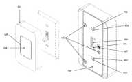
- FIG. 3shows the front cover of version A of the present invention in the orientation in which it would attach to a toggle switch.
- FIG. 4shows the posterior view of version A of the present invention.
- FIG. 5is an internal view of version A of the present invention.
- FIG. 6is perspective view of the rack, pinion, and servomechanism for version A of the present invention.
- FIG. 7is a posterior and perspective view of the back cover for version A of the present invention.
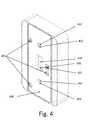
- FIG. 8shows the front cover of version B of the present invention in the orientation in which it would attach to a rocker switch.
- FIG. 9shows the posterior view of version B of the present invention.
- FIG. 10shows the internal view of version B of the present invention.
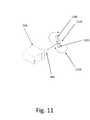
- FIG. 11shows the rotational head for version B of the present invention and the servomechanism it attaches to.
- FIG. 12shows the posterior and perspective view of the back cover for version B of the present invention.
- FIG. 13shows a bowed rack according to an alternative embodiment of version B.
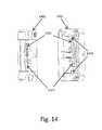
- FIG. 14shows the bowed rack and housing configuration according to the alternative embodiment of version B.
- the present inventionserves as an automation device to toggle a lever on a pre-existing fixture by both a button input on the automation device as well as wirelessly from any device capable of communicating on the same wireless communication protocol.
- These devicesmay include, but are not limited to, personal computers, smart phones, tablet devices, and wireless gateways.
- this devicemay operate with, version A and version b of the automation device are capable of automating toggle 101 and rocker 201 switches, respectively.
- FIG. 3there is shown the front cover 301 of version A of the present invention and a button input 304 .
- This button input 304serves as manual method of actuating the lever on the pre-existing fixture as well as providing tactile feedback to the user.
- the buttondoes not actuate the lever, but rather serves as an input on the internal circuitry which in turn activates the servomechanism to toggle the lever 102 from its previous position.
- the two interfaces to toggle the lever on the pre-existing fixtureare through the button input 304 and by a wireless command.
- the microcontroller 502receives an input and activates the servomechanism 509 .
- the microcontroller 502is able to keep track of the state of the lever based on the previous command, forgoing the need of a sensor for this state-tracking.
- the metal screws 104 on the pre-existing fix hireserve as the attachment points for the magnets 402 on the automation device.
- FIG. 8depicts an analogous view for version B of the device for a broader, flat lever 202 on the rocker switch with metal screws 104 at a different spacing.
- the magnets 402 on version B of the deviceare spaced apart to directly contact these metal screws.
- the button input 304 and the photo-luminescent material 305remains the same as version A of the device.
- FIG. 4a posterior perspective is shown of version A of the automation device with the backing plate 406 attached.
- the backing plate 406includes two apertures 403 with chamfered edges around the magnets 402 , spaced apart to match the placement of metal screws 104 of the pre-existing fixture shown in FIG. 1 .
- a rectangular apertureis present 404 on the backing plate to allow for the lever of the pre-existing fixture to protrude through and be actuated by the internal rack 405 .
- FIG. 9a posterior perspective is shown of version B of the automation device with the backing plate 907 attached.
- Two apertures 906 with chamfered edgessurround magnets 402 , spaced apart to match the placement of the metal screw 104 of the pre-existing fixture shown in FIG. 2 .
- This Chamfered geometryimproves the alignment of the automation device as it matches hemispherical heads of screws commonly present on toggle and rocker switches.
- a material capable of providing this frictional forcewould also be sufficient for a rocker switch 201 since the force generated during actuation for this type of switch is primarily orthogonal to the surface of the switch, as depicted in FIG. 2 in direction 205 .
- this coatingcan include, but are not limited to, polyurethane and silicone.
- a permanent coatingneed not be used; an alternative solution could include a temporary or pressure sensitive adhesives such as rubber, standard acrylic, and silicone on the backing plate.
- a toggle switch 407 for version A and version B of the present inventionis used to power the automation device on and off.
- FIG. 5depicts the interior of the front cover for version A and FIG. 10 depicts the interior of the front cover for version B of the automation device, holding many of the internal components.
- holes 513 for the screws meant to attach the back plate 406are shown as well as a path 505 to guide wires from the button input 304 is shown.
- a filleted track 511is made to provide a guiding track for the motion of the rack 405 as it is actuated by the pinion 507 on the head of the servomechanism 509 in two directions 514 .
- FIG. 6shows the rack 405 and the pinion 507 for version A of the automation device in greater detail.
- the rackcontains an aperture 602 to allow the lever 102 of the pre-existing fixture to protrude through.
- the teeth 603 of the rackmatch the teeth 606 of the pinion 507 to allow for smooth actuation.
- a small aperture 607 on the pinionallows it to be held in place onto the servomechanism head 605 with a screw.
- a servomechanismwas selected to provide sufficient torque.
- the rackactuates the lever 102 of the toggle switch at approximately 0.2 inches from the surface 103 of the toggle switch.
- typical toggle switchesrequire approximately 2.5 pounds to flip.
- sufficient torqueis met by being able to provide a minimum peak force of 2.5 pounds at a lever arm distance of 0.2 inches.
- the servomechanismmust have a torque output exceeding 0.5 lb-in.
- FIG. 11depicts the rotational head 1101 as well as the head 605 of the servomechanism it attaches to.
- This rotational headhas a rotational motion 1104 which allows the fins 1105 of the rotational head to directly contact the lever 202 of the rocker switch. These fins can protrude through an aperture 1203 the backing plate 907 to make contact with the rocker switch.
- Typical rocker switchesrequire 1 pound of force to toggle and the fins 1105 create a lever arm distance of approximately 0.9 inches, creating a torque requirement of 0.19 lb-in for the servomechanism.
- the version A and version B microcontroller 502 on the circuit hoard 501contains logic for scheduling timers, proximity detection, and range of motion. Timers can be set by wireless commands using devices such as smart phones, personal computers, and tablets.
- the firmware implementation on the microcontrollerallows these timers to be recurring on a daily, weekly, and monthly basis. Random number generators within the microcontroller also allow for the randomization of these timers.
- the wireless moduleis also able to detect proximity of another device operating on the same wireless protocol using on-board hardware capable of measuring received signal strength. This value, known as received signal strength indicator (RSSI), is a measurement of power received by the antenna on the wireless module.
- RSSIreceived signal strength indicator
- logic can be implemented on the microcontrolleris able to activate the servomechanism to change the state of the lever on the pre-existing fixture.
- a usercan create a setting with a smartphone to have the automation device change the state of the toggle switch to “on” when the user is within range.
- the microcontroller on the automation devicecan use logic such that when the RSSI value is greater than or equal to ⁇ 80 dBm, the microcontroller will activate the servomechanism to flip the toggle switch to the “on” position. The user would then be able to have lights turn on automatically without needing to explicitly send a command upon entering the home.
- the RSSI value which serves as the threshold for an actuation event to occurcan be set by the user or a default value can be used based on needed sensitivity and range.
- the microcontroller logic for actuating the servomechanismis explained in the subsequent paragraphs.
- FIG. 5version A of the internals of automation device is shown with the rack 405 in the center position.
- the pinion 507 below the rack 405is able to rotate from 0-180° by the servomechanism 509 .
- the microcontrollerUpon power-up of the device, the microcontroller provides a pulse width modulated signal to the servomechanism to move the servo head to the center position (90° position) and move the rack 405 to the center position of the fillet 511 .
- This center positionis denoted the “90° position” of the pinion 507 .
- This center positionensures that the rack does not interfere with the lever 102 on the pre-existing fixture 101 during installation.
- FIG. 4depicts the posterior of the device with the backing plate when the rack is in the center position.
- a PWM (pulse width modulation) signalis sent for 350 milliseconds corresponding to either the 0° position or 180° position, moving the rack 405 to the top or bottom of the filleted track 511 , respectively.
- the lever 102protrudes through the aperture 602 of the rack 405 .
- the edges of the rack 601come in contact with the lever 102 and exert a force on the lever in a direction parallel to the surface 103 of the toggle switch.
- Toggle switcheshave an inherent spring which returns them to their previous state if the lever 102 is not moved beyond the center axis 106 .
- the microcontrollerreturns the rack 405 to an offset position from end positions (0° or 180°). This is done by the microcontroller first providing a PWM signal for 350 milliseconds corresponding to 0° or 180°, depending on the command received. Due to the variability of the thickness of the lever 102 on toggle switches, in these positions (0° or 180°), the rack may be in a state where it is exerting torque on the lever but the lever cannot move any further. In this state, the servomechanism is at stall and can be damaged should it remain in this state.
- the microcontrollerAfter the microcontroller has provided a PWM signal for 350 milliseconds, the microcontroller provides a second PWM signal for 100 milliseconds corresponding to a 10° offset from these end state positions (10° or 170°). This returns the rack to a state where the edges 601 are no longer in contact with the lever 102 on the toggle switch.
- the microcontrolleralso supplies a PWM signal but has a closed loop control system based on the current consumption of the servomechanism.
- the torque generating component of a servomechanismis a DC motor.
- the current drawnis directly proportional to the torque output of the motor. Motor current at stall and various loads can be measured experimentally or retrieved from a data sheet. Therefore, by measuring motor current it is possible to detect when the DC motor inside the servomechanism has stalled.
- Current consumption of the servois measured by the voltage drop across a shunt resistor in series with the power line of the servomechanism.
- This voltage dropis amplified such that the stall current of the servo corresponds to 90% the maximum value the ADC (analog to digital converter) on the microcontroller is capable of measuring.
- the servomechanismactuates the rocker switch, the current increases, due to increasing load, until it has completely flipped the switch. Once the rocker switch cannot move any further, the servomechanism reaches the stall current.
- the microcontrolleris able to detect this stall by the ADC measurement and the microcontroller supplies a PWM signal to return the rotational head 1101 to the state depicted in FIG. 10 , parallel to the surface of the backing plate 908 .
- This feedback systemprevents the servomechanism from actuating the rocker switch after it has already been toggled and prevents the motor from remaining in a stalled state.
- an equal but opposite farceis generated in an orthogonal direction 205 to the surface of the switch.
- this forceis approximately 1 pound. Therefore the magnets 402 on version B of the must be able to provide at minimum this attachment force.
- neodymium magnets (N52) 402were selected such that there was a safety factor exceeding 5 ⁇ (5 pounds of pull force) and the dimensions were constrained such that the magnets did not come into contact with any internal components or increase the thickness of the automation device overall.
- FIG. 7shows a posterior and perspective view of the backing plate 406 for version A of the present invention.
- Three apertures 706allow this backing plate to be mounted onto the frontal cover with screws, although this need not be the only mechanism of attachment.
- a weld or adhesivecould also be used for attachment.
- Compartments 703 and 704house neodymium magnets; apertures 403 within these compartments to allow the magnets to directly contact metal screws on the pre-existing fixture.
- FIG. 12shows the posterior and perspective view of the backing plate for version B of the present invention.
- two apertures 1205allow this backing plate to be mounted to the frontal cover with screws.
- Compartments 1206are for the placement of neodymium magnets to contact the metal screws on the pre-existing fixture. Apertures 906 allow for this direct contact between the magnets and metal screws.
- the devicecan incorporate a wireless local area network module, such as WiFi, or communicate to a wireless gateway with wireless local area network capabilities. It would then be possible to send commands to the automation device from any device capable of joining this wireless local area network, regardless of distance. These commands can include scheduling timers, requests for status of the state of the lever, and toggling of the state of the lever. As mentioned earlier, the state of the lever is known because the microcontroller is able to keep track of the last command received.
- a wireless local area network modulesuch as WiFi
- commandscan include scheduling timers, requests for status of the state of the lever, and toggling of the state of the lever.
- the state of the leveris known because the microcontroller is able to keep track of the last command received.
- a wireless gatewayis capable of communicating with three or more automation devices, it would be able utilize a technique known as trilateration to create a physical map of the position of other wireless devices within range.
- each of the three automation deviceswould provide the gateway with their respective signal strength to a smart phone.
- the gatewaywould be able to approximate the relative location of the smart phone, effectively creating an indoor positioning system.
- itcould send commands to the automation devices such as toggling the state of the switch they automate.
- An example of how this can be usedwould be that the user can implement logic through a smartphone such that if the user is near two automation devices (e.g.
- the gatewaycan send a command to have the third automation device toggle the state of the pre-existing fixture to turn lights off.
- the RSSI threshold values for this logiccan be set by the user or set to default values.
- While this systemhas been described to communicate with the Bluetooth Low Energy protocol, it need not be limited to this and could operate with a protocol more suited for a mesh network such as Zigbee or Z-wave.
- two automation devicescould provide their respective measured signal strength to a smart phone to a third automation device. This third automation device could then use these two values, in addition to its own measured signal strength, and apply the trilateration algorithm to map the location of the smartphone.
- the usercan implement logic to toggle the state of the pre-existing fixture based on measured RSSI values.
- the userhas the ability to name each automation device on the smartphone app and/or web portal. If the user were to use a name such as “front door” or “back yard”, the app can make the assumption that the automation devices have been installed near the front and back of the house, respectively. A third device which does not have any keywords such as “front” or “back” can be assumed to be between two such devices. To prevent false positives, the user can also provide the app with the approximate distance of the device from the front of the house. With this information, it is possible to provide the relative location of another Bluetooth or Zigbee device within the home. As an example, it would be possible to calculate the approximate location of a child, wearing a Bluetooth low energy bracelet, within a home.
- An alternative embodiment of version B of the automation devicereplaces rotational head 1101 with a curved or bowed rack driven by a pinion in a rack and pinion mechanism functionally operating in a similar fashion to the rack and pinion mechanism of version A of the automation device.
- FIG. 13an example embodiment of such a curvilinear or bowed rack is shown having pinion matching teeth on a side opposite from that of the direction of the bow.
- the curved or bowed rack 1301is moved by a toothed or geared pinion such that ends of the curved or bowed rack 1301 contact the lever of the rocker switch in order to toggle the rocker switch between an on and off state.
- FIG. 14This operation can more readily be seen in FIG. 14 where front portion 1403 and back portion 1401 of the automation device housing, which when combined contains or holds the bowed rack 1301 , can be seen.
- the pinionmoves the bowed rack 1301 , along and between curvilinear guides 1407 of front portion 1403 and back portion 1401 of the automation device housing, thereby causing ends of the bowed rack 1301 to extend in a rearward direction from the automation device housing and towards the lever of the rocker switch.
- Moving the bowed rack 1301 in one directionthus causes one end to flip the lever of the rocker switch into an “on” state and moving the bowed rack 1301 in the opposite direction thus causes an opposite end to flip the lever of the rocker switch into an “off” state.
- this embodiment of version B of the automation deviceincludes limit switches 1405 which are contacted by the ends of bowed rack 1301 as bowed rack 1301 is moved between these two positions or states.
- the limit switches 1405are coupled to the microcontroller 502 in order to send a signal to microcontroller 502 when one end of bowed rack 1301 contacts one of the limit switches 1405 thereby informing microcontroller 502 that the bowed rack 1301 has reached an end position (equivalent to the 0° position or 180° position described above with reference to version A of the automation device).
- microcontroller 502Upon receipt of this signal, microcontroller 502 directs that the pinion stop moving bowed rack 1301 in its current direction and, instead, briefly reverse its direction in order to return bowed rack 1301 to an offset position from the end position, to achieve the same effect as was described above with reference to version A of the automation device.
- version A of the automation devicecan likewise incorporate limit switches 1405 to be contacted by ends of rack 405 , the linear actuator of version A, to thereby operate in essentially the same fashion as described above with reference to the alternative embodiment of version B of the automation device.
- the servomechanism portion of the actuator mechanismcan be replaced by a direct current (DC) motor to drive the pinion of the rack and pinion mechanism.
- DCdirect current
- This DC motor based arrangementwhile functionally similar to that of the servomechanism based arrangement, can be used in conjunction with the limit switches 1405 as will now be described.
- the DC motordirects the pinion to move the rack until one of the limit switches sends a signal to the microprocessor that the rack has made contact with it.
- the microcontroller 502directs the DC motor to reverse direction for a predetermined period of time, based on the known revolutions per minute (RPM) of the DC motor, to cause the rack to be placed in a neutral or center position of the automation device.
- RPMrevolutions per minute
- the useris instructed to place the automation device on the light switch in an up position (as may be indicated by a visual marker on the automation device) after this power up sequence.
- any command received by the microcontroller 502 to either flip the switch on or offresults in the microcontroller signaling the DC motor to cause the pinion to move the rack in the appropriate direction (e.g., up for on and down for off) until one of the limit switches 1405 signals the microcontroller 502 that the rack has made contact with it, thereby indicating that the rack has reached an end position, at which point the microcontroller signals the DC motor to reverse direction for a brief period of time thereby placing the rack in the offset position, as was described above.
- mechanismssuch as solenoids, stepper motors and Shape Memory Alloys (SMAs) can likewise be used in place of the DC motor.
- a time out operationis used with the above-described process to prevent possible damage to components of the automation device as well as achieve potential power savings.
- the rackmay not be able to move far enough to contact one of the limit switches despite already having moved far enough to flip the light switch. Not receiving an end position signal from a limit switch could cause the microcontroller to continue directing the DC motor to move the pinion until either the DC motor burns out or the rack and pinion mechanism breaks and also continues to consume power running the DC motor.
- the microcontrollerstops signaling the DC motor to cause the pinion to move the rack upon either receiving the limit switch signal or a first time out period has elapsed, whichever occurs first.
- the first time out periodwould typically be the amount of time, again based on the known RPMs of the DC motor, expected to move the rack from the intermediate position to the end position.
- a second time out periodapproximately twice as long as the first time out period because the rack's length of travel is approximately twice as long when going from one end position (or the offset position) to the other end position, would then be used for any later switching operations between the on and off states of the light switch.
- one or more additional sensorsare included within the automation device to detect presence of a user. Any known sensor can be used including a motion sensor, a temperature sensor, a humidity sensor, a camera, etc. Such sensor can then signal to the microcontroller that a user is present thereby causing the microcontroller to turn on the switch.
- the described method and apparatuscan be implemented in numerous ways, including as a process, an apparatus, or a system.
- the methods described hereinmay be implemented by program instructions for instructing a processor to perform such methods, and such instructions recorded on a non-transitory computer readable storage medium such as a hard disk drive, floppy disk, optical disc such as a compact disc (CD) or digital versatile disc (DVD), flash memory, etc., or communicated over a computer network wherein the program instructions are sent over optical or electronic communication links.
- a non-transitory computer readable storage mediumsuch as a hard disk drive, floppy disk, optical disc such as a compact disc (CD) or digital versatile disc (DVD), flash memory, etc.
Landscapes
- Engineering & Computer Science (AREA)
- General Engineering & Computer Science (AREA)
- Switch Cases, Indication, And Locking (AREA)
Abstract
Description
Claims (21)
Priority Applications (6)
| Application Number | Priority Date | Filing Date | Title |
|---|---|---|---|
| US14/617,020US9418802B2 (en) | 2014-02-08 | 2015-02-09 | Switch automation device |
| US15/236,482US9520247B1 (en) | 2014-02-08 | 2016-08-15 | Automated operation of fixtures |
| US15/368,573US20170105176A1 (en) | 2014-02-08 | 2016-12-03 | Home automation ecosystem devices and power management |
| US15/846,005US10172082B2 (en) | 2014-02-08 | 2017-12-18 | Power optimized video for smart home ecosystem |
| US15/846,080US20180108230A1 (en) | 2014-02-08 | 2017-12-18 | Monitoring of legacy controls in smart home system |
| US16/234,589US11171803B2 (en) | 2014-02-08 | 2018-12-28 | Smart home communications architecture |
Applications Claiming Priority (3)
| Application Number | Priority Date | Filing Date | Title |
|---|---|---|---|
| US201461937493P | 2014-02-08 | 2014-02-08 | |
| US201462065564P | 2014-10-17 | 2014-10-17 | |
| US14/617,020US9418802B2 (en) | 2014-02-08 | 2015-02-09 | Switch automation device |
Related Child Applications (1)
| Application Number | Title | Priority Date | Filing Date |
|---|---|---|---|
| US15/236,482Continuation-In-PartUS9520247B1 (en) | 2014-02-08 | 2016-08-15 | Automated operation of fixtures |
Publications (2)
| Publication Number | Publication Date |
|---|---|
| US20150228426A1 US20150228426A1 (en) | 2015-08-13 |
| US9418802B2true US9418802B2 (en) | 2016-08-16 |
Family
ID=53775517
Family Applications (1)
| Application Number | Title | Priority Date | Filing Date |
|---|---|---|---|
| US14/617,020Active - Reinstated2035-05-09US9418802B2 (en) | 2014-02-08 | 2015-02-09 | Switch automation device |
Country Status (1)
| Country | Link |
|---|---|
| US (1) | US9418802B2 (en) |
Cited By (43)
| Publication number | Priority date | Publication date | Assignee | Title |
|---|---|---|---|---|
| US20160196938A1 (en)* | 2014-08-12 | 2016-07-07 | Ecolink Intelligent Technology, Inc. | Remote controlled switch cover |
| US20170005819A1 (en)* | 2006-01-31 | 2017-01-05 | Sigma Designs, Inc. | Method and system for synchronization and remote control of controlling units |
| US10237954B2 (en) | 2016-06-03 | 2019-03-19 | Lutron Electronics Co., Inc. | Battery-powered retrofit remote control device |
| US10277519B2 (en) | 2006-01-31 | 2019-04-30 | Silicon Laboratories Inc. | Response time for a gateway connecting a lower bandwidth network with a higher speed network |
| US10326537B2 (en) | 2006-01-31 | 2019-06-18 | Silicon Laboratories Inc. | Environmental change condition detection through antenna-based sensing of environmental change |
| US10342103B2 (en) | 2016-10-21 | 2019-07-02 | Lutron Technology Company Llc | Control device with multiple feedback types |
| US10349502B2 (en) | 2013-10-30 | 2019-07-09 | Cantigny Lighting Control, Llc | Timer and a method of implementing a timer |
| US10375803B2 (en) | 2016-06-03 | 2019-08-06 | Lutron Technology Company Llc | Control device for controlling multiple operating characteristics of an electrical load |
| US10410802B2 (en) | 2016-03-24 | 2019-09-10 | Lutron Technology Company Llc | Self-adjusting frame for mounting over a wall-mounted electrical device |
| US10411401B1 (en) | 2018-06-01 | 2019-09-10 | Christmas Northeast, Inc. | Electrical junction receptacle for magnetic electrical connectors |
| US10418193B2 (en) | 2012-10-26 | 2019-09-17 | Lutron Tehnology Company LLC | Controllable light source |
| US10426017B2 (en) | 2016-07-05 | 2019-09-24 | Lutron Technology Company Llc | Controlling groups of electrical loads via multicast and/or unicast messages |
| US10446019B2 (en) | 2016-03-24 | 2019-10-15 | Lutron Technology Company Llc | Gesture-based control device for controlling an electrical load |
| US10475596B2 (en) | 2017-06-28 | 2019-11-12 | Lutron Technology Company Llc | Control device base that attaches to the paddle actuator of a mechanical switch |
| WO2019217620A1 (en)* | 2018-05-09 | 2019-11-14 | Michael Wong | Switch automating and monitoring adapter devices |
| WO2020028224A1 (en)* | 2018-08-03 | 2020-02-06 | Delos Living Llc | Smart switch cover |
| US10586667B2 (en) | 2016-06-03 | 2020-03-10 | Lutron Technology Company Llc | Retrofit remote control device |
| US10637681B2 (en) | 2014-03-13 | 2020-04-28 | Silicon Laboratories Inc. | Method and system for synchronization and remote control of controlling units |
| US10637673B2 (en) | 2016-12-12 | 2020-04-28 | Silicon Laboratories Inc. | Energy harvesting nodes in a mesh network |
| US10720274B2 (en) | 2016-06-30 | 2020-07-21 | Lutron Technology Company Llc | Magnetic sensing system for a rotary control device |
| US10772180B2 (en) | 2016-07-05 | 2020-09-08 | Lutron Technology Company Llc | State retention load control system |
| US10816223B2 (en) | 2017-07-26 | 2020-10-27 | Therm Controls Incorporated | Automated temperature control of heating radiators |
| US10856396B2 (en) | 2016-10-21 | 2020-12-01 | Lutron Technology Company Llc | Battery-powered control device including a rotating portion |
| US10910176B2 (en) | 2018-09-11 | 2021-02-02 | Lutron Technology Company Llc | Control device configured to provide visual feedback |
| US10964494B2 (en) | 2018-10-12 | 2021-03-30 | Lutron Technology Company Llc | Control device for controlling multiple operating characteristics of an electrical load |
| US11043115B2 (en) | 2014-06-24 | 2021-06-22 | Lutron Technology Company Llc | Battery-powered retrofit remote control device |
| US11107651B2 (en) | 2019-05-14 | 2021-08-31 | Lutron Technology Company Llc | Base for a retrofit remote control device |
| US11127144B2 (en) | 2018-08-24 | 2021-09-21 | Lutron Technology Company Llc | Occupant counting device |
| US11237665B2 (en) | 2019-08-27 | 2022-02-01 | Lutron Technology Company Llc | Load control device having a capacitive touch surface |
| US11297709B2 (en) | 2011-02-01 | 2022-04-05 | Cantigny Lighting Control, Llc | Circuit arrangement for enabling motion detection to control an outdoor light |
| US11304284B2 (en) | 2019-05-17 | 2022-04-12 | Lutron Technology Company Llc | Lamp synchronization after excessive user interaction |
| US11425811B2 (en) | 2019-05-17 | 2022-08-23 | Lutron Technology Company Llc | Controlling groups of electrical loads |
| US11437814B2 (en) | 2016-07-05 | 2022-09-06 | Lutron Technology Company Llc | State retention load control system |
| US11502490B2 (en) | 2019-07-12 | 2022-11-15 | Lutron Technology Company Llc | Retrofit remote control device mounting assembly |
| US11636754B2 (en) | 2019-05-14 | 2023-04-25 | Lutron Technology Company Llc | Retrofit remote control device |
| US20230266729A1 (en)* | 2022-02-23 | 2023-08-24 | International Business Machines Corporation | Cognitive retrofit for legacy control devices |
| US11849521B1 (en) | 2021-10-08 | 2023-12-19 | Vivint, Inc. | Apparatus for lighting control |
| US11894203B2 (en) | 2016-12-30 | 2024-02-06 | Ecolink Intelligent Technology, Inc. | Remote-controlled switch cover assembly |
| US12035443B2 (en) | 2019-08-27 | 2024-07-09 | Lutron Technology Company Llc | Control device having a visible indicator |
| DE102023134002B3 (en) | 2023-12-05 | 2024-12-12 | Albrecht Jung Gmbh & Co. Kg | Arrangement comprising a functional module and a switching device and method for assembly |
| US12300449B2 (en) | 2012-10-26 | 2025-05-13 | Lutron Technology Company Llc | Battery-powered retrofit remote control device |
| US12339014B2 (en) | 2017-07-26 | 2025-06-24 | Therm Controls Incorporated | Automated temperature control of heating radiators |
| US12426143B2 (en) | 2020-12-09 | 2025-09-23 | Lutron Technology Company Llc | System for controlling load control parameters over fade times |
Families Citing this family (35)
| Publication number | Priority date | Publication date | Assignee | Title |
|---|---|---|---|---|
| US9799469B2 (en) | 2014-08-12 | 2017-10-24 | Ecolink Intelligent Technology, Inc. | Remote controlled light switch cover assembly |
| WO2017120010A1 (en)* | 2016-01-05 | 2017-07-13 | Ecolink Intelligent Technology, Inc. | Remote controlled switch cover |
| US9818559B2 (en)* | 2016-01-19 | 2017-11-14 | Rev-A-Shelf Company, Llc | Wireless lighting control device |
| US10727731B1 (en) | 2017-04-01 | 2020-07-28 | Smart Power Partners, LLC | Power adapters adapted to receive a module and methods of implementing power adapters with modules |
| US12027968B2 (en) | 2017-04-01 | 2024-07-02 | John J. King | Power adapters and methods of implementing a power adapter |
| US10996645B1 (en) | 2017-04-01 | 2021-05-04 | Smart Power Partners LLC | Modular power adapters and methods of implementing modular power adapters |
| US10530597B1 (en) | 2017-04-01 | 2020-01-07 | Smart Power Partners LLC | System for controlling a plurality of power switches configured to apply power to devices |
| US12093004B1 (en) | 2017-04-01 | 2024-09-17 | Smart Power Partners LLC | In-wall power adapter and method of implementing an in-wall power adapter |
| USD904319S1 (en)* | 2018-11-16 | 2020-12-08 | Promier Products Inc. | Light switch with sliding actuator and integrated light source |
| CN208208582U (en)* | 2018-03-30 | 2018-12-07 | 施耐德电气(澳大利亚)有限公司 | Control module component and switch comprising the control module component |
| CN110691345A (en)* | 2018-07-05 | 2020-01-14 | 深圳市圆景科技有限公司 | Low-power consumption remote control's doorbell system |
| US11579640B1 (en) | 2019-06-30 | 2023-02-14 | Smart Power Partners LLC | Control attachment for an in-wall power adapter |
| US10938168B2 (en) | 2019-06-30 | 2021-03-02 | Smart Power Partners LLC | In-wall power adapter and method of controlling the application of power to a load |
| US11043768B1 (en) | 2019-06-30 | 2021-06-22 | Smart Power Partners LLC | Power adapter configured to provide power to a load and method of implementing a power adapter |
| US10958020B1 (en) | 2019-06-30 | 2021-03-23 | Smart Power Partners LLC | Control attachment for an in-wall power adapter and method of controlling an in-wall power adapter |
| US12045071B1 (en) | 2019-06-30 | 2024-07-23 | Smart Power Partners LLC | In-wall power adapter having an outlet |
| US11201444B1 (en) | 2019-06-30 | 2021-12-14 | Smart Power Partners LLC | Power adapter having contact elements in a recess and method of controlling a power adapter |
| US11189948B1 (en) | 2019-06-30 | 2021-11-30 | Smart Power Partners LLC | Power adapter and method of implementing a power adapter to provide power to a load |
| US11990712B1 (en) | 2019-06-30 | 2024-05-21 | Smart Power Partners LLC | Control attachment for a power adapter and method of implementing a control attachment |
| US11460874B1 (en) | 2019-06-30 | 2022-10-04 | Smart Power Partners LLC | In-wall power adapter configured to control the application of power to a load |
| US10965068B1 (en) | 2019-06-30 | 2021-03-30 | Smart Power Partners LLC | In-wall power adapter having an outlet and method of controlling an in-wall power adapter |
| US12164350B1 (en) | 2019-06-30 | 2024-12-10 | Smart Power Partners LLC | Power adapter configured to provide power to a load |
| US11264769B1 (en) | 2019-06-30 | 2022-03-01 | Smart Power Partners LLC | Power adapter having contact elements in a recess and method of controlling a power adapter |
| US11231730B1 (en) | 2019-06-30 | 2022-01-25 | Smart Power Power LLC | Control attachment for a power adapter configured to control power applied to a load |
| US12066848B1 (en) | 2019-06-30 | 2024-08-20 | Smart Power Partners LLC | In-wall power adaper adapted to receive a control attachment and method of implementing a power adapter |
| US10917956B1 (en) | 2019-06-30 | 2021-02-09 | Smart Power Partners LLC | Control attachment configured to provide power to a load and method of configuring a control attachment |
| US10958026B1 (en) | 2019-06-30 | 2021-03-23 | Smart Power Partners LLC | Contactless thermometer for an in-wall power adapter |
| CN110299260B (en)* | 2019-07-16 | 2024-12-03 | 长江大学 | A non-contact pressing device for remotely controlled lighting switch |
| US12155164B2 (en) | 2021-11-03 | 2024-11-26 | Smart Power Partners LLC | In-wall power adapter having a switch and a connector for controlling the application of a voltage |
| US12080494B2 (en)* | 2022-08-24 | 2024-09-03 | NovaVolta Limited | Switch augmentation |
| USD1047939S1 (en)* | 2023-01-03 | 2024-10-22 | Wenzhou Nova New Energy Co., Ltd. | Electric switch |
| USD1080560S1 (en)* | 2023-02-09 | 2025-06-24 | Ajax Systems Cyprus Holdings Ltd | Lighting control switch |
| USD1074622S1 (en)* | 2023-02-09 | 2025-05-13 | Ajax Systems Cyprus Holdings Ltd | Lighting control switch |
| USD1067203S1 (en)* | 2023-04-07 | 2025-03-18 | Ajax Systems Cyprus Holdings Ltd | Cover plate for switches |
| CN118712909B (en)* | 2024-08-27 | 2024-11-15 | 浙江旭纶智能科技有限公司 | Multifunctional distribution box based on BAS monitoring system |
Citations (5)
| Publication number | Priority date | Publication date | Assignee | Title |
|---|---|---|---|---|
| US7214898B1 (en)* | 2006-03-07 | 2007-05-08 | Isamar Margareten | Cover for light switch |
| US7273983B1 (en)* | 1996-05-02 | 2007-09-25 | Rintz William J | Light switch assembly |
| US20090020307A1 (en)* | 2007-07-18 | 2009-01-22 | Roach Jr Peter | Methods and apparatuses for a magnetic decorator wall cover plate with the option to record decorating choices |
| US8796567B2 (en)* | 2009-10-13 | 2014-08-05 | Michael Mahle | Switch conversion apparatus |
| US20150244121A1 (en)* | 2013-08-21 | 2015-08-27 | N2 Global Solutions Incorporated | System and apparatus for providing and managing electricity |
- 2015
- 2015-02-09USUS14/617,020patent/US9418802B2/enactiveActive - Reinstated
Patent Citations (5)
| Publication number | Priority date | Publication date | Assignee | Title |
|---|---|---|---|---|
| US7273983B1 (en)* | 1996-05-02 | 2007-09-25 | Rintz William J | Light switch assembly |
| US7214898B1 (en)* | 2006-03-07 | 2007-05-08 | Isamar Margareten | Cover for light switch |
| US20090020307A1 (en)* | 2007-07-18 | 2009-01-22 | Roach Jr Peter | Methods and apparatuses for a magnetic decorator wall cover plate with the option to record decorating choices |
| US8796567B2 (en)* | 2009-10-13 | 2014-08-05 | Michael Mahle | Switch conversion apparatus |
| US20150244121A1 (en)* | 2013-08-21 | 2015-08-27 | N2 Global Solutions Incorporated | System and apparatus for providing and managing electricity |
Cited By (139)
| Publication number | Priority date | Publication date | Assignee | Title |
|---|---|---|---|---|
| US10277519B2 (en) | 2006-01-31 | 2019-04-30 | Silicon Laboratories Inc. | Response time for a gateway connecting a lower bandwidth network with a higher speed network |
| US20170005819A1 (en)* | 2006-01-31 | 2017-01-05 | Sigma Designs, Inc. | Method and system for synchronization and remote control of controlling units |
| US9954692B2 (en)* | 2006-01-31 | 2018-04-24 | Sigma Designs, Inc. | Method for triggered activation of an actuator |
| US10326537B2 (en) | 2006-01-31 | 2019-06-18 | Silicon Laboratories Inc. | Environmental change condition detection through antenna-based sensing of environmental change |
| US11297709B2 (en) | 2011-02-01 | 2022-04-05 | Cantigny Lighting Control, Llc | Circuit arrangement for enabling motion detection to control an outdoor light |
| US11102874B2 (en) | 2012-10-26 | 2021-08-24 | Lutron Technology Company Llc | Controllable light source |
| US10849206B2 (en) | 2012-10-26 | 2020-11-24 | Lutron Technology Company Llc | Battery-powered retrofit remote control device |
| US11102875B2 (en) | 2012-10-26 | 2021-08-24 | Lutron Technology Company Llc | Battery-powered retrofit remote control device |
| US10418193B2 (en) | 2012-10-26 | 2019-09-17 | Lutron Tehnology Company LLC | Controllable light source |
| US12300449B2 (en) | 2012-10-26 | 2025-05-13 | Lutron Technology Company Llc | Battery-powered retrofit remote control device |
| US11837418B2 (en) | 2012-10-26 | 2023-12-05 | Lutron Technology Company Llc | Battery-powered retrofit remote control device |
| US10349502B2 (en) | 2013-10-30 | 2019-07-09 | Cantigny Lighting Control, Llc | Timer and a method of implementing a timer |
| US10433406B2 (en) | 2013-10-30 | 2019-10-01 | Cantigny Lighting Control, Llc | Programmable light timer and a method of implementing a programmable light timer |
| US10637681B2 (en) | 2014-03-13 | 2020-04-28 | Silicon Laboratories Inc. | Method and system for synchronization and remote control of controlling units |
| US11657702B2 (en) | 2014-06-24 | 2023-05-23 | Lutron Technology Company Llc | Battery-powered retrofit remote control device |
| US11043115B2 (en) | 2014-06-24 | 2021-06-22 | Lutron Technology Company Llc | Battery-powered retrofit remote control device |
| US12020561B2 (en) | 2014-06-24 | 2024-06-25 | Lutron Technology Company Llc | Battery-powered retrofit remote control device |
| US10586666B2 (en) | 2014-08-12 | 2020-03-10 | Ecolink Intelligent Technology, Inc. | Remote controlled switch cover |
| US20160196938A1 (en)* | 2014-08-12 | 2016-07-07 | Ecolink Intelligent Technology, Inc. | Remote controlled switch cover |
| US11901138B2 (en) | 2014-08-12 | 2024-02-13 | Ecolink Intelligent Technology, Inc. | Remote controlled light switch cover |
| US11031197B2 (en) | 2014-08-12 | 2021-06-08 | Ecolink Intelligent Technology, Inc. | Remote controlled light switch cover |
| US9959997B2 (en)* | 2014-08-12 | 2018-05-01 | Ecolink Intelligent Technology, Inc. | Remote controlled switch cover |
| US10446019B2 (en) | 2016-03-24 | 2019-10-15 | Lutron Technology Company Llc | Gesture-based control device for controlling an electrical load |
| US10977931B2 (en) | 2016-03-24 | 2021-04-13 | Lutron Technology Company Llc | Remote load control device capable of orientation detection |
| US11538643B2 (en) | 2016-03-24 | 2022-12-27 | Lutron Technology Company Llc | Gesture-based control device for controlling an electrical load |
| US11626261B2 (en) | 2016-03-24 | 2023-04-11 | Lutron Technology Company, LLC | Self-adjusting frame for mounting over a wall-mounted electrical device |
| US11264184B2 (en) | 2016-03-24 | 2022-03-01 | Lutron Technology Company Llc | Remote load control device capable of orientation detection |
| US11646166B2 (en) | 2016-03-24 | 2023-05-09 | Lutron Technology Company Llc | Remote load control device capable of orientation detection |
| US10672261B2 (en) | 2016-03-24 | 2020-06-02 | Lutron Technology Company Llc | Gesture-based control device for controlling an electrical load |
| US11232916B2 (en) | 2016-03-24 | 2022-01-25 | Lutron Technology Company Llc | Gesture-based control device for controlling an electrical load |
| US10685560B2 (en) | 2016-03-24 | 2020-06-16 | Lutron Technology Company Llc | Remote load control device capable of orientation detection |
| US12040151B2 (en) | 2016-03-24 | 2024-07-16 | Lutron Technology Company Llc | Self-adjusting frame for mounting over a wall-mounted electrical device |
| US10410802B2 (en) | 2016-03-24 | 2019-09-10 | Lutron Technology Company Llc | Self-adjusting frame for mounting over a wall-mounted electrical device |
| US11069490B2 (en) | 2016-03-24 | 2021-07-20 | Lutron Technology Company, LLC | Self-adjusting frame for mounting over a wall-mounted electrical device |
| US10741339B2 (en) | 2016-03-24 | 2020-08-11 | Lutron Technology Company Llc | Retrofit remote control devices |
| US12261008B2 (en) | 2016-03-24 | 2025-03-25 | Lutron Technology Company Llc | Retrofit remote control devices |
| US12278076B2 (en) | 2016-03-24 | 2025-04-15 | Lutron Technology Company Llc | Remote load control device capable of orientation detection |
| US12283445B2 (en) | 2016-03-24 | 2025-04-22 | Lutron Technology Company Llc | Gesture-based control device for controlling an electrical load |
| US11804339B2 (en) | 2016-03-24 | 2023-10-31 | Lutron Technology Company Llc | Gesture-based control device for controlling an electrical load |
| US10475333B2 (en) | 2016-03-24 | 2019-11-12 | Lutron Technology Company Llc | Gesture-based control device for controlling an electrical load |
| US11410821B2 (en) | 2016-03-24 | 2022-08-09 | Lutron Technology Company Llc | Retrofit remote control devices |
| US11830696B2 (en) | 2016-03-24 | 2023-11-28 | Lutron Technology Company Llc | Remote load control device capable of orientation detection |
| US11682534B2 (en) | 2016-06-03 | 2023-06-20 | Lutron Technology Company Llc | Retrofit remote control device |
| US12131628B2 (en) | 2016-06-03 | 2024-10-29 | Lutron Technology Company Llc | Battery-powered retrofit remote control device |
| US10832880B2 (en) | 2016-06-03 | 2020-11-10 | Lutron Technology Company Llc | Retrofit remote control device |
| US10524333B2 (en) | 2016-06-03 | 2019-12-31 | Lutron Technology Company Llc | User interface for a control device |
| US12389502B2 (en) | 2016-06-03 | 2025-08-12 | Lutron Technology Company Llc | Retrofit remote control devices |
| US12400811B2 (en) | 2016-06-03 | 2025-08-26 | Lutron Technology Company Llc | Retrofit remote control device |
| US10721811B2 (en) | 2016-06-03 | 2020-07-21 | Lutron Technology Company Llc | Battery-powered retrofit remote control device |
| US12040142B2 (en) | 2016-06-03 | 2024-07-16 | Lutron Technology Company Llc | Retrofit remote control device |
| US10375803B2 (en) | 2016-06-03 | 2019-08-06 | Lutron Technology Company Llc | Control device for controlling multiple operating characteristics of an electrical load |
| US11800612B2 (en) | 2016-06-03 | 2023-10-24 | Lutron Technology Company Llc | Control device for controlling multiple operating characteristics of an electrical load |
| US11765800B2 (en) | 2016-06-03 | 2023-09-19 | Lutron Technology Company Llc | User interface for a control device |
| US11166354B2 (en) | 2016-06-03 | 2021-11-02 | Lutron Technology Company Llc | Retrofit remote control devices |
| US10939534B2 (en) | 2016-06-03 | 2021-03-02 | Lutron Technology Company Llc | Control device for controlling multiple operating characteristics of an electrical load |
| US11234300B2 (en) | 2016-06-03 | 2022-01-25 | Lutron Technology Company Llc | User interface for a control device |
| US11823561B2 (en) | 2016-06-03 | 2023-11-21 | Lutron Technology Company Llc | Battery-powered retrofit remote control device |
| US10681791B2 (en) | 2016-06-03 | 2020-06-09 | Lutron Technology Company Llc | User interface for a control device |
| US12418964B2 (en) | 2016-06-03 | 2025-09-16 | Lutron Technology Company Llc | Control device for controlling multiple operating characteristics of an electrical load |
| US11251002B2 (en) | 2016-06-03 | 2022-02-15 | Lutron Technology Comapny LLC | Retrofit remote control device |
| US12096528B2 (en) | 2016-06-03 | 2024-09-17 | Lutron Technology Company Llc | User interface for a control device |
| US10548205B2 (en) | 2016-06-03 | 2020-01-28 | Lutron Technology Company Llc | Battery-powered retrofit remote control device |
| US10237954B2 (en) | 2016-06-03 | 2019-03-19 | Lutron Electronics Co., Inc. | Battery-powered retrofit remote control device |
| US11202351B2 (en) | 2016-06-03 | 2021-12-14 | Lutron Technology Company Llc | Control device for controlling multiple operating characteristics of an electrical load |
| US11602024B2 (en) | 2016-06-03 | 2023-03-07 | Lutron Technology Company Llc | Retrofit remote control devices |
| US11308794B2 (en) | 2016-06-03 | 2022-04-19 | Lutron Technology Company Llc | Battery-powered retrofit remote control device |
| US10586667B2 (en) | 2016-06-03 | 2020-03-10 | Lutron Technology Company Llc | Retrofit remote control device |
| US11869710B2 (en) | 2016-06-30 | 2024-01-09 | Lutron Technology Company Llc | Magnetic sensing system for a rotary control device |
| US11574754B2 (en) | 2016-06-30 | 2023-02-07 | Lutron Technology Company Llc | Magnetic sensing system for a rotary control device |
| US10720274B2 (en) | 2016-06-30 | 2020-07-21 | Lutron Technology Company Llc | Magnetic sensing system for a rotary control device |
| US12237106B2 (en) | 2016-06-30 | 2025-02-25 | Lutron Technology Company Llc | Magnetic sensing system for a rotary control device |
| US11309111B2 (en) | 2016-06-30 | 2022-04-19 | Lutron Technology Company Llc | Magnetic sensing system for a rotary control device |
| US11658840B2 (en) | 2016-07-05 | 2023-05-23 | Lutron Technology Company Llc | State retention load control system |
| US10772180B2 (en) | 2016-07-05 | 2020-09-08 | Lutron Technology Company Llc | State retention load control system |
| US11832368B2 (en) | 2016-07-05 | 2023-11-28 | Lutron Technology Company Llc | State retention load control system |
| US10827596B2 (en) | 2016-07-05 | 2020-11-03 | Lutron Technology Company Llc | Controlling groups of electrical loads via multicast and/or unicast messages |
| US11588660B2 (en) | 2016-07-05 | 2023-02-21 | Lutron Technology Company Llc | Controlling groups of electrical loads via multicast and/or unicast messages |
| US11437814B2 (en) | 2016-07-05 | 2022-09-06 | Lutron Technology Company Llc | State retention load control system |
| US11924000B2 (en) | 2016-07-05 | 2024-03-05 | Lutron Technology Company Llc | State retention load control system |
| US12418436B2 (en) | 2016-07-05 | 2025-09-16 | Lutron Technology Company Llc | State retention load control system |
| US10426017B2 (en) | 2016-07-05 | 2019-09-24 | Lutron Technology Company Llc | Controlling groups of electrical loads via multicast and/or unicast messages |
| US12295084B2 (en) | 2016-07-05 | 2025-05-06 | Lutron Technology Company Llc | State retention load control system |
| US12081358B2 (en) | 2016-07-05 | 2024-09-03 | Lutron Technology Company Llc | Controlling groups of electrical loads via multicast and/or unicast messages |
| US11196581B2 (en) | 2016-07-05 | 2021-12-07 | Lutron Technology Company Llc | State retention load control system |
| US11417203B2 (en) | 2016-10-21 | 2022-08-16 | Lutron Technology Company, LLC | Controlling groups of electrical loads |
| US11869345B2 (en) | 2016-10-21 | 2024-01-09 | Lutron Technology Company Llc | Controlling groups of electrical loads |
| US11715368B2 (en) | 2016-10-21 | 2023-08-01 | Lutron Technology Company Llc | Controlling groups of electrical loads |
| US12354468B2 (en) | 2016-10-21 | 2025-07-08 | Lutron Technology Company Llc | Battery-powered control device configured to detect persistent actuation |
| US10856396B2 (en) | 2016-10-21 | 2020-12-01 | Lutron Technology Company Llc | Battery-powered control device including a rotating portion |
| US10694613B2 (en) | 2016-10-21 | 2020-06-23 | Lutron Technology Company Llc | Controlling groups of electrical loads |
| US12322281B2 (en) | 2016-10-21 | 2025-06-03 | Lutron Technology Company Llc | Controlling groups of electrical loads |
| US12300097B2 (en) | 2016-10-21 | 2025-05-13 | Lutron Technology Company Llc | Controlling groups of electrical loads |
| US10342103B2 (en) | 2016-10-21 | 2019-07-02 | Lutron Technology Company Llc | Control device with multiple feedback types |
| US10624184B2 (en) | 2016-10-21 | 2020-04-14 | Lutron Technology Company Llc | Controlling groups of electrical loads |
| US11816979B2 (en) | 2016-10-21 | 2023-11-14 | Lutron Technology Company Llc | Battery-powered control device including a rotation portion |
| US10420194B2 (en) | 2016-10-21 | 2019-09-17 | Lutron Technology Company Llc | Controlling groups of electrical loads |
| US11335185B2 (en) | 2016-10-21 | 2022-05-17 | Lutron Technology Company Llc | Battery-powered control device including a rotating portion |
| US10637673B2 (en) | 2016-12-12 | 2020-04-28 | Silicon Laboratories Inc. | Energy harvesting nodes in a mesh network |
| US11894203B2 (en) | 2016-12-30 | 2024-02-06 | Ecolink Intelligent Technology, Inc. | Remote-controlled switch cover assembly |
| US11437209B2 (en) | 2017-06-28 | 2022-09-06 | Lutron Technology Company Llc | Control device base that attaches to the paddle actuator of a mechanical switch |
| US10916385B2 (en) | 2017-06-28 | 2021-02-09 | Lutron Technology Company Llc | Control device base that attaches to the paddle actuator of a mechanical switch |
| US10475596B2 (en) | 2017-06-28 | 2019-11-12 | Lutron Technology Company Llc | Control device base that attaches to the paddle actuator of a mechanical switch |
| US10816223B2 (en) | 2017-07-26 | 2020-10-27 | Therm Controls Incorporated | Automated temperature control of heating radiators |
| US12339014B2 (en) | 2017-07-26 | 2025-06-24 | Therm Controls Incorporated | Automated temperature control of heating radiators |
| WO2019217620A1 (en)* | 2018-05-09 | 2019-11-14 | Michael Wong | Switch automating and monitoring adapter devices |
| US10411401B1 (en) | 2018-06-01 | 2019-09-10 | Christmas Northeast, Inc. | Electrical junction receptacle for magnetic electrical connectors |
| WO2020028224A1 (en)* | 2018-08-03 | 2020-02-06 | Delos Living Llc | Smart switch cover |
| US11935251B2 (en) | 2018-08-24 | 2024-03-19 | Lutron Technology Company Llc | Occupant counting device |
| US11127144B2 (en) | 2018-08-24 | 2021-09-21 | Lutron Technology Company Llc | Occupant counting device |
| US12249083B2 (en) | 2018-08-24 | 2025-03-11 | Lutron Technology Company Llc | Occupant counting device |
| US11669981B2 (en) | 2018-08-24 | 2023-06-06 | Lutron Technology Company Llc | Occupant counting device |
| US11264187B2 (en) | 2018-09-11 | 2022-03-01 | Lutron Technology Company Llc | Control device configured to provide visual feedback |
| US10910176B2 (en) | 2018-09-11 | 2021-02-02 | Lutron Technology Company Llc | Control device configured to provide visual feedback |
| US12080493B2 (en) | 2018-09-11 | 2024-09-03 | Lutron Technology Company, LLC | Control device configured to provide visual feedback |
| US11621133B2 (en) | 2018-09-11 | 2023-04-04 | Lutron Technology Company Llc | Control device configured to provide visual feedback |
| US11942287B2 (en) | 2018-10-12 | 2024-03-26 | Lutron Technology Company Llc | Control device for controlling multiple operating characteristics of an electrical load |
| US10964494B2 (en) | 2018-10-12 | 2021-03-30 | Lutron Technology Company Llc | Control device for controlling multiple operating characteristics of an electrical load |
| US12293885B2 (en) | 2018-10-12 | 2025-05-06 | Lutron Technology Company Llc | Control device for controlling multiple operating characteristics of an electrical load |
| US11107651B2 (en) | 2019-05-14 | 2021-08-31 | Lutron Technology Company Llc | Base for a retrofit remote control device |
| US11636754B2 (en) | 2019-05-14 | 2023-04-25 | Lutron Technology Company Llc | Retrofit remote control device |
| US12300448B2 (en) | 2019-05-14 | 2025-05-13 | Lutron Technology Company Llc | Base for a retrofit remote control device |
| US12073712B2 (en) | 2019-05-14 | 2024-08-27 | Lutron Technology Company, LLC | Retrofit remote control device |
| US11569051B2 (en) | 2019-05-14 | 2023-01-31 | Lutron Technology Company Llc | Base for a retrofit remote control device |
| US11778716B2 (en) | 2019-05-17 | 2023-10-03 | Lutron Technology Company Llc | Controlling groups of electrical loads |
| US11785695B2 (en) | 2019-05-17 | 2023-10-10 | Lutron Technology Company Llc | Lamp synchronization after excessive user interaction |
| US12250758B2 (en) | 2019-05-17 | 2025-03-11 | Lutron Technology Company Llc | Lamp synchronization after continued excessive user interaction |
| US11304284B2 (en) | 2019-05-17 | 2022-04-12 | Lutron Technology Company Llc | Lamp synchronization after excessive user interaction |
| US11425811B2 (en) | 2019-05-17 | 2022-08-23 | Lutron Technology Company Llc | Controlling groups of electrical loads |
| US11735897B2 (en) | 2019-07-12 | 2023-08-22 | Lutron Technology Company Llc | Retrofit remote control device mounting assembly |
| US12074419B2 (en) | 2019-07-12 | 2024-08-27 | Lutron Technology Company Llc | Retrofit remote control device mounting assembly |
| US11502490B2 (en) | 2019-07-12 | 2022-11-15 | Lutron Technology Company Llc | Retrofit remote control device mounting assembly |
| US11237665B2 (en) | 2019-08-27 | 2022-02-01 | Lutron Technology Company Llc | Load control device having a capacitive touch surface |
| US12356529B2 (en) | 2019-08-27 | 2025-07-08 | Lutron Technology Company Llc | Control device having a visible indicator |
| US12035443B2 (en) | 2019-08-27 | 2024-07-09 | Lutron Technology Company Llc | Control device having a visible indicator |
| US12426143B2 (en) | 2020-12-09 | 2025-09-23 | Lutron Technology Company Llc | System for controlling load control parameters over fade times |
| US11849521B1 (en) | 2021-10-08 | 2023-12-19 | Vivint, Inc. | Apparatus for lighting control |
| US12130604B2 (en)* | 2022-02-23 | 2024-10-29 | International Business Machines Corporation | Cognitive retrofit for legacy control devices |
| US20230266729A1 (en)* | 2022-02-23 | 2023-08-24 | International Business Machines Corporation | Cognitive retrofit for legacy control devices |
| DE102023134002B3 (en) | 2023-12-05 | 2024-12-12 | Albrecht Jung Gmbh & Co. Kg | Arrangement comprising a functional module and a switching device and method for assembly |
Also Published As
| Publication number | Publication date |
|---|---|
| US20150228426A1 (en) | 2015-08-13 |
Similar Documents
| Publication | Publication Date | Title |
|---|---|---|
| US9418802B2 (en) | Switch automation device | |
| US20160358719A1 (en) | Automated Operation Of Fixtures | |
| US20170105176A1 (en) | Home automation ecosystem devices and power management | |
| US10932347B2 (en) | Intelligent lighting control system electrical connector apparatuses, systems, and methods | |
| KR101530766B1 (en) | Toggle switch with magnetic mechanical and electrical control | |
| US20180070429A1 (en) | Intelligent lighting control system spatial definition control apparatuses, systems, and methods | |
| EP2858193A1 (en) | A switching device and a method of controlling the same | |
| JP6373041B2 (en) | Wireless reception driving apparatus and power supply method | |
| US20120112562A1 (en) | Timing power switch | |
| US9898906B2 (en) | RFID based event sensor | |
| US20140262713A1 (en) | Wall switch assembly | |
| CN103326199B (en) | Intelligence controllable and energy saving socket | |
| EP3584672A3 (en) | Systems for controlling laser projector and mobile terminals | |
| US10292238B1 (en) | System and method for three-way switching | |
| CN112020720A (en) | Electronic badge, control method and device thereof, storage medium and attendance management system | |
| CN204760320U (en) | Relay of state transmission can carry out through WIFI | |
| CN109952689B (en) | Battery-type power supply device and battery-driven load device | |
| US20170346318A1 (en) | Sensory and Control Platform for an Automation System | |
| US20190072930A1 (en) | Control apparatus | |
| CN200941361Y (en) | Magnetic switch | |
| Aman | Home automation based on IOT | |
| MX2021008078A (en) | MODULAR ELECTRONIC DEVICE FOR ELECTRICAL AND/OR DOMOTIC SYSTEMS. | |
| CN207531121U (en) | A kind of touch light modulation structure | |
| CN205385470U (en) | Starting drive | |
| CN207425651U (en) | A kind of buffering stop block of module and its sliding block |
Legal Events
| Date | Code | Title | Description |
|---|---|---|---|
| AS | Assignment | Owner name:SWITCHMATE INC., CALIFORNIA Free format text:ASSIGNMENT OF ASSIGNORS INTEREST;ASSIGNORS:ROMANO, ROBERT Y.;KROYMANN, TYLER;DUA, ASHISH;AND OTHERS;SIGNING DATES FROM 20150204 TO 20150205;REEL/FRAME:034917/0816 | |
| AS | Assignment | Owner name:SWITCHMATE HOME LLC, CALIFORNIA Free format text:ASSIGNMENT OF ASSIGNORS INTEREST;ASSIGNOR:SWITCHMATE INC.;REEL/FRAME:037790/0645 Effective date:20160210 | |
| STCF | Information on status: patent grant | Free format text:PATENTED CASE | |
| FEPP | Fee payment procedure | Free format text:MAINTENANCE FEE REMINDER MAILED (ORIGINAL EVENT CODE: REM.); ENTITY STATUS OF PATENT OWNER: SMALL ENTITY | |
| LAPS | Lapse for failure to pay maintenance fees | Free format text:PATENT EXPIRED FOR FAILURE TO PAY MAINTENANCE FEES (ORIGINAL EVENT CODE: EXP.); ENTITY STATUS OF PATENT OWNER: SMALL ENTITY | |
| PRDP | Patent reinstated due to the acceptance of a late maintenance fee | Effective date:20201112 | |
| FEPP | Fee payment procedure | Free format text:PETITION RELATED TO MAINTENANCE FEES FILED (ORIGINAL EVENT CODE: PMFP); ENTITY STATUS OF PATENT OWNER: SMALL ENTITY Free format text:SURCHARGE, PETITION TO ACCEPT PYMT AFTER EXP, UNINTENTIONAL. (ORIGINAL EVENT CODE: M2558); ENTITY STATUS OF PATENT OWNER: SMALL ENTITY Free format text:PETITION RELATED TO MAINTENANCE FEES GRANTED (ORIGINAL EVENT CODE: PMFG); ENTITY STATUS OF PATENT OWNER: SMALL ENTITY | |
| MAFP | Maintenance fee payment | Free format text:PAYMENT OF MAINTENANCE FEE, 4TH YR, SMALL ENTITY (ORIGINAL EVENT CODE: M2551); ENTITY STATUS OF PATENT OWNER: SMALL ENTITY Year of fee payment:4 | |
| STCF | Information on status: patent grant | Free format text:PATENTED CASE | |
| MAFP | Maintenance fee payment | Free format text:PAYMENT OF MAINTENANCE FEE, 8TH YR, SMALL ENTITY (ORIGINAL EVENT CODE: M2552); ENTITY STATUS OF PATENT OWNER: SMALL ENTITY Year of fee payment:8 |