US9414137B2 - Methods and systems for distributing fiber optic telecommunication services to local areas and for supporting distributed antenna systems - Google Patents
Methods and systems for distributing fiber optic telecommunication services to local areas and for supporting distributed antenna systemsDownload PDFInfo
- Publication number
- US9414137B2 US9414137B2US14/486,453US201414486453AUS9414137B2US 9414137 B2US9414137 B2US 9414137B2US 201414486453 AUS201414486453 AUS 201414486453AUS 9414137 B2US9414137 B2US 9414137B2
- Authority
- US
- United States
- Prior art keywords
- cable
- fiber
- drop terminal
- optical
- distribution
- Prior art date
- Legal status (The legal status is an assumption and is not a legal conclusion. Google has not performed a legal analysis and makes no representation as to the accuracy of the status listed.)
- Expired - Fee Related
Links
Images


Classifications
- H—ELECTRICITY
- H04—ELECTRIC COMMUNICATION TECHNIQUE
- H04Q—SELECTING
- H04Q11/00—Selecting arrangements for multiplex systems
- H04Q11/0001—Selecting arrangements for multiplex systems using optical switching
- H04Q11/0062—Network aspects
- H04Q11/0067—Provisions for optical access or distribution networks, e.g. Gigabit Ethernet Passive Optical Network (GE-PON), ATM-based Passive Optical Network (A-PON), PON-Ring
- G—PHYSICS
- G02—OPTICS
- G02B—OPTICAL ELEMENTS, SYSTEMS OR APPARATUS
- G02B6/00—Light guides; Structural details of arrangements comprising light guides and other optical elements, e.g. couplings
- G02B6/44—Mechanical structures for providing tensile strength and external protection for fibres, e.g. optical transmission cables
- G02B6/4439—Auxiliary devices
- G02B6/444—Systems or boxes with surplus lengths
- G02B6/4441—Boxes
- G02B6/44515—Fibre drop terminals with surplus length
- G—PHYSICS
- G02—OPTICS
- G02B—OPTICAL ELEMENTS, SYSTEMS OR APPARATUS
- G02B6/00—Light guides; Structural details of arrangements comprising light guides and other optical elements, e.g. couplings
- G02B6/46—Processes or apparatus adapted for installing or repairing optical fibres or optical cables
- G02B6/48—Overhead installation
- G02B6/483—Installation of aerial type
- H—ELECTRICITY
- H04—ELECTRIC COMMUNICATION TECHNIQUE
- H04B—TRANSMISSION
- H04B10/00—Transmission systems employing electromagnetic waves other than radio-waves, e.g. infrared, visible or ultraviolet light, or employing corpuscular radiation, e.g. quantum communication
- H04B10/25—Arrangements specific to fibre transmission
- H04B10/2575—Radio-over-fibre, e.g. radio frequency signal modulated onto an optical carrier
- H04B10/25752—Optical arrangements for wireless networks
- H04B10/25753—Distribution optical network, e.g. between a base station and a plurality of remote units
- H—ELECTRICITY
- H04—ELECTRIC COMMUNICATION TECHNIQUE
- H04B—TRANSMISSION
- H04B10/00—Transmission systems employing electromagnetic waves other than radio-waves, e.g. infrared, visible or ultraviolet light, or employing corpuscular radiation, e.g. quantum communication
- H04B10/80—Optical aspects relating to the use of optical transmission for specific applications, not provided for in groups H04B10/03 - H04B10/70, e.g. optical power feeding or optical transmission through water
- H04B10/806—Arrangements for feeding power
- H04B10/807—Optical power feeding, i.e. transmitting power using an optical signal
- G—PHYSICS
- G02—OPTICS
- G02B—OPTICAL ELEMENTS, SYSTEMS OR APPARATUS
- G02B6/00—Light guides; Structural details of arrangements comprising light guides and other optical elements, e.g. couplings
- G02B6/44—Mechanical structures for providing tensile strength and external protection for fibres, e.g. optical transmission cables
- G02B6/4439—Auxiliary devices
- G02B6/4457—Bobbins; Reels
- H—ELECTRICITY
- H04—ELECTRIC COMMUNICATION TECHNIQUE
- H04Q—SELECTING
- H04Q11/00—Selecting arrangements for multiplex systems
- H04Q11/0001—Selecting arrangements for multiplex systems using optical switching
- H04Q11/0062—Network aspects
- H04Q2011/009—Topology aspects
- H—ELECTRICITY
- H04—ELECTRIC COMMUNICATION TECHNIQUE
- H04W—WIRELESS COMMUNICATION NETWORKS
- H04W88/00—Devices specially adapted for wireless communication networks, e.g. terminals, base stations or access point devices
- H04W88/08—Access point devices
- H04W88/085—Access point devices with remote components
Definitions
- Fiber optic telecommunications technologyis becoming more prevalent as service providers strive to deliver higher bandwidth communication capabilities to customers/subscribers.
- the phrase “fiber to the x”(FTTX) generically refers to any network architecture that uses optical fiber in place of copper within a local distribution area.
- Example FTTX networksinclude fiber-to-the-node (FTTN) networks, fiber-to-the-curb (FTTC) networks and fiber-to-the-premises (FTTP) networks.
- FTTN and FTTC networksuse fiber optic cables that are run from a service provider's central office to a cabinet serving a neighborhood. Subscribers connect to the cabinet using traditional copper cable technology such as coaxial cable or twisted pair wiring. The difference between an FTTN network and an FTTC network relates to the area served by the cabinet. Typically, FTTC networks typically have cabinets closer to the subscribers that serve a smaller subscriber area than the cabinets of FTTN networks.
- Example FTTP networksinclude fiber-to-the-home (FTTH) networks and fiber-to-the-building (FTTB) networks.
- FTTHfiber-to-the-home
- FTTBfiber-to-the-building
- ONToptical network terminal
- the ONTtypically includes active components that convert the optical signals into electrical signals.
- the electrical signalsare typically routed from the ONT to the subscriber's residence or office space using traditional copper cable technology.
- fiber optic cableis run from the service provider's central office to an ONT located at the subscriber's residence or office space.
- ONToptical signals are typically converted into an electrical signal for use with the subscriber's devices.
- conversion of the optical signal to an electrical signalmay not be necessary.
- FTTP networksinclude active optical networks and passive optical networks.
- Active optical networksuse electrically powered equipment (e.g., a switch, router, multiplexer or other equipment) to distribute signals and to provide signal buffering.
- Passive optical networksuse passive beam splitters instead of electrically powered equipment to split optical signals.
- ONT'sare typically equipped with equipment (e.g., wave-division multiplexing and time-division multiplexing equipment) that prevents incoming and outgoing signals from colliding and that filters out signals intended for other subscribers.
- a typical passive FTTP networkincludes fiber optic cables routed from a central location (e.g., a service provider's central office) to a fiber distribution hub (FDH) located in a local area such as a neighborhood.
- the fiber distribution hubtypically includes a cabinet in which one or more passive optical splitters are mounted. The splitters each are capable of splitting a signal carried by a single fiber to a plurality of fibers. The fibers split out at the splitter are routed from the fiber distribution hub into the local area using a fiber optic distribution cable. Fibers are routed from the fiber distribution cable to subscriber locations (e.g., homes, businesses or buildings) using various techniques.
- fiber optic drop cablescan be routed directly from a breakout location on the distribution cable to an ONT at a subscriber location.
- a stub cablecan be routed from a breakout location of the distribution cable to a drop terminal.
- Drop cablescan be run from the drop terminal to ONT's located at a plurality of premises located near the drop terminal.
- DASDistributed Antenna Systems
- wireless servicee.g., cell phone, WiFi, etc.
- DASinclude a network of spaced-apart antenna nodes optically or electrically connected to a common control location (e.g., a base station).
- Each antenna nodetypically includes an antenna and a remote unit (i.e., a radio head, a remote transceiver, etc.).
- DASare one way that a wireless cellular service provider can improve the coverage provided by a given base station or group of base stations.
- radio frequency (RF) signalsare communicated between a host unit and one or more remote units.
- the host unitcan be communicatively coupled to one or more base stations directly by connecting the host unit to the base station using, for example, electrical or fiber telecommunications cabling.
- the host unitcan also be communicatively coupled to one or more base stations wirelessly, for example, using a donor antenna and a bi-directional amplifier (BDA).
- BDAbi-directional amplifier
- RF signals(also referred to here as “downlink RF signals”) transmitted from the base station are received at the host unit.
- the host unituses the downlink RF signals to generate a downlink transport signal that is distributed to one or more of the remote units.
- Each such remote unitreceives the downlink transport signal and reconstructs the downlink RF signals based on the downlink transport signal and causes the reconstructed downlink RF signals to be radiated from at least one antenna coupled to or included in that remote unit.
- RF signals(also referred to here as “uplink RF signals”) transmitted from mobile units are received at each remote unit.
- Each remote unituses the uplink RF signals to generate an uplink transport signal that is transmitted from the remote unit to the host unit.
- the host unitreceives and combines the uplink transport signals transmitted from the remote units.
- the host unitreconstructs the uplink RF signals received at the remote units and communicates the reconstructed uplink RF signals to the base station. In this way, the coverage of the base station can be expanded using the DAS.
- One or more intermediate devicescan be placed between the host unit and the remote units in order to increase the number of remote units that a single host unit can feed and/or to increase the hub-unit-to-remote-unit distance.
- DASOne general type of DAS is configured to use optical fibers to communicatively couple the host unit to the remote units and/or expansions hubs.
- optical fiberstypically makes use of dedicated optical fibers that are deployed specifically to support that DAS.
- An aspect of the present disclosurerelates to a fiber optic network including a fiber distribution hub and a plurality of drop terminals (i.e., multi-service terminals) optically connected to the fiber distribution hub by a plurality of fiber optic distribution cables.
- the fiber optic networkis used to connect antenna nodes of a Distributed Antenna System to a base station.
- a feeder cablee.g., an F1 cable
- drop cablescan be used to connect the antenna nodes to the drop terminals
- the distribution cablesconnect the drop terminals to the fiber distribution hub.
- the optical networkprovides optical signal pathways between the antenna nodes and the base station for linking the base station to the antenna nodes.
- Another aspect of the present disclosurerelates to a method for supporting a Distributed Antenna System by using excess capacity of an existing FTTX network. In this way, a new Distributed Antenna System can be deployed in the field while minimizing the amount of new optical fiber that need be installed to support the Distributed Antenna System.
- FIG. 1shows a fiber optic network in accordance with the principles of the present disclosure.
- FIGS. 2-4illustrate a sequence for installing the fiber optic network of FIG. 1 .
- FIG. 5shows another fiber optic network in accordance with the principles of the present disclosure.
- FIGS. 6 and 7show a sequence for installing the fiber optic network of FIG. 5 .
- FIG. 8shows still another fiber optic network in accordance with principles of the present disclosure.
- FIG. 9is a perspective view of a fiber distribution hub suitable for use in fiber optic networks of FIGS. 1, 5 and 8 in accordance with the principles of the present disclosure.
- FIG. 10is a perspective view of the fiber distribution hub of FIG. 9 with front doors in an open position.
- FIG. 11is a perspective view of the fiber distribution hub of FIG. 9 with a swing frame in an open position.
- FIGS. 12A-12Dare schematic representations of example cable routing schemes for a fiber distribution hub suitable for use in fiber optic networks of FIGS. 1, 5 and 8 in accordance with the principles of the present disclosure.
- FIG. 13is an exploded perspective view of a drop terminal suitable for use in the fiber optic networks of FIGS. 1, 5 and 8 .
- FIG. 14is a perspective view of a housing suitable for use with the drop terminal in the fiber optic networks of FIGS. 1, 5 and 8 .
- FIG. 15is a front view of the housing of FIG. 14 .
- FIG. 16is a side view of the housing of FIG. 14 .
- FIG. 17is an exploded view of a ruggedized fiber optic adapter suitable for use with the drop terminal of FIG. 13 .
- FIG. 18is a perspective view of a back piece of the housing of FIGS. 14-16 .
- FIG. 19is an alternate embodiment of a spool end suitable for use with the drop terminal of FIG. 13 .
- FIG. 20is a perspective view of an alternate embodiment of a fiber spooling system in accordance with the principles of the present disclosure for use with a drop terminal.
- FIG. 21is a perspective view of the fiber spooling system of FIG. 20 with a hinge plate in an open position.
- FIG. 22is a perspective view of the fiber spooling system of FIG. 20 with the hinge plate in the open position.
- FIG. 23is a perspective view of an alternate embodiment of a spooling system.
- FIG. 24is a perspective view of the spooling system with a hinge plate in an open position.
- FIG. 25is a perspective view of a cover of a drop terminal of the spooling system of FIG. 23 .
- FIG. 26is a perspective view of a drop terminal assembly suitable for use with the spooling system of FIG. 23 .
- FIG. 27is a perspective view of the drop terminal assembly of FIG. 26 .
- FIG. 28is a perspective view of the spooling system of FIG. 23 .
- FIG. 29is a rear perspective view of the drop terminal assembly of FIG. 26 .
- FIG. 30is a perspective view of the spooling system of FIG. 23 .
- FIG. 31is a side view of the spooling system of FIG. 23 with a mandrel.
- FIG. 32is a block diagram of one exemplary embodiment of a distributed antenna system (DAS).
- DASdistributed antenna system
- An aspect of the present disclosurerelates to a fiber optic network including a fiber distribution hub and a plurality of drop terminals (i.e., multi-service terminals) optically connected to the fiber distribution hub by a plurality of fiber optic distribution cables.
- the fiber optic networkis used to connect antenna nodes of a Distributed Antenna System to a base station.
- a feeder cablee.g., an F1 cable
- drop cablescan be used to connect the antenna nodes to the drop terminals
- the distribution cablesconnect the drop terminals to the fiber distribution hub.
- the fiber optic networkcan also be used to connect a central office to a plurality of subscriber locations so as to provide the subscriber locations with service.
- a feeder cablee.g., an F1 cable
- drop cablescan be used to connect the subscriber locations to the drop terminals
- the distribution cablesconnect the drop terminals to the fiber distribution hub.
- the base stationincludes active electrical components for managing the various signals fed back and forth between the antenna nodes and the base station.
- the base stationcan include a plurality of transceivers for receiving and transmitting signals and a power amplifier for amplifying the signals.
- the base stationcan be configured for any one or more telecommunications standards including 3G (e.g., GSM, EDGE, UMTS, CDMA, DECT, WiMAX, etc.), LTE, and 4G.
- the base stationincludes optical multiplexers (e.g., wavelength division multiplexers) to join signal transmitted through the feeder cable to the FDH and to separate signals received from the FDH through the feeder cable.
- the fiber distribution hubcan include one or more splitters as well as a termination field including an array of fiber optic adapters.
- the splitterscan include passive optical power splitters and/or passive wavelength splitters such as wavelength division multipliers (e.g., core wavelength division multipliers or dense wavelength division multipliers).
- Passive optical power splitterse.g., 1 to 8 splitters, 1 to 16 splitters, 1 to 32 splitters, 1 to 64 splitters, etc.
- Passive optical power splittersare often used as part of a passive FTTX network for splitting signals that are ultimately routed to subscriber locations.
- a signal carried by an optical fiber of a feeder cable routed from the central officeis split at the passive optical power splitter to a plurality of connectorized pigtails.
- the connectorized pigtailsare routed to the termination field of the fiber distribution hub where the connectorized pigtails are placed in optical connection with the distribution cables routed to the drop terminals.
- the drop terminalsprovide connection locations for connecting subscribers to the FTTX network via drop cables.
- Passive wavelength splitterssplit signals split signals from one to many and combine signals from many to one based on wavelength (e.g., 1 to 8 splitters, 1 to 16 splitters, 1 to 32 splitters, 1 to 64 splitters, 1 to 160 splitters, etc.).
- a wavelength splittercan be used to split a signal from a fiber of the feeder cable connected to the base unit to a plurality of connectorized pigtails such that each of the connectorized pigtails carries a signal having a different wavelength band. Signals carried from the connectorized pigtails to the wavelength splitter are combined by the wavelength splitter before being transmitted through the fiber of the feeder cable.
- the connectorized pigtailsare routed to the termination field of the fiber distribution hub where the connectorized pigtails are placed in optical connection with the distribution cables routed to the drop terminals.
- the drop terminalsprovide connection locations for connecting the antenna nodes of the distributed antenna system to the fiber optic network.
- a given antenna nodecan include a remote unit including transmit and receive connection locations.
- signals from the base unitcan be split based on wavelength band at the fiber distribution hub and then routed to subscriber locations, and signals from the subscriber locations having different wavelength bands can be combined at the fiber distribution hub and routed to the base unit.
- a duplexing or multiplexing arrangementmay be used so that one cable can be used to optically connect the antenna node to the drop terminal.
- at least some of the ports of the drop terminalcan include duplex adapters for receiving duplex connectors mounted on a drop cable containing two separate optical fibers for conveying transmit signals and received signals between the antenna node and the drop terminal.
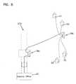
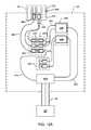
- FIG. 1shows a passive fiber optic distribution network 20 having features that are examples of inventive aspects in accordance with the principles of the present disclosure.
- a distribution network 20is adapted for transmitting fiber optic telecommunication services between a central office 22 and a local area 24 (e.g., a local loop).
- the distribution networkincludes one or more F1 distribution cables 26 that each preferably includes a plurality of optical fibers.
- a first F1 distribution cable 26may have on the order of 12 to 48 fibers. However, alternative numbers of fibers may also be used.
- One or more of the optical fibers of the first F1 distribution cable 26are routed to a fiber distribution hub 28 .
- the fiber distribution hub 28preferably includes one or more passive optical splitter modules adapted to receive signals carried by the fibers of the first F1 distribution cable 26 and output a plurality of signals onto fibers that are optically coupled to one or more F2 distribution cables 30 a - c routed from the distribution hub 28 into the local area 24 .
- the F2 distribution cables 30 a - ccan each include 12 optical fibers.
- one or more of the optical splittersare configured to split an incoming signal into a plurality of lesser powered iterations of the same signal.
- one or more of the optical splittersare wave division multiplexers (WDM) that separate out an plurality of different signals from an incoming signal based on signal wavelength.
- the WDMis a coarse wave divisional multiplexer (CWDM).
- the WDMis a dense wave divisional multiplexer (DWDM), which can separate out more signals than the CWDM.
- the F2 distribution cables 30 a - cinclude first ends 31 terminated by ruggedized multi-fiber connectors 32 .
- the multi-fiber connectors 32interface with a bank 34 of fiber optic adapters provided at an exterior of the fiber distribution hub 28 .
- the adapter bank 34facilitates quickly providing an optical connection between the optical fibers within the fiber distribution hub 28 and the optical fibers of the F2 distribution cables 30 a - c .
- Fiber optic drop terminals 36 a - care respectively located at second ends 33 of the F2 distribution cables 30 a - c .
- Drop terminal 36 ais shown positioned within hand hole 38 a
- drop terminal 36 bis shown mounted within hand hole 38 b
- drop terminal 36 cis shown mounted to a utility pole 40 .
- the F2 distribution cables 30 a - care shown routed through an underground conduit 41 that is shown interconnecting three hand holes 38 a - 38 c .
- fiber optic drop cables 50are routed from the drop terminals 36 a - c to ONT's located at subscriber locations 52 .
- a distributed antenna system (DAS) 90can be integrated with the passive fiber optic distribution network 20 .
- the DAS 90includes a base station 92 including at least one WDM 94 .
- the base station 92is located within the central office 22 .
- the base station 92is external of the central office 22 .
- the base station 92is locate remote from the central office 22 .
- the WDM 94 of the base station 92includes one or more CWDMs.
- the WDM 94includes one or more DWDMs.
- the DAS 90also includes one or more antenna nodes 96 and remote units (i.e. remote units) 98 positioned at various locations (e.g., within a building, campus, city, or geographic region).
- the antenna nodes 96 and remote units 98can be mounted to utility poles, light poles, water towers, signs, or other such suitable locations.
- Each remote unit 98includes a signal receiving port and a signal transmitting port (see FIG. 5 ).
- Signals to be transmitted over the DAS 90are provided over a second F1 feeder cable 95 that connects the base station 92 to the FDH 28 .
- Signals provided over the second F1 feeder cable 95are provided to one or more of the optical splitters within the FDH (see FIGS. 12A-12D ) at which the signals are separated onto F2 distribution cable fibers that are routed to one or more drop terminals 36 a - c.
- Drop cables 50connect the drop terminals 36 to the remote units 98 of the DAS.
- a first fiber 97can connect a first port of the drop terminal 36 to the signal receiving port of the remote unit 98 and a second fiber 99 can connect a second port of the drop terminal 36 to the signal transmitting port of the remote unit 98 .
- the antenna 96can include or be connected to a duplexer, thereby allowing the transmission and reception signals to be passed over a single fiber between the antenna 96 and the drop terminal 36 .
- the DAS 90can be retrofitted to any existing fiber to the premises (FTTX) network by mounting suitable antennas 96 and remote units 98 adjacent existing drop terminals 36 .
- FTTXfiber to the premises
- an antenna 96 and remote unit 98can be mounted to a water tower and connected to unused ports of an underground drop terminal 36 a , 36 b via one or more drop cables 50 .
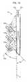
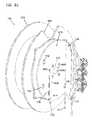
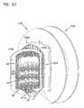
- each of the drop terminals 36 a - cincludes a housing 42 and a spool 44 connected to the housing 42 .
- a plurality of ruggedized fiber optic adapters 46are mounted to each of the housings 42 .
- the ruggedized fiber optic adapters 46include first ports that are accessible from outside the housings 42 and second ports that are accessible from inside the housings 42 .
- the fibers of the F2 distribution cables 30 a - care terminated by optical connectors that are inserted into the second ports of the ruggedized fiber optic adapters 46 .
- the optical connectorscan be terminated directly on the ends of the fibers of the F2 distribution cables 30 a - c .
- the optical connectorscan be terminated indirectly to the ends of the optical fibers of the F2 distribution cables 30 through the use of connectorized pigtails that are spliced to the ends of the fibers of the F2 distribution cables 30 a - c.
- the drop cables 50can be terminated at each end by a ruggedized optical connector.
- An example ruggedized optical connectoris disclosed at U.S. Pat. No. 7,090,406 that is hereby incorporated by reference.
- the ruggedized optical connector terminated at one end of a given drop cablecan be inserted into the first port of one of the drop terminals 36 a - c , while the ruggedized optical connector located at the opposite end of the drop cable can be inserted into a corresponding ruggedized adapter provided at the ONT located at the subscriber location 52 .
- the ruggedized optical connectorincludes a sealing member that engages a sealing surface of the ruggedized fiber optic adapter to provide an environmental seal or a weatherproof seal between the ruggedized optical connector and the ruggedized adapter 46 .
- Portions of the F2 distribution cables 30 a - care preferably wrapped around the spools 44 of the drop terminals 36 a - c .
- the F2 distribution cables 30 a - cmay include first lengths that extend from the drop terminals 36 a - c to the fiber distribution hub 28 , and second lengths that are wrapped around the spool 44 corresponding to the given drop terminal 36 a - c .
- the total length of each of the F2 distribution cables 30 a - cincludes the length of cable extending from the drop terminal to the fiber distribution hub 28 plus an excess length that remains wrapped around the spool 44 after installation of the drop terminal 36 a - c .
- the fibers of the multi-fiber cables 30are routed into the interior of the housing 42 through an access opening.
- An environmental sealpreferably is provided at the access opening.
- the access openingis provided at a backside of the housing while the ruggedized fiber optic adapters are provided at a front side of the housing.
- the installercan identify the locations where it is desired to mount drop terminals. The installer can then roughly estimate the distances from the drop terminal mounting locations to the fiber distribution hub 28 . The installer can preferably select drop terminals from a supply of drop terminals having different lengths of F2 distribution cable pre-wrapped around the spools of the drop terminals. For example, drop terminals can be provided with F2 distribution cable lengths of 100 feet, 250 feet, 500 feet, 1,000 feet, 1,500 feet, 2,000 feet, 2,500 feet, 3,000 feet, etc.
- the distance from the drop terminal location to the fiber distribution hubis estimated and a drop terminal having a pre-spooled length of F2 distribution cable sufficient to reach from the drop terminal mounting location to the fiber distribution hub is selected.
- the spoolwill have a certain amount of excess cable that remains on the spool after the F2 distribution cable has been routed from the drop terminal mounting location to the fiber distribution hub.
- the installercan select three separate drop terminals 36 a - c each having a pre-spooled length of F2 distribution cable that is sufficiently long to reach from the desired drop terminal mounting location to the fiber distribution hub 28 .
- the installercan then first mount the drop terminal 36 c to the utility pole 40 as shown at FIG. 2 .
- the multi-fiber connector 32 at the end of the F2 distribution cable 30 c pre-coiled about the spool 44 of the drop terminal 36 cis then connected to a pulling cable 55 that has been pre-routed through the underground conduit 41 .
- the pulling cable 55is then used to pull the F2 distribution cable 30 c through the underground conduit 41 in a direction extending from the hand hole 38 c toward the hand hole 38 b through the use of a cable puller 57 located near the fiber distribution hub 28 .
- the spool 44 and the housing 40 of the drip terminal 36 crotate in unison about a common axis 65 c to allow the F2 distribution cable 30 c to be paid off from the spool.
- the drop terminal 36 bcan be mounted at the hand hole 38 b and the multi-fiber connector 32 of the F2 distribution cable 30 b spooled about the spool 44 of the drop terminal 36 b is also connected to the pulling cable 55 . Thereafter, the cable puller 57 resumes pulling and both F2 distribution cables 30 b and 30 c are pulled together through the conduit 41 toward the hand hole 38 a .
- the housings 42 and spools 44 of the drop terminals 36 b,crotate about respective axes 65 b , 65 c to allow the cables 30 b,c to be paid off from the spools 44 .
- the multi-fiber connectors 32 of the F2 distribution cables 30 b, creach the hand hole 38 a , pulling of the cable 55 stops and the operator installs the drop terminal 36 a at the hand hole 38 a .
- the multi-fiber connector 32 of the F2 distribution cable 30 a wrapped around the spool 44 of the drop terminal 36 ais then connected to the cable 55 and pulling resumes to pull all three cables 30 a - c through the underground conduit 41 from the hand hole 38 a to the fiber distribution hub 28 .
- the housings 42 and spools 44 of the drop terminals 36 a - crotate about respective axes 65 a - c to allow the cables 30 a - c to be paid off from the spools 44 .
- the multi-fiber connectors 32reach the fiber distribution hub 28 , the multi-fiber connectors 32 are disconnected from the cable 55 and plugged into the adapter bank 34 of the fiber distribution hub 28 . In this way, the fiber distribution hub 28 provides an interface between the optical fibers of the F1 distribution cable and the F2 distribution cables.
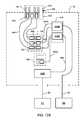
- FIG. 5shows another fiber optic network 120 having features that are examples of inventive aspects in accordance with the principles of the present disclosure.
- the network 120shows a fiber distribution hub 28 mounted on a utility pole 40 and drop terminals 36 a , 36 b mounted on utility poles 40 a , 40 b .
- a utility line 61is routed across the utility poles.
- the drop terminals 36 a , 36 bhave F2 distribution cables 30 a , 30 b that are routed from the fiber distribution hub 28 along the utility line 61 to the utility poles 40 a , 40 b .
- the F2 distribution cables 30 a , 30 bcan be secured to the utility line 61 by conventional techniques such as lashing, tying, or other securing techniques.
- Drop cables 55can be routed from the drop terminals 30 a , 30 b to the ONT's of subscriber locations in need of telecommunication services.
- antenna nodes 96 and remote units 98also can be mounted to one or more utility poles 40 a , 40 b .
- one or more of the antenna nodes 96 and remote units 98can form a DAS (e.g., for providing cellular phone service).
- the remote units 98connect to ports on the drop terminals 36 a , 36 b .
- a first fiber 97can connect a first drop terminal port with a first port on the remote unit 98 and a second fiber 99 can connect a second drop terminal port with a second port on the remote unit 98 .
- the drop terminal mounting locationsare identified and the operator selects drop terminals that are pre-spooled with a sufficient length of F2 distribution cable to reach from the fiber distribution hub 28 to the identified drop terminal mounting location.
- Multi-fiber connectors 32 of the F2 multi-fiber distribution cables 30 a , 30 bare then inserted into an adapter bank 34 of the fiber distribution hub 28 .
- the drop terminals 36 a , 36 bare then mounted on an elevated carrying device 63 that carries the drop terminals 36 a , 36 b along the utility line 61 from pole to pole.
- the elevated carrying device 63moves the drop terminals 36 a , 36 b , the drop terminals housings 42 and their corresponding spools 44 rotate in unison about rotation axes 65 a , 65 b to allow the F2 distribution cables 30 a , 30 b to be paid off from the spools 44 .
- the elevated carrying device 63can be stopped to allow the operator to lash the F2 distribution cables 30 a , 30 b to the utility line 61 .
- the drop terminal 36 ais removed from the elevated carrying device 63 and secured to the pole 40 a .
- the elevated carrying device 63continues to move along the utility line 61 while the housing 42 and spool 44 of the drop terminal 36 b spin in unison about axis 65 b to allow the F2 distribution cable 30 b to be paid off from the spool 44 .
- the operatorcan periodically stop to lash the F2 distribution cable 30 b to the utility line 61 .
- the drop terminal 36 bis removed from the elevated carrying device 63 and mounted to the pole 40 b .
- drop cables 55can be routed from the drop terminals 30 a , 30 b to the ONT's of subscriber locations in need of telecommunication services.
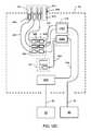
- FIG. 8shows another fiber optic network 220 in accordance with the principles of the present disclosure.
- the fiber optic network of FIG. 8has decentralized passive splitting that eliminates the need for a fiber distribution hub where all of the splitting takes place. Instead, splitters are provided within drop terminals 36 a , 36 b .
- a distribution cablee.g., a single fiber or multi-fiber distribution cable
- the signalis split into a plurality of fibers that have connectorized ends inserted within inner ports of ruggedized adapters mounted at the drop terminal 36 a .
- Another distribution cablecan be plugged into the outer port of one of the adapters and routed to drop terminal 36 b having a splitter therein.
- drop cablescan be routed from the ports of the drop terminal to subscriber locations 52 .
- the drop terminalsare preferably selected so as to have a sufficient amount of pre-wrapped distribution cable provided on the spools to reach from the drop terminal mounting location to the other connection location.
- the drop terminals 36 a , 36 bcan be mounted at their desired locations. Thereafter, the cables can be paid off from the drop terminal spools and pulled to the desired interconnection location. As the cables are pulled, the spools 44 and the corresponding housings 42 of the drop terminals 36 rotate in unison to allow the distribution cables to be paid off from the spools 44 .
- the drop terminal 36 aIn the case of the drop terminal 36 a , the drop terminal 36 a is mounted at a desired location and then the distribution cable is pulled to the desired interconnect location where the fibers interconnect with a fiber from the central office. Thereafter, the drop terminal 36 b is mounted at its desired location and its corresponding distribution cable is pulled from the drop terminal mounting location to the first drop terminal mounting location where the distribution cable is plugged into an adapter port of the drop terminal 36 a.
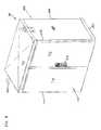
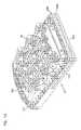
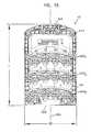
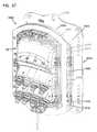
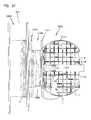
- FIGS. 9-11an exemplary configuration of the fiber distribution hub (FDH) 28 is shown. Certain aspects of the FDH shown in FIGS. 9-11 have been described in U.S. patent application Ser. No. 11/354,286, published as U.S. Publication No. 2007/0189691, which is hereby incorporated by reference in its entirety.
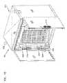
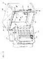
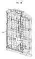
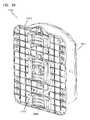
- the FDH 28includes a cabinet 400 that houses internal components.
- the cabinet 400 of the FDH 28includes a top panel 402 , a bottom panel 403 , a right side panel 404 , a left side panel 406 , a back panel 408 , and at least one front door 410 .
- the at least one front door 410includes a right door 412 and a left door 414 .
- the front doors 412 , 414include a lock 416 .
- the at least one front door 410is pivotally mounted to the cabinet 400 using hinges 418 , 420 to facilitate access to the components mounted within the cabinet 400 .
- the cabinet 400 of the FDH 28is configured to protect the internal components against rain, wind, dust, rodents and other contaminants.
- the cabinet 400remains relatively lightweight for easy installation, and breathable to prevent accumulation of moisture in the unit.
- an aluminum construction with a heavy powder coat finishalso provides for corrosion resistance.
- the cabinet 400is manufactured from heavy gauge aluminum and is NEMA-4X rated. In other embodiments, however, other materials can also be used.
- the FDH 28is provided in pole mount or pedestal mount configurations.
- loops 422can be provided on the cabinet 400 for facilitating deployment of the cabinet 400 at a desired location.
- the loops 422can be used to position the cabinet using a crane.
- the cranecan lower the cabinet 400 into an underground region.
- the loops 422are removable or can be adjusted to not protrude from the top panel 402 .
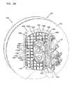
- a swing frame 424is pivotably mounted on hinges 426 within the cabinet 400 .
- the swing frame 424includes bulkhead 428 that divides the swing frame 424 into a front portion 430 and a back portion 432 (shown in FIG. 11 ).
- the bulkhead 428includes a main panel 434 having a termination region 436 and a storage region 438 .
- at least one termination module 440(shown schematically in FIG. 12 ) is provided at the termination region 436 and at least one storage module 442 (shown schematically in FIG. 12 ) is provided at the storage region 438 .
- One or more distribution cable interfaces 444can be positioned within the back portion 432 of the swing frame 424 .
- At least one optical separator module housing 446 accommodating one or more optical separator modules 448is positioned at the top of the swing frame 424 .
- the FDH 28generally administers connections at a termination panel between incoming fiber and outgoing fiber in an Outside Plant (OSP) environment.
- a connectionbetween fibers includes both direct and indirect connections.
- incoming fibersinclude the F1 distribution cable fibers that enter the cabinet and intermediate fibers (e.g., connectorized pigtails extending from splitters and patching fibers/jumpers) that connect the F1 distribution cable fiber to the termination panel.
- intermediate fiberse.g., connectorized pigtails extending from splitters and patching fibers/jumpers
- Examples of outgoing fibersinclude the F2 distribution cable fibers that exit the cabinet and any intermediate fibers that connect the F2 distribution cable fibers to the termination panel.
- the FDH 28provides an interconnect interface for optical transmission signals at a location in the network where operational access and reconfiguration are desired.
- the FDH 28is designed to accommodate a range of alternative sizes and fiber counts and support factory installation of pigtails, fanouts, and splitters.
- the FDH 28can be used to split the F1 distribution cables and terminate the split F1 distribution cables to F2 distribution cables.
- the FDH 28can be used to split the F1 distribution cable signals of a DAS 90 onto F2 distribution cables 97 , 99 .
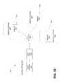
- FIGS. 12A-12Cschematic diagrams of four example cable routing schemes for the FDH 28 are shown.
- FIG. 12Ashows a first example cable routing scheme for the FDH 28 in which signals from the central office 22 are routed through optical splitters 448 and no DAS signals are present.
- FIGS. 12B-12Dthe F1 cable 26 and fiber connected thereto can be routed in the same way.
- FIG. 12 Bshows a second example cable routing scheme in which DAS signals are routed through a WDM 448 B.
- FIG. 12Cshows a third example cable routing scheme for the FDH 28 in which DAS signals are routed through an optical power splitter 448 A.
- FIG. 12Dshows a fourth example cable routing scheme in which DAS signals are routed directly to the termination region 436 without passing through an optical splitter 448 .
- the F1 distribution cable 26is initially routed into the FDH 28 through the cabinet 400 (e.g., typically through the back or bottom of the cabinet 400 as shown in FIG. 11 ).
- the fibers of the F1 distribution cable 26can include ribbon fibers.
- An example F1 distribution cable 26may include twelve to forty-eight individual fibers connected to the central office 22 .
- the fibers of the F1 distribution cable 26are routed to the distribution cable interface 444 (e.g., fiber optic adapter modules, a splice tray, etc.).
- one or more of the fibers of the F1 distribution cable 26are individually connected to separate intermediate fibers 450 .
- the intermediate fibers 450are routed from the distribution cable interface 444 to the optical splitter module housing 446 .
- the intermediate fibers 450are connected to separate optical splitter modules 448 , wherein the signals carried on the intermediate fibers 450 are each separated onto multiple pigtails 454 , each having connectorized ends 456 .
- the fibers of the F1 distribution cable 26can be connectorized and can be routed directly to the optical splitter modules 448 , thereby bypassing or eliminating the need for the distribution cable interface 444 .
- the connectorized ends 456can be temporarily stored on the storage module 442 that is mounted at the storage region 438 of the swing frame 424 .
- the pigtails 454are routed from the splitter modules 448 to the termination module 440 that is provided at the termination region 436 of the swing frame 424 .
- the pigtails 454are connected to fibers of an F2 distribution pigtail 460 .
- one or more of the fibers of the F1 distribution cable 26are not connected to any of the splitter modules 448 . Rather, these fibers of the F1 distribution cable 26 are connected to pass-through fibers 474 having connectorized ends 476 .
- the pass-through fibers 474are connected to the termination modules 440 , without first connecting to the splitter modules 452 . By refraining from splitting the fiber 474 , a stronger signal can be sent to one of the subscribers.
- the connectorized ends 476 of the pass-through fibers 474can be stored at the storage region 438 when not in use.
- the F1 distribution cable fiberscan be routed directly to the termination modules 440 instead of connecting to separate pass-through fibers 474 .
- the F2 distribution pigtail 460includes a plurality of single fiber connectorized ends 462 on one end and a multi-fiber connectorized end 464 on an opposite end of the F2 distribution pigtail 460 .
- the fibers of the F2 distribution pigtail 460are routed to a fanout 466 where the individual fibers of the F2 distribution pigtail 460 are brought together.
- the multi-fiber connectorized end 464 of the F2 distribution pigtail 460is adapted for engagement with a multi-fiber optic adapter 468 disposed in the adapter bank 34 , which in the subject embodiment extends through the cabinet 400 .
- the multi-fiber optic adapter 468includes an interior port 470 and an exterior port 472 .
- the interior port 470 of the fiber optic adapter 468is accessible from the interior of the cabinet 400 while the exterior port 472 is accessible from the exterior of the cabinet 400 .
- the multi-fiber connectorized end 466 of the intermediate cable 464is engaged with the interior port 470 of the multi-fiber optic adapter 468 .
- the multi-fiber connector 32 of the F2 distribution cable 30is adapted for engagement with the exterior port 472 of the multi-fiber optic adapter 468 .
- the DAS F1 distribution cable 95is initially routed into the FDH 28 through the cabinet 400 (e.g., typically through the back or bottom of the cabinet 400 as shown in FIG. 11 ).
- the fibers of the DAS F1 distribution cable 95can include ribbon fibers.
- An example DAS F1 distribution cable 95may include twelve to forty-eight individual fibers connected to the base station 92 .
- the fibers of the DAS F1 distribution cable 95can be connectorized and can be routed directly to the optical splitter modules 448 , thereby bypassing or eliminating the need for the distribution cable interface 444 .
- the fibers of the DAS F1 distribution cable 95are routed to the distribution cable interface 444 (e.g., fiber optic adapter modules, a splice tray, etc.).
- the interface 444is the same interface at which the F1 cable 26 is routed.
- one or more of the fibers of the DAS F1 distribution cable 95can be individually connected to separate intermediate fibers 450 .
- the intermediate fibers 450are routed from the distribution cable interface 444 to the optical splitter module housing 446 .
- the intermediate fibers 450are connected to one or more separate optical splitter modules 448 , wherein the signals carried on the intermediate fibers 450 are each separated onto multiple pigtails 454 , each having connectorized ends 456 .
- the signals from the DAS F1 cable 95are routed to a WDM 448 B.
- the WDM 448 Bcan be a DWDM.
- the WDM 448 Bcan be a CWDM.
- signals from the central office 22can be routed to one or more optical power splitters 448 A, which separates the signal into multiple copies of the same signal. Accordingly, the optical power of the split signals is reduced compared to the incoming signal.
- FIG. 12Cat least some of the signals from the DAS F1 cable 95 are routed to one or more optical power splitters 448 A instead of to WDMs.
- at least some of the signals from the DAS F1 cable 95can be routed to the same optical splitter 448 A as the signals from the F1 cable 26 .
- the connectorized ends 456can be temporarily stored on the storage module 442 that is mounted at the storage region 438 of the swing frame 424 .
- the pigtails 454are routed from the splitter modules 448 to the termination module 440 that is provided at the termination region 436 of the swing frame 424 .
- the pigtails 454are connected to fibers of an F2 distribution pigtail 460 .
- the F2 distribution pigtails 460are adapted for engagement with the multi-fiber optic adapter 468 disposed in the adapter bank 34 as described above.
- the multi-fiber connector 32 of the F2 distribution cable 30is adapted for engagement with the exterior port 472 of the multi-fiber optic adapter 468 .
- the F2 distribution pigtails 460are optically coupled (e.g., spliced, connected via an adapter, etc.) to a stub cable (not shown) that is routed out of the cabinet 400 .
- a stub cablecan be found in U.S. Provisional Application No. 61/310,214, filed Mar. 3, 2010, and titled Fiber Distribution Hub with Connectorized Stub Cables, the disclosure of which is hereby incorporated herein by reference.
- one or more of the fibers of the DAS F1 distribution cable 95are not connected to any of the splitter modules 448 . Rather, these fibers of the F1 distribution cable 95 are routed directly to the termination region 436 for connection to F2 fibers 495 .
- the fibers of the DAS F1 distribution cable 95are optically coupled to pass-through fibers 474 having connectorized ends 476 (see FIG. 12A ). The pass-through fibers 474 are connected to the termination modules 440 without first connecting to the splitter modules 452 .
- the connectorized ends 476 of the pass-through fibers 474can be stored at the storage region 438 when not in use.
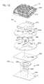
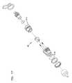
- the drop terminal 36includes the housing 42 , the spool 44 disposed on an exterior surface of the housing 42 and a mounting assembly 500 adapted for rotational engagement with the spool 44 .
- FIGS. 14-16an exemplary configuration of the housing 42 of the drop terminal 36 is shown.
- the drop terminal shown in FIGS. 13-15has been has been described in U.S. patent application Ser. No. 11/728,043 (now U.S. Pat. No. 7,512,304), the disclosure of which is hereby incorporated by reference in its entirety.
- the housing 42 of the drop terminal 36includes a central longitudinal axis 502 that extends from a first end 504 to a second end 506 of the housing 42 .
- the housing 42includes a front piece 508 and a back piece 510 that cooperate to define an enclosed interior of the housing 42 .
- the front and back pieces 508 , 510are joined by fasteners 512 (e.g., bolts or other fastening elements) spaced about a periphery of the housing 42 .
- the front and back pieces 508 , 510are elongated along the central axis 502 so as to extend generally from the first end 504 to the second end 506 of the housing 42 .
- the drop terminal 36is environmentally sealed.
- the drop terminal 36includes a gasket mounted between the front and back pieces 508 , 510 of the housing 42 .
- the gasketextends around the perimeter or periphery of the housing 42 and prevents moisture from entering the enclosed interior of the assembled housing 42 .
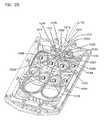
- the housing 42 of the drop terminal 36also includes the plurality of ruggedized fiber optic adapters 46 mounted to the front piece 508 of the housing 42 .
- each of the ruggedized fiber optic adapters 46include the first port 516 accessible from outside the housing 42 and the second port 518 accessible from within the housing 42 .
- the housing 42 of the drop terminal 36includes a length L and a width W.
- the length Lis parallel to the central longitudinal axis 502 of the housing 42 .
- first, second and third rows 520 1 - 520 3 of the ruggedized fiber optic adapters 46are mounted to the front piece 508 of the housing 42 .
- Each of the first, second and third rows 520 1 - 520 3includes four ruggedized fiber optic adapters 46 spaced-apart across the width W of the housing 42 . It will be understood, however, that the scope of the present disclosure is not limited to the housing 42 of the drop terminal 36 having first, second and third rows 520 1 - 520 3 or to the housing 42 having four ruggedized fiber optic adapters 46 per row.
- the first row 520 1is located closest the first end 504 of the housing 42
- the third row 520 3is located closest the second end 506 of the housing 42
- the second row 520 2is located between the first and third rows 520 1 , 520 3 .
- the front face of the front piece 508has a stepped configuration with three steps 522 1 - 522 3 positioned consecutively along the length L of the housing 42 .
- Each step 522 1 - 522 3includes an adapter mounting wall 524 1 - 524 3 defining adapter mounting openings in which the ruggedized fiber optic adapters 46 are mounted.
- a sealing member 523(shown in FIG. 17 ) is compressed between a main housing 525 of the ruggedized fiber optic adapter 46 and the adapter mounting wall 524 1 - 524 3 to provide an environmental seal about the adapter mounting opening.
- the adapter mounting walls 524 1 - 524 3are generally parallel to one another and are spaced apart along the length L of the housing 42 .
- the adapter mounting walls 524 1 - 524 3have front faces that are aligned at an oblique angle ⁇ 1 relative to a plane P that extends through the central longitudinal axis 502 and across the width W of the housing 42 .
- the angled configuration of the adapter mounting walls 524causes the ruggedized fiber optic adapters 46 to be angled relative to the plane P.
- center axes 526 of the ruggedized fiber optic adapters 46are shown aligned at an oblique angle ⁇ 2 relative to the plane.
- the back piece 512 of the housing 42defines a cable passage 530 that extends through the back piece 512 .
- the cable passage 530is adapted to allow the distribution cable 30 to enter/exit the interior of the housing 42 .
- the cable passage 530is adapted to receive a cable seal through which the distribution cable 30 passes.
- the cable sealis adapted to be in sealing engagement with the distribution cable 30 and the cable passage 530 to prevent the ingress of dirt, dust, water, etc. from entering the drop terminal 36 through the cable passage 530 .
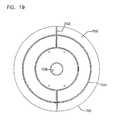
- the spool 44includes a first end 600 a , an oppositely disposed second end 600 b , and a drum portion 602 around which the F2 distribution cable 30 is coiled or wrapped.
- a spool 44 suitable for use with the drop terminal 36has been described in U.S. patent application Ser. No. 12/113,786, the disclosure of which is hereby incorporated by reference in its entirety.
- the first end 600 ais disposed adjacent to the back piece 510 of the housing 42 . In one embodiment, the first end 600 a is sealingly engaged with the back piece 510 .
- first and second spool ends 600 a , 600 b of the spool 44are substantially similar.
- first and second ends 600 a , 600 b in the subject embodimentare substantially similar, the first and second ends 600 a , 600 b shall be referred to as spool end 600 in both singular and plural tense as required by context. It will be understood, however, that the scope of the present disclosure is not limited to the first and second ends 600 a , 600 b being substantially similar.
- Each spool end 600is adapted to be a tear-away end.
- the spool end 600includes a line of weakness 604 .
- the line of weakness 604extends from an inner diameter 606 of the spool end 600 to an outer diameter 608 of the spool end 600 .
- the spool end 700includes at least one radial area of weakness 702 and at least one circular area of weakness 704 .
- the radial area of weaknessextends from an outside diameter 706 radially inward toward an inner diameter 708 of the spool end 700 .
- the circular area of weakness 704forms a ring having a diameter that is less than the outer diameter 706 but greater than the inner diameter 708 .
- the circular area of weakness 704is concentric with the outer diameter 706 .
- the radial and circular areas of weakness 702 , 704are perforated areas.
- the radial and circular areas of weakness 702 , 704are areas of reduced thickness.
- each of the spool ends 600defines an access notch 610 that extends outwardly in a radial direction from the inner diameter 606 and a tab 612 that extends inwardly in a radial direction.
- the access notch 610is adapted to provide access to cable wound around the drum portion 602 of the spool 44 .
- the access notch 610is also adapted to provide a location through which the F2 distribution cable 30 can pass to get access to the cable passage 530 in the housing 42 of the drop terminal 36 .
- the tab 612is adapted for engagement with the drum portion 602 in order to prevent rotation of the spool ends 600 relative to the drum portion 602 .
- the drum portion 602is generally cylindrical in shape and includes a first axial end 614 and an oppositely disposed second axial end 616 .
- the first axial end 614is disposed adjacent to a bracket 618 that is adapted to receive the housing 42 while the second axial end 616 is disposed adjacent to the mounting assembly 500 .
- the drum portionfurther includes an inner bore 620 and an outer surface 622 .
- each of the first and second axial ends 614 , 616defines a groove 624 .
- each groove 624extends from the inner bore 620 through the outer surface 622 and is adapted to receive the tab 612 from one of the spool ends 600 .
- the engagement of the tab 612 of spool end 600 in the groove 624 of the drum portion 602prevents rotation of the spool end 600 relative to the drum portion 602 .
- the second axial end 616further defines a notch 626 .
- the notch 626extends from the inner bore 620 through the outer surface 622 and is disposed on the second axial end 616 opposite the groove 624 on the second axial end 616 .
- the notch 626is adapted to engage a protrusion 628 on a first plate 630 of the mounting assembly 500 .
- the engagement of the notch 626 and the protrusion 628 of the first plate 630 of the mounting assembly 500prevents relative rotation between the drum portion 602 and the first plate 630 of the mounting assembly 500 .
- the mounting assembly 500includes the first plate 630 and a second plate 632 .
- the first plate 630is adapted for engagement with the spool 44 while the second plate 632 is adapted for engagement with a mounting location (e.g., hand hole 38 , telephone pole 40 , etc.).
- a bearing 634is disposed between the first and second plates 630 .
- the bearing 634is a simple bearing having a ring member 636 , which is engaged with the second plate 632 , and a puck 638 , which is engaged with the first plate 630 .
- the puck 638is adapted for sliding rotational engagement with the ring member 636 .
- the bearing 634 and the engagement between the first plate 630 , the spool 44 , and the housing 42 of the drop terminal 36allow the drop terminal 36 to rotate relative to the second plate 632 .
- This engagement of the first plate 630 , the spool 44 and the housing 42allows the first end 31 of the F2 distribution cable 30 to be deployed from the spool 44 while the second end 33 is optically engaged within the interior of the housing 42 .
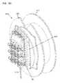
- FIGS. 20-22show another fiber optic cable spooling system 900 in accordance with the principles of the present disclosure.
- the spooling system 900is shown used in combination with drop terminal 36 .
- the spooling system 900includes a slack storage spool 902 mounted to a disposable bulk storage spool 904 .
- a central passage 906extends axially through both the bulk storage spool 904 and the slack storage spool 902 .
- the central passage 906is formed by a first opening 906 a that extends coaxially through the slack storage spool 902 and a second opening (not shown) that extends through the bulk storage spool 904 in coaxial alignment with the first opening 906 a .
- the spooling system 900further includes a hinge plate 908 mounted to a front face of the slack storage spool 902 .
- the hinge plate 908is pivotally connected to the slack storage spool 902 by a hinge or other type of pivot structure that allows the hinge plate 908 to pivot relative to the slack storage spool 902 about a pivot axis 910 that is generally parallel to the front face of the slack storage spool 902 .
- the drop terminal 36mounts to a front face of the hinge plate 908 .
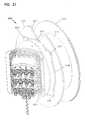
- the hinge plate 908allows the drop terminal 36 to be pivoted between a first position (see FIG. 20 ) and second position (see FIGS. 21 and 22 ).
- a front side of the drop terminal 36faces outwardly from the front side of the slack storage spool 902 and a back side of the drop terminal 36 faces toward the front side of the slack storage spool 902 .
- the hinge plate 908 and the drop terminal 36block access to the central passage 906 from the front side of the spooling system 900 .
- the hinge plate 908 and the drop terminal 36are pivoted away from the front side of the slack storage spool 902 such that the central passage 906 can be access from the front side of the spooling system 900 .
- a distribution cable 912 corresponding to the drop terminal 36Prior to installation of the drop terminal 36 in the field, a distribution cable 912 corresponding to the drop terminal 36 is spooled around both the slack storage spool 902 and the bulk storage spool 904 to facilitate shipping and handling of the drop terminals 36 along with the corresponding distribution cable 912 .
- a first portion of the distribution cable 912is stored at the slack storage spool 902 while a second portion of the distribution cable 912 is stored about the bulk storage spool 704 .
- the spooling system 900 and its corresponding drop terminal 36can be delivered to a location in close proximity to where it is desired to mount the drop terminal 36 .
- the hinge plate 908 and drop terminal 36are oriented in the closed position.
- the hinge plate 908is pivoted from the closed position of FIG. 20 to the open position of FIGS. 21 and 22 . With the hinge plate 908 in the open position, a front end of the central passage 906 is exposed such that a mandrel can be inserted through the central passage 906 .
- the mandrelmay be supported on a cart, frame, or other structure so that the spooling system 900 is elevated above the ground.
- the distal end of the distribution cable 912(i.e., the end of the distribution cable that is farthest from the drop terminal 36 ) can then be accessed and pulled towards a connection/termination location such as a fiber distribution hub.
- a connection/termination locationsuch as a fiber distribution hub.
- the distal end of the distribution cable 912could be pulled through an underground conduit or routed along an aerial routing path.
- the second portion of the distribution cable 912is removed from the bulk storage spool 904 .
- the bulk storage spool 904As the second portion of the distribution cable 912 is removed from the bulk storage spool 904 , the bulk storage spool 904 , the slack storage spool 902 , the hinge plate 908 and the drop terminal 36 all rotate together in unison about the mandrel as the cable pays off of the bulk storage spool 904 .
- the first portion of the distribution cable 912begins to pay off of the slack storage spool 902 .
- the first portion of the distribution cable 912continues to be paid off of the slack storage spool 902 until the distal end of the distribution cable 912 reaches its end destination (e.g., a fiber distribution hub, collector box or other termination location).
- the spools 902 , 904can be removed from the mandrel, and the bulk storage spool 904 can be disconnected from the slack storage spool 902 and discarded. Extra length of the distribution cable 912 can remain stored on the slack storage spool 902 .
- the hinge plate 908can then be moved back to the closed position of FIG. 20 , and the drop terminal 36 can be mounted to its desired mounting location by securing the slack storage spool 902 to the mounting location (e.g., a wall, a pole or other structure).
- the spooling system 900is preferably adapted to hold a relatively large amount of cable.
- the slack storage spool 902holds about 60 meters of 5 mm diameter distribution cable
- the bulk spool 904is sized to hold about 550 meters of 5 mm diameter distribution cable.
- the spooling system 900holds at least 200 meters of 5 millimeter diameter cable.
- the spooling system 900is sized to hold at least 400 meters of 5 millimeter diameter cable.
- the spooling system 900is configured to hold at least 600 meters of 5 millimeter diameter cable.
- the bulk storage spool 904has a diameter that is substantially larger than the diameter of the slack storage spool 902 .
- the bulk storage spool 904includes a core 918 about which the distribution cable is wrapped during storage.
- the bulk storage spool 904also includes front and back radial flanges 920 , 922 positioned at front and back axial ends of the core 918 .
- the flanges 920 , 922are spaced-apart in a direction extending along the axis of the core 918 so as to define a cable storage space between the flanges 920 , 922 which surrounds the core 918 .
- the central passage 906extends axially through a center of the core 918 .
- the second portion of the distribution cable 912is wrapped around the core 918 and is contained in the region between the front and back flanges 920 , 922 .
- the slack storage spoolincludes a core 919 that is coaxially aligned with the core 918 of the bulk storage spool 904 .
- the core 919has a diameter that is substantially smaller than the diameter of the core 918 and the passage 906 extends axially through a center of the core 919 .
- the slack storage spool 902also includes front and back radial flanges 924 , 926 positioned at front and back axial ends of the core 919 .
- the flanges 924 , 926are spaced-apart in a direction extending along the axis of the core 919 so as to define a cable storage space between the flanges 924 , 926 which surrounds the core 919 .
- the flanges 924 , 926have smaller diameters than the flanges 920 , 922 .
- the first portion of the distribution cable 912is wrapped around the core 919 and is contained in the region between the front and back flanges 924 , 926 .
- the slack storage spool 902is preferably non-rotatably mounted to the bulk storage spool 904 .
- non-rotatably mountedit is meant that the slack storage spool 902 is mounted in such a way that the slack storage spool 902 and the bulk storage spool 904 can rotate in unison about a mandrel through the central passage 906 when cable is dispensed from the spooling system 900 .
- the slack storage spool 902can be secured to a front face of the front flange 920 of the bulk storage spool 904 by fasteners (e.g., bolts, screws, rivets, pins, snaps, etc.) inserted through fastener openings 930 defined through the rear flange 926 of the slack storage spool 902 .
- the fastenersare removable so that the slack storage spool 902 can be disconnected from the bulk storage spool 904 after the second portion distribution cable 912 has been removed from the bulk storage spool 904 .
- the mounting openings 930can be used to receive fasteners for securing the slack storage spool 902 to the structure (e.g., a wall or pole) to which it is desired to mount the drop terminal 36 .
- the front face of the front flange 924 of the slack storage spool 902includes a pair of flexible latches 932 that engage the hinge plate 908 when the hinge plate 908 is in the closed position to selectively hold the hinge plate 908 in the closed position.
- the drop terminal 36can be secured to the hinge plate 908 by fasteners inserted through openings defined through the housing 42 of the drop terminal 36 that coaxially align with corresponding opening 936 provided through the hinge plate 908 .
- the openings 936can be aligned with corresponding opening 938 provided in the front flange 924 of the slack storage spool 902 , and the fasteners used to secure the drop terminal 36 to the hinge plate 908 can be removed and replaced with longer fasteners that extend through the openings defined by the housing 42 of the drop terminal 36 , the openings 936 defined by the hinge plate 908 and the openings 938 defined through the front flange 924 of the slack storage spool 902 .
- the fastenersprovide retention of the drop terminal 36 to the slack storage spool 902 that supplements the retention force provided by the clip 932 .
- the front flange 920 of the bulk storage spool 904defines a cable transition notch 940 having a bottom end 942 that is generally flush with an outer circumferential surface of the core 918 and is also generally flush with the outer peripheral surface of the rear flange 926 of the slack storage spool 902 .
- the slack storage spool 902includes a cable transition slot 950 having a closed end 952 that is generally flush with the outer circumferential surface of the core 919 of the slack storage spool 902 .
- the slot 950also includes an open end 954 located at an outer peripheral edge of the front flange 924 of the slack storage spool 902 .
- the distribution cable 912When spooling the distribution cable 912 on the spooling system 900 , the distribution cable 912 is routed from the bottom end of the drop terminal 36 through the cable transition slot 950 to the core 919 . The first portion of the distribution cable 912 is then wrapped around the core 919 until the space between the flanges 924 , 926 is filled and the cable reaches the outer peripheral edges of the flanges 924 , 926 . The cable is then passed through the cable transition notch 940 to the outer circumferential surface of the core 918 of the bulk storage spool 904 . The second portion of the distribution cable 912 is then wrapped around the core 918 to complete the storage of the remainder of the distribution cable 912 .
- the spooling system 900 and the corresponding drop terminal 36can initially be delivered to a termination location (e.g., a fiber distribution hub, collector box or other structure) that is remote from the desired mounting location of the drop terminal 36 .
- the distal end of the distribution cableis then connected to the termination location.
- the hinge plate 908is pivoted to the open position of FIGS. 21 and 22 , and a mandrel mounted to a moveable structure such as a moveable cart is passed through the central opening 906 . Thereafter, the cart is used to move the spooling system 900 and its corresponding drop terminal 36 to the desired mounting location.
- the slack storage spool 902 , the bulk spool 904 and the drop terminal 36rotate in unison as the distribution cable 912 is paid off the spooling system.
- the bulk spool 904can be removed from the slack storage spool 902 and discarded.
- the slack storage spool 902can be mounted to a desired mounting location to secure the drop terminal at the desired location.
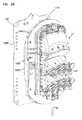
- the spooling system 1000includes a drop terminal assembly 1002 having a drop terminal 36 ′ that is selectively releasably engaged with a slack storage spool 1004 that is selectively releasably engaged with the bulk storage spool 904 .
- the drop terminal 36 ′includes a housing 42 ′.
- the housing 42 ′includes a cover 1006 and a base 1008 .
- the cover 1006 and the base 1008cooperatively define an interior region 1010 .
- a plurality of ruggedized fiber optic adapters 46 ′is mounted to the housing 42 ′.
- the plurality of ruggedized fiber optic adapters 46 ′is mounted to the cover 1006 .
- the ruggedized fiber optic adapters 46 ′include first ports that are accessible from outside the housing 42 ′ and second ports that are accessible from inside the housing 42 ′.
- the first ports of the ruggedized fiber optic adapters 46 ′are adapted to receive connectorized ends of distribution cables.
- the second ports of the ruggedized fiber optic adapters 46 ′are adapted to receive fibers of the multi-fiber distribution cable 30 .
- the housing 42 ′defines an access opening 1012 .
- the access opening 1012is cooperatively defined by the cover 1006 and the base 1008 .
- the access opening 1012is disposed in a sidewall 1014 of the housing 42 ′.
- the multi-fiber cable 30is routed into the interior of the housing 42 ′ through the access opening 1012 .
- the housing 42 ′includes a first environmental seal 1016 and a second environmental seal 1018 .
- the first and second environmental seals 1016 , 1018are disposed in the access opening 1012 .
- the first environmental seal 1016is a grommet.
- the first environmental seal 1016is adapted to sealingly engage the multi-fiber cable 30 .
- the second environmental seal 1018includes a passage 1020 through which the multi-fiber cable 30 passes.
- the second environmental seal 1018is adapted to seal around the multi-fiber cable 30 .
- the housing 42 ′further includes an anchor block 1022 .
- the anchor block 122is disposed in the interior region 1010 of the housing 42 ′.
- the anchor block 1022is disposed immediately adjacent to the access opening 1012 of the drop terminal 36 ′.
- the anchor block 1022includes a body 1024 having a first end 1026 and a second end 1028 .
- the anchor block 1022defines a passage 1030 that extends through the first and second ends 1026 , 1028 .
- the passage 1030is adapted to receive a portion of the multi-fiber cable 30 .
- the anchor block 1022is engaged with the housing 42 ′. In the subject embodiment, the anchor block 1022 is in interlocking engagement with the housing 42 ′.
- the anchor block 1022includes a plurality of tabs 1032 that extend outwardly from the anchor block 1022 . In the subject embodiment, the plurality of tabs 1032 extends outwardly from the body 1024 of the anchor block 1022 in a direction that is generally perpendicular to a central longitudinal axis of the anchor block 1022 .
- the plurality of tabs 1032is adapted to engage a first receptacle 1036 in the housing 42 ′ of the drop terminal 36 ′.
- the anchor block 1022includes a crimp 1038 and a retainer 1040 disposed in the passage 1030 .
- the crimp 1038is a cylindrical tube that is made of a deformable material.
- the crimp 1038defines a thru-bore that is adapted to receive the multi-fiber cable 30 . With the multi-fiber cable 30 disposed in the thru-bore of the crimp 1038 , the crimp 1038 can be deformed around the multi-fiber cable 30 by compressing the crimp 1038 .
- the retainer 1040includes a first end portion 1042 , a second end portion 1044 and a flange 1046 disposed between the first and second end portions 1042 , 1044 .
- the retainer 1040defines a bore that extends though the first and second end portions 1042 , 1044 .
- the boreis adapted to receive the multi-fiber cable 30 .
- the retainer 1040is adapted to interlock with the anchor block 1022 .
- the flange 1046 of the retainer 1040is adapted to be received in a second receptacle 1048 defined by the first end 1026 of the anchor block 1022 .
- the engagement of the flange 1046 and the second receptacle 1048axially retains the retainer 1040 in the anchor block 1022 .
- the slack storage spool 1004includes a first flange 1050 , a drum portion 1052 and a second flange 1054 .
- the second flange 1054is adapted for engagement with the front radial flange 920 of the bulk storage spool 904 .
- a plurality of fasteners 1055e.g., bolts, screws, rivets, etc. is used to engage the second flange 1054 to the front radial flange 920 of the bulk storage spool 904 .
- the second flange 1054includes a first surface 1056 and an oppositely disposed second surface 1058 .
- the first surface 1056faces in a direction toward the drum portion 1052 while the second surface 1058 faces in a direction toward the bulk cable spool 904 .
- the second surface 1058includes a mounting area 1060 .
- the mounting area 1060extends outwardly from the second surface 1058 .
- the mounting area 1060adapted for mounting the slack storage spool 1004 and the drop terminal 36 ′ to a mounting location (e.g., wall, pole, post, hand hole, etc.).
- the mounting area 1060defines a channel 1062 .
- the channel 1062is arcuate in shape.
- the channel 1062is adapted to receive a portion of a mounting structure (e.g., a post, pole, etc.).
- the drum portion 1052is disposed between the first flange 1050 and the second flange 1054 .
- the drum portion 1052is releasably engaged to the first flange 1050 .
- the releasable engagementis potentially advantageous as it allows the drum portion 1052 and the second flange 1054 to be removed from the drop terminal 36 ′ in the event all of the cable 30 is unwound from the bulk storage spool 904 and the slack storage spool 1004 .
- the drum portion 1052is in snap-fit engagement with the first flange 1050 .
- the drum portion 1052is engaged with the first flange 1050 by fasteners 1061 (e.g., bolts, screws, etc.).
- the drum portion 1052includes an outer surface 1063 (shown in FIG. 26 ) and defines an inner cavity.
- the drum portion 1052is configured to receive the multi-fiber cable 30 such that the multi-fiber cable 30 wraps around the outer surface 1063 of the drum portion 1052 .
- the drum portion 1052is cylindrical in shape having a cross-section that is generally oblong. In another embodiment, the drum portion 1052 has a cross-section that is generally oval in shape.
- the first flange 1050includes a flange plate 1065 and a hinge plate 1066 .
- the first flange 1050further includes a hinge assembly 1068 .
- the hinge assembly 1068includes a hinge pin 1070 and a hinge receptacle 1072 .
- the hinge receptacle 1072is adapted to receive the hinge pin 1070 .
- the hinge pin 1070is engaged to the hinge plate 1066 while the hinge receptacle 1072 is fixed to the flange plate 1065 .
- the hinge receptacle 1072includes a base end 1074 that is fixed to the flange plate 1065 and a free end 1076 that extends outwardly from the flange plate 1065 .
- the free end 1076 of the hinge receptacle 1072is generally hook-shaped.
- the hinge assembly 1068is adapted to allow the hinge plate 1066 to pivot relative to the flange plate 1065 between a first position (shown in FIG. 27 ) and a second position (shown in FIG. 28 ) relative to the flange plate 1065 .
- the hinge plate 1066pivots in a range of about 0 degrees to about 180 degrees.
- the hinge plate 1066pivots in a range of about 0 degrees to about 90 degrees.
- the hinge plate 1066pivots an amount greater than or equal to 45 degrees.
- the flange plate 1065includes a base wall 1080 having a first surface 1082 and an oppositely disposed second surface 1084 .
- the first surface 1082faces toward the drop terminal 36 ′ when the hinge plate 1066 is in the first position relative to the flange plate 1065 .
- the second surface 1084faces toward the drum portion 1052 of the slack storage spool 1004 .
- the flange plate 1065further includes a cable management area 1088 .
- the cable management area 1088is a recessed area.
- the cable management area 1088includes a base 1090 that is axially offset from the base wall 1080 of the flange plate 1065 and a sidewall 1092 that extends between the base 1090 of the cable management area 1088 and the base wall 1080 of the flange plate 1065 .
- the cable management area 1088is adapted to be received in the inner cavity 1064 of the drum portion 1052 .
- the cable management area 1088includes a first cable management spool 1094 a and a second cable management spool 1094 b .
- the first and second cable management spools 1094 a , 1094 bare offset from a central axis that extends axially through the center of the slack storage spool 1004 .
- each of the first and second cable management spools 1094 a , 1094 bincludes at least one cable retention projection 1096 that extends outwardly from an end 1097 of the first and second cable management spool 1094 a , 1094 b .
- the cable retention projection 1096extends outwardly from the cable management spool 1094 in a radial direction.
- the cable retention projection 1096is aligned with a retention projection 1098 that extends inwardly from the sidewall 1092 .
- a gap 1099is disposed between an end of the cable retention projection 1096 and an end of the retention projection 1098 of the sidewall 1092 so that the multi-fiber cable 30 can be inserted in to the space between the cable management spool 1094 and the sidewall 1092 .
- the cable management area 1088provides an additional location at which a portion of the multi-fiber cable 30 can be stored. Storage at this location is potentially advantageous during manufacturing as it allows for a length of cable to be stored prior to installation in the drop terminal 36 ′.
- the cable management area 1088may provide a strain relief function. For example, as the spooling system 1000 is rotating during cable payout, the cable management area 1088 will reduce the risk of a tensile force being applied to the multi-fiber cable 30 at the access opening 1012 of the drop terminal 36 ′ if all of the cable 30 is unwound from the bulk cable spool 904 and the slack storage spool 1004 .
- the sidewall 1092 of the cable management area 1088defines a cable opening 1100 through which the multi-fiber cable 30 is routed to the cable management area 1088 from the drum portion 1052 .
- the cable opening 1100is adapted to receive a transition portion 1102 disposed on an axial end, which is nearest the first flange 1050 , of the drum portion 1052 .
- the transition portion 1102extends through the cable opening 1100 and into the cable management area 1088 .
- the base wall 1080 of the flange plate 1065defines a cable channel 1104 .
- the cable channel 1104extends from the cable management area 1088 to an outer edge 1106 of the flange plate 1065 .
- the cable channel 1104is adapted to receive the multi-fiber cable 30 as the multi-fiber cable 30 is routed from the cable management area 1088 to the access opening 1012 of the drop terminal 36 ′.
- the base wall 1080includes a latch 1108 .
- the latch 1108is a resilient latch that is adapted to engage a catch on the hinge plate 1066 .
- the latch 1108includes a first resilient latch 1108 a and a second resilient latch 1108 b .
- Each of the first and second resilient latches 1108 a , 1108 bincludes a protrusion 1110 .
- the protrusion 1110 of the first resilient latch 1108 afaces the protrusion of the second resilient latch 1108 b .
- Each protrusion 1110engages the catch on the hinge plate 1066 .
- the latch 1108can be disengaged by moving the protrusion 1110 of the first resilient latch 1108 a in a direction away from the protrusion 1110 of the second resilient latch 1108 b.
- the hinge plate 1066includes a plurality of mounts 1112 at which the drop terminal 36 ′ is mounted to the hinge plate 1066 .
- the hinge plate 1066further includes a plurality of cable tie openings 1114 .
- the cable tie openings 1114extend through the hinge plate 1066 and are disposed adjacent to the catch.
- the cable tie openings 1114are adapted to receive a cable tie that can be tied around a mandrel 1116 .
- the mandrel 1116is a cylindrical bar that extends through a central opening that extends through the flange plate 1065 , the drum portion 1052 , the second flange 1054 and the bulk storage spool 904 .
- the mandrel 1116can be held at opposite ends allowing the spooling system 1000 to rotate about the mandrel 1116 as multi-fiber cable 30 is paid out.
- the cable tieprevents the drop terminal 36 ′ and the hinge plate 1066 from striking the mandrel 1116 as the spooling system 1000 rotates.
- the second flange 1054further includes a tether 1120 .
- the tether 1120includes a first end portion 1122 and an oppositely disposed second end portion 1124 .
- the first end portion 1122is engaged with the flange plate 1065 while the second end portion 1124 is engaged with the hinge plate 1066 .
- the tether 1120is adapted to prevent the hinge plate 1066 from opening beyond the second position.
- the hinge plate 1066includes a mounting area similar to the mounting area 1060 on the second flange 1054 . If the cable 30 is completely paid out from the bulk storage spool 904 and the slack storage spool 1004 , the bulk storage spool 904 , the second flange 1054 , the drum portion 1052 and the flange plate 1065 can be removed from the spooling system 1000 such that the hinge plate 1066 and the drop terminal 36 ′ can be directly mounted to a mounting structure.
- FIG. 32is a block diagram of one exemplary embodiment of a distributed antenna system (DAS) 3000 .
- the DAS 3000is used to distribute bi-directional wireless communications between one or more base stations 3002 and one or more wireless devices (not shown in FIG. 32 ) (such as mobile wireless devices such as mobile telephones, mobile computers, and/or combinations thereof such as personal digital assistants (PDAs) and smartphones).
- the DAS 3000is used to distribute a plurality of bi-directional radio frequency bands. Each radio frequency band is typically used to communicate multiple logical bi-directional RF channels.
- the techniques described hereare especially useful in connection with the distribution of wireless communications that use licensed radio frequency spectrum, such as cellular radio frequency communications.
- cellular RF communicationsinclude cellular communications that support one or more of the second generation, third generation, and fourth generation Global System for Mobile communication (GSM) family of telephony and data specifications and standards, one or more of the second generation, third generation, and fourth generation Code Division Multiple Access (CDMA) family of telephony and data specifications and standards, and/or the WIMAX family of specification and standards.
- GSMGlobal System for Mobile communication
- CDMACode Division Multiple Access
- the DAS 3000is used to distributed wireless communications that make use of unlicensed radio frequency spectrum such as wireless local area networking communications that support one or more of the IEEE 802.11 family of standards.
- the DAS 3000is configured to distribute wireless communications that use frequency division duplexing to implement the logical bi-directional RF channels that are distributed by the DAS 3000 .
- the DAS 3000is configured to communicate at least some wireless communications that use other duplexing techniques (such as time division duplexing, which is used, for example, in some WIMAX implementations).
- each of the bi-directional radio frequency bands distributed by the DAS 3000includes a separate radio frequency band for each of two directions of communications.
- One direction of communicationgoes from the base station 3002 to a wireless device and is referred to here as the “downstream” or “downlink” direction.
- the other direction of communicationgoes from the wireless device to the base station 3002 and is referred to here as the “upstream” or “uplink” direction.
- Each of the distributed bi-directional radio frequency bandsincludes a “downstream” band in which downstream RF channels are communicated for that bidirectional radio frequency band and an “upstream” band in which upstream RF channels are communicated for that bidirectional radio frequency band.
- the DAS 3000comprises a host unit 3006 that is deployed in a first location 3008 (for example, a central office of a telecommunication service provider).
- a first location 3008for example, a central office of a telecommunication service provider.
- the DAS 3000also comprises multiple remote units 3010 that are located at other locations 3012 that are remote from the first location 3008 (for example, near the premises of homes and/or businesses that otherwise receive wireline telecommunication services from the telecommunication service providers).
- the host unit 3006is communicatively coupled to the one or more base stations 3002 either directly via one or more telecommunications cable connections (for example, when the base stations 3002 are co-located with the host unit 3006 at the first location 3008 ) or indirectly via one or more donor antennas and one or more bidirectional amplifiers (for example, when the base stations 3002 are not co-located with the host unit 3006 at the first location 3008 ).
- each remote unit 3010is communicatively coupled to a respective antenna 3016 (for example, over a respective telecommunication cable).
- the remote unit 3010is communicatively coupled to multiple antennas and/or is integrated into a common package with one or more antennas.
- the host unit 3006is communicatively coupled to the remote units 3010 using an optical access network 3014 .
- optical networks suitable for use with the host unit 3006 and remote units 3010include the passive fiber optic distribution network 20 of FIG. 1 , the fiber optic distribution network 120 of FIG. 5 , and the fiber optic distribution network 220 of FIG. 8 .
- the optical access network 3014is an existing fiber optical access network that is otherwise used to deliver “wireline” telecommunication services (for example, wireline telephony, video, or data services).
- the optical access network 3014is also referred to here as an “FTTX” network 3014 .
- FTTX networks 3014include, without limitation, active and passive fiber-to-the-node (FTTN), networks, active and passive fiber-to-the-cabinet or fiber-to-the-curb (FTTC) networks, active and passive fiber-to-the-building or fiber-to-the-basement (FTTB) networks, fiber-to-the-home (FTTH) networks, and active and passive fiber-to-the premises (FTTP) networks and combinations thereof.
- FTTNactive and passive fiber-to-the-node
- FTTCactive and passive fiber-to-the-cabinet or fiber-to-the-curb
- FTTBactive and passive fiber-to-the-building or fiber-to-the-basement
- FTTHfiber-to-the-home
- FTTPactive and passive fiber-to-the premises
- the host unit 3006 and the remote units 3010are configured to connect to the optical access network 3014 using a pair of optical fibers—one of which is used to communicate data from the host unit 3006 to the remote unit 3010 (and is also referred to here as a “downstream” fiber) and the other of which is used to communicate data from the remote unit 3010 to the host unit 3006 (and is also referred to here as the “upstream” fiber).
- the host unit 106 and the remote units 3010are configured to connect to the optical access network 3014 using a single optical fiber (for example, where each such unit includes suitable multiplexing functionality).
- RF signals(also referred to here as “downlink RF signals”) transmitted from the base station 3002 are received at the host unit 3006 .
- the host unit 3006uses the downlink RF signals to generate a downlink transport signal that is distributed to the remote units 3010 via the FTTX network 3014 .
- Each such remote unit 3010receives the downlink transport signal and reconstructs the downlink RF signals based on the downlink transport signal and causes the reconstructed downlink RF signals to be radiated from the antenna 3016 coupled to or included in that remote unit 3010 .
- RF signals(also referred to here as “uplink RF signals”) transmitted from mobile units or other wireless devices are received at each remote unit 3010 (via the respective antenna 3016 ).
- Each remote unit 3010uses the uplink RF signals to generate an uplink transport signal that is transmitted from the remote unit 3010 to the host unit 3006 via the FTTX network 3014 .
- the host unit 3006receives and combines the uplink transport signals transmitted from the remote units 3010 .
- the host unit 3006reconstructs the uplink RF signals received at the remote units 3010 and communicates the reconstructed uplink RF signals to the base station 3002 . In this way, the coverage of the base station 3002 can be expanded using the DAS 3000 and an existing FTTX network 3014 .
- the DAS 3000is implemented as a digital DAS in which the downlink and uplink transport signals are generated by digitizing the downlink and uplink RF signals.
- the host unit 3006receives downstream radio frequency signals for that bi-directional radio frequency band from the base station 3002 and band-pass filters the relevant downstream radio frequency band.
- the host unit 3006down-converts the downstream radio frequency band for each bi-directional radio frequency band to an intermediate frequency version of the downstream radio frequency band and digitizes the resulting intermediate frequency version.
- the host unit 3010for each of the bi-directional radio frequency bands distributed by the DAS 3000 , generates digital samples of that respective downstream frequency band.
- the host unit 3010frames together digital samples for the downstream frequency bands (along with overhead data such as, for example, synchronization data and gain control data) and generates one or more downstream optical signals that are communicated over the FTTX network 3014 to the remote units 3010 (using one or more optical transmitters or other electrical-to-optical devices).
- Each remote unit 3010receives the one or more downstream optical signals transmitted by the host unit 3006 (using one or more optical receivers or other optical-to-electrical devices).
- the downstream frames transmitted by the host unit 106are recovered by each remote unit 3010 .
- the remote unit 3010removes the digital samples for the downstream frequency bands and uses a digital-to-analog process to recreate each of the analog downstream intermediate frequency versions of the downstream frequency bands that were digitized in the host unit 3006 (using the associated overhead data to, for example, synchronize the digital samples and adjust the gain of the IF signals). Each remote unit 3010 then up-converts each recreated downstream IF signal back to its original RF frequency band. The reconstructed downstream RF signals for each of the downstream RF frequency bands are combined and output to the relevant antenna 3016 . The downstream RF signals are radiated from the antenna 3016 for reception by the relevant wireless devices.
- each remote unit 3010receives upstream radio frequency signals for that bi-directional radio frequency band from any wireless devices that are transmitting in that upstream frequency band.
- the remote unit 3010band-pass filters the received upstream RF signals.
- the remote unit 3010down-converts the upstream radio frequency band for each bi-directional radio frequency band to an intermediate frequency version of the upstream radio frequency band and digitizes the resulting intermediate frequency version.
- each remote unit 3010for each of the bi-directional radio frequency bands distributed by the DAS 3000 , generates digital samples of that respective upstream frequency band.
- Each remote unit 3010frames together digital samples for the upstream frequency bands (along with overhead data such as, for example, synchronization data and gain control data) and generates one or more upstream optical signals that are communicated over the FTTX network 3014 to the host unit 3006 (using one or more optical transmitters or other electrical-to-optical devices).
- the host unit 3006receives the one or more upstream optical signals transmitted by each of the remote units 3010 (using one or more optical receivers or other optical-to-electrical devices).
- the upstream frames transmitted by each remote unit 3010are recovered by the host unit 3006 .
- the host unit 3006for each upstream frequency band, combines the digital samples received from each of the remote units 3010 for that upstream frequency band.
- the digital samplesare combined by digitally summing, for each sample period, the digital samples received from each remote unit 3010 for each upstream frequency band. That is, in such an implementation, for each sample period, the respective digital samples for each upstream frequency band are added together (with suitable overflow control to keep the sum within the number of bits supported by the digital-to-analog process in the host unit 3006 ).
- the host unit 3006uses a digital-to-analog process to create analog upstream intermediate frequency signals for each of the upstream frequency bands (using the associated overhead data in the frames to, for example, synchronize the digital samples and adjust the gain of the resulting IF signals).
- the host unit 3006then individually up-converts the analog upstream intermediate frequency signals for each of the upstream frequency bands back to the respective original radio frequency at which the corresponding signals were received at one or more of the remote units 3010 .
- the resulting radio frequency versions of the upstream frequency bandsare communicated to the one or more base stations 3002 .
- standard optical technologysuch as SONET technology
- proprietary technologycan be used to frame and deframe the digital samples and overhead data and/or to send and receive the optical signals over the FTTX network 3014 .
- the DAS 3000is implemented as an analog DAS in which the downlink and uplink transport signals are generated by amplitude modulating an optical carrier signal with the relevant RF signals (or frequency-translated versions of the relevant RF signals).
- An example of such an analog DASis described in U.S. Pat. No. 6,801,767, entitled “METHOD AND SYSTEM FOR DISTRIBUTING MULTIBAND WIRELESS COMMUNICATIONS SIGNALS”, filed on Jan. 26, 2001, which is hereby incorporated herein by reference.
- the DAS 3000is implemented using a distributed base station architecture in which the host unit 3006 and the remote units 3010 includes base station functionality.
- the host unit 3006comprises base station baseband signal processing functionality and base station control functionally and the remote units 3010 comprise remote radio heads.
- the remote radio headsinclude RF transceivers and power amplifiers.
- Digital baseband datais transported between the baseband processing located in the host unit 3006 and the remotely located RF transceivers located at the remote units 3010 using the FTTX network 3014 .
- the host units 3006 and remote radio heads 3010are configured to support specifications published by at least one of the Common Public Radio Interface (CPRI) consortium and the Open Base Station Architecture Initiative (OBSAI) consortium.
- CPRICommon Public Radio Interface
- OBSAIOpen Base Station Architecture Initiative
- the DAS 3000is configured for use in a “neutral host” or “base station hotel” configuration in which multiple wireless service providers share a single DAS 3000 .
- neutral-host DAS systemsare described in U.S. Pat. No. 6,785,558, entitled “SYSTEM AND METHOD FOR DISTRIBUTING WIRELESS COMMUNICATION SIGNALS OVER METROPOLITAN TELECOMMUNICATION NETWORKS” filed Dec. 6, 2002, and U.S. Pat. No. 6,963,552, entitled “MULTI-PROTOCOL DISTRIBUTED WIRELESS SYSTEM ARCHITECTURE” filed Mar. 27, 2001, all of which are hereby incorporated herein by reference.
Landscapes
- Physics & Mathematics (AREA)
- Engineering & Computer Science (AREA)
- Computer Networks & Wireless Communication (AREA)
- General Physics & Mathematics (AREA)
- Optics & Photonics (AREA)
- Electromagnetism (AREA)
- Signal Processing (AREA)
- Light Guides In General And Applications Therefor (AREA)
Abstract
Description
Claims (19)
Priority Applications (3)
| Application Number | Priority Date | Filing Date | Title |
|---|---|---|---|
| US14/486,453US9414137B2 (en) | 2010-04-14 | 2014-09-15 | Methods and systems for distributing fiber optic telecommunication services to local areas and for supporting distributed antenna systems |
| US15/231,138US10819444B2 (en) | 2010-04-14 | 2016-08-08 | Methods and systems for distributing fiber optic telecommunication services to local areas and for supporting distributed antenna systems |
| US17/079,962US20210111812A1 (en) | 2010-04-14 | 2020-10-26 | Methods and systems for distributing fiber optic telecommunication services to local areas and for supporting distributed antenna systems |
Applications Claiming Priority (3)
| Application Number | Priority Date | Filing Date | Title |
|---|---|---|---|
| US32428410P | 2010-04-14 | 2010-04-14 | |
| US13/086,909US8837940B2 (en) | 2010-04-14 | 2011-04-14 | Methods and systems for distributing fiber optic telecommunication services to local areas and for supporting distributed antenna systems |
| US14/486,453US9414137B2 (en) | 2010-04-14 | 2014-09-15 | Methods and systems for distributing fiber optic telecommunication services to local areas and for supporting distributed antenna systems |
Related Parent Applications (1)
| Application Number | Title | Priority Date | Filing Date |
|---|---|---|---|
| US13/086,909ContinuationUS8837940B2 (en) | 2010-04-14 | 2011-04-14 | Methods and systems for distributing fiber optic telecommunication services to local areas and for supporting distributed antenna systems |
Related Child Applications (1)
| Application Number | Title | Priority Date | Filing Date |
|---|---|---|---|
| US15/231,138ContinuationUS10819444B2 (en) | 2010-04-14 | 2016-08-08 | Methods and systems for distributing fiber optic telecommunication services to local areas and for supporting distributed antenna systems |
Publications (2)
| Publication Number | Publication Date |
|---|---|
| US20150334476A1 US20150334476A1 (en) | 2015-11-19 |
| US9414137B2true US9414137B2 (en) | 2016-08-09 |
Family
ID=45328766
Family Applications (4)
| Application Number | Title | Priority Date | Filing Date |
|---|---|---|---|
| US13/086,909Active2031-07-21US8837940B2 (en) | 2010-04-14 | 2011-04-14 | Methods and systems for distributing fiber optic telecommunication services to local areas and for supporting distributed antenna systems |
| US14/486,453Expired - Fee RelatedUS9414137B2 (en) | 2010-04-14 | 2014-09-15 | Methods and systems for distributing fiber optic telecommunication services to local areas and for supporting distributed antenna systems |
| US15/231,138Active2031-05-13US10819444B2 (en) | 2010-04-14 | 2016-08-08 | Methods and systems for distributing fiber optic telecommunication services to local areas and for supporting distributed antenna systems |
| US17/079,962AbandonedUS20210111812A1 (en) | 2010-04-14 | 2020-10-26 | Methods and systems for distributing fiber optic telecommunication services to local areas and for supporting distributed antenna systems |
Family Applications Before (1)
| Application Number | Title | Priority Date | Filing Date |
|---|---|---|---|
| US13/086,909Active2031-07-21US8837940B2 (en) | 2010-04-14 | 2011-04-14 | Methods and systems for distributing fiber optic telecommunication services to local areas and for supporting distributed antenna systems |
Family Applications After (2)
| Application Number | Title | Priority Date | Filing Date |
|---|---|---|---|
| US15/231,138Active2031-05-13US10819444B2 (en) | 2010-04-14 | 2016-08-08 | Methods and systems for distributing fiber optic telecommunication services to local areas and for supporting distributed antenna systems |
| US17/079,962AbandonedUS20210111812A1 (en) | 2010-04-14 | 2020-10-26 | Methods and systems for distributing fiber optic telecommunication services to local areas and for supporting distributed antenna systems |
Country Status (1)
| Country | Link |
|---|---|
| US (4) | US8837940B2 (en) |
Cited By (6)
| Publication number | Priority date | Publication date | Assignee | Title |
|---|---|---|---|---|
| US20160301474A1 (en)* | 2015-04-08 | 2016-10-13 | Corning Optical Communications LLC | Fiber-wireless system and methods for simplified and flexible fttx deployment and installation |
| US20170052335A1 (en)* | 2013-08-26 | 2017-02-23 | Commscope Technologies Llc | Wave division multiplexer arrangement for small cell networks |
| US10530479B2 (en) | 2012-03-02 | 2020-01-07 | Corning Optical Communications LLC | Systems with optical network units (ONUs) for high bandwidth connectivity, and related components and methods |
| US10735838B2 (en) | 2016-11-14 | 2020-08-04 | Corning Optical Communications LLC | Transparent wireless bridges for optical fiber-wireless networks and related methods and systems |
| US10819444B2 (en) | 2010-04-14 | 2020-10-27 | Commscope Technologies Llc | Methods and systems for distributing fiber optic telecommunication services to local areas and for supporting distributed antenna systems |
| US11611817B2 (en) | 2020-09-14 | 2023-03-21 | Corning Research & Development Corporation | Time division multiplexing and wavelength division multiplexing hybrid distribution component and systems |
Families Citing this family (100)
| Publication number | Priority date | Publication date | Assignee | Title |
|---|---|---|---|---|
| US9276673B2 (en)* | 2008-04-24 | 2016-03-01 | Commscope Technologies Llc | Methods and systems for testing a fiber optic network |
| US9673904B2 (en) | 2009-02-03 | 2017-06-06 | Corning Optical Communications LLC | Optical fiber-based distributed antenna systems, components, and related methods for calibration thereof |
| CN102369678B (en) | 2009-02-03 | 2015-08-19 | 康宁光缆系统有限责任公司 | Optical fiber based distributed antenna systems, assemblies and related methods for calibrating optical fiber based distributed antenna systems, assemblies |
| CN102396171B (en) | 2009-02-03 | 2015-09-30 | 康宁光缆系统有限责任公司 | Based on the distributing antenna system of optical fiber, assembly and the correlation technique for monitoring and configure distributing antenna system based on optical fiber, assembly |
| US8280259B2 (en) | 2009-11-13 | 2012-10-02 | Corning Cable Systems Llc | Radio-over-fiber (RoF) system for protocol-independent wired and/or wireless communication |
| US8275265B2 (en) | 2010-02-15 | 2012-09-25 | Corning Cable Systems Llc | Dynamic cell bonding (DCB) for radio-over-fiber (RoF)-based networks and communication systems and related methods |
| US9078287B2 (en) | 2010-04-14 | 2015-07-07 | Adc Telecommunications, Inc. | Fiber to the antenna |
| US9525488B2 (en) | 2010-05-02 | 2016-12-20 | Corning Optical Communications LLC | Digital data services and/or power distribution in optical fiber-based distributed communications systems providing digital data and radio frequency (RF) communications services, and related components and methods |
| US20110268446A1 (en) | 2010-05-02 | 2011-11-03 | Cune William P | Providing digital data services in optical fiber-based distributed radio frequency (rf) communications systems, and related components and methods |
| US11251608B2 (en) | 2010-07-13 | 2022-02-15 | Raycap S.A. | Overvoltage protection system for wireless communication systems |
| WO2012024247A1 (en) | 2010-08-16 | 2012-02-23 | Corning Cable Systems Llc | Remote antenna clusters and related systems, components, and methods supporting digital data signal propagation between remote antenna units |
| US9252874B2 (en) | 2010-10-13 | 2016-02-02 | Ccs Technology, Inc | Power management for remote antenna units in distributed antenna systems |
| EP2671111B1 (en) | 2011-02-01 | 2018-11-07 | Opterna Technology Limiited | Fiber distribution hubs |
| US8861919B2 (en)* | 2011-02-16 | 2014-10-14 | Tyco Electronics Corporation | Fiber optic closure |
| EP2678972B1 (en) | 2011-02-21 | 2018-09-05 | Corning Optical Communications LLC | Providing digital data services as electrical signals and radio-frequency (rf) communications over optical fiber in distributed communications systems, and related components and methods |
| US8510150B2 (en)* | 2011-03-04 | 2013-08-13 | Verizon North Llc | Fiber to the premises network modeling systems and methods |
| WO2012148940A1 (en) | 2011-04-29 | 2012-11-01 | Corning Cable Systems Llc | Systems, methods, and devices for increasing radio frequency (rf) power in distributed antenna systems |
| WO2012148938A1 (en) | 2011-04-29 | 2012-11-01 | Corning Cable Systems Llc | Determining propagation delay of communications in distributed antenna systems, and related components, systems and methods |
| WO2012158787A2 (en)* | 2011-05-17 | 2012-11-22 | 3M Innovative Properties Company | Remote socket apparatus |
| US20130216187A1 (en) | 2011-08-17 | 2013-08-22 | Douglas Ferris Dowling | Distributed passive optical networks |
| US10123327B2 (en)* | 2011-09-19 | 2018-11-06 | Telefonaktiebolaget Lm Ericsson (Publ) | Method and apparatus for transmitting and receiving data in orthogonal frequency division multiplexing system |
| US9106981B2 (en) | 2011-10-03 | 2015-08-11 | Tyco Electronics Uk Ltd | Aggregation enclosure for elevated, outdoor locations |
| US11564110B2 (en)* | 2011-11-07 | 2023-01-24 | Dali Wireless, Inc. | Soft hand-off and routing data in a virtualized distributed antenna system |
| US8913867B2 (en)* | 2011-11-21 | 2014-12-16 | Opterna Technology Limited | Fiber optic collector and terminal assemblies |
| RU2569323C1 (en)* | 2012-02-09 | 2015-11-20 | Телефонактиеболагет Лм Эрикссон (Пабл) | Network node and method in node, which provides first unit with possibility of connection to or being connected to second unit in mode of self-organising network |
| US9348096B2 (en)* | 2012-03-30 | 2016-05-24 | Commscope Technologies Llc | Passive distribution system using fiber indexing |
| WO2013162988A1 (en) | 2012-04-25 | 2013-10-31 | Corning Cable Systems Llc | Distributed antenna system architectures |
| US9219543B2 (en)* | 2012-07-11 | 2015-12-22 | Commscope Technologies Llc | Monitoring optical decay in fiber connectivity systems |
| WO2014024192A1 (en) | 2012-08-07 | 2014-02-13 | Corning Mobile Access Ltd. | Distribution of time-division multiplexed (tdm) management services in a distributed antenna system, and related components, systems, and methods |
| US9684144B2 (en)* | 2012-09-28 | 2017-06-20 | Commscope Technologies Llc | Rapid deployment packaging for optical fiber |
| WO2014070511A1 (en)* | 2012-10-29 | 2014-05-08 | Adc Telecommunications, Inc. | System for testing passive optical lines |
| US9455784B2 (en) | 2012-10-31 | 2016-09-27 | Corning Optical Communications Wireless Ltd | Deployable wireless infrastructures and methods of deploying wireless infrastructures |
| WO2014072368A1 (en)* | 2012-11-07 | 2014-05-15 | Tyco Electronics Raychem Bvba | Rapid distribution terminal |
| EP2917775B1 (en) | 2012-11-07 | 2019-06-05 | CommScope Connectivity Belgium BVBA | Cable over-length storage system |
| US9647758B2 (en) | 2012-11-30 | 2017-05-09 | Corning Optical Communications Wireless Ltd | Cabling connectivity monitoring and verification |
| US9198308B2 (en)* | 2013-03-14 | 2015-11-24 | Hubbell Incorporated | Metro cell aggregator enclosure |
| US9319916B2 (en) | 2013-03-15 | 2016-04-19 | Isco International, Llc | Method and appartus for signal interference processing |
| WO2014199380A1 (en) | 2013-06-12 | 2014-12-18 | Corning Optical Communications Wireless, Ltd. | Time-division duplexing (tdd) in distributed communications systems, including distributed antenna systems (dass) |
| CN105452951B (en) | 2013-06-12 | 2018-10-19 | 康宁光电通信无线公司 | Voltage type optical directional coupler |
| US9247543B2 (en) | 2013-07-23 | 2016-01-26 | Corning Optical Communications Wireless Ltd | Monitoring non-supported wireless spectrum within coverage areas of distributed antenna systems (DASs) |
| US9661781B2 (en) | 2013-07-31 | 2017-05-23 | Corning Optical Communications Wireless Ltd | Remote units for distributed communication systems and related installation methods and apparatuses |
| US20150063815A1 (en)* | 2013-08-29 | 2015-03-05 | Opterna Technology Limited | Fiber-to-the-antenna systems and fiber optic demarcation units |
| US20150093088A1 (en)* | 2013-09-30 | 2015-04-02 | Optema Technology Limited | Fiber Optic Terminal Assemblies |
| US9385810B2 (en) | 2013-09-30 | 2016-07-05 | Corning Optical Communications Wireless Ltd | Connection mapping in distributed communication systems |
| US20170250927A1 (en) | 2013-12-23 | 2017-08-31 | Dali Systems Co. Ltd. | Virtual radio access network using software-defined network of remotes and digital multiplexing switches |
| US9178635B2 (en) | 2014-01-03 | 2015-11-03 | Corning Optical Communications Wireless Ltd | Separation of communication signal sub-bands in distributed antenna systems (DASs) to reduce interference |
| US9775123B2 (en) | 2014-03-28 | 2017-09-26 | Corning Optical Communications Wireless Ltd. | Individualized gain control of uplink paths in remote units in a distributed antenna system (DAS) based on individual remote unit contribution to combined uplink power |
| US9794888B2 (en) | 2014-05-05 | 2017-10-17 | Isco International, Llc | Method and apparatus for increasing performance of a communication link of a communication node |
| US9357551B2 (en) | 2014-05-30 | 2016-05-31 | Corning Optical Communications Wireless Ltd | Systems and methods for simultaneous sampling of serial digital data streams from multiple analog-to-digital converters (ADCS), including in distributed antenna systems |
| US20160018615A1 (en)* | 2014-07-15 | 2016-01-21 | Ofs Fitel, Llc | Plug-and-play optical fiber distribution system |
| US9971118B1 (en)* | 2014-08-06 | 2018-05-15 | FiberNext, LLC | Launch cable assembly |
| US9730228B2 (en) | 2014-08-29 | 2017-08-08 | Corning Optical Communications Wireless Ltd | Individualized gain control of remote uplink band paths in a remote unit in a distributed antenna system (DAS), based on combined uplink power level in the remote unit |
| US9602210B2 (en) | 2014-09-24 | 2017-03-21 | Corning Optical Communications Wireless Ltd | Flexible head-end chassis supporting automatic identification and interconnection of radio interface modules and optical interface modules in an optical fiber-based distributed antenna system (DAS) |
| US9420542B2 (en) | 2014-09-25 | 2016-08-16 | Corning Optical Communications Wireless Ltd | System-wide uplink band gain control in a distributed antenna system (DAS), based on per band gain control of remote uplink paths in remote units |
| US10659163B2 (en) | 2014-09-25 | 2020-05-19 | Corning Optical Communications LLC | Supporting analog remote antenna units (RAUs) in digital distributed antenna systems (DASs) using analog RAU digital adaptors |
| WO2016071902A1 (en) | 2014-11-03 | 2016-05-12 | Corning Optical Communications Wireless Ltd. | Multi-band monopole planar antennas configured to facilitate improved radio frequency (rf) isolation in multiple-input multiple-output (mimo) antenna arrangement |
| WO2016075696A1 (en) | 2014-11-13 | 2016-05-19 | Corning Optical Communications Wireless Ltd. | Analog distributed antenna systems (dass) supporting distribution of digital communications signals interfaced from a digital signal source and analog radio frequency (rf) communications signals |
| CN105676380B (en)* | 2014-11-21 | 2019-07-12 | 泰科电子(上海)有限公司 | Cable runs system and multifibre joint |
| WO2016098109A1 (en) | 2014-12-18 | 2016-06-23 | Corning Optical Communications Wireless Ltd. | Digital interface modules (dims) for flexibly distributing digital and/or analog communications signals in wide-area analog distributed antenna systems (dass) |
| WO2016098111A1 (en) | 2014-12-18 | 2016-06-23 | Corning Optical Communications Wireless Ltd. | Digital- analog interface modules (da!ms) for flexibly.distributing digital and/or analog communications signals in wide-area analog distributed antenna systems (dass) |
| US20160249365A1 (en) | 2015-02-19 | 2016-08-25 | Corning Optical Communications Wireless Ltd. | Offsetting unwanted downlink interference signals in an uplink path in a distributed antenna system (das) |
| US10560211B2 (en) | 2015-02-26 | 2020-02-11 | Commscope Technologies Llc | Cable arrangement with wavelength division multiplexer |
| US9980318B2 (en)* | 2015-03-16 | 2018-05-22 | Commscope Technologies Llc | DAS management by radio access network node |
| EP3822676A1 (en) | 2015-04-02 | 2021-05-19 | CommScope Technologies LLC | Fiber optic network architecture using high fiber-count fiber optic connectors |
| US9681313B2 (en) | 2015-04-15 | 2017-06-13 | Corning Optical Communications Wireless Ltd | Optimizing remote antenna unit performance using an alternative data channel |
| US9448369B1 (en)* | 2015-04-28 | 2016-09-20 | Senko Advanced Components, Inc. | Ingress protected optical fiber connector having small diameter (mini-IP connector) |
| US9482825B1 (en)* | 2015-04-28 | 2016-11-01 | Senko Advanced Components, Inc | Ingress protected optical fiber connector having small diameter (mini-IP connector) |
| EP3651386B1 (en) | 2015-05-04 | 2023-08-23 | ISCO International, LLC | Method and apparatus for increasing the performance of communication paths for communication nodes |
| US10602411B2 (en)* | 2015-07-02 | 2020-03-24 | Qualcomm Incorporated | Redirection in a neutral-host network |
| US9948349B2 (en) | 2015-07-17 | 2018-04-17 | Corning Optical Communications Wireless Ltd | IOT automation and data collection system |
| AU2016323386B2 (en) | 2015-09-14 | 2021-04-22 | CommScope Connectivity Belgium BVBA | Terminal enclosure with modular aspects and modules for interfacing with the terminal enclosure |
| US10560214B2 (en) | 2015-09-28 | 2020-02-11 | Corning Optical Communications LLC | Downlink and uplink communication path switching in a time-division duplex (TDD) distributed antenna system (DAS) |
| US9971119B2 (en)* | 2015-11-03 | 2018-05-15 | Raycap Intellectual Property Ltd. | Modular fiber optic cable splitter |
| US10802237B2 (en) | 2015-11-03 | 2020-10-13 | Raycap S.A. | Fiber optic cable management system |
| US10151897B2 (en)* | 2016-01-26 | 2018-12-11 | Commscope Technologies Llc | Fiber indexing systems |
| US10236924B2 (en) | 2016-03-31 | 2019-03-19 | Corning Optical Communications Wireless Ltd | Reducing out-of-channel noise in a wireless distribution system (WDS) |
| WO2017182449A1 (en)* | 2016-04-18 | 2017-10-26 | CommScope Connectivity Belgium BVBA | Cable spool assembly and methods |
| WO2017210056A1 (en) | 2016-06-01 | 2017-12-07 | Isco International, Llc | Method and apparatus for performing signal conditioning to mitigate interference detected in a communication system |
| EP3542198A1 (en)* | 2016-11-15 | 2019-09-25 | CommScope Connectivity Belgium BVBA | Optical and power network for modular equipment |
| BR102016029000B1 (en)* | 2016-12-09 | 2022-09-13 | Furukawa Industrial S.A. Produtos Elétricos | OPTICAL TERMINATION BOX |
| US10652056B2 (en) | 2017-11-14 | 2020-05-12 | Cable Television Laboratories, Inc | Systems and methods for delta-sigma digitization |
| US10742321B2 (en)* | 2016-12-19 | 2020-08-11 | Cable Television Laboratories, Inc. | Systems and methods for delta-sigma digitization |
| WO2018136812A1 (en) | 2017-01-20 | 2018-07-26 | Raycap S.A. | Power transmission system for wireless communication systems |
| US10298279B2 (en) | 2017-04-05 | 2019-05-21 | Isco International, Llc | Method and apparatus for increasing performance of communication paths for communication nodes |
| US10935745B1 (en) | 2017-07-20 | 2021-03-02 | Forrest Tyrone Gay | Multi-carrier fiber distribution hub |
| US10284313B2 (en) | 2017-08-09 | 2019-05-07 | Isco International, Llc | Method and apparatus for monitoring, detecting, testing, diagnosing and/or mitigating interference in a communication system |
| US10812121B2 (en) | 2017-08-09 | 2020-10-20 | Isco International, Llc | Method and apparatus for detecting and analyzing passive intermodulation interference in a communication system |
| MX2021000254A (en) | 2018-07-09 | 2021-03-25 | Commscope Technologies Llc | TELECOMMUNICATIONS TERMINAL. |
| US10971928B2 (en) | 2018-08-28 | 2021-04-06 | Raycap Ip Assets Ltd | Integrated overvoltage protection and monitoring system |
| US10945306B2 (en)* | 2018-09-07 | 2021-03-09 | Daniel Urban | Wireless device powered by a city device and a method of providing wireless cellular and internet services |
| EP3867982A4 (en) | 2018-10-19 | 2022-07-13 | CommScope Technologies LLC | TELECOMMUNICATIONS TERMINAL WITH BREAK CORD |
| WO2020097189A2 (en)* | 2018-11-09 | 2020-05-14 | Corning Research & Development Corporation | Fiber optic networks and terminals having wireless connectivity |
| CN115437085A (en) | 2018-12-29 | 2022-12-06 | 华为技术有限公司 | Spectroscopic device |
| EP3980829B1 (en)* | 2019-06-04 | 2024-08-21 | PPC Broadband Fiber Ltd. | Pull-back fiber optic cable installation for multi dwelling units |
| US11211778B2 (en) | 2019-06-05 | 2021-12-28 | North American Interconnect L.L.C. | Telecommunication system comprising a cable distribution assembly |
| US11677164B2 (en) | 2019-09-25 | 2023-06-13 | Raycap Ip Assets Ltd | Hybrid antenna distribution unit |
| JP7058252B2 (en)* | 2019-10-08 | 2022-04-21 | 株式会社フジクラ | Cable wiring method |
| CA3166361A1 (en) | 2020-01-29 | 2021-08-05 | Terry Lee Cooke | Preconnectorized distribution cable assemblies and methods of making using a pull string |
| WO2023100155A1 (en)* | 2021-12-03 | 2023-06-08 | Ppc Broadband Fiber Ltd. | Fiber reel and demarcation box assembly with reel controller and/or reversible cover |
| US12237134B2 (en) | 2021-12-28 | 2025-02-25 | Raycap Ip Assets Ltd | Circuit protection for hybrid antenna distribution units |
Citations (280)
| Publication number | Priority date | Publication date | Assignee | Title |
|---|---|---|---|---|
| US1276825A (en) | 1916-07-21 | 1918-08-27 | David Swope | Automatic take-up attachment for portable-telephone conductors. |
| US1442999A (en) | 1921-03-03 | 1923-01-23 | Boyle Rudolph Boardman | Automatic reel for electric devices |
| US1446410A (en) | 1922-03-31 | 1923-02-20 | Bennett Sandy Boyd | Winding reel |
| US1474580A (en) | 1923-02-19 | 1923-11-20 | George L Clark | Electric-wiring machine |
| USRE20995E (en) | 1939-02-07 | beasley | ||
| US2434363A (en) | 1946-04-27 | 1948-01-13 | Frank J Lenox | Spool |
| US2502496A (en) | 1944-09-30 | 1950-04-04 | George D Wickman | Equalizer for ground conductors |
| US2521226A (en) | 1946-09-07 | 1950-09-05 | Hugo F Keller | Electric cord reel |
| US2727703A (en) | 1952-11-15 | 1955-12-20 | Robert N Bonnett | Insert for coreless roll of wire |
| US3091433A (en) | 1961-10-02 | 1963-05-28 | Black & Decker Mfg Co | Vacuum-actuated apparatus and method for drawing lines through a pipe or conduit |
| US3131729A (en) | 1959-12-04 | 1964-05-05 | Sulzer Ag | Weft thread supply system for looms for weaving |
| US3657491A (en) | 1970-05-28 | 1972-04-18 | Illinois Tool Works | Cord reel |
| US3667417A (en) | 1970-04-24 | 1972-06-06 | Us Navy | Messenger buoy recovery device |
| US3920308A (en) | 1974-04-01 | 1975-11-18 | Harry C Murray | Ready stored power cord |
| US3940086A (en) | 1973-11-23 | 1976-02-24 | Stoquelet Michel R A | Reel for a cable |
| US4053118A (en) | 1976-05-21 | 1977-10-11 | Swing-Shift Mfg. Co. | Reversible reel unit |
| US4081258A (en) | 1976-05-12 | 1978-03-28 | International Telephone And Telegraph Corporation | Method for using on line optic fiber loss monitor |
| US4282954A (en) | 1980-02-11 | 1981-08-11 | Hill John O | Rewinder device |
| US4365865A (en) | 1981-01-30 | 1982-12-28 | Sea-Log Corporation | Hybrid cable construction |
| US4384688A (en) | 1981-05-26 | 1983-05-24 | Warren F. B. Lindsley | Self-storing cord and hose reel assemblies |
| US4420220A (en) | 1979-06-25 | 1983-12-13 | Bicc Public Limited Company | Optical guides |
| US4497537A (en) | 1983-06-09 | 1985-02-05 | Bicc Public Limited Company | Electric and/or optical cable |
| US4552432A (en) | 1983-04-21 | 1985-11-12 | Cooper Industries, Inc. | Hybrid cable |
| FR2566997A1 (en) | 1984-07-03 | 1986-01-10 | Reden Karl | Fishing line reel with external spool |
| US4587801A (en) | 1984-05-30 | 1986-05-13 | Societe Anonyme De Telecommunications | System for rotationally slaving an optical fiber feeding and dispensing device in a cabling line |
| US4635875A (en) | 1984-01-19 | 1987-01-13 | Apple Merrill K | Cable pulling device |
| US4657140A (en) | 1985-12-18 | 1987-04-14 | The United States Of America As Represented By The Secretary Of The Air Force | Fiber optic cable storage device |
| US4666237A (en) | 1983-01-27 | 1987-05-19 | British Telecommunications Public Limited Company | Optical fibre terminations and methods of and apparatus for making optical fibre terminations |
| US4669705A (en) | 1984-09-07 | 1987-06-02 | Langston Ralph C | Apparatus for pulling long runs of fiber optic cable |
| US4695127A (en) | 1985-03-27 | 1987-09-22 | Cooper Industries, Inc. | Hybrid coaxial-optical cable and method of use |
| US4723832A (en) | 1985-06-28 | 1988-02-09 | Fujikura Limited | Composite overhead cable structure for electric and optical transmission |
| US4767073A (en) | 1984-09-10 | 1988-08-30 | Malzacher Fred H | Cable spooling system |
| US4787705A (en) | 1986-09-05 | 1988-11-29 | Fujikura Ltd. | Composite optical fiber and power cable |
| US4846343A (en) | 1988-04-11 | 1989-07-11 | Amp Incorporated | Packaging for coiled fiber optic cable assemblies |
| US4867527A (en) | 1987-03-31 | 1989-09-19 | Societa' Cavi Pirelli S.P.A. | Combined electrical power and optical fiber cable |
| US4869437A (en) | 1987-07-16 | 1989-09-26 | Sms Schloemann-Siemag Aktiengesellschaft | Wire coiling apparatus with a recovery device for a coiled wire reel |
| US4880182A (en) | 1988-03-25 | 1989-11-14 | Stanley Gelfman | Cable reel |
| US4883337A (en) | 1988-08-29 | 1989-11-28 | The Charles Stark Draper Laboratory, Inc. | Low strain optical fiber coil |
| US4895426A (en) | 1988-09-20 | 1990-01-23 | The Boeing Company | Electrically conducting reinforced optical fiber |
| US4913369A (en) | 1989-06-02 | 1990-04-03 | Welch Allyn, Inc. | Reel for borescope insertion tube |
| US4938432A (en) | 1989-04-12 | 1990-07-03 | Cooper Industries, Inc. | Cable spool with integral end storage flange |
| US4940859A (en) | 1989-07-24 | 1990-07-10 | Daniel Peterson | Telephone cord take-up reel assembly |
| US4939798A (en) | 1988-10-17 | 1990-07-10 | Last Harry J | Leading edge and track slider system for an automatic swimming pool cover |
| US5013121A (en) | 1989-06-29 | 1991-05-07 | Anton Mark A | Optical fiber storage container |
| US5016554A (en) | 1990-03-29 | 1991-05-21 | Romar Technologies, Inc. | Line storage reel for boat fenders, respectively, boat fenders equipped with line storage reels |
| US5066256A (en) | 1989-02-17 | 1991-11-19 | Ward Sr Robert B | Buoy and releasing system for ships in distress |
| US5074863A (en) | 1990-10-12 | 1991-12-24 | Dines Lenna V | Disposable retractable surgical instrument |
| US5109467A (en) | 1991-02-27 | 1992-04-28 | Keptel, Inc. | Interconnect cabinet for optical fibers |
| US5168969A (en) | 1991-12-13 | 1992-12-08 | Mayhew Joseph C | Cable re-winder box for electronic game controllers |
| US5185843A (en) | 1992-01-28 | 1993-02-09 | At&T Bell Laboratories | Restoration kit for communications cable |
| US5265815A (en) | 1992-06-17 | 1993-11-30 | The United States Of America As Represented By The Secretary Of The Army | Multi-cable storage and retrieval device |
| US5268971A (en) | 1991-11-07 | 1993-12-07 | Alcatel Na Cable Systems, Inc. | Optical fiber/metallic conductor composite cable |
| US5280861A (en) | 1992-11-25 | 1994-01-25 | Lippert Pintlepin Mfg. Inc. | Spool assembly for pintle |
| DE4226368A1 (en) | 1992-08-09 | 1994-02-10 | Suhner Elektronik Gmbh | Transmission path for systems equipped with fiber optic cables |
| US5317663A (en) | 1993-05-20 | 1994-05-31 | Adc Telecommunications, Inc. | One-piece SC adapter |
| US5323479A (en) | 1993-06-17 | 1994-06-21 | Porta Systems Corp. | Package for fiber optic cable |
| US5326040A (en) | 1993-04-23 | 1994-07-05 | Fairchild Space And Defense Corporation | Sphere and cable deployer |
| US5335874A (en) | 1992-11-20 | 1994-08-09 | Siecor Corporation | Connectorized optical fiber cable reel |
| US5388781A (en) | 1991-01-30 | 1995-02-14 | Sauber; Charles J. | Cable pulling and reeling apparatus having anti-spill device and method |
| US5394466A (en) | 1993-02-16 | 1995-02-28 | Keptel, Inc. | Combination telephone network interface and cable television apparatus and cable television module |
| US5469523A (en) | 1994-06-10 | 1995-11-21 | Commscope, Inc. | Composite fiber optic and electrical cable and associated fabrication method |
| US5485972A (en) | 1993-11-19 | 1996-01-23 | The United States Of America As Represented By The Secretary Of The Navy | Cable recovery winder |
| US5494234A (en) | 1994-02-08 | 1996-02-27 | Fairchild Space And Defense Corporation | Multiple spheres and cable deployer |
| US5494446A (en) | 1994-01-05 | 1996-02-27 | Delucia; Eugene | Receptacle mounted, retractable, extension cord |
| US5497444A (en) | 1994-01-21 | 1996-03-05 | Adc Telecommunications, Inc. | High-density fiber distribution frame |
| US5519275A (en) | 1994-03-18 | 1996-05-21 | Coleman Powermate, Inc. | Electric machine with a transformer having a rotating component |
| US5520346A (en) | 1992-12-10 | 1996-05-28 | The United States Of America As Represented By The Secretary Of The Navy | Reel payout system |
| US5522561A (en) | 1992-06-03 | 1996-06-04 | The United States Of America As Represented By The Secretary Of The Navy | Fiber optic cable payout system |
| US5529186A (en) | 1994-12-09 | 1996-06-25 | At&T Corp. | Boxed pay-out reel for optic fiber cable or wire or the like, with smooth pay-out, high-impact and cable end holding features |
| US5539851A (en) | 1995-04-17 | 1996-07-23 | Taylor; John A. | Hybrid optical fiber/copper coaxial data transmission cable |
| US5544836A (en) | 1994-06-03 | 1996-08-13 | Lloyds International Trust | Extensible and self-retractable cable device |
| US5551545A (en) | 1994-03-18 | 1996-09-03 | Gelfman; Stanley | Automatic deployment and retrieval tethering system |
| US5555338A (en) | 1994-07-19 | 1996-09-10 | Alcatel Kabel Ag & Co. | Self-supporting electrical and optical overhead cable |
| US5555336A (en) | 1994-12-27 | 1996-09-10 | Hughes Aircraft Company | Fiber optic ower distribution |
| US5557698A (en) | 1994-08-19 | 1996-09-17 | Belden Wire & Cable Company | Coaxial fiber optical cable |
| US5638481A (en) | 1995-09-26 | 1997-06-10 | Lucent Technologies Inc. | Flush mounted outlet |
| JPH09236709A (en) | 1996-02-28 | 1997-09-09 | Fujikura Ltd | Optical branch module |
| US5677974A (en) | 1995-08-28 | 1997-10-14 | Southern New England Telephone Company | Hybrid communications and power cable and distribution method and network using the same |
| US5682256A (en)* | 1988-11-11 | 1997-10-28 | British Telecommunications Public Limited Company | Communications system |
| US5699176A (en) | 1995-11-06 | 1997-12-16 | Lucent Technologies Inc. | Upgradable fiber-coax network |
| US5703990A (en) | 1996-03-14 | 1997-12-30 | Lucent Technologies Inc. | Apparatus for housing a linearized optical fiber amplifier |
| US5709347A (en) | 1995-07-24 | 1998-01-20 | Alcatel Kabel Ag & Co | Device for electromagnetically braking and clutching a spool |
| US5718397A (en) | 1996-12-23 | 1998-02-17 | Sonoco Products Company, Inc. | Reel having concentric flange supports |
| US5745627A (en) | 1995-12-28 | 1998-04-28 | Lucent Technologies Inc. | Composite cable for fiber-to-the-curb architecture using centralized power |
| US5749148A (en) | 1993-12-22 | 1998-05-12 | The Toro Company | Filament trimmer head |
| US5773757A (en) | 1996-08-12 | 1998-06-30 | Pembroke Properties, Inc. | Retractable electrical power cord apparatus |
| US5778122A (en) | 1996-12-24 | 1998-07-07 | Siecor Corporation | Fiber optic cable assembly for interconnecting optical fibers within a receptacle mounted within the wall of an enclosure |
| US5787219A (en) | 1996-03-20 | 1998-07-28 | Siemens Aktiengesellschaft | Cable closure |
| US5864672A (en) | 1995-09-12 | 1999-01-26 | At&T Corp. | System for converter for providing downstream second FDM signals over access path and upstream FDM signals sent to central office over the second path |
| US5880865A (en) | 1996-12-03 | 1999-03-09 | Lucent Technologies Inc. | Wavelength-division-multiplexed network having broadcast capability |
| US5913003A (en) | 1997-01-10 | 1999-06-15 | Lucent Technologies Inc. | Composite fiber optic distribution cable |
| US5915062A (en) | 1997-07-01 | 1999-06-22 | Lucent Technologies Inc. | Low loss optical fiber reel |
| US5915640A (en) | 1996-02-14 | 1999-06-29 | Innoessentials International B.V. | Reel for storing surplus cable |
| US5946617A (en) | 1996-06-28 | 1999-08-31 | Telxon Corporation | Cellular communication system with remote power source for providing power to access points |
| US5987203A (en) | 1997-10-09 | 1999-11-16 | Lucent Technologies Inc. | Distribution module for optical couplings |
| US5992787A (en) | 1997-02-06 | 1999-11-30 | Burke; Donald D. | Cord reel and storage device |
| JPH11349230A (en) | 1998-06-09 | 1999-12-21 | Hitachi Cable Ltd | Optical cable reel and optical cable temporary mounting method using the same |
| US6087587A (en) | 1998-05-08 | 2000-07-11 | Gonzalez; Sean | Electrical outlet box with extendable connector |
| US6169834B1 (en) | 1998-05-13 | 2001-01-02 | Alcatel | Slotted composite cable having a cable housing with a tubular opening for copper pairs and a slot for an optical fiber |
| US6195487B1 (en) | 1998-06-30 | 2001-02-27 | Pirelli Cable Corporation | Composite cable for access networks |
| US6215938B1 (en) | 1998-09-21 | 2001-04-10 | Adc Telecommunications, Inc. | Fiber optic cabinet and tray |
| US6220413B1 (en) | 1999-10-19 | 2001-04-24 | Siecor Operations, Llc | Retractable cable reel |
| US6236789B1 (en) | 1999-12-22 | 2001-05-22 | Pirelli Cables And Systems Llc | Composite cable for access networks |
| EP1107031A1 (en) | 1999-12-07 | 2001-06-13 | Molex Incorporated | Alignment system for mating connectors |
| US6315598B1 (en) | 2000-02-01 | 2001-11-13 | Adc Telecommunications, Inc. | Outlet box with cable management spool |
| US20010048044A1 (en) | 2000-05-30 | 2001-12-06 | Sumitomo Wiring Systems, Ltd. | Cable reel structure |
| US20020003186A1 (en) | 2000-07-06 | 2002-01-10 | Hinds Cecil R. | Cable unwinding system and method |
| US6343172B1 (en) | 1999-08-24 | 2002-01-29 | Corning Cable System Llc | Composite fiber optic/coaxial electrical cables |
| US20020023814A1 (en) | 2000-02-29 | 2002-02-28 | Andrew Poutiatine | Daul retractable cord device with sliding electrical connector |
| US6363192B1 (en) | 1998-12-23 | 2002-03-26 | Corning Cable Systems Llc | Composite cable units |
| US6367347B1 (en) | 1998-08-04 | 2002-04-09 | Sram Deutschland Gmbh | Switch for bicycle speed-changing gear |
| US6385381B1 (en) | 1999-09-21 | 2002-05-07 | Lucent Technologies Inc. | Fiber optic interconnection combination closure |
| US20020126980A1 (en) | 2000-09-21 | 2002-09-12 | Adc Telecommunications, Inc. | Cable storage cartridge |
| US20020136510A1 (en) | 2001-03-23 | 2002-09-26 | Edgar Heinz | Hybrid cable with optical and electrical cores and hybrid cable arrangement |
| US6463198B1 (en) | 2000-03-30 | 2002-10-08 | Corning Cable Systems Llc | Micro composite fiber optic/electrical cables |
| US20020164121A1 (en) | 2001-03-15 | 2002-11-07 | 3M Innovative Properties Company | Wide-bandwidth chirped fiber bragg gratings with low delay ripple amplitude |
| US20020171002A1 (en) | 2001-05-21 | 2002-11-21 | Lake Restoration, Inc. | Retractable fence having a line dispenser |
| US6496641B1 (en) | 1999-08-12 | 2002-12-17 | Bellsouth Intellectual Property Corporation | Fiber optic interface device |
| US6503097B2 (en) | 2000-11-20 | 2003-01-07 | Francis Archambault | Electrical outlet cord support |
| US6511009B1 (en) | 2000-06-09 | 2003-01-28 | Cisco Technology, Inc. | Fiber optic cable spool |
| US6522826B2 (en) | 2001-05-11 | 2003-02-18 | Fibersense Technology Corporation | System and method of winding a fog coil |
| US20030037480A1 (en) | 2001-08-22 | 2003-02-27 | Davis Scott B. | Method and apparatus for dispensing filament such as tippet fishing line |
| US6546175B1 (en) | 2000-05-26 | 2003-04-08 | Corning Cable Systems Llc | Self-supporting fiber optic cable |
| JP2003114339A (en) | 2001-10-04 | 2003-04-18 | Mitsubishi Electric Corp | Fiber take-up storage reel and fiber take-up storage method |
| US6567592B1 (en) | 2000-09-29 | 2003-05-20 | Corning Cable Systems Llc | Optical cables with flexible strength sections |
| US6591051B2 (en) | 2001-11-16 | 2003-07-08 | Adc Telecommunications, Inc. | Fiber termination block with angled slide |
| US6599025B1 (en) | 1998-03-11 | 2003-07-29 | Ccs Technology, Inc. | Hybrid data plug |
| US6616080B1 (en) | 1999-04-28 | 2003-09-09 | Speculative Product Design, Inc. | Retractable cord device |
| US6625374B2 (en) | 2001-03-07 | 2003-09-23 | Adc Telecommunications, Inc. | Cable storage spool |
| US6640041B2 (en) | 2001-11-20 | 2003-10-28 | Toyokuni Electric Cable Co., Ltd. | Device for winding optical fiber cable |
| US20030215197A1 (en) | 2002-05-14 | 2003-11-20 | Simon Jonathan N. | Combined optical and electrical transmission line |
| US6661961B1 (en) | 2000-11-01 | 2003-12-09 | Tyco Electronics Corporation | Fiber low profile network interface device |
| US6669129B1 (en) | 2001-08-31 | 2003-12-30 | Stocker Yale, Inc. | Fiber optic cable winding tool |
| US6674966B1 (en) | 1998-10-15 | 2004-01-06 | Lucent Technologies Inc. | Re-configurable fibre wireless network |
| US6687437B1 (en) | 2000-06-05 | 2004-02-03 | Essex Group, Inc. | Hybrid data communications cable |
| US6711339B2 (en) | 2002-05-31 | 2004-03-23 | Adc Telecommunications, Inc. | Fiber management module with cable storage |
| US6714710B2 (en) | 2000-08-25 | 2004-03-30 | Corning Cable Systems, Llc | Fiber optic cables with strength members |
| US6719461B2 (en) | 2002-02-19 | 2004-04-13 | Fiber Systems International | Hybrid fiber optic and power connector |
| US6721484B1 (en) | 2002-09-27 | 2004-04-13 | Corning Cable Systems Llc | Fiber optic network interface device |
| US6755575B2 (en) | 2000-07-12 | 2004-06-29 | Zarlink Semiconductor Ab | Self powered data communication optical fiber cable extender |
| US6758693B2 (en) | 2000-11-02 | 2004-07-06 | Ntt Advanced Technology Corporation | Optical active connector plug for LAN and its connector port |
| US6785558B1 (en) | 2002-12-06 | 2004-08-31 | Lgc Wireless, Inc. | System and method for distributing wireless communication signals over metropolitan telecommunication networks |
| US20040170369A1 (en) | 2003-02-28 | 2004-09-02 | Pons Sean M. | Retractable optical fiber assembly |
| US6801767B1 (en) | 2001-01-26 | 2004-10-05 | Lgc Wireless, Inc. | Method and system for distributing multiband wireless communications signals |
| US20040244430A1 (en) | 2003-06-05 | 2004-12-09 | Sheehy James J. | Yarn feeding system |
| US6847767B2 (en) | 1998-06-22 | 2005-01-25 | Corning Cable Systems Llc | Self-supporting cables and an apparatus and methods for making the same |
| US6856748B1 (en) | 2003-09-30 | 2005-02-15 | Corning Cable Systems Llc | Interconnection enclosure having a connector port and preterminated optical connector |
| JP2005073365A (en) | 2003-08-22 | 2005-03-17 | Matsushita Electric Works Ltd | Floor wiring device |
| US6885674B2 (en) | 2002-05-28 | 2005-04-26 | Amperion, Inc. | Communications system for providing broadband communications using a medium voltage cable of a power system |
| US6895185B1 (en)* | 2000-08-24 | 2005-05-17 | Korea Advanced Institute Of Science And Technology | Multi-purpose optical fiber access network |
| US6899467B2 (en) | 2001-09-28 | 2005-05-31 | Corning Cable Systems Llc | Fiber optic plug and receptacle assembly |
| US20050172328A1 (en) | 2004-01-30 | 2005-08-04 | Se-Hong Park | FTTH system based on passive optical network for broadcasting service |
| US6926449B1 (en) | 2004-02-23 | 2005-08-09 | Corning Cable Systems Llc | Connector port for network interface device |
| US6931183B2 (en) | 1996-03-29 | 2005-08-16 | Dominion Lasercom, Inc. | Hybrid electro-optic cable for free space laser antennas |
| US6933441B2 (en) | 2003-11-14 | 2005-08-23 | Denise E. Fuller | Fiber optic cable enclosure |
| US6937725B2 (en) | 2001-12-07 | 2005-08-30 | Sheng Hsin Liao | Short wire length wire-winding box |
| JP2005249858A (en) | 2004-03-01 | 2005-09-15 | Oki Electric Ind Co Ltd | Cable support |
| US6948680B2 (en) | 2002-06-18 | 2005-09-27 | Andrew Corporation | Device and method for storing electric cable and electric cable components |
| US20050213920A1 (en) | 2004-02-20 | 2005-09-29 | Matsushita Electric Works, Ltd. | Wiring device for optical fiber |
| US6963552B2 (en) | 2000-03-27 | 2005-11-08 | Adc Telecommunications, Inc. | Multi-protocol distributed wireless system architecture |
| US20050247136A1 (en) | 2004-05-07 | 2005-11-10 | Cross Joseph A | Wireline extensometer |
| US6965718B2 (en) | 2004-02-20 | 2005-11-15 | Hewlett-Packard Development Company, L.P. | Apparatus and method for supplying power over an optical link |
| US20050258411A1 (en) | 2002-07-09 | 2005-11-24 | Markus Zeitler | Appliance for introducing flex into a cable sheath for the subsequent introduction of an electric cable |
| US20050266854A1 (en) | 2003-04-22 | 2005-12-01 | Tsutomu Niiho | Wireless access system and method |
| US6983095B2 (en) | 2003-11-17 | 2006-01-03 | Fiber Optic Network Solutions Corporation | Systems and methods for managing optical fibers and components within an enclosure in an optical communications network |
| US6997410B1 (en) | 2004-09-08 | 2006-02-14 | Kui-Hsien Huang | Positioning device for a reel |
| US7000863B2 (en) | 2003-09-29 | 2006-02-21 | Lucent Technologies Inc. | Method and apparatus for operational low-stress optical fiber storage |
| US7006740B1 (en) | 1999-05-28 | 2006-02-28 | Corning Cable Systems, Llc | Communication cable having a soft housing |
| US7011538B2 (en) | 2004-06-02 | 2006-03-14 | Elementech International Co., Ltd. | Dual input charger with cable storing mechanism |
| US7017721B1 (en) | 2004-09-29 | 2006-03-28 | Plantronics, Inc. | Cable winding device with clocked keycap and revolving electrical switch |
| US7035513B2 (en) | 2004-03-25 | 2006-04-25 | Corning Cable Systems Llc | Fiber optic drop cables suitable for outdoor fiber to the subscriber applications |
| US7044278B2 (en) | 2003-08-01 | 2006-05-16 | Timothy Wayne Cleveland | Cord reel adapting device and method |
| US20060163403A1 (en) | 2005-01-04 | 2006-07-27 | Dickson Richard M | Spincast fishing reel with top-mounted quick-change line spool |
| US7090406B2 (en) | 2000-05-26 | 2006-08-15 | Corning Cable Systems Llc | Preconnectorized fiber optic drop cables and assemblies |
| US7090407B2 (en) | 2000-05-26 | 2006-08-15 | Corning Cable Systems Llc | Preconnectorized fiber optic drop cables and assemblies for efficient deployment |
| US20060183362A1 (en) | 2006-04-07 | 2006-08-17 | Julian Mullaney | Coiled cable products and methods of forming the same |
| US20060210230A1 (en) | 2005-03-16 | 2006-09-21 | Fiber Optic Cable Storage, Inc. | Fiber optic storing and dispensing apparatus |
| US7111990B2 (en) | 2000-05-26 | 2006-09-26 | Corning Cable Systems, Llc | Figure-eight preconnectorized fiber optic drop cables and assemblies |
| US7113679B2 (en) | 2000-05-26 | 2006-09-26 | Corning Cable Systems, Llc | Fiber optic drop cables and preconnectorized assemblies having toning portions |
| US7120347B2 (en) | 2004-01-27 | 2006-10-10 | Corning Cable Systems Llc | Multi-port optical connection terminal |
| US20060291787A1 (en) | 2005-06-27 | 2006-12-28 | Seddon David A | Fiber optic cable having strength component |
| US7158703B2 (en) | 2005-02-11 | 2007-01-02 | Nexans | Power umbilical for deep water |
| US20070025675A1 (en) | 2005-07-27 | 2007-02-01 | Anne Kramer | Fiber optic adapter module |
| US20070065089A1 (en) | 2005-08-19 | 2007-03-22 | Tadashi Matsuoka | Optical termination apparatus and optical transmission system |
| US7198409B2 (en) | 2003-06-30 | 2007-04-03 | Adc Telecommunications, Inc. | Fiber optic connector holder and method |
| US20070110026A1 (en) | 2005-11-14 | 2007-05-17 | Airdefense, Inc. | Systems and methods for dual power and data over a single cable |
| US7220144B1 (en) | 2000-02-01 | 2007-05-22 | Adc Telecommunications, Inc. | Multimedia outlet box |
| WO2007062606A1 (en) | 2005-12-02 | 2007-06-07 | Huawei Technologies Co., Ltd. | A method and system for interconnecting the broadband wireless access network with the optical access broadband network |
| US7233731B2 (en) | 2003-07-02 | 2007-06-19 | Adc Telecommunications, Inc. | Telecommunications connection cabinet |
| US20070165995A1 (en) | 2005-08-30 | 2007-07-19 | Randy Reagan | Fiber distribution hub with modular termination blocks |
| US7272281B2 (en) | 2006-02-01 | 2007-09-18 | Sbc Knowledge Ventures, L.P. | Powered fiber cable |
| US7292763B2 (en) | 2004-03-08 | 2007-11-06 | Adc Telecommunications, Inc. | Fiber access terminal |
| US20070269170A1 (en) | 2006-05-19 | 2007-11-22 | Easton Martyn N | Fiber optic cable and fiber optic cable assembly for wireless access |
| US7310430B1 (en) | 2006-06-02 | 2007-12-18 | Sbc Knowledge Ventures | Hybrid cables for communication networks |
| US7315681B2 (en) | 2004-08-09 | 2008-01-01 | Anthony Kewitsch | Fiber optic rotary coupling and devices |
| US20080008437A1 (en)* | 2003-11-17 | 2008-01-10 | Fiber Optics Network Solutions Corp. | Hinged parking in fiber distribution hubs |
| US20080025725A1 (en) | 2003-01-03 | 2008-01-31 | Tellabs Bedford, Inc. | Fiber to the Home Broadband Home Unit |
| US20080035778A1 (en) | 2006-08-14 | 2008-02-14 | Alpha Security Products, Inc. | Swivel recoiler |
| US20080037945A1 (en) | 2006-08-09 | 2008-02-14 | Jeff Gniadek | Cable payout systems and methods |
| US20080063397A1 (en)* | 2006-09-12 | 2008-03-13 | Hu Junqiang | System and method for providing wireless over a passive optical network (pon) |
| US7346253B2 (en) | 2003-12-24 | 2008-03-18 | Corning Cable Systems Llc | Fiber optic drop cable slack storage receptacle |
| US7349605B2 (en) | 2005-04-19 | 2008-03-25 | Adc Telecommunications, Inc. | Fiber breakout with radio frequency identification device |
| US7362936B2 (en) | 2006-03-01 | 2008-04-22 | Defense Photonics Group, Inc. | Optical harness assembly and method |
| US7364108B2 (en) | 2004-05-14 | 2008-04-29 | Mu-Joong Kim | Connection structure and reel |
| US7369739B2 (en) | 2005-08-08 | 2008-05-06 | Fiber Optic Protection Systems, Inc. | Fiber optic cable protective apparatus |
| US7371014B2 (en) | 2006-08-21 | 2008-05-13 | Intel Corporation | Monolithic active optical cable assembly for data device applications and various connector types |
| US20080159744A1 (en) | 2005-03-01 | 2008-07-03 | Soto Alexander I | System and method for a subscriber-powered network element |
| US7400814B1 (en) | 2007-01-13 | 2008-07-15 | Furukawa Electric North America, Inc. | Wall-mountable optical fiber and cable management apparatus |
| US7401985B2 (en) | 2006-04-10 | 2008-07-22 | Finisar Corporation | Electrical-optical active optical cable |
| US7418181B2 (en) | 2006-02-13 | 2008-08-26 | Adc Telecommunications, Inc. | Fiber optic splitter module |
| US20080218947A1 (en) | 2007-03-08 | 2008-09-11 | Tellabs Vienna, Inc. | Method and apparatus of integration for primary and secondary power with addition of fiber storage for use in FTTx deployments |
| US20080236209A1 (en) | 2007-03-28 | 2008-10-02 | Checkpoint Systems, Inc. | Cable wrap security device |
| US7445389B2 (en) | 2006-04-10 | 2008-11-04 | Finisar Corporation | Active optical cable with integrated eye safety |
| US20080315030A1 (en) | 2007-06-22 | 2008-12-25 | Furukawa Electric North America, Inc. | Fiber optic rapid spooling tool |
| US7477829B2 (en) | 2006-04-27 | 2009-01-13 | Multilink, Inc. | Slack cable storage box |
| US7489849B2 (en) | 2004-11-03 | 2009-02-10 | Adc Telecommunications, Inc. | Fiber drop terminal |
| US7494287B2 (en) | 2004-10-15 | 2009-02-24 | Emcore Corporation | Integrated optical fiber and electro-optical converter |
| US7499616B2 (en) | 2006-04-10 | 2009-03-03 | Finisar Corporation | Active optical cable with electrical connector |
| US20090060531A1 (en) | 2007-08-30 | 2009-03-05 | Calix, Inc. | Optical network interface devices and methods |
| US20090074370A1 (en) | 2007-08-06 | 2009-03-19 | Adc Telecommunications, Inc. | Fiber optic enclosure with internal cable spool |
| US7512304B2 (en) | 2007-03-23 | 2009-03-31 | Adc Telecommunications, Inc. | Drop terminal with anchor block for retaining a stub cable |
| US7546018B2 (en) | 2007-01-13 | 2009-06-09 | Ofs Fitel, Llc | Fiber optic cabling for multi-dwelling unit (MDU) and commercial building deployments |
| US7548679B2 (en) | 2006-10-26 | 2009-06-16 | Sumitomo Electric Industries, Ltd. | Container for accommodating optical fiber coil and optical fiber module having the container |
| US20090162016A1 (en) | 2007-01-24 | 2009-06-25 | Adc Telecommunications, Inc. | Hardened fiber optic connector |
| US7565080B2 (en)* | 2001-10-16 | 2009-07-21 | Telefonaktiebolaget L M Ericsson (Publ) | System and method for integrating a fiber optic fixed access network and a fiber optic radio access network |
| US20090190894A1 (en) | 2007-11-16 | 2009-07-30 | Adc Telecommunications, Inc. | Edge Protector for Fiber Optic Cable Routing |
| US7591595B2 (en) | 2007-01-24 | 2009-09-22 | Adc Telelcommunications, Inc. | Hardened fiber optic adapter |
| US20090317047A1 (en) | 2008-06-19 | 2009-12-24 | Adc Telecommunications, Inc. | Methods and systems for distributing fiber optic telecommunications services to local area |
| US7643713B2 (en) | 2005-08-31 | 2010-01-05 | Nexans | Composite cable |
| US20100014868A1 (en) | 2008-07-18 | 2010-01-21 | Emcore Corporation | Hybrid optical/wireless RF transceiver modules and photonic network components |
| US20100021164A1 (en)* | 2008-07-25 | 2010-01-28 | Nortel Networks Limited | Wdm pon rf/video broadcast overlay |
| US20100054680A1 (en) | 2008-08-27 | 2010-03-04 | Lochkovic Gregory A | Optical fiber assemblies for fiber to the subscriber applications |
| US7676136B2 (en) | 2008-06-26 | 2010-03-09 | Emerson Network Power, Energy Systems, North America, Inc. | Fiber distribution hubs with patch and splice enclosures |
| US7680388B2 (en) | 2004-11-03 | 2010-03-16 | Adc Telecommunications, Inc. | Methods for configuring and testing fiber drop terminals |
| US7692098B2 (en) | 2002-07-10 | 2010-04-06 | Commscope Properties, Llc | Coaxial cable having wide continuous usable bandwidth |
| US7712976B2 (en) | 2006-04-10 | 2010-05-11 | Finisar Corporation | Active optical cable with integrated retiming |
| US7715679B2 (en) | 2007-05-07 | 2010-05-11 | Adc Telecommunications, Inc. | Fiber optic enclosure with external cable spool |
| US7720343B2 (en) | 2006-02-13 | 2010-05-18 | Adc Telecommunications, Inc. | Fiber distribution hub with swing frame and modular termination panels |
| US7744288B2 (en) | 2007-12-11 | 2010-06-29 | Adc Telecommunications, Inc. | Hardened fiber optic connector compatible with hardened and non-hardened fiber optic adapters |
| US20100166376A1 (en) | 2008-12-31 | 2010-07-01 | Nair K R Suresh | System for an internal rotating storage spool combined with top and bottom cable access in a fiber distribution terminal |
| US7751672B2 (en) | 2007-10-31 | 2010-07-06 | Adc Telecommunications, Inc. | Low profile fiber distribution hub |
| US20100200270A1 (en) | 2009-02-12 | 2010-08-12 | Commscope, Inc. Of North Carolina | Communications cables having outer surface with reduced coefficient of friction and methods of making same |
| US7778510B2 (en) | 2006-04-10 | 2010-08-17 | Finisar Corporation | Active optical cable electrical connector |
| US7809234B2 (en) | 2004-06-18 | 2010-10-05 | Adc Telecommunications, Inc. | Telecommunications cabinet with connector storage |
| US7816602B2 (en) | 2006-02-13 | 2010-10-19 | Adc Telecommunications, Inc. | Fiber distribution hub with outside accessible grounding terminals |
| US7844158B2 (en) | 2007-10-09 | 2010-11-30 | Adc Telecommunications, Inc. | Mini drop terminal |
| US7869682B2 (en) | 2007-09-05 | 2011-01-11 | Adc Telecommunications, Inc. | Fiber optic enclosure with tear-away spool |
| US7869681B2 (en) | 2004-02-06 | 2011-01-11 | Corning Cable Systems Llc | Optical connection closure having at least one connector port for optically connecting a drop cable to a distribution cable |
| US7876989B2 (en) | 2006-04-10 | 2011-01-25 | Finisar Corporation | Active optical cable with integrated power |
| US20110216751A1 (en) | 1999-04-21 | 2011-09-08 | Lgc Wireless, Inc. | Architecture for signal and power distribution in wireless data network |
| US8060081B2 (en) | 2000-04-17 | 2011-11-15 | At&T Intellectual Property I, L.P. | Remote battery replacement notification system and method |
| US20110280527A1 (en) | 2010-05-14 | 2011-11-17 | Sumitomo Electric Industries, Ltd. | Composite optical fiber cable and composite optical fiber cable assembly |
| US20110293227A1 (en) | 2010-05-31 | 2011-12-01 | Hon Hai Precision Industry Co., Ltd. | Cable assembly with elecrical and optical transmitting |
| US20110311191A1 (en) | 2010-06-22 | 2011-12-22 | Sumitomo Electric Industries, Ltd. | Opto-electro hybrid cable |
| US8083417B2 (en) | 2006-04-10 | 2011-12-27 | Finisar Corporation | Active optical cable electrical adaptor |
| US20120008904A1 (en) | 2010-07-06 | 2012-01-12 | Hon Hai Precision Industry Co., Ltd. | Optical-electrical hybrid transmission cable |
| US20120008906A1 (en) | 2010-07-06 | 2012-01-12 | Hon Hai Precision Industry Co., Ltd. | Optical-electrical hybrid transmission cable |
| US20120008905A1 (en) | 2010-07-06 | 2012-01-12 | Hon Hai Precision Industry Co., Ltd. | Optical-electrical hybrid transmission cable |
| US20120080225A1 (en) | 2010-09-30 | 2012-04-05 | Apple Inc. | Cable for electrical and optical transmission |
| US8155525B2 (en) | 2009-05-15 | 2012-04-10 | Corning Cable Systems Llc | Power distribution devices, systems, and methods for radio-over-fiber (RoF) distributed communication |
| US8175433B2 (en) | 2007-07-31 | 2012-05-08 | Corning Cable Systems Llc | Fiber optic cables coupling and methods therefor |
| US20120114288A1 (en) | 2010-11-05 | 2012-05-10 | Hon Hai Precision Industry Co., Ltd. | Cable assembly transmitting with electrical and optical signals |
| US8204348B2 (en) | 2009-06-30 | 2012-06-19 | Nexans | Composite, optical fiber, power and signal tactical cable |
| US20120191997A1 (en) | 2011-01-25 | 2012-07-26 | Avago Technologies Fiber Ip (Singapore) Pte. Ltd. | Active optical cable (aoc) and a method and apparatus for performing power management in the aoc |
| US8244087B2 (en) | 2007-10-18 | 2012-08-14 | Prysmian Cables Y Sistemas S.L. | Hybrid cable |
| US8249410B2 (en) | 2008-04-25 | 2012-08-21 | Corning Cable Systems Llc | Connector housing for a communication network |
| US8270387B2 (en) | 2009-01-13 | 2012-09-18 | Adc Telecommunications, Inc. | Systems and methods for improved digital RF transport in distributed antenna systems |
| US8301003B2 (en) | 2010-05-14 | 2012-10-30 | Corning Cable Systems Llc | Cable network interconnection system with connector package and cable package |
| US8297854B2 (en) | 2009-02-14 | 2012-10-30 | Corning Cable Systems Llc | Multimode fiber optic assemblies |
| US20120281952A1 (en) | 2011-05-03 | 2012-11-08 | Avago Technologies Fiber Ip (Singapore) Pte. Ltd. | Active optical cable (aoc) having a molded plastic leadframe that obviates the need for an optical connector, an aoc that incorporates the aoc connector, and a method of using the aoc |
| US20120281953A1 (en) | 2011-05-03 | 2012-11-08 | Sehf-Korea Co., Ltd. | Optical electrical hybrid cable |
| US20120288245A1 (en) | 2008-12-02 | 2012-11-15 | Hurley William C | Optical fiber array cables and associated fiber optic cables and systems |
| US8328433B2 (en) | 2008-12-12 | 2012-12-11 | Kabushiki Kaisha Toshiba | Optical/electrical composite cable |
| US20130011106A1 (en) | 2011-07-06 | 2013-01-10 | Tyco Electronics Corporation | Electrical cable with optical fiber |
| US20130022318A1 (en) | 2011-07-18 | 2013-01-24 | Fiber Connections Inc. | Field terminated fiber optic and electrical connection device |
| US8532490B2 (en) | 2009-03-05 | 2013-09-10 | Adc Telecommunications, Inc. | Methods, systems and devices for integrating wireless technology into a fiber optic network |
| US8583100B2 (en) | 2007-01-25 | 2013-11-12 | Adc Telecommunications, Inc. | Distributed remote base station system |
| US8649649B2 (en)* | 2010-03-03 | 2014-02-11 | Adc Telecommunications, Inc. | Fiber distribution hub with connectorized stub cables |
| US8737454B2 (en) | 2007-01-25 | 2014-05-27 | Adc Telecommunications, Inc. | Modular wireless communications platform |
| US8837940B2 (en) | 2010-04-14 | 2014-09-16 | Adc Telecommunications, Inc. | Methods and systems for distributing fiber optic telecommunication services to local areas and for supporting distributed antenna systems |
Family Cites Families (13)
| Publication number | Priority date | Publication date | Assignee | Title |
|---|---|---|---|---|
| DE3913300A1 (en)* | 1989-04-22 | 1990-10-25 | Standard Elektrik Lorenz Ag | OPTICAL MESSAGE TRANSMISSION SYSTEM FOR THE PARTICIPANT CONNECTION AREA |
| US5457557A (en)* | 1994-01-21 | 1995-10-10 | Ortel Corporation | Low cost optical fiber RF signal distribution system |
| US6909833B2 (en)* | 2002-03-15 | 2005-06-21 | Fiber Optic Network Solutions, Inc. | Optical fiber enclosure system using integrated optical connector and coupler assembly |
| US7142764B2 (en)* | 2003-03-20 | 2006-11-28 | Tyco Electronics Corporation | Optical fiber interconnect cabinets, termination modules and fiber connectivity management for the same |
| EP1665869A1 (en)* | 2003-09-23 | 2006-06-07 | BRITISH TELECOMMUNICATIONS public limited company | Broadband communications |
| GB0602751D0 (en)* | 2006-02-10 | 2006-03-22 | British Telecomm | Optical communication |
| US8229265B2 (en)* | 2007-11-21 | 2012-07-24 | Adc Telecommunications, Inc. | Fiber distribution hub with multiple configurations |
| US8107816B2 (en)* | 2008-01-29 | 2012-01-31 | Adc Telecommunications, Inc. | Wavelength division multiplexing module |
| US8083302B2 (en)* | 2008-06-11 | 2011-12-27 | Adc Telecommunications, Inc. | L-shaped doors with trapezoidal seal |
| US8879882B2 (en)* | 2008-10-27 | 2014-11-04 | Corning Cable Systems Llc | Variably configurable and modular local convergence point |
| WO2014072368A1 (en)* | 2012-11-07 | 2014-05-15 | Tyco Electronics Raychem Bvba | Rapid distribution terminal |
| US9557505B2 (en)* | 2013-03-18 | 2017-01-31 | Commscope Technologies Llc | Power and optical fiber interface |
| US9442266B2 (en)* | 2014-09-11 | 2016-09-13 | Commscope Technologies Llc | Fiber optic enclosure for retrofitting pedestals in the field |
- 2011
- 2011-04-14USUS13/086,909patent/US8837940B2/enactiveActive
- 2014
- 2014-09-15USUS14/486,453patent/US9414137B2/ennot_activeExpired - Fee Related
- 2016
- 2016-08-08USUS15/231,138patent/US10819444B2/enactiveActive
- 2020
- 2020-10-26USUS17/079,962patent/US20210111812A1/ennot_activeAbandoned
Patent Citations (324)
| Publication number | Priority date | Publication date | Assignee | Title |
|---|---|---|---|---|
| USRE20995E (en) | 1939-02-07 | beasley | ||
| US1276825A (en) | 1916-07-21 | 1918-08-27 | David Swope | Automatic take-up attachment for portable-telephone conductors. |
| US1442999A (en) | 1921-03-03 | 1923-01-23 | Boyle Rudolph Boardman | Automatic reel for electric devices |
| US1446410A (en) | 1922-03-31 | 1923-02-20 | Bennett Sandy Boyd | Winding reel |
| US1474580A (en) | 1923-02-19 | 1923-11-20 | George L Clark | Electric-wiring machine |
| US2502496A (en) | 1944-09-30 | 1950-04-04 | George D Wickman | Equalizer for ground conductors |
| US2434363A (en) | 1946-04-27 | 1948-01-13 | Frank J Lenox | Spool |
| US2521226A (en) | 1946-09-07 | 1950-09-05 | Hugo F Keller | Electric cord reel |
| US2727703A (en) | 1952-11-15 | 1955-12-20 | Robert N Bonnett | Insert for coreless roll of wire |
| US3131729A (en) | 1959-12-04 | 1964-05-05 | Sulzer Ag | Weft thread supply system for looms for weaving |
| US3091433A (en) | 1961-10-02 | 1963-05-28 | Black & Decker Mfg Co | Vacuum-actuated apparatus and method for drawing lines through a pipe or conduit |
| US3667417A (en) | 1970-04-24 | 1972-06-06 | Us Navy | Messenger buoy recovery device |
| US3657491A (en) | 1970-05-28 | 1972-04-18 | Illinois Tool Works | Cord reel |
| US3940086A (en) | 1973-11-23 | 1976-02-24 | Stoquelet Michel R A | Reel for a cable |
| US3920308A (en) | 1974-04-01 | 1975-11-18 | Harry C Murray | Ready stored power cord |
| US4081258A (en) | 1976-05-12 | 1978-03-28 | International Telephone And Telegraph Corporation | Method for using on line optic fiber loss monitor |
| US4053118A (en) | 1976-05-21 | 1977-10-11 | Swing-Shift Mfg. Co. | Reversible reel unit |
| US4420220A (en) | 1979-06-25 | 1983-12-13 | Bicc Public Limited Company | Optical guides |
| US4282954A (en) | 1980-02-11 | 1981-08-11 | Hill John O | Rewinder device |
| US4365865A (en) | 1981-01-30 | 1982-12-28 | Sea-Log Corporation | Hybrid cable construction |
| US4384688A (en) | 1981-05-26 | 1983-05-24 | Warren F. B. Lindsley | Self-storing cord and hose reel assemblies |
| US4666237A (en) | 1983-01-27 | 1987-05-19 | British Telecommunications Public Limited Company | Optical fibre terminations and methods of and apparatus for making optical fibre terminations |
| US4552432A (en) | 1983-04-21 | 1985-11-12 | Cooper Industries, Inc. | Hybrid cable |
| US4497537A (en) | 1983-06-09 | 1985-02-05 | Bicc Public Limited Company | Electric and/or optical cable |
| US4635875A (en) | 1984-01-19 | 1987-01-13 | Apple Merrill K | Cable pulling device |
| US4587801A (en) | 1984-05-30 | 1986-05-13 | Societe Anonyme De Telecommunications | System for rotationally slaving an optical fiber feeding and dispensing device in a cabling line |
| FR2566997A1 (en) | 1984-07-03 | 1986-01-10 | Reden Karl | Fishing line reel with external spool |
| US4669705A (en) | 1984-09-07 | 1987-06-02 | Langston Ralph C | Apparatus for pulling long runs of fiber optic cable |
| US4767073A (en) | 1984-09-10 | 1988-08-30 | Malzacher Fred H | Cable spooling system |
| US4695127A (en) | 1985-03-27 | 1987-09-22 | Cooper Industries, Inc. | Hybrid coaxial-optical cable and method of use |
| US4723832A (en) | 1985-06-28 | 1988-02-09 | Fujikura Limited | Composite overhead cable structure for electric and optical transmission |
| US4657140A (en) | 1985-12-18 | 1987-04-14 | The United States Of America As Represented By The Secretary Of The Air Force | Fiber optic cable storage device |
| US4787705A (en) | 1986-09-05 | 1988-11-29 | Fujikura Ltd. | Composite optical fiber and power cable |
| US4867527A (en) | 1987-03-31 | 1989-09-19 | Societa' Cavi Pirelli S.P.A. | Combined electrical power and optical fiber cable |
| US4869437A (en) | 1987-07-16 | 1989-09-26 | Sms Schloemann-Siemag Aktiengesellschaft | Wire coiling apparatus with a recovery device for a coiled wire reel |
| US4880182A (en) | 1988-03-25 | 1989-11-14 | Stanley Gelfman | Cable reel |
| US4846343A (en) | 1988-04-11 | 1989-07-11 | Amp Incorporated | Packaging for coiled fiber optic cable assemblies |
| US4883337A (en) | 1988-08-29 | 1989-11-28 | The Charles Stark Draper Laboratory, Inc. | Low strain optical fiber coil |
| US4895426A (en) | 1988-09-20 | 1990-01-23 | The Boeing Company | Electrically conducting reinforced optical fiber |
| US4939798A (en) | 1988-10-17 | 1990-07-10 | Last Harry J | Leading edge and track slider system for an automatic swimming pool cover |
| US5682256A (en)* | 1988-11-11 | 1997-10-28 | British Telecommunications Public Limited Company | Communications system |
| US5066256A (en) | 1989-02-17 | 1991-11-19 | Ward Sr Robert B | Buoy and releasing system for ships in distress |
| US4938432A (en) | 1989-04-12 | 1990-07-03 | Cooper Industries, Inc. | Cable spool with integral end storage flange |
| US4913369A (en) | 1989-06-02 | 1990-04-03 | Welch Allyn, Inc. | Reel for borescope insertion tube |
| US5013121A (en) | 1989-06-29 | 1991-05-07 | Anton Mark A | Optical fiber storage container |
| US4940859A (en) | 1989-07-24 | 1990-07-10 | Daniel Peterson | Telephone cord take-up reel assembly |
| US5016554A (en) | 1990-03-29 | 1991-05-21 | Romar Technologies, Inc. | Line storage reel for boat fenders, respectively, boat fenders equipped with line storage reels |
| US5074863A (en) | 1990-10-12 | 1991-12-24 | Dines Lenna V | Disposable retractable surgical instrument |
| US5388781A (en) | 1991-01-30 | 1995-02-14 | Sauber; Charles J. | Cable pulling and reeling apparatus having anti-spill device and method |
| US5109467A (en) | 1991-02-27 | 1992-04-28 | Keptel, Inc. | Interconnect cabinet for optical fibers |
| US5268971A (en) | 1991-11-07 | 1993-12-07 | Alcatel Na Cable Systems, Inc. | Optical fiber/metallic conductor composite cable |
| US5168969A (en) | 1991-12-13 | 1992-12-08 | Mayhew Joseph C | Cable re-winder box for electronic game controllers |
| US5185843A (en) | 1992-01-28 | 1993-02-09 | At&T Bell Laboratories | Restoration kit for communications cable |
| US5522561A (en) | 1992-06-03 | 1996-06-04 | The United States Of America As Represented By The Secretary Of The Navy | Fiber optic cable payout system |
| US5265815A (en) | 1992-06-17 | 1993-11-30 | The United States Of America As Represented By The Secretary Of The Army | Multi-cable storage and retrieval device |
| DE4226368A1 (en) | 1992-08-09 | 1994-02-10 | Suhner Elektronik Gmbh | Transmission path for systems equipped with fiber optic cables |
| US5335874A (en) | 1992-11-20 | 1994-08-09 | Siecor Corporation | Connectorized optical fiber cable reel |
| US5280861A (en) | 1992-11-25 | 1994-01-25 | Lippert Pintlepin Mfg. Inc. | Spool assembly for pintle |
| US5520346A (en) | 1992-12-10 | 1996-05-28 | The United States Of America As Represented By The Secretary Of The Navy | Reel payout system |
| US5394466A (en) | 1993-02-16 | 1995-02-28 | Keptel, Inc. | Combination telephone network interface and cable television apparatus and cable television module |
| US5326040A (en) | 1993-04-23 | 1994-07-05 | Fairchild Space And Defense Corporation | Sphere and cable deployer |
| US5317663A (en) | 1993-05-20 | 1994-05-31 | Adc Telecommunications, Inc. | One-piece SC adapter |
| US5323479A (en) | 1993-06-17 | 1994-06-21 | Porta Systems Corp. | Package for fiber optic cable |
| US5485972A (en) | 1993-11-19 | 1996-01-23 | The United States Of America As Represented By The Secretary Of The Navy | Cable recovery winder |
| US5749148A (en) | 1993-12-22 | 1998-05-12 | The Toro Company | Filament trimmer head |
| US5494446A (en) | 1994-01-05 | 1996-02-27 | Delucia; Eugene | Receptacle mounted, retractable, extension cord |
| US5717810A (en) | 1994-01-21 | 1998-02-10 | Adc Telecommunications, Inc. | High-density fiber distribution frame |
| US5497444A (en) | 1994-01-21 | 1996-03-05 | Adc Telecommunications, Inc. | High-density fiber distribution frame |
| US5494234A (en) | 1994-02-08 | 1996-02-27 | Fairchild Space And Defense Corporation | Multiple spheres and cable deployer |
| US5519275A (en) | 1994-03-18 | 1996-05-21 | Coleman Powermate, Inc. | Electric machine with a transformer having a rotating component |
| US5551545A (en) | 1994-03-18 | 1996-09-03 | Gelfman; Stanley | Automatic deployment and retrieval tethering system |
| US5544836A (en) | 1994-06-03 | 1996-08-13 | Lloyds International Trust | Extensible and self-retractable cable device |
| US5469523A (en) | 1994-06-10 | 1995-11-21 | Commscope, Inc. | Composite fiber optic and electrical cable and associated fabrication method |
| US5651081A (en) | 1994-06-10 | 1997-07-22 | Commscope, Inc. | Composite fiber optic and electrical cable and associated fabrication method |
| US5555338A (en) | 1994-07-19 | 1996-09-10 | Alcatel Kabel Ag & Co. | Self-supporting electrical and optical overhead cable |
| US5557698A (en) | 1994-08-19 | 1996-09-17 | Belden Wire & Cable Company | Coaxial fiber optical cable |
| US5529186A (en) | 1994-12-09 | 1996-06-25 | At&T Corp. | Boxed pay-out reel for optic fiber cable or wire or the like, with smooth pay-out, high-impact and cable end holding features |
| US5555336A (en) | 1994-12-27 | 1996-09-10 | Hughes Aircraft Company | Fiber optic ower distribution |
| US5539851A (en) | 1995-04-17 | 1996-07-23 | Taylor; John A. | Hybrid optical fiber/copper coaxial data transmission cable |
| US5709347A (en) | 1995-07-24 | 1998-01-20 | Alcatel Kabel Ag & Co | Device for electromagnetically braking and clutching a spool |
| US5677974A (en) | 1995-08-28 | 1997-10-14 | Southern New England Telephone Company | Hybrid communications and power cable and distribution method and network using the same |
| US5864672A (en) | 1995-09-12 | 1999-01-26 | At&T Corp. | System for converter for providing downstream second FDM signals over access path and upstream FDM signals sent to central office over the second path |
| US5638481A (en) | 1995-09-26 | 1997-06-10 | Lucent Technologies Inc. | Flush mounted outlet |
| US5699176A (en) | 1995-11-06 | 1997-12-16 | Lucent Technologies Inc. | Upgradable fiber-coax network |
| US5745627A (en) | 1995-12-28 | 1998-04-28 | Lucent Technologies Inc. | Composite cable for fiber-to-the-curb architecture using centralized power |
| US5915640A (en) | 1996-02-14 | 1999-06-29 | Innoessentials International B.V. | Reel for storing surplus cable |
| JPH09236709A (en) | 1996-02-28 | 1997-09-09 | Fujikura Ltd | Optical branch module |
| US5703990A (en) | 1996-03-14 | 1997-12-30 | Lucent Technologies Inc. | Apparatus for housing a linearized optical fiber amplifier |
| US5787219A (en) | 1996-03-20 | 1998-07-28 | Siemens Aktiengesellschaft | Cable closure |
| US6931183B2 (en) | 1996-03-29 | 2005-08-16 | Dominion Lasercom, Inc. | Hybrid electro-optic cable for free space laser antennas |
| US5946617A (en) | 1996-06-28 | 1999-08-31 | Telxon Corporation | Cellular communication system with remote power source for providing power to access points |
| US5773757A (en) | 1996-08-12 | 1998-06-30 | Pembroke Properties, Inc. | Retractable electrical power cord apparatus |
| US5880865A (en) | 1996-12-03 | 1999-03-09 | Lucent Technologies Inc. | Wavelength-division-multiplexed network having broadcast capability |
| US5718397A (en) | 1996-12-23 | 1998-02-17 | Sonoco Products Company, Inc. | Reel having concentric flange supports |
| US5778122A (en) | 1996-12-24 | 1998-07-07 | Siecor Corporation | Fiber optic cable assembly for interconnecting optical fibers within a receptacle mounted within the wall of an enclosure |
| US5913003A (en) | 1997-01-10 | 1999-06-15 | Lucent Technologies Inc. | Composite fiber optic distribution cable |
| US5992787A (en) | 1997-02-06 | 1999-11-30 | Burke; Donald D. | Cord reel and storage device |
| US5915062A (en) | 1997-07-01 | 1999-06-22 | Lucent Technologies Inc. | Low loss optical fiber reel |
| US5987203A (en) | 1997-10-09 | 1999-11-16 | Lucent Technologies Inc. | Distribution module for optical couplings |
| US6599025B1 (en) | 1998-03-11 | 2003-07-29 | Ccs Technology, Inc. | Hybrid data plug |
| US6087587A (en) | 1998-05-08 | 2000-07-11 | Gonzalez; Sean | Electrical outlet box with extendable connector |
| US6169834B1 (en) | 1998-05-13 | 2001-01-02 | Alcatel | Slotted composite cable having a cable housing with a tubular opening for copper pairs and a slot for an optical fiber |
| JPH11349230A (en) | 1998-06-09 | 1999-12-21 | Hitachi Cable Ltd | Optical cable reel and optical cable temporary mounting method using the same |
| US6847767B2 (en) | 1998-06-22 | 2005-01-25 | Corning Cable Systems Llc | Self-supporting cables and an apparatus and methods for making the same |
| US6195487B1 (en) | 1998-06-30 | 2001-02-27 | Pirelli Cable Corporation | Composite cable for access networks |
| US6367347B1 (en) | 1998-08-04 | 2002-04-09 | Sram Deutschland Gmbh | Switch for bicycle speed-changing gear |
| US6215938B1 (en) | 1998-09-21 | 2001-04-10 | Adc Telecommunications, Inc. | Fiber optic cabinet and tray |
| US6674966B1 (en) | 1998-10-15 | 2004-01-06 | Lucent Technologies Inc. | Re-configurable fibre wireless network |
| US6363192B1 (en) | 1998-12-23 | 2002-03-26 | Corning Cable Systems Llc | Composite cable units |
| US6738547B2 (en) | 1998-12-23 | 2004-05-18 | Corning Cable Systems Llc | Composite cable units |
| US20110216751A1 (en) | 1999-04-21 | 2011-09-08 | Lgc Wireless, Inc. | Architecture for signal and power distribution in wireless data network |
| US6616080B1 (en) | 1999-04-28 | 2003-09-09 | Speculative Product Design, Inc. | Retractable cord device |
| US7006740B1 (en) | 1999-05-28 | 2006-02-28 | Corning Cable Systems, Llc | Communication cable having a soft housing |
| US6496641B1 (en) | 1999-08-12 | 2002-12-17 | Bellsouth Intellectual Property Corporation | Fiber optic interface device |
| US6343172B1 (en) | 1999-08-24 | 2002-01-29 | Corning Cable System Llc | Composite fiber optic/coaxial electrical cables |
| US6385381B1 (en) | 1999-09-21 | 2002-05-07 | Lucent Technologies Inc. | Fiber optic interconnection combination closure |
| US6220413B1 (en) | 1999-10-19 | 2001-04-24 | Siecor Operations, Llc | Retractable cable reel |
| EP1107031A1 (en) | 1999-12-07 | 2001-06-13 | Molex Incorporated | Alignment system for mating connectors |
| US6236789B1 (en) | 1999-12-22 | 2001-05-22 | Pirelli Cables And Systems Llc | Composite cable for access networks |
| US6315598B1 (en) | 2000-02-01 | 2001-11-13 | Adc Telecommunications, Inc. | Outlet box with cable management spool |
| US7220144B1 (en) | 2000-02-01 | 2007-05-22 | Adc Telecommunications, Inc. | Multimedia outlet box |
| US20020023814A1 (en) | 2000-02-29 | 2002-02-28 | Andrew Poutiatine | Daul retractable cord device with sliding electrical connector |
| US6963552B2 (en) | 2000-03-27 | 2005-11-08 | Adc Telecommunications, Inc. | Multi-protocol distributed wireless system architecture |
| US6463198B1 (en) | 2000-03-30 | 2002-10-08 | Corning Cable Systems Llc | Micro composite fiber optic/electrical cables |
| US8060081B2 (en) | 2000-04-17 | 2011-11-15 | At&T Intellectual Property I, L.P. | Remote battery replacement notification system and method |
| US7090406B2 (en) | 2000-05-26 | 2006-08-15 | Corning Cable Systems Llc | Preconnectorized fiber optic drop cables and assemblies |
| US7111990B2 (en) | 2000-05-26 | 2006-09-26 | Corning Cable Systems, Llc | Figure-eight preconnectorized fiber optic drop cables and assemblies |
| US6785450B2 (en) | 2000-05-26 | 2004-08-31 | Corning Cable Systems Llc | Self-supporting fiber optic cable |
| US6546175B1 (en) | 2000-05-26 | 2003-04-08 | Corning Cable Systems Llc | Self-supporting fiber optic cable |
| US7090407B2 (en) | 2000-05-26 | 2006-08-15 | Corning Cable Systems Llc | Preconnectorized fiber optic drop cables and assemblies for efficient deployment |
| US7113679B2 (en) | 2000-05-26 | 2006-09-26 | Corning Cable Systems, Llc | Fiber optic drop cables and preconnectorized assemblies having toning portions |
| US20010048044A1 (en) | 2000-05-30 | 2001-12-06 | Sumitomo Wiring Systems, Ltd. | Cable reel structure |
| US6494396B2 (en) | 2000-05-30 | 2002-12-17 | Sumitomo Wiring Systems, Ltd. | Cable reel structure |
| US6687437B1 (en) | 2000-06-05 | 2004-02-03 | Essex Group, Inc. | Hybrid data communications cable |
| US6511009B1 (en) | 2000-06-09 | 2003-01-28 | Cisco Technology, Inc. | Fiber optic cable spool |
| US20020003186A1 (en) | 2000-07-06 | 2002-01-10 | Hinds Cecil R. | Cable unwinding system and method |
| US6554221B2 (en) | 2000-07-06 | 2003-04-29 | Cecil R. Hinds | Cable unwinding system and method |
| US6755575B2 (en) | 2000-07-12 | 2004-06-29 | Zarlink Semiconductor Ab | Self powered data communication optical fiber cable extender |
| US6895185B1 (en)* | 2000-08-24 | 2005-05-17 | Korea Advanced Institute Of Science And Technology | Multi-purpose optical fiber access network |
| US6714710B2 (en) | 2000-08-25 | 2004-03-30 | Corning Cable Systems, Llc | Fiber optic cables with strength members |
| US6643443B2 (en) | 2000-09-21 | 2003-11-04 | Adc Telecommunications, Inc. | Cable storage cartridge |
| US20020126980A1 (en) | 2000-09-21 | 2002-09-12 | Adc Telecommunications, Inc. | Cable storage cartridge |
| US6567592B1 (en) | 2000-09-29 | 2003-05-20 | Corning Cable Systems Llc | Optical cables with flexible strength sections |
| US6661961B1 (en) | 2000-11-01 | 2003-12-09 | Tyco Electronics Corporation | Fiber low profile network interface device |
| US6758693B2 (en) | 2000-11-02 | 2004-07-06 | Ntt Advanced Technology Corporation | Optical active connector plug for LAN and its connector port |
| US6503097B2 (en) | 2000-11-20 | 2003-01-07 | Francis Archambault | Electrical outlet cord support |
| US6801767B1 (en) | 2001-01-26 | 2004-10-05 | Lgc Wireless, Inc. | Method and system for distributing multiband wireless communications signals |
| US6625374B2 (en) | 2001-03-07 | 2003-09-23 | Adc Telecommunications, Inc. | Cable storage spool |
| US20020164121A1 (en) | 2001-03-15 | 2002-11-07 | 3M Innovative Properties Company | Wide-bandwidth chirped fiber bragg gratings with low delay ripple amplitude |
| US20020136510A1 (en) | 2001-03-23 | 2002-09-26 | Edgar Heinz | Hybrid cable with optical and electrical cores and hybrid cable arrangement |
| US6522826B2 (en) | 2001-05-11 | 2003-02-18 | Fibersense Technology Corporation | System and method of winding a fog coil |
| US20020171002A1 (en) | 2001-05-21 | 2002-11-21 | Lake Restoration, Inc. | Retractable fence having a line dispenser |
| US20030037480A1 (en) | 2001-08-22 | 2003-02-27 | Davis Scott B. | Method and apparatus for dispensing filament such as tippet fishing line |
| US6669129B1 (en) | 2001-08-31 | 2003-12-30 | Stocker Yale, Inc. | Fiber optic cable winding tool |
| US6899467B2 (en) | 2001-09-28 | 2005-05-31 | Corning Cable Systems Llc | Fiber optic plug and receptacle assembly |
| JP2003114339A (en) | 2001-10-04 | 2003-04-18 | Mitsubishi Electric Corp | Fiber take-up storage reel and fiber take-up storage method |
| US7565080B2 (en)* | 2001-10-16 | 2009-07-21 | Telefonaktiebolaget L M Ericsson (Publ) | System and method for integrating a fiber optic fixed access network and a fiber optic radio access network |
| US6591051B2 (en) | 2001-11-16 | 2003-07-08 | Adc Telecommunications, Inc. | Fiber termination block with angled slide |
| US6640041B2 (en) | 2001-11-20 | 2003-10-28 | Toyokuni Electric Cable Co., Ltd. | Device for winding optical fiber cable |
| US6937725B2 (en) | 2001-12-07 | 2005-08-30 | Sheng Hsin Liao | Short wire length wire-winding box |
| US6719461B2 (en) | 2002-02-19 | 2004-04-13 | Fiber Systems International | Hybrid fiber optic and power connector |
| US20030215197A1 (en) | 2002-05-14 | 2003-11-20 | Simon Jonathan N. | Combined optical and electrical transmission line |
| US6885674B2 (en) | 2002-05-28 | 2005-04-26 | Amperion, Inc. | Communications system for providing broadband communications using a medium voltage cable of a power system |
| US6711339B2 (en) | 2002-05-31 | 2004-03-23 | Adc Telecommunications, Inc. | Fiber management module with cable storage |
| US6948680B2 (en) | 2002-06-18 | 2005-09-27 | Andrew Corporation | Device and method for storing electric cable and electric cable components |
| US20050258411A1 (en) | 2002-07-09 | 2005-11-24 | Markus Zeitler | Appliance for introducing flex into a cable sheath for the subsequent introduction of an electric cable |
| US7692098B2 (en) | 2002-07-10 | 2010-04-06 | Commscope Properties, Llc | Coaxial cable having wide continuous usable bandwidth |
| US6721484B1 (en) | 2002-09-27 | 2004-04-13 | Corning Cable Systems Llc | Fiber optic network interface device |
| US6785558B1 (en) | 2002-12-06 | 2004-08-31 | Lgc Wireless, Inc. | System and method for distributing wireless communication signals over metropolitan telecommunication networks |
| US20080025725A1 (en) | 2003-01-03 | 2008-01-31 | Tellabs Bedford, Inc. | Fiber to the Home Broadband Home Unit |
| US20040170369A1 (en) | 2003-02-28 | 2004-09-02 | Pons Sean M. | Retractable optical fiber assembly |
| US6915058B2 (en) | 2003-02-28 | 2005-07-05 | Corning Cable Systems Llc | Retractable optical fiber assembly |
| US20050266854A1 (en) | 2003-04-22 | 2005-12-01 | Tsutomu Niiho | Wireless access system and method |
| US6834517B1 (en) | 2003-06-05 | 2004-12-28 | Precision Products Co. Inc. | Yarn feeding system |
| US20040244430A1 (en) | 2003-06-05 | 2004-12-09 | Sheehy James J. | Yarn feeding system |
| US7198409B2 (en) | 2003-06-30 | 2007-04-03 | Adc Telecommunications, Inc. | Fiber optic connector holder and method |
| US7233731B2 (en) | 2003-07-02 | 2007-06-19 | Adc Telecommunications, Inc. | Telecommunications connection cabinet |
| US7044278B2 (en) | 2003-08-01 | 2006-05-16 | Timothy Wayne Cleveland | Cord reel adapting device and method |
| JP2005073365A (en) | 2003-08-22 | 2005-03-17 | Matsushita Electric Works Ltd | Floor wiring device |
| US7000863B2 (en) | 2003-09-29 | 2006-02-21 | Lucent Technologies Inc. | Method and apparatus for operational low-stress optical fiber storage |
| US6856748B1 (en) | 2003-09-30 | 2005-02-15 | Corning Cable Systems Llc | Interconnection enclosure having a connector port and preterminated optical connector |
| US6933441B2 (en) | 2003-11-14 | 2005-08-23 | Denise E. Fuller | Fiber optic cable enclosure |
| US20080013910A1 (en) | 2003-11-17 | 2008-01-17 | Fiber Optics Network Solutions Corp. | Hinged parking in fiber distribution hubs |
| US20080008437A1 (en)* | 2003-11-17 | 2008-01-10 | Fiber Optics Network Solutions Corp. | Hinged parking in fiber distribution hubs |
| US7873255B2 (en) | 2003-11-17 | 2011-01-18 | Adc Telecommunications, Inc. | Fiber distribution hubs |
| US6983095B2 (en) | 2003-11-17 | 2006-01-03 | Fiber Optic Network Solutions Corporation | Systems and methods for managing optical fibers and components within an enclosure in an optical communications network |
| US7346253B2 (en) | 2003-12-24 | 2008-03-18 | Corning Cable Systems Llc | Fiber optic drop cable slack storage receptacle |
| US7333708B2 (en) | 2004-01-27 | 2008-02-19 | Corning Cable Systems Llc | Multi-port optical connection terminal |
| US7653282B2 (en) | 2004-01-27 | 2010-01-26 | Corning Cable Systems Llc | Multi-port optical connection terminal |
| US7120347B2 (en) | 2004-01-27 | 2006-10-10 | Corning Cable Systems Llc | Multi-port optical connection terminal |
| US20050172328A1 (en) | 2004-01-30 | 2005-08-04 | Se-Hong Park | FTTH system based on passive optical network for broadcasting service |
| US7869681B2 (en) | 2004-02-06 | 2011-01-11 | Corning Cable Systems Llc | Optical connection closure having at least one connector port for optically connecting a drop cable to a distribution cable |
| US20050213920A1 (en) | 2004-02-20 | 2005-09-29 | Matsushita Electric Works, Ltd. | Wiring device for optical fiber |
| US7016590B2 (en) | 2004-02-20 | 2006-03-21 | Matsushita Electric Works, Ltd. | Wiring device for optical fiber |
| US6965718B2 (en) | 2004-02-20 | 2005-11-15 | Hewlett-Packard Development Company, L.P. | Apparatus and method for supplying power over an optical link |
| US6926449B1 (en) | 2004-02-23 | 2005-08-09 | Corning Cable Systems Llc | Connector port for network interface device |
| JP2005249858A (en) | 2004-03-01 | 2005-09-15 | Oki Electric Ind Co Ltd | Cable support |
| US7941027B2 (en) | 2004-03-08 | 2011-05-10 | Adc Telecommunications, Inc. | Fiber access terminal |
| US7397997B2 (en) | 2004-03-08 | 2008-07-08 | Adc Telecommunications, Inc. | Fiber access terminal |
| US7539388B2 (en) | 2004-03-08 | 2009-05-26 | Adc Telecommunications, Inc. | Fiber access terminal |
| USRE43762E1 (en) | 2004-03-08 | 2012-10-23 | Adc Telecommunications, Inc. | Fiber access terminal |
| US7292763B2 (en) | 2004-03-08 | 2007-11-06 | Adc Telecommunications, Inc. | Fiber access terminal |
| US7400815B2 (en) | 2004-03-08 | 2008-07-15 | Adc Telecommunications, Inc. | Fiber access terminal |
| US7480437B2 (en) | 2004-03-08 | 2009-01-20 | Adc Telecommunications, Inc. | Fiber access terminal |
| US7539387B2 (en) | 2004-03-08 | 2009-05-26 | Adc Telecommunications, Inc. | Fiber access terminal |
| US7035513B2 (en) | 2004-03-25 | 2006-04-25 | Corning Cable Systems Llc | Fiber optic drop cables suitable for outdoor fiber to the subscriber applications |
| US20050247136A1 (en) | 2004-05-07 | 2005-11-10 | Cross Joseph A | Wireline extensometer |
| US7364108B2 (en) | 2004-05-14 | 2008-04-29 | Mu-Joong Kim | Connection structure and reel |
| US7011538B2 (en) | 2004-06-02 | 2006-03-14 | Elementech International Co., Ltd. | Dual input charger with cable storing mechanism |
| US7809234B2 (en) | 2004-06-18 | 2010-10-05 | Adc Telecommunications, Inc. | Telecommunications cabinet with connector storage |
| US7315681B2 (en) | 2004-08-09 | 2008-01-01 | Anthony Kewitsch | Fiber optic rotary coupling and devices |
| US6997410B1 (en) | 2004-09-08 | 2006-02-14 | Kui-Hsien Huang | Positioning device for a reel |
| US7017721B1 (en) | 2004-09-29 | 2006-03-28 | Plantronics, Inc. | Cable winding device with clocked keycap and revolving electrical switch |
| US7494287B2 (en) | 2004-10-15 | 2009-02-24 | Emcore Corporation | Integrated optical fiber and electro-optical converter |
| US7805044B2 (en) | 2004-11-03 | 2010-09-28 | Adc Telecommunications, Inc. | Fiber drop terminal |
| US7680388B2 (en) | 2004-11-03 | 2010-03-16 | Adc Telecommunications, Inc. | Methods for configuring and testing fiber drop terminals |
| US7489849B2 (en) | 2004-11-03 | 2009-02-10 | Adc Telecommunications, Inc. | Fiber drop terminal |
| US7627222B2 (en) | 2004-11-03 | 2009-12-01 | Adc Telecommunications, Inc. | Fiber drop terminal |
| US20060163403A1 (en) | 2005-01-04 | 2006-07-27 | Dickson Richard M | Spincast fishing reel with top-mounted quick-change line spool |
| US7158703B2 (en) | 2005-02-11 | 2007-01-02 | Nexans | Power umbilical for deep water |
| US20080159744A1 (en) | 2005-03-01 | 2008-07-03 | Soto Alexander I | System and method for a subscriber-powered network element |
| US20060210230A1 (en) | 2005-03-16 | 2006-09-21 | Fiber Optic Cable Storage, Inc. | Fiber optic storing and dispensing apparatus |
| US7266283B2 (en) | 2005-03-16 | 2007-09-04 | Fiber Optic Cable Storage, Inc. | Fiber optic storing and dispensing apparatus |
| US7565055B2 (en) | 2005-04-19 | 2009-07-21 | Adc Telecommunications, Inc. | Loop back plug and method |
| US7349605B2 (en) | 2005-04-19 | 2008-03-25 | Adc Telecommunications, Inc. | Fiber breakout with radio frequency identification device |
| US8041178B2 (en) | 2005-04-19 | 2011-10-18 | Adc Telecommunications, Inc. | Loop back plug and method |
| US20060291787A1 (en) | 2005-06-27 | 2006-12-28 | Seddon David A | Fiber optic cable having strength component |
| US20070025675A1 (en) | 2005-07-27 | 2007-02-01 | Anne Kramer | Fiber optic adapter module |
| US7369739B2 (en) | 2005-08-08 | 2008-05-06 | Fiber Optic Protection Systems, Inc. | Fiber optic cable protective apparatus |
| US20070065089A1 (en) | 2005-08-19 | 2007-03-22 | Tadashi Matsuoka | Optical termination apparatus and optical transmission system |
| US20070165995A1 (en) | 2005-08-30 | 2007-07-19 | Randy Reagan | Fiber distribution hub with modular termination blocks |
| US7643713B2 (en) | 2005-08-31 | 2010-01-05 | Nexans | Composite cable |
| US20070110026A1 (en) | 2005-11-14 | 2007-05-17 | Airdefense, Inc. | Systems and methods for dual power and data over a single cable |
| WO2007062606A1 (en) | 2005-12-02 | 2007-06-07 | Huawei Technologies Co., Ltd. | A method and system for interconnecting the broadband wireless access network with the optical access broadband network |
| US7272281B2 (en) | 2006-02-01 | 2007-09-18 | Sbc Knowledge Ventures, L.P. | Powered fiber cable |
| US7816602B2 (en) | 2006-02-13 | 2010-10-19 | Adc Telecommunications, Inc. | Fiber distribution hub with outside accessible grounding terminals |
| US8121458B2 (en) | 2006-02-13 | 2012-02-21 | Adc Telecommunications, Inc. | Fiber distribution hub with swing frame and modular termination panels |
| US7720343B2 (en) | 2006-02-13 | 2010-05-18 | Adc Telecommunications, Inc. | Fiber distribution hub with swing frame and modular termination panels |
| US8263861B2 (en) | 2006-02-13 | 2012-09-11 | Adc Telecommunications, Inc. | Fiber distribution hub with outside accessible grounding terminals |
| US7418181B2 (en) | 2006-02-13 | 2008-08-26 | Adc Telecommunications, Inc. | Fiber optic splitter module |
| US8569618B2 (en) | 2006-02-13 | 2013-10-29 | Adc Telecommunications, Inc. | Fiber distribution hub with outside accessible grounding terminals |
| US7362936B2 (en) | 2006-03-01 | 2008-04-22 | Defense Photonics Group, Inc. | Optical harness assembly and method |
| US20060183362A1 (en) | 2006-04-07 | 2006-08-17 | Julian Mullaney | Coiled cable products and methods of forming the same |
| US7762727B2 (en) | 2006-04-10 | 2010-07-27 | Finisar Corporation | Active optical cable with integrated control features |
| US20120057821A1 (en) | 2006-04-10 | 2012-03-08 | Finisar Corporation | Active optical cable |
| US7712976B2 (en) | 2006-04-10 | 2010-05-11 | Finisar Corporation | Active optical cable with integrated retiming |
| US7778510B2 (en) | 2006-04-10 | 2010-08-17 | Finisar Corporation | Active optical cable electrical connector |
| US7499616B2 (en) | 2006-04-10 | 2009-03-03 | Finisar Corporation | Active optical cable with electrical connector |
| US7876989B2 (en) | 2006-04-10 | 2011-01-25 | Finisar Corporation | Active optical cable with integrated power |
| US8083417B2 (en) | 2006-04-10 | 2011-12-27 | Finisar Corporation | Active optical cable electrical adaptor |
| US7445389B2 (en) | 2006-04-10 | 2008-11-04 | Finisar Corporation | Active optical cable with integrated eye safety |
| US7401985B2 (en) | 2006-04-10 | 2008-07-22 | Finisar Corporation | Electrical-optical active optical cable |
| US7477829B2 (en) | 2006-04-27 | 2009-01-13 | Multilink, Inc. | Slack cable storage box |
| US20070269170A1 (en) | 2006-05-19 | 2007-11-22 | Easton Martyn N | Fiber optic cable and fiber optic cable assembly for wireless access |
| US20080037941A1 (en) | 2006-06-02 | 2008-02-14 | Mallya Arvind R | Hybrid cables for communication networks |
| US7310430B1 (en) | 2006-06-02 | 2007-12-18 | Sbc Knowledge Ventures | Hybrid cables for communication networks |
| US20080037945A1 (en) | 2006-08-09 | 2008-02-14 | Jeff Gniadek | Cable payout systems and methods |
| US20080035778A1 (en) | 2006-08-14 | 2008-02-14 | Alpha Security Products, Inc. | Swivel recoiler |
| US7371014B2 (en) | 2006-08-21 | 2008-05-13 | Intel Corporation | Monolithic active optical cable assembly for data device applications and various connector types |
| US20080063397A1 (en)* | 2006-09-12 | 2008-03-13 | Hu Junqiang | System and method for providing wireless over a passive optical network (pon) |
| US7548679B2 (en) | 2006-10-26 | 2009-06-16 | Sumitomo Electric Industries, Ltd. | Container for accommodating optical fiber coil and optical fiber module having the container |
| US7400814B1 (en) | 2007-01-13 | 2008-07-15 | Furukawa Electric North America, Inc. | Wall-mountable optical fiber and cable management apparatus |
| US7522806B2 (en) | 2007-01-13 | 2009-04-21 | Ofs Fitel, Llc | Fiber optic cable distribution box |
| US7546018B2 (en) | 2007-01-13 | 2009-06-09 | Ofs Fitel, Llc | Fiber optic cabling for multi-dwelling unit (MDU) and commercial building deployments |
| US20090162016A1 (en) | 2007-01-24 | 2009-06-25 | Adc Telecommunications, Inc. | Hardened fiber optic connector |
| US7591595B2 (en) | 2007-01-24 | 2009-09-22 | Adc Telelcommunications, Inc. | Hardened fiber optic adapter |
| US7572065B2 (en) | 2007-01-24 | 2009-08-11 | Adc Telecommunications, Inc. | Hardened fiber optic connector |
| US8583100B2 (en) | 2007-01-25 | 2013-11-12 | Adc Telecommunications, Inc. | Distributed remote base station system |
| US8737454B2 (en) | 2007-01-25 | 2014-05-27 | Adc Telecommunications, Inc. | Modular wireless communications platform |
| US20080218947A1 (en) | 2007-03-08 | 2008-09-11 | Tellabs Vienna, Inc. | Method and apparatus of integration for primary and secondary power with addition of fiber storage for use in FTTx deployments |
| US7512304B2 (en) | 2007-03-23 | 2009-03-31 | Adc Telecommunications, Inc. | Drop terminal with anchor block for retaining a stub cable |
| US20080236209A1 (en) | 2007-03-28 | 2008-10-02 | Checkpoint Systems, Inc. | Cable wrap security device |
| US20100090830A1 (en) | 2007-03-28 | 2010-04-15 | Checkpoint Systems, Inc. | Cable wrap security device |
| US20110094274A1 (en) | 2007-03-28 | 2011-04-28 | Checkpoint Systems, Inc. | Cable wrap security device |
| US20100247051A1 (en) | 2007-05-07 | 2010-09-30 | Adc Telecommuncations, Inc. | Fiber optic enclosure with external cable spool |
| US7715679B2 (en) | 2007-05-07 | 2010-05-11 | Adc Telecommunications, Inc. | Fiber optic enclosure with external cable spool |
| US20080315030A1 (en) | 2007-06-22 | 2008-12-25 | Furukawa Electric North America, Inc. | Fiber optic rapid spooling tool |
| US8175433B2 (en) | 2007-07-31 | 2012-05-08 | Corning Cable Systems Llc | Fiber optic cables coupling and methods therefor |
| US7756379B2 (en) | 2007-08-06 | 2010-07-13 | Adc Telecommunications, Inc. | Fiber optic enclosure with internal cable spool |
| US20090074370A1 (en) | 2007-08-06 | 2009-03-19 | Adc Telecommunications, Inc. | Fiber optic enclosure with internal cable spool |
| US7894701B2 (en) | 2007-08-06 | 2011-02-22 | Adc Telecommunications, Inc. | Fiber optic enclosure with internal cable spool |
| US20110158599A1 (en) | 2007-08-06 | 2011-06-30 | Adc Telecommunications, Inc. | Fiber optic enclosure with internal cable spool |
| US20090060531A1 (en) | 2007-08-30 | 2009-03-05 | Calix, Inc. | Optical network interface devices and methods |
| US7869682B2 (en) | 2007-09-05 | 2011-01-11 | Adc Telecommunications, Inc. | Fiber optic enclosure with tear-away spool |
| US20110091180A1 (en) | 2007-09-05 | 2011-04-21 | Adc Telecommunications, Inc. | Fiber optic enclosure with tear-away spool |
| US7844158B2 (en) | 2007-10-09 | 2010-11-30 | Adc Telecommunications, Inc. | Mini drop terminal |
| US8244087B2 (en) | 2007-10-18 | 2012-08-14 | Prysmian Cables Y Sistemas S.L. | Hybrid cable |
| US7751672B2 (en) | 2007-10-31 | 2010-07-06 | Adc Telecommunications, Inc. | Low profile fiber distribution hub |
| US20090190894A1 (en) | 2007-11-16 | 2009-07-30 | Adc Telecommunications, Inc. | Edge Protector for Fiber Optic Cable Routing |
| US7744288B2 (en) | 2007-12-11 | 2010-06-29 | Adc Telecommunications, Inc. | Hardened fiber optic connector compatible with hardened and non-hardened fiber optic adapters |
| US8249410B2 (en) | 2008-04-25 | 2012-08-21 | Corning Cable Systems Llc | Connector housing for a communication network |
| US8254740B2 (en) | 2008-06-19 | 2012-08-28 | Adc Telecommunications, Inc. | Methods and systems for distributing fiber optic telecommunications services to local area |
| US20090317047A1 (en) | 2008-06-19 | 2009-12-24 | Adc Telecommunications, Inc. | Methods and systems for distributing fiber optic telecommunications services to local area |
| US7676136B2 (en) | 2008-06-26 | 2010-03-09 | Emerson Network Power, Energy Systems, North America, Inc. | Fiber distribution hubs with patch and splice enclosures |
| US20100014868A1 (en) | 2008-07-18 | 2010-01-21 | Emcore Corporation | Hybrid optical/wireless RF transceiver modules and photonic network components |
| US20100021164A1 (en)* | 2008-07-25 | 2010-01-28 | Nortel Networks Limited | Wdm pon rf/video broadcast overlay |
| US20100054680A1 (en) | 2008-08-27 | 2010-03-04 | Lochkovic Gregory A | Optical fiber assemblies for fiber to the subscriber applications |
| US20120288245A1 (en) | 2008-12-02 | 2012-11-15 | Hurley William C | Optical fiber array cables and associated fiber optic cables and systems |
| US8328433B2 (en) | 2008-12-12 | 2012-12-11 | Kabushiki Kaisha Toshiba | Optical/electrical composite cable |
| US20100166376A1 (en) | 2008-12-31 | 2010-07-01 | Nair K R Suresh | System for an internal rotating storage spool combined with top and bottom cable access in a fiber distribution terminal |
| US8270387B2 (en) | 2009-01-13 | 2012-09-18 | Adc Telecommunications, Inc. | Systems and methods for improved digital RF transport in distributed antenna systems |
| US7897873B2 (en) | 2009-02-12 | 2011-03-01 | Commscope Inc. Of North Carolina | Communications cables having outer surface with reduced coefficient of friction and methods of making same |
| US20100200270A1 (en) | 2009-02-12 | 2010-08-12 | Commscope, Inc. Of North Carolina | Communications cables having outer surface with reduced coefficient of friction and methods of making same |
| US8297854B2 (en) | 2009-02-14 | 2012-10-30 | Corning Cable Systems Llc | Multimode fiber optic assemblies |
| US8532490B2 (en) | 2009-03-05 | 2013-09-10 | Adc Telecommunications, Inc. | Methods, systems and devices for integrating wireless technology into a fiber optic network |
| US8155525B2 (en) | 2009-05-15 | 2012-04-10 | Corning Cable Systems Llc | Power distribution devices, systems, and methods for radio-over-fiber (RoF) distributed communication |
| US8270838B2 (en) | 2009-05-15 | 2012-09-18 | Corning Cable Systems Llc | Power distribution devices, systems, and methods for Radio-over-Fiber (RoF) distributed communication |
| US8204348B2 (en) | 2009-06-30 | 2012-06-19 | Nexans | Composite, optical fiber, power and signal tactical cable |
| US8649649B2 (en)* | 2010-03-03 | 2014-02-11 | Adc Telecommunications, Inc. | Fiber distribution hub with connectorized stub cables |
| US8837940B2 (en) | 2010-04-14 | 2014-09-16 | Adc Telecommunications, Inc. | Methods and systems for distributing fiber optic telecommunication services to local areas and for supporting distributed antenna systems |
| US20110280527A1 (en) | 2010-05-14 | 2011-11-17 | Sumitomo Electric Industries, Ltd. | Composite optical fiber cable and composite optical fiber cable assembly |
| US8301003B2 (en) | 2010-05-14 | 2012-10-30 | Corning Cable Systems Llc | Cable network interconnection system with connector package and cable package |
| US20110293227A1 (en) | 2010-05-31 | 2011-12-01 | Hon Hai Precision Industry Co., Ltd. | Cable assembly with elecrical and optical transmitting |
| US20110311191A1 (en) | 2010-06-22 | 2011-12-22 | Sumitomo Electric Industries, Ltd. | Opto-electro hybrid cable |
| US20120008905A1 (en) | 2010-07-06 | 2012-01-12 | Hon Hai Precision Industry Co., Ltd. | Optical-electrical hybrid transmission cable |
| US20120008904A1 (en) | 2010-07-06 | 2012-01-12 | Hon Hai Precision Industry Co., Ltd. | Optical-electrical hybrid transmission cable |
| US20120008906A1 (en) | 2010-07-06 | 2012-01-12 | Hon Hai Precision Industry Co., Ltd. | Optical-electrical hybrid transmission cable |
| US20120080225A1 (en) | 2010-09-30 | 2012-04-05 | Apple Inc. | Cable for electrical and optical transmission |
| US20120114288A1 (en) | 2010-11-05 | 2012-05-10 | Hon Hai Precision Industry Co., Ltd. | Cable assembly transmitting with electrical and optical signals |
| US20120191997A1 (en) | 2011-01-25 | 2012-07-26 | Avago Technologies Fiber Ip (Singapore) Pte. Ltd. | Active optical cable (aoc) and a method and apparatus for performing power management in the aoc |
| US20120281953A1 (en) | 2011-05-03 | 2012-11-08 | Sehf-Korea Co., Ltd. | Optical electrical hybrid cable |
| US20120281952A1 (en) | 2011-05-03 | 2012-11-08 | Avago Technologies Fiber Ip (Singapore) Pte. Ltd. | Active optical cable (aoc) having a molded plastic leadframe that obviates the need for an optical connector, an aoc that incorporates the aoc connector, and a method of using the aoc |
| US20130011106A1 (en) | 2011-07-06 | 2013-01-10 | Tyco Electronics Corporation | Electrical cable with optical fiber |
| US20130022318A1 (en) | 2011-07-18 | 2013-01-24 | Fiber Connections Inc. | Field terminated fiber optic and electrical connection device |
Non-Patent Citations (31)
| Title |
|---|
| "V-Linx(TM) EZ-Spool Combiner", Furukawa Electric North America, Copyright © 2007. |
| "V-Linx(TM) EZ-Spool Terminal", Furukawa Electric North America, Copyright © 2007. |
| "V-Linx™ EZ-Spool Combiner", Furukawa Electric North America, Copyright © 2007. |
| "V-Linx™ EZ-Spool Terminal", Furukawa Electric North America, Copyright © 2007. |
| 7 Inch Modules, ADC Telecommunications, Inc, © 1998, "7 Inch Connector Module with IFC", pp. 127. |
| Above Ground Level (AGL) magazine; dated Jul. 2006 (vol. 3, No. 4) and Aug./Sep. 2006 (vol. 3, No. 5); pp. 1-8. |
| Broadband Properties You Don't Know Jack?; dated Jun. 2005; pp. 26-29. |
| Corning Cable Systems Evolant® Solutions for Wireless Networks; dated Sep. 2006; pp. 1-6. |
| Description of Admitted Prior Art, 30 pages. |
| F3DF Modules, ADC Telecommunications, Inc. © 1995, "Individual 12-Pack Assemblies", pp. 90. |
| Fiber Cable Management Products, Third Edition, ADC Telecommunications, Inc., © 1995, 1998. |
| Fiber Distribution Frame, Pre-Terminated Rear Load Connector Module, Installation Instructions, ADC Telecommunications, Inc., © 2000. |
| Fiber Main Distribution Frame (FMDF), Fiber Terminal Block, Installation Instructions, ADC Telecommunications, Inc., © 2001. |
| Fiber Panel Products, Second Edition, ADC Telecommunications, Inc., © 1994, 1996. |
| Fiber Panel Products-Cable Management Tray Panels, ADC Telecommunications, Inc., © 1994, 1996 "72 Fiber Distribution Module (FDM) with Intrafacility Fiber Cable", pp. 56. |
| FL2000 Products, ADC Telecommunications, Inc., © 1994, 1996. |
| FL2000 System, ADC Telecommunications, Inc., © 1994, 1996, "Rack Mount Panel with Intrafacility Fiber Cable", pp. 16. |
| FL2000 System-Preconfigured Panels, ADC Telecommunications, Inc., © 2000 "Rack or Cabinet Mount Termination Panel with Multifiber Cable", pp. 13. |
| IFC Style Frame Modules, ADC Telecommunications, Inc., © 1995, "Connector Module Equipped with IFC", pp. 27. |
| Next Generation Frame (NGF), Product Family Ordering Guide, ADC Telecommunications, Inc., © 1996, 1999, 2000, "Fiber Termination Blocks (FTB) Preterminated", pp. 8. |
| Next Generation Frame (NGF), Product Family Ordering Guide, ADC Telecommunications, Inc., © 1996, 1999, 2000. |
| Next Generation Frames-Fiber Termination Blocks, ADC Telecommunication, Inc., © 1998, "Fiber Termination Blocks (FTB) Preterminated" pp. 6. |
| Value-Added Module System, ADC Telecommunications, Inc., © 1993, 1194, 1998, "12-Pack Module Assemblies", pp. 30-31. |
| Webopedia "CO"; dated Apr. 23, 2008; pp. 1-4. |
| Wikipedia "Fiber to the premises (FTTP)"; dated Apr. 15, 2008; pp. 1-4. |
| Wikipedia "Fiber to the x (FTTX)"; Dated Apr. 15, 2008; pp. 1-4. |
| Wikipedia "local loop"; dated Apr. 16, 2008; pp. 1-2. |
| Wikipedia "Local-Area Network"; dated Apr. 18, 2008; pp. 1-3. |
| Wikipedia "Voice over Internet Protocol (VoIP)"; dated Apr. 18, 2008; pp. 1-14. |
| Wikipedia "Wireless local loop (WLL)"; dated Apr. 16, 2008; pp. 1-6. |
| Wikipedia Network Operations Center; dated Apr. 23, 2008; pp. 1-2. |
Cited By (11)
| Publication number | Priority date | Publication date | Assignee | Title |
|---|---|---|---|---|
| US10819444B2 (en) | 2010-04-14 | 2020-10-27 | Commscope Technologies Llc | Methods and systems for distributing fiber optic telecommunication services to local areas and for supporting distributed antenna systems |
| US10530479B2 (en) | 2012-03-02 | 2020-01-07 | Corning Optical Communications LLC | Systems with optical network units (ONUs) for high bandwidth connectivity, and related components and methods |
| US20170052335A1 (en)* | 2013-08-26 | 2017-02-23 | Commscope Technologies Llc | Wave division multiplexer arrangement for small cell networks |
| US10001608B2 (en)* | 2013-08-26 | 2018-06-19 | Commscope Technologies Llc | Wave division multiplexer arrangement for small cell networks |
| US10754109B2 (en)* | 2013-08-26 | 2020-08-25 | Commscope Technologies Llc | Wave division multiplexer arrangement for small cell networks |
| US11249262B2 (en) | 2013-08-26 | 2022-02-15 | Commscope Technologies Llc | Wave division multiplexer arrangement for small cell networks |
| US11733470B2 (en) | 2013-08-26 | 2023-08-22 | Commscope Technologies Llc | Wave division multiplexer arrangement for small cell networks |
| US20160301474A1 (en)* | 2015-04-08 | 2016-10-13 | Corning Optical Communications LLC | Fiber-wireless system and methods for simplified and flexible fttx deployment and installation |
| US9787400B2 (en)* | 2015-04-08 | 2017-10-10 | Corning Optical Communications LLC | Fiber-wireless system and methods for simplified and flexible FTTX deployment and installation |
| US10735838B2 (en) | 2016-11-14 | 2020-08-04 | Corning Optical Communications LLC | Transparent wireless bridges for optical fiber-wireless networks and related methods and systems |
| US11611817B2 (en) | 2020-09-14 | 2023-03-21 | Corning Research & Development Corporation | Time division multiplexing and wavelength division multiplexing hybrid distribution component and systems |
Also Published As
| Publication number | Publication date |
|---|---|
| US20170063470A1 (en) | 2017-03-02 |
| US8837940B2 (en) | 2014-09-16 |
| US20150334476A1 (en) | 2015-11-19 |
| US20210111812A1 (en) | 2021-04-15 |
| US10819444B2 (en) | 2020-10-27 |
| US20110311226A1 (en) | 2011-12-22 |
Similar Documents
| Publication | Publication Date | Title |
|---|---|---|
| US20210111812A1 (en) | Methods and systems for distributing fiber optic telecommunication services to local areas and for supporting distributed antenna systems | |
| US10852488B2 (en) | Methods and systems for distributing fiber optic telecommunications services to local area | |
| US11249262B2 (en) | Wave division multiplexer arrangement for small cell networks | |
| US11705980B2 (en) | Cable arrangement with wavelength division multiplexer | |
| US11960134B2 (en) | Powered fiber distribution hub |
Legal Events
| Date | Code | Title | Description |
|---|---|---|---|
| AS | Assignment | Owner name:TYCO ELECTRONICS SERVICES GMBH, SWITZERLAND Free format text:ASSIGNMENT OF ASSIGNORS INTEREST;ASSIGNORS:ADC TELECOMMUNICATIONS, INC.;TE CONNECTIVITY SOLUTIONS GMBH;REEL/FRAME:036908/0443 Effective date:20150825 | |
| AS | Assignment | Owner name:COMMSCOPE EMEA LIMITED, IRELAND Free format text:ASSIGNMENT OF ASSIGNORS INTEREST;ASSIGNOR:TYCO ELECTRONICS SERVICES GMBH;REEL/FRAME:036956/0001 Effective date:20150828 | |
| AS | Assignment | Owner name:COMMSCOPE TECHNOLOGIES LLC, NORTH CAROLINA Free format text:ASSIGNMENT OF ASSIGNORS INTEREST;ASSIGNOR:COMMSCOPE EMEA LIMITED;REEL/FRAME:037012/0001 Effective date:20150828 | |
| ZAAA | Notice of allowance and fees due | Free format text:ORIGINAL CODE: NOA | |
| ZAAB | Notice of allowance mailed | Free format text:ORIGINAL CODE: MN/=. | |
| AS | Assignment | Owner name:JPMORGAN CHASE BANK, N.A., AS COLLATERAL AGENT, ILLINOIS Free format text:PATENT SECURITY AGREEMENT (TERM);ASSIGNOR:COMMSCOPE TECHNOLOGIES LLC;REEL/FRAME:037513/0709 Effective date:20151220 Owner name:JPMORGAN CHASE BANK, N.A., AS COLLATERAL AGENT, ILLINOIS Free format text:PATENT SECURITY AGREEMENT (ABL);ASSIGNOR:COMMSCOPE TECHNOLOGIES LLC;REEL/FRAME:037514/0196 Effective date:20151220 Owner name:JPMORGAN CHASE BANK, N.A., AS COLLATERAL AGENT, IL Free format text:PATENT SECURITY AGREEMENT (TERM);ASSIGNOR:COMMSCOPE TECHNOLOGIES LLC;REEL/FRAME:037513/0709 Effective date:20151220 Owner name:JPMORGAN CHASE BANK, N.A., AS COLLATERAL AGENT, IL Free format text:PATENT SECURITY AGREEMENT (ABL);ASSIGNOR:COMMSCOPE TECHNOLOGIES LLC;REEL/FRAME:037514/0196 Effective date:20151220 | |
| ZAAA | Notice of allowance and fees due | Free format text:ORIGINAL CODE: NOA | |
| ZAAB | Notice of allowance mailed | Free format text:ORIGINAL CODE: MN/=. | |
| STCF | Information on status: patent grant | Free format text:PATENTED CASE | |
| AS | Assignment | Owner name:ALLEN TELECOM LLC, ILLINOIS Free format text:RELEASE BY SECURED PARTY;ASSIGNOR:JPMORGAN CHASE BANK, N.A.;REEL/FRAME:048840/0001 Effective date:20190404 Owner name:ANDREW LLC, NORTH CAROLINA Free format text:RELEASE BY SECURED PARTY;ASSIGNOR:JPMORGAN CHASE BANK, N.A.;REEL/FRAME:048840/0001 Effective date:20190404 Owner name:COMMSCOPE TECHNOLOGIES LLC, NORTH CAROLINA Free format text:RELEASE BY SECURED PARTY;ASSIGNOR:JPMORGAN CHASE BANK, N.A.;REEL/FRAME:048840/0001 Effective date:20190404 Owner name:REDWOOD SYSTEMS, INC., NORTH CAROLINA Free format text:RELEASE BY SECURED PARTY;ASSIGNOR:JPMORGAN CHASE BANK, N.A.;REEL/FRAME:048840/0001 Effective date:20190404 Owner name:COMMSCOPE, INC. OF NORTH CAROLINA, NORTH CAROLINA Free format text:RELEASE BY SECURED PARTY;ASSIGNOR:JPMORGAN CHASE BANK, N.A.;REEL/FRAME:048840/0001 Effective date:20190404 Owner name:COMMSCOPE TECHNOLOGIES LLC, NORTH CAROLINA Free format text:RELEASE BY SECURED PARTY;ASSIGNOR:JPMORGAN CHASE BANK, N.A.;REEL/FRAME:049260/0001 Effective date:20190404 Owner name:ANDREW LLC, NORTH CAROLINA Free format text:RELEASE BY SECURED PARTY;ASSIGNOR:JPMORGAN CHASE BANK, N.A.;REEL/FRAME:049260/0001 Effective date:20190404 Owner name:COMMSCOPE, INC. OF NORTH CAROLINA, NORTH CAROLINA Free format text:RELEASE BY SECURED PARTY;ASSIGNOR:JPMORGAN CHASE BANK, N.A.;REEL/FRAME:049260/0001 Effective date:20190404 Owner name:REDWOOD SYSTEMS, INC., NORTH CAROLINA Free format text:RELEASE BY SECURED PARTY;ASSIGNOR:JPMORGAN CHASE BANK, N.A.;REEL/FRAME:049260/0001 Effective date:20190404 Owner name:ALLEN TELECOM LLC, ILLINOIS Free format text:RELEASE BY SECURED PARTY;ASSIGNOR:JPMORGAN CHASE BANK, N.A.;REEL/FRAME:049260/0001 Effective date:20190404 | |
| AS | Assignment | Owner name:WILMINGTON TRUST, NATIONAL ASSOCIATION, AS COLLATE Free format text:PATENT SECURITY AGREEMENT;ASSIGNOR:COMMSCOPE TECHNOLOGIES LLC;REEL/FRAME:049892/0051 Effective date:20190404 Owner name:JPMORGAN CHASE BANK, N.A., NEW YORK Free format text:ABL SECURITY AGREEMENT;ASSIGNORS:COMMSCOPE, INC. OF NORTH CAROLINA;COMMSCOPE TECHNOLOGIES LLC;ARRIS ENTERPRISES LLC;AND OTHERS;REEL/FRAME:049892/0396 Effective date:20190404 Owner name:JPMORGAN CHASE BANK, N.A., NEW YORK Free format text:TERM LOAN SECURITY AGREEMENT;ASSIGNORS:COMMSCOPE, INC. OF NORTH CAROLINA;COMMSCOPE TECHNOLOGIES LLC;ARRIS ENTERPRISES LLC;AND OTHERS;REEL/FRAME:049905/0504 Effective date:20190404 Owner name:WILMINGTON TRUST, NATIONAL ASSOCIATION, AS COLLATERAL AGENT, CONNECTICUT Free format text:PATENT SECURITY AGREEMENT;ASSIGNOR:COMMSCOPE TECHNOLOGIES LLC;REEL/FRAME:049892/0051 Effective date:20190404 | |
| MAFP | Maintenance fee payment | Free format text:PAYMENT OF MAINTENANCE FEE, 4TH YEAR, LARGE ENTITY (ORIGINAL EVENT CODE: M1551); ENTITY STATUS OF PATENT OWNER: LARGE ENTITY Year of fee payment:4 | |
| AS | Assignment | Owner name:WILMINGTON TRUST, DELAWARE Free format text:SECURITY INTEREST;ASSIGNORS:ARRIS SOLUTIONS, INC.;ARRIS ENTERPRISES LLC;COMMSCOPE TECHNOLOGIES LLC;AND OTHERS;REEL/FRAME:060752/0001 Effective date:20211115 | |
| FEPP | Fee payment procedure | Free format text:MAINTENANCE FEE REMINDER MAILED (ORIGINAL EVENT CODE: REM.); ENTITY STATUS OF PATENT OWNER: LARGE ENTITY | |
| LAPS | Lapse for failure to pay maintenance fees | Free format text:PATENT EXPIRED FOR FAILURE TO PAY MAINTENANCE FEES (ORIGINAL EVENT CODE: EXP.); ENTITY STATUS OF PATENT OWNER: LARGE ENTITY | |
| STCH | Information on status: patent discontinuation | Free format text:PATENT EXPIRED DUE TO NONPAYMENT OF MAINTENANCE FEES UNDER 37 CFR 1.362 | |
| FP | Lapsed due to failure to pay maintenance fee | Effective date:20240809 | |
| AS | Assignment | Owner name:RUCKUS WIRELESS, LLC (F/K/A RUCKUS WIRELESS, INC.), NORTH CAROLINA Free format text:RELEASE OF SECURITY INTEREST AT REEL/FRAME 049905/0504;ASSIGNOR:JPMORGAN CHASE BANK, N.A., AS COLLATERAL AGENT;REEL/FRAME:071477/0255 Effective date:20241217 Owner name:COMMSCOPE TECHNOLOGIES LLC, NORTH CAROLINA Free format text:RELEASE OF SECURITY INTEREST AT REEL/FRAME 049905/0504;ASSIGNOR:JPMORGAN CHASE BANK, N.A., AS COLLATERAL AGENT;REEL/FRAME:071477/0255 Effective date:20241217 Owner name:COMMSCOPE, INC. OF NORTH CAROLINA, NORTH CAROLINA Free format text:RELEASE OF SECURITY INTEREST AT REEL/FRAME 049905/0504;ASSIGNOR:JPMORGAN CHASE BANK, N.A., AS COLLATERAL AGENT;REEL/FRAME:071477/0255 Effective date:20241217 Owner name:ARRIS SOLUTIONS, INC., NORTH CAROLINA Free format text:RELEASE OF SECURITY INTEREST AT REEL/FRAME 049905/0504;ASSIGNOR:JPMORGAN CHASE BANK, N.A., AS COLLATERAL AGENT;REEL/FRAME:071477/0255 Effective date:20241217 Owner name:ARRIS TECHNOLOGY, INC., NORTH CAROLINA Free format text:RELEASE OF SECURITY INTEREST AT REEL/FRAME 049905/0504;ASSIGNOR:JPMORGAN CHASE BANK, N.A., AS COLLATERAL AGENT;REEL/FRAME:071477/0255 Effective date:20241217 Owner name:ARRIS ENTERPRISES LLC (F/K/A ARRIS ENTERPRISES, INC.), NORTH CAROLINA Free format text:RELEASE OF SECURITY INTEREST AT REEL/FRAME 049905/0504;ASSIGNOR:JPMORGAN CHASE BANK, N.A., AS COLLATERAL AGENT;REEL/FRAME:071477/0255 Effective date:20241217 |