US9412269B2 - Object detection based on image pixels - Google Patents
Object detection based on image pixelsDownload PDFInfo
- Publication number
- US9412269B2 US9412269B2US14/885,479US201514885479AUS9412269B2US 9412269 B2US9412269 B2US 9412269B2US 201514885479 AUS201514885479 AUS 201514885479AUS 9412269 B2US9412269 B2US 9412269B2
- Authority
- US
- United States
- Prior art keywords
- interest
- detection zone
- video
- virtual beam
- video data
- Prior art date
- Legal status (The legal status is an assumption and is not a legal conclusion. Google has not performed a legal analysis and makes no representation as to the accuracy of the status listed.)
- Active
Links
Images


Classifications
- G—PHYSICS
- G08—SIGNALLING
- G08G—TRAFFIC CONTROL SYSTEMS
- G08G1/00—Traffic control systems for road vehicles
- G08G1/01—Detecting movement of traffic to be counted or controlled
- G08G1/0104—Measuring and analyzing of parameters relative to traffic conditions
- G08G1/0125—Traffic data processing
- G08G1/0133—Traffic data processing for classifying traffic situation
- G06K9/00771—
- G06K9/00785—
- G—PHYSICS
- G06—COMPUTING OR CALCULATING; COUNTING
- G06T—IMAGE DATA PROCESSING OR GENERATION, IN GENERAL
- G06T15/00—3D [Three Dimensional] image rendering
- G06T15/08—Volume rendering
- G—PHYSICS
- G06—COMPUTING OR CALCULATING; COUNTING
- G06T—IMAGE DATA PROCESSING OR GENERATION, IN GENERAL
- G06T7/00—Image analysis
- G06T7/20—Analysis of motion
- G—PHYSICS
- G06—COMPUTING OR CALCULATING; COUNTING
- G06T—IMAGE DATA PROCESSING OR GENERATION, IN GENERAL
- G06T7/00—Image analysis
- G06T7/20—Analysis of motion
- G06T7/215—Motion-based segmentation
- G06T7/408—
- G—PHYSICS
- G06—COMPUTING OR CALCULATING; COUNTING
- G06T—IMAGE DATA PROCESSING OR GENERATION, IN GENERAL
- G06T7/00—Image analysis
- G06T7/90—Determination of colour characteristics
- G—PHYSICS
- G06—COMPUTING OR CALCULATING; COUNTING
- G06V—IMAGE OR VIDEO RECOGNITION OR UNDERSTANDING
- G06V20/00—Scenes; Scene-specific elements
- G06V20/40—Scenes; Scene-specific elements in video content
- G06V20/49—Segmenting video sequences, i.e. computational techniques such as parsing or cutting the sequence, low-level clustering or determining units such as shots or scenes
- G—PHYSICS
- G06—COMPUTING OR CALCULATING; COUNTING
- G06V—IMAGE OR VIDEO RECOGNITION OR UNDERSTANDING
- G06V20/00—Scenes; Scene-specific elements
- G06V20/50—Context or environment of the image
- G06V20/52—Surveillance or monitoring of activities, e.g. for recognising suspicious objects
- G—PHYSICS
- G06—COMPUTING OR CALCULATING; COUNTING
- G06V—IMAGE OR VIDEO RECOGNITION OR UNDERSTANDING
- G06V20/00—Scenes; Scene-specific elements
- G06V20/50—Context or environment of the image
- G06V20/52—Surveillance or monitoring of activities, e.g. for recognising suspicious objects
- G06V20/54—Surveillance or monitoring of activities, e.g. for recognising suspicious objects of traffic, e.g. cars on the road, trains or boats
- G—PHYSICS
- G06—COMPUTING OR CALCULATING; COUNTING
- G06V—IMAGE OR VIDEO RECOGNITION OR UNDERSTANDING
- G06V40/00—Recognition of biometric, human-related or animal-related patterns in image or video data
- G06V40/10—Human or animal bodies, e.g. vehicle occupants or pedestrians; Body parts, e.g. hands
- G06V40/103—Static body considered as a whole, e.g. static pedestrian or occupant recognition
- G—PHYSICS
- G08—SIGNALLING
- G08B—SIGNALLING OR CALLING SYSTEMS; ORDER TELEGRAPHS; ALARM SYSTEMS
- G08B13/00—Burglar, theft or intruder alarms
- G08B13/18—Actuation by interference with heat, light, or radiation of shorter wavelength; Actuation by intruding sources of heat, light, or radiation of shorter wavelength
- G08B13/189—Actuation by interference with heat, light, or radiation of shorter wavelength; Actuation by intruding sources of heat, light, or radiation of shorter wavelength using passive radiation detection systems
- G08B13/194—Actuation by interference with heat, light, or radiation of shorter wavelength; Actuation by intruding sources of heat, light, or radiation of shorter wavelength using passive radiation detection systems using image scanning and comparing systems
- G08B13/196—Actuation by interference with heat, light, or radiation of shorter wavelength; Actuation by intruding sources of heat, light, or radiation of shorter wavelength using passive radiation detection systems using image scanning and comparing systems using television cameras
- G08B13/19602—Image analysis to detect motion of the intruder, e.g. by frame subtraction
- G08B13/19613—Recognition of a predetermined image pattern or behaviour pattern indicating theft or intrusion
- G—PHYSICS
- G08—SIGNALLING
- G08B—SIGNALLING OR CALLING SYSTEMS; ORDER TELEGRAPHS; ALARM SYSTEMS
- G08B13/00—Burglar, theft or intruder alarms
- G08B13/22—Electrical actuation
- G08B13/24—Electrical actuation by interference with electromagnetic field distribution
- G08B13/2491—Intrusion detection systems, i.e. where the body of an intruder causes the interference with the electromagnetic field
- H—ELECTRICITY
- H04—ELECTRIC COMMUNICATION TECHNIQUE
- H04N—PICTORIAL COMMUNICATION, e.g. TELEVISION
- H04N7/00—Television systems
- H04N7/18—Closed-circuit television [CCTV] systems, i.e. systems in which the video signal is not broadcast
- H—ELECTRICITY
- H04—ELECTRIC COMMUNICATION TECHNIQUE
- H04N—PICTORIAL COMMUNICATION, e.g. TELEVISION
- H04N7/00—Television systems
- H04N7/18—Closed-circuit television [CCTV] systems, i.e. systems in which the video signal is not broadcast
- H04N7/181—Closed-circuit television [CCTV] systems, i.e. systems in which the video signal is not broadcast for receiving images from a plurality of remote sources
- H—ELECTRICITY
- H04—ELECTRIC COMMUNICATION TECHNIQUE
- H04N—PICTORIAL COMMUNICATION, e.g. TELEVISION
- H04N7/00—Television systems
- H04N7/18—Closed-circuit television [CCTV] systems, i.e. systems in which the video signal is not broadcast
- H04N7/183—Closed-circuit television [CCTV] systems, i.e. systems in which the video signal is not broadcast for receiving images from a single remote source
- H—ELECTRICITY
- H04—ELECTRIC COMMUNICATION TECHNIQUE
- H04N—PICTORIAL COMMUNICATION, e.g. TELEVISION
- H04N7/00—Television systems
- H04N7/18—Closed-circuit television [CCTV] systems, i.e. systems in which the video signal is not broadcast
- H04N7/188—Capturing isolated or intermittent images triggered by the occurrence of a predetermined event, e.g. an object reaching a predetermined position
- G—PHYSICS
- G06—COMPUTING OR CALCULATING; COUNTING
- G06T—IMAGE DATA PROCESSING OR GENERATION, IN GENERAL
- G06T2207/00—Indexing scheme for image analysis or image enhancement
- G06T2207/10—Image acquisition modality
- G06T2207/10016—Video; Image sequence
- G—PHYSICS
- G06—COMPUTING OR CALCULATING; COUNTING
- G06T—IMAGE DATA PROCESSING OR GENERATION, IN GENERAL
- G06T2207/00—Indexing scheme for image analysis or image enhancement
- G06T2207/30—Subject of image; Context of image processing
- G06T2207/30196—Human being; Person
- G—PHYSICS
- G06—COMPUTING OR CALCULATING; COUNTING
- G06T—IMAGE DATA PROCESSING OR GENERATION, IN GENERAL
- G06T2207/00—Indexing scheme for image analysis or image enhancement
- G06T2207/30—Subject of image; Context of image processing
- G06T2207/30232—Surveillance
- G—PHYSICS
- G06—COMPUTING OR CALCULATING; COUNTING
- G06T—IMAGE DATA PROCESSING OR GENERATION, IN GENERAL
- G06T2207/00—Indexing scheme for image analysis or image enhancement
- G06T2207/30—Subject of image; Context of image processing
- G06T2207/30241—Trajectory
- G—PHYSICS
- G06—COMPUTING OR CALCULATING; COUNTING
- G06T—IMAGE DATA PROCESSING OR GENERATION, IN GENERAL
- G06T2207/00—Indexing scheme for image analysis or image enhancement
- G06T2207/30—Subject of image; Context of image processing
- G06T2207/30242—Counting objects in image
- G—PHYSICS
- G06—COMPUTING OR CALCULATING; COUNTING
- G06T—IMAGE DATA PROCESSING OR GENERATION, IN GENERAL
- G06T2207/00—Indexing scheme for image analysis or image enhancement
- G06T2207/30—Subject of image; Context of image processing
- G06T2207/30248—Vehicle exterior or interior
- G06T2207/30252—Vehicle exterior; Vicinity of vehicle
- G—PHYSICS
- G06—COMPUTING OR CALCULATING; COUNTING
- G06V—IMAGE OR VIDEO RECOGNITION OR UNDERSTANDING
- G06V20/00—Scenes; Scene-specific elements
- G06V20/40—Scenes; Scene-specific elements in video content
- G06V20/44—Event detection
Definitions
- This disclosurerelates generally to detection of objects using video analytics, and, in particular, to either two- or three-dimensional virtual beam detection for video analytics.
- a typical beam detectorincludes a light source at one end and a light sensor at the opposite end.
- the light sourcemay include one or more infrared LEDs emitting a beam of light toward the light sensor, which is tuned to detect the wavelength of light emitted by the light source. If a person or vehicle breaks the beam of light propagating between the light source and the light sensor, the light sensor will detect a drop in the intensity of the light reaching the sensor and thereby trigger an alarm.
- Beam detectorsare prone to false alarms, which can occur, for example, when an animal or leaf blowing in the wind crosses the beam.
- the detectorcan also be rendered useless, intentionally or by accident, if the light source or the light sensor becomes blocked, forcing an attendant to visit the site to correct the problem. For this reason, more robust systems use a series of light sources and sensors to create a series of beams that all must be tripped before alarm-producing detection occurs.
- Video surveillance technologymay also be used as part of a physical security system.
- a video surveillance cameracaptures images of a scene. The images may be viewed by a human observer, or the images may be transmitted to a video analytics system for detecting and tracking objects as they move through the field of view of the video camera.
- the video analytics systemmay distinguish between objects of interest and objects not of interest. For example, a human being or a vehicle may be an object of interest, but an animal or a blowing leaf may be an object not of interest.
- Video-based surveillancecan be at least partly automated when the video analytics system includes a virtual tripwire or a region of interest (ROI) for triggering an event.
- ROIregion of interest
- a typical virtual tripwireis a line superimposed over an image captured by a surveillance camera.
- An eventmay be triggered when the video analytics system detects an object of interest crossing the virtual tripwire.
- the surveillance camerais positioned to capture images of a street in front of a sidewalk.
- a virtual tripwiremay be drawn across the sidewalk, and an event would be triggered when an object of interest, such as a person, walks along the sidewalk and crosses the tripwire.
- a typical ROIis defined by an area superimposed over an image captured by a surveillance camera.
- An eventmay be triggered when the video analytics system detects an object of interest moving within the area. Alternatively, an event may be triggered when the video analytics system detects an object of interest entering or leaving the area.
- a false alarmwould be, for example, the triggering of an event when even a small portion of an object of interest crosses a tripwire or enters an ROI.
- a typical tripwiredoes not have a three-dimensional shape, the exact location covered by the tripwire may not always be clear. For example, a tripwire drawn across a sidewalk may appear to be on the sidewalk, but depending on the viewpoint of the camera, a person walking near the sidewalk or across the street may trigger an event if the person's head, rather than the person's feet, crosses the tripwire.
- ROIsmay create false alarms when used to detect people entering or leaving a doorway, because anyone walking by the front of the doorway, without passing through the doorway, may trigger an event.
- an ROI sized to count cars on a highwaymay produce false alarms caused by tree branches, shadows, headlights, or animals moving into or within the ROI. Detecting objects moving in a specific direction may also be more difficult when using an ROI for triggering an event, especially if the object wanders around and does not follow a straight path.
- the detection zone of a virtual tripwire or an ROIis static.
- the virtual tripwire or the ROIdoes not move once a user of the video surveillance system defines the tripwire or the ROI.
- the disclosed preferred embodimentsimplement methods and systems for reducing false alarms when monitoring whether an object of interest is passing through a detection zone within a field of view of a scene observed by a video camera.
- video data representing the field of view of the scene observed by the video cameraare received.
- Video analyticsis used to track the object of interest represented in the video data.
- a multi-dimensional virtual beamis used to detect whether the tracked object of interest is continually present in the detection zone.
- An occurrence of an eventis signaled when the tracked object of interest is continually present in the detection zone during a period beginning when the tracked object of interest enters the detection zone and ending when the tracked object of interest leaves the detection zone through the opposite side, after having completely crossed through the detection zone.
- the multi-dimensional virtual beammay represent a two-dimensional area or a three-dimensional volume.
- a two-dimensional virtual beammay correspond to an area superimposed over an image represented by the video data.
- a three-dimensional virtual beammay correspond to a volume of space oriented in a three-dimensional representation of the scene observed by the video camera.
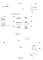
- FIG. 1is a block diagram of one embodiment of a video surveillance system.
- FIG. 2is a schematic diagram of one embodiment of a three-dimensional virtual beam.
- FIG. 3is a pictorial diagram illustrating one embodiment of a three-dimensional virtual beam in a scene within a field of view of a video camera.
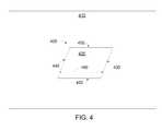
- FIG. 4is a schematic diagram of one embodiment of a two-dimensional virtual beam.
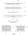
- FIG. 5is a flowchart of a method of monitoring whether an object of interest is passing through a detection zone within a field of view of a video camera, according to one embodiment.
- FIG. 6is a flowchart of a method of monitoring whether one or more objects of interest are located in a detection zone within a field of view of a video camera, according to one embodiment.
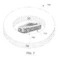
- FIG. 7is a pictorial diagrammatic view of one embodiment of a virtual beam associated with an object of interest.
- FIG. 8is a flowchart of a method of monitoring whether a first object of interest is passing through a detection zone that is within a field of view of a video camera and is associated with a second object of interest, according to one embodiment.
- FIG. 9is a flowchart of a method of configuring a virtual beam, according to one embodiment.
- the disclosed preferred embodimentsimplement methods and systems for reducing false alarms when monitoring whether an object of interest is passing through a detection zone within a field of view of a scene observed by a video camera.
- the object of interestmay be tracked to determine whether the tracked object of interest is continually present in the detection zone as the tracked object of interest crosses from one side of the detection zone to the other side of the detection zone.
- the detection zonemay be observed by a video surveillance system including video analytics and a virtual beam.
- the virtual beamcan be used to define opposite sides of the detection zone.
- the virtual beamcan be drawn on a computer screen over the visual image rendered from video data generated by a surveillance camera to define the area of detection, similar to the way an ROI is drawn.
- a virtual beamcan be drawn as a two-dimensional or three dimensional space.
- FIG. 1illustrates a block diagram of one embodiment of a video surveillance system 100 , which includes a camera 110 , mass storage 120 , a computer system 130 , an output device 150 , and an input device 160 .
- Video surveillance system 100may include an interconnection network 170 for connecting camera 110 , mass storage 120 , and computer system 130 to one another.
- the term “connected”means logically or physically connected directly or indirectly through one or more intermediaries.
- Interconnection network 170facilitates wired or wireless communication among camera 110 , mass storage 120 , and computer system 130 .
- interconnection network 170may include the Internet, Ethernet, Universal Serial Bus (USB), asynchronous transfer mode (ATM), Packet over SONET/SDH (POS), Peripheral Component Interconnect Express (PCI-Express), IEEE 802.11 (Wi-Fi), cellular telephone network, or other interconnect that is capable of providing a communication pathway among came a 110 , mass storage 120 , and computer system 130 .
- USBUniversal Serial Bus
- ATMasynchronous transfer mode
- POSPacket over SONET/SDH
- PCI-ExpressPeripheral Component Interconnect Express
- Wi-FiIEEE 802.11
- Camera 110includes an imaging system for capturing images of a scene observed by camera 110 .
- Camera 110may be a video camera generating video data representing the field of view of the scene observed by the video camera.
- camera 110may be a video camera as described in commonly owned U.S. Patent Application Pub. No. 2009/0219387, titled “Intelligent High Resolution Video System.”
- Camera 110may have a fixed field of view or a variable field of view.
- a camera with a variable field of viewmay be of a pan-tilt-zoom (PTZ) type having mechanically driven optics to zoom-in on objects, for example.
- the field of view of the cameraincludes a detection zone or an area to be monitored.
- the detection zonemay include a secured area where entry is restricted, or the detection zone may include an area leading to a cashier in a store where the length of a check-out line may be monitored.
- the video datamay be formatted as an analog or digital signal, and the video data may be encrypted or compressed.
- the video datamay be encoded in the NTSC/PAL, MPEG-4 SVC, H.264, or any other format suitable for recording time sequenced images.
- Camera 110may be programmable and capable of producing multiple quality levels of video data, including higher quality (HiQ) video data and lower quality (LowQ) video data.
- HiQ video datamay represent high definition 1080p resolution video recorded at 30 frames-per-second (fps)
- LowQ video datamay represent D 1 resolution video recorded at 5 fps.
- HiQ and LowQ video dataare not limited to the parameters above.
- HiQ video datamay represent high definition 1080p resolution video recorded at a lower frame rate—for example, 15 fps.
- HiQ video dataare video data that represent higher quality video than that of LowQ video data.
- Camera 110may produce more than two quality levels of video data.
- Camera 110may be capable of producing different quality levels for different portions of a field of view within a video frame.
- camera 110may generate HiQ quality video data representing an object of interest, e.g. a person, in the field of view while simultaneously generating LowQ video data representing background scene images of the field of view.
- video analytics 132is used to differentiate between objects of interest and background images of the field of view.
- Mass storage 120is used for recording video data from camera 110 .
- Mass storage 120may also be used for storing metadata associated with the video data, rules used by video surveillance system 100 , and intermediate data, such as during compression and decompression of the video data.
- Mass storage 120may be hierarchical.
- mass storage 120may include a hard disk drive housed with camera 110 and a video server connected by means of a local area network (LAN) or a wide area network (WAN).
- Mass storage 120may include semiconductor memory, an optical storage device, a magnetic storage device, such as a hard disk drive, or any combination of them.
- the amount of storage capacitymay be determined based on at least the desired time to retain video data, the resolution of the video data, the compression of the video data, and the number of cameras writing to mass storage 120 .
- a typical cameracan generate approximately 0.4 GB of video data each day when images are captured with CIF resolution at 5 fps and are compressed with H.264 compression.
- a typical cameracan generate approximately 5.4 GB of video data each day when images are captured with 01 resolution at 15 fps and are compressed with MPEG-4 compression.
- Computer system 130receives video data and includes video analytics 132 and virtual beam 140 modules.
- Computer system 130may be integrated in the same housing as camera 110 , remote from camera 110 , or distributed across network 170 .
- Video datamay be received by an input/output (I/O) interface 138 , for example.
- Video analytics 132 and virtual beam 140 modulesmay be implemented in hardware, software, or combinations of them.
- computer-executable instructions for implementing virtual beam 140may be stored in local storage 134 and executed by processor 136 .
- Processor 136may include a Freescale Semiconductor® i.MX27 multimedia applications processor or a Texas Instruments DaVinciTM DM6437 processor, for example.
- virtual beam 140may be implemented in a field programmable gate array (FPGA) or application specific integrated circuit (ASIC).
- Local storage 134may include a semiconductor memory, a magnetic storage device, an optical storage device, or any combination of them.
- Semiconductor memorymay include read only memory (ROM) programmable ROM, random access memory (RAM), or flash memory.
- ROMread only memory
- RAMrandom access memory
- a magnetic storage devicemay include a floppy disk drive, a hard disk drive, a magnetic drum, a magnetic tape, or a magneto-optical disk.
- An optical storage devicemay include compact disc or holographic memory.
- Output device 150may include a display, an audible or visual alarm, a pager, a cellular telephone, a land line telephone, or other device capable of displaying video data or alerting an attendant when an object of interest is passing through the detection zone.
- video data from camera 110may be streamed by I/O interface 138 to output device 150 , such as a video display.
- a text messagemay be sent to output device 150 , such as a cellular telephone, when video analytics module 132 detects a tracked object of interest that is continually present in the detection zone as the tracked object of interest crosses through the detection zone in a predefined direction.
- Computer system 130communicates with an input device 160 .
- Input device 160may include a keyboard, a pointing device, such as a mouse or a touch screen, a microphone, a cellular telephone, a land line telephone, or other device capable of allowing a user to provide input to computer system 130 .
- input device 160may be a keyboard, and a user may send a command or setup information to computer system 130 by typing on the keyboard.
- input device 160may be a mouse, and a user may indicate a boundary of the detection zone by using the mouse to drag a cursor along the boundary over an image of the scene observed by camera 110 .
- input device 160may be a sensor or an external arming signal that could be used by rules to determine an event of interest.
- One implementationwould be use of an alarm system signal for the purpose of indicating the system is armed also for the purpose of arming the virtual beam detection rule.
- Computer system 130includes video analytics 132 .
- Video analytics 132analyzes the video data generated by camera 110 to detect whether a predefined event or object of interest is being captured by camera 110 .
- a preferred embodiment of video analytics 132is described in commonly owned U.S. Patent Application Pub. No. 2009/0245573, titled “Object Matching for Tracking, Indexing, and Search.”
- the video data analyzed by video analytics 132is preferably HiQ video data.
- Video analytics 132generates metadata that describe the content of video data.
- the metadata produced by video analytics 132may be a textual and semantic description of the content of the video.
- Events and objects of interestmay be programmed by a user and specified in an XML definitions file.
- the definitions file and video analytics 132may be updated periodically.
- Video analytics 132may include multiple analytic capabilities. Multiple events of interest may be defined, and more than one event of interest may occur at a particular time. Also, the nonoccurrence of one event leaves open the possibility of an occurrence of a second event.
- the metadatamay be supplied for storage in local storage 134 and mass storage 120 .
- the metadata representing an arbitrary frame ncan be associated with video data representing frame n.
- the metadatamay be searchable to allow a user to efficiently search and semantically browse large video archives, whether stored locally or remotely.
- Video analytics 132may also implement blob detection (e.g., detecting a group of moving pixels as a potential moving object, without identifying what type of object it is), lighting change adjustment, and geometric calibration based on object size in the field of view to distinguish objects based on types.
- video analytics 132may be able to classify an object as a human being, a vehicle, or another type of object and be able to recognize an object when it appears in any portion within the field of view of camera 110 .
- video analytics 132may be able to recognize certain identifiable features of an object such as, for example, human faces and vehicle license plates.
- Video analytics 132may be able to recognize when camera 110 is capturing a new object and assign a unique object ID to the new object. Video analytics 132 may be able to recognize the speed and trajectory at which an object moves. Video analytics 132 may be able to recognize events such as perimeter intrusion, object movement in a particular direction, objects approaching one another, a number of objects located in a specified area, objects left behind, and object removal. Video analytics 132 can also recognize specific locations, or coordinates, within the field of view where an event or object of interest is being captured, or a combination of objects and events, as defined by a rule.
- Video analytics 132When video analytics 132 detects an event or object of interest within the video data, video analytics 132 generates metadata that correspond to the event or object of interest and supplies the metadata to rules based engine 142 .
- Rules based engine 142includes rules that associate events or objects of interest, specified in the metadata, to specific actions to be taken.
- the actions associated with the rulesmay be to perform, for example, one or more of the following: signaling an event when a tracked object of interest is continually present in the detection zone during a period beginning when the tracked object of interest enters a detection zone and ending when the tracked object of interest leaves the detection zone through the opposite side, after having completely crossed through the detection zone; signaling an event when a number of objects of interest crossing the detection zone and continually present in the detection zone exceeds a threshold number; signaling an event when a first object of interest is continually present in a detection zone, the detection zone associated with a second object of interest, as the first object of interest crosses the detection zone; store HiQ or LowQ video data in local storage 134 ; store HiQ or LowQ video data in remote mass storage 120 ; stream HiQ or LowQ video data from output device 150 to a user; generate and send from output device 150 to a user a short video clip file of the event of interest; send an alert (e.g., instructions to generate one or both of a visual display and an audible sound) from output
- An application of counting objects crossing the detection zone and generating reports from object count datacan provide traffic flow pattern information. For example, placement of virtual beams at critical locations in a retail store enables determination of customer traffic flow throughout the store.
- a reportcan be generated to show customer traffic patterns based on time of day, seasons of year, or comparison of traffic flow among multiple store locations.
- Virtual beam 140may be associated with one or more objects.
- a type of object to be detectedmay be configured during detection rules setup, such as by choosing from a drop-down computer menu.
- Virtual beam 140may be set to detect general types of objects, such as people, vehicles, or boats.
- Virtual beam 140may be set to detect more specific types of objects, such as school buses, fire trucks, red sedans, people riding bicycles, adults, or non-guards.
- virtual beam 140may be associated with an object of interest.
- a virtual beamcan act as a four-dimensional beam by inclusion of a measure of time elapsed in crossing the virtual beam.
- An exampleis setting as a detection rule a speed limit of travel of an object through the virtual beam. This can be accomplished by establishing a time allowed for an object to pass through the virtual beam of known distance between its entrance and exit sides. An object taking too much or too little time to cross the virtual beam could trigger an event of interest.
- FIG. 2illustrates one embodiment of a three-dimensional virtual beam 200 that defines a detection zone that includes an entrance side 210 and an exit side 220 located on the opposite side of the detection zone.
- entrance side 210 and exit side 220are the borders of the detection zone, which has a rectangular shape and is arranged in parallel planes, but other shapes and arrangements are possible.
- a virtual beam zone of detectionmay be defined as an annulus, i.e., a ring with thickness.
- the detection area of a three-dimensional virtual beammay be planar, curved, or include one or more linear borders.
- Virtual beam 200exhibits an inherent direction of motion because events are detected when a tracked object of interest is continually present in the detection zone, after the tracked object of interest enters entrance side 210 of the detection zone, thereafter crosses through the detection zone, and leaves completely the detection zone from exit side 220 , thereby triggering detection.
- a direction of virtual beam 200may be defined by an object entering through entrance side 210 and triggering detection when the object crosses through the detection zone and leaves completely through exit side 220 .
- Virtual beam 200may also ignore objects entering or leaving through other sides of the detection zone, such as sides 230 and 240 . Objects entering or leaving the detection zone through sides 230 and 240 will be ignored.
- One virtual beamis used to detect an object crossing a detection zone in a single direction. Multiple virtual beams may be used to detect an object crossing a detection one in multiple directions. For example, two virtual beams defining the same detection zone, but swapping the entrance and exit sides, may be set up to detect traffic going in two directions.
- a distance 250 between entrance side 210 and exit side 220may be varied to customize a false alarm immunity versus a sensitivity of detection.
- Distance 250may be lengthened to widen virtual beam 200 and to reduce false alarms. In other words, distance 250 may be lengthened to increase false alarm immunity.
- Distance 250may be shortened to narrow virtual beam 200 and increase sensitivity of detection.
- Virtual beam 200may be aligned with a spatial location within a three-dimensional representation of the scene observed by camera 110 .
- the three-dimensional representationmay be created manually, such as by a user or an installer providing a physical mapping of the background scene to rules based engine 142 .
- a ground plane 260 of the visual scenemay be manually entered by use of input device 160 .
- video analytics 132can automatically observe and analyze traffic, such as people and vehicles in various areas of the scene, to generate a ground plane model, including the angle of the ground plane.
- the three-dimensional representation of the scenemay include a horizon, where ground plane 260 appears to intersect the sky from the field of view of camera 110 . Similar to the ground plane, the horizon may be manually entered or automatically detected by operation of video analytics 132 .
- Distance 250may be shortened or lengthened, depending on how far the detection zone is from camera 110 or how close the detection zone is to camera 110 . For example, an area closer to the horizon in the video scene is typically farther away than areas farther from and below the horizon. Thus, it may be desirable to have a wider virtual beam for areas closer to camera 110 compared to areas farther from camera 110 , since each pixel located near the horizon may represent more distance traveled than each pixel located farther from and below the horizon would represent. Similarly, a height 270 of the detection zone may be increased or reduced depending on how far away from or close to the detection zone is from camera 110 . For example, it may be desirable to increase height 270 as the detection zone is positioned closer to camera 110 to provide similar false alarm immunity as that provided by a detection zone positioned farther from camera 110 .
- Virtual beam 200may include a detection zone having a border coincident with ground-plane 260 or above ground-plane 260 , such as at height 280 .
- FIG. 3illustrates how a three-dimensional virtual beam 300 may be overlaid on a three-dimensional representation of a scene 310 within a field of view of a video camera.
- FIG. 3shows a suburban car lot with a sidewalk 320 proximal to one side of which several cars 340 are parked side by side and proximal to the other side of which a street 300 runs parallel.
- Virtual beam 300includes a detection zone with a boundary coincident with a ground plane located on the surface of sidewalk 320 .
- Virtual beam 300includes detection sides 302 and 304 and is preferably configured to detect only the feet and lower portions of the legs of a human being as an object of interest. If detection side 302 is the entrance side and detection side 304 is the exit side, virtual beam 300 can detect people walking along sidewalk 320 from right to left. If detection side 304 is the entrance side and detection side 302 is the exit side, virtual beam 300 can detect people walking along sidewalk 320 from left to right. In this manner, the movement of people along the sidewalk can be monitored with high false alarm immunity. For example, people walking on the street, in front of sidewalk 320 , will be ignored when their heads rather than their feet pass through virtual beam 300 . As used with reference to FIG. 3 , “in front of” means closer to camera 110 .
- a two-dimensional virtual beammay be used as an overlay on an image represented by video data.
- a three-dimensional representation of a scenemay not be available because a user has not manually entered a physical mapping of the background scene or video analytics 132 has not completed calibrating the scene.
- a two-dimensional virtual beammay be implemented with fewer computational resources than those used in implementing a three-dimensional virtual beam. Skilled persons will appreciate that the dimensions of a scene and the dimensions of a virtual beam are separate and distinct.
- a three-dimensional virtual beamneed not be used with a three-dimensional representation of a scene.
- a two-dimensional beamcan, therefore, be located in a three-dimensional representation of a scene.
- a three-dimensional virtual beamcan be implemented by a two-dimensional beam and a rule specifying the height of an object.
- FIG. 4illustrates one embodiment of a two-dimensional virtual beam 400 overlaid on an image 410 represented by video data from camera 110 .
- Virtual beam 400can be used to define the entrance and exit sides of a detection zone 420 .
- virtual beam 400may include an entrance side 430 bounding detection zone 420 on one side and an exit side 440 bounding detection zone 420 on the opposite side.
- Virtual beam 400may include one or more sides 450 where the entrance or exit of objects is ignored.
- Virtual beam 400includes a distance 460 between entrance side 430 and exit side 440 . Increasing distance 460 may reduce false alarms, and decreasing distance 460 may increase sensitivity of detection.
- FIG. 4illustrates one embodiment of a two-dimensional virtual beam 400 overlaid on an image 410 represented by video data from camera 110 .
- Virtual beam 400can be used to define the entrance and exit sides of a detection zone 420 .
- virtual beam 400may include an entrance side 430 bounding detection zone 420 on one side and an exit side 440 bounding detection zone
- FIG. 9illustrates a method of configuring a virtual beam that may be used in the methods illustrated in FIGS. 5, 6, and 8 .
- FIG. 5is a flowchart of a method 500 of monitoring whether an object of interest is passing through a detection zone within a field of view of a video camera, according to one embodiment.
- Method 500may be implemented, for example, by video surveillance system 100 .
- Method 500begins at 510 by receiving video data.
- the video datamay be received in real-time, such as from camera 110 , or delayed from when the video data were recorded.
- Real-time datamay be delayed by computations or buffering within video surveillance system 100 .
- real-time datamay be delayed by encoding, decoding, compressing, decompressing, packetizing, or other system delays.
- video data from camera 110may be recorded at mass storage 120 or local storage 134 , stored for a time, and then retrieved at a later time for post-processing by method 500 .
- the color of an objectmay be used to determine whether the object is considered to be of interest. For example, a red sedan could be considered to be of interest and cars of different colors could be ignored. Tracking objects of a given color may be used to aid police officers when they are looking for a car with a known color, such as during an Amber alert or when a car has been reported stolen. Similarly, the shape of car, which may correspond to a make and model of the car, may be used to determine whether the car is considered to be of interest. As another example, employees or guards may have uniforms of one color and people wearing a different color may be considered to be of interest for certain types of activities, such as entering into employee-only areas.
- Colors corresponding to temperaturesmay be used to determine whether an object is considered to be of interest.
- a thermal cameramay generate different colors corresponding to different temperatures.
- a thermal cameramay generate black and white images, with the intensity of the white corresponding to different temperatures.
- a threshold color or intensitymay be set, and when the color or intensity of the object exceeds the threshold, the object can be identified as an object of interest.
- One application in which tracking objects based on color from a thermal camera may be desirableis the monitoring of electrical substations. For example, the spread of unwanted heat in substation equipment may be tracked to provide an early warning of occurrences and potentially reduce the expense of system failures.
- a tracked object of interestmay be part of another object of interest.
- objects that may be part of another objectinclude a license plate of a vehicle or a face, arm, or head of a person. Tracking a license plate can be useful when combined with a license plate recognition system. Similarly, tracking a face can be useful when combined with a facial recognition system. Tracking a part of an object may improve the accuracy of tracking. For example, tracking heads may be more accurate than tracking full bodies, especially when a full view of the bodies may be obscured by obstacles or heavy traffic, such as in an airport or a train terminal.
- Bounding box coordinateswill move with an object of interest, and the bounding box coordinates may be filtered through a smoothing function between frames to reduce jerkiness.
- bounding box coordinatesmay be a set of (X, Y, Z) coordinates corresponding to the boundary of the object of interest in the three-dimensional representation of the scene observed by video camera 110 .
- Event datamay include whether an event occurred or a time-stamp of when an event occurred.
- the presence of an object in the detection zonemay be determined in different ways.
- the objectis “present” in the detection zone when a bounding box associated with the object intersects or is contained within the detection zone.
- the objectis “present” in the detection zone when a center of the bounding box associated with the object intersects or is contained within the detection zone.
- the objectis “present” in the detection zone when any pixel of the object intersects or is contained within the detection zone.
- Metadatasuch as an entry time-stamp
- an exit time-stampmay be created and associated with the object when the object exits the detection zone.
- the entry and exit time-stamps of the objectmay be compared to time-stamps marking the time during which the object is present in the detection zone to determine whether the object is continually present in the detection zone.
- rules-based criteriaare used to define an event of interest. Criteria may include, for example, time of day or week, speed of object, color of object, type of object, and multiple objects simultaneously crossing the virtual beam. Another criterion may be establishing as the virtual beam an annulus surrounding an object of interest.
- an eventis signaled when the tracked object of interest is continually present in the detection zone during a period beginning when the tracked object of interest enters through the entrance side of the virtual beam and ending when the tracked object of interest crosses through the detection zone and leaves through the exit side of the virtual beam.
- rules for determining when the object enters through an entrance sideinclude: (1) when a bounding box associated with the object first enters the detection zone through the entrance side, (2) when a center of the bounding box associated with the object enters the detection zone through the entrance side, (3) when any pixel of the object enters the detection zone through the entrance side, and (4) when a bounding box associated with the object enters the detection zone through the complete height of the detection zone (for three-dimensional virtual beams).
- the rules for determining when the object enters or leaves the detection zonemay be different.
- the rules for determining when the object enters or leaves the detection zonemay vary the sensitivity and false alarm immunity for the detection zone crossing. For example, rule (1) would likely be more sensitive than would rule (2) for detecting an object entering a detection zone, e.g., rule (1) would detect entry of an object into a detection zone sooner than would rule (2), but rule (1) might result in more false alarms than would rule (2).
- Method 500may be used in a variety of applications. For example, the steps of method 500 may be performed with virtual beam 300 to detect people walking along sidewalk 320 as described with reference to FIG. 3 . Similarly, use of a virtual beam in the performance of method 500 may detect a person entering a property area with no physical barriers, such as a schoolyard that adjoins a wooded area.
- Method 500may be used for fence beam applications, such as detecting a person climbing a fence or a cellular telephone tower by having an entrance side of a virtual beam set near the bottom of the structure and an exit side set at a higher point of the structure.
- the distance between the entrance side and the exit sidecan be used to determine how far the person must climb before an alarm is triggered.
- the height of the exit side over the entrance sidecan be used to determine how tall the person needs to be to create a detection.
- the distance between entrance and exit sidesmay reduce false alarms caused by tree branches blowing in the wind, birds landing on the fence, or even small animals, such as squirrels crawling up the fence. In this fence beam application, false alarms caused by passers-by may also be reduced, since people crossing only from the entrance side to the exit side will generate an alarm.
- Method 500may be used for a virtual corridor application, such as for a one-way exit at an airport or a museum.
- the distance between entrance and exit sides or depth of the virtual beamcan be used to establish how far people must travel in one direction before being detected. Increasing the depth may reduce false alarms caused by people stopping to momentarily turn around before exiting. For example, movements opposite to the direction of the exit might be caused by a person turning around to wave goodbye to someone, stepping backwards for a moment, or deciding not to leave.
- the height of the virtual beamcan also be set to just detect the heads of people and thereby may be helpful in crowded areas where it may be difficult for the camera to see full body views.
- an eventis signaled when the number of objects of interest entering through the entrance side and continually present in the detection zone at about the same time, and crossing through the detection zone and leaving through the exit side, exceeds a threshold number.
- the threshold numbermay be preconfigured by a user, such as with method 900 ( FIG. 9 ), for example.
- video analytics 132may adjust the threshold number based on one or more conditions detected by video analytics 132 .
- additional stepsmay be optionally performed based on the occurrence of an event, such as the event signaled at 640 .
- Method 600may be used for a virtual corridor application, such as in front of a cashier or service counter.
- method 600may be used to detect the length of a queue of people waiting in line.
- the height of the virtual beamcan be set to determine how tall people need to be for detection. For example, the height can be set to detect people over 4 feet tall to ignore children waiting with their parents, as well as to ignore shopping carts.
- the threshold number of peoplecan be set based on a store policy for a desirable number of people standing in line. When the desirable number is exceeded, an alert can be generated and additional service personnel can be requested to open another checkout counter.
- the virtual corridor applicationmay be modified to account for a store policy of a desirable waiting time in line.
- a linemay be short and slow, such as when a cashier is delayed with a problem customer.
- the threshold for the number of people in linemay be reduced based on the length of time elapsed after the last person left through the exit side of the virtual beam. Thus, the threshold number of people may drop as the speed of the line slows.
- a timeris started when a person enters the virtual beam through the entrance side and the timer is stopped when the person leaves the virtual beam through the exit side. If the person has not left the detection zone after a predefined time, an alert can then be generated.
- virtual beam 700is illustrated as an annulus, other shapes are possible.
- each of the sidesmay be in the shape of a dome, sphere, box, pyramid, hexagon, or any other shape that completely or partly surrounds object of interest 710 .
- the shape and center of inner side 720may be different from the shape and center of outer side 720 .
- inner side 720is contained within the perimeter of outer side 730 .
- a two-dimensional virtual beammay also be associated with an object of interest.
- the sidesmay be in the shapes of concentric circles.
- the entrance side and the exit sideneed not be concentric.
- the sidesmay be any other two-dimensional shape that completely or partly surrounds object of interest.
- the inner sideis contained within the perimeter of the outer side.
- FIG. 8is a flowchart of a method 800 of monitoring whether a first object of interest is passing through a detection zone that is within a field of view of a video camera and is associated with a second object of interest, according to one embodiment.
- Method BOOmay be implemented, for example, by video surveillance system 100 .
- Method BOObegins at 510 by receiving video data.
- video analytics 132are used to track the first object of interest in the video data.
- the first object of interestmay be tracked as described at 520 , for example.
- a second object of interest represented by the video data and different from the first object of interestis tracked.
- the second object of interestmay be tracked with video analytics 132 , such as in 520 or B 20 , or may be tracked in other ways.
- the second object of interestmay be tracked using radio frequency identification (RFID) or other radio triangulation methods, GPS, or any other method of determining a position of the second object of interest.
- RFIDradio frequency identification
- GPSGPS
- a multi-dimensional virtual beamsuch as virtual beam 700 , is used to detect whether the first object of interest is continually present in the detection zone as the first object of interest passes through the detection zone associated with the second object of interest.
- the multi-dimensional virtual beamincludes an entrance side bounding the detection zone on one side and an exit side bounding the detection zone on a side opposite the entrance side.
- the entrance sideis farther from the second object of interest than is the exit side so that objects approaching the second object of interest can be detected.
- the entrance sideis closer to the second object of interest than is exit side so that objects leaving the second object of interest can be detected.
- an eventis signaled when the first object of interest is continually present in the detection zone during a period beginning when the first object of interest enters into the detection zone through the entrance side and ending when the first object of interest leaves the detection zone through the exit side. Whether an object enters through an entrance side or leaves through an exit side may be determined according to the rules described at 550 .
- additional stepsmay be optionally performed based on the occurrence of an event, such as the event signaled at B 50 .
- additional stepsinclude alerting an attendant, recording a video clip, adjusting a recording quality level, sending an email, sounding an audible alarm, generating metadata, or logging a report.
- Method 800may be used in a variety of object localized applications.
- An object localized applicationincludes a virtual beam that is associated with or localized around an object that may move.
- method 800may be used for detecting when people leave their vehicles, or when someone walks up to a vehicle.
- a virtual beam associated with the vehiclecan be defined to surround the vehicle, as illustrated in FIG. 7 . By choosing whether the outer side or the inner side is the entrance side, the virtual beam can distinguish between people approaching a vehicle or leaving it.
- One potential advantage of using a virtual beam as an object localized beame.g., a virtual beam associated with an object, is that the virtual beam can follow the object around which the virtual beam is localized. For example, if the vehicle moves, the surrounding virtual beam moves with the vehicle. Or, if the virtual beam is localized around a person, and the person walks into a public park, the virtual beam can provide a detection zone around the person and triggers an alarm if that person is approached by another person.
- Method 800may be used in a hospital setting.
- a virtual beamcan be localized around a piece of hospital equipment to detect and create a video record whenever someone touches the equipment.
- the equipmentis moved, which is quite common in hospitals, then as soon as the equipment is stationary and in the view of a camera, such as camera 110 , the virtual beam surrounding it can again become active.
- the localized beamcan be configured to detect a person approaching or leaving the equipment.
- a detection eventcan cause a video clip to be recorded and stored in local storage 134 or mass storage 120 . If the equipment is missing or damaged, then the video records associated with the equipment may be searched to find a cause of the missing or damaged equipment.
- a preferred video analytics systemcan use virtual beams as part of an overall behavior detection process. For example, a video analytics system can set up a rule to automatically create virtual beams around objects of a certain type, such as vehicles, when they enter a parking lot. The system can automatically set up a first virtual beam around an arriving car. An event can be triggered after the vehicle parks and someone leaves the car, crossing through the first virtual beam. If that same person, tracked by video analytics, then approaches another parked vehicle surrounded by a second virtual beam, the video analytics system can identify potentially suspicious activity. If the car in which that person arrived is driven away and that person thereafter approaches parked vehicles, the system can treat this behavior as suspicious and alert security guards.
- a rulecan automatically create virtual beams around objects of a certain type, such as vehicles, when they enter a parking lot.
- the systemcan automatically set up a first virtual beam around an arriving car. An event can be triggered after the vehicle parks and someone leaves the car, crossing through the first virtual beam. If that same person, tracked by video analytics, then approaches another parked
- the video analyticscan also detect a situation in which that person enters and starts a parked car that then begins to move from its parking space. In this manner, repeatable patterns of behavior practiced by criminals may be automatically detected by a video analytics system. By detecting suspicious activity in real time, security guards may be given valuable early warning to close automatic gate openings to prevent the thieves from leaving. Alternatively, the security guards can potentially operate a PTZ camera to 25 zoom in to identify license plates and get close-up pictures of those involved, and send this information to the police, for capture and arrest.
- FIG. 9is a flowchart of a method 900 of configuring a multi-dimensional virtual beam, according to one embodiment.
- Method 900may be implemented, for example, by video surveillance system 100 .
- Method 900begins at 910 by defining a multi-dimensional virtual beam having an entrance side and an exit side bounding the detection zone on opposite sides.
- a two-dimensional virtual beam overlaid on a visual imagemay be defined by pixel coordinates.
- a three-dimensional virtual beam representing a spatial location within a three-dimensional representation of the scene observed by camera 110may be defined by coordinates corresponding to the scene representation.
- a two-dimensional virtual beamcan be defined to represent area coordinates in a three-dimensional representation of the scene observed by camera 110 .
- the entrance and exit sidesmay be defined, for example, in an XML file or by a user dragging a cursor along the detection zone boundary over an image of the scene observed by camera 110 .
- video analytics 132may recommend narrower beams for areas farther from camera 110 and wider beams for areas closer to camera 110 .
- a virtual beam for a virtual corridor or virtual doorwaymay be defined in two dimensions, and a user may separately select a size of the object to be detected.
- Video analytics 132may automatically determine the average size of adults present in a region of the scene and automatically offer the user an option in a drop-down menu to choose between adults and children. Similarly, vehicles may be specified in meters or feet to detect only big-rig trucks while ignoring sedans, for example. After a detection zone boundary is defined, video analytics 132 may provide at its output a graphical representation of the boundary over the video image displayed by output device 150 . When a ground plane is specified, video analytics 132 may shape automatically the angles of the detection area to match the angle of the ground plane.
- the multi-dimensional virtual beam defined at 910can be optionally associated with an object of interest, a characteristic of an object, or an object independent rule.
- the virtual beammay be associated with a position of an object of interest.
- the virtual beammay be defined relative to the position of the object of interest so the virtual beam can move with the object.
- the virtual beammay be associated with a type of object so that only objects of a predefined type tracked within the boundary of the virtual beam will trigger a detection.
- the type of object to be detectedcan be configured when setting up the detection rules, such as by choosing from a drop-down computer menu.
- the virtual beamcan be set to detect people, vehicles, boats, or more specific types of objects, such as school buses, fire trucks, and bicyclists.
- object independent rulesinclude detecting objects at limited times of the day or during a reduced set of ambient lighting conditions.
- other rulescan be added, such as the length of time allowed for objects to cross the virtual beam. An object's taking too much time (i.e., is moving too slow) or too little time (i.e., is moving too fast) to cross the virtual beam could be considered an event of interest.
- a threshold number of objects of interestmay optionally be defined and associated with the virtual beam, such as when method 600 is to be implemented.
- the threshold numbercan be preconfigured by a user and automatically adjusted if various criteria are met.
- method 900tests whether a threshold number of objects is defined for the virtual beam. If so, method 900 continues at 960 , otherwise, method 900 continues at 970 .
- the video analytics systemis armed to trigger an event when the object of interest is continually present in the detection zone during a period beginning when the object of interest enters the detection zone through the entrance side of the virtual beam and ending when the object of interest leaves the detection zone through the exit side of the virtual beam. In this manner, the video analytics system may be armed to implement method 500 or method 900 .
Landscapes
- Engineering & Computer Science (AREA)
- Physics & Mathematics (AREA)
- General Physics & Mathematics (AREA)
- Multimedia (AREA)
- Theoretical Computer Science (AREA)
- Computer Vision & Pattern Recognition (AREA)
- Signal Processing (AREA)
- Electromagnetism (AREA)
- Computer Graphics (AREA)
- Analytical Chemistry (AREA)
- Chemical & Material Sciences (AREA)
- Human Computer Interaction (AREA)
- Computing Systems (AREA)
- Closed-Circuit Television Systems (AREA)
- Alarm Systems (AREA)
- Image Analysis (AREA)
Abstract
Description
Claims (37)
Priority Applications (1)
| Application Number | Priority Date | Filing Date | Title |
|---|---|---|---|
| US14/885,479US9412269B2 (en) | 2012-11-15 | 2015-10-16 | Object detection based on image pixels |
Applications Claiming Priority (2)
| Application Number | Priority Date | Filing Date | Title |
|---|---|---|---|
| US13/678,273US9197861B2 (en) | 2012-11-15 | 2012-11-15 | Multi-dimensional virtual beam detection for video analytics |
| US14/885,479US9412269B2 (en) | 2012-11-15 | 2015-10-16 | Object detection based on image pixels |
Related Parent Applications (1)
| Application Number | Title | Priority Date | Filing Date |
|---|---|---|---|
| US13/678,273ContinuationUS9197861B2 (en) | 2012-11-15 | 2012-11-15 | Multi-dimensional virtual beam detection for video analytics |
Publications (2)
| Publication Number | Publication Date |
|---|---|
| US20160044286A1 US20160044286A1 (en) | 2016-02-11 |
| US9412269B2true US9412269B2 (en) | 2016-08-09 |
Family
ID=50681336
Family Applications (6)
| Application Number | Title | Priority Date | Filing Date |
|---|---|---|---|
| US13/678,273Active2033-11-27US9197861B2 (en) | 2012-11-15 | 2012-11-15 | Multi-dimensional virtual beam detection for video analytics |
| US14/885,459ActiveUS9412268B2 (en) | 2012-11-15 | 2015-10-16 | Vehicle detection and counting |
| US14/885,209ActiveUS9449510B2 (en) | 2012-11-15 | 2015-10-16 | Selective object detection |
| US14/885,499ActiveUS9449398B2 (en) | 2012-11-15 | 2015-10-16 | Directional object detection |
| US14/885,479ActiveUS9412269B2 (en) | 2012-11-15 | 2015-10-16 | Object detection based on image pixels |
| US15/240,933Active2032-11-16US9721168B2 (en) | 2012-11-15 | 2016-08-18 | Directional object detection |
Family Applications Before (4)
| Application Number | Title | Priority Date | Filing Date |
|---|---|---|---|
| US13/678,273Active2033-11-27US9197861B2 (en) | 2012-11-15 | 2012-11-15 | Multi-dimensional virtual beam detection for video analytics |
| US14/885,459ActiveUS9412268B2 (en) | 2012-11-15 | 2015-10-16 | Vehicle detection and counting |
| US14/885,209ActiveUS9449510B2 (en) | 2012-11-15 | 2015-10-16 | Selective object detection |
| US14/885,499ActiveUS9449398B2 (en) | 2012-11-15 | 2015-10-16 | Directional object detection |
Family Applications After (1)
| Application Number | Title | Priority Date | Filing Date |
|---|---|---|---|
| US15/240,933Active2032-11-16US9721168B2 (en) | 2012-11-15 | 2016-08-18 | Directional object detection |
Country Status (1)
| Country | Link |
|---|---|
| US (6) | US9197861B2 (en) |
Cited By (15)
| Publication number | Priority date | Publication date | Assignee | Title |
|---|---|---|---|---|
| US20140003657A1 (en)* | 2012-06-28 | 2014-01-02 | Canon Kabushiki Kaisha | Setting apparatus and setting method |
| US20170277967A1 (en)* | 2016-03-22 | 2017-09-28 | Tyco International Management Company | System and method for designating surveillance camera regions of interest |
| US20170278367A1 (en)* | 2016-03-22 | 2017-09-28 | Tyco International Management Company | System and method for overlap detection in surveillance camera network |
| US20180005033A1 (en)* | 2016-06-29 | 2018-01-04 | Xiaoyi Technology Co., Ltd. | System and method for detecting and tracking a moving object |
| US10347102B2 (en) | 2016-03-22 | 2019-07-09 | Sensormatic Electronics, LLC | Method and system for surveillance camera arbitration of uplink consumption |
| US10475315B2 (en) | 2016-03-22 | 2019-11-12 | Sensormatic Electronics, LLC | System and method for configuring surveillance cameras using mobile computing devices |
| US10665071B2 (en) | 2016-03-22 | 2020-05-26 | Sensormatic Electronics, LLC | System and method for deadzone detection in surveillance camera network |
| US10733231B2 (en) | 2016-03-22 | 2020-08-04 | Sensormatic Electronics, LLC | Method and system for modeling image of interest to users |
| US10764539B2 (en) | 2016-03-22 | 2020-09-01 | Sensormatic Electronics, LLC | System and method for using mobile device of zone and correlated motion detection |
| US10977487B2 (en) | 2016-03-22 | 2021-04-13 | Sensormatic Electronics, LLC | Method and system for conveying data from monitored scene via surveillance cameras |
| US11206376B2 (en) | 2017-12-08 | 2021-12-21 | Zhejiang Dahua Technology Co., Ltd. | Systems and methods for image processing |
| US11216847B2 (en) | 2016-03-22 | 2022-01-04 | Sensormatic Electronics, LLC | System and method for retail customer tracking in surveillance camera network |
| US20220058392A1 (en)* | 2020-08-21 | 2022-02-24 | Ubicquia Iq Llc | Automated virtual tripwire placement |
| US20220299612A1 (en)* | 2019-08-28 | 2022-09-22 | Bae Systems Plc | Detection of modulating elements |
| US11601583B2 (en) | 2016-03-22 | 2023-03-07 | Johnson Controls Tyco IP Holdings LLP | System and method for controlling surveillance cameras |
Families Citing this family (85)
| Publication number | Priority date | Publication date | Assignee | Title |
|---|---|---|---|---|
| US11657606B2 (en)* | 2010-03-16 | 2023-05-23 | OMNIQ Corp. | Dynamic image capture and processing |
| US9197861B2 (en)* | 2012-11-15 | 2015-11-24 | Avo Usa Holding 2 Corporation | Multi-dimensional virtual beam detection for video analytics |
| US20140335852A1 (en)* | 2013-03-14 | 2014-11-13 | Wenlong Li | Cross-device notification apparatus and method |
| US9405974B2 (en)* | 2013-11-13 | 2016-08-02 | Xerox Corporation | System and method for using apparent size and orientation of an object to improve video-based tracking in regularized environments |
| CA2936651A1 (en)* | 2014-01-17 | 2015-07-23 | Gojo Industries, Inc. | Sensor configuration |
| US9934453B2 (en)* | 2014-06-19 | 2018-04-03 | Bae Systems Information And Electronic Systems Integration Inc. | Multi-source multi-modal activity recognition in aerial video surveillance |
| KR20160014418A (en) | 2014-07-29 | 2016-02-11 | 삼성전자주식회사 | User interface apparatus and user interface method |
| US10438070B2 (en)* | 2014-09-25 | 2019-10-08 | Filippo Guerzoni | Surveillance method, device and system |
| US9870637B2 (en)* | 2014-12-18 | 2018-01-16 | Intel Corporation | Frame removal and replacement for stop-action animation |
| JP6597643B2 (en)* | 2015-02-05 | 2019-10-30 | 株式会社リコー | Image processing apparatus, image processing system, image processing method, and program |
| US20160335484A1 (en)* | 2015-03-11 | 2016-11-17 | Fortinet, Inc. | Access point stream and video surveillance stream based object location detection and activity analysis |
| WO2016157330A1 (en)* | 2015-03-27 | 2016-10-06 | 日本電気株式会社 | Mobile monitoring device, program, and control method |
| US10007849B2 (en)* | 2015-05-29 | 2018-06-26 | Accenture Global Solutions Limited | Predicting external events from digital video content |
| EP3317680B1 (en)* | 2015-06-26 | 2021-03-31 | INTEL Corporation | System manager to adaptively manage data collection devices in distributed computing systems, corresponding method and corresponding machine readable medium |
| US9965531B2 (en)* | 2015-07-21 | 2018-05-08 | Accenture Global Services Limited | Data storage extract, transform and load operations for entity and time-based record generation |
| WO2017035025A1 (en)* | 2015-08-21 | 2017-03-02 | T1V, Inc. | Engagement analytic system and display system responsive to user's interaction and/or position |
| US20170083790A1 (en) | 2015-09-23 | 2017-03-23 | Behavioral Recognition Systems, Inc. | Detected object tracker for a video analytics system |
| US10323450B2 (en)* | 2015-10-20 | 2019-06-18 | Hi-Tech Solutions Ltd. | Cloud-base ANPR management |
| EP3391339A2 (en)* | 2015-12-18 | 2018-10-24 | Iris Automation, Inc. | Real-time visual situational awareness system |
| JP6390860B2 (en)* | 2016-01-25 | 2018-09-19 | パナソニックIpマネジメント株式会社 | Left object monitoring device, left object monitoring system including the same, and left object monitoring method |
| JP6393360B2 (en)* | 2016-05-11 | 2018-09-19 | パナソニック インテレクチュアル プロパティ コーポレーション オブ アメリカPanasonic Intellectual Property Corporation of America | Imaging control method, imaging control system, and imaging control server |
| CN105869334A (en)* | 2016-05-28 | 2016-08-17 | 张维秀 | Fire alarm method and system |
| CN106127292B (en)* | 2016-06-29 | 2019-05-07 | 上海小蚁科技有限公司 | Flow method of counting and equipment |
| US10403107B2 (en)* | 2016-07-07 | 2019-09-03 | Sri International | Passive optical detection method and system for vehicles |
| US10074205B2 (en) | 2016-08-30 | 2018-09-11 | Intel Corporation | Machine creation of program with frame analysis method and apparatus |
| JP6651133B2 (en)* | 2016-09-01 | 2020-02-19 | カシオ計算機株式会社 | Electronic device, image data storage method, program, and photographing system |
| US10192143B1 (en)* | 2016-09-20 | 2019-01-29 | Gopro, Inc. | Systems and methods to distinguish between features depicted in images |
| FR3056171B1 (en)* | 2016-09-20 | 2020-05-08 | Renault S.A.S | METHOD OF INSTALLING A GEOMETRIC REFERENTIAL ON A FLOOR FOR THE CALIBRATION OF ELECTRIC OR ELECTRONIC COMPONENTS OF A MOTOR VEHICLE AND ADAPTED EQUIPMENT. |
| US10553092B2 (en) | 2016-12-05 | 2020-02-04 | A9.Com, Inc. | Passing vehicle filters for audio/video recording and communication devices |
| US10095933B2 (en)* | 2016-12-05 | 2018-10-09 | Google Llc | Systems and methods for locating image data for selected regions of interest |
| TWI633525B (en)* | 2016-12-09 | 2018-08-21 | 正文科技股份有限公司 | Parking position sensing device |
| JP6803749B2 (en)* | 2016-12-28 | 2020-12-23 | パナソニックi−PROセンシングソリューションズ株式会社 | Number measurement area setting method, number measurement area setting program, flow line analysis system, camera device and number measurement program |
| US10409279B2 (en)* | 2017-01-31 | 2019-09-10 | GM Global Technology Operations LLC | Efficient situational awareness by event generation and episodic memory recall for autonomous driving systems |
| JP2018146440A (en)* | 2017-03-07 | 2018-09-20 | 株式会社豊田自動織機 | Environment recognition device |
| US10776930B2 (en)* | 2017-05-05 | 2020-09-15 | John W. Perry | Mobile device, system, and computerized method for tracking flying objects and displaying tracked flying objects on the mobile device |
| US10157476B1 (en)* | 2017-06-15 | 2018-12-18 | Satori Worldwide, Llc | Self-learning spatial recognition system |
| CN107274674B (en)* | 2017-06-28 | 2020-04-24 | 深圳市金溢科技股份有限公司 | Parking area management method, device and system based on video identification |
| US10783379B2 (en) | 2017-08-23 | 2020-09-22 | Bossa Nova Robotics Ip, Inc. | Method for new package detection |
| US10915777B2 (en)* | 2017-09-11 | 2021-02-09 | Ricoh Company, Ltd. | Communication terminal, communication system, and image processing method |
| CN107820010B (en)* | 2017-11-17 | 2020-11-06 | 英业达科技有限公司 | photocounting device |
| RU2671994C1 (en)* | 2018-02-06 | 2018-11-08 | Общество с ограниченной ответственостью "Ай Ти Ви групп" | System and method of detection of alarm trajectories of object motion |
| KR102449185B1 (en)* | 2018-02-14 | 2022-09-29 | 삼성전자주식회사 | Electronic device for selectively generating a moving picture using image data acquired at a frame rate changed according to a distance between a subject and a reference area, and an operating method thereof |
| JP7169752B2 (en)* | 2018-03-22 | 2022-11-11 | キヤノン株式会社 | MONITORING DEVICE, MONITORING SYSTEM, CONTROL METHOD, AND PROGRAM |
| US20190297131A1 (en)* | 2018-03-23 | 2019-09-26 | Satori Worldwide, Llc | System and Method for Querying and Updating a Live Video Stream Using a Structured Query Language |
| JP6791200B2 (en)* | 2018-05-11 | 2020-11-25 | トヨタ自動車株式会社 | Search support system, search support device, and search support method |
| US11126863B2 (en) | 2018-06-08 | 2021-09-21 | Southwest Airlines Co. | Detection system |
| US10823879B2 (en) | 2018-07-27 | 2020-11-03 | The Chamberlain Group, Inc. | Obstacle detection systems and methods |
| RU2703152C1 (en)* | 2018-09-20 | 2019-10-15 | Общество с ограниченной ответственностью "Ай Ти Ви групп" | System and method of displaying objects movement scheme |
| CN109376601B (en)* | 2018-09-21 | 2021-05-11 | 深圳市九洲电器有限公司 | Object tracking method based on high-speed ball, monitoring server and video monitoring system |
| JP7195098B2 (en)* | 2018-09-27 | 2022-12-23 | 株式会社Subaru | VEHICLE COMMUNICATION DEVICE, VEHICLE CONTROL SYSTEM AND TRAFFIC SYSTEM USING THE SAME |
| JP7132057B2 (en)* | 2018-09-27 | 2022-09-06 | 株式会社Subaru | VEHICLE COMMUNICATION DEVICE, VEHICLE CONTROL SYSTEM AND TRAFFIC SYSTEM USING THE SAME |
| US10970941B2 (en)* | 2018-10-26 | 2021-04-06 | Raytheon Company | All seeing one camera system for electronic tolling |
| US11055874B2 (en)* | 2018-10-30 | 2021-07-06 | Ncr Corporation | Image processing for tracking actions of individuals |
| US20200145623A1 (en)* | 2018-11-07 | 2020-05-07 | Avigilon Corporation | Method and System for Initiating a Video Stream |
| CN109743543B (en)* | 2018-12-21 | 2021-02-02 | 黑龙江工业学院 | English teaching computer monitoring device |
| CN109995978B (en)* | 2019-04-08 | 2020-12-18 | 浙江多普勒环保科技有限公司 | Vehicle identification system |
| US11482005B2 (en) | 2019-05-28 | 2022-10-25 | Apple Inc. | Techniques for secure video frame management |
| CN110830766B (en)* | 2019-10-15 | 2021-05-04 | 许昌许继软件技术有限公司 | A method and device for automatic configuration and correction of interval screen of substation monitoring system |
| CN111131765A (en)* | 2019-10-24 | 2020-05-08 | 广脉科技股份有限公司 | Multidimensional sensing regional management sensing system |
| CN110942578A (en)* | 2019-11-29 | 2020-03-31 | 韦达信息技术(深圳)有限公司 | Intelligent analysis anti-theft alarm system |
| EP3866056A1 (en)* | 2020-02-17 | 2021-08-18 | Touchless Animal Metrics, SL | Method, system and computer programs for traceability of living specimens |
| US11270118B2 (en) | 2020-04-10 | 2022-03-08 | Toyota Motor Engineering & Manufacturing North America, Inc. | Creating a valuable video clip using metadata flagging |
| CN111540020B (en)* | 2020-04-28 | 2023-10-10 | 浙江大华技术股份有限公司 | Method and device for determining target behavior, storage medium and electronic device |
| US11908143B2 (en) | 2020-06-03 | 2024-02-20 | Apple Inc. | Activity zones for camera video |
| US11356352B2 (en) | 2020-06-03 | 2022-06-07 | Apple Inc. | Identifying reachability of network-connected devices |
| US11514717B2 (en) | 2020-06-03 | 2022-11-29 | Apple Inc. | Identifying objects within images from different sources |
| US11657613B2 (en) | 2020-08-11 | 2023-05-23 | Analog Devices International Unlimited Company | Zone based object tracking and counting |
| CN112040181B (en)* | 2020-08-19 | 2022-08-05 | 北京软通智慧科技有限公司 | Visual area determining method, device, equipment and storage medium |
| CN112188018A (en)* | 2020-09-25 | 2021-01-05 | 中徽建技术有限公司 | Intelligent community fire fighting channel blockage alarming method and device |
| CN112215148B (en)* | 2020-10-13 | 2021-07-27 | 江门市景舟科技发展有限公司 | Electronic and manual monitoring integrated system and method |
| CN112333431B (en)* | 2020-10-30 | 2022-06-07 | 深圳市商汤科技有限公司 | Scene monitoring method and device, electronic equipment and storage medium |
| US11953586B2 (en) | 2020-11-17 | 2024-04-09 | Ford Global Technologies, Llc | Battery-powered vehicle sensors |
| CN112509324A (en)* | 2020-12-01 | 2021-03-16 | 苏州金螳螂怡和科技有限公司 | Vehicle detection system and method based on virtual coil video |
| US11951937B2 (en) | 2021-03-12 | 2024-04-09 | Ford Global Technologies, Llc | Vehicle power management |
| US11912235B2 (en) | 2021-03-12 | 2024-02-27 | Ford Global Technologies, Llc | Vehicle object detection |
| US11614513B2 (en) | 2021-03-12 | 2023-03-28 | Ford Global Technologies, Llc | Battery-powered vehicle sensors |
| US11916420B2 (en) | 2021-03-12 | 2024-02-27 | Ford Global Technologies, Llc | Vehicle sensor operation |
| CN113507588A (en)* | 2021-06-03 | 2021-10-15 | 山西三友和智慧信息技术股份有限公司 | Wisdom campus visitor flow monitoring system based on artificial intelligence |
| US12020728B2 (en)* | 2021-06-10 | 2024-06-25 | Kyle Quinton Beatch | Systems and methods for generating video compilations for tracked activities |
| GB2617352A (en)* | 2022-04-05 | 2023-10-11 | Canon Kk | Method, device, and computer program for encapsulating region annotations in media tracks |
| US11743580B1 (en) | 2022-05-16 | 2023-08-29 | Motorola Solutions, Inc. | Method and system for controlling operation of a fixed position camera |
| US12363263B2 (en) | 2022-11-08 | 2025-07-15 | Motorola Solutions, Inc. | Dynamically sized security monitoring region |
| US11715305B1 (en) | 2022-11-30 | 2023-08-01 | Amitha Nandini Mandava | Traffic detection system using machine vision |
| US12400352B2 (en) | 2023-03-15 | 2025-08-26 | Black Sesame Technologies Inc. | System for counting objects in an ultra-wide scene |
| EP4564314A1 (en)* | 2023-11-29 | 2025-06-04 | Axis AB | Method of tracking objects |
Citations (60)
| Publication number | Priority date | Publication date | Assignee | Title |
|---|---|---|---|---|
| US5334974A (en) | 1992-02-06 | 1994-08-02 | Simms James R | Personal security system |
| US6249740B1 (en) | 1998-01-21 | 2001-06-19 | Kabushikikaisha Equos Research | Communications navigation system, and navigation base apparatus and vehicle navigation apparatus both used in the navigation system |
| US6321158B1 (en) | 1994-06-24 | 2001-11-20 | Delorme Publishing Company | Integrated routing/mapping information |
| US20020044070A1 (en) | 2000-07-06 | 2002-04-18 | Ralf Duckeck | Method for determining and outputting travel instructions |
| US20030028314A1 (en) | 2001-07-31 | 2003-02-06 | Akira Nagamune | Communication navigation system, communication navigation method, route guidance information transmitting device, and terminal unit |
| US6658136B1 (en) | 1999-12-06 | 2003-12-02 | Microsoft Corporation | System and process for locating and tracking a person or object in a scene using a series of range images |
| US6696945B1 (en) | 2001-10-09 | 2004-02-24 | Diamondback Vision, Inc. | Video tripwire |
| US20040240542A1 (en) | 2002-02-06 | 2004-12-02 | Arie Yeredor | Method and apparatus for video frame sequence-based object tracking |
| US20050102183A1 (en)* | 2003-11-12 | 2005-05-12 | General Electric Company | Monitoring system and method based on information prior to the point of sale |
| US20050137479A1 (en) | 2003-12-19 | 2005-06-23 | Haider Bruno H. | Method and apparatus for flow parameter imaging |
| US6970083B2 (en) | 2001-10-09 | 2005-11-29 | Objectvideo, Inc. | Video tripwire |
| US20060170769A1 (en) | 2005-01-31 | 2006-08-03 | Jianpeng Zhou | Human and object recognition in digital video |
| US20060227862A1 (en) | 2005-04-06 | 2006-10-12 | March Networks Corporation | Method and system for counting moving objects in a digital video stream |
| US20060238347A1 (en) | 2005-04-22 | 2006-10-26 | W.R. Parkinson, Co., Inc. | Object tracking system |
| US20060243798A1 (en) | 2004-06-21 | 2006-11-02 | Malay Kundu | Method and apparatus for detecting suspicious activity using video analysis |
| US20060269103A1 (en) | 2005-05-27 | 2006-11-30 | International Business Machines Corporation | Methods and apparatus for automatically tracking moving entities entering and exiting a specified region |
| US20060291695A1 (en)* | 2005-06-24 | 2006-12-28 | Objectvideo, Inc. | Target detection and tracking from overhead video streams |
| US20070008101A1 (en)* | 2003-02-21 | 2007-01-11 | Sensormatic Electronics Corporation | Integrated electronic article surveillance (EAS) and point of sale (POS) system and method |
| US20070058040A1 (en)* | 2005-09-09 | 2007-03-15 | Objectvideo, Inc. | Video surveillance using spatial-temporal motion analysis |
| US20070150179A1 (en)* | 2003-02-26 | 2007-06-28 | Ayal Pinkus | Navigation device and method for displaying simulated navigation data |
| US20070219654A1 (en) | 2006-03-14 | 2007-09-20 | Viditotus Llc | Internet-based advertising via web camera search contests |
| US20070276597A1 (en) | 2004-03-29 | 2007-11-29 | Hitachi, Ltd. | Navigation Apparatus and Route Guiding Method |
| US20080018738A1 (en)* | 2005-05-31 | 2008-01-24 | Objectvideo, Inc. | Video analytics for retail business process monitoring |
| US20080120392A1 (en) | 2006-11-17 | 2008-05-22 | Kevin Dillon | Member information identifier apparatus, system and method |
| US20080303902A1 (en)* | 2007-06-09 | 2008-12-11 | Sensomatic Electronics Corporation | System and method for integrating video analytics and data analytics/mining |
| US20090141939A1 (en) | 2007-11-29 | 2009-06-04 | Chambers Craig A | Systems and Methods for Analysis of Video Content, Event Notification, and Video Content Provision |
| US20090187322A1 (en) | 2008-01-23 | 2009-07-23 | Yoshiyuki Yasui | Motion Control Device for Vehicle |
| US20090219387A1 (en) | 2008-02-28 | 2009-09-03 | Videolq, Inc. | Intelligent high resolution video system |
| US20090237219A1 (en)* | 2008-03-21 | 2009-09-24 | Berlin Bradley M | Security apparatus, system and method of using same |
| US20090245573A1 (en) | 2008-03-03 | 2009-10-01 | Videolq, Inc. | Object matching for tracking, indexing, and search |
| US20090273489A1 (en) | 2008-05-02 | 2009-11-05 | Jeffery Khuong Lu | System and method for transportation vehicle tracking |
| US20100013917A1 (en) | 2003-08-12 | 2010-01-21 | Keith Hanna | Method and system for performing surveillance |
| US20100046799A1 (en) | 2003-07-03 | 2010-02-25 | Videoiq, Inc. | Methods and systems for detecting objects of interest in spatio-temporal signals |
| US20100057358A1 (en) | 2008-08-28 | 2010-03-04 | TeleType Co., Inc. | Portable gps map device for commercial vehicle industry |
| US7729854B2 (en) | 2004-12-28 | 2010-06-01 | Nissan Motor Co., Ltd. | System and method for navigation |
| US20110043631A1 (en) | 2008-03-03 | 2011-02-24 | Videoiq, Inc. | Use of video camera analytics for content aware detection and redundant storage of occurrences of events of interest |
| US20110205359A1 (en)* | 2010-02-19 | 2011-08-25 | Panasonic Corporation | Video surveillance system |
| US8035530B2 (en) | 2006-11-09 | 2011-10-11 | Sridhara Subbiah Ramasubbu | RFID intelligent traffic signaling |
| US20120062732A1 (en) | 2010-09-10 | 2012-03-15 | Videoiq, Inc. | Video system with intelligent visual display |
| US8165348B2 (en) | 2008-11-17 | 2012-04-24 | International Business Machines Corporation | Detecting objects crossing a virtual boundary line |
| US8165805B2 (en) | 2006-11-24 | 2012-04-24 | Bayerische Motoren Werke Aktiengesellschaft | System and method for marking a region of a road map displayed by a vehicle navigation system |
| US20120207346A1 (en) | 2011-02-10 | 2012-08-16 | Microsoft Corporation | Detecting and Localizing Multiple Objects in Images Using Probabilistic Inference |
| US20120236024A1 (en) | 2009-12-04 | 2012-09-20 | Panasonic Corporation | Display control device, and method for forming display image |
| US20120242809A1 (en) | 2011-03-22 | 2012-09-27 | Ben White | Video surveillance apparatus using dual camera and method thereof |
| US20120259541A1 (en)* | 2011-04-11 | 2012-10-11 | Garmin Switzerland Gmbh | Route selection employing metrics |
| US20120259539A1 (en) | 2009-12-28 | 2012-10-11 | Clarion Co., Ltd. | Navigation Device and Guiding Method Thereof |
| US8359160B2 (en) | 2007-06-15 | 2013-01-22 | Garmin Würzburg GmbH | Method for the operation of a navigation device |
| US20130035853A1 (en) | 2011-08-03 | 2013-02-07 | Google Inc. | Prominence-Based Generation and Rendering of Map Features |
| US20130191020A1 (en) | 2012-01-20 | 2013-07-25 | Gm Global Technology Operations, Llc | Adaptable navigation device |
| US20130266190A1 (en)* | 2012-04-06 | 2013-10-10 | Xerox Corporation | System and method for street-parking-vehicle identification through license plate capturing |
| US8775071B2 (en) | 2008-05-02 | 2014-07-08 | Tomtom International B.V. | Navigation device and method for displaying map information |
| US8787725B2 (en)* | 2010-11-11 | 2014-07-22 | Honeywell International Inc. | Systems and methods for managing video data |
| US8798918B2 (en) | 2005-04-20 | 2014-08-05 | Navitime Japan Co., Ltd. | Navigation system, route search server, route search method and route search program |
| US8953044B2 (en)* | 2011-10-05 | 2015-02-10 | Xerox Corporation | Multi-resolution video analysis and key feature preserving video reduction strategy for (real-time) vehicle tracking and speed enforcement systems |
| US8977498B2 (en) | 2011-12-28 | 2015-03-10 | Apple Inc. | User-specified route rating and alerts |
| US8983778B2 (en) | 2012-06-05 | 2015-03-17 | Apple Inc. | Generation of intersection information by a mapping service |
| US9047691B2 (en)* | 2012-06-05 | 2015-06-02 | Apple Inc. | Route display and review |
| US9076212B2 (en) | 2006-05-19 | 2015-07-07 | The Queen's Medical Center | Motion tracking system for real time adaptive imaging and spectroscopy |
| US9146125B2 (en)* | 2012-06-05 | 2015-09-29 | Apple Inc. | Navigation application with adaptive display of graphical directional indicators |
| US9171464B2 (en)* | 2012-06-10 | 2015-10-27 | Apple Inc. | Encoded representation of route data |
Family Cites Families (2)
| Publication number | Priority date | Publication date | Assignee | Title |
|---|---|---|---|---|
| US8995531B2 (en)* | 2010-08-02 | 2015-03-31 | Peking University | Representative motion flow extraction for effective video classification and retrieval |
| US9197861B2 (en)* | 2012-11-15 | 2015-11-24 | Avo Usa Holding 2 Corporation | Multi-dimensional virtual beam detection for video analytics |
- 2012
- 2012-11-15USUS13/678,273patent/US9197861B2/enactiveActive
- 2015
- 2015-10-16USUS14/885,459patent/US9412268B2/enactiveActive
- 2015-10-16USUS14/885,209patent/US9449510B2/enactiveActive
- 2015-10-16USUS14/885,499patent/US9449398B2/enactiveActive
- 2015-10-16USUS14/885,479patent/US9412269B2/enactiveActive
- 2016
- 2016-08-18USUS15/240,933patent/US9721168B2/enactiveActive
Patent Citations (60)
| Publication number | Priority date | Publication date | Assignee | Title |
|---|---|---|---|---|
| US5334974A (en) | 1992-02-06 | 1994-08-02 | Simms James R | Personal security system |
| US6321158B1 (en) | 1994-06-24 | 2001-11-20 | Delorme Publishing Company | Integrated routing/mapping information |
| US6249740B1 (en) | 1998-01-21 | 2001-06-19 | Kabushikikaisha Equos Research | Communications navigation system, and navigation base apparatus and vehicle navigation apparatus both used in the navigation system |
| US6658136B1 (en) | 1999-12-06 | 2003-12-02 | Microsoft Corporation | System and process for locating and tracking a person or object in a scene using a series of range images |
| US20020044070A1 (en) | 2000-07-06 | 2002-04-18 | Ralf Duckeck | Method for determining and outputting travel instructions |
| US20030028314A1 (en) | 2001-07-31 | 2003-02-06 | Akira Nagamune | Communication navigation system, communication navigation method, route guidance information transmitting device, and terminal unit |
| US6696945B1 (en) | 2001-10-09 | 2004-02-24 | Diamondback Vision, Inc. | Video tripwire |
| US6970083B2 (en) | 2001-10-09 | 2005-11-29 | Objectvideo, Inc. | Video tripwire |
| US20040240542A1 (en) | 2002-02-06 | 2004-12-02 | Arie Yeredor | Method and apparatus for video frame sequence-based object tracking |
| US20070008101A1 (en)* | 2003-02-21 | 2007-01-11 | Sensormatic Electronics Corporation | Integrated electronic article surveillance (EAS) and point of sale (POS) system and method |
| US20070150179A1 (en)* | 2003-02-26 | 2007-06-28 | Ayal Pinkus | Navigation device and method for displaying simulated navigation data |
| US20100046799A1 (en) | 2003-07-03 | 2010-02-25 | Videoiq, Inc. | Methods and systems for detecting objects of interest in spatio-temporal signals |
| US20100013917A1 (en) | 2003-08-12 | 2010-01-21 | Keith Hanna | Method and system for performing surveillance |
| US20050102183A1 (en)* | 2003-11-12 | 2005-05-12 | General Electric Company | Monitoring system and method based on information prior to the point of sale |
| US20050137479A1 (en) | 2003-12-19 | 2005-06-23 | Haider Bruno H. | Method and apparatus for flow parameter imaging |
| US20070276597A1 (en) | 2004-03-29 | 2007-11-29 | Hitachi, Ltd. | Navigation Apparatus and Route Guiding Method |
| US20060243798A1 (en) | 2004-06-21 | 2006-11-02 | Malay Kundu | Method and apparatus for detecting suspicious activity using video analysis |
| US7729854B2 (en) | 2004-12-28 | 2010-06-01 | Nissan Motor Co., Ltd. | System and method for navigation |
| US20060170769A1 (en) | 2005-01-31 | 2006-08-03 | Jianpeng Zhou | Human and object recognition in digital video |
| US20060227862A1 (en) | 2005-04-06 | 2006-10-12 | March Networks Corporation | Method and system for counting moving objects in a digital video stream |
| US8798918B2 (en) | 2005-04-20 | 2014-08-05 | Navitime Japan Co., Ltd. | Navigation system, route search server, route search method and route search program |
| US20060238347A1 (en) | 2005-04-22 | 2006-10-26 | W.R. Parkinson, Co., Inc. | Object tracking system |
| US20060269103A1 (en) | 2005-05-27 | 2006-11-30 | International Business Machines Corporation | Methods and apparatus for automatically tracking moving entities entering and exiting a specified region |
| US20080018738A1 (en)* | 2005-05-31 | 2008-01-24 | Objectvideo, Inc. | Video analytics for retail business process monitoring |
| US20060291695A1 (en)* | 2005-06-24 | 2006-12-28 | Objectvideo, Inc. | Target detection and tracking from overhead video streams |
| US20070058040A1 (en)* | 2005-09-09 | 2007-03-15 | Objectvideo, Inc. | Video surveillance using spatial-temporal motion analysis |
| US20070219654A1 (en) | 2006-03-14 | 2007-09-20 | Viditotus Llc | Internet-based advertising via web camera search contests |
| US9076212B2 (en) | 2006-05-19 | 2015-07-07 | The Queen's Medical Center | Motion tracking system for real time adaptive imaging and spectroscopy |
| US8035530B2 (en) | 2006-11-09 | 2011-10-11 | Sridhara Subbiah Ramasubbu | RFID intelligent traffic signaling |
| US20080120392A1 (en) | 2006-11-17 | 2008-05-22 | Kevin Dillon | Member information identifier apparatus, system and method |
| US8165805B2 (en) | 2006-11-24 | 2012-04-24 | Bayerische Motoren Werke Aktiengesellschaft | System and method for marking a region of a road map displayed by a vehicle navigation system |
| US20080303902A1 (en)* | 2007-06-09 | 2008-12-11 | Sensomatic Electronics Corporation | System and method for integrating video analytics and data analytics/mining |
| US8359160B2 (en) | 2007-06-15 | 2013-01-22 | Garmin Würzburg GmbH | Method for the operation of a navigation device |
| US20090141939A1 (en) | 2007-11-29 | 2009-06-04 | Chambers Craig A | Systems and Methods for Analysis of Video Content, Event Notification, and Video Content Provision |
| US20090187322A1 (en) | 2008-01-23 | 2009-07-23 | Yoshiyuki Yasui | Motion Control Device for Vehicle |
| US20090219387A1 (en) | 2008-02-28 | 2009-09-03 | Videolq, Inc. | Intelligent high resolution video system |
| US20090245573A1 (en) | 2008-03-03 | 2009-10-01 | Videolq, Inc. | Object matching for tracking, indexing, and search |
| US20110043631A1 (en) | 2008-03-03 | 2011-02-24 | Videoiq, Inc. | Use of video camera analytics for content aware detection and redundant storage of occurrences of events of interest |
| US20090237219A1 (en)* | 2008-03-21 | 2009-09-24 | Berlin Bradley M | Security apparatus, system and method of using same |
| US20090273489A1 (en) | 2008-05-02 | 2009-11-05 | Jeffery Khuong Lu | System and method for transportation vehicle tracking |
| US8775071B2 (en) | 2008-05-02 | 2014-07-08 | Tomtom International B.V. | Navigation device and method for displaying map information |
| US20100057358A1 (en) | 2008-08-28 | 2010-03-04 | TeleType Co., Inc. | Portable gps map device for commercial vehicle industry |
| US8165348B2 (en) | 2008-11-17 | 2012-04-24 | International Business Machines Corporation | Detecting objects crossing a virtual boundary line |
| US20120236024A1 (en) | 2009-12-04 | 2012-09-20 | Panasonic Corporation | Display control device, and method for forming display image |
| US20120259539A1 (en) | 2009-12-28 | 2012-10-11 | Clarion Co., Ltd. | Navigation Device and Guiding Method Thereof |
| US20110205359A1 (en)* | 2010-02-19 | 2011-08-25 | Panasonic Corporation | Video surveillance system |
| US20120062732A1 (en) | 2010-09-10 | 2012-03-15 | Videoiq, Inc. | Video system with intelligent visual display |
| US8787725B2 (en)* | 2010-11-11 | 2014-07-22 | Honeywell International Inc. | Systems and methods for managing video data |
| US20120207346A1 (en) | 2011-02-10 | 2012-08-16 | Microsoft Corporation | Detecting and Localizing Multiple Objects in Images Using Probabilistic Inference |
| US20120242809A1 (en) | 2011-03-22 | 2012-09-27 | Ben White | Video surveillance apparatus using dual camera and method thereof |
| US20120259541A1 (en)* | 2011-04-11 | 2012-10-11 | Garmin Switzerland Gmbh | Route selection employing metrics |
| US20130035853A1 (en) | 2011-08-03 | 2013-02-07 | Google Inc. | Prominence-Based Generation and Rendering of Map Features |
| US8953044B2 (en)* | 2011-10-05 | 2015-02-10 | Xerox Corporation | Multi-resolution video analysis and key feature preserving video reduction strategy for (real-time) vehicle tracking and speed enforcement systems |
| US8977498B2 (en) | 2011-12-28 | 2015-03-10 | Apple Inc. | User-specified route rating and alerts |
| US20130191020A1 (en) | 2012-01-20 | 2013-07-25 | Gm Global Technology Operations, Llc | Adaptable navigation device |
| US20130266190A1 (en)* | 2012-04-06 | 2013-10-10 | Xerox Corporation | System and method for street-parking-vehicle identification through license plate capturing |
| US8983778B2 (en) | 2012-06-05 | 2015-03-17 | Apple Inc. | Generation of intersection information by a mapping service |
| US9047691B2 (en)* | 2012-06-05 | 2015-06-02 | Apple Inc. | Route display and review |
| US9146125B2 (en)* | 2012-06-05 | 2015-09-29 | Apple Inc. | Navigation application with adaptive display of graphical directional indicators |
| US9171464B2 (en)* | 2012-06-10 | 2015-10-27 | Apple Inc. | Encoded representation of route data |
Cited By (26)
| Publication number | Priority date | Publication date | Assignee | Title |
|---|---|---|---|---|
| US10410063B2 (en) | 2012-06-28 | 2019-09-10 | Canon Kabushiki Kaisha | Setting apparatus and setting method |
| US9536164B2 (en)* | 2012-06-28 | 2017-01-03 | Canon Kabushiki Kaisha | Setting apparatus and setting method |
| US20140003657A1 (en)* | 2012-06-28 | 2014-01-02 | Canon Kabushiki Kaisha | Setting apparatus and setting method |
| US10733231B2 (en) | 2016-03-22 | 2020-08-04 | Sensormatic Electronics, LLC | Method and system for modeling image of interest to users |
| US10977487B2 (en) | 2016-03-22 | 2021-04-13 | Sensormatic Electronics, LLC | Method and system for conveying data from monitored scene via surveillance cameras |
| US10192414B2 (en)* | 2016-03-22 | 2019-01-29 | Sensormatic Electronics, LLC | System and method for overlap detection in surveillance camera network |
| US10318836B2 (en)* | 2016-03-22 | 2019-06-11 | Sensormatic Electronics, LLC | System and method for designating surveillance camera regions of interest |
| US12206984B2 (en) | 2016-03-22 | 2025-01-21 | Tyco Fire & Security Gmbh | System and method for controlling surveillance cameras |
| US10347102B2 (en) | 2016-03-22 | 2019-07-09 | Sensormatic Electronics, LLC | Method and system for surveillance camera arbitration of uplink consumption |
| US20170278367A1 (en)* | 2016-03-22 | 2017-09-28 | Tyco International Management Company | System and method for overlap detection in surveillance camera network |
| US10475315B2 (en) | 2016-03-22 | 2019-11-12 | Sensormatic Electronics, LLC | System and method for configuring surveillance cameras using mobile computing devices |
| US10665071B2 (en) | 2016-03-22 | 2020-05-26 | Sensormatic Electronics, LLC | System and method for deadzone detection in surveillance camera network |
| US20170277967A1 (en)* | 2016-03-22 | 2017-09-28 | Tyco International Management Company | System and method for designating surveillance camera regions of interest |
| US10764539B2 (en) | 2016-03-22 | 2020-09-01 | Sensormatic Electronics, LLC | System and method for using mobile device of zone and correlated motion detection |
| US11601583B2 (en) | 2016-03-22 | 2023-03-07 | Johnson Controls Tyco IP Holdings LLP | System and method for controlling surveillance cameras |
| US11216847B2 (en) | 2016-03-22 | 2022-01-04 | Sensormatic Electronics, LLC | System and method for retail customer tracking in surveillance camera network |
| US20180005033A1 (en)* | 2016-06-29 | 2018-01-04 | Xiaoyi Technology Co., Ltd. | System and method for detecting and tracking a moving object |
| US10346685B2 (en)* | 2016-06-29 | 2019-07-09 | Shanghai Xiaoyi Technology Co., Ltd. | System and method for detecting and tracking a moving object |
| US11206376B2 (en) | 2017-12-08 | 2021-12-21 | Zhejiang Dahua Technology Co., Ltd. | Systems and methods for image processing |
| US20220299612A1 (en)* | 2019-08-28 | 2022-09-22 | Bae Systems Plc | Detection of modulating elements |
| US12008805B2 (en)* | 2019-08-28 | 2024-06-11 | Bae Systems Plc | Detection of modulating elements |
| US20220058392A1 (en)* | 2020-08-21 | 2022-02-24 | Ubicquia Iq Llc | Automated virtual tripwire placement |
| WO2022040611A1 (en)* | 2020-08-21 | 2022-02-24 | Ubicquia Iq Llc | Automated virtual tripwire placement |
| US11727684B2 (en)* | 2020-08-21 | 2023-08-15 | Ubicquia Iq Llc | Automated virtual tripwire placement |
| US20230351749A1 (en)* | 2020-08-21 | 2023-11-02 | Ubicquia Iq Llc | Automated virtual tripwire placement |
| US12094204B2 (en)* | 2020-08-21 | 2024-09-17 | Ubicquia Iq Llc | Automated virtual tripwire placement |
Also Published As
| Publication number | Publication date |
|---|---|
| US20160203615A1 (en) | 2016-07-14 |
| US20160042640A1 (en) | 2016-02-11 |
| US9449510B2 (en) | 2016-09-20 |
| US20140132758A1 (en) | 2014-05-15 |
| US20160034767A1 (en) | 2016-02-04 |
| US9449398B2 (en) | 2016-09-20 |
| US20160044286A1 (en) | 2016-02-11 |
| US20170185847A1 (en) | 2017-06-29 |
| US9721168B2 (en) | 2017-08-01 |
| US9197861B2 (en) | 2015-11-24 |
| US9412268B2 (en) | 2016-08-09 |
Similar Documents
| Publication | Publication Date | Title |
|---|---|---|
| US9721168B2 (en) | Directional object detection | |
| TWI819450B (en) | Monitoring systems | |
| US20240386739A1 (en) | Monitoring systems | |
| Candamo et al. | Understanding transit scenes: A survey on human behavior-recognition algorithms | |
| CN103270536B (en) | Stopping object detection | |
| JP5473801B2 (en) | Monitoring device | |
| KR102039277B1 (en) | Pedestrian face recognition system and method thereof | |
| CN108206932A (en) | A kind of campus intelligent monitoring management system | |
| US20120188370A1 (en) | Surveillance systems and methods to monitor, recognize, track objects and unusual activities in real time within user defined boundaries in an area | |
| Kumar et al. | Study of robust and intelligent surveillance in visible and multi-modal framework | |
| MX2008000421A (en) | Video surveillance system employing video primitives. | |
| KR20080005404A (en) | Video Surveillance System Using Video Primitives | |
| EP1864495A2 (en) | Video surveillance system employing video primitives | |
| KR20080044812A (en) | Automated security system for crime and accident prevention using computer image analysis technology | |
| KR102397839B1 (en) | A captioning sensor apparatus based on image analysis and a method for operating it | |
| TWM615449U (en) | Monitoring system of man and vehicle | |
| Das et al. | Intelligent surveillance system | |
| KR20220064241A (en) | Caption sensor apparatus for providing autonomous AI image sensor image analysis-based security monitoring service | |
| CN120279644B (en) | Multi-data fusion intelligent perimeter security method and system | |
| KR100712959B1 (en) | Local Crime Tracking System and Method | |
| Carletti et al. | Improving safety through advanced obstacle detection at railway level crossings | |
| GB2562251A (en) | System and method for detecting unauthorised personnel | |
| KR20220064471A (en) | Program for providing security monitoring service based on caption data | |
| KR20220064214A (en) | Program for operation of security monitoring device | |
| Javed et al. | Knight Surveillance System Deployment |
Legal Events
| Date | Code | Title | Description |
|---|---|---|---|
| AS | Assignment | Owner name:VIDEOIQ, INC., MASSACHUSETTS Free format text:ASSIGNMENT OF ASSIGNORS INTEREST;ASSIGNORS:SAPTHARISHI, MAHESH;MARMAN, DOUGLAS H.;SIGNING DATES FROM 20121113 TO 20121115;REEL/FRAME:036974/0655 Owner name:AVO USA HOLDING 2 CORPORATION, MASSACHUSETTS Free format text:ASSIGNMENT OF ASSIGNORS INTEREST;ASSIGNOR:VIDEOIQ, INC.;REEL/FRAME:037056/0233 Effective date:20141217 | |
| AS | Assignment | Owner name:AVO USA HOLDING 2 CORPORATION, MASSACHUSETTS Free format text:ASSIGNMENT OF ASSIGNORS INTEREST;ASSIGNOR:VIDEOIQ, INC.;REEL/FRAME:037114/0238 Effective date:20141217 | |
| AS | Assignment | Owner name:AVIGILON PATENT HOLDING 2 CORPORATION, CANADA Free format text:ASSIGNMENT OF ASSIGNORS INTEREST;ASSIGNOR:AVO USA HOLDING 2 CORPORATION;REEL/FRAME:037425/0222 Effective date:20151211 | |
| AS | Assignment | Owner name:AVIGILON ANALYTICS CORPORATION, CANADA Free format text:CHANGE OF NAME;ASSIGNOR:AVIGILON PATENT HOLDING 2 CORPORATION;REEL/FRAME:038824/0915 Effective date:20160427 | |
| STCF | Information on status: patent grant | Free format text:PATENTED CASE | |
| AS | Assignment | Owner name:AVIGILON ANALYTICS CORPORATION, CANADA Free format text:RELEASE BY SECURED PARTY;ASSIGNOR:HSBC BANK CANADA;REEL/FRAME:047029/0362 Effective date:20180813 | |
| MAFP | Maintenance fee payment | Free format text:PAYMENT OF MAINTENANCE FEE, 4TH YEAR, LARGE ENTITY (ORIGINAL EVENT CODE: M1551); ENTITY STATUS OF PATENT OWNER: LARGE ENTITY Year of fee payment:4 | |
| AS | Assignment | Owner name:MOTOROLA SOLUTIONS, INC., ILLINOIS Free format text:NUNC PRO TUNC ASSIGNMENT;ASSIGNOR:AVIGILON ANALYTICS CORPORATION;REEL/FRAME:060942/0249 Effective date:20220411 | |
| MAFP | Maintenance fee payment | Free format text:PAYMENT OF MAINTENANCE FEE, 8TH YEAR, LARGE ENTITY (ORIGINAL EVENT CODE: M1552); ENTITY STATUS OF PATENT OWNER: LARGE ENTITY Year of fee payment:8 |