US9411111B2 - Pluggable optical connector, lock and release mechanism therefor - Google Patents
Pluggable optical connector, lock and release mechanism thereforDownload PDFInfo
- Publication number
- US9411111B2 US9411111B2US14/564,136US201414564136AUS9411111B2US 9411111 B2US9411111 B2US 9411111B2US 201414564136 AUS201414564136 AUS 201414564136AUS 9411111 B2US9411111 B2US 9411111B2
- Authority
- US
- United States
- Prior art keywords
- leaf spring
- bridge
- connector
- extending
- vertical wall
- Prior art date
- Legal status (The legal status is an assumption and is not a legal conclusion. Google has not performed a legal analysis and makes no representation as to the accuracy of the status listed.)
- Active
Links
- 230000003287optical effectEffects0.000titleclaimsabstractdescription79
- 230000007246mechanismEffects0.000titleclaimsabstractdescription18
- 239000013307optical fiberSubstances0.000claimsdescription7
- 239000002184metalSubstances0.000claimsdescription5
- 230000006835compressionEffects0.000description7
- 238000007906compressionMethods0.000description7
- 238000012986modificationMethods0.000description5
- 230000004048modificationEffects0.000description5
- 238000012546transferMethods0.000description5
- 230000009471actionEffects0.000description4
- 238000004891communicationMethods0.000description3
- 239000000463materialSubstances0.000description3
- 238000005516engineering processMethods0.000description1
- 238000000034methodMethods0.000description1
- 230000002093peripheral effectEffects0.000description1
- 230000008569processEffects0.000description1
- 238000012545processingMethods0.000description1
Images


Classifications
- G—PHYSICS
- G02—OPTICS
- G02B—OPTICAL ELEMENTS, SYSTEMS OR APPARATUS
- G02B6/00—Light guides; Structural details of arrangements comprising light guides and other optical elements, e.g. couplings
- G02B6/24—Coupling light guides
- G02B6/42—Coupling light guides with opto-electronic elements
- G02B6/4201—Packages, e.g. shape, construction, internal or external details
- G02B6/4256—Details of housings
- G02B6/426—Details of housings mounting, engaging or coupling of the package to a board, a frame or a panel
- G02B6/4261—Packages with mounting structures to be pluggable or detachable, e.g. having latches or rails
- G—PHYSICS
- G02—OPTICS
- G02B—OPTICAL ELEMENTS, SYSTEMS OR APPARATUS
- G02B6/00—Light guides; Structural details of arrangements comprising light guides and other optical elements, e.g. couplings
- G02B6/24—Coupling light guides
- G02B6/36—Mechanical coupling means
- G02B6/38—Mechanical coupling means having fibre to fibre mating means
- G02B6/3807—Dismountable connectors, i.e. comprising plugs
- G02B6/389—Dismountable connectors, i.e. comprising plugs characterised by the method of fastening connecting plugs and sockets, e.g. screw- or nut-lock, snap-in, bayonet type
- G02B6/3893—Push-pull type, e.g. snap-in, push-on
- G—PHYSICS
- G02—OPTICS
- G02B—OPTICAL ELEMENTS, SYSTEMS OR APPARATUS
- G02B6/00—Light guides; Structural details of arrangements comprising light guides and other optical elements, e.g. couplings
- G02B6/24—Coupling light guides
- G02B6/36—Mechanical coupling means
- G02B6/38—Mechanical coupling means having fibre to fibre mating means
- G02B6/3807—Dismountable connectors, i.e. comprising plugs
- G02B6/381—Dismountable connectors, i.e. comprising plugs of the ferrule type, e.g. fibre ends embedded in ferrules, connecting a pair of fibres
- G02B6/3818—Dismountable connectors, i.e. comprising plugs of the ferrule type, e.g. fibre ends embedded in ferrules, connecting a pair of fibres of a low-reflection-loss type
- G02B6/3821—Dismountable connectors, i.e. comprising plugs of the ferrule type, e.g. fibre ends embedded in ferrules, connecting a pair of fibres of a low-reflection-loss type with axial spring biasing or loading means
- G—PHYSICS
- G02—OPTICS
- G02B—OPTICAL ELEMENTS, SYSTEMS OR APPARATUS
- G02B6/00—Light guides; Structural details of arrangements comprising light guides and other optical elements, e.g. couplings
- G02B6/24—Coupling light guides
- G02B6/36—Mechanical coupling means
- G02B6/38—Mechanical coupling means having fibre to fibre mating means
- G02B6/3807—Dismountable connectors, i.e. comprising plugs
- G02B6/381—Dismountable connectors, i.e. comprising plugs of the ferrule type, e.g. fibre ends embedded in ferrules, connecting a pair of fibres
- G02B6/3825—Dismountable connectors, i.e. comprising plugs of the ferrule type, e.g. fibre ends embedded in ferrules, connecting a pair of fibres with an intermediate part, e.g. adapter, receptacle, linking two plugs
- G—PHYSICS
- G02—OPTICS
- G02B—OPTICAL ELEMENTS, SYSTEMS OR APPARATUS
- G02B6/00—Light guides; Structural details of arrangements comprising light guides and other optical elements, e.g. couplings
- G02B6/24—Coupling light guides
- G02B6/36—Mechanical coupling means
- G02B6/38—Mechanical coupling means having fibre to fibre mating means
- G02B6/3807—Dismountable connectors, i.e. comprising plugs
- G02B6/3873—Connectors using guide surfaces for aligning ferrule ends, e.g. tubes, sleeves, V-grooves, rods, pins, balls
- G02B6/3885—Multicore or multichannel optical connectors, i.e. one single ferrule containing more than one fibre, e.g. ribbon type
- G—PHYSICS
- G02—OPTICS
- G02B—OPTICAL ELEMENTS, SYSTEMS OR APPARATUS
- G02B6/00—Light guides; Structural details of arrangements comprising light guides and other optical elements, e.g. couplings
- G02B6/24—Coupling light guides
- G02B6/42—Coupling light guides with opto-electronic elements
- G02B6/4201—Packages, e.g. shape, construction, internal or external details
- G02B6/4274—Electrical aspects
- G02B6/4284—Electrical aspects of optical modules with disconnectable electrical connectors
- G—PHYSICS
- G02—OPTICS
- G02B—OPTICAL ELEMENTS, SYSTEMS OR APPARATUS
- G02B6/00—Light guides; Structural details of arrangements comprising light guides and other optical elements, e.g. couplings
- G02B6/24—Coupling light guides
- G02B6/42—Coupling light guides with opto-electronic elements
- G02B6/4292—Coupling light guides with opto-electronic elements the light guide being disconnectable from the opto-electronic element, e.g. mutually self aligning arrangements
Definitions
- the present applicationrelates to a pluggable optical connector, and a lock and release mechanism for a pluggable optical connector.
- Optical connectorsare used to transfer data signals for long or short distances between electronic peripherals or even more circuit connections. Higher data transfer rate is in demand for high speed optical signals to replace electrical connection to achieve the needed data transfer rate.
- the mechanical integrity of assembly of this kind of electronic deviceis important as optical fiber is used for data transfer and higher data rate is required.
- a pluggable optical connectorincluding (a) a two-part housing having a top housing part and a bottom housing part; (b) a slider having a handle, two spaced apart longitudinal arms extending from the handle and along two opposite sidewalls of the housing respectively, two wedges formed at two free ends of the two arms respectively for forcing two deflectable locking tabs formed on a cage outwards when the connector is plugged into the cage and locked therein, and a bridge connected to and extending between the two arms; and (c) a single transverse leaf spring positioned between the bridge and a transverse vertical wall extending inwardly from the top housing part.
- the leaf springmay be made of metal and can exert spring force against the bridge and the vertical wall in a longitudinal direction, whereby locking of the connector can be released with a reverse movement of the connector countering the spring force of the leaf spring.
- the leaf springcan be positioned in a space defined by the bridge, the vertical wall, the top housing part from which the vertical wall extends, and a cap provided on the bottom housing part.
- the bridgemay include a first wing portion extending inwardly from one arm and a second wing portion extending inwardly from the other arm, and wherein free ends of the two wing portions can be connected to each other at midway of the bridge.
- the free ends of the two wing portionscan be in the form of two interlocking tabs.
- a cutoutmay be formed at a middle portion of the bridge to receive therein a middle convex portion of the leaf spring to thereby prevent transverse movement thereof.
- the leaf springcan be in the form of a strip having a middle convex portion pressing against the bridge, and two legs extending in opposite directions from the middle convex portion and having two convexly curved end portions pressing against the vertical wall.
- the leaf springmay further include two extended convexly curved portions extending from the two convexly curved end portions respectively for pressing against the two opposite sidewalls of the housing when the leaf spring is pressed and transversely extends.
- the leaf springcan be in a form of a J-shaped spring member having a transverse elongate portion pressing against the transverse vertical wall, a semi-circular convex portion extending from one end of the elongate portion and pressing against one of the two opposite sidewalls of the housing, and a middle convex portion extending from the semi-circular convex portion and pressing against the bridge at a middle portion thereof.
- a lower edge of the leaf springmay be positioned on a top surface of a cap which is mounted on a receptacle support for supporting two optical receptacle modules, and wherein the two optical receptacle modules can be connected respectively to two optical fibers extending from an optical module mounted on a printed circuit board sub-assembly.
- a lock and release mechanismfor a pluggable optical connector.
- the lock and release mechanismmay include (a) a slider having a handle, two spaced apart longitudinal arms extending from the handle and along two opposite sidewalls of a housing of the connector, two wedges formed at two free ends of the two arms respectively for forcing two deflectable locking tabs formed on a cage outwards when the connector is plugged into the cage and locked therein, and a bridge connected to and extending between the two arms; and (b) a single transverse leaf spring positioned between the bridge and a transverse vertical wall extending inwardly from the housing of the connector.
- the leaf springcan exert spring force against the bridge and the vertical wall in a longitudinal direction, whereby locking of the connector can be released with a reverse movement of the connector countering the spring force of the leaf spring.
- the housing of the connectorcan be a two-part housing having a top housing part and a bottom housing part.
- the leaf springcan be positioned in a space defined by the bridge, the vertical wall, the top housing part from which the vertical wall extends, and a cap provided on the bottom housing part.
- the bridgemay be formed by a first wing portion extending inwardly from one arm and a second wing portion extending inwardly from the other arm, and wherein free ends of the two wing portions can be connected to each other at midway of the bridge.
- the free ends of the two wing portionscan be in the form of two interlocking tabs.
- a cutoutmay be formed at a middle portion of the bridge to receive therein a middle convex portion of the leaf spring to thereby prevent transverse movement thereof.
- the leaf springcan be in the form of a strip having a middle convex portion pressing against the bridge, and two legs extending in opposite directions from the middle convex portion and having two convexly curved end portions pressing against the vertical wall.
- the leaf springmay further include two extended convexly curved portions extending from the two convexly curved end portions respectively for pressing against the two opposite sidewalls of the housing when the leaf spring is pressed and transversely extends.
- the leaf springcan be in the form of a J-shaped spring member having a transverse elongate portion pressing against the transverse vertical wall, a semi-circular convex portion extending from one end of the elongate portion and pressing against one of the two opposite sidewalls of the housing, and a middle convex portion extending from the semi-circular convex portion and pressing against the bridge at a middle portion thereof.
- a lower edge of the leaf springmay be positioned on a top surface of a cap which is mounted on a receptacle support for supporting an optical receptacle module, and wherein the optical receptacle module is connected to an optical fiber extending from an optical module mounted on a printed circuit board sub-assembly.
- pluggable optical connectoris shown and described with respect to certain embodiments, it is obvious that equivalents and modifications will occur to others skilled in the art upon the reading and understanding of the specification.
- the pluggable optical connector in the present applicationincludes all such equivalents and modifications, and is limited only by the scope of the claims.
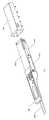
- FIG. 1is a perspective view of a pluggable optical connector according to an embodiment thereof.
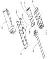
- FIG. 2is an exploded view of the optical connector shown in FIG. 1 .
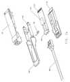
- FIG. 2 ais an exploded view of the optical connector shown in FIG. 1 , showing another embodiment of a leaf spring.
- FIG. 3is a bottom perspective view of a top housing part with a single transverse leaf spring.
- FIG. 3 ais a bottom perspective view of a top housing part with the transverse leaf spring shown in FIG. 2 a.
- FIG. 4is a perspective view of the transverse leaf spring according to an embodiment thereof.
- FIG. 4 ais an enlarged perspective view of the leaf spring shown in FIG. 2 a.
- FIG. 5is a perspective view of a slider of the optical connector according to an embodiment thereof.
- FIG. 6is a bottom perspective view of the top housing part showing a vertical wall and sidewalls of the top housing part.
- FIG. 7is an enlarged perspective view of the cage according to an embodiment thereof.
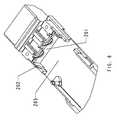
- FIG. 8is an exploded view of an optical module assembly according to an embodiment thereof.
- FIG. 9is a perspective view of the optical module assembly shown in FIG. 8 .
- FIG. 10is a cross sectional view of the optical connector.
- pluggable optical connectoris not limited to the precise embodiments described below and that various changes and modifications thereof may be effected by one skilled in the art without departing from the spirit or scope of the protection.
- elements and/or features of different illustrative embodimentsmay be combined with each other and/or substituted for each other within the scope of this disclosure and appended claims.
- FIG. 1is a perspective view of a pluggable optical connector with a lock and release mechanism according to an embodiment thereof.
- the lock and release mechanism of the pluggable optical connectormay include a bottom housing part 100 , a top housing part 200 , a handle 300 , and a slider 400 .
- the optical connectorcan be pluggable into a cage 700 .
- the cage 700may be permanently mounted on a printed circuit board.
- the bottom housing part 100 and the top housing part 200 togethermay form a two-part housing of the optical connector.
- Optical cables 800can be attached to the optical connector.
- the slider 400 and the handle 300may be attached to each other as over molded parts.
- the slider 400 and the handle 300can only travel longitudinally forwards in a plug-in direction or backwards within guiding slots formed at opposite sides of the optical connector, as it is pulled by a user or it is pushed by the leaf spring 500 inside the optical connector.
- pluggable connectoris pluggable optical connector
- pluggable connectorcan be any pluggable electronic connectors with the lock and release mechanism disclosed herein.
- FIG. 2is an exploded view of the optical connector shown in FIG. 1 .
- the optical connectorincludes a single transverse leaf spring 500 which may be positioned on a support or cap 600 .
- An optical module 670may be mounted on a printed circuit board (PCB) sub-assembly 640 .
- the PCB sub-assembly 640can be mounted on the bottom housing part 100 .
- the term “leaf spring”means a spring member made of a flat piece of metal.
- FIG. 3is a bottom perspective view of the top housing part 200 with the single transverse leaf spring 500 provided thereon.
- the single transverse leaf spring 500can be positioned transversely between the bridge 406 and a transverse vertical wall 201 extending inwardly from the top housing part 200 and facing the bridge 406 .
- the leaf spring 500can exert spring force against the bridge 406 and the vertical wall 201 in a longitudinal direction.
- the locking of the optical connectorcan be released with a reverse movement of the optical connector countering the spring force of the leaf spring 500 .
- FIG. 4is a perspective view of the transverse leaf spring 500 according to an embodiment thereof.
- the leaf spring 500may be in the form of a strip having a middle convex portion 502 pressing against the bridge 406 , and two legs 503 extending in opposite directions from the middle convex portion 502 and having two convexly curved end portions 501 pressing against the vertical wall 201 of the top housing part 200 .
- the leaf spring 500may be made of metal or any other suitable material.
- the leaf spring 500may further include two extended convexly curved portions 504 extending from the two convexly curved end portions 501 respectively for pressing against two opposite sidewalls 202 of the top housing part 200 when the leaf spring 500 is pressed and transversely extends.
- the two extended convexly curved portions 504can be used to further increase the spring force of the leaf spring 500 .
- the legs 503 of the leaf spring 500spread or flatten and extend transversely until the two extended convexly curved portions 504 are in contact with the sidewalls 202 of the top housing part 200 .
- the two extended convexly curved portions 504compress and perform its spring action, and then release or expand after release of the handle 300 .
- leaf spring 500Although one embodiment of the leaf spring 500 has been shown and described, it is understood by one skilled in the art that the leaf spring 500 can be in any other possible shape and configuration so long as it can perform the functions described herein. Another embodiment of the leaf spring 500 is shown in FIGS. 2 a , 3 a and 4 a
- FIG. 2 ais an exploded view of the optical connector of FIG. 1 , showing a second embodiment of the leaf spring.
- a single generally J-shaped transverse leaf spring 900may be positioned on the support or cap 600 .
- the optical module 670may be mounted on the printed circuit board (PCB) sub-assembly 640 .
- the PCB sub-assembly 640can be mounted on the bottom housing part 100 .
- FIG. 3 ais a bottom perspective view of the top housing part 200 with the single transverse leaf spring 900 provided thereon.
- the single transverse leaf spring 900can be positioned between the bridge 406 and the transverse vertical wall 201 extending inwardly from the top housing part 200 and facing the bridge 406 .
- the leaf spring 900can exert spring force against the bridge 406 and the vertical wall 201 in a longitudinal direction.
- the locking of the optical connectorcan be released with a reverse movement of the optical connector countering the spring force of the leaf spring 900 .
- FIG. 4 ais a perspective view of the leaf spring 900 .
- the leaf spring 900may be in the form of a J-shaped spring member having a transverse elongate portion 901 pressing against the transverse vertical wall 201 , a semi-circular convex portion 902 extending from one end of the elongate portion 901 and pressing against one of the two opposite sidewalls 202 of the housing, and a middle convex portion 904 extending from the semi-circular convex portion 902 and pressing against the bridge 406 at a middle portion thereof.
- a concave portion 903may be formed between the semi-circular convex portion 902 and the middle convex portion 904 .
- the semi-circular convex portion 902can generate a spring action, and then release or expand after release of the handle 300 .
- the J-shaped spring member 900can be assembled in either direction as long as the transverse elongate portion 902 with a longer length is in contact with the transverse vertical wall 201 of the housing.
- the semi-circular convex portion 902when assembled, can be pressing against one of the two opposite sidewalls 202 of the housing and facing one direction, or the semi-circular convex portion 902 can be pressing against the other one of the two opposite sidewalls 202 of the housing and facing the other direction.
- FIG. 5is a perspective view of the slider 400 of the optical connector according to an embodiment thereof.
- the handle 300can be connected to an outer end of the slider 400 .
- the slider 400may include two spaced part longitudinal arms 405 extending from the handle 300 and along two opposite sidewalls 202 of the top housing part 200 .
- Two wedges 403may be formed at two free ends of the two arms 405 respectively for forcing two deflectable tabs 701 ( FIG. 7 ) formed on the cage 700 outwards when the optical connector is plugged into the cage 700 and then locked therein.
- a bridge 406may be connected to and extending between the two arms 405 .
- the slider 400may be made of metal or any other suitable material.
- the bridge 406may be formed by a first wing portion 402 extending inwardly from one arm 405 and a second wing portion 408 extending inwardly from the other arm 405 .
- the ends of the two wing portions 402 , 408can interlock each other at midway of the bridge 406 .
- the free ends of the two wing portions 402 , 408may include two tabs 404 interlocking with each other to make the bridge 406 stronger.
- a cutout 401may be formed at a middle portion of the bridge 406 to receive therein the middle convex portion 502 of the leaf spring 500 to thereby prevent transverse movement thereof, as illustrated in FIG. 3 .
- FIG. 6is a bottom perspective view of the top housing part 200 showing the vertical wall 201 , the sidewall 202 and an inner surface 203 of the top housing part 200 with the slider 400 and the leaf spring 500 being removed therefrom.
- FIG. 7is an enlarged perspective view of the cage 700 according to an embodiment thereof.
- the two deflectable tabs 701can be formed on two opposite sidewalls of the cage 700 respectively.
- FIG. 8is an exploded view of an optical module assembly according to an embodiment thereof
- FIG. 9is a perspective view of the optical module assembly shown in FIG. 8
- the cap 600may be mounted on a receptacle support 641 to form an enclosure for supporting an optical receptacle module 671 therein.
- the optical receptacle module 671can be connected to an optical fiber 672 extending from an optical module 670 , such as Transmitter and Receiver devices, mounted on a printed circuit board (PCB) sub-assembly 640 .
- PCBprinted circuit board
- the cap 600is snap-fitted on a receptacle support 641 for supporting two optical receptacle modules 671 .
- the two optical receptacle modules 671are connected respectively to two optical fibers 672 extending from the optical module 670 .
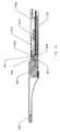
- FIG. 10is a cross sectional view of the pluggable optical connector.
- the top and bottom housing parts 200 , 100can be tightly connected by two screws or any other suitable fastening means after all the components of the optical connector are assembled together. It can be seen that the leaf spring 500 can be positioned in a space defined by the bridge 406 , the vertical wall 201 , the top housing part 200 from which the vertical wall 201 extends, and the cap 600 provided on the bottom housing part 100 .
- the leaf spring 500may have tendency to move vertically up or down during release action. However, its vertical movement can be prevented by the inner surface 203 of the top housing part 200 and the top surface of the cap 600 . These surfaces can limit vertical movement of the leaf spring 500 and help to maintain constant and reliable spring force during release action.
- the cap 600is also useful to prevent the leaf spring 500 from coming out from its desired position.
- the space inside the existing pluggable connector with two compression springsis not enough when more electronic components are added to achieve the required functions.
- the single leaf spring 500can replace the traditional two compression springs and can maintain the function of the release mechanism of the connector.
- the use of the single leaf spring 500can reduce one part assembly in the process of assembling the connector.
- the assembling of a single leaf springis quicker and easier than assembling the traditional two compression springs.
- the single leaf spring 500requires a shorter vertical space than two compression springs.
- the single leaf spring 500is smaller in size than that of two compression springs, and yet it can perform the same function as two compression springs.
- the spring force at each side of the single leaf spring 500is more balance than the spring force of two separate compression springs.
Landscapes
- Physics & Mathematics (AREA)
- General Physics & Mathematics (AREA)
- Optics & Photonics (AREA)
- Engineering & Computer Science (AREA)
- Microelectronics & Electronic Packaging (AREA)
- Optical Couplings Of Light Guides (AREA)
- Mechanical Coupling Of Light Guides (AREA)
Abstract
Description
Claims (17)
Priority Applications (1)
| Application Number | Priority Date | Filing Date | Title |
|---|---|---|---|
| US14/564,136US9411111B2 (en) | 2014-12-09 | 2014-12-09 | Pluggable optical connector, lock and release mechanism therefor |
Applications Claiming Priority (1)
| Application Number | Priority Date | Filing Date | Title |
|---|---|---|---|
| US14/564,136US9411111B2 (en) | 2014-12-09 | 2014-12-09 | Pluggable optical connector, lock and release mechanism therefor |
Publications (2)
| Publication Number | Publication Date |
|---|---|
| US20160161681A1 US20160161681A1 (en) | 2016-06-09 |
| US9411111B2true US9411111B2 (en) | 2016-08-09 |
Family
ID=56094164
Family Applications (1)
| Application Number | Title | Priority Date | Filing Date |
|---|---|---|---|
| US14/564,136ActiveUS9411111B2 (en) | 2014-12-09 | 2014-12-09 | Pluggable optical connector, lock and release mechanism therefor |
Country Status (1)
| Country | Link |
|---|---|
| US (1) | US9411111B2 (en) |
Cited By (12)
| Publication number | Priority date | Publication date | Assignee | Title |
|---|---|---|---|---|
| US10079452B1 (en)* | 2017-03-15 | 2018-09-18 | Fujitsu Component Limited | Removal unit |
| US20210208348A1 (en)* | 2018-07-31 | 2021-07-08 | Lumentum Operations Llc | Latching for a transceiver module |
| US20220190511A1 (en)* | 2020-12-16 | 2022-06-16 | Dongguan Luxshare Technologies Co., Ltd | Wire end connector and connector assembly |
| US20230003957A1 (en)* | 2020-02-28 | 2023-01-05 | Ii-Vi Delaware, Inc. | Optoelectronic module for receiving multiple optical connectors |
| US11764520B2 (en) | 2020-12-16 | 2023-09-19 | Dongguan Luxshare Technologies Co., Ltd | Board end connector and connector assembly |
| US12158623B2 (en) | 2016-12-05 | 2024-12-03 | Senko Advanced Components, Inc. | Optical fiber connector |
| US12222559B2 (en) | 2016-01-15 | 2025-02-11 | Senko Advanced Components, Inc. | Narrow width adapters and connectors with pull tab release |
| US12228774B2 (en) | 2017-07-14 | 2025-02-18 | Senko Advanced Components, Inc. | Ultra-small form factor optical connector and adapter |
| US12235493B2 (en) | 2017-07-14 | 2025-02-25 | Senko Advanced Components, Inc. | Small form factor fiber optic connector with multi-purpose boot |
| US12248191B2 (en) | 2017-07-14 | 2025-03-11 | Senko Advanced Components, Inc. | Fiber optical connectors |
| US12259585B2 (en) | 2015-03-03 | 2025-03-25 | Senko Advanced Components, Inc. | Optical fiber connector with changeable polarity |
| US12399329B2 (en) | 2016-06-28 | 2025-08-26 | Senko Advanced Components, Inc. | Adapter system for multi-fiber mechanical transfer type ferrule |
Families Citing this family (19)
| Publication number | Priority date | Publication date | Assignee | Title |
|---|---|---|---|---|
| US10718911B2 (en) | 2017-08-24 | 2020-07-21 | Senko Advanced Components, Inc. | Ultra-small form factor optical connectors using a push-pull boot receptacle release |
| US10712512B2 (en) | 2017-11-21 | 2020-07-14 | Senko Advanced Components, Inc | Fiber optic connector assemblies with cable boot release |
| US11002923B2 (en) | 2017-11-21 | 2021-05-11 | Senko Advanced Components, Inc. | Fiber optic connector with cable boot release having a two-piece clip assembly |
| US11016250B2 (en)* | 2017-12-19 | 2021-05-25 | Us Conec, Ltd. | Mini duplex connector with push-pull polarity mechanism, carrier, and rail-receiving crimp body |
| EP3776038B1 (en) | 2018-03-28 | 2024-07-03 | Senko Advanced Components Inc. | Small form factor fiber optic connector with multi-purpose boot |
| CN112088327A (en) | 2018-07-15 | 2020-12-15 | 扇港元器件股份有限公司 | Subminiature Optical Connectors and Adapters |
| US11073664B2 (en) | 2018-08-13 | 2021-07-27 | Senko Advanced Components, Inc. | Cable boot assembly for releasing fiber optic connector from a receptacle |
| US10921531B2 (en) | 2018-09-12 | 2021-02-16 | Senko Advanced Components, Inc. | LC type connector with push/pull assembly for releasing connector from a receptacle using a cable boot |
| US10921530B2 (en) | 2018-09-12 | 2021-02-16 | Senko Advanced Components, Inc. | LC type connector with push/pull assembly for releasing connector from a receptacle using a cable boot |
| WO2020055439A1 (en)* | 2018-09-12 | 2020-03-19 | Senko Advanced Components, Inc | Fiber optic connector assemblies with cable boot release |
| WO2020055440A1 (en) | 2018-09-12 | 2020-03-19 | Senko Advanced Componetns, Inc. | Lc type connector with clip-on push/pull tab for releasing connector from a receptacle using a cable boot |
| JP6860607B2 (en)* | 2019-04-17 | 2021-04-14 | イヤー ラウンド テクノロジー コーポレーション | Fiber optic transmission module |
| US11340406B2 (en) | 2019-04-19 | 2022-05-24 | Senko Advanced Components, Inc. | Small form factor fiber optic connector with resilient latching mechanism for securing within a hook-less receptacle |
| CN110261972B (en)* | 2019-06-17 | 2020-05-12 | 武汉光迅科技股份有限公司 | An optical module unlocking device |
| CN114600018B (en) | 2019-07-23 | 2024-04-09 | 扇港元器件有限公司 | Ultra-small receptacle for receiving a fiber optic connector opposite a ferrule assembly |
| WO2021179568A1 (en)* | 2020-03-12 | 2021-09-16 | 青岛海信宽带多媒体技术有限公司 | Optical module |
| WO2022036119A1 (en)* | 2020-08-14 | 2022-02-17 | Commscope Technologies Llc | Connector push release |
| JP7596728B2 (en) | 2020-11-12 | 2024-12-10 | 住友電気工業株式会社 | Optical Transceiver |
| CN116645887A (en)* | 2022-02-15 | 2023-08-25 | 武汉光迅科技股份有限公司 | A limit display device |
Citations (20)
| Publication number | Priority date | Publication date | Assignee | Title |
|---|---|---|---|---|
| US20010010741A1 (en)* | 2000-01-24 | 2001-08-02 | Hidehiko Hizuka | Apparatus for connecting optical connectors and printed circuit board, unit mounting the same |
| US6412986B1 (en)* | 2000-06-30 | 2002-07-02 | Berg Technology, Inc. | Adapter for assembling multiple optical connectors |
| US20020150344A1 (en)* | 2001-04-14 | 2002-10-17 | Chiu Liew C. | Pull-action de-latching mechanisms for fiber optic modules |
| US20030012520A1 (en)* | 2000-01-12 | 2003-01-16 | Clemens Rogge | Multichannel optical coupling configuration |
| US20030206403A1 (en)* | 2002-05-02 | 2003-11-06 | Optical Communication Products, Inc. | Pluggable optical transceiver with push-pull actuator release collar |
| US6644868B2 (en)* | 1997-11-13 | 2003-11-11 | Diamond Sa | Plug construction for an optical plug-and-socket connection |
| US20030236019A1 (en)* | 2002-06-21 | 2003-12-25 | Jds Uniphase Corporation | Pluggable optical transceiver latch |
| US20040033027A1 (en)* | 2001-04-14 | 2004-02-19 | Pang Ron Cheng Chuan | Cam-follower release mechanism for fiber optic modules with side delatching mechanisms |
| US6846115B1 (en)* | 2001-01-29 | 2005-01-25 | Jds Uniphase Corporation | Methods, apparatus, and systems of fiber optic modules, elastomeric connections, and retention mechanisms therefor |
| US20060027686A1 (en)* | 1999-05-28 | 2006-02-09 | Cepheid | Apparatus and method for cell disruption |
| US7255490B2 (en) | 2004-04-01 | 2007-08-14 | Fiberxon, Inc. | Small form factor pluggable optical transceiver having automatic-restoring unlocking mechanism and mechanism for locating optical transceiver components |
| US7309250B2 (en) | 2004-12-16 | 2007-12-18 | Molex Incorporated | Plug connector ejector mechanism with integrated return action |
| US20090046981A1 (en)* | 2007-08-13 | 2009-02-19 | Illum Technologies, Inc. | High density fiber optic interconnect system with push-release mechanism and method for using same |
| US7507111B2 (en)* | 2001-10-04 | 2009-03-24 | Finisar Corporation | Electronic modules having integrated lever-activated latching mechanisms |
| US20100081303A1 (en)* | 2008-10-01 | 2010-04-01 | Roth Richard F | High density pluggable electrical and optical connector |
| US8545252B2 (en) | 2011-02-25 | 2013-10-01 | Hon Hai Precision Industry Co., Ltd. | Plug connector having a releasing mechanism |
| US20140134898A1 (en) | 2011-08-16 | 2014-05-15 | HARTING Electronics GmbH | Locking apparatus for electrical plug-type connectors |
| US20140254993A1 (en)* | 2013-03-05 | 2014-09-11 | Finisar Corporation | Latch mechanism for communication module |
| US20150038905A1 (en)* | 2013-05-03 | 2015-02-05 | Clearside Biomedical, Inc. | Apparatus and methods for ocular injection |
| US20150370025A1 (en)* | 2014-06-23 | 2015-12-24 | Adc Telecommunications, Inc. | Bladed chassis systems |
- 2014
- 2014-12-09USUS14/564,136patent/US9411111B2/enactiveActive
Patent Citations (20)
| Publication number | Priority date | Publication date | Assignee | Title |
|---|---|---|---|---|
| US6644868B2 (en)* | 1997-11-13 | 2003-11-11 | Diamond Sa | Plug construction for an optical plug-and-socket connection |
| US20060027686A1 (en)* | 1999-05-28 | 2006-02-09 | Cepheid | Apparatus and method for cell disruption |
| US20030012520A1 (en)* | 2000-01-12 | 2003-01-16 | Clemens Rogge | Multichannel optical coupling configuration |
| US20010010741A1 (en)* | 2000-01-24 | 2001-08-02 | Hidehiko Hizuka | Apparatus for connecting optical connectors and printed circuit board, unit mounting the same |
| US6412986B1 (en)* | 2000-06-30 | 2002-07-02 | Berg Technology, Inc. | Adapter for assembling multiple optical connectors |
| US6846115B1 (en)* | 2001-01-29 | 2005-01-25 | Jds Uniphase Corporation | Methods, apparatus, and systems of fiber optic modules, elastomeric connections, and retention mechanisms therefor |
| US20020150344A1 (en)* | 2001-04-14 | 2002-10-17 | Chiu Liew C. | Pull-action de-latching mechanisms for fiber optic modules |
| US20040033027A1 (en)* | 2001-04-14 | 2004-02-19 | Pang Ron Cheng Chuan | Cam-follower release mechanism for fiber optic modules with side delatching mechanisms |
| US7507111B2 (en)* | 2001-10-04 | 2009-03-24 | Finisar Corporation | Electronic modules having integrated lever-activated latching mechanisms |
| US20030206403A1 (en)* | 2002-05-02 | 2003-11-06 | Optical Communication Products, Inc. | Pluggable optical transceiver with push-pull actuator release collar |
| US20030236019A1 (en)* | 2002-06-21 | 2003-12-25 | Jds Uniphase Corporation | Pluggable optical transceiver latch |
| US7255490B2 (en) | 2004-04-01 | 2007-08-14 | Fiberxon, Inc. | Small form factor pluggable optical transceiver having automatic-restoring unlocking mechanism and mechanism for locating optical transceiver components |
| US7309250B2 (en) | 2004-12-16 | 2007-12-18 | Molex Incorporated | Plug connector ejector mechanism with integrated return action |
| US20090046981A1 (en)* | 2007-08-13 | 2009-02-19 | Illum Technologies, Inc. | High density fiber optic interconnect system with push-release mechanism and method for using same |
| US20100081303A1 (en)* | 2008-10-01 | 2010-04-01 | Roth Richard F | High density pluggable electrical and optical connector |
| US8545252B2 (en) | 2011-02-25 | 2013-10-01 | Hon Hai Precision Industry Co., Ltd. | Plug connector having a releasing mechanism |
| US20140134898A1 (en) | 2011-08-16 | 2014-05-15 | HARTING Electronics GmbH | Locking apparatus for electrical plug-type connectors |
| US20140254993A1 (en)* | 2013-03-05 | 2014-09-11 | Finisar Corporation | Latch mechanism for communication module |
| US20150038905A1 (en)* | 2013-05-03 | 2015-02-05 | Clearside Biomedical, Inc. | Apparatus and methods for ocular injection |
| US20150370025A1 (en)* | 2014-06-23 | 2015-12-24 | Adc Telecommunications, Inc. | Bladed chassis systems |
Cited By (20)
| Publication number | Priority date | Publication date | Assignee | Title |
|---|---|---|---|---|
| US12313889B2 (en) | 2015-03-03 | 2025-05-27 | Senko Advanced Components, Inc. | Optical fiber connector with changeable polarity |
| US12259585B2 (en) | 2015-03-03 | 2025-03-25 | Senko Advanced Components, Inc. | Optical fiber connector with changeable polarity |
| US12222559B2 (en) | 2016-01-15 | 2025-02-11 | Senko Advanced Components, Inc. | Narrow width adapters and connectors with pull tab release |
| US12399329B2 (en) | 2016-06-28 | 2025-08-26 | Senko Advanced Components, Inc. | Adapter system for multi-fiber mechanical transfer type ferrule |
| US12158623B2 (en) | 2016-12-05 | 2024-12-03 | Senko Advanced Components, Inc. | Optical fiber connector |
| US20180269630A1 (en)* | 2017-03-15 | 2018-09-20 | Fujitsu Component Limited | Removal unit |
| US10079452B1 (en)* | 2017-03-15 | 2018-09-18 | Fujitsu Component Limited | Removal unit |
| US12248191B2 (en) | 2017-07-14 | 2025-03-11 | Senko Advanced Components, Inc. | Fiber optical connectors |
| US12235493B2 (en) | 2017-07-14 | 2025-02-25 | Senko Advanced Components, Inc. | Small form factor fiber optic connector with multi-purpose boot |
| US12228774B2 (en) | 2017-07-14 | 2025-02-18 | Senko Advanced Components, Inc. | Ultra-small form factor optical connector and adapter |
| US11609394B2 (en)* | 2018-07-31 | 2023-03-21 | Lumentum Operations Llc | Latching for a transceiver module |
| US20210208348A1 (en)* | 2018-07-31 | 2021-07-08 | Lumentum Operations Llc | Latching for a transceiver module |
| US11953741B2 (en)* | 2020-02-28 | 2024-04-09 | Ii-Vi Delaware, Inc. | Optoelectronic module for receiving multiple optical connectors |
| US20230003957A1 (en)* | 2020-02-28 | 2023-01-05 | Ii-Vi Delaware, Inc. | Optoelectronic module for receiving multiple optical connectors |
| US12034248B2 (en) | 2020-12-16 | 2024-07-09 | Dongguan Luxshare Technologies Co., Ltd | Wire end connector and connector assembly |
| US12034249B2 (en) | 2020-12-16 | 2024-07-09 | Dongguan Luxshare Technologies Co., Ltd | Wire end connector with releasable latch and connector assembly |
| US11764521B2 (en) | 2020-12-16 | 2023-09-19 | Dongguan Luxshare Technologies Co., Ltd | Board end connector and connector assembly |
| US11764520B2 (en) | 2020-12-16 | 2023-09-19 | Dongguan Luxshare Technologies Co., Ltd | Board end connector and connector assembly |
| US11695235B2 (en)* | 2020-12-16 | 2023-07-04 | Dongguan Luxshare Technologies Co., Ltd | Wire end connector and connector assembly |
| US20220190511A1 (en)* | 2020-12-16 | 2022-06-16 | Dongguan Luxshare Technologies Co., Ltd | Wire end connector and connector assembly |
Also Published As
| Publication number | Publication date |
|---|---|
| US20160161681A1 (en) | 2016-06-09 |
Similar Documents
| Publication | Publication Date | Title |
|---|---|---|
| US9411111B2 (en) | Pluggable optical connector, lock and release mechanism therefor | |
| US9671582B2 (en) | Pluggable optical transceiver module | |
| US20160020569A1 (en) | Electrical connector | |
| US9373920B2 (en) | Connector including module that includes molded part insert-molded with contacts each including first contact part, second contact part, and body that extends between first and second contact parts and includes spring portion greater in width than first and second contact parts | |
| US10038262B1 (en) | Electrical bridge device including a support bracket and a flex bridge subassembly | |
| US8956187B2 (en) | Electrical connector | |
| US20150364871A1 (en) | Mating connector | |
| US20150200495A1 (en) | Electrical connector with reinforced shielding cage | |
| US9311571B2 (en) | Electronic card connector and electronic device using same | |
| US10116071B2 (en) | Electrical connector and contacts thereof | |
| US10777952B2 (en) | Electrical plug connector | |
| US20110249419A1 (en) | Circuit board assembly and connecting bracket thereof | |
| KR102588118B1 (en) | spring loaded electrical connectors | |
| US20130148321A1 (en) | Expansion slot and motherboard having the expansion slot | |
| US7824224B2 (en) | Printed board connector | |
| CN105684230A (en) | Plug connector having latching system | |
| US9502844B2 (en) | Battery connector and terminal thereof | |
| US9711877B2 (en) | Plug and connector module | |
| US9835803B2 (en) | Attaching connectors | |
| US8414305B2 (en) | Connector assembly | |
| US20140170872A1 (en) | Data cable with connector | |
| US20160029499A1 (en) | Communication Module | |
| US20150179229A1 (en) | Hard disk drive mounting device | |
| US20140377981A1 (en) | Cable binding device | |
| US9397452B1 (en) | Connecting device with jumper |
Legal Events
| Date | Code | Title | Description |
|---|---|---|---|
| AS | Assignment | Owner name:SAE MAGNETICS (H.K.) LTD., HONG KONG Free format text:ASSIGNMENT OF ASSIGNORS INTEREST;ASSIGNORS:BANAL, MARGARITO P., JR.;HUNG, VINCENT WAI;GAMBOA, FRANCIS GUILLEN;REEL/FRAME:034445/0975 Effective date:20141208 | |
| STCF | Information on status: patent grant | Free format text:PATENTED CASE | |
| AS | Assignment | Owner name:CLOUD LIGHT TECHNOLOGY LIMITED, HONG KONG Free format text:ASSIGNMENT OF ASSIGNORS INTEREST;ASSIGNOR:SAE MAGNETICS (H.K.) LTD.;REEL/FRAME:046569/0754 Effective date:20180713 | |
| FEPP | Fee payment procedure | Free format text:ENTITY STATUS SET TO SMALL (ORIGINAL EVENT CODE: SMAL); ENTITY STATUS OF PATENT OWNER: SMALL ENTITY | |
| MAFP | Maintenance fee payment | Free format text:PAYMENT OF MAINTENANCE FEE, 4TH YR, SMALL ENTITY (ORIGINAL EVENT CODE: M2551); ENTITY STATUS OF PATENT OWNER: SMALL ENTITY Year of fee payment:4 | |
| FEPP | Fee payment procedure | Free format text:ENTITY STATUS SET TO UNDISCOUNTED (ORIGINAL EVENT CODE: BIG.); ENTITY STATUS OF PATENT OWNER: LARGE ENTITY | |
| MAFP | Maintenance fee payment | Free format text:PAYMENT OF MAINTENANCE FEE, 8TH YEAR, LARGE ENTITY (ORIGINAL EVENT CODE: M1552); ENTITY STATUS OF PATENT OWNER: LARGE ENTITY Year of fee payment:8 |