US9411068B2 - 3D borehole imager - Google Patents
3D borehole imagerDownload PDFInfo
- Publication number
- US9411068B2 US9411068B2US13/061,759US200913061759AUS9411068B2US 9411068 B2US9411068 B2US 9411068B2US 200913061759 AUS200913061759 AUS 200913061759AUS 9411068 B2US9411068 B2US 9411068B2
- Authority
- US
- United States
- Prior art keywords
- tool
- borehole
- transmitter
- image
- formation
- Prior art date
- Legal status (The legal status is an assumption and is not a legal conclusion. Google has not performed a legal analysis and makes no representation as to the accuracy of the status listed.)
- Active, expires
Links
Images


Classifications
- G—PHYSICS
- G01—MEASURING; TESTING
- G01V—GEOPHYSICS; GRAVITATIONAL MEASUREMENTS; DETECTING MASSES OR OBJECTS; TAGS
- G01V3/00—Electric or magnetic prospecting or detecting; Measuring magnetic field characteristics of the earth, e.g. declination, deviation
- G01V3/18—Electric or magnetic prospecting or detecting; Measuring magnetic field characteristics of the earth, e.g. declination, deviation specially adapted for well-logging
- G01V3/30—Electric or magnetic prospecting or detecting; Measuring magnetic field characteristics of the earth, e.g. declination, deviation specially adapted for well-logging operating with electromagnetic waves
- G—PHYSICS
- G01—MEASURING; TESTING
- G01V—GEOPHYSICS; GRAVITATIONAL MEASUREMENTS; DETECTING MASSES OR OBJECTS; TAGS
- G01V3/00—Electric or magnetic prospecting or detecting; Measuring magnetic field characteristics of the earth, e.g. declination, deviation
- G01V3/08—Electric or magnetic prospecting or detecting; Measuring magnetic field characteristics of the earth, e.g. declination, deviation operating with magnetic or electric fields produced or modified by objects or geological structures or by detecting devices
- G01V3/10—Electric or magnetic prospecting or detecting; Measuring magnetic field characteristics of the earth, e.g. declination, deviation operating with magnetic or electric fields produced or modified by objects or geological structures or by detecting devices using induction coils
- G—PHYSICS
- G01—MEASURING; TESTING
- G01V—GEOPHYSICS; GRAVITATIONAL MEASUREMENTS; DETECTING MASSES OR OBJECTS; TAGS
- G01V3/00—Electric or magnetic prospecting or detecting; Measuring magnetic field characteristics of the earth, e.g. declination, deviation
- G01V3/18—Electric or magnetic prospecting or detecting; Measuring magnetic field characteristics of the earth, e.g. declination, deviation specially adapted for well-logging
Definitions
- Oil field operatorsseek as much information as possible regarding parameters and conditions encountered downhole. Such information typically includes characteristics of the earth formations traversed by the borehole, and data relating to the size and configuration of the borehole itself.
- the collection of information relating to conditions downholewhich commonly is referred to as “logging,” can be performed by several methods including wireline logging, “logging while drilling” (LWD), drillpipe conveyed logging, and coil tubing conveyed logging.
- LWDlogging while drilling
- a probe or “sonde”In wireline logging, a probe or “sonde” is lowered into the borehole after some or all of the well has been drilled.
- the sondehangs at the end of a long cable or “wireline” that provides mechanical support to the sonde and also provides an electrical connection between the sonde and electrical equipment located at the surface of the well.
- various parameters of the earth's formationsare measured and correlated with the position of the sonde in the borehole as the sonde is pulled uphole.
- the drilling assemblyincludes sensing instruments that measure various parameters as the formation is being penetrated. While LWD techniques allow more contemporaneous formation measurements, drilling operations create an environment that is generally hostile to electronic instrumentation and sensor operations.
- sensing instrumentsare mounted on a tubing string, which moves the instrument package through an existing borehole.
- the tubing stringenables logging of horizontal well bores without requiring the sensing instruments to tolerate the hostile drilling environment.
- the measurement datais stored in internal memory and recovered along with the instrument package.
- Most logging toolsacquire a single depth-dependent measurement, enabling a driller to see the measurement of temperature, pressure, density, resistivity, natural gamma radiation, borehole diameter, etc., as a function of depth.
- a few existing logging toolsoffer measurements as a function of depth and rotational angle, enabling a driller to see, e.g., an image of the borehole wall.
- a very few existing logging toolsoffer measurements as a function of depth and radial distance from the borehole (e.g., induction tools having multiple depths of investigation). While each of these tools is useful to some degree, they leave the driller with an incomplete picture of the situation downhole.
- FIG. 1shows an illustrative logging while drilling (LWD) environment
- FIG. 2shows an illustrative wireline logging environment
- FIG. 3shows an illustrative LWD tool having a first antenna arrangement suitable for 3D imaging
- FIG. 4shows an illustrative LWD tool having a second antenna arrangement suitable for 3D imaging
- FIG. 5Ashows an illustrative broadband horn antenna
- FIG. 5Bshows a resistively loaded bowtie antenna
- FIG. 6is a block diagram of illustrative tool electronics
- FIG. 7shows illustrative 3D image measurement contributions
- FIG. 8shows an illustrative transmit pulse
- FIG. 9shows an illustrative receive signal
- FIG. 10shows an illustrative 3D image.
- a 3D imaging toolrotates, transmitting pulses that are approximately a nanosecond long and measuring the time it takes to receive reflections of these pulses.
- Multiple receiversare employed to provide accurate triangulation of the reflectors.
- multiple transmittersare employed to obtain compensated measurements, i.e., measurements that compensate for variations in the receiver electronics. Because reflections occur at boundaries between materials having different dielectric constants, the 3D imaging tool can map out such boundaries in the neighborhood of the borehole.
- Such boundariescan include: the borehole wall itself, boundaries between different formation materials, faults or other discontinuities in a formation, and boundaries between fluids in a formation.
- the size of the borehole neighborhood mapped out by this 3D imaging toolcan be as large as 1 meter.
- FIG. 1shows an illustrative logging-while-drilling (“LWD”) environment.
- a drilling platform 2supports a derrick 4 having a traveling block 6 for raising and lowering a drill string 8 .
- a top drive 10supports and rotates the drill string 8 as it is lowered through the wellhead 12 .
- a drill bit 14is driven by a downhole motor and/or rotation of the drill string 8 . As bit 14 rotates, it creates a borehole 16 that passes through various formations.
- a pump 18circulates drilling fluid 20 through a feed pipe 22 , through the interior of the drill string 8 to drill bit 14 . The fluid exits through orifices in the drill bit 14 and flows upward through the annulus around the drill string 8 to transport drill cuttings to the surface, where the fluid is filtered and recirculated.
- the drill bit 14is just one piece of a bottom-hole assembly that includes one or more drill collars (thick-walled steel pipe) to provide rigidity and add weight to aid the drilling process.
- drill collarsinclude built-in logging instruments to gather measurements of various drilling parameters such as position, orientation, weight-on-bit, borehole diameter, etc.
- the tool orientationmay be specified in terms of a tool face angle (rotational orientation), an inclination angle (the slope), and compass direction, each of which can be derived from measurements by magnetometers, inclinometers, and/or accelerometers, though other sensor types such as gyroscopes may alternatively be used.
- the toolincludes a 3-axis fluxgate magnetometer and a 3-axis accelerometer. As is known in the art, the combination of those two sensor systems enables the measurement of the tool face angle, inclination angle, and compass direction.
- Such orientation measurementscan be combined with gyroscopic or inertial measurements to accurately track tool position.
- a LWD 3D imaging tool 24can be included in the bottom-hole assembly near the bit 14 .
- 3D imaging tool 26rotates and collects azimuthally-dependent reflection measurements that a downhole controller associates with tool position and orientation measurements to form a 3D image map of the borehole neighborhood.
- the measurementscan be stored in internal memory and/or communicated to the surface.
- a telemetry sub 26may be included in the bottom-hole assembly to maintain a communications link with the surface. Mud pulse telemetry is one common telemetry technique for transferring tool measurements to surface receivers and receiving commands from the surface, but other telemetry techniques can also be used.
- a data acquisition module 36receives the uplink signal from the telemetry sub 26 .
- Module 36optionally provides some preliminary processing and digitizes the signal.
- a data processing system 50(shown in FIG. 1 as a computer) receives a digital telemetry signal, demodulates the signal, and displays the tool data or well logs to a user.
- Software(represented in FIG. 1 as information storage media 52 ) governs the operation of system 50 .
- a userinteracts with system 50 and its software 52 via one or more input devices 54 and one or more output devices 56 .
- the drill string 8may be removed from the borehole as indicated in FIG. 2 .
- logging operationscan be conducted using a wireline logging tool 34 , i.e., a sensing instrument sonde suspended by a cable 42 having conductors for transporting power to the tool and telemetry from the tool to the surface.
- a dielectric logging portion of the logging tool 34may have sensing pads 36 that slide along the borehole wall as the tool is pulled uphole.
- a logging facility 44collects measurements from the logging tool 34 , and includes computing facilities for processing and storing the measurements gathered by the logging tool.
- FIG. 3shows a side view of an illustrative LWD tool 302 having a first antenna arrangement suitable for 3D imaging.
- the electronics behind faceplate 304are coupled to a transmitter 306 and two receivers 308 , 310 .
- Multiple receiversare provided to enable triangulation of the reflectors.
- the receiversare spaced at different distances and in different directions from the transmitter.
- an alternative LWD tool 402has a second antenna arrangement suitable for 3D imaging. In the second antenna arrangement, three receivers 408 , 410 , and 412 , are positioned in a row between two transmitters 404 and 406 .
- This antenna arrangementenables compensated measurements to be made and improves measurement reliability because more information is available that can be used to correct for environmental effects. Moreover, the second antenna arrangement provides a degree of redundancy that enables the tool to continue operating even if one of the receivers and one of the transmitters fail.
- each sensing surfacewill trace a helical path on the borehole wall.
- Orientation sensors within the toolcan be used to associate the measurements with the sensors' positions on the borehole wall.
- Electronics within the toolcan aggregate measurements versus position to form a detailed map (or 3D image) of the borehole wall, which can be stored for later retrieval or compressed and transmitted to the surface for timely use by the drilling team. If sufficient telemetry bandwidth is available, surface computing facilities can collect formation property measurements, orientation (azimuth) measurements, and tool position measurements, and process the collected measurements to create and display the map (or 3D image).
- FIGS. 3 and 4are shown on LWD tools, they can be employed in 3D imaging wireline tools.
- the antennascan be mounted on a rotating head to enable scanning in each direction.
- multiple azimuthally-spaced antennascan be employed to enable scanning in different directions without requiring antenna and/or tool rotation.
- the antennascan take the form of ridged microwave horns such as that shown in FIG. 5A , or the form of resistively loaded bowtie antennas as shown in FIG. 5B .
- FIG. 5Athe isometric scale drawing of FIG.
- the overall dimensions of the antenna horn 702are about 2.5 cm high, 3.8 cm wide, and 4.0 cm deep, including the rectangular feed chamber 704 .
- the antenna bandwidthis increased by the presence of two ridges 706 extending from the feed point to the aperture.
- a coaxial cable 708is used to drive the antenna.
- the interior of the horn 702is filled with a dielectric material having a relative permittivity between 1 and 100.
- the bowtie antenna shown in FIG. 5Bhas two conductive elements 722 mounted on a pad of microwave-absorbing material 724 .
- the conductive elementshave a generally triangular shape with an opening angle ⁇ of about 60°.
- the combined length of the conductive elements, Lis greater than or equal to half of the pulse span in space.
- a tool operating with a pulse width of 1 ⁇ 10 ⁇ 9 s in an environment where the speed of light c is 2.8 ⁇ 10 8 m/swould have an overall length L greater than or equal to about 14 cm.
- the microwave-absorbing materialprovides resistive loading to broaden the bandwidth of the antenna, and it further acts to reduce the influence of the conductive tool body on the performance of the antenna.
- the bowtie antenna structurecan in many cases be easier to manufacture and install than the horn antenna.
- FIG. 6shows a block diagram of the electronics for an illustrative 3D imaging tool.
- the tool electronicsinclude a system clock and control unit 902 , multiple time delay lines 904 , 906 , 908 , an electromagnetic pulse transmitter 912 , two pulse wave receivers, a multichannel data acquisition unit 916 , a data processing and storage unit 918 , and the transmitting and receiving antennas discussed previously.
- the clock and control unit 902determines the sampling rate of the system. To do each measurement, unit 902 sends a trigger signal via the programmable delay lines 904 - 908 to the transmitter 912 and the receivers 910 , 914 . Upon the receiving of the trigger signal, the transmitter 912 generates a short electromagnetic pulse wave and emits it into space through the transmitting antenna. The trigger signal also causes the receivers start sampling the reflected signals with a dynamic gain, i.e., a gain that increases with time to at least partly compensate for signal attenuation. Since the transmitter and the receivers have different response speeds, the time delay lines are carefully adjusted to guarantee synchronization between the transmitter and the receivers.
- a dynamic gaini.e., a gain that increases with time to at least partly compensate for signal attenuation. Since the transmitter and the receivers have different response speeds, the time delay lines are carefully adjusted to guarantee synchronization between the transmitter and the receivers.
- the receivers 910 , 914sample and output analog signals to the data acquisition unit 916 , which converts the analog signals into digital signals.
- the processing and storage unit 918processes the received digital signals to extract measurement information.
- the extracted informationcan be stored and/or transmitted via the telemetry system to the surface for real-time monitoring.
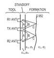
- FIG. 7illustrates the operation of a time-domain electromagnetic (EM) tool that provides 3-D imaging of the borehole and the formation behind the borehole wall in the presence of non-conducting oil-based mud.
- the toolincludes an array of EM short-pulse transmitters, time-synchronized receivers, and antennas.
- the antennasare mounted on the mandrel for LWD applications.
- the borehole and formation reflectionsare processed to find out the imaging and the eccentricity of the borehole and the formation near the borehole region, which results in a 3-D imaging of the borehole and the formation near the borehole.
- FIG. 7shows two receiver antennas placed at different spacings with respect to the transmitter antenna to provide enough measurement equations to solve parameters for multi-layer formations, and to enlarge the dynamic range of measurements.
- the drill collaris surrounded by oil-based mud having permittivity ⁇ m and conductivity ⁇ m .
- the standoff distance between the antennas and the borehole wallmay vary with the tool-face angle in eccentric boreholes.
- formation 1having permittivity ⁇ 1 and conductivity ⁇ 1
- second formation 2having permittivity ⁇ 2 and conductivity ⁇ 2
- the signals received by receiver antenna 1include 3 components: EM waves propagating through the oil-based mud (A), EM waves propagating through formation 1 (B), and the waves reflected from the boundary between formation 1 and formation 2 (C).
- receiver antenna 2also receives a signal having these three components.
- FIG. 8shows an approximately Gaussian pulse having a pulse width T of in the range between 0.3-2.0 nanoseconds. (Some tool embodiments may support pulse widths up to 100 ns.)
- FIG. 9shows the simulated signal that is received in response to the transmission of the pulse in FIG. 8 . In this simulation, the transmission of a pulse wave such as that shown in FIG. 8 results in the signal received by either receive antenna having the three wavelets shown in FIG. 9 (other formation configurations can produce a greater or lesser number of wavelets).
- the three waveletsare identified from the received signals, their magnitudes and time delays can be obtained and used to solve for various parameters including ⁇ m , ⁇ m , ⁇ 1 , ⁇ 1 , ⁇ 2 , and ⁇ 2 , and the distances to the borehole wall and the formation boundaries.
- the coordinate ztakes the direction of the borehole axis. With the drill collar going forward, the three dimensional distribution of the formation parameters is determined, thereby yielding a 3D image of the formation.
- the amplitude of the wavelet 1 shown in FIG. 9is not only influenced by the resistivity of the drilling fluid, but also by the standoff distance of the borehole.
- the antenna arrangement of FIG. 4exploits three receivers and two transmitters to increase the number of measurement equations.
- the two transmitters at the ends of the antenna arraytake turns transmitting EM pulses, and the signals from each of the three receivers are sampled in response to the transmitted pulses.
- the use of two transmitters at two endsenables the system to determine compensated measurements that cancel system heat noise and other system errors.
- the three receiversmake measurements more reliable by providing more measurement equations and making it possible to image formations with more layers.
- the antenna arrangement of FIG. 4also provides redundancy, enabling the system to continue operating even if one of the transmitters and one of the receivers break down.
- the disclosed toolsoffer a power savings in that the high-power transmit signals have extremely short durations and a low duty cycle, creating a low average power consumption.
- the sensorscan be mounted on a rotating head to provide full azimuthal scanning at each depth in the well.
- sensorscan be mounted at different azimuthal orientations on the tool to provide “azimuthally sampled” coverage.
- the data acquired by the 3D imaging toolcan be presented in a number of forms, including a volumetric solid in cylindrical coordinates as shown in FIG. 10 .
- the volume around the boreholeis divided into a cylindrical grid 1002 , with each of the cells in the grid having associated formation properties, which can be shown by color, transparency, texture, and/or other visual characteristics.
- the data acquisition systeme.g., computer 50 of FIG. 1
- the imageis displayed on a computer screen 56 , the user can interact with it to gain a better understanding of the structures shown, e.g., by viewing different cross-sections, different orientations, adjusting the colors, etc.
- invasion depth and invasion ratei.e., the distance that drilling fluid has penetrated into the formation.
- Asymmetries in the invasion ratesmay be indicative of stress orientations and fracture orientations, and the invasion rate can provide a measure of formation fluid mobility.
- Another application exampleis the measurement of borehole caliper, shape, texture. Travel time inversion, combined with the measurement of drilling fluid properties with a so-called “mud cell”, enables accurate determination of the borehole geometry and the eccentering of the tool. From the borehole geometry measurements, an accurate 3D model of the borehole can be constructed and displayed.
- Another application exampleis the measurement of formation dip and dip azimuth.
- the toolcan detect formation boundary distances and measure the variation of these distances as a function of tool face angle and tool position within the borehole. These measurements enable straightforward determination of the relative dip.
- the antennasare enlarged and spaced further apart to support the use of low frequency electromagnetic signal pulses.
- Such low frequency pulsesenable deeper signal penetrations into the formation. Deeper investigation depths may be possible, possibly even ahead of the bit.
- Other applications for such tool variationsinclude mapping of natural fractures in the formation and monitoring the growth of hydraulic fractures.
- the processing of reflected signalsneed not be limited to simple time-of-flight measurements.
- the toolcan analyze reflection amplitudes, shapes, and waveform coda (signals indicative of multiple reflections or multiple scattering of the transmitted pulse) to determine formation properties, formation structural information, formation fluid properties, borehole fluid properties, borehole geometry, invasion zone geometry, and other petrophysical information that can be displayed in a 3D image either separately or combined.
Landscapes
- Physics & Mathematics (AREA)
- Life Sciences & Earth Sciences (AREA)
- Electromagnetism (AREA)
- Engineering & Computer Science (AREA)
- Environmental & Geological Engineering (AREA)
- Geology (AREA)
- Remote Sensing (AREA)
- General Life Sciences & Earth Sciences (AREA)
- General Physics & Mathematics (AREA)
- Geophysics (AREA)
- Geophysics And Detection Of Objects (AREA)
- Investigating Or Analyzing Materials By The Use Of Electric Means (AREA)
Abstract
Description
A1=a0+b0sin(φ+θ0) (1)
where θ0is an initial phase angle, φ is the tool-face angle, a0is the average amplitude in the plane z=P, and b0is determined by the eccentricity of the drilling collar. The larger the b0, the more serious the eccentricity is.
Claims (18)
Priority Applications (1)
| Application Number | Priority Date | Filing Date | Title |
|---|---|---|---|
| US13/061,759US9411068B2 (en) | 2008-11-24 | 2009-11-23 | 3D borehole imager |
Applications Claiming Priority (3)
| Application Number | Priority Date | Filing Date | Title |
|---|---|---|---|
| US11743308P | 2008-11-24 | 2008-11-24 | |
| PCT/US2009/065537WO2010060040A1 (en) | 2008-11-24 | 2009-11-23 | A 3d borehole imager |
| US13/061,759US9411068B2 (en) | 2008-11-24 | 2009-11-23 | 3D borehole imager |
Related Parent Applications (1)
| Application Number | Title | Priority Date | Filing Date |
|---|---|---|---|
| US11743308PContinuation | 2008-11-24 | 2008-11-24 |
Publications (2)
| Publication Number | Publication Date |
|---|---|
| US20110251794A1 US20110251794A1 (en) | 2011-10-13 |
| US9411068B2true US9411068B2 (en) | 2016-08-09 |
Family
ID=42198432
Family Applications (2)
| Application Number | Title | Priority Date | Filing Date |
|---|---|---|---|
| US13/128,676Active2030-01-14US8957683B2 (en) | 2008-11-24 | 2009-08-11 | High frequency dielectric measurement tool |
| US13/061,759Active2031-02-22US9411068B2 (en) | 2008-11-24 | 2009-11-23 | 3D borehole imager |
Family Applications Before (1)
| Application Number | Title | Priority Date | Filing Date |
|---|---|---|---|
| US13/128,676Active2030-01-14US8957683B2 (en) | 2008-11-24 | 2009-08-11 | High frequency dielectric measurement tool |
Country Status (6)
| Country | Link |
|---|---|
| US (2) | US8957683B2 (en) |
| EP (1) | EP2361394B1 (en) |
| AU (1) | AU2009318042B2 (en) |
| GB (1) | GB2475456B (en) |
| MY (1) | MY160258A (en) |
| WO (2) | WO2010059275A1 (en) |
Cited By (3)
| Publication number | Priority date | Publication date | Assignee | Title |
|---|---|---|---|---|
| US9909414B2 (en) | 2009-08-20 | 2018-03-06 | Halliburton Energy Services, Inc. | Fracture characterization using directional electromagnetic resistivity measurements |
| US11286763B2 (en)* | 2016-01-25 | 2022-03-29 | Schlumberger Technology Corporation | Drilling with information characterizing lateral heterogeneities based on deep directional resistivity measurements |
| US12000266B2 (en) | 2020-03-13 | 2024-06-04 | Geonomic Technologies Inc. | Method and apparatus for measuring a wellbore |
Families Citing this family (68)
| Publication number | Priority date | Publication date | Assignee | Title |
|---|---|---|---|---|
| US7659722B2 (en)* | 1999-01-28 | 2010-02-09 | Halliburton Energy Services, Inc. | Method for azimuthal resistivity measurement and bed boundary detection |
| WO2008008386A2 (en) | 2006-07-11 | 2008-01-17 | Halliburton Energy Services, Inc. | Modular geosteering tool assembly |
| US8593147B2 (en)* | 2006-08-08 | 2013-11-26 | Halliburton Energy Services, Inc. | Resistivity logging with reduced dip artifacts |
| WO2008076130A1 (en) | 2006-12-15 | 2008-06-26 | Halliburton Energy Services, Inc. | Antenna coupling component measurement tool having rotating antenna configuration |
| WO2008118735A1 (en) | 2007-03-27 | 2008-10-02 | Halliburton Energy Services, Inc. | Systems and methods for displaying logging data |
| GB2468734B (en) | 2008-01-18 | 2012-08-08 | Halliburton Energy Serv Inc | Em-guided drilling relative to an existing borehole |
| WO2009131584A1 (en)* | 2008-04-25 | 2009-10-29 | Halliburton Energy Services, Inc. | Multimodal geosteering systems and methods |
| EP2361394B1 (en) | 2008-11-24 | 2022-01-12 | Halliburton Energy Services, Inc. | A high frequency dielectric measurement tool |
| WO2011063086A1 (en) | 2009-11-19 | 2011-05-26 | Halliburton Energy Services, Inc. | Downhole optical radiometry tool |
| AU2009356978B2 (en) | 2009-12-23 | 2013-08-01 | Halliburton Energy Services, Inc. | Interferometry-based downhole analysis tool |
| MX2012010692A (en) | 2010-03-31 | 2012-11-06 | Halliburton Energy Serv Inc | Multi-step borehole correction scheme for multi-component induction tools. |
| AU2011261584B2 (en) | 2010-06-01 | 2014-11-13 | Halliburton Energy Services, Inc. | Spectroscopic nanosensor logging systems and methods |
| US8917094B2 (en) | 2010-06-22 | 2014-12-23 | Halliburton Energy Services, Inc. | Method and apparatus for detecting deep conductive pipe |
| US9115569B2 (en) | 2010-06-22 | 2015-08-25 | Halliburton Energy Services, Inc. | Real-time casing detection using tilted and crossed antenna measurement |
| US8749243B2 (en) | 2010-06-22 | 2014-06-10 | Halliburton Energy Services, Inc. | Real time determination of casing location and distance with tilted antenna measurement |
| CA2800148C (en) | 2010-06-29 | 2015-06-23 | Halliburton Energy Services, Inc. | Method and apparatus for sensing elongated subterranean anomalies |
| WO2012008965A1 (en) | 2010-07-16 | 2012-01-19 | Halliburton Energy Services, Inc. | Efficient inversion systems and methods for directionally-sensitive resistivity logging tools |
| WO2012144977A1 (en)* | 2011-04-18 | 2012-10-26 | Halliburton Energy Services, Inc. | Multicomponent borehole radar systems and methods |
| US8861307B2 (en)* | 2011-09-14 | 2014-10-14 | Schlumberger Technology Corporation | Acoustic logging while drilling tool with active control of source orientation |
| US9500762B2 (en) | 2011-09-19 | 2016-11-22 | Precision Energy Services, Inc. | Borehole resistivity imager using discrete energy pulsing |
| WO2013048375A1 (en)* | 2011-09-27 | 2013-04-04 | Halliburton Energy Services, Inc. | Systems and methods of robust determination of boundaries |
| US9243488B2 (en)* | 2011-10-26 | 2016-01-26 | Precision Energy Services, Inc. | Sensor mounting assembly for drill collar stabilizer |
| US10330818B2 (en) | 2011-10-31 | 2019-06-25 | Halliburton Energy Services, Inc. | Multi-component induction logging systems and methods using real-time OBM borehole correction |
| US9261620B2 (en)* | 2011-11-09 | 2016-02-16 | Micah Thomas Mangione | Apparatus, method and system for mapping fracture features in hydraulically fractured strata using functional proppant properties |
| WO2014003702A1 (en) | 2012-06-25 | 2014-01-03 | Halliburton Energy Services, Inc. | Tilted antenna logging systems and methods yielding robust measurement signals |
| CA2876326A1 (en)* | 2012-06-29 | 2014-01-03 | Halliburton Energy Services, Inc. | Full tensor micro-impedance imaging |
| MX348211B (en) | 2012-06-29 | 2017-06-05 | Halliburton Energy Services Inc | Multi - axial induction borehole imager. |
| US9091782B2 (en) | 2012-12-13 | 2015-07-28 | Halliburton Energy Services, Inc. | Modular resistivity logging tool systems and methods employing an adapter in an isolation joint configuration |
| AU2012397192B2 (en) | 2012-12-23 | 2017-01-19 | Halliburton Energy Services, Inc. | Deep formation evaluation systems and methods |
| US9720125B2 (en) | 2013-02-14 | 2017-08-01 | Schlumberger Technology Corporation | Subterranean formation oil mobility quicklook |
| US20140266214A1 (en)* | 2013-03-15 | 2014-09-18 | Chevron U.S.A. Inc. | Method and system for monitoring subsurface injection processes using a borehole electromagnetic source |
| US9650888B2 (en)* | 2013-10-03 | 2017-05-16 | Halliburton Energy Services, Inc. | Multi-mode measurements with a downhole tool using conformable sensors |
| CN103643946A (en)* | 2013-12-16 | 2014-03-19 | 西南石油大学 | Dual-electrical-parameter logging instrument while drilling |
| WO2015099765A1 (en) | 2013-12-27 | 2015-07-02 | Halliburton Energy Services, Inc. | Multi-frequency dielectric borehole imager |
| MX2016009439A (en)* | 2014-02-21 | 2016-10-13 | Halliburton Energy Services Inc | Determining water salinity and water-filled porosity of a formation. |
| WO2015152758A1 (en)* | 2014-04-02 | 2015-10-08 | Baker Hughes Incorporated | Imaging of earth formation with high frequency sensor |
| MX2016011719A (en)* | 2014-04-08 | 2016-11-07 | Halliburton Energy Services Inc | Borehole wall imaging tool having a grooved wall-contacting face. |
| US9556726B2 (en) | 2014-05-16 | 2017-01-31 | Baker Hughes Incorporated | Use of a fractal antenna in array dielectric logging |
| WO2016072979A1 (en)* | 2014-11-05 | 2016-05-12 | Halliburton Energy Services, Inc. | Electromagnetic sensor for a downhole dielectric tool |
| US20170306744A1 (en)* | 2015-01-23 | 2017-10-26 | Halliburton Energy Services, Inc. | Downhole Electrode Apparatus, Systems, And Methods |
| US11530605B2 (en)* | 2015-03-13 | 2022-12-20 | The Charles Machine Works, Inc. | Horizontal directional drilling crossbore detector |
| US10725196B2 (en)* | 2015-04-29 | 2020-07-28 | Halliburton Energy Services, Inc. | Bi-mode high frequency dielectric tool |
| US10061051B2 (en)* | 2015-10-12 | 2018-08-28 | Baker Hughes, A Ge Company, Llc | Whole-space inversion using phase correction method for multi-frequency dielectric array logging tool |
| US10190411B2 (en)* | 2015-11-12 | 2019-01-29 | Halliburton Energy Services, Inc. | Downhole fluid characterization methods and systems using multi-electrode configurations |
| US10483939B2 (en) | 2015-11-13 | 2019-11-19 | Halliburton Energy Services, Inc. | Downhole logging tool using resonant cavity antennas with real-time impedance matching |
| WO2017082929A1 (en) | 2015-11-13 | 2017-05-18 | Halliburton Energy Services, Inc. | Microstrip antenna-based logging tool and method |
| WO2017086951A1 (en) | 2015-11-18 | 2017-05-26 | Halliburton Energy Services, Inc. | Dielectric logging tool comprising high-impedance metamaterials |
| US10935687B2 (en)* | 2016-02-23 | 2021-03-02 | Halliburton Energy Services, Inc. | Formation imaging with electronic beam steering |
| WO2017184164A1 (en) | 2016-04-22 | 2017-10-26 | Halliburton Energy Services, Inc. | Dual mode electromagnetic imaging of a borehole |
| WO2017196313A1 (en) | 2016-05-11 | 2017-11-16 | Halliburton Energy Services, Inc. | Determining subterranean-formation resistivity using an electromagnetic telemetry system |
| CN109642456B (en)* | 2016-09-15 | 2022-08-16 | 李善军 | System and method for detecting instruments before drilling and laterally |
| WO2018125214A1 (en)* | 2016-12-30 | 2018-07-05 | Wilson Glenn A | Time-domain broadband dielectric logging |
| US10317558B2 (en) | 2017-03-14 | 2019-06-11 | Saudi Arabian Oil Company | EMU impulse antenna |
| US10330815B2 (en) | 2017-03-14 | 2019-06-25 | Saudi Arabian Oil Company | EMU impulse antenna for low frequency radio waves using giant dielectric and ferrite materials |
| US10416335B2 (en) | 2017-03-14 | 2019-09-17 | Saudi Arabian Oil Company | EMU impulse antenna with controlled directionality and improved impedance matching |
| US11442194B2 (en) | 2017-04-14 | 2022-09-13 | The Charles Machine Works, Inc. | System for locating a utility with a downhole beacon |
| EA036852B1 (en)* | 2017-04-26 | 2020-12-28 | Общество С Ограниченной Ответственностью "Русские Универсальные Системы" | Method for production of electromagnetic 3d scanner, and electromagnetic 3d scanner made by the method |
| US10782437B2 (en) | 2017-10-16 | 2020-09-22 | Halliburton Energy Servies, Inc. | Radial magnetic dipole dielectric tool |
| US10365393B2 (en) | 2017-11-07 | 2019-07-30 | Saudi Arabian Oil Company | Giant dielectric nanoparticles as high contrast agents for electromagnetic (EM) fluids imaging in an oil reservoir |
| GB2569583B (en)* | 2017-12-20 | 2020-05-06 | Reeves Wireline Tech Ltd | Apparatuses and methods for determining properties of subterranean layers |
| US10564310B2 (en) | 2018-02-27 | 2020-02-18 | Baker Hughes, A Ge Company, Llc | Dielectric logging with broadband excitation |
| US11332991B2 (en) | 2019-07-17 | 2022-05-17 | Saudi Arabian Oil Company | Targeted downhole delivery with container |
| RU2724177C1 (en)* | 2019-12-30 | 2020-06-22 | Общество С Ограниченной Ответственностью "Радионда" | Dielectric logging method of near-wellbore |
| US11879328B2 (en) | 2021-08-05 | 2024-01-23 | Saudi Arabian Oil Company | Semi-permanent downhole sensor tool |
| US11914098B2 (en) | 2022-05-04 | 2024-02-27 | Halliburton Energy Services, Inc. | Multi-frequency borehole imagers utilizing resonator antennas |
| US11867049B1 (en) | 2022-07-19 | 2024-01-09 | Saudi Arabian Oil Company | Downhole logging tool |
| US11913329B1 (en) | 2022-09-21 | 2024-02-27 | Saudi Arabian Oil Company | Untethered logging devices and related methods of logging a wellbore |
| US20240396200A1 (en)* | 2023-05-24 | 2024-11-28 | Halliburton Energy Services, Inc. | Antenna tuning and filtering for deep transmitter extension subs |
Citations (167)
| Publication number | Priority date | Publication date | Assignee | Title |
|---|---|---|---|---|
| GB1111629A (en) | 1966-09-13 | 1968-05-01 | Chevron Res | Method for mapping salt domes at depth |
| US3496455A (en) | 1964-02-06 | 1970-02-17 | Schlumberger Prospection | Methods and apparatus for investigating earth formations including multiple frequency operation and phase correction and quadrature phase cancellation using a magnetic core |
| GB1363079A (en) | 1971-10-29 | 1974-08-14 | Marconi Co Ltd | Directional aerial systems and apparatus |
| US3849721A (en) | 1973-08-23 | 1974-11-19 | Schlumberger Technology Corp | Microwave logging apparatus having dual processing channels |
| US3914603A (en) | 1973-12-17 | 1975-10-21 | Texaco Inc | Neutron lifetime well logging methods and apparatus |
| US3944910A (en) | 1973-08-23 | 1976-03-16 | Schlumberger Technology Corporation | Method and apparatus utilizing microwave electromagnetic energy for investigating earth formations |
| US4104596A (en) | 1976-12-10 | 1978-08-01 | Geosource Inc. | Instantaneous floating point amplifier |
| US4258321A (en) | 1978-03-09 | 1981-03-24 | Neale Jr Dory J | Radio geophysical surveying method and apparatus |
| US4278941A (en) | 1978-10-30 | 1981-07-14 | Shell Oil Company | High frequency induction log for determining resistivity and dielectric constant of the earth |
| US4297699A (en) | 1979-10-24 | 1981-10-27 | Ensco, Inc. | Radar drill guidance system |
| US4365322A (en) | 1980-04-18 | 1982-12-21 | Bernard Widrow | Apparatus and method for determining the position of a gas-saturated porous rock in the vicinity of a deep borehole in the earth |
| GB2030414B (en) | 1978-07-31 | 1983-02-02 | Prakla Seismos Gmbh | Method for monitoring subsurfaces in coal seams |
| US4430653A (en) | 1979-11-02 | 1984-02-07 | Conoco Inc. | Earth probing radar system |
| US4504833A (en) | 1981-12-09 | 1985-03-12 | Xadar Corporation | Synthetic pulse radar system and method |
| US4626773A (en) | 1984-10-26 | 1986-12-02 | Exxon Production Research Co. | Method and means for determining rock properties using time-domain dielectric spectroscopy |
| US4670717A (en) | 1983-03-08 | 1987-06-02 | Friedhelm Sender | Borehole antenna array for determining radar incidence direction |
| US4689569A (en) | 1984-12-17 | 1987-08-25 | Southwest Research Institute | Directional antenna system for use in a borehole incorporating antenna dipole elements |
| US4704581A (en) | 1985-12-28 | 1987-11-03 | Schlumberger Technology Corp. | Electromagnetic logging apparatus using vertical magnetic dipole slot antennas |
| US4721853A (en) | 1986-01-31 | 1988-01-26 | Schlumberger Technology Corporation | Thermal decay time logging method and apparatus |
| US4730161A (en) | 1986-09-22 | 1988-03-08 | Texaco Inc. | Dual frequency well logging system for determining the water resistivity and water saturation of an earth formation |
| FR2561395B1 (en) | 1984-03-19 | 1989-01-20 | Prakla Seismos Gmbh | DRILLING MEASURING DEVICE |
| US4814768A (en) | 1987-09-28 | 1989-03-21 | The United States Of America As Represented By The United States Department Of Energy | Downhole pulse radar |
| US4825421A (en) | 1986-05-19 | 1989-04-25 | Jeter John D | Signal pressure pulse generator |
| US4829488A (en) | 1988-03-22 | 1989-05-09 | Atlantic Richfield Company | Drive mechanism for borehole televiewer |
| US4909336A (en) | 1988-09-29 | 1990-03-20 | Applied Navigation Devices | Drill steering in high magnetic interference areas |
| US4968940A (en) | 1987-10-30 | 1990-11-06 | Schlumberger Technology Corporation | Well logging apparatus and method using two spaced apart transmitters with two receivers located between the transmitters |
| US5113192A (en) | 1991-05-03 | 1992-05-12 | Conoco Inc. | Method for using seismic data acquisition technology for acquisition of ground penetrating radar data |
| US5115198A (en) | 1989-09-14 | 1992-05-19 | Halliburton Logging Services, Inc. | Pulsed electromagnetic dipmeter method and apparatus employing coils with finite spacing |
| US5133418A (en) | 1991-01-28 | 1992-07-28 | Lag Steering Systems | Directional drilling system with eccentric mounted motor and biaxial sensor and method |
| US5155198A (en) | 1989-04-24 | 1992-10-13 | Cape Cod Research | Primer composition containing epoxy phosphate esters, silane coupling agent, reactive end group-terminated polydiorganosiloxane, organometallic catalysts and amine hardening agents |
| US5159978A (en) | 1991-08-13 | 1992-11-03 | Halliburton Logging Services, Inc. | Connecting apparatus for logging tools including electrical feedthrough and isolation system with bridle assembly |
| US5210495A (en) | 1991-05-28 | 1993-05-11 | Schlumberger Technology Corp. | Electromagnetic logging method and apparatus with scanned magnetic dipole direction |
| US5248975A (en) | 1991-06-26 | 1993-09-28 | Geophysical Survey Systems, Inc. | Ground probing radar with multiple antenna capability |
| US5318123A (en) | 1992-06-11 | 1994-06-07 | Halliburton Company | Method for optimizing hydraulic fracturing through control of perforation orientation |
| US5345179A (en) | 1992-03-09 | 1994-09-06 | Schlumberger Technology Corporation | Logging earth formations with electromagnetic energy to determine conductivity and permittivity |
| US5357253A (en) | 1993-04-02 | 1994-10-18 | Earth Sounding International | System and method for earth probing with deep subsurface penetration using low frequency electromagnetic signals |
| US5367262A (en) | 1991-07-12 | 1994-11-22 | Halliburton Logging Serivces, Inc. | Advances in high frequency dielectric logging |
| US5377104A (en) | 1993-07-23 | 1994-12-27 | Teledyne Industries, Inc. | Passive seismic imaging for real time management and verification of hydraulic fracturing and of geologic containment of hazardous wastes injected into hydraulic fractures |
| US5377105A (en) | 1991-04-12 | 1994-12-27 | Halliburton Logging Services | Enhanced vertical resolution processing of dual-spaced neutron and density tools |
| US5389881A (en) | 1992-07-22 | 1995-02-14 | Baroid Technology, Inc. | Well logging method and apparatus involving electromagnetic wave propagation providing variable depth of investigation by combining phase angle and amplitude attenuation |
| US5400030A (en) | 1994-02-09 | 1995-03-21 | Exxon Production Research Company | Detection and mapping of hydrocarbon reservoirs with radar waves |
| US5420589A (en) | 1993-06-07 | 1995-05-30 | Wells; C. T. | System for evaluating the inner medium characteristics of non-metallic materials |
| US5434507A (en) | 1992-05-27 | 1995-07-18 | Schlumberger Technology Corporation | Method and apparatus for electromagnetic logging with two dimensional antenna array |
| US5469062A (en) | 1994-03-11 | 1995-11-21 | Baker Hughes, Inc. | Multiple depths and frequencies for simultaneous inversion of electromagnetic borehole measurements |
| US5503225A (en) | 1995-04-21 | 1996-04-02 | Atlantic Richfield Company | System and method for monitoring the location of fractures in earth formations |
| US5530359A (en) | 1995-02-03 | 1996-06-25 | Schlumberger Technology Corporation | Borehole logging tools and methods using reflected electromagnetic signals |
| US5552786A (en) | 1994-12-09 | 1996-09-03 | Schlumberger Technology Corporation | Method and apparatus for logging underground formations using radar |
| US5557580A (en) | 1993-08-18 | 1996-09-17 | Texas Instruments Incorporated | Word line driving circuit |
| US5631562A (en) | 1994-03-31 | 1997-05-20 | Western Atlas International, Inc. | Time domain electromagnetic well logging sensor including arcuate microwave strip lines |
| US5720354A (en)* | 1996-01-11 | 1998-02-24 | Vermeer Manufacturing Company | Trenchless underground boring system with boring tool location |
| US5720355A (en) | 1993-07-20 | 1998-02-24 | Baroid Technology, Inc. | Drill bit instrumentation and method for controlling drilling or core-drilling |
| US5747750A (en) | 1994-08-31 | 1998-05-05 | Exxon Production Research Company | Single well system for mapping sources of acoustic energy |
| US5757191A (en) | 1994-12-09 | 1998-05-26 | Halliburton Energy Services, Inc. | Virtual induction sonde for steering transmitted and received signals |
| US5765642A (en) | 1996-12-23 | 1998-06-16 | Halliburton Energy Services, Inc. | Subterranean formation fracturing methods |
| US5811973A (en) | 1994-03-14 | 1998-09-22 | Baker Hughes Incorporated | Determination of dielectric properties with propagation resistivity tools using both real and imaginary components of measurements |
| US5892361A (en) | 1994-03-14 | 1999-04-06 | Baker Hughes Incorporated | Use of raw amplitude and phase in propagation resistivity measurements to measure borehole environmental parameters |
| US5900833A (en) | 1996-04-16 | 1999-05-04 | Zircon Corporation | Imaging radar suitable for material penetration |
| US5917160A (en) | 1994-08-31 | 1999-06-29 | Exxon Production Research Company | Single well system for mapping sources of acoustic energy |
| WO2000000852A1 (en) | 1998-06-18 | 2000-01-06 | Den Norske Stats Oljeselskap A.S | Method and device for detection of em waves in a well |
| US6078867A (en)* | 1998-04-08 | 2000-06-20 | Schlumberger Technology Corporation | Method and apparatus for generation of 3D graphical borehole analysis |
| US6100839A (en) | 1996-04-16 | 2000-08-08 | Zircon Corporation | Enhanced impulse radar system |
| US6163155A (en) | 1999-01-28 | 2000-12-19 | Dresser Industries, Inc. | Electromagnetic wave resistivity tool having a tilted antenna for determining the horizontal and vertical resistivities and relative dip angle in anisotropic earth formations |
| US6173793B1 (en) | 1998-12-18 | 2001-01-16 | Baker Hughes Incorporated | Measurement-while-drilling devices with pad mounted sensors |
| US6179066B1 (en) | 1997-12-18 | 2001-01-30 | Baker Hughes Incorporated | Stabilization system for measurement-while-drilling sensors |
| US6181138B1 (en) | 1999-02-22 | 2001-01-30 | Halliburton Energy Services, Inc. | Directional resistivity measurements for azimuthal proximity detection of bed boundaries |
| US6191586B1 (en) | 1998-06-10 | 2001-02-20 | Dresser Industries, Inc. | Method and apparatus for azimuthal electromagnetic well logging using shielded antennas |
| US6191588B1 (en) | 1998-07-15 | 2001-02-20 | Schlumberger Technology Corporation | Methods and apparatus for imaging earth formation with a current source, a current drain, and a matrix of voltage electrodes therebetween |
| US6218842B1 (en) | 1999-08-04 | 2001-04-17 | Halliburton Energy Services, Inc. | Multi-frequency electromagnetic wave resistivity tool with improved calibration measurement |
| US6216783B1 (en) | 1998-11-17 | 2001-04-17 | Golder Sierra, Llc | Azimuth control of hydraulic vertical fractures in unconsolidated and weakly cemented soils and sediments |
| WO2001048353A1 (en) | 1999-12-27 | 2001-07-05 | Ball Corporation | Autonomous omnidirectional driller |
| US20010022464A1 (en) | 1998-09-28 | 2001-09-20 | Peter Kenneth Seear | Mining machine |
| US20010022238A1 (en) | 2000-03-15 | 2001-09-20 | Houwelingen Mark Van | Directional drilling machine and method of directional drilling |
| US6353321B1 (en) | 2000-01-27 | 2002-03-05 | Halliburton Energy Services, Inc. | Uncompensated electromagnetic wave resistivity tool for bed boundary detection and invasion profiling |
| US6359438B1 (en) | 2000-01-28 | 2002-03-19 | Halliburton Energy Services, Inc. | Multi-depth focused resistivity imaging tool for logging while drilling applications |
| US6389438B1 (en) | 1998-02-25 | 2002-05-14 | Yozan Inc. | Matched filter and signal reception apparatus |
| US6460936B1 (en) | 1999-06-19 | 2002-10-08 | Grigori Y. Abramov | Borehole mining tool |
| US6476609B1 (en) | 1999-01-28 | 2002-11-05 | Dresser Industries, Inc. | Electromagnetic wave resistivity tool having a tilted antenna for geosteering within a desired payzone |
| US20020167314A1 (en) | 1995-10-12 | 2002-11-14 | Manfred Prammer | System and method for determining oil, water and gas saturations for low-field gradient NMR logging tools |
| US20020177427A1 (en) | 2001-03-27 | 2002-11-28 | Nadgauda Nikhil S. | Method and apparatus for restoring a soft decision component of a signal |
| US6496137B1 (en) | 1999-09-19 | 2002-12-17 | Mala Geoscience Ab | Ground penetrating radar array and timing circuit |
| US20020195247A1 (en) | 1997-06-02 | 2002-12-26 | Schlumberger Technology Corporation | Well-bore sensor apparatus and method |
| US6538447B2 (en) | 2000-12-13 | 2003-03-25 | Halliburton Energy Services, Inc. | Compensated multi-mode elctromagnetic wave resistivity tool |
| US20030056983A1 (en) | 1999-09-24 | 2003-03-27 | Vermeer Manufacturing Company | Underground drilling device and method employing down-hole radar |
| US20030080743A1 (en)* | 2001-10-29 | 2003-05-01 | Baker Hughes Incorporated | Integrated, single collar measurement while drilling tool |
| US20030137301A1 (en)* | 2002-01-19 | 2003-07-24 | Thompson Larry W. | Well logging system for determining resistivity using multiple transmitter-receiver groups operating at three frequencies and at optimized gain |
| US20030184302A1 (en) | 2002-03-26 | 2003-10-02 | Dzevat Omeragic | Electromagnetic resistivity instrument having look ahead capability |
| US6633252B2 (en) | 2001-03-28 | 2003-10-14 | Larry G. Stolarczyk | Radar plow drillstring steering |
| US6651739B2 (en) | 2001-02-21 | 2003-11-25 | The United States Of America As Represented By The Administrator Of The National Aeronautics And Space Administration | Medium frequency pseudo noise geological radar |
| US20030223620A1 (en)* | 1999-12-22 | 2003-12-04 | Schlumberger Technology Corporation | Methods of producing images of underground formations surrounding a borehole |
| WO2003080988A3 (en) | 2002-03-27 | 2003-12-24 | Tracto Technik | Drill head and method for controlled horizontal drilling |
| US6672409B1 (en) | 2000-10-24 | 2004-01-06 | The Charles Machine Works, Inc. | Downhole generator for horizontal directional drilling |
| US20040008027A1 (en) | 1995-10-12 | 2004-01-15 | Manfred Prammer | Method and apparatus for detecting diffusion sensitive phases with estimation of residual error in NMR logs |
| US20040019427A1 (en) | 2002-07-29 | 2004-01-29 | Halliburton Energy Services, Inc. | Method for determining parameters of earth formations surrounding a well bore using neural network inversion |
| GB2352259B (en) | 1999-07-22 | 2004-02-04 | Sofitech Nv | Hydraulic fracturing of earth formations |
| US6714153B1 (en) | 1998-06-18 | 2004-03-30 | Den Norske Stats Oljeselskap A.S. | Device for electromagnetic detection of geological properties in a well |
| US6712140B2 (en) | 2000-07-07 | 2004-03-30 | T & A Survey B.V. | 3rd borehole radar antenna and algorithm, method and apparatus for subsurface surveys |
| US20040108853A1 (en) | 2002-12-09 | 2004-06-10 | Rosthal Richard A. | Method and apparatus for determining the presence and orientation of a fracture in an earth formation |
| US20040123655A1 (en)* | 2002-09-09 | 2004-07-01 | Baker Hughes Incorporated | Azimuthal resistivity using a non-directional device |
| US6765385B2 (en) | 2001-11-13 | 2004-07-20 | Weatherford/Lamb, Inc. | Method, apparatus and system for compensating the effects of borehole variations |
| US6771206B2 (en) | 1999-12-14 | 2004-08-03 | Centre National De La Recherches Scientifique | Method for obtaining underground imagery using a ground-penetrating radar |
| US6778127B2 (en) | 2001-03-28 | 2004-08-17 | Larry G. Stolarczyk | Drillstring radar |
| US6799117B1 (en) | 2003-05-28 | 2004-09-28 | Halliburton Energy Services, Inc. | Predicting sample quality real time |
| US20040196184A1 (en) | 2003-04-07 | 2004-10-07 | Kevin Hollander | Method and apparatus for determining the position and orientation of an object using a doppler shift of electromagnetic signals |
| US6810331B2 (en) | 2002-09-25 | 2004-10-26 | Halliburton Energy Services, Inc. | Fixed-depth of investigation log for multi-spacing multi-frequency LWD resistivity tools |
| US6856132B2 (en)* | 2002-11-08 | 2005-02-15 | Shell Oil Company | Method and apparatus for subterranean formation flow imaging |
| US20050083063A1 (en) | 2003-08-08 | 2005-04-21 | Schlumberger Technology Corporation | Electromagnetic method for determining dip angles independent of mud type and borehole environment |
| US6885943B2 (en) | 2002-09-20 | 2005-04-26 | Halliburton Energy Services, Inc. | Simultaneous resolution enhancement and dip correction of resistivity logs through nonlinear iterative deconvolution |
| US20050134280A1 (en) | 2003-12-22 | 2005-06-23 | Halliburton Energy Services, Inc. | Multi-mode oil base mud imager |
| US20050150692A1 (en) | 2003-11-05 | 2005-07-14 | Baker Hughes Incorporated | Directional cased hole side track method applying rotary closed loop system and casing mill |
| US6918293B2 (en) | 2003-04-09 | 2005-07-19 | Halliburton Energy Services, Inc. | System and method having radiation intensity measurements with standoff correction |
| US6925031B2 (en) | 2001-12-13 | 2005-08-02 | Baker Hughes Incorporated | Method of using electrical and acoustic anisotropy measurements for fracture identification |
| US6940446B2 (en) | 2003-10-08 | 2005-09-06 | David B. Cist | System and methods for obtaining ground conductivity information using GPR data |
| US6944546B2 (en) | 2003-10-01 | 2005-09-13 | Halliburton Energy Services, Inc. | Method and apparatus for inversion processing of well logging data in a selected pattern space |
| US20050231436A1 (en)* | 2004-04-20 | 2005-10-20 | Mclean James S | Dual- and quad-ridged horn antenna with improved antenna pattern characteristics |
| US20050230107A1 (en) | 2004-04-14 | 2005-10-20 | Mcdaniel Billy W | Methods of well stimulation during drilling operations |
| US6958610B2 (en) | 2001-06-03 | 2005-10-25 | Halliburton Energy Services, Inc. | Method and apparatus measuring electrical anisotropy in formations surrounding a wellbore |
| US20060022887A1 (en) | 2002-09-25 | 2006-02-02 | Halliburton Energy Services Inc. | Ruggedized multi-layer printed circuit board based downhole antenna |
| US7013991B2 (en) | 2003-09-24 | 2006-03-21 | Gas Technology Institute | Obstacle detection system for underground operations |
| US20060061364A1 (en) | 2003-11-05 | 2006-03-23 | Erik Banning | System and method for locating an anomaly |
| US7038455B2 (en) | 2003-08-05 | 2006-05-02 | Halliburton Energy Services, Inc. | Electromagnetic wave resistivity tool |
| US7046010B2 (en) | 2003-12-22 | 2006-05-16 | Halliburton Energy Services, Inc. | Multi-mode microresistivity tool in boreholes drilled with conductive mud |
| US7046009B2 (en) | 2003-12-24 | 2006-05-16 | Baker Hughes Incorporated | Method for measuring transient electromagnetic components to perform deep geosteering while drilling |
| US20060157277A1 (en) | 2002-09-25 | 2006-07-20 | Halliburton Energy Services, Inc. | Method and system of controlling drilling direction using directionally sensitive resistivity readings |
| WO2006079154A1 (en) | 2004-10-22 | 2006-08-03 | Geomole Pty Ltd | Method and apparatus for sensor deployment |
| US20060173624A1 (en) | 2005-01-31 | 2006-08-03 | Baker Hughes Incorporated | Method for real-time well-site interpretation of array resistivity log data in vertical and deviated wells |
| US7123016B2 (en) | 2000-05-09 | 2006-10-17 | Admiralty Corporation | Systems and methods useful for detecting presence and / or location of various materials |
| US7143844B2 (en) | 1999-09-24 | 2006-12-05 | Vermeer Manufacturing Company | Earth penetrating apparatus and method employing radar imaging and rate sensing |
| US20070079989A1 (en) | 2005-10-11 | 2007-04-12 | Halliburton Energy Services, Inc. | Borehole generator |
| US7227363B2 (en) | 2001-06-03 | 2007-06-05 | Gianzero Stanley C | Determining formation anisotropy based in part on lateral current flow measurements |
| US20070137854A1 (en) | 2004-07-14 | 2007-06-21 | Schlumberger Oilfield Services | Resistivity Tool with Selectable Depths of Investigation |
| US7242194B2 (en) | 2000-04-07 | 2007-07-10 | Schlumberger Technology Corporation | Formation imaging while drilling in non-conductive fluids |
| JP4001392B2 (en) | 1992-10-02 | 2007-10-31 | 富士ゼロックス株式会社 | Structured document processing device |
| US20070256830A1 (en) | 2003-07-25 | 2007-11-08 | Schlumberger Technology Corporation | Method and an apparatus for evaluating a geometry of a hydraulic fracture in a rock formation |
| US7296462B2 (en) | 2005-05-03 | 2007-11-20 | Halliburton Energy Services, Inc. | Multi-purpose downhole tool |
| WO2007149106A1 (en) | 2006-06-19 | 2007-12-27 | Halliburton Energy Services, Inc. | Antenna cutout in a downhole tubular |
| WO2008021868A2 (en) | 2006-08-08 | 2008-02-21 | Halliburton Energy Services, Inc. | Resistivty logging with reduced dip artifacts |
| WO2007149146A3 (en) | 2006-06-19 | 2008-02-21 | Saudi Arabian Oil Co | Sulfur loading apparatus |
| US7336222B2 (en) | 2005-06-23 | 2008-02-26 | Enerlab, Inc. | System and method for measuring characteristics of a continuous medium and/or localized targets using multiple sensors |
| US7350568B2 (en) | 2005-02-09 | 2008-04-01 | Halliburton Energy Services, Inc. | Logging a well |
| US20080078580A1 (en) | 1999-01-28 | 2008-04-03 | Halliburton Energy Services, Inc. | Tool for azimuthal resistivity measurement and bed boundary detection |
| US20080079432A1 (en) | 2006-09-28 | 2008-04-03 | Baker Hughes Incorporated | Broadband resistivity interpretation |
| US20080128166A1 (en) | 2006-12-05 | 2008-06-05 | Baker Hughes Incorporated | Method to Improve Downhole Instruments |
| US7460060B2 (en) | 2005-03-30 | 2008-12-02 | Denso Corporation | Electromagnetic wave transmitting/receiving module and imaging sensor having electromagnetic wave transmitting/receiving module |
| WO2008154679A1 (en) | 2007-06-18 | 2008-12-24 | Commonwealth Scientific And Industrial Research Organisation | Method and apparatus for detection using magnetic gradient tensor |
| US20090138202A1 (en)* | 2007-10-02 | 2009-05-28 | Baker Hughes Incorporated | Method and apparatus for imaging bed boundaries using azimuthal propagation resistivity measurements |
| US20090210161A1 (en) | 2008-02-20 | 2009-08-20 | Carbo Ceramics Inc. | Methods of Identifying High Neutron Capture Cross Section Doped Proppant in Induced Subterranean Formation Fractures |
| US20090230968A1 (en) | 2006-12-15 | 2009-09-17 | Halliburton Energy Services, Inc. | Antenna coupling component measurement tool having rotating antenna configuration |
| US20090278543A1 (en) | 2007-01-29 | 2009-11-12 | Halliburton Energy Services, Inc. | Systems and Methods Having Radially Offset Antennas for Electromagnetic Resistivity Logging |
| US20090277630A1 (en) | 2008-05-08 | 2009-11-12 | Mcdaniel Robert R | Analysis of radar ranging data from a down hole radar ranging tool for determining width, height, and length of a subterranean fracture |
| US20090302851A1 (en) | 2006-07-11 | 2009-12-10 | Halliburton Energy Services, Inc. | Modular geosteering tool assembly |
| US20090310441A1 (en)* | 2008-06-12 | 2009-12-17 | Johnson Paul A | Method and system for generating a beam of acoustic energy from a borehole, and applications thereof |
| US20090309798A1 (en) | 2006-07-12 | 2009-12-17 | Bittar Michael S | Method and Apparatus for Building a Tilted Antenna |
| US20090315563A1 (en) | 2006-01-13 | 2009-12-24 | Fox Anthony C L | Detection of Resistivity of Offshore Seismic Structures Mainly Using Vertical Magnetic Component of Earth's Naturally Varying Electromagnetic Field |
| US20100012377A1 (en) | 2005-11-16 | 2010-01-21 | The Charles Machine Works, Inc. | System And Apparatus For Locating And Avoiding An Underground Obstacle |
| WO2010059275A1 (en) | 2008-11-24 | 2010-05-27 | Halliburton Energy Services, Inc. | A high frequency dielectric measurement tool |
| US20100134111A1 (en) | 2008-12-01 | 2010-06-03 | Baker Hughes Incorporated | Method of Measuring and Imaging RXO (Near Wellbore Resistivity) Using Transient EM |
| US7775276B2 (en) | 2006-03-03 | 2010-08-17 | Halliburton Energy Services, Inc. | Method and apparatus for downhole sampling |
| US20100262370A1 (en) | 2008-11-19 | 2010-10-14 | Halliburton Energy Services, Inc. | Data Transmission Systems and Methods for Azimuthally Sensitive Tools with Multiple Depths of Investigation |
| US20100284250A1 (en) | 2007-12-06 | 2010-11-11 | Halliburton Energy Services, Inc. | Acoustic steering for borehole placement |
| US7839148B2 (en) | 2006-04-03 | 2010-11-23 | Halliburton Energy Services, Inc. | Method and system for calibrating downhole tools for drift |
| US20110006773A1 (en) | 2008-01-18 | 2011-01-13 | Hilliburton Energy Services, Inc. | EM-Guided Drilling Relative to an Existing Borehole |
| US7982464B2 (en) | 2007-05-01 | 2011-07-19 | Halliburton Energy Services, Inc. | Drilling systems and methods using radial current flow for boundary detection or boundary distance estimation |
| US8030937B2 (en) | 2005-12-13 | 2011-10-04 | Halliburton Energy Services, Inc. | Multiple frequency based leakage correction for imaging in oil based muds |
| US8085050B2 (en) | 2007-03-16 | 2011-12-27 | Halliburton Energy Services, Inc. | Robust inversion systems and methods for azimuthally sensitive resistivity logging tools |
| WO2012144977A1 (en) | 2011-04-18 | 2012-10-26 | Halliburton Energy Services, Inc. | Multicomponent borehole radar systems and methods |
| US20120283951A1 (en) | 2011-05-05 | 2012-11-08 | Shanjun Li | Methods and systems for determining formation parameters using a rotating tool equipped with tilted antenna loops |
| US8378908B2 (en) | 2007-03-12 | 2013-02-19 | Precision Energy Services, Inc. | Array antenna for measurement-while-drilling |
Family Cites Families (8)
| Publication number | Priority date | Publication date | Assignee | Title |
|---|---|---|---|---|
| US3412323A (en)* | 1966-11-14 | 1968-11-19 | Chevron Res | Subsurface electromagnetic irradiation ranging method for locating fractures within formations |
| US3412321A (en)* | 1966-11-14 | 1968-11-19 | Chevron Res | Oil-water contact location with frequency modulated electromagnetic energy |
| US3845299A (en)* | 1972-11-29 | 1974-10-29 | Mobil Oil Corp | Method for uranium exploration employing radioactive reconnaissance and assay logging |
| FR2498337A1 (en)* | 1981-01-20 | 1982-07-23 | Aerospatiale | METHOD FOR ILLUMINATING SOIL AND CALCULATING DIELECTRIC CONSTANT AND CONDUCTIVITY THEREOF USING ELECTROMAGNETIC PULSE, AND SIMULATOR FOR CARRYING OUT SAID METHOD |
| US4482634A (en)* | 1981-12-31 | 1984-11-13 | Texaco Inc. | Chemical flood testing method |
| CH653383A5 (en)* | 1982-03-10 | 1985-12-31 | Heberlein & Co Ag | DEVICE FOR TEXTURING AT LEAST ONE CONTINUOUS YARN consisting of a MULTIPLE NUMBER OF FILAMENTS. |
| US5132623A (en)* | 1990-11-20 | 1992-07-21 | Chevron Research And Technology Company | Method and apparatus for broadband measurement of dielectric properties |
| US7656342B2 (en)* | 2006-10-23 | 2010-02-02 | Stolar, Inc. | Double-sideband suppressed-carrier radar to null near-field reflections from a first interface between media layers |
- 2009
- 2009-08-11EPEP09827917.7Apatent/EP2361394B1/enactiveActive
- 2009-08-11WOPCT/US2009/053354patent/WO2010059275A1/enactiveApplication Filing
- 2009-08-11USUS13/128,676patent/US8957683B2/enactiveActive
- 2009-08-11MYMYPI2011002291Apatent/MY160258A/enunknown
- 2009-08-11AUAU2009318042Apatent/AU2009318042B2/ennot_activeCeased
- 2009-11-23USUS13/061,759patent/US9411068B2/enactiveActive
- 2009-11-23WOPCT/US2009/065537patent/WO2010060040A1/enactiveApplication Filing
- 2009-11-23GBGB1104663.8Apatent/GB2475456B/enactiveActive
Patent Citations (212)
| Publication number | Priority date | Publication date | Assignee | Title |
|---|---|---|---|---|
| US3496455A (en) | 1964-02-06 | 1970-02-17 | Schlumberger Prospection | Methods and apparatus for investigating earth formations including multiple frequency operation and phase correction and quadrature phase cancellation using a magnetic core |
| GB1111629A (en) | 1966-09-13 | 1968-05-01 | Chevron Res | Method for mapping salt domes at depth |
| GB1363079A (en) | 1971-10-29 | 1974-08-14 | Marconi Co Ltd | Directional aerial systems and apparatus |
| US3849721A (en) | 1973-08-23 | 1974-11-19 | Schlumberger Technology Corp | Microwave logging apparatus having dual processing channels |
| US3944910A (en) | 1973-08-23 | 1976-03-16 | Schlumberger Technology Corporation | Method and apparatus utilizing microwave electromagnetic energy for investigating earth formations |
| US3914603A (en) | 1973-12-17 | 1975-10-21 | Texaco Inc | Neutron lifetime well logging methods and apparatus |
| US4104596A (en) | 1976-12-10 | 1978-08-01 | Geosource Inc. | Instantaneous floating point amplifier |
| US4258321A (en) | 1978-03-09 | 1981-03-24 | Neale Jr Dory J | Radio geophysical surveying method and apparatus |
| GB2030414B (en) | 1978-07-31 | 1983-02-02 | Prakla Seismos Gmbh | Method for monitoring subsurfaces in coal seams |
| US4278941A (en) | 1978-10-30 | 1981-07-14 | Shell Oil Company | High frequency induction log for determining resistivity and dielectric constant of the earth |
| US4297699A (en) | 1979-10-24 | 1981-10-27 | Ensco, Inc. | Radar drill guidance system |
| US4430653A (en) | 1979-11-02 | 1984-02-07 | Conoco Inc. | Earth probing radar system |
| US4365322A (en) | 1980-04-18 | 1982-12-21 | Bernard Widrow | Apparatus and method for determining the position of a gas-saturated porous rock in the vicinity of a deep borehole in the earth |
| US4504833A (en) | 1981-12-09 | 1985-03-12 | Xadar Corporation | Synthetic pulse radar system and method |
| US4670717A (en) | 1983-03-08 | 1987-06-02 | Friedhelm Sender | Borehole antenna array for determining radar incidence direction |
| FR2561395B1 (en) | 1984-03-19 | 1989-01-20 | Prakla Seismos Gmbh | DRILLING MEASURING DEVICE |
| US4626773A (en) | 1984-10-26 | 1986-12-02 | Exxon Production Research Co. | Method and means for determining rock properties using time-domain dielectric spectroscopy |
| US4689569A (en) | 1984-12-17 | 1987-08-25 | Southwest Research Institute | Directional antenna system for use in a borehole incorporating antenna dipole elements |
| US4704581A (en) | 1985-12-28 | 1987-11-03 | Schlumberger Technology Corp. | Electromagnetic logging apparatus using vertical magnetic dipole slot antennas |
| US4721853A (en) | 1986-01-31 | 1988-01-26 | Schlumberger Technology Corporation | Thermal decay time logging method and apparatus |
| US4825421A (en) | 1986-05-19 | 1989-04-25 | Jeter John D | Signal pressure pulse generator |
| US4730161A (en) | 1986-09-22 | 1988-03-08 | Texaco Inc. | Dual frequency well logging system for determining the water resistivity and water saturation of an earth formation |
| US4814768A (en) | 1987-09-28 | 1989-03-21 | The United States Of America As Represented By The United States Department Of Energy | Downhole pulse radar |
| US4968940A (en) | 1987-10-30 | 1990-11-06 | Schlumberger Technology Corporation | Well logging apparatus and method using two spaced apart transmitters with two receivers located between the transmitters |
| US4829488A (en) | 1988-03-22 | 1989-05-09 | Atlantic Richfield Company | Drive mechanism for borehole televiewer |
| US4909336A (en) | 1988-09-29 | 1990-03-20 | Applied Navigation Devices | Drill steering in high magnetic interference areas |
| US5155198A (en) | 1989-04-24 | 1992-10-13 | Cape Cod Research | Primer composition containing epoxy phosphate esters, silane coupling agent, reactive end group-terminated polydiorganosiloxane, organometallic catalysts and amine hardening agents |
| US5115198A (en) | 1989-09-14 | 1992-05-19 | Halliburton Logging Services, Inc. | Pulsed electromagnetic dipmeter method and apparatus employing coils with finite spacing |
| US5133418A (en) | 1991-01-28 | 1992-07-28 | Lag Steering Systems | Directional drilling system with eccentric mounted motor and biaxial sensor and method |
| US5377105A (en) | 1991-04-12 | 1994-12-27 | Halliburton Logging Services | Enhanced vertical resolution processing of dual-spaced neutron and density tools |
| US5113192A (en) | 1991-05-03 | 1992-05-12 | Conoco Inc. | Method for using seismic data acquisition technology for acquisition of ground penetrating radar data |
| US5210495A (en) | 1991-05-28 | 1993-05-11 | Schlumberger Technology Corp. | Electromagnetic logging method and apparatus with scanned magnetic dipole direction |
| US5248975A (en) | 1991-06-26 | 1993-09-28 | Geophysical Survey Systems, Inc. | Ground probing radar with multiple antenna capability |
| US5367262A (en) | 1991-07-12 | 1994-11-22 | Halliburton Logging Serivces, Inc. | Advances in high frequency dielectric logging |
| US5159978A (en) | 1991-08-13 | 1992-11-03 | Halliburton Logging Services, Inc. | Connecting apparatus for logging tools including electrical feedthrough and isolation system with bridle assembly |
| US5345179A (en) | 1992-03-09 | 1994-09-06 | Schlumberger Technology Corporation | Logging earth formations with electromagnetic energy to determine conductivity and permittivity |
| US5434507A (en) | 1992-05-27 | 1995-07-18 | Schlumberger Technology Corporation | Method and apparatus for electromagnetic logging with two dimensional antenna array |
| US5318123A (en) | 1992-06-11 | 1994-06-07 | Halliburton Company | Method for optimizing hydraulic fracturing through control of perforation orientation |
| US5389881A (en) | 1992-07-22 | 1995-02-14 | Baroid Technology, Inc. | Well logging method and apparatus involving electromagnetic wave propagation providing variable depth of investigation by combining phase angle and amplitude attenuation |
| JP4001392B2 (en) | 1992-10-02 | 2007-10-31 | 富士ゼロックス株式会社 | Structured document processing device |
| US5357253A (en) | 1993-04-02 | 1994-10-18 | Earth Sounding International | System and method for earth probing with deep subsurface penetration using low frequency electromagnetic signals |
| US5420589A (en) | 1993-06-07 | 1995-05-30 | Wells; C. T. | System for evaluating the inner medium characteristics of non-metallic materials |
| US5720355A (en) | 1993-07-20 | 1998-02-24 | Baroid Technology, Inc. | Drill bit instrumentation and method for controlling drilling or core-drilling |
| US5377104A (en) | 1993-07-23 | 1994-12-27 | Teledyne Industries, Inc. | Passive seismic imaging for real time management and verification of hydraulic fracturing and of geologic containment of hazardous wastes injected into hydraulic fractures |
| US5557580A (en) | 1993-08-18 | 1996-09-17 | Texas Instruments Incorporated | Word line driving circuit |
| US5400030A (en) | 1994-02-09 | 1995-03-21 | Exxon Production Research Company | Detection and mapping of hydrocarbon reservoirs with radar waves |
| US5469062A (en) | 1994-03-11 | 1995-11-21 | Baker Hughes, Inc. | Multiple depths and frequencies for simultaneous inversion of electromagnetic borehole measurements |
| US5892361A (en) | 1994-03-14 | 1999-04-06 | Baker Hughes Incorporated | Use of raw amplitude and phase in propagation resistivity measurements to measure borehole environmental parameters |
| US5811973A (en) | 1994-03-14 | 1998-09-22 | Baker Hughes Incorporated | Determination of dielectric properties with propagation resistivity tools using both real and imaginary components of measurements |
| US5631562A (en) | 1994-03-31 | 1997-05-20 | Western Atlas International, Inc. | Time domain electromagnetic well logging sensor including arcuate microwave strip lines |
| US5917160A (en) | 1994-08-31 | 1999-06-29 | Exxon Production Research Company | Single well system for mapping sources of acoustic energy |
| US5747750A (en) | 1994-08-31 | 1998-05-05 | Exxon Production Research Company | Single well system for mapping sources of acoustic energy |
| US5757191A (en) | 1994-12-09 | 1998-05-26 | Halliburton Energy Services, Inc. | Virtual induction sonde for steering transmitted and received signals |
| US5552786A (en) | 1994-12-09 | 1996-09-03 | Schlumberger Technology Corporation | Method and apparatus for logging underground formations using radar |
| US5530359A (en) | 1995-02-03 | 1996-06-25 | Schlumberger Technology Corporation | Borehole logging tools and methods using reflected electromagnetic signals |
| US5503225A (en) | 1995-04-21 | 1996-04-02 | Atlantic Richfield Company | System and method for monitoring the location of fractures in earth formations |
| US20020167314A1 (en) | 1995-10-12 | 2002-11-14 | Manfred Prammer | System and method for determining oil, water and gas saturations for low-field gradient NMR logging tools |
| US20040008027A1 (en) | 1995-10-12 | 2004-01-15 | Manfred Prammer | Method and apparatus for detecting diffusion sensitive phases with estimation of residual error in NMR logs |
| US5720354A (en)* | 1996-01-11 | 1998-02-24 | Vermeer Manufacturing Company | Trenchless underground boring system with boring tool location |
| US6100839A (en) | 1996-04-16 | 2000-08-08 | Zircon Corporation | Enhanced impulse radar system |
| US5900833A (en) | 1996-04-16 | 1999-05-04 | Zircon Corporation | Imaging radar suitable for material penetration |
| US5765642A (en) | 1996-12-23 | 1998-06-16 | Halliburton Energy Services, Inc. | Subterranean formation fracturing methods |
| US20020195247A1 (en) | 1997-06-02 | 2002-12-26 | Schlumberger Technology Corporation | Well-bore sensor apparatus and method |
| US6179066B1 (en) | 1997-12-18 | 2001-01-30 | Baker Hughes Incorporated | Stabilization system for measurement-while-drilling sensors |
| US6389438B1 (en) | 1998-02-25 | 2002-05-14 | Yozan Inc. | Matched filter and signal reception apparatus |
| US6078867A (en)* | 1998-04-08 | 2000-06-20 | Schlumberger Technology Corporation | Method and apparatus for generation of 3D graphical borehole analysis |
| US6191586B1 (en) | 1998-06-10 | 2001-02-20 | Dresser Industries, Inc. | Method and apparatus for azimuthal electromagnetic well logging using shielded antennas |
| US6714153B1 (en) | 1998-06-18 | 2004-03-30 | Den Norske Stats Oljeselskap A.S. | Device for electromagnetic detection of geological properties in a well |
| WO2000000852A1 (en) | 1998-06-18 | 2000-01-06 | Den Norske Stats Oljeselskap A.S | Method and device for detection of em waves in a well |
| US6191588B1 (en) | 1998-07-15 | 2001-02-20 | Schlumberger Technology Corporation | Methods and apparatus for imaging earth formation with a current source, a current drain, and a matrix of voltage electrodes therebetween |
| US20010022464A1 (en) | 1998-09-28 | 2001-09-20 | Peter Kenneth Seear | Mining machine |
| US6216783B1 (en) | 1998-11-17 | 2001-04-17 | Golder Sierra, Llc | Azimuth control of hydraulic vertical fractures in unconsolidated and weakly cemented soils and sediments |
| US6173793B1 (en) | 1998-12-18 | 2001-01-16 | Baker Hughes Incorporated | Measurement-while-drilling devices with pad mounted sensors |
| US6163155A (en) | 1999-01-28 | 2000-12-19 | Dresser Industries, Inc. | Electromagnetic wave resistivity tool having a tilted antenna for determining the horizontal and vertical resistivities and relative dip angle in anisotropic earth formations |
| US7138803B2 (en) | 1999-01-28 | 2006-11-21 | Halliburton Energy Services, Inc. | Electromagnetic wave resistivity tool having a tilted antenna for geosteering within a desired payzone |
| US8085049B2 (en) | 1999-01-28 | 2011-12-27 | Halliburton Energy Services, Inc. | Electromagnetic wave resistivity tool having a tilted antenna for geosteering within a desired payzone |
| US6476609B1 (en) | 1999-01-28 | 2002-11-05 | Dresser Industries, Inc. | Electromagnetic wave resistivity tool having a tilted antenna for geosteering within a desired payzone |
| US20060033502A1 (en) | 1999-01-28 | 2006-02-16 | Bittar Michael S | Electromagnetic wave resistivity tool having a tilted antenna for geosteering within a desired payzone |
| US20070235225A1 (en) | 1999-01-28 | 2007-10-11 | Halliburton Energy Services, Inc. | Electromagnetic wave resistivity tool having a tilted antenna for geosteering within a desired payzone |
| US7948238B2 (en) | 1999-01-28 | 2011-05-24 | Halliburton Energy Services, Inc. | Electromagnetic wave resistivity tool having a tilted antenna for determining properties of earth formations |
| US20060244455A1 (en) | 1999-01-28 | 2006-11-02 | Halliburton Energy Services, Inc. | Electromagnetic Wave Resistivity Tool Having A Tilted Antenna For Geosteering Within A Desired Payzone |
| US20030051914A1 (en) | 1999-01-28 | 2003-03-20 | Bittar Michael S. | Electromagnetic wave resistivity tool having a tilted antenna for geosteering within a desired payzone |
| US7019528B2 (en) | 1999-01-28 | 2006-03-28 | Halliburton Energy Services, Inc. | Electromagnetic wave resistivity tool having a tilted antenna for geosteering within a desired payzone |
| US20080078580A1 (en) | 1999-01-28 | 2008-04-03 | Halliburton Energy Services, Inc. | Tool for azimuthal resistivity measurement and bed boundary detection |
| US20080258733A1 (en) | 1999-01-28 | 2008-10-23 | Halliburton Energy Services, Inc. | Electromagnetic Wave Resistivity Tool Having a Tilted Antenna for Geosteering Within a Desired Payzone |
| US7557580B2 (en) | 1999-01-28 | 2009-07-07 | Halliburton Energy Services, Inc. | Electromagnetic wave resistivity tool having a tilted antenna for geosteering within a desired payzone |
| US7557579B2 (en) | 1999-01-28 | 2009-07-07 | Halliburton Energy Services, Inc. | Electromagnetic wave resistivity tool having a tilted antenna for determining the horizontal and vertical resistivities and relative dip angle in anisotropic earth formations |
| US20090224764A1 (en) | 1999-01-28 | 2009-09-10 | Halliburton Energy Services, Inc. | Electromagnetic Wave Resistivity Tool Having a Tilted Antenna for Determining the Horizontal and Vertical Resistivities and Relative Dip Angle in Anisotropic Earth Formations |
| US6911824B2 (en) | 1999-01-28 | 2005-06-28 | Halliburton Energy Services, Inc. | Electromagnetic wave resistivity tool having a tilted antenna for geosteering within a desired payzone |
| US7659722B2 (en) | 1999-01-28 | 2010-02-09 | Halliburton Energy Services, Inc. | Method for azimuthal resistivity measurement and bed boundary detection |
| US20100117655A1 (en) | 1999-01-28 | 2010-05-13 | Halliburton Energy Services, Inc. | Tool for Azimuthal Resistivity Measurement and Bed Boundary Detection |
| US20040027131A1 (en) | 1999-01-28 | 2004-02-12 | Bittar Michael S. | Electromagnetic wave resistivity tool having a tilted antenna for geosteering within a desired payzone |
| US7265552B2 (en) | 1999-01-28 | 2007-09-04 | Halliburton Energy Services, Inc. | Electromagnetic wave resistivity tool having a tilted antenna for geosteering within a desired payzone |
| EP1155343B1 (en) | 1999-01-28 | 2011-03-09 | Halliburton Energy Services, Inc. | Electromagnetic wave resistivity tool having tilted antenna |
| US6181138B1 (en) | 1999-02-22 | 2001-01-30 | Halliburton Energy Services, Inc. | Directional resistivity measurements for azimuthal proximity detection of bed boundaries |
| US6460936B1 (en) | 1999-06-19 | 2002-10-08 | Grigori Y. Abramov | Borehole mining tool |
| GB2352259B (en) | 1999-07-22 | 2004-02-04 | Sofitech Nv | Hydraulic fracturing of earth formations |
| US6218842B1 (en) | 1999-08-04 | 2001-04-17 | Halliburton Energy Services, Inc. | Multi-frequency electromagnetic wave resistivity tool with improved calibration measurement |
| US6496137B1 (en) | 1999-09-19 | 2002-12-17 | Mala Geoscience Ab | Ground penetrating radar array and timing circuit |
| US6755263B2 (en) | 1999-09-24 | 2004-06-29 | Vermeer Manufacturing Company | Underground drilling device and method employing down-hole radar |
| US7143844B2 (en) | 1999-09-24 | 2006-12-05 | Vermeer Manufacturing Company | Earth penetrating apparatus and method employing radar imaging and rate sensing |
| US20030056983A1 (en) | 1999-09-24 | 2003-03-27 | Vermeer Manufacturing Company | Underground drilling device and method employing down-hole radar |
| US6771206B2 (en) | 1999-12-14 | 2004-08-03 | Centre National De La Recherches Scientifique | Method for obtaining underground imagery using a ground-penetrating radar |
| US20030223620A1 (en)* | 1999-12-22 | 2003-12-04 | Schlumberger Technology Corporation | Methods of producing images of underground formations surrounding a borehole |
| WO2001048353A1 (en) | 1999-12-27 | 2001-07-05 | Ball Corporation | Autonomous omnidirectional driller |
| US6353321B1 (en) | 2000-01-27 | 2002-03-05 | Halliburton Energy Services, Inc. | Uncompensated electromagnetic wave resistivity tool for bed boundary detection and invasion profiling |
| US6359438B1 (en) | 2000-01-28 | 2002-03-19 | Halliburton Energy Services, Inc. | Multi-depth focused resistivity imaging tool for logging while drilling applications |
| US20010022238A1 (en) | 2000-03-15 | 2001-09-20 | Houwelingen Mark Van | Directional drilling machine and method of directional drilling |
| US7242194B2 (en) | 2000-04-07 | 2007-07-10 | Schlumberger Technology Corporation | Formation imaging while drilling in non-conductive fluids |
| US7123016B2 (en) | 2000-05-09 | 2006-10-17 | Admiralty Corporation | Systems and methods useful for detecting presence and / or location of various materials |
| US6712140B2 (en) | 2000-07-07 | 2004-03-30 | T & A Survey B.V. | 3rd borehole radar antenna and algorithm, method and apparatus for subsurface surveys |
| EP1315984B1 (en) | 2000-07-13 | 2011-01-19 | Halliburton Energy Services, Inc. | Electromagnetic wave resistivity tool with tilted antenna |
| US6672409B1 (en) | 2000-10-24 | 2004-01-06 | The Charles Machine Works, Inc. | Downhole generator for horizontal directional drilling |
| US6538447B2 (en) | 2000-12-13 | 2003-03-25 | Halliburton Energy Services, Inc. | Compensated multi-mode elctromagnetic wave resistivity tool |
| US6651739B2 (en) | 2001-02-21 | 2003-11-25 | The United States Of America As Represented By The Administrator Of The National Aeronautics And Space Administration | Medium frequency pseudo noise geological radar |
| US20020177427A1 (en) | 2001-03-27 | 2002-11-28 | Nadgauda Nikhil S. | Method and apparatus for restoring a soft decision component of a signal |
| US6633252B2 (en) | 2001-03-28 | 2003-10-14 | Larry G. Stolarczyk | Radar plow drillstring steering |
| US6778127B2 (en) | 2001-03-28 | 2004-08-17 | Larry G. Stolarczyk | Drillstring radar |
| US7227363B2 (en) | 2001-06-03 | 2007-06-05 | Gianzero Stanley C | Determining formation anisotropy based in part on lateral current flow measurements |
| US6958610B2 (en) | 2001-06-03 | 2005-10-25 | Halliburton Energy Services, Inc. | Method and apparatus measuring electrical anisotropy in formations surrounding a wellbore |
| US20030080743A1 (en)* | 2001-10-29 | 2003-05-01 | Baker Hughes Incorporated | Integrated, single collar measurement while drilling tool |
| US6961663B2 (en) | 2001-11-13 | 2005-11-01 | Weatherford/Lamb, Inc. | Borehole compensation system and method for a resistivity logging tool |
| US6765385B2 (en) | 2001-11-13 | 2004-07-20 | Weatherford/Lamb, Inc. | Method, apparatus and system for compensating the effects of borehole variations |
| US6925031B2 (en) | 2001-12-13 | 2005-08-02 | Baker Hughes Incorporated | Method of using electrical and acoustic anisotropy measurements for fracture identification |
| US20030137301A1 (en)* | 2002-01-19 | 2003-07-24 | Thompson Larry W. | Well logging system for determining resistivity using multiple transmitter-receiver groups operating at three frequencies and at optimized gain |
| US6819110B2 (en) | 2002-03-26 | 2004-11-16 | Schlumberger Technology Corporation | Electromagnetic resistivity logging instrument with transverse magnetic dipole component antennas providing axially extended response |
| US20030184302A1 (en) | 2002-03-26 | 2003-10-02 | Dzevat Omeragic | Electromagnetic resistivity instrument having look ahead capability |
| WO2003080988A3 (en) | 2002-03-27 | 2003-12-24 | Tracto Technik | Drill head and method for controlled horizontal drilling |
| US20040019427A1 (en) | 2002-07-29 | 2004-01-29 | Halliburton Energy Services, Inc. | Method for determining parameters of earth formations surrounding a well bore using neural network inversion |
| US20040123655A1 (en)* | 2002-09-09 | 2004-07-01 | Baker Hughes Incorporated | Azimuthal resistivity using a non-directional device |
| US6885943B2 (en) | 2002-09-20 | 2005-04-26 | Halliburton Energy Services, Inc. | Simultaneous resolution enhancement and dip correction of resistivity logs through nonlinear iterative deconvolution |
| US6810331B2 (en) | 2002-09-25 | 2004-10-26 | Halliburton Energy Services, Inc. | Fixed-depth of investigation log for multi-spacing multi-frequency LWD resistivity tools |
| US20060022887A1 (en) | 2002-09-25 | 2006-02-02 | Halliburton Energy Services Inc. | Ruggedized multi-layer printed circuit board based downhole antenna |
| US7098858B2 (en) | 2002-09-25 | 2006-08-29 | Halliburton Energy Services, Inc. | Ruggedized multi-layer printed circuit board based downhole antenna |
| US20060157277A1 (en) | 2002-09-25 | 2006-07-20 | Halliburton Energy Services, Inc. | Method and system of controlling drilling direction using directionally sensitive resistivity readings |
| US7839346B2 (en) | 2002-09-25 | 2010-11-23 | Halliburton Energy Services, Inc. | Ruggedized multi-layer printed circuit board based downhole antenna |
| US7345487B2 (en) | 2002-09-25 | 2008-03-18 | Halliburton Energy Services, Inc. | Method and system of controlling drilling direction using directionally sensitive resistivity readings |
| US6856132B2 (en)* | 2002-11-08 | 2005-02-15 | Shell Oil Company | Method and apparatus for subterranean formation flow imaging |
| US20040108853A1 (en) | 2002-12-09 | 2004-06-10 | Rosthal Richard A. | Method and apparatus for determining the presence and orientation of a fracture in an earth formation |
| US20040196184A1 (en) | 2003-04-07 | 2004-10-07 | Kevin Hollander | Method and apparatus for determining the position and orientation of an object using a doppler shift of electromagnetic signals |
| US6918293B2 (en) | 2003-04-09 | 2005-07-19 | Halliburton Energy Services, Inc. | System and method having radiation intensity measurements with standoff correction |
| US6799117B1 (en) | 2003-05-28 | 2004-09-28 | Halliburton Energy Services, Inc. | Predicting sample quality real time |
| US20070256830A1 (en) | 2003-07-25 | 2007-11-08 | Schlumberger Technology Corporation | Method and an apparatus for evaluating a geometry of a hydraulic fracture in a rock formation |
| US7038455B2 (en) | 2003-08-05 | 2006-05-02 | Halliburton Energy Services, Inc. | Electromagnetic wave resistivity tool |
| US20050083063A1 (en) | 2003-08-08 | 2005-04-21 | Schlumberger Technology Corporation | Electromagnetic method for determining dip angles independent of mud type and borehole environment |
| US7202670B2 (en) | 2003-08-08 | 2007-04-10 | Schlumberger Technology Corporation | Method for characterizing a subsurface formation with a logging instrument disposed in a borehole penetrating the formation |
| US7013991B2 (en) | 2003-09-24 | 2006-03-21 | Gas Technology Institute | Obstacle detection system for underground operations |
| US6944546B2 (en) | 2003-10-01 | 2005-09-13 | Halliburton Energy Services, Inc. | Method and apparatus for inversion processing of well logging data in a selected pattern space |
| US6940446B2 (en) | 2003-10-08 | 2005-09-06 | David B. Cist | System and methods for obtaining ground conductivity information using GPR data |
| US7425830B2 (en) | 2003-11-05 | 2008-09-16 | Shell Oil Company | System and method for locating an anomaly |
| US20060061364A1 (en) | 2003-11-05 | 2006-03-23 | Erik Banning | System and method for locating an anomaly |
| US7609065B2 (en) | 2003-11-05 | 2009-10-27 | Shell Oil Company | System and method for locating an anomaly |
| US7306056B2 (en) | 2003-11-05 | 2007-12-11 | Baker Hughes Incorporated | Directional cased hole side track method applying rotary closed loop system and casing mill |
| US20050150692A1 (en) | 2003-11-05 | 2005-07-14 | Baker Hughes Incorporated | Directional cased hole side track method applying rotary closed loop system and casing mill |
| US7425831B2 (en) | 2003-11-05 | 2008-09-16 | Shell Oil Company | System and method for locating an anomaly |
| US7046010B2 (en) | 2003-12-22 | 2006-05-16 | Halliburton Energy Services, Inc. | Multi-mode microresistivity tool in boreholes drilled with conductive mud |
| US20060255811A1 (en) | 2003-12-22 | 2006-11-16 | Halliburton Energy Services, Inc. | A Multi-Mode Oil Base Mud Imager |
| US20050134280A1 (en) | 2003-12-22 | 2005-06-23 | Halliburton Energy Services, Inc. | Multi-mode oil base mud imager |
| US7098664B2 (en) | 2003-12-22 | 2006-08-29 | Halliburton Energy Services, Inc. | Multi-mode oil base mud imager |
| US7746078B2 (en) | 2003-12-22 | 2010-06-29 | Halliburton Energy Services, Inc. | Method and system of calculating resistivity of an earth formation |
| US7427863B2 (en) | 2003-12-22 | 2008-09-23 | Halliburton Energy Services, Inc. | Method and system for calculating resistivity of an earth formation |
| US20080315884A1 (en) | 2003-12-22 | 2008-12-25 | Halliburton Energy Services, Inc. | Multi-mode oil base mud imager |
| US7046009B2 (en) | 2003-12-24 | 2006-05-16 | Baker Hughes Incorporated | Method for measuring transient electromagnetic components to perform deep geosteering while drilling |
| US20050230107A1 (en) | 2004-04-14 | 2005-10-20 | Mcdaniel Billy W | Methods of well stimulation during drilling operations |
| US20050231436A1 (en)* | 2004-04-20 | 2005-10-20 | Mclean James S | Dual- and quad-ridged horn antenna with improved antenna pattern characteristics |
| US20070137854A1 (en) | 2004-07-14 | 2007-06-21 | Schlumberger Oilfield Services | Resistivity Tool with Selectable Depths of Investigation |
| US7825664B2 (en) | 2004-07-14 | 2010-11-02 | Schlumberger Technology Corporation | Resistivity tool with selectable depths of investigation |
| WO2006079154A1 (en) | 2004-10-22 | 2006-08-03 | Geomole Pty Ltd | Method and apparatus for sensor deployment |
| US20060173624A1 (en) | 2005-01-31 | 2006-08-03 | Baker Hughes Incorporated | Method for real-time well-site interpretation of array resistivity log data in vertical and deviated wells |
| US7350568B2 (en) | 2005-02-09 | 2008-04-01 | Halliburton Energy Services, Inc. | Logging a well |
| US7460060B2 (en) | 2005-03-30 | 2008-12-02 | Denso Corporation | Electromagnetic wave transmitting/receiving module and imaging sensor having electromagnetic wave transmitting/receiving module |
| US7296462B2 (en) | 2005-05-03 | 2007-11-20 | Halliburton Energy Services, Inc. | Multi-purpose downhole tool |
| US7336222B2 (en) | 2005-06-23 | 2008-02-26 | Enerlab, Inc. | System and method for measuring characteristics of a continuous medium and/or localized targets using multiple sensors |
| US20070079989A1 (en) | 2005-10-11 | 2007-04-12 | Halliburton Energy Services, Inc. | Borehole generator |
| US20100012377A1 (en) | 2005-11-16 | 2010-01-21 | The Charles Machine Works, Inc. | System And Apparatus For Locating And Avoiding An Underground Obstacle |
| US8030937B2 (en) | 2005-12-13 | 2011-10-04 | Halliburton Energy Services, Inc. | Multiple frequency based leakage correction for imaging in oil based muds |
| US20090315563A1 (en) | 2006-01-13 | 2009-12-24 | Fox Anthony C L | Detection of Resistivity of Offshore Seismic Structures Mainly Using Vertical Magnetic Component of Earth's Naturally Varying Electromagnetic Field |
| US7775276B2 (en) | 2006-03-03 | 2010-08-17 | Halliburton Energy Services, Inc. | Method and apparatus for downhole sampling |
| US7839148B2 (en) | 2006-04-03 | 2010-11-23 | Halliburton Energy Services, Inc. | Method and system for calibrating downhole tools for drift |
| WO2007149146A3 (en) | 2006-06-19 | 2008-02-21 | Saudi Arabian Oil Co | Sulfur loading apparatus |
| US20090015260A1 (en) | 2006-06-19 | 2009-01-15 | Bittar Michael S | Antenna cutout in a downhole tubular |
| WO2007149106A1 (en) | 2006-06-19 | 2007-12-27 | Halliburton Energy Services, Inc. | Antenna cutout in a downhole tubular |
| US20090302851A1 (en) | 2006-07-11 | 2009-12-10 | Halliburton Energy Services, Inc. | Modular geosteering tool assembly |
| US8222902B2 (en) | 2006-07-11 | 2012-07-17 | Halliburton Energy Services, Inc. | Modular geosteering tool assembly |
| US8264228B2 (en) | 2006-07-12 | 2012-09-11 | Halliburton Energy Services, Inc. | Method and apparatus for building a tilted antenna |
| US20090309798A1 (en) | 2006-07-12 | 2009-12-17 | Bittar Michael S | Method and Apparatus for Building a Tilted Antenna |
| US20100127708A1 (en) | 2006-08-08 | 2010-05-27 | Halliburton Energy Services Inc. | Resistivity Logging with Reduced Dip Artifacts |
| WO2008021868A2 (en) | 2006-08-08 | 2008-02-21 | Halliburton Energy Services, Inc. | Resistivty logging with reduced dip artifacts |
| US20080079432A1 (en) | 2006-09-28 | 2008-04-03 | Baker Hughes Incorporated | Broadband resistivity interpretation |
| US20080128166A1 (en) | 2006-12-05 | 2008-06-05 | Baker Hughes Incorporated | Method to Improve Downhole Instruments |
| US20090230968A1 (en) | 2006-12-15 | 2009-09-17 | Halliburton Energy Services, Inc. | Antenna coupling component measurement tool having rotating antenna configuration |
| US20090278543A1 (en) | 2007-01-29 | 2009-11-12 | Halliburton Energy Services, Inc. | Systems and Methods Having Radially Offset Antennas for Electromagnetic Resistivity Logging |
| US8378908B2 (en) | 2007-03-12 | 2013-02-19 | Precision Energy Services, Inc. | Array antenna for measurement-while-drilling |
| US8085050B2 (en) | 2007-03-16 | 2011-12-27 | Halliburton Energy Services, Inc. | Robust inversion systems and methods for azimuthally sensitive resistivity logging tools |
| US7982464B2 (en) | 2007-05-01 | 2011-07-19 | Halliburton Energy Services, Inc. | Drilling systems and methods using radial current flow for boundary detection or boundary distance estimation |
| WO2008154679A1 (en) | 2007-06-18 | 2008-12-24 | Commonwealth Scientific And Industrial Research Organisation | Method and apparatus for detection using magnetic gradient tensor |
| US20090138202A1 (en)* | 2007-10-02 | 2009-05-28 | Baker Hughes Incorporated | Method and apparatus for imaging bed boundaries using azimuthal propagation resistivity measurements |
| US20100284250A1 (en) | 2007-12-06 | 2010-11-11 | Halliburton Energy Services, Inc. | Acoustic steering for borehole placement |
| US20110006773A1 (en) | 2008-01-18 | 2011-01-13 | Hilliburton Energy Services, Inc. | EM-Guided Drilling Relative to an Existing Borehole |
| US20090210161A1 (en) | 2008-02-20 | 2009-08-20 | Carbo Ceramics Inc. | Methods of Identifying High Neutron Capture Cross Section Doped Proppant in Induced Subterranean Formation Fractures |
| US20090277630A1 (en) | 2008-05-08 | 2009-11-12 | Mcdaniel Robert R | Analysis of radar ranging data from a down hole radar ranging tool for determining width, height, and length of a subterranean fracture |
| US20090310441A1 (en)* | 2008-06-12 | 2009-12-17 | Johnson Paul A | Method and system for generating a beam of acoustic energy from a borehole, and applications thereof |
| US20100262370A1 (en) | 2008-11-19 | 2010-10-14 | Halliburton Energy Services, Inc. | Data Transmission Systems and Methods for Azimuthally Sensitive Tools with Multiple Depths of Investigation |
| WO2010059275A1 (en) | 2008-11-24 | 2010-05-27 | Halliburton Energy Services, Inc. | A high frequency dielectric measurement tool |
| WO2010060040A1 (en) | 2008-11-24 | 2010-05-27 | Halliburton Energy Services, Inc. | A 3d borehole imager |
| US20110221443A1 (en) | 2008-11-24 | 2011-09-15 | Halliburton Energy Services, Inc. | High Frequency Dielectric Measurement Tool |
| GB2475456B (en) | 2008-11-24 | 2012-11-07 | Halliburton Energy Serv Inc | A 3d borehole imager |
| AU2009318042B2 (en) | 2008-11-24 | 2013-11-14 | Halliburton Energy Services, Inc. | A high frequency dielectric measurement tool |
| US20100134111A1 (en) | 2008-12-01 | 2010-06-03 | Baker Hughes Incorporated | Method of Measuring and Imaging RXO (Near Wellbore Resistivity) Using Transient EM |
| WO2012144977A1 (en) | 2011-04-18 | 2012-10-26 | Halliburton Energy Services, Inc. | Multicomponent borehole radar systems and methods |
| US20140032116A1 (en) | 2011-04-18 | 2014-01-30 | Halliburton Energy Services, Inc. | Multicomponent borehole radar systems and methods |
| US20120283951A1 (en) | 2011-05-05 | 2012-11-08 | Shanjun Li | Methods and systems for determining formation parameters using a rotating tool equipped with tilted antenna loops |
Non-Patent Citations (52)
| Title |
|---|
| "PCT Intl Seach Report and Written Opinion", dated Oct. 20, 2009, Appl No. PCT/US09/054470, "Fracture Characterization Using Directional Electromagnetic Resistivity Measurements", filed Aug. 20, 2009, 13 pgs. |
| "PCT Int'l Search Report and Written Opinion", dated Jan. 19, 2010, Appl No. PCT/US09/65537, "A 3D Borehole Imager", filed Nov. 23, 2009, 7 pgs. |
| AU First Exam Report, dated Feb. 3, 2012, Appl No. 2009318042, "A High Frequency Dielectric Measurement Tool", filed Aug. 11, 2009, 4 pgs. |
| AU Patent Examination Report No. 3, dated Apr. 20, 2015, Appl No. 2011366229, "Multicomponent Borehole Radar Systems and Methods," Filed Apr. 18, 2011, 3 pgs. |
| AU Second Exam Report, dated Mar. 1, 2013, Appl No. 2009318042, "A High Frequency Dielectric Measurement Tool", filed Aug. 11, 2009, 4 pgs. |
| AU Third Examination Report, dated Jul. 3, 2013, Appl No. 2009318042, "A High Frequency Dielectric Measurement Tool", filed Aug. 11, 2009, 3 pgs. |
| Bittar, Michael S., "A New Azimuthal Deep-Reading Resistivity Tool for Geosteering and Advanced Formation Evaluation", 2007 SPE Annual Technical Conference and Exhibition, SPE 109971, (Nov. 11, 2007), pp. 1-9, Anaheim, CA, USA. |
| Bittar, Michael S., "Electromagnetic Wave Resistivity Tool Having a Tilted Antenna for Determining the Horizontal and Vertical Resistivities and Relative Dip Angle in Anisotropic Earth Formations", U.S. Appl. No. 12/467,427, filed May 18, 2009. |
| Bittar, Michael S., "Resistivity Logging with Reduced Dip Artifacts", PCT Appl No. US2007/075455, filed Aug. 8, 2006. |
| Bittar, Michael S., et al., "A 3D Borehole Imager and a Dielectric Measurement Tool", PCT Appl No. US09/65537, filed Nov. 23, 2009. |
| Bittar, Michael S., et al., "A True Multiple Depth of Investigation Electromagnetic Wave Resistivity Sensor: Theory, Experiment, and Prototype Field Test Results", SPE 22705, 66th Annual Technical Conference and Exhibition of the SPE, Dallas, TX, (Oct. 6, 1991), 18 pgs. |
| Bittar, Michael S., et al., "Antenna Coupling Component Measurement Tool Having a Rotating Antenna Configuration", U.S. Appl. No. 12/294,557, filed Sep. 25, 2008. |
| Bittar, Michael S., et al., "Invasion Profiling with a Multiple Depth of Investigation, Electromagnetic Wave Resistivity Sensor", SPE 28425, 69th Annual Technical Conference and Exhibition of the SPE, New Orleans, LA, (Sep. 25, 1994), 23 pgs. |
| Bittar, Michael S., et al., "Look-Ahead Boundary Detection and Distance Measurement", U.S. Appl. No. 12/067,582, filed Mar. 20, 2008. |
| Bittar, Michael S., et al., "Method and Apparatus for Building a Tilted Antenna", U.S. Appl. No. 12/306,954, filed Dec. 30, 2008. |
| Bittar, Michael S., et al., "Method and Apparatus with High Resolution Electrode Configuration for Imaging in Oil-Based Muds", U.S. Appl. No. 12/680,868, filed Mar. 30, 2010. |
| Bittar, Michael S., et al., "Multimodal Geosteering Systems and Methods", U.S. Appl. No. 12/679,502, filed Mar. 23, 2010. |
| Bittar, Michael S., et al., "Systems and Methods for Displaying Logging Data", U.S. Appl. No. 12/295,158, filed Sep. 29, 2008. |
| Bittar, Michael S., et al., "The Effects of Rock Anisotropy on MWD Electromagnetic Wave Resistivity Sensors", SPWLA 35th Annual Logging Symposium, (Jun. 19, 1994),18 pgs. |
| Bonner, S. et al., "A New Generation of Electrode Resistivity Measurements for Formation Evaluation While Drilling", SPWLA 35th Annual Lodging Symposium, (Jun. 19, 1994),pp. 1-19. |
| CA Examination Report, dated Feb. 23, 2015, Appl No. 2,831,277, "Multicomponent Borehole Radar Systems and Methods," filed Apr. 18, 2011, 4 pgs. |
| Callaghan, G. "HFSS Modeling of Cross-Coupling in Borehole Radar", The Institution of Electrical Engineers, printed and published by IEEE, 2002, pp. 217-221. |
| Cheung, P. et al., "Field Test Results of a New Oil-Based Mud Formation Imager Tool", SPWLA 42nd Annual Logging Symposium, 14 pgs., (Jun. 17, 2001). |
| Clark, Brian et al., "A Dual Depth Resistivity Measurement for Fewd", SPWLA 29th Annual Logging Symposium, (Jun. 1988), 25 pgs. |
| Clark, Brian et al., "Electromagnetic Propagation Logging While Drilling: Theory and Experiment", SPE Formation Evaluation, (Sep. 1990), pp. 263-271. |
| Daniels, David J., "Surface-Penetrating Radar", Electronics & Communication Engineering Journal, Aug. 1996, pp. 165-182. |
| Gianzero, Stanley et al., "Method and Apparatus Having Antennas Configured to Measure Electrical Anisotropy", U.S. Appl. No. 10/173,528, filed Jun. 17, 2002. |
| Gianzero, Stanley et al., "Method and Apparatus Having Antennas Configured to Measure Electrical Anisotropy", U.S. Appl. No. 10/957,415, filed Oct. 1, 2004. |
| Hagiwara, T. "A New Method to Determine Horizontal-Resistivity in Anisotropic Formations Without Prior Knowledge of Relative Dip", 37th Annual SPWLA Lodging Symposium, New Orleans, LA, (Jun. 16, 1996),pp. 1-5 , plus 3 pgs of Figs. |
| International Preliminary Report on Patentability, dated Jun. 10, 2013, Appl No. PCT/US2011/032865, "Multicomponent Borehole Radar Systems and Methods", filed Apr. 18, 2011, 17 pgs. |
| Liu, Sixin et al., "Application of Borehole Radar for Subsurface Physical Measurement", Nanjing Institute of Geophysical Prospecting and Institute of Physics Publishing, J. Geophys. Eng. 1 (2004), pp. 221-227. |
| Liu, Sixin et al., "Electromagnetic Logging Technique Based on Borehole Radar", IEEE Transactions on Geoscience and Remote Sensing, vol. 40, No. 9, Sep. 2002, pp. 2083-2092. |
| Lofts, J. et al., "A New Micor-Resistivity Imaging Device for Use in Oil-Based Mud", SPWLA 43rd Annual Logging Symposium, 14 pgs., (Jun. 2, 2002). |
| Luling, Martin G., et al., "Processing and Modeling 2-MHz Resistivity Tools in Dipping, Laminated, Anisotropic Formations: SPWLA", SPWLA 35th Annual Logging Symposium, Paper QQ, Jun. 19-22, 1994, (1994), p. 1-25. |
| Mack, S. G., et al., "MWD Tool Accurately Measures Four Resistivities", Oil & Gas Journal, (May 25, 1992),pp. 1-5. |
| Mechetin, V. F., et al., "Temp-A New Dual Electromagnetic and Laterolog Apparatus-Technological Complex", All-Union Research Logging Institute, Ufa, USSR. Ch. Ostrander, Petro Physics Int'l, Dallas, Texas, USA, (Date Unkn),17 pgs. |
| Meyer, W. H., "New Two Frequency Propagation Resistivity Tools", SPWLA 36th Annual Logging Symposium, Jun. 26-29, 1995,12 pgs. |
| PCT International Preliminary Report on Patentability, dated Jun. 3, 2011, Appl No. PCT/US2009/053354, "A High Frequency Dielectric Measurement Tool", filed Aug. 11, 2009, 8 pgs. |
| PCT International Preliminary Report on Patentability, dated Jun. 3, 2011, Appl No. PCT/US2009/065537, "A 3D Borehole Imager", filed Nov. 23, 2009, 6 pgs. |
| PCT International Preliminary Report on Patentability, dated Mar. 1, 2012, Appl No. PCT/US2009/054470, "Fracture Characterization Using Directional Electromagnetic Resistivity Measurements", filed Aug. 20, 2009, 9 pgs. |
| PCT International Search Report and Written Opinion, dated Jul. 26, 2011, Appl No. PCT/US2011/032865, "Multicomponent Borehole Radar Systems and Methods", filed Apr. 18, 2011, 8 pgs. |
| PCT International Search Report and Written Opinion, dated Oct. 8, 2009, Appl No. PCT/US09/053354, "A High Frequency Dielectric Measurement Tool", filed Aug. 11, 2009, 11 pgs. |
| Rodney, Paul F., et al., "Electromagnetic Wave Resistivity MWD Tool", SPE Drilling Engineering, Oct. 1986, p. 337-346. |
| US Final Office Action, dated Apr. 1, 2014, U.S. Appl. No. 13/131,872, "Fracture Characterization Using Directional Electromagnetic Resistivity Measurements," filed May 30, 2011, 14 pgs. |
| US Final Office Action, dated Feb. 11, 2016, U.S. Appl. No. 13/131,872, "Fracture Characterization Using Directional Electromagnetic Resistivity Measurements," filed Aug. 20, 2009, 15 pgs. |
| US Final Office Action, dated Jul. 10, 2013, U.S. Appl. No. 13/128,676, "A High Frequency Dielectric Measurement Tool", filed Aug. 11, 2009, 23 pgs. |
| US Final Office Action, dated May 7, 2014, U.S. Appl. No. 13/128,676, "A High Frequency Dielectric Measurement Tool", filed May 11, 2011, 22 pgs. |
| US Non-Final Office Action, dated Apr. 5, 2013, U.S. Appl. No. 13/128,676, "A High Frequency Dielectric Measurement Tool", filed Aug. 11, 2009, 23 pgs. |
| US Non-Final Office Action, dated Nov. 20, 2013, U.S. Appl. No. 13/131,872, "Fracture Characterization Using Directional Electromagnetic Resistivity Measurements," filed May 20, 2011, 22 pgs. |
| US Non-Final Office Action, dated Sep. 23, 2014, U.S. Appl. No. 13/131,872, "Fracture Characterization Using Directional Electromagnetic Resistivity Measurements," filed May 30, 2011, 17 pgs. |
| Van Dongen, Koen W., et al., "A Directional Borehole Radar System", Subsurface Sensing Technologies and Applications, vol. 3, No. 4, Oct. 2002, pp. 327 346. |
| Zhu, Tianfei, et al., "Two Dimensional Velocity Inversion and Synthetic Seismogram Computation", Geophysics, vol. 52, No. 1, (Jan. 1987), p. 37-49. |
Cited By (4)
| Publication number | Priority date | Publication date | Assignee | Title |
|---|---|---|---|---|
| US9909414B2 (en) | 2009-08-20 | 2018-03-06 | Halliburton Energy Services, Inc. | Fracture characterization using directional electromagnetic resistivity measurements |
| US11286763B2 (en)* | 2016-01-25 | 2022-03-29 | Schlumberger Technology Corporation | Drilling with information characterizing lateral heterogeneities based on deep directional resistivity measurements |
| US12000266B2 (en) | 2020-03-13 | 2024-06-04 | Geonomic Technologies Inc. | Method and apparatus for measuring a wellbore |
| US12326080B2 (en) | 2020-03-13 | 2025-06-10 | Geonomic Technologies Inc. | Method and apparatus for measuring a wellbore |
Also Published As
| Publication number | Publication date |
|---|---|
| AU2009318042B2 (en) | 2013-11-14 |
| US20110221443A1 (en) | 2011-09-15 |
| WO2010059275A1 (en) | 2010-05-27 |
| EP2361394A1 (en) | 2011-08-31 |
| GB2475456B (en) | 2012-11-07 |
| GB2475456A (en) | 2011-05-18 |
| EP2361394A4 (en) | 2015-09-02 |
| AU2009318042A1 (en) | 2010-05-27 |
| GB201104663D0 (en) | 2011-05-04 |
| WO2010060040A1 (en) | 2010-05-27 |
| US8957683B2 (en) | 2015-02-17 |
| MY160258A (en) | 2017-02-28 |
| US20110251794A1 (en) | 2011-10-13 |
| EP2361394B1 (en) | 2022-01-12 |
Similar Documents
| Publication | Publication Date | Title |
|---|---|---|
| US9411068B2 (en) | 3D borehole imager | |
| US9562987B2 (en) | Multicomponent borehole radar systems and methods | |
| US7394257B2 (en) | Modular downhole tool system | |
| US9182509B2 (en) | System and method for generating true depth seismic surveys | |
| US10768336B2 (en) | Formation logging using multicomponent signal-based measurement of anisotropic permittivity and resistivity | |
| US10301935B2 (en) | MCI logging for processing downhole measurements | |
| US10473810B2 (en) | Near-bit ultradeep measurement system for geosteering and formation evaluation | |
| CA2895780C (en) | Fast formation dip angle estimation systems and methods | |
| WO2000000852A1 (en) | Method and device for detection of em waves in a well | |
| US10928542B2 (en) | Method of determining full green's tensor with resistivity measurement | |
| US10948621B2 (en) | Microstrip antenna-based logging tool and method | |
| CN104321669A (en) | Anisotropy processing in low angle wells | |
| US6714153B1 (en) | Device for electromagnetic detection of geological properties in a well | |
| EP2784550A2 (en) | Acoustic borehole imaging tool | |
| US9933542B2 (en) | Drill bit for performing electromagnetic measurements in a subterranean formation | |
| NO20130395A1 (en) | Apparatus and method for capacitive measurement of sensor standoff in boreholes filled with oil-based drilling fluid | |
| US20210373190A1 (en) | Evaluation and visualization of azimuthal resistivity data | |
| US10459110B2 (en) | Flexible conductive shield for downhole electromagnetic noise suppression |
Legal Events
| Date | Code | Title | Description |
|---|---|---|---|
| AS | Assignment | Owner name:HALLIBURTON ENERGY SERVICES, INC., TEXAS Free format text:ASSIGNMENT OF ASSIGNORS INTEREST;ASSIGNORS:BITTAR, MICHAEL S.;LI, JING;ZANNONI, STEPHEN;SIGNING DATES FROM 20091119 TO 20091130;REEL/FRAME:023598/0683 | |
| AS | Assignment | Owner name:HALLIBURTON ENERGY SERVICES, INC., TEXAS Free format text:ASSIGNMENT OF ASSIGNORS INTEREST;ASSIGNORS:BITTAR, MICHAEL S.;LI, JING;ZANNONI, STEPHEN;SIGNING DATES FROM 20091119 TO 20091130;REEL/FRAME:025886/0338 | |
| FEPP | Fee payment procedure | Free format text:PAYOR NUMBER ASSIGNED (ORIGINAL EVENT CODE: ASPN); ENTITY STATUS OF PATENT OWNER: LARGE ENTITY | |
| STCF | Information on status: patent grant | Free format text:PATENTED CASE | |
| CC | Certificate of correction | ||
| MAFP | Maintenance fee payment | Free format text:PAYMENT OF MAINTENANCE FEE, 4TH YEAR, LARGE ENTITY (ORIGINAL EVENT CODE: M1551); ENTITY STATUS OF PATENT OWNER: LARGE ENTITY Year of fee payment:4 | |
| MAFP | Maintenance fee payment | Free format text:PAYMENT OF MAINTENANCE FEE, 8TH YEAR, LARGE ENTITY (ORIGINAL EVENT CODE: M1552); ENTITY STATUS OF PATENT OWNER: LARGE ENTITY Year of fee payment:8 |