US9410924B2 - Test chip with plug for measuring the concentration of an analyte in a liquid, housing for test chip and socket for plug - Google Patents
Test chip with plug for measuring the concentration of an analyte in a liquid, housing for test chip and socket for plugDownload PDFInfo
- Publication number
- US9410924B2 US9410924B2US12/600,738US60073807AUS9410924B2US 9410924 B2US9410924 B2US 9410924B2US 60073807 AUS60073807 AUS 60073807AUS 9410924 B2US9410924 B2US 9410924B2
- Authority
- US
- United States
- Prior art keywords
- measurement
- opening
- channel
- sample
- sample handling
- Prior art date
- Legal status (The legal status is an assumption and is not a legal conclusion. Google has not performed a legal analysis and makes no representation as to the accuracy of the status listed.)
- Active, expires
Links
- 239000007788liquidSubstances0.000titleclaimsabstractdescription64
- 239000012491analyteSubstances0.000title1
- 238000005259measurementMethods0.000claimsabstractdescription338
- 238000011156evaluationMethods0.000claimsabstractdescription25
- 238000007789sealingMethods0.000claimsdescription43
- 239000000463materialSubstances0.000claimsdescription20
- 238000001704evaporationMethods0.000claimsdescription16
- 230000008020evaporationEffects0.000claimsdescription16
- 238000001962electrophoresisMethods0.000claimsdescription15
- WHXSMMKQMYFTQS-UHFFFAOYSA-NLithiumChemical compound[Li]WHXSMMKQMYFTQS-UHFFFAOYSA-N0.000claimsdescription14
- 229910052744lithiumInorganic materials0.000claimsdescription14
- 238000003780insertionMethods0.000claimsdescription13
- 230000037431insertionEffects0.000claimsdescription13
- 230000007246mechanismEffects0.000claimsdescription10
- 239000011521glassSubstances0.000claimsdescription5
- 210000001124body fluidAnatomy0.000claimsdescription3
- 239000010839body fluidSubstances0.000claimsdescription3
- 210000004369bloodAnatomy0.000description16
- 239000008280bloodSubstances0.000description16
- 239000010410layerSubstances0.000description8
- DGAQECJNVWCQMB-PUAWFVPOSA-MIlexoside XXIXChemical compoundC[C@@H]1CC[C@@]2(CC[C@@]3(C(=CC[C@H]4[C@]3(CC[C@@H]5[C@@]4(CC[C@@H](C5(C)C)OS(=O)(=O)[O-])C)C)[C@@H]2[C@]1(C)O)C)C(=O)O[C@H]6[C@@H]([C@H]([C@@H]([C@H](O6)CO)O)O)O.[Na+]DGAQECJNVWCQMB-PUAWFVPOSA-M0.000description7
- 238000000034methodMethods0.000description7
- 229910052708sodiumInorganic materials0.000description7
- 239000011734sodiumSubstances0.000description7
- KDLHZDBZIXYQEI-UHFFFAOYSA-NPalladiumChemical compound[Pd]KDLHZDBZIXYQEI-UHFFFAOYSA-N0.000description6
- 150000002500ionsChemical class0.000description6
- BASFCYQUMIYNBI-UHFFFAOYSA-NplatinumChemical compound[Pt]BASFCYQUMIYNBI-UHFFFAOYSA-N0.000description6
- 239000008151electrolyte solutionSubstances0.000description5
- 239000011888foilSubstances0.000description5
- 239000000243solutionSubstances0.000description5
- 238000005251capillar electrophoresisMethods0.000description4
- 238000011109contaminationMethods0.000description4
- 238000001514detection methodMethods0.000description4
- 210000002381plasmaAnatomy0.000description4
- 230000008901benefitEffects0.000description3
- 230000015572biosynthetic processEffects0.000description3
- 239000007789gasSubstances0.000description3
- 229910052763palladiumInorganic materials0.000description3
- 229910052697platinumInorganic materials0.000description3
- 229910052709silverInorganic materials0.000description3
- 239000004332silverSubstances0.000description3
- 208000020925Bipolar diseaseDiseases0.000description2
- RYGMFSIKBFXOCR-UHFFFAOYSA-NCopperChemical compound[Cu]RYGMFSIKBFXOCR-UHFFFAOYSA-N0.000description2
- PXHVJJICTQNCMI-UHFFFAOYSA-NNickelChemical compound[Ni]PXHVJJICTQNCMI-UHFFFAOYSA-N0.000description2
- 239000004372Polyvinyl alcoholSubstances0.000description2
- 229910021607Silver chlorideInorganic materials0.000description2
- 210000004027cellAnatomy0.000description2
- 239000011248coating agentSubstances0.000description2
- 238000000576coating methodMethods0.000description2
- 229910052802copperInorganic materials0.000description2
- 239000010949copperSubstances0.000description2
- 239000012530fluidSubstances0.000description2
- 125000004435hydrogen atomChemical group[H]*0.000description2
- 238000012544monitoring processMethods0.000description2
- 229920003023plasticPolymers0.000description2
- 239000004033plasticSubstances0.000description2
- 229920001296polysiloxanePolymers0.000description2
- 229920002451polyvinyl alcoholPolymers0.000description2
- 229940068984polyvinyl alcoholDrugs0.000description2
- 235000019422polyvinyl alcoholNutrition0.000description2
- 239000004065semiconductorSubstances0.000description2
- HKZLPVFGJNLROG-UHFFFAOYSA-Msilver monochlorideChemical compound[Cl-].[Ag+]HKZLPVFGJNLROG-UHFFFAOYSA-M0.000description2
- OYPRJOBELJOOCE-UHFFFAOYSA-NCalciumChemical compound[Ca]OYPRJOBELJOOCE-UHFFFAOYSA-N0.000description1
- VEXZGXHMUGYJMC-UHFFFAOYSA-MChloride anionChemical compound[Cl-]VEXZGXHMUGYJMC-UHFFFAOYSA-M0.000description1
- VYZAMTAEIAYCRO-UHFFFAOYSA-NChromiumChemical compound[Cr]VYZAMTAEIAYCRO-UHFFFAOYSA-N0.000description1
- JPVYNHNXODAKFH-UHFFFAOYSA-NCu2+Chemical compound[Cu+2]JPVYNHNXODAKFH-UHFFFAOYSA-N0.000description1
- MYMOFIZGZYHOMD-UHFFFAOYSA-NDioxygenChemical compoundO=OMYMOFIZGZYHOMD-UHFFFAOYSA-N0.000description1
- 241000282414Homo sapiensSpecies0.000description1
- HBBGRARXTFLTSG-UHFFFAOYSA-NLithium ionChemical compound[Li+]HBBGRARXTFLTSG-UHFFFAOYSA-N0.000description1
- FYYHWMGAXLPEAU-UHFFFAOYSA-NMagnesiumChemical compound[Mg]FYYHWMGAXLPEAU-UHFFFAOYSA-N0.000description1
- 241001465754MetazoaSpecies0.000description1
- ZLMJMSJWJFRBEC-UHFFFAOYSA-NPotassiumChemical compound[K]ZLMJMSJWJFRBEC-UHFFFAOYSA-N0.000description1
- BQCADISMDOOEFD-UHFFFAOYSA-NSilverChemical compound[Ag]BQCADISMDOOEFD-UHFFFAOYSA-N0.000description1
- 239000012790adhesive layerSubstances0.000description1
- 229910052783alkali metalInorganic materials0.000description1
- 150000001340alkali metalsChemical class0.000description1
- QVGXLLKOCUKJST-UHFFFAOYSA-Natomic oxygenChemical compound[O]QVGXLLKOCUKJST-UHFFFAOYSA-N0.000description1
- 210000000601blood cellAnatomy0.000description1
- 239000011575calciumSubstances0.000description1
- 229910052791calciumInorganic materials0.000description1
- 150000001767cationic compoundsChemical class0.000description1
- 238000004140cleaningMethods0.000description1
- 239000004020conductorSubstances0.000description1
- 229910001431copper ionInorganic materials0.000description1
- 230000008878couplingEffects0.000description1
- 238000010168coupling processMethods0.000description1
- 238000005859coupling reactionMethods0.000description1
- 238000000151depositionMethods0.000description1
- 239000004205dimethyl polysiloxaneSubstances0.000description1
- 235000013870dimethyl polysiloxaneNutrition0.000description1
- 229910001882dioxygenInorganic materials0.000description1
- 239000003651drinking waterSubstances0.000description1
- 235000020188drinking waterNutrition0.000description1
- 239000003814drugSubstances0.000description1
- 229940079593drugDrugs0.000description1
- 238000005370electroosmosisMethods0.000description1
- 238000012854evaluation processMethods0.000description1
- 238000000605extractionMethods0.000description1
- 239000001257hydrogenSubstances0.000description1
- 229910052739hydrogenInorganic materials0.000description1
- 238000002347injectionMethods0.000description1
- 239000007924injectionSubstances0.000description1
- 229910001411inorganic cationInorganic materials0.000description1
- 229910001410inorganic ionInorganic materials0.000description1
- 229910001416lithium ionInorganic materials0.000description1
- 238000009136lithium therapyMethods0.000description1
- 239000011777magnesiumSubstances0.000description1
- 229910052749magnesiumInorganic materials0.000description1
- 238000004519manufacturing processMethods0.000description1
- 239000011159matrix materialSubstances0.000description1
- 238000000691measurement methodMethods0.000description1
- 229910052751metalInorganic materials0.000description1
- 239000002184metalSubstances0.000description1
- 238000012986modificationMethods0.000description1
- 230000004048modificationEffects0.000description1
- 210000000653nervous systemAnatomy0.000description1
- 229910052759nickelInorganic materials0.000description1
- CXQXSVUQTKDNFP-UHFFFAOYSA-NoctamethyltrisiloxaneChemical compoundC[Si](C)(C)O[Si](C)(C)O[Si](C)(C)CCXQXSVUQTKDNFP-UHFFFAOYSA-N0.000description1
- 239000001301oxygenSubstances0.000description1
- 229910052760oxygenInorganic materials0.000description1
- 230000036470plasma concentrationEffects0.000description1
- 238000004987plasma desorption mass spectroscopyMethods0.000description1
- 229920000435poly(dimethylsiloxane)Polymers0.000description1
- 239000002861polymer materialSubstances0.000description1
- 229910052700potassiumInorganic materials0.000description1
- 239000011591potassiumSubstances0.000description1
- 238000002203pretreatmentMethods0.000description1
- 230000002035prolonged effectEffects0.000description1
- 239000011241protective layerSubstances0.000description1
- 230000003252repetitive effectEffects0.000description1
- 239000002210silicon-based materialSubstances0.000description1
- 239000007787solidSubstances0.000description1
- 238000001179sorption measurementMethods0.000description1
- 241000894007speciesSpecies0.000description1
- 230000007480spreadingEffects0.000description1
- 238000003892spreadingMethods0.000description1
- 238000004659sterilization and disinfectionMethods0.000description1
- 239000000126substanceSubstances0.000description1
- 229910052715tantalumInorganic materials0.000description1
- GUVRBAGPIYLISA-UHFFFAOYSA-Ntantalum atomChemical compound[Ta]GUVRBAGPIYLISA-UHFFFAOYSA-N0.000description1
- 230000001225therapeutic effectEffects0.000description1
- 231100001274therapeutic indexToxicity0.000description1
- 231100000331toxicToxicity0.000description1
- 231100000816toxic doseToxicity0.000description1
- 230000002588toxic effectEffects0.000description1
- 239000011573trace mineralSubstances0.000description1
- 235000013619trace mineralNutrition0.000description1
- 238000012549trainingMethods0.000description1
- 238000012546transferMethods0.000description1
Images


Classifications
- G—PHYSICS
- G01—MEASURING; TESTING
- G01N—INVESTIGATING OR ANALYSING MATERIALS BY DETERMINING THEIR CHEMICAL OR PHYSICAL PROPERTIES
- G01N27/00—Investigating or analysing materials by the use of electric, electrochemical, or magnetic means
- G01N27/26—Investigating or analysing materials by the use of electric, electrochemical, or magnetic means by investigating electrochemical variables; by using electrolysis or electrophoresis
- G01N27/416—Systems
- G01N27/447—Systems using electrophoresis
- G01N27/44704—Details; Accessories
- G01N27/44717—Arrangements for investigating the separated zones, e.g. localising zones
- G01N27/4473—Arrangements for investigating the separated zones, e.g. localising zones by electric means
- G—PHYSICS
- G01—MEASURING; TESTING
- G01N—INVESTIGATING OR ANALYSING MATERIALS BY DETERMINING THEIR CHEMICAL OR PHYSICAL PROPERTIES
- G01N33/00—Investigating or analysing materials by specific methods not covered by groups G01N1/00 - G01N31/00
- G01N33/48—Biological material, e.g. blood, urine; Haemocytometers
- G01N33/483—Physical analysis of biological material
- G01N33/487—Physical analysis of biological material of liquid biological material
- G01N33/49—Blood
- B—PERFORMING OPERATIONS; TRANSPORTING
- B01—PHYSICAL OR CHEMICAL PROCESSES OR APPARATUS IN GENERAL
- B01L—CHEMICAL OR PHYSICAL LABORATORY APPARATUS FOR GENERAL USE
- B01L3/00—Containers or dishes for laboratory use, e.g. laboratory glassware; Droppers
- B01L3/50—Containers for the purpose of retaining a material to be analysed, e.g. test tubes
- B01L3/502—Containers for the purpose of retaining a material to be analysed, e.g. test tubes with fluid transport, e.g. in multi-compartment structures
- B01L3/5027—Containers for the purpose of retaining a material to be analysed, e.g. test tubes with fluid transport, e.g. in multi-compartment structures by integrated microfluidic structures, i.e. dimensions of channels and chambers are such that surface tension forces are important, e.g. lab-on-a-chip
- B01L3/502715—Containers for the purpose of retaining a material to be analysed, e.g. test tubes with fluid transport, e.g. in multi-compartment structures by integrated microfluidic structures, i.e. dimensions of channels and chambers are such that surface tension forces are important, e.g. lab-on-a-chip characterised by interfacing components, e.g. fluidic, electrical, optical or mechanical interfaces
- G—PHYSICS
- G01—MEASURING; TESTING
- G01N—INVESTIGATING OR ANALYSING MATERIALS BY DETERMINING THEIR CHEMICAL OR PHYSICAL PROPERTIES
- G01N27/00—Investigating or analysing materials by the use of electric, electrochemical, or magnetic means
- G01N27/26—Investigating or analysing materials by the use of electric, electrochemical, or magnetic means by investigating electrochemical variables; by using electrolysis or electrophoresis
- G01N27/416—Systems
- G01N27/447—Systems using electrophoresis
- G01N27/44704—Details; Accessories
- G01N27/44743—Introducing samples
- B—PERFORMING OPERATIONS; TRANSPORTING
- B01—PHYSICAL OR CHEMICAL PROCESSES OR APPARATUS IN GENERAL
- B01L—CHEMICAL OR PHYSICAL LABORATORY APPARATUS FOR GENERAL USE
- B01L2200/00—Solutions for specific problems relating to chemical or physical laboratory apparatus
- B01L2200/02—Adapting objects or devices to another
- B01L2200/026—Fluid interfacing between devices or objects, e.g. connectors, inlet details
- B01L2200/027—Fluid interfacing between devices or objects, e.g. connectors, inlet details for microfluidic devices
- B—PERFORMING OPERATIONS; TRANSPORTING
- B01—PHYSICAL OR CHEMICAL PROCESSES OR APPARATUS IN GENERAL
- B01L—CHEMICAL OR PHYSICAL LABORATORY APPARATUS FOR GENERAL USE
- B01L2200/00—Solutions for specific problems relating to chemical or physical laboratory apparatus
- B01L2200/04—Exchange or ejection of cartridges, containers or reservoirs
- B—PERFORMING OPERATIONS; TRANSPORTING
- B01—PHYSICAL OR CHEMICAL PROCESSES OR APPARATUS IN GENERAL
- B01L—CHEMICAL OR PHYSICAL LABORATORY APPARATUS FOR GENERAL USE
- B01L2200/00—Solutions for specific problems relating to chemical or physical laboratory apparatus
- B01L2200/10—Integrating sample preparation and analysis in single entity, e.g. lab-on-a-chip concept
- B—PERFORMING OPERATIONS; TRANSPORTING
- B01—PHYSICAL OR CHEMICAL PROCESSES OR APPARATUS IN GENERAL
- B01L—CHEMICAL OR PHYSICAL LABORATORY APPARATUS FOR GENERAL USE
- B01L2300/00—Additional constructional details
- B01L2300/06—Auxiliary integrated devices, integrated components
- B01L2300/0627—Sensor or part of a sensor is integrated
- B01L2300/0645—Electrodes
- B—PERFORMING OPERATIONS; TRANSPORTING
- B01—PHYSICAL OR CHEMICAL PROCESSES OR APPARATUS IN GENERAL
- B01L—CHEMICAL OR PHYSICAL LABORATORY APPARATUS FOR GENERAL USE
- B01L2300/00—Additional constructional details
- B01L2300/08—Geometry, shape and general structure
- B01L2300/0861—Configuration of multiple channels and/or chambers in a single devices
- B—PERFORMING OPERATIONS; TRANSPORTING
- B01—PHYSICAL OR CHEMICAL PROCESSES OR APPARATUS IN GENERAL
- B01L—CHEMICAL OR PHYSICAL LABORATORY APPARATUS FOR GENERAL USE
- B01L2400/00—Moving or stopping fluids
- B01L2400/04—Moving fluids with specific forces or mechanical means
- B01L2400/0403—Moving fluids with specific forces or mechanical means specific forces
- B01L2400/0415—Moving fluids with specific forces or mechanical means specific forces electrical forces, e.g. electrokinetic
- B01L2400/0421—Moving fluids with specific forces or mechanical means specific forces electrical forces, e.g. electrokinetic electrophoretic flow
- B—PERFORMING OPERATIONS; TRANSPORTING
- B01—PHYSICAL OR CHEMICAL PROCESSES OR APPARATUS IN GENERAL
- B01L—CHEMICAL OR PHYSICAL LABORATORY APPARATUS FOR GENERAL USE
- B01L3/00—Containers or dishes for laboratory use, e.g. laboratory glassware; Droppers
- B01L3/50—Containers for the purpose of retaining a material to be analysed, e.g. test tubes
- B01L3/502—Containers for the purpose of retaining a material to be analysed, e.g. test tubes with fluid transport, e.g. in multi-compartment structures
- B01L3/5027—Containers for the purpose of retaining a material to be analysed, e.g. test tubes with fluid transport, e.g. in multi-compartment structures by integrated microfluidic structures, i.e. dimensions of channels and chambers are such that surface tension forces are important, e.g. lab-on-a-chip
- B01L3/50273—Containers for the purpose of retaining a material to be analysed, e.g. test tubes with fluid transport, e.g. in multi-compartment structures by integrated microfluidic structures, i.e. dimensions of channels and chambers are such that surface tension forces are important, e.g. lab-on-a-chip characterised by the means or forces applied to move the fluids
- B—PERFORMING OPERATIONS; TRANSPORTING
- B01—PHYSICAL OR CHEMICAL PROCESSES OR APPARATUS IN GENERAL
- B01L—CHEMICAL OR PHYSICAL LABORATORY APPARATUS FOR GENERAL USE
- B01L9/00—Supporting devices; Holding devices
- B01L9/52—Supports specially adapted for flat sample carriers, e.g. for plates, slides, chips
- B01L9/527—Supports specially adapted for flat sample carriers, e.g. for plates, slides, chips for microfluidic devices, e.g. used for lab-on-a-chip
- Y—GENERAL TAGGING OF NEW TECHNOLOGICAL DEVELOPMENTS; GENERAL TAGGING OF CROSS-SECTIONAL TECHNOLOGIES SPANNING OVER SEVERAL SECTIONS OF THE IPC; TECHNICAL SUBJECTS COVERED BY FORMER USPC CROSS-REFERENCE ART COLLECTIONS [XRACs] AND DIGESTS
- Y10—TECHNICAL SUBJECTS COVERED BY FORMER USPC
- Y10T—TECHNICAL SUBJECTS COVERED BY FORMER US CLASSIFICATION
- Y10T29/00—Metal working
- Y10T29/49—Method of mechanical manufacture
- Y10T29/49826—Assembling or joining
Definitions
- the inventionrelates to sensors for components in liquid samples.
- the inventionrelates to sensors for evaluating charged species concentrations, in particular ion concentrations, for example lithium ion concentrations, in samples, such as blood that can be easily handled by a user, i.e. a patient.
- Inorganic ionsare an essential requirement for life and are found in large amounts in drinking water, blood and cells of an organism as well as in the environment. For example, the presence of many ions, e.g. sodium, potassium, magnesium, and calcium, inside and outside of the cells is essential for a living organism. Consequently, a measurement of the ion concentration in the blood and in blood cells of animals and human beings is of high importance for a large variety of body functions.
- ionse.g. sodium, potassium, magnesium, and calcium
- lithiumis not at all or solely as a trace element present in the blood plasma, but it is also used as a drug to treat bipolar mood disorder. It is estimated that worldwide over one million people take lithium on a daily basis. A disadvantage in the use of lithium is the very low therapeutic index, i.e., the ratio between the toxic concentration and the therapeutic concentration. Most patients respond well to a blood plasma concentration of 0.4-1.2 mmol/L lithium while a lithium concentration of above 1.6 mmol/L is considered toxic. A prolonged high blood lithium level can result in permanent damage to the nervous system and even death. Monitoring of the lithium concentration during treatment is therefore essential, with regular checks every couple of months to keep the lithium level at desired level.
- the components of the blood sampleare separated electrophoretically inside a micro-channel.
- a double T injection geometryis used to select the ion components of interest and to guide them to detection electrodes.
- a method and an apparatus for measuring the ion concentration in liquid samplesis disclosed in the co-pending PCT application PCT/EP2006/011148 the teachings of which are included by reference herewith.
- This PCT applicationdescribes an apparatus for the measurement of a concentration of a charged species in a sample, the sample comprising a plurality of types of charged species and at least one insoluble component, the apparatus comprising at least one channel with at least one opening with a filter function, at least two electrophoresis electrodes arranged along the at least one channel, and at least one sensor for measuring at least one type of charged species in the at least one channel.
- the dimensions of the opening and the channels used in such an apparatusare usually very small in order to reduce the amount of liquid necessary and the size of the apparatus.
- Typical channel dimensionare in the order of less than 1 cm in width and less than 100 ⁇ m in depth. Consequently the apparatus can be quite small as well in order to minimize the amount of material used for the apparatus.
- the materialis often expensive as for example glass.
- the apparatusshould also be easily usable by a patient or other user.
- the patients suffering from bipolar mood disorder or similar illnessesoften suffer from quivering or shaking hands and encounter problems in handling small pieces.
- blood sample and consequently the channelscan be easily contaminated by blood or other liquids and can not be reused without intensive cleaning and sterilisation.
- the known prior measurement devicesare complex microfluidic and electronic components that are expensive and therefore not suited for one-time use only.
- a measurement sample handling deviceand a method for taking a liquid sample according to the invention, wherein the measurement sample handing device comprises a measurement device and a handling unit.
- the measurement device for taking the liquid samplescomprises: a measurement portion with a measurement surface for being in use contacted with the liquid sample and a plug portion having a plurality of electrical contacts, wherein the plug portion is mountable to a socket of a measurement evaluation apparatus.
- the measurement surfacemay be arranged at a different position of the measurement device than the plug portion in order to avoid liquid of the liquid sample to come into contact with the electrical contacts.
- the plug portionmay be arranged at a different side of the measurement device, than the measurement surface.
- the measurement surface and the measurement portionmay be made form the same material, for example from glass and may be realized in one piece.
- the measurement devicemay further comprise a plurality of electrodes coupled to the electrical contacts.
- the measurement devicemay neither have any active electrical components, such as switches, transistors nor an electrical power supply.
- the measurement devicemay comprise some passive electrical components such as temperature sensors or the like.
- the measurement devicemight be inserted into a handling unit the handling unit having a first opening for the measurement surface and at least a second opening for the plurality of electrical contacts.
- the measurement surfaceis accessible by a user or patient for placing a liquid sample.
- the plug portionis accessible through the second opening of the handling unit for allowing access to the electrical contact, for example by a socket.
- the handling unitmay form an electrical contact seal for preventing liquid to come into contact with the electrical contacts at the plug portion of the measurement device.
- the handling unitmay not comprise any electrical components as all electrical contacts are provided by the measurement device. In some cases, however, the handling unit may comprise electrical contacts and electrical components.
- the handling unitmay be substantially large in size than the measurement device.
- the handling unitcan be of handy size for easy and safe handling of the measurement sample handling device even by patients suffering from shaking hands or similar.
- the measurement devicecan be kept small in order to minimize the amount of liquid sample necessary for reliable measurements.
- the smaller measurement devicesmay be cheaper to produce.
- the measurement sample handling devicecan thus be a disposable device that is for few time or one-time use. This is in particular useful if the liquid sample is a body fluid such as blood or another sample that requires sterile and/or clean environment.
- the handling unitmay also be adapted to accommodate a plurality of measurement devices, for carrying out a plurality of sample measurements in a row or in parallel.
- the measurement devicemay also be positioned at a particular side of the handling unit, for example such that the second opening provides in use easy access to the plug portion from the outside, for example by a plurality of electrical pins, when the measurement sample handling device is inserted into a socket of a measurement evaluation device.
- the plurality of electrical pinsmay be arranged to come into electrical contact with the plurality of electrical contacts of the measurement device, when the measurement device or the measurement sample handling device is mounted to the socket.
- the measurement evaluation device for evaluating at least one parameter of the liquid samplemay comprise a power supply for the measurement device and all further electric and electronic means to carry out a measurement for evaluating the at least parameter.
- the measurement evaluation devicemay comprise control means for controlling and monitoring the electrodes in the measurement device, when the measurement device is inserted into the socket.
- the inventionalso comprises a method for evaluating at least one parameter of a liquid sample comprising: placing the liquid sample on a measurement surface of a measuring device, wherein the measuring device has a plurality of electrical contacts, inserting the measuring device into a socket having a plurality of electrical pins such that at least some of the plurality of electrical pins come into contact with at least some of the plurality of electrical contacts, and determining the at least one parameter by electrical measurements.
- the measurement devicemay also be part of a measurement sample handling device and comprise a handling unit.
- the methodcan be advantageously applied by patient or elderly users, even with shaking hands.
- a liquid samplesuch a blood sample or another body fluid is placed on the measurement surface prior to insertion of the measurement device into the socket.
- no electrical poweris present in the measurement device when handling the liquid sample.
- a measurement of the liquid samplecan only be started once placing of the sample on the measurement surface has been finished.
- the measurement surfacemay be concealed by a closure device to protect the liquid sample and/or to prevent evaporation.
- the inventionalso comprises a method for the assembly of the measurement sample handling device, the method comprising: filling at least one channel in a measurement device having a measurement surface and a plug portion, with a solution, the at least one channel having at least one channel opening in the measurement surface, inserting the measurement device into an opening of a handling unit, such that the measurement surface of the measurement device is accessible, and closing the channel opening with a protective layer to be removed prior to use of the measurement device.
- the insertion of the measurement device into the handling unitmay be performed through the first opening.
- the measurement devicemay also be inserted through a third opening, for example on the opposite side of the handling unit.
- the second openingmay also be enlarged or combined with the third opening to enable insertion of the measurement device into the handling unit.
- Inserting the measurement device into the opening of the handling unit and closing or sealing the channel openingwhich may be performed directly after filling the at least one channel in order to prevent evaporation of the liquid.
- the measurement environmentmay also be kept in a wet or humid environment prior to closing or sealing the channel opening may be performed directly after removing the measurement device from the wet or humid environment.
- the at least one channel in the measurement devicemay be filled with a solution prior to use.
- the solutionmay be an electrolyte solution (BGE).
- BGEelectrolyte solution
- the solutionmay also comprise an electroosmotic flow suppressing substance or a dynamic coating such as poly vinyl alcohol (PVA).
- prior to useis in this respect understood as being prior to use of the measurement sample handling device by a patient or a user. Prior to use may also include prior to shipment to the user or the patient.
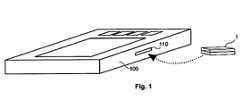
- FIG. 1shows a measurement system according to the invention comprising a measurement evaluation device with a socket for a measurement sample handling device comprising a handling unit and a measurement device.
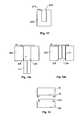
- FIGS. 2 a to 2 cshow the disposable device according to the invention in an exploded view, assembled and a portion of the disposable device in greater detail.
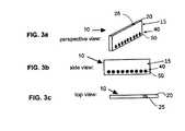
- FIGS. 3 a , 3 b , and 3 cshow the measurement device in a perspective view, side view and top view, respectively.
- FIG. 4shows a schematic view of the measurement device in greater detail.
- FIG. 5shows a detailed view of a specific embodiment of two openings of the measurement device.
- FIG. 6shows the plurality of electrical contacts of the measurement device according to the invention in more detail
- FIG. 7shows the socket of measurement evaluation device in greater detail.
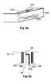
- FIGS. 8 a and 8 bshows a finger tip positioning tool on the handling unit and a plurality of opening and control electrodes at the opening.
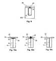
- FIG. 9shows a cross sectional view of the handling unit with the measurement device inserted and a sealing droplet.
- FIGS. 10 a to 10 cshow variants of the sealing and a sealing droplet attached to the measurement device.
- FIG. 11shows the handling unit with a locking device for fixing the measurement device in the handling unit.
- FIGS. 12 a and 12 bshow the insertion of measurement device into the handling unit through a third opening in the handling unit.
- FIG. 13shows a locking mechanism for closing the handling unit with the closure device.
- FIG. 1shows a measurement system comprising a combination of a measurement evaluation apparatus 100 having a socket 110 and a measurement sample handling device or disposable device 1 comprising a measurement device 10 (shown in FIG. 2 a ) attachable to the socket 110 .
- the measurement evaluation apparatus 100comprises electronics for computing and evaluating a species ion concentration taken from a sample in the measurement sample handling device 1 .
- the measurement evaluation apparatus 100may comprise controls for controlling and checking the measurement and evaluation process.
- the measurement evaluation apparatus 100may also comprise indication means, such as a display or similar, to indicate results and setting of the measurement system to a user. The indication means is not shown in the figure.
- the measurement evaluation apparatus 100may also comprise interfaces for connecting the measurement system to a computer or a clinical data system (not shown) for data transfer and measurement system control.
- the measurement evaluation device 110may also be a personal computer equipped with a socket 110 for receiving the measurement sample handling device 1 .
- the measurement sample handling devicemay be a one-time use disposable that is only used for one measurement.
- the disposable devicemay, however, also be used for several times, for example for repetitive or parallel measurements.
- the terms disposable device and measurement sample handling deviceare used as synonyms within this disclosure.
- FIGS. 2 a to 2 cshow the measurement sample handling device 1 in more detail.
- FIG. 2 aan exploded view is illustrated, an assembled view is illustrated in FIG. 2 b and in FIG. 2 c the portion of the measurement sample handling device 1 that can be attached to the socket 110 is illustrated in greater detail.
- the measurement sample handling device 1also comprises a handling unit 200 .
- the handling unit 200has a first opening 210 on a first side 202 , defined to be the measurement side, and a second opening 220 at a second side 204 of the handling unit 200 as illustrated in FIGS. 2 a and 2 c .
- the second surface 204faces towards the socket 110 of the measurement evaluation device 100 when the measurement sample handling device 1 is mounted in the measurement evaluation apparatus 100 .
- the first opening 210 and the second opening 220may also be arranged at the bottom face, at the edge of the bottom face and the second face 204 of the handling unit 200 or at any other side of the handling unit 200 .
- the openingsmay also be enlarged in size to enable the insertion of the measurement device 20 into the handling unit 200 .
- the first opening 210 and the second opening 220are interconnected inside the handling unit 200 as illustrated by the dotted lines in FIGS. 2 a and 2 c.
- the measurement device 10is inserted into the first opening 210 of the handling unit 200 .
- the measurement device 10has a measurement surface 20 and a plug portion 40 .
- the measurement device 10may also be inserted through second opening 220 or a third opening 230 as will be explained with respect to FIGS. 9 and 12 a,b .
- the measurement surface 20is substantially in the same plane as the first side 202 of the handling unit 200 when the measurement device 10 is inserted in the handling unit 200 .
- the plug potion 40is accessible from the outside of the measurement sample handling device 1 through the second opening 220 of the handling unit 200 .
- the measurement device 10is described in further detail below with respect to FIG. 3 .
- the measurement device 10may be made from a different material that the handling unit 200 .
- the measurement device 10may be made partially or completely from glass material, whilst the handling unit 200 is made from plastics material.
- the measurement device 10may also be formed from polymer material.
- the measurement device 10is much smaller in size than the handling unit 20 . Thus millimeter dimensions of the measurement device 10 may be implemented, while the measurement device 10 can be easily handled with the handling unit 200 .
- the size of the handling unit 200can be adapted to the needs of the user (patient).
- the handling unit 200may have dimensions that provide an easy handling even with shaking hands.
- the size of the handling unit 200may be larger than 1 cm, in particular about 4 cm or more in at least one dimension.
- at least the second side 204 of the handling unit 200is adapted to fit into the socket 110 .
- the side faces or other geometrical parameters of the handling unit 200may also be adapted to fit into the socket 110 .
- the socket 110 and the handling unit 200may be formed in a way that there is only one possibility of inserting the disposable or measurement sample handling device 1 comprising the handling unit into the socket 110 . Thereby faulty operation by unexperienced or elderly users or patients can be excluded and measurement errors can be avoided.
- the measurement device 10may be arranged close to the second side 204 when inserted inside the handling unit 200 .
- the measurement deviceis close to the socket 110 when the measurement sample handling device 1 is inserted into the socket 110 .
- the measurement device 10may be arranged inside the handling unit 200 such that side of the measurement device 10 comprising the plug portion 40 is parallel to the second side 204 when inserted into handling unit 200 .
- the handling unit 200 and the measurement surface 20might be covered by a permeable layer 32 (as seen clearly in FIG. 2 a ) for providing access to the measurement surface 20 of the measurement device 10 .
- the permeable layer 32may completely or partially cover the measurement side 202 and the measurement surface 20 .
- a sealing 34is provided on top of the measurement side 202 for sealing the permeable layer 32 or the measurement surface 20 for preventing leakage or evaporation of fluids.
- the sealing layer 34may be removed by the patient or user prior to use of the measurement device.
- the permeable layer 32 and the sealing 34may be of different size. A person skilled in the art will understand that more or fewer layers may be arranged on top of the measurement surface 20 or the first surface 202 .
- a closure device 30may be used for closing the measurement surface 20 prior to and/or after use.
- the sealing 34 and permeable layer 32may be attached to the measurement device 10 , the closure device 30 or to the handling unit 200 .
- the handling device 200 and the closure device 30may be made from the same material, for example plastics material.
- the handling device 200 and the closure device 30may also be made in one piece.
- An integral hingemay be provided for separating the closure device portion form the handling device portion and for enabling folding of the closure device on top of the handling device in order to conceal or close the measurement surface 20 .
- FIGS. 3 a , 3 b , and 3 cshow the measurement device 10 in a perspective view, a side view and a top view, respectively.
- the measurement device 10has a first opening 25 in the measurement portion 15 .
- a microfluidic channel 60(shown in FIG. 4 ) is implemented in the measurement portion 15 inside the measurement device 10 .
- the first opening 25provides an access from the surroundings of the measurement surface 20 to the microfluidic channel 60 .
- a person skilled in the artwill understand that a plurality of openings 25 can be provided and that the microfluidic channel 60 can comprise a network of different ones of the channels 60 which are realized in the measurement device 10 .
- An example for a channel 60 with a first opening 25that is particularly useful with the present invention can be found in the patent application PCT/EP2006/011148.
- the measurement device 10may be at least partially formed in glass material or another material that can be microstructured.
- the first opening 25may be in the measurement surface 20 .
- the first opening 25may also be in another side of the measurement portion 15 of measurement device 10 in close proximity to the measurement surface 20 to which the liquid sample is applied. In this case the liquid sample will go from the measurement surface 20 to the first opening 25
- the plug portion 40is arranged at a different side of the measurement device 10 than the measurement surface 20 comprising the first opening 25 .
- the plug portion 40when inserted into the handling unit 200 , the plug portion 40 is only accessible through the second opening 220 of the handling unit 200 while the measurement surface 20 is solely accessible through first opening 210 of the handling unit 200 .
- the handling unit 200may thus provide a seal that ensures that the liquid sample that is in use added to the measurement surface 20 can not come into contact with any of the plurality of electrical contacts 50 .
- electrical short-circuits between two or more of the plurality of contacts 50 that would impair a measurement or control of functions of the measurement device 10can be advantageously excluded.
- the plug portion 40 and the measurement surface 20may also be arranged on the same side of the measurement device 10 . However, the plug portion 40 and the measurement surface 20 are separated form each other by a sealing portion of the handling unit 200 when the measurement device 10 is inserted into the handling unit 200 . Thus, liquids on the measurement surface 20 are prevented from coming into contact with electrical contacts of the plug portion 40 .
- FIG. 4shows a schematic view of the measurement device 10 in the view of FIG. 3 b in greater detail.
- the microfluidic channel 60is arranged between two microfluidic reservoirs 61 and 62 .
- the microfluidic channel 60further has the first opening 25 in the measurement surface 20 .
- the first opening 25may be connected via a sample channel 26 with the microfluidic channel 60 .
- electrodes 65may be integrated in the measurement device 10 .
- the electrodes 65may be constructed as electrophoresis electrodes 65 b and 65 c for separating charged species in the sample inside the microfluidic channel 60 .
- An electrophoresis electrode 65 bmay be integrated in each ones of the reservoirs 61 , 62 , 64 .
- the reservoirs 61 , 62 , 64may be closed, such that the microfluidic channel 60 provides the only access to the reservoir 61 , 62 64 In this way the liquid inside the reservoir is prevented from evaporation and gas formation.
- the reservoirs 61 , 62 , 64may be substantially larger in size that the width, height or depth of the microfluidic channel 60 .
- Each ones of the electrodes 65 bare in electrical contact via electrical path with electrical contact 50 b , 50 h and 50 g , respectively.
- electrophoresis inside the microfluidic channels 60can be controlled by applying voltages independently to each ones of the electrophoresis electrodes 65 b by the measurement evaluation device 100 when the measurement device 10 is attached to the socket 110 .
- the opening electrode 65 cmay be integrated at the first opening 25 and connected with electrical contact 50 i .
- the opening electrode 65 cmay also serve as an electrophoresis electrode or as a control electrode as will be explained later.
- the electrodes 65may also be provided as conductivity electrodes 65 a for measuring the conductivity in a section of the microfluidic channel 60 for determining a charge concentration in this section of the microfluidic channel 60 .
- the conductivity electrodes 65 aare connected to and addressed by electrical contacts 50 a and 50 d (as illustrated in FIG. 4 ) and thus controlled by measurement evaluation device 100 when the measurement device 10 is attached to the socket 110 .
- the electrophoresis electrodes 65 b in capillary electrophoresis systemmay be based on material that can adsorb hydrogen atoms due to its intrinsic characteristics, for instance palladium or platinum. The adsorption makes it possible to prevent gas formation for example of hydrogen near the electrophoresis electrode 65 b used as a cathode.
- the use of palladium or platinum as materialis in particular useful for the electrophoresis electrode 65 b used as a cathode but the other ones of the electrodes 65 may also be made from the same material.
- the electrophoresis electrode 65 b and/or the opening electrode 65 c used as anodemay also be made from a different material in order to prevent oxygen gas formation.
- the electrophoresis electrode 65 b used as anodemay be a silver/silver chloride electrode or may be made from copper. In this case, chloride and solid silver or copper ions will be formed instead of oxygen.
- Palladium, platinum, nickel, silver/silver chloride and/or copper as well as further materialsmay also be mixed in one or more of electrodes 65 to combine the advantages of each material.
- One or more of the electrodes 65 , 65 a , 65 b , 65 cmay also be provided with an adhesive layer made from en inert metal such as tantalum or chrome.
- the measurement device 10may further comprise electric components, such as temperature sensors, pH sensors and others that may be electrically contacted and controlled with the remaining electrical contacts 50 c , 50 c and 50 f . It is obvious to a person skilled in the art that the number of the plurality of electrical contacts 50 , 50 a to 50 i is purely exemplary and that more or less electrical contacts can be provided within the scope of the invention.
- the measurement device 10can comprise solely passive electrical components such as wires, conductors and electrodes. No active component, such as transistors, diodes, flip-flops or similar other active electronic components are necessary.
- the measurement device 10may be electronically controlled by the measurement evaluation device 100 .
- sensorsmay be integrated into measurement device 10 that can comprise semiconductor elements that may also be active semiconductor elements in some cases.
- FIG. 5shows a detailed view of a specific embodiment of the first opening 25 of the measurement device 20 that is connected to the microfluidic channel 60 by the sample channel 26 .
- a second opening 27may be provided, for example to prevent evaporation of fluids.
- the second opening 27is fluidly connected to the sample channel 26 and the first opening 25 .
- the second opening 27may be substantially larger in size than the first opening 25 . The difference in size results in different contact angles ⁇ 1 and ⁇ ⁇ at first opening 25 and second opening 27 , respectively, when a liquid is filled into the microfluidic system and sample channel 26 .
- the difference in the contact angle ⁇ 1 and ⁇ ⁇will result in a pressure difference in the first opening 25 and the second opening 27 that will, when the liquid is allowed to evaporate from the first opening 25 and the second opening 27 , result in the level of the liquid remaining at essentially the same level in first opening 25 while the liquid level goes down in second opening 27 due to evaporation.
- FIG. 6shows the plurality of electrical contacts 50 in more detail.
- Each of the plurality of electrical contacts 50may be arranged inside a hole 42 formed in the plug portion 40 of the measurement device 10 .
- an electrical contactmay be provided at the bottom of the hole 42 .
- each one of the plurality of electrical contacts 50will be positioned in a separate hole 42 .
- two or more of the plurality of electrical contacts 50may also be arranged together in a single one of the holes 42 .
- holes 42may be provided without any contacts in case the measurement device 10 provides only some functionality.
- the electrical contacts 50 d , 50 e and 50 f shown in FIG. 4may be left out if no further electrical component are used.
- the plug portionprovides corresponding holes 42 providing space for the corresponding pins of the socket 110 .
- the hole 42may be round and of cylindrical shape or conical shape or have any other shape known to a person skilled in the art.
- the conical shapemay be used to align or guide pins of the socket 110 towards each of the plurality of contacts 50 .
- Other shapes of the holes 42may also be implemented within the scope of the invention.
- FIG. 7shows the socket 110 of measurement evaluation device 100 in greater detail.
- the socket 110may be provided in a side wall of the measurement evaluation device 100 as illustrated in FIG. 1 or may be provide in a separate socket container that is electrically connectable to the measurement evaluation device 100 .
- the socket 110comprises a plurality of pins 120 that is arranged in a pattern corresponding to the plurality of contacts 50 of the measurement device 10 such that when the measurement sample handling device 1 is inserted into the socket 110 , at least a portion of the plurality of pins 120 comes into electrical contact with at least one of the plurality of contacts 50 .
- the number of the plurality of pins 120may be inferior, equal or superior to the number of contacts 50 of the measurement device 10 .
- the same socket 110 and consequently the same measurement evaluation device 100may be used with a plurality of different measurement devices 10 .
- the measurement devices 10may differ in the number of electrical contacts 50 , for example due to additional sensors, like temperature, pH sensors or similar, that are integrated in the measurement device 10 , or due to a different number of electrodes 65 for different applications of the measurement device 10 .
- the number of electrical contacts 50may vary, the number and shape of the holes 42 in the plug portion 40 might be adapted to the number and shape of pins 120 in the socket 110 in order to provide correct contact and positioning for each of the pins 120 when the measurement sample handling or measurement sample handling device 1 with the measurement device 10 is inserted into the socket 110 .
- the plurality of pins 120may be made of electrical spring contacts in order to ensure the contact of the plurality of pins 120 with the corresponding ones of the plurality of electrical contacts 50 when the measurement device 100 is inserted into the socket 110 .
- the spring contactsmay recede and thus prevent damage on the measurement device 10 , when the measurement device 10 is inserted into the socket 110 and the electrical contacts 50 are forced against the pins 120 .
- the plurality of pins 120may be arranged inside the socket 110 as illustrated in FIG. 6 .
- the measurement sample handling device 1 or solely measurement device 10is introduced into the socket 110 , the measurement device 10 is completely or partially positioned inside the socket 110 . In this case no modification to the sample on the measurement surface is possible after the measurement is started and no electric contacts are necessary in the handling unit 200 while keeping the measurement device 10 small and therefore cheap
- the measurement devicecan be safely used by a patient or other user without specific training or care. This is important because high voltages, e.g. in the range or 1000 Volts may be used during measurement of the sample.
- the measurement evaluation device 100may only start a measurement when the measurement sample handling device 1 with the measurement device 10 is inserted correctly into socket 110 . For example, a measurement may only be started if the required ones of the contacts 50 a to 50 i are actually in contact with the corresponding pins.
- the actual measurementmay only be started after successful control measurements are carried out in order to ensure correct operation of the measurement device 10 .
- a control measurementmay be for example measuring the sodium concentration in the liquid sample 5 .
- the sodium concentrationmay be measured and evaluated substantially in parallel to the actual measurement of the lithium concentration.
- the sodium concentrationhas to be in a range corresponding to that which is usually found in blood. In case a different sodium concentration is evaluated, something went wrong in the measurement and it can not be ensured that the evaluated lithium concentration is correct. The measurement would therefore be ignored.
- Additional and initial controlscan be performed, for instance measuring the conductivity or the temperature of the background electrolyte solution (BGE), in order to check the correctness of for example sodium concentrations.
- BGEbackground electrolyte solution
- FIG. 8 ashows a specific embodiment of the invention with a finger tip positioning tool integrated in the handling unit 200 described in detail above with respect to FIGS. 2 a to 2 c .
- a rim 212is provided on one or more sides of the first opening 210 in the measurement side 202 of the handling unit 200 .
- the rim 212has the shape and height that it can easily be felt and or seen by a user (patient) using the measurement sample handling device 1 when putting a finger on top of the measurement side 202 .
- the rim 212may be arranged along the first opening 210 around the position, at which the opening 25 is located when the measurement device 10 is inserted into the handling unit 200 .
- the rim 212may thus serve as a positioning tool for depositing a liquid or blood sample onto the opening 25 at the measurement surface 20 , as it may be felt by the finger tip of a user or because the rim may be simply seen by eye. This is in particular useful because the opening 25 itself may be too small to be seen by the user (patient) by eye.
- a cavity or groove in the measurement surface 20may also be used as positioning tool.
- the cavity or groovehas the further advantage that the cavity or groove serves as collector for sample liquid and that can prevent sample liquid from leaking or spreading onto the measurement device.
- the opening electrode 56 cpresent at the first opening 25 as illustrated in FIG. 4 or FIG. 8 b , may be used to detect the presence of sample liquid on or around the first opening 25 .
- the opening electrode 65 ccan be present at a certain position or height within the positioning cavity or groove.
- FIG. 8 bshows an example how additional electrodes can be arranged at the first opening 25 .
- at least one control electrode 65 d , 65 e , and 65 fcan be used.
- the at least one control electrode 65 d , 65 e , 65 fcan be arranged close to the first opening 25 , for measuring additional parameters such as conductivity of the liquid sample.
- the conductivity of a liquid samplecan be measured between the control electrode 65 d and the control electrode 65 e .
- the electrode 65 fcan be from a different material or can have a coating for measuring a different parameter of the liquid sample.
- a channel electrode 65 gmay be provided in proximity to the first opening 25 .
- the channel electrode 65 gis in contact with the solution inside the sample channel 26 , when the sample channel is filled with an electrolyte solution. In case evaporation of the electrolyte solution should occur, the level of the electrolyte solution would sink below the channel electrode 65 g , which can be easily detected by conductivity measurements.
- the channel electrode 65 g as well as the opening electrode 65 c and the control electrodes 65 d , 65 e , and 65 fcan thus be used for initial control measurements as for instance as indication for initial conductivity or evaporation and or gas bubble detection.
- the opening electrode 65 c or the control electrode 65 d , 65 e or 65 f or the channel electrode 65 gmay also be used as electrophoresis electrode, for example for capillary electrophoresis inside the sample channel 26 .
- FIG. 9shows a cross sectional view of the handling unit 200 with the measurement device 10 inserted.
- a sealing droplet 29may be placed at least on top of the opening 25 .
- the sealing droplet 29may be from silicone, PDMS or other material and covers the opening 25 and thus the microfluidic channel 60 in order to prevent evaporation and contamination.
- the sealing 34described above with respect to FIG. 2 a , may be a sticky foil for covering the measurement surface prior to use.
- the sealing droplet 29may stick to the sticking foil.
- the usermay remove the sticky foil and in the same time the sealing droplet 29 sticking to it, thereby providing access to the opening 25 .
- FIGS. 10 a to 10 cshow different arrangements of the sealing 34 and the sealing droplet 29 on the first opening 25 of measurement device 10 .
- a sealing droplet 29that may be from silicon material or the like, may be placed on the first opening 25 after the microfluidic network comprising the microfluidic channel 60 and the sample channel 26 has been filled with a liquid prior to use of the measurement device 10 .
- the sealing droplet 29thus prevents any evaporation of liquid from the microfluidic network through the first opening 25 .
- a further sealing 34for example in form of a tape or foil may be applied on top of sealing droplet 29 .
- When a patient or user wants to use the measurement device 10he removes the sealing 34 and the sealing droplet 29 away, before applying the liquid sample 5 to the first opening 25 .
- the sealing droplet 29may be attached to the sealing 34 in order to facilitate its removal.
- the sealing 34may also comprise a hole 35 aligned substantially on top of the first opening 25 when the sealing 34 is placed on the measurement surface 20 of measurement device 10 as illustrated in FIG. 10 b .
- the sealing droplet 29may extend through the hole 35 in the sealing 34 for secure attachment.
- the sealing droplet 29is removed form the first opening 25 when a user or patient removes the sealing 34 prior to use of the measurement device 10 .
- the sealing 34may also be directly attached to the measurement surface 20 of measurement device 10 .
- the sealing 34may thus directly seal the first opening 25 .
- the sealingmay be a tape or a foil, made from or covered by silicone or other suitable material.
- the sealing 34 and eventually the sealing droplet 29may also be attached to the closure device 30 .
- the sealingis removed when the closure device 30 is opened prior to use of the measurement device 10 .
- the sealingmay also be applied when closing the closure device 30 after placing the liquid sample 5 on the measurement surface 20 in order to prevent contamination and evaporation of the liquid sample 5 .
- sealing 34 described above with respect to the first opening 25can also be applied to further openings in the measurement device 10 , for example to the second opening 27 illustrated describe with respect to in FIG. 5 .
- FIG. 11shows the handling unit 200 of the present invention with a locking device 214 for fixing the measurement device 10 in the handling unit 200 .
- the measurement device 10may be inserted through first opening 210 into handling unit 200 , as illustrated in FIG. 2 a .
- a locking device 214 in form of a rimmay be provided at the opening 210 .
- the width of the opening 210 in at least one directionmay be somewhat smaller or equal to the corresponding size of the measurement device 10 .
- the locking device 214may serve as a fixation or snap-in mechanism for the measurement device 10 in the handling unit 200 .
- FIGS. 12 a and 12 bshows the insertion of measurement device 10 into the handling unit 200 through a third opening 230 provided in the handling unit 200 .
- the third openingmay be provided on an opposite side to first side 202 of handling unit 200 .
- the first opening 210 in handling unit 200can be smaller in size and provide essentially only access to the first opening 25 on the measurement surface 20 .
- the contact seal for preventing sample liquid form coming into contact with the plug portion 40can be substantially large in size.
- positioning of the measurement surface 20 and the first opening 25can be carried out more precisely.
- the third opening 230may also be combined with the second opening 220 to form one enlarged opening for the plug portion 40 and the insertion of the measurement device 10 .
- a locking device 234that may be snap-in mechanism is provided at handling unit 200 and/or measurement device 10 in order to ensure fixation and correct positioning of the measurement device 10 inside the handling unit 200 , as illustrated in FIG. 12 b .
- the seal 34 , the permeable layer 32 or other means provided in the handling unit 200may provide a counterforce for when the measurement device 10 is inserted to ensure the closure of the first opening 25 in order to prevent contamination and evaporation
- FIG. 13shows a locking mechanism for closing the handling unit 200 with the closure device 30 .
- the closure device 30may be provided with a hook 38 , that may engage with a corresponding notch 238 at the handling unit 200 , when the closure device 30 is positioned on the first surface 202 of handling unit 200 in order to cover and protect the measurement surface 20 and opening 25 , in particular after a liquid sample has been placed on the opening 25 of the measurement device 10 .
- the hook 38 and the notch 238may engage with each other in non-removable manner forming a snap-in locking device. In this case, after closing the closure device 30 , the handling unit 200 can not be reopened and thus not be reused. This prevents contamination of the sample as well as falsification of the measurement results.
- the locking mechanismmay be provided as a mechanism that can be opened and closed several times for allowing multiple access to the measurement surface. Such mechanisms are commonly known and widely used.
Landscapes
- Health & Medical Sciences (AREA)
- Life Sciences & Earth Sciences (AREA)
- Chemical & Material Sciences (AREA)
- Molecular Biology (AREA)
- General Health & Medical Sciences (AREA)
- Analytical Chemistry (AREA)
- Chemical Kinetics & Catalysis (AREA)
- Physics & Mathematics (AREA)
- Pathology (AREA)
- General Physics & Mathematics (AREA)
- Immunology (AREA)
- Biochemistry (AREA)
- Electrochemistry (AREA)
- Hematology (AREA)
- Engineering & Computer Science (AREA)
- Biomedical Technology (AREA)
- Dispersion Chemistry (AREA)
- Clinical Laboratory Science (AREA)
- Ecology (AREA)
- Food Science & Technology (AREA)
- Medicinal Chemistry (AREA)
- Urology & Nephrology (AREA)
- Biophysics (AREA)
- Investigating Or Analyzing Materials By The Use Of Electric Means (AREA)
- Automatic Analysis And Handling Materials Therefor (AREA)
- Investigating Or Analysing Biological Materials (AREA)
Abstract
Description
Claims (27)
Applications Claiming Priority (2)
| Application Number | Priority Date | Filing Date | Title |
|---|---|---|---|
| US12/515,635US8465637B2 (en) | 2006-11-21 | 2006-11-21 | Ion sensor for fluid and method for its manufacture |
| PCT/EP2007/004468WO2008141659A1 (en) | 2007-05-18 | 2007-05-18 | Test chip with plug for measuring the concentration of an analyte in a liquid, housing for test chip and socket for plug |
Publications (2)
| Publication Number | Publication Date |
|---|---|
| US20100236926A1 US20100236926A1 (en) | 2010-09-23 |
| US9410924B2true US9410924B2 (en) | 2016-08-09 |
Family
ID=38617428
Family Applications (1)
| Application Number | Title | Priority Date | Filing Date |
|---|---|---|---|
| US12/600,738Active2029-11-30US9410924B2 (en) | 2007-05-18 | 2007-05-18 | Test chip with plug for measuring the concentration of an analyte in a liquid, housing for test chip and socket for plug |
Country Status (9)
| Country | Link |
|---|---|
| US (1) | US9410924B2 (en) |
| EP (2) | EP2565640B1 (en) |
| JP (1) | JP5237359B2 (en) |
| KR (3) | KR101346468B1 (en) |
| CN (1) | CN101711359A (en) |
| BR (1) | BRPI0721675A2 (en) |
| CA (1) | CA2685361C (en) |
| EA (1) | EA200901553A1 (en) |
| WO (1) | WO2008141659A1 (en) |
Cited By (1)
| Publication number | Priority date | Publication date | Assignee | Title |
|---|---|---|---|---|
| KR20220092731A (en)* | 2020-12-24 | 2022-07-04 | 경북대학교 산학협력단 | Measuring system of electrical properties of liquid and method for the measuring electrical properties of liquid |
Families Citing this family (4)
| Publication number | Priority date | Publication date | Assignee | Title |
|---|---|---|---|---|
| USD604302S1 (en) | 2008-04-02 | 2009-11-17 | Medimate Holding B.V. | Housing for test chip |
| KR102316022B1 (en)* | 2015-01-30 | 2021-10-21 | 휴렛-팩커드 디벨롭먼트 컴퍼니, 엘.피. | Fluid Test Chips and Cassettes |
| DK3502231T3 (en)* | 2017-12-19 | 2020-10-12 | Eppendorf Ag | BIOPROCESS CONTROL DEVICE AND BIOPROCESS SYSTEM |
| US11219642B1 (en)* | 2020-09-01 | 2022-01-11 | Catherine Lueninghoener | Methods and compositions for treating heart conditions |
Citations (63)
| Publication number | Priority date | Publication date | Assignee | Title |
|---|---|---|---|---|
| US3506554A (en) | 1968-03-15 | 1970-04-14 | Samuel Raymond | Apparatus for separating electrophoretically active substances |
| US4242194A (en) | 1978-12-07 | 1980-12-30 | Raimund Kaufmann | Apparatus for spectroscopic measurement of the velocity of particles in a fluid |
| US4415418A (en) | 1980-12-22 | 1983-11-15 | Turre Gilles H J | Gel electrophoresis device and method |
| EP0215419A2 (en) | 1985-09-18 | 1987-03-25 | Miles Inc. | Volume metering capillary gap device for applying a liquid sample onto a reactive surface |
| EP0295942A2 (en) | 1987-06-17 | 1988-12-21 | The Board Of Trustees Of The Leland Stanford Junior University | On-column conductivity detector for microcolumn electrokinetic separations |
| US4956062A (en) | 1988-04-14 | 1990-09-11 | Japan As Represented By Director General Of Agency Of Industrial Science And Technology | Method for concentration determination of lithium ions |
| JPH04501768A (en) | 1988-09-15 | 1992-03-26 | アイ―スタット コーポレーション | Disposable sensing device for real-time fluid analysis |
| JPH053998A (en) | 1991-06-28 | 1993-01-14 | Sanyo Electric Co Ltd | Clothes drying machine |
| JPH0552799A (en) | 1986-12-11 | 1993-03-02 | Horiba Ltd | Manufacture of gel-shaped member for ion measurement electrode |
| US5223114A (en) | 1987-06-17 | 1993-06-29 | Board Of Trustees Of The Leland Stanford Junior University | On-column conductivity detector for microcolumn electrokinetic separations |
| EP0631133A2 (en) | 1993-06-21 | 1994-12-28 | Helena Laboratories Corporation | An electrophoresis plate and a method of making an electrophoresis plate package |
| WO1996033405A1 (en) | 1995-04-17 | 1996-10-24 | Mayo Foundation For Medical Education And Research | Sample preprocessor |
| WO1998005424A1 (en) | 1996-08-02 | 1998-02-12 | Caliper Technologies Corporation | Analytical system and method |
| JPH10311827A (en) | 1997-03-12 | 1998-11-24 | Kdk Corp | Test tool for analyzing liquid sample |
| US5849208A (en)* | 1995-09-07 | 1998-12-15 | Microfab Technoologies, Inc. | Making apparatus for conducting biochemical analyses |
| JPH1158342A (en) | 1997-05-23 | 1999-03-02 | Sekisui Chem Co Ltd | Forming die for alkaline material, and forming method for alkaline material |
| US5882496A (en) | 1997-02-27 | 1999-03-16 | The Regents Of The University Of California | Porous silicon structures with high surface area/specific pore size |
| US5900130A (en) | 1997-06-18 | 1999-05-04 | Alcara Biosciences, Inc. | Method for sample injection in microchannel device |
| US5989402A (en) | 1997-08-29 | 1999-11-23 | Caliper Technologies Corp. | Controller/detector interfaces for microfluidic systems |
| JP2000002677A (en) | 1998-06-15 | 2000-01-07 | Asahi Chem Ind Co Ltd | Analyzer |
| EP1016864A2 (en) | 1998-12-28 | 2000-07-05 | Affymetrix, Inc. (a California Corporation) | Process for microfabrication of integrated PCR-CE device and product produced by the same |
| US6090545A (en) | 1995-03-10 | 2000-07-18 | Meso Scale Technologies, Llc. | Multi-array, multi-specific electrochemiluminescence testing |
| JP2000227414A (en) | 1999-02-08 | 2000-08-15 | Shimadzu Corp | Chip unit for microchip electrophoresis |
| KR20000066685A (en) | 1999-04-20 | 2000-11-15 | 김순택 | Electrode assembly of electron gun for CRT |
| WO2000067907A2 (en) | 1999-05-11 | 2000-11-16 | Aclara Biosciences, Inc. | Sample evaporative control |
| US6258254B1 (en) | 1997-07-28 | 2001-07-10 | Matsushita Electric Industrial Co., Ltd. | Biosensor |
| JP2001258868A (en) | 2000-03-15 | 2001-09-25 | Jun Kikuchi | Method and device for blood analysis |
| WO2001077641A1 (en) | 2000-04-06 | 2001-10-18 | Caliper Technologies Corp. | Microfluidic devices and systems incorporating cover layers |
| US20020025576A1 (en) | 1998-03-17 | 2002-02-28 | Cepheid | Integrated sample analysis device |
| US20020027075A1 (en) | 1993-04-15 | 2002-03-07 | Andreas Manz | Method for controlling sample introduction in microcolumn separation techiques and samplinh device |
| JP2002527250A (en) | 1998-10-13 | 2002-08-27 | バイオマイクロ システムズ インコーポレイテッド | Fluid circuit components based on passive hydrodynamics |
| US6444474B1 (en)* | 1998-04-22 | 2002-09-03 | Eltron Research, Inc. | Microfluidic system for measurement of total organic carbon |
| WO2003012421A1 (en) | 2001-08-01 | 2003-02-13 | Arkray, Inc. | Analyzing implement, analyzing device, and method of manufacturing analyzing implement |
| CA2737892A1 (en) | 2002-03-05 | 2003-09-18 | Abbott Point Of Care Inc. | Apparatus and methods for analyte measurement and immunoassay |
| US20030209314A1 (en) | 2002-05-13 | 2003-11-13 | Guo Lingjie J. | Method of forming nanofluidic channels |
| JP2004020367A (en) | 2002-06-17 | 2004-01-22 | Arkray Inc | Analyzing apparatus |
| US20040037739A1 (en)* | 2001-03-09 | 2004-02-26 | Mcneely Michael | Method and system for microfluidic interfacing to arrays |
| FR2844052A1 (en) | 2002-08-28 | 2004-03-05 | Commissariat Energie Atomique | Device for measuring electrical activity in biological samples, useful e.g. in screening for therapeutic compounds, comprises substrate for sample, sandwiched between electrodes |
| JP2004109082A (en) | 2002-09-20 | 2004-04-08 | Japan Science & Technology Corp | Blood analyzer and plasma separation method |
| US6730199B1 (en)* | 1998-06-08 | 2004-05-04 | Haenni Claude | Apparatus for measuring the electrophysiological activity of a group of cells |
| US20040086872A1 (en)* | 2002-10-31 | 2004-05-06 | Childers Winthrop D. | Microfluidic system for analysis of nucleic acids |
| US20040089546A1 (en)* | 2002-11-08 | 2004-05-13 | Dar Bahatt | Apparatus and method for confining eluted samples in electrophoresis systems |
| US20040126279A1 (en)* | 2002-08-02 | 2004-07-01 | Renzi Ronald F. | Portable apparatus for separating sample and detecting target analytes |
| EP1486778A2 (en) | 2003-06-09 | 2004-12-15 | I-Sens, Inc. | Electrochemical biosensor |
| WO2005003724A2 (en) | 2003-06-27 | 2005-01-13 | Bayer Healthcare Llc | Method and apparatus for entry and storage of specimens into a microfluidic device |
| US6864480B2 (en) | 2001-12-19 | 2005-03-08 | Sau Lan Tang Staats | Interface members and holders for microfluidic array devices |
| JP2005134190A (en) | 2003-10-29 | 2005-05-26 | Gunze Ltd | Sensor-mounting structure and measurement indicator |
| EP1543935A2 (en) | 2003-12-17 | 2005-06-22 | F. Hoffmann-La Roche Ag | Injection moulded plastic article with embedded part |
| US20050150766A1 (en) | 2001-11-02 | 2005-07-14 | Andreas Manz | Capillary electrophoresis microchip system and method |
| DE202005009960U1 (en) | 2005-06-24 | 2005-09-01 | Forschungszentrum Karlsruhe Gmbh | Measurement unit, for capillary electrophoresis, has a capillary array in a micro-fluid chip within a box with conductive walls, a high tension supply and a high frequency transmitter/receiver for non-contact conductivity detection |
| WO2005094286A2 (en) | 2004-03-25 | 2005-10-13 | The Regents Of The University Of California | Systems and methods for reducing the effect of corruptive signals during nanoliter osmometry |
| JP2005331411A (en) | 2004-05-20 | 2005-12-02 | Shimadzu Corp | Isoelectric focusing chip and apparatus |
| US20050268701A1 (en) | 2004-04-28 | 2005-12-08 | Rainer Hintsche | Sensor for detection of liquid ingredients, particularly for biological materials and the detection device contained in the sensor |
| US20060204143A1 (en) | 2005-02-28 | 2006-09-14 | Fuji Photo Film Co., Ltd. | Electronic album editing system, electronic album editing method, and electronic album editing program |
| JP2007006858A (en) | 2005-07-04 | 2007-01-18 | Matsushita Electric Ind Co Ltd | Microbial test chip and microbiological test method |
| US20070053796A1 (en)* | 2005-09-02 | 2007-03-08 | Jen-Jr Gau | Cartridge having variable volume reservoirs |
| US20070051628A1 (en) | 2005-09-02 | 2007-03-08 | Vladislav Dolnik | Neutral polysaccharide wall coating for electrophoretic separations in capillaries and microchannels |
| JP2007064742A (en) | 2005-08-30 | 2007-03-15 | Nec Corp | Chemical chip and connection device |
| US20070065346A1 (en)* | 2005-09-19 | 2007-03-22 | Henry Lauren R | Micro-fluidic device with neutralization and neutralization methods |
| US7217352B2 (en) | 2002-05-31 | 2007-05-15 | Hitachi High-Technologies Corporation | Capillary electrophoresis device |
| US20090302190A1 (en)* | 2006-10-25 | 2009-12-10 | Fraunhofer-Gesellschaft Zur Foerderung Der Angewandten Forschung E.V. | Chip holder, fluidic system and chip holder system |
| US20100062082A1 (en)* | 2006-11-21 | 2010-03-11 | Steven Selwyn Staal | Ion sensor for fluid and method for its manufacture |
| US8202492B2 (en)* | 2007-05-04 | 2012-06-19 | Opko Diagnostics, Llc | Fluidic connectors and microfluidic systems |
Family Cites Families (3)
| Publication number | Priority date | Publication date | Assignee | Title |
|---|---|---|---|---|
| CA2308532C (en)* | 1999-05-12 | 2005-11-29 | Gador S.A. | Use of bisphosphonates for the treatment of osteogenesis imperfecta |
| DE60140553D1 (en)* | 2000-09-14 | 2009-12-31 | Caliper Life Sciences Inc | MICROFLUIDIC DEVICES AND METHODS FOR CARRYING OUT TEMPERATURE-MEDIATED REACTIONS |
| RU2006110931A (en)* | 2003-09-05 | 2007-10-20 | Кайлипер Лайф Сайенсиз, Инк. (Us) | ANALYZED SUBSTANCE INJECTION SYSTEM |
- 2007
- 2007-05-18KRKR1020097023090Apatent/KR101346468B1/ennot_activeExpired - Fee Related
- 2007-05-18CNCN200780052977Apatent/CN101711359A/enactivePending
- 2007-05-18KRKR1020137011248Apatent/KR101401711B1/ennot_activeExpired - Fee Related
- 2007-05-18EPEP12183415.4Apatent/EP2565640B1/ennot_activeNot-in-force
- 2007-05-18USUS12/600,738patent/US9410924B2/enactiveActive
- 2007-05-18JPJP2010507797Apatent/JP5237359B2/enactiveActive
- 2007-05-18WOPCT/EP2007/004468patent/WO2008141659A1/enactiveApplication Filing
- 2007-05-18CACA2685361Apatent/CA2685361C/ennot_activeExpired - Fee Related
- 2007-05-18EPEP07725376.3Apatent/EP2150815B1/ennot_activeWithdrawn - After Issue
- 2007-05-18KRKR1020137011249Apatent/KR101366487B1/ennot_activeExpired - Fee Related
- 2007-05-18EAEA200901553Apatent/EA200901553A1/enunknown
- 2007-05-18BRBRPI0721675-0Apatent/BRPI0721675A2/ennot_activeIP Right Cessation
Patent Citations (80)
| Publication number | Priority date | Publication date | Assignee | Title |
|---|---|---|---|---|
| US3506554A (en) | 1968-03-15 | 1970-04-14 | Samuel Raymond | Apparatus for separating electrophoretically active substances |
| US4242194A (en) | 1978-12-07 | 1980-12-30 | Raimund Kaufmann | Apparatus for spectroscopic measurement of the velocity of particles in a fluid |
| US4415418A (en) | 1980-12-22 | 1983-11-15 | Turre Gilles H J | Gel electrophoresis device and method |
| EP0215419A2 (en) | 1985-09-18 | 1987-03-25 | Miles Inc. | Volume metering capillary gap device for applying a liquid sample onto a reactive surface |
| JPS6269139A (en) | 1985-09-18 | 1987-03-30 | マイルス・インコーポレーテッド | Metering Capillary Gap Apparatus and Metering Method for Applying Liquid Samples onto Reactive Surfaces |
| JPH0552799A (en) | 1986-12-11 | 1993-03-02 | Horiba Ltd | Manufacture of gel-shaped member for ion measurement electrode |
| US5223114A (en) | 1987-06-17 | 1993-06-29 | Board Of Trustees Of The Leland Stanford Junior University | On-column conductivity detector for microcolumn electrokinetic separations |
| EP0295942A2 (en) | 1987-06-17 | 1988-12-21 | The Board Of Trustees Of The Leland Stanford Junior University | On-column conductivity detector for microcolumn electrokinetic separations |
| US4956062A (en) | 1988-04-14 | 1990-09-11 | Japan As Represented By Director General Of Agency Of Industrial Science And Technology | Method for concentration determination of lithium ions |
| JPH04501768A (en) | 1988-09-15 | 1992-03-26 | アイ―スタット コーポレーション | Disposable sensing device for real-time fluid analysis |
| JPH053998A (en) | 1991-06-28 | 1993-01-14 | Sanyo Electric Co Ltd | Clothes drying machine |
| US20020027075A1 (en) | 1993-04-15 | 2002-03-07 | Andreas Manz | Method for controlling sample introduction in microcolumn separation techiques and samplinh device |
| EP0631133A2 (en) | 1993-06-21 | 1994-12-28 | Helena Laboratories Corporation | An electrophoresis plate and a method of making an electrophoresis plate package |
| JP2006047321A (en) | 1995-03-10 | 2006-02-16 | Meso Scale Technologies Llc | Multi-specific electrochemiluminescence test for multi-array |
| US6090545A (en) | 1995-03-10 | 2000-07-18 | Meso Scale Technologies, Llc. | Multi-array, multi-specific electrochemiluminescence testing |
| WO1996033405A1 (en) | 1995-04-17 | 1996-10-24 | Mayo Foundation For Medical Education And Research | Sample preprocessor |
| US5849208A (en)* | 1995-09-07 | 1998-12-15 | Microfab Technoologies, Inc. | Making apparatus for conducting biochemical analyses |
| WO1998005424A1 (en) | 1996-08-02 | 1998-02-12 | Caliper Technologies Corporation | Analytical system and method |
| US5955028A (en)* | 1996-08-02 | 1999-09-21 | Caliper Technologies Corp. | Analytical system and method |
| EP0952890A1 (en) | 1996-08-02 | 1999-11-03 | Caliper Technologies Corporation | Analytical system and method |
| JP2000515630A (en) | 1996-08-02 | 2000-11-21 | カリパー テクノロジーズ コーポレイション | Analysis system and analysis method |
| US6432720B2 (en) | 1996-08-02 | 2002-08-13 | Caliper Technologies Corp. | Analytical system and method |
| US6503757B1 (en) | 1996-08-02 | 2003-01-07 | Caliper Technologies Corp. | Analytical system and method |
| US6399025B1 (en) | 1996-08-02 | 2002-06-04 | Caliper Technologies Corp. | Analytical system and method |
| US5882496A (en) | 1997-02-27 | 1999-03-16 | The Regents Of The University Of California | Porous silicon structures with high surface area/specific pore size |
| JPH10311827A (en) | 1997-03-12 | 1998-11-24 | Kdk Corp | Test tool for analyzing liquid sample |
| JPH1158342A (en) | 1997-05-23 | 1999-03-02 | Sekisui Chem Co Ltd | Forming die for alkaline material, and forming method for alkaline material |
| US5900130A (en) | 1997-06-18 | 1999-05-04 | Alcara Biosciences, Inc. | Method for sample injection in microchannel device |
| US6258254B1 (en) | 1997-07-28 | 2001-07-10 | Matsushita Electric Industrial Co., Ltd. | Biosensor |
| US5989402A (en) | 1997-08-29 | 1999-11-23 | Caliper Technologies Corp. | Controller/detector interfaces for microfluidic systems |
| US20050279635A1 (en)* | 1997-08-29 | 2005-12-22 | Caliper Life Sciences, Inc. | Controller/detector interfaces for microfluidic systems |
| US20020025576A1 (en) | 1998-03-17 | 2002-02-28 | Cepheid | Integrated sample analysis device |
| US6444474B1 (en)* | 1998-04-22 | 2002-09-03 | Eltron Research, Inc. | Microfluidic system for measurement of total organic carbon |
| US6730199B1 (en)* | 1998-06-08 | 2004-05-04 | Haenni Claude | Apparatus for measuring the electrophysiological activity of a group of cells |
| JP2000002677A (en) | 1998-06-15 | 2000-01-07 | Asahi Chem Ind Co Ltd | Analyzer |
| JP2002527250A (en) | 1998-10-13 | 2002-08-27 | バイオマイクロ システムズ インコーポレイテッド | Fluid circuit components based on passive hydrodynamics |
| EP1016864A2 (en) | 1998-12-28 | 2000-07-05 | Affymetrix, Inc. (a California Corporation) | Process for microfabrication of integrated PCR-CE device and product produced by the same |
| JP2000227414A (en) | 1999-02-08 | 2000-08-15 | Shimadzu Corp | Chip unit for microchip electrophoresis |
| KR20000066685A (en) | 1999-04-20 | 2000-11-15 | 김순택 | Electrode assembly of electron gun for CRT |
| US20030068646A1 (en)* | 1999-05-11 | 2003-04-10 | Sharat Singh | Sample evaporative control |
| JP2002544494A (en) | 1999-05-11 | 2002-12-24 | アクララ バイオサイエンシーズ, インコーポレイテッド | Sample evaporation control |
| WO2000067907A2 (en) | 1999-05-11 | 2000-11-16 | Aclara Biosciences, Inc. | Sample evaporative control |
| JP2001258868A (en) | 2000-03-15 | 2001-09-25 | Jun Kikuchi | Method and device for blood analysis |
| US20030114785A1 (en) | 2000-03-15 | 2003-06-19 | Jun Kikuchi | Blood analyzing method and apparatus |
| JP2003530566A (en) | 2000-04-06 | 2003-10-14 | カリパー・テクノロジーズ・コープ. | Microfluidic device and system incorporating protective layer |
| WO2001077641A1 (en) | 2000-04-06 | 2001-10-18 | Caliper Technologies Corp. | Microfluidic devices and systems incorporating cover layers |
| US20040037739A1 (en)* | 2001-03-09 | 2004-02-26 | Mcneely Michael | Method and system for microfluidic interfacing to arrays |
| WO2003012421A1 (en) | 2001-08-01 | 2003-02-13 | Arkray, Inc. | Analyzing implement, analyzing device, and method of manufacturing analyzing implement |
| EP1413879A1 (en) | 2001-08-01 | 2004-04-28 | ARKRAY, Inc. | Analyzing implement, analyzing device, and method of manufacturing analyzing implement |
| US20050150766A1 (en) | 2001-11-02 | 2005-07-14 | Andreas Manz | Capillary electrophoresis microchip system and method |
| US6864480B2 (en) | 2001-12-19 | 2005-03-08 | Sau Lan Tang Staats | Interface members and holders for microfluidic array devices |
| CA2737892A1 (en) | 2002-03-05 | 2003-09-18 | Abbott Point Of Care Inc. | Apparatus and methods for analyte measurement and immunoassay |
| US20030209314A1 (en) | 2002-05-13 | 2003-11-13 | Guo Lingjie J. | Method of forming nanofluidic channels |
| US7217352B2 (en) | 2002-05-31 | 2007-05-15 | Hitachi High-Technologies Corporation | Capillary electrophoresis device |
| JP2004020367A (en) | 2002-06-17 | 2004-01-22 | Arkray Inc | Analyzing apparatus |
| US20040126279A1 (en)* | 2002-08-02 | 2004-07-01 | Renzi Ronald F. | Portable apparatus for separating sample and detecting target analytes |
| FR2844052A1 (en) | 2002-08-28 | 2004-03-05 | Commissariat Energie Atomique | Device for measuring electrical activity in biological samples, useful e.g. in screening for therapeutic compounds, comprises substrate for sample, sandwiched between electrodes |
| US7494622B2 (en)* | 2002-08-28 | 2009-02-24 | Commissariat A L'energie Atomique | Device for measuring the electrical activity of biological elements and its applications |
| JP2004109082A (en) | 2002-09-20 | 2004-04-08 | Japan Science & Technology Corp | Blood analyzer and plasma separation method |
| EP1553395A1 (en) | 2002-09-20 | 2005-07-13 | Japan Science and Technology Agency | Blood analyzer and method of separating plasma |
| US20040086872A1 (en)* | 2002-10-31 | 2004-05-06 | Childers Winthrop D. | Microfluidic system for analysis of nucleic acids |
| US20040089546A1 (en)* | 2002-11-08 | 2004-05-13 | Dar Bahatt | Apparatus and method for confining eluted samples in electrophoresis systems |
| EP1486778A2 (en) | 2003-06-09 | 2004-12-15 | I-Sens, Inc. | Electrochemical biosensor |
| WO2005003724A2 (en) | 2003-06-27 | 2005-01-13 | Bayer Healthcare Llc | Method and apparatus for entry and storage of specimens into a microfluidic device |
| JP2005134190A (en) | 2003-10-29 | 2005-05-26 | Gunze Ltd | Sensor-mounting structure and measurement indicator |
| US20050135968A1 (en) | 2003-12-17 | 2005-06-23 | Manfred Augstein | Plastic injection-moulded part with embedded component |
| EP1543935A2 (en) | 2003-12-17 | 2005-06-22 | F. Hoffmann-La Roche Ag | Injection moulded plastic article with embedded part |
| WO2005094286A2 (en) | 2004-03-25 | 2005-10-13 | The Regents Of The University Of California | Systems and methods for reducing the effect of corruptive signals during nanoliter osmometry |
| US20050268701A1 (en) | 2004-04-28 | 2005-12-08 | Rainer Hintsche | Sensor for detection of liquid ingredients, particularly for biological materials and the detection device contained in the sensor |
| JP2005331411A (en) | 2004-05-20 | 2005-12-02 | Shimadzu Corp | Isoelectric focusing chip and apparatus |
| US20060204143A1 (en) | 2005-02-28 | 2006-09-14 | Fuji Photo Film Co., Ltd. | Electronic album editing system, electronic album editing method, and electronic album editing program |
| DE202005009960U1 (en) | 2005-06-24 | 2005-09-01 | Forschungszentrum Karlsruhe Gmbh | Measurement unit, for capillary electrophoresis, has a capillary array in a micro-fluid chip within a box with conductive walls, a high tension supply and a high frequency transmitter/receiver for non-contact conductivity detection |
| JP2007006858A (en) | 2005-07-04 | 2007-01-18 | Matsushita Electric Ind Co Ltd | Microbial test chip and microbiological test method |
| JP2007064742A (en) | 2005-08-30 | 2007-03-15 | Nec Corp | Chemical chip and connection device |
| US20070051628A1 (en) | 2005-09-02 | 2007-03-08 | Vladislav Dolnik | Neutral polysaccharide wall coating for electrophoretic separations in capillaries and microchannels |
| US20070053796A1 (en)* | 2005-09-02 | 2007-03-08 | Jen-Jr Gau | Cartridge having variable volume reservoirs |
| US20070065346A1 (en)* | 2005-09-19 | 2007-03-22 | Henry Lauren R | Micro-fluidic device with neutralization and neutralization methods |
| US20090302190A1 (en)* | 2006-10-25 | 2009-12-10 | Fraunhofer-Gesellschaft Zur Foerderung Der Angewandten Forschung E.V. | Chip holder, fluidic system and chip holder system |
| US20100062082A1 (en)* | 2006-11-21 | 2010-03-11 | Steven Selwyn Staal | Ion sensor for fluid and method for its manufacture |
| US8202492B2 (en)* | 2007-05-04 | 2012-06-19 | Opko Diagnostics, Llc | Fluidic connectors and microfluidic systems |
Non-Patent Citations (15)
| Title |
|---|
| Eurasian Search Report issued in Eurasian Application No. 200901553/26 on Oct. 13, 2010. |
| Extended European Search Report issued in European Application No. 12183414.7 on Feb. 6, 2013. |
| Extended European Search Report issued in European Application No. 12183414.7 on Jan. 30, 2013. |
| Extended European Search Report issued in European Patent Application No. 12175953.4 on Jan. 14, 2013. |
| Invitation to Pay Additional Fees, European Patent Office Form PCT/ISA/2006, Nov. 27, 2007. |
| Japanese Official Action issued in Application No. 2009/537484 on May 12, 2011. |
| Official Action issued in EP Application No. 12183415.4 on Oct. 22, 2013. |
| Official Action issued in JP Application No. 2013-069912 on Apr. 8, 2014. |
| Official Action issued in JP Application No. 2013-069913 on Apr. 8, 2014. |
| Partial International Search Report, European Patent Office Form PCT/ISA/2006 (Annex), Nov. 27, 2007. |
| ReliaLAB, Insta Read Lithium System Information Sheet, Jun. 2005, 7 pages. |
| Tjerkstra et al, "Multi-Walled Microchannels: Free-Standing Porous Silicon Membranes for Use in muTAS", Journal of Microelectromechanical Systems, Dec. 2000, pp. 495-501, vol. 9, No. 4. |
| Tjerkstra et al, "Multi-Walled Microchannels: Free-Standing Porous Silicon Membranes for Use in μTAS", Journal of Microelectromechanical Systems, Dec. 2000, pp. 495-501, vol. 9, No. 4. |
| Vrouwe et al, "Microchip Analysis of Lithium in Blood Using Moving Boundary Electrophesis and Zone Electrophoresis", Electrophoresis, 2005, vol. 26, pp. 3032-3042. |
| Vrouwe, et al, "Direct Measurement of Lithium in Whole Blood Using Microchip Capillary Electrophoresis with Integrated Conductivity Detection", Electrophesis, vol. 25, 2004, pp. 1660-1667. |
Cited By (2)
| Publication number | Priority date | Publication date | Assignee | Title |
|---|---|---|---|---|
| KR20220092731A (en)* | 2020-12-24 | 2022-07-04 | 경북대학교 산학협력단 | Measuring system of electrical properties of liquid and method for the measuring electrical properties of liquid |
| KR102618172B1 (en) | 2020-12-24 | 2023-12-29 | 경북대학교 산학협력단 | Measuring system of electrical properties of liquid and method for the measuring electrical properties of liquid |
Also Published As
| Publication number | Publication date |
|---|---|
| KR20130051515A (en) | 2013-05-20 |
| BRPI0721675A2 (en) | 2013-01-22 |
| KR101401711B1 (en) | 2014-05-30 |
| KR20100005207A (en) | 2010-01-14 |
| EP2565640A1 (en) | 2013-03-06 |
| EP2565640B1 (en) | 2016-09-14 |
| US20100236926A1 (en) | 2010-09-23 |
| KR101346468B1 (en) | 2014-01-02 |
| CA2685361C (en) | 2014-05-06 |
| JP2010527444A (en) | 2010-08-12 |
| EA200901553A1 (en) | 2010-04-30 |
| JP5237359B2 (en) | 2013-07-17 |
| WO2008141659A1 (en) | 2008-11-27 |
| EP2150815A1 (en) | 2010-02-10 |
| CA2685361A1 (en) | 2008-11-27 |
| KR20130051516A (en) | 2013-05-20 |
| EP2150815B1 (en) | 2014-12-03 |
| KR101366487B1 (en) | 2014-02-21 |
| CN101711359A (en) | 2010-05-19 |
Similar Documents
| Publication | Publication Date | Title |
|---|---|---|
| US10932761B2 (en) | Advanced sweat sensor adhesion, sealing, and fluidic strategies | |
| US12048538B2 (en) | Detecting an analyte in a body fluid | |
| EP2551667B1 (en) | Method and apparatus for sensing ion concentrations in a fluid sample | |
| US9410924B2 (en) | Test chip with plug for measuring the concentration of an analyte in a liquid, housing for test chip and socket for plug | |
| JP7196162B2 (en) | Microfluidic device with laterally insertable electrodes | |
| JP6838033B2 (en) | Cleanable sample measuring instrument, sealed connector, its manufacturing method and its usage | |
| EP2562537B1 (en) | Liquid sample test method and device with test chip and handling unit | |
| JP2013156268A (en) | Measurement sample handling device having channel filled with liquid and sealed | |
| JP2013137327A (en) | Micro fluid type measuring device | |
| CN103499628A (en) | Ion sensor for liquid and manufacturing method of ion sensor | |
| Steven et al. | ION SENSOR FOR FLUID AND METHOD FOR ITS MANUFACTURE |
Legal Events
| Date | Code | Title | Description |
|---|---|---|---|
| AS | Assignment | Owner name:MEDIMATE HOLDING B.V., NETHERLANDS Free format text:ASSIGNMENT OF ASSIGNORS INTEREST;ASSIGNORS:STAAL, STEVEN S;FLORIS, JAN;BLOM, MARKO;AND OTHERS;SIGNING DATES FROM 20091222 TO 20100104;REEL/FRAME:024317/0828 | |
| AS | Assignment | Owner name:CE-MATE B.V, NETHERLANDS Free format text:ASSIGNMENT OF ASSIGNORS INTEREST;ASSIGNOR:MEDIMATE HOLDING B.V.;REEL/FRAME:035782/0694 Effective date:20150520 | |
| STCF | Information on status: patent grant | Free format text:PATENTED CASE | |
| CC | Certificate of correction | ||
| FEPP | Fee payment procedure | Free format text:MAINTENANCE FEE REMINDER MAILED (ORIGINAL EVENT CODE: REM.); ENTITY STATUS OF PATENT OWNER: SMALL ENTITY | |
| FEPP | Fee payment procedure | Free format text:SURCHARGE FOR LATE PAYMENT, SMALL ENTITY (ORIGINAL EVENT CODE: M2554); ENTITY STATUS OF PATENT OWNER: SMALL ENTITY | |
| MAFP | Maintenance fee payment | Free format text:PAYMENT OF MAINTENANCE FEE, 4TH YR, SMALL ENTITY (ORIGINAL EVENT CODE: M2551); ENTITY STATUS OF PATENT OWNER: SMALL ENTITY Year of fee payment:4 | |
| AS | Assignment | Owner name:FISIC BV, NETHERLANDS Free format text:ASSIGNMENT OF ASSIGNORS INTEREST;ASSIGNOR:CE-MATE B.V.;REEL/FRAME:053012/0001 Effective date:20200603 | |
| AS | Assignment | Owner name:FISIC HOLDING BV, NETHERLANDS Free format text:ASSIGNMENT OF ASSIGNORS INTEREST;ASSIGNOR:FISIC BV;REEL/FRAME:054891/0378 Effective date:20200412 | |
| MAFP | Maintenance fee payment | Free format text:PAYMENT OF MAINTENANCE FEE, 8TH YR, SMALL ENTITY (ORIGINAL EVENT CODE: M2552); ENTITY STATUS OF PATENT OWNER: SMALL ENTITY Year of fee payment:8 |