US9410452B2 - Fuel generation using high-voltage electric fields methods - Google Patents
Fuel generation using high-voltage electric fields methodsDownload PDFInfo
- Publication number
- US9410452B2 US9410452B2US14/426,083US201314426083AUS9410452B2US 9410452 B2US9410452 B2US 9410452B2US 201314426083 AUS201314426083 AUS 201314426083AUS 9410452 B2US9410452 B2US 9410452B2
- Authority
- US
- United States
- Prior art keywords
- working fluid
- plasma
- voltage electric
- electric field
- exposing
- Prior art date
- Legal status (The legal status is an assumption and is not a legal conclusion. Google has not performed a legal analysis and makes no representation as to the accuracy of the status listed.)
- Expired - Fee Related
Links
Images


Classifications
- F—MECHANICAL ENGINEERING; LIGHTING; HEATING; WEAPONS; BLASTING
- F01—MACHINES OR ENGINES IN GENERAL; ENGINE PLANTS IN GENERAL; STEAM ENGINES
- F01K—STEAM ENGINE PLANTS; STEAM ACCUMULATORS; ENGINE PLANTS NOT OTHERWISE PROVIDED FOR; ENGINES USING SPECIAL WORKING FLUIDS OR CYCLES
- F01K25/00—Plants or engines characterised by use of special working fluids, not otherwise provided for; Plants operating in closed cycles and not otherwise provided for
- F01K25/06—Plants or engines characterised by use of special working fluids, not otherwise provided for; Plants operating in closed cycles and not otherwise provided for using mixtures of different fluids
- B—PERFORMING OPERATIONS; TRANSPORTING
- B01—PHYSICAL OR CHEMICAL PROCESSES OR APPARATUS IN GENERAL
- B01D—SEPARATION
- B01D21/00—Separation of suspended solid particles from liquids by sedimentation
- B01D21/0009—Settling tanks making use of electricity or magnetism
- B—PERFORMING OPERATIONS; TRANSPORTING
- B01—PHYSICAL OR CHEMICAL PROCESSES OR APPARATUS IN GENERAL
- B01D—SEPARATION
- B01D21/00—Separation of suspended solid particles from liquids by sedimentation
- B01D21/01—Separation of suspended solid particles from liquids by sedimentation using flocculating agents
- B—PERFORMING OPERATIONS; TRANSPORTING
- B01—PHYSICAL OR CHEMICAL PROCESSES OR APPARATUS IN GENERAL
- B01J—CHEMICAL OR PHYSICAL PROCESSES, e.g. CATALYSIS OR COLLOID CHEMISTRY; THEIR RELEVANT APPARATUS
- B01J12/00—Chemical processes in general for reacting gaseous media with gaseous media; Apparatus specially adapted therefor
- B01J12/002—Chemical processes in general for reacting gaseous media with gaseous media; Apparatus specially adapted therefor carried out in the plasma state
- B—PERFORMING OPERATIONS; TRANSPORTING
- B01—PHYSICAL OR CHEMICAL PROCESSES OR APPARATUS IN GENERAL
- B01J—CHEMICAL OR PHYSICAL PROCESSES, e.g. CATALYSIS OR COLLOID CHEMISTRY; THEIR RELEVANT APPARATUS
- B01J19/00—Chemical, physical or physico-chemical processes in general; Their relevant apparatus
- B01J19/08—Processes employing the direct application of electric or wave energy, or particle radiation; Apparatus therefor
- B01J19/087—Processes employing the direct application of electric or wave energy, or particle radiation; Apparatus therefor employing electric or magnetic energy
- B01J19/088—Processes employing the direct application of electric or wave energy, or particle radiation; Apparatus therefor employing electric or magnetic energy giving rise to electric discharges
- B09B3/005—
- B—PERFORMING OPERATIONS; TRANSPORTING
- B09—DISPOSAL OF SOLID WASTE; RECLAMATION OF CONTAMINATED SOIL
- B09B—DISPOSAL OF SOLID WASTE NOT OTHERWISE PROVIDED FOR
- B09B3/00—Destroying solid waste or transforming solid waste into something useful or harmless
- B09B3/20—Agglomeration, binding or encapsulation of solid waste
- B09B3/25—Agglomeration, binding or encapsulation of solid waste using mineral binders or matrix
- B09B3/29—Agglomeration, binding or encapsulation of solid waste using mineral binders or matrix involving a melting or softening step
- C—CHEMISTRY; METALLURGY
- C01—INORGANIC CHEMISTRY
- C01B—NON-METALLIC ELEMENTS; COMPOUNDS THEREOF; METALLOIDS OR COMPOUNDS THEREOF NOT COVERED BY SUBCLASS C01C
- C01B3/00—Hydrogen; Gaseous mixtures containing hydrogen; Separation of hydrogen from mixtures containing it; Purification of hydrogen
- C01B3/02—Production of hydrogen or of gaseous mixtures containing a substantial proportion of hydrogen
- C01B3/04—Production of hydrogen or of gaseous mixtures containing a substantial proportion of hydrogen by decomposition of inorganic compounds, e.g. ammonia
- C01B3/042—Decomposition of water
- C—CHEMISTRY; METALLURGY
- C01—INORGANIC CHEMISTRY
- C01B—NON-METALLIC ELEMENTS; COMPOUNDS THEREOF; METALLOIDS OR COMPOUNDS THEREOF NOT COVERED BY SUBCLASS C01C
- C01B3/00—Hydrogen; Gaseous mixtures containing hydrogen; Separation of hydrogen from mixtures containing it; Purification of hydrogen
- C01B3/02—Production of hydrogen or of gaseous mixtures containing a substantial proportion of hydrogen
- C01B3/06—Production of hydrogen or of gaseous mixtures containing a substantial proportion of hydrogen by reaction of inorganic compounds containing electro-positively bound hydrogen, e.g. water, acids, bases, ammonia, with inorganic reducing agents
- C01B3/12—Production of hydrogen or of gaseous mixtures containing a substantial proportion of hydrogen by reaction of inorganic compounds containing electro-positively bound hydrogen, e.g. water, acids, bases, ammonia, with inorganic reducing agents by reaction of water vapour with carbon monoxide
- C—CHEMISTRY; METALLURGY
- C07—ORGANIC CHEMISTRY
- C07C—ACYCLIC OR CARBOCYCLIC COMPOUNDS
- C07C1/00—Preparation of hydrocarbons from one or more compounds, none of them being a hydrocarbon
- C07C1/02—Preparation of hydrocarbons from one or more compounds, none of them being a hydrocarbon from oxides of a carbon
- C07C1/04—Preparation of hydrocarbons from one or more compounds, none of them being a hydrocarbon from oxides of a carbon from carbon monoxide with hydrogen
- C—CHEMISTRY; METALLURGY
- C10—PETROLEUM, GAS OR COKE INDUSTRIES; TECHNICAL GASES CONTAINING CARBON MONOXIDE; FUELS; LUBRICANTS; PEAT
- C10G—CRACKING HYDROCARBON OILS; PRODUCTION OF LIQUID HYDROCARBON MIXTURES, e.g. BY DESTRUCTIVE HYDROGENATION, OLIGOMERISATION, POLYMERISATION; RECOVERY OF HYDROCARBON OILS FROM OIL-SHALE, OIL-SAND, OR GASES; REFINING MIXTURES MAINLY CONSISTING OF HYDROCARBONS; REFORMING OF NAPHTHA; MINERAL WAXES
- C10G2/00—Production of liquid hydrocarbon mixtures of undefined composition from oxides of carbon
- C10G2/30—Production of liquid hydrocarbon mixtures of undefined composition from oxides of carbon from carbon monoxide with hydrogen
- C10G2/32—Production of liquid hydrocarbon mixtures of undefined composition from oxides of carbon from carbon monoxide with hydrogen with the use of catalysts
- C—CHEMISTRY; METALLURGY
- C10—PETROLEUM, GAS OR COKE INDUSTRIES; TECHNICAL GASES CONTAINING CARBON MONOXIDE; FUELS; LUBRICANTS; PEAT
- C10J—PRODUCTION OF PRODUCER GAS, WATER-GAS, SYNTHESIS GAS FROM SOLID CARBONACEOUS MATERIAL, OR MIXTURES CONTAINING THESE GASES; CARBURETTING AIR OR OTHER GASES
- C10J3/00—Production of combustible gases containing carbon monoxide from solid carbonaceous fuels
- C—CHEMISTRY; METALLURGY
- C10—PETROLEUM, GAS OR COKE INDUSTRIES; TECHNICAL GASES CONTAINING CARBON MONOXIDE; FUELS; LUBRICANTS; PEAT
- C10L—FUELS NOT OTHERWISE PROVIDED FOR; NATURAL GAS; SYNTHETIC NATURAL GAS OBTAINED BY PROCESSES NOT COVERED BY SUBCLASSES C10G OR C10K; LIQUIFIED PETROLEUM GAS; USE OF ADDITIVES TO FUELS OR FIRES; FIRE-LIGHTERS
- C10L1/00—Liquid carbonaceous fuels
- C10L1/04—Liquid carbonaceous fuels essentially based on blends of hydrocarbons
- C10L1/06—Liquid carbonaceous fuels essentially based on blends of hydrocarbons for spark ignition
- C—CHEMISTRY; METALLURGY
- C10—PETROLEUM, GAS OR COKE INDUSTRIES; TECHNICAL GASES CONTAINING CARBON MONOXIDE; FUELS; LUBRICANTS; PEAT
- C10L—FUELS NOT OTHERWISE PROVIDED FOR; NATURAL GAS; SYNTHETIC NATURAL GAS OBTAINED BY PROCESSES NOT COVERED BY SUBCLASSES C10G OR C10K; LIQUIFIED PETROLEUM GAS; USE OF ADDITIVES TO FUELS OR FIRES; FIRE-LIGHTERS
- C10L1/00—Liquid carbonaceous fuels
- C10L1/04—Liquid carbonaceous fuels essentially based on blends of hydrocarbons
- C10L1/08—Liquid carbonaceous fuels essentially based on blends of hydrocarbons for compression ignition
- F—MECHANICAL ENGINEERING; LIGHTING; HEATING; WEAPONS; BLASTING
- F02—COMBUSTION ENGINES; HOT-GAS OR COMBUSTION-PRODUCT ENGINE PLANTS
- F02C—GAS-TURBINE PLANTS; AIR INTAKES FOR JET-PROPULSION PLANTS; CONTROLLING FUEL SUPPLY IN AIR-BREATHING JET-PROPULSION PLANTS
- F02C1/00—Gas-turbine plants characterised by the use of hot gases or unheated pressurised gases, as the working fluid
- F02C1/04—Gas-turbine plants characterised by the use of hot gases or unheated pressurised gases, as the working fluid the working fluid being heated indirectly
- F02C1/05—Gas-turbine plants characterised by the use of hot gases or unheated pressurised gases, as the working fluid the working fluid being heated indirectly characterised by the type or source of heat, e.g. using nuclear or solar energy
- H—ELECTRICITY
- H05—ELECTRIC TECHNIQUES NOT OTHERWISE PROVIDED FOR
- H05H—PLASMA TECHNIQUE; PRODUCTION OF ACCELERATED ELECTRICALLY-CHARGED PARTICLES OR OF NEUTRONS; PRODUCTION OR ACCELERATION OF NEUTRAL MOLECULAR OR ATOMIC BEAMS
- H05H1/00—Generating plasma; Handling plasma
- H05H1/24—Generating plasma
- H05H1/26—Plasma torches
- H05H1/32—Plasma torches using an arc
- H05H1/34—Details, e.g. electrodes, nozzles
- H—ELECTRICITY
- H05—ELECTRIC TECHNIQUES NOT OTHERWISE PROVIDED FOR
- H05H—PLASMA TECHNIQUE; PRODUCTION OF ACCELERATED ELECTRICALLY-CHARGED PARTICLES OR OF NEUTRONS; PRODUCTION OR ACCELERATION OF NEUTRAL MOLECULAR OR ATOMIC BEAMS
- H05H1/00—Generating plasma; Handling plasma
- H05H1/24—Generating plasma
- H05H1/26—Plasma torches
- H05H1/32—Plasma torches using an arc
- H05H1/42—Plasma torches using an arc with provisions for introducing materials into the plasma, e.g. powder or liquid
- H—ELECTRICITY
- H05—ELECTRIC TECHNIQUES NOT OTHERWISE PROVIDED FOR
- H05H—PLASMA TECHNIQUE; PRODUCTION OF ACCELERATED ELECTRICALLY-CHARGED PARTICLES OR OF NEUTRONS; PRODUCTION OR ACCELERATION OF NEUTRAL MOLECULAR OR ATOMIC BEAMS
- H05H1/00—Generating plasma; Handling plasma
- H05H1/24—Generating plasma
- H05H1/26—Plasma torches
- H05H1/32—Plasma torches using an arc
- H05H1/44—Plasma torches using an arc using more than one torch
- B—PERFORMING OPERATIONS; TRANSPORTING
- B01—PHYSICAL OR CHEMICAL PROCESSES OR APPARATUS IN GENERAL
- B01J—CHEMICAL OR PHYSICAL PROCESSES, e.g. CATALYSIS OR COLLOID CHEMISTRY; THEIR RELEVANT APPARATUS
- B01J2219/00—Chemical, physical or physico-chemical processes in general; Their relevant apparatus
- B01J2219/08—Processes employing the direct application of electric or wave energy, or particle radiation; Apparatus therefor
- B01J2219/0803—Processes employing the direct application of electric or wave energy, or particle radiation; Apparatus therefor employing electric or magnetic energy
- B01J2219/0805—Processes employing the direct application of electric or wave energy, or particle radiation; Apparatus therefor employing electric or magnetic energy giving rise to electric discharges
- B01J2219/0807—Processes employing the direct application of electric or wave energy, or particle radiation; Apparatus therefor employing electric or magnetic energy giving rise to electric discharges involving electrodes
- B01J2219/0809—Processes employing the direct application of electric or wave energy, or particle radiation; Apparatus therefor employing electric or magnetic energy giving rise to electric discharges involving electrodes employing two or more electrodes
- B—PERFORMING OPERATIONS; TRANSPORTING
- B01—PHYSICAL OR CHEMICAL PROCESSES OR APPARATUS IN GENERAL
- B01J—CHEMICAL OR PHYSICAL PROCESSES, e.g. CATALYSIS OR COLLOID CHEMISTRY; THEIR RELEVANT APPARATUS
- B01J2219/00—Chemical, physical or physico-chemical processes in general; Their relevant apparatus
- B01J2219/08—Processes employing the direct application of electric or wave energy, or particle radiation; Apparatus therefor
- B01J2219/0803—Processes employing the direct application of electric or wave energy, or particle radiation; Apparatus therefor employing electric or magnetic energy
- B01J2219/0805—Processes employing the direct application of electric or wave energy, or particle radiation; Apparatus therefor employing electric or magnetic energy giving rise to electric discharges
- B01J2219/0807—Processes employing the direct application of electric or wave energy, or particle radiation; Apparatus therefor employing electric or magnetic energy giving rise to electric discharges involving electrodes
- B01J2219/0815—Processes employing the direct application of electric or wave energy, or particle radiation; Apparatus therefor employing electric or magnetic energy giving rise to electric discharges involving electrodes involving stationary electrodes
- B—PERFORMING OPERATIONS; TRANSPORTING
- B01—PHYSICAL OR CHEMICAL PROCESSES OR APPARATUS IN GENERAL
- B01J—CHEMICAL OR PHYSICAL PROCESSES, e.g. CATALYSIS OR COLLOID CHEMISTRY; THEIR RELEVANT APPARATUS
- B01J2219/00—Chemical, physical or physico-chemical processes in general; Their relevant apparatus
- B01J2219/08—Processes employing the direct application of electric or wave energy, or particle radiation; Apparatus therefor
- B01J2219/0873—Materials to be treated
- B01J2219/0875—Gas
- B—PERFORMING OPERATIONS; TRANSPORTING
- B01—PHYSICAL OR CHEMICAL PROCESSES OR APPARATUS IN GENERAL
- B01J—CHEMICAL OR PHYSICAL PROCESSES, e.g. CATALYSIS OR COLLOID CHEMISTRY; THEIR RELEVANT APPARATUS
- B01J2219/00—Chemical, physical or physico-chemical processes in general; Their relevant apparatus
- B01J2219/08—Processes employing the direct application of electric or wave energy, or particle radiation; Apparatus therefor
- B01J2219/0873—Materials to be treated
- B01J2219/0877—Liquid
- B—PERFORMING OPERATIONS; TRANSPORTING
- B01—PHYSICAL OR CHEMICAL PROCESSES OR APPARATUS IN GENERAL
- B01J—CHEMICAL OR PHYSICAL PROCESSES, e.g. CATALYSIS OR COLLOID CHEMISTRY; THEIR RELEVANT APPARATUS
- B01J2219/00—Chemical, physical or physico-chemical processes in general; Their relevant apparatus
- B01J2219/08—Processes employing the direct application of electric or wave energy, or particle radiation; Apparatus therefor
- B01J2219/0894—Processes carried out in the presence of a plasma
- B01J2219/0898—Hot plasma
- C—CHEMISTRY; METALLURGY
- C01—INORGANIC CHEMISTRY
- C01B—NON-METALLIC ELEMENTS; COMPOUNDS THEREOF; METALLOIDS OR COMPOUNDS THEREOF NOT COVERED BY SUBCLASS C01C
- C01B2203/00—Integrated processes for the production of hydrogen or synthesis gas
- C01B2203/06—Integration with other chemical processes
- C01B2203/062—Hydrocarbon production, e.g. Fischer-Tropsch process
- C—CHEMISTRY; METALLURGY
- C01—INORGANIC CHEMISTRY
- C01B—NON-METALLIC ELEMENTS; COMPOUNDS THEREOF; METALLOIDS OR COMPOUNDS THEREOF NOT COVERED BY SUBCLASS C01C
- C01B2203/00—Integrated processes for the production of hydrogen or synthesis gas
- C01B2203/08—Methods of heating or cooling
- C01B2203/0805—Methods of heating the process for making hydrogen or synthesis gas
- C01B2203/0861—Methods of heating the process for making hydrogen or synthesis gas by plasma
- C—CHEMISTRY; METALLURGY
- C10—PETROLEUM, GAS OR COKE INDUSTRIES; TECHNICAL GASES CONTAINING CARBON MONOXIDE; FUELS; LUBRICANTS; PEAT
- C10J—PRODUCTION OF PRODUCER GAS, WATER-GAS, SYNTHESIS GAS FROM SOLID CARBONACEOUS MATERIAL, OR MIXTURES CONTAINING THESE GASES; CARBURETTING AIR OR OTHER GASES
- C10J2300/00—Details of gasification processes
- C10J2300/12—Heating the gasifier
- C10J2300/123—Heating the gasifier by electromagnetic waves, e.g. microwaves
- C10J2300/1238—Heating the gasifier by electromagnetic waves, e.g. microwaves by plasma
- C—CHEMISTRY; METALLURGY
- C10—PETROLEUM, GAS OR COKE INDUSTRIES; TECHNICAL GASES CONTAINING CARBON MONOXIDE; FUELS; LUBRICANTS; PEAT
- C10J—PRODUCTION OF PRODUCER GAS, WATER-GAS, SYNTHESIS GAS FROM SOLID CARBONACEOUS MATERIAL, OR MIXTURES CONTAINING THESE GASES; CARBURETTING AIR OR OTHER GASES
- C10J2300/00—Details of gasification processes
- C10J2300/16—Integration of gasification processes with another plant or parts within the plant
- C10J2300/1671—Integration of gasification processes with another plant or parts within the plant with the production of electricity
- C10J2300/1675—Integration of gasification processes with another plant or parts within the plant with the production of electricity making use of a steam turbine
- C—CHEMISTRY; METALLURGY
- C10—PETROLEUM, GAS OR COKE INDUSTRIES; TECHNICAL GASES CONTAINING CARBON MONOXIDE; FUELS; LUBRICANTS; PEAT
- C10L—FUELS NOT OTHERWISE PROVIDED FOR; NATURAL GAS; SYNTHETIC NATURAL GAS OBTAINED BY PROCESSES NOT COVERED BY SUBCLASSES C10G OR C10K; LIQUIFIED PETROLEUM GAS; USE OF ADDITIVES TO FUELS OR FIRES; FIRE-LIGHTERS
- C10L2200/00—Components of fuel compositions
- C10L2200/04—Organic compounds
- C10L2200/0407—Specifically defined hydrocarbon fractions as obtained from, e.g. a distillation column
- C10L2200/0415—Light distillates, e.g. LPG, naphtha
- C10L2200/0423—Gasoline
- C—CHEMISTRY; METALLURGY
- C10—PETROLEUM, GAS OR COKE INDUSTRIES; TECHNICAL GASES CONTAINING CARBON MONOXIDE; FUELS; LUBRICANTS; PEAT
- C10L—FUELS NOT OTHERWISE PROVIDED FOR; NATURAL GAS; SYNTHETIC NATURAL GAS OBTAINED BY PROCESSES NOT COVERED BY SUBCLASSES C10G OR C10K; LIQUIFIED PETROLEUM GAS; USE OF ADDITIVES TO FUELS OR FIRES; FIRE-LIGHTERS
- C10L2200/00—Components of fuel compositions
- C10L2200/04—Organic compounds
- C10L2200/0407—Specifically defined hydrocarbon fractions as obtained from, e.g. a distillation column
- C10L2200/043—Kerosene, jet fuel
- C—CHEMISTRY; METALLURGY
- C10—PETROLEUM, GAS OR COKE INDUSTRIES; TECHNICAL GASES CONTAINING CARBON MONOXIDE; FUELS; LUBRICANTS; PEAT
- C10L—FUELS NOT OTHERWISE PROVIDED FOR; NATURAL GAS; SYNTHETIC NATURAL GAS OBTAINED BY PROCESSES NOT COVERED BY SUBCLASSES C10G OR C10K; LIQUIFIED PETROLEUM GAS; USE OF ADDITIVES TO FUELS OR FIRES; FIRE-LIGHTERS
- C10L2200/00—Components of fuel compositions
- C10L2200/04—Organic compounds
- C10L2200/0407—Specifically defined hydrocarbon fractions as obtained from, e.g. a distillation column
- C10L2200/0438—Middle or heavy distillates, heating oil, gasoil, marine fuels, residua
- C10L2200/0446—Diesel
- C—CHEMISTRY; METALLURGY
- C10—PETROLEUM, GAS OR COKE INDUSTRIES; TECHNICAL GASES CONTAINING CARBON MONOXIDE; FUELS; LUBRICANTS; PEAT
- C10L—FUELS NOT OTHERWISE PROVIDED FOR; NATURAL GAS; SYNTHETIC NATURAL GAS OBTAINED BY PROCESSES NOT COVERED BY SUBCLASSES C10G OR C10K; LIQUIFIED PETROLEUM GAS; USE OF ADDITIVES TO FUELS OR FIRES; FIRE-LIGHTERS
- C10L2290/00—Fuel preparation or upgrading, processes or apparatus therefore, comprising specific process steps or apparatus units
- C10L2290/38—Applying an electric field or inclusion of electrodes in the apparatus
- C—CHEMISTRY; METALLURGY
- C10—PETROLEUM, GAS OR COKE INDUSTRIES; TECHNICAL GASES CONTAINING CARBON MONOXIDE; FUELS; LUBRICANTS; PEAT
- C10L—FUELS NOT OTHERWISE PROVIDED FOR; NATURAL GAS; SYNTHETIC NATURAL GAS OBTAINED BY PROCESSES NOT COVERED BY SUBCLASSES C10G OR C10K; LIQUIFIED PETROLEUM GAS; USE OF ADDITIVES TO FUELS OR FIRES; FIRE-LIGHTERS
- C10L2290/00—Fuel preparation or upgrading, processes or apparatus therefore, comprising specific process steps or apparatus units
- C10L2290/42—Fischer-Tropsch steps
- Y—GENERAL TAGGING OF NEW TECHNOLOGICAL DEVELOPMENTS; GENERAL TAGGING OF CROSS-SECTIONAL TECHNOLOGIES SPANNING OVER SEVERAL SECTIONS OF THE IPC; TECHNICAL SUBJECTS COVERED BY FORMER USPC CROSS-REFERENCE ART COLLECTIONS [XRACs] AND DIGESTS
- Y02—TECHNOLOGIES OR APPLICATIONS FOR MITIGATION OR ADAPTATION AGAINST CLIMATE CHANGE
- Y02E—REDUCTION OF GREENHOUSE GAS [GHG] EMISSIONS, RELATED TO ENERGY GENERATION, TRANSMISSION OR DISTRIBUTION
- Y02E50/00—Technologies for the production of fuel of non-fossil origin
- Y02E50/30—Fuel from waste, e.g. synthetic alcohol or diesel
- Y02E50/32—
- Y—GENERAL TAGGING OF NEW TECHNOLOGICAL DEVELOPMENTS; GENERAL TAGGING OF CROSS-SECTIONAL TECHNOLOGIES SPANNING OVER SEVERAL SECTIONS OF THE IPC; TECHNICAL SUBJECTS COVERED BY FORMER USPC CROSS-REFERENCE ART COLLECTIONS [XRACs] AND DIGESTS
- Y02—TECHNOLOGIES OR APPLICATIONS FOR MITIGATION OR ADAPTATION AGAINST CLIMATE CHANGE
- Y02E—REDUCTION OF GREENHOUSE GAS [GHG] EMISSIONS, RELATED TO ENERGY GENERATION, TRANSMISSION OR DISTRIBUTION
- Y02E60/00—Enabling technologies; Technologies with a potential or indirect contribution to GHG emissions mitigation
- Y02E60/30—Hydrogen technology
- Y02E60/36—Hydrogen production from non-carbon containing sources, e.g. by water electrolysis
- Y02E60/364—
- Y—GENERAL TAGGING OF NEW TECHNOLOGICAL DEVELOPMENTS; GENERAL TAGGING OF CROSS-SECTIONAL TECHNOLOGIES SPANNING OVER SEVERAL SECTIONS OF THE IPC; TECHNICAL SUBJECTS COVERED BY FORMER USPC CROSS-REFERENCE ART COLLECTIONS [XRACs] AND DIGESTS
- Y02—TECHNOLOGIES OR APPLICATIONS FOR MITIGATION OR ADAPTATION AGAINST CLIMATE CHANGE
- Y02P—CLIMATE CHANGE MITIGATION TECHNOLOGIES IN THE PRODUCTION OR PROCESSING OF GOODS
- Y02P20/00—Technologies relating to chemical industry
- Y02P20/10—Process efficiency
- Y02P20/129—Energy recovery, e.g. by cogeneration, H2recovery or pressure recovery turbines
- Y02P20/13—
Definitions
- Fuel materialscome in a wide variety of forms, from simple gases such as hydrogen to complex mixtures typically found in aviation fuels. Due to the wide range of chemical compositions for each type of fuel, fuels may be generated through a variety of processes. As a result, certain fuels may require dedicated facilities for fuel synthesis. Accordingly, such facilities may be optimized to generate only the fuels to which they are dedicated. In addition, each facility may require feed stocks and/or precursor materials for fuel synthesis.
- Improved efficiencymay be obtained in part by having the fuel generating facility also produce at least some electric power to lessen the facility's dependence on external power sources. Improved efficiency may also be obtained by a facility having multiple points of process control to properly adjust reaction temperatures and various other process conditions to optimize the fuel generation methods.
- a method of making fuelmay include providing a first working fluid, a second working fluid, and a third working fluid.
- the methodmay further include exposing the first working fluid to a first high-voltage electric field to produce a first plasma, exposing the second working fluid to a second high-voltage electric field to produce a second plasma, and exposing the third working fluid to a third high-voltage electric field to produce a third plasma.
- the methodmay also include contacting the third plasma, the second plasma, and the first plasma to form a plasma mixture, cooling the plasma mixture using a heat exchange device to form a cooled plasma mixture, and contacting the cooled plasma mixture with a catalyst to form a fuel fluid.
- FIG. 1Adepicts a block diagram of a system for generating fuel from at least one plasma source according to an embodiment.
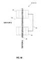
- FIG. 1Bdepicts a block diagram of a high-voltage electric field generator according to an embodiment.
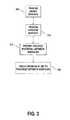
- FIG. 2depicts a flow diagram of a method of making fuel according to an embodiment.
- FIG. 3depicts a flow diagram of a method of exposing a working fluid to a high-voltage electric field according to an embodiment.
- FIG. 4depicts a flow diagram of a method of cooling a plasma mixture according to an embodiment.
- a fuelrefers to any composition of matter that provides a source of energy.
- Particular fuels that may be used hereininclude naphtha, diesel fuel, a diesel fuel blend, Jet Propellant 8 (JP-8) fuel, jet fuel, a jet fuel blend, or gasoline.
- Naphthamay be a process stream that contains predominantly five carbons and heavier chemical components.
- Naphthamay include a debutanized stream of cracked hydrocarbons that may be processed and used, for example, as a gasoline blending stock.
- Jet fuelmay be a fuel that is generally suitable for use as an aviation fuel. Jet fuel may comply with one or more regulations or requirements, such as, for example, ASTM D 1655 Specification for Aviation Turbine Fuels.
- the jet fuelmay be a liquid hydrocarbon fuel.
- the jet fuelmay include paraffins as a major component, as well as various aromatics and napthenes.
- a blendsuch as the diesel fuel blend or the jet fuel blend, refers to a fuel blend that contains at least in part diesel fuel or jet fuel, respectively.
- a plasma torchrefers to any device capable of generating a directed flow of plasma.
- Illustrative plasma torchesmay include, but are not limited to, ionized gas plasma generating systems, such as Inductively Coupled Plasma, Transferred Arc DC Plasma, and Non-Transferred Arc DC Plasma.
- the terms “torch” or “torches”refer to plasma torches.
- Plasma torchesmay be capable of reaching temperatures ranging of up to about 10,000° F. to about 20,000° F. (about 5,540° C. to about 11,080° C.), or more.
- Each plasma torchmay be a portion of a plasma reactor, which is generally a combination of a plasma torch and a reaction vessel with which the plasma torch is used.
- a Fischer-Tropsch process as used hereinrefers to a series of chemical reactions that produce a variety of hydrocarbon molecules according to the formula (C n H (2n+2) ).
- the series of chemical reactionsmay produce alkanes as follows: (2 n+ 1)H 2 +n CO ⁇ C n H (2n+2) +n H 2 O where n is a positive integer.
- competing reactionsgive small amounts of alkenes, as well as alcohols and other oxygenated hydrocarbons, as described in greater detail herein.
- a method of making fuelmay include exposing a first working fluid to a first high-voltage electric field to produce a first plasma, exposing a second working fluid to a second high-voltage electric field to produce a second plasma, exposing a third working fluid to a third high-voltage electric field to produce a third plasma, and contacting the first plasma, the second fluid plasma, and the third plasma to form a plasma mixture.
- the plasma mixturemay be transported to a heat exchange device that may cool the plasma mixture to form a cooled plasma mixture.
- the cooled plasma mixturemay be contacted with a catalyst to form a fuel.
- the fuelmay include at least one of naphtha, diesel fuel, a diesel fuel blend, JP-8 fuel, jet fuel, or a jet fuel blend.
- FIG. 1Adepicts a system for making fuel according to an embodiment.
- the systemmay include one or more high-voltage electric field generators, such as 105 , 110 , 115 , a first processing chamber 120 , a heat exchanger 125 , a second processing chamber 130 , and a fuel storage tank 135 .
- Each of the one or more high-voltage electric field generators 105 , 110 , 115may generally be any of various components that may be used to generate a high voltage potential.
- each of the one or more high-voltage electric field generators 105 , 110 , 115may have at least one anode surface 150 , at least one cathode surface 155 , and an electric potential 160 between the anode surface and the cathode surface.
- a magnetic field 165 and an electric field 170may be generated when the electric potential 160 is applied between the at least one anode surface 150 and the at least one cathode surface 155 .
- a flow of gasmay be substantially perpendicular to the magnetic field 165 .
- the flow of gasmay be substantially parallel to the magnetic field 165 .
- the magnetic field 165 and the electric field 170may each have an effect on gas that flows through a gap between the anode surface 150 and the cathode surface 155 .
- the electric field 170may stabilize the gas and/or ionize the gas.
- the magnetic field 165may alter a spin and/or a velocity of the gas.
- each of the one or more high-voltage electric field generators 105 , 110 , 115may be a plasma torch. While FIG. 1A depicts three high-voltage electric field generators 105 , 110 , 115 , those skilled in the art will recognize that any number of high-voltage electric field generators may be used without departing from the scope of the present disclosure. Thus, for example, the system 100 may include 1, 2, 3, 4, 5, 6, 7, 8, or more high-voltage electric field generators.
- a source of each of the one or more high-voltage electric field generators 105 , 110 , 115may be controlled by one or more control systems (not shown).
- the one or more control systemsmay control all of the one or more high-voltage electric field generators 105 , 110 , 115 together and may be different from or included with a control system for the entire system 100 .
- each of the one or more high-voltage electric field generators 105 , 110 , 115may have a separate control system.
- a control system for a high-voltage electric field generator 105 , 110 , 115may include control functions for torch parameters, such as the voltage of the plasma torch and a frequency of the plasma torch.
- Control of the high-voltage electric field generators 105 , 110 , 115may be based on one or more process measurements, including, but not limited to, a measurement of a voltage applied to components that generate the high-voltage electric field, a current drain of a voltage supply for high-voltage electric field generators, a temperature of the plasma output of the high-voltage electric field generators, and a composition of the plasma generated by the high-voltage electric field generators. It may further be appreciated that each of the high-voltage electric field generators 105 , 110 , 115 may be controlled according to one or more process algorithms.
- the high-voltage electric field generators 105 , 110 , 115may be controlled according to the same process methods and/or algorithms (as provided by individual controllers or a single controller). Alternatively, each of the high-voltage electric field generators 105 , 110 , 115 may be controlled according to a different process method and/or algorithm (as provided by individual controllers or by a single controller).
- the first processing chamber (FPC) 120as used herein may generally refer to any chamber that is capable of withstanding one or more processing conditions such as temperature, pressure, corrosion, and the like under which the combustion of a working fluid in the presence of carbon dioxide, oxygen, and/or water takes place.
- the FPC 120may be incorporated with the one or more high-voltage electric field generators 105 , 110 , 115 .
- the FPC 120may include one or more inlets for receiving plasma from the various high-voltage electric field generators 105 , 110 , 115 and at least one outlet for discharging a plasma mixture, as described in greater detail herein.
- An illustrative FPC 120may be a plasma arc centrifugal treatment (PACT) system available from Retech Systems, LLC (Ukiah, Calif.), which includes at least one plasma torch.
- PACTplasma arc centrifugal treatment
- the FPC 120may be maintained at a vacuum or near vacuum. In a particular embodiment, the FPC 120 may be maintained at a pressure of about 50 kPa to about 507 kPa (about 0.5 atmospheres to about 5 atmospheres), including about 50 kPa, about 100 kPa, about 150 kPa, about 200 kPa, about 250 kPa, about 300 kPa, about 350 kPa, about 400 kPa, about 450 kPa, about 500 kPa, about 507 kPa, or any value or range between any two of these values (including endpoints).
- the plasma mixturewhile in the FPC 120 , may attain temperatures of about 4000° C. to about 6000° C., as described in greater detail herein. Higher or lower temperatures may be attained according to various conditions under which the high-voltage electric field generators 105 , 110 , 115 operate.
- the plasma mixturemay be cooled within the FPC 120 , at an exit port of the FPC, in a transport device (such as a pipe or other conduit) at an exit of the FPC, or at a combination of these locations using a coolant addition device (not shown).
- the coolant addition devicemay use a coolant to effect cooling.
- An illustrative coolantmay include liquid oxygen (LOX).
- An amount of coolant introduced into the plasma mixture by the coolant addition devicemay be controlled by a control system.
- the amount of the coolant added to the plasma mixturemay be controlled according to a temperature of the plasma mixture, a composition of the plasma mixture, or other measured parameters of the plasma mixture.
- the control systemmay be associated only with the coolant addition device. In other embodiments, the control system may be incorporated into a system for controlling the entire system 100 .
- the addition of the coolant to the plasma mixturemay reduce the temperature of the resulting plasma mixture (an admixed plasma mixture) to about 1450° C.
- the admixed plasma mixturemay have a composition that is different from that of the plasma mixture.
- the heat exchanger 125may generally be a device that is configured to transfer thermal energy from one medium to another such as, for example, a gas to another gas, a gas to a liquid, a liquid to another liquid, and the like.
- Illustrative examples of the heat exchanger 125may include a steam generating heat exchanger (i.e., a boiler), a gas-gas interchanger, a boiler feed water exchanger, a forced air exchanger, a cooling water exchanger, or a combination thereof.
- Use of a plurality of heat exchangers 125is contemplated to be within the scope of the present disclosure.
- the heat exchanger 125may include a radiant heat exchanger, a convective heat exchanger, or a combination thereof. Steam and condensate may be generated from the heat exchange process and may include one or more steam products of different pressures.
- the heat exchanger 125may be a heat recovery steam generator (HRSG) such as, for example, a device manufactured by NEM (Leiden, Netherlands).
- HRSGheat recovery steam generator
- the HRSG 125may be configured so that no loss or degradation of the plasma mixture occurs when the HRSG receives the plasma mixture from the FPC 100 .
- the HRSG 125may be capable of withstanding various temperatures, pressures, corrosive chemicals, and the like when contacting the plasma mixture.
- the HRSG 125may be lined with a ceramic to assist in accommodating an elevated temperature of the plasma mixture.
- the HRSG 125may include a first inlet for receiving the plasma mixture or the admixed plasma mixture discharged from the FPC 120 , a second inlet for receiving a fluid such as water, a first outlet for discharging steam, and a second outlet for discharging a cooled plasma mixture, as described in greater detail herein.
- an amount of water that enters the heat exchanger 125 via the second inletmay be controlled by a control system, as described in greater detail herein.
- a heated heat exchange materialwhich may include steam as a non-limiting example, may exit the heat exchanger 125 by means of the first outlet. The heated heat exchange material may be further transported to a first electric turbine to generate a first supply of electric power.
- the heat exchange materialmay be water, which may be converted to a supply of steam in the heat exchanger 125 . Once the supply of steam has activated the electric turbine, the supply of steam may be cooled to liquid water. In some embodiments, the liquid water may be returned to the heat exchanger 125 to be reheated by more of the plasma mixture or the admixed plasma mixture. Alternatively, the first supply of steam, after activating the electric turbine, may be returned to a working fluid source to be supplied to one or more of the high-voltage electric field generators 105 , 110 , 115 .
- the second processing chamber 130is not limited by this disclosure, and may generally be any type of structure, such as a chamber, a furnace, a tube, or the like, that may be used for controlling and containing a reaction. It will be appreciated that the second processing chamber may include a plurality of chambers. In particular embodiments, the second processing chamber 130 may be a chamber that is configured for any Fischer-Tropsch process.
- the fuel storage tank 135is not limited by this disclosure, and may generally be any vessel configured to at least receive fuel from the second processing chamber 130 .
- the fuel storage tank 135may, for example, be used to store fuel, transport fuel, dispense fuel, and/or the like.
- the system 100may further include a gas separator (not shown).
- the gas separatormay include, for example, a membrane separation system, a molecular sieve, or a combination thereof.
- the gas separatormay generally be used to separate various components described herein, and may optionally deposit the separated components into various gas holding containers.
- the gas holding containersfor example, an H 2 container and a CO container, may each include an outflow metering device. Each outflow metering device may be controlled by a controller. Alternatively, the outflow metering devices of each of the individual gas holding containers may be controlled by the same controller.
- Each gas holding containermay also have a gas output port associated with the corresponding outflow metering device. Each gas output port may direct the gas from the corresponding gas holding container into a common supply duct.
- the outflow metering devices of each of the gas holding containersmay be controlled to permit an amount of gas into the common supply duct to create a cooled plasma mixture having a controlled composition, as described in greater detail herein.
- the cooled plasma mixturemay be controlled based on one or more gas composition sensors associated with the common supply duct.
- the cooled mixturemay be controlled based on a volume of gas emitted by each outflow metering device.
- the cooled plasma mixturemay be controlled based on the pressure of gas contained in each gas holding container. Accordingly, various ratios of the components of the cooled plasma mixture, as described in greater detail herein, may be obtained.
- FIG. 2depicts a flow diagram of a method of making fuel according to an embodiment.
- the methodmay include providing 205 a first working fluid, providing 215 a second working fluid, and providing 225 a third working fluid.
- the first working fluidmay be oxygen gas (O 2 )
- the second working fluidmay be water vapor (H 2 O)
- the third working fluidmay be carbon dioxide gas (CO 2 ).
- the CO 2 , O 2 , and H 2 O in the first processing chambermay be used as working fluids for the respective plasma torches, as described herein.
- each gasmay be exposed to a high-voltage electric field.
- the gasesmay be reduced to free radical species.
- H 2 Omay be reduced to a hydroxyl radical OH • and O 2 may be reduced to a superoxide anion radical O2 • ⁇ .
- the gasesmay be reduced to ionized species.
- O 2may be reduced to O ⁇ , O 2 , O 2 + , and/or O + .
- the types and amounts of reactive species created by exposure of the gases to high-voltage electric fieldsmay differ from those generated by exposure of the gases to heat alone.
- Each working fluidmay be supplied by its own working fluid source.
- CO 2may be supplied from a CO 2 source
- O 2may be supplied from an O 2 source
- water vapor (H 2 O)may be supplied from an H 2 O source.
- control of the fluid plasma from each of the high voltage field sourcesmay also include control of the amount of working fluid supplied to each of the high voltage field sources.
- the working fluid supply sources for the CO 2 , O 2 , and H 2 Omay also include control and measurement components.
- Such componentsmay include, without limitation, components to control the amount of the working fluid supplied by each of the working fluid supply sources (valves) and devices to measure the amount of each of the working fluid supplied (such as, for example, by measuring chemical composition or pressure of the gas delivered). It may be further understood that such measurement and control devices may be controlled by one or more control systems, as disclosed above. In some embodiments, the control systems may be specific to one or more of the working fluid supply sources. In other embodiments, all working fluid supply sources may be controlled by the same control system. In some embodiments, the working fluid supply sources may be controlled by a control system common to the entire power generation system.
- an embodimentmay include three working fluids, such as CO 2 , O 2 , and H 2 O, that may be combined into one or two combined working fluids before being supplied to one or more high-voltage electric field generators.
- the CO 2 , the O 2 , and the H 2 Omay be combined into a single combined working fluid to be supplied to a high-voltage electric field generator 105 , 110 , 115 ( FIG. 1A ).
- the controllers associated with each of the supply sources for the CO 2 , the O 2 , and the H 2 Omay cause a specific amount of each gas to be added to the combined working fluid to produce an optimized ratio of gases.
- the controller associated with a single plasma torchmay cause the plasma torch to operate under optimum conditions for a specific ratio of gases in the combined working fluid.
- the first working fluidmay be exposed 210 to a high-voltage electric field to generate a first plasma.
- exposing 210 the first working fluid to the high-voltage electric fieldmay include providing 305 an anode surface and providing 310 a cathode surface.
- the anode surface and the cathode surfacemay be separated by a distance to create a gap between the two surfaces.
- the distancemay generally be selected such that (for the electrical voltage selected), the electrical field is about 0.3 kV/cm to about 8.0 kV/cm, including about 0.3 kV/cm, about 0.3149 kV/com, about 0.5 kV/cm, about 0.75 kV/cm, about 1.0 kV/cm, about 1.25 kV/cm, about 1.5 kV/cm, about 1.574 kV/cm, about 2.0 kV/com, about 2.5 kV/cm, about 3.0 kV/cm, about 3.149 kV/cm, about 3.5 kV/cm, about 4.0 kV/cm, about 4.5 kV/cm, about 5.0 kV/cm, about 5.5 kV/cm, about 6.0 kV/cm, about 6.5 kV/cm, about 7.0 kV/cm, about 7.5 kV/cm, about 7.559 kV/
- Illustrative distancesmay be about 0.15 cm to about 0.65 cm, including about 0.15 cm, about 0.20 cm, about 0.25 cm, about 0.30 cm, about 0.3175 cm, about 0.35 cm, about 0.40 cm, about 0.45 cm, about 0.50 cm, about 0.55 cm, about 0.60 cm, about 0.65 cm, or any value or range between any two of these values (including endpoints).
- a voltage potentialmay be provided 315 between the anode surface and the cathode surface.
- a first high voltage electric potentialmay be induced between the anode surface and the cathode surface, and the first working fluid may be induced 320 to traverse the gap between the two surfaces.
- the high voltage potentialmay be about 2.4 kV times the gap distance in centimeters to about 60 kV times the gap distance in centimeters, including about 2.4 kV, about 5 kV, about 10 kV, about 20 kV, about 30 kV, about 40 kV, about 50 kV, about 60 kV, or any value or range between any two of these values (including endpoints).
- a voltage between the anode surface and the cathode surface(which is 0.3175 cm) is 2.4 kV, thereby resulting in an electrical field of about 7.559 kV/cm.
- the high-voltage electric potentialmay be an alternating current (AC) potential having a frequency of about 1 MHz to about 50 MHz, including about 1 MHz, about 5 MHz, about 10 MHz, about 20 MHz, about 25 MHz, about 30 MHz, about 40 MHz, about 50 MHz, or any value or range between any two of these values (including endpoints).
- ACalternating current
- the high-voltage electric potentialmay have a current of about 100 Amperes to about 1000 Amperes, including about 100 Amperes, about 200 Amperes, about 300 Amperes, about 400 Amperes, about 500 Amperes, about 600 Amperes, about 700 Amperes, about 800 Amperes, about 900 Amperes, about 1000 Amperes, or any value or range between any two of these values (including endpoints).
- the second working fluidmay be exposed 220 to a high-voltage electric field to generate a second plasma.
- exposing 220 the second working fluid to the high-voltage electric fieldmay include providing 305 an anode surface and providing 310 a cathode surface. The anode surface and the cathode surface may be separated by a distance to create a gap between the two surfaces.
- the distancemay generally be selected such that (for the electrical voltage selected), the electrical field is about 0.3 kV/cm to about 8.0 kV/cm, including about 0.3 kV/cm, about 0.3149 kV/com, about 0.5 kV/cm, about 0.75 kV/cm, about 1.0 kV/com, about 1.25 kV/cm, about 1.5 kV/cm, about 1.574 kV/cm, about 2.0 kV/cm, about 2.5 kV/cm, about 3.0 kV/cm, about 3.149 kV/cm, about 3.5 kV/cm, about 4.0 kV/cm, about 4.5 kV/cm, about 5.0 kV/cm, about 5.5 kV/cm, about 6.0 kV/cm, about 6.5 kV/cm, about 7.0 kV/cm, about 7.5 kV/cm, about 7.559 kV/
- Illustrative distancesmay be about 0.15 cm to about 0.65 cm, including about 0.15 cm, about 0.20 cm, about 0.25 cm, about 0.30 cm, about 0.3175 cm, about 0.35 cm, about 0.40 cm, about 0.45 cm, about 0.50 cm, about 0.55 cm, about 0.60 cm, about 0.65 cm, or any value or range between any two of these values (including endpoints).
- a voltage potentialmay be provided 315 between the anode surface and the cathode surface.
- a second high voltage electric potentialmay be induced between the anode surface and the cathode surface, and the second working fluid may be induced 320 to traverse the gap between the two surfaces.
- the high voltage potentialmay be about 2.4 kV times the gap distance in centimeters to about 60 kV times the gap distance in centimeters, including about 2.4 kV, about 5 kV, about 10 kV, about 20 kV, about 30 kV, about 40 kV, about 50 kV, about 60 kV, or any value or range between any two of these values (including endpoints).
- a voltage between the anode surface and the cathode surface(which is 0.3175 cm) is 2.4 kV, thereby resulting in an electrical field of about 7.559 kV/cm.
- the high-voltage electric potentialmay be an alternating current (AC) potential having a frequency of about 1 MHz to about 50 MHz, including about 1 MHz, about 5 MHz, about 10 MHz, about 20 MHz, about 25 MHz, about 30 MHz, about 40 MHz, about 50 MHz, or any value or range between any two of these values (including endpoints).
- ACalternating current
- the high-voltage electric potentialmay have a current of about 100 Amperes to about 1000 Amperes, including about 100 Amperes, about 200 Amperes, about 300 Amperes, about 400 Amperes, about 500 Amperes, about 600 Amperes, about 700 Amperes, about 800 Amperes, about 900 Amperes, about 1000 Amperes, or any value or range between any two of these values (including endpoints).
- the third working fluidmay be exposed 230 to a high-voltage electric field to generate a third plasma.
- exposing 230 the third working fluid to the high-voltage electric fieldmay include providing 305 an anode surface and providing 310 a cathode surface. The anode surface and the cathode surface may be separated by a distance to create a gap between the two surfaces.
- the distancemay generally be selected such that (for the electrical voltage selected), the electrical field is about 0.3 kV/cm to about 8.0 kV/cm, including about 0.3 kV/cm, about 0.3149 kV/cm, about 0.5 kV/cm, about 0.75 kV/cm, about 1.0 kV/cm, about 1.25 kV/cm, about 1.5 kV/cm, about 1.574 kV/cm, about 2.0 kV/com, about 2.5 kV/cm, about 3.0 kV/cm, about 3.149 kV/cm, about 3.5 kV/cm, about 4.0 kV/cm, about 4.5 kV/cm, about 5.0 kV/cm, about 5.5 kV/cm, about 6.0 kV/cm, about 6.5 kV/cm, about 7.0 kV/cm, about 7.5 kV/cm, about 7.559 kV
- Illustrative distancesmay be about 0.15 cm to about 0.65 cm, including about 0.15 cm, about 0.20 cm, about 0.25 cm, about 0.30 cm, about 0.3175 cm, about 0.35 cm, about 0.40 cm, about 0.45 cm, about 0.50 cm, about 0.55 cm, about 0.60 cm, about 0.65 cm, or any value or range between any two of these values (including endpoints).
- a voltage potentialmay be provided 315 between the anode surface and the cathode surface.
- a third high voltage electric potentialmay be induced between the anode surface and the cathode surface, and the third working fluid may be induced 320 to traverse the gap between the two surfaces.
- the high voltage potentialmay be about 2.4 kV times the gap distance in centimeters to about 60 kV times the gap distance in centimeters, including about 2.4 kV, about 5 kV, about 10 kV, about 20 kV, about 30 kV, about 40 kV, about 50 kV, about 60 kV, or any value or range between any two of these values (including endpoints).
- a voltage between the anode surface and the cathode surface(which is 0.3175 cm) is 2.4 kV, thereby resulting in an electrical field of about 7.559 kV/cm.
- the high-voltage electric potentialmay be an alternating current (AC) potential having a frequency of about 1 MHz to about 50 MHz, including about 1 MHz, about 5 MHz, about 10 MHz, about 20 MHz, about 25 MHz, about 30 MHz, about 40 MHz, about 50 MHz, or any value or range between any two of these values (including endpoints).
- ACalternating current
- the high-voltage electric potentialmay have a current of about 100 Amperes to about 1000 Amperes, including about 100 Amperes, about 200 Amperes, about 300 Amperes, about 400 Amperes, about 500 Amperes, about 600 Amperes, about 700 Amperes, about 800 Amperes, about 900 Amperes, about 1000 Amperes, or any value or range between any two of these values (including endpoints).
- anode and cathode surfaces contacting the first working fluid, the second working fluid, and the third working fluidmay be the same set of surfaces or they may be different sets of surfaces. If each working fluid contacts an independent pair of anode and cathode surfaces, the respective gap distances may be essentially the same or different, and high voltage electric potentials to which the working fluids are exposed may have essentially the same or different characteristics.
- exposing 210 the first working fluid to a first high-voltage electric fieldmay include causing the first working fluid to pass through a first plasma torch.
- exposing 220 the second working fluid to a second high-voltage electric fieldmay include causing the second working fluid to pass through a second plasma torch.
- exposing 230 the third working fluid to a third high-voltage electric fieldmay include causing the third working fluid to pass through a third plasma torch.
- the first working fluid, the second working fluid, and the third working fluidmay pass through the same plasma torch or may pass through individual plasma torches.
- the first working fluid, the second working fluid, and the third working fluidmay pass through a plasma torch consecutively or may pass through a plasma torch at substantially the same time.
- exposing 210 , 220 , 230 the various working fluids to various high-voltage electric fieldsmay cause the various plasmas to reach a temperature of about 36,000° F. (20,000° C.).
- the temperaturemay be sufficiently high to enable effective disassociation of various individual compounds in each of the various working fluids, as previously described herein.
- the first, second, and third plasmasmay be contacted 235 in any temporal or spatial order to form a plasma mixture.
- the first plasma, the second plasma, and the third plasmamay be contacted 235 by directing the second plasma to mix with the first plasma and the third plasma, directing the first plasma to mix with the second plasma and the third plasma, directing the third plasma to mix with the first plasma and the second plasma, or directing the first plasma, the second plasma, and the third plasma to mix together.
- Contacting 235 the first plasma, the second plasma, and the third plasmamay form a plasma mixture of all three plasmas.
- the plasma mixturemay have a temperature of about 7232° F. to about 10,832° F. (about 4000° C.
- the plasma mixturemay cool from the initial temperatures of the first, second, and third plasmas upon passing through the respective high-voltage electrical fields.
- the third plasma, the second plasma, and the first plasma togethermay be directed to contact a carbon-based feedstock within the FPC to create the plasma mixture.
- the carbon-based feedstockmay be supplied from a carbon-based feedstock supply.
- the mechanical components used to transport the carbon-based feedstock into the FPCmay be controlled according to various process parameters.
- the control of the transport of the carbon-based feedstockmay be supplied by a control system.
- a control systemmay be specific to the mechanical components used to transport the carbon-based feedstock into the FPC.
- such a control systemmay be included in a control system used to control the entire system, as described in greater detail herein.
- illustrative examples of the carbon-based feedstockmay include one or more of bagasse, coal, wood, green waste, sugar beets, corn, or bio-waste products.
- Bagasseas used herein, may generally refer to any fibrous matter obtained from a plant-based source.
- bagassemay include fibrous matter obtained from sugarcane or sorghum stalks, particularly after the stalks have been crushed to remove their juice.
- Green wastemay generally include biodegradable waste that can be comprised of garden or park waste material such as grass cuttings, flower cuttings, hedge trimmings, leaves, shrubs, plants, and tree trimmings, and/or waste from fruit and food processing.
- Bio-waste productsmay generally include kitchen waste, such as, for example, food scraps, which may be of animal or plant origin.
- the plasma mixturemay be transported 240 to the heat exchanger.
- Transporting 240is not limited by this disclosure, and may be via any method of transport. Any number of pumps, conduit, channels, ducts, pipes, and/or the like may be used to transport 240 the plasma mixture.
- the plasma mixturemay be cooled 245 to a temperature of about 100° F. to about 2950° F. (about 38° C. to about 1620° C.), including about 38° C., about 100° C., about 150° C., about 200° C., about 260° C., about 500° C., about 750° C., about 11° C., about 1300° C., about 1600° C., about 1620° C., or any value or range between any of these values (including endpoints).
- the plasma mixturemay be cooled 245 to a temperature of about 100° F. to about 400° F. (about 38° C. to about 204° C.).
- coolingmay effect a change in composition of the plasma mixture, such as dissociation of various components, as described herein.
- the componentsmay be separated via a gas separator and directed to various holding containers, as described in greater detail herein.
- cooling 245may be completed by contacting 405 the plasma mixture with a heat exchanger within a heat exchange device, such as, for example, an HRSG, to produce a cooled plasma mixture.
- a heat exchange devicesuch as, for example, an HRSG
- the heat exchanged from the plasma mixturemay be conveyed 410 by the heat exchange device to provide heat to a recovery steam generator, as described in greater detail herein.
- the steam generated by the heat transfer to the recovery steam generatormay provide preheated water vapor that may be used at least in part as the second working fluid for conversion into a plasma. Accordingly, the steam generated by the heat transfer may increase an efficiency of the systems and methods described herein by providing a reusable heat source.
- the recovery steam generatormay use the heat from the plasma mixture to heat and vaporize 415 a vaporizable fluid (such as liquid water or the like).
- a vaporizable fluidsuch as liquid water or the like.
- the resulting vaporized fluid(e.g., the steam) may be directed to and contacted 420 with a steam-powered electrical turbine.
- the steam-powered electrical turbinemay, in turn, generate electric power that may be used, at least in part, for providing electrical power to the system described herein and/or a facility used to generate the fuel.
- cooling 245 the plasma mixturemay include cooling with liquid oxygen (O 2 ) to reduce the plasma mixture from a first temperature to a second temperature.
- the first temperatureas described herein, may be about 7232° F. to about 10,832° F. (about 4000° C. to about 6000° C.).
- the second temperatureas described herein, may be about 4892° F. to about 5432° F. (about 2700° C. to about 3000° C.).
- This cooling 245may allow for a split of O 2 and H 2 O in the plasma mixture to become O ⁇ and O + , H + and OH ⁇ , and/or H ⁇ and OH + .
- the cooling 245may further allow for thermal chemical reconversion, thereby resulting in compounds H 2 , H 2 O, O 2 , and/or H 2 O 2 .
- cooling 245may result in a water-gas shift reaction (WGSR).
- WGSRwater-gas shift reaction
- the WGSRmay be sensitive to temperature, with the tendency to shift towards reactants as temperature increases due to Le Chatelier's principle. Over the temperature range of about 600 K to about 2000 K, the logarithm of the equilibrium constant for the WGSR is given by:
- a first stagemay include a high-temperature shift (HTS) at about 662° F. (350° C.).
- a second stagemay include a low-temperature shift (LTS) at about 374° F. to about 410° F. (about 190° C. to about 210° C.).
- Standard industrial catalysts for this processmay include iron oxide promoted with chromium oxide for the HTS step and copper on a mixed support composed of zinc oxide and aluminum oxide for the LTS step.
- the cooled plasma mixturemay include at least carbon monoxide and hydrogen gas.
- the cooled plasma mixturemay include carbon monoxide and hydrogen gas in a ratio of about 0.08:1.5 to about 1.3:2.5, including about 0.1:1.5, about 0.5:1.5, about 1:1.5, about 1.3:1.5, about 1:2, about 1:2.25, about 1:2.5, or any value or range between any two of these values (including endpoints).
- the ratio of the plasma mixturemay be effectively measured and/or maintained by placing the plasma into a gas separator and using volumetric flow metering to add or remove components to or from the gas holding containers. Accordingly, various flow meters may be used to indicate an amount of gas that can be used to maintain a specified ratio.
- the cooled plasma mixturemay be contacted 250 with a catalyst.
- Contacting 250 the cooled plasma mixture with a catalystmay result in forming a fuel.
- the type of fuel that results from contacting 250may be determined by the ratio of hydrogen gas to carbon monoxide in the plasma, as described in greater detail herein.
- Contacting 250 the cooled plasma mixture with the catalystmay include transporting the cooled plasma mixture to the second processing chamber 130 ( FIG. 1A ).
- the catalystmay be, for example, a Fischer-Tropsch (F-T)-type catalyst or a F-T catalyst.
- the F-T catalystmay contain iron, cobalt, nickel, or ruthenium.
- the F-T catalystmay be supported, promoted, and/or activated by one or more additional materials.
- the catalystmay include at least one of cobalt, iron, ruthenium, nickel, copper, an alkali metal oxide, silica, alumina, or a zeolite.
- the catalystmay be a Fischer-Tropsch variation catalyst, such as, for example, various catalysts that are commercially available from Emerging Fuels Technology (Tulsa, Okla.).
- the catalystmay degrade over a period of time and may be replaced.
- the fuelmay be collected 255 .
- Collectionis not limited by this disclosure, and may include any form of collection, storage, transport, dispensing, and/or the like.
- the fuelmay be collected 255 in the fuel storage tank 135 ( FIG. 1A ).
- compositions, methods, and devicesare described in terms of “comprising” various components or steps (interpreted as meaning “including, but not limited to”), the compositions, methods, and devices can also “consist essentially of” or “consist of” the various components and steps, and such terminology should be interpreted as defining essentially closed-member groups. It will be further understood by those within the art that if a specific number of an introduced claim recitation is intended, such an intent will be explicitly recited in the claim, and in the absence of such recitation no such intent is present. For example, as an aid to understanding, the following appended claims may contain usage of the introductory phrases at least one and one or more to introduce claim recitations.
- a rangeincludes each individual member.
- a group having 1-3 cellsrefers to groups having 1, 2, or 3 cells.
- a group having 1-5 cellsrefers to groups having 1, 2, 3, 4, or 5 cells, and so forth.
Landscapes
- Chemical & Material Sciences (AREA)
- Engineering & Computer Science (AREA)
- Organic Chemistry (AREA)
- Chemical Kinetics & Catalysis (AREA)
- Oil, Petroleum & Natural Gas (AREA)
- Combustion & Propulsion (AREA)
- Physics & Mathematics (AREA)
- Plasma & Fusion (AREA)
- General Chemical & Material Sciences (AREA)
- Health & Medical Sciences (AREA)
- General Health & Medical Sciences (AREA)
- Inorganic Chemistry (AREA)
- Spectroscopy & Molecular Physics (AREA)
- Mechanical Engineering (AREA)
- General Engineering & Computer Science (AREA)
- Toxicology (AREA)
- Life Sciences & Earth Sciences (AREA)
- High Energy & Nuclear Physics (AREA)
- Sustainable Development (AREA)
- Sustainable Energy (AREA)
- Environmental & Geological Engineering (AREA)
- Physical Or Chemical Processes And Apparatus (AREA)
- Plasma Technology (AREA)
- Production Of Liquid Hydrocarbon Mixture For Refining Petroleum (AREA)
Abstract
Description
(2n+1)H2+nCO→CnH(2n+2)+nH2O
where n is a positive integer. The formation of methane (n=1) may generally be excluded as methane is gaseous at standard temperature and pressure. Most of the alkanes produced tend to be straight-chain and may be suitable as fuel. In addition to alkane formation, competing reactions give small amounts of alkenes, as well as alcohols and other oxygenated hydrocarbons, as described in greater detail herein.
CO(g)+H2O(g)→CO2(g)+H2(g)
where the ΔHreac=−41.16 kJ at 298.15K.
where the value of Kequilapproaches 1 at 1,100K. The process may be used in two stages. A first stage may include a high-temperature shift (HTS) at about 662° F. (350° C.). A second stage may include a low-temperature shift (LTS) at about 374° F. to about 410° F. (about 190° C. to about 210° C.). Standard industrial catalysts for this process may include iron oxide promoted with chromium oxide for the HTS step and copper on a mixed support composed of zinc oxide and aluminum oxide for the LTS step.
Claims (25)
Priority Applications (1)
| Application Number | Priority Date | Filing Date | Title |
|---|---|---|---|
| US14/426,083US9410452B2 (en) | 2012-09-05 | 2013-09-05 | Fuel generation using high-voltage electric fields methods |
Applications Claiming Priority (3)
| Application Number | Priority Date | Filing Date | Title |
|---|---|---|---|
| US201261697148P | 2012-09-05 | 2012-09-05 | |
| US14/426,083US9410452B2 (en) | 2012-09-05 | 2013-09-05 | Fuel generation using high-voltage electric fields methods |
| PCT/US2013/058301WO2014039704A1 (en) | 2012-09-05 | 2013-09-05 | Fuel generation using high-voltage electric fields methods |
Publications (2)
| Publication Number | Publication Date |
|---|---|
| US20150259615A1 US20150259615A1 (en) | 2015-09-17 |
| US9410452B2true US9410452B2 (en) | 2016-08-09 |
Family
ID=55538139
Family Applications (1)
| Application Number | Title | Priority Date | Filing Date |
|---|---|---|---|
| US14/426,083Expired - Fee RelatedUS9410452B2 (en) | 2012-09-05 | 2013-09-05 | Fuel generation using high-voltage electric fields methods |
Country Status (6)
| Country | Link |
|---|---|
| US (1) | US9410452B2 (en) |
| EP (1) | EP2893324A4 (en) |
| KR (1) | KR20150053781A (en) |
| BR (1) | BR112015004828A2 (en) |
| HK (1) | HK1212439A1 (en) |
| WO (1) | WO2014039704A1 (en) |
Families Citing this family (1)
| Publication number | Priority date | Publication date | Assignee | Title |
|---|---|---|---|---|
| GB202102409D0 (en) | 2021-02-19 | 2021-04-07 | Altunin Sergi | Energy cell |
Citations (125)
| Publication number | Priority date | Publication date | Assignee | Title |
|---|---|---|---|---|
| US1746464A (en) | 1925-07-21 | 1930-02-11 | Fischer Franz | Process for the production of paraffin-hydrocarbons with more than one carbon atom |
| GB573982A (en) | 1941-01-14 | 1945-12-17 | Synthetic Oils Ltd | Improvements in or relating to methods of producing hydrocarbon oils from gaseous mixtures of hydrogen and carbon monoxide |
| US3979205A (en) | 1971-04-07 | 1976-09-07 | Wanzenberg Fritz Walter | Metal recovery method |
| US4466807A (en) | 1981-03-10 | 1984-08-21 | Skf Steel Engineering Aktiebolag | Manufacture of a gas containing monoxide and hydrogen gas from a starting material containing carbon and/or hydrocarbon |
| US4508040A (en) | 1982-01-18 | 1985-04-02 | Skf Steel Engineering Aktiebolag | Method and plant for conversion of waste material to stable final products |
| US4591428A (en) | 1984-03-01 | 1986-05-27 | Shell Oil Company | Continuous process for the catalytic treatment of hydrocarbon oils |
| US4770109A (en) | 1987-05-04 | 1988-09-13 | Retech, Inc. | Apparatus and method for high temperature disposal of hazardous waste materials |
| US4831944A (en) | 1987-01-22 | 1989-05-23 | Aerospatiale Societe Nationale Industrielle | Process and device for destroying solid waste by pyrolysis |
| US4845334A (en) | 1988-01-26 | 1989-07-04 | Oregon Metallurgical Corporation | Plasma furnace inert gas recycling system and process |
| US4898748A (en) | 1988-08-31 | 1990-02-06 | The Board Of Trustees Of Leland Stanford Junior University | Method for enhancing chemical reactivity in thermal plasma processes |
| US5046144A (en) | 1987-10-15 | 1991-09-03 | Rockwool International A/S | Method and furnace for the preparation of a melt for mineral wool production |
| US5107517A (en) | 1987-04-30 | 1992-04-21 | Oy Partek Ab | Melting furnace |
| US5136137A (en) | 1987-05-04 | 1992-08-04 | Retech, Inc. | Apparatus for high temperature disposal of hazardous waste materials |
| US5138959A (en) | 1988-09-15 | 1992-08-18 | Prabhakar Kulkarni | Method for treatment of hazardous waste in absence of oxygen |
| US5288969A (en) | 1991-08-16 | 1994-02-22 | Regents Of The University Of California | Electrodeless plasma torch apparatus and methods for the dissociation of hazardous waste |
| US5301620A (en) | 1993-04-01 | 1994-04-12 | Molten Metal Technology, Inc. | Reactor and method for disassociating waste |
| US5319176A (en) | 1991-01-24 | 1994-06-07 | Ritchie G. Studer | Plasma arc decomposition of hazardous wastes into vitrified solids and non-hazardous gasses |
| US5493578A (en) | 1992-09-24 | 1996-02-20 | Ishikawajima-Harima Heavy Industries Co., Ltd. | Ash melting furnace |
| US5534659A (en) | 1994-04-18 | 1996-07-09 | Plasma Energy Applied Technology Incorporated | Apparatus and method for treating hazardous waste |
| US5544597A (en) | 1995-08-29 | 1996-08-13 | Plasma Technology Corporation | Plasma pyrolysis and vitrification of municipal waste |
| US5611947A (en) | 1994-09-07 | 1997-03-18 | Alliant Techsystems, Inc. | Induction steam plasma torch for generating a steam plasma for treating a feed slurry |
| US5666891A (en) | 1995-02-02 | 1997-09-16 | Battelle Memorial Institute | ARC plasma-melter electro conversion system for waste treatment and resource recovery |
| US5673635A (en) | 1995-06-12 | 1997-10-07 | L.E. Maxwitat | Process for the recycling of organic wastes |
| US5725616A (en) | 1991-12-12 | 1998-03-10 | Kvaerner Engineering A.S. | Method for combustion of hydrocarbons |
| US5798496A (en) | 1995-01-09 | 1998-08-25 | Eckhoff; Paul S. | Plasma-based waste disposal system |
| US5935293A (en) | 1995-03-14 | 1999-08-10 | Lockheed Martin Idaho Technologies Company | Fast quench reactor method |
| US5958264A (en) | 1996-10-21 | 1999-09-28 | Pyrogenesis Inc. | Plasma gasification and vitrification of ashes |
| US6127645A (en) | 1995-02-02 | 2000-10-03 | Battelle Memorial Institute | Tunable, self-powered arc plasma-melter electro conversion system for waste treatment and resource recovery |
| CN1268550A (en) | 1999-03-24 | 2000-10-04 | Abb研究有限公司 | Method for synthesizing fuel |
| US6173002B1 (en) | 1999-04-21 | 2001-01-09 | Edgar J. Robert | Electric arc gasifier as a waste processor |
| CA2379892A1 (en) | 1999-07-29 | 2001-02-08 | David Systems & Technology S.L. | Plasma converter of fossil fuels into hydrogen-rich gas |
| US6187226B1 (en) | 1995-03-14 | 2001-02-13 | Bechtel Bwxt Idaho, Llc | Thermal device and method for production of carbon monoxide and hydrogen by thermal dissociation of hydrocarbon gases |
| US6215678B1 (en) | 1995-02-02 | 2001-04-10 | Integrated Environmental Technologies, Llc | Arc plasma-joule heated melter system for waste treatment and resource recovery |
| US6289851B1 (en) | 2000-10-18 | 2001-09-18 | Institute Of Gas Technology | Compact low-nox high-efficiency heating apparatus |
| US20020000085A1 (en) | 1998-11-25 | 2002-01-03 | Hall Kenneth R. | Method for converting natural gas to liquid hydrocarbons |
| US6355904B1 (en) | 1996-06-07 | 2002-03-12 | Science Applications International Corporation | Method and system for high-temperature waste treatment |
| US20020040889A1 (en) | 1999-12-20 | 2002-04-11 | Research Triangle Institute | Plasma furnace disposal of hazardous wastes |
| US6372156B1 (en) | 1999-08-19 | 2002-04-16 | Bechtel Bwxt Idaho, Llc | Methods of chemically converting first materials to second materials utilizing hybrid-plasma systems |
| US20020151604A1 (en) | 1999-12-21 | 2002-10-17 | Detering Brent A. | Hydrogen and elemental carbon production from natural gas and other hydrocarbons |
| EP1270508A1 (en) | 2001-06-26 | 2003-01-02 | Hydro Tech International Inc. | Process and device for producing hydrogen |
| US6505567B1 (en) | 2001-11-26 | 2003-01-14 | Alstom (Switzerland) Ltd | Oxygen fired circulating fluidized bed steam generator |
| US20030029796A1 (en) | 2000-12-28 | 2003-02-13 | Takaaki Maekawa | Apparatus for purifying water containing dissolved organic matters and trace harmful substances |
| US6524538B2 (en) | 1999-04-28 | 2003-02-25 | Hana Barankova | Method and apparatus for plasma treatment of gas |
| US20030065042A1 (en) | 2001-10-01 | 2003-04-03 | Shaw John M. | Methanol production process |
| US20030209174A1 (en) | 2002-05-08 | 2003-11-13 | Chan Benjamin Chun Pong | Hazardous waste treatment method and apparatus |
| US20040134517A1 (en) | 1996-10-16 | 2004-07-15 | Clark Steve L. | Process for cleaning hydrocarbons from soils |
| US6821500B2 (en) | 1995-03-14 | 2004-11-23 | Bechtel Bwxt Idaho, Llc | Thermal synthesis apparatus and process |
| WO2005005009A2 (en) | 2003-06-30 | 2005-01-20 | Bar-Gadda, Llc. | Dissociation of molecular water into molecular hydrogen |
| US6874434B1 (en) | 2003-04-18 | 2005-04-05 | Bigelow Aerospace | Biomass waste disposal method and apparatus |
| US6971323B2 (en) | 2004-03-19 | 2005-12-06 | Peat International, Inc. | Method and apparatus for treating waste |
| US6976362B2 (en) | 2001-09-25 | 2005-12-20 | Rentech, Inc. | Integrated Fischer-Tropsch and power production plant with low CO2 emissions |
| US6987792B2 (en) | 2001-08-22 | 2006-01-17 | Solena Group, Inc. | Plasma pyrolysis, gasification and vitrification of organic material |
| US20060053791A1 (en) | 2003-12-16 | 2006-03-16 | Advanced Combustion Energy Systems, Inc. | Method and apparatus for the production of energy |
| US20060060464A1 (en) | 2002-05-08 | 2006-03-23 | Chang Chak M T | Plasma formed in a fluid |
| US20060112639A1 (en) | 2003-11-29 | 2006-06-01 | Nick Peter A | Process for pyrolytic heat recovery enhanced with gasification of organic material |
| US7070634B1 (en) | 2003-11-03 | 2006-07-04 | Wang Chi S | Plasma reformer for hydrogen production from water and fuel |
| CN1810938A (en) | 2005-08-24 | 2006-08-02 | 周开根 | Method of synthesizing fuel gas with water and oil and its burner |
| US20060201157A1 (en) | 2005-03-11 | 2006-09-14 | Villalobos Victor M | Arc-hydrolysis steam generator apparatus and method |
| US20060233699A1 (en) | 2003-04-15 | 2006-10-19 | Mills Randell L | Plasma reactor and process for producing lower-energy hydrogen species |
| US20070017228A1 (en) | 2005-07-06 | 2007-01-25 | Integrated Environmental Technologies, Llc | Method for enhancing the efficient operation of electrical power plants and energy storage |
| US20070186474A1 (en) | 2006-02-14 | 2007-08-16 | Gas Technology Institute | Plasma assisted conversion of carbonaceous materials into a gas |
| US7279655B2 (en) | 2003-06-11 | 2007-10-09 | Plasmet Corporation | Inductively coupled plasma/partial oxidation reformation of carbonaceous compounds to produce fuel for energy production |
| US20070253874A1 (en) | 2001-07-16 | 2007-11-01 | Todd Foret | System, method and apparatus for treating liquids with wave energy from plasma |
| US20070266633A1 (en) | 2006-05-05 | 2007-11-22 | Andreas Tsangaris | Gas Reformulating System Using Plasma Torch Heat |
| US20070267289A1 (en) | 2006-04-06 | 2007-11-22 | Harry Jabs | Hydrogen production using plasma- based reformation |
| US20070272131A1 (en) | 2003-04-04 | 2007-11-29 | Pierre Carabin | Two-Stage Plasma Process For Converting Waste Into Fuel Gas And Apparatus Therefor |
| US7335320B2 (en) | 2001-03-06 | 2008-02-26 | Alchemix Corporation | Method for the production of hydrogen-containing gaseous mixtures |
| US20080083701A1 (en) | 2006-10-04 | 2008-04-10 | Mks Instruments, Inc. | Oxygen conditioning of plasma vessels |
| US7384619B2 (en) | 2003-06-30 | 2008-06-10 | Bar-Gadda, Llc | Method for generating hydrogen from water or steam in a plasma |
| US20080147241A1 (en) | 2006-05-05 | 2008-06-19 | Placso Energy Group Inc. | Control System for the Conversion of Carbonaceous Feedstock into Gas |
| US20080184621A1 (en) | 2006-10-02 | 2008-08-07 | Clark Steve L | Reduced-emission gasification and oxidation of hydrocarbon materials for power generation |
| US20080202028A1 (en) | 2005-06-03 | 2008-08-28 | Plasco Energy Group Inc. | System For the Conversion of Carbonaceous Fbedstocks to a Gas of a Specified Composition |
| US20080209807A1 (en) | 2006-05-05 | 2008-09-04 | Andreas Tsangaris | Low Temperature Gasification Facility with a Horizontally Oriented Gasifier |
| US20080223047A1 (en) | 2006-10-19 | 2008-09-18 | Troy Lee Oliver | Xplogen TM: a system, method, and apparatus for generating energy from a series of dissociation reactions |
| US20080222956A1 (en) | 2005-06-03 | 2008-09-18 | Plasco Energy Group Inc. | System for the Conversion of Coal to a Gas of Specified Composition |
| WO2008130260A1 (en) | 2007-04-18 | 2008-10-30 | Sgc Energia Sgps, S.A. | Waste to liquid hydrocarbon refinery system |
| US20080277265A1 (en) | 2007-05-11 | 2008-11-13 | Plasco Energy Group, Inc. | Gas reformulation system comprising means to optimize the effectiveness of gas conversion |
| US20080283411A1 (en) | 2007-05-04 | 2008-11-20 | Eastman Craig D | Methods and devices for the production of Hydrocarbons from Carbon and Hydrogen sources |
| US20080283153A1 (en) | 2007-05-09 | 2008-11-20 | Air Products And Chemicals, Inc. | Furnace atmosphere activation method and apparatus |
| US20080290322A1 (en) | 2005-05-10 | 2008-11-27 | Hartmut Hederer | Method for Heating and Partial Oxidation of a Steam/Natural Gas Mixture After a Primary Reformer |
| US20090038958A1 (en) | 2007-07-06 | 2009-02-12 | Coyle Edward L | Method and Apparatus for a Low Cost and Carbon Free Point of Use Dissociation of Water into Elemental Gases and Production of Hydrogen Related Power |
| US20090133407A1 (en) | 2007-11-28 | 2009-05-28 | Nrg Energy, Inc. | Plasma gasification system |
| US20090183430A1 (en) | 2008-01-23 | 2009-07-23 | Packer Engineering, Inc. | Process and system for syngas production from biomass materials |
| US20090188127A1 (en) | 2004-07-19 | 2009-07-30 | Earthrenew, Inc. | Process and System for Drying and Heat Treating Materials |
| US7576296B2 (en) | 1995-03-14 | 2009-08-18 | Battelle Energy Alliance, Llc | Thermal synthesis apparatus |
| US7622693B2 (en) | 2001-07-16 | 2009-11-24 | Foret Plasma Labs, Llc | Plasma whirl reactor apparatus and methods of use |
| US20090307975A1 (en) | 2006-07-31 | 2009-12-17 | Bw-Energiesysteme Gmbh | Method for reprocessing combustion products from fossil fuels |
| WO2009156761A2 (en) | 2008-06-25 | 2009-12-30 | Horizon Ventures Limited | Processing of waste |
| US20100050654A1 (en) | 2008-07-31 | 2010-03-04 | Alstom Technology Ltd. | System for hot solids combustion and gasification |
| US7674443B1 (en) | 2008-08-18 | 2010-03-09 | Irvin Davis | Zero emission gasification, power generation, carbon oxides management and metallurgical reduction processes, apparatus, systems, and integration thereof |
| US20100065781A1 (en) | 2005-10-14 | 2010-03-18 | Commissariat A L'energie Atomique | Device for Gasification of Biomass and Organic Waste Under High Temperature and with an External Energy Supply in Order to Generate a High-Quality Synthetic Gas |
| WO2010056462A1 (en) | 2008-11-12 | 2010-05-20 | Uni-Control, Llc | Biological water-gas shift reaction system comprising plasma gasification |
| US20100167139A1 (en) | 2003-09-23 | 2010-07-01 | Synfuels International, Inc. | Process for the conversion of natural gas to hydrocarbon liquids |
| US20100229522A1 (en) | 2009-03-16 | 2010-09-16 | Jim Kingzett | Plasma-Assisted E-Waste Conversion Techniques |
| US7832344B2 (en) | 2006-02-28 | 2010-11-16 | Peat International, Inc. | Method and apparatus of treating waste |
| US20100298449A1 (en) | 2006-08-08 | 2010-11-25 | Ifp | Method of producing synthetic gas with partial oxidation and steam reforming |
| US7845411B2 (en) | 2006-10-20 | 2010-12-07 | Shell Oil Company | In situ heat treatment process utilizing a closed loop heating system |
| US20110067376A1 (en) | 2009-03-16 | 2011-03-24 | Geovada, Llc | Plasma-based waste-to-energy techniques |
| US20110162958A1 (en) | 2007-10-11 | 2011-07-07 | Moon-Ki Cho | Plasma decomposition apparatus and method for carbon dioxide |
| US20110162523A1 (en) | 2008-08-06 | 2011-07-07 | Re.Co 2 S.R.L. | Gas cleaning method and apparatus |
| US7981371B2 (en) | 2004-02-18 | 2011-07-19 | Commissariat A L'energie Atomique | Device and method for destroying liquid, powder or gaseous waste using an inductively coupled plasma |
| WO2011091327A1 (en) | 2010-01-21 | 2011-07-28 | Usa Green Energy Group, Llc | Generating steam from carbonaceous material |
| US20110201700A1 (en) | 2010-02-08 | 2011-08-18 | Lucas Stephen H | Product Recycle Loops In Process For Converting Municipal Solid Waste Into Ethanol |
| US20110212012A1 (en) | 2010-02-13 | 2011-09-01 | Mcalister Technologies, Llc | Carbon-based durable goods and renewable fuel from biomass waste dissociation |
| US20110265698A1 (en) | 2010-05-03 | 2011-11-03 | Powerdyne, Inc. | System and method for reutilizing co2 from combusted carbonaceous material |
| US20110286893A1 (en) | 2009-01-06 | 2011-11-24 | The University Of Sheffield | Plasma microreactor apparatus, sterilisation unit and analyser |
| US20120000115A1 (en) | 2010-07-01 | 2012-01-05 | Aarmonia Chemicals Private, Ltd. | Diesel fuel additive |
| US8129654B2 (en) | 2006-04-04 | 2012-03-06 | Cheju National University Industry Academic Cooperation Foundation | DC arc plasmatron and method of using the same |
| US20120070347A1 (en) | 2010-03-01 | 2012-03-22 | Plasco Energy Group, Inc. | Carbon Conversion System with Integrated Processing Zones |
| WO2012039751A2 (en) | 2010-09-24 | 2012-03-29 | James Charles Juranitch | Renewable combined cycle low turbine boost |
| US20120090985A1 (en) | 2010-10-01 | 2012-04-19 | Drexel University | Non-equilibrium gliding arc plasma system for co2 dissociation |
| US8168128B2 (en) | 2005-10-26 | 2012-05-01 | Edwards Limited | Plasma reactor |
| US20120114877A1 (en) | 2010-11-05 | 2012-05-10 | Synos Technology, Inc. | Radical Reactor with Multiple Plasma Chambers |
| WO2012064936A1 (en) | 2010-11-10 | 2012-05-18 | Air Products And Chemicals, Inc. | Syngas produced by plasma gasification |
| US8199790B2 (en) | 2007-11-02 | 2012-06-12 | Plasma Waste Recycling, Inc. | Reactor vessel for plasma gasification |
| WO2012077198A1 (en) | 2010-12-08 | 2012-06-14 | トヨタ自動車株式会社 | Fuel production system |
| US8216433B2 (en) | 2006-03-07 | 2012-07-10 | University Of The Ryukyus | Plasma generator and method of generating plasma using the same |
| US8252244B2 (en) | 2008-02-08 | 2012-08-28 | Peat International, Inc. | Method and apparatus of treating waste |
| US8303916B2 (en) | 2008-02-01 | 2012-11-06 | Oscura, Inc. | Gaseous transfer in multiple metal bath reactors |
| WO2012158797A1 (en) | 2011-05-16 | 2012-11-22 | Powerdyne, Inc. | Steam generation system |
| WO2012177666A1 (en) | 2011-06-21 | 2012-12-27 | Staton Vernon Eric | Apparatus and method for hydrocarbon pyrolysis |
| US8367005B2 (en) | 2007-07-12 | 2013-02-05 | Imagineering, Inc. | Gas processing apparatus, gas processing system, and gas processing method, and exhaust gas processing system and internal combustion engine using the same |
| US8518162B2 (en) | 2005-08-15 | 2013-08-27 | Edwards Limited | Method of treating a gas stream |
| US8519354B2 (en) | 2008-02-12 | 2013-08-27 | Purdue Research Foundation | Low temperature plasma probe and methods of use thereof |
| US20130300121A1 (en) | 2009-07-17 | 2013-11-14 | Green Energy And Technology Sdn. Bhd. | Method and system for producing energy from waste |
Family Cites Families (1)
| Publication number | Priority date | Publication date | Assignee | Title |
|---|---|---|---|---|
| US6153852A (en)* | 1999-02-12 | 2000-11-28 | Thermal Conversion Corp | Use of a chemically reactive plasma for thermal-chemical processes |
- 2013
- 2013-09-05USUS14/426,083patent/US9410452B2/ennot_activeExpired - Fee Related
- 2013-09-05HKHK16100165.1Apatent/HK1212439A1/enunknown
- 2013-09-05WOPCT/US2013/058301patent/WO2014039704A1/enactiveApplication Filing
- 2013-09-05EPEP13834468.4Apatent/EP2893324A4/ennot_activeWithdrawn
- 2013-09-05KRKR1020157008612Apatent/KR20150053781A/ennot_activeWithdrawn
- 2013-09-05BRBR112015004828Apatent/BR112015004828A2/ennot_activeIP Right Cessation
Patent Citations (141)
| Publication number | Priority date | Publication date | Assignee | Title |
|---|---|---|---|---|
| US1746464A (en) | 1925-07-21 | 1930-02-11 | Fischer Franz | Process for the production of paraffin-hydrocarbons with more than one carbon atom |
| GB573982A (en) | 1941-01-14 | 1945-12-17 | Synthetic Oils Ltd | Improvements in or relating to methods of producing hydrocarbon oils from gaseous mixtures of hydrogen and carbon monoxide |
| US3979205A (en) | 1971-04-07 | 1976-09-07 | Wanzenberg Fritz Walter | Metal recovery method |
| US4466807A (en) | 1981-03-10 | 1984-08-21 | Skf Steel Engineering Aktiebolag | Manufacture of a gas containing monoxide and hydrogen gas from a starting material containing carbon and/or hydrocarbon |
| US4508040A (en) | 1982-01-18 | 1985-04-02 | Skf Steel Engineering Aktiebolag | Method and plant for conversion of waste material to stable final products |
| US4591428A (en) | 1984-03-01 | 1986-05-27 | Shell Oil Company | Continuous process for the catalytic treatment of hydrocarbon oils |
| US4831944A (en) | 1987-01-22 | 1989-05-23 | Aerospatiale Societe Nationale Industrielle | Process and device for destroying solid waste by pyrolysis |
| US5107517A (en) | 1987-04-30 | 1992-04-21 | Oy Partek Ab | Melting furnace |
| US5136137A (en) | 1987-05-04 | 1992-08-04 | Retech, Inc. | Apparatus for high temperature disposal of hazardous waste materials |
| US4770109A (en) | 1987-05-04 | 1988-09-13 | Retech, Inc. | Apparatus and method for high temperature disposal of hazardous waste materials |
| US5046144A (en) | 1987-10-15 | 1991-09-03 | Rockwool International A/S | Method and furnace for the preparation of a melt for mineral wool production |
| US4845334A (en) | 1988-01-26 | 1989-07-04 | Oregon Metallurgical Corporation | Plasma furnace inert gas recycling system and process |
| US4898748A (en) | 1988-08-31 | 1990-02-06 | The Board Of Trustees Of Leland Stanford Junior University | Method for enhancing chemical reactivity in thermal plasma processes |
| US5138959A (en) | 1988-09-15 | 1992-08-18 | Prabhakar Kulkarni | Method for treatment of hazardous waste in absence of oxygen |
| US5319176A (en) | 1991-01-24 | 1994-06-07 | Ritchie G. Studer | Plasma arc decomposition of hazardous wastes into vitrified solids and non-hazardous gasses |
| US5541386A (en) | 1991-01-24 | 1996-07-30 | Irm, L.P. | Plasma arc decomposition of hazardous wastes into vitrified solids and non-hazardous gasses |
| US5288969A (en) | 1991-08-16 | 1994-02-22 | Regents Of The University Of California | Electrodeless plasma torch apparatus and methods for the dissociation of hazardous waste |
| US5725616A (en) | 1991-12-12 | 1998-03-10 | Kvaerner Engineering A.S. | Method for combustion of hydrocarbons |
| US5493578A (en) | 1992-09-24 | 1996-02-20 | Ishikawajima-Harima Heavy Industries Co., Ltd. | Ash melting furnace |
| US5301620A (en) | 1993-04-01 | 1994-04-12 | Molten Metal Technology, Inc. | Reactor and method for disassociating waste |
| US5534659A (en) | 1994-04-18 | 1996-07-09 | Plasma Energy Applied Technology Incorporated | Apparatus and method for treating hazardous waste |
| US5611947A (en) | 1994-09-07 | 1997-03-18 | Alliant Techsystems, Inc. | Induction steam plasma torch for generating a steam plasma for treating a feed slurry |
| US5798496A (en) | 1995-01-09 | 1998-08-25 | Eckhoff; Paul S. | Plasma-based waste disposal system |
| US5666891A (en) | 1995-02-02 | 1997-09-16 | Battelle Memorial Institute | ARC plasma-melter electro conversion system for waste treatment and resource recovery |
| US6215678B1 (en) | 1995-02-02 | 2001-04-10 | Integrated Environmental Technologies, Llc | Arc plasma-joule heated melter system for waste treatment and resource recovery |
| US6127645A (en) | 1995-02-02 | 2000-10-03 | Battelle Memorial Institute | Tunable, self-powered arc plasma-melter electro conversion system for waste treatment and resource recovery |
| US7576296B2 (en) | 1995-03-14 | 2009-08-18 | Battelle Energy Alliance, Llc | Thermal synthesis apparatus |
| US6187226B1 (en) | 1995-03-14 | 2001-02-13 | Bechtel Bwxt Idaho, Llc | Thermal device and method for production of carbon monoxide and hydrogen by thermal dissociation of hydrocarbon gases |
| US6821500B2 (en) | 1995-03-14 | 2004-11-23 | Bechtel Bwxt Idaho, Llc | Thermal synthesis apparatus and process |
| US5935293A (en) | 1995-03-14 | 1999-08-10 | Lockheed Martin Idaho Technologies Company | Fast quench reactor method |
| US5673635A (en) | 1995-06-12 | 1997-10-07 | L.E. Maxwitat | Process for the recycling of organic wastes |
| US5544597A (en) | 1995-08-29 | 1996-08-13 | Plasma Technology Corporation | Plasma pyrolysis and vitrification of municipal waste |
| US5634414A (en) | 1995-08-29 | 1997-06-03 | Plasma Technology Corporation | Process for plasma pyrolysis and vitrification of municipal waste |
| US6355904B1 (en) | 1996-06-07 | 2002-03-12 | Science Applications International Corporation | Method and system for high-temperature waste treatment |
| US20040134517A1 (en) | 1996-10-16 | 2004-07-15 | Clark Steve L. | Process for cleaning hydrocarbons from soils |
| US5958264A (en) | 1996-10-21 | 1999-09-28 | Pyrogenesis Inc. | Plasma gasification and vitrification of ashes |
| US20020000085A1 (en) | 1998-11-25 | 2002-01-03 | Hall Kenneth R. | Method for converting natural gas to liquid hydrocarbons |
| CN1268550A (en) | 1999-03-24 | 2000-10-04 | Abb研究有限公司 | Method for synthesizing fuel |
| US6375832B1 (en) | 1999-03-24 | 2002-04-23 | Abb Research Ltd. | Fuel synthesis |
| US6173002B1 (en) | 1999-04-21 | 2001-01-09 | Edgar J. Robert | Electric arc gasifier as a waste processor |
| US6524538B2 (en) | 1999-04-28 | 2003-02-25 | Hana Barankova | Method and apparatus for plasma treatment of gas |
| CA2379892A1 (en) | 1999-07-29 | 2001-02-08 | David Systems & Technology S.L. | Plasma converter of fossil fuels into hydrogen-rich gas |
| US6372156B1 (en) | 1999-08-19 | 2002-04-16 | Bechtel Bwxt Idaho, Llc | Methods of chemically converting first materials to second materials utilizing hybrid-plasma systems |
| US20020040889A1 (en) | 1999-12-20 | 2002-04-11 | Research Triangle Institute | Plasma furnace disposal of hazardous wastes |
| US6552295B2 (en) | 1999-12-20 | 2003-04-22 | Research Triangle Institute | Plasma furnace disposal of hazardous wastes |
| US20020151604A1 (en) | 1999-12-21 | 2002-10-17 | Detering Brent A. | Hydrogen and elemental carbon production from natural gas and other hydrocarbons |
| US7097675B2 (en) | 1999-12-21 | 2006-08-29 | Battelle Energy Alliance, Llc | Fast-quench reactor for hydrogen and elemental carbon production from natural gas and other hydrocarbons |
| US6289851B1 (en) | 2000-10-18 | 2001-09-18 | Institute Of Gas Technology | Compact low-nox high-efficiency heating apparatus |
| US20030029796A1 (en) | 2000-12-28 | 2003-02-13 | Takaaki Maekawa | Apparatus for purifying water containing dissolved organic matters and trace harmful substances |
| US7335320B2 (en) | 2001-03-06 | 2008-02-26 | Alchemix Corporation | Method for the production of hydrogen-containing gaseous mixtures |
| EP1270508A1 (en) | 2001-06-26 | 2003-01-02 | Hydro Tech International Inc. | Process and device for producing hydrogen |
| US8324523B2 (en) | 2001-07-16 | 2012-12-04 | Foret Plasma Labs, Llc | Plasma whirl reactor apparatus and methods of use |
| US8357873B2 (en) | 2001-07-16 | 2013-01-22 | Foret Plasma Labs, Llc | Plasma whirl reactor apparatus and methods of use |
| US20070253874A1 (en) | 2001-07-16 | 2007-11-01 | Todd Foret | System, method and apparatus for treating liquids with wave energy from plasma |
| US7622693B2 (en) | 2001-07-16 | 2009-11-24 | Foret Plasma Labs, Llc | Plasma whirl reactor apparatus and methods of use |
| US6987792B2 (en) | 2001-08-22 | 2006-01-17 | Solena Group, Inc. | Plasma pyrolysis, gasification and vitrification of organic material |
| US6976362B2 (en) | 2001-09-25 | 2005-12-20 | Rentech, Inc. | Integrated Fischer-Tropsch and power production plant with low CO2 emissions |
| US20030065042A1 (en) | 2001-10-01 | 2003-04-03 | Shaw John M. | Methanol production process |
| US6505567B1 (en) | 2001-11-26 | 2003-01-14 | Alstom (Switzerland) Ltd | Oxygen fired circulating fluidized bed steam generator |
| US20030209174A1 (en) | 2002-05-08 | 2003-11-13 | Chan Benjamin Chun Pong | Hazardous waste treatment method and apparatus |
| US6810821B2 (en) | 2002-05-08 | 2004-11-02 | Benjamin Chun Pong Chan | Hazardous waste treatment method and apparatus |
| US20060060464A1 (en) | 2002-05-08 | 2006-03-23 | Chang Chak M T | Plasma formed in a fluid |
| US20070272131A1 (en) | 2003-04-04 | 2007-11-29 | Pierre Carabin | Two-Stage Plasma Process For Converting Waste Into Fuel Gas And Apparatus Therefor |
| US20060233699A1 (en) | 2003-04-15 | 2006-10-19 | Mills Randell L | Plasma reactor and process for producing lower-energy hydrogen species |
| US6874434B1 (en) | 2003-04-18 | 2005-04-05 | Bigelow Aerospace | Biomass waste disposal method and apparatus |
| US7279655B2 (en) | 2003-06-11 | 2007-10-09 | Plasmet Corporation | Inductively coupled plasma/partial oxidation reformation of carbonaceous compounds to produce fuel for energy production |
| US20080041829A1 (en) | 2003-06-11 | 2008-02-21 | Plasmet Corporation | Inductively coupled plasma/partial oxidation reformation of carbonaceous compounds to produce fuel for energy production |
| WO2005005009A2 (en) | 2003-06-30 | 2005-01-20 | Bar-Gadda, Llc. | Dissociation of molecular water into molecular hydrogen |
| US7384619B2 (en) | 2003-06-30 | 2008-06-10 | Bar-Gadda, Llc | Method for generating hydrogen from water or steam in a plasma |
| US20100167139A1 (en) | 2003-09-23 | 2010-07-01 | Synfuels International, Inc. | Process for the conversion of natural gas to hydrocarbon liquids |
| US7070634B1 (en) | 2003-11-03 | 2006-07-04 | Wang Chi S | Plasma reformer for hydrogen production from water and fuel |
| US20060112639A1 (en) | 2003-11-29 | 2006-06-01 | Nick Peter A | Process for pyrolytic heat recovery enhanced with gasification of organic material |
| US20060053791A1 (en) | 2003-12-16 | 2006-03-16 | Advanced Combustion Energy Systems, Inc. | Method and apparatus for the production of energy |
| US7981371B2 (en) | 2004-02-18 | 2011-07-19 | Commissariat A L'energie Atomique | Device and method for destroying liquid, powder or gaseous waste using an inductively coupled plasma |
| US6971323B2 (en) | 2004-03-19 | 2005-12-06 | Peat International, Inc. | Method and apparatus for treating waste |
| US20090188127A1 (en) | 2004-07-19 | 2009-07-30 | Earthrenew, Inc. | Process and System for Drying and Heat Treating Materials |
| US20060201157A1 (en) | 2005-03-11 | 2006-09-14 | Villalobos Victor M | Arc-hydrolysis steam generator apparatus and method |
| US20080290322A1 (en) | 2005-05-10 | 2008-11-27 | Hartmut Hederer | Method for Heating and Partial Oxidation of a Steam/Natural Gas Mixture After a Primary Reformer |
| US20120121468A1 (en) | 2005-06-03 | 2012-05-17 | Plasco Energy Group Inc. | System For The Conversion Of Carbonaceous Feedstocks To A Gas Of A Specified Composition |
| US20080202028A1 (en) | 2005-06-03 | 2008-08-28 | Plasco Energy Group Inc. | System For the Conversion of Carbonaceous Fbedstocks to a Gas of a Specified Composition |
| US20080222956A1 (en) | 2005-06-03 | 2008-09-18 | Plasco Energy Group Inc. | System for the Conversion of Coal to a Gas of Specified Composition |
| US20070017228A1 (en) | 2005-07-06 | 2007-01-25 | Integrated Environmental Technologies, Llc | Method for enhancing the efficient operation of electrical power plants and energy storage |
| US8518162B2 (en) | 2005-08-15 | 2013-08-27 | Edwards Limited | Method of treating a gas stream |
| CN1810938A (en) | 2005-08-24 | 2006-08-02 | 周开根 | Method of synthesizing fuel gas with water and oil and its burner |
| US20100065781A1 (en) | 2005-10-14 | 2010-03-18 | Commissariat A L'energie Atomique | Device for Gasification of Biomass and Organic Waste Under High Temperature and with an External Energy Supply in Order to Generate a High-Quality Synthetic Gas |
| US8168128B2 (en) | 2005-10-26 | 2012-05-01 | Edwards Limited | Plasma reactor |
| US20070186474A1 (en) | 2006-02-14 | 2007-08-16 | Gas Technology Institute | Plasma assisted conversion of carbonaceous materials into a gas |
| US7832344B2 (en) | 2006-02-28 | 2010-11-16 | Peat International, Inc. | Method and apparatus of treating waste |
| US8216433B2 (en) | 2006-03-07 | 2012-07-10 | University Of The Ryukyus | Plasma generator and method of generating plasma using the same |
| US8129654B2 (en) | 2006-04-04 | 2012-03-06 | Cheju National University Industry Academic Cooperation Foundation | DC arc plasmatron and method of using the same |
| US20070267289A1 (en) | 2006-04-06 | 2007-11-22 | Harry Jabs | Hydrogen production using plasma- based reformation |
| US20080209807A1 (en) | 2006-05-05 | 2008-09-04 | Andreas Tsangaris | Low Temperature Gasification Facility with a Horizontally Oriented Gasifier |
| US20070266633A1 (en) | 2006-05-05 | 2007-11-22 | Andreas Tsangaris | Gas Reformulating System Using Plasma Torch Heat |
| US8475551B2 (en) | 2006-05-05 | 2013-07-02 | Plasco Energy Group Inc. | Gas reformulating system using plasma torch heat |
| US20080147241A1 (en) | 2006-05-05 | 2008-06-19 | Placso Energy Group Inc. | Control System for the Conversion of Carbonaceous Feedstock into Gas |
| US20090307975A1 (en) | 2006-07-31 | 2009-12-17 | Bw-Energiesysteme Gmbh | Method for reprocessing combustion products from fossil fuels |
| US20100298449A1 (en) | 2006-08-08 | 2010-11-25 | Ifp | Method of producing synthetic gas with partial oxidation and steam reforming |
| US20080184621A1 (en) | 2006-10-02 | 2008-08-07 | Clark Steve L | Reduced-emission gasification and oxidation of hydrocarbon materials for power generation |
| US20080083701A1 (en) | 2006-10-04 | 2008-04-10 | Mks Instruments, Inc. | Oxygen conditioning of plasma vessels |
| US20080223047A1 (en) | 2006-10-19 | 2008-09-18 | Troy Lee Oliver | Xplogen TM: a system, method, and apparatus for generating energy from a series of dissociation reactions |
| US7845411B2 (en) | 2006-10-20 | 2010-12-07 | Shell Oil Company | In situ heat treatment process utilizing a closed loop heating system |
| WO2008130260A1 (en) | 2007-04-18 | 2008-10-30 | Sgc Energia Sgps, S.A. | Waste to liquid hydrocarbon refinery system |
| US20080283411A1 (en) | 2007-05-04 | 2008-11-20 | Eastman Craig D | Methods and devices for the production of Hydrocarbons from Carbon and Hydrogen sources |
| US8277631B2 (en) | 2007-05-04 | 2012-10-02 | Principle Energy Solutions, Inc. | Methods and devices for the production of hydrocarbons from carbon and hydrogen sources |
| US8268094B2 (en) | 2007-05-09 | 2012-09-18 | Air Products And Chemicals, Inc. | Furnace atmosphere activation method and apparatus |
| US20080283153A1 (en) | 2007-05-09 | 2008-11-20 | Air Products And Chemicals, Inc. | Furnace atmosphere activation method and apparatus |
| US20080277265A1 (en) | 2007-05-11 | 2008-11-13 | Plasco Energy Group, Inc. | Gas reformulation system comprising means to optimize the effectiveness of gas conversion |
| US20090038958A1 (en) | 2007-07-06 | 2009-02-12 | Coyle Edward L | Method and Apparatus for a Low Cost and Carbon Free Point of Use Dissociation of Water into Elemental Gases and Production of Hydrogen Related Power |
| US8367005B2 (en) | 2007-07-12 | 2013-02-05 | Imagineering, Inc. | Gas processing apparatus, gas processing system, and gas processing method, and exhaust gas processing system and internal combustion engine using the same |
| US20110162958A1 (en) | 2007-10-11 | 2011-07-07 | Moon-Ki Cho | Plasma decomposition apparatus and method for carbon dioxide |
| US8199790B2 (en) | 2007-11-02 | 2012-06-12 | Plasma Waste Recycling, Inc. | Reactor vessel for plasma gasification |
| US20090133407A1 (en) | 2007-11-28 | 2009-05-28 | Nrg Energy, Inc. | Plasma gasification system |
| US20090183430A1 (en) | 2008-01-23 | 2009-07-23 | Packer Engineering, Inc. | Process and system for syngas production from biomass materials |
| US8303916B2 (en) | 2008-02-01 | 2012-11-06 | Oscura, Inc. | Gaseous transfer in multiple metal bath reactors |
| US8252244B2 (en) | 2008-02-08 | 2012-08-28 | Peat International, Inc. | Method and apparatus of treating waste |
| US8519354B2 (en) | 2008-02-12 | 2013-08-27 | Purdue Research Foundation | Low temperature plasma probe and methods of use thereof |
| WO2009156761A2 (en) | 2008-06-25 | 2009-12-30 | Horizon Ventures Limited | Processing of waste |
| US20100050654A1 (en) | 2008-07-31 | 2010-03-04 | Alstom Technology Ltd. | System for hot solids combustion and gasification |
| US20110162523A1 (en) | 2008-08-06 | 2011-07-07 | Re.Co 2 S.R.L. | Gas cleaning method and apparatus |
| US7674443B1 (en) | 2008-08-18 | 2010-03-09 | Irvin Davis | Zero emission gasification, power generation, carbon oxides management and metallurgical reduction processes, apparatus, systems, and integration thereof |
| WO2010056462A1 (en) | 2008-11-12 | 2010-05-20 | Uni-Control, Llc | Biological water-gas shift reaction system comprising plasma gasification |
| US20110286893A1 (en) | 2009-01-06 | 2011-11-24 | The University Of Sheffield | Plasma microreactor apparatus, sterilisation unit and analyser |
| US20100229522A1 (en) | 2009-03-16 | 2010-09-16 | Jim Kingzett | Plasma-Assisted E-Waste Conversion Techniques |
| US20110067376A1 (en) | 2009-03-16 | 2011-03-24 | Geovada, Llc | Plasma-based waste-to-energy techniques |
| US20130300121A1 (en) | 2009-07-17 | 2013-11-14 | Green Energy And Technology Sdn. Bhd. | Method and system for producing energy from waste |
| WO2011091327A1 (en) | 2010-01-21 | 2011-07-28 | Usa Green Energy Group, Llc | Generating steam from carbonaceous material |
| US20130200624A1 (en) | 2010-01-21 | 2013-08-08 | Powerdyne, Inc. | Generating steam from carbonaceous material |
| US20110201700A1 (en) | 2010-02-08 | 2011-08-18 | Lucas Stephen H | Product Recycle Loops In Process For Converting Municipal Solid Waste Into Ethanol |
| US20110212012A1 (en) | 2010-02-13 | 2011-09-01 | Mcalister Technologies, Llc | Carbon-based durable goods and renewable fuel from biomass waste dissociation |
| US20120070347A1 (en) | 2010-03-01 | 2012-03-22 | Plasco Energy Group, Inc. | Carbon Conversion System with Integrated Processing Zones |
| US20110265698A1 (en) | 2010-05-03 | 2011-11-03 | Powerdyne, Inc. | System and method for reutilizing co2 from combusted carbonaceous material |
| WO2011140080A2 (en) | 2010-05-03 | 2011-11-10 | Usa Green Energy Group, Llc | Method for reutilizing co2 from combusted carbonaceous material |
| US20120000115A1 (en) | 2010-07-01 | 2012-01-05 | Aarmonia Chemicals Private, Ltd. | Diesel fuel additive |
| WO2012039751A2 (en) | 2010-09-24 | 2012-03-29 | James Charles Juranitch | Renewable combined cycle low turbine boost |
| US20120090985A1 (en) | 2010-10-01 | 2012-04-19 | Drexel University | Non-equilibrium gliding arc plasma system for co2 dissociation |
| US20120114877A1 (en) | 2010-11-05 | 2012-05-10 | Synos Technology, Inc. | Radical Reactor with Multiple Plasma Chambers |
| WO2012064936A1 (en) | 2010-11-10 | 2012-05-18 | Air Products And Chemicals, Inc. | Syngas produced by plasma gasification |
| WO2012077198A1 (en) | 2010-12-08 | 2012-06-14 | トヨタ自動車株式会社 | Fuel production system |
| US20120291436A1 (en) | 2011-05-16 | 2012-11-22 | Powerdyne Inc. | Steam generation system |
| WO2012158797A1 (en) | 2011-05-16 | 2012-11-22 | Powerdyne, Inc. | Steam generation system |
| WO2012177666A1 (en) | 2011-06-21 | 2012-12-27 | Staton Vernon Eric | Apparatus and method for hydrocarbon pyrolysis |
Non-Patent Citations (25)
| Title |
|---|
| "C-17 flight uses synthetic fuel blend," (Oct. 25, 2007), Wright-Patterson Air Force Base, Retrieved Feb. 7, 2008, http://www.wpafb.af.mil/news/story.asp?id=123073170. |
| "Governor Rendell leads with innovative solution to help address PA energy needs," State of Pennsylvania. Archived from original on Dec. 11, 2008, http://web.archive.org/web/20081211180710/http:/www.state.pa.us/papower/cwp/view.asp?Q=446127&A=11. |
| "PetroSA technology ready for next stage," Businessday.co.za, (May 10, 2011) Retrieved Jun. 5, 2013, http://www.bdlive.co.za/articles/2011/05/10/petrosa-technology-ready-for-next-stage. |
| "PetroSA Wins Innovation Award," SouthAfrica.info, (Oct. 10, 2008), Retrieved Dec. 18, 2012, http://www.southafrica.info/business/trends/innovations/petrosa-101008.htm. |
| "Schweitzer wants to convert Otter Creek coal into liquid fuel," (Aug. 2, 2005), Billings Gazette, Archived from original on Jan. 1, 2009. |
| "UPM-Kymmene says to establish beachhead in biodesel market," NewsRoom Finland. Archived from original on Mar. 17, 2007, http://web.archive.org/web/20070317104947/http:/newsroom.finland.fi/stt/showarticle.asp?intNWSAID=14179&group=Business. |
| Fairley, Peter, "Growing Biofuels," (Nov. 23, 2005), MIT Technology Review, http://www.technologyreview.com/news/404941/growing-biofuels/. |
| International Search Report and Written Opinion dated Dec. 12, 2013 for International Application No. PCT/US2013/058305. |
| International Search Report and Written Opinion dated Feb. 24, 2015 for International Application No. PCT/US2014/069342. |
| International Search Report and Written Opinion dated Feb. 7, 2014 for International Application No. PCT/US2013/058301. |
| International Search Report and Written Opinion dated Feb. 7, 2014 for International Application No. PCT/US2013/058315. |
| International Search Report and Written Opinion dated Feb. 7, 2014 for International Application No. PCT/US2013/058326. |
| International Search Report and Written Opinion dated Jan. 16, 2014 for International Application No. PCT/US2013/058335. |
| International Search Report and Written Opinion dated Jan. 17, 2014 for International Application No. PCT/US2013/058287. |
| International Search Report and Written Opinion dated Jan. 22, 2014 for International Application No. PCT/US2013/058331. |
| International Search Report and Written Opinion dated Jul. 28, 2014 for International Application No. PCT/US2014/024606. |
| Jamieson et al., "Keeping the Options Open", Petroleum Economist, Retrieved LNG 2012. |
| Krauss, Clifford, "South African Company to Build U.S. Plant to Convert Gas to Liquid Fuels," (Dec. 3, 2012), New York Times, http://www.nytimes.com/2012/12/04/business/energy-environment/sasol-plans-first-gas-to-liquids-plant-in-us.html?-r=1. |
| Lane, Jim, "Little Big Tech: Can Fischer-Tropsch technology work at smaller scale?" (Nov. 20, 2012), Biofuels Digest, http://www.biofuelsdigest.com/bdigest/2012/11/20/little-big-tech-can-fischer-tropsch-technology-work-at-smaller-scale/. |
| Pitt, Anthea, "Linc gears up for Chinchilla GTL," (Nov. 28, 2012), Upstreamonline.com, http://www.upstreamonline.com/live/article1149671.ece?print=preview. |
| Plasco Group, "How is Plasco Different?," http://www.plascoenergygroup.com/our-solution/how-is-plasco-different/, retrieved from web Jul. 5, 2011. |
| Schuey et al., "LLW Processing and Operational Experience Using a Plasma ARC Centrifugal Treatment (PACT) System," WM'06 Conference, Feb. 26-Mar. 2, 2006, Tucson, AZ. |
| Smedley, Mark, "Small GTL's Market Reach as Great as Opec's, UK Firm Says," World Gas Intelligence, Retrieved Dec. 19, 2012, http://www.oxfordcatalysts.com/press/egs/world-gas-intelligence-121219.pdf. |
| Steynberg et al., "Clean Coal Conversion Options Using Fischer-Tropsch Technology," (2003), Fuel Chemistry Division Preprints, 48(1); 459-461. |
| Urashima et al., "Removal of Volatile Organic Compounds from Air Streams and Industrial Flue Gases by Non-Thermal Plasma Technology," IEEE Transactions on Dielectrics and Electrical Insulation, Oct. 2000, 7(5):602-614. |
Also Published As
| Publication number | Publication date |
|---|---|
| BR112015004828A2 (en) | 2017-07-04 |
| US20150259615A1 (en) | 2015-09-17 |
| WO2014039704A1 (en) | 2014-03-13 |
| EP2893324A4 (en) | 2016-05-11 |
| KR20150053781A (en) | 2015-05-18 |
| EP2893324A1 (en) | 2015-07-15 |
| HK1212439A1 (en) | 2016-06-10 |
Similar Documents
| Publication | Publication Date | Title |
|---|---|---|
| US8784617B2 (en) | Process of converting gaseous hydrocarbons to a liquid hydrocarbon composition | |
| Sun et al. | Large capacity hydrogen production by microwave discharge plasma in liquid fuels ethanol | |
| RU2585647C2 (en) | Method of modifying a methane-containing gas stream | |
| CN104718010B (en) | System and method for the devolatilization of heat liquid processed | |
| Chernyak et al. | Plasma-assisted reforming of ethanol in dynamic plasma-liquid system: experiments and modeling | |
| JP2022527864A (en) | Equipment and processes for producing hydrogen and solid carbon from C1-C4 alkane-containing gases | |
| US9677431B2 (en) | Methods for generating hydrogen gas using plasma sources | |
| US9410452B2 (en) | Fuel generation using high-voltage electric fields methods | |
| US9382818B2 (en) | Fuel generation using high-voltage electric fields methods | |
| US9273570B2 (en) | Methods for power generation from H2O, CO2, O2 and a carbon feed stock | |
| US9561486B2 (en) | System for generating fuel materials using Fischer-Tropsch catalysts and plasma sources | |
| US9765270B2 (en) | Fuel generation using high-voltage electric fields methods | |
| Ouni et al. | Effect of oxygen on methane steam reforming in a sliding discharge reactor | |
| El‐Shafie et al. | Comprehensive assessment of hydrogen production in argon‐water vapors plasmolysis | |
| Thanompongchart et al. | Partial oxidation reforming of simulated biogas in gliding arc discharge system | |
| PL209944B1 (en) | Method and system for production of hydrogen | |
| WO2023039043A1 (en) | Systems and methods for processing gases | |
| RU115352U1 (en) | DEVICE FOR PRODUCING METHANOL | |
| CN104477847A (en) | Method for producing hydrogen by reforming biological oil by virtue of plasma | |
| RU2485416C1 (en) | Method of solar energy conversion | |
| Arabi et al. | Hydrogen production from hydrogenated liquids compounds by a non-thermal plasma | |
| Chun et al. | SynGas production from organic waste using non-thermal-pulsed discharge |
Legal Events
| Date | Code | Title | Description |
|---|---|---|---|
| AS | Assignment | Owner name:POWERDYNE, INC., CALIFORNIA Free format text:ASSIGNMENT OF ASSIGNORS INTEREST;ASSIGNOR:HIRSON, GEOFFREY;REEL/FRAME:031413/0833 Effective date:20131003 Owner name:POWERDYNE, INC, CALIFORNIA Free format text:ASSIGNMENT OF ASSIGNORS INTEREST;ASSIGNOR:GUS F. SHOUSE;REEL/FRAME:031413/0700 Effective date:20131003 | |
| AS | Assignment | Owner name:POWERDYNE, INC., CALIFORNIA Free format text:ASSIGNMENT OF ASSIGNORS INTEREST;ASSIGNOR:SHOUSE, GUS F.;REEL/FRAME:035099/0517 Effective date:20131003 Owner name:POWERDYNE, INC., CALIFORNIA Free format text:ASSIGNMENT OF ASSIGNORS INTEREST;ASSIGNOR:HIRSON, GEOFFREY;REEL/FRAME:035099/0592 Effective date:20131003 | |
| STCF | Information on status: patent grant | Free format text:PATENTED CASE | |
| FEPP | Fee payment procedure | Free format text:MAINTENANCE FEE REMINDER MAILED (ORIGINAL EVENT CODE: REM.); ENTITY STATUS OF PATENT OWNER: SMALL ENTITY | |
| LAPS | Lapse for failure to pay maintenance fees | Free format text:PATENT EXPIRED FOR FAILURE TO PAY MAINTENANCE FEES (ORIGINAL EVENT CODE: EXP.); ENTITY STATUS OF PATENT OWNER: SMALL ENTITY | |
| STCH | Information on status: patent discontinuation | Free format text:PATENT EXPIRED DUE TO NONPAYMENT OF MAINTENANCE FEES UNDER 37 CFR 1.362 |