US9409510B1 - Automatic tractor/trailer tracking system - Google Patents
Automatic tractor/trailer tracking systemDownload PDFInfo
- Publication number
- US9409510B1 US9409510B1US14/080,392US201314080392AUS9409510B1US 9409510 B1US9409510 B1US 9409510B1US 201314080392 AUS201314080392 AUS 201314080392AUS 9409510 B1US9409510 B1US 9409510B1
- Authority
- US
- United States
- Prior art keywords
- input
- output
- microcontroller
- trailer
- transmitter
- Prior art date
- Legal status (The legal status is an assumption and is not a legal conclusion. Google has not performed a legal analysis and makes no representation as to the accuracy of the status listed.)
- Expired - Fee Related, expires
Links
Images


Classifications
- H—ELECTRICITY
- H01—ELECTRIC ELEMENTS
- H01R—ELECTRICALLY-CONDUCTIVE CONNECTIONS; STRUCTURAL ASSOCIATIONS OF A PLURALITY OF MUTUALLY-INSULATED ELECTRICAL CONNECTING ELEMENTS; COUPLING DEVICES; CURRENT COLLECTORS
- H01R13/00—Details of coupling devices of the kinds covered by groups H01R12/70 or H01R24/00 - H01R33/00
- H01R13/44—Means for preventing access to live contacts
- H01R13/447—Shutter or cover plate
- B—PERFORMING OPERATIONS; TRANSPORTING
- B60—VEHICLES IN GENERAL
- B60Q—ARRANGEMENT OF SIGNALLING OR LIGHTING DEVICES, THE MOUNTING OR SUPPORTING THEREOF OR CIRCUITS THEREFOR, FOR VEHICLES IN GENERAL
- B60Q1/00—Arrangement of optical signalling or lighting devices, the mounting or supporting thereof or circuits therefor
- B—PERFORMING OPERATIONS; TRANSPORTING
- B60—VEHICLES IN GENERAL
- B60D—VEHICLE CONNECTIONS
- B60D1/00—Traction couplings; Hitches; Draw-gear; Towing devices
- B60D1/58—Auxiliary devices
- B60D1/62—Auxiliary devices involving supply lines, electric circuits, or the like
- B60D1/64—Couplings or joints therefor
- G—PHYSICS
- G06—COMPUTING OR CALCULATING; COUNTING
- G06Q—INFORMATION AND COMMUNICATION TECHNOLOGY [ICT] SPECIALLY ADAPTED FOR ADMINISTRATIVE, COMMERCIAL, FINANCIAL, MANAGERIAL OR SUPERVISORY PURPOSES; SYSTEMS OR METHODS SPECIALLY ADAPTED FOR ADMINISTRATIVE, COMMERCIAL, FINANCIAL, MANAGERIAL OR SUPERVISORY PURPOSES, NOT OTHERWISE PROVIDED FOR
- G06Q10/00—Administration; Management
- G06Q10/08—Logistics, e.g. warehousing, loading or distribution; Inventory or stock management
- G06Q10/083—Shipping
- G06Q10/0833—Tracking
- G—PHYSICS
- G08—SIGNALLING
- G08G—TRAFFIC CONTROL SYSTEMS
- G08G1/00—Traffic control systems for road vehicles
- G08G1/20—Monitoring the location of vehicles belonging to a group, e.g. fleet of vehicles, countable or determined number of vehicles
- G08G1/202—Dispatching vehicles on the basis of a location, e.g. taxi dispatching
- H—ELECTRICITY
- H01—ELECTRIC ELEMENTS
- H01R—ELECTRICALLY-CONDUCTIVE CONNECTIONS; STRUCTURAL ASSOCIATIONS OF A PLURALITY OF MUTUALLY-INSULATED ELECTRICAL CONNECTING ELEMENTS; COUPLING DEVICES; CURRENT COLLECTORS
- H01R13/00—Details of coupling devices of the kinds covered by groups H01R12/70 or H01R24/00 - H01R33/00
- H01R13/66—Structural association with built-in electrical component
- H01R13/70—Structural association with built-in electrical component with built-in switch
- H01R13/701—Structural association with built-in electrical component with built-in switch the switch being actuated by an accessory, e.g. cover, locking member
Definitions
- the inventiongenerally pertains to systems that monitor the status and location of a tractor/trailer, and more particularly to an automatic tractor/trailer tracking system that provides the identification and the location of a particular trailer.
- tractor/trailersTo properly manage a fleet of tractor/trailers is necessary to provide real time data on the location of each tractor and trailer, the time and location of where and when a trailer is tethered or un-tethered and the identification of the trailer and the tractor pulling the trailer.
- This systemis prone to errors due to potential misreading the tractor's or trailer's identification, damaged labeling or identification plates, theft, or human error.
- PLCPower Line Carrier
- Wireless trailer identification systemshave also been used in combination with a Tire Pressure Monitoring Systems (TPMS). These systems have a long event reporting latency time since the system is not active unless the trailer gets power and the trailer starts moving.
- TPMSTire Pressure Monitoring Systems
- the U.S. Pat. No. 8,068,019discloses a system that upon connection of a trailer to a tow vehicle, recognizes the trailer and applies a stored trailer configuration in a controller.
- tire pressure sensorstransmit RF signals that are received by the tire pressure monitoring system (TPMS). Transmission from the sensor are decoded in a controller and processed to identify a particular trailer configuration.
- TPMStire pressure monitoring system
- the U.S. Pat. No. 6,799,814discloses the status of one or more subsystems positioned on one or more trailer is communicated to a tractor electrically and mechanically connected to the trailer.
- the statusis automatically supplied by the subsystem or can be requested either by the operator of the tractor/trailer combination or automatically by another subsystem on either the tractor or the trailer.
- PLCPower Line Carrier
- the U.S. Pat. No. 6,529,529discloses an automatic tracking system that utilizes a multiplicity device for reducing the time period during which a signal is formatted that is applied to a relay exchange mode.
- This systemrequires the use of a complex system of sensors and transmitters. The system also fails to properly identify the exact time and location of a hook/unhook event as well as the identification of the tracker/trailer.
- the automatic tractor/trailer tracking systemis designed to produce and provide to a receiver located in a tractor cab, on a trailer or in a dispatch office data pertaining to the location, date, and time that a trailer is tethered or un-tethered from a tractor.
- the ATTSis comprised of an electronic circuit that functions in combination with a power connector or the like, that includes a hinged cover.
- the coveris either in a closed vertical position or in an open horizontal position which allows access to the connector.
- the electronic circuitis attached to the connector cover and is comprised of a microcontroller enabled by a battery that is controlled by a switching unit.
- a microcontrollerenabled by a battery that is controlled by a switching unit.
- the microcontrolleris enabled and data pertinent to the trailer is applied to a short range RF transmitter that sends the data, via an RF antenna, to, the tractor cab, the trailer and/or to a dispatch office.
- the electronic circuitis located on a single printed circuit board (PCB) that, in turn, is enclosed in a hermetically sealed enclosure which is attached typically by screws to the inside cover of the power connector.
- PCBprinted circuit board
- the placement of the electronic circuit on the coverallows the movement of the cover from either a closed to an open position or from an open to a closed position which are then detected and applied to the transmitter.
- the primary object of the inventionis to provide an ATTS that wirelessly and automatically sends data to a receiver that pertains to the time, date and the connectivity status of the trailer.
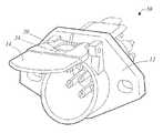
- FIG. 1is a front isometric view of a typical power connector having attached to its hinged cover an ATTS
- FIG. 2is a block diagram of a typical ATTS electronic circuit.
- the best mode for carrying out the inventionis presented in terms that disclose a preferred embodiment of an automatic tractor/trailer tracking system (ATTS).
- the ATTSis designed to identify and provide the status of a particular trailer assigned to a particular tractor.
- the preferred embodiment of the ATTS 10is comprised of an electronics circuit 20 that functions in combination with a trailer attached power connector 12 such as a SAE J560 7-pin connector and a tractor.
- the power connector 12as shown in FIG. 12 , includes a hinged cover 14 that is in either a closed vertical position, or in an open horizontal position in which position a power cable can be connected from the power connector 12 to a tractor.
- the power connector 12can be comprised of any power connector having a hinged cover 14 such as a data communication connector or an air hose connector.
- the electronic circuit 20is comprised of a microcontroller 22 , a transmitter 24 , a switching unit 26 , a battery 28 , and a radio frequency (RF) antenna 30 .
- the microcontroller 22has a first input 11 , a second input 13 , a third input 15 and an output 17 .
- a set of preset signalswhich include a unique identification of a specific trailer and a specific microcontroller 22 are programmed into the non-volatile memory of the microcontroller 22 via the first input 11 .
- the transmitter 24which is comprised of a short range transmitter, has a first input 19 , a second input 21 and an output 23 .
- the first input 19is connected to the second output 17 of the microcontroller 22 .
- the switching unit 26has an input 25 and an output 27 .
- the output 27is connected to the second input 13 on the microcontroller 22 .
- the switching unit 26can consist of an accelerometer, a tactile button switch, a toggle switch, a tilt switch, a magnetic reed switch, an optically coupled switch and a near field communication (NFC) receiver coil.
- NFCnear field communication
- the electronic circuit 20is attached by an attachment means 34 , as shown in FIG. 1 , to a trailer's structural member that interfaces with the hinged cover 14 of the power connector 12 or directly on the cover 14 .
- the switching unit 26When the cover 14 is closed, the switching unit 26 is open indicating that the trailer is not tethered to a tractor. When the over 14 is open, the switching unit 26 is closed indicating that the trailer is or can be tethered to the tractor.
- the battery 28provides the power that enables the electronic circuit 20 , as shown in FIG. 2 .
- the battery 28has a first output 29 connected to the third input 15 of the microcontroller 22 , a second output 31 connected to the input 25 of the switching unit 26 , a third output 33 connected to the second input 21 of the transmitter 24 and a fourth output 35 connected to circuit ground 32 .
- the output 23 from the transmitter 24is connected to the input 39 on the RF antenna 30 from where a set of trailer status signals are automatically and wirelessly transmitted to a designated RF receiver (not shown).
- the set of trailer status signalscomprise:
- the power connector 12has a hinged cover 14 that can be positioned in either a closed vertical position or an open horizontal position.
- the switching unit 26closes, thereby causing power from the battery 28 to be applied to the third input 15 which enables the microcontroller 22 .
- the microcontroller 22then sends, via the transmitter 24 and the RF antenna 30 , the trailer status signals to the tractor connected to the trailer and/or to a remote location. To conserve power, the output from the transmitter 24 is periodically transmitted and controlled by the microcontroller 22 .
- the switching unit 26opens, causing the power from the battery 28 from being applied to the microcontroller 22 .
- the microcontroller 22then goes into a sleep mode which is maintained until the cover transitions from the closed position to the open position.
- the microcontroller 22When the cover is initially placed in a closed position the microcontroller 22 goes into a steady state mode. In this mode, the microcontroller 22 keeps sending the trailer status signals for a selectable period of time, after which the microcontroller goes into a sleep mode.
Landscapes
- Engineering & Computer Science (AREA)
- Business, Economics & Management (AREA)
- General Physics & Mathematics (AREA)
- Physics & Mathematics (AREA)
- Economics (AREA)
- Mechanical Engineering (AREA)
- Marketing (AREA)
- Human Resources & Organizations (AREA)
- Entrepreneurship & Innovation (AREA)
- Operations Research (AREA)
- Quality & Reliability (AREA)
- Strategic Management (AREA)
- Tourism & Hospitality (AREA)
- Development Economics (AREA)
- General Business, Economics & Management (AREA)
- Transportation (AREA)
- Theoretical Computer Science (AREA)
- Arrangements For Transmission Of Measured Signals (AREA)
Abstract
Description
| U.S. PAT. NO. | INVENTOR | ISSUED |
| 8,068,019 | Bennie | 29 Nov. 2011 |
| 6,799,814 | Lesesky | 5 Oct. 2004 |
| 6,529,529 | Tohkairin | 4 Mar. 2003 |
- can be applied to various tractor/trailer combination,
- is easily maintained,
- is reliable,
- can be designed to be attached to fit a variety of power connector,
- can be processed as an aftermarket product or an OEM product,
- avoids situations where a trailer is attached to the wrong tractor, and
- is cost effective from both a manufacturer's and fleet's point of view.
- trailer identification,
- cover position status (up, down, moving up, moving down), and
- battery status.
Claims (2)
Priority Applications (1)
| Application Number | Priority Date | Filing Date | Title |
|---|---|---|---|
| US14/080,392US9409510B1 (en) | 2013-11-14 | 2013-11-14 | Automatic tractor/trailer tracking system |
Applications Claiming Priority (1)
| Application Number | Priority Date | Filing Date | Title |
|---|---|---|---|
| US14/080,392US9409510B1 (en) | 2013-11-14 | 2013-11-14 | Automatic tractor/trailer tracking system |
Publications (1)
| Publication Number | Publication Date |
|---|---|
| US9409510B1true US9409510B1 (en) | 2016-08-09 |
Family
ID=56556352
Family Applications (1)
| Application Number | Title | Priority Date | Filing Date |
|---|---|---|---|
| US14/080,392Expired - Fee RelatedUS9409510B1 (en) | 2013-11-14 | 2013-11-14 | Automatic tractor/trailer tracking system |
Country Status (1)
| Country | Link |
|---|---|
| US (1) | US9409510B1 (en) |
Cited By (5)
| Publication number | Priority date | Publication date | Assignee | Title |
|---|---|---|---|---|
| US10173486B1 (en) | 2017-11-15 | 2019-01-08 | Samsara Networks Inc. | Method and apparatus for automatically deducing a trailer is physically coupled with a vehicle |
| US20190364406A1 (en)* | 2018-05-25 | 2019-11-28 | Paccar Inc | Near field connection for secure tractor trailer communication, and associated systems and methods |
| EP3592627B1 (en) | 2017-03-06 | 2021-12-15 | Volvo Truck Corporation | Methods for assisting automatic uncoupling/coupling of a trailer |
| DE102020124092A1 (en) | 2020-09-16 | 2022-03-17 | Md Elektronik Gmbh | Connector arrangement for connecting an electrical line to an electrical component |
| US11394427B2 (en) | 2020-02-27 | 2022-07-19 | Bendix Commercial Vehicle Systems Llc | Interface device interfacing tractor and towed unit networks in a combination vehicle |
Citations (7)
| Publication number | Priority date | Publication date | Assignee | Title |
|---|---|---|---|---|
| US6054779A (en)* | 1998-04-14 | 2000-04-25 | Strick Corporation | Electrical power connector for tandem trailers |
| US20020016086A1 (en)* | 2000-01-13 | 2002-02-07 | Kinsey Gregory W. | Integrated communications and connection system for truck tractors |
| US6466028B1 (en)* | 2001-04-23 | 2002-10-15 | Transcommunications, Inc. | Trailer tether sensor circuit |
| US6529529B1 (en) | 1997-10-28 | 2003-03-04 | Fujitsu Limited | Multiplexing device having a digital 1-link relay capability |
| US6799814B2 (en) | 1995-11-09 | 2004-10-05 | Power Talk, Inc. | Systems and methods for monitoring and controlling tractor/trailer vehicle systems |
| US20060085099A1 (en)* | 2004-10-18 | 2006-04-20 | Stmicroelectronics, Inc. | Method and system for driving a vehicle trailer tow connector |
| US8068019B2 (en) | 2008-12-23 | 2011-11-29 | Ford Global Technologies | Trailer identification system |
- 2013
- 2013-11-14USUS14/080,392patent/US9409510B1/ennot_activeExpired - Fee Related
Patent Citations (7)
| Publication number | Priority date | Publication date | Assignee | Title |
|---|---|---|---|---|
| US6799814B2 (en) | 1995-11-09 | 2004-10-05 | Power Talk, Inc. | Systems and methods for monitoring and controlling tractor/trailer vehicle systems |
| US6529529B1 (en) | 1997-10-28 | 2003-03-04 | Fujitsu Limited | Multiplexing device having a digital 1-link relay capability |
| US6054779A (en)* | 1998-04-14 | 2000-04-25 | Strick Corporation | Electrical power connector for tandem trailers |
| US20020016086A1 (en)* | 2000-01-13 | 2002-02-07 | Kinsey Gregory W. | Integrated communications and connection system for truck tractors |
| US6466028B1 (en)* | 2001-04-23 | 2002-10-15 | Transcommunications, Inc. | Trailer tether sensor circuit |
| US20060085099A1 (en)* | 2004-10-18 | 2006-04-20 | Stmicroelectronics, Inc. | Method and system for driving a vehicle trailer tow connector |
| US8068019B2 (en) | 2008-12-23 | 2011-11-29 | Ford Global Technologies | Trailer identification system |
Cited By (10)
| Publication number | Priority date | Publication date | Assignee | Title |
|---|---|---|---|---|
| EP3592627B1 (en) | 2017-03-06 | 2021-12-15 | Volvo Truck Corporation | Methods for assisting automatic uncoupling/coupling of a trailer |
| US11820181B2 (en) | 2017-03-06 | 2023-11-21 | Volvo Truck Corporation | Methods for assisting automatic uncoupling/coupling of a trailer |
| US12350983B2 (en) | 2017-03-06 | 2025-07-08 | Volvo Truck Corporation | Methods for assisting automatic uncoupling/coupling of a trailer |
| US10173486B1 (en) | 2017-11-15 | 2019-01-08 | Samsara Networks Inc. | Method and apparatus for automatically deducing a trailer is physically coupled with a vehicle |
| US20190364406A1 (en)* | 2018-05-25 | 2019-11-28 | Paccar Inc | Near field connection for secure tractor trailer communication, and associated systems and methods |
| US10924905B2 (en)* | 2018-05-25 | 2021-02-16 | Paccar Inc | Near field connection for secure tractor trailer communication, and associated systems and methods |
| US11363438B2 (en) | 2018-05-25 | 2022-06-14 | Paccar Inc. | Near field connection for secure tractor trailer communication, and associated systems and methods |
| US11394427B2 (en) | 2020-02-27 | 2022-07-19 | Bendix Commercial Vehicle Systems Llc | Interface device interfacing tractor and towed unit networks in a combination vehicle |
| DE102020124092A1 (en) | 2020-09-16 | 2022-03-17 | Md Elektronik Gmbh | Connector arrangement for connecting an electrical line to an electrical component |
| DE102020124092B4 (en) | 2020-09-16 | 2022-03-31 | Md Elektronik Gmbh | Connector arrangement for connecting an electrical line to an electrical component |
Similar Documents
| Publication | Publication Date | Title |
|---|---|---|
| US9409510B1 (en) | Automatic tractor/trailer tracking system | |
| US8957770B2 (en) | Automatic networking apparatus and system for vehicles | |
| CA2559348A1 (en) | Tire pressure monitoring system with permanent tire identification | |
| EP2394827B1 (en) | A tire pressure monitoring system | |
| CN105313613B (en) | Transponder for automatic positioning of tire pressure monitoring system (TPMS) | |
| US7880595B2 (en) | Vehicle monitoring system | |
| US6871157B2 (en) | Method for automatically locating a motor vehicle wheel and corresponding locating unit | |
| US8818569B2 (en) | Vehicle communications and access | |
| US20210245678A1 (en) | Camera system and assistance system for a vehicle and a method for operating a camera system | |
| US9604613B2 (en) | Brake controller | |
| US20170203619A1 (en) | Tire parameter monitoring system | |
| US20110012723A1 (en) | Embedded in tire self-powered semi-passive rfid transponder | |
| US20050270148A1 (en) | Trailer tire monitoring system and method | |
| US20010038239A1 (en) | Braking system with wireless communication capability and trailer including same | |
| GB2443302A (en) | Tyre pressure monitoring system and method | |
| KR101460570B1 (en) | Camera Position Recognition System | |
| US11336322B2 (en) | High frequency communication apparatus for vehicle | |
| CN103921629A (en) | Commercial vehicle TPMS (Tire Pressure Monitoring System) | |
| JP4585357B2 (en) | Tire information transfer device, tire information transfer method, and vehicle | |
| US20150061853A1 (en) | Repeater module for tire pressure monitoring system | |
| EP2212874B1 (en) | Tracker and localizer of semi-trailers | |
| US20110241856A1 (en) | Automatic networking apparatus for vehicles | |
| WO2001051326A1 (en) | Braking system with wireless communication capability and trailer including same | |
| US7920057B2 (en) | Method and device for localization of the position of a wheel of a vehicle | |
| WO2020048574A1 (en) | Wireless trailer indication system |
Legal Events
| Date | Code | Title | Description |
|---|---|---|---|
| ZAAA | Notice of allowance and fees due | Free format text:ORIGINAL CODE: NOA | |
| ZAAB | Notice of allowance mailed | Free format text:ORIGINAL CODE: MN/=. | |
| STCF | Information on status: patent grant | Free format text:PATENTED CASE | |
| FEPP | Fee payment procedure | Free format text:MAINTENANCE FEE REMINDER MAILED (ORIGINAL EVENT CODE: REM.); ENTITY STATUS OF PATENT OWNER: MICROENTITY | |
| LAPS | Lapse for failure to pay maintenance fees | Free format text:PATENT EXPIRED FOR FAILURE TO PAY MAINTENANCE FEES (ORIGINAL EVENT CODE: EXP.); ENTITY STATUS OF PATENT OWNER: MICROENTITY | |
| PRDP | Patent reinstated due to the acceptance of a late maintenance fee | Effective date:20201209 | |
| FEPP | Fee payment procedure | Free format text:ENTITY STATUS SET TO MICRO (ORIGINAL EVENT CODE: MICR); ENTITY STATUS OF PATENT OWNER: MICROENTITY Free format text:SURCHARGE, PETITION TO ACCEPT PYMT AFTER EXP, UNINTENTIONAL (ORIGINAL EVENT CODE: M3558); ENTITY STATUS OF PATENT OWNER: MICROENTITY Free format text:PETITION RELATED TO MAINTENANCE FEES FILED (ORIGINAL EVENT CODE: PMFP); ENTITY STATUS OF PATENT OWNER: MICROENTITY Free format text:PETITION RELATED TO MAINTENANCE FEES GRANTED (ORIGINAL EVENT CODE: PMFG); ENTITY STATUS OF PATENT OWNER: MICROENTITY | |
| MAFP | Maintenance fee payment | Free format text:PAYMENT OF MAINTENANCE FEE, 4TH YEAR, MICRO ENTITY (ORIGINAL EVENT CODE: M3551); ENTITY STATUS OF PATENT OWNER: MICROENTITY Year of fee payment:4 | |
| STCF | Information on status: patent grant | Free format text:PATENTED CASE | |
| FEPP | Fee payment procedure | Free format text:MAINTENANCE FEE REMINDER MAILED (ORIGINAL EVENT CODE: REM.); ENTITY STATUS OF PATENT OWNER: MICROENTITY | |
| LAPS | Lapse for failure to pay maintenance fees | Free format text:PATENT EXPIRED FOR FAILURE TO PAY MAINTENANCE FEES (ORIGINAL EVENT CODE: EXP.); ENTITY STATUS OF PATENT OWNER: MICROENTITY | |
| STCH | Information on status: patent discontinuation | Free format text:PATENT EXPIRED DUE TO NONPAYMENT OF MAINTENANCE FEES UNDER 37 CFR 1.362 | |
| FP | Lapsed due to failure to pay maintenance fee | Effective date:20240809 |