US9409011B2 - Method of constructing an implantable microelectrode array - Google Patents
Method of constructing an implantable microelectrode arrayDownload PDFInfo
- Publication number
- US9409011B2 US9409011B2US14/320,316US201414320316AUS9409011B2US 9409011 B2US9409011 B2US 9409011B2US 201414320316 AUS201414320316 AUS 201414320316AUS 9409011 B2US9409011 B2US 9409011B2
- Authority
- US
- United States
- Prior art keywords
- layer
- electrodes
- parylene
- openings
- spinal cord
- Prior art date
- Legal status (The legal status is an assumption and is not a legal conclusion. Google has not performed a legal analysis and makes no representation as to the accuracy of the status listed.)
- Expired - Fee Related
Links
- 238000000034methodMethods0.000titleclaimsdescription36
- VRBFTYUMFJWSJY-UHFFFAOYSA-N28804-46-8Chemical compoundClC1CC(C=C2)=CC=C2C(Cl)CC2=CC=C1C=C2VRBFTYUMFJWSJY-UHFFFAOYSA-N0.000claimsdescription38
- 229920002120photoresistant polymerPolymers0.000claimsdescription19
- 239000000463materialSubstances0.000claimsdescription12
- 239000000758substrateSubstances0.000claimsdescription10
- 239000011248coating agentSubstances0.000claimsdescription9
- 238000000576coating methodMethods0.000claimsdescription9
- 239000004020conductorSubstances0.000claimsdescription9
- 239000012811non-conductive materialSubstances0.000claimsdescription7
- GUHKMHMGKKRFDT-UHFFFAOYSA-N1785-64-4Chemical compoundC1CC(=C(F)C=2F)C(F)=C(F)C=2CCC2=C(F)C(F)=C1C(F)=C2FGUHKMHMGKKRFDT-UHFFFAOYSA-N0.000claimsdescription6
- -1parylene-AMChemical compound0.000claimsdescription5
- 238000005516engineering processMethods0.000claimsdescription4
- XUIMIQQOPSSXEZ-UHFFFAOYSA-NSiliconChemical compound[Si]XUIMIQQOPSSXEZ-UHFFFAOYSA-N0.000claimsdescription3
- 230000008020evaporationEffects0.000claimsdescription3
- 238000001704evaporationMethods0.000claimsdescription3
- 238000001465metallisationMethods0.000claimsdescription3
- 229910052710siliconInorganic materials0.000claimsdescription3
- 239000010703siliconSubstances0.000claimsdescription3
- 230000000638stimulationEffects0.000abstractdescription64
- 210000000278spinal cordAnatomy0.000abstractdescription55
- 230000002093peripheral effectEffects0.000abstractdescription5
- 230000037361pathwayEffects0.000abstractdescription4
- 241000700159RattusSpecies0.000description35
- 230000033001locomotionEffects0.000description16
- 206010033799ParalysisDiseases0.000description13
- 238000002567electromyographyMethods0.000description11
- 229920000052poly(p-xylylene)Polymers0.000description11
- 230000004044responseEffects0.000description9
- 238000003491arrayMethods0.000description8
- 210000003141lower extremityAnatomy0.000description8
- 208000020431spinal cord injuryDiseases0.000description8
- 238000010586diagramMethods0.000description7
- CSCPPACGZOOCGX-UHFFFAOYSA-NAcetoneChemical compoundCC(C)=OCSCPPACGZOOCGX-UHFFFAOYSA-N0.000description6
- 238000000151depositionMethods0.000description6
- 238000002513implantationMethods0.000description6
- BASFCYQUMIYNBI-UHFFFAOYSA-NplatinumChemical compound[Pt]BASFCYQUMIYNBI-UHFFFAOYSA-N0.000description6
- 238000011084recoveryMethods0.000description6
- 241001269524DuraSpecies0.000description5
- 239000004593EpoxySubstances0.000description5
- 238000005530etchingMethods0.000description5
- 238000011160researchMethods0.000description5
- 241000124008MammaliaSpecies0.000description4
- 230000001684chronic effectEffects0.000description4
- PCHJSUWPFVWCPO-UHFFFAOYSA-NgoldChemical compound[Au]PCHJSUWPFVWCPO-UHFFFAOYSA-N0.000description4
- 229920001296polysiloxanePolymers0.000description4
- 238000009987spinningMethods0.000description4
- 241001465754MetazoaSpecies0.000description3
- RTAQQCXQSZGOHL-UHFFFAOYSA-NTitaniumChemical compound[Ti]RTAQQCXQSZGOHL-UHFFFAOYSA-N0.000description3
- 230000002567autonomic effectEffects0.000description3
- 208000029028brain injuryDiseases0.000description3
- 230000006870functionEffects0.000description3
- 229910052737goldInorganic materials0.000description3
- 239000010931goldSubstances0.000description3
- 229910052751metalInorganic materials0.000description3
- 239000002184metalSubstances0.000description3
- 210000003205muscleAnatomy0.000description3
- 229910052697platinumInorganic materials0.000description3
- 230000002207retinal effectEffects0.000description3
- 238000012360testing methodMethods0.000description3
- 229910052719titaniumInorganic materials0.000description3
- 239000010936titaniumSubstances0.000description3
- 238000007740vapor depositionMethods0.000description3
- 241000282412HomoSpecies0.000description2
- 208000032319Primary lateral sclerosisDiseases0.000description2
- 239000004809TeflonSubstances0.000description2
- 229920006362Teflon®Polymers0.000description2
- 206010046298Upper motor neurone lesionDiseases0.000description2
- 206010002026amyotrophic lateral sclerosisDiseases0.000description2
- 230000037424autonomic functionEffects0.000description2
- 230000008901benefitEffects0.000description2
- 230000008512biological responseEffects0.000description2
- 230000036760body temperatureEffects0.000description2
- 230000009084cardiovascular functionEffects0.000description2
- 230000003920cognitive functionEffects0.000description2
- 229940079593drugDrugs0.000description2
- 239000003814drugSubstances0.000description2
- 238000002474experimental methodMethods0.000description2
- 230000036541healthEffects0.000description2
- 208000010726hind limb paralysisDiseases0.000description2
- 239000007943implantSubstances0.000description2
- 208000015181infectious diseaseDiseases0.000description2
- 230000000302ischemic effectEffects0.000description2
- 201000010901lateral sclerosisDiseases0.000description2
- 230000006742locomotor activityEffects0.000description2
- 230000004060metabolic processEffects0.000description2
- 238000012986modificationMethods0.000description2
- 230000004048modificationEffects0.000description2
- 208000005264motor neuron diseaseDiseases0.000description2
- 230000000626neurodegenerative effectEffects0.000description2
- 230000000926neurological effectEffects0.000description2
- 230000001144postural effectEffects0.000description2
- 230000008569processEffects0.000description2
- 230000036299sexual functionEffects0.000description2
- 229920002379silicone rubberPolymers0.000description2
- 230000004936stimulating effectEffects0.000description2
- 210000001519tissueAnatomy0.000description2
- 238000011282treatmentMethods0.000description2
- 230000001457vasomotorEffects0.000description2
- 230000021542voluntary musculoskeletal movementEffects0.000description2
- XLYOFNOQVPJJNP-UHFFFAOYSA-NwaterSubstancesOXLYOFNOQVPJJNP-UHFFFAOYSA-N0.000description2
- VYZAMTAEIAYCRO-UHFFFAOYSA-NChromiumChemical compound[Cr]VYZAMTAEIAYCRO-UHFFFAOYSA-N0.000description1
- 208000023105Huntington diseaseDiseases0.000description1
- 208000018737Parkinson diseaseDiseases0.000description1
- BQCADISMDOOEFD-UHFFFAOYSA-NSilverChemical compound[Ag]BQCADISMDOOEFD-UHFFFAOYSA-N0.000description1
- 208000006011StrokeDiseases0.000description1
- 208000030886Traumatic Brain injuryDiseases0.000description1
- 230000001154acute effectEffects0.000description1
- 230000002730additional effectEffects0.000description1
- 229910045601alloyInorganic materials0.000description1
- 239000000956alloySubstances0.000description1
- 238000000137annealingMethods0.000description1
- QVGXLLKOCUKJST-UHFFFAOYSA-Natomic oxygenChemical compound[O]QVGXLLKOCUKJST-UHFFFAOYSA-N0.000description1
- 239000000560biocompatible materialSubstances0.000description1
- 230000007321biological mechanismEffects0.000description1
- 210000000988bone and boneAnatomy0.000description1
- 210000004556brainAnatomy0.000description1
- 206010008129cerebral palsyDiseases0.000description1
- 229910052804chromiumInorganic materials0.000description1
- 239000011651chromiumSubstances0.000description1
- 238000004891communicationMethods0.000description1
- 230000006378damageEffects0.000description1
- 230000032798delaminationEffects0.000description1
- 230000001627detrimental effectEffects0.000description1
- 238000011161developmentMethods0.000description1
- 230000000694effectsEffects0.000description1
- 230000000763evoking effectEffects0.000description1
- 208000014674injuryDiseases0.000description1
- 229910052741iridiumInorganic materials0.000description1
- GKOZUEZYRPOHIO-UHFFFAOYSA-Niridium atomChemical compound[Ir]GKOZUEZYRPOHIO-UHFFFAOYSA-N0.000description1
- 208000037906ischaemic injuryDiseases0.000description1
- 208000028867ischemiaDiseases0.000description1
- 210000004705lumbosacral regionAnatomy0.000description1
- 238000004519manufacturing processMethods0.000description1
- 150000002739metalsChemical class0.000description1
- 239000003607modifierSubstances0.000description1
- 229910052760oxygenInorganic materials0.000description1
- 239000001301oxygenSubstances0.000description1
- 230000037081physical activityEffects0.000description1
- 238000001020plasma etchingMethods0.000description1
- 230000011514reflexEffects0.000description1
- 238000000926separation methodMethods0.000description1
- 229910052709silverInorganic materials0.000description1
- 239000004332silverSubstances0.000description1
- 210000000115thoracic cavityAnatomy0.000description1
- 230000001256tonic effectEffects0.000description1
- 238000012549trainingMethods0.000description1
- 230000008733traumaEffects0.000description1
- 230000009529traumatic brain injuryEffects0.000description1
- WFKWXMTUELFFGS-UHFFFAOYSA-NtungstenChemical compound[W]WFKWXMTUELFFGS-UHFFFAOYSA-N0.000description1
- 229910052721tungstenInorganic materials0.000description1
- 239000010937tungstenSubstances0.000description1
- 230000002747voluntary effectEffects0.000description1
Images


Classifications
- A—HUMAN NECESSITIES
- A61—MEDICAL OR VETERINARY SCIENCE; HYGIENE
- A61N—ELECTROTHERAPY; MAGNETOTHERAPY; RADIATION THERAPY; ULTRASOUND THERAPY
- A61N1/00—Electrotherapy; Circuits therefor
- A61N1/02—Details
- A61N1/04—Electrodes
- A61N1/05—Electrodes for implantation or insertion into the body, e.g. heart electrode
- A61N1/0551—Spinal or peripheral nerve electrodes
- A61N1/0553—Paddle shaped electrodes, e.g. for laminotomy
- A—HUMAN NECESSITIES
- A61—MEDICAL OR VETERINARY SCIENCE; HYGIENE
- A61B—DIAGNOSIS; SURGERY; IDENTIFICATION
- A61B5/00—Measuring for diagnostic purposes; Identification of persons
- A61B5/24—Detecting, measuring or recording bioelectric or biomagnetic signals of the body or parts thereof
- A—HUMAN NECESSITIES
- A61—MEDICAL OR VETERINARY SCIENCE; HYGIENE
- A61N—ELECTROTHERAPY; MAGNETOTHERAPY; RADIATION THERAPY; ULTRASOUND THERAPY
- A61N1/00—Electrotherapy; Circuits therefor
- A61N1/02—Details
- A61N1/04—Electrodes
- A61N1/05—Electrodes for implantation or insertion into the body, e.g. heart electrode
- A61N1/0551—Spinal or peripheral nerve electrodes
- A61N1/0558—Anchoring or fixation means therefor
- A—HUMAN NECESSITIES
- A61—MEDICAL OR VETERINARY SCIENCE; HYGIENE
- A61N—ELECTROTHERAPY; MAGNETOTHERAPY; RADIATION THERAPY; ULTRASOUND THERAPY
- A61N1/00—Electrotherapy; Circuits therefor
- A61N1/18—Applying electric currents by contact electrodes
- A61N1/32—Applying electric currents by contact electrodes alternating or intermittent currents
- A61N1/36—Applying electric currents by contact electrodes alternating or intermittent currents for stimulation
- A61N1/3605—Implantable neurostimulators for stimulating central or peripheral nerve system
- A61N1/3606—Implantable neurostimulators for stimulating central or peripheral nerve system adapted for a particular treatment
- A61N1/36062—Spinal stimulation
- A—HUMAN NECESSITIES
- A61—MEDICAL OR VETERINARY SCIENCE; HYGIENE
- A61N—ELECTROTHERAPY; MAGNETOTHERAPY; RADIATION THERAPY; ULTRASOUND THERAPY
- A61N1/00—Electrotherapy; Circuits therefor
- A61N1/18—Applying electric currents by contact electrodes
- A61N1/32—Applying electric currents by contact electrodes alternating or intermittent currents
- A61N1/36—Applying electric currents by contact electrodes alternating or intermittent currents for stimulation
- A61N1/3605—Implantable neurostimulators for stimulating central or peripheral nerve system
- A61N1/3606—Implantable neurostimulators for stimulating central or peripheral nerve system adapted for a particular treatment
- A61N1/36067—Movement disorders, e.g. tremor or Parkinson disease
- A—HUMAN NECESSITIES
- A61—MEDICAL OR VETERINARY SCIENCE; HYGIENE
- A61N—ELECTROTHERAPY; MAGNETOTHERAPY; RADIATION THERAPY; ULTRASOUND THERAPY
- A61N1/00—Electrotherapy; Circuits therefor
- A61N1/18—Applying electric currents by contact electrodes
- A61N1/32—Applying electric currents by contact electrodes alternating or intermittent currents
- A61N1/36—Applying electric currents by contact electrodes alternating or intermittent currents for stimulation
- A61N1/3605—Implantable neurostimulators for stimulating central or peripheral nerve system
- A61N1/36128—Control systems
- A—HUMAN NECESSITIES
- A61—MEDICAL OR VETERINARY SCIENCE; HYGIENE
- A61N—ELECTROTHERAPY; MAGNETOTHERAPY; RADIATION THERAPY; ULTRASOUND THERAPY
- A61N1/00—Electrotherapy; Circuits therefor
- A61N1/18—Applying electric currents by contact electrodes
- A61N1/32—Applying electric currents by contact electrodes alternating or intermittent currents
- A61N1/36—Applying electric currents by contact electrodes alternating or intermittent currents for stimulation
- A61N1/372—Arrangements in connection with the implantation of stimulators
- A61N1/375—Constructional arrangements, e.g. casings
- A—HUMAN NECESSITIES
- A61—MEDICAL OR VETERINARY SCIENCE; HYGIENE
- A61B—DIAGNOSIS; SURGERY; IDENTIFICATION
- A61B2562/00—Details of sensors; Constructional details of sensor housings or probes; Accessories for sensors
- A61B2562/12—Manufacturing methods specially adapted for producing sensors for in-vivo measurements
- A61B2562/125—Manufacturing methods specially adapted for producing sensors for in-vivo measurements characterised by the manufacture of electrodes
- H—ELECTRICITY
- H01—ELECTRIC ELEMENTS
- H01B—CABLES; CONDUCTORS; INSULATORS; SELECTION OF MATERIALS FOR THEIR CONDUCTIVE, INSULATING OR DIELECTRIC PROPERTIES
- H01B5/00—Non-insulated conductors or conductive bodies characterised by their form
- H01B5/14—Non-insulated conductors or conductive bodies characterised by their form comprising conductive layers or films on insulating-supports
Definitions
- the present inventionis directed generally to implantable electrode arrays, and more particularly to implantable electrode arrays used to deliver electrical stimulation to the spinal cord.
- Embodiments of the inventioninclude an implantable device configured to apply electrical stimulation to a spinal cord of a subject (e.g., a human being or other mammal, such as a rat).
- the deviceincludes a body portion and a first layer.
- the body portionhas a peripheral portion.
- the peripheral portionincludes a frame positioned adjacent the first layer.
- the framemay be constructed from one or more layers of a substantially electrically nonconductive material (e.g., parylene-A, parylene-C, parylene-AM, parylene-F, parylene-N, parylene-D, and the like).
- the first layeris constructed from a substantially electrically nonconductive material.
- the first layeris constructed from at least one of parylene-A, parylene-C, parylene-AM, parylene-F, parylene-N, and parylene-D.
- the first layerhas a first portion and a second portion.
- the first portionis positionable alongside the spinal cord and includes a first plurality of openings.
- the first portion of the first layermay be positioned against a dura of the spinal cord and the device configured to provide electrical stimulation to the dura.
- the second portionincludes a second plurality of openings.
- a plurality of electrodesis positioned inside the peripheral portion and alongside the first portion of the first layer. At least one of the first plurality of openings is adjacent each of the electrodes to provide a pathway through which the electrode may provide electrical stimulation to the spinal cord when the first portion is positioned alongside the spinal cord. In some embodiments, more than one of the first plurality of openings is adjacent each of the plurality of electrodes. In embodiments in which the first portion of the first layer is to be positioned against the dura of the spinal cord, the plurality of electrodes is configured to provide electrical stimulation to the dura.
- a plurality of tracesis positioned inside the peripheral portion and alongside the first layer with at least one of the second plurality of openings being adjacent each of the traces to provide a pathway through which the trace may receive electrical stimulation.
- One or more of the tracesis/are connected to each of the electrodes and configured to conduct electrical stimulation received by the one or more of the traces to the electrode.
- two of the tracesare connected to each of the electrodes.
- the plurality of tracesare configured to conduct different electrical stimulation to different ones of the plurality of electrodes. Further, the plurality of traces may be configured to conduct electrical stimulation to fewer than all of the plurality of electrodes.
- the first layerincludes a plurality of grid structures with a different one of the grid structures adjacent each of the plurality of electrodes.
- Each grid structuredefines a plurality of cells.
- each of the at least one of the first plurality of openings adjacent the electrodeis positioned inside a different one of the cells of the grid structure adjacent the electrode.
- the body portionincludes a second layer.
- the plurality of electrodes and the plurality of tracesmay be positioned between the first and second layers.
- the first and second layersmay each be constructed from at least one of parylene-A, parylene-C, parylene-AM, parylene-F, parylene-N, and parylene-D.
- a flexible outer coatingmay coat at least a portion of the second layer of the body portion and a portion of the first layer between the first portion of the first layer and the second portion of the first layer.
- the outer coatingmay include at least one of a biomedical grade epoxy and a silicone elastomer.
- Embodimentsalso include a method of constructing an implantable electrode array assembly configured to apply electrical stimulation to the spinal cord of a subject (e.g., a human being or other mammal, such as a rat).
- the methodincludes forming a patterned layer of electrically conductive material defining a plurality of electrodes and a plurality of traces, at least one trace being connected to each of the plurality of electrodes.
- the methodalso includes forming a first layer of a substantially electrically nonconductive material adjacent the patterned layer.
- the methodalso includes forming (e.g., etching) a plurality of first openings and a plurality of second openings in the first layer. The first openings provide access to the plurality of electrodes through the first layer.
- a different grid defining portion of the first openingsis adjacent each of the electrodes.
- Each grid defining portionexposes a plurality of contacts of the electrode to which the grid defining portion is adjacent.
- the plurality of second openingsprovide access to the plurality of traces through the first layer.
- the first and second layersmay each be constructed from at least one of parylene-A, parylene-C, parylene-AM, parylene-F, parylene-N, and parylene-D.
- the first and second layersmay be formed from the same material.
- the methodmay include applying a coating to at least a portion of the second layer and at least a portion of the first layer.
- Another embodimentincludes a system that includes a stimulation generator, an implantable electrode array assembly, a baseplate, and a plurality of wires.
- the stimulation generatoris configured to generate electrical stimulation.
- the implantable electrode array assemblyhas a proximal end portion connectable to at least one vertebrae and a distal end portion positionable along the spinal cord.
- the proximal end portionhas a plurality of electrical connections to a plurality of electrodes positioned on the distal end portion.
- the baseplateis configured to be connected to the at least one vertebrae and to connect the assembly to the at least one vertebrae.
- the plurality of wiresis connected to the baseplate and the stimulation generator.
- the plurality of wiresis configured to conduct electrical stimulation generated by the stimulation generator to the baseplate.
- the baseplateis configured to conduct the electrical stimulation to the plurality of electrical connections of the proximal end portion of the assembly.
- the systemmay include an overhanging portion connected to the baseplate and positioned to overhang at least a portion of the proximal portion of the assembly to help protect the assembly from external moving tissue.
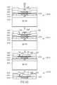
- FIG. 1is a view of an underside of an implantable electrode array assembly.
- FIG. 2is an enlarged view of a portion of the assembly of FIG. 1 .
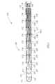
- FIG. 3is a cross-sectional view of a cable system incorporating the assembly of FIG. 1 implanted in a rat.
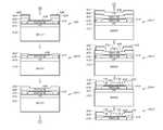
- FIG. 4Ais an illustration of a first portion of a method of constructing the assembly of FIG. 1 .
- FIG. 4Bis an illustration of a second portion of the method of constructing the assembly of FIG. 1 .
- FIG. 4Cis an illustration of a third portion of the method of constructing the assembly of FIG. 1 .
- FIG. 4Dis an illustration of a fourth portion of the method of constructing the assembly of FIG. 1 .
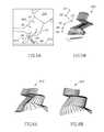
- FIG. 5Ais an illustration of a spinalized rat implanted with the assembly of FIG. 1 suspended above a treadmill and a portion of a motion capture system used to record stepping motion of the rat on the treadmill.
- FIG. 5Bis a stick diagram illustrating a dragging motion of the hindlimb of the rat on the treadmill when no stimulation is applied to the rat's spinal cord by the assembly of FIG. 1 .
- FIG. 6Ais a stick diagram illustrating hind limb motion when bipolar stimulation was applied to the rat's spinal cord by a first pair of electrodes of the assembly of FIG. 1 .
- FIG. 6Bis a stick diagram illustrating hind limb motion when bipolar stimulation was applied to the rat's spinal cord by a second different pair of electrodes of the assembly of FIG. 1 .
- FIG. 7Ais a graphical representation of an electromyography (“EMG”) recording recorded when bipolar stimulation was applied to the rat's spinal cord by a first pair of electrodes of the assembly of FIG. 1 .
- EMGelectromyography
- FIG. 7Bis a graphical representation of an EMG recording recorded when bipolar stimulation was applied to the rat's spinal cord by a second different pair of electrodes of the assembly of FIG. 1 .
- FIG. 1illustrates an implantable electrode array assembly 100 . While the embodiment of the assembly 100 illustrated is configured for implantation in a rat 500 (see FIG. 5A ), embodiments may be constructed for use in other subjects, such as other mammals, including humans, and such embodiments are within the scope of the present teachings.
- the assembly 100is for use with a subject that has a spinal cord 330 (see FIG. 3 ) with at least one selected spinal circuit (not shown) and a neurologically derived paralysis in a portion of the subject's body.
- the assembly 100may be implanted epidurally along the spinal cord 330 .
- the assembly 100may be positioned at one or more of a lumbosacral region, a cervical region, and a thoracic region of the spinal cord 330 .
- the selected spinal circuitwhen activated, may (a) enable voluntary movement of muscles involved in at least one of standing, stepping, reaching, grasping, voluntarily changing positions of one or both legs, voiding the subject's bladder, voiding the subject's bowel, postural activity, and locomotor activity; (b) enable or improve autonomic control of at least one of cardiovascular function, body temperature, and metabolic processes; and/or (c) help facilitate recovery of at least one of an autonomic function, sexual function, vasomotor function, and cognitive function.
- the selected spinal circuithas a first stimulation threshold representing a minimum amount of stimulation required to activate the selected spinal circuit, and a second stimulation threshold representing an amount of stimulation above which the selected spinal circuit is fully activated and adding the induced neurological signals has no additional effect on the at least one selected spinal circuit.
- the paralysismay be a motor complete paralysis or a motor incomplete paralysis.
- the paralysismay have been caused by a spinal cord injury classified as motor complete or motor incomplete.
- the paralysismay have been caused by an ischemic or traumatic brain injury.
- the paralysismay have been caused by an ischemic brain injury that resulted from a stroke or acute trauma.
- the paralysismay have been caused by a neurodegenerative brain injury.
- the neurodegenerative brain injurymay be associated with at least one of Parkinson's disease, Huntington's disease, Alzheimer's, ischemia, stroke, amyotrophic lateral sclerosis (ALS), primary lateral sclerosis (PLS), and cerebral palsy.
- the assembly 100may be implanted (e.g., epidurally) at a second location below the first location along the spinal cord relative to the subject's brain (not shown).
- the assembly 100is configured to apply electrical stimulation to a portion of a spinal cord 330 of the subject.
- the electrical stimulationmay include at least one of tonic stimulation and intermittent stimulation.
- the stimulation appliedmay be pulsed.
- the electrical stimulationmay include simultaneous or sequential stimulation of different regions of the spinal cord.
- the electrical stimulation applied by the assembly 100may be below the second stimulation threshold such that the at least one selected spinal circuit is at least partially activatable by the addition of signals generated by the subject.
- such subject generated signalsmay be induced by subjecting the subject to physical activity or training (such as stepping on a treadmill). These signals may be induced in a paralyzed portion of the subject.
- the subject generated signalsmay include supraspinal signals.
- the embodiment of the assembly 100 illustrated in FIGS. 1-3is configured for implantation in the rat 500 (see FIG. 5A ).
- the embodiment of the assembly 100 illustratedis sized (e.g., about 59 mm by about 3 mm) and shaped for implantation into the rat 500 .
- embodimentsmay be constructed for use with other subjects, such as other mammals, including humans.
- FIG. 2illustrates an enlarged portion 200 of the assembly 100 depicted in FIG. 1 .
- the assembly 100may be characterized as being a microelectromechanical systems (“MEMS”) device.
- MEMSmicroelectromechanical systems
- the assembly 100is configured for implantation along the spinal cord 330 (see FIG. 3 ) and to provide electrical stimulation thereto.
- the assembly 100may provide epidural stimulation to the spinal cord 330 .
- the assembly 100allows for a high degree of freedom and specificity in selecting the site of stimulation compared to prior art wire-based implants, and triggers varied biological responses that can lead to an increased understanding of the spinal cord 330 and locomotion recovery for victims of spinal cord injury.
- the assembly 100includes a body portion 110 , an electrode array 120 , and a plurality of electrically conductive traces 130 .
- the body portion 110includes a distal end portion 112 , a proximal end portion 114 (opposite the distal end portion), a frame 140 , and a grid structure 210 (see FIG. 2 ) for each electrode E11-E19, E21-E29, and E31-E39 of the electrode array 120 .
- Each of the grid structures 210defines a plurality of cells 212 .
- the grid structures 210may each be constructed from parylene (e.g., parylene-C). In the embodiment illustrated, the grid structure 210 includes 40 cells.
- the electrode array 120includes the plurality of electrodes E11-E19, E21-E29, and E31-E39 (e.g., 9 ⁇ 3 electrodes).
- the electrodes E11-E19, E21-E29, and E31-E39are arranged in a two-dimensional array.
- Each of the electrodes E11-E19, E21-E29, and E31-E39includes a plurality of electrically conductive contacts 220 .
- the contacts 220are sites at which the electrode (e.g., the electrode E37 illustrated in FIG. 2 ) will contact the spinal cord (e.g., the dura).
- the contacts 220are in electrically communication with one another.
- the embodiment of the electrode E37 illustratedincludes 40 contacts 220 .
- each of the electrodes E11-E19, E21-E29, and E31-E39corresponds to a unique one of the grid structures 210 .
- each of the contacts 220is positioned within a different one of the cells 212 of the corresponding grid structure 210 .
- the grid structure 210may help prevent delamination of the layers of the assembly 100 (see FIG. 1 ).
- the grid structure 210 and contacts 220may be formed by selectively etching a layer of substantially electrically non-conductive material (e.g., parylene) adjacent a pad of electrically conductive material (e.g., metal) to define the grid structure 210 and expose portions of the electrically conductive material within the cells 212 of the grid structure to define the contacts 220 .
- substantially electrically non-conductive materiale.g., parylene
- electrically conductive materiale.g., metal
- the electrode array 120 illustratedincludes 27 electrodes, in other embodiments, the number of electrodes may range from one electrode to about 100,000 electrodes or more. In certain embodiments, the electrode array 120 includes at least 10, at least 15, at least 20, at least 25, at least 50, at least 100, at least 250, at least 500, or at least 1000 electrodes. In various embodiments, the interelectrode spacing of adjacent electrodes in the electrode array 120 varies from about 100 ⁇ m or about 500 ⁇ m, or about 1000 ⁇ m or about 1500 ⁇ m to about 2000 ⁇ m, or about 3000 ⁇ m, or about 4000 ⁇ m, or about 4500 ⁇ m, or about 5000 ⁇ m.
- interelectrode spacingranges from about 100 ⁇ m, about 150 ⁇ m, about 200 ⁇ m, or about 250 ⁇ m up to about 1,000 ⁇ m, about 2000 ⁇ m, about 3000 ⁇ m, or about 4,000 ⁇ m.
- the diameter (or width) of each of the electrodes E11-E19, E21-E29, and E31-E39ranges from about 50 ⁇ m, 100 ⁇ m, 150 ⁇ m, 200 ⁇ m, or 250 ⁇ m up to about 500 ⁇ m, about 1000 ⁇ m, about 1500 ⁇ m, or about 2000 ⁇ m.
- the electrode array 120can be formed in any geometric shape such as a square shape, rectangular shape, or circular shape. Typically the size of the electrode array 120 will be on the order of about 0.1 mm to about 2 cm, wide or in diameter, depending in part on the number of electrodes in the electrode array 120 . In various embodiments, the length of the electrode array 120 ranges from about 0.01 mmm, or 0.1 mm up to about 10 cm or greater.
- One or more of the traces 130is connected to each of the electrodes E11-E19, E21-E29, and E31-E39.
- two traces “T 1 ” and “T 2 ”are connected to each of the electrodes E11-E19, E21-E29, and E31-E39.
- more than two traces 130may be connected to each of the electrodes E11-E19, E21-E29, and E31-E39. Connecting more than one of the traces 130 to each of the electrodes E11-E19, E21-E29, and E31-E39 helps ensure signals reach each of the electrodes E11-E19, E21-E29, and E31-E39.
- redundancymay be used to improve reliability.
- the traces 130are connected to each of the contacts 220 of the electrode and carry signals thereto. Openings 132 (see FIG. 3 ) formed (e.g., etched) in the body portion 110 expose portions of the traces 130 .
- the traces 130may be used to selectively deliver electrical signals (e.g., pulsed signals) to the electrodes E11-E19, E21-E29, and E31-E39. In this manner, only a selected one or more of the electrodes E11-E19, E21-E29, and E31-E39 may deliver stimulation to the spinal cord 330 (see FIG. 3 ).
- the electrodes E11-E19, E21-E29, and E31-E39are operably linked by the traces 130 to control circuitry (not shown).
- the control circuitry(not shown) is configured to select one or more of the electrodes E11-E19, E21-E29, and E31-E39 to activate/stimulate and/or to control the parameters (e.g., frequency, pulse width, amplitude, and the like) of the electrical stimulation.
- the electrode selection, frequency, amplitude, and pulse widthare independently selectable. For example, at different times, different electrodes can be selected.
- different electrodescan provide stimulation having different parameter values (e.g., frequencies, amplitudes, and the like).
- at least a portion of the electrodesmay be operated in a monopolar mode and/or a bipolar mode.
- constant current or constant voltagemay be used to deliver the stimulation.
- the traces 130may receive signals from implantable control circuitry (not shown) and/or an implantable power source (not shown).
- the implantable control circuitry (not shown)may be programmed and/or reprogrammed by an external device (e.g., using a handheld device that communicates with the control circuitry through the skin). The programming may be repeated as often as necessary.
- FIG. 3illustrates a cable system 300 incorporating the assembly 100 .
- the cable system 300is illustrated implanted along the spine 320 and spinal cord 330 of the rat 500 (see FIG. 5A ). Due to the difficulty preventing infection at connectors that cross the skin (not shown), in chronic experiments, it is often highly desirable to pass signals through a headplug 310 positioned on the head (not shown) of the rat 500 , where the large bone surface, lack of muscle tissue, and minimal movement of skin help minimize the risk of infection.
- the cable system 300was devised to confine strain imposed on the assembly 100 to acceptable limits.
- FIG. 3illustrates how the cable system 300 (including the assembly 100 ) is positioned along the spine 320 of the subject (e.g., the rat 500 illustrated in FIG. 5A ) after implantation.
- the cable system 300is composed of a spinal baseplate 340 , a wire bundle 350 , and the headplug 310 .
- Another set of wiresmay be implanted in the leg(s) 520 (see FIG. 5A ) of the subject to record electromyography (“EMG”) signals.
- EMGelectromyography
- the baseplate 340may be constructed from a standard FR-4 PCB substrate.
- the baseplate 340is attached (e.g., by a suture 342 ) to a selected vertebrae (e.g., vertebrae “L 2 ”).
- the baseplate 340is attached to the “L 2 ” vertebrae.
- the assembly 100is attached (e.g., by a suture 344 ) to the spinal cord 300 .
- the distal end portion 112 of the assembly 100is attached to the spinal cord 300 at a location adjacent vertebrae “T 13 .”
- the proximal end portion 114 of the assembly 100is attached to the baseplate 340 using a conductive material (e.g., conductive epoxy) to bridge electrical connections.
- a conductive materiale.g., conductive epoxy
- the proximal end portion 114 of the assembly 100may be secured to the baseplate 340 using Loctite M-121 HP Medical device epoxy.
- the wire bundle 350includes a plurality of wires 352 .
- the wires 352may include a different wire for each of the electrodes E11-E19, E21-E29, and E31-E39 (e.g., 27 wires total for a 9 ⁇ 3 array of electrodes).
- Each of the wires 352may be constructed from gold and include a Teflon coating.
- 75 ⁇ m gold wirese.g., Teflon coated gold wire manufactured by AM Systems
- the wires 352may be soldered to the baseplate 340 and connected by high density connectors 360 to the headplug 310 .
- the traces 130are connected to the baseplate 340 via the openings 132 formed in the body portion 110 of the assembly 100 .
- silver epoxy(not shown) may be used to connect the traces 130 to the baseplate 340 .
- the entire cable system 300may be coated with a coating 370 configured to insulate electrical connections and provide mechanical strength while retaining the flexibility wherever necessary.
- the coating 370may include a biomedical grade epoxy and a silicone elastomer (e.g., MDX 4-4210 Biomedical grade silicone).
- a silicone cap 380(or overhanging portion) is formed on the end of the baseplate 340 to protect the assembly 100 from external moving tissue.
- the cap 380may be formed from the same material as the coating 370 .
- the coating 370may be implemented as a thin layer of silicone (e.g., about 100 ⁇ m thick) to reduce stress concentration as the assembly 100 bends with the subject's spine 320 during movement.
- a thicker layer of silicone applied to the assembly 100may be detrimental to the health of the spinal cord 330 because of increased pressure that is applied by a more rigid assembly to the spinal cord. In other words, flexibility may be an important feature of a successful chronic implantable electrode array assembly.
- the assembly 100may be fabricated using a method somewhat similar to that described in D. C. Rodger, et al., “Flexible microfabricated parylene multielectrode arrays for retinal stimulation and spinal cord field modulation,” Proc. 4 th International IEEE - EMBS Special Topic Conference on Microtechnologies in Medicine and Biology , Okinawa, Japan, pp. 31-34 (2006), which describes a method of forming a sandwich-like structure of parylene-metal-parylene.
- the assembly 100may be constructed using a method 400 .
- the method 400will be described with respect to using parylene-C, which is substantially electrically nonconductive.
- Parylene-Cis a United States Pharmacopeial Convention (“USP”) class VI biocompatible material, and its mechanical properties provide the necessary flexibility to make good epidural contact with the spinal cord 330 (see FIG. 3 ).
- USPUnited States Pharmacopeial Convention
- other materialsmay be used instead of or in combination with parylene-C. Examples of other materials include flexible materials such as parylene-A, parylene-AM, parylene-F, parylene-N, parylene-D, and the like.
- the electrode arrays 120will be described as including metal, which may be implemented using one or more biocompatible metals (e.g., gold, platinum, chromium, titanium, iridium, tungsten, and/or oxides and/or alloys thereof).
- biocompatible metalse.g., gold, platinum, chromium, titanium, iridium, tungsten, and/or oxides and/or alloys thereof.
- the method 400will be described with respect to using platinum (and titanium) to construct the electrode arrays 120 .
- a first subassembly “SA 1 ”is constructed by applying (e.g., spinning) an optional first layer of sacrificial photoresist 410 on a substrate 412 (e.g., a silicon wafer).
- a second subassembly “SA 2 ”is constructed by depositing (e.g., using conventional vapor-deposition) a first (frame) layer of parylene-C 416 on the first layer of photoresist 410 .
- the first (frame) layer of parylene-C 416may be about 10 ⁇ m thick.
- a third subassembly “SA 3 ”is constructed by applying (e.g., spinning) a second layer of photoresist 422 on the second subassembly “SA 2 .”
- a fourth subassembly “SA 4 ”is constructed by exposing and developing the second layer of photoresist 422 to define the frame 140 (see FIG. 1 ) using conventional photoresist techniques.
- a fifth subassembly “SA 5 ”is constructed by removing (e.g., etching) at least a portion of the first (frame) layer of parylene-C 416 to define the at least a portion of the frame 140 that surrounds the electrode array 120 . Then, the second layer of photoresist 422 is removed (e.g., dissolved using acetone).
- a sixth subassembly “SA 6 ”is constructed by depositing (e.g., using conventional vapor-deposition) a second (base) layer of parylene-C 420 on the fifth subassembly “SA 5 .”
- the second (base) layer of parylene-C 420may be about 5 ⁇ m thick.
- the second (base) layer of parylene-C 420forms an underside for the body portion 110 (see FIG. 1 ) of the assembly 100 (see FIG. 1 ).
- the second (base) layer of parylene-C 420may also be characterized as defining at least a portion of the frame 140 because the first (frame) layer of parylene-C 416 is underneath and helps shape the second (base) layer of parylene-C 420 .
- the frame 140may be characterized as including both first (frame) and the second (base) layers 416 and 420 .
- the frame 140may be characterized as being defined entirely by the first (frame) layer 416 .
- a seventh subassembly “SA 7 ”is constructed by applying (e.g., spinning) a third layer of photoresist 424 onto the sixth subassembly “SA 6 .”
- An eighth subassembly “SA 8 ”is constructed by exposing and developing the third layer of photoresist 424 to define a pattern using conventional photoresist techniques.
- the patterndefines the electrode array 120 and the traces 130 .
- a ninth subassembly “SA 9 ”is constructed by depositing (e.g., using ebeam evaporation) an electrically conductive layer 428 on the eighth subassembly “SA 8 .”
- the electrically conductive layer 428may be constructed by first depositing an adhesion layer of a first material (e.g., 100 ⁇ of titanium) and then depositing an electrode layer of a second different electrically conductive material (e.g., 2000 ⁇ of platinum) suitable for conducting electrical stimulation.
- the electrically conductive layer 428may be constructed using more than one layer of material.
- a tenth subassembly “SA 10 ”is constructed by removing (e.g., dissolving) the third layer of photoresist 424 , which removes portions of the electrically conductive layer 428 positioned thereupon to form the electrode array 120 and the traces 130 .
- a conventional liftoff processis used to pattern the electrically conductive layer 428 to form the electrode array 120 and the traces 130 .
- an eleventh subassembly “SA 11 ”is constructed by depositing (e.g., using conventional vapor-deposition) a third (top) layer of parylene-C 430 on the tenth subassembly “SA 10 .”
- the third (top) layer of parylene-C 430may be about 5 ⁇ m thick.
- a twelfth subassembly “SA 12 ”is created by applying (e.g., spinning) a fourth layer of photoresist 432 onto the eleventh subassembly “SA 11 .”
- a thirteenth subassembly “SA 13 ”is constructed by exposing and developing the fourth layer of photoresist 432 to define a pattern using conventional photoresist techniques.
- the patterndefines the openings 132 , which are formed in the third (top) layer of parylene-C 430 .
- a fourteenth subassembly “SA 14 ”is created by forming the openings 132 in the third (top) layer of parylene-C 430 to expose portions of the electrically conductive layer 428 .
- the openings 132may be formed using etching (e.g., oxygen plasma etching).
- etchinge.g., oxygen plasma etching
- the contacts 220contact the spinal cord 330 (see FIG. 3 ) through the openings 132 .
- a different portion of the openings 132provide access to the traces 130 so that the baseplate 340 may be electrically connected thereto. Etching may also be used to define the shape of the assembly 100 .
- the fourth layer of photoresist 432is removed (e.g., dissolved using acetone or water).
- a fifteenth subassembly “SA 15 ”is formed by removing (e.g., dissolving) the first layer of photoresist 410 to release the layers above the first layer of photoresist 410 from the substrate 412 .
- the first layer of photoresist 410may be dissolved using acetone or water.
- the assembly 100may be created by annealing the fifteenth subassembly “SA 15 ” in a vacuum oven at 200° C. for 48 hours.
- Implementations of the cable system 300were implanted in rats and functioned for up to eight weeks. This level of reliability makes the cable system 300 (and assembly 100 ) suitable for studying stepping ability over time.
- the cable system 300 (and assembly 100 )also provides site selectivity, afforded by the high density microfabricated electrode array 120 .
- FIG. 5Ais an illustration of the rat 500 suspended over a treadmill 510 by a jacket 530 .
- the rat 500has a completely transected spinal cord and thus hindlimb paralysis. Stepping by the hind limbs was achieved in the rat 500 by stimulating the rat's spinal cord 330 (see FIG. 3 ) while with the rat was suspended over the treadmill 510 .
- FIG. 5Aalso illustrates portions of a motion capture system (e.g., dots D 1 -D 5 ) used to record stepping ability.
- FIG. 5Bis a stick diagram 550 representing hind limb motion when the rat's spinal cord 330 was not stimulated. As expected, the rat 500 dragged its feet when its spinal cord 330 was not stimulated due to the hindlimb paralysis.
- FIGS. 6A and 6Bdepict a pair of stick diagrams 610 and 620 , respectively, that illustrate hind limb motion when bipolar stimulation is applied to the rat's spinal cord 330 by two different electrode pairs.
- the diagrams 610 and 620are believed to illustrate the first stepping achieved by a spinalized rat stimulated by a MEMS electrode array.
- the stimulation site pairs for the two different stepping patterns illustrated in FIGS. 6A and 6Bwere close together in the electrode array 120 , suggesting that the high-density electrode configuration of the assembly 100 is of great value in understanding the biological mechanisms underlying locomotion and its application to recovery after spinal cord injury.
- FIGS. 7A and 7Bshow two EMG recordings for two different stimulation pairs at three different voltages.
- FIG. 7Adepicts an EMG recording recorded when stimulation was applied by one pair of electrodes
- FIG. 7Bdepicts an EMG recording recorded when stimulation was applied by a different pair of electrodes.
- FIG. 7Aillustrates a monosynaptic response “R 1 .” Such monosynaptic responses generally occur in the first six milliseconds of the recordings, while polysynaptic responses (such as polysynaptic responses “P 1 ”) generally occur later.
- P 1polysynaptic responses
- FIG. 7Aincludes both the monosynaptic response “R 1 ” and the polysynaptic responses “P 1 ,” while the recording depicted in FIG. 7B includes only polysynaptic responses “P 2 .”
- the EMG signals of FIGS. 7A and 7Bwere obtained during reflex tests (0.3 Hz stimulation pulses), and the stick diagrams of FIGS. 6A and 6B were obtained during stepping testing (40 Hz).
- the assembly 100has been shown to survive in a living rat for up to eight weeks and may survive much longer, because the impact of mechanical damage observed on the functionality of the assembly 100 is minimal.
- the cable system 300provides a means for stimulating the spinal cord 330 and recording evoked responses.
- the electrodes E11-E19, E21-E29, and E31-E39 of the assembly 100may be used to detect neurological signals in addition to delivering stimulation.
- the stimulation applied by the assembly 100may be used to induce stepping in a rat with a completely transected spinal cord.
- the assembly 100provides a means for controlling the site of stimulation to produce different EMG responses and stepping patterns. This level of control is useful for understanding neurobiological circuits inside the spinal cord 330 and developing possible treatments for locomotion recovery in victims of spinal cord injury.
- While the cable system 300 including the assembly 100has been described with respect to enabling stepping in a subject (e.g., the rat 500 ), through application of ordinary skill in the art to the present teachings embodiments can be constructed that enable other types of functionality, such as to (a) enable voluntary movement of muscles involved in at least one of standing, stepping, reaching, grasping, voluntarily changing positions of one or both legs, voiding the bladder, voiding the bowel, postural activity, and locomotor activity; (b) enable or improve autonomic control of at least one of cardiovascular function, body temperature, and metabolic processes; and/or (c) help facilitate recovery of at least one of an autonomic function, sexual function, vasomotor function, and cognitive function.
- any two components herein combined to achieve a particular functionalitycan be seen as “associated with” each other such that the desired functionality is achieved, irrespective of architectures or intermedial components.
- any two components so associatedcan also be viewed as being “operably connected,” or “operably coupled,” to each other to achieve the desired functionality.
Landscapes
- Health & Medical Sciences (AREA)
- Life Sciences & Earth Sciences (AREA)
- General Health & Medical Sciences (AREA)
- Neurology (AREA)
- Veterinary Medicine (AREA)
- Public Health (AREA)
- Engineering & Computer Science (AREA)
- Biomedical Technology (AREA)
- Animal Behavior & Ethology (AREA)
- Neurosurgery (AREA)
- Nuclear Medicine, Radiotherapy & Molecular Imaging (AREA)
- Radiology & Medical Imaging (AREA)
- Heart & Thoracic Surgery (AREA)
- Orthopedic Medicine & Surgery (AREA)
- Cardiology (AREA)
- Physics & Mathematics (AREA)
- Biophysics (AREA)
- Pathology (AREA)
- Medical Informatics (AREA)
- Molecular Biology (AREA)
- Surgery (AREA)
- Hospice & Palliative Care (AREA)
- Electrotherapy Devices (AREA)
Abstract
Description
Claims (12)
Priority Applications (2)
| Application Number | Priority Date | Filing Date | Title |
|---|---|---|---|
| US14/320,316US9409011B2 (en) | 2011-01-21 | 2014-06-30 | Method of constructing an implantable microelectrode array |
| US15/232,623US20170157389A1 (en) | 2011-01-21 | 2016-08-09 | Parylene-based microelectrode array implant for spinal cord stimulation |
Applications Claiming Priority (4)
| Application Number | Priority Date | Filing Date | Title |
|---|---|---|---|
| US201161435188P | 2011-01-21 | 2011-01-21 | |
| PCT/US2012/022257WO2012100260A2 (en) | 2011-01-21 | 2012-01-23 | A parylene-based microelectrode array implant for spinal cord stimulation |
| US13/946,338US8805542B2 (en) | 2011-01-21 | 2013-07-19 | Parylene-based microelectrode array implant for spinal cord stimulation |
| US14/320,316US9409011B2 (en) | 2011-01-21 | 2014-06-30 | Method of constructing an implantable microelectrode array |
Related Parent Applications (1)
| Application Number | Title | Priority Date | Filing Date |
|---|---|---|---|
| US13/946,338DivisionUS8805542B2 (en) | 2011-01-21 | 2013-07-19 | Parylene-based microelectrode array implant for spinal cord stimulation |
Related Child Applications (1)
| Application Number | Title | Priority Date | Filing Date |
|---|---|---|---|
| US15/232,623ContinuationUS20170157389A1 (en) | 2011-01-21 | 2016-08-09 | Parylene-based microelectrode array implant for spinal cord stimulation |
Publications (2)
| Publication Number | Publication Date |
|---|---|
| US20140316503A1 US20140316503A1 (en) | 2014-10-23 |
| US9409011B2true US9409011B2 (en) | 2016-08-09 |
Family
ID=46516437
Family Applications (3)
| Application Number | Title | Priority Date | Filing Date |
|---|---|---|---|
| US13/946,338ActiveUS8805542B2 (en) | 2011-01-21 | 2013-07-19 | Parylene-based microelectrode array implant for spinal cord stimulation |
| US14/320,316Expired - Fee RelatedUS9409011B2 (en) | 2011-01-21 | 2014-06-30 | Method of constructing an implantable microelectrode array |
| US15/232,623AbandonedUS20170157389A1 (en) | 2011-01-21 | 2016-08-09 | Parylene-based microelectrode array implant for spinal cord stimulation |
Family Applications Before (1)
| Application Number | Title | Priority Date | Filing Date |
|---|---|---|---|
| US13/946,338ActiveUS8805542B2 (en) | 2011-01-21 | 2013-07-19 | Parylene-based microelectrode array implant for spinal cord stimulation |
Family Applications After (1)
| Application Number | Title | Priority Date | Filing Date |
|---|---|---|---|
| US15/232,623AbandonedUS20170157389A1 (en) | 2011-01-21 | 2016-08-09 | Parylene-based microelectrode array implant for spinal cord stimulation |
Country Status (9)
| Country | Link |
|---|---|
| US (3) | US8805542B2 (en) |
| EP (1) | EP2665514B1 (en) |
| JP (1) | JP2014508581A (en) |
| KR (1) | KR20140038940A (en) |
| CN (1) | CN103608067A (en) |
| AU (1) | AU2012207115B2 (en) |
| CA (1) | CA2824782C (en) |
| ES (1) | ES2640110T3 (en) |
| WO (1) | WO2012100260A2 (en) |
Cited By (4)
| Publication number | Priority date | Publication date | Assignee | Title |
|---|---|---|---|---|
| US11065461B2 (en) | 2019-07-08 | 2021-07-20 | Bioness Inc. | Implantable power adapter |
| US11417987B2 (en)* | 2019-11-25 | 2022-08-16 | Northeastern University | Magnetic matrix connector for high density, soft neural interface |
| US12042432B1 (en) | 2024-01-11 | 2024-07-23 | Michael Reynard | Method and device for the treatment of glaucoma |
| US12274640B1 (en) | 2024-11-08 | 2025-04-15 | Michael Reynard | Implant for electrolysis of aqueous humor |
Families Citing this family (43)
| Publication number | Priority date | Publication date | Assignee | Title |
|---|---|---|---|---|
| EP2661307A4 (en) | 2011-01-03 | 2014-08-06 | Univ California | HIGH DENSITY EPIDURAL STIMULATION TO FACILITATE LOCOMOTION, POSTURE, VOLUNTARY MOVEMENT AND RECOVERY OF SEXUAL, VASOMOTOR AND COGNITIVE AUTONOMY FUNCTION AFTER NEUROLOGICAL INJURY |
| KR20140038940A (en) | 2011-01-21 | 2014-03-31 | 캘리포니아 인스티튜트 오브 테크놀로지 | A parylene-based microelectrode array implant for spinal cord stimulation |
| EP2688642B1 (en) | 2011-03-24 | 2022-05-11 | California Institute of Technology | Neurostimulator |
| US10092750B2 (en) | 2011-11-11 | 2018-10-09 | Neuroenabling Technologies, Inc. | Transcutaneous neuromodulation system and methods of using same |
| EP2776120B1 (en) | 2011-11-11 | 2020-09-09 | Neuroenabling Technologies, Inc. | Non invasive neuromodulation device for enabling recovery of motor, sensory, autonomic, sexual, vasomotor and cognitive function |
| WO2013071309A1 (en) | 2011-11-11 | 2013-05-16 | The Regents Of The University Of California | Transcutaneous spinal cord stimulation: noninvasive tool for activation of locomotor circuitry |
| US9956396B2 (en) | 2012-02-08 | 2018-05-01 | Medtronic Bakken Research Center B.V. | Thin film for a lead for brain applications |
| WO2014144785A1 (en) | 2013-03-15 | 2014-09-18 | The Regents Of The University Of California | Multi-site transcutaneous electrical stimulation of the spinal cord for facilitation of locomotion |
| US10137299B2 (en) | 2013-09-27 | 2018-11-27 | The Regents Of The University Of California | Engaging the cervical spinal cord circuitry to re-enable volitional control of hand function in tetraplegic subjects |
| WO2015106286A1 (en) | 2014-01-13 | 2015-07-16 | California Institute Of Technology | Neuromodulation systems and methods of using same |
| JP6382347B2 (en)* | 2014-05-28 | 2018-08-29 | コーニンクレッカ フィリップス エヌ ヴェKoninklijke Philips N.V. | Method of manufacturing flexible conductive track configuration, flexible conductive track configuration and neural stimulation system |
| US20180338712A1 (en)* | 2014-07-17 | 2018-11-29 | Imperial Innovations Limited | Mutli-probe microstructured arrays |
| WO2016029159A2 (en) | 2014-08-21 | 2016-02-25 | The Regents Of The University Of California | Regulation of autonomic control of bladder voiding after a complete spinal cord injury |
| EP3185950A4 (en)* | 2014-08-27 | 2018-04-11 | The Regents of The University of California | Methods of fabricating a multi-electrode array for spinal cord epidural stimulation |
| AU2015308779B2 (en)* | 2014-08-27 | 2020-06-25 | The Regents Of The University Of California | Multi-electrode array for spinal cord epidural stimulation |
| US10507321B2 (en) | 2014-11-25 | 2019-12-17 | Medtronic Bakken Research Center B.V. | Multilayer structure and method of manufacturing a multilayer structure |
| EP3331603A4 (en)* | 2015-08-06 | 2019-01-23 | The Regents of The University of California | METHODS OF MAKING ELECTRODE NETWORK FOR TRANSCUTANEOUS ELECTRICAL STIMULATION OF SPINAL CORD |
| US11298533B2 (en) | 2015-08-26 | 2022-04-12 | The Regents Of The University Of California | Concerted use of noninvasive neuromodulation device with exoskeleton to enable voluntary movement and greater muscle activation when stepping in a chronically paralyzed subject |
| US11097122B2 (en) | 2015-11-04 | 2021-08-24 | The Regents Of The University Of California | Magnetic stimulation of the spinal cord to restore control of bladder and/or bowel |
| TWI647101B (en)* | 2016-06-02 | 2019-01-11 | 美樺興業股份有限公司 | Patterned film structure, patterned film composite structure, method of selective inhibition of formation of organic film and method of selective adjustment of thickness of organic film |
| CN110267704B (en) | 2016-11-07 | 2023-10-27 | 微导股份有限公司 | Multi-electrode array with integrated body |
| WO2018136822A1 (en) | 2017-01-19 | 2018-07-26 | Micro-Leads, Inc. | Spinal cord stimulation method to treat lateral neural tissues |
| EP3573517B1 (en) | 2017-01-24 | 2023-10-18 | The Regents of the University of California | Accessing spinal network to enable respiratory function |
| US11235154B2 (en) | 2017-02-17 | 2022-02-01 | The University Of British Columbia | Apparatus and methods for maintaining physiological functions |
| US10523258B2 (en) | 2017-03-06 | 2019-12-31 | Samsung Electronics Co., Ltd. | Communication device to perform wireless communication and wireless power transfer, and electrode device to transmit and receive electrical signal from target |
| WO2018217791A1 (en) | 2017-05-23 | 2018-11-29 | The Regents Of The University Of California | Accessing spinal networks to address sexual dysfunction |
| EP3974021B1 (en) | 2017-06-30 | 2023-06-14 | ONWARD Medical N.V. | A system for neuromodulation |
| WO2019110400A1 (en) | 2017-12-05 | 2019-06-13 | Ecole Polytechnique Federale De Lausanne (Epfl) | A system for planning and/or providing neuromodulation |
| US12357828B2 (en) | 2017-12-05 | 2025-07-15 | Ecole Polytechnique Federale De Lausanne (Epfl) | System for planning and/or providing neuromodulation |
| WO2019140203A1 (en)* | 2018-01-12 | 2019-07-18 | University Of Louisville Research Foundation Inc. | Normalization of blood pressure with spinal cord epidural stimulation |
| WO2020060881A1 (en) | 2018-09-18 | 2020-03-26 | Verily Life Sciences Llc | Monolithic lead assembly and methods of microfabricating a monolithic lead assembly |
| KR102318885B1 (en)* | 2018-11-13 | 2021-11-02 | 단국대학교 천안캠퍼스 산학협력단 | Electrode For Stimulating Spinal Cord |
| EP3653260A1 (en) | 2018-11-13 | 2020-05-20 | GTX medical B.V. | Sensor in clothing of limbs or footwear |
| DE18205821T1 (en) | 2018-11-13 | 2020-12-24 | Gtx Medical B.V. | CONTROL SYSTEM FOR MOTION RECONSTRUCTION AND / OR RECOVERY FOR A PATIENT |
| CN113015552B (en) | 2018-11-16 | 2025-07-22 | 威里利生命科学有限责任公司 | Branched proximal connector for high density neural interface |
| US11395924B2 (en) | 2019-01-07 | 2022-07-26 | Micro-Leads, Inc. | Implantable devices with welded multi-contact electrodes and continuous conductive elements |
| EP3695878B1 (en) | 2019-02-12 | 2023-04-19 | ONWARD Medical N.V. | A system for neuromodulation |
| EP3972683A4 (en) | 2019-05-22 | 2023-11-08 | The Regents Of The University Of California | TRANSCUTANEOUS ELECTRICAL SPINAL CORD NEUROMODULATOR AND USES THEREOF |
| CN110772251B (en)* | 2019-10-28 | 2020-11-17 | 浙江大学 | Soft double-sided nerve probe and preparation method thereof |
| DE19211698T1 (en) | 2019-11-27 | 2021-09-02 | Onward Medical B.V. | Neuromodulation system |
| EP3827875B1 (en) | 2019-11-27 | 2023-07-05 | ONWARD Medical N.V. | Neuromodulation system |
| WO2022076533A1 (en)* | 2020-10-06 | 2022-04-14 | The Johns Hopkins University | Systems and methods for monitoring and treatment of an injury |
| CN114634151B (en)* | 2022-02-28 | 2025-02-28 | 复旦大学 | An easily releasable ultra-thin flexible neural electrode array and preparation method thereof |
Citations (224)
| Publication number | Priority date | Publication date | Assignee | Title |
|---|---|---|---|---|
| US3543761A (en) | 1967-10-05 | 1970-12-01 | Univ Minnesota | Bladder stimulating method |
| US3662758A (en) | 1969-06-30 | 1972-05-16 | Mentor Corp | Stimulator apparatus for muscular organs with external transmitter and implantable receiver |
| US3724467A (en) | 1971-04-23 | 1973-04-03 | Avery Labor Inc | Electrode implant for the neuro-stimulation of the spinal cord |
| US4044774A (en) | 1976-02-23 | 1977-08-30 | Medtronic, Inc. | Percutaneously inserted spinal cord stimulation lead |
| US4102344A (en) | 1976-11-15 | 1978-07-25 | Mentor Corporation | Stimulator apparatus for internal body organ |
| US4141365A (en) | 1977-02-24 | 1979-02-27 | The Johns Hopkins University | Epidural lead electrode and insertion needle |
| US4285347A (en) | 1979-07-25 | 1981-08-25 | Cordis Corporation | Stabilized directional neural electrode lead |
| US4340063A (en) | 1980-01-02 | 1982-07-20 | Empi, Inc. | Stimulation device |
| US4379462A (en) | 1980-10-29 | 1983-04-12 | Neuromed, Inc. | Multi-electrode catheter assembly for spinal cord stimulation |
| US4414986A (en) | 1982-01-29 | 1983-11-15 | Medtronic, Inc. | Biomedical stimulation lead |
| US4538624A (en) | 1982-12-08 | 1985-09-03 | Cordis Corporation | Method for lead introduction and fixation |
| US4549556A (en) | 1982-12-08 | 1985-10-29 | Cordis Corporation | Implantable lead |
| US4800898A (en) | 1983-10-07 | 1989-01-31 | Cordis Corporation | Neural stimulator electrode element and lead |
| US4934368A (en) | 1988-01-21 | 1990-06-19 | Myo/Kinetics Systems, Inc. | Multi-electrode neurological stimulation apparatus |
| US5002053A (en) | 1989-04-21 | 1991-03-26 | University Of Arkansas | Method of and device for inducing locomotion by electrical stimulation of the spinal cord |
| US5031618A (en) | 1990-03-07 | 1991-07-16 | Medtronic, Inc. | Position-responsive neuro stimulator |
| US5081989A (en) | 1989-04-07 | 1992-01-21 | Sigmedics, Inc. | Microprocessor-controlled enhanced multiplexed functional electrical stimulator for surface stimulation in paralyzed patients |
| US5121754A (en) | 1990-08-21 | 1992-06-16 | Medtronic, Inc. | Lateral displacement percutaneously inserted epidural lead |
| US5344439A (en) | 1992-10-30 | 1994-09-06 | Medtronic, Inc. | Catheter with retractable anchor mechanism |
| US5354320A (en) | 1991-09-12 | 1994-10-11 | Biotronik Mess- Und Therapiegerate Gmbh & Co., Ingenieurburo Berlin | Neurostimulator for production of periodic stimulation pulses |
| US5374285A (en) | 1992-07-31 | 1994-12-20 | Aries S.R.L. | Spinal electrode catheter |
| US5417719A (en) | 1993-08-25 | 1995-05-23 | Medtronic, Inc. | Method of using a spinal cord stimulation lead |
| US5562718A (en) | 1994-06-03 | 1996-10-08 | Palermo; Francis X. | Electronic neuromuscular stimulation device |
| US5643330A (en) | 1994-01-24 | 1997-07-01 | Medtronic, Inc. | Multichannel apparatus for epidural spinal cord stimulation |
| WO1997047357A1 (en) | 1996-06-13 | 1997-12-18 | The Victoria University Of Manchester | Stimulation of muscles |
| US5733322A (en) | 1995-05-23 | 1998-03-31 | Medtronic, Inc. | Positive fixation percutaneous epidural neurostimulation lead |
| RU2130326C1 (en) | 1996-08-20 | 1999-05-20 | Шапков Юрий Тимофеевич | Method for treating patients having injured spinal cord |
| US5983141A (en) | 1996-06-27 | 1999-11-09 | Radionics, Inc. | Method and apparatus for altering neural tissue function |
| RU2141851C1 (en) | 1997-03-31 | 1999-11-27 | Российский научный центр реабилитации и физиотерапии | Method of treatment of children's displastic scoliosis |
| US6066163A (en) | 1996-02-02 | 2000-05-23 | John; Michael Sasha | Adaptive brain stimulation method and system |
| US6104957A (en) | 1998-08-21 | 2000-08-15 | Alo; Kenneth M. | Epidural nerve root stimulation with lead placement method |
| US6122548A (en) | 1997-04-30 | 2000-09-19 | Medtronic, Inc. | System and method for preventing cross-conduction in a human-implantable dual channel neurostimulator |
| RU2160127C1 (en) | 1999-09-16 | 2000-12-10 | Вязников Александр Леонидович | Method for treating diseases and applying local impulse electric stimulation |
| US6308103B1 (en) | 1999-09-13 | 2001-10-23 | Medtronic Inc. | Self-centering epidural spinal cord lead and method |
| US6319241B1 (en) | 1998-04-30 | 2001-11-20 | Medtronic, Inc. | Techniques for positioning therapy delivery elements within a spinal cord or a brain |
| RU2178319C2 (en) | 1999-05-11 | 2002-01-20 | Российский научно-исследовательский нейрохирургический институт им. проф. А.Л. Поленова | Electric stimulator |
| US20020055779A1 (en) | 1996-03-05 | 2002-05-09 | Brian J. Andrews | Neural prosthesis |
| US20020111661A1 (en) | 1998-04-30 | 2002-08-15 | Medtronic, Inc. | Multiple electrode lead body for spinal cord stimulation |
| US6470213B1 (en) | 1999-03-30 | 2002-10-22 | Kenneth A. Alley | Implantable medical device |
| RU2192897C2 (en) | 1999-11-17 | 2002-11-20 | Красноярская государственная медицинская академия | Method for treating cases of postinsult pareses |
| RU2001102533A (en) | 2001-01-18 | 2002-11-27 | Алла Николаевна Шандурина | METHOD FOR RESTORING FUNCTIONS OF THE NERVOUS SYSTEM IF ITS DAMAGE |
| US20030032992A1 (en) | 2001-08-13 | 2003-02-13 | Thacker James R. | System and method of rapid, Comfortable parameter switching in spinal cord stimulation |
| WO2003026735A2 (en) | 2001-09-28 | 2003-04-03 | Meagan Medical, Inc. | Method and apparatus for controlling percutaneous electrical signals |
| US20030078633A1 (en) | 2001-09-28 | 2003-04-24 | Firlik Andrew D. | Methods and implantable apparatus for electrical therapy |
| US6587724B2 (en) | 1999-12-17 | 2003-07-01 | Advanced Bionics Corporation | Magnitude programming for implantable electrical stimulator |
| WO2003092795A1 (en) | 2002-05-03 | 2003-11-13 | Afferent Corporation | A method and apparatus for enhancing neurophysiologic performance |
| US6662053B2 (en) | 2000-08-17 | 2003-12-09 | William N. Borkan | Multichannel stimulator electronics and methods |
| US6666831B1 (en) | 1999-08-20 | 2003-12-23 | The Regents Of The University Of California | Method, apparatus and system for automation of body weight support training (bwst) of biped locomotion over a treadmill using a programmable stepper device (psd) operating like an exoskeleton drive system from a fixed base |
| US6685729B2 (en) | 2001-06-29 | 2004-02-03 | George Gonzalez | Process for testing and treating aberrant sensory afferents and motors efferents |
| US20040044380A1 (en) | 2002-08-29 | 2004-03-04 | Bruninga Keith Walter | Microstimulator neural prosthesis |
| RU2226114C1 (en) | 2002-11-05 | 2004-03-27 | Беленький Виктор Евгеньевич | Electrotherapy method |
| US20040122483A1 (en) | 2001-12-18 | 2004-06-24 | N.E.S.S. Neuromuscular Electrical Stimulation Systems Ltd. | Neuroprosthesis system for improved lower-limb function |
| US20040133248A1 (en) | 2002-10-15 | 2004-07-08 | Medtronic, Inc. | Channel-selective blanking for a medical device system |
| US20040138518A1 (en) | 2002-10-15 | 2004-07-15 | Medtronic, Inc. | Medical device system with relaying module for treatment of nervous system disorders |
| US20040172097A1 (en) | 2001-05-16 | 2004-09-02 | Roland Brodard | Therapeutic and/or training device for a person's lower limbs |
| WO2004087116A2 (en) | 2003-03-05 | 2004-10-14 | Osmotica Corp. | Drug combination for motor dysfunction in parkinson's disease |
| US6819956B2 (en) | 1998-08-05 | 2004-11-16 | Dilorenzo Daniel J. | Optimal method and apparatus for neural modulation for the treatment of neurological disease, particularly movement disorders |
| US6839594B2 (en) | 2001-04-26 | 2005-01-04 | Biocontrol Medical Ltd | Actuation and control of limbs through motor nerve stimulation |
| US20050004622A1 (en) | 2003-07-03 | 2005-01-06 | Advanced Neuromodulation Systems | System and method for implantable pulse generator with multiple treatment protocols |
| US6871099B1 (en) | 2000-08-18 | 2005-03-22 | Advanced Bionics Corporation | Fully implantable microstimulator for spinal cord stimulation as a therapy for chronic pain |
| US6892098B2 (en) | 2001-04-26 | 2005-05-10 | Biocontrol Medical Ltd. | Nerve stimulation for treating spasticity, tremor, muscle weakness, and other motor disorders |
| US6895283B2 (en) | 2000-08-10 | 2005-05-17 | Advanced Neuromodulation Systems, Inc. | Stimulation/sensing lead adapted for percutaneous insertion |
| US6895280B2 (en) | 1999-07-27 | 2005-05-17 | Advanced Bionics Corporation | Rechargeable spinal cord stimulator system |
| US20050113882A1 (en) | 2003-11-20 | 2005-05-26 | Advanced Neuromodulation Systems, Inc. | Electrical stimulation system, lead, and method providing reduced neuroplasticity effects |
| WO2005051306A2 (en) | 1998-08-05 | 2005-06-09 | Bioneuronics Corporation | Apparatus and method for closed-loop intracranial stimulation for optimal control of neurological disease |
| US20050125045A1 (en) | 2001-07-03 | 2005-06-09 | Brighton Carl T. | Device and method for electrically inducing osteogenesis in the spine |
| RU2258496C2 (en) | 2003-07-15 | 2005-08-20 | Саратовский научно-исследовательский институт травматологии и ортопедии (СарНИИТО) Министерства здравоохранения РФ | Method for treating patients with traumatic and degenerative lesions of vertebral column and spinal cord |
| US6937891B2 (en) | 2002-04-26 | 2005-08-30 | Medtronic, Inc. | Independent therapy programs in an implantable medical device |
| WO2005087307A2 (en) | 2004-02-05 | 2005-09-22 | Motorika Inc. | Neuromuscular stimulation |
| US6950706B2 (en) | 2002-04-26 | 2005-09-27 | Medtronic, Inc. | Wave shaping for an implantable medical device |
| US20050231186A1 (en) | 2004-03-23 | 2005-10-20 | Saavedra Barrera Rafael H | High throughput electrophysiology system |
| US20050246004A1 (en) | 2004-04-28 | 2005-11-03 | Advanced Neuromodulation Systems, Inc. | Combination lead for electrical stimulation and sensing |
| US6975907B2 (en) | 2001-11-13 | 2005-12-13 | Dynamed Systems, Llc | Apparatus and method for repair of spinal cord injury |
| US6988006B2 (en) | 1996-04-04 | 2006-01-17 | Medtronic, Inc. | Technique for adjusting the locus of excitation of electrically excitable tissue |
| US6999820B2 (en) | 2003-05-29 | 2006-02-14 | Advanced Neuromodulation Systems, Inc. | Winged electrode body for spinal cord stimulation |
| US20060041295A1 (en) | 2004-08-17 | 2006-02-23 | Osypka Thomas P | Positive fixation percutaneous epidural neurostimulation lead |
| US7020521B1 (en) | 2002-11-08 | 2006-03-28 | Pacesetter, Inc. | Methods and apparatus for detecting and/or monitoring heart failure |
| US7024247B2 (en) | 2001-10-15 | 2006-04-04 | Northstar Neuroscience, Inc. | Systems and methods for reducing the likelihood of inducing collateral neural activity during neural stimulation threshold test procedures |
| US7035690B2 (en) | 2002-11-15 | 2006-04-25 | Medtronic, Inc. | Human-implantable-neurostimulator user interface having multiple levels of abstraction |
| US20060089696A1 (en) | 2004-10-21 | 2006-04-27 | Medtronic, Inc. | Implantable medical lead with reinforced outer jacket |
| US20060100671A1 (en) | 2004-10-21 | 2006-05-11 | De Ridder Dirk | Stimulation of the amygdalohippocampal complex to treat neurological conditions |
| US7047084B2 (en) | 2002-11-20 | 2006-05-16 | Advanced Neuromodulation Systems, Inc. | Apparatus for directionally stimulating nerve tissue |
| US20060122678A1 (en) | 2004-10-21 | 2006-06-08 | Medtronic, Inc. | Transverse tripole neurostimulation methods, kits and systems |
| US7065408B2 (en) | 2001-01-11 | 2006-06-20 | Herman Richard M | Method for restoring gait in individuals with chronic spinal cord injury |
| US20060142822A1 (en) | 2002-12-12 | 2006-06-29 | Metin Tulgar | Externally activated neuro-implant which directly transmits therapeutic signals |
| US20060149337A1 (en) | 2005-01-21 | 2006-07-06 | John Michael S | Systems and methods for tissue stimulation in medical treatment |
| US7096070B1 (en) | 2000-02-09 | 2006-08-22 | Transneuronix, Inc. | Medical implant device for electrostimulation using discrete micro-electrodes |
| US20060195153A1 (en) | 2004-02-11 | 2006-08-31 | Diubaldi Anthony | System and method for selectively stimulating different body parts |
| US7110820B2 (en) | 2002-02-05 | 2006-09-19 | Tcheng Thomas K | Responsive electrical stimulation for movement disorders |
| US7127297B2 (en) | 1996-06-07 | 2006-10-24 | Advanced Neuromodulation Systems, Inc. | Multiprogrammable tissue stimulator and method |
| US7127296B2 (en) | 2001-11-02 | 2006-10-24 | Advanced Bionics Corporation | Method for increasing the therapeutic ratio/usage range in a neurostimulator |
| US7127287B2 (en) | 2002-02-11 | 2006-10-24 | Neopraxis Pty Limited | Distributed functional electrical stimulation system |
| US20060241356A1 (en) | 2005-01-06 | 2006-10-26 | Flaherty J C | Biological interface system with gated control signal |
| US20060239482A1 (en) | 2005-04-13 | 2006-10-26 | Nagi Hatoum | System and method for providing a waveform for stimulating biological tissue |
| US20070016097A1 (en) | 2003-01-15 | 2007-01-18 | Nuvasive, Inc. | System and methods for determining nerve direction to a surgical instrument |
| US7184837B2 (en) | 2003-09-15 | 2007-02-27 | Medtronic, Inc. | Selection of neurostimulator parameter configurations using bayesian networks |
| US20070049814A1 (en) | 2005-08-24 | 2007-03-01 | Muccio Philip E | System and device for neuromuscular stimulation |
| US20070060980A1 (en) | 2004-06-10 | 2007-03-15 | Ndi Medical, Llc | Implantable pulse generator systems and methods for providing functional and/or therapeutic stimulation of muscles and/or nerves and/or central nervous system tissue |
| US20070060954A1 (en) | 2005-02-25 | 2007-03-15 | Tracy Cameron | Method of using spinal cord stimulation to treat neurological disorders or conditions |
| US7200443B2 (en) | 2003-10-07 | 2007-04-03 | John Faul | Transcutaneous electrical nerve stimulator for appetite control |
| US20070083240A1 (en) | 2003-05-08 | 2007-04-12 | Peterson David K L | Methods and systems for applying stimulation and sensing one or more indicators of cardiac activity with an implantable stimulator |
| US7228179B2 (en) | 2002-07-26 | 2007-06-05 | Advanced Neuromodulation Systems, Inc. | Method and apparatus for providing complex tissue stimulation patterns |
| US7239920B1 (en) | 2002-02-12 | 2007-07-03 | Advanced Bionics Corporation | Neural stimulation system providing auto adjustment of stimulus output as a function of sensed pressure changes |
| US20070156179A1 (en) | 2003-03-06 | 2007-07-05 | S E Karashurov | Multi-channel and multi dimensional system and method |
| US7251529B2 (en) | 2002-05-29 | 2007-07-31 | Oklahoma Foundation For Digestive Research | Spinal cord stimulation as treatment for functional bowel disorders |
| US20070179534A1 (en) | 2005-10-19 | 2007-08-02 | Firlik Andrew D | Systems and methods for patient interactive neural stimulation and/or chemical substance delivery |
| US7252090B2 (en) | 2003-09-15 | 2007-08-07 | Medtronic, Inc. | Selection of neurostimulator parameter configurations using neural network |
| US20070191709A1 (en) | 2006-02-10 | 2007-08-16 | Swanson John W | Self-folding paddle lead and method of fabricating a paddle lead |
| WO2007107831A2 (en) | 2006-03-17 | 2007-09-27 | Lorenz Biotech S.P.A. | Electrostimulating apparatus and method |
| US20070233204A1 (en) | 2006-02-16 | 2007-10-04 | Lima Marcelo G | RFID-based apparatus, system, and method for therapeutic treatment of a patient |
| US20070265691A1 (en) | 2006-04-28 | 2007-11-15 | John Swanson | Spinal cord stimulation paddle lead and method of making the same |
| US7313440B2 (en) | 2004-04-14 | 2007-12-25 | Medtronic, Inc. | Collecting posture and activity information to evaluate therapy |
| US20080009927A1 (en) | 2005-01-11 | 2008-01-10 | Vilims Bradley D | Combination Electrical Stimulating and Infusion Medical Device and Method |
| US7330760B2 (en) | 2004-03-16 | 2008-02-12 | Medtronic, Inc. | Collecting posture information to evaluate therapy |
| US20080046049A1 (en) | 2006-08-21 | 2008-02-21 | Skubitz Sean P | Novel assembly methods for medical electrical leads |
| US7337006B2 (en) | 2004-09-08 | 2008-02-26 | Spinal Modulation, Inc. | Methods and systems for modulating neural tissue |
| US20080051851A1 (en) | 2006-08-28 | 2008-02-28 | The U.S. Government represented by the Department of Veterans Affairs and The Regents of the | Restoring cough using microstimulators |
| JP2008067917A (en) | 2006-09-14 | 2008-03-27 | Terumo Corp | Leg exercise device by electrical stimulation |
| US20080103579A1 (en) | 2006-10-31 | 2008-05-01 | Medtronic, Inc. | Implantable medical elongated member with adhesive elements |
| US20080140152A1 (en) | 2006-12-06 | 2008-06-12 | Spinal Modulation, Inc. | Implantable flexible circuit leads and methods of use |
| US20080140169A1 (en) | 2006-12-06 | 2008-06-12 | Spinal Modulation, Inc. | Delivery devices, systems and methods for stimulating nerve tissue on multiple spinal levels |
| US20080183224A1 (en) | 2007-01-25 | 2008-07-31 | Giancarlo Barolat | Electrode paddle for neurostimulation |
| US7415309B2 (en) | 2005-07-11 | 2008-08-19 | Boston Scientific Scimed, Inc. | Percutaneous access for neuromodulation procedures |
| US20080221653A1 (en) | 2007-03-08 | 2008-09-11 | Rajat Agrawal | Flexible circuit electrode array |
| US20080228250A1 (en) | 2007-03-16 | 2008-09-18 | Mironer Y Eugene | Paddle lead comprising opposing diagonal arrangements of electrodes and method for using the same |
| US20080234791A1 (en) | 2007-01-17 | 2008-09-25 | Jeffrey Edward Arle | Spinal cord implant systems and methods |
| WO2008121891A1 (en) | 2007-03-30 | 2008-10-09 | Boston Scientific Neuromodulation Corporation | Use of interphase to incrementally adjust the volume of activated tissue |
| US7463927B1 (en) | 2004-09-02 | 2008-12-09 | Intelligent Neurostimulation Microsystems, Llc | Self-adaptive system for the automatic detection of discomfort and the automatic generation of SCS therapies for chronic pain control |
| US7463928B2 (en) | 2003-04-25 | 2008-12-09 | Medtronic, Inc. | Identifying combinations of electrodes for neurostimulation therapy |
| US7467016B2 (en) | 2006-01-27 | 2008-12-16 | Cyberonics, Inc. | Multipolar stimulation electrode with mating structures for gripping targeted tissue |
| US7493170B1 (en) | 2003-04-18 | 2009-02-17 | Advnaced Bionics, Llc | Adaptive place-pitch ranking procedure for optimizing performance of a multi-channel neural stimulator |
| US7502652B2 (en) | 2004-01-22 | 2009-03-10 | Rehabtronics, Inc. | Method of routing electrical current to bodily tissues via implanted passive conductors |
| WO2009042217A1 (en) | 2007-09-26 | 2009-04-02 | Duke University | Method of treating parkinson's disease and other movement disorders |
| US20090112281A1 (en) | 2007-10-26 | 2009-04-30 | Medtronic, Inc. | Medical device configuration based on sensed brain signals |
| RU2361631C2 (en) | 2007-07-04 | 2009-07-20 | Федеральное государственное учреждение здравоохранения Центральная клиническая больница восстановительного лечения Федерального медико-биологического агентства (ФГУЗ ЦКБВЛ ФМБА России) | Way of treatment of patients with traumatic disease of spinal cord |
| US20090204173A1 (en) | 2007-11-05 | 2009-08-13 | Zi-Ping Fang | Multi-Frequency Neural Treatments and Associated Systems and Methods |
| US7584000B2 (en) | 2002-07-26 | 2009-09-01 | Advanced Neuromodulation Systems, Inc. | Method and system for energy conservation in implantable stimulation devices |
| WO2009111142A2 (en)* | 2008-03-06 | 2009-09-11 | Stryker Corporation | Foldable, implantable electrode array assembly and tool for implanting same |
| US7590454B2 (en) | 2004-03-12 | 2009-09-15 | Boston Scientific Neuromodulation Corporation | Modular stimulation lead network |
| RU2368401C1 (en) | 2008-05-26 | 2009-09-27 | Андрей Александрович Олейников | Treatment method of hernias of lumbar intervertebral discs |
| US7603178B2 (en) | 2005-04-14 | 2009-10-13 | Advanced Neuromodulation Systems, Inc. | Electrical stimulation lead, system, and method |
| US20090270960A1 (en) | 2008-04-29 | 2009-10-29 | Weiying Zhao | Systems and methods for delivering electric current for spinal cord stimulation |
| US20090293270A1 (en)* | 2008-05-30 | 2009-12-03 | Robert Brindley | Method of assembling an electrode array that includes a plastically deforamble carrier |
| US20090299166A1 (en) | 2006-09-11 | 2009-12-03 | University Of Florida Research Foundation, Inc. | Mems flexible substrate neural probe and method of fabricating same |
| US20090299167A1 (en) | 2006-01-26 | 2009-12-03 | Seymour John P | Microelectrode with laterally extending platform for reduction of tissue encapsulation |
| US20090306491A1 (en) | 2008-05-30 | 2009-12-10 | Marcus Haggers | Implantable neural prosthetic device and methods of use |
| US20100004715A1 (en) | 2008-07-02 | 2010-01-07 | Brian Fahey | Systems and methods for automated muscle stimulation |
| US20100023103A1 (en) | 2008-07-28 | 2010-01-28 | Boston Scientific Neuromodulation Corporation | Systems and Methods for Treating Essential Tremor or Restless Leg Syndrome Using Spinal Cord Stimulation |
| US7660636B2 (en) | 2006-01-04 | 2010-02-09 | Accelerated Care Plus Corp. | Electrical stimulation device and method for the treatment of dysphagia |
| US7697995B2 (en) | 2002-04-25 | 2010-04-13 | Medtronic, Inc. | Surgical lead paddle |
| RU2387467C1 (en) | 2008-11-18 | 2010-04-27 | Инна Игоревна Русинова | Method for correction of muscular imbalance in children with fault in posture and scoliosis 1 and 2 degree |
| US20100125313A1 (en) | 2008-11-14 | 2010-05-20 | Boston Scientific Neuromodulation Corporation | System and method for modulating action potential propagation during spinal cord stimulation |
| US7729781B2 (en) | 2006-03-16 | 2010-06-01 | Greatbatch Ltd. | High efficiency neurostimulation lead |
| US20100137938A1 (en) | 2008-10-27 | 2010-06-03 | Eyad Kishawi | Selective stimulation systems and signal parameters for medical conditions |
| US7734351B2 (en) | 2006-12-15 | 2010-06-08 | Medtronic Xomed, Inc. | Method and apparatus for assisting deglutition |
| US20100152811A1 (en) | 2006-06-30 | 2010-06-17 | Flaherty Christopher J | Nerve regeneration system and lead devices associated therewith |
| US20100185253A1 (en) | 2009-01-19 | 2010-07-22 | Dimarco Anthony F | Respiratory muscle activation by spinal cord stimulation |
| US7769463B2 (en) | 2007-06-19 | 2010-08-03 | Kalaco Scientific, Inc. | Multi-channel electrostimulation apparatus and method |
| RU2396995C2 (en) | 2008-07-14 | 2010-08-20 | Государственное образовательное учреждение высшего профессионального образования "Санкт-Петербургская государственная медицинская академия им. И.И. Мечникова Федерального агентства по здравоохранению и социальному развитию" | Method of treating patients suffering lumbar osteochondrosis with radicular syndrome |
| US20100217355A1 (en) | 2007-10-30 | 2010-08-26 | Peter Tass | Apparatus for the stimulation of neural networks |
| RU2397788C2 (en) | 2008-11-21 | 2010-08-27 | Государственное учреждение Московский областной научно-исследовательский клинический институт им. М.Ф. Владимирского (МОНИКИ им. М.Ф. Владимирского) | Method of restoring microcirculation in affected tissues |
| US7797057B2 (en) | 2002-10-23 | 2010-09-14 | Medtronic, Inc. | Medical paddle lead and method for spinal cord stimulation |
| US7801601B2 (en) | 2006-01-27 | 2010-09-21 | Cyberonics, Inc. | Controlling neuromodulation using stimulus modalities |
| WO2010114998A1 (en) | 2009-04-03 | 2010-10-07 | Stryker Corporation | Delivery assembly for percutaneously delivering and deploying an electrode array at a target location, the assembly capable of steering the electrode array to the target location |
| US7813803B2 (en) | 2005-06-09 | 2010-10-12 | Medtronic, Inc. | Regional therapies for treatment of pain |
| WO2010124128A1 (en) | 2009-04-22 | 2010-10-28 | Nevro Corporation | Spinal cord modulation for inducing paresthetic and anesthetic effects, and associated systems and methods |
| WO2011005607A1 (en) | 2009-07-08 | 2011-01-13 | Nevro Corporation | Systems and methods for adjusting electrical therapy based on impedance changes |
| US20110034977A1 (en)* | 2009-08-05 | 2011-02-10 | John Janik | Implantable electrode array assembly including a carrier for supporting the electrodes and control modules for regulating operation of the electrodes embedded in the carrier, and method of making same |
| US7890182B2 (en) | 2008-05-15 | 2011-02-15 | Boston Scientific Neuromodulation Corporation | Current steering for an implantable stimulator device involving fractionalized stimulation pulses |
| US20110054568A1 (en) | 2009-08-28 | 2011-03-03 | Boston Scientific Neuromodulation Corporation | Methods to avoid frequency locking in a multi-channel neurostimulation system using pulse placement |
| US20110054567A1 (en) | 2009-08-28 | 2011-03-03 | Boston Scientific Neuromodulation Corporation | Methods to avoid frequency locking in a multi-channel neurostimulation system using pulse shifting |
| US7949395B2 (en) | 1999-10-01 | 2011-05-24 | Boston Scientific Neuromodulation Corporation | Implantable microdevice with extended lead and remote electrode |
| US7949403B2 (en) | 2007-02-27 | 2011-05-24 | Accelerated Care Plus Corp. | Electrical stimulation device and method for the treatment of neurological disorders |
| US20110130804A1 (en) | 2009-11-30 | 2011-06-02 | UniMed Investment Inc. | Implantable pulsed-radiofrequency micro-stimulation system |
| US20110160810A1 (en) | 2009-12-30 | 2011-06-30 | Boston Scientific Neuromodulation Corporation | System and method for independently operating multiple neurostimulation channels |
| US7987000B2 (en) | 2008-09-04 | 2011-07-26 | Boston Scientific Neuromodulation Corporation | Multiple tunable central cathodes on a paddle for increased medial-lateral and rostral-caudal flexibility via current steering |
| US7991465B2 (en) | 2005-07-01 | 2011-08-02 | K.U.Leuven Research & Development | Means for functional restoration of a damaged nervous system |
| US20110218594A1 (en) | 2010-03-04 | 2011-09-08 | Eyal Doron | Ultrasonic transducer for bi-directional wireless communication |
| US8019427B2 (en) | 2006-11-07 | 2011-09-13 | Boston Scientific Neuromodulation Corporation | System and method for computationally determining migration of neurostimulation leads |
| US20110224665A1 (en) | 2010-03-11 | 2011-09-15 | Peter Andrew Crosby | Modular stimulator for treatment of back pain, implantable rf ablation system and methods of use |
| US20110224757A1 (en) | 2008-11-13 | 2011-09-15 | Mark Zdeblick | Multiplexed Multi-Electrode Neurostimulation Devices |
| US20110237921A1 (en)* | 2009-09-23 | 2011-09-29 | Ripple Llc | Systems and methods for flexible electrodes |
| US8050773B2 (en) | 2008-09-28 | 2011-11-01 | Jie Zhu | Expandable neuromodular stimulation lead |
| US8108052B2 (en) | 2008-05-29 | 2012-01-31 | Nervo Corporation | Percutaneous leads with laterally displaceable portions, and associated systems and methods |
| US20120035684A1 (en) | 2009-02-09 | 2012-02-09 | Todd Thompson | Multiplexed, Multi-Electrode Neurostimulation Devices with Integrated Circuits Having Integrated Electrodes |
| US8131358B2 (en) | 2008-07-24 | 2012-03-06 | Boston Scientific Neuromodulation Corporation | System and method for maintaining a distribution of currents in an electrode array using independent voltage sources |
| US20120071950A1 (en) | 2010-09-20 | 2012-03-22 | Neuropace, Inc. | Current Management System for a Stimulation Output Stage of an Implantable Neurostimulation System |
| RU2445990C1 (en) | 2010-11-12 | 2012-03-27 | Государственное учреждение Московский областной научно-исследовательский клинический институт им. М.Ф. Владимирского (ГУ МОНИКИ им. М.Ф. Владимирского) | Method of treating paresis and paralysis |
| US8155750B2 (en) | 2008-07-24 | 2012-04-10 | Boston Scientific Neuromodulation Corporation | System and method for avoiding, reversing, and managing neurological accommodation to electrical stimulation |
| US8170660B2 (en) | 2007-12-05 | 2012-05-01 | The Invention Science Fund I, Llc | System for thermal modulation of neural activity |
| US20120109251A1 (en) | 2006-03-23 | 2012-05-03 | Valery Pavlovich Lebedev | Transcranial electrostimulation device |
| US20120123293A1 (en) | 2010-11-11 | 2012-05-17 | IINN, Inc. | Motor nerve root stimulation |
| US8190262B2 (en) | 2005-02-23 | 2012-05-29 | Medtronic, Inc. | Adaptive electrical stimulation therapy for fecal incontinence |
| US8195304B2 (en) | 2004-06-10 | 2012-06-05 | Medtronic Urinary Solutions, Inc. | Implantable systems and methods for acquisition and processing of electrical signals |
| US20120165899A1 (en) | 2000-07-13 | 2012-06-28 | Bradford Evan Gliner | Neural stimulation system and method responsive to collateral neural activity |
| US20120172946A1 (en) | 2010-11-30 | 2012-07-05 | Konstantinos Alataris | Extended pain relief via high frequency spinal cord modulation, and associated systems and methods |
| WO2012094346A2 (en) | 2011-01-03 | 2012-07-12 | The Regents Of The University Of California | High density epidural stimulation for facilitation of locomotion, posture, voluntary movement, and recovery of autonomic, sexual, vasomotor, and cognitive function after neurological injury |
| WO2012100260A2 (en) | 2011-01-21 | 2012-07-26 | California Institute Of Technology | A parylene-based microelectrode array implant for spinal cord stimulation |
| US8239038B2 (en) | 2010-10-14 | 2012-08-07 | Wolf Ii Erich W | Apparatus and method using near infrared reflectometry to reduce the effect of positional changes during spinal cord stimulation |
| US8260436B2 (en) | 2003-10-31 | 2012-09-04 | Medtronic, Inc. | Implantable stimulation lead with fixation mechanism |
| US20120232615A1 (en) | 2011-03-07 | 2012-09-13 | Giancarlo Barolat | Modular Limb Peripheral Nerve Stimulation System and Method of Use |
| WO2012129574A2 (en) | 2011-03-24 | 2012-09-27 | California Institute Of Technology | Neurostimulator |
| US20120277834A1 (en) | 2009-12-01 | 2012-11-01 | Mercanzini Andre | Microfabricated surface neurostimulation device and methods of making and using the same |
| US8311644B2 (en) | 2007-05-23 | 2012-11-13 | Boston Scientific Neuromodulation Corporation | Short duration pre-pulsing to reduce stimulation-evoked side-effects |
| US8332029B2 (en) | 2005-06-28 | 2012-12-11 | Bioness Inc. | Implant system and method using implanted passive conductors for routing electrical current |
| US20120330391A1 (en) | 2011-06-23 | 2012-12-27 | Kerry Bradley | System and method for spinal cord stimulation to treat motor disorders |
| RU2471518C2 (en) | 2011-03-23 | 2013-01-10 | Учреждение Российской Академии Наук Институт физиологии им. И.П. Павлова ИФ РАН | Method for electric stimulation of spinal cord |
| US8355797B2 (en) | 2009-02-10 | 2013-01-15 | Nevro Corporation | Systems and methods for delivering neural therapy correlated with patient status |
| US8364273B2 (en) | 2007-04-24 | 2013-01-29 | Dirk De Ridder | Combination of tonic and burst stimulations to treat neurological disorders |
| US20130030501A1 (en) | 2006-01-26 | 2013-01-31 | Advanced Neuromodulation Systems, Inc. | Method of neurostimulation of distinct neural structures using single paddle lead to treat multiple pain locations and multi-column, multi-row paddle lead for such neurostimulation |
| US8369961B2 (en) | 2006-06-09 | 2013-02-05 | Cardiac Pacemakers, Inc. | Multi-antenna for an implantable medical device |
| RU2475283C2 (en) | 2011-05-10 | 2013-02-20 | Федеральное государственное бюджетное учреждение "Санкт-Петербургский научно-исследовательский институт фтизиопульмонологии" Министерства здравоохранения и социального развития Российской Федерации | Method of restoring arm movements in patients with upper paralyses and pareses |
| US8412345B2 (en) | 2009-11-03 | 2013-04-02 | Boston Scientific Neuromodulation Corporation | System and method for mapping arbitrary electric fields to pre-existing lead electrodes |
| US20130085361A1 (en) | 2010-04-01 | 2013-04-04 | Ecole Polytechnique Federale De Lausanne | Device for interacting with neurological tissue and methods of making and using the same |
| US8428728B2 (en) | 2007-03-09 | 2013-04-23 | Mainstay Medical Limited | Muscle stimulator |
| US8442655B2 (en) | 2008-09-04 | 2013-05-14 | Boston Scientific Neuromodulation Corporation | Multiple tunable central cathodes on a paddle for increased medial-lateral and rostral-caudal flexibility via current steering |
| WO2013071309A1 (en) | 2011-11-11 | 2013-05-16 | The Regents Of The University Of California | Transcutaneous spinal cord stimulation: noninvasive tool for activation of locomotor circuitry |
| WO2013071307A1 (en) | 2011-11-11 | 2013-05-16 | Edgerton Victor Reggie | Non invasive neuromodulation device for enabling recovery of motor, sensory, autonomic, sexual, vasomotor and cognitive function |
| US20130123568A1 (en) | 2010-07-01 | 2013-05-16 | Stimdesigns Llc | Universal closed-loop electrical stimulation system |
| US8452406B2 (en) | 2010-09-15 | 2013-05-28 | Cardiac Pacemakers, Inc. | Automatic selection of lead configuration for a neural stimulation lead |
| US20130253299A1 (en) | 2012-03-20 | 2013-09-26 | University Of Pittsburgh - Of The Commonwealth System Of Higher Education | Monitoring and regulating physiological states and functions via sensory neural inputs to the spinal cord |
| US20130253611A1 (en) | 2012-03-23 | 2013-09-26 | Boston Scientific Neuromodulation Corporation | Heuristic safety net for transitioning configurations in a neural stimulation system |
| WO2014144785A1 (en) | 2013-03-15 | 2014-09-18 | The Regents Of The University Of California | Multi-site transcutaneous electrical stimulation of the spinal cord for facilitation of locomotion |
| WO2015106286A1 (en) | 2014-01-13 | 2015-07-16 | California Institute Of Technology | Neuromodulation systems and methods of using same |
Family Cites Families (2)
| Publication number | Priority date | Publication date | Assignee | Title |
|---|---|---|---|---|
| AU2008275911A1 (en)* | 2007-07-19 | 2009-01-22 | Arizona Board of Regents, a body corporate acting for and on behalf of Arizona State University | Self- anchoring MEMS intrafascicular neural electrode |
| US8137285B1 (en)* | 2008-08-26 | 2012-03-20 | Rhythmlink International, Llc | Monopolar stimulation probe system |
- 2012
- 2012-01-23KRKR1020137020762Apatent/KR20140038940A/ennot_activeWithdrawn
- 2012-01-23CACA2824782Apatent/CA2824782C/enactiveActive
- 2012-01-23CNCN201280011943.3Apatent/CN103608067A/enactivePending
- 2012-01-23ESES12736491.7Tpatent/ES2640110T3/enactiveActive
- 2012-01-23AUAU2012207115Apatent/AU2012207115B2/ennot_activeCeased
- 2012-01-23WOPCT/US2012/022257patent/WO2012100260A2/enactiveApplication Filing
- 2012-01-23EPEP12736491.7Apatent/EP2665514B1/ennot_activeNot-in-force
- 2012-01-23JPJP2013550660Apatent/JP2014508581A/enactivePending
- 2013
- 2013-07-19USUS13/946,338patent/US8805542B2/enactiveActive
- 2014
- 2014-06-30USUS14/320,316patent/US9409011B2/ennot_activeExpired - Fee Related
- 2016
- 2016-08-09USUS15/232,623patent/US20170157389A1/ennot_activeAbandoned
Patent Citations (247)
| Publication number | Priority date | Publication date | Assignee | Title |
|---|---|---|---|---|
| US3543761A (en) | 1967-10-05 | 1970-12-01 | Univ Minnesota | Bladder stimulating method |
| US3662758A (en) | 1969-06-30 | 1972-05-16 | Mentor Corp | Stimulator apparatus for muscular organs with external transmitter and implantable receiver |
| US3724467A (en) | 1971-04-23 | 1973-04-03 | Avery Labor Inc | Electrode implant for the neuro-stimulation of the spinal cord |
| US4044774A (en) | 1976-02-23 | 1977-08-30 | Medtronic, Inc. | Percutaneously inserted spinal cord stimulation lead |
| US4102344A (en) | 1976-11-15 | 1978-07-25 | Mentor Corporation | Stimulator apparatus for internal body organ |
| US4141365A (en) | 1977-02-24 | 1979-02-27 | The Johns Hopkins University | Epidural lead electrode and insertion needle |
| US4285347A (en) | 1979-07-25 | 1981-08-25 | Cordis Corporation | Stabilized directional neural electrode lead |
| US4340063A (en) | 1980-01-02 | 1982-07-20 | Empi, Inc. | Stimulation device |
| US4379462A (en) | 1980-10-29 | 1983-04-12 | Neuromed, Inc. | Multi-electrode catheter assembly for spinal cord stimulation |
| US4414986A (en) | 1982-01-29 | 1983-11-15 | Medtronic, Inc. | Biomedical stimulation lead |
| US4538624A (en) | 1982-12-08 | 1985-09-03 | Cordis Corporation | Method for lead introduction and fixation |
| US4549556A (en) | 1982-12-08 | 1985-10-29 | Cordis Corporation | Implantable lead |
| US4800898A (en) | 1983-10-07 | 1989-01-31 | Cordis Corporation | Neural stimulator electrode element and lead |
| US4934368A (en) | 1988-01-21 | 1990-06-19 | Myo/Kinetics Systems, Inc. | Multi-electrode neurological stimulation apparatus |
| US5081989A (en) | 1989-04-07 | 1992-01-21 | Sigmedics, Inc. | Microprocessor-controlled enhanced multiplexed functional electrical stimulator for surface stimulation in paralyzed patients |
| US5002053A (en) | 1989-04-21 | 1991-03-26 | University Of Arkansas | Method of and device for inducing locomotion by electrical stimulation of the spinal cord |
| US5031618A (en) | 1990-03-07 | 1991-07-16 | Medtronic, Inc. | Position-responsive neuro stimulator |
| US5121754A (en) | 1990-08-21 | 1992-06-16 | Medtronic, Inc. | Lateral displacement percutaneously inserted epidural lead |
| US5354320A (en) | 1991-09-12 | 1994-10-11 | Biotronik Mess- Und Therapiegerate Gmbh & Co., Ingenieurburo Berlin | Neurostimulator for production of periodic stimulation pulses |
| US5374285A (en) | 1992-07-31 | 1994-12-20 | Aries S.R.L. | Spinal electrode catheter |
| US5344439A (en) | 1992-10-30 | 1994-09-06 | Medtronic, Inc. | Catheter with retractable anchor mechanism |
| US5417719A (en) | 1993-08-25 | 1995-05-23 | Medtronic, Inc. | Method of using a spinal cord stimulation lead |
| US5643330A (en) | 1994-01-24 | 1997-07-01 | Medtronic, Inc. | Multichannel apparatus for epidural spinal cord stimulation |
| US5562718A (en) | 1994-06-03 | 1996-10-08 | Palermo; Francis X. | Electronic neuromuscular stimulation device |
| US5733322A (en) | 1995-05-23 | 1998-03-31 | Medtronic, Inc. | Positive fixation percutaneous epidural neurostimulation lead |
| US6066163A (en) | 1996-02-02 | 2000-05-23 | John; Michael Sasha | Adaptive brain stimulation method and system |
| US20020055779A1 (en) | 1996-03-05 | 2002-05-09 | Brian J. Andrews | Neural prosthesis |
| US6988006B2 (en) | 1996-04-04 | 2006-01-17 | Medtronic, Inc. | Technique for adjusting the locus of excitation of electrically excitable tissue |
| US7127297B2 (en) | 1996-06-07 | 2006-10-24 | Advanced Neuromodulation Systems, Inc. | Multiprogrammable tissue stimulator and method |
| WO1997047357A1 (en) | 1996-06-13 | 1997-12-18 | The Victoria University Of Manchester | Stimulation of muscles |
| US5983141A (en) | 1996-06-27 | 1999-11-09 | Radionics, Inc. | Method and apparatus for altering neural tissue function |
| RU2130326C1 (en) | 1996-08-20 | 1999-05-20 | Шапков Юрий Тимофеевич | Method for treating patients having injured spinal cord |
| RU2141851C1 (en) | 1997-03-31 | 1999-11-27 | Российский научный центр реабилитации и физиотерапии | Method of treatment of children's displastic scoliosis |
| US6122548A (en) | 1997-04-30 | 2000-09-19 | Medtronic, Inc. | System and method for preventing cross-conduction in a human-implantable dual channel neurostimulator |
| US6319241B1 (en) | 1998-04-30 | 2001-11-20 | Medtronic, Inc. | Techniques for positioning therapy delivery elements within a spinal cord or a brain |
| US20020111661A1 (en) | 1998-04-30 | 2002-08-15 | Medtronic, Inc. | Multiple electrode lead body for spinal cord stimulation |
| US7209787B2 (en) | 1998-08-05 | 2007-04-24 | Bioneuronics Corporation | Apparatus and method for closed-loop intracranial stimulation for optimal control of neurological disease |
| WO2005051306A2 (en) | 1998-08-05 | 2005-06-09 | Bioneuronics Corporation | Apparatus and method for closed-loop intracranial stimulation for optimal control of neurological disease |
| US6819956B2 (en) | 1998-08-05 | 2004-11-16 | Dilorenzo Daniel J. | Optimal method and apparatus for neural modulation for the treatment of neurological disease, particularly movement disorders |
| US6104957A (en) | 1998-08-21 | 2000-08-15 | Alo; Kenneth M. | Epidural nerve root stimulation with lead placement method |
| US6470213B1 (en) | 1999-03-30 | 2002-10-22 | Kenneth A. Alley | Implantable medical device |
| RU2178319C2 (en) | 1999-05-11 | 2002-01-20 | Российский научно-исследовательский нейрохирургический институт им. проф. А.Л. Поленова | Electric stimulator |
| US7496404B2 (en) | 1999-07-27 | 2009-02-24 | Boston Scientific Neuromodulation Corporation | Rechargeable spinal cord stimulator system |
| US6895280B2 (en) | 1999-07-27 | 2005-05-17 | Advanced Bionics Corporation | Rechargeable spinal cord stimulator system |
| US6666831B1 (en) | 1999-08-20 | 2003-12-23 | The Regents Of The University Of California | Method, apparatus and system for automation of body weight support training (bwst) of biped locomotion over a treadmill using a programmable stepper device (psd) operating like an exoskeleton drive system from a fixed base |
| US6308103B1 (en) | 1999-09-13 | 2001-10-23 | Medtronic Inc. | Self-centering epidural spinal cord lead and method |
| RU2160127C1 (en) | 1999-09-16 | 2000-12-10 | Вязников Александр Леонидович | Method for treating diseases and applying local impulse electric stimulation |
| US7949395B2 (en) | 1999-10-01 | 2011-05-24 | Boston Scientific Neuromodulation Corporation | Implantable microdevice with extended lead and remote electrode |
| RU2192897C2 (en) | 1999-11-17 | 2002-11-20 | Красноярская государственная медицинская академия | Method for treating cases of postinsult pareses |
| US6587724B2 (en) | 1999-12-17 | 2003-07-01 | Advanced Bionics Corporation | Magnitude programming for implantable electrical stimulator |
| US7096070B1 (en) | 2000-02-09 | 2006-08-22 | Transneuronix, Inc. | Medical implant device for electrostimulation using discrete micro-electrodes |
| US20120165899A1 (en) | 2000-07-13 | 2012-06-28 | Bradford Evan Gliner | Neural stimulation system and method responsive to collateral neural activity |
| US6895283B2 (en) | 2000-08-10 | 2005-05-17 | Advanced Neuromodulation Systems, Inc. | Stimulation/sensing lead adapted for percutaneous insertion |
| US6662053B2 (en) | 2000-08-17 | 2003-12-09 | William N. Borkan | Multichannel stimulator electronics and methods |
| US6871099B1 (en) | 2000-08-18 | 2005-03-22 | Advanced Bionics Corporation | Fully implantable microstimulator for spinal cord stimulation as a therapy for chronic pain |
| US20050119713A1 (en) | 2000-08-18 | 2005-06-02 | Whitehurst Todd K. | Methods for implanting a spinal cord stimulator |
| US7065408B2 (en) | 2001-01-11 | 2006-06-20 | Herman Richard M | Method for restoring gait in individuals with chronic spinal cord injury |
| RU2001102533A (en) | 2001-01-18 | 2002-11-27 | Алла Николаевна Шандурина | METHOD FOR RESTORING FUNCTIONS OF THE NERVOUS SYSTEM IF ITS DAMAGE |
| US6892098B2 (en) | 2001-04-26 | 2005-05-10 | Biocontrol Medical Ltd. | Nerve stimulation for treating spasticity, tremor, muscle weakness, and other motor disorders |
| US6839594B2 (en) | 2001-04-26 | 2005-01-04 | Biocontrol Medical Ltd | Actuation and control of limbs through motor nerve stimulation |
| US7628750B2 (en) | 2001-04-26 | 2009-12-08 | Biocontrol Medical Ltd. | Actuation and control of limbs through motor nerve stimulation |
| US20040172097A1 (en) | 2001-05-16 | 2004-09-02 | Roland Brodard | Therapeutic and/or training device for a person's lower limbs |
| US6685729B2 (en) | 2001-06-29 | 2004-02-03 | George Gonzalez | Process for testing and treating aberrant sensory afferents and motors efferents |
| US20050125045A1 (en) | 2001-07-03 | 2005-06-09 | Brighton Carl T. | Device and method for electrically inducing osteogenesis in the spine |
| US20030032992A1 (en) | 2001-08-13 | 2003-02-13 | Thacker James R. | System and method of rapid, Comfortable parameter switching in spinal cord stimulation |
| US20030078633A1 (en) | 2001-09-28 | 2003-04-24 | Firlik Andrew D. | Methods and implantable apparatus for electrical therapy |
| WO2003026735A2 (en) | 2001-09-28 | 2003-04-03 | Meagan Medical, Inc. | Method and apparatus for controlling percutaneous electrical signals |
| US7024247B2 (en) | 2001-10-15 | 2006-04-04 | Northstar Neuroscience, Inc. | Systems and methods for reducing the likelihood of inducing collateral neural activity during neural stimulation threshold test procedures |
| US7127296B2 (en) | 2001-11-02 | 2006-10-24 | Advanced Bionics Corporation | Method for increasing the therapeutic ratio/usage range in a neurostimulator |
| US6975907B2 (en) | 2001-11-13 | 2005-12-13 | Dynamed Systems, Llc | Apparatus and method for repair of spinal cord injury |
| US20040122483A1 (en) | 2001-12-18 | 2004-06-24 | N.E.S.S. Neuromuscular Electrical Stimulation Systems Ltd. | Neuroprosthesis system for improved lower-limb function |
| US7110820B2 (en) | 2002-02-05 | 2006-09-19 | Tcheng Thomas K | Responsive electrical stimulation for movement disorders |
| US7127287B2 (en) | 2002-02-11 | 2006-10-24 | Neopraxis Pty Limited | Distributed functional electrical stimulation system |
| US7239920B1 (en) | 2002-02-12 | 2007-07-03 | Advanced Bionics Corporation | Neural stimulation system providing auto adjustment of stimulus output as a function of sensed pressure changes |
| US7697995B2 (en) | 2002-04-25 | 2010-04-13 | Medtronic, Inc. | Surgical lead paddle |
| US6950706B2 (en) | 2002-04-26 | 2005-09-27 | Medtronic, Inc. | Wave shaping for an implantable medical device |
| US6937891B2 (en) | 2002-04-26 | 2005-08-30 | Medtronic, Inc. | Independent therapy programs in an implantable medical device |
| WO2003092795A1 (en) | 2002-05-03 | 2003-11-13 | Afferent Corporation | A method and apparatus for enhancing neurophysiologic performance |
| US7251529B2 (en) | 2002-05-29 | 2007-07-31 | Oklahoma Foundation For Digestive Research | Spinal cord stimulation as treatment for functional bowel disorders |
| US7228179B2 (en) | 2002-07-26 | 2007-06-05 | Advanced Neuromodulation Systems, Inc. | Method and apparatus for providing complex tissue stimulation patterns |
| US7584000B2 (en) | 2002-07-26 | 2009-09-01 | Advanced Neuromodulation Systems, Inc. | Method and system for energy conservation in implantable stimulation devices |
| US20040044380A1 (en) | 2002-08-29 | 2004-03-04 | Bruninga Keith Walter | Microstimulator neural prosthesis |
| US20040138518A1 (en) | 2002-10-15 | 2004-07-15 | Medtronic, Inc. | Medical device system with relaying module for treatment of nervous system disorders |
| US20040133248A1 (en) | 2002-10-15 | 2004-07-08 | Medtronic, Inc. | Channel-selective blanking for a medical device system |
| US7797057B2 (en) | 2002-10-23 | 2010-09-14 | Medtronic, Inc. | Medical paddle lead and method for spinal cord stimulation |
| RU2226114C1 (en) | 2002-11-05 | 2004-03-27 | Беленький Виктор Евгеньевич | Electrotherapy method |
| US7020521B1 (en) | 2002-11-08 | 2006-03-28 | Pacesetter, Inc. | Methods and apparatus for detecting and/or monitoring heart failure |
| US7035690B2 (en) | 2002-11-15 | 2006-04-25 | Medtronic, Inc. | Human-implantable-neurostimulator user interface having multiple levels of abstraction |
| US7047084B2 (en) | 2002-11-20 | 2006-05-16 | Advanced Neuromodulation Systems, Inc. | Apparatus for directionally stimulating nerve tissue |
| US20060142822A1 (en) | 2002-12-12 | 2006-06-29 | Metin Tulgar | Externally activated neuro-implant which directly transmits therapeutic signals |
| US20070016097A1 (en) | 2003-01-15 | 2007-01-18 | Nuvasive, Inc. | System and methods for determining nerve direction to a surgical instrument |
| WO2004087116A2 (en) | 2003-03-05 | 2004-10-14 | Osmotica Corp. | Drug combination for motor dysfunction in parkinson's disease |
| US20070156179A1 (en) | 2003-03-06 | 2007-07-05 | S E Karashurov | Multi-channel and multi dimensional system and method |
| US7493170B1 (en) | 2003-04-18 | 2009-02-17 | Advnaced Bionics, Llc | Adaptive place-pitch ranking procedure for optimizing performance of a multi-channel neural stimulator |
| US7463928B2 (en) | 2003-04-25 | 2008-12-09 | Medtronic, Inc. | Identifying combinations of electrodes for neurostimulation therapy |
| US20070083240A1 (en) | 2003-05-08 | 2007-04-12 | Peterson David K L | Methods and systems for applying stimulation and sensing one or more indicators of cardiac activity with an implantable stimulator |
| US6999820B2 (en) | 2003-05-29 | 2006-02-14 | Advanced Neuromodulation Systems, Inc. | Winged electrode body for spinal cord stimulation |
| US20050004622A1 (en) | 2003-07-03 | 2005-01-06 | Advanced Neuromodulation Systems | System and method for implantable pulse generator with multiple treatment protocols |
| RU2258496C2 (en) | 2003-07-15 | 2005-08-20 | Саратовский научно-исследовательский институт травматологии и ортопедии (СарНИИТО) Министерства здравоохранения РФ | Method for treating patients with traumatic and degenerative lesions of vertebral column and spinal cord |
| US7252090B2 (en) | 2003-09-15 | 2007-08-07 | Medtronic, Inc. | Selection of neurostimulator parameter configurations using neural network |
| US7184837B2 (en) | 2003-09-15 | 2007-02-27 | Medtronic, Inc. | Selection of neurostimulator parameter configurations using bayesian networks |
| US7200443B2 (en) | 2003-10-07 | 2007-04-03 | John Faul | Transcutaneous electrical nerve stimulator for appetite control |
| US8260436B2 (en) | 2003-10-31 | 2012-09-04 | Medtronic, Inc. | Implantable stimulation lead with fixation mechanism |
| US20050113882A1 (en) | 2003-11-20 | 2005-05-26 | Advanced Neuromodulation Systems, Inc. | Electrical stimulation system, lead, and method providing reduced neuroplasticity effects |
| US7502652B2 (en) | 2004-01-22 | 2009-03-10 | Rehabtronics, Inc. | Method of routing electrical current to bodily tissues via implanted passive conductors |
| WO2005087307A2 (en) | 2004-02-05 | 2005-09-22 | Motorika Inc. | Neuromuscular stimulation |
| US20060195153A1 (en) | 2004-02-11 | 2006-08-31 | Diubaldi Anthony | System and method for selectively stimulating different body parts |
| US7590454B2 (en) | 2004-03-12 | 2009-09-15 | Boston Scientific Neuromodulation Corporation | Modular stimulation lead network |
| US7330760B2 (en) | 2004-03-16 | 2008-02-12 | Medtronic, Inc. | Collecting posture information to evaluate therapy |
| US20050231186A1 (en) | 2004-03-23 | 2005-10-20 | Saavedra Barrera Rafael H | High throughput electrophysiology system |
| US7313440B2 (en) | 2004-04-14 | 2007-12-25 | Medtronic, Inc. | Collecting posture and activity information to evaluate therapy |
| US20050246004A1 (en) | 2004-04-28 | 2005-11-03 | Advanced Neuromodulation Systems, Inc. | Combination lead for electrical stimulation and sensing |
| US8195304B2 (en) | 2004-06-10 | 2012-06-05 | Medtronic Urinary Solutions, Inc. | Implantable systems and methods for acquisition and processing of electrical signals |
| US20070060980A1 (en) | 2004-06-10 | 2007-03-15 | Ndi Medical, Llc | Implantable pulse generator systems and methods for providing functional and/or therapeutic stimulation of muscles and/or nerves and/or central nervous system tissue |
| US20060041295A1 (en) | 2004-08-17 | 2006-02-23 | Osypka Thomas P | Positive fixation percutaneous epidural neurostimulation lead |
| US7463927B1 (en) | 2004-09-02 | 2008-12-09 | Intelligent Neurostimulation Microsystems, Llc | Self-adaptive system for the automatic detection of discomfort and the automatic generation of SCS therapies for chronic pain control |
| US7337006B2 (en) | 2004-09-08 | 2008-02-26 | Spinal Modulation, Inc. | Methods and systems for modulating neural tissue |
| US7337005B2 (en) | 2004-09-08 | 2008-02-26 | Spinal Modulations, Inc. | Methods for stimulating a nerve root ganglion |
| US20060122678A1 (en) | 2004-10-21 | 2006-06-08 | Medtronic, Inc. | Transverse tripole neurostimulation methods, kits and systems |
| US7734340B2 (en) | 2004-10-21 | 2010-06-08 | Advanced Neuromodulation Systems, Inc. | Stimulation design for neuromodulation |
| US20060100671A1 (en) | 2004-10-21 | 2006-05-11 | De Ridder Dirk | Stimulation of the amygdalohippocampal complex to treat neurological conditions |
| US20060089696A1 (en) | 2004-10-21 | 2006-04-27 | Medtronic, Inc. | Implantable medical lead with reinforced outer jacket |
| US20060241356A1 (en) | 2005-01-06 | 2006-10-26 | Flaherty J C | Biological interface system with gated control signal |
| US20080009927A1 (en) | 2005-01-11 | 2008-01-10 | Vilims Bradley D | Combination Electrical Stimulating and Infusion Medical Device and Method |
| US20060149337A1 (en) | 2005-01-21 | 2006-07-06 | John Michael S | Systems and methods for tissue stimulation in medical treatment |
| US8190262B2 (en) | 2005-02-23 | 2012-05-29 | Medtronic, Inc. | Adaptive electrical stimulation therapy for fecal incontinence |
| US20070060954A1 (en) | 2005-02-25 | 2007-03-15 | Tracy Cameron | Method of using spinal cord stimulation to treat neurological disorders or conditions |
| US20060239482A1 (en) | 2005-04-13 | 2006-10-26 | Nagi Hatoum | System and method for providing a waveform for stimulating biological tissue |
| US7603178B2 (en) | 2005-04-14 | 2009-10-13 | Advanced Neuromodulation Systems, Inc. | Electrical stimulation lead, system, and method |
| US7813803B2 (en) | 2005-06-09 | 2010-10-12 | Medtronic, Inc. | Regional therapies for treatment of pain |
| US8332029B2 (en) | 2005-06-28 | 2012-12-11 | Bioness Inc. | Implant system and method using implanted passive conductors for routing electrical current |
| US7991465B2 (en) | 2005-07-01 | 2011-08-02 | K.U.Leuven Research & Development | Means for functional restoration of a damaged nervous system |
| US7415309B2 (en) | 2005-07-11 | 2008-08-19 | Boston Scientific Scimed, Inc. | Percutaneous access for neuromodulation procedures |
| US20070049814A1 (en) | 2005-08-24 | 2007-03-01 | Muccio Philip E | System and device for neuromuscular stimulation |
| US20070179534A1 (en) | 2005-10-19 | 2007-08-02 | Firlik Andrew D | Systems and methods for patient interactive neural stimulation and/or chemical substance delivery |
| US7660636B2 (en) | 2006-01-04 | 2010-02-09 | Accelerated Care Plus Corp. | Electrical stimulation device and method for the treatment of dysphagia |
| US20130030501A1 (en) | 2006-01-26 | 2013-01-31 | Advanced Neuromodulation Systems, Inc. | Method of neurostimulation of distinct neural structures using single paddle lead to treat multiple pain locations and multi-column, multi-row paddle lead for such neurostimulation |
| US20090299167A1 (en) | 2006-01-26 | 2009-12-03 | Seymour John P | Microelectrode with laterally extending platform for reduction of tissue encapsulation |
| US7467016B2 (en) | 2006-01-27 | 2008-12-16 | Cyberonics, Inc. | Multipolar stimulation electrode with mating structures for gripping targeted tissue |
| US7801601B2 (en) | 2006-01-27 | 2010-09-21 | Cyberonics, Inc. | Controlling neuromodulation using stimulus modalities |
| US20070191709A1 (en) | 2006-02-10 | 2007-08-16 | Swanson John W | Self-folding paddle lead and method of fabricating a paddle lead |
| US20070233204A1 (en) | 2006-02-16 | 2007-10-04 | Lima Marcelo G | RFID-based apparatus, system, and method for therapeutic treatment of a patient |
| US7729781B2 (en) | 2006-03-16 | 2010-06-01 | Greatbatch Ltd. | High efficiency neurostimulation lead |
| WO2007107831A2 (en) | 2006-03-17 | 2007-09-27 | Lorenz Biotech S.P.A. | Electrostimulating apparatus and method |
| US20120109251A1 (en) | 2006-03-23 | 2012-05-03 | Valery Pavlovich Lebedev | Transcranial electrostimulation device |
| US20070265691A1 (en) | 2006-04-28 | 2007-11-15 | John Swanson | Spinal cord stimulation paddle lead and method of making the same |
| US8369961B2 (en) | 2006-06-09 | 2013-02-05 | Cardiac Pacemakers, Inc. | Multi-antenna for an implantable medical device |
| US20100152811A1 (en) | 2006-06-30 | 2010-06-17 | Flaherty Christopher J | Nerve regeneration system and lead devices associated therewith |
| US20080046049A1 (en) | 2006-08-21 | 2008-02-21 | Skubitz Sean P | Novel assembly methods for medical electrical leads |
| US20080051851A1 (en) | 2006-08-28 | 2008-02-28 | The U.S. Government represented by the Department of Veterans Affairs and The Regents of the | Restoring cough using microstimulators |
| US20090299166A1 (en) | 2006-09-11 | 2009-12-03 | University Of Florida Research Foundation, Inc. | Mems flexible substrate neural probe and method of fabricating same |
| JP2008067917A (en) | 2006-09-14 | 2008-03-27 | Terumo Corp | Leg exercise device by electrical stimulation |
| US20080103579A1 (en) | 2006-10-31 | 2008-05-01 | Medtronic, Inc. | Implantable medical elongated member with adhesive elements |
| US8019427B2 (en) | 2006-11-07 | 2011-09-13 | Boston Scientific Neuromodulation Corporation | System and method for computationally determining migration of neurostimulation leads |
| US8355791B2 (en) | 2006-11-07 | 2013-01-15 | Boston Scientific Neuromodulation Corporation | System and method for computationally determining migration of neurostimulation leads |
| US20080140152A1 (en) | 2006-12-06 | 2008-06-12 | Spinal Modulation, Inc. | Implantable flexible circuit leads and methods of use |
| WO2008070807A3 (en) | 2006-12-06 | 2008-09-18 | Spinal Modulation Inc | Delivery devices, systems and methods for stimulating nerve tissue on multiple spinal levels |
| US20080140169A1 (en) | 2006-12-06 | 2008-06-12 | Spinal Modulation, Inc. | Delivery devices, systems and methods for stimulating nerve tissue on multiple spinal levels |
| US7734351B2 (en) | 2006-12-15 | 2010-06-08 | Medtronic Xomed, Inc. | Method and apparatus for assisting deglutition |
| US20100241191A1 (en) | 2006-12-15 | 2010-09-23 | Medtronic Xomed, Inc. | Method and apparatus for assisting deglutition |
| US8346366B2 (en) | 2007-01-17 | 2013-01-01 | Lahey Clinic Foundation, Inc. | Spinal cord implant systems and methods |
| US20080234791A1 (en) | 2007-01-17 | 2008-09-25 | Jeffrey Edward Arle | Spinal cord implant systems and methods |
| US20080183224A1 (en) | 2007-01-25 | 2008-07-31 | Giancarlo Barolat | Electrode paddle for neurostimulation |
| US7949403B2 (en) | 2007-02-27 | 2011-05-24 | Accelerated Care Plus Corp. | Electrical stimulation device and method for the treatment of neurological disorders |
| US20110224753A1 (en) | 2007-02-27 | 2011-09-15 | Palermo Francis X | Electrical Stimulation Device and Method for the Treatment of Neurological Disorders |
| US20080221653A1 (en) | 2007-03-08 | 2008-09-11 | Rajat Agrawal | Flexible circuit electrode array |
| WO2008109862A2 (en) | 2007-03-08 | 2008-09-12 | Second Sight Medical Products, Inc. | Flexible circuit electrode array |
| US8428728B2 (en) | 2007-03-09 | 2013-04-23 | Mainstay Medical Limited | Muscle stimulator |
| US20080228250A1 (en) | 2007-03-16 | 2008-09-18 | Mironer Y Eugene | Paddle lead comprising opposing diagonal arrangements of electrodes and method for using the same |
| WO2008121891A1 (en) | 2007-03-30 | 2008-10-09 | Boston Scientific Neuromodulation Corporation | Use of interphase to incrementally adjust the volume of activated tissue |
| US8364273B2 (en) | 2007-04-24 | 2013-01-29 | Dirk De Ridder | Combination of tonic and burst stimulations to treat neurological disorders |
| US8311644B2 (en) | 2007-05-23 | 2012-11-13 | Boston Scientific Neuromodulation Corporation | Short duration pre-pulsing to reduce stimulation-evoked side-effects |
| US7769463B2 (en) | 2007-06-19 | 2010-08-03 | Kalaco Scientific, Inc. | Multi-channel electrostimulation apparatus and method |
| RU2361631C2 (en) | 2007-07-04 | 2009-07-20 | Федеральное государственное учреждение здравоохранения Центральная клиническая больница восстановительного лечения Федерального медико-биологического агентства (ФГУЗ ЦКБВЛ ФМБА России) | Way of treatment of patients with traumatic disease of spinal cord |
| WO2009042217A1 (en) | 2007-09-26 | 2009-04-02 | Duke University | Method of treating parkinson's disease and other movement disorders |
| US20110184489A1 (en) | 2007-09-26 | 2011-07-28 | Duke University | Method of treating parkinson's disease and other movement disorders |
| US20090112281A1 (en) | 2007-10-26 | 2009-04-30 | Medtronic, Inc. | Medical device configuration based on sensed brain signals |
| US20100217355A1 (en) | 2007-10-30 | 2010-08-26 | Peter Tass | Apparatus for the stimulation of neural networks |
| US20090204173A1 (en) | 2007-11-05 | 2009-08-13 | Zi-Ping Fang | Multi-Frequency Neural Treatments and Associated Systems and Methods |
| US8170660B2 (en) | 2007-12-05 | 2012-05-01 | The Invention Science Fund I, Llc | System for thermal modulation of neural activity |
| WO2009111142A2 (en)* | 2008-03-06 | 2009-09-11 | Stryker Corporation | Foldable, implantable electrode array assembly and tool for implanting same |
| US20110077660A1 (en)* | 2008-03-06 | 2011-03-31 | Janik John J | Foldable, implantable electrode assembly and tool for implanting same |
| US20090270960A1 (en) | 2008-04-29 | 2009-10-29 | Weiying Zhao | Systems and methods for delivering electric current for spinal cord stimulation |
| US7890182B2 (en) | 2008-05-15 | 2011-02-15 | Boston Scientific Neuromodulation Corporation | Current steering for an implantable stimulator device involving fractionalized stimulation pulses |
| RU2368401C1 (en) | 2008-05-26 | 2009-09-27 | Андрей Александрович Олейников | Treatment method of hernias of lumbar intervertebral discs |
| US8108052B2 (en) | 2008-05-29 | 2012-01-31 | Nervo Corporation | Percutaneous leads with laterally displaceable portions, and associated systems and methods |
| US20090306491A1 (en) | 2008-05-30 | 2009-12-10 | Marcus Haggers | Implantable neural prosthetic device and methods of use |
| US20090293270A1 (en)* | 2008-05-30 | 2009-12-03 | Robert Brindley | Method of assembling an electrode array that includes a plastically deforamble carrier |
| US20100004715A1 (en) | 2008-07-02 | 2010-01-07 | Brian Fahey | Systems and methods for automated muscle stimulation |
| RU2396995C2 (en) | 2008-07-14 | 2010-08-20 | Государственное образовательное учреждение высшего профессионального образования "Санкт-Петербургская государственная медицинская академия им. И.И. Мечникова Федерального агентства по здравоохранению и социальному развитию" | Method of treating patients suffering lumbar osteochondrosis with radicular syndrome |
| US8155750B2 (en) | 2008-07-24 | 2012-04-10 | Boston Scientific Neuromodulation Corporation | System and method for avoiding, reversing, and managing neurological accommodation to electrical stimulation |
| US20120179222A1 (en) | 2008-07-24 | 2012-07-12 | Boston Scientific Neuromodulation Corporation | System and method for avoiding, reversing, and managing neurological accommodation to electrical stimulation |
| US8131358B2 (en) | 2008-07-24 | 2012-03-06 | Boston Scientific Neuromodulation Corporation | System and method for maintaining a distribution of currents in an electrode array using independent voltage sources |
| US20100023103A1 (en) | 2008-07-28 | 2010-01-28 | Boston Scientific Neuromodulation Corporation | Systems and Methods for Treating Essential Tremor or Restless Leg Syndrome Using Spinal Cord Stimulation |
| US7987000B2 (en) | 2008-09-04 | 2011-07-26 | Boston Scientific Neuromodulation Corporation | Multiple tunable central cathodes on a paddle for increased medial-lateral and rostral-caudal flexibility via current steering |
| US8442655B2 (en) | 2008-09-04 | 2013-05-14 | Boston Scientific Neuromodulation Corporation | Multiple tunable central cathodes on a paddle for increased medial-lateral and rostral-caudal flexibility via current steering |
| US8050773B2 (en) | 2008-09-28 | 2011-11-01 | Jie Zhu | Expandable neuromodular stimulation lead |
| US20100137938A1 (en) | 2008-10-27 | 2010-06-03 | Eyad Kishawi | Selective stimulation systems and signal parameters for medical conditions |
| US20110224757A1 (en) | 2008-11-13 | 2011-09-15 | Mark Zdeblick | Multiplexed Multi-Electrode Neurostimulation Devices |
| US20100125313A1 (en) | 2008-11-14 | 2010-05-20 | Boston Scientific Neuromodulation Corporation | System and method for modulating action potential propagation during spinal cord stimulation |
| RU2387467C1 (en) | 2008-11-18 | 2010-04-27 | Инна Игоревна Русинова | Method for correction of muscular imbalance in children with fault in posture and scoliosis 1 and 2 degree |
| RU2397788C2 (en) | 2008-11-21 | 2010-08-27 | Государственное учреждение Московский областной научно-исследовательский клинический институт им. М.Ф. Владимирского (МОНИКИ им. М.Ф. Владимирского) | Method of restoring microcirculation in affected tissues |
| US8352036B2 (en) | 2009-01-19 | 2013-01-08 | Anthony DiMarco | Respiratory muscle activation by spinal cord stimulation |
| US20100185253A1 (en) | 2009-01-19 | 2010-07-22 | Dimarco Anthony F | Respiratory muscle activation by spinal cord stimulation |
| US20120035684A1 (en) | 2009-02-09 | 2012-02-09 | Todd Thompson | Multiplexed, Multi-Electrode Neurostimulation Devices with Integrated Circuits Having Integrated Electrodes |
| US8355797B2 (en) | 2009-02-10 | 2013-01-15 | Nevro Corporation | Systems and methods for delivering neural therapy correlated with patient status |
| WO2010114998A1 (en) | 2009-04-03 | 2010-10-07 | Stryker Corporation | Delivery assembly for percutaneously delivering and deploying an electrode array at a target location, the assembly capable of steering the electrode array to the target location |
| WO2010124128A1 (en) | 2009-04-22 | 2010-10-28 | Nevro Corporation | Spinal cord modulation for inducing paresthetic and anesthetic effects, and associated systems and methods |
| US20100274312A1 (en) | 2009-04-22 | 2010-10-28 | Konstantinos Alataris | Spinal cord modulation for inducing paresthetic and anesthetic effects, and associated systems and methods |
| WO2011005607A1 (en) | 2009-07-08 | 2011-01-13 | Nevro Corporation | Systems and methods for adjusting electrical therapy based on impedance changes |
| US20110034977A1 (en)* | 2009-08-05 | 2011-02-10 | John Janik | Implantable electrode array assembly including a carrier for supporting the electrodes and control modules for regulating operation of the electrodes embedded in the carrier, and method of making same |
| US20110054568A1 (en) | 2009-08-28 | 2011-03-03 | Boston Scientific Neuromodulation Corporation | Methods to avoid frequency locking in a multi-channel neurostimulation system using pulse placement |
| US20110054567A1 (en) | 2009-08-28 | 2011-03-03 | Boston Scientific Neuromodulation Corporation | Methods to avoid frequency locking in a multi-channel neurostimulation system using pulse shifting |
| US20110237921A1 (en)* | 2009-09-23 | 2011-09-29 | Ripple Llc | Systems and methods for flexible electrodes |
| US8412345B2 (en) | 2009-11-03 | 2013-04-02 | Boston Scientific Neuromodulation Corporation | System and method for mapping arbitrary electric fields to pre-existing lead electrodes |
| US20110130804A1 (en) | 2009-11-30 | 2011-06-02 | UniMed Investment Inc. | Implantable pulsed-radiofrequency micro-stimulation system |
| US20120277834A1 (en) | 2009-12-01 | 2012-11-01 | Mercanzini Andre | Microfabricated surface neurostimulation device and methods of making and using the same |
| US20110160810A1 (en) | 2009-12-30 | 2011-06-30 | Boston Scientific Neuromodulation Corporation | System and method for independently operating multiple neurostimulation channels |
| US20110218594A1 (en) | 2010-03-04 | 2011-09-08 | Eyal Doron | Ultrasonic transducer for bi-directional wireless communication |
| US20110224665A1 (en) | 2010-03-11 | 2011-09-15 | Peter Andrew Crosby | Modular stimulator for treatment of back pain, implantable rf ablation system and methods of use |
| US20130085361A1 (en) | 2010-04-01 | 2013-04-04 | Ecole Polytechnique Federale De Lausanne | Device for interacting with neurological tissue and methods of making and using the same |
| US20130123568A1 (en) | 2010-07-01 | 2013-05-16 | Stimdesigns Llc | Universal closed-loop electrical stimulation system |
| US8452406B2 (en) | 2010-09-15 | 2013-05-28 | Cardiac Pacemakers, Inc. | Automatic selection of lead configuration for a neural stimulation lead |
| US20120071950A1 (en) | 2010-09-20 | 2012-03-22 | Neuropace, Inc. | Current Management System for a Stimulation Output Stage of an Implantable Neurostimulation System |
| US8239038B2 (en) | 2010-10-14 | 2012-08-07 | Wolf Ii Erich W | Apparatus and method using near infrared reflectometry to reduce the effect of positional changes during spinal cord stimulation |
| US20120123293A1 (en) | 2010-11-11 | 2012-05-17 | IINN, Inc. | Motor nerve root stimulation |
| RU2445990C1 (en) | 2010-11-12 | 2012-03-27 | Государственное учреждение Московский областной научно-исследовательский клинический институт им. М.Ф. Владимирского (ГУ МОНИКИ им. М.Ф. Владимирского) | Method of treating paresis and paralysis |
| US20120172946A1 (en) | 2010-11-30 | 2012-07-05 | Konstantinos Alataris | Extended pain relief via high frequency spinal cord modulation, and associated systems and methods |
| US20140163640A1 (en) | 2011-01-03 | 2014-06-12 | The Regents Of The University Of California | High density epidural stimulation for facilitation of locomotion, posture, voluntary movement, and recovery of autonomic, sexual, vasomotor, and cognitive function after neurological injury |
| WO2012094346A2 (en) | 2011-01-03 | 2012-07-12 | The Regents Of The University Of California | High density epidural stimulation for facilitation of locomotion, posture, voluntary movement, and recovery of autonomic, sexual, vasomotor, and cognitive function after neurological injury |
| WO2012100260A2 (en) | 2011-01-21 | 2012-07-26 | California Institute Of Technology | A parylene-based microelectrode array implant for spinal cord stimulation |
| US8805542B2 (en) | 2011-01-21 | 2014-08-12 | California Institute Of Technology | Parylene-based microelectrode array implant for spinal cord stimulation |
| US20120232615A1 (en) | 2011-03-07 | 2012-09-13 | Giancarlo Barolat | Modular Limb Peripheral Nerve Stimulation System and Method of Use |
| RU2471518C2 (en) | 2011-03-23 | 2013-01-10 | Учреждение Российской Академии Наук Институт физиологии им. И.П. Павлова ИФ РАН | Method for electric stimulation of spinal cord |
| US20150231396A1 (en) | 2011-03-24 | 2015-08-20 | California Institute Of Technology | Neurostimulator |
| WO2012129574A2 (en) | 2011-03-24 | 2012-09-27 | California Institute Of Technology | Neurostimulator |
| US20140180361A1 (en) | 2011-03-24 | 2014-06-26 | California Institute Of Technology | Neurostimulator |
| RU2475283C2 (en) | 2011-05-10 | 2013-02-20 | Федеральное государственное бюджетное учреждение "Санкт-Петербургский научно-исследовательский институт фтизиопульмонологии" Министерства здравоохранения и социального развития Российской Федерации | Method of restoring arm movements in patients with upper paralyses and pareses |
| US20120330391A1 (en) | 2011-06-23 | 2012-12-27 | Kerry Bradley | System and method for spinal cord stimulation to treat motor disorders |
| WO2013071307A1 (en) | 2011-11-11 | 2013-05-16 | Edgerton Victor Reggie | Non invasive neuromodulation device for enabling recovery of motor, sensory, autonomic, sexual, vasomotor and cognitive function |
| WO2013071309A1 (en) | 2011-11-11 | 2013-05-16 | The Regents Of The University Of California | Transcutaneous spinal cord stimulation: noninvasive tool for activation of locomotor circuitry |
| US20140316484A1 (en) | 2011-11-11 | 2014-10-23 | Neuroenabling Technologies, Inc. | Non invasive neuromodulation device for enabling recovery of motor, sensory, autonomic, sexual, vasomotor and cognitive function |
| US20130253299A1 (en) | 2012-03-20 | 2013-09-26 | University Of Pittsburgh - Of The Commonwealth System Of Higher Education | Monitoring and regulating physiological states and functions via sensory neural inputs to the spinal cord |
| US20130253611A1 (en) | 2012-03-23 | 2013-09-26 | Boston Scientific Neuromodulation Corporation | Heuristic safety net for transitioning configurations in a neural stimulation system |
| WO2014144785A1 (en) | 2013-03-15 | 2014-09-18 | The Regents Of The University Of California | Multi-site transcutaneous electrical stimulation of the spinal cord for facilitation of locomotion |
| WO2015106286A1 (en) | 2014-01-13 | 2015-07-16 | California Institute Of Technology | Neuromodulation systems and methods of using same |
| US20150217120A1 (en) | 2014-01-13 | 2015-08-06 | Mandheerej Nandra | Neuromodulation systems and methods of using same |
Non-Patent Citations (32)
| Title |
|---|
| "Hermann et al., Spinal cord stimulation facilitates functional walking in a chronic, incomplete spinal cord injured. Spinal Cord, vol. 40, pp. 65-68 (2002)." |
| Dimitrijevic et al., Clinical elements for the neuromuscular stimulation and functional electrical stimulation protocols in the practice of neurorehabilitation, Artificial Organs, 26(3): 256-259 (2002). |
| Dimitrijevic et al., Evidence for a spinal central pattern generator in humans. Annals New York Academy Sciences, 860: 360-376 (1998). |
| Ganley et al., Epidural spinal cord stimulation improves locomoter performance in low ASIA C, Wheel-chair-Dependent, spinal cord-injured individuals: Insights from metabolic response. Top. Spinal Cord Inj. Rehabil; 11(2); 50-63 (2005). |
| Gerasimenko et al., Control of locomotor activity in humans and animals in the absence of supraspinal influences. Neuroscience and Behavioral Physiology, 32(4): 417-423 (2002). |
| Hofstoetter et al., Model of spinal cord reflex circuits in humans: stimulation frequency-dependence of segmental activities and their interactions. Second Congress International Society of Intraoperative Neurophysiology (ISIN), Dubrovnik, Croatia, pp. 8-10 (2009). |
| Hofstoetter et al., Modification of reflex responses to lumbar posterior root stimulation by motor tasks in healthy subjects. Artificial Organs, 32(8):644-648 (2008). |
| International Search Report and Written Opinion mailed on May 19, 2015 for International Application Serial No. PCT/US2015/011263 filed on Jan. 13, 2015. |
| International Search Report for International Application Serial No. PCT/US2012/020112 filed on Jan. 3, 2012. |
| International Search Report for International Application Serial No. PCT/US2012/022257 filed on Jan. 23, 2012. |
| International Search Report for International Application Serial No. PCT/US2012/030624 filed on Mar. 26, 2012. |
| International Search Report for International Application Serial No. PCT/US2012/064874 filed on Nov. 13, 2012. |
| International Search Report for International Application Serial No. PCT/US2012/064878 filed on Nov. 13, 2012. |
| International Search Report for International Application Serial No. PCT/US2014/029340 filed on Mar. 14, 2014. |
| Jilge et al, Initiating extension of the lower limbs in subjects with complete spinal cord injury by epidural lumbar cord stimulation. Exp Brain Res., 154: 308-326 (2004). |
| Ladenbauer et al., Stimulation of the human lumbar spinal cord with implanted and surface electrodes: a computer simulation study. IEEE Transactions on Neural Systems and Rehabiltation Engineering, 18(6):637-645 (2010). |
| Minassian et al., Human lumbar cord circuitries can be activated by extrinsic tonic input to generate locomotor-like activity. Human Movement Science, 26(2):275-295 (2007). |
| Minassian et al., Human lumbar cord model of the locomotor central pattern generator. Second Congress International Society of Intraoperative Neurophysiology (ISIN), Dubrovnik, Croatia, pp. 11-13 (2009). |
| Minassian et al., Peripheral and central afferent input to the lumbar cord. Biocybernetics and Biomedical Engineering, 25(3): 11-29 (2005). |
| Minassian et al., Posterior root-muscle reflex, Second Congress International Society of Intraoperative Neurophysiology (ISIN), Dubrovnik, Croatia, pp. 77-80 (2009). |
| Minassian et al., Posterior root-muscle reflexes elicited by transcutaneous stimulation of the human lumbosacral cord. Muscle & Nerve, 35(3):327-336 (2007) Article first published online in 2006. |
| Minassian et al., Stepping-like movements in humans with complete spinal cord injury induced by epidural stimulation of the lumbar cord: electromyographic study of compound muscle action potentials. Spinal Cord, 42: 401-416 (2004). |
| Minassian et al., Transcutaneous stimulation of the human lumbar spinal cord: Facilitating locomotor output in spinal cord injury. Society for Neuroscience, Conference Proceedings, Neuroscience 2010, San Diego, CA, Abstract Viewer/Itinerary Planner No. 286. 19, Abstract & Poster attached (2010). |
| Murg et al., Epidural electric stimulation of posterior structures of the human lumbar spinal cord: 1. Muscle twitches-a functional method to define the site of stimulation. Spinal Cord, 38: 394-402 (2000). |
| Nandra et al., A parylene-based microelectrode arrary implant for spinal cord stimulation in rats. Conf. Proc. IEEE Eng. Med. Biol. Soc., pp. 1007-1010 (2011). |
| Nandra et al., A wireless microelectode implant for spinal cord stimulation and recording in rats. Presentation Abstract, 2013. |
| Rattay et al., Epidural electrical stimulation of posterior structures of the human lumbosacral cord: 2. Quantitative analysis by computer modeling. Spinal Cord, 38: 473-489 (2000). |
| Rodger et al., High density flexible parylene-based multielectrode arrays for retinal and spinal cord stimulation. Proc. of the 14th International Conference on Solid-State Sensors, Actuators and Microsystems, pp. 1385-1888 (2007). |
| Supplementary European Search Report and Opinion for European Patent Application Serial No. 12848368.2 filed on Nov. 13, 2012. |
| Transcutaneous Lumbar Spinal Cord Stimulation, http://www.restrorativeneurology.org (available online and attached), International Society for Restorative Neurology, 2012. |
| U.S. Appl. No. 14/790,729, filed Jul. 2, 2015. |
| Ward, Electrical Stimulation Using Kilohertz-Frequency Alternating Current. Physical therapy, 89:181-190 (2009) (published online Dec. 18, 2008). |
Cited By (5)
| Publication number | Priority date | Publication date | Assignee | Title |
|---|---|---|---|---|
| US11065461B2 (en) | 2019-07-08 | 2021-07-20 | Bioness Inc. | Implantable power adapter |
| US11890485B2 (en) | 2019-07-08 | 2024-02-06 | Bioness Inc. | Implantable power adapter |
| US11417987B2 (en)* | 2019-11-25 | 2022-08-16 | Northeastern University | Magnetic matrix connector for high density, soft neural interface |
| US12042432B1 (en) | 2024-01-11 | 2024-07-23 | Michael Reynard | Method and device for the treatment of glaucoma |
| US12274640B1 (en) | 2024-11-08 | 2025-04-15 | Michael Reynard | Implant for electrolysis of aqueous humor |
Also Published As
| Publication number | Publication date |
|---|---|
| CA2824782C (en) | 2020-06-30 |
| KR20140038940A (en) | 2014-03-31 |
| US20140316503A1 (en) | 2014-10-23 |
| US20170157389A1 (en) | 2017-06-08 |
| US20130310911A1 (en) | 2013-11-21 |
| AU2012207115B2 (en) | 2016-03-10 |
| EP2665514A2 (en) | 2013-11-27 |
| WO2012100260A2 (en) | 2012-07-26 |
| CA2824782A1 (en) | 2012-07-26 |
| WO2012100260A3 (en) | 2012-11-01 |
| AU2012207115A1 (en) | 2013-05-23 |
| JP2014508581A (en) | 2014-04-10 |
| US8805542B2 (en) | 2014-08-12 |
| EP2665514B1 (en) | 2017-07-26 |
| CN103608067A (en) | 2014-02-26 |
| ES2640110T3 (en) | 2017-10-31 |
| EP2665514A4 (en) | 2014-06-18 |
Similar Documents
| Publication | Publication Date | Title |
|---|---|---|
| US9409011B2 (en) | Method of constructing an implantable microelectrode array | |
| US10786673B2 (en) | Neuromodulation systems and methods of using same | |
| Rodger et al. | Flexible parylene-based multielectrode array technology for high-density neural stimulation and recording | |
| Navarro et al. | A critical review of interfaces with the peripheral nervous system for the control of neuroprostheses and hybrid bionic systems | |
| Nandra et al. | A parylene-based microelectrode array implant for spinal cord stimulation in rats | |
| US7945336B2 (en) | Probe with multiple arms and system for deep electrical neurostimulation comprising such a probe | |
| US10130274B2 (en) | PDMS-based stretchable multi-electrode and chemotrode array for epidural and subdural neuronal recording, electrical stimulation and drug delivery | |
| US8792973B2 (en) | Bipolar sieve electrode and method of assembly | |
| JP2013512062A (en) | Microfabricated surface nerve stimulation device and methods of making and using the same | |
| Stieglitz et al. | Microtechnical interfaces to neurons | |
| Rodger et al. | High-density flexible parylene-based multielectrode arrays for retinal and spinal cord stimulation | |
| Stieglitz et al. | Biomedical microdevices for neural implants | |
| Poppendieck et al. | A new generation of double-sided intramuscular electrodes for multi-channel recording and stimulation | |
| Silveira et al. | W: Ti flexible transversal electrode array for peripheral nerve stimulation: a feasibility study | |
| Lee et al. | Flexible sling electrode for bidirectional neural signal recording and selective stimulation | |
| Stieglitz | Neural prostheses in clinical practice: biomedical microsystems in neurological rehabilitation | |
| HK1192734A (en) | A parylene-based microelectrode array implant for spinal cord stimulation | |
| HK1192734B (en) | A parylene-based microelectrode array implant for spinal cord stimulation | |
| Kim et al. | Spirally arrayed electrode for spatially selective and minimally displacive peripheral nerve interface | |
| van Niekerk | Fabrication of gold-platinum and gold-carbon hybrid polyimide spinal cord surface electrodes for the stimulation of spinal neurons | |
| LEE | FLEXIBLE NEURAL INTERFACES FOR RECORDING AND STIMULATION OF PERIPHERAL AND VISCERAL NERVES | |
| Park et al. | Towards the development of bidirectional peripheral nerve interface for long-term implantation | |
| Hoffmann et al. | Introduction to neuroprosthetics | |
| Normann et al. | A multichannel, neural interface for the peripheral nervous system | |
| Guo et al. | Muscle surface recording and stimulation using integrated PDMS-based microelectrode arrays: Recording-triggered stimulation for prosthetic purposes |
Legal Events
| Date | Code | Title | Description |
|---|---|---|---|
| AS | Assignment | Owner name:NATIONAL INSTITUTES OF HEALTH (NIH), U.S. DEPT. OF Free format text:CONFIRMATORY LICENSE;ASSIGNOR:CALIFORNIA INSTITUTE OF TECHNOLOGY;REEL/FRAME:033577/0407 Effective date:20140707 | |
| AS | Assignment | Owner name:US ARMY, SECRETARY OF THE ARMY, MARYLAND Free format text:CONFIRMATORY LICENSE;ASSIGNOR:CALIFORNIA INSTITUTE OF TECHNOLOGY;REEL/FRAME:037484/0290 Effective date:20140707 | |
| STCF | Information on status: patent grant | Free format text:PATENTED CASE | |
| AS | Assignment | Owner name:CALIFORNIA INSTITUTE OF TECHNOLOGY, CALIFORNIA Free format text:ASSIGNMENT OF ASSIGNORS INTEREST;ASSIGNORS:TAI, YU-CHONG;NANDRA, MANDHEEREJ S.;BURDICK, JOEL W.;AND OTHERS;SIGNING DATES FROM 20130402 TO 20131106;REEL/FRAME:040141/0538 Owner name:UNIVERSITY OF LOUISVILLE RESEARCH FOUNDATION, INC. Free format text:ASSIGNMENT OF ASSIGNORS INTEREST;ASSIGNORS:HARKEMA, SUSAN J.;ANGELI, CLAUDIA A.;REEL/FRAME:040141/0653 Effective date:20130522 Owner name:THE REGENTS OF THE UNIVERSITY OF CALIFORNIA, CALIF Free format text:ASSIGNMENT OF ASSIGNORS INTEREST;ASSIGNORS:EDGERTON, VICTOR REGGIE;GERASIMENKO, YURY;LAVROV, IGOR;AND OTHERS;SIGNING DATES FROM 20130813 TO 20130821;REEL/FRAME:040141/0785 | |
| MAFP | Maintenance fee payment | Free format text:PAYMENT OF MAINTENANCE FEE, 4TH YR, SMALL ENTITY (ORIGINAL EVENT CODE: M2551); ENTITY STATUS OF PATENT OWNER: SMALL ENTITY Year of fee payment:4 | |
| FEPP | Fee payment procedure | Free format text:MAINTENANCE FEE REMINDER MAILED (ORIGINAL EVENT CODE: REM.); ENTITY STATUS OF PATENT OWNER: SMALL ENTITY | |
| LAPS | Lapse for failure to pay maintenance fees | Free format text:PATENT EXPIRED FOR FAILURE TO PAY MAINTENANCE FEES (ORIGINAL EVENT CODE: EXP.); ENTITY STATUS OF PATENT OWNER: SMALL ENTITY | |
| STCH | Information on status: patent discontinuation | Free format text:PATENT EXPIRED DUE TO NONPAYMENT OF MAINTENANCE FEES UNDER 37 CFR 1.362 | |
| FP | Lapsed due to failure to pay maintenance fee | Effective date:20240809 |