US9408738B2 - Orthopedic brace for animals - Google Patents
Orthopedic brace for animalsDownload PDFInfo
- Publication number
- US9408738B2 US9408738B2US13/839,737US201313839737AUS9408738B2US 9408738 B2US9408738 B2US 9408738B2US 201313839737 AUS201313839737 AUS 201313839737AUS 9408738 B2US9408738 B2US 9408738B2
- Authority
- US
- United States
- Prior art keywords
- thermoformable
- component
- limb
- section
- animal
- Prior art date
- Legal status (The legal status is an assumption and is not a legal conclusion. Google has not performed a legal analysis and makes no representation as to the accuracy of the status listed.)
- Active, expires
Links
- 241001465754MetazoaSpecies0.000titleclaimsabstractdescription133
- 230000000399orthopedic effectEffects0.000titleclaimsabstractdescription43
- 230000033001locomotionEffects0.000claimsabstractdescription12
- 210000003414extremityAnatomy0.000claimsdescription132
- 230000006641stabilisationEffects0.000claimsdescription87
- 238000011105stabilizationMethods0.000claimsdescription87
- 210000000689upper legAnatomy0.000claimsdescription49
- 239000002131composite materialSubstances0.000claimsdescription39
- 210000002303tibiaAnatomy0.000claimsdescription39
- 239000006260foamSubstances0.000claimsdescription29
- 239000004744fabricSubstances0.000claimsdescription21
- 230000007246mechanismEffects0.000claimsdescription11
- 238000010276constructionMethods0.000claimsdescription2
- 229920000642polymerPolymers0.000claims1
- 208000027418Wounds and injuryDiseases0.000abstractdescription16
- 230000006378damageEffects0.000abstractdescription16
- 208000014674injuryDiseases0.000abstractdescription16
- 238000001356surgical procedureMethods0.000abstractdescription12
- 206010060820Joint injuryDiseases0.000abstractdescription7
- 230000007774longtermEffects0.000abstractdescription6
- 239000000463materialSubstances0.000description116
- 210000004124hockAnatomy0.000description47
- 238000010438heat treatmentMethods0.000description29
- 210000002683footAnatomy0.000description25
- 241000282465CanisSpecies0.000description22
- 210000002414legAnatomy0.000description21
- 230000008901benefitEffects0.000description20
- 238000000034methodMethods0.000description18
- 239000002184metalSubstances0.000description15
- 229910000831SteelInorganic materials0.000description12
- 230000001055chewing effectEffects0.000description12
- 239000010959steelSubstances0.000description12
- 239000004677NylonSubstances0.000description11
- 210000000629knee jointAnatomy0.000description11
- 229920001778nylonPolymers0.000description11
- 239000002861polymer materialSubstances0.000description11
- 238000005266castingMethods0.000description10
- 230000006835compressionEffects0.000description10
- 238000007906compressionMethods0.000description10
- 239000004033plasticSubstances0.000description9
- 229920003023plasticPolymers0.000description9
- 210000003141lower extremityAnatomy0.000description7
- 241000282472Canis lupus familiarisSpecies0.000description6
- 238000005516engineering processMethods0.000description6
- 210000003127kneeAnatomy0.000description6
- XLYOFNOQVPJJNP-UHFFFAOYSA-NwaterSubstancesOXLYOFNOQVPJJNP-UHFFFAOYSA-N0.000description6
- 238000007654immersionMethods0.000description5
- 238000010348incorporationMethods0.000description5
- 238000009736wettingMethods0.000description5
- 239000000853adhesiveSubstances0.000description4
- 230000001070adhesive effectEffects0.000description4
- 229920001084poly(chloroprene)Polymers0.000description4
- 230000000069prophylactic effectEffects0.000description4
- 230000008961swellingEffects0.000description4
- 206010003694AtrophyDiseases0.000description3
- 241000282412HomoSpecies0.000description3
- 206010061223Ligament injuryDiseases0.000description3
- 230000037444atrophyEffects0.000description3
- 238000003780insertionMethods0.000description3
- 230000037431insertionEffects0.000description3
- 238000012986modificationMethods0.000description3
- 230000004048modificationEffects0.000description3
- 235000008119Larix laricinaNutrition0.000description2
- 241000218653Larix laricinaSpecies0.000description2
- 238000004026adhesive bondingMethods0.000description2
- 210000000988bone and boneAnatomy0.000description2
- 238000002788crimpingMethods0.000description2
- 230000009977dual effectEffects0.000description2
- 230000003100immobilizing effectEffects0.000description2
- 210000003041ligamentAnatomy0.000description2
- 210000001872metatarsal boneAnatomy0.000description2
- 238000000465mouldingMethods0.000description2
- 230000008569processEffects0.000description2
- 238000009958sewingMethods0.000description2
- 238000005476solderingMethods0.000description2
- 230000000087stabilizing effectEffects0.000description2
- 241000894006BacteriaSpecies0.000description1
- 208000035143Bacterial infectionDiseases0.000description1
- 206010023204Joint dislocationDiseases0.000description1
- 210000003484anatomyAnatomy0.000description1
- 230000000845anti-microbial effectEffects0.000description1
- 239000004599antimicrobialSubstances0.000description1
- 208000022362bacterial infectious diseaseDiseases0.000description1
- 230000015572biosynthetic processEffects0.000description1
- 229920001870copolymer plasticPolymers0.000description1
- 230000001419dependent effectEffects0.000description1
- 230000000694effectsEffects0.000description1
- 229920001971elastomerPolymers0.000description1
- 229920002457flexible plasticPolymers0.000description1
- 210000004744fore-footAnatomy0.000description1
- 210000003194forelimbAnatomy0.000description1
- 210000000548hind-footAnatomy0.000description1
- 208000015181infectious diseaseDiseases0.000description1
- 230000037361pathwayEffects0.000description1
- 230000009467reductionEffects0.000description1
- 230000008439repair processEffects0.000description1
- 230000000452restraining effectEffects0.000description1
- 210000004722stifleAnatomy0.000description1
- 210000001364upper extremityAnatomy0.000description1
- 210000000707wristAnatomy0.000description1
Images


Classifications
- A—HUMAN NECESSITIES
- A61—MEDICAL OR VETERINARY SCIENCE; HYGIENE
- A61D—VETERINARY INSTRUMENTS, IMPLEMENTS, TOOLS, OR METHODS
- A61D9/00—Bandages, poultices, compresses specially adapted to veterinary purposes
- A—HUMAN NECESSITIES
- A61—MEDICAL OR VETERINARY SCIENCE; HYGIENE
- A61F—FILTERS IMPLANTABLE INTO BLOOD VESSELS; PROSTHESES; DEVICES PROVIDING PATENCY TO, OR PREVENTING COLLAPSING OF, TUBULAR STRUCTURES OF THE BODY, e.g. STENTS; ORTHOPAEDIC, NURSING OR CONTRACEPTIVE DEVICES; FOMENTATION; TREATMENT OR PROTECTION OF EYES OR EARS; BANDAGES, DRESSINGS OR ABSORBENT PADS; FIRST-AID KITS
- A61F5/00—Orthopaedic methods or devices for non-surgical treatment of bones or joints; Nursing devices ; Anti-rape devices
- A61F5/01—Orthopaedic devices, e.g. long-term immobilising or pressure directing devices for treating broken or deformed bones such as splints, casts or braces
- A61F5/0102—Orthopaedic devices, e.g. long-term immobilising or pressure directing devices for treating broken or deformed bones such as splints, casts or braces specially adapted for correcting deformities of the limbs or for supporting them; Ortheses, e.g. with articulations
Definitions
- the present inventionrelates generally to a custom fit orthosis. More particularly, the present invention relates to heat formable orthoses for animals to treat a variety of injuries.
- Braces and splintsprovide immobilization of the limb, by resisting flexion and extension of the joint, and also provide stabilization by maintaining proper alignment of the joint in relation to the rest of the limb while providing support to the joint.
- Braces and splintsare used to provide support and stabilization to an animal's fore and/or rear limbs due to injury or surgery.
- CCLcranial cruciate ligament
- the CCLis located in the knee or stifle joint of an animal's rear leg and, in canines, a CCL injury is the most common torn ligament injury. It is estimated that, per year, 1.2 million dogs undergo surgery to repair the CCL at a cost of approximately $1.3 billion. It is further estimated that of the 73 million dogs in the United States, 37% of large breed dogs and 45% of small breed dogs rupture their CCL.
- Braces and splints that immobilize the limbare generally one continuous structure and are universally sized to fit animals within a certain size range.
- the universal devicesare generally not modified to fit an individual animal or can only be slightly modified and are generally inexpensive.
- Hinged bracesthat allow a fuller range of motion are more expensive and generally consist of two or more pieces that are joined to form a hinge or joined by a hinge.
- Hinged bracescan be universally sized or are custom made and fitted. Hinged braces are generally bulky, cumbersome, and heavy.
- the upper portionis generally constructed of a flexible plastic or rubber material that partially surrounds the upper limb and is held in place with at least one hook and loop closure (e.g. VELCRO® brand look and loop closures) or straps.
- the bottom portionis normally connected to the upper portion with a hinge mechanism.
- the bottom portionis held to the lower limb using at least one hook and loop closure (e.g. VELCRO® brand hook and loop closures) or straps.
- the hinged bracescan have stabilizing bars formed into the brace.
- Another common problemis that the lineal proportions can also be out of scale in comparison to the animals limb so that the brace or splint is either too long or too short.
- Custom made and fitted braces and splintsnormally require casting, molding, and fitting activities over a period of weeks requiring multiple trips to the veterinarian.
- One example of a custom fitted braceis manufactured by Ace Ortho Solutions. This jointed brace is custom fitted using a casting, molding, and fitting process which can take at least two weeks. A casting is made, by a veterinarian, of the animals limb and is mailed to an off-site laboratory. The brace is shaped from co-polymer plastic based on the casting of the animals limb and shipped back to the veterinarian. A separate unattached piece of neoprene is provided with the brace that the veterinarian must correctly trim for proper fitting. The neoprene is then tightly wrapped around the limb.
- the braceis placed over the neoprene with the idea that the neoprene prevents the brace from slipping.
- Strips of a hook and loop closuree.g. VELCRO® brand and loop closures
- VELCRO® brand and loop closuresare then tightly secured around the brace to compress the brace and hold it securely to the animals limb.
- braces and splintsaddress some of the fit problems presented by universal braces and splints, the delay between casting and fitting results in a period of time in which the animal can further injure itself or requires the added expense and inconvenience of temporary use of an alternate brace.
- braces and splintsAnother problem with existing animal limb braces and splints is the propensity for the brace or splint to slip or move.
- Some braces and splintscome equipped with an elaborate harness system. Others brace or splint beyond the affected area in an attempt to use other areas of the limb or body to hold the brace in place. Some use a “non-slip” material between the animals limb and the brace or splint. Some just accept the slippage as a matter of course.
- Another problem with existing animal limb braces and splintsis that the devices are normally made or designed to treat or support only one joint or one localized limb area when the entirety of the limb may need treatment or support. This then results in using various braces and/or splints that were not designed to be used in conjunction with each other and the treatment or support can be ineffective.
- Another problem with existing animal limb braces and splintsis the internal portion of the brace or splint that is adjacent the leg becomes dirty and riddled with bacteria thus presenting hygienic issues and in some instances, providing a vehicle for the introduction of infection to an incision area. Additionally, if the padding is not fitted correctly, the circulation of the limb is affected severely damaging the limb or paw.
- existing animal limb braces and splintsutilize strips of a hook and loop Closure (e.g. VELCRO® brand look and loop closures) or straps as the tightening and/or attachment method.
- a hook and loop Closuree.g. VELCRO® brand look and loop closures
- strapsas the tightening and/or attachment method.
- Thisallows the brace or splint to be adjusted by pulling the strip/strap tighter or loosening it.
- a problem with this methodis that it provides compression of the brace or splint only at the strip/strap locations and causes a pressure point where the strip/strap contacts the animals limb, resulting in inconsistent, uneven or undue pressure.
- the cross section of the upper thigh area of a human legis substantially round while the cross section of the upper thigh area of a canine's rear leg is substantially oval.
- the forces acting on the leg from the contact points of the bracecan be quite different.
- an orthopedic animal brace or splintwhich is simple to employ but capable of exerting distributed compression forces against the animal to effectively treat and stabilize the weakened limb, is customizable in size, and provides sufficient anatomical support capable of servicing a wide variety of anatomical contours and treatment levels.
- orthosesfor use on a limb of an animal that provide stability for unstable joints and limbs for short or long term support and function.
- These devicesare designed to prevent the occurrence of, or reduce the severity of, a joint injury.
- These devicesmay be custom molded and fitted immediately after corrective surgery, or during a single visit to a veterinarian office, and can support and stabilize the joint while assisting or restricting the range of motion.
- these devicesare configured to be fully modular with components that are replaceable as well as individually customizable so as to treat a wide range of injuries.
- these devicesmay be modular in configuration such that from one to all components can be used, customized or replaced as needed.
- a rigid customizable bracethat can be thermoformed to fit any part of a limb of an animal.
- Each thermoformed brace componentmay be linearly and/or circumferentially adjustable, lightweight, removable, reusable and waterproof.
- the bracemay include one or more modular brace components that each may be provided in different sizes with each brace member being replaceable and/or customizable.
- multiple brace componentscan be interconnected using a hinge mechanism which can be locked, or set in one position, or have range of motion as desired.
- a fastening/tightening systemprovides for consistent, even pressure forces along the limb.
- Some embodimentsutilize a laced cord tightening system that provides for uniform tensioning at multiple points along the linear length of a brace component.
- Some embodiments of the fastening/tightening systemmay include the feature of a partly or fully detachable closure system which provides consistent, even pressure across and/or along a limb, and which can be coupled to the brace component as desired for a custom fit.
- the present inventioncomprises a brace having a single brace portion.
- a bracemay be suitable to treat metatarsal injuries on the hind limb of an animal, or to treat metacarpal injuries on the front limb of an animal.
- the present inventioncomprises a brace configured with two separate individual brace portions, each portion connected by a rigid and/or hinged structure, as desired.
- a bracemay be suitable to treat an Achilles injury on the hind limb of an animal, or to treat an elbow injury (subluxation) on the front limb of an animal.
- the present inventioncomprises a brace configured with three separate individual brace portions, each portion connected by a rigid and/or hinged structure, as necessary.
- a bracemay be suitable to treat cranial cruciate ligament injuries on the hind limb of an animal.
- paw coverthat can be formed to fit the paw of an animal and is able to be incorporated into, or coupled with, the brace or splint.
- the present inventionmay be suitable for short-term stabilization of a limb of an animal. According to various embodiments, the present invention may be suitable for long-term stabilization of a limb of an animal. According to various embodiments, the present invention may be suitable for prophylactic usage prior to surgery to prevent further injury. According to various embodiments, the present invention may be suitable for immediate immobilization and/or stabilization of a limb after surgery. According to various embodiments, the present invention may be suitable for usage during rehabilitation, including rehabilitative exercises in water.
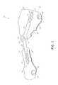
- FIG. 1is a side view of the animal orthopedic brace designed for the stifle joint of a canine.
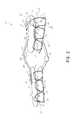
- FIG. 2is a front or anterior view of the animal orthopedic brace designed for the stifle joint of a canine.
- FIG. 2 ais a cross sectional view of the replaceable open cell foam provided for the inner surface of the brace components.
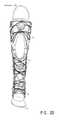
- FIG. 2 bis a front or anterior view of the animal orthopedic brace incorporating a sub-hock component and a body closure system.
- FIG. 2 cis a side view of an alternate embodiment of the brace of FIG. 2 b.
- FIG. 2 dis a front view of the brace of FIG. 2 c.
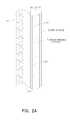
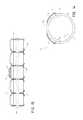
- FIG. 3 ais a top view of a brace stabilization bar system and hinge where the individual openings are spaced longitudinally along the stabilization bars.
- FIG. 3 bis a side view which shows the elevation of a flat stabilization bar and hinge system.
- FIG. 4is a cross sectional view of a cover over the mechanical reel.
- FIG. 5is a front view of the animal orthopedic brace designed for the stifle joint of a canine incorporating a closure system in the open position.
- FIG. 6is a front view of the animal orthopedic brace designed for the stifle joint of a canine incorporating a closure system in the closed position.
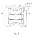
- FIG. 7is a top plan view of the closure system for an animal orthopedic brace.
- FIG. 8is a cross sectional view of the animal orthopedic brace incorporating a closure system in the closed position.
- FIG. 9is a cross sectional view of the animal orthopedic brace incorporating a closure system in the open position.
- FIG. 10is a front view of the animal orthopedic dual-valve splint having a first splint component and a second splint component.
- FIG. 11is a cross sectional view of the animal orthopedic dual-valve splint incorporating a first splint component and a second splint component.
- FIG. 12is a top plan view of an embodiment of the tensioning system using a mechanical reel and a plurality of hook and loop wings.
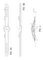
- FIG. 13is a front view of the semi-customizable animal orthopedic splint type brace having a first splint component and an attached closure system.
- FIG. 14is a cross sectional view of the animal orthopedic splint type brace incorporating a first splint component and a second splint component.
- FIG. 15is a front view of the semi-customizable animal orthopedic splint type brace having a first splint component and a second splint component, the second splint component provided with lacing guides.
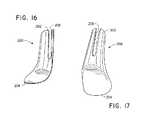
- FIG. 16is a front view of a paw cover.
- FIG. 17is a rear view of a paw cover.
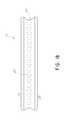
- FIG. 18is a top view of a basic splint.
- Embodiments of the present inventioninclude various arrangements of orthopedic braces and splints for supporting or immobilizing one or more limbs of an animal.
- the braces and splintsmay be configured to treat injuries on a front limb or on a rear limb,
- FIGS. 1 and 2depict an embodiment of an animal orthopedic brace configured to support and stabilize the stifle joint of a canine.
- Components of the brace 100include a customizable femur component 102 , a customizable tibia component 104 , an upper stabilization bar 106 , a lower stabilization bar 108 , a hinge 110 , lower adjustment screws 112 , upper adjustment screws 114 , and a closure system 116 .
- FIG. 2 bdepicts another embodiment of an animal orthopedic brace configured to support and stabilize the stifle joint in conjunction with supporting and stabilizing the hock of a canine.
- Components of the brace 101include the same features as the brace depicted in FIGS. 1 and 2 but additionally feature a semi-customizable hock component 103 , a secondary upper stabilization bar 107 , a secondary lower stabilization bar 109 , a secondary hinge 111 , secondary lower adjustment screws 117 , secondary upper adjustment screws 115 , and a closure system 116 .
- the brace 101can also feature an optional paw cover 200 .
- the brace 100 , 101is fully modular and each component listed above is swappable/replaceable so that various sizes and configurations can be adjoined to properly size the orthosis to the limb of the animal. For example, a reduction in the swelling of the upper thigh could result in improper compression of the femur component 102 .
- the femur component 102can be replaced with a femur component 102 of a different size while retaining all other components including the tibia component 104 , the upper stabilization bar 106 , the lower stabilization bar 108 , the hinge 110 , the lower adjustment screws 112 , the upper adjustment screws 114 , and the closure system 116 .
- Another examplewould be of a long-legged animal where the upper and lower stabilization bars 106 , 108 can be swapped with bars of a different length to be length appropriate.
- Another exampleis a damaged component that will not function as designed, e.g. a closure system 116 that has been chewed by the animal. The component, in this case the closure system 116 , is easily removed and replaced with a fully functional component while retaining all of the other original components.
- the braces described hereinare configured to be modular, such that femur component 102 may be used individually, or may alternately be configured to be used in conjunction with a tibia component 104 with the use of stabilization bars 106 , 108 .
- brace 100 , 101is not required to be replaced resulting in a cost savings to the owner of the animal. Another advantage is that all components can be sized and properly fitted to the needs of the animal whereas current bracing systems that do not provide modularity may fit one area of a limb properly while allowing another area to float. Another advantage is that where the entirety of the limb may need treatment or support, the brace 100 , 101 is specifically made and designed to treat or support the entire limb thus providing effective treatment and support.
- the brace 100 , 101can be applied as a prophylactic device to prevent or reduce the severity of a joint injury, as a rehabilitative device to support and stabilize a joint while assisting or restricting range or motion, or as a functional device to provide stability for chronically unstable joints and limbs for long term support and function.
- the customized formation of the femur component 102 , the tibia component 104 and the hock component 103 along with the proper placement of the stabilization bars 106 , 107 , 108 , 109provide stabilization in which the brace 100 , 101 maintains proper alignment of the joints in relation to the rest of the limb while providing support to the joints so that the biomechanical forces of the animal joint are as natural as possible.
- the customizable femur component 102 and the customizable tibia component 104are made of a lightweight composite material including at least one layer of thermoformable material, and are designed to substantially encompass the circumference of the limb.
- the composite materialis of the type described in U.S. Published Patent Application No. 2012/01011417 to Joseph, or in U.S. Pat. No. 8,303,527 to Joseph, the disclosures of which are hereby incorporated by reference in their entireties.
- the composite materialgenerally includes an inner foam layer for comfort, a middle thermoformable polymer material, and an outer layer of durable fabric.
- the thermoformable polymer materialmay be thermoformable within a target temperature range of 150-320 degrees Fahrenheit, or within a target temperature range of 160-240 degrees Fahrenheit, or within a target temperature range of 180-225 degrees Fahrenheit.
- the thermoformable polymer materialis substantially rigid at temperatures below a minimum formable temperature of about 150 degrees Fahrenheit, or below about 140 degrees Fahrenheit, or below about 130 degrees Fahrenheit.
- the thermoformable polymer materialmay have a dwell time of about three to ten minutes, or of about five to eight minutes.
- the outer layercan be manufactured of an unbroken loop fabric which complements the hook fabric in a hook and loop type fastener.
- components 102 , 104are constructed of a material such as described in U.S. patent application Ser. No. 13/836,660 to Joseph, filed Mar. 15, 2013 and titled “Foam Core Sandwich Splint,” the disclosure of which is incorporated by reference.
- the inner surface 211 of the brace componentis comprised of an unbroken loop fabric 212 and does not include an incorporated inner foam layer (as noted above) but can instead be provided with a separate open cell foam sheet 214 , as illustrated in FIG. 2 a .
- One side of the open cell foam sheetis provided with the hook portion 216 of a hook and loop material, the hook portion 216 complementing the unbroken loop fabric 212 covering the inner surface of the component.
- the open cell foam sheet 214is adherently attached to the inner surface of the component and can be easily removed and replaced.
- the open cell foam sheet 214can be provided with an anti-microbial treatment to reduce the chance of bacterial infections.
- the replaceable open cell foam sheet 214is that the foam layer can be replaced without the need to replace the entire component resulting in cost savings and extending the life of the component.
- the open cell foamalso has the advantage of being provided in different thicknesses, and also in varying thicknesses of the same sheet, thus providing varying levels of cushioning or breathability as needed. It should be noted that this embodiment is equally adaptable and able to be incorporated in all embodiments as described below in this detailed description.
- the femur component 102 and tibia component 104can be provided to a veterinarian as part of a kit that includes substantially flat (planar) sheets of shaped material or somewhat pre-formed into a general u-shape.
- the veterinarianheats the components 102 , 104 , generally using a dry heat source, making the material malleable and able to be custom shaped, in the veterinarian's office, to the animals limb. Heating can be accomplished using, for example, ovens, convection ovens, radiant lamp heat sources, infrared heaters, microwave ovens, self heating pouches, internal heating system built into the material, or exothermic heating source.
- wet heatcan be used, for example, immersion of the material into hot water.
- the veterinarianplaces the material on the appropriate area of the animal's limb and forms the material around the limb to obtain a precise custom fit. As the material cools, the material becomes rigid and retains the shape of the limb.
- An advantage of using this lightweight composite materialis that the components 102 , 104 can be molded and custom fitted in the veterinarian's office without the need to make a casting or send the components 102 , 104 to an outside laboratory.
- Another advantageis that due to the dry heating methods the brace can be applied immediately after surgery versus a cast or other brace that may require wetting in order to form it thus introducing moisture to the incision area.
- the femur component 102is molded to the upper thigh area of a canine's hind leg.
- the veterinarianchooses the material based on the size of the animal so that the material, when formed, fits substantially around the circumference of the upper thigh leaving a longitudinal opening 128 at the front or anterior of the leg.
- the femur component 102forms a substantially u-shaped channel 130 , as shown in FIG. 2 , where the ends 132 of the u-shaped channel 130 do not touch.
- the opening 128allows for easy placement and removal of the femur component 102 since the ends 132 of the u-shaped channel 130 , though rigid, can be easily spread apart in order to place the canine's upper thigh into the u-shaped channel 130 between the ends 132 of the u-shaped channel 130 .
- the component 102can be formed such that the longitudinal opening 128 can be located at the posterior or rear of the leg.
- the femur component 102is molded so that the ends 132 of the u-shaped channel 130 overlap when formed to the canine's upper thigh.
- the tibia component 104is molded to the lower thigh area of the canine's hind leg.
- the veterinarianchooses the material based on the size of the animal so that the material, when formed, fits substantially around the circumference of the lower thigh leaving a longitudinal opening 134 at the front or anterior of the leg.
- the tibia component 104forms a substantially u-shaped channel 136 , as shown in FIG. 2 , where the ends 138 of the u-shaped channel 136 do not touch.
- the opening 134allows for easy placement and removal of the tibia component 104 since the ends 138 of the u-shaped channel 136 , though rigid, can be easily spread apart in order to place the canine's lower thigh into the u-shaped channel 136 between the ends 138 of the u-shaped channel 136 .
- the component 104can be formed such that the longitudinal opening 134 can be located at the posterior or rear of the leg.
- the tibia component 104is molded so that the ends 138 of the u-shaped channel 136 overlap when formed to the canine's lower thigh.
- an external frameprovides connectivity between the femur component 102 and the tibia component 104 .
- the external framehas an upper stabilization bar 106 attached to the femur component 102 and a lower stabilization bar 108 attached to the tibia component 104 .
- the stabilization bars 106 , 108can be designed to be linearly adjustable in relation to the femur component 102 and the tibia component 104 . That is, the linear adjustment is in the longitudinal direction of the limbs.
- the stabilization bars 106 , 108can be designed to be non-adjustable in relation to the femur component 102 and the tibia component 104 .
- Attachment of the stabilization bars 106 , 108 to the components 102 , 104can be made as shown in the embodiment of FIGS. 1 and 2 with the use of adjustment screws 112 , 114 and threaded receivers that are molded into, combined with, or otherwise engaged with the lightweight composite material. Separate receivers may be provided for each of screws 112 , 114 , or a single receiver may be provided to receive both of screws 112 , 114 .
- Other embodimentscontemplate other methods of attaching the stabilization bars 106 , 108 to the components 102 , 104 including other known fasteners such as nuts, bolts, rivets, pins, retaining rings, clips, etc.
- attachment of the stabilization bar 106 , 108 to the lightweight composite material of the femur component 102 or tibia component 104can be made by the use of crimping, gluing, soldering, cementing, adhesives, etc. or incorporation of the stabilization bar 106 , 108 into the lightweight composite material of the femur component 102 or tibia component 104 .
- the upper stabilization bar 106 and lower stabilization bar 108are linearly adjustable in relation to the components 102 , 104 .
- the stabilization bars 106 , 108are provided with bar adjustment slots 113 at their distal ends 120 , 122 .
- the slots 113are sized to be smaller than the head of the adjustment screws 112 , 114 so that tightening of the screws 112 , 114 cause the heads to compress the stabilization bars 106 , 108 against the components 102 , 104 preventing the stabilization bars 106 , 108 from moving in relation to the components 102 , 104 .
- the adjustment screws 112 , 114are thumbscrews but they can be any type of fastener that can be tightened including, wingnuts, nuts, ratchets, screws, etc.
- FIG. 3can incorporate separate openings 118 that are evenly spaced longitudinally along the stabilization bars 106 , 108 .
- the openingscan be sized to accept pins, screws, push-button adjustments, etc.
- the openingscan be any shape including round, square, triangular, etc.
- a tuberosity strapis provided as part of the present invention, and may be separate from, or coupled to a portion of the orthopedic brace and/or the external frame.
- the proximal end 124 of the upper stabilization bar 106engages with the proximal end 126 of the lower stabilization bar 108 and forms an orthopedic hinge assembly 110 .
- the hinge assembly 110maintains the animal joint in a biomechanically natural state to support the joint while restraining the joint from harmful motions.
- the hinge assembly 110can be a full range of motion (ROM) hinge maintaining selective ranges of flexion and extension.
- Other embodimentscan incorporate other hinges known in the art, for example, single pivot hinges, dual pivot hinges, and veterinary TAMARACK FLEXURE JOINTS®.
- the hinge assembly 110can be designed so that it can be used in a locked position preventing any rotation or unlocked allowing limited to full rotation.
- the upper stabilization bar 106 and lower stabilization bar 108can be configured so that the profile of the stabilization bars 106 , 108 follow the contours of the animal's leg, as illustrated in FIG. 2 .
- An alternate embodiment, shown in FIG. 3 aallows for the upper stabilization bar 106 and lower stabilization bar 108 to be substantially flat. It is contemplated that alternate configurations of upper stabilization bar 106 and lower stabilization bar 108 can be incorporated, e.g., a contoured upper stabilization bar 106 paired with a flat lower stabilization bar 108 or vice versa.
- the brace 100includes a closure system 116 having a mechanical reel 140 and lace 142 to provide smooth, uniform closure of the brace 100 with little or no pressure points.
- Reel 140comprises a tightening mechanism, and is preferably of the type available from Boa Technology, such as described in U.S. Pat. Nos. 5,934,599, 6,202,953, 6,289,558, 7,950,112, 7,954,204, 7,992,261, 8,091,182, and 8,277,401, the disclosures of which are incorporated by reference herein.
- other fastening mechanismssuch as cord locks, cam cord locks, traditional lacing bows, ratchet lace systems, or other lacing or cabling methods may be used in place of any of the closure systems described herein.
- At least one closure system 116can be provided for the femur component 102 and at least one closure system 116 can be provided for the tibia component 104 .
- the mechanical reel 140is attached to the appropriate component 102 , 104 at a convenient location. There are no restrictions as to where the mechanical reel can be attached as long as the lace 142 and the reel 140 are not impeded by other structures on the component 102 , 104 .
- the reel 140is located on the posterior side of the component 102 , 104 . In another embodiment, the reel 140 is located on the side of the component 102 , 104 .
- the mechanical reelallows for the lace 142 to be drawn in and tightened by turning the mechanical reel 140 .
- the mechanical wheel 140allows for precise tightening of the lace 142 in order to fine tune, and then lock in, the amount of compression provided to the leg by the brace 100 .
- the lace 142can be, for example, steel, nylon or other non-stretchable material.
- a lace 142 constructed of steel or other suitable metalprovides superior resistance to chewing by the animal during the duration of wearing brace 100 .
- the lace 142is threaded through guides 144 that are molded into or otherwise engaged with the lightweight composite material. In one embodiment, the guides 144 are a plurality of nylon sleeves or loops.
- the guides 144can be made of the lightweight composite material, plastic, metal or another suitable material and form a protrusion having an aperture that the lace 142 is threaded through.
- the guides 144are placed longitudinally along the component 102 , 104 so that they are substantially parallel to each other on either side of the u-shaped channel 130 , 136 .
- guides 144may be coupled to or otherwise included as one-half of a clip or buckle arrangement, wherein the other half of the clip or buckle is secured to brace 100 .
- the closure system 116allows for adjustability, to a micro level, to allow adjustment after initial fitment such as to accommodate swelling and/or atrophy.
- the mechanical wheel 140can be designed so that its low profile or material resists chewing.
- the mechanical wheel 140can be covered with a cover 141 as is depicted in FIG. 4 .
- the cover 141may comprise a conical shape, and is configured to completely cover the mechanical reel 140 . Openings (not shown) are provided at the outer edges of cover 141 allowing the laces 142 to pass through unimpeded.
- the cover 141can be manufactured from plastic or metal so long as the profile of cover 141 is such that an animal biting at the cover could not grip the cover between its teeth.
- the cover 141can be a pyramid, or a partial spherical or ovoid shape.
- FIGS. 5 and 6depict another embodiment of an animal orthopedic brace configured to support and stabilize the stifle joint of a canine. Where the features of this embodiment are comparable to the features of FIGS. 1 and 2 , the same reference numbers will be used. In addition, for the sake of brevity, description is only provided for those features of this embodiment that are not provided in the embodiment as shown in FIGS. 1 and 2 .
- components of this embodiment of the brace 100include a customizable femur component 102 , a customizable tibia component 104 , an upper stabilization bar 106 , a lower stabilization bar 108 , a hinge 110 , lower adjustment screws 112 , upper adjustment screws 114 , a femur closure body system 150 and a tibia closure body system 152 . It is contemplated that the femur component 102 and the tibia component 104 can be used in conjunction with each other or alone.
- the customizable femur component 102 and the customizable tibia component 104are each made of a lightweight composite material including an inner foam layer for comfort, a middle thermoformable polymer material, and an outer layer of durable fabric.
- the outer layercan be manufactured of an unbroken loop fabric which complements the hook fabric in a hook and loop type fastener.
- the customizable femur component 102 and the customizable tibia component 104are each designed to substantially encompass the circumference of the limb.
- the femur component 102is heated and molded to the upper thigh area of the canine's hind leg so it fits substantially around the circumference of the upper thigh leaving a longitudinal opening 128 at the front or anterior of the leg or alternately, at the rear or posterior of the leg.
- the femur component 102forms a substantially u-shaped channel 130 , as depicted in FIG. 5 , where the ends 132 of the u-shaped channel 130 do not touch.
- at least one side of the outer surface 153 of the femur component 102is provided with the loop portion of a hook and loop closure 154 (e.g. VELCRO® Brand hook and loop closures) along its length.
- both outer surfaces 153 of the femur component 102are provided with the loop portion of a hook and loop closure 154 along their lengths.
- the tibia component 104is heated and molded to the lower thigh area of the canine's rear leg so it fits substantially around the circumference of the lower thigh leaving a longitudinal opening 134 at the front or anterior of the leg or alternately, at the rear or posterior of the leg.
- the tibia component 104forms a substantially u-shaped channel 136 , as depicted in FIG. 3 , where the ends 138 of the u-shaped channel 136 do not touch.
- at least one side of the outer surface 155 of the tibia component 102is provided with the loop portion of a hook and loop closure 154 (e.g. VELCRO® brand hook and loop closures) along at least a substantial portion of its length.
- both outer surfaces 155 of the tibia component 104are provided with the loop portion of a hook and loop closure 154 along their lengths.
- the brace 100is provided with a femur closure body system 150 and a tibia closure body system 152 , as detailed in FIG. 7 .
- the closure body 156 of the closure body system 150 , 152can be made of the same lightweight composite material as the component 102 , 104 and is heated and subsequently formed to the appropriate portion of the animals limb.
- the closure body 156can be provided so that it has a preformed u-shaped channel along its length.
- the closure body 156can be made of another flexible material that can be shaped.
- the closure body 156is sized so that when placed on the limb of the animal, it fits partially around the circumference of the animals limb.
- a plurality of guides 158are located on the closure body 156 and are substantially perpendicular to the longitudinal axis 160 of the closure body 156 .
- the profile of one or more of body 156 , components 102 , 103 and 104may include reliefs or cutouts to provide clearance around joints, as depicted in FIGS. 2 b -2 d , and 5 - 7 .
- FIGS. 8 and 9illustrate the component 102 , 104 having a closure system 150 , 152 in the closed and open positions, respectively.
- the closure body 156when closed, the closure body 156 preferably sits on the animals limb so that when the component 102 , 104 is positioned, the ends 132 , 138 of the u-shaped channel 130 , 136 overlap the closure body 156 sandwiching the closure body 156 between the ends 132 , 138 of the u-shaped channel 130 , 136 and the animals limb.
- the outer surface 168 of the closure body 156slidably engages with the inner surface 167 of the component 102 , 104 .
- the closure system 150 , 152has a first wing 162 made from the hook portion of a hook and loop woven material and a second wing 164 made from either woven material or the hook portion of a hook and loop woven material. Alternatively, more than two wings can be provided.
- the wings 162 , 164are provided with a plurality of guides 165 that are placed linearly along the length of the wings 162 , 164 either on the edge of the wing 162 , 164 or on the topside of the wing 162 , 164 .
- the guides 165are a plurality of nylon sleeves.
- the guides 165are a plurality of loops made from a woven material.
- the hook material of the bottom side of the first wing 162complements the unbroken loop fabric covering the brace.
- the hook material of the bottom side of the first wing 162complements the loop portion of the hook and loop closure 154 provided on the at least one outer side 153 , 155 of the component 102 , 104 thereby providing adhesion with the material on the at least one outer side 153 , 155 of the component 102 , 104 .
- the wing 162is adhered with the component 102 , 104 surface opposite that of the animals limb.
- closure system 150 , 152can be detached from at least one side of the component 102 , 104 allowing for easy insertion or removal of the animals limb into or out of the component 102 , 104 .
- the second wing 164can be made of a woven material. As depicted in FIG. 9 , the woven material of the second wing 164 can be fixedly attached to the outer side 153 , 155 of the component 102 , 104 so that the wing 164 is on the component 102 , 104 surface opposite that of the animals limb. Attachment can be by any manner that permanently attaches the woven material to the component 102 , 104 , for example, by adhesives, sewing, rivets, etc. Alternatively, the second wing 164 can be comprised of the hook of the hook and loop woven material and can be detachably connected to the unbroken loop fabric covering the component 102 , 104 surface.
- the hookprovides adhesion to the loop portion of a hook and loop closure 154 provided on the at least one outer side 153 , 155 of the component 102 , 104 so that the wing 164 adheres with the component 102 , 104 surface opposite that of the animals limb.
- the closure body system 150 , 152further comprises a closure system 116 having a mechanical reel 140 and lace 142 to provide smooth, even closure of the brace 100 with no pressure points.
- Reel 140is preferably of the type available from Boa Technology, such as described in U.S. Pat. Nos. 5,934,599, 6,202,953, 6,289,558, 7,950,112, 7,954,204, 7,992,261, and 8,091,182, the disclosures of which are incorporated by reference herein.
- other fastening mechanismssuch as cord locks, cam cord locks, traditional lacing bows, ratchet lace systems, or other lacing methods may be used in place of any of the closure systems described herein.
- At least one closure body system 150 , 152can be provided for the femur component 102 and at least one closure body system 150 , 152 can be provided for the tibia component 104 .
- the mechanical reel 140is attached to the appropriate component 102 , 104 or alternatively to the closure body system 150 , 152 wing 162 , 164 or closure body 156 .
- the lace 142is threaded through the channels 158 and the guides 165 of the wings 162 , 164 so that they are able to be drawn in and tightened by turning the mechanical reel 140 .
- the mechanical wheel 140allows for precise tightening of the lace 142 in order to fine tune, and then lock in, the amount of compression provided to the leg by the brace 100 .
- the lace 142can be steel, nylon or other non-stretchable material.
- a lace 142 constructed of steel or other suitable metalprovides superior resistance to chewing by the animal during the duration of wearing brace 100 .
- the mechanical wheel 140can be designed so that its low profile or material resists chewing.
- the mechanical wheel 140can be covered with a cover 141 as is depicted in FIG. 4 .
- the cover 141may comprise a conical shape, and is configured to completely cover the mechanical reel 140 . Openings (not shown) are provided at the outer edges of cover 141 allowing the laces 142 to pass through unimpeded.
- the cover 141can be manufactured from plastic or metal so long as the profile of cover 141 is such that an animal biting at the cover could not grip the cover between its teeth.
- the cover 141can be a pyramid, or a partial spherical or ovoid shape.
- the profile of component 102 , 104may be relieved or scalloped for clearance as necessary to allow sufficient tightening of brace 100 .
- a hock component 103is provided.
- the hock component 103as illustrated, is provided with a body closure system but the hock component 103 can also be provided and used without a body closure system.
- the hock component 103can be used as part of the brace system 101 , used alone, or used in combination with only the tibia component 104 . Attached to the hock component 103 is a secondary upper stabilization bar 107 , a secondary lower stabilization bar 109 , a secondary hinge 111 , secondary lower adjustment screws 117 , secondary upper adjustment screws 115 , and a closure system 116 .
- the brace 101can also feature an optional paw cover 200 attached to the hock component 103 .
- the hock component 103can be provided in alternate standard sizes.
- the braces described hereinare configured to be modular, such that various combinations of component 102 , component 104 , component 103 and paw cover 200 may be utilized as desired for to treat different injuries.
- a single component 103may be provided.
- component 104 and stabilization barsmay be added to component 103 .
- component 102 and stabilization barsmay be added to component 104 and component 103 .
- the hock component 103is made of a composite material of the type described in U.S. Published Patent Application No. 2012/01011417 to Joseph, the disclosure of which is incorporated by reference herein in its entirety.
- the composite materialgenerally includes an inner foam layer for comfort, a middle thermoformable polymer material, and an outer layer of durable fabric.
- the outer layercan be made of an unbroken loop material.
- the hock component 103is constructed of a material such as described in U.S. patent application Ser. No. 13/836,660 to Joseph, filed Mar. 15, 2013 and titled “Foam Core Sandwich Splint,” the disclosure of which has been incorporated by reference.
- the hock component 103is provided to a veterinarian pre-formed into a general u-shape and is of a specified length.
- the veterinarianheats the hock component 103 , generally using a dry heat source, making the material malleable and able to be further custom formed to the animals limb, in the veterinarian's office. Heating can be accomplished using, for example, ovens, convection ovens, radiant lamp heat sources, infrared heaters, microwave ovens, self heating pouches, internal heating system built into the material, or exothermic heating source.
- wet heatcan be used, for example, immersion of the material into hot water.
- the veterinarianplaces the material on the limb below the hock joint and above the paw and forms the material around the limb to obtain a precise custom fit. As the material cools, the material becomes rigid and retains the shape of the limb.
- An advantage of using the composite materialis that the hock component 103 can be molded and custom fitted in the veterinarian's office without the need to make a casting or send the hock component 103 to an outside laboratory. Another advantage is that due to the dry heating methods the hock component 103 can be applied immediately after surgery versus a cast or other splint that may require wetting in order to form it thus introducing moisture to the incision area.
- the veterinarianchooses the material based on the size of the animal so that the material, when formed, fits substantially around the circumference of the limb leaving a longitudinal opening 148 at the front or anterior of the limb.
- the hock component 103forms a substantially u-shaped channel 145 , where the ends 146 of the u-shaped channel 145 do not touch.
- the opening 148allows for easy placement and removal of the hock component 103 since the ends 146 of the u-shaped channel 145 , though rigid, can be easily spread apart in order to place the limb into the u-shaped channel 145 between the ends 146 of the u-shaped channel 145 .
- the hock component 103can be formed such that the longitudinal opening 148 can be located at the posterior or rear of the limb.
- the hock component 103is molded so that the ends 146 of the u-shaped channel 145 overlap when formed to the limb.
- an external frameprovides connectivity between the hock component 103 and the tibia component 104 .
- the external framehas a secondary upper stabilization bar 107 attached to the tibia component 104 and a secondary lower stabilization bar 109 attached to the hock component 103 .
- the stabilization bars 107 , 109can be designed to be linearly adjustable in relation to the tibia component 104 and the hock component 103 .
- the stabilization bars 107 , 109can be designed to be non-adjustable in relation to the tibia component 104 and the hock component 103 .
- Attachment of the stabilization bars 107 , 109 to the components 103 , 104can be made as depicted in the embodiment of FIG. 2 b with the use of adjustment screws 115 , 117 and threaded receivers that are molded into or otherwise engaged with the lightweight composite material.
- Other embodimentscontemplate other methods of attaching the stabilization bars 107 , 109 to the components 103 , 104 including other known fasteners such as nuts, bolts, rivets, pins, retaining rings, clips, etc.
- Other embodiments contemplate that attachment of the stabilization bar 107 , 109 to the lightweight composite material of the hock component 103 or tibia component 104can be made by the use of crimping, gluing, soldering, cementing, adhesives, etc. or incorporation of the stabilization bar 107 , 109 into the lightweight composite material of the hock component 103 or tibia component 104 .
- the upper stabilization bar 107 and lower stabilization bar 109are linearly adjustable in relation to the components 103 , 104 via bar adjustment slots 121 at their distal ends 123 , 125 .
- the slots 121are sized to be smaller than the head of the adjustment screws 115 , 117 so that tightening of the screws 115 , 117 cause the heads to compress the stabilization bars 107 , 109 against the components 103 , 104 preventing the stabilization bars 107 , 109 from moving in relation to the components 103 , 104 .
- the adjustment screws 115 , 117are thumbscrews but they can be any type of fastener that can be tightened including, wingnuts, nuts, ratchets, screws, etc.
- FIG. 3can incorporate separate openings 118 in the stabilization bars 107 , 109 that are longitudinally evenly spaced.
- the openings 118can be sized to accept pins, screws, push-button adjustments, etc.
- the openings 118can be any shape including round, square, triangular, etc.
- the proximal end 127 of the secondary upper stabilization bar 107engages with the proximal end 129 of the secondary lower stabilization bar 109 and forms an orthopedic hinge assembly 111 .
- the hinge assembly 111can be a full range of motion (ROM) hinge maintaining selective ranges of flexion and extension.
- Other embodimentscan incorporate other hinges known in the art, for example, single pivot hinges, dual pivot hinges, and veterinary TAMARACK FLEXURE JOINTS®.
- the hinge assembly 111can be designed so that it can be used in a locked position preventing any rotation or unlocked allowing limited to full rotation.
- the upper stabilization bar 107 and lower stabilization bar 109can be configured so that the profile of the stabilization bars 107 , 109 follow the contours of the animal's leg.
- An alternate embodimentallows for the upper stabilization bar 107 and lower stabilization bar 109 to be substantially flat. It is contemplated that alternate configurations of upper stabilization bar 107 and lower stabilization bar 109 can be incorporated, e.g., a contoured upper stabilization bar 107 paired with a flat lower stabilization bar 109 or vice versa.
- the closure system 116has a mechanical reel 140 and lace 142 to provide smooth, even closure of the hock component 103 with no pressure points.
- Reel 140is preferably of the type available from Boa Technology, such as described in U.S. Pat. Nos. 5,934,599, 6,202,953, 6,289,558, 7,950,112, 7,954,204, 7,992,261, and 8,091,182, the disclosures of which are incorporated by reference herein.
- other fastening mechanismssuch as cord locks, cam cord locks, traditional lacing bows, ratchet lace systems, or other lacing methods may be used in place of any of the closure systems described herein.
- At least one closure system 116can be provided for the hock component 103 .
- the mechanical reel 140is attached to the hock component 103 at a convenient location. There are no restrictions as to where the mechanical reel can be attached as long as the lace 142 and the reel 140 are not impeded by other structures on the hock component 103 .
- the reel 140is located on the posterior side of the hock component 103 . In another embodiment, the reel 140 is located on the side of the hock component 103 . In another embodiment, reel 140 is location on the anterior side.
- the mechanical reelallows for the lace 142 to be drawn in and tightened by turning the mechanical reel 140 .
- the mechanical wheel 140allows for precise tightening of the lace 142 in order to fine tune, and then lock in, the amount of compression provided to the leg by the hock component 103 .
- the lace 142can be, for example, steel, nylon or other non-stretchable material.
- a lace 142 constructed of steel or other suitable metalprovides superior resistance to chewing by the animal during the duration of wearing the hock component 103 .
- the lace 142is threaded through guides 166 that are molded into or otherwise engaged with the lightweight composite material. In one embodiment, the guides 166 are a plurality of nylon sleeves or loops.
- the guides 166can be made of the lightweight composite material, plastic, metal or another suitable material and form a protrusion having an aperture that the lace 142 is threaded through. In some embodiments, the guides 166 are placed longitudinally along the hock component 103 so that they are substantially parallel to each other on either side of the u-shaped channel 145 .
- the mechanical wheel 140can be designed so that its low profile or material resists chewing.
- the mechanical wheel 140can be covered with a cover 141 as is depicted in FIG. 4 .
- the cover 141may comprise a conical shape, and is configured to completely cover the mechanical reel 140 . Openings (not shown) are provided at the outer edges of cover 141 allowing the laces 142 to pass through unimpeded.
- the cover 141can be manufactured from plastic or metal so long as the profile of cover 141 is such that an animal biting at the cover could not grip the cover between its teeth.
- the cover 141can be a pyramid, or a partial spherical or ovoid shape.
- the hock component 103is provided with a closure body system 151 as is described above in relation to the femur component 102 and the tibia component 103 .
- the closure body system 151is formed and fitted identically to the closure body systems 150 , 152 described above but in relation to the hock component 103 , thus the same reference numbers will be used.
- the closure body 156 of the closure body system 151can be made of the same lightweight composite material as the component 103 and is heated and subsequently formed to the appropriate portion of the animals limb.
- the closure body 156can be provided so that it has a preformed u-shaped channel along its length.
- the closure body 156can be made of another flexible material that can be shaped.
- the closure body 156is sized so that when placed on the limb of the animal, it fits partially around the circumference of the animals limb.
- a plurality of guides 158may be located on the closure body 156 and are substantially perpendicular to the longitudinal axis 160 of the closure body 156 .
- FIGS. 8 and 9illustrate the component 103 having a closure system 151 in the closed and open positions, respectively.
- the closure body 156when closed, the closure body 156 preferably sits on the animals limb so that when the component 103 is positioned, the ends 146 of the u-shaped channel 145 overlap the closure body 156 sandwiching the closure body 156 between the ends 146 of the u-shaped channel 145 and the animals limb.
- the outer surface 168 of the closure body 156slidably engages with the inner surface 167 of the component 103 .
- the closure system 151has a first wing 162 made from the hook portion of a hook and loop woven material and a second wing 164 made from either woven material or the hook portion of a hook and loop woven material. Alternatively, more than two wings can be provided.
- the wings 162 , 164are provided with a plurality of guides 165 that are placed linearly along the length of the wings 162 , 164 either on the edge of the wing 162 , 164 or on the topside of the wing 162 , 164 .
- the guides 165are a plurality of nylon sleeves.
- the guides 165are a plurality of loops made from a woven material.
- the hook material of the bottom side of the first wing 162complements the unbroken loop fabric covering the brace.
- the hook material of the bottom side of the first wing 162complements the loop portion of the hook and loop closure 154 provided on the at least one outer side of the component 103 thereby providing adhesion with the material on the at least one outer side of the component 103 .
- the wing 162is adhered with the component 103 surface opposite that of the animals limb.
- One advantage in providing a hook and loop closureis that the closure system 151 can be detached from at least one side of the component 103 allowing for easy insertion or removal of the animals limb into or out of the component 103 .
- the second wing 164can be made of a woven material. As depicted in FIG. 9 , the woven material of the second wing 164 can be fixedly attached to the outer side of the component 103 so that the wing 164 is on the component 103 surface opposite that of the animals limb. Attachment can be by any manner that permanently attaches the woven material to the component 103 , for example, by adhesives, sewing, rivets, etc. Alternatively, the second wing 164 can be comprised of the hook of the hook and loop woven material and can be detachably connected to the unbroken loop fabric covering the component 103 surface. In another embodiment, the hook provides adhesion to the loop portion of a hook and loop closure 154 provided on the at least one outer side of the component 103 so that the wing 164 adheres with the component 103 surface opposite that of the animals limb.
- the closure body system 151further comprises a closure system 116 having a mechanical reel 140 and lace 142 to provide smooth, even closure of the brace 100 with no pressure points.
- Reel 140is preferably of the type available from Boa Technology, such as described in U.S. Pat. Nos. 5,934,599, 6,202,953, 6,289,558, 7,950,112, 7,954,204, 7,992,261, and 8,091,182, the disclosures of which are incorporated by reference herein.
- other fastening mechanismssuch as cord locks, cam cord locks, traditional lacing bows, ratchet lace systems, or other lacing methods may be used in place of any of the closure systems described herein.
- At least one closure body system 151can be provided for the hock component 103 .
- the mechanical reel 140is attached to the hock component 103 or alternatively to the closure body system 151 wing 162 , 164 or closure body 156 .
- the lace 142is threaded through the optional channels 158 and the guides 165 of the wings 162 , 164 so that they are able to be drawn in and tightened by turning the mechanical reel 140 .
- the mechanical wheel 140allows for precise tightening of the lace 142 in order to fine tune, and then lock in, the amount of compression provided to the leg by the brace 100 .
- the lace 142can be steel, nylon or other non-stretchable material.
- a lace 142 constructed of steel or other suitable metalprovides superior resistance to chewing by the animal during the duration of wearing brace 100 .
- the mechanical wheel 140can be designed so that its low profile or material resists chewing.
- the mechanical wheel 140can be covered with a cover 141 as is depicted in FIG. 4 .
- the cover 141may comprise a conical shape, and is configured to completely cover the mechanical reel 140 . Openings (not shown) are provided at the outer edges of cover 141 allowing the laces 142 to pass through unimpeded.
- the cover 141can be manufactured from plastic or metal so long as the profile of cover 141 is such that an animal biting at the cover could not grip the cover between its teeth.
- the cover 141can be a pyramid, or a partial spherical or ovoid shape.
- a paw cover 200can be provided and attached to the hock component 103 .
- the paw cover 200is provided in a variety of sizes and can be selected to conform generally to the size of the paw. As depicted in FIGS. 16 and 17 , the paw cover 200 can be pre-formed into a general u-shape providing a natural stance for the paw of a canine.
- the paw cover 200can be made of a lightweight composite material including at least one layer of thermoformable material.
- the paw cover 200is sized such that the distal end 202 ends below the hind foot hock or the forefoot wrist of the canine.
- the proximal end 204 of the paw cover 200is located near or at the end of the canine's foot.
- the paw cover 200can be provided with an adjustment slot 206 extending longitudinally from the distal end 202 .
- the adjustment slot 206is provided to attach the paw cover 200 to the hock component 103 as depicted in FIG. 2 b .
- the hock component 103can be provided with at least two adjustment screws located on its posterior (not shown).
- the paw cover 200is disposed so that the shaft or threaded portion of the adjustment screws reside in the adjustment slot 206 so that when tightened, paw cover is sandwiched between the head of the adjustment screw and the hock component 103 thus fixedly attaching the paw cover 200 to the hock component 103 .
- separate adjustment openingscan be provided in the paw cover 200 .
- the separate openingscan be evenly spaced longitudinally along the paw cover 200 posterior.
- the openingscan be sized to accept pins, screws, push-button adjustments, etc.
- the openingscan be any shape including round, square, triangular, etc.
- a formed splint 170is provided that includes a semi-customizable first splint component 171 and a closure system 116 attachable in any position and adjustable as desired, allowing customizable, universal fitment for a variety of uses.
- the formed splint 170is provided in alternate standard sizes. It is understood that the splint 170 can be configured to be incorporated into the brace 100 system as described above.
- the semi-customizable first splint component 171is made of a composite material of the type described in U.S. Published Patent Application No. 2012/01011417 to Joseph, the disclosure of which is incorporated by reference herein in its entirety. As described therein, the composite material generally includes an inner foam layer for comfort, a middle thermoformable polymer material, and an outer layer of durable fabric. In another embodiment, the semi-customizable first splint component 171 is constructed of a material such as described in U.S. patent application Ser. No. 13/836,660 to Joseph, filed Mar. 15, 2013 and titled “Foam Core Sandwich Splint,” the disclosure of which has been incorporated by reference.
- the first splint component 171is provided to a veterinarian pre-formed into a general u-shape and is of a specified length.
- the veterinarianheats the first splint component 171 , generally using a dry heat source, making the material malleable and able to be further custom formed to the animals limb, in the veterinarian's office. Heating can be accomplished using, for example, ovens, convection ovens, radiant lamp heat sources, infrared heaters, microwave ovens, self heating pouches, internal heating system built into the material, or exothermic heating source.
- wet heatcan be used, for example, immersion of the material into hot water.
- the veterinarianplaces the material on the appropriate area of the animals limb and forms the material around the limb to obtain a precise custom fit. As the material cools, the material becomes rigid and retains the shape of the limb.
- An advantage of using the composite materialis that the first splint component 171 can be molded and custom fitted in the veterinarian's office without the need to make a casting or send the first splint component 171 to an outside laboratory. Another advantage is that due to the dry heating methods the splint can be applied immediately after surgery versus a cast or other splint that may require wetting in order to form it thus introducing moisture to the incision area.
- the veterinarianchooses the material based on the size of the animal so that the material, when formed, fits substantially around the circumference of the limb leaving a longitudinal opening 176 at the front or anterior of the limb.
- the first splint component 171forms a substantially u-shaped channel 172 , where the ends 174 of the u-shaped channel 172 do not touch.
- the opening 176allows for easy placement and removal of the first splint component 171 since the ends 174 of the u-shaped channel 172 , though rigid, can be easily spread apart in order to place the limb into the u-shaped channel 172 between the ends 174 of the u-shaped channel 172 .
- the first splint component 171can be formed such that the longitudinal opening 176 can be located at the posterior or rear of the limb.
- the first splint component 171is molded so that the ends 174 of the u-shaped channel 172 overlap when formed to the limb.
- a second splint component 178is provided that partially encompasses the circumference of the limb and is comparable in length to the length of the first splint component 171 .
- the second splint component 178is worn so that when the first splint component 171 is placed in position, the ends 174 of the u-shaped channel 172 overlap the ends of the second splint component 178 longitudinally.
- the second splint component 178is thus partially sandwiched between the limb and the first splint component 171 .
- the outer surface 179 of the second splint component 178slidably engages with the inner surface 173 of the first splint component 171 .
- the second splint component 178is made of a composite material of the type described in U.S. Published Patent Application No. 2012/01011417 to Joseph, the disclosure of which is incorporated by reference herein in its entirety. As described therein, the composite material generally includes an inner foam layer for comfort, a middle thermoformable polymer material, and an outer layer of durable fabric. In another embodiment, the customizable second splint component 178 is constructed of a material such as described in U.S. patent application Ser. No. 13/836,660 to Joseph, filed Mar. 15, 2013 and titled “Foam Core Sandwich Splint,” the disclosure of which has been incorporated by reference.
- the formed splint 170includes an attached closure system 116 having a mechanical reel 140 and lace 142 to provide smooth, even closure of the brace 100 with no pressure points.
- Reel 140is preferably of the type available from Boa Technology, such as described in U.S. Pat. Nos. 5,934,599, 6,202,953, 6,289,558, 7,950,112, 7,954,204, 7,992,261, and 8,091,182, the disclosures of which are incorporated by reference herein.
- other fastening mechanismssuch as cord locks, cam cord locks, traditional lacing bows, ratchet lace systems, or other lacing methods may be used in place of any of the closure systems described herein.
- the closure system 116uses a mechanical reel 140 and lace 142 to provide smooth, even closure of the splint component 171 with no pressure points. At least one closure system 116 can be provided for the splint 170 .
- the mechanical reel 140is attached to the posterior of the splint component 171 . Alternatively, the reel 140 can be attached to the side of the splint component 171 .
- the mechanical reelallows for the lace 142 to be drawn in and tightened by turning the mechanical reel 140 .
- the mechanical wheel 140allows for precise tightening of the lace 142 in order to fine tune, and then lock in, the amount of compression provided to the limb by the splint component 171 .
- the lace 142can be steel, nylon or other non-stretchable material.
- a lace 142 constructed of steel or other suitable metalprovides superior resistance to chewing by the animal during the duration of wearing brace 100 .
- the lace 142is threaded through guides 144 that are molded into or otherwise engaged with the composite material.
- the guides 144are a plurality of nylon sleeves or loops.
- the guides 144can be made of the composite material, plastic, metal or another suitable material and form a protrusion having an aperture that the lace 142 is threaded through.
- the guides 144are placed longitudinally along the splint component 171 so that they are substantially parallel to each other on either side of the u-shaped channel 172 .
- the closure system 116allows for adjustability, to a micro level, to accommodate swelling and/or atrophy.
- the mechanical wheel 140can be designed so that its low profile or material resists chewing.
- the mechanical wheel 140can be covered with a cover 141 as is depicted in FIG. 4 .
- the cover 141may comprise a conical shape, and is configured to completely cover the mechanical reel 140 . Openings (not shown) are provided at the outer edges of cover 141 allowing the laces 142 to pass through unimpeded.
- the cover 141can be manufactured from plastic or metal so long as the profile of cover 141 is such that an animal biting at the cover could not grip the cover between its teeth.
- the cover 141can be a pyramid, or a partial spherical or ovoid shape.
- lacing guides 194can be provided on the second splint component 178 , as is depicted in FIGS. 14 and 15 .
- the guides 194are attached to the second splint component 178 thus providing a pathway for the lace 142 .
- the second splint component 178is not provided with guides 194 .
- a dual-valve splint-type braceis provided.
- the dual-valve splint 180 as illustrated in FIGS. 10 and 11depicts an embodiment of an animal orthopedic splint configured to support and stabilize the limb of an animal.
- the features of this embodimentare comparable to the features of FIGS. 1 and 2 , the same reference numbers will be used.
- descriptionis only provided for those features of this embodiment that are not provided in the embodiment as depicted in FIGS. 1 and 2 .
- the dual-valve splint 180can be applied as a prophylactic device to prevent or reduce the severity of an injury, as a rehabilitative device to support and stabilize a limb while restricting motion, or as a functional device to provide stability for long term support and function.
- the dual-valve splint 180is generally comprised of a first splint component (or valve) 181 , a second splint component (or valve) 188 , and a removable tensioning system (as depicted in FIG. 12 ).
- the dual-valve splint 180may be provided in the form of a kit, including one or more sheets of composite material, at least one universal removable tensioning system, and optionally a set of instructions for use to create a splint from the materials of the kit.
- the instructionsmay be provided as part of the kit, or indications may be provided linking a user to electronically accessible instructions.
- dual-valve splint 180may be provided in the form of various pre-sized sheets of composite material, at least one universal removable tensioning system, and optionally instructions for use to create a splint from the materials of the kit.
- the customizable first splint component 181is made of a composite material of the type described in U.S. Published Patent Application No. 2012/01011417 to Joseph, the disclosure of which is incorporated by reference herein in its entirety.
- the composite materialgenerally includes an inner foam layer for comfort, a middle thermoformable polymer material, and an outer layer of durable fabric.
- the inner foam layercan be replaceable.
- the customizable first splint component 181is constructed of a material such as described in U.S. patent application Ser. No. 13/836,660 to Joseph, filed Mar. 15, 2013 and titled “Foam Core Sandwich Splint,” the disclosure of which has been incorporated by reference.
- the first splint component 181can be provided to a veterinarian as a flat sheet, or pre-formed into a general u-shape.
- the veterinarianheats the first splint component 181 , generally using a dry heat source, making the material malleable and able to be further custom formed to the animals limb, in the veterinarian's office. Heating can be accomplished using, for example, ovens, convection ovens, radiant lamp heat sources, infrared heaters, microwave ovens, self heating pouches, internal heating system built into the material, or exothermic heating source.
- wet heatcan be used, for example, immersion of the material into hot water.
- the veterinarianplaces the material on the appropriate area of the animals limb and forms the material around the limb to obtain a precise custom fit.
- the materialcan be trimmed as necessary to custom form the material as necessary, e.g., leave incision sites uncovered or form to provide an angular configuration. As the material cools, the material becomes rigid and retains the shape of the limb.
- An advantage of using the composite materialis that the first splint component 181 can be molded and custom fitted in the veterinarian's office without the need to make a casting or send the first splint component 181 to an outside laboratory. Another advantage is that due to the dry heating methods the splint can be applied immediately after surgery versus a cast or other splint that may require wetting in order to form it thus introducing moisture to the incision area.
- the veterinarianchooses the material based on the size of the animal so that the material, when formed, fits substantially around the circumference of the limb leaving a longitudinal opening 186 at the front or anterior of the limb.
- the first splint component 181forms a substantially u-shaped channel 182 , as depicted in FIG. 10 , where the ends 184 of the u-shaped channel 182 do not touch.
- the opening 186allows for easy placement and removal of the first splint component 181 since the ends 184 of the u-shaped channel 182 , though rigid, can be easily spread apart in order to place the limb into the u-shaped channel 182 between the ends 184 of the u-shaped channel 182 .
- the first splint component 181can be formed such that the longitudinal opening 186 can be located at the posterior or rear of the limb.
- the first splint component 181is molded so that the ends 184 of the u-shaped channel 182 overlap when formed to the limb.
- a second splint component 188can be provided that partially encompasses the circumference of the limb and is cut to be comparable in length to the length of the first splint component 181 .
- the second splint component 188is worn so that when the first splint component 181 is placed in position, the ends 184 of the u-shaped channel 182 overlap the ends of the second splint component 188 longitudinally.
- the second splint component 188is thus partially sandwiched between the limb and the first splint component 181 .
- the outer surface 189 of the second splint component 188slidably engages with the inner surface 183 of the first splint component 181 .
- the second splint component 188is made of a composite material of the type described in U.S. Published Patent Application No. 2012/01011417 to Joseph, the disclosure of which is incorporated by reference herein in its entirety.
- the composite materialgenerally includes an inner foam layer for comfort, a middle thermoformable polymer material, and an outer layer of durable fabric.
- the outer fabricis comprised of an unbroken loop fabric.
- the inner foam layercan be replaceable.
- the customizable second splint component 188is constructed of a material such as described in U.S. patent application Ser. No. 13/836,660 to Joseph, filed Mar. 15, 2013 and titled “Foam Core Sandwich Splint,” the disclosure of which has been incorporated by reference.
- the dual-valve splint 180can be provided with a detachable tensioning system 190 , as illustrated in FIG. 12 .
- the dual-valve splint 180is not provided with a closure system 116 integral to the dual-valve splint 180 but instead is provided with a tensioning system 190 that is removably attached after forming the dual-valve splint 180 to the limb.
- the tensioning system 190uses a mechanical reel 140 and lace 142 to provide smooth, even closure of the splint 180 with no pressure points.
- Reel 140is preferably of the type available from Boa Technology, such as described in U.S. Pat. Nos.
- the tensioning system 190has a plurality of wings 192 , the plurality being one up to whatever number the veterinarian deems appropriate.
- the wings 192are made from either the hook portion of a hook and loop woven material and can be rectangular in shape. In other embodiments, the shape of the wings 192 can be circular, square, triangular or a combination thereof.
- One edge portion of the wing 192is provided with a guide 196 that is placed linearly along the edge of the wing 192 .
- the guide 196is encompassed as part of the wing 192 material.
- the wing 192is comprised of the hook portion of the hook and loop woven material. This hook complements the material of the outer surface of the first splint component 181 so the wing is removably attached to the outer surface of the first splint component 181 .
- One advantage in providing a hook and loop closureis that the tensioning system 190 can be detached from the first splint component 181 allowing for easy insertion or removal of the animals limb into or out of the splint 180 .
- Another advantageis that based on the animal's anatomy, the tensioning system 190 can be placed wherever needed.
- At least one tensioning system 190can be provided for the dual-valve splint 180 .
- the mechanical reel 140can be attached to a wing 192 or alternatively, the reel 140 can be removably attached via a hook and loop material to the body of the dual-valve splint 180 .
- the lace 142is threaded through the wing guides 196 allowing the dual-valve splint 180 to be drawn in and tightened by turning the mechanical reel 140 .
- the mechanical wheel 140allows for precise tightening of the lace 142 in order to fine tune, and then lock in, the amount of compression provided to the limb by the dual-valve splint 180 .
- the lace 142can be steel, nylon or other non-stretchable material.
- a lace 142 constructed of steel or other suitable metalprovides superior resistance to chewing by the animal during the duration of wearing brace 100 .
- the tensioning system 190allows for adjustability, to a micro level, to accommodate swelling and/or atrophy.
- the mechanical wheel 140can be designed so that its low profile or material resists chewing.
- the mechanical wheel 140can be covered with a cover 141 as is depicted in FIG. 4 .
- the cover 141may comprise a conical shape, and is configured to completely cover the mechanical reel 140 . Openings (not shown) are provided at the outer edges of cover 141 allowing the laces 142 to pass through unimpeded.
- the cover 141can be manufactured from plastic or metal so long as the profile of cover 141 is such that an animal biting at the cover could not grip the cover between its teeth.
- the cover 141can be a pyramid, or a partial spherical or ovoid shape.
- a basic splintis provided.
- the basic splint 220 as illustrated in FIG. 18depicts an embodiment of an animal orthopedic splint configured to support and stabilize the limb of an animal.
- the basic splint 220can be applied as a prophylactic device to prevent or reduce the severity of an injury, as a rehabilitative device to support and stabilize a limb while restricting motion, or as a functional device to provide stability for long term support and function.
- the basic splint 220is made of a composite material of the type described in U.S. Published Patent Application No. 2012/01011417 to Joseph, the disclosure of which is incorporated by reference herein in its entirety.
- the composite materialgenerally includes an inner foam layer for comfort, a middle thermoformable polymer material, and an outer layer of durable fabric.
- the inner foam layercan be replaceable.
- the basic splint 220is constructed of a material such as described in U.S. patent application Ser. No. 13/836,660 to Joseph, filed Mar. 15, 2013 and titled “Foam Core Sandwich Splint,” the disclosure of which has been incorporated by reference.
- the basic splint 220can be provided to a veterinarian pre-formed into a general u-shape.
- the veterinarianheats the basic splint 220 , generally using a dry heat source, making the material malleable and able to be further custom formed to the animals limb, in the veterinarian's office. Heating can be accomplished using, for example, ovens, convection ovens, radiant lamp heat sources, infrared heaters, microwave ovens, self heating pouches, internal heating system built into the material, or exothermic heating source.
- wet heatcan be used, for example, immersion of the material into hot water.
- the veterinarianplaces the material on the appropriate area of the animals limb and forms the material around the limb to obtain a precise custom fit.
- the materialcan be trimmed as necessary to custom form the material as necessary, e.g., shorten the length, leave incision sites uncovered or form to provide an angular configuration. As the material cools, the material becomes rigid and retains the shape of the limb.
- An advantage of using the composite materialis that the basic splint 220 can be molded and custom fitted in the veterinarian's office without the need to make a casting or send the basic splint 220 to an outside laboratory. Another advantage is that due to the dry heating methods the splint can be applied immediately after surgery versus a cast or other splint that may require wetting in order to form it thus introducing moisture to the incision area.
- the veterinarianchooses the material based on the size of the animal so that the material, when formed, fits substantially around the circumference of the limb leaving a longitudinal opening 222 at the front or anterior of the limb.
- the basic splint 220forms a substantially u-shaped channel 224 , as depicted in FIG. 18 , where the ends 226 of the u-shaped channel 224 do not touch.
- the opening 222allows for easy placement and removal of the basic splint 220 since the ends 226 of the u-shaped channel 224 , though rigid, can be easily spread apart in order to place the limb into the u-shaped channel 224 between the ends 226 of the u-shaped channel 224 .
- the longitudinal opening 222can be located at the posterior or rear of the limb.
- the basic splint 220is molded so that the ends 226 of the u-shaped channel 224 overlap when formed to the limb.
- the base splint 220can be circumferentially wrapped and tensioned as desired using various known tensioning techniques, e.g., ACE Bandages, hook and loop closures (e.g. VELCRO® brand hook and loop closures) straps, tape, etc.
- tensioning techniquese.g., ACE Bandages, hook and loop closures (e.g. VELCRO® brand hook and loop closures) straps, tape, etc.
Landscapes
- Health & Medical Sciences (AREA)
- Life Sciences & Earth Sciences (AREA)
- Veterinary Medicine (AREA)
- General Health & Medical Sciences (AREA)
- Engineering & Computer Science (AREA)
- Animal Behavior & Ethology (AREA)
- Public Health (AREA)
- Biomedical Technology (AREA)
- Heart & Thoracic Surgery (AREA)
- Vascular Medicine (AREA)
- Orthopedic Medicine & Surgery (AREA)
- Nursing (AREA)
- Wood Science & Technology (AREA)
- Zoology (AREA)
- Orthopedics, Nursing, And Contraception (AREA)
Abstract
Description
Claims (17)
Priority Applications (2)
| Application Number | Priority Date | Filing Date | Title |
|---|---|---|---|
| US13/839,737US9408738B2 (en) | 2012-08-01 | 2013-03-15 | Orthopedic brace for animals |
| US15/219,792US11191627B2 (en) | 2012-08-01 | 2016-07-26 | Orthopedic brace for animals |
Applications Claiming Priority (2)
| Application Number | Priority Date | Filing Date | Title |
|---|---|---|---|
| US201261678426P | 2012-08-01 | 2012-08-01 | |
| US13/839,737US9408738B2 (en) | 2012-08-01 | 2013-03-15 | Orthopedic brace for animals |
Related Child Applications (1)
| Application Number | Title | Priority Date | Filing Date |
|---|---|---|---|
| US15/219,792ContinuationUS11191627B2 (en) | 2012-08-01 | 2016-07-26 | Orthopedic brace for animals |
Publications (2)
| Publication Number | Publication Date |
|---|---|
| US20140039367A1 US20140039367A1 (en) | 2014-02-06 |
| US9408738B2true US9408738B2 (en) | 2016-08-09 |
Family
ID=50026158
Family Applications (2)
| Application Number | Title | Priority Date | Filing Date |
|---|---|---|---|
| US13/839,737Active2034-08-02US9408738B2 (en) | 2012-08-01 | 2013-03-15 | Orthopedic brace for animals |
| US15/219,792Active2036-09-20US11191627B2 (en) | 2012-08-01 | 2016-07-26 | Orthopedic brace for animals |
Family Applications After (1)
| Application Number | Title | Priority Date | Filing Date |
|---|---|---|---|
| US15/219,792Active2036-09-20US11191627B2 (en) | 2012-08-01 | 2016-07-26 | Orthopedic brace for animals |
Country Status (1)
| Country | Link |
|---|---|
| US (2) | US9408738B2 (en) |
Cited By (10)
| Publication number | Priority date | Publication date | Assignee | Title |
|---|---|---|---|---|
| US20150336265A1 (en)* | 2014-05-23 | 2015-11-26 | Samsung Electronics Co., Ltd. | Supporting modules and motion assistance apparatuses including the same |
| US20180078352A1 (en)* | 2016-09-19 | 2018-03-22 | Wheels For Pets, Llc | Animal Splint |
| KR101857413B1 (en) | 2016-05-02 | 2018-05-14 | 홍승영 | Pressing device for medical use |
| US10463544B2 (en) | 2007-06-20 | 2019-11-05 | Djo, Llc | Orthopedic system for immobilizing and supporting body parts |
| US10517749B2 (en) | 2012-11-12 | 2019-12-31 | Djo, Llc | Orthopedic back brace |
| US10940031B2 (en) | 2009-02-24 | 2021-03-09 | Djo, Llc | Composite material for custom fitted products |
| US10966856B2 (en) | 2012-07-31 | 2021-04-06 | Djo, Llc | Foam core sandwich splint |
| US11191627B2 (en) | 2012-08-01 | 2021-12-07 | Djo, Llc | Orthopedic brace for animals |
| PL442494A1 (en)* | 2022-10-11 | 2024-04-15 | Wimba Poland Spółka Z Ograniczoną Odpowiedzialnością | Brace, especially for animals |
| EP4487813A1 (en) | 2023-07-05 | 2025-01-08 | WIMBA spolka z ograniczona odpowiedzialnoscia | Knee joint orthosis |
Families Citing this family (12)
| Publication number | Priority date | Publication date | Assignee | Title |
|---|---|---|---|---|
| US10248200B2 (en)* | 2014-03-02 | 2019-04-02 | Drexel University | Wearable devices, wearable robotic devices, gloves, and systems, methods, and computer program products interacting with the same |
| FR3030224A1 (en)* | 2014-12-18 | 2016-06-24 | Twist | EQUIPMENT OF THE ORTHESIS TYPE FOR CONTROLLING THE MOVEMENT OF AN ARTICULATION OF A MEMBER OF AN EQUINE |
| KR101550806B1 (en)* | 2015-01-02 | 2015-09-08 | 스피어다인 주식회사 | Joint apparatus |
| US20210259871A1 (en)* | 2017-04-05 | 2021-08-26 | University Of Tennessee Research Foundation | Dynamic ankle orthosis devices, systems, and methods |
| US10834898B2 (en) | 2018-02-05 | 2020-11-17 | Horsepower Technologies Inc. | Tools and methods for fitting orthoses |
| US10926449B2 (en)* | 2018-02-05 | 2021-02-23 | Horsepower Technologies Inc | Heater for fitting orthoses to individual body joint |
| CN109464232A (en)* | 2019-01-02 | 2019-03-15 | 京东方科技集团股份有限公司 | Splint and how to operate it |
| CN112006827A (en)* | 2020-09-13 | 2020-12-01 | 郑渊旭 | Pet walking aid capable of fixing hip joint and provided with detachable ankle |
| TWM625264U (en)* | 2021-12-15 | 2022-04-01 | 榕樹實業有限公司 | horse leg braces |
| US20230200353A1 (en)* | 2021-12-28 | 2023-06-29 | Jone Shou Industrial Co., Ltd. | Protector worn on a horse leg |
| CN114795615A (en)* | 2022-05-11 | 2022-07-29 | 黑龙江中医药大学 | Spinal cord injury rat hind limb abnormity correction frame and stable gait orthopedic auxiliary appliance for spinal cord injury rat |
| US20250064619A1 (en)* | 2023-08-22 | 2025-02-27 | Iowa State University Research Foundation, Inc. | Animal hock splint |
Citations (290)
| Publication number | Priority date | Publication date | Assignee | Title |
|---|---|---|---|---|
| US57283A (en) | 1866-08-21 | Improvement in corn-huskers | ||
| US482647A (en) | 1892-09-13 | Tennis-glove | ||
| US911243A (en)* | 1908-07-31 | 1909-02-02 | Karl Johannesen | Orthopedic apparatus. |
| US975734A (en) | 1909-08-17 | 1910-11-15 | Lewis B Tebeau | Hand-shield. |
| US1082542A (en) | 1912-09-13 | 1913-12-30 | Donald Manson | Leather-worker's thimble. |
| US1360840A (en) | 1920-03-10 | 1920-11-30 | Ernest H White | Hand and arm protector |
| US1471948A (en) | 1922-03-13 | 1923-10-23 | Cox Jesse Claude | Thumb protector |
| US1477070A (en)* | 1922-03-28 | 1923-12-11 | Martin Christian Hubert | Orthopedic appliance |
| US1583606A (en) | 1923-09-05 | 1926-05-04 | Roussel William Herbert | Palm grip |
| US2070810A (en) | 1936-08-03 | 1937-02-16 | William J Saling | Metal splint |
| US2181689A (en) | 1936-02-10 | 1939-11-28 | William L Bell | Spinal brace |
| US2206404A (en) | 1938-04-25 | 1940-07-02 | Walter J Jones | Wrist splint |
| US2477040A (en) | 1945-03-13 | 1949-07-26 | Rca Corp | Sewing machine for thermoplastic materials |
| US2554337A (en) | 1946-10-21 | 1951-05-22 | Chester P Lampert | Sacroiliac belt |
| US2736314A (en) | 1953-04-13 | 1956-02-28 | Randall H Hale | Cervical brace |
| US2759475A (en) | 1953-04-17 | 1956-08-21 | Henri Van Swaay | Form for making splints and the like |
| US2818063A (en) | 1954-01-13 | 1957-12-31 | W E Isle Company | Cervical collar |
| US2904040A (en) | 1958-08-11 | 1959-09-15 | Randall H Hale | Cervical brace |
| US3230952A (en)* | 1962-03-08 | 1966-01-25 | Terron Candido Reyes | Orthopedic apparatus having an improved joint construction |
| US3302642A (en) | 1963-11-29 | 1967-02-07 | Dow Chemical Co | Method for providing a plastic surgical support |
| US3306284A (en) | 1962-03-12 | 1967-02-28 | Paul E Mckinley | Cervical brace |
| US3313297A (en) | 1962-06-18 | 1967-04-11 | Surgical Appliance Ind | Cervical splint |
| US3320950A (en) | 1963-04-25 | 1967-05-23 | Robert T Mcelvenny | Neck brace |
| US3420231A (en) | 1966-07-18 | 1969-01-07 | Johnson & Johnson | Thermoplastic cast forming material including an inversely water soluble resin |
| US3490444A (en) | 1967-11-14 | 1970-01-20 | Lester M Larson | Thermoplastic splint or cast |
| US3512523A (en) | 1967-02-27 | 1970-05-19 | Harry E Barnett | Cervical collar with means for varying the height and shape thereof |
| US3692023A (en) | 1970-07-20 | 1972-09-19 | Union Carbide Corp | Formable orthopedic cast materials, resultant casts and method |
| US3788307A (en) | 1972-05-01 | 1974-01-29 | H Kistner | Orthopedic splint |
| US3896843A (en) | 1973-05-11 | 1975-07-29 | Parker Hannifin Corp | Pilot valve for controlling a fluid pressure operated valve |
| US3906943A (en) | 1974-04-29 | 1975-09-23 | Yardney Co | Orthopedic device |
| US3916885A (en) | 1974-11-14 | 1975-11-04 | Medical Specialties Inc | Adjustable cervical collar |
| US3924272A (en) | 1974-05-03 | 1975-12-09 | George H Allen | Protective device for use by football athletes |
| US4006741A (en) | 1974-04-29 | 1977-02-08 | Yardney Company | Orthopedic device |
| US4019505A (en) | 1974-09-30 | 1977-04-26 | Norman S. Blodgett | Method of forming an orthopedic cast |
| US4136686A (en) | 1975-07-29 | 1979-01-30 | Yardney Company | Orthopedic device |
| US4169469A (en) | 1975-07-29 | 1979-10-02 | Yardney Company | Orthopedic device |
| US4193395A (en) | 1978-08-24 | 1980-03-18 | Gruber William A | Removable cast for intermediate phase orthopedic rehabilitation |
| USD256055S (en) | 1978-04-04 | 1980-07-22 | Alan Finnieston | Wrist and hand zone immobilizer |
| US4235228A (en) | 1979-07-27 | 1980-11-25 | Medical Specialties, Inc. | Orthopedic cast material |
| US4240415A (en) | 1978-12-18 | 1980-12-23 | WFR/Aquaplast Corp. | Orthopedic cast |
| USD259955S (en) | 1979-03-14 | 1981-07-21 | Surgical Appliance Industries, Inc. | Wrist brace |
| US4286586A (en) | 1979-03-27 | 1981-09-01 | Union Carbide Corporation | Orthopedic devices, materials and methods |
| US4316457A (en) | 1978-06-19 | 1982-02-23 | Hexcel Corporation | Process for producing orthopedic structures and a thermoplastic linear polyurethane for use in such process |
| USD266288S (en) | 1980-06-23 | 1982-09-28 | Coon Richard H | Bowling glove |
| US4379463A (en)* | 1981-04-13 | 1983-04-12 | Camp International, Inc. | Multicentric knee cage |
| USD270284S (en) | 1980-11-12 | 1983-08-23 | Lindh Kjell E | Foot joint support |
| US4427002A (en) | 1981-11-18 | 1984-01-24 | Hexcel Corporation | Cold water curable orthopedic cast |
| US4441711A (en) | 1982-09-20 | 1984-04-10 | Dubar Kenneth W | Wrist and ring finger support for bowler |
| US4442834A (en) | 1981-10-02 | 1984-04-17 | Jobst Institute, Inc. | Pneumatic splint |
| US4454873A (en) | 1982-02-26 | 1984-06-19 | Hexcel Corporation | Separator medium for orthopedic cast material |
| US4471993A (en) | 1981-11-13 | 1984-09-18 | Watson Steven R | Personalized low back support device |
| US4473671A (en) | 1983-09-01 | 1984-09-25 | Johnson & Johnson Products, Inc. | Formable orthopedic casts and splints |
| US4483333A (en) | 1982-06-01 | 1984-11-20 | Wrf/Aquaplast Corporation | Orthopedic cast |
| US4510927A (en) | 1983-04-14 | 1985-04-16 | Peters Rick E | Ankle brace |
| US4531241A (en) | 1984-10-03 | 1985-07-30 | Grumman Aerospace Corporation | Hand glove |
| US4572167A (en) | 1981-03-25 | 1986-02-25 | Sumner Brunswick | Orthopedic device and process |
| US4584993A (en) | 1982-07-06 | 1986-04-29 | Nelson Ronald E | Wrist brace |
| US4600618A (en) | 1984-03-16 | 1986-07-15 | Raychok Jr Paul G | Splint material with hook and loop fastener |
| USD287640S (en) | 1983-11-25 | 1987-01-06 | Primiano George A | Removable thumb sheath with a wrist collar |
| US4661535A (en) | 1984-07-13 | 1987-04-28 | Johnson & Johnson | Thermoplastic composition |
| US4726361A (en)* | 1986-01-10 | 1988-02-23 | Farley Michael D | Method and apparatus for correction of defects in an equine leg |
| US4765319A (en) | 1986-11-25 | 1988-08-23 | Alan Finnieston | Hand splint |
| US4770299A (en) | 1987-01-06 | 1988-09-13 | Parker Medical Associates | Roll form medical bandaging product |
| US4784123A (en) | 1986-01-03 | 1988-11-15 | Union Carbide Corporation | Orthopedic/orthotic splint materials |
| US4827915A (en) | 1988-09-21 | 1989-05-09 | Gorsen Robert M | Spring loaded cervical collar |
| US4872448A (en)* | 1986-10-22 | 1989-10-10 | Johnson Jr Glenn W | Knee brace having adjustable inflatable U-shaped air cell |
| US4888225A (en) | 1985-10-04 | 1989-12-19 | Minnesota Mining And Manufacturing Company | Resin-impregnated foam materials and methods |
| US4912174A (en) | 1982-01-20 | 1990-03-27 | Laboratoires D'hygiene Et De Dietetique (L.H.D.) | Process of preparation of a new memory thermoplastic composition from polycaprolactone and polyurethane, product obtained by this process and its use particularly in orthopedics |
| US4946726A (en) | 1985-10-04 | 1990-08-07 | Minnesota Mining And Manufacturing Company | Orthopedic splinting articles and methods |
| US4955368A (en) | 1987-07-28 | 1990-09-11 | Dieter Heimann | Cervical collar |
| US5031607A (en) | 1989-09-07 | 1991-07-16 | Active Ankle Systems, Inc. | Ankle brace |
| US5038759A (en) | 1989-05-26 | 1991-08-13 | Walthen Industries, Inc. | Cervical orthopedic device |
| US5058576A (en) | 1988-07-12 | 1991-10-22 | Royce Medical Company | Adjustable wrist and hand splint |
| USD326719S (en) | 1988-10-25 | 1992-06-02 | Axini AB | Ankle support |
| US5158098A (en) | 1990-09-26 | 1992-10-27 | Armen Jalalian | Pelvic belt with hand mounts for spinal unloading |
| US5180361A (en) | 1990-11-28 | 1993-01-19 | The Jerome Group Inc. | Antidecubitus immobilization cervical collar |
| EP0393003B1 (en) | 1986-10-08 | 1993-05-26 | Tom Paul Marthe Ghislain Ponnet | Composite material for medical or paramedical, particularly orthopaedic use |
| US5230698A (en) | 1990-12-07 | 1993-07-27 | Garth Geoffrey C | Extended wear cervical collar |
| WO1993021967A1 (en) | 1992-04-29 | 1993-11-11 | Landec Corporation | Orthopedic casts |
| US5316604A (en) | 1990-12-04 | 1994-05-31 | Hexcel Corporation | Process for the preparation of thermoplastic sandwich structures |
| USRE34714E (en) | 1986-12-17 | 1994-08-30 | Burns; William R. | Cervical collar of laminate construction |
| EP0401883B1 (en) | 1989-06-05 | 1994-08-31 | Orfit Industries, N.V. | Thermoplastic immobilization element for ortopedics |
| US5364693A (en) | 1993-01-25 | 1994-11-15 | Minnesota Mining And Manufacturing Company | Orthopedic support materials |
| US5366439A (en) | 1989-09-07 | 1994-11-22 | Active Ankle Systems, Inc. | Ankle brace with bubble cushioning |
| USD357745S (en) | 1992-08-13 | 1995-04-25 | Remploy Limited | Wrist brace |
| US5409761A (en) | 1991-03-22 | 1995-04-25 | Kappler Safety Group | Breathable non-woven composite barrier fabric and fabrication process |
| US5415622A (en) | 1990-02-02 | 1995-05-16 | Parker Medical Associates | Easily removed tubular cast assembly and method for removing a cast |
| US5454780A (en) | 1992-03-30 | 1995-10-03 | Parker Medical Associates | Custom body protective device with variable reenforcement |
| USD363780S (en) | 1994-02-22 | 1995-10-31 | Darco International Corporation | Immobilization brace |
| US5520529A (en) | 1993-05-18 | 1996-05-28 | Carbontec Gmbh, Gesellschaft Zur Anwendung Von Faserverbundwerkstoffen | Device for producing a material for orthopedic purposes |
| US5554104A (en) | 1992-12-18 | 1996-09-10 | Royce Medical Company | Custom formable knee brace |
| USD373639S (en) | 1995-08-22 | 1996-09-10 | Mckie Ann W | Thumb splint |
| US5599288A (en) | 1994-11-30 | 1997-02-04 | Gsa, Inc. | External ligament system |
| US5624386A (en) | 1994-02-15 | 1997-04-29 | Bay Mills Limited | Thermoplastic orthopedic brace and method of manufacturing same |
| US5632722A (en) | 1995-05-10 | 1997-05-27 | The Jerome Group Inc. | Cervical collar |
| JPH09234241A (en) | 1996-02-29 | 1997-09-09 | Shimadzu Corp | Thermally deformable orthosis |
| US5688229A (en) | 1996-05-17 | 1997-11-18 | Bauer; Eric | Cervical collar |
| US5737774A (en) | 1993-09-18 | 1998-04-14 | Spine-Issimus Limited | Device for preventing or reducing the incidence or intensity of pain in the body |
| US5752926A (en) | 1992-04-29 | 1998-05-19 | Landec Corporation | Orthopedic casts |
| US5752873A (en) | 1996-03-25 | 1998-05-19 | Morris; Judith Ann | Abdominal support and slimming garment |
| US5763047A (en) | 1996-04-03 | 1998-06-09 | Olympic General Corporation | Blown-film textured liner having a smooth welding strip |
| USD395514S (en) | 1997-03-27 | 1998-06-23 | Stano William S | Combined ankle and foot orthosis splint with orthowedge for wearing at night |
| US5769804A (en) | 1996-07-26 | 1998-06-23 | Becton Dickinson And Company | Carpal tunnel syndrome wrist brace |
| US5819312A (en) | 1996-07-30 | 1998-10-13 | Snyder; Randy Bruce | Hand protection device |
| US5823984A (en) | 1996-06-10 | 1998-10-20 | Silverberg; Ian | Expandable wrap with multiple panels and attachable pocket |
| US5826304A (en) | 1993-08-06 | 1998-10-27 | Carlson; J. Martin | Composite flexure unit |
| US5830167A (en) | 1996-09-19 | 1998-11-03 | Jung; Hyo Sik | Splint for a person with a fractured bone or intervertebral herniated disk |
| USD405180S (en) | 1997-12-19 | 1999-02-02 | Smith & Nephew, Inc. | Thumb support |
| US5865778A (en) | 1997-03-03 | 1999-02-02 | Johnson; James F. | Footwear with integral ankle support |
| US5882322A (en) | 1995-12-22 | 1999-03-16 | Hoechst Celanese Corporation | Medical casts and other orthopedic devices comprising thermoplastic three-dimensional fiber networks |
| US5902259A (en) | 1995-12-27 | 1999-05-11 | Wilkerson; Gary | Therapeutic ankle orthosis |
| US5926843A (en) | 1997-11-19 | 1999-07-27 | Winchester; Stanley Robert | Moldable limb protector |
| US5934599A (en) | 1997-08-22 | 1999-08-10 | Hammerslag; Gary R. | Footwear lacing system |
| US5951504A (en) | 1993-07-29 | 1999-09-14 | Royce Medical Products | Ankle brace with adjustable heel strap |
| US5971946A (en) | 1997-07-10 | 1999-10-26 | Swede-O, Inc. | Ankle support brace |
| US5982285A (en) | 1998-05-14 | 1999-11-09 | Bueche; Kenneth M. | Compliance monitoring system |
| US6042557A (en) | 1998-06-10 | 2000-03-28 | K.R. Ferguson Technologies, Inc. | Orthopedic splints and methods of making same |
| US6053884A (en) | 1999-02-18 | 2000-04-25 | Athlete Protection Gear, Llc | Ankle brace with cuff |
| US6056671A (en) | 1997-12-19 | 2000-05-02 | Marmer; Keith S. | Functional capacity assessment system and method |
| US6056713A (en) | 1996-05-31 | 2000-05-02 | Hayashi; Melvin M. | Moldable custom-fitted ankle brace |
| USRE36745E (en) | 1994-09-29 | 2000-06-20 | Ambu Inc. | Extrication cervical collar with adjustable supports |
| US6093161A (en) | 1995-12-06 | 2000-07-25 | Smith & Nephew, Inc. | Thermoplastic apparatus with fastener |
| US6110134A (en) | 1997-03-24 | 2000-08-29 | Smith & Nephew, Inc. | Gel padded thermoplastic splint |
| US6146240A (en) | 1998-05-18 | 2000-11-14 | Morris; Judith Ann | Garment accessory |
| USD436177S1 (en) | 2000-06-21 | 2001-01-09 | Clinitex Medical Corporation | Ankle brace |
| US6179798B1 (en)* | 2000-06-06 | 2001-01-30 | Mico Nelson | Adjustment splint assembly |
| USD437416S1 (en) | 2000-02-18 | 2001-02-06 | Fla Orthopedics, Inc. | Combined maternity abdominal and lumbar support |
| US6186966B1 (en) | 1998-06-02 | 2001-02-13 | Royce Medical Co. | Hardenable orthopaedic support with improved configuration |
| US6254560B1 (en) | 1998-06-08 | 2001-07-03 | The Jerome Group, Inc. | Cervical collars |
| US6289558B1 (en) | 1997-08-22 | 2001-09-18 | Boa Technology, Inc. | Footwear lacing system |
| US6322529B1 (en) | 2000-10-24 | 2001-11-27 | Joon Young Chung | Detachment type waist protecting belt |
| US6325772B1 (en) | 1997-06-24 | 2001-12-04 | Bauerfeind Orthopadie Gmbh & Co. Kg | Orthesis for immobilizing thumb base joint |
| US6358220B1 (en) | 1999-02-19 | 2002-03-19 | Karl Otto Braun Kg | Thermoplastic casting material and method for production thereof |
| US20020068890A1 (en) | 2000-12-05 | 2002-06-06 | Schwenn Shannon R. | Modular orthosis closure system and method |
| US6416074B1 (en) | 1999-06-15 | 2002-07-09 | The Burton Corporation | Strap for a snowboard boot, binding or interface |
| US6423020B1 (en) | 1999-01-14 | 2002-07-23 | Ferno-Washington, Inc. | Cervical extrication collar |
| US20020095750A1 (en) | 1997-08-22 | 2002-07-25 | Hammerslag Gary R. | Footwear lacing system |
| USD463565S1 (en) | 2001-04-19 | 2002-09-24 | Fla Orthopedics, Inc. | Motion modulation device for a hand |
| US20020148461A1 (en) | 1999-10-19 | 2002-10-17 | Thomas J. Heinz | Orthotic trauma device |
| US20020161114A1 (en) | 1999-07-20 | 2002-10-31 | Gunatillake Pathiraja A. | Shape memory polyurethane or polyurethane-urea polymers |
| US6509078B1 (en) | 1999-08-18 | 2003-01-21 | Moeller Plast Gmbh | Composite material |
| US6520925B1 (en) | 2000-09-06 | 2003-02-18 | Calvin Thibodo, Jr. | Splint system for the thumb |
| USD473653S1 (en) | 2002-04-08 | 2003-04-22 | Beiersdorf Ag | Orthopedic device for stabilizing the thumb |
| USD477088S1 (en) | 2002-09-11 | 2003-07-08 | Fla Orthopedics, Inc. | Universal wrist splint |
| USD477410S1 (en) | 2002-11-13 | 2003-07-15 | Chris E. Wiggins | Low profile metacarpal fracture brace |
| USD477409S1 (en) | 2002-01-31 | 2003-07-15 | Beiersdorf Inc. | Wrist brace |
| US6602215B1 (en) | 2002-07-03 | 2003-08-05 | Douglas H. Richie, Jr. | Ankle brace with arch sling support |
| US20030178404A1 (en) | 2002-03-21 | 2003-09-25 | Dimartino Arthur | Heater for orthopedic splints |
| US20030204938A1 (en) | 1997-08-22 | 2003-11-06 | Hammerslag Gary R. | Footwear lacing system |
| US6663581B1 (en) | 1999-04-09 | 2003-12-16 | Salvatore Calabrese | Cervical collar having multiple sizes |
| US20040024337A1 (en) | 2002-08-05 | 2004-02-05 | Biotech One Inc. | Orthopedic casting material and the method of making the same |
| US20040034316A1 (en) | 2002-08-15 | 2004-02-19 | Castro Ernesto G. | Semi-custom ankle brace system |
| EP0795307B1 (en) | 1996-02-27 | 2004-04-14 | YKK Europe Limited | Disposable nappies with hook and loop fastener and method of manufacturing the nappy |
| USD492787S1 (en) | 2002-11-27 | 2004-07-06 | Beiersdorf, Inc. | Back brace |
| US6779282B2 (en) | 1998-12-23 | 2004-08-24 | Groehninger Frank Friedrich | Insole |
| USD496465S1 (en) | 2003-11-04 | 2004-09-21 | Beiersdorf, Inc. | Wrist brace with adjustable thumb closure |
| USD500855S1 (en) | 2004-01-30 | 2005-01-11 | Aircast, Inc. | Low profile pneumatic walking brace |
| US6843190B1 (en) | 2003-06-30 | 2005-01-18 | Lapierre-Mcafee Florence L. | Free motion sewing methods and mechanisms |
| US20050033207A1 (en) | 2003-08-04 | 2005-02-10 | 3Fi Products Llc | Immobilizing apparatus, and methods of use and manufacture |
| US20050034686A1 (en) | 2001-11-30 | 2005-02-17 | Spatt Joel F. | Support garment for quadrapeds |
| US20050043664A1 (en) | 2002-06-29 | 2005-02-24 | Reaux Brian K. | Orthopedic cast or splint |
| US6872188B2 (en) | 2000-10-25 | 2005-03-29 | Pmt Corporation | Cervical collar device |
| US20050101898A1 (en) | 2003-11-07 | 2005-05-12 | Cohen Jack E. | Orthopedic braces for the third, fourth and/or fifth metacarpals and/or phalanges |
| US6893410B1 (en) | 2002-12-04 | 2005-05-17 | Weber Orthopedic Inc. | Multi-adjustable wrist brace |
| USD505727S1 (en) | 2003-08-29 | 2005-05-31 | Dj Orthopedics, Llc | Thermal therapy pad |
| US6922917B2 (en) | 2003-07-30 | 2005-08-02 | Dashamerica, Inc. | Shoe tightening system |
| US20050197606A1 (en) | 2004-03-08 | 2005-09-08 | Alejandro Freire | Adjustable soft neck brace |
| US6960176B1 (en) | 2004-02-23 | 2005-11-01 | Weber Orthopedic Inc. | Reinforced wrist brace with gang connected multiple straps |
| US20050273030A1 (en) | 2004-06-02 | 2005-12-08 | Aurelia Koby | Reversible wrist and thumb support |
| US20050281999A1 (en) | 2003-03-12 | 2005-12-22 | Petritech, Inc. | Structural and other composite materials and methods for making same |
| US7001348B2 (en) | 2003-05-19 | 2006-02-21 | Aspen Medical Products | Double pull body brace |
| US20060051402A1 (en) | 2004-09-08 | 2006-03-09 | Abilityone Corporation | Splinting orthopedic and rehabilitative product |
| US20060052730A1 (en) | 2004-09-07 | 2006-03-09 | Hargrave David C | Fracture brace |
| US20060062991A1 (en) | 2003-05-09 | 2006-03-23 | Troy Polymers, Inc. | Foam articles |
| USD518895S1 (en) | 2002-10-18 | 2006-04-11 | Beiersdorf, Inc. | Back brace |
| US7025737B2 (en) | 2003-01-03 | 2006-04-11 | Deroyal Industries, Inc. | Spinal brace having overlapping rigid members |
| USD519211S1 (en) | 2003-12-18 | 2006-04-18 | Dj Orthopedics, Llc | Walker |
| US7041073B1 (en) | 2005-05-02 | 2006-05-09 | Martin Rizo Patron | Custom fit cervical collar |
| US7056298B1 (en) | 2005-06-17 | 2006-06-06 | Weber Orthopedic Inc. | Thumb brace |
| US20060129075A1 (en) | 2003-02-03 | 2006-06-15 | The Seaberg Company, Inc. | Orthopedic splints |
| US20060155226A1 (en) | 2005-01-12 | 2006-07-13 | Grim Tracy E | Cast assembly with breathable double knit type padding |
| US20060156517A1 (en) | 1997-08-22 | 2006-07-20 | Hammerslag Gary R | Reel based closure system |
| US7083585B2 (en) | 2004-05-07 | 2006-08-01 | Mark Alan Latham | String arrangement of a separate back immobilizing, dynamically self-adjusting, customizing back support for a vertebra related patient |
| US7082701B2 (en) | 2004-01-23 | 2006-08-01 | Vans, Inc. | Footwear variable tension lacing systems |
| US20060173390A1 (en) | 2005-01-31 | 2006-08-03 | Robert Van Wyk | Immobilizing assembly and methods for use in diagnostic and therapeutic procedures |
| US7090653B2 (en) | 2004-09-10 | 2006-08-15 | Carsar, Llc | Cervical collar with curve inducing tab |
| USD530016S1 (en) | 2004-11-24 | 2006-10-10 | Sroufe Jon W | Leg splint |
| US7141031B2 (en) | 2002-05-24 | 2006-11-28 | W. G. Holdings, Llc. | Cervical collar with end-supported chin strap |
| US20070004993A1 (en) | 2005-03-04 | 2007-01-04 | Qfix Systems, Llc | Reinforced low temperature thermoplastic material |
| US7182741B2 (en) | 2001-08-27 | 2007-02-27 | Porrata Group Llc | Adaptable apparatus and method for treating carpal tunnel syndrome |
| WO2007035875A2 (en) | 2005-09-21 | 2007-03-29 | Qfix Systems, Llc | Reinforced low temperature thermoplastic material |
| US20070077393A1 (en) | 2001-05-02 | 2007-04-05 | La Pointique International Ltd. | Elastic material for compression braces and the like |
| US7204817B1 (en) | 2001-12-14 | 2007-04-17 | Nuplyonix, L.L.C. | Form-in-place foam orthopedic splint system |
| USD542919S1 (en) | 2004-09-17 | 2007-05-15 | Leatt Christopher James | Neck brace |
| US7217060B2 (en) | 2004-04-30 | 2007-05-15 | Ossur Hf | Prosthesis locking assembly |
| CN2902232Y (en) | 2006-03-27 | 2007-05-23 | 易民 | Thermoplastic fixation plate |
| USD550370S1 (en) | 2005-12-07 | 2007-09-04 | Ultra Athlete Llc | Ankle brace shell |
| USD552744S1 (en) | 2005-10-04 | 2007-10-09 | Djo, Llc | Ankle brace |
| USD552743S1 (en) | 2005-10-04 | 2007-10-09 | Djo, Llc | Ankle brace |
| USD558883S1 (en) | 2006-09-29 | 2008-01-01 | Becton, Dickinson And Company | Thumb immobilizer |
| US7316660B1 (en) | 2003-01-03 | 2008-01-08 | Deroyal Industries, Inc. | Spinal brace having laminate shells |
| US20080060167A1 (en) | 1997-08-22 | 2008-03-13 | Hammerslag Gary R | Reel based closure system |
| US20080066272A1 (en)* | 2006-09-12 | 2008-03-20 | Hammerslag Gary R | Closure System For Braces, Protective Wear And Similar Articles |
| USD565189S1 (en) | 2006-11-16 | 2008-03-25 | Beiersdorf, Inc. | Wrist support with pad |
| US20080082033A1 (en) | 2006-09-29 | 2008-04-03 | Becton Dickinson And Company | Thumb immobilizer |
| US7392602B2 (en) | 2003-12-10 | 2008-07-01 | The Burton Corporation | Lace system for footwear |
| US7399288B2 (en) | 2006-05-22 | 2008-07-15 | Richard Chao | Adjustable neck brace |
| US20080177210A1 (en) | 2006-10-06 | 2008-07-24 | Mcdevitt Larson Nicole Suzanne | Orthotic device for an animal |
| US20080262400A1 (en) | 2007-04-21 | 2008-10-23 | Gabriel Clark | Composite moldable splint and method of forming same |
| USD580064S1 (en) | 2008-02-28 | 2008-11-04 | Mueller Sports Medicine, Inc. | Wrist support |
| US7449006B2 (en) | 2006-06-30 | 2008-11-11 | Wolanske Walter J | Equalizing lumbar orthosis |
| USD580555S1 (en) | 2008-02-28 | 2008-11-11 | Mueller Sports Medicine, Inc. | Wrist support |
| US7470243B2 (en) | 2002-03-22 | 2008-12-30 | Garth Geoffrey C | Progressive flexible tabs on orthotic devices |
| USD584822S1 (en) | 2007-09-18 | 2009-01-13 | Weber Orthopedic Inc. | Hand brace |
| US7507215B2 (en) | 2005-07-08 | 2009-03-24 | Jri Development Group, Llc | Orthotic brace |
| US20090082707A1 (en) | 2007-07-27 | 2009-03-26 | Royce Rumsey | Orthotic Device |
| US20090192425A1 (en) | 2003-05-19 | 2009-07-30 | Garth Geoffrey C | Highly Adjustable Lumbar Support And Methods |
| US20090192427A1 (en) | 2008-01-29 | 2009-07-30 | Brown Medical Industries | Walking splint with anti-skid bottom |
| US20090204047A1 (en) | 2008-02-08 | 2009-08-13 | MacArthur | Quick Release Casts |
| US7597671B2 (en) | 2007-04-03 | 2009-10-06 | Daniel Robert Baumgartner | Low-temperature reusable thermoplastic splint |
| US20090264802A1 (en) | 2008-04-16 | 2009-10-22 | Jyi Feng Chen | Cervical collar |
| US7608052B1 (en) | 2004-08-10 | 2009-10-27 | Baker Ford S | Cervical brace and therapy device |
| US7674234B2 (en) | 2005-07-28 | 2010-03-09 | Carsar, Llc | Cervical collar with geared adjustment |
| USD616556S1 (en) | 2009-09-22 | 2010-05-25 | Ossur Hf | Orthopedic device |
| US7727172B2 (en) | 2007-11-07 | 2010-06-01 | Kao Chen Enterprise Co., Ltd. | Back brace having pull cord for size adjustment |
| USD617464S1 (en) | 2009-07-13 | 2010-06-08 | 3M Innovative Properties Company | Wrist brace |
| US20100168630A1 (en) | 2008-12-01 | 2010-07-01 | Dean Cropper | Back orthosis and orthotic method |
| US20100185130A1 (en) | 2006-11-08 | 2010-07-22 | Martin Eduardo Rizo Patron | Custom fit cervical collar |
| WO2010099130A1 (en) | 2009-02-24 | 2010-09-02 | Exos Corporation | Composite material for custom fitted products |
| US20100262054A1 (en) | 2008-11-09 | 2010-10-14 | Scott Summit | Custom braces, casts and devices having fenestrations and methods for designing and fabricating |
| US20100268141A1 (en) | 2009-04-13 | 2010-10-21 | Bio Cybernetics International, Inc. | Adjustable closure system for an orthotic device and related methods |
| US20100268139A1 (en) | 2009-04-21 | 2010-10-21 | Garth Geoffrey C | Cervical Collar With Kyphosis Adjustment |
| US20100268140A1 (en) | 2006-09-25 | 2010-10-21 | Abe Sport Group S.R.L. | Lumbar back brace support member for a back brace support belt |
| USD626244S1 (en) | 2009-12-01 | 2010-10-26 | Electrostim Medical Services, Inc. | Back wrap for maintaining electrodes adjacent body for physical therapy |
| USD626242S1 (en) | 2009-12-01 | 2010-10-26 | Electrostim Medical Services, Inc. | Carpal wrap |
| USD628300S1 (en) | 2010-05-27 | 2010-11-30 | Jodi E. Caden | Abdominal wrap |
| US20100299959A1 (en) | 2004-10-29 | 2010-12-02 | Boa Technology, Inc. | Reel based closure system |
| USD628696S1 (en) | 2009-08-28 | 2010-12-07 | Ossur Hf | Handle |
| US7846118B2 (en) | 2004-09-30 | 2010-12-07 | Life Core Technologies, Llc | Cervical immobilization collar with arterial cooling elements |
| USD629115S1 (en) | 2009-08-28 | 2010-12-14 | Ossur Hf | Back brace |
| US20100318010A1 (en) | 2007-10-17 | 2010-12-16 | Sandifer Alan T | Adjustable posterior spinal orthosis |
| US7854714B1 (en) | 2007-05-29 | 2010-12-21 | Weber Orthopedic Inc. | Thumb wrap |
| US7874997B2 (en) | 2004-09-22 | 2011-01-25 | Sports & Supports Limited | Medical product, also for sports use, and relative manufacturing method |
| USD632401S1 (en) | 2009-09-16 | 2011-02-08 | Stevens Kenneth K | Anti-thumb sucking device |
| US7883485B2 (en) | 2005-08-01 | 2011-02-08 | Stephen P. Moenning | Restraint device and method of use |
| US20110034844A1 (en) | 2009-08-10 | 2011-02-10 | Thora Thorgilsdottir | Cervical collar having height and circumferential adjustment |
| USD633623S1 (en) | 2008-10-07 | 2011-03-01 | Xceed Holdings Cc | Neck brace |
| USD633622S1 (en) | 2010-07-23 | 2011-03-01 | Pang-Ching Chiang | Back support |
| USD635269S1 (en) | 2009-07-15 | 2011-03-29 | Toad Corporation | Weight-bearing lower extremity brace |
| USD635270S1 (en) | 2010-06-23 | 2011-03-29 | Pang-Ching Chiang | Ankle brace |
| USD635682S1 (en) | 2010-09-13 | 2011-04-05 | Pang-Ching Chiang | Back brace |
| US20110082402A1 (en) | 2005-01-12 | 2011-04-07 | Paul Oddou | Orthopedic Brace Having a Length-Adjusting Mechanism and a Lockable Rotation Hinge |
| USD636494S1 (en) | 2009-07-01 | 2011-04-19 | Aspen Medical Holdings | Lumbar belt |
| USD638948S1 (en) | 2009-06-16 | 2011-05-31 | Aet Australasia European Trading Gmbh Import-Export | Lumbar brace |
| US20110130694A1 (en) | 2009-07-02 | 2011-06-02 | Djo, Llc | Adjustable wrist brace |
| US7955287B2 (en) | 2005-05-03 | 2011-06-07 | Gianluigi Frangi | Orthopaedic support for immobilizing the thumb |
| USD639965S1 (en) | 2010-07-27 | 2011-06-14 | Otto Bock Healthcare Gmbh | Orthosis |
| WO2011071264A2 (en) | 2009-12-11 | 2011-06-16 | Lee Sang-Ho | Neck guard |
| USD641482S1 (en) | 2010-05-25 | 2011-07-12 | Ossur Hf | Orthosis component |
| USD641483S1 (en) | 2010-05-25 | 2011-07-12 | Ossur Hf | Orthosis component |
| USD643978S1 (en) | 2010-03-17 | 2011-08-23 | Fundacion Cidaut | Neck protector for helmet |
| US20110213284A1 (en) | 2010-02-26 | 2011-09-01 | Geoffrey Garth | Highly Adjustable Lumbar Brace |
| CN101279110B (en) | 2008-05-29 | 2011-09-21 | 诸燮平 | Novel bone surgery fixing system and method of use thereof and polyurethane applied therein |
| USD647623S1 (en) | 2010-08-06 | 2011-10-25 | Ossur Hf | Height adjustment mechanism for cervical collar |
| USD647624S1 (en) | 2010-08-06 | 2011-10-25 | Ossur Hf | Cervical collar |
| US8057417B2 (en) | 2009-03-09 | 2011-11-15 | Daiya Industry Co., Ltd. | Lower back supporter |
| USD649648S1 (en) | 2007-12-15 | 2011-11-29 | William Cavalieri | Back support |
| USD649649S1 (en) | 2010-12-22 | 2011-11-29 | Leatt Corporation | Neck brace |
| USD649650S1 (en) | 2010-06-29 | 2011-11-29 | Otto Bock Healthcare Gmbh | Orthosis |
| USD650485S1 (en) | 2009-06-22 | 2011-12-13 | Sports & Supports Limited | Corset |
| US20110313389A1 (en) | 2010-06-21 | 2011-12-22 | 3M Innovative Properties Company | Slit hook strips and laminates and articles containing the same |
| USD654180S1 (en) | 2010-12-03 | 2012-02-14 | 3M Innovative Properties Company | Back brace |
| US20120065562A1 (en) | 2009-05-20 | 2012-03-15 | Wieland Kaphingst | Orthotic with limited migration |
| USD657063S1 (en) | 2011-01-25 | 2012-04-03 | Pang-Ching Chiang | Back support |
| USD657062S1 (en) | 2011-01-25 | 2012-04-03 | Pang-Ching Chiang | Back support |
| USD663850S1 (en) | 2010-08-18 | 2012-07-17 | Exos Corporation | Long thumb spica brace |
| USD663851S1 (en) | 2010-08-18 | 2012-07-17 | Exos Corporation | Short thumb spica brace |
| USD663852S1 (en) | 2011-12-08 | 2012-07-17 | Exos Corporation | Ankle brace |
| USD664259S1 (en) | 2011-12-08 | 2012-07-24 | Exos Corporation | Walking boot |
| USD665088S1 (en) | 2010-08-18 | 2012-08-07 | Exos Corporation | Wrist brace |
| US8246560B2 (en) | 2009-08-18 | 2012-08-21 | Medical Specialties, Inc. | Hand brace for immobilizing and adjustably positioning one or more digits |
| USD666302S1 (en) | 2011-12-08 | 2012-08-28 | Exos Corporation | Cervical collar |
| USD666301S1 (en) | 2011-12-08 | 2012-08-28 | Exos Corporation | Back brace |
| WO2012138523A1 (en) | 2011-04-04 | 2012-10-11 | Thornton Todd M | Adjustable brace apparatus |
| US8303527B2 (en)* | 2007-06-20 | 2012-11-06 | Exos Corporation | Orthopedic system for immobilizing and supporting body parts |
| USD687556S1 (en) | 2012-02-14 | 2013-08-06 | Exos Corporation | BOXER'S fracture brace |
| US20140039366A1 (en) | 2012-07-31 | 2014-02-06 | Exos Corporation | Foam core sandwich splint |
| US20140135672A1 (en) | 2012-11-12 | 2014-05-15 | Mark Joseph | Orthopedic back brace |
| US8856972B2 (en) | 2010-12-20 | 2014-10-14 | Jason Edward Kirshon | Liquid-gel impact reaction liner |
| US20150119775A1 (en) | 2013-10-29 | 2015-04-30 | Djo, Llc | Stabilizing ankle brace |
Family Cites Families (14)
| Publication number | Priority date | Publication date | Assignee | Title |
|---|---|---|---|---|
| US4482414A (en) | 1983-10-31 | 1984-11-13 | Milton Schonberger | Foam-fillable enclosure |
| US5151315A (en) | 1986-10-08 | 1992-09-29 | Ponnet Tom P M G | Composite material for medical or paramedical particularly orthopaedic use and method for manufacturing it |
| US5098778A (en) | 1990-04-24 | 1992-03-24 | General Electric Company | Plastic based laminates comprising outer fiber-reinforced thermoset sheets, lofted fiber-reinforced thermoplastic sheets and a foam core layer |
| ATE202916T1 (en) | 1993-02-08 | 2001-07-15 | Dj Orthopedics Llc | ANKLE Brace |
| US6168966B1 (en) | 1999-02-18 | 2001-01-02 | Taiwan Semiconductor Manufacturing Company | Fabrication of uniform areal sensitivity image array |
| US6470832B1 (en)* | 2000-02-16 | 2002-10-29 | Charlton Peacock | Animal boots |
| US6393810B1 (en)* | 2000-03-03 | 2002-05-28 | Robin S. Mier | Horse leg protection system |
| GB2407777B (en)* | 2002-10-30 | 2005-09-21 | Andrew Sean Gordon Daly | An air, fluid or gas cooled horse exercise boot |
| US7905849B2 (en) | 2008-02-07 | 2011-03-15 | Dae Shik Park | Back brace frame with two individual power modules |
| US9044306B2 (en)* | 2010-04-06 | 2015-06-02 | Hosso, Inc. | Limb protection device |
| US20130260080A1 (en) | 2012-03-28 | 2013-10-03 | Richard W. Roberts | In-situ foam core structural articles and injection molding methods of manufacture |
| JP5273831B1 (en)* | 2012-04-13 | 2013-08-28 | 智博 池水 | External fixation device for animal fracture treatment and animal fracture treatment method using the same |
| USD687566S1 (en) | 2012-04-20 | 2013-08-06 | Stratec Biomedical Ag | Cuvette |
| US9408738B2 (en)* | 2012-08-01 | 2016-08-09 | Exos Llc | Orthopedic brace for animals |
- 2013
- 2013-03-15USUS13/839,737patent/US9408738B2/enactiveActive
- 2016
- 2016-07-26USUS15/219,792patent/US11191627B2/enactiveActive
Patent Citations (311)
| Publication number | Priority date | Publication date | Assignee | Title |
|---|---|---|---|---|
| US57283A (en) | 1866-08-21 | Improvement in corn-huskers | ||
| US482647A (en) | 1892-09-13 | Tennis-glove | ||
| US911243A (en)* | 1908-07-31 | 1909-02-02 | Karl Johannesen | Orthopedic apparatus. |
| US975734A (en) | 1909-08-17 | 1910-11-15 | Lewis B Tebeau | Hand-shield. |
| US1082542A (en) | 1912-09-13 | 1913-12-30 | Donald Manson | Leather-worker's thimble. |
| US1360840A (en) | 1920-03-10 | 1920-11-30 | Ernest H White | Hand and arm protector |
| US1471948A (en) | 1922-03-13 | 1923-10-23 | Cox Jesse Claude | Thumb protector |
| US1477070A (en)* | 1922-03-28 | 1923-12-11 | Martin Christian Hubert | Orthopedic appliance |
| US1583606A (en) | 1923-09-05 | 1926-05-04 | Roussel William Herbert | Palm grip |
| US2181689A (en) | 1936-02-10 | 1939-11-28 | William L Bell | Spinal brace |
| US2070810A (en) | 1936-08-03 | 1937-02-16 | William J Saling | Metal splint |
| US2206404A (en) | 1938-04-25 | 1940-07-02 | Walter J Jones | Wrist splint |
| US2477040A (en) | 1945-03-13 | 1949-07-26 | Rca Corp | Sewing machine for thermoplastic materials |
| US2554337A (en) | 1946-10-21 | 1951-05-22 | Chester P Lampert | Sacroiliac belt |
| US2736314A (en) | 1953-04-13 | 1956-02-28 | Randall H Hale | Cervical brace |
| US2759475A (en) | 1953-04-17 | 1956-08-21 | Henri Van Swaay | Form for making splints and the like |
| US2818063A (en) | 1954-01-13 | 1957-12-31 | W E Isle Company | Cervical collar |
| US2904040A (en) | 1958-08-11 | 1959-09-15 | Randall H Hale | Cervical brace |
| US3230952A (en)* | 1962-03-08 | 1966-01-25 | Terron Candido Reyes | Orthopedic apparatus having an improved joint construction |
| US3306284A (en) | 1962-03-12 | 1967-02-28 | Paul E Mckinley | Cervical brace |
| US3313297A (en) | 1962-06-18 | 1967-04-11 | Surgical Appliance Ind | Cervical splint |
| US3320950A (en) | 1963-04-25 | 1967-05-23 | Robert T Mcelvenny | Neck brace |
| US3302642A (en) | 1963-11-29 | 1967-02-07 | Dow Chemical Co | Method for providing a plastic surgical support |
| US3420231A (en) | 1966-07-18 | 1969-01-07 | Johnson & Johnson | Thermoplastic cast forming material including an inversely water soluble resin |
| US3512523A (en) | 1967-02-27 | 1970-05-19 | Harry E Barnett | Cervical collar with means for varying the height and shape thereof |
| US3490444A (en) | 1967-11-14 | 1970-01-20 | Lester M Larson | Thermoplastic splint or cast |
| US3692023A (en) | 1970-07-20 | 1972-09-19 | Union Carbide Corp | Formable orthopedic cast materials, resultant casts and method |
| US3788307A (en) | 1972-05-01 | 1974-01-29 | H Kistner | Orthopedic splint |
| US3896843A (en) | 1973-05-11 | 1975-07-29 | Parker Hannifin Corp | Pilot valve for controlling a fluid pressure operated valve |
| US3906943A (en) | 1974-04-29 | 1975-09-23 | Yardney Co | Orthopedic device |
| US4006741A (en) | 1974-04-29 | 1977-02-08 | Yardney Company | Orthopedic device |
| US3924272A (en) | 1974-05-03 | 1975-12-09 | George H Allen | Protective device for use by football athletes |
| US4019505A (en) | 1974-09-30 | 1977-04-26 | Norman S. Blodgett | Method of forming an orthopedic cast |
| US3916885A (en) | 1974-11-14 | 1975-11-04 | Medical Specialties Inc | Adjustable cervical collar |
| US4136686A (en) | 1975-07-29 | 1979-01-30 | Yardney Company | Orthopedic device |
| US4169469A (en) | 1975-07-29 | 1979-10-02 | Yardney Company | Orthopedic device |
| USD256055S (en) | 1978-04-04 | 1980-07-22 | Alan Finnieston | Wrist and hand zone immobilizer |
| US4316457A (en) | 1978-06-19 | 1982-02-23 | Hexcel Corporation | Process for producing orthopedic structures and a thermoplastic linear polyurethane for use in such process |
| US4193395A (en) | 1978-08-24 | 1980-03-18 | Gruber William A | Removable cast for intermediate phase orthopedic rehabilitation |
| US4240415A (en) | 1978-12-18 | 1980-12-23 | WFR/Aquaplast Corp. | Orthopedic cast |
| USD259955S (en) | 1979-03-14 | 1981-07-21 | Surgical Appliance Industries, Inc. | Wrist brace |
| US4286586A (en) | 1979-03-27 | 1981-09-01 | Union Carbide Corporation | Orthopedic devices, materials and methods |
| US4235228A (en) | 1979-07-27 | 1980-11-25 | Medical Specialties, Inc. | Orthopedic cast material |
| USD266288S (en) | 1980-06-23 | 1982-09-28 | Coon Richard H | Bowling glove |
| USD270284S (en) | 1980-11-12 | 1983-08-23 | Lindh Kjell E | Foot joint support |
| US4572167A (en) | 1981-03-25 | 1986-02-25 | Sumner Brunswick | Orthopedic device and process |
| US4379463A (en)* | 1981-04-13 | 1983-04-12 | Camp International, Inc. | Multicentric knee cage |
| US4442834A (en) | 1981-10-02 | 1984-04-17 | Jobst Institute, Inc. | Pneumatic splint |
| US4471993A (en) | 1981-11-13 | 1984-09-18 | Watson Steven R | Personalized low back support device |
| US4427002A (en) | 1981-11-18 | 1984-01-24 | Hexcel Corporation | Cold water curable orthopedic cast |
| US4912174A (en) | 1982-01-20 | 1990-03-27 | Laboratoires D'hygiene Et De Dietetique (L.H.D.) | Process of preparation of a new memory thermoplastic composition from polycaprolactone and polyurethane, product obtained by this process and its use particularly in orthopedics |
| US4454873A (en) | 1982-02-26 | 1984-06-19 | Hexcel Corporation | Separator medium for orthopedic cast material |
| US4483333A (en) | 1982-06-01 | 1984-11-20 | Wrf/Aquaplast Corporation | Orthopedic cast |
| US4584993A (en) | 1982-07-06 | 1986-04-29 | Nelson Ronald E | Wrist brace |
| US4441711A (en) | 1982-09-20 | 1984-04-10 | Dubar Kenneth W | Wrist and ring finger support for bowler |
| US4510927A (en) | 1983-04-14 | 1985-04-16 | Peters Rick E | Ankle brace |
| US4473671A (en) | 1983-09-01 | 1984-09-25 | Johnson & Johnson Products, Inc. | Formable orthopedic casts and splints |
| USD287640S (en) | 1983-11-25 | 1987-01-06 | Primiano George A | Removable thumb sheath with a wrist collar |
| US4600618A (en) | 1984-03-16 | 1986-07-15 | Raychok Jr Paul G | Splint material with hook and loop fastener |
| US4661535A (en) | 1984-07-13 | 1987-04-28 | Johnson & Johnson | Thermoplastic composition |
| US4531241A (en) | 1984-10-03 | 1985-07-30 | Grumman Aerospace Corporation | Hand glove |
| US4946726A (en) | 1985-10-04 | 1990-08-07 | Minnesota Mining And Manufacturing Company | Orthopedic splinting articles and methods |
| US4888225A (en) | 1985-10-04 | 1989-12-19 | Minnesota Mining And Manufacturing Company | Resin-impregnated foam materials and methods |
| US4784123A (en) | 1986-01-03 | 1988-11-15 | Union Carbide Corporation | Orthopedic/orthotic splint materials |
| US4726361A (en)* | 1986-01-10 | 1988-02-23 | Farley Michael D | Method and apparatus for correction of defects in an equine leg |
| EP0393003B1 (en) | 1986-10-08 | 1993-05-26 | Tom Paul Marthe Ghislain Ponnet | Composite material for medical or paramedical, particularly orthopaedic use |
| US4872448A (en)* | 1986-10-22 | 1989-10-10 | Johnson Jr Glenn W | Knee brace having adjustable inflatable U-shaped air cell |
| US4765319A (en) | 1986-11-25 | 1988-08-23 | Alan Finnieston | Hand splint |
| USRE34714E (en) | 1986-12-17 | 1994-08-30 | Burns; William R. | Cervical collar of laminate construction |
| US4770299A (en) | 1987-01-06 | 1988-09-13 | Parker Medical Associates | Roll form medical bandaging product |
| US4955368A (en) | 1987-07-28 | 1990-09-11 | Dieter Heimann | Cervical collar |
| US5058576A (en) | 1988-07-12 | 1991-10-22 | Royce Medical Company | Adjustable wrist and hand splint |
| US4827915A (en) | 1988-09-21 | 1989-05-09 | Gorsen Robert M | Spring loaded cervical collar |
| USD326719S (en) | 1988-10-25 | 1992-06-02 | Axini AB | Ankle support |
| US5038759A (en) | 1989-05-26 | 1991-08-13 | Walthen Industries, Inc. | Cervical orthopedic device |
| EP0401883B1 (en) | 1989-06-05 | 1994-08-31 | Orfit Industries, N.V. | Thermoplastic immobilization element for ortopedics |
| US5031607A (en) | 1989-09-07 | 1991-07-16 | Active Ankle Systems, Inc. | Ankle brace |
| US5366439A (en) | 1989-09-07 | 1994-11-22 | Active Ankle Systems, Inc. | Ankle brace with bubble cushioning |
| US5415622A (en) | 1990-02-02 | 1995-05-16 | Parker Medical Associates | Easily removed tubular cast assembly and method for removing a cast |
| US5158098A (en) | 1990-09-26 | 1992-10-27 | Armen Jalalian | Pelvic belt with hand mounts for spinal unloading |
| US5180361A (en) | 1990-11-28 | 1993-01-19 | The Jerome Group Inc. | Antidecubitus immobilization cervical collar |
| US5316604A (en) | 1990-12-04 | 1994-05-31 | Hexcel Corporation | Process for the preparation of thermoplastic sandwich structures |
| US5230698A (en) | 1990-12-07 | 1993-07-27 | Garth Geoffrey C | Extended wear cervical collar |
| US5409761A (en) | 1991-03-22 | 1995-04-25 | Kappler Safety Group | Breathable non-woven composite barrier fabric and fabrication process |
| US5454780A (en) | 1992-03-30 | 1995-10-03 | Parker Medical Associates | Custom body protective device with variable reenforcement |
| US5807291A (en) | 1992-04-29 | 1998-09-15 | Larson; Andrew W. | Method of forming an orthopedic cast |
| WO1993021967A1 (en) | 1992-04-29 | 1993-11-11 | Landec Corporation | Orthopedic casts |
| US5752926A (en) | 1992-04-29 | 1998-05-19 | Landec Corporation | Orthopedic casts |
| USD357745S (en) | 1992-08-13 | 1995-04-25 | Remploy Limited | Wrist brace |
| US5554104A (en) | 1992-12-18 | 1996-09-10 | Royce Medical Company | Custom formable knee brace |
| US5364693A (en) | 1993-01-25 | 1994-11-15 | Minnesota Mining And Manufacturing Company | Orthopedic support materials |
| US5520529A (en) | 1993-05-18 | 1996-05-28 | Carbontec Gmbh, Gesellschaft Zur Anwendung Von Faserverbundwerkstoffen | Device for producing a material for orthopedic purposes |
| EP0625342B1 (en) | 1993-05-18 | 1998-08-12 | Küschall, Rainer | Mouldable material, particularly for orthopedic applications, method of its production, device for performing this method, and utilisation of the material |
| US5951504A (en) | 1993-07-29 | 1999-09-14 | Royce Medical Products | Ankle brace with adjustable heel strap |
| US5826304A (en) | 1993-08-06 | 1998-10-27 | Carlson; J. Martin | Composite flexure unit |
| US5737774A (en) | 1993-09-18 | 1998-04-14 | Spine-Issimus Limited | Device for preventing or reducing the incidence or intensity of pain in the body |
| US5624386A (en) | 1994-02-15 | 1997-04-29 | Bay Mills Limited | Thermoplastic orthopedic brace and method of manufacturing same |
| USD363780S (en) | 1994-02-22 | 1995-10-31 | Darco International Corporation | Immobilization brace |
| USRE36745E (en) | 1994-09-29 | 2000-06-20 | Ambu Inc. | Extrication cervical collar with adjustable supports |
| US5599288A (en) | 1994-11-30 | 1997-02-04 | Gsa, Inc. | External ligament system |
| US5632722A (en) | 1995-05-10 | 1997-05-27 | The Jerome Group Inc. | Cervical collar |
| USD373639S (en) | 1995-08-22 | 1996-09-10 | Mckie Ann W | Thumb splint |
| US6093161A (en) | 1995-12-06 | 2000-07-25 | Smith & Nephew, Inc. | Thermoplastic apparatus with fastener |
| US5882322A (en) | 1995-12-22 | 1999-03-16 | Hoechst Celanese Corporation | Medical casts and other orthopedic devices comprising thermoplastic three-dimensional fiber networks |
| US5902259A (en) | 1995-12-27 | 1999-05-11 | Wilkerson; Gary | Therapeutic ankle orthosis |
| EP0795307B1 (en) | 1996-02-27 | 2004-04-14 | YKK Europe Limited | Disposable nappies with hook and loop fastener and method of manufacturing the nappy |
| JPH09234241A (en) | 1996-02-29 | 1997-09-09 | Shimadzu Corp | Thermally deformable orthosis |
| US5752873A (en) | 1996-03-25 | 1998-05-19 | Morris; Judith Ann | Abdominal support and slimming garment |
| US5763047A (en) | 1996-04-03 | 1998-06-09 | Olympic General Corporation | Blown-film textured liner having a smooth welding strip |
| US5688229A (en) | 1996-05-17 | 1997-11-18 | Bauer; Eric | Cervical collar |
| US6056713A (en) | 1996-05-31 | 2000-05-02 | Hayashi; Melvin M. | Moldable custom-fitted ankle brace |
| US5823984A (en) | 1996-06-10 | 1998-10-20 | Silverberg; Ian | Expandable wrap with multiple panels and attachable pocket |
| US5769804A (en) | 1996-07-26 | 1998-06-23 | Becton Dickinson And Company | Carpal tunnel syndrome wrist brace |
| US5819312A (en) | 1996-07-30 | 1998-10-13 | Snyder; Randy Bruce | Hand protection device |
| US5830167A (en) | 1996-09-19 | 1998-11-03 | Jung; Hyo Sik | Splint for a person with a fractured bone or intervertebral herniated disk |
| US5865778A (en) | 1997-03-03 | 1999-02-02 | Johnson; James F. | Footwear with integral ankle support |
| US6110134A (en) | 1997-03-24 | 2000-08-29 | Smith & Nephew, Inc. | Gel padded thermoplastic splint |
| USD395514S (en) | 1997-03-27 | 1998-06-23 | Stano William S | Combined ankle and foot orthosis splint with orthowedge for wearing at night |
| US6325772B1 (en) | 1997-06-24 | 2001-12-04 | Bauerfeind Orthopadie Gmbh & Co. Kg | Orthesis for immobilizing thumb base joint |
| US5971946A (en) | 1997-07-10 | 1999-10-26 | Swede-O, Inc. | Ankle support brace |
| US20080066345A1 (en) | 1997-08-22 | 2008-03-20 | Hammerslag Gary R | Reel based closure system |
| US20060156517A1 (en) | 1997-08-22 | 2006-07-20 | Hammerslag Gary R | Reel based closure system |
| US20030204938A1 (en) | 1997-08-22 | 2003-11-06 | Hammerslag Gary R. | Footwear lacing system |
| US7950112B2 (en) | 1997-08-22 | 2011-05-31 | Boa Technology, Inc. | Reel based closure system |
| US20080083135A1 (en) | 1997-08-22 | 2008-04-10 | Hammerslag Gary R | Reel based closure system |
| US20020095750A1 (en) | 1997-08-22 | 2002-07-25 | Hammerslag Gary R. | Footwear lacing system |
| US20080060168A1 (en) | 1997-08-22 | 2008-03-13 | Hammerslag Gary R | Reel based closure system |
| US20080060167A1 (en) | 1997-08-22 | 2008-03-13 | Hammerslag Gary R | Reel based closure system |
| US5934599A (en) | 1997-08-22 | 1999-08-10 | Hammerslag; Gary R. | Footwear lacing system |
| US8091182B2 (en) | 1997-08-22 | 2012-01-10 | Boa Technology, Inc. | Reel based closure system |
| US6202953B1 (en) | 1997-08-22 | 2001-03-20 | Gary R. Hammerslag | Footwear lacing system |
| US7591050B2 (en) | 1997-08-22 | 2009-09-22 | Boa Technology, Inc. | Footwear lacing system |
| US6289558B1 (en) | 1997-08-22 | 2001-09-18 | Boa Technology, Inc. | Footwear lacing system |
| US20080066346A1 (en) | 1997-08-22 | 2008-03-20 | Hammerslag Gary R | Reel based closure system |
| US7992261B2 (en) | 1997-08-22 | 2011-08-09 | Boa Technology, Inc. | Reel based closure system |
| US7954204B2 (en) | 1997-08-22 | 2011-06-07 | Boa Technology, Inc. | Reel based closure system |
| US5926843A (en) | 1997-11-19 | 1999-07-27 | Winchester; Stanley Robert | Moldable limb protector |
| USD405180S (en) | 1997-12-19 | 1999-02-02 | Smith & Nephew, Inc. | Thumb support |
| US6056671A (en) | 1997-12-19 | 2000-05-02 | Marmer; Keith S. | Functional capacity assessment system and method |
| US5982285A (en) | 1998-05-14 | 1999-11-09 | Bueche; Kenneth M. | Compliance monitoring system |
| US6146240A (en) | 1998-05-18 | 2000-11-14 | Morris; Judith Ann | Garment accessory |
| US6186966B1 (en) | 1998-06-02 | 2001-02-13 | Royce Medical Co. | Hardenable orthopaedic support with improved configuration |
| US6254560B1 (en) | 1998-06-08 | 2001-07-03 | The Jerome Group, Inc. | Cervical collars |
| US6042557A (en) | 1998-06-10 | 2000-03-28 | K.R. Ferguson Technologies, Inc. | Orthopedic splints and methods of making same |
| US6779282B2 (en) | 1998-12-23 | 2004-08-24 | Groehninger Frank Friedrich | Insole |
| US6423020B1 (en) | 1999-01-14 | 2002-07-23 | Ferno-Washington, Inc. | Cervical extrication collar |
| US6053884A (en) | 1999-02-18 | 2000-04-25 | Athlete Protection Gear, Llc | Ankle brace with cuff |
| US6358220B1 (en) | 1999-02-19 | 2002-03-19 | Karl Otto Braun Kg | Thermoplastic casting material and method for production thereof |
| US6663581B1 (en) | 1999-04-09 | 2003-12-16 | Salvatore Calabrese | Cervical collar having multiple sizes |
| US6416074B1 (en) | 1999-06-15 | 2002-07-09 | The Burton Corporation | Strap for a snowboard boot, binding or interface |
| US20020161114A1 (en) | 1999-07-20 | 2002-10-31 | Gunatillake Pathiraja A. | Shape memory polyurethane or polyurethane-urea polymers |
| US6509078B1 (en) | 1999-08-18 | 2003-01-21 | Moeller Plast Gmbh | Composite material |
| US20020148461A1 (en) | 1999-10-19 | 2002-10-17 | Thomas J. Heinz | Orthotic trauma device |
| USD437416S1 (en) | 2000-02-18 | 2001-02-06 | Fla Orthopedics, Inc. | Combined maternity abdominal and lumbar support |
| US6179798B1 (en)* | 2000-06-06 | 2001-01-30 | Mico Nelson | Adjustment splint assembly |
| USD436177S1 (en) | 2000-06-21 | 2001-01-09 | Clinitex Medical Corporation | Ankle brace |
| US6520925B1 (en) | 2000-09-06 | 2003-02-18 | Calvin Thibodo, Jr. | Splint system for the thumb |
| US6322529B1 (en) | 2000-10-24 | 2001-11-27 | Joon Young Chung | Detachment type waist protecting belt |
| US6872188B2 (en) | 2000-10-25 | 2005-03-29 | Pmt Corporation | Cervical collar device |
| US20020068890A1 (en) | 2000-12-05 | 2002-06-06 | Schwenn Shannon R. | Modular orthosis closure system and method |
| US20070179417A1 (en) | 2000-12-05 | 2007-08-02 | Schwenn Shannon R | Modular orthosis closure system and method |
| USD463565S1 (en) | 2001-04-19 | 2002-09-24 | Fla Orthopedics, Inc. | Motion modulation device for a hand |
| US20070077393A1 (en) | 2001-05-02 | 2007-04-05 | La Pointique International Ltd. | Elastic material for compression braces and the like |
| US7182741B2 (en) | 2001-08-27 | 2007-02-27 | Porrata Group Llc | Adaptable apparatus and method for treating carpal tunnel syndrome |
| US20050034686A1 (en) | 2001-11-30 | 2005-02-17 | Spatt Joel F. | Support garment for quadrapeds |
| US7204817B1 (en) | 2001-12-14 | 2007-04-17 | Nuplyonix, L.L.C. | Form-in-place foam orthopedic splint system |
| USD477409S1 (en) | 2002-01-31 | 2003-07-15 | Beiersdorf Inc. | Wrist brace |
| US20030178404A1 (en) | 2002-03-21 | 2003-09-25 | Dimartino Arthur | Heater for orthopedic splints |
| US7470243B2 (en) | 2002-03-22 | 2008-12-30 | Garth Geoffrey C | Progressive flexible tabs on orthotic devices |
| USD473653S1 (en) | 2002-04-08 | 2003-04-22 | Beiersdorf Ag | Orthopedic device for stabilizing the thumb |
| US7141031B2 (en) | 2002-05-24 | 2006-11-28 | W. G. Holdings, Llc. | Cervical collar with end-supported chin strap |
| US20050043664A1 (en) | 2002-06-29 | 2005-02-24 | Reaux Brian K. | Orthopedic cast or splint |
| US6602215B1 (en) | 2002-07-03 | 2003-08-05 | Douglas H. Richie, Jr. | Ankle brace with arch sling support |
| JP2004065912A (en) | 2002-08-05 | 2004-03-04 | Biotech One Inc | External bone fixing material and manufacturing method thereof |
| US20040024337A1 (en) | 2002-08-05 | 2004-02-05 | Biotech One Inc. | Orthopedic casting material and the method of making the same |
| US20040034316A1 (en) | 2002-08-15 | 2004-02-19 | Castro Ernesto G. | Semi-custom ankle brace system |
| USD477088S1 (en) | 2002-09-11 | 2003-07-08 | Fla Orthopedics, Inc. | Universal wrist splint |
| USD518895S1 (en) | 2002-10-18 | 2006-04-11 | Beiersdorf, Inc. | Back brace |
| USD477410S1 (en) | 2002-11-13 | 2003-07-15 | Chris E. Wiggins | Low profile metacarpal fracture brace |
| USD492787S1 (en) | 2002-11-27 | 2004-07-06 | Beiersdorf, Inc. | Back brace |
| US6893410B1 (en) | 2002-12-04 | 2005-05-17 | Weber Orthopedic Inc. | Multi-adjustable wrist brace |
| US7025737B2 (en) | 2003-01-03 | 2006-04-11 | Deroyal Industries, Inc. | Spinal brace having overlapping rigid members |
| US7316660B1 (en) | 2003-01-03 | 2008-01-08 | Deroyal Industries, Inc. | Spinal brace having laminate shells |
| US7329229B2 (en) | 2003-02-03 | 2008-02-12 | The Seaberg Company, Inc. | Orthopedic splints |
| US20060129075A1 (en) | 2003-02-03 | 2006-06-15 | The Seaberg Company, Inc. | Orthopedic splints |
| US20050281999A1 (en) | 2003-03-12 | 2005-12-22 | Petritech, Inc. | Structural and other composite materials and methods for making same |
| US20060062991A1 (en) | 2003-05-09 | 2006-03-23 | Troy Polymers, Inc. | Foam articles |
| US20090192425A1 (en) | 2003-05-19 | 2009-07-30 | Garth Geoffrey C | Highly Adjustable Lumbar Support And Methods |
| US7001348B2 (en) | 2003-05-19 | 2006-02-21 | Aspen Medical Products | Double pull body brace |
| US6843190B1 (en) | 2003-06-30 | 2005-01-18 | Lapierre-Mcafee Florence L. | Free motion sewing methods and mechanisms |
| US6922917B2 (en) | 2003-07-30 | 2005-08-02 | Dashamerica, Inc. | Shoe tightening system |
| US20050033207A1 (en) | 2003-08-04 | 2005-02-10 | 3Fi Products Llc | Immobilizing apparatus, and methods of use and manufacture |
| USD505727S1 (en) | 2003-08-29 | 2005-05-31 | Dj Orthopedics, Llc | Thermal therapy pad |
| USD496465S1 (en) | 2003-11-04 | 2004-09-21 | Beiersdorf, Inc. | Wrist brace with adjustable thumb closure |
| US20050101898A1 (en) | 2003-11-07 | 2005-05-12 | Cohen Jack E. | Orthopedic braces for the third, fourth and/or fifth metacarpals and/or phalanges |
| US7392602B2 (en) | 2003-12-10 | 2008-07-01 | The Burton Corporation | Lace system for footwear |
| USD519211S1 (en) | 2003-12-18 | 2006-04-18 | Dj Orthopedics, Llc | Walker |
| US7082701B2 (en) | 2004-01-23 | 2006-08-01 | Vans, Inc. | Footwear variable tension lacing systems |
| USD500855S1 (en) | 2004-01-30 | 2005-01-11 | Aircast, Inc. | Low profile pneumatic walking brace |
| US6960176B1 (en) | 2004-02-23 | 2005-11-01 | Weber Orthopedic Inc. | Reinforced wrist brace with gang connected multiple straps |
| US20050197606A1 (en) | 2004-03-08 | 2005-09-08 | Alejandro Freire | Adjustable soft neck brace |
| US7217060B2 (en) | 2004-04-30 | 2007-05-15 | Ossur Hf | Prosthesis locking assembly |
| US7083585B2 (en) | 2004-05-07 | 2006-08-01 | Mark Alan Latham | String arrangement of a separate back immobilizing, dynamically self-adjusting, customizing back support for a vertebra related patient |
| US20050273030A1 (en) | 2004-06-02 | 2005-12-08 | Aurelia Koby | Reversible wrist and thumb support |
| US7645250B2 (en) | 2004-06-02 | 2010-01-12 | Aurelia Koby | Reversible wrist and thumb support |
| US7608052B1 (en) | 2004-08-10 | 2009-10-27 | Baker Ford S | Cervical brace and therapy device |
| US20060052730A1 (en) | 2004-09-07 | 2006-03-09 | Hargrave David C | Fracture brace |
| US20060051402A1 (en) | 2004-09-08 | 2006-03-09 | Abilityone Corporation | Splinting orthopedic and rehabilitative product |
| US7090653B2 (en) | 2004-09-10 | 2006-08-15 | Carsar, Llc | Cervical collar with curve inducing tab |
| USD542919S1 (en) | 2004-09-17 | 2007-05-15 | Leatt Christopher James | Neck brace |
| US7874997B2 (en) | 2004-09-22 | 2011-01-25 | Sports & Supports Limited | Medical product, also for sports use, and relative manufacturing method |
| US7846118B2 (en) | 2004-09-30 | 2010-12-07 | Life Core Technologies, Llc | Cervical immobilization collar with arterial cooling elements |
| US20100299959A1 (en) | 2004-10-29 | 2010-12-02 | Boa Technology, Inc. | Reel based closure system |
| USD530016S1 (en) | 2004-11-24 | 2006-10-10 | Sroufe Jon W | Leg splint |
| US20060155226A1 (en) | 2005-01-12 | 2006-07-13 | Grim Tracy E | Cast assembly with breathable double knit type padding |
| US20110082402A1 (en) | 2005-01-12 | 2011-04-07 | Paul Oddou | Orthopedic Brace Having a Length-Adjusting Mechanism and a Lockable Rotation Hinge |
| US20060173390A1 (en) | 2005-01-31 | 2006-08-03 | Robert Van Wyk | Immobilizing assembly and methods for use in diagnostic and therapeutic procedures |
| US20070004993A1 (en) | 2005-03-04 | 2007-01-04 | Qfix Systems, Llc | Reinforced low temperature thermoplastic material |
| US7041073B1 (en) | 2005-05-02 | 2006-05-09 | Martin Rizo Patron | Custom fit cervical collar |
| US7955287B2 (en) | 2005-05-03 | 2011-06-07 | Gianluigi Frangi | Orthopaedic support for immobilizing the thumb |
| US7056298B1 (en) | 2005-06-17 | 2006-06-06 | Weber Orthopedic Inc. | Thumb brace |
| US7507215B2 (en) | 2005-07-08 | 2009-03-24 | Jri Development Group, Llc | Orthotic brace |
| US7674234B2 (en) | 2005-07-28 | 2010-03-09 | Carsar, Llc | Cervical collar with geared adjustment |
| US7883485B2 (en) | 2005-08-01 | 2011-02-08 | Stephen P. Moenning | Restraint device and method of use |
| WO2007035875A2 (en) | 2005-09-21 | 2007-03-29 | Qfix Systems, Llc | Reinforced low temperature thermoplastic material |
| USD552744S1 (en) | 2005-10-04 | 2007-10-09 | Djo, Llc | Ankle brace |
| USD552743S1 (en) | 2005-10-04 | 2007-10-09 | Djo, Llc | Ankle brace |
| USD550370S1 (en) | 2005-12-07 | 2007-09-04 | Ultra Athlete Llc | Ankle brace shell |
| CN2902232Y (en) | 2006-03-27 | 2007-05-23 | 易民 | Thermoplastic fixation plate |
| US7399288B2 (en) | 2006-05-22 | 2008-07-15 | Richard Chao | Adjustable neck brace |
| US7449006B2 (en) | 2006-06-30 | 2008-11-11 | Wolanske Walter J | Equalizing lumbar orthosis |
| US20080066272A1 (en)* | 2006-09-12 | 2008-03-20 | Hammerslag Gary R | Closure System For Braces, Protective Wear And Similar Articles |
| US8277401B2 (en) | 2006-09-12 | 2012-10-02 | Boa Technology, Inc. | Closure system for braces, protective wear and similar articles |
| US20100268140A1 (en) | 2006-09-25 | 2010-10-21 | Abe Sport Group S.R.L. | Lumbar back brace support member for a back brace support belt |
| US20080082033A1 (en) | 2006-09-29 | 2008-04-03 | Becton Dickinson And Company | Thumb immobilizer |
| USD558883S1 (en) | 2006-09-29 | 2008-01-01 | Becton, Dickinson And Company | Thumb immobilizer |
| US20080177210A1 (en) | 2006-10-06 | 2008-07-24 | Mcdevitt Larson Nicole Suzanne | Orthotic device for an animal |
| US20100185130A1 (en) | 2006-11-08 | 2010-07-22 | Martin Eduardo Rizo Patron | Custom fit cervical collar |
| USD565189S1 (en) | 2006-11-16 | 2008-03-25 | Beiersdorf, Inc. | Wrist support with pad |
| US7597671B2 (en) | 2007-04-03 | 2009-10-06 | Daniel Robert Baumgartner | Low-temperature reusable thermoplastic splint |
| US20080262400A1 (en) | 2007-04-21 | 2008-10-23 | Gabriel Clark | Composite moldable splint and method of forming same |
| US7942837B2 (en) | 2007-04-21 | 2011-05-17 | Prosthotics Functional Systems, Llc | Composite moldable splint and method of forming same |
| US7854714B1 (en) | 2007-05-29 | 2010-12-21 | Weber Orthopedic Inc. | Thumb wrap |
| US20130102940A1 (en) | 2007-06-20 | 2013-04-25 | Exos Corporation | Orthopedic system for immobilizing and supporting body parts |
| US8303527B2 (en)* | 2007-06-20 | 2012-11-06 | Exos Corporation | Orthopedic system for immobilizing and supporting body parts |
| US20090082707A1 (en) | 2007-07-27 | 2009-03-26 | Royce Rumsey | Orthotic Device |
| USD584822S1 (en) | 2007-09-18 | 2009-01-13 | Weber Orthopedic Inc. | Hand brace |
| US20100318010A1 (en) | 2007-10-17 | 2010-12-16 | Sandifer Alan T | Adjustable posterior spinal orthosis |
| US7727172B2 (en) | 2007-11-07 | 2010-06-01 | Kao Chen Enterprise Co., Ltd. | Back brace having pull cord for size adjustment |
| USD649648S1 (en) | 2007-12-15 | 2011-11-29 | William Cavalieri | Back support |
| US20090192427A1 (en) | 2008-01-29 | 2009-07-30 | Brown Medical Industries | Walking splint with anti-skid bottom |
| US20090204047A1 (en) | 2008-02-08 | 2009-08-13 | MacArthur | Quick Release Casts |
| USD580555S1 (en) | 2008-02-28 | 2008-11-11 | Mueller Sports Medicine, Inc. | Wrist support |
| USD580064S1 (en) | 2008-02-28 | 2008-11-04 | Mueller Sports Medicine, Inc. | Wrist support |
| US20090264802A1 (en) | 2008-04-16 | 2009-10-22 | Jyi Feng Chen | Cervical collar |
| CN101279110B (en) | 2008-05-29 | 2011-09-21 | 诸燮平 | Novel bone surgery fixing system and method of use thereof and polyurethane applied therein |
| USD633623S1 (en) | 2008-10-07 | 2011-03-01 | Xceed Holdings Cc | Neck brace |
| US20100262054A1 (en) | 2008-11-09 | 2010-10-14 | Scott Summit | Custom braces, casts and devices having fenestrations and methods for designing and fabricating |
| US20100168630A1 (en) | 2008-12-01 | 2010-07-01 | Dean Cropper | Back orthosis and orthotic method |
| US20120101417A1 (en)* | 2009-02-24 | 2012-04-26 | Mark Joseph | Composite material for custom fitted products |
| WO2010099130A1 (en) | 2009-02-24 | 2010-09-02 | Exos Corporation | Composite material for custom fitted products |
| US8057417B2 (en) | 2009-03-09 | 2011-11-15 | Daiya Industry Co., Ltd. | Lower back supporter |
| US20100268141A1 (en) | 2009-04-13 | 2010-10-21 | Bio Cybernetics International, Inc. | Adjustable closure system for an orthotic device and related methods |
| US20100268139A1 (en) | 2009-04-21 | 2010-10-21 | Garth Geoffrey C | Cervical Collar With Kyphosis Adjustment |
| US20120065562A1 (en) | 2009-05-20 | 2012-03-15 | Wieland Kaphingst | Orthotic with limited migration |
| USD638948S1 (en) | 2009-06-16 | 2011-05-31 | Aet Australasia European Trading Gmbh Import-Export | Lumbar brace |
| USD650485S1 (en) | 2009-06-22 | 2011-12-13 | Sports & Supports Limited | Corset |
| USD636494S1 (en) | 2009-07-01 | 2011-04-19 | Aspen Medical Holdings | Lumbar belt |
| US20110130694A1 (en) | 2009-07-02 | 2011-06-02 | Djo, Llc | Adjustable wrist brace |
| USD617464S1 (en) | 2009-07-13 | 2010-06-08 | 3M Innovative Properties Company | Wrist brace |
| USD635269S1 (en) | 2009-07-15 | 2011-03-29 | Toad Corporation | Weight-bearing lower extremity brace |
| US20110034844A1 (en) | 2009-08-10 | 2011-02-10 | Thora Thorgilsdottir | Cervical collar having height and circumferential adjustment |
| US8246560B2 (en) | 2009-08-18 | 2012-08-21 | Medical Specialties, Inc. | Hand brace for immobilizing and adjustably positioning one or more digits |
| USD629115S1 (en) | 2009-08-28 | 2010-12-14 | Ossur Hf | Back brace |
| USD628696S1 (en) | 2009-08-28 | 2010-12-07 | Ossur Hf | Handle |
| USD632401S1 (en) | 2009-09-16 | 2011-02-08 | Stevens Kenneth K | Anti-thumb sucking device |
| USD616556S1 (en) | 2009-09-22 | 2010-05-25 | Ossur Hf | Orthopedic device |
| USD626244S1 (en) | 2009-12-01 | 2010-10-26 | Electrostim Medical Services, Inc. | Back wrap for maintaining electrodes adjacent body for physical therapy |
| USD626242S1 (en) | 2009-12-01 | 2010-10-26 | Electrostim Medical Services, Inc. | Carpal wrap |
| WO2011071264A2 (en) | 2009-12-11 | 2011-06-16 | Lee Sang-Ho | Neck guard |
| US20110213284A1 (en) | 2010-02-26 | 2011-09-01 | Geoffrey Garth | Highly Adjustable Lumbar Brace |
| USD643978S1 (en) | 2010-03-17 | 2011-08-23 | Fundacion Cidaut | Neck protector for helmet |
| USD641482S1 (en) | 2010-05-25 | 2011-07-12 | Ossur Hf | Orthosis component |
| USD641483S1 (en) | 2010-05-25 | 2011-07-12 | Ossur Hf | Orthosis component |
| USD652937S1 (en) | 2010-05-25 | 2012-01-24 | Ossur Hf | Orthosis component |
| USD628300S1 (en) | 2010-05-27 | 2010-11-30 | Jodi E. Caden | Abdominal wrap |
| US20110313389A1 (en) | 2010-06-21 | 2011-12-22 | 3M Innovative Properties Company | Slit hook strips and laminates and articles containing the same |
| USD635270S1 (en) | 2010-06-23 | 2011-03-29 | Pang-Ching Chiang | Ankle brace |
| USD649650S1 (en) | 2010-06-29 | 2011-11-29 | Otto Bock Healthcare Gmbh | Orthosis |
| USD633622S1 (en) | 2010-07-23 | 2011-03-01 | Pang-Ching Chiang | Back support |
| USD639965S1 (en) | 2010-07-27 | 2011-06-14 | Otto Bock Healthcare Gmbh | Orthosis |
| USD647623S1 (en) | 2010-08-06 | 2011-10-25 | Ossur Hf | Height adjustment mechanism for cervical collar |
| USD647624S1 (en) | 2010-08-06 | 2011-10-25 | Ossur Hf | Cervical collar |
| USD663851S1 (en) | 2010-08-18 | 2012-07-17 | Exos Corporation | Short thumb spica brace |
| USD663850S1 (en) | 2010-08-18 | 2012-07-17 | Exos Corporation | Long thumb spica brace |
| USD665088S1 (en) | 2010-08-18 | 2012-08-07 | Exos Corporation | Wrist brace |
| USD635682S1 (en) | 2010-09-13 | 2011-04-05 | Pang-Ching Chiang | Back brace |
| USD654180S1 (en) | 2010-12-03 | 2012-02-14 | 3M Innovative Properties Company | Back brace |
| US8856972B2 (en) | 2010-12-20 | 2014-10-14 | Jason Edward Kirshon | Liquid-gel impact reaction liner |
| USD649649S1 (en) | 2010-12-22 | 2011-11-29 | Leatt Corporation | Neck brace |
| USD657062S1 (en) | 2011-01-25 | 2012-04-03 | Pang-Ching Chiang | Back support |
| USD657063S1 (en) | 2011-01-25 | 2012-04-03 | Pang-Ching Chiang | Back support |
| WO2012138523A1 (en) | 2011-04-04 | 2012-10-11 | Thornton Todd M | Adjustable brace apparatus |
| USD666301S1 (en) | 2011-12-08 | 2012-08-28 | Exos Corporation | Back brace |
| USD666302S1 (en) | 2011-12-08 | 2012-08-28 | Exos Corporation | Cervical collar |
| USD664259S1 (en) | 2011-12-08 | 2012-07-24 | Exos Corporation | Walking boot |
| USD663852S1 (en) | 2011-12-08 | 2012-07-17 | Exos Corporation | Ankle brace |
| USD687556S1 (en) | 2012-02-14 | 2013-08-06 | Exos Corporation | BOXER'S fracture brace |
| US20140039366A1 (en) | 2012-07-31 | 2014-02-06 | Exos Corporation | Foam core sandwich splint |
| US20140135672A1 (en) | 2012-11-12 | 2014-05-15 | Mark Joseph | Orthopedic back brace |
| US20150119775A1 (en) | 2013-10-29 | 2015-04-30 | Djo, Llc | Stabilizing ankle brace |
Non-Patent Citations (2)
| Title |
|---|
| Aquaplast Splinting Materials, http://www.wisdomking.com/aquaplast-splinting, archived 2008. |
| Johnson & Johnson Orthoplast Splinting Materials, http://www.medco-school.com/Supply/Product.asp?Leaf-Id-80365, archived 2007. |
Cited By (17)
| Publication number | Priority date | Publication date | Assignee | Title |
|---|---|---|---|---|
| US10463544B2 (en) | 2007-06-20 | 2019-11-05 | Djo, Llc | Orthopedic system for immobilizing and supporting body parts |
| US10940031B2 (en) | 2009-02-24 | 2021-03-09 | Djo, Llc | Composite material for custom fitted products |
| US10966856B2 (en) | 2012-07-31 | 2021-04-06 | Djo, Llc | Foam core sandwich splint |
| US11191627B2 (en) | 2012-08-01 | 2021-12-07 | Djo, Llc | Orthopedic brace for animals |
| US11484429B2 (en) | 2012-11-12 | 2022-11-01 | Djo, Llc | Orthopedic back brace |
| US10517749B2 (en) | 2012-11-12 | 2019-12-31 | Djo, Llc | Orthopedic back brace |
| US20150336265A1 (en)* | 2014-05-23 | 2015-11-26 | Samsung Electronics Co., Ltd. | Supporting modules and motion assistance apparatuses including the same |
| US10449666B2 (en)* | 2014-05-23 | 2019-10-22 | Samsung Electronics Co., Ltd. | Supporting modules and motion assistance apparatuses including the same |
| KR101857413B1 (en) | 2016-05-02 | 2018-05-14 | 홍승영 | Pressing device for medical use |
| CN110072490A (en)* | 2016-09-19 | 2019-07-30 | 宠物轮有限责任公司 | animal splint |
| EP3515359A4 (en)* | 2016-09-19 | 2020-04-15 | Wheels for Pets, LLC | Animal splint |
| JP2019530553A (en)* | 2016-09-19 | 2019-10-24 | ウィールズ フォー ペッツ リミテッド ライアビリティ カンパニー | Veterinary splint |
| US11135046B2 (en)* | 2016-09-19 | 2021-10-05 | Wheels For Pets, Llc | Animal splint |
| WO2018053491A1 (en)* | 2016-09-19 | 2018-03-22 | Wheels For Pets, Llc | Animal splint |
| US20180078352A1 (en)* | 2016-09-19 | 2018-03-22 | Wheels For Pets, Llc | Animal Splint |
| PL442494A1 (en)* | 2022-10-11 | 2024-04-15 | Wimba Poland Spółka Z Ograniczoną Odpowiedzialnością | Brace, especially for animals |
| EP4487813A1 (en) | 2023-07-05 | 2025-01-08 | WIMBA spolka z ograniczona odpowiedzialnoscia | Knee joint orthosis |
Also Published As
| Publication number | Publication date |
|---|---|
| US11191627B2 (en) | 2021-12-07 |
| US20170014216A1 (en) | 2017-01-19 |
| US20140039367A1 (en) | 2014-02-06 |
Similar Documents
| Publication | Publication Date | Title |
|---|---|---|
| US11191627B2 (en) | Orthopedic brace for animals | |
| US11253386B2 (en) | Rigid ankle support system | |
| US4494534A (en) | Universal leg brace system | |
| US7857776B2 (en) | Dynamically adjustable joint extension and flexion device | |
| US7892195B2 (en) | Knee immobilizer | |
| US20080177210A1 (en) | Orthotic device for an animal | |
| US7918813B2 (en) | Flexibly adjustable dorsal splint | |
| US5014690A (en) | Adjustable splint | |
| EP2708212B1 (en) | Dorsal foot splint | |
| US4981132A (en) | Orthosis for the treatment of tibial torsion in children | |
| US20080300524A1 (en) | Patella Stabilizing Method and System | |
| US11039600B2 (en) | Animal surgery protective sleeve | |
| US20050034686A1 (en) | Support garment for quadrapeds | |
| JP2004525665A (en) | Custom Fit Knee Fixture and Knee Fixation Method | |
| JP2011161065A (en) | Brace for animal | |
| US20220117715A1 (en) | Pet hip brace system | |
| CN110072490B (en) | Animal splint | |
| US20150230963A1 (en) | Adjustable cuff knee brace | |
| US20040220502A1 (en) | Apparatus for supporting the back | |
| US7837642B2 (en) | Knee immobilizer | |
| WO2005087150A1 (en) | Orthotic device including adaptive support structure | |
| RU2388208C1 (en) | Device for treatment of animal joint | |
| RU80338U1 (en) | DEVICE FOR TREATING AN ANIMAL JOINT |
Legal Events
| Date | Code | Title | Description |
|---|---|---|---|
| AS | Assignment | Owner name:EXOS CORPORATION, MINNESOTA Free format text:ASSIGNMENT OF ASSIGNORS INTEREST;ASSIGNORS:BORAAS, CHRIS;GAMBLE, KRISTIAN;REEL/FRAME:030069/0722 Effective date:20130108 | |
| AS | Assignment | Owner name:EXOS LLC, CALIFORNIA Free format text:CHANGE OF NAME;ASSIGNOR:EXOS CORPORATION;REEL/FRAME:032287/0141 Effective date:20121231 | |
| AS | Assignment | Owner name:WELLS FARGO BANK, NATIONAL ASSOCIATION, AS THE COL Free format text:SECURITY INTEREST;ASSIGNORS:DJO, LLC;EMPI, INC.;ENCORE MEDICAL ASSET CORPORATION;AND OTHERS;REEL/FRAME:035614/0001 Effective date:20150507 | |
| AS | Assignment | Owner name:MACQUARIE US TRADING LLC, AS COLLATERAL AGENT, ILL Free format text:SECURITY AGREEMENT;ASSIGNORS:DJO, LLC;EMPI, INC.;ENCORE MEDICAL ASSET CORPORATION;AND OTHERS;REEL/FRAME:035707/0398 Effective date:20150507 Owner name:THE BANK OF NEW YORK MELLON, AS THIRD LIEN AGENT, Free format text:SECURITY AGREEMENT;ASSIGNORS:DJO, LLC;EMPI, INC.;ENCORE MEDICAL ASSET CORPORATION;AND OTHERS;REEL/FRAME:035707/0498 Effective date:20150507 Owner name:THE BANK OF NEW YORK MELLON, AS SECOND LIEN AGENT, Free format text:SECURITY AGREEMENT;ASSIGNORS:DJO, LLC;EMPI, INC.;ENCORE MEDICAL ASSET CORPORATION;AND OTHERS;REEL/FRAME:035707/0454 Effective date:20150507 | |
| AS | Assignment | Owner name:EXOS LLC, CALIFORNIA Free format text:ASSIGNMENT OF ASSIGNORS INTEREST;ASSIGNORS:BORAAS, CHRIS;GAMBLE, KRISTIAN;SIGNING DATES FROM 20160527 TO 20160613;REEL/FRAME:038925/0882 | |
| STCF | Information on status: patent grant | Free format text:PATENTED CASE | |
| CC | Certificate of correction | ||
| AS | Assignment | Owner name:DJO, LLC, CALIFORNIA Free format text:MERGER;ASSIGNOR:EXOS, LLC;REEL/FRAME:042034/0648 Effective date:20161230 | |
| AS | Assignment | Owner name:EMPI, INC., CALIFORNIA Free format text:RELEASE BY SECURED PARTY;ASSIGNOR:MACQUARIE US TRADING LLC AS COLLATERAL AGENT;REEL/FRAME:048655/0067 Effective date:20190222 Owner name:DJO, LLC, CALIFORNIA Free format text:RELEASE BY SECURED PARTY;ASSIGNOR:MACQUARIE US TRADING LLC AS COLLATERAL AGENT;REEL/FRAME:048655/0067 Effective date:20190222 Owner name:RIKCO INTERNATIONAL, LLC, CALIFORNIA Free format text:RELEASE BY SECURED PARTY;ASSIGNOR:MACQUARIE US TRADING LLC AS COLLATERAL AGENT;REEL/FRAME:048655/0067 Effective date:20190222 Owner name:ENCORE MEDICAL, L.P., CALIFORNIA Free format text:RELEASE BY SECURED PARTY;ASSIGNOR:MACQUARIE US TRADING LLC AS COLLATERAL AGENT;REEL/FRAME:048655/0067 Effective date:20190222 Owner name:ENCORE MEDICAL ASSET CORPORATION, CALIFORNIA Free format text:RELEASE BY SECURED PARTY;ASSIGNOR:MACQUARIE US TRADING LLC AS COLLATERAL AGENT;REEL/FRAME:048655/0067 Effective date:20190222 Owner name:RIKCO INTERNATIONAL, LLC, CALIFORNIA Free format text:RELEASE BY SECURED PARTY;ASSIGNOR:THE BANK OF NEW YORK MELLON AS THIRD LIEN AGENT;REEL/FRAME:048608/0932 Effective date:20190222 Owner name:ENCORE MEDICAL, L.P., CALIFORNIA Free format text:RELEASE BY SECURED PARTY;ASSIGNOR:THE BANK OF NEW YORK MELLON AS THIRD LIEN AGENT;REEL/FRAME:048608/0932 Effective date:20190222 Owner name:EMPI, INC., CALIFORNIA Free format text:RELEASE BY SECURED PARTY;ASSIGNOR:THE BANK OF NEW YORK MELLON AS THIRD LIEN AGENT;REEL/FRAME:048608/0932 Effective date:20190222 Owner name:DJO, LLC, CALIFORNIA Free format text:RELEASE BY SECURED PARTY;ASSIGNOR:THE BANK OF NEW YORK MELLON AS THIRD LIEN AGENT;REEL/FRAME:048608/0932 Effective date:20190222 Owner name:ENCORE MEDICAL ASSET CORPORATION, CALIFORNIA Free format text:RELEASE BY SECURED PARTY;ASSIGNOR:THE BANK OF NEW YORK MELLON AS THIRD LIEN AGENT;REEL/FRAME:048608/0932 Effective date:20190222 Owner name:ENCORE MEDICAL ASSET CORPORATION, CALIFORNIA Free format text:RELEASE BY SECURED PARTY;ASSIGNOR:THE BANK OF NEW YORK MELLON AS SECOND LIEN AGENT;REEL/FRAME:050129/0262 Effective date:20190222 Owner name:RIKCO INTERNATIONAL, LLC, CALIFORNIA Free format text:RELEASE BY SECURED PARTY;ASSIGNOR:THE BANK OF NEW YORK MELLON AS SECOND LIEN AGENT;REEL/FRAME:050129/0262 Effective date:20190222 Owner name:ENCORE MEDICAL, L.P., CALIFORNIA Free format text:RELEASE BY SECURED PARTY;ASSIGNOR:THE BANK OF NEW YORK MELLON AS SECOND LIEN AGENT;REEL/FRAME:050129/0262 Effective date:20190222 Owner name:DJO, LLC, CALIFORNIA Free format text:RELEASE BY SECURED PARTY;ASSIGNOR:THE BANK OF NEW YORK MELLON AS SECOND LIEN AGENT;REEL/FRAME:050129/0262 Effective date:20190222 Owner name:EMPI, INC., CALIFORNIA Free format text:RELEASE BY SECURED PARTY;ASSIGNOR:THE BANK OF NEW YORK MELLON AS SECOND LIEN AGENT;REEL/FRAME:050129/0262 Effective date:20190222 | |
| AS | Assignment | Owner name:ENCORE MEDICAL ASSET CORPORATION, CALIFORNIA Free format text:RELEASE BY SECURED PARTY;ASSIGNOR:WELLS FARGO BANK, NATIONAL ASSOCIATION AS COLLATERAL AGENT;REEL/FRAME:048672/0661 Effective date:20190222 Owner name:EMPI, INC., CALIFORNIA Free format text:RELEASE BY SECURED PARTY;ASSIGNOR:WELLS FARGO BANK, NATIONAL ASSOCIATION AS COLLATERAL AGENT;REEL/FRAME:048672/0661 Effective date:20190222 Owner name:RIKCO INTERNATIONAL, LLC, CALIFORNIA Free format text:RELEASE BY SECURED PARTY;ASSIGNOR:WELLS FARGO BANK, NATIONAL ASSOCIATION AS COLLATERAL AGENT;REEL/FRAME:048672/0661 Effective date:20190222 Owner name:DJO, LLC, CALIFORNIA Free format text:RELEASE BY SECURED PARTY;ASSIGNOR:WELLS FARGO BANK, NATIONAL ASSOCIATION AS COLLATERAL AGENT;REEL/FRAME:048672/0661 Effective date:20190222 Owner name:ENCORE MEDICAL, L.P., CALIFORNIA Free format text:RELEASE BY SECURED PARTY;ASSIGNOR:WELLS FARGO BANK, NATIONAL ASSOCIATION AS COLLATERAL AGENT;REEL/FRAME:048672/0661 Effective date:20190222 | |
| MAFP | Maintenance fee payment | Free format text:PAYMENT OF MAINTENANCE FEE, 4TH YEAR, LARGE ENTITY (ORIGINAL EVENT CODE: M1551); ENTITY STATUS OF PATENT OWNER: LARGE ENTITY Year of fee payment:4 | |
| AS | Assignment | Owner name:JPMORGAN CHASE BANK, N.A., AS ADMINISTRATIVE AGENT, ILLINOIS Free format text:SECURITY INTEREST;ASSIGNOR:DJO, LLC;REEL/FRAME:066186/0659 Effective date:20240103 | |
| MAFP | Maintenance fee payment | Free format text:PAYMENT OF MAINTENANCE FEE, 8TH YEAR, LARGE ENTITY (ORIGINAL EVENT CODE: M1552); ENTITY STATUS OF PATENT OWNER: LARGE ENTITY Year of fee payment:8 |