US9408710B2 - Intervertebral device and methods of use - Google Patents
Intervertebral device and methods of useDownload PDFInfo
- Publication number
- US9408710B2 US9408710B2US13/252,427US201113252427AUS9408710B2US 9408710 B2US9408710 B2US 9408710B2US 201113252427 AUS201113252427 AUS 201113252427AUS 9408710 B2US9408710 B2US 9408710B2
- Authority
- US
- United States
- Prior art keywords
- intervertebral device
- struts
- strut
- intervertebral
- adjacent
- Prior art date
- Legal status (The legal status is an assumption and is not a legal conclusion. Google has not performed a legal analysis and makes no representation as to the accuracy of the status listed.)
- Active, expires
Links
Images


Classifications
- A—HUMAN NECESSITIES
- A61—MEDICAL OR VETERINARY SCIENCE; HYGIENE
- A61F—FILTERS IMPLANTABLE INTO BLOOD VESSELS; PROSTHESES; DEVICES PROVIDING PATENCY TO, OR PREVENTING COLLAPSING OF, TUBULAR STRUCTURES OF THE BODY, e.g. STENTS; ORTHOPAEDIC, NURSING OR CONTRACEPTIVE DEVICES; FOMENTATION; TREATMENT OR PROTECTION OF EYES OR EARS; BANDAGES, DRESSINGS OR ABSORBENT PADS; FIRST-AID KITS
- A61F2/00—Filters implantable into blood vessels; Prostheses, i.e. artificial substitutes or replacements for parts of the body; Appliances for connecting them with the body; Devices providing patency to, or preventing collapsing of, tubular structures of the body, e.g. stents
- A61F2/02—Prostheses implantable into the body
- A61F2/30—Joints
- A61F2/44—Joints for the spine, e.g. vertebrae, spinal discs
- A61F2/4455—Joints for the spine, e.g. vertebrae, spinal discs for the fusion of spinal bodies, e.g. intervertebral fusion of adjacent spinal bodies, e.g. fusion cages
- A—HUMAN NECESSITIES
- A61—MEDICAL OR VETERINARY SCIENCE; HYGIENE
- A61B—DIAGNOSIS; SURGERY; IDENTIFICATION
- A61B17/00—Surgical instruments, devices or methods
- A61B17/56—Surgical instruments or methods for treatment of bones or joints; Devices specially adapted therefor
- A61B17/58—Surgical instruments or methods for treatment of bones or joints; Devices specially adapted therefor for osteosynthesis, e.g. bone plates, screws or setting implements
- A61B17/68—Internal fixation devices, including fasteners and spinal fixators, even if a part thereof projects from the skin
- A61B17/70—Spinal positioners or stabilisers, e.g. stabilisers comprising fluid filler in an implant
- A—HUMAN NECESSITIES
- A61—MEDICAL OR VETERINARY SCIENCE; HYGIENE
- A61F—FILTERS IMPLANTABLE INTO BLOOD VESSELS; PROSTHESES; DEVICES PROVIDING PATENCY TO, OR PREVENTING COLLAPSING OF, TUBULAR STRUCTURES OF THE BODY, e.g. STENTS; ORTHOPAEDIC, NURSING OR CONTRACEPTIVE DEVICES; FOMENTATION; TREATMENT OR PROTECTION OF EYES OR EARS; BANDAGES, DRESSINGS OR ABSORBENT PADS; FIRST-AID KITS
- A61F2/00—Filters implantable into blood vessels; Prostheses, i.e. artificial substitutes or replacements for parts of the body; Appliances for connecting them with the body; Devices providing patency to, or preventing collapsing of, tubular structures of the body, e.g. stents
- A61F2/02—Prostheses implantable into the body
- A61F2/28—Bones
- A—HUMAN NECESSITIES
- A61—MEDICAL OR VETERINARY SCIENCE; HYGIENE
- A61F—FILTERS IMPLANTABLE INTO BLOOD VESSELS; PROSTHESES; DEVICES PROVIDING PATENCY TO, OR PREVENTING COLLAPSING OF, TUBULAR STRUCTURES OF THE BODY, e.g. STENTS; ORTHOPAEDIC, NURSING OR CONTRACEPTIVE DEVICES; FOMENTATION; TREATMENT OR PROTECTION OF EYES OR EARS; BANDAGES, DRESSINGS OR ABSORBENT PADS; FIRST-AID KITS
- A61F2/00—Filters implantable into blood vessels; Prostheses, i.e. artificial substitutes or replacements for parts of the body; Appliances for connecting them with the body; Devices providing patency to, or preventing collapsing of, tubular structures of the body, e.g. stents
- A61F2/02—Prostheses implantable into the body
- A61F2/30—Joints
- A61F2/44—Joints for the spine, e.g. vertebrae, spinal discs
- A61F2/442—Intervertebral or spinal discs, e.g. resilient
- A—HUMAN NECESSITIES
- A61—MEDICAL OR VETERINARY SCIENCE; HYGIENE
- A61F—FILTERS IMPLANTABLE INTO BLOOD VESSELS; PROSTHESES; DEVICES PROVIDING PATENCY TO, OR PREVENTING COLLAPSING OF, TUBULAR STRUCTURES OF THE BODY, e.g. STENTS; ORTHOPAEDIC, NURSING OR CONTRACEPTIVE DEVICES; FOMENTATION; TREATMENT OR PROTECTION OF EYES OR EARS; BANDAGES, DRESSINGS OR ABSORBENT PADS; FIRST-AID KITS
- A61F2/00—Filters implantable into blood vessels; Prostheses, i.e. artificial substitutes or replacements for parts of the body; Appliances for connecting them with the body; Devices providing patency to, or preventing collapsing of, tubular structures of the body, e.g. stents
- A61F2/02—Prostheses implantable into the body
- A61F2/30—Joints
- A61F2/44—Joints for the spine, e.g. vertebrae, spinal discs
- A61F2/4455—Joints for the spine, e.g. vertebrae, spinal discs for the fusion of spinal bodies, e.g. intervertebral fusion of adjacent spinal bodies, e.g. fusion cages
- A61F2/447—Joints for the spine, e.g. vertebrae, spinal discs for the fusion of spinal bodies, e.g. intervertebral fusion of adjacent spinal bodies, e.g. fusion cages substantially parallelepipedal, e.g. having a rectangular or trapezoidal cross-section
- A—HUMAN NECESSITIES
- A61—MEDICAL OR VETERINARY SCIENCE; HYGIENE
- A61F—FILTERS IMPLANTABLE INTO BLOOD VESSELS; PROSTHESES; DEVICES PROVIDING PATENCY TO, OR PREVENTING COLLAPSING OF, TUBULAR STRUCTURES OF THE BODY, e.g. STENTS; ORTHOPAEDIC, NURSING OR CONTRACEPTIVE DEVICES; FOMENTATION; TREATMENT OR PROTECTION OF EYES OR EARS; BANDAGES, DRESSINGS OR ABSORBENT PADS; FIRST-AID KITS
- A61F2/00—Filters implantable into blood vessels; Prostheses, i.e. artificial substitutes or replacements for parts of the body; Appliances for connecting them with the body; Devices providing patency to, or preventing collapsing of, tubular structures of the body, e.g. stents
- A61F2/02—Prostheses implantable into the body
- A61F2/28—Bones
- A61F2002/2817—Bone stimulation by chemical reactions or by osteogenic or biological products for enhancing ossification, e.g. by bone morphogenetic or morphogenic proteins [BMP] or by transforming growth factors [TGF]
- A—HUMAN NECESSITIES
- A61—MEDICAL OR VETERINARY SCIENCE; HYGIENE
- A61F—FILTERS IMPLANTABLE INTO BLOOD VESSELS; PROSTHESES; DEVICES PROVIDING PATENCY TO, OR PREVENTING COLLAPSING OF, TUBULAR STRUCTURES OF THE BODY, e.g. STENTS; ORTHOPAEDIC, NURSING OR CONTRACEPTIVE DEVICES; FOMENTATION; TREATMENT OR PROTECTION OF EYES OR EARS; BANDAGES, DRESSINGS OR ABSORBENT PADS; FIRST-AID KITS
- A61F2/00—Filters implantable into blood vessels; Prostheses, i.e. artificial substitutes or replacements for parts of the body; Appliances for connecting them with the body; Devices providing patency to, or preventing collapsing of, tubular structures of the body, e.g. stents
- A61F2/02—Prostheses implantable into the body
- A61F2/28—Bones
- A61F2002/2835—Bone graft implants for filling a bony defect or an endoprosthesis cavity, e.g. by synthetic material or biological material
- A—HUMAN NECESSITIES
- A61—MEDICAL OR VETERINARY SCIENCE; HYGIENE
- A61F—FILTERS IMPLANTABLE INTO BLOOD VESSELS; PROSTHESES; DEVICES PROVIDING PATENCY TO, OR PREVENTING COLLAPSING OF, TUBULAR STRUCTURES OF THE BODY, e.g. STENTS; ORTHOPAEDIC, NURSING OR CONTRACEPTIVE DEVICES; FOMENTATION; TREATMENT OR PROTECTION OF EYES OR EARS; BANDAGES, DRESSINGS OR ABSORBENT PADS; FIRST-AID KITS
- A61F2/00—Filters implantable into blood vessels; Prostheses, i.e. artificial substitutes or replacements for parts of the body; Appliances for connecting them with the body; Devices providing patency to, or preventing collapsing of, tubular structures of the body, e.g. stents
- A61F2/02—Prostheses implantable into the body
- A61F2/30—Joints
- A61F2002/30001—Additional features of subject-matter classified in A61F2/28, A61F2/30 and subgroups thereof
- A61F2002/30316—The prosthesis having different structural features at different locations within the same prosthesis; Connections between prosthetic parts; Special structural features of bone or joint prostheses not otherwise provided for
- A61F2002/30329—Connections or couplings between prosthetic parts, e.g. between modular parts; Connecting elements
- A61F2002/30471—Connections or couplings between prosthetic parts, e.g. between modular parts; Connecting elements connected by a hinged linkage mechanism, e.g. of the single-bar or multi-bar linkage type
- A—HUMAN NECESSITIES
- A61—MEDICAL OR VETERINARY SCIENCE; HYGIENE
- A61F—FILTERS IMPLANTABLE INTO BLOOD VESSELS; PROSTHESES; DEVICES PROVIDING PATENCY TO, OR PREVENTING COLLAPSING OF, TUBULAR STRUCTURES OF THE BODY, e.g. STENTS; ORTHOPAEDIC, NURSING OR CONTRACEPTIVE DEVICES; FOMENTATION; TREATMENT OR PROTECTION OF EYES OR EARS; BANDAGES, DRESSINGS OR ABSORBENT PADS; FIRST-AID KITS
- A61F2/00—Filters implantable into blood vessels; Prostheses, i.e. artificial substitutes or replacements for parts of the body; Appliances for connecting them with the body; Devices providing patency to, or preventing collapsing of, tubular structures of the body, e.g. stents
- A61F2/02—Prostheses implantable into the body
- A61F2/30—Joints
- A61F2002/30001—Additional features of subject-matter classified in A61F2/28, A61F2/30 and subgroups thereof
- A61F2002/30316—The prosthesis having different structural features at different locations within the same prosthesis; Connections between prosthetic parts; Special structural features of bone or joint prostheses not otherwise provided for
- A61F2002/30535—Special structural features of bone or joint prostheses not otherwise provided for
- A61F2002/30579—Special structural features of bone or joint prostheses not otherwise provided for with mechanically expandable devices, e.g. fixation devices
- A—HUMAN NECESSITIES
- A61—MEDICAL OR VETERINARY SCIENCE; HYGIENE
- A61F—FILTERS IMPLANTABLE INTO BLOOD VESSELS; PROSTHESES; DEVICES PROVIDING PATENCY TO, OR PREVENTING COLLAPSING OF, TUBULAR STRUCTURES OF THE BODY, e.g. STENTS; ORTHOPAEDIC, NURSING OR CONTRACEPTIVE DEVICES; FOMENTATION; TREATMENT OR PROTECTION OF EYES OR EARS; BANDAGES, DRESSINGS OR ABSORBENT PADS; FIRST-AID KITS
- A61F2/00—Filters implantable into blood vessels; Prostheses, i.e. artificial substitutes or replacements for parts of the body; Appliances for connecting them with the body; Devices providing patency to, or preventing collapsing of, tubular structures of the body, e.g. stents
- A61F2/02—Prostheses implantable into the body
- A61F2/30—Joints
- A61F2002/30001—Additional features of subject-matter classified in A61F2/28, A61F2/30 and subgroups thereof
- A61F2002/30316—The prosthesis having different structural features at different locations within the same prosthesis; Connections between prosthetic parts; Special structural features of bone or joint prostheses not otherwise provided for
- A61F2002/30535—Special structural features of bone or joint prostheses not otherwise provided for
- A61F2002/30593—Special structural features of bone or joint prostheses not otherwise provided for hollow
- A—HUMAN NECESSITIES
- A61—MEDICAL OR VETERINARY SCIENCE; HYGIENE
- A61F—FILTERS IMPLANTABLE INTO BLOOD VESSELS; PROSTHESES; DEVICES PROVIDING PATENCY TO, OR PREVENTING COLLAPSING OF, TUBULAR STRUCTURES OF THE BODY, e.g. STENTS; ORTHOPAEDIC, NURSING OR CONTRACEPTIVE DEVICES; FOMENTATION; TREATMENT OR PROTECTION OF EYES OR EARS; BANDAGES, DRESSINGS OR ABSORBENT PADS; FIRST-AID KITS
- A61F2/00—Filters implantable into blood vessels; Prostheses, i.e. artificial substitutes or replacements for parts of the body; Appliances for connecting them with the body; Devices providing patency to, or preventing collapsing of, tubular structures of the body, e.g. stents
- A61F2/02—Prostheses implantable into the body
- A61F2/30—Joints
- A61F2002/30001—Additional features of subject-matter classified in A61F2/28, A61F2/30 and subgroups thereof
- A61F2002/30667—Features concerning an interaction with the environment or a particular use of the prosthesis
- A61F2002/30673—Lubricating means, e.g. synovial pocket
- A—HUMAN NECESSITIES
- A61—MEDICAL OR VETERINARY SCIENCE; HYGIENE
- A61F—FILTERS IMPLANTABLE INTO BLOOD VESSELS; PROSTHESES; DEVICES PROVIDING PATENCY TO, OR PREVENTING COLLAPSING OF, TUBULAR STRUCTURES OF THE BODY, e.g. STENTS; ORTHOPAEDIC, NURSING OR CONTRACEPTIVE DEVICES; FOMENTATION; TREATMENT OR PROTECTION OF EYES OR EARS; BANDAGES, DRESSINGS OR ABSORBENT PADS; FIRST-AID KITS
- A61F2/00—Filters implantable into blood vessels; Prostheses, i.e. artificial substitutes or replacements for parts of the body; Appliances for connecting them with the body; Devices providing patency to, or preventing collapsing of, tubular structures of the body, e.g. stents
- A61F2/02—Prostheses implantable into the body
- A61F2/30—Joints
- A61F2/30767—Special external or bone-contacting surface, e.g. coating for improving bone ingrowth
- A61F2/30771—Special external or bone-contacting surface, e.g. coating for improving bone ingrowth applied in original prostheses, e.g. holes or grooves
- A61F2002/30841—Sharp anchoring protrusions for impaction into the bone, e.g. sharp pins, spikes
- A—HUMAN NECESSITIES
- A61—MEDICAL OR VETERINARY SCIENCE; HYGIENE
- A61F—FILTERS IMPLANTABLE INTO BLOOD VESSELS; PROSTHESES; DEVICES PROVIDING PATENCY TO, OR PREVENTING COLLAPSING OF, TUBULAR STRUCTURES OF THE BODY, e.g. STENTS; ORTHOPAEDIC, NURSING OR CONTRACEPTIVE DEVICES; FOMENTATION; TREATMENT OR PROTECTION OF EYES OR EARS; BANDAGES, DRESSINGS OR ABSORBENT PADS; FIRST-AID KITS
- A61F2/00—Filters implantable into blood vessels; Prostheses, i.e. artificial substitutes or replacements for parts of the body; Appliances for connecting them with the body; Devices providing patency to, or preventing collapsing of, tubular structures of the body, e.g. stents
- A61F2/02—Prostheses implantable into the body
- A61F2/30—Joints
- A61F2/30767—Special external or bone-contacting surface, e.g. coating for improving bone ingrowth
- A61F2/30771—Special external or bone-contacting surface, e.g. coating for improving bone ingrowth applied in original prostheses, e.g. holes or grooves
- A61F2002/30904—Special external or bone-contacting surface, e.g. coating for improving bone ingrowth applied in original prostheses, e.g. holes or grooves serrated profile, i.e. saw-toothed
- A—HUMAN NECESSITIES
- A61—MEDICAL OR VETERINARY SCIENCE; HYGIENE
- A61F—FILTERS IMPLANTABLE INTO BLOOD VESSELS; PROSTHESES; DEVICES PROVIDING PATENCY TO, OR PREVENTING COLLAPSING OF, TUBULAR STRUCTURES OF THE BODY, e.g. STENTS; ORTHOPAEDIC, NURSING OR CONTRACEPTIVE DEVICES; FOMENTATION; TREATMENT OR PROTECTION OF EYES OR EARS; BANDAGES, DRESSINGS OR ABSORBENT PADS; FIRST-AID KITS
- A61F2/00—Filters implantable into blood vessels; Prostheses, i.e. artificial substitutes or replacements for parts of the body; Appliances for connecting them with the body; Devices providing patency to, or preventing collapsing of, tubular structures of the body, e.g. stents
- A61F2/02—Prostheses implantable into the body
- A61F2/30—Joints
- A61F2/44—Joints for the spine, e.g. vertebrae, spinal discs
- A61F2002/4415—Joints for the spine, e.g. vertebrae, spinal discs elements of the prosthesis being arranged in a chain like manner
- A61F2002/4475—
- A—HUMAN NECESSITIES
- A61—MEDICAL OR VETERINARY SCIENCE; HYGIENE
- A61F—FILTERS IMPLANTABLE INTO BLOOD VESSELS; PROSTHESES; DEVICES PROVIDING PATENCY TO, OR PREVENTING COLLAPSING OF, TUBULAR STRUCTURES OF THE BODY, e.g. STENTS; ORTHOPAEDIC, NURSING OR CONTRACEPTIVE DEVICES; FOMENTATION; TREATMENT OR PROTECTION OF EYES OR EARS; BANDAGES, DRESSINGS OR ABSORBENT PADS; FIRST-AID KITS
- A61F2/00—Filters implantable into blood vessels; Prostheses, i.e. artificial substitutes or replacements for parts of the body; Appliances for connecting them with the body; Devices providing patency to, or preventing collapsing of, tubular structures of the body, e.g. stents
- A61F2/02—Prostheses implantable into the body
- A61F2/30—Joints
- A61F2/44—Joints for the spine, e.g. vertebrae, spinal discs
- A61F2002/448—Joints for the spine, e.g. vertebrae, spinal discs comprising multiple adjacent spinal implants within the same intervertebral space or within the same vertebra, e.g. comprising two adjacent spinal implants
- A—HUMAN NECESSITIES
- A61—MEDICAL OR VETERINARY SCIENCE; HYGIENE
- A61F—FILTERS IMPLANTABLE INTO BLOOD VESSELS; PROSTHESES; DEVICES PROVIDING PATENCY TO, OR PREVENTING COLLAPSING OF, TUBULAR STRUCTURES OF THE BODY, e.g. STENTS; ORTHOPAEDIC, NURSING OR CONTRACEPTIVE DEVICES; FOMENTATION; TREATMENT OR PROTECTION OF EYES OR EARS; BANDAGES, DRESSINGS OR ABSORBENT PADS; FIRST-AID KITS
- A61F2210/00—Particular material properties of prostheses classified in groups A61F2/00 - A61F2/26 or A61F2/82 or A61F9/00 or A61F11/00 or subgroups thereof
- A61F2210/0071—Particular material properties of prostheses classified in groups A61F2/00 - A61F2/26 or A61F2/82 or A61F9/00 or A61F11/00 or subgroups thereof thermoplastic
- A—HUMAN NECESSITIES
- A61—MEDICAL OR VETERINARY SCIENCE; HYGIENE
- A61F—FILTERS IMPLANTABLE INTO BLOOD VESSELS; PROSTHESES; DEVICES PROVIDING PATENCY TO, OR PREVENTING COLLAPSING OF, TUBULAR STRUCTURES OF THE BODY, e.g. STENTS; ORTHOPAEDIC, NURSING OR CONTRACEPTIVE DEVICES; FOMENTATION; TREATMENT OR PROTECTION OF EYES OR EARS; BANDAGES, DRESSINGS OR ABSORBENT PADS; FIRST-AID KITS
- A61F2220/00—Fixations or connections for prostheses classified in groups A61F2/00 - A61F2/26 or A61F2/82 or A61F9/00 or A61F11/00 or subgroups thereof
- A61F2220/0008—Fixation appliances for connecting prostheses to the body
- A61F2220/0016—Fixation appliances for connecting prostheses to the body with sharp anchoring protrusions, e.g. barbs, pins, spikes
- A—HUMAN NECESSITIES
- A61—MEDICAL OR VETERINARY SCIENCE; HYGIENE
- A61F—FILTERS IMPLANTABLE INTO BLOOD VESSELS; PROSTHESES; DEVICES PROVIDING PATENCY TO, OR PREVENTING COLLAPSING OF, TUBULAR STRUCTURES OF THE BODY, e.g. STENTS; ORTHOPAEDIC, NURSING OR CONTRACEPTIVE DEVICES; FOMENTATION; TREATMENT OR PROTECTION OF EYES OR EARS; BANDAGES, DRESSINGS OR ABSORBENT PADS; FIRST-AID KITS
- A61F2310/00—Prostheses classified in A61F2/28 or A61F2/30 - A61F2/44 being constructed from or coated with a particular material
- A61F2310/00005—The prosthesis being constructed from a particular material
- A61F2310/00011—Metals or alloys
- A61F2310/00017—Iron- or Fe-based alloys, e.g. stainless steel
- A—HUMAN NECESSITIES
- A61—MEDICAL OR VETERINARY SCIENCE; HYGIENE
- A61F—FILTERS IMPLANTABLE INTO BLOOD VESSELS; PROSTHESES; DEVICES PROVIDING PATENCY TO, OR PREVENTING COLLAPSING OF, TUBULAR STRUCTURES OF THE BODY, e.g. STENTS; ORTHOPAEDIC, NURSING OR CONTRACEPTIVE DEVICES; FOMENTATION; TREATMENT OR PROTECTION OF EYES OR EARS; BANDAGES, DRESSINGS OR ABSORBENT PADS; FIRST-AID KITS
- A61F2310/00—Prostheses classified in A61F2/28 or A61F2/30 - A61F2/44 being constructed from or coated with a particular material
- A61F2310/00005—The prosthesis being constructed from a particular material
- A61F2310/00011—Metals or alloys
- A61F2310/00023—Titanium or titanium-based alloys, e.g. Ti-Ni alloys
- A—HUMAN NECESSITIES
- A61—MEDICAL OR VETERINARY SCIENCE; HYGIENE
- A61F—FILTERS IMPLANTABLE INTO BLOOD VESSELS; PROSTHESES; DEVICES PROVIDING PATENCY TO, OR PREVENTING COLLAPSING OF, TUBULAR STRUCTURES OF THE BODY, e.g. STENTS; ORTHOPAEDIC, NURSING OR CONTRACEPTIVE DEVICES; FOMENTATION; TREATMENT OR PROTECTION OF EYES OR EARS; BANDAGES, DRESSINGS OR ABSORBENT PADS; FIRST-AID KITS
- A61F2310/00—Prostheses classified in A61F2/28 or A61F2/30 - A61F2/44 being constructed from or coated with a particular material
- A61F2310/00005—The prosthesis being constructed from a particular material
- A61F2310/00161—Carbon; Graphite
Definitions
- the present inventionrelates generally to a device for treating intervertebral injuries and, more specifically relates to a minimally invasive intervertebral implant.
- Vertebraeare the individual irregular bones that make up the spinal column (aka ischis) a flexuous and flexible column. There are normally thirty-three vertebrae in humans, including the five that are fused to form the sacrum (the others are separated by intervertebral discs) and the four coccygeal bones which form the tailbone. The upper three regions comprise the remaining 24, and are grouped under the names cervical (7 vertebrae), thoracic (12 vertebrae) and lumbar (5 vertebrae), according to the regions they occupy. This number is sometimes increased by an additional vertebra in one region, or it may be diminished in one region, the deficiency often being supplied by an additional vertebra in another. The number of cervical vertebrae is, however, very rarely increased or diminished.
- a typical vertebraconsists of two essential parts: an anterior (front) segment, which is the vertebral body; and a posterior part—the vertebral (neural) arch—which encloses the vertebral foramen.
- the vertebral archis formed by a pair of pedicles and a pair of laminae, and supports seven processes, four articular, two transverse, and one spinous, the latter also being known as the neural spine.
- the bodiesWhen the vertebrae are articulated with each other, the bodies form a strong pillar for the support of the head and trunk, and the vertebral foramina constitute a canal for the protection of the medulla spinalis (spinal cord), while between every pair of vertebrae are two apertures, the intervertebral foramina, one on either side, for the transmission of the spinal nerves and vessels.
- the vertebral foraminaconstitute a canal for the protection of the medulla spinalis (spinal cord)
- the intervertebral foraminaone on either side, for the transmission of the spinal nerves and vessels.
- Conventional spinal spacer assembliesare used in spinal fusion procedures to repair damaged or incorrectly articulating vertebrae.
- Spinal fusionemploys the use of spacer assemblies having a hollow mesh spacer tube and end caps that space apart and fuse together adjacent vertebrae.
- These mesh spacer tubesare often formed of titanium and are available in varying shapes and sizes. In addition, they can be trimmed on site by the surgeon to provide a better individual fit for each patient.
- Conventional spinal spacer assembliescome in different cross sections. These spacer assemblies are generally hollow and include openings in the side thereof to provide access for bone to grow and fuse within the mesh tube.
- the current intervertebral or interbody devicesare designed using 3 major principles; the anatomical limitations of the surgical approach, optimization of bone graft volume to promote bony fusion, and optimization of the device contact with the vertebral endplates to resist subsidence.
- the current devicesare generally static in that they cannot change shape or volume, thus they are limited by the anatomy and technique, and therefore they do not provide optimal bone graft volume or surface contact.
- the present inventionattempts to solve these problems as well as others.
- the intervertebral devicegenerally comprises a plurality of struts, wherein each adjacent strut is rotatably associated with each adjacent strut to form a modifiable inner volume V for bone graft containment when the intervertebral device is in an expanded state, and whereby the inner volume V is enclosed by the plurality of struts.
- the method of using an intervertebral devicegenerally comprising the steps of: preparing an intervertebral disc space by removing a portion of the annulus, evacuating the nucleus, and then removing the cartilaginous endplates; rotating the intervertebral device about its transverse axis and placing the intervertebral device into the intervertebral disc space with the width TT of the intervertebral device parallel to the vertebral endplates; rotating the intervertebral device 90 degrees about its transverse axis to increase the height of the intervertebral disc space; expanding the intervertebral device to increase the inner volume V enclosed within the plurality of struts, such that the intervertebral device is opened; and filling the inner volume V with bone graft material to permit bone fusion between adjacent vertebrae.
- FIG. 1Ais a perspective view of one embodiment of the intervertebral device in the expanded state
- FIG. 1Bis a side view of one embodiment of the intervertebral device taken along lines 1 B- 1 B as shown in FIG. 1A
- FIG. 1Cis a perspective view of one embodiment of the intervertebral device in the closed state or with a substantially zero inner volume V.
- FIG. 2Ais a perspective view of one embodiment of the strut
- FIG. 2Bis a top view of one embodiment of the strut taken along lines 2 B- 2 B as shown in FIG. 2A
- FIG. 2Cis a perspective view of an alternative embodiment of the strut
- FIG. 2Dis a perspective view of an alternative embodiment of the strut.
- FIG. 3is a perspective view of one embodiment of adjacent struts and angle A between rotatably associated struts.
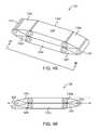
- FIG. 4Ais perspective view of one embodiment of the intervertebral device in the closed state or with a substantially zero inner volume V
- FIG. 4Bis a top view of the intervertebral device in the closed state with a substantially zero inner volume V taken along lines 4 B- 4 B as shown in FIG. 4A
- FIG. 4Cis a top view of the intervertebral device in the expanded state with a locking mechanism.
- FIG. 5is a perspective view of an alternative embodiment of the intervertebral device.
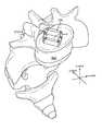
- FIG. 6Ais a perspective view of the intervertebral device and the vertebra, where the intervertebral device is being delivered to an intervertebral disc space rotated about its transverse axis
- FIG. 6Bis a perspective view of the intervertebral device and the vertebra, where the intervertebral device is rotated about its transverse axis once within the intervertebral disc space
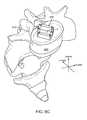
- FIG. 6Cis a perspective view of the intervertebral device and the vertebra, where the intervertebral device is expanded with an inner volume V once deployed in the intervertebral disc space for bone graft containment.
- FIG. 7is a schematic diagram for the method of using the intervertebral device.
- the intervertebral device 100comprises a plurality of struts 120 that are rotatably associated with each adjacent strut 120 to form a modifiable inner volume V for bone graft containment, as shown in FIG. 1A .
- the intervertebral device 100includes an expanded state, whereby the inner volume V is enclosed by the plurality of struts 120 .
- the intervertebral device 100generally includes a longitudinal axis 102 running along the proximal portion 110 to the distal portion 112 of the intervertebral device 100 .
- the intervertebral device 100generally includes a transverse axis 104 , generally running along the left portion 114 to the right portion 116 .
- the plurality of struts 210rotatably associate with each adjacent strut 120 and rotate to expand or contract the modifiable inner volume V generally along at least the longitudinal axis 102 and/or the transverse axis 104 .
- the intervertebral device 100includes an anterior-posterior axis 106 , which generally runs along the anterior surface 108 to the posterior surface 118 , as shown in FIG. 1B .
- the modifiable inner volume Vgenerally runs from the anterior surface 108 to the posterior surface 118 when the intervertebral device 100 is in an expanded state.
- the modifiable inner volume Vprovides an optimal bone graft volume and surface contact area for adjacent vertebra on the anterior surface 108 and the posterior surface 118 of the intervertebral device 100 .
- the plurality of struts 120is preferably static in relation to adjacent struts 120 .
- a bone graft materialis placed into the inner volume V, the bone graft will generally create an outward force on the intervertebral device 100 so it will not collapse or deform to an unexpanded or closed state.
- the intervertebral device 100may include any number of struts 120 that may form a modifiable inner volume V by way of rotation or pivoting of adjacent struts 120 generally along the longitudinal axis 102 and/or the transverse axis 104 to the expanded state. Although six struts 120 are shown in FIG. 1A , the intervertebral device may include any number of struts, including, but not limited to, at least three struts, at least four struts, at least five struts, at least seven struts, at least eight struts, at least nine struts, at least ten struts, or at least between about 2 and 20 struts.
- the number of struts 120 selected for the intervertebral devicemay be selected upon the particular application for disc replacement, bone grafting, or to best match the anatomy of the adjacent vertebra.
- FIG. 1Ashows six struts for the intervertebral device 100 comprising a first strut 120 a , a second strut 120 b , a third strut 120 c , a fourth strut 120 d , a fifth strut 120 e , and a sixth strut 120 f , wherein each adjacent strut is rotatably associate with adjacent struts generally along the longitudinal axis and/or transverse axis.
- the second strut 120 b and the third strut 120 care positioned on the distal end 112 of the intervertebral device 100 , while the fifth strut 120 e and the sixth strut 120 f are positioned on the proximal end 110 .
- Each adjacent strutis rotatably associated with each other.
- the anterior surface 108 and/or the posterior surface 118include a roughed or teethed surface 130 to grip the plates of the vertebra, as shown in FIG. 1B .
- the teethed surfacemay be spaced throughout the anterior surface 108 and the posterior surface 118 of the struts 120 , which can be configured to have a variable thickness, height, and width, as well as angle of orientation with respect to the anterior and poster portions 108 and 118 .
- the teethed surface 130can be further configured to provide additional support after the spinal spacer 100 is implanted in the vertebrae of the patient.
- the teethed surface 130can reduce movement of the intervertebral device 100 in the vertebrae and create additional friction between the vertebrae and the intervertebral device 100 .
- the teethed surface 130 of one intervertebral device 100can be configured to interact and/or mate with teeth of another intervertebral device, thereby creating stacked intervertebral devices. Such interaction can be useful, when multiple intervertebral devices are needed to be implanted into the vertebrae.
- the teethed surface 130can be configured to have a shape of triangular protrusions extending away from the surfaces of the top and bottom portions of the spinal spacer 100 .
- the triangular protrusionscan be configured to be right-angled isosceles triangles.
- the triangular protrusionscan be any size and shape triangles are not necessarily limited to the right-angled isosceles triangles. Further, the triangular protrusions can be configured to protrude a distance away from the anterior surface or posterior surface (whether top or bottom surfaces) of the intervertebral device 100 , preferably about 0.03 millimeters. The triangular protrusions can also be spaced apart a distance D, preferably about 0.1 mm. As can be understood by one skilled in the art, the teethed surface 130 can be configured to have any shape, size, or orientation as well as can protrude any distance away from the surfaces of the spinal spacer and can have any distance between them.
- the intervertebral device 100may include a modifiable inner volume V of substantially zero when the intervertebral device 100 is in the closed state, and when the plurality of adjacent struts 120 rotate towards the interior faces of the struts 120 .
- the intervertebral device 100includes a zero volume state or closed state when the struts 120 are closed upon each other or the interior faces 128 of the struts face and abut the interior face of adjacent struts.
- the intervertebral device 100includes thickness TT profile when in the closed state. The thickness TT profile may be selected to approximate the intervertebral space between adjacent vertebrae that may be damaged or incorrectly articulating vertebrae.
- the distal and proximal ends 112 and 110 of the intervertebral device 100are tapered, such that intervertebral device 100 is minimally invasive, easily inserted through an incision site or retracted tissue, or easily displaces damaged intervertebral spaces by wedging between damaged adjacent vertebrae.
- the tapered distal and proximal ends 112 and 110may be at angle with respect to longitudinal axis 102 .
- each strut 120includes a longitudinal body member 122 extending from a first end 124 and a second end 126 , which generally runs along the longitudinal axis or length of the strut 120 .
- Each adjacent strut 120is rotatably associated with adjacent struts 120 by the first end 124 of a first strut rotatably associating with the second end 126 of a second strut, and the second end 126 of the first strut rotatably associating with the first end 124 of a third struts, accordingly.
- the struts 120include an interior face 128 and an exterior face 129 , as shown in FIG.
- the second end 126includes a pivot pin 146 and the first end includes a circular housing 140 , such that when each strut 120 rotatably connects to an adjacent strut, the pivot pin 146 sits within the circular housing 140 , as shown in FIG. 2A .
- the circular housing 140includes a circular lumen 142 that approximates the size or circumference of the pivot pin 146 .
- the pivot pin 146is a substantially circular pin with a cylindrical shaft.
- the pivot pin 146 or the circular lumen 142may include lubrication to allow for pivoting or rotation of the adjacent struts 120 .
- the pivot pin 146may be locked into place once adjacent struts are rotated to form the inner volume V of choice, by way of a screw, bolt, or fastener within the pivot pin 146 .
- each strut 120includes a width W, which extends from the anterior surface to the posterior surface of the strut 120 .
- the width Wmay be selected based upon the particular vertebra that needs to resist subsidence or shortening of the intervertebral disc space.
- the width Wmay be selected for the amount of bone that must be grafted between adjacent vertebrae.
- each intervertebral spaceincludes a varied width, and the width W may be selected to match a particular intervertebral space.
- Each strut 120also includes a length L, which extends from the first end 124 to the second 126 . In one embodiment, the length L may be selected based upon the size of the intervertebral disc to be replaced.
- Each strut 120also includes a thickness T.
- the intervertebral device 100may include struts if different thicknesses T in the same device.
- the thickness Tmay be selected to fit a space between adjacent vertebrae. For instance, when the intervertebral device 100 is in the substantially closed state or zero inner volume state, the thickness T of adjacent strut 120 will approximate the space between adjacent vertebrae.
- the inner volume Vmay be calculated by taking the surface area of the anterior surface 108 or the posterior surface 118 and multiplying the surface area by the width W of the struts 120 .
- the surface area of the anterior surface 108 or the posterior surface 118may be calculated by taking the length L of each strut and calculating the surface area of the intervertebral device depending on how many struts are included in the intervertebral device 100 . For example, if the intervertebral device includes 6 struts where each include the same length L, the area is calculated by a hexagonal structure with ((3*sqrt(3))/2)*L ⁇ 2, where L is the length. In one embodiment, the surface area may be between about 200 mm2 and 700 mm2 in the expanded state, alternatively, between about 250 and 600 mm2, alternatively, between about 260 and 500 mm2.
- the longitudinal body member 122generally includes a rectangular or square shape.
- the longitudinal body member 122may assume alternative shapes and may include trapezoidal, hexagonal, polygonal, and the like.
- the anterior and posterior surfaces of the longitudinal body member 122may be tapered or at an angle, such that the width W of the strut 120 varies along the length L of the strut. Such variation in the width W of the strut 120 may be preferable if the adjacent vertebra is deformed or at an angle with respect to the longitudinal axis 102 of the intervertebral device 100 .
- the strut 120may be rotatably associated with adjacent struts by including a clearance hole 150 on the second end 126 and a capture whole 152 on the first end 124 .
- Adjacent struts 120are press fit to coaxially align the clearance hole 150 and capture hole 152 , while a pin or screw passes through the clearance hole 150 and the capture hole 152 .
- the capture holemay include a threaded portion to secure the pin or screw therein, which allows the strut 120 with the clearance hole 150 to rotate about an axis when the first end 124 is rotatably coupled with the second end 126 .
- the pin or screw passing through the clearance hole and the capture hole 152may lock the adjacent struts once adjacent struts have been rotated to a set angle.
- the strut 120may be rotatably associated with adjacent struts by including a protrusion 160 on the second end 126 and a mating hole 162 on the first end 124 .
- the mating hole 162may be flexed open to receive the protrusion 160 of an adjacent strut 120 .
- the protrusion 160may be a slotted circular member having radial flexibility provided by the slots and a distal end that is larger than a base end thereof.
- the mating hole 162may include a corresponding inner shoulder such that upon insertion the protrusion 160 is compressed radially until the enlarged distal end passes over and is accommodated by the internal shoulders, thus permanently trapping the protrusion 160 within the mating hole 162 .
- adjacent strutsare rotatably associated about the respective first end 124 and second end 126 . Any type of fastener, bolt, or screw may be used to lock the protrusion 160 with the mating whole 162 once adjacent struts are rotated at an angle with respect to each other.
- the adjacent struts 120rotate or pivot to create an angle A between adjacent struts 120 .
- the angle Amay be selected upon the number of struts 120 used in the intervertebral device 100 .
- the angle Amay be selected upon the inner volume V to be attained for bone containment.
- the angle Amay be greater where the inner volume V is to be greater.
- the angle A between adjacent strutsmay be selected upon the number struts to be included in the intervertebral device.
- the angle A between adjacent struts 120is between about 30 and 270 degrees, alternatively, between about 60 and 240 degrees, alternatively, between about 90 and 200 degrees, alternatively, between about 120 and 170 degrees.
- the angle Amay be locked or fastened once adjacent struts are rotated at an angle A of choice. Such locking or fastening of angle A maintains the inner volume V in a static or fixed state.
- the intervertebral device 100may include a tapered portion on the proximal end 110 and distal end 110 when the intervertebral device 100 is in the closed state when the inner volume V is substantially zero.
- the distal end 112includes a second strut 120 b and a third strut 120 c
- the proximal end 110includes a fifth strut 120 e and a sixth strut 120 f .
- the second strut 120 b and the third strut 120 crotatably associate to the closed state when the interior faces of the second strut 120 b and the third strut 120 c abut each other and close thereupon on the distal end 112 .
- the fifth strut 120 e and the sixth strut 120 frotatably associate to the closed state when the interior faces of the fifth strut 120 e and the sixth strut 120 f abut each other and close thereupon on the proximal end 110 .
- a first strut 120 a and a fourth strut 120 dare rotatably associated with the proximal end 110 and the distal end 112 , such that the interior faces of the first strut 120 a and the fourth strut 120 d substantially abut each other when the intervertebral device 100 is in the closed state.
- the exterior faces 129 of the first and fourth strut 120 a , 120 dmay include a coating or slick edge, as to assist in the insertion of the intervertebral device 100 through an incision point and/or sliding between adjacent vertebrae.
- the fifth strut 120 e , and the sixth strut 120 fare tapered at an angle TA when the intervertebral device 100 is in a zero inner volume V state or closed state.
- the angle TAis taken with respect to the first strut 120 a and fourth strut 120 d substantially parallel with the longitudinal axis 102 of the intervertebral device 100 .
- the tapered angle TAis between about 0 and 45 degrees, alternatively, between about 0 and 30 degrees, alternatively, between about 0 and 15 degrees, alternatively, between about 0 and 5 degrees.
- the tapered anglemay be selected as to optimize the insertion of the intervertebral device 100 through an incision or retracted tissue point, as for minimally invasive during surgery, or to approximate a damaged intervertebral disc space to be wedged there within.
- the intervertebral device 100includes a locking mechanism 180 to lock the intervertebral device 100 when it is in the expanded state.
- the locking mechanism 180may be a pin disposed generally along the transverse axis 104 spanning from the first strut 120 a to the fourth strut 120 d .
- the locking mechanism 140may be a threaded pin, whereby at least one strut 120 includes a complimentary thread to receive the locking mechanism.
- the locking mechanism 180may span from any opposing strut, generally along the longitudinal axis. The locking mechanism 180 may assist in keeping the intervertebral device 100 in an expanded state and to maintain a particular inner volume V.
- first end 124 and the second end 126 of each strutmay include a hinged locking mechanism within the rotatable portion of the first end 124 or the second end 126 .
- the hinged locking mechanismmay be secured in alternative or additional to the locking mechanism 140 to further lock down or fasten the rotatable associations on the first and second ends 124 and 126 of the struts 120 .
- the intervertebral device 300includes eight rotatably associated struts 120 and an inner volume V.
- the intervertebral device 300includes a first strut 120 a , a second strut 120 b , a third strut 120 c , a fourth strut 120 d , a fifth strut 120 e , a sixth strut 120 f , a seventh strut 120 g , and an eight strut 120 h , wherein each adjacent strut is rotatably associated with the adjacent strut.
- the first order of the surgical procedureis to prepare the intervertebral space by accessing the intervertebral disc space 510 , removing a portion of the annulus, evacuating the nucleus, and then removing the cartilaginous endplates.
- the vertebrae 500includes a cranio-caudal axis that is generally shown along the z-axis, a left-right axis that is generally shown along the x-axis, and a dorsoventral axis that is generally shown along the y-axis of FIGS. 6A-C .
- the intervertebral deviceis connected to an instrumentation system for implantation and deployment of the intervertebral device 100 into the intervertebral disc space 510 . Then, the intervertebral device is rotated about its transverse axis and is placed into the intervertebral disc space 510 with the width TT of the intervertebral device parallel to the vertebral endplates or the exterior faces 129 of the first and fourth struts 120 a and 120 d , as shown in FIG. 6A . Next, as shown in FIG.
- the intervertebral deviceis rotated 90 degrees about it's transverse axis to increase the height of the disc space and then the intervertebral device is expanded to the expanded state whereby the inner volume V is enclosed within the plurality of struts, such that the intervertebral device is “opened”.
- the intervertebral deviceincreases the inner volume V and bone fusion-enhancing compounds are placed within the inner volume V, including but not limited to autologous bone, allograft bone, bone morphogenic protein (BMP), and/or any number of suitable biomaterials for bone graft containment, as shown in FIG. 6C .
- Step 210is preparing the intervertebral disc space by removing a portion of the annulus, evacuating the nucleus, and then removing the cartilaginous endplates.
- Step 212is rotating the intervertebral device about its transverse axis and placing the intervertebral device into the intervertebral disc space with the width TT of the intervertebral device parallel to the vertebral endplates.
- Step 214is rotating the intervertebral device 90 degrees about its transverse axis to increase the height of the intervertebral disc space.
- Step 216is expanding the intervertebral device to increase the inner volume V enclosed within the plurality of struts, such that the intervertebral device is “opened”.
- Optional Step 218is locking the intervertebral device with a locking mechanism between the plurality of struts.
- Final Step 220is filling the inner volume V with bone graft material to permit bone fusion between adjacent vertebrae.
- the intervertebral device 100 and/or any of its componentsmay have any size, shape, length, thickness, height, weight, or any other parameters. Such parameters may be selected by the surgeon (or other qualified professional) for performance of specific procedures. Further, the intervertebral device 100 and/or any of its components may be manufactured from metal, plastic, synthetic material, or other suitable materials, or any combination thereof. In one embodiment, the intervertebral device 100 is composed of titanium, nitinol, or stainless steel, pyrolitic carbon, any biocompatible material, or any medical grade polymer, such as Polyether ether ketone (PEEK).
- PEEKPolyether ether ketone
- the struts 120are included in various lengths and configurations, and may also include various features to accommodate different applications for the interspinous spacer.
- the struts 120can be constructed of various materials to aid in radio translucency, strength, flexibility, and integration with anatomy, etc.
Landscapes
- Health & Medical Sciences (AREA)
- Engineering & Computer Science (AREA)
- Biomedical Technology (AREA)
- Orthopedic Medicine & Surgery (AREA)
- Neurology (AREA)
- Life Sciences & Earth Sciences (AREA)
- Animal Behavior & Ethology (AREA)
- Veterinary Medicine (AREA)
- Heart & Thoracic Surgery (AREA)
- Public Health (AREA)
- General Health & Medical Sciences (AREA)
- Cardiology (AREA)
- Oral & Maxillofacial Surgery (AREA)
- Transplantation (AREA)
- Vascular Medicine (AREA)
- Surgery (AREA)
- Molecular Biology (AREA)
- Medical Informatics (AREA)
- Nuclear Medicine, Radiotherapy & Molecular Imaging (AREA)
- Prostheses (AREA)
Abstract
Description
Claims (16)
Priority Applications (3)
| Application Number | Priority Date | Filing Date | Title |
|---|---|---|---|
| US13/252,427US9408710B2 (en) | 2010-10-05 | 2011-10-04 | Intervertebral device and methods of use |
| US15/218,295US10045858B2 (en) | 2010-10-05 | 2016-07-25 | Intervertebral device and methods of use |
| US16/102,664US10952868B2 (en) | 2010-10-05 | 2018-08-13 | Intervertebral device and methods of use |
Applications Claiming Priority (2)
| Application Number | Priority Date | Filing Date | Title |
|---|---|---|---|
| US38986210P | 2010-10-05 | 2010-10-05 | |
| US13/252,427US9408710B2 (en) | 2010-10-05 | 2011-10-04 | Intervertebral device and methods of use |
Related Child Applications (1)
| Application Number | Title | Priority Date | Filing Date |
|---|---|---|---|
| US15/218,295DivisionUS10045858B2 (en) | 2010-10-05 | 2016-07-25 | Intervertebral device and methods of use |
Publications (2)
| Publication Number | Publication Date |
|---|---|
| US20120083889A1 US20120083889A1 (en) | 2012-04-05 |
| US9408710B2true US9408710B2 (en) | 2016-08-09 |
Family
ID=45890471
Family Applications (3)
| Application Number | Title | Priority Date | Filing Date |
|---|---|---|---|
| US13/252,427Active2031-11-09US9408710B2 (en) | 2010-10-05 | 2011-10-04 | Intervertebral device and methods of use |
| US15/218,295Active2031-12-21US10045858B2 (en) | 2010-10-05 | 2016-07-25 | Intervertebral device and methods of use |
| US16/102,664Active2031-11-02US10952868B2 (en) | 2010-10-05 | 2018-08-13 | Intervertebral device and methods of use |
Family Applications After (2)
| Application Number | Title | Priority Date | Filing Date |
|---|---|---|---|
| US15/218,295Active2031-12-21US10045858B2 (en) | 2010-10-05 | 2016-07-25 | Intervertebral device and methods of use |
| US16/102,664Active2031-11-02US10952868B2 (en) | 2010-10-05 | 2018-08-13 | Intervertebral device and methods of use |
Country Status (6)
| Country | Link |
|---|---|
| US (3) | US9408710B2 (en) |
| EP (1) | EP2624790B1 (en) |
| JP (1) | JP5885270B2 (en) |
| KR (1) | KR101852966B1 (en) |
| CN (1) | CN103687575B (en) |
| WO (1) | WO2012047859A2 (en) |
Cited By (5)
| Publication number | Priority date | Publication date | Assignee | Title |
|---|---|---|---|---|
| US20170100256A1 (en)* | 2015-10-09 | 2017-04-13 | DePuy Synthes Products, Inc. | Expandable Trials |
| US11026805B2 (en)* | 2019-07-30 | 2021-06-08 | Loubert S. Suddaby | Expandable intervertebral fusion implant |
| US12102537B2 (en) | 2022-07-18 | 2024-10-01 | Loubert S. Suddaby | Minimally invasive expandable intervertebral fusion implant |
| US12161560B2 (en) | 2021-08-03 | 2024-12-10 | Warsaw Orthopedic, Inc. | Integral graft interbody devices |
| US12318307B2 (en) | 2021-07-16 | 2025-06-03 | Blue Ocean Spine Gmbh | Adjustable spinal implants, associated instruments and methods |
Families Citing this family (79)
| Publication number | Priority date | Publication date | Assignee | Title |
|---|---|---|---|---|
| US6793678B2 (en) | 2002-06-27 | 2004-09-21 | Depuy Acromed, Inc. | Prosthetic intervertebral motion disc having dampening |
| AU2004212942A1 (en) | 2003-02-14 | 2004-09-02 | Depuy Spine, Inc. | In-situ formed intervertebral fusion device |
| US20040267367A1 (en) | 2003-06-30 | 2004-12-30 | Depuy Acromed, Inc | Intervertebral implant with conformable endplate |
| US8636802B2 (en) | 2004-03-06 | 2014-01-28 | DePuy Synthes Products, LLC | Dynamized interspinal implant |
| WO2007089318A2 (en)* | 2005-11-23 | 2007-08-09 | Orexigen Therapeutics, Inc. | Compositions and methods for reducing food cravings |
| WO2008070863A2 (en) | 2006-12-07 | 2008-06-12 | Interventional Spine, Inc. | Intervertebral implant |
| US9039768B2 (en) | 2006-12-22 | 2015-05-26 | Medos International Sarl | Composite vertebral spacers and instrument |
| US8900307B2 (en) | 2007-06-26 | 2014-12-02 | DePuy Synthes Products, LLC | Highly lordosed fusion cage |
| EP2237748B1 (en) | 2008-01-17 | 2012-09-05 | Synthes GmbH | An expandable intervertebral implant |
| US20090248092A1 (en) | 2008-03-26 | 2009-10-01 | Jonathan Bellas | Posterior Intervertebral Disc Inserter and Expansion Techniques |
| US8936641B2 (en) | 2008-04-05 | 2015-01-20 | DePuy Synthes Products, LLC | Expandable intervertebral implant |
| BRPI0921108A2 (en)* | 2008-12-22 | 2016-02-16 | Synthes Gmbh | expandable vertebral body replacement method and system |
| US9526620B2 (en) | 2009-03-30 | 2016-12-27 | DePuy Synthes Products, Inc. | Zero profile spinal fusion cage |
| KR101687435B1 (en) | 2009-07-06 | 2016-12-19 | 신세스 게엠바하 | Expandable fixation assemblies |
| US9393129B2 (en) | 2009-12-10 | 2016-07-19 | DePuy Synthes Products, Inc. | Bellows-like expandable interbody fusion cage |
| US9907560B2 (en) | 2010-06-24 | 2018-03-06 | DePuy Synthes Products, Inc. | Flexible vertebral body shavers |
| US8979860B2 (en) | 2010-06-24 | 2015-03-17 | DePuy Synthes Products. LLC | Enhanced cage insertion device |
| US8623091B2 (en) | 2010-06-29 | 2014-01-07 | DePuy Synthes Products, LLC | Distractible intervertebral implant |
| BR112013002765A2 (en) | 2010-07-15 | 2017-09-19 | Nlt Spine Ltd | deflectable implant, system and methods for implantation |
| US20120078373A1 (en) | 2010-09-23 | 2012-03-29 | Thomas Gamache | Stand alone intervertebral fusion device |
| US20120078372A1 (en) | 2010-09-23 | 2012-03-29 | Thomas Gamache | Novel implant inserter having a laterally-extending dovetail engagement feature |
| US11529241B2 (en) | 2010-09-23 | 2022-12-20 | DePuy Synthes Products, Inc. | Fusion cage with in-line single piece fixation |
| KR101877806B1 (en) | 2010-10-05 | 2018-07-12 | 모건 피. 로리오 | Minimally invasive intervertebral systems and methods |
| JP5885270B2 (en) | 2010-10-05 | 2016-03-15 | ロリオ,モーガン,ピー. | Intervertebral device and method of use |
| US9402732B2 (en) | 2010-10-11 | 2016-08-02 | DePuy Synthes Products, Inc. | Expandable interspinous process spacer implant |
| US9308099B2 (en)* | 2011-02-14 | 2016-04-12 | Imds Llc | Expandable intervertebral implants and instruments |
| US9248028B2 (en) | 2011-09-16 | 2016-02-02 | DePuy Synthes Products, Inc. | Removable, bone-securing cover plate for intervertebral fusion cage |
| US9198765B1 (en) | 2011-10-31 | 2015-12-01 | Nuvasive, Inc. | Expandable spinal fusion implants and related methods |
| HK1197964A2 (en) | 2011-12-03 | 2015-02-27 | DePuy Synthes Products, Inc. | Safe cutting heads and systems for fast removal of a target tissue |
| US9271836B2 (en) | 2012-03-06 | 2016-03-01 | DePuy Synthes Products, Inc. | Nubbed plate |
| CN104582639A (en) | 2012-05-29 | 2015-04-29 | Nlt-脊椎有限公司 | Laterally deflectable implant |
| US9044342B2 (en)* | 2012-05-30 | 2015-06-02 | Globus Medical, Inc. | Expandable interbody spacer |
| EP2877127B1 (en) | 2012-07-26 | 2019-08-21 | Synthes GmbH | Expandable implant |
| WO2014035835A1 (en) | 2012-08-27 | 2014-03-06 | Lorio Morgan Packard | Intervertebral cage apparatus and system and methods of using the same |
| US9445918B1 (en) | 2012-10-22 | 2016-09-20 | Nuvasive, Inc. | Expandable spinal fusion implants and related instruments and methods |
| US10182921B2 (en) | 2012-11-09 | 2019-01-22 | DePuy Synthes Products, Inc. | Interbody device with opening to allow packing graft and other biologics |
| US8663332B1 (en) | 2012-12-13 | 2014-03-04 | Ouroboros Medical, Inc. | Bone graft distribution system |
| US9717601B2 (en) | 2013-02-28 | 2017-08-01 | DePuy Synthes Products, Inc. | Expandable intervertebral implant, system, kit and method |
| US9522070B2 (en) | 2013-03-07 | 2016-12-20 | Interventional Spine, Inc. | Intervertebral implant |
| US10022240B2 (en)* | 2013-03-12 | 2018-07-17 | Morgan Packard Lorio | Vertically expandable intervertebral cage, deployment devices, and methods of using the same |
| US10265192B2 (en) | 2013-07-03 | 2019-04-23 | Spine Innovation, Llc | Methods and apparatus for implanting an interbody device |
| US10828171B2 (en) | 2013-07-18 | 2020-11-10 | The University Of Toledo | Expandable inter-vertebral cage and method of installing same |
| EP3021768B1 (en) | 2013-07-19 | 2020-08-19 | DePuy Synthes Products, Inc. | An anti-clogging device for a vacuum-assisted, tissue removal system |
| US9186259B2 (en) | 2013-09-09 | 2015-11-17 | Ouroboros Medical, Inc. | Expandable trials |
| US9737411B2 (en) | 2013-12-11 | 2017-08-22 | Nlt Spine Ltd. | Worm-gear actuated orthopedic implants and methods |
| US10492923B2 (en) | 2014-06-25 | 2019-12-03 | Seaspine, Inc. | Expanding implant with hinged arms |
| CN105310803B (en)* | 2014-07-27 | 2018-11-23 | 温州医科大学附属第二医院、温州医科大学附属育英儿童医院 | A minimally invasive shape memory intervertebral fusion device |
| JP5947351B2 (en)* | 2014-09-12 | 2016-07-06 | 陳桂蓉 | Vertebral implants that are elastic and automatically expand |
| US9060876B1 (en) | 2015-01-20 | 2015-06-23 | Ouroboros Medical, Inc. | Stabilized intervertebral scaffolding systems |
| US11426290B2 (en) | 2015-03-06 | 2022-08-30 | DePuy Synthes Products, Inc. | Expandable intervertebral implant, system, kit and method |
| US9913727B2 (en) | 2015-07-02 | 2018-03-13 | Medos International Sarl | Expandable implant |
| JP6949006B2 (en) | 2015-08-25 | 2021-10-13 | アイエムディーエス リミテッド ライアビリティ カンパニー | Expandable facet implant |
| WO2017039596A1 (en) | 2015-08-30 | 2017-03-09 | Lorio Morgan Packard | Expandable intervertebral cage with living hinges apparatus, systems and methods of manufacture thereof |
| CN105232191A (en)* | 2015-11-06 | 2016-01-13 | 天津市天津医院 | Intervertebral fusion device capable of being braced in transverse direction |
| EP3474784A2 (en) | 2016-06-28 | 2019-05-01 | Eit Emerging Implant Technologies GmbH | Expandable and angularly adjustable intervertebral cages with articulating joint |
| US11510788B2 (en) | 2016-06-28 | 2022-11-29 | Eit Emerging Implant Technologies Gmbh | Expandable, angularly adjustable intervertebral cages |
| US9883953B1 (en) | 2016-09-21 | 2018-02-06 | Integrity Implants Inc. | Stabilized laterovertically-expanding fusion cage systems with tensioner |
| WO2018081322A1 (en) | 2016-10-25 | 2018-05-03 | Imds Llc | Methods and instrumentation for intervertebral cage expansion |
| FR3058043B1 (en)* | 2016-10-27 | 2020-11-13 | Ldr Medical | EXPANDABLE INTERSOMATIC CAGE |
| US10537436B2 (en) | 2016-11-01 | 2020-01-21 | DePuy Synthes Products, Inc. | Curved expandable cage |
| US10888433B2 (en) | 2016-12-14 | 2021-01-12 | DePuy Synthes Products, Inc. | Intervertebral implant inserter and related methods |
| JP7085554B2 (en) | 2017-01-10 | 2022-06-16 | インテグリティ インプランツ インコーポレイテッド | Deployable intervertebral fusion device |
| US10398563B2 (en) | 2017-05-08 | 2019-09-03 | Medos International Sarl | Expandable cage |
| US11344424B2 (en) | 2017-06-14 | 2022-05-31 | Medos International Sarl | Expandable intervertebral implant and related methods |
| US10940016B2 (en) | 2017-07-05 | 2021-03-09 | Medos International Sarl | Expandable intervertebral fusion cage |
| CN111031969A (en) | 2017-07-24 | 2020-04-17 | 整体植入有限公司 | Surgical implants and related methods |
| US10709578B2 (en) | 2017-08-25 | 2020-07-14 | Integrity Implants Inc. | Surgical biologics delivery system and related methods |
| US10945859B2 (en) | 2018-01-29 | 2021-03-16 | Amplify Surgical, Inc. | Expanding fusion cages |
| JP7572857B2 (en) | 2018-03-01 | 2024-10-24 | インテグリティ インプランツ インコーポレイテッド | Expandable Fusion Device with Independent Deployment System |
| US11446156B2 (en) | 2018-10-25 | 2022-09-20 | Medos International Sarl | Expandable intervertebral implant, inserter instrument, and related methods |
| EP3818964B1 (en) | 2019-11-07 | 2024-07-10 | OSSAWARE Biotech Co., Ltd. | Multi-section expandable device |
| US11426286B2 (en) | 2020-03-06 | 2022-08-30 | Eit Emerging Implant Technologies Gmbh | Expandable intervertebral implant |
| EP4171448A4 (en) | 2020-07-20 | 2025-02-12 | Integrity Implants Inc. | EXPANDABLE FUSION DEVICE WITH INDEPENDENT EXPANSION SYSTEMS |
| CN111938879B (en)* | 2020-08-17 | 2023-03-28 | 复旦大学附属中山医院 | Folding and unfolding type interbody fusion cage |
| US11850160B2 (en) | 2021-03-26 | 2023-12-26 | Medos International Sarl | Expandable lordotic intervertebral fusion cage |
| US11752009B2 (en) | 2021-04-06 | 2023-09-12 | Medos International Sarl | Expandable intervertebral fusion cage |
| US11980398B2 (en) | 2021-11-18 | 2024-05-14 | Astura Medical Inc | Crosslink locking mechanism |
| US12090064B2 (en) | 2022-03-01 | 2024-09-17 | Medos International Sarl | Stabilization members for expandable intervertebral implants, and related systems and methods |
| CN115068177A (en)* | 2022-06-15 | 2022-09-20 | 浙江德康医疗器械有限公司 | Three-dimensional adjustable minimally invasive interbody fusion cage made of antibacterial copper-containing titanium alloy |
Citations (62)
| Publication number | Priority date | Publication date | Assignee | Title |
|---|---|---|---|---|
| US4877020A (en) | 1984-11-30 | 1989-10-31 | Vich Jose M O | Apparatus for bone graft |
| US5176587A (en)* | 1991-10-17 | 1993-01-05 | Borg-Warner Automotive Transmission & Engine Components Corporation | Single pin rocker joint bushing chain |
| US5549679A (en) | 1994-05-20 | 1996-08-27 | Kuslich; Stephen D. | Expandable fabric implant for stabilizing the spinal motion segment |
| US5782832A (en) | 1996-10-01 | 1998-07-21 | Surgical Dynamics, Inc. | Spinal fusion implant and method of insertion thereof |
| US6039761A (en)* | 1997-02-12 | 2000-03-21 | Li Medical Technologies, Inc. | Intervertebral spacer and tool and method for emplacement thereof |
| US6126689A (en) | 1998-06-15 | 2000-10-03 | Expanding Concepts, L.L.C. | Collapsible and expandable interbody fusion device |
| US20010012942A1 (en) | 1998-04-09 | 2001-08-09 | Estes Bradley T. | Method and instrumentation for posterior interbody fusion |
| US20010032020A1 (en) | 1999-07-02 | 2001-10-18 | Petrus Besselink | Reinforced expandable cage |
| US20020156481A1 (en) | 1998-04-09 | 2002-10-24 | Boyd Lawrence M. | Method and instrumentation for vertebral interbody fusion |
| US6527804B1 (en) | 1998-12-11 | 2003-03-04 | Dimso (Distribution Medicale Du Sud-Quest) | Intervertebral disk prosthesis |
| US20030236520A1 (en)* | 2002-06-25 | 2003-12-25 | Roy Lim | Minimally invasive expanding spacer and method |
| US20050021041A1 (en) | 2001-03-27 | 2005-01-27 | Michelson Gary K. | Instrumentation for use with radially expanding interbody spinal fusion implant |
| US20050070911A1 (en) | 2003-09-29 | 2005-03-31 | Scimed Life Systems, Inc. | Apparatus and methods for reducing compression bone fractures using high strength ribbed members |
| US6893464B2 (en) | 2002-03-05 | 2005-05-17 | The Regents Of The University Of California | Method and apparatus for providing an expandable spinal fusion cage |
| US20050113920A1 (en) | 1998-10-29 | 2005-05-26 | Kevin Foley | Expandable intervertebral spacers |
| US20050130929A1 (en) | 2001-11-01 | 2005-06-16 | Boyd Lawrence M. | System and method for the pretreatment of the endplates of an intervertebral disc |
| US20050182416A1 (en)* | 2004-02-13 | 2005-08-18 | Roy Lim | Spacer with height and angle adjustments for spacing vertebral members |
| US20060142858A1 (en) | 2004-12-16 | 2006-06-29 | Dennis Colleran | Expandable implants for spinal disc replacement |
| US7137997B2 (en) | 2003-12-29 | 2006-11-21 | Globus Medical, Inc. | Spinal fusion implant |
| WO2007076377A2 (en) | 2005-12-19 | 2007-07-05 | Stout Medical Group, L.P. | Expandable support device |
| US20080015701A1 (en) | 2001-11-09 | 2008-01-17 | Javier Garcia | Spinal implant |
| US20080125865A1 (en)* | 2006-09-21 | 2008-05-29 | Abdelgany Mahmoud F | Articulating interbody spacer, vertebral body replacement |
| US20080140207A1 (en) | 2006-12-07 | 2008-06-12 | Interventional Spine, Inc. | Intervertebral implant |
| US20080243255A1 (en)* | 2007-03-29 | 2008-10-02 | Butler Michael S | Radially expandable spinal interbody device and implantation tool |
| WO2008152501A2 (en) | 2007-06-15 | 2008-12-18 | Ldr Medical | Nucleus prosthesis |
| US20090143859A1 (en)* | 2007-11-30 | 2009-06-04 | Mcclellan Iii John W | Maximum support tlif implant |
| WO2009125242A1 (en) | 2008-04-08 | 2009-10-15 | Vexim | Apparatus for restoration of the spine and methods of use thereof |
| US20090270873A1 (en) | 2008-04-24 | 2009-10-29 | Fabian Henry F | Spine surgery method and inserter |
| US7621950B1 (en) | 1999-01-27 | 2009-11-24 | Kyphon Sarl | Expandable intervertebral spacer |
| US7621956B2 (en) | 2003-07-31 | 2009-11-24 | Globus Medical, Inc. | Prosthetic spinal disc replacement |
| US7674296B2 (en) | 2005-04-21 | 2010-03-09 | Globus Medical, Inc. | Expandable vertebral prosthesis |
| US20100137987A1 (en) | 2008-11-19 | 2010-06-03 | Endospinal, Inc. | Intramedullary Repair System for Vertebra Fractures |
| US7731751B2 (en) | 2005-03-31 | 2010-06-08 | Life Spine, Inc. | Expandable spinal devices and method of insertion |
| US7758644B2 (en) | 2002-11-21 | 2010-07-20 | Warsaw Orthopedic, Inc. | Systems and techniques for intravertebral spinal stabilization with expandable devices |
| USD623750S1 (en) | 2009-11-05 | 2010-09-14 | Duffield William E | Intervertebral fusion implant |
| US20110125270A1 (en) | 2009-11-23 | 2011-05-26 | David C Paul | Prosthetic Spinal Disc Replacement |
| US20110125266A1 (en)* | 2007-12-28 | 2011-05-26 | Nuvasive, Inc. | Spinal Surgical Implant and Related Methods |
| US8021393B2 (en) | 2008-12-12 | 2011-09-20 | Globus Medical, Inc. | Lateral spinous process spacer with deployable wings |
| US20110251692A1 (en) | 2010-04-12 | 2011-10-13 | Mclaughlin Colm | Expandable Vertebral Implant |
| US20110276142A1 (en) | 2008-10-13 | 2011-11-10 | Marcin Niemiec | Articulating Spacer |
| US20110295370A1 (en) | 2010-06-01 | 2011-12-01 | Sean Suh | Spinal Implants and Methods of Use Thereof |
| US20120016481A1 (en) | 2005-02-24 | 2012-01-19 | Morphogeny, Llc | Linked Slideable and Interlockable Rotatable Components |
| US20120016371A1 (en) | 2009-12-07 | 2012-01-19 | O'halloran Damien | Methods and Apparatus For Treating Vertebral Fractures |
| WO2012007918A2 (en) | 2010-07-15 | 2012-01-19 | Nonlinear Technologies Ltd. | Surgical systems and methods for implanting deflectable implants |
| US20120059470A1 (en) | 2010-09-03 | 2012-03-08 | Mark Weiman | Expandable Fusion Device and Method of Installation Thereof |
| US20120059475A1 (en) | 2010-09-03 | 2012-03-08 | Mark Weiman | Expandable Fusion Device and Method of Installation Thereof |
| US20120083887A1 (en) | 2010-10-05 | 2012-04-05 | Alphatec Spine, Inc. | Intervertebral device and methods of use |
| US20120083889A1 (en) | 2010-10-05 | 2012-04-05 | Alphatec Spine, Inc. | Intervertebral device and methods of use |
| US20120123544A1 (en) | 2010-11-16 | 2012-05-17 | Sean Suh | Intervertebral Spacer and Method of Installation Thereof |
| US20120123546A1 (en) | 2010-11-15 | 2012-05-17 | MEDevice IP Holdings, LLC. | Implant apparatus for spinal fusion |
| USD665081S1 (en) | 2011-08-18 | 2012-08-07 | Noah Hansell | Intervertebral spacer |
| US20120215314A1 (en) | 2011-02-23 | 2012-08-23 | Jeff Bennett | Six Degree Spine Stabilization Devices and Methods |
| US8268001B2 (en) | 2007-10-29 | 2012-09-18 | Life Spine, Inc. | Foldable orthopedic implant |
| WO2012135764A1 (en) | 2011-03-30 | 2012-10-04 | Trinity Ortopedics, Llc | Articulating interbody cage and methods thereof |
| US20130018467A1 (en) | 2011-07-15 | 2013-01-17 | Sean Suh | Systems and Methods For Vertebral Body and Disc Height Restoration |
| US20130041471A1 (en) | 2011-07-14 | 2013-02-14 | Nlt Spine Ltd. | Laterally Deflectable Implant |
| US8394145B2 (en) | 2010-02-24 | 2013-03-12 | Globus Medical | Expandable intervertebral spacer and method of posterior insertion thereof |
| US8398713B2 (en) | 2010-09-03 | 2013-03-19 | Globus Medical, Inc. | Expandable fusion device and method of installation thereof |
| US8435298B2 (en) | 2010-09-03 | 2013-05-07 | Globus Medical, Inc. | Expandable fusion device and method of installation thereof |
| US8454623B2 (en) | 2009-11-11 | 2013-06-04 | Alphatec Spine, Inc | Instrument for insertion and deployment of features on an implant |
| US8460386B2 (en) | 2003-07-31 | 2013-06-11 | Globus Medical, Inc. | Transforaminal prosthetic spinal disc replacement and methods thereof |
| US8496713B2 (en) | 2010-12-10 | 2013-07-30 | Globus Medical, Inc. | Spine stabilization device and methods |
Family Cites Families (1)
| Publication number | Priority date | Publication date | Assignee | Title |
|---|---|---|---|---|
| EP2408382A4 (en)* | 2009-03-13 | 2013-06-19 | Univ Toledo | FOLDING CAGE LITTLE INVASIVE |
- 2011
- 2011-10-04JPJP2013532878Apatent/JP5885270B2/enactiveActive
- 2011-10-04USUS13/252,427patent/US9408710B2/enactiveActive
- 2011-10-04WOPCT/US2011/054729patent/WO2012047859A2/enactiveApplication Filing
- 2011-10-04CNCN201180056812.2Apatent/CN103687575B/enactiveActive
- 2011-10-04EPEP11831430.1Apatent/EP2624790B1/enactiveActive
- 2011-10-04KRKR1020137011714Apatent/KR101852966B1/ennot_activeExpired - Fee Related
- 2016
- 2016-07-25USUS15/218,295patent/US10045858B2/enactiveActive
- 2018
- 2018-08-13USUS16/102,664patent/US10952868B2/enactiveActive
Patent Citations (73)
| Publication number | Priority date | Publication date | Assignee | Title |
|---|---|---|---|---|
| US4877020A (en) | 1984-11-30 | 1989-10-31 | Vich Jose M O | Apparatus for bone graft |
| US5176587A (en)* | 1991-10-17 | 1993-01-05 | Borg-Warner Automotive Transmission & Engine Components Corporation | Single pin rocker joint bushing chain |
| US5549679A (en) | 1994-05-20 | 1996-08-27 | Kuslich; Stephen D. | Expandable fabric implant for stabilizing the spinal motion segment |
| US5571189A (en) | 1994-05-20 | 1996-11-05 | Kuslich; Stephen D. | Expandable fabric implant for stabilizing the spinal motion segment |
| US5782832A (en) | 1996-10-01 | 1998-07-21 | Surgical Dynamics, Inc. | Spinal fusion implant and method of insertion thereof |
| US6039761A (en)* | 1997-02-12 | 2000-03-21 | Li Medical Technologies, Inc. | Intervertebral spacer and tool and method for emplacement thereof |
| US20010012942A1 (en) | 1998-04-09 | 2001-08-09 | Estes Bradley T. | Method and instrumentation for posterior interbody fusion |
| US20020156481A1 (en) | 1998-04-09 | 2002-10-24 | Boyd Lawrence M. | Method and instrumentation for vertebral interbody fusion |
| US6126689A (en) | 1998-06-15 | 2000-10-03 | Expanding Concepts, L.L.C. | Collapsible and expandable interbody fusion device |
| US6409766B1 (en)* | 1998-07-30 | 2002-06-25 | Expanding Concepts, Llc | Collapsible and expandable interbody fusion device |
| US20050113920A1 (en) | 1998-10-29 | 2005-05-26 | Kevin Foley | Expandable intervertebral spacers |
| US6527804B1 (en) | 1998-12-11 | 2003-03-04 | Dimso (Distribution Medicale Du Sud-Quest) | Intervertebral disk prosthesis |
| US7621950B1 (en) | 1999-01-27 | 2009-11-24 | Kyphon Sarl | Expandable intervertebral spacer |
| US20010032020A1 (en) | 1999-07-02 | 2001-10-18 | Petrus Besselink | Reinforced expandable cage |
| US6488710B2 (en) | 1999-07-02 | 2002-12-03 | Petrus Besselink | Reinforced expandable cage and method of deploying |
| US20050021041A1 (en) | 2001-03-27 | 2005-01-27 | Michelson Gary K. | Instrumentation for use with radially expanding interbody spinal fusion implant |
| US7445636B2 (en) | 2001-03-27 | 2008-11-04 | Warsaw Orthopedic, Inc. | Instrumentation for use with radially expanding interbody spinal fusion implant |
| US20050130929A1 (en) | 2001-11-01 | 2005-06-16 | Boyd Lawrence M. | System and method for the pretreatment of the endplates of an intervertebral disc |
| US20080015701A1 (en) | 2001-11-09 | 2008-01-17 | Javier Garcia | Spinal implant |
| US6893464B2 (en) | 2002-03-05 | 2005-05-17 | The Regents Of The University Of California | Method and apparatus for providing an expandable spinal fusion cage |
| US20030236520A1 (en)* | 2002-06-25 | 2003-12-25 | Roy Lim | Minimally invasive expanding spacer and method |
| US7758644B2 (en) | 2002-11-21 | 2010-07-20 | Warsaw Orthopedic, Inc. | Systems and techniques for intravertebral spinal stabilization with expandable devices |
| US8460386B2 (en) | 2003-07-31 | 2013-06-11 | Globus Medical, Inc. | Transforaminal prosthetic spinal disc replacement and methods thereof |
| US8167948B2 (en) | 2003-07-31 | 2012-05-01 | Globus Medical, Inc. | Anterior prosthetic spinal disc replacement |
| US7641666B2 (en) | 2003-07-31 | 2010-01-05 | Globus Medical, Inc. | Prosthetic spinal disc replacement |
| US7621956B2 (en) | 2003-07-31 | 2009-11-24 | Globus Medical, Inc. | Prosthetic spinal disc replacement |
| US7513900B2 (en) | 2003-09-29 | 2009-04-07 | Boston Scientific Scimed, Inc. | Apparatus and methods for reducing compression bone fractures using high strength ribbed members |
| US20050070911A1 (en) | 2003-09-29 | 2005-03-31 | Scimed Life Systems, Inc. | Apparatus and methods for reducing compression bone fractures using high strength ribbed members |
| US7137997B2 (en) | 2003-12-29 | 2006-11-21 | Globus Medical, Inc. | Spinal fusion implant |
| US20050182416A1 (en)* | 2004-02-13 | 2005-08-18 | Roy Lim | Spacer with height and angle adjustments for spacing vertebral members |
| US7763028B2 (en)* | 2004-02-13 | 2010-07-27 | Warsaw Orthopedic, Inc. | Spacer with height and angle adjustments for spacing vertebral members |
| US20060142858A1 (en) | 2004-12-16 | 2006-06-29 | Dennis Colleran | Expandable implants for spinal disc replacement |
| US20120016481A1 (en) | 2005-02-24 | 2012-01-19 | Morphogeny, Llc | Linked Slideable and Interlockable Rotatable Components |
| US7731751B2 (en) | 2005-03-31 | 2010-06-08 | Life Spine, Inc. | Expandable spinal devices and method of insertion |
| US7674296B2 (en) | 2005-04-21 | 2010-03-09 | Globus Medical, Inc. | Expandable vertebral prosthesis |
| WO2007076377A2 (en) | 2005-12-19 | 2007-07-05 | Stout Medical Group, L.P. | Expandable support device |
| US20080125865A1 (en)* | 2006-09-21 | 2008-05-29 | Abdelgany Mahmoud F | Articulating interbody spacer, vertebral body replacement |
| US8025697B2 (en)* | 2006-09-21 | 2011-09-27 | Custom Spine, Inc. | Articulating interbody spacer, vertebral body replacement |
| US20080140207A1 (en) | 2006-12-07 | 2008-06-12 | Interventional Spine, Inc. | Intervertebral implant |
| US20080243255A1 (en)* | 2007-03-29 | 2008-10-02 | Butler Michael S | Radially expandable spinal interbody device and implantation tool |
| US8241358B2 (en)* | 2007-03-29 | 2012-08-14 | Life Spine, Inc. | Radially expandable spinal interbody device and implantation tool |
| WO2008152501A2 (en) | 2007-06-15 | 2008-12-18 | Ldr Medical | Nucleus prosthesis |
| US8268001B2 (en) | 2007-10-29 | 2012-09-18 | Life Spine, Inc. | Foldable orthopedic implant |
| US20090143859A1 (en)* | 2007-11-30 | 2009-06-04 | Mcclellan Iii John W | Maximum support tlif implant |
| US20110125266A1 (en)* | 2007-12-28 | 2011-05-26 | Nuvasive, Inc. | Spinal Surgical Implant and Related Methods |
| WO2009125242A1 (en) | 2008-04-08 | 2009-10-15 | Vexim | Apparatus for restoration of the spine and methods of use thereof |
| US20090270873A1 (en) | 2008-04-24 | 2009-10-29 | Fabian Henry F | Spine surgery method and inserter |
| US20110276142A1 (en) | 2008-10-13 | 2011-11-10 | Marcin Niemiec | Articulating Spacer |
| US8545566B2 (en) | 2008-10-13 | 2013-10-01 | Globus Medical, Inc. | Articulating spacer |
| US20100137987A1 (en) | 2008-11-19 | 2010-06-03 | Endospinal, Inc. | Intramedullary Repair System for Vertebra Fractures |
| US8021393B2 (en) | 2008-12-12 | 2011-09-20 | Globus Medical, Inc. | Lateral spinous process spacer with deployable wings |
| USD623750S1 (en) | 2009-11-05 | 2010-09-14 | Duffield William E | Intervertebral fusion implant |
| US8454623B2 (en) | 2009-11-11 | 2013-06-04 | Alphatec Spine, Inc | Instrument for insertion and deployment of features on an implant |
| US20110125270A1 (en) | 2009-11-23 | 2011-05-26 | David C Paul | Prosthetic Spinal Disc Replacement |
| US20120016371A1 (en) | 2009-12-07 | 2012-01-19 | O'halloran Damien | Methods and Apparatus For Treating Vertebral Fractures |
| US8394145B2 (en) | 2010-02-24 | 2013-03-12 | Globus Medical | Expandable intervertebral spacer and method of posterior insertion thereof |
| US20110251692A1 (en) | 2010-04-12 | 2011-10-13 | Mclaughlin Colm | Expandable Vertebral Implant |
| US20110295370A1 (en) | 2010-06-01 | 2011-12-01 | Sean Suh | Spinal Implants and Methods of Use Thereof |
| WO2012007918A2 (en) | 2010-07-15 | 2012-01-19 | Nonlinear Technologies Ltd. | Surgical systems and methods for implanting deflectable implants |
| US8435298B2 (en) | 2010-09-03 | 2013-05-07 | Globus Medical, Inc. | Expandable fusion device and method of installation thereof |
| US8398713B2 (en) | 2010-09-03 | 2013-03-19 | Globus Medical, Inc. | Expandable fusion device and method of installation thereof |
| US20120059470A1 (en) | 2010-09-03 | 2012-03-08 | Mark Weiman | Expandable Fusion Device and Method of Installation Thereof |
| US20120059475A1 (en) | 2010-09-03 | 2012-03-08 | Mark Weiman | Expandable Fusion Device and Method of Installation Thereof |
| US20120083887A1 (en) | 2010-10-05 | 2012-04-05 | Alphatec Spine, Inc. | Intervertebral device and methods of use |
| US20120083889A1 (en) | 2010-10-05 | 2012-04-05 | Alphatec Spine, Inc. | Intervertebral device and methods of use |
| US20120123546A1 (en) | 2010-11-15 | 2012-05-17 | MEDevice IP Holdings, LLC. | Implant apparatus for spinal fusion |
| US20120123544A1 (en) | 2010-11-16 | 2012-05-17 | Sean Suh | Intervertebral Spacer and Method of Installation Thereof |
| US8496713B2 (en) | 2010-12-10 | 2013-07-30 | Globus Medical, Inc. | Spine stabilization device and methods |
| US20120215314A1 (en) | 2011-02-23 | 2012-08-23 | Jeff Bennett | Six Degree Spine Stabilization Devices and Methods |
| WO2012135764A1 (en) | 2011-03-30 | 2012-10-04 | Trinity Ortopedics, Llc | Articulating interbody cage and methods thereof |
| US20130041471A1 (en) | 2011-07-14 | 2013-02-14 | Nlt Spine Ltd. | Laterally Deflectable Implant |
| US20130018467A1 (en) | 2011-07-15 | 2013-01-17 | Sean Suh | Systems and Methods For Vertebral Body and Disc Height Restoration |
| USD665081S1 (en) | 2011-08-18 | 2012-08-07 | Noah Hansell | Intervertebral spacer |
Non-Patent Citations (4)
| Title |
|---|
| International Search Report and Written Opinion for PCT/US2011/054001 in 15 pages dated Jan. 17, 2012. |
| International Search Report and Written Opinion for PCT/US2011/054729 in 13 pages, dated Jan. 31, 2012. |
| International Search Report and Written Opinion in PCT Application No. PCT/US2013/056500 mailed Dec. 6, 2013 in 16 pages. |
| Supplementary Search Report and Written Opinion in Europe Application No. 11831430.1, dated Jun. 16, 2014 in 07 pages. |
Cited By (7)
| Publication number | Priority date | Publication date | Assignee | Title |
|---|---|---|---|---|
| US20170100256A1 (en)* | 2015-10-09 | 2017-04-13 | DePuy Synthes Products, Inc. | Expandable Trials |
| US10729554B2 (en)* | 2015-10-09 | 2020-08-04 | DePuy Synthes Products, Inc. | Expandable trials |
| US11529240B2 (en) | 2015-10-09 | 2022-12-20 | DePuy Synthes Products, Inc. | Expandable trials |
| US11026805B2 (en)* | 2019-07-30 | 2021-06-08 | Loubert S. Suddaby | Expandable intervertebral fusion implant |
| US12318307B2 (en) | 2021-07-16 | 2025-06-03 | Blue Ocean Spine Gmbh | Adjustable spinal implants, associated instruments and methods |
| US12161560B2 (en) | 2021-08-03 | 2024-12-10 | Warsaw Orthopedic, Inc. | Integral graft interbody devices |
| US12102537B2 (en) | 2022-07-18 | 2024-10-01 | Loubert S. Suddaby | Minimally invasive expandable intervertebral fusion implant |
Also Published As
| Publication number | Publication date |
|---|---|
| CN103687575A (en) | 2014-03-26 |
| WO2012047859A2 (en) | 2012-04-12 |
| JP2014504889A (en) | 2014-02-27 |
| US10045858B2 (en) | 2018-08-14 |
| EP2624790A2 (en) | 2013-08-14 |
| US10952868B2 (en) | 2021-03-23 |
| EP2624790B1 (en) | 2020-02-26 |
| CN103687575B (en) | 2017-01-18 |
| US20180344478A1 (en) | 2018-12-06 |
| US20120083889A1 (en) | 2012-04-05 |
| KR20140019773A (en) | 2014-02-17 |
| KR101852966B1 (en) | 2018-04-27 |
| EP2624790A4 (en) | 2014-08-13 |
| WO2012047859A3 (en) | 2013-10-17 |
| JP5885270B2 (en) | 2016-03-15 |
| US20160331547A1 (en) | 2016-11-17 |
Similar Documents
| Publication | Publication Date | Title |
|---|---|---|
| US10952868B2 (en) | Intervertebral device and methods of use | |
| US10226356B2 (en) | Universally expanding cage | |
| US7758648B2 (en) | Stabilized, adjustable expandable implant and method | |
| US7879096B2 (en) | Centrally driven expandable implant | |
| US8366779B2 (en) | Expandable implant, instrument, and method | |
| US8231681B2 (en) | Self-contained expandable implant and method | |
| CA2801755C (en) | A plastically deformable inter-osseous device | |
| US8241358B2 (en) | Radially expandable spinal interbody device and implantation tool | |
| US20140148902A1 (en) | Expandable implant, instrument, and method | |
| HK1194962A (en) | Intervertebral device and methods of use | |
| AU2011279588B2 (en) | A plastically deformable inter-osseous device |
Legal Events
| Date | Code | Title | Description |
|---|---|---|---|
| AS | Assignment | Owner name:MORGAN PACKARD LORIO, M.D., TENNESSEE Free format text:ASSIGNMENT OF ASSIGNORS INTEREST;ASSIGNOR:ALPHATEC SPINE, INC.;REEL/FRAME:028388/0150 Effective date:20120407 Owner name:ALPHATEC SPINE, INC., CALIFORNIA Free format text:ASSIGNMENT OF ASSIGNORS INTEREST;ASSIGNORS:PURCELL, THOMAS;LORIO, M.D. MORGAN;SIGNING DATES FROM 20101008 TO 20101013;REEL/FRAME:028388/0153 | |
| AS | Assignment | Owner name:MIDCAP FINANCIAL LLC, MARYLAND Free format text:SECURITY INTEREST;ASSIGNOR:ALPHATEC HOLDINGS, INC; ALPHATEC SPINE, INC; ALPHATEC INTERNATIONAL LLC; ALPHATEC PACIFIC, INC.;REEL/FRAME:036515/0808 Effective date:20150710 | |
| STCF | Information on status: patent grant | Free format text:PATENTED CASE | |
| AS | Assignment | Owner name:MIDCAP FINANCIAL LLC, MARYLAND Free format text:CORRECTIVE ASSIGNMENT TO CORRECT THE TO ADD THE INADVERTENT CONVEYANCE OF SECURITY INTEREST ON APPLICATION. NO. 13252427 PREVIOUSLY RECORDED AT REEL: 036515 FRAME: 0808. ASSIGNOR(S) HEREBY CONFIRMS THE SECURITY INTEREST;ASSIGNOR:ALPHATEC HOLDINGS, INC; ALPHATEC SPINE, INC; ALPHATEC INTERNATIONAL LLC; ALPHATEC PACIFIC, INC.;REEL/FRAME:039537/0252 Effective date:20150710 Owner name:MIDCAP FINANCIAL LLC, MARYLAND Free format text:CORRECTIVE ASSIGNMENT TO CORRECT APPLICATION. NO. 13252427 PREVIOUSLY RECORDED AT REEL: 036515 FRAME: 0808. ASSIGNOR(S) HEREBY CONFIRMS THE SECURITY INTEREST;ASSIGNOR:ALPHATEC HOLDINGS, INC; ALPHATEC SPINE, INC; ALPHATEC INTERNATIONAL LLC; ALPHATEC PACIFIC, INC.;REEL/FRAME:039537/0252 Effective date:20150710 | |
| AS | Assignment | Owner name:EIT EMERGING IMPLANT TECHNOLOGIES GMBH, GERMANY Free format text:ASSIGNMENT OF ASSIGNORS INTEREST;ASSIGNOR:LORIO, MORGAN P., M.D.;REEL/FRAME:047078/0529 Effective date:20180910 | |
| FEPP | Fee payment procedure | Free format text:ENTITY STATUS SET TO UNDISCOUNTED (ORIGINAL EVENT CODE: BIG.); ENTITY STATUS OF PATENT OWNER: LARGE ENTITY | |
| MAFP | Maintenance fee payment | Free format text:PAYMENT OF MAINTENANCE FEE, 4TH YEAR, LARGE ENTITY (ORIGINAL EVENT CODE: M1551); ENTITY STATUS OF PATENT OWNER: LARGE ENTITY Year of fee payment:4 | |
| MAFP | Maintenance fee payment | Free format text:PAYMENT OF MAINTENANCE FEE, 8TH YEAR, LARGE ENTITY (ORIGINAL EVENT CODE: M1552); ENTITY STATUS OF PATENT OWNER: LARGE ENTITY Year of fee payment:8 |