US9408665B2 - Offset catheter - Google Patents
Offset catheterDownload PDFInfo
- Publication number
- US9408665B2 US9408665B2US12/333,427US33342708AUS9408665B2US 9408665 B2US9408665 B2US 9408665B2US 33342708 AUS33342708 AUS 33342708AUS 9408665 B2US9408665 B2US 9408665B2
- Authority
- US
- United States
- Prior art keywords
- catheter
- guidewire
- tubular member
- offset
- distal end
- Prior art date
- Legal status (The legal status is an assumption and is not a legal conclusion. Google has not performed a legal analysis and makes no representation as to the accuracy of the status listed.)
- Expired - Fee Related, expires
Links
- 238000000926separation methodMethods0.000claimsabstractdescription24
- 229920002725thermoplastic elastomerPolymers0.000claimsdescription6
- 230000000284resting effectEffects0.000abstract4
- 239000000463materialSubstances0.000description17
- 210000001367arteryAnatomy0.000description10
- 238000000034methodMethods0.000description9
- 238000002399angioplastyMethods0.000description5
- 239000013307optical fiberSubstances0.000description5
- 239000013013elastic materialSubstances0.000description4
- 238000013151thrombectomyMethods0.000description3
- 208000037260Atherosclerotic PlaqueDiseases0.000description2
- 239000004696Poly ether ether ketoneSubstances0.000description2
- QVGXLLKOCUKJST-UHFFFAOYSA-Natomic oxygenChemical compound[O]QVGXLLKOCUKJST-UHFFFAOYSA-N0.000description2
- 239000008280bloodSubstances0.000description2
- 210000004369bloodAnatomy0.000description2
- 239000003814drugSubstances0.000description2
- 229940079593drugDrugs0.000description2
- 238000002651drug therapyMethods0.000description2
- 238000013147laser angioplastyMethods0.000description2
- 239000007788liquidSubstances0.000description2
- 230000002879macerating effectEffects0.000description2
- 239000003550markerSubstances0.000description2
- 210000004165myocardiumAnatomy0.000description2
- 229910052760oxygenInorganic materials0.000description2
- 239000001301oxygenSubstances0.000description2
- 229920002530polyetherether ketonePolymers0.000description2
- 229920000642polymerPolymers0.000description2
- 239000002861polymer materialSubstances0.000description2
- 200000000007Arterial diseaseDiseases0.000description1
- 229920000049Carbon (fiber)Polymers0.000description1
- 206010008479Chest PainDiseases0.000description1
- 208000005189EmbolismDiseases0.000description1
- 208000031481Pathologic ConstrictionDiseases0.000description1
- 239000004642PolyimideSubstances0.000description1
- 208000006011StrokeDiseases0.000description1
- 208000007536ThrombosisDiseases0.000description1
- 208000027418Wounds and injuryDiseases0.000description1
- 238000002679ablationMethods0.000description1
- 230000003143atherosclerotic effectEffects0.000description1
- 239000002876beta blockerSubstances0.000description1
- 229940097320beta blocking agentDrugs0.000description1
- 210000004204blood vesselAnatomy0.000description1
- 239000004917carbon fiberSubstances0.000description1
- 230000006378damageEffects0.000description1
- 230000000694effectsEffects0.000description1
- 239000000835fiberSubstances0.000description1
- 239000003527fibrinolytic agentSubstances0.000description1
- -1for exampleSubstances0.000description1
- 239000012634fragmentSubstances0.000description1
- 238000000265homogenisationMethods0.000description1
- 208000014674injuryDiseases0.000description1
- 230000003902lesionEffects0.000description1
- 230000007774longtermEffects0.000description1
- 238000002844meltingMethods0.000description1
- 230000008018meltingEffects0.000description1
- VNWKTOKETHGBQD-UHFFFAOYSA-NmethaneChemical compoundCVNWKTOKETHGBQD-UHFFFAOYSA-N0.000description1
- 208000010125myocardial infarctionDiseases0.000description1
- 150000002823nitratesChemical class0.000description1
- 230000002093peripheral effectEffects0.000description1
- 229920001721polyimidePolymers0.000description1
- 229920001470polyketonePolymers0.000description1
- 230000036262stenosisEffects0.000description1
- 208000037804stenosisDiseases0.000description1
- ATJFFYVFTNAWJD-AHCXROLUSA-Ntin-115 atomChemical group[115Sn]ATJFFYVFTNAWJD-AHCXROLUSA-N0.000description1
- 239000003071vasodilator agentSubstances0.000description1
Images


Classifications
- A—HUMAN NECESSITIES
- A61—MEDICAL OR VETERINARY SCIENCE; HYGIENE
- A61B—DIAGNOSIS; SURGERY; IDENTIFICATION
- A61B18/00—Surgical instruments, devices or methods for transferring non-mechanical forms of energy to or from the body
- A61B18/18—Surgical instruments, devices or methods for transferring non-mechanical forms of energy to or from the body by applying electromagnetic radiation, e.g. microwaves
- A61B18/20—Surgical instruments, devices or methods for transferring non-mechanical forms of energy to or from the body by applying electromagnetic radiation, e.g. microwaves using laser
- A61B18/22—Surgical instruments, devices or methods for transferring non-mechanical forms of energy to or from the body by applying electromagnetic radiation, e.g. microwaves using laser the beam being directed along or through a flexible conduit, e.g. an optical fibre; Couplings or hand-pieces therefor
- A61B18/24—Surgical instruments, devices or methods for transferring non-mechanical forms of energy to or from the body by applying electromagnetic radiation, e.g. microwaves using laser the beam being directed along or through a flexible conduit, e.g. an optical fibre; Couplings or hand-pieces therefor with a catheter
- A61B18/245—Surgical instruments, devices or methods for transferring non-mechanical forms of energy to or from the body by applying electromagnetic radiation, e.g. microwaves using laser the beam being directed along or through a flexible conduit, e.g. an optical fibre; Couplings or hand-pieces therefor with a catheter for removing obstructions in blood vessels or calculi
- A—HUMAN NECESSITIES
- A61—MEDICAL OR VETERINARY SCIENCE; HYGIENE
- A61B—DIAGNOSIS; SURGERY; IDENTIFICATION
- A61B17/00—Surgical instruments, devices or methods
- A61B17/32—Surgical cutting instruments
- A61B17/3205—Excision instruments
- A61B17/3207—Atherectomy devices working by cutting or abrading; Similar devices specially adapted for non-vascular obstructions
- A61B17/320758—Atherectomy devices working by cutting or abrading; Similar devices specially adapted for non-vascular obstructions with a rotating cutting instrument, e.g. motor driven
- A—HUMAN NECESSITIES
- A61—MEDICAL OR VETERINARY SCIENCE; HYGIENE
- A61B—DIAGNOSIS; SURGERY; IDENTIFICATION
- A61B18/00—Surgical instruments, devices or methods for transferring non-mechanical forms of energy to or from the body
- A61B18/18—Surgical instruments, devices or methods for transferring non-mechanical forms of energy to or from the body by applying electromagnetic radiation, e.g. microwaves
- A61B18/20—Surgical instruments, devices or methods for transferring non-mechanical forms of energy to or from the body by applying electromagnetic radiation, e.g. microwaves using laser
- A61B18/22—Surgical instruments, devices or methods for transferring non-mechanical forms of energy to or from the body by applying electromagnetic radiation, e.g. microwaves using laser the beam being directed along or through a flexible conduit, e.g. an optical fibre; Couplings or hand-pieces therefor
- A61B18/24—Surgical instruments, devices or methods for transferring non-mechanical forms of energy to or from the body by applying electromagnetic radiation, e.g. microwaves using laser the beam being directed along or through a flexible conduit, e.g. an optical fibre; Couplings or hand-pieces therefor with a catheter
- A—HUMAN NECESSITIES
- A61—MEDICAL OR VETERINARY SCIENCE; HYGIENE
- A61M—DEVICES FOR INTRODUCING MEDIA INTO, OR ONTO, THE BODY; DEVICES FOR TRANSDUCING BODY MEDIA OR FOR TAKING MEDIA FROM THE BODY; DEVICES FOR PRODUCING OR ENDING SLEEP OR STUPOR
- A61M25/00—Catheters; Hollow probes
- A61M25/0067—Catheters; Hollow probes characterised by the distal end, e.g. tips
- A61M25/0068—Static characteristics of the catheter tip, e.g. shape, atraumatic tip, curved tip or tip structure
- A—HUMAN NECESSITIES
- A61—MEDICAL OR VETERINARY SCIENCE; HYGIENE
- A61M—DEVICES FOR INTRODUCING MEDIA INTO, OR ONTO, THE BODY; DEVICES FOR TRANSDUCING BODY MEDIA OR FOR TAKING MEDIA FROM THE BODY; DEVICES FOR PRODUCING OR ENDING SLEEP OR STUPOR
- A61M25/00—Catheters; Hollow probes
- A61M25/0067—Catheters; Hollow probes characterised by the distal end, e.g. tips
- A61M25/0074—Dynamic characteristics of the catheter tip, e.g. openable, closable, expandable or deformable
- A—HUMAN NECESSITIES
- A61—MEDICAL OR VETERINARY SCIENCE; HYGIENE
- A61M—DEVICES FOR INTRODUCING MEDIA INTO, OR ONTO, THE BODY; DEVICES FOR TRANSDUCING BODY MEDIA OR FOR TAKING MEDIA FROM THE BODY; DEVICES FOR PRODUCING OR ENDING SLEEP OR STUPOR
- A61M25/00—Catheters; Hollow probes
- A61M25/01—Introducing, guiding, advancing, emplacing or holding catheters
- A61M25/09—Guide wires
- A—HUMAN NECESSITIES
- A61—MEDICAL OR VETERINARY SCIENCE; HYGIENE
- A61B—DIAGNOSIS; SURGERY; IDENTIFICATION
- A61B17/00—Surgical instruments, devices or methods
- A61B17/32—Surgical cutting instruments
- A61B17/3205—Excision instruments
- A61B17/3207—Atherectomy devices working by cutting or abrading; Similar devices specially adapted for non-vascular obstructions
- A61B17/320758—Atherectomy devices working by cutting or abrading; Similar devices specially adapted for non-vascular obstructions with a rotating cutting instrument, e.g. motor driven
- A61B2017/320775—Morcellators, impeller or propeller like means
- A—HUMAN NECESSITIES
- A61—MEDICAL OR VETERINARY SCIENCE; HYGIENE
- A61B—DIAGNOSIS; SURGERY; IDENTIFICATION
- A61B18/00—Surgical instruments, devices or methods for transferring non-mechanical forms of energy to or from the body
- A61B18/18—Surgical instruments, devices or methods for transferring non-mechanical forms of energy to or from the body by applying electromagnetic radiation, e.g. microwaves
- A61B18/20—Surgical instruments, devices or methods for transferring non-mechanical forms of energy to or from the body by applying electromagnetic radiation, e.g. microwaves using laser
- A61B18/22—Surgical instruments, devices or methods for transferring non-mechanical forms of energy to or from the body by applying electromagnetic radiation, e.g. microwaves using laser the beam being directed along or through a flexible conduit, e.g. an optical fibre; Couplings or hand-pieces therefor
- A61B2018/2238—Surgical instruments, devices or methods for transferring non-mechanical forms of energy to or from the body by applying electromagnetic radiation, e.g. microwaves using laser the beam being directed along or through a flexible conduit, e.g. an optical fibre; Couplings or hand-pieces therefor with means for selectively laterally deflecting the tip of the fibre
- A—HUMAN NECESSITIES
- A61—MEDICAL OR VETERINARY SCIENCE; HYGIENE
- A61B—DIAGNOSIS; SURGERY; IDENTIFICATION
- A61B2217/00—General characteristics of surgical instruments
- A61B2217/002—Auxiliary appliance
- A61B2217/005—Auxiliary appliance with suction drainage system
- A—HUMAN NECESSITIES
- A61—MEDICAL OR VETERINARY SCIENCE; HYGIENE
- A61M—DEVICES FOR INTRODUCING MEDIA INTO, OR ONTO, THE BODY; DEVICES FOR TRANSDUCING BODY MEDIA OR FOR TAKING MEDIA FROM THE BODY; DEVICES FOR PRODUCING OR ENDING SLEEP OR STUPOR
- A61M25/00—Catheters; Hollow probes
- A61M25/01—Introducing, guiding, advancing, emplacing or holding catheters
- A61M25/09—Guide wires
- A61M2025/09166—Guide wires having radio-opaque features
- A—HUMAN NECESSITIES
- A61—MEDICAL OR VETERINARY SCIENCE; HYGIENE
- A61M—DEVICES FOR INTRODUCING MEDIA INTO, OR ONTO, THE BODY; DEVICES FOR TRANSDUCING BODY MEDIA OR FOR TAKING MEDIA FROM THE BODY; DEVICES FOR PRODUCING OR ENDING SLEEP OR STUPOR
- A61M25/00—Catheters; Hollow probes
- A61M25/0067—Catheters; Hollow probes characterised by the distal end, e.g. tips
- A61M25/0068—Static characteristics of the catheter tip, e.g. shape, atraumatic tip, curved tip or tip structure
- A61M25/007—Side holes, e.g. their profiles or arrangements; Provisions to keep side holes unblocked
Definitions
- This disclosurerelates in general to catheters and, but not by way of limitation, to catheters with distal tips that are axially biased from a guidewire tube among other things.
- Arteriesare the primary blood vessels that are responsible for providing blood and oxygen to the heart muscle. Arterial disease occurs when arteries become narrowed or blocked by a buildup of plaque (as some examples, atherosclerotic plaque or other deposits). When the blockage is severe, the flow of blood and oxygen to the heart muscle is reduced, causing chest pain. Arterial blockage by clots formed in a human body may be relieved in a number of traditional ways. Drug therapy, including nitrates, beta-blockers, and peripheral vasodilatator drugs to dilate the arteries or thrombolytic drugs to dissolve the clot, can be effective. If drug treatment fails, angioplasty may be used to reform or remove the atherosclerotic plaque or other deposits in the artery.
- Laser angioplasty procedureis similar in some respects to conventional coronary balloon angioplasty.
- a narrow, flexible lumen, the laser catheteris inserted into an artery in the arm or leg.
- the laser cathetercontains one or more optical fibers, which can transmit laser energy.
- the laser catheteris then advanced inside the artery to the targeted obstruction at the desired treatment site. After the laser catheter has been positioned, the laser is energized to “remove” the obstruction.
- the lesionis often engaged similar to conventional balloon angioplasty by crossing the blockage with a guidewire.
- the laser catheter's thin, flexible optical fibersfacilitate the desired positioning and alignment of the catheter.
- the clinicianuses the excimer laser, the clinician performs a controlled blockage removal by sending bursts of ultraviolet light through the catheter and against the blockage, a process called “ablation.”
- the catheteris then slowly advanced through the blockage reopening the artery. If there are multiple blockages, the catheter is advanced to the next blockage site and the above step is repeated. When the indicated blockages appear to be cleared, the catheter is withdrawn.
- Mechanical thrombectomy cathetersmay be used to restore patency to a vessel that had been at least partially occluded by material.
- rotary cathetersmay employ a rotary cutting head, a rotating macerator or some homogenization device to remove blockage by the effects of a hydrodynamic vortex generated near the blockage.
- some instrumentsrepeatedly drum into the occlusive material, displacing and distorting the material in order to create a lumen there through, while leaving the material within the vessel.
- An offset cathetercomprises a catheter body, a guidewire tubular member configured to accept a guide wire, a working tubular member, and an elastic rib.
- the guidewire tubular member and the working tubular memberare movable relative to each other near the distal end, and may be coupled with the elastic rib.
- the elastic ribmay include a relaxed state that provides a separation between the working tubular member and the guidewire tubular member and/or a compressed state where the guidewire tubular member and the working tubular member are generally adjacent to each other.
- the elastic ribcomprises a thermoplastic elastomer.
- An offset catheteris also provide that includes a guidewire tube, a catheter and separation means.
- the guidewire tubehaving a distal end and a proximal end.
- the catheterhaving a distal end and a proximal end.
- the separation meansprovides separation between the distal end of the catheter and the guidewire tube.
- the separation meansmay also be coupled with the catheter proximal to the distal end of the catheter and coupled with the guidewire tube proximal to the distal end of the guidewire tube.
- An offset catheter distal tipincluding a catheter coupler, a guidewire lumen, and an elastic member.
- the catheter couplerconfigured to couple with the distal end of a catheter.
- the elastic membermay include a guide wire lumen, in some embodiments.
- the guidewire lumenis coupled with the catheter coupler.
- the elastic membermay also be configured to laterally separate the guide wire lumen from the catheter coupler in a relaxed state; and the elastic member being configured to collapse under mechanical pressure bringing the guidewire tube and the catheter coupler proximate to one another in a collapsed state.
- Another offset cathetercomprising a guidewire tubular member, a laser catheter, a laser and an elastic rib.
- the guidewire tubular memberincluding an inner lumen configured to accept a guide wire, a proximal end, and a distal end.
- the laser catheterincluding a proximal end coupled with the laser, and a distal end.
- the elastic ribmay be coupled with the guidewire tube proximate to the distal end of the guidewire tube and coupled with the laser catheter proximate to the distal end of the laser catheter.
- the elastic ribmay include a relaxed state that provides a separation between the distal end of the laser catheter and the guidewire tube.
- an offset cathetermay include a second rib coupled with the guidewire tube proximate to the distal end of the guidewire tube and coupled with the working tubular member proximate to the distal end of the working tubular member.
- the working tubular membermay include a light guide, an aspiration aperture, an aspiration macerator and/or an aspiration vacuum.
- the guidewire tubemay comprises a stiffness that may be greater than the stiffness of a guidewire or a typical guidewire known in the art.
- the offset cathetermay also include a proximal sheath that contains a portion of the catheter and a portion of the guidewire tube
- a guidewiremay be fed through at least a distal portion of the guidewire tube.
- the guidewireis first introduced within a guidewire lumen in an elastic member or within a distal end.
- the guidewirehaving been previously positioned in some embodiments.
- the guidewire tube and the cathetermay be pinched together forcing the distal tip and or the elastic rib into a collapsed state.
- the pinched together guidewire tube and cathetermay then be slid through a catheter sheath.
- the guidewire tube, the catheter, the elastic rib and/or the distal tipmay return to their relaxed state upon exit from the catheter sheath.
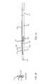
- FIG. 1Ais a side view of an offset catheter with a full rib in a relaxed state according to one embodiment.
- FIG. 1Bis an end view of an offset catheter in a relaxed state according to one embodiment.
- FIG. 2Ais a side view of an offset catheter with a full rib in a compressed state according to one embodiment.
- FIG. 2Bis an end view of an offset catheter in a compressed state according to one embodiment.
- FIG. 3Ais a side view of an offset catheter in a relaxed state according to one embodiment.
- FIG. 3Bis an end view of an offset catheter with a single rib in a relaxed state according to one embodiment.
- FIG. 3Cis an end view of an offset catheter with a double rib in a relaxed state according to one embodiment.
- FIG. 4Ais a side view of an offset catheter in a compressed state according to one embodiment.
- FIG. 4Bis an end view of an offset catheter with a single rib in a compressed state according to one embodiment.
- FIG. 4Cis an end view of an offset catheter with a double rib in a compressed state according to one embodiment.
- FIG. 5Ais a side view of an offset catheter in a relaxed state according to one embodiment.
- FIG. 5Bis an end view of an offset catheter with a roughly rectangular shaped rib in a relaxed state according to one embodiment.
- FIG. 5Cis an end view of an offset catheter with a roughly rectangular shaped rib in a compressed state according to one embodiment.
- FIG. 6Ais a side view of an offset catheter in a relaxed state according to one embodiment.
- FIG. 6Bis an end view of an offset catheter with a roughly rectangular shaped double rib in a relaxed state according to one embodiment.
- FIG. 6Cis an end view of an offset catheter with a roughly rectangular shaped double rib in a compressed state according to one embodiment.
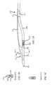
- FIGS. 7A and 7Bshow an offset catheter being introduced into a vessel and the offset catheter positioned within the vessel according to one embodiment.
- FIG. 8shows a flowchart describing the use of an offset catheter according to one embodiment.
- FIG. 9is a side view of an offset catheter in a relaxed state according to one embodiment.
- FIG. 10is a side view of another offset catheter in a relaxed state according to one embodiment.
- an offset catheteris provided that includes a guidewire tube with an inner lumen and a catheter separated by an elastic and collapsible rib in a relaxed state.
- the cathetermay provide aspiration of occlusive material.
- Such cathetersare provided in U.S. patent application Ser. No. 10/832,830, U.S. patent application Ser. No. 11/751,443, and U.S. patent application Ser. No. 11/871,908 each of which are entitled “Thrombectomy and Soft Debris Removal Device” and each of which are incorporated herein for all purposes.
- the catheterin other embodiments, may be a laser catheter.
- the ribmay encompass a portion of the catheter and/or a portion of the guidewire tube.
- the ribmay be triangularly shaped when the rib is in a relaxed (not compressed) state.
- the guidewire tubemay extend along a first triangular edge of the rib and may have an exit aperture, for example, at the apex of the triangle.
- the cathetermay extend along a second triangular edge and may meet at the apex of the triangle.
- a stiffening membermay extend along the second triangular edge instead of the catheter. The stiffening member, for example, may be coupled with the distal tip of the stiffening member.
- the offset cathetermay be collapsed and slid through the sheath of a catheter.
- the collapsible ribmay be collapsed by pinching the guidewire tube together with the catheter or stiffening member.
- the guidewire tube and the catheter or stiffening memberare contiguous and/or somewhat parallel with one another.
- the cathetermay then be slid through a sheath.
- the collapsible ribmay elastically expand separating the distal end of the catheter and the guidewire tube.
- such an arrangementmay allow an aspiration catheter to aspirate debris within a large vessel that is axially distant from the guidewire tube.
- such an arrangementmay also allow a laser catheter to ablate axially distant blockage within a large vessel.
- FIG. 1Ashows a side view of an offset catheter with a full rib 130 in a relaxed state according to one embodiment.
- FIG. 1Bshows an end view of the offset catheter in FIG. 1A along line X-X.
- the offset catheterincludes guidewire tube 110 , catheter 105 , and a distal tip 115 .
- Distal tip 115includes an elastic and/or collapsible rib 130 that, in some embodiments, extends triangularly between distal tip guidewire lumen 120 and distal tip support member 135 (or stiffening member).
- Rib 130may comprise a thermoplastic elastomer (TPE). In other embodiments, rib 130 may include various polymer and non-polymer materials.
- TPEthermoplastic elastomer
- rib 130may also comprise a material that can be stretched or collapsed under stress and, upon the removal of stress, rib 130 will return to substantially close to its original shape. Rib 130 may be collapsed under stress and/or external forces as shown in FIG. 2A . When the stress and/or external forces are released, rib 130 may return to its relaxed state as shown in FIG. 1A . Rib 130 , in some embodiments, may include a spring or any other elastic material that is also compressible.
- Distal tip guidewire lumen 120may include guidewire exit aperture 116 .
- a guidewiremay be introduced into the catheter through guidewire exit aperture 116 .
- the guidewiremay then slide through distal tip guidewire lumen 120 and guidewire tube 110 .
- guidewire tube 110may extend through catheter body 114 and/or extend through a sheath 112 .
- a proximal guidewire lumen 113may also be utilized.
- Guidewire tube 110may comprise a material, such as, for example, polyimide, polyketone, and/or polyetheretherketone (PEEK).
- PEEKpolyetheretherketone
- guidewire tube 110may be carbon fiber reinforced.
- guidewire tube 110may comprise a material with stiffness greater than a guidewire used with the offset catheter and/or greater than the stiffness of a typical guidewire.
- guidewire tube 110in some embodiments, may be manufactured with an elastic material in a curved shaped, for example, as shown in FIG. 1A .
- Distal tip guidewire lumen 120 and guidewire tube 110may return to its curved shape.
- Distal tip guidewire lumen 120may include a radio opaque marker band (not shown) near guidewire exit aperture 116 .
- distal tip 115may comprise a single molded material.
- distal tip 115may include a catheter coupler 133 that couples the distal tin 115 with catheter 105 .
- Catheter 105may include an aspiration catheter, a laser catheter and/or a mechanical catheter.
- FIG. 1Ashows an aspiration catheter that includes one or more aspiration apertures 125 .
- Aspiration apertures 125may be disposed within the distal end of catheter 105 and/or within the circumference or periphery of catheter 105 .
- Catheter 105may also include a macerating head or a cutting head 126 at the distal end of catheter 105 .
- the macerating head or a cutting head 126may include a helical head.
- Catheter 105may comprise an aspiration catheter, for example, as described in U.S. patent application Ser. No. 10/832,830, U.S. patent application Ser. No. 11/751,443, and U.S. patent application Ser. No. 11/871,908 each of which are entitled “Thrombectomy and Soft Debris Removal Device.”
- Catheter 105may include a tubular member or a tube
- Distal tip 115provides lateral separation between guidewire tube 110 and the distal end of catheter 105 in the distal tip's 115 relaxed state.
- distal end of catheter 105may include a radio opaque marker band.
- catheter 105in some embodiments, may be manufactured with an elastic material in a curved shaped, for example, as shown in FIG. 1A . Thus, when catheter 105 is released from being restrained in a straight configuration, catheter 105 returns to its curved shape.
- Catheter 105may include a catheter tubular member, a tube, or a sheath 112 with an inner lumen.
- catheter 105may comprise a laser catheter.
- catheter 105may include one more optical fibers that extend from the proximal end of catheter 105 toward the distal end of catheter 105 within the inner lumen.
- a laser couplermay be coupled with the catheter at the proximal end of catheter 105 .
- the laser couplermay be coupled with a laser.
- catheter 105may include a liquid light guide. In other embodiments, catheter 105 may include both a liquid light guide and one or more optical fibers.
- FIG. 2Ashows a side view of an offset catheter with a full rib 130 in a compressed state according to one embodiment.
- FIG. 2Bshows the end view of the offset catheter in FIG. 2A along line X-X.
- distal tip 115is compressed by forcibly compressing and/or pinching distal tip guidewire lumen 120 and distal tip support member 135 together.
- rib 130is folded or bunched together as shown in FIG. 2B .
- the offset cathetermay slidably fit within a sheath 112 .
- an offset cathetermay be compressed (for example, as shown in FIG.
- distal tip 115may be introduced into sheath 112 or any other lumen, and due to its triangular shape the rib may collapse allowing the offset catheter to slide within the sheath 112 .
- the distal tipmay return to its relaxed shape as shown in FIG. 1A .
- a secondary sheathmay also be employed in some embodiments.
- a secondary sheathmay slide relative to the offset catheter and may be used to collapse the offset catheter.
- the secondary sheathmay be used to collapse the collapsible rib during introduction of the catheter into lumen or sheath 112 .
- the secondary sheathmay also be used when the offset catheter is located within a vessel to collapse the offset catheter in order to move the offset catheter through a narrower stenosis or a portion of the vessel with a smaller inner diameter. Accordingly, the user may be able to move the secondary sheath relative to the offset catheter to collapse the offset catheter when in use.
- FIG. 3Ais a side view of an offset catheter in a relaxed state according to another embodiment.
- FIG. 3Bshows the end view of the offset catheter in FIG. 3A along line X-X with a single rib.
- FIG. 3Cshows the end view of the offset catheter in FIG. 3A along line X-X with a double rib.
- rib 305is not triangular shaped as shown in FIG. 1A ; and rib 305 is not in full contact with distal tip guidewire lumen 120 and/or distal tip support member 135 as shown in FIG. 1A .
- rib 305may be a single rib (as shown in FIG.
- a double ribmay be coupled with the periphery of the distal tip guidewire lumen 120 and distal tip support member 135 .
- FIG. 4Ashows a side view of an offset catheter with a partial rib in a compressed state.
- FIG. 4Bshows an end view of the compressed offset catheter in FIG. 4A with a single rib and
- FIG. 4Cshows an end view of the compressed offset catheter in FIG. 4A with a double rib.
- one or two ribsmay be coupled with the side of either or both of distal tip guidewire lumen 120 and/or distal tip support member 135 .
- FIG. 5Ashows a side view of an offset catheter with a full rectangular rib 530 in a relaxed state according to one embodiment.
- FIG. 5Bshows an end view of the offset catheter in FIG. 5A along line X-X in a relaxed state
- FIG. 5Cshows another end view of the offset catheter in FIG. 5A along line X-X in a compressed state.
- rib 530may be roughly rectangular shaped.
- distal tip 515does not include a distal tip support member. Rather, rib 530 is coupled with distal tip guidewire lumen 520 and catheter 505 . Accordingly, rib 530 provides separation between the distal end of distal tip guidewire lumen 520 and the distal end of catheter 505 .
- catheter 505may include a laser catheter comprising, for example, a fiber optic bundle that extends to distal end 516 .
- Catheter 135 as shown in FIGS. 5B and 56comprises a laser catheter with a plurality of optical fibers 516 .
- Rib 530may comprise a thermoplastic elastomer (TPE).
- TPEthermoplastic elastomer
- rib 530may include various polymer and non-polymer materials.
- rib 530may also comprise a material that can be stretched or collapsed under stress and, upon the removal of stress, return to substantially close to its original shape. Rib 530 may be collapsed under stress and/or external forces. When the stress and/or external forces are released, rib 530 may return to its relaxed state.
- FIGS. 6A, 6B and 6Cshow various views of an offset catheter similar to the offset catheter shown in FIGS. 5A, 5B and 5C , but with two ribs 630 and 635 .
- Rib 630is located near the distal ends of distal tip guidewire lumen 120 and distal tip support member 135 .
- FIG. 7Ashows an offset catheter with a collapsed elastic rib 705 disposed between a guidewire lumen in a distal tip or a guidewire tube 715 and a distal tip support member.
- the offset catheteris shown within a lumen of a sheath or elongated body 720 .
- catheter 710 and guidewire tubeare roughly proximate with each other within the sheath 720 .
- Sheath 720may be advanced within vessel 730 with the offset catheter inside. The sheath may follow guidewire 725 . Once in position, the offset catheter may be advanced from within sheath 720 as shown in FIG. 7B . Once elastic rib 705 has exited sheath 720 , rib 705 returns to its relaxed state.
- the offset affected by rib 705 in the relaxed statemay provide some force against the material to be removed.
- a rotary aspiration cathetermay increase performance when the catheter is pressed against the material being removed.
- the offsetmay provide positive tool pressure against the material being removed thereby maintaining engagement with the material being removed and increasing the effectiveness of the aspiration.
- the offset cathetermay be advanced within vessel 730 .
- offset cathetermay be reintroduced within sheath 720 by sliding the offset catheter backwards into sheath 720 . In doing so, the offset catheter returns to it collapsed state.
- FIG. 8shows describes a method of operating an offset catheter according to another embodiment.
- a guidewireis fed through the guidewire tube at block 805 .
- the guidewiremay first be fed through the guidewire lumen of an elastic distal tip.
- guidewiremay also be fed into the guidewire tube while the offset catheter is housed within or without a sheath.
- the guidewire tube and the catheterare placed in a collapsed state by pinching the two together at block 810 . In doing so, a rib between the two may be elastically collapsed.
- the offset cathetermay then be slid through a sheath at block 815 .
- the offset cathetermay then exit the proximal end of the sheath, whereupon the offset catheter and/or distal tip return to a relaxed state at block 820 .
- Elastic material in the distal tip, the rib, the catheter, and/or the guidewire tubemay provide the requisite force to return the offset catheter to its relaxed state.
- the cathetermay then be operated at block 825 .
- a laser catheteris activated.
- an aspiration catheteris used.
- the offset cathetermay be advanced independent and/or with the sheath as needed.
- the offset cathetermay be rotated about the offset catheter's central axis.
- distal tipmay be rotated about the catheter guidewire tube's central axis.
- the usermay apply a torque at the proximal end of the working catheter that causes the distal tip to rotate axially.
- FIG. 9shows another offset catheter providing separation between the distal end of a working catheter 105 and guidewire lumen 120 and/or guidewire tube 110 in a relaxed state according to another embodiment.
- a spring member 131coupled with guidewire lumen 120 of distal tip 115 and/or distal tip support member 135 .
- spring member 131is coupled with working catheter 105 and/or guidewire tube 110 .
- spring member 131may be comprised of flat or round wire.
- spring member 131may be embedded within distal tip 115 .
- the spring member 131may have a higher melting point than distal tip 115 so that spring member 131 may be insert molded into distal tip 115 .
- Spring member 131may bias guidewire lumen 120 of distal tip 115 and distal tip support member 135 by exerting a separation force.
- FIG. 10shows another configuration of an offset catheter according to another embodiment.
- rib 132is oriented in the relaxed state such that when collapsed, rib 132 lays flat proximate with distal tip support member 135 .
Landscapes
- Health & Medical Sciences (AREA)
- Life Sciences & Earth Sciences (AREA)
- General Health & Medical Sciences (AREA)
- Heart & Thoracic Surgery (AREA)
- Veterinary Medicine (AREA)
- Public Health (AREA)
- Animal Behavior & Ethology (AREA)
- Engineering & Computer Science (AREA)
- Biomedical Technology (AREA)
- Surgery (AREA)
- Physics & Mathematics (AREA)
- Biophysics (AREA)
- Pulmonology (AREA)
- Anesthesiology (AREA)
- Hematology (AREA)
- Medical Informatics (AREA)
- Molecular Biology (AREA)
- Nuclear Medicine, Radiotherapy & Molecular Imaging (AREA)
- Otolaryngology (AREA)
- Electromagnetism (AREA)
- Optics & Photonics (AREA)
- Vascular Medicine (AREA)
- Media Introduction/Drainage Providing Device (AREA)
Abstract
Description
Claims (16)
Priority Applications (3)
| Application Number | Priority Date | Filing Date | Title |
|---|---|---|---|
| US12/333,427US9408665B2 (en) | 2008-12-12 | 2008-12-12 | Offset catheter |
| PCT/US2009/065556WO2010068409A1 (en) | 2008-12-12 | 2009-11-23 | Offset catheter |
| US15/230,148US9931166B2 (en) | 2008-12-12 | 2016-08-05 | Offset catheter |
Applications Claiming Priority (1)
| Application Number | Priority Date | Filing Date | Title |
|---|---|---|---|
| US12/333,427US9408665B2 (en) | 2008-12-12 | 2008-12-12 | Offset catheter |
Related Child Applications (1)
| Application Number | Title | Priority Date | Filing Date |
|---|---|---|---|
| US15/230,148ContinuationUS9931166B2 (en) | 2008-12-12 | 2016-08-05 | Offset catheter |
Publications (2)
| Publication Number | Publication Date |
|---|---|
| US20100152720A1 US20100152720A1 (en) | 2010-06-17 |
| US9408665B2true US9408665B2 (en) | 2016-08-09 |
Family
ID=42241437
Family Applications (2)
| Application Number | Title | Priority Date | Filing Date |
|---|---|---|---|
| US12/333,427Expired - Fee RelatedUS9408665B2 (en) | 2008-12-12 | 2008-12-12 | Offset catheter |
| US15/230,148Expired - Fee RelatedUS9931166B2 (en) | 2008-12-12 | 2016-08-05 | Offset catheter |
Family Applications After (1)
| Application Number | Title | Priority Date | Filing Date |
|---|---|---|---|
| US15/230,148Expired - Fee RelatedUS9931166B2 (en) | 2008-12-12 | 2016-08-05 | Offset catheter |
Country Status (2)
| Country | Link |
|---|---|
| US (2) | US9408665B2 (en) |
| WO (1) | WO2010068409A1 (en) |
Cited By (5)
| Publication number | Priority date | Publication date | Assignee | Title |
|---|---|---|---|---|
| US10772683B2 (en) | 2014-05-18 | 2020-09-15 | Eximo Medical Ltd. | System for tissue ablation using pulsed laser |
| US11576724B2 (en) | 2011-02-24 | 2023-02-14 | Eximo Medical Ltd. | Hybrid catheter for vascular intervention |
| US11684420B2 (en) | 2016-05-05 | 2023-06-27 | Eximo Medical Ltd. | Apparatus and methods for resecting and/or ablating an undesired tissue |
| US12038322B2 (en) | 2022-06-21 | 2024-07-16 | Eximo Medical Ltd. | Devices and methods for testing ablation systems |
| US12376904B1 (en) | 2020-09-08 | 2025-08-05 | Angiodynamics, Inc. | Dynamic laser stabilization and calibration system |
Families Citing this family (19)
| Publication number | Priority date | Publication date | Assignee | Title |
|---|---|---|---|---|
| US9700655B2 (en) | 2011-10-14 | 2017-07-11 | Ra Medical Systems, Inc. | Small flexible liquid core catheter for laser ablation in body lumens and methods for use |
| US9320530B2 (en) | 2013-03-13 | 2016-04-26 | The Spectranetics Corporation | Assisted cutting balloon |
| US10842567B2 (en) | 2013-03-13 | 2020-11-24 | The Spectranetics Corporation | Laser-induced fluid filled balloon catheter |
| US10201387B2 (en) | 2013-03-13 | 2019-02-12 | The Spectranetics Corporation | Laser-induced fluid filled balloon catheter |
| US9962527B2 (en) | 2013-10-16 | 2018-05-08 | Ra Medical Systems, Inc. | Methods and devices for treatment of stenosis of arteriovenous fistula shunts |
| EP3139989A4 (en)* | 2014-05-08 | 2017-05-17 | Eximo Medical Ltd. | Methods for deflecting catheters |
| US11246659B2 (en) | 2014-08-25 | 2022-02-15 | The Spectranetics Corporation | Liquid laser-induced pressure wave emitting catheter sheath |
| EP3240603B1 (en) | 2014-12-30 | 2019-05-01 | The Spectranetics Corporation | Laser-induced fluid filled balloon catheter |
| US11058492B2 (en) | 2014-12-30 | 2021-07-13 | The Spectranetics Corporation | Laser-induced pressure wave emitting catheter sheath |
| WO2016109739A1 (en) | 2014-12-30 | 2016-07-07 | The Spectranetics Corporation | Electrically-induced pressure wave emitting catheter sheath |
| US10555772B2 (en) | 2015-11-23 | 2020-02-11 | Ra Medical Systems, Inc. | Laser ablation catheters having expanded distal tip windows for efficient tissue ablation |
| JP2019166289A (en) | 2018-03-22 | 2019-10-03 | ラ メディカル システムズ, インコーポレイテッド | Liquid filled ablation catheter with overjacket |
| US11484366B2 (en)* | 2018-11-29 | 2022-11-01 | Acclarent, Inc. | Adapter assembly to enable navigation for ENT instruments |
| US20230089786A1 (en)* | 2020-02-24 | 2023-03-23 | Ra Medical Systems, Inc. | Laser ablation catheter with outer jacket support |
| US11679195B2 (en) | 2021-04-27 | 2023-06-20 | Contego Medical, Inc. | Thrombus aspiration system and methods for controlling blood loss |
| JP2024518961A (en) | 2021-06-07 | 2024-05-08 | アバンテック バスキュラー コーポレイション | Hybrid Atherectomy Device |
| US11883616B2 (en) | 2021-07-07 | 2024-01-30 | Mekal, LLC | Multi-lumen intravascular catheters with inner converging lumens for multiple guidewire control |
| US12220140B1 (en) | 2023-08-16 | 2025-02-11 | Avantec Vascular Corporation | Thrombectomy devices with lateral and vertical bias |
| US12414785B1 (en) | 2025-03-17 | 2025-09-16 | Avantec Vascular Corporation | Cutters with pulsating vacuum control |
Citations (80)
| Publication number | Priority date | Publication date | Assignee | Title |
|---|---|---|---|---|
| US3906957A (en)* | 1973-04-24 | 1975-09-23 | Ici Ltd | Forceps |
| US4053845A (en) | 1967-03-06 | 1977-10-11 | Gordon Gould | Optically pumped laser amplifiers |
| US4217904A (en) | 1977-03-25 | 1980-08-19 | Zahorsky Carroll L | Drain construction |
| US4641912A (en) | 1984-12-07 | 1987-02-10 | Tsvi Goldenberg | Excimer laser delivery system, angioscope and angioplasty system incorporating the delivery system and angioscope |
| US4686979A (en) | 1984-01-09 | 1987-08-18 | The United States Of America As Represented By The United States Department Of Energy | Excimer laser phototherapy for the dissolution of abnormal growth |
| US4732448A (en) | 1984-12-07 | 1988-03-22 | Advanced Interventional Systems, Inc. | Delivery system for high-energy pulsed ultraviolet laser light |
| US4735606A (en) | 1982-10-12 | 1988-04-05 | Sherwood Medical Company | Chest drainage apparatus |
| US4747405A (en) | 1984-03-01 | 1988-05-31 | Vaser, Inc. | Angioplasty catheter |
| US4748982A (en) | 1987-01-06 | 1988-06-07 | Advanced Cardiovascular Systems, Inc. | Reinforced balloon dilatation catheter with slitted exchange sleeve and method |
| US4772268A (en) | 1984-05-25 | 1988-09-20 | Cook Incorporated | Two lumen hemodialysis catheter |
| US4784132A (en) | 1983-03-25 | 1988-11-15 | Fox Kenneth R | Method of and apparatus for laser treatment of body lumens |
| US4794931A (en) | 1986-02-28 | 1989-01-03 | Cardiovascular Imaging Systems, Inc. | Catheter apparatus, system and method for intravascular two-dimensional ultrasonography |
| US4799754A (en) | 1985-09-25 | 1989-01-24 | Advanced Interventional Systems, Inc. | Delivery system for high-energy pulsed ultraviolet laser light |
| US4807620A (en) | 1987-05-22 | 1989-02-28 | Advanced Interventional Systems, Inc. | Apparatus for thermal angioplasty |
| US4830460A (en) | 1987-05-19 | 1989-05-16 | Advanced Interventional Systems, Inc. | Guidance system and method for delivery system for high-energy pulsed ultraviolet laser light |
| US4834093A (en) | 1986-02-03 | 1989-05-30 | Littleford Phillip O | Dilation catheter and method |
| US4842582A (en) | 1985-02-12 | 1989-06-27 | Mahurkar Sakharam D | Method and apparatus for using dual-lumen catheters for extracorporeal treatment |
| US4844062A (en) | 1987-10-23 | 1989-07-04 | Spectranetics Corporation | Rotating fiberoptic laser catheter assembly with eccentric lumen |
| US4848336A (en) | 1981-12-11 | 1989-07-18 | Fox Kenneth R | Apparatus for laser treatment of body lumens |
| US4899363A (en) | 1987-07-23 | 1990-02-06 | The Spectranetics Corporation | Gas bearings for gas lasers |
| US4919508A (en) | 1988-08-04 | 1990-04-24 | The Spectranetics Corporation | Fiberoptic coupler |
| US4924863A (en) | 1988-05-04 | 1990-05-15 | Mmtc, Inc. | Angioplastic method for removing plaque from a vas |
| US4961809A (en) | 1988-04-21 | 1990-10-09 | Vas-Cath Incorporated | Method of producing a dual lumen catheter including forming a flare |
| US4998794A (en) | 1989-10-27 | 1991-03-12 | The Spectranetics Corporation | Meniscus lens for coupling an excimer beam into an optical fiber |
| US5016964A (en) | 1989-10-04 | 1991-05-21 | Spectranetics Corporation | Optical fiber coupler with linear input |
| US5024234A (en) | 1989-10-17 | 1991-06-18 | Cardiovascular Imaging Systems, Inc. | Ultrasonic imaging catheter with guidewire channel |
| US5041108A (en) | 1981-12-11 | 1991-08-20 | Pillco Limited Partnership | Method for laser treatment of body lumens |
| US5054492A (en) | 1990-12-17 | 1991-10-08 | Cardiovascular Imaging Systems, Inc. | Ultrasonic imaging catheter having rotational image correlation |
| US5054500A (en) | 1989-04-13 | 1991-10-08 | Littleford Philip O | Catheter guiding and positioning method |
| US5057073A (en) | 1988-04-21 | 1991-10-15 | Vas-Cath Incorporated | Dual lumen catheter |
| US5165773A (en) | 1990-08-01 | 1992-11-24 | Genther Nath | Flexible light guide having a liquid core and illuminating device including a light guide of this type |
| US5179961A (en) | 1989-04-13 | 1993-01-19 | Littleford Philip O | Catheter guiding and positioning method |
| US5188632A (en) | 1984-12-07 | 1993-02-23 | Advanced Interventional Systems, Inc. | Guidance and delivery system for high-energy pulsed laser light |
| US5203338A (en) | 1990-12-17 | 1993-04-20 | Cardiovascular Imaging Systems, Inc. | Vascular catheter having low-profile distal end |
| US5250045A (en) | 1991-06-11 | 1993-10-05 | The Spectranetics Corporation | Optical fiber catheter with spaced optical fiber |
| US5263952A (en) | 1992-03-25 | 1993-11-23 | Spectranetics | Two-piece tip for fiber optic catheter |
| US5267341A (en) | 1991-10-30 | 1993-11-30 | Baxter International Inc. | Fluid catheter with aqueous fluid core and method of use |
| US5304171A (en) | 1990-10-18 | 1994-04-19 | Gregory Kenton W | Catheter devices and methods for delivering |
| US5315614A (en) | 1993-05-03 | 1994-05-24 | The Spectranetics Corporation | Apparatus and method for soft focusing energy into an optical fiber array |
| US5321783A (en) | 1992-06-16 | 1994-06-14 | Spectranetics Corporation | Mount for optical fibers |
| US5339441A (en) | 1992-07-02 | 1994-08-16 | Advanced Intervention Systems, Inc. | Polarizing device with optically contacted thin film interface for high power density ultraviolet light |
| US5350375A (en) | 1993-03-15 | 1994-09-27 | Yale University | Methods for laser induced fluorescence intensity feedback control during laser angioplasty |
| US5352197A (en) | 1992-03-18 | 1994-10-04 | The Spectranetics Corporation | Turn limiter for a catheter with twistable tip |
| US5383199A (en) | 1992-07-02 | 1995-01-17 | Advanced Interventional Systems, Inc. | Apparatus and method for optically controlling the output energy of a pulsed laser source |
| US5400428A (en) | 1992-05-13 | 1995-03-21 | Spectranetics Corporation | Method and apparatus for linearly scanning energy over an optical fiber array and coupler for coupling energy to the optical fiber array |
| US5412682A (en) | 1994-03-31 | 1995-05-02 | Advanced Interventional Systems, Inc. | Halogen compatible laser head |
| US5415653A (en) | 1992-08-26 | 1995-05-16 | Advanced Interventional Systems, Inc. | Optical catheter with stranded fibers |
| US5429604A (en) | 1992-03-18 | 1995-07-04 | Spectranetics Corporation | Fiber optic catheter with twistable tip |
| US5429617A (en) | 1993-12-13 | 1995-07-04 | The Spectranetics Corporation | Radiopaque tip marker for alignment of a catheter within a body |
| US5438587A (en) | 1994-03-31 | 1995-08-01 | Spectranetics | Preionizer for laser assembly |
| US5440664A (en) | 1994-01-13 | 1995-08-08 | Rutgers, The State University Of New Jersey | Coherent, flexible, coated-bore hollow-fiber waveguide |
| US5456680A (en) | 1993-09-14 | 1995-10-10 | Spectranetics Corp | Fiber optic catheter with shortened guide wire lumen |
| US5470330A (en) | 1984-12-07 | 1995-11-28 | Advanced Interventional Systems, Inc. | Guidance and delivery system for high-energy pulsed laser light |
| US5484433A (en) | 1993-12-30 | 1996-01-16 | The Spectranetics Corporation | Tissue ablating device having a deflectable ablation area and method of using same |
| US5514128A (en) | 1992-08-18 | 1996-05-07 | Spectranetics Corporation | Fiber optic guide wire and support catheter therefor |
| US5555883A (en)* | 1992-02-24 | 1996-09-17 | Avitall; Boaz | Loop electrode array mapping and ablation catheter for cardiac chambers |
| US5571151A (en) | 1994-10-25 | 1996-11-05 | Gregory; Kenton W. | Method for contemporaneous application of laser energy and localized pharmacologic therapy |
| US5573531A (en) | 1994-06-20 | 1996-11-12 | Gregory; Kenton W. | Fluid core laser angioscope |
| US5623940A (en) | 1994-08-02 | 1997-04-29 | S.L.T. Japan Co., Ltd. | Catheter apparatus with a sensor |
| US5649923A (en) | 1988-10-24 | 1997-07-22 | The General Hospital Corporation | Catheter devices for delivering laser energy |
| US5722972A (en) | 1993-08-12 | 1998-03-03 | Power; John A. | Method and apparatus for ablation of atherosclerotic blockage |
| US5737473A (en) | 1995-05-17 | 1998-04-07 | Nath; Guenther | Light guide having a flexible plastic tube filled with an aqueous salt solution |
| US5817144A (en) | 1994-10-25 | 1998-10-06 | Latis, Inc. | Method for contemporaneous application OF laser energy and localized pharmacologic therapy |
| US5824026A (en) | 1996-06-12 | 1998-10-20 | The Spectranetics Corporation | Catheter for delivery of electric energy and a process for manufacturing same |
| US5836940A (en) | 1994-10-25 | 1998-11-17 | Latis, Inc. | Photoacoustic drug delivery |
| US5840076A (en)* | 1996-04-12 | 1998-11-24 | Ep Technologies, Inc. | Tissue heating and ablation systems and methods using electrode structures with distally oriented porous regions |
| US5859946A (en) | 1997-06-27 | 1999-01-12 | Southeastern Univ. Research Assn. | Liquid-core light guide designed to withstand interior bubble formation from temperature-induced volumetric variations |
| USRE36104E (en) | 1992-10-30 | 1999-02-16 | Cordis Corporation | Dilation catheter with eccentric balloon |
| US5976124A (en) | 1998-01-05 | 1999-11-02 | Spectranetics Corporation | Phototherapy device and method |
| US5989243A (en) | 1984-12-07 | 1999-11-23 | Advanced Interventional Systems, Inc. | Excimer laser angioplasty system |
| US6117128A (en) | 1997-04-30 | 2000-09-12 | Kenton W. Gregory | Energy delivery catheter and method for the use thereof |
| US6290668B1 (en) | 1998-04-30 | 2001-09-18 | Kenton W. Gregory | Light delivery catheter and methods for the use thereof |
| US6314226B1 (en) | 1997-02-28 | 2001-11-06 | NATH GüNTHER | Flexible lightguide with a liquid core |
| US6418257B1 (en) | 1997-12-15 | 2002-07-09 | Gunther Nath | UVC liquid light guide |
| US6458098B1 (en) | 2000-03-17 | 2002-10-01 | Nozomu Kanesaka | Vascular therapy device |
| US6743208B1 (en) | 2003-06-19 | 2004-06-01 | Medtronic Vascular, Inc | Occlusion balloon catheter with distal valve |
| US20050240146A1 (en) | 2004-04-27 | 2005-10-27 | Nash John E | Thrombectomy and soft debris removal device |
| US7050692B2 (en) | 2002-03-29 | 2006-05-23 | The Spectranetics Corporation | Proximal coupler for optical fibers |
| US20060167442A1 (en)* | 2004-09-17 | 2006-07-27 | Hebert Chris J | Apparatus and methods for directional delivery of laser energy |
| US20080097499A1 (en)* | 2004-04-27 | 2008-04-24 | Nash John E | Thrombectomy and soft debris removal device |
Family Cites Families (3)
| Publication number | Priority date | Publication date | Assignee | Title |
|---|---|---|---|---|
| US5263953A (en)* | 1991-12-31 | 1993-11-23 | Spine-Tech, Inc. | Apparatus and system for fusing bone joints |
| US5571087A (en)* | 1992-02-10 | 1996-11-05 | Scimed Life Systems, Inc. | Intravascular catheter with distal tip guide wire lumen |
| JP3144710U (en)* | 2008-06-27 | 2008-09-11 | 有限会社オールウエイズ | Chopstick aid |
- 2008
- 2008-12-12USUS12/333,427patent/US9408665B2/ennot_activeExpired - Fee Related
- 2009
- 2009-11-23WOPCT/US2009/065556patent/WO2010068409A1/enactiveApplication Filing
- 2016
- 2016-08-05USUS15/230,148patent/US9931166B2/ennot_activeExpired - Fee Related
Patent Citations (88)
| Publication number | Priority date | Publication date | Assignee | Title |
|---|---|---|---|---|
| US4053845A (en) | 1967-03-06 | 1977-10-11 | Gordon Gould | Optically pumped laser amplifiers |
| US4053845B1 (en) | 1967-03-06 | 1987-04-28 | ||
| US3906957A (en)* | 1973-04-24 | 1975-09-23 | Ici Ltd | Forceps |
| US4217904A (en) | 1977-03-25 | 1980-08-19 | Zahorsky Carroll L | Drain construction |
| US5041108A (en) | 1981-12-11 | 1991-08-20 | Pillco Limited Partnership | Method for laser treatment of body lumens |
| US4848336A (en) | 1981-12-11 | 1989-07-18 | Fox Kenneth R | Apparatus for laser treatment of body lumens |
| US4735606A (en) | 1982-10-12 | 1988-04-05 | Sherwood Medical Company | Chest drainage apparatus |
| US4784132B1 (en) | 1983-03-25 | 1990-03-13 | R Fox Kenneth | |
| US4784132A (en) | 1983-03-25 | 1988-11-15 | Fox Kenneth R | Method of and apparatus for laser treatment of body lumens |
| US4686979A (en) | 1984-01-09 | 1987-08-18 | The United States Of America As Represented By The United States Department Of Energy | Excimer laser phototherapy for the dissolution of abnormal growth |
| US4747405A (en) | 1984-03-01 | 1988-05-31 | Vaser, Inc. | Angioplasty catheter |
| US4772268A (en) | 1984-05-25 | 1988-09-20 | Cook Incorporated | Two lumen hemodialysis catheter |
| US4732448A (en) | 1984-12-07 | 1988-03-22 | Advanced Interventional Systems, Inc. | Delivery system for high-energy pulsed ultraviolet laser light |
| US5188632A (en) | 1984-12-07 | 1993-02-23 | Advanced Interventional Systems, Inc. | Guidance and delivery system for high-energy pulsed laser light |
| US4641912A (en) | 1984-12-07 | 1987-02-10 | Tsvi Goldenberg | Excimer laser delivery system, angioscope and angioplasty system incorporating the delivery system and angioscope |
| US5989243A (en) | 1984-12-07 | 1999-11-23 | Advanced Interventional Systems, Inc. | Excimer laser angioplasty system |
| US5470330A (en) | 1984-12-07 | 1995-11-28 | Advanced Interventional Systems, Inc. | Guidance and delivery system for high-energy pulsed laser light |
| US4842582A (en) | 1985-02-12 | 1989-06-27 | Mahurkar Sakharam D | Method and apparatus for using dual-lumen catheters for extracorporeal treatment |
| US4799754A (en) | 1985-09-25 | 1989-01-24 | Advanced Interventional Systems, Inc. | Delivery system for high-energy pulsed ultraviolet laser light |
| US4834093A (en) | 1986-02-03 | 1989-05-30 | Littleford Phillip O | Dilation catheter and method |
| US4794931A (en) | 1986-02-28 | 1989-01-03 | Cardiovascular Imaging Systems, Inc. | Catheter apparatus, system and method for intravascular two-dimensional ultrasonography |
| US4748982A (en) | 1987-01-06 | 1988-06-07 | Advanced Cardiovascular Systems, Inc. | Reinforced balloon dilatation catheter with slitted exchange sleeve and method |
| US4830460A (en) | 1987-05-19 | 1989-05-16 | Advanced Interventional Systems, Inc. | Guidance system and method for delivery system for high-energy pulsed ultraviolet laser light |
| US4807620A (en) | 1987-05-22 | 1989-02-28 | Advanced Interventional Systems, Inc. | Apparatus for thermal angioplasty |
| US4899363A (en) | 1987-07-23 | 1990-02-06 | The Spectranetics Corporation | Gas bearings for gas lasers |
| US4844062A (en) | 1987-10-23 | 1989-07-04 | Spectranetics Corporation | Rotating fiberoptic laser catheter assembly with eccentric lumen |
| US4961809A (en) | 1988-04-21 | 1990-10-09 | Vas-Cath Incorporated | Method of producing a dual lumen catheter including forming a flare |
| US5057073A (en) | 1988-04-21 | 1991-10-15 | Vas-Cath Incorporated | Dual lumen catheter |
| US4924863A (en) | 1988-05-04 | 1990-05-15 | Mmtc, Inc. | Angioplastic method for removing plaque from a vas |
| US5267993A (en) | 1988-08-04 | 1993-12-07 | The Spectranetics Corporation | Fiberoptic coupler |
| US5157750A (en) | 1988-08-04 | 1992-10-20 | The Spectranetics Corporation | Fiberoptic coupler for coupling an optical fiber to a laser light source |
| US4919508A (en) | 1988-08-04 | 1990-04-24 | The Spectranetics Corporation | Fiberoptic coupler |
| US5649923A (en) | 1988-10-24 | 1997-07-22 | The General Hospital Corporation | Catheter devices for delivering laser energy |
| US6066130A (en) | 1988-10-24 | 2000-05-23 | The General Hospital Corporation | Delivering laser energy |
| US5054500A (en) | 1989-04-13 | 1991-10-08 | Littleford Philip O | Catheter guiding and positioning method |
| US5179961A (en) | 1989-04-13 | 1993-01-19 | Littleford Philip O | Catheter guiding and positioning method |
| US5016964A (en) | 1989-10-04 | 1991-05-21 | Spectranetics Corporation | Optical fiber coupler with linear input |
| US5024234A (en) | 1989-10-17 | 1991-06-18 | Cardiovascular Imaging Systems, Inc. | Ultrasonic imaging catheter with guidewire channel |
| US4998794A (en) | 1989-10-27 | 1991-03-12 | The Spectranetics Corporation | Meniscus lens for coupling an excimer beam into an optical fiber |
| US5165773A (en) | 1990-08-01 | 1992-11-24 | Genther Nath | Flexible light guide having a liquid core and illuminating device including a light guide of this type |
| US5304171A (en) | 1990-10-18 | 1994-04-19 | Gregory Kenton W | Catheter devices and methods for delivering |
| US5054492A (en) | 1990-12-17 | 1991-10-08 | Cardiovascular Imaging Systems, Inc. | Ultrasonic imaging catheter having rotational image correlation |
| US5203338A (en) | 1990-12-17 | 1993-04-20 | Cardiovascular Imaging Systems, Inc. | Vascular catheter having low-profile distal end |
| US5250045A (en) | 1991-06-11 | 1993-10-05 | The Spectranetics Corporation | Optical fiber catheter with spaced optical fiber |
| US5267341A (en) | 1991-10-30 | 1993-11-30 | Baxter International Inc. | Fluid catheter with aqueous fluid core and method of use |
| US5555883A (en)* | 1992-02-24 | 1996-09-17 | Avitall; Boaz | Loop electrode array mapping and ablation catheter for cardiac chambers |
| US5429604A (en) | 1992-03-18 | 1995-07-04 | Spectranetics Corporation | Fiber optic catheter with twistable tip |
| US5352197A (en) | 1992-03-18 | 1994-10-04 | The Spectranetics Corporation | Turn limiter for a catheter with twistable tip |
| US5263952A (en) | 1992-03-25 | 1993-11-23 | Spectranetics | Two-piece tip for fiber optic catheter |
| US5400428A (en) | 1992-05-13 | 1995-03-21 | Spectranetics Corporation | Method and apparatus for linearly scanning energy over an optical fiber array and coupler for coupling energy to the optical fiber array |
| US5321783A (en) | 1992-06-16 | 1994-06-14 | Spectranetics Corporation | Mount for optical fibers |
| US5339441A (en) | 1992-07-02 | 1994-08-16 | Advanced Intervention Systems, Inc. | Polarizing device with optically contacted thin film interface for high power density ultraviolet light |
| US5383199A (en) | 1992-07-02 | 1995-01-17 | Advanced Interventional Systems, Inc. | Apparatus and method for optically controlling the output energy of a pulsed laser source |
| US5643251A (en) | 1992-08-18 | 1997-07-01 | Spectranetics Corporation | Fibert optic guide wire and support catheter therefor |
| US5514128A (en) | 1992-08-18 | 1996-05-07 | Spectranetics Corporation | Fiber optic guide wire and support catheter therefor |
| US5415653A (en) | 1992-08-26 | 1995-05-16 | Advanced Interventional Systems, Inc. | Optical catheter with stranded fibers |
| USRE36104E (en) | 1992-10-30 | 1999-02-16 | Cordis Corporation | Dilation catheter with eccentric balloon |
| US5350375A (en) | 1993-03-15 | 1994-09-27 | Yale University | Methods for laser induced fluorescence intensity feedback control during laser angioplasty |
| US5315614A (en) | 1993-05-03 | 1994-05-24 | The Spectranetics Corporation | Apparatus and method for soft focusing energy into an optical fiber array |
| US5722972A (en) | 1993-08-12 | 1998-03-03 | Power; John A. | Method and apparatus for ablation of atherosclerotic blockage |
| US5456680A (en) | 1993-09-14 | 1995-10-10 | Spectranetics Corp | Fiber optic catheter with shortened guide wire lumen |
| US5429617A (en) | 1993-12-13 | 1995-07-04 | The Spectranetics Corporation | Radiopaque tip marker for alignment of a catheter within a body |
| US5484433A (en) | 1993-12-30 | 1996-01-16 | The Spectranetics Corporation | Tissue ablating device having a deflectable ablation area and method of using same |
| US5440664A (en) | 1994-01-13 | 1995-08-08 | Rutgers, The State University Of New Jersey | Coherent, flexible, coated-bore hollow-fiber waveguide |
| US5412682A (en) | 1994-03-31 | 1995-05-02 | Advanced Interventional Systems, Inc. | Halogen compatible laser head |
| US5438587A (en) | 1994-03-31 | 1995-08-01 | Spectranetics | Preionizer for laser assembly |
| US5573531A (en) | 1994-06-20 | 1996-11-12 | Gregory; Kenton W. | Fluid core laser angioscope |
| US5623940A (en) | 1994-08-02 | 1997-04-29 | S.L.T. Japan Co., Ltd. | Catheter apparatus with a sensor |
| US5817144A (en) | 1994-10-25 | 1998-10-06 | Latis, Inc. | Method for contemporaneous application OF laser energy and localized pharmacologic therapy |
| US5836940A (en) | 1994-10-25 | 1998-11-17 | Latis, Inc. | Photoacoustic drug delivery |
| US5571151A (en) | 1994-10-25 | 1996-11-05 | Gregory; Kenton W. | Method for contemporaneous application of laser energy and localized pharmacologic therapy |
| US5737473A (en) | 1995-05-17 | 1998-04-07 | Nath; Guenther | Light guide having a flexible plastic tube filled with an aqueous salt solution |
| US5840076A (en)* | 1996-04-12 | 1998-11-24 | Ep Technologies, Inc. | Tissue heating and ablation systems and methods using electrode structures with distally oriented porous regions |
| US5836946A (en) | 1996-06-12 | 1998-11-17 | The Spectranetics Corporation | Catheter for delivery of electric energy and a process for manufacturing same |
| US5824026A (en) | 1996-06-12 | 1998-10-20 | The Spectranetics Corporation | Catheter for delivery of electric energy and a process for manufacturing same |
| US6314226B1 (en) | 1997-02-28 | 2001-11-06 | NATH GüNTHER | Flexible lightguide with a liquid core |
| US6117128A (en) | 1997-04-30 | 2000-09-12 | Kenton W. Gregory | Energy delivery catheter and method for the use thereof |
| US5859946A (en) | 1997-06-27 | 1999-01-12 | Southeastern Univ. Research Assn. | Liquid-core light guide designed to withstand interior bubble formation from temperature-induced volumetric variations |
| US6418257B1 (en) | 1997-12-15 | 2002-07-09 | Gunther Nath | UVC liquid light guide |
| US5976124A (en) | 1998-01-05 | 1999-11-02 | Spectranetics Corporation | Phototherapy device and method |
| US6290668B1 (en) | 1998-04-30 | 2001-09-18 | Kenton W. Gregory | Light delivery catheter and methods for the use thereof |
| US6458098B1 (en) | 2000-03-17 | 2002-10-01 | Nozomu Kanesaka | Vascular therapy device |
| US7050692B2 (en) | 2002-03-29 | 2006-05-23 | The Spectranetics Corporation | Proximal coupler for optical fibers |
| US6743208B1 (en) | 2003-06-19 | 2004-06-01 | Medtronic Vascular, Inc | Occlusion balloon catheter with distal valve |
| US20050240146A1 (en) | 2004-04-27 | 2005-10-27 | Nash John E | Thrombectomy and soft debris removal device |
| US20070282303A1 (en) | 2004-04-27 | 2007-12-06 | Nash John E | Thrombectomy and soft debris removal device |
| US20080097499A1 (en)* | 2004-04-27 | 2008-04-24 | Nash John E | Thrombectomy and soft debris removal device |
| US20060167442A1 (en)* | 2004-09-17 | 2006-07-27 | Hebert Chris J | Apparatus and methods for directional delivery of laser energy |
Non-Patent Citations (5)
| Title |
|---|
| "Lactated Ringer's Solution", from Wikipedia website, http://en.wikipedia.org/wiki/Lactated-Ringer%27ssolution ,printed Sep. 6, 2007, 2 pages, no date. |
| Gregory, Kenton W. and Anderson, R. Rox, "Light Core Light Guide for Laser Angioplasty," IEEE Journal of Quantum Electronics, vol. 26, No. 12, pp. 2289-2296, Dec. 1990. |
| Grundfest, Warren S., MD, et al., "Laser Ablation of Human Atherosclerotic Plaque Without Adjacent Tissue Injury," JACC vol. 5, No. 4, pp. 929-933, Apr. 1985. |
| International Preliminary Report on Patentability for PCT App. No. PCT/US09/65556, mailed Jun. 23, 2011. |
| PCT International Search Report and Written Opinion mailed Jan. 21, 2010; International Application No. PCT/US2009/065556; 10 pages. |
Cited By (7)
| Publication number | Priority date | Publication date | Assignee | Title |
|---|---|---|---|---|
| US11576724B2 (en) | 2011-02-24 | 2023-02-14 | Eximo Medical Ltd. | Hybrid catheter for vascular intervention |
| US12042223B2 (en) | 2011-02-24 | 2024-07-23 | Eximo Medical Ltd. | Hybrid catheter for vascular intervention |
| US10772683B2 (en) | 2014-05-18 | 2020-09-15 | Eximo Medical Ltd. | System for tissue ablation using pulsed laser |
| US11116573B2 (en) | 2014-05-18 | 2021-09-14 | Eximo Medical Ltd | System for tissue ablation using pulsed laser |
| US11684420B2 (en) | 2016-05-05 | 2023-06-27 | Eximo Medical Ltd. | Apparatus and methods for resecting and/or ablating an undesired tissue |
| US12376904B1 (en) | 2020-09-08 | 2025-08-05 | Angiodynamics, Inc. | Dynamic laser stabilization and calibration system |
| US12038322B2 (en) | 2022-06-21 | 2024-07-16 | Eximo Medical Ltd. | Devices and methods for testing ablation systems |
Also Published As
| Publication number | Publication date |
|---|---|
| US20160338775A1 (en) | 2016-11-24 |
| US9931166B2 (en) | 2018-04-03 |
| US20100152720A1 (en) | 2010-06-17 |
| WO2010068409A1 (en) | 2010-06-17 |
Similar Documents
| Publication | Publication Date | Title |
|---|---|---|
| US9931166B2 (en) | Offset catheter | |
| US12185968B2 (en) | Intravascular catheter having an expandable incising portion | |
| JP6968861B2 (en) | Systems and methods for crossing and treating obstructions | |
| JP6408517B2 (en) | Catheter and catheter assembly | |
| JP6438495B2 (en) | Retraction and suction device and related systems and methods for treating embolism | |
| US5792158A (en) | University dilator with expandable incisor | |
| US10111709B2 (en) | Rapid exchange bias laser catheter design | |
| US5697944A (en) | Universal dilator with expandable incisor | |
| US10987167B2 (en) | Biasing laser catheter: monorail design | |
| JP2018086267A (en) | Devices and methods for removal of acute blockages from blood vessels | |
| EP1974684A2 (en) | Apparatus and methods for directional delivery af laser energy | |
| US12096955B2 (en) | Intravascular catheter having an expandable incising portion and abrasive surfaces | |
| JPH03158146A (en) | Acelectomy device and its method | |
| US10463387B2 (en) | Intravascular catheter having an expandable incising portion for incising atherosclerotic material located in a blood vessel | |
| US11357533B2 (en) | Intravascular catheter having an expandable incising portion and abrasive surfaces | |
| CN111212608A (en) | Systems and methods for traversing and treating an occlusion | |
| EP4031029B1 (en) | Devices for removing obstructing materials from blood vessels | |
| CN116829081A (en) | Delivery auxiliary wire-catheter assembly | |
| WO2019053685A1 (en) | Active crossing device with bendable tip |
Legal Events
| Date | Code | Title | Description |
|---|---|---|---|
| AS | Assignment | Owner name:SPECTRANETICS,COLORADO Free format text:ASSIGNMENT OF ASSIGNORS INTEREST;ASSIGNORS:SAURO, DENNIS M.;FISHER, WILLIAM T.;REEL/FRAME:022275/0349 Effective date:20090105 Owner name:SPECTRANETICS, COLORADO Free format text:ASSIGNMENT OF ASSIGNORS INTEREST;ASSIGNORS:SAURO, DENNIS M.;FISHER, WILLIAM T.;REEL/FRAME:022275/0349 Effective date:20090105 | |
| AS | Assignment | Owner name:SPECTRANETICS,COLORADO Free format text:ASSIGNMENT OF ASSIGNORS INTEREST;ASSIGNORS:SAURO, DENNIS M.;FISHER, WILLIAM T.;REEL/FRAME:022328/0949 Effective date:20090105 Owner name:SPECTRANETICS, COLORADO Free format text:ASSIGNMENT OF ASSIGNORS INTEREST;ASSIGNORS:SAURO, DENNIS M.;FISHER, WILLIAM T.;REEL/FRAME:022328/0949 Effective date:20090105 | |
| AS | Assignment | Owner name:THE SPECTRANETICS CORPORATION, COLORADO Free format text:CORRECTIVE ASSIGNMENT TO CORRECT THE ASSIGNEE NAME PREVIOUSLY RECORDED ON REEL 022275 FRAME 0349. ASSIGNOR(S) HEREBY CONFIRMS THE THE SPECTRANETICS CORPORATION;ASSIGNORS:SAURO, DENNIS M.;FISHER, WILLIAM T.;REEL/FRAME:025358/0722 Effective date:20090105 | |
| AS | Assignment | Owner name:WELLS FARGO BANK, NATIONAL ASSOCIATION, COLORADO Free format text:SECURITY AGREEMENT;ASSIGNOR:THE SPECTRANETICS CORPORATION;REEL/FRAME:026100/0647 Effective date:20110225 | |
| AS | Assignment | Owner name:THE SPECTRANETICS CORPORATION, COLORADO Free format text:RELEASE BY SECURED PARTY;ASSIGNOR:WELLS FARGO BANK, NATIONAL ASSOCIATION;REEL/FRAME:037261/0819 Effective date:20151208 | |
| AS | Assignment | Owner name:MIDCAP FINANCIAL TRUST, AS AGENT, MARYLAND Free format text:SECURITY INTEREST (REVOLVER);ASSIGNOR:THE SPECTRANETICS CORPORATION;REEL/FRAME:037269/0425 Effective date:20151207 Owner name:MIDCAP FINANCIAL TRUST, AS AGENT, MARYLAND Free format text:SECURITY INTEREST (TERM);ASSIGNOR:THE SPECTRANETICS CORPORATION;REEL/FRAME:037269/0506 Effective date:20151207 | |
| STCF | Information on status: patent grant | Free format text:PATENTED CASE | |
| AS | Assignment | Owner name:MIDCAP FINANCIAL TRUST, AS AGENT, MARYLAND Free format text:SECURITY INTEREST (TERM);ASSIGNOR:THE SPECTRANETICS CORPORATION;REEL/FRAME:042782/0958 Effective date:20151207 Owner name:MIDCAP FINANCIAL TRUST, AS AGENT, MARYLAND Free format text:SECURITY INTEREST (REVOLVER);ASSIGNOR:THE SPECTRANETICS CORPORATION;REEL/FRAME:042787/0001 Effective date:20151207 | |
| AS | Assignment | Owner name:ANGIOSCORE INC., CALIFORNIA Free format text:RELEASE BY SECURED PARTY;ASSIGNOR:MIDCAP FINANCIAL TRUST;REEL/FRAME:043518/0142 Effective date:20170809 Owner name:THE SPECTRANETICS CORPORATION, COLORADO Free format text:RELEASE BY SECURED PARTY;ASSIGNOR:MIDCAP FINANCIAL TRUST;REEL/FRAME:043518/0066 Effective date:20170809 Owner name:ANGIOSCORE INC., CALIFORNIA Free format text:RELEASE BY SECURED PARTY;ASSIGNOR:MIDCAP FINANCIAL TRUST;REEL/FRAME:043518/0066 Effective date:20170809 Owner name:THE SPECTRANETICS CORPORATION, COLORADO Free format text:RELEASE BY SECURED PARTY;ASSIGNOR:MIDCAP FINANCIAL TRUST;REEL/FRAME:043518/0142 Effective date:20170809 | |
| CC | Certificate of correction | ||
| FEPP | Fee payment procedure | Free format text:MAINTENANCE FEE REMINDER MAILED (ORIGINAL EVENT CODE: REM.); ENTITY STATUS OF PATENT OWNER: LARGE ENTITY | |
| LAPS | Lapse for failure to pay maintenance fees | Free format text:PATENT EXPIRED FOR FAILURE TO PAY MAINTENANCE FEES (ORIGINAL EVENT CODE: EXP.); ENTITY STATUS OF PATENT OWNER: LARGE ENTITY | |
| STCH | Information on status: patent discontinuation | Free format text:PATENT EXPIRED DUE TO NONPAYMENT OF MAINTENANCE FEES UNDER 37 CFR 1.362 | |
| FP | Lapsed due to failure to pay maintenance fee | Effective date:20200809 |