US9408618B2 - Total hip replacement surgical guide tool - Google Patents
Total hip replacement surgical guide toolDownload PDFInfo
- Publication number
- US9408618B2 US9408618B2US12/391,008US39100809AUS9408618B2US 9408618 B2US9408618 B2US 9408618B2US 39100809 AUS39100809 AUS 39100809AUS 9408618 B2US9408618 B2US 9408618B2
- Authority
- US
- United States
- Prior art keywords
- region
- tool
- mating
- femur
- approximately
- Prior art date
- Legal status (The legal status is an assumption and is not a legal conclusion. Google has not performed a legal analysis and makes no representation as to the accuracy of the status listed.)
- Active, expires
Links
Images


Classifications
- A—HUMAN NECESSITIES
- A61—MEDICAL OR VETERINARY SCIENCE; HYGIENE
- A61B—DIAGNOSIS; SURGERY; IDENTIFICATION
- A61B17/00—Surgical instruments, devices or methods
- A61B17/16—Instruments for performing osteoclasis; Drills or chisels for bones; Trepans
- A61B17/17—Guides or aligning means for drills, mills, pins or wires
- A61B17/1739—Guides or aligning means for drills, mills, pins or wires specially adapted for particular parts of the body
- A61B17/1742—Guides or aligning means for drills, mills, pins or wires specially adapted for particular parts of the body for the hip
- A61B17/175—Guides or aligning means for drills, mills, pins or wires specially adapted for particular parts of the body for the hip for preparing the femur for hip prosthesis insertion
- A—HUMAN NECESSITIES
- A61—MEDICAL OR VETERINARY SCIENCE; HYGIENE
- A61B—DIAGNOSIS; SURGERY; IDENTIFICATION
- A61B17/00—Surgical instruments, devices or methods
- A61B17/14—Surgical saws
- A61B17/15—Guides therefor
- A—HUMAN NECESSITIES
- A61—MEDICAL OR VETERINARY SCIENCE; HYGIENE
- A61B—DIAGNOSIS; SURGERY; IDENTIFICATION
- A61B34/00—Computer-aided surgery; Manipulators or robots specially adapted for use in surgery
- A61B34/10—Computer-aided planning, simulation or modelling of surgical operations
- A—HUMAN NECESSITIES
- A61—MEDICAL OR VETERINARY SCIENCE; HYGIENE
- A61F—FILTERS IMPLANTABLE INTO BLOOD VESSELS; PROSTHESES; DEVICES PROVIDING PATENCY TO, OR PREVENTING COLLAPSING OF, TUBULAR STRUCTURES OF THE BODY, e.g. STENTS; ORTHOPAEDIC, NURSING OR CONTRACEPTIVE DEVICES; FOMENTATION; TREATMENT OR PROTECTION OF EYES OR EARS; BANDAGES, DRESSINGS OR ABSORBENT PADS; FIRST-AID KITS
- A61F2/00—Filters implantable into blood vessels; Prostheses, i.e. artificial substitutes or replacements for parts of the body; Appliances for connecting them with the body; Devices providing patency to, or preventing collapsing of, tubular structures of the body, e.g. stents
- A61F2/02—Prostheses implantable into the body
- A61F2/30—Joints
- A61F2/32—Joints for the hip
- A61F2/36—Femoral heads ; Femoral endoprostheses
- A61F2/3609—Femoral heads or necks; Connections of endoprosthetic heads or necks to endoprosthetic femoral shafts
- G—PHYSICS
- G05—CONTROLLING; REGULATING
- G05B—CONTROL OR REGULATING SYSTEMS IN GENERAL; FUNCTIONAL ELEMENTS OF SUCH SYSTEMS; MONITORING OR TESTING ARRANGEMENTS FOR SUCH SYSTEMS OR ELEMENTS
- G05B19/00—Programme-control systems
- G05B19/02—Programme-control systems electric
- G05B19/418—Total factory control, i.e. centrally controlling a plurality of machines, e.g. direct or distributed numerical control [DNC], flexible manufacturing systems [FMS], integrated manufacturing systems [IMS] or computer integrated manufacturing [CIM]
- G05B19/41885—Total factory control, i.e. centrally controlling a plurality of machines, e.g. direct or distributed numerical control [DNC], flexible manufacturing systems [FMS], integrated manufacturing systems [IMS] or computer integrated manufacturing [CIM] characterised by modeling, simulation of the manufacturing system
- A—HUMAN NECESSITIES
- A61—MEDICAL OR VETERINARY SCIENCE; HYGIENE
- A61B—DIAGNOSIS; SURGERY; IDENTIFICATION
- A61B17/00—Surgical instruments, devices or methods
- A61B17/56—Surgical instruments or methods for treatment of bones or joints; Devices specially adapted therefor
- A61B2017/568—Surgical instruments or methods for treatment of bones or joints; Devices specially adapted therefor produced with shape and dimensions specific for an individual patient
- A61B2019/502—
- A61B2019/508—
- A—HUMAN NECESSITIES
- A61—MEDICAL OR VETERINARY SCIENCE; HYGIENE
- A61B—DIAGNOSIS; SURGERY; IDENTIFICATION
- A61B34/00—Computer-aided surgery; Manipulators or robots specially adapted for use in surgery
- A61B34/10—Computer-aided planning, simulation or modelling of surgical operations
- A61B2034/101—Computer-aided simulation of surgical operations
- A61B2034/102—Modelling of surgical devices, implants or prosthesis
- A—HUMAN NECESSITIES
- A61—MEDICAL OR VETERINARY SCIENCE; HYGIENE
- A61B—DIAGNOSIS; SURGERY; IDENTIFICATION
- A61B34/00—Computer-aided surgery; Manipulators or robots specially adapted for use in surgery
- A61B34/10—Computer-aided planning, simulation or modelling of surgical operations
- A61B2034/101—Computer-aided simulation of surgical operations
- A61B2034/105—Modelling of the patient, e.g. for ligaments or bones
- A—HUMAN NECESSITIES
- A61—MEDICAL OR VETERINARY SCIENCE; HYGIENE
- A61B—DIAGNOSIS; SURGERY; IDENTIFICATION
- A61B34/00—Computer-aided surgery; Manipulators or robots specially adapted for use in surgery
- A61B34/10—Computer-aided planning, simulation or modelling of surgical operations
- A61B2034/107—Visualisation of planned trajectories or target regions
- A—HUMAN NECESSITIES
- A61—MEDICAL OR VETERINARY SCIENCE; HYGIENE
- A61B—DIAGNOSIS; SURGERY; IDENTIFICATION
- A61B34/00—Computer-aided surgery; Manipulators or robots specially adapted for use in surgery
- A61B34/10—Computer-aided planning, simulation or modelling of surgical operations
- A61B2034/108—Computer aided selection or customisation of medical implants or cutting guides
- A—HUMAN NECESSITIES
- A61—MEDICAL OR VETERINARY SCIENCE; HYGIENE
- A61F—FILTERS IMPLANTABLE INTO BLOOD VESSELS; PROSTHESES; DEVICES PROVIDING PATENCY TO, OR PREVENTING COLLAPSING OF, TUBULAR STRUCTURES OF THE BODY, e.g. STENTS; ORTHOPAEDIC, NURSING OR CONTRACEPTIVE DEVICES; FOMENTATION; TREATMENT OR PROTECTION OF EYES OR EARS; BANDAGES, DRESSINGS OR ABSORBENT PADS; FIRST-AID KITS
- A61F2/00—Filters implantable into blood vessels; Prostheses, i.e. artificial substitutes or replacements for parts of the body; Appliances for connecting them with the body; Devices providing patency to, or preventing collapsing of, tubular structures of the body, e.g. stents
- A61F2/02—Prostheses implantable into the body
- A61F2/30—Joints
- A61F2/32—Joints for the hip
- A61F2/36—Femoral heads ; Femoral endoprostheses
- A61F2/3601—Femoral heads ; Femoral endoprostheses for replacing only the epiphyseal or metaphyseal parts of the femur, e.g. endoprosthetic femoral heads or necks directly fixed to the natural femur by internal fixation devices
- A61F2/3603—Femoral heads ; Femoral endoprostheses for replacing only the epiphyseal or metaphyseal parts of the femur, e.g. endoprosthetic femoral heads or necks directly fixed to the natural femur by internal fixation devices implanted without ablation of the whole natural femoral head
- A—HUMAN NECESSITIES
- A61—MEDICAL OR VETERINARY SCIENCE; HYGIENE
- A61F—FILTERS IMPLANTABLE INTO BLOOD VESSELS; PROSTHESES; DEVICES PROVIDING PATENCY TO, OR PREVENTING COLLAPSING OF, TUBULAR STRUCTURES OF THE BODY, e.g. STENTS; ORTHOPAEDIC, NURSING OR CONTRACEPTIVE DEVICES; FOMENTATION; TREATMENT OR PROTECTION OF EYES OR EARS; BANDAGES, DRESSINGS OR ABSORBENT PADS; FIRST-AID KITS
- A61F2/00—Filters implantable into blood vessels; Prostheses, i.e. artificial substitutes or replacements for parts of the body; Appliances for connecting them with the body; Devices providing patency to, or preventing collapsing of, tubular structures of the body, e.g. stents
- A61F2/02—Prostheses implantable into the body
- A61F2/30—Joints
- A61F2/30767—Special external or bone-contacting surface, e.g. coating for improving bone ingrowth
- A61F2/30771—Special external or bone-contacting surface, e.g. coating for improving bone ingrowth applied in original prostheses, e.g. holes or grooves
- A61F2002/30878—Special external or bone-contacting surface, e.g. coating for improving bone ingrowth applied in original prostheses, e.g. holes or grooves with non-sharp protrusions, for instance contacting the bone for anchoring, e.g. keels, pegs, pins, posts, shanks, stems, struts
- A—HUMAN NECESSITIES
- A61—MEDICAL OR VETERINARY SCIENCE; HYGIENE
- A61F—FILTERS IMPLANTABLE INTO BLOOD VESSELS; PROSTHESES; DEVICES PROVIDING PATENCY TO, OR PREVENTING COLLAPSING OF, TUBULAR STRUCTURES OF THE BODY, e.g. STENTS; ORTHOPAEDIC, NURSING OR CONTRACEPTIVE DEVICES; FOMENTATION; TREATMENT OR PROTECTION OF EYES OR EARS; BANDAGES, DRESSINGS OR ABSORBENT PADS; FIRST-AID KITS
- A61F2/00—Filters implantable into blood vessels; Prostheses, i.e. artificial substitutes or replacements for parts of the body; Appliances for connecting them with the body; Devices providing patency to, or preventing collapsing of, tubular structures of the body, e.g. stents
- A61F2/50—Prostheses not implantable in the body
- A61F2/5044—Designing or manufacturing processes
- A61F2/5046—Designing or manufacturing processes for designing or making customized prostheses, e.g. using templates, finite-element analysis or CAD-CAM techniques
- A61F2002/505—Designing or manufacturing processes for designing or making customized prostheses, e.g. using templates, finite-element analysis or CAD-CAM techniques using CAD-CAM techniques or NC-techniques
- B—PERFORMING OPERATIONS; TRANSPORTING
- B33—ADDITIVE MANUFACTURING TECHNOLOGY
- B33Y—ADDITIVE MANUFACTURING, i.e. MANUFACTURING OF THREE-DIMENSIONAL [3-D] OBJECTS BY ADDITIVE DEPOSITION, ADDITIVE AGGLOMERATION OR ADDITIVE LAYERING, e.g. BY 3-D PRINTING, STEREOLITHOGRAPHY OR SELECTIVE LASER SINTERING
- B33Y80/00—Products made by additive manufacturing
- Y—GENERAL TAGGING OF NEW TECHNOLOGICAL DEVELOPMENTS; GENERAL TAGGING OF CROSS-SECTIONAL TECHNOLOGIES SPANNING OVER SEVERAL SECTIONS OF THE IPC; TECHNICAL SUBJECTS COVERED BY FORMER USPC CROSS-REFERENCE ART COLLECTIONS [XRACs] AND DIGESTS
- Y02—TECHNOLOGIES OR APPLICATIONS FOR MITIGATION OR ADAPTATION AGAINST CLIMATE CHANGE
- Y02P—CLIMATE CHANGE MITIGATION TECHNOLOGIES IN THE PRODUCTION OR PROCESSING OF GOODS
- Y02P90/00—Enabling technologies with a potential contribution to greenhouse gas [GHG] emissions mitigation
- Y02P90/02—Total factory control, e.g. smart factories, flexible manufacturing systems [FMS] or integrated manufacturing systems [IMS]
Definitions
- the present inventionrelates to medical apparatus and methods. More specifically, the present invention relates to total hip replacement surgical guide tools and methods of manufacturing and using such tools.
- THRTotal Hip Replacement
- hip arthroplastyis a surgical procedure wherein the proximal femur, with its femoral head and neck, is removed and a prosthetic device (or stem) having a prosthetic femoral head is implanted into the femur.
- the acetabulum, or hip socketis also replaced or modified to accept a cup.
- the cupis configured to receive the prosthetic head.
- the prosthetic device (or stem)is typically made of titanium or a titanium alloy.
- the headmay be made of a biocompatible plastic, ceramic or other suitable material.
- the cupmay be made of a biocompatible plastic or other suitable material.
- the prosthetic device and the cupare typically anchored to the bone with bone cement.
- the surgeonwill take a number of measurements by hand or x-ray scan related to proper selection of the prosthetic device, limb length, and hip rotation.
- the femuris pushed out of socket to expose the joint cavity and the deteriorated or damaged femoral head is removed.
- the femuris then prepared to receive the stem by cleaning and enlarging the hollow center portion of the bone, thereby creating a cavity that matches the shape of the implant stem.
- the top end of the femuris planed and smoothed so the stem can be inserted flush with the bone surface. If the head is a separate piece, the proper size is selected and attached. Finally, the head is seated within the cup so the joint is properly aligned and the incision is closed.
- Hand measuring techniques and x-ray scansare inaccurate and increase the error rate or potential for error in a THR, and may lead to an improperly positioned prosthetic device. Improper positioning of the prosthetic device can result in a change of leg length, dislocation of the hip or perforation of the femur.
- the toolincludes an index surface and a saw slot.
- the index surfaceis configured to matingly receive a predetermined surface of the femur.
- the index surface and the saw slotare integrated with each other such that when the index surface matingly receives the predetermined surface of the femur, the saw slot corresponds with the resection plane of the femur.
- the implantincluding a feature configured to abut against a resection surface of the proximal femur when the implant is fully implanted in the proximal femur in a manner that generally replicates a preoperatively planned implantation for the implant.
- the toolincludes a mating region and a saw guide. When the mating region matingly contacts the proximal portion, the saw guide is aligned with a resection plane generally corresponding to the resection surface.
- the saw guideincludes at least one planar surface. In one version of the embodiment, the at least one planar surface forms a saw slot.
- a surgical guide toolfor use in total hip replacement surgery on a proximal portion of a femur having a head, a neck extending distally from the head, and a surface region distal the head.
- the toolincludes a body including a saw guide and a mating region configured to matingly contact the surface region.
- the saw guide and mating regionare positioned relative to each other so the saw guide is positioned to guide a resection that generally corresponds to a preoperatively planned resection plane when the mating region matingly contacts the surface region.
- the surface regionincludes at least a portion of a superior-posterior region of the neck.
- the at least a portion of a superior-posterior region of the neckstarts between approximately 1 mm and approximately 5 mm after a cartilage covering the head terminates distally and extending between approximately 15 mm and approximately 35 mm towards a trochanteric fossa.
- the saw guideincludes at least one planar surface.
- the at least a portion of a superior-posterior region of the neckhas an inferior border that begins approximately midway along an intertrochanteric crest and follows along the axis of the neck.
- the at least a portion of a superior-posterior region of the neckhas a superior border between approximately 1 mm and approximately 3 mm below a junction between superior and anterior surfaces of the neck.
- a surgical guide toolfor use in total hip replacement surgery on a proximal portion of a femur having a head, a neck extending distally from the head, and a surface region distal the head.
- the toolincludes a body including a saw guide and a mating region configured to matingly contact the surface region.
- the saw guide and mating regionare positioned relative to each other so the saw guide is positioned to guide a resection that generally corresponds to a preoperatively planned resection plane when the mating region matingly contacts the surface region.
- the surface regionincludes at least a portion of a superior-posterior region of the neck.
- the at least a portion of a superior-posterior region of the neckincludes a narrow band that follows along an intertrochanteric crest and has a medial-lateral width of between approximately 0.5 mm and approximately 8 mm.
- the saw guideincludes at least one planar surface.
- the at least a portion of a superior-posterior region of the neckbegins approximately midway along the intertrochanteric crest and extends at least approximately 5 mm towards a most superior tip of a posterior surface of a greater trochanter.
- a surgical guide toolfor use in total hip replacement surgery on a proximal portion of a femur having a head, a neck extending distally from the head, and a surface region distal the head.
- the toolincludes a body including a saw guide and a mating region configured to matingly contact the surface region.
- the saw guide and mating regionare positioned relative to each other so the saw guide is positioned to guide a resection that generally corresponds to a preoperatively planned resection plane when the mating region matingly contacts the surface region.
- the surface regionincludes at least a portion of a superior-anterior region of the neck.
- the at least a portion of a superior-anterior region of the neckstarts between approximately 1 mm and approximately 5 mm after a cartilage covering the head terminates distally and extends between approximately 15 mm and approximately 35 mm to terminate before a tubercle.
- the saw guideincludes at least one planar surface.
- the at least a portion of a superior-anterior region of the neckhas a superior border approximately 1 mm to approximately 3 mm below a junction between superior and anterior surfaces of the neck.
- the at least a portion of a superior-anterior region of the neckmay have an inferior border that is between approximately 5 mm and approximately 10 mm from the superior boarder.
- the at least a portion of a superior-anterior region of the necklies on an anterior greater trochanter, distal to a tubercle, and inferior to an origin of an obturator internus.
- the at least a portion of a superior-anterior regionmay have a medial-lateral distance that measures between approximately 3 mm to approximately 14 mm.
- the at least a portion of a superior-anterior regionmay have an inferior-superior distance that measures between approximately 3 mm to approximately 10 mm.
- a surgical guide toolfor use in total hip replacement surgery on a proximal portion of a femur having a head, a neck extending distally from the head, and a surface region distal the head.
- the toolincludes a body including a saw guide and a mating region configured to matingly contact the surface region.
- the saw guide and mating regionare positioned relative to each other so the saw guide is positioned to guide a resection that generally corresponds to a preoperatively planned resection plane when the mating region matingly contacts the surface region.
- the surface regionincludes at least a portion of a superior-posterior region of the neck and at least a portion of a superior-anterior region of the neck, but does not include a junction between the superior-posterior and superior-anterior regions of the neck.
- the saw guideincludes at least one planar surface.
- the at least a portion of the superior-posterior region of the neckincludes an area that extends along the intertrochanteric chest, but does not include an area that spans portions of a trochanteric fossa.
- the at least a portion of a superior-anterior region of the neckmay lay on an anterior greater trochanter, distal to a tubercle, and inferior to an origin of an obturator internus, but does not include portions of the tubercle.
- a surgical guide toolfor use in total hip replacement surgery on a proximal portion of a femur having a head, a neck extending distally from the head, and a surface region distal the head.
- the toolincludes a body including a saw guide and a mating region configured to matingly contact the surface region.
- the saw guide and mating regionare positioned relative to each other so the saw guide is positioned to guide a resection that generally corresponds to a preoperatively planned resection plane when the mating region matingly contacts the surface region.
- the surface regionincludes at least a portion of a posterior region of the neck.
- the at least a portion of the posterior region of the neckincludes an area that extends towards a trochanteric fossa between approximately 15 mm and approximately 35 mm from a first point being between approximately 1 mm and approximately 5 mm distal of a distal termination of a cartilage covering the head.
- the saw guideincludes at least one planar surface.
- the at least a portion of a posterior region of the neckhas an inferior border that terminates up to approximately 5 mm superior to a border between posterior and inferior surfaces of the neck.
- the at least a portion of a posterior region of the neckhas a superior border that terminates approximately 0 mm to approximately 5 mm posterior of a border between posterior and anterior surfaces of the neck.
- the at least a portion of a posterior region of the neckextends along an intertrochanteric crest from a lesser trochanter to a point near a tip of a greater trochanter.
- the at least a portion of a posterior region of the neckdoes not include at least one of a portion of the trochanteric fossa and a portion of posterior region of the greater trochanter.
- a surgical guide toolfor use in total hip replacement surgery on a proximal portion of a femur having a head, a neck extending distally from the head, and a surface region distal the head.
- the toolincludes a body including a saw guide and a mating region configured to matingly contact the surface region.
- the saw guide and mating regionare positioned relative to each other so the saw guide is positioned to guide a resection that generally corresponds to a preoperatively planned resection plane when the mating region matingly contacts the surface region.
- the surface regionincludes at least a portion of a posterior region of the neck.
- the at least a portion of the posterior region of the neckincludes an area that includes a narrow band measuring between approximately 0.5 mm and approximately 12 mm and following along an intertrochanteric crest.
- the saw guideincludes at least one planar surface.
- the narrow bandbegins approximately 0 mm to approximately 12 mm superior to a lesser trochanter.
- the narrow bandmay extend approximately 0 mm to approximately 18 mm inferior to a most superior tip of a posterior surface of a greater trochanter.
- a surgical guide toolfor use in total hip replacement surgery on a proximal portion of a femur having a head, a neck extending distally from the head, and a surface region distal the head.
- the toolincludes a body including a saw guide and a mating region configured to matingly contact the surface region.
- the saw guide and mating regionare positioned relative to each other so the saw guide is positioned to guide a resection that generally corresponds to a preoperatively planned resection plane when the mating region matingly contacts the surface region.
- the surface regionincludes at least a portion of a posterior region of the neck.
- the at least a portion of the posterior region of the neckincludes an area that extends towards a trochanteric fossa from a first point being between approximately 1 mm and approximately 5 mm distal of a distal termination of a cartilage covering the head, but does not include an area spanning portions of the trochanteric fossa.
- the saw guideincludes at least one planar surface.
- the tool of claim 32wherein the area spanning portions of the trochanteric fossa has a width generally transverse to a femoral longitudinal axis of between approximately 0 mm and approximately 20 mm.
- the at least a portion of the posterior region of the neckfurther includes an area that includes a band following along an intertrochanteric crest, but does not include portions of a posterior greater trochanter.
- the portion of the posterior greater trochanterhas a distally extending dimension of between approximately 0 mm and approximately 12 mm.
- a surgical guide toolfor use in total hip replacement surgery on a proximal portion of a femur having a head, a neck extending distally from the head, and a surface region distal the head.
- the toolincludes a body including a saw guide and a mating region configured to matingly contact the surface region.
- the saw guide and mating regionare positioned relative to each other so the saw guide is positioned to guide a resection that generally corresponds to a preoperatively planned resection plane when the mating region matingly contacts the surface region.
- the surface regionincludes at least a portion of an anterior region of the neck.
- the at least a portion of an anterior region of the neckextends up to approximately 8 mm laterally past an intertrochanteric line.
- the saw guideincludes at least one planar surface.
- the surface regionincludes a medial surface of a greater trochanter.
- the toolincludes a body including a saw guide and a mating region configured to matingly contact the surface region.
- the saw guide and mating regionare positioned relative to each other so the saw guide is positioned to guide a resection that generally corresponds to a preoperatively planned resection plane when the mating region matingly contacts the surface region.
- the surface regionincludes at least a portion of a lateral posterior greater trochanter.
- the saw guideincludes at least one planar surface.
- the surface regionfurther includes at least a portion of a medial posterior greater trochanter.
- the surface regionmay not include at least a portion of an intertrochanteric crest.
- the surface regionfurther includes at least a portion of a posterior region of the neck.
- the surface regiondoes not include at least a portion of a trochanteric fossa.
- the surface regionfurther includes at least a portion of a medial posterior greater trochanter and at least a portion of a posterior region of the neck, and wherein the surface region does not include at least a portion of an intertrochanteric crest and does not include at least a portion of an trochanteric fossa.
- the toolincludes a mating region and a saw guide.
- the mating regionmatingly contacts the proximal portion.
- the saw guideis generally aligned with a preoperatively planned resection plane.
- the saw guideincludes at least one planar surface. The at least one planar surface may form a saw slot.
- the mating regionincludes contact surfaces and non-contact surfaces, wherein, when the mating region matingly contacts the proximal portion, the contact surfaces matingly contact surfaces of the proximal portion opposing the contact surfaces, and the non-contact surfaces are spaced apart from surfaces of the proximal portion opposing the non-contact surfaces.
- the non-contact surfacesmay be a result of an overestimation process.
- Disclosed hereinis a method of manufacturing a surgical guide tool for use in total hip replacement surgery on a proximal portion of a femur having a head, a neck extending distally from the head, and a surface region distal the head.
- the methodinclude: a) generating medical imaging data associated with the proximal portion of the femur; b) employing the imaging data to generate a three-dimensional computer-generated femur model of the proximal portion of the femur; c) providing a three-dimensional computer-generated implant model; d) providing a three-dimensional computer-generated tool model of at least a portion of at least a surgical guide tool and a surgical guide tool blank; e) superimposing the femur model and implant model; f superimposing the tool model with the superimposed femur model and implant model; g) computer generating manufacturing instructions from data determined from step f; and h) employing the manufacturing instructions at a manufacturing machine to generate the surgical guide tool.
- the surgical guide toolis generated from a surgical guide tool blank.
- the implant modelincludes a shaft portion and a head portion.
- Superimposing the femur model and implant modelmay include: causing a center of the head of the implant model to generally coincide with a center of a head of the femur model; and causing the shaft of the implant model to generally align with a shaft of the femur model.
- superimposing the tool model with the superimposed femur model and implant modelincludes causing the superimposed location of the tool model to generally correspond to a tool position to be employed by a selected surgical approach.
- the methodfurther includes providing at least one of a three-dimensional computer generated sphere model and a computer generated rod model and at least one of: superimposing the sphere model with the femur model so a center of the sphere model is caused to generally coincide with a center of a head of the femur model; and superimposing the rod model with the femur model so the rod model is caused to generally align with a shaft of the femur model.
- Superimposing the femur model and implant modelmay include at least one of: causing a center of the head of the implant model to generally coincide with the center of the sphere model; and causing the shaft of the implant model to generally align with the rod model.
- the medical imaging datais generated via at least one of MRI and CT.
- the manufacturing machineis at least one of a CNC machine and a SLA.
- the methodfurther includes subjecting the medical imaging data to a segmentation process that determines bone contour lines and then adjusting the bone contour lines outward in locations of the bone contour lines corresponding to regions of the proximal portion of the femur that have surface topography that is unlikely to be accurately replicated during at least one of a three-dimensional computer modeling process and generating the tool via the machine.
- the surface topographymay be at least one of highly varied and too small to be manufactured into the tool.
- the methodmay further include employing the adjusted bone contour lines to generate the three-dimensional computer-generated femur model of the proximal portion of the femur.
- the regions of the proximal portion of the femur that have surface topography that is unlikely to be accurately replicatedmay include at least one of a portion of a tubercle and a portion of a superior intersection between anterior and posterior regions of the neck.
- the regions of the proximal portion of the femur that have surface topography that is unlikely to be accurately replicatedmay include at least one of a portion of a trochanteric fossa and a portion of a superior intersection between anterior and posterior regions of the neck.
- the regions of the proximal portion of the femur that have surface topography that is unlikely to be accurately replicatedmay include at least one of a portion of a trochanteric fossa and a portion of a posterior greater trochanter near an intertrochanteric crest.
- the regions of the proximal portion of the femur that have surface topography that is unlikely to be accurately replicatedmay include at least one of a portion of a trochanteric fossa and a portion of an intertrochanteric crest.
- the data determined from step fincludes a resection plane corresponding to a planar surface of a spacer region of the implant model.
- the data determined from step fmay further include a mating surface corresponding to a region of the femur model contacted by the tool model.
- the mating surface and resection planemay be positionally referenced to each other.
- the mating surface and resection planemay be respectively used to define an indexing surface and a saw guide in the tool, the indexing surface and saw guide being configured such that, when the indexing surface matingly contacts the proximal femur, the saw guide will be positioned to facilitate a resection of the proximal femur corresponding to a preoperatively planned resection.
- FIG. 1Ais a diagrammatic depiction of a system for preoperatively planning and manufacturing a surgical guide tool as described herein.
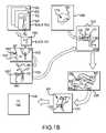
- FIG. 1Bis a diagrammatic depiction of the preoperative planning process, beginning with the generation of the 2D medical images and ending with the manufacturing instructions being sent to the CNC machine.
- FIG. 1Cis a flow chart extending from the generation of the 2D medical images, through the preoperative planning and manufacturing of the tool, and finishing with the tool being employed in the arthroplasty procedure.
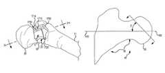
- FIG. 2Ais an isometric view of a surgical guide tool matingly engaged with a proximal femur having a femoral head and neck.
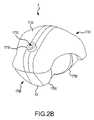
- FIG. 2Bis a side top isometric view of the surgical guide tool of FIG. 2A , wherein the tool is in a non-customized state or is in the form of a blank from which a customized tool is generated via an automated manufacturing machine, such as, for example, a CNC milling machine.
- an automated manufacturing machinesuch as, for example, a CNC milling machine.
- FIG. 2Cis a front view of the surgical guide tool of FIG. 2B .
- FIG. 2Dis a side view of the surgical guide tool of FIG. 2B .
- FIG. 2Eis a top plan view of the surgical guide tool of FIG. 2B .
- FIG. 2Fis the same view as FIG. 2B , except the tool is in the customized state depicted in FIG. 2A and a saw slot is shown.
- FIG. 2Gis a side bottom isometric view of a version of the tool depicted in FIG. 2F , except the tool of FIG. 2G employs a planar surface as the saw guide in place of the saw slot depicted in FIG. 2F , the mating region of the tool of FIG. 2G being configured to engage the mating region of the femur depicted in FIG. 13 .
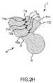
- FIG. 2His a cross section taken through section line 2 H- 2 H, which extends generally posterior-anterior in FIG. 2A , except employing the version of the tool depicted in FIG. 2G .
- FIG. 2Iis a view similar to FIG. 2G , except of a tool with a mating region configured to matingly engage the mating region of the femur depicted in FIGS. 14A-14B .
- FIG. 2Jis the same view as 2 G, except of a tool with a mating region configured to matingly engage the mating region of the femur depicted in FIG. 15 .
- FIG. 3is a posterior view of a 3D computer generated model of the proximal femur, including its femoral head, neck and greater trochanter, illustrating the angle Z at which the bone scan is sectioned.
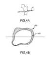
- FIG. 4Ais a 3D view of the proximal femur of FIG. 2A , illustrating a section line A at which the bone is sectioned during a CT scan to help create a cortical bone model and trabecular bone model.
- FIG. 4Bis a CT slice as taken along section line A of FIG. 2A .
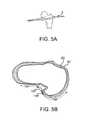
- FIG. 5Ais a 3D view of the proximal femur of FIG. 2A , illustrating a section line B at which the bone is sectioned during a CT scan to help create a cortical bone model and trabecular bone model.
- FIG. 5Bis a CT slice as taken along section line B of FIG. 5A .
- FIG. 6Ais a 3D view of the proximal femur of FIG. 2A , illustrating a section line C at which the bone is sectioned during a CT scan to help create a cortical bone model and trabecular bone model.
- FIG. 6Bis a CT slice as taken along section line C of FIG. 6A .
- FIG. 7is an example superior view CT scan of the proximal femur, wherein the correct coronal alignment for CT reconstruction is shown.
- FIG. 8is an example CT scan of the proximal femur, wherein the correct alignment for the final CT reconstruction is shown.
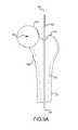
- FIG. 9Ais a transparent posterior view of a model of the proximal femur of FIG. 2A , wherein a sphere model and a rod model are shown.
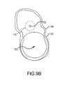
- FIG. 9Bis a transparent superior view of the models depicted in FIG. 9A .
- FIG. 9Cis the same view as FIG. 9A , except a femoral component model is also shown.
- FIG. 10is an isometric posterior view of a model of the femur of FIG. 2A , wherein the surgical guide tool blank model is shown positioned on the femur.
- FIG. 11is an isometric inferior-posterior view of the model of the femur and the surgical guide tool blank model, wherein the distal end of the tool model is highlighted to illustrate a portion of the tool that may be removed for proper exposure of the greater trochanter.
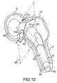
- FIG. 12is a transparent view of the femoral component model, model of the femur, and the model of the customized surgical guide tool properly superimposed relative to each other.
- FIG. 13is a posterior medial view of the proximal femur of FIG. 2A showing the regions of the femur that are mated with the index surfaces of an embodiment of the tool and the regions that correspond to over-estimated or non-contacting surfaces of the tool.
- FIGS. 14A-14Bare, respectively, posterior and anterior views of the proximal femur, wherein the mating region of the femur may be appropriate for a posterior or anteriorlateral surgical approach.
- FIG. 15is an isometric posterior view of the proximal femur and illustrates yet another mating region of the femur that may be used to define the mating region of another embodiment of the tool configured for a posterior surgical approach.
- FIGS. 16A-16Bare, respectively, posterior and anterior views of the proximal femur, wherein the mating region of the femur may be appropriate for a posterior or anteriorlateral surgical approach.
- the present disclosuredescribes a customized surgical guide tool 5 for use in total hip replacement surgery (“THR”).
- the customized surgical guide tool 5may be preoperatively planned via three-dimensional (“3D”) computer modeling procedures such that, when the tool 5 is matingly engaged with the proximal femur 40 of the patient, a resection guided by the tool 5 will result in a desired resection that will allow a femoral prosthetic implant or component 800 to be implanted in the femur 40 as planned during the preoperative planning.
- 3Dthree-dimensional
- the tool 5may include a single-piece construction, a fastener receiving feature 1710 , a customized saw guide 1725 , and a customized indexing or mating region 20 having customized indexing or mating surfaces 708 a , 710 a .
- the fastener receiving feature 1710may be used to receive an anchor that may secure the tool 5 in mating engagement with the proximal femur 40 .
- the mating region 20 and its mating surfaces 708 a , 710 amay be configured such that, when the mating region 20 matingly receives therein a region of the proximal femur 40 having predetermined bone surfaces 708 , 710 , the mating surfaces 708 a , 710 a of the mating region 20 of the tool 5 will matingly contact the predetermined bone surfaces 708 , 710 on the proximal femur 40 .
- the mating region 20may also include non-contacting surfaces 718 a , 720 a that correspond to surfaces of proximal femur 40 that are within the region of the femur engaged by the tool mating region 20 and that have surface topography of such variation that it is difficult to accurately scan or computer model or too small to manufacture into the tool mating region.
- These non-contacting surfaces 718 a , 720 a of the tool mating region 20may be the result of an overestimation process during image segmentation and will be spaced apart in a non-contacting fashion from the adjacent femur surfaces when the tool mating region 20 matingly receives the femur 40 .
- the saw guide 1725may be a slot, planar surface, or other feature capable of guiding a saw blade during a sawing procedure.
- the saw guide 1725may be positioned and oriented relative to the customized mating or indexing region 20 such that, when the mating surfaces 708 a , 710 a of the mating region 20 matingly contact the bone surfaces 708 , 710 when the tool mating region 20 matingly receives therein the region of the femur 40 having the bone surfaces 708 , 710 , the saw guide 1725 may be oriented over the femur neck 35 such that the saw guide 1725 corresponds with a desired resection plane 805 through the femoral neck 35 that was identified during the preoperative planning.
- the resection plane 805may correspond with a spacer region 801 of the femoral prosthetic implant or component 800 that limits the extent to which the femoral component may be inserted into the resected proximal femur during implantation.
- the femoral component 800which may be selected based on the information obtained during the preoperative planning, may then be inserted into the resected proximal femur 40 .
- the tool 5may have a single-piece construction, which may increase the accuracy associated with the resectioning process by minimizing tolerance errors normally associated with multi-piece, multi-joint, conventional guide tools.
- the tool 5may have a multi-piece construction.
- the saw slot 1725may be in the form of a separate guide that is mounted on the rest of the tool 5 in an indexed manner, the rest of the tool 5 having the customized mating region having the customized mating surfaces.
- the guide tool 5aids the surgeon in accurately implanting the femoral component 800 during a THR according to an alignment and position determined during preoperative planning.
- the tool 5once matingly engaged with the proximal femur, may guide the resection of the proximal femur according to a resection plane identified during the preoperative planning.
- Accurate implant alignment and positionis important because an improperly positioned and aligned femoral component 800 may result in a change of leg length, dislocation of the hip or perforation of the femur.
- the tool 5is configured to generally automatically provide an appropriate resection through the femur neck for a proper alignment of the femoral component upon causing the indexing region 20 to matingly receive the region of the femur having the bone surfaces 708 , 710 , the time and effort required by the surgeon to properly prepare the femur for the implantation of the femoral component 800 is substantially minimized.
- use of the tool 5may reduce the overall time spent in surgery. The reduction in the time spent in surgery may reduce the patient's chances of infection.
- a three dimensional (“3D”) model of the patient's proximal femur 40is computer generated from two dimensional (“2D”) medical imaging slices 500 (e.g., CT slices, MRI slices, etc.) taken of the patient's proximal femur 40 .
- a sphere 3D computer model 701 and a rod 3D computer model 702may be respectively aligned with the femoral head 30 and medullary canal 170 or the central axis 100 of the femur shaft of the femur 3D computer model 1040 to approximate the positioning of the femoral component 800 relative to the center of the hip joint 703 .
- a 3D model of the femoral component 800may be selected from a database of 3D models of candidate femoral component 800 .
- the selected 3D model of the femoral componentmay be aligned with the 3D model of the femur 40 and the sphere and rod models 701 , 702 such that the component head is generally centered with the center of the sphere model and the component shaft is generally coaxial with the rod model.
- a 3D model of a blank of the tool 5may be positioned on the femur model, which is still aligned with the sphere, rod and femoral component models 701 , 702 , 800 .
- the resection planemay be determined from the location of a spacer region surface or distal end 803 of a spacer region 801 of the femoral component 800 and used to define a saw slot 1725 in the 3D model of the blank of the tool 5 .
- the 3D model of the femuris analyzed to determine shape and location of the mating or indexing femur surfaces 708 , 710 .
- the shape and location of the surfaces 708 , 710may be used to define corresponding mating surfaces 708 a , 710 a in the mating region 20 of the 3D model of the blank of the tool 5 .
- the indexing surfaces 708 a , 710 a of the mating region 20 , the saw slot 1725 , and the orientation relationships between the surfaces 708 a , 710 a and the saw slot 1725may be imported into the 3D computer generated model of the blank of the tool 5 .
- the surfaces 708 a , 710 a and saw slot 1725end up being defined and imported into the 3D tool blank model such that a resulting tool 5 will position the saw slot 1725 to create the preoperatively planned resection in the femur when the mating surfaces 708 a , 710 a of the mating region 20 matingly contact the femur surfaces 708 , 710 when the mating region 20 matingly receives the region of the femur having the femur surfaces 708 , 710 .
- the resulting 3D model of the blank of the tool 5may be used to generate manufacturing instructions (e.g., machining paths, etc.), which are sent to an automated manufacturing device, such as a CNC machine, a stereolithography apparatus (“SLA”), etc. to mill or otherwise manufacture an actual tool 5 from an actual tool blank 50 .
- manufacturing instructionse.g., machining paths, etc.
- SLAstereolithography apparatus
- the relationships between these modelscan be analyzed to determine the location and orientation of the saw guide 1725 , the location and shape of the indexing surfaces 708 a , 710 a of the mating region 20 , and the positional relationship between the saw guide 1725 and indexing surfaces 708 a , 710 a , all of which can be imported into the 3D computer generated model of the blank of the tool 5 to define such features into the 3D model of the tool blank.
- the resulting 3D computer generated model of the blank of the tool 5may then be used as manufacturing instructions for the automated manufacture of a customized guide tool 5 having a saw guide 1725 that will result in the preoperatively planned resection of the proximal femur 40 when the tool 5 is matingly engaged with the proximal femur such that the indexing surfaces 708 a , 710 a mating contact the predetermined femur surfaces 708 , 710 when the tool mating region matingly receives the proximal femur 40 .
- the resulting tool 5is customized for the specific patient via a preoperative planning process that employs a 3D model of the patient's femur compiled from 2D medical images 500 taken of the patient's femur.
- the resulting tool 5includes the “data” physically integrated therein that allows the tool 5 to matingly engage the patient femur 40 and direct the resection of the femur as calculated during the preoperative planning process to facilitate a desired preoperatively planned position and orientation of the implanted femur component 800 .
- FIG. 2Ais an isometric view of a surgical guide tool 5 matingly engaged on a proximal femur 40 having a femoral head 30 and neck 35 .
- FIG. 2Bis a side top isometric view of the surgical guide tool 5 of FIG. 2A , wherein the tool 5 is in a non-customized state or is in the form of a blank from which a customized tool 5 is generated via an automated manufacturing machine, such as, for example, a CNC milling machine.
- FIGS. 2C-2Eare front, side and top plan views, respectively, of the tool 5 of FIG. 2B .
- FIG. 2Fis the same view as FIG. 2B , except the tool 5 is in the customized state depicted in FIG. 2A and a saw slot 1725 is shown.
- FIG. 2Gis a side bottom isometric view of a version of the tool 5 depicted in FIG. 2F , except the tool 5 of FIG. 2G employs a planar surface 1725 as the saw guide 1725 in place of the saw slot 1725 depicted in FIG. 2F , the mating region 20 of the tool 5 of FIG. 2G being configured to engage the mating region of the femur 40 depicted in FIG. 13 .
- FIG. 2His a cross section taken through section line 2 H- 2 H, which extends generally posterior-anterior in FIG. 2A , except employing the version of the tool 5 depicted in FIG. 2G .
- the surgical guide tool 5includes a proximal or head end 1745 , a distal or greater trochanter end 1750 , a top side 1755 and a bottom side 1760 .
- the bottom side 1760 and the top side 1755are generally arcuately shaped.
- the width of the tool 5may gradually increase from the proximal end 1745 to the distal end 1750 .
- the ends 1745 , 1750are formed or otherwise joined together via the bottom side 1760 and top side 1755 such that the tool 5 may be a single-piece tool having a single-piece construction that is generally unitary and continuous in nature.
- the tool 5may have a multi-piece construction, for example, where the saw guide is mounted as a separate and independent piece on the rest of the tool that includes the mating region.
- the tool 5may be made of polyoxymethylene (acetal resin), a low density polyethylene, or other biocompatible plastics.
- portions of the bottom side 1760 and the top side 1755may include a customizable mating or indexing region 20 that may have mating contact surfaces 708 a , 710 a and non-contacting surfaces 718 a , 720 a defined therein.
- the mating or indexing region 20may be adapted to matingly receive regions of the proximal femur 40 having mating contact surfaces 708 , 710 and non-contacting surfaces 718 , 720 such as those discussed in detail later this Detailed Description with respect to FIG. 13 or similar to those discussed in detail with respect to FIGS. 14A-16B .
- the region of the femur 40which may be matingly received by the tool mating region 20 when the tool 5 is mounted on the femur 40 , may include a mating contact surface 708 covering portions of the posterior region of the neck 35 and a mating contact surface 710 that is a narrow band following along the intertrochanteric crest 116 .
- the mating contact surfaces 708 a , 710 a of the tool mating region 20may be configured to matingly contact the mating contact surfaces 708 , 710 of the femur 40 when the tool mating region 20 matingly receives therein the region of the femur that has the mating contact surfaces 708 , 710 .
- the femur surfaces 708 , 710 to be mated or indexed by the tool mating or index surfaces 708 a , 710 amay be separated by non-contacting surfaces 718 , 720 of the femur 40 .
- the non-contacting surfaces 718 , 720 of the femur 40may be spanned in a spaced-apart, non-contacting arrangement by non-contacting surfaces 718 a , 720 a of the tool mating region 20 when the tool mating region 20 matingly receives the region of the femur 40 including the non-contacting surfaces 718 , 720 and the tool mating surfaces 708 a , 710 a matingly contact the femur contacting surfaces 708 , 710 .
- the non-contacting surfaces 718 a , 720 a of the tool mating region 20may be the result of an over-estimating process occurring during image segmentation as described later in this Detailed Description. As can be understood from FIG.
- the non-mating surfaces 718 , 720 of the proximal femur 40may include portions 718 of the posterior greater trochanter 115 and portions 720 of the trochanteric fossa 210 (i.e., the depression between the greater trochanter and the femur neck).
- the top side 1755may include a fastener-receiving feature 1710 .
- the fastener-receiving feature 1710may be generally ring shaped and may include a hole 1715 extending axially therethrough.
- the top side 1755includes one fastener-receiving feature 1710 .
- the top side 1755includes more than one fastener-receiving feature 1710 .
- the fastener receiving feature 1710is configured to receive a fastener 1716 through the hole 1715 , thereby securing the tool 5 to the femur 40 when the indexing surfaces 708 a , 710 a of the tool mating region 20 matingly contact the corresponding bone surfaces 708 , 710 .
- the top facedoes not include a fastener receiving feature 1710 and the tool is secured by other methods, such as being held in place by the surgeon.
- the fastener 1716may be a pin, screw or other suitable device.
- the top side 1755may also include a saw guide 1725 that is configured to receive a saw blade during a THR.
- the saw guide 1725may be in the form of a planar surface, a slot or any other feature capable of guiding a saw during a resection.
- the saw slot 1725is generally an open-ended rectangle and extends axially through the tool 5 from the top side 1755 to the bottom side 1760 .
- the saw slot 1725may extend across the entire width of the neck 35 such that the surgeon may make a complete resection of the neck.
- the saw slot 1725may extend at least partially across the width of the neck such that the surgeon may make a partial neck resection.
- the saw slot 1725may be positioned in the tool 5 such that the slot 1725 is aligned with a preoperatively planned resection plane 805 , as determined by 3D modeling.
- the resection plane 805may correspond with a spacer region 801 of the femoral prosthetic implant or component 800 that limits the extent to which the femoral component may be inserted into the resected proximal femur during implantation.
- the resection plane 805defines the location of the head and neck resection during surgery.
- the subsequent cut through the neck 35 of the proximal femur 40will expose a portion of the neck 35 for receipt of the femoral component 800 .
- the location of the saw slot 1725is determined based on preoperative planning employing 3D models of the patient's femur and the specific implant 800 to employed in the THR, the subsequent cut through the neck is positioned to expose a portion of the neck aligned to receive the femoral component 800 such that the femoral component 800 may be accurately positioned upon insertion into the femur.
- the above-described customized guide tool 5may be designed and manufactured employing a system 4 similar to that schematically depicted in FIG. 1A .
- the system 4may include a preoperative planning system 6 in the form of a computer 6 having a CPU 7 , a monitor or screen 9 and operator interface controls 11 , such as a keyboard, mouse, etc.
- the computer 6may be linked to a medical imaging system 8 , such as a CT or MRI machine 8 , and an automated or rapid manufacturing machine 10 , such as a stereolithography apparatus (“SLA”) or a computer numerical controlled (“CNC”) milling machine 10 .
- SLAstereolithography apparatus
- CNCcomputer numerical controlled
- the imaging machine 8 , the manufacturing machine 10 , and the modeling system 6 of the system 4may be in communication with each other via, for example, hardwire, internet, wireless, portable memory devices or any combination thereof.
- the medical imaging machine 8may be employed to generate medical images 500 of the joint 14 of the patient 12 that is the subject of the arthroplasty. While this Detailed Description is given in the context of the joint 14 being a hip joint 14 and the tool 5 being configured for the preparation of the proximal femur 40 to receive a total hip replacement prosthetic implant, the concepts disclosed herein may be readily applicable to arthroplasty for other types of joints, including, for example, ankles, knees, wrists, elbows, shoulders, vertebra, fingers, toes, etc. Any resulting 2D medical images 500 may be sent to the computer 6 for use in the preoperative planning.
- an operatormay view the various 3D computer generated models, such as the femur model 1040 and others, via the monitor 11 as the operator interacts with the computer 6 via the controls 11 to direct the preoperative planning.
- Computer programs for creating, storing and manipulating the various 3D computer generated modelsmay be stored in computer memory accessible by the CPU 7 .
- Computer programs for creating the 3D computer generated bone model 1040 from the 2D images 500include: Analyze from AnalyzeDirect, Inc., Overland Park, Kans.; Insight Toolkit, an open-source software available from the National Library of Medicine Insight Segmentation and Registration Toolkit (“ITK”), www.itk.org; 3D Slicer, an open-source software available from www.slicer.org; Mimics from Materialise, Ann Arbor, Mich.; and Paraview available at www.paraview.org.
- the resulting informationis used to create manufacturing instructions that are sent to the automated manufacturing machine 10 to generate the final tool 5 , which in some embodiments, may be manufactured from a tool blank 50 placed in the manufacturing machine 10 .
- FIG. 1Bis a diagrammatic depiction of the tool planning process, beginning with the generation of the 2D medical images 500 and ending with the manufacturing instructions being sent to the CNC machine 10 .
- FIG. 1Cis a flow chart extending from the generation of the 2D medical images 500 , through the planning and manufacturing of the tool 5 , and finishing with the tool 5 being employed in the arthroplasty procedure.
- a patient 12has a hip joint 14 that is the subject of a THR surgery.
- the hip joint 14 of the patient 12is scanned in the imaging machine 8 [block 1500 and block 1600 ].
- the scanningmay include up to one-third of the proximal femur 40 , including the femoral head 30 and the lesser trochanter 740 .
- the scanningmay include a greater or lesser portion of the femur.
- the resolution of a CT scan or an MRI scanis greater than the resolution of x-ray. Greater resolution leads to more accuracy in the preoperative planning process, which leads to greater precision in the resulting tool 5 .
- the resolution of the scanis between approximately 0 mm and approximately 2 mm. In other embodiments, the resolution of the scan is between approximately 0.3 mm and approximately 0.6 mm. In one embodiment, a CT scan with a resolution of approximately 0.6 mm is utilized for creation of the tool.
- a CT scanwith a resolution of approximately 0.5 mm to 2 mm, with a tube current ranging from 200 mA to 400 mA and a tube voltage ranging from 120 kV to 140 kV and a direct field of view (“DFOV”) ranging from approximately 16 cm to approximately 26 cm is utilized for creation of the tool.
- DFOVdirect field of view
- the imaging machine 8makes a plurality of scans of the joint 14 , wherein each scan pertains to a thin 2D image slice 500 of the joint 14 .
- the plurality of 2D images 500which may be CT, MRI or other 2D medical images, are sent from the imaging machine 8 to the preoperative planning system 6 .
- the 2D imagesare subjected to an image segmentation process, wherein the bone contour lines 502 are identified in each of the images 500 [block 1500 and block 1602 ].
- the bone surface contour lines of the femur 40 depicted in the image slices 500may be auto segmented via a image segmentation process as disclosed in U.S. Patent Application 61/126,102, which was filed Apr. 30, 2008, is entitled System and Method for Image Segmentation in Generating Computer Models of a Joint to Undergo Arthroplasty, and is hereby incorporated by reference into the present application in its entirety.
- the bone scanmay be sectioned for the segmentation process at an angle Z.
- image segmentationis performed utilizing image slices or sections 500 at an angle Z off the central axis 100 of the femoral neck 35 viewed posteriorly.
- the segmentationcan be done in several ways and for ease of the reader are described in relation to a CT-scan.
- the CT locatorcould be positioned at an angle Z to section the CT scan.
- the CT scancould be sectioned at an angle Z during post-processing.
- the angle Zis between approximately thirty degrees and approximately sixty degrees. In an alternative embodiment, the angle Z is approximately a 45 degree angle. It can be appreciated that segmentation of an MRI scan may be achieved in a similar manner.
- FIGS. 4A-6Bare 3D views of the proximal femur 40 respectively showing section or scan planes A, B and C extending through the femur 40 .
- FIGS. 4B, 5B and 6Bare respectively the segmented image slices of planes A, B and C, respectively.
- section or scan plane Aextends through the proximal femur generally transverse to the femoral axis and just distal of the lesser trochanter.
- the contour line 601 corresponding to the cortical bone and the contour line 602 corresponding to the trabecular bone 602may be identified.
- section or scan plane Bextends through the proximal femur generally transverse to the femoral axis and approximately midway between the tip of the greater trochanter and the lesser trochanter.
- the contour line 601 corresponding to the cortical bone and the contour line 602 corresponding to the trabecular bone 602may be identified.
- section or scan plane Cextends through the proximal femur generally transverse to the femoral axis and just distal the tip of the greater trochanter.
- the contour line 601 corresponding to the cortical bone and the contour line 602 corresponding to the trabecular bone 602may be identified.
- the region of the femur 40which may be matingly received by the tool mating region 20 when the tool 5 is mounted on the femur 40 , may include a mating contact surface 708 covering portions of the posterior region of the neck 35 and a mating contact surface 710 that is a narrow band following along the intertrochanteric crest 116 .
- the femur mating contact surfaces 708 , 710may be separated by non-contacting surfaces 718 , 720 of the femur 40 .
- the non-contacting surfaces 718 , 720 of the proximal femur 40may include portions 718 of the posterior greater trochanter 115 and portions 720 of the trochanteric fossa 210 .
- the portions 708 P, 710 P of the cortical bone contour lines 601 in FIGS. 5B and 6Bcorrespond to the mating contact surfaces 708 , 710 of the femur 40
- the portions 718 P, 720 P of the cortical bone contour lines 601 in FIGS. 5B and 6Bcorrespond to the non-contact surfaces 718 , 720 of the femur 40
- the cortical contour line 601 depicted in FIG. 4Bis from a slice that would be located below the tool mating regions of the femur 40 . Therefore, this contour line 601 depicted in FIG. 4B does not have portions 718 P, 720 P, 708 P, 710 P.
- the non-contact portions 718 P, 720 P of the cortical bone contour lines 601correspond to surfaces 718 , 720 of the femur 40 that are difficult to replicate in the tool mating region 20 due to the extreme variance in surface topography for the surfaces 718 , 720 .
- other difficult to replicate surfaces that surfaces portions 718 P, 720 P may correspond tomay include surfaces of osteophytes or other bone surface irregularities.
- corresponding regions of the tool mating region 20would be difficult to machine to correspond to the surfaces 718 , 720 of the femur 40 due to limitations in the milling process; or (2) the surfaces 718 , 720 would be difficult to model because of limitations in the scanning or 3D computer modeling processes.
- the difficult to replicate contour line portions 718 P, 720 Pmay be subjected to an overestimation process. Specifically, the difficult to replicate contour line portions 718 P, 720 P are modified to be extended outwardly away from the interior of the bone (i.e., over-estimated) and, in some instances smoothed with respect to shape.
- the resulting cortical bone contour lines 601now include the original portions 708 P, 710 P in their original shape and location and the now overestimated or outwardly adjusted portions 718 P, 720 P; these resulting cortical bone contour lines 601 from each image slice are then compiled or reconstructed into the 3D computer generated femur model 1040 used for the preoperative planning process.
- the end result of the overestimation process with respect to the manufacture of the completed tool 5is that the CNC tool paths corresponding to the overestimated regions of the femur model 1040 remove excess materials from the mating region 20 of the blank used to form the tool 5 .
- the tool mating region 20is configured to matingly contact only with those surfaces 708 , 710 of the femur that can be accurately replicated in the tool mating region 20 , and those surfaces 718 , 720 that cannot be accurately replicated in the tool mating region 20 are not contacted by any surface of the tool mating region 20 because the tool mating region 20 has been over-milled in the areas of the tool mating region 20 corresponding to the difficult to replicate femur surfaces 718 , 720 .
- the resultis a tool 5 with a mating region 20 that accurately mates to the mating region of the femur 40 .
- the line contours 601 for the cortical bonemay be subjected to overestimation while the line contours 602 for the trabecular bone are not subjected to overestimation.
- the contour lines 601 , 602 for both the cortical and trabecular bonesare subjected to overestimation.
- the cortical bone contour lines 601may be employed to generate a 3D computer generated cortical bone model
- the trabecular bone contour lines 602may be employed to generate a 3D computer generated trabecular bone model.
- the cortical bone model and the trabecular bone modelmay be combined into a single 3D computer generated femur model 1040 [block 1501 ], as depicted in FIG. 9A discussed below.
- FIG. 9Awhich is a posterior view of the femur model 1040
- the contour linesmay be imported into a 3D computer modeling program.
- the model programmay then be used to generate 3D computer models of the cortical bone 601 and the trabecular bone 602 of the proximal femur 40 .
- the model of the trabecular bone 602may be subtracted from the model of the cortical bone 601 to create a hollow 3D computer generated femur model 1040 , wherein the subtracted model of the trabecular bone 602 creates a hollow region of the femur model 1040 that represents the medullary canal 170 .
- FIG. 7which is an example superior view CT scan of the proximal femur 40 of FIG. 2A
- the CT scanmay be reconstructed for proper coronal alignment by causing the coronal slices to be parallel to the femoral neck 35 .
- the slice width and overlapmay range from approximately 0.5 mm to approximately 2 mm. In one embodiment, a slice width and overlap of 0.5 mm is used.
- the DFOVmay range between approximately 16 cm to approximately 26 cm field of view.
- the reformatted CT scanmay include up to one-third of the proximal femur 40 , including the femoral head 30 and the lesser trochanter 740 . In other embodiments, the CT scan may include a greater or lesser amount of the proximal femur.
- FIG. 8which is an example CT scan of the proximal femur 40 of FIG. 2A , wherein the proper alignment for the final CT reconstruction is shown from a coronal slice.
- the final reconstruction alignment 1760 ais set to an angle Q relative to the long axis 1761 of the femoral neck 35 .
- Angle Qmay range from approximately 30 degrees to approximately 60 degrees. In one embodiment, angle Q is 45 degrees.
- the slice width and overlapmay range from approximately 0.5 mm to approximately 2 mm. In one embodiment, the slice width and overlap is 1 mm.
- the field of viewmay range from approximately 16 mm to approximately 26 mm.
- the scanmay include up to one-third of the proximal femur 40 , including the femoral head 30 and the lesser trochanter 740 . In other embodiments, the CT scan may include a greater or lesser amount of the proximal femur.
- the pre-operative planning processmay begin [block 1604 ], wherein the 3D bone model is utilized to determine: (1) the proper size and placement of a femoral component (e.g.
- the following preoperative planning methodsmay employ a 3D computer modeling program, such as, for example, Solidworks or Paraview, in the generation, placement, manipulation, determination and importation of various 3D computer models described below.
- the preoperative planningmay begin with the femur model 1040 , a 3D computer generated sphere model 701 , and a 3D computer generated rod model 702 being imported into a modeling space [block 1502 ].
- FIGS. 1B and FIGS. 9A and 9Bare respective transparent posterior and superior views of a 3D computer generated model 1040 of the proximal femur 40 of FIG. 2A
- the preoperative planningmay begin with the femur model 1040 , a 3D computer generated sphere model 701 , and a 3D computer generated rod model 702 being imported into a modeling space [block 1502 ].
- the femur model 1040which is a result of the compiled or reconstructed contour lines, some of which may have been overestimated, may have a head 30 , a neck 35 , a shaft 51 , a greater trochanter, and an medullary canal 170 .
- the models 701 , 702 , 1040are combined together in a superpositioned arrangement.
- the rod model 702may be positioned so that it generally aligns with the center of the medullary canal 170 of the shaft of the femur model 1040 , which generally corresponds to a central axis 100 of the shaft of the femur.
- the rod 702may be positioned to be generally coaxial with the femur axis 100 .
- the sphere model 701may be positioned so the centers of the sphere 701 and head 35 are located at the same point.
- the diameter of the sphere model 701may be increase or decreased to cause the sphere model 701 to generally approximate the femoral head 30 such that the hemispherical surfaces of the head 30 and the sphere 701 are generally coextensive for a significant portion of the hemispherical surface of the head 30 .
- the damageis typically to the superior and anterior surfaces, so the sphere 701 is typically positioned and sized such that hemispherical surface of the sphere 701 is generally coextensive with the inferior and posterior regions of the head 30 .
- the center 703 of the sphere 701will generally approximate the center of the hip joint.
- the proper positioning and sizing of the models 701 , 702can be verified by looking at both posterior ( FIG. 9A ) and superior ( FIG. 9B ) views.
- a 3D computer generated femoral component model 850may be imported into the modeling space [block 1503 ].
- the femoral component model 850may include a shaft 804 , a head 802 and a spacer region 801 .
- the spacer region 801may have a surface 803 that abuts against the surface of the bone resection when the actual implant is properly and fully implanted in the resected femur.
- the 3D femoral component model 850may be selected from a database of femoral component models, the models in the data base corresponding to the sizes of femoral components available from a selected manufacturer. Size selection is based on the shape and size of the medullary canal 170 . Once the position of the neck resection has been determined, the largest component that fits within the canal is chosen.
- the sphere model 701 and rod model 702are used to plan the proper alignment and placement of the femoral component model 850 .
- the femoral component model 850may be superimposed with the rest of the models 701 , 702 , 1040 such that the long axis of the shaft 804 of the component 800 generally corresponds to the long axis of the rod 702 in a generally coaxial manner, and the center of the head 802 of the component model 850 generally corresponds to the approximated hip joint center 703 .
- the size and the shaft to neck angle of the spacer 801may be adjusted according to the ranges available from the manufacturer for the femoral component.
- the above-described embodimentsuperimposes the sphere and rod models 701 , 702 on the femur model 1040 prior to superimposing the femoral component model 850 and using the sphere and rod model locations to position and size the femoral component model 850 .
- the femoral component model 850may be superimposed on the femur model 1040 for positioning and sizing without the presence and use of the sphere and rod models 701 , 702 .
- FIGS. 1B and 1C and FIG. 10which is an isometric posterior view of the femoral model 1040 of FIG. 9C , except with the other models 701 , 702 , 850 hidden for clarity purposes, a 3D computer generated tool blank model 550 is generated [block 1504 ] and imported into the modeling space to be superpositioned with the femoral model 1040 to define the mating region 20 and saw guide 1725 in the tool blank model 550 [block 1505 and 1606 ].
- the tool blank model 550is positioned over the posterior surface of the femur model 1040 such that: (1) the surfaces of the femur model 1040 corresponding to the mating contact surfaces 708 , 710 and non-contact surfaces 718 , 720 of the femur 40 , as discussed in detail below with respect to FIG. 13 , are covered by the tool 5 ; and (2) the head 30 of the femur model 1040 is exposed.
- FIG. 11which is a inferior-posterior isometric view of what is depicted in FIG. 10
- a distal portion 1750 of the tool blank model 550may be removed to provide a non-contacting arrangement between the resulting tool 5 and non-mating regions of the proximal femur 40 , such as those regions near the greater trochanter 115 .
- FIGS. 1B and 1C and FIG. 12which is generally the same view as FIG. 11 , except the femoral component model 850 is visible and the tool blank model 550 is now a customized tool model 603 , once the tool blank model 550 is properly positioned on the femur model 1040 , the tool mating region 20 and saw guide 1725 may be defined and imported into the tool blank model 550 to create the tool model 603 [block 1506 and block 1606 ].
- those mating contact surfaces 708 a , 710 a and non-contacting surfaces 718 a , 720 a of the tool mating region 20 that respectively correspond to the contact surfaces 708 , 710 and non-contact or overestimated surfaces 718 , 720 of the femur 40 of FIG. 13are identified on the surface of the femur model 1040 and imported or otherwise used to define the contacting surfaces 708 a , 710 a and non-contacting surfaces 718 a , 720 a in the mating region of the tool blank model 550 . As can be understood from FIG.
- the contacting surfaces 708 , 710 and non-contacting surfaces 718 , 720 of the femur model 1040may be identified and defined as 3D surface models 537 , 539 or other types of “data” that are imported into the tool blank model 550 to create the contacting surfaces 708 a , 710 a and non-contacting surfaces 718 a , 720 a in the mating region of the tool blank model 550 [block 1506 ].
- the surface 803 of the spacer region 801 of the component model 850may be coplanar to the resection plane 805 needed to allow the actual implanted femoral component to achieve the implant positioning that will achieve the predicted desirable surgical outcome.
- the spacer region surface 803will correspond to the position and orientation of the resection plane 805 when the component model 850 is properly positioned in the femur model 1040 .
- the position and orientation of the spacer region surface 803may be used to define the position and orientation of the resection plane 805 and, as can be understood from FIG. 1B , a resection plane model 538 or other types of “data” may be defined and imported into the tool blank model 550 to define the saw guide 1725 in the tool blank model 550 [block 1506 ]. Since the location and orientation of the surface models 539 , 537 and plane model 538 may be referenced relative to each other due to the femur, component and blank models 1040 , 805 , 550 being superimposed with each other, the position and orientation relationships are maintained in the resulting tool model 603 [block 1507 ].
- the saw guide 1725may be positioned and oriented relative to the customized mating or indexing region 20 such that, when the mating surfaces 708 a , 710 a of the mating region 20 matingly contact the bone surfaces 708 , 710 when the tool mating region 20 matingly receives therein the region of the femur 40 having the bone surfaces 708 , 710 , the saw guide 1725 may be oriented over the femur neck 35 such that the saw guide 1725 corresponds with a desired resection plane 805 through the femoral neck 35 that was identified during the preoperative planning.
- the cavity or mating region 20 of the tool 5conforms to the segmented CT scans or MRI scans, overestimated as necessary, of the patient's femur, and the saw guide 1725 is positioned so as to result in a preoperatively planned resection of the proximal femur when the tool mating region 20 matingly engages the proximal femur and a sawing action is guided by the saw guide 1725 .
- Proper alignment of the saw slot 1725 with the preoperatively planned resection planeexposes the femoral neck to provide a properly oriented surface for proper alignment of the femoral component.
- a properly positioned femoral componentprevents or at least minimizes the chances of several undesirable complications. For example, an improperly positioned femoral component can cause a change of leg length, dislocation of the hip or perforation of the femur.
- the tool model 603may be used to generate automated manufacturing instructions (e.g., tool paths, etc.).
- the tool model 603 or automated manufacturing instructionsare sent to the CNC machine 10 from the preoperative planning system 6 [block 1508 ], and the actual tool 5 is manufactured from an actual tool blank 50 via the CNC machine 10 [block 1608 ].
- the finished tool 5may be marked with patient data (e.g., name, hip identification, etc.), surgeon name, medical facility name, or other information.
- the tool 5may then be sterilized, packaged and sent to the surgeon [block 1610 ].
- the surgeonmay fit the tool appropriately on the femur and, in one embodiment, drill into the hole 1715 of the fastener feature 1710 at the top side 1755 of the tool and insert a fastening member 1716 to stabilize the tool [block 1612 ].
- the tool 5may be held in place by the surgeon or other medical personnel. Once positioned, the surgeon may place a saw blade through the saw slot 1725 and prepare to saw through the resection plane to make at least a partial head and neck resection [block 1614 ]. Once the resection is at least partially complete, the tool may be discarded [block 1616 ]. In some embodiments, the tool 5 may remain in place until the resection is complete.
- the surgeonmay then further prep the resected proximal femur and then implant the femoral component 800 in a manner that replicates the preoperative planning such that the surface 803 abuts against the resection surface of the femur.
- the tool 5is custom configured to facilitate the preoperatively planned positioning of the femoral component
- the tool 5 disclosed hereinfacilitates HRS that is substantially more likely to result in a positive surgical outcome for the patient as compared to conventional methods that rely on x-rays, hand measuring techniques and surgeon visual assessment.
- the tool 5decreases the risks commonly associated with an improperly placed femoral component in total hip replacement surgery, such as dislocation of the hip, a change in the length of the leg or perforation of the femur.
- the surgical timeis substantially reduced because the surgeon simply has to cause the tool 5 to engage the proximal femur, as opposed to determining the proper location for the resection based off of visual inspection at the time of surgery.
- the tool 5aids the surgeon in accurately and quickly placing the femoral component 800 .
- the tool 5also decreases the risks associated with the length of the surgical time, such as, infection, excessive bleeding, etc.
- the above-described POP procedureis a manual process, wherein computer generated 3D models 701 , 702 , 1040 , 850 are manually manipulated relative to each other by a person sitting in front of a computer 6 and visually observing the 3D models 701 , 702 , 1040 , 850 on the computer screen 9 and manipulating the 3D models 701 , 702 , 1040 , 850 via the computer controls 11 .
- the POP processis generally or completely automated.
- a computer programmay manipulate computer generated 3D models 701 , 702 , 1040 , 850 relative to each other to preoperatively plan the tool 5 .
- the above-described POP processmay have portions that are generally manual while other portions that are generally automated.
- the mating region 20 of the tool 5may be customized based on a patient's individual bone shape.
- the tool 5may be machined, molded or otherwise formed from the non-customized state as illustrated in FIGS. 2B-2E to a customized state as indicated in FIGS. 2F-2H , based on a patient's individual bone scan, for example an MRI scan or CT-scan.
- the bone scan datamay be utilized to generate a 3D computer generated model 1040 of the patient's proximal femur 40 .
- a 3D computer generated model 550 of the blank of the tool 5 , the 3D femur model 1040 , and 3D computer generated models of the implant component 850 , the sphere 701 , and the rod 702may be superimposed and aligned as described above to preoperatively plan the patient specific tool 5 . That is, through the information received from the MRI scan or CT-scan and the computer modeling, the tool 5 may be customized at the mating region 20 such that the tool 5 will have mating or indexing surfaces 708 a , 710 a of the mating region 20 that generally conform to the predetermined specific surface geometry of the patient's own proximal femur 40 .
- the predetermined specific geometrywill be that of surfaces 708 , 710 discussed with respect to FIG. 13 , which is a posterior medial view of the proximal femur 40 of FIG. 2A showing the surfaces 708 , 710 of the femur 40 that are mated with the index surfaces 708 a , 710 a of the tool mating region 20 and the surfaces 718 , 720 that correspond to over-estimated or non-contacting surfaces 718 a , 720 a of the tool mating region 20 .
- the femur mating region depicted in FIG. 13may be applicable to a posterior approach to help with stable positioning of the tool 5 on the femur 40 .
- a first mating surface 708covers portions of the posterior region of the neck 35 , starting medially between approximately 1 mm and approximately 5 mm after the cartilage covering the head 30 of the femur 40 terminates laterally and laterally extends between approximately 15 mm and approximately 35 mm to or towards the trochanteric fossa 210 .
- the inferior boundary of surface 708may terminate approximately 5 mm superior to the inferior border between the posterior and anterior surfaces of the neck 35 , or may extend up to approximately 5 mm anterior past this border.
- the superior boundary of mating surface 708may extend approximately 0 mm to approximately 5 mm posterior to the superior junction between the posterior surface and the anterior surface of the neck 35 .
- a second mating surface 710may be a narrow band measuring between approximately 0.5 mm and approximately 12 mm medial-lateral. The second mating surface 710 may follow along the intertrochanteric crest 116 . Mating surface 710 may begin approximately 0 mm to approximately 12 mm superior to the lesser trochanter 740 and may extend approximately 0 mm to approximately 18 mm inferior to the most superior tip 215 of the posterior surface of the greater trochanter 115 .
- mating surfaces 708 , 710 of the femur 40may be used to define the mating contact surfaces 708 a , 710 a of the tool mating region 20 (see FIG. 2G ) such that the tool contact surfaces 708 a , 710 a may matingly contact the femur surfaces 708 , 710 when the tool mating region 20 mating receives or engages the femur 40 as depicted in FIG. 2H .
- the non-mating surfaces 718 , 720 of the femur 40which are spanned in a spaced-apart or non-contacting arrangement by corresponding non-contacting surfaces 718 a , 720 a of the tool mating region 20 , as depicted in FIG. 2H , are also depicted in FIG. 13 .
- a first non-mating surface 718may include portions of the posterior greater trochanter 115 and extend superior-inferior adjacent the intertrochanteric crest 116 .
- the medial boundary of the first non-mating surface 718may be the second mating surface 710 , and may extend medial-lateral approximately 0 mm to approximately 12 mm.
- the second non-mating surface 20may span portions of the trochanteric fossa 210 , and may have a medial boundary that is the first mating surface 708 and a lateral boundary that is the second mating surface 710 , and a medial-lateral width that may vary between approximately 0 mm and approximately 20 mm. Both the first non-mating surface 718 and the second non-mating surface 720 may have inferior-superior dimensions similar to the first mating surface 708 and the second mating surface 710 .
- contour line portions corresponding to non-mating surfaces 718 , 720 and osteophytesmay be overestimated (e.g., moved outward from the interior of the bone and smoothed) such that portions of the tool mating region 20 defined according to those overestimated contour line portions are over-machined, ensuring that little or no contact occurs between the resulting non-mating surfaces 718 a , 720 a of the tool mating region 20 (see FIG. 2G ) and the corresponding non-mating surfaces 718 , 720 of the bone when the tool mating region 20 matingly receives the region of the femur 40 having the non-mating surfaces 718 , 720 , as shown in FIG. 2H .
- the femur 40may include contact surfaces 708 , 710 and non-contact surfaces 718 , 720 such that a tool 5 configured for a posterior approach may have a mating region 20 configured to have corresponding mating contact surfaces 708 a , 710 a and non-contacting surfaces 718 a , 720 a , as indicated in FIGS. 2G and 2H .
- the tool mating region 20may be such that the mating contact and non-contact surfaces of the tool mating region 20 are configured to correspond to mating and non-contact surfaces of other regions of the femur 40 as described below with respect to FIGS. 14A-14B, 15 and 16A-16B .
- the mating region of the femur 40may be appropriate for a posterior or anteriorlateral surgical approach.
- the mating region of the femur 40may include mating surfaces 700 a , 701 a , 702 a , 704 a .
- FIG. 2Iwhich is a view similar to FIG. 2G , except of a tool mating region 20 configured to matingly engage the mating surfaces 700 a , 701 a , 702 a , 704 a depicted in FIGS.
- the mating surfaces 700 a , 701 a , 702 a , 704 a of the femur 40may be matingly contacted by corresponding mating or index contact surfaces 700 b , 701 b , 702 b , 704 b of the tool mating region 20 to help stabilize the positioning of the tool 5 on the femur 40 .
- the tool mating region 20 depicted in FIG. 2Gis configured to matingly engage the mating surfaces of the femur 40 depicted in FIG. 13
- the tool mating region 20 depicted in FIG. 2Iis configured to matingly engage the mating surfaces of the femur 40 depicted in FIGS. 14A-14B .
- a first mating surface 700 aincludes portions of the posterior region 724 of the neck 35 , having a medial starting point between approximately 1 mm and approximately 5 mm after the cartilage covering the femoral head 30 terminates laterally and extends laterally between approximately 15 mm and approximately 35 mm to or towards the trochanteric fossa 210 .
- the inferior border of the first mating surface 700 abegins approximately midway superiorly-inferiorly along the intertrochanteric crest 116 , and follows the long axis of the neck 35 .
- the superior border of the first mating surface 700 ais between approximately 1 mm and approximately 3 mm below the superior junction 728 between the posterior and anterior surfaces of the neck 35 .
- a second mating surface 701 ahas approximately the same medial-lateral width as section 700 a , but may terminate before the tubercle 730 of the femur 40 .
- the superior border of the second mating surface 701 ais approximately 1 mm to approximately 3 mm below the superior junction 728 between the posterior and anterior surfaces of the neck 35 .
- the inferior-superior distance of second mating surface 701 ais between 5 and 10 mm.
- a third mating surface 702 ais a narrow band, measuring generally medial-lateral between approximately 0.5 mm and approximately 8 mm, that follows along the intertrochanteric crest 116 .
- Mating surface 702 abegins approximately midway superior-inferior along the intertrochanteric crest 116 and may extend any length greater than approximately 5 mm to or towards the most superior tip 215 of the posterior surface of the greater trochanter 115 .
- a fourth mating surface 704 alies on the anterior greater trochanter 115 , lateral to the tubercle 730 of the femur 40 , and inferior to the origin of the obturator internus 732 .
- the medial-lateral distance of mating surface 704 ameasures between approximately 3 mm to approximately 14 mm, and its inferior-superior distance measures between approximately 3 mm to approximately 10 mm.
- mating surfaces 700 a , 701 a , 702 a , 704 amay be separated by non-mating surfaces 712 , 714 , 716 that are spanned by and correspond respectively with non-contacting surfaces 22 , 24 , 26 of the mating region 20 of the tool 5 (see FIG. 2I ).
- a first non-mating surface 712may include portions of the tubercle 730 of the femur 40 .
- a second non-mating surface 714may span portions of the trochanteric fossa 210 .
- a third non-mating surface 716may contain the superior junction 728 between the posterior and anterior surfaces of the neck 35 , and may be between approximately 1 mm to approximately 5 mm anterior-posterior. In a manner similar to that described above with respect to the non-contact surfaces 718 a , 720 a of the tool mating region 20 depicted in FIGS.
- contour line portions corresponding to non-mating surfaces 712 , 714 , 716may be overestimated (e.g., moved outward from the interior of the bone and smoothed) such that portions of the tool mating region 20 defined according to those overestimated contour line portions are over-machined, ensuring that little or no contact occurs between the resulting non-mating surfaces 22 , 24 , 26 of the tool mating region 20 (see FIG. 2I ) and the corresponding non-mating surfaces 712 , 714 , 716 of the femur 40 when the tool mating region 20 matingly receives the region of the bone having the non-mating surfaces 712 , 714 , 716 .
- FIG. 15which is an isometric posterior view of the proximal femur 40 , illustrates yet another mating region of the femur 40 that may be used to define the mating region 20 of another embodiment of the tool 5 .
- FIG. 15 and FIG. 2Jwhich is the same view as 2 G, except of a tool 5 with a mating region 20 configured to matingly engage the mating region of the femur 40 depicted in FIG. 15 instead of the mating region of the femur 40 depicted in FIG.
- the tool mating region 20may be adapted to receive therein and mate with surfaces of the proximal femur 40 , such as, for example, the posterior region 37 of the neck 35 , a medial posterior surface 38 of the greater trochanter 115 between the intertrochanteric crest 116 and trochanteric fossa 118 , and a region 39 that is part of the lateral posterior greater trochanter 115 and the lateral posterior body of the femur bordering the lateral side of the intertrochanteric crest 116 .
- surfaces of the proximal femur 40such as, for example, the posterior region 37 of the neck 35 , a medial posterior surface 38 of the greater trochanter 115 between the intertrochanteric crest 116 and trochanteric fossa 118 , and a region 39 that is part of the lateral posterior greater trochanter 115 and the lateral posterior body of the femur bordering the lateral side of the intertrochanteric crest 116
- the mating surface 37may cover portions of the posterior region of the neck 35 , starting medially between approximately 1 mm and approximately 5 mm after the cartilage covering the head 30 of the femur 40 terminates laterally and laterally extends between approximately 15 mm and approximately 35 mm to or towards the trochanteric fossa 118 .
- Region 38may be a band, extending from the lesser trochanter 740 to the anterior surface of the femur, and ranging in width from between approximately 0 mm to approximately 14 mm.
- the medial border of region 38is the trochanteric fossa 118 and the lateral border is approximately the intertrochanteric crest 116 .
- Region 39begins medially at approximately the crest 116 , and may extend from 0 mm to approximately the edge of the posterior surface of the femur 40 .
- the inferior/superior length of region 39may be 0 mm, or may extend from the lesser trochanter 740 to the superior border of the posterior surface of the femur 40 .
- the surfaces 37 , 38 , 39which are to be mated or indexed by the tool index surfaces 101 , 102 , 103 of the mating region 20 of the tool 5 , may be separated by areas of non-mating surfaces 110 , 111 that are spanned by overestimated or non-contacting surfaces 22 , 24 of the mating region 20 of the tool 5 .
- the non-contacting surfaces 22 , 24 of the mating region 20 of the tool 5do not contact the corresponding non-mating surfaces 110 , 111 of the femur 40 and may be generated via an over-estimating process during image segmentation.
- the non-mating surfaces 110 , 111 of the proximal femur 40may be portions 111 of the trochanteric fossa 118 (i.e., the depression between the greater trochanter and the femur neck) and portions 110 of the intertrochanteric crest 116 . More specifically, the non-mating surface or portion 111 may span portions of the trochanteric fossa 118 , and may have a medial boundary that is the mating surface 37 and a lateral boundary that is the mating surface 38 , and a medial-lateral width that may vary between approximately 0 mm and approximately 20 mm.
- Non-mating surface or portion 110may be a band including the intertrochanteric crest 116 , and may extend from the lesser trochanter 740 to the most superior point of the greater trochanter 115 .
- the medial-lateral width of the surface 110may be from approximately 0 mm to approximately 12 mm.
- any surface of mating region 20 that is outside of tool mating surfaces 101 , 102 , 103(which correspond to femur mating surfaces 37 , 38 , 39 , respectively) may be tool non-contacting surfaces 22 , 24 , which correspond, respectively to femur non-contacting surfaces 110 , 111 .
- the toolmay be placed on the femur 40 such that the mating region 20 of the tool 5 covers and matingly receives the femur area encompassing the mating surfaces 37 , 38 , 39 and non-mating surfaces 110 , 111 of the proximal femur 40 .
- non-mating regions 110 , 111including portions of the trochanteric fossa 118 (the depression between the greater trochanter and the neck of femur) and the intertrochanteric crest 116 , are not easily estimated due to drastic changes in surface geometry, and corresponding non-mating surfaces 22 , 24 of the mating region 20 of the tool 5 do not contact these surfaces 110 , 111 when the region of the femur that includes the femur mating surfaces 37 , 38 , 39 and non-mating surfaces 22 , 24 are matingly received by the mating region 20 of the tool 5 .
- the mating region of the femur 40may be configured for use with any surgical approach, and, in a manner similar to that discussed above with respect to FIGS. 2G-2H and 13 and FIGS. 2I and 14A-14B , the tool mating region 20 may be configured to matingly engage the mating region of the femur 40 as depicted in FIGS. 16A-16B .
- a first mating surface 706 of the femur 40may include the entire or any portion of the circumferential surface 734 of the neck 35 .
- the mating surface 706may start medially between approximately 1 mm and approximately 5 mm after the cartilage covering the head 30 of the femur 40 terminates laterally and extend laterally up to approximately 8 mm past the intertrochanteric crest 116 , extending along the intertrochanteric crest 116 from the lesser trochanter 740 to or towards the tip 215 of the greater trochanter 115 .
- the mating surface 706may start medially between approximately 1 mm and approximately 5 mm after the cartilage covering the head 30 of the femur 40 terminates laterally and extend laterally up to approximately 8 mm laterally past the intertrochanteric line 738 .
- the surface 706may also contain the medial surface of the greater trochanter 115 . As discussed above, portions within the mating surface 706 may be overestimated if geometry is too erratic for the surface to be accurately captured with the CT scan. Some such areas may include the trochanteric fossa 210 , the superior junction 728 between the posterior and anterior surfaces of the neck 35 , and the tubercle 730 .
- the configuration of the mating region 20 of the tool 5may be determined from and correspond to the specific surface geometry or topography of the surface of the femur 40 that corresponds to the surgical approach for which the tool 5 is being designed.
- the tool mating region 20may be configured to have the contact and non-contact surfaces that correspond to at least some, if not all, of the contact and non-contact surfaces of the femur mating region discussed above with respect to FIG. 13 .
- the tool mating region 20may be configured to have the contact and non-contact surfaces that correspond to at least some, if not all, of the contact and non-contact surfaces of the femur mating region discussed above with respect to FIGS. 14A-14B . In yet other embodiments, the tool mating region 20 may be configured to have the contact and non-contact surfaces that correspond to at least some, if not all, of the contact and non-contact surfaces of the femur mating region discussed above with respect to FIG. 15 . In still other embodiments, the tool mating region 20 may be configured to have the contact and non-contact surfaces that correspond to at least some, if not all, of the contact and non-contact surfaces of the femur mating region discussed above with respect to FIGS.
- the tool mating region 20may be based off of the medical imaging scans take of the femur 40 and preoperatively planned via 3D computer generated models to have a customized engagement with the femur 40 when applied to the femur to guide a resection in a THR.
- the arrangement between the customized mating region 20 of the tool 5 and the saw guide 1725may be such that when the mating region 20 matingly receives the mating region of the femur 40 , the saw guide 1725 may cause a resection procedure guided by the guide 1725 to create a preoperatively planned resection of the femur 40 .
- a arthroplasty tool 5 or surgical guide tool 5are described in the context of a tool 5 for use in a total hip replacement procedure, the features, methods of determining proper placement of the prosthetic device and the mating surfaces and the generation thereof disclosed herein may be equally useful and applicable for use in total arthroplasty procedures in other joint contexts. Thus, the disclosure provided herein should be considered as encompassing tools and the generation thereof for any total arthroplasty procedures.
Landscapes
- Health & Medical Sciences (AREA)
- Engineering & Computer Science (AREA)
- Life Sciences & Earth Sciences (AREA)
- Surgery (AREA)
- Biomedical Technology (AREA)
- Veterinary Medicine (AREA)
- Public Health (AREA)
- General Health & Medical Sciences (AREA)
- Animal Behavior & Ethology (AREA)
- Heart & Thoracic Surgery (AREA)
- Orthopedic Medicine & Surgery (AREA)
- Nuclear Medicine, Radiotherapy & Molecular Imaging (AREA)
- Medical Informatics (AREA)
- Oral & Maxillofacial Surgery (AREA)
- Molecular Biology (AREA)
- Dentistry (AREA)
- Manufacturing & Machinery (AREA)
- Automation & Control Theory (AREA)
- General Physics & Mathematics (AREA)
- Physics & Mathematics (AREA)
- Quality & Reliability (AREA)
- Transplantation (AREA)
- General Engineering & Computer Science (AREA)
- Cardiology (AREA)
- Vascular Medicine (AREA)
- Robotics (AREA)
- Surgical Instruments (AREA)
- Prostheses (AREA)
Abstract
Description
Claims (51)
Priority Applications (7)
| Application Number | Priority Date | Filing Date | Title |
|---|---|---|---|
| US12/391,008US9408618B2 (en) | 2008-02-29 | 2009-02-23 | Total hip replacement surgical guide tool |
| EP09718041.8AEP2265194B1 (en) | 2008-02-29 | 2009-02-24 | Total hip replacement surgical guide tool |
| PCT/US2009/034983WO2009111216A1 (en) | 2008-02-29 | 2009-02-24 | Total hip replacement surgical guide tool |
| TW098106317ATW200950743A (en) | 2008-02-29 | 2009-02-27 | Total hip replacement surgical guide tool |
| US15/202,417US9901404B2 (en) | 2008-02-29 | 2016-07-05 | Total hip replacement surgical guide tool |
| US15/875,895US10537391B2 (en) | 2008-02-29 | 2018-01-19 | Total hip replacement surgical guide tool |
| US16/725,545US11298142B2 (en) | 2008-02-29 | 2019-12-23 | Total joint arthroplasty jig |
Applications Claiming Priority (4)
| Application Number | Priority Date | Filing Date | Title |
|---|---|---|---|
| US3267108P | 2008-02-29 | 2008-02-29 | |
| US10876108P | 2008-10-27 | 2008-10-27 | |
| US11123808P | 2008-11-04 | 2008-11-04 | |
| US12/391,008US9408618B2 (en) | 2008-02-29 | 2009-02-23 | Total hip replacement surgical guide tool |
Related Child Applications (1)
| Application Number | Title | Priority Date | Filing Date |
|---|---|---|---|
| US15/202,417DivisionUS9901404B2 (en) | 2008-02-29 | 2016-07-05 | Total hip replacement surgical guide tool |
Publications (2)
| Publication Number | Publication Date |
|---|---|
| US20090222016A1 US20090222016A1 (en) | 2009-09-03 |
| US9408618B2true US9408618B2 (en) | 2016-08-09 |
Family
ID=41013734
Family Applications (5)
| Application Number | Title | Priority Date | Filing Date |
|---|---|---|---|
| US12/390,667Active2032-04-22US8734455B2 (en) | 2008-02-29 | 2009-02-23 | Hip resurfacing surgical guide tool |
| US12/391,008Active2034-06-30US9408618B2 (en) | 2008-02-29 | 2009-02-23 | Total hip replacement surgical guide tool |
| US15/202,417Active2029-04-01US9901404B2 (en) | 2008-02-29 | 2016-07-05 | Total hip replacement surgical guide tool |
| US15/875,895Active2029-08-25US10537391B2 (en) | 2008-02-29 | 2018-01-19 | Total hip replacement surgical guide tool |
| US16/725,545Active2029-11-06US11298142B2 (en) | 2008-02-29 | 2019-12-23 | Total joint arthroplasty jig |
Family Applications Before (1)
| Application Number | Title | Priority Date | Filing Date |
|---|---|---|---|
| US12/390,667Active2032-04-22US8734455B2 (en) | 2008-02-29 | 2009-02-23 | Hip resurfacing surgical guide tool |
Family Applications After (3)
| Application Number | Title | Priority Date | Filing Date |
|---|---|---|---|
| US15/202,417Active2029-04-01US9901404B2 (en) | 2008-02-29 | 2016-07-05 | Total hip replacement surgical guide tool |
| US15/875,895Active2029-08-25US10537391B2 (en) | 2008-02-29 | 2018-01-19 | Total hip replacement surgical guide tool |
| US16/725,545Active2029-11-06US11298142B2 (en) | 2008-02-29 | 2019-12-23 | Total joint arthroplasty jig |
Country Status (4)
| Country | Link |
|---|---|
| US (5) | US8734455B2 (en) |
| EP (2) | EP2265194B1 (en) |
| TW (2) | TW200950744A (en) |
| WO (2) | WO2009111213A2 (en) |
Cited By (2)
| Publication number | Priority date | Publication date | Assignee | Title |
|---|---|---|---|---|
| US20160199075A1 (en)* | 2013-06-28 | 2016-07-14 | Episurf Ip-Management Ab | Guide tool for bone and/or cartilage repair or joint remodeling |
| US9788845B2 (en) | 2008-12-16 | 2017-10-17 | Howmedica Osteonics Corporation | Unicompartmental customized arthroplasty cutting jigs |
Families Citing this family (167)
| Publication number | Priority date | Publication date | Assignee | Title |
|---|---|---|---|---|
| US8801720B2 (en) | 2002-05-15 | 2014-08-12 | Otismed Corporation | Total joint arthroplasty system |
| ES2343958T3 (en)* | 2004-02-24 | 2010-08-13 | Lafarge Platres | PROCESS AND APPLIANCE FOR MANUFACTURING A CELL BODY BASED ON A HYDRAULIC LINK. |
| CA2642615A1 (en) | 2006-02-15 | 2007-08-30 | Otismed Corp | Arthroplasty jigs and related methods |
| US9808262B2 (en) | 2006-02-15 | 2017-11-07 | Howmedica Osteonics Corporation | Arthroplasty devices and related methods |
| US8568487B2 (en) | 2006-02-27 | 2013-10-29 | Biomet Manufacturing, Llc | Patient-specific hip joint devices |
| US10278711B2 (en) | 2006-02-27 | 2019-05-07 | Biomet Manufacturing, Llc | Patient-specific femoral guide |
| US8591516B2 (en) | 2006-02-27 | 2013-11-26 | Biomet Manufacturing, Llc | Patient-specific orthopedic instruments |
| US8377066B2 (en)* | 2006-02-27 | 2013-02-19 | Biomet Manufacturing Corp. | Patient-specific elbow guides and associated methods |
| US8608749B2 (en) | 2006-02-27 | 2013-12-17 | Biomet Manufacturing, Llc | Patient-specific acetabular guides and associated instruments |
| US9173661B2 (en) | 2006-02-27 | 2015-11-03 | Biomet Manufacturing, Llc | Patient specific alignment guide with cutting surface and laser indicator |
| US8133234B2 (en) | 2006-02-27 | 2012-03-13 | Biomet Manufacturing Corp. | Patient specific acetabular guide and method |
| US20150335438A1 (en) | 2006-02-27 | 2015-11-26 | Biomet Manufacturing, Llc. | Patient-specific augments |
| US8070752B2 (en) | 2006-02-27 | 2011-12-06 | Biomet Manufacturing Corp. | Patient specific alignment guide and inter-operative adjustment |
| US8298237B2 (en) | 2006-06-09 | 2012-10-30 | Biomet Manufacturing Corp. | Patient-specific alignment guide for multiple incisions |
| US8864769B2 (en) | 2006-02-27 | 2014-10-21 | Biomet Manufacturing, Llc | Alignment guides with patient-specific anchoring elements |
| US8603180B2 (en) | 2006-02-27 | 2013-12-10 | Biomet Manufacturing, Llc | Patient-specific acetabular alignment guides |
| US8858561B2 (en) | 2006-06-09 | 2014-10-14 | Blomet Manufacturing, LLC | Patient-specific alignment guide |
| US8473305B2 (en) | 2007-04-17 | 2013-06-25 | Biomet Manufacturing Corp. | Method and apparatus for manufacturing an implant |
| US9907659B2 (en) | 2007-04-17 | 2018-03-06 | Biomet Manufacturing, Llc | Method and apparatus for manufacturing an implant |
| US8282646B2 (en) | 2006-02-27 | 2012-10-09 | Biomet Manufacturing Corp. | Patient specific knee alignment guide and associated method |
| US9345548B2 (en) | 2006-02-27 | 2016-05-24 | Biomet Manufacturing, Llc | Patient-specific pre-operative planning |
| US9289253B2 (en) | 2006-02-27 | 2016-03-22 | Biomet Manufacturing, Llc | Patient-specific shoulder guide |
| US9113971B2 (en) | 2006-02-27 | 2015-08-25 | Biomet Manufacturing, Llc | Femoral acetabular impingement guide |
| US9918740B2 (en) | 2006-02-27 | 2018-03-20 | Biomet Manufacturing, Llc | Backup surgical instrument system and method |
| US8535387B2 (en) | 2006-02-27 | 2013-09-17 | Biomet Manufacturing, Llc | Patient-specific tools and implants |
| US8407067B2 (en) | 2007-04-17 | 2013-03-26 | Biomet Manufacturing Corp. | Method and apparatus for manufacturing an implant |
| US7967868B2 (en) | 2007-04-17 | 2011-06-28 | Biomet Manufacturing Corp. | Patient-modified implant and associated method |
| US8608748B2 (en) | 2006-02-27 | 2013-12-17 | Biomet Manufacturing, Llc | Patient specific guides |
| US8092465B2 (en) | 2006-06-09 | 2012-01-10 | Biomet Manufacturing Corp. | Patient specific knee alignment guide and associated method |
| US9339278B2 (en) | 2006-02-27 | 2016-05-17 | Biomet Manufacturing, Llc | Patient-specific acetabular guides and associated instruments |
| US8241293B2 (en)* | 2006-02-27 | 2012-08-14 | Biomet Manufacturing Corp. | Patient specific high tibia osteotomy |
| US9795399B2 (en) | 2006-06-09 | 2017-10-24 | Biomet Manufacturing, Llc | Patient-specific knee alignment guide and associated method |
| US7805853B2 (en)* | 2006-08-31 | 2010-10-05 | David H Littig | Transfemoral pelvic impression system |
| US8460302B2 (en) | 2006-12-18 | 2013-06-11 | Otismed Corporation | Arthroplasty devices and related methods |
| JP5755445B2 (en)* | 2007-07-11 | 2015-07-29 | スミス アンド ネフュー インコーポレーテッド | Method and apparatus for determining pin placement during hip surgery |
| US8831302B2 (en) | 2007-08-17 | 2014-09-09 | Mohamed Rashwan Mahfouz | Implant design analysis suite |
| US8265949B2 (en) | 2007-09-27 | 2012-09-11 | Depuy Products, Inc. | Customized patient surgical plan |
| WO2011106430A1 (en) | 2010-02-25 | 2011-09-01 | Depuy Products, Inc | Customized patient-specific bone cutting blocks |
| US9173662B2 (en) | 2007-09-30 | 2015-11-03 | DePuy Synthes Products, Inc. | Customized patient-specific tibial cutting blocks |
| WO2011106400A1 (en) | 2010-02-25 | 2011-09-01 | Depuy Products, Inc. | Customized patient-specific tibial cutting blocks |
| EP2194889B1 (en) | 2007-09-30 | 2015-09-23 | DePuy Products, Inc. | Customized patient-specific orthopaedic surgical instrumentation |
| US8357111B2 (en) | 2007-09-30 | 2013-01-22 | Depuy Products, Inc. | Method and system for designing patient-specific orthopaedic surgical instruments |
| US8979855B2 (en) | 2007-09-30 | 2015-03-17 | DePuy Synthes Products, Inc. | Customized patient-specific bone cutting blocks |
| US8460303B2 (en) | 2007-10-25 | 2013-06-11 | Otismed Corporation | Arthroplasty systems and devices, and related methods |
| USD642263S1 (en) | 2007-10-25 | 2011-07-26 | Otismed Corporation | Arthroplasty jig blank |
| US10582934B2 (en) | 2007-11-27 | 2020-03-10 | Howmedica Osteonics Corporation | Generating MRI images usable for the creation of 3D bone models employed to make customized arthroplasty jigs |
| US8160345B2 (en) | 2008-04-30 | 2012-04-17 | Otismed Corporation | System and method for image segmentation in generating computer models of a joint to undergo arthroplasty |
| US8617171B2 (en) | 2007-12-18 | 2013-12-31 | Otismed Corporation | Preoperatively planning an arthroplasty procedure and generating a corresponding patient specific arthroplasty resection guide |
| US8480679B2 (en) | 2008-04-29 | 2013-07-09 | Otismed Corporation | Generation of a computerized bone model representative of a pre-degenerated state and useable in the design and manufacture of arthroplasty devices |
| US8311306B2 (en) | 2008-04-30 | 2012-11-13 | Otismed Corporation | System and method for image segmentation in generating computer models of a joint to undergo arthroplasty |
| US8777875B2 (en) | 2008-07-23 | 2014-07-15 | Otismed Corporation | System and method for manufacturing arthroplasty jigs having improved mating accuracy |
| US8715291B2 (en) | 2007-12-18 | 2014-05-06 | Otismed Corporation | Arthroplasty system and related methods |
| US8737700B2 (en) | 2007-12-18 | 2014-05-27 | Otismed Corporation | Preoperatively planning an arthroplasty procedure and generating a corresponding patient specific arthroplasty resection guide |
| US8545509B2 (en)* | 2007-12-18 | 2013-10-01 | Otismed Corporation | Arthroplasty system and related methods |
| US8221430B2 (en) | 2007-12-18 | 2012-07-17 | Otismed Corporation | System and method for manufacturing arthroplasty jigs |
| US8734455B2 (en) | 2008-02-29 | 2014-05-27 | Otismed Corporation | Hip resurfacing surgical guide tool |
| TW201023816A (en)* | 2008-12-26 | 2010-07-01 | Lu-Sun Shi | Thighbone replacement module and its surgical tool |
| US8170641B2 (en) | 2009-02-20 | 2012-05-01 | Biomet Manufacturing Corp. | Method of imaging an extremity of a patient |
| CA2753488C (en) | 2009-02-25 | 2014-04-29 | Mohamed Rashwan Mahfouz | Customized orthopaedic implants and related methods |
| US9078755B2 (en) | 2009-02-25 | 2015-07-14 | Zimmer, Inc. | Ethnic-specific orthopaedic implants and custom cutting jigs |
| RU2011148292A (en)* | 2009-05-07 | 2013-06-20 | Смит Энд Нефью, Инк. | RELATED PATIENT FEATURES GUIDE DEVICE FOR PROXIMAL FEM DIVISION |
| DE102009028503B4 (en) | 2009-08-13 | 2013-11-14 | Biomet Manufacturing Corp. | Resection template for the resection of bones, method for producing such a resection template and operation set for performing knee joint surgery |
| CA2778057C (en) | 2009-10-29 | 2019-02-19 | Zimmer, Inc. | Patient-specific mill guide |
| WO2011106407A1 (en) | 2010-02-25 | 2011-09-01 | Depuy Products, Inc. | Method of fabricating customized patient-specific bone cutting blocks |
| US8632547B2 (en) | 2010-02-26 | 2014-01-21 | Biomet Sports Medicine, Llc | Patient-specific osteotomy devices and methods |
| US9066727B2 (en) | 2010-03-04 | 2015-06-30 | Materialise Nv | Patient-specific computed tomography guides |
| US9579106B2 (en) | 2010-03-31 | 2017-02-28 | New York Society For The Relief Of The Ruptured And Crippled, Maintaining The Hospital For Special Surgery | Shoulder arthroplasty instrumentation |
| AU2011239570A1 (en)* | 2010-04-14 | 2012-11-01 | Smith & Nephew, Inc. | Systems and methods for patient- based computer assisted surgical procedures |
| US9386994B2 (en)* | 2010-06-11 | 2016-07-12 | Smith & Nephew, Inc. | Patient-matched instruments |
| EP2582328B1 (en) | 2010-06-18 | 2017-09-13 | Howmedica Osteonics Corp. | Patient-specific total hip arthroplasty |
| WO2012027402A2 (en)* | 2010-08-23 | 2012-03-01 | Luke Andrew Gibson | Patient-matched instruments |
| CA2810233C (en) | 2010-09-07 | 2018-09-25 | The Cleveland Clinic Foundation | Positioning apparatus and method for a prosthetic implant |
| US9271744B2 (en) | 2010-09-29 | 2016-03-01 | Biomet Manufacturing, Llc | Patient-specific guide for partial acetabular socket replacement |
| US20120089146A1 (en)* | 2010-10-06 | 2012-04-12 | Howmedica Osteonics Corp. | System and method of bone preparation |
| US9254155B2 (en) | 2010-10-29 | 2016-02-09 | The Cleveland Clinic Foundation | System and method for assisting with arrangement of a stock instrument with respect to a patient tissue |
| US9717508B2 (en)* | 2010-10-29 | 2017-08-01 | The Cleveland Clinic Foundation | System of preoperative planning and provision of patient-specific surgical aids |
| CA3054709C (en) | 2010-10-29 | 2022-04-12 | The Cleveland Clinic Foundation | System and method for association of a guiding aid with a patient tissue |
| EP2632349B1 (en) | 2010-10-29 | 2018-03-07 | The Cleveland Clinic Foundation | System for assisting with attachment of a stock implant to a patient tissue |
| EP2637578A1 (en)* | 2010-11-11 | 2013-09-18 | Zimmer, Inc. | Patient-specific instruments for total hip arthroplasty |
| US9968376B2 (en) | 2010-11-29 | 2018-05-15 | Biomet Manufacturing, Llc | Patient-specific orthopedic instruments |
| US9241745B2 (en) | 2011-03-07 | 2016-01-26 | Biomet Manufacturing, Llc | Patient-specific femoral version guide |
| US8715289B2 (en) | 2011-04-15 | 2014-05-06 | Biomet Manufacturing, Llc | Patient-specific numerically controlled instrument |
| US9675400B2 (en) | 2011-04-19 | 2017-06-13 | Biomet Manufacturing, Llc | Patient-specific fracture fixation instrumentation and method |
| US8956364B2 (en) | 2011-04-29 | 2015-02-17 | Biomet Manufacturing, Llc | Patient-specific partial knee guides and other instruments |
| US8668700B2 (en) | 2011-04-29 | 2014-03-11 | Biomet Manufacturing, Llc | Patient-specific convertible guides |
| US10130378B2 (en) | 2011-05-11 | 2018-11-20 | The Cleveland Clinic Foundation | Generating patient specific instruments for use as surgical aids |
| GB201108078D0 (en)* | 2011-05-16 | 2011-06-29 | Materialise Nv | Surgical guides and methods for manufacturing thereof |
| CA2836535C (en) | 2011-05-19 | 2019-09-24 | The Cleveland Clinic Foundation | Apparatus and method for providing a reference indication to a patient tissue |
| US8532807B2 (en) | 2011-06-06 | 2013-09-10 | Biomet Manufacturing, Llc | Pre-operative planning and manufacturing method for orthopedic procedure |
| US9084618B2 (en) | 2011-06-13 | 2015-07-21 | Biomet Manufacturing, Llc | Drill guides for confirming alignment of patient-specific alignment guides |
| US8641721B2 (en) | 2011-06-30 | 2014-02-04 | DePuy Synthes Products, LLC | Customized patient-specific orthopaedic pin guides |
| US20130001121A1 (en) | 2011-07-01 | 2013-01-03 | Biomet Manufacturing Corp. | Backup kit for a patient-specific arthroplasty kit assembly |
| US8764760B2 (en) | 2011-07-01 | 2014-07-01 | Biomet Manufacturing, Llc | Patient-specific bone-cutting guidance instruments and methods |
| US8597365B2 (en) | 2011-08-04 | 2013-12-03 | Biomet Manufacturing, Llc | Patient-specific pelvic implants for acetabular reconstruction |
| US9119722B1 (en) | 2011-08-18 | 2015-09-01 | Sharat Kusuma | Measurement and placement techniques in hip resurfacing and the like |
| US9295497B2 (en) | 2011-08-31 | 2016-03-29 | Biomet Manufacturing, Llc | Patient-specific sacroiliac and pedicle guides |
| US9066734B2 (en) | 2011-08-31 | 2015-06-30 | Biomet Manufacturing, Llc | Patient-specific sacroiliac guides and associated methods |
| US9386993B2 (en) | 2011-09-29 | 2016-07-12 | Biomet Manufacturing, Llc | Patient-specific femoroacetabular impingement instruments and methods |
| WO2013062848A1 (en) | 2011-10-27 | 2013-05-02 | Biomet Manufacturing Corporation | Patient-specific glenoid guides |
| KR20130046337A (en) | 2011-10-27 | 2013-05-07 | 삼성전자주식회사 | Multi-view device and contol method thereof, display apparatus and contol method thereof, and display system |
| US9301812B2 (en) | 2011-10-27 | 2016-04-05 | Biomet Manufacturing, Llc | Methods for patient-specific shoulder arthroplasty |
| US9451973B2 (en) | 2011-10-27 | 2016-09-27 | Biomet Manufacturing, Llc | Patient specific glenoid guide |
| US9554910B2 (en) | 2011-10-27 | 2017-01-31 | Biomet Manufacturing, Llc | Patient-specific glenoid guide and implants |
| EP2806810B1 (en) | 2012-01-24 | 2018-03-28 | Zimmer, Inc. | Method and system for creating patient-specific instrumentation for chondral graft transfer |
| US9237950B2 (en) | 2012-02-02 | 2016-01-19 | Biomet Manufacturing, Llc | Implant with patient-specific porous structure |
| JP6166775B2 (en) | 2012-03-28 | 2017-07-19 | オーソソフト インコーポレイティド | Glenoid implants using patient-specific instruments |
| US10327786B2 (en) | 2012-05-24 | 2019-06-25 | Zimmer, Inc. | Patient-specific instrumentation and method for articular joint repair |
| WO2013188960A1 (en) | 2012-06-20 | 2013-12-27 | Avenir Medical Inc. | Computer-assisted joint replacement surgery and patient-specific jig systems |
| CA2873074C (en) | 2012-07-23 | 2020-09-22 | Orthosoft Inc. | Patient-specific instrumentation for implant revision surgery |
| AU2013296108B2 (en) | 2012-07-24 | 2017-08-31 | Orthosoft Ulc | Patient specific instrumentation with mems in surgery |
| US20150223941A1 (en)* | 2012-08-27 | 2015-08-13 | Conformis, Inc. | Methods, Devices and Techniques for Improved Placement and Fixation of Shoulder Implant Components |
| US9402637B2 (en) | 2012-10-11 | 2016-08-02 | Howmedica Osteonics Corporation | Customized arthroplasty cutting guides and surgical methods using the same |
| US9060788B2 (en) | 2012-12-11 | 2015-06-23 | Biomet Manufacturing, Llc | Patient-specific acetabular guide for anterior approach |
| US9204977B2 (en) | 2012-12-11 | 2015-12-08 | Biomet Manufacturing, Llc | Patient-specific acetabular guide for anterior approach |
| US8920512B2 (en) | 2012-12-19 | 2014-12-30 | Biomet Sports Medicine, Llc | Method and apparatus for pre-forming a high tibial osteotomy |
| US9839438B2 (en) | 2013-03-11 | 2017-12-12 | Biomet Manufacturing, Llc | Patient-specific glenoid guide with a reusable guide holder |
| US9579107B2 (en) | 2013-03-12 | 2017-02-28 | Biomet Manufacturing, Llc | Multi-point fit for patient specific guide |
| US9498233B2 (en) | 2013-03-13 | 2016-11-22 | Biomet Manufacturing, Llc. | Universal acetabular guide and associated hardware |
| US9826981B2 (en) | 2013-03-13 | 2017-11-28 | Biomet Manufacturing, Llc | Tangential fit of patient-specific guides |
| EP2996589B1 (en)* | 2013-03-15 | 2022-01-19 | Howmedica Osteonics Corporation | Generation of a mating surface model for patient specific cutting guide based on anatomical model segmentation |
| US9517145B2 (en) | 2013-03-15 | 2016-12-13 | Biomet Manufacturing, Llc | Guide alignment system and method |
| WO2014179817A1 (en) | 2013-05-02 | 2014-11-06 | Yangqiu Hu | Surface and image integration for model evaluation and landmark determination |
| CN105246433B (en) | 2013-06-11 | 2018-06-05 | 奥尔索夫特公司 | Acetabular cup prosthesis positioning apparatus and method |
| US10124124B2 (en) | 2013-06-11 | 2018-11-13 | Zimmer, Inc. | Computer assisted subchondral injection |
| US9924950B2 (en) | 2013-09-25 | 2018-03-27 | Zimmer, Inc. | Patient specific instrumentation (PSI) for orthopedic surgery and systems and methods for using X-rays to produce same |
| EP3057524B1 (en) | 2013-10-10 | 2019-11-20 | Imascap | Method for designing and producing a shoulder surgery guide |
| CA2927811C (en) | 2013-10-17 | 2022-07-05 | Imascap Sas | Methods, systems and devices for pre-operatively planned glenoid placement guides and uses thereof |
| US20150112349A1 (en) | 2013-10-21 | 2015-04-23 | Biomet Manufacturing, Llc | Ligament Guide Registration |
| EP3925574A1 (en) | 2013-11-08 | 2021-12-22 | Imascap | Pre-operatively planned adaptive glenoid implants and method for planning its design |
| US10405993B2 (en) | 2013-11-13 | 2019-09-10 | Tornier Sas | Shoulder patient specific instrument |
| US9925069B2 (en)* | 2013-11-21 | 2018-03-27 | Somersault Orthopedics Inc. | Method for femur resection alignment approximation in hip replacement procedures |
| US10282488B2 (en) | 2014-04-25 | 2019-05-07 | Biomet Manufacturing, Llc | HTO guide with optional guided ACL/PCL tunnels |
| US10350022B2 (en) | 2014-04-30 | 2019-07-16 | Zimmer, Inc. | Acetabular cup impacting using patient-specific instrumentation |
| US9408616B2 (en) | 2014-05-12 | 2016-08-09 | Biomet Manufacturing, Llc | Humeral cut guide |
| US9561040B2 (en) | 2014-06-03 | 2017-02-07 | Biomet Manufacturing, Llc | Patient-specific glenoid depth control |
| US10217530B2 (en) | 2014-06-03 | 2019-02-26 | Zimmer, Inc. | Patient-specific cutting block and method of manufacturing same |
| US9839436B2 (en) | 2014-06-03 | 2017-12-12 | Biomet Manufacturing, Llc | Patient-specific glenoid depth control |
| USD747481S1 (en)* | 2014-09-25 | 2016-01-12 | Materialise N.V. | Surgical guide |
| US9833245B2 (en) | 2014-09-29 | 2017-12-05 | Biomet Sports Medicine, Llc | Tibial tubercule osteotomy |
| US9826994B2 (en) | 2014-09-29 | 2017-11-28 | Biomet Manufacturing, Llc | Adjustable glenoid pin insertion guide |
| CN107205783B (en) | 2015-02-02 | 2020-04-14 | 奥尔索夫特无限责任公司 | Acetabular rim digitization device and method |
| WO2016149824A1 (en) | 2015-03-25 | 2016-09-29 | Orthosoft Inc. | Method and system for assisting implant placement in thin bones such as scapula |
| US9820868B2 (en) | 2015-03-30 | 2017-11-21 | Biomet Manufacturing, Llc | Method and apparatus for a pin apparatus |
| FR3036516B1 (en)* | 2015-05-20 | 2017-05-19 | Beguec Pierre Le | IMPLANTATION SIMULATION METHOD |
| US10271858B2 (en) | 2015-05-28 | 2019-04-30 | Zimmer, Inc. | Patient-specific bone grafting system and method |
| US10226262B2 (en) | 2015-06-25 | 2019-03-12 | Biomet Manufacturing, Llc | Patient-specific humeral guide designs |
| US10568647B2 (en) | 2015-06-25 | 2020-02-25 | Biomet Manufacturing, Llc | Patient-specific humeral guide designs |
| AU2016290962B2 (en) | 2015-07-08 | 2021-04-08 | Zimmer, Inc. | Patient-specific instrumentation for implant revision surgery |
| US10123883B2 (en) | 2015-07-22 | 2018-11-13 | Karl Baird | Length/offset reproducing device for total hip arthroplasty |
| US11357546B2 (en)* | 2015-07-24 | 2022-06-14 | IOMetry, Inc. | Device for enabling placement of intra-osseous infusion tools in the upper extremity |
| US9532845B1 (en) | 2015-08-11 | 2017-01-03 | ITKR Software LLC | Methods for facilitating individualized kinematically aligned total knee replacements and devices thereof |
| EP3355831A4 (en) | 2015-09-30 | 2020-05-13 | Zimmer, Inc. | Patient-specific instrumentation for patellar resurfacing surgery and method |
| US10624764B2 (en) | 2015-11-26 | 2020-04-21 | Orthosoft Ulc | System and method for the registration of an anatomical feature |
| CN107303200B (en)* | 2016-04-21 | 2020-03-06 | 齐欣 | Femur side marking system in hip joint replacement operation and manufacturing method thereof |
| WO2018165323A1 (en)* | 2017-03-07 | 2018-09-13 | Imascap Sas | Computer modeling procedures for surgical simulation and planning |
| US10722310B2 (en) | 2017-03-13 | 2020-07-28 | Zimmer Biomet CMF and Thoracic, LLC | Virtual surgery planning system and method |
| TWI639409B (en)* | 2017-05-31 | 2018-11-01 | 長庚醫療財團法人林口長庚紀念醫院 | Method for designing surgical instrument and positioning instrument |
| EP3498197A3 (en) | 2017-12-12 | 2019-10-16 | Orthosoft, Inc. | Patient-specific instrumentation for implant revision surgery |
| TWI649062B (en)* | 2018-04-26 | 2019-02-01 | 台灣微創醫療器材股份有限公司 | Spinal reaming device |
| CN108567510A (en)* | 2018-05-17 | 2018-09-25 | 西南医科大学附属医院 | Leg length measuring instrument in replacement of total hip |
| US11051829B2 (en) | 2018-06-26 | 2021-07-06 | DePuy Synthes Products, Inc. | Customized patient-specific orthopaedic surgical instrument |
| CN109501241B (en)* | 2018-11-05 | 2020-12-04 | 北京工业大学 | High-intensity multi-directional FDM 3D printing method for stereo vision surveillance |
| WO2020123928A1 (en) | 2018-12-14 | 2020-06-18 | Mako Surgical Corp. | Systems and methods for preoperative planning and postoperative analysis of surgical procedures |
| CN110353759B (en)* | 2019-07-22 | 2024-09-13 | 北京长木谷医疗科技股份有限公司 | Osteotomy guide plate |
| EP4236851A1 (en) | 2020-10-30 | 2023-09-06 | MAKO Surgical Corp. | Robotic surgical system with slingshot prevention |
| USD1044829S1 (en) | 2021-07-29 | 2024-10-01 | Mako Surgical Corp. | Display screen or portion thereof with graphical user interface |
| JP7019225B1 (en)* | 2021-08-02 | 2022-02-15 | 大介 古賀 | Hip surgery aids |
Citations (451)
| Publication number | Priority date | Publication date | Assignee | Title |
|---|---|---|---|---|
| US3195411A (en) | 1961-08-08 | 1965-07-20 | Lockwood Kessler & Bartlett In | Method and system for reproducing two or three dimensional objects by photogrammetry |
| US3825151A (en) | 1972-05-08 | 1974-07-23 | F Arnaud | Container and detachable handle structure therefor |
| USD245920S (en) | 1976-10-01 | 1977-09-27 | Zimmer, U.S.A. Inc. | Os calsis prosthesis |
| US4198712A (en) | 1978-10-13 | 1980-04-22 | Swanson Alfred B | Scaphoid implant |
| FR2478462A1 (en) | 1980-03-19 | 1981-09-25 | Judet Robert | Artificial joint component securing system - uses parallel lugs pressed into holes previously bored in bone with openings in lugs for osseous invasion |
| US4298992A (en) | 1980-01-21 | 1981-11-10 | New York Society For The Relief Of The Ruptured And Crippled | Posteriorly stabilized total knee joint prosthesis |
| DE3305237A1 (en) | 1982-02-18 | 1983-08-25 | Paul Marie Dijon Côte d'Or Grammont | Trochlear-patellar complete knee prosthesis |
| US4436684A (en) | 1982-06-03 | 1984-03-13 | Contour Med Partners, Ltd. | Method of forming implantable prostheses for reconstructive surgery |
| USD274093S (en) | 1982-02-18 | 1984-05-29 | Howmedica, Inc. | Femoral spacer/tensor jig for the implantation of a prosthetic knee |
| USD274161S (en) | 1982-02-18 | 1984-06-05 | Howmedica, Inc. | Distal femoral cutting jig for the implantation of a prosthetic knee |
| US4467801A (en) | 1983-03-09 | 1984-08-28 | Wright Manufacturing Company | Method and apparatus for shaping a proximal tibial surface |
| US4517969A (en) | 1983-03-03 | 1985-05-21 | Zimmer, Inc. | Prosthetic gauge |
| US4575330A (en) | 1984-08-08 | 1986-03-11 | Uvp, Inc. | Apparatus for production of three-dimensional objects by stereolithography |
| US4646726A (en) | 1984-11-27 | 1987-03-03 | Landstingens Inkopscentral Lic | Ankle joint orthosis |
| US4719585A (en) | 1985-08-28 | 1988-01-12 | General Electric Company | Dividing cubes system and method for the display of surface structures contained within the interior region of a solid body |
| US4721104A (en) | 1985-12-02 | 1988-01-26 | Dow Corning Wright Corporation | Femoral surface shaping apparatus for posterior-stabilized knee implants |
| US4821213A (en) | 1986-12-19 | 1989-04-11 | General Electric Co. | System for the simultaneous display of two or more internal surfaces within a solid object |
| US4822365A (en) | 1986-05-30 | 1989-04-18 | Walker Peter S | Method of design of human joint prosthesis |
| US4825857A (en) | 1982-02-18 | 1989-05-02 | Howmedica, Inc. | Prosthetic knee implantation |
| US4841975A (en) | 1987-04-15 | 1989-06-27 | Cemax, Inc. | Preoperative planning of bone cuts and joint replacement using radiant energy scan imaging |
| US4931056A (en) | 1987-09-04 | 1990-06-05 | Neurodynamics, Inc. | Catheter guide apparatus for perpendicular insertion into a cranium orifice |
| US4936862A (en) | 1986-05-30 | 1990-06-26 | Walker Peter S | Method of designing and manufacturing a human joint prosthesis |
| US4976737A (en) | 1988-01-19 | 1990-12-11 | Research And Education Institute, Inc. | Bone reconstruction |
| US5007936A (en) | 1988-02-18 | 1991-04-16 | Cemax, Inc. | Surgical method for hip joint replacement |
| US5011405A (en) | 1989-01-24 | 1991-04-30 | Dolphin Imaging Systems | Method for determining orthodontic bracket placement |
| US5027281A (en) | 1989-06-09 | 1991-06-25 | Regents Of The University Of Minnesota | Method and apparatus for scanning and recording of coordinates describing three dimensional objects of complex and unique geometry |
| US5030219A (en) | 1990-01-22 | 1991-07-09 | Boehringer Mannheim Corporation | Glenoid component installation tools |
| US5035699A (en) | 1990-01-09 | 1991-07-30 | Dow Corning Wright | Patella track cutter and guide |
| US5037424A (en) | 1989-12-21 | 1991-08-06 | Aboczsky Robert I | Instrument for orienting, inserting and impacting an acetabular cup prosthesis |
| US5075866A (en) | 1988-10-26 | 1991-12-24 | Mazda Motor Corporation | Apparatus for automatically designing jig |
| US5078719A (en) | 1990-01-08 | 1992-01-07 | Schreiber Saul N | Osteotomy device and method therefor |
| US5086401A (en) | 1990-05-11 | 1992-02-04 | International Business Machines Corporation | Image-directed robotic system for precise robotic surgery including redundant consistency checking |
| US5098436A (en) | 1991-03-07 | 1992-03-24 | Dow Corning Wright Corporation | Modular guide for shaping of femur to accommodate intercondylar stabilizing housing and patellar track of implant |
| US5098383A (en) | 1990-02-08 | 1992-03-24 | Artifax Ltd. | Device for orienting appliances, prostheses, and instrumentation in medical procedures and methods of making same |
| US5099846A (en) | 1988-12-23 | 1992-03-31 | Hardy Tyrone L | Method and apparatus for video presentation from a variety of scanner imaging sources |
| US5122144A (en)* | 1989-09-26 | 1992-06-16 | Kirschner Medical Corporation | Method and instrumentation for unicompartmental total knee arthroplasty |
| US5123927A (en) | 1990-12-05 | 1992-06-23 | University Of British Columbia | Method and apparatus for antibiotic knee prothesis |
| US5133758A (en) | 1991-09-16 | 1992-07-28 | Research And Education Institute, Inc. Harbor-Ucla Medical Center | Total knee endoprosthesis with fixed flexion-extension axis of rotation |
| US5140646A (en) | 1990-04-13 | 1992-08-18 | Matsushita Electric Industrial Co., Ltd. | Pattern detector for detecting a reference mark or marks formed on a printed circuit board |
| US5139419A (en) | 1990-01-19 | 1992-08-18 | Ormco Corporation | Method of forming an orthodontic brace |
| US5141512A (en) | 1989-08-28 | 1992-08-25 | Farmer Malcolm H | Alignment of hip joint sockets in hip joint replacement |
| US5154717A (en) | 1988-04-26 | 1992-10-13 | The Board Of Regents Of The University Of Washington | Robot-aided system for surgery |
| US5156777A (en) | 1991-03-21 | 1992-10-20 | Kaye Alan H | Process for making a prosthetic implant |
| US5171276A (en) | 1990-01-08 | 1992-12-15 | Caspari Richard B | Knee joint prosthesis |
| US5218427A (en) | 1991-09-06 | 1993-06-08 | Koch Stephen K | Ranging system for three-dimensional object digitizing |
| USD336518S (en) | 1990-02-26 | 1993-06-15 | Engineering & Precison Machining, Inc. | Clamp for external fixation orthopedic system |
| US5234433A (en) | 1989-09-26 | 1993-08-10 | Kirschner Medical Corporation | Method and instrumentation for unicompartmental total knee arthroplasty |
| US5236461A (en) | 1991-03-22 | 1993-08-17 | Forte Mark R | Totally posterior stabilized knee prosthesis |
| WO1993025157A1 (en) | 1992-06-18 | 1993-12-23 | Klaus Radermacher | Template for treatment tools and method for the treatment of osseous structures |
| US5274565A (en) | 1990-10-03 | 1993-12-28 | Board Of Regents, The University Of Texas System | Process for making custom joint replacements |
| US5282803A (en) | 1991-03-07 | 1994-02-01 | Smith & Nephew Richards Inc. | Instrumentation for long stem surgery |
| US5298254A (en) | 1989-09-21 | 1994-03-29 | Osteotech, Inc. | Shaped, swollen demineralized bone and its use in bone repair |
| US5298115A (en) | 1989-11-09 | 1994-03-29 | Ian Leonard | Producing prostheses |
| US5305203A (en) | 1988-02-01 | 1994-04-19 | Faro Medical Technologies Inc. | Computer-aided surgery apparatus |
| USD346979S (en) | 1993-02-11 | 1994-05-17 | Zimmer, Inc. | Bone milling template |
| US5320529A (en) | 1992-09-09 | 1994-06-14 | Howard C. Weitzman | Method and apparatus for locating an ideal site for a dental implant and for the precise surgical placement of that implant |
| US5360446A (en) | 1992-12-18 | 1994-11-01 | Zimmer, Inc. | Interactive prosthesis design system for implantable prosthesis |
| US5364402A (en) | 1993-07-29 | 1994-11-15 | Intermedics Orthopedics, Inc. | Tibial spacer saw guide |
| US5365996A (en) | 1992-06-10 | 1994-11-22 | Amei Technologies Inc. | Method and apparatus for making customized fixation devices |
| US5368478A (en) | 1990-01-19 | 1994-11-29 | Ormco Corporation | Method for forming jigs for custom placement of orthodontic appliances on teeth |
| USD355254S (en) | 1993-10-29 | 1995-02-07 | Zimmer, Inc. | Bone cutting guide |
| WO1995007509A1 (en) | 1993-09-10 | 1995-03-16 | The University Of Queensland | Stereolithographic anatomical modelling process |
| USD357315S (en) | 1993-03-15 | 1995-04-11 | Zimmer, Inc. | Bone milling template |
| DE4341367C1 (en) | 1993-12-04 | 1995-06-14 | Harald Dr Med Dr Med Eufinger | Process for the production of endoprostheses |
| US5431562A (en) | 1990-01-19 | 1995-07-11 | Ormco Corporation | Method and apparatus for designing and forming a custom orthodontic appliance and for the straightening of teeth therewith |
| WO1995027450A1 (en) | 1994-04-11 | 1995-10-19 | Corin Medical Limited | Unicompartmental knee prosthesis________________________________ |
| US5462550A (en) | 1992-08-13 | 1995-10-31 | Zimmer, Inc. | Alignment guide and method |
| US5484446A (en) | 1994-06-27 | 1996-01-16 | Zimmer, Inc. | Alignment guide for use in orthopaedic surgery |
| EP0709061A1 (en) | 1994-10-27 | 1996-05-01 | Merck Biomaterial France | Femoral ancillary instrumentation for implanting a unicompartmental knee prosthesis |
| US5514140A (en) | 1991-03-07 | 1996-05-07 | Smith & Nephew Richards Inc. | Instrumentation for long stem surgery |
| USD372309S (en) | 1995-07-06 | 1996-07-30 | Zimmer, Inc. | Orthopaedic broach impactor |
| US5556278A (en) | 1994-09-07 | 1996-09-17 | Meitner; Sean W. | Method for making and using a template for a dental implant osteotomy and components relating thereto |
| USD374078S (en) | 1994-06-09 | 1996-09-24 | Zimmer, Inc. | Femoral implant |
| US5569260A (en) | 1994-12-01 | 1996-10-29 | Petersen; Thomas D. | Distal femoral resector guide |
| US5569261A (en) | 1993-11-08 | 1996-10-29 | Smith & Nephew Richards Inc. | Distal femoral cutting guide apparatus with anterior or posterior referencing for use in knee joint replacement surgery |
| US5601565A (en) | 1995-06-02 | 1997-02-11 | Huebner; Randall J. | Osteotomy method and apparatus |
| US5601563A (en) | 1995-08-25 | 1997-02-11 | Zimmer, Inc. | Orthopaedic milling template with attachable cutting guide |
| WO1997023172A2 (en) | 1995-12-26 | 1997-07-03 | Musculographics, Inc. | Computer-assisted surgical system |
| US5662656A (en) | 1995-12-08 | 1997-09-02 | Wright Medical Technology, Inc. | Instrumentation and method for distal femoral sizing, and anterior and distal femoral resections |
| US5681354A (en) | 1996-02-20 | 1997-10-28 | Board Of Regents, University Of Colorado | Asymmetrical femoral component for knee prosthesis |
| US5683398A (en) | 1996-02-20 | 1997-11-04 | Smith & Nephew Inc. | Distal femoral cutting block assembly |
| US5716361A (en) | 1995-11-02 | 1998-02-10 | Masini; Michael A. | Bone cutting guides for use in the implantation of prosthetic joint components |
| US5725376A (en) | 1996-02-27 | 1998-03-10 | Poirier; Michel | Methods for manufacturing a dental implant drill guide and a dental implant superstructure |
| WO1998012995A2 (en) | 1996-09-25 | 1998-04-02 | Ninian Spenceley Peckitt | Prosthetic implants |
| US5735277A (en) | 1994-09-27 | 1998-04-07 | Schuster; Luis | Method of producing an endoprosthesis as a joint substitute for knee-joints |
| JPH1094538A (en) | 1996-09-25 | 1998-04-14 | Fuji Photo Film Co Ltd | Method and apparatus for detecting abnormal shade candidate |
| US5749876A (en) | 1994-07-12 | 1998-05-12 | Biomicron | Apparatus for resection of the condyles of the knee for putting a prosthesis into place, and method for putting such an apparatus into position |
| US5755803A (en) | 1994-09-02 | 1998-05-26 | Hudson Surgical Design | Prosthetic implant |
| US5768134A (en) | 1994-04-19 | 1998-06-16 | Materialise, Naamloze Vennootschap | Method for making a perfected medical model on the basis of digital image information of a part of the body |
| US5769859A (en) | 1996-04-09 | 1998-06-23 | Dorsey; William R. | Umbilical scissors |
| US5769092A (en) | 1996-02-22 | 1998-06-23 | Integrated Surgical Systems, Inc. | Computer-aided system for revision total hip replacement surgery |
| WO1998032384A1 (en) | 1997-01-28 | 1998-07-30 | New York Society For The Relief Of The Ruptured And Crippled Maintaining The Hospital For Special Surgery | Method and apparatus for femoral resection |
| USD398058S (en) | 1997-06-27 | 1998-09-08 | Collier Milo S | Prosthetic brace |
| US5810830A (en) | 1996-11-13 | 1998-09-22 | Howmedica Inc. | Machining assembly and methods for preparing the medullary cavity of a femur in hip arthroplasty |
| US5824111A (en) | 1997-01-31 | 1998-10-20 | Prosthetic Design, Inc. | Method for fabricating a prosthetic limb socket |
| US5824100A (en) | 1996-10-30 | 1998-10-20 | Osteonics Corp. | Knee prosthesis with increased balance and reduced bearing stress |
| US5824098A (en) | 1994-10-24 | 1998-10-20 | Stein; Daniel | Patello-femoral joint replacement device and method |
| US5824085A (en) | 1996-09-30 | 1998-10-20 | Integrated Surgical Systems, Inc. | System and method for cavity generation for surgical planning and initial placement of a bone prosthesis |
| US5860981A (en) | 1993-07-06 | 1999-01-19 | Dennis W. Burke | Guide for femoral milling instrumention for use in total knee arthroplasty |
| US5860980A (en) | 1997-09-15 | 1999-01-19 | Axelson, Jr.; Stuart L. | Surgical apparatus for use in total knee arthroplasty and surgical methods for using said apparatus |
| US5880976A (en) | 1997-02-21 | 1999-03-09 | Carnegie Mellon University | Apparatus and method for facilitating the implantation of artificial components in joints |
| EP0908836A2 (en) | 1997-10-06 | 1999-04-14 | General Electric Company | Computer-constructed surgical guide |
| US5908424A (en) | 1994-05-16 | 1999-06-01 | Zimmer, Inc, By Said Stalcup, Dietz, Bays And Vanlaningham | Tibial milling guide system |
| US5911724A (en) | 1995-05-26 | 1999-06-15 | Mathys Medizinaltechnik Ag | Instrument for adjustment osteotomy of a lower extremity |
| US5916221A (en) | 1997-09-17 | 1999-06-29 | Bristol-Myers Squibb Company | Notch/chamfer guide |
| US5964808A (en) | 1996-07-11 | 1999-10-12 | Wright Medical Technology, Inc. | Knee prosthesis |
| US5967777A (en) | 1997-11-24 | 1999-10-19 | Klein; Michael | Surgical template assembly and method for drilling and installing dental implants |
| US5993448A (en) | 1995-10-02 | 1999-11-30 | Remmler; Daniel J. | Implantable apparatus, matrix and method for correction of craniofacial bone deformities |
| US6068658A (en) | 1997-03-13 | 2000-05-30 | Zimmer Ltd. | Prosthesis for knee replacement |
| US6090114A (en) | 1997-02-10 | 2000-07-18 | Stryker Howmedica Osteonics Corp. | Tibial plateau resection guide |
| US6096043A (en) | 1998-12-18 | 2000-08-01 | Depuy Orthopaedics, Inc. | Epicondylar axis alignment-femoral positioning drill guide |
| US6106529A (en) | 1998-12-18 | 2000-08-22 | Johnson & Johnson Professional, Inc. | Epicondylar axis referencing drill guide |
| US6126690A (en) | 1996-07-03 | 2000-10-03 | The Trustees Of Columbia University In The City Of New York | Anatomically correct prosthesis and method and apparatus for manufacturing prosthesis |
| WO2000035346A3 (en) | 1998-09-14 | 2000-10-26 | Univ Stanford | Assessing the condition of a joint and preventing damage |
| US6161080A (en) | 1997-11-17 | 2000-12-12 | The Trustees Of Columbia University In The City Of New York | Three dimensional multibody modeling of anatomical joints |
| EP1059153A2 (en) | 1999-06-09 | 2000-12-13 | MERCK PATENT GmbH | Manufacturing mould for bone replacement implants |
| US6173200B1 (en) | 1997-04-04 | 2001-01-09 | T. Derek V. Cooke | Method and apparatus for locating transepicondylar line in a joint that defines transverse action for a motion |
| US6171340B1 (en) | 1998-02-27 | 2001-01-09 | Mcdowell Charles L. | Method and device for regenerating cartilage in articulating joints |
| US6183515B1 (en) | 1994-08-08 | 2001-02-06 | Board Of Regents, The University Of Texas System | Artificial bone implants |
| US6205411B1 (en) | 1997-02-21 | 2001-03-20 | Carnegie Mellon University | Computer-assisted surgery planner and intra-operative guidance system |
| JP2001092950A (en) | 1999-09-24 | 2001-04-06 | Ngk Spark Plug Co Ltd | Prosthetic artificial bone design system and production of prosthetic artificial bone using the same |
| US6228121B1 (en) | 1999-06-21 | 2001-05-08 | Depuy Othopedics, Inc. | Prosthesis system and method of implanting |
| US6285902B1 (en) | 1999-02-10 | 2001-09-04 | Surgical Insights, Inc. | Computer assisted targeting device for use in orthopaedic surgery |
| WO2001070142A1 (en) | 2000-03-17 | 2001-09-27 | Kinamed, Inc. | A custom replacement device for resurfacing a femur and method of making the same |
| WO2001085040A1 (en) | 2000-05-10 | 2001-11-15 | Nanyang Polytechnic | Method of producing profiled sheets as prosthesis |
| US6327491B1 (en) | 1998-07-06 | 2001-12-04 | Neutar, Llc | Customized surgical fixture |
| US6343987B2 (en) | 1996-11-07 | 2002-02-05 | Kabushiki Kaisha Sega Enterprises | Image processing device, image processing method and recording medium |
| US6382975B1 (en) | 1997-02-26 | 2002-05-07 | Technique D'usinage Sinlab Inc. | Manufacturing a dental implant drill guide and a dental implant superstructure |
| US6385475B1 (en) | 1997-03-11 | 2002-05-07 | Philippe Cinquin | Process and device for the preoperative determination of the positioning data of endoprosthetic parts |
| US6383228B1 (en) | 1998-02-11 | 2002-05-07 | Plus Endoprothetik Ag | Femoral hip-joint prosthesis with a logarithmically extending curvature |
| US6415171B1 (en) | 1999-07-16 | 2002-07-02 | International Business Machines Corporation | System and method for fusing three-dimensional shape data on distorted images without correcting for distortion |
| US6458135B1 (en) | 2001-02-02 | 2002-10-01 | Howmedica Osteonics Corp. | Femoral guide for implanting a femoral knee prosthesis and method |
| US6463351B1 (en) | 1997-01-08 | 2002-10-08 | Clynch Technologies, Inc. | Method for producing custom fitted medical devices |
| US20020160337A1 (en) | 2001-04-30 | 2002-10-31 | Michael Klein | Method of using computer data to modify or alter an existing cast or model |
| WO2002096268A2 (en) | 2001-05-25 | 2002-12-05 | Imaging Therapeutics, Inc. | Methods and compositions for articular resurfacing |
| US20030009167A1 (en) | 2001-06-15 | 2003-01-09 | Finsbury (Development) Limited | Device |
| US6510334B1 (en) | 2000-11-14 | 2003-01-21 | Luis Schuster | Method of producing an endoprosthesis as a joint substitute for a knee joint |
| US6514259B2 (en) | 2001-02-02 | 2003-02-04 | Carnegie Mellon University | Probe and associated system and method for facilitating planar osteotomy during arthoplasty |
| US6520964B2 (en) | 2000-05-01 | 2003-02-18 | Std Manufacturing, Inc. | System and method for joint resurface repair |
| US6533737B1 (en) | 1998-05-28 | 2003-03-18 | Orthosoft, Inc. | Interactive computer-assisted surgical system and method thereof |
| USD473307S1 (en) | 2001-12-19 | 2003-04-15 | T. Derek V. Cooke | Knee prosthesis |
| US6558426B1 (en) | 2000-11-28 | 2003-05-06 | Medidea, Llc | Multiple-cam, posterior-stabilized knee prosthesis |
| US20030176783A1 (en) | 2000-07-06 | 2003-09-18 | Qingmao Hu | Method and device for impingement detection |
| US6672870B2 (en) | 2001-03-20 | 2004-01-06 | John G. Knapp | Method and instrumentation for attaching dentures |
| US6692448B2 (en) | 2000-09-18 | 2004-02-17 | Fuji Photo Film Co., Ltd. | Artificial bone template selection system, artificial bone template display system, artificial bone template storage system and artificial bone template recording medium |
| US6701174B1 (en) | 2000-04-07 | 2004-03-02 | Carnegie Mellon University | Computer-aided bone distraction |
| US6702821B2 (en) | 2000-01-14 | 2004-03-09 | The Bonutti 2003 Trust A | Instrumentation for minimally invasive joint replacement and methods for using same |
| US6711431B2 (en) | 2002-02-13 | 2004-03-23 | Kinamed, Inc. | Non-imaging, computer assisted navigation system for hip replacement surgery |
| US6711432B1 (en) | 2000-10-23 | 2004-03-23 | Carnegie Mellon University | Computer-aided orthopedic surgery |
| US6716249B2 (en) | 2001-01-16 | 2004-04-06 | Edward R. Hyde | Joint prosthesis and method of implantation |
| WO2004032806A1 (en) | 2002-10-07 | 2004-04-22 | Conformis, Inc. | Minimally invasive joint implant with 3-dimensional geometry matching the articular surfaces |
| US20040097952A1 (en) | 2002-02-13 | 2004-05-20 | Sarin Vineet Kumar | Non-image, computer assisted navigation system for joint replacement surgery with modular implant system |
| US20040102866A1 (en) | 2001-01-29 | 2004-05-27 | Harris Simon James | Modelling for surgery |
| US20040102792A1 (en) | 2002-08-09 | 2004-05-27 | Sarin Vineet Kumar | Non-imaging tracking tools and method for hip replacement surgery |
| WO2004049981A2 (en) | 2002-11-27 | 2004-06-17 | Conformis, Inc. | Patient selectable joint arthroplasty devices and surgical tools facilitating increased accuracy, speed and simplicity in performing total and partial joint arthroplasty |
| US20040147927A1 (en) | 2002-11-07 | 2004-07-29 | Imaging Therapeutics, Inc. | Methods for determining meniscal size and shape and for devising treatment |
| US20040146369A1 (en) | 2002-10-22 | 2004-07-29 | Sankyo Seisakusho Co | Inclining and rotating table apparatus |
| US6772026B2 (en) | 2000-04-05 | 2004-08-03 | Therics, Inc. | System and method for rapidly customizing design, manufacture and/or selection of biomedical devices |
| US6770099B2 (en) | 2002-11-19 | 2004-08-03 | Zimmer Technology, Inc. | Femoral prosthesis |
| US20040153066A1 (en) | 2003-02-03 | 2004-08-05 | Coon Thomas M. | Apparatus for knee surgery and method of use |
| US20040152970A1 (en) | 2003-01-30 | 2004-08-05 | Mark Hunter | Six degree of freedom alignment display for medical procedures |
| US20040153087A1 (en) | 2003-02-04 | 2004-08-05 | Sanford Adam H. | Provisional orthopedic implant with removable guide |
| US6799066B2 (en) | 2000-09-14 | 2004-09-28 | The Board Of Trustees Of The Leland Stanford Junior University | Technique for manipulating medical images |
| US20040204760A1 (en) | 2001-05-25 | 2004-10-14 | Imaging Therapeutics, Inc. | Patient selectable knee arthroplasty devices |
| US20040220583A1 (en) | 2003-02-04 | 2004-11-04 | Zimmer Technology, Inc. | Instrumentation for total knee arthroplasty, and methods of performing same |
| US6814575B2 (en) | 1997-02-26 | 2004-11-09 | Technique D'usinage Sinlab Inc. | Manufacturing a dental implant drill guide and a dental implant superstructure |
| US20040236424A1 (en) | 2001-05-25 | 2004-11-25 | Imaging Therapeutics, Inc. | Patient selectable joint arthroplasty devices and surgical tools facilitating increased accuracy, speed and simplicity in performing total and partial joint arthroplasty |
| US20040243148A1 (en) | 2003-04-08 | 2004-12-02 | Wasielewski Ray C. | Use of micro- and miniature position sensing devices for use in TKA and THA |
| EP1486900A1 (en) | 2003-06-12 | 2004-12-15 | Materialise, Naamloze Vennootschap | Method and system for manufacturing a surgical guide |
| US20050054914A1 (en) | 2003-05-05 | 2005-03-10 | Duerk Jeffrey L. | MRI probe designs for minimally invasive intravascular tracking and imaging applications |
| US20050059978A1 (en)* | 2001-11-02 | 2005-03-17 | Eugene Sherry | Apparatus and methods for bone surgery |
| US20050065617A1 (en) | 2003-09-05 | 2005-03-24 | Moctezuma De La Barrera Jose Luis | System and method of performing ball and socket joint arthroscopy |
| US20050080426A1 (en) | 2001-12-29 | 2005-04-14 | Benwen Qian | Apparatus for fitting the protecting femoral neck device |
| EP1532939A1 (en) | 2003-11-18 | 2005-05-25 | von Straelen, Frank, Dr. | Process and apparatus for manufacturing a navigated drilling template for bringing in of tooth implant drillings |
| US20050113841A1 (en) | 2003-11-20 | 2005-05-26 | Wright Medical Technology, Inc. | Guide clamp for guiding placement of a guide wire in a femur |
| US6905510B2 (en) | 1992-08-13 | 2005-06-14 | Mark A. Saab | Heat transfer catheters and methods of making and using same |
| US20050148860A1 (en) | 2003-09-19 | 2005-07-07 | Imaging Therapeutics, Inc. | Method for bone structure prognosis and simulated bone remodeling |
| US20050149091A1 (en) | 2004-01-03 | 2005-07-07 | Linggawati Tanamal | Guided osteotomes |
| US20050148843A1 (en) | 2003-12-30 | 2005-07-07 | Roose Jeffrey R. | System and method of designing and manufacturing customized instrumentation for accurate implantation of prosthesis by utilizing computed tomography data |
| US6923817B2 (en) | 2001-02-27 | 2005-08-02 | Smith & Nephew, Inc. | Total knee arthroplasty systems and processes |
| US6932842B1 (en) | 1999-05-11 | 2005-08-23 | 3Di Gmbh | Method for generating patient-specific implants |
| US20050192588A1 (en) | 2004-02-27 | 2005-09-01 | Garcia Daniel X. | Instrumentation and method for prosthetic knee |
| US6944518B2 (en) | 2003-09-18 | 2005-09-13 | Depuy Products, Inc. | Customized prosthesis and method of designing and manufacturing a customized prosthesis by utilizing computed tomography data |
| US20050201509A1 (en) | 2004-03-15 | 2005-09-15 | Hassan Mostafavi | Breathing synchronized computed tomography image acquisition |
| WO2005087125A2 (en) | 2004-03-10 | 2005-09-22 | Depuy International Ltd | Orthopaedic operating systems, methods, implants and instruments |
| US20050216024A1 (en) | 2004-03-29 | 2005-09-29 | Massoud Yehia A | Surgical guide for use during sinus elevation surgery utilizing the Caldwell-Luc osteotomy |
| WO2005099636A1 (en) | 2004-03-31 | 2005-10-27 | Niigata Tlo Corporation | Intramedullary rod for assisting artificial knee joint replacing operation and method for managing operation using that rod |
| US20050245934A1 (en) | 2004-03-09 | 2005-11-03 | Finsbury (Development) Limited | Tool |
| US20050245936A1 (en) | 2004-04-20 | 2005-11-03 | Finsbury (Development) Limited | Tool |
| US20050256389A1 (en) | 2001-11-16 | 2005-11-17 | Yoshio Koga | Calculation method, calculation program and calculation system for information supporting arthroplasty |
| US6969393B2 (en) | 2000-03-10 | 2005-11-29 | Smith & Nephew, Inc. | Apparatus for use in arthroplasty of the knees |
| US20050267584A1 (en) | 2001-05-25 | 2005-12-01 | Burdulis Albert G Jr | Patient selectable knee joint arthroplasty devices |
| US20050272998A1 (en) | 2003-10-27 | 2005-12-08 | Dirk Diehl | Magnetic resonance apparatus and operating method for generating a homogenous RF field in the examination volume |
| US6975894B2 (en) | 2001-04-12 | 2005-12-13 | Trustees Of The University Of Pennsylvania | Digital topological analysis of trabecular bone MR images and prediction of osteoporosis fractures |
| US6978188B1 (en) | 2002-09-30 | 2005-12-20 | Medical Modeling, Llc | Method for contouring bone reconstruction plates |
| US20060015188A1 (en) | 2004-07-17 | 2006-01-19 | Nexus Consulting Limited | Prosthesis and method of implantation |
| US20060015018A1 (en) | 2003-02-04 | 2006-01-19 | Sebastien Jutras | CAS modular body reference and limb position measurement system |
| US20060015109A1 (en) | 2004-01-14 | 2006-01-19 | Haines Timothy G | Methods and apparatus for improved cutting tools for resection |
| US20060015030A1 (en) | 2002-08-26 | 2006-01-19 | Orthosoft Inc. | Method for placing multiple implants during a surgery using a computer aided surgery system |
| US20060030853A1 (en) | 2004-01-14 | 2006-02-09 | Haines Timothy G | Methods and apparatus for pinplasty bone resection |
| US20060036257A1 (en) | 2004-08-06 | 2006-02-16 | Zimmer Technology, Inc. | Tibial spacer blocks and femoral cutting guide |
| US20060079755A1 (en) | 2004-08-25 | 2006-04-13 | Stazzone Madelyn M | Method and apparatus for acquiring overlapped medical image slices |
| US20060110017A1 (en) | 2004-11-25 | 2006-05-25 | Chung Yuan Christian University | Method for spinal disease diagnosis based on image analysis of unaligned transversal slices |
| US20060111628A1 (en) | 2004-11-23 | 2006-05-25 | Chung Yuan Christian University | Image analysis method for abnormal hip structures based on transverse sections |
| GB2420717A (en) | 2004-12-06 | 2006-06-07 | Biomet Uk Ltd | Surgical Instrument |
| WO2006060795A1 (en) | 2004-12-02 | 2006-06-08 | Conformis, Inc. | Surgical tools facilitating increased accuracy, speed and simplicity in performing joint arthroplasty |
| US7060074B2 (en) | 2001-11-28 | 2006-06-13 | Wright Medical Technology, Inc. | Instrumentation for minimally invasive unicompartmental knee replacement |
| EP1669033A1 (en) | 2004-12-08 | 2006-06-14 | Perception Raisonnement Action En Medecine | Device for positioning a bone cutting guide |
| US7074241B2 (en) | 2000-03-14 | 2006-07-11 | Smith & Nephew, Inc. | Variable geometry rim surface acetabular shell liner |
| US20060155294A1 (en) | 2005-01-11 | 2006-07-13 | Zimmer Technology, Inc. | Tibial/femoral recutter with paddle |
| US20060155293A1 (en) | 2005-01-07 | 2006-07-13 | Zimmer Technology | External rotation cut guide |
| US20060161167A1 (en) | 2005-01-18 | 2006-07-20 | Reese Myers | Acetabular instrument alignment guide |
| US7090677B2 (en) | 2002-02-12 | 2006-08-15 | Medicine Lodge, Inc. | Surgical milling instrument for shaping a bone cavity |
| US7094241B2 (en) | 2002-11-27 | 2006-08-22 | Zimmer Technology, Inc. | Method and apparatus for achieving correct limb alignment in unicondylar knee arthroplasty |
| US20060195113A1 (en) | 1997-09-18 | 2006-08-31 | Masini Michael A | Joint replacement methods and apparatus |
| WO2006092600A1 (en) | 2005-03-01 | 2006-09-08 | Kings College London | Surgical planning |
| US7104997B2 (en) | 2003-06-19 | 2006-09-12 | Lionberger Jr David R | Cutting guide apparatus and surgical method for use in knee arthroplasty |
| USRE39301E1 (en) | 1992-04-03 | 2006-09-19 | Zimmer, Inc. | Method for resecting the knee using a resection guide and provisional prosthetic component |
| US20060244448A1 (en) | 2005-04-15 | 2006-11-02 | Cornell Research Foundation, Inc. | High-pass two-dimensional ladder network resonator |
| DE102005023028A1 (en) | 2005-05-13 | 2006-11-16 | Frank, Elmar, Dr. | Medical template e.g. for implantation guide, has template base and guides for hole or implant with guides connected to template base and secured against unintentional distance of template base |
| USD532515S1 (en) | 2004-01-19 | 2006-11-21 | Synthes Usa | Basis for surgical aiming device |
| US7141053B2 (en) | 2001-11-28 | 2006-11-28 | Wright Medical Technology, Inc. | Methods of minimally invasive unicompartmental knee replacement |
| WO2006127486A2 (en) | 2005-05-20 | 2006-11-30 | Smith & Nephew, Inc. | Patello-femoral joint implant and instrumentation |
| US20060271058A1 (en) | 2003-06-11 | 2006-11-30 | Ashton Roger W F | Guide wire location means for the insertion of a prosthetic hip resurfacing |
| WO2006134345A1 (en) | 2005-06-13 | 2006-12-21 | T. J. Smith & Nephew Limited | Apparatus for locating the central axis through the femoral head and neck junction |
| US7153309B2 (en) | 2002-11-19 | 2006-12-26 | Acumed Llc | Guide system for bone-repair devices |
| US20060293681A1 (en) | 2005-06-13 | 2006-12-28 | Jody Claypool | Adjustable cut guide |
| US20070005073A1 (en) | 2005-06-16 | 2007-01-04 | Jody Claypool | Multi-positionable cut guide |
| US20070010732A1 (en) | 2005-05-26 | 2007-01-11 | Deyoe Edgar | Method for measuring neurovascular uncoupling in fMRI |
| US7166833B2 (en) | 2003-10-10 | 2007-01-23 | Optelecom-Nkf | Fiber optic remote reading encoder |
| US20070021838A1 (en) | 2005-07-22 | 2007-01-25 | Dugas Jeffrey R | Site specific minimally invasive joint implants |
| US7174282B2 (en) | 2001-06-22 | 2007-02-06 | Scott J Hollister | Design methodology for tissue engineering scaffolds and biomaterial implants |
| US7172597B2 (en) | 2003-02-04 | 2007-02-06 | Zimmer Technology, Inc. | Provisional orthopedic implant and recutting instrument guide |
| US20070038059A1 (en) | 2005-07-07 | 2007-02-15 | Garrett Sheffer | Implant and instrument morphing |
| US7184814B2 (en) | 1998-09-14 | 2007-02-27 | The Board Of Trustees Of The Leland Stanford Junior University | Assessing the condition of a joint and assessing cartilage loss |
| US20070055268A1 (en) | 2005-08-17 | 2007-03-08 | Aesculap Ag & Co. Kg | Cutting blocks for a surgical procedure and methods for using cutting blocks |
| US7203628B1 (en) | 1999-08-23 | 2007-04-10 | St Ville James A | Manufacturing system and method |
| US20070083266A1 (en) | 2001-05-25 | 2007-04-12 | Vertegen, Inc. | Devices and methods for treating facet joints, uncovertebral joints, costovertebral joints and other joints |
| US20070100462A1 (en) | 2001-05-25 | 2007-05-03 | Conformis, Inc | Joint Arthroplasty Devices |
| US20070100338A1 (en) | 2005-10-27 | 2007-05-03 | Deffenbaugh Daren L | Orthopaedic instrument joint, instrument and associated method |
| US20070106389A1 (en) | 2000-03-14 | 2007-05-10 | Smith & Nephew, Inc. | Variable geometry rim surface acetabular shell liner |
| US20070118243A1 (en) | 2005-10-14 | 2007-05-24 | Vantus Technology Corporation | Personal fit medical implants and orthopedic surgical instruments and methods for making |
| US20070114370A1 (en) | 2003-10-10 | 2007-05-24 | Smith Ronald H | Fiber optic remote reading encoder |
| US20070118055A1 (en) | 2005-11-04 | 2007-05-24 | Smith & Nephew, Inc. | Systems and methods for facilitating surgical procedures involving custom medical implants |
| WO2007058632A1 (en) | 2005-11-21 | 2007-05-24 | Agency For Science, Technology And Research | Superimposing brain atlas images and brain images with delineation of infarct and penumbra for stroke diagnosis |
| US20070123857A1 (en) | 2005-10-27 | 2007-05-31 | Deffenbaugh Daren L | Orthopaedic joint, device and associated method |
| US20070123856A1 (en) | 2005-10-27 | 2007-05-31 | Deffenbaugh Daren L | Trauma joint, external fixator and associated method |
| US20070123912A1 (en) | 2001-02-27 | 2007-05-31 | Carson Christopher P | Surgical navigation systems and processes for unicompartmental knee arthroplasty |
| US7235080B2 (en) | 2003-02-20 | 2007-06-26 | Zimmer Technology, Inc. | Femoral reference tibial cut guide |
| US7238190B2 (en) | 2003-03-28 | 2007-07-03 | Concepts In Medicine Iii, Llc | Surgical apparatus to allow replacement of degenerative ankle tissue |
| US7239908B1 (en) | 1998-09-14 | 2007-07-03 | The Board Of Trustees Of The Leland Stanford Junior University | Assessing the condition of a joint and devising treatment |
| US20070162039A1 (en) | 2005-12-16 | 2007-07-12 | Finsbury (Development) Limited | Tool |
| US20070167833A1 (en) | 2005-12-09 | 2007-07-19 | Thomas Redel | Method and apparatus for ECG-synchronized optically-based image acquisition and transformation |
| US20070173858A1 (en) | 2001-06-14 | 2007-07-26 | Alexandria Research Technologies, Llc | Apparatus and Method for Sculpting the Surface of a Joint |
| US20070173853A1 (en) | 2006-01-11 | 2007-07-26 | University Of Florida Research Foundation, Inc. | System and Method for Centering Surgical Cutting Tools About the Spinous Process or Other Bone Structure |
| WO2007092841A2 (en) | 2006-02-06 | 2007-08-16 | Conformis, Inc. | Patient selectable joint arthroplasty devices and surgical tools |
| US20070191741A1 (en) | 2006-02-15 | 2007-08-16 | Chung Yuan Christian University | Image analysis methods for gleno-humeral joint morphology |
| US7258701B2 (en) | 2004-01-12 | 2007-08-21 | Depuy Products, Inc. | Systems and methods for compartmental replacement in a knee |
| WO2007097853A2 (en) | 2006-02-15 | 2007-08-30 | Otismed Corp | Arthroplasty jigs and related methods |
| WO2007097854A2 (en) | 2006-02-15 | 2007-08-30 | Otismed Corp | Arthroplasty jigs and related methods |
| US20070211928A1 (en) | 2005-11-10 | 2007-09-13 | Rosetta Inpharmatics Llc | Discover biological features using composite images |
| US20070213738A1 (en) | 2006-03-09 | 2007-09-13 | Martin Jeffrey W | Instruments for Total Knee Arthroplasty |
| US7275218B2 (en) | 2002-03-29 | 2007-09-25 | Depuy Products, Inc. | Method, apparatus, and program for analyzing a prosthetic device |
| US20070233269A1 (en) | 2001-05-25 | 2007-10-04 | Conformis, Inc. | Interpositional Joint Implant |
| US20070233136A1 (en) | 2006-01-30 | 2007-10-04 | Finsbury (Development) Limited. | Tool |
| US20070233140A1 (en) | 2006-02-27 | 2007-10-04 | Biomet Manufacturing Corp. | Femoral adjustment device and associated method |
| US20070232959A1 (en) | 2006-01-25 | 2007-10-04 | Pierre Couture | Cas system for condyle measurement |
| US20070237372A1 (en) | 2005-12-29 | 2007-10-11 | Shoupu Chen | Cross-time and cross-modality inspection for medical image diagnosis |
| US20070249967A1 (en) | 2006-03-21 | 2007-10-25 | Perception Raisonnement Action En Medecine | Computer-aided osteoplasty surgery system |
| US20070276400A1 (en) | 2003-09-22 | 2007-11-29 | Gary Moore | Drill Guide Assembly |
| US20070276224A1 (en) | 1998-09-14 | 2007-11-29 | The Board Of Trustees Of The Leland Stanford Junior University | Assessing the Condition of a Joint and Devising Treatment |
| WO2007137327A1 (en) | 2006-05-26 | 2007-12-06 | Ellysian Ltd | Hip resurfacing clamp |
| US20070282451A1 (en) | 2006-05-31 | 2007-12-06 | Biomet Manufacturing Corp. | Prosthesis and implementation system |
| US20070288030A1 (en) | 2006-06-09 | 2007-12-13 | Biomet Manufacturing Corp. | Patient Specific Knee Alignment Guide And Associated Method |
| US7309339B2 (en) | 2003-02-04 | 2007-12-18 | Howmedica Osteonics Corp. | Apparatus for aligning an instrument during a surgical procedure |
| US20080004701A1 (en) | 2006-06-30 | 2008-01-03 | Howmedica Osteonics Corp. | Femoral component and instrumentation |
| US20080015600A1 (en) | 2006-06-21 | 2008-01-17 | Howmedica Osteonics Corp. | Unicondylar knee implants and insertion methods therefor |
| US20080015602A1 (en) | 2006-06-22 | 2008-01-17 | Howmedica Osteonics Corp. | Cutting block for bone resection |
| US20080021299A1 (en) | 2006-07-18 | 2008-01-24 | Meulink Steven L | Method for selecting modular implant components |
| WO2008014618A1 (en) | 2006-08-03 | 2008-02-07 | Orthosoft Inc. | Computer-assisted surgery tools and system |
| US20080031412A1 (en) | 2003-09-19 | 2008-02-07 | Imaging Therapeutics, Inc. | Method for Bone Structure Prognosis and Simulated Bone Remodeling |
| US7340316B2 (en) | 2004-06-28 | 2008-03-04 | Hanger Orthopedic Group, Inc. | System and method for producing medical devices |
| US20080058613A1 (en) | 2003-09-19 | 2008-03-06 | Imaging Therapeutics, Inc. | Method and System for Providing Fracture/No Fracture Classification |
| US7359746B2 (en) | 2002-09-09 | 2008-04-15 | Z-Kat, Inc. | Image guided interventional method and apparatus |
| US20080089591A1 (en) | 2006-10-11 | 2008-04-17 | Hui Zhou | Method And Apparatus For Automatic Image Categorization |
| US20080088761A1 (en) | 2006-10-11 | 2008-04-17 | Kuang-Hsiang Lin | Thin film transistor array substrate and repair method thereof |
| US7373286B2 (en) | 2000-02-17 | 2008-05-13 | Align Technology, Inc. | Efficient data representation of teeth model |
| US20080114370A1 (en) | 2006-06-09 | 2008-05-15 | Biomet Manufacturing Corp. | Patient-Specific Alignment Guide For Multiple Incisions |
| US7383164B2 (en) | 2004-03-05 | 2008-06-03 | Depuy Products, Inc. | System and method for designing a physiometric implant system |
| US20080137926A1 (en) | 2006-11-21 | 2008-06-12 | General Electric Company | Method and system for adjusting 3D CT vessel segmentation |
| US7388972B2 (en) | 2002-09-26 | 2008-06-17 | Meridian Technique Limited | Orthopaedic surgery planning |
| US20080147072A1 (en) | 2006-12-18 | 2008-06-19 | Ilwhan Park | Arthroplasty devices and related methods |
| US7392076B2 (en) | 2003-11-04 | 2008-06-24 | Stryker Leibinger Gmbh & Co. Kg | System and method of registering image data to intra-operatively digitized landmarks |
| US20080153067A1 (en) | 2005-10-24 | 2008-06-26 | Biomet 3I, Inc. | Methods for placing an implant analog in a physical model of the patient's mouth |
| US7393012B2 (en) | 2003-11-21 | 2008-07-01 | Calsonic Kansei Corporation | Knee bolster structure |
| US7394946B2 (en) | 2004-05-18 | 2008-07-01 | Agfa Healthcare | Method for automatically mapping of geometric objects in digital medical images |
| US20080161815A1 (en) | 2006-02-27 | 2008-07-03 | Biomet Manufacturing Corp. | Patient Specific Knee Alignment Guide And Associated Method |
| WO2008091358A1 (en) | 2006-06-12 | 2008-07-31 | Smith And Nephew Inc | Systems, methods and devices for tibial resection |
| US20080195108A1 (en) | 2007-02-12 | 2008-08-14 | Jmea Corporation | Total Knee Arthoplasty System |
| US20080208081A1 (en) | 2005-05-02 | 2008-08-28 | Smith & Nephew, Inc. | System and Method For Determining Tibial Rotation |
| GB2447702A (en) | 2007-03-23 | 2008-09-24 | Univ Leeds | Surgical bone cutting template |
| US20080234685A1 (en) | 2004-05-18 | 2008-09-25 | Scandinavian Customized Prosthesis Asa | Patient-Adapted Osteotomy Template for Precise Resection of the Neck of the Femur in a Total Hip Prosthesis Operation |
| US7429346B2 (en) | 2002-03-13 | 2008-09-30 | Ortho Development Corporation | Method of forming a temporary prosthetic joint using a disposable mold |
| US20080243127A1 (en) | 2001-05-25 | 2008-10-02 | Conformis, Inc. | Surgical Tools for Arthroplasty |
| US20080262624A1 (en) | 2007-04-17 | 2008-10-23 | Biomet Manufacturing Corp. | Patient-Modified Implant And Associated Method |
| US20080257363A1 (en) | 2007-04-17 | 2008-10-23 | Biomet Manufacturing Corp. | Method And Apparatus For Manufacturing An Implant |
| US20080275452A1 (en) | 2001-05-25 | 2008-11-06 | Conformis, Inc. | Surgical Cutting Guide |
| US20080287954A1 (en) | 2007-05-14 | 2008-11-20 | Queen's University At Kingston | Patient-specific surgical guidance tool and method of use |
| US20080286722A1 (en) | 2007-05-18 | 2008-11-20 | Biomet 3I, Inc. | Method for selecting implant components |
| US20080287953A1 (en) | 2004-05-04 | 2008-11-20 | Laurent Sers | Custom-Fit Implantable Surgical Guide and Associated Milling Tool, Method for the Production and Use Thereof |
| US20080312659A1 (en) | 2006-02-27 | 2008-12-18 | Biomet Manufacturing Corp. | Patient specific alignment guide and inter-operative adjustment |
| US20080319491A1 (en) | 2007-06-19 | 2008-12-25 | Ryan Schoenefeld | Patient-matched surgical component and methods of use |
| US20090024131A1 (en) | 2006-02-27 | 2009-01-22 | Biomet Manufacturing Corp. | Patient specific guides |
| US20090088674A1 (en) | 2007-09-30 | 2009-04-02 | James Caillouette | Method and system for designing patient-specific orthopaedic surgical instruments |
| US20090085567A1 (en) | 2007-10-01 | 2009-04-02 | Ralph Kimmlingen | Magnetic resonance apparatus with shim arrangement |
| US20090088753A1 (en) | 2007-09-30 | 2009-04-02 | Aram Luke J | Customized Patient-Specific Instrumentation for Use in Orthopaedic Surgical Procedures |
| US20090110498A1 (en) | 2007-10-25 | 2009-04-30 | Ilwhan Park | Arthroplasty systems and devices, and related methods |
| US20090112213A1 (en) | 2007-09-11 | 2009-04-30 | Zimmer, Inc. | Method and apparatus for remote alignment of a cut guide |
| US20090125114A1 (en) | 2007-10-10 | 2009-05-14 | Biomet Manufacturing Corp. | Knee joint prosthesis system and method for implantation |
| US20090131941A1 (en) | 2002-05-15 | 2009-05-21 | Ilwhan Park | Total joint arthroplasty system |
| US20090138020A1 (en) | 2007-11-27 | 2009-05-28 | Otismed Corporation | Generating mri images usable for the creation of 3d bone models employed to make customized arthroplasty jigs |
| US7542791B2 (en) | 2003-01-30 | 2009-06-02 | Medtronic Navigation, Inc. | Method and apparatus for preplanning a surgical procedure |
| US7547307B2 (en) | 2001-02-27 | 2009-06-16 | Smith & Nephew, Inc. | Computer assisted knee arthroplasty instrumentation, systems, and processes |
| US7548638B2 (en) | 2004-02-27 | 2009-06-16 | Siemens Aktiengesellschaft | Method and magnetic resonance imaging apparatus for automatically determining the sagittal plane of a subject |
| US20090151736A1 (en) | 2007-04-17 | 2009-06-18 | Biomet Manufacturing Corp. | Method And Apparatus For Manufacturing An Implant |
| US20090157083A1 (en) | 2007-12-18 | 2009-06-18 | Ilwhan Park | System and method for manufacturing arthroplasty jigs |
| US20090163923A1 (en) | 2004-02-27 | 2009-06-25 | Magnus Flett | Surgical jig and methods of use |
| US20090209884A1 (en) | 2008-02-20 | 2009-08-20 | Mako Surgical Corp. | Implant planning using corrected captured joint motion information |
| US20090222103A1 (en) | 2001-05-25 | 2009-09-03 | Conformis, Inc. | Articular Implants Providing Lower Adjacent Cartilage Wear |
| US20090222015A1 (en) | 2008-02-29 | 2009-09-03 | Otismed Corporation | Hip resurfacing surgical guide tool |
| US20090222014A1 (en) | 2001-05-25 | 2009-09-03 | Conformis, Inc. | Patient Selectable Joint Arthroplasty Devices and Surgical Tools |
| US20090226068A1 (en) | 2008-03-05 | 2009-09-10 | Conformis, Inc. | Implants for Altering Wear Patterns of Articular Surfaces |
| US20090228113A1 (en) | 2008-03-05 | 2009-09-10 | Comformis, Inc. | Edge-Matched Articular Implant |
| US20090248044A1 (en) | 2008-03-25 | 2009-10-01 | Orthosoft, Inc. | Method and system for planning/guiding alterations to a bone |
| US20090254093A1 (en) | 2006-06-09 | 2009-10-08 | Biomet Manufacturing Corp. | Patient-Specific Alignment Guide |
| US20090254367A1 (en) | 2007-04-17 | 2009-10-08 | Biomet Manufacturing Corp. | Method and Apparatus for Manufacturing an Implant |
| US20090270868A1 (en) | 2008-04-29 | 2009-10-29 | Otismed Corporation | Generation of a computerized bone model representative of a pre-degenerated state and useable in the design and manufacture of arthroplasty devices |
| US7611519B2 (en) | 2001-11-05 | 2009-11-03 | Depuy (Ireland) Limited | Methods for selecting knee prosthesis elements and device therefor |
| US20090276045A1 (en) | 2001-05-25 | 2009-11-05 | Conformis, Inc. | Devices and Methods for Treatment of Facet and Other Joints |
| US20090274350A1 (en) | 2008-04-30 | 2009-11-05 | Otismed Corporation | System and method for image segmentation in generating computer models of a joint to undergo arthroplasty |
| US7616800B2 (en) | 2004-11-08 | 2009-11-10 | The Board Of Trustees Of The Leland Stanford Junior University | Polyp identification through subtraction of models of medical images |
| US7618421B2 (en) | 2001-10-10 | 2009-11-17 | Howmedica Osteonics Corp. | Tools for femoral resection in knee surgery |
| US20090285465A1 (en) | 2008-05-15 | 2009-11-19 | Martin Haimerl | Joint reconstruction planning using model data |
| US7630750B2 (en) | 2001-02-05 | 2009-12-08 | The Research Foundation For The State University Of New York | Computer aided treatment planning |
| US7634119B2 (en) | 2002-12-04 | 2009-12-15 | Conformis, Inc. | Fusion of multiple imaging planes for isotropic imaging in MRI and quantitative image analysis using isotropic or near-isotropic imaging |
| US7643862B2 (en) | 2005-09-15 | 2010-01-05 | Biomet Manufacturing Corporation | Virtual mouse for use in surgical navigation |
| US7641660B2 (en) | 2004-03-08 | 2010-01-05 | Biomet Manufacturing Corporation | Method, apparatus, and system for image guided bone cutting |
| US20100016986A1 (en) | 2008-07-21 | 2010-01-21 | Harutaro Trabish | Femoral Head Surgical Resurfacing Aid |
| US20100023015A1 (en) | 2008-07-23 | 2010-01-28 | Otismed Corporation | System and method for manufacturing arthroplasty jigs having improved mating accuracy |
| US20100042105A1 (en) | 2007-12-18 | 2010-02-18 | Otismed Corporation | Arthroplasty system and related methods |
| US20100049195A1 (en) | 2007-12-18 | 2010-02-25 | Otismed Corporation | Arthroplasty system and related methods |
| US7693321B2 (en) | 2004-09-06 | 2010-04-06 | Siemens Aktiengesellschaft | Mr method and apparatus for determining coronal and sagittal image planes from an image data set of a knee joint |
| US20100087829A1 (en) | 2006-02-27 | 2010-04-08 | Biomet Manufacturing Corp. | Patient Specific Alignment Guide With Cutting Surface and Laser Indicator |
| US7702380B1 (en) | 1999-11-03 | 2010-04-20 | Case Western Reserve University | System and method for producing a three-dimensional model |
| US20100099977A1 (en) | 2008-10-22 | 2010-04-22 | Biomet Manufacturing Corp. | Mechanical axis alignment using mri imaging |
| US7715602B2 (en) | 2002-01-18 | 2010-05-11 | Orthosoft Inc. | Method and apparatus for reconstructing bone surfaces during surgery |
| US20100145344A1 (en) | 2007-02-14 | 2010-06-10 | Smith & Nephew, Inc. | Method and system for computer assisted surgery for bicompartmental knee replacement |
| US20100153081A1 (en) | 2008-12-11 | 2010-06-17 | Mako Surgical Corp. | Implant planning for multiple implant components using constraints |
| US20100152741A1 (en) | 2008-12-16 | 2010-06-17 | Otismed Corporation | Unicompartmental customized arthroplasty cutting jigs and methods of making the same |
| USD618796S1 (en) | 2009-07-28 | 2010-06-29 | Vertos Medical, Inc. | Lockable articulating base plate |
| US7747305B2 (en) | 2003-06-11 | 2010-06-29 | Case Western Reserve University | Computer-aided-design of skeletal implants |
| USD619718S1 (en) | 2009-01-07 | 2010-07-13 | Jamy Gannoe | Trapezium prosthesis |
| US20100185202A1 (en) | 2009-01-16 | 2010-07-22 | Lester Mark B | Customized patient-specific patella resectioning guide |
| US20100191242A1 (en) | 2004-03-29 | 2010-07-29 | Massoud Yehia A | Surgical Guide for use during sinus elevation surgery utilizing the caldwell-luc osteotomy |
| US20100209868A1 (en) | 2006-07-20 | 2010-08-19 | Dental Vision Bvba | Drill jig for positioning dental implants |
| US20100217336A1 (en) | 2006-08-31 | 2010-08-26 | Catholic Healthcare West (Chw) | Computerized Planning Tool For Spine Surgery and Method and Device for Creating a Customized Guide for Implantations |
| US20100217338A1 (en) | 2009-02-24 | 2010-08-26 | Wright Medical Technology, Inc. | Patient Specific Surgical Guide Locator and Mount |
| US20100217270A1 (en) | 2009-02-25 | 2010-08-26 | Conformis, Inc. | Integrated Production of Patient-Specific Implants and Instrumentation |
| US7787932B2 (en) | 2002-04-26 | 2010-08-31 | Brainlab Ag | Planning and navigation assistance using two-dimensionally adapted generic and detected patient data |
| USD622854S1 (en) | 2008-12-19 | 2010-08-31 | Mako Surgical Corp. | Patellofemoral implant |
| US20100228257A1 (en) | 2000-01-14 | 2010-09-09 | Bonutti Peter M | Joint replacement component |
| US7794467B2 (en) | 2003-11-14 | 2010-09-14 | Smith & Nephew, Inc. | Adjustable surgical cutting systems |
| US20100256479A1 (en) | 2007-12-18 | 2010-10-07 | Otismed Corporation | Preoperatively planning an arthroplasty procedure and generating a corresponding patient specific arthroplasty resection guide |
| US20100262150A1 (en) | 2009-04-13 | 2010-10-14 | George John Lian | Custom radiographically designed cutting guides and instruments for use in total ankle replacement surgery |
| USD626234S1 (en) | 2009-11-24 | 2010-10-26 | Mako Surgical Corp. | Tibial implant |
| US20100274534A1 (en) | 2001-05-25 | 2010-10-28 | Conformis, Inc. | Automated Systems for Manufacturing Patient-Specific Orthopedic Implants and Instrumentation |
| US20100274253A1 (en) | 2009-04-23 | 2010-10-28 | Ure Keith J | Device and method for achieving accurate positioning of acetabular cup during total hip replacement |
| US20100292963A1 (en) | 2009-04-15 | 2010-11-18 | James Schroeder | Personal fit medical implants and orthopedic surgical instruments and methods for making |
| US20100298894A1 (en) | 2006-02-06 | 2010-11-25 | Conformis, Inc. | Patient-Specific Joint Arthroplasty Devices for Ligament Repair |
| US7842092B2 (en) | 2006-03-14 | 2010-11-30 | Mako Surgical Corp. | Prosthetic device and system and method for implanting prosthetic device |
| US20100332194A1 (en) | 2009-04-29 | 2010-12-30 | Lifemodeler, Inc. | Implant training system |
| US20110016690A1 (en) | 2007-12-11 | 2011-01-27 | Universiti Malaya | Process to design and fabricate a custom-fit implant |
| US20110029091A1 (en) | 2009-02-25 | 2011-02-03 | Conformis, Inc. | Patient-Adapted and Improved Orthopedic Implants, Designs, and Related Tools |
| US20110029093A1 (en) | 2001-05-25 | 2011-02-03 | Ray Bojarski | Patient-adapted and improved articular implants, designs and related guide tools |
| US20110046735A1 (en) | 2006-02-27 | 2011-02-24 | Biomet Manufacturing Corp. | Patient-Specific Implants |
| US20110054486A1 (en) | 2009-08-25 | 2011-03-03 | Active Implants Corporation | Devices, Methods, and Systems for Prosthetic Meniscus Selection, Trialing, and Implantation |
| US20110060341A1 (en) | 2009-09-10 | 2011-03-10 | Laurent Angibaud | Alignment guides for use in computer assisted orthopedic surgery to prepare a bone element for an implant |
| US20110071802A1 (en) | 2009-02-25 | 2011-03-24 | Ray Bojarski | Patient-adapted and improved articular implants, designs and related guide tools |
| US20110071645A1 (en) | 2009-02-25 | 2011-03-24 | Ray Bojarski | Patient-adapted and improved articular implants, designs and related guide tools |
| US20110071533A1 (en) | 2006-02-27 | 2011-03-24 | Biomet Manufacturing Corp. | Patient-Specific Orthopedic Instruments |
| US20110087465A1 (en) | 2007-08-17 | 2011-04-14 | Mohamed Rashwan Mahfouz | Implant design analysis suite |
| US20110087332A1 (en) | 2001-05-25 | 2011-04-14 | Ray Bojarski | Patient-adapted and improved articular implants, designs and related guide tools |
| US7927335B2 (en) | 2004-09-27 | 2011-04-19 | Depuy Products, Inc. | Instrument for preparing an implant support surface and associated method |
| US20110092977A1 (en) | 2008-03-03 | 2011-04-21 | Smith & Nephew, Inc. | Low profile patient specific cutting blocks for a knee joint |
| US20110093108A1 (en) | 2008-02-27 | 2011-04-21 | Depuy International Ltd | Customised surgical apparatus |
| US20110092804A1 (en) | 2006-02-27 | 2011-04-21 | Biomet Manufacturing Corp. | Patient-Specific Pre-Operative Planning |
| US20110106093A1 (en) | 2009-10-29 | 2011-05-05 | Zimmer, Inc. | Patient-specific mill guide |
| US20110112808A1 (en) | 2008-02-04 | 2011-05-12 | Iain Alexander Anderson | Integrated-model musculoskeletal therapies |
| US7950924B2 (en) | 2001-12-28 | 2011-05-31 | Nobel Biocare Services Ag | Arrangement and device for using a template to form holes for implants in bone, preferably jaw bone |
| US20110144760A1 (en) | 2004-01-05 | 2011-06-16 | Conformis, Inc. | Patient-Specific and Patient-Engineered Orthopedic Implants |
| US7963968B2 (en) | 2004-12-21 | 2011-06-21 | Smith & Nephew, Inc. | Distal femoral trial with removable cutting guide |
| US20110160736A1 (en) | 2006-02-27 | 2011-06-30 | Biomet Manufacturing Corp. | Patient-specific femoral guide |
| US20110166578A1 (en) | 2006-02-27 | 2011-07-07 | Biomet Manufacturing Corp. | Alignment guides with patient-specific anchoring elements |
| US20110166666A1 (en) | 2006-07-18 | 2011-07-07 | Zimmer, Inc. | Modular orthopaedic component case |
| US20110172672A1 (en) | 2006-02-27 | 2011-07-14 | Biomet Manufacturing Corp. | Instrument with transparent portion for use with patient-specific alignment guide |
| USD642263S1 (en) | 2007-10-25 | 2011-07-26 | Otismed Corporation | Arthroplasty jig blank |
| USD642689S1 (en) | 2009-01-07 | 2011-08-02 | Jamy Gannoe | Trapezium prosthesis |
| US20110190899A1 (en) | 2006-02-27 | 2011-08-04 | Biomet Manufacturing Corp. | Patient-specific augments |
| US20110190775A1 (en) | 2010-02-02 | 2011-08-04 | Ure Keith J | Device and method for achieving accurate positioning of acetabular cup during total hip replacement |
| US20110196377A1 (en) | 2009-08-13 | 2011-08-11 | Zimmer, Inc. | Virtual implant placement in the or |
| US8007448B2 (en) | 2004-10-08 | 2011-08-30 | Stryker Leibinger Gmbh & Co. Kg. | System and method for performing arthroplasty of a joint and tracking a plumb line plane |
| US20110218542A1 (en) | 2009-04-13 | 2011-09-08 | Lian George J | Systems and instrumentalities for use in total ankle replacement surgery |
| US20110245835A1 (en) | 2007-06-25 | 2011-10-06 | Depuy Orthopadie Gmbh | Surgical Instrument |
| US20110270072A9 (en) | 2003-03-26 | 2011-11-03 | Thomas Feilkas | Registering mr patient data on the basis of generic models |
| US20110268248A1 (en) | 1999-03-23 | 2011-11-03 | Medtronic Navigation, Inc. | System and Method for Placing and Determining an Appropriately Sized Surgical Implant |
| US20110266265A1 (en) | 2007-02-14 | 2011-11-03 | Conformis, Inc. | Implant Device and Method for Manufacture |
| US8052623B2 (en) | 2007-06-15 | 2011-11-08 | Brainlab Ag | Computer-assisted joint analysis using surface projection |
| US20110282473A1 (en) | 2008-04-30 | 2011-11-17 | Otismed Corporation | System and method for image segmentation in generating computer models of a joint to undergo arthroplasty |
| US20110295378A1 (en) | 2001-05-25 | 2011-12-01 | Conformis, Inc. | Patient-Adapted and Improved Orthopedic Implants, Designs and Related Tools |
| US20110305379A1 (en) | 2009-02-25 | 2011-12-15 | Mohamed Rashwan Mahfouz | DEFORMABLE ARTICULATING TEMPLATE (formerly: CUSTOMIZED ORTHOPAEDIC IMPLANTS & RELATED METHODS) |
| US8086336B2 (en) | 2002-09-30 | 2011-12-27 | Medical Modeling Inc. | Method for design and production of a custom-fit prosthesis |
| US20120004725A1 (en) | 2008-04-09 | 2012-01-05 | Active Implants Corporation | Tensioned Meniscus Prosthetic Devices and Associated Methods |
| US8115485B1 (en) | 2006-03-10 | 2012-02-14 | General Electric Company | Method and apparatus for interactively setting parameters of an MR imaging sequence through inspection of frequency spectrum |
| US20120041446A1 (en) | 2006-02-06 | 2012-02-16 | Conformis, Inc. | Patient Selectable Joint Arthroplasty Devices and Surgical Tools Incorporating Anatomical Relief |
| US8126234B1 (en) | 2008-07-25 | 2012-02-28 | O.N.Diagnostics, LLC | Automated patient-specific bone-implant biomechanical analysis |
| US8126533B2 (en) | 2000-11-06 | 2012-02-28 | Perception Raisonnement Action En Medecine | System for determining the position of a knee prosthesis |
| USD655008S1 (en) | 2009-01-07 | 2012-02-28 | Extremity Medical Llc | Trapezium prosthesis |
| US20120053591A1 (en) | 1994-09-02 | 2012-03-01 | Haines Timothy G | Apparatuses for femoral and tibial resection |
| US8133234B2 (en) | 2006-02-27 | 2012-03-13 | Biomet Manufacturing Corp. | Patient specific acetabular guide and method |
| US8152855B2 (en) | 2006-11-03 | 2012-04-10 | Howmedica Osteonics Corp. | Method and apparatus for hip femoral resurfacing tooling |
| US8165657B2 (en) | 2006-03-10 | 2012-04-24 | Siemens Aktiengesellschaft | Method and apparatus for magnetic resonance imaging on the basis of a gradient echo sequence |
| US8170641B2 (en) | 2009-02-20 | 2012-05-01 | Biomet Manufacturing Corp. | Method of imaging an extremity of a patient |
| US8170716B2 (en) | 2001-06-07 | 2012-05-01 | Intuitive Surgical Operations, Inc. | Methods and apparatus for surgical planning |
| US8177850B2 (en) | 2006-06-19 | 2012-05-15 | iGO Technologies, Inc. | Joint placement methods and apparatuses |
| US20120130434A1 (en) | 2009-02-24 | 2012-05-24 | Wright Medical Technology, Inc. | Orthopedic surgical guide |
| US20120143198A1 (en) | 2009-06-30 | 2012-06-07 | Blue Ortho | Adjustable guide in computer assisted orthopaedic surgery |
| US20120165820A1 (en) | 2009-07-17 | 2012-06-28 | Karla De Smedt | Surgical guiding tool, methods for manufacture and uses thereof |
| US8214016B2 (en) | 2006-12-12 | 2012-07-03 | Perception Raisonnement Action En Medecine | System and method for determining an optimal type and position of an implant |
| US20120172882A1 (en) | 2007-09-28 | 2012-07-05 | Takashi Sato | Apparatus for preoperative planning of artificial knee joint replacement operation and jig for supporting operation |
| US20120179147A1 (en) | 2009-09-11 | 2012-07-12 | Materialise N.V. | Adaptable therapeutic, diagnostic or surgical guide |
| US8224127B2 (en) | 2007-05-02 | 2012-07-17 | The Mitre Corporation | Synthesis of databases of realistic, biologically-based 2-D images |
| US8231634B2 (en) | 2006-03-17 | 2012-07-31 | Zimmer, Inc. | Methods of predetermining the contour of a resected bone surface and assessing the fit of a prosthesis on the bone |
| US8241293B2 (en) | 2006-02-27 | 2012-08-14 | Biomet Manufacturing Corp. | Patient specific high tibia osteotomy |
| US8265949B2 (en) | 2007-09-27 | 2012-09-11 | Depuy Products, Inc. | Customized patient surgical plan |
| US20120230566A1 (en) | 1999-08-11 | 2012-09-13 | Case Western Reserve University | Producing a three dimensional model of an implant |
| US8331634B2 (en) | 2006-09-26 | 2012-12-11 | Siemens Aktiengesellschaft | Method for virtual adaptation of an implant to a body part of a patient |
| US8377066B2 (en) | 2006-02-27 | 2013-02-19 | Biomet Manufacturing Corp. | Patient-specific elbow guides and associated methods |
| US8407067B2 (en) | 2007-04-17 | 2013-03-26 | Biomet Manufacturing Corp. | Method and apparatus for manufacturing an implant |
| US8617171B2 (en) | 2007-12-18 | 2013-12-31 | Otismed Corporation | Preoperatively planning an arthroplasty procedure and generating a corresponding patient specific arthroplasty resection guide |
| US8702712B2 (en) | 2007-12-06 | 2014-04-22 | Smith & Nephew, Inc. | Systems and methods for determining the mechanical axis of a femur |
| US9014438B2 (en) | 2005-08-17 | 2015-04-21 | Koninklijke Philips N.V. | Method and apparatus featuring simple click style interactions according to a clinical task workflow |
Family Cites Families (15)
| Publication number | Priority date | Publication date | Assignee | Title |
|---|---|---|---|---|
| EP0425714A1 (en)* | 1989-10-28 | 1991-05-08 | Metalpraecis Berchem + Schaberg Gesellschaft Für Metallformgebung Mbh | Process for manufacturing an implantable joint prosthesis |
| US5454717A (en) | 1990-01-19 | 1995-10-03 | Ormco Corporation | Custom orthodontic brackets and bracket forming method and apparatus |
| US5735856A (en) | 1997-01-31 | 1998-04-07 | Johnson & Johnson Professional, Inc. | Orthopedic cutting guide and bushing |
| US6033415A (en)* | 1998-09-14 | 2000-03-07 | Integrated Surgical Systems | System and method for performing image directed robotic orthopaedic procedures without a fiducial reference system |
| CA2367271C (en) | 1999-03-17 | 2008-12-16 | Synthes (U.S.A.) | System and method for ligament graft placement |
| US20190038298A1 (en)* | 2001-05-25 | 2019-02-07 | Conformis, Inc. | Patient Selectable Joint Arthroplasty Devices and Surgical Tools |
| US6554838B2 (en) | 2001-05-31 | 2003-04-29 | Howmedica Osteonics Corp. | Method and apparatus for implanting a prosthetic device |
| US6757582B2 (en) | 2002-05-03 | 2004-06-29 | Carnegie Mellon University | Methods and systems to control a shaping tool |
| US20100036252A1 (en) | 2002-06-07 | 2010-02-11 | Vikram Chalana | Ultrasound system and method for measuring bladder wall thickness and mass |
| US9113971B2 (en)* | 2006-02-27 | 2015-08-25 | Biomet Manufacturing, Llc | Femoral acetabular impingement guide |
| US8165659B2 (en) | 2006-03-22 | 2012-04-24 | Garrett Sheffer | Modeling method and apparatus for use in surgical navigation |
| US20080271058A1 (en)* | 2007-04-30 | 2008-10-30 | Nokia Corporation | Tangible interface for mobile middleware |
| US8377073B2 (en) | 2008-04-21 | 2013-02-19 | Ray Wasielewski | Method of designing orthopedic implants using in vivo data |
| USD672038S1 (en) | 2011-06-29 | 2012-12-04 | George Frey | Surgical guide |
| USD661808S1 (en) | 2011-12-09 | 2012-06-12 | Kang H Wook | Femoral component of an artificial knee joint |
- 2009
- 2009-02-23USUS12/390,667patent/US8734455B2/enactiveActive
- 2009-02-23USUS12/391,008patent/US9408618B2/enactiveActive
- 2009-02-24WOPCT/US2009/034967patent/WO2009111213A2/enactiveApplication Filing
- 2009-02-24EPEP09718041.8Apatent/EP2265194B1/enactiveActive
- 2009-02-24WOPCT/US2009/034983patent/WO2009111216A1/enactiveApplication Filing
- 2009-02-24EPEP09718014.5Apatent/EP2265198A4/ennot_activeWithdrawn
- 2009-02-27TWTW098106319Apatent/TW200950744A/enunknown
- 2009-02-27TWTW098106317Apatent/TW200950743A/enunknown
- 2016
- 2016-07-05USUS15/202,417patent/US9901404B2/enactiveActive
- 2018
- 2018-01-19USUS15/875,895patent/US10537391B2/enactiveActive
- 2019
- 2019-12-23USUS16/725,545patent/US11298142B2/enactiveActive
Patent Citations (640)
| Publication number | Priority date | Publication date | Assignee | Title |
|---|---|---|---|---|
| US3195411A (en) | 1961-08-08 | 1965-07-20 | Lockwood Kessler & Bartlett In | Method and system for reproducing two or three dimensional objects by photogrammetry |
| US3825151A (en) | 1972-05-08 | 1974-07-23 | F Arnaud | Container and detachable handle structure therefor |
| USD245920S (en) | 1976-10-01 | 1977-09-27 | Zimmer, U.S.A. Inc. | Os calsis prosthesis |
| US4198712A (en) | 1978-10-13 | 1980-04-22 | Swanson Alfred B | Scaphoid implant |
| US4298992A (en) | 1980-01-21 | 1981-11-10 | New York Society For The Relief Of The Ruptured And Crippled | Posteriorly stabilized total knee joint prosthesis |
| FR2478462A1 (en) | 1980-03-19 | 1981-09-25 | Judet Robert | Artificial joint component securing system - uses parallel lugs pressed into holes previously bored in bone with openings in lugs for osseous invasion |
| US4825857A (en) | 1982-02-18 | 1989-05-02 | Howmedica, Inc. | Prosthetic knee implantation |
| DE3305237A1 (en) | 1982-02-18 | 1983-08-25 | Paul Marie Dijon Côte d'Or Grammont | Trochlear-patellar complete knee prosthesis |
| USD274093S (en) | 1982-02-18 | 1984-05-29 | Howmedica, Inc. | Femoral spacer/tensor jig for the implantation of a prosthetic knee |
| USD274161S (en) | 1982-02-18 | 1984-06-05 | Howmedica, Inc. | Distal femoral cutting jig for the implantation of a prosthetic knee |
| US4436684B1 (en) | 1982-06-03 | 1988-05-31 | ||
| US4436684A (en) | 1982-06-03 | 1984-03-13 | Contour Med Partners, Ltd. | Method of forming implantable prostheses for reconstructive surgery |
| US4517969A (en) | 1983-03-03 | 1985-05-21 | Zimmer, Inc. | Prosthetic gauge |
| US4467801A (en) | 1983-03-09 | 1984-08-28 | Wright Manufacturing Company | Method and apparatus for shaping a proximal tibial surface |
| US4575330A (en) | 1984-08-08 | 1986-03-11 | Uvp, Inc. | Apparatus for production of three-dimensional objects by stereolithography |
| US4575330B1 (en) | 1984-08-08 | 1989-12-19 | ||
| US4646726A (en) | 1984-11-27 | 1987-03-03 | Landstingens Inkopscentral Lic | Ankle joint orthosis |
| US4719585A (en) | 1985-08-28 | 1988-01-12 | General Electric Company | Dividing cubes system and method for the display of surface structures contained within the interior region of a solid body |
| US4721104A (en) | 1985-12-02 | 1988-01-26 | Dow Corning Wright Corporation | Femoral surface shaping apparatus for posterior-stabilized knee implants |
| US4822365A (en) | 1986-05-30 | 1989-04-18 | Walker Peter S | Method of design of human joint prosthesis |
| US4936862A (en) | 1986-05-30 | 1990-06-26 | Walker Peter S | Method of designing and manufacturing a human joint prosthesis |
| US4821213A (en) | 1986-12-19 | 1989-04-11 | General Electric Co. | System for the simultaneous display of two or more internal surfaces within a solid object |
| US4841975A (en) | 1987-04-15 | 1989-06-27 | Cemax, Inc. | Preoperative planning of bone cuts and joint replacement using radiant energy scan imaging |
| US4931056A (en) | 1987-09-04 | 1990-06-05 | Neurodynamics, Inc. | Catheter guide apparatus for perpendicular insertion into a cranium orifice |
| US4976737A (en) | 1988-01-19 | 1990-12-11 | Research And Education Institute, Inc. | Bone reconstruction |
| US5305203A (en) | 1988-02-01 | 1994-04-19 | Faro Medical Technologies Inc. | Computer-aided surgery apparatus |
| US5007936A (en) | 1988-02-18 | 1991-04-16 | Cemax, Inc. | Surgical method for hip joint replacement |
| US5690635A (en) | 1988-04-26 | 1997-11-25 | The Board Of Regents Of The University Of Washington | Prosthesis template for use in a robot-aided system for surgery |
| US5154717A (en) | 1988-04-26 | 1992-10-13 | The Board Of Regents Of The University Of Washington | Robot-aided system for surgery |
| US5075866A (en) | 1988-10-26 | 1991-12-24 | Mazda Motor Corporation | Apparatus for automatically designing jig |
| US5099846A (en) | 1988-12-23 | 1992-03-31 | Hardy Tyrone L | Method and apparatus for video presentation from a variety of scanner imaging sources |
| US5011405A (en) | 1989-01-24 | 1991-04-30 | Dolphin Imaging Systems | Method for determining orthodontic bracket placement |
| US5027281A (en) | 1989-06-09 | 1991-06-25 | Regents Of The University Of Minnesota | Method and apparatus for scanning and recording of coordinates describing three dimensional objects of complex and unique geometry |
| US5141512A (en) | 1989-08-28 | 1992-08-25 | Farmer Malcolm H | Alignment of hip joint sockets in hip joint replacement |
| US5298254A (en) | 1989-09-21 | 1994-03-29 | Osteotech, Inc. | Shaped, swollen demineralized bone and its use in bone repair |
| US5122144A (en)* | 1989-09-26 | 1992-06-16 | Kirschner Medical Corporation | Method and instrumentation for unicompartmental total knee arthroplasty |
| US5234433A (en) | 1989-09-26 | 1993-08-10 | Kirschner Medical Corporation | Method and instrumentation for unicompartmental total knee arthroplasty |
| US5298115A (en) | 1989-11-09 | 1994-03-29 | Ian Leonard | Producing prostheses |
| US5037424A (en) | 1989-12-21 | 1991-08-06 | Aboczsky Robert I | Instrument for orienting, inserting and impacting an acetabular cup prosthesis |
| US5078719A (en) | 1990-01-08 | 1992-01-07 | Schreiber Saul N | Osteotomy device and method therefor |
| US5171276A (en) | 1990-01-08 | 1992-12-15 | Caspari Richard B | Knee joint prosthesis |
| US5035699A (en) | 1990-01-09 | 1991-07-30 | Dow Corning Wright | Patella track cutter and guide |
| US5368478A (en) | 1990-01-19 | 1994-11-29 | Ormco Corporation | Method for forming jigs for custom placement of orthodontic appliances on teeth |
| US5431562A (en) | 1990-01-19 | 1995-07-11 | Ormco Corporation | Method and apparatus for designing and forming a custom orthodontic appliance and for the straightening of teeth therewith |
| US5139419A (en) | 1990-01-19 | 1992-08-18 | Ormco Corporation | Method of forming an orthodontic brace |
| US5030219A (en) | 1990-01-22 | 1991-07-09 | Boehringer Mannheim Corporation | Glenoid component installation tools |
| US5098383A (en) | 1990-02-08 | 1992-03-24 | Artifax Ltd. | Device for orienting appliances, prostheses, and instrumentation in medical procedures and methods of making same |
| USD336518S (en) | 1990-02-26 | 1993-06-15 | Engineering & Precison Machining, Inc. | Clamp for external fixation orthopedic system |
| US5140646A (en) | 1990-04-13 | 1992-08-18 | Matsushita Electric Industrial Co., Ltd. | Pattern detector for detecting a reference mark or marks formed on a printed circuit board |
| US5408409A (en) | 1990-05-11 | 1995-04-18 | International Business Machines Corporation | Image-directed robotic system for precise robotic surgery including redundant consistency checking |
| US5086401A (en) | 1990-05-11 | 1992-02-04 | International Business Machines Corporation | Image-directed robotic system for precise robotic surgery including redundant consistency checking |
| US5448489A (en) | 1990-10-03 | 1995-09-05 | Board Of Regents, The University Of Texas System | Process for making custom joint replacements |
| US5274565A (en) | 1990-10-03 | 1993-12-28 | Board Of Regents, The University Of Texas System | Process for making custom joint replacements |
| US5123927A (en) | 1990-12-05 | 1992-06-23 | University Of British Columbia | Method and apparatus for antibiotic knee prothesis |
| US5282803A (en) | 1991-03-07 | 1994-02-01 | Smith & Nephew Richards Inc. | Instrumentation for long stem surgery |
| US5514140A (en) | 1991-03-07 | 1996-05-07 | Smith & Nephew Richards Inc. | Instrumentation for long stem surgery |
| US5098436A (en) | 1991-03-07 | 1992-03-24 | Dow Corning Wright Corporation | Modular guide for shaping of femur to accommodate intercondylar stabilizing housing and patellar track of implant |
| US5156777A (en) | 1991-03-21 | 1992-10-20 | Kaye Alan H | Process for making a prosthetic implant |
| US5236461A (en) | 1991-03-22 | 1993-08-17 | Forte Mark R | Totally posterior stabilized knee prosthesis |
| US5218427A (en) | 1991-09-06 | 1993-06-08 | Koch Stephen K | Ranging system for three-dimensional object digitizing |
| US5133758A (en) | 1991-09-16 | 1992-07-28 | Research And Education Institute, Inc. Harbor-Ucla Medical Center | Total knee endoprosthesis with fixed flexion-extension axis of rotation |
| USRE39301E1 (en) | 1992-04-03 | 2006-09-19 | Zimmer, Inc. | Method for resecting the knee using a resection guide and provisional prosthetic component |
| US5365996A (en) | 1992-06-10 | 1994-11-22 | Amei Technologies Inc. | Method and apparatus for making customized fixation devices |
| US5452407A (en) | 1992-06-10 | 1995-09-19 | Amei Technologies Inc. | Method for representing a patient's treatment site as data for use with a CAD or CAM device |
| WO1993025157A1 (en) | 1992-06-18 | 1993-12-23 | Klaus Radermacher | Template for treatment tools and method for the treatment of osseous structures |
| US6905510B2 (en) | 1992-08-13 | 2005-06-14 | Mark A. Saab | Heat transfer catheters and methods of making and using same |
| US5462550A (en) | 1992-08-13 | 1995-10-31 | Zimmer, Inc. | Alignment guide and method |
| US5320529A (en) | 1992-09-09 | 1994-06-14 | Howard C. Weitzman | Method and apparatus for locating an ideal site for a dental implant and for the precise surgical placement of that implant |
| US5360446A (en) | 1992-12-18 | 1994-11-01 | Zimmer, Inc. | Interactive prosthesis design system for implantable prosthesis |
| USD346979S (en) | 1993-02-11 | 1994-05-17 | Zimmer, Inc. | Bone milling template |
| USD357315S (en) | 1993-03-15 | 1995-04-11 | Zimmer, Inc. | Bone milling template |
| US5860981A (en) | 1993-07-06 | 1999-01-19 | Dennis W. Burke | Guide for femoral milling instrumention for use in total knee arthroplasty |
| US5364402A (en) | 1993-07-29 | 1994-11-15 | Intermedics Orthopedics, Inc. | Tibial spacer saw guide |
| US6112109A (en) | 1993-09-10 | 2000-08-29 | The University Of Queensland | Constructive modelling of articles |
| US5741215A (en) | 1993-09-10 | 1998-04-21 | The University Of Queensland | Stereolithographic anatomical modelling process |
| WO1995007509A1 (en) | 1993-09-10 | 1995-03-16 | The University Of Queensland | Stereolithographic anatomical modelling process |
| USD355254S (en) | 1993-10-29 | 1995-02-07 | Zimmer, Inc. | Bone cutting guide |
| US5569261A (en) | 1993-11-08 | 1996-10-29 | Smith & Nephew Richards Inc. | Distal femoral cutting guide apparatus with anterior or posterior referencing for use in knee joint replacement surgery |
| DE4341367C1 (en) | 1993-12-04 | 1995-06-14 | Harald Dr Med Dr Med Eufinger | Process for the production of endoprostheses |
| WO1995027450A1 (en) | 1994-04-11 | 1995-10-19 | Corin Medical Limited | Unicompartmental knee prosthesis________________________________ |
| US5768134A (en) | 1994-04-19 | 1998-06-16 | Materialise, Naamloze Vennootschap | Method for making a perfected medical model on the basis of digital image information of a part of the body |
| US5908424A (en) | 1994-05-16 | 1999-06-01 | Zimmer, Inc, By Said Stalcup, Dietz, Bays And Vanlaningham | Tibial milling guide system |
| USD374078S (en) | 1994-06-09 | 1996-09-24 | Zimmer, Inc. | Femoral implant |
| US5484446A (en) | 1994-06-27 | 1996-01-16 | Zimmer, Inc. | Alignment guide for use in orthopaedic surgery |
| US5749876A (en) | 1994-07-12 | 1998-05-12 | Biomicron | Apparatus for resection of the condyles of the knee for putting a prosthesis into place, and method for putting such an apparatus into position |
| US6183515B1 (en) | 1994-08-08 | 2001-02-06 | Board Of Regents, The University Of Texas System | Artificial bone implants |
| US6540784B2 (en) | 1994-08-08 | 2003-04-01 | Board Of Regents, The University Of Texas System | Artificial bone implants |
| US5755803A (en) | 1994-09-02 | 1998-05-26 | Hudson Surgical Design | Prosthetic implant |
| US20120053591A1 (en) | 1994-09-02 | 2012-03-01 | Haines Timothy G | Apparatuses for femoral and tibial resection |
| US5556278A (en) | 1994-09-07 | 1996-09-17 | Meitner; Sean W. | Method for making and using a template for a dental implant osteotomy and components relating thereto |
| US5735277A (en) | 1994-09-27 | 1998-04-07 | Schuster; Luis | Method of producing an endoprosthesis as a joint substitute for knee-joints |
| US5824098A (en) | 1994-10-24 | 1998-10-20 | Stein; Daniel | Patello-femoral joint replacement device and method |
| EP0709061A1 (en) | 1994-10-27 | 1996-05-01 | Merck Biomaterial France | Femoral ancillary instrumentation for implanting a unicompartmental knee prosthesis |
| US5569260A (en) | 1994-12-01 | 1996-10-29 | Petersen; Thomas D. | Distal femoral resector guide |
| US5911724A (en) | 1995-05-26 | 1999-06-15 | Mathys Medizinaltechnik Ag | Instrument for adjustment osteotomy of a lower extremity |
| US5601565A (en) | 1995-06-02 | 1997-02-11 | Huebner; Randall J. | Osteotomy method and apparatus |
| USD372309S (en) | 1995-07-06 | 1996-07-30 | Zimmer, Inc. | Orthopaedic broach impactor |
| US5601563A (en) | 1995-08-25 | 1997-02-11 | Zimmer, Inc. | Orthopaedic milling template with attachable cutting guide |
| US5993448A (en) | 1995-10-02 | 1999-11-30 | Remmler; Daniel J. | Implantable apparatus, matrix and method for correction of craniofacial bone deformities |
| US6503254B2 (en) | 1995-11-02 | 2003-01-07 | Medidea, Llc | Apparatus and method for preparing box cuts in a distal femur with a cutting guide attached to an intramedullary stem |
| US6602259B1 (en) | 1995-11-02 | 2003-08-05 | Medidea, Llc | Bone cutting guides for use in the implantation of prosthetic joint components |
| US5716361A (en) | 1995-11-02 | 1998-02-10 | Masini; Michael A. | Bone cutting guides for use in the implantation of prosthetic joint components |
| US5662656A (en) | 1995-12-08 | 1997-09-02 | Wright Medical Technology, Inc. | Instrumentation and method for distal femoral sizing, and anterior and distal femoral resections |
| US5871018A (en) | 1995-12-26 | 1999-02-16 | Delp; Scott L. | Computer-assisted surgical method |
| US5682886A (en) | 1995-12-26 | 1997-11-04 | Musculographics Inc | Computer-assisted surgical system |
| WO1997023172A2 (en) | 1995-12-26 | 1997-07-03 | Musculographics, Inc. | Computer-assisted surgical system |
| US5683398A (en) | 1996-02-20 | 1997-11-04 | Smith & Nephew Inc. | Distal femoral cutting block assembly |
| US5681354A (en) | 1996-02-20 | 1997-10-28 | Board Of Regents, University Of Colorado | Asymmetrical femoral component for knee prosthesis |
| US5769092A (en) | 1996-02-22 | 1998-06-23 | Integrated Surgical Systems, Inc. | Computer-aided system for revision total hip replacement surgery |
| US5725376A (en) | 1996-02-27 | 1998-03-10 | Poirier; Michel | Methods for manufacturing a dental implant drill guide and a dental implant superstructure |
| US5769859A (en) | 1996-04-09 | 1998-06-23 | Dorsey; William R. | Umbilical scissors |
| US6132447A (en) | 1996-04-09 | 2000-10-17 | Dorsey; William R. | Umbilical scissors |
| US6126690A (en) | 1996-07-03 | 2000-10-03 | The Trustees Of Columbia University In The City Of New York | Anatomically correct prosthesis and method and apparatus for manufacturing prosthesis |
| US5964808A (en) | 1996-07-11 | 1999-10-12 | Wright Medical Technology, Inc. | Knee prosthesis |
| US6254639B1 (en) | 1996-09-25 | 2001-07-03 | Ninian Peckitt | Prosthetic implants |
| JPH1094538A (en) | 1996-09-25 | 1998-04-14 | Fuji Photo Film Co Ltd | Method and apparatus for detecting abnormal shade candidate |
| WO1998012995A2 (en) | 1996-09-25 | 1998-04-02 | Ninian Spenceley Peckitt | Prosthetic implants |
| US5824085A (en) | 1996-09-30 | 1998-10-20 | Integrated Surgical Systems, Inc. | System and method for cavity generation for surgical planning and initial placement of a bone prosthesis |
| US5824100A (en) | 1996-10-30 | 1998-10-20 | Osteonics Corp. | Knee prosthesis with increased balance and reduced bearing stress |
| US6343987B2 (en) | 1996-11-07 | 2002-02-05 | Kabushiki Kaisha Sega Enterprises | Image processing device, image processing method and recording medium |
| US5810830A (en) | 1996-11-13 | 1998-09-22 | Howmedica Inc. | Machining assembly and methods for preparing the medullary cavity of a femur in hip arthroplasty |
| US6463351B1 (en) | 1997-01-08 | 2002-10-08 | Clynch Technologies, Inc. | Method for producing custom fitted medical devices |
| US6575980B1 (en) | 1997-01-28 | 2003-06-10 | New York Society For The Ruptured And Crippled Maintaining The Hospital For Special Surgery | Method and apparatus for femoral resection |
| WO1998032384A1 (en) | 1997-01-28 | 1998-07-30 | New York Society For The Relief Of The Ruptured And Crippled Maintaining The Hospital For Special Surgery | Method and apparatus for femoral resection |
| US5824111A (en) | 1997-01-31 | 1998-10-20 | Prosthetic Design, Inc. | Method for fabricating a prosthetic limb socket |
| US6090114A (en) | 1997-02-10 | 2000-07-18 | Stryker Howmedica Osteonics Corp. | Tibial plateau resection guide |
| US6002859A (en) | 1997-02-21 | 1999-12-14 | Carnegie Mellon University | Apparatus and method facilitating the implantation of artificial components in joints |
| US5880976A (en) | 1997-02-21 | 1999-03-09 | Carnegie Mellon University | Apparatus and method for facilitating the implantation of artificial components in joints |
| US5995738A (en) | 1997-02-21 | 1999-11-30 | Carnegie Mellon University | Apparatus and method for facilitating the implantation of artificial components in joints |
| US6205411B1 (en) | 1997-02-21 | 2001-03-20 | Carnegie Mellon University | Computer-assisted surgery planner and intra-operative guidance system |
| US6814575B2 (en) | 1997-02-26 | 2004-11-09 | Technique D'usinage Sinlab Inc. | Manufacturing a dental implant drill guide and a dental implant superstructure |
| US6382975B1 (en) | 1997-02-26 | 2002-05-07 | Technique D'usinage Sinlab Inc. | Manufacturing a dental implant drill guide and a dental implant superstructure |
| US7033360B2 (en) | 1997-03-11 | 2006-04-25 | Aesculap Ag & Co. Kg | Process and device for the preoperative determination of the positioning data endoprosthetic parts |
| US6385475B1 (en) | 1997-03-11 | 2002-05-07 | Philippe Cinquin | Process and device for the preoperative determination of the positioning data of endoprosthetic parts |
| US6068658A (en) | 1997-03-13 | 2000-05-30 | Zimmer Ltd. | Prosthesis for knee replacement |
| US6173200B1 (en) | 1997-04-04 | 2001-01-09 | T. Derek V. Cooke | Method and apparatus for locating transepicondylar line in a joint that defines transverse action for a motion |
| USD398058S (en) | 1997-06-27 | 1998-09-08 | Collier Milo S | Prosthetic brace |
| US5860980A (en) | 1997-09-15 | 1999-01-19 | Axelson, Jr.; Stuart L. | Surgical apparatus for use in total knee arthroplasty and surgical methods for using said apparatus |
| US5916221A (en) | 1997-09-17 | 1999-06-29 | Bristol-Myers Squibb Company | Notch/chamfer guide |
| US20060195113A1 (en) | 1997-09-18 | 2006-08-31 | Masini Michael A | Joint replacement methods and apparatus |
| US7128745B2 (en) | 1997-09-18 | 2006-10-31 | Medidea, Llc | Joint replacement methods and apparatus |
| EP0908836A2 (en) | 1997-10-06 | 1999-04-14 | General Electric Company | Computer-constructed surgical guide |
| EP0908836A3 (en) | 1997-10-06 | 1999-12-01 | General Electric Company | Computer-constructed surgical guide |
| US6161080A (en) | 1997-11-17 | 2000-12-12 | The Trustees Of Columbia University In The City Of New York | Three dimensional multibody modeling of anatomical joints |
| US5967777A (en) | 1997-11-24 | 1999-10-19 | Klein; Michael | Surgical template assembly and method for drilling and installing dental implants |
| US6383228B1 (en) | 1998-02-11 | 2002-05-07 | Plus Endoprothetik Ag | Femoral hip-joint prosthesis with a logarithmically extending curvature |
| US6171340B1 (en) | 1998-02-27 | 2001-01-09 | Mcdowell Charles L. | Method and device for regenerating cartilage in articulating joints |
| US6533737B1 (en) | 1998-05-28 | 2003-03-18 | Orthosoft, Inc. | Interactive computer-assisted surgical system and method thereof |
| US6327491B1 (en) | 1998-07-06 | 2001-12-04 | Neutar, Llc | Customized surgical fixture |
| US6738657B1 (en) | 1998-07-06 | 2004-05-18 | Neutar L.L.C. | Customized surgical fixture |
| US8306601B2 (en) | 1998-09-14 | 2012-11-06 | The Board Of Trustees Of The Leland Stanford Junior University | Assessing the condition of a joint and devising treatment |
| US7184814B2 (en) | 1998-09-14 | 2007-02-27 | The Board Of Trustees Of The Leland Stanford Junior University | Assessing the condition of a joint and assessing cartilage loss |
| US20080015433A1 (en) | 1998-09-14 | 2008-01-17 | The Board Of Trustees Of The Leland Stanford Junior University | Assessing the Condition of a Joint and Devising Treatment |
| USRE43282E1 (en) | 1998-09-14 | 2012-03-27 | The Board Of Trustees Of The Leland Stanford Junior University | Assessing the condition of a joint and devising treatment |
| US7239908B1 (en) | 1998-09-14 | 2007-07-03 | The Board Of Trustees Of The Leland Stanford Junior University | Assessing the condition of a joint and devising treatment |
| US20020087274A1 (en) | 1998-09-14 | 2002-07-04 | Alexander Eugene J. | Assessing the condition of a joint and preventing damage |
| US20070276224A1 (en) | 1998-09-14 | 2007-11-29 | The Board Of Trustees Of The Leland Stanford Junior University | Assessing the Condition of a Joint and Devising Treatment |
| US8036729B2 (en) | 1998-09-14 | 2011-10-11 | The Board Of Trustees Of The Leland Stanford Junior University | Assessing the condition of a joint and devising treatment |
| US7881768B2 (en) | 1998-09-14 | 2011-02-01 | The Board Of Trustees Of The Leland Stanford Junior University | Assessing the condition of a joint and devising treatment |
| WO2000035346A3 (en) | 1998-09-14 | 2000-10-26 | Univ Stanford | Assessing the condition of a joint and preventing damage |
| US6096043A (en) | 1998-12-18 | 2000-08-01 | Depuy Orthopaedics, Inc. | Epicondylar axis alignment-femoral positioning drill guide |
| US6106529A (en) | 1998-12-18 | 2000-08-22 | Johnson & Johnson Professional, Inc. | Epicondylar axis referencing drill guide |
| US6285902B1 (en) | 1999-02-10 | 2001-09-04 | Surgical Insights, Inc. | Computer assisted targeting device for use in orthopaedic surgery |
| US20110268248A1 (en) | 1999-03-23 | 2011-11-03 | Medtronic Navigation, Inc. | System and Method for Placing and Determining an Appropriately Sized Surgical Implant |
| US6932842B1 (en) | 1999-05-11 | 2005-08-23 | 3Di Gmbh | Method for generating patient-specific implants |
| EP1059153A2 (en) | 1999-06-09 | 2000-12-13 | MERCK PATENT GmbH | Manufacturing mould for bone replacement implants |
| US6228121B1 (en) | 1999-06-21 | 2001-05-08 | Depuy Othopedics, Inc. | Prosthesis system and method of implanting |
| WO2001000096A1 (en) | 1999-06-29 | 2001-01-04 | Howmedica Osteonics Corp. | Tibial plateau resection guide |
| US6747646B2 (en) | 1999-07-16 | 2004-06-08 | International Business Machines Corporation | System and method for fusing three-dimensional shape data on distorted images without correcting for distortion |
| US6415171B1 (en) | 1999-07-16 | 2002-07-02 | International Business Machines Corporation | System and method for fusing three-dimensional shape data on distorted images without correcting for distortion |
| US20120230566A1 (en) | 1999-08-11 | 2012-09-13 | Case Western Reserve University | Producing a three dimensional model of an implant |
| US7203628B1 (en) | 1999-08-23 | 2007-04-10 | St Ville James A | Manufacturing system and method |
| JP2001092950A (en) | 1999-09-24 | 2001-04-06 | Ngk Spark Plug Co Ltd | Prosthetic artificial bone design system and production of prosthetic artificial bone using the same |
| US7702380B1 (en) | 1999-11-03 | 2010-04-20 | Case Western Reserve University | System and method for producing a three-dimensional model |
| US7806896B1 (en) | 2000-01-14 | 2010-10-05 | Marctec, Llc | Knee arthroplasty method |
| US20120215226A1 (en) | 2000-01-14 | 2012-08-23 | Bonutti Peter M | Methods for using a patient specific alignment device |
| US6702821B2 (en) | 2000-01-14 | 2004-03-09 | The Bonutti 2003 Trust A | Instrumentation for minimally invasive joint replacement and methods for using same |
| US20100228257A1 (en) | 2000-01-14 | 2010-09-09 | Bonutti Peter M | Joint replacement component |
| US7373286B2 (en) | 2000-02-17 | 2008-05-13 | Align Technology, Inc. | Efficient data representation of teeth model |
| US20070239167A1 (en) | 2000-03-10 | 2007-10-11 | Smith & Nephew, Inc. | Method of arthroplasty on a knee joint and apparatus for use in same |
| US6969393B2 (en) | 2000-03-10 | 2005-11-29 | Smith & Nephew, Inc. | Apparatus for use in arthroplasty of the knees |
| US7074241B2 (en) | 2000-03-14 | 2006-07-11 | Smith & Nephew, Inc. | Variable geometry rim surface acetabular shell liner |
| US20070106389A1 (en) | 2000-03-14 | 2007-05-10 | Smith & Nephew, Inc. | Variable geometry rim surface acetabular shell liner |
| US7517365B2 (en) | 2000-03-17 | 2009-04-14 | Kinamed, Inc. | Marking template for installing a custom replacement device for resurfacing a femur and associated installation method |
| US20120158002A1 (en) | 2000-03-17 | 2012-06-21 | Kinamed, Inc. | Marking template for installing a custom replacement device for resurfacing a femur and associated installation method |
| US20080215059A1 (en) | 2000-03-17 | 2008-09-04 | Kinamed, Inc. | Marking template for installing a custom replacement device for resurfacing a femur and associated installation method |
| US20120165821A1 (en) | 2000-03-17 | 2012-06-28 | Kinamed, Inc. | Marking template for installing a custom replacement device for resurfacing a femur and associated installation method |
| US6905514B2 (en) | 2000-03-17 | 2005-06-14 | Kinamed, Inc. | Custom replacement device for resurfacing a femur and method of making the same |
| US20110276145A1 (en) | 2000-03-17 | 2011-11-10 | Roger Carignan | Marking template for installing a custom replacement device for resurfacing a femur and associated installation method |
| US6712856B1 (en) | 2000-03-17 | 2004-03-30 | Kinamed, Inc. | Custom replacement device for resurfacing a femur and method of making the same |
| WO2001070142A1 (en) | 2000-03-17 | 2001-09-27 | Kinamed, Inc. | A custom replacement device for resurfacing a femur and method of making the same |
| US6772026B2 (en) | 2000-04-05 | 2004-08-03 | Therics, Inc. | System and method for rapidly customizing design, manufacture and/or selection of biomedical devices |
| US20040243481A1 (en) | 2000-04-05 | 2004-12-02 | Therics, Inc. | System and method for rapidly customizing design, manufacture and/or selection of biomedical devices |
| US6701174B1 (en) | 2000-04-07 | 2004-03-02 | Carnegie Mellon University | Computer-aided bone distraction |
| US6520964B2 (en) | 2000-05-01 | 2003-02-18 | Std Manufacturing, Inc. | System and method for joint resurface repair |
| US7029479B2 (en) | 2000-05-01 | 2006-04-18 | Arthrosurface, Inc. | System and method for joint resurface repair |
| WO2001085040A1 (en) | 2000-05-10 | 2001-11-15 | Nanyang Polytechnic | Method of producing profiled sheets as prosthesis |
| US20030176783A1 (en) | 2000-07-06 | 2003-09-18 | Qingmao Hu | Method and device for impingement detection |
| US6799066B2 (en) | 2000-09-14 | 2004-09-28 | The Board Of Trustees Of The Leland Stanford Junior University | Technique for manipulating medical images |
| US7039225B2 (en) | 2000-09-18 | 2006-05-02 | Fuji Photo Film Co., Ltd. | Artificial bone template selection system, artificial bone template display system, artificial bone template storage system and artificial bone template recording medium |
| US6692448B2 (en) | 2000-09-18 | 2004-02-17 | Fuji Photo Film Co., Ltd. | Artificial bone template selection system, artificial bone template display system, artificial bone template storage system and artificial bone template recording medium |
| US6711432B1 (en) | 2000-10-23 | 2004-03-23 | Carnegie Mellon University | Computer-aided orthopedic surgery |
| US8126533B2 (en) | 2000-11-06 | 2012-02-28 | Perception Raisonnement Action En Medecine | System for determining the position of a knee prosthesis |
| US6510334B1 (en) | 2000-11-14 | 2003-01-21 | Luis Schuster | Method of producing an endoprosthesis as a joint substitute for a knee joint |
| US6558426B1 (en) | 2000-11-28 | 2003-05-06 | Medidea, Llc | Multiple-cam, posterior-stabilized knee prosthesis |
| US6716249B2 (en) | 2001-01-16 | 2004-04-06 | Edward R. Hyde | Joint prosthesis and method of implantation |
| US20040102866A1 (en) | 2001-01-29 | 2004-05-27 | Harris Simon James | Modelling for surgery |
| US6514259B2 (en) | 2001-02-02 | 2003-02-04 | Carnegie Mellon University | Probe and associated system and method for facilitating planar osteotomy during arthoplasty |
| US6458135B1 (en) | 2001-02-02 | 2002-10-01 | Howmedica Osteonics Corp. | Femoral guide for implanting a femoral knee prosthesis and method |
| US7630750B2 (en) | 2001-02-05 | 2009-12-08 | The Research Foundation For The State University Of New York | Computer aided treatment planning |
| US20070123912A1 (en) | 2001-02-27 | 2007-05-31 | Carson Christopher P | Surgical navigation systems and processes for unicompartmental knee arthroplasty |
| US6923817B2 (en) | 2001-02-27 | 2005-08-02 | Smith & Nephew, Inc. | Total knee arthroplasty systems and processes |
| US7547307B2 (en) | 2001-02-27 | 2009-06-16 | Smith & Nephew, Inc. | Computer assisted knee arthroplasty instrumentation, systems, and processes |
| US6672870B2 (en) | 2001-03-20 | 2004-01-06 | John G. Knapp | Method and instrumentation for attaching dentures |
| US6975894B2 (en) | 2001-04-12 | 2005-12-13 | Trustees Of The University Of Pennsylvania | Digital topological analysis of trabecular bone MR images and prediction of osteoporosis fractures |
| US20020160337A1 (en) | 2001-04-30 | 2002-10-31 | Michael Klein | Method of using computer data to modify or alter an existing cast or model |
| US20110029093A1 (en) | 2001-05-25 | 2011-02-03 | Ray Bojarski | Patient-adapted and improved articular implants, designs and related guide tools |
| US20110071581A1 (en) | 2001-05-25 | 2011-03-24 | Conformis, Inc. | Surgical Tools for Arthroplasty |
| US20120101503A1 (en) | 2001-05-25 | 2012-04-26 | Conformis, Inc. | Surgical Tools for Arthroplasty |
| US20040236424A1 (en) | 2001-05-25 | 2004-11-25 | Imaging Therapeutics, Inc. | Patient selectable joint arthroplasty devices and surgical tools facilitating increased accuracy, speed and simplicity in performing total and partial joint arthroplasty |
| US20120232671A1 (en) | 2001-05-25 | 2012-09-13 | Bojarski Raymond A | Patient-adapted and improved articular implants, designs and related guide tools |
| WO2002096268A2 (en) | 2001-05-25 | 2002-12-05 | Imaging Therapeutics, Inc. | Methods and compositions for articular resurfacing |
| US20070233269A1 (en) | 2001-05-25 | 2007-10-04 | Conformis, Inc. | Interpositional Joint Implant |
| US20050267584A1 (en) | 2001-05-25 | 2005-12-01 | Burdulis Albert G Jr | Patient selectable knee joint arthroplasty devices |
| US20120071881A1 (en) | 2001-05-25 | 2012-03-22 | Conformis, Inc. | Patient selectable joint arthroplasty devices and surgical tools |
| US20120143197A1 (en) | 2001-05-25 | 2012-06-07 | Conformis, Inc. | Surgical Tools for Arthroplasty |
| US20080243127A1 (en) | 2001-05-25 | 2008-10-02 | Conformis, Inc. | Surgical Tools for Arthroplasty |
| US20120071882A1 (en) | 2001-05-25 | 2012-03-22 | Conformis, Inc. | Patient selectable joint arthroplasty devices and surgical tools |
| US20120066892A1 (en) | 2001-05-25 | 2012-03-22 | Conformis, Inc. | Patient selectable joint arthroplasty devices and surgical tools |
| US20120071883A1 (en) | 2001-05-25 | 2012-03-22 | Conformis, Inc. | Patient selectable joint arthroplasty devices and surgical tools |
| US20080275452A1 (en) | 2001-05-25 | 2008-11-06 | Conformis, Inc. | Surgical Cutting Guide |
| US20120072185A1 (en) | 2001-05-25 | 2012-03-22 | Conformis, Inc. | Patient selectable joint arthroplasty devices and surgical tools |
| US20080281329A1 (en) | 2001-05-25 | 2008-11-13 | Conformis, Inc. | Patient Selectable Joint Arthroplasty Devices and Surgical Tools |
| US20080281328A1 (en) | 2001-05-25 | 2008-11-13 | Conformis, Inc. | Surgical Tools for Arthroplasty |
| US20120158001A1 (en) | 2001-05-25 | 2012-06-21 | Conformis, Inc. | Surgical Tools Facilitating Increased Accuracy, Speed and Simplicity in Performing Joint Arthroplasty |
| US20080281426A1 (en) | 2001-05-25 | 2008-11-13 | Conformis, Inc. | Patient Selectable Joint Arthroplasty Devices and Surgical Tools |
| US20120151730A1 (en) | 2001-05-25 | 2012-06-21 | Conformis, Inc. | Joint arthroplasty devices and surgical tools |
| US20070198022A1 (en) | 2001-05-25 | 2007-08-23 | Conformis, Inc. | Patient Selectable Joint Arthroplasty Devices and Surgical Tools |
| US20110295329A1 (en) | 2001-05-25 | 2011-12-01 | Conformis, Inc. | Patient Selectable Joint Arthroplasty Devices and Surgical Tools |
| US20110295378A1 (en) | 2001-05-25 | 2011-12-01 | Conformis, Inc. | Patient-Adapted and Improved Orthopedic Implants, Designs and Related Tools |
| US7468075B2 (en) | 2001-05-25 | 2008-12-23 | Conformis, Inc. | Methods and compositions for articular repair |
| US20070100462A1 (en) | 2001-05-25 | 2007-05-03 | Conformis, Inc | Joint Arthroplasty Devices |
| US7534263B2 (en) | 2001-05-25 | 2009-05-19 | Conformis, Inc. | Surgical tools facilitating increased accuracy, speed and simplicity in performing joint arthroplasty |
| US20070083266A1 (en) | 2001-05-25 | 2007-04-12 | Vertegen, Inc. | Devices and methods for treating facet joints, uncovertebral joints, costovertebral joints and other joints |
| US20120232670A1 (en) | 2001-05-25 | 2012-09-13 | Bojarski Raymond A | Patient-adapted and improved orthopedic implants, designs and related tools |
| US20090222103A1 (en) | 2001-05-25 | 2009-09-03 | Conformis, Inc. | Articular Implants Providing Lower Adjacent Cartilage Wear |
| US20110087332A1 (en) | 2001-05-25 | 2011-04-14 | Ray Bojarski | Patient-adapted and improved articular implants, designs and related guide tools |
| US20090307893A1 (en) | 2001-05-25 | 2009-12-17 | Conformis, Inc. | Surgical Tools Facilitating Increased Accuracy, Speed and Simplicity in Performing Joint Arthroplasty |
| US20030055502A1 (en) | 2001-05-25 | 2003-03-20 | Philipp Lang | Methods and compositions for articular resurfacing |
| US20090222014A1 (en) | 2001-05-25 | 2009-09-03 | Conformis, Inc. | Patient Selectable Joint Arthroplasty Devices and Surgical Tools |
| US20110066193A1 (en) | 2001-05-25 | 2011-03-17 | Conformis, Inc. | Surgical Tools for Arthroplasty |
| US20040204760A1 (en) | 2001-05-25 | 2004-10-14 | Imaging Therapeutics, Inc. | Patient selectable knee arthroplasty devices |
| US20120232669A1 (en) | 2001-05-25 | 2012-09-13 | Bojarski Raymond A | Patient-adapted and improved articular implants, designs and related guide tools |
| US20120191420A1 (en) | 2001-05-25 | 2012-07-26 | Bojarski Raymond A | Patient-adapted and improved articular implants, designs and related guide tools |
| US20090276045A1 (en) | 2001-05-25 | 2009-11-05 | Conformis, Inc. | Devices and Methods for Treatment of Facet and Other Joints |
| US20120191205A1 (en) | 2001-05-25 | 2012-07-26 | Bojarski Raymond A | Patient-adapted and improved articular implants, designs and related guide tools |
| US20100329530A1 (en) | 2001-05-25 | 2010-12-30 | Conformis, Inc. | Patient Selectable Knee Joint Arthroplasty Devices |
| US20100305574A1 (en) | 2001-05-25 | 2010-12-02 | Conformis, Inc. | Patient Selectable Joint Arthroplasty Devices and Surgical Tools |
| US20100303313A1 (en) | 2001-05-25 | 2010-12-02 | Conformis, Inc. | Methods and Compositions for Articular Repair |
| US20090312805A1 (en) | 2001-05-25 | 2009-12-17 | Conformis, Inc. | Methods and compositions for articular repair |
| US20100305907A1 (en) | 2001-05-25 | 2010-12-02 | Conformis, Inc. | Patient Selectable Knee Arthroplasty Devices |
| US20100303324A1 (en) | 2001-05-25 | 2010-12-02 | Conformis, Inc. | Methods and Compositions for Articular Repair |
| US20100305708A1 (en) | 2001-05-25 | 2010-12-02 | Conformis, Inc. | Patient Selectable Knee Joint Arthroplasty Devices |
| US20100274534A1 (en) | 2001-05-25 | 2010-10-28 | Conformis, Inc. | Automated Systems for Manufacturing Patient-Specific Orthopedic Implants and Instrumentation |
| US8337501B2 (en) | 2001-05-25 | 2012-12-25 | Conformis, Inc. | Patient selectable joint arthroplasty devices and surgical tools |
| US8234097B2 (en) | 2001-05-25 | 2012-07-31 | Conformis, Inc. | Automated systems for manufacturing patient-specific orthopedic implants and instrumentation |
| US7618451B2 (en) | 2001-05-25 | 2009-11-17 | Conformis, Inc. | Patient selectable joint arthroplasty devices and surgical tools facilitating increased accuracy, speed and simplicity in performing total and partial joint arthroplasty |
| US20100174376A1 (en) | 2001-05-25 | 2010-07-08 | Conformis, Inc. | Joint Arthroplasty Devices Formed In Situ |
| US20100168754A1 (en) | 2001-05-25 | 2010-07-01 | Conformis, Inc. | Joint Arthroplasty Devices and Surgical Tools |
| US20100160917A1 (en) | 2001-05-25 | 2010-06-24 | Conformis, Inc. | Joint Arthroplasty Devices and Surgical Tools |
| US20120197260A1 (en) | 2001-05-25 | 2012-08-02 | Conformis, Inc. | Joint arthroplasty devices and surgical tools |
| US7717956B2 (en) | 2001-05-25 | 2010-05-18 | Conformis, Inc. | Joint arthroplasty devices formed in situ |
| US20090306676A1 (en) | 2001-05-25 | 2009-12-10 | Conformis, Inc. | Methods and compositions for articular repair |
| US20120197408A1 (en) | 2001-05-25 | 2012-08-02 | Conformis, Inc. | Joint Arthroplasty Devices |
| US8170716B2 (en) | 2001-06-07 | 2012-05-01 | Intuitive Surgical Operations, Inc. | Methods and apparatus for surgical planning |
| US20070173858A1 (en) | 2001-06-14 | 2007-07-26 | Alexandria Research Technologies, Llc | Apparatus and Method for Sculpting the Surface of a Joint |
| US20030009167A1 (en) | 2001-06-15 | 2003-01-09 | Finsbury (Development) Limited | Device |
| US7174282B2 (en) | 2001-06-22 | 2007-02-06 | Scott J Hollister | Design methodology for tissue engineering scaffolds and biomaterial implants |
| US7618421B2 (en) | 2001-10-10 | 2009-11-17 | Howmedica Osteonics Corp. | Tools for femoral resection in knee surgery |
| US20050059978A1 (en)* | 2001-11-02 | 2005-03-17 | Eugene Sherry | Apparatus and methods for bone surgery |
| US7611519B2 (en) | 2001-11-05 | 2009-11-03 | Depuy (Ireland) Limited | Methods for selecting knee prosthesis elements and device therefor |
| US20050256389A1 (en) | 2001-11-16 | 2005-11-17 | Yoshio Koga | Calculation method, calculation program and calculation system for information supporting arthroplasty |
| US7060074B2 (en) | 2001-11-28 | 2006-06-13 | Wright Medical Technology, Inc. | Instrumentation for minimally invasive unicompartmental knee replacement |
| US7141053B2 (en) | 2001-11-28 | 2006-11-28 | Wright Medical Technology, Inc. | Methods of minimally invasive unicompartmental knee replacement |
| USD473307S1 (en) | 2001-12-19 | 2003-04-15 | T. Derek V. Cooke | Knee prosthesis |
| US8142189B2 (en) | 2001-12-28 | 2012-03-27 | Noble Biocare Services AG | Arrangement and device for using a template to form holes for implants in bone, preferably jaw bone |
| US7950924B2 (en) | 2001-12-28 | 2011-05-31 | Nobel Biocare Services Ag | Arrangement and device for using a template to form holes for implants in bone, preferably jaw bone |
| US20050080426A1 (en) | 2001-12-29 | 2005-04-14 | Benwen Qian | Apparatus for fitting the protecting femoral neck device |
| US7715602B2 (en) | 2002-01-18 | 2010-05-11 | Orthosoft Inc. | Method and apparatus for reconstructing bone surfaces during surgery |
| US7090677B2 (en) | 2002-02-12 | 2006-08-15 | Medicine Lodge, Inc. | Surgical milling instrument for shaping a bone cavity |
| US20040254584A1 (en) | 2002-02-13 | 2004-12-16 | Sarin Vineet Kumar | Non-imaging, computer assisted navigation system for hip replacement surgery |
| US20040097952A1 (en) | 2002-02-13 | 2004-05-20 | Sarin Vineet Kumar | Non-image, computer assisted navigation system for joint replacement surgery with modular implant system |
| US6711431B2 (en) | 2002-02-13 | 2004-03-23 | Kinamed, Inc. | Non-imaging, computer assisted navigation system for hip replacement surgery |
| US7634306B2 (en) | 2002-02-13 | 2009-12-15 | Kinamed, Inc. | Non-image, computer assisted navigation system for joint replacement surgery with modular implant system |
| US7429346B2 (en) | 2002-03-13 | 2008-09-30 | Ortho Development Corporation | Method of forming a temporary prosthetic joint using a disposable mold |
| US7275218B2 (en) | 2002-03-29 | 2007-09-25 | Depuy Products, Inc. | Method, apparatus, and program for analyzing a prosthetic device |
| US7787932B2 (en) | 2002-04-26 | 2010-08-31 | Brainlab Ag | Planning and navigation assistance using two-dimensionally adapted generic and detected patient data |
| US8801720B2 (en) | 2002-05-15 | 2014-08-12 | Otismed Corporation | Total joint arthroplasty system |
| US20090131941A1 (en) | 2002-05-15 | 2009-05-21 | Ilwhan Park | Total joint arthroplasty system |
| US8882779B2 (en) | 2002-05-15 | 2014-11-11 | Otismed Corporation | Total joint arthroplasty system |
| US8801719B2 (en) | 2002-05-15 | 2014-08-12 | Otismed Corporation | Total joint arthroplasty system |
| US20140330278A1 (en) | 2002-05-15 | 2014-11-06 | Otismed Corporation | Arthroplasty jig and method of performing arthroplasty |
| US20140324205A1 (en) | 2002-05-15 | 2014-10-30 | Otismed Corporation | Method of manufacturing an arthroplasty jig |
| US20160015466A1 (en) | 2002-05-15 | 2016-01-21 | Otismed Corporation | Method of manufacturing a custom arthroplasty guide |
| US20130190767A1 (en) | 2002-05-15 | 2013-07-25 | Otismed Corporation | Total joint arthroplasty system |
| US20140330279A1 (en) | 2002-05-15 | 2014-11-06 | Otismed Corporation | Arthroplasty jig |
| US9265509B2 (en) | 2002-05-15 | 2016-02-23 | Howmedica Osteonics Corporation | Femoral arthroplasty jig |
| US20040102792A1 (en) | 2002-08-09 | 2004-05-27 | Sarin Vineet Kumar | Non-imaging tracking tools and method for hip replacement surgery |
| US20060015030A1 (en) | 2002-08-26 | 2006-01-19 | Orthosoft Inc. | Method for placing multiple implants during a surgery using a computer aided surgery system |
| US7359746B2 (en) | 2002-09-09 | 2008-04-15 | Z-Kat, Inc. | Image guided interventional method and apparatus |
| US7388972B2 (en) | 2002-09-26 | 2008-06-17 | Meridian Technique Limited | Orthopaedic surgery planning |
| US6978188B1 (en) | 2002-09-30 | 2005-12-20 | Medical Modeling, Llc | Method for contouring bone reconstruction plates |
| US8086336B2 (en) | 2002-09-30 | 2011-12-27 | Medical Modeling Inc. | Method for design and production of a custom-fit prosthesis |
| US20110066245A1 (en) | 2002-10-07 | 2011-03-17 | Conformis, Inc. | Minimally Invasive Joint Implant with 3-Dimensional Geometry Matching the Articular Surfaces |
| US20040133276A1 (en) | 2002-10-07 | 2004-07-08 | Imaging Therapeutics, Inc. | Minimally invasive joint implant with 3-Dimensional geometry matching the articular surfaces |
| WO2004032806A1 (en) | 2002-10-07 | 2004-04-22 | Conformis, Inc. | Minimally invasive joint implant with 3-dimensional geometry matching the articular surfaces |
| US20040138754A1 (en) | 2002-10-07 | 2004-07-15 | Imaging Therapeutics, Inc. | Minimally invasive joint implant with 3-Dimensional geometry matching the articular surfaces |
| US20040146369A1 (en) | 2002-10-22 | 2004-07-29 | Sankyo Seisakusho Co | Inclining and rotating table apparatus |
| US20040153079A1 (en) | 2002-11-07 | 2004-08-05 | Imaging Therapeutics, Inc. | Methods for determining meniscal size and shape and for devising treatment |
| US8077950B2 (en) | 2002-11-07 | 2011-12-13 | Conformis, Inc. | Methods for determining meniscal size and shape and for devising treatment |
| US20100303317A1 (en) | 2002-11-07 | 2010-12-02 | Conformis, Inc. | Methods for Determining Meniscal Size and Shape and for Devising Treatment |
| US20040147927A1 (en) | 2002-11-07 | 2004-07-29 | Imaging Therapeutics, Inc. | Methods for determining meniscal size and shape and for devising treatment |
| US20120093377A1 (en) | 2002-11-07 | 2012-04-19 | Conformis, Inc. | Methods for determining meniscal size and shape and for devising treatment |
| US6770099B2 (en) | 2002-11-19 | 2004-08-03 | Zimmer Technology, Inc. | Femoral prosthesis |
| US7153309B2 (en) | 2002-11-19 | 2006-12-26 | Acumed Llc | Guide system for bone-repair devices |
| US7842039B2 (en) | 2002-11-27 | 2010-11-30 | Zimmer Technology, Inc. | Method and apparatus for achieving correct limb alignment in unicondylar knee arthroplasty |
| WO2004049981A2 (en) | 2002-11-27 | 2004-06-17 | Conformis, Inc. | Patient selectable joint arthroplasty devices and surgical tools facilitating increased accuracy, speed and simplicity in performing total and partial joint arthroplasty |
| US7094241B2 (en) | 2002-11-27 | 2006-08-22 | Zimmer Technology, Inc. | Method and apparatus for achieving correct limb alignment in unicondylar knee arthroplasty |
| US7634119B2 (en) | 2002-12-04 | 2009-12-15 | Conformis, Inc. | Fusion of multiple imaging planes for isotropic imaging in MRI and quantitative image analysis using isotropic or near-isotropic imaging |
| US20040152970A1 (en) | 2003-01-30 | 2004-08-05 | Mark Hunter | Six degree of freedom alignment display for medical procedures |
| US7542791B2 (en) | 2003-01-30 | 2009-06-02 | Medtronic Navigation, Inc. | Method and apparatus for preplanning a surgical procedure |
| US20090234217A1 (en) | 2003-01-30 | 2009-09-17 | Surgical Navigation Technologies, Inc. | Method And Apparatus For Preplanning A Surgical Procedure |
| US20040153066A1 (en) | 2003-02-03 | 2004-08-05 | Coon Thomas M. | Apparatus for knee surgery and method of use |
| US20040220583A1 (en) | 2003-02-04 | 2004-11-04 | Zimmer Technology, Inc. | Instrumentation for total knee arthroplasty, and methods of performing same |
| US7172597B2 (en) | 2003-02-04 | 2007-02-06 | Zimmer Technology, Inc. | Provisional orthopedic implant and recutting instrument guide |
| US20060015018A1 (en) | 2003-02-04 | 2006-01-19 | Sebastien Jutras | CAS modular body reference and limb position measurement system |
| US7309339B2 (en) | 2003-02-04 | 2007-12-18 | Howmedica Osteonics Corp. | Apparatus for aligning an instrument during a surgical procedure |
| US20040153087A1 (en) | 2003-02-04 | 2004-08-05 | Sanford Adam H. | Provisional orthopedic implant with removable guide |
| US7235080B2 (en) | 2003-02-20 | 2007-06-26 | Zimmer Technology, Inc. | Femoral reference tibial cut guide |
| US20070219560A1 (en) | 2003-02-20 | 2007-09-20 | Zimmer, Inc. | Femoral reference tibial cut guide |
| US8059878B2 (en) | 2003-03-26 | 2011-11-15 | Brainlab Ag | Registering MR patient data on the basis of generic models |
| US20110270072A9 (en) | 2003-03-26 | 2011-11-03 | Thomas Feilkas | Registering mr patient data on the basis of generic models |
| US7238190B2 (en) | 2003-03-28 | 2007-07-03 | Concepts In Medicine Iii, Llc | Surgical apparatus to allow replacement of degenerative ankle tissue |
| US20040243148A1 (en) | 2003-04-08 | 2004-12-02 | Wasielewski Ray C. | Use of micro- and miniature position sensing devices for use in TKA and THA |
| US20050054914A1 (en) | 2003-05-05 | 2005-03-10 | Duerk Jeffrey L. | MRI probe designs for minimally invasive intravascular tracking and imaging applications |
| US20060271058A1 (en) | 2003-06-11 | 2006-11-30 | Ashton Roger W F | Guide wire location means for the insertion of a prosthetic hip resurfacing |
| US7747305B2 (en) | 2003-06-11 | 2010-06-29 | Case Western Reserve University | Computer-aided-design of skeletal implants |
| EP1486900A1 (en) | 2003-06-12 | 2004-12-15 | Materialise, Naamloze Vennootschap | Method and system for manufacturing a surgical guide |
| US7104997B2 (en) | 2003-06-19 | 2006-09-12 | Lionberger Jr David R | Cutting guide apparatus and surgical method for use in knee arthroplasty |
| US20070073305A1 (en) | 2003-06-19 | 2007-03-29 | Lionberger David R | Cutting guide apparatus and surgical method for use in knee arthroplasty |
| US20050065617A1 (en) | 2003-09-05 | 2005-03-24 | Moctezuma De La Barrera Jose Luis | System and method of performing ball and socket joint arthroscopy |
| US6944518B2 (en) | 2003-09-18 | 2005-09-13 | Depuy Products, Inc. | Customized prosthesis and method of designing and manufacturing a customized prosthesis by utilizing computed tomography data |
| US20050148860A1 (en) | 2003-09-19 | 2005-07-07 | Imaging Therapeutics, Inc. | Method for bone structure prognosis and simulated bone remodeling |
| US20080031412A1 (en) | 2003-09-19 | 2008-02-07 | Imaging Therapeutics, Inc. | Method for Bone Structure Prognosis and Simulated Bone Remodeling |
| US20080058613A1 (en) | 2003-09-19 | 2008-03-06 | Imaging Therapeutics, Inc. | Method and System for Providing Fracture/No Fracture Classification |
| US20070276400A1 (en) | 2003-09-22 | 2007-11-29 | Gary Moore | Drill Guide Assembly |
| US7166833B2 (en) | 2003-10-10 | 2007-01-23 | Optelecom-Nkf | Fiber optic remote reading encoder |
| US20070114370A1 (en) | 2003-10-10 | 2007-05-24 | Smith Ronald H | Fiber optic remote reading encoder |
| US20050272998A1 (en) | 2003-10-27 | 2005-12-08 | Dirk Diehl | Magnetic resonance apparatus and operating method for generating a homogenous RF field in the examination volume |
| US7392076B2 (en) | 2003-11-04 | 2008-06-24 | Stryker Leibinger Gmbh & Co. Kg | System and method of registering image data to intra-operatively digitized landmarks |
| US7794467B2 (en) | 2003-11-14 | 2010-09-14 | Smith & Nephew, Inc. | Adjustable surgical cutting systems |
| EP1532939A1 (en) | 2003-11-18 | 2005-05-25 | von Straelen, Frank, Dr. | Process and apparatus for manufacturing a navigated drilling template for bringing in of tooth implant drillings |
| US20050113841A1 (en) | 2003-11-20 | 2005-05-26 | Wright Medical Technology, Inc. | Guide clamp for guiding placement of a guide wire in a femur |
| US7393012B2 (en) | 2003-11-21 | 2008-07-01 | Calsonic Kansei Corporation | Knee bolster structure |
| US20110213431A1 (en) | 2003-11-25 | 2011-09-01 | Conformis, Inc. | Patient Selectable Joint Arthroplasty Devices and Surgical Tools |
| US20110213427A1 (en) | 2003-11-25 | 2011-09-01 | Conformis, Inc. | Patient Selectable Joint Arthroplasty Devices and Surgical Tools |
| US20110238073A1 (en) | 2003-11-25 | 2011-09-29 | Conformis, Inc. | Patient Selectable Joint Arthroplasty Devices and Surgical Tools |
| US20110230888A1 (en) | 2003-11-25 | 2011-09-22 | Conformis, Inc. | Patient Selectable Joint Arthroplasty Devices and Surgical Tools |
| US20110218539A1 (en) | 2003-11-25 | 2011-09-08 | Conformis, Inc. | Patient Selectable Joint Arthroplasty Devices and Surgical Tools |
| WO2005051240A1 (en) | 2003-11-25 | 2005-06-09 | Conformis, Inc. | Patient selectable knee joint arthroplasty devices |
| US20110218584A1 (en) | 2003-11-25 | 2011-09-08 | Conformis, Inc. | Patient Selectable Joint Arthroplasty Devices and Surgical Tools |
| US20110213377A1 (en) | 2003-11-25 | 2011-09-01 | Conformis, Inc. | Patient Selectable Joint Arthroplasty Devices and Surgical Tools |
| US20110213374A1 (en) | 2003-11-25 | 2011-09-01 | Conformis, Inc. | Patient Selectable Joint Arthroplasty Devices and Surgical Tools |
| US20110213368A1 (en) | 2003-11-25 | 2011-09-01 | Conformis, Inc. | Patient Selectable Joint Arthroplasty Devices and Surgical Tools |
| US20120029520A1 (en) | 2003-11-25 | 2012-02-02 | Conformis, Inc. | Patient Selectable Joint Arthroplasty Devices and Surgical Tools |
| US20110213373A1 (en) | 2003-11-25 | 2011-09-01 | Conformis, Inc. | Patient Selectable Joint Arthroplasty Devices and Surgical Tools |
| US20110213429A1 (en) | 2003-11-25 | 2011-09-01 | Conformis, Inc. | Patient Selectable Joint Arthroplasty Devices and Surgical Tools |
| US20110213428A1 (en) | 2003-11-25 | 2011-09-01 | Conformis, Inc. | Patient Selectable Joint Arthroplasty Devices and Surgical Tools |
| US20110213430A1 (en) | 2003-11-25 | 2011-09-01 | Conformis, Inc. | Patient Selectable Joint Arthroplasty Devices and Surgical Tools |
| US20050148843A1 (en) | 2003-12-30 | 2005-07-07 | Roose Jeffrey R. | System and method of designing and manufacturing customized instrumentation for accurate implantation of prosthesis by utilizing computed tomography data |
| US20050149091A1 (en) | 2004-01-03 | 2005-07-07 | Linggawati Tanamal | Guided osteotomes |
| US20110144760A1 (en) | 2004-01-05 | 2011-06-16 | Conformis, Inc. | Patient-Specific and Patient-Engineered Orthopedic Implants |
| US7258701B2 (en) | 2004-01-12 | 2007-08-21 | Depuy Products, Inc. | Systems and methods for compartmental replacement in a knee |
| US20060015109A1 (en) | 2004-01-14 | 2006-01-19 | Haines Timothy G | Methods and apparatus for improved cutting tools for resection |
| US20060030853A1 (en) | 2004-01-14 | 2006-02-09 | Haines Timothy G | Methods and apparatus for pinplasty bone resection |
| USD532515S1 (en) | 2004-01-19 | 2006-11-21 | Synthes Usa | Basis for surgical aiming device |
| US20090163923A1 (en) | 2004-02-27 | 2009-06-25 | Magnus Flett | Surgical jig and methods of use |
| US7548638B2 (en) | 2004-02-27 | 2009-06-16 | Siemens Aktiengesellschaft | Method and magnetic resonance imaging apparatus for automatically determining the sagittal plane of a subject |
| US20050192588A1 (en) | 2004-02-27 | 2005-09-01 | Garcia Daniel X. | Instrumentation and method for prosthetic knee |
| US7383164B2 (en) | 2004-03-05 | 2008-06-03 | Depuy Products, Inc. | System and method for designing a physiometric implant system |
| US7641660B2 (en) | 2004-03-08 | 2010-01-05 | Biomet Manufacturing Corporation | Method, apparatus, and system for image guided bone cutting |
| US20050245934A1 (en) | 2004-03-09 | 2005-11-03 | Finsbury (Development) Limited | Tool |
| WO2005087125A2 (en) | 2004-03-10 | 2005-09-22 | Depuy International Ltd | Orthopaedic operating systems, methods, implants and instruments |
| US20050201509A1 (en) | 2004-03-15 | 2005-09-15 | Hassan Mostafavi | Breathing synchronized computed tomography image acquisition |
| US20050216024A1 (en) | 2004-03-29 | 2005-09-29 | Massoud Yehia A | Surgical guide for use during sinus elevation surgery utilizing the Caldwell-Luc osteotomy |
| US20100191242A1 (en) | 2004-03-29 | 2010-07-29 | Massoud Yehia A | Surgical Guide for use during sinus elevation surgery utilizing the caldwell-luc osteotomy |
| WO2005099636A1 (en) | 2004-03-31 | 2005-10-27 | Niigata Tlo Corporation | Intramedullary rod for assisting artificial knee joint replacing operation and method for managing operation using that rod |
| US20110071537A1 (en) | 2004-03-31 | 2011-03-24 | Yoshio Koga | Intramedullary Rod for Assisting Total Knee Joint Replacing Operation and Method for Controle Operation Using the Rod |
| US20050245936A1 (en) | 2004-04-20 | 2005-11-03 | Finsbury (Development) Limited | Tool |
| US20080287953A1 (en) | 2004-05-04 | 2008-11-20 | Laurent Sers | Custom-Fit Implantable Surgical Guide and Associated Milling Tool, Method for the Production and Use Thereof |
| US20080234685A1 (en) | 2004-05-18 | 2008-09-25 | Scandinavian Customized Prosthesis Asa | Patient-Adapted Osteotomy Template for Precise Resection of the Neck of the Femur in a Total Hip Prosthesis Operation |
| US7394946B2 (en) | 2004-05-18 | 2008-07-01 | Agfa Healthcare | Method for automatically mapping of geometric objects in digital medical images |
| US7340316B2 (en) | 2004-06-28 | 2008-03-04 | Hanger Orthopedic Group, Inc. | System and method for producing medical devices |
| US20060015188A1 (en) | 2004-07-17 | 2006-01-19 | Nexus Consulting Limited | Prosthesis and method of implantation |
| US20060036257A1 (en) | 2004-08-06 | 2006-02-16 | Zimmer Technology, Inc. | Tibial spacer blocks and femoral cutting guide |
| US20060079755A1 (en) | 2004-08-25 | 2006-04-13 | Stazzone Madelyn M | Method and apparatus for acquiring overlapped medical image slices |
| US7693321B2 (en) | 2004-09-06 | 2010-04-06 | Siemens Aktiengesellschaft | Mr method and apparatus for determining coronal and sagittal image planes from an image data set of a knee joint |
| US7927335B2 (en) | 2004-09-27 | 2011-04-19 | Depuy Products, Inc. | Instrument for preparing an implant support surface and associated method |
| US8007448B2 (en) | 2004-10-08 | 2011-08-30 | Stryker Leibinger Gmbh & Co. Kg. | System and method for performing arthroplasty of a joint and tracking a plumb line plane |
| US7616800B2 (en) | 2004-11-08 | 2009-11-10 | The Board Of Trustees Of The Leland Stanford Junior University | Polyp identification through subtraction of models of medical images |
| US20060111628A1 (en) | 2004-11-23 | 2006-05-25 | Chung Yuan Christian University | Image analysis method for abnormal hip structures based on transverse sections |
| WO2006058057A2 (en) | 2004-11-24 | 2006-06-01 | Conformis, Inc. | Patient selectable knee joint arthroplasty devices |
| US20060110017A1 (en) | 2004-11-25 | 2006-05-25 | Chung Yuan Christian University | Method for spinal disease diagnosis based on image analysis of unaligned transversal slices |
| WO2006060795A1 (en) | 2004-12-02 | 2006-06-08 | Conformis, Inc. | Surgical tools facilitating increased accuracy, speed and simplicity in performing joint arthroplasty |
| GB2420717A (en) | 2004-12-06 | 2006-06-07 | Biomet Uk Ltd | Surgical Instrument |
| US20060122491A1 (en) | 2004-12-06 | 2006-06-08 | Murray David W | Surgical instrument |
| EP1669033A1 (en) | 2004-12-08 | 2006-06-14 | Perception Raisonnement Action En Medecine | Device for positioning a bone cutting guide |
| US7963968B2 (en) | 2004-12-21 | 2011-06-21 | Smith & Nephew, Inc. | Distal femoral trial with removable cutting guide |
| US20060155293A1 (en) | 2005-01-07 | 2006-07-13 | Zimmer Technology | External rotation cut guide |
| US20060155294A1 (en) | 2005-01-11 | 2006-07-13 | Zimmer Technology, Inc. | Tibial/femoral recutter with paddle |
| US20060161167A1 (en) | 2005-01-18 | 2006-07-20 | Reese Myers | Acetabular instrument alignment guide |
| US20090089034A1 (en) | 2005-03-01 | 2009-04-02 | Graeme Penney | Surgical Planning |
| WO2006092600A1 (en) | 2005-03-01 | 2006-09-08 | Kings College London | Surgical planning |
| US20060244448A1 (en) | 2005-04-15 | 2006-11-02 | Cornell Research Foundation, Inc. | High-pass two-dimensional ladder network resonator |
| US20080208081A1 (en) | 2005-05-02 | 2008-08-28 | Smith & Nephew, Inc. | System and Method For Determining Tibial Rotation |
| DE102005023028A1 (en) | 2005-05-13 | 2006-11-16 | Frank, Elmar, Dr. | Medical template e.g. for implantation guide, has template base and guides for hole or implant with guides connected to template base and secured against unintentional distance of template base |
| WO2006127486A2 (en) | 2005-05-20 | 2006-11-30 | Smith & Nephew, Inc. | Patello-femoral joint implant and instrumentation |
| US20070010732A1 (en) | 2005-05-26 | 2007-01-11 | Deyoe Edgar | Method for measuring neurovascular uncoupling in fMRI |
| WO2006134345A1 (en) | 2005-06-13 | 2006-12-21 | T. J. Smith & Nephew Limited | Apparatus for locating the central axis through the femoral head and neck junction |
| US20060293681A1 (en) | 2005-06-13 | 2006-12-28 | Jody Claypool | Adjustable cut guide |
| US20070005073A1 (en) | 2005-06-16 | 2007-01-04 | Jody Claypool | Multi-positionable cut guide |
| US20070038059A1 (en) | 2005-07-07 | 2007-02-15 | Garrett Sheffer | Implant and instrument morphing |
| WO2007014164A2 (en) | 2005-07-22 | 2007-02-01 | Ortho Ventions, Llc | Site specific minimally invasive joint implants |
| US20070021838A1 (en) | 2005-07-22 | 2007-01-25 | Dugas Jeffrey R | Site specific minimally invasive joint implants |
| US9014438B2 (en) | 2005-08-17 | 2015-04-21 | Koninklijke Philips N.V. | Method and apparatus featuring simple click style interactions according to a clinical task workflow |
| US20070055268A1 (en) | 2005-08-17 | 2007-03-08 | Aesculap Ag & Co. Kg | Cutting blocks for a surgical procedure and methods for using cutting blocks |
| US7643862B2 (en) | 2005-09-15 | 2010-01-05 | Biomet Manufacturing Corporation | Virtual mouse for use in surgical navigation |
| US20070118243A1 (en) | 2005-10-14 | 2007-05-24 | Vantus Technology Corporation | Personal fit medical implants and orthopedic surgical instruments and methods for making |
| US20080153067A1 (en) | 2005-10-24 | 2008-06-26 | Biomet 3I, Inc. | Methods for placing an implant analog in a physical model of the patient's mouth |
| US20070100338A1 (en) | 2005-10-27 | 2007-05-03 | Deffenbaugh Daren L | Orthopaedic instrument joint, instrument and associated method |
| US20070123857A1 (en) | 2005-10-27 | 2007-05-31 | Deffenbaugh Daren L | Orthopaedic joint, device and associated method |
| US20070123856A1 (en) | 2005-10-27 | 2007-05-31 | Deffenbaugh Daren L | Trauma joint, external fixator and associated method |
| US20110092978A1 (en) | 2005-11-04 | 2011-04-21 | Mccombs Daniel L | Systems and methods for facilitating surgical procedures involving custom medical implants |
| US20070118055A1 (en) | 2005-11-04 | 2007-05-24 | Smith & Nephew, Inc. | Systems and methods for facilitating surgical procedures involving custom medical implants |
| US20070211928A1 (en) | 2005-11-10 | 2007-09-13 | Rosetta Inpharmatics Llc | Discover biological features using composite images |
| WO2007058632A1 (en) | 2005-11-21 | 2007-05-24 | Agency For Science, Technology And Research | Superimposing brain atlas images and brain images with delineation of infarct and penumbra for stroke diagnosis |
| US20070167833A1 (en) | 2005-12-09 | 2007-07-19 | Thomas Redel | Method and apparatus for ECG-synchronized optically-based image acquisition and transformation |
| US20070162039A1 (en) | 2005-12-16 | 2007-07-12 | Finsbury (Development) Limited | Tool |
| US20070237372A1 (en) | 2005-12-29 | 2007-10-11 | Shoupu Chen | Cross-time and cross-modality inspection for medical image diagnosis |
| US20070173853A1 (en) | 2006-01-11 | 2007-07-26 | University Of Florida Research Foundation, Inc. | System and Method for Centering Surgical Cutting Tools About the Spinous Process or Other Bone Structure |
| US20070232959A1 (en) | 2006-01-25 | 2007-10-04 | Pierre Couture | Cas system for condyle measurement |
| US20070233136A1 (en) | 2006-01-30 | 2007-10-04 | Finsbury (Development) Limited. | Tool |
| US20110319897A1 (en) | 2006-02-06 | 2011-12-29 | Conformis, Inc. | Patient Selectable Joint Arthroplasty Devices and Surgical Tools |
| US20120041446A1 (en) | 2006-02-06 | 2012-02-16 | Conformis, Inc. | Patient Selectable Joint Arthroplasty Devices and Surgical Tools Incorporating Anatomical Relief |
| US20110313423A1 (en) | 2006-02-06 | 2011-12-22 | Conformis, Inc. | Patient Selectable Joint Arthroplasty Devices and Surgical Tools |
| WO2007092841A2 (en) | 2006-02-06 | 2007-08-16 | Conformis, Inc. | Patient selectable joint arthroplasty devices and surgical tools |
| US20110319900A1 (en) | 2006-02-06 | 2011-12-29 | Conformis, Inc. | Patient Selectable Joint Arthroplasty Devices and Surgical Tools |
| US20100298894A1 (en) | 2006-02-06 | 2010-11-25 | Conformis, Inc. | Patient-Specific Joint Arthroplasty Devices for Ligament Repair |
| US20070233141A1 (en) | 2006-02-15 | 2007-10-04 | Ilwhan Park | Arthroplasty devices and related methods |
| US20070191741A1 (en) | 2006-02-15 | 2007-08-16 | Chung Yuan Christian University | Image analysis methods for gleno-humeral joint morphology |
| WO2007097853A2 (en) | 2006-02-15 | 2007-08-30 | Otismed Corp | Arthroplasty jigs and related methods |
| US20070226986A1 (en) | 2006-02-15 | 2007-10-04 | Ilwhan Park | Arthroplasty devices and related methods |
| WO2007097854A2 (en) | 2006-02-15 | 2007-08-30 | Otismed Corp | Arthroplasty jigs and related methods |
| US9017336B2 (en) | 2006-02-15 | 2015-04-28 | Otismed Corporation | Arthroplasty devices and related methods |
| US20110046735A1 (en) | 2006-02-27 | 2011-02-24 | Biomet Manufacturing Corp. | Patient-Specific Implants |
| US20110160736A1 (en) | 2006-02-27 | 2011-06-30 | Biomet Manufacturing Corp. | Patient-specific femoral guide |
| US8241293B2 (en) | 2006-02-27 | 2012-08-14 | Biomet Manufacturing Corp. | Patient specific high tibia osteotomy |
| US20110092804A1 (en) | 2006-02-27 | 2011-04-21 | Biomet Manufacturing Corp. | Patient-Specific Pre-Operative Planning |
| US20080161815A1 (en) | 2006-02-27 | 2008-07-03 | Biomet Manufacturing Corp. | Patient Specific Knee Alignment Guide And Associated Method |
| US8377066B2 (en) | 2006-02-27 | 2013-02-19 | Biomet Manufacturing Corp. | Patient-specific elbow guides and associated methods |
| US20110166578A1 (en) | 2006-02-27 | 2011-07-07 | Biomet Manufacturing Corp. | Alignment guides with patient-specific anchoring elements |
| US20080312659A1 (en) | 2006-02-27 | 2008-12-18 | Biomet Manufacturing Corp. | Patient specific alignment guide and inter-operative adjustment |
| US20110172672A1 (en) | 2006-02-27 | 2011-07-14 | Biomet Manufacturing Corp. | Instrument with transparent portion for use with patient-specific alignment guide |
| US20100087829A1 (en) | 2006-02-27 | 2010-04-08 | Biomet Manufacturing Corp. | Patient Specific Alignment Guide With Cutting Surface and Laser Indicator |
| US8133234B2 (en) | 2006-02-27 | 2012-03-13 | Biomet Manufacturing Corp. | Patient specific acetabular guide and method |
| US20070233140A1 (en) | 2006-02-27 | 2007-10-04 | Biomet Manufacturing Corp. | Femoral adjustment device and associated method |
| US20110190899A1 (en) | 2006-02-27 | 2011-08-04 | Biomet Manufacturing Corp. | Patient-specific augments |
| US20110071533A1 (en) | 2006-02-27 | 2011-03-24 | Biomet Manufacturing Corp. | Patient-Specific Orthopedic Instruments |
| US20090024131A1 (en) | 2006-02-27 | 2009-01-22 | Biomet Manufacturing Corp. | Patient specific guides |
| US20070213738A1 (en) | 2006-03-09 | 2007-09-13 | Martin Jeffrey W | Instruments for Total Knee Arthroplasty |
| US8165657B2 (en) | 2006-03-10 | 2012-04-24 | Siemens Aktiengesellschaft | Method and apparatus for magnetic resonance imaging on the basis of a gradient echo sequence |
| US8115485B1 (en) | 2006-03-10 | 2012-02-14 | General Electric Company | Method and apparatus for interactively setting parameters of an MR imaging sequence through inspection of frequency spectrum |
| US7842092B2 (en) | 2006-03-14 | 2010-11-30 | Mako Surgical Corp. | Prosthetic device and system and method for implanting prosthetic device |
| US20120265499A1 (en) | 2006-03-17 | 2012-10-18 | Zimmer, Inc. | Methods of predetermining the contour of a resected bone surface and assessing the fit of a prosthesis on the bone |
| US8231634B2 (en) | 2006-03-17 | 2012-07-31 | Zimmer, Inc. | Methods of predetermining the contour of a resected bone surface and assessing the fit of a prosthesis on the bone |
| US20070249967A1 (en) | 2006-03-21 | 2007-10-25 | Perception Raisonnement Action En Medecine | Computer-aided osteoplasty surgery system |
| WO2007137327A1 (en) | 2006-05-26 | 2007-12-06 | Ellysian Ltd | Hip resurfacing clamp |
| US20070282451A1 (en) | 2006-05-31 | 2007-12-06 | Biomet Manufacturing Corp. | Prosthesis and implementation system |
| US20090254093A1 (en) | 2006-06-09 | 2009-10-08 | Biomet Manufacturing Corp. | Patient-Specific Alignment Guide |
| US8398646B2 (en) | 2006-06-09 | 2013-03-19 | Biomet Manufacturing Corp. | Patient-specific knee alignment guide and associated method |
| US20080114370A1 (en) | 2006-06-09 | 2008-05-15 | Biomet Manufacturing Corp. | Patient-Specific Alignment Guide For Multiple Incisions |
| US20070288030A1 (en) | 2006-06-09 | 2007-12-13 | Biomet Manufacturing Corp. | Patient Specific Knee Alignment Guide And Associated Method |
| WO2008091358A1 (en) | 2006-06-12 | 2008-07-31 | Smith And Nephew Inc | Systems, methods and devices for tibial resection |
| US8177850B2 (en) | 2006-06-19 | 2012-05-15 | iGO Technologies, Inc. | Joint placement methods and apparatuses |
| US20080015606A1 (en) | 2006-06-21 | 2008-01-17 | Howmedica Osteonics Corp. | Unicondylar knee implants and insertion methods therefor |
| US20080015599A1 (en) | 2006-06-21 | 2008-01-17 | Howmedica Osteonics Corp. | Unicondylar knee implants and insertion methods therefor |
| US20080015607A1 (en) | 2006-06-21 | 2008-01-17 | Howmedica Osteonics Corp. | Unicondylar knee implants and insertion methods therefor |
| US20080015600A1 (en) | 2006-06-21 | 2008-01-17 | Howmedica Osteonics Corp. | Unicondylar knee implants and insertion methods therefor |
| US20080015602A1 (en) | 2006-06-22 | 2008-01-17 | Howmedica Osteonics Corp. | Cutting block for bone resection |
| US20080004701A1 (en) | 2006-06-30 | 2008-01-03 | Howmedica Osteonics Corp. | Femoral component and instrumentation |
| US20110166666A1 (en) | 2006-07-18 | 2011-07-07 | Zimmer, Inc. | Modular orthopaedic component case |
| US8202324B2 (en) | 2006-07-18 | 2012-06-19 | Zimmer, Inc. | Modular orthopaedic component case |
| US20080021299A1 (en) | 2006-07-18 | 2008-01-24 | Meulink Steven L | Method for selecting modular implant components |
| US20100198351A1 (en) | 2006-07-18 | 2010-08-05 | Zimmer, Inc. | Method for selecting modular implant components |
| US20100209868A1 (en) | 2006-07-20 | 2010-08-19 | Dental Vision Bvba | Drill jig for positioning dental implants |
| WO2008014618A1 (en) | 2006-08-03 | 2008-02-07 | Orthosoft Inc. | Computer-assisted surgery tools and system |
| US20080033442A1 (en) | 2006-08-03 | 2008-02-07 | Louis-Philippe Amiot | Computer-assisted surgery tools and system |
| US20120150243A9 (en) | 2006-08-31 | 2012-06-14 | Catholic Healthcare West (Chw) | Computerized Planning Tool For Spine Surgery and Method and Device for Creating a Customized Guide for Implantations |
| US20100217336A1 (en) | 2006-08-31 | 2010-08-26 | Catholic Healthcare West (Chw) | Computerized Planning Tool For Spine Surgery and Method and Device for Creating a Customized Guide for Implantations |
| US8331634B2 (en) | 2006-09-26 | 2012-12-11 | Siemens Aktiengesellschaft | Method for virtual adaptation of an implant to a body part of a patient |
| US20080089591A1 (en) | 2006-10-11 | 2008-04-17 | Hui Zhou | Method And Apparatus For Automatic Image Categorization |
| US20080088761A1 (en) | 2006-10-11 | 2008-04-17 | Kuang-Hsiang Lin | Thin film transistor array substrate and repair method thereof |
| US8152855B2 (en) | 2006-11-03 | 2012-04-10 | Howmedica Osteonics Corp. | Method and apparatus for hip femoral resurfacing tooling |
| US20080137926A1 (en) | 2006-11-21 | 2008-06-12 | General Electric Company | Method and system for adjusting 3D CT vessel segmentation |
| US8214016B2 (en) | 2006-12-12 | 2012-07-03 | Perception Raisonnement Action En Medecine | System and method for determining an optimal type and position of an implant |
| US20130116697A1 (en) | 2006-12-18 | 2013-05-09 | Otismed Corporation | Arthroplasty devices and related methods |
| US8460302B2 (en) | 2006-12-18 | 2013-06-11 | Otismed Corporation | Arthroplasty devices and related methods |
| US20080147072A1 (en) | 2006-12-18 | 2008-06-19 | Ilwhan Park | Arthroplasty devices and related methods |
| US8828011B2 (en) | 2006-12-18 | 2014-09-09 | Otismed Corporation | Arthroplasty devices and related methods |
| US20080195108A1 (en) | 2007-02-12 | 2008-08-14 | Jmea Corporation | Total Knee Arthoplasty System |
| US20110266265A1 (en) | 2007-02-14 | 2011-11-03 | Conformis, Inc. | Implant Device and Method for Manufacture |
| US20100145344A1 (en) | 2007-02-14 | 2010-06-10 | Smith & Nephew, Inc. | Method and system for computer assisted surgery for bicompartmental knee replacement |
| GB2447702A (en) | 2007-03-23 | 2008-09-24 | Univ Leeds | Surgical bone cutting template |
| US20100191244A1 (en) | 2007-03-23 | 2010-07-29 | Derrick White | Surgical templates |
| US20090254367A1 (en) | 2007-04-17 | 2009-10-08 | Biomet Manufacturing Corp. | Method and Apparatus for Manufacturing an Implant |
| US20110184526A1 (en) | 2007-04-17 | 2011-07-28 | Biomet Manufacturing Corp. | Patient-modified implant |
| US20080257363A1 (en) | 2007-04-17 | 2008-10-23 | Biomet Manufacturing Corp. | Method And Apparatus For Manufacturing An Implant |
| US8407067B2 (en) | 2007-04-17 | 2013-03-26 | Biomet Manufacturing Corp. | Method and apparatus for manufacturing an implant |
| US20080262624A1 (en) | 2007-04-17 | 2008-10-23 | Biomet Manufacturing Corp. | Patient-Modified Implant And Associated Method |
| US20090151736A1 (en) | 2007-04-17 | 2009-06-18 | Biomet Manufacturing Corp. | Method And Apparatus For Manufacturing An Implant |
| US8224127B2 (en) | 2007-05-02 | 2012-07-17 | The Mitre Corporation | Synthesis of databases of realistic, biologically-based 2-D images |
| US20080287954A1 (en) | 2007-05-14 | 2008-11-20 | Queen's University At Kingston | Patient-specific surgical guidance tool and method of use |
| US20080286722A1 (en) | 2007-05-18 | 2008-11-20 | Biomet 3I, Inc. | Method for selecting implant components |
| US8052623B2 (en) | 2007-06-15 | 2011-11-08 | Brainlab Ag | Computer-assisted joint analysis using surface projection |
| US20080319491A1 (en) | 2007-06-19 | 2008-12-25 | Ryan Schoenefeld | Patient-matched surgical component and methods of use |
| US20110245835A1 (en) | 2007-06-25 | 2011-10-06 | Depuy Orthopadie Gmbh | Surgical Instrument |
| US20110087465A1 (en) | 2007-08-17 | 2011-04-14 | Mohamed Rashwan Mahfouz | Implant design analysis suite |
| US20090112213A1 (en) | 2007-09-11 | 2009-04-30 | Zimmer, Inc. | Method and apparatus for remote alignment of a cut guide |
| US8265949B2 (en) | 2007-09-27 | 2012-09-11 | Depuy Products, Inc. | Customized patient surgical plan |
| US20120172882A1 (en) | 2007-09-28 | 2012-07-05 | Takashi Sato | Apparatus for preoperative planning of artificial knee joint replacement operation and jig for supporting operation |
| US20090088760A1 (en) | 2007-09-30 | 2009-04-02 | Aram Luke J | Customized Patient-Specific Bone Cutting Instrumentation |
| US20090087276A1 (en) | 2007-09-30 | 2009-04-02 | Bryan Rose | Apparatus and Method for Fabricating a Customized Patient-Specific Orthopaedic Instrument |
| US8323288B2 (en) | 2007-09-30 | 2012-12-04 | Depuy Products, Inc. | Customized patient-specific bone cutting blocks |
| US20090088761A1 (en) | 2007-09-30 | 2009-04-02 | Roose Jeffrey R | Patient-Customizable Device and System for Performing an Orthopaedic Surgical Procedure |
| US20090088758A1 (en) | 2007-09-30 | 2009-04-02 | Travis Bennett | Orthopaedic Bone Saw and Method of Use Thereof |
| US20090088754A1 (en) | 2007-09-30 | 2009-04-02 | Chris Aker | Customized Patient-Specific Multi-Cutting Blocks |
| US20090131942A1 (en) | 2007-09-30 | 2009-05-21 | Chris Aker | Femoral Tibial Customized Patient-Specific Orthopaedic Surgical Instrumentation |
| US20090088674A1 (en) | 2007-09-30 | 2009-04-02 | James Caillouette | Method and system for designing patient-specific orthopaedic surgical instruments |
| US20090093816A1 (en) | 2007-09-30 | 2009-04-09 | Roose Jeffrey R | System and Method for Fabricating a Customized Patient-Specific Surgical Instrument |
| US20090088759A1 (en) | 2007-09-30 | 2009-04-02 | Aram Luke J | Customized Patient-Specific Instrumentation and Method for Performing a Bone Re-Cut |
| US20090088763A1 (en) | 2007-09-30 | 2009-04-02 | Aram Luke J | Customized Patient-Specific Bone Cutting Block with External Reference |
| US20090088753A1 (en) | 2007-09-30 | 2009-04-02 | Aram Luke J | Customized Patient-Specific Instrumentation for Use in Orthopaedic Surgical Procedures |
| US20090088755A1 (en) | 2007-09-30 | 2009-04-02 | Chris Aker | Customized Patient-Specific Instrumentation for Use in Orthopaedic Surgical Procedures |
| US20090085567A1 (en) | 2007-10-01 | 2009-04-02 | Ralph Kimmlingen | Magnetic resonance apparatus with shim arrangement |
| US20090125114A1 (en) | 2007-10-10 | 2009-05-14 | Biomet Manufacturing Corp. | Knee joint prosthesis system and method for implantation |
| USD691719S1 (en) | 2007-10-25 | 2013-10-15 | Otismed Corporation | Arthroplasty jig blank |
| US8460303B2 (en) | 2007-10-25 | 2013-06-11 | Otismed Corporation | Arthroplasty systems and devices, and related methods |
| US8777955B2 (en) | 2007-10-25 | 2014-07-15 | Otismed Corporation | Arthroplasty systems and devices, and related methods |
| USD642263S1 (en) | 2007-10-25 | 2011-07-26 | Otismed Corporation | Arthroplasty jig blank |
| US20130115474A1 (en) | 2007-10-25 | 2013-05-09 | Otismed Corporation | Arthroplasty systems and devices, and related methods |
| US20090110498A1 (en) | 2007-10-25 | 2009-04-30 | Ilwhan Park | Arthroplasty systems and devices, and related methods |
| US20090138020A1 (en) | 2007-11-27 | 2009-05-28 | Otismed Corporation | Generating mri images usable for the creation of 3d bone models employed to make customized arthroplasty jigs |
| US8702712B2 (en) | 2007-12-06 | 2014-04-22 | Smith & Nephew, Inc. | Systems and methods for determining the mechanical axis of a femur |
| US20110016690A1 (en) | 2007-12-11 | 2011-01-27 | Universiti Malaya | Process to design and fabricate a custom-fit implant |
| US8737700B2 (en) | 2007-12-18 | 2014-05-27 | Otismed Corporation | Preoperatively planning an arthroplasty procedure and generating a corresponding patient specific arthroplasty resection guide |
| US8968320B2 (en) | 2007-12-18 | 2015-03-03 | Otismed Corporation | System and method for manufacturing arthroplasty jigs |
| US20100256479A1 (en) | 2007-12-18 | 2010-10-07 | Otismed Corporation | Preoperatively planning an arthroplasty procedure and generating a corresponding patient specific arthroplasty resection guide |
| US20130345845A1 (en) | 2007-12-18 | 2013-12-26 | Otismed Corporation | Arthroplasty system and related methods |
| US20100042105A1 (en) | 2007-12-18 | 2010-02-18 | Otismed Corporation | Arthroplasty system and related methods |
| US8545509B2 (en) | 2007-12-18 | 2013-10-01 | Otismed Corporation | Arthroplasty system and related methods |
| US8617171B2 (en) | 2007-12-18 | 2013-12-31 | Otismed Corporation | Preoperatively planning an arthroplasty procedure and generating a corresponding patient specific arthroplasty resection guide |
| US20100049195A1 (en) | 2007-12-18 | 2010-02-25 | Otismed Corporation | Arthroplasty system and related methods |
| US20090157083A1 (en) | 2007-12-18 | 2009-06-18 | Ilwhan Park | System and method for manufacturing arthroplasty jigs |
| US20120310400A1 (en) | 2007-12-18 | 2012-12-06 | Otismed Corporation | System and method for manufacturing arthroplasty jigs |
| US20140078139A1 (en) | 2007-12-18 | 2014-03-20 | Otismed Corporation | Preoperatively planning an arthroplasty procedure and generating a corresponding patient specific arthroplasty resection guide |
| US8221430B2 (en) | 2007-12-18 | 2012-07-17 | Otismed Corporation | System and method for manufacturing arthroplasty jigs |
| US20110112808A1 (en) | 2008-02-04 | 2011-05-12 | Iain Alexander Anderson | Integrated-model musculoskeletal therapies |
| US20090209884A1 (en) | 2008-02-20 | 2009-08-20 | Mako Surgical Corp. | Implant planning using corrected captured joint motion information |
| US20110093108A1 (en) | 2008-02-27 | 2011-04-21 | Depuy International Ltd | Customised surgical apparatus |
| US20090222015A1 (en) | 2008-02-29 | 2009-09-03 | Otismed Corporation | Hip resurfacing surgical guide tool |
| US8734455B2 (en) | 2008-02-29 | 2014-05-27 | Otismed Corporation | Hip resurfacing surgical guide tool |
| US20110092977A1 (en) | 2008-03-03 | 2011-04-21 | Smith & Nephew, Inc. | Low profile patient specific cutting blocks for a knee joint |
| US20090226068A1 (en) | 2008-03-05 | 2009-09-10 | Conformis, Inc. | Implants for Altering Wear Patterns of Articular Surfaces |
| US20090228113A1 (en) | 2008-03-05 | 2009-09-10 | Comformis, Inc. | Edge-Matched Articular Implant |
| US20090248044A1 (en) | 2008-03-25 | 2009-10-01 | Orthosoft, Inc. | Method and system for planning/guiding alterations to a bone |
| US20120004725A1 (en) | 2008-04-09 | 2012-01-05 | Active Implants Corporation | Tensioned Meniscus Prosthetic Devices and Associated Methods |
| US8480679B2 (en) | 2008-04-29 | 2013-07-09 | Otismed Corporation | Generation of a computerized bone model representative of a pre-degenerated state and useable in the design and manufacture of arthroplasty devices |
| US20090270868A1 (en) | 2008-04-29 | 2009-10-29 | Otismed Corporation | Generation of a computerized bone model representative of a pre-degenerated state and useable in the design and manufacture of arthroplasty devices |
| US20140005997A1 (en) | 2008-04-29 | 2014-01-02 | Otismed Corporation | Generation of a computerized bone model representative of a pre-degenerated state and useable in the design and manufacture of arthroplasty devices |
| US20120192401A1 (en) | 2008-04-30 | 2012-08-02 | Otismed Corporation | System and method for image segmentation in generating computer models of a joint to undergo arthroplasty |
| US20130197687A1 (en) | 2008-04-30 | 2013-08-01 | Otismed Corporation | System and method for image segmentation in generating computer models of a joint to undergo arthroplasty |
| US8483469B2 (en) | 2008-04-30 | 2013-07-09 | Otismed Corporation | System and method for image segmentation in generating computer models of a joint to undergo arthroplasty |
| US20110282473A1 (en) | 2008-04-30 | 2011-11-17 | Otismed Corporation | System and method for image segmentation in generating computer models of a joint to undergo arthroplasty |
| US8311306B2 (en) | 2008-04-30 | 2012-11-13 | Otismed Corporation | System and method for image segmentation in generating computer models of a joint to undergo arthroplasty |
| US20090274350A1 (en) | 2008-04-30 | 2009-11-05 | Otismed Corporation | System and method for image segmentation in generating computer models of a joint to undergo arthroplasty |
| US20090285465A1 (en) | 2008-05-15 | 2009-11-19 | Martin Haimerl | Joint reconstruction planning using model data |
| US20100016986A1 (en) | 2008-07-21 | 2010-01-21 | Harutaro Trabish | Femoral Head Surgical Resurfacing Aid |
| US8777875B2 (en) | 2008-07-23 | 2014-07-15 | Otismed Corporation | System and method for manufacturing arthroplasty jigs having improved mating accuracy |
| US8961527B2 (en) | 2008-07-23 | 2015-02-24 | Otismed Corporation | System and method for manufacturing arthroplasty jigs having improved mating accuracy |
| US20140378978A1 (en) | 2008-07-23 | 2014-12-25 | Otismed Corporation | Arthroplasty jigs with mating accuracy |
| US20100023015A1 (en) | 2008-07-23 | 2010-01-28 | Otismed Corporation | System and method for manufacturing arthroplasty jigs having improved mating accuracy |
| US20130123789A1 (en) | 2008-07-23 | 2013-05-16 | Otismed Corporation | System and method for manufacturing arthroplasty jigs having improved mating accuracy |
| US8126234B1 (en) | 2008-07-25 | 2012-02-28 | O.N.Diagnostics, LLC | Automated patient-specific bone-implant biomechanical analysis |
| US20100099977A1 (en) | 2008-10-22 | 2010-04-22 | Biomet Manufacturing Corp. | Mechanical axis alignment using mri imaging |
| US20100153081A1 (en) | 2008-12-11 | 2010-06-17 | Mako Surgical Corp. | Implant planning for multiple implant components using constraints |
| US20100153076A1 (en) | 2008-12-11 | 2010-06-17 | Mako Surgical Corp. | Implant planning using areas representing cartilage |
| US20100152741A1 (en) | 2008-12-16 | 2010-06-17 | Otismed Corporation | Unicompartmental customized arthroplasty cutting jigs and methods of making the same |
| US20140128875A1 (en) | 2008-12-16 | 2014-05-08 | Otismed Corporation | Unicompartmental customized arthroplasty cutting jigs |
| US20140081277A1 (en) | 2008-12-16 | 2014-03-20 | Otismed Corporation | Unicompartmental customized arthroplasty cutting jigs |
| US8617175B2 (en) | 2008-12-16 | 2013-12-31 | Otismed Corporation | Unicompartmental customized arthroplasty cutting jigs and methods of making the same |
| USD622854S1 (en) | 2008-12-19 | 2010-08-31 | Mako Surgical Corp. | Patellofemoral implant |
| USD619718S1 (en) | 2009-01-07 | 2010-07-13 | Jamy Gannoe | Trapezium prosthesis |
| USD655008S1 (en) | 2009-01-07 | 2012-02-28 | Extremity Medical Llc | Trapezium prosthesis |
| USD642689S1 (en) | 2009-01-07 | 2011-08-02 | Jamy Gannoe | Trapezium prosthesis |
| US20100185202A1 (en) | 2009-01-16 | 2010-07-22 | Lester Mark B | Customized patient-specific patella resectioning guide |
| US8170641B2 (en) | 2009-02-20 | 2012-05-01 | Biomet Manufacturing Corp. | Method of imaging an extremity of a patient |
| US20120130434A1 (en) | 2009-02-24 | 2012-05-24 | Wright Medical Technology, Inc. | Orthopedic surgical guide |
| US20100217338A1 (en) | 2009-02-24 | 2010-08-26 | Wright Medical Technology, Inc. | Patient Specific Surgical Guide Locator and Mount |
| US20120221008A1 (en) | 2009-02-24 | 2012-08-30 | Wright Medical Technology, Inc. | Patient specific surgical guide locator and mount |
| US20100212138A1 (en) | 2009-02-24 | 2010-08-26 | Wright Medical Technology, Inc. | Method For Forming A Patient Specific Surgical Guide Mount |
| US20110071645A1 (en) | 2009-02-25 | 2011-03-24 | Ray Bojarski | Patient-adapted and improved articular implants, designs and related guide tools |
| US20110071802A1 (en) | 2009-02-25 | 2011-03-24 | Ray Bojarski | Patient-adapted and improved articular implants, designs and related guide tools |
| US20110305379A1 (en) | 2009-02-25 | 2011-12-15 | Mohamed Rashwan Mahfouz | DEFORMABLE ARTICULATING TEMPLATE (formerly: CUSTOMIZED ORTHOPAEDIC IMPLANTS & RELATED METHODS) |
| US20100217270A1 (en) | 2009-02-25 | 2010-08-26 | Conformis, Inc. | Integrated Production of Patient-Specific Implants and Instrumentation |
| US20110029091A1 (en) | 2009-02-25 | 2011-02-03 | Conformis, Inc. | Patient-Adapted and Improved Orthopedic Implants, Designs, and Related Tools |
| US20100262150A1 (en) | 2009-04-13 | 2010-10-14 | George John Lian | Custom radiographically designed cutting guides and instruments for use in total ankle replacement surgery |
| US20110218542A1 (en) | 2009-04-13 | 2011-09-08 | Lian George J | Systems and instrumentalities for use in total ankle replacement surgery |
| US20100292963A1 (en) | 2009-04-15 | 2010-11-18 | James Schroeder | Personal fit medical implants and orthopedic surgical instruments and methods for making |
| US20100274253A1 (en) | 2009-04-23 | 2010-10-28 | Ure Keith J | Device and method for achieving accurate positioning of acetabular cup during total hip replacement |
| US20100332194A1 (en) | 2009-04-29 | 2010-12-30 | Lifemodeler, Inc. | Implant training system |
| US20120143198A1 (en) | 2009-06-30 | 2012-06-07 | Blue Ortho | Adjustable guide in computer assisted orthopaedic surgery |
| US20120165820A1 (en) | 2009-07-17 | 2012-06-28 | Karla De Smedt | Surgical guiding tool, methods for manufacture and uses thereof |
| USD618796S1 (en) | 2009-07-28 | 2010-06-29 | Vertos Medical, Inc. | Lockable articulating base plate |
| US20110196377A1 (en) | 2009-08-13 | 2011-08-11 | Zimmer, Inc. | Virtual implant placement in the or |
| US20110054486A1 (en) | 2009-08-25 | 2011-03-03 | Active Implants Corporation | Devices, Methods, and Systems for Prosthetic Meniscus Selection, Trialing, and Implantation |
| US20110060341A1 (en) | 2009-09-10 | 2011-03-10 | Laurent Angibaud | Alignment guides for use in computer assisted orthopedic surgery to prepare a bone element for an implant |
| US20120179147A1 (en) | 2009-09-11 | 2012-07-12 | Materialise N.V. | Adaptable therapeutic, diagnostic or surgical guide |
| US20110106093A1 (en) | 2009-10-29 | 2011-05-05 | Zimmer, Inc. | Patient-specific mill guide |
| USD626234S1 (en) | 2009-11-24 | 2010-10-26 | Mako Surgical Corp. | Tibial implant |
| US20110190775A1 (en) | 2010-02-02 | 2011-08-04 | Ure Keith J | Device and method for achieving accurate positioning of acetabular cup during total hip replacement |
Non-Patent Citations (390)
| Title |
|---|
| Advisory Action and Interview Summary, U.S. Appl. No. 12/390,667, mailed Apr. 27, 2012, 23 pages. |
| Advisory Action, U.S. Appl. No. 11/642,385, dated Aug. 1, 2014. |
| Advisory Action, U.S. Appl. No. 11/642,385, dated Oct. 29, 2010, 3 pages. |
| AKCA, "Matching of 3D Surfaces and Their Intensities," ISPRS Journal of Photogrammetry & Remote Sensing, 62(2007), 112-121. |
| Akenine-Möller et al., Real-Time Rendering, Second Edition, AK Peters, Natick, MA, 6 pages (Table of Contents), 2002. |
| Amendment and Response After Final Office Action, U.S. Appl. No. 11/656,323, dated Aug. 25, 2014. |
| Amendment and Response to Ex Parte Quayle Action, U.S. Appl. No. 29/296,687 dated Mar. 24, 2011, 17 pages. |
| Amendment and Response to Final Office Action, U.S. Appl. No. 11/642,385, filed Oct. 4, 2010, 16 pages. |
| Amendment and Response to Non-Final Office Action, U.S. Appl. No. 11/641,382, dated Apr. 20, 2010, 23 pages. |
| Amendment and Response to Non-Final Office Action, U.S. Appl. No. 11/959,344, dated Jul. 15, 2011, 13 pages. |
| Amendment and Response to Office Action and Petition to Revive, U.S. Appl. No. 10/146,862, filed Jan. 18, 2006, 29 pages. |
| Amendment and Response to Office Action, U.S. Appl. No. 11/641,569, dated Feb. 5, 2010, 20 pages. |
| Amendment and Response to Office Action, U.S. Appl. No. 11/656,323, filed Jun. 25, 2010, 7 pages. |
| Amendment and Response to Restriction Requirement, U.S. Appl. No. 11/641,382, dated Oct. 5, 2009, 10 pages. |
| Amendment and Response to Restriction Requirement, U.S. Appl. No. 11/641,569, dated May 27, 2009, 12 pages. |
| Amendment and Response to Restriction Requirement, U.S. Appl. No. 11/642,385, filed Nov. 24, 2009, 10 pages. |
| Amendment and Response to Restriction/Election Requirement, U.S. Appl. No. 11/656,323, filed Dec. 8, 2009, 6 pages. |
| Amendment and Response, U.S. Appl. No. 11/642,385, filed May 28, 2010, 11 pages. |
| Amendment Under 37 C.F.R. 1.312, U.S. Appl. No. 12/386,105, filed Oct. 1, 2012, 6 pages. |
| Amendment Under 37 C.F.R. 1.312, U.S. Appl. No. 13/374,960, filed May 7, 2013, 6 pages. |
| Amendment Under 37 CFR 1.312, U.S. Appl. No. 14/824,731, dated Dec. 28, 2015. |
| Appeal Brief, U.S. Appl. No. 11/642,385, dated Oct. 7, 2014. |
| Appeal Brief, U.S. Appl. No. 12/390,667, filed Jul. 12, 2012, 32 pages. |
| Arima et al., "Femoral Rotational Alignment, Based on the Anteroposterior Axis, in Total Knee Arthroplasty in a Valgus Knee. A Technical Note," Journal Bone Joint Surg Am. 1995;77(9):1331-4. |
| Audette et al. "An algorithmic overview of surface registration techniques for medical imaging." Medical Image Analysis, vol. 4, No. 3, Sep. 1, 2000, pp. 201-217. |
| Australian Patent Examination Report No. 1, AU 2013200861, dated Mar. 3, 2015. |
| Author Unknown, "MRI Protocol Reference Guide for GE Systems," ConforMIS, Inc., copyright 2007, http://www.conformis.com/Imaging-Professionals/MRI-Protocol-Guides, last visited on Mar. 28, 2008, 18 pages. |
| Author Unknown, "MRI Protocol Reference Guide for Phillips Systems," ConforMIS, Inc., copyright 2007, http://www.conformis.com/Imaging-Professionals/MRI-Protocol-Guides, last visited on Mar. 28, 2008, 19 pages. |
| Author Unknown, "MRI Protocol Reference Guide for Siemens Systems," ConforMIS, Inc., copyright 2007, http://www.conformis.com/Imaging-Professionals/MRI-Protocol-Guides, last visited on Mar. 28, 2008, 18 pages. |
| Author Unknown, "MRI Protocol Reference," ConforMIS, Inc., copyright 2007, http://www.conformis.com/Imaging-Professionals/MRI-Protocol-Guides, last visited on Mar. 28, 2008, 18 pages. |
| Banks et al. "Accurate Measurement of Three-Dimensional Knee Replacement Kinematics Using Single-Plane Fluoroscopy." IEEE Transactions on Biomedical Engineering, vol. 43, No. 6, Jun. 1996. |
| Barequet et al., "Filling Gaps in the Boundary of a Polyhedron," Computer Aided Geometric Design, vol. 12, pp. 207-229, 1995. |
| Barequet et al., "Repairing CAD Models," Proceedings of the 8th IEEE Visualization '97 Conference, pp. 363-370, Oct. 1997. |
| Bargar et al., "Robotic Systems in Surgery," Orthopedic and Spine Surgery, Surgical Technology International II, 1993, 419-423. |
| Berry et al., "Personalised image-based templates for intra-operative guidance," Proc. Inst. Mech. Eng. Part H: J. Engineering in Medicine, vol. 219, pp. 111-118, Oct. 7, 2004. |
| Besl et al., "A Method for Registration of 3-D Shapes," IEEE Transactions on Pattern Analysis and Machine Intelligence (PAMI), 14(2):239-256, Feb. 1992. |
| Bi{hacek over (s)}{hacek over (c)}ević et al., "Variations of Femoral Condyle Shape," Coll. Antropol., vol. 29 No. 2, pp. 409-414, 2005. |
| Blaha et al., "Using the Transepicondylar Axis to Define the Sagittal Morphology of the Distal Part of the Femur," J Bone Joint Surg Am. 2002;84-A Suppl 2:48-55. |
| Blinn, Jim Blinn's Corner-A Trip Down the Graphics Pipeline, Morgan Kaufmann Publishers, Inc., San Francisco, CA, 5 pages (Table of Contents), 1996. |
| Bøhn et al., "A Topology-Based Approach for Shell-Closure," Geometric Modeling for Product Realization (P.R. Wilson et al. editors), pp. 297-319, Elsevier Science Publishers B.V., North-Holland, 1993. |
| Bullough et al., "The Geometry of Diarthrodial Joints, Its Physiologic Maintenance and the Possible significance of Age-Related Changes in Geometry-to-Load distribution and the Development of Osteoarthritis," Clin Orthop Rel Res 1981, 156:61-6. |
| Burgkart et al., "Magnetic Resonance Imaging-Based Assessment of Cartilage Loss in Severe Osteoarthritis: Accuracy, Precision, and Diagnostic Value," Arthritis Rheum 2001, 44:2072-7. |
| Calvo et al., "High Resolution MRI Detects Cartilage Swelling at the Early Stages of Experimental Osteoarthritis," OARSI, 2001, pp. 463-472. |
| Canadian Office Action, Appl. No. 2642616, dated Apr. 22, 2015. |
| Canadian Office Action, Appl. No. 2708393, dated Jul. 29, 2014. |
| Canadian Office Action, CA2708393, dated May 7, 2015. |
| Canadian Office Action, CA2721735, dated Jul. 7, 2015. |
| Canadian Office Action, CA2721762, dated Nov. 10, 2015. |
| Canny, "A computational Approach to Edge Detection," IEEE Transactions on Pattern Analysis and Machine Intelligence, PAMI 8(6), pp. 679-698 (1986). |
| Chauhan et al., "Computer-assisted knee arthroplasty versus a conventional jig-based technique-a randomised, prospective trial," The Journal of Bone and Joint Surgery, vol. 86-B, No. 3, pp. 372-377, Apr. 2004. |
| Churchill et al., "The Transepicondylar Axis Approximates the Optimal Flexion Axis of the Knee," Clin Orthop Relat Res. 1998(356):111-8. |
| Cicuttini et al., "Gender Differences in Knee Cartilage vol. as Measured by Magnetic Resonance Imaging," Osteoarthritis Cartilage 1999, 7:265-71. |
| Cicuttini et al., "Longitudinal Study of the Relationship Between Knee angle and Tibiofemoral cartilage Volume in Subjects with Knee Osteoarthritis," Rheumatology (Oxford) 2004, 43:321-4. |
| Cohen et al., Radiosity and Realistic Image Synthesis, Academic Press Professional, Cambridge, MA, 8 pages (Table of Contents), 1993. |
| Couglin et al., "Tibial Axis and Patellar Position Relative to the Femoral Epicondylar Axis During Squatting," The Journal of Arthroplasty, vol. 18, No. 8, Elsevier, 2003. |
| Delp et al. "An Interactive Graphics-Based Model of the lower Extremity to Study Orthopaedic Surgical Procedures." IEEE Transactions on Biomedical Engineering, vol. 37, No. 8, Aug. 1990. |
| Delp et al., "Computer Assisted Knee Replacement," Clinical Orthopaedics and Related Research, No. 354, pp. 49-56, Sep. 1998. |
| Dutré et al., Advanced Global Illumination, AK Peters, Natick, MA, 5 pages (Table of Contents), 2003. |
| Eckhoff et al., "Difference Between the Epicondylar and Cylindrical Axis of the Knee," Clin Orthop Relat Res. 2007;461:238-44. |
| Eckhoff et al., "Three-Dimensional Mechanics, Kinematics, and Morphology of the Knee Viewed in Virtual Realty," The Journal of Bone and Joint Surgery, vol. 87-A, Supplement 2, pp. 71-80, 2005. |
| Eisenhart-Rothe et al., "Femorotibial and Patellar Cartilage Loss in Patients Prior to Total Knee arthroplasty, Heterogeneity, and Correlation with alignment of the Knee," Ann Rheum Dis., Jun. 2005 (BMJ Publishing Group Ltd & European League Against Rheumatism). |
| Eisenhart-Rothe et al., "The Role of Knee alignment in Disease Progression and Functional Decline in Knee Osteoarthritis," JAMA 2001, 286:188-95. |
| Elias et al., "A Correlative Study of the Geometry and anatomy of the Distal Femur," Clin orthop Relat Res. 1990(260):98-103. |
| EP Communication pursuant to Article 94(3) EPC, EP10192631.9, dated Feb. 12, 2016. |
| Erikson, "Error Correction of a Large Architectural Model: The Henderson County Courthouse," Technical Report TR95-013, Dept. of Computer Science, University of North Carolina at Chapel Hill, pp. 1-11, 1995. |
| Ervin et al., Landscape Modeling, McGraw-Hill, New York, NY, 8 pages (Table of Contents), 2001. |
| European Examination Report, EP10192631.9, dated Feb. 11, 2015. |
| European Patent Office, Summons to Attend Oral Proceedings, EP07749030.8, dated Sep. 10, 2015. |
| European Search Report, 10192631.9-2310, dated Mar. 17, 2011, 5 pages. |
| European Search Report, EP 09835583.7, dated May 9, 2014. |
| European Search Report, EP09718014.5, dated May 13, 2015. |
| European Search Report, EP09718041.8, dated May 12, 2015. |
| European Search Report, EP09739422.5, dated Mar. 28, 2013, 9 pages. |
| European Search Report, EP09823986.6, dated Sep. 23, 2014. |
| European search Report, European Appl. No. 08863202.1, dated May 16, 2014. |
| Ex Parte Quayle Action, U.S. Appl. No. 29/296,687, mailed Jan. 24, 2011, 11 pages. |
| Extended European Search Report, European Appl. No. 13188389.4, dated Jan. 8, 2014. |
| Farin, Nurb Curves and Surfaces: From Projective Geometry to Practical Use, AK Peters, Wellesley, MA, 7 pages (Table of Contents), 1995. |
| Favorito et al., "total Knee Arthroplasty in the Valgus Knee," Journal Am Acad Orthop surg. 2002;10(1):16-24. |
| Final Office Action and PTO-892, U.S. Appl. No. 11/641,382, mailed Aug. 5, 2010, 13 pages. |
| Final Office Action and PTO-892, U.S. Appl. No. 11/656,323, mailed Sep. 3, 2010, 11 pages. |
| Final Office Action, U.S. Appl. No. 11/641,382, mailed Jul. 25, 2012, 12 pages. |
| Final Office Action, U.S. Appl. No. 11/641,569, dated Nov. 29, 2013, 20 pages. |
| Final Office Action, U.S. Appl. No. 11/641,569, mailed Mar. 1, 2012, 12 pages. |
| Final Office Action, U.S. Appl. No. 11/641,569, mailed May 10, 2010, 9 pages. |
| Final Office Action, U.S. Appl. No. 11/642,385, dated Apr. 25, 2014. |
| Final Office Action, U.S. Appl. No. 11/656,323, dated Apr. 3, 2014. |
| Final Office Action, U.S. Appl. No. 11/924,425, mailed Jul. 6, 2012, 14 pages. |
| Final Office Action, U.S. Appl. No. 11/946,002, dated Nov. 30, 2015. |
| Final Office Action, U.S. Appl. No. 11/946,002, dated Sep. 17, 2014. |
| Final Office Action, U.S. Appl. No. 11/946,002, mailed May 9, 2012, 24 pages. |
| Final Office Action, U.S. Appl. No. 11/959,344, mailed Oct. 27, 2011, 12 pages. |
| Final Office Action, U.S. Appl. No. 12/390,667, dated Oct. 25, 2013, 17 pages. |
| Final Office Action, U.S. Appl. No. 12/390,667, mailed Jan. 13, 2012, 27 pages. |
| Final Office Action, U.S. Appl. No. 12/505,056, dated Dec. 30, 2013, 48 pages. |
| Final Office Action, U.S. Appl. No. 12/546,545, dated Dec. 20, 2012, 16 pages. |
| Final Office Action, U.S. Appl. No. 12/546,545, dated Oct. 7, 2013, 24 pages. |
| Final Office Action, U.S. Appl. No. 12/563,809, mailed Mar. 7, 2013, 14 pages. |
| Final Office Action, U.S. Appl. No. 12/636,939, mailed Jan. 25, 2013, 9 pages. |
| Final Office Action, U.S. Appl. No. 13/723,904, dated Dec. 24, 2013, 10 pages. |
| Final Office Action, U.S. Appl. No. 13/730,585, dated Dec. 27, 2013, 8 pages. |
| Final Rejection, U.S. Appl. No. 13/749,095, dated Dec. 24, 2015. |
| Final Rejection, U.S. Appl. No. 14/476,500, dated Feb. 1, 2016. |
| Fleischer et al., "Accurate Polygon Scan Conversion Using Half-Open Intervals," Graphics Gems III, pp. 362-365, code: pp. 599-605, 1992. |
| Foley et al., Computer Graphics: Principles and Practice, Addison-Wesley Publishing Company, Reading, MA, 9 pages (Table of Contents), 1990. |
| Freeman et al., "The Movement of the Knee Studied by Magnetic Resonance Imaging," Clinical orthop Relat Res. 2003(410):35-43. |
| Freeman et al., "The movement of the Normal Tibio-Femoral Joint," Journal Biomech. 2005;38(2):197-208. |
| Garg, A. et al.. "Prediction of Total Knee Motion Using a Three-Dimensional Computer-Graphics Model." J. Biomechanics, vol. 23, No. 1, pp. 45-58, 1990. |
| Glassner (editor), An Introduction to Ray Tracing, Academic Press Limited, San Diego, CA, 4 pages (Table of Contents), 1989. |
| Glassner, Principles of Digital Image Synthesis, vols. One and Two, Morgan Kaufmann Publishers, Inc., San Francisco, CA, 32 pages (Table of Contents), 1995. |
| Gooch et al., Non-Photorealistic Rendering, AK Peters, Natick, MA, 4 pages (Table of Contents), 2001. |
| Graichen et al., "quantitative Assessment of Cartilage Status in Osteoarthritis by Quantitative Magnetic Resonance Imaging: Technical Validation for Use in analysis of Cartilage Volume and Further Morphologic Parameters," Arthritis Rheum 2004, 50:811-16. |
| Gruen et al., "least Squares 3D Surface and Curve Matching," ISPRS Journal of Photogrammetry & Remote Sensing, 59(2005), 151-174. |
| Grüne et al., "On numerical algorithm and interactive visualization for optimal control problems," Journal of Computation and Visualization in Science, vol. 1, No. 4, pp. 221-229, Jul. 1999. |
| Guéziec et al., "Converting Sets of Polygons to Manifold Surfaces by Cutting and Stitching," Proc. IEEE Visualization 1998, pp. 383-390, Oct. 1998. |
| Hafez et al., "Computer Assisted Total Knee Replacement: Could a Two-Piece Custom Template Replace the Complex Conventional Instrumentations?", Computer Aided Surgery, vol. 9, No. 3, pp. 93-94, 2004. |
| Hafez et al., "Computer-Assisted Total Knee Arthroplasty Using Patient-Specific Templating," Clinical Orthopaedics and Related Research, No. 0, pp. 1-9, 2006. |
| Hafez et al., "Patient Specific Instrumentation for TKA: Testing the Reliability Using a Navigational System," MIS Meets CAOS Symposium & Instructional Academy, Less and Minimally Invasive Surgery for Joint Arthroplasty: Fact and Fiction Syllabus, San Diego, CA, 8 pages, Oct. 20-22, 2005 (best available copy). |
| Hollister et al., "The Axes of Rotation of the Knee," Clin Orthop Relat Res. 1993(290):259-68. |
| Howell et al., "In Vivo Adduction and Reverse Axial Rotation (External) of the Tibial Component can be Minimized During Standing and Kneeling," Orthopedics, In Press. |
| Howell et al., "Longitudinal Shapes of the Tibia and Femur are Unrelated and Variable," Clinical Orthopaedics and Related Research (2010) 468: 1142-1148. |
| Howell et al., "Results of an Initial Experience with Custom-Fit Positioning Total Knee Arthroplasty in a Series of 48 Patients," Orthopedics, 2008;31(9):857-63. |
| Ibanez et al., The ITK Software Guide, Second Edition, Updated for ITK version 2.4, Nov. 21, 2005, pp. 114, 396-411, and 426. |
| International Search Report and Written Opinion, International Application No. PCT/US2009/034967, mailed Jun. 16, 2009, 15 pages. |
| International Search Report and Written Opinion, International Application No. PCT/US2009/040629, mailed Aug. 6, 2009, 9 pages. |
| International Search Report and Written Opinion, International Application No. PCT/US2009/041519, mailed Jun. 17, 2009, 10 pages. |
| International Search Report and Written Opinion, International Application No. PCT/US2009/051109, mailed Nov. 6, 2009, 13 pages. |
| International Search Report and Written Opinion, International Application No. PCT/US2009/058946, mailed Jan. 28, 2010, 14 pages. |
| International Search Report and Written Opinion, International Application No. PCT/US2009/068055, mailed Mar. 11, 2010, 10 pages. |
| International Search Report and Written Opinion, International Application No. PCT/US2009/34983, mailed May 22, 2009, 15 pages. |
| International Search Report and Written Opinion, PCT/US2008/083125, dated Mar. 9, 2009, 13 pages. |
| International Search Report and Written Opinion, PCT/US2011/032342, dated Jul. 1, 2011, 8 pages. |
| International Search Report and Written Opinion, PCT/US2014/030496, dated Aug. 6, 2014. |
| Iwaki et al., "Tibiofemoral Movement 1: The Shapes and Relative Movements of the Femur and Tibia in the Unloaded Cadaver Knee," Journal Bone Joint Surg Br. 2000;82(8):1189-95. |
| Jacobs et al., "Hip Resurfacing Through an Anterolateral Approach," J. Bone Joint Surg Am. 2008:90 Suppl 3:38-44. |
| Japanese Office Action, JP Application No. 2011-507530, dated Dec. 17, 2013, 8 pages. |
| Japanese Office Action, JP2014-147908, dated Jun. 9, 2015. |
| Jensen, Realistic Image Synthesis Using Photon Mapping, AK Peters, Natick, MA, 7 pages (Table of Contents), 2001. |
| Johnson, "Joint Remodeling as the Basis for Osteoarthritis," Journal Am Vet Med Assoc. 1962, 141:1233-41. |
| Jones et al., "A new approach to the construction of surfaces from contour data," Computer Graphics Forum, vol. 13, No. 3, pp. 75-84, 1994 [ISSN 0167-7055]. |
| Kass et al., "Active Contour Models," International Journal of Computer Vision, pp. 321-331 (1988). |
| Kellgren et al., "Radiological Assessment of Osteoarthrosis," Ann Rheum Dis 1957, 10:494-501. |
| Kessler et al, "Sagittal Curvature of Total Knee Replacements Predicts in vivo Kinematics," Clin Biomech (Bristol, Avon) 2007; 22(1):52-8. |
| Khorramabadi, "A Walk Through the Planned CS Building," Technical Report UCB/CSD 91/652, Computer Science Department, University of California at Berkeley, 74 pages, 1991. |
| Kidder et al., "3-D Model Acquisition, Design, Planning and Manufacturing of Orthopaedic Devices: A Framework," Advanced Sensor and Control-System Interface (B.O. Nnaji editor), Proceedings SPIE-The International Society for Optical Engineering, Bellingham, WA, vol. 2911, pp. 9-22, Nov. 21-22, 1996. |
| Kienzel III et al., "An Integrated CAD-Robotics System for Total Knee Replacement Surgery", IEEE International Conference, pp. 889-894, vol. 1, May 1993. |
| Kienzel III et al., "Total Knee Replacement," IEEE May/Jun. 1995. |
| Krackow et al., "Flexion-Extension Joint Gap Changes After Lateral Structure Release for Valgus Deformity Correction in Total Knee Arthroplasty: A Cadaveric Study," Journal Arthroplasty, 1999;14(8):994-1004. |
| Krackow et al., "Primary Total Knee Arthroplasty in Patients with Fixed Valgus Deformity," Clin Orthop Relat Res. 1991(273):9-18. |
| Krackow, "Approaches to Planning lower Extremity alignment for Total Knee arthroplasty and Osteotomy About the Knee," adv Orthop surg 7:69, 1983. |
| Kumar, Robust Incremental Polygon Triangulation for Surface Rendering, Center for Geometric Computing, Department of Computer Science, Johns Hopkins University, Baltimore, MD, WSCG, The International Conference in Central Europe on Computer Graphics, Visualization and Computer Vision, pp. 381-388, 2000. |
| Kunz et al., "Computer Assisted Hip Resurfacing Using Individualized Drill Templates," The Journal of Arthroplasty, vol. 00, No. 0, pp. 1-7, 2009. |
| Lea et al., "Registration and immobilization in robot-assisted surgery", Journal of Image Guided Surgery, pp. 1-10, 1995. |
| Lorensen et al., "Marching Cubes: A High Resolution 3d Surface Construction Algorithm," Computer Graphics, vol. 21, No. 4, pp. 163-169, 1987. |
| Manner et al., "Knee Deformity in Congenital Longitudinal Deficiencies of the Lower Extremity," Clin Orthop Relat Res. 2006;448:185-92. |
| Matsuda et al., "Anatomical Analysis of the Femoral Condyle in Normal and Osteoarthritic Knees," Journal Orthopaedic Res. 2004;22(1):104-9. |
| Matsuda et al., "Femoral Condyle Geometry in the Normal and Varus Knee," Clinical Orthop Relat Res. 1998(349):183-8. |
| Messmer et al., "Volumetric Determination of the Tibia Based on 2d Radiographs Using a 2d/3d Database", Dept. of Surgery, Trauma Unit, University Hospital, Bassel, Switzerland, Computer Aided Surgery 6:183-194 (2001). |
| Mihalko et al., The Variability of Intramedullary Alignment of the Femoral Component During Total Knee Arthroplasty, Journal Arthroplasty. 2005;20(1):25-8. |
| Morvan et al., IVECS, Interactively Correcting .STL Files in a Virtual Environment, Clemson University, Clemson, SC, Proc. Conf. Virtual Design, Aug. 1996. |
| Naoki Kusumoto, Taiji et al., "Application of Virtual Reality Force Feedback Haptic Device for Oral Implant Surgery", Graduate School of Dentistry Course for Integrated Oral Science and Stomatology, Jun. 16, 2005. |
| Non-Final Office Action and PTO-892, U.S. Appl. No. 11/641,382, mailed Jan. 20, 2010, 12 pages. |
| NonFinal Office Action and PTO-892, U.S. Appl. No. 11/642,385, mailed Mar. 2, 2010, 11 pages. |
| Non-Final Office Action and PTO-892, U.S. Appl. No. 11/656,323, mailed Mar. 30, 2010, 10 pages. |
| Non-Final Office Action, U.S. Appl. No. 11/641,382, mailed Mar. 29, 2012, 24 pages. |
| Non-Final Office Action, U.S. Appl. No. 11/641,569, dated Aug. 3, 2011, 14 pages. |
| Non-Final Office Action, U.S. Appl. No. 11/641,569, dated Jan. 3, 2013, 12 pages. |
| Non-Final Office Action, U.S. Appl. No. 11/641,569, mailed Jul. 12, 2013, 21 pages. |
| NonFinal Office Action, U.S. Appl. No. 11/641,569, mailed Nov. 12, 2009, 9 pages. |
| Non-Final Office Action, U.S. Appl. No. 11/642,385, dated Oct. 22, 2013, 37 pages. |
| Non-Final Office Action, U.S. Appl. No. 11/656,323, dated Oct. 22, 2013, 36 pages. |
| Non-Final Office Action, U.S. Appl. No. 11/656,323, dated Sep. 18, 2014. |
| Non-Final Office Action, U.S. Appl. No. 11/924,425, mailed Jan. 25, 2012, 35 pages. |
| Non-Final Office Action, U.S. Appl. No. 11/946,002, dated Feb. 6, 2014, 46 pages. |
| Non-Final Office Action, U.S. Appl. No. 11/946,002, dated Jun. 29, 2015. |
| Non-Final Office Action, U.S. Appl. No. 11/946,002, dated May 18, 2016. |
| Non-Final Office Action, U.S. Appl. No. 11/946,002, dated Nov. 25, 2011, 44 pages. |
| Non-Final Office Action, U.S. Appl. No. 11/946,002, dated Oct. 2, 2013, 39 pages. |
| Nonfinal Office Action, U.S. Appl. No. 11/959,344, dated Feb. 15, 2011, 29 pages. |
| Non-Final Office Action, U.S. Appl. No. 12/111,924, mailed Jun. 29, 2012, 35 pages. |
| Non-Final Office Action, U.S. Appl. No. 12/386,105, dated Feb. 9, 2012, 30 pages. |
| Non-Final Office Action, U.S. Appl. No. 12/390,667, dated Aug. 24, 2011, 49 pages. |
| Non-Final Office Action, U.S. Appl. No. 12/390,667, mailed May 8, 2013, 20 pages. |
| Non-Final Office Action, U.S. Appl. No. 12/390,667, mailed Sep. 26, 2012, 21 pages. |
| Non-Final Office Action, U.S. Appl. No. 12/505,056, mailed Jun. 28, 2013, 7 pages. |
| Non-Final Office Action, U.S. Appl. No. 12/546,545, mailed Jul. 19, 2012, 28 pages. |
| Non-Final Office Action, U.S. Appl. No. 12/546,545, mailed Mar. 13, 2013, 10 pages. |
| Non-Final Office Action, U.S. Appl. No. 12/563,809, mailed Sep. 21, 2012, 32 pages. |
| Non-Final Office Action, U.S. Appl. No. 12/636,939, mailed Apr. 25, 2013, 16 pages. |
| Non-Final Office Action, U.S. Appl. No. 12/636,939, mailed Jul. 20, 2012, 25 pages. |
| Non-Final Office Action, U.S. Appl. No. 12/760,388, mailed Jun. 20, 2013, 54 pages. |
| Non-Final Office Action, U.S. Appl. No. 13/086,275, mailed Feb. 7, 2013, 36 pages. |
| Non-Final Office Action, U.S. Appl. No. 13/374,960, mailed Aug. 1, 2012, 6 pages. |
| Non-Final Office Action, U.S. Appl. No. 13/488,505, dated Jul. 17, 2014. |
| Non-Final Office Action, U.S. Appl. No. 13/723,904, mailed Aug. 9, 2013, 6 pages. |
| Non-Final Office Action, U.S. Appl. No. 13/730,467, dated Jan. 15, 2014, 8 pages. |
| Non-Final Office Action, U.S. Appl. No. 13/730,585, mailed Jun. 11, 2013, 10 pages. |
| Non-Final Office Action, U.S. Appl. No. 13/730,608, dated Oct. 7, 2013, 10 pages. |
| Non-Final Office Action, U.S. Appl. No. 13/731,697, dated Jan. 29, 2015. |
| Non-Final Office Action, U.S. Appl. No. 13/749,095, dated Jan. 27, 2015. |
| Non-Final Office Action, U.S. Appl. No. 13/749,095, dated Sep. 10, 2015. |
| Non-Final Office Action, U.S. Appl. No. 13/923,093, dated Dec. 2, 2015. |
| Non-Final Office Action, U.S. Appl. No. 13/960,498, dated Feb. 9, 2016. |
| Non-Final Office Action, U.S. Appl. No. 14/011,998, dated Feb. 12, 2016. |
| Non-Final Office Action, U.S. Appl. No. 14/084,255, dated Feb. 25, 2016. |
| Non-Final Office Action, U.S. Appl. No. 14/476,500, dated Jun. 18, 2015. |
| Non-Final Office Action, U.S. Appl. No. 14/869,762, dated Mar. 31, 2016. |
| Nooruddin et al., Simplification and Repair of Polygonal Models Using Volumetric Techniques, IEEE Transactions on Visualization and Computer Graphics, vol. 9, No. 2, pp. 191-205, Apr.-Jun. 2003. |
| Notice of Allowance, U.S. Appl. No. 11/641,382, mailed Feb. 6, 2013, 14 pages. |
| Notice of Allowance, U.S. Appl. No. 11/641,382, mailed Oct. 9, 2012, 9 pages. |
| Notice of Allowance, U.S. Appl. No. 11/641,569, dated Feb. 5, 2014, 11 pages. |
| Notice of Allowance, U.S. Appl. No. 11/656,323, dated Feb. 3, 2015. |
| Notice of Allowance, U.S. Appl. No. 11/924,425, mailed Feb. 5, 2013, 16 pages. |
| Notice of Allowance, U.S. Appl. No. 11/924,425, mailed Sep. 25, 2012, 18 pages. |
| Notice of Allowance, U.S. Appl. No. 11/959,344, mailed Mar. 5, 2012, 13 pages. |
| Notice of Allowance, U.S. Appl. No. 12/111,924, dated Dec. 24, 2012, 10 pages. |
| Notice of Allowance, U.S. Appl. No. 12/111,924, mailed Mar. 11, 2013, 14 pages. |
| Notice of Allowance, U.S. Appl. No. 12/386,105, mailed Jul. 5, 2012, 11 pages. |
| Notice of Allowance, U.S. Appl. No. 12/390,667, dated Jan. 17, 2014, 9 pages. |
| Notice of Allowance, U.S. Appl. No. 12/505,056, dated Mar. 6, 2014, 10 pages. |
| Notice of Allowance, U.S. Appl. No. 12/546,545, dated Dec. 26, 2013, 9 pages. |
| Notice of Allowance, U.S. Appl. No. 12/563,809, mailed May 28, 2013, 11 pages. |
| Notice of Allowance, U.S. Appl. No. 12/636,939, dated Oct. 7, 2013, 28 pages. |
| Notice of Allowance, U.S. Appl. No. 12/760,388, dated Jan. 22, 2014, 13 pages. |
| Notice of Allowance, U.S. Appl. No. 13/066,568, mailed Oct. 26, 2011, 28 pages. |
| Notice of Allowance, U.S. Appl. No. 13/086,275, mailed Aug. 27, 2013, 31 pages. |
| Notice of Allowance, U.S. Appl. No. 13/374,960, mailed May 6, 2013, 20 pages. |
| Notice of Allowance, U.S. Appl. No. 13/374,960, mailed Nov. 2, 2012, 24 pages. |
| Notice of Allowance, U.S. Appl. No. 13/573,662, mailed Mar. 19, 2013, 34 pages. |
| Notice of Allowance, U.S. Appl. No. 13/723,904, dated Mar. 7, 2014, 8 pages. |
| Notice of Allowance, U.S. Appl. No. 13/730,467, dated May 5, 2014. |
| Notice of Allowance, U.S. Appl. No. 13/730,585, dated Mar. 18, 2014, 10 pages. |
| Notice of Allowance, U.S. Appl. No. 13/730,608, dated Apr. 18, 2014. |
| Notice of Allowance, U.S. Appl. No. 13/731,697, dated Jul. 29, 2015. |
| Notice of Allowance, U.S. Appl. No. 13/731,850, dated Jun. 6, 2014. |
| Notice of Allowance, U.S. Appl. No. 13/749,095, dated Apr. 7, 2016. |
| Notice of Allowance, U.S. Appl. No. 14/476,500, dated May 19, 2016. |
| Notice of Allowance, U.S. Appl. No. 14/824,731, dated Oct. 20, 2015. |
| Notice of Allowance, U.S. Appl. No. 29,296,687, mailed Mar. 31, 2011, 18 pages. |
| Notice of Allowance, U.S. Appl. No. 29/394,882, mailed Feb. 4, 2013, 32 pages. |
| Notice of Allowance, U.S. Design Appl. No. 29/394,882, mailed May 24, 2013, 16 pages. |
| Notice of Non-Compliant Amendment, U.S. Appl. No. 11/641,569, mailed Aug. 7, 2009, 3 pages. |
| Office Action (Restriction Requirement), U.S. Appl. No. 12/563,809, dated Feb. 2, 2012, 7 pages. |
| Office Action, U.S. Appl. No. 10/146,862, mailed Jan. 13, 2005, 10 pages. |
| Panjabi et al., "Errors in Kinematic Parameters of a Planar Joint: Guidelines for Optimal Experimental Design," Journal Biomech. 1982;15(7):537-44. |
| Perillo-Marcone et al., "Effect of Varus/Valgus Malalignment on Bone Strains in the Proximal Tibia After TKR: An Explicit Finite element Study," Journal Biomechanical Engineering 2007, vol. 129, 1:1-11. |
| Peterfy et al., "Quantification of articular Cartilage in the Knee with Pulsed Saturation Transfer Subtraction and Fact-Suppressed MR Imaging: Optimization and Validation," Radiology 1994, 192:485-91. |
| Pharr et al., Physically Based Rendering, from Theory to Implementation, Morgan Kaufmann Publishers, San Francisco, CA, 13 pages (Table of Contents), 2004. |
| Pinskerova et al., "The Shapes and Relative Movements of the Femur and Tibia at the Knee," Orthopaedics 2000;29 Suppl 1:S3-5. |
| Platt et al., "Mould Arthroplasty of the Knee, A Ten-Year Follow-up Study," The Journal of Bone and Joint Surgery (British Volume), vol. 51-B, No. 1, pp. 76-87, Feb. 1969. |
| Potter, "Arthroplasty of the Knee with Tibial Metallic Implants of the McKeever and Macintosh Design," The Surgical Clinics of North America, vol. 49, No. 4, pp. 903-915, Aug. 1969. |
| Preliminary Amendment, U.S. Appl. No. 11/641,569, dated Aug. 14, 2008, 13 pages. |
| Preliminary Amendment, U.S. Appl. No. 13/731,697, filed May 10, 2013, 6 pages. |
| Preliminary Amendment, U.S. Appl. No. 13/731,850, filed Apr. 11, 2014, 8 pages. |
| Preliminary Amendment, U.S. Application No. 11/642,385, filed Aug. 22, 2008, 42 pages. |
| Radermacher et al., "Computer Assisted Orthopaedic Surgery with Image Based Individual Templates," Clinical Orthopaedics and Related Research, vol. 354, pp. 28-38, Sep. 1998. |
| RCE/Amendment, U.S. Appl. No. 11/641,569, filed Aug. 9, 2010, 18 pages. |
| RCE/Amendment, U.S. Appl. No. 11/642,382, filed Oct. 26, 2010, 14 pages. |
| RCE/Amendment, U.S. Appl. No. 11/642,385, filed Dec. 6, 2010, 13 pages. |
| RCE/Amendment, U.S. Appl. No. 11/656,323, filed Nov. 19, 2010, 12 pages. |
| RCE/Amendment, U.S. Appl. No. 11/946,002, filed Sep. 6, 2012, 38 pages. |
| Reply Brief, U.S. Appl. No. 11/642,385, dated Jan. 23, 2015. |
| Response to Final Office Action, U.S. Appl. No. 11/641,382, filed Sep. 24, 2012, 11 pages. |
| Response to Final Office Action, U.S. Appl. No. 11/641,569, dated Jan. 29, 2014, 10 pages. |
| Response to Final Office Action, U.S. Appl. No. 11/641,569, filed Jun. 28, 2012, 10 pages. |
| Response to Final Office Action, U.S. Appl. No. 11/642,385, dated Jul. 22, 2014. |
| Response to Final Office Action, U.S. Appl. No. 11/924,425, filed Sep. 5, 2012, 9 pages. |
| Response to Final Office Action, U.S. Appl. No. 11/959,344, filed Dec. 27, 2011, 16 pages. |
| Response to Final Office Action, U.S. Appl. No. 12/390,667, dated Dec. 23, 2013, 5 page. |
| Response to Final Office Action, U.S. Appl. No. 12/390,667, filed Mar. 12, 2012, 19 pages. |
| Response to Final Office Action, U.S. Appl. No. 12/505,056, dated Feb. 26, 2014, 19 pages. |
| Response to Final Office Action, U.S. Appl. No. 12/546,545, dated Dec. 9, 2013, 8 pages. |
| Response to Final Office Action, U.S. Appl. No. 12/546,545, filed Feb. 20, 2013, 13 pages. |
| Response to Final Office Action, U.S. Appl. No. 12/563,809, filed May 6, 2013, 15 pages. |
| Response to Final Office Action, U.S. Appl. No. 12/636,939, filed Apr. 8, 2013, 10 pages. |
| Response to Final Office Action, U.S. Appl. No. 13/723,904, dated Feb. 19, 2014, 7 pages. |
| Response to Final Office Action, U.S. Appl. No. 13/730,585, dated Feb. 26, 2014, 9 pages. |
| Response to Final Office Action, U.S. Appl. No. 13/749,095, dated Feb. 17, 2016. |
| Response to Non-Final Office Action, U.S. Appl. No. 11/641,569, filed Apr. 3, 2013, 9 pages. |
| Response to Non-Final Office Action, U.S. Appl. No. 11/641,569, filed Dec. 2, 2011, 7 pages. |
| Response to Non-Final Office Action, U.S. Appl. No. 11/641,569, filed Oct. 11, 2013, 12 pages. |
| Response to Non-Final Office Action, U.S. Appl. No. 11/642,385, dated Feb. 24, 2014, 16 pages. |
| Response to Non-Final Office Action, U.S. Appl. No. 11/656,323, dated Jan. 17, 2014, 10 pages. |
| Response to Non-Final Office Action, U.S. Appl. No. 11/924,425, filed Apr. 25, 2012, 8 pages. |
| Response to Non-Final Office Action, U.S. Appl. No. 11/946,002, dated Jul. 7, 2014. |
| Response to Non-Final Office Action, U.S. Appl. No. 11/946,002, dated Sep. 29, 2015. |
| Response to Non-Final Office Action, U.S. Appl. No. 11/946,002, filed Dec. 6, 2013, 18 pages. |
| Response to Non-Final Office Action, U.S. Appl. No. 11/946,002, filed Mar. 8, 2012, 16 pages. |
| Response to Non-Final Office Action, U.S. Appl. No. 12/111,924, filed Sep. 28, 2012, 10 pages. |
| Response to Non-Final Office Action, U.S. Appl. No. 12/386,105, filed Jun. 8, 2012, 13 pages. |
| Response to Non-Final Office Action, U.S. Appl. No. 12/390,667, filed Aug. 7, 2013, 22 pages. |
| Response to Non-Final Office Action, U.S. Appl. No. 12/390,667, filed Feb. 26, 2013, 36 pages. |
| Response to Non-Final Office Action, U.S. Appl. No. 12/390,667, filed Nov. 18, 2011, 16 pages. |
| Response to Non-Final Office Action, U.S. Appl. No. 12/505,056, filed Oct. 9, 2013, 17 pages. |
| Response to Non-Final Office Action, U.S. Appl. No. 12/546,545, filed Jul. 15, 2013, 14 pages. |
| Response to Non-Final Office Action, U.S. Appl. No. 12/546,545, filed Oct. 19, 2012, 15 pages. |
| Response to Non-Final Office Action, U.S. Appl. No. 12/563,809, filed Dec. 13, 2012, 15 pages. |
| Response to Non-Final Office Action, U.S. Appl. No. 12/636,939, filed Jul. 16, 2013, 15 pages. |
| Response to Non-Final Office Action, U.S. Appl. No. 12/636,939, filed Oct. 10, 2012, 8 pages. |
| Response to Non-Final Office Action, U.S. Appl. No. 12/760,388, filed Sep. 12, 2013, 15 pages. |
| Response to Non-Final Office Action, U.S. Appl. No. 13/086,275, filed May 7, 2013, 11 pages. |
| Response to Non-Final Office Action, U.S. Appl. No. 13/723,904, filed Nov. 6, 2013, 8 pages. |
| Response to Non-Final Office Action, U.S. Appl. No. 13/730,467, dated Apr. 11, 2014, 8 pages. |
| Response to Non-Final Office Action, U.S. Appl. No. 13/730,585, filed Oct. 9, 2013, 15 pages. |
| Response to Non-Final Office Action, U.S. Appl. No. 13/730,608, dated Jan. 7, 2014, 16 pages. |
| Response to Non-Final Office Action, U.S. Appl. No. 13/731,697, dated May 26, 2015. |
| Response to Non-Final Office Action, U.S. Appl. No. 13/749,095, dated Apr. 20, 2015. |
| Response to Non-Final Office Action, U.S. Appl. No. 13/923,093, dated May 2, 2016. |
| Response to Non-Final Office Action, U.S. Appl. No. 14/011,998, dated May 6, 2016. |
| Response to Non-Final Office Action, U.S. Appl. No. 14/084,255, dated May 23, 2016. |
| Response to Non-Final Office Action, U.S. Appl. No. 14/476,500, dated Oct. 16, 2015. |
| Response to Non-Final Office Action, U.S. Patent Application No. 11/641,382, filed Jun. 27, 2012, 12 pages. |
| Response to Notice of Non-Complaint Amendment, U.S. Appl. No. 11/641,569, dated Aug. 19, 2009, 11 pages. |
| Response to Restriction Requirement U.S. Appl. No. 29/296,687, filed Oct. 7, 2010, 3 pages. |
| Response to Restriction Requirement, U.S. Appl. No. 11/959,344, filed Nov. 24, 2010, 13 pages. |
| Response to Restriction Requirement, U.S. Appl. No. 12/111,924, filed Apr. 16, 2012, 8 pages. |
| Response to Restriction Requirement, U.S. Appl. No. 12/386,105, filed Dec. 21, 2011, 9 pages. |
| Response to Restriction Requirement, U.S. Appl. No. 12/390,667, dated Jul. 27, 2011, 8 pages. |
| Response to Restriction Requirement, U.S. Appl. No. 12/563,809, filed Feb. 24, 2012, 10 pages. |
| Response to Restriction Requirement, U.S. Appl. No. 12/636,939, filed Apr. 19, 2012, 6 pages. |
| Response to Restriction Requirement, U.S. Appl. No. 12/760,388, filed Apr. 5, 2013, 7 pages. |
| Response to Restriction, U.S. Appl. No. 11/924,425, filed Nov. 8, 2011, 5 pages. |
| Response to Restriction, U.S. Appl. No. 11/946,002, filed Sep. 23, 2011, 7 pages. |
| Response to Restriction, U.S. Appl. No. 12/505,056, filed Apr. 11, 2012, 9 pages. |
| Response to Restriction, U.S. Appl. No. 12/546,545, filed Jun. 4, 2012, 7 pages. |
| Response to Restriction, U.S. Appl. No. 12/563,809, filed Aug. 6, 2012, 10 pages. |
| Response to Restriction, U.S. Appl. No. 13/488,505, dated May 5, 2014, 7 pages. |
| Response to Restriction, U.S. Appl. No. 13/573,662, filed Feb. 8, 2013, 8 pages. |
| Response to Restriction, U.S. Appl. No. 13/749,095, dated Nov. 13, 2014. |
| Response to Restriction, U.S. Appl. No. 13/960,498, dated Nov. 19, 2015. |
| Response to Restriction, U.S. Appl. No. 14/476,500, dated Mar. 17, 2015. |
| Restriction Requirement, U.S. Appl. No. 11/641,382, mailed Sep. 3, 2009, 6 pages. |
| Restriction Requirement, U.S. Appl. No. 11/641,569, mailed Apr. 27, 2009, 7 pages. |
| Restriction Requirement, U.S. Appl. No. 11/642,385, mailed Oct. 27, 2009, 7 pages. |
| Restriction Requirement, U.S. Appl. No. 11/656,323, mailed Nov. 13, 2009, 10 pages. |
| Restriction Requirement, U.S. Appl. No. 11/924,425, dated Oct. 13, 2011, 6 pages. |
| Restriction Requirement, U.S. Appl. No. 11/946,002, dated Sep. 1, 2011, 8 pages. |
| Restriction Requirement, U.S. Appl. No. 11/959,344, dated Oct. 29, 2010, 6 pages. |
| Restriction Requirement, U.S. Appl. No. 12/111,924, mailed Mar. 19, 2012, 8 pages. |
| Restriction Requirement, U.S. Appl. No. 12/386,105, dated Oct. 24, 2011, 7 pages. |
| Restriction Requirement, U.S. Appl. No. 12/390,667, dated Jul. 14, 2011, 9 pages. |
| Restriction Requirement, U.S. Appl. No. 12/505,056, mailed Mar. 14, 2012, 8 pages. |
| Restriction Requirement, U.S. Appl. No. 12/546,545, mailed May 3, 2012, 8 pages. |
| Restriction Requirement, U.S. Appl. No. 12/563,809, mailed Jul. 6, 2012, 6 pages. |
| Restriction Requirement, U.S. Appl. No. 12/636,939, mailed Apr. 13, 2012, 6 pages. |
| Restriction Requirement, U.S. Appl. No. 12/760,388, mailed Mar. 6, 2013, 7 pages. |
| Restriction Requirement, U.S. Appl. No. 13/488,505, dated Mar. 4, 2014, 5 pages. |
| Restriction Requirement, U.S. Appl. No. 13/573,662, mailed Jan. 17, 2013, 6 pages. |
| Restriction Requirement, U.S. Appl. No. 13/749,095, dated Sep. 25, 2014. |
| Restriction Requirement, U.S. Appl. No. 13/960,498, dated Sep. 23, 2015. |
| Restriction Requirement, U.S. Appl. No. 14/476,500, dated Feb. 25, 2015. |
| Restriction Requirement, U.S. Appl. No. 29/296,687, mailed Sep. 21, 2010, 7 pages. |
| Richolt et al. "Planning and Evaluation of Reorienting Osteotomies of the Proximal Femur in Cases of SCFE Using Virtual Three-Dimensional Models." Lecture Notes in Computer Science, vol. 1496, 1998, pp. 1-8. |
| Rohlfing et al., "Quo Vadis, Atlas-Based Segmentation?", The Handbook of Medical Image Analysis: Segmentation and Registration Models (Kluwer), pp. 1-55, (http://www.stanford.edu/˜rohlfing/publications/2005-rohlfing-chapter-quo-vadis-atlas-based-segmentation.pdf). |
| Rosset et al., "General Consumer Communication Tools for Improved Image Management and Communication in Medicine," Journal Digital Imaging, 2005;18(4):270-9. |
| Shakespeare D., "Conventional Instruments in Total Knee Replacement: What Should We Do With Them?" Knee. 2006;13(1):1-6. |
| Shepstone et al., "The shape of the Distal Femur: A Palaeopathological Comparison of Eburnated and Non-Eburnated Femora," Ann. Rheum Dis. 1999, 58:72-8. |
| Shirley et al., Realistic Ray Tracing, Second Edition, AK Peters, Natick, MA, 7 pages (Table of Contents), 2003. |
| Siemens MAGNETOM Sonata 1.5T Technical Specifications, pp. 1-4, accessed online Jan. 28, 2014. |
| Siston et al., "Averaging Different Alignment Axes Improves Femoral Rotational Alignment in Computer-Navigated Total Knee Arthroplasty," Journal Bone Joint Surg Am. 2008;90(10):2098-104. |
| Siston et al., "The Variability of Femoral Rotational Alignment in Total Knee Arthroplasty," Journal Bone Joint Surg Am. 2005;87(10):2276-80. |
| Soudan et al., "Methods, Difficulties and Inaccuracies in the Study of Human Joint Kinematics and Pathokinematics by the Instant axis Concept. Example: The Knee Joint," Journal Biomech. 1979;12(1):27-33. |
| Spencer et al., "Initial Experience with Custom-Fit Total Knee Replacement: Intra-operative Events and Long-Leg Coronal alignment," International Orthopaedics (SICOT), 2009:In Press. |
| Strothotte et al., Non-Photorealistic Computer Graphics-Modeling, Rendering, and Animation, Morgan Kaufmann Publishers, San Francisco, CA, 9 pages (Table of Contents), 2002. |
| Stulberg et al., "Computer- and Robot-Assisted Orthopaedic Surgery", Computer-Integrated Surgery Technology and Clinical Applications, edited by Taylor et al., Massachusetts Institute of Technology, Chapter 27, pp. 373-378, 1996. |
| Supplementary European Search Report and Opinion, EP 09739474.6, dated Feb. 27, 2014, 7 pages. |
| Taylor et al., "Computer-integrated revision total hip replacement surgery: concept and preliminary results," Medical Image Analysis (1999) vol. 3, No. 3, pp. 301-319. |
| Teeny et al., "Primary Total Knee Arthroplasty in Patients with Severe Varus Deformity. A Comparative Study," Clin Orthop Relat Res. 1991(273):19-31. |
| U.S. Appl. No. 10/146,862, filed May 15, 2002, Park et al. |
| U.S. Appl. No. 12/111,924, filed Apr. 29, 2008, Park et al. |
| U.S. Appl. No. 12/386,105, filed Apr. 14, 2009, Pavlovskaia et al. |
| U.S. Appl. No. 12/390,667, filed Feb. 23, 2009, Park et al. |
| U.S. Appl. No. 12/505,056, filed Jul. 17, 2009, Park. |
| U.S. Appl. No. 12/546,545, filed Aug. 24, 2009, Park et al. |
| U.S. Appl. No. 12/563,809, filed Sep. 21, 2009, Park et al. |
| U.S. Appl. No. 13/488,505, filed Jun. 5, 2012, Ilwhan Park et al. |
| U.S. Appl. No. 13/573,662, filed Oct. 2, 2012, Pavlovskaia et al. |
| U.S. Appl. No. 13/723,904, filed Dec. 21, 2012, Park. |
| U.S. Appl. No. 13/730,467, filed Dec. 28, 2012, Park et al. |
| U.S. Appl. No. 13/730,585, filed Dec. 28, 2012, Park et al. |
| U.S. Appl. No. 13/730,608, filed Dec. 28, 2012, Park et al. |
| U.S. Appl. No. 13/731,697, filed Dec. 31, 2012, Pavlovskaia et al. |
| U.S. Appl. No. 13/731,850, filed Dec. 31, 2012, Park. |
| U.S. Appl. No. 13/749,095, filed Jan. 24, 2013, Song. |
| U.S. Appl. No. 29/296,687, filed Oct. 25, 2007, Park. |
| Vande Berg et al., "Assessment of Knee Cartilage in Cadavers with Dual-Detector Spiral CT Arthrography and MR Imaging," Radiology, vol. 222, No. 2, pp. 430-436, Feb. 2002. |
| Walker, P. S. et al. "Range of Motion in Total Knee Arthroplasty: A Computer Analysis." Clinical Orthopaedics and Related Research, No. 262, Jan. 1991. |
| Wikipedia, the Free Encyclopedia, "CNC," (date unknown) located at http://en.wikipedia.org/wiki/CNC>, 6 pages, last visited on Apr. 12, 2007. |
| Wright Medical Technology, Inc., "Prophecy Pre-Operative Naviation Guides Surgical Technique," 2009. |
| Xie et al. "Segmentation by surface-to-image registration." proceedings of SPIE, vol. 6144, Mar. 2, 2006, pp. 614405-1-614405-7. |
Cited By (3)
| Publication number | Priority date | Publication date | Assignee | Title |
|---|---|---|---|---|
| US9788845B2 (en) | 2008-12-16 | 2017-10-17 | Howmedica Osteonics Corporation | Unicompartmental customized arthroplasty cutting jigs |
| US20160199075A1 (en)* | 2013-06-28 | 2016-07-14 | Episurf Ip-Management Ab | Guide tool for bone and/or cartilage repair or joint remodeling |
| US9888931B2 (en)* | 2013-06-28 | 2018-02-13 | Episurf Ip-Management Ab | Guide tool for bone and/or cartilage repair or joint remodeling |
Also Published As
| Publication number | Publication date |
|---|---|
| WO2009111216A1 (en) | 2009-09-11 |
| US8734455B2 (en) | 2014-05-27 |
| US20090222016A1 (en) | 2009-09-03 |
| EP2265194A1 (en) | 2010-12-29 |
| US11298142B2 (en) | 2022-04-12 |
| US20200205899A1 (en) | 2020-07-02 |
| US20160310217A1 (en) | 2016-10-27 |
| US20090222015A1 (en) | 2009-09-03 |
| EP2265194A4 (en) | 2015-06-10 |
| TW200950744A (en) | 2009-12-16 |
| TW200950743A (en) | 2009-12-16 |
| WO2009111213A2 (en) | 2009-09-11 |
| EP2265198A2 (en) | 2010-12-29 |
| US20180140358A1 (en) | 2018-05-24 |
| EP2265194B1 (en) | 2023-05-24 |
| US9901404B2 (en) | 2018-02-27 |
| WO2009111213A3 (en) | 2010-12-16 |
| EP2265198A4 (en) | 2015-06-10 |
| US10537391B2 (en) | 2020-01-21 |
Similar Documents
| Publication | Publication Date | Title |
|---|---|---|
| US11298142B2 (en) | Total joint arthroplasty jig | |
| US20190201005A1 (en) | Manipulate guide registration surface | |
| US10426622B2 (en) | Customized acetabular cup positioning guide and method of generating and employing such a guide | |
| US11179165B2 (en) | Ligament guide registration | |
| AU2012253956B2 (en) | Patient specific instruments | |
| US8133234B2 (en) | Patient specific acetabular guide and method | |
| US20150342616A1 (en) | Patient-specific instruments for total hip arthroplasty | |
| AU2017201027A1 (en) | Patient-matched guides for orthopedic implants | |
| JP2022546381A (en) | Robotic Surgical System for Augmented Hip Arthroplasty Procedures | |
| US20220233203A1 (en) | Customized patient-specific contact segments for orthopaedic surgical instrument using bone silhouette curves |
Legal Events
| Date | Code | Title | Description |
|---|---|---|---|
| AS | Assignment | Owner name:OTISMED CORPORATION, CALIFORNIA Free format text:ASSIGNMENT OF ASSIGNORS INTEREST;ASSIGNORS:PARK, ILWHAN;KOEHLE, MICHAEL;DEVEZA, LORENZO R.;SIGNING DATES FROM 20090316 TO 20090317;REEL/FRAME:022483/0740 Owner name:OTISMED CORPORATION, CALIFORNIA Free format text:ASSIGNMENT OF ASSIGNORS INTEREST;ASSIGNORS:PARK, ILWHAN;KOEHLE, MICHAEL;DEVEZA, LORENZO R.;REEL/FRAME:022483/0740;SIGNING DATES FROM 20090316 TO 20090317 | |
| AS | Assignment | Owner name:HOWMEDICA OSTEONICS CORPORATION, NEW JERSEY Free format text:ASSIGNMENT OF ASSIGNORS INTEREST;ASSIGNOR:OTISMED CORPORATION;REEL/FRAME:036904/0251 Effective date:20151005 | |
| STCF | Information on status: patent grant | Free format text:PATENTED CASE | |
| MAFP | Maintenance fee payment | Free format text:PAYMENT OF MAINTENANCE FEE, 4TH YEAR, LARGE ENTITY (ORIGINAL EVENT CODE: M1551); ENTITY STATUS OF PATENT OWNER: LARGE ENTITY Year of fee payment:4 | |
| MAFP | Maintenance fee payment | Free format text:PAYMENT OF MAINTENANCE FEE, 8TH YEAR, LARGE ENTITY (ORIGINAL EVENT CODE: M1552); ENTITY STATUS OF PATENT OWNER: LARGE ENTITY Year of fee payment:8 |