US9408594B2 - Self closing tissue fastener - Google Patents
Self closing tissue fastenerDownload PDFInfo
- Publication number
- US9408594B2 US9408594B2US11/728,569US72856907AUS9408594B2US 9408594 B2US9408594 B2US 9408594B2US 72856907 AUS72856907 AUS 72856907AUS 9408594 B2US9408594 B2US 9408594B2
- Authority
- US
- United States
- Prior art keywords
- tissue
- zones
- central
- ring
- fastener
- Prior art date
- Legal status (The legal status is an assumption and is not a legal conclusion. Google has not performed a legal analysis and makes no representation as to the accuracy of the status listed.)
- Active, expires
Links
- 230000000087stabilizing effectEffects0.000claimsabstractdescription23
- 239000000463materialSubstances0.000claimsdescription41
- 239000002131composite materialSubstances0.000claimsdescription6
- 239000000203mixtureSubstances0.000claimsdescription6
- 229910045601alloyInorganic materials0.000claimsdescription5
- 239000000956alloySubstances0.000claimsdescription5
- 230000006835compressionEffects0.000claimsdescription5
- 238000007906compressionMethods0.000claimsdescription5
- 229910001000nickel titaniumInorganic materials0.000claimsdescription4
- HLXZNVUGXRDIFK-UHFFFAOYSA-Nnickel titaniumChemical compound[Ti].[Ti].[Ti].[Ti].[Ti].[Ti].[Ti].[Ti].[Ti].[Ti].[Ti].[Ni].[Ni].[Ni].[Ni].[Ni].[Ni].[Ni].[Ni].[Ni].[Ni].[Ni].[Ni].[Ni].[Ni]HLXZNVUGXRDIFK-UHFFFAOYSA-N0.000claimsdescription4
- 229910001220stainless steelInorganic materials0.000claimsdescription4
- 239000010935stainless steelSubstances0.000claimsdescription2
- 239000013013elastic materialSubstances0.000claims2
- 229910000792MonelInorganic materials0.000claims1
- RTAQQCXQSZGOHL-UHFFFAOYSA-NTitaniumChemical compound[Ti]RTAQQCXQSZGOHL-UHFFFAOYSA-N0.000claims1
- 229910000701elgiloys (Co-Cr-Ni Alloy)Inorganic materials0.000claims1
- 229910000856hastalloyInorganic materials0.000claims1
- 229910001026inconelInorganic materials0.000claims1
- -1laminatesSubstances0.000claims1
- 230000002441reversible effectEffects0.000claims1
- 229910052719titaniumInorganic materials0.000claims1
- 239000010936titaniumSubstances0.000claims1
- WFKWXMTUELFFGS-UHFFFAOYSA-NtungstenChemical compound[W]WFKWXMTUELFFGS-UHFFFAOYSA-N0.000claims1
- 229910052721tungstenInorganic materials0.000claims1
- 239000010937tungstenSubstances0.000claims1
- 239000003381stabilizerSubstances0.000abstractdescription8
- 238000001356surgical procedureMethods0.000abstractdescription5
- 238000012544monitoring processMethods0.000abstract1
- 238000000034methodMethods0.000description27
- UQMRAFJOBWOFNS-UHFFFAOYSA-Nbutyl 2-(2,4-dichlorophenoxy)acetateChemical compoundCCCCOC(=O)COC1=CC=C(Cl)C=C1ClUQMRAFJOBWOFNS-UHFFFAOYSA-N0.000description10
- 238000013461designMethods0.000description8
- 230000008901benefitEffects0.000description5
- 238000000576coating methodMethods0.000description5
- WYTGDNHDOZPMIW-RCBQFDQVSA-NalstonineNatural productsC1=CC2=C3C=CC=CC3=NC2=C2N1C[C@H]1[C@H](C)OC=C(C(=O)OC)[C@H]1C2WYTGDNHDOZPMIW-RCBQFDQVSA-N0.000description4
- 229910052751metalInorganic materials0.000description4
- 239000002184metalSubstances0.000description4
- 239000007787solidSubstances0.000description4
- 230000004913activationEffects0.000description3
- 238000010276constructionMethods0.000description3
- 238000004146energy storageMethods0.000description3
- 238000007726management methodMethods0.000description3
- 230000007246mechanismEffects0.000description3
- 238000005381potential energyMethods0.000description3
- 238000011084recoveryMethods0.000description3
- 238000007789sealingMethods0.000description3
- 239000000853adhesiveSubstances0.000description2
- 230000001070adhesive effectEffects0.000description2
- 238000004873anchoringMethods0.000description2
- 238000005520cutting processMethods0.000description2
- 230000000694effectsEffects0.000description2
- 238000005516engineering processMethods0.000description2
- 238000005530etchingMethods0.000description2
- 230000006870functionEffects0.000description2
- 238000004519manufacturing processMethods0.000description2
- 150000002739metalsChemical class0.000description2
- 210000000056organAnatomy0.000description2
- 230000001225therapeutic effectEffects0.000description2
- 238000012800visualizationMethods0.000description2
- 229910000639Spring steelInorganic materials0.000description1
- 239000002253acidSubstances0.000description1
- 230000009471actionEffects0.000description1
- 230000000844anti-bacterial effectEffects0.000description1
- 238000013459approachMethods0.000description1
- 230000000712assemblyEffects0.000description1
- 238000000429assemblyMethods0.000description1
- 238000005452bendingMethods0.000description1
- 230000036760body temperatureEffects0.000description1
- 230000008859changeEffects0.000description1
- 238000006243chemical reactionMethods0.000description1
- 230000007812deficiencyEffects0.000description1
- 238000003745diagnosisMethods0.000description1
- 239000003814drugSubstances0.000description1
- 229940079593drugDrugs0.000description1
- 230000001700effect on tissueEffects0.000description1
- 238000005538encapsulationMethods0.000description1
- 238000002674endoscopic surgeryMethods0.000description1
- 230000035876healingEffects0.000description1
- 239000007943implantSubstances0.000description1
- 230000006872improvementEffects0.000description1
- 238000011065in-situ storageMethods0.000description1
- 238000003780insertionMethods0.000description1
- 230000037431insertionEffects0.000description1
- 238000007689inspectionMethods0.000description1
- 230000010354integrationEffects0.000description1
- 230000003993interactionEffects0.000description1
- 238000012423maintenanceMethods0.000description1
- 230000008384membrane barrierEffects0.000description1
- 230000037361pathwayEffects0.000description1
- 229920000642polymerPolymers0.000description1
- 229920002959polymer blendPolymers0.000description1
- 230000008569processEffects0.000description1
- 230000008439repair processEffects0.000description1
- 230000000717retained effectEffects0.000description1
- 210000001050stapeAnatomy0.000description1
- 238000003860storageMethods0.000description1
- 238000012360testing methodMethods0.000description1
- 238000011285therapeutic regimenMethods0.000description1
- 229920001169thermoplasticPolymers0.000description1
- 229920001187thermosetting polymerPolymers0.000description1
- 239000004416thermosoftening plasticSubstances0.000description1
- 238000011282treatmentMethods0.000description1
Images


Classifications
- A—HUMAN NECESSITIES
- A61—MEDICAL OR VETERINARY SCIENCE; HYGIENE
- A61B—DIAGNOSIS; SURGERY; IDENTIFICATION
- A61B17/00—Surgical instruments, devices or methods
- A61B17/0057—Implements for plugging an opening in the wall of a hollow or tubular organ, e.g. for sealing a vessel puncture or closing a cardiac septal defect
- A—HUMAN NECESSITIES
- A61—MEDICAL OR VETERINARY SCIENCE; HYGIENE
- A61B—DIAGNOSIS; SURGERY; IDENTIFICATION
- A61B17/00—Surgical instruments, devices or methods
- A61B17/064—Surgical staples, i.e. penetrating the tissue
- A61B17/0644—Surgical staples, i.e. penetrating the tissue penetrating the tissue, deformable to closed position
- A—HUMAN NECESSITIES
- A61—MEDICAL OR VETERINARY SCIENCE; HYGIENE
- A61B—DIAGNOSIS; SURGERY; IDENTIFICATION
- A61B17/00—Surgical instruments, devices or methods
- A61B17/068—Surgical staplers, e.g. containing multiple staples or clamps
- A—HUMAN NECESSITIES
- A61—MEDICAL OR VETERINARY SCIENCE; HYGIENE
- A61B—DIAGNOSIS; SURGERY; IDENTIFICATION
- A61B17/00—Surgical instruments, devices or methods
- A61B17/0057—Implements for plugging an opening in the wall of a hollow or tubular organ, e.g. for sealing a vessel puncture or closing a cardiac septal defect
- A61B2017/00575—Implements for plugging an opening in the wall of a hollow or tubular organ, e.g. for sealing a vessel puncture or closing a cardiac septal defect for closure at remote site, e.g. closing atrial septum defects
- A61B2017/00579—Barbed implements
- A—HUMAN NECESSITIES
- A61—MEDICAL OR VETERINARY SCIENCE; HYGIENE
- A61B—DIAGNOSIS; SURGERY; IDENTIFICATION
- A61B17/00—Surgical instruments, devices or methods
- A61B17/0057—Implements for plugging an opening in the wall of a hollow or tubular organ, e.g. for sealing a vessel puncture or closing a cardiac septal defect
- A61B2017/00575—Implements for plugging an opening in the wall of a hollow or tubular organ, e.g. for sealing a vessel puncture or closing a cardiac septal defect for closure at remote site, e.g. closing atrial septum defects
- A61B2017/00592—Elastic or resilient implements
- A—HUMAN NECESSITIES
- A61—MEDICAL OR VETERINARY SCIENCE; HYGIENE
- A61B—DIAGNOSIS; SURGERY; IDENTIFICATION
- A61B17/00—Surgical instruments, devices or methods
- A61B17/0057—Implements for plugging an opening in the wall of a hollow or tubular organ, e.g. for sealing a vessel puncture or closing a cardiac septal defect
- A61B2017/00575—Implements for plugging an opening in the wall of a hollow or tubular organ, e.g. for sealing a vessel puncture or closing a cardiac septal defect for closure at remote site, e.g. closing atrial septum defects
- A61B2017/00623—Introducing or retrieving devices therefor
- A—HUMAN NECESSITIES
- A61—MEDICAL OR VETERINARY SCIENCE; HYGIENE
- A61B—DIAGNOSIS; SURGERY; IDENTIFICATION
- A61B17/00—Surgical instruments, devices or methods
- A61B17/0057—Implements for plugging an opening in the wall of a hollow or tubular organ, e.g. for sealing a vessel puncture or closing a cardiac septal defect
- A61B2017/00646—Type of implements
- A61B2017/00668—Type of implements the implement being a tack or a staple
- A—HUMAN NECESSITIES
- A61—MEDICAL OR VETERINARY SCIENCE; HYGIENE
- A61B—DIAGNOSIS; SURGERY; IDENTIFICATION
- A61B17/00—Surgical instruments, devices or methods
- A61B2017/00831—Material properties
- A61B2017/00862—Material properties elastic or resilient
- A—HUMAN NECESSITIES
- A61—MEDICAL OR VETERINARY SCIENCE; HYGIENE
- A61B—DIAGNOSIS; SURGERY; IDENTIFICATION
- A61B17/00—Surgical instruments, devices or methods
- A61B2017/00831—Material properties
- A61B2017/00889—Material properties antimicrobial, disinfectant
- A—HUMAN NECESSITIES
- A61—MEDICAL OR VETERINARY SCIENCE; HYGIENE
- A61B—DIAGNOSIS; SURGERY; IDENTIFICATION
- A61B17/00—Surgical instruments, devices or methods
- A61B2017/00831—Material properties
- A61B2017/00893—Material properties pharmaceutically effective
- A—HUMAN NECESSITIES
- A61—MEDICAL OR VETERINARY SCIENCE; HYGIENE
- A61B—DIAGNOSIS; SURGERY; IDENTIFICATION
- A61B17/00—Surgical instruments, devices or methods
- A61B17/064—Surgical staples, i.e. penetrating the tissue
- A61B2017/0641—Surgical staples, i.e. penetrating the tissue having at least three legs as part of one single body
- A—HUMAN NECESSITIES
- A61—MEDICAL OR VETERINARY SCIENCE; HYGIENE
- A61B—DIAGNOSIS; SURGERY; IDENTIFICATION
- A61B17/00—Surgical instruments, devices or methods
- A61B17/064—Surgical staples, i.e. penetrating the tissue
- A61B2017/0645—Surgical staples, i.e. penetrating the tissue being elastically deformed for insertion
- A—HUMAN NECESSITIES
- A61—MEDICAL OR VETERINARY SCIENCE; HYGIENE
- A61B—DIAGNOSIS; SURGERY; IDENTIFICATION
- A61B17/00—Surgical instruments, devices or methods
- A61B17/064—Surgical staples, i.e. penetrating the tissue
- A61B2017/0647—Surgical staples, i.e. penetrating the tissue having one single leg, e.g. tacks
Definitions
- the present inventionrelates generally to medical apparatus and methods for securing tissue. More particularly, the present invention describes a unique self closing tissue fastener, which is a device for securing or closing of surgically altered tissue, where the device is itself self closing in nature.
- the devicecomprises a central ring to which both tissue-piercing members and stabilizing members are affixed.
- the stabilizing membersallow the device to be stored in its activated state on the inside of a tube.
- the fastener delivery apparatuscan provide an unobstructed, preferably sealed, working access channel through which other surgical instruments, devices and apparatus, for diagnosis or for the control, closure or manipulation of tissue, may be delivered to the surgical site.
- a fastenercan be delivered to a site under endoscopic observation.
- conventional surgical fastenershave been in the form of ordinary metal staples, which are bent by the delivery apparatus to hook together body tissue.
- conventional staplescomprise a pair of legs joined together at one end by a crown.
- the crownmay be a straight member connecting the legs or may form an apex.
- the legsmay extend substantially perpendicular from the crown or at some angle. Irrespective of the particular configuration, however, conventional staples are designed so that they may be deformed to hold body tissue.
- the stapler applicatorshave conventionally embodied structure functioning to project the conventional staple into tissue as well as to deform the staple so that it is retained against the tissue.
- Such applicatorsas described by U.S. Pat. No. 6,446,854, Remiszewski et al., include an anvil cooperating with means to eject the conventional staple from the applicator.
- access to the body tissue from two opposite directionsis available and the anvil can operate to deform the legs of the staple after they have passed through the body tissue.
- the anvilmay deform the crown of the conventional staple so that its legs will project into the body tissue in a fashion so as to hold the staple against the tissue.
- U.S. Pat. No. 6,884,248 Bolduc, et al.represents a class of spring like coil devices typically helical in design which can be driven rotationally in a corkscrew like manner to thread the fastener article into the tissue.
- This patentfurther describes both single and double embodiments of this device design such as coil-like devices which can be screwed into tissue to fasten it.
- the fastenerIn order to close tissue tightly, the fastener typically must have a portion of the coil configured to provide a gathering and tightening of the tissue as it is driven.
- the embodimentis typically configured as a spiral helical shape where the pitch and diameter are continuously shrinking.
- the helical fastenerwill also require multiple deployments spaced in a circular pattern about the area to be secured. All such multiple deployment methods are time consuming and difficult to execute via typical ported access multifunctional surgical procedures.
- These embodimentsare comprised of a uniform geometrical backbone portion having a continuous serpentine path of looped elements which are generally symmetrical in construct and geometrical relation. Barbs are attached to some of these serpentine elements, and project inward in the relaxed planar state. They are activated by insertion of a central stabilizing core, forcing the devices from a planar arrangement to an annular configuration. The annular configuration is unstable without the central core. Upon removal of the central stabilizing core, the device folds back to the original configuration, gathering tissue that lies under its pointed projections.
- a drawback of these devicesis that the symmetrical composition of serpentine features and their location are only stable while a solid core is inserted through the center of the planar object to make the transverse form. If the devices are inserted on the inside of a tube in the transverse configuration, the tips of the barbs will rotate inwards to meet in the center of the tube, or to meet the tube walls, thus obstructing the tube and perhaps preventing proper delivery.
- the improved device of the present inventionprovides a self closing tissue fastener, and a delivery system therefore, that overcomes these deficiencies of the current art.
- the device and systemprovide both a clear space in an endoscopic surgical device for access to the surgical site through which instruments may easily pass, and means for storing and delivering one or more self-closing tissue fasteners close to the operative site and inside the endoscope-passing instrument, thereby creating a unique, more easily managed overall approach to tissue management, tissue visualization and closure.
- a key difference between the devices of the invention, and the devices of Carley et al.,is that the inventive devices have a stable ring (rather than an unnecessarily flexible folded serpentine wire), to which tissue-affixing elements and novel stabilizing elements are affixed.
- the ringserves as a torsional energy storage device, and there may be discrete zones in the ring where torsional energy is localized, interspaced with robust stiffening axial zones. These features also serve to stabilize the fastener in storage near the site of use.
- the improved fastener of the inventioncan be moved from its planar state to an activated transverse state by finger pressure. The fastener can thus be loaded rapidly into a delivery device during an operation, if required or convenient.
- the channelis preferably sealed or sealable sufficiently to allow the use of vacuum through the channel for the manipulation of tissue.
- FIGS. 1 and 2show a first embodiment of the tissue fastener of the invention, having only one tissue-affixing projection.
- FIGS. 3 and 4illustrate a second embodiment of the fastener.
- FIGS. 5A, and 6illustrate a preferred embodiment of the fastener.
- FIG. 5Bis an axial view of the device of FIG. 5A .
- FIGS. 7 and 8illustrate the preferred embodiment residing within a representative endoscopic instrument delivery system.
- FIGS. 9 and 10illustrate a preferred embodiment in which vacuum is used to immobilize tissue for fixation with the fastener of the invention.
- the fastener in the preferred embodiment of the present inventioncomprises an annular hoop or ring-like portion (a “ring” in the following discussion).
- the ringhas one or more integrated tissue piercing members (also called elements) projecting from the ring on one side (edge), and one or more stabilizing members projecting from the ring on the other side.
- each of the one or more zones carrying piercing or stabilizing membersare integrally interconnected to an adjacent second zone.
- the second zoneis specifically designed and configured to provide a torsional or rotational energy storage component to the tissue piercing and/or tissue surface interacting zones.
- Energyis stored in the ring when the ring is deformed from a first, essentially planar configuration to a second annular configuration, the annular configuration having an open annular space within the ring, of substantially the same diameter as the ring.
- This stored torsion rotational energyenables the tissue piercing and stabilizing zones to translate from an open, annular, virtually cylindrical stored condition with high, releasable potential energy, to a closed, “deployed”, relatively planar orientation upon completion of a deployment process. Release of the fastener from the device allows the release of the stored potential energy of the fastener to close openings in tissue.
- the released energyis stored in the torsion zones of the fastener when the fastener is loaded into the deployment mechanism.
- the loading actionrotates the tissue interacting members in relation to the torsion members when the tissue-interacting members are deformed from a relatively planar geometry to a relatively cylindrical or annular geometry.
- the resulting annular geometric condition of the fastenerwhen placed within a deployment apparatus, provides a significant advantage to the physician, by providing a clear, unobstructed, optionally sealed, space within the apparatus through which other instruments or diagnostic devices may pass, without interference between the other instrument and the annular configuration of the fastener.
- Thisallows one or more fasteners to be deployed close to their site of use at the beginning of a procedure; they can be used to close the site without having to remove the endoscope and replace it with a fastener delivery device.
- geometrical termssuch as “hoop”, “ring”, “annular”, “cylindrical”, “volumetric”, “channel” and “planar” have been used to illustrate to the reader the spatial inter-working relationships and attributes of the key elements, sub elements, tissue structures and interactions between and among entities.
- geometrical termssuch as “hoop”, “ring”, “annular”, “cylindrical”, “volumetric”, “channel” and “planar” have been used to illustrate to the reader the spatial inter-working relationships and attributes of the key elements, sub elements, tissue structures and interactions between and among entities.
- the generally cylindrical geometric condition and associated volume of the basic preferred embodimentin its higher energy annular form, is advantageous due to its minimal perimeter and maximum volume.
- the preferred embodimentmay also adopt any number of closed perimeter profiles which generate volume such as “square” “rectangular” “triangular” and the like and/or smooth closed perimeter profile curved forms such as elliptical or oval and similar forms, and any generally convex combinations thereof.
- Such geometrical entities, definitions, constructs features and/or construction controlling entities and the likemay be defined and/or described as but not limited to; “triangles”, “polygons”, “squares”, “rectangles”, “splines”, “arcs”, “circles”, “curves”, “spheres”, “projected features”, “deformed features”, “projected surfaces”, “deformed surfaces”, “lofted features” and/or “lofted surfaces” and includes any portion wholly or in part and/or sub portion thereof which may be used to define a preferred embodiment configuration or a portion thereof and in doing so, provide a unique and/or more improved functionality to the basic preferred embodiment.
- FIG. 1 and FIG. 2show perspective views of an embodiment of the present invention, namely a self closing tissue fastener device in its most basic functional embodiment.
- FIG. 1 and FIG. 2detail the fastener function and key system geometrical entities that comprise a preferred embodiment of the present invention. It can be defined in its simplest construct in FIG. 2 which shows the self closing fastener in the tissue locking condition. This is also typically a planar configuration, and typically the device is manufactured so as to be originally in this state.
- the device 1has a generally ring-like configuration, comprising a ring 2 and at least one pair of projecting members 3 , 4 extending from each side of the ring.
- the ring 2has several functional zones, which in this embodiment comprise zones 10 , 11 A, 11 B, 11 C and 11 D.
- Zones 11 A and 11 Dare twistable zones, which can absorb at least a 90 degree twist during activation, and which will also recover more than about 50% of said twist when released.
- Zones 11 B and 11 C, connecting zones 11 A and 11 Dmay be relatively resistant to deformation under torque, or may have similar underlying mechanical properties to the materials in zones 11 A and 11 D.
- the projecting members 3 , 4comprise a central zone 10 , which comprises an integrated tissue piercing member 12 .
- Piercing member 12may preferably contain one or more securing tissue interacting members 13 (“barbs”), which as illustrated project toward the center of the device in its planar form ( FIG. 2 ).
- Optional tissue gripping teeth 15reside on and are preferably integral to the ring 2 as a linker between zones 11 B and 11 C.
- Central zone 10also will normally include a stabilizing member 14 .
- Stabilizer 14may also include annular or locking embodiment features, such as hole 16 for example, to secure or attach other devices, sutures, stapes or connecting entities.
- the length of tissue piercing member 12reaches to about the center of the ring 2 in the planar state ( FIG. 2 ).
- the overall length of zone 10 and its associated projections 3 and 4may alternatively be constructed to be sufficiently long to span the relatively annular opening defined by ring 2 including its zones 11 A, 11 B, 11 C and 11 D respectively, with the embodiment in the planar condition of FIG. 2 (not illustrated).
- Such an embodimentwould allow members 12 and/or 13 to interact directly with feature 15 in a predefined manner, and/or compress tissue that is trapped in or about zone 10 and tissue-piercing member 12 , and features such as teeth 15 , thereby locking the tissue so that it cannot readily escape from the fastener.
- Torsion rotational energyis imparted to the preferred embodiment as it is physically driven in shape from the planar orientation of FIG. 2 to the cylindrical orientation of FIG. 1 , and then placed in a delivery mechanism which secures it in its high energy open state.
- the planar form of device 1 as shown in FIG. 2is converted to the stressed form of FIG. 1 by being passed over a solid mandrel, typically round or having a reasonably smooth contour.
- the stressed formcan then be stored on either the outside or the inside of a tube or other hollow object, which provides a constraint preventing the device 1 from rotating from the general shape shown in FIG. 1 back to the lower-energy planar state as shown in FIG. 2 .
- the stressed formwill revert to its original state only when released from the constraint.
- the most similar prior art devicecannot be maintained in a stable state in the interior of a tube, as will be explained below.
- Torsional energyis imparted to the device 1 during the rotation of central spine zone 10 and its projections 3 , 4 with respect to the other zones of ring 2 , to obtain an annular orientation of the device.
- the annular formis then stored in a placement device.
- the spring-like zones 11 A and 11 Dalong with energy stored within the overall spring-like ring 2 , drive the central spine zone 10 and its tissue interacting geometry members rotationally from a condition like that shown FIG. 1 , to a condition like that shown in FIG. 2 . If the tip of tissue piercing member 12 has been inserted into tissue, the tissue will be locked by the device after the device has returned to an approximately planar orientation.
- the band 2must be relatively resistant to stretching in diameter, since if it stretches easily; the fastener may be able to escape from the carrier under some conditions.
- One criterion for the material of the bandis that it cannot be stretched by more than about 50% in circumference without failure, thereby providing dimensional stability to the tissue closure.
- the circumference for this purposeis the path length of the outside edge of the band when it is in the configuration shown in FIG. 1 .
- FIG. 3 and FIG. 4show perspective views of a preferred embodiment of the present invention demonstrating a multi element tissue engaging configuration of the self closing tissue fastener device.
- the device 16 in this embodimenthas a generally ring-like configuration, comprising a ring 17 and multiple projection members 18 , 19 extending from each side of the ring.
- the projection members from the ring 17shown as features 18 and 19 , are symmetrical in spacing.
- the ring 17has several functional zones, which in this embodiment comprise multiple independent zones along the ring annulus 20 , 21 A, and 21 B respectively.
- Zones 21 Aare twistable zones, which can absorb a 90 degree twist during activation, and which will also recover at least about 50% of said bend when released.
- Zones 20 and connecting zone projection member features 22 , 23 and 24may be relatively resistant to deformation under torque, or may have similar underlying mechanical properties to the materials in zones 21 A and 21 B.
- Zones 21 Bmay be like either zones 21 A or zones 20 in torque properties, or may be intermediate.
- the entire deviceis made from a single sheet of material.
- Zones 21 Aare connected to the geometric interconnecting zone 21 B and central tissue engaging zones 20 in a smooth integrated blended manner, thus forming in their entirety the closed generally annular ring like space defined by ring 17 , surrounding a central area, with multiple projections 18 , 19 projecting from zones 20 .
- the integrationis achieved by making the entire fastener from a sheet of metal.
- the multiple zones 20comprise integrated tissue piercing members 22 and stabilizing members 24 .
- Piercing members 22(“spines”) may preferably contain one or more securing tissue interacting member features 23 (“barbs”), which as illustrated project toward the center of the device in its planar form ( FIG. 4 ) from ring 17 .
- Stabilizers 24project outwardly.
- the barbs 23could point outwards and the stabilizers 42 could point inwards. This would create a fastener with a significant open central space in the closed, tissue-locking configuration.
- planar form of this embodiment device 16 as shown in FIG. 4is converted to the stressed form of FIG. 3 by being passed over a solid mandrel, typically round or having a reasonably smooth contour.
- this multiple zone embodiment 16may be squeezed diametrically, for example manually, such that member 20 and associated features rotate to an axial alignment condition.
- This stressed embodimentcan then be inserted into a hollow cavity such as a tube which will constrain and maintain the embodiment in the axial stressed form.
- the stressed form attained through either configuration methodcan then be transferred and stored on either the outside or the inside of a tube or other geometrically hollow object, which provides a constraint preventing the device 16 from rotating from the annular shape shown in FIG. 3 back to the lower-energy planar state as shown in FIG. 4 .
- the stressed form of the embodimentwill revert to its original state only when released from said constraint geometry.
- tissue interacting member 22is shown as a piercing geometry construct and member 23 may be viewed as a tissue stopping construct which further imparts a compression locking force to the tissue pierced by feature 22 .
- any number of combinations and location of piercing, locking, grabbing, hooking, spearing clamping and/or securing type geometries, coatings and/or materialsmay be defined and placed along or attached anywhere in proximity to central zone 20 or on, along and/or integral to torsion members 21 A and connecting members 21 B to achieve a desired effect on tissue when the self closing fastener is actuated.
- Such embodiment featuresmay also be geometrically interlocking and/or non symmetrical in design location or spatial deployment.
- the numbers of torsion members like 21 Ahas to be twice the number of member elements 20 , as drawn, and the number of elements 20 may be an even number, as illustrated, or an odd number. Teeth analogous to those illustrated in FIG. 1 as element 15 may be present.
- These features and/or any portion or sub portion thereof of the functions as described by fastener members 20 , 21 A, 21 B, 22 , 23 and 24 inclusivelymay be dissimilar in composition, non planar in nature and/or non axial in alignment and/or non symmetrical in spacing and/or spatial position and/or location, thus providing additional options in securing tissue.
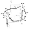
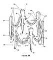
- FIGS. 5A, 5B and FIG. 6show perspective views ( FIGS. 5A, 6 ) and an axial view ( FIG. 5B ) of a preferred embodiment of the present invention which demonstrates the key parameters for multi-element, multi-directional tissue engaging geometry as a self closing tissue locking fastener embodiment.
- the device 26 in this preferred embodiment of the present inventionhas a generally ring-like configuration, comprising a ring 27 and multiple projection member features 28 , 29 extending from each side of said ring.
- the projection members from the ring 27shown as features 28 and 29 are multiple in nature and symmetrical in spacing.
- the ring 27 in the annular configuration of FIG. 5Adefines a central area 36 (best seen in FIG. 5B ).
- the ring 27has several functional zones, which in this embodiment comprise multiple independent torsional zones 30 , 31 A, and 31 B along the ring annulus. Zones 31 A are twistable zones, which can absorb at least a 90 degree twist during activation, and which will also recover at least about 50% of said bend when released.
- Zone 30 and connecting zone features 30 , 32 , 33 and 34may be relatively resistant to deformation under torque, or may have similar underlying mechanical properties to the materials in zones 31 A.
- Zones 31 Aare connected to the interconnecting zones 31 B and central zones 30 in a smooth manner, thus forming in their entirety the closed generally annular ring 27 which surrounds an area 36 .
- Connecting zones 31 Bmay have the same mechanical properties as one the zones they connect, or be intermediate.
- recovery of the positions of the spines 32upon return from the annular to the planar configuration, with the spines 32 embedded in the tissue, is substantially complete, i.e., nearly 100%.
- some permanent distortionmay occur during the conversion of the device from the planar form to the annular form.
- the tissue itselfmay prevent complete return of the spines 32 to the planar configuration.
- a significant residual bendis acceptable, since opposed tissue-piercing members disposed around the perimeter of a ring will collectively hold the fastener in place even with a significant degrees of residual deformation. It is believed that an approximately 50% return to the original position will prove to be effective in most situations, and in some cases a higher degree of residual deformation may be acceptable, depending on the particular tissue and the type of stresses placed on the tissue.
- the projection memberscomprise multiple central zones 30 , with attached features which comprises an integrated tissue piercing member 32 and stabilizing member 34 .
- Piercing member 32may preferably contain one or more securing tissue interacting members 33 (“barbs”), which as illustrated project toward the center of the device from ring 27 in its planar form ( FIG. 6 ).
- Said zones 30also may include a load stabilizing and deployment position location member 34 . It may have any number of different or multifaceted tissue interacting barbs 33 arrayed along projection from the tip of piercing member 32 to the central spine connecting the junction of zone 30 and zone 31 A features respectively.
- tissue interacting geometrymay also be defined in a preferred embodiment as projecting from or integral to torsion members 31 A and connecting members 31 B, in like wise fashion as described for members 11 A- 11 D and 15 in previously described FIGS. 1 and 2 respectively.
- FIGS. 5A and 6there are a sufficient number of zones 30 that stabilizing projections 34 need not be present on every zone 30 .
- FIG. 6The planar form of this embodiment device 26 as shown in FIG. 6 with minimal enclosed open area 36 is converted to the stressed annular form of FIG. 5A and maximum area 36 by being passed over a solid mandrel, typically round or having a reasonably smooth contour.
- this multiple zone embodiment 26may be squeezed diametrically, for example by squeezing the projections 34 together, so that zones 30 rotate to an axial alignment condition.
- FIG. 5Bshows an axial view of the embodiment in this condition, and its open central space 36 is easy to visualize in this projection.
- This stressed embodiment shown in an axial view in FIG. 5B generated by either methodcan then be inserted into a hollow cavity such as a tube which will constrain the embodiment in the axial stressed form.
- the stressed formcan then be transferred and stored on either the outside or the inside of a tube or other geometrically hollow object, provided that the geometry selected provides a constraint preventing the device 26 from rotating from the general shape shown in FIG. 5A back to the lower-energy planar state as shown in FIG. 6 .
- the stressed form of the fastener 26 embodimentwill revert to its original state only when released from said constraint geometry.
- tissue interacting member 32is shown as a piercing geometry construct and member 33 may be viewed as a tissue stopping construct which further imparts a compression locking force to the tissue pierced by feature 32 .
- FIGS. 5A 5 B and FIG. 6provides a sizeable clear annular central region 36 for the passage of instruments when the self closing tissue fastener is residing within the placement and deployment apparatus.
- this embodimentby design may be geometrically configured to engage and lock tissue yet leave a defined smaller central unobstructed zone 36 in the tissue locking position ( FIG. 6 ) where access through the tissue that has been fastened by the self closing fastener may be created and maintained.
- Such devicesas a stoma style port or plug for example may be secured without interference from the deployed fastener features.
- a larger central zonecan also be created, if needed, by having the tissue-affixing spines 32 pointing outward; or by having the spines 32 shorter in length.
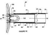
- FIGS. 7-10show perspective and sectional views of a preferred embodiment of the present invention placed within a deployment device that enables tissue manipulation, site placement and fastener deployment of the self closing tissue fastener.
- FIGS. 7 and 8describe a preferred embodiment of the positioning and deploying apparatus which can effectively deliver and deploy the self closing tissue fastener to the surgical site while maintaining a significant unobstructed central volume in the instrument for surgical and endoscopic instruments to pass.
- FIG. 7is a perspective views of the delivery system 39 with a fastener 26 (i.e., a fastener of the embodiment shown in FIGS. 5 and 6 ) in the stressed annular condition, before deployment of the fastener begins.
- a fastener 26i.e., a fastener of the embodiment shown in FIGS. 5 and 6
- FIG. 8a cross sectional view, shows the delivery system 39 in a fastener deployment condition where the fastener 26 in the stressed configuration shown in FIG. 5 is shown residing within and just held by an outer tubular like retaining member 40 with a proximal end 42 and distal end 41 .
- a clear unobstructed area 36is defined by this apparatus configuration through which other surgical instruments, apparatus, diagnostic or tissue control, closure or manipulation devices may pass.
- a preferred embodiment of fastener 26is residing within and against the inner wall of tubular outer shell like member 40 .
- Shell 40comprises a distal tissue contact end 41 and a proximal actuating end 42 . It is an advantage that fastener 26 is covered by tubular outer shell 40 such that the tissue engaging features 32 of fastener 26 are not exposed and so cannot inadvertently engage tissue during manipulation of the instrument.
- Shell 40is located at the distal end of tubular member 50 with fastener 26 residing within.
- the delivery apparatus 39holds the fastener 26 in the stressed state in this configuration, and with fastener 26 held in position, delivery apparatus 39 is easily manipulated within the surgical site.
- Shell 40 , tubular member 50 and endoscopic delivery tube 60are preferably all sealably connected. which also provides a significant advantage to the surgeon in that a sterile field can be maintained within the central area 36 of the instrument and a vacuum force can be transmitted to the distal end of the apparatus 39 .
- proximal end 42 of member 40is attached to a deployment pull wire member 72 at the distal end 71 of wire 70 .
- Pull wire member 70resides within a secondary lumen 63 of endoscopic instrument delivery tube 60 .
- Delivery tube 60is connected at the distal end 61 to a second axial tubular member 50 at proximal end 52 .
- Distal end 51 of tubular member 50resides, preferably sealably, within outer tubular shell member 40 .
- the distal end 51 of tube 50is essentially identical in diameter to the diameter of fastener 26 when fastener 26 is in the stressed or annular state, as illustrated in FIG. 8 .
- Shell 40is axially slidable along the outer surface of tubular member 50 from distal end 51 toward proximal end 52 respectively.
- shell 40is in sealing engagement with tube 50 to seal their mutual contact for use with vacuum.
- pull wire 70when pulled at proximal end 72 in the axial proximal direction, will then move the shell 40 of the apparatus to deploy fastener 26 .
- Fastener 26is held within and released from delivery system 39 by holding relative position and then applying a relative motion between endoscopic instrument delivery tube 60 and pull wire 70 .
- Endoscopic instrument delivery tube 60 and pull wire 70are shown in a truncated length state for illustration purposes, and are not intended to be limited in length or construct.
- Delivery tube 60may be comprised of flexible materials for control and direction. Numerous schemes features and constructs well known in the art may be applied at proximal end 62 of the endoscopic instrument delivery tube 60 to generate a required relative motion between endoscopic instrument delivery tube 60 and wire 70 .
- fastener 26rotates from the general shape shown in FIG. 5A back to the lower-energy planar state as shown in FIG. 6 . Since the points of the spines 32 were forced into tissue before the fastener 26 was released, then the rotation from the annular state of FIG. 6 to the planar state of FIG. 5 drives the points of the fasteners into the tissue and towards the center of the circular area 36 (see FIG. 5B ), thereby locking the tissue in position as the self-closing fastener 26 closes itself.
- FIGS. 7 and 8illustrate preferred embodiments of the positioning and deploying apparatus which can effectively deliver and deploy the self closing tissue fastener 26 to the surgical site.
- Preferred embodiment features of the present invention so describedalso can be used to manipulate and manage tissue during a surgical procedure or set and maintain an entry site portal to allow further access to deeper tissue or body organs.
- a sealed channel volume 35is described as passing wholly through the center core of the fastener and the delivery apparatus and thus the whole apparatus including fastener 26 is available for the surgeon to utilize as a “virtual port”.
- FIG. 9 and FIG. 10illustrate in cross sectional views a method of operation which facilitates the manipulation of tissue and the location and placement of the self closing tissue fastener on said tissue.
- the delivery apparatus 39 shown in FIGS. 9 and 10is functionally the same as the apparatus described in FIGS. 7 and 8 and identical numbers are used for identical parts.
- FIG. 9shows a cross sectional view of the preferred fastener 26 residing within the delivery system described in FIGS. 7 and 8 .
- the distal end of delivery apparatus 39(feature 41 ) is moved within the surgical field and placed in proximity to target tissue 100 .
- the delivery apparatus 39consisting of elements 40 , 50 , 60 and self closing fastener 26 within central volume 36 , with features and embodiments illustrated in FIGS. 7 and 8 , is deployed to target tissue element 100 .
- the proximal end of the unobstructed, sealed, and preferably centrally located channel 36is connected in a sealed manner to a vacuum source at the proximal end (not shown), and the distal end is then advanced and placed against target tissue.
- a vacuum sourceconnected to tube 60 at the proximal end of the delivery apparatus 39 allows the vacuum in the tubes 40 , 50 and 60 to pull on target tissue 100 , thereby creating a central dome-like distended tissue mass 101 pulled in by said vacuum.
- the tissue 101now resides the lumens of tubular elements 40 and 50 , which are designed to be sufficiently self-sealing to maintain said vacuum force.
- the self closing tissue fastener 26is then advanced into surrounding tissue 100 as described in the discussion of FIGS. 7 and 8 , thereby engaging tissue 100 with the multiple tissue piercing and retaining elements 32 and 33 of self closing tissue fastener 26 .
- the shell 40is shown as being retracted, via pull wire 70 , with respect to the device support tube 50 , and the self closing tissue fastener 26 is now released from its confinement. It will now be able to self actuate to attain the planar condition as detailed in the description of FIG. 6 .
- the stabilizer members 34 of fastener 26can now rotate outwards, allowing the tissue-piercing features 32 and tissue stop features 33 to enter tissue mass 100 and affix the parts of tissue 100 together.
- tissueis then removed from tube 50 of delivery apparatus 39 by releasing the vacuum.
- the delivery apparatus 39now can be withdrawn.
- Fastener 26is now fully engaged with tissue 100 , and remains within and locks and secures said tissue.
- a separate catheter-like devicecould be inserted in a sealing fashion down to tube 50 , and used to aspirate tissue 100 to form a dome 101 .
- the fastener 26could be released, and then the vacuum catheter or similar device could be withdrawn.
- tissue fasteners 26can be released one by one as required by the procedure, without having to withdraw the endoscope from the patient.
- tissue-piercing members 32or their equivalent in other embodiments, project outward when in the planar state, and stabilizers 34 project inward.
- stabilizers 34 located on ring 27can be shorter, and tissue piercing elements 32 can optionally be longer.
- a clear space 36 in the center of the planar fastener, when closed,may be larger in this configuration.
- the closure device of the inventionMoreover, once the basic tissue closure mechanism illustrated in FIG. 7-10 is understood, it becomes evident that new and improved methods of endoscopic surgery are made possible by the use of the closure device of the invention.
- the major improvement provided by the deviceis the opportunity to insert an endoscopic device, carrying one or more ready-to-deploy fasteners, to a site in the body; and then, in contrast to prior art devices, to conduct procedures using instruments inserted through the endoscopic device. Because the central lumen is open, complex devices, of relatively large diameter, can be inserted. It is possible in particular to have both visualization devices and manipulative or therapeutic devices present in the endoscope lumen, with fasteners waiting to be deployed, as described in this application, at the end of the procedure.
- Such procedures and devicesmay include, but are not limited to: vacuum, suture style attachment, needle or anchoring constructs of all types, quantity, spatial arrangement and/or delivery configuration.
- Multifunctional multi-lumen type devices and apparatusmay include hooks, snares, barbs, needles and/or inflatable and/or vacuum element constructs whether single or multiple in nature or in combinations thereof. Any of these devices may be positioned, transported or utilized through tubes 50 and 60 of the endoscope to satisfy the surgeon's need for selective tissue position securing and management.
- multiple nested delivery systems and fastenerscomprised of the preferred embodiment design and method, enabling the surgeon to control, manipulate access and close multiple sequential tissue membrane barriers organs, or tissues within the patient using tubes 50 and 60 as a conduit to advance to the surgical site.
- the materials comprising the self closing tissue fastener featuresbe selected for the ability to undergo the required deformations of stressed condition and planar condition as illustrated and defined in the numerous embodiment geometries shown by but not limited to FIGS. 1 through 6 and utilized in methods described in apparatus FIGS. 7 through 10 without mechanical failure or breakage.
- loading a fastener into a delivery apparatusthereby imparting stress or strain to the fastener 26 (or other designation), will not cause stress significant enough to permanently deform the fastener so much that it is unable to return sufficiently toward the original planar configuration to be able to fasten tissue in place.
- the fastenerwill return to a substantially planar configuration.
- the degree of rotation of the tissue locking members within the embodiment required for generating appropriate tissue locking or securing effectmay be varied based on the surgical application, procedure and technique employed. As such it may be advantageous to the patient for the surgeon to select an embodiment constructed from materials and geometries that may be designed to not recover completely from the stressed or annular condition, thus allowing tissue to be held in close proximity yet not in a fully compressed and/or closed state as represented or implied by the “planar” figure construct examples.
- materials selected to comprise those embodiments or portions thereofexhibit a high degree of “elasticity” and a low degree of “yield” and/or “creep”.
- These material attributeshave been shown to provide the embodiment with excellent functionality and perform in a satisfactory manner. That is, the ability of the interacting members to bend but not yield or break, while maintaining the overall geometric shape and spatial relationship, and preferably coupled with good kinetic energy storage capability, is preferred for this application.
- high performance high strength unique materialsmay not necessarily be selected nor desired in specific applications where tissue high compression is not needed, and should not be construed as being a requirement of all embodiments of the present invention.
- elasticityrefers to a material that is reversibly distortable, in that it can be bent or twisted up to 90 degrees or more, at room to body temperature, and will return to its original shape, or a reasonable approximation thereof, upon release from the “distortable” confined state
- composition of the preferred embodimentwill return to its original shape or a reasonable approximation thereof on release from its confinement.
- a “reasonable approximation”is “sufficiently close to the original configuration to reliably serve as a tissue fastener”. This can readily be determined by experimentation on candidate materials—alloys, composites, laminates, and the like: Bending the proposed material through up to 90 degrees or more, and determining if the material will fasten the target tissue that it has impaled while bent, provides a simple test of suitability of a material for use in the invention.
- a material suitable for use in the inventionrequires a sufficiently high modulus that the return force can overcome resistance by tissue; this implication is also easily tested by functional experimentation methods.
- the named materials in the scope of this applicationbelieved to be suitable, such as for example nitinol and certain stainless steels, have elastic moduli in the range of about 30 million psi or more. However, it is likely that not all materials with moduli in this range will be suitable. Furthermore, it may also be the case that materials, including metals, alloys, composites, laminates and/or unique combinations of materials coatings, adhesives and polymers, all or some with perhaps lower moduli, will, by their ability to be resilient and resistant to breakage when deformed, also prove to be suitable for this embodiment. Any such embodiment construct is by definition within the scope of this application
- Biodegradable materialsmay be utilized within the construction of the self closing tissue fastener or any portions thereof.
- tissue-piercing regions of the fastenergradually degrade in situ, allowing tissue to more nearly return to its original configuration.
- Coatings, treatments, finishes and/or encapsulationsmay be utilized to further enhance the performance properties or moderate or enhance desired geometric or performance traits to met specific clinical outcomes.
- the present inventionmay consist wholly or in part of the following types and general classes of materials: Nitinol, Stainless Steel, Spring Steel; Thermoplastic, Elastomeric and/or Thermoset Polymers or Polymer Blends; and any combinations or composite constructs combining any of these materials. It is necessary that the material have a sufficiently high modulus that the return force can overcome resistance by tissue; this is easily tested by simple experimentation.
- materialsincluding metals, alloys, composites, laminates or unique combinations of materials coatings and adhesives, all or some with perhaps lower moduli, will, by their ability to be resilient and resistant to breakage when deformed, also prove to be suitable for this embodiment. Any such embodiment construct is by definition within the scope of this application.
- Biological, drug, therapeutic and/or antibacterial coatingsmay also be employed on the surfaces or integral to the whole or a portion of the self closing tissue fastener and/or elements of the position and deploy apparatus to aid and assist in the healing processes or to provide and execute a specific therapeutic regimen protocol.
Landscapes
- Health & Medical Sciences (AREA)
- Life Sciences & Earth Sciences (AREA)
- Surgery (AREA)
- Heart & Thoracic Surgery (AREA)
- Engineering & Computer Science (AREA)
- Biomedical Technology (AREA)
- Nuclear Medicine, Radiotherapy & Molecular Imaging (AREA)
- Medical Informatics (AREA)
- Molecular Biology (AREA)
- Animal Behavior & Ethology (AREA)
- General Health & Medical Sciences (AREA)
- Public Health (AREA)
- Veterinary Medicine (AREA)
- Cardiology (AREA)
- Surgical Instruments (AREA)
Abstract
Description
Claims (21)
Priority Applications (1)
| Application Number | Priority Date | Filing Date | Title |
|---|---|---|---|
| US11/728,569US9408594B2 (en) | 2006-03-25 | 2007-03-26 | Self closing tissue fastener |
Applications Claiming Priority (2)
| Application Number | Priority Date | Filing Date | Title |
|---|---|---|---|
| US78583006P | 2006-03-25 | 2006-03-25 | |
| US11/728,569US9408594B2 (en) | 2006-03-25 | 2007-03-26 | Self closing tissue fastener |
Publications (2)
| Publication Number | Publication Date |
|---|---|
| US20070225762A1 US20070225762A1 (en) | 2007-09-27 |
| US9408594B2true US9408594B2 (en) | 2016-08-09 |
Family
ID=38957069
Family Applications (1)
| Application Number | Title | Priority Date | Filing Date |
|---|---|---|---|
| US11/728,569Active2028-07-30US9408594B2 (en) | 2006-03-25 | 2007-03-26 | Self closing tissue fastener |
Country Status (7)
| Country | Link |
|---|---|
| US (1) | US9408594B2 (en) |
| EP (1) | EP1998687B1 (en) |
| JP (1) | JP5584464B2 (en) |
| CN (1) | CN101453957B (en) |
| AU (1) | AU2007275882B2 (en) |
| BR (1) | BRPI0709278A2 (en) |
| WO (1) | WO2008010856A1 (en) |
Cited By (3)
| Publication number | Priority date | Publication date | Assignee | Title |
|---|---|---|---|---|
| US20150250461A1 (en)* | 2012-09-26 | 2015-09-10 | Eric Berreklouw | Constrictor for closing or narrowing a passage through tissue of a hollow organ |
| US10716547B2 (en) | 2008-11-18 | 2020-07-21 | United States Endoscopy Group, Inc. | Adapter for attaching devices to endoscopes |
| US20220061837A1 (en)* | 2020-09-03 | 2022-03-03 | Joseph Paul Ritz | Orthopedic torsion generated compression implants and methods for using same |
Families Citing this family (20)
| Publication number | Priority date | Publication date | Assignee | Title |
|---|---|---|---|---|
| BRPI0711615A2 (en)* | 2006-05-18 | 2011-12-06 | Aponos Medical Corp | introducer to access a site on a mammal's body, and method of making a high-torsion folding tubular introducer |
| US10149681B2 (en) | 2007-10-23 | 2018-12-11 | Insightra Medical, Inc. | Devices and methods for securing tissue |
| US9125656B2 (en) | 2007-10-23 | 2015-09-08 | Insightra Medical, Inc. | Devices and methods for securing tissue |
| US9265502B2 (en) | 2007-10-23 | 2016-02-23 | Insightra Medical, Inc. | Delivery assembly for resilient tissue clamp |
| US7926691B2 (en)* | 2008-04-14 | 2011-04-19 | Tyco Healthcare Group, L.P. | Variable compression surgical fastener cartridge |
| US8683895B2 (en)* | 2010-02-23 | 2014-04-01 | Kensey Nash Corporation | Single revolution snap action drive for surgical fasteners |
| US9775702B2 (en) | 2010-03-10 | 2017-10-03 | Smith & Nephew, Inc. | Composite interference screws and drivers |
| EP2809271B1 (en)* | 2012-02-01 | 2016-09-14 | St. Jude Medical, Inc. | Clip delivery system for heart valve repair |
| US10226270B2 (en)* | 2012-08-10 | 2019-03-12 | W. L. Gore & Associates, Inc. | Microanchors for anchoring devices to body tissues |
| US9155531B2 (en)* | 2013-03-15 | 2015-10-13 | Smith & Nephew, Inc. | Miniaturized dual drive open architecture suture anchor |
| CN103932748B (en)* | 2014-05-13 | 2015-06-03 | 吴伟 | Medical suture clip |
| US20160089130A1 (en)* | 2014-09-30 | 2016-03-31 | Biomet Sports Medicine, Llc | Soft Tissue Attachment |
| US20170079658A1 (en)* | 2015-09-18 | 2017-03-23 | Empire Technology Development Llc | Insitu swappable clip delivery cartridge |
| US10667819B2 (en) | 2016-01-18 | 2020-06-02 | Insightra Medical, Inc. | Delivery assembly for resilient tissue clamp |
| CN107137119A (en)* | 2017-07-04 | 2017-09-08 | 安瑞医疗器械(杭州)有限公司 | A kind of closing clamp and its method for releasing |
| CN107374685B (en)* | 2017-07-09 | 2023-08-15 | 杨西群 | Soft tissue sleeve cutting anastomat based on shape memory alloy |
| EP3781046A4 (en)* | 2018-04-17 | 2021-12-29 | Ruebeck, David | Device and method for connecting tubular structures |
| CN108577917B (en)* | 2018-05-17 | 2024-08-02 | 南微医学科技股份有限公司 | Self-help anastomosis clamp for alimentary canal and release device thereof |
| US12127742B2 (en) | 2019-07-26 | 2024-10-29 | Boston Scientific Scimed, Inc. | Devices, systems, and methods for closing a wound |
| CN116236246A (en)* | 2022-12-30 | 2023-06-09 | 先健科技(深圳)有限公司 | Suture device and suture system |
Citations (72)
| Publication number | Priority date | Publication date | Assignee | Title |
|---|---|---|---|---|
| US3266059A (en) | 1963-06-19 | 1966-08-16 | North American Aviation Inc | Prestressed flexible joint for mechanical arms and the like |
| US3598125A (en) | 1968-06-07 | 1971-08-10 | James J Cogley | Aneurism clamp |
| US3613683A (en) | 1969-06-04 | 1971-10-19 | George Kees Jr | Clip-applying surgical instrument |
| US3954108A (en) | 1972-11-03 | 1976-05-04 | Davis Hugh J | Occlusion clip and instrument for applying same |
| US4217902A (en) | 1977-05-02 | 1980-08-19 | March Alfred L | Hemostatic clip |
| US4735194A (en) | 1987-01-13 | 1988-04-05 | University Patents, Inc. | Flexible endoscopic ligating instrument |
| US4791707A (en) | 1986-08-26 | 1988-12-20 | Tucker Wilson H | Clip applicator, spreadable clips and method for applying the clips |
| US4832027A (en) | 1985-05-31 | 1989-05-23 | Alice Utz | Surgical clamp |
| US5026379A (en) | 1989-12-05 | 1991-06-25 | Inbae Yoon | Multi-functional instruments and stretchable ligating and occluding devices |
| US5035692A (en) | 1990-02-13 | 1991-07-30 | Nicholas Herbert | Hemostasis clip applicator |
| US5174276A (en) | 1988-11-18 | 1992-12-29 | Hillway Surgical Limited | Endoscope device for applying an aneurysm clip |
| US5190542A (en) | 1991-11-05 | 1993-03-02 | Nakao Naomi L | Surgical retrieval assembly and related method |
| US5201908A (en) | 1991-06-10 | 1993-04-13 | Endomedical Technologies, Inc. | Sheath for protecting endoscope from contamination |
| US5217001A (en) | 1991-12-09 | 1993-06-08 | Nakao Naomi L | Endoscope sheath and related method |
| US5381782A (en) | 1992-01-09 | 1995-01-17 | Spectrum Medsystems Corporation | Bi-directional and multi-directional miniscopes |
| US5386817A (en) | 1991-06-10 | 1995-02-07 | Endomedical Technologies, Inc. | Endoscope sheath and valve system |
| US5569274A (en) | 1993-02-22 | 1996-10-29 | Heartport, Inc. | Endoscopic vascular clamping system and method |
| US5651788A (en) | 1995-05-17 | 1997-07-29 | C.R. Bard, Inc. | Mucosectomy process and device |
| US5695448A (en) | 1994-08-29 | 1997-12-09 | Olympus Optical Co., Ltd. | Endoscopic sheath |
| DE19711673A1 (en) | 1997-03-20 | 1998-10-01 | Erbe Elektromedizin | Device for the coagulation of biological tissues |
| US5972002A (en) | 1998-06-02 | 1999-10-26 | Cabot Technology Corporation | Apparatus and method for surgical ligation |
| US6059719A (en) | 1997-08-06 | 2000-05-09 | Olympus Optical Co., Ltd. | Endoscope system |
| US6071233A (en) | 1997-10-31 | 2000-06-06 | Olympus Optical Co., Ltd. | Endoscope |
| US6152937A (en)* | 1998-11-06 | 2000-11-28 | St. Jude Medical Cardiovascular Group, Inc. | Medical graft connector and methods of making and installing same |
| US6196966B1 (en) | 1995-10-10 | 2001-03-06 | Conceptus, Inc. | Access catheter and method for maintaining separation between a falloposcope and a tubal wall |
| US6197042B1 (en)* | 2000-01-05 | 2001-03-06 | Medical Technology Group, Inc. | Vascular sheath with puncture site closure apparatus and methods of use |
| US6293909B1 (en) | 1998-08-07 | 2001-09-25 | Scimed Life Systems, Inc. | Device and method of using a surgical assembly with mesh sheath |
| US6306081B1 (en) | 1998-04-21 | 2001-10-23 | Olympus Optical Co., Ltd. | Hood for an endoscope |
| US20010053909A1 (en) | 2000-05-26 | 2001-12-20 | Olympus Optical Co., Ltd. | Endoscope hood for mucous membrane resection |
| US20020055668A1 (en) | 1998-06-11 | 2002-05-09 | Stm Medizintechnik | Endoscope shaft |
| US20020082641A1 (en)* | 2000-12-07 | 2002-06-27 | Ginn Richard S. | Closure device and methods for making and using them |
| US6428548B1 (en) | 1999-11-18 | 2002-08-06 | Russell F. Durgin | Apparatus and method for compressing body tissue |
| US6450948B1 (en) | 1999-11-02 | 2002-09-17 | Vista Medical Technologies, Inc. | Deflecting tip for surgical cannula |
| US20020133150A1 (en) | 1996-12-19 | 2002-09-19 | Whayne James G. | Structures for supporting multiple electrode elements |
| US20020188318A1 (en) | 2000-12-07 | 2002-12-12 | Carley Michael T. | Closure device and methods for making and using them |
| US6520974B2 (en) | 1997-06-30 | 2003-02-18 | Eva Corporation | Surgical fastener |
| US6569085B2 (en) | 2001-08-16 | 2003-05-27 | Syntheon, Llc | Methods and apparatus for delivering a medical instrument over an endoscope while the endoscope is in a body lumen |
| US6582452B2 (en) | 2000-09-08 | 2003-06-24 | James Coleman | Surgical stapler |
| US6602263B1 (en)* | 1999-11-30 | 2003-08-05 | St. Jude Medical Atg, Inc. | Medical grafting methods and apparatus |
| US20030153932A1 (en) | 1996-09-16 | 2003-08-14 | Spence Paul A. | Apparatus and method for performing an anastomosis |
| US20030158578A1 (en) | 2002-02-21 | 2003-08-21 | Integrated Vascular Systems, Inc. | Sheath apparatus and methods for delivering a closure device |
| US6669708B1 (en) | 1999-12-09 | 2003-12-30 | Michael Nissenbaum | Devices, systems and methods for creating sutureless on-demand vascular anastomoses and hollow organ communication channels |
| US6689130B2 (en) | 2001-06-04 | 2004-02-10 | Olympus Corporation | Treatment apparatus for endoscope |
| US6699180B2 (en) | 2000-10-11 | 2004-03-02 | Olympus Corporation | Endoscopic hood |
| US20040068279A1 (en) | 2002-10-04 | 2004-04-08 | St. Jude Medical Atg, Inc. | Apparatus and methods for creating anastomoses |
| US6726704B1 (en)* | 1998-05-29 | 2004-04-27 | By-Pass, Inc. | Advanced closure device |
| US20040087981A1 (en) | 2000-01-25 | 2004-05-06 | Rod Berube | Tissue fastener |
| US20040097982A1 (en) | 1999-11-18 | 2004-05-20 | Jugenheimer Kristin A. | Apparatus and method for compressing body tissue |
| US20040210111A1 (en) | 2002-12-02 | 2004-10-21 | Olympus Corporation | Mucosa excision device using endoscope |
| DE102004015291A1 (en) | 2003-03-28 | 2004-10-21 | Fuji Photo Optical Co. Ltd. | Cap for attaching to rigid tip of endoscope insertion sleeve, for image enlargement, cap part which protrudes axially forward in direction of tip end section, and has continuously varying wall thickness |
| US20040230095A1 (en) | 2003-05-16 | 2004-11-18 | David Stefanchik | Medical apparatus for use with an endoscope |
| WO2004103430A2 (en) | 2003-05-19 | 2004-12-02 | Usgi Medical Inc. | Endoluminal tool deployment system |
| US20050075538A1 (en) | 2003-04-01 | 2005-04-07 | Banik Michael S. | Single use endoscopic imaging system |
| US20050107667A1 (en) | 2003-05-23 | 2005-05-19 | Novare Surgical Systems, Inc. | Hand-actuated device for remote manipulation of a grasping tool |
| US6974411B2 (en) | 2000-04-03 | 2005-12-13 | Neoguide Systems, Inc. | Endoscope with single step guiding apparatus |
| US20050283188A1 (en)* | 1998-05-29 | 2005-12-22 | By-Pass, Inc. | Vascular closure device |
| US20060058582A1 (en) | 2002-06-13 | 2006-03-16 | Usgi Medical Inc. | Disposable shapelocking system |
| US20060069304A1 (en) | 2004-09-24 | 2006-03-30 | Olympus Corporation | Endoscopic treatment instrument, endoscopic treatment system and supporting adaptor |
| US7056284B2 (en) | 2002-01-04 | 2006-06-06 | Vision Sciences, Inc. | Endoscope assemblies having working channels with reduced bending and stretching resistance |
| US7059508B2 (en) | 2004-06-30 | 2006-06-13 | Ethicon Endo-Surgery, Inc. | Surgical stapling instrument incorporating an uneven multistroke firing mechanism having a rotary transmission |
| US20060135989A1 (en) | 2000-12-07 | 2006-06-22 | Carley Michael T | Closure device |
| US7189247B1 (en) | 2002-09-06 | 2007-03-13 | Conmed Endoscopic Technologies, Inc. | Endoscopic band ligator |
| US7204804B2 (en) | 2002-09-06 | 2007-04-17 | C.R. Bard, Inc. | Endoscopic accessory mounting adaptor |
| US20070197862A1 (en) | 2004-06-18 | 2007-08-23 | Jacques Deviere | Endoscopic device |
| US20070270752A1 (en) | 2006-05-18 | 2007-11-22 | Labombard Denis | Multifunctional instrument introducer |
| US20100038403A1 (en) | 2006-09-08 | 2010-02-18 | D Arcangelo Michele | Surgical instrument and actuating movement transmitting device therefore |
| US20100048988A1 (en) | 2006-07-07 | 2010-02-25 | Alessandro Pastorelli | A deployment system for introducing a surgical instrument in a patients body |
| US20100069933A1 (en) | 2006-01-16 | 2010-03-18 | D Arcangelo Michele | Positioning device for deploying at least one locking portion of an anastomotic device and method for carrying out anastomosis in tracts of the digestive tube |
| US20100125164A1 (en) | 2008-11-18 | 2010-05-20 | Labombard Denis | Adapter for attaching devices to endoscopes |
| US20100133320A1 (en) | 2004-09-10 | 2010-06-03 | Federico Bilotti | Surgical Stapling Instrument |
| US8182422B2 (en) | 2005-12-13 | 2012-05-22 | Avantis Medical Systems, Inc. | Endoscope having detachable imaging device and method of using |
| US8313496B2 (en) | 2001-02-02 | 2012-11-20 | Lsi Solutions, Inc. | System for endoscopic suturing |
Family Cites Families (4)
| Publication number | Priority date | Publication date | Assignee | Title |
|---|---|---|---|---|
| WO2000056227A1 (en)* | 1999-03-19 | 2000-09-28 | By-Pass, Inc. | Advanced closure device |
| NL1010386C2 (en)* | 1998-10-23 | 2000-04-26 | Eric Berreklouw | Anastomosis device. |
| US6767356B2 (en)* | 2000-09-01 | 2004-07-27 | Angiolink Corporation | Advanced wound site management systems and methods |
| EP1283143A1 (en)* | 2001-08-10 | 2003-02-12 | Schwab Verkehrstechnik AG | Gas-hydraulic damping device |
- 2007
- 2007-03-26AUAU2007275882Apatent/AU2007275882B2/enactiveActive
- 2007-03-26JPJP2009502911Apatent/JP5584464B2/enactiveActive
- 2007-03-26WOPCT/US2007/007396patent/WO2008010856A1/enactiveApplication Filing
- 2007-03-26EPEP07835715.9Apatent/EP1998687B1/enactiveActive
- 2007-03-26USUS11/728,569patent/US9408594B2/enactiveActive
- 2007-03-26CNCN2007800191223Apatent/CN101453957B/enactiveActive
- 2007-03-26BRBRPI0709278-4Apatent/BRPI0709278A2/ennot_activeApplication Discontinuation
Patent Citations (86)
| Publication number | Priority date | Publication date | Assignee | Title |
|---|---|---|---|---|
| US3266059A (en) | 1963-06-19 | 1966-08-16 | North American Aviation Inc | Prestressed flexible joint for mechanical arms and the like |
| US3598125A (en) | 1968-06-07 | 1971-08-10 | James J Cogley | Aneurism clamp |
| US3613683A (en) | 1969-06-04 | 1971-10-19 | George Kees Jr | Clip-applying surgical instrument |
| US3954108A (en) | 1972-11-03 | 1976-05-04 | Davis Hugh J | Occlusion clip and instrument for applying same |
| US4217902A (en) | 1977-05-02 | 1980-08-19 | March Alfred L | Hemostatic clip |
| US4832027A (en) | 1985-05-31 | 1989-05-23 | Alice Utz | Surgical clamp |
| US4791707A (en) | 1986-08-26 | 1988-12-20 | Tucker Wilson H | Clip applicator, spreadable clips and method for applying the clips |
| US4735194A (en) | 1987-01-13 | 1988-04-05 | University Patents, Inc. | Flexible endoscopic ligating instrument |
| US4735194C1 (en) | 1987-01-13 | 2001-05-08 | Dept Of Veterans Affairs The U | Flexile endoscopic ligating instrument |
| US5174276A (en) | 1988-11-18 | 1992-12-29 | Hillway Surgical Limited | Endoscope device for applying an aneurysm clip |
| US5334209A (en) | 1989-12-05 | 1994-08-02 | Inbae Yoon | Multi-functional instruments and stretchable ligating and occluding devices |
| US5026379A (en) | 1989-12-05 | 1991-06-25 | Inbae Yoon | Multi-functional instruments and stretchable ligating and occluding devices |
| US5035692A (en) | 1990-02-13 | 1991-07-30 | Nicholas Herbert | Hemostasis clip applicator |
| US5201908A (en) | 1991-06-10 | 1993-04-13 | Endomedical Technologies, Inc. | Sheath for protecting endoscope from contamination |
| US5386817A (en) | 1991-06-10 | 1995-02-07 | Endomedical Technologies, Inc. | Endoscope sheath and valve system |
| US5190542A (en) | 1991-11-05 | 1993-03-02 | Nakao Naomi L | Surgical retrieval assembly and related method |
| US5217001A (en) | 1991-12-09 | 1993-06-08 | Nakao Naomi L | Endoscope sheath and related method |
| US5381782A (en) | 1992-01-09 | 1995-01-17 | Spectrum Medsystems Corporation | Bi-directional and multi-directional miniscopes |
| US5569274A (en) | 1993-02-22 | 1996-10-29 | Heartport, Inc. | Endoscopic vascular clamping system and method |
| US5695448A (en) | 1994-08-29 | 1997-12-09 | Olympus Optical Co., Ltd. | Endoscopic sheath |
| US5651788A (en) | 1995-05-17 | 1997-07-29 | C.R. Bard, Inc. | Mucosectomy process and device |
| US6196966B1 (en) | 1995-10-10 | 2001-03-06 | Conceptus, Inc. | Access catheter and method for maintaining separation between a falloposcope and a tubal wall |
| US20030153932A1 (en) | 1996-09-16 | 2003-08-14 | Spence Paul A. | Apparatus and method for performing an anastomosis |
| US20020133150A1 (en) | 1996-12-19 | 2002-09-19 | Whayne James G. | Structures for supporting multiple electrode elements |
| DE19711673A1 (en) | 1997-03-20 | 1998-10-01 | Erbe Elektromedizin | Device for the coagulation of biological tissues |
| US6520974B2 (en) | 1997-06-30 | 2003-02-18 | Eva Corporation | Surgical fastener |
| US6059719A (en) | 1997-08-06 | 2000-05-09 | Olympus Optical Co., Ltd. | Endoscope system |
| US6071233A (en) | 1997-10-31 | 2000-06-06 | Olympus Optical Co., Ltd. | Endoscope |
| US6306081B1 (en) | 1998-04-21 | 2001-10-23 | Olympus Optical Co., Ltd. | Hood for an endoscope |
| US20050283188A1 (en)* | 1998-05-29 | 2005-12-22 | By-Pass, Inc. | Vascular closure device |
| US6726704B1 (en)* | 1998-05-29 | 2004-04-27 | By-Pass, Inc. | Advanced closure device |
| US5972002A (en) | 1998-06-02 | 1999-10-26 | Cabot Technology Corporation | Apparatus and method for surgical ligation |
| US20020055668A1 (en) | 1998-06-11 | 2002-05-09 | Stm Medizintechnik | Endoscope shaft |
| US6293909B1 (en) | 1998-08-07 | 2001-09-25 | Scimed Life Systems, Inc. | Device and method of using a surgical assembly with mesh sheath |
| US6152937A (en)* | 1998-11-06 | 2000-11-28 | St. Jude Medical Cardiovascular Group, Inc. | Medical graft connector and methods of making and installing same |
| US6450948B1 (en) | 1999-11-02 | 2002-09-17 | Vista Medical Technologies, Inc. | Deflecting tip for surgical cannula |
| US6428548B1 (en) | 1999-11-18 | 2002-08-06 | Russell F. Durgin | Apparatus and method for compressing body tissue |
| US6849078B2 (en) | 1999-11-18 | 2005-02-01 | Ovesco Endoscopy, Gmbh | Apparatus and method for compressing body tissue |
| US6911032B2 (en) | 1999-11-18 | 2005-06-28 | Scimed Life Systems, Inc. | Apparatus and method for compressing body tissue |
| EP2263572B1 (en) | 1999-11-18 | 2014-08-06 | Ovesco Endoscopy AG | Apparatus for compressing body tissue |
| EP1143861B1 (en) | 1999-11-18 | 2011-07-20 | Ovesco Endoscopy AG | Apparatus for compressing body tissue |
| US20040097982A1 (en) | 1999-11-18 | 2004-05-20 | Jugenheimer Kristin A. | Apparatus and method for compressing body tissue |
| US6602263B1 (en)* | 1999-11-30 | 2003-08-05 | St. Jude Medical Atg, Inc. | Medical grafting methods and apparatus |
| US6669708B1 (en) | 1999-12-09 | 2003-12-30 | Michael Nissenbaum | Devices, systems and methods for creating sutureless on-demand vascular anastomoses and hollow organ communication channels |
| US6197042B1 (en)* | 2000-01-05 | 2001-03-06 | Medical Technology Group, Inc. | Vascular sheath with puncture site closure apparatus and methods of use |
| US20040087981A1 (en) | 2000-01-25 | 2004-05-06 | Rod Berube | Tissue fastener |
| US6974411B2 (en) | 2000-04-03 | 2005-12-13 | Neoguide Systems, Inc. | Endoscope with single step guiding apparatus |
| US20010053909A1 (en) | 2000-05-26 | 2001-12-20 | Olympus Optical Co., Ltd. | Endoscope hood for mucous membrane resection |
| US6926731B2 (en) | 2000-09-08 | 2005-08-09 | James Coleman | Surgical stapler |
| US6582452B2 (en) | 2000-09-08 | 2003-06-24 | James Coleman | Surgical stapler |
| US6699180B2 (en) | 2000-10-11 | 2004-03-02 | Olympus Corporation | Endoscopic hood |
| US20060135989A1 (en) | 2000-12-07 | 2006-06-22 | Carley Michael T | Closure device |
| US7001398B2 (en) | 2000-12-07 | 2006-02-21 | Integrated Vascular Systems, Inc. | Closure device and methods for making and using them |
| US20020188318A1 (en) | 2000-12-07 | 2002-12-12 | Carley Michael T. | Closure device and methods for making and using them |
| US20020082641A1 (en)* | 2000-12-07 | 2002-06-27 | Ginn Richard S. | Closure device and methods for making and using them |
| US8313496B2 (en) | 2001-02-02 | 2012-11-20 | Lsi Solutions, Inc. | System for endoscopic suturing |
| US6689130B2 (en) | 2001-06-04 | 2004-02-10 | Olympus Corporation | Treatment apparatus for endoscope |
| US6569085B2 (en) | 2001-08-16 | 2003-05-27 | Syntheon, Llc | Methods and apparatus for delivering a medical instrument over an endoscope while the endoscope is in a body lumen |
| US7056284B2 (en) | 2002-01-04 | 2006-06-06 | Vision Sciences, Inc. | Endoscope assemblies having working channels with reduced bending and stretching resistance |
| US20030158578A1 (en) | 2002-02-21 | 2003-08-21 | Integrated Vascular Systems, Inc. | Sheath apparatus and methods for delivering a closure device |
| WO2003071955A2 (en) | 2002-02-21 | 2003-09-04 | Integrated Vascular Systems, Inc. | Closure device and methods for making and using them |
| US20060058582A1 (en) | 2002-06-13 | 2006-03-16 | Usgi Medical Inc. | Disposable shapelocking system |
| US7204804B2 (en) | 2002-09-06 | 2007-04-17 | C.R. Bard, Inc. | Endoscopic accessory mounting adaptor |
| US7189247B1 (en) | 2002-09-06 | 2007-03-13 | Conmed Endoscopic Technologies, Inc. | Endoscopic band ligator |
| US20040068279A1 (en) | 2002-10-04 | 2004-04-08 | St. Jude Medical Atg, Inc. | Apparatus and methods for creating anastomoses |
| US7588580B2 (en) | 2002-12-02 | 2009-09-15 | Olympus Corporation | Mucosa excision device using endoscope |
| US20040210111A1 (en) | 2002-12-02 | 2004-10-21 | Olympus Corporation | Mucosa excision device using endoscope |
| DE102004015291A1 (en) | 2003-03-28 | 2004-10-21 | Fuji Photo Optical Co. Ltd. | Cap for attaching to rigid tip of endoscope insertion sleeve, for image enlargement, cap part which protrudes axially forward in direction of tip end section, and has continuously varying wall thickness |
| US20050075538A1 (en) | 2003-04-01 | 2005-04-07 | Banik Michael S. | Single use endoscopic imaging system |
| US20040230095A1 (en) | 2003-05-16 | 2004-11-18 | David Stefanchik | Medical apparatus for use with an endoscope |
| WO2004103430A2 (en) | 2003-05-19 | 2004-12-02 | Usgi Medical Inc. | Endoluminal tool deployment system |
| US20050107667A1 (en) | 2003-05-23 | 2005-05-19 | Novare Surgical Systems, Inc. | Hand-actuated device for remote manipulation of a grasping tool |
| US20070197862A1 (en) | 2004-06-18 | 2007-08-23 | Jacques Deviere | Endoscopic device |
| US7059508B2 (en) | 2004-06-30 | 2006-06-13 | Ethicon Endo-Surgery, Inc. | Surgical stapling instrument incorporating an uneven multistroke firing mechanism having a rotary transmission |
| US20100133320A1 (en) | 2004-09-10 | 2010-06-03 | Federico Bilotti | Surgical Stapling Instrument |
| US7575548B2 (en) | 2004-09-24 | 2009-08-18 | Olympus Corporation | Endoscopic treatment instrument, endoscopic treatment system and supporting adaptor |
| US20060069304A1 (en) | 2004-09-24 | 2006-03-30 | Olympus Corporation | Endoscopic treatment instrument, endoscopic treatment system and supporting adaptor |
| US8182422B2 (en) | 2005-12-13 | 2012-05-22 | Avantis Medical Systems, Inc. | Endoscope having detachable imaging device and method of using |
| US20100069933A1 (en) | 2006-01-16 | 2010-03-18 | D Arcangelo Michele | Positioning device for deploying at least one locking portion of an anastomotic device and method for carrying out anastomosis in tracts of the digestive tube |
| US20070270752A1 (en) | 2006-05-18 | 2007-11-22 | Labombard Denis | Multifunctional instrument introducer |
| US20100048988A1 (en) | 2006-07-07 | 2010-02-25 | Alessandro Pastorelli | A deployment system for introducing a surgical instrument in a patients body |
| US20100038403A1 (en) | 2006-09-08 | 2010-02-18 | D Arcangelo Michele | Surgical instrument and actuating movement transmitting device therefore |
| US20100125164A1 (en) | 2008-11-18 | 2010-05-20 | Labombard Denis | Adapter for attaching devices to endoscopes |
| WO2010059200A1 (en) | 2008-11-18 | 2010-05-27 | Denis Labombard | Adapter for attaching devices to endoscopes |
| US8920311B2 (en) | 2008-11-18 | 2014-12-30 | Aponos Medical Corp. | Adapter for attaching devices to endoscopes |
| US20150230782A1 (en) | 2008-11-18 | 2015-08-20 | Aponos Medical Corporation | Adapter for Attaching Devices to Endoscopes |
Non-Patent Citations (16)
| Title |
|---|
| ASGE/SAGES Working Group on Natural Orifice Translumenal Endoscopic Surgery, Gastrointest Endosc, 63(2):199-203 (2006). |
| Cotton, P. B., "Interventional Gastroenterology (Endoscopy) at the Crossroads: A Plea for Restructuring in Digestive Diseases," Gastroenterology, 107:294-299 (1994). |
| Desilets, D., et al., "Gastric closure in NOTES using a novel, over-the-scope nitinol clip-A survival study in an animal model", International NOSCAR Conference on NOTES (4th). Boston, MA. Jul. 9-Jul. 11, 2009, 1 page. |
| Desilets, D., et al., "Gastrotomy closure with the lock-it system and the Padlock-G clip: a survival study in a porcine model", J. Laparoendosc. Adv. Surg. Tech. A., 20(8):671-676 (2010). PubMed Abstract, available at: http://www.ncbi.nlm.nih.gov/pubmed/20687850, 1 page. |
| Fritscher-Ravens, A., et al., "Transgastric Gastropexy and Hiatal Hernia Repair for GERD Under EUS Control: A Porcine Model," Gastrointest Endosc, 59(1):89-95 (2004). |
| Guarncr-Argcntc, C., et al., "Yes, we can: reliable colonic closure with the Padlock-G clip in a survival porcine study (with video)", Gastrointestinal Endoscopy, 72(4):841-844 (2010). |
| International Preliminary Report on Patentability in International Application No. PCT PCT/US2009/006164 "Adapter for Attaching Devices to Endoscopes," mailed May 24, 2011. |
| International Search Report "Multifunctional Instrument Introducer," mailed Nov. 6, 2007 from International Application No. PCT/US2007/012049 filed May 18, 2007. |
| International Search Report and Written Opinion mailed Aug. 30, 2007 from International Application No. PCT/US2007/007396 filed Mar. 26, 2007. |
| International Search Report in International Application No. PCT/US2009/006164 "Adapter for Attaching Devices to Endoscopes," mailed Mar. 5, 2010. |
| Jagannath, S. B. et al., "Peroral Transgastric Endoscopic Ligation of Fallopian Tubes with Long-Term Survival in a Procine Model," Gastrointest Endos, 61(3):449-453 (2005). |
| Modlin, I. M., "Perspectives and Reflections on Integrated Digestive Surgery," Best Practice & Res Clin Gastroenterol, 16(6):885-914 (2002). |
| Ponsky, J. L., "Gastroenterologists as Surgeons What They Need to Know", Gastrointest Endosc, 61(3):454 (2005). |
| Romanelli, J.R., et al., "Natural orifice transluminal endoscopic surgery gastrotomy closure in porcine explants with the Padlock-G clip using the Lock-It system", Endoscopy, 42:306-310 (2010). |
| Vitale, G. C., et al., "The Advancing Art and Science of Endoscopy", Amer J. Surg, 190:228-233 (2005). |
| Written Opinion of the International Searching Authority "Multifunctional Instrument Introducer," mailed Nov. 6, 2007 from International Application No. PCT/US2007/012049 filed May 18, 2007. |
Cited By (5)
| Publication number | Priority date | Publication date | Assignee | Title |
|---|---|---|---|---|
| US10716547B2 (en) | 2008-11-18 | 2020-07-21 | United States Endoscopy Group, Inc. | Adapter for attaching devices to endoscopes |
| US11266390B2 (en) | 2008-11-18 | 2022-03-08 | United States Endoscopy Group, Inc. | Adapter for attaching devices to endoscopes |
| US20150250461A1 (en)* | 2012-09-26 | 2015-09-10 | Eric Berreklouw | Constrictor for closing or narrowing a passage through tissue of a hollow organ |
| US20220061837A1 (en)* | 2020-09-03 | 2022-03-03 | Joseph Paul Ritz | Orthopedic torsion generated compression implants and methods for using same |
| US12268426B2 (en)* | 2020-09-03 | 2025-04-08 | 210 Dynamic, Llc | Orthopedic torsion generated compression implants and methods for using same |
Also Published As
| Publication number | Publication date |
|---|---|
| JP2009531136A (en) | 2009-09-03 |
| AU2007275882B2 (en) | 2011-08-04 |
| CN101453957A (en) | 2009-06-10 |
| US20070225762A1 (en) | 2007-09-27 |
| JP5584464B2 (en) | 2014-09-03 |
| EP1998687A1 (en) | 2008-12-10 |
| CN101453957B (en) | 2011-04-20 |
| WO2008010856A1 (en) | 2008-01-24 |
| EP1998687B1 (en) | 2016-10-05 |
| EP1998687A4 (en) | 2012-12-26 |
| BRPI0709278A2 (en) | 2011-07-12 |
| AU2007275882A1 (en) | 2008-01-24 |
Similar Documents
| Publication | Publication Date | Title |
|---|---|---|
| US9408594B2 (en) | Self closing tissue fastener | |
| JP5367933B2 (en) | A device for making and holding tissue bags | |
| US6387114B2 (en) | Gastrointestinal compression clips | |
| JP4777885B2 (en) | Tissue closure device and tissue closure device | |
| US10278703B2 (en) | Temporary fixation tools for use with circular anastomotic staplers | |
| EP1030606B1 (en) | Gastrointestinal compression clips | |
| AU719161B2 (en) | Suture spring device | |
| RU2661056C2 (en) | Circular anvil introduction system with alignment feature | |
| EP2685912B1 (en) | Surgical stapling instruments | |
| US9521995B2 (en) | Devices and systems for approximation and fastening of soft tissue | |
| EP2037820B1 (en) | Low profile tissue anchors and tissue anchor systems | |
| JP6749915B2 (en) | Curved surgical fasteners for securing a prosthesis to tissue | |
| US9783329B2 (en) | Articulating apparatus with shipping wedge | |
| US8133241B2 (en) | Articulated elements and methods for use | |
| JP4245481B2 (en) | Surgical fastener | |
| CN103429170B (en) | Surgical Fastening Instruments | |
| US5782844A (en) | Suture spring device applicator | |
| US20130030462A1 (en) | Laparoscopic surgical device | |
| US20140058419A1 (en) | Method of forming through hole | |
| JP2017533042A (en) | Clips and applicators for tissue closure | |
| AU2013206096B2 (en) | Surgical fasteners and methods and devices for deploying a surgical fastener | |
| US20130006272A1 (en) | Sealing Clip, Delivery Systems, and Methods | |
| US20080234703A1 (en) | Tissue approximation system | |
| MX2015006801A (en) | Pivoting anvil for surgical circular stapler. | |
| JP2019537479A (en) | Minimally invasive tissue suturing device |
Legal Events
| Date | Code | Title | Description |
|---|---|---|---|
| AS | Assignment | Owner name:SANDBOX LLC, MASSACHUSETTS Free format text:ASSIGNMENT OF ASSIGNORS INTEREST;ASSIGNOR:LABOMBARD, DENIS;REEL/FRAME:019202/0281 Effective date:20070323 | |
| AS | Assignment | Owner name:APONOS INC., NEW HAMPSHIRE Free format text:ASSIGNMENT OF ASSIGNORS INTEREST;ASSIGNOR:LABOMBARD, DENIS;REEL/FRAME:021809/0101 Effective date:20081027 | |
| AS | Assignment | Owner name:APONOS MEDICAL CORP., NEW HAMPSHIRE Free format text:ASSIGNMENT OF ASSIGNORS INTEREST;ASSIGNOR:SANDBOX, LLC;REEL/FRAME:026904/0274 Effective date:20110910 | |
| STCF | Information on status: patent grant | Free format text:PATENTED CASE | |
| AS | Assignment | Owner name:UNITED STATES ENDOSCOPY GROUP, INC., OHIO Free format text:ASSIGNMENT OF ASSIGNORS INTEREST;ASSIGNOR:APONOS MEDICAL CORP;REEL/FRAME:042500/0115 Effective date:20170426 | |
| FEPP | Fee payment procedure | Free format text:ENTITY STATUS SET TO UNDISCOUNTED (ORIGINAL EVENT CODE: BIG.); ENTITY STATUS OF PATENT OWNER: LARGE ENTITY | |
| MAFP | Maintenance fee payment | Free format text:PAYMENT OF MAINTENANCE FEE, 4TH YEAR, LARGE ENTITY (ORIGINAL EVENT CODE: M1551); ENTITY STATUS OF PATENT OWNER: LARGE ENTITY Year of fee payment:4 | |
| MAFP | Maintenance fee payment | Free format text:PAYMENT OF MAINTENANCE FEE, 8TH YEAR, LARGE ENTITY (ORIGINAL EVENT CODE: M1552); ENTITY STATUS OF PATENT OWNER: LARGE ENTITY Year of fee payment:8 |