US9408545B2 - Method for efficiently encoding and compressing ECG data optimized for use in an ambulatory ECG monitor - Google Patents
Method for efficiently encoding and compressing ECG data optimized for use in an ambulatory ECG monitorDownload PDFInfo
- Publication number
- US9408545B2 US9408545B2US14/614,265US201514614265AUS9408545B2US 9408545 B2US9408545 B2US 9408545B2US 201514614265 AUS201514614265 AUS 201514614265AUS 9408545 B2US9408545 B2US 9408545B2
- Authority
- US
- United States
- Prior art keywords
- electrocardiography
- value
- ecg
- bin
- codes
- Prior art date
- Legal status (The legal status is an assumption and is not a legal conclusion. Google has not performed a legal analysis and makes no representation as to the accuracy of the status listed.)
- Active
Links
Images


Classifications
- A61B5/04017—
- A—HUMAN NECESSITIES
- A61—MEDICAL OR VETERINARY SCIENCE; HYGIENE
- A61B—DIAGNOSIS; SURGERY; IDENTIFICATION
- A61B5/00—Measuring for diagnostic purposes; Identification of persons
- A61B5/72—Signal processing specially adapted for physiological signals or for diagnostic purposes
- A61B5/7232—Signal processing specially adapted for physiological signals or for diagnostic purposes involving compression of the physiological signal, e.g. to extend the signal recording period
- A—HUMAN NECESSITIES
- A61—MEDICAL OR VETERINARY SCIENCE; HYGIENE
- A61B—DIAGNOSIS; SURGERY; IDENTIFICATION
- A61B5/00—Measuring for diagnostic purposes; Identification of persons
- A61B5/0002—Remote monitoring of patients using telemetry, e.g. transmission of vital signals via a communication network
- A61B5/0004—Remote monitoring of patients using telemetry, e.g. transmission of vital signals via a communication network characterised by the type of physiological signal transmitted
- A61B5/0006—ECG or EEG signals
- A61B5/04087—
- A61B5/0432—
- A61B5/0452—
- A—HUMAN NECESSITIES
- A61—MEDICAL OR VETERINARY SCIENCE; HYGIENE
- A61B—DIAGNOSIS; SURGERY; IDENTIFICATION
- A61B5/00—Measuring for diagnostic purposes; Identification of persons
- A61B5/103—Measuring devices for testing the shape, pattern, colour, size or movement of the body or parts thereof, for diagnostic purposes
- A61B5/11—Measuring movement of the entire body or parts thereof, e.g. head or hand tremor or mobility of a limb
- A61B5/1118—Determining activity level
- A—HUMAN NECESSITIES
- A61—MEDICAL OR VETERINARY SCIENCE; HYGIENE
- A61B—DIAGNOSIS; SURGERY; IDENTIFICATION
- A61B5/00—Measuring for diagnostic purposes; Identification of persons
- A61B5/24—Detecting, measuring or recording bioelectric or biomagnetic signals of the body or parts thereof
- A61B5/25—Bioelectric electrodes therefor
- A61B5/251—Means for maintaining electrode contact with the body
- A61B5/257—Means for maintaining electrode contact with the body using adhesive means, e.g. adhesive pads or tapes
- A61B5/259—Means for maintaining electrode contact with the body using adhesive means, e.g. adhesive pads or tapes using conductive adhesive means, e.g. gels
- A—HUMAN NECESSITIES
- A61—MEDICAL OR VETERINARY SCIENCE; HYGIENE
- A61B—DIAGNOSIS; SURGERY; IDENTIFICATION
- A61B5/00—Measuring for diagnostic purposes; Identification of persons
- A61B5/24—Detecting, measuring or recording bioelectric or biomagnetic signals of the body or parts thereof
- A61B5/25—Bioelectric electrodes therefor
- A61B5/279—Bioelectric electrodes therefor specially adapted for particular uses
- A61B5/28—Bioelectric electrodes therefor specially adapted for particular uses for electrocardiography [ECG]
- A61B5/282—Holders for multiple electrodes
- A—HUMAN NECESSITIES
- A61—MEDICAL OR VETERINARY SCIENCE; HYGIENE
- A61B—DIAGNOSIS; SURGERY; IDENTIFICATION
- A61B5/00—Measuring for diagnostic purposes; Identification of persons
- A61B5/24—Detecting, measuring or recording bioelectric or biomagnetic signals of the body or parts thereof
- A61B5/316—Modalities, i.e. specific diagnostic methods
- A61B5/318—Heart-related electrical modalities, e.g. electrocardiography [ECG]
- A61B5/333—Recording apparatus specially adapted therefor
- A—HUMAN NECESSITIES
- A61—MEDICAL OR VETERINARY SCIENCE; HYGIENE
- A61B—DIAGNOSIS; SURGERY; IDENTIFICATION
- A61B5/00—Measuring for diagnostic purposes; Identification of persons
- A61B5/24—Detecting, measuring or recording bioelectric or biomagnetic signals of the body or parts thereof
- A61B5/316—Modalities, i.e. specific diagnostic methods
- A61B5/318—Heart-related electrical modalities, e.g. electrocardiography [ECG]
- A61B5/346—Analysis of electrocardiograms
- A61B5/349—Detecting specific parameters of the electrocardiograph cycle
- A—HUMAN NECESSITIES
- A61—MEDICAL OR VETERINARY SCIENCE; HYGIENE
- A61B—DIAGNOSIS; SURGERY; IDENTIFICATION
- A61B5/00—Measuring for diagnostic purposes; Identification of persons
- A61B5/68—Arrangements of detecting, measuring or recording means, e.g. sensors, in relation to patient
- A61B5/6801—Arrangements of detecting, measuring or recording means, e.g. sensors, in relation to patient specially adapted to be attached to or worn on the body surface
- A61B5/6813—Specially adapted to be attached to a specific body part
- A61B5/6823—Trunk, e.g., chest, back, abdomen, hip
- A—HUMAN NECESSITIES
- A61—MEDICAL OR VETERINARY SCIENCE; HYGIENE
- A61B—DIAGNOSIS; SURGERY; IDENTIFICATION
- A61B5/00—Measuring for diagnostic purposes; Identification of persons
- A61B5/68—Arrangements of detecting, measuring or recording means, e.g. sensors, in relation to patient
- A61B5/6801—Arrangements of detecting, measuring or recording means, e.g. sensors, in relation to patient specially adapted to be attached to or worn on the body surface
- A61B5/683—Means for maintaining contact with the body
- A61B5/6832—Means for maintaining contact with the body using adhesives
- A61B5/6833—Adhesive patches
- A—HUMAN NECESSITIES
- A61—MEDICAL OR VETERINARY SCIENCE; HYGIENE
- A61B—DIAGNOSIS; SURGERY; IDENTIFICATION
- A61B5/00—Measuring for diagnostic purposes; Identification of persons
- A61B5/72—Signal processing specially adapted for physiological signals or for diagnostic purposes
- A61B5/7203—Signal processing specially adapted for physiological signals or for diagnostic purposes for noise prevention, reduction or removal
- A61B5/7207—Signal processing specially adapted for physiological signals or for diagnostic purposes for noise prevention, reduction or removal of noise induced by motion artifacts
- A61B5/721—Signal processing specially adapted for physiological signals or for diagnostic purposes for noise prevention, reduction or removal of noise induced by motion artifacts using a separate sensor to detect motion or using motion information derived from signals other than the physiological signal to be measured
Definitions
- This applicationrelates in general to electrocardiographic monitoring and, in particular, to a method for efficiently encoding and compressing ECG data optimized for use in an ambulatory electrocardiography monitor.
- ECGelectrocardiogram
- Dr. Einthoven's original workincluding his naming of various waveform deflections (Einthoven's triangle)
- ECG machineshave evolved from his original three-lead ECG, to ECGs with unipolar leads connected to a central reference terminal starting in 1934, to augmented unipolar leads beginning in 1942, and finally to the 12-lead ECG standardized by the American Heart Association in 1954 and still in use today.
- Further advances in portability and computerized interpretationhave been made, yet the electronic design of the ECG recording apparatuses has remained fundamentally the same for much of the past 40 years.
- an ECGmeasures the electrical signals emitted by the heart as generated by the propagation of the action potentials that trigger depolarization of heart fibers.
- transmembrane ionic currentsare generated within the heart during cardiac activation and recovery sequences.
- Cardiac depolarizationoriginates high in the right atrium in the sinoatrial (SA) node before spreading leftward towards the left atrium and inferiorly towards the atrioventricular (AV) node. After a delay occasioned by the AV node, the depolarization impulse transits the Bundle of His and moves into the right and left bundle branches and Purkinje fibers to activate the right and left ventricles.
- SAsinoatrial
- AVatrioventricular
- the ionic currentscreate an electrical field in and around the heart that can be detected by ECG electrodes placed on the skin. Cardiac electrical activity is then visually represented in an ECG trace by PQRSTU-waveforms.
- the P-waverepresents atrial electrical activity
- the QRSTU componentsrepresent ventricular electrical activity.
- a P-waverepresents atrial depolarization, which causes atrial contraction.
- P-wave analysis based on ECG monitoringis critical to accurate cardiac rhythm diagnosis and focuses on localizing the sites of origin and pathways of arrhythmic conditions. P-wave analysis is also used in the diagnosis of other medical disorders, including imbalance of blood chemistry. Cardiac arrhythmias are defined by the morphology of P-waves and their relationship to QRS intervals. For instance, atrial fibrillation (AF), an abnormally rapid heart rhythm, can be confirmed by an absence of P-waves and an irregular ventricular rate.
- AFatrial fibrillation
- sinoatrial blockis characterized by a delay in the onset of P-waves, while junctional rhythm, an abnormal heart rhythm resulting from impulses coming from a locus of tissue in the area of the AV node, usually presents without P-waves or with inverted P-waves.
- the amplitudes of P-wavesare valuable for diagnosis. The presence of broad, notched P-waves can indicate left atrial enlargement. Conversely, the presence of tall, peaked P-waves can indicate right atrial enlargement.
- P-waves with increased amplitudecan indicate hypokalemia, caused by low blood potassium, whereas P-waves with decreased amplitude can indicate hyperkalemia, caused by elevated blood potassium.
- Cardiac rhythm disordersmay present with lightheadedness, fainting, chest pain, hypoxia, syncope, palpitations, and congestive heart failure (CHF), yet rhythm disorders are often sporadic in occurrence and may not show up in-clinic during a conventional 12-second ECG.
- Continuous ECG monitoring with P-wave-centric action potential acquisition over an extended periodis more apt to capture sporadic cardiac events.
- recording sufficient ECG and related physiological data over an extended periodremains a significant challenge, despite an over 40-year history of ambulatory ECG monitoring efforts combined with no appreciable improvement in P-wave acquisition techniques since Dr. Einthoven's original pioneering work over a 110 years ago.
- Electrocardiographic monitoring over an extended periodprovides a physician with the kinds of data essential to identifying the underlying cause of sporadic cardiac conditions, especially rhythm disorders, and other physiological events of potential concern.
- a 30-day observation periodis considered the “gold standard” of monitoring, yet a 14-day observation period is currently pitched as being achievable by conventional ECG monitoring approaches. Realizing a 30-day observation period has proven unworkable with existing ECG monitoring systems, which are arduous to employ; cumbersome, uncomfortable and not user-friendly to the patient; and costly to manufacture and deploy.
- the location of the atria and their low amplitude, low frequency content electrical signalsmake P-waves difficult to sense, particularly through ambulatory ECG monitoring.
- the atriaare located posteriorly within the chest, and their physical distance from the skin surface adversely affects current strength and signal fidelity.
- Cardiac electrical potentials measured dermallyhave an amplitude of only one-percent of the amplitude of transmembrane electrical potentials.
- the distance between the heart and ECG electrodesreduces the magnitude of electrical potentials in proportion to the square of change in distance, which compounds the problem of sensing low amplitude P-waves.
- the tissues and structures that lie between the activation regions within the heart and the body's surfacealter the cardiac electrical field due to changes in the electrical resistivity of adjacent tissues.
- dislodgmentmay occur unbeknownst to the patient, making the ECG recordings worthless.
- some patientsmay have skin that is susceptible to itching or irritation, and the wearing of ECG electrodes can aggravate such skin conditions.
- a patientmay want or need to periodically remove or replace ECG electrodes during a long-term ECG monitoring period, whether to replace a dislodged electrode, reestablish better adhesion, alleviate itching or irritation, allow for cleansing of the skin, allow for showering and exercise, or for other purpose.
- Such replacement or slight alteration in electrode locationactually facilitates the goal of recording the ECG signal for long periods of time.
- multi-week or multi-month monitoringcan be performed by implantable ECG monitors, such as the Reveal LINQ insertable cardiac monitor, manufactured by Medtronic, Inc., Minneapolis, Minn.
- This monitorcan detect and record paroxysmal or asymptomatic arrhythmias for up to three years.
- IMDimplantable medical device
- use of this monitorrequires invasive surgical implantation, which significantly increases costs; requires ongoing follow up by a physician throughout the period of implantation; requires specialized equipment to retrieve monitoring data; and carries complications attendant to all surgery, including risks of infection, injury or death.
- Holter monitorsare widely used for extended ECG monitoring. Typically, they are often used for only 24-48 hours.
- a typical Holter monitoris a wearable and portable version of an ECG that include cables for each electrode placed on the skin and a separate battery-powered ECG recorder. The leads are placed in the anterior thoracic region in a manner similar to what is done with an in-clinic standard ECG machine using electrode locations that are not specifically intended for optimal P-wave capture. The duration of monitoring depends on the sensing and storage capabilities of the monitor.
- a “looping” Holter (or event) monitorcan operate for a longer period of time by overwriting older ECG tracings, thence “recycling” storage in favor of extended operation, yet at the risk of losing event data.
- U.S. Pat. No. 8,460,189, to Libbus et al.discloses an adherent wearable cardiac monitor that includes at least two measurement electrodes and an accelerometer.
- the deviceincludes a reusable electronics module and a disposable adherent patch that includes the electrodes. ECG monitoring can be conducted using multiple disposable patches adhered to different locations on the patient's body.
- the deviceincludes a processor configured to control collection and transmission of data from ECG circuitry, including generating and processing of ECG signals and data acquired from two or more electrodes.
- the ECG circuitrycan be coupled to the electrodes in many ways to define an ECG vector, and the orientation of the ECG vector can be determined in response to the polarity of the measurement electrodes and orientation of the electrode measurement axis.
- the accelerometercan be used to determine the orientation of the measurement electrodes in each of the locations.
- the ECG signals measured at different locationscan be rotated based on the accelerometer data to modify amplitude and direction of the ECG features to approximate a standard ECG vector.
- the signals recorded at different locationscan be combined by summing a scaled version of each signal.
- Libbusfurther discloses that inner ECG electrodes may be positioned near outer electrodes to increase the voltage of measured ECG signals.
- Libbustreats ECG signal acquisition as the measurement of a simple aggregate directional data signal without differentiating between the distinct kinds of cardiac electrical activities presented with an ECG waveform, particularly atrial (P-wave) activity.
- the ZIO XT Patch and ZIO Event Card devicesmanufactured by iRhythm Tech., Inc., San Francisco, Calif., are wearable monitoring devices that are typically worn on the upper left pectoral region to respectively provide continuous and looping ECG recording. The location is used to simulate surgically implanted monitors, but without specifically enhancing P-wave capture. Both of these devices are prescription-only and for single patient use.
- the ZIO XT Patch deviceis limited to a 14-day period, while the electrodes only of the ZIO Event Card device can be worn for up to 30 days.
- the ZIO XT Patch devicecombines both electronic recordation components and physical electrodes into a unitary assembly that adheres to the patient's skin.
- the ZIO XT Patch deviceuses adhesive sufficiently strong to support the weight of both the monitor and the electrodes over an extended period and to resist disadherence from the patient's body, albeit at the cost of disallowing removal or relocation during the monitoring period.
- the ZIO Event Card deviceis a form of downsized Holter monitor with a recorder component that must be removed temporarily during baths or other activities that could damage the non-waterproof electronics. Both devices represent compromises between length of wear and quality of ECG monitoring, especially with respect to ease of long term use, female-friendly fit, and quality of cardiac electrical potential signals, especially atrial (P-wave) signals.
- ECG signalscontain a large amount of information that requires large storage space, large transmission bandwidth, and long transmission time. Long-term ECG monitoring further increases the amount of information to be stored and processed.
- Data compressionis useful in ECG applications, especially long-term monitoring. Data compression can reduce the requirement for data storage space, reduce power consumption, and extends monitoring time. ECG compression can be evaluated based on compression ratio, signal error loss, and time of execution. A good ECG data compression preferably should preserve the useful diagnostic information while compressing a signal to a smaller acceptable size.
- many Holter monitorsuse some types of compression algorithm; however, compression ratios are not satisfactory.
- Physiological monitoringcan be provided through a lightweight wearable monitor that includes two components, a flexible extended wear electrode patch and a reusable monitor recorder that removably snaps into a receptacle on the electrode patch.
- the wearable monitorsits centrally (in the midline) on the patient's chest along the sternum oriented top-to-bottom.
- the ECG electrodes on the electrode patchare tailored to be positioned axially along the midline of the sternum for capturing action potential propagation in an orientation that corresponds to the aVF lead used in a conventional 12-lead ECG that is used to sense positive or upright P-waves.
- the electrocardiography monitoroffers superior patient comfort, convenience and user-friendliness.
- the electrode patchis specifically designed for ease of use by a patient (or caregiver); assistance by professional medical personnel is not required.
- the patientis free to replace the electrode patch at any time and need not wait for a doctor's appointment to have a new electrode patch placed.
- Patientscan easily be taught to find the familiar physical landmarks on the body necessary for proper placement of the electrode patch.
- Empowering patients with the knowledge to place the electrode patch in the right placeensures that the ECG electrodes will be correctly positioned on the skin, no matter the number of times that the electrode patch is replaced.
- the monitor recorderoperates automatically and the patient only need snap the monitor recorder into place on the electrode patch to initiate ECG monitoring.
- the synergistic combination of the electrode patch and monitor recordermakes the use of the electrocardiography monitor a reliable and virtually foolproof way to monitor a patient's ECG and physiology for an extended, or even open-ended, period of time.
- the ECG data collected during the long-term monitoringare compressed through a two-step compression algorithm executed by the electrocardiography monitor.
- the algorithmgenerates a compression ratio significantly higher than other Holter-type monitors. Requirement for storage space and power cell consumption are reduced, contributing to the long-term availability of the monitor and efficient transmission of recorded data post-processing.
- One embodimentprovides a computer-implemented method for encoding and compressing electrocardiography values.
- a series of electrocardiography valuesis obtained.
- a plurality of binsare defined, each bin comprising a lower threshold ECG value, an upper threshold ECG value, and a code for the bin.
- a serial accumulatoris set to a pre-determined value, such as a center value of an ECG recorder.
- a recursive processis performed that includes the following processes: selecting the electrocardiography value next remaining in the series of the electrocardiography values; taking a difference of the selected electrocardiography value and the serial accumulator; identifying the bin in the plurality of the bins corresponding to the difference; representing the selected electrocardiography value by the code for the identified bin; and adjusting the serial accumulator by a value derived from the identified bin.
- the resulting string of represented codesare written into a sequence in a non-volatile memory.
- Another embodimentprovides a computer-implemented method for encoding and compressing electrocardiography values.
- a series of electrocardiography valuesis obtained.
- a plurality of binsare defined, each bin comprising a lower threshold ECG value, an upper threshold ECG value, and a code for the bin.
- a serial accumulatoris set to a pre-determined value, such as a center value of an ECG recorder.
- a recursive processis performed that includes the following processes: selecting the electrocardiography value next remaining in the series of electrocardiography values; taking a difference of the selected electrocardiography value and the serial accumulator; identifying the bin in the plurality of the bins corresponding to the difference; representing the selected electrocardiography value by the code for the identified bin; and adjusting the serial accumulator by a value derived from the identified bin.
- the recursive processgenerates a sequence of represented codes.
- the sequence of represented codesis further encoded in the form of a single number between 0 and 1, through the following steps: setting a range for an initial code from the sequence of the represented codes, processing each of the codes remaining in the sequence of the represented codes, by a recursive process of: obtaining an estimation of probabilities of next codes; dividing the range into sub-ranges, each sub-range representing a fraction of the range proportional to the probabilities of the next codes; obtaining a next code; selecting the sub-range corresponding to the next code; representing the next code by the selected sub-range; substituting the selected sub-range in place of the range and continuing the steps of the process using the selected sub-range in place of the range.
- strings of codes represented by the selected sub-rangesare encoded into part of the single number between 0 and 1 and can be periodically or continually stored into the non-volatile memory, can be stored on-demand or as-needed, or can be queued up and stored en masse upon completion of the process.
- the foregoing aspectsenhance ECG monitoring performance and quality by facilitating long-term ECG recording, which is critical to accurate arrhythmia and cardiac rhythm disorder diagnoses.
- the monitoring patchis especially suited to the female anatomy, although also easily used over the male sternum.
- the narrow longitudinal midsectioncan fit nicely within the inter-mammary cleft of the breasts without inducing discomfort, whereas conventional patch electrodes are wide and, if adhered between the breasts, would cause chafing, irritation, discomfort, and annoyance, leading to low patient compliance.
- the foregoing aspectsenhance comfort in women (and certain men), but not irritation of the breasts, by placing the monitoring patch in the best location possible for optimizing the recording of cardiac signals from the atrium, particularly P-waves, which is another feature critical to proper arrhythmia and cardiac rhythm disorder diagnoses.
- FIGS. 1 and 2are diagrams showing, by way of examples, an extended wear electrocardiography monitor, including an extended wear electrode patch, in accordance with one embodiment, respectively fitted to the sternal region of a female patient and a male patient.
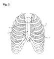
- FIG. 3is a front anatomical view showing, by way of illustration, the locations of the heart and lungs within the rib cage of an adult human.
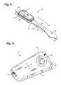
- FIG. 4is a perspective view showing an extended wear electrode patch in accordance with one embodiment with a monitor recorder inserted.
- FIG. 5is a perspective view showing the monitor recorder of FIG. 4 .
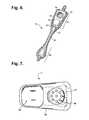
- FIG. 6is a perspective view showing the extended wear electrode patch of FIG. 4 without a monitor recorder inserted.
- FIG. 7is a bottom plan view of the monitor recorder of FIG. 4 .
- FIG. 8is a top view showing the flexible circuit of the extended wear electrode patch of FIG. 4 .
- FIG. 9is a functional block diagram showing the component architecture of the circuitry of the monitor recorder of FIG. 4 .
- FIG. 10is a functional block diagram showing the circuitry of the extended wear electrode patch of FIG. 4 .
- FIG. 11is a schematic diagram showing the ECG front end circuit of the circuitry of the monitor recorder of FIG. 9 .
- FIG. 12is a flow diagram showing a monitor recorder-implemented method for monitoring ECG data for use in the monitor recorder of FIG. 4 .
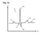
- FIG. 13is a graph showing, by way of example, a typical ECG waveform.
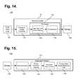
- FIG. 14is a functional block diagram showing the signal processing functionality of the microcontroller.
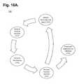
- FIG. 15is a functional block diagram showing the operations performed by the download station.
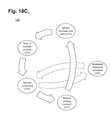
- FIGS. 16A-Care functional block diagrams respectively showing practical uses of the extended wear electrocardiography monitors of FIGS. 1 and 2 .
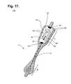
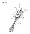
- FIG. 17is a perspective view of an extended wear electrode patch with a flexile wire electrode assembly in accordance with a still further embodiment.
- FIG. 18is perspective view of the flexile wire electrode assembly from FIG. 17 , with a layer of insulating material shielding a bare distal wire around the midsection of the flexible backing.
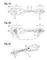
- FIG. 19is a bottom view of the flexile wire electrode assembly as shown in FIG. 17 .
- FIG. 20is a bottom view of a flexile wire electrode assembly in accordance with a still yet further embodiment.
- FIG. 21is a perspective view showing the longitudinal midsection of the flexible backing of the electrode assembly from FIG. 17 .
- FIG. 22is a flow diagram showing a monitor recorder-implemented method for ECG signal processing and ECG data compressing for use in the monitor recorders of FIG. 4 .
- FIG. 23is a flow diagram showing a monitor recorder-implemented method for encoding ECG values.
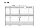
- FIG. 24is an example of a panel of codes or encodings with each code covering a range defined by a lower threshold ECG value and an upper threshold ECG value.
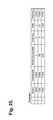
- FIG. 25is an illustrating the encoding and compression scheme in accordance with method and parameters as described with reference to in FIGS. 23 and 24 .
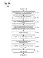
- FIG. 26is a flow diagram showing a monitor recorder-implemented method for further compressing the encodings.
- FIGS. 1 and 2are diagrams showing, by way of examples, an extended wear electrocardiography monitor 12 , including a monitor recorder 14 , in accordance with one embodiment, respectively fitted to the sternal region of a female patient 10 and a male patient 11 .
- the wearable monitor 12sits centrally, positioned axially along the sternal midline 16 , on the patient's chest along the sternum 13 and oriented top-to-bottom with the monitor recorder 14 preferably situated towards the patient's head.
- the orientation of the wearable monitor 12can be corrected post-monitoring, as further described infra, for instance, if the wearable monitor 12 is inadvertently fitted upside down.
- the electrode patch 15is shaped to fit comfortably and conformal to the contours of the patient's chest approximately centered on the sternal midline 16 (or immediately to either side of the sternum 13 ).
- the distal end of the electrode patch 15under which a lower or inferior pole (ECG electrode) is adhered, extends towards the Xiphoid process and lower sternum and, depending upon the patient's build, may straddle the region over the Xiphoid process and lower sternum.
- the proximal end of the electrode patch 15located under the monitor recorder 14 , under which an upper or superior pole (ECG electrode) is adhered, is below the manubrium and, depending upon patient's build, may straddle the region over the manubrium.
- the amplitude and strength of action potentials sensed on the body's surfaceare affected to varying degrees by cardiac, cellular, extracellular, vector of current flow, and physical factors, like obesity, dermatitis, large breasts, and high impedance skin, as can occur in dark-skinned individuals.
- Sensing along the sternal midline 16 (or immediately to either side of the sternum 13 )significantly improves the ability of the wearable monitor 12 to cutaneously sense cardiac electric signals, particularly the P-wave (or atrial activity) and, to a lesser extent, the QRS interval signals in the ECG waveforms that indicate ventricular activity by countering some of the effects of these factors.
- FIG. 3is a front anatomical view showing, by way of illustration, the locations of the heart 4 and lungs 5 within the rib cage of an adult human.
- ECG electrodesmay be separated from activation regions within the heart 4 by differing combinations of internal tissues and body structures, including heart muscle, intracardiac blood, the pericardium, intrathoracic blood and fluids, the lungs 5 , skeletal muscle, bone structure, subcutaneous fat, and the skin, plus any contaminants present between the skin's surface and electrode signal pickups.
- the degree of amplitude degradation of cardiac transmembrane potentialsincreases with the number of tissue boundaries between the heart 4 and the skin's surface that are encountered.
- the cardiac electrical fieldis degraded each time the transmembrane potentials encounter a physical boundary separating adjoining tissues due to differences in the respective tissues' electrical resistances.
- other non-spatial factorssuch as pericardial effusion, emphysema or fluid accumulation in the lungs, as further explained infra, can further degrade body surface potentials.
- the atria 6are generally located posteriorly within the thoracic cavity (with the exception of the anterior right atrium and right atrial appendage), and, physically, the left atrium constitutes the portion of the heart 4 furthest away from the surface of the skin on the chest.
- ventricles 7which generate larger amplitude signals, generally are located anteriorly with the anterior right ventricle and most of the left ventricle situated relatively close to the skin surface on the chest, which contributes to the relatively stronger amplitudes of ventricular waveforms.
- the quality of P-waves (and other already-low amplitude action potential signals)is more susceptible to weakening from intervening tissues and structures than the waveforms associated with ventricular activation.
- ECG electrodes along the sternal midline 15have largely been overlooked by conventional approaches to ECG monitoring, in part due to the inability of their sensing circuitry to reliably detect low amplitude, low frequency content electrical signals, particularly in P-waves. In turn, that inability to keenly sense P-waves has motivated ECG electrode placement in other non-sternal midline thoracic locations, where the QRSTU components that represent ventricular electrical activity are more readily detectable by their sensing circuitry than P-waves.
- ECG electrode placement along the sternal midline 15presents major patient wearability challenges, such as fitting a monitoring ensemble within the narrow confines of the inter-mammary cleft between the breasts, that to large extent drive physical packaging concerns, which can be incompatible with ECG monitors intended for placement, say, in the upper pectoral region or other non-sternal midline thoracic locations.
- the wearable monitor 12uses an electrode patch 15 that is specifically intended for extended wear placement in a location at the sternal midline 16 (or immediately to either side of the sternum 13 ).
- the electrode patch 15helps to significantly improve atrial activation (P-wave) sensing through placement in a body location that robustly minimizes the effects of tissue and body structure.
- the placement of the wearable monitor 12 in the region of the sternal midline 13puts the ECG electrodes of the electrode patch 15 in locations better adapted to sensing and recording low amplitude cardiac action potentials during atrial propagation (P-wave signals) than placement in other locations, such as the upper left pectoral region, as commonly seen in most conventional ambulatory ECG monitors.
- the sternum 13overlies the right atrium of the heart 4 .
- action potential signalshave to travel through fewer layers of tissue and structure to reach the ECG electrodes of the electrode patch 15 on the body's surface along the sternal midline 13 when compared to other monitoring locations, a distinction that is of critical importance when capturing low frequency content electrical signals, such as P-waves.
- cardiac action potential propagationtravels simultaneously along a north-to-south and right-to-left vector, beginning high in the right atrium and ultimately ending in the posterior and lateral region of the left ventricle.
- Cardiac depolarizationoriginates high in the right atrium in the SA node before concurrently spreading leftward towards the left atrium and inferiorly towards the AV node.
- the ECG electrodes of the electrode patch 15are placed with the upper or superior pole (ECG electrode) along the sternal midline 13 in the region of the manubrium and the lower or inferior pole (ECG electrode) along the sternal midline 13 in the region of the Xiphoid process 9 and lower sternum.
- the ECG electrodesare placed primarily in a north-to-south orientation along the sternum 13 that corresponds to the north-to-south waveform vector exhibited during atrial activation. This orientation corresponds to the aVF lead used in a conventional 12-lead ECG that is used to sense positive or upright P-waves.
- the thoracic region underlying the sternum 13 along the midline 16 between the manubrium 8 and Xiphoid process 9is relatively free of lung tissue, musculature, and other internal body structures that could occlude the electrical signal path between the heart 4 , particularly the atria, and ECG electrodes placed on the surface of the skin. Fewer obstructions means that cardiac electrical potentials encounter fewer boundaries between different tissues. As a result, when compared to other thoracic ECG sensing locations, the cardiac electrical field is less altered when sensed dermally along the sternal midline 13 . As well, the proximity of the sternal midline 16 to the ventricles 7 facilitates sensing of right ventricular activity and provides superior recordation of the QRS interval, again, in part due to the relatively clear electrical path between the heart 4 and the skin surface.
- non-spatial factorscan affect transmembrane action potential shape and conductivity.
- myocardial ischemiaan acute cardiac condition, can cause a transient increase in blood perfusion in the lungs 5 .
- the perfused bloodcan significantly increase electrical resistance across the lungs 5 and therefore degrade transmission of the cardiac electrical field to the skin's surface.
- the placement of the wearable monitor 12 along the sternal midline 16 in the inter-mammary cleft between the breastsis relatively resilient to the adverse effects to cardiac action potential degradation caused by ischemic conditions as the body surface potentials from a location relatively clear of underlying lung tissue and fat help compensate for the loss of signal amplitude and content.
- the monitor recorder 14is thus able to record the P-wave morphology that may be compromised by myocardial ischemia and therefore make diagnosis of the specific arrhythmias that can be associated with myocardial ischemia more difficult.
- FIG. 4is a perspective view showing an extended wear electrode patch 15 in accordance with one embodiment with a monitor recorder 14 inserted.
- the body of the electrode patch 15is preferably constructed using a flexible backing 20 formed as an elongated strip 21 of wrap knit or similar stretchable material about 145 mm long and 32 mm at the widest point with a narrow longitudinal mid-section 23 evenly tapering inward from both sides.
- a pair of cut-outs 22 between the distal and proximal ends of the electrode patch 15create a narrow longitudinal midsection 23 or “isthmus” and defines an elongated “hourglass”-like shape, when viewed from above, such as described in commonly-assigned U.S. Design Patent application, entitled “Extended Wear Electrode Patch,” Ser. No. 29/472,045, filed Nov. 7, 2013, pending, the disclosure of which is incorporated by reference.
- the upper part of the “hourglass”is sized to allow an electrically non-conductive receptacle 25 , sits on top of the outward-facing surface of the electrode patch 15 , to be affixed to the electrode patch 15 with an ECG electrode placed underneath on the patient-facing underside, or contact, surface of the electrode patch 15 ;
- the upper part of the “hourglass”has a longer and wider profile (but still rounded and tapered to fit comfortably between the breasts) than the lower part of the “hourglass,” which is sized primarily to allow just the placement of an ECG electrode of appropriate shape and surface area to record the P-wave and the QRS signals sufficiently given the inter-electrode spacing.
- the electrode patch 15incorporates features that significantly improve wearability, performance, and patient comfort throughout an extended monitoring period.
- the entire electrode patch 15is lightweight in construction, which allows the patch to be resilient to disadhesing or falling off and, critically, to avoid creating distracting discomfort to the patient, even when the patient is asleep.
- the weight of a heavy ECG monitorimpedes patient mobility and will cause the monitor to constantly tug downwards and press on the patient's body that can generate skin inflammation with frequent adjustments by the patient needed to maintain comfort.
- the electrode patch 15is subjected to pushing, pulling, and torsional movements, including compressional and torsional forces when the patient bends forward, or tensile and torsional forces when the patient leans backwards.
- the electrode patch 15incorporates crimp and strain reliefs, such as described in commonly-assigned U.S. Patent application, entitled “Extended Wear Electrocardiography Patch,” Ser. No. 14/080,717, filed Nov. 14, 2013, pending, the disclosure of which is incorporated by reference.
- the cut-outs 22 and longitudinal midsection 23help minimize interference with and discomfort to breast tissue, particularly in women (and gynecomastic men).
- the cut-outs 22 and longitudinal midsection 23further allow better conformity of the electrode patch 15 to sternal bowing and to the narrow isthmus of flat skin that can occur along the bottom of the inter-mammary cleft between the breasts, especially in buxom women.
- the cut-outs 22 and narrow and flexible longitudinal midsection 23help the electrode patch 15 fit nicely between a pair of female breasts in the inter-mammary cleft.
- the cut-outs 22can be graduated to form the longitudinal midsection 23 as a narrow in-between stem or isthmus portion about 7 mm wide.
- tabs 24can respectively extend an additional 8 mm to 12 mm beyond the distal and proximal ends of the flexible backing 20 to facilitate with adhering the electrode patch 15 to or removing the electrode patch 15 from the sternum 13 .
- These tabspreferably lack adhesive on the underside, or contact, surface of the electrode patch 15 . Still other shapes, cut-outs and conformities to the electrode patch 15 are possible.
- the monitor recorder 14removably and reusably snaps into an electrically non-conductive receptacle 25 during use.
- the monitor recorder 14contains electronic circuitry for recording and storing the patient's electrocardiography as sensed via a pair of ECG electrodes provided on the electrode patch 15 , as further described infra beginning with reference to FIG. 9 .
- the non-conductive receptacle 25is provided on the top surface of the flexible backing 20 with a retention catch 26 and tension clip 27 molded into the non-conductive receptacle 25 to conformably receive and securely hold the monitor recorder 14 in place.
- the monitor recorder 14includes a sealed housing that snaps into place in the non-conductive receptacle 25 .
- FIG. 5is a perspective view showing the monitor recorder 14 of FIG. 4 .
- the sealed housing 50 of the monitor recorder 14intentionally has a rounded isosceles trapezoidal-like shape 52 , when viewed from above, such as described in commonly-assigned U.S. Design Patent application, entitled “Electrocardiography Monitor,” Ser. No. 29/472,046, filed Nov. 7, 2013, pending, the disclosure of which is incorporated by reference.
- the edges 51 along the top and bottom surfacesare rounded for patient comfort.
- the sealed housing 50is approximately 47 mm long, 23 mm wide at the widest point, and 7 mm high, excluding a patient-operable tactile-feedback button 55 .
- the sealed housing 50can be molded out of polycarbonate, ABS, or an alloy of those two materials.
- the button 55is waterproof and the button's top outer surface is molded silicon rubber or similar soft pliable material.
- a retention detent 53 and tension detent 54are molded along the edges of the top surface of the housing 50 to respectively engage the retention catch 26 and the tension clip 27 molded into non-conductive receptacle 25 .
- Other shapes, features, and conformities of the sealed housing 50are possible.
- the electrode patch 15is intended to be disposable, while the monitor recorder 14 is designed for reuse and can be transferred to successive electrode patches 15 to ensure continuity of monitoring, if so desired.
- the monitor recorder 14can be used only once, but single use effectively wastes the synergistic benefits provided by the combination of the disposable electrode patch and reusable monitor recorder, as further explained infra with reference to FIGS. 16A-C .
- the placement of the wearable monitor 12 in a location at the sternal midline 16 (or immediately to either side of the sternum 13 )benefits long-term extended wear by removing the requirement that ECG electrodes be continually placed in the same spots on the skin throughout the monitoring period. Instead, the patient is free to place an electrode patch 15 anywhere within the general region of the sternum 13 .
- a monitor recorder 14is merely unsnapped from a worn out electrode patch 15 , the worn out electrode patch 15 is removed from the skin, a new electrode patch 15 is adhered to the skin, possibly in a new spot immediately adjacent to the earlier location, and the same monitor recorder 14 is snapped into the new electrode patch 15 to reinitiate and continue the ECG monitoring.
- FIG. 6is a perspective view showing the extended wear electrode patch 15 of FIG. 4 without a monitor recorder 14 inserted.
- a flexible circuit 32is adhered to each end of the flexible backing 20 .
- a distal circuit trace 33 from the distal end 30 of the flexible backing 20 and a proximal circuit trace (not shown) from the proximal end 31 of the flexible backing 20electrically couple ECG electrodes (not shown) with a pair of electrical pads 34 .
- the distal and proximal circuit tracesare replaced with interlaced or sewn-in flexible wires, as further described infra beginning with reference to FIG. 17 .
- the electrical pads 34are provided within a moisture-resistant seal 35 formed on the bottom surface of the non-conductive receptacle 25 .
- the electrical pads 34interface to electrical contacts (not shown) protruding from the bottom surface of the monitor recorder 14 .
- the moisture-resistant seal 35enables the monitor recorder 14 to be worn at all times, even during showering or other activities that could expose the monitor recorder 14 to moisture or adverse conditions.
- a battery compartment 36is formed on the bottom surface of the non-conductive receptacle 25 .
- a pair of battery leads (not shown) from the battery compartment 36 to another pair of the electrical pads 34electrically interface the battery to the monitor recorder 14 .
- the battery contained within the battery compartment 35is a direct current (DC) power cell and can be replaceable, rechargeable or disposable.
- FIG. 7is a bottom plan view of the monitor recorder 14 of FIG. 4 .
- a cavity 58is formed on the bottom surface of the sealed housing 50 to accommodate the upward projection of the battery compartment 36 from the bottom surface of the non-conductive receptacle 25 , when the monitor recorder 14 is secured in place on the non-conductive receptacle 25 .
- a set of electrical contacts 56protrude from the bottom surface of the sealed housing 50 and are arranged in alignment with the electrical pads 34 provided on the bottom surface of the non-conductive receptacle 25 to establish electrical connections between the electrode patch 15 and the monitor recorder 14 .
- a seal coupling 57circumferentially surrounds the set of electrical contacts 56 and securely mates with the moisture-resistant seal 35 formed on the bottom surface of the non-conductive receptacle 25 .
- the battery contained within the battery compartment 36can be replaceable, rechargeable or disposable.
- the ECG sensing circuitry of the monitor recorder 14can be supplemented with additional sensors, including an SpO 2 sensor, a blood pressure sensor, a temperature sensor, respiratory rate sensor, a glucose sensor, an air flow sensor, and a volumetric pressure sensor, which can be incorporated directly into the monitor recorder 14 or onto the non-conductive receptacle 25 .
- additional sensorsincluding an SpO 2 sensor, a blood pressure sensor, a temperature sensor, respiratory rate sensor, a glucose sensor, an air flow sensor, and a volumetric pressure sensor, which can be incorporated directly into the monitor recorder 14 or onto the non-conductive receptacle 25 .
- the placement of the flexible backing 20 on the sternal midline 16 (or immediately to either side of the sternum 13 )also helps to minimize the side-to-side movement of the wearable monitor 12 in the left- and right-handed directions during wear.
- the wearable monitor 12is still susceptible to pushing, pulling, and torqueing movements, including compressional and torsional forces when the patient bends forward, and tensile and torsional forces when the patient leans backwards or twists.
- a layer of non-irritating adhesivesuch as hydrocolloid, is provided at least partially on the underside, or contact, surface of the flexible backing 20 , but only on the distal end 30 and the proximal end 31 .
- the underside, or contact surface of the longitudinal midsection 23does not have an adhesive layer and remains free to move relative to the skin.
- the longitudinal midsection 23forms a crimp relief that respectively facilitates compression and twisting of the flexible backing 20 in response to compressional and torsional forces.
- Other forms of flexible backing crimp reliefsare possible.
- FIG. 8is a top view showing the flexible circuit 32 of the extended wear electrode patch 15 of FIG. 4 when mounted above the flexible backing 20 .
- a distal ECG electrode 38 and proximal ECG electrode 39are respectively coupled to the distal and proximal ends of the flexible circuit 32 to serve as electrode signal pickups.
- the flexible circuit 32preferably does not extend to the outside edges of the flexible backing 20 , thereby avoiding gouging or discomforting the patient's skin during extended wear, such as when sleeping on the side. During wear, the ECG electrodes 38 , 39 must remain in continual contact with the skin.
- a strain relief 40is defined in the flexible circuit 32 at a location that is partially underneath the battery compartment 36 when the flexible circuit 32 is affixed to the flexible backing 20 .
- the strain relief 40is laterally extendable to counter dislodgment of the ECG electrodes 38 , 39 due to bending, tensile and torsional forces.
- a pair of strain relief cutouts 41partially extend transversely from each opposite side of the flexible circuit 32 and continue longitudinally towards each other to define in ‘S’-shaped pattern, when viewed from above.
- the strain reliefrespectively facilitates longitudinal extension and twisting of the flexible circuit 32 in response to tensile and torsional forces.
- Other forms of circuit board strain reliefare possible.
- FIG. 9is a functional block diagram showing the component architecture of the circuitry 60 of the monitor recorder 14 of FIG. 4 .
- the circuitry 60is externally powered through a battery provided in the non-conductive receptacle 25 (shown in FIG. 6 ).
- Both power and raw ECG signals, which originate in the pair of ECG electrodes 38 , 39 (shown in FIG. 8 ) on the distal and proximal ends of the electrode patch 15are received through an external connector 65 that mates with a corresponding physical connector on the electrode patch 15 .
- the external connector 65includes the set of electrical contacts 56 that protrude from the bottom surface of the sealed housing 50 and which physically and electrically interface with the set of pads 34 provided on the bottom surface of the non-conductive receptacle 25 .
- the external connectorincludes electrical contacts 56 for data download, microcontroller communications, power, analog inputs, and a peripheral expansion port.
- the external connector 65also serves as a physical interface to a download station that permits the retrieval of stored ECG monitoring data, communication with the monitor recorder 14 , and performance of other functions. The download station is further described infra with reference to FIG. 15 .
- Operation of the circuitry 60 of the monitor recorder 14is managed by a microcontroller 61 , such as the EFM32 Tiny Gecko 32-bit microcontroller, manufactured by Silicon Laboratories Inc., Austin, Tex.
- the microcontroller 61has flexible energy management modes and includes a direct memory access controller and built-in analog-to-digital and digital-to-analog converters (ADC and DAC, respectively).
- the microcontroller 61also includes a program memory unit containing internal flash memory that is readable and writeable. The internal flash memory can also be programmed externally.
- the microcontroller 61operates under modular micro program control as specified in firmware stored in the internal flash memory.
- the functionality and firmware modules relating to signal processing by the microcontroller 61are further described infra with reference to FIG. 14 .
- the microcontroller 61draws power externally from the battery provided on the electrode patch 15 via a pair of the electrical contacts 56 .
- the microcontroller 61connects to the ECG front end circuit 63 that measures raw cutaneous electrical signals using a driven reference that eliminates common mode noise, as further described infra with reference to FIG. 11 .
- the circuitry 60 of the monitor recorder 14also includes a flash memory 62 , which the microcontroller 61 uses for storing ECG monitoring data and other physiology and information.
- the flash memory 62also draws power externally from the battery provided on the electrode patch 15 via a pair of the electrical contacts 56 .
- Datais stored in a serial flash memory circuit, which supports read, erase and program operations over a communications bus.
- the flash memory 62enables the microcontroller 61 to store digitized ECG data.
- the communications busfurther enables the flash memory 62 to be directly accessed externally over the external connector 65 when the monitor recorder 14 is interfaced to a download station.
- the microcontroller 61includes functionality that enables the acquisition of samples of analog ECG signals, which are converted into a digital representation, as further described infra with reference to FIG. 14 .
- the microcontroller 61will acquire, sample, digitize, signal process, and store digitized ECG data into available storage locations in the flash memory 62 until all memory storage locations are filled, after which the digitized ECG data needs to be downloaded or erased to restore memory capacity. Data download or erasure can also occur before all storage locations are filled, which would free up memory space sooner, albeit at the cost of possibly interrupting monitoring while downloading or erasure is performed.
- the microcontroller 61can include a loop recorder feature that will overwrite the oldest stored data once all storage locations are filled, albeit at the cost of potentially losing the stored data that was overwritten, if not previously downloaded. Still other modes of data storage and capacity recovery are possible.
- the circuitry 60 of the monitor recorder 14further includes an actigraphy sensor 64 implemented as a 3-axis accelerometer.
- the accelerometermay be configured to generate interrupt signals to the microcontroller 61 by independent initial wake up and free fall events, as well as by device position.
- the actigraphy provided by the accelerometercan be used during post-monitoring analysis to correct the orientation of the monitor recorder 14 if, for instance, the monitor recorder 14 has been inadvertently installed upside down, that is, with the monitor recorder 14 oriented on the electrode patch 15 towards the patient's feet, as well as for other event occurrence analyses.
- the microcontroller 61includes an expansion port that also utilizes the communications bus. External devices, separately drawing power externally from the battery provided on the electrode patch 15 or other source, can interface to the microcontroller 61 over the expansion port in half duplex mode.
- an external physiology sensorcan be provided as part of the circuitry 60 of the monitor recorder 14 , or can be provided on the electrode patch 15 with communication with the microcontroller 61 provided over one of the electrical contacts 56 .
- the physiology sensorcan include an SpO 2 sensor, blood pressure sensor, temperature sensor, respiratory rate sensor, glucose sensor, airflow sensor, volumetric pressure sensing, or other types of sensor or telemetric input sources.
- a wireless interface for interfacing with other wearable (or implantable) physiology monitors, as well as data offload and programmingcan be provided as part of the circuitry 60 of the monitor recorder 14 , or can be provided on the electrode patch 15 with communication with the microcontroller 61 provided over one of the electrical contacts 56 .
- the circuitry 60 of the monitor recorder 14includes patient-interfaceable components, including a tactile feedback button 66 , which a patient can press to mark events or to perform other functions, and a buzzer 67 , such as a speaker, magnetic resonator or piezoelectric buzzer.
- the buzzer 67can be used by the microcontroller 61 to output feedback to a patient such as to confirm power up and initiation of ECG monitoring. Still other components as part of the circuitry 60 of the monitor recorder 14 are possible.
- FIG. 10is a functional block diagram showing the circuitry 70 of the extended wear electrode patch 15 of FIG. 4 .
- the circuitry 70 of the electrode patch 15is electrically coupled with the circuitry 60 of the monitor recorder 14 through an external connector 74 .
- the external connector 74is terminated through the set of pads 34 provided on the bottom of the non-conductive receptacle 25 , which electrically mate to corresponding electrical contacts 56 protruding from the bottom surface of the sealed housing 50 to electrically interface the monitor recorder 14 to the electrode patch 15 .
- the circuitry 70 of the electrode patch 15performs three primary functions.
- a battery 71is provided in a battery compartment formed on the bottom surface of the non-conductive receptacle 25 .
- the battery 71is electrically interfaced to the circuitry 60 of the monitor recorder 14 as a source of external power.
- the unique provisioning of the battery 71 on the electrode patch 15provides several advantages. First, the locating of the battery 71 physically on the electrode patch 15 lowers the center of gravity of the overall wearable monitor 12 and thereby helps to minimize shear forces and the effects of movements of the patient and clothing.
- the housing 50 of the monitor recorder 14is sealed against moisture and providing power externally avoids having to either periodically open the housing 50 for the battery replacement, which also creates the potential for moisture intrusion and human error, or to recharge the battery, which can potentially take the monitor recorder 14 off line for hours at a time.
- the electrode patch 15is intended to be disposable, while the monitor recorder 14 is a reusable component. Each time that the electrode patch 15 is replaced, a fresh battery is provided for the use of the monitor recorder 14 , which enhances ECG monitoring performance quality and duration of use.
- the architecture of the monitor recorder 14is open, in that other physiology sensors or components can be added by virtue of the expansion port of the microcontroller 61 .
- the pair of ECG electrodes 38 , 39 respectively provided on the distal and proximal ends of the flexible circuit 32are electrically coupled to the set of pads 34 provided on the bottom of the non-conductive receptacle 25 by way of their respective circuit traces 33 , 37 .
- the signal ECG electrode 39includes a protection circuit 72 , which is an inline resistor that protects the patient from excessive leakage current should the front end circuit fail.
- the circuitry 70 of the electrode patch 15includes a cryptographic circuit 73 to authenticate an electrode patch 15 for use with a monitor recorder 14 .
- the cryptographic circuit 73includes a device capable of secure authentication and validation. The cryptographic device 73 ensures that only genuine, non-expired, safe, and authenticated electrode patches 15 are permitted to provide monitoring data to a monitor recorder 14 and for a specific patient.
- FIG. 11is a schematic diagram 80 showing the ECG front end circuit 63 of the circuitry 60 of the monitor recorder 14 of FIG. 9 .
- the ECG front end circuit 63senses body surface potentials through a signal lead (“S 1 ”) and reference lead (“REF”) that are respectively connected to the ECG electrodes of the electrode patch 15 .
- Poweris provided to the ECG front end circuit 63 through a pair of DC power leads (“VCC” and “GND”).
- An analog ECG signal (“ECG”) representative of the electrical activity of the patient's heart over timeis output, which the micro controller 11 converts to digital representation and filters, as further described infra.
- the ECG front end circuit 63is organized into five stages, a passive input filter stage 81 , a unity gain voltage follower stage 82 , a passive high pass filtering stage 83 , a voltage amplification and active filtering stage 84 , and an anti-aliasing passive filter stage 85 , plus a reference generator. Each of these stages and the reference generator will now be described.
- the passive input filter stage 81includes the parasitic impedance of the ECG electrodes 38 , 39 (shown in FIG. 8 ), the protection resistor that is included as part of the protection circuit 72 of the ECG electrode 39 (shown in FIG. 10 ), an AC coupling capacitor 87 , a termination resistor 88 , and filter capacitor 89 .
- This stagepassively shifts the frequency response poles downward there is a high electrode impedance from the patient on the signal lead S 1 and reference lead REF, which reduces high frequency noise.
- the unity gain voltage follower stage 82provides a unity voltage gain that allows current amplification by an Operational Amplifier (“Op Amp”) 90 .
- Op AmpOperational Amplifier
- the voltagestays the same as the input, but more current is available to feed additional stages. This configuration allows a very high input impedance, so as not to disrupt the body surface potentials or the filtering effect of the previous stage.
- the passive high pass filtering stage 83is a high pass filter that removes baseline wander and any offset generated from the previous stage. Adding an AC coupling capacitor 91 after the Op Amp 90 allows the use of lower cost components, while increasing signal fidelity.
- the voltage amplification and active filtering stage 84amplifies the voltage of the input signal through Op Amp 91 , while applying a low pass filter.
- the DC bias of the input signalis automatically centered in the highest performance input region of the Op Amp 91 because of the AC coupling capacitor 91 .
- the anti-aliasing passive filter stage 85provides an anti-aliasing low pass filter.
- a disruption in the signaloccurs as a sample and hold capacitor that is internal to the microcontroller 61 is charged to supply signal for acquisition.
- the reference generator in subcircuit 86drives a driven reference containing power supply noise and system noise to the reference lead REF.
- a coupling capacitor 87is included on the signal lead S 1 and a pair of resistors 93 a , 93 b inject system noise into the reference lead REF.
- the reference generatoris connected directly to the patient, thereby avoiding the thermal noise of the protection resistor that is included as part of the protection circuit 72 .
- the parasitic impedance of the ECG electrodes 38 , 39 , the protection resistor that is included as part of the protection circuit 72 and the coupling capacitor 87allow the reference lead REF to be connected directly to the skin's surface without any further components. As a result, the differential thermal noise problem caused by pairing protection resistors to signal and reference leads, as used in conventional approaches, is avoided.
- FIG. 12is a flow diagram showing a monitor recorder-implemented method 100 for monitoring ECG data for use in the monitor recorder 14 of FIG. 4 .
- the microcontroller 61executes a power up sequence (step 101 ).
- the voltage of the battery 71is checked, the state of the flash memory 62 is confirmed, both in terms of operability check and available capacity, and microcontroller operation is diagnostically confirmed.
- an authentication procedure between the microcontroller 61 and the electrode patch 15are also performed.
- an iterative processing loop(steps 102 - 110 ) is continually executed by the microcontroller 61 .
- the ECG frontend 63(shown in FIG. 9 ) continually senses the cutaneous ECG electrical signals (step 103 ) via the ECG electrodes 38 , 29 and is optimized to maintain the integrity of the P-wave.
- a sample of the ECG signalis read (step 104 ) by the microcontroller 61 by sampling the analog ECG signal that is output by the ECG front end circuit 63 .
- FIG. 13is a graph showing, by way of example, a typical ECG waveform 120 .
- the x-axisrepresents time in approximate units of tenths of a second.
- the y-axisrepresents cutaneous electrical signal strength in approximate units of millivolts.
- the P-wave 121has a smooth, normally upward, that is, positive, waveform that indicates atrial depolarization.
- the QRS complexoften begins with the downward deflection of a Q-wave 122 , followed by a larger upward deflection of an R-wave 123 , and terminated with a downward waveform of the S-wave 124 , collectively representative of ventricular depolarization.
- the T-wave 125is normally a modest upward waveform, representative of ventricular depolarization, while the U-wave 126 , often not directly observable, indicates the recovery period of the Purkinje conduction fibers.
- the R-to-R intervalrepresents the ventricular rate and rhythm
- the P-to-P intervalrepresents the atrial rate and rhythm
- the PR intervalis indicative of atrioventricular (AV) conduction time and abnormalities in the PR interval can reveal underlying heart disorders, thus representing another reason why the P-wave quality achievable by the ambulatory electrocardiography monitoring patch optimized for capturing low amplitude cardiac action potential propagation described herein is medically unique and important.
- AVatrioventricular
- each sampled ECG signalis processed by signal processing modules as specified in firmware (step 105 ), as described infra, and temporarily staged in a buffer (step 106 ), pending compression preparatory to storage in the flash memory 62 (step 107 ).
- the compressed ECG digitized sampleis again buffered (step 108 ), then written to the flash memory 62 (step 109 ) using the communications bus.
- Processingcontinues (step 110 ), so long as the monitoring recorder 14 remains connected to the electrode patch 15 (and storage space remains available in the flash memory 62 ), after which the processing loop is exited (step 110 ) and execution terminates. Still other operations and steps are possible.
- the microcontroller 61operates under modular micro program control as specified in firmware, and the program control includes processing of the analog ECG signal output by the ECG front end circuit 63 .
- FIG. 14is a functional block diagram showing the signal processing functionality 130 of the microcontroller 61 .
- the microcontroller 61operates under modular micro program control as specified in firmware 132 .
- the firmware modules 132include high and low pass filtering 133 , and compression 134 . Other modules are possible.
- the microcontroller 61has a built-in ADC, although ADC functionality could also be provided in the firmware 132 .
- the ECG front end circuit 63first outputs an analog ECG signal, which the ADC 131 acquires, samples and converts into an uncompressed digital representation.
- the microcontroller 61includes one or more firmware modules 133 that perform filtering. In one embodiment, three low pass filters and two high pass filters are used. Following filtering, the digital representation of the cardiac activation wave front amplitudes are compressed by a compression module 134 before being written out to storage 135 , as further described infra beginning with reference to FIG. 22 .
- the download stationexecutes a communications or offload program (“Offload”) or similar program that interacts with the monitor recorder 14 via the external connector 65 to retrieve the stored ECG monitoring data.
- FIG. 15is a functional block diagram showing the operations 140 performed by the download station.
- the download stationcould be a server, personal computer, tablet or handheld computer, smart mobile device, or purpose-built programmer designed specific to the task of interfacing with a monitor recorder 14 .
- Still other forms of download stationare possible, including download stations connected through wireless interfacing using, for instance, a smart phone connected to the monitor recorder 14 through Bluetooth or Wi-Fi.
- the download stationis responsible for offloading stored ECG monitoring data from a monitor recorder 14 and includes an electro mechanical docking interface by which the monitor recorder 14 is connected at the external connector 65 .
- the download stationoperates under programmable control as specified in software 141 .
- the stored ECG monitoring data retrieved from storage 142 on a monitor recorder 14is first decompressed by a decompression module 143 , which converts the stored ECG monitoring data back into an uncompressed digital representation more suited to signal processing than a compressed signal.
- the retrieved ECG monitoring datamay be stored into local storage for archival purposes, either in original compressed form, or as uncompressed.
- the download stationcan include an array of filtering modules.
- a set of phase distortion filtering tools 144may be provided, where corresponding software filters can be provided for each filter implemented in the firmware executed by the microcontroller 61 .
- the digital signalsare run through the software filters in a reverse direction to remove phase distortion.
- a 45 Hertz high pass filter in firmwaremay have a matching reverse 45 Hertz high pass filter in software.
- Most of the phase distortionis corrected, that is, canceled to eliminate noise at the set frequency, but data at other frequencies in the waveform remain unaltered.
- bidirectional impulse infinite response (IIR) high pass filters and reverse direction (symmetric) IIR low pass filterscan be provided.
- An automatic gain control (AGC) module 145can also be provided to adjust the digital signals to a usable level based on peak or average signal level or other metric.
- AGCis particularly critical to single-lead ECG monitors, where physical factors, such as the tilt of the heart, can affect the electrical field generated.
- the leadsare oriented in vertical, horizontal and diagonal directions. As a result, the horizontal and diagonal leads may be higher amplitude and ECG interpretation will be based on one or both of the higher amplitude leads.
- the electrocardiography monitor 12has only a single lead that is oriented in the vertical direction, so variations in amplitude will be wider than available with multi-lead monitors, which have alternate leads to fall back upon.
- AGCmay be necessary to maintain compatibility with existing ECG interpretation software, which is typically calibrated for multi-lead ECG monitors for viewing signals over a narrow range of amplitudes.
- existing ECG interpretation softwarewhich is typically calibrated for multi-lead ECG monitors for viewing signals over a narrow range of amplitudes.
- the gain of signals recorded by the monitor recorder 14 of the electrocardiography monitor 12can be attenuated up (or down) to work with FDA-approved commercially available ECG interpretation.
- AGCcan be implemented in a fixed fashion that is uniformly applied to all signals in an ECG recording, adjusted as appropriate on a recording-by-recording basis. Typically, a fixed AGC value is calculated based on how an ECG recording is received to preserve the amplitude relationship between the signals. Alternatively, AGC can be varied dynamically throughout an ECG recording, where signals in different segments of an ECG recording are amplified up (or down) by differing amounts of gain.
- the monitor recorder 14will record a high resolution, low frequency signal for the P-wave segment. However, for some patients, the result may still be a visually small signal. Although high resolution is present, the unaided eye will normally be unable to discern the P-wave segment. Therefore, gaining the signal is critical to visually depicting P-wave detail. This technique works most efficaciously with a raw signal with low noise and high resolution, as generated by the monitor recorder 14 . Automatic gain control applied to a high noise signal will only exacerbate noise content and be self-defeating.
- the download stationcan include filtering modules specifically intended to enhance P-wave content.
- a P-wave base boost filter 146which is a form of pre-emphasis filter, can be applied to the signal to restore missing frequency content or to correct phase distortion. Still other filters and types of signal processing are possible.
- FIGS. 16A-Care functional block diagrams respectively showing practical uses 150 , 160 , 170 of the extended wear electrocardiography monitors 12 of FIGS. 1 and 2 .
- the combination of a flexible extended wear electrode patch and a removable reusable (or single use) monitor recorderempowers physicians and patients alike with the ability to readily perform long-term ambulatory monitoring of the ECG and physiology.
- the electrocardiography monitor 12offers superior patient comfort, convenience and user-friendliness.
- the electrode patch 15is specifically designed for ease of use by a patient (or caregiver); assistance by professional medical personnel is not required.
- the patientis free to replace the electrode patch 15 at any time and need not wait for a doctor's appointment to have a new electrode patch 15 placed.
- the monitor recorder 14operates automatically and the patient only need snap the monitor recorder 14 into place on the electrode patch 15 to initiate ECG monitoring.
- the synergistic combination of the electrode patch 15 and monitor recorder 14makes the use of the electrocardiography monitor 12 a reliable and virtually foolproof way to monitor a patient's ECG and physiology for an extended, or even open-ended, period of time.
- extended wear monitoringcan be performed by using the same monitor recorder 14 inserted into a succession of fresh new electrode patches 15 .
- the electrode patch 15can be replaced by the patient (or caregiver) with a fresh new electrode patch 15 throughout the overall monitoring period.
- a patientadheres a new electrode patch 15 in a location at the sternal midline 16 (or immediately to either side of the sternum 13 ) oriented top-to-bottom (step 151 ).
- Placementinvolves simply adhering the electrode patch 15 on the skin along the sternal midline 16 (or immediately to either side of the sternum 13 ). Patients can easily be taught to find the physical landmarks on the body necessary for proper placement of the electrode patch 15 .
- the physical landmarksare locations on the surface of the body that are already familiar to patients, including the inter-mammary cleft between the breasts above the manubrium (particularly easily locatable by women and gynecomastic men), the sternal notch immediately above the manubrium, and the Xiphoid process located at the bottom of the sternum.
- Empowering patients with the knowledge to place the electrode patch 15 in the right placeensures that the ECG electrodes will be correctly positioned on the skin, no matter the number of times that the electrode patch 15 is replaced.
- a monitor recorder 14is snapped into the non-conductive receptacle 25 on the outward-facing surface of the electrode patch 15 (step 152 ).
- the monitor recorder 14draws power externally from a battery provided in the non-conductive receptacle 25 .
- the batteryis replaced each time that a fresh new electrode patch 15 is placed on the skin, which ensures that the monitor recorder 14 is always operating with a fresh power supply and minimizing the chances of a loss of monitoring continuity due to a depleted battery source.
- the monitor recorder 14automatically initiates monitoring upon sensing body surface potentials through the pair of ECG electrodes (step 153 ).
- the monitor recorder 14can be configured for manual operation, such as by using the tactile feedback button 66 on the outside of the sealed housing 50 , or other user-operable control.
- the monitor recorder 14can be configured for remotely-controlled operation by equipping the monitor recorder 14 with a wireless transceiver, such as described in commonly-assigned U.S. Patent application, entitled “Remote Interfacing of an Extended Wear Electrocardiography and Physiological Sensor Monitor,” Ser. No. 14/082,071, filed Nov. 15, 2013, pending, the disclosure of which is incorporated by reference.
- the wireless transceiverallows wearable or mobile communications devices to wirelessly interface with the monitor recorder 14 .
- a key feature of the extended wear electrocardiography monitor 12is the ability to monitor ECG and physiological data for an extended period of time, which can be well in excess of the 14 days currently pitched as being achievable by conventional ECG monitoring approaches.
- ECG monitoringcan even be performed over an open-ended time period, as further explained infra.
- the monitor recorder 14is reusable and, if so desired, can be transferred to successive electrode patches 15 to ensure continuity of monitoring.
- a patientor caregiver can remove the monitor recorder 14 (step 154 ) and replace the electrode patch 15 currently being worn with a fresh new electrode patch 15 (step 151 ).
- the electrode patch 15may need to be replaced for any number of reasons.
- the electrode patch 15may be starting to come off after a period of wear or the patient may have skin that is susceptible to itching or irritation.
- the wearing of ECG electrodescan aggravate such skin conditions.
- a patientmay want or need to periodically remove or replace ECG electrodes during a long-term ECG monitoring period, whether to replace a dislodged electrode, reestablish better adhesion, alleviate itching or irritation, allow for cleansing of the skin, allow for showering and exercise, or for other purpose.
- the monitor recorder 14is again snapped into the electrode patch 15 (step 152 ) and monitoring resumes (step 153 ).
- the ability to transfer the same monitor recorder 14 to successive electrode patches 15 during a period of extended wear monitoringis advantageous not to just diagnose cardiac rhythm disorders and other physiological events of potential concern, but to do extremely long term monitoring, such as following up on cardiac surgery, ablation procedures, or medical device implantation. In these cases, several weeks of monitoring or more may be needed.
- some IMDssuch as pacemakers or implantable cardioverter defibrillators, incorporate a loop recorder that will capture cardiac events over a fixed time window.
- the monitor recorder 14provides continuity of monitoring that acts to prevent loss of cardiac event data.
- the firmware executed by the microcontroller 61 of the monitor recorder 14can be optimized for minimal power consumption and additional flash memory for storing monitoring data can be added to achieve a multi-week monitor recorder 14 that can be snapped into a fresh new electrode patch 15 every seven days, or other interval, for weeks or even months on end.
- the monitor recorder 14Upon the conclusion of monitoring, the monitor recorder 14 is removed (step 154 ) and recorded ECG and physiological telemetry are downloaded (step 155 ). For instance, a download station can be physically interfaced to the external connector 65 of the monitor recorder 14 to initiate and conduct downloading, as described supra with reference to FIG. 15 .
- the monitoring periodcan be of indeterminate duration.
- FIG. 16Ba similar series of operations are followed with respect to replacement of electrode patches 15 , reinsertion of the same monitor recorder 14 , and eventual download of ECG and physiological telemetry (steps 161 - 165 ), as described supra with reference to FIG. 16A .
- the flash memory 62shown in FIG. 9 ) in the circuitry 60 of the monitor recorder 14 has a finite capacity.
- the flash memory 62can be cleared to restore storage capacity and monitoring can resume once more, either by first adhering a new electrode patch 15 (step 161 ) or by snapping the monitor recorder 14 into an already-adhered electrode patch 15 (step 162 ).
- the foregoing expanded series of operationsto include reuse of the same monitor recorder 14 following data download, allows monitoring to continue indefinitely and without the kinds of interruptions that often affect conventional approaches, including the retrieval of monitoring data only by first making an appointment with a medical professional.
- the use of a download stationcan be skipped.
- FIG. 16Ca similar series of operations are followed with respect to replacement of electrode patches 15 and reinsertion of the same monitor recorder 14 (steps 171 - 174 ), as described supra with reference to FIG. 16A .
- recorded ECG and physiological telemetryare downloaded wirelessly (step 175 ), such as described in commonly-assigned U.S. patent application Ser. No. 14/082,071, cited supra.
- the recorded ECG and physiological telemetrycan even be downloaded wirelessly directly from a monitor recorder 14 during monitoring while still snapped into the non-conductive receptacle 25 on the electrode patch 15 .
- the wireless interfacingenables monitoring to continue for an open-ended period of time, as the downloading of the recorded ECG and physiological telemetry will continually free up onboard storage space. Further, wireless interfacing simplifies patient use, as the patient (or caregiver) only need worry about placing (and replacing) electrode patches 15 and inserting the monitor recorder 14 . Still other forms of practical use of the extended wear electrocardiography monitors 12 are possible.
- the circuit trace and ECG electrodes components of the electrode patch 15can be structurally simplified.
- the flexible circuit 32shown in FIG. 5
- distal ECG electrode 38 and proximal ECG electrode 39are replaced with a pair of interlaced flexile wires.
- the interlacing of flexile wires through the flexible backing 20reduces both manufacturing costs and environmental impact, as further described infra.
- the flexible circuit and ECG electrodesare replaced with a pair of flexile wires that serve as both electrode circuit traces and electrode signal pickups.
- FIG. 17is a perspective view 180 of an extended wear electrode patch 15 with a flexile wire electrode assembly in accordance with a still further embodiment.
- the flexible backing 20maintains the unique narrow “hourglass”-like shape that aids long term extended wear, particularly in women, as described supra with reference to FIG. 4 .
- the non-conductive receptacle 25is omitted to show the exposed battery printed circuit board 182 that is adhered underneath the non-conductive receptacle 25 to the proximal end 31 of the flexible backing 20 .
- a pair of flexile wiresare separately interlaced or sewn into the flexible backing 20 to serve as circuit connections for an anode electrode lead and for a cathode electrode lead.
- a distal wire 181is interlaced into the distal end 30 of the flexible backing 20 , continues along an axial path through the narrow longitudinal midsection of the elongated strip, and electrically connects to the battery printed circuit board 182 on the proximal end 31 of the flexible backing 20 .
- the distal wire 181is connected to the battery printed circuit board 182 by stripping the distal wire 181 of insulation, if applicable, and interlacing or sewing the uninsulated end of the distal wire 181 directly into an exposed circuit trace 183 .
- the distal wire-to-battery printed circuit board connectioncan be made, for instance, by back stitching the distal wire 181 back and forth across the edge of the battery printed circuit board 182 .
- a proximal wire(not shown) is interlaced into the proximal end 31 of the flexible backing 20 .
- the proximal wireis connected to the battery printed circuit board 182 by stripping the proximal wire of insulation, if applicable, and interlacing or sewing the uninsulated end of the proximal wire directly into an exposed circuit trace 184 .
- the resulting flexile wire connectionsboth establish electrical connections and help to affix the battery printed circuit board 182 to the flexible backing 20 .
- the battery printed circuit board 182is provided with a battery compartment 36 .
- a set of electrical pads 34are formed on the battery printed circuit board 182 .
- the electrical pads 34electrically interface the battery printed circuit board 182 with a monitor recorder 14 when fitted into the non-conductive receptacle 25 .
- the battery compartment 36contains a spring 185 and a clasp 186 , or similar assembly, to hold a battery (not shown) in place and electrically interfaces the battery to the electrical pads 34 through a pair battery leads 187 for powering the electrocardiography monitor 14 .
- Other types of battery compartmentare possible.
- the battery contained within the battery compartment 36can be replaceable, rechargeable, or disposable.
- circuit board and non-conductive receptacle 25are replaced by a combined housing that includes a battery compartment and a plurality of electrical pads.
- the housingcan be affixed to the proximal end of the elongated strip through the interlacing or sewing of the flexile wires or other wires or threads.
- the core of the flexile wiresmay be made from a solid, stranded, or braided conductive metal or metal compounds. In general, a solid wire will be less flexible than a stranded wire with the same total cross-sectional area, but will provide more mechanical rigidity than the stranded wire.
- the conductive coremay be copper, aluminum, silver, or other material.
- the pair of the flexile wiresmay be provided as insulated wire.
- the flexile wiresare made from a magnet wire from Belden Cable, catalogue number 8051, with a solid core of AWG 22 with bare copper as conductor material and insulated by polyurethane or nylon. Still other types of flexile wires are possible.
- conductive ink or graphenecan be used to print electrical connections, either in combination with or in place of the flexile wires.
- FIG. 18is perspective view of the flexile wire electrode assembly from FIG. 17 , with a layer of insulating material 189 shielding a bare uninsulated distal wire 181 around the midsection on the contact side of the flexible backing.
- a layer of insulating material 189shielding a bare uninsulated distal wire 181 around the midsection on the contact side of the flexible backing.
- the bare uninsulated distal wire 181may be insulated using a layer of plastic, rubber-like polymers, or varnish, or by an additional layer of gauze or adhesive (or non-adhesive) gel.
- the bare uninsulated wire 181 on the non-contact side of the flexible backingmay be insulated or can simply be left uninsulated.
- FIG. 19is a bottom view 190 of the flexile wire electrode assembly as shown in FIG. 17 .
- the uninsulated end portions of the distal wire 181 and the proximal wire 191enable the monitor recorder 14 to measure dermal electrical potential differentials.
- the uninsulated end portions of the flexile wiresmay be configured into an appropriate pattern to provide an electrode signal pickup, which would typically be a spiral shape formed by guiding the flexile wire along an inwardly spiraling pattern.
- the surface area of the electrode pickupscan also be variable, such as by selectively removing some or all of the insulation on the contact surface.
- an electrode signal pickup arranged by sewing insulated flexile wire in a spiral patterncould have a crescent-shaped cutout of uninsulated flexile wire facing towards the signal source.
- FIG. 20is a bottom view 200 of a flexile wire electrode assembly in accordance with a still yet further embodiment.
- the distal wire 181is interlaced onto the midsection and extends an exposed end portion 192 onto the distal end 30 .
- the proximal wire 191extends an exposed end portion 193 onto the proximal end 31 .
- the exposed end portions 192 and 193are further embedded within an electrically conductive adhesive 201 .
- the adhesive 201makes contact to skin during use and conducts skin electrical potentials to the monitor recorder 14 (not shown) via the flexile wires.
- the adhesive 201can be formed from electrically conductive, non-irritating adhesive, such as hydrocolloid.
- the distal wire 181is interlaced or sewn through the longitudinal midsection of the flexible backing 20 and takes the place of the flexible circuit 32 .
- FIG. 21is a perspective view showing the longitudinal midsection of the flexible backing of the electrode assembly from FIG. 17 .
- Various stitching patternsmay be adopted to provide a proper combination of rigidity and flexibility.
- the distal wire 181can be manually threaded through a plurality of holes provided at regularly-spaced intervals along an axial path defined between the battery printed circuit board 182 (not shown) and the distal end 30 of the flexible backing 20 .
- the distal wire 181can be threaded through the plurality of holes by stitching the flexile wire as a single “thread.” Other types of stitching patterns or stitching of multiple “threads” could also be used, as well as using a sewing machine or similar device to machine-stitch the distal wire 181 into place, as further described infra. Further, the path of the distal wire 181 need not be limited to a straight line from the distal to the proximal end of the flexible backing 20 .
- An effective ECG compression solutioncan reduce battery power consumption, ameliorate storage restriction, and extend monitoring time.
- the effectiveness of an ECG compression techniqueis evaluated mainly through compression ratio, degree of error loss, and execution time.
- the compression ratiois the ratio between the bit rate of the original signal and the bit rate of the compressed one.
- the error lossis the error and loss in the reconstructed data compared to non-compressed data.
- the execution timeis the computer processing time required for compression and decompression.
- a lossless compressionsmay provide exact reconstruction of ECG data, but usually cannot provide a significant compression ratio, thus may not be a good choice when high compression ratio is required.
- analysis of ECG datadoes not require exact reconstruction; only certain feature of the ECG signal are actually important. Therefore, lossy compression, or techniques that introduce some error in the reconstructed data, is useful because lossy compression may achieve high compression ratios.
- FIG. 22is a flow diagram showing a monitor recorder-implemented method for ECG signal processing and ECG data compressing for use in the monitor recorders of FIG. 4 .
- a series of ECG signalsare sensed through the front end circuit 63 , which converts analog ECG signals into an uncompressed digital representation.
- the compressing module 134first read the digital presentation of the ECG signals or ECG values (step 201 ).
- the compressing module 134subsequently encodes the ECG value (step 202 ).
- This encoding stepachieves one level of compression and in one embodiment is a lossy compression, as further discussed infra in FIG. 23 .
- the compressing module 134also perform a second level of compression by further encoding and compressing the sequence of codes resulting from the encoding process of step 202 (step 203 ).
- the compressed datais stored into a non-volatile memory, such as the flash memory 62 .
- FIG. 23is a flow diagram showing a monitor recorder-implemented method for encoding ECG values.
- FIG. 24is an example of a panel of codes or encodings with each code covering a range defined by a lower threshold ECG value and an upper threshold ECG value, to be referenced to during the encoding process described in FIG. 23 .
- a series of ECG valuesare obtained, which constitute a datastream (step 211 ).
- the series of ECG valuecan be one of raw electrocardiography value, processed electrocardiography value, filtered electrocardiography value, averaged electrocardiography value, or sampled electrocardiography value.
- the compression module 134defines a plurality of bins, each bin comprising a lower threshold ECG value, an upper threshold ECG value, and an encoding or code (step 212 ).
- One example of such a panel of the binsis shown in the Table in FIG. 24 , with the first column denoting the lower threshold ECG value, the second column denoting the upper threshold ECG value, and the third column denoting the code of a bin.
- An ECG data valueis assigned to a corresponding bin, based upon the difference between the data value and a serial accumulator.
- the first serial accumulatoris set to a pre-determined value such as a center value of an ECG recorder (step 213 ), each succeeding serial accumulator is a function of a previous serial accumulator and the actual ECG reading and will be described infra.
- the compression modulesteps 214 to 220 .
- steps 215includes: selecting the ECG value next remaining in the series to be processed (step 215 ); taking a difference between the selected ECG value and the serial accumulator (step 216 ); identifying the bin in the plurality of the bins corresponding to the difference (step 217 ), which will be further described infra; representing the selected ECG value by the encoding for the identified bin ( 218 ); and adjusting the serial accumulator by a value derived from the identified bin (step 219 ).
- each ECG valueis represented, or encoded, by one of the bins.
- one level of data compressionis achieved since the limited number of bins requires less storage space compared to the actual ECG data values.
- a differenceis assigned to a bin when the difference lies between the lower threshold ECG value and the upper threshold ECG value of the bin.
- a binis identified when the difference is equal to or larger than the lower threshold ECG value and smaller than the upper threshold ECG value of the identified bin.
- a binis identified when the difference is larger than the lower threshold ECG value and equal to or smaller than the upper threshold ECG value of the identified bin.
- the value derived from the identified bincan be the lower threshold ECG value, the higher threshold ECG value, or a number derived from the lower threshold ECG value, upper threshold ECG value, or both.
- the derivationcan be an addition or subtraction of the lower or upper threshold ECG value by a constant number or an offset.
- the derivationcan also be an adaptive process wherein the offset may be adjusted to input ECG data, and varies from one bin to another bin.
- ECG values into a limited numbers of codesfacilitate a further compression step which will be described infra.
- Some data error lossis introduced by the encoding process; however, proper bin setup minimizes the ECG data error loss and preserves useful data essential for accurate diagnosis, including P-wave signal.
- the number of codes and the lower and upper threshold ECG value of the codesare determined to achieve both efficient encoding and sufficient data reconstruction, especially for P-wave signals.
- the number of codes and the lower and upper threshold ECG value of the codesare flexible and can be adjusted to adapt to ECG data input and storage space. In one embodiment, the number of the bins are chosen from 2 3 to 2 10 . A higher number of bins usually results in less ECG data error loss but more storage space and battery power use.
- each successive bincontinues forward from a previous bin so as to cover a contiguous range of electrocardiography values.
- the size of the binsi.e., the interval between the higher threshold ECG value and the lower threshold ECG value, are not equal thought the contiguous range; instead, areas of high frequency calls for a smaller size of bins.
- the size of the binsis partly determined by the frequency of the ECG values falling into the bin.
- This setupprovides minimum error loss and a significant compression ratio, among other considerations.
- the first, second, and third columnsrepresent the lower threshold ECG value, the upper threshold ECG value, and the coding of the bins.
- the bin that an ECG data will fall intodepends on the difference between the raw ECG data value and corresponding serial accumulator compared to the range that the bin covers. If an ECG raw data falls into a particular bin, the raw ECG data can be represented by the code of the bin.
- the codesare encoded with a four-bit storage space, with one bit to encode sign and three bits to encode magnitude. Similar, up to 32 codes can be encoded with a five-bit storage space, with one bit to encode sign and 4 bits to encode magnitude.
- the minimum (Min) and maximum (Max) values in FIG. 24defines an inclusive range of ECG values for each ECG code.
- An input ECG value that fall within the range defined by Min and Max valuewill be encoded by the code in the third column in FIG. 24 .
- the Min and Max rangescan be the same for all of the bins or can be tailored to specific ranges of ECG values, to emphasize higher or lower density.
- the Min and Max value 5,001-50,000correspond to code +7 is low density and reflects the expectation that few actual ECG values exceeding 5001 ⁇ V will occur.
- the density of the Min and Max valuecan be adjusted to enhance ECG signal detection such as P-wave signal.
- the Min and Max ECG value rangescan be evenly defined throughout, or be doubled each of the successive bin.
- the number of binsis selected to be a power of two, although a power of two is not strictly required, particularly when a second stage compression as further described below with reference to FIG. 26 .
- FIG. 25is an example illustrating the encoding and compression scheme in accordance with method and parameters as described with reference to in FIGS. 23 and 24 .
- the first three ECG values of an ECG datastream, 12000, 11904, and 12537,are shown in column Ito show a recursive process. Remaining values are omitted since they are processed through the same recursive process.
- the initial ECG value, 12000is equivalent to the center value of the ECG recorder.
- the initial serial accumulatoris assigned to the center value of the ECG recorder, 12000.
- the difference between the initial ECG value to the initial serial accumulatoris 0, which falls within the lower and upper threshold of bin 0.
- the initial ECG valueis encoded with the code 0.
- the second ECG valueis encoded with the code of ⁇ 3, which is the bin identification.
- an encoderFor the purpose of decoding the second value, an encoder first refers to the assigned bin, which is bin ⁇ 3; the encoder then reads the lower threshold ECG value of the assigned bin ⁇ 3, which is ⁇ 41; and the encoder finally add the lower threshold ECG value of the assigned bin to the decoded value of the first ECG value, which is 12000, to arrive at a decoded value of 11959.
- the decoded value 11959in turn serves as the serial accumulator for the next ECG value, in this case the next ECG value is the third one of 12537.
- the third ECG valueis encoded with the code of +5.
- the third ECG valueis decoded by adding the lower threshed ECG value of the assigned bin +5, which is 301, to the decoded value of second ECG value, which is 11959, to arrive at the decoded value of 12260.
- the decoded value of 12260in turn will serve as the serial accumulator for the next ECG value.
- the encoding processcontinue until the last reading is taken.
- the encoderkeeps track of the accumulated encoded value as the encoding process progresses along.
- the encoding process described aboveis also a lossy compression process that encodes raw ECG signals with a finite number of codes. This process captures essential information while achieving significant data compression.
- an other compressing stepis performed.
- the other compression stepmay be performed independently.
- the other compression stepmay also be performed on top of the encoding process described above to achieve a higher level compression than one step alone.
- the second compression stepcan be a lossless compression performed on the codes from the first step.
- the compression ratio of the second compressionis in the range of 1.4 to 1.6, increasing the data storage capacity of a non-volatile memory by more than 41-66%.
- the compression ratio of the second compressionis in excess of 1.6, increasing the data storage capacity of a non-volatile memory by more than 66%.
- the combination of the lossy compression and the lossless compressionserves to achieve both high fidelity of the ECG signal preservation and high compression ratio, which translate into increased data storage capacity and reduced power consumption for the ambulatory electrocardiography monitor, resulting in extended wear time of the monitor.
- the second compressionis effected by encoding a sequence of codes obtained from the first compression into a single number between 0 and 1, with frequently used codes using fewer bits and not-so-frequently occurring codes using more bits, resulting in reduced storage space use in total.
- FIG. 26is a flow diagram showing a monitor recorder-implemented method for further compressing the codes.
- a sequence of the codes corresponding to the series of the ECG valuesis provided to the compressing module 134 .
- the compressing module 134set a range of 0 to 1 to an initial sequence of the codes (step 231 ).
- the compressing module 134further performs recursive steps of assigning each successive codes into a sub-range within a previous range according to the probabilities of the codes appearing after a code (steps 232 - 239 ). In order to do so, the compressing module 134 obtains an estimation of probabilities of next codes, given a current code (step 233 ). Several variations of calculating and adjusting the probabilities of the next codes will be described infra.
- the compressing module 134divides the range of the current code into sub-ranges, each sub-range representing a fraction of the range proportional to the probabilities of the next codes (step 234 ). These sub-ranges are contiguous and sequential.
- the compressing module 134reads the next code (step 235 ) and selects the sub-range corresponding to the read next code (step 236 ).
- the read next codeis represented, or encoded, by the corresponding sub-range (step 237 ).
- the sub-range corresponding to the read next codeis assigned to be the range for the code next to the read next code (step 238 ), and the range is further divided into sub-ranges with each sub-range representing a fraction of the range proportional to the probabilities of codes next to the read next code (step 39 ). In this way, each code in the sequence of the codes is represented by, or encoded through, its location within a sub-range through a recursive process.
- strings of codes represented by the selected sub-rangesare encoded into part of the single number between 0 and 1 and can be periodically or continually stored into the non-volatile memory, can be stored on-demand or as-needed, or can be queued up and stored en masse upon completion of the process.
- the non-volatile memoryis the flash memory 62 .
- the compressing module 134uses a statistical model to predict what the next code is, given a current encoding (Step 233 ).
- a total of 16 codes or bin numbersare used, thus the statistical model uses 16 tables, one for each current code. Within each table, numeric possibilities for 16 possible next codes given the particular current code are generated.
- the probabilities of the next codescan be calculated from sample ECG values.
- the probabilities of the next codescan be modified by ECG data including recorded ECG data and data presently recorded.
- the probabilities of next codescan be adaptive, i.e, adjusted or varied along the recursive compression steps.
- the compressing module 134may use a statistical model to arrive at the estimation of probabilities of next codes, given two or more consecutive preceding codes.
- the compressing module 134generates 256 tables, each tables containing numeric possibilities for 16 possible next codes given a particular pair of previous codes.
- the compressing module 134generates 4096 tables, each tables containing numeric possibilities for 16 possible next codes given a particular trio of previous codes.
- Using two or more consecutive preceding codesfurther enhances compression ratio compared to using one preceding code, but also demands more processing power from the microcontroller.
Landscapes
- Health & Medical Sciences (AREA)
- Life Sciences & Earth Sciences (AREA)
- Engineering & Computer Science (AREA)
- General Health & Medical Sciences (AREA)
- Veterinary Medicine (AREA)
- Biophysics (AREA)
- Biomedical Technology (AREA)
- Heart & Thoracic Surgery (AREA)
- Medical Informatics (AREA)
- Molecular Biology (AREA)
- Surgery (AREA)
- Animal Behavior & Ethology (AREA)
- Physics & Mathematics (AREA)
- Public Health (AREA)
- Pathology (AREA)
- Physiology (AREA)
- Cardiology (AREA)
- Signal Processing (AREA)
- Artificial Intelligence (AREA)
- Computer Vision & Pattern Recognition (AREA)
- Psychiatry (AREA)
- Computer Networks & Wireless Communication (AREA)
- Dentistry (AREA)
- Oral & Maxillofacial Surgery (AREA)
- Chemical & Material Sciences (AREA)
- Dispersion Chemistry (AREA)
- Measurement And Recording Of Electrical Phenomena And Electrical Characteristics Of The Living Body (AREA)
Abstract
Description
Claims (19)
Priority Applications (31)
| Application Number | Priority Date | Filing Date | Title |
|---|---|---|---|
| US14/614,265US9408545B2 (en) | 2013-09-25 | 2015-02-04 | Method for efficiently encoding and compressing ECG data optimized for use in an ambulatory ECG monitor |
| US14/997,416US9345414B1 (en) | 2013-09-25 | 2016-01-15 | Method for providing dynamic gain over electrocardiographic data with the aid of a digital computer |
| HK18105769.8AHK1246133A1 (en) | 2015-02-04 | 2016-02-04 | Efficiently encoding and compressing ecg data optimized for use in an ambulatory ecg monitor |
| PCT/US2016/016550WO2016126931A1 (en) | 2015-02-04 | 2016-02-04 | Efficiently encoding and compressing ecg data optimized for use in an ambulatory ecg monitor |
| EP16705409.7AEP3240475A1 (en) | 2015-02-04 | 2016-02-04 | Efficiently encoding and compressing ecg data optimized for use in an ambulatory ecg monitor |
| CA2975610ACA2975610C (en) | 2015-02-04 | 2016-02-04 | Efficiently encoding and compressing ecg data optimized for use in an ambulatory ecg monitor |
| US15/066,883US9408551B2 (en) | 2013-11-14 | 2016-03-10 | System and method for facilitating diagnosis of cardiac rhythm disorders with the aid of a digital computer |
| US15/162,489US9554715B2 (en) | 2013-09-25 | 2016-05-23 | System and method for electrocardiographic data signal gain determination with the aid of a digital computer |
| US15/231,657US9730641B2 (en) | 2013-09-25 | 2016-08-08 | Monitor recorder-implemented method for electrocardiography value encoding and compression |
| US15/231,752US10045709B2 (en) | 2013-09-25 | 2016-08-08 | System and method for facilitating a cardiac rhythm disorder diagnosis with the aid of a digital computer |
| US15/420,032US9737211B2 (en) | 2013-09-25 | 2017-01-30 | Ambulatory rescalable encoding monitor recorder |
| US15/676,174US10716516B2 (en) | 2013-09-25 | 2017-08-14 | Monitor recorder-implemented method for electrocardiography data compression |
| US15/682,242US10052022B2 (en) | 2013-09-25 | 2017-08-21 | System and method for providing dynamic gain over non-noise electrocardiographic data with the aid of a digital computer |
| US15/934,888US10251576B2 (en) | 2013-09-25 | 2018-03-23 | System and method for ECG data classification for use in facilitating diagnosis of cardiac rhythm disorders with the aid of a digital computer |
| US16/102,608US10736532B2 (en) | 2013-09-25 | 2018-08-13 | System and method for facilitating a cardiac rhythm disorder diagnosis with the aid of a digital computer |
| US16/105,603US10499812B2 (en) | 2013-09-25 | 2018-08-20 | System and method for applying a uniform dynamic gain over cardiac data with the aid of a digital computer |
| US16/178,463US10433751B2 (en) | 2013-09-25 | 2018-11-01 | System and method for facilitating a cardiac rhythm disorder diagnosis based on subcutaneous cardiac monitoring data |
| US16/378,312US10849523B2 (en) | 2013-09-25 | 2019-04-08 | System and method for ECG data classification for use in facilitating diagnosis of cardiac rhythm disorders |
| US16/537,408US10799137B2 (en) | 2013-09-25 | 2019-08-09 | System and method for facilitating a cardiac rhythm disorder diagnosis with the aid of a digital computer |
| US16/595,226US10813567B2 (en) | 2013-09-25 | 2019-10-07 | System and method for composite display of subcutaneous cardiac monitoring data |
| US16/708,319US11445907B2 (en) | 2013-09-25 | 2019-12-09 | Ambulatory encoding monitor recorder optimized for rescalable encoding and method of use |
| US16/736,582US10820801B2 (en) | 2013-09-25 | 2020-01-07 | Electrocardiography monitor configured for self-optimizing ECG data compression |
| US16/989,180US11647939B2 (en) | 2013-09-25 | 2020-08-10 | System and method for facilitating a cardiac rhythm disorder diagnosis with the aid of a digital computer |
| US17/067,466US11179087B2 (en) | 2013-09-25 | 2020-10-09 | System for facilitating a cardiac rhythm disorder diagnosis with the aid of a digital computer |
| US17/080,757US11445969B2 (en) | 2013-09-25 | 2020-10-26 | System and method for event-centered display of subcutaneous cardiac monitoring data |
| US17/086,137US11445908B2 (en) | 2013-09-25 | 2020-10-30 | Subcutaneous electrocardiography monitor configured for self-optimizing ECG data compression |
| US17/107,797US11826151B2 (en) | 2013-09-25 | 2020-11-30 | System and method for physiological data classification for use in facilitating diagnosis |
| US17/533,006US11647941B2 (en) | 2013-09-25 | 2021-11-22 | System and method for facilitating a cardiac rhythm disorder diagnosis with the aid of a digital computer |
| US17/944,899US11653870B2 (en) | 2013-09-25 | 2022-09-14 | System and method for display of subcutaneous cardiac monitoring data |
| US17/944,702US11678799B2 (en) | 2013-09-25 | 2022-09-14 | Subcutaneous electrocardiography monitor configured for test-based data compression |
| US18/493,413US20240050019A1 (en) | 2013-09-25 | 2023-10-24 | System and method for physiological data classification for use in facilitating diagnosis |
Applications Claiming Priority (4)
| Application Number | Priority Date | Filing Date | Title |
|---|---|---|---|
| US201361882403P | 2013-09-25 | 2013-09-25 | |
| US14/080,725US9730593B2 (en) | 2013-09-25 | 2013-11-14 | Extended wear ambulatory electrocardiography and physiological sensor monitor |
| US14/488,230US9700227B2 (en) | 2013-09-25 | 2014-09-16 | Ambulatory electrocardiography monitoring patch optimized for capturing low amplitude cardiac action potential propagation |
| US14/614,265US9408545B2 (en) | 2013-09-25 | 2015-02-04 | Method for efficiently encoding and compressing ECG data optimized for use in an ambulatory ECG monitor |
Related Parent Applications (1)
| Application Number | Title | Priority Date | Filing Date |
|---|---|---|---|
| US14/488,230Continuation-In-PartUS9700227B2 (en) | 2013-09-25 | 2014-09-16 | Ambulatory electrocardiography monitoring patch optimized for capturing low amplitude cardiac action potential propagation |
Related Child Applications (2)
| Application Number | Title | Priority Date | Filing Date |
|---|---|---|---|
| US14/997,416Continuation-In-PartUS9345414B1 (en) | 2013-09-25 | 2016-01-15 | Method for providing dynamic gain over electrocardiographic data with the aid of a digital computer |
| US15/231,657ContinuationUS9730641B2 (en) | 2013-09-25 | 2016-08-08 | Monitor recorder-implemented method for electrocardiography value encoding and compression |
Publications (2)
| Publication Number | Publication Date |
|---|---|
| US20160150989A1 US20160150989A1 (en) | 2016-06-02 |
| US9408545B2true US9408545B2 (en) | 2016-08-09 |
Family
ID=56078392
Family Applications (3)
| Application Number | Title | Priority Date | Filing Date |
|---|---|---|---|
| US14/614,265ActiveUS9408545B2 (en) | 2013-09-25 | 2015-02-04 | Method for efficiently encoding and compressing ECG data optimized for use in an ambulatory ECG monitor |
| US15/231,657ActiveUS9730641B2 (en) | 2013-09-25 | 2016-08-08 | Monitor recorder-implemented method for electrocardiography value encoding and compression |
| US15/676,174Active2034-03-06US10716516B2 (en) | 2013-09-25 | 2017-08-14 | Monitor recorder-implemented method for electrocardiography data compression |
Family Applications After (2)
| Application Number | Title | Priority Date | Filing Date |
|---|---|---|---|
| US15/231,657ActiveUS9730641B2 (en) | 2013-09-25 | 2016-08-08 | Monitor recorder-implemented method for electrocardiography value encoding and compression |
| US15/676,174Active2034-03-06US10716516B2 (en) | 2013-09-25 | 2017-08-14 | Monitor recorder-implemented method for electrocardiography data compression |
Country Status (1)
| Country | Link |
|---|---|
| US (3) | US9408545B2 (en) |
Cited By (17)
| Publication number | Priority date | Publication date | Assignee | Title |
|---|---|---|---|---|
| US20160345909A1 (en)* | 2013-09-25 | 2016-12-01 | Bardy Diagnostics, Inc. | Monitor Recorder-Implemented Method for Electrocardiography Value Encoding and Compression |
| US10368756B2 (en)* | 2015-12-31 | 2019-08-06 | BioPause LLC | Sensing circuit with cascaded reference |
| US10426364B2 (en) | 2015-10-27 | 2019-10-01 | Cardiologs Technologies Sas | Automatic method to delineate or categorize an electrocardiogram |
| US10779744B2 (en) | 2015-10-27 | 2020-09-22 | Cardiologs Technologies Sas | Automatic method to delineate or categorize an electrocardiogram |
| US10813565B2 (en) | 2014-10-31 | 2020-10-27 | Irhythm Technologies, Inc. | Wearable monitor |
| US10827938B2 (en) | 2018-03-30 | 2020-11-10 | Cardiologs Technologies Sas | Systems and methods for digitizing electrocardiograms |
| US11083371B1 (en) | 2020-02-12 | 2021-08-10 | Irhythm Technologies, Inc. | Methods and systems for processing data via an executable file on a monitor to reduce the dimensionality of the data and encrypting the data being transmitted over the wireless network |
| US11141091B2 (en) | 2010-05-12 | 2021-10-12 | Irhythm Technologies, Inc. | Device features and design elements for long-term adhesion |
| US11246523B1 (en) | 2020-08-06 | 2022-02-15 | Irhythm Technologies, Inc. | Wearable device with conductive traces and insulator |
| US11331034B2 (en) | 2015-10-27 | 2022-05-17 | Cardiologs Technologies Sas | Automatic method to delineate or categorize an electrocardiogram |
| US11350865B2 (en) | 2020-08-06 | 2022-06-07 | Irhythm Technologies, Inc. | Wearable device with bridge portion |
| US11627902B2 (en) | 2013-01-24 | 2023-04-18 | Irhythm Technologies, Inc. | Physiological monitoring device |
| US11672464B2 (en) | 2015-10-27 | 2023-06-13 | Cardiologs Technologies Sas | Electrocardiogram processing system for delineation and classification |
| US11678831B2 (en) | 2020-08-10 | 2023-06-20 | Cardiologs Technologies Sas | Electrocardiogram processing system for detecting and/or predicting cardiac events |
| US11826150B2 (en) | 2017-08-25 | 2023-11-28 | Koninklijke Philips N.V. | User interface for analysis of electrocardiograms |
| US12016694B2 (en) | 2019-02-04 | 2024-06-25 | Cardiologs Technologies Sas | Electrocardiogram processing system for delineation and classification |
| USD1063079S1 (en) | 2021-08-06 | 2025-02-18 | Irhythm Technologies, Inc. | Physiological monitoring device |
Families Citing this family (8)
| Publication number | Priority date | Publication date | Assignee | Title |
|---|---|---|---|---|
| EP3922171A1 (en)* | 2007-09-14 | 2021-12-15 | Medtronic Monitoring, Inc. | Adherent cardiac monitor with advanced sensing capabilities |
| GB2536163B (en)* | 2013-10-17 | 2017-11-15 | Monica Healthcare Ltd | Apparatus and method for detecting an abdominal electrophysiological signal |
| US20170055870A1 (en)* | 2015-08-25 | 2017-03-02 | Spaulding Medical, LLC | Simplified ECG Acquisition, Transmission And Sharing System |
| US11406288B2 (en)* | 2017-01-06 | 2022-08-09 | Philips Healthcare Informatics, Inc. | Activity monitoring via accelerometer threshold interrupt method |
| RU2746844C2 (en)* | 2017-11-08 | 2021-04-21 | Общество с ограниченной ответственностью "Собственный вектор" | ECG compression and playback method |
| US11577084B2 (en)* | 2020-04-08 | 2023-02-14 | Pacesetter, Inc. | Method and device for managing biological activity data storage utilizing lossy compression |
| US11744501B2 (en) | 2020-05-07 | 2023-09-05 | GE Precision Healthcare LLC | Multi-sensor patch |
| CN113796872B (en)* | 2020-06-12 | 2022-12-30 | 华为技术有限公司 | Electrocardiogram detection device and detection circuit |
Citations (214)
| Publication number | Priority date | Publication date | Assignee | Title |
|---|---|---|---|---|
| US3215136A (en) | 1962-07-06 | 1965-11-02 | Holter Res Foundation Inc | Electrocardiographic means |
| US3699948A (en)* | 1970-05-16 | 1972-10-24 | Jeol Ltd | Recording device with automatic gain range changer and d.c. correction means |
| US4123785A (en) | 1976-08-25 | 1978-10-31 | Del Mar Avionics | Recorder for cardiac signals with manually actuated event marking |
| US4328814A (en) | 1980-06-04 | 1982-05-11 | The Kendall Company | Precordial ECG strip |
| US4532934A (en) | 1978-11-01 | 1985-08-06 | Del Mar Avionics | Pacemaker monitoring recorder and malfunction analyzer |
| US4550502A (en) | 1983-04-15 | 1985-11-05 | Joseph Grayzel | Device for analysis of recorded electrocardiogram |
| US4716903A (en) | 1986-10-06 | 1988-01-05 | Telectronics N.V. | Storage in a pacemaker memory |
| US4809705A (en) | 1984-10-11 | 1989-03-07 | Gilles Ascher | Portable electrocardiogram monitor |
| US4915656A (en) | 1988-10-21 | 1990-04-10 | Physio-Control Corporation | Discriminating medical electrode connector |
| US5025794A (en) | 1988-08-30 | 1991-06-25 | Corazonix Corporation | Method for analysis of electrocardiographic signal QRS complex |
| US5168876A (en) | 1990-10-30 | 1992-12-08 | American Home Products Corporation | Connector device for use in monitoring fetal heart rate |
| US5215098A (en) | 1991-08-12 | 1993-06-01 | Telectronics Pacing Systems, Inc. | Data compression of cardiac electrical signals using scanning correlation and temporal data compression |
| USD341423S (en) | 1991-02-14 | 1993-11-16 | Chris Bible | Ambulatory cardiac monitor |
| US5341806A (en) | 1991-04-18 | 1994-08-30 | Physio-Control Corporation | Multiple electrode strip |
| US5392784A (en) | 1993-08-20 | 1995-02-28 | Hewlett-Packard Company | Virtual right leg drive and augmented right leg drive circuits for common mode voltage reduction in ECG and EEG measurements |
| US5402780A (en) | 1993-09-02 | 1995-04-04 | Faasse, Jr.; Adrian L. | Medical electrode with offset contact stud |
| US5402884A (en) | 1992-09-24 | 1995-04-04 | Surviva Link Corporation | Medical electrode packaging technology |
| USD357069S (en) | 1993-08-25 | 1995-04-04 | Quinton Instrument Company | Medical electrode |
| US5458141A (en) | 1993-08-04 | 1995-10-17 | Quinton Instrument Company | Abrasive skin electrode |
| US5473537A (en) | 1993-07-30 | 1995-12-05 | Psychresources Development Company | Method for evaluating and reviewing a patient's condition |
| US5582181A (en) | 1994-09-10 | 1996-12-10 | Hewlett-Packard Company | Device and a method for equalizing a patient's potential with respect to medical equipment |
| USD377983S (en) | 1995-09-13 | 1997-02-11 | Mohamed Sabri | Cardiac monitor |
| US5601089A (en) | 1993-03-12 | 1997-02-11 | Hewlett-Packard Company | Method and apparatus for boosting the amplitude of ECG signals within a predetermined frequency range |
| US5623935A (en) | 1994-07-07 | 1997-04-29 | Ela Medical, S.A. | Data compression methods and apparatus for use with physiological data |
| US5697955A (en) | 1996-05-10 | 1997-12-16 | Survivalink Corporation | Defibrillator electrodes and date code detector circuit |
| US5749902A (en) | 1996-05-22 | 1998-05-12 | Survivalink Corporation | Recorded data correction method and apparatus for isolated clock systems |
| US5817151A (en) | 1996-06-04 | 1998-10-06 | Survivalink Corporation | Circuit detectable packaged medical electrodes |
| US5819741A (en) | 1994-10-07 | 1998-10-13 | Ortivus Medical Ab | Cardiac monitoring system and method |
| USD407159S (en) | 1998-04-30 | 1999-03-23 | Anne-Marie Roberg | Pre-natal heartbeat monitor |
| US5906583A (en) | 1997-08-20 | 1999-05-25 | R.Z. Comparative Diagnostics Ltd. | Automatic cardiometer |
| US5951598A (en) | 1997-01-14 | 1999-09-14 | Heartstream, Inc. | Electrode system |
| US5957857A (en)* | 1998-05-07 | 1999-09-28 | Cardiac Pacemakers, Inc. | Apparatus and method for automatic sensing threshold determination in cardiac pacemakers |
| US5984102A (en) | 1992-09-24 | 1999-11-16 | Survivalink Corporation | Medical electrode packaging technology |
| US6032064A (en) | 1996-10-11 | 2000-02-29 | Aspect Medical Systems, Inc. | Electrode array system for measuring electrophysiological signals |
| US6038469A (en) | 1994-10-07 | 2000-03-14 | Ortivus Ab | Myocardial ischemia and infarction analysis and monitoring method and apparatus |
| US6101413A (en) | 1996-06-04 | 2000-08-08 | Survivalink Corporation | Circuit detectable pediatric defibrillation electrodes |
| US6115638A (en) | 1998-05-04 | 2000-09-05 | Survivalink Corporation | Medical electrode with conductive release liner |
| US6117077A (en) | 1999-01-22 | 2000-09-12 | Del Mar Medical Systems, Llc | Long-term, ambulatory physiological recorder |
| US6134479A (en) | 1998-07-09 | 2000-10-17 | Survivalink Corporation | Electrode triad for external defibrillation |
| US6148233A (en) | 1997-03-07 | 2000-11-14 | Cardiac Science, Inc. | Defibrillation system having segmented electrodes |
| US6149602A (en) | 1996-09-10 | 2000-11-21 | Arcelus; Almudena | User-worn electrocardiogram viewer device |
| WO2000078213A3 (en) | 1999-06-09 | 2001-05-10 | Aspect Medical Systems Inc | A smart electrophysiological sensor system with automatic authentication and validation |
| USD443063S1 (en) | 2000-08-25 | 2001-05-29 | Nexan Limited | Chest multisensor array |
| DE19955211A1 (en) | 1999-11-17 | 2001-05-31 | Siemens Ag | Patient referral method for referring patient to other medical department |
| USD445507S1 (en) | 2000-08-25 | 2001-07-24 | Nexan Limited | Electronics unit for chest multisensor array |
| US6269267B1 (en) | 1998-09-02 | 2001-07-31 | Agilent Technologies, Inc. | Configurable arrhythmia analysis algorithm with security interface |
| US6272385B1 (en) | 1998-09-01 | 2001-08-07 | Agilent Technologies, Inc. | Independently deployable sealed defibrillator electrode pad and method of use |
| US6304783B1 (en) | 1999-10-14 | 2001-10-16 | Heartstream, Inc. | Defibrillator system including a removable monitoring electrodes adapter and method of detecting the monitoring adapter |
| US6304773B1 (en) | 1998-05-21 | 2001-10-16 | Medtronic Physio-Control Manufacturing Corp. | Automatic detection and reporting of cardiac asystole |
| US20020013538A1 (en) | 1997-09-30 | 2002-01-31 | David Teller | Method and apparatus for health signs monitoring |
| US20020013717A1 (en) | 2000-12-28 | 2002-01-31 | Masahiro Ando | Exercise body monitor with functions to verify individual policy holder and wear of the same, and a business model for a discounted insurance premium for policy holder wearing the same |
| US6424860B1 (en) | 1994-10-07 | 2002-07-23 | Ortivus Ab | Myocardial ischemia and infarction analysis and monitoring method and apparatus |
| US20020120310A1 (en) | 2000-08-22 | 2002-08-29 | Linden Gregory J. | Medical device systems implemented network system for remote patient management |
| US6456872B1 (en) | 1999-06-23 | 2002-09-24 | Ela Medical S.A. | Holter-type apparatus for recording physiological signals indicative of cardiac activity |
| US20020184055A1 (en) | 2001-05-29 | 2002-12-05 | Morteza Naghavi | System and method for healthcare specific operating system |
| US20020193668A1 (en) | 2001-04-30 | 2002-12-19 | Dave Munneke | Method and system for compressing and storing data in a medical device having limited storage |
| US20030073916A1 (en) | 2000-04-28 | 2003-04-17 | Cardiac Pacemakers, Inc. | Automatic input impedance balancing for electrocardiogram (ECG) sensing applications |
| US20030083559A1 (en) | 2001-10-31 | 2003-05-01 | Thompson David L. | Non-contact monitor |
| WO2003032192A8 (en) | 2001-10-12 | 2003-07-03 | Studico Pty Ltd | Service provider selection and management system and method |
| US20030139785A1 (en) | 1999-12-24 | 2003-07-24 | Medtronic, Inc. | Method and a system for using implanted medical device data for accessing therapies |
| US6605046B1 (en) | 1991-06-03 | 2003-08-12 | Del Mar Medical Systems, Llc | Ambulatory physio-kinetic monitor with envelope enclosure |
| US6607485B2 (en) | 1999-06-03 | 2003-08-19 | Cardiac Intelligence Corporation | Computer readable storage medium containing code for automated collection and analysis of patient information retrieved from an implantable medical device for remote patient care |
| US6611705B2 (en) | 2000-07-18 | 2003-08-26 | Motorola, Inc. | Wireless electrocardiograph system and method |
| US6671547B2 (en) | 2001-06-13 | 2003-12-30 | Koninklijke Philips Electronics N.V. | Adaptive analysis method for an electrotherapy device and apparatus |
| US20040008123A1 (en) | 2002-07-15 | 2004-01-15 | Battelle Memorial Institute | System and method for tracking medical devices |
| US20040019288A1 (en) | 2002-07-23 | 2004-01-29 | Eric Kinast | Patient-worn medical monitoring device |
| US6694186B2 (en) | 1999-11-16 | 2004-02-17 | Cardiac Intelligence Corporation | Automated collection and analysis patient care system for managing the pathophysiological outcomes of atrial fibrillation |
| US20040034284A1 (en) | 2002-04-10 | 2004-02-19 | Aversano Thomas R. | Patient initiated emergency response system |
| US20040049132A1 (en) | 2000-06-15 | 2004-03-11 | The Procter & Gamble Company | Device for body activity detection and processing |
| US20040087836A1 (en) | 2002-10-31 | 2004-05-06 | Green Michael R. | Computer system and method for closed-loop support of patient self-testing |
| US6754523B2 (en) | 2000-11-28 | 2004-06-22 | J. Gerald Toole | Method of analysis of the electrocardiogram |
| US20040148194A1 (en) | 2003-01-27 | 2004-07-29 | Wellons David L. | Virtual physician office systems and methods |
| US6782293B2 (en) | 2001-09-14 | 2004-08-24 | Zoll Medical Corporation | Defibrillation electrode assembly including CPR pad |
| US20040236202A1 (en) | 2003-05-22 | 2004-11-25 | Burton Steven Angell | Expandable strap for use in electrical impedance tomography |
| US20040243435A1 (en) | 2003-05-29 | 2004-12-02 | Med-Sched, Inc. | Medical information management system |
| US20040260188A1 (en) | 2003-06-17 | 2004-12-23 | The General Hospital Corporation | Automated auscultation system |
| US20040256453A1 (en) | 2003-06-23 | 2004-12-23 | Robert Lammle | Method and system for providing pharmaceutical product information to a patient |
| US6860897B2 (en) | 1999-06-03 | 2005-03-01 | Cardiac Intelligence Corporation | System and method for providing feedback to an individual patient for automated remote patient care |
| US6866629B2 (en) | 1999-07-26 | 2005-03-15 | Cardiac Intelligence Corporation | Automated system and method for establishing a patient status reference baseline |
| US6887201B2 (en) | 1999-07-26 | 2005-05-03 | Cardiac Intelligence Corporation | System and method for determining a reference baseline of regularly retrieved patient information for automated remote patient care |
| US20050096717A1 (en) | 1999-12-01 | 2005-05-05 | Bishay Jon M. | Apparatus and method for coupling therapeutic and/or monitoring equipment to a patient |
| US20050108055A1 (en) | 2002-11-13 | 2005-05-19 | Biomedical Systems Corporation | Method and system for collecting and analyzing holter data employing a web site |
| US6913577B2 (en) | 1999-11-16 | 2005-07-05 | Cardiac Intelligence Corporation | System and method for diagnosing and monitoring myocardial ischemia for automated remote patient care |
| US20050154267A1 (en) | 1999-06-03 | 2005-07-14 | Bardy Gust H. | System and method for providing voice feedback for automated remote patient care |
| US20050215918A1 (en) | 2004-03-24 | 2005-09-29 | Frantz Ann K | Thoracic impedance monitor and electrode array and method of use |
| US20050245839A1 (en) | 2002-08-22 | 2005-11-03 | John Stivoric | Non-invasive temperature monitoring device |
| US6978169B1 (en) | 2002-04-04 | 2005-12-20 | Guerra Jim J | Personal physiograph |
| WO2006009767A1 (en) | 2004-06-18 | 2006-01-26 | Neuronetrix, Inc | Wireless electrode for biopotential measurement |
| US6993377B2 (en) | 2002-02-22 | 2006-01-31 | The Board Of Trustees Of The University Of Arkansas | Method for diagnosing heart disease, predicting sudden death, and analyzing treatment response using multifractal analysis |
| US20060025696A1 (en) | 2004-05-25 | 2006-02-02 | Kurzweil Raymond C | Cooperative processing with mobile monitoring device and computer system |
| US20060025824A1 (en) | 2004-05-12 | 2006-02-02 | Freeman Gary A | Automatic therapy advisor |
| WO2006014806A2 (en) | 2004-07-26 | 2006-02-09 | Dennis Garboski | Medical monitoring system |
| US20060041201A1 (en) | 2004-08-23 | 2006-02-23 | Khosrow Behbehani | System, software, and method for detection of sleep-disordered breathing using an electrocardiogram |
| US7020508B2 (en) | 2002-08-22 | 2006-03-28 | Bodymedia, Inc. | Apparatus for detecting human physiological and contextual information |
| US7027864B2 (en) | 2002-04-17 | 2006-04-11 | Koninklijke Philips Electronics N.V. | Defibrillation system and method designed for rapid attachment |
| US20060122469A1 (en) | 2004-11-16 | 2006-06-08 | Martel Normand M | Remote medical monitoring system |
| US7065401B2 (en) | 2002-05-08 | 2006-06-20 | Michael Worden | Method of applying electrical signals to a patient and automatic wearable external defibrillator |
| US7085601B1 (en) | 1999-11-17 | 2006-08-01 | Koninklijke Philips Electronics N.V. | External atrial defibrillator and method for personal termination of atrial fibrillation |
| US7104955B2 (en) | 1999-06-03 | 2006-09-12 | Cardiac Intelligence Corporation | System and method for collection and analysis of regularly retrieved patient information for automated remote patient care |
| US20060224072A1 (en) | 2005-03-31 | 2006-10-05 | Cardiovu, Inc. | Disposable extended wear heart monitor patch |
| US20060235320A1 (en) | 2004-05-12 | 2006-10-19 | Zoll Medical Corporation | ECG rhythm advisory method |
| US7134996B2 (en) | 1999-06-03 | 2006-11-14 | Cardiac Intelligence Corporation | System and method for collection and analysis of patient information for automated remote patient care |
| US20070003115A1 (en) | 2005-06-30 | 2007-01-04 | Eastman Kodak Company | Remote diagnostic device for medical testing |
| US20070050209A1 (en) | 2004-11-08 | 2007-03-01 | Paul Yered | Method for Providing Prescriptions and Additional Services at Lower Costs Using an Ethnic and Demographic Prescription Program |
| US20070078324A1 (en) | 2005-09-30 | 2007-04-05 | Textronics, Inc. | Physiological Monitoring Wearable Having Three Electrodes |
| US20070093719A1 (en) | 2005-10-20 | 2007-04-26 | Nichols Allen B Jr | Personal heart rhythm recording device |
| US7215991B2 (en) | 1993-09-04 | 2007-05-08 | Motorola, Inc. | Wireless medical diagnosis and monitoring equipment |
| US20070123801A1 (en) | 2005-11-28 | 2007-05-31 | Daniel Goldberger | Wearable, programmable automated blood testing system |
| US20070136091A1 (en) | 2005-12-13 | 2007-06-14 | Mctaggart Ryan | Method and system for patient transfers and referrals |
| WO2007092543A2 (en) | 2006-02-06 | 2007-08-16 | The Board Of Trustees Of The Leland Stanford Junior University | Non-invasive cardiac monitor and methods of using continuously recorded cardiac data |
| US20070203423A1 (en) | 1999-11-16 | 2007-08-30 | Bardy Gust H | System and method for managing respiratory insufficiency through remote patient care |
| US20070208233A1 (en) | 2006-03-03 | 2007-09-06 | Physiowave Inc. | Integrated physiologic monitoring systems and methods |
| WO2007066270A3 (en) | 2005-12-08 | 2007-09-20 | Koninkl Philips Electronics Nv | Medical sensor having electrodes and a motion sensor |
| US7277752B2 (en) | 2002-06-11 | 2007-10-02 | Matos Jeffrey A | System for cardiac resuscitation |
| US20070244405A1 (en) | 2006-04-17 | 2007-10-18 | Xue Joel Q | Multi-tier system for cardiology and patient monitoring data analysis |
| EP1859833A2 (en) | 1997-08-01 | 2007-11-28 | Harbinger Medical Inc. | System and method of non-invasively determining a patient's susceptibility to arrhythmia |
| US20070276275A1 (en) | 2006-05-24 | 2007-11-29 | University Of Miami | Screening method and system to estimate the severity of injury in critically ill patients |
| US20070276270A1 (en) | 2006-05-24 | 2007-11-29 | Bao Tran | Mesh network stroke monitoring appliance |
| USD558882S1 (en) | 2006-03-14 | 2008-01-01 | Unomedical Limited | Biomedical electrode for attachment to skin |
| US7328061B2 (en) | 2000-10-06 | 2008-02-05 | Ge Medical Systems Information Technologies | Method and apparatus for perioperative assessment of cardiovascular risk |
| US20080091097A1 (en) | 2004-06-23 | 2008-04-17 | Ditf Deutsche Institute Fur Textil-Und Faserforschung | Garment With Integrated Sensor System |
| WO2008057884A2 (en) | 2006-11-01 | 2008-05-15 | Welch Allyn, Inc. | Body worn physiological sensor device having a disposable electrode module |
| US7412395B2 (en) | 2000-12-29 | 2008-08-12 | Ge Medical Systems Information Technologies, Inc. | Automated scheduling of emergency procedure based on identification of high-risk patient |
| US20080194927A1 (en) | 1999-06-03 | 2008-08-14 | Kenknight Bruce | System and method for processing directly-collected normalized voice feedback for use in automated patient care |
| US20080208009A1 (en) | 2004-07-09 | 2008-08-28 | Dror Shklarski | Wearable Device, System and Method for Measuring Vital Parameters |
| US7429938B1 (en) | 2007-03-26 | 2008-09-30 | Medtronic, Inc. | Method of compressing waveform data with differential entropy based compression |
| US20080284599A1 (en) | 2005-04-28 | 2008-11-20 | Proteus Biomedical, Inc. | Pharma-Informatics System |
| US20080288026A1 (en) | 2005-11-30 | 2008-11-20 | Koninklijke Philips Electronics N. V. | Electro-Mechanical Connector for Thin Medical Monitoring Patch |
| US20080306359A1 (en) | 2005-09-01 | 2008-12-11 | Zdeblick Mark J | Medical Diagnostic and Treatment Platform Using Near-Field Wireless Communication of Information Within a Patient's Body |
| US20090054952A1 (en) | 2007-08-23 | 2009-02-26 | Arkady Glukhovsky | System for transmitting electrical current to a bodily tissue |
| US20090076346A1 (en) | 2007-09-14 | 2009-03-19 | Corventis, Inc. | Tracking and Security for Adherent Patient Monitor |
| US20090076401A1 (en) | 2007-09-14 | 2009-03-19 | Corventis, Inc. | Injectable Physiological Monitoring System |
| US20090076397A1 (en) | 2007-09-14 | 2009-03-19 | Corventis, Inc. | Adherent Emergency Patient Monitor |
| US20090076559A1 (en) | 2007-09-14 | 2009-03-19 | Corventis, Inc. | Adherent Device for Cardiac Rhythm Management |
| WO2009036327A1 (en) | 2007-09-14 | 2009-03-19 | Corventis, Inc. | Adherent device for respiratory monitoring and sleep disordered breathing |
| US20090076336A1 (en) | 2007-09-14 | 2009-03-19 | Corventis, Inc. | Medical Device Automatic Start-up Upon Contact to Patient Tissue |
| WO2009036306A1 (en) | 2007-09-14 | 2009-03-19 | Corventis, Inc. | Adherent cardiac monitor with advanced sensing capabilities |
| US20090076349A1 (en) | 2007-09-14 | 2009-03-19 | Corventis, Inc. | Adherent Multi-Sensor Device with Implantable Device Communication Capabilities |
| US20090076342A1 (en) | 2007-09-14 | 2009-03-19 | Corventis, Inc. | Adherent Multi-Sensor Device with Empathic Monitoring |
| US20090076341A1 (en) | 2007-09-14 | 2009-03-19 | Corventis, Inc. | Adherent Athletic Monitor |
| WO2008010216A3 (en) | 2007-07-17 | 2009-04-16 | Biopad Ltd | Fetal motor activity monitoring apparatus and pad therfor |
| US20090112116A1 (en) | 2003-09-18 | 2009-04-30 | Kent Lee | System And Method For Discrimination Of Central And Obstructive Disordered Breathing Events |
| US20090131759A1 (en) | 2003-11-04 | 2009-05-21 | Nathaniel Sims | Life sign detection and health state assessment system |
| US20090216132A1 (en) | 2005-03-21 | 2009-08-27 | Tuvi Orbach | System for Continuous Blood Pressure Monitoring |
| WO2009112978A1 (en) | 2008-03-10 | 2009-09-17 | Koninklijke Philips Electronics N.V. | A method for refurbishing ecg monitoring systems |
| WO2009112976A1 (en) | 2008-03-10 | 2009-09-17 | Koninklijke Philips Electronics N.V. | Cellphone handset with cover for an ecg monitoring system |
| WO2009112979A1 (en) | 2008-03-10 | 2009-09-17 | Koninklijke Philips Electronics N.V. | Cellphone handset with a custom control program for an egg monitoring system |
| US20090270747A1 (en) | 2008-04-24 | 2009-10-29 | Peter Van Dam | Template Matching Method for Monitoring of ECG Morphology Changes |
| WO2009142975A1 (en) | 2008-05-23 | 2009-11-26 | Medtronic, Inc. | Fall detection algorithm utilizing a three-axis accelerometer |
| US20090292194A1 (en) | 2008-05-23 | 2009-11-26 | Corventis, Inc. | Chiropractic Care Management Systems and Methods |
| USD606656S1 (en) | 2008-04-04 | 2009-12-22 | Seiko Epson Corporation | Wrist watch type purse sensor |
| US20100022897A1 (en) | 2006-05-24 | 2010-01-28 | Dawood Parker | Heart Monitor |
| US20100056881A1 (en) | 2008-08-29 | 2010-03-04 | Corventis, Inc. | Method and Apparatus For Acute Cardiac Monitoring |
| US20100081913A1 (en) | 2006-12-07 | 2010-04-01 | Koninklijke Philips Electronics N.V. | Handheld, repositionable ecg detector |
| WO2010066507A1 (en) | 2008-12-10 | 2010-06-17 | Robert Bosch Gmbh | Method for remote diagnostics monitoring and support of patients and device and telemedical center |
| US7756721B1 (en) | 1997-03-14 | 2010-07-13 | Best Doctors, Inc. | Health care management system |
| US20100191154A1 (en) | 2007-07-17 | 2010-07-29 | Biopad, Ltd. | Fetal wellbeing monitoring apparatus and pad therefor |
| US20100191310A1 (en) | 2008-07-29 | 2010-07-29 | Corventis, Inc. | Communication-Anchor Loop For Injectable Device |
| US7787943B2 (en) | 2007-07-25 | 2010-08-31 | Mcdonough Daniel K | Heart rate monitor for swimmers |
| US20100234716A1 (en) | 2009-03-12 | 2010-09-16 | Corventis, Inc. | Method and Apparatus for Monitoring Fluid Content within Body Tissues |
| US7874993B2 (en) | 1999-11-16 | 2011-01-25 | Cardiac Pacemakers, Inc. | System and method for diagnosing and monitoring congestive heart failure |
| US7881785B2 (en) | 2008-03-26 | 2011-02-01 | Cardiac Science Corporation | Method and apparatus for defrosting a defibrillation electrode |
| US20110054286A1 (en) | 2009-08-27 | 2011-03-03 | William Crosby | Expandable Electrode Pad |
| US20110077497A1 (en) | 2008-05-01 | 2011-03-31 | Oster Craig D | Biomedical sensor system |
| WO2011047207A2 (en) | 2009-10-15 | 2011-04-21 | Masimo Corporation | Acoustic respiratory monitoring sensor having multiple sensing elements |
| USD639437S1 (en) | 2010-10-08 | 2011-06-07 | Cardiac Science Corporation | Wearable ambulatory electrocardiographic monitor |
| US20110144470A1 (en) | 2009-12-14 | 2011-06-16 | Corventis, Inc. | Body adherent patch with electronics for physiologic monitoring |
| US20110237924A1 (en) | 2003-10-30 | 2011-09-29 | Halthion Medical Technologies, Inc. | Physiological data collection system |
| US20110245711A1 (en) | 2010-04-05 | 2011-10-06 | Corventis, Inc. | Method and apparatus for personalized physiologic parameters |
| US20120003933A1 (en) | 2010-06-30 | 2012-01-05 | Welch Allyn, Inc. | Medical devices with proximity detection |
| US20120029306A1 (en) | 2010-07-27 | 2012-02-02 | Carefusion 303, Inc. | Vital-signs monitor with encapsulation arrangement |
| US20120029316A1 (en) | 2010-07-27 | 2012-02-02 | Carefusion 303, Inc. | System and method for saving battery power in a patient monitoring system |
| US20120035432A1 (en) | 2010-08-03 | 2012-02-09 | Rodolphe Katra | Medical device and methods of monitoring a patient with renal dysfunction |
| US8116841B2 (en) | 2007-09-14 | 2012-02-14 | Corventis, Inc. | Adherent device with multiple physiological sensors |
| EP2438852A2 (en) | 2010-10-08 | 2012-04-11 | Cardiac Science Corporation | Microcontrolled electrocardiographic monitoring circuit with feedback control |
| EP2438851A2 (en) | 2010-10-08 | 2012-04-11 | Cardiac Science Corporation | Microcontrolled electrocardiographic monitoring circuit with differential voltage encoding |
| US20120089417A1 (en) | 2010-10-08 | 2012-04-12 | Bardy Gust H | Computer-Implemented System And Method For Mediating Patient-Initiated Physiological Monitoring |
| US20120089000A1 (en) | 2010-10-08 | 2012-04-12 | Jon Mikalson Bishay | Ambulatory Electrocardiographic Monitor For Providing Ease Of Use In Women And Method Of Use |
| US20120088998A1 (en) | 2010-10-08 | 2012-04-12 | Bardy Gust H | Computer-Implemented System And Method For Evaluating Ambulatory Electrocardiographic Monitoring Of Cardiac Rhythm Disorders |
| US20120089001A1 (en) | 2010-10-08 | 2012-04-12 | Jon Mikalson Bishay | Ambulatory Electrocardiographic Monitor And Method Of Use |
| US20120089412A1 (en) | 2010-10-08 | 2012-04-12 | Bardy Gust H | Computer-Implemented System And Method For Facilitating Patient Advocacy Through Online Healthcare Provisioning |
| US20120095352A1 (en) | 2006-05-16 | 2012-04-19 | Bao Tran | Health monitoring appliance |
| US20120101358A1 (en) | 2010-09-16 | 2012-04-26 | Bonniejean Boettcher | Apparatus and method for the automated measurement of sural nerve conduction velocity and amplitude |
| US20120101396A1 (en) | 2008-03-10 | 2012-04-26 | Koninklijke Philips Electronics N.V. | Continuous outpatinet ecg monitoring system |
| US8172761B1 (en) | 2004-09-28 | 2012-05-08 | Impact Sports Technologies, Inc. | Monitoring device with an accelerometer, method and system |
| US8180425B2 (en) | 2006-12-05 | 2012-05-15 | Tyco Healthcare Group Lp | ECG lead wire organizer and dispenser |
| US8266008B1 (en) | 2006-08-15 | 2012-09-11 | Amazon Technologies, Inc. | Facilitating a supply of used items |
| WO2012140559A1 (en) | 2011-04-11 | 2012-10-18 | Medic4All Ag | Pulse oximetry measurement triggering ecg measurement |
| WO2012146957A1 (en) | 2011-04-29 | 2012-11-01 | Koninklijke Philips Electronics N.V. | An apparatus for use in a fall detector or fall detection system, and a method of operating the same |
| US8374688B2 (en) | 2007-09-14 | 2013-02-12 | Corventis, Inc. | System and methods for wireless body fluid monitoring |
| US20130079611A1 (en) | 2011-09-22 | 2013-03-28 | Nellcor Puritan Bennett Llc | Technique for remanufacturing a medical sensor |
| US8412317B2 (en) | 2008-04-18 | 2013-04-02 | Corventis, Inc. | Method and apparatus to measure bioelectric impedance of patient tissue |
| EP2589333A1 (en) | 2011-11-04 | 2013-05-08 | BIOTRONIK SE & Co. KG | Apparatus and system for long-term cutaneous cardiac monitoring |
| US20130158361A1 (en) | 1999-11-16 | 2013-06-20 | Cardiac Pacemakers, Inc. | System and method for prioritizing medical conditions |
| US8473047B2 (en) | 2010-08-03 | 2013-06-25 | Corventis, Inc. | Multifrequency bioimpedence device and related methods |
| US8478418B2 (en) | 2011-04-15 | 2013-07-02 | Infobionic, Inc. | Remote health monitoring system |
| EP2465415B1 (en) | 2010-12-20 | 2013-07-03 | General Electric Company | Single-use biomedical sensors |
| US20130243105A1 (en) | 2012-03-16 | 2013-09-19 | National Cheng Kung University | Electrocardiogram signal compression and de-compression system |
| US8554311B2 (en) | 2011-06-17 | 2013-10-08 | General Electric Company | System and method of noise reduction in an electrocardiology study |
| US20130274584A1 (en) | 2012-03-02 | 2013-10-17 | Corventis, Inc. | Heuristic management of physiological data |
| US8594763B1 (en) | 2010-05-25 | 2013-11-26 | Neurowave Systems Inc. | Physiological electrode assembly for fast application |
| US8613708B2 (en) | 2010-10-08 | 2013-12-24 | Cardiac Science Corporation | Ambulatory electrocardiographic monitor with jumpered sensing electrode |
| US8620418B1 (en) | 2013-01-04 | 2013-12-31 | Infobionic, Inc. | Systems and methods for processing and displaying patient electrocardiograph data |
| US8718752B2 (en) | 2008-03-12 | 2014-05-06 | Corventis, Inc. | Heart failure decompensation prediction based on cardiac rhythm |
| US20140140359A1 (en) | 2012-08-13 | 2014-05-22 | Gurulogic Microsystems Oy | Encoder and method |
| US20140206977A1 (en) | 2013-01-24 | 2014-07-24 | Irhythm Technologies, Inc. | Physiological monitoring device |
| US8790259B2 (en) | 2009-10-22 | 2014-07-29 | Corventis, Inc. | Method and apparatus for remote detection and monitoring of functional chronotropic incompetence |
| US8818478B2 (en) | 2011-03-31 | 2014-08-26 | Adidas Ag | Sensor garment |
| US8823490B2 (en) | 2008-12-15 | 2014-09-02 | Corventis, Inc. | Patient monitoring systems and methods |
| US20150048836A1 (en) | 2012-03-30 | 2015-02-19 | Lifescan Scotland Limited | Battery status detection and storage method and system in medical monitoring |
| US20150165211A1 (en) | 2013-12-16 | 2015-06-18 | Atcor Medical Pty Ltd | Optimization of Pacemaker Settings with R-Wave Detection |
| US20150257670A1 (en) | 2012-10-02 | 2015-09-17 | Xsynchro, Inc. | Ventricular Pacing In Cardiac-Related Applications |
| US20150359489A1 (en) | 2013-01-25 | 2015-12-17 | Vanderbilt University | Smart mobile health monitoring system and related methods |
| US9277864B2 (en) | 2012-05-24 | 2016-03-08 | Vital Connect, Inc. | Modular wearable sensor device |
Family Cites Families (190)
| Publication number | Priority date | Publication date | Assignee | Title |
|---|---|---|---|---|
| US3602215A (en) | 1968-09-16 | 1971-08-31 | Honeywell Inc | Electrode failure detection device |
| US3569852A (en) | 1969-01-23 | 1971-03-09 | American Optical Corp | Frequency selective variable gain amplifier |
| US3718772A (en) | 1971-12-09 | 1973-02-27 | Del Mar Eng Lab | Dynamic egg presentation |
| US3893453A (en) | 1974-02-11 | 1975-07-08 | American Optical Corp | Compressed data display system |
| US4151513A (en) | 1975-03-06 | 1979-04-24 | Medtronic, Inc. | Apparatus for sensing and transmitting a pacemaker's stimulating pulse |
| US4441500A (en) | 1980-04-17 | 1984-04-10 | Ferris Manufacturing Corp. | EKG Electrode |
| US4580572A (en) | 1983-06-01 | 1986-04-08 | Bio-Stimu Trend Corp. | Garment apparatus for delivering or receiving electric impulses |
| FR2554704B1 (en) | 1983-11-10 | 1987-04-24 | Ascher Gilles | PORTABLE CARDIAC ACTIVITY MONITORING DEVICE |
| US4546342A (en) | 1983-12-14 | 1985-10-08 | Digital Recording Research Limited Partnership | Data compression method and apparatus |
| JPS6145733A (en) | 1984-08-09 | 1986-03-05 | 株式会社 建部青州堂 | Portable electrocardiograph memory apparatus |
| US5511553A (en) | 1989-02-15 | 1996-04-30 | Segalowitz; Jacob | Device-system and method for monitoring multiple physiological parameters (MMPP) continuously and simultaneously |
| NL8902613A (en) | 1989-10-23 | 1991-05-16 | Philips Nv | DEVICE FOR READING DIGITAL INFORMATION RECORDED ON AN INFORMATION CARRIER AND A PEAK DETECTOR AND AN INFORMATION CARRIER FOR SUCH A DEVICE. |
| US5365934A (en) | 1991-06-28 | 1994-11-22 | Life Fitness | Apparatus and method for measuring heart rate |
| US5191891A (en) | 1991-09-10 | 1993-03-09 | Ralin, Inc. | Portable ECG monitor/recorder |
| US5353793A (en) | 1991-11-25 | 1994-10-11 | Oishi-Kogyo Company | Sensor apparatus |
| GB9200586D0 (en) | 1992-01-13 | 1992-03-11 | Oxford Medical Ltd | Ecg analyzer |
| US5263481A (en) | 1992-05-21 | 1993-11-23 | Jens Axelgaard | Electrode system with disposable gel |
| US5333615A (en) | 1992-06-22 | 1994-08-02 | William Craelius | Apparatus for digitally recording and analyzing electrocardial and other bioelectric signals |
| US5231990A (en) | 1992-07-09 | 1993-08-03 | Spacelabs, Medical, Inc. | Application specific integrated circuit for physiological monitoring |
| US5265579A (en) | 1992-09-21 | 1993-11-30 | Ferrari R Keith | X-ray transparent monitoring electrode and method for making |
| US5450845A (en) | 1993-01-11 | 1995-09-19 | Axelgaard; Jens | Medical electrode system |
| JPH06319711A (en) | 1993-05-13 | 1994-11-22 | Sharp Corp | Portable electrocardiograph |
| WO1995003739A1 (en) | 1993-08-03 | 1995-02-09 | Peter Walter Kamen | A method of measuring autonomic activity of a patient |
| US5451876A (en) | 1993-10-18 | 1995-09-19 | General Electric Company | MRI system with dynamic receiver gain |
| US6149781A (en) | 1994-01-10 | 2000-11-21 | Forand; James L. | Method and apparatus for electrochemical processing |
| US5540733A (en) | 1994-09-21 | 1996-07-30 | Medtronic, Inc. | Method and apparatus for detecting and treating obstructive sleep apnea |
| US5483969A (en) | 1994-09-21 | 1996-01-16 | Medtronic, Inc. | Method and apparatus for providing a respiratory effort waveform for the treatment of obstructive sleep apnea |
| US5549655A (en) | 1994-09-21 | 1996-08-27 | Medtronic, Inc. | Method and apparatus for synchronized treatment of obstructive sleep apnea |
| US5546952A (en) | 1994-09-21 | 1996-08-20 | Medtronic, Inc. | Method and apparatus for detection of a respiratory waveform |
| US8280682B2 (en) | 2000-12-15 | 2012-10-02 | Tvipr, Llc | Device for monitoring movement of shipped goods |
| DE69530427T2 (en) | 1995-08-10 | 2004-03-04 | Pentavox Kft. | DEVICE FOR MEASURING THE FETAL HEART RATE |
| US5724967A (en) | 1995-11-21 | 1998-03-10 | Nellcor Puritan Bennett Incorporated | Noise reduction apparatus for low level analog signals |
| AUPO247496A0 (en) | 1996-09-23 | 1996-10-17 | Resmed Limited | Assisted ventilation to match patient respiratory need |
| US5788633A (en) | 1997-01-28 | 1998-08-04 | Hewlett-Packard Company | ECG electrode strip with elongated slots |
| JPH11188015A (en) | 1997-12-25 | 1999-07-13 | Suzuki Motor Corp | Biological signal measuring apparatus |
| US5876351A (en) | 1997-04-10 | 1999-03-02 | Mitchell Rohde | Portable modular diagnostic medical device |
| US5983127A (en) | 1997-05-21 | 1999-11-09 | Quinton Instruments Company | ECG noise detection system |
| US6381482B1 (en) | 1998-05-13 | 2002-04-30 | Georgia Tech Research Corp. | Fabric or garment with integrated flexible information infrastructure |
| US6856832B1 (en) | 1997-12-25 | 2005-02-15 | Nihon Kohden Corporation | Biological signal detection apparatus Holter electrocardiograph and communication system of biological signals |
| US6188407B1 (en) | 1998-03-04 | 2001-02-13 | Critikon Company, Llc | Reconfigurable user interface for modular patient monitor |
| US6246330B1 (en) | 1998-05-29 | 2001-06-12 | Wyn Y. Nielsen | Elimination-absorber monitoring system |
| US6970731B1 (en) | 1998-09-21 | 2005-11-29 | Georgia Tech Research Corp. | Fabric-based sensor for monitoring vital signs |
| WO2000041764A1 (en) | 1999-01-11 | 2000-07-20 | Bmr Research & Development Limited | An electrotherapy device and method |
| US6416471B1 (en) | 1999-04-15 | 2002-07-09 | Nexan Limited | Portable remote patient telemonitoring system |
| US6427085B1 (en) | 1999-05-11 | 2002-07-30 | Cardiac Pacemakers, Inc. | Cardiac sense amplifier for capture verification |
| US6463320B1 (en) | 1999-12-22 | 2002-10-08 | Ge Medical Systems Information Technologies, Inc. | Clinical research workstation |
| US9183351B2 (en) | 2000-05-30 | 2015-11-10 | Vladimir Shusterman | Mobile system with network-distributed data processing for biomedical applications |
| US20030028811A1 (en) | 2000-07-12 | 2003-02-06 | Walker John David | Method, apparatus and system for authenticating fingerprints, and communicating and processing commands and information based on the fingerprint authentication |
| US6895261B1 (en) | 2000-07-13 | 2005-05-17 | Thomas R. Palamides | Portable, wireless communication apparatus integrated with garment |
| JP2002041544A (en) | 2000-07-25 | 2002-02-08 | Toshiba Corp | Text information analyzer |
| US6647292B1 (en) | 2000-09-18 | 2003-11-11 | Cameron Health | Unitary subcutaneous only implantable cardioverter-defibrillator and optional pacer |
| US20060100530A1 (en) | 2000-11-28 | 2006-05-11 | Allez Physionix Limited | Systems and methods for non-invasive detection and monitoring of cardiac and blood parameters |
| DE10104451B4 (en) | 2001-02-01 | 2006-10-05 | Siemens Ag | Device for carrying out a physiologically controlled measurement on a living being |
| EP1377913A4 (en) | 2001-03-19 | 2008-02-20 | B S P Biolog Signal Proc Ltd | METHOD AND DEVICE FOR EFFICIENTLY PRESENTING PERIODIC AND NEARLY PERIODIC SIGNALS FOR ANALYSIS |
| US7221279B2 (en) | 2001-06-11 | 2007-05-22 | Nielsen Wyn Y | Elimination—absorber monitoring system |
| US7933642B2 (en) | 2001-07-17 | 2011-04-26 | Rud Istvan | Wireless ECG system |
| US6755795B2 (en) | 2001-10-26 | 2004-06-29 | Koninklijke Philips Electronics N.V. | Selectively applied wearable medical sensors |
| JP3817163B2 (en) | 2001-11-16 | 2006-08-30 | 株式会社パラマ・テック | Portable biological data measuring device |
| US6719701B2 (en) | 2002-01-28 | 2004-04-13 | Pacesetter, Inc. | Implantable syncope monitor and method of using the same |
| ATE427699T1 (en) | 2002-02-07 | 2009-04-15 | Ecole Polytech | BODY MOVEMENT MONITORING DEVICE |
| US6778852B2 (en) | 2002-03-14 | 2004-08-17 | Inovise Medical, Inc. | Color-coded ECG |
| US7144830B2 (en) | 2002-05-10 | 2006-12-05 | Sarnoff Corporation | Plural layer woven electronic textile, article and method |
| US7027858B2 (en) | 2002-09-11 | 2006-04-11 | Medtronic, Inc. | Methods and apparatus for cardiac R-wave sensing in a subcutaneous ECG waveform |
| JP2004129788A (en) | 2002-10-09 | 2004-04-30 | Nippon Koden Corp | Biological information processing device |
| US7424427B2 (en) | 2002-10-17 | 2008-09-09 | Verizon Corporate Services Group Inc. | Systems and methods for classifying audio into broad phoneme classes |
| US7433736B2 (en) | 2002-10-31 | 2008-10-07 | Medtronic, Inc. | Atrial capture detection via atrial-ventricular conduction |
| US8672852B2 (en) | 2002-12-13 | 2014-03-18 | Intercure Ltd. | Apparatus and method for beneficial modification of biorhythmic activity |
| AT412756B (en) | 2002-12-13 | 2005-07-25 | Leonhard Lang Kg | MEDICAL ELECTRODE |
| US7035684B2 (en) | 2003-02-26 | 2006-04-25 | Medtronic, Inc. | Method and apparatus for monitoring heart function in a subcutaneously implanted device |
| JP2005000409A (en) | 2003-06-12 | 2005-01-06 | Omron Healthcare Co Ltd | ECG and ECG waveform display method |
| US20070185390A1 (en) | 2003-08-19 | 2007-08-09 | Welch Allyn, Inc. | Information workflow for a medical diagnostic workstation |
| US8620402B2 (en) | 2003-10-30 | 2013-12-31 | Halthion Medical Technologies, Inc. | Physiological sensor device |
| US7301451B2 (en) | 2003-12-31 | 2007-11-27 | Ge Medical Systems Information Technologies, Inc. | Notification alarm transfer methods, system, and device |
| US8668653B2 (en) | 2004-03-24 | 2014-03-11 | Nihon Kohden Corporation | Biological information measuring garment having sensor, biological information measuring system and equipment, and control method of equipment |
| US7167745B2 (en) | 2004-03-30 | 2007-01-23 | Quinton Cardiology, Inc. | Methods for quantifying the morphology and amplitude of cardiac action potential alternans |
| KR100592934B1 (en) | 2004-05-21 | 2006-06-23 | 한국전자통신연구원 | Wearable biosignal detection module and measuring device including the same |
| US7173437B2 (en) | 2004-06-10 | 2007-02-06 | Quantum Applied Science And Research, Inc. | Garment incorporating embedded physiological sensors |
| US7761167B2 (en) | 2004-06-10 | 2010-07-20 | Medtronic Urinary Solutions, Inc. | Systems and methods for clinician control of stimulation systems |
| US7890180B2 (en) | 2004-08-09 | 2011-02-15 | Cardiac Pacemakers, Inc. | Secure remote access for an implantable medical device |
| US20070299325A1 (en) | 2004-08-20 | 2007-12-27 | Brian Farrell | Physiological status monitoring system |
| US7546975B2 (en) | 2004-09-14 | 2009-06-16 | The Boeing Company | Tandem rotor wing rotational position control system |
| WO2006045065A2 (en)* | 2004-10-19 | 2006-04-27 | University Of Washington | Long-term monitoring for detection of atrial fibrillation |
| IL165232A0 (en) | 2004-11-16 | 2005-12-18 | Tapuz Medical Technologies T M | An ergometry belt |
| US7570989B2 (en) | 2004-11-22 | 2009-08-04 | Cardiodynamics International Corporation | Method and apparatus for signal assessment including event rejection |
| US7191803B2 (en) | 2004-12-13 | 2007-03-20 | Woven Electronics Corporation | Elastic fabric with sinusoidally disposed wires |
| US7294108B1 (en) | 2005-01-27 | 2007-11-13 | Pacesetter, Inc. | Cardiac event microrecorder and method for implanting same |
| US7706868B2 (en) | 2005-02-25 | 2010-04-27 | Joseph Wiesel | Detecting atrial fibrillation, method of and apparatus for |
| US20060229522A1 (en) | 2005-04-08 | 2006-10-12 | Exelys, Llc | Portable cardiac monitor including RF communication |
| US8688189B2 (en) | 2005-05-17 | 2014-04-01 | Adnan Shennib | Programmable ECG sensor patch |
| JP4738958B2 (en) | 2005-09-26 | 2011-08-03 | 学校法人立命館 | ECG measurement device |
| GB2420628B (en) | 2005-09-27 | 2006-11-01 | Toumaz Technology Ltd | Monitoring method and apparatus |
| US20070089800A1 (en) | 2005-10-24 | 2007-04-26 | Sensatex, Inc. | Fabrics and Garments with Information Infrastructure |
| US7657307B2 (en) | 2005-10-31 | 2010-02-02 | Medtronic, Inc. | Method of and apparatus for classifying arrhythmias using scatter plot analysis |
| KR100759948B1 (en) | 2005-12-08 | 2007-09-19 | 한국전자통신연구원 | Garment apparatus for measuring physiological signal |
| US7815809B2 (en) | 2005-12-13 | 2010-10-19 | Gambro Lundia Ab | Method for conductivity calculation in a treatment fluid upstream and downstream a filtration unit in apparatuses for the blood treatment |
| US20070208232A1 (en) | 2006-03-03 | 2007-09-06 | Physiowave Inc. | Physiologic monitoring initialization systems and methods |
| ATE529042T1 (en) | 2006-03-03 | 2011-11-15 | Cardiac Science Corp | METHOD FOR QUANTIFYING CARDIAC DEATH RISK USING EXERCISE-INDUCED HEART RATE VARIABILITY METRICS |
| US20070299617A1 (en) | 2006-06-27 | 2007-12-27 | Willis John P | Biofouling self-compensating biosensor |
| US7880626B2 (en) | 2006-10-12 | 2011-02-01 | Masimo Corporation | System and method for monitoring the life of a physiological sensor |
| US20080091089A1 (en) | 2006-10-12 | 2008-04-17 | Kenneth Shane Guillory | Single use, self-contained surface physiological monitor |
| US8108035B1 (en) | 2006-10-18 | 2012-01-31 | Pacesetter, Inc. | Systems and methods for detecting and compensating for changes in posture during ischemia detection a using an implantable medical device |
| US7878030B2 (en) | 2006-10-27 | 2011-02-01 | Textronics, Inc. | Wearable article with band portion adapted to include textile-based electrodes and method of making such article |
| TW200820938A (en) | 2006-11-07 | 2008-05-16 | Leadtek Research Inc | Physiological data measuring device and measuring patch |
| JP5238712B2 (en) | 2006-11-10 | 2013-07-17 | コーニンクレッカ フィリップス エレクトロニクス エヌ ヴィ | ECG electrode contact quality measurement system |
| EP2109397B1 (en) | 2007-01-25 | 2020-02-19 | LifeSync Corporation | Radiolucent assembly for connecting electrode or sensor |
| US20080294024A1 (en) | 2007-05-24 | 2008-11-27 | Cosentino Daniel L | Glucose meter system and monitor |
| US8060175B2 (en) | 2007-06-15 | 2011-11-15 | General Electric Company | System and apparatus for collecting physiological signals from a plurality of electrodes |
| US7783648B2 (en) | 2007-07-02 | 2010-08-24 | Teradata Us, Inc. | Methods and systems for partitioning datasets |
| US7706870B2 (en) | 2007-07-10 | 2010-04-27 | Yuan Ze University | Method for analyzing irreversible apneic coma (IAC) |
| KR100895300B1 (en) | 2007-07-20 | 2009-05-07 | 한국전자통신연구원 | Biosignal garments and biosignal processing systems |
| KR100863064B1 (en) | 2007-08-03 | 2008-10-13 | 한국전자통신연구원 | Clothing for measuring bio-signals and its manufacturing method |
| US9072884B2 (en) | 2007-09-04 | 2015-07-07 | Axelgaard Manufacturing Company, Ltd. | Differential diameter electrode |
| US20090088652A1 (en) | 2007-09-28 | 2009-04-02 | Kathleen Tremblay | Physiological sensor placement and signal transmission device |
| US8628020B2 (en) | 2007-10-24 | 2014-01-14 | Hmicro, Inc. | Flexible wireless patch for physiological monitoring and methods of manufacturing the same |
| WO2009055205A1 (en) | 2007-10-24 | 2009-04-30 | Medtronic, Inc. | Remote calibration of an implantable patient sensor |
| US8180442B2 (en) | 2007-12-14 | 2012-05-15 | Greatbatch Ltd. | Deriving patient activity information from sensed body electrical information |
| JP5643656B2 (en) | 2008-03-10 | 2014-12-17 | コーニンクレッカ フィリップス エヌ ヴェ | Waterproof heart monitoring system |
| JP5211773B2 (en) | 2008-03-13 | 2013-06-12 | 株式会社デンソー | ECG waveform measuring device |
| TWI472301B (en) | 2008-04-25 | 2015-02-11 | Taiwan Textile Res Inst | Sports clothes |
| US20100280366A1 (en) | 2008-05-13 | 2010-11-04 | Lawrence Arne | Continuous field tomography systems and methods of using the same |
| US9439566B2 (en) | 2008-12-15 | 2016-09-13 | Proteus Digital Health, Inc. | Re-wearable wireless device |
| TWI503101B (en) | 2008-12-15 | 2015-10-11 | Proteus Digital Health Inc | Body-associated receiver and method |
| US8777895B2 (en) | 2009-01-06 | 2014-07-15 | Hospira, Inc. | System and method for authorized medication delivery |
| US20100177100A1 (en) | 2009-01-09 | 2010-07-15 | Tony Carnes | System and method for customized display of physiological parameters |
| WO2010105045A2 (en) | 2009-03-11 | 2010-09-16 | Corventis, Inc. | Method and apparatus for fall prevention and monitoring |
| WO2010103164A1 (en) | 2009-03-13 | 2010-09-16 | Polar Electro Oy | Data transfer |
| US9002427B2 (en) | 2009-03-30 | 2015-04-07 | Lifewave Biomedical, Inc. | Apparatus and method for continuous noninvasive measurement of respiratory function and events |
| US9775529B2 (en) | 2009-06-17 | 2017-10-03 | Sotera Wireless, Inc. | Body-worn pulse oximeter |
| US9603542B2 (en) | 2009-07-13 | 2017-03-28 | Koninklijke Philips N.V. | Electro-physiological measurement with reduced motion artifacts |
| US8475371B2 (en) | 2009-09-01 | 2013-07-02 | Adidas Ag | Physiological monitoring garment |
| US20110066042A1 (en) | 2009-09-15 | 2011-03-17 | Texas Instruments Incorporated | Estimation of blood flow and hemodynamic parameters from a single chest-worn sensor, and other circuits, devices and processes |
| US9339202B2 (en) | 2009-11-03 | 2016-05-17 | Vivaquant Llc | System for processing physiological data |
| US9414786B1 (en) | 2009-11-03 | 2016-08-16 | Vivaquant Llc | ECG sensing with noise filtering |
| US9492096B2 (en) | 2009-11-03 | 2016-11-15 | Vivaquant Llc | ECG sensing apparatuses, systems and methods |
| EP3150114B1 (en) | 2009-12-23 | 2022-11-09 | Braemar Manufacturing, LLC | Monitoring device for attachment to the skin surface |
| US8874186B2 (en) | 2009-12-30 | 2014-10-28 | Avery Dennison Corporation | Apparatus and method for monitoring physiological parameters using electrical measurements |
| US20110224499A1 (en) | 2010-03-10 | 2011-09-15 | Sotera Wireless, Inc. | Body-worn vital sign monitor |
| US8467862B2 (en) | 2010-03-30 | 2013-06-18 | Pacesetter, Inc. | Systems and methods related to ST segment monitoring by an implantable medical device |
| WO2011131234A1 (en) | 2010-04-20 | 2011-10-27 | Wearable Information Technologies, S.L. (Weartech) | Sensor apparatus adapted to be incorporated in a garment |
| DK2568878T3 (en) | 2010-05-12 | 2018-10-29 | Irhythm Tech Inc | Interior features and design elements for long-term adhesion |
| US8706215B2 (en) | 2010-05-18 | 2014-04-22 | Zoll Medical Corporation | Wearable ambulatory medical device with multiple sensing electrodes |
| US9615792B2 (en) | 2010-07-27 | 2017-04-11 | Carefusion 303, Inc. | System and method for conserving battery power in a patient monitoring system |
| US8650045B2 (en) | 2010-09-02 | 2014-02-11 | Medical Management International, Inc. | Electronic health record sharing using hybrid architecture |
| US8585606B2 (en) | 2010-09-23 | 2013-11-19 | QinetiQ North America, Inc. | Physiological status monitoring system |
| SG190304A1 (en) | 2010-11-17 | 2013-06-28 | Smart Solutions Technologies S L | Sensor for acquiring physiological signals |
| US9808196B2 (en) | 2010-11-17 | 2017-11-07 | Smart Solutions Technologies, S.L. | Sensors |
| US9375179B2 (en) | 2010-12-23 | 2016-06-28 | Biosense Webster, Inc. | Single radio-transparent connector for multi-functional reference patch |
| US9775561B2 (en) | 2010-12-23 | 2017-10-03 | Covidien Lp | System method and device for monitoring physiological parameters of a person |
| KR101747858B1 (en) | 2011-01-03 | 2017-06-16 | 삼성전자주식회사 | Electrode for living body and device for measuring living body signal |
| GB201101858D0 (en) | 2011-02-03 | 2011-03-23 | Isansys Lifecare Ltd | Health monitoring |
| WO2012112407A1 (en) | 2011-02-14 | 2012-08-23 | Chung Wayne | Wireless physiological sensor system and method |
| CA2829256C (en) | 2011-03-09 | 2022-05-03 | Humetrix.Com, Inc. | Mobile device-based system for automated, real time health record exchange |
| US9436801B2 (en) | 2011-03-18 | 2016-09-06 | St. Jude Medical Ab | Hemodynamic status assessment |
| US8909318B2 (en) | 2011-03-18 | 2014-12-09 | Nike Inc. | Apparel for physiological telemetry during athletics |
| WO2012135028A1 (en) | 2011-03-25 | 2012-10-04 | Zoll Medical Corporation | Method of detecting signal clipping in a wearable ambulatory medical device |
| US20120253847A1 (en) | 2011-03-31 | 2012-10-04 | General Electric Company | Health information telecommunications system and method |
| US8773258B2 (en) | 2011-06-06 | 2014-07-08 | Halthion Medical Technologies, Inc. | Data collection module for a physiological data collection system |
| US20130087609A1 (en) | 2011-06-17 | 2013-04-11 | The University of Washington through its Center for Commercialization, a public Institution of Hig | Medical Device Tracking System and Method |
| US9247907B2 (en) | 2011-09-27 | 2016-02-02 | Under Armour, Inc. | Garment with receptacle and electronic module |
| EP2604182B1 (en) | 2011-09-27 | 2018-12-05 | Under Armour, Inc. | Electronic housing and sensor connection arrangement |
| US9668668B2 (en) | 2011-09-30 | 2017-06-06 | Medtronic, Inc. | Electrogram summary |
| US8996109B2 (en) | 2012-01-17 | 2015-03-31 | Pacesetter, Inc. | Leadless intra-cardiac medical device with dual chamber sensing through electrical and/or mechanical sensing |
| US9403000B2 (en) | 2011-11-11 | 2016-08-02 | National University Of Ireland, Galway | Apparatus and methods for prevention of syncope |
| US9668804B2 (en) | 2011-11-11 | 2017-06-06 | Massachusetts Institute Of Technology | Automated cell patch clamping method and apparatus |
| US9700222B2 (en) | 2011-12-02 | 2017-07-11 | Lumiradx Uk Ltd | Health-monitor patch |
| US8606351B2 (en)* | 2011-12-28 | 2013-12-10 | General Electric Company | Compression of electrocardiograph signals |
| US10034614B2 (en) | 2012-02-29 | 2018-07-31 | General Electric Company | Fractional flow reserve estimation |
| US20140214134A1 (en) | 2012-03-12 | 2014-07-31 | Valencia Technologies Corporation | Closed Loop Chronic Electroacupuncture System Using Changes in Body Temperature or Impedance |
| US20130324809A1 (en) | 2012-05-31 | 2013-12-05 | Nellcor Puritan Bennett Llc | Methods and systems for power optimization in a medical device |
| US9241643B2 (en) | 2012-05-31 | 2016-01-26 | Covidien Lp | Methods and systems for power optimization in a medical device |
| US9241676B2 (en) | 2012-05-31 | 2016-01-26 | Covidien Lp | Methods and systems for power optimization in a medical device |
| US20140056452A1 (en) | 2012-08-21 | 2014-02-27 | Analog Devices, Inc. | Portable Device with Power Management Controls |
| EP2710953B1 (en) | 2012-09-21 | 2015-03-04 | BIOTRONIK SE & Co. KG | Method of enhancing the signal-to-noise ratio (SNR) of measured electrocardiogram (ECG) signals and a cardiac device for use in detecting heartbeats |
| US20140107509A1 (en) | 2012-10-08 | 2014-04-17 | Perminova Inc | Internet-based system for collecting and analyzing data before, during, and after a cardiovascular procedure |
| JP2015534495A (en) | 2012-10-12 | 2015-12-03 | デルタ、ダンスク・エレクトリニク、リス・オ・アクスティクDelta,Dansk Elektronik,Lys Og Akustik | Monitoring device |
| US10070815B2 (en) | 2012-11-24 | 2018-09-11 | Healthwatch Ltd. | Vertical conductive textile traces and methods of knitting thereof |
| US20140180027A1 (en) | 2012-12-20 | 2014-06-26 | U.S. Government, As Represented By The Secretary Of The Army | Estimation of Human Core Temperature based on Heart Rate System and Method |
| US9146605B2 (en) | 2013-01-31 | 2015-09-29 | Salutron, Inc. | Ultra low power actigraphy based on dynamic threshold |
| US9298882B2 (en) | 2013-03-04 | 2016-03-29 | Hello Inc. | Methods using patient monitoring devices with unique patient IDs and a telemetry system |
| US20140296651A1 (en) | 2013-04-01 | 2014-10-02 | Robert T. Stone | System and Method for Monitoring Physiological Characteristics |
| WO2014165997A1 (en) | 2013-04-10 | 2014-10-16 | Omsignal Inc. | Textile blank with seamless knitted electrode system |
| WO2015030712A1 (en) | 2013-08-26 | 2015-03-05 | Bodhi Technology Ventures Llc | Method of detecting the wearing limb of a wearable electronic device |
| KR101536139B1 (en) | 2013-09-05 | 2015-07-13 | 연세대학교 산학협력단 | Textile electrode kit, and the motion artifact-minimizing clothing installed with the kit |
| US9408545B2 (en)* | 2013-09-25 | 2016-08-09 | Bardy Diagnostics, Inc. | Method for efficiently encoding and compressing ECG data optimized for use in an ambulatory ECG monitor |
| WO2015072984A1 (en) | 2013-11-13 | 2015-05-21 | Empire Technology Development Llc | Dispatch of automated external defibrillators |
| EP4537748A1 (en) | 2013-12-12 | 2025-04-16 | Alivecor, Inc. | Methods and systems for arrhythmia tracking and scoring |
| US9500616B2 (en) | 2013-12-23 | 2016-11-22 | Cilag Gmbh International | Multi-orientation test strip |
| US9636505B2 (en) | 2014-11-24 | 2017-05-02 | AtaCor Medical, Inc. | Cardiac pacing sensing and control |
| WO2016070128A1 (en) | 2014-10-31 | 2016-05-06 | Irhythm Technologies, Inc. | Wireless physiological monitoring device and systems |
| US10350417B2 (en) | 2014-11-26 | 2019-07-16 | Medtronic, Inc. | Atrial synchronized ventricular pacing system using intracardiac pacemaker and extracardiac atrial sensing |
- 2015
- 2015-02-04USUS14/614,265patent/US9408545B2/enactiveActive
- 2016
- 2016-08-08USUS15/231,657patent/US9730641B2/enactiveActive
- 2017
- 2017-08-14USUS15/676,174patent/US10716516B2/enactiveActive
Patent Citations (293)
| Publication number | Priority date | Publication date | Assignee | Title |
|---|---|---|---|---|
| US3215136A (en) | 1962-07-06 | 1965-11-02 | Holter Res Foundation Inc | Electrocardiographic means |
| US3699948A (en)* | 1970-05-16 | 1972-10-24 | Jeol Ltd | Recording device with automatic gain range changer and d.c. correction means |
| US4123785A (en) | 1976-08-25 | 1978-10-31 | Del Mar Avionics | Recorder for cardiac signals with manually actuated event marking |
| US4532934A (en) | 1978-11-01 | 1985-08-06 | Del Mar Avionics | Pacemaker monitoring recorder and malfunction analyzer |
| US4328814A (en) | 1980-06-04 | 1982-05-11 | The Kendall Company | Precordial ECG strip |
| US4550502A (en) | 1983-04-15 | 1985-11-05 | Joseph Grayzel | Device for analysis of recorded electrocardiogram |
| US4809705A (en) | 1984-10-11 | 1989-03-07 | Gilles Ascher | Portable electrocardiogram monitor |
| US4716903A (en) | 1986-10-06 | 1988-01-05 | Telectronics N.V. | Storage in a pacemaker memory |
| US5025794A (en) | 1988-08-30 | 1991-06-25 | Corazonix Corporation | Method for analysis of electrocardiographic signal QRS complex |
| US4915656A (en) | 1988-10-21 | 1990-04-10 | Physio-Control Corporation | Discriminating medical electrode connector |
| US5168876A (en) | 1990-10-30 | 1992-12-08 | American Home Products Corporation | Connector device for use in monitoring fetal heart rate |
| USD341423S (en) | 1991-02-14 | 1993-11-16 | Chris Bible | Ambulatory cardiac monitor |
| US5341806A (en) | 1991-04-18 | 1994-08-30 | Physio-Control Corporation | Multiple electrode strip |
| US6605046B1 (en) | 1991-06-03 | 2003-08-12 | Del Mar Medical Systems, Llc | Ambulatory physio-kinetic monitor with envelope enclosure |
| US5215098A (en) | 1991-08-12 | 1993-06-01 | Telectronics Pacing Systems, Inc. | Data compression of cardiac electrical signals using scanning correlation and temporal data compression |
| US5984102A (en) | 1992-09-24 | 1999-11-16 | Survivalink Corporation | Medical electrode packaging technology |
| US5402884A (en) | 1992-09-24 | 1995-04-04 | Surviva Link Corporation | Medical electrode packaging technology |
| US5850920A (en) | 1992-09-24 | 1998-12-22 | Survivalink Corporation | Medical electrode packaging technology |
| US5579919A (en) | 1992-09-24 | 1996-12-03 | Survivalink Corporation | Medical electrode packaging technology |
| US5601089A (en) | 1993-03-12 | 1997-02-11 | Hewlett-Packard Company | Method and apparatus for boosting the amplitude of ECG signals within a predetermined frequency range |
| US5473537A (en) | 1993-07-30 | 1995-12-05 | Psychresources Development Company | Method for evaluating and reviewing a patient's condition |
| US5458141A (en) | 1993-08-04 | 1995-10-17 | Quinton Instrument Company | Abrasive skin electrode |
| US5392784A (en) | 1993-08-20 | 1995-02-28 | Hewlett-Packard Company | Virtual right leg drive and augmented right leg drive circuits for common mode voltage reduction in ECG and EEG measurements |
| USD357069S (en) | 1993-08-25 | 1995-04-04 | Quinton Instrument Company | Medical electrode |
| US5402780A (en) | 1993-09-02 | 1995-04-04 | Faasse, Jr.; Adrian L. | Medical electrode with offset contact stud |
| US7215991B2 (en) | 1993-09-04 | 2007-05-08 | Motorola, Inc. | Wireless medical diagnosis and monitoring equipment |
| US5623935A (en) | 1994-07-07 | 1997-04-29 | Ela Medical, S.A. | Data compression methods and apparatus for use with physiological data |
| US5582181A (en) | 1994-09-10 | 1996-12-10 | Hewlett-Packard Company | Device and a method for equalizing a patient's potential with respect to medical equipment |
| US6424860B1 (en) | 1994-10-07 | 2002-07-23 | Ortivus Ab | Myocardial ischemia and infarction analysis and monitoring method and apparatus |
| US5819741A (en) | 1994-10-07 | 1998-10-13 | Ortivus Medical Ab | Cardiac monitoring system and method |
| US6038469A (en) | 1994-10-07 | 2000-03-14 | Ortivus Ab | Myocardial ischemia and infarction analysis and monitoring method and apparatus |
| USD377983S (en) | 1995-09-13 | 1997-02-11 | Mohamed Sabri | Cardiac monitor |
| US5697955A (en) | 1996-05-10 | 1997-12-16 | Survivalink Corporation | Defibrillator electrodes and date code detector circuit |
| US5749902A (en) | 1996-05-22 | 1998-05-12 | Survivalink Corporation | Recorded data correction method and apparatus for isolated clock systems |
| US5817151A (en) | 1996-06-04 | 1998-10-06 | Survivalink Corporation | Circuit detectable packaged medical electrodes |
| US6101413A (en) | 1996-06-04 | 2000-08-08 | Survivalink Corporation | Circuit detectable pediatric defibrillation electrodes |
| US6149602A (en) | 1996-09-10 | 2000-11-21 | Arcelus; Almudena | User-worn electrocardiogram viewer device |
| US6032064A (en) | 1996-10-11 | 2000-02-29 | Aspect Medical Systems, Inc. | Electrode array system for measuring electrophysiological signals |
| US5951598A (en) | 1997-01-14 | 1999-09-14 | Heartstream, Inc. | Electrode system |
| US6944498B2 (en) | 1997-03-07 | 2005-09-13 | Cardiac Science, Inc. | Method of utilizing an external defibrillator by replacing its electrodes |
| US6301502B1 (en) | 1997-03-07 | 2001-10-09 | Cardiac Science Inc. | Defibrillation system |
| US6148233A (en) | 1997-03-07 | 2000-11-14 | Cardiac Science, Inc. | Defibrillation system having segmented electrodes |
| US6546285B1 (en) | 1997-03-07 | 2003-04-08 | Cardiac Science, Inc. | Long term wear electrode for defibrillation system |
| US6427083B1 (en) | 1997-03-07 | 2002-07-30 | Cardiac Science, Inc. | Defibrillation system |
| US6418342B1 (en) | 1997-03-07 | 2002-07-09 | Cardiac Science Inc. | Defibrillation system |
| US6374138B1 (en) | 1997-03-07 | 2002-04-16 | Cardiac Science Inc. | Defibrillation system |
| US20030004547A1 (en) | 1997-03-07 | 2003-01-02 | Owen James M. | Defibrillation system |
| US6304780B1 (en) | 1997-03-07 | 2001-10-16 | Cardiac Science Inc. | External defibrillator system with diagnostic module |
| US6671545B2 (en) | 1997-03-07 | 2003-12-30 | Cardiac Science, Inc. | Defibrillator with controller operating in a low power mode |
| US7756721B1 (en) | 1997-03-14 | 2010-07-13 | Best Doctors, Inc. | Health care management system |
| EP1859833A2 (en) | 1997-08-01 | 2007-11-28 | Harbinger Medical Inc. | System and method of non-invasively determining a patient's susceptibility to arrhythmia |
| US5906583A (en) | 1997-08-20 | 1999-05-25 | R.Z. Comparative Diagnostics Ltd. | Automatic cardiometer |
| US20020013538A1 (en) | 1997-09-30 | 2002-01-31 | David Teller | Method and apparatus for health signs monitoring |
| USD407159S (en) | 1998-04-30 | 1999-03-23 | Anne-Marie Roberg | Pre-natal heartbeat monitor |
| US6115638A (en) | 1998-05-04 | 2000-09-05 | Survivalink Corporation | Medical electrode with conductive release liner |
| US5957857A (en)* | 1998-05-07 | 1999-09-28 | Cardiac Pacemakers, Inc. | Apparatus and method for automatic sensing threshold determination in cardiac pacemakers |
| US6304773B1 (en) | 1998-05-21 | 2001-10-16 | Medtronic Physio-Control Manufacturing Corp. | Automatic detection and reporting of cardiac asystole |
| US6134479A (en) | 1998-07-09 | 2000-10-17 | Survivalink Corporation | Electrode triad for external defibrillation |
| US6272385B1 (en) | 1998-09-01 | 2001-08-07 | Agilent Technologies, Inc. | Independently deployable sealed defibrillator electrode pad and method of use |
| US6269267B1 (en) | 1998-09-02 | 2001-07-31 | Agilent Technologies, Inc. | Configurable arrhythmia analysis algorithm with security interface |
| US6117077A (en) | 1999-01-22 | 2000-09-12 | Del Mar Medical Systems, Llc | Long-term, ambulatory physiological recorder |
| US20080194927A1 (en) | 1999-06-03 | 2008-08-14 | Kenknight Bruce | System and method for processing directly-collected normalized voice feedback for use in automated patient care |
| US7134996B2 (en) | 1999-06-03 | 2006-11-14 | Cardiac Intelligence Corporation | System and method for collection and analysis of patient information for automated remote patient care |
| US8277378B2 (en) | 1999-06-03 | 2012-10-02 | Cardiac Pacemakers, Inc | System and method for collection and analysis of patient information for automated remote patient care |
| US20090069867A1 (en) | 1999-06-03 | 2009-03-12 | Kenknight Bruce | apparatus for providing on-patient communication |
| US6860897B2 (en) | 1999-06-03 | 2005-03-01 | Cardiac Intelligence Corporation | System and method for providing feedback to an individual patient for automated remote patient care |
| US20070293739A1 (en) | 1999-06-03 | 2007-12-20 | Bardy Gust H | System and method for processing voice feedback in conjunction with heart failure assessment |
| US20070100667A1 (en) | 1999-06-03 | 2007-05-03 | Bardy Gust H | System and method for analyzing data during automated patient management |
| US20070293740A1 (en) | 1999-06-03 | 2007-12-20 | Bardy Gust H | System and method for evaluating a patient status for use in heart failure assessment |
| US20070293772A1 (en) | 1999-06-03 | 2007-12-20 | Bardy Gust H | System and method for processing voice feedback in conjunction with heart failure assessment |
| US20070293738A1 (en) | 1999-06-03 | 2007-12-20 | Bardy Gust H | System and method for evaluating a patient status for use in heart failure assessment |
| US6607485B2 (en) | 1999-06-03 | 2003-08-19 | Cardiac Intelligence Corporation | Computer readable storage medium containing code for automated collection and analysis of patient information retrieved from an implantable medical device for remote patient care |
| US6705991B2 (en) | 1999-06-03 | 2004-03-16 | Cardiac Intelligence Corporation | System and method for providing patient status diagnosis for use in automated patient care |
| US20060253006A1 (en) | 1999-06-03 | 2006-11-09 | Bardy Gust H | System and method for generating feeback on physiometry analyzed during automated patient management |
| US7104955B2 (en) | 1999-06-03 | 2006-09-12 | Cardiac Intelligence Corporation | System and method for collection and analysis of regularly retrieved patient information for automated remote patient care |
| US20080208014A1 (en) | 1999-06-03 | 2008-08-28 | Kenknight Bruce | System and method for soliciting directly-collected normalized voice feedback for use in automated patient care |
| US20050228243A1 (en) | 1999-06-03 | 2005-10-13 | Bardy Gust H | System and method for providing feedback to an individual patient |
| US20100185063A1 (en) | 1999-06-03 | 2010-07-22 | Cardiac Pacemakers, Inc. | System and Method for Providing Voice Feedback for Automated Remote Patient Care |
| US20050182309A1 (en) | 1999-06-03 | 2005-08-18 | Bardy Gust H. | Product and method for analyzing normalized patient voice feedback in an automated collection and analysis patient care system |
| US20050154267A1 (en) | 1999-06-03 | 2005-07-14 | Bardy Gust H. | System and method for providing voice feedback for automated remote patient care |
| US6908431B2 (en) | 1999-06-03 | 2005-06-21 | Cardiac Intelligence Corporation | System and method for providing feedback to an individual patient for automated remote patient care |
| US6298255B1 (en) | 1999-06-09 | 2001-10-02 | Aspect Medical Systems, Inc. | Smart electrophysiological sensor system with automatic authentication and validation and an interface for a smart electrophysiological sensor system |
| WO2000078213A3 (en) | 1999-06-09 | 2001-05-10 | Aspect Medical Systems Inc | A smart electrophysiological sensor system with automatic authentication and validation |
| US6456872B1 (en) | 1999-06-23 | 2002-09-24 | Ela Medical S.A. | Holter-type apparatus for recording physiological signals indicative of cardiac activity |
| US7147600B2 (en) | 1999-07-26 | 2006-12-12 | Cardiac Intelligence Corporation | System and method for determining a reference baseline of patient information |
| US20050182308A1 (en) | 1999-07-26 | 2005-08-18 | Bardy Gust H. | System and method for determining a reference baseline record |
| US20070265510A1 (en) | 1999-07-26 | 2007-11-15 | Bardy Gust H | System and method for determining a reference baseline for use in cardiac decompensation assessment |
| US20070293741A1 (en) | 1999-07-26 | 2007-12-20 | Bardy Gust H | System and method for determining a reference baseline for use in heart failure assessment |
| US7248916B2 (en) | 1999-07-26 | 2007-07-24 | Cardiac Intelligence Corporation | Automated system and method for establishing a patient status reference baseline |
| US8308650B2 (en) | 1999-07-26 | 2012-11-13 | Cardiac Pacemakers, Inc. | System and method for generating baseline data for automated management of cardiovascular pressure |
| US6866629B2 (en) | 1999-07-26 | 2005-03-15 | Cardiac Intelligence Corporation | Automated system and method for establishing a patient status reference baseline |
| US6887201B2 (en) | 1999-07-26 | 2005-05-03 | Cardiac Intelligence Corporation | System and method for determining a reference baseline of regularly retrieved patient information for automated remote patient care |
| US20070179357A1 (en) | 1999-07-26 | 2007-08-02 | Bardy Gust H | System and method for providing baseline data for automated patient management |
| US6893397B2 (en) | 1999-07-26 | 2005-05-17 | Cardiac Intelligence Corporation | System and method for determining a reference baseline of patient information for automated remote patient care |
| US6960167B2 (en) | 1999-07-26 | 2005-11-01 | Cardiac Intelligence Corporation | System and method for patient monitoring using a reference baseline for use in automated patient care |
| US6304783B1 (en) | 1999-10-14 | 2001-10-16 | Heartstream, Inc. | Defibrillator system including a removable monitoring electrodes adapter and method of detecting the monitoring adapter |
| US20070203423A1 (en) | 1999-11-16 | 2007-08-30 | Bardy Gust H | System and method for managing respiratory insufficiency through remote patient care |
| US7959574B2 (en) | 1999-11-16 | 2011-06-14 | Cardiac Pacemakers, Inc. | System and method for analyzing a patient status for respiratory insufficiency for use in automated patient care |
| US6913577B2 (en) | 1999-11-16 | 2005-07-05 | Cardiac Intelligence Corporation | System and method for diagnosing and monitoring myocardial ischemia for automated remote patient care |
| US6704595B2 (en) | 1999-11-16 | 2004-03-09 | Cardiac Intelligence Corporation | Automated method for diagnosing and monitoring the outcomes of atrial fibrillation |
| US8231540B2 (en) | 1999-11-16 | 2012-07-31 | Cardiac Pacemakers, Inc. | System and method for managing respiratory insufficiency in conjunction with heart failure assessment |
| US6904312B2 (en) | 1999-11-16 | 2005-06-07 | Cardiac Intelligence Corporation | System and method for diagnosing and monitoring outcomes of atrial fibrillation for automated remote patient care |
| US20080051668A1 (en) | 1999-11-16 | 2008-02-28 | Bardy Gust H | System And Method For Automated Diagnosis Of Atrial Fibrillation Through Remote Monitoring |
| US6694186B2 (en) | 1999-11-16 | 2004-02-17 | Cardiac Intelligence Corporation | Automated collection and analysis patient care system for managing the pathophysiological outcomes of atrial fibrillation |
| US20130123651A1 (en) | 1999-11-16 | 2013-05-16 | Cardiac Pacemakers, Inc. | System and method for analyzing a patient status for congestive heart failure for use in automated patient care |
| US8366629B2 (en) | 1999-11-16 | 2013-02-05 | Cardiac Pacemakers, Inc. | System and method for diagnosing and monitoring congestive heart failure |
| US20070203415A1 (en) | 1999-11-16 | 2007-08-30 | Bardy Gust H | System and method for determining edema through remote patient monitoring |
| US20080058661A1 (en) | 1999-11-16 | 2008-03-06 | Bardy Gust H | System And Method For Automated Diagnosis Of Myocardial Ischemia Through Remote Monitoring |
| US7874993B2 (en) | 1999-11-16 | 2011-01-25 | Cardiac Pacemakers, Inc. | System and method for diagnosing and monitoring congestive heart failure |
| US20130158361A1 (en) | 1999-11-16 | 2013-06-20 | Cardiac Pacemakers, Inc. | System and method for prioritizing medical conditions |
| US8231539B2 (en) | 1999-11-16 | 2012-07-31 | Cardiac Pacemakers, Inc. | Automated patient care system and method for diagnosing and monitoring respiratory insufficiency |
| DE19955211A1 (en) | 1999-11-17 | 2001-05-31 | Siemens Ag | Patient referral method for referring patient to other medical department |
| US7085601B1 (en) | 1999-11-17 | 2006-08-01 | Koninklijke Philips Electronics N.V. | External atrial defibrillator and method for personal termination of atrial fibrillation |
| US20050096717A1 (en) | 1999-12-01 | 2005-05-05 | Bishay Jon M. | Apparatus and method for coupling therapeutic and/or monitoring equipment to a patient |
| US20030139785A1 (en) | 1999-12-24 | 2003-07-24 | Medtronic, Inc. | Method and a system for using implanted medical device data for accessing therapies |
| US20030073916A1 (en) | 2000-04-28 | 2003-04-17 | Cardiac Pacemakers, Inc. | Automatic input impedance balancing for electrocardiogram (ECG) sensing applications |
| US20040049132A1 (en) | 2000-06-15 | 2004-03-11 | The Procter & Gamble Company | Device for body activity detection and processing |
| US6611705B2 (en) | 2000-07-18 | 2003-08-26 | Motorola, Inc. | Wireless electrocardiograph system and method |
| US20020120310A1 (en) | 2000-08-22 | 2002-08-29 | Linden Gregory J. | Medical device systems implemented network system for remote patient management |
| USD445507S1 (en) | 2000-08-25 | 2001-07-24 | Nexan Limited | Electronics unit for chest multisensor array |
| USD443063S1 (en) | 2000-08-25 | 2001-05-29 | Nexan Limited | Chest multisensor array |
| US7328061B2 (en) | 2000-10-06 | 2008-02-05 | Ge Medical Systems Information Technologies | Method and apparatus for perioperative assessment of cardiovascular risk |
| US6754523B2 (en) | 2000-11-28 | 2004-06-22 | J. Gerald Toole | Method of analysis of the electrocardiogram |
| US20020013717A1 (en) | 2000-12-28 | 2002-01-31 | Masahiro Ando | Exercise body monitor with functions to verify individual policy holder and wear of the same, and a business model for a discounted insurance premium for policy holder wearing the same |
| US7412395B2 (en) | 2000-12-29 | 2008-08-12 | Ge Medical Systems Information Technologies, Inc. | Automated scheduling of emergency procedure based on identification of high-risk patient |
| US20020193668A1 (en) | 2001-04-30 | 2002-12-19 | Dave Munneke | Method and system for compressing and storing data in a medical device having limited storage |
| US20020184055A1 (en) | 2001-05-29 | 2002-12-05 | Morteza Naghavi | System and method for healthcare specific operating system |
| US6671547B2 (en) | 2001-06-13 | 2003-12-30 | Koninklijke Philips Electronics N.V. | Adaptive analysis method for an electrotherapy device and apparatus |
| US6782293B2 (en) | 2001-09-14 | 2004-08-24 | Zoll Medical Corporation | Defibrillation electrode assembly including CPR pad |
| WO2003032192A8 (en) | 2001-10-12 | 2003-07-03 | Studico Pty Ltd | Service provider selection and management system and method |
| US20030083559A1 (en) | 2001-10-31 | 2003-05-01 | Thompson David L. | Non-contact monitor |
| US6993377B2 (en) | 2002-02-22 | 2006-01-31 | The Board Of Trustees Of The University Of Arkansas | Method for diagnosing heart disease, predicting sudden death, and analyzing treatment response using multifractal analysis |
| US6978169B1 (en) | 2002-04-04 | 2005-12-20 | Guerra Jim J | Personal physiograph |
| US20040034284A1 (en) | 2002-04-10 | 2004-02-19 | Aversano Thomas R. | Patient initiated emergency response system |
| US7027864B2 (en) | 2002-04-17 | 2006-04-11 | Koninklijke Philips Electronics N.V. | Defibrillation system and method designed for rapid attachment |
| US7065401B2 (en) | 2002-05-08 | 2006-06-20 | Michael Worden | Method of applying electrical signals to a patient and automatic wearable external defibrillator |
| US7277752B2 (en) | 2002-06-11 | 2007-10-02 | Matos Jeffrey A | System for cardiac resuscitation |
| US20040008123A1 (en) | 2002-07-15 | 2004-01-15 | Battelle Memorial Institute | System and method for tracking medical devices |
| US20040019288A1 (en) | 2002-07-23 | 2004-01-29 | Eric Kinast | Patient-worn medical monitoring device |
| US7257438B2 (en) | 2002-07-23 | 2007-08-14 | Datascope Investment Corp. | Patient-worn medical monitoring device |
| US7020508B2 (en) | 2002-08-22 | 2006-03-28 | Bodymedia, Inc. | Apparatus for detecting human physiological and contextual information |
| US20050245839A1 (en) | 2002-08-22 | 2005-11-03 | John Stivoric | Non-invasive temperature monitoring device |
| US20060264730A1 (en) | 2002-08-22 | 2006-11-23 | Bodymedia, Inc. | Apparatus for detecting human physiological and contextual information |
| US20040087836A1 (en) | 2002-10-31 | 2004-05-06 | Green Michael R. | Computer system and method for closed-loop support of patient self-testing |
| US20050108055A1 (en) | 2002-11-13 | 2005-05-19 | Biomedical Systems Corporation | Method and system for collecting and analyzing holter data employing a web site |
| US20040148194A1 (en) | 2003-01-27 | 2004-07-29 | Wellons David L. | Virtual physician office systems and methods |
| US20040236202A1 (en) | 2003-05-22 | 2004-11-25 | Burton Steven Angell | Expandable strap for use in electrical impedance tomography |
| US20040243435A1 (en) | 2003-05-29 | 2004-12-02 | Med-Sched, Inc. | Medical information management system |
| US20040260188A1 (en) | 2003-06-17 | 2004-12-23 | The General Hospital Corporation | Automated auscultation system |
| US20040256453A1 (en) | 2003-06-23 | 2004-12-23 | Robert Lammle | Method and system for providing pharmaceutical product information to a patient |
| US20090112116A1 (en) | 2003-09-18 | 2009-04-30 | Kent Lee | System And Method For Discrimination Of Central And Obstructive Disordered Breathing Events |
| US20110237924A1 (en) | 2003-10-30 | 2011-09-29 | Halthion Medical Technologies, Inc. | Physiological data collection system |
| US20090131759A1 (en) | 2003-11-04 | 2009-05-21 | Nathaniel Sims | Life sign detection and health state assessment system |
| US20050215918A1 (en) | 2004-03-24 | 2005-09-29 | Frantz Ann K | Thoracic impedance monitor and electrode array and method of use |
| US20060235320A1 (en) | 2004-05-12 | 2006-10-19 | Zoll Medical Corporation | ECG rhythm advisory method |
| US20060025824A1 (en) | 2004-05-12 | 2006-02-02 | Freeman Gary A | Automatic therapy advisor |
| US20060025696A1 (en) | 2004-05-25 | 2006-02-02 | Kurzweil Raymond C | Cooperative processing with mobile monitoring device and computer system |
| WO2006009767A1 (en) | 2004-06-18 | 2006-01-26 | Neuronetrix, Inc | Wireless electrode for biopotential measurement |
| US20080091097A1 (en) | 2004-06-23 | 2008-04-17 | Ditf Deutsche Institute Fur Textil-Und Faserforschung | Garment With Integrated Sensor System |
| US20080208009A1 (en) | 2004-07-09 | 2008-08-28 | Dror Shklarski | Wearable Device, System and Method for Measuring Vital Parameters |
| WO2006014806A2 (en) | 2004-07-26 | 2006-02-09 | Dennis Garboski | Medical monitoring system |
| US20060041201A1 (en) | 2004-08-23 | 2006-02-23 | Khosrow Behbehani | System, software, and method for detection of sleep-disordered breathing using an electrocardiogram |
| US8172761B1 (en) | 2004-09-28 | 2012-05-08 | Impact Sports Technologies, Inc. | Monitoring device with an accelerometer, method and system |
| US20070050209A1 (en) | 2004-11-08 | 2007-03-01 | Paul Yered | Method for Providing Prescriptions and Additional Services at Lower Costs Using an Ethnic and Demographic Prescription Program |
| US20060122469A1 (en) | 2004-11-16 | 2006-06-08 | Martel Normand M | Remote medical monitoring system |
| US20090216132A1 (en) | 2005-03-21 | 2009-08-27 | Tuvi Orbach | System for Continuous Blood Pressure Monitoring |
| US20060224072A1 (en) | 2005-03-31 | 2006-10-05 | Cardiovu, Inc. | Disposable extended wear heart monitor patch |
| US20080284599A1 (en) | 2005-04-28 | 2008-11-20 | Proteus Biomedical, Inc. | Pharma-Informatics System |
| US20070003115A1 (en) | 2005-06-30 | 2007-01-04 | Eastman Kodak Company | Remote diagnostic device for medical testing |
| US20080306359A1 (en) | 2005-09-01 | 2008-12-11 | Zdeblick Mark J | Medical Diagnostic and Treatment Platform Using Near-Field Wireless Communication of Information Within a Patient's Body |
| US20070078324A1 (en) | 2005-09-30 | 2007-04-05 | Textronics, Inc. | Physiological Monitoring Wearable Having Three Electrodes |
| US20070093719A1 (en) | 2005-10-20 | 2007-04-26 | Nichols Allen B Jr | Personal heart rhythm recording device |
| US20070123801A1 (en) | 2005-11-28 | 2007-05-31 | Daniel Goldberger | Wearable, programmable automated blood testing system |
| US20080288026A1 (en) | 2005-11-30 | 2008-11-20 | Koninklijke Philips Electronics N. V. | Electro-Mechanical Connector for Thin Medical Monitoring Patch |
| WO2007066270A3 (en) | 2005-12-08 | 2007-09-20 | Koninkl Philips Electronics Nv | Medical sensor having electrodes and a motion sensor |
| US20070136091A1 (en) | 2005-12-13 | 2007-06-14 | Mctaggart Ryan | Method and system for patient transfers and referrals |
| US20070249946A1 (en) | 2006-02-06 | 2007-10-25 | Kumar Uday N | Non-invasive cardiac monitor and methods of using continuously recorded cardiac data |
| WO2007092543A2 (en) | 2006-02-06 | 2007-08-16 | The Board Of Trustees Of The Leland Stanford Junior University | Non-invasive cardiac monitor and methods of using continuously recorded cardiac data |
| US20070225611A1 (en) | 2006-02-06 | 2007-09-27 | Kumar Uday N | Non-invasive cardiac monitor and methods of using continuously recorded cardiac data |
| US20070255153A1 (en) | 2006-02-06 | 2007-11-01 | Kumar Uday N | Non-invasive cardiac monitor and methods of using continuously recorded cardiac data |
| US8200320B2 (en) | 2006-03-03 | 2012-06-12 | PhysioWave, Inc. | Integrated physiologic monitoring systems and methods |
| US20070208233A1 (en) | 2006-03-03 | 2007-09-06 | Physiowave Inc. | Integrated physiologic monitoring systems and methods |
| USD558882S1 (en) | 2006-03-14 | 2008-01-01 | Unomedical Limited | Biomedical electrode for attachment to skin |
| US20070244405A1 (en) | 2006-04-17 | 2007-10-18 | Xue Joel Q | Multi-tier system for cardiology and patient monitoring data analysis |
| US20120095352A1 (en) | 2006-05-16 | 2012-04-19 | Bao Tran | Health monitoring appliance |
| US20070276275A1 (en) | 2006-05-24 | 2007-11-29 | University Of Miami | Screening method and system to estimate the severity of injury in critically ill patients |
| US20070276270A1 (en) | 2006-05-24 | 2007-11-29 | Bao Tran | Mesh network stroke monitoring appliance |
| US20100022897A1 (en) | 2006-05-24 | 2010-01-28 | Dawood Parker | Heart Monitor |
| US8266008B1 (en) | 2006-08-15 | 2012-09-11 | Amazon Technologies, Inc. | Facilitating a supply of used items |
| WO2008057884A2 (en) | 2006-11-01 | 2008-05-15 | Welch Allyn, Inc. | Body worn physiological sensor device having a disposable electrode module |
| US20080139953A1 (en) | 2006-11-01 | 2008-06-12 | Welch Allyn, Inc. | Body worn physiological sensor device having a disposable electrode module |
| US8180425B2 (en) | 2006-12-05 | 2012-05-15 | Tyco Healthcare Group Lp | ECG lead wire organizer and dispenser |
| US20100081913A1 (en) | 2006-12-07 | 2010-04-01 | Koninklijke Philips Electronics N.V. | Handheld, repositionable ecg detector |
| US7429938B1 (en) | 2007-03-26 | 2008-09-30 | Medtronic, Inc. | Method of compressing waveform data with differential entropy based compression |
| WO2008010216A3 (en) | 2007-07-17 | 2009-04-16 | Biopad Ltd | Fetal motor activity monitoring apparatus and pad therfor |
| US20100191154A1 (en) | 2007-07-17 | 2010-07-29 | Biopad, Ltd. | Fetal wellbeing monitoring apparatus and pad therefor |
| US7787943B2 (en) | 2007-07-25 | 2010-08-31 | Mcdonough Daniel K | Heart rate monitor for swimmers |
| US20090054952A1 (en) | 2007-08-23 | 2009-02-26 | Arkady Glukhovsky | System for transmitting electrical current to a bodily tissue |
| US20090076342A1 (en) | 2007-09-14 | 2009-03-19 | Corventis, Inc. | Adherent Multi-Sensor Device with Empathic Monitoring |
| US20090076341A1 (en) | 2007-09-14 | 2009-03-19 | Corventis, Inc. | Adherent Athletic Monitor |
| US20090076346A1 (en) | 2007-09-14 | 2009-03-19 | Corventis, Inc. | Tracking and Security for Adherent Patient Monitor |
| WO2009036327A1 (en) | 2007-09-14 | 2009-03-19 | Corventis, Inc. | Adherent device for respiratory monitoring and sleep disordered breathing |
| US8790257B2 (en) | 2007-09-14 | 2014-07-29 | Corventis, Inc. | Multi-sensor patient monitor to detect impending cardiac decompensation |
| US20130338448A1 (en) | 2007-09-14 | 2013-12-19 | Corventis, Inc. | Adherent cardiac monitor with advanced sensing capabilities |
| US8795174B2 (en) | 2007-09-14 | 2014-08-05 | Corventis, Inc. | Adherent device with multiple physiological sensors |
| US20130331665A1 (en) | 2007-09-14 | 2013-12-12 | Corventis, Inc. | System and methods for wireless body fluid monitoring |
| US8818481B2 (en) | 2007-09-14 | 2014-08-26 | Corventis, Inc. | Adherent device with multiple physiological sensors |
| US20090076559A1 (en) | 2007-09-14 | 2009-03-19 | Corventis, Inc. | Adherent Device for Cardiac Rhythm Management |
| US8591430B2 (en) | 2007-09-14 | 2013-11-26 | Corventis, Inc. | Adherent device for respiratory monitoring |
| US20090076336A1 (en) | 2007-09-14 | 2009-03-19 | Corventis, Inc. | Medical Device Automatic Start-up Upon Contact to Patient Tissue |
| US8460189B2 (en) | 2007-09-14 | 2013-06-11 | Corventis, Inc. | Adherent cardiac monitor with advanced sensing capabilities |
| WO2009036306A1 (en) | 2007-09-14 | 2009-03-19 | Corventis, Inc. | Adherent cardiac monitor with advanced sensing capabilities |
| US8684925B2 (en) | 2007-09-14 | 2014-04-01 | Corventis, Inc. | Injectable device for physiological monitoring |
| US20090076343A1 (en) | 2007-09-14 | 2009-03-19 | Corventis, Inc. | Energy Management for Adherent Patient Monitor |
| US8116841B2 (en) | 2007-09-14 | 2012-02-14 | Corventis, Inc. | Adherent device with multiple physiological sensors |
| US20090073991A1 (en) | 2007-09-14 | 2009-03-19 | Corventis, Inc. | Dynamic Pairing of Patients to Data Collection Gateways |
| US20090076397A1 (en) | 2007-09-14 | 2009-03-19 | Corventis, Inc. | Adherent Emergency Patient Monitor |
| US8285356B2 (en) | 2007-09-14 | 2012-10-09 | Corventis, Inc. | Adherent device with multiple physiological sensors |
| US8374688B2 (en) | 2007-09-14 | 2013-02-12 | Corventis, Inc. | System and methods for wireless body fluid monitoring |
| US8688190B2 (en) | 2007-09-14 | 2014-04-01 | Corventis, Inc. | Adherent device for sleep disordered breathing |
| US20090076401A1 (en) | 2007-09-14 | 2009-03-19 | Corventis, Inc. | Injectable Physiological Monitoring System |
| US8249686B2 (en) | 2007-09-14 | 2012-08-21 | Corventis, Inc. | Adherent device for sleep disordered breathing |
| US20090076349A1 (en) | 2007-09-14 | 2009-03-19 | Corventis, Inc. | Adherent Multi-Sensor Device with Implantable Device Communication Capabilities |
| WO2009112978A1 (en) | 2008-03-10 | 2009-09-17 | Koninklijke Philips Electronics N.V. | A method for refurbishing ecg monitoring systems |
| WO2009112976A1 (en) | 2008-03-10 | 2009-09-17 | Koninklijke Philips Electronics N.V. | Cellphone handset with cover for an ecg monitoring system |
| WO2009112979A1 (en) | 2008-03-10 | 2009-09-17 | Koninklijke Philips Electronics N.V. | Cellphone handset with a custom control program for an egg monitoring system |
| US20120101396A1 (en) | 2008-03-10 | 2012-04-26 | Koninklijke Philips Electronics N.V. | Continuous outpatinet ecg monitoring system |
| US8718752B2 (en) | 2008-03-12 | 2014-05-06 | Corventis, Inc. | Heart failure decompensation prediction based on cardiac rhythm |
| US7881785B2 (en) | 2008-03-26 | 2011-02-01 | Cardiac Science Corporation | Method and apparatus for defrosting a defibrillation electrode |
| US8260414B2 (en) | 2008-03-26 | 2012-09-04 | Cardiac Science Corporation | Method and apparatus for defrosting a defibrillation electrode |
| USD606656S1 (en) | 2008-04-04 | 2009-12-22 | Seiko Epson Corporation | Wrist watch type purse sensor |
| US20140012154A1 (en) | 2008-04-18 | 2014-01-09 | Corventis, Inc. | Method and apparatus to measure bioelectric impedance of patient tissue |
| US8412317B2 (en) | 2008-04-18 | 2013-04-02 | Corventis, Inc. | Method and apparatus to measure bioelectric impedance of patient tissue |
| US20090270747A1 (en) | 2008-04-24 | 2009-10-29 | Peter Van Dam | Template Matching Method for Monitoring of ECG Morphology Changes |
| US20110077497A1 (en) | 2008-05-01 | 2011-03-31 | Oster Craig D | Biomedical sensor system |
| WO2009142975A1 (en) | 2008-05-23 | 2009-11-26 | Medtronic, Inc. | Fall detection algorithm utilizing a three-axis accelerometer |
| US20090292194A1 (en) | 2008-05-23 | 2009-11-26 | Corventis, Inc. | Chiropractic Care Management Systems and Methods |
| US20100191310A1 (en) | 2008-07-29 | 2010-07-29 | Corventis, Inc. | Communication-Anchor Loop For Injectable Device |
| US20100056881A1 (en) | 2008-08-29 | 2010-03-04 | Corventis, Inc. | Method and Apparatus For Acute Cardiac Monitoring |
| WO2010066507A1 (en) | 2008-12-10 | 2010-06-17 | Robert Bosch Gmbh | Method for remote diagnostics monitoring and support of patients and device and telemedical center |
| US8823490B2 (en) | 2008-12-15 | 2014-09-02 | Corventis, Inc. | Patient monitoring systems and methods |
| US20100234716A1 (en) | 2009-03-12 | 2010-09-16 | Corventis, Inc. | Method and Apparatus for Monitoring Fluid Content within Body Tissues |
| US20110054286A1 (en) | 2009-08-27 | 2011-03-03 | William Crosby | Expandable Electrode Pad |
| WO2011047207A2 (en) | 2009-10-15 | 2011-04-21 | Masimo Corporation | Acoustic respiratory monitoring sensor having multiple sensing elements |
| US8790259B2 (en) | 2009-10-22 | 2014-07-29 | Corventis, Inc. | Method and apparatus for remote detection and monitoring of functional chronotropic incompetence |
| US20110144470A1 (en) | 2009-12-14 | 2011-06-16 | Corventis, Inc. | Body adherent patch with electronics for physiologic monitoring |
| US20130096395A1 (en) | 2010-04-05 | 2013-04-18 | Corventis, Inc. | Method and apparatus for personalized physiologic parameters |
| US20110245711A1 (en) | 2010-04-05 | 2011-10-06 | Corventis, Inc. | Method and apparatus for personalized physiologic parameters |
| US8594763B1 (en) | 2010-05-25 | 2013-11-26 | Neurowave Systems Inc. | Physiological electrode assembly for fast application |
| US20120003933A1 (en) | 2010-06-30 | 2012-01-05 | Welch Allyn, Inc. | Medical devices with proximity detection |
| US20120029306A1 (en) | 2010-07-27 | 2012-02-02 | Carefusion 303, Inc. | Vital-signs monitor with encapsulation arrangement |
| US20120029316A1 (en) | 2010-07-27 | 2012-02-02 | Carefusion 303, Inc. | System and method for saving battery power in a patient monitoring system |
| US20120035432A1 (en) | 2010-08-03 | 2012-02-09 | Rodolphe Katra | Medical device and methods of monitoring a patient with renal dysfunction |
| US8473047B2 (en) | 2010-08-03 | 2013-06-25 | Corventis, Inc. | Multifrequency bioimpedence device and related methods |
| US20120101358A1 (en) | 2010-09-16 | 2012-04-26 | Bonniejean Boettcher | Apparatus and method for the automated measurement of sural nerve conduction velocity and amplitude |
| EP2438851A2 (en) | 2010-10-08 | 2012-04-11 | Cardiac Science Corporation | Microcontrolled electrocardiographic monitoring circuit with differential voltage encoding |
| US20120089412A1 (en) | 2010-10-08 | 2012-04-12 | Bardy Gust H | Computer-Implemented System And Method For Facilitating Patient Advocacy Through Online Healthcare Provisioning |
| US8285370B2 (en) | 2010-10-08 | 2012-10-09 | Cardiac Science Corporation | Microcontrolled electrocardiographic monitoring circuit with feedback control |
| USD639437S1 (en) | 2010-10-08 | 2011-06-07 | Cardiac Science Corporation | Wearable ambulatory electrocardiographic monitor |
| EP2438852A2 (en) | 2010-10-08 | 2012-04-11 | Cardiac Science Corporation | Microcontrolled electrocardiographic monitoring circuit with feedback control |
| US8626277B2 (en) | 2010-10-08 | 2014-01-07 | Cardiac Science Corporation | Computer-implemented electrocardiographic data processor with time stamp correlation |
| US8239012B2 (en) | 2010-10-08 | 2012-08-07 | Cardiac Science Corporation | Microcontrolled electrocardiographic monitoring circuit with differential voltage encoding |
| US20120088999A1 (en) | 2010-10-08 | 2012-04-12 | Jon Mikalson Bishay | Ambulatory Electrocardiographic Monitor With Jumpered Sensing Electrode For Providing Ease Of Use In Women And Method Of Use |
| US20120302906A1 (en) | 2010-10-08 | 2012-11-29 | Jason Felix | Computer-Implemented Electrocardiographic Data Processor With Time Stamp Correlation |
| US20120089417A1 (en) | 2010-10-08 | 2012-04-12 | Bardy Gust H | Computer-Implemented System And Method For Mediating Patient-Initiated Physiological Monitoring |
| US20120089000A1 (en) | 2010-10-08 | 2012-04-12 | Jon Mikalson Bishay | Ambulatory Electrocardiographic Monitor For Providing Ease Of Use In Women And Method Of Use |
| US20120088998A1 (en) | 2010-10-08 | 2012-04-12 | Bardy Gust H | Computer-Implemented System And Method For Evaluating Ambulatory Electrocardiographic Monitoring Of Cardiac Rhythm Disorders |
| US20120089001A1 (en) | 2010-10-08 | 2012-04-12 | Jon Mikalson Bishay | Ambulatory Electrocardiographic Monitor And Method Of Use |
| US8613709B2 (en) | 2010-10-08 | 2013-12-24 | Cardiac Science Corporation | Ambulatory electrocardiographic monitor for providing ease of use in women |
| US8613708B2 (en) | 2010-10-08 | 2013-12-24 | Cardiac Science Corporation | Ambulatory electrocardiographic monitor with jumpered sensing electrode |
| EP2465415B1 (en) | 2010-12-20 | 2013-07-03 | General Electric Company | Single-use biomedical sensors |
| US8818478B2 (en) | 2011-03-31 | 2014-08-26 | Adidas Ag | Sensor garment |
| WO2012140559A1 (en) | 2011-04-11 | 2012-10-18 | Medic4All Ag | Pulse oximetry measurement triggering ecg measurement |
| US8744561B2 (en) | 2011-04-15 | 2014-06-03 | Infobionic, Inc. | Remote health monitoring system |
| US8774932B2 (en) | 2011-04-15 | 2014-07-08 | Infobionic, Inc. | Remote health monitoring system |
| US20130275158A1 (en) | 2011-04-15 | 2013-10-17 | Infobionic, Inc. | Remote health monitoring system |
| US8478418B2 (en) | 2011-04-15 | 2013-07-02 | Infobionic, Inc. | Remote health monitoring system |
| WO2012146957A1 (en) | 2011-04-29 | 2012-11-01 | Koninklijke Philips Electronics N.V. | An apparatus for use in a fall detector or fall detection system, and a method of operating the same |
| US8554311B2 (en) | 2011-06-17 | 2013-10-08 | General Electric Company | System and method of noise reduction in an electrocardiology study |
| US20130079611A1 (en) | 2011-09-22 | 2013-03-28 | Nellcor Puritan Bennett Llc | Technique for remanufacturing a medical sensor |
| US20130116533A1 (en) | 2011-11-04 | 2013-05-09 | Biotronik Se & Co. Kg | Long-term cutaneous cardiac monitoring |
| EP2589333A1 (en) | 2011-11-04 | 2013-05-08 | BIOTRONIK SE & Co. KG | Apparatus and system for long-term cutaneous cardiac monitoring |
| US20130274584A1 (en) | 2012-03-02 | 2013-10-17 | Corventis, Inc. | Heuristic management of physiological data |
| US20130243105A1 (en) | 2012-03-16 | 2013-09-19 | National Cheng Kung University | Electrocardiogram signal compression and de-compression system |
| US20150048836A1 (en) | 2012-03-30 | 2015-02-19 | Lifescan Scotland Limited | Battery status detection and storage method and system in medical monitoring |
| US9277864B2 (en) | 2012-05-24 | 2016-03-08 | Vital Connect, Inc. | Modular wearable sensor device |
| US20140140359A1 (en) | 2012-08-13 | 2014-05-22 | Gurulogic Microsystems Oy | Encoder and method |
| US20150257670A1 (en) | 2012-10-02 | 2015-09-17 | Xsynchro, Inc. | Ventricular Pacing In Cardiac-Related Applications |
| US8798734B2 (en) | 2013-01-04 | 2014-08-05 | Infobionic Inc. | Systems and methods for processing and displaying patient electrocardiograph data |
| US8620418B1 (en) | 2013-01-04 | 2013-12-31 | Infobionic, Inc. | Systems and methods for processing and displaying patient electrocardiograph data |
| US20140206977A1 (en) | 2013-01-24 | 2014-07-24 | Irhythm Technologies, Inc. | Physiological monitoring device |
| US20150359489A1 (en) | 2013-01-25 | 2015-12-17 | Vanderbilt University | Smart mobile health monitoring system and related methods |
| US20150165211A1 (en) | 2013-12-16 | 2015-06-18 | Atcor Medical Pty Ltd | Optimization of Pacemaker Settings with R-Wave Detection |
Non-Patent Citations (46)
| Title |
|---|
| 15 of the Hottest Wearable Gadgets, URL (Web page cached on Sep. 27, 2008). |
| 15 of the Hottest Wearable Gadgets, URL <http://thehottestgadgets.com/2008/09/the-15-hottest-wearable-gadgets-001253> (Web page cached on Sep. 27, 2008). |
| Actigraphy/ Circadian Rhythm SOMNOwatch, URL (Web page cached on Jan. 23, 2010). |
| Actigraphy/ Circadian Rhythm SOMNOwatch, URL <http://www.somnomedics.eu/news-events/publications/somnowatchtm.html> (Web page cached on Jan. 23, 2010). |
| Alivecor's Heart Monitor for iPhone Receives FDA Clearance, URL <http://www.businesswire.com/news/home/20121203005545/en/AliveCor%E2%80%99s-Heart-Monitor-iPhone-Receives-FDA-Clearance#.U7rtq7FVTyF> (Dec. 3, 2012). |
| Anonymous. "Omegawave Launches Consumer App 2.0 in U.S." Endurance Sportswire-Endurance Sportswire. Jul. 11, 2013. URL:http://endurancesportswire.com/omegawave-launches-consumer-app-2-0-in-u-s/. |
| Bharadwaj et al., Techniques for Accurate ECG signal processing, EE Times, URL (Feb. 14, 2011). |
| Bharadwaj et al., Techniques for Accurate ECG signal processing, EE Times, URL <www.eetimes.com/document.asp?doc-id=1278571> (Feb. 14, 2011). |
| Chan et al. "Wireless Patch Sensor for Remote Monitoring of Heart Rate, Respiration, Activity, and Falls." pp. 6115-6118. 2013 35th Annual International Conference of the IEEE Engineering in Medical and Biology Society. Jul. 1, 2013. |
| Chen et al., "Monitoring Body Temperature of Newborn Infants at Neonatal Intensive Care Units Using Wearable Sensors," BodyNets 2010, Corfu Island, Greece. (Sep. 10, 2010). |
| Daoud et al. "Fall Detection Using Shimmer Technology and Multiresolution Analysis." Aug. 2, 2013. URL: https://decibel.ni.com/content/docs/DOC-26652. |
| Dolcourt, Jessica, "See the Samsung Galaxy S5's Heart rate monitor in action," URL (Feb. 25, 2014). |
| Dolcourt, Jessica, "See the Samsung Galaxy S5's Heart rate monitor in action," URL <http://www.cnet.com/news/see-the-samsung-galaxy-s5s-heart-rate-monitor-in-action> (Feb. 25, 2014). |
| Duttweiler et al., "Probability Estimation In Arithmetic And Adaptive-Huffman Entropy Coders," IEEE Transactions on Image Processing. vol. 4, No. 3, Mar. 1, 1995, pp. 237-246. |
| Epstein, Andrew E. et al.; ACC/AHA/HRS 2008 Guidelines for Device-Based Therapy of Cardiac Rhythm Abnormalities. J. Am. Coll. Cardiol. 2008; 51; eI-e62, 66 Pgs. |
| Fitbit automatically tracks your fitness and sleep, URL (Web page cached on Sep. 10, 2008). |
| Fitbit automatically tracks your fitness and sleep, URL <http://www.fitbit.com/> (Web page cached on Sep. 10, 2008). |
| Gupta et al., "An ECG Compression Technique For Telecardiology Application," India Conference (INDICON), 2011 Annual IEEE, Dec. 16, 2011, pp. 1-4. |
| Initial hands-on with Polar Loop activity tracker, URL (Sep. 17, 2013). |
| Initial hands-on with Polar Loop activity tracker, URL <http://www.dcrainmaker.com/2013/09/polar-loop-firstlook.html> (Sep. 17, 2013). |
| Kligfield, Paul et al., Recommendations for the Standardization and Interpretation of the Electrocardiogram: Part I. J.Am.Coll. Cardiol; 2007; 49; 1109-27, 75 Pgs. |
| Lauren Gravitz, "When Your Diet Needs a Band-Aid," Technology Review, MIT. (May 1, 2009). |
| Libbus. "Adherent Cardiac Monitor With Wireless Fall Detection for Patients With Unexplained Syncope." Abstracts of the First AMA-IEEE Medical Technology Conference on Individualized Healthcare. May 22, 2010. |
| Lieberman, Jonathan, "How Telemedicine Is Aiding Prompt ECG Diagnosis in Primary Care," British Journal of Community Nursing, vol. 13, No. 3, Mar. 1, 2008, pp. 123-126, XP009155082, ISSN: 1462-4753. |
| McManus et al., "A Novel Application for the Detection of an Irregular Pulse using an iPhone 4S in Patients with Atrial Fibrillation," vol. 10(3), pp. 315-319 (Mar. 2013). |
| Nave et al., "ECG Compression Using Long-Term Prediction," IEEE Transactions on Biomedical Engineering, IEEE Service Center, NY, USA, vol. 40, No. 9, Sep. 1, 1993, pp. 877-885. |
| Nike+ Fuel Band, URL (Web page cached on Jan. 11, 2013). |
| Nike+ Fuel Band, URL <http://www.nike.com/us/en-us/c/nikeplus-fuelband> (Web page cached on Jan. 11, 2013). |
| P. Libby et al.,"Braunwald's Heart Disease-A Textbook of Cardiovascular Medicine," Chs. 11, pp. 125-148 and 12, pp. 149-193 (8th ed. 2008), American Heart Association. |
| Saadi et al. "Heart Rhythm Analysis Using ECG Recorded With a Novel Sternum Based Patch Technology-A Pilot Study." Cardio technix 2013-Proceedings of the International Congress on Cardiovascular Technologies, Sep. 20, 2013. |
| Seifert, Dan, "Samsung dives into fitness wearable with the Gear Fit/ The Verge," URL (Feb. 24, 2014). |
| Seifert, Dan, "Samsung dives into fitness wearable with the Gear Fit/ The Verge," URL <http://www.theverge.com/2014/2/24/5440310/samsung-dives-into-fitness-wearables-with-the-gear-fit> (Feb. 24, 2014). |
| Sittig et al., "A Computer-Based Outpatient Clinical Referral System," International Journal of Medical Informatics, Shannon, IR, vol. 55, No. 2, Aug. 1, 1999, pp. 149-158, X0004262434, ISSN: 1386-5056(99)00027-1. |
| Skretting et al., "Improved Huffman Coding Using Recursive Splitting," NORSIG, Jan. 1, 1999. |
| Sleepview, URL (Web pages cached on Feb. 23, 2010, Dec. 29, 2012 and Sep. 4, 2013). |
| Sleepview, URL <http://www.clevemed.com/sleepview/overview.shtml> (Web pages cached on Feb. 23, 2010, Dec. 29, 2012 and Sep. 4, 2013). |
| Smith, Kevin, "Jawbone Up VS. Fitbit Flex: Which Is the Best Fitness Band?" URL (Jun. 1, 2013). |
| Smith, Kevin, "Jawbone Up VS. Fitbit Flex: Which Is the Best Fitness Band?" URL <http://www.businessinsider.com/fitbit-flex-vs-jawbone-up-2013-5?op=1> (Jun. 1, 2013). |
| Soper, Taylor, "Samsung's new Galaxy S5 flagship phone has fingerprint reader, heart rate monitor," URL (Feb. 24, 2014). |
| Soper, Taylor, "Samsung's new Galaxy S5 flagship phone has fingerprint reader, heart rate monitor," URL <http://www.geekwire.com/2014/samsung-galaxy-s5-fingerprint> (Feb. 24, 2014). |
| US 6,527,714, 3/2003, Bardy (withdrawn). |
| Wei et al. "A Stretchable and Flexible System for Skin-Mounted Measurement of Motion Tracking and Physiological Signals." pp. 5772-5775. 2014 36th Annual International Conference of the IEEE Engineering in Medicine and Biology Society. Aug. 26, 2014. |
| Zio Event Card, URL (Web page cached on Mar. 11, 2013). |
| Zio Event Card, URL <http://www.irhythmtech.com/zio-solution/zio-event/> (Web page cached on Mar. 11, 2013). |
| Zio Patch System, URL (Web page cached on Sep. 8, 2013). |
| Zio Patch System, URL <http://www.irhythmtech.com/zio-solution/zio-system/index.html> (Web page cached on Sep. 8, 2013). |
Cited By (53)
| Publication number | Priority date | Publication date | Assignee | Title |
|---|---|---|---|---|
| US12133734B2 (en) | 2010-05-12 | 2024-11-05 | Irhythm Technologies, Inc. | Device features and design elements for long-term adhesion |
| US12274554B2 (en) | 2010-05-12 | 2025-04-15 | Irhythm Technologies, Inc. | Device features and design elements for long-term adhesion |
| US12303277B2 (en) | 2010-05-12 | 2025-05-20 | Irhythm Technologies, Inc. | Device features and design elements for long-term adhesion |
| US12324668B2 (en) | 2010-05-12 | 2025-06-10 | Irhythm Technologies, Inc. | Device features and design elements for long-term adhesion |
| US12408856B1 (en) | 2010-05-12 | 2025-09-09 | Irhythm Technologies, Inc. | Device features and design elements for long-term adhesion |
| US11141091B2 (en) | 2010-05-12 | 2021-10-12 | Irhythm Technologies, Inc. | Device features and design elements for long-term adhesion |
| US12402819B1 (en) | 2013-01-24 | 2025-09-02 | Irhythm Technologies, Inc. | Physiological monitoring device |
| US11627902B2 (en) | 2013-01-24 | 2023-04-18 | Irhythm Technologies, Inc. | Physiological monitoring device |
| US12245860B2 (en) | 2013-01-24 | 2025-03-11 | Irhythm Technologies, Inc. | Physiological monitoring device |
| US12245859B2 (en) | 2013-01-24 | 2025-03-11 | Irhythm Technologies, Inc. | Physiological monitoring device |
| US12303275B2 (en) | 2013-01-24 | 2025-05-20 | Irhythm Technologies, Inc. | Physiological monitoring device |
| US12357212B2 (en) | 2013-01-24 | 2025-07-15 | Irhythm Technologies, Inc. | Physiological monitoring device |
| US20160345909A1 (en)* | 2013-09-25 | 2016-12-01 | Bardy Diagnostics, Inc. | Monitor Recorder-Implemented Method for Electrocardiography Value Encoding and Compression |
| US9730641B2 (en)* | 2013-09-25 | 2017-08-15 | Bardy Diagnostics, Inc. | Monitor recorder-implemented method for electrocardiography value encoding and compression |
| US10813565B2 (en) | 2014-10-31 | 2020-10-27 | Irhythm Technologies, Inc. | Wearable monitor |
| US11605458B2 (en) | 2014-10-31 | 2023-03-14 | Irhythm Technologies, Inc | Wearable monitor |
| US11756684B2 (en) | 2014-10-31 | 2023-09-12 | Irhythm Technologies, Inc. | Wearable monitor |
| US11289197B1 (en) | 2014-10-31 | 2022-03-29 | Irhythm Technologies, Inc. | Wearable monitor |
| US10779744B2 (en) | 2015-10-27 | 2020-09-22 | Cardiologs Technologies Sas | Automatic method to delineate or categorize an electrocardiogram |
| US11331034B2 (en) | 2015-10-27 | 2022-05-17 | Cardiologs Technologies Sas | Automatic method to delineate or categorize an electrocardiogram |
| US11147500B2 (en) | 2015-10-27 | 2021-10-19 | Cardiologs Technologies Sas | Electrocardiogram processing system for delineation and classification |
| US10758139B2 (en) | 2015-10-27 | 2020-09-01 | Cardiologs Technologies Sas | Automatic method to delineate or categorize an electrocardiogram |
| US10426364B2 (en) | 2015-10-27 | 2019-10-01 | Cardiologs Technologies Sas | Automatic method to delineate or categorize an electrocardiogram |
| US10959660B2 (en) | 2015-10-27 | 2021-03-30 | Cardiologs Technologies Sas | Electrocardiogram processing system for delineation and classification |
| US11134880B2 (en) | 2015-10-27 | 2021-10-05 | Cardiologs Technologies Sas | Automatic method to delineate or categorize an electrocardiogram |
| US11672464B2 (en) | 2015-10-27 | 2023-06-13 | Cardiologs Technologies Sas | Electrocardiogram processing system for delineation and classification |
| US10368756B2 (en)* | 2015-12-31 | 2019-08-06 | BioPause LLC | Sensing circuit with cascaded reference |
| US11826150B2 (en) | 2017-08-25 | 2023-11-28 | Koninklijke Philips N.V. | User interface for analysis of electrocardiograms |
| US10827938B2 (en) | 2018-03-30 | 2020-11-10 | Cardiologs Technologies Sas | Systems and methods for digitizing electrocardiograms |
| US12016694B2 (en) | 2019-02-04 | 2024-06-25 | Cardiologs Technologies Sas | Electrocardiogram processing system for delineation and classification |
| US11246524B2 (en) | 2020-02-12 | 2022-02-15 | Irhythm Technologies, Inc. | Non-invasive cardiac monitor and methods of using recorded cardiac data to infer a physiological characteristic of a patient |
| US11382555B2 (en) | 2020-02-12 | 2022-07-12 | Irhythm Technologies, Inc. | Non-invasive cardiac monitor and methods of using recorded cardiac data to infer a physiological characteristic of a patient |
| US11083371B1 (en) | 2020-02-12 | 2021-08-10 | Irhythm Technologies, Inc. | Methods and systems for processing data via an executable file on a monitor to reduce the dimensionality of the data and encrypting the data being transmitted over the wireless network |
| US11253186B2 (en) | 2020-02-12 | 2022-02-22 | Irhythm Technologies, Inc. | Methods and systems for processing data via an executable file on a monitor to reduce the dimensionality of the data and encrypting the data being transmitted over the wireless network |
| US11253185B2 (en) | 2020-02-12 | 2022-02-22 | Irhythm Technologies, Inc. | Methods and systems for processing data via an executable file on a monitor to reduce the dimensionality of the data and encrypting the data being transmitted over the wireless network |
| US11375941B2 (en) | 2020-02-12 | 2022-07-05 | Irhythm Technologies, Inc. | Methods and systems for processing data via an executable file on a monitor to reduce the dimensionality of the data and encrypting the data being transmitted over the wireless network |
| US11925469B2 (en) | 2020-02-12 | 2024-03-12 | Irhythm Technologies, Inc. | Non-invasive cardiac monitor and methods of using recorded cardiac data to infer a physiological characteristic of a patient |
| US11998342B2 (en) | 2020-02-12 | 2024-06-04 | Irhythm Technologies, Inc. | Methods and systems for processing data via an executable file on a monitor to reduce the dimensionality of the data and encrypting the data being transmitted over the wireless network |
| US11497432B2 (en) | 2020-02-12 | 2022-11-15 | Irhythm Technologies, Inc. | Methods and systems for processing data via an executable file on a monitor to reduce the dimensionality of the data and encrypting the data being transmitted over the wireless |
| US12213791B2 (en) | 2020-08-06 | 2025-02-04 | Irhythm Technologies, Inc. | Wearable device |
| US11350865B2 (en) | 2020-08-06 | 2022-06-07 | Irhythm Technologies, Inc. | Wearable device with bridge portion |
| US11751789B2 (en) | 2020-08-06 | 2023-09-12 | Irhythm Technologies, Inc. | Wearable device with conductive traces and insulator |
| US11246523B1 (en) | 2020-08-06 | 2022-02-15 | Irhythm Technologies, Inc. | Wearable device with conductive traces and insulator |
| US11399760B2 (en) | 2020-08-06 | 2022-08-02 | Irhythm Technologies, Inc. | Wearable device with conductive traces and insulator |
| US11504041B2 (en) | 2020-08-06 | 2022-11-22 | Irhythm Technologies, Inc. | Electrical components for physiological monitoring device |
| US11350864B2 (en) | 2020-08-06 | 2022-06-07 | Irhythm Technologies, Inc. | Adhesive physiological monitoring device |
| US12133731B2 (en) | 2020-08-06 | 2024-11-05 | Irhythm Technologies, Inc. | Adhesive physiological monitoring device |
| US11337632B2 (en) | 2020-08-06 | 2022-05-24 | Irhythm Technologies, Inc. | Electrical components for physiological monitoring device |
| US11806150B2 (en) | 2020-08-06 | 2023-11-07 | Irhythm Technologies, Inc. | Wearable device with bridge portion |
| US11589792B1 (en) | 2020-08-06 | 2023-02-28 | Irhythm Technologies, Inc. | Wearable device with bridge portion |
| US11678831B2 (en) | 2020-08-10 | 2023-06-20 | Cardiologs Technologies Sas | Electrocardiogram processing system for detecting and/or predicting cardiac events |
| USD1083114S1 (en) | 2021-08-06 | 2025-07-08 | Irhythm Technologies, Inc. | Physiological monitoring device |
| USD1063079S1 (en) | 2021-08-06 | 2025-02-18 | Irhythm Technologies, Inc. | Physiological monitoring device |
Also Published As
| Publication number | Publication date |
|---|---|
| US20160345909A1 (en) | 2016-12-01 |
| US20160150989A1 (en) | 2016-06-02 |
| US20170340290A1 (en) | 2017-11-30 |
| US9730641B2 (en) | 2017-08-15 |
| US10716516B2 (en) | 2020-07-21 |
Similar Documents
| Publication | Publication Date | Title |
|---|---|---|
| US11445907B2 (en) | Ambulatory encoding monitor recorder optimized for rescalable encoding and method of use | |
| US11445964B2 (en) | System for electrocardiographic potentials processing and acquisition | |
| US10716516B2 (en) | Monitor recorder-implemented method for electrocardiography data compression | |
| US10561328B2 (en) | Multipart electrocardiography monitor optimized for capturing low amplitude cardiac action potential propagation | |
| US10264992B2 (en) | Extended wear sewn electrode electrocardiography monitor | |
| US11678799B2 (en) | Subcutaneous electrocardiography monitor configured for test-based data compression | |
| CA2975610C (en) | Efficiently encoding and compressing ecg data optimized for use in an ambulatory ecg monitor | |
| EP3847966B1 (en) | Electrocardiography monitor configured for self-optimizing ecg data compression |
Legal Events
| Date | Code | Title | Description |
|---|---|---|---|
| AS | Assignment | Owner name:BARDY DIAGNOSTICS, INC., WASHINGTON Free format text:ASSIGNMENT OF ASSIGNORS INTEREST;ASSIGNORS:FELIX, JASON;DREISBACH, EZRA M.;SIGNING DATES FROM 20150203 TO 20150204;REEL/FRAME:034890/0634 | |
| STCF | Information on status: patent grant | Free format text:PATENTED CASE | |
| MAFP | Maintenance fee payment | Free format text:PAYMENT OF MAINTENANCE FEE, 4TH YR, SMALL ENTITY (ORIGINAL EVENT CODE: M2551); ENTITY STATUS OF PATENT OWNER: SMALL ENTITY Year of fee payment:4 | |
| AS | Assignment | Owner name:JPMORGAN CHASE BANK, N.A., ILLINOIS Free format text:SECURITY AGREEMENT SUPPLEMENT;ASSIGNOR:BARDY DIAGNOSTICS, INC.;REEL/FRAME:058567/0677 Effective date:20211022 | |
| FEPP | Fee payment procedure | Free format text:ENTITY STATUS SET TO UNDISCOUNTED (ORIGINAL EVENT CODE: BIG.); ENTITY STATUS OF PATENT OWNER: LARGE ENTITY | |
| AS | Assignment | Owner name:HILL-ROM HOLDINGS, INC., ILLINOIS Free format text:RELEASE OF SECURITY INTEREST (SENT FOR RECORDAL OCTOBER 25, 2021);ASSIGNOR:JPMORGAN CHASE BANK, N.A.;REEL/FRAME:058516/0312 Effective date:20211213 Owner name:BARDY DIAGNOSTICS, INC., ILLINOIS Free format text:RELEASE OF SECURITY INTEREST (SENT FOR RECORDAL OCTOBER 25, 2021);ASSIGNOR:JPMORGAN CHASE BANK, N.A.;REEL/FRAME:058516/0312 Effective date:20211213 Owner name:VOALTE, INC., FLORIDA Free format text:RELEASE OF SECURITY INTEREST (SENT FOR RECORDAL OCTOBER 25, 2021);ASSIGNOR:JPMORGAN CHASE BANK, N.A.;REEL/FRAME:058516/0312 Effective date:20211213 Owner name:HILL-ROM, INC., ILLINOIS Free format text:RELEASE OF SECURITY INTEREST (SENT FOR RECORDAL OCTOBER 25, 2021);ASSIGNOR:JPMORGAN CHASE BANK, N.A.;REEL/FRAME:058516/0312 Effective date:20211213 Owner name:WELCH ALLYN, INC., NEW YORK Free format text:RELEASE OF SECURITY INTEREST (SENT FOR RECORDAL OCTOBER 25, 2021);ASSIGNOR:JPMORGAN CHASE BANK, N.A.;REEL/FRAME:058516/0312 Effective date:20211213 Owner name:ALLEN MEDICAL SYSTEMS, INC., ILLINOIS Free format text:RELEASE OF SECURITY INTEREST (SENT FOR RECORDAL OCTOBER 25, 2021);ASSIGNOR:JPMORGAN CHASE BANK, N.A.;REEL/FRAME:058516/0312 Effective date:20211213 Owner name:HILL-ROM SERVICES, INC., ILLINOIS Free format text:RELEASE OF SECURITY INTEREST (SENT FOR RECORDAL OCTOBER 25, 2021);ASSIGNOR:JPMORGAN CHASE BANK, N.A.;REEL/FRAME:058516/0312 Effective date:20211213 Owner name:BREATHE TECHNOLOGIES, INC., CALIFORNIA Free format text:RELEASE OF SECURITY INTEREST (SENT FOR RECORDAL OCTOBER 25, 2021);ASSIGNOR:JPMORGAN CHASE BANK, N.A.;REEL/FRAME:058516/0312 Effective date:20211213 | |
| MAFP | Maintenance fee payment | Free format text:PAYMENT OF MAINTENANCE FEE, 8TH YEAR, LARGE ENTITY (ORIGINAL EVENT CODE: M1552); ENTITY STATUS OF PATENT OWNER: LARGE ENTITY Year of fee payment:8 |