US9407311B2 - Contactless signal splicing using an extremely high frequency (EHF) communication link - Google Patents
Contactless signal splicing using an extremely high frequency (EHF) communication linkDownload PDFInfo
- Publication number
- US9407311B2 US9407311B2US13/657,482US201213657482AUS9407311B2US 9407311 B2US9407311 B2US 9407311B2US 201213657482 AUS201213657482 AUS 201213657482AUS 9407311 B2US9407311 B2US 9407311B2
- Authority
- US
- United States
- Prior art keywords
- ehf
- communication
- circuit
- signal
- electronic
- Prior art date
- Legal status (The legal status is an assumption and is not a legal conclusion. Google has not performed a legal analysis and makes no representation as to the accuracy of the status listed.)
- Active, expires
Links
Images


Classifications
- H—ELECTRICITY
- H04—ELECTRIC COMMUNICATION TECHNIQUE
- H04B—TRANSMISSION
- H04B1/00—Details of transmission systems, not covered by a single one of groups H04B3/00 - H04B13/00; Details of transmission systems not characterised by the medium used for transmission
- H04B1/38—Transceivers, i.e. devices in which transmitter and receiver form a structural unit and in which at least one part is used for functions of transmitting and receiving
- H04B1/40—Circuits
- H—ELECTRICITY
- H01—ELECTRIC ELEMENTS
- H01Q—ANTENNAS, i.e. RADIO AERIALS
- H01Q1/00—Details of, or arrangements associated with, antennas
- H01Q1/48—Earthing means; Earth screens; Counterpoises
- H04B5/0031—
- H—ELECTRICITY
- H04—ELECTRIC COMMUNICATION TECHNIQUE
- H04B—TRANSMISSION
- H04B5/00—Near-field transmission systems, e.g. inductive or capacitive transmission systems
- H04B5/20—Near-field transmission systems, e.g. inductive or capacitive transmission systems characterised by the transmission technique; characterised by the transmission medium
- H—ELECTRICITY
- H04—ELECTRIC COMMUNICATION TECHNIQUE
- H04L—TRANSMISSION OF DIGITAL INFORMATION, e.g. TELEGRAPHIC COMMUNICATION
- H04L12/00—Data switching networks
- H04L12/28—Data switching networks characterised by path configuration, e.g. LAN [Local Area Networks] or WAN [Wide Area Networks]
- H04L12/46—Interconnection of networks
- H04L12/4633—Interconnection of networks using encapsulation techniques, e.g. tunneling
- H—ELECTRICITY
- H05—ELECTRIC TECHNIQUES NOT OTHERWISE PROVIDED FOR
- H05K—PRINTED CIRCUITS; CASINGS OR CONSTRUCTIONAL DETAILS OF ELECTRIC APPARATUS; MANUFACTURE OF ASSEMBLAGES OF ELECTRICAL COMPONENTS
- H05K1/00—Printed circuits
- H05K1/02—Details
- H05K1/0213—Electrical arrangements not otherwise provided for
- H05K1/0237—High frequency adaptations
- H05K1/0243—Printed circuits associated with mounted high frequency components
- H—ELECTRICITY
- H05—ELECTRIC TECHNIQUES NOT OTHERWISE PROVIDED FOR
- H05K—PRINTED CIRCUITS; CASINGS OR CONSTRUCTIONAL DETAILS OF ELECTRIC APPARATUS; MANUFACTURE OF ASSEMBLAGES OF ELECTRICAL COMPONENTS
- H05K2201/00—Indexing scheme relating to printed circuits covered by H05K1/00
- H05K2201/10—Details of components or other objects attached to or integrated in a printed circuit board
- H05K2201/10007—Types of components
- H05K2201/10098—Components for radio transmission, e.g. radio frequency identification [RFID] tag, printed or non-printed antennas
Definitions
- the disclosurerelates to data transfer using Extremely High Frequency (EHF) communications devices. More particularly, the disclosure relates to contactless monitoring or other control of a first device by a second device using EHF communication.
- EHFExtremely High Frequency
- PCBsprinted circuit boards
- ICsintegrated circuit boards
- connector and backplane architecturesintroduce a variety of impedance discontinuities into the signal path, resulting in a degradation of signal quality or integrity.
- Connecting to boards by conventional means, such as signal-carrying mechanical connectorsgenerally creates discontinuities, requiring expensive electronics to negotiate.
- Conventional mechanical connectorsmay also wear out over time, require precise alignment and manufacturing methods, and are susceptible to mechanical jostling.
- an electronic devicemay include a first electronic circuit and a second electronic circuit.
- the electronic devicemay also have an internal communication link providing a signal path for conducting communication signals between the first electronic circuit and the second electronic circuit.
- An interface circuitoperatively coupled to the internal communication link.
- the interface circuitmay include an extremely high frequency (EHF) communications circuit configured to receive an EHF electromagnetic signal from an external device and generate from the received EHF electromagnetic signal a receive communication signal. This receive communication signal may be selectively applied by the interface circuit to the internal communication link.
- the external devicemay control the electronic device with the EHF electromagnetic signal.
- EHFextremely high frequency
- an electronic devicemay include a first electronic circuit and a second electronic circuit.
- the electronic devicemay also have an internal communication link providing a signal path for conducting communication signals between the first electronic circuit and the second electronic circuit.
- An interface circuitmay be operatively coupled to the internal communication link.
- the interface circuitmay include an EHF communications circuit configured to transmit to an external device an EHF electromagnetic signal representative of a communication signal conducted on the internal communication link. The external device may use such an EHF electromagnetic signal to monitor the electronic device.
- an electronic devicemay include a controller configured to generate a transmit communication signal appropriate for controlling an operation of an external device by applying the transmit communication signal to a communication link between two circuits in the external device. Also, an extremely high frequency (EHF) communications circuit operatively coupled to the controller and configured to convert the transmit communication signal into a transmit EHF electromagnetic signal and transmit the transmit EHF electromagnetic signal to the external device.
- EHFextremely high frequency
- an electronic systemmay include a first device and a second device external to the first device.
- the first devicemay include a first electronic circuit, an operational component and an internal communication link providing a signal path for conducting communication signals between the first electronic circuit and the operational component.
- a first interface circuitmay be operatively coupled to the internal communication link and include a first EHF communications circuit configured to receive an EHF electromagnetic signal from an external device and generate from the received EHF electromagnetic signal a receive communication signal, the interface circuit selectively applying the receive communication signal to the internal communication link.
- the second devicemay include a controller configured to generate a transmit communication signal appropriate for controlling an operation of an external device by applying the transmit communication signal to a communication link between two circuits in the external device.
- a second EHF communications circuitmay be operatively coupled to the controller and configured to convert the transmit communication signal into a transmit EHF electromagnetic signal and transmit the transmit EHF electromagnetic signal to the first device.
- the first and second EHF communication circuitsmay provide an EHF electromagnetic communication link when the first device and the second device are positioned with the first EHF communication circuit and the second EHF communication circuit in proximity.
- a method of communication between a first EHF-communication enabled device and a second EHF-communication enabled deviceis provided.
- the first EHF-communication enabled devicemay be placed in close proximity to the second EHF-communication enabled device.
- the first EHF-communication enabled devicemay transmit an EHF signal and the second EHF-communication enabled device may receive the EHF signal transmitted by the first EHF-communication enabled device.
- This signalmay then be interpreted by the first EHF-communication enabled device, and a response to the interpreted EHF signal is generated by enabling at least one of monitoring of the second EHF-communication enabled device by the first EHF-communication enabled device and controlling by the first EHF-communication enabled device a function of the second EHF-communication enabled device.
- FIG. 1shows a side view of an exemplary communication unit including an IC package and PCB;
- FIG. 2is an isometric view of another exemplary communication unit including an IC package with external circuit conductors;
- FIG. 3is a block diagram showing two illustrative devices communicating via EHF communication circuits
- FIG. 4is a block diagram showing another example of two illustrative devices communicating via EHF communication circuits
- FIG. 5is an isometric view of a portion of two illustrative devices communicating via two pairs of EHF communication units
- FIG. 6is an isometric view of a portion of two other illustrative devices communicating via one pair of EHF communication units.
- FIGS. 7A and 7Bshow simplified isometric views of two illustrative devices in spaced relationship without intercommunication and in proximity with intercommunication.
- FIGS. 8A and 8Bshow simplified block diagrams of the devices of FIGS. 7A and 7B in spaced and proximal positions.
- the present inventionutilizes apparatus components and method steps related to electronic devices capable of EHF communication. Accordingly the apparatus components have been represented where appropriate by conventional symbols in the drawings, showing specific details that are pertinent for an understanding of the present invention so as not to obscure the disclosure with details that will be readily apparent to those with ordinary skill in the art having the benefit of the description herein. While the specification concludes with the claims defining the features that are regarded as novel, it is believed that the claims will be better understood from a consideration of the following description in conjunction with the drawings.
- Methods and apparatus using EHF communicationmay provide secure, stable, and high-bandwidth communication between and within these devices.
- EHF communications unitAn example of an EHF communications unit is an EHF comm-link chip.
- the terms comm-link chip, comm-link chip package, and EHF communication link chip packagewill be used to refer to EHF antennas embedded in IC packages. Examples of such comm-link chips are described in detail in U.S. Provisional Patent Applications Ser. Nos. 61/491,811, 61/467,334, 61/485,543, and 61/535,277, all of which are hereby incorporated in their entireties for all purposes.
- Comm-link chipsare an example of a communication device, also referred to as communication unit, whether or not they provide wireless communication and whether or not they operate in the EHF frequency band.
- FIG. 1shows a representative side view of a communication unit 100 including an IC package 102 flip-mounted to an exemplary printed circuit board (PCB) 104 .
- IC package 102includes a die 106 , a ground plane 108 , an antenna 110 , bond wires, including bond wire 112 , connecting die 106 to the antenna 110 .
- Die 106 , antenna 110 , and bond wires 112are mounted on a package substrate 114 and encapsulated in encapsulating material 116 .
- Ground plane 108may be mounted to a lower surface of die 106 , and may be any suitable structure configured to provide an electrical ground for die 106 .
- the PCB 104may include a top dielectric layer 118 having a major face or surface 120 .
- IC package 102is flip-mounted to surface 120 with flip-mounting bumps 122 attached to a metallization pattern (not shown).
- Die 106may include any suitable structure configured as a miniaturized circuit on a suitable die substrate, and is functionally equivalent to a component also referred to as a chip or an integrated circuit (IC).
- a die substratemay be any suitable semiconductor material; for example, a die substrate may be silicon.
- die 106may have a length and a width dimension, each of which may be about 1.0 mm to about 2.0 mm, and preferably about 1.2 mm to about 1.5 mm.
- Die 106may be mounted with further electrical conductors, such as a lead frame, (not shown in FIG. 1 ), providing connection to external circuits. Further, a transformer (not shown) may also be provided to provide impedance matching between a circuit on die 106 and antenna 110 .
- Antenna 110may be in the form of a folded dipole or a loop antenna.
- antenna 110may be configured to operate at radio frequencies such as in the EHF spectrum, and may be configured to transmit and/or receive electromagnetic signal, in other words to act as a transmitter, a receiver, or a transceiver.
- Antenna 110may be separate from but operatively connected to the die 106 by suitable conductors like the bond wires 112 , and may be located proximal to die 106 .
- dimensions of antenna 110are suitable for operation in the EHF band of the electromagnetic frequency spectrum.
- Encapsulating material 116may be used to assist in holding the various components of the IC package 102 in fixed relative positions.
- Encapsulating material 116may be any suitable material configured to provide electrical insulation and physical protection for the electrical and electronic components of IC package 102 .
- encapsulating material 116also referred to as insulating material, may be a mold compound, glass, plastic, or ceramic.
- the encapsulating materialmay also be formed in any suitable shape.
- the encapsulating materialmay be in the form of a rectangular block, encapsulating all components of the IC package except the unconnected ends of conductors connecting the die to external circuits.
- External connectionsmay be formed with other circuits or components.
- external connectionsmay include ball pads and/or external solder balls for connection to a printed circuit board.
- PCB 104may further include a layer 124 spaced from the surface 120 made of conductive material forming a ground plane within the PCB.
- the PCB ground planemay be any suitable structure configured to provide an electrical ground to circuits and components on PCB 104 .
- IC package 202may include a die 208 , a lead frame 210 , conductive connectors 212 in the form of bond wires, an antenna 214 , encapsulating material 216 , and other components not shown to simplify the illustration.
- Die 208may be mounted in electrical communication with lead frame 210 , which may be any suitable arrangement of electrical conductors or leads 218 configured to allow one or more other circuits to operatively connect with the die.
- the antennamay be constructed as a part of the manufacturing process that produces the lead frame.
- Leads 218may be embedded or fixed in a lead frame substrate 220 , shown in phantom lines, corresponding to package substrate 114 .
- the lead frame substratemay be any suitable insulating material configured to substantially hold the leads in a predetermined arrangement. Electrical communication between the die and the leads of the lead frame may be accomplished by any suitable method using the conductive connectors.
- conductive connectors 212may include bond wires that electrically connect terminals on a circuit of die 208 with corresponding lead conductors 218 .
- a conductor or the leadsmay include a plated lead 222 formed on an upper surface of lead frame substrate 220 , a via 224 extending through the substrate, a flip-mounting bump 226 mounting the IC package 202 to a circuit on a base substrate, such as a PCB, not shown.
- the circuit on the base substratemay include external conductors, such as external conductor 204 , which for example, may include a strip conductor 228 connecting bump 226 to a further via 230 extending through the base substrate.
- Other vias 232may extend through the lead frame substrate 220 and there may be additional vias 234 extending through the base substrate.
- die 208may be inverted and conductive connectors 212 may include bumps, or die solder balls, as described previously, which may be configured to electrically connect points on a circuit of the die directly to corresponding leads 218 in what is commonly known as a “flip chip” arrangement.
- first and second communication unitssimilar to communication units 100 and 200 may be co-located on a single PCB and may provide intra-PCB communication.
- a first communication devicemay be located on a first PCB and a second communication device may be located on a second PCB and may therefore provide inter-PCB communication.
- either of the two communication devicesmay be configured to transmit and/or receive electromagnetic signals, providing one- or two-way communication between the first and the second communication devices respectively, and accompanying electronic circuits or components.
- FIG. 3a block diagram depicting an electronic system 300 that includes a first electronic device 302 and second electronic device 304 external to and configured to enable monitoring or other control of the first electronic device.
- First electronic device 302includes a first electronic circuit 306 , a second electronic circuit 308 , and an internal communication link 310 providing a signal path for conducting communication signals between the first and second electronic circuits.
- the first and second electronic circuitsmay be portions of a larger circuit or may be separate circuits with different functionality.
- the first electronic device 302may also inlcude an interface circuit 312 operatively coupled to the internal communication link and including a first EHF communication circuit 313 .
- First EHF communication circuit 313may include one or more EHF communication units, such as EHF communication unit 315 , and may be configured to transmit an EHF electromagnetic signal 318 and/or receive an EHF electromagnetic signal 320 , to and from an external device, like the second electronic device 304 .
- the first EHF communication circuitmay generate from a received EHF electromagnetic signal, a receive communication signal.
- the interface circuitmay selectively apply the receive communication signal to the internal communication link 310 .
- the interface circuitmay be configured to transmit to an external device, like the second electronic device 304 , an EHF electromagnetic signal representative of a communication signal conducted on the internal communication link 310 .
- first electronic device 302may further include a second EHF communications circuit (not shown) configured to generate an EHF electromagnetic signal from an internal communication signal conducted on the internal communication link 310 , and transmit the generated EHF electromagnetic signal to the second electronic device 304 .
- the first EHF communication circuit 312may be configured to transmit a modulated EHF signal representing communication signals between the first electronic circuit 306 and the second electronic circuit 308 or transmit a moduated EHF signal, which may represent an output of one of the first and second electronic circuits.
- the second electronic device 304may include a controlling circuit 314 and a second EHF communication circuit 316 .
- the second EHF communication circuitmay include one or more EHF communication units, such as EHF communication unit 322 configured to receive and interpret an EHF signal transmitted by first electronic device 302 . Further, based on the interpretation the EHF communication circuit generates a receive transmission signal that is in turn used by the controlling circuit to generate a transmit communication signal appropriate for monitoring or otherwise controlling an operation of the first electronic device 302 by applying the transmit communication signal to the communication link 310 between first and second electronic circuits 306 and 308 .
- the second electronic circuit 308can include an operational component.
- the operational componentmay be a processor and the controlling circuit 314 may be configured to generate the transmit communication signal appropriate for selectively bypassing signal communication between the first electronic circuit 306 and the processor of second electronic circuit 308 of the first device and enable control of the processor of the first device 302 by the second device 304 .
- first and second EHF communication circuits 312 and 316may be configured to selectively monitor signal communication between the first electronic circuit 306 and the processor in second electronic circuit 308 .
- the second devicemay provide different information to or control operation of the second electronic circuit based on information received from the first electronic circuit.
- the first electronic circuitmay include a processor and the second electronic circuit may include a data storage component as an operational component.
- Second device 304may take over control of the data storage component in the first device.
- the controlling circuitmay be configured to read contents of the data storage component and the interface circuit may be configured to write the contents to the data storage component.
- first electronic device 302may include a first EHF communication unit that is in communication with the data storage component.
- the first electronic devicemay be placed such that the first EHF communication unit is in proximity with the second EHF communication unit. Placing the devices in proximity may enable data to be electromagnetically transferred between a processor in second electronic device 302 and the data storage component by transferring data between the processor in controlling circuit 314 and EHF communication unit 322 , transferring electromagnetic signals between the EHF communication unit 322 and the EHF communication unit 313 , and transferring data between the EHF communication unit 313 and data storage component in electronic circuit 308 .
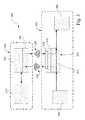
- FIG. 4a block diagram is shown depicting an exemplary electronic system 400 configured to enable monitoring or other control of an electronic device 402 by an external device 404 is shown.
- Electronic device 402is shown to include a first electronic circuit 406 and a second electronic circuit 407 in communication by an interconnecting signal pathway or communication link 408 .
- the first electronic device 402may also inlcude an interface circuit 409 having a first EHF communications circuit 410 including EHF communication units 411 and 412 .
- EHF communication units 411 and 412may be configured, respectively, to transmit and receive EHF electromagnetic signals, such as transmit signal 414 and receive signal 416 , transmitted to and received from an external device, like second electronic device 304 .
- second electronic device 404may include a second EHF communication circuit 418 that may be configured to act as a transceiver for communicating with electronic device 402 .
- Interface circuit 409may also include a controller 420 and a multiplexer 422 .
- communication link 408may include a first communication link portion 424 connecting an output of electronic circuit 406 with an input of multiplexer 422 , and a second link portion 426 connecting an output of the multiplexer with an input to electronic circuit 407 . The communication link thus provides communication between the two electronic circuits via the multiplexer.
- a signal from the receiver EHF communication unit 412may also be routed to another input of multiplexer 422 .
- the multiplexermay have a receiver-generated input and an internal communication link input.
- the controllermay be configured to receive a signal from receiver EHF communication unit 412 and, in response to an interpretation of that signal, control the multiplexer to switch between the internal communication link input and the receiver generated input, thus linking one or the other signal path to the electronic circuit 407 and controlling operation of the multiplexer to selectively substitute the communication signal received from the external device 404 .
- the controllermay also be configured to selectively enable or disable transmitter EHF communication unit 411 in response to the received EHF electromagnetic signal to substitute on the internal communication link a communication signal received from the external device 404 for a communication signal generated by one of the first and second electronic circuits 406 and 407 .
- This arrangementmay allow first device 402 to transmit an EHF signal 416 , such as the one illustrated in FIG. 4 .
- receive signal 416may contain a control sequence 428 and a data payload 430 .
- Control sequence 428may be interpreted by controller 420 as a signal to enable or disable the transmitter EHF communication unit and/or to switch the multiplexer 422 between inputs.
- the data payload 430may subsequently be routed to the second electronic circuit 407 or ignored, while a signal from first electronic circuit 406 may be transmitted or isolated, or any combination of these actions.
- controller 420may be configured to respond to a received EHF electromagnetic signal to substitute on the internal communication link the communication signal generated by one of first electronic circuit 406 and second electronic circuit 407 .
- the controllermay be configured to direct an internal signal generated by the first electronic device 402 to the second electronic device 404 and to direct the communication signal received from the second electronic device to second electronic circuit 407 .
- FIGS. 5 to 7illustrate various simplified exemplary systems having two electronic devices in communication.
- a communication system 500includes first and second electronic devices 502 and 504 .
- First electronic device 502is shown to include two EHF communication units 506 and 508 , acting as a transmitter and a receiver respectively, which are configured to pair with two corresponding EHF communication units 510 and 512 on second electronic device 504 such that a signal pathway or communication link 513 between two operational components 514 and 516 may be monitored or otherwise controlled.
- the EHF communication unitsmay configured and aligned when the first and second electronic devices are placed in close proximity to each other, thereby enabling contactless signal monitoring or other form of control of the first electronic device 502 by the second electronic device 504 , data transfer from the second electronic device and the first electronic device.
- a communication system 600includes first and second electronic devices 602 and 604 .
- first electronic device 602is shown to include a single EHF communication unit 606 , functioning as a transceiver and second electronic device 604 is shown to include a single EHF communication unit 608 also functioning as a transceiver.
- the two EHF communication unitsare configured to communicate as described above such that a signal pathway or communication link 609 , coupled to EHF communication unit 606 , and extending between two operational components 610 and 612 may be monitored or otherwise controlled.
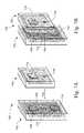
- FIG. 7Aillustrates a representative communication system 700 similar to system 600 having first and second electronic devices 702 and 704 .
- First electronic device 702is shown to include an EHF communication unit 706 , functioning as a transceiver, operational components 708 and 710 , such as electronic circuits, and a communication link 712 providing communication between the operational components and coupled to EHF communication circuit 706 .
- Second electronic device 704includes a controller 714 and an EHF communication circuit 716 in communication with the controller. The two EHF communication circuits are configured to communicate as described above along a communication signal path 718 .
- FIG. 8Aillustrates simplistically a further example of system 700 with the electronic devices in the positions shown in FIG. 7A .
- operational component 708 of electronic device 702includes a CPU and operational component 710 includes a data storage device, such as a memory.
- Controller 714 of electronic device 704also includes a CPU and may include a data storage device as well.
- Communication link 712is shown connecting operational components 708 and 710 .
- Communication signal path 718is shown terminated with an ‘X’ indicating there is no communication between the CPU of controller 714 and communication link 712 over communication signal path 718 .
- FIG. 7Billustrates the position of electronic devices 702 and 704 when they are placed proximate each other appropriately to establish communication signal path 718 .
- electronic device 704may send signals to electronic device 702 to substitute the data transmitted from the CPU of controller 714 for the data that would otherwise be transmitted from the CPU of operational component 708 to the memory of operational component 710 .
- data from a data storage device on one electronic devicemay be communicated to the other electronic device and may be stored on a data storage device of the other electronic device. This may be achieved by appropriate control circuitry in electronic device 702 , such as are provided in interface circuit 409 of electronic device 402 described above.
- FIG. 8Bshows a signal path from the CPU of controller 714 to the memory of operational component 710 , but the signal path from the CPU of operational component 708 provided normally by communication link 712 is not terminated at operational component 710 .
- systems, devices, and methods as described above for providing wireless communicationmay include one or more of the following examples.
- an electronic devicemay include a first electronic circuit and a second electronic circuit.
- the electronic devicemay also include an internal communication link providing a signal path for conducting communication signals between the first electronic circuit and the second electronic circuit.
- An interface circuitmay be operatively coupled to the internal communication link.
- the interface circuitmay include an EHF communications circuit configured to receive an EHF electromagnetic signal from an external device and generate from the received EHF electromagnetic signal a receive communication signal. This receive communication signal may be selectively applied by the interface circuit to the internal communication link, thereby enabling the external device to control the electronic device.
- the electronic devicemay also include a second EHF communications circuit configured to generate an EHF electromagnetic signal from an internal communication signal conducted on the internal communication link, and transmit the generated EHF electromagnetic signal to the external device.
- the EHF communications circuitmay be configured to transmit a modulated EHF signal representing communication signals between the first electronic circuit and the second electronic circuit.
- the EHF communications circuitmay be configured to transmit a modulated EHF signal representing an output of the first electronic circuit.
- the interface circuitmay include a controller configured to enable or disable a transmit EHF communications circuit in response to the received EHF electromagnetic signal.
- the controllermay substitute on the internal communication link a communication signal received from the external device for a communication signal generated by one of the first and second electronic circuits.
- the interface circuitmay include a multiplexer having as inputs the communication signal from the external device and the internal communication link from the first circuit, such that the controller may selectively substitute the communication signal received from the external device by controlling operation of the multiplexer.
- the controllermay be configured to respond to the received EHF electromagnetic signal to substitute on the internal communication link the communication signal generated by one of the first and second circuits.
- the controllermay be configured to direct an internal signal generated by the first electronic circuit to the external device and to direct the communication signal received from the external device to the second electronic circuit.
- an electronic deviceincluding a first electronic circuit and a second electronic circuit.
- the electronic devicemay be provided with an internal communication link providing a signal path for conducting communication signals between the first electronic circuit and the second electronic circuit.
- An interface circuitmay be operatively coupled to the internal communication link.
- the interface circuitincludes an extremely high frequency (EHF) communications circuit configured to transmit to an external device an EHF electromagnetic signal representative of a communication signal conducted on the internal communication link, thereby enabling the external device to monitor the electronic device.
- EHFextremely high frequency
- an electronic devicemay include a controller configured to generate a transmit communication signal appropriate for controlling an operation of an external device by applying the transmit communication signal to a communication link between two circuits in the external device.
- An extremely high frequency (EHF) communications circuitmay be operatively coupled to the controller and configured to convert the transmit communication signal into a transmit EHF electromagnetic signal and transmit the transmit EHF electromagnetic signal to the external device.
- EHFextremely high frequency
- the EHF communication circuitmay be configured to receive a receive EHF electromagnetic signal communicated from the communication link of the external device and generate a receive communication signal.
- the controllermay further be configured to generate the transmit communication signal in response to the receive communication signal.
- the controllermay be further configured to generate the transmit communication signal as a signal to be conducted to one of the two circuits on the communication link of the external device.
- an electronic systemmay include a first device and a second device external to the first device.
- the first devicemay include a first electronic circuit, an operational component and an internal communication link providing a signal path for conducting communication signals between the first electronic circuit and the operational component.
- a first interface circuitoperatively coupled to the internal communication link and including a first EHF communications circuit configured to receive an EHF electromagnetic signal from an external device and generate from the received EHF electromagnetic signal a receive communication signal, the interface circuit selectively applying the receive communication signal to the internal communication link.
- the second devicemay include a controller configured to generate a transmit communication signal appropriate for controlling an operation of an external device by applying the transmit communication signal to a communication link between two circuits in the external device.
- An extremely high frequency (EHF) communications circuitmay be operatively coupled to the controller and configured to convert the transmit communication signal into a transmit EHF electromagnetic signal and transmit the transmit EHF electromagnetic signal to the first device.
- the first and second EHF communication circuitsmay provide an EHF electromagnetic communication link when the first device and the second device are positioned with the first EHF communication circuit and the second EHF communication circuit in proximity.
- the controller in the electronic systemmay be configured to generate the transmit communication signal appropriate for selectively bypassing signal communication between the first electronic circuit and the operational component of the first device, and enabling control of the operational component of the first device by the second device.
- the first EHF communication circuit and the second EHF communication circuitmay be configured to selectively monitor signal communication between the first electronic circuit and the operational component of the first device.
- the first devicemay comprise a first data storage component and a second storage component, respectively, wherein the controller may be configured to read contents of the second data storage component and the interface circuit may be configured to write the contents to the first data storage component.
- One or both of the first and second EHF communication circuitsmay include an EHF communication unit that includes an integrated circuit (IC), an antenna operatively connected to the IC, a lead frame, a ground plane operatively connected to the IC and an insulating material encapsulating the IC, the lead frame, the ground plane, and the antenna to form an IC package.
- ICintegrated circuit
- antennaoperatively connected to the IC
- lead frameoperatively connected to the IC
- a ground planeoperatively connected to the IC and an insulating material encapsulating the IC, the lead frame, the ground plane, and the antenna to form an IC package.
- the EHF communication unitsmay be configured and aligned when the first device is placed in close proximity to the second device, thereby enabling contactless signal monitoring of the first device by the second device. Also, the EHF communication units may be configured and aligned when the second device is placed in close proximity to the first device, thereby enabling contactless data transfer from the second device and the first device. In another embodiment, the EHF communication units may be configured and aligned when the second device in placed in close proximity to the first device, thereby enabling contactless control of the first device by the second device.
- a methodmay provide communication between a first EHF-communication enabled device and a second EHF-communication enabled device.
- the first EHF-communication enabled devicemay be placed in close proximity to the second EHF-communication enabled device.
- the first EHF-communication enabled devicemay transmit an EHF signal and the second EHF-communication enabled device may receive the EHF signal transmitted by the first EHF-communication enabled device.
- This signalmay then be interpreted by the first EHF-communication enabled device, and a response to the interpreted EHF signal may be generated by enabling at least one of monitoring of the second EHF-communication enabled device by the first EHF-communication enabled device and controlling by the first EHF-communication enabled device of a function of the second EHF-communication enabled device.
- the inventions described hereinrelate to industrial and commercial industries, such as electronics and communications industries using devices that communicate with other devices or devices having communication between components in the devices.
Landscapes
- Engineering & Computer Science (AREA)
- Computer Networks & Wireless Communication (AREA)
- Signal Processing (AREA)
- Near-Field Transmission Systems (AREA)
Abstract
Description
Claims (12)
Priority Applications (10)
| Application Number | Priority Date | Filing Date | Title |
|---|---|---|---|
| US13/657,482US9407311B2 (en) | 2011-10-21 | 2012-10-22 | Contactless signal splicing using an extremely high frequency (EHF) communication link |
| US13/969,565US9474099B2 (en) | 2008-12-23 | 2013-08-17 | Smart connectors and associated communications links |
| PCT/US2013/055487WO2014058534A1 (en) | 2012-09-14 | 2013-08-17 | Smart connectors and associated communications links |
| EP13845508.4AEP2896148B1 (en) | 2012-09-14 | 2013-08-17 | Smart connectors and associated communications links |
| CN201380047942.9ACN104756411B (en) | 2012-09-14 | 2013-08-17 | Smart Connectors and associated communication links |
| CN201710766860.XACN107888234B (en) | 2012-09-14 | 2013-08-17 | Method for providing application support for a first device host system and first device |
| KR1020157009223AKR102095319B1 (en) | 2012-09-14 | 2013-08-17 | Smart connectors and associated communications links |
| US15/204,988US9647715B2 (en) | 2011-10-21 | 2016-07-07 | Contactless signal splicing using an extremely high frequency (EHF) communication link |
| US15/290,262US9954579B2 (en) | 2008-12-23 | 2016-10-11 | Smart connectors and associated communications links |
| US15/960,105US10588002B2 (en) | 2008-12-23 | 2018-04-23 | Smart connectors and associated communications links |
Applications Claiming Priority (2)
| Application Number | Priority Date | Filing Date | Title |
|---|---|---|---|
| US201161550274P | 2011-10-21 | 2011-10-21 | |
| US13/657,482US9407311B2 (en) | 2011-10-21 | 2012-10-22 | Contactless signal splicing using an extremely high frequency (EHF) communication link |
Related Parent Applications (3)
| Application Number | Title | Priority Date | Filing Date |
|---|---|---|---|
| US13/541,543Continuation-In-PartUS20120295539A1 (en) | 2008-12-23 | 2012-07-03 | Ehf communication with electrical isolation and with dielectric transmission medium |
| US13/848,735Continuation-In-PartUS9960820B2 (en) | 2008-12-23 | 2013-03-22 | Contactless data transfer systems and methods |
| US13/969,565Continuation-In-PartUS9474099B2 (en) | 2008-12-23 | 2013-08-17 | Smart connectors and associated communications links |
Related Child Applications (3)
| Application Number | Title | Priority Date | Filing Date |
|---|---|---|---|
| US13/713,564Continuation-In-PartUS8794980B2 (en) | 2008-12-23 | 2012-12-13 | Connectors providing HAPTIC feedback |
| US13/969,565Continuation-In-PartUS9474099B2 (en) | 2008-12-23 | 2013-08-17 | Smart connectors and associated communications links |
| US15/204,988ContinuationUS9647715B2 (en) | 2011-10-21 | 2016-07-07 | Contactless signal splicing using an extremely high frequency (EHF) communication link |
Publications (2)
| Publication Number | Publication Date |
|---|---|
| US20130109303A1 US20130109303A1 (en) | 2013-05-02 |
| US9407311B2true US9407311B2 (en) | 2016-08-02 |
Family
ID=47226404
Family Applications (2)
| Application Number | Title | Priority Date | Filing Date |
|---|---|---|---|
| US13/657,482Active2033-10-16US9407311B2 (en) | 2008-12-23 | 2012-10-22 | Contactless signal splicing using an extremely high frequency (EHF) communication link |
| US15/204,988ActiveUS9647715B2 (en) | 2011-10-21 | 2016-07-07 | Contactless signal splicing using an extremely high frequency (EHF) communication link |
Family Applications After (1)
| Application Number | Title | Priority Date | Filing Date |
|---|---|---|---|
| US15/204,988ActiveUS9647715B2 (en) | 2011-10-21 | 2016-07-07 | Contactless signal splicing using an extremely high frequency (EHF) communication link |
Country Status (3)
| Country | Link |
|---|---|
| US (2) | US9407311B2 (en) |
| TW (2) | TWI562555B (en) |
| WO (1) | WO2013059802A1 (en) |
Cited By (3)
| Publication number | Priority date | Publication date | Assignee | Title |
|---|---|---|---|---|
| US10250418B2 (en)* | 2016-08-02 | 2019-04-02 | Keyssa Systems, Inc. | EHF receiver architecture with dynamically adjustable discrimination threshold |
| US10469112B2 (en)* | 2017-05-31 | 2019-11-05 | Silicon Laboratories Inc. | System, apparatus and method for performing automatic gain control in a receiver for a packet-based protocol |
| US12334889B1 (en) | 2023-12-14 | 2025-06-17 | Silicon Laboratories Inc. | Gain contol to optimize sensitivity and blocking performance |
Families Citing this family (29)
| Publication number | Priority date | Publication date | Assignee | Title |
|---|---|---|---|---|
| US8554136B2 (en) | 2008-12-23 | 2013-10-08 | Waveconnex, Inc. | Tightly-coupled near-field communication-link connector-replacement chips |
| US9474099B2 (en) | 2008-12-23 | 2016-10-18 | Keyssa, Inc. | Smart connectors and associated communications links |
| US8794980B2 (en) | 2011-12-14 | 2014-08-05 | Keyssa, Inc. | Connectors providing HAPTIC feedback |
| US9191263B2 (en) | 2008-12-23 | 2015-11-17 | Keyssa, Inc. | Contactless replacement for cabled standards-based interfaces |
| US9219956B2 (en) | 2008-12-23 | 2015-12-22 | Keyssa, Inc. | Contactless audio adapter, and methods |
| US9954579B2 (en) | 2008-12-23 | 2018-04-24 | Keyssa, Inc. | Smart connectors and associated communications links |
| KR101615082B1 (en) | 2011-03-24 | 2016-04-29 | 키사, 아이엔씨. | Integrated circuit with electromagnetic communication |
| US8714459B2 (en) | 2011-05-12 | 2014-05-06 | Waveconnex, Inc. | Scalable high-bandwidth connectivity |
| US9614590B2 (en) | 2011-05-12 | 2017-04-04 | Keyssa, Inc. | Scalable high-bandwidth connectivity |
| US8811526B2 (en) | 2011-05-31 | 2014-08-19 | Keyssa, Inc. | Delta modulated low power EHF communication link |
| TWI569031B (en) | 2011-06-15 | 2017-02-01 | 奇沙公司 | Near-end sensing and distance measurement using EHF signals |
| KR101879907B1 (en) | 2011-09-15 | 2018-08-16 | 키사, 아이엔씨. | Wireless communication with dielectric medium |
| EP2769477A1 (en) | 2011-10-20 | 2014-08-27 | Keyssa, Inc. | Low-profile wireless connectors |
| TWI562555B (en) | 2011-10-21 | 2016-12-11 | Keyssa Inc | Contactless signal splicing |
| US9559790B2 (en) | 2012-01-30 | 2017-01-31 | Keyssa, Inc. | Link emission control |
| US9344201B2 (en) | 2012-01-30 | 2016-05-17 | Keyssa, Inc. | Shielded EHF connector assemblies |
| CN107276641B (en) | 2012-03-02 | 2021-07-02 | 凯萨股份有限公司 | Duplex communication system and method |
| CN104303436B (en) | 2012-03-06 | 2017-04-05 | 凯萨股份有限公司 | System for constraining operating parameters of an EHF communication chip |
| EP2832192B1 (en) | 2012-03-28 | 2017-09-27 | Keyssa, Inc. | Redirection of electromagnetic signals using substrate structures |
| CN104321930A (en) | 2012-04-17 | 2015-01-28 | 凯萨股份有限公司 | Dielectric lens structures for interchip communication |
| EP2883271B1 (en) | 2012-08-10 | 2020-07-22 | Keyssa, Inc. | Dielectric coupling systems for ehf communications |
| US9374154B2 (en) | 2012-09-14 | 2016-06-21 | Keyssa, Inc. | Wireless connections with virtual hysteresis |
| WO2014100058A1 (en) | 2012-12-17 | 2014-06-26 | Waveconnex, Inc. | Modular electronics |
| TWI551093B (en) | 2013-03-15 | 2016-09-21 | 奇沙公司 | Extremely high frequency communication chip |
| EP2974058B1 (en) | 2013-03-15 | 2020-07-15 | Keyssa, Inc. | Contactless ehf data communication |
| KR20150132459A (en) | 2013-03-15 | 2015-11-25 | 키사, 아이엔씨. | Ehf secure communication device |
| US9602648B2 (en) | 2015-04-30 | 2017-03-21 | Keyssa Systems, Inc. | Adapter devices for enhancing the functionality of other devices |
| US10049801B2 (en) | 2015-10-16 | 2018-08-14 | Keyssa Licensing, Inc. | Communication module alignment |
| KR102542759B1 (en)* | 2016-07-05 | 2023-06-15 | 삼성디스플레이 주식회사 | Display apparatus |
Citations (268)
| Publication number | Priority date | Publication date | Assignee | Title |
|---|---|---|---|---|
| US2753551A (en) | 1951-06-20 | 1956-07-03 | Raytheon Mfg Co | Circularly polarized radio object locating system |
| GB817349A (en) | 1956-04-24 | 1959-07-29 | Marie G R P | Circularly polarised microwave lenses |
| US3796831A (en) | 1972-11-13 | 1974-03-12 | Rca Corp | Pulse modulation and detection communications system |
| US3971930A (en) | 1974-04-24 | 1976-07-27 | The United States Of America As Represented By The Administrator Of The National Aeronautics And Space Administration | Polarization compensator for optical communications |
| US3987365A (en) | 1974-03-01 | 1976-10-19 | Hitachi, Ltd. | Digital frequency comparator circuit |
| JPS5272502A (en) | 1975-12-13 | 1977-06-17 | Mitsubishi Electric Corp | Code transmitter |
| US4293833A (en) | 1979-11-01 | 1981-10-06 | Hughes Aircraft Company | Millimeter wave transmission line using thallium bromo-iodide fiber |
| US4485312A (en) | 1981-06-15 | 1984-11-27 | Tokyo Shibaura Denki Kabushiki Kaisha | Hysteresis circuit |
| US4497068A (en) | 1982-01-25 | 1985-01-29 | Eaton Corporation | Encoding system for optic data link |
| US4525693A (en) | 1982-05-01 | 1985-06-25 | Junkosha Company Ltd. | Transmission line of unsintered PTFE having sintered high density portions |
| EP0152246A2 (en) | 1984-02-03 | 1985-08-21 | Rosemount Limited | Electrical isolation circuit |
| US4694504A (en) | 1985-06-03 | 1987-09-15 | Itt Electro Optical Products, A Division Of Itt Corporation | Synchronous, asynchronous, and data rate transparent fiber optic communications link |
| US4771294A (en) | 1986-09-10 | 1988-09-13 | Harris Corporation | Modular interface for monolithic millimeter wave antenna array |
| US4800350A (en) | 1985-05-23 | 1989-01-24 | The United States Of America As Represented By The Secretary Of The Navy | Dielectric waveguide using powdered material |
| US4875026A (en) | 1987-08-17 | 1989-10-17 | W. L. Gore & Associates, Inc. | Dielectric waveguide having higher order mode suppression |
| GB2217114A (en) | 1988-03-31 | 1989-10-18 | Junkosha Co Ltd | Electrical transmission circuit |
| US4946237A (en) | 1989-06-30 | 1990-08-07 | At&T Bell Laboratories | Cable having non-metallic armoring layer |
| US5164942A (en) | 1990-09-06 | 1992-11-17 | Ncr Corporation | Antenna control for a wireless local area network station |
| EP0515187A2 (en) | 1991-05-22 | 1992-11-25 | Wolff Controls Corporation | Method and apparatus for sensing proximity of an object using near-field effects |
| US5199086A (en) | 1991-01-17 | 1993-03-30 | Massachusetts Institute Of Technology | Electro-optic system |
| JPH05236031A (en) | 1991-07-23 | 1993-09-10 | Hitachi Maxell Ltd | Data transmission system |
| JPH05327788A (en) | 1992-05-15 | 1993-12-10 | Hitachi Maxell Ltd | Data demodulating circuit |
| JPH076817A (en) | 1993-06-15 | 1995-01-10 | Hitachi Ltd | Connect device |
| US5471668A (en) | 1994-06-15 | 1995-11-28 | Texas Instruments Incorporated | Combined transmitter/receiver integrated circuit with learn mode |
| US5543808A (en) | 1995-05-24 | 1996-08-06 | The United States Of America As Represented By The Secretary Of The Army | Dual band EHF, VHF vehicular whip antenna |
| CN2237914Y (en) | 1995-09-20 | 1996-10-16 | 汪雪松 | Wireless hearing aid |
| JPH0983538A (en) | 1995-09-18 | 1997-03-28 | Fujitsu Ltd | IO card for wireless communication and wireless communication method using the IO card |
| US5621913A (en) | 1992-05-15 | 1997-04-15 | Micron Technology, Inc. | System with chip to chip communication |
| EP0789421A2 (en) | 1996-02-12 | 1997-08-13 | BOEING NORTH AMERICAN, Inc. | Durable, lightweight, radar lens antenna |
| WO1997032413A1 (en) | 1996-02-29 | 1997-09-04 | Ericsson Inc. | Multiple access communications system and method using code and time division |
| JPH1013296A (en) | 1996-03-25 | 1998-01-16 | Internatl Business Mach Corp <Ibm> | Radio transponder |
| CN1178402A (en) | 1996-08-09 | 1998-04-08 | 住友电装株式会社 | Charging Connectors for Electric Vehicles |
| US5749052A (en) | 1995-05-24 | 1998-05-05 | Tele Digital Development, Inc. | Cellular telephone management system |
| US5754948A (en) | 1995-12-29 | 1998-05-19 | University Of North Carolina At Charlotte | Millimeter-wave wireless interconnection of electronic components |
| US5773878A (en) | 1995-10-28 | 1998-06-30 | Institute Of Microelectronics National University Of Singapore | IC packaging lead frame for reducing chip stress and deformation |
| EP0884799A2 (en) | 1997-06-13 | 1998-12-16 | Fujitsu Limited | Semiconductor module having antenna element therein |
| US5861782A (en) | 1995-08-18 | 1999-01-19 | Murata Manufacturing Co., Ltd. | Nonradiative dielectric waveguide and method of producing the same |
| EP0896380A2 (en) | 1997-07-11 | 1999-02-10 | Murata Manufacturing Co., Ltd. | Dielectric waveguide |
| CN2313296Y (en) | 1997-07-25 | 1999-04-07 | 电子工业部第五十四研究所 | Eight-multiple diversity receiving simple device for communication signals |
| US5921783A (en) | 1995-04-01 | 1999-07-13 | Klaus-Dieter Fritsch | Electromechanical connection device |
| US5943374A (en) | 1995-12-11 | 1999-08-24 | Hitachi Denshi Kabushiki Kaisha | Out-of-synchronization recovery method and apparatus of data transmission system |
| US5941729A (en) | 1997-09-10 | 1999-08-24 | International Business Machines Corporation | Safe-snap computer cable |
| US5956626A (en) | 1996-06-03 | 1999-09-21 | Motorola, Inc. | Wireless communication device having an electromagnetic wave proximity sensor |
| US6011785A (en) | 1994-06-01 | 2000-01-04 | Airnet Communications Corporation | Wideband wireless base-station making use of time division multiple-access bus to effect switchable connections to modulator/demodulator resources |
| EP0996189A2 (en) | 1998-10-22 | 2000-04-26 | Murata Manufacturing Co., Ltd. | Dielectric line converter, dielectric line unit, directional coupler, high-frequency circuit module, and transmitter-receiver |
| US6072433A (en) | 1996-07-31 | 2000-06-06 | California Institute Of Technology | Autonomous formation flying sensor |
| EP1041666A1 (en) | 1997-12-17 | 2000-10-04 | Murata Manufacturing Co., Ltd. | Nonradiating dielectric line and its integrated circuit |
| JP2001153963A (en) | 1999-11-26 | 2001-06-08 | Nec Corp | Object detector and crew detection system |
| US6252767B1 (en) | 1999-06-22 | 2001-06-26 | Hewlett-Packard Company | Low impedance hinge for notebook computer |
| JP2001326506A (en) | 2000-05-12 | 2001-11-22 | Hitachi Cable Ltd | Array antenna |
| US20020008665A1 (en) | 2000-05-26 | 2002-01-24 | Kyocera Corporation | Antenna feeder line, and antenna module provided with the antenna feeder line |
| US6351237B1 (en) | 1995-06-08 | 2002-02-26 | Metawave Communications Corporation | Polarization and angular diversity among antenna beams |
| US20020027481A1 (en) | 1995-12-07 | 2002-03-07 | Fiedziuszko Slawomir J. | Electromagnetic transmission line elements having a boundary between materials of high and low dielectric constants |
| US6373447B1 (en) | 1998-12-28 | 2002-04-16 | Kawasaki Steel Corporation | On-chip antenna, and systems utilizing same |
| US20020058484A1 (en) | 2000-10-06 | 2002-05-16 | Bobier Joseph A. | Suppressed cycle based carrier modulation using amplitude modulation |
| US20020106041A1 (en) | 2001-02-05 | 2002-08-08 | Chang Donald C. D. | Sampling technique for digital beam former |
| US20020118083A1 (en) | 2001-02-28 | 2002-08-29 | Albert Pergande | Millimeterwave module compact interconnect |
| JP2002261514A (en) | 2001-02-28 | 2002-09-13 | Matsushita Electric Ind Co Ltd | NRD guide circuit |
| JP2002265729A (en) | 2001-03-12 | 2002-09-18 | Nippon Pillar Packing Co Ltd | Fluororesin composition for electronic part |
| US20020140584A1 (en) | 2001-02-08 | 2002-10-03 | Hitachi. Ltd. | Method for recording information, method for reproducing information, and information recording apparatus |
| US6490443B1 (en) | 1999-09-02 | 2002-12-03 | Automated Business Companies | Communication and proximity authorization systems |
| US6492973B1 (en) | 1998-09-28 | 2002-12-10 | Sharp Kabushiki Kaisha | Method of driving a flat display capable of wireless connection and device for driving the same |
| US20030025626A1 (en) | 2001-08-03 | 2003-02-06 | Mcewan Thomas E. | Pulse center detector for radars and reflectometers |
| US6534784B2 (en) | 2001-05-21 | 2003-03-18 | The Regents Of The University Of Colorado | Metal-oxide electron tunneling device for solar energy conversion |
| US6542720B1 (en) | 1999-03-01 | 2003-04-01 | Micron Technology, Inc. | Microelectronic devices, methods of operating microelectronic devices, and methods of providing microelectronic devices |
| EP1298809A2 (en) | 2001-09-28 | 2003-04-02 | Siemens Information and Communication Mobile LLC | System and method for reducing SAR values |
| US20030088404A1 (en) | 2001-04-16 | 2003-05-08 | Yukio Koyanagi | Compression method and apparatus, decompression method and apparatus, compression/decompression system, peak detection method, program, and recording medium |
| US6590544B1 (en) | 1998-09-01 | 2003-07-08 | Qualcomm, Inc. | Dielectric lens assembly for a feed antenna |
| US20030137371A1 (en) | 2001-11-16 | 2003-07-24 | Atsushi Saitoh | Dielectric line, high frequency circuit and high frequency apparatus |
| JP2003209511A (en) | 2002-01-15 | 2003-07-25 | Kddi Research & Development Laboratories Inc | Communication link connecting and disconnecting method for mobile station in communication system between road and vehicle |
| US6607136B1 (en) | 1998-09-16 | 2003-08-19 | Beepcard Inc. | Physical presence digital authentication system |
| EP1357395A1 (en) | 2002-04-26 | 2003-10-29 | Hitachi, Ltd. | Miniaturized and hermetically sealed radar sensor for millimeter wave signals |
| US6647246B1 (en) | 2000-01-10 | 2003-11-11 | Industrial Technology Research Institute | Apparatus and method of synchronization using delay measurements |
| JP2004505505A (en) | 2000-07-25 | 2004-02-19 | トムソン ライセンシング ソシエテ アノニム | Transmission of main and auxiliary data using pulse width modulation |
| US20040043734A1 (en) | 2002-08-27 | 2004-03-04 | Shuichi Hashidate | Semiconductor device |
| US6768770B1 (en) | 1999-04-21 | 2004-07-27 | Infineon Technologies Ag | Transceiver with bidirectional internal interface lines |
| US20040160294A1 (en) | 1999-10-29 | 2004-08-19 | Berg Technology, Inc. | Waveguide and backplane systems |
| US20040214621A1 (en) | 2003-04-25 | 2004-10-28 | Motorola, Inc. | Wireless communication device with variable antenna radiation pattern and corresponding method |
| US20050032474A1 (en) | 2003-08-05 | 2005-02-10 | Gordon Gary B. | Resonant frequency user proximity detection |
| JP2005117153A (en) | 2003-10-03 | 2005-04-28 | Toshiba Corp | Wireless communication apparatus, wireless communication method, and wireless communication medium |
| US20050099242A1 (en) | 2003-11-07 | 2005-05-12 | Toko Inc. | Input/output coupling structure for dielectric waveguide |
| US20050109841A1 (en) | 2003-11-17 | 2005-05-26 | Ryan Dennis J. | Multi-interface compact personal token apparatus and methods of use |
| US20050124307A1 (en) | 2003-12-08 | 2005-06-09 | Xytrans, Inc. | Low cost broadband wireless communication system |
| US20050140436A1 (en) | 2002-07-19 | 2005-06-30 | Micro Mobio | Dual band power amplifier module for wireless communication devices |
| US6915529B1 (en) | 1998-02-27 | 2005-07-05 | Sharp Kabushiki Kaisha | Milliwave transmitting device, milliwave receiving device and milliwave transmission and reception system capable of simplifying wiring of a receiving system of terrestrial broadcasting service and satellite broadcasting service |
| US6967347B2 (en) | 2001-05-21 | 2005-11-22 | The Regents Of The University Of Colorado | Terahertz interconnect system and applications |
| US20060003710A1 (en) | 2003-02-12 | 2006-01-05 | Yoichi Nakagawa | Transmitter apparatus and radio communication method |
| US20060029229A1 (en) | 2004-08-03 | 2006-02-09 | Alexei Trifonov | QKD station with EMI signature suppression |
| US20060051981A1 (en) | 2002-09-13 | 2006-03-09 | Hermann Neidlein | Method and device for producing an electrical connection of sub-assemblies and modules |
| US20060077043A1 (en) | 2002-11-21 | 2006-04-13 | Koninlijke Philips Electronics N.V. | Method of recognizing whether a trasponder belongs to a group of transponders |
| US20060082518A1 (en) | 2004-10-19 | 2006-04-20 | Pranil Ram | Multiple monitor display apparatus |
| US7050763B2 (en) | 2001-01-30 | 2006-05-23 | Infineon Technologies Ag | Method and device for transferring a signal from a signal source to a signal sink in a system |
| CN1781255A (en) | 2003-03-07 | 2006-05-31 | 诺基亚有限公司 | Tone Detection and Adaptive Gain Control for Direct Conversion Receivers |
| US20060128372A1 (en) | 2004-12-14 | 2006-06-15 | Gazzola James P | System and method for coverage analysis in a wireless network |
| US20060140305A1 (en) | 2004-12-29 | 2006-06-29 | Netsell Aaron W | Method and apparatus for adaptive modulation of wireless communication signals |
| US20060159158A1 (en) | 2004-12-22 | 2006-07-20 | Artimi Ltd | Contactless connector systems |
| US7113087B1 (en) | 2003-04-08 | 2006-09-26 | Microsoft Corporation | Proximity sensing based on antenna impedance variation |
| US20060258289A1 (en) | 2005-05-12 | 2006-11-16 | Robin Dua | Wireless media system and player and method of operation |
| US20060276157A1 (en)* | 2005-06-03 | 2006-12-07 | Chen Zhi N | Apparatus and methods for packaging antennas with integrated circuit chips for millimeter wave applications |
| US20070010295A1 (en) | 2005-07-08 | 2007-01-11 | Firefly Power Technologies, Inc. | Power transmission system, apparatus and method with communication |
| US20070024504A1 (en) | 2005-07-27 | 2007-02-01 | Kabushiki Kaisha Toshiba | Semiconductor device |
| US20070035917A1 (en) | 2005-08-09 | 2007-02-15 | Apple Computer, Inc. | Methods and apparatuses for docking a portable electronic device that has a planar like configuration and that operates in multiple orientations |
| US20070063056A1 (en) | 2005-09-21 | 2007-03-22 | International Business Machines Corporation | Apparatus and methods for packaging antennas with integrated circuit chips for millimeter wave applications |
| EP1798867A2 (en) | 2005-12-16 | 2007-06-20 | Innovision Research & Technology PLC | Communications devices and method comprising near field RF communicators |
| US20070147425A1 (en) | 2005-12-28 | 2007-06-28 | Wavesat | Wireless modem |
| US20070229270A1 (en) | 2006-03-16 | 2007-10-04 | Broadcom Corporation, A California Corporation | RFID system with RF bus |
| US20070242621A1 (en) | 2006-04-13 | 2007-10-18 | Qualcomm Incorporated | Dynamic carrier sensing thresholds |
| US20070273476A1 (en) | 2004-03-26 | 2007-11-29 | Semiconductor Energy Laboratory Co., Ltd. | Thin Semiconductor Device And Operation Method Of Thin Semiconductor Device |
| US20070278632A1 (en) | 2006-06-01 | 2007-12-06 | Broadcom Corporation | Leadframe IC packages having top and bottom integrated heat spreaders |
| CN101090179A (en) | 2006-06-08 | 2007-12-19 | 诺基亚公司 | Magnetic Connectors for Mobile Electronics |
| US7311526B2 (en) | 2005-09-26 | 2007-12-25 | Apple Inc. | Magnetic connector for electronic device |
| US20080002652A1 (en) | 2004-11-10 | 2008-01-03 | Gupta Dev V | System and apparatus for high data rate wireless communications |
| US20080055303A1 (en) | 2006-08-31 | 2008-03-06 | Seiko Epson Corporation | Display unit and electronic device |
| US20080055093A1 (en) | 2006-08-30 | 2008-03-06 | Exponent | Shield for radio frequency ID tag or contactless smart card |
| JP2008079241A (en) | 2006-09-25 | 2008-04-03 | Sharp Corp | Detection circuit, modulation method determination circuit, integrated circuit, tuner device, and multi-system shared receiver |
| US20080089667A1 (en) | 2006-10-13 | 2008-04-17 | Jeff Grady | Interface systems for portable digital media storage and playback devices |
| US20080112101A1 (en) | 2006-11-15 | 2008-05-15 | Mcelwee Patrick T | Transmission line filter for esd protection |
| JP2008129919A (en) | 2006-11-22 | 2008-06-05 | Toshiba Corp | Non-contact IC card reader / writer device and transmission radio wave output level control method |
| US20080142250A1 (en) | 2006-12-18 | 2008-06-19 | Tang George C | Electronic component connection support structures including air as a dielectric |
| US20080143435A1 (en) | 2005-01-25 | 2008-06-19 | Innovision Research & Technology Plc | Demodulator |
| US20080150799A1 (en) | 2006-12-21 | 2008-06-26 | Hemmi Christian O | Polarization Control System and Method for an Antenna Array |
| US20080150821A1 (en) | 2006-12-22 | 2008-06-26 | Sony Deutschland Gmbh | Flexible substrate integrated waveguides |
| US20080159243A1 (en) | 2006-12-30 | 2008-07-03 | Broadcom Corporation | Local wireless communications within a device |
| US20080165002A1 (en) | 2005-01-07 | 2008-07-10 | Optex Co., Ltd. | Microwave Sensor |
| US20080165065A1 (en) | 2007-01-04 | 2008-07-10 | Hill Robert J | Antennas for handheld electronic devices |
| US20080195788A1 (en) | 2007-02-12 | 2008-08-14 | Wilocity Ltd. | Wireless Docking Station |
| US20080192726A1 (en) | 2006-11-01 | 2008-08-14 | Kumar Mahesh | Wireless HD MAC frame format |
| US20080197973A1 (en) | 2004-06-03 | 2008-08-21 | Jean-Pierre Enguent | Load Modulation in an Electromagnetic Transponder |
| US20080238632A1 (en) | 2007-03-30 | 2008-10-02 | Takefumi Endo | Semiconductor integrated circuit device |
| JP2008252566A (en) | 2007-03-30 | 2008-10-16 | Matsushita Electric Ind Co Ltd | AV equipment |
| US20080293446A1 (en) | 2007-05-23 | 2008-11-27 | Broadcom Corporation | Fully integrated RF transceiver integrated circuit |
| US20080289426A1 (en) | 2007-05-25 | 2008-11-27 | Kearns Justin D | Structural health monitoring (shm) transducer assembly and system |
| US20080290959A1 (en) | 2007-05-22 | 2008-11-27 | Mohammed Ershad Ali | Millimeter wave integrated circuit interconnection scheme |
| US20090006677A1 (en) | 2007-06-28 | 2009-01-01 | Broadcom Corporation | Universal serial bus dongle device with wireless telephony transceiver and system for use therewith |
| US20090009337A1 (en) | 2006-06-21 | 2009-01-08 | Broadcom Corporation | Rfid integrated circuit with integrated antenna structure |
| US20090029659A1 (en) | 2007-07-23 | 2009-01-29 | Gonzalez David M | Rf circuit with control unit to reduce signal power under appropriate conditions |
| US20090028177A1 (en) | 2007-06-22 | 2009-01-29 | Vubiq Incorporated | System and method for wireless communication in a backplane fabric architecture |
| US20090037628A1 (en)* | 2007-07-31 | 2009-02-05 | Broadcom Corporation | Processing system with millimeter wave host interface and method for use therewith |
| US20090033455A1 (en) | 2007-07-31 | 2009-02-05 | Daniella Strat | Antenna-Based Trigger |
| US20090075688A1 (en) | 2007-09-18 | 2009-03-19 | Ahmadreza Rofougaran | Method and system for calibrating a power amplifier |
| US20090073070A1 (en) | 2007-03-30 | 2009-03-19 | Broadcom Corporation | Dual band antenna and methods for use therewith |
| US7512395B2 (en) | 2006-01-31 | 2009-03-31 | International Business Machines Corporation | Receiver and integrated AM-FM/IQ demodulators for gigabit-rate data detection |
| US20090086844A1 (en) | 2007-09-28 | 2009-04-02 | Ahmadreza Rofougaran | Method And System For A Programmable Local Oscillator Generator Utilizing A DDFS For Extremely High Frequencies |
| US20090091486A1 (en) | 2007-10-05 | 2009-04-09 | Infineon Technologies Ag | Analog To Digital Conversion Using Irregular Sampling |
| US20090094506A1 (en) | 2007-10-03 | 2009-04-09 | Qualcomm Incorporated | Millimeter-wave communications for peripheral devices |
| US20090098826A1 (en) | 2007-10-16 | 2009-04-16 | Rafi Zack | Virtual connector based on contactless link |
| US20090111390A1 (en) | 2007-10-24 | 2009-04-30 | Sutton Brian P | Radio communications system designed for a low-power receiver |
| US20090110131A1 (en) | 2001-10-01 | 2009-04-30 | Transoma Medical, Inc. | Assessing Noise on a Communication Channel |
| US20090175323A1 (en) | 2008-01-08 | 2009-07-09 | Qualcomm Incorporated | Methods and Devices for Wireless Chip-to-Chip Communications |
| US20090180408A1 (en) | 2008-01-11 | 2009-07-16 | John Graybeal | Realizing fdd capability by leveraging existing tdd technology |
| US20090218701A1 (en) | 2008-02-28 | 2009-09-03 | Broadcom Corporation | Inductively coupled integrated circuit with magnetic communication path and methods for use therewith |
| US20090218407A1 (en) | 2008-02-29 | 2009-09-03 | Broadcom Corporation | Integrated circuit with millimeter wave and inductive coupling and methods for use therewith |
| WO2009113373A1 (en) | 2008-03-13 | 2009-09-17 | 日本電気株式会社 | Semiconductor device |
| US20090237317A1 (en) | 2007-03-26 | 2009-09-24 | Broadcom Corporation | Very high frequency dielectric substrate wave guide |
| US20090239392A1 (en) | 2008-03-24 | 2009-09-24 | Kabushiki Kaisha Toshiba | Electronic Apparatus |
| US20090239483A1 (en) | 2007-01-31 | 2009-09-24 | Broadcom Corporation | Apparatus for allocation of wireless resources |
| US20090236701A1 (en) | 2008-03-18 | 2009-09-24 | Nanyang Technological University | Chip arrangement and a method of determining an inductivity compensation structure for compensating a bond wire inductivity in a chip arrangement |
| EP2106192A2 (en) | 2008-03-26 | 2009-09-30 | Sony Corporation | Communication apparatus and communication method, and computer program therefor |
| US20090245808A1 (en) | 2008-03-28 | 2009-10-01 | Ahmadreza Rofougaran | Method and system for inter-chip communication via integrated circuit package waveguides |
| US7599427B2 (en) | 2005-12-30 | 2009-10-06 | Honeywell International Inc. | Micro range radio frequency (RF) communications link |
| US7598923B2 (en) | 2006-05-22 | 2009-10-06 | Sony Corporation | Apparatus and method for communications via multiple millimeter wave signals |
| US20090257445A1 (en) | 2008-04-09 | 2009-10-15 | Altera Corporation | Pld architecture optimized for 10g ethernet physical layer solution |
| JP2009239842A (en) | 2008-03-28 | 2009-10-15 | Renesas Technology Corp | Radio communication system |
| US7612630B2 (en) | 2001-05-08 | 2009-11-03 | Formfactor, Inc. | Electromagnetically coupled interconnect system architecture |
| US20090280765A1 (en) | 2008-05-07 | 2009-11-12 | Ahmadreza Rofougaran | Method And System For On-Demand Filtering In A Receiver |
| US20090310649A1 (en) | 2002-11-15 | 2009-12-17 | Time Domain Corporation | System And Method For Fast Acquisition Of Ultra Wideband Signals |
| US20100009627A1 (en) | 2006-12-15 | 2010-01-14 | Heikki Huomo | Nfc communicator and method of data communication |
| US7656205B2 (en) | 2008-01-21 | 2010-02-02 | National Taiwan University | Dual-injection locked frequency dividing circuit |
| US7664461B2 (en) | 2006-03-02 | 2010-02-16 | Broadcom Corporation | RFID reader architecture |
| US20100103045A1 (en) | 2008-10-29 | 2010-04-29 | Yong Liu | Efficient and Flexible Transmit Beamforming Sector Sweep in a Multi-Antenna Communication Device |
| US20100120406A1 (en) | 2008-11-08 | 2010-05-13 | Phoenix Technologies Ltd. | Secure platform management with power savings capacity |
| US20100127804A1 (en) | 2008-11-26 | 2010-05-27 | Nick Vouloumanos | multi-component waveguide assembly |
| US20100149149A1 (en) | 2008-12-15 | 2010-06-17 | Lawther Joel S | Display system |
| US20100159829A1 (en) | 2008-12-23 | 2010-06-24 | Mccormack Gary D | Tightly-coupled near-field communication-link connector-replacement chips |
| US20100167645A1 (en) | 2008-12-25 | 2010-07-01 | Kabushiki Kaisha Toshiba | Information processing apparatus |
| US7760045B2 (en) | 2006-05-19 | 2010-07-20 | Sony Corporation | Semiconductor device interconnecting unit, semiconductor device, high-frequency module, and semiconductor device interconnecting method |
| US7761092B2 (en) | 2004-02-06 | 2010-07-20 | Sony Corporation | Systems and methods for communicating with multiple devices |
| US7768457B2 (en) | 2007-06-22 | 2010-08-03 | Vubiq, Inc. | Integrated antenna and chip package and method of manufacturing thereof |
| US7769347B2 (en) | 2001-05-02 | 2010-08-03 | Trex Enterprises Corp. | Wireless communication system |
| US20100203833A1 (en) | 2009-02-09 | 2010-08-12 | Dorsey John G | Portable electronic device with proximity-based content synchronization |
| US20100202345A1 (en) | 2009-02-06 | 2010-08-12 | Sony Corporation | Wireless home mesh network bridging adaptor |
| US20100202499A1 (en) | 2009-02-06 | 2010-08-12 | National Taiwan University | Wireless radio frequency signal transceiving system |
| JP2010183055A (en) | 2009-01-07 | 2010-08-19 | Sony Corp | Semiconductor device, method for producing same, millimeter-wave dielectric transmission device, method for producing same, and millimeter-wave dielectric transmission system |
| CN201562854U (en) | 2009-11-25 | 2010-08-25 | 联想(北京)有限公司 | Magnetic connector and electronic device with same |
| US7791167B1 (en) | 2008-02-27 | 2010-09-07 | Broadcom Corporation | Inductively coupled integrated circuit and methods for use therewith |
| US20100231452A1 (en) | 2005-09-23 | 2010-09-16 | California Institute Of Technology | Mm-wave fully integrated phased array receiver and transmitter with on-chip antennas |
| JP2010531035A (en) | 2007-06-15 | 2010-09-16 | マイクロソフト コーポレーション | Electrical connection between devices |
| US20100260274A1 (en) | 2009-04-09 | 2010-10-14 | Seiko Epson Corporation | Communication method and communication system |
| US20100265648A1 (en) | 2009-04-21 | 2010-10-21 | Sony Corporation | Information processing device |
| US7820990B2 (en) | 2006-12-11 | 2010-10-26 | Lockheed Martin Corporation | System, method and apparatus for RF directed energy |
| US20100277394A1 (en) | 2007-09-05 | 2010-11-04 | Thomas Haustein | Adaptive Adjustment of an Antenna Arrangement for Exploiting Polarization and/or Beamforming Separation |
| US20100283700A1 (en) | 2009-05-08 | 2010-11-11 | Anokiwave, Inc. | Antennas Using Chip-Package Interconnections for Millimeter-wave Wireless Communication |
| US20100282849A1 (en) | 2008-01-03 | 2010-11-11 | Nxp B.V. | Transponder detection by resonance frequency reduction |
| US20100297954A1 (en) | 2009-05-20 | 2010-11-25 | Ahmadreza Rofougaran | Method and system for chip-to-chip mesh networks |
| US20100315954A1 (en) | 2009-06-16 | 2010-12-16 | Samsung Electronics Co., Ltd. | System and method for wireless multi-band networks association and maintenance |
| US20110009078A1 (en) | 2009-07-13 | 2011-01-13 | Sony Corporation | Radio transmission system and electronic device |
| US7881675B1 (en) | 2005-01-07 | 2011-02-01 | Gazdzinski Robert F | Wireless connector and methods |
| US7881753B2 (en) | 2007-09-28 | 2011-02-01 | Broadcom Corporation | Method and system for sharing multiple antennas between TX and RX in a repeat field of polarization isolation |
| US20110038282A1 (en) | 2009-08-13 | 2011-02-17 | Sony Corporation | Wireless transmission system and wireless transmission method |
| US20110044404A1 (en) | 2008-03-31 | 2011-02-24 | Nxp B.V. | Digital modulator |
| US20110047588A1 (en) | 2009-08-21 | 2011-02-24 | Sony Corporation | Wired transmission line for AV devices |
| US20110050446A1 (en) | 2009-09-01 | 2011-03-03 | Guidance IP, Ltd. | Proximity sensors |
| US7907924B2 (en) | 2006-05-19 | 2011-03-15 | Sony Corporation | Semiconductor device interconnecting unit, semiconductor device and high-frequency module having a millimeter wave band |
| EP2309608A1 (en) | 2009-10-09 | 2011-04-13 | Ondal Industrietechnik GmbH | Rotatable electrical coupling and connector therefor |
| US20110084398A1 (en) | 2009-10-08 | 2011-04-14 | Stmicroelectronics S.A. | Semiconductor device comprising an electromagnetic waveguide |
| US20110092212A1 (en) | 2008-06-16 | 2011-04-21 | Mitsuhiro Kubota | Base station control module, wireless base station, base station control device, and base station control method |
| US20110122932A1 (en) | 2008-08-07 | 2011-05-26 | Trex Enterprises Corp. | High data rate milllimeter wave radio on a chip |
| EP2328226A1 (en) | 2008-09-25 | 2011-06-01 | Sony Corporation | Millimetre wave transmission device, millimetre wave transmission method and millimetre wave transmission system |
| US20110127954A1 (en) | 2009-11-30 | 2011-06-02 | Broadcom Corporation | Battery with integrated wireless power receiver and/or RFID |
| US7975079B2 (en) | 2005-02-07 | 2011-07-05 | Broadcom Corporation | Computer chip set having on board wireless interfaces to support parallel communication |
| US20110197237A1 (en) | 2008-10-10 | 2011-08-11 | Turner Steven E | Controlled Delivery of Content Data Streams to Remote Users |
| EP2360923A1 (en) | 2010-02-24 | 2011-08-24 | Thomson Licensing | Method for selectively requesting adaptive streaming content and a device implementing the method |
| US20110207425A1 (en) | 2009-08-04 | 2011-08-25 | Georgia Tech Research Corporation | Multi-gigabit millimeter wave receiver system and demodulator system |
| US8013610B1 (en) | 2006-12-21 | 2011-09-06 | Seektech, Inc. | High-Q self tuning locating transmitter |
| US8014416B2 (en) | 2006-02-14 | 2011-09-06 | Sibeam, Inc. | HD physical layer of a wireless communication device |
| US20110221582A1 (en) | 2003-07-30 | 2011-09-15 | Lear Corporation | User-Assisted Programmable Appliance Control |
| US8023886B2 (en) | 2007-09-28 | 2011-09-20 | Broadcom Corporation | Method and system for repeater with gain control and isolation via polarization |
| WO2011114737A1 (en) | 2010-03-19 | 2011-09-22 | シリコンライブラリ株式会社 | Wireless transmission system and wireless transmitter, wireless receiver, wireless transmission method, wireless reception method and wireless communication method used with same |
| WO2011114738A1 (en) | 2010-03-19 | 2011-09-22 | シリコンライブラリ株式会社 | Wireless transmission system and wireless transmitter, wireless receiver, wireless transmission method wireless reception method and wireless communication method used with same |
| US20110250928A1 (en) | 2010-04-13 | 2011-10-13 | Schlub Robert W | Adjustable wireless circuitry with antenna-based proximity detector |
| US8041227B2 (en) | 2006-11-16 | 2011-10-18 | Silicon Laboratories Inc. | Apparatus and method for near-field communication |
| US20110286703A1 (en) | 2007-10-12 | 2011-11-24 | Sony Corporation | Connector system, connecting cable and receiving tool |
| US20110285606A1 (en) | 2008-11-19 | 2011-11-24 | Nxp B.V. | Millimetre-wave radio antenna module |
| US20110292972A1 (en) | 2010-05-27 | 2011-12-01 | Qualcomm Incorporated | System and method for transmtting and receiving signal with quasi-periodic pulse sequence |
| US8081699B2 (en) | 2006-07-15 | 2011-12-20 | Kazimierz Siwiak | Wireless communication system and method with elliptically polarized radio frequency signals |
| US20110311231A1 (en) | 2009-02-26 | 2011-12-22 | Battelle Memorial Institute | Submersible vessel data communications system |
| US20120009880A1 (en) | 2010-07-06 | 2012-01-12 | Solomon Trainin | Device, system and method of wireless communication over a beamformed communication link |
| US20120013499A1 (en) | 2009-03-31 | 2012-01-19 | Kyocera Corporation | Circuit Board, High Frequency Module, and Radar Apparatus |
| US8131645B2 (en) | 2008-09-30 | 2012-03-06 | Apple Inc. | System and method for processing media gifts |
| US20120064664A1 (en) | 2010-09-13 | 2012-03-15 | Semiconductor Energy Laboratory Co., Ltd. | Method for manufacturing semiconductor device |
| US20120069772A1 (en) | 2010-09-20 | 2012-03-22 | Research In Motion Limited | Communications system providing mobile wireless communications device application module associations for respective wireless communications formats and related methods |
| US20120072620A1 (en) | 2010-09-17 | 2012-03-22 | Samsung Electro-Mechanics Co., Ltd. | Terminal and wireless communication method thereof |
| US20120082194A1 (en) | 2009-06-10 | 2012-04-05 | The Regents Of The University Of California | Milli-meter-wave-wireless-interconnect (m2w2 - interconnect) method for short-range communications with ultra-high data capability |
| US20120091799A1 (en) | 2010-09-30 | 2012-04-19 | Broadcom Corporation | Portable computing device with wireless power distribution |
| US20120110635A1 (en) | 2003-04-03 | 2012-05-03 | Mci Communications Services, Inc. | Method and system for detecting characteristics of a wireless network |
| US8183935B2 (en) | 2006-10-03 | 2012-05-22 | Milano Alberto | Phased shifted oscilator and antenna |
| US20120126794A1 (en) | 2010-11-22 | 2012-05-24 | Raymond Jensen | Sensor Assembly And Methods Of Assembling A Sensor Probe |
| US20120139768A1 (en) | 2010-12-01 | 2012-06-07 | Dialog Semiconductor Gmbh | Device and method for the transmission and reception of high fidelity audio using a single wire |
| US8244175B2 (en) | 2007-09-28 | 2012-08-14 | Broadcom Corporation | Method and system for signal repeater with gain control and spatial isolation |
| US20120219039A1 (en) | 2005-08-03 | 2012-08-30 | Kamilo Feher | Polar and quadrature modulated cellular, WiFi, WiLAN, satellite, mobile, communication and position finder systems |
| US8279611B2 (en) | 2009-12-09 | 2012-10-02 | Research In Motion Limited | Flexible cable having rectangular waveguide formed therein and methods of manufacturing same |
| US20120249366A1 (en) | 2011-04-04 | 2012-10-04 | Raytheon Company | Communications on the move antenna system |
| US20120263244A1 (en) | 2011-03-24 | 2012-10-18 | Waveconnex, Inc. | Integrated circuit with electromagnetic communication |
| US20120265596A1 (en) | 2007-09-06 | 2012-10-18 | Mazed Mohammad A | System and method for intelligent social commerce |
| US20120286049A1 (en) | 2011-05-12 | 2012-11-15 | Waveconnex, Inc. | Scalable high-bandwidth connectivity |
| WO2012154550A1 (en) | 2011-05-06 | 2012-11-15 | Google Inc. | Physical confirmation for network-provided content |
| US20120290760A1 (en) | 2011-05-12 | 2012-11-15 | Waveconnex, Inc. | Scalable high-bandwidth connectivity |
| US20120295539A1 (en) | 2008-12-23 | 2012-11-22 | Waveconnex, Inc. | Ehf communication with electrical isolation and with dielectric transmission medium |
| US20120307932A1 (en) | 2011-05-31 | 2012-12-06 | Waveconnex, Inc. | Delta modulated low power ehf communication link |
| WO2012166922A1 (en) | 2011-05-31 | 2012-12-06 | Waveconnex, Inc. | Delta modulated low power ehf communication link |
| WO2012174350A1 (en) | 2011-06-15 | 2012-12-20 | Waveconnex, Inc. | Proximity sensing and distance measurement using ehf signals |
| US8346847B2 (en) | 2009-06-03 | 2013-01-01 | Apple Inc. | Installing applications based on a seed application from a separate device |
| WO2012155135A3 (en) | 2011-05-12 | 2013-03-21 | Waveconnex, Inc. | Scalable high-bandwidth connectivity |
| WO2013040396A1 (en) | 2011-09-15 | 2013-03-21 | Waveconnex, Inc. | Wireless communication with dielectric medium |
| US8422482B2 (en) | 2004-05-19 | 2013-04-16 | Sony Corporation | Space-diversity wireless image communication system |
| WO2013059802A1 (en) | 2011-10-21 | 2013-04-25 | Waveconnex, Inc. | Contactless signal splicing |
| WO2013059801A1 (en) | 2011-10-20 | 2013-04-25 | Waveconnex, Inc. | Low-profile wireless connectors |
| US20130157477A1 (en) | 2011-12-14 | 2013-06-20 | Waveconnex, Inc. | Connectors providing haptic feedback |
| US20130196598A1 (en) | 2012-01-30 | 2013-08-01 | Waveconnex, Inc. | Link emission control |
| WO2013134444A1 (en) | 2012-03-06 | 2013-09-12 | Waveconnex, Inc. | System for constraining an operating parameter of an ehf communication chip |
| US20130257670A1 (en) | 2012-03-28 | 2013-10-03 | Waveconnex, Inc. | Redirection of electromagnetic signals using substrate structures |
| US20130278360A1 (en) | 2011-07-05 | 2013-10-24 | Waveconnex, Inc. | Dielectric conduits for ehf communications |
| US8634767B2 (en) | 2007-09-30 | 2014-01-21 | Broadcom Corporation | Method and system for utilizing EHF repeaters and/or transceivers for detecting and/or tracking an entity |
| WO2014026191A1 (en) | 2012-08-10 | 2014-02-13 | Waveconnex, Inc. | Ehf enabled display systems |
| US20140043208A1 (en) | 2012-08-10 | 2014-02-13 | Waveconnex, Inc. | Dielectric coupling systems for ehf communications |
| US8755849B2 (en) | 2008-05-07 | 2014-06-17 | Broadcom Corporation | Method and system for power management in a beamforming system |
| US20140266331A1 (en) | 2011-06-03 | 2014-09-18 | Marvell World Trade Ltd. | Method and apparatus for local oscillation distribution |
| US20150111496A1 (en) | 2013-10-18 | 2015-04-23 | Keyssa, Inc. | Contactless communication unit connector assemblies with signal directing structures |
Family Cites Families (42)
| Publication number | Priority date | Publication date | Assignee | Title |
|---|---|---|---|---|
| JPH1065568A (en) | 1996-08-21 | 1998-03-06 | Oki Electric Ind Co Ltd | Radio equipment |
| JPH10341108A (en) | 1997-04-10 | 1998-12-22 | Murata Mfg Co Ltd | Antenna system and radar module |
| JPH11298343A (en) | 1998-04-15 | 1999-10-29 | Sony Corp | Portable communication equipment |
| JP3028804B2 (en) | 1998-07-03 | 2000-04-04 | 日本電気株式会社 | CDMA receiving method and receiving circuit |
| JP4049239B2 (en) | 2000-08-30 | 2008-02-20 | Tdk株式会社 | Method for manufacturing high-frequency module component including surface acoustic wave element |
| TW493369B (en) | 2000-09-21 | 2002-07-01 | Shu-Shiung Guo | Electromagnetic wave isolation method for portable communication equipment |
| US6977546B2 (en) | 2000-10-30 | 2005-12-20 | Simon Fraser University | High efficiency power amplifier systems and methods |
| CN1389988A (en) | 2002-07-12 | 2003-01-08 | 王逖 | Multiplex commuicator with radio transceivers in several regions and its working method |
| TW200520434A (en) | 2003-12-02 | 2005-06-16 | Jau-Jiun Chen | System of multi-function satellite network |
| US7667974B2 (en) | 2004-01-28 | 2010-02-23 | Panasonic Corporation | Module and mounted structure using the same |
| US20060166740A1 (en) | 2004-03-08 | 2006-07-27 | Joaquin Sufuentes | Method and system for identifying, matching and transacting information among portable devices within radio frequency proximity |
| JP4684730B2 (en) | 2004-04-30 | 2011-05-18 | シャープ株式会社 | High frequency semiconductor device, transmission device, and reception device |
| JP3769580B2 (en) | 2004-05-18 | 2006-04-26 | 株式会社東芝 | Information processing apparatus, information processing method, and information processing program |
| CN100499358C (en) | 2005-01-24 | 2009-06-10 | 北京新体感电子技术有限公司 | Body-response vibration acoustics power amplifying circuit |
| US7512037B2 (en) | 2005-09-26 | 2009-03-31 | Raytheon Company | Method and apparatus for acoustic system having a transceiver module |
| US7620095B2 (en) | 2006-06-14 | 2009-11-17 | Vishay Intertechnology Inc | RF modem utilizing saw device with pulse shaping and programmable frequency synthesizer |
| JP2008022247A (en) | 2006-07-12 | 2008-01-31 | Toshiba Corp | AGC system |
| JP4345851B2 (en) | 2006-09-11 | 2009-10-14 | ソニー株式会社 | Communication system and communication apparatus |
| WO2008053789A1 (en) | 2006-10-31 | 2008-05-08 | Semiconductor Energy Laboratory Co., Ltd. | Semiconductor device |
| WO2008060082A1 (en) | 2006-11-13 | 2008-05-22 | Lg Innotek Co., Ltd | Sensor device, sensor network system, and sensor device control method |
| JP2008124917A (en) | 2006-11-14 | 2008-05-29 | Sony Corp | Radio communications system and radio communications device |
| US8150807B2 (en) | 2007-10-03 | 2012-04-03 | Eastman Kodak Company | Image storage system, device and method |
| US8310444B2 (en) | 2008-01-29 | 2012-11-13 | Pacinian Corporation | Projected field haptic actuation |
| JP2009272874A (en) | 2008-05-07 | 2009-11-19 | Sony Corp | Communication apparatus, communicating method, program, and communicating system |
| US8116676B2 (en)* | 2008-05-07 | 2012-02-14 | Broadcom Corporation | Method and system for inter IC communications utilizing a spatial multi-link repeater |
| JP2010068106A (en) | 2008-09-09 | 2010-03-25 | Future Mobile Inc | Method for providing service, server, and mobile communication device |
| US8392965B2 (en) | 2008-09-15 | 2013-03-05 | Oracle International Corporation | Multiple biometric smart card authentication |
| FR2940568A1 (en) | 2008-12-22 | 2010-06-25 | Thomson Licensing | METHOD FOR TRANSMITTING IN A WIRELESS NETWORK AND CORRESPONDING COMMUNICATION MANAGEMENT METHOD |
| US9191263B2 (en) | 2008-12-23 | 2015-11-17 | Keyssa, Inc. | Contactless replacement for cabled standards-based interfaces |
| US8188802B2 (en) | 2009-05-13 | 2012-05-29 | Qualcomm Incorporated | System and method for efficiently generating an oscillating signal |
| US8442581B2 (en) | 2009-06-05 | 2013-05-14 | Mediatek Inc. | System for the coexistence between a plurality of wireless communication modules |
| US8812833B2 (en) | 2009-06-24 | 2014-08-19 | Marvell World Trade Ltd. | Wireless multiband security |
| US8427296B2 (en) | 2009-07-14 | 2013-04-23 | Apple Inc. | Method and apparatus for determining the relative positions of connectors |
| JP2011044944A (en) | 2009-08-21 | 2011-03-03 | Sony Corp | Communication device, communication system, and communication method |
| JP2011176672A (en) | 2010-02-25 | 2011-09-08 | Olympus Corp | Communication conversion device, communication relay system, and communication device |
| US8264310B2 (en) | 2010-09-17 | 2012-09-11 | Apple Inc. | Accessory device for peek mode |
| CN107276641B (en) | 2012-03-02 | 2021-07-02 | 凯萨股份有限公司 | Duplex communication system and method |
| US9374154B2 (en) | 2012-09-14 | 2016-06-21 | Keyssa, Inc. | Wireless connections with virtual hysteresis |
| US9179490B2 (en) | 2012-11-29 | 2015-11-03 | Intel Corporation | Apparatus, system and method of disconnecting a wireless communication link |
| WO2014093958A2 (en) | 2012-12-14 | 2014-06-19 | Waveconnex, Inc. | Contactless digital rights management data transfer systems and methods |
| US9237216B2 (en) | 2013-03-11 | 2016-01-12 | Intel Corporation | Techniques for wirelessly docking to a device |
| US9608862B2 (en) | 2013-03-15 | 2017-03-28 | Elwha Llc | Frequency accommodation |
- 2012
- 2012-10-22TWTW101138870Apatent/TWI562555B/ennot_activeIP Right Cessation
- 2012-10-22WOPCT/US2012/061346patent/WO2013059802A1/enactiveApplication Filing
- 2012-10-22TWTW105134730Apatent/TWI633766B/ennot_activeIP Right Cessation
- 2012-10-22USUS13/657,482patent/US9407311B2/enactiveActive
- 2016
- 2016-07-07USUS15/204,988patent/US9647715B2/enactiveActive
Patent Citations (313)
| Publication number | Priority date | Publication date | Assignee | Title |
|---|---|---|---|---|
| US2753551A (en) | 1951-06-20 | 1956-07-03 | Raytheon Mfg Co | Circularly polarized radio object locating system |
| GB817349A (en) | 1956-04-24 | 1959-07-29 | Marie G R P | Circularly polarised microwave lenses |
| US3796831A (en) | 1972-11-13 | 1974-03-12 | Rca Corp | Pulse modulation and detection communications system |
| US3987365A (en) | 1974-03-01 | 1976-10-19 | Hitachi, Ltd. | Digital frequency comparator circuit |
| US3971930A (en) | 1974-04-24 | 1976-07-27 | The United States Of America As Represented By The Administrator Of The National Aeronautics And Space Administration | Polarization compensator for optical communications |
| JPS5272502A (en) | 1975-12-13 | 1977-06-17 | Mitsubishi Electric Corp | Code transmitter |
| US4293833A (en) | 1979-11-01 | 1981-10-06 | Hughes Aircraft Company | Millimeter wave transmission line using thallium bromo-iodide fiber |
| US4485312A (en) | 1981-06-15 | 1984-11-27 | Tokyo Shibaura Denki Kabushiki Kaisha | Hysteresis circuit |
| US4497068A (en) | 1982-01-25 | 1985-01-29 | Eaton Corporation | Encoding system for optic data link |
| US4525693A (en) | 1982-05-01 | 1985-06-25 | Junkosha Company Ltd. | Transmission line of unsintered PTFE having sintered high density portions |
| EP0152246A2 (en) | 1984-02-03 | 1985-08-21 | Rosemount Limited | Electrical isolation circuit |
| US4800350A (en) | 1985-05-23 | 1989-01-24 | The United States Of America As Represented By The Secretary Of The Navy | Dielectric waveguide using powdered material |
| US4694504A (en) | 1985-06-03 | 1987-09-15 | Itt Electro Optical Products, A Division Of Itt Corporation | Synchronous, asynchronous, and data rate transparent fiber optic communications link |
| US4771294A (en) | 1986-09-10 | 1988-09-13 | Harris Corporation | Modular interface for monolithic millimeter wave antenna array |
| US4875026A (en) | 1987-08-17 | 1989-10-17 | W. L. Gore & Associates, Inc. | Dielectric waveguide having higher order mode suppression |
| GB2217114A (en) | 1988-03-31 | 1989-10-18 | Junkosha Co Ltd | Electrical transmission circuit |
| US4946237A (en) | 1989-06-30 | 1990-08-07 | At&T Bell Laboratories | Cable having non-metallic armoring layer |
| US5164942A (en) | 1990-09-06 | 1992-11-17 | Ncr Corporation | Antenna control for a wireless local area network station |
| US5199086A (en) | 1991-01-17 | 1993-03-30 | Massachusetts Institute Of Technology | Electro-optic system |
| EP0515187A2 (en) | 1991-05-22 | 1992-11-25 | Wolff Controls Corporation | Method and apparatus for sensing proximity of an object using near-field effects |
| JPH05236031A (en) | 1991-07-23 | 1993-09-10 | Hitachi Maxell Ltd | Data transmission system |
| US5621913A (en) | 1992-05-15 | 1997-04-15 | Micron Technology, Inc. | System with chip to chip communication |
| JPH05327788A (en) | 1992-05-15 | 1993-12-10 | Hitachi Maxell Ltd | Data demodulating circuit |
| JPH076817A (en) | 1993-06-15 | 1995-01-10 | Hitachi Ltd | Connect device |
| US6011785A (en) | 1994-06-01 | 2000-01-04 | Airnet Communications Corporation | Wideband wireless base-station making use of time division multiple-access bus to effect switchable connections to modulator/demodulator resources |
| US5471668A (en) | 1994-06-15 | 1995-11-28 | Texas Instruments Incorporated | Combined transmitter/receiver integrated circuit with learn mode |
| US5921783A (en) | 1995-04-01 | 1999-07-13 | Klaus-Dieter Fritsch | Electromechanical connection device |
| US5749052A (en) | 1995-05-24 | 1998-05-05 | Tele Digital Development, Inc. | Cellular telephone management system |
| US5543808A (en) | 1995-05-24 | 1996-08-06 | The United States Of America As Represented By The Secretary Of The Army | Dual band EHF, VHF vehicular whip antenna |
| US6351237B1 (en) | 1995-06-08 | 2002-02-26 | Metawave Communications Corporation | Polarization and angular diversity among antenna beams |
| US5861782A (en) | 1995-08-18 | 1999-01-19 | Murata Manufacturing Co., Ltd. | Nonradiative dielectric waveguide and method of producing the same |
| JPH0983538A (en) | 1995-09-18 | 1997-03-28 | Fujitsu Ltd | IO card for wireless communication and wireless communication method using the IO card |
| CN2237914Y (en) | 1995-09-20 | 1996-10-16 | 汪雪松 | Wireless hearing aid |
| US5773878A (en) | 1995-10-28 | 1998-06-30 | Institute Of Microelectronics National University Of Singapore | IC packaging lead frame for reducing chip stress and deformation |
| US20020027481A1 (en) | 1995-12-07 | 2002-03-07 | Fiedziuszko Slawomir J. | Electromagnetic transmission line elements having a boundary between materials of high and low dielectric constants |
| US5943374A (en) | 1995-12-11 | 1999-08-24 | Hitachi Denshi Kabushiki Kaisha | Out-of-synchronization recovery method and apparatus of data transmission system |
| US5754948A (en) | 1995-12-29 | 1998-05-19 | University Of North Carolina At Charlotte | Millimeter-wave wireless interconnection of electronic components |
| EP0789421A2 (en) | 1996-02-12 | 1997-08-13 | BOEING NORTH AMERICAN, Inc. | Durable, lightweight, radar lens antenna |
| WO1997032413A1 (en) | 1996-02-29 | 1997-09-04 | Ericsson Inc. | Multiple access communications system and method using code and time division |
| US5786626A (en) | 1996-03-25 | 1998-07-28 | Ibm Corporation | Thin radio frequency transponder with leadframe antenna structure |
| JPH1013296A (en) | 1996-03-25 | 1998-01-16 | Internatl Business Mach Corp <Ibm> | Radio transponder |
| US5956626A (en) | 1996-06-03 | 1999-09-21 | Motorola, Inc. | Wireless communication device having an electromagnetic wave proximity sensor |
| US6072433A (en) | 1996-07-31 | 2000-06-06 | California Institute Of Technology | Autonomous formation flying sensor |
| CN1178402A (en) | 1996-08-09 | 1998-04-08 | 住友电装株式会社 | Charging Connectors for Electric Vehicles |
| EP0884799A2 (en) | 1997-06-13 | 1998-12-16 | Fujitsu Limited | Semiconductor module having antenna element therein |
| EP0896380A2 (en) | 1997-07-11 | 1999-02-10 | Murata Manufacturing Co., Ltd. | Dielectric waveguide |
| CN2313296Y (en) | 1997-07-25 | 1999-04-07 | 电子工业部第五十四研究所 | Eight-multiple diversity receiving simple device for communication signals |
| US5941729A (en) | 1997-09-10 | 1999-08-24 | International Business Machines Corporation | Safe-snap computer cable |
| EP1041666A1 (en) | 1997-12-17 | 2000-10-04 | Murata Manufacturing Co., Ltd. | Nonradiating dielectric line and its integrated circuit |
| US6915529B1 (en) | 1998-02-27 | 2005-07-05 | Sharp Kabushiki Kaisha | Milliwave transmitting device, milliwave receiving device and milliwave transmission and reception system capable of simplifying wiring of a receiving system of terrestrial broadcasting service and satellite broadcasting service |
| US6590544B1 (en) | 1998-09-01 | 2003-07-08 | Qualcomm, Inc. | Dielectric lens assembly for a feed antenna |
| US6607136B1 (en) | 1998-09-16 | 2003-08-19 | Beepcard Inc. | Physical presence digital authentication system |
| US6492973B1 (en) | 1998-09-28 | 2002-12-10 | Sharp Kabushiki Kaisha | Method of driving a flat display capable of wireless connection and device for driving the same |
| EP0996189A2 (en) | 1998-10-22 | 2000-04-26 | Murata Manufacturing Co., Ltd. | Dielectric line converter, dielectric line unit, directional coupler, high-frequency circuit module, and transmitter-receiver |
| US6373447B1 (en) | 1998-12-28 | 2002-04-16 | Kawasaki Steel Corporation | On-chip antenna, and systems utilizing same |
| US7593708B2 (en) | 1999-03-01 | 2009-09-22 | Keystone Technology Solutions, Llc | Methods of operating electronic devices, and methods of providing electronic devices |
| US6718163B2 (en) | 1999-03-01 | 2004-04-06 | Micron Technology, Inc. | Methods of operating microelectronic devices, and methods of providing microelectronic devices |
| US20120028582A1 (en) | 1999-03-01 | 2012-02-02 | Round Rock Research, Llc | Methods of operating electronic devices, and methods of providing electronic devices |
| US8036629B2 (en) | 1999-03-01 | 2011-10-11 | Round Rock Research, Llc | Methods of operating electronic devices, and methods of providing electronic devices |
| US7778621B2 (en) | 1999-03-01 | 2010-08-17 | Round Rock Research, Llc | Methods of operating electronic devices, and methods of providing electronic devices |
| US7107019B2 (en) | 1999-03-01 | 2006-09-12 | Micron Technology, Inc. | Methods of operating microelectronic devices, and methods of providing microelectronic devices |
| US6542720B1 (en) | 1999-03-01 | 2003-04-01 | Micron Technology, Inc. | Microelectronic devices, methods of operating microelectronic devices, and methods of providing microelectronic devices |
| US6768770B1 (en) | 1999-04-21 | 2004-07-27 | Infineon Technologies Ag | Transceiver with bidirectional internal interface lines |
| US6252767B1 (en) | 1999-06-22 | 2001-06-26 | Hewlett-Packard Company | Low impedance hinge for notebook computer |
| US6490443B1 (en) | 1999-09-02 | 2002-12-03 | Automated Business Companies | Communication and proximity authorization systems |
| US20040160294A1 (en) | 1999-10-29 | 2004-08-19 | Berg Technology, Inc. | Waveguide and backplane systems |
| JP2001153963A (en) | 1999-11-26 | 2001-06-08 | Nec Corp | Object detector and crew detection system |
| US6647246B1 (en) | 2000-01-10 | 2003-11-11 | Industrial Technology Research Institute | Apparatus and method of synchronization using delay measurements |
| JP2001326506A (en) | 2000-05-12 | 2001-11-22 | Hitachi Cable Ltd | Array antenna |
| US20020008665A1 (en) | 2000-05-26 | 2002-01-24 | Kyocera Corporation | Antenna feeder line, and antenna module provided with the antenna feeder line |
| JP2004505505A (en) | 2000-07-25 | 2004-02-19 | トムソン ライセンシング ソシエテ アノニム | Transmission of main and auxiliary data using pulse width modulation |
| US20020058484A1 (en) | 2000-10-06 | 2002-05-16 | Bobier Joseph A. | Suppressed cycle based carrier modulation using amplitude modulation |
| US7050763B2 (en) | 2001-01-30 | 2006-05-23 | Infineon Technologies Ag | Method and device for transferring a signal from a signal source to a signal sink in a system |
| US20020106041A1 (en) | 2001-02-05 | 2002-08-08 | Chang Donald C. D. | Sampling technique for digital beam former |
| US20020140584A1 (en) | 2001-02-08 | 2002-10-03 | Hitachi. Ltd. | Method for recording information, method for reproducing information, and information recording apparatus |
| US20020118083A1 (en) | 2001-02-28 | 2002-08-29 | Albert Pergande | Millimeterwave module compact interconnect |
| JP2002261514A (en) | 2001-02-28 | 2002-09-13 | Matsushita Electric Ind Co Ltd | NRD guide circuit |
| JP2002265729A (en) | 2001-03-12 | 2002-09-18 | Nippon Pillar Packing Co Ltd | Fluororesin composition for electronic part |
| US20030088404A1 (en) | 2001-04-16 | 2003-05-08 | Yukio Koyanagi | Compression method and apparatus, decompression method and apparatus, compression/decompression system, peak detection method, program, and recording medium |
| US7769347B2 (en) | 2001-05-02 | 2010-08-03 | Trex Enterprises Corp. | Wireless communication system |
| US7889022B2 (en) | 2001-05-08 | 2011-02-15 | Formfactor, Inc. | Electromagnetically coupled interconnect system architecture |
| US7612630B2 (en) | 2001-05-08 | 2009-11-03 | Formfactor, Inc. | Electromagnetically coupled interconnect system architecture |
| US6534784B2 (en) | 2001-05-21 | 2003-03-18 | The Regents Of The University Of Colorado | Metal-oxide electron tunneling device for solar energy conversion |
| US20060038168A1 (en) | 2001-05-21 | 2006-02-23 | Estes Michael J | Terahertz interconnect system and applications |
| US6967347B2 (en) | 2001-05-21 | 2005-11-22 | The Regents Of The University Of Colorado | Terahertz interconnect system and applications |
| US20030025626A1 (en) | 2001-08-03 | 2003-02-06 | Mcewan Thomas E. | Pulse center detector for radars and reflectometers |
| EP1298809A2 (en) | 2001-09-28 | 2003-04-02 | Siemens Information and Communication Mobile LLC | System and method for reducing SAR values |
| US20090110131A1 (en) | 2001-10-01 | 2009-04-30 | Transoma Medical, Inc. | Assessing Noise on a Communication Channel |
| US6803841B2 (en) | 2001-11-16 | 2004-10-12 | Murata Manufacturing Co., Ltd. | Dielectric line, having a dielectric strip fitted in a groove between two contacting conductors |
| US20030137371A1 (en) | 2001-11-16 | 2003-07-24 | Atsushi Saitoh | Dielectric line, high frequency circuit and high frequency apparatus |
| JP2003209511A (en) | 2002-01-15 | 2003-07-25 | Kddi Research & Development Laboratories Inc | Communication link connecting and disconnecting method for mobile station in communication system between road and vehicle |
| EP1357395A1 (en) | 2002-04-26 | 2003-10-29 | Hitachi, Ltd. | Miniaturized and hermetically sealed radar sensor for millimeter wave signals |
| US20050140436A1 (en) | 2002-07-19 | 2005-06-30 | Micro Mobio | Dual band power amplifier module for wireless communication devices |
| US20040043734A1 (en) | 2002-08-27 | 2004-03-04 | Shuichi Hashidate | Semiconductor device |
| US20060051981A1 (en) | 2002-09-13 | 2006-03-09 | Hermann Neidlein | Method and device for producing an electrical connection of sub-assemblies and modules |
| US20090310649A1 (en) | 2002-11-15 | 2009-12-17 | Time Domain Corporation | System And Method For Fast Acquisition Of Ultra Wideband Signals |
| US20060077043A1 (en) | 2002-11-21 | 2006-04-13 | Koninlijke Philips Electronics N.V. | Method of recognizing whether a trasponder belongs to a group of transponders |
| US20060003710A1 (en) | 2003-02-12 | 2006-01-05 | Yoichi Nakagawa | Transmitter apparatus and radio communication method |
| CN1781255A (en) | 2003-03-07 | 2006-05-31 | 诺基亚有限公司 | Tone Detection and Adaptive Gain Control for Direct Conversion Receivers |
| US20120110635A1 (en) | 2003-04-03 | 2012-05-03 | Mci Communications Services, Inc. | Method and system for detecting characteristics of a wireless network |
| US7113087B1 (en) | 2003-04-08 | 2006-09-26 | Microsoft Corporation | Proximity sensing based on antenna impedance variation |
| US20040214621A1 (en) | 2003-04-25 | 2004-10-28 | Motorola, Inc. | Wireless communication device with variable antenna radiation pattern and corresponding method |
| US20110221582A1 (en) | 2003-07-30 | 2011-09-15 | Lear Corporation | User-Assisted Programmable Appliance Control |
| US20050032474A1 (en) | 2003-08-05 | 2005-02-10 | Gordon Gary B. | Resonant frequency user proximity detection |
| JP2005117153A (en) | 2003-10-03 | 2005-04-28 | Toshiba Corp | Wireless communication apparatus, wireless communication method, and wireless communication medium |
| US20050099242A1 (en) | 2003-11-07 | 2005-05-12 | Toko Inc. | Input/output coupling structure for dielectric waveguide |
| US20050109841A1 (en) | 2003-11-17 | 2005-05-26 | Ryan Dennis J. | Multi-interface compact personal token apparatus and methods of use |
| US7213766B2 (en) | 2003-11-17 | 2007-05-08 | Dpd Patent Trust Ltd | Multi-interface compact personal token apparatus and methods of use |
| US20050124307A1 (en) | 2003-12-08 | 2005-06-09 | Xytrans, Inc. | Low cost broadband wireless communication system |
| US7761092B2 (en) | 2004-02-06 | 2010-07-20 | Sony Corporation | Systems and methods for communicating with multiple devices |
| US20070273476A1 (en) | 2004-03-26 | 2007-11-29 | Semiconductor Energy Laboratory Co., Ltd. | Thin Semiconductor Device And Operation Method Of Thin Semiconductor Device |
| US8422482B2 (en) | 2004-05-19 | 2013-04-16 | Sony Corporation | Space-diversity wireless image communication system |
| US20080197973A1 (en) | 2004-06-03 | 2008-08-21 | Jean-Pierre Enguent | Load Modulation in an Electromagnetic Transponder |
| US20060029229A1 (en) | 2004-08-03 | 2006-02-09 | Alexei Trifonov | QKD station with EMI signature suppression |
| US20060082518A1 (en) | 2004-10-19 | 2006-04-20 | Pranil Ram | Multiple monitor display apparatus |
| US20080002652A1 (en) | 2004-11-10 | 2008-01-03 | Gupta Dev V | System and apparatus for high data rate wireless communications |
| US20060128372A1 (en) | 2004-12-14 | 2006-06-15 | Gazzola James P | System and method for coverage analysis in a wireless network |
| US20060159158A1 (en) | 2004-12-22 | 2006-07-20 | Artimi Ltd | Contactless connector systems |
| US20060140305A1 (en) | 2004-12-29 | 2006-06-29 | Netsell Aaron W | Method and apparatus for adaptive modulation of wireless communication signals |
| US7881675B1 (en) | 2005-01-07 | 2011-02-01 | Gazdzinski Robert F | Wireless connector and methods |
| US20080165002A1 (en) | 2005-01-07 | 2008-07-10 | Optex Co., Ltd. | Microwave Sensor |
| US20080143435A1 (en) | 2005-01-25 | 2008-06-19 | Innovision Research & Technology Plc | Demodulator |
| US7975079B2 (en) | 2005-02-07 | 2011-07-05 | Broadcom Corporation | Computer chip set having on board wireless interfaces to support parallel communication |
| US20060258289A1 (en) | 2005-05-12 | 2006-11-16 | Robin Dua | Wireless media system and player and method of operation |
| US8244179B2 (en) | 2005-05-12 | 2012-08-14 | Robin Dua | Wireless inter-device data processing configured through inter-device transmitted data |
| WO2006133108A2 (en) | 2005-06-03 | 2006-12-14 | International Business Machines Corporation | Packaging antennas with integrated circuit chips |
| CN101496298A (en) | 2005-06-03 | 2009-07-29 | 国际商业机器公司 | Apparatus and methods for packaging antennas with integrated circuit chips for millimeter wave applications |
| US20060276157A1 (en)* | 2005-06-03 | 2006-12-07 | Chen Zhi N | Apparatus and methods for packaging antennas with integrated circuit chips for millimeter wave applications |
| US20070010295A1 (en) | 2005-07-08 | 2007-01-11 | Firefly Power Technologies, Inc. | Power transmission system, apparatus and method with communication |
| US20070024504A1 (en) | 2005-07-27 | 2007-02-01 | Kabushiki Kaisha Toshiba | Semiconductor device |
| US20120219039A1 (en) | 2005-08-03 | 2012-08-30 | Kamilo Feher | Polar and quadrature modulated cellular, WiFi, WiLAN, satellite, mobile, communication and position finder systems |
| US20070035917A1 (en) | 2005-08-09 | 2007-02-15 | Apple Computer, Inc. | Methods and apparatuses for docking a portable electronic device that has a planar like configuration and that operates in multiple orientations |
| US20070063056A1 (en) | 2005-09-21 | 2007-03-22 | International Business Machines Corporation | Apparatus and methods for packaging antennas with integrated circuit chips for millimeter wave applications |
| US20100231452A1 (en) | 2005-09-23 | 2010-09-16 | California Institute Of Technology | Mm-wave fully integrated phased array receiver and transmitter with on-chip antennas |
| US8087939B2 (en) | 2005-09-26 | 2012-01-03 | Apple Inc. | Magnetic connector for electronic device |
| US7517222B2 (en) | 2005-09-26 | 2009-04-14 | Apple Inc. | Magnetic connector for electronic device |
| US7645143B2 (en) | 2005-09-26 | 2010-01-12 | Apple Inc. | Magnetic connector for electronic device |
| US7311526B2 (en) | 2005-09-26 | 2007-12-25 | Apple Inc. | Magnetic connector for electronic device |
| US20120083137A1 (en) | 2005-09-26 | 2012-04-05 | Apple Inc. | Magnetic connector for electronic device |
| EP1798867A2 (en) | 2005-12-16 | 2007-06-20 | Innovision Research & Technology PLC | Communications devices and method comprising near field RF communicators |
| US20070147425A1 (en) | 2005-12-28 | 2007-06-28 | Wavesat | Wireless modem |
| US7599427B2 (en) | 2005-12-30 | 2009-10-06 | Honeywell International Inc. | Micro range radio frequency (RF) communications link |
| US7512395B2 (en) | 2006-01-31 | 2009-03-31 | International Business Machines Corporation | Receiver and integrated AM-FM/IQ demodulators for gigabit-rate data detection |
| US8014416B2 (en) | 2006-02-14 | 2011-09-06 | Sibeam, Inc. | HD physical layer of a wireless communication device |
| US7664461B2 (en) | 2006-03-02 | 2010-02-16 | Broadcom Corporation | RFID reader architecture |
| US20070229270A1 (en) | 2006-03-16 | 2007-10-04 | Broadcom Corporation, A California Corporation | RFID system with RF bus |
| US20070242621A1 (en) | 2006-04-13 | 2007-10-18 | Qualcomm Incorporated | Dynamic carrier sensing thresholds |
| US7760045B2 (en) | 2006-05-19 | 2010-07-20 | Sony Corporation | Semiconductor device interconnecting unit, semiconductor device, high-frequency module, and semiconductor device interconnecting method |
| US7907924B2 (en) | 2006-05-19 | 2011-03-15 | Sony Corporation | Semiconductor device interconnecting unit, semiconductor device and high-frequency module having a millimeter wave band |
| US7598923B2 (en) | 2006-05-22 | 2009-10-06 | Sony Corporation | Apparatus and method for communications via multiple millimeter wave signals |
| US20070278632A1 (en) | 2006-06-01 | 2007-12-06 | Broadcom Corporation | Leadframe IC packages having top and bottom integrated heat spreaders |
| CN101090179A (en) | 2006-06-08 | 2007-12-19 | 诺基亚公司 | Magnetic Connectors for Mobile Electronics |
| US20090015353A1 (en) | 2006-06-21 | 2009-01-15 | Broadcom Corporation | Integrated circuit with electromagnetic intrachip communication and methods for use therewith |
| US20090009337A1 (en) | 2006-06-21 | 2009-01-08 | Broadcom Corporation | Rfid integrated circuit with integrated antenna structure |
| US8081699B2 (en) | 2006-07-15 | 2011-12-20 | Kazimierz Siwiak | Wireless communication system and method with elliptically polarized radio frequency signals |
| US20080055093A1 (en) | 2006-08-30 | 2008-03-06 | Exponent | Shield for radio frequency ID tag or contactless smart card |
| US20080055303A1 (en) | 2006-08-31 | 2008-03-06 | Seiko Epson Corporation | Display unit and electronic device |
| JP2008079241A (en) | 2006-09-25 | 2008-04-03 | Sharp Corp | Detection circuit, modulation method determination circuit, integrated circuit, tuner device, and multi-system shared receiver |
| US8183935B2 (en) | 2006-10-03 | 2012-05-22 | Milano Alberto | Phased shifted oscilator and antenna |
| US20080089667A1 (en) | 2006-10-13 | 2008-04-17 | Jeff Grady | Interface systems for portable digital media storage and playback devices |
| US20080192726A1 (en) | 2006-11-01 | 2008-08-14 | Kumar Mahesh | Wireless HD MAC frame format |
| US20080112101A1 (en) | 2006-11-15 | 2008-05-15 | Mcelwee Patrick T | Transmission line filter for esd protection |
| US8041227B2 (en) | 2006-11-16 | 2011-10-18 | Silicon Laboratories Inc. | Apparatus and method for near-field communication |
| JP2008129919A (en) | 2006-11-22 | 2008-06-05 | Toshiba Corp | Non-contact IC card reader / writer device and transmission radio wave output level control method |
| US7820990B2 (en) | 2006-12-11 | 2010-10-26 | Lockheed Martin Corporation | System, method and apparatus for RF directed energy |
| US20100009627A1 (en) | 2006-12-15 | 2010-01-14 | Heikki Huomo | Nfc communicator and method of data communication |
| US20080142250A1 (en) | 2006-12-18 | 2008-06-19 | Tang George C | Electronic component connection support structures including air as a dielectric |
| US20080150799A1 (en) | 2006-12-21 | 2008-06-26 | Hemmi Christian O | Polarization Control System and Method for an Antenna Array |
| US8013610B1 (en) | 2006-12-21 | 2011-09-06 | Seektech, Inc. | High-Q self tuning locating transmitter |
| US20080150821A1 (en) | 2006-12-22 | 2008-06-26 | Sony Deutschland Gmbh | Flexible substrate integrated waveguides |
| US20080159243A1 (en) | 2006-12-30 | 2008-07-03 | Broadcom Corporation | Local wireless communications within a device |
| US20080165065A1 (en) | 2007-01-04 | 2008-07-10 | Hill Robert J | Antennas for handheld electronic devices |
| US20090239483A1 (en) | 2007-01-31 | 2009-09-24 | Broadcom Corporation | Apparatus for allocation of wireless resources |
| US20080195788A1 (en) | 2007-02-12 | 2008-08-14 | Wilocity Ltd. | Wireless Docking Station |
| US20090237317A1 (en) | 2007-03-26 | 2009-09-24 | Broadcom Corporation | Very high frequency dielectric substrate wave guide |
| US20090073070A1 (en) | 2007-03-30 | 2009-03-19 | Broadcom Corporation | Dual band antenna and methods for use therewith |
| US20080238632A1 (en) | 2007-03-30 | 2008-10-02 | Takefumi Endo | Semiconductor integrated circuit device |
| JP2008250713A (en) | 2007-03-30 | 2008-10-16 | Renesas Technology Corp | Semiconductor integrated circuit device |
| US8339258B2 (en) | 2007-03-30 | 2012-12-25 | Broadcom Corporation | Dual band antenna and methods for use therewith |
| JP2008252566A (en) | 2007-03-30 | 2008-10-16 | Matsushita Electric Ind Co Ltd | AV equipment |
| US8063769B2 (en) | 2007-03-30 | 2011-11-22 | Broadcom Corporation | Dual band antenna and methods for use therewith |
| US20080290959A1 (en) | 2007-05-22 | 2008-11-27 | Mohammed Ershad Ali | Millimeter wave integrated circuit interconnection scheme |
| US20080293446A1 (en) | 2007-05-23 | 2008-11-27 | Broadcom Corporation | Fully integrated RF transceiver integrated circuit |
| US20080289426A1 (en) | 2007-05-25 | 2008-11-27 | Kearns Justin D | Structural health monitoring (shm) transducer assembly and system |
| JP2010531035A (en) | 2007-06-15 | 2010-09-16 | マイクロソフト コーポレーション | Electrical connection between devices |
| US7929474B2 (en) | 2007-06-22 | 2011-04-19 | Vubiq Incorporated | System and method for wireless communication in a backplane fabric architecture |
| US20110181484A1 (en) | 2007-06-22 | 2011-07-28 | Vubiq, Inc. | Integrated antenna and chip package and method of manufacturing thereof |
| US7768457B2 (en) | 2007-06-22 | 2010-08-03 | Vubiq, Inc. | Integrated antenna and chip package and method of manufacturing thereof |
| US20090028177A1 (en) | 2007-06-22 | 2009-01-29 | Vubiq Incorporated | System and method for wireless communication in a backplane fabric architecture |
| US20090006677A1 (en) | 2007-06-28 | 2009-01-01 | Broadcom Corporation | Universal serial bus dongle device with wireless telephony transceiver and system for use therewith |
| US7617342B2 (en) | 2007-06-28 | 2009-11-10 | Broadcom Corporation | Universal serial bus dongle device with wireless telephony transceiver and system for use therewith |
| US20090029659A1 (en) | 2007-07-23 | 2009-01-29 | Gonzalez David M | Rf circuit with control unit to reduce signal power under appropriate conditions |
| US20090037628A1 (en)* | 2007-07-31 | 2009-02-05 | Broadcom Corporation | Processing system with millimeter wave host interface and method for use therewith |
| US20090033455A1 (en) | 2007-07-31 | 2009-02-05 | Daniella Strat | Antenna-Based Trigger |
| US20100277394A1 (en) | 2007-09-05 | 2010-11-04 | Thomas Haustein | Adaptive Adjustment of an Antenna Arrangement for Exploiting Polarization and/or Beamforming Separation |
| US20120265596A1 (en) | 2007-09-06 | 2012-10-18 | Mazed Mohammad A | System and method for intelligent social commerce |
| US20090075688A1 (en) | 2007-09-18 | 2009-03-19 | Ahmadreza Rofougaran | Method and system for calibrating a power amplifier |
| US20090086844A1 (en) | 2007-09-28 | 2009-04-02 | Ahmadreza Rofougaran | Method And System For A Programmable Local Oscillator Generator Utilizing A DDFS For Extremely High Frequencies |
| US7881753B2 (en) | 2007-09-28 | 2011-02-01 | Broadcom Corporation | Method and system for sharing multiple antennas between TX and RX in a repeat field of polarization isolation |
| US8244175B2 (en) | 2007-09-28 | 2012-08-14 | Broadcom Corporation | Method and system for signal repeater with gain control and spatial isolation |
| US8023886B2 (en) | 2007-09-28 | 2011-09-20 | Broadcom Corporation | Method and system for repeater with gain control and isolation via polarization |
| US8634767B2 (en) | 2007-09-30 | 2014-01-21 | Broadcom Corporation | Method and system for utilizing EHF repeaters and/or transceivers for detecting and/or tracking an entity |
| US20090094506A1 (en) | 2007-10-03 | 2009-04-09 | Qualcomm Incorporated | Millimeter-wave communications for peripheral devices |
| US20090091486A1 (en) | 2007-10-05 | 2009-04-09 | Infineon Technologies Ag | Analog To Digital Conversion Using Irregular Sampling |
| US20110286703A1 (en) | 2007-10-12 | 2011-11-24 | Sony Corporation | Connector system, connecting cable and receiving tool |
| US20090098826A1 (en) | 2007-10-16 | 2009-04-16 | Rafi Zack | Virtual connector based on contactless link |
| US8121542B2 (en) | 2007-10-16 | 2012-02-21 | Rafi Zack | Virtual connector based on contactless link |
| US20090111390A1 (en) | 2007-10-24 | 2009-04-30 | Sutton Brian P | Radio communications system designed for a low-power receiver |
| US20100282849A1 (en) | 2008-01-03 | 2010-11-11 | Nxp B.V. | Transponder detection by resonance frequency reduction |
| US20090175323A1 (en) | 2008-01-08 | 2009-07-09 | Qualcomm Incorporated | Methods and Devices for Wireless Chip-to-Chip Communications |
| US20090180408A1 (en) | 2008-01-11 | 2009-07-16 | John Graybeal | Realizing fdd capability by leveraging existing tdd technology |
| US7656205B2 (en) | 2008-01-21 | 2010-02-02 | National Taiwan University | Dual-injection locked frequency dividing circuit |
| US7791167B1 (en) | 2008-02-27 | 2010-09-07 | Broadcom Corporation | Inductively coupled integrated circuit and methods for use therewith |
| US20100285634A1 (en) | 2008-02-28 | 2010-11-11 | Broadcom Corporation | Inductively coupled integrated circuit with magnetic communication path and methods for use therewith |
| US20090218701A1 (en) | 2008-02-28 | 2009-09-03 | Broadcom Corporation | Inductively coupled integrated circuit with magnetic communication path and methods for use therewith |
| US20090218407A1 (en) | 2008-02-29 | 2009-09-03 | Broadcom Corporation | Integrated circuit with millimeter wave and inductive coupling and methods for use therewith |
| WO2009113373A1 (en) | 2008-03-13 | 2009-09-17 | 日本電気株式会社 | Semiconductor device |
| US20090236701A1 (en) | 2008-03-18 | 2009-09-24 | Nanyang Technological University | Chip arrangement and a method of determining an inductivity compensation structure for compensating a bond wire inductivity in a chip arrangement |
| JP2009231114A (en) | 2008-03-24 | 2009-10-08 | Toshiba Corp | Electronic equipment |
| US20090239392A1 (en) | 2008-03-24 | 2009-09-24 | Kabushiki Kaisha Toshiba | Electronic Apparatus |
| EP2106192A2 (en) | 2008-03-26 | 2009-09-30 | Sony Corporation | Communication apparatus and communication method, and computer program therefor |
| US20090245808A1 (en) | 2008-03-28 | 2009-10-01 | Ahmadreza Rofougaran | Method and system for inter-chip communication via integrated circuit package waveguides |
| JP2009239842A (en) | 2008-03-28 | 2009-10-15 | Renesas Technology Corp | Radio communication system |
| US20110044404A1 (en) | 2008-03-31 | 2011-02-24 | Nxp B.V. | Digital modulator |
| US20090257445A1 (en) | 2008-04-09 | 2009-10-15 | Altera Corporation | Pld architecture optimized for 10g ethernet physical layer solution |
| US20090280765A1 (en) | 2008-05-07 | 2009-11-12 | Ahmadreza Rofougaran | Method And System For On-Demand Filtering In A Receiver |
| US8755849B2 (en) | 2008-05-07 | 2014-06-17 | Broadcom Corporation | Method and system for power management in a beamforming system |
| US20110092212A1 (en) | 2008-06-16 | 2011-04-21 | Mitsuhiro Kubota | Base station control module, wireless base station, base station control device, and base station control method |
| US20110122932A1 (en) | 2008-08-07 | 2011-05-26 | Trex Enterprises Corp. | High data rate milllimeter wave radio on a chip |
| EP2328226A1 (en) | 2008-09-25 | 2011-06-01 | Sony Corporation | Millimetre wave transmission device, millimetre wave transmission method and millimetre wave transmission system |
| US8131645B2 (en) | 2008-09-30 | 2012-03-06 | Apple Inc. | System and method for processing media gifts |
| US20110197237A1 (en) | 2008-10-10 | 2011-08-11 | Turner Steven E | Controlled Delivery of Content Data Streams to Remote Users |
| US20100103045A1 (en) | 2008-10-29 | 2010-04-29 | Yong Liu | Efficient and Flexible Transmit Beamforming Sector Sweep in a Multi-Antenna Communication Device |
| US20100120406A1 (en) | 2008-11-08 | 2010-05-13 | Phoenix Technologies Ltd. | Secure platform management with power savings capacity |
| US20110285606A1 (en) | 2008-11-19 | 2011-11-24 | Nxp B.V. | Millimetre-wave radio antenna module |
| US20100127804A1 (en) | 2008-11-26 | 2010-05-27 | Nick Vouloumanos | multi-component waveguide assembly |
| US20100149149A1 (en) | 2008-12-15 | 2010-06-17 | Lawther Joel S | Display system |
| US20100159829A1 (en) | 2008-12-23 | 2010-06-24 | Mccormack Gary D | Tightly-coupled near-field communication-link connector-replacement chips |
| US8554136B2 (en) | 2008-12-23 | 2013-10-08 | Waveconnex, Inc. | Tightly-coupled near-field communication-link connector-replacement chips |
| US20140038521A1 (en) | 2008-12-23 | 2014-02-06 | Waveconnex, Inc. | Tightly-coupled near-field communication-link connector-replacement chips |
| US20120295539A1 (en) | 2008-12-23 | 2012-11-22 | Waveconnex, Inc. | Ehf communication with electrical isolation and with dielectric transmission medium |
| US20100167645A1 (en) | 2008-12-25 | 2010-07-01 | Kabushiki Kaisha Toshiba | Information processing apparatus |
| JP2010183055A (en) | 2009-01-07 | 2010-08-19 | Sony Corp | Semiconductor device, method for producing same, millimeter-wave dielectric transmission device, method for producing same, and millimeter-wave dielectric transmission system |
| US20100202345A1 (en) | 2009-02-06 | 2010-08-12 | Sony Corporation | Wireless home mesh network bridging adaptor |
| US20100202499A1 (en) | 2009-02-06 | 2010-08-12 | National Taiwan University | Wireless radio frequency signal transceiving system |
| US20100203833A1 (en) | 2009-02-09 | 2010-08-12 | Dorsey John G | Portable electronic device with proximity-based content synchronization |
| US20110311231A1 (en) | 2009-02-26 | 2011-12-22 | Battelle Memorial Institute | Submersible vessel data communications system |
| US20120013499A1 (en) | 2009-03-31 | 2012-01-19 | Kyocera Corporation | Circuit Board, High Frequency Module, and Radar Apparatus |
| US20100260274A1 (en) | 2009-04-09 | 2010-10-14 | Seiko Epson Corporation | Communication method and communication system |
| US20100265648A1 (en) | 2009-04-21 | 2010-10-21 | Sony Corporation | Information processing device |
| US20100283700A1 (en) | 2009-05-08 | 2010-11-11 | Anokiwave, Inc. | Antennas Using Chip-Package Interconnections for Millimeter-wave Wireless Communication |
| US20100297954A1 (en) | 2009-05-20 | 2010-11-25 | Ahmadreza Rofougaran | Method and system for chip-to-chip mesh networks |
| US8346847B2 (en) | 2009-06-03 | 2013-01-01 | Apple Inc. | Installing applications based on a seed application from a separate device |
| US20120082194A1 (en) | 2009-06-10 | 2012-04-05 | The Regents Of The University Of California | Milli-meter-wave-wireless-interconnect (m2w2 - interconnect) method for short-range communications with ultra-high data capability |
| US20100315954A1 (en) | 2009-06-16 | 2010-12-16 | Samsung Electronics Co., Ltd. | System and method for wireless multi-band networks association and maintenance |
| JP2011022640A (en) | 2009-07-13 | 2011-02-03 | Sony Corp | Radio transmission system and electronic device |
| US20110009078A1 (en) | 2009-07-13 | 2011-01-13 | Sony Corporation | Radio transmission system and electronic device |
| US20110207425A1 (en) | 2009-08-04 | 2011-08-25 | Georgia Tech Research Corporation | Multi-gigabit millimeter wave receiver system and demodulator system |
| US20110038282A1 (en) | 2009-08-13 | 2011-02-17 | Sony Corporation | Wireless transmission system and wireless transmission method |
| JP2011041078A (en) | 2009-08-13 | 2011-02-24 | Sony Corp | Wireless transmission system and wireless transmission method |
| US20110047588A1 (en) | 2009-08-21 | 2011-02-24 | Sony Corporation | Wired transmission line for AV devices |
| US20110050446A1 (en) | 2009-09-01 | 2011-03-03 | Guidance IP, Ltd. | Proximity sensors |
| US20110084398A1 (en) | 2009-10-08 | 2011-04-14 | Stmicroelectronics S.A. | Semiconductor device comprising an electromagnetic waveguide |
| EP2309608A1 (en) | 2009-10-09 | 2011-04-13 | Ondal Industrietechnik GmbH | Rotatable electrical coupling and connector therefor |
| CN201562854U (en) | 2009-11-25 | 2010-08-25 | 联想(北京)有限公司 | Magnetic connector and electronic device with same |
| US20110127954A1 (en) | 2009-11-30 | 2011-06-02 | Broadcom Corporation | Battery with integrated wireless power receiver and/or RFID |
| US8279611B2 (en) | 2009-12-09 | 2012-10-02 | Research In Motion Limited | Flexible cable having rectangular waveguide formed therein and methods of manufacturing same |
| EP2360923A1 (en) | 2010-02-24 | 2011-08-24 | Thomson Licensing | Method for selectively requesting adaptive streaming content and a device implementing the method |
| WO2011114738A1 (en) | 2010-03-19 | 2011-09-22 | シリコンライブラリ株式会社 | Wireless transmission system and wireless transmitter, wireless receiver, wireless transmission method wireless reception method and wireless communication method used with same |
| WO2011114737A1 (en) | 2010-03-19 | 2011-09-22 | シリコンライブラリ株式会社 | Wireless transmission system and wireless transmitter, wireless receiver, wireless transmission method, wireless reception method and wireless communication method used with same |
| US20110250928A1 (en) | 2010-04-13 | 2011-10-13 | Schlub Robert W | Adjustable wireless circuitry with antenna-based proximity detector |
| US20110292972A1 (en) | 2010-05-27 | 2011-12-01 | Qualcomm Incorporated | System and method for transmtting and receiving signal with quasi-periodic pulse sequence |
| US20120009880A1 (en) | 2010-07-06 | 2012-01-12 | Solomon Trainin | Device, system and method of wireless communication over a beamformed communication link |
| US20120064664A1 (en) | 2010-09-13 | 2012-03-15 | Semiconductor Energy Laboratory Co., Ltd. | Method for manufacturing semiconductor device |
| US20120072620A1 (en) | 2010-09-17 | 2012-03-22 | Samsung Electro-Mechanics Co., Ltd. | Terminal and wireless communication method thereof |
| US20120069772A1 (en) | 2010-09-20 | 2012-03-22 | Research In Motion Limited | Communications system providing mobile wireless communications device application module associations for respective wireless communications formats and related methods |
| US20120091799A1 (en) | 2010-09-30 | 2012-04-19 | Broadcom Corporation | Portable computing device with wireless power distribution |
| US20120126794A1 (en) | 2010-11-22 | 2012-05-24 | Raymond Jensen | Sensor Assembly And Methods Of Assembling A Sensor Probe |
| US20120139768A1 (en) | 2010-12-01 | 2012-06-07 | Dialog Semiconductor Gmbh | Device and method for the transmission and reception of high fidelity audio using a single wire |
| US20120263244A1 (en) | 2011-03-24 | 2012-10-18 | Waveconnex, Inc. | Integrated circuit with electromagnetic communication |
| WO2012129426A3 (en) | 2011-03-24 | 2012-12-27 | Waveconnex, Inc. | Integrated circuit with electromagnetic communication |
| US20120249366A1 (en) | 2011-04-04 | 2012-10-04 | Raytheon Company | Communications on the move antenna system |
| WO2012154550A1 (en) | 2011-05-06 | 2012-11-15 | Google Inc. | Physical confirmation for network-provided content |
| US20120290760A1 (en) | 2011-05-12 | 2012-11-15 | Waveconnex, Inc. | Scalable high-bandwidth connectivity |
| US20120286049A1 (en) | 2011-05-12 | 2012-11-15 | Waveconnex, Inc. | Scalable high-bandwidth connectivity |
| US20130183903A1 (en) | 2011-05-12 | 2013-07-18 | Waveconnex, Inc. | Scalable high-bandwidth connectivity |
| WO2012155135A3 (en) | 2011-05-12 | 2013-03-21 | Waveconnex, Inc. | Scalable high-bandwidth connectivity |
| JP2014516221A (en) | 2011-05-12 | 2014-07-07 | ウェーブコネックス・インコーポレーテッド | Scalable high bandwidth connectivity |
| US20120307932A1 (en) | 2011-05-31 | 2012-12-06 | Waveconnex, Inc. | Delta modulated low power ehf communication link |
| WO2012166922A1 (en) | 2011-05-31 | 2012-12-06 | Waveconnex, Inc. | Delta modulated low power ehf communication link |
| US20140266331A1 (en) | 2011-06-03 | 2014-09-18 | Marvell World Trade Ltd. | Method and apparatus for local oscillation distribution |
| US20120319890A1 (en) | 2011-06-15 | 2012-12-20 | Waveconnex, Inc. | Distance measurement using ehf signals |
| US20120319496A1 (en) | 2011-06-15 | 2012-12-20 | Waveconnex, Inc. | Proximity sensing using ehf signals |
| WO2012174350A1 (en) | 2011-06-15 | 2012-12-20 | Waveconnex, Inc. | Proximity sensing and distance measurement using ehf signals |
| WO2013006641A3 (en) | 2011-07-05 | 2013-03-14 | Waveconnex, Inc. | Ehf communication with electrical isolation and with dielectric transmission medium |
| US20130278360A1 (en) | 2011-07-05 | 2013-10-24 | Waveconnex, Inc. | Dielectric conduits for ehf communications |
| US20130070817A1 (en) | 2011-09-15 | 2013-03-21 | Gary D. McCormack | Wireless communication with dielectric medium |
| WO2013040396A1 (en) | 2011-09-15 | 2013-03-21 | Waveconnex, Inc. | Wireless communication with dielectric medium |
| US20130106673A1 (en) | 2011-10-20 | 2013-05-02 | Waveconnex, Inc. | Low-profile wireless connectors |
| WO2013059801A1 (en) | 2011-10-20 | 2013-04-25 | Waveconnex, Inc. | Low-profile wireless connectors |
| US20130109303A1 (en) | 2011-10-21 | 2013-05-02 | Waveconnex, Inc. | Contactless signal splicing |
| WO2013059802A1 (en) | 2011-10-21 | 2013-04-25 | Waveconnex, Inc. | Contactless signal splicing |
| WO2013090625A1 (en) | 2011-12-14 | 2013-06-20 | Waveconnex, Inc. | Connectors providing haptic feedback |
| US20130157477A1 (en) | 2011-12-14 | 2013-06-20 | Waveconnex, Inc. | Connectors providing haptic feedback |
| US8794980B2 (en) | 2011-12-14 | 2014-08-05 | Keyssa, Inc. | Connectors providing HAPTIC feedback |
| US8939773B2 (en) | 2011-12-14 | 2015-01-27 | Keyssa, Inc. | Connectors providing haptic feedback |
| US20130196598A1 (en) | 2012-01-30 | 2013-08-01 | Waveconnex, Inc. | Link emission control |
| US20130316653A1 (en) | 2012-03-06 | 2013-11-28 | Waveconnex, Inc. | System for constraining an operating parameter of an ehf communication chip |
| WO2013134444A1 (en) | 2012-03-06 | 2013-09-12 | Waveconnex, Inc. | System for constraining an operating parameter of an ehf communication chip |
| US20130257670A1 (en) | 2012-03-28 | 2013-10-03 | Waveconnex, Inc. | Redirection of electromagnetic signals using substrate structures |
| WO2014026191A1 (en) | 2012-08-10 | 2014-02-13 | Waveconnex, Inc. | Ehf enabled display systems |
| US20140043208A1 (en) | 2012-08-10 | 2014-02-13 | Waveconnex, Inc. | Dielectric coupling systems for ehf communications |
| US20150111496A1 (en) | 2013-10-18 | 2015-04-23 | Keyssa, Inc. | Contactless communication unit connector assemblies with signal directing structures |
Non-Patent Citations (136)
| Title |
|---|
| "Understanding the FCC Regulations for Low-Power Non-Licensed Transmitters", Office of Engineering and Technology, Federal Communications Commission, OET Bulletin No. 63, Oct. 1993. |
| Ablerga, Vito, Authorized Officer, European Patent Office, "International Search Report" in connection with related Application Serial No. PCT/US2012/042616 dated Oct. 1, 2012, 4 pages. |
| Ablerga, Vito, Authorized Officer, European Patent Office, "Written Opinion of the International Searching Authority" in connection with related Application Serial No. PCT/US2012/042616 dated Oct. 1, 2012, 10 pages. |
| Bluetooth Audio Dongle Receiver 3.5mm Stereo, Feb. 8, 2013. |
| Bluetooth Headset, Jabra clipper, Jul. 28, 2010. |
| Bouhana, Emmanuel, Authorized Officer, European Patent Office, "International Search Report" in connection with related Application No. PCT/US2012/069576, dated May 2, 2013, 3 pages. |
| Bouhana, Emmanuel, Authorized Officer, European Patent Office, "Written Opinion of the International Searching Authority" in connection with related Application No. PCT/US2012/069576, dated May 2, 2013, 13 pages. |
| Chinese First Office Action, Chinese Application 201280043190.4, Jan. 21, 2015, 18 pages. |
| Chinese First Office Action, Chinese Application No. 201280038180.1, Dec. 1, 2015, 16 pages. |
| Chinese First Office Action, Chinese Application No. 201280062118.6, Jan. 5, 2016, 15 pages. |
| Chinese First Office Action, Chinese Application No. 201380048407.5, Feb. 3, 2016, 14 pages. |
| Chinese First Office Action, Chinese Application No. 201380055859.6, Jan. 20, 2016, 5 pages |
| Chinese Office Action, Chinese Application No. 201280025060.8, Oct. 30, 2014, 8 pages (with concise explanation of relevance). |
| Chinese Second Office Action, Chinese Application 201280043190.4, Oct. 26, 2015, 5 pages. |
| Chinese Second Office Action, Chinese Application No. 201280025060.8, Jun. 11, 2015, 8 pages. |
| Chinese Third Office Action, Chinese Application No. 201280025060.8, Dec. 28, 2015, 6 pages. |
| Cortes Rosa, Joao, Authorized Officer, European Patent Office, "International Search Report" in connection with related Application No. PCT/US2012/030166, dated Oct. 31, 2010, 6 pages. |
| Cortes Rosa, Joao, Authorized Officer, European Patent Office, "Written Opinion of the International Searching Authority" in connection with related Application No. PCT/US2012/030166, dated Oct. 31, 2010, 9 pages. |
| ECMA International, "Standard ECMA-398: Close Proximity Electric Induction Wireless Communications", Internet citation, Jun. 1, 2011, pp. 1-99. |
| ECMA Standard: "Standard ECMA-398: Close Proximity Electric Induction Wireless Communications," Jun. 1, 2011, pp. 1-100, May be retrieved from the Internet. |
| ECMA Standard: "Standard ECMA-398: Close Proximity Electric Induction Wireless Communications," Jun. 1, 2011, pp. 1-100, May be retrieved from the Internet<URL:http://www.ecma-international.org/publications/standards/Ecma398.htm>. |
| Enumeration: How the Host Learns about Devices, Jan Axelson's Lakeview Research. |
| Eric A. Juntunen, "60 GHz CMOS Pico-Joule/Bit Oook Receiver Design for Multi-Gigabit Per Second Wireless Communications" thesis paper, Aug. 2008, 52 pages. |
| European Examination Report, European Application No. 13711499.7, Oct. 5, 2015, 8 pages. |
| Franz, Volker, Authorized Officer, European Patent Office, "International Search Report" in connection with related Application No. PCT/US2012/061346, dated Jan. 24, 2013, 5 pages. |
| Franz, Volker, Authorized Officer, European Patent Office, "Witten Opinion of the International Searching Authority" in connection with related Application No. PCT/US2012/061346, dated Jan. 24, 2013, 9 pages. |
| Future Technology Devices International Limited (FTDI), "Technical Note TN-113 Simplified Description of USB Device Enumeration", Doc. Ref. No. FT-000180, Version 1.0, Issue Date Oct. 28, 2009, 19 pages. |
| Future Technology Devices Interntional Limited (FTDI) "Technical Note TN-I 13 Simplified Description ofUSB Device Enumeration", Doc. Ref. No. FT-000180, Version 1.0, Issue Date Oct. 28, 2009, 19 pages. |
| Goldstone , L. L., "MM Wave Transmission Polarizer", International Symposium Digest-Antennas & Propagation vol. 2, Jun. 1979, 5 pages. |
| Helms, Jochen, Authorized Officer, European Patent Office, "International Search Report" in connection with related Application No. PCT/US2012/037795, dated Jan. 21, 2013, 7 pages. |
| Helms, Jochen, Authorized Officer, European Patent Office, "International Search Report" in connection with related Application No. PCT/US2012/045444, dated Jan. 21, 2013, 7 pages. |
| Helms, Jochen, Authorized Officer, European Patent Office, "International Search Report" in connection with related Application No. PCT/US2012/055488, dated Dec. 13, 2012, 4 pages. |
| Helms, Jochen, Authorized Officer, European Patent Office, "International Search Report" in connection with related Application No. PCT/US2012/061345, dated Jan. 24, 2013, 4 pages. |
| Helms, Jochen, Authorized Officer, European Patent Office, "Written Opinion of the International Searching Authority" in connection with related Application No. PCT/US2012/037795, dated Jan. 21, 2013, 12 pages. |
| Helms, Jochen, Authorized Officer, European Patent Office, "Written Opinion of the International Searching Authority" in connection with related Application No. PCT/US2012/045444, dated Jan. 21, 2013, 9 pages. |
| Helms, Jochen, Authorized Officer, European Patent Office, "Written Opinion of the International Searching Authority" in connection with related Application No. PCT/US2012/055488, dated Dec. 13, 2012, 8 pages. |
| Helms, Jochen, Authorized Officer, European Patent Office, "Written Opinion of the International Searching Authority" in connection with related Application No. PCT/US2012/061345, dated Jan. 24, 2013, 7 pages. |
| Japanese Office Action, Japanese Application No. 2014-513697, Jan. 20, 2015, 7 pages. |
| Japanese Office Action, Japanese Application No. 2014-513697, Nov. 2, 2015, 5 pages. |
| Japanese Office Action, Japanese Application No. 2014-519270, Mar. 9, 2015, 17 pages. |
| Japanese Office Action, Japanese Application No. 2014-547442, May 25, 2015, 7 pages. |
| Japanese Office Action, Japanese Application No. 2015-004839, Aug. 10, 2015, 12 pages. |
| Japanese Office Action, Japanese Patent Office, "Notice of Reasons for Rejection" in connection with related Japanese Patent Application No. 2014-501249, dated Jul. 22, 2014, 7 pages. |
| Jochen Helms, Authorized Officer, European Patent Office, "International Search Report" in connection with related PCT Patent App. No. PCT/US2013/023665, dated Jun. 20, 2013, 5 pages. |
| Jochen Helms, Authorized Officer, European Patent Office, "Written Opinion of the International Searching Authority" in connection with related PCT Patent App. No. PCT/US2013/023665, dated Jun. 20, 2013, 10 pages. |
| Juntunen, E. A., "60 GHz CMOS Pico-Joule/Bit Oook Receiver Design for Multi-Gigabit Per Second Wireless Communications" thesis paper, Aug. 2008, 52 pages. |
| Korean Office Action, Korean Application No. 10-2013-7027865, Apr. 13, 2015, 8 pages. |
| Korean Office Action, Korean Application No. 10-2013-7027865, Oct. 22, 2014, 12 pages. |
| L. L. Goldstone, "MM Wave Transmission Polarizer", International Symposium Digest-Antennas & Propagation vol. 2, Jun. 1979, 5 pages. |
| Lee W. Young, Authorized Officer, U.S. Patent and Trademark Office, "International Search Report" in connection with related PCT Patent App. No. PCT/US2013/027835, dated May 3, 2013, 4 pages. |
| Lee W. Young, Authorized Officer, U.S. Patent and Trademark Office, "Written Opinion of the International Searching Authority" in connection with related PCT Patent App. No. PCT/US2013/027835, dated May 3, 2013, 8 pages. |
| Li, X. et al., "Space-Time Transmissions for Wireless Secret-Key Agreement with Information-Theoretic Secrecy," IEEE, 2003, pp. 1-5. |
| Márquez, T. López, Authorized Officer, European Patent Office, "International Search Report" in connection with related PCT Patent App. No. PCT/US2013/029469, dated Jun. 6, 2013, 5 pages. |
| Márquez, T. López, Authorized Officer, European Patent Office, "Written Opinion of the International Searching Authority" in connection with related PCT Patent App. No. PCT/US2013/029469, dated Jun. 6, 2013, 5 pages. |
| Murcia Martinez, J., Authorized Officer, European Patent Office, "International Search Report" in connection with related Application Serial No. PCT/US2012/040214, dated Aug. 21, 2012, 3 pages. |
| Murcia Martinez, J., Authorized Officer, European Patent Office, "Written Opinion of the International Searching Authority" in connection with related Application Serial No. PCT/US2012/040214, dated Aug. 21, 2012, 8 pages. |
| Office of Engineering and Technology Federal Communications Commission, "Understanding the FCC Regulations for Low-Power, Non-Licensed Transmitters", OET Bulletin No. 63, Oct. 1993, 34 pages. |
| PCM510x 2VRMS DirectPath(TM), 112/106/IOOdB Audio Stereo DAC with 32-bit, 384kHz PCM Interface by Texas Instruments. |
| PCM510x 2VRMS DirectPath™, 112/106/IOOdB Audio Stereo DAC with 32-bit, 384kHz PCM Interface by Texas Instruments. |
| PCT International Search Report and Written Opinion, PCT Application No. PCT/U52013/059811, Dec. 2, 2013, 11 pages. |
| PCT International Search Report and Written Opinion, PCT Application No. PCT/US2013/033394, Aug. 8, 2013, 10 pages. |
| PCT International Search Report and Written Opinion, PCT Application No. PCT/US2013/055487, Jan. 24, 2014, 9 pages. |
| PCT International Search Report and Written Opinion, PCT Application No. PCT/US2013/076687, May 21, 2014, 20 pages. |
| PCT International Search Report and Written Opinion, PCT Application No. PCT/US2014/024027, Jul. 21, 2014, 15 pages. |
| PCT International Search Report and Written Opinion, PCT Application No. PCT/US2014/030115, Sep. 22, 2014, 15 pages. |
| PCT International Search Report, PCT Application No. PCT/US2013/075222, Jul. 17, 2014, 4 pages. |
| PCT International Search Report, PCT Application No. PCT/US2013/075892, Apr. 23, 2014, 4 pages. |
| PCT International Search Report, PCT Patent Application No. PCT/US2012/030166, Oct. 31, 2010, 6 pages. |
| PCT International Search Report, PCT Patent Application No. PCT/US2012/037795, Jan. 21, 2013, 7 pages. |
| PCT International Search Report, PCT Patent Application No. PCT/US2012/040214, Aug. 21, 2012, 3 pages. |
| PCT International Search Report, PCT Patent Application No. PCT/US2012/042616, Oct. 1, 2012, 4 pages. |
| PCT International Search Report, PCT Patent Application No. PCT/US2012/045444, Jan. 21, 2013, 7 pages. |
| PCT International Search Report, PCT Patent Application No. PCT/US2012/055488, Dec. 13, 2012, 4 pages. |
| PCT International Search Report, PCT Patent Application No. PCT/US2012/061345, Jan. 24, 2013, 4 pages. |
| PCT International Search Report, PCT Patent Application No. PCT/US2012/061346, Jan. 24, 2013, 5 pages. |
| PCT International Search Report, PCT Patent Application No. PCT/US2012/069576, May 2, 2013, 3 pages. |
| PCT International Search Report, PCT Patent Application No. PCT/US2013/023665, Jun. 20, 2013, 5 pages. |
| PCT International Search Report, PCT Patent Application No. PCT/US2013/027835, dated May 3, 2013, 4 pages. |
| PCT International Search Report, PCT Patent Application No. PCT/US2013/028896, Sep. 26, 2013, 4 pages. |
| PCT International Search Report, PCT Patent Application No. PCT/US2013/029469, Jun. 6, 2013, 5 pages. |
| PCT International Search Report, PCT Patent Application No. PCT/US2013/046631, Sep. 20, 2013, 4 pages. |
| PCT International Search Report, PCT Patent Application No. PCT/US2013/054292, Nov. 29, 2013, 4 pages. |
| PCT Written Opinion, PCT Application No. PCT/US2013/075222, Jul. 17, 2014, 8 pages. |
| PCT Written Opinion, PCT Application No. PCT/US2013/075892, Apr. 23, 2014, 8 pages. |
| PCT Written Opinion, PCT Patent Application No. PCT/US2012/030166, Oct. 31, 2010, 9 pages. |
| PCT Written Opinion, PCT Patent Application No. PCT/US2012/037795, Jan. 21, 2013, 12 pages. |
| PCT Written Opinion, PCT Patent Application No. PCT/US2012/040214, Aug. 21, 2012, 8 pages. |
| PCT Written Opinion, PCT Patent Application No. PCT/US2012/042616, Oct. 1, 2012, 10 pages. |
| PCT Written Opinion, PCT Patent Application No. PCT/US2012/045444, Jan. 21, 2013, 9 pages. |
| PCT Written Opinion, PCT Patent Application No. PCT/US2012/055488, Dec. 13, 2012, 8 pages. |
| PCT Written Opinion, PCT Patent Application No. PCT/US2012/061345, Jan. 24, 2013, 7 pages. |
| PCT Written Opinion, PCT Patent Application No. PCT/US2012/061346, Jan. 24, 2013, 9 pages. |
| PCT Written Opinion, PCT Patent Application No. PCT/US2012/069576, May 2, 2013, 13 pages. |
| PCT Written Opinion, PCT Patent Application No. PCT/US2013/023665, Jun. 20, 2013, 10 pages. |
| PCT Written Opinion, PCT Patent Application No. PCT/US2013/027835, May 3, 2013, 8 pages. |
| PCT Written Opinion, PCT Patent Application No. PCT/US2013/028896, Sep. 26, 2013, 4 pages. |
| PCT Written Opinion, PCT Patent Application No. PCT/US2013/029469, Jun. 6, 2013, 5 pages. |
| PCT Written Opinion, PCT Patent Application No. PCT/US2013/046631, Sep. 20, 2013, 6 pages. |
| PCT Written Opinion, PCT Patent Application No. PCT/US2013/054292, Nov. 29, 2013, 7 pages. |
| Philips, I2S Bus Specification, Jun. 5, 1996. |
| RF Power Amplifier, Mar. 22, 2008, 1 page, May be Retrieved at . |
| RF Power Amplifier, Mar. 22, 2008, 1 page, May be Retrieved at <http://en.wikipedia.org/wiki/RF-power-amplifier>. |
| Silicon Labs USB-to-12S Audio Bridge Chip Brings Plug-and-Play Simplicity to Audio Design, Cision Wire, Feb. 4, 2013. |
| TN21065L-I2S, Interfacing 12S-Compatible Audio Devices to the ADSP-21065L Serial Ports, Apr. 1999. |
| United States Office Action, U.S. Appl. No. 12/655,041, Jun. 7, 2013, 9 pages. |
| United States Office Action, U.S. Appl. No. 13/427,576, Oct. 30, 2014, 6 pages. |
| United States Office Action, U.S. Appl. No. 13/485,306, Sep. 26, 2013, 11 pages. |
| United States Office Action, U.S. Appl. No. 13/524,956, Feb. 9, 2015, 17 pages. |
| United States Office Action, U.S. Appl. No. 13/524,963, Mar. 17, 2014, 14 pages. |
| United States Office Action, U.S. Appl. No. 13/541,543, Dec. 21, 2015, 20 pages. |
| United States Office Action, U.S. Appl. No. 13/541,543, Feb. 12, 2015, 25 pages. |
| United States Office Action, U.S. Appl. No. 13/541,543, May 28, 2015, 17 pages. |
| United States Office Action, U.S. Appl. No. 13/541,543, Oct. 28, 2014, 42 pages. |
| United States Office Action, U.S. Appl. No. 13/760,089, Jul. 7, 2014, 14 pages. |
| United States Office Action, U.S. Appl. No. 13/784,396, Sep. 11, 2014, 7 pages. |
| United States Office Action, U.S. Appl. No. 13/922,062, Jul. 23, 2015, 10 pages. |
| United States Office Action, U.S. Appl. No. 13/963,199, Jul. 27, 2015, 9 pages. |
| United States Office Action, U.S. Appl. No. 14/026,913, Feb. 25, 2015, 15 pages. |
| United States Office Action, U.S. Appl. No. 14/026,913, Jun. 5, 2015, 16 pages. |
| United States Office Action, U.S. Appl. No. 14/026,913, Sep. 18, 2015, 9 pages. |
| United States Office Action, U.S. Appl. No. 14/047,924, Dec. 19, 2014, 8 pages. |
| United States Office Action, U.S. Appl. No. 14/047,924, Feb. 27, 2014, 9 pages. |
| United States Office Action, U.S. Appl. No. 14/047,924, May 21, 2015, 6 pages. |
| United States Office Action, U.S. Appl. No. 14/047,924, Nov. 18, 2015, 7 pages. |
| United States Office Action, U.S. Appl. No. 14/109,938, Aug. 14, 2015, 12 pages. |
| United States Office Action, U.S. Appl. No. 14/135,458, Apr. 13, 2015, 13 pages. |
| United States Office Action, U.S. Appl. No. 14/215,069, Oct. 30, 2015, 15 pages. |
| United States Office Action, U.S. Appl. No. 14/462,560, Feb. 13, 2015, 12 pages. |
| United States Office Action, U.S. Appl. No. 14/596,172, Feb. 10, 2015, 7 pages. |
| United States Office Action, U.S. Appl. No. 14/881,901, Dec. 17, 2015, 15 pages. |
| Universal Serial Bus, Wikipedia, 2012 (32 pages). |
| USB in a NutShell . . . (43 pages). |
| USB Made Simple, MQP Electronics Ltd, 2006-2008 (78 pages). |
| Vahle Electrification Systems, "CPS Contactless Power System", Catalog No. 9d/E, 2004, 12 pages. |
| Wireless HD: "WirelessHD Specification Version 1.1 Overview," May 1, 2010, pp. 1-95, May be retrieved from the Internet. |
| Wireless HD: "WirelessHD Specification Version 1.1 Overview," May 1, 2010, pp. 1-95, May be retrieved from the Internet<URL:http://www.wirelesshd.org/pdfs/WirelessHD-Specification-Overview-v1.1May2010.pdf>. |
Cited By (4)
| Publication number | Priority date | Publication date | Assignee | Title |
|---|---|---|---|---|
| US10250418B2 (en)* | 2016-08-02 | 2019-04-02 | Keyssa Systems, Inc. | EHF receiver architecture with dynamically adjustable discrimination threshold |
| US10797916B2 (en) | 2016-08-02 | 2020-10-06 | Keyssa, Inc. | EHF receiver architecture with dynamically adjustable discrimination threshold |
| US10469112B2 (en)* | 2017-05-31 | 2019-11-05 | Silicon Laboratories Inc. | System, apparatus and method for performing automatic gain control in a receiver for a packet-based protocol |
| US12334889B1 (en) | 2023-12-14 | 2025-06-17 | Silicon Laboratories Inc. | Gain contol to optimize sensitivity and blocking performance |
Also Published As
| Publication number | Publication date |
|---|---|
| WO2013059802A1 (en) | 2013-04-25 |
| TWI562555B (en) | 2016-12-11 |
| US20160323009A1 (en) | 2016-11-03 |
| TW201705697A (en) | 2017-02-01 |
| US9647715B2 (en) | 2017-05-09 |
| TWI633766B (en) | 2018-08-21 |
| TW201328224A (en) | 2013-07-01 |
| US20130109303A1 (en) | 2013-05-02 |
Similar Documents
| Publication | Publication Date | Title |
|---|---|---|
| US9647715B2 (en) | Contactless signal splicing using an extremely high frequency (EHF) communication link | |
| US9705204B2 (en) | Low-profile wireless connectors | |
| US9379450B2 (en) | Integrated circuit with electromagnetic communication | |
| EP2792031B1 (en) | Connectors providing haptic feedback | |
| US20120295539A1 (en) | Ehf communication with electrical isolation and with dielectric transmission medium | |
| EP2626897B1 (en) | Transmission line transition having vertical structure and single chip package using land grid array joining | |
| EP3442314A1 (en) | Ic package | |
| US10305196B2 (en) | Dielectric lens structures for EHF radiation | |
| US20080084677A1 (en) | Electronic apparatus | |
| US7795719B2 (en) | Electro component package | |
| TW202207519A (en) | Radio frequency systems and communication devices | |
| CN217444379U (en) | Packaging structure of semiconductor device and electronic equipment | |
| US10122420B2 (en) | Wireless in-chip and chip to chip communication |
Legal Events
| Date | Code | Title | Description |
|---|---|---|---|
| AS | Assignment | Owner name:WAVECONNEX, INC., CALIFORNIA Free format text:ASSIGNMENT OF ASSIGNORS INTEREST;ASSIGNORS:KYLES, IAN A.;MCCORMACK, GARY D.;REEL/FRAME:029900/0114 Effective date:20130222 | |
| AS | Assignment | Owner name:KEYSSA, INC., CALIFORNIA Free format text:CHANGE OF NAME;ASSIGNOR:WAVECONNEX, INC.;REEL/FRAME:033245/0234 Effective date:20140523 | |
| STCF | Information on status: patent grant | Free format text:PATENTED CASE | |
| CC | Certificate of correction | ||
| MAFP | Maintenance fee payment | Free format text:PAYMENT OF MAINTENANCE FEE, 4TH YEAR, LARGE ENTITY (ORIGINAL EVENT CODE: M1551); ENTITY STATUS OF PATENT OWNER: LARGE ENTITY Year of fee payment:4 | |
| AS | Assignment | Owner name:KEYSSA (ASSIGNMENT FOR THE BENEFIT OF CREDITORS), LLC, CALIFORNIA Free format text:ASSIGNMENT OF ASSIGNORS INTEREST;ASSIGNOR:KEYSSA, INC.;REEL/FRAME:061521/0271 Effective date:20210624 Owner name:MOLEX, LLC, ILLINOIS Free format text:ASSIGNMENT OF ASSIGNORS INTEREST;ASSIGNOR:KEYSSA (ASSIGNMENT FOR THE BENEFIT OF CREDITORS), LLC;REEL/FRAME:061521/0305 Effective date:20211123 | |
| MAFP | Maintenance fee payment | Free format text:PAYMENT OF MAINTENANCE FEE, 8TH YEAR, LARGE ENTITY (ORIGINAL EVENT CODE: M1552); ENTITY STATUS OF PATENT OWNER: LARGE ENTITY Year of fee payment:8 |