US9405951B2 - Integrated illumination assembly for symbology reader - Google Patents
Integrated illumination assembly for symbology readerDownload PDFInfo
- Publication number
- US9405951B2 US9405951B2US12/900,617US90061710AUS9405951B2US 9405951 B2US9405951 B2US 9405951B2US 90061710 AUS90061710 AUS 90061710AUS 9405951 B2US9405951 B2US 9405951B2
- Authority
- US
- United States
- Prior art keywords
- light
- diffuser
- illumination
- mark
- transmitter
- Prior art date
- Legal status (The legal status is an assumption and is not a legal conclusion. Google has not performed a legal analysis and makes no representation as to the accuracy of the status listed.)
- Expired - Fee Related, expires
Links
Images


Classifications
- G—PHYSICS
- G06—COMPUTING OR CALCULATING; COUNTING
- G06K—GRAPHICAL DATA READING; PRESENTATION OF DATA; RECORD CARRIERS; HANDLING RECORD CARRIERS
- G06K7/00—Methods or arrangements for sensing record carriers, e.g. for reading patterns
- G06K7/10—Methods or arrangements for sensing record carriers, e.g. for reading patterns by electromagnetic radiation, e.g. optical sensing; by corpuscular radiation
- G06K7/10544—Methods or arrangements for sensing record carriers, e.g. for reading patterns by electromagnetic radiation, e.g. optical sensing; by corpuscular radiation by scanning of the records by radiation in the optical part of the electromagnetic spectrum
- G06K7/10712—Fixed beam scanning
- G06K7/10722—Photodetector array or CCD scanning
- G06K7/10732—Light sources
Definitions
- This inventionrelates to machine vision systems and symbology readers that employ machine vision and more particularly to illuminators for the same.
- Machine vision systemsuse image acquisition devices that include camera sensors to deliver information on a viewed subject. The system then interprets this information according to a variety of algorithms to perform a programmed decision-making and/or identification function. For an image to be most-effectively acquired by a sensor in the visible, and near-visible light range, the subject should be properly illuminated.
- Symbology readingentails the aiming of an image acquisition sensor (CMOS camera, CCD, etc.) at a location on an object that contains a symbol (a “barcode”), and acquiring an image of that symbol.
- the symbolcontains a set of predetermined patterns that represent an ordered group of characters or shapes from which an attached data processor (for example, a microcomputer) can derive useful information about the object (e.g., its serial number, type, model, price, etc.).
- Symbols/barcodesare available in a variety of shapes and sizes.
- Two of the most commonly employed symbol types used in marking and identifying objectsare the so-called one-dimensional barcode, consisting of a line of vertical stripes of varying width and spacing, and the so-called two-dimensional barcode consisting of a two-dimensional array of dots or rectangles.
- FIG. 1shows an exemplary scanning system 100 adapted for handheld operation.
- An exemplary handheld scanning appliance or handpiece 102is provided. It includes a grip section 104 and a body section 106 .
- An image formation system 151shown in phantom, can be controlled and can direct image data to an on-board embedded processor 109 .
- This processorcan include a scanning software application 113 by which lighting is controlled, images are acquired and image data is interpreted into usable information (for example, alphanumeric strings derived from the symbols (such as the depicted two-dimensional barcode image 195 ).
- the decoded informationcan be directed via a cable 111 to a PC or other data storage device 112 having (for example) a display 114 , keyboard 116 and mouse 118 , where it can be stored and further manipulated using an appropriate application 121 .
- the cable 111can be directly connected to an interface in the scanning appliance and an appropriate interface in the computer 112 .
- the computer-based application 121performs various image interpretation/decoding and lighting control functions as needed.
- the precise arrangement of the handheld scanning appliance with respect to an embedded processor, computer or other processoris highly variable.
- a wireless interconnectcan be provided in which no cable 111 is present.
- the depicted microcomputercan be substituted with another processing device, including an onboard processor or a miniaturized processing unit such as a personal digital assistant or other small-scale computing device.
- the scanning application 113can be adapted to respond to inputs from the scanning appliance 102 .
- an internal camera image sensorthat is part of the image formation system 151 ) acquires an image of a region of interest 131 on an object 105 .
- the exemplary region of interestincludes a two-dimensional symbol 195 that can be used to identify the object 105 .
- Identification and other processing functionsare carried out by the scanning application 113 , based upon image data transmitted from the hand held scanning appliance 102 to the processor 109 .
- a visual indicator 141can be illuminated by signals from the processor 109 to indicate a successful read and decode of the symbol 195 .
- a diffuse, high-angle “bright field” illuminationmay best highlight these features for the sensor.
- high-angleit is meant, generally, light that strikes the subject nearly perpendicularly (normal) or at an angle that is typically no more than about 45 degrees from perpendicular (normal) to the surface of the item being scanned.
- Such illuminationis subject to substantial reflection back toward the sensor.
- barcodes and other subjects requiring mainly bright field illuminationmay be present on a printed label adhered to an item or container, or on a printed field in a relatively smooth area of item or container.
- a peened/etched surfacehas two-dimensional properties that tend to scatter bright field illumination, thereby obscuring the acquired image.
- a viewed subjectmay be best illuminated with dark field illumination. This is an illumination with a characteristic low angle (approximately 45 degrees or less, for example) with respect to the surface of the subject (i.e. an angle of more than approximately 45 degrees with respect to normal).
- dark field illuminationtwo-dimensional surface texture is contrasted more effectively (with indents appearing as bright spots and the surroundings as shadow) for better image acquisition.
- a diffuse direct illuminationmay be preferred.
- Such illuminationis typically produced using a direct-projected illumination source (e.g., light emitting diodes (LEDs)) that passes through a diffuser to generate the desired illumination effect.
- a direct-projected illumination sourcee.g., light emitting diodes (LEDs)
- LEDslight emitting diodes
- HAND HELD SYMBOLOGY READER ILLUMINATION DIFFUSERfurther teaches the use of particular colors for improving the illumination applicable to certain types of surfaces.
- the choice of bright field, dark field, direct or diffuse lightis not intuitive to user for many types of surfaces and/or the particular angles at which the reader is directed toward them.
- a surfacemay appear to be best read using dark field illumination, but in practice, bright field is preferred for picking out needed details, especially at a certain viewing angle.
- the viewing angleis never quite the same from surface to surface (part-to-part) and some viewing angles be better served by bright field while other may be better served by dark field.
- the above-referenced patent applicationscontemplate the application of a plurality of illumination types to achieve the best image for a particular surface and viewing angle.
- the light pipes described in the above referenced patentsmay include a chamfered end to project dark field illumination via internal reflection. Refraction through the polished chamfered end also generates direct bright field illumination. The optical clarity of the light pipe and end tends to create a spotlight effect, in which each individual illumination source (red LEDs, for example) is clearly visible on certain surfaces (see FIG. 7 below). This controverts the typical goal of providing an even spread of illumination.
- a conical diffuseris employed to provide an overall source of direct diffuse illumination
- prior art devicesare limited in their ability to spread light from a few individual illumination sources (LEDs, for example) throughout the diffuser surface, and then onto the subject as diffuse light.
- LEDsindividual illumination sources
- the diffuse lighttends to exhibit a characteristic, localized light spot and dark spot effect.
- Adding further illumination sources to the diffuse sectionmay be limited both by space and the relative cost of illumination sources, particularly where relatively costly blue-colored LEDs are employed.
- prior art readersoften include visual indicators located at their back, top or another surface that denote the current status of the reader (for example, power on/off, good read, error, bad read, ready, not-ready, etc.).
- Various informationcan be presented to the user via different color lights (red/green, for example) and/or via blinking patterns.
- small, rear-mounted or top-mounted indicatorsmay be overlooked or present a distraction while the user tries to focus on the surface being read.
- a technique for more-conveniently integrating indicators with the user's main point of interestis highly desirable.
- This inventionovercomes the disadvantages of the prior art by providing a plurality of novel features that can be applied variously to a reader to improve the illumination performance in both dark field/direct bright field and direct diffuse types of illumination. Further features allow for increased light pipe durability without increasing weight or size and better readability of status indicators by placing such indicators in proximity to the subject and significantly enlarging to overall size of the indicator.
- the light pipeis constructed from durable polycarbonate for increased shock resistance.
- the chamfered end of the light pipeis textured or frosted to further diffuse refracted light passing through the end so as to present a more even effect.
- the conical/tapered diffuser within the light pipeis illuminated by a reflector with a white textured surface that reflects a plurality of rearward-directed (opposite the illumination and viewing direction) illumination sources back into the diffuser.
- the reflectorcan define a predetermined cross section that directs further light into the forwardmost, remote regions of the diffuser to generate a better overall spread of light and alleviate light and dark spotting effects.
- the textured surface on the chamfered light pipe endcan be employed to better project indicator light.
- the textured surfacecan alternatively (or in addition) be applied to the exposed portion of the inner wall adjacent to the distal (forward) end of the pipe.
- the illumination sourcesare arranged in a ring at the inner end of the light pipe, and can be multi-colored sources that respond to the controller to project and appropriate color and/or blink in an appropriate pattern to indicate various conditions, such as read success or failure.
- the controlleris adapted to provide these specialized indications between actual image acquisition, so that the image acquisition is properly illuminated.
- the controllercan operate individual portions of the ring so that only corresponding portions of the light pipe perimeter are illuminated in a particular color (quadrants, for example) at a given time. Different quadrants may be simultaneously illuminated in different colors in one example.
- the light pipedefines a polygonal (for example rectangular) cross section (with the polygon being generally defined as at least four linear or non-linear sides, joined at corners (that may be rounded) to form a (typically) non-equilateral shape.
- the chamfered edge on each sideis at a fixed angle and thus the differing length of the North-South versus East-West sides (in the case of a rectangle), generates two different distances for convergence of dark field rays, which increases depth of field.
- the polygon (rectangle)includes at least two pairs of opposing sides and the first pair of opposing sides has a length different than the second pair of opposing sides to generate two differing-distance convergence points for dark field rays.
- FIG. 1is a perspective view of a handheld scanning system with integrated illumination according to the prior art
- FIG. 2is a side cross section of a handheld scanning system that can be employed in connection with the teachings of this invention
- FIG. 3is a front view of the scanning system of FIG. 2 ;
- FIG. 4is an exploded view of the illumination assembly and image sensor for the scanning system of FIG. 2 ;
- FIG. 5is a somewhat schematic side cross section of the sensor and illuminator assembly for use with the scanning system of FIG. 2 detailing the path taken by various illumination types;
- FIG. 6is a somewhat schematic side cross section of the light pipe of the illuminator assembly of FIG. 5 more particularly showing the projection of direct bright field illumination;
- FIG. 7is a diagram showing an illumination effect in which individual illumination sources are projected onto a surface through a polished chamfered light pipe end;
- FIG. 8is a fragmentary perspective view of the viewing end of the reader featuring the illumination assembly and having a textured surface on the chamfered light pipe end;
- FIG. 9is a diagram showing an illumination effect achieved on a surface employing a textured chamfered light pipe end in accordance with an embodiment of this invention.
- FIG. 10is a block diagram of the image processor and illumination control circuitry interacting with the sensor, trigger and illumination ring, featuring individual quadrant control and multi-color illumination sources;
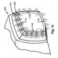
- FIG. 11is a fragmentary perspective view of the viewing end of the reader showing the textured chamfered light pipe end illuminated in red as an indicator;
- FIG. 12is a fragmentary perspective view of the viewing end of the reader showing the textured chamfered light pipe end illuminated in green as an indicator;
- FIG. 13is a fragmentary perspective view of the viewing end of the reader showing the textured chamfered light pipe end illuminated in red in predetermined quadrants and green in other predetermined quadrants as an indicator;
- FIG. 14is a schematic side cross section of the light pipe, diffuser, illumination sources and reflector showing a predetermined reflector geometry so as to increase projection of light along remote regions of the diffuser;
- FIG. 15is a somewhat schematic side cross section of the light pipe of the illuminator assembly detailing the draft angle provided to allow molding of the light pipe and showing an alternative placement of the diffusive surface at the distal end of the light pipe;
- FIG. 16is a schematic diagram of a generalized shape for a rectangular cross section light pipe featuring representations of a North, South, East and West edge;
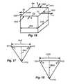
- FIG. 17is a schematic representation of the convergence of dark field rays from the North and South edges of the light pipe of FIG. 16 showing a first distance thereto;
- FIG. 18is a schematic representation of the convergence of dark field rays from the East and West edges of the light pipe of FIG. 16 showing a first distance thereto;
- FIG. 19is an exposed perspective view of a light pipe according to an alternate embodiment of this invention defining an elliptical cross section.
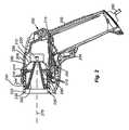
- FIG. 2shows a cross sectional side view of an illustrative embodiment of the reader 200 according to the present invention.
- the imager 212 and an illumination board 214are positioned on a shock-resistant mounting (not shown) within the housing 206 .
- the processor module and related functional electronic componentsare mounted on a processor board 215 .
- the grip portion 202 and the trigger 204are functionally cooperative with the housing 206 and components of the processor board 215 .
- the grip portion 206includes a conveniently placed trigger 204 that can be actuated by a finger of the user to initiate the image acquisition and decoding function. More particularly, pressing the trigger causes all types and colors of illumination (as described further below) to be simultaneously projected onto the subject of interest, and also causes corresponding acquisition of an image by the imager.
- the illumination board 214supports a plurality of LEDs 310 that are red in this embodiment (a variety of colors can be used).
- the LEDs 310are directed forwardly, toward the opening of the reader. These LEDs are positioned behind a passive light pipe 244 that internally transmits light from the ring of LEDs 310 to a front end 230 .
- the front end 230includes a chamfered surface 232 .
- Various examples of a light pipe for use with a reader or similar applicationare shown and described in U.S. patent application Ser. No. 10/693,626, entitled LIGHT PIPE ILLUMINATION SYSTEM AND METHOD, by William H. Equitz, et al., the teachings of which are expressly incorporated herein by reference.
- the light pipeis formed from a transmissive/transparent substance.
- the light pipeis constructed from transparent polycarbonate (available under the trade name Makrolon from BASF of Germany, or alternatively Lexan® available from the General Electric Company). This substance can be injection-molded using a liquid resin that is formed into a desired shape as discussed further below.
- the transmitted lightis reflected internally by the angled/chamfered surface 232 of the light pipe 244 to exit at a low angle toward the center optical axis 270 .
- the refractive index of polycarbonate(approximately 1.49) is sufficient to achieve the degree of light transmission and internal reflection employed for dark field illumination in accordance with embodiments of this invention.
- the inner and/or outer wall surfaces of the light pipe 244can be coated with opaque paint or another compound to prevent leakage of light into or out of the pipe.
- a shield 250is also provided along the inner surface of the light pipe. One function of the shield 250 is to prevent transmission of diffuse light (described below) in to the light pipe. Another function is to redirect light transmitted from the reflector (see below) back into the diffuser.
- the ring of LEDs 310acts to produce a red direct bright field effect along with the dark field effect through refraction of some light from the LEDs through the chamfered surface 232 .
- the bright field illumination from the light pipe 230tends not to interfere with the dark field illumination.
- the bright field illuminationis available, however, for larger reading distances (>25 mm between the end 230 and the surface). This is useful for easy-to-read codes, such as black-and-white printed labels.
- a separate bright field illuminatorcan be provided, and as described below. In fact, many available imagers include integral red bright field illuminators. In an alternate embodiment, a separate bright field illuminator can be provided in a discrete color, such as green.
- aiming LEDs 220typically emitting green light
- aiming LEDsmay be integral with the commercially available image employed herein.
- a tether cord 260provides electrical power to the reader 200 , as well as a communication transmission path for the decoded character string of the encoded information, though it is contemplated that the reader 200 can be configured with battery power and wireless communication for complete portable flexibility.
- a front view of the reader 200is shown.
- the distribution and placement of the individual LEDs (or other appropriate light elements) 310 that transmit light to the light pipe 244is represented by a series of adjacent Xs positioned around the perimeter of the light pipe 244 in line with the distal end 230 .
- the illustrative LED placementcreates a generally uniform lighting effect.
- the placement of these light elements and others used hereinis highly variable.
- the addressing of light elementscan be controlled so that only certain elements are activated at certain times to create the desired overall dark field illumination intensity and/or bias (e.g., lighter on one side than another) to the dark field illumination effect on the subject. This variable-addressing feature is described further below and is discussed in further detail in the above-incorporated U.S. patent Applications and in other commonly assigned U.S. patent Applications referenced therein.
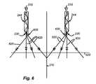
- FIG. 4further details the components of the overall illuminator assembly with respect to the imager 212 .
- the imager 212resides at the left side of the view.
- the illumination board assembly 214is located ahead of it. Placed in front of the illumination board 214 and LEDs 310 is the proximal (or base) end 410 of the light pipe 244 , which receives transmitted light from the LEDs 310 , and internally transmits it to the chamfered distal end 230 .
- a tapered (also loosely termed “conical”) diffuser 280(refer also to FIG.
- this diffuser 280can be constructed from a thin (1-3 millimeter) polymer material with a frosted/textured interior.
- a thin shield 250is provided against the interior of the light pipe to block the diffuser's transmitted light from entering the light pipe 244 . In this manner, the light emitted from the diffuser does not mix with the light pipe's transmission.
- Spacemay be limited in the region between the shield 250 and the inner surface of the diffuser 280 .
- use of a smaller number of such LEDsis highly desirable.
- the light projected by the diffuseris provided by a set of (four) rearward-projecting LEDs 282 mounted on the illumination board 214 on a side opposite the ring of light pipe LEDs 310 .
- These LEDs 282project rearward into a conical, spherical, parabolic (or other shape) reflector 290 that spreads the reflected light throughout the inner surface of the diffuser 280 so that it exits as a substantially uniform spread of direct, diffuse light onto the surface of interest.
- the reflector's shapecan be optimized to improve the spread of light along the conical diffuser.
- the reflector 290is constructed from polymer with a white textured surface to further diffuse the light reflected therefrom.
- This indirect projection of light with a diffusing reflective surfacesignificantly aids in reducing the number of diffuse illumination LEDs 282 employed to project the diffuse illumination, thereby reducing production costs and power consumption.
- the diffuse illumination LEDs 282are high-output blue LEDs.
- the particular colors used for each type of illuminationare highly variable.
- a translucent “conical” filter 292is provided.
- the filter 292is adapted to filter out light with larger wavelengths, thereby allowing smaller wavelength blue light to pass out of the diffuser and onto the surface, but preventing the retransmission of any reflected red light from the surface, which would otherwise tend to become retransmitted as diffuse red light along with the red dark field illumination.
- the wavelength spread between red light and blue lightis sufficient to accomplish this filtering without compromising the performance of either type (dark field/direct bright field versus direct diffuse) of illumination.
- the filter 292conforms to the shape of the diffuser's outer (exposed) surface, and can be snapped or adhered onto the diffuser surface using a variety of fastening techniques that should be clear to those of ordinary skill.
- a similar effectcan be obtained through the use of a colored diffuser (see FIG. 6 below).
- the colorshould be selected so that the diffuser transmits the diffuse light (blue in this embodiment), but does not reflect the dark field light (red in this embodiment) transmitted from the light pipe.
- each discrete set of transmitters 282 and 310generates a corresponding discrete illumination color.
- direct diffuse illuminationcan be generated by blue LEDs and dark field (and direct bright field) can be generated by red LEDs.
- red LEDscan be generated by red LEDs.
- the imager in this embodimentincludes a conventional monochrome sensor that produces a grayscale image from the colored light.
- a color sensorcan be employed.
- One such implementationis shown and described in commonly assigned U.S. patent Application entitled SYSTEM AND METHOD FOR EMPLOYING COLOR ILLUMINATION AND COLOR FILTRATION IN A SYMBOLOGY READER by Laurens W. Nunnink, and filed on even date herewith, the teachings of which are expressly incorporated herein by reference.
- FIGS. 5 and 6describe generally the illumination patterns achieved by the light pipe 244 and diffuser 280 of the illumination assembly.
- FIG. 5a cross section of an implementation of the diffuser 280 is shown, with light pipe 244 as described generally above, relative to the imager assembly 212 (and associated lens structure 240 ).
- Dark field illumination(rays 510 ) is directed into the light pipe 244 that is internally reflected at the chamfered distal (forward) end 230 to be, thus, directed at the object surface 520 at a low angle.
- Further information regarding the basic design and implementation of passive light pipes with selectively actuated illumination to provide dark field illuminationcan be found in the above incorporated U.S. patent application Ser. No.
- Direct illumination (rays 532 ) from blue LEDs 282is converted into totally diffuse direct illumination by reflection off the reflector 290 , and passage into and through the diffuser 280 of this embodiment.
- the diffuser 280thereby projects diffuse illumination on the object surface 520 within the field of view, depicted as the region defined by dashed lines 540 .
- the diffuser 280is, itself, translucent, without a color tint or color-filtering effect.
- the diffusercan be tinted to generate a desired color and/or act as a filter (using colored or white illumination sources ( 282 )).
- the diffuser 280can be constructed and arranged so as to be removably attached to the hand held scanning appliance.
- the diffusercan be removed to allow the transmitters 282 to operate as non-diffuse direct bright field illumination.
- the diffusercan be provided with movable shutters that selectively expose clear (nonfrosted/non-diffusing) windows in the overall diffuser.
- the removability of the diffuser 280can be achieved by incorporating snap-fit clearances and/or features in the diffuser and light pipe 242 that permit removable assembly (not shown).
- direct non-diffuse bright field illuminationis provided by refraction of light through the chamfered end 230 of the light pipe 244 .
- a portion of the light internally reflected along the pipe 244exits directly from the chamfered end 230 as relatively high-angle (usually greater than 45 degrees relative to the axis surface 520 ) bright field light (rays 620 ).
- the remaining lightis internally reflected by the chamfered end 230 to exit adjacent to the inner corner 630 of the pipe 244 as discussed generally above.
- the light pipecan be modified in alternate embodiments to include a flattened ring residing in a plane perpendicular to the axis 270 .
- a nested light pipe with a flat (un-chamfered) ring formed at its distal endcan be used in alternate embodiments for direct transmission of bright field light along a waveguide separate from the depicted dark field light pipe 244 . This can be useful where illuminators having a discrete color are used for direct bright field light. Alternatively, where optional direct bright field transmitters are employed they can be located so as to project light through clear/transparent portions (not shown) of the diffuser 280 .
- a filtermay be applied over the diffuser to prevent migration of reflected dark field (and bright field) light into the diffuser 280 .
- illuminator light pipesinclude a polished distal end.
- FIG. 7an image 710 acquired of a reflective surface using a light pipe with a polished end is shown. This image 710 clearly depicts delineated spots 720 produced by the individual illumination sources in the illumination ring. These spots lead to a somewhat broken illumination pattern that may effect acquisition of the mark 730 .
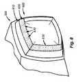
- the reader 200is fitted with an illumination assembly 800 that includes a light pipe 810 according to an embodiment of this invention.
- the light pipe 810includes a chamfered end 820 about its forward perimeter having a general size and shape as described above.
- the depicted outer surface 830 of the chamfered end 820is finely frosted or textured. This provides a mild diffusive effect to light exiting as direct bright field illumination (see FIG. 6 ) and also to internally reflected light exiting as dark field illumination.
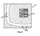
- the resulting diffusiongenerates the image shown in FIG. 9 .
- the ring of light 920 surrounding the mark 930is more uniform and the mark, itself, appears better contrasted than the results of the polished-end version shown in FIG. 7 .
- the frosted or textured surface 830 provided along the chamfered endfacilitates a novel and desirable display of reader status according to an embodiment of this invention.
- FIG. 10schematically describes the basic components of the illumination and image processing system of the reader.
- the circuit board ( 215 in FIG. 2 ) of the readerincludes a processor and illumination controller, shown schematically as processor/control block 1010 .
- the processor/control 1010can employ conventional image processing and mark-recognition/decoding processes.
- the processor/control 1010receives signals from the trigger (block 1012 ), which are used to operate the illumination assembly and to obtain image date via the imager (block 1014 ).
- the aiming LEDs(block 1016 and see also 220 in FIG.
- acquisition of the imageinvolves a stepping through of a plurality of illumination types (dark field and diffuse) in timed sequence, with associated image acquisition of the mark during each type of illumination.
- illumination typesdark field and diffuse
- the best imageor a combination of the images
- the readermay indicate a variety of status codes, such as ready-to-read, read successful, read unsuccessful, etc. These indicators are described further below.
- the processor 1010directs the illumination ring (block 1020 ) to illuminate. It then directs the diffuse illuminator (block 1018 ) to illuminate.
- the ring 1020can include individual banks of LEDs (or other illumination sources) that, in this example, are formed into quadrants-namely top/north 1022 , bottom/south 1024 , right/east 1026 and left/west 1028 (as viewed from outside, toward the reader front). These quadrants can be individually addressed by the processor. This allows the output of each quadrant to be varied so as to generate the desired effect on the object.
- the individual illumination sourcesare commercially available multi-color LEDs (red and green in this embodiment, denoted schematically by the split line down the middle of each LED 1030 ), capable of projecting either of two colors in response to the processor 1010 .
- Thiscan be useful, form an imaging standpoint, where a different color is to be provided for dark field and direct bright field. More significantly, the illumination ring's multicolor capability allows the light pipe (particularly the frosted end 820 ) to project a highly visible, subject-adjacent indicator light in a plurality of colors.
- FIG. 11details generally the illumination of the light pipe 810 for the purpose of providing the user an indicator.
- the four quadrants 1110 , 1120 , 1130 and 1140 of the textured chamfered edge 820are illuminated red (denoted by the encircled R′s) by their appropriate banks of LEDs in the ring.
- the frosted surfacein fact generates a bright, diffuse color strip that enhances viewing of the indicator.
- This indicatorcan be illuminated before, during or after image acquisition as a continuous or blinking signal.
- Blinkscan be timed in the manner of Morse code to achieve a desired status message.
- all light-pipe-end quadrants 1110 , 1120 , 1130 , 1140are illuminated in green (denoted by the encircled G's).
- Thiscan be a solid (continuously green) or blinking indicator. It can also blink alternatively with red (or another color) according to any predetermined pattern to provide a particular message.
- the indicatoris characterized by two (or more) simultaneous colors displayed by different quadrants (or other sections) of the light pipe edge.
- the top quadrant 1110is red and the left quadrant 1140 is green.
- the opposed bottom and left quadrants 1120 and 1130may also be red and green. This pattern may blink, or alternate (e.g., red and green switch).
- a unique rolling change of colorsmay occur in which each quadrant, in turn changes to a different color so that the color change appears to migrate around the perimeter. Any observable and desirable shift of colors is contemplated as an indicator according to this invention.
- FIG. 14shows a variation of the above described reflector shape.
- the length and angle (A) of the conical diffuser 280(typically less than 45 degrees with respect to the axis 270 in each quadrant) defines a remote, distal region 1410 between the interior wall of the diffuser 280 and the shield 250 that is small in volume and difficult for light from the reflector 1420 to fill adequately.
- the gap between the inner perimeter of the illumination board 214 and the interior wall of the diffuserfurther obscures transmission of light into this remote region 1410 .
- the reflecting surface 1422 of the reflector 1420 of this embodimentincludes a plurality of steps 1424 , 1426 , 1428 , 1429 which are designed to direct specific portions of the reflected light (rays 1430 ) from the LEDs 282 toward the various parts of the diffuser, including the remote regions 1410 .
- the plurality of small, angled steps 1429 formed in the cross sectionare particularly adapted to transmit rays 1430 from the light sources 282 to various points along the remote region 1410 for an optimized spread of light along the entire diffuser surface.
- the reflector 1420 in this embodimentalso includes a textured surface and a white surface color for maximum diffusion. In alternate embodiments, a different surface color and surface finish can be employed. In this manner a more-uniform illumination of the complete diffuser surface is achieved, and the presence of light and dark spotting on the object is minimized.
- stepped reflector 1420is shown and described according to an embodiment of this invention, it is expressly contemplated that reflectors having a variety of surface cross-sectional profiles can be employed in alternate embodiments. Such reflectors should be adapted, using optical-focusing techniques, to spread light along the length of a tapered or conical diffuser of a shape generally contemplated herein so as to avoid undesirable spotting on localized regions of the surface of interest.
- a light pipe with a textured or frosted chamfered endcan be produced by a variety of techniques including grit blasting or peening of a finished surface, a desirable construction technique entails molding of the light pipe from poured resin.
- the chamfered endis located near the bottom of the mold and the rearward end (adjacent to the illumination ring) is located at the top of the mold, at which location the finished pipe is ejected from the mold.
- the bottom of the moldis provided with a frosted or textured pattern so as to form this surface effect on the chamfered end of the finished pipe.
- FIG. 15which shows the cross section of the light pipe 244 the mold is constructed with a slight draft angle that tapers, so that the resulting light pipe 244 defines a pair of inner walls having a draft angle AD therebetween of approximately at least 2 degrees (each side being 1 degree relative to the axis 270 ).
- the draft angleis set at approximately 2 degrees, rather than the typical 1 degree for a smooth molded part. This 2-degree draft angle better overcomes the possible adhesion effects created between the finished pipe and the textured mold surface. This draft angle is employed where the texture is applied to the chamfered ends 230 .
- the chamfered ends 230each define therebetween an angle of approximately 70 degrees (each end being approximately 35 degrees relative to the axis 270 ). It should be clear, however, that the techniques used for forming the light pipe and other components herein can vary within the scope of ordinary skill.
- the frosted or textured finishcan be applied to the inner wall of the light pipe 244 at the end location 1520 . This location 1520 is exposed beyond the distal end of the diffuser 280 and shield 250 described above to allow unobstructed passage of dark field light (rays 510 ). This causes the reflected dark field light to pass through a diffusive structure prior to striking the mark surface.
- the textured surfacecan also be applied to the outer side (location 820 ) in an embodiment of the invention. Alternatively, the textured surface may be selectively applied to only one of the inner location ( 1520 ) or outer location ( 820 ) as appropriate. It should be noted that, when applying texture to the interior wall at location 1520 , the draft angle AD ( FIG. 14 ) would typically be greater than 2 degrees. An appropriate draft angle can be determined by those of skill in the molding plastic parts.
- the general cross sectional perimeter shape of the light pipeis rectangular (taken on a plane through axis 270 ).
- the term “rectangular”shall include minor deviations of the sides of the rectangle from a straight-line geometry.
- a rectangular shape hereinmay include, for example, curvilinear arcs as shown and described.
- the term rectangularshall be defined generally as a set of linear of non-linear sides that inters sect at each of four corners (that may be significantly rounded corners) that cause the approximate direction of two adjacent sides to vary by approximately ninety degrees.
- a highly generalized representation of a rectangular light pipe 1610is shown in FIG. 16 .
- the sides 1620 , 1622 , 1624 and 1626 of the rectangular light pipe 1610can be defined in terms of North (arrow N), South (arrow S), East (arrow E) and West (arrow W).
- each edge of the distal, chamfered endcan be correspondingly represented as EN (edge North), ES (edge South), EE (edge East) and (EW (edge West).
- ENedge North
- ESedge South
- EEedge East
- EWedge West
- the length LNS between the North edge EN and South edge ESis shorter (in this embodiment) that the length LEW between the East edge EE and West edge EW (LNS ⁇ LEW). Note that in alternate embodiments the reverse may be true (LNS>LEW) or these measurements can be approximately equal.
- the chamfered edge along each sideis disposed at the same fixed angle (approximately 55 degrees in this embodiment), generating dark field light rays that converge at point 1710 at an average fixed angle 0 of approximately 32 degrees (representing half the chamfer angle along with an induced draft angle of 1 degree and further refraction as the light exits the pipe interior wall).
- the distance LNSis less than the distance LEW
- the convergence distance of light DNS for the pair of opposing sides EN and ESis less than the convergence distance DEW of light from the pair of opposing sides EE and EW.
- this arrangementaffords a wider depth of field for the reader by providing two differing distance ranges of illumination for the mark.
- the approximate length NSis 3 cm
- the approximate length EWis 4.5 cm.
- DNSis approximately 0.92 cm
- DEWis approximately 1.23 cm.
- the above-described rectangular light pipe shapepresents several advantages over round light pipes and those of other regular, equilateral shapes.
- the rectangular shapemore closely conforms to the conventional 4:3 horizontal-to-vertical ratio exhibited by commercially available sensors.
- the rectangular cross sectionyields a larger dark field range than provided by round pipes. It also allows for a lower-profile reader, in terms of overall height.
- the use of discrete “sides” on the pipemakes it easier to control separate quadrants, as described above.
- FIG. 19details an elliptical cross section light pipe 1910 that can be adapted for use with an embodiment of the invention (with appropriate reshaping of the illumination ring and diffuser, where applicable.
- the distal end of the light pipe 1910terminates in a chamfered end 1920 having an angle and function as generally described herein.
- the edge of the chamfered endin essence defines an opposing pair of North and South sides ( 1930 and 1932 , respectively) and East and West sides ( 1940 and 1942 , respectively), which are separated by distances that differ.
- the distancesare the minor axis MIA and the major axis MAA (respectively) of the ellipse.
- the “sides”can be characterized as continuously running into each other with arbitrary boundaries or with “continuously curving corners.” A variety of variations on this basic elliptical shape are expressly contemplated. In any case, the sides generate at least two discrete distances of ray convergence for a given fixed chamfer angle.
- top and rightmay always work together or top and bottom may always work together.
- additional ring colorssuch as yellow can be employed to provide further types of indicators.
- Multi-colored illumination sources or a plurality of adjacent individual illumination sources (or combinations of individual and multi-colored sources)can be used to generate the desired seat of ring colors.
- a greater range of depth of fieldmay be obtained by providing a non-equilateral shape having more than four sides joined by corners (for example, an oblique hexagon).
- This inventioncontemplates polygonal light pipe cross sections having four or more sides (linear or curvilinear) joined at corners (that may be rounded).
Landscapes
- Physics & Mathematics (AREA)
- Engineering & Computer Science (AREA)
- Electromagnetism (AREA)
- Artificial Intelligence (AREA)
- Toxicology (AREA)
- General Health & Medical Sciences (AREA)
- Health & Medical Sciences (AREA)
- Computer Vision & Pattern Recognition (AREA)
- General Physics & Mathematics (AREA)
- Theoretical Computer Science (AREA)
- Length Measuring Devices By Optical Means (AREA)
- Image Input (AREA)
- Facsimile Scanning Arrangements (AREA)
- Illuminated Signs And Luminous Advertising (AREA)
- Non-Portable Lighting Devices Or Systems Thereof (AREA)
Abstract
Description
Claims (28)
Priority Applications (5)
| Application Number | Priority Date | Filing Date | Title |
|---|---|---|---|
| US12/900,617US9405951B2 (en) | 2005-10-24 | 2010-10-08 | Integrated illumination assembly for symbology reader |
| US13/340,752US9070031B2 (en) | 2003-10-24 | 2011-12-30 | Integrated illumination assembly for symbology reader |
| US13/971,320US9292724B1 (en) | 2004-12-16 | 2013-08-20 | Hand held symbology reader illumination diffuser with aimer optics |
| US14/683,622US9536124B1 (en) | 2003-10-24 | 2015-04-10 | Integrated illumination assembly for symbology reader |
| US15/225,546US20170213060A1 (en) | 2003-10-24 | 2016-08-01 | Integrated illumination assembly for symbology reader |
Applications Claiming Priority (2)
| Application Number | Priority Date | Filing Date | Title |
|---|---|---|---|
| US11/257,411US7874487B2 (en) | 2005-10-24 | 2005-10-24 | Integrated illumination assembly for symbology reader |
| US12/900,617US9405951B2 (en) | 2005-10-24 | 2010-10-08 | Integrated illumination assembly for symbology reader |
Related Parent Applications (1)
| Application Number | Title | Priority Date | Filing Date |
|---|---|---|---|
| US11/257,411ContinuationUS7874487B2 (en) | 2003-10-24 | 2005-10-24 | Integrated illumination assembly for symbology reader |
Related Child Applications (4)
| Application Number | Title | Priority Date | Filing Date |
|---|---|---|---|
| US11/019,763Continuation-In-PartUS7823789B2 (en) | 2003-10-24 | 2004-12-21 | Low profile illumination for direct part mark readers |
| US13/340,752Continuation-In-PartUS9070031B2 (en) | 2003-10-24 | 2011-12-30 | Integrated illumination assembly for symbology reader |
| US13/971,320Continuation-In-PartUS9292724B1 (en) | 2004-12-16 | 2013-08-20 | Hand held symbology reader illumination diffuser with aimer optics |
| US14/683,622Continuation-In-PartUS9536124B1 (en) | 2003-10-24 | 2015-04-10 | Integrated illumination assembly for symbology reader |
Publications (2)
| Publication Number | Publication Date |
|---|---|
| US20110080729A1 US20110080729A1 (en) | 2011-04-07 |
| US9405951B2true US9405951B2 (en) | 2016-08-02 |
Family
ID=37745812
Family Applications (2)
| Application Number | Title | Priority Date | Filing Date |
|---|---|---|---|
| US11/257,411Expired - Fee RelatedUS7874487B2 (en) | 2003-10-24 | 2005-10-24 | Integrated illumination assembly for symbology reader |
| US12/900,617Expired - Fee RelatedUS9405951B2 (en) | 2003-10-24 | 2010-10-08 | Integrated illumination assembly for symbology reader |
Family Applications Before (1)
| Application Number | Title | Priority Date | Filing Date |
|---|---|---|---|
| US11/257,411Expired - Fee RelatedUS7874487B2 (en) | 2003-10-24 | 2005-10-24 | Integrated illumination assembly for symbology reader |
Country Status (5)
| Country | Link |
|---|---|
| US (2) | US7874487B2 (en) |
| JP (1) | JP5102215B2 (en) |
| CN (2) | CN101346729B (en) |
| DE (3) | DE112006002867T5 (en) |
| WO (1) | WO2007050454A2 (en) |
Cited By (3)
| Publication number | Priority date | Publication date | Assignee | Title |
|---|---|---|---|---|
| US10210369B2 (en) | 2010-12-23 | 2019-02-19 | Cognex Corporation | Mark reader with reduced trigger-to-decode response time |
| US11347951B2 (en) | 2017-05-17 | 2022-05-31 | Hand Held Products, Inc. | Multi-functional optical illuminators |
| US12060991B1 (en) | 2023-11-17 | 2024-08-13 | Brady Worldwide, Inc. | Light pipe with uniform and segmented light outputs for barcode-reading devices |
Families Citing this family (63)
| Publication number | Priority date | Publication date | Assignee | Title |
|---|---|---|---|---|
| US9070031B2 (en) | 2003-10-24 | 2015-06-30 | Cognex Technology And Investment Llc | Integrated illumination assembly for symbology reader |
| US7823789B2 (en) | 2004-12-21 | 2010-11-02 | Cognex Technology And Investment Corporation | Low profile illumination for direct part mark readers |
| US7823783B2 (en) | 2003-10-24 | 2010-11-02 | Cognex Technology And Investment Corporation | Light pipe illumination system and method |
| US9536124B1 (en) | 2003-10-24 | 2017-01-03 | Cognex Corporation | Integrated illumination assembly for symbology reader |
| US7874487B2 (en) | 2005-10-24 | 2011-01-25 | Cognex Technology And Investment Corporation | Integrated illumination assembly for symbology reader |
| US7604174B2 (en) | 2003-10-24 | 2009-10-20 | Cognex Technology And Investment Corporation | Method and apparatus for providing omnidirectional lighting in a scanning device |
| US7617984B2 (en) | 2004-12-16 | 2009-11-17 | Cognex Technology And Investment Corporation | Hand held symbology reader illumination diffuser |
| US9292724B1 (en) | 2004-12-16 | 2016-03-22 | Cognex Corporation | Hand held symbology reader illumination diffuser with aimer optics |
| US8061610B2 (en)* | 2005-10-24 | 2011-11-22 | Cognex Technology And Investment Corporation | System and method for employing color illumination and color filtration in a symbology reader |
| US7965887B2 (en)* | 2005-12-01 | 2011-06-21 | Cognex Technology And Investment Corp. | Method of pattern location using color image data |
| US7614563B1 (en) | 2005-12-29 | 2009-11-10 | Cognex Technology And Investment Corporation | System and method for providing diffuse illumination in a symbology reader |
| US20070267490A1 (en)* | 2006-05-18 | 2007-11-22 | Hand Held Products, Inc. | Multipurpose optical reader |
| US7886979B2 (en) | 2006-09-19 | 2011-02-15 | Microscan Systems, Inc. | Methods for illuminating barcodes |
| US7857224B2 (en)* | 2006-09-19 | 2010-12-28 | Microscan Systems, Inc. | Devices and/or systems for automatically imaging barcodes |
| US20080105745A1 (en)* | 2006-09-19 | 2008-05-08 | Ming Lei | Devices and/or systems for illuminating barcodes |
| US20080105749A1 (en)* | 2006-09-19 | 2008-05-08 | Ming Lei | Methods for automatically imaging barcodes |
| US8374498B2 (en)* | 2006-09-29 | 2013-02-12 | Microscan Systems, Inc. | Systems and/or devices for camera-based inspections |
| US8032017B2 (en)* | 2006-09-29 | 2011-10-04 | Microscan Systems, Inc. | Methods for providing diffuse light |
| DE102007043609B4 (en) | 2007-09-13 | 2014-05-28 | Ioss Intelligente Optische Sensoren & Systeme Gmbh | Integrated lighting device for an optical code reader |
| US7822300B2 (en)* | 2007-11-20 | 2010-10-26 | Aptina Imaging Corporation | Anti-resonant reflecting optical waveguide for imager light pipe |
| US20090218403A1 (en)* | 2008-02-29 | 2009-09-03 | Eugene Joseph | Arrangement for and method of accurately aiming at direct part markings prior to being imaged and electro-optically read |
| US8448867B2 (en)* | 2008-12-19 | 2013-05-28 | Symbol Technologies, Inc. | Illumination apparatus for an imaging-based bar code system |
| US8768159B2 (en) | 2009-07-10 | 2014-07-01 | Microscan Systems, Inc. | Combination dark field and bright field illuminator |
| JP5240137B2 (en)* | 2009-09-10 | 2013-07-17 | 株式会社デンソーウェーブ | Optical information reader |
| EP2793163B1 (en) | 2010-03-11 | 2016-05-18 | Datalogic IP TECH S.r.l. | Image capturing device |
| JP5581157B2 (en)* | 2010-09-17 | 2014-08-27 | 株式会社キーエンス | Illumination setting support device for optical information reader |
| US9135484B2 (en) | 2010-09-28 | 2015-09-15 | Datalogic ADC, Inc. | Data reader with light source arrangement for improved illumination |
| US8746924B2 (en)* | 2011-03-09 | 2014-06-10 | Rolls-Royce Corporation | Illumination system with illumination shield |
| JP2012242908A (en)* | 2011-05-16 | 2012-12-10 | Toshiba Tec Corp | Image recognition device and program |
| CN102621775B (en)* | 2012-03-29 | 2014-04-16 | 北京慧眼智行科技有限公司 | Imaging and lighting device and optical identifying equipment |
| CN102663339A (en)* | 2012-03-30 | 2012-09-12 | 深圳市富晶科技有限公司 | Multifunctional scanner |
| WO2013184970A2 (en)* | 2012-06-08 | 2013-12-12 | Datalogic ADC, Inc. | Imaging reader with improved illumination |
| WO2014071040A1 (en)* | 2012-10-31 | 2014-05-08 | Datacard Corporation | Machine vision verification |
| USD723563S1 (en)* | 2012-12-21 | 2015-03-03 | Datalogic Ip Tech S.R.L. | Reader of coded information |
| USD734339S1 (en)* | 2013-12-05 | 2015-07-14 | Hand Held Products, Inc. | Indicia scanner |
| USD982585S1 (en) | 2013-12-05 | 2023-04-04 | Hand Held Products, Inc. | Indicia scanner |
| USD826234S1 (en) | 2016-04-11 | 2018-08-21 | Hand Held Products, Inc. | Indicia scanner |
| JP6290651B2 (en) | 2014-02-27 | 2018-03-07 | 株式会社キーエンス | Image measuring instrument |
| CN105022979B (en)* | 2015-07-27 | 2018-01-16 | 深圳市民德电子科技股份有限公司 | Imaging system and the image recognition device that light-supplementing system optical axis is in that angle is set |
| CN105069390A (en)* | 2015-07-27 | 2015-11-18 | 深圳市民德电子科技股份有限公司 | Bar code reader using planar light source for illumination |
| JP6608679B2 (en)* | 2015-11-13 | 2019-11-20 | 株式会社キーエンス | Portable optical reader |
| JP2017091332A (en)* | 2015-11-13 | 2017-05-25 | 株式会社キーエンス | Portable optical reading device |
| JP6592337B2 (en)* | 2015-11-13 | 2019-10-16 | 株式会社キーエンス | Portable optical reader |
| USD804482S1 (en) | 2016-03-15 | 2017-12-05 | Symbol Technologies, Llc | Data capture device |
| US9569653B1 (en) | 2016-06-13 | 2017-02-14 | Datalogic IP Tech, S.r.l. | Dark field illumination system obtained in a tilted plane |
| USD832845S1 (en)* | 2016-08-01 | 2018-11-06 | Hand Held Products, Inc. | Optical scanner |
| US10325127B2 (en) | 2016-12-13 | 2019-06-18 | Datalogic Usa, Inc. | Imaging reader with low stray visibility illumination |
| EP3635611B1 (en)* | 2017-06-06 | 2021-04-21 | Sicpa Holding Sa | An illumination device for an optical system of a reader apparatus |
| US10216969B2 (en) | 2017-07-10 | 2019-02-26 | Hand Held Products, Inc. | Illuminator for directly providing dark field and bright field illumination |
| CN109424871B (en)* | 2017-08-18 | 2023-05-05 | 手持产品公司 | Illuminator for bar code scanner |
| US10674055B2 (en)* | 2017-08-29 | 2020-06-02 | Omron Corporation | Apparatus for detecting, reading, and verifying 1-D, 2-D, and DPM symbologies |
| CN107895133B (en)* | 2017-12-08 | 2024-03-08 | 苏州斯普锐智能系统股份有限公司 | Desktop imaging bar code scanning equipment |
| JP7242686B2 (en)* | 2018-02-09 | 2023-03-20 | ソシエテ・デ・プロデュイ・ネスレ・エス・アー | Beverage preparation machine that recognizes capsules |
| DE102018211517A1 (en)* | 2018-07-11 | 2019-08-14 | Carl Zeiss Automated Inspection GmbH | Method for integrating a sensor unit with an optical sensor into a network and a sensor unit with an optical sensor |
| TWI662353B (en)* | 2018-07-13 | 2019-06-11 | 松翰科技股份有限公司 | Optical image sensing module |
| US11162663B2 (en) | 2018-10-02 | 2021-11-02 | Electronic Theatre Controls, Inc. | Lighting fixture |
| US10984204B2 (en)* | 2019-06-28 | 2021-04-20 | Zebra Technologies Corporation | Hybrid illumination system for symbology readers and method of reading DPM codes therewith |
| DE102019119501A1 (en)* | 2019-07-18 | 2021-01-21 | Ioss Intelligente Optische Sensoren & Systeme Gmbh | Passive lighting device |
| US10845030B1 (en) | 2020-02-26 | 2020-11-24 | Electronic Theatre Controls, Inc. | Lighting fixture with internal shutter blade |
| US11120236B1 (en)* | 2020-02-27 | 2021-09-14 | Zebra Technologies Corporation | Optical arrangement in machine vision system with diffusive and direct illumination for DPM indicia |
| US11494576B2 (en) | 2020-12-23 | 2022-11-08 | Hand Held Products, Inc. | Systems, methods, and apparatuses for imaging using a dual-purpose illuminator |
| US11717973B2 (en) | 2021-07-31 | 2023-08-08 | Cognex Corporation | Machine vision system with multispectral light assembly |
| US20230030276A1 (en)* | 2021-07-31 | 2023-02-02 | Cognex Corporation | Machine vision system and method with multispectral light assembly |
Citations (251)
| Publication number | Priority date | Publication date | Assignee | Title |
|---|---|---|---|---|
| US2357378A (en) | 1941-12-01 | 1944-09-05 | Bausch & Lomb | Microscope illuminator |
| US3726998A (en) | 1971-08-09 | 1973-04-10 | Phonocopy Inc | Light pipe illuminated scan reader |
| US3857626A (en) | 1971-12-10 | 1974-12-31 | Bausch & Lomb | Microscope coaxial illumination apparatus |
| US3961198A (en) | 1975-04-28 | 1976-06-01 | Rockwell International Corporation | Visually alignable sensor wand which excludes unwanted light from a sensor system |
| JPS5362387A (en) | 1976-11-17 | 1978-06-03 | Hitachi Ltd | Illumination device for microscope |
| US4240748A (en) | 1978-06-26 | 1980-12-23 | Caere Corporation | Hand-held optical character recognition wand with visual aligner |
| US4282425A (en) | 1979-07-25 | 1981-08-04 | Norand Corporation | Instant portable bar code reader |
| JPS59163677U (en) | 1983-04-15 | 1984-11-01 | 松下電工株式会社 | Support structure of flush toilet water supply hose |
| US4570057A (en) | 1981-12-28 | 1986-02-11 | Norand Corporation | Instant portable bar code reader |
| US4734773A (en) | 1985-08-20 | 1988-03-29 | Victor Company Of Japan, Ltd. | Imaging apparatus having high-frequency electron purging circuit operable during an exposure time |
| US4743773A (en) | 1984-08-23 | 1988-05-10 | Nippon Electric Industry Co., Ltd. | Bar code scanner with diffusion filter and plural linear light source arrays |
| JPS6318209Y2 (en) | 1981-05-20 | 1988-05-23 | ||
| US4766300A (en) | 1984-08-06 | 1988-08-23 | Norand Corporation | Instant portable bar code reader |
| EP0185782B1 (en) | 1984-12-28 | 1989-03-15 | International Business Machines Corporation | Waveguide for an optical near-field microscope |
| US4820911A (en) | 1986-07-11 | 1989-04-11 | Photographic Sciences Corporation | Apparatus for scanning and reading bar codes |
| DE3737792A1 (en) | 1987-11-06 | 1989-05-18 | Hannes Burkhardt | Bar-code reader |
| US4894523A (en) | 1981-12-28 | 1990-01-16 | Norand Corporation | Instant portable bar code reader |
| EP0356680A1 (en) | 1988-08-11 | 1990-03-07 | Siemens Aktiengesellschaft | Optical recording apparatus for an image-processing system |
| US4929053A (en) | 1988-02-01 | 1990-05-29 | U.S. Philips Corporation | Display unit and optical waveguide for use in same |
| US4984523A (en) | 1988-12-07 | 1991-01-15 | Jervis B. Webb Company | Self-propelled trolley and supporting track structure |
| US5019699A (en) | 1988-08-31 | 1991-05-28 | Norand Corporation | Hand-held optical character reader with means for instantaneously reading information from a predetermined area at an optical sensing area |
| WO1991012489A1 (en) | 1990-02-09 | 1991-08-22 | Abos Automation, Bildverarbeitung Optische Systeme Gmbh | Process and device for automatic monitoring of space-shape data in the manufacture of semiconductor components |
| JPH0353784Y2 (en) | 1988-06-01 | 1991-11-26 | ||
| DE3931044C2 (en) | 1989-09-16 | 1992-01-02 | Dirk R. H. 6101 Bickenbach De Dickfeld | |
| DE4123916A1 (en) | 1990-07-19 | 1992-01-23 | Reinhard Malz | Identifying and classifying surface qualities and defects of object - using video camera to store reflected images arising from sequential exposure to light from distributed sources |
| JPH04223583A (en) | 1990-12-26 | 1992-08-13 | Smk Corp | barcode reader device |
| US5149948A (en) | 1990-07-16 | 1992-09-22 | Computer Identics | Improved bar code reader system for reading bar codes under high specular reflection conditions with a variety of surface effects |
| WO1992016909A1 (en) | 1991-03-21 | 1992-10-01 | Dansam Holdings Limited | Bar-code reader |
| US5177346A (en) | 1989-12-13 | 1993-01-05 | Computer Identics | Bar code reader system for reading bar code labels with a highly specular and low contrast surface |
| US5202817A (en) | 1989-06-07 | 1993-04-13 | Norand Corporation | Hand-held data capture system with interchangeable modules |
| US5227614A (en) | 1986-08-15 | 1993-07-13 | Norand Corporation | Core computer processor module, and peripheral shell module assembled to form a pocket size data capture unit |
| US5239169A (en) | 1991-05-20 | 1993-08-24 | Microscan Systems Incorporated | Optical signal processor for barcode reader |
| US5258606A (en) | 1981-12-28 | 1993-11-02 | Norand Corporation | Instant portable bar code reader |
| US5291009A (en) | 1992-02-27 | 1994-03-01 | Roustaei Alexander R | Optical scanning head |
| US5309277A (en) | 1992-06-19 | 1994-05-03 | Zygo Corporation | High intensity illuminator |
| JPH06124361A (en) | 1992-10-12 | 1994-05-06 | Nippon Electric Ind Co Ltd | Method for light projection of bar code reader |
| US5313373A (en) | 1992-11-25 | 1994-05-17 | United Parcel Service Of America, Inc. | Apparatus for the uniform illumination of a surface |
| JPH06139398A (en) | 1992-10-26 | 1994-05-20 | Tokyo Electric Co Ltd | 2D code scanner |
| US5319182A (en) | 1992-03-04 | 1994-06-07 | Welch Allyn, Inc. | Integrated solid state light emitting and detecting array and apparatus employing said array |
| US5331176A (en) | 1992-04-10 | 1994-07-19 | Veritec Inc. | Hand held two dimensional symbol reader with a symbol illumination window |
| WO1994019908A1 (en) | 1993-02-16 | 1994-09-01 | Northeast Robotics, Inc. | Continuous diffuse illumination method and apparatus |
| US5349172A (en) | 1992-02-27 | 1994-09-20 | Alex Roustaei | Optical scanning head |
| US5354977A (en) | 1992-02-27 | 1994-10-11 | Alex Roustaei | Optical scanning head |
| US5359185A (en) | 1992-05-11 | 1994-10-25 | Norand Corporation | Chromatic ranging method and apparatus for reading optically readable information over a substantial range of distances |
| US5367439A (en) | 1992-12-24 | 1994-11-22 | Cognex Corporation | System for frontal illumination |
| US5374817A (en) | 1988-05-11 | 1994-12-20 | Symbol Technologies, Inc. | Pre-objective scanner with flexible optical support |
| US5378883A (en) | 1991-07-19 | 1995-01-03 | Omniplanar Inc. | Omnidirectional wide range hand held bar code reader |
| US5393967A (en) | 1993-07-21 | 1995-02-28 | Sensis Corporation | Method and apparatus for non-contact reading of a relief pattern |
| US5406060A (en) | 1993-05-06 | 1995-04-11 | Opticon Inc. | Bar code reader for sensing at an acute angle |
| US5408084A (en) | 1993-02-18 | 1995-04-18 | United Parcel Service Of America, Inc. | Method and apparatus for illumination and imaging of a surface using 2-D LED array |
| US5414251A (en) | 1992-03-12 | 1995-05-09 | Norand Corporation | Reader for decoding two-dimensional optical information |
| US5422472A (en) | 1992-12-04 | 1995-06-06 | Psc, Inc. | Optical symbol (bar code) reading systems having an electro-optic receptor with embedded grating rings |
| US5430285A (en) | 1993-08-20 | 1995-07-04 | Welch Allyn, Inc. | Illumination system for optical reader |
| US5434618A (en) | 1993-06-07 | 1995-07-18 | Fuji Photo Film Co., Ltd. | Electronic still camera operable with a removably mounted storage medium |
| US5442247A (en) | 1991-12-20 | 1995-08-15 | Minebea Kabushiki-Kaisha | Outer-rotor type spindle motor with a reduced thickness in the axial direction |
| US5449892A (en) | 1991-10-29 | 1995-09-12 | Nippondenso Co., Ltd. | Information reading apparatus |
| JPH07271890A (en) | 1994-04-01 | 1995-10-20 | Asahi Optical Co Ltd | Data symbol reader |
| US5463214A (en) | 1994-03-04 | 1995-10-31 | Welch Allyn, Inc. | Apparatus for optimizing throughput in decoded-output scanners and method of using same |
| US5469294A (en) | 1992-05-01 | 1995-11-21 | Xrl, Inc. | Illumination system for OCR of indicia on a substrate |
| US5481098A (en) | 1993-11-09 | 1996-01-02 | Spectra-Physics Scanning Systems, Inc. | Method and apparatus for reading multiple bar code formats |
| US5484994A (en) | 1993-10-18 | 1996-01-16 | Roustaei; Alexander | Optical scanning head with improved resolution |
| US5500516A (en) | 1994-08-30 | 1996-03-19 | Norand Corporation | Portable oblique optical reader system and method |
| US5504317A (en) | 1994-01-05 | 1996-04-02 | Opticon, Inc. | Optical reader |
| US5504367A (en) | 1994-03-21 | 1996-04-02 | Intermec Corporation | Symbology reader illumination system |
| US5513264A (en) | 1994-04-05 | 1996-04-30 | Metanetics Corporation | Visually interactive encoding and decoding of dataforms |
| US5515452A (en) | 1992-12-31 | 1996-05-07 | Electroglas, Inc. | Optical character recognition illumination method and system |
| US5514858A (en) | 1995-02-10 | 1996-05-07 | Intermec Corporation | Method and apparatus for decoding unresolved complex multi-width bar code symbology profiles |
| JPH08129597A (en) | 1994-09-07 | 1996-05-21 | Alps Electric Co Ltd | Optical reader |
| US5569902A (en) | 1995-01-17 | 1996-10-29 | Welch Allyn, Inc. | Contact two-dimensional bar code reader having pressure actuated switch |
| JPH08287176A (en) | 1995-04-13 | 1996-11-01 | Keyence Corp | Bar code reader |
| US5576527A (en) | 1994-06-20 | 1996-11-19 | Asahi Kogaku Kogyo Kabushiki Kaisha | Optical reader for information pattern representing coded data |
| US5586212A (en) | 1994-07-06 | 1996-12-17 | Hewlett-Packard | Optical wave guide for hand-held scanner |
| US5585616A (en) | 1995-05-05 | 1996-12-17 | Rockwell International Corporation | Camera for capturing and decoding machine-readable matrix symbol images applied to reflective surfaces |
| US5591955A (en) | 1993-05-11 | 1997-01-07 | Laser; Vadim | Portable data file readers |
| US5598007A (en) | 1994-03-21 | 1997-01-28 | Intermec Corporation | Symbology reader with fixed focus spotter beam |
| US5606160A (en) | 1993-03-25 | 1997-02-25 | Asahi Kogaku Kogyo Kabushiki Kaisha | Symbol reading device |
| JPH0962831A (en) | 1995-08-25 | 1997-03-07 | Hitachi Eng Co Ltd | Imaging device and lighting device |
| US5619029A (en) | 1995-04-04 | 1997-04-08 | Rockwell International Corporation | Imaging enhancement for touch cameras |
| US5623137A (en) | 1993-08-20 | 1997-04-22 | Welch Allyn, Inc. | Illumination apparatus for optical readers |
| US5654533A (en) | 1992-10-26 | 1997-08-05 | Kabushiki Kaisha Tec | Apparatus and method for reading two-dimensional symbols |
| US5654540A (en) | 1995-08-17 | 1997-08-05 | Stanton; Stuart | High resolution remote position detection using segmented gratings |
| US5690417A (en) | 1996-05-13 | 1997-11-25 | Optical Gaging Products, Inc. | Surface illuminator with means for adjusting orientation and inclination of incident illumination |
| US5697699A (en) | 1993-09-09 | 1997-12-16 | Asahi Kogaku Kogyo Kabushiki Kaisha | Lighting apparatus |
| US5703348A (en) | 1994-12-26 | 1997-12-30 | Kabushiki Kaisha Tec | Hand-held optical code reader |
| US5715095A (en) | 1994-02-22 | 1998-02-03 | Matsushita Electric Industrial Co., Ltd. | Color separating device and color image reading device incorporating same |
| US5723868A (en) | 1995-05-15 | 1998-03-03 | Welch Allyn, Inc. | Illuminating assembly for use with bar code readers |
| US5734153A (en) | 1985-02-28 | 1998-03-31 | Symbol Technologies, Inc. | Hand-held scanning head with aiming beam |
| US5743633A (en) | 1995-12-27 | 1998-04-28 | Physical Optics Corporation | Bar code illuminator |
| US5750974A (en) | 1995-04-13 | 1998-05-12 | Keyence Corporation | Lighting apparatus having light emitting diodes arranged in a plurality of planes on a printed circuit board |
| JPH10134133A (en) | 1996-11-05 | 1998-05-22 | Olympus Optical Co Ltd | Bar code reader |
| US5756981A (en) | 1992-02-27 | 1998-05-26 | Symbol Technologies, Inc. | Optical scanner for reading and decoding one- and-two-dimensional symbologies at variable depths of field including memory efficient high speed image processing means and high accuracy image analysis means |
| US5773810A (en) | 1996-03-29 | 1998-06-30 | Welch Allyn, Inc. | Method for generating real time degree of focus signal for handheld imaging device |
| US5777314A (en) | 1992-02-27 | 1998-07-07 | Symbol | Optical scanner with fixed focus optics |
| US5783811A (en) | 1995-06-26 | 1998-07-21 | Metanetics Corporation | Portable data collection device with LED targeting and illumination assembly |
| US5786586A (en) | 1995-01-17 | 1998-07-28 | Welch Allyn, Inc. | Hand-held optical reader having a detachable lens-guide assembly |
| US5793033A (en) | 1996-03-29 | 1998-08-11 | Metanetics Corporation | Portable data collection device with viewing assembly |
| US5811784A (en) | 1995-06-26 | 1998-09-22 | Telxon Corporation | Extended working range dataform reader |
| US5821518A (en) | 1994-10-25 | 1998-10-13 | United Parcel Service Of America, Inc. | Method and apparatus for a portable non-contact label imager |
| US5859418A (en) | 1996-01-25 | 1999-01-12 | Symbol Technologies, Inc. | CCD-based bar code scanner with optical funnel |
| US5861910A (en) | 1996-04-02 | 1999-01-19 | Mcgarry; E. John | Image formation apparatus for viewing indicia on a planar specular substrate |
| US5894348A (en) | 1994-06-17 | 1999-04-13 | Kensington Laboratories, Inc. | Scribe mark reader |
| US5903391A (en) | 1996-03-27 | 1999-05-11 | Kimoto Co., Ltd. | Optical film |
| US5907148A (en) | 1994-08-22 | 1999-05-25 | Casio Computer Co., Ltd. | Portable reading apparatus for scan-reading a code using a laser light beam |
| US5920643A (en) | 1997-05-16 | 1999-07-06 | Northeast Robotics Llc | Flexible lighting element circuit and method of manufacturing the same |
| US5923020A (en) | 1995-03-31 | 1999-07-13 | Lintec Corporation | Lighting apparatus |
| US5949763A (en) | 1997-07-17 | 1999-09-07 | Ameritech Corporation | Method and apparatus for providing broadband access conferencing services |
| WO1999049347A1 (en) | 1998-03-20 | 1999-09-30 | Auto Image Id, Inc. | Target illumination device |
| US5969321A (en) | 1986-08-08 | 1999-10-19 | Norand Corporation | Hand-held optically readable information set reader with operation over a range of distances |
| US5979763A (en) | 1995-10-13 | 1999-11-09 | Metanetics Corporation | Sub-pixel dataform reader with dynamic noise margins |
| JPH11312898A (en) | 1998-02-27 | 1999-11-09 | Matsushita Electric Ind Co Ltd | Electronic component mounting equipment |
| US5984494A (en) | 1995-09-08 | 1999-11-16 | Jimmy G. Cook | Light shield for an illumination system |
| US6011586A (en) | 1996-12-04 | 2000-01-04 | Cognex Corporation | Low-profile image formation apparatus |
| US6022124A (en) | 1997-08-19 | 2000-02-08 | Ppt Vision, Inc. | Machine-vision ring-reflector illumination system and method |
| US6034379A (en) | 1996-03-01 | 2000-03-07 | Intermec Ip Corp. | Code reader having replaceable optics assemblies supporting multiple illuminators |
| US6036095A (en) | 1996-05-17 | 2000-03-14 | Asahi Kogaku Kogyo Kabushiki Kaisha | Data symbol reader with observation window |
| US6039255A (en) | 1996-08-28 | 2000-03-21 | Asahi Kogaku Kogyo Kabushiki Kaisha | Data symbol reading apparatus |
| US6039254A (en) | 1993-03-18 | 2000-03-21 | Siemens Aktiengesellschaft | Method for imaging bar codes |
| WO2000016073A1 (en) | 1998-09-11 | 2000-03-23 | Robotic Vision Systems Inc. | Diffuse surface illumination apparatus and methods |
| US6042012A (en) | 1994-12-23 | 2000-03-28 | Spectra-Physics Scanning Systems, Inc. | Method and apparatus for reading images without need for self-generated illumination source |
| US6045047A (en) | 1995-01-17 | 2000-04-04 | Welch Allyn Data Collection, Inc. | Two-dimensional part reader having a focussing guide |
| US6060722A (en) | 1995-05-15 | 2000-05-09 | Havens; William H. | Optical reader having illumination assembly including improved aiming pattern generator |
| US6073852A (en) | 1996-06-06 | 2000-06-13 | Asahi Kogaku Kogyo Kabushiki Kaisha | Data symbol reader with an observation window |
| US6105869A (en) | 1997-10-31 | 2000-08-22 | Microscan Systems, Incorporated | Symbol reading device including optics for uniformly illuminating symbology |
| JP2000231600A (en) | 1998-12-22 | 2000-08-22 | Datalogig Spa | Automatic adjustment method of characteristic variables in optical code reading system |
| US6119939A (en) | 1998-07-08 | 2000-09-19 | Welch Allyn, Inc. | Optical assembly for barcode scanner |
| US6141046A (en) | 1994-10-25 | 2000-10-31 | Roth; Stephen Anthony | Electronic camera having an illuminator with dispersing ring lens |
| US6158661A (en) | 1981-12-28 | 2000-12-12 | Intermec Ip Corp. | Instant portable bar code reader |
| US6164544A (en) | 1998-07-08 | 2000-12-26 | Welch Allyn Data Collection, Inc. | Adjustable illumination system for a barcode scanner |
| WO2001001118A1 (en) | 1999-06-24 | 2001-01-04 | Koninklijke Philips Electronics N.V. | Illumination module |
| JP2001043301A (en) | 1999-05-26 | 2001-02-16 | Denso Corp | Two-dimensional code reader |
| US6210013B1 (en) | 1996-03-10 | 2001-04-03 | Imperial Chemical Industries Plc | Refrigerator comprising edge-lit panel illumination system |
| US6223986B1 (en) | 1997-04-17 | 2001-05-01 | Psc Scanning, Inc. | Aiming aid for optical data reading |
| US6234397B1 (en) | 1998-10-22 | 2001-05-22 | Symbol Technologies, Inc. | Techniques for reading two dimensional code, including maxicode |
| US6247645B1 (en) | 1999-01-25 | 2001-06-19 | International Business Machines Corporation | Optical reader with combined housing and light pipe |
| US6250551B1 (en) | 1998-06-12 | 2001-06-26 | Symbol Technologies, Inc. | Autodiscrimination and line drawing techniques for code readers |
| US6260763B1 (en) | 1996-02-06 | 2001-07-17 | Psc Scanning, Inc. | Integral illumination source/collection lens assembly for data reading system |
| US6267294B1 (en) | 1998-09-11 | 2001-07-31 | Robotic Vision Systems Inc. | Method of operating a charge coupled device in an accelerated mode, and in conjunction with an optical symbology imager |
| WO2001063258A1 (en) | 2000-02-25 | 2001-08-30 | Robotic Vision Systems, Inc. | Optimal symbology illumination-apparatus and method |
| US6283374B1 (en) | 1998-09-11 | 2001-09-04 | Robotic Vision Systems, Inc. | Symbology imaging and reading apparatus and method |
| WO2001065469A1 (en) | 2000-03-02 | 2001-09-07 | Physical Optics Corporation | Scanner utilizing light pipe with diffuser |
| US20010026301A1 (en) | 2000-03-31 | 2001-10-04 | Hideo Fukazawa | Ink jet recording apparatus and ink tank mounted on such ink jet recording apparatus |
| US20010027999A1 (en) | 1998-09-11 | 2001-10-11 | Lee Jason J. | Focus and illumination analysis algorithm for imaging device |
| JP2001307011A (en) | 2000-04-27 | 2001-11-02 | Matsushita Electric Ind Co Ltd | Optical information reader |
| EP1158460A2 (en) | 2000-05-26 | 2001-11-28 | Sick AG | Image processing system and method |
| US6330974B1 (en) | 1996-03-29 | 2001-12-18 | Intermec Ip Corp. | High resolution laser imager for low contrast symbology |
| US20020000472A1 (en) | 1999-08-04 | 2002-01-03 | John R. Hattersley | Optical symbol scanner with low angle illumination |
| US6340114B1 (en) | 1998-06-12 | 2002-01-22 | Symbol Technologies, Inc. | Imaging engine and method for code readers |
| US6341878B1 (en) | 1999-08-31 | 2002-01-29 | Cognex Corporation | Method and apparatus for providing uniform diffuse illumination to a surface |
| US6347163B2 (en) | 1994-10-26 | 2002-02-12 | Symbol Technologies, Inc. | System for reading two-dimensional images using ambient and/or projected light |
| US6347874B1 (en) | 2000-02-16 | 2002-02-19 | 3M Innovative Properties Company | Wedge light extractor with risers |
| US20020030094A1 (en) | 1997-02-10 | 2002-03-14 | Daniel Curry | Arrangement for and method of establishing a logical relationship among peripherals in a wireless local area network |
| US6360948B1 (en) | 1998-11-27 | 2002-03-26 | Denso Corporation | Method of reading two-dimensional code and storage medium thereof |
| US6385352B1 (en) | 1994-10-26 | 2002-05-07 | Symbol Technologies, Inc. | System and method for reading and comparing two-dimensional images |
| US6394349B1 (en) | 1997-10-15 | 2002-05-28 | Denso Corporation | Optical information reader and recording medium |
| US6407810B1 (en) | 2000-03-10 | 2002-06-18 | Robotic Vision Systems, Inc. | Imaging system |
| US20020074403A1 (en) | 1997-02-03 | 2002-06-20 | Mark Krichever | Extended range bar code reader |
| US20020080187A1 (en) | 2000-10-02 | 2002-06-27 | Lawton Scott S. | Enhanced method and system for category selection |
| US20020096566A1 (en) | 2000-11-01 | 2002-07-25 | Welch Allyn, Inc. | Adjustable illumination system for a barcode scanner |
| US20020104887A1 (en) | 1999-02-22 | 2002-08-08 | Symbol Technologies, Inc. | Hand-held data acquisition device |
| US6435411B1 (en) | 1997-04-21 | 2002-08-20 | Intermec Ip Corp. | Optoelectronic device for acquisition of images, in particular of bar codes |
| US20020125322A1 (en) | 2001-03-08 | 2002-09-12 | Mccall Melvin D. | Imaging module for optical reader comprising refractive diffuser |
| WO2002075637A1 (en) | 2001-03-19 | 2002-09-26 | Gavitec Ag | Reader with an image recording unit for reading a code and method for reading a code |
| US20020170970A1 (en) | 2001-05-15 | 2002-11-21 | Welch Allyn Data Collection, Inc. | Optical reader having decoding and image capturing functionality |
| US6491223B1 (en) | 1996-09-03 | 2002-12-10 | Hand Held Products, Inc. | Autodiscriminating optical reader |
| US20030001018A1 (en) | 2001-05-02 | 2003-01-02 | Hand Held Products, Inc. | Optical reader comprising good read indicator |
| US6505778B1 (en) | 1998-07-17 | 2003-01-14 | Psc Scanning, Inc. | Optical reader with selectable processing characteristics for reading data in multiple formats |
| US6513714B1 (en) | 1998-09-14 | 2003-02-04 | Psc Scanning, Inc. | Character reconstruction and element level processing in bar code scanning system |
| US20030029917A1 (en) | 1999-10-04 | 2003-02-13 | Hand Held Products, Inc. | Optical reader for imaging module |
| US20030034394A1 (en) | 1999-10-04 | 2003-02-20 | Hand Held Products, Inc. | Optical reader comprising finely adjustable lens assembly |
| US20030058631A1 (en) | 2001-09-25 | 2003-03-27 | Kenji Yoneda | Lighting apparatus for insepection |
| US20030062413A1 (en) | 1999-10-04 | 2003-04-03 | Hand Held Products, Inc. | Optical reader comprising multiple color illumination |
| US20030062418A1 (en) | 2001-01-22 | 2003-04-03 | Welch Allyn Data Collection, Inc. | Optical reader having partial frame operating mode |
| US6547146B1 (en) | 2000-05-03 | 2003-04-15 | Ipilot, Inc. | Method, system and apparatus for processing barcode data |
| US20030080187A1 (en) | 1998-06-01 | 2003-05-01 | Marco Piva | Apparatus and method for reading an optical code |
| US20030080189A1 (en) | 2001-10-26 | 2003-05-01 | Symbol Technologies, Inc. | Bar code reader including linear sensor array and hybrid camera and bar code reader |
| US6575367B1 (en) | 1998-11-05 | 2003-06-10 | Welch Allyn Data Collection, Inc. | Image data binarization methods enabling optical reader to read fine print indicia |
| US6592040B2 (en) | 1998-03-20 | 2003-07-15 | Symbol Technologies, Inc. | Hand-held bar code reader with single printed circuit board |
| US6595422B1 (en) | 1999-06-23 | 2003-07-22 | Assure Systems, Inc. | Bar code reader |
| US6607128B1 (en) | 1998-07-08 | 2003-08-19 | Welch Allyn Data Collection Inc. | Optical assembly for barcode scanner |
| US6607132B1 (en) | 1998-03-20 | 2003-08-19 | Symbol Technologies, Inc. | Bar code reader with an integrated scanning component module mountable on printed circuit board |
| US20030163623A1 (en) | 2002-02-22 | 2003-08-28 | Yeung Chi Ping | Image capture device |
| US6621065B1 (en) | 1999-11-30 | 2003-09-16 | Mitutoyo Corporation | Imaging probe |
| WO2004006438A2 (en) | 2002-07-08 | 2004-01-15 | Veritec, Inc. | Method for reading a symbol having encoded information |
| US6681037B1 (en) | 1999-05-27 | 2004-01-20 | Cognex Corporation | Apparatus for locating features of an object using varied illumination |
| US6689998B1 (en) | 2000-07-05 | 2004-02-10 | Psc Scanning, Inc. | Apparatus for optical distancing autofocus and imaging and method of using the same |
| US20040069855A1 (en) | 2002-10-15 | 2004-04-15 | Mehul Patel | Imaging bar code reader with moving beam simulation |
| JP2004127215A (en) | 2002-09-30 | 2004-04-22 | Aisin Engineering Kk | Code reader |
| US6760165B2 (en) | 2002-04-22 | 2004-07-06 | Symbol Technologies, Inc. | System and method for manufacturing an assembly including a housing and a window member therein |
| US20040156539A1 (en) | 2003-02-10 | 2004-08-12 | Asm Assembly Automation Ltd | Inspecting an array of electronic components |
| US6803088B2 (en) | 2002-10-24 | 2004-10-12 | Eastman Kodak Company | Reflection media for scannable information system |
| US6809847B2 (en) | 1999-04-27 | 2004-10-26 | Psc Scanning, Inc. | Scanner with synchronously switched optics |
| US20040217173A1 (en) | 2003-05-01 | 2004-11-04 | Lizotte Todd E | Method and apparatus for reading firearm microstamping |
| US20040238637A1 (en) | 2000-04-18 | 2004-12-02 | Metrologic Instruments, Inc. | Point of sale (POS) based bar code reading and cash register systems with integrated internet-enabled customer-kiosk terminals |
| US6831290B2 (en) | 2002-07-16 | 2004-12-14 | Strube, Inc. | Electro-optic fluid quantity measurement system |
| US20050029439A1 (en) | 2003-07-21 | 2005-02-10 | Beneficial Imaging Corporation | Method and apparatus for scanning an optical beam using an optical conduit |
| US6854650B2 (en) | 2002-04-10 | 2005-02-15 | Microscan Systems, Inc. | Mirrored surface optical symbol scanner |
| US6860428B1 (en) | 1998-09-11 | 2005-03-01 | Robotic Vision Systems Inc. | Optical symbologies imager |
| US20050047723A1 (en) | 2001-05-25 | 2005-03-03 | Li Kenneth K. | Lensed tapered optical waveguide |
| US20050045725A1 (en) | 2003-08-25 | 2005-03-03 | Vladimir Gurevich | Axial chromatic aberration auto-focusing system and method |
| US20050087601A1 (en) | 2003-10-24 | 2005-04-28 | Gerst Carl W.Iii | Light pipe illumination system and method |
| WO2005043449A1 (en) | 2003-10-24 | 2005-05-12 | Cognex Technology And Investment Corporation | Method and apparatus for providing omnidirectional lighting in a scanning device |
| JP2005122355A (en) | 2003-10-15 | 2005-05-12 | Matsushita Electric Ind Co Ltd | Optical information reader |
| US20050117144A1 (en) | 2002-04-10 | 2005-06-02 | Bryan Greenway | Automated protein crystallization imaging |
| US6914679B2 (en) | 2001-12-18 | 2005-07-05 | Cognex Technology And Investment Corporation | Side light apparatus and method |
| US20050180037A1 (en) | 2004-02-18 | 2005-08-18 | Boulder Nonlinear Systems, Inc. | Electronic filter wheel |
| US20050199725A1 (en) | 2004-03-11 | 2005-09-15 | Pierre Craen | Optical adjustment for increased working range and performance in electro-optical readers |
| US20060027657A1 (en) | 2004-08-04 | 2006-02-09 | Laurens Ninnink | Method and apparatus for high resolution decoding of encoded symbols |
| US20060027659A1 (en) | 2003-08-01 | 2006-02-09 | Symbol Technologies, Inc. | Integrated exit window and imaging engine |
| US20060060653A1 (en) | 2004-09-23 | 2006-03-23 | Carl Wittenberg | Scanner system and method for simultaneously acquiring data images from multiple object planes |
| US7021542B2 (en) | 2003-08-01 | 2006-04-04 | Symbol Technologies, Inc. | Imaging and illumination engine for an optical code reader |
| US7025272B2 (en) | 2002-12-18 | 2006-04-11 | Symbol Technologies, Inc. | System and method for auto focusing an optical code reader |
| US7025273B2 (en) | 2002-12-18 | 2006-04-11 | Symbol Technologies, Inc. | Miniature auto focus voice coil actuator system |
| US7025572B2 (en) | 2001-07-25 | 2006-04-11 | Denso Corporation | Compressor with integral control unit |
| US7025271B2 (en) | 2002-12-18 | 2006-04-11 | Symbol Technologies, Inc. | Imaging optical code reader having selectable depths of field |
| US7038853B2 (en) | 1992-03-30 | 2006-05-02 | Symbol Technlogies, Inc. | Athermalized plastic lens |
| US7044377B2 (en) | 2003-08-01 | 2006-05-16 | Symbol Technologies Inc. | Plug-and-play imaging and illumination engine for an optical code reader |
| US20060131419A1 (en) | 2004-12-21 | 2006-06-22 | Laurens Nunnink | Low profile illumination for direct part mark readers |
| US20060133757A1 (en) | 2004-12-16 | 2006-06-22 | Laurens Nunnink | Hand held symbology reader illumination diffuser |
| US7090132B2 (en) | 2002-06-11 | 2006-08-15 | Hand Held Products, Inc. | Long range optical reader |
| US7128266B2 (en) | 2003-11-13 | 2006-10-31 | Metrologic Instruments. Inc. | Hand-supportable digital imaging-based bar code symbol reader supporting narrow-area and wide-area modes of illumination and image capture |
| US7131587B2 (en) | 2004-03-02 | 2006-11-07 | Symbol Technologies, Inc. | System and method for illuminating and reading optical codes imprinted or displayed on reflective surfaces |
| US20060266840A1 (en) | 2005-05-31 | 2006-11-30 | Symbol Technologies, Inc. | Feedback mechanism for scanner devices |
| US7159764B1 (en) | 2003-05-30 | 2007-01-09 | Intermec Ip Corp. | Versatile window system for information gathering systems |
| JP2007028088A (en) | 2005-07-14 | 2007-02-01 | Konica Minolta Holdings Inc | Imaging apparatus and image processing method |
| US7180052B1 (en) | 2005-09-13 | 2007-02-20 | Symbol Technologies, Inc. | Non-heavy metal optical bandpass filter in electro-optical readers |
| US7187825B2 (en) | 2003-12-17 | 2007-03-06 | Symbol Technologies, Inc. | System and method for extending viewing angle of light emitted from light pipe |
| US7204420B2 (en) | 2004-08-31 | 2007-04-17 | Symbol Technologies, Inc. | Scanner and method for eliminating specular reflection |
| US7204418B2 (en) | 2004-12-08 | 2007-04-17 | Symbol Technologies, Inc. | Pulsed illumination in imaging reader |
| US20070090193A1 (en) | 2005-10-24 | 2007-04-26 | Laurens Nunnink | Integrated illumination assembly for symbology reader |
| US20070091332A1 (en) | 2005-10-24 | 2007-04-26 | Laurens Nunnink | System and method for employing color illumination and color filtration in a symbology reader |
| US7224540B2 (en) | 2005-01-31 | 2007-05-29 | Datalogic Scanning, Inc. | Extended depth of field imaging system using chromatic aberration |
| US20070152064A1 (en) | 2005-12-30 | 2007-07-05 | Laurens Nunnink | Diffuse light ring for reading encoded symbols |
| US7253384B2 (en) | 2005-03-23 | 2007-08-07 | Microscan Systems Incorporated | Focusing system using light source and image sensor |
| US20070206183A1 (en) | 1999-07-08 | 2007-09-06 | Ppt Vision, Inc. | Method and apparatus for auto-adjusting illumination |
| US7270274B2 (en) | 1999-10-04 | 2007-09-18 | Hand Held Products, Inc. | Imaging module comprising support post for optical reader |
| US7296749B2 (en) | 2004-01-23 | 2007-11-20 | Intermec Ip Corp. | Autofocus barcode scanner and the like employing micro-fluidic lens |
| US7299310B2 (en) | 2003-11-14 | 2007-11-20 | Sick Ag | Connection module for the connection of a sensor to a fieldbus |
| US7306155B2 (en) | 1998-07-08 | 2007-12-11 | Hand Held Products, Inc. | Image sensor assembly for optical reader |
| US7314173B2 (en) | 1998-09-11 | 2008-01-01 | Lv Partners, L.P. | Optical reader with ultraviolet wavelength capability |
| US7360705B2 (en) | 2005-07-14 | 2008-04-22 | Intermec Ip Corp. | Apparatus and method for reading machine-readable symbols |
| US20080170380A1 (en) | 2006-09-29 | 2008-07-17 | Pastore Timothy M | Systems and/or devices for camera-based inspections |
| US7451917B2 (en) | 2002-01-11 | 2008-11-18 | Hand Held Products, Inc. | Transaction terminal comprising imaging module |
| US7490774B2 (en) | 2003-11-13 | 2009-02-17 | Metrologic Instruments, Inc. | Hand-supportable imaging based bar code symbol reader employing automatic light exposure measurement and illumination control subsystem integrated therein |
| US7520434B2 (en) | 2004-06-25 | 2009-04-21 | Intermec Ip Corp. | Reader for reading machine-readable symbols, for example bar code symbols |
| US7568628B2 (en) | 2005-03-11 | 2009-08-04 | Hand Held Products, Inc. | Bar code reading device with global electronic shutter control |
| US7793017B2 (en) | 2006-06-30 | 2010-09-07 | Sick Ag | Connection module for sensors |
| US7861037B2 (en) | 2007-06-27 | 2010-12-28 | Sandisk Corporation | Methods of auto starting with portable mass storage device |
| USRE42337E1 (en) | 1997-02-20 | 2011-05-10 | Eastman Kodak Company | Network configuration file for automatically transmitting images from an electronic still camera |
| US7967632B2 (en) | 2009-02-26 | 2011-06-28 | Fujitsu Component Limited | Card connector |
| US8069289B2 (en) | 2008-07-31 | 2011-11-29 | Ametek, Inc. | Modbus register data formatting |
| US9112489B2 (en) | 2012-05-30 | 2015-08-18 | Freescale Semiconductor, Inc. | Sequential logic circuit and method of providing setup timing violation tolerance therefor |
Family Cites Families (8)
| Publication number | Priority date | Publication date | Assignee | Title |
|---|---|---|---|---|
| JP3193837B2 (en) | 1994-10-18 | 2001-07-30 | 株式会社日立製作所 | Heating resistance type flow measurement device |
| JP3301580B2 (en) | 1996-06-07 | 2002-07-15 | 矢崎総業株式会社 | Standby connector |
| US6386721B1 (en)* | 1999-07-08 | 2002-05-14 | Physical Optics Corporation | Light pipe having one or more integral diffusers |
| US6855650B1 (en) | 2000-08-25 | 2005-02-15 | American Excelsior Company | Synthetic fiber filled erosion control blanket |
| JP2004510179A (en)* | 2000-09-20 | 2004-04-02 | ウェイビエン・インコーポレイテッド | Light focusing and focusing system using light pipe with lens |
| JP3941543B2 (en)* | 2001-11-29 | 2007-07-04 | 株式会社デンソー | Code reader |
| JP4179804B2 (en)* | 2002-05-29 | 2008-11-12 | 富士フイルム株式会社 | Recording tape cartridge |
| CN1591164A (en)* | 2003-09-04 | 2005-03-09 | 台达电子工业股份有限公司 | Projection lighting system and projection lighting method thereof |
- 2005
- 2005-10-24USUS11/257,411patent/US7874487B2/ennot_activeExpired - Fee Related
- 2006
- 2006-10-19WOPCT/US2006/041041patent/WO2007050454A2/enactiveApplication Filing
- 2006-10-19CNCN2006800486668Apatent/CN101346729B/ennot_activeExpired - Fee Related
- 2006-10-19DEDE112006002867Tpatent/DE112006002867T5/ennot_activeCeased
- 2006-10-19CNCN201110284018.5Apatent/CN102419814B/ennot_activeExpired - Fee Related
- 2006-10-19DEDE112006004282.3Tpatent/DE112006004282A5/ennot_activeCeased
- 2006-10-19DEDE112006004283.1Tpatent/DE112006004283A5/ennot_activeCeased
- 2006-10-19JPJP2008537812Apatent/JP5102215B2/ennot_activeExpired - Fee Related
- 2010
- 2010-10-08USUS12/900,617patent/US9405951B2/ennot_activeExpired - Fee Related
Patent Citations (302)
| Publication number | Priority date | Publication date | Assignee | Title |
|---|---|---|---|---|
| US2357378A (en) | 1941-12-01 | 1944-09-05 | Bausch & Lomb | Microscope illuminator |
| US3726998A (en) | 1971-08-09 | 1973-04-10 | Phonocopy Inc | Light pipe illuminated scan reader |
| US3857626A (en) | 1971-12-10 | 1974-12-31 | Bausch & Lomb | Microscope coaxial illumination apparatus |
| US3961198A (en) | 1975-04-28 | 1976-06-01 | Rockwell International Corporation | Visually alignable sensor wand which excludes unwanted light from a sensor system |
| JPS5362387A (en) | 1976-11-17 | 1978-06-03 | Hitachi Ltd | Illumination device for microscope |
| US4240748A (en) | 1978-06-26 | 1980-12-23 | Caere Corporation | Hand-held optical character recognition wand with visual aligner |
| US4282425A (en) | 1979-07-25 | 1981-08-04 | Norand Corporation | Instant portable bar code reader |
| JPS6318209Y2 (en) | 1981-05-20 | 1988-05-23 | ||
| US4570057A (en) | 1981-12-28 | 1986-02-11 | Norand Corporation | Instant portable bar code reader |
| US5258606A (en) | 1981-12-28 | 1993-11-02 | Norand Corporation | Instant portable bar code reader |
| US4894523A (en) | 1981-12-28 | 1990-01-16 | Norand Corporation | Instant portable bar code reader |
| US6158661A (en) | 1981-12-28 | 2000-12-12 | Intermec Ip Corp. | Instant portable bar code reader |
| JPS59163677U (en) | 1983-04-15 | 1984-11-01 | 松下電工株式会社 | Support structure of flush toilet water supply hose |
| US4766300A (en) | 1984-08-06 | 1988-08-23 | Norand Corporation | Instant portable bar code reader |
| US4743773A (en) | 1984-08-23 | 1988-05-10 | Nippon Electric Industry Co., Ltd. | Bar code scanner with diffusion filter and plural linear light source arrays |
| EP0185782B1 (en) | 1984-12-28 | 1989-03-15 | International Business Machines Corporation | Waveguide for an optical near-field microscope |
| US5734153A (en) | 1985-02-28 | 1998-03-31 | Symbol Technologies, Inc. | Hand-held scanning head with aiming beam |
| US4734773A (en) | 1985-08-20 | 1988-03-29 | Victor Company Of Japan, Ltd. | Imaging apparatus having high-frequency electron purging circuit operable during an exposure time |
| US4820911A (en) | 1986-07-11 | 1989-04-11 | Photographic Sciences Corporation | Apparatus for scanning and reading bar codes |
| US5969321A (en) | 1986-08-08 | 1999-10-19 | Norand Corporation | Hand-held optically readable information set reader with operation over a range of distances |
| US5227614A (en) | 1986-08-15 | 1993-07-13 | Norand Corporation | Core computer processor module, and peripheral shell module assembled to form a pocket size data capture unit |
| DE3737792A1 (en) | 1987-11-06 | 1989-05-18 | Hannes Burkhardt | Bar-code reader |
| US4929053A (en) | 1988-02-01 | 1990-05-29 | U.S. Philips Corporation | Display unit and optical waveguide for use in same |
| US5374817A (en) | 1988-05-11 | 1994-12-20 | Symbol Technologies, Inc. | Pre-objective scanner with flexible optical support |
| JPH0353784Y2 (en) | 1988-06-01 | 1991-11-26 | ||
| US4969037A (en) | 1988-08-11 | 1990-11-06 | Siemens Aktiengesellschaft | Arrangement for illuminating and detecting parts in an image processing system |
| JPH02100580A (en) | 1988-08-11 | 1990-04-12 | Siemens Ag | optical imaging device |
| EP0356680A1 (en) | 1988-08-11 | 1990-03-07 | Siemens Aktiengesellschaft | Optical recording apparatus for an image-processing system |
| US5019699A (en) | 1988-08-31 | 1991-05-28 | Norand Corporation | Hand-held optical character reader with means for instantaneously reading information from a predetermined area at an optical sensing area |
| US4984523A (en) | 1988-12-07 | 1991-01-15 | Jervis B. Webb Company | Self-propelled trolley and supporting track structure |
| US5202817A (en) | 1989-06-07 | 1993-04-13 | Norand Corporation | Hand-held data capture system with interchangeable modules |
| DE3931044C2 (en) | 1989-09-16 | 1992-01-02 | Dirk R. H. 6101 Bickenbach De Dickfeld | |
| US5177346A (en) | 1989-12-13 | 1993-01-05 | Computer Identics | Bar code reader system for reading bar code labels with a highly specular and low contrast surface |
| WO1991012489A1 (en) | 1990-02-09 | 1991-08-22 | Abos Automation, Bildverarbeitung Optische Systeme Gmbh | Process and device for automatic monitoring of space-shape data in the manufacture of semiconductor components |
| DE4003983C1 (en) | 1990-02-09 | 1991-08-29 | Abos Automation, Bildverarbeitung, Optische Systeme Gmbh, 8057 Eching, De | Automated monitoring of space=shape data for mfg. semiconductors - compares image signals for defined illumination angle range with master signals, to determine defects |
| US5149948A (en) | 1990-07-16 | 1992-09-22 | Computer Identics | Improved bar code reader system for reading bar codes under high specular reflection conditions with a variety of surface effects |
| DE4123916A1 (en) | 1990-07-19 | 1992-01-23 | Reinhard Malz | Identifying and classifying surface qualities and defects of object - using video camera to store reflected images arising from sequential exposure to light from distributed sources |
| JPH04223583A (en) | 1990-12-26 | 1992-08-13 | Smk Corp | barcode reader device |
| WO1992016909A1 (en) | 1991-03-21 | 1992-10-01 | Dansam Holdings Limited | Bar-code reader |
| US5239169A (en) | 1991-05-20 | 1993-08-24 | Microscan Systems Incorporated | Optical signal processor for barcode reader |
| US5378883A (en) | 1991-07-19 | 1995-01-03 | Omniplanar Inc. | Omnidirectional wide range hand held bar code reader |
| US5449892A (en) | 1991-10-29 | 1995-09-12 | Nippondenso Co., Ltd. | Information reading apparatus |
| US5442247A (en) | 1991-12-20 | 1995-08-15 | Minebea Kabushiki-Kaisha | Outer-rotor type spindle motor with a reduced thickness in the axial direction |
| US5532467A (en) | 1992-02-27 | 1996-07-02 | Roustaei; Alex | Optical scanning head |
| US5349172A (en) | 1992-02-27 | 1994-09-20 | Alex Roustaei | Optical scanning head |
| US5354977A (en) | 1992-02-27 | 1994-10-11 | Alex Roustaei | Optical scanning head |
| US5777314A (en) | 1992-02-27 | 1998-07-07 | Symbol | Optical scanner with fixed focus optics |
| US5756981A (en) | 1992-02-27 | 1998-05-26 | Symbol Technologies, Inc. | Optical scanner for reading and decoding one- and-two-dimensional symbologies at variable depths of field including memory efficient high speed image processing means and high accuracy image analysis means |
| US5291009A (en) | 1992-02-27 | 1994-03-01 | Roustaei Alexander R | Optical scanning head |
| US5319182A (en) | 1992-03-04 | 1994-06-07 | Welch Allyn, Inc. | Integrated solid state light emitting and detecting array and apparatus employing said array |
| US5414251A (en) | 1992-03-12 | 1995-05-09 | Norand Corporation | Reader for decoding two-dimensional optical information |
| US7038853B2 (en) | 1992-03-30 | 2006-05-02 | Symbol Technlogies, Inc. | Athermalized plastic lens |
| US5331176A (en) | 1992-04-10 | 1994-07-19 | Veritec Inc. | Hand held two dimensional symbol reader with a symbol illumination window |
| US5469294A (en) | 1992-05-01 | 1995-11-21 | Xrl, Inc. | Illumination system for OCR of indicia on a substrate |
| US5359185A (en) | 1992-05-11 | 1994-10-25 | Norand Corporation | Chromatic ranging method and apparatus for reading optically readable information over a substantial range of distances |
| US5309277A (en) | 1992-06-19 | 1994-05-03 | Zygo Corporation | High intensity illuminator |
| JPH06124361A (en) | 1992-10-12 | 1994-05-06 | Nippon Electric Ind Co Ltd | Method for light projection of bar code reader |
| JPH06139398A (en) | 1992-10-26 | 1994-05-20 | Tokyo Electric Co Ltd | 2D code scanner |
| US5654533A (en) | 1992-10-26 | 1997-08-05 | Kabushiki Kaisha Tec | Apparatus and method for reading two-dimensional symbols |
| US5313373A (en) | 1992-11-25 | 1994-05-17 | United Parcel Service Of America, Inc. | Apparatus for the uniform illumination of a surface |
| US5422472A (en) | 1992-12-04 | 1995-06-06 | Psc, Inc. | Optical symbol (bar code) reading systems having an electro-optic receptor with embedded grating rings |
| US5367439A (en) | 1992-12-24 | 1994-11-22 | Cognex Corporation | System for frontal illumination |
| US5515452A (en) | 1992-12-31 | 1996-05-07 | Electroglas, Inc. | Optical character recognition illumination method and system |
| US5461417A (en) | 1993-02-16 | 1995-10-24 | Northeast Robotics, Inc. | Continuous diffuse illumination method and apparatus |
| WO1994019908A1 (en) | 1993-02-16 | 1994-09-01 | Northeast Robotics, Inc. | Continuous diffuse illumination method and apparatus |
| JPH08510053A (en) | 1993-02-16 | 1996-10-22 | ノースイースト ロボティックス,インコーポレイテッド | Method and apparatus for continuous diffuse illumination |
| US5408084A (en) | 1993-02-18 | 1995-04-18 | United Parcel Service Of America, Inc. | Method and apparatus for illumination and imaging of a surface using 2-D LED array |
| US6039254A (en) | 1993-03-18 | 2000-03-21 | Siemens Aktiengesellschaft | Method for imaging bar codes |
| US5606160A (en) | 1993-03-25 | 1997-02-25 | Asahi Kogaku Kogyo Kabushiki Kaisha | Symbol reading device |
| US5406060A (en) | 1993-05-06 | 1995-04-11 | Opticon Inc. | Bar code reader for sensing at an acute angle |
| US5992751A (en) | 1993-05-11 | 1999-11-30 | Norand Corporation | Portable data file readers |
| US5591955A (en) | 1993-05-11 | 1997-01-07 | Laser; Vadim | Portable data file readers |
| US5434618A (en) | 1993-06-07 | 1995-07-18 | Fuji Photo Film Co., Ltd. | Electronic still camera operable with a removably mounted storage medium |
| US5393967A (en) | 1993-07-21 | 1995-02-28 | Sensis Corporation | Method and apparatus for non-contact reading of a relief pattern |
| US5430285A (en) | 1993-08-20 | 1995-07-04 | Welch Allyn, Inc. | Illumination system for optical reader |
| US5623137A (en) | 1993-08-20 | 1997-04-22 | Welch Allyn, Inc. | Illumination apparatus for optical readers |
| US6033090A (en) | 1993-09-09 | 2000-03-07 | Asahi Kogaku Kogyo Kabushiki Kaisha | Lighting apparatus |
| US5697699A (en) | 1993-09-09 | 1997-12-16 | Asahi Kogaku Kogyo Kabushiki Kaisha | Lighting apparatus |
| US5484994A (en) | 1993-10-18 | 1996-01-16 | Roustaei; Alexander | Optical scanning head with improved resolution |
| US5481098A (en) | 1993-11-09 | 1996-01-02 | Spectra-Physics Scanning Systems, Inc. | Method and apparatus for reading multiple bar code formats |
| US5504317A (en) | 1994-01-05 | 1996-04-02 | Opticon, Inc. | Optical reader |
| US5715095A (en) | 1994-02-22 | 1998-02-03 | Matsushita Electric Industrial Co., Ltd. | Color separating device and color image reading device incorporating same |
| US5463214A (en) | 1994-03-04 | 1995-10-31 | Welch Allyn, Inc. | Apparatus for optimizing throughput in decoded-output scanners and method of using same |
| US5684290A (en) | 1994-03-21 | 1997-11-04 | Intermec Corporation | Symbology reader illumination system |
| US5504367A (en) | 1994-03-21 | 1996-04-02 | Intermec Corporation | Symbology reader illumination system |
| US5886338A (en) | 1994-03-21 | 1999-03-23 | Intermec Ip Corporation | Symbology reader illumination system |
| US5598007A (en) | 1994-03-21 | 1997-01-28 | Intermec Corporation | Symbology reader with fixed focus spotter beam |
| JPH07271890A (en) | 1994-04-01 | 1995-10-20 | Asahi Optical Co Ltd | Data symbol reader |
| US5513264A (en) | 1994-04-05 | 1996-04-30 | Metanetics Corporation | Visually interactive encoding and decoding of dataforms |
| US5659167A (en) | 1994-04-05 | 1997-08-19 | Metanetics Corporation | Visually interactive decoding of dataforms |
| US5894348A (en) | 1994-06-17 | 1999-04-13 | Kensington Laboratories, Inc. | Scribe mark reader |
| US5576527A (en) | 1994-06-20 | 1996-11-19 | Asahi Kogaku Kogyo Kabushiki Kaisha | Optical reader for information pattern representing coded data |
| US5586212A (en) | 1994-07-06 | 1996-12-17 | Hewlett-Packard | Optical wave guide for hand-held scanner |
| US5907148A (en) | 1994-08-22 | 1999-05-25 | Casio Computer Co., Ltd. | Portable reading apparatus for scan-reading a code using a laser light beam |
| US5500516A (en) | 1994-08-30 | 1996-03-19 | Norand Corporation | Portable oblique optical reader system and method |
| JPH08129597A (en) | 1994-09-07 | 1996-05-21 | Alps Electric Co Ltd | Optical reader |
| US5821518A (en) | 1994-10-25 | 1998-10-13 | United Parcel Service Of America, Inc. | Method and apparatus for a portable non-contact label imager |
| US6141046A (en) | 1994-10-25 | 2000-10-31 | Roth; Stephen Anthony | Electronic camera having an illuminator with dispersing ring lens |
| US6729546B2 (en) | 1994-10-26 | 2004-05-04 | Symbol Technologies, Inc. | System for reading two-dimensional images using ambient and/or projected light |
| US6347163B2 (en) | 1994-10-26 | 2002-02-12 | Symbol Technologies, Inc. | System for reading two-dimensional images using ambient and/or projected light |
| US6385352B1 (en) | 1994-10-26 | 2002-05-07 | Symbol Technologies, Inc. | System and method for reading and comparing two-dimensional images |
| US6042012A (en) | 1994-12-23 | 2000-03-28 | Spectra-Physics Scanning Systems, Inc. | Method and apparatus for reading images without need for self-generated illumination source |
| US5703348A (en) | 1994-12-26 | 1997-12-30 | Kabushiki Kaisha Tec | Hand-held optical code reader |
| US5569902A (en) | 1995-01-17 | 1996-10-29 | Welch Allyn, Inc. | Contact two-dimensional bar code reader having pressure actuated switch |
| US6045047A (en) | 1995-01-17 | 2000-04-04 | Welch Allyn Data Collection, Inc. | Two-dimensional part reader having a focussing guide |
| US5786586A (en) | 1995-01-17 | 1998-07-28 | Welch Allyn, Inc. | Hand-held optical reader having a detachable lens-guide assembly |
| US5514858A (en) | 1995-02-10 | 1996-05-07 | Intermec Corporation | Method and apparatus for decoding unresolved complex multi-width bar code symbology profiles |
| US5923020A (en) | 1995-03-31 | 1999-07-13 | Lintec Corporation | Lighting apparatus |
| US5619029A (en) | 1995-04-04 | 1997-04-08 | Rockwell International Corporation | Imaging enhancement for touch cameras |
| US5750974A (en) | 1995-04-13 | 1998-05-12 | Keyence Corporation | Lighting apparatus having light emitting diodes arranged in a plurality of planes on a printed circuit board |
| JPH08287176A (en) | 1995-04-13 | 1996-11-01 | Keyence Corp | Bar code reader |
| US5585616A (en) | 1995-05-05 | 1996-12-17 | Rockwell International Corporation | Camera for capturing and decoding machine-readable matrix symbol images applied to reflective surfaces |
| US6060722A (en) | 1995-05-15 | 2000-05-09 | Havens; William H. | Optical reader having illumination assembly including improved aiming pattern generator |
| US5723868A (en) | 1995-05-15 | 1998-03-03 | Welch Allyn, Inc. | Illuminating assembly for use with bar code readers |
| US5780834A (en) | 1995-05-15 | 1998-07-14 | Welch Allyn, Inc. | Imaging and illumination optics assembly |
| US5811784A (en) | 1995-06-26 | 1998-09-22 | Telxon Corporation | Extended working range dataform reader |
| US5783811A (en) | 1995-06-26 | 1998-07-21 | Metanetics Corporation | Portable data collection device with LED targeting and illumination assembly |
| US5654540A (en) | 1995-08-17 | 1997-08-05 | Stanton; Stuart | High resolution remote position detection using segmented gratings |
| JPH0962831A (en) | 1995-08-25 | 1997-03-07 | Hitachi Eng Co Ltd | Imaging device and lighting device |
| US5984494A (en) | 1995-09-08 | 1999-11-16 | Jimmy G. Cook | Light shield for an illumination system |
| US5979763A (en) | 1995-10-13 | 1999-11-09 | Metanetics Corporation | Sub-pixel dataform reader with dynamic noise margins |
| US5743633A (en) | 1995-12-27 | 1998-04-28 | Physical Optics Corporation | Bar code illuminator |
| US5859418A (en) | 1996-01-25 | 1999-01-12 | Symbol Technologies, Inc. | CCD-based bar code scanner with optical funnel |
| US6065678A (en) | 1996-01-25 | 2000-05-23 | Symbol Technologies, Inc. | Bar code scanner having a focusing system |
| US6260763B1 (en) | 1996-02-06 | 2001-07-17 | Psc Scanning, Inc. | Integral illumination source/collection lens assembly for data reading system |
| US6249008B1 (en) | 1996-03-01 | 2001-06-19 | Intermec Ip Corp. | Code reader having replaceable optics assemblies supporting multiple illuminators |
| US6034379A (en) | 1996-03-01 | 2000-03-07 | Intermec Ip Corp. | Code reader having replaceable optics assemblies supporting multiple illuminators |
| US6210013B1 (en) | 1996-03-10 | 2001-04-03 | Imperial Chemical Industries Plc | Refrigerator comprising edge-lit panel illumination system |
| US5903391A (en) | 1996-03-27 | 1999-05-11 | Kimoto Co., Ltd. | Optical film |
| US5949057A (en) | 1996-03-29 | 1999-09-07 | Telxon Corporation | Portable data collection device with crosshair targeting illumination assembly |
| US5773810A (en) | 1996-03-29 | 1998-06-30 | Welch Allyn, Inc. | Method for generating real time degree of focus signal for handheld imaging device |
| US6330974B1 (en) | 1996-03-29 | 2001-12-18 | Intermec Ip Corp. | High resolution laser imager for low contrast symbology |
| US5793033A (en) | 1996-03-29 | 1998-08-11 | Metanetics Corporation | Portable data collection device with viewing assembly |
| US5834754A (en) | 1996-03-29 | 1998-11-10 | Metanetics Corporation | Portable data collection device with viewing assembly |
| US5861910A (en) | 1996-04-02 | 1999-01-19 | Mcgarry; E. John | Image formation apparatus for viewing indicia on a planar specular substrate |
| US5690417A (en) | 1996-05-13 | 1997-11-25 | Optical Gaging Products, Inc. | Surface illuminator with means for adjusting orientation and inclination of incident illumination |
| US6036095A (en) | 1996-05-17 | 2000-03-14 | Asahi Kogaku Kogyo Kabushiki Kaisha | Data symbol reader with observation window |
| US6073852A (en) | 1996-06-06 | 2000-06-13 | Asahi Kogaku Kogyo Kabushiki Kaisha | Data symbol reader with an observation window |
| US6039255A (en) | 1996-08-28 | 2000-03-21 | Asahi Kogaku Kogyo Kabushiki Kaisha | Data symbol reading apparatus |
| US6491223B1 (en) | 1996-09-03 | 2002-12-10 | Hand Held Products, Inc. | Autodiscriminating optical reader |
| JPH10134133A (en) | 1996-11-05 | 1998-05-22 | Olympus Optical Co Ltd | Bar code reader |
| US6011586A (en) | 1996-12-04 | 2000-01-04 | Cognex Corporation | Low-profile image formation apparatus |
| US20020074403A1 (en) | 1997-02-03 | 2002-06-20 | Mark Krichever | Extended range bar code reader |
| US20020030094A1 (en) | 1997-02-10 | 2002-03-14 | Daniel Curry | Arrangement for and method of establishing a logical relationship among peripherals in a wireless local area network |
| USRE42337E1 (en) | 1997-02-20 | 2011-05-10 | Eastman Kodak Company | Network configuration file for automatically transmitting images from an electronic still camera |
| US6223986B1 (en) | 1997-04-17 | 2001-05-01 | Psc Scanning, Inc. | Aiming aid for optical data reading |
| US6435411B1 (en) | 1997-04-21 | 2002-08-20 | Intermec Ip Corp. | Optoelectronic device for acquisition of images, in particular of bar codes |
| US5920643A (en) | 1997-05-16 | 1999-07-06 | Northeast Robotics Llc | Flexible lighting element circuit and method of manufacturing the same |
| US5949763A (en) | 1997-07-17 | 1999-09-07 | Ameritech Corporation | Method and apparatus for providing broadband access conferencing services |
| US6022124A (en) | 1997-08-19 | 2000-02-08 | Ppt Vision, Inc. | Machine-vision ring-reflector illumination system and method |
| US6394349B1 (en) | 1997-10-15 | 2002-05-28 | Denso Corporation | Optical information reader and recording medium |
| US6105869A (en) | 1997-10-31 | 2000-08-22 | Microscan Systems, Incorporated | Symbol reading device including optics for uniformly illuminating symbology |
| JPH11312898A (en) | 1998-02-27 | 1999-11-09 | Matsushita Electric Ind Co Ltd | Electronic component mounting equipment |
| US6542238B1 (en) | 1998-02-27 | 2003-04-01 | Matsushita Electric Industrial Co., Ltd. | Electronic component mounting apparatus |
| US6607132B1 (en) | 1998-03-20 | 2003-08-19 | Symbol Technologies, Inc. | Bar code reader with an integrated scanning component module mountable on printed circuit board |
| US6592040B2 (en) | 1998-03-20 | 2003-07-15 | Symbol Technologies, Inc. | Hand-held bar code reader with single printed circuit board |
| WO1999049347A1 (en) | 1998-03-20 | 1999-09-30 | Auto Image Id, Inc. | Target illumination device |
| US20030080187A1 (en) | 1998-06-01 | 2003-05-01 | Marco Piva | Apparatus and method for reading an optical code |
| US6250551B1 (en) | 1998-06-12 | 2001-06-26 | Symbol Technologies, Inc. | Autodiscrimination and line drawing techniques for code readers |
| US6340114B1 (en) | 1998-06-12 | 2002-01-22 | Symbol Technologies, Inc. | Imaging engine and method for code readers |
| US6405925B2 (en) | 1998-06-12 | 2002-06-18 | Symbol Technologies, Inc. | Autodiscrimination and line drawing techniques for code readers |
| US6119939A (en) | 1998-07-08 | 2000-09-19 | Welch Allyn, Inc. | Optical assembly for barcode scanner |
| US6607128B1 (en) | 1998-07-08 | 2003-08-19 | Welch Allyn Data Collection Inc. | Optical assembly for barcode scanner |
| US6164544A (en) | 1998-07-08 | 2000-12-26 | Welch Allyn Data Collection, Inc. | Adjustable illumination system for a barcode scanner |
| US7306155B2 (en) | 1998-07-08 | 2007-12-11 | Hand Held Products, Inc. | Image sensor assembly for optical reader |
| US6371374B1 (en) | 1998-07-08 | 2002-04-16 | Welch Allyn Data Collection, Inc. | Adjustable illumination system for a barcode scanner |
| US6505778B1 (en) | 1998-07-17 | 2003-01-14 | Psc Scanning, Inc. | Optical reader with selectable processing characteristics for reading data in multiple formats |
| US6429934B1 (en) | 1998-09-11 | 2002-08-06 | Robotic Vision Systems, Inc. | Optimal symbology illumination-apparatus and method |
| JP2002525644A (en) | 1998-09-11 | 2002-08-13 | ロボティック ビジョン システムズ インコーポレイテッド | Diffuse surface illumination device and method |
| US6267294B1 (en) | 1998-09-11 | 2001-07-31 | Robotic Vision Systems Inc. | Method of operating a charge coupled device in an accelerated mode, and in conjunction with an optical symbology imager |
| WO2000016073A1 (en) | 1998-09-11 | 2000-03-23 | Robotic Vision Systems Inc. | Diffuse surface illumination apparatus and methods |
| US20010027999A1 (en) | 1998-09-11 | 2001-10-11 | Lee Jason J. | Focus and illumination analysis algorithm for imaging device |
| US6283374B1 (en) | 1998-09-11 | 2001-09-04 | Robotic Vision Systems, Inc. | Symbology imaging and reading apparatus and method |
| US6661521B1 (en) | 1998-09-11 | 2003-12-09 | Robotic Vision Systems, Inc. | Diffuse surface illumination apparatus and methods |
| US6860428B1 (en) | 1998-09-11 | 2005-03-01 | Robotic Vision Systems Inc. | Optical symbologies imager |
| US7314173B2 (en) | 1998-09-11 | 2008-01-01 | Lv Partners, L.P. | Optical reader with ultraviolet wavelength capability |
| US6598797B2 (en) | 1998-09-11 | 2003-07-29 | Jason J. Lee | Focus and illumination analysis algorithm for imaging device |
| US6513714B1 (en) | 1998-09-14 | 2003-02-04 | Psc Scanning, Inc. | Character reconstruction and element level processing in bar code scanning system |
| US6234397B1 (en) | 1998-10-22 | 2001-05-22 | Symbol Technologies, Inc. | Techniques for reading two dimensional code, including maxicode |
| US6575367B1 (en) | 1998-11-05 | 2003-06-10 | Welch Allyn Data Collection, Inc. | Image data binarization methods enabling optical reader to read fine print indicia |
| US6360948B1 (en) | 1998-11-27 | 2002-03-26 | Denso Corporation | Method of reading two-dimensional code and storage medium thereof |
| JP2000231600A (en) | 1998-12-22 | 2000-08-22 | Datalogig Spa | Automatic adjustment method of characteristic variables in optical code reading system |
| US6247645B1 (en) | 1999-01-25 | 2001-06-19 | International Business Machines Corporation | Optical reader with combined housing and light pipe |
| US20020104887A1 (en) | 1999-02-22 | 2002-08-08 | Symbol Technologies, Inc. | Hand-held data acquisition device |
| US6809847B2 (en) | 1999-04-27 | 2004-10-26 | Psc Scanning, Inc. | Scanner with synchronously switched optics |
| JP2001043301A (en) | 1999-05-26 | 2001-02-16 | Denso Corp | Two-dimensional code reader |
| US6681037B1 (en) | 1999-05-27 | 2004-01-20 | Cognex Corporation | Apparatus for locating features of an object using varied illumination |
| US6595422B1 (en) | 1999-06-23 | 2003-07-22 | Assure Systems, Inc. | Bar code reader |
| US6385507B1 (en) | 1999-06-24 | 2002-05-07 | U.S. Philips Corporation | Illumination module |
| JP2003503701A (en) | 1999-06-24 | 2003-01-28 | コーニンクレッカ フィリップス エレクトロニクス エヌ ヴィ | Lighting module |
| WO2001001118A1 (en) | 1999-06-24 | 2001-01-04 | Koninklijke Philips Electronics N.V. | Illumination module |
| US20070206183A1 (en) | 1999-07-08 | 2007-09-06 | Ppt Vision, Inc. | Method and apparatus for auto-adjusting illumination |
| US6352204B2 (en) | 1999-08-04 | 2002-03-05 | Industrial Data Entry Automation Systems Incorporated | Optical symbol scanner with low angle illumination |
| US20020000472A1 (en) | 1999-08-04 | 2002-01-03 | John R. Hattersley | Optical symbol scanner with low angle illumination |
| US6341878B1 (en) | 1999-08-31 | 2002-01-29 | Cognex Corporation | Method and apparatus for providing uniform diffuse illumination to a surface |
| US20030062413A1 (en) | 1999-10-04 | 2003-04-03 | Hand Held Products, Inc. | Optical reader comprising multiple color illumination |
| US20030029917A1 (en) | 1999-10-04 | 2003-02-13 | Hand Held Products, Inc. | Optical reader for imaging module |
| US6832725B2 (en) | 1999-10-04 | 2004-12-21 | Hand Held Products, Inc. | Optical reader comprising multiple color illumination |
| US7270274B2 (en) | 1999-10-04 | 2007-09-18 | Hand Held Products, Inc. | Imaging module comprising support post for optical reader |
| US20030034394A1 (en) | 1999-10-04 | 2003-02-20 | Hand Held Products, Inc. | Optical reader comprising finely adjustable lens assembly |
| US6621065B1 (en) | 1999-11-30 | 2003-09-16 | Mitutoyo Corporation | Imaging probe |
| US6347874B1 (en) | 2000-02-16 | 2002-02-19 | 3M Innovative Properties Company | Wedge light extractor with risers |
| WO2001063258A1 (en) | 2000-02-25 | 2001-08-30 | Robotic Vision Systems, Inc. | Optimal symbology illumination-apparatus and method |
| WO2001065469A1 (en) | 2000-03-02 | 2001-09-07 | Physical Optics Corporation | Scanner utilizing light pipe with diffuser |
| CN1426570A (en) | 2000-03-02 | 2003-06-25 | 物理光学公司 | Scanner utilizing light pipe with diffuser |
| US6407810B1 (en) | 2000-03-10 | 2002-06-18 | Robotic Vision Systems, Inc. | Imaging system |
| US20010026301A1 (en) | 2000-03-31 | 2001-10-04 | Hideo Fukazawa | Ink jet recording apparatus and ink tank mounted on such ink jet recording apparatus |
| US20040238637A1 (en) | 2000-04-18 | 2004-12-02 | Metrologic Instruments, Inc. | Point of sale (POS) based bar code reading and cash register systems with integrated internet-enabled customer-kiosk terminals |
| JP2001307011A (en) | 2000-04-27 | 2001-11-02 | Matsushita Electric Ind Co Ltd | Optical information reader |
| US6547146B1 (en) | 2000-05-03 | 2003-04-15 | Ipilot, Inc. | Method, system and apparatus for processing barcode data |
| US6581838B1 (en) | 2000-05-03 | 2003-06-24 | Ipilot, Inc. | Optical scanner head for processing barcode data and method of manufacture |
| DE10026301A1 (en) | 2000-05-26 | 2001-11-29 | Sick Ag | Image processing method and apparatus |
| EP1158460A2 (en) | 2000-05-26 | 2001-11-28 | Sick AG | Image processing system and method |
| US6689998B1 (en) | 2000-07-05 | 2004-02-10 | Psc Scanning, Inc. | Apparatus for optical distancing autofocus and imaging and method of using the same |
| US20020080187A1 (en) | 2000-10-02 | 2002-06-27 | Lawton Scott S. | Enhanced method and system for category selection |
| US6659350B2 (en) | 2000-11-01 | 2003-12-09 | Hand Held Products | Adjustable illumination system for a barcode scanner |
| US20020096566A1 (en) | 2000-11-01 | 2002-07-25 | Welch Allyn, Inc. | Adjustable illumination system for a barcode scanner |
| US20030062418A1 (en) | 2001-01-22 | 2003-04-03 | Welch Allyn Data Collection, Inc. | Optical reader having partial frame operating mode |
| US20020125322A1 (en) | 2001-03-08 | 2002-09-12 | Mccall Melvin D. | Imaging module for optical reader comprising refractive diffuser |
| US6601768B2 (en) | 2001-03-08 | 2003-08-05 | Welch Allyn Data Collection, Inc. | Imaging module for optical reader comprising refractive diffuser |
| WO2002075637A1 (en) | 2001-03-19 | 2002-09-26 | Gavitec Ag | Reader with an image recording unit for reading a code and method for reading a code |
| DE10113426A1 (en) | 2001-03-19 | 2002-09-26 | Gavitec Gmbh | Code reader incorporates illumination device for sidewards illumination of scanned code |
| US20030001018A1 (en) | 2001-05-02 | 2003-01-02 | Hand Held Products, Inc. | Optical reader comprising good read indicator |
| US20020170970A1 (en) | 2001-05-15 | 2002-11-21 | Welch Allyn Data Collection, Inc. | Optical reader having decoding and image capturing functionality |
| US20050047723A1 (en) | 2001-05-25 | 2005-03-03 | Li Kenneth K. | Lensed tapered optical waveguide |
| US7025572B2 (en) | 2001-07-25 | 2006-04-11 | Denso Corporation | Compressor with integral control unit |
| US20030058631A1 (en) | 2001-09-25 | 2003-03-27 | Kenji Yoneda | Lighting apparatus for insepection |
| US20030080189A1 (en) | 2001-10-26 | 2003-05-01 | Symbol Technologies, Inc. | Bar code reader including linear sensor array and hybrid camera and bar code reader |
| US6914679B2 (en) | 2001-12-18 | 2005-07-05 | Cognex Technology And Investment Corporation | Side light apparatus and method |
| US7451917B2 (en) | 2002-01-11 | 2008-11-18 | Hand Held Products, Inc. | Transaction terminal comprising imaging module |
| US20030163623A1 (en) | 2002-02-22 | 2003-08-28 | Yeung Chi Ping | Image capture device |
| US6854650B2 (en) | 2002-04-10 | 2005-02-15 | Microscan Systems, Inc. | Mirrored surface optical symbol scanner |
| US20050117144A1 (en) | 2002-04-10 | 2005-06-02 | Bryan Greenway | Automated protein crystallization imaging |
| US6760165B2 (en) | 2002-04-22 | 2004-07-06 | Symbol Technologies, Inc. | System and method for manufacturing an assembly including a housing and a window member therein |
| US7090132B2 (en) | 2002-06-11 | 2006-08-15 | Hand Held Products, Inc. | Long range optical reader |
| WO2004006438A2 (en) | 2002-07-08 | 2004-01-15 | Veritec, Inc. | Method for reading a symbol having encoded information |
| US6831290B2 (en) | 2002-07-16 | 2004-12-14 | Strube, Inc. | Electro-optic fluid quantity measurement system |
| JP2004127215A (en) | 2002-09-30 | 2004-04-22 | Aisin Engineering Kk | Code reader |
| US20040069855A1 (en) | 2002-10-15 | 2004-04-15 | Mehul Patel | Imaging bar code reader with moving beam simulation |
| US6803088B2 (en) | 2002-10-24 | 2004-10-12 | Eastman Kodak Company | Reflection media for scannable information system |
| US7025271B2 (en) | 2002-12-18 | 2006-04-11 | Symbol Technologies, Inc. | Imaging optical code reader having selectable depths of field |
| US7025272B2 (en) | 2002-12-18 | 2006-04-11 | Symbol Technologies, Inc. | System and method for auto focusing an optical code reader |
| US7025273B2 (en) | 2002-12-18 | 2006-04-11 | Symbol Technologies, Inc. | Miniature auto focus voice coil actuator system |
| US20040156539A1 (en) | 2003-02-10 | 2004-08-12 | Asm Assembly Automation Ltd | Inspecting an array of electronic components |
| US20040217173A1 (en) | 2003-05-01 | 2004-11-04 | Lizotte Todd E | Method and apparatus for reading firearm microstamping |
| US7159764B1 (en) | 2003-05-30 | 2007-01-09 | Intermec Ip Corp. | Versatile window system for information gathering systems |
| US20050029439A1 (en) | 2003-07-21 | 2005-02-10 | Beneficial Imaging Corporation | Method and apparatus for scanning an optical beam using an optical conduit |
| US7021542B2 (en) | 2003-08-01 | 2006-04-04 | Symbol Technologies, Inc. | Imaging and illumination engine for an optical code reader |
| US7044377B2 (en) | 2003-08-01 | 2006-05-16 | Symbol Technologies Inc. | Plug-and-play imaging and illumination engine for an optical code reader |
| US20060027659A1 (en) | 2003-08-01 | 2006-02-09 | Symbol Technologies, Inc. | Integrated exit window and imaging engine |
| US20050045725A1 (en) | 2003-08-25 | 2005-03-03 | Vladimir Gurevich | Axial chromatic aberration auto-focusing system and method |
| JP2005122355A (en) | 2003-10-15 | 2005-05-12 | Matsushita Electric Ind Co Ltd | Optical information reader |
| US7823783B2 (en) | 2003-10-24 | 2010-11-02 | Cognex Technology And Investment Corporation | Light pipe illumination system and method |
| US8061614B2 (en) | 2003-10-24 | 2011-11-22 | Cognex Technology And Investment Corporation | Light pipe illumination system and method |
| US8061613B2 (en) | 2003-10-24 | 2011-11-22 | Cognex Technology And Investment Corporation | Method and apparatus for providing omnidirectional lighting in a scanning device |
| US20060032921A1 (en) | 2003-10-24 | 2006-02-16 | Gerst Carl W Iii | Method and apparatus for providing omnidirectional lighting in a scanning device |
| WO2005043449A1 (en) | 2003-10-24 | 2005-05-12 | Cognex Technology And Investment Corporation | Method and apparatus for providing omnidirectional lighting in a scanning device |
| US20050087601A1 (en) | 2003-10-24 | 2005-04-28 | Gerst Carl W.Iii | Light pipe illumination system and method |
| US7604174B2 (en) | 2003-10-24 | 2009-10-20 | Cognex Technology And Investment Corporation | Method and apparatus for providing omnidirectional lighting in a scanning device |
| US7490774B2 (en) | 2003-11-13 | 2009-02-17 | Metrologic Instruments, Inc. | Hand-supportable imaging based bar code symbol reader employing automatic light exposure measurement and illumination control subsystem integrated therein |
| US7240844B2 (en) | 2003-11-13 | 2007-07-10 | Metrologic Instruments, Inc. | Hand-suportable imaging-based bar code symbol reader employing an automatic light exposure measurement and illumination control subsystem for measuring illumination exposure on CMOS image sensing array and controlling LED illumination array driver circuitry |
| US7267282B2 (en) | 2003-11-13 | 2007-09-11 | Metrologic Instruments, Inc. | Hand-supportable imaging-based bar code symbol reader capable of exposing an automatically detected object to a field of narrow-band LED-based illumination only when substantially all rows of pixels in a CMOS image sensing array are in a state of integration |
| US7278575B2 (en) | 2003-11-13 | 2007-10-09 | Metrologic Instruments, Inc. | Hand-supportable image-based bar code symbol reader employing helically-sweeping feature-extraction analysis on a captured digital image of an object referenced from the center thereof |
| US7281661B2 (en) | 2003-11-13 | 2007-10-16 | Metrologic Instruments, Inc. | Hand-supportable digital imaging-based bar code symbol reading system employing a method of intelligently illuminating an object so as to generate a digital image thereof which is substantially free of noise caused by specular-type reflection |
| US7225989B2 (en) | 2003-11-13 | 2007-06-05 | Metrologic Instruments, Inc. | Method of performing auto-discrimination of 1D/2D bar code symbologies in a semi-automatic hand-supportable imaging-based bar code symbol reader having narrow-area and wide-area image capture modes of operation |
| US7128266B2 (en) | 2003-11-13 | 2006-10-31 | Metrologic Instruments. Inc. | Hand-supportable digital imaging-based bar code symbol reader supporting narrow-area and wide-area modes of illumination and image capture |
| US7299310B2 (en) | 2003-11-14 | 2007-11-20 | Sick Ag | Connection module for the connection of a sensor to a fieldbus |
| US7187825B2 (en) | 2003-12-17 | 2007-03-06 | Symbol Technologies, Inc. | System and method for extending viewing angle of light emitted from light pipe |
| US7296749B2 (en) | 2004-01-23 | 2007-11-20 | Intermec Ip Corp. | Autofocus barcode scanner and the like employing micro-fluidic lens |
| US20050180037A1 (en) | 2004-02-18 | 2005-08-18 | Boulder Nonlinear Systems, Inc. | Electronic filter wheel |
| US7131587B2 (en) | 2004-03-02 | 2006-11-07 | Symbol Technologies, Inc. | System and method for illuminating and reading optical codes imprinted or displayed on reflective surfaces |
| US7163149B2 (en) | 2004-03-02 | 2007-01-16 | Symbol Technologies, Inc. | System and method for illuminating and reading optical codes imprinted or displayed on reflective surfaces |
| US20050199725A1 (en) | 2004-03-11 | 2005-09-15 | Pierre Craen | Optical adjustment for increased working range and performance in electro-optical readers |
| US7520434B2 (en) | 2004-06-25 | 2009-04-21 | Intermec Ip Corp. | Reader for reading machine-readable symbols, for example bar code symbols |
| US20060027657A1 (en) | 2004-08-04 | 2006-02-09 | Laurens Ninnink | Method and apparatus for high resolution decoding of encoded symbols |
| US7204420B2 (en) | 2004-08-31 | 2007-04-17 | Symbol Technologies, Inc. | Scanner and method for eliminating specular reflection |
| US20060060653A1 (en) | 2004-09-23 | 2006-03-23 | Carl Wittenberg | Scanner system and method for simultaneously acquiring data images from multiple object planes |
| US7204418B2 (en) | 2004-12-08 | 2007-04-17 | Symbol Technologies, Inc. | Pulsed illumination in imaging reader |
| JP2008524709A (en) | 2004-12-16 | 2008-07-10 | コグネックス・テクノロジー・アンド・インベストメント・コーポレーション | Handheld symbol reader lighting diffuser |
| US7617984B2 (en) | 2004-12-16 | 2009-11-17 | Cognex Technology And Investment Corporation | Hand held symbology reader illumination diffuser |
| US8286878B2 (en) | 2004-12-16 | 2012-10-16 | Cognex Technology And Investment Corporation | Hand held symbology reader illumination diffuser |
| US20060133757A1 (en) | 2004-12-16 | 2006-06-22 | Laurens Nunnink | Hand held symbology reader illumination diffuser |
| US20060131419A1 (en) | 2004-12-21 | 2006-06-22 | Laurens Nunnink | Low profile illumination for direct part mark readers |
| US7823789B2 (en) | 2004-12-21 | 2010-11-02 | Cognex Technology And Investment Corporation | Low profile illumination for direct part mark readers |
| US7224540B2 (en) | 2005-01-31 | 2007-05-29 | Datalogic Scanning, Inc. | Extended depth of field imaging system using chromatic aberration |
| US7568628B2 (en) | 2005-03-11 | 2009-08-04 | Hand Held Products, Inc. | Bar code reading device with global electronic shutter control |
| US7253384B2 (en) | 2005-03-23 | 2007-08-07 | Microscan Systems Incorporated | Focusing system using light source and image sensor |
| US20060266840A1 (en) | 2005-05-31 | 2006-11-30 | Symbol Technologies, Inc. | Feedback mechanism for scanner devices |
| US7331524B2 (en) | 2005-05-31 | 2008-02-19 | Symbol Technologies, Inc. | Feedback mechanism for scanner devices |
| JP2007028088A (en) | 2005-07-14 | 2007-02-01 | Konica Minolta Holdings Inc | Imaging apparatus and image processing method |
| US7360705B2 (en) | 2005-07-14 | 2008-04-22 | Intermec Ip Corp. | Apparatus and method for reading machine-readable symbols |
| US7180052B1 (en) | 2005-09-13 | 2007-02-20 | Symbol Technologies, Inc. | Non-heavy metal optical bandpass filter in electro-optical readers |
| US20070090193A1 (en) | 2005-10-24 | 2007-04-26 | Laurens Nunnink | Integrated illumination assembly for symbology reader |
| US20070091332A1 (en) | 2005-10-24 | 2007-04-26 | Laurens Nunnink | System and method for employing color illumination and color filtration in a symbology reader |
| US7874487B2 (en)* | 2005-10-24 | 2011-01-25 | Cognex Technology And Investment Corporation | Integrated illumination assembly for symbology reader |
| US20070152064A1 (en) | 2005-12-30 | 2007-07-05 | Laurens Nunnink | Diffuse light ring for reading encoded symbols |
| US7793017B2 (en) | 2006-06-30 | 2010-09-07 | Sick Ag | Connection module for sensors |
| US20080170380A1 (en) | 2006-09-29 | 2008-07-17 | Pastore Timothy M | Systems and/or devices for camera-based inspections |
| US7861037B2 (en) | 2007-06-27 | 2010-12-28 | Sandisk Corporation | Methods of auto starting with portable mass storage device |
| US8069289B2 (en) | 2008-07-31 | 2011-11-29 | Ametek, Inc. | Modbus register data formatting |
| US7967632B2 (en) | 2009-02-26 | 2011-06-28 | Fujitsu Component Limited | Card connector |
| US9112489B2 (en) | 2012-05-30 | 2015-08-18 | Freescale Semiconductor, Inc. | Sequential logic circuit and method of providing setup timing violation tolerance therefor |
Non-Patent Citations (90)
| Title |
|---|
| "International Preliminary Report on Patentability", PCT/2006/041041, (Oct. 9, 2007). |
| CCS Inc., LFX-series Lights, http://www.ccs-inc.co.jp/cgi-bin/hp.cgi?menu=102-115-01e, Feb. 12, 2009. |
| Civil Action, 1:13-cv-02027-JSR Declaration of Jacob K. Baron in Opposition to Defendant's Motion for Summary Judgment that Claims of U.S. Patent No. 7,874,487 are Invalid filed Jun. 17, 2013. 7 pages. |
| Civil Action, 1:13-cv-02027-JSR. Civil Docket, U.S. District Court, Southern Distric of New York (Foley Square), dated Sep. 17, 2013, 13 pages. |
| Civil Action, 1:13-cv-02027-JSR. Cognex's Opposition to Defendant's Motion for Summary Judgment that Claims of U.S. Patent No. 7,874,487 are Invalid filed Jun. 17, 2013. 26 pages. |
| Civil Action, 1:13-cv-02027-JSR. Cognex's Statement of Material Facts Submitted in Opposition to Defendants' Motion for Summary Judgment filed Jun. 17, 2013. 8 pages. |
| Civil Action, 1:13-cv-02027-JSR. Declaration of Bruce Robert Scharf in Support of Defendants' Motion to Stay This Action Pending Reexamination of U.S. Patent No. 7,874,487 filed May 6, 2013. 6 pages. |
| Civil Action, 1:13-cv-02027-JSR. Declaration of Colin Garry in Support of Defendants' Motion for Summary Judgment that Claims of U.S. Patent No. 7,874,487 are Invalid filed Jun. 24, 2013. 20 pages. |
| Civil Action, 1:13-cv-02027-JSR. Declaration of Colin Garry in Support of Defendants' Motion to Stay This Action Pending Reexamination of U.S. Patent No. 7,874,487 filed May 6, 2013. 16 pages. |
| Civil Action, 1:13-cv-02027-JSR. Declaration of Colin J. Garry in Support of Defendants' Claim Construction Response Brief filed Aug. 10, 2013. 172 pages. |
| Civil Action, 1:13-cv-02027-JSR. Declaration of Colin J. Garry in Support of Defendants' Motion for Summary Judgment that Claims of U.S. Patent No 7,874,487 are Invalid filed Jun. 3, 2013. 162 pages. |
| Civil Action, 1:13-cv-02027-JSR. Declaration of Jacob K. Baron in Opposition of Defendants' Motion to Stay This Action Pending Reexamination of U.S. Patent No. 7,874,487 filed May 20, 2013. 2 pages. |
| Civil Action, 1:13-cv-02027-JSR. Declaration of Jacob K. Baron in Support of Plaintiffs' Opening Claim Construction Brief filed Aug. 2, 2013. 159 pages. |
| Civil Action, 1:13-cv-02027-JSR. Defendants' Claim Construction Response Brief filed Aug. 9, 2013. 31 pages. |
| Civil Action, 1:13-cv-02027-JSR. Defendants' Local Rule 56.1 Statement Submitted in Reply to Cognex's Statement of Material Facts filed Jun. 24, 2013. 26 pages. |
| Civil Action, 1:13-cv-02027-JSR. Defendants' Memorandum of Law in Support of Defendants' Motion for Summary Judgment that Claims of U.S. Patent No. 7,874,487 are Invalid filed Jun. 3, 2013. 28 pages. |
| Civil Action, 1:13-cv-02027-JSR. Defendants Memorandum of Law in Support of Defendants' Motion to Stay This Action Pending Reexamination of U.S. Patent No. 7,874,487 filed May 6, 2013. 21 pages. |
| Civil Action, 1:13-cv-02027-JSR. Defendants' Notice of Motion for Summary Judgment that Claims of U.S. Patent No. 7,874,487 are Invalid filed Jun. 3, 2013. 3 pages. |
| Civil Action, 1:13-cv-02027-JSR. Defendants' Notice of Motion to Stay This Action Pending Reexamination of U.S. Patent No. 7,874,487 filed May 6, 2013. 3 pages. |
| Civil Action, 1:13-cv-02027-JSR. Defendants' Reply in Support of Defendants' Motion for Summary Judgment that Claims of U.S. Patent No. 7,874,487 are Invalid filed Jun. 24, 2013. 14 pages. |
| Civil Action, 1:13-cv-02027-JSR. Defendants' Response to Plaintiffs' Proposed Claim Constructions in Opposition to Defendants' Motion for Summary Judgment of Invalidity of Claims of U.S. Patent No. 7,874,487 filed Jul. 15, 2013. 5 pages. |
| Civil Action, 1:13-cv-02027-JSR. Memorandum Order filed Sep. 17, 2013. 5 pages. |
| Civil Action, 1:13-cv-02027-JSR. Modified Order Regarding Defendants' Motion for Summary Judgment that Claims of U.S. Patent No. 7,874,487 are Invalid dated Aug. 29, 2013. 1 page. |
| Civil Action, 1:13-cv-02027-JSR. Notice of Motion for Summary Judgment That Claims 1 and 30 of U.S. Patent No. 7,874,487 are Invalid as Anticipated by the Hawkeye 5x Handheld Readers filed Sep. 16, 2013. 3 pages. |
| Civil Action, 1:13-cv-02027-JSR. Notice of Motion for Summary Judgment That the Mobile Hawk Device Does Not Infringe U.S. Patent No. 7,874,487 filed Sep. 16, 2013. 3 pages. |
| Civil Action, 1:13-cv-02027-JSR. Order Regarding Defendants' Motion for Summary Judgment that Claims of U.S. Patent No. 7,874,487 are Invalid dated Aug. 29, 2013. 1 page. |
| Civil Action, 1:13-cv-02027-JSR. Plaintiff Cognex's Opposition to Defendants' Motion to Stay This Action Pending Reexamination of U.S. Patent No. 7,874,487 filed May 20, 2013. 13 pages. |
| Civil Action, 1:13-cv-02027-JSR. Plaintiffs' Claim Constructions in Opposition to Defendants' Motion for Summary Judgment filed Jul. 10, 2013. 3 pages. |
| Civil Action, 1:13-cv-02027-JSR. Plaintiffs' Complaint and Jury Trial Demand filed Mar. 26, 2013. 39 pages. |
| Civil Action, 1:13-cv-02027-JSR. Plaintiffs' Notice of Motion for Summary Judgment of no Invalidity filed Sep. 16, 2013. 3 pages. |
| Civil Action, 1:13-cv-02027-JSR. Plaintiffs' Notice of Supplemental Authority Reporting on Action from The Patent Office filed Jul. 17, 2013. 14 pages. |
| Civil Action, 1:13-cv-02027-JSR. Plaintiffs' Opening Claim Construction Brief filed Aug. 2, 2013. 31 pages. |
| Civil Action, 1:13-cv-02027-JSR. Plaintiffs' Reply Claim Construction Brief filed Aug. 16, 2013. 15 pages. |
| Cognex Corporation, 50mm Ring Light Image Formation System, for the In-Sight 5000 Series ID Readers, 2006. |
| Cognex Corporation, AcuReader/OCR, Accurate, Fast Water Identification, 1995-1996. |
| Cognex Corporation, DataMan 6500 Series, Quick Reference Guide, Aug. 2004. |
| Cognex Corporation, DataMan 6500 Series, Quick Reference, 2004. |
| Cognex Corporation, DataMan 7500 Series, Handheld Models, Cognex Machine Vision System and Machine Vision Sensors, 2009. |
| Cognex Corporation, DataMan Handheld ID Readers, 2005. |
| Cognex Corporation, Diffuse Ring Light Installation Instructions, In-Sight, 2006. |
| German Patent and Trademark Office, Official Action, Application No. 102 91 122.3, Apr. 29, 2010. |
| German Patent and Trademark Office, Official Action, Application No. 102 91 122.3, Mar. 14, 2013. |
| German Patent and Trademark Office, Official Action, Application No. 11 2006 002 867.7, Jan. 23, 2013. |
| InData Systems, 4410LDS Hand Held Etched 2D Image Reader, 27 Fennell Street, Skaneateles, NY, 13152, www.indatasys.com., Jan. 1, 2005. |
| Japan Patent Office, Notification of Reasons for Refusal, Application No. 2006-536784, Oct. 6, 2009. |
| Japanese Patent Application No. 2008537812. Notification of Reasons for Rejection. English Translation. dated Feb. 28, 2012. |
| PCT International Search Report and Written Opinion, PCT/US2004/034389, May 2, 2005. |
| PCT International Search Report and Written Opinion, PCT/US2004/034872, Feb. 24, 2005. |
| PCT International Search Report and Written Opinion, PCT/US2005/044466, Apr. 12, 2006. |
| PCT International Search Report and Written Opinion, PCT/US2006/041041, May 25, 2007. |
| PCT International Search Report, PCT/US2005/044452, Mar. 20, 2006. |
| State Intellectual Property Office, P.R. China, First Office Action, Application No. 200680048666.8, Mar. 19, 2010. |
| U.S. Patent Office Ex Parte Quayle Action for U.S. Appl. No. 11/019,763, pp. 1-5, dated Apr. 16, 2009. |
| U.S. Patent Office Examiner Interview Summary for U.S. Appl. No. 11/322,370, p. 1, dated Dec. 3, 2007. |
| U.S. Patent Office Examiner Interview Summary for U.S. Appl. No. 11/322,370, pp. 1-2, dated Nov. 13, 2008. |
| U.S. Patent Office Final Office Action for U.S. Appl. No. 10/693,626, pp. 1-10, dated Dec. 1, 2006. |
| U.S. Patent Office Final Office Action for U.S. Appl. No. 10/693,626, pp. 1-17, dated Feb. 22, 2008. |
| U.S. Patent Office Final Office Action for U.S. Appl. No. 10/911,989, pp. 1-11, dated Sep. 26, 2007. |
| U.S. Patent Office Final Office Action for U.S. Appl. No. 11/019,763, pp. 1-8, dated Nov. 27, 2007. |
| U.S. Patent Office Final Office Action for U.S. Appl. No. 11/322,370, pp. 1-8, dated Sep. 5, 2008. |
| U.S. Patent Office Final Office Action for U.S. Appl. No. 11/322,370, pp. 1-9, dated Oct. 4, 2007. |
| U.S. Patent Office Non-Final Office Action for U.S. Appl. No. 10/693,626, pp. 1-11, dated Oct. 17, 2008. |
| U.S. Patent Office Non-Final Office Action for U.S. Appl. No. 10/693,626, pp. 1-9, dated Dec. 13, 2005. |
| U.S. Patent Office Non-Final Office Action for U.S. Appl. No. 10/693,626, pp. 1-9, dated Jul. 26, 2007. |
| U.S. Patent Office Non-Final Office Action for U.S. Appl. No. 10/693,626, pp. 1-9, dated Jun. 15, 2006. |
| U.S. Patent Office Non-Final Office Action for U.S. Appl. No. 10/693,626, pp. 1-9, dated Jun. 28, 2005. |
| U.S. Patent Office Non-Final Office Action for U.S. Appl. No. 10/911,989, pp. 1-11, dated Feb. 21, 2007. |
| U.S. Patent Office Non-Final Office Action for U.S. Appl. No. 10/911,989, pp. 1-11, dated Oct. 17, 2008. |
| U.S. Patent Office Non-Final Office Action for U.S. Appl. No. 11/014,478, pp. 1-8, dated Jan. 24, 2006. |
| U.S. Patent Office Non-Final Office Action for U.S. Appl. No. 11/019,763, pp. 1-6, dated Apr. 11, 2008. |
| U.S. Patent Office Non-Final Office Action for U.S. Appl. No. 11/019,763, pp. 1-7, dated Jun. 12, 2007. |
| U.S. Patent Office Non-Final Office Action for U.S. Appl. No. 11/257,411, pp. 1-5, Nov. 6, 2009. |
| U.S. Patent Office Non-Final Office Action for U.S. Appl. No. 11/257,411, pp. 1-6, Feb. 23, 2009. |
| U.S. Patent Office Non-Final Office Action for U.S. Appl. No. 11/321,702, pp. 1-7, dated Jun. 25, 2008. |
| U.S. Patent Office Non-Final Office Action for U.S. Appl. No. 11/322,370, pp. 1-10, dated Mar. 6, 2007. |
| U.S. Patent Office Non-Final Office Action for U.S. Appl. No. 11/322,370, pp. 1-11, dated Nov. 25, 2008. |
| U.S. Patent Office Non-Final Office Action for U.S. Appl. No. 11/322,370, pp. 1-7, dated Jan. 7, 2008. |
| U.S. Patent Office Non-Final Office Action for U.S. Appl. No. 12/573,402, pp. 1-11, dated Apr. 5, 2011. |
| U.S. Patent Office Non-Final Office Action for U.S. Appl. No. 12/573,402, pp. 1-8, dated May 25, 2010. |
| U.S. Patent Office Non-Final Office Action for U.S. Appl. No. 12/573,402, pp. 1-8, dated Sep. 22, 2010. |
| U.S. Patent Office Notice of Allowance for U.S. Appl. No. 10/693,626, pp. 1-7, dated Dec. 21, 2009. |
| U.S. Patent Office Notice of Allowance for U.S. Appl. No. 10/911,989, pp. 1-7, dated Jun. 3, 2009. |
| U.S. Patent Office Notice of Allowance for U.S. Appl. No. 11/014,478, 6 pages, dated Jul. 1, 2009. |
| U.S. Patent Office Notice of Allowance for U.S. Appl. No. 11/019,763, pp. 1-6, dated Aug. 11, 2009. |
| U.S. Patent Office Notice of Allowance for U.S. Appl. No. 11/019,763, pp. 1-6, dated Nov. 5, 2008. |
| U.S. Patent Office Notice of Allowance for U.S. Appl. No. 11/321,702, 7 pages, dated Jun. 25, 2009. |
| U.S. Patent Office Notice of Allowance for U.S. Appl. No. 11/322,370, pp. 1-7, dated Dec. 2, 2009. |
| U.S. Patent Office Notice of Allowance for U.S. Appl. No. 11/322,370, pp. 1-8, dated Jun. 30, 2009. |
| U.S. Patent Office Notice of Allowance for U.S. Appl. No. 12/573,402, 9 pages, dated Jun. 6, 2012. |
| Vision-Supplies.com, Siemens LytePipe 1.5×30, 1999. |
Cited By (5)
| Publication number | Priority date | Publication date | Assignee | Title |
|---|---|---|---|---|
| US10210369B2 (en) | 2010-12-23 | 2019-02-19 | Cognex Corporation | Mark reader with reduced trigger-to-decode response time |
| US11347951B2 (en) | 2017-05-17 | 2022-05-31 | Hand Held Products, Inc. | Multi-functional optical illuminators |
| US11907800B2 (en) | 2017-05-17 | 2024-02-20 | Hand Held Products, Inc. | Multi-functional optical illuminators |
| US12265879B2 (en) | 2017-05-17 | 2025-04-01 | Hand Held Products, Inc. | Multi-functional optical illuminators |
| US12060991B1 (en) | 2023-11-17 | 2024-08-13 | Brady Worldwide, Inc. | Light pipe with uniform and segmented light outputs for barcode-reading devices |
Also Published As
| Publication number | Publication date |
|---|---|
| US20070090193A1 (en) | 2007-04-26 |
| JP5102215B2 (en) | 2012-12-19 |
| WO2007050454A2 (en) | 2007-05-03 |
| HK1169504A1 (en) | 2013-01-25 |
| JP2009512957A (en) | 2009-03-26 |
| DE112006004283A5 (en) | 2016-01-28 |
| US20110080729A1 (en) | 2011-04-07 |
| CN101346729B (en) | 2011-11-23 |
| CN101346729A (en) | 2009-01-14 |
| DE112006004282A5 (en) | 2016-01-28 |
| DE112006002867T5 (en) | 2008-10-30 |
| WO2007050454A9 (en) | 2008-05-29 |
| US7874487B2 (en) | 2011-01-25 |
| WO2007050454A3 (en) | 2007-08-02 |
| CN102419814A (en) | 2012-04-18 |
| CN102419814B (en) | 2015-04-22 |
Similar Documents
| Publication | Publication Date | Title |
|---|---|---|
| US9405951B2 (en) | Integrated illumination assembly for symbology reader | |
| US9070031B2 (en) | Integrated illumination assembly for symbology reader | |
| US9536124B1 (en) | Integrated illumination assembly for symbology reader | |
| US8061610B2 (en) | System and method for employing color illumination and color filtration in a symbology reader | |
| US7617984B2 (en) | Hand held symbology reader illumination diffuser | |
| US7614563B1 (en) | System and method for providing diffuse illumination in a symbology reader | |
| EP1687752B2 (en) | Method and apparatus for providing omnidirectional lighting in a scanning device | |
| US20130194819A1 (en) | Light Pipe Illumination System and Method | |
| US20070131770A1 (en) | Selectable focus direct part mark reader | |
| US9292724B1 (en) | Hand held symbology reader illumination diffuser with aimer optics | |
| HK1169504B (en) | Integrated illumination assembly for symbology reader |
Legal Events
| Date | Code | Title | Description |
|---|---|---|---|
| AS | Assignment | Owner name:COGNEX TECHNOLOGY AND INVESTMENT CORPORATON, CALIF Free format text:ASSIGNMENT OF ASSIGNORS INTEREST;ASSIGNORS:NUNNINK, LAURENS;EQUITZ, WILLIAM H.;SIGNING DATES FROM 20051219 TO 20051223;REEL/FRAME:027866/0950 | |
| AS | Assignment | Owner name:COGNEX TECHNOLOGY AND INVESTMENT LLC, CALIFORNIA Free format text:CORRECTIVE ASSIGNMENT TO CORRECT THE NAME AND COMPANY IDENTITY OF ASSIGNEE PREVIOUSLY RECORDED ON REEL 027866 FRAME 0950. ASSIGNOR(S) HEREBY CONFIRMS THE ASSIGNMENT;ASSIGNORS:NUNNINK, LAURENS;EQUITZ, WILLIAM H.;SIGNING DATES FROM 20051219 TO 20051223;REEL/FRAME:032892/0450 | |
| ZAAA | Notice of allowance and fees due | Free format text:ORIGINAL CODE: NOA | |
| ZAAB | Notice of allowance mailed | Free format text:ORIGINAL CODE: MN/=. | |
| ZAAA | Notice of allowance and fees due | Free format text:ORIGINAL CODE: NOA | |
| ZAAB | Notice of allowance mailed | Free format text:ORIGINAL CODE: MN/=. | |
| ZAAA | Notice of allowance and fees due | Free format text:ORIGINAL CODE: NOA | |
| ZAAB | Notice of allowance mailed | Free format text:ORIGINAL CODE: MN/=. | |
| STCF | Information on status: patent grant | Free format text:PATENTED CASE | |
| FEPP | Fee payment procedure | Free format text:MAINTENANCE FEE REMINDER MAILED (ORIGINAL EVENT CODE: REM.); ENTITY STATUS OF PATENT OWNER: LARGE ENTITY | |
| FEPP | Fee payment procedure | Free format text:SURCHARGE FOR LATE PAYMENT, LARGE ENTITY (ORIGINAL EVENT CODE: M1554); ENTITY STATUS OF PATENT OWNER: LARGE ENTITY | |
| MAFP | Maintenance fee payment | Free format text:PAYMENT OF MAINTENANCE FEE, 4TH YEAR, LARGE ENTITY (ORIGINAL EVENT CODE: M1551); ENTITY STATUS OF PATENT OWNER: LARGE ENTITY Year of fee payment:4 | |
| FEPP | Fee payment procedure | Free format text:MAINTENANCE FEE REMINDER MAILED (ORIGINAL EVENT CODE: REM.); ENTITY STATUS OF PATENT OWNER: LARGE ENTITY | |
| AS | Assignment | Owner name:COGNEX CORPORATION, MASSACHUSETTS Free format text:ASSIGNMENT OF ASSIGNORS INTEREST;ASSIGNOR:COGNEX TECHNOLOGY AND INVESTMENT LLC;REEL/FRAME:068221/0679 Effective date:20240101 | |
| LAPS | Lapse for failure to pay maintenance fees | Free format text:PATENT EXPIRED FOR FAILURE TO PAY MAINTENANCE FEES (ORIGINAL EVENT CODE: EXP.); ENTITY STATUS OF PATENT OWNER: LARGE ENTITY | |
| STCH | Information on status: patent discontinuation | Free format text:PATENT EXPIRED DUE TO NONPAYMENT OF MAINTENANCE FEES UNDER 37 CFR 1.362 | |
| FP | Lapsed due to failure to pay maintenance fee | Effective date:20240802 |