US9405303B2 - Power stealing for a wireless-enabled thermostat - Google Patents
Power stealing for a wireless-enabled thermostatDownload PDFInfo
- Publication number
- US9405303B2 US9405303B2US13/886,797US201313886797AUS9405303B2US 9405303 B2US9405303 B2US 9405303B2US 201313886797 AUS201313886797 AUS 201313886797AUS 9405303 B2US9405303 B2US 9405303B2
- Authority
- US
- United States
- Prior art keywords
- thermostat
- wireless network
- power
- load
- capacitor
- Prior art date
- Legal status (The legal status is an assumption and is not a legal conclusion. Google has not performed a legal analysis and makes no representation as to the accuracy of the status listed.)
- Active, expires
Links
Images


Classifications
- G—PHYSICS
- G05—CONTROLLING; REGULATING
- G05D—SYSTEMS FOR CONTROLLING OR REGULATING NON-ELECTRIC VARIABLES
- G05D23/00—Control of temperature
- G05D23/19—Control of temperature characterised by the use of electric means
- G05D23/1902—Control of temperature characterised by the use of electric means characterised by the use of a variable reference value
- G05D23/1905—Control of temperature characterised by the use of electric means characterised by the use of a variable reference value associated with tele control
- H—ELECTRICITY
- H02—GENERATION; CONVERSION OR DISTRIBUTION OF ELECTRIC POWER
- H02M—APPARATUS FOR CONVERSION BETWEEN AC AND AC, BETWEEN AC AND DC, OR BETWEEN DC AND DC, AND FOR USE WITH MAINS OR SIMILAR POWER SUPPLY SYSTEMS; CONVERSION OF DC OR AC INPUT POWER INTO SURGE OUTPUT POWER; CONTROL OR REGULATION THEREOF
- H02M1/00—Details of apparatus for conversion
- H02M1/0003—Details of control, feedback or regulation circuits
- H02M1/0006—Arrangements for supplying an adequate voltage to the control circuit of converters
- H02M2001/0006—
- H—ELECTRICITY
- H02—GENERATION; CONVERSION OR DISTRIBUTION OF ELECTRIC POWER
- H02M—APPARATUS FOR CONVERSION BETWEEN AC AND AC, BETWEEN AC AND DC, OR BETWEEN DC AND DC, AND FOR USE WITH MAINS OR SIMILAR POWER SUPPLY SYSTEMS; CONVERSION OF DC OR AC INPUT POWER INTO SURGE OUTPUT POWER; CONTROL OR REGULATION THEREOF
- H02M7/00—Conversion of AC power input into DC power output; Conversion of DC power input into AC power output
- H02M7/02—Conversion of AC power input into DC power output without possibility of reversal
- H02M7/04—Conversion of AC power input into DC power output without possibility of reversal by static converters
- H02M7/06—Conversion of AC power input into DC power output without possibility of reversal by static converters using discharge tubes without control electrode or semiconductor devices without control electrode
Definitions
- the present disclosuregenerally relates to power stealing, and more particularly (but not exclusively) to power stealing for a wireless-enabled thermostat.
- thermostats in climate control systemstypically have microcomputers and other components that continuously use electrical power.
- a number of currently available thermostatsalso have wireless communication capabilities.
- Such a thermostat(referred to herein as a “wireless-enabled” thermostat) may be wirelessly connected, e.g., with one or more sensors in a network to provide climate control in a home or other structure.
- a wireless-enabled thermostat for use in a climate control systemgenerally includes a control having a wireless network interface configured to intermittently connect the thermostat in a wireless network in accordance with a duty cycle, the duty cycle having a connect time in which the thermostat is connected in the wireless network and a sleep time in which the thermostat is not connected in the wireless network.
- a power stealing circuit of the thermostatis configured to steal power through an “on-mode” load of the climate control system and to charge a capacitor or other energy storage device to provide the power for the wireless network interface.
- the controlis configured to adjust at least the sleep time in accordance with a time for charging the capacitor or other energy storage device to a threshold voltage.
- a wireless-enabled thermostat for use in a climate control systemincludes a control having a wireless network interface configured to intermittently connect the thermostat in a wireless network in accordance with a duty cycle, the duty cycle having a connect time in which the thermostat is connected in the wireless network and a sleep time in which the thermostat is not connected in the wireless network.
- a power stealing circuitis configured to steal power through an “on-mode” load of the climate control system and to charge an energy storage device over a time period varying with current through the “on-mode” load, to provide the power for the wireless network interface.
- the controlis configured to adjust at least the sleep time in accordance with the varying time period.
- an example methodthat generally includes controlling a wireless network interface of the thermostat to intermittently connect the thermostat in a wireless network in accordance with a duty cycle, the duty cycle having a connect time in which the thermostat is connected in the wireless network and a sleep time in which the thermostat is not connected in the wireless network.
- the methodincludes stealing power through an “on-mode” load of the climate control system; using the stolen power for charging an energy storage device to provide the power for the wireless network interface; and adjusting at least the sleep time in accordance with a time for charging the energy storage device to a threshold voltage.
- FIG. 1is a diagram of an exemplary climate control system including a thermostat in accordance with an exemplary embodiment of the present disclosure
- FIG. 2is a diagram of an exemplary power stealing circuit in accordance with an exemplary embodiment of the present disclosure.
- FIG. 3is a flow diagram of a control-performed method for controlling wireless thermostat network connections in accordance with an exemplary implementation of the present disclosure.
- thermostatstypically require continuous power.
- Various digital thermostatsutilize “off-mode” power stealing to obtain operating power. That is, when a climate control system load (e.g., a compressor, fan, or gas valve) has been switched off, power may be stolen from the “off-mode” load's circuit to power the thermostat.
- a wireless-enabled thermostatconsumes more power than generally would be available from batteries or from currently used methods of power stealing.
- Wireless-enabled thermostatstypically are connected to a climate control system transformer “hot” wire (e.g., an R wire) and a common wire (e.g., a C wire), so that the full transformer voltage might be accessed to power the thermostat's wireless capability.
- the inventorsalso have observed, however, that most current gas furnace applications do not make use of a C wire. Also, it often happens that a C wire is not provided in a wire bundle that has been run from a climate control system transformer to a thermostat. In such cases, a homeowner or contractor may find it necessary to pull a C wire, e.g., through walls and/or other infrastructure in order to be able to install a wireless-enabled thermostat.
- a wireless-enabled thermostatin which a wireless interface may be powered by power stealing from a transformer through a load that is in an “on” mode, e.g., through a compressor when the thermostat is calling for cooling, and/or, e.g., through a gas valve when the thermostat is calling for heat.
- FIG. 1illustrates an exemplary embodiment of a climate control system 10 embodying one or more aspects of the present disclosure.
- the climate control system 10includes two power sources, e.g., two transformers 14 and 18 for providing power respectively to a heating subsystem 22 and a cooling subsystem 24 .
- the heating subsystem transformer 14has a hot (typically 24-volt) side 28 and a common, i.e., neutral, side 30 .
- the cooling subsystem transformer 18has a hot (typically 24-volt) side 32 and a common, i.e., neutral, side 34 .
- the cooling subsystem 24includes a fan 38 and a compressor 42 connected on the common side 34 of the transformer 18 .
- the heating subsystem 22includes a furnace gas valve 46 connected on the common side 30 of the heating subsystem transformer 14 .
- a C terminalis provided from a common C wire connected, e.g., with the common side 34 of the transformer 18 .
- no C wireis used or even provided.
- a thermostat 50is provided for controlling operation of the climate control system 10 .
- the thermostat 50may activate one or more relays and/or other switching devices(s) (not shown in FIG. 1 ) to activate the heating subsystem 22 or cooling subsystem 24 .
- the thermostat 50turns on the heating subsystem 22 and gas valve 46 by using a relay or other switching device to connect a “hot” terminal RH to a load terminal W.
- the thermostat 50may turn on the compressor 42 and/or fan 38 by using one or more relays or other switching device(s) to connect a “hot” terminal RC to load terminals Y and/or G.
- An example power stealing circuit 60may obtain power from the transformers 14 and/or 18 for the thermostat 50 .
- the power stealing circuit 60may utilize “on-mode” power stealing.
- Stolen powermay be used for powering one or more components of the thermostat 50 , including but not necessarily limited to a control 64 having a processor 66 and memory 68 , and a wireless network interface 70 , e.g., a network interface card (NIC).
- the wireless network interface 70is configured to provide intermittent connection of the thermostat 50 in a wireless network, e.g., a home network through which the user may communicate with an energy management service and manage climate control in the home using a wireless connection with the thermostat 50 .
- the thermostat 50may be connected with the wireless home network in accordance with a duty cycle.
- the duty cyclehas a connect time in which the thermostat 50 is connected in the wireless network, and a sleep time in which the thermostat 50 is in a “sleep” state, i.e., not connected in the wireless network.
- the thermostat 50may be connected with the wireless network for a connect time, e.g., of 30 seconds, after which the thermostat 50 sleeps for a sleep time of, e.g., 30 seconds, and so on.
- the power stealing circuit 60is configured to steal power through an “on-mode” load of the climate control system 10 to provide power for at least the wireless network interface 70 during connect times of the duty cycle as further described below.
- thermostat embodiments and/or power stealing circuit embodiments in accordance with various aspects of the disclosurecould be installed in other types of climate control systems, including but not limited to systems having a single transformer, heat-only systems, cool-only systems, heat pump systems, etc.
- a C terminalmay be provided, e.g., from the common side 30 of the transformer 14 .
- a thermostatmay not be provided with a connection to a common C wire.
- the climate control system 10 shown in FIG. 1provides single-stage heat and single-stage cooling. But in other embodiments, a thermostat having a power stealing circuit as described herein may be provided in a climate control system having multiple stages of heating and/or cooling.
- the power stealing circuit 100may be adapted for use in a thermostat for any one of a plurality of climate control system types, e.g., systems having a single transformer, two-transformer systems, heat-only systems, cool-only systems, heat pump systems, etc.
- the power stealing circuit 100may be configured to steal power through one or more climate control system loads.
- the power stealing circuit 100is configured to steal power from a load that is in an “on” mode.
- the power stealing circuit 100is configured to steal power, e.g., from a heating subsystem controlled through a thermostat in which the power stealing circuit 100 is included.
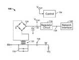
- a thermostat control 104turns on the heating subsystem gas valve by closing relay(s) 108 to connect a “hot” terminal RH to a load terminal W.
- the power stealing circuit 100includes a current sensor 116 , e.g., a clipper circuit, a step-down current transformer 120 , and a rectifier 124 , e.g., a full wave rectifier. In some embodiments, a half-wave rectifier could be used.
- the rectifier 124is connected across a high-voltage capacitor 130 (or other energy storage device) and a regulator circuit 134 , e.g., a buck circuit, to provide an output 138 to a wireless network interface 140 of the thermostat.
- the regulator circuit 134may be configured to reduce the capacitor voltage to a level compatible with the wireless network interface 140 .
- the output 138may be, e.g., a 3.3 VDC voltage.
- the capacitor 130becomes charged as rectified current flows through the rectifier 124 .
- the regulator circuit 134outputs power sufficient to make and at least temporarily maintain a network connection through the network interface 140 .
- the capacitor 130typically takes a maximum of 30 seconds to charge to the threshold voltage.
- a voltage Vmon across the capacitor 130is monitored by the control 104 , which controls the wireless network interface 140 based at least in part on the capacitor voltage.
- the control 104also controls the wireless network interface 140 based at least in part on a duty cycle as previously discussed with reference to FIG. 1 .
- control-performed method for controlling thermostat network connections through a network interfaceis indicated generally in FIG. 3 by reference number 200 and shall be described with reference to the power stealing circuit 100 shown in FIG. 2 .
- the control 104sets a timer for a duty cycle sleep time, e.g., for 30 seconds, and causes the thermostat to “sleep.”
- control 104may adjust at least the sleep time period in accordance with a time for charging the capacitor 130 to the threshold voltage.
- controlmay return to process 204 in which the timer is reset and the thermostat returns to sleep. If in process 208 the timer is still active and the capacitor is not yet charged to the threshold voltage, then control returns to process 208 .
- the thermostatcan be cycled more quickly through network connection cycles and can spend more time connected in the network than through adherence to only the predetermined duty cycle. In this way, performance of the example method 200 automatically adjusts the cycle times for network connections. The more power that can be stolen, the more frequently the network connections can be cycled, thereby reducing latency time to and/or from the network.
- various capacitors and threshold capacitor voltagesmay be used in relation to, e.g., various types of regulator circuits, including but not limited to buck circuits, boost circuits, converter circuits, integrated circuits, etc. Additionally or alternatively, various duty cycles could be provided, e.g., to accommodate various capacitor charging times.
- a thermostatmay include a battery to provide backup power in the event that power stealing is not available. Additionally or alternatively, power can be stolen, e.g., from both “on-mode” and “off-mode” loads at the same time in some example embodiments.
- Embodiments of the foregoing thermostats and power stealing circuitsdo not require a common wire to provide power for a wireless capability. Instead, a capacitor of a thermostat power stealing circuit can be used as a power reservoir that charges and discharges so that intermittent wireless network connections for network updates can be provided to the thermostat.
- a wireless thermostat radiocould be powered almost continuously (i.e., powered during duty cycle connection time periods that are long compared to sleep time periods.)
- exemplary embodimentsare disclosed that include a capacitor.
- other energy storage devicesmay be used besides capacitors, such as rechargeable batteries, etc.
- Example embodimentsare provided so that this disclosure will be thorough, and will fully convey the scope to those who are skilled in the art. Numerous specific details are set forth such as examples of specific components, devices, and methods, to provide a thorough understanding of embodiments of the present disclosure. It will be apparent to those skilled in the art that specific details need not be employed, that example embodiments may be embodied in many different forms, and that neither should be construed to limit the scope of the disclosure. In some example embodiments, well-known processes, well-known device structures, and well-known technologies are not described in detail.
- parameter Xmay have a range of values from about A to about Z.
- disclosure of two or more ranges of values for a parametersubsume all possible combination of ranges for the value that might be claimed using endpoints of the disclosed ranges.
- parameter Xis exemplified herein to have values in the range of 1-10, or 2-9, or 3-8, it is also envisioned that Parameter X may have other ranges of values including 1-9, 1-8, 1-3, 1-2, 2-10, 2-8, 2-3, 3-10, and 3-9.
- first, second, third, etc.may be used herein to describe various elements, components, regions, layers and/or sections, these elements, components, regions, layers and/or sections should not be limited by these terms. These terms may be only used to distinguish one element, component, region, layer or section from another region, layer or section. Terms such as “first,” “second,” and other numerical terms when used herein do not imply a sequence or order unless clearly indicated by the context. Thus, a first element, component, region, layer or section discussed below could be termed a second element, component, region, layer or section without departing from the teachings of the example embodiments.
- Spatially relative termssuch as “inner,” “outer,” “beneath,” “below,” “lower,” “above,” “upper” and the like, may be used herein for ease of description to describe one element or feature's relationship to another element(s) or feature(s) as illustrated in the figures. Spatially relative terms may be intended to encompass different orientations of the device in use or operation in addition to the orientation depicted in the figures. For example, if the device in the figures is turned over, elements described as “below” or “beneath” other elements or features would then be oriented “above” the other elements or features. Thus, the example term “below” can encompass both an orientation of above and below. The device may be otherwise oriented (rotated 90 degrees or at other orientations) and the spatially relative descriptors used herein interpreted accordingly.
Landscapes
- Physics & Mathematics (AREA)
- General Physics & Mathematics (AREA)
- Engineering & Computer Science (AREA)
- Automation & Control Theory (AREA)
- Charge And Discharge Circuits For Batteries Or The Like (AREA)
- Remote Monitoring And Control Of Power-Distribution Networks (AREA)
Abstract
Description
Claims (20)
Priority Applications (4)
| Application Number | Priority Date | Filing Date | Title |
|---|---|---|---|
| US13/886,797US9405303B2 (en) | 2013-04-22 | 2013-05-03 | Power stealing for a wireless-enabled thermostat |
| CA2846799ACA2846799C (en) | 2013-04-22 | 2014-03-17 | Power stealing for a wireless-enable thermostat |
| CN201410163042.7ACN104112347B (en) | 2013-04-22 | 2014-04-22 | The stealing of temperature controller with radio function |
| US15/219,634US10025328B2 (en) | 2013-04-22 | 2016-07-26 | Power stealing for a wireless-enabled thermostat |
Applications Claiming Priority (2)
| Application Number | Priority Date | Filing Date | Title |
|---|---|---|---|
| US201361814776P | 2013-04-22 | 2013-04-22 | |
| US13/886,797US9405303B2 (en) | 2013-04-22 | 2013-05-03 | Power stealing for a wireless-enabled thermostat |
Related Child Applications (1)
| Application Number | Title | Priority Date | Filing Date |
|---|---|---|---|
| US15/219,634Continuation-In-PartUS10025328B2 (en) | 2013-04-22 | 2016-07-26 | Power stealing for a wireless-enabled thermostat |
Publications (2)
| Publication Number | Publication Date |
|---|---|
| US20140312129A1 US20140312129A1 (en) | 2014-10-23 |
| US9405303B2true US9405303B2 (en) | 2016-08-02 |
Family
ID=51728260
Family Applications (1)
| Application Number | Title | Priority Date | Filing Date |
|---|---|---|---|
| US13/886,797Active2034-11-20US9405303B2 (en) | 2013-04-22 | 2013-05-03 | Power stealing for a wireless-enabled thermostat |
Country Status (2)
| Country | Link |
|---|---|
| US (1) | US9405303B2 (en) |
| CA (1) | CA2846799C (en) |
Cited By (10)
| Publication number | Priority date | Publication date | Assignee | Title |
|---|---|---|---|---|
| US20140368036A1 (en)* | 2013-06-14 | 2014-12-18 | Sinope Technologies Inc. Inc. | Low power and low emi power stealing circuit for a control device |
| US20160094074A1 (en)* | 2013-10-23 | 2016-03-31 | Apple Inc. | Method and Apparatus for Inductive Power Transfer |
| US20160334812A1 (en)* | 2013-04-22 | 2016-11-17 | Emerson Electric Co. | Power Stealing for a Wireless-Enabled Thermostat |
| US10404235B2 (en) | 2013-11-21 | 2019-09-03 | Apple Inc. | Using pulsed biases to represent DC bias for charging |
| US10601250B1 (en) | 2016-09-22 | 2020-03-24 | Apple Inc. | Asymmetric duty control of a half bridge power converter |
| US11268717B2 (en) | 2017-08-16 | 2022-03-08 | Carrier Corporation | Thermostat power monitoring, mitigation and alert |
| US11567861B2 (en) | 2021-04-26 | 2023-01-31 | Apple Inc. | Hashing with soft memory folding |
| US11803471B2 (en) | 2021-08-23 | 2023-10-31 | Apple Inc. | Scalable system on a chip |
| US11972140B2 (en) | 2021-04-26 | 2024-04-30 | Apple Inc. | Hashing with soft memory folding |
| US12236130B2 (en) | 2021-04-26 | 2025-02-25 | Apple Inc. | Address hashing in a multiple memory controller system |
Families Citing this family (18)
| Publication number | Priority date | Publication date | Assignee | Title |
|---|---|---|---|---|
| US11216020B2 (en) | 2015-05-04 | 2022-01-04 | Johnson Controls Tyco IP Holdings LLP | Mountable touch thermostat using transparent screen technology |
| AU2016257459B2 (en) | 2015-05-04 | 2019-04-04 | Johnson Controls Technology Company | Multi-function home control system with control system hub and remote sensors |
| US10677484B2 (en) | 2015-05-04 | 2020-06-09 | Johnson Controls Technology Company | User control device and multi-function home control system |
| US10760809B2 (en) | 2015-09-11 | 2020-09-01 | Johnson Controls Technology Company | Thermostat with mode settings for multiple zones |
| US10410300B2 (en) | 2015-09-11 | 2019-09-10 | Johnson Controls Technology Company | Thermostat with occupancy detection based on social media event data |
| US10345781B2 (en) | 2015-10-28 | 2019-07-09 | Johnson Controls Technology Company | Multi-function thermostat with health monitoring features |
| US10546472B2 (en) | 2015-10-28 | 2020-01-28 | Johnson Controls Technology Company | Thermostat with direction handoff features |
| US11277893B2 (en) | 2015-10-28 | 2022-03-15 | Johnson Controls Technology Company | Thermostat with area light system and occupancy sensor |
| US10655881B2 (en) | 2015-10-28 | 2020-05-19 | Johnson Controls Technology Company | Thermostat with halo light system and emergency directions |
| US10318266B2 (en) | 2015-11-25 | 2019-06-11 | Johnson Controls Technology Company | Modular multi-function thermostat |
| US10941951B2 (en) | 2016-07-27 | 2021-03-09 | Johnson Controls Technology Company | Systems and methods for temperature and humidity control |
| CN106646330A (en)* | 2016-11-16 | 2017-05-10 | 江苏林洋能源股份有限公司 | Load high resistance and bypass electricity stealing detection circuit and detection method |
| US10458669B2 (en) | 2017-03-29 | 2019-10-29 | Johnson Controls Technology Company | Thermostat with interactive installation features |
| US11162698B2 (en) | 2017-04-14 | 2021-11-02 | Johnson Controls Tyco IP Holdings LLP | Thermostat with exhaust fan control for air quality and humidity control |
| WO2018191510A1 (en) | 2017-04-14 | 2018-10-18 | Johnson Controls Technology Company | Multi-function thermostat with air quality display |
| CN107846325B (en)* | 2017-11-08 | 2020-09-04 | 广东小天才科技有限公司 | Network state detection method and terminal |
| US11131474B2 (en) | 2018-03-09 | 2021-09-28 | Johnson Controls Tyco IP Holdings LLP | Thermostat with user interface features |
| US11107390B2 (en) | 2018-12-21 | 2021-08-31 | Johnson Controls Technology Company | Display device with halo |
Citations (17)
| Publication number | Priority date | Publication date | Assignee | Title |
|---|---|---|---|---|
| US5192874A (en) | 1991-09-26 | 1993-03-09 | Honeywell, Inc. | Interface circuit for low power drain microprocessor-based thermostat |
| US5903139A (en)* | 1997-01-27 | 1999-05-11 | Honeywell Inc. | Power stealing solid state switch for supplying operating power to an electronic control device |
| US6490174B1 (en)* | 2001-06-04 | 2002-12-03 | Honeywell International Inc. | Electronic interface for power stealing circuit |
| US6886754B2 (en)* | 2003-06-03 | 2005-05-03 | Tim Simon, Inc. | Thermostat operable from various power sources |
| US6998816B2 (en) | 2003-06-30 | 2006-02-14 | Sony Electronics Inc. | System and method for reducing external battery capacity requirement for a wireless card |
| US7476988B2 (en) | 2005-11-23 | 2009-01-13 | Honeywell International Inc. | Power stealing control devices |
| US7755220B2 (en) | 2004-08-11 | 2010-07-13 | Carrier Corporation | Power stealing for a thermostat using a TRIAC with FET control |
| US7826815B2 (en) | 2007-07-13 | 2010-11-02 | Fairchild Semiconductor Corporation | Dynamic selection of oscillation signal frequency for power converter |
| US8110945B2 (en) | 2008-07-29 | 2012-02-07 | Honeywell International Inc. | Power stealing circuitry for a control device |
| US20120126019A1 (en)* | 2010-11-19 | 2012-05-24 | Nest Labs, Inc. | Thermostat battery recharging during hvac function active and inactive states |
| US8195313B1 (en)* | 2010-11-19 | 2012-06-05 | Nest Labs, Inc. | Thermostat user interface |
| US20120256009A1 (en)* | 2011-02-24 | 2012-10-11 | Nest Labs, Inc. | Power-preserving communications architecture with long-polling persistent cloud channel for wireless network-connected thermostat |
| US20120325919A1 (en)* | 2011-02-24 | 2012-12-27 | Nest Labs, Inc. | Thermostat with power stealing delay interval at transitions between power stealing states |
| US20130103204A1 (en)* | 2011-10-21 | 2013-04-25 | Nest Labs, Inc. | Prospective determination of processor wake-up conditions in energy buffered hvac control unit |
| US8523083B2 (en)* | 2011-02-24 | 2013-09-03 | Nest Labs, Inc. | Thermostat with self-configuring connections to facilitate do-it-yourself installation |
| US20130228633A1 (en)* | 2012-03-01 | 2013-09-05 | Emerson Electric Co. | Systems and Methods for Power Stealing |
| US9092039B2 (en)* | 2010-11-19 | 2015-07-28 | Google Inc. | HVAC controller with user-friendly installation features with wire insertion detection |
- 2013
- 2013-05-03USUS13/886,797patent/US9405303B2/enactiveActive
- 2014
- 2014-03-17CACA2846799Apatent/CA2846799C/ennot_activeExpired - Fee Related
Patent Citations (20)
| Publication number | Priority date | Publication date | Assignee | Title |
|---|---|---|---|---|
| US5192874A (en) | 1991-09-26 | 1993-03-09 | Honeywell, Inc. | Interface circuit for low power drain microprocessor-based thermostat |
| US5903139A (en)* | 1997-01-27 | 1999-05-11 | Honeywell Inc. | Power stealing solid state switch for supplying operating power to an electronic control device |
| US6490174B1 (en)* | 2001-06-04 | 2002-12-03 | Honeywell International Inc. | Electronic interface for power stealing circuit |
| US6886754B2 (en)* | 2003-06-03 | 2005-05-03 | Tim Simon, Inc. | Thermostat operable from various power sources |
| US6998816B2 (en) | 2003-06-30 | 2006-02-14 | Sony Electronics Inc. | System and method for reducing external battery capacity requirement for a wireless card |
| US7755220B2 (en) | 2004-08-11 | 2010-07-13 | Carrier Corporation | Power stealing for a thermostat using a TRIAC with FET control |
| US7476988B2 (en) | 2005-11-23 | 2009-01-13 | Honeywell International Inc. | Power stealing control devices |
| US7826815B2 (en) | 2007-07-13 | 2010-11-02 | Fairchild Semiconductor Corporation | Dynamic selection of oscillation signal frequency for power converter |
| US8110945B2 (en) | 2008-07-29 | 2012-02-07 | Honeywell International Inc. | Power stealing circuitry for a control device |
| US20120155137A1 (en) | 2008-07-29 | 2012-06-21 | Honeywell International Inc. | Power stealing circuitry for a control device |
| US20120126021A1 (en)* | 2010-09-14 | 2012-05-24 | Nest Labs, Inc. | Thermostat circuitry for connection to hvac systems |
| US20120199660A1 (en)* | 2010-09-14 | 2012-08-09 | Nest Labs, Inc. | Adaptive power stealing thermostat |
| US8195313B1 (en)* | 2010-11-19 | 2012-06-05 | Nest Labs, Inc. | Thermostat user interface |
| US20120126019A1 (en)* | 2010-11-19 | 2012-05-24 | Nest Labs, Inc. | Thermostat battery recharging during hvac function active and inactive states |
| US9092039B2 (en)* | 2010-11-19 | 2015-07-28 | Google Inc. | HVAC controller with user-friendly installation features with wire insertion detection |
| US20120256009A1 (en)* | 2011-02-24 | 2012-10-11 | Nest Labs, Inc. | Power-preserving communications architecture with long-polling persistent cloud channel for wireless network-connected thermostat |
| US20120325919A1 (en)* | 2011-02-24 | 2012-12-27 | Nest Labs, Inc. | Thermostat with power stealing delay interval at transitions between power stealing states |
| US8523083B2 (en)* | 2011-02-24 | 2013-09-03 | Nest Labs, Inc. | Thermostat with self-configuring connections to facilitate do-it-yourself installation |
| US20130103204A1 (en)* | 2011-10-21 | 2013-04-25 | Nest Labs, Inc. | Prospective determination of processor wake-up conditions in energy buffered hvac control unit |
| US20130228633A1 (en)* | 2012-03-01 | 2013-09-05 | Emerson Electric Co. | Systems and Methods for Power Stealing |
Non-Patent Citations (4)
| Title |
|---|
| Canadian Office Action issued in Canadian Patent Application No. 2,846,799 dated Aug. 26, 2015, which claims priority to the instant application; 3 pgs. |
| http://support.nest.com/article/1st-generation-Nest-Learning-Thermostat-Installation-Guide; updated Oct. 11, 2012; 6 pgs. |
| Radio Thermostat Corporation of America; CT80 and CT30 Thermostats; Mar. 25, 2012; 1 pg. |
| www.ritetemp-thermostats.com/60XX/6080.html; 2008 ©; 12 pgs. |
Cited By (17)
| Publication number | Priority date | Publication date | Assignee | Title |
|---|---|---|---|---|
| US20160334812A1 (en)* | 2013-04-22 | 2016-11-17 | Emerson Electric Co. | Power Stealing for a Wireless-Enabled Thermostat |
| US10025328B2 (en)* | 2013-04-22 | 2018-07-17 | Emerson Electric Co. | Power stealing for a wireless-enabled thermostat |
| US20140368036A1 (en)* | 2013-06-14 | 2014-12-18 | Sinope Technologies Inc. Inc. | Low power and low emi power stealing circuit for a control device |
| US9608507B2 (en)* | 2013-06-14 | 2017-03-28 | Sinope Technologies Inc. | Low power and low EMI power stealing circuit for a control device |
| US20160094074A1 (en)* | 2013-10-23 | 2016-03-31 | Apple Inc. | Method and Apparatus for Inductive Power Transfer |
| US10404235B2 (en) | 2013-11-21 | 2019-09-03 | Apple Inc. | Using pulsed biases to represent DC bias for charging |
| US10601250B1 (en) | 2016-09-22 | 2020-03-24 | Apple Inc. | Asymmetric duty control of a half bridge power converter |
| US11268717B2 (en) | 2017-08-16 | 2022-03-08 | Carrier Corporation | Thermostat power monitoring, mitigation and alert |
| US11567861B2 (en) | 2021-04-26 | 2023-01-31 | Apple Inc. | Hashing with soft memory folding |
| US11693585B2 (en) | 2021-04-26 | 2023-07-04 | Apple Inc. | Address hashing in a multiple memory controller system |
| US11714571B2 (en) | 2021-04-26 | 2023-08-01 | Apple Inc. | Address bit dropping to create compacted pipe address for a memory controller |
| US11972140B2 (en) | 2021-04-26 | 2024-04-30 | Apple Inc. | Hashing with soft memory folding |
| US12236130B2 (en) | 2021-04-26 | 2025-02-25 | Apple Inc. | Address hashing in a multiple memory controller system |
| US11803471B2 (en) | 2021-08-23 | 2023-10-31 | Apple Inc. | Scalable system on a chip |
| US11934313B2 (en) | 2021-08-23 | 2024-03-19 | Apple Inc. | Scalable system on a chip |
| US12007895B2 (en) | 2021-08-23 | 2024-06-11 | Apple Inc. | Scalable system on a chip |
| US12399830B2 (en) | 2021-08-23 | 2025-08-26 | Apple Inc. | Scalable system on a chip |
Also Published As
| Publication number | Publication date |
|---|---|
| CA2846799C (en) | 2017-01-10 |
| US20140312129A1 (en) | 2014-10-23 |
| CA2846799A1 (en) | 2014-10-22 |
Similar Documents
| Publication | Publication Date | Title |
|---|---|---|
| US9405303B2 (en) | Power stealing for a wireless-enabled thermostat | |
| US10025328B2 (en) | Power stealing for a wireless-enabled thermostat | |
| CA2855188C (en) | Optimizing communication modes in wireless-enabled climate control system controllers | |
| US9404667B2 (en) | Determining power stealing capability of a climate control system controller | |
| US10536017B2 (en) | Managing charge of a battery in a climate control device to prolong battery life | |
| US7800251B2 (en) | System and method for load control | |
| US20140312694A1 (en) | Dual-Mode Power Stealing for a Climate Control System Controller | |
| US20180375384A1 (en) | Control apparatus | |
| CN111373596B (en) | Internal heating of the battery | |
| WO2017033399A1 (en) | Management device, charging and discharging control device, electricity storage system, and charging and discharging control method | |
| EP2803917A1 (en) | Air conditioning device | |
| US20140152101A1 (en) | Startup control method, grid interconnection apparatus, and controller | |
| EP3829268A1 (en) | Iot light switch module for smart home construction | |
| US9330870B2 (en) | AC line powered relay driving circuits | |
| WO2015191674A1 (en) | Systems and methods for warming batteries | |
| CA2919800C (en) | Staging climate control system controller functions based on available power | |
| US20160036242A1 (en) | Wireless Power Supply Device and Wireless Power Supply System | |
| CN104112347B (en) | The stealing of temperature controller with radio function | |
| CN211531395U (en) | Switch device | |
| JP2015057003A (en) | Air conditioner | |
| JP7643746B2 (en) | Power supply including control of thermal management system | |
| JP2015111986A (en) | Power storage system | |
| JP6913754B2 (en) | Battery pack | |
| CN114824577A (en) | Remote heating control method and device for rechargeable energy storage system and vehicle | |
| JP2017212835A (en) | Power supply control system |
Legal Events
| Date | Code | Title | Description |
|---|---|---|---|
| AS | Assignment | Owner name:EMERSON ELECTRIC CO., MISSOURI Free format text:ASSIGNMENT OF ASSIGNORS INTEREST;ASSIGNORS:ZIKES, BRADLEY C.;BUTLER, WILLIAM P.;PERRY, DAVID L.;REEL/FRAME:030347/0769 Effective date:20130423 | |
| STCF | Information on status: patent grant | Free format text:PATENTED CASE | |
| MAFP | Maintenance fee payment | Free format text:PAYMENT OF MAINTENANCE FEE, 4TH YEAR, LARGE ENTITY (ORIGINAL EVENT CODE: M1551); ENTITY STATUS OF PATENT OWNER: LARGE ENTITY Year of fee payment:4 | |
| AS | Assignment | Owner name:COPELAND COMFORT CONTROL LP, MISSOURI Free format text:SUPPLEMENTAL IP ASSIGNMENT AGREEMENT;ASSIGNOR:EMERSON ELECTRIC CO.;REEL/FRAME:063804/0611 Effective date:20230426 | |
| AS | Assignment | Owner name:ROYAL BANK OF CANADA, AS COLLATERAL AGENT, CANADA Free format text:SECURITY INTEREST;ASSIGNOR:COPELAND COMFORT CONTROL LP;REEL/FRAME:064278/0165 Effective date:20230531 Owner name:U.S. BANK TRUST COMPANY, NATIONAL ASSOCIATION, AS NOTES COLLATERAL AGENT, MINNESOTA Free format text:SECURITY INTEREST;ASSIGNOR:COPELAND COMFORT CONTROL LP;REEL/FRAME:064280/0333 Effective date:20230531 Owner name:WELLS FARGO BANK, NATIONAL ASSOCIATION, AS COLLATERAL AGENT, CALIFORNIA Free format text:SECURITY INTEREST;ASSIGNOR:COPELAND COMFORT CONTROL LP;REEL/FRAME:064286/0001 Effective date:20230531 | |
| MAFP | Maintenance fee payment | Free format text:PAYMENT OF MAINTENANCE FEE, 8TH YEAR, LARGE ENTITY (ORIGINAL EVENT CODE: M1552); ENTITY STATUS OF PATENT OWNER: LARGE ENTITY Year of fee payment:8 | |
| AS | Assignment | Owner name:U.S. BANK TRUST COMPANY, NATIONAL ASSOCIATION, AS NOTES COLLATERAL AGENT, MINNESOTA Free format text:SECURITY INTEREST;ASSIGNOR:COPELAND COMFORT CONTROL LP;REEL/FRAME:068255/0466 Effective date:20240708 |