US9404414B2 - Internal combustion engine coupled turbocharger with an infinitely variable transmission - Google Patents
Internal combustion engine coupled turbocharger with an infinitely variable transmissionDownload PDFInfo
- Publication number
- US9404414B2 US9404414B2US14/175,584US201414175584AUS9404414B2US 9404414 B2US9404414 B2US 9404414B2US 201414175584 AUS201414175584 AUS 201414175584AUS 9404414 B2US9404414 B2US 9404414B2
- Authority
- US
- United States
- Prior art keywords
- driving engagement
- turbocharger
- internal combustion
- combustion engine
- differential device
- Prior art date
- Legal status (The legal status is an assumption and is not a legal conclusion. Google has not performed a legal analysis and makes no representation as to the accuracy of the status listed.)
- Expired - Fee Related
Links
Images


Classifications
- F—MECHANICAL ENGINEERING; LIGHTING; HEATING; WEAPONS; BLASTING
- F02—COMBUSTION ENGINES; HOT-GAS OR COMBUSTION-PRODUCT ENGINE PLANTS
- F02B—INTERNAL-COMBUSTION PISTON ENGINES; COMBUSTION ENGINES IN GENERAL
- F02B37/00—Engines characterised by provision of pumps driven at least for part of the time by exhaust
- F02B37/04—Engines with exhaust drive and other drive of pumps, e.g. with exhaust-driven pump and mechanically-driven second pump
- F02B37/10—Engines with exhaust drive and other drive of pumps, e.g. with exhaust-driven pump and mechanically-driven second pump at least one pump being alternatively or simultaneously driven by exhaust and other drive, e.g. by pressurised fluid from a reservoir or an engine-driven pump
- F02B37/105—Engines with exhaust drive and other drive of pumps, e.g. with exhaust-driven pump and mechanically-driven second pump at least one pump being alternatively or simultaneously driven by exhaust and other drive, e.g. by pressurised fluid from a reservoir or an engine-driven pump exhaust drive and pump being both connected through gearing to engine-driven shaft
- F—MECHANICAL ENGINEERING; LIGHTING; HEATING; WEAPONS; BLASTING
- F02—COMBUSTION ENGINES; HOT-GAS OR COMBUSTION-PRODUCT ENGINE PLANTS
- F02B—INTERNAL-COMBUSTION PISTON ENGINES; COMBUSTION ENGINES IN GENERAL
- F02B39/00—Component parts, details, or accessories relating to, driven charging or scavenging pumps, not provided for in groups F02B33/00 - F02B37/00
- F02B39/02—Drives of pumps; Varying pump drive gear ratio
- F02B39/04—Mechanical drives; Variable-gear-ratio drives
- F—MECHANICAL ENGINEERING; LIGHTING; HEATING; WEAPONS; BLASTING
- F02—COMBUSTION ENGINES; HOT-GAS OR COMBUSTION-PRODUCT ENGINE PLANTS
- F02B—INTERNAL-COMBUSTION PISTON ENGINES; COMBUSTION ENGINES IN GENERAL
- F02B41/00—Engines characterised by special means for improving conversion of heat or pressure energy into mechanical power
- F02B41/02—Engines with prolonged expansion
- F02B41/10—Engines with prolonged expansion in exhaust turbines
- F—MECHANICAL ENGINEERING; LIGHTING; HEATING; WEAPONS; BLASTING
- F02—COMBUSTION ENGINES; HOT-GAS OR COMBUSTION-PRODUCT ENGINE PLANTS
- F02C—GAS-TURBINE PLANTS; AIR INTAKES FOR JET-PROPULSION PLANTS; CONTROLLING FUEL SUPPLY IN AIR-BREATHING JET-PROPULSION PLANTS
- F02C3/00—Gas-turbine plants characterised by the use of combustion products as the working fluid
- F02C3/04—Gas-turbine plants characterised by the use of combustion products as the working fluid having a turbine driving a compressor
- F02C3/107—Gas-turbine plants characterised by the use of combustion products as the working fluid having a turbine driving a compressor with two or more rotors connected by power transmission
- F02C3/113—Gas-turbine plants characterised by the use of combustion products as the working fluid having a turbine driving a compressor with two or more rotors connected by power transmission with variable power transmission between rotors
- F—MECHANICAL ENGINEERING; LIGHTING; HEATING; WEAPONS; BLASTING
- F02—COMBUSTION ENGINES; HOT-GAS OR COMBUSTION-PRODUCT ENGINE PLANTS
- F02C—GAS-TURBINE PLANTS; AIR INTAKES FOR JET-PROPULSION PLANTS; CONTROLLING FUEL SUPPLY IN AIR-BREATHING JET-PROPULSION PLANTS
- F02C6/00—Plural gas-turbine plants; Combinations of gas-turbine plants with other apparatus; Adaptations of gas-turbine plants for special use
- F02C6/04—Gas-turbine plants providing heated or pressurised working fluid for other apparatus, e.g. without mechanical power output
- F02C6/10—Gas-turbine plants providing heated or pressurised working fluid for other apparatus, e.g. without mechanical power output supplying working fluid to a user, e.g. a chemical process, which returns working fluid to a turbine of the plant
- F02C6/12—Turbochargers, i.e. plants for augmenting mechanical power output of internal-combustion piston engines by increase of charge pressure
- F—MECHANICAL ENGINEERING; LIGHTING; HEATING; WEAPONS; BLASTING
- F02—COMBUSTION ENGINES; HOT-GAS OR COMBUSTION-PRODUCT ENGINE PLANTS
- F02C—GAS-TURBINE PLANTS; AIR INTAKES FOR JET-PROPULSION PLANTS; CONTROLLING FUEL SUPPLY IN AIR-BREATHING JET-PROPULSION PLANTS
- F02C7/00—Features, components parts, details or accessories, not provided for in, or of interest apart form groups F02C1/00 - F02C6/00; Air intakes for jet-propulsion plants
- F02C7/36—Power transmission arrangements between the different shafts of the gas turbine plant, or between the gas-turbine plant and the power user
- F—MECHANICAL ENGINEERING; LIGHTING; HEATING; WEAPONS; BLASTING
- F04—POSITIVE - DISPLACEMENT MACHINES FOR LIQUIDS; PUMPS FOR LIQUIDS OR ELASTIC FLUIDS
- F04D—NON-POSITIVE-DISPLACEMENT PUMPS
- F04D25/00—Pumping installations or systems
- F04D25/02—Units comprising pumps and their driving means
- F04D25/026—Units comprising pumps and their driving means with a magnetic coupling
- F—MECHANICAL ENGINEERING; LIGHTING; HEATING; WEAPONS; BLASTING
- F04—POSITIVE - DISPLACEMENT MACHINES FOR LIQUIDS; PUMPS FOR LIQUIDS OR ELASTIC FLUIDS
- F04D—NON-POSITIVE-DISPLACEMENT PUMPS
- F04D25/00—Pumping installations or systems
- F04D25/02—Units comprising pumps and their driving means
- F04D25/028—Units comprising pumps and their driving means the driving means being a planetary gear
- F—MECHANICAL ENGINEERING; LIGHTING; HEATING; WEAPONS; BLASTING
- F16—ENGINEERING ELEMENTS AND UNITS; GENERAL MEASURES FOR PRODUCING AND MAINTAINING EFFECTIVE FUNCTIONING OF MACHINES OR INSTALLATIONS; THERMAL INSULATION IN GENERAL
- F16H—GEARING
- F16H15/00—Gearings for conveying rotary motion with variable gear ratio, or for reversing rotary motion, by friction between rotary members
- F16H15/02—Gearings for conveying rotary motion with variable gear ratio, or for reversing rotary motion, by friction between rotary members without members having orbital motion
- F16H15/04—Gearings providing a continuous range of gear ratios
- F16H15/06—Gearings providing a continuous range of gear ratios in which a member A of uniform effective diameter mounted on a shaft may co-operate with different parts of a member B
- F16H15/26—Gearings providing a continuous range of gear ratios in which a member A of uniform effective diameter mounted on a shaft may co-operate with different parts of a member B in which the member B has a spherical friction surface centered on its axis of revolution
- F16H15/28—Gearings providing a continuous range of gear ratios in which a member A of uniform effective diameter mounted on a shaft may co-operate with different parts of a member B in which the member B has a spherical friction surface centered on its axis of revolution with external friction surface
- F—MECHANICAL ENGINEERING; LIGHTING; HEATING; WEAPONS; BLASTING
- F16—ENGINEERING ELEMENTS AND UNITS; GENERAL MEASURES FOR PRODUCING AND MAINTAINING EFFECTIVE FUNCTIONING OF MACHINES OR INSTALLATIONS; THERMAL INSULATION IN GENERAL
- F16H—GEARING
- F16H48/00—Differential gearings
- F16H48/06—Differential gearings with gears having orbital motion
- F16H48/08—Differential gearings with gears having orbital motion comprising bevel gears
- G—PHYSICS
- G06—COMPUTING OR CALCULATING; COUNTING
- G06F—ELECTRIC DIGITAL DATA PROCESSING
- G06F8/00—Arrangements for software engineering
- G06F8/60—Software deployment
- G06F8/65—Updates
- H—ELECTRICITY
- H02—GENERATION; CONVERSION OR DISTRIBUTION OF ELECTRIC POWER
- H02K—DYNAMO-ELECTRIC MACHINES
- H02K49/00—Dynamo-electric clutches; Dynamo-electric brakes
- H02K49/10—Dynamo-electric clutches; Dynamo-electric brakes of the permanent-magnet type
- H—ELECTRICITY
- H02—GENERATION; CONVERSION OR DISTRIBUTION OF ELECTRIC POWER
- H02K—DYNAMO-ELECTRIC MACHINES
- H02K49/00—Dynamo-electric clutches; Dynamo-electric brakes
- H02K49/10—Dynamo-electric clutches; Dynamo-electric brakes of the permanent-magnet type
- H02K49/102—Magnetic gearings, i.e. assembly of gears, linear or rotary, by which motion is magnetically transferred without physical contact
- F—MECHANICAL ENGINEERING; LIGHTING; HEATING; WEAPONS; BLASTING
- F05—INDEXING SCHEMES RELATING TO ENGINES OR PUMPS IN VARIOUS SUBCLASSES OF CLASSES F01-F04
- F05D—INDEXING SCHEME FOR ASPECTS RELATING TO NON-POSITIVE-DISPLACEMENT MACHINES OR ENGINES, GAS-TURBINES OR JET-PROPULSION PLANTS
- F05D2220/00—Application
- F05D2220/40—Application in turbochargers
- F—MECHANICAL ENGINEERING; LIGHTING; HEATING; WEAPONS; BLASTING
- F16—ENGINEERING ELEMENTS AND UNITS; GENERAL MEASURES FOR PRODUCING AND MAINTAINING EFFECTIVE FUNCTIONING OF MACHINES OR INSTALLATIONS; THERMAL INSULATION IN GENERAL
- F16H—GEARING
- F16H15/00—Gearings for conveying rotary motion with variable gear ratio, or for reversing rotary motion, by friction between rotary members
- F16H15/02—Gearings for conveying rotary motion with variable gear ratio, or for reversing rotary motion, by friction between rotary members without members having orbital motion
- F16H15/04—Gearings providing a continuous range of gear ratios
- F16H15/40—Gearings providing a continuous range of gear ratios in which two members co-operative by means of balls, or rollers of uniform effective diameter, not mounted on shafts
- Y—GENERAL TAGGING OF NEW TECHNOLOGICAL DEVELOPMENTS; GENERAL TAGGING OF CROSS-SECTIONAL TECHNOLOGIES SPANNING OVER SEVERAL SECTIONS OF THE IPC; TECHNICAL SUBJECTS COVERED BY FORMER USPC CROSS-REFERENCE ART COLLECTIONS [XRACs] AND DIGESTS
- Y02—TECHNOLOGIES OR APPLICATIONS FOR MITIGATION OR ADAPTATION AGAINST CLIMATE CHANGE
- Y02T—CLIMATE CHANGE MITIGATION TECHNOLOGIES RELATED TO TRANSPORTATION
- Y02T10/00—Road transport of goods or passengers
- Y02T10/10—Internal combustion engine [ICE] based vehicles
- Y02T10/12—Improving ICE efficiencies
- Y02T10/144—
- Y02T10/163—
Definitions
- the present inventionrelates to energy recovery systems and more specifically to waste heat recovery systems used with internal combustions engines.
- turbochargerIn order to improve the volumetric efficiency of naturally aspirated engines, two forced induction devices may be typically used; a turbocharger or a supercharger.
- a superchargertypically comprises a compressor in driving engagement with an engine crankshaft to compress additional air before intake into the engine.
- Superchargerswill not be discussed in detail herein as they do not recuperate the kinetic energy from an exhaust gas flow; instead superchargers increase the power of the engine by increasing the volumetric efficiency of the engine.
- FIG. 1shows a cut-through sketch of a turbocharger 100 known in the prior art.
- a turbine 102which is a radial inflow turbine expander, is shown which has an intake port 104 where the exhaust gas flow enters the turbine 102 radially and leaves through an outlet port 106 axially.
- a plurality of blades 108 of the turbine 102allow for a recuperation of kinetic energy from the exhaust gas flow, which is directed to a central rotor hub 110 .
- the central rotor hub 110is also drivingly engaged with a compressor 112 , in which a flow of air enters an intake port 114 axially and is pushed radially to an outlet port 116 by a plurality of blades 118 of the compressor 112 .
- Due to inherent limitations in the designthe turbocharger 100 is subject to several issues that may be solved by using a complex control methodology or through the addition of costly technologies to the turbocharger 100 .
- a boost pressureincreases depending on am amount of exhaust gases, as the compressor is directly linked to the turbine. At a certain point, pressure has to be limited to avoid engine knocking and other potential damage related to the increased pressure at an intake manifold of the engine. This issue is commonly corrected through the use of a wastegate.
- the wastegatediverts a portion of the exhaust gas from the turbine, thus limiting the pressure and amount of energy that can be recuperated by the turbine. In a conventional configuration of a turbocharger, the excessive wasted exhaust and the complex control of the wastegate cannot be avoided.
- Turbo lagis a time required to adjust a power output of the turbocharger in response to an adjustment in a throttle of the vehicle. Turbo lag is caused by an amount of time needed to generate a required pressure boost by an exhaust system and the turbine. Turbo lag significantly depends on the inertia of the components of the turbocharger, an amount of friction within the turbocharger, and an initial speed of the turbocharger, and an amount of exhaust gas passing through the turbine. A number of ways exist to decrease the turbo lag. For example, it is possible to decrease the rotational inertia, to change the aspect ratio of the turbine, to use variable geometry components, amongst other improvement, but all improvements significantly affect a cost and complexity of the turbocharger.
- boost thresholdAnother issue associated with such a turbocharger is a boost threshold.
- Turbochargersstart producing boost only when enough energy can be recuperated by the turbine. Without the required amount of kinetic energy, the turbocharger will not be able to provide the required amount of boost.
- An engine speed at which this limitation disappearsis called a boost threshold speed.
- the boost threshold speedis dependent on an engine size and an operating speed of the engine, a throttle opening, and a design of the turbocharger. As a result of the boot threshold, an operator of a vehicle including the turbocharger may notice an ineffectiveness of the turbocharger when the engine is operated under a certain speed.
- a final issue associated with such a turbochargeris based on an energy recuperation capability of the turbocharger.
- the turbine of the turbochargeris only able to recuperate energy from the exhaust gas flow to compress intake gases. If the operator of the vehicle requests a low amount of power output from the engine, compression of the intake gases is not necessary, and all of the kinetic energy in the exhaust gas flow is directed around the turbine using the wastegate. Directing the exhaust gas flow around the turbine using the wastegate is an inefficient manner of operation for the turbocharger.
- turbochargerfor an internal combustion engine that is simply controlled, reduces turbo lag, decreases a boost threshold of the turbocharger, and increases an efficiency of the internal combustion engine.
- a turbocharger for an internal combustion enginethat is simply controlled, reduces turbo lag, decreases a boost threshold of the turbocharger, and increases an efficiency of the internal combustion engine, has surprisingly been discovered.
- the present inventionis directed to a turbocharger for an internal combustion engine.
- the turbochargercomprises a differential device having a carrier portion, a compressor portion, and a turbine portion.
- the compressor portionis in driving engagement with a first portion of the differential device.
- the turbine portionis in driving engagement with a second portion of the differential device.
- the carrier portion of the differential deviceis in driving engagement with an infinitely variable transmission.
- the infinitely variable transmissionis in driving engagement with the internal combustion engine.
- the present inventionis directed to a turbocharger for an internal combustion engine.
- the turbochargercomprises a differential device having a carrier portion, a compressor portion, a turbine portion, and an output shaft.
- the compressor portionis in driving engagement with a first portion of the differential device.
- the turbine portionis in driving engagement with a second portion of the differential device.
- the output shaftis in driving engagement with the carrier portion of the differential device and a ratio adjusting device.
- the ratio adjusting deviceis in further engagement with an infinitely variable transmission.
- the infinitely variable transmissionis in driving engagement with the internal combustion engine.
- the present inventionis directed to a turbocharger for an internal combustion engine.
- the turbochargercomprises a differential device having a carrier portion, a compressor portion, a turbine portion, a first ratio adjusting device, and an output shaft.
- the compressor portionis in driving engagement with a first portion of the differential device.
- the turbine portionis in driving engagement with a second portion of the differential device.
- a first ratio adjusting deviceis in driving engagement with at least one of the compressor portion and the first portion of the differential device and the turbine portion and the second portion of the differential device.
- the output shaftis in driving engagement with the carrier portion of the differential device and a second ratio adjusting device.
- the second ratio adjusting deviceis in further engagement with an infinitely variable transmission.
- the infinitely variable transmissionis in driving engagement with the internal combustion engine.
- FIG. 1is a schematic illustration of a cut away side view of a turbocharger known in the prior art
- FIG. 2is a schematic illustration of a cut away side view of an embodiment of a turbocharger according to the present invention, the turbocharger in driving engagement with a ratio adjusting device, an infinitely variable transmission, and an internal combustion engine;
- FIG. 3is a schematic illustration of a cut away side view of an embodiment of a turbocharger according to another embodiment of the present invention, the turbocharger in driving engagement with a ratio adjusting device, an infinitely variable transmission, and an internal combustion engine;
- FIG. 4is a schematic illustration of a cut away side view of an embodiment of a turbocharger according to another embodiment of the present invention, the turbocharger in driving engagement with a ratio adjusting device, an infinitely variable transmission, and an internal combustion engine;
- FIG. 5is a schematic illustration of a cut away side view of an embodiment of a turbocharger according to another embodiment of the present invention, the turbocharger in driving engagement with a ratio adjusting device, an infinitely variable transmission, and an internal combustion engine;
- FIG. 6is a schematic illustration of a cut away side view of an embodiment of a turbocharger according to another embodiment of the present invention, the turbocharger in driving engagement with a ratio adjusting device, an infinitely variable transmission, and an internal combustion engine;
- FIG. 7is a schematic illustration of a cut away side view of an embodiment of a turbocharger according to another embodiment of the present invention, the turbocharger in driving engagement with a ratio adjusting device, an infinitely variable transmission, and an internal combustion engine;
- FIG. 8is a speed diagram of the turbocharger according to any one of the embodiments of the present invention.
- FIG. 2schematically illustrates a turbocharger 200 for use with an internal combustion engine 202 .
- the turbocharger 200is in driving engagement and fluid communication with the internal combustion engine 202 .
- the turbocharger 200is in driving engagement with the internal combustion engine 202 through a differential device 204 , a ratio adjusting device 206 , and an infinitely variable transmission 208 .
- the internal combustion engine 202is used as a power source for a vehicle (not shown); however, it is understood that the internal combustion engine 202 may be used in other applications, such as in stationary power generation applications.
- the turbocharger 200includes a turbine portion 210 , a compressor portion 212 , the differential device 204 , and an output shaft 214 .
- the turbine portion 210 , the compressor portion 212 , the differential device 204 , and the output shaft 214are rotatably mounted within a housing 216 using a plurality of bearings (not shown).
- the turbine portion 210 and the compressor portion 212are drivingly engaged with the output shaft 214 through the differential device 204 .
- the turbine portion 210is driven by exhaust gases via an exhaust port 218 of the internal combustion engine 202 .
- the turbine portion 210is drivingly engaged with the compressor portion 212 through the differential device 204 to provide compressed air to an intake port 220 of the internal combustion engine 202 .
- the output shaft 214is also drivingly engaged with the internal combustion engine 202 through the ratio adjusting device 206 and the infinitely variable transmission 208 ; however, it is understood that the turbine portion 210 and the compressor portion 212 may be drivingly engaged internal combustion engine 202 in another manner that facilitates infinitely variable driving engagement therebetween. As shown in FIG. 2 , the output shaft 214 passes through a central perforation 221 formed through the compressor portion 212 ; however, it is understood that the output shaft 214 may pass through the turbine portion 210 or that the output shaft 214 may be drivingly engaged with the internal combustion engine 202 in another manner.
- the differential device 204comprises a first side gear 222 , a second side gear 224 , a differential carrier 226 , and a plurality of spider gears 228 .
- the first side gear 222 , the second side gear 224 , the differential carrier 226 , and the plurality of spider gears 228are disposed within the housing 216 , between the turbine portion 210 and the compressor portion 212 .
- the first side gear 222 and the second side gear 224are bevel gears respectively disposed on and spliningly engaged with the compressor portion 212 and the turbine portion 210 .
- the first side gear 222 and the second side gear 224may be integrally formed with the compressor portion 212 and the turbine portion 210 , respectively.
- the differential carrier 226is a member in driving engagement with the output shaft 214 on which the plurality of spider gears 228 are rotatingly disposed.
- the plurality of spider gears 228are bevel gears each in driving engagement with the first side gear 222 and the second side gear 224 and facilitate a differential action therebetween.
- FIG. 2illustrates the differential device 204 having two spider gears 228 ; however, it is understood that the differential device 204 may include three or more spider gears 228 . It is also understood that it is within the scope of the invention for the turbocharger 200 to be adapted to include a planetary style differential, instead of the bevel gear style differential shown in FIG. 2 .
- the internal combustion engine 202comprises at least an engine block (not shown) and an engine output 232 ; however, it is understood that the internal combustion engine 202 will typically include other components, such as a plurality of valves, a plurality of pistons, at least one crankshaft, a plurality of connecting rods, a clutching device, a fuel delivery system, an ignition system, and a cooling system.
- the internal combustion engine 202is in fluid communication with the turbocharger 200 through the intake port 220 and the exhaust port 218 .
- the internal combustion engine 202is in driving engagement with the output shaft 214 through the infinitely variable transmission 208 and the ratio adjusting device 206 .
- the internal combustion engine 202may be any type of internal combustion engine which may be fitted with a turbocharger.
- the ratio adjusting device 206is a drive ratio adjusting device in driving engagement with the output shaft 214 and the infinitely variable transmission 208 .
- the ratio adjusting device 206is a fixed ratio device which adjusts a drive ratio between the output shaft 214 and the infinitely variable transmission 208 .
- the ratio adjusting device 206may comprise a plurality of gears drivingly engaged with one another.
- FIG. 2illustrates the ratio adjusting device 206 disposed about a portion of the output shaft 214 ; however, it is understood that the ratio adjusting device 206 may be arranged in another manner, such as through a gear, a belt, or a power take off, for example.
- the infinitely variable transmission 208is a drive ratio adjusting device that is in driving engagement with the ratio adjusting device 206 and the internal combustion engine 202 .
- the infinitely variable transmission 208may be placed in an infinite number of drive ratios to facilitate driving engagement between the ratio adjusting device 206 and the internal combustion engine 202 . It is understood that the infinitely variable transmission 208 may be placed in a positive drive ratio, a negative drive ratio, and a zero drive ratio.
- the infinitely variable transmission 208may include a clutching device (not shown) for drivingly disengaging the internal combustion engine 202 from the turbocharger 200 .
- the infinitely variable transmission 208may be a tilting ball style infinitely variable transmission or another type of infinitely variable transmission. FIG.
- the infinitely variable transmission 208disposed about a portion of the output shaft 214 ; however, it is understood that the infinitely variable transmission 208 may be arranged in another manner, such as through a gear, a belt, or a power take off, for example. It is also understood that it is within the scope of the invention for the infinitely variable transmission 208 to be substituted with an electric motor (not shown), the electric motor in electrical communication with a control system (not shown) of a vehicle incorporating the turbocharger 200 .
- FIG. 3schematically illustrates a turbocharger 300 for use with an internal combustion engine 302 according to another embodiment of the invention.
- the embodiment shown in FIG. 3includes similar components to the turbocharger 200 for use with the internal combustion engine 202 illustrated in FIG. 2 .
- Similar features of the embodiment shown in FIG. 3are numbered similarly in series, with the exception of the features described below.
- FIG. 3schematically illustrates the turbocharger 300 for use with an internal combustion engine 302 .
- the turbocharger 300is in driving engagement and fluid communication with the internal combustion engine 302 .
- the turbocharger 300is in driving engagement with the internal combustion engine 302 through a differential device 340 , a ratio adjusting device 306 , and an infinitely variable transmission 308 .
- the internal combustion engine 302is used as a power source for a vehicle (not shown); however, it is understood that the internal combustion engine 302 may be used in other applications, such as in stationary power generation applications.
- the differential device 340comprises a first side gear 342 , a second side gear 344 , a differential carrier 346 , and a plurality of spider gears 348 .
- the first side gear 342 , the second side gear 344 , the differential carrier 346 , and the plurality of spider gears 348are disposed within the housing 316 , between the turbine portion 310 and the compressor portion 312 .
- the first side gear 342 and the second side gear 344are magnetic bevel gears respectively disposed on and spliningly engaged with the compressor portion 312 and the turbine portion 310 .
- Each of the side gears 342 , 344comprise a plurality of magnets arranged in a circular pattern in a face of the side gears 342 , 344 .
- a polarity of alternating magnetsis reversed for magnetically engaging each of the plurality of spider gears 348 .
- the first side gear 342 and the second side gear 344may be integrally formed with the compressor portion 312 and the turbine portion 310 , respectively.
- the differential carrier 346is a member in driving engagement with the output shaft 314 on which the plurality of spider gears 348 are rotatingly disposed.
- the plurality of spider gears 348are magnetic bevel gears each in magnetic engagement with the first side gear 342 and the second side gear 344 and facilitate a differential action therebetween.
- Each of the spider gears 348comprise a plurality of magnets arranged in a circular pattern in a face of the gears 348 . A polarity of alternating magnets is reversed for magnetically engaging each of the side gears 342 , 344 .
- FIG. 3illustrates the differential device 340 having two spider gears 328 ; however, it is understood that the differential device 340 may include three or more spider gears 348 .
- FIG. 4schematically illustrates a turbocharger 400 for use with an internal combustion engine 402 according to another embodiment of the invention.
- the embodiment shown in FIG. 4includes similar components to the turbocharger 200 for use with the internal combustion engine 202 illustrated in FIG. 2 . Similar features of the embodiment shown in FIG. 4 are numbered similarly in series, with the exception of the features described below.
- FIG. 4schematically illustrates the turbocharger 400 for use with an internal combustion engine 402 .
- the turbocharger 400is in driving engagement and fluid communication with the internal combustion engine 402 .
- the turbocharger 400is in driving engagement with the internal combustion engine 402 through a differential device 450 , a ratio adjusting device 406 , and an infinitely variable transmission 408 .
- the internal combustion engine 402is used as a power source for a vehicle (not shown); however, it is understood that the internal combustion engine 402 may be used in other applications, such as in stationary power generation applications.
- the differential device 450comprises a first side gear 452 , a second side gear 454 , a first intermediate ferrite member 455 , a second intermediate ferrite member 456 , a differential carrier 457 , and a plurality of spider gears 458 .
- the first side gear 452 , the second side gear 454 , the first intermediate ferrite member 455 , the second intermediate ferrite member 456 , the differential carrier 457 , and the plurality of spider gears 458are disposed within the housing 416 , between the turbine portion 410 and the compressor portion 412 .
- the first side gear 452 and the second side gear 454are magnetic bevel gears respectively disposed on and spliningly engaged with the compressor portion 412 and the turbine portion 410 .
- Each of the side gears 452 , 454comprise a plurality of magnets arranged in a circular pattern in a face of the side gears 452 , 454 .
- a polarity of alternating magnetsis reversed for magnetically engaging each of the plurality of spider gears 458 through the intermediate ferrite members 455 , 456 .
- the first side gear 452 and the second side gear 454may be integrally formed with the compressor portion 412 and the turbine portion 410 , respectively.
- the first intermediate ferrite member 455is a member disposed between the first side gear 452 and the plurality of spider gears 458 .
- the first intermediate ferrite member 455is formed from a ferrous material and facilitates in a transfer of the magnetic field between the first side gear 452 and the plurality of spider gears 458 .
- the second intermediate ferrite member 456is a member disposed between the second side gear 454 and the plurality of spider gears 458 .
- the second intermediate ferrite member 456is formed from a ferrous material and facilitates in a transfer of the magnetic field between the second side gear 454 and the plurality of spider gears 458 .
- the differential carrier 457is a member in driving engagement with the output shaft 414 on which the plurality of spider gears 458 are rotatingly disposed.
- the plurality of spider gears 458are magnetic bevel gears each in magnetic engagement with the first side gear 452 and the second side gear 454 through the intermediate ferrite members 455 , 456 and facilitate a differential action between the first side gear 452 and the second side gear 454 .
- Each of the spider gears 458comprise a plurality of magnets arranged in a circular pattern in a face of the gears 458 . A polarity of alternating magnets is reversed for magnetically engaging each of the side gears 452 , 454 through the intermediate ferrite members 455 , 456 .
- FIG. 4illustrates the differential device 450 having two spider gears 458 ; however, it is understood that the differential device 450 may include three or more spider gears 458 .
- FIG. 5schematically illustrates a turbocharger 500 for use with an internal combustion engine 502 according to another embodiment of the invention.
- the embodiment shown in FIG. 5includes similar components to the turbocharger 200 for use with the internal combustion engine 202 illustrated in FIG. 2 . Similar features of the embodiment shown in FIG. 5 are numbered similarly in series, with the exception of the features described below.
- FIG. 5schematically illustrates the turbocharger 500 for use with an internal combustion engine 502 .
- the turbocharger 500is in driving engagement and fluid communication with the internal combustion engine 502 .
- the turbocharger 500is in driving engagement with the internal combustion engine 502 through a differential device 560 , a ratio adjusting device 506 , and an infinitely variable transmission 508 .
- the internal combustion engine 502is used as a power source for a vehicle (not shown); however, it is understood that the internal combustion engine 502 may be used in other applications, such as in stationary power generation applications.
- the differential device 560comprises a first drive ring 562 , a second drive ring 564 , a ball carrier 566 , and a plurality of balls 568 .
- the first drive ring 562 , the second drive ring 564 , the ball carrier 566 , and the plurality of balls 568are disposed within the housing 516 , between the turbine portion 510 and the compressor portion 512 .
- the first drive ring 562is an annular member formed from a metal.
- the first drive ring 562is disposed on and spliningly engaged with the compressor portion 512 .
- a portion of an outer surface of the first drive ring 562is configured to contact a portion of each of the plurality of balls 568 .
- the portion of each of the plurality of balls 568is in driving engagement with the first drive ring 562 through one of a boundary layer type friction and an elastohydrodynamic film. Such driving engagement affords a transfer of torque without slipping.
- At least a portion of the housing 516is filled with a shear thickening fluid to facilitate the driving engagement with the first drive ring 562 and the plurality of balls 568 .
- the second drive ring 564is an annular member formed from a metal.
- the second drive ring 564is disposed on and spliningly engaged with the turbine portion 510 .
- a portion of an outer surface of the second drive ring 564is configured to contact a portion of each of the plurality of balls 568 .
- the portion of each of the plurality of balls 568is in driving engagement with the second drive ring 564 through one of a boundary layer type friction and an elastohydrodynamic film.
- at least a portion of the housing 516is filled with the shear thickening fluid to facilitate the driving engagement with the second drive ring 564 and the plurality of balls 568 .
- the ball carrier 566is a member in driving engagement with the output shaft 514 .
- the ball carrierincludes a plurality of axes 569 in a radially arrangement onto which the plurality of balls 568 are rotatingly disposed.
- the plurality of balls 568are metal spheres in driving engagement with the first drive ring 562 and the second drive ring 564 through the shear thickening fluid.
- the plurality of balls 568facilitates a differential action between the first drive ring 562 and the second drive ring 564 , when the balls 568 rotate about the plurality of axes 569 .
- the differential device 560may include three or more balls 568 .
- FIG. 6schematically illustrates a turbocharger 600 for use with an internal combustion engine 602 according to another embodiment of the invention.
- the embodiment shown in FIG. 6includes similar components to the turbocharger 200 for use with the internal combustion engine 202 illustrated in FIG. 2 . Similar features of the embodiment shown in FIG. 6 are numbered similarly in series, with the exception of the features described below.
- FIG. 6schematically illustrates the turbocharger 600 for use with an internal combustion engine 602 .
- the turbocharger 600is in driving engagement and fluid communication with the internal combustion engine 602 .
- the turbocharger 600is in driving engagement with the internal combustion engine 602 through a differential device 670 , a ratio adjusting device 606 , and an infinitely variable transmission 608 .
- the internal combustion engine 602is used as a power source for a vehicle (not shown); however, it is understood that the internal combustion engine 602 may be used in other applications, such as in stationary power generation applications.
- the turbocharger 600includes a turbine portion 610 , a compressor portion 612 , the differential device 670 , an output gear 613 , and an output shaft 615 .
- the turbine portion 610 , the compressor portion 612 , the differential device 670 , the output gear 613 , and the output shaft 615are rotatably mounted within a housing 616 using a plurality of bearings (not shown).
- the turbine portion 610 and the compressor portion 612are drivingly engaged with the output shaft 615 through the differential device 670 and the output gear 613 .
- the turbine portion 610is driven by exhaust gases via an exhaust port 618 of the internal combustion engine 602 .
- the turbine portion 610is drivingly engaged with the compressor portion 612 through the differential device 670 to provide compressed air to an intake port 620 of the internal combustion engine 602 .
- the output shaft 615is also drivingly engaged with the internal combustion engine 602 through the ratio adjusting device 606 and the infinitely variable transmission 608 ; however, it is understood that the turbine portion 610 and the compressor portion 612 may be drivingly engaged internal combustion engine 602 in another manner that facilitates infinitely variable driving engagement therebetween.
- the differential device 670comprises a first side gear 672 , a second side gear 674 , a differential carrier 676 , a plurality of spider gears 677 , and a differential housing 678 .
- the first side gear 672 , the second side gear 674 , the differential carrier 676 , and the plurality of spider gears 677are disposed within the differential housing 678 , which is rotatably disposed between the turbine portion 610 and the compressor portion 612 .
- the first side gear 672 and the second side gear 674are bevel gears respectively disposed on and spliningly engaged with the compressor portion 612 and the turbine portion 610 .
- first side gear 672 and the second side gear 674may be integrally formed with the compressor portion 612 and the turbine portion 610 , respectively.
- the differential carrier 676is a member in driving engagement with the differential housing 678 .
- the plurality of spider gears 677is rotatingly disposed on the differential carrier 676 .
- the plurality of spider gears 677are bevel gears each in driving engagement with the first side gear 672 and the second side gear 674 and facilitate a differential action therebetween.
- FIG. 6illustrates the differential device 670 having two spider gears 677 ; however, it is understood that the differential device 670 may include three or more spider gears 677 .
- the differential housing 678is a hollow member into which the first side gear 672 , the second side gear 674 , the differential carrier 676 , and the plurality of spider gears 677 are disposed.
- An outer surface of the differential housing 678includes a ring gear 679 coupled thereto. Alternately, it is understood that the ring gear 679 may be integrally formed with the differential housing 678 .
- the ring gear 679is in driving engagement with the output gear 613 .
- the output gear 613is drivingly engaged with the ring gear 679 and the output shaft 615 .
- the output gear 613is rotatably disposed in the housing 616 and supported by bearings (not shown).
- the output shaft 615is a member drivingly engaged with the internal combustion engine 602 and the output gear 613 .
- the output shaft 615is drivingly engaged with the internal combustion engine 602 through the ratio adjusting device 606 and the infinitely variable transmission 608 .
- FIG. 7schematically illustrates a turbocharger 700 for use with an internal combustion engine 702 according to another embodiment of the invention.
- the embodiment shown in FIG. 7includes similar components to the turbocharger 200 for use with an internal combustion engine 202 illustrated in FIG. 2 . Similar features of the embodiment shown in FIG. 7 are numbered similarly in series, with the exception of the features described below.
- FIG. 7schematically illustrates the turbocharger 700 for use with an internal combustion engine 702 .
- the turbocharger 700is in driving engagement and fluid communication with the internal combustion engine 702 .
- the turbocharger 700is in driving engagement with the internal combustion engine 702 through a differential device 780 , a ratio adjusting device 706 , and an infinitely variable transmission 708 .
- the internal combustion engine 702is used as a power source for a vehicle (not shown); however, it is understood that the internal combustion engine 702 may be used in other applications, such as in stationary power generation applications.
- the turbocharger 700includes a turbine portion 782 , a compressor portion 784 , the differential device 780 , an output gear 713 , and an output shaft 715 .
- the turbine portion 782 , the compressor portion 784 , the differential device 780 , the output gear 713 , and the output shaft 715are rotatably mounted within a housing 716 using a plurality of bearings (not shown).
- the output shaft 715is also drivingly engaged with the internal combustion engine 702 through the ratio adjusting device 706 and the infinitely variable transmission 708 ; however, it is understood that the turbine portion 782 and the compressor portion 784 may be drivingly engaged internal combustion engine 702 in another manner that facilitates infinitely variable driving engagement therebetween.
- the turbine portion 782 and the compressor portion 784are drivingly engaged with the output shaft 715 through the differential device 780 and the output gear 713 .
- the turbine portion 782is driven by exhaust gases via an exhaust port 718 of the internal combustion engine 702 .
- the turbine portion 782is drivingly engaged with the compressor portion 784 through the differential device 780 to provide compressed air to an intake port 720 of the internal combustion engine 702 .
- the turbine portion 782includes a first magnetic array 785 to facilitate driving engagement with the differential device 780 .
- the first magnetic array 785is cylindrical in shape and is disposed within a portion of the differential device 780 .
- the compressor portion 784includes a second magnetic array 786 to facilitate driving engagement with the differential device 780 .
- the second magnetic array 786is cylindrical in shape and is disposed within a portion of the differential device 780 .
- the differential device 780comprises a first side gear 787 , a second side gear 788 , a differential carrier 789 , a plurality of spider gears 790 , a pair of intermediate ferrous members 791 , and a differential housing 792 .
- the first side gear 787 , the second side gear 788 , the differential carrier 789 , and the plurality of spider gears 790are disposed within the differential housing 792 , which is rotatably disposed between the turbine portion 782 and the compressor portion 784 .
- Each of intermediate ferrous members 791is fixed with respect to the housing 716 and each is disposed between the first side gear 787 and the compressor portion 784 and the second side gear 788 and the turbine portion 782 , respectively.
- the first side gear 787 and the second side gear 788are bevel gears respectively disposed adjacent to and in magnetic driving engagement with the compressor portion 784 and the turbine portion 782 .
- the first side gear 787includes a third magnetic array 793 to facilitate driving engagement with the compressor portion 784 .
- the third magnetic array 793is cylindrical in shape and is disposed about the second magnetic array 786 of the compressor portion 784 .
- the second side gear 788includes a fourth magnetic array 794 to facilitate driving engagement with the turbine portion 782 .
- the fourth magnetic array 794is cylindrical in shape and is disposed about the first magnetic array 785 of the turbine portion 782 .
- the third magnetic array 793 , one of the intermediate ferrous members 791 , and the second magnetic array 786form a magnetic drive ratio adjusting device, which is used to adjust a drive ratio between the compressor portion 784 and the first side gear 787 .
- the magnetic drive ratio adjusting deviceis used to cause a speed reduction between the compressor portion 784 and the first side gear 787 . It is understood that other magnetic arrangements may be used to cause a speed reduction between the compressor portion 784 and the first side gear 787 .
- the fourth magnetic array 794 , one of the intermediate ferrous members 791 , and the first magnetic array 785form a magnetic drive ratio adjusting device, which is used to adjust a drive ratio between the turbine portion 782 and the second side gear 788 .
- the magnetic drive ratio adjusting deviceis used to cause a speed reduction between the turbine portion 782 and the second side gear 788 . It is understood that other magnetic arrangements may be used to cause a speed reduction between the turbine portion 782 and the second side gear 788 . Further, it is understood that the principles of the magnetic drive ratio adjusting device may be applied to any of the embodiments of the invention described hereinabove.
- the differential carrier 789is a member in driving engagement with the differential housing 792 .
- the plurality of spider gears 790is rotatingly disposed on the differential carrier 789 .
- the plurality of spider gears 790are bevel gears each in driving engagement with the first side gear 787 and the second side gear 788 and facilitate a differential action therebetween.
- FIG. 7illustrates the differential device 780 having two spider gears 790 ; however, it is understood that the differential device 780 may include three or more spider gears 790 .
- the differential housing 792is a hollow member into which the first side gear 787 , the second side gear 788 , the differential carrier 789 , and the plurality of spider gears 790 are disposed.
- An outer surface of the differential housing 792includes a ring gear 795 coupled thereto.
- the ring gear 795may be integrally formed with the differential housing 792 .
- the ring gear 795is in driving engagement with the output gear 713 .
- the output gear 713is drivingly engaged with the ring gear 795 and the output shaft 715 .
- the output gear 713is rotatably disposed in the housing 716 and supported by bearings (not shown).
- the output shaft 715is a member drivingly engaged with the internal combustion engine 702 and the output gear 713 .
- the output shaft 715is drivingly engaged with the internal combustion engine 702 through the ratio adjusting device 706 and the infinitely variable transmission 708 .
- the manner of providing driving engagement between the internal combustion engine 602 , 702 and the differential device 670 , 780may be adapted to provide driving engagement between the internal combustion engine 202 , 302 , 402 , 502 and the differential device 204 , 340 , 450 , 560 .
- the turbocharger 200 , 300 , 400 , 500 , 600 , 700is drivingly engaged with the internal combustion engine 202 , 302 , 402 , 502 , 602 , 702 through the infinitely variable transmission 208 , 308 , 408 , 508 , 608 , 708 for at least two purposes: a first purpose is to allow the compressor portion 212 , 312 , 412 , 512 , 612 , 784 to be at least partially driven by the internal combustion engine 202 , 302 , 402 , 502 , 602 , 702 ; a second purpose is to allow the turbine portion 210 , 310 , 410 , 510 , 610 , 782 to be drivingly engaged with the internal combustion engine 202 , 302 , 402 , 502 , 602 , 702 , or an output (not shown) thereof, through the infinitely variable transmission 208 , 308 , 408 , 508 , 608 , 60
- differential device 204 , 340 , 450 , 560 , 670 , 780allow for the turbine portion 210 , 310 , 410 , 510 , 610 , 782 and the compressor portion 212 , 312 , 412 , 512 , 612 , 784 to rotate at different speeds, which increases a performance of the turbocharger 200 , 300 , 400 , 500 , 600 , 700 .
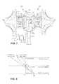
- FIG. 8illustrates an exemplary speed diagram of the compressor portion 212 , 312 , 412 , 512 , 612 , 784 , the carrier 226 , 346 , 457 , 566 , 676 , 789 , and the turbine portion 210 , 310 , 410 , 510 , 610 , 782 of the differential device 204 , 340 , 450 , 560 , 670 , 780 during three different modes of operation of the turbocharger 200 , 300 , 400 , 500 , 600 , 700 .
- a control systemin communication with the infinitely variable transmission 208 , 308 , 408 , 508 , 608 , 708 is used to control a rotational speed of the carrier 226 , 346 , 457 , 566 , 676 , 789 (and thus a rotational speed of the compressor portion 212 , 312 , 412 , 512 , 612 , 784 .
- the control systemmay adjust the infinitely variable transmission 208 , 308 , 408 , 508 , 608 , 708 based on at least one of a driver action, a speed of a vehicle the turbocharger 200 , 300 , 400 , 500 , 600 , 700 is incorporated in, a rotational speed of the compressor portion 212 , 312 , 412 , 512 , 612 , 784 , and a rotational speed of the turbine portion 210 , 310 , 410 , 510 , 610 , 782 .
- the driver actionmay a throttle adjustment.
- the three horizontal axes of FIG. 8represent respectively, from top to bottom, a rotation speed of the compressor portion 212 , 312 , 412 , 512 , 612 , 784 (and the side gear 222 , 342 , 452 , 672 , 787 or the drive ring 562 ), a rotation speed of the carrier 226 , 346 , 457 , 566 , 676 , 789 , and a rotation speed of the turbine portion 210 , 310 , 410 , 510 , 610 , 782 (and the side gear 224 , 344 , 454 , 674 , 788 or the drive ring 564 ).
- the rotation speed of the turbine portion 210 , 310 , 410 , 510 , 610 , 782is determined by the exhaust gases flowing through the turbine portion 210 , 310 , 410 , 510 , 610 , 782 .
- the rotational speed of the compressor portion 212 , 312 , 412 , 512 , 612 , 784may be varied while keeping the rotational speed of the turbine portion 210 , 310 , 410 , 510 , 610 , 782 substantially constant.
- a first mode of operation of the turbocharger 200 , 300 , 400 , 500 , 600 , 700is represented on the speed diagram at point A.
- the rotational speed of the carrier 226 , 346 , 457 , 566 , 676 , 789is substantially equal to zero, which is indicative that a ratio of the infinitely variable transmission 208 , 308 , 408 , 508 , 608 , 708 is substantially equal to zero.
- the compressor portion 212 , 312 , 412 , 512 , 612 , 784is rotating at the same speed as the turbine portion 210 , 310 , 410 , 510 , 610 , 782 , but in an opposite direction.
- a second mode of operation of the turbocharger 200 , 300 , 400 , 500 , 600 , 700is represented on the speed diagram by a range of speeds at B.
- the rotational speed of the carrier 226 , 346 , 457 , 566 , 676 , 789is a negative value (with respect to the turbine portion 210 , 310 , 410 , 510 , 610 , 782 ).
- energyis applied from the internal combustion engine 202 , 302 , 402 , 502 , 602 , 702 to accelerate the compressor portion 212 , 312 , 412 , 512 , 612 , 784 and to provide additional boost.
- Energy applied from the internal combustion engine 202 , 302 , 402 , 502 , 602 , 702reduces a turbo lag of the turbocharger 200 , 300 , 400 , 500 , 600 , 700 .
- Energy applied from the internal combustion engine 202 , 302 , 402 , 502 , 602 , 702is in addition to energy applied by the turbine portion 210 , 310 , 410 , 510 , 610 , 782 .
- the rotational speed of the carrier 226 , 346 , 457 , 566 , 676 , 789is the product of the speed of the internal combustion engine 202 , 302 , 402 , 502 , 602 , 702 , a ratio employed by the infinitely variable transmission 208 , 308 , 408 , 508 , 608 , 708 , and a ratio employed by the ratio adjusting device 206 , 306 , 406 , 506 , 606 , 706 . It is understood that each of the aforementioned ratios may be determined in order to increase an effectiveness of the turbocharger 200 , 300 , 400 , 500 , 600 , 700 .
- a third mode of operation of the turbocharger 200 , 300 , 400 , 500 , 600 , 700is represented on the speed diagram by a range of speeds at C.
- the rotational speed of the carrier 226 , 346 , 457 , 566 , 676 , 789is a positive value (with respect to the turbine portion 210 , 310 , 410 , 510 , 610 , 782 ).
- energyis applied from the turbine portion 210 , 310 , 410 , 510 , 610 , 782 to the internal combustion engine 202 , 302 , 402 , 502 , 602 , 702 .
- the amount of energy applied from the turbine portion 210 , 310 , 410 , 510 , 610 , 782is a surplus amount of energy not required by the compressor portion 212 , 312 , 412 , 512 , 612 , 784 .
- substantially all or a very large percentage of energy from the turbine portion 210 , 310 , 410 , 510 , 610 , 782is applied to the carrier 226 , 346 , 457 , 566 , 676 , 789 , the ratio adjusting device 206 , 306 , 406 , 506 , 606 , 706 , the infinitely variable transmission 208 , 308 , 408 , 508 , 608 , 708 , and the internal combustion engine 202 , 302 , 402 , 502 , 602 , 702 .
- the third mode of operationallows energy to be recuperated and to be applied to the internal combustion engine 202 , 302 , 402 , 502 , 602 , 702 , or the output 232 , 332 , 432 , 532 , 632 , 732 thereof.
- the rotational speed of the carrier 226 , 346 , 457 , 566 , 676 , 789is the product of the speed of the internal combustion engine 202 , 302 , 402 , 502 , 602 , 702 , a ratio employed by the infinitely variable transmission 208 , 308 , 408 , 508 , 608 , 708 , and a ratio employed by the ratio adjusting device 206 , 306 , 406 , 506 , 606 , 706 . It is understood that each of the aforementioned ratios may be determined in order to increase an effectiveness of the turbocharger 200 , 300 , 400 , 500 , 600 , 700 .
- the turbocharger 200 , 300 , 400 , 500 , 600 , 700 for use with the internal combustion engine 202 , 302 , 402 , 502 , 602 , 702offer many advantages over a conventional turbocharger.
- One advantage of the turbocharger 200 , 300 , 400 , 500 , 600 , 700is being able to direct the kinetic energy from the turbine portion 210 , 310 , 410 , 510 , 610 , 782 to the internal combustion engine 202 , 302 , 402 , 502 , 602 , 702 and an associated driveline (not shown).
- the internal combustion engine 202 , 302 , 402 , 502 , 602 , 702has an improved fuel economy.
- the turbocharger 200 , 300 , 400 , 500 , 600 , 700also minimizes a turbo lag by being able to apply energy from the internal combustion engine 202 , 302 , 402 , 502 , 602 , 702 to the compressor portion 212 , 312 , 412 , 512 , 612 , 784 .
- the turbocharger 200 , 300 , 400 , 500 , 600 , 700also reduces a boost threshold by being able to provide energy from the internal combustion engine 202 , 302 , 402 , 502 , 602 , 702 to the compressor portion 212 , 312 , 412 , 512 , 612 , 784 .
- the turbocharger 200 , 300 , 400 , 500 , 600 , 700also prevents a maximum boost pressure from being exceeded by being able to direct at least a portion of the energy recuperated in the turbine portion 210 , 310 , 410 , 510 , 610 , 782 to the internal combustion engine 202 , 302 , 402 , 502 , 602 , 702 .
- turbocharger 200 , 300 , 400 , 500 , 600 , 700is able to adapt a speed of the compressor portion 212 , 312 , 412 , 512 , 612 , 784 to achieve a required compression by adjusting a ratio of the infinitely variable transmission 208 , 308 , 408 , 508 , 608 , 708 .
Landscapes
- Engineering & Computer Science (AREA)
- General Engineering & Computer Science (AREA)
- Mechanical Engineering (AREA)
- Chemical & Material Sciences (AREA)
- Combustion & Propulsion (AREA)
- Theoretical Computer Science (AREA)
- Software Systems (AREA)
- Power Engineering (AREA)
- General Chemical & Material Sciences (AREA)
- Chemical Kinetics & Catalysis (AREA)
- Computer Security & Cryptography (AREA)
- General Physics & Mathematics (AREA)
- Physics & Mathematics (AREA)
- Supercharger (AREA)
- Information Transfer Between Computers (AREA)
Abstract
Description
Claims (16)
Priority Applications (2)
| Application Number | Priority Date | Filing Date | Title |
|---|---|---|---|
| US14/175,584US9404414B2 (en) | 2013-02-08 | 2014-02-07 | Internal combustion engine coupled turbocharger with an infinitely variable transmission |
| US15/209,487US9644530B2 (en) | 2013-02-08 | 2016-07-13 | Internal combustion engine coupled turbocharger with an infinitely variable transmission |
Applications Claiming Priority (2)
| Application Number | Priority Date | Filing Date | Title |
|---|---|---|---|
| US201361762379P | 2013-02-08 | 2013-02-08 | |
| US14/175,584US9404414B2 (en) | 2013-02-08 | 2014-02-07 | Internal combustion engine coupled turbocharger with an infinitely variable transmission |
Related Child Applications (1)
| Application Number | Title | Priority Date | Filing Date |
|---|---|---|---|
| US15/209,487ContinuationUS9644530B2 (en) | 2013-02-08 | 2016-07-13 | Internal combustion engine coupled turbocharger with an infinitely variable transmission |
Publications (2)
| Publication Number | Publication Date |
|---|---|
| US20140223901A1 US20140223901A1 (en) | 2014-08-14 |
| US9404414B2true US9404414B2 (en) | 2016-08-02 |
Family
ID=50189765
Family Applications (2)
| Application Number | Title | Priority Date | Filing Date |
|---|---|---|---|
| US14/175,584Expired - Fee RelatedUS9404414B2 (en) | 2013-02-08 | 2014-02-07 | Internal combustion engine coupled turbocharger with an infinitely variable transmission |
| US15/209,487Expired - Fee RelatedUS9644530B2 (en) | 2013-02-08 | 2016-07-13 | Internal combustion engine coupled turbocharger with an infinitely variable transmission |
Family Applications After (1)
| Application Number | Title | Priority Date | Filing Date |
|---|---|---|---|
| US15/209,487Expired - Fee RelatedUS9644530B2 (en) | 2013-02-08 | 2016-07-13 | Internal combustion engine coupled turbocharger with an infinitely variable transmission |
Country Status (4)
| Country | Link |
|---|---|
| US (2) | US9404414B2 (en) |
| EP (2) | EP3431734A1 (en) |
| JP (2) | JP6317371B2 (en) |
| WO (2) | WO2014124063A1 (en) |
Cited By (5)
| Publication number | Priority date | Publication date | Assignee | Title |
|---|---|---|---|---|
| US9644530B2 (en) | 2013-02-08 | 2017-05-09 | Dana Limited | Internal combustion engine coupled turbocharger with an infinitely variable transmission |
| US10006527B2 (en) | 2012-09-07 | 2018-06-26 | Dana Limited | Ball type continuously variable transmission/infinitely variable transmission |
| US10030594B2 (en) | 2015-09-18 | 2018-07-24 | Dana Limited | Abuse mode torque limiting control method for a ball-type continuously variable transmission |
| US10604009B2 (en) | 2018-05-16 | 2020-03-31 | Industrial Technology Research Institute | Dual-shaft gearbox mechanism |
| US10948049B2 (en) | 2017-05-19 | 2021-03-16 | Industrial Technology Research Institute | Transmission mechanism and one-way component thereof |
Families Citing this family (27)
| Publication number | Priority date | Publication date | Assignee | Title |
|---|---|---|---|---|
| US9347532B2 (en) | 2012-01-19 | 2016-05-24 | Dana Limited | Tilting ball variator continuously variable transmission torque vectoring device |
| CN104204615B (en) | 2012-02-15 | 2017-10-24 | 德纳有限公司 | Transmission device and the power train with tilt ball speed changer infinitely variable speed transmission |
| EP2893219A4 (en) | 2012-09-06 | 2016-12-28 | Dana Ltd | Transmission having a continuously or infinitely variable variator drive |
| CN104768787A (en) | 2012-09-07 | 2015-07-08 | 德纳有限公司 | Ball type CVT with powersplit paths |
| WO2014039708A1 (en) | 2012-09-07 | 2014-03-13 | Dana Limited | Ball type cvt including a direct drive mode |
| WO2014039713A1 (en) | 2012-09-07 | 2014-03-13 | Dana Limited | Ivt based on a ball type cvp including powersplit paths |
| US9599204B2 (en) | 2012-09-07 | 2017-03-21 | Dana Limited | Ball type CVT with output coupled powerpaths |
| US10030748B2 (en) | 2012-11-17 | 2018-07-24 | Dana Limited | Continuously variable transmission |
| CN105121905A (en) | 2013-03-14 | 2015-12-02 | 德纳有限公司 | Ball type continuously variable transmission |
| US9551404B2 (en) | 2013-03-14 | 2017-01-24 | Dana Limited | Continuously variable transmission and an infinitely variable transmission variator drive |
| US9752500B2 (en)* | 2013-03-14 | 2017-09-05 | Pratt & Whitney Canada Corp. | Gas turbine engine with transmission and method of adjusting rotational speed |
| EP3004686B1 (en) | 2013-06-06 | 2018-08-08 | Dana Limited | 3-mode front wheel drive and rear wheel drive continuously variable planetary transmission |
| WO2015073948A2 (en) | 2013-11-18 | 2015-05-21 | Dana Limited | Torque peak detection and control mechanism for cvp |
| US10030751B2 (en) | 2013-11-18 | 2018-07-24 | Dana Limited | Infinite variable transmission with planetary gear set |
| US9796477B2 (en) | 2014-11-20 | 2017-10-24 | Hamilton Sundstrand Corporation | Engine driven-shaft driven compressor utilizing infinitely variable transmission |
| US10224798B2 (en) | 2015-06-23 | 2019-03-05 | Michael F. Leas | Magnetic spiral bevel gear |
| CN106438041A (en)* | 2015-08-12 | 2017-02-22 | 熵零股份有限公司 | Blade wheel engine |
| US9664253B2 (en)* | 2015-09-11 | 2017-05-30 | Gkn Driveline North America, Inc. | Crowned profile driveshaft journal |
| CN105204915A (en)* | 2015-10-29 | 2015-12-30 | 小米科技有限责任公司 | Application program updating method, device and system |
| CN105610866A (en)* | 2016-02-18 | 2016-05-25 | 四川长虹电器股份有限公司 | System and method for automatically accessing intelligent equipment to home wireless local area network |
| US20170363098A1 (en)* | 2016-06-20 | 2017-12-21 | United Technologies Corporation | Booster compressor with speed change system |
| GB2561532B (en)* | 2017-01-30 | 2019-06-19 | Jaguar Land Rover Ltd | Waste heat recovery system |
| CN109681448A (en)* | 2018-11-06 | 2019-04-26 | 樊品良 | A kind of sky oxygen pump |
| CN110748417B (en)* | 2019-12-24 | 2020-04-10 | 沈阳微控新能源技术有限公司 | Turbocharger and engine based on magnetic coupling |
| US11480098B1 (en) | 2021-07-23 | 2022-10-25 | Mustafa Ali Al-Huwaider | Continuously variable transmission (CVT) driven supercharger through transmission output |
| US11773793B2 (en)* | 2022-02-04 | 2023-10-03 | Ford Global Technologies, Llc | Method and system for compressed air supply |
| US12392283B1 (en)* | 2024-05-15 | 2025-08-19 | Flowserve Pte. Ltd. | Energy recovery turbocharger with integral motor/generator |
Citations (238)
| Publication number | Priority date | Publication date | Assignee | Title |
|---|---|---|---|---|
| US1063244A (en) | 1908-03-18 | 1913-06-03 | Ludwig Maria Dieterich | Variable-power transmitting and controlling mechanism. |
| US1215969A (en) | 1916-12-14 | 1917-02-13 | Thomas E Murray | Sheet-metal piston. |
| US1526140A (en) | 1921-10-03 | 1925-02-10 | Hollow Ball Company Inc | Manufacture of hollow metal balls |
| US2019006A (en) | 1934-02-01 | 1935-10-29 | Ferrarl Lorenzo | Change speed gear |
| US2060884A (en) | 1933-09-19 | 1936-11-17 | Erban Operating Corp | Power transmission mechanism |
| US2405201A (en) | 1942-08-29 | 1946-08-06 | Imp Brass Mfg Co | Method of forming closed metal capsules |
| FR1030702A (en) | 1950-12-06 | 1953-06-16 | Tiltman Langley Lab Ltd | Improvements to variable speed ratio transmission mechanisms in a continuous range |
| US2660897A (en) | 1950-09-20 | 1953-12-01 | Dabo Ltd | Infinitely-variable change-speed gear |
| US2729118A (en)* | 1955-04-25 | 1956-01-03 | Lyell M Emslie | Gearless differential |
| US2931235A (en) | 1957-11-12 | 1960-04-05 | George Cohen 600 Group Ltd | Variable speed friction drive transmissions |
| US3203278A (en) | 1963-01-02 | 1965-08-31 | Ford Motor Co | Variable speed friction drive transmission |
| FR1472282A (en) | 1966-02-24 | 1967-03-10 | Chambre Syndicale Des Fabrican | Method and apparatus for transforming a section of metal tube into a sphere, and application of the sphere thus obtained to the production of assembly nodes, in particular for tubular frames |
| DE1237380B (en)* | 1958-08-13 | 1967-03-23 | Differential Diesel Engines Es | Supercharged internal combustion engine with a supercharging system with two drives |
| GB1127825A (en) | 1966-06-15 | 1968-09-18 | Filden Engineering Ltd | Improvements relating to the manufacture of spherical and spheroidal objects |
| US3407687A (en) | 1967-03-27 | 1968-10-29 | Hayashi Tadashi | Variable ratio power transmission device |
| US3470720A (en) | 1967-09-01 | 1969-10-07 | Phillip R Eklund | Method of making hollow balls for use in ball bearing and/or similar rolling operations |
| US3583060A (en) | 1968-12-30 | 1971-06-08 | Ametek Inc | Method of swaging a metal fitting on a steel wire |
| US3765270A (en) | 1971-04-26 | 1973-10-16 | Ford Motor Co | Multiple ratio power transmission mechanism with an infinitely variable overdrive range |
| US3774280A (en) | 1972-07-18 | 1973-11-27 | Us Air Force | Method of fabricating hollow balls for use in rolling contact bearing applications |
| US3831245A (en) | 1973-03-01 | 1974-08-27 | Columbus Auto Parts | Method of producing ball joints |
| US3894559A (en) | 1974-03-28 | 1975-07-15 | Leland Q Depuy | Manifold valve |
| FR2280451A1 (en) | 1974-08-01 | 1976-02-27 | Roche Jean | Hollow spherical body mfr - with tubing hot or cold spun between hemispherical dies |
| US4046988A (en) | 1976-03-05 | 1977-09-06 | Kobe Steel Ltd. | Method of preventing base metal end crack in arc welding and end tab used therefor |
| US4226140A (en) | 1976-12-14 | 1980-10-07 | Gaasenbeek Johannes L | Self-propelled vehicle |
| US4333358A (en) | 1979-12-18 | 1982-06-08 | Fiat-Allis Macchine Movimento Terra S.P.A. | Power-shift countershaft type transmission |
| US4368572A (en) | 1979-10-15 | 1983-01-18 | Toyo Kogyo Co., Ltd. | Method of manufacturing a shaft structure having a spherical bulb |
| DE3245045A1 (en) | 1982-12-06 | 1984-06-07 | Adam Opel AG, 6090 Rüsselsheim | Motor vehicle hybrid drive arrangement |
| US4464952A (en) | 1980-05-31 | 1984-08-14 | Bl Technology Limited | Control systems for continuously variable ratio transmissions (CVT) |
| EP0156936A1 (en) | 1984-04-03 | 1985-10-09 | Klinger AG | Process for producing a spherical plug for a fluid valve |
| EP0210053A2 (en) | 1985-07-22 | 1987-01-28 | Borg-Warner Corporation | Dual-pass continuously variable transmission with asymetric variator |
| US4693134A (en) | 1985-06-20 | 1987-09-15 | Excelermatic Inc. | High-powered vehicle drive train |
| US4731044A (en) | 1985-12-18 | 1988-03-15 | Borg-Warner Automotive, Inc. | Tension sensor and control arrangement for a continuously variable transmission |
| US4756211A (en) | 1985-09-13 | 1988-07-12 | Fellows Thomas G | Continuously-variable ratio transmission for an automobile vehicle |
| US4784017A (en) | 1986-07-03 | 1988-11-15 | Johnshoy Edward W | Continuously variable transmission and torque retaining differential |
| US4856371A (en) | 1987-03-12 | 1989-08-15 | Tractiontec Corporation | Traction drive transmission system |
| US4856374A (en) | 1987-03-02 | 1989-08-15 | Planetroll Antriebe Gmbh | Adjustable transmission |
| US4950208A (en) | 1988-06-17 | 1990-08-21 | Malcolm Tomlinson | Variable ratio power transmission |
| US4963122A (en) | 1987-06-04 | 1990-10-16 | The Gleason Works | Continuously variable differential |
| US4963124A (en) | 1988-10-26 | 1990-10-16 | Toyota Jidosha Kabushiski Kaisha | Planetary gear transmission for motor vehicle |
| GB2248895A (en) | 1990-09-12 | 1992-04-22 | Malcolm Tomlinson | Double toroidal race variator with two variable outputs |
| US5109962A (en) | 1989-12-28 | 1992-05-05 | Fuji Jukogyo Kabushiki Kaisha | Transmission ratio control system for a continuously variable transmission |
| US5217412A (en) | 1990-10-20 | 1993-06-08 | Luk Lamellen Und Kupplungsbau Gmbh | Continuously variable speed transmission |
| US5230670A (en) | 1990-12-25 | 1993-07-27 | Nissan Motor Co., Ltd. | Friction roller type continuously variable transmission |
| US5238460A (en) | 1991-02-28 | 1993-08-24 | Mazda Motor Corporation | Power transmission system for vehicle |
| US5318486A (en) | 1991-08-16 | 1994-06-07 | Fichtel & Sachs Ag | Driving hub for a vehicle, particularly a bicycle, with an infinitely adjustable transmission ratio |
| US5390759A (en) | 1992-08-10 | 1995-02-21 | Sauer Inc. | Driving mechanism for an automotive propel drive |
| US5401221A (en) | 1990-08-17 | 1995-03-28 | Torotrak (Development) Limited | Transmission of the toroidal-race, rolling-traction type having a mixer and a reducer epicyclic type gearing with clutches brakes |
| US5520588A (en) | 1995-05-03 | 1996-05-28 | General Motors Corporation | Power transmission |
| US5527231A (en) | 1991-06-21 | 1996-06-18 | Dr. Ing. H.C.F. Porsche Ag | Method for controlling a continuously variable transmission of a motor vehicle |
| US5577423A (en) | 1994-03-04 | 1996-11-26 | Mimura; Kenji | Differential gear |
| US5599251A (en) | 1995-09-27 | 1997-02-04 | Ford Motor Company | Six speed automatic transmission for automotive vehicles |
| JPH09119506A (en) | 1995-10-23 | 1997-05-06 | Toyota Motor Corp | Differential device |
| US5659956A (en) | 1996-02-12 | 1997-08-26 | Braginsky; Mikhail | Process for the production of hollow ball bearings |
| US5683322A (en) | 1993-04-21 | 1997-11-04 | Meyerle; Michael | Continuous hydrostatic-mechanical branch power split transmission particularly for power vehicles |
| US5726353A (en) | 1995-11-21 | 1998-03-10 | Honda Giken Kogyo Kabushiki Kaisha | System for detecting torque of automatic vehicle transmission and controlling the same based on detected torque |
| US5730678A (en) | 1996-02-28 | 1998-03-24 | Gen Dynamics Defense Syst Inc | Multi-range, hydromechanical transmission for motor vehicles |
| US5766105A (en) | 1993-12-20 | 1998-06-16 | Torotrak (Development) Limited | Continuously variable transmission capable of torque control |
| US5776028A (en) | 1995-09-01 | 1998-07-07 | Honda Giken Kogyo Kabushiki Kaisha | Belt-type continuously variable transmission |
| US5800303A (en) | 1994-11-28 | 1998-09-01 | Chrysler Corporation | Four-speed automatic transmission |
| US5860888A (en) | 1996-06-18 | 1999-01-19 | Hyundai Motor Co. | Automatic transmission with a toroidal CVT and a belt type CVT for vehicle |
| US5915801A (en) | 1995-07-18 | 1999-06-29 | Toyota Jidosha Kabushiki Kaisha | Regenerative brake controller for controlling value of regenerative braking torque simulating engine braking torque |
| US5971883A (en) | 1998-03-13 | 1999-10-26 | General Motors Corporation | Multi-speed power transmission |
| US5996226A (en) | 1997-12-23 | 1999-12-07 | Itt Manufacturing Enterprises, Inc. | Method of manufacturing push rod balls |
| US6009365A (en) | 1997-12-25 | 1999-12-28 | Nissan Motor Co., Ltd. | Vehicle drive system controller and control method |
| US6045477A (en) | 1999-06-14 | 2000-04-04 | General Motors Corporation | Continuously variable multi-range powertrain with a geared neutral |
| US6053839A (en) | 1999-06-18 | 2000-04-25 | Ford Global Technologies, Inc. | Multiple speed overdrive transmission for a motor vehicle |
| US6059685A (en) | 1999-05-06 | 2000-05-09 | Ford Global Technologies, Inc. | Coaxial traction drive automatic transmission for automotive vehicles |
| US6071208A (en) | 1998-06-22 | 2000-06-06 | Koivunen; Erkki | Compact multi-ratio automatic transmission |
| US6080080A (en) | 1997-09-30 | 2000-06-27 | Robert Bosch Gmbh | Device and method for adjusting the transmission ratio of a CVT |
| US6083135A (en) | 1999-06-18 | 2000-07-04 | Ford Global Technologies, Inc. | Multiple speed overdrive transmission for a motor vehicle |
| US6086504A (en) | 1996-04-22 | 2000-07-11 | Zf Friedrichshafen Ag | Planetary gear and clutch-brake arrangement |
| US6089287A (en) | 1995-07-20 | 2000-07-18 | Black & Decker Inc. | Portable wood planing machine |
| US6095942A (en) | 1998-08-18 | 2000-08-01 | Honda Giken Kogyo Kabushiki Kaisha | Speed change control device for vehicular continuously variable transmission |
| US6155951A (en) | 1997-01-31 | 2000-12-05 | Zf Friedrichshafen Ag | Toroidal drive |
| US6217474B1 (en) | 1999-10-22 | 2001-04-17 | General Motors Corporation | Multi speed power transmission |
| US6251038B1 (en) | 1998-10-21 | 2001-06-26 | Nsk Ltd. | Continuously variable transmission unit |
| US6273838B1 (en) | 1999-07-08 | 2001-08-14 | Hyundai Motor Company | Gear train for vehicle automatic transmissions |
| US20020004438A1 (en) | 2000-07-10 | 2002-01-10 | Nissan Motor Co., Ltd. | Input torque limiting device for an infinitely variable transmission |
| US6342026B1 (en) | 1999-07-29 | 2002-01-29 | Aisin Seiki Kabushiki Kaisha | Automatic transmission for vehicles |
| US6358178B1 (en) | 2000-07-07 | 2002-03-19 | General Motors Corporation | Planetary gearing for a geared neutral traction drive |
| US6371880B1 (en) | 1999-06-03 | 2002-04-16 | Hyundai Motor Company | Limited slip differential |
| US20020094911A1 (en) | 2001-01-16 | 2002-07-18 | Haka Raymond James | Dual mode, geared neutral continuously variable transmission |
| US6481258B1 (en) | 1997-06-18 | 2002-11-19 | Jacob S. Belinky | Removable trailer hitch ball |
| US6554735B2 (en) | 2000-09-28 | 2003-04-29 | Fuji Jukogyo Kabushiki Kaisha | Planetary gear type differential apparatus |
| US6558285B1 (en) | 1999-06-26 | 2003-05-06 | Robert Bosch Gmbh | Friction-wheel planetary gear with bevel gears |
| US6585619B2 (en) | 2000-08-11 | 2003-07-01 | Daimler Chrysler Ag | Transmission arrangement |
| US6609994B2 (en) | 2001-03-16 | 2003-08-26 | Nissan Motor Co., Ltd. | Braking/driving control apparatus and method for automotive vehicle |
| US20030181280A1 (en) | 2002-02-15 | 2003-09-25 | Daimlerchrysler Ag | Motor vehicle transmission with a toroidal variable-speed drive unit |
| US20030200783A1 (en) | 2002-04-26 | 2003-10-30 | Dean Shai | Hollow tubular blank provided in wall thereof with one or more reinforcing ribs |
| US6641497B2 (en) | 2001-12-07 | 2003-11-04 | Murray, Inc. | Epicyclic transmission for zero turning radius vehicles |
| US6645106B2 (en) | 2000-08-22 | 2003-11-11 | Teak-Seo Goo | Transmission for performing reliable continuously-variable-speed operation through gear meshing, and vehicle-use continuously-variable transmission device using it |
| US20030213125A1 (en) | 2002-05-20 | 2003-11-20 | Su-Yueh Chiuchang | Ball valve body manufacturing method |
| US20030216121A1 (en) | 2001-10-11 | 2003-11-20 | Mark Yarkosky | Method for in-building distribution using wireless access technology |
| US20030228952A1 (en) | 2002-06-05 | 2003-12-11 | Nissan Motor Co., Ltd. | Toroidal continuously variable transmission control apparatus |
| US6705964B2 (en) | 2001-12-11 | 2004-03-16 | Jatco Ltd | Power transmission system |
| US20040058769A1 (en) | 2002-09-23 | 2004-03-25 | Larkin Robert P. | Multi-range parallel-hybrid continuously variable transmission |
| US20040061639A1 (en) | 2000-11-11 | 2004-04-01 | Klaus Voigtlaender | Radar device and method for operating a radar device |
| US6719659B2 (en) | 2000-05-05 | 2004-04-13 | Daimlerchrysler Ag | Continuously variable vehicle transmission |
| US6723016B2 (en) | 2001-09-27 | 2004-04-20 | Jatco Ltd | Torque split infinitely variable transmission |
| US6726590B2 (en) | 2001-04-28 | 2004-04-27 | Daimlerchrysler Ag | Speed change transmission arrangement including a continuously variable toroidal transmission |
| US6733412B2 (en) | 2001-05-21 | 2004-05-11 | Honda Giken Kogyo Kabushiki Kaisha | Automotive automatic transmission |
| US6752696B2 (en) | 2001-03-12 | 2004-06-22 | Nsk Ltd. | Rolling elements for rolling bearing, method of producing the same, and rolling bearing |
| US20040166984A1 (en) | 2002-12-05 | 2004-08-26 | Nsk Ltd. | Continuously variable transmission apparatus |
| US20040171452A1 (en) | 2003-02-28 | 2004-09-02 | Miller Donald C. | Continuously variable transmission |
| US6793603B2 (en) | 2001-10-25 | 2004-09-21 | Tochigi Fuji Sangyo Kabushiki Kaisha | Power transmission system with sub transmission mechanism |
| US6849020B2 (en) | 2002-08-07 | 2005-02-01 | Jatco Ltd | Continuously variable power-split transmission |
| US6866606B2 (en) | 2001-10-25 | 2005-03-15 | Honda Giken Kogyo Kabushiki Kaisha | Continuously variable transmission system for vehicles |
| US20050102082A1 (en) | 2003-11-12 | 2005-05-12 | Nissan Motor Co., Ltd. | Shift control system of hybrid transmission |
| US20050137046A1 (en) | 2003-08-11 | 2005-06-23 | Miller Donald C. | Continuously variable planetary gear set |
| US6949045B2 (en) | 2002-10-24 | 2005-09-27 | Zf Friedrichshafen Ag | Power distributed 2-range transmission |
| US6979275B2 (en) | 2001-05-14 | 2005-12-27 | Nissan Motor Co., Ltd. | Auxiliary transmission in transmission system |
| WO2006002457A1 (en) | 2004-07-06 | 2006-01-12 | Bruce Winston Brockhoff | Solar collector |
| WO2006041718A2 (en) | 2004-10-05 | 2006-04-20 | Fallbrook Technologies, Inc. | Continuously variable transmission |
| US7033298B2 (en) | 2002-12-18 | 2006-04-25 | General Motors Corporation | Family of five-speed dual-clutch transmissions having three planetary gear sets |
| US7074154B2 (en) | 1998-08-12 | 2006-07-11 | Fallbrook Technologies Inc. | Continuously variable transmission |
| US7104917B2 (en) | 2004-09-28 | 2006-09-12 | General Motors Corporation | Countershaft planetary transmissions |
| DE102005010751A1 (en) | 2005-03-09 | 2006-09-14 | Zf Friedrichshafen Ag | Differential transmission unit for four-wheel drive vehicle, employs variator drive principle to distribute input power between front and rear wheels |
| US7128681B2 (en) | 2003-11-12 | 2006-10-31 | Honda Motor Co., Ltd. | Transmission |
| US7160220B2 (en) | 2003-07-14 | 2007-01-09 | Nsk Ltd. | Continuously variable transmission apparatus |
| US20070032327A1 (en) | 2005-08-03 | 2007-02-08 | Madhusudan Raghavan | Electrically variable transmission having two or three planetary gear sets with two or three fixed interconnections |
| US20070042856A1 (en) | 2003-07-01 | 2007-02-22 | Greenwood Christopher J | Continuously variable ratio transmission system |
| US7186199B1 (en) | 2004-10-29 | 2007-03-06 | Torque-Traction Technologies. Llc. | Torque vectoring gear drive apparatus |
| US20070072732A1 (en) | 2005-09-23 | 2007-03-29 | Donald Klemen | Nine speed automatic transmission with six torque-transmitting mechanisms |
| WO2007046722A1 (en) | 2005-10-18 | 2007-04-26 | Champlon Joao Armando Soledade | Continuously variable transmission (cvt) through gears |
| US20070096556A1 (en) | 2005-10-28 | 2007-05-03 | Koichi Kokubo | Automatic braking apparatus for a vehicle |
| WO2007051827A1 (en) | 2005-11-02 | 2007-05-10 | Infinitrak, Llc | Continuously variable ratio transmission drive |
| US7234543B2 (en) | 2003-04-25 | 2007-06-26 | Intersyn Ip Holdings, Llc | Systems and methods for directionally drilling a borehole using a continuously variable transmission |
| US7288044B2 (en) | 2003-04-04 | 2007-10-30 | Zf Friedrichshafen Ag | Transmission, in particular an automated power-branched multi-speed gearing |
| US20070275808A1 (en) | 2006-05-25 | 2007-11-29 | Aisin Aw Co., Ltd. | Hybrid drive device |
| US7335126B2 (en) | 2005-02-23 | 2008-02-26 | Kabushikikaisha Equos Research | Continuously variable transmission |
| US7347801B2 (en) | 2004-04-30 | 2008-03-25 | Getrag Getriebe-Und Zahnradfabrik Hermann Hagenmeyer Gmbh & Cie Kg | Toroidal transmission |
| US20080103002A1 (en) | 2006-10-25 | 2008-05-01 | Holmes Alan G | Hybrid electrically variable transmission with dual power paths and selective motor connection |
| US7396309B2 (en) | 2005-05-31 | 2008-07-08 | Zf Friedrichshafen Ag | Split power transmission to include a variable drive |
| US20080185201A1 (en) | 2004-12-22 | 2008-08-07 | Timothy Bishop | Spring Hybrid Drive |
| JP2008180214A (en) | 2006-12-28 | 2008-08-07 | Toyota Motor Corp | Camshaft torque reduction mechanism for internal combustion engine |
| WO2008103543A1 (en) | 2007-02-23 | 2008-08-28 | Gm Global Technology Operations, Inc. | Low cost torque vectoring system |
| US7473202B2 (en) | 2005-04-15 | 2009-01-06 | Eaton Corporation | Continuously variable dual mode transmission |
| FR2918433A1 (en) | 2007-07-05 | 2009-01-09 | Peugeot Citroen Automobiles Sa | Transmission component for e.g. automobile, has hydraulic control system for controlling inclination of pivoting axis of each roller to control distribution of engine torques transmitted to disks |
| US20090017959A1 (en) | 2007-06-21 | 2009-01-15 | Luk Lamellen Und Kupplungsbau Beteiligungs Kg | Vehicle transmission with continuously variable transmission ratio |
| US7485069B2 (en) | 2006-07-20 | 2009-02-03 | Hyundai Motor Company | Power train of automatic transmission |
| US7497798B2 (en) | 2006-09-21 | 2009-03-03 | Hyundai Motor Company | Hybrid power train structure using toroidal variator |
| US20090062064A1 (en) | 2007-08-31 | 2009-03-05 | Toyota Jidosha Kabushiki Kaisha | Shift control apparatus |
| US20090132135A1 (en) | 2007-11-16 | 2009-05-21 | Fallbrook Technologies Inc. | Controller for variable transmission |
| US20090221393A1 (en) | 2005-09-29 | 2009-09-03 | Magna Steyr Fahrzeugtechnik Ag & Co Kg | Differential Gearing Unit For Motor Vehicles With Active Control Of The Drive Force Distribution |
| US20090221391A1 (en) | 2008-02-29 | 2009-09-03 | Fallbrook Technologies Inc. | Continuously and/or infinitely variable transmissions and methods therefor |
| US7588514B2 (en) | 2005-12-27 | 2009-09-15 | Eaton Corporation | Method for controlling engine braking in a vehicle powertrain |
| US20090286651A1 (en) | 2008-05-13 | 2009-11-19 | Kawasaki Jukogyo Kabushiki Kaisha | Starting and generating apparatus for engine |
| US20090312137A1 (en) | 2002-09-30 | 2009-12-17 | Ulrich Rohs | Transmission |
| US7637838B2 (en) | 2006-02-14 | 2009-12-29 | Zf Friedrichshafen Ag | Multi-speed transmission |
| CN101617146A (en) | 2007-02-21 | 2009-12-30 | 托罗特拉克(开发)有限公司 | Stepless speed change transmission device |
| US7672770B2 (en) | 2005-06-15 | 2010-03-02 | Toyota Jidosha Kabushiki Kaisha | Deceleration control apparatus for a vehicle |
| US20100056322A1 (en) | 2008-08-26 | 2010-03-04 | Fallbrook Technologies Inc. | Continuously variable transmission |
| US20100093479A1 (en) | 2007-02-12 | 2010-04-15 | Fallbrook Technologies Inc. | Continuously variable transmissions and methods therefor |
| US20100106386A1 (en) | 2006-12-18 | 2010-04-29 | Peugeot Citroen Automobiles S.A. | Method for braking a hybrid vehicle and method for improving a hybrid vehicle implementing said method |
| US20100113211A1 (en) | 2007-02-26 | 2010-05-06 | Gif Gesellschaft Fur Industrieforschung Mbh | Drive arrangement with an infinitely variable sub-gear box |
| US7717815B2 (en) | 2005-07-23 | 2010-05-18 | Luk Lamellen Und Kupplungsbau Beteiligings Kg | Power-branched transmission having a plurality of transmission ration ranges with continuously variable transmission ratio |
| US20100137094A1 (en) | 2007-04-24 | 2010-06-03 | Fallbrook Technologies Inc. | Electric traction drives |
| US20100141193A1 (en) | 2008-12-04 | 2010-06-10 | Paola Rotondo | Torsional mode damping apparatus |
| US7780566B2 (en) | 2007-05-08 | 2010-08-24 | Hyundai Motor Company | 8-speed automatic transmission for a vehicle |
| US20100244755A1 (en) | 2009-03-30 | 2010-09-30 | Aisin Aw Co., Ltd. | Rotary electric machine control device |
| US20100267510A1 (en) | 2009-04-16 | 2010-10-21 | Fallbrook Technologies Inc. | Continuously variable transmission |
| US20100282020A1 (en) | 2007-09-04 | 2010-11-11 | Christopher John Greenwood | Continuously variable transmission |
| US20100304915A1 (en) | 2006-04-10 | 2010-12-02 | Derek Lahr | Cam-based infinitely variable transmission |
| US20100310815A1 (en) | 2008-02-01 | 2010-12-09 | Omnidea, Lda. | Plastic deformation technological process for production of thin wall revolution shells from tubular billets |
| US20110015021A1 (en) | 2009-07-16 | 2011-01-20 | Gm Global Technology Operations, Inc. | Clutch arrangements for an electrically-variable transmission |
| US7874153B2 (en) | 2005-12-16 | 2011-01-25 | Bosch Rexroth Ag | Hydrostatic drive and method of braking a hydrostatic drive |
| US7878935B2 (en) | 2007-11-26 | 2011-02-01 | Derek Lahr | Continuously variable transmission with external cam |
| WO2011011991A1 (en) | 2009-07-31 | 2011-02-03 | 中兴通讯股份有限公司 | Method and apparatus for network elements in lan to obtain service content |
| US20110034284A1 (en) | 2005-12-30 | 2011-02-10 | Fallbrook Technologies Inc. | Continuously variable transmission |
| US7951035B2 (en) | 2008-02-07 | 2011-05-31 | American Axle & Manufacturing, Inc. | Continuously variable torque vectoring axle assembly |
| US20110152031A1 (en) | 2009-12-16 | 2011-06-23 | Brian Schoolcraft | System and method for controlling endload force of a variator |
| US20110165982A1 (en) | 2010-07-22 | 2011-07-07 | Ford Global Technologies, Llc | Accessory Drive and Engine Restarting System |
| US20110165985A1 (en) | 2010-12-07 | 2011-07-07 | Ford Global Technologies, Llc | Transmission Producing Continuously Variable Speed Ratios |
| US20110165986A1 (en) | 2010-07-19 | 2011-07-07 | Ford Global Technologies, Llc | Transmission Producing Continuously Speed Ratios |
| US7980972B1 (en) | 2006-05-01 | 2011-07-19 | Purdue Research Foundation | Roller variator for actuating continuously variable transmissions |
| JP2011153583A (en) | 2010-01-28 | 2011-08-11 | Toyota Central R&D Labs Inc | Supercharger |
| US20110230297A1 (en) | 2010-03-18 | 2011-09-22 | Toyota Jidosha Kabushiki Kaisha | Continuously variable transmission |
| US8029401B2 (en) | 2008-10-31 | 2011-10-04 | Deere & Company | Split path power shift transmission |
| AU2011224083A1 (en) | 2004-10-05 | 2011-10-06 | Fallbrook Intellectual Property Company Llc | Continuously Variable Transmission |
| US8052569B2 (en) | 2005-10-26 | 2011-11-08 | Toyota Jidosha Kabushiki Kaisha | Controller of power transmission |
| US8062175B2 (en) | 2008-11-04 | 2011-11-22 | GM Global Technology Operations LLC | Method and apparatus for optimizing braking control during a threshold braking event |
| US20110319222A1 (en) | 2009-02-10 | 2011-12-29 | Toyota Jidosha Kabushiki Kaisha | Continuously variable transmission mechanism and transmission using the same |
| WO2012008884A1 (en) | 2010-07-16 | 2012-01-19 | Volvo Construction Equipment Ab | Continuously variable transmission and a working maching including a continuously variable transmission |
| US20120024991A1 (en) | 2010-08-02 | 2012-02-02 | Techtronic Floor Care Technology Limited | Force responsive shredder |
| US20120040794A1 (en) | 2010-08-16 | 2012-02-16 | Brian Schoolcraft | Gear scheme for infinitely variable transmission |
| US8142323B2 (en) | 2005-03-31 | 2012-03-27 | Torotrak (Development) Limited | Continuously variable transmission |
| US20120122624A1 (en) | 2010-11-15 | 2012-05-17 | Hawkins Jr Glen S | Input Clutch Assembly For Infinitely Variable Transmission |
| US20120142477A1 (en) | 2009-05-19 | 2012-06-07 | Torotrak (Development) Limited | Continuously variable ratio transmission |
| US20120165154A1 (en) | 2010-12-22 | 2012-06-28 | GM Global Technology Operations LLC | Planetary layshaft transmission |
| US8226518B2 (en) | 2005-06-06 | 2012-07-24 | Power Gear S.L. | Continually variable transmission |
| US8257216B2 (en) | 2010-01-14 | 2012-09-04 | Ford Global Technologies, Llc | Infinitely variable transmission |
| US8257217B2 (en) | 2009-02-03 | 2012-09-04 | Ford Global Technologies, Llc | Infinitely variable transmission with offset output shaft |
| US20120244990A1 (en) | 2009-12-02 | 2012-09-27 | Toyota Jidosha Kabushiki Kaisha | Continuously variable transmission |
| US8287414B2 (en) | 2007-10-02 | 2012-10-16 | Zf Friedrichshafen Ag | Transmission device having a variator |
| US8313404B2 (en) | 2007-02-16 | 2012-11-20 | Fallbrook Intellectual Property Company Llc | Infinitely variable transmissions, continuously variable transmissions, methods, assemblies, subassemblies, and components therefor |
| WO2012177187A1 (en) | 2011-06-21 | 2012-12-27 | Volvo Construction Equipment Ab | A method for controlling a power split continuously variable transmission and a power split continuously variable transmission |
| US8382636B2 (en) | 2009-12-02 | 2013-02-26 | Toyota Jidosha Kabushiki Kaisha | Continuously variable transmission |
| US20130130859A1 (en) | 2011-11-21 | 2013-05-23 | GM Global Technology Operations LLC | Two-mode continuously variable transmission |
| US20130133965A1 (en) | 2011-11-30 | 2013-05-30 | Martin T. Books | Vehicle braking management for a hybrid power train system |
| US20130184115A1 (en) | 2012-01-12 | 2013-07-18 | Shimano Inc. | Continuously variable bicycle transmission |
| US20130190131A1 (en) | 2012-01-19 | 2013-07-25 | Dana Limited | Tilting ball variator continuously variable transmission torque vectoring device |
| WO2013123117A1 (en) | 2012-02-15 | 2013-08-22 | Dana Limited | Transmission and driveline having a tilting ball variator continuously variable transmission |
| US20130226416A1 (en) | 2012-02-28 | 2013-08-29 | Caterpillar Inc. | Multi-range hydro-mechanical transmission |
| US8545368B1 (en) | 2012-11-01 | 2013-10-01 | Caterpillar Inc. | Regulation of a machine with a continuously variable transmission and service brakes |
| US20130304344A1 (en) | 2011-01-21 | 2013-11-14 | Toyota Jidosha Kabushiki Kaisha | Vehicle control apparatus |
| US20130303325A1 (en) | 2012-05-09 | 2013-11-14 | GM Global Technology Operations LLC | Toroidal traction drive transmission |
| US8594867B2 (en) | 2007-11-04 | 2013-11-26 | GM Global Technology Operations LLC | System architecture for a blended braking system in a hybrid powertrain system |
| US8639419B2 (en) | 2008-09-19 | 2014-01-28 | Cnh America Llc | Agricultural vehicle with a continuously variable transmission |
| WO2014039900A1 (en) | 2012-09-07 | 2014-03-13 | Dana Limited | Ball type cvt with powersplit paths |
| WO2014039440A1 (en) | 2012-09-07 | 2014-03-13 | Dana Limited | Cvt based on a ball type cvp including powersplit paths through a bevel gear |
| WO2014039438A2 (en) | 2012-09-06 | 2014-03-13 | Dana Limited | Cvt variator ball and method of construction thereof |
| WO2014039713A1 (en) | 2012-09-07 | 2014-03-13 | Dana Limited | Ivt based on a ball type cvp including powersplit paths |
| WO2014039708A1 (en) | 2012-09-07 | 2014-03-13 | Dana Limited | Ball type cvt including a direct drive mode |
| WO2014039447A1 (en) | 2012-09-06 | 2014-03-13 | Dana Limited | Transmission having a continuously or infinitely variable variator drive |
| WO2014039901A1 (en) | 2012-09-07 | 2014-03-13 | Dana Limited | Ball type continuously variable transmission/ infinitely variable transmission |
| WO2014039439A1 (en) | 2012-09-07 | 2014-03-13 | Dana Limited | Ball type cvt/ivt including planetary gear sets |
| WO2014039448A2 (en) | 2012-09-07 | 2014-03-13 | Dana Limited | Ball type cvt with output coupled powerpaths |
| WO2014039846A2 (en) | 2012-09-07 | 2014-03-13 | Dana Limited | Active torque ripple rectifier |
| US8678975B2 (en) | 2010-08-05 | 2014-03-25 | Honda Motor Co., Ltd. | Vehicle braking system |
| WO2014078583A1 (en) | 2012-11-17 | 2014-05-22 | Dana Limited | Continuously variable transmission |
| WO2014124291A1 (en) | 2013-02-08 | 2014-08-14 | Dana Limited | Internal combustion engine coupled turbocharger with an infinitely variable transmission |
| US20140274552A1 (en) | 2013-03-14 | 2014-09-18 | Dana Limited | Cvt variator ball and method of construction thereof |
| WO2014159755A2 (en) | 2013-03-14 | 2014-10-02 | Dana Limited | Ball type continuously variable transmission |
| WO2014159756A2 (en) | 2013-03-14 | 2014-10-02 | Dana Limited | Continuously variable transmission and an infinitely variable transmission variatory drive |
| WO2014165259A1 (en) | 2013-03-13 | 2014-10-09 | Dana Limited | Transmission with cvt and ivt variator drive |
| US8870711B2 (en) | 2008-10-14 | 2014-10-28 | Fallbrook Intellectual Property Company Llc | Continuously variable transmission |
| WO2014179719A1 (en) | 2013-05-03 | 2014-11-06 | Dana Limited | 4-mode rear wheel drive continuously variable planetary transmission |
| WO2014179717A1 (en) | 2013-05-03 | 2014-11-06 | Dana Limited | Dual-mode synchronous shift continuousley variable transmission |
| US8888643B2 (en) | 2010-11-10 | 2014-11-18 | Fallbrook Intellectual Property Company Llc | Continuously variable transmission |
| WO2014186732A1 (en) | 2013-05-17 | 2014-11-20 | Dana Limited | 3-mode front-wheel drive continuously variable planetary transmission with stacked gearsets |
| WO2014197711A1 (en) | 2013-06-06 | 2014-12-11 | Dana Limited | 3-mode front wheel drive and rear wheel drive continuously variable planetary transmission |
| US20150024899A1 (en) | 2013-07-18 | 2015-01-22 | Dana Limited | Variable-radius contact geometry for traction drives |
| WO2015059601A1 (en) | 2013-10-21 | 2015-04-30 | Rubinetterie Utensilerie Bonomi S.R.L. | Assembly, precursor and process for forming hollow bodies |
| WO2015073948A2 (en) | 2013-11-18 | 2015-05-21 | Dana Limited | Torque peak detection and control mechanism for cvp |
| WO2015073883A1 (en) | 2013-11-18 | 2015-05-21 | Dana Limited | Infinite variable transmission with planetary gear set |
| US20150142281A1 (en) | 2013-11-18 | 2015-05-21 | Dana Limited | Braking management system for a transmission incorporating a cvp |
| US9114799B2 (en) | 2012-10-09 | 2015-08-25 | Kanzaki Kokyukoki Mfg. Co., Ltd. | Brake system for vehicle including continuously variable belt transmission |
| US9156463B2 (en) | 2011-05-18 | 2015-10-13 | Zf Friedrichshafen Ag | Vehicle and method for operating a vehicle |
Family Cites Families (44)
| Publication number | Priority date | Publication date | Assignee | Title |
|---|---|---|---|---|
| FR796188A (en) | 1935-10-04 | 1936-03-31 | Friction shifting | |
| US2148759A (en) | 1938-02-10 | 1939-02-28 | Grand Cecil W Le | Variable transmission unit |
| US3376633A (en) | 1966-04-20 | 1968-04-09 | Richard H. Wesley | Ball joint forming methods |
| US3505718A (en) | 1968-01-15 | 1970-04-14 | Gen Ind Inc | One-piece sheet metal hollow ball for ball valves |
| US3688600A (en) | 1971-04-26 | 1972-09-05 | Ford Motor Co | Infinitely variable overdrive transmission mechanism |
| FR2185076A5 (en) | 1972-05-16 | 1973-12-28 | Burke John | |
| JPS5266804U (en)* | 1975-11-14 | 1977-05-18 | ||
| US4187709A (en) | 1976-08-23 | 1980-02-12 | Kevin Strickland | Explosive forming |
| US4344336A (en) | 1979-07-23 | 1982-08-17 | Ford Motor Company | Differential traction drive with extreme overall torque ratios for use in a gas turbine engine driveline |
| US4360090A (en) | 1980-10-20 | 1982-11-23 | General Motors Corporation | Torque reversal control valve for a torque converter clutch |
| GB2196892B (en) | 1986-11-05 | 1990-01-17 | Concentric Pumps Ltd | Fixing components on shafts |
| JPH04357347A (en)* | 1991-05-31 | 1992-12-10 | Fuji Oozx Kk | power transmission device |
| US5168778A (en) | 1991-08-29 | 1992-12-08 | Borg-Warner Automotive, Inc. | CVT downshift control strategy to minimize slip at the drive pulley |
| US6036616A (en) | 1998-03-19 | 2000-03-14 | Ford Global Technologies, Inc. | All wheel drive continously variable transmission having dual mode operation |
| US5961415A (en) | 1998-09-17 | 1999-10-05 | Ford Global Technologies, Inc. | Single cavity toroidal traction drive continually variable transmission |
| DE19844618A1 (en) | 1998-09-29 | 2000-03-30 | Zahnradfabrik Friedrichshafen | Method for reducing the thermal load on an automatic transmission for a motor vehicle in an emergency mode |
| KR100854795B1 (en) | 2001-04-26 | 2008-08-27 | 모션 테크놀로지즈 엘엘씨 | Device for speed ratio adjustment of roller traction transmission and continuous variable transmission |
| US7720522B2 (en) | 2003-02-25 | 2010-05-18 | Medtronic, Inc. | Fiducial marker devices, tools, and methods |
| US6986725B2 (en) | 2002-11-01 | 2006-01-17 | Eaton Corporation | Continuously variable stepped transmission |
| DE10358114A1 (en) | 2002-12-23 | 2004-07-01 | Luk Lamellen Und Kupplungsbau Beteiligungs Kg | Power-branched gearbox with continuously adjustable ratio has at least two ratio ranges that differ only in conversion ratio between input shaft of parallel discrete gearbox and output shaft |
| US7086981B2 (en) | 2004-02-18 | 2006-08-08 | The Gates Corporation | Transmission and constant speed accessory drive |
| US8182351B2 (en) | 2004-10-29 | 2012-05-22 | Ronjo Llc | Universal joint assembly for an automotive driveline system |
| WO2006050151A2 (en) | 2004-10-29 | 2006-05-11 | Ronjo Company | A universal joint assembly for an automotive driveline system |
| US7238135B2 (en) | 2005-06-03 | 2007-07-03 | Gm Global Technology Operations, Inc. | Three-mode continuously variable transmission with a direct low mode and two split path high modes |
| KR20080087781A (en)* | 2005-09-21 | 2008-10-01 | 퀵커, 인크. | Device aware content delivery |
| US7311634B2 (en) | 2005-09-28 | 2007-12-25 | Hyundai Motor Company | Seven-speed powertrain of an automatic transmission for vehicles |
| PL2089642T3 (en) | 2006-11-08 | 2013-09-30 | Fallbrook Ip Co Llc | Clamping force generator |
| JP5173459B2 (en) | 2008-01-31 | 2013-04-03 | 本田技研工業株式会社 | Shift control method for continuously variable transmission |
| US20100031935A1 (en)* | 2008-08-05 | 2010-02-11 | Vandyne Ed | Super-turbocharger having a high speed traction drive and a continuously variable transmission |
| WO2011071529A1 (en)* | 2009-12-08 | 2011-06-16 | Hydracharge Llc | Hydraulic turbo accelerator apparatus |
| WO2012018644A1 (en)* | 2010-07-26 | 2012-02-09 | Vandyne Super Turbo, Inc. | Superturbocharger control systems |
| US8622871B2 (en) | 2010-12-20 | 2014-01-07 | Caterpillar Inc. | Control arrangement and method of controlling a transmission in a machine |
| DE112012000506B4 (en) | 2011-01-19 | 2021-02-18 | Vandyne Superturbo, Inc. | High-torque traction drive |
| CN202165536U (en) | 2011-06-30 | 2012-03-14 | 长城汽车股份有限公司 | Automatic transmission with six forward gears and reverse gear |
| US20130174544A1 (en)* | 2012-01-05 | 2013-07-11 | Vincent Valetutti | Electric Supercharged Co-Power Hybrid Vehicle |
| CN104302949B (en) | 2012-01-23 | 2017-05-03 | 福博科知识产权有限责任公司 | Infinitely variable continuously variable transmission, continuously variable continuously variable transmission, method, assembly, subassembly, and parts thereof |
| US9103249B2 (en)* | 2012-02-29 | 2015-08-11 | Caterpillar Inc. | Flywheel mechanical energy derived from engine exhaust heat |
| US9429232B2 (en) | 2012-06-15 | 2016-08-30 | Allison Transmission, Inc. | Redundant controls for a multi-mode transmission |
| CN105452727B (en) | 2013-03-15 | 2019-01-01 | 艾里逊变速箱公司 | The structure of the stepless transmission device that decomposes the power |
| JP5941882B2 (en) | 2013-08-08 | 2016-06-29 | ジヤトコ株式会社 | Shift control device for continuously variable transmission |
| CN106536987A (en) | 2014-06-17 | 2017-03-22 | 德纳有限公司 | Off-highway continuously variable planetary-based multimore transmission including infinite variable transmission and direct continuously variable tranmission |
| EP3161347A4 (en) | 2014-06-27 | 2018-04-11 | Dana Limited | 4-mode powersplit transmission based on continuously variable planetary technology |
| US9644721B2 (en) | 2014-10-17 | 2017-05-09 | Allison Transmission, Inc. | Split power infinitely variable transmission architecture incorporating a planetary type ball variator with multiple fixed ranges and low variator load at vehicle launch |
| JP2017537285A (en) | 2014-12-08 | 2017-12-14 | ダナ リミテッド | Three-mode planetary mechanism continuously variable transmission for front wheel drive and rear wheel drive |
- 2014
- 2014-02-06WOPCT/US2014/014970patent/WO2014124063A1/enactiveApplication Filing
- 2014-02-07WOPCT/US2014/015352patent/WO2014124291A1/enactiveApplication Filing
- 2014-02-07USUS14/175,584patent/US9404414B2/ennot_activeExpired - Fee Related
- 2014-02-07EPEP18193076.9Apatent/EP3431734A1/ennot_activeWithdrawn
- 2014-02-07JPJP2015557132Apatent/JP6317371B2/enactiveActive
- 2014-02-07EPEP14707270.6Apatent/EP2954180B1/ennot_activeNot-in-force
- 2016
- 2016-07-13USUS15/209,487patent/US9644530B2/ennot_activeExpired - Fee Related
- 2018
- 2018-03-29JPJP2018064898Apatent/JP2018135887A/enactivePending
Patent Citations (266)
| Publication number | Priority date | Publication date | Assignee | Title |
|---|---|---|---|---|
| US1063244A (en) | 1908-03-18 | 1913-06-03 | Ludwig Maria Dieterich | Variable-power transmitting and controlling mechanism. |
| US1215969A (en) | 1916-12-14 | 1917-02-13 | Thomas E Murray | Sheet-metal piston. |
| US1526140A (en) | 1921-10-03 | 1925-02-10 | Hollow Ball Company Inc | Manufacture of hollow metal balls |
| US2060884A (en) | 1933-09-19 | 1936-11-17 | Erban Operating Corp | Power transmission mechanism |
| US2019006A (en) | 1934-02-01 | 1935-10-29 | Ferrarl Lorenzo | Change speed gear |
| US2405201A (en) | 1942-08-29 | 1946-08-06 | Imp Brass Mfg Co | Method of forming closed metal capsules |
| US2660897A (en) | 1950-09-20 | 1953-12-01 | Dabo Ltd | Infinitely-variable change-speed gear |
| FR1030702A (en) | 1950-12-06 | 1953-06-16 | Tiltman Langley Lab Ltd | Improvements to variable speed ratio transmission mechanisms in a continuous range |
| US2729118A (en)* | 1955-04-25 | 1956-01-03 | Lyell M Emslie | Gearless differential |
| US2931235A (en) | 1957-11-12 | 1960-04-05 | George Cohen 600 Group Ltd | Variable speed friction drive transmissions |
| DE1237380B (en)* | 1958-08-13 | 1967-03-23 | Differential Diesel Engines Es | Supercharged internal combustion engine with a supercharging system with two drives |
| US3203278A (en) | 1963-01-02 | 1965-08-31 | Ford Motor Co | Variable speed friction drive transmission |
| FR1472282A (en) | 1966-02-24 | 1967-03-10 | Chambre Syndicale Des Fabrican | Method and apparatus for transforming a section of metal tube into a sphere, and application of the sphere thus obtained to the production of assembly nodes, in particular for tubular frames |
| GB1127825A (en) | 1966-06-15 | 1968-09-18 | Filden Engineering Ltd | Improvements relating to the manufacture of spherical and spheroidal objects |
| US3407687A (en) | 1967-03-27 | 1968-10-29 | Hayashi Tadashi | Variable ratio power transmission device |
| US3470720A (en) | 1967-09-01 | 1969-10-07 | Phillip R Eklund | Method of making hollow balls for use in ball bearing and/or similar rolling operations |
| US3583060A (en) | 1968-12-30 | 1971-06-08 | Ametek Inc | Method of swaging a metal fitting on a steel wire |
| US3765270A (en) | 1971-04-26 | 1973-10-16 | Ford Motor Co | Multiple ratio power transmission mechanism with an infinitely variable overdrive range |
| US3774280A (en) | 1972-07-18 | 1973-11-27 | Us Air Force | Method of fabricating hollow balls for use in rolling contact bearing applications |
| US3831245A (en) | 1973-03-01 | 1974-08-27 | Columbus Auto Parts | Method of producing ball joints |
| US3894559A (en) | 1974-03-28 | 1975-07-15 | Leland Q Depuy | Manifold valve |
| FR2280451A1 (en) | 1974-08-01 | 1976-02-27 | Roche Jean | Hollow spherical body mfr - with tubing hot or cold spun between hemispherical dies |
| US4046988A (en) | 1976-03-05 | 1977-09-06 | Kobe Steel Ltd. | Method of preventing base metal end crack in arc welding and end tab used therefor |
| US4226140A (en) | 1976-12-14 | 1980-10-07 | Gaasenbeek Johannes L | Self-propelled vehicle |
| US4368572A (en) | 1979-10-15 | 1983-01-18 | Toyo Kogyo Co., Ltd. | Method of manufacturing a shaft structure having a spherical bulb |
| US4333358A (en) | 1979-12-18 | 1982-06-08 | Fiat-Allis Macchine Movimento Terra S.P.A. | Power-shift countershaft type transmission |
| US4464952A (en) | 1980-05-31 | 1984-08-14 | Bl Technology Limited | Control systems for continuously variable ratio transmissions (CVT) |
| DE3245045A1 (en) | 1982-12-06 | 1984-06-07 | Adam Opel AG, 6090 Rüsselsheim | Motor vehicle hybrid drive arrangement |
| EP0156936A1 (en) | 1984-04-03 | 1985-10-09 | Klinger AG | Process for producing a spherical plug for a fluid valve |
| US4693134A (en) | 1985-06-20 | 1987-09-15 | Excelermatic Inc. | High-powered vehicle drive train |
| EP0210053A2 (en) | 1985-07-22 | 1987-01-28 | Borg-Warner Corporation | Dual-pass continuously variable transmission with asymetric variator |
| US4756211A (en) | 1985-09-13 | 1988-07-12 | Fellows Thomas G | Continuously-variable ratio transmission for an automobile vehicle |
| US4731044A (en) | 1985-12-18 | 1988-03-15 | Borg-Warner Automotive, Inc. | Tension sensor and control arrangement for a continuously variable transmission |
| US4784017A (en) | 1986-07-03 | 1988-11-15 | Johnshoy Edward W | Continuously variable transmission and torque retaining differential |
| US4856374A (en) | 1987-03-02 | 1989-08-15 | Planetroll Antriebe Gmbh | Adjustable transmission |
| US4856371A (en) | 1987-03-12 | 1989-08-15 | Tractiontec Corporation | Traction drive transmission system |
| US4963122A (en) | 1987-06-04 | 1990-10-16 | The Gleason Works | Continuously variable differential |
| US4950208A (en) | 1988-06-17 | 1990-08-21 | Malcolm Tomlinson | Variable ratio power transmission |
| US4963124A (en) | 1988-10-26 | 1990-10-16 | Toyota Jidosha Kabushiski Kaisha | Planetary gear transmission for motor vehicle |
| US5109962A (en) | 1989-12-28 | 1992-05-05 | Fuji Jukogyo Kabushiki Kaisha | Transmission ratio control system for a continuously variable transmission |
| US5401221A (en) | 1990-08-17 | 1995-03-28 | Torotrak (Development) Limited | Transmission of the toroidal-race, rolling-traction type having a mixer and a reducer epicyclic type gearing with clutches brakes |
| GB2248895A (en) | 1990-09-12 | 1992-04-22 | Malcolm Tomlinson | Double toroidal race variator with two variable outputs |
| US5217412A (en) | 1990-10-20 | 1993-06-08 | Luk Lamellen Und Kupplungsbau Gmbh | Continuously variable speed transmission |
| US5230670A (en) | 1990-12-25 | 1993-07-27 | Nissan Motor Co., Ltd. | Friction roller type continuously variable transmission |
| US5238460A (en) | 1991-02-28 | 1993-08-24 | Mazda Motor Corporation | Power transmission system for vehicle |
| US5527231A (en) | 1991-06-21 | 1996-06-18 | Dr. Ing. H.C.F. Porsche Ag | Method for controlling a continuously variable transmission of a motor vehicle |
| US5318486A (en) | 1991-08-16 | 1994-06-07 | Fichtel & Sachs Ag | Driving hub for a vehicle, particularly a bicycle, with an infinitely adjustable transmission ratio |
| US5390759A (en) | 1992-08-10 | 1995-02-21 | Sauer Inc. | Driving mechanism for an automotive propel drive |
| US5683322A (en) | 1993-04-21 | 1997-11-04 | Meyerle; Michael | Continuous hydrostatic-mechanical branch power split transmission particularly for power vehicles |
| US5766105A (en) | 1993-12-20 | 1998-06-16 | Torotrak (Development) Limited | Continuously variable transmission capable of torque control |
| US5577423A (en) | 1994-03-04 | 1996-11-26 | Mimura; Kenji | Differential gear |
| US5800303A (en) | 1994-11-28 | 1998-09-01 | Chrysler Corporation | Four-speed automatic transmission |
| US5520588A (en) | 1995-05-03 | 1996-05-28 | General Motors Corporation | Power transmission |
| US5915801A (en) | 1995-07-18 | 1999-06-29 | Toyota Jidosha Kabushiki Kaisha | Regenerative brake controller for controlling value of regenerative braking torque simulating engine braking torque |
| US6089287A (en) | 1995-07-20 | 2000-07-18 | Black & Decker Inc. | Portable wood planing machine |
| US5776028A (en) | 1995-09-01 | 1998-07-07 | Honda Giken Kogyo Kabushiki Kaisha | Belt-type continuously variable transmission |
| US5599251A (en) | 1995-09-27 | 1997-02-04 | Ford Motor Company | Six speed automatic transmission for automotive vehicles |
| JPH09119506A (en) | 1995-10-23 | 1997-05-06 | Toyota Motor Corp | Differential device |
| US5726353A (en) | 1995-11-21 | 1998-03-10 | Honda Giken Kogyo Kabushiki Kaisha | System for detecting torque of automatic vehicle transmission and controlling the same based on detected torque |
| US5659956A (en) | 1996-02-12 | 1997-08-26 | Braginsky; Mikhail | Process for the production of hollow ball bearings |
| US5730678A (en) | 1996-02-28 | 1998-03-24 | Gen Dynamics Defense Syst Inc | Multi-range, hydromechanical transmission for motor vehicles |
| US6086504A (en) | 1996-04-22 | 2000-07-11 | Zf Friedrichshafen Ag | Planetary gear and clutch-brake arrangement |
| US5860888A (en) | 1996-06-18 | 1999-01-19 | Hyundai Motor Co. | Automatic transmission with a toroidal CVT and a belt type CVT for vehicle |
| US6155951A (en) | 1997-01-31 | 2000-12-05 | Zf Friedrichshafen Ag | Toroidal drive |
| US6481258B1 (en) | 1997-06-18 | 2002-11-19 | Jacob S. Belinky | Removable trailer hitch ball |
| US7727107B2 (en) | 1997-09-02 | 2010-06-01 | Fallbrook Technologies Inc. | Continuously variable transmission |
| US6080080A (en) | 1997-09-30 | 2000-06-27 | Robert Bosch Gmbh | Device and method for adjusting the transmission ratio of a CVT |
| US5996226A (en) | 1997-12-23 | 1999-12-07 | Itt Manufacturing Enterprises, Inc. | Method of manufacturing push rod balls |
| US6009365A (en) | 1997-12-25 | 1999-12-28 | Nissan Motor Co., Ltd. | Vehicle drive system controller and control method |
| US5971883A (en) | 1998-03-13 | 1999-10-26 | General Motors Corporation | Multi-speed power transmission |
| US6071208A (en) | 1998-06-22 | 2000-06-06 | Koivunen; Erkki | Compact multi-ratio automatic transmission |
| US7074154B2 (en) | 1998-08-12 | 2006-07-11 | Fallbrook Technologies Inc. | Continuously variable transmission |
| US6095942A (en) | 1998-08-18 | 2000-08-01 | Honda Giken Kogyo Kabushiki Kaisha | Speed change control device for vehicular continuously variable transmission |
| US6251038B1 (en) | 1998-10-21 | 2001-06-26 | Nsk Ltd. | Continuously variable transmission unit |
| US6059685A (en) | 1999-05-06 | 2000-05-09 | Ford Global Technologies, Inc. | Coaxial traction drive automatic transmission for automotive vehicles |
| US6371880B1 (en) | 1999-06-03 | 2002-04-16 | Hyundai Motor Company | Limited slip differential |
| US6045477A (en) | 1999-06-14 | 2000-04-04 | General Motors Corporation | Continuously variable multi-range powertrain with a geared neutral |
| EP1061288A2 (en) | 1999-06-14 | 2000-12-20 | General Motors Corporation | A continuously variable multi-range powertrain with a geared neutral |
| US6083135A (en) | 1999-06-18 | 2000-07-04 | Ford Global Technologies, Inc. | Multiple speed overdrive transmission for a motor vehicle |
| US6053839A (en) | 1999-06-18 | 2000-04-25 | Ford Global Technologies, Inc. | Multiple speed overdrive transmission for a motor vehicle |
| US6558285B1 (en) | 1999-06-26 | 2003-05-06 | Robert Bosch Gmbh | Friction-wheel planetary gear with bevel gears |
| US6273838B1 (en) | 1999-07-08 | 2001-08-14 | Hyundai Motor Company | Gear train for vehicle automatic transmissions |
| US6342026B1 (en) | 1999-07-29 | 2002-01-29 | Aisin Seiki Kabushiki Kaisha | Automatic transmission for vehicles |
| US6217474B1 (en) | 1999-10-22 | 2001-04-17 | General Motors Corporation | Multi speed power transmission |
| US6719659B2 (en) | 2000-05-05 | 2004-04-13 | Daimlerchrysler Ag | Continuously variable vehicle transmission |
| US6358178B1 (en) | 2000-07-07 | 2002-03-19 | General Motors Corporation | Planetary gearing for a geared neutral traction drive |
| US20020004438A1 (en) | 2000-07-10 | 2002-01-10 | Nissan Motor Co., Ltd. | Input torque limiting device for an infinitely variable transmission |
| US6585619B2 (en) | 2000-08-11 | 2003-07-01 | Daimler Chrysler Ag | Transmission arrangement |
| US6645106B2 (en) | 2000-08-22 | 2003-11-11 | Teak-Seo Goo | Transmission for performing reliable continuously-variable-speed operation through gear meshing, and vehicle-use continuously-variable transmission device using it |
| US6554735B2 (en) | 2000-09-28 | 2003-04-29 | Fuji Jukogyo Kabushiki Kaisha | Planetary gear type differential apparatus |
| US20040061639A1 (en) | 2000-11-11 | 2004-04-01 | Klaus Voigtlaender | Radar device and method for operating a radar device |
| US20020094911A1 (en) | 2001-01-16 | 2002-07-18 | Haka Raymond James | Dual mode, geared neutral continuously variable transmission |
| US6752696B2 (en) | 2001-03-12 | 2004-06-22 | Nsk Ltd. | Rolling elements for rolling bearing, method of producing the same, and rolling bearing |
| US6609994B2 (en) | 2001-03-16 | 2003-08-26 | Nissan Motor Co., Ltd. | Braking/driving control apparatus and method for automotive vehicle |
| US6726590B2 (en) | 2001-04-28 | 2004-04-27 | Daimlerchrysler Ag | Speed change transmission arrangement including a continuously variable toroidal transmission |
| US6979275B2 (en) | 2001-05-14 | 2005-12-27 | Nissan Motor Co., Ltd. | Auxiliary transmission in transmission system |
| US6733412B2 (en) | 2001-05-21 | 2004-05-11 | Honda Giken Kogyo Kabushiki Kaisha | Automotive automatic transmission |
| US6723016B2 (en) | 2001-09-27 | 2004-04-20 | Jatco Ltd | Torque split infinitely variable transmission |
| US20030216121A1 (en) | 2001-10-11 | 2003-11-20 | Mark Yarkosky | Method for in-building distribution using wireless access technology |
| US6866606B2 (en) | 2001-10-25 | 2005-03-15 | Honda Giken Kogyo Kabushiki Kaisha | Continuously variable transmission system for vehicles |
| US6793603B2 (en) | 2001-10-25 | 2004-09-21 | Tochigi Fuji Sangyo Kabushiki Kaisha | Power transmission system with sub transmission mechanism |
| US6641497B2 (en) | 2001-12-07 | 2003-11-04 | Murray, Inc. | Epicyclic transmission for zero turning radius vehicles |
| US6705964B2 (en) | 2001-12-11 | 2004-03-16 | Jatco Ltd | Power transmission system |
| US20030181280A1 (en) | 2002-02-15 | 2003-09-25 | Daimlerchrysler Ag | Motor vehicle transmission with a toroidal variable-speed drive unit |
| US20030200783A1 (en) | 2002-04-26 | 2003-10-30 | Dean Shai | Hollow tubular blank provided in wall thereof with one or more reinforcing ribs |
| US20030213125A1 (en) | 2002-05-20 | 2003-11-20 | Su-Yueh Chiuchang | Ball valve body manufacturing method |
| US20030228952A1 (en) | 2002-06-05 | 2003-12-11 | Nissan Motor Co., Ltd. | Toroidal continuously variable transmission control apparatus |
| US6849020B2 (en) | 2002-08-07 | 2005-02-01 | Jatco Ltd | Continuously variable power-split transmission |
| US20040058769A1 (en) | 2002-09-23 | 2004-03-25 | Larkin Robert P. | Multi-range parallel-hybrid continuously variable transmission |
| US20090312137A1 (en) | 2002-09-30 | 2009-12-17 | Ulrich Rohs | Transmission |
| US6949045B2 (en) | 2002-10-24 | 2005-09-27 | Zf Friedrichshafen Ag | Power distributed 2-range transmission |
| US20040166984A1 (en) | 2002-12-05 | 2004-08-26 | Nsk Ltd. | Continuously variable transmission apparatus |
| US7033298B2 (en) | 2002-12-18 | 2006-04-25 | General Motors Corporation | Family of five-speed dual-clutch transmissions having three planetary gear sets |
| US8066614B2 (en) | 2003-02-28 | 2011-11-29 | Fallbrook Technologies, Inc. | Continuously variable transmission |
| US20120035016A1 (en) | 2003-02-28 | 2012-02-09 | Fallbrook Technologies Inc. | Continuously variable transmission |
| US20040171452A1 (en) | 2003-02-28 | 2004-09-02 | Miller Donald C. | Continuously variable transmission |
| US20120309579A1 (en) | 2003-02-28 | 2012-12-06 | Fallbrook Intellectual Property Company Llc | Continuously variable transmission |
| US7686729B2 (en) | 2003-02-28 | 2010-03-30 | Fallbrook Technologies Inc. | Continuously variable transmission |
| US7288044B2 (en) | 2003-04-04 | 2007-10-30 | Zf Friedrichshafen Ag | Transmission, in particular an automated power-branched multi-speed gearing |
| US7234543B2 (en) | 2003-04-25 | 2007-06-26 | Intersyn Ip Holdings, Llc | Systems and methods for directionally drilling a borehole using a continuously variable transmission |
| US20070042856A1 (en) | 2003-07-01 | 2007-02-22 | Greenwood Christopher J | Continuously variable ratio transmission system |
| US7160220B2 (en) | 2003-07-14 | 2007-01-09 | Nsk Ltd. | Continuously variable transmission apparatus |
| US20050153810A1 (en) | 2003-08-11 | 2005-07-14 | Miller Donald C. | Continuously variable planetary gear set |
| US7470210B2 (en) | 2003-08-11 | 2008-12-30 | Fallbrook Technologies Inc. | Continuously variable planetary gear set |
| US20070270270A1 (en) | 2003-08-11 | 2007-11-22 | Fallbrook Technologies Inc. | Continuously variable planetary gear set |
| US20050137046A1 (en) | 2003-08-11 | 2005-06-23 | Miller Donald C. | Continuously variable planetary gear set |
| US7431677B2 (en) | 2003-08-11 | 2008-10-07 | Fallbrook Technologies Inc. | Continuously variable planetary gear set |
| US7128681B2 (en) | 2003-11-12 | 2006-10-31 | Honda Motor Co., Ltd. | Transmission |
| US20050102082A1 (en) | 2003-11-12 | 2005-05-12 | Nissan Motor Co., Ltd. | Shift control system of hybrid transmission |
| US7347801B2 (en) | 2004-04-30 | 2008-03-25 | Getrag Getriebe-Und Zahnradfabrik Hermann Hagenmeyer Gmbh & Cie Kg | Toroidal transmission |
| WO2006002457A1 (en) | 2004-07-06 | 2006-01-12 | Bruce Winston Brockhoff | Solar collector |
| US7104917B2 (en) | 2004-09-28 | 2006-09-12 | General Motors Corporation | Countershaft planetary transmissions |
| AU2011224083A1 (en) | 2004-10-05 | 2011-10-06 | Fallbrook Intellectual Property Company Llc | Continuously Variable Transmission |
| WO2006041718A2 (en) | 2004-10-05 | 2006-04-20 | Fallbrook Technologies, Inc. | Continuously variable transmission |
| US20080039273A1 (en) | 2004-10-05 | 2008-02-14 | Fallbrook Technologies Inc. | Continuously variable transmission |
| US7186199B1 (en) | 2004-10-29 | 2007-03-06 | Torque-Traction Technologies. Llc. | Torque vectoring gear drive apparatus |
| US20080185201A1 (en) | 2004-12-22 | 2008-08-07 | Timothy Bishop | Spring Hybrid Drive |
| US7335126B2 (en) | 2005-02-23 | 2008-02-26 | Kabushikikaisha Equos Research | Continuously variable transmission |
| DE102005010751A1 (en) | 2005-03-09 | 2006-09-14 | Zf Friedrichshafen Ag | Differential transmission unit for four-wheel drive vehicle, employs variator drive principle to distribute input power between front and rear wheels |
| US8142323B2 (en) | 2005-03-31 | 2012-03-27 | Torotrak (Development) Limited | Continuously variable transmission |
| US7473202B2 (en) | 2005-04-15 | 2009-01-06 | Eaton Corporation | Continuously variable dual mode transmission |
| US7396309B2 (en) | 2005-05-31 | 2008-07-08 | Zf Friedrichshafen Ag | Split power transmission to include a variable drive |
| US8226518B2 (en) | 2005-06-06 | 2012-07-24 | Power Gear S.L. | Continually variable transmission |
| US7672770B2 (en) | 2005-06-15 | 2010-03-02 | Toyota Jidosha Kabushiki Kaisha | Deceleration control apparatus for a vehicle |
| US7717815B2 (en) | 2005-07-23 | 2010-05-18 | Luk Lamellen Und Kupplungsbau Beteiligings Kg | Power-branched transmission having a plurality of transmission ration ranges with continuously variable transmission ratio |
| US20070032327A1 (en) | 2005-08-03 | 2007-02-08 | Madhusudan Raghavan | Electrically variable transmission having two or three planetary gear sets with two or three fixed interconnections |
| US20070072732A1 (en) | 2005-09-23 | 2007-03-29 | Donald Klemen | Nine speed automatic transmission with six torque-transmitting mechanisms |
| US20090221393A1 (en) | 2005-09-29 | 2009-09-03 | Magna Steyr Fahrzeugtechnik Ag & Co Kg | Differential Gearing Unit For Motor Vehicles With Active Control Of The Drive Force Distribution |
| WO2007046722A1 (en) | 2005-10-18 | 2007-04-26 | Champlon Joao Armando Soledade | Continuously variable transmission (cvt) through gears |
| US8052569B2 (en) | 2005-10-26 | 2011-11-08 | Toyota Jidosha Kabushiki Kaisha | Controller of power transmission |
| US20070096556A1 (en) | 2005-10-28 | 2007-05-03 | Koichi Kokubo | Automatic braking apparatus for a vehicle |
| WO2007051827A1 (en) | 2005-11-02 | 2007-05-10 | Infinitrak, Llc | Continuously variable ratio transmission drive |
| US7874153B2 (en) | 2005-12-16 | 2011-01-25 | Bosch Rexroth Ag | Hydrostatic drive and method of braking a hydrostatic drive |
| US7588514B2 (en) | 2005-12-27 | 2009-09-15 | Eaton Corporation | Method for controlling engine braking in a vehicle powertrain |
| US20110034284A1 (en) | 2005-12-30 | 2011-02-10 | Fallbrook Technologies Inc. | Continuously variable transmission |
| US7637838B2 (en) | 2006-02-14 | 2009-12-29 | Zf Friedrichshafen Ag | Multi-speed transmission |
| US20100304915A1 (en) | 2006-04-10 | 2010-12-02 | Derek Lahr | Cam-based infinitely variable transmission |
| US7980972B1 (en) | 2006-05-01 | 2011-07-19 | Purdue Research Foundation | Roller variator for actuating continuously variable transmissions |
| US20070275808A1 (en) | 2006-05-25 | 2007-11-29 | Aisin Aw Co., Ltd. | Hybrid drive device |
| US7485069B2 (en) | 2006-07-20 | 2009-02-03 | Hyundai Motor Company | Power train of automatic transmission |
| US7497798B2 (en) | 2006-09-21 | 2009-03-03 | Hyundai Motor Company | Hybrid power train structure using toroidal variator |
| US20080103002A1 (en) | 2006-10-25 | 2008-05-01 | Holmes Alan G | Hybrid electrically variable transmission with dual power paths and selective motor connection |
| US20100106386A1 (en) | 2006-12-18 | 2010-04-29 | Peugeot Citroen Automobiles S.A. | Method for braking a hybrid vehicle and method for improving a hybrid vehicle implementing said method |
| JP2008180214A (en) | 2006-12-28 | 2008-08-07 | Toyota Motor Corp | Camshaft torque reduction mechanism for internal combustion engine |
| US20100093479A1 (en) | 2007-02-12 | 2010-04-15 | Fallbrook Technologies Inc. | Continuously variable transmissions and methods therefor |
| US8313404B2 (en) | 2007-02-16 | 2012-11-20 | Fallbrook Intellectual Property Company Llc | Infinitely variable transmissions, continuously variable transmissions, methods, assemblies, subassemblies, and components therefor |
| EP2113056B1 (en) | 2007-02-21 | 2012-07-18 | Torotrak (Development) Limited | Continuously variable transmission |
| CN101617146A (en) | 2007-02-21 | 2009-12-30 | 托罗特拉克(开发)有限公司 | Stepless speed change transmission device |
| WO2008103543A1 (en) | 2007-02-23 | 2008-08-28 | Gm Global Technology Operations, Inc. | Low cost torque vectoring system |
| US20100113211A1 (en) | 2007-02-26 | 2010-05-06 | Gif Gesellschaft Fur Industrieforschung Mbh | Drive arrangement with an infinitely variable sub-gear box |
| US20100137094A1 (en) | 2007-04-24 | 2010-06-03 | Fallbrook Technologies Inc. | Electric traction drives |
| US7780566B2 (en) | 2007-05-08 | 2010-08-24 | Hyundai Motor Company | 8-speed automatic transmission for a vehicle |
| US20090017959A1 (en) | 2007-06-21 | 2009-01-15 | Luk Lamellen Und Kupplungsbau Beteiligungs Kg | Vehicle transmission with continuously variable transmission ratio |
| FR2918433A1 (en) | 2007-07-05 | 2009-01-09 | Peugeot Citroen Automobiles Sa | Transmission component for e.g. automobile, has hydraulic control system for controlling inclination of pivoting axis of each roller to control distribution of engine torques transmitted to disks |
| US20090062064A1 (en) | 2007-08-31 | 2009-03-05 | Toyota Jidosha Kabushiki Kaisha | Shift control apparatus |
| US20100282020A1 (en) | 2007-09-04 | 2010-11-11 | Christopher John Greenwood | Continuously variable transmission |
| US8287414B2 (en) | 2007-10-02 | 2012-10-16 | Zf Friedrichshafen Ag | Transmission device having a variator |
| US8594867B2 (en) | 2007-11-04 | 2013-11-26 | GM Global Technology Operations LLC | System architecture for a blended braking system in a hybrid powertrain system |
| US20090132135A1 (en) | 2007-11-16 | 2009-05-21 | Fallbrook Technologies Inc. | Controller for variable transmission |
| US7878935B2 (en) | 2007-11-26 | 2011-02-01 | Derek Lahr | Continuously variable transmission with external cam |
| US20100310815A1 (en) | 2008-02-01 | 2010-12-09 | Omnidea, Lda. | Plastic deformation technological process for production of thin wall revolution shells from tubular billets |
| US7951035B2 (en) | 2008-02-07 | 2011-05-31 | American Axle & Manufacturing, Inc. | Continuously variable torque vectoring axle assembly |
| US20090221391A1 (en) | 2008-02-29 | 2009-09-03 | Fallbrook Technologies Inc. | Continuously and/or infinitely variable transmissions and methods therefor |
| US20090286651A1 (en) | 2008-05-13 | 2009-11-19 | Kawasaki Jukogyo Kabushiki Kaisha | Starting and generating apparatus for engine |
| US20100056322A1 (en) | 2008-08-26 | 2010-03-04 | Fallbrook Technologies Inc. | Continuously variable transmission |
| US8639419B2 (en) | 2008-09-19 | 2014-01-28 | Cnh America Llc | Agricultural vehicle with a continuously variable transmission |
| US8870711B2 (en) | 2008-10-14 | 2014-10-28 | Fallbrook Intellectual Property Company Llc | Continuously variable transmission |
| US8029401B2 (en) | 2008-10-31 | 2011-10-04 | Deere & Company | Split path power shift transmission |
| US8062175B2 (en) | 2008-11-04 | 2011-11-22 | GM Global Technology Operations LLC | Method and apparatus for optimizing braking control during a threshold braking event |
| US20100141193A1 (en) | 2008-12-04 | 2010-06-10 | Paola Rotondo | Torsional mode damping apparatus |
| US8257217B2 (en) | 2009-02-03 | 2012-09-04 | Ford Global Technologies, Llc | Infinitely variable transmission with offset output shaft |
| US20110319222A1 (en) | 2009-02-10 | 2011-12-29 | Toyota Jidosha Kabushiki Kaisha | Continuously variable transmission mechanism and transmission using the same |
| US20100244755A1 (en) | 2009-03-30 | 2010-09-30 | Aisin Aw Co., Ltd. | Rotary electric machine control device |
| US20100267510A1 (en) | 2009-04-16 | 2010-10-21 | Fallbrook Technologies Inc. | Continuously variable transmission |
| US20120142477A1 (en) | 2009-05-19 | 2012-06-07 | Torotrak (Development) Limited | Continuously variable ratio transmission |
| US20110015021A1 (en) | 2009-07-16 | 2011-01-20 | Gm Global Technology Operations, Inc. | Clutch arrangements for an electrically-variable transmission |
| WO2011011991A1 (en) | 2009-07-31 | 2011-02-03 | 中兴通讯股份有限公司 | Method and apparatus for network elements in lan to obtain service content |
| US20120244990A1 (en) | 2009-12-02 | 2012-09-27 | Toyota Jidosha Kabushiki Kaisha | Continuously variable transmission |
| US8382636B2 (en) | 2009-12-02 | 2013-02-26 | Toyota Jidosha Kabushiki Kaisha | Continuously variable transmission |
| US20110152031A1 (en) | 2009-12-16 | 2011-06-23 | Brian Schoolcraft | System and method for controlling endload force of a variator |
| US8257216B2 (en) | 2010-01-14 | 2012-09-04 | Ford Global Technologies, Llc | Infinitely variable transmission |
| JP2011153583A (en) | 2010-01-28 | 2011-08-11 | Toyota Central R&D Labs Inc | Supercharger |
| US20110230297A1 (en) | 2010-03-18 | 2011-09-22 | Toyota Jidosha Kabushiki Kaisha | Continuously variable transmission |
| WO2012008884A1 (en) | 2010-07-16 | 2012-01-19 | Volvo Construction Equipment Ab | Continuously variable transmission and a working maching including a continuously variable transmission |
| US20110165986A1 (en) | 2010-07-19 | 2011-07-07 | Ford Global Technologies, Llc | Transmission Producing Continuously Speed Ratios |
| US20110165982A1 (en) | 2010-07-22 | 2011-07-07 | Ford Global Technologies, Llc | Accessory Drive and Engine Restarting System |
| US20120024991A1 (en) | 2010-08-02 | 2012-02-02 | Techtronic Floor Care Technology Limited | Force responsive shredder |
| US8678975B2 (en) | 2010-08-05 | 2014-03-25 | Honda Motor Co., Ltd. | Vehicle braking system |
| US20120040794A1 (en) | 2010-08-16 | 2012-02-16 | Brian Schoolcraft | Gear scheme for infinitely variable transmission |
| US8888643B2 (en) | 2010-11-10 | 2014-11-18 | Fallbrook Intellectual Property Company Llc | Continuously variable transmission |
| US20120122624A1 (en) | 2010-11-15 | 2012-05-17 | Hawkins Jr Glen S | Input Clutch Assembly For Infinitely Variable Transmission |
| US20110165985A1 (en) | 2010-12-07 | 2011-07-07 | Ford Global Technologies, Llc | Transmission Producing Continuously Variable Speed Ratios |
| US20120165154A1 (en) | 2010-12-22 | 2012-06-28 | GM Global Technology Operations LLC | Planetary layshaft transmission |
| US20130304344A1 (en) | 2011-01-21 | 2013-11-14 | Toyota Jidosha Kabushiki Kaisha | Vehicle control apparatus |
| US9156463B2 (en) | 2011-05-18 | 2015-10-13 | Zf Friedrichshafen Ag | Vehicle and method for operating a vehicle |
| WO2012177187A1 (en) | 2011-06-21 | 2012-12-27 | Volvo Construction Equipment Ab | A method for controlling a power split continuously variable transmission and a power split continuously variable transmission |
| US20130130859A1 (en) | 2011-11-21 | 2013-05-23 | GM Global Technology Operations LLC | Two-mode continuously variable transmission |
| US20130133965A1 (en) | 2011-11-30 | 2013-05-30 | Martin T. Books | Vehicle braking management for a hybrid power train system |
| US20130184115A1 (en) | 2012-01-12 | 2013-07-18 | Shimano Inc. | Continuously variable bicycle transmission |
| WO2013109723A1 (en) | 2012-01-19 | 2013-07-25 | Dana Limited | Tilting ball variator continuously variable transmission torque vectoring device |
| US20130190131A1 (en) | 2012-01-19 | 2013-07-25 | Dana Limited | Tilting ball variator continuously variable transmission torque vectoring device |
| WO2013123117A1 (en) | 2012-02-15 | 2013-08-22 | Dana Limited | Transmission and driveline having a tilting ball variator continuously variable transmission |
| US20130226416A1 (en) | 2012-02-28 | 2013-08-29 | Caterpillar Inc. | Multi-range hydro-mechanical transmission |
| US20130303325A1 (en) | 2012-05-09 | 2013-11-14 | GM Global Technology Operations LLC | Toroidal traction drive transmission |
| WO2014039438A2 (en) | 2012-09-06 | 2014-03-13 | Dana Limited | Cvt variator ball and method of construction thereof |
| US20150226294A1 (en) | 2012-09-06 | 2015-08-13 | Dana Limited | Transmission Having a Continuously or Infinitely Variable Variator Drive |
| WO2014039447A1 (en) | 2012-09-06 | 2014-03-13 | Dana Limited | Transmission having a continuously or infinitely variable variator drive |
| US20140194243A1 (en) | 2012-09-07 | 2014-07-10 | Dana Limited | Ball type continuously variable transmission/infinitely variable transmission |
| US20150252881A1 (en) | 2012-09-07 | 2015-09-10 | Dana Limited | Ivt based on a ball-type cvp including powersplit paths |
| WO2014039448A2 (en) | 2012-09-07 | 2014-03-13 | Dana Limited | Ball type cvt with output coupled powerpaths |
| WO2014039846A2 (en) | 2012-09-07 | 2014-03-13 | Dana Limited | Active torque ripple rectifier |
| WO2014039901A1 (en) | 2012-09-07 | 2014-03-13 | Dana Limited | Ball type continuously variable transmission/ infinitely variable transmission |
| US20150159741A1 (en) | 2012-09-07 | 2015-06-11 | Dana Limited | Ball Type Continuously Variable Transmission/Infinitely Variable Transmission |
| WO2014039708A1 (en) | 2012-09-07 | 2014-03-13 | Dana Limited | Ball type cvt including a direct drive mode |
| US8986150B2 (en) | 2012-09-07 | 2015-03-24 | Dana Limited | Ball type continuously variable transmission/infinitely variable transmission |
| US20150354676A1 (en) | 2012-09-07 | 2015-12-10 | Dana Limited | Ball type cvt including a direct drive mode |
| US20150204429A1 (en) | 2012-09-07 | 2015-07-23 | Dana Limited | Ball type cvt with output coupled powerpaths |
| WO2014039439A1 (en) | 2012-09-07 | 2014-03-13 | Dana Limited | Ball type cvt/ivt including planetary gear sets |
| US9052000B2 (en) | 2012-09-07 | 2015-06-09 | Dana Limited | Ball type CVT/IVT including planetary gear sets |
| US20150204430A1 (en) | 2012-09-07 | 2015-07-23 | Dana Limited | Ball type cvt with powersplit paths |
| WO2014039713A1 (en) | 2012-09-07 | 2014-03-13 | Dana Limited | Ivt based on a ball type cvp including powersplit paths |
| US20150226299A1 (en) | 2012-09-07 | 2015-08-13 | Dana Limited | Ball type cvt/ivt including planetary gear sets |
| WO2014039900A1 (en) | 2012-09-07 | 2014-03-13 | Dana Limited | Ball type cvt with powersplit paths |
| WO2014039440A1 (en) | 2012-09-07 | 2014-03-13 | Dana Limited | Cvt based on a ball type cvp including powersplit paths through a bevel gear |
| US20150226298A1 (en) | 2012-09-07 | 2015-08-13 | Dana Limited | Ball type continuously variable transmission/infinitely variable transmission |
| US9114799B2 (en) | 2012-10-09 | 2015-08-25 | Kanzaki Kokyukoki Mfg. Co., Ltd. | Brake system for vehicle including continuously variable belt transmission |
| US8545368B1 (en) | 2012-11-01 | 2013-10-01 | Caterpillar Inc. | Regulation of a machine with a continuously variable transmission and service brakes |
| WO2014078583A1 (en) | 2012-11-17 | 2014-05-22 | Dana Limited | Continuously variable transmission |
| WO2014124291A1 (en) | 2013-02-08 | 2014-08-14 | Dana Limited | Internal combustion engine coupled turbocharger with an infinitely variable transmission |
| WO2014165259A1 (en) | 2013-03-13 | 2014-10-09 | Dana Limited | Transmission with cvt and ivt variator drive |
| WO2014159755A2 (en) | 2013-03-14 | 2014-10-02 | Dana Limited | Ball type continuously variable transmission |
| US20140274552A1 (en) | 2013-03-14 | 2014-09-18 | Dana Limited | Cvt variator ball and method of construction thereof |
| WO2014151889A2 (en) | 2013-03-14 | 2014-09-25 | Dana Limited | Cvt variator ball and method of construction thereof |
| WO2014159756A2 (en) | 2013-03-14 | 2014-10-02 | Dana Limited | Continuously variable transmission and an infinitely variable transmission variatory drive |
| US20150111683A1 (en) | 2013-03-14 | 2015-04-23 | Dana Limited | Ball type continuously variable transmission |
| US8926468B2 (en) | 2013-03-14 | 2015-01-06 | Dana Limited | Ball type continuously variable transmission |
| WO2014179719A1 (en) | 2013-05-03 | 2014-11-06 | Dana Limited | 4-mode rear wheel drive continuously variable planetary transmission |
| WO2014179717A1 (en) | 2013-05-03 | 2014-11-06 | Dana Limited | Dual-mode synchronous shift continuousley variable transmission |
| WO2014186732A1 (en) | 2013-05-17 | 2014-11-20 | Dana Limited | 3-mode front-wheel drive continuously variable planetary transmission with stacked gearsets |
| WO2014197711A1 (en) | 2013-06-06 | 2014-12-11 | Dana Limited | 3-mode front wheel drive and rear wheel drive continuously variable planetary transmission |
| US20150024899A1 (en) | 2013-07-18 | 2015-01-22 | Dana Limited | Variable-radius contact geometry for traction drives |
| WO2015059601A1 (en) | 2013-10-21 | 2015-04-30 | Rubinetterie Utensilerie Bonomi S.R.L. | Assembly, precursor and process for forming hollow bodies |
| WO2015073948A2 (en) | 2013-11-18 | 2015-05-21 | Dana Limited | Torque peak detection and control mechanism for cvp |
| WO2015073887A1 (en) | 2013-11-18 | 2015-05-21 | Dana Limited | Infinite variable transmission with planetary gear set |
| US20150142281A1 (en) | 2013-11-18 | 2015-05-21 | Dana Limited | Braking management system for a transmission incorporating a cvp |
| WO2015073883A1 (en) | 2013-11-18 | 2015-05-21 | Dana Limited | Infinite variable transmission with planetary gear set |
Non-Patent Citations (71)
| Title |
|---|
| Co-pending U.S. Appl. No. 14/925,813, filed Oct. 28, 2015. |
| Co-pending U.S. Appl. No. 15/067,427, filed on Mar. 11, 2016. |
| Co-pending U.S. Appl. No. 15/067,752, filed on Mar. 11, 2016. |
| Fallbrook Technologies. 'NuVinci® Technology', Feb. 26, 2013; [retrieved on Jun. 5, 2014]. Retrieved from internet: <URL: https://web.archive.org/web/20130226233109/http://www.fallbrooktech.com/nuvinci-technology. |
| Fallbrook Technologies. 'NuVinci® Technology', Feb. 26, 2013; [retrieved on Jun. 5, 2014]. Retrieved from internet: <URL: https://web.archive.org/web/20130226233109/http://www.fallbrooktech.com/nuvinci-technology. |
| International Search Report with Written Opinion for PCT/US2014/015352. |
| Machine Translation DE 1237380 Published on Mar. 1967.* |
| Moore et al. A Three Revolute Cobot Using CVTs in Parallel, Proceedings of IMECE, 1999, 6 pgs. |
| PCT/US2013/021890 International Preliminary Report on Patentability dated Jul. 31, 2014. |
| PCT/US2013/021890 International Search Report dated Apr. 10, 2013. |
| PCT/US2013/026037 International Preliminary Report on Patentability dated Aug. 28, 2014. |
| PCT/US2013/026037 International Search Report dated Jul. 15, 2013. |
| PCT/US2013/057837 International Preliminary Report on Patentability dated Mar. 19, 2015. |
| PCT/US2013/057837 International Search Report and Written Opinion dated Mar. 31, 2014. |
| PCT/US2013/057838 International Preliminary Report on Patentability dated Mar. 19, 2015. |
| PCT/US2013/057838 International Search Report and Written Opinion dated Jan. 17, 2014. |
| PCT/US2013/057839 International Preliminary Report on Patentability dated Mar. 19, 2015. |
| PCT/US2013/057839 International Search Report and Written Opinion dated Feb. 6, 2014. |
| PCT/US2013/057866 International Preliminary Report on Patentability dated Mar. 19, 2015. |
| PCT/US2013/057866 International Search Report dated Feb. 11, 2014. |
| PCT/US2013/057868 International Preliminary Report on Patentability dated Mar. 19, 2015. |
| PCT/US2013/057868 International Search Report and Written Opinion dated Apr. 9, 2014. |
| PCT/US2013/058309 International Preliminary Report on Patentability dated Mar. 19, 2015. |
| PCT/US2013/058309 International Search Report and Written Opinion dated Feb. 11, 2014. |
| PCT/US2013/058318 International Preliminary Report on Patentability dated Mar. 19, 2015. |
| PCT/US2013/058318 International Search Report and Written Opinion dated Feb. 11, 2014. |
| PCT/US2013/058545 International Preliminary Report on Patentability dated Mar. 19, 2015. |
| PCT/US2013/058545 International Search Report and Written Opinion dated Feb. 19, 2014. |
| PCT/US2013/058615 International Preliminary Report on Patentability dated Mar. 19, 2015. |
| PCT/US2013/058615 International Search Report and Written Opinion dated Feb. 11, 2014. |
| PCT/US2013/058616 International Preliminary Report on Patentability dated Mar. 19, 2015. |
| PCT/US2013/058616 International Search Report and Written Opinion dated Feb. 11, 2014. |
| PCT/US2013/070177 International Preliminary Report on Patentability dated May 28, 2015. |
| PCT/US2013/070177 International Search Report and Written Opinion dated Apr. 14, 2014. |
| PCT/US2014/025001 International Preliminary Report on Patent ability dated Sep. 24, 2015. |
| PCT/US2014/025001 International Search Report and Written Opinion dated Jul. 14, 2014. |
| PCT/US2014/025004 International Search Report and Written Opinion dated Jul. 14, 2014. |
| PCT/US2014/025005 International Preliminary Report on Patentability dated Oct. 1, 2015. |
| PCT/US2014/025005 International Search Report and Written Opinion dated Jul. 14, 2014. |
| PCT/US2014/026619 International Preliminary Report on Patentability dated Sep. 24, 2015. |
| PCT/US2014/026619 International Search Report and Written Opinion dated Sep. 9, 2014. |
| PCT/US2014/036621 International Preliminary Report on Patentability dated Nov. 12, 2015. |
| PCT/US2014/036621 International Search Report and Written Opinion dated Sep. 4, 2014. |
| PCT/US2014/036623 International Preliminary Report on Patentability dated Nov. 12, 2015. |
| PCT/US2014/036623 International Search Report and Written Opinion dated Sep. 4, 2014. |
| PCT/US2014/038439 International Preliminary Report on Patentability dated Nov. 26, 2015. |
| PCT/US2014/038439 International Search Report and Written Opinion dated Sep. 30, 2014. |
| PCT/US2014/041124 International Preliminary Report on Patentability dated Dec. 17, 2015. |
| PCT/US2014/041124 International Search Report and Written Opinion dated Oct. 15, 2014. |
| PCT/US2014/065792 International Search Report and Written Opinion dated Apr. 9, 2015. |
| PCT/US2014/065796 International Preliminary Report on Patentability dated Nov. 6, 2015. |
| PCT/US2014/065796 International Search Report and Written Opinion dated Apr. 9, 2015. |
| PCT/US2014/065909 International Search Report and Written Opinion dated Feb. 19, 2015. |
| PCT/US2014/065909 Written Opinion dated Dec. 11, 2015. |
| PCT/US2014/25004 International Preliminary Report on Patentability dated Oct. 1, 2015. |
| PCT/US2015/36170 International Search Report and Written Opinion dated Dec. 17, 2015. |
| PCT/US2015/37916 International Search Report and Written Opinion dated Sep. 29, 2015. |
| PCT/US2015/64087 International Search Report and Written Opinion dated Feb. 11, 2016. |
| U.S. Appl. No. 13/743,951 Office Action dated Aug. 19, 2015. |
| U.S. Appl. No. 13/743,951 Office Action dated Jan. 21, 2016. |
| U.S. Appl. No. 13/743,951 Office Action dated Mar. 18, 2015. |
| U.S. Appl. No. 14/017,054 Office Action dated Aug. 27, 2014. |
| U.S. Appl. No. 14/017,054 Office Action dated Dec. 12, 2014. |
| U.S. Appl. No. 14/175,584 Office Action dated Apr. 2, 2015. |
| U.S. Appl. No. 14/210,130 Office Action dated Nov. 20, 2015. |
| U.S. Appl. No. 14/378,750 Office Action dated Apr. 8, 2016. |
| U.S. Appl. No. 14/426,139 Office Action dated Oct. 6, 2015. |
| U.S. Appl. No. 14/542,336 Office Action dated Nov. 25, 2015. |
| U.S. Appl. No. 60/616,399, filed on Oct. 5, 2004. |
| U.S. Appl. No. 61/819,414, filed May 3, 2013. |
| Wong. The Temple of VTEC Asia Special Focus on the Multimatic Transmission. Temple of VTEC Asia. 2000. |
Cited By (6)
| Publication number | Priority date | Publication date | Assignee | Title |
|---|---|---|---|---|
| US10006527B2 (en) | 2012-09-07 | 2018-06-26 | Dana Limited | Ball type continuously variable transmission/infinitely variable transmission |
| US9644530B2 (en) | 2013-02-08 | 2017-05-09 | Dana Limited | Internal combustion engine coupled turbocharger with an infinitely variable transmission |
| US10030594B2 (en) | 2015-09-18 | 2018-07-24 | Dana Limited | Abuse mode torque limiting control method for a ball-type continuously variable transmission |
| US10948049B2 (en) | 2017-05-19 | 2021-03-16 | Industrial Technology Research Institute | Transmission mechanism and one-way component thereof |
| US11536349B2 (en) | 2017-05-19 | 2022-12-27 | Industrial Technology Research Institute | One-way component of transmission mechanism |
| US10604009B2 (en) | 2018-05-16 | 2020-03-31 | Industrial Technology Research Institute | Dual-shaft gearbox mechanism |
Also Published As
| Publication number | Publication date |
|---|---|
| US20160319731A1 (en) | 2016-11-03 |
| WO2014124063A1 (en) | 2014-08-14 |
| EP2954180A1 (en) | 2015-12-16 |
| EP2954180B1 (en) | 2018-11-14 |
| US9644530B2 (en) | 2017-05-09 |
| US20140223901A1 (en) | 2014-08-14 |
| WO2014124291A1 (en) | 2014-08-14 |
| JP2016507032A (en) | 2016-03-07 |
| JP2018135887A (en) | 2018-08-30 |
| EP3431734A1 (en) | 2019-01-23 |
| JP6317371B2 (en) | 2018-04-25 |
Similar Documents
| Publication | Publication Date | Title |
|---|---|---|
| US9644530B2 (en) | Internal combustion engine coupled turbocharger with an infinitely variable transmission | |
| US7055507B2 (en) | Continuously variable drive for superchargers | |
| EP2042705B1 (en) | Supercharged turbocompound engine | |
| US20160001649A1 (en) | Dual ratio drive for variable speed hybrid electric supercharger assembly | |
| US20060032225A1 (en) | Super-turbocharger | |
| CN102444465B (en) | The system of correcting turbo lag | |
| JPH10238354A (en) | Hybrid supercharged engine | |
| CN108397287B (en) | System for power integration and engine with same | |
| US20200011229A1 (en) | Driven turbocharger with dual stage compressors | |
| JP2011153583A (en) | Supercharger | |
| US10677147B2 (en) | Electrically-assisted turbocharger | |
| EP2573356B1 (en) | Supercharging system and method for operation | |
| US20140260244A1 (en) | Centrifugal supercharger and supercharging system for engine using the same | |
| JP2002242687A (en) | Multiple speed gear device for centrifugal engine supercharger | |
| US20100307465A1 (en) | Infinitely variable, computer-controlled, positive pressure, electrically driven supercharger to increase fuel economy and performance | |
| US20160252095A1 (en) | Axial compressor with a magnetic stepper or servo motor | |
| JP6634014B2 (en) | Supercharging device | |
| US20100155160A1 (en) | Dual housing clutch assembly for a hybrid vehicle | |
| CN1751172A (en) | car blower | |
| US20200200074A1 (en) | Multiple stage turbo-charged engine system | |
| JP6281237B2 (en) | Internal combustion engine and control method of internal combustion engine | |
| KR101774593B1 (en) | Intake manifold structure | |
| GB2533661A (en) | 2 - stage compression and expansion wankel engines, with interstage intercooling, using exhaust powered wankel rotary superchargers, | |
| KR20190014877A (en) | Varivable speed supercharger | |
| JP2015045279A (en) | Turbocharger system, internal combustion engine and method for supercharging internal combustion engine |
Legal Events
| Date | Code | Title | Description |
|---|---|---|---|
| AS | Assignment | Owner name:DANA LIMITED, OHIO Free format text:ASSIGNMENT OF ASSIGNORS INTEREST;ASSIGNORS:VERSTEYHE, MARK RJ;DUCHENE, THIBAUT E.;BYLTIAUW, MATTHIAS WJ;AND OTHERS;SIGNING DATES FROM 20140212 TO 20140401;REEL/FRAME:032870/0748 | |
| STCF | Information on status: patent grant | Free format text:PATENTED CASE | |
| CC | Certificate of correction | ||
| FEPP | Fee payment procedure | Free format text:MAINTENANCE FEE REMINDER MAILED (ORIGINAL EVENT CODE: REM.); ENTITY STATUS OF PATENT OWNER: LARGE ENTITY | |
| AS | Assignment | Owner name:CITIBANK, N.A., NEW YORK Free format text:SECURITY AGREEMENT SUPPLEMENT;ASSIGNORS:DANA HEAVY VEHICLE SYSTEMS GROUP, LLC;DANA LIMITED;DANA AUTOMOTIVE SYSTEMS GROUP, LLC;AND OTHERS;REEL/FRAME:052459/0224 Effective date:20200416 Owner name:CITIBANK, N.A., NEW YORK Free format text:SECURITY AGREEMENT (BRIDGE);ASSIGNORS:DANA HEAVY VEHICLE SYSTEMS GROUP, LLC;DANA LIMITED;DANA AUTOMOTIVE SYSTEMS GROUP, LLC;AND OTHERS;REEL/FRAME:052459/0001 Effective date:20200416 | |
| AS | Assignment | Owner name:DANA LIMITED, OHIO Free format text:RELEASE BY SECURED PARTY;ASSIGNOR:CITIBANK, N.A.;REEL/FRAME:053309/0686 Effective date:20200619 Owner name:DANA HEAVY VEHICLE SYSTEMS GROUP, LLC, OHIO Free format text:RELEASE BY SECURED PARTY;ASSIGNOR:CITIBANK, N.A.;REEL/FRAME:053309/0686 Effective date:20200619 Owner name:FAIRFIELD MANUFACTURING COMPANY, INC., OHIO Free format text:RELEASE BY SECURED PARTY;ASSIGNOR:CITIBANK, N.A.;REEL/FRAME:053309/0686 Effective date:20200619 Owner name:DANA AUTOMOTIVE SYSTEMS GROUP, LLC, OHIO Free format text:RELEASE BY SECURED PARTY;ASSIGNOR:CITIBANK, N.A.;REEL/FRAME:053309/0686 Effective date:20200619 | |
| LAPS | Lapse for failure to pay maintenance fees | Free format text:PATENT EXPIRED FOR FAILURE TO PAY MAINTENANCE FEES (ORIGINAL EVENT CODE: EXP.); ENTITY STATUS OF PATENT OWNER: LARGE ENTITY | |
| STCH | Information on status: patent discontinuation | Free format text:PATENT EXPIRED DUE TO NONPAYMENT OF MAINTENANCE FEES UNDER 37 CFR 1.362 | |
| FP | Expired due to failure to pay maintenance fee | Effective date:20200802 |