US9402940B2 - Wound healing system using positive pressure to promote granulation at a tissue site - Google Patents
Wound healing system using positive pressure to promote granulation at a tissue siteDownload PDFInfo
- Publication number
- US9402940B2 US9402940B2US14/597,024US201514597024AUS9402940B2US 9402940 B2US9402940 B2US 9402940B2US 201514597024 AUS201514597024 AUS 201514597024AUS 9402940 B2US9402940 B2US 9402940B2
- Authority
- US
- United States
- Prior art keywords
- filler member
- wound
- reduced pressure
- fluid
- tissue site
- Prior art date
- Legal status (The legal status is an assumption and is not a legal conclusion. Google has not performed a legal analysis and makes no representation as to the accuracy of the status listed.)
- Active
Links
- 230000029663wound healingEffects0.000titleclaimsabstractdescription39
- 230000003179granulationEffects0.000titledescription15
- 238000005469granulationMethods0.000titledescription15
- 239000012530fluidSubstances0.000claimsabstractdescription159
- 239000000945fillerSubstances0.000claimsabstractdescription158
- 206010052428WoundDiseases0.000claimsabstractdescription41
- 208000027418Wounds and injuryDiseases0.000claimsabstractdescription41
- 230000035876healingEffects0.000claimsabstractdescription10
- 230000001737promoting effectEffects0.000claimsabstractdescription9
- 239000000463materialSubstances0.000claimsdescription36
- 230000002745absorbentEffects0.000claimsdescription31
- 239000002250absorbentSubstances0.000claimsdescription31
- 238000007789sealingMethods0.000claimsdescription14
- 229920001247Reticulated foamPolymers0.000claimsdescription5
- 210000000416exudates and transudateAnatomy0.000claimsdescription5
- -1open-cellPolymers0.000claimsdescription5
- 229920002635polyurethanePolymers0.000claimsdescription5
- 239000004814polyurethaneSubstances0.000claimsdescription5
- 239000006260foamSubstances0.000abstractdescription16
- 238000004891communicationMethods0.000abstractdescription14
- 210000001519tissueAnatomy0.000description204
- 238000011282treatmentMethods0.000description61
- 210000002615epidermisAnatomy0.000description29
- 238000002560therapeutic procedureMethods0.000description21
- 239000007788liquidSubstances0.000description12
- 230000001105regulatory effectEffects0.000description10
- 238000000034methodMethods0.000description9
- 239000000853adhesiveSubstances0.000description8
- 230000001070adhesive effectEffects0.000description8
- 238000001514detection methodMethods0.000description8
- 230000001939inductive effectEffects0.000description7
- 230000008901benefitEffects0.000description6
- 230000007423decreaseEffects0.000description6
- 210000004027cellAnatomy0.000description5
- 230000001965increasing effectEffects0.000description5
- 238000003860storageMethods0.000description5
- 230000008467tissue growthEffects0.000description5
- 206010063560Excessive granulation tissueDiseases0.000description4
- 210000001126granulation tissueAnatomy0.000description4
- 230000012010growthEffects0.000description4
- 230000008569processEffects0.000description4
- 238000012545processingMethods0.000description4
- 239000000758substrateSubstances0.000description4
- 230000009286beneficial effectEffects0.000description3
- 238000007906compressionMethods0.000description3
- 230000006835compressionEffects0.000description3
- 230000002706hydrostatic effectEffects0.000description3
- 229920000642polymerPolymers0.000description3
- 239000011148porous materialSubstances0.000description3
- 229920001634CopolyesterPolymers0.000description2
- 239000004952PolyamideSubstances0.000description2
- 229920002614Polyether block amidePolymers0.000description2
- 239000004721Polyphenylene oxideSubstances0.000description2
- 239000007767bonding agentSubstances0.000description2
- 125000000484butyl groupChemical group[H]C([*])([H])C([H])([H])C([H])([H])C([H])([H])[H]0.000description2
- 210000002421cell wallAnatomy0.000description2
- 230000005465channelingEffects0.000description2
- 229920001577copolymerPolymers0.000description2
- 239000000835fiberSubstances0.000description2
- 239000000499gelSubstances0.000description2
- 239000000017hydrogelSubstances0.000description2
- 238000007726management methodMethods0.000description2
- 206010033675panniculitisDiseases0.000description2
- 230000037361pathwayEffects0.000description2
- 229920002755poly(epichlorohydrin)Polymers0.000description2
- 229920002647polyamidePolymers0.000description2
- 229920000570polyetherPolymers0.000description2
- 229920000098polyolefinPolymers0.000description2
- 230000009467reductionEffects0.000description2
- 230000000717retained effectEffects0.000description2
- 229920002379silicone rubberPolymers0.000description2
- 210000004304subcutaneous tissueAnatomy0.000description2
- 239000000126substanceSubstances0.000description2
- 229920002725thermoplastic elastomerPolymers0.000description2
- 229920004482WACKER®Polymers0.000description1
- 238000004026adhesive bondingMethods0.000description1
- 210000000577adipose tissueAnatomy0.000description1
- 239000003463adsorbentSubstances0.000description1
- 238000013459approachMethods0.000description1
- 230000015572biosynthetic processEffects0.000description1
- 230000017531blood circulationEffects0.000description1
- 210000000988bone and boneAnatomy0.000description1
- 210000000845cartilageAnatomy0.000description1
- 230000001413cellular effectEffects0.000description1
- 210000002808connective tissueAnatomy0.000description1
- 230000008602contractionEffects0.000description1
- 230000007547defectEffects0.000description1
- 230000002950deficientEffects0.000description1
- 230000003111delayed effectEffects0.000description1
- 239000002274desiccantSubstances0.000description1
- 238000011161developmentMethods0.000description1
- 230000018109developmental processEffects0.000description1
- 238000009826distributionMethods0.000description1
- 230000002500effect on skinEffects0.000description1
- 230000000694effectsEffects0.000description1
- 210000000981epitheliumAnatomy0.000description1
- 238000005755formation reactionMethods0.000description1
- 230000006870functionEffects0.000description1
- 239000003292glueSubstances0.000description1
- 239000012943hotmeltSubstances0.000description1
- 239000000416hydrocolloidSubstances0.000description1
- 230000006698inductionEffects0.000description1
- 238000009434installationMethods0.000description1
- 210000003041ligamentAnatomy0.000description1
- 230000007246mechanismEffects0.000description1
- 239000012528membraneSubstances0.000description1
- 238000013508migrationMethods0.000description1
- 230000005012migrationEffects0.000description1
- 238000012986modificationMethods0.000description1
- 230000004048modificationEffects0.000description1
- 210000003205muscleAnatomy0.000description1
- 238000009581negative-pressure wound therapyMethods0.000description1
- 230000001537neural effectEffects0.000description1
- 238000000554physical therapyMethods0.000description1
- 229920001296polysiloxanePolymers0.000description1
- 238000002278reconstructive surgeryMethods0.000description1
- 238000011160researchMethods0.000description1
- 239000000565sealantSubstances0.000description1
- 238000000926separation methodMethods0.000description1
- 210000002435tendonAnatomy0.000description1
- 238000012360testing methodMethods0.000description1
- 230000025366tissue developmentEffects0.000description1
- 230000009772tissue formationEffects0.000description1
- 238000012546transferMethods0.000description1
- 230000001052transient effectEffects0.000description1
- 238000011277treatment modalityMethods0.000description1
- 230000002792vascularEffects0.000description1
- 238000003466weldingMethods0.000description1
Images


Classifications
- A61M1/0088—
- A—HUMAN NECESSITIES
- A61—MEDICAL OR VETERINARY SCIENCE; HYGIENE
- A61M—DEVICES FOR INTRODUCING MEDIA INTO, OR ONTO, THE BODY; DEVICES FOR TRANSDUCING BODY MEDIA OR FOR TAKING MEDIA FROM THE BODY; DEVICES FOR PRODUCING OR ENDING SLEEP OR STUPOR
- A61M1/00—Suction or pumping devices for medical purposes; Devices for carrying-off, for treatment of, or for carrying-over, body-liquids; Drainage systems
- A61M1/84—Drainage tubes; Aspiration tips
- A61M1/85—Drainage tubes; Aspiration tips with gas or fluid supply means, e.g. for supplying rinsing fluids or anticoagulants
- A61F13/00068—
- A—HUMAN NECESSITIES
- A61—MEDICAL OR VETERINARY SCIENCE; HYGIENE
- A61F—FILTERS IMPLANTABLE INTO BLOOD VESSELS; PROSTHESES; DEVICES PROVIDING PATENCY TO, OR PREVENTING COLLAPSING OF, TUBULAR STRUCTURES OF THE BODY, e.g. STENTS; ORTHOPAEDIC, NURSING OR CONTRACEPTIVE DEVICES; FOMENTATION; TREATMENT OR PROTECTION OF EYES OR EARS; BANDAGES, DRESSINGS OR ABSORBENT PADS; FIRST-AID KITS
- A61F13/00—Bandages or dressings; Absorbent pads
- A61F13/05—Bandages or dressings; Absorbent pads specially adapted for use with sub-pressure or over-pressure therapy, wound drainage or wound irrigation, e.g. for use with negative-pressure wound therapy [NPWT]
- A61M1/0066—
- A61M1/0084—
- A—HUMAN NECESSITIES
- A61—MEDICAL OR VETERINARY SCIENCE; HYGIENE
- A61M—DEVICES FOR INTRODUCING MEDIA INTO, OR ONTO, THE BODY; DEVICES FOR TRANSDUCING BODY MEDIA OR FOR TAKING MEDIA FROM THE BODY; DEVICES FOR PRODUCING OR ENDING SLEEP OR STUPOR
- A61M1/00—Suction or pumping devices for medical purposes; Devices for carrying-off, for treatment of, or for carrying-over, body-liquids; Drainage systems
- A61M1/80—Suction pumps
- A—HUMAN NECESSITIES
- A61—MEDICAL OR VETERINARY SCIENCE; HYGIENE
- A61M—DEVICES FOR INTRODUCING MEDIA INTO, OR ONTO, THE BODY; DEVICES FOR TRANSDUCING BODY MEDIA OR FOR TAKING MEDIA FROM THE BODY; DEVICES FOR PRODUCING OR ENDING SLEEP OR STUPOR
- A61M1/00—Suction or pumping devices for medical purposes; Devices for carrying-off, for treatment of, or for carrying-over, body-liquids; Drainage systems
- A61M1/90—Negative pressure wound therapy devices, i.e. devices for applying suction to a wound to promote healing, e.g. including a vacuum dressing
- A61M1/91—Suction aspects of the dressing
- A61M1/915—Constructional details of the pressure distribution manifold
- A—HUMAN NECESSITIES
- A61—MEDICAL OR VETERINARY SCIENCE; HYGIENE
- A61M—DEVICES FOR INTRODUCING MEDIA INTO, OR ONTO, THE BODY; DEVICES FOR TRANSDUCING BODY MEDIA OR FOR TAKING MEDIA FROM THE BODY; DEVICES FOR PRODUCING OR ENDING SLEEP OR STUPOR
- A61M1/00—Suction or pumping devices for medical purposes; Devices for carrying-off, for treatment of, or for carrying-over, body-liquids; Drainage systems
- A61M1/90—Negative pressure wound therapy devices, i.e. devices for applying suction to a wound to promote healing, e.g. including a vacuum dressing
- A61M1/91—Suction aspects of the dressing
- A61M1/916—Suction aspects of the dressing specially adapted for deep wounds
- A—HUMAN NECESSITIES
- A61—MEDICAL OR VETERINARY SCIENCE; HYGIENE
- A61M—DEVICES FOR INTRODUCING MEDIA INTO, OR ONTO, THE BODY; DEVICES FOR TRANSDUCING BODY MEDIA OR FOR TAKING MEDIA FROM THE BODY; DEVICES FOR PRODUCING OR ENDING SLEEP OR STUPOR
- A61M1/00—Suction or pumping devices for medical purposes; Devices for carrying-off, for treatment of, or for carrying-over, body-liquids; Drainage systems
- A61M1/90—Negative pressure wound therapy devices, i.e. devices for applying suction to a wound to promote healing, e.g. including a vacuum dressing
- A61M1/98—Containers specifically adapted for negative pressure wound therapy
Definitions
- the present inventionrelates generally to reduced pressure treatment systems and more particularly to a wound healing system for promoting granulation at a tissue site by delivery of reduced pressure and positive pressure.
- reduced pressureis applied by a reduced pressure source to tissue through a porous pad or other manifold device.
- the porous padcontains cells or pores that are capable of distributing reduced pressure to the tissue and channeling fluids that are drawn from the tissue.
- the porous padoften is incorporated into a dressing having other components that facilitate treatment.
- a wound healing systemfor promoting healing of a wound of a patient.
- the systemincludes a positive pressure source, a reduced pressure source, and a porous foam positioned in contact with the wound.
- the porous foamincludes a plurality of flow channels in fluid communication with the reduced pressure source.
- the systemfurther includes a filler member having a flexible wall defining an interior chamber. The interior chamber is in fluid communication with the positive pressure source, and a cover member is positioned over the filler member.
- a wound healing system for promoting healing of a woundincludes a positive pressure source, a reduced pressure source, and a filler member having an expandable wall defining an interior chamber.
- the interior chamberis in fluid communication with the positive pressure source, and a cover member is positioned over the filler member to secure the filler member at the wound.
- the cover membercreates a sealed space capable of maintaining a reduced pressure, and the sealed spaced is in fluid communication with the reduced pressure source.
- external fluidsare not supplied to the wound.
- the inlet of the pumphas a reduced pressure that is less than a reference pressure, and the exhaust has a positive pressure that is greater than the reference pressure.
- the systemfurther includes a granulation-promoting material positioned at the wound and fluidly connected to the inlet of the pump.
- a filler member having an interior chamberis fluidly connected to the exhaust of the pump, and a cover member is positioned over the filler member to secure the filler member at the wound.
- Each of the sealed compartmentsincludes a fluid at a pressure that is greater than or equal to an ambient pressure surrounding the sealed compartments.
- a cover memberis positioned over the filler member to secure the filler member at the wound, the cover member creating a sealed space capable of maintaining a reduced pressure.
- the sealed spacedis in fluid communication with the reduced pressure source.
- the cover memberprovides a biasing force to the filler member directed toward the wound.
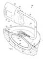
- FIG. 1illustrates a partially cross-sectional, perspective view of a tissue treatment system according to an illustrative embodiment
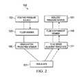
- FIG. 2illustrates a fluid flow schematic for an embodiment of the tissue treatment system of FIG. 1 ;
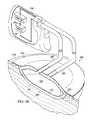
- FIGS. 3A and 3Billustrate a partially cross-sectional, perspective view of a tissue treatment system according to an illustrative embodiment
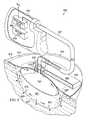
- FIG. 4illustrates a partially cross-sectional, perspective view of a tissue treatment system according to an illustrative embodiment
- FIG. 5illustrates a partially cross-sectional, perspective view of a tissue treatment system according to an illustrative embodiment
- FIG. 6illustrates a partially cross-sectional, perspective view of a tissue treatment system according to an illustrative embodiment
- FIG. 7illustrates a partially cross-sectional, perspective view of a tissue treatment system according to an illustrative embodiment
- FIG. 8illustrates a partially cross-sectional, perspective view of a tissue treatment system according to an illustrative embodiment, the tissue treatment system having a pre-inflated filler member;
- FIG. 9illustrates a perspective view of the pre-inflated filler member of FIG. 8 .
- FIG. 10illustrates a cross-sectional side view of the pre-inflated filler member of FIG. 9 taken at 10 - 10 .
- reduced pressuregenerally refers to a pressure less than the ambient pressure at a tissue site that is being subjected to treatment. In most cases, this reduced pressure will be less than the atmospheric pressure at which the patient is located. Alternatively, the reduced pressure may be less than a hydrostatic pressure associated with tissue at the tissue site. Although the terms “vacuum” and “negative pressure” may be used to describe the pressure applied to the tissue site, the actual pressure reduction applied to the tissue site may be significantly less than the pressure reduction normally associated with a complete vacuum. Reduced pressure may initially generate fluid flow in the area of the tissue site. As the hydrostatic pressure around the tissue site approaches the desired reduced pressure, the flow may subside, and the reduced pressure is then maintained. Unless otherwise indicated, values of pressure stated herein are gauge pressures. Similarly, references to increases in reduced pressure typically refer to a decrease in absolute pressure, while decreases in reduced pressure typically refer to an increase in absolute pressure.
- positive pressuregenerally refers to a pressure greater than the ambient pressure at a tissue site that is being subjected to treatment. In some cases, this positive pressure will be greater than the atmospheric pressure at which the patient is located. Alternatively, the positive pressure may be greater than a hydrostatic pressure associated with tissue at the tissue site.
- the tissue treatment systems and methods described in this applicationimprove the treatment of a tissue site by increasing or improving granulation tissue development, thus allowing healing of a wound that may not otherwise heal with traditional treatment modalities, or in some cases, allowing an increased rate in healing of a wound.
- Granulationmay be promoted by exposing the tissue site to micro-mechanical stresses and strains. While the creation of micro-mechanical stresses and strains at a tissue site may be provided by applying a reduced pressure to a sealed space adjacent the tissue site, the system and methods described herein employ the use of positive pressure or forces to create such stresses and strains. Use of positive pressure or forces can decrease the amount of reduced pressure that is applied to a tissue site to remove fluids and exudate from the tissue site. In some cases, use of a positive pressure or forces may eliminate the need for reduced pressure entirely, especially when absorbent materials or other fluid-removal materials or mechanisms are employed.
- tissue sitemay refer to a wound, such as a wound 105 , or defect located on or within any tissue, including but not limited to, bone tissue, adipose tissue, muscle tissue, neural tissue, dermal tissue, vascular tissue, connective tissue, cartilage, tendons, or ligaments.
- tissue sitemay further refer to areas of any tissue that are not necessarily wounded or defective, but are instead areas in which it is desired to add or promote the growth of additional tissue. For example, reduced pressure tissue treatment may be used in certain tissue areas to grow additional tissue that may be harvested and transplanted to another tissue location.
- the dressing 102is configured to promote the growth of new tissue at the tissue site 101 and includes a wound healing apparatus 106 positioned adjacent to or, in some embodiments, in contact with the tissue site 101 .
- the dressing 102may further include a cover or drape 110 positioned over the wound healing apparatus 106 to secure the wound healing apparatus 106 at the tissue site 101 and to seal a space that is located beneath the cover and is at least partially occupied by the wound healing apparatus 106 .
- the drape 110extends beyond a perimeter of the tissue site 101 and is placed either in contact with or otherwise in proximity to a patient's epidermis 113 to create a fluid seal between the drape 110 and the epidermis 113 .
- the drape 110may include an adhesive 115 or bonding agent to secure the drape 110 to the epidermis 113 .
- the adhesive 115may be used to create a seal between the drape 110 and the epidermis 113 to prevent leakage of reduced pressure from the tissue site 101 .
- a seal layer(not shown) such as, for example, a hydrogel or other material may be disposed between the drape 110 and the epidermis 113 to augment or substitute for the sealing properties of the adhesive 115 .
- “fluid seal”means a seal adequate to maintain reduced pressure at a desired site given the particular reduced pressure source involved and the particular treatment desired.
- the drape 110 and the bonding characteristics of the drape 110provide sealing sufficient to prevent leakage greater than 0.5 L/min at 125 mmHg reduced pressure.
- the wound healing apparatus 106may include a manifold 121 and a filler member 125 .
- the term “manifold” as used hereingenerally refers to a substance or structure that is provided to assist in applying reduced pressure to, delivering fluids to, or removing fluids from the tissue site 101 .
- the manifoldtypically includes a plurality of flow channels or pathways that distribute fluids provided to and removed from the tissue site around the manifold. In one illustrative embodiment, the flow channels or pathways are interconnected to improve distribution of fluids provided or removed from the tissue site 101 .
- manifoldsmay include, for example, without limitation, devices that have structural elements arranged to form flow channels, such as, for example, cellular foam, open-cell foam, porous tissue collections, liquids, gels, and foams that include, or cure to include, flow channels.
- the wound healing apparatus 106includes a porous foam and having a plurality of interconnected cells or pores that act as flow channels.
- the porous foammay be a polyurethane, open-cell, reticulated foam such as GranuFoam® material manufactured by Kinetic Concepts, Incorporated of San Antonio, Tex.
- the filler member 125 of the reduced pressure apparatus 106may be provided to occupy additional space or volume between the tissue site 101 and the cover 110 and may also be provided to better facilitate the application of a positive force to the tissue site 106 in order to encourage granulation and new tissue growth.
- the filler member 125may in some embodiments be an inflatable bladder or balloon that is expandable when injected or otherwise filled with a fluid. In other embodiments, the filler member 125 may be a pre-filled bladder or other container that is positioned between the tissue site 106 and the cover 110 .
- filler members 125are provided herein.
- the manifold 121 and filler member 125may work together to encourage tissue growth in the presence of a positive force or pressure.
- the manifold 121may include at least one granulation-promoting surface 127 that is capable of contacting the tissue site 101 .
- the granulation-promoting surface 127is capable of inducing micro-stresses and micro-strain at the tissue site 101 when the granulation-promoting surface 127 contacts the tissue site 101 .
- the manifold 121is a reticulated porous foam that includes a plurality of interconnected cells formed by struts or cell walls
- the struts of the reticulated foammay be capable of inducing micro-stresses and micro-strains when the struts are pressed against or into the tissue.
- expansion of the filler member 125 within the sealed space beneath the cover 110directs a force on the manifold 121 at least in the direction of the tissue site 101 . This force is capable of generating the required micro-stresses and micro-strains where the tissue contacts the granulation-promoting surface 127 .
- the filler member 125is embedded within the manifold such that the manifold completely surrounds the filler member 125 .
- the manifoldmay be omitted and the filler member alone positioned within the sealed space beneath the cover.
- the filler membermay include a granulation-promoting surface that is placed in contact with the tissue site.
- the granulation-promoting surfacemay includes projections, protrusions, or a substantially-rough profile to induce micro-stresses and micro-strains at the tissue site.
- the filler membermay be omitted and simply a manifold or other granulation-inducing substrate may be placed beneath the cover.
- a force on the manifold or granulation-inducing substratemay create the desired micro-strain to induce granulation at the tissue site.
- the dressing 102further may include a pressure interface 133 fluidly coupled to the wound healing apparatus 106 and the cover 110 .
- the interface 133may be positioned adjacent to or coupled to the cover 110 to provide fluid access to the wound healing apparatus 106 .
- the drape 110includes an aperture 135 for providing fluid access to the interface 133 .
- a conduit 137fluidly couples the therapy unit 104 and the interface 133 .
- the interface 133is capable of allowing reduced pressure to be delivered to the tissue site 101 when it is desired to remove fluid from the tissue site 101 under the influence of reduced pressure.
- the interface 133may also be fluidly coupled to the filler member 125 through a filler conduit 141 . Fluid connection between the interface 133 and the filler member 125 allows a fluid (i.e. a gas or liquid) to be delivered to the filler member 125 under positive pressure such that the filler member 125 may be inflated or expanded.
- the therapy unit 104includes a fluid containment member 145 in fluid communication with a reduced pressure source 151 .
- the fluid containment member 145is a collection canister that includes a chamber for collecting fluids from the tissue site 101 .
- the fluid containment member 145alternatively could be an absorbent material or any other container, device, or material that is capable of collecting fluid.
- a separate positive pressure source 153may be housed within the therapy unit 104 .
- a singe vacuum pumpmay be disposed within the therapy unit 104 such that an inlet of the vacuum pump serves as the reduced pressure source 151 and an outlet of the vacuum pump serves as the positive pressure source 153 .
- the conduit 137may be a multi-lumen tube that is capable of providing one or more conduits to deliver reduced pressure to the dressing 102 and one or more conduits to deliver positive pressure to the dressing 102 . Liquids or exudates communicated from the wound healing apparatus 106 through the conduit 137 are removed from the conduit 137 and retained within the collection canister 145 . Additional information regarding the transfer of fluids between the dressing and the therapy unit is provided below with reference to FIG. 2 .
- the reduced pressure source 151 and positive pressure source 153may be one or more electrically-driven vacuum pumps.
- the reduced and positive pressure sources 151 , 153may instead be one or more manually-actuated or manually—charged pumps that do not require electrical power.
- the reduced pressure and positive pressure sources 151 , 153may be one or more piezoelectric-actuated micropumps that may be positioned remotely from the dressing 102 , or at the dressing beneath or adjacent to the cover 110 .
- the reduced and positive pressure sources 151 , 153instead may be any other type of pump, or alternatively a wall suction port or air delivery port such as those available in hospitals and other medical facilities.
- the reduced and positive pressure sources 151 , 153may be housed within or used in conjunction with the therapy unit 104 , which may also contain sensors, processing units, alarm indicators, memory, databases, software, display units, and user interfaces 161 that further facilitate the application of reduced pressure treatment to the tissue site 101 .
- pressure-detection sensors(not shown) may be disposed at or near the reduced and positive pressure sources 151 , 153 .
- the pressure-detection sensorsmay receive pressure data from the interface 133 via lumens in the conduit 137 that are dedicated to delivering reduced pressure data to the pressure-detection sensors.
- the pressure-detection sensorsmay communicate with a processing unit that monitors and controls the reduced pressure and positive pressure that is delivered by the reduced and positive pressure sources 151 , 153 .
- the positive pressure source 153provides a fluid such as a gas or a liquid to the filler member 125 .
- the direction of fluid flowis from the positive pressure source 153 to the filler member 125 .
- the positive pressure source 153may be physically (and fluidly) connected to the filler member 125 by a conduit such as conduit 137 (see FIG. 1 ), or alternatively the positive pressure source 153 may include an outlet directly coupled to the filler member 125 .
- the positive pressure source 153may be a micropump such as a piezoelectric-actuated pump that is disposed adjacent to the filler member 125 .
- the filler member 125is operably associated with a granulation-promoting member 165 that may be placed adjacent to or in contact with the tissue site 101 .
- the granulation-promoting membermay be a manifold such as manifold 121 , a granulation-promoting surface on the filler member 125 , or any other type of material or substrate that is capable of promoting granulation tissue growth.
- the reduced pressure source 151provides reduced pressure by drawing or pulling a fluid such as a gas or a liquid toward the reduced pressure source 151 .
- the reduced pressure source 151is physically (and fluidly) connected to the fluid containment member 145 and draws fluid from the fluid containment member 145 .
- the reduced pressure created at the reduced pressure source 151 and the fluid containment member 145is capable of drawing fluid from a fluid space 171 adjacent the tissue site 101 . It should be understood that the fluid space 171 may be occupied by the manifold 121 to better distribute reduced pressure within the fluid space 171 and at the tissue site 101 , thereby resulting in more efficient removal of the fluid.
- an illustrative embodiment of a tissue treatment system 300 for treating a tissue site 301 on a patientincludes a dressing 302 placed proximate to the tissue site 301 and a therapy unit 104 fluidly coupled to the dressing 302 .
- Tissue treatment system 300is similar to tissue treatment system 100 and includes many components that are the same as or similar to those in tissue treatment system 100 .
- Tissue treatment system 300illustrates a filler member 325 that is fully inflated with a fluid.
- the filler member 125is embedded within a manifold 321 that includes at least one granulation-promoting surface 327 that is brought into contact with the tissue site 301 by the inflation of the filler member 325 .
- the filler member 325 and manifold 321are constrained by a cover 310 secured to an epidermis 313 of the patient such that biasing forces may be applied to the tissue site 301 by the granulation-promoting surface 327 .
- the cover 310may be substantially inelastic such that the cover 310 acts as a substantially rigid constraint, the cover 310 may instead by elastic, thereby allowing some expansion of the dressing above the epidermis 313 of the patient that surrounds the tissue site 301 (as shown in FIGS. 3A and 3B ).
- the cover 310creates a sealed space 328 beneath the cover 310 in which the manifold 321 and the filler member 325 reside.
- an inner space of the filler member 325is fluidly coupled to a positive pressure source 353
- a reduced pressure source 351is fluid coupled to the manifold 321 .
- the positive pressure source 353 and the reduced pressure source 351are each separate pumps.
- the positive pressure source 353 and the reduced pressure source 351are the same pump, the pump providing reduced pressure to the manifold 321 through an inlet of the pump and positive pressure to the filler member 325 through the outlet of the pump.
- pumpsare illustrated as being the positive pressure source 353 and reduced pressure source 351 in FIGS. 3A and 3B , it should be noted that the positive and reduced pressure sources 353 , 351 may be any source of positive or negative fluid flow as described previously with respect to positive pressure source 153 and reduced pressure source 151 .
- conduits 383 , 385fluids are exchanged with the manifold 321 and the filler member 325 through conduits 383 , 385 .
- Conduit 383permits the application of reduced pressure and thus the removal of fluids from the manifold 321 or the space 328 surrounding the filler member 325 .
- Conduit 385permits the application of positive pressure and thus the delivery of fluids to the filler member 325 .
- Conduits 383 , 385may be any type of tube or other fluid conveying device. As illustrated in FIGS. 3A and 3B , conduits 383 , 385 may be positioned through the cover 310 .
- an aperture in the cover 310 though which each conduit 383 , 385 is placedbe sealed around the conduit 383 , 385 , either using a sealant or other adhesive, or using a drape material that may be adhered to both the cover 310 and the conduit 383 , 385 .
- the conduits 383 , 385may be inserted beneath the cover 310 near an edge of the cover 310 where the cover 310 is adhered to the patient's epidermis 313 .
- sealing of the cover 310 around the conduit 383 , 385 entry pointis important, both to maintain the ability of the cover 310 to secure the filler member 325 and the manifold 321 at the tissue site 301 and to allow the cover 310 to maintain a reduced pressure within the manifold 321 or the space 328 between the filler member 325 and the tissue site 301 .
- conduit 385it is important for conduit 385 to be properly sealed to the filler member 325 . Proper sealing of the conduit 385 prevents positively-pressurized fluid from the conduit 385 from leaking into the manifold 325 or the space 328 between the filler member 325 and the tissue site 301 .
- conduits 383 , 385have been described as passing through or underneath the cover 310 , the conduits 383 , 385 instead could be connected to an interface similar to interface 133 associated with FIG. 1 .
- the interfacewould allow sealed passage of fluid carried by the conduits 383 , 385 through the cover 310 .
- a canister 345may be fluidly coupled between the dressing 302 and the reduced pressure source 351 .
- the canister 345is capable of collecting fluids (especially liquids) drawn from the tissue site 301 by the reduced pressure source 351 .
- tissue treatment system 400 for treating a tissue site 401 on a patientincludes a dressing 402 placed proximate to the tissue site 401 and a therapy unit 404 fluidly coupled to the dressing 402 .
- Tissue treatment system 400is similar to tissue treatment systems 100 , 300 and includes many components that are the same as or similar to those in tissue treatment systems 100 , 300 .
- Tissue treatment system 400includes a filler member 425 that is inflated with a fluid. Positioned beneath the filler member 425 is a manifold 421 that includes at least one granulation-promoting surface 427 that is brought into contact with the tissue site 401 by the inflation of the filler member 425 .
- An absorbent layer 429is positioned above the filler member 425 and in fluid communication with the manifold 421 .
- the absorbent layer 429 , filler member 425 , and manifold 421are constrained by a cover 410 secured to an epidermis 413 of the patient. The attachment of the cover 410 over the layers of the dressing 402 allows biasing forces to be applied to the tissue site 401 by the granulation-promoting surface 427 .
- cover 410may be substantially inelastic such that the cover 410 acts as a substantially rigid constraint
- the cover 410instead may be elastic, thereby allowing some expansion of the dressing above or below the epidermis 413 of the patient that surrounds the tissue site 401 .
- an inner space of the filler member 425is fluidly coupled to a positive pressure source 453
- a reduced pressure source 451is fluid coupled to the absorbent layer 429 and the manifold 421 .
- the function of the positive pressure source 453 and the reduced pressure source 451are provided by a single pump. Reduced pressure is provided by an inlet 454 of the pump and is regulated by a regulating valve 456 . Positive pressure is provided by an outlet 458 of the pump and is regulated by a regulating valve 460 . While a single pump is illustrated as providing both positive and negative pressure, it should be noted that the positive and reduced pressures may be supplied by separate pumps or by any other source of positive or negative fluid flow.
- the fluid connection between the reduced pressure source 451 and the absorbent layer 429assists in drawing liquids from the manifold 421 into the absorbent layer 429 for storage.
- the absorbent layer 451may be formed from an absorbent, adsorbent, desiccant, or any other type of material that is capable of capturing or storing liquid from the tissue site 401 .
- absorbent layerexamples include, without limitation, BASF's Luquafleece material, superabsorbent-fibre-based non-woven materials such as that offered by Technical Absorbents, hydrophylic foams such as that offered by Foam Partners HME, high-wicking fibre-based materials such as that offered by Filtrona, and hydrophylic sintered polymers such as that offered by Poryair.
- the application of reduced pressure through the absorbent layer 429 and manifold 421may result in the dressing 402 being compressed such that cover 410 is pulled below the epidermis 413 of the patient that surrounds the tissue site 401 . While this compression of the dressing 402 assists in applying a biasing force, represented by arrows 472 , to the tissue site 401 , the biasing force may be increased by the presence of the filler member 425 beneath the cover 410 . The inflation of the filler member 425 beneath the cover 410 results in less reduced pressure being needed to encourage granulation. Instead, reduced pressure can be provided primarily to remove fluid from the tissue site 401 .
- tissue treatment system 500 for treating a tissue site 501 on a patientincludes a dressing 502 placed proximate to the tissue site 501 and a therapy unit 504 fluidly coupled to the dressing 502 .
- Tissue treatment system 500is similar to tissue treatment systems 100 , 300 , 400 and includes many components that are the same as or similar to those in tissue treatment systems 100 , 300 , 400 .
- Tissue treatment system 500includes a filler member 525 that is inflated with a fluid.
- the filler member 525is embedded within a manifold 521 that includes at least one granulation-promoting surface 527 that is brought into contact with the tissue site 501 by the inflation of the filler member 525 .
- the filler member 525 and manifold 521are constrained by a cover 510 secured to an epidermis 513 of the patient such that biasing forces may be applied to the tissue site 501 by the granulation-promoting surface 527 .
- the cover 510creates a sealed space 528 beneath the cover 510 in which the manifold 521 and filler member 525 reside.
- cover 510may be substantially inelastic such that the cover 510 acts as a substantially rigid constraint
- the cover 510instead may be elastic, thereby allowing some expansion of the dressing above or below the epidermis 513 of the patient that surrounds the tissue site 501 .
- a fluid containment member 545is positioned in fluid communication with the manifold 521 and the space 528 beneath the cover 510 .
- the fluid containment member 545is a fluid pouch that includes an absorbent 529 similar to other absorbents described herein.
- the fluid containment member 545may be positioned above the cover 510 outside of the sealed space 528 .
- the fluid containment member 545may be positioned beneath the cover, and in one embodiment fluid containment member 545 , or the absorbent 529 therein, may be in direct contact with the manifold 521 .
- an inner space of the filler member 525is fluidly coupled to a positive pressure source 553 .
- the pressure of fluid provided by the positive pressure source 553is regulated by a regulating valve 560 .
- No reduced pressure sourceis provided in the embodiment illustrated in FIG. 5 .
- fluid removal from the tissue site 501is provided by the fluid containment member 545 .
- the absorbent 529 in the fluid containment member 545assists in drawing the fluid from the manifold 521 and into the fluid containment member 545 for storage.
- the movement of the fluidis further aided by the inflation of the filler member 525 , which decreases the volume of the space 528 occupied by the manifold 521 and thus the fluid.
- a reduced pressure sourcemay be fluidly connected to the fluid containment member 545 to provide active drainage of the space 528 and the tissue site 501 .
- Such a reduced pressure sourcemay be similar to the other reduced pressure sources described herein.
- the fluid containment member 545is fluidly connected to the manifold 521 by a pressure interface 533 positioned adjacent to or coupled to the cover 510 .
- the cover 510includes an aperture 535 through which the pressure interface 533 passes.
- a conduit 537fluidly couples the therapy unit 504 (and positive pressure source 553 ) to the interface 533 .
- Fluid connection between the interface 533 and the filler member 525allows a fluid (i.e. a gas or liquid) to be delivered to the filler member 525 under positive pressure such that the filler member 525 may be inflated or expanded.
- the filling of the filler member 525 in the absence of reduced pressure to the space 528may result in the dressing 502 expanding above the epidermis 513 of the patient that surrounds the tissue site 501 .
- This expansion of the dressing 502assists in applying a biasing force, represented by arrows 572 , to the tissue site 501 .
- the inflation of the filler member 525 beneath the cover 510results in no reduced pressure being needed to encourage granulation.
- fluidis removed from the dressing 502 without reduced pressure as well.
- tissue treatment system 600for treating a tissue site 601 on a patient includes a dressing 602 placed proximate to the tissue site 601 and a therapy unit 604 fluidly coupled to the dressing 602 .
- Tissue treatment system 600is similar to tissue treatment systems 100 , 300 , 400 , 500 and includes many components that are the same as or similar to those in tissue treatment systems 100 , 300 , 400 , 500 .
- Tissue treatment system 600includes a filler member 625 that is inflated with a fluid. Positioned beneath the filler member 625 is a manifold 621 that includes at least one granulation-promoting surface 627 that is brought into contact with the tissue site 601 by the inflation of the filler member 625 .
- the filler member 625 and manifold 621are constrained by a cover 610 secured to an epidermis 613 of the patient such that biasing forces may be applied to the tissue site 601 by the granulation-promoting surface 627 .
- the covercreates a sealed space 628 beneath the cover in which the manifold 621 and filler member 625 reside.
- cover 610may be substantially inelastic such that the cover 610 acts as a substantially rigid constraint
- the cover 610instead may be elastic, thereby allowing some expansion of the dressing above or below the epidermis 613 of the patient that surrounds the tissue site 601 .
- a fluid containment member 645is positioned in fluid communication with the manifold 621 and the space 628 beneath the cover 610 .
- the fluid containment member 645is a fluid pouch that includes an absorbent 629 similar to other absorbents described herein.
- the fluid containment member 645may be positioned above the cover 610 outside of the sealed space 628 .
- the fluid containment member 645may be positioned beneath the cover, and in one embodiment fluid containment member 645 , or absorbent 629 therein, may be in direct contact with the manifold 621 .
- an inner space of the filler member 625is fluidly coupled to a positive pressure source 653 .
- the pressure of fluid provided by the positive pressure source 653is regulated by a regulating valve 660 .
- No reduced pressure sourceis provided in the embodiment illustrated in FIG. 6 .
- fluid removal from the tissue site 601is provided by the fluid containment member 645 .
- the absorbent 629 in the fluid containment member 645assists in drawing the fluid from the manifold 621 and into the fluid containment member 645 for storage.
- the movement of the fluidis further aided by the inflation of the filler member 625 , which decreases the volume of the space 628 occupied by the manifold 621 and thus the fluid.
- a reduced pressure sourcemay be fluidly connected to the fluid containment member 645 to provide active drainage of the space 628 and the tissue site 601 .
- Such a reduced pressure sourcemay be similar to the other reduced pressure sources described herein.
- the fluid containment member 645is fluidly connected to the manifold 621 by a pressure interface 633 positioned adjacent to or coupled to the cover 610 .
- the cover 610includes an aperture 635 through which the pressure interface 633 passes.
- a conduit 637fluidly couples the therapy unit 604 (and positive pressure source 653 ) to the interface 633 .
- Fluid connection between the interface 633 and the filler member 625allows a fluid (i.e. a gas or liquid) to be delivered to the filler member 625 under positive pressure such that the filler member 625 may be inflated or expanded.
- the filling of the filler member 625 in the absence of reduced pressure to the space 628may result in the dressing 602 expanding above the epidermis 613 of the patient that surrounds the tissue site 601 .
- This expansion of the dressing 602assists in applying a biasing force, represented by arrows 672 , to the tissue site 601 .
- the inflation of the filler member 625 beneath the cover 610results in no reduced pressure being needed to encourage granulation.
- fluidis removed from the dressing 602 without reduced pressure as well.
- tissue treatment system 700for treating a tissue site 701 on a patient includes a dressing 702 placed proximate to the tissue site 701 and a therapy unit 704 fluidly coupled to the dressing 702 .
- Tissue treatment system 700is similar to tissue treatment systems 100 , 300 , 400 , 500 , 600 and includes many components that are the same as or similar to those in tissue treatment systems 100 , 300 , 400 , 500 , 600 .
- Tissue treatment system 700includes a filler member 725 that is inflated with a fluid. Unlike, some previously illustrated embodiments, the embodiment illustrated in FIG. 7 does not include a manifold. Instead, the filler member 725 includes at least one granulation-promoting surface 727 that is brought into contact with the tissue site 701 when the filler member 725 is inflated. The filler member 725 is constrained by a cover 710 secured to an epidermis 713 of the patient such that biasing forces may be applied to the tissue site 701 by the granulation-promoting surface 727 . The cover creates a sealed space 728 beneath the cover in which the filler member 725 resides.
- cover 710may be substantially inelastic such that the cover 710 acts as a substantially rigid constraint
- the cover 710instead may be elastic, thereby allowing some expansion of the dressing above or below the epidermis 713 of the patient that surrounds the tissue site 701 .
- a fluid containment member 745is positioned in fluid communication with the space 728 beneath the cover 710 .
- the fluid containment member 745is a fluid pouch that includes an absorbent 729 similar to other absorbents described herein.
- the fluid containment member 745may be positioned above the cover 710 outside of the sealed space 728 .
- the fluid containment member 745may be positioned beneath the cover, and in one embodiment fluid containment member 745 , or absorbent 729 therein, may be in direct contact with the filler member 725 .
- an inner space of the filler member 725is fluidly coupled to a positive pressure source 753 .
- the pressure of fluid provided by the positive pressure source 753is regulated by a regulating valve 770 .
- No reduced pressure sourceis provided in the embodiment illustrated in FIG. 7 .
- fluid removal from the tissue site 701is provided by the fluid containment member 745 .
- the absorbent 729 in the fluid containment member 745assists in drawing the fluid from the spaced 728 and into the fluid containment member 745 for storage.
- the movement of the fluidis further aided by the inflation of the filler member 725 , which decreases the volume of the space 728 .
- a reduced pressure sourcemay be fluidly connected to the fluid containment member 745 to provide active drainage of the space 728 and the tissue site 701 .
- Such a reduced pressure sourcemay be similar to the other reduced pressure sources described herein.
- the fluid containment member 745is fluidly connected to the space 728 by a pressure interface 733 positioned adjacent to or coupled to the cover 710 .
- the cover 710includes an aperture 735 through which the pressure interface 733 passes.
- a conduit 737fluidly couples the therapy unit 704 (and positive pressure source 753 ) to the interface 733 .
- Fluid connection between the interface 733 and the filler member 725allows a fluid (i.e. a gas or liquid) to be delivered to the filler member 725 under positive pressure such that the filler member 725 may be inflated or expanded.
- the filling of the filler member 725 in the absence of reduced pressure to the space 728may result in the dressing 702 expanding above the epidermis 713 of the patient that surrounds the tissue site 701 .
- This expansion of the dressing 702assists in applying a biasing force, represented by arrows 772 , to the tissue site 701 .
- the inflation of the filler member 725 beneath the cover 710results in no reduced pressure being needed to encourage granulation.
- fluidis removed from the dressing 702 without reduced pressure as well.
- an illustrative embodiment of a tissue treatment system 800 for treating a tissue site 801 on a patientincludes a dressing 802 placed proximate to the tissue site 801 and a therapy unit 804 fluidly coupled to the dressing 802 .
- the dressing 802is configured to promote the growth of new tissue at the tissue site 801 and includes a wound healing apparatus 806 positioned adjacent to or, in some embodiments, in contact with the tissue site 801 .
- the dressing 802may further include a cover or drape 810 positioned over the wound healing apparatus 806 to secure the wound healing apparatus 806 at the tissue site 801 and to seal a space that is beneath the cover and is at least partially occupied by the wound healing apparatus 806 .
- the drape 810extends beyond a perimeter of the tissue site 801 and is placed either in contact with or otherwise in proximity to a patient's epidermis 813 to create a fluid seal between the drape 810 and the epidermis 813 .
- the drape 810may include an adhesive 815 or bonding agent to secure the drape 810 to the epidermis 813 .
- the adhesive 815may be used to create a seal between the drape 810 and the epidermis 813 to prevent leakage of reduced pressure from the tissue site 801 .
- a seal layersuch as, for example, a hydrogel, hydrocolloid (for example as supplied by Avery or 3M), silicone gel (for example as supplied by Dowcoming, Wacker, or NuSil), hot-melt glue (for example as supplied by Plasto, Adhesive Research, or Avery), or other material may be disposed between the drape 810 and the epidermis 813 to augment or substitute for the sealing properties of the adhesive 815 .
- a seal layersuch as, for example, a hydrogel, hydrocolloid (for example as supplied by Avery or 3M), silicone gel (for example as supplied by Dowcoming, Wacker, or NuSil), hot-melt glue (for example as supplied by Plasto, Adhesive Research, or Avery), or other material may be disposed between the drape 810 and the epidermis 813 to augment or substitute for the sealing properties of the adhesive 815 .
- the wound healing apparatus 806may include a manifold 821 and a filler member 825 .
- the wound healing apparatus 806includes a porous foam and having a plurality of interconnected cells or pores that act as flow channels.
- the porous foammay be a polyurethane, open-cell, reticulated foam such as GranuFoam® material manufactured by Kinetic Concepts, Incorporated of San Antonio, Tex.
- the filler member 825 of the reduced pressure apparatus 806may be provided to occupy additional space or volume between the tissue site 801 and the cover 810 and may also be provided to better facilitate the application of a positive force to the tissue site 801 in order to encourage granulation and new tissue growth.
- the filler member 825is a pre-filled bladder or other container that is positioned between the tissue site 801 and the cover 810 .
- the filler member 825includes at least one chamber 824 sealingly enclosed by chamber walls 826 .
- the chamber 824retains a fluid that in one embodiment may be a gas such as air.
- the pressure of the fluid within the chamber 824may be greater than or equal to ambient pressure. If the chamber walls 826 are elastically deformed, the fluid is most likely at a pressure slightly greater than ambient pressure. If the chamber walls 826 are not elastically deformed, the pressure of the fluid may be about the same as ambient.
- the chamber walls 826 of the filler member 825include a first wall 828 joined to a second wall 830 to form the chamber 824 .
- the filler member 825includes a plurality of chambers 824 , each chamber 824 being connected to an adjacent chamber at a sealing joint 832 .
- the sealing joint 832is the location at which the first and second walls 828 , 830 are sealed together, and this sealing process may be accomplished by heat bonding, adhesive bonding, ultrasonic welding, or any other process capable of connecting the walls 828 , 830 together.
- the process chosen to bond the walls 828 , 830may vary depending on the material property of the walls 828 , 830 .
- the sealing joint 832acts as a hinge between adjacent chambers 824 , thereby allowing rotational movement of one chamber 824 relative to another.
- a plurality of chambers 824may be adhered or otherwise attached to a flexible membrane or substrate such that a hinged configuration is provided between adjacent chambers 824 .
- each chamber 825may constructed from individual walls separate from the walls that form adjacent chambers.
- the number of walls associated with the filler member 825 or each chambermay vary depending on the desired shape of each chamber or the filler member. For example, a chamber that is formed in the shape of an octahedron may include eight walls. Alternatively, a spherical chamber may only include a single wall.
- the walls 828 , 830 of the filler member 825may be made from any flexible material that is capable of maintaining a substantially sealed chamber.
- suitable materialsmay include polyurethanes, thermoplastic elastomers, silicone elastomers and other elastomeric polymers such as polyepichlorohydrin, butyls (including halogenated forms), or polyether block amine copolymers (PEBAX), and thin flexible films, such as polyolefines, copolyesters, and polyamides.
- the manifold 821 and filler member 825may work together to encourage tissue growth in the presence of a positive force or pressure.
- the manifold 821may include at least one granulation-promoting surface 827 that is capable of contacting the tissue site 801 .
- the granulation-promoting surface 827is capable of inducing micro-stresses and micro-strain at the tissue site 801 when the granulation-promoting surface 827 contacts the tissue site 801 .
- the manifold 821is a reticulated porous foam that includes a plurality of interconnected cells formed by struts or cell walls
- the struts of the reticulated foammay be capable of inducing micro-stresses and micro-strains when the struts are pressed against or into the tissue.
- the cover 810By sealing the manifold 821 and filler member 825 proximate the tissue site 801 with the cover 810 , the presence of the filler member 825 within the sealed space beneath the cover 810 assists in directing a force on the manifold 821 at least in the direction of the tissue site 801 . This force is capable of generating the required micro-stresses and micro-strains where the tissue contacts the granulation-promoting surface 827 .
- the cover 810may be placed over the manifold 821 and filler member 825 such that the filler member 825 is somewhat compressed as the cover 810 is attached to the patient. This compression of the filler member 825 assists in amplifying the force applied to the manifold 821 and thus the tissue site 801 .
- the cover 810may be formed from a material that is elastically deformed as the cover 810 is applied.
- cover materialsmay include polyurethanes, thermoplastic elastomers, silicone elastomers and other elastomeric polymers such as polyepichlorohydrin, butyls (including halogenated forms), or polyether block amine copolymers (PEBAX), and thin flexible films, such as polyolefines, copolyesters, and polyamides.
- polyurethanesthermoplastic elastomers, silicone elastomers and other elastomeric polymers such as polyepichlorohydrin, butyls (including halogenated forms), or polyether block amine copolymers (PEBAX)
- thin flexible filmssuch as polyolefines, copolyesters, and polyamides.
- the filler member 825is positioned between a first portion 834 and a second portion 836 of the manifold 821 .
- a pressure interface 833is fluidly coupled to the wound healing apparatus 806 and the cover 810 .
- the interface 833may be positioned adjacent to or coupled to the cover 810 to provide fluid access to the wound healing apparatus 806 .
- the cover 810includes an aperture 835 for providing fluid access to the interface 833 .
- a conduit 837fluidly couples the therapy unit 804 and the interface 833 .
- the interface 833is capable of allowing reduced pressure to be delivered to the tissue site 801 when it is desired to remove fluid from the tissue site 801 under the influence of reduced pressure.
- the therapy unit 804includes a fluid containment member 845 in fluid communication with a reduced pressure source 851 . Liquids or exudates communicated from the wound healing apparatus 806 through the conduit 837 are removed from the conduit 837 and retained within the containment member 845 .
- the fluid containment member 845is a collection canister that includes a chamber for collecting fluids from the tissue site 801 .
- the fluid containment member 845alternatively could be an absorbent material or any other container, device, or material that is capable of collecting fluid.
- the reduced pressure source 851may be one or more electrically-driven vacuum pumps. In another implementation, the reduced pressure source 851 may instead be one or more manually-actuated or manually-charged pumps that do not require electrical power.
- the reduced pressure source 851instead may be any other type of pump, or alternatively a wall suction port or air delivery port such as those available in hospitals and other medical facilities.
- the reduced pressure source 851may be housed within or used in conjunction with the therapy unit 804 , which may also contain sensors, processing units, alarm indicators, memory, databases, software, display units, and user interfaces 861 that further facilitate the application of reduced pressure treatment to the tissue site 801 .
- pressure-detection sensorsmay be disposed at or near the reduced pressure source 851 .
- the pressure-detection sensorsmay receive pressure data from the interface 833 via lumens in the conduit 837 that are dedicated to delivering reduced pressure data to the pressure-detection sensors.
- the pressure-detection sensorsmay communicate with a processing unit that monitors and controls the reduced pressure that is delivered by the reduced pressure source 851 .
- a caregiverplaces the first portion 834 of the manifold 821 in contact with the tissue site 801 such that the granulation-promoting surface 827 is in contact with the tissue site 801 .
- the filler member 825is then positioned above the first portion 834 , and preferably the amount of filler member 825 is adjusted to substantially fill the space that will be beneath the cover 810 .
- the filler member 825may be trimmed along the sealing joints 832 or through the chambers 824 to re-size the filler member 825 to an appropriate size. In the embodiment illustrated in FIG. 8 , a single-piece filler member 825 is folded in half to more adequately fill the space.
- multiple pieces of the filler member 825may be positioned to substantially fill the space.
- enough of the filler member 825is added to allow the filler member 825 to be substantially level with the epidermis 813 surrounding the tissue site 801 .
- the second portion 836 of the manifold 821is positioned above the filler member 825 , and then the cover 810 is positioned over the second portion 836 .
- the cover 810is secured to the epidermis 813 surrounding the tissue site 801 , and the pressure interface 833 is positioned in contact with the cover 810 and in communication with the aperture 835 .
- the reduced pressure source 851is fluidly connected to the pressure interface 833 .
- tissue treatment system 800 of FIG. 8is described as having a two-piece manifold system surrounding the filler member, the manifold could be a one-piece manifold that encases the filler member. Alternatively, as previously described in relation to FIG. 7 , the manifold may be omitted and a filler member used that includes a granulation-promoting surface. Similarly, many fluid handling and storage alternatives are possible for the tissue treatment system 800 .
- the collection canister that is remotely located from the tissue sitemay instead be an absorbent material. The absorbent material may be provided as a layer of the dressing as shown in FIG. 4 , or may be located external to the dressing as shown in FIGS. 5-7 .
- the multi-chambered filler member 825 described hereinis pre-inflated and sealed such that the fluid within each chamber is trapped. While it may be preferred in the embodiment illustrated in FIG. 8 to use a pre-inflated filler member, it should be noted that the fillable and expandable filler members described herein and illustrated in FIGS. 1-7 may also be multi-chambered similar to filler member 810 . In other words, it is contemplated that a multi-chambered filler member could be connected to a positive pressure source such that the delivery of fluid to the chambers under positive pressure may be controlled following placement of the filler member in proximity to the tissue site.
- tissue treatment systems described hereinallow the use of a reduced pressure treatment protocol that uses less reduced pressure (i.e. higher absolute pressures) than traditional protocols.
- reduced pressurei.e. higher absolute pressures
- the amount of reduced pressure needed for treatmentis greatly reduced.
- testinghas shown that a pressure of ⁇ 75 mm Hg, coupled with a positive pressure provided by either an inflatable or pre-inflated bladder, achieves an interface-pressure equivalent (the pressure measured at the interface of the granulation-promoting surface and the tissue site) of ⁇ 125 mm Hg.
- the systems described hereinhave the ability to manage fluid and interfacial pressures independently. This is particularly useful in intermittent mode where a caregiver can maintain constant fluid management (e.g. removal) while alternating the application of microstrain on the tissue site. This also may be more beneficial for pain management in that the effect of transient strains my be reduced by managing the application of the positive and negative pressures independently. Finally, these methods result in a simpler system with lower energy requirements.
- the separation of fluid removal and microstrain inductionmay also be beneficial when it is not desirable to draw together the perimeter of a wound or tissue site.
- traditional reduced pressure treatmentthe application of higher amounts of reduced pressure to dressings promoted closure by primary intention by drawing together the edges or perimeter of the wound.
- thisis not always advantageous, especially when the wound is to a joint or articulation point.
- the contraction of tissuemay lead to impinged movement, which may cause secondary problems for the patient or the need for painful physiotherapy to break down these tissue formations to restore movement.
- the tissue treatment systems described hereinallow the benefit of reduced pressure treatment to be applied to a wound, yet the inflatable or pre-inflated bladder resists the collapse of the wound perimeter inward and thus constriction of the surrounding tissue.
- While many of the systems described hereinhave been illustrated in use with tissue sites or wounds that are at or near the epidermis of a patient, the systems and methods may similarly be used to treat subcutaneous tissue sites, tunnel wounds, or other undermined areas of tissue. With these types of wounds or tissue sites, accessibility may be limited, thereby making placement and removal of traditional foams and manifolds more difficult. The ability of the bladders described herein to be deflated upon installation and removal would ease the process of applying treatment to these difficult-to-access wounds and tissue sites.
- tissue treatment systems described hereininclude the use of negative pressure in conjunction with the application of a positive pressure or force
- the use of absorbent materials for passive fluid removalmay assist in completely eliminating the need for reduced pressure.
- fluidmay be removed passively from the wound and stored in an absorbent layer, while a positive pressure or force is used to create microstrains at the tissue site.
- the cover member or drapemay be integrally combined with the filler member to secure or seal these components at the tissue site.
- the cover membermay be an integral portion of the filler member that is capable of being secured to an epidermis of the patient such that the interior chamber of the filler member and any granulation-promoting material is sealed within a space beneath the cover member at the tissue site.
Landscapes
- Health & Medical Sciences (AREA)
- Heart & Thoracic Surgery (AREA)
- Public Health (AREA)
- Vascular Medicine (AREA)
- Engineering & Computer Science (AREA)
- Biomedical Technology (AREA)
- Veterinary Medicine (AREA)
- Life Sciences & Earth Sciences (AREA)
- Animal Behavior & Ethology (AREA)
- General Health & Medical Sciences (AREA)
- Anesthesiology (AREA)
- Hematology (AREA)
- Oral & Maxillofacial Surgery (AREA)
- Pulmonology (AREA)
- Surgery (AREA)
- Media Introduction/Drainage Providing Device (AREA)
- External Artificial Organs (AREA)
Abstract
Description
Claims (12)
Priority Applications (1)
| Application Number | Priority Date | Filing Date | Title |
|---|---|---|---|
| US14/597,024US9402940B2 (en) | 2011-05-25 | 2015-01-14 | Wound healing system using positive pressure to promote granulation at a tissue site |
Applications Claiming Priority (3)
| Application Number | Priority Date | Filing Date | Title |
|---|---|---|---|
| US201161489786P | 2011-05-25 | 2011-05-25 | |
| US13/473,986US8961496B2 (en) | 2011-05-25 | 2012-05-17 | Wound healing system using positive pressure to promote granulation at a tissue site |
| US14/597,024US9402940B2 (en) | 2011-05-25 | 2015-01-14 | Wound healing system using positive pressure to promote granulation at a tissue site |
Related Parent Applications (1)
| Application Number | Title | Priority Date | Filing Date |
|---|---|---|---|
| US13/473,986DivisionUS8961496B2 (en) | 2011-05-25 | 2012-05-17 | Wound healing system using positive pressure to promote granulation at a tissue site |
Publications (2)
| Publication Number | Publication Date |
|---|---|
| US20150190559A1 US20150190559A1 (en) | 2015-07-09 |
| US9402940B2true US9402940B2 (en) | 2016-08-02 |
Family
ID=46614581
Family Applications (2)
| Application Number | Title | Priority Date | Filing Date |
|---|---|---|---|
| US13/473,986Expired - Fee RelatedUS8961496B2 (en) | 2011-05-25 | 2012-05-17 | Wound healing system using positive pressure to promote granulation at a tissue site |
| US14/597,024ActiveUS9402940B2 (en) | 2011-05-25 | 2015-01-14 | Wound healing system using positive pressure to promote granulation at a tissue site |
Family Applications Before (1)
| Application Number | Title | Priority Date | Filing Date |
|---|---|---|---|
| US13/473,986Expired - Fee RelatedUS8961496B2 (en) | 2011-05-25 | 2012-05-17 | Wound healing system using positive pressure to promote granulation at a tissue site |
Country Status (7)
| Country | Link |
|---|---|
| US (2) | US8961496B2 (en) |
| EP (2) | EP2896413A1 (en) |
| JP (1) | JP2014516711A (en) |
| CN (1) | CN103517721A (en) |
| AU (1) | AU2012259109A1 (en) |
| CA (1) | CA2844279A1 (en) |
| WO (1) | WO2012162098A2 (en) |
Cited By (1)
| Publication number | Priority date | Publication date | Assignee | Title |
|---|---|---|---|---|
| US20160038626A1 (en)* | 2014-08-11 | 2016-02-11 | Kci Licensing, Inc. | Protease modulating wound interface layer for use with negative pressure wound therapy |
Families Citing this family (52)
| Publication number | Priority date | Publication date | Assignee | Title |
|---|---|---|---|---|
| US10058642B2 (en) | 2004-04-05 | 2018-08-28 | Bluesky Medical Group Incorporated | Reduced pressure treatment system |
| US11253399B2 (en) | 2007-12-06 | 2022-02-22 | Smith & Nephew Plc | Wound filling apparatuses and methods |
| US20130096518A1 (en) | 2007-12-06 | 2013-04-18 | Smith & Nephew Plc | Wound filling apparatuses and methods |
| US9999702B2 (en) | 2010-04-09 | 2018-06-19 | Kci Licensing Inc. | Apparatuses, methods, and compositions for the treatment and prophylaxis of chronic wounds |
| US8597264B2 (en) | 2011-03-24 | 2013-12-03 | Kci Licensing, Inc. | Apparatuses, methods, and compositions for the treatment and prophylaxis of chronic wounds |
| WO2013066426A2 (en)* | 2011-06-24 | 2013-05-10 | Kci Licensing, Inc. | Reduced-pressure dressings employing tissue-fixation elements |
| JP6250571B2 (en) | 2012-03-12 | 2017-12-20 | スミス アンド ネフュー ピーエルシーSmith & Nephew Public Limited Company | Pressure reducing apparatus and method |
| USD764654S1 (en) | 2014-03-13 | 2016-08-23 | Smith & Nephew, Inc. | Canister for collecting wound exudate |
| EP2976095B1 (en) | 2013-03-15 | 2020-12-23 | 3M Innovative Properties Company | Wound healing compositions |
| EP2815731A1 (en)* | 2013-06-18 | 2014-12-24 | Mölnlycke Health Care AB | Fluid transport dressing |
| CA2918157A1 (en) | 2013-07-16 | 2015-01-22 | Smith & Nephew Plc | Apparatus for wound therapy |
| CN106170275B (en) | 2013-10-21 | 2021-05-07 | 史密夫和内修有限公司 | Negative pressure wound closure device |
| US20150257968A1 (en)* | 2014-03-11 | 2015-09-17 | Carl E. VAUSE | Soft conformal compression devices and methods |
| AU359280S (en)* | 2014-04-30 | 2014-12-08 | Talley Group Ltd | Negative pressure wound therapy pump |
| USD764048S1 (en) | 2014-05-28 | 2016-08-16 | Smith & Nephew, Inc. | Device for applying negative pressure to a wound |
| USD764047S1 (en)* | 2014-05-28 | 2016-08-16 | Smith & Nephew, Inc. | Therapy unit assembly |
| USD764653S1 (en) | 2014-05-28 | 2016-08-23 | Smith & Nephew, Inc. | Canister for collecting wound exudate |
| USD770173S1 (en) | 2014-06-02 | 2016-11-01 | Smith & Nephew, Inc. | Bag |
| USD765830S1 (en)* | 2014-06-02 | 2016-09-06 | Smith & Nephew, Inc. | Therapy unit assembly |
| WO2016008154A1 (en)* | 2014-07-18 | 2016-01-21 | 科际精密股份有限公司 | Negative pressure wound therapy apparatus |
| DK3288508T3 (en) | 2015-04-27 | 2020-03-09 | Smith & Nephew | REDUCED PRESSURE DEVICES |
| BR112018008475B1 (en) | 2015-10-30 | 2023-01-24 | Johnson & Johnson Consumer Inc | METHOD OF GENERATING AN AEROSOL MIST USING A PORTABLE DEVICE, UNIT-DOSE CAPSULE FOR USE WITH A SONIC GENERATOR AND KIT COMPRISING THE SAME |
| JP6828032B2 (en) | 2015-10-30 | 2021-02-10 | ジョンソン・アンド・ジョンソン・コンシューマー・インコーポレイテッドJohnson & Johnson Consumer Inc. | Aseptic aerosol mist |
| WO2017075318A1 (en)* | 2015-10-30 | 2017-05-04 | Johnson & Johnson Consumer Inc. | Aseptic aerosol misting device |
| US10575991B2 (en)* | 2015-12-15 | 2020-03-03 | University Of Massachusetts | Negative pressure wound closure devices and methods |
| WO2017119996A1 (en)* | 2016-01-06 | 2017-07-13 | Kci Liecensing, Inc. | System and methods for the treatment of wounds with dressing having closed cells |
| EP3426206B1 (en) | 2016-03-07 | 2023-05-10 | Smith & Nephew plc | Wound treatment apparatuses and methods with negative pressure source integrated into wound dressing |
| CA3022184A1 (en) | 2016-04-26 | 2017-11-02 | Smith & Nephew Plc | Wound dressings and methods of use with integrated negative pressure source having a fluid ingress inhibition component |
| US11096831B2 (en) | 2016-05-03 | 2021-08-24 | Smith & Nephew Plc | Negative pressure wound therapy device activation and control |
| WO2017191158A1 (en) | 2016-05-03 | 2017-11-09 | Smith & Nephew Plc | Systems and methods for driving negative pressure sources in negative pressure therapy systems |
| CA3038206A1 (en) | 2016-05-03 | 2017-11-09 | Smith & Nephew Plc | Optimizing power transfer to negative pressure sources in negative pressure therapy systems |
| SE540964C2 (en)* | 2016-08-23 | 2019-01-29 | Halao Ab | Wound dressing with inflatable structures |
| WO2018037075A1 (en) | 2016-08-25 | 2018-03-01 | Smith & Nephew Plc | Absorbent negative pressure wound therapy dressing |
| EP3519001B1 (en) | 2016-09-30 | 2025-05-21 | Smith & Nephew plc | Negative pressure wound treatment apparatuses and methods with integrated electronics |
| EP3551244A1 (en) | 2016-12-12 | 2019-10-16 | Smith & Nephew PLC | Pressure wound therapy status indication via external device |
| JP2020508794A (en)* | 2017-03-06 | 2020-03-26 | ケーシーアイ ライセンシング インコーポレイテッド | System and method for improving battery life in portable negative pressure therapy through hysteresis control |
| EP3592312B1 (en) | 2017-03-08 | 2024-01-10 | Smith & Nephew plc | Negative pressure wound therapy device control in presence of fault condition |
| JP7121050B2 (en) | 2017-05-09 | 2022-08-17 | スミス アンド ネフュー ピーエルシー | Redundant control of negative pressure wound therapy systems |
| AU2018285239B2 (en) | 2017-06-14 | 2023-09-21 | Smith & Nephew Plc | Collapsible sheet for wound closure and method of use |
| CA3074780A1 (en) | 2017-09-13 | 2019-03-21 | Smith & Nephew Plc | Negative pressure wound treatment apparatuses and methods with integrated electronics |
| GB201718070D0 (en) | 2017-11-01 | 2017-12-13 | Smith & Nephew | Negative pressure wound treatment apparatuses and methods with integrated electronics |
| GB201718072D0 (en) | 2017-11-01 | 2017-12-13 | Smith & Nephew | Negative pressure wound treatment apparatuses and methods with integrated electronics |
| GB201718054D0 (en) | 2017-11-01 | 2017-12-13 | Smith & Nephew | Sterilization of integrated negative pressure wound treatment apparatuses and sterilization methods |
| US11497653B2 (en) | 2017-11-01 | 2022-11-15 | Smith & Nephew Plc | Negative pressure wound treatment apparatuses and methods with integrated electronics |
| USD898925S1 (en) | 2018-09-13 | 2020-10-13 | Smith & Nephew Plc | Medical dressing |
| WO2020061264A1 (en)* | 2018-09-19 | 2020-03-26 | Deroyal Industries, Inc. | Multiple-wound negative pressure wound therapy using multiple fluid collection volumes |
| GB201903774D0 (en) | 2019-03-20 | 2019-05-01 | Smith & Nephew | Negative pressure wound treatment apparatuses and methods with integrated electronics |
| GB201907716D0 (en) | 2019-05-31 | 2019-07-17 | Smith & Nephew | Systems and methods for extending operational time of negative pressure wound treatment apparatuses |
| EP4017446B1 (en)* | 2019-08-20 | 2025-02-12 | Solventum Intellectual Properties Company | Gel-blocking connection assembly for absorbent negative pressure dressing |
| MX2022010815A (en)* | 2020-03-03 | 2022-09-27 | Deroyal Ind Inc | Negative pressure wound therapy instillation system. |
| CA3168899A1 (en) | 2020-03-18 | 2021-09-23 | Compression Dynamics, LLC | Wound dressing garments, kits, systems, and methods |
| GB2605954B (en) | 2021-04-13 | 2024-07-24 | Act Medical Ltd | A system for treating stab wounds |
Citations (131)
| Publication number | Priority date | Publication date | Assignee | Title |
|---|---|---|---|---|
| US1355846A (en) | 1920-02-06 | 1920-10-19 | David A Rannells | Medical appliance |
| US2547758A (en) | 1949-01-05 | 1951-04-03 | Wilmer B Keeling | Instrument for treating the male urethra |
| US2632443A (en) | 1949-04-18 | 1953-03-24 | Eleanor P Lesher | Surgical dressing |
| GB692578A (en) | 1949-09-13 | 1953-06-10 | Minnesota Mining & Mfg | Improvements in or relating to drape sheets for surgical use |
| US2682873A (en) | 1952-07-30 | 1954-07-06 | Johnson & Johnson | General purpose protective dressing |
| US2910763A (en) | 1955-08-17 | 1959-11-03 | Du Pont | Felt-like products |
| US2969057A (en) | 1957-11-04 | 1961-01-24 | Brady Co W H | Nematodic swab |
| US3066672A (en) | 1960-09-27 | 1962-12-04 | Jr William H Crosby | Method and apparatus for serial sampling of intestinal juice |
| US3367332A (en) | 1965-08-27 | 1968-02-06 | Gen Electric | Product and process for establishing a sterile area of skin |
| US3520300A (en) | 1967-03-15 | 1970-07-14 | Amp Inc | Surgical sponge and suction device |
| US3568675A (en) | 1968-08-30 | 1971-03-09 | Clyde B Harvey | Fistula and penetrating wound dressing |
| US3648692A (en) | 1970-12-07 | 1972-03-14 | Parke Davis & Co | Medical-surgical dressing for burns and the like |
| US3682180A (en) | 1970-06-08 | 1972-08-08 | Coilform Co Inc | Drain clip for surgical drain |
| US3826254A (en) | 1973-02-26 | 1974-07-30 | Verco Ind | Needle or catheter retaining appliance |
| DE2640413A1 (en) | 1976-09-08 | 1978-03-09 | Wolf Gmbh Richard | CATHETER MONITORING DEVICE |
| US4080970A (en) | 1976-11-17 | 1978-03-28 | Miller Thomas J | Post-operative combination dressing and internal drain tube with external shield and tube connector |
| US4096853A (en) | 1975-06-21 | 1978-06-27 | Hoechst Aktiengesellschaft | Device for the introduction of contrast medium into an anus praeter |
| US4139004A (en) | 1977-02-17 | 1979-02-13 | Gonzalez Jr Harry | Bandage apparatus for treating burns |
| US4165748A (en) | 1977-11-07 | 1979-08-28 | Johnson Melissa C | Catheter tube holder |
| US4184510A (en) | 1977-03-15 | 1980-01-22 | Fibra-Sonics, Inc. | Valued device for controlling vacuum in surgery |
| WO1980002182A1 (en) | 1979-04-06 | 1980-10-16 | J Moss | Portable suction device for collecting fluids from a closed wound |
| US4233969A (en) | 1976-11-11 | 1980-11-18 | Lock Peter M | Wound dressing materials |
| US4245630A (en) | 1976-10-08 | 1981-01-20 | T. J. Smith & Nephew, Ltd. | Tearable composite strip of materials |
| US4256109A (en) | 1978-07-10 | 1981-03-17 | Nichols Robert L | Shut off valve for medical suction apparatus |
| US4261363A (en) | 1979-11-09 | 1981-04-14 | C. R. Bard, Inc. | Retention clips for body fluid drains |
| US4275721A (en) | 1978-11-28 | 1981-06-30 | Landstingens Inkopscentral Lic, Ekonomisk Forening | Vein catheter bandage |
| US4284079A (en) | 1979-06-28 | 1981-08-18 | Adair Edwin Lloyd | Method for applying a male incontinence device |
| US4297995A (en) | 1980-06-03 | 1981-11-03 | Key Pharmaceuticals, Inc. | Bandage containing attachment post |
| US4333468A (en) | 1980-08-18 | 1982-06-08 | Geist Robert W | Mesentery tube holder apparatus |
| US4373519A (en) | 1981-06-26 | 1983-02-15 | Minnesota Mining And Manufacturing Company | Composite wound dressing |
| US4382441A (en) | 1978-12-06 | 1983-05-10 | Svedman Paul | Device for treating tissues, for example skin |
| US4392858A (en) | 1981-07-16 | 1983-07-12 | Sherwood Medical Company | Wound drainage device |
| US4392853A (en) | 1981-03-16 | 1983-07-12 | Rudolph Muto | Sterile assembly for protecting and fastening an indwelling device |
| US4419097A (en) | 1981-07-31 | 1983-12-06 | Rexar Industries, Inc. | Attachment for catheter tube |
| EP0100148A1 (en) | 1982-07-06 | 1984-02-08 | Dow Corning Limited | Medical-surgical dressing and a process for the production thereof |
| US4465485A (en) | 1981-03-06 | 1984-08-14 | Becton, Dickinson And Company | Suction canister with unitary shut-off valve and filter features |
| EP0117632A2 (en) | 1983-01-27 | 1984-09-05 | Johnson & Johnson Products Inc. | Adhesive film dressing |
| US4475909A (en) | 1982-05-06 | 1984-10-09 | Eisenberg Melvin I | Male urinary device and method for applying the device |
| US4480638A (en) | 1980-03-11 | 1984-11-06 | Eduard Schmid | Cushion for holding an element of grafted skin |
| US4525166A (en) | 1981-11-21 | 1985-06-25 | Intermedicat Gmbh | Rolled flexible medical suction drainage device |
| US4525374A (en) | 1984-02-27 | 1985-06-25 | Manresa, Inc. | Treating hydrophobic filters to render them hydrophilic |
| US4540412A (en) | 1983-07-14 | 1985-09-10 | The Kendall Company | Device for moist heat therapy |
| US4543100A (en) | 1983-11-01 | 1985-09-24 | Brodsky Stuart A | Catheter and drain tube retainer |
| US4548202A (en) | 1983-06-20 | 1985-10-22 | Ethicon, Inc. | Mesh tissue fasteners |
| US4551139A (en) | 1982-02-08 | 1985-11-05 | Marion Laboratories, Inc. | Method and apparatus for burn wound treatment |
| EP0161865A2 (en) | 1984-05-03 | 1985-11-21 | Smith and Nephew Associated Companies p.l.c. | Adhesive wound dressing |
| US4569348A (en) | 1980-02-22 | 1986-02-11 | Velcro Usa Inc. | Catheter tube holder strap |
| AU550575B2 (en) | 1981-08-07 | 1986-03-27 | Richard Christian Wright | Wound drainage device |
| US4605399A (en) | 1984-12-04 | 1986-08-12 | Complex, Inc. | Transdermal infusion device |
| US4608041A (en) | 1981-10-14 | 1986-08-26 | Frese Nielsen | Device for treatment of wounds in body tissue of patients by exposure to jets of gas |
| US4640688A (en) | 1985-08-23 | 1987-02-03 | Mentor Corporation | Urine collection catheter |
| US4655754A (en) | 1984-11-09 | 1987-04-07 | Stryker Corporation | Vacuum wound drainage system and lipids baffle therefor |
| US4664662A (en) | 1984-08-02 | 1987-05-12 | Smith And Nephew Associated Companies Plc | Wound dressing |
| WO1987004626A1 (en) | 1986-01-31 | 1987-08-13 | Osmond, Roger, L., W. | Suction system for wound and gastro-intestinal drainage |
| US4710165A (en) | 1985-09-16 | 1987-12-01 | Mcneil Charles B | Wearable, variable rate suction/collection device |
| US4733659A (en) | 1986-01-17 | 1988-03-29 | Seton Company | Foam bandage |
| GB2195255A (en) | 1986-09-30 | 1988-04-07 | Vacutec Uk Limited | Method and apparatus for vacuum treatment of an epidermal surface |
| US4743232A (en) | 1986-10-06 | 1988-05-10 | The Clinipad Corporation | Package assembly for plastic film bandage |
| GB2197789A (en) | 1986-11-28 | 1988-06-02 | Smiths Industries Plc | Anti-foaming disinfectants used in surgical suction apparatus |
| US4758220A (en) | 1985-09-26 | 1988-07-19 | Alcon Laboratories, Inc. | Surgical cassette proximity sensing and latching apparatus |
| US4787888A (en) | 1987-06-01 | 1988-11-29 | University Of Connecticut | Disposable piezoelectric polymer bandage for percutaneous delivery of drugs and method for such percutaneous delivery (a) |
| US4826494A (en) | 1984-11-09 | 1989-05-02 | Stryker Corporation | Vacuum wound drainage system |
| US4838883A (en) | 1986-03-07 | 1989-06-13 | Nissho Corporation | Urine-collecting device |
| US4840187A (en) | 1986-09-11 | 1989-06-20 | Bard Limited | Sheath applicator |
| US4863449A (en) | 1987-07-06 | 1989-09-05 | Hollister Incorporated | Adhesive-lined elastic condom cathether |
| US4872450A (en) | 1984-08-17 | 1989-10-10 | Austad Eric D | Wound dressing and method of forming same |
| US4878901A (en) | 1986-10-10 | 1989-11-07 | Sachse Hans Ernst | Condom catheter, a urethral catheter for the prevention of ascending infections |
| GB2220357A (en) | 1988-05-28 | 1990-01-10 | Smiths Industries Plc | Medico-surgical containers |
| US4897081A (en) | 1984-05-25 | 1990-01-30 | Thermedics Inc. | Percutaneous access device |
| US4906233A (en) | 1986-05-29 | 1990-03-06 | Terumo Kabushiki Kaisha | Method of securing a catheter body to a human skin surface |
| US4906240A (en) | 1988-02-01 | 1990-03-06 | Matrix Medica, Inc. | Adhesive-faced porous absorbent sheet and method of making same |
| US4919654A (en) | 1988-08-03 | 1990-04-24 | Kalt Medical Corporation | IV clamp with membrane |
| CA2005436A1 (en) | 1988-12-13 | 1990-06-13 | Glenda G. Kalt | Transparent tracheostomy tube dressing |
| US4941882A (en) | 1987-03-14 | 1990-07-17 | Smith And Nephew Associated Companies, P.L.C. | Adhesive dressing for retaining a cannula on the skin |
| US4953565A (en) | 1986-11-26 | 1990-09-04 | Shunro Tachibana | Endermic application kits for external medicines |
| WO1990010424A1 (en) | 1989-03-16 | 1990-09-20 | Smith & Nephew Plc | Absorbent devices and precursors therefor |
| US4969880A (en) | 1989-04-03 | 1990-11-13 | Zamierowski David S | Wound dressing and treatment method |
| US4985019A (en) | 1988-03-11 | 1991-01-15 | Michelson Gary K | X-ray marker |
| GB2235877A (en) | 1989-09-18 | 1991-03-20 | Antonio Talluri | Closed wound suction apparatus |
| US5037397A (en) | 1985-05-03 | 1991-08-06 | Medical Distributors, Inc. | Universal clamp |
| US5086170A (en) | 1989-01-16 | 1992-02-04 | Roussel Uclaf | Process for the preparation of azabicyclo compounds |
| US5092858A (en) | 1990-03-20 | 1992-03-03 | Becton, Dickinson And Company | Liquid gelling agent distributor device |
| US5100396A (en) | 1989-04-03 | 1992-03-31 | Zamierowski David S | Fluidic connection system and method |
| US5134994A (en) | 1990-02-12 | 1992-08-04 | Say Sam L | Field aspirator in a soft pack with externally mounted container |
| US5149331A (en) | 1991-05-03 | 1992-09-22 | Ariel Ferdman | Method and device for wound closure |
| US5167613A (en) | 1992-03-23 | 1992-12-01 | The Kendall Company | Composite vented wound dressing |
| US5176663A (en) | 1987-12-02 | 1993-01-05 | Pal Svedman | Dressing having pad with compressibility limiting elements |
| WO1993009727A1 (en) | 1991-11-14 | 1993-05-27 | Wake Forest University | Method and apparatus for treating tissue damage |
| US5215522A (en) | 1984-07-23 | 1993-06-01 | Ballard Medical Products | Single use medical aspirating device and method |
| US5232453A (en) | 1989-07-14 | 1993-08-03 | E. R. Squibb & Sons, Inc. | Catheter holder |
| US5261893A (en) | 1989-04-03 | 1993-11-16 | Zamierowski David S | Fastening system and method |
| US5278100A (en) | 1991-11-08 | 1994-01-11 | Micron Technology, Inc. | Chemical vapor deposition technique for depositing titanium silicide on semiconductor wafers |
| US5279550A (en) | 1991-12-19 | 1994-01-18 | Gish Biomedical, Inc. | Orthopedic autotransfusion system |
| US5298015A (en) | 1989-07-11 | 1994-03-29 | Nippon Zeon Co., Ltd. | Wound dressing having a porous structure |
| US5342376A (en) | 1993-05-03 | 1994-08-30 | Dermagraphics, Inc. | Inserting device for a barbed tissue connector |
| US5344415A (en) | 1993-06-15 | 1994-09-06 | Deroyal Industries, Inc. | Sterile system for dressing vascular access site |
| DE4306478A1 (en) | 1993-03-02 | 1994-09-08 | Wolfgang Dr Wagner | Drainage device, in particular pleural drainage device, and drainage method |
| WO1994020041A1 (en) | 1993-03-09 | 1994-09-15 | Wake Forest University | Wound treatment employing reduced pressure |
| US5358494A (en) | 1989-07-11 | 1994-10-25 | Svedman Paul | Irrigation dressing |
| US5437651A (en) | 1993-09-01 | 1995-08-01 | Research Medical, Inc. | Medical suction apparatus |
| US5437622A (en) | 1992-04-29 | 1995-08-01 | Laboratoire Hydrex (Sa) | Transparent adhesive dressing with reinforced starter cuts |
| DE29504378U1 (en) | 1995-03-15 | 1995-09-14 | MTG Medizinisch, technische Gerätebau GmbH, 66299 Friedrichsthal | Electronically controlled low-vacuum pump for chest and wound drainage |
| WO1996005873A1 (en) | 1994-08-22 | 1996-02-29 | Kinetic Concepts Inc. | Wound drainage equipment |
| US5527293A (en) | 1989-04-03 | 1996-06-18 | Kinetic Concepts, Inc. | Fastening system and method |
| US5549584A (en) | 1994-02-14 | 1996-08-27 | The Kendall Company | Apparatus for removing fluid from a wound |
| US5556375A (en) | 1994-06-16 | 1996-09-17 | Hercules Incorporated | Wound dressing having a fenestrated base layer |
| US5607388A (en) | 1994-06-16 | 1997-03-04 | Hercules Incorporated | Multi-purpose wound dressing |
| WO1997018007A1 (en) | 1995-11-14 | 1997-05-22 | Kci Medical Limited | Portable wound treatment apparatus |
| GB2329127A (en) | 1997-09-12 | 1999-03-17 | Kci Medical Ltd | Suction head and drape wound treatment assembly |
| US6071267A (en) | 1998-02-06 | 2000-06-06 | Kinetic Concepts, Inc. | Medical patient fluid management interface system and method |
| US6135116A (en) | 1997-07-28 | 2000-10-24 | Kci Licensing, Inc. | Therapeutic method for treating ulcers |
| US6241747B1 (en) | 1993-05-03 | 2001-06-05 | Quill Medical, Inc. | Barbed Bodily tissue connector |
| US6287316B1 (en) | 1999-03-26 | 2001-09-11 | Ethicon, Inc. | Knitted surgical mesh |
| US20020077661A1 (en) | 2000-12-20 | 2002-06-20 | Vahid Saadat | Multi-barbed device for retaining tissue in apposition and methods of use |
| US20020115951A1 (en) | 2001-02-22 | 2002-08-22 | Core Products International, Inc. | Ankle brace providing upper and lower ankle adjustment |
| US20020120185A1 (en) | 2000-05-26 | 2002-08-29 | Kci Licensing, Inc. | System for combined transcutaneous blood gas monitoring and vacuum assisted wound closure |
| US20020143286A1 (en) | 2001-03-05 | 2002-10-03 | Kci Licensing, Inc. | Vacuum assisted wound treatment apparatus and infection identification system and method |
| US6488643B1 (en) | 1998-10-08 | 2002-12-03 | Kci Licensing, Inc. | Wound healing foot wrap |
| US6493568B1 (en) | 1994-07-19 | 2002-12-10 | Kci Licensing, Inc. | Patient interface system |
| AU755496B2 (en) | 1997-09-12 | 2002-12-12 | Kci Licensing, Inc. | Surgical drape and suction head for wound treatment |
| WO2004037334A1 (en) | 2002-10-28 | 2004-05-06 | Smith & Nephew Plc | Apparatus for aspirating, irrigating and cleansing wounds |
| WO2005082435A1 (en) | 2004-02-24 | 2005-09-09 | Huntleigh Technology Plc | Tissue treatment device |
| JP4129536B2 (en) | 2000-02-24 | 2008-08-06 | ヴェネテック インターナショナル,インコーポレイテッド | Highly compatible catheter anchoring system |
| WO2009111657A2 (en) | 2008-03-05 | 2009-09-11 | Kci Licensing Inc. | Dressing and method for applying reduced pressure to and collecting and storing fluid from a tissue site |
| WO2009146441A1 (en) | 2008-05-30 | 2009-12-03 | Kci Licensing, Inc. | Super-absorbent, reduced-pressure wound dressing and systems |
| US20090306580A1 (en) | 2005-04-27 | 2009-12-10 | Smith & Nephew Plc | Wound treatment apparatus and method |
| WO2010005709A1 (en) | 2008-07-08 | 2010-01-14 | Tyco Healthcare Group Lp | Portable negative pressure wound therapy device |
| WO2010017437A1 (en) | 2008-08-08 | 2010-02-11 | Tyco Healthcare Group Lp | Wound dressing of continuous fibers |
| US20110054423A1 (en)* | 2003-10-28 | 2011-03-03 | Smith & Nephew Plc | Wound cleansing apparatus in-situ |
| US20110112492A1 (en)* | 2008-04-04 | 2011-05-12 | Vivek Bharti | Wound dressing with micropump |
| US20120078154A1 (en)* | 2009-02-04 | 2012-03-29 | Systagenix Wound Management(Us), Inc. | Absorbent foam wound dressing materials |
Family Cites Families (11)
| Publication number | Priority date | Publication date | Assignee | Title |
|---|---|---|---|---|
| SE445298B (en)* | 1982-11-17 | 1986-06-16 | Gunnar Pontus Em Swanbeck | DEVICE FOR CLEANING AND TREATMENT OF SARS AND INFECTED SKIN PARTIES |
| GB2415382A (en)* | 2004-06-21 | 2005-12-28 | Johnson & Johnson Medical Ltd | Wound dressings for vacuum therapy |
| AU2007212488B2 (en)* | 2006-02-07 | 2012-07-12 | Smith & Nephew Inc. | Surgical wound dressing |
| CA2695728A1 (en)* | 2007-08-06 | 2009-02-12 | Ohio Medical Corporation | Wound treatment system and suction regulator for use therewith |
| US8366692B2 (en)* | 2008-01-08 | 2013-02-05 | Richard Scott Weston | Sustained variable negative pressure wound treatment and method of controlling same |
| GB0803564D0 (en)* | 2008-02-27 | 2008-04-02 | Smith & Nephew | Fluid collection |
| US8449508B2 (en) | 2008-03-05 | 2013-05-28 | Kci Licensing, Inc. | Dressing and method for applying reduced pressure to and collecting and storing fluid from a tissue site |
| US8425478B2 (en)* | 2008-09-18 | 2013-04-23 | Kci Licensing, Inc. | Multi-layer dressings, systems, and methods for applying reduced pressure at a tissue site |
| WO2010051071A1 (en)* | 2008-10-29 | 2010-05-06 | Kci Licensing, Inc. | Reduced-pressure, wound-closure and treatment systems and methods |
| CN102215799B (en)* | 2008-11-14 | 2013-09-18 | 凯希特许有限公司 | Fluid bag, system and method for storing fluid from a tissue site |
| CN102215798B (en)* | 2008-11-18 | 2014-09-10 | 凯希特许有限公司 | Pressure Reducing Composite Manifold |
- 2012
- 2012-05-17EPEP14195922.1Apatent/EP2896413A1/ennot_activeWithdrawn
- 2012-05-17USUS13/473,986patent/US8961496B2/ennot_activeExpired - Fee Related
- 2012-05-17CNCN201280022166.2Apatent/CN103517721A/enactivePending
- 2012-05-17CACA2844279Apatent/CA2844279A1/ennot_activeAbandoned
- 2012-05-17WOPCT/US2012/038416patent/WO2012162098A2/enactiveApplication Filing
- 2012-05-17AUAU2012259109Apatent/AU2012259109A1/ennot_activeAbandoned
- 2012-05-17EPEP12743554.3Apatent/EP2714121B1/enactiveActive
- 2012-05-17JPJP2014512891Apatent/JP2014516711A/enactivePending
- 2015
- 2015-01-14USUS14/597,024patent/US9402940B2/enactiveActive
Patent Citations (143)
| Publication number | Priority date | Publication date | Assignee | Title |
|---|---|---|---|---|
| US1355846A (en) | 1920-02-06 | 1920-10-19 | David A Rannells | Medical appliance |
| US2547758A (en) | 1949-01-05 | 1951-04-03 | Wilmer B Keeling | Instrument for treating the male urethra |
| US2632443A (en) | 1949-04-18 | 1953-03-24 | Eleanor P Lesher | Surgical dressing |
| GB692578A (en) | 1949-09-13 | 1953-06-10 | Minnesota Mining & Mfg | Improvements in or relating to drape sheets for surgical use |
| US2682873A (en) | 1952-07-30 | 1954-07-06 | Johnson & Johnson | General purpose protective dressing |
| US2910763A (en) | 1955-08-17 | 1959-11-03 | Du Pont | Felt-like products |
| US2969057A (en) | 1957-11-04 | 1961-01-24 | Brady Co W H | Nematodic swab |
| US3066672A (en) | 1960-09-27 | 1962-12-04 | Jr William H Crosby | Method and apparatus for serial sampling of intestinal juice |
| US3367332A (en) | 1965-08-27 | 1968-02-06 | Gen Electric | Product and process for establishing a sterile area of skin |
| US3520300A (en) | 1967-03-15 | 1970-07-14 | Amp Inc | Surgical sponge and suction device |
| US3568675A (en) | 1968-08-30 | 1971-03-09 | Clyde B Harvey | Fistula and penetrating wound dressing |
| US3682180A (en) | 1970-06-08 | 1972-08-08 | Coilform Co Inc | Drain clip for surgical drain |
| US3648692A (en) | 1970-12-07 | 1972-03-14 | Parke Davis & Co | Medical-surgical dressing for burns and the like |
| US3826254A (en) | 1973-02-26 | 1974-07-30 | Verco Ind | Needle or catheter retaining appliance |
| US4096853A (en) | 1975-06-21 | 1978-06-27 | Hoechst Aktiengesellschaft | Device for the introduction of contrast medium into an anus praeter |
| DE2640413A1 (en) | 1976-09-08 | 1978-03-09 | Wolf Gmbh Richard | CATHETER MONITORING DEVICE |
| US4245630A (en) | 1976-10-08 | 1981-01-20 | T. J. Smith & Nephew, Ltd. | Tearable composite strip of materials |
| US4233969A (en) | 1976-11-11 | 1980-11-18 | Lock Peter M | Wound dressing materials |
| US4080970A (en) | 1976-11-17 | 1978-03-28 | Miller Thomas J | Post-operative combination dressing and internal drain tube with external shield and tube connector |
| US4139004A (en) | 1977-02-17 | 1979-02-13 | Gonzalez Jr Harry | Bandage apparatus for treating burns |
| US4184510A (en) | 1977-03-15 | 1980-01-22 | Fibra-Sonics, Inc. | Valued device for controlling vacuum in surgery |
| US4165748A (en) | 1977-11-07 | 1979-08-28 | Johnson Melissa C | Catheter tube holder |
| US4256109A (en) | 1978-07-10 | 1981-03-17 | Nichols Robert L | Shut off valve for medical suction apparatus |
| US4275721A (en) | 1978-11-28 | 1981-06-30 | Landstingens Inkopscentral Lic, Ekonomisk Forening | Vein catheter bandage |
| US4382441A (en) | 1978-12-06 | 1983-05-10 | Svedman Paul | Device for treating tissues, for example skin |
| WO1980002182A1 (en) | 1979-04-06 | 1980-10-16 | J Moss | Portable suction device for collecting fluids from a closed wound |
| US4284079A (en) | 1979-06-28 | 1981-08-18 | Adair Edwin Lloyd | Method for applying a male incontinence device |
| US4261363A (en) | 1979-11-09 | 1981-04-14 | C. R. Bard, Inc. | Retention clips for body fluid drains |
| US4569348A (en) | 1980-02-22 | 1986-02-11 | Velcro Usa Inc. | Catheter tube holder strap |
| US4480638A (en) | 1980-03-11 | 1984-11-06 | Eduard Schmid | Cushion for holding an element of grafted skin |
| US4297995A (en) | 1980-06-03 | 1981-11-03 | Key Pharmaceuticals, Inc. | Bandage containing attachment post |
| US4333468A (en) | 1980-08-18 | 1982-06-08 | Geist Robert W | Mesentery tube holder apparatus |
| US4465485A (en) | 1981-03-06 | 1984-08-14 | Becton, Dickinson And Company | Suction canister with unitary shut-off valve and filter features |
| US4392853A (en) | 1981-03-16 | 1983-07-12 | Rudolph Muto | Sterile assembly for protecting and fastening an indwelling device |
| US4373519A (en) | 1981-06-26 | 1983-02-15 | Minnesota Mining And Manufacturing Company | Composite wound dressing |
| US4392858A (en) | 1981-07-16 | 1983-07-12 | Sherwood Medical Company | Wound drainage device |
| US4419097A (en) | 1981-07-31 | 1983-12-06 | Rexar Industries, Inc. | Attachment for catheter tube |
| AU550575B2 (en) | 1981-08-07 | 1986-03-27 | Richard Christian Wright | Wound drainage device |
| US4608041A (en) | 1981-10-14 | 1986-08-26 | Frese Nielsen | Device for treatment of wounds in body tissue of patients by exposure to jets of gas |
| US4525166A (en) | 1981-11-21 | 1985-06-25 | Intermedicat Gmbh | Rolled flexible medical suction drainage device |
| US4551139A (en) | 1982-02-08 | 1985-11-05 | Marion Laboratories, Inc. | Method and apparatus for burn wound treatment |
| US4475909A (en) | 1982-05-06 | 1984-10-09 | Eisenberg Melvin I | Male urinary device and method for applying the device |
| EP0100148A1 (en) | 1982-07-06 | 1984-02-08 | Dow Corning Limited | Medical-surgical dressing and a process for the production thereof |
| EP0117632A2 (en) | 1983-01-27 | 1984-09-05 | Johnson & Johnson Products Inc. | Adhesive film dressing |
| US4548202A (en) | 1983-06-20 | 1985-10-22 | Ethicon, Inc. | Mesh tissue fasteners |
| US4540412A (en) | 1983-07-14 | 1985-09-10 | The Kendall Company | Device for moist heat therapy |
| US4543100A (en) | 1983-11-01 | 1985-09-24 | Brodsky Stuart A | Catheter and drain tube retainer |
| US4525374A (en) | 1984-02-27 | 1985-06-25 | Manresa, Inc. | Treating hydrophobic filters to render them hydrophilic |
| EP0161865A2 (en) | 1984-05-03 | 1985-11-21 | Smith and Nephew Associated Companies p.l.c. | Adhesive wound dressing |
| US4897081A (en) | 1984-05-25 | 1990-01-30 | Thermedics Inc. | Percutaneous access device |
| US5215522A (en) | 1984-07-23 | 1993-06-01 | Ballard Medical Products | Single use medical aspirating device and method |
| US4664662A (en) | 1984-08-02 | 1987-05-12 | Smith And Nephew Associated Companies Plc | Wound dressing |
| US4872450A (en) | 1984-08-17 | 1989-10-10 | Austad Eric D | Wound dressing and method of forming same |
| US4655754A (en) | 1984-11-09 | 1987-04-07 | Stryker Corporation | Vacuum wound drainage system and lipids baffle therefor |
| US4826494A (en) | 1984-11-09 | 1989-05-02 | Stryker Corporation | Vacuum wound drainage system |
| US4605399A (en) | 1984-12-04 | 1986-08-12 | Complex, Inc. | Transdermal infusion device |
| US5037397A (en) | 1985-05-03 | 1991-08-06 | Medical Distributors, Inc. | Universal clamp |
| US4640688A (en) | 1985-08-23 | 1987-02-03 | Mentor Corporation | Urine collection catheter |
| US4710165A (en) | 1985-09-16 | 1987-12-01 | Mcneil Charles B | Wearable, variable rate suction/collection device |
| US4758220A (en) | 1985-09-26 | 1988-07-19 | Alcon Laboratories, Inc. | Surgical cassette proximity sensing and latching apparatus |
| US4733659A (en) | 1986-01-17 | 1988-03-29 | Seton Company | Foam bandage |
| WO1987004626A1 (en) | 1986-01-31 | 1987-08-13 | Osmond, Roger, L., W. | Suction system for wound and gastro-intestinal drainage |
| US4838883A (en) | 1986-03-07 | 1989-06-13 | Nissho Corporation | Urine-collecting device |
| US4906233A (en) | 1986-05-29 | 1990-03-06 | Terumo Kabushiki Kaisha | Method of securing a catheter body to a human skin surface |
| US4840187A (en) | 1986-09-11 | 1989-06-20 | Bard Limited | Sheath applicator |
| GB2195255A (en) | 1986-09-30 | 1988-04-07 | Vacutec Uk Limited | Method and apparatus for vacuum treatment of an epidermal surface |
| US4743232A (en) | 1986-10-06 | 1988-05-10 | The Clinipad Corporation | Package assembly for plastic film bandage |
| US4878901A (en) | 1986-10-10 | 1989-11-07 | Sachse Hans Ernst | Condom catheter, a urethral catheter for the prevention of ascending infections |
| US4953565A (en) | 1986-11-26 | 1990-09-04 | Shunro Tachibana | Endermic application kits for external medicines |
| GB2197789A (en) | 1986-11-28 | 1988-06-02 | Smiths Industries Plc | Anti-foaming disinfectants used in surgical suction apparatus |
| US4941882A (en) | 1987-03-14 | 1990-07-17 | Smith And Nephew Associated Companies, P.L.C. | Adhesive dressing for retaining a cannula on the skin |
| US4787888A (en) | 1987-06-01 | 1988-11-29 | University Of Connecticut | Disposable piezoelectric polymer bandage for percutaneous delivery of drugs and method for such percutaneous delivery (a) |
| US4863449A (en) | 1987-07-06 | 1989-09-05 | Hollister Incorporated | Adhesive-lined elastic condom cathether |
| US5176663A (en) | 1987-12-02 | 1993-01-05 | Pal Svedman | Dressing having pad with compressibility limiting elements |
| US4906240A (en) | 1988-02-01 | 1990-03-06 | Matrix Medica, Inc. | Adhesive-faced porous absorbent sheet and method of making same |
| US4985019A (en) | 1988-03-11 | 1991-01-15 | Michelson Gary K | X-ray marker |
| GB2220357A (en) | 1988-05-28 | 1990-01-10 | Smiths Industries Plc | Medico-surgical containers |
| EP0358302A2 (en) | 1988-05-28 | 1990-03-14 | Smiths Industries Public Limited Company | Medico-surgical suction container |
| US4919654A (en) | 1988-08-03 | 1990-04-24 | Kalt Medical Corporation | IV clamp with membrane |
| CA2005436A1 (en) | 1988-12-13 | 1990-06-13 | Glenda G. Kalt | Transparent tracheostomy tube dressing |
| US5086170A (en) | 1989-01-16 | 1992-02-04 | Roussel Uclaf | Process for the preparation of azabicyclo compounds |
| WO1990010424A1 (en) | 1989-03-16 | 1990-09-20 | Smith & Nephew Plc | Absorbent devices and precursors therefor |
| US5100396A (en) | 1989-04-03 | 1992-03-31 | Zamierowski David S | Fluidic connection system and method |
| US5527293A (en) | 1989-04-03 | 1996-06-18 | Kinetic Concepts, Inc. | Fastening system and method |
| US4969880A (en) | 1989-04-03 | 1990-11-13 | Zamierowski David S | Wound dressing and treatment method |
| US5261893A (en) | 1989-04-03 | 1993-11-16 | Zamierowski David S | Fastening system and method |
| US5298015A (en) | 1989-07-11 | 1994-03-29 | Nippon Zeon Co., Ltd. | Wound dressing having a porous structure |
| US5358494A (en) | 1989-07-11 | 1994-10-25 | Svedman Paul | Irrigation dressing |
| US5232453A (en) | 1989-07-14 | 1993-08-03 | E. R. Squibb & Sons, Inc. | Catheter holder |
| GB2235877A (en) | 1989-09-18 | 1991-03-20 | Antonio Talluri | Closed wound suction apparatus |
| US5134994A (en) | 1990-02-12 | 1992-08-04 | Say Sam L | Field aspirator in a soft pack with externally mounted container |
| US5092858A (en) | 1990-03-20 | 1992-03-03 | Becton, Dickinson And Company | Liquid gelling agent distributor device |
| US5149331A (en) | 1991-05-03 | 1992-09-22 | Ariel Ferdman | Method and device for wound closure |
| US5278100A (en) | 1991-11-08 | 1994-01-11 | Micron Technology, Inc. | Chemical vapor deposition technique for depositing titanium silicide on semiconductor wafers |
| US5645081A (en) | 1991-11-14 | 1997-07-08 | Wake Forest University | Method of treating tissue damage and apparatus for same |
| US5636643A (en) | 1991-11-14 | 1997-06-10 | Wake Forest University | Wound treatment employing reduced pressure |
| WO1993009727A1 (en) | 1991-11-14 | 1993-05-27 | Wake Forest University | Method and apparatus for treating tissue damage |
| US5279550A (en) | 1991-12-19 | 1994-01-18 | Gish Biomedical, Inc. | Orthopedic autotransfusion system |
| US5167613A (en) | 1992-03-23 | 1992-12-01 | The Kendall Company | Composite vented wound dressing |
| US5437622A (en) | 1992-04-29 | 1995-08-01 | Laboratoire Hydrex (Sa) | Transparent adhesive dressing with reinforced starter cuts |
| DE4306478A1 (en) | 1993-03-02 | 1994-09-08 | Wolfgang Dr Wagner | Drainage device, in particular pleural drainage device, and drainage method |
| WO1994020041A1 (en) | 1993-03-09 | 1994-09-15 | Wake Forest University | Wound treatment employing reduced pressure |
| US6241747B1 (en) | 1993-05-03 | 2001-06-05 | Quill Medical, Inc. | Barbed Bodily tissue connector |
| US5342376A (en) | 1993-05-03 | 1994-08-30 | Dermagraphics, Inc. | Inserting device for a barbed tissue connector |
| US5344415A (en) | 1993-06-15 | 1994-09-06 | Deroyal Industries, Inc. | Sterile system for dressing vascular access site |
| US5437651A (en) | 1993-09-01 | 1995-08-01 | Research Medical, Inc. | Medical suction apparatus |
| US5549584A (en) | 1994-02-14 | 1996-08-27 | The Kendall Company | Apparatus for removing fluid from a wound |
| US5607388A (en) | 1994-06-16 | 1997-03-04 | Hercules Incorporated | Multi-purpose wound dressing |
| US5556375A (en) | 1994-06-16 | 1996-09-17 | Hercules Incorporated | Wound dressing having a fenestrated base layer |
| US6493568B1 (en) | 1994-07-19 | 2002-12-10 | Kci Licensing, Inc. | Patient interface system |
| WO1996005873A1 (en) | 1994-08-22 | 1996-02-29 | Kinetic Concepts Inc. | Wound drainage equipment |
| DE29504378U1 (en) | 1995-03-15 | 1995-09-14 | MTG Medizinisch, technische Gerätebau GmbH, 66299 Friedrichsthal | Electronically controlled low-vacuum pump for chest and wound drainage |
| WO1997018007A1 (en) | 1995-11-14 | 1997-05-22 | Kci Medical Limited | Portable wound treatment apparatus |
| US6135116A (en) | 1997-07-28 | 2000-10-24 | Kci Licensing, Inc. | Therapeutic method for treating ulcers |
| US6345623B1 (en) | 1997-09-12 | 2002-02-12 | Keith Patrick Heaton | Surgical drape and suction head for wound treatment |
| AU755496B2 (en) | 1997-09-12 | 2002-12-12 | Kci Licensing, Inc. | Surgical drape and suction head for wound treatment |
| US6814079B2 (en) | 1997-09-12 | 2004-11-09 | Kci Licensing, Inc. | Surgical drape and suction head for wound treatment |
| GB2333965A (en) | 1997-09-12 | 1999-08-11 | Kci Medical Ltd | Surgical drape |
| EP1018967A1 (en) | 1997-09-12 | 2000-07-19 | KCI Medical Ltd. | Surgical drape and suction head for wound treatment |
| WO1999013793A1 (en) | 1997-09-12 | 1999-03-25 | Kci Medical Limited | Surgical drape and suction head for wound treatment |
| AU745271B2 (en) | 1997-09-12 | 2002-03-14 | Kci Licensing, Inc. | Surgical drape and suction head for wound treatment |
| US6553998B2 (en) | 1997-09-12 | 2003-04-29 | Kci Licensing, Inc. | Surgical drape and suction head for wound treatment |
| GB2329127A (en) | 1997-09-12 | 1999-03-17 | Kci Medical Ltd | Suction head and drape wound treatment assembly |
| US6071267A (en) | 1998-02-06 | 2000-06-06 | Kinetic Concepts, Inc. | Medical patient fluid management interface system and method |
| US6488643B1 (en) | 1998-10-08 | 2002-12-03 | Kci Licensing, Inc. | Wound healing foot wrap |
| US6287316B1 (en) | 1999-03-26 | 2001-09-11 | Ethicon, Inc. | Knitted surgical mesh |
| JP4129536B2 (en) | 2000-02-24 | 2008-08-06 | ヴェネテック インターナショナル,インコーポレイテッド | Highly compatible catheter anchoring system |
| US20020120185A1 (en) | 2000-05-26 | 2002-08-29 | Kci Licensing, Inc. | System for combined transcutaneous blood gas monitoring and vacuum assisted wound closure |
| US20020077661A1 (en) | 2000-12-20 | 2002-06-20 | Vahid Saadat | Multi-barbed device for retaining tissue in apposition and methods of use |
| US20020115951A1 (en) | 2001-02-22 | 2002-08-22 | Core Products International, Inc. | Ankle brace providing upper and lower ankle adjustment |
| US20020143286A1 (en) | 2001-03-05 | 2002-10-03 | Kci Licensing, Inc. | Vacuum assisted wound treatment apparatus and infection identification system and method |
| WO2004037334A1 (en) | 2002-10-28 | 2004-05-06 | Smith & Nephew Plc | Apparatus for aspirating, irrigating and cleansing wounds |
| US20090254054A1 (en)* | 2002-10-28 | 2009-10-08 | Smith & Nephew Plc | Apparatus for aspirating, irrigating and cleansing wounds |
| US20110054423A1 (en)* | 2003-10-28 | 2011-03-03 | Smith & Nephew Plc | Wound cleansing apparatus in-situ |
| US20070129660A1 (en) | 2004-02-24 | 2007-06-07 | Mcleod Alastair G | Tissue treatment device |
| WO2005082435A1 (en) | 2004-02-24 | 2005-09-09 | Huntleigh Technology Plc | Tissue treatment device |
| US20090306580A1 (en) | 2005-04-27 | 2009-12-10 | Smith & Nephew Plc | Wound treatment apparatus and method |
| WO2009111657A2 (en) | 2008-03-05 | 2009-09-11 | Kci Licensing Inc. | Dressing and method for applying reduced pressure to and collecting and storing fluid from a tissue site |
| US20110112492A1 (en)* | 2008-04-04 | 2011-05-12 | Vivek Bharti | Wound dressing with micropump |
| WO2009146441A1 (en) | 2008-05-30 | 2009-12-03 | Kci Licensing, Inc. | Super-absorbent, reduced-pressure wound dressing and systems |
| WO2010005709A1 (en) | 2008-07-08 | 2010-01-14 | Tyco Healthcare Group Lp | Portable negative pressure wound therapy device |
| WO2010017437A1 (en) | 2008-08-08 | 2010-02-11 | Tyco Healthcare Group Lp | Wound dressing of continuous fibers |
| US20120078154A1 (en)* | 2009-02-04 | 2012-03-29 | Systagenix Wound Management(Us), Inc. | Absorbent foam wound dressing materials |
Non-Patent Citations (41)
| Title |
|---|
| A.A. Safronov, Dissertation Abstract, Vacuum Therapy of Trophic Ulcers of the Lower Leg with Simultaneous Autoplasty of the Skin (Central Scientific Research Institute of Traumatology and Orthopedics, Moscow, U.S.S.R. 1967) (certified translation). |
| Arnljots, Björn et al.: "Irrigation Treatment in Split-Thickness Skin Grafting of Intractable Leg Ulcers", Scand J. Plast Reconstr. Surg., No. 19, 1985, pp. 211-213. |
| C.E. Tennants, "The Use of Hypermia in the Postoperative Treatment of Lesions of the Extremities and Thorax," Journal of the American Medical Association 64 (1915), pp. 1548-1549. |
| Chariker, Mark E., M.D., et al; "Effective Management of incisional and cutaneous fistulae with closed suction wound drainage"; Contemporary Surgery, vol. 34, Jun. 1989, pp. 59-63. |
| Chinn, Steven D. et al.: "Closed Wound Suction Drainage", The Journal of Foot Surgery, vol. 24, No. 1, 1985, pp. 76-81. |
| D.E. Tribble, An Improved Sump Drain-Irrigation Device of Simple Construction, Archives of Surgery 105 (1972) pp. 511-513. |
| Dattilo, Philip P., Jr., et al; "Medical Textiles: Application of an Absorbable Barbed Bi-directional Surgical Suture"; Journal of Textile and Apparel, Technology and Management, vol. 2, Issue 2, Spring 2002, pp. 1-5. |
| Davydov, Yu. A., et al; "Vacuum Therapy in the Treatment of Purulent Lactation Mastitis"; Vestnik Khirurgi, May 14, 1986, pp. 66-70, and 9 page English translation thereof. |
| Davydov, Yu.A., et al; "Bacteriological and Cytological Assessment of Vacuum Therapy for Purulent Wounds"; Vestnik Khirugi, Oct. 1988, pp. 48-52, and 8 page English translation thereof. |
| Davydov, Yu.A., et al; "Concepts for the Clinical-Biological Management of the Wound Process in the Treatment of Purulent Wounds by Means of Vacuum Therapy"; Vestnik Khirurgi, Jul. 7, 1980, pp. 132-136, and 8 page English translation thereof. |
| Egnell Minor, Instruction Book, First Edition, 300 7502, Feb. 1975, pp. 24. |
| Egnell Minor: Addition to the Users Manual Concerning Overflow Protection-Concerns all Egnell Pumps, Feb. 3, 1983, pp. 2. |
| European Search Report completed on Apr. 1, 2015 for EP Application No. 14195922.1. |
| F.E. Johnson, "An Improved Technique for Skin Graft Placement Using a Suction Drain," Surgery, Gynecology, and Obstetrics 159 (1984), pp. 584-585. |
| G. {hacek over (Z)}ivadinovi?, V. ?uki?, {hacek over (Z)}. Maksimovi?, ?. Radak, and P. Pe{hacek over (s)}ka, "Vacuum Therapy in the Treatment of Peripheral Blood Vessels," Timok Medical Journal 11 (1986), pp. 161-164 (certified translation). |
| George V. Letsou, MD., et al; "Stimulation of Adenylate Cyclase Activity in Cultured Endothelial Cells Subjected to Cyclic Stretch"; Journal of Cardiovascular Surgery, 31, 1990, pp. 634-639. |
| International Search Report for PCT International Application PCT/GB95/01983; Nov. 23, 1995. |
| James H. Blackburn II, MD et al.: Negative-Pressure Dressings as a Bolster for Skin Grafts; Annals of Plastic Surgery, vol. 40, No. 5, May 1998, pp. 453-457; Lippincott Williams & Wilkins, Inc., Philidelphia, PA, USA. |
| John Masters; "Reliable, Inexpensive and Simple Suction Dressings"; Letter to the Editor, British Journal of Plastic Surgery, 198, vol. 51 (3), p. 267; Elsevier Science/The British Association of Plastic Surgeons, UK. |
| K.F. Jeter, T.E. Tintle, and M. Chariker, "Managing Draining Wounds and Fistulae: New and Established Methods," Chronic Wound Care, edited by D. Krasner (Health Management Publications, Inc., King of Prussia, PA 1990), pp. 240-246. |
| Kostyuchenok, B.M., et al; "Vacuum Treatment in the Surgical Management of Purulent Wounds"; Vestnik Khirurgi, Sep. 1986, pp. 18-21 and 6 page English translation thereof. |
| Louis C. Argenta, MD and Michael J. Morykwas, PHD; Vacuum-Assisted Closure: A New Method for Wound Control and Treatment: Clinical Experience; Annals of Plastic Surgery. |
| M. Schein, R. Saadia, J.R. Jamieson, and G.A.G. Decker, "The 'Sandwich Technique' in the Management of the Open Abdomen," British Journal of Surgery 73 (1986), pp. 369-370. |
| M.J. Morykwas, L.C. Argenta, E.I. Shelton-Brown, and W. McGuirt, "Vacuum-Assisted Closure: A New Method for Wound Control and Treatment: Animal Studies and Basic Foundation," Annals of Plastic Surgery 38 (1997), pp. 553-562 (Morykwas I). |
| N.A. Bagautdinov, "Variant of External Vacuum Aspiration in the Treatment of Purulent Diseases of Soft Tissues," Current Problems in Modern Clinical Surgery: Interdepartmental Collection, edited by V. Ye Volkov et al. (Chuvashia State University, Cheboksary, U.S.S.R. 1986); pp. 94-96 (certified translation). |
| Orringer, Jay, et al; "Management of Wounds in Patients with Complex Enterocutaneous Fistulas"; Surgery, Gynecology & Obstetrics, Jul. 1987, vol. 165, pp. 79-80. |
| PCT International Examination and Search Report, PCT International Application PCT/GB96/02802; Jan. 15, 1998 & Apr. 29, 1997. |
| PCT International Search Report for PCT International Application PCT/GB98/02713; Jan. 8, 1999. |
| PCT Written Opinion, PCT International Application PCT/GB96/02802; Sep. 3, 1997. |
| PCT Written Opinion; PCT International Application PCT/GB98/02713; Jun. 8, 1999. |
| S.E. Greer, et al. "The Use of Subatmospheric Pressure Dressing Therapy to Close Lymphocutaneous Fistulas of the Groin" British Journal of Plastic Surgery (2000), 53, pp. 484-487. |
| Selections from W. Meyer and V. Schmieden, Bier's Hyperemic Treatment in Surgery, Medicine, and the Specialties: A Manual of Its Practical Application, (W.B. Saunders Co., Philadelphia, PA 1909), pp. 17-25, 44-64, 90-96, 167-170, and 210-211. |
| Susan Mendez-Eatmen, RN; "When wounds Won't Heal" RN Jan. 1998, vol. 61 (1); Medical Economics Company, Inc., Montvale, NJ, USA; pp. 20-24. |
| Svedman, P. et al: "A Dressing System Providing Fluid Supply and Suction Drainage Used for Continuous of Intermittent Irrigation", Annals of Plastic Surgery, vol. 17, No. 2, Aug. 1986, pp. 125-133. |
| Svedman, P.: "A Dressing Allowing Continuous Treatment of a Biosurface", IRCS Medical Science: Biomedical Technology, Clinical Medicine, Surgery and Transplantation, vol. 7, 1979, p. 221. |
| Svedman, P.: "Irrigation Treatment of Leg Ulcers", The Lancet, Sep. 3, 1983, pp. 532-534. |
| V.A. Kuznetsov & N.a. Bagautdinov, "Vacuum and Vacuum-Sorption Treatment of Open Septic Wounds," in II All-Union Conference on Wounds and Wound Infections: Presentation Abstracts, edited by B.M. Kostyuchenok et al. (Moscow, U.S.S.R. Oct. 28-29, 1986) pp. 91-92 ("Bagautdinov II"). |
| V.A. Solovev et al., Guidelines, The Method of Treatment of Immature External Fistulas in the Upper Gastrointestinal Tract, editor-in-chief Prov. V.I. Parahonyak (S.M. Kirov Gorky State Medical Institute, Gorky, U.S.S.R. 1987) ("Solovev Guidelines"). |
| V.A. Solovev, Dissertation Abstract, Treatment and Prevention of Suture Failures after Gastric Resection (S.M. Kirov Gorky State Medical Institute, Gorky, U.S.S.R. 1988) ("Solovev Abstract"). |
| V.A.C.® Therapy Clinical Guidelines: A Reference Source for Clinicians; Jul. 2007. |
| Yusupov. Yu.N., et al; "Active Wound Drainage", Vestnki Khirurgi, vol. 138, Issue 4, 1987, and 7 page English translation thereof. |
Cited By (2)
| Publication number | Priority date | Publication date | Assignee | Title |
|---|---|---|---|---|
| US20160038626A1 (en)* | 2014-08-11 | 2016-02-11 | Kci Licensing, Inc. | Protease modulating wound interface layer for use with negative pressure wound therapy |
| US10076587B2 (en)* | 2014-08-11 | 2018-09-18 | Kci Licensing, Inc. | Protease modulating wound interface layer for use with negative pressure wound therapy |
Also Published As
| Publication number | Publication date |
|---|---|
| EP2714121B1 (en) | 2015-01-14 |
| WO2012162098A2 (en) | 2012-11-29 |
| JP2014516711A (en) | 2014-07-17 |
| AU2012259109A1 (en) | 2013-10-31 |
| US20150190559A1 (en) | 2015-07-09 |
| EP2896413A1 (en) | 2015-07-22 |
| EP2714121A2 (en) | 2014-04-09 |
| US20120302979A1 (en) | 2012-11-29 |
| WO2012162098A3 (en) | 2013-03-14 |
| CA2844279A1 (en) | 2012-11-29 |
| US8961496B2 (en) | 2015-02-24 |
| CN103517721A (en) | 2014-01-15 |
Similar Documents
| Publication | Publication Date | Title |
|---|---|---|
| US9402940B2 (en) | Wound healing system using positive pressure to promote granulation at a tissue site | |
| US9352075B2 (en) | Wound healing apparatus for promoting granulation and epithelialization at a tissue site | |
| US20230147519A1 (en) | Wound debridement by irrigation with ultrasonically activated microbubbles | |
| CN102089018B (en) | Manually actuated decompression system for treating trauma | |
| US10610415B2 (en) | Reduced-pressure, composite manifolds | |
| JP6313350B2 (en) | Fluid supply / storage bridge for use with vacuum systems | |
| US20210370043A1 (en) | Apparatus for irrigation with negative pressure | |
| US9981075B2 (en) | Reduced pressure tissue treatment systems and methods having a reduced pressure dressing and associated valve | |
| CN102036700B (en) | Dressing assembly for wound management using reduced pressure | |
| CN110267630A (en) | Wound dressing layers for improved fluid removal | |
| US11890404B2 (en) | System and apparatus for treating a tissue site having an in-line canister | |
| US20220387696A1 (en) | Fluid bridge configured for use vertically and/or under compression |
Legal Events
| Date | Code | Title | Description |
|---|---|---|---|
| AS | Assignment | Owner name:KCI LICENSING, INC., TEXAS Free format text:ASSIGNMENT OF ASSIGNORS INTEREST;ASSIGNORS:LOCKE, CHRISTOPHER BRIAN;ROBINSON, TIMOTHY MARK;COULTHARD, RICHARD DANIEL JOHN;AND OTHERS;SIGNING DATES FROM 20120511 TO 20120514;REEL/FRAME:036235/0077 | |
| FEPP | Fee payment procedure | Free format text:PAYOR NUMBER ASSIGNED (ORIGINAL EVENT CODE: ASPN); ENTITY STATUS OF PATENT OWNER: LARGE ENTITY | |
| STCF | Information on status: patent grant | Free format text:PATENTED CASE | |
| AS | Assignment | Owner name:WILMINGTON TRUST, NATIONAL ASSOCIATION, AS COLLATERAL AGENT, MINNESOTA Free format text:SECOND LIEN SECURITY AGREEMENT;ASSIGNORS:KCI USA, INC.;LIFECELL CORPORATION;KCI LICENSING, INC.;REEL/FRAME:040098/0268 Effective date:20160920 Owner name:WILMINGTON TRUST, NATIONAL ASSOCIATION, AS COLLATE Free format text:SECOND LIEN SECURITY AGREEMENT;ASSIGNORS:KCI USA, INC.;LIFECELL CORPORATION;KCI LICENSING, INC.;REEL/FRAME:040098/0268 Effective date:20160920 | |
| AS | Assignment | Owner name:WILMINGTON TRUST, NATIONAL ASSOCIATION, AS COLLATERAL AGENT, MINNESOTA Free format text:LIMITED THIRD LIEN INTELLECTUAL PROPERTY SECURITY AGREEMENT;ASSIGNORS:KCI USA, INC.;LIFECELL CORPORATION;KCI LICENSING, INC.;REEL/FRAME:040291/0237 Effective date:20161006 Owner name:WILMINGTON TRUST, NATIONAL ASSOCIATION, AS COLLATE Free format text:LIMITED THIRD LIEN INTELLECTUAL PROPERTY SECURITY AGREEMENT;ASSIGNORS:KCI USA, INC.;LIFECELL CORPORATION;KCI LICENSING, INC.;REEL/FRAME:040291/0237 Effective date:20161006 | |
| AS | Assignment | Owner name:KCI USA, INC., TEXAS Free format text:RELEASE OF SECURITY INTEREST REEL/FRAME 040098/0268;ASSIGNOR:WILMINGTON TRUST;REEL/FRAME:041666/0320 Effective date:20170203 | |
| AS | Assignment | Owner name:KCI USA, INC., TEXAS Free format text:RELEASE OF SECURITY INTEREST IN PATENTS;ASSIGNOR:WILMINGTON TRUST, NATIONAL ASSOCIATION;REEL/FRAME:050966/0547 Effective date:20191011 Owner name:KCI LICENSING, INC., TEXAS Free format text:RELEASE OF SECURITY INTEREST IN PATENTS;ASSIGNOR:WILMINGTON TRUST, NATIONAL ASSOCIATION;REEL/FRAME:050966/0547 Effective date:20191011 | |
| MAFP | Maintenance fee payment | Free format text:PAYMENT OF MAINTENANCE FEE, 4TH YEAR, LARGE ENTITY (ORIGINAL EVENT CODE: M1551); ENTITY STATUS OF PATENT OWNER: LARGE ENTITY Year of fee payment:4 | |
| AS | Assignment | Owner name:3M INNOVATIVE PROPERTIES COMPANY, MINNESOTA Free format text:ASSIGNMENT OF ASSIGNORS INTEREST;ASSIGNOR:KCI LICENSING, INC.;REEL/FRAME:064730/0218 Effective date:20230824 | |
| MAFP | Maintenance fee payment | Free format text:PAYMENT OF MAINTENANCE FEE, 8TH YEAR, LARGE ENTITY (ORIGINAL EVENT CODE: M1552); ENTITY STATUS OF PATENT OWNER: LARGE ENTITY Year of fee payment:8 | |
| AS | Assignment | Owner name:SOLVENTUM INTELLECTUAL PROPERTIES COMPANY, MINNESOTA Free format text:ASSIGNMENT OF ASSIGNORS INTEREST;ASSIGNOR:3M INNOVATIVE PROPERTIES COMPANY;REEL/FRAME:066436/0063 Effective date:20240201 |