US9402733B1 - Stabilized, laterovertically-expanding fusion cage systems - Google Patents
Stabilized, laterovertically-expanding fusion cage systemsDownload PDFInfo
- Publication number
- US9402733B1 US9402733B1US14/701,013US201514701013AUS9402733B1US 9402733 B1US9402733 B1US 9402733B1US 201514701013 AUS201514701013 AUS 201514701013AUS 9402733 B1US9402733 B1US 9402733B1
- Authority
- US
- United States
- Prior art keywords
- top beam
- bottom beam
- leg
- expanding
- laterovertically
- Prior art date
- Legal status (The legal status is an assumption and is not a legal conclusion. Google has not performed a legal analysis and makes no representation as to the accuracy of the status listed.)
- Active
Links
Images


Classifications
- A—HUMAN NECESSITIES
- A61—MEDICAL OR VETERINARY SCIENCE; HYGIENE
- A61F—FILTERS IMPLANTABLE INTO BLOOD VESSELS; PROSTHESES; DEVICES PROVIDING PATENCY TO, OR PREVENTING COLLAPSING OF, TUBULAR STRUCTURES OF THE BODY, e.g. STENTS; ORTHOPAEDIC, NURSING OR CONTRACEPTIVE DEVICES; FOMENTATION; TREATMENT OR PROTECTION OF EYES OR EARS; BANDAGES, DRESSINGS OR ABSORBENT PADS; FIRST-AID KITS
- A61F2/00—Filters implantable into blood vessels; Prostheses, i.e. artificial substitutes or replacements for parts of the body; Appliances for connecting them with the body; Devices providing patency to, or preventing collapsing of, tubular structures of the body, e.g. stents
- A61F2/02—Prostheses implantable into the body
- A61F2/30—Joints
- A61F2/44—Joints for the spine, e.g. vertebrae, spinal discs
- A61F2/4455—Joints for the spine, e.g. vertebrae, spinal discs for the fusion of spinal bodies, e.g. intervertebral fusion of adjacent spinal bodies, e.g. fusion cages
- A61F2/447—Joints for the spine, e.g. vertebrae, spinal discs for the fusion of spinal bodies, e.g. intervertebral fusion of adjacent spinal bodies, e.g. fusion cages substantially parallelepipedal, e.g. having a rectangular or trapezoidal cross-section
- A—HUMAN NECESSITIES
- A61—MEDICAL OR VETERINARY SCIENCE; HYGIENE
- A61F—FILTERS IMPLANTABLE INTO BLOOD VESSELS; PROSTHESES; DEVICES PROVIDING PATENCY TO, OR PREVENTING COLLAPSING OF, TUBULAR STRUCTURES OF THE BODY, e.g. STENTS; ORTHOPAEDIC, NURSING OR CONTRACEPTIVE DEVICES; FOMENTATION; TREATMENT OR PROTECTION OF EYES OR EARS; BANDAGES, DRESSINGS OR ABSORBENT PADS; FIRST-AID KITS
- A61F2/00—Filters implantable into blood vessels; Prostheses, i.e. artificial substitutes or replacements for parts of the body; Appliances for connecting them with the body; Devices providing patency to, or preventing collapsing of, tubular structures of the body, e.g. stents
- A61F2/02—Prostheses implantable into the body
- A61F2/30—Joints
- A61F2/44—Joints for the spine, e.g. vertebrae, spinal discs
- A61F2/442—Intervertebral or spinal discs, e.g. resilient
- A—HUMAN NECESSITIES
- A61—MEDICAL OR VETERINARY SCIENCE; HYGIENE
- A61F—FILTERS IMPLANTABLE INTO BLOOD VESSELS; PROSTHESES; DEVICES PROVIDING PATENCY TO, OR PREVENTING COLLAPSING OF, TUBULAR STRUCTURES OF THE BODY, e.g. STENTS; ORTHOPAEDIC, NURSING OR CONTRACEPTIVE DEVICES; FOMENTATION; TREATMENT OR PROTECTION OF EYES OR EARS; BANDAGES, DRESSINGS OR ABSORBENT PADS; FIRST-AID KITS
- A61F2/00—Filters implantable into blood vessels; Prostheses, i.e. artificial substitutes or replacements for parts of the body; Appliances for connecting them with the body; Devices providing patency to, or preventing collapsing of, tubular structures of the body, e.g. stents
- A61F2/02—Prostheses implantable into the body
- A61F2/30—Joints
- A61F2/44—Joints for the spine, e.g. vertebrae, spinal discs
- A61F2/4455—Joints for the spine, e.g. vertebrae, spinal discs for the fusion of spinal bodies, e.g. intervertebral fusion of adjacent spinal bodies, e.g. fusion cages
- A—HUMAN NECESSITIES
- A61—MEDICAL OR VETERINARY SCIENCE; HYGIENE
- A61F—FILTERS IMPLANTABLE INTO BLOOD VESSELS; PROSTHESES; DEVICES PROVIDING PATENCY TO, OR PREVENTING COLLAPSING OF, TUBULAR STRUCTURES OF THE BODY, e.g. STENTS; ORTHOPAEDIC, NURSING OR CONTRACEPTIVE DEVICES; FOMENTATION; TREATMENT OR PROTECTION OF EYES OR EARS; BANDAGES, DRESSINGS OR ABSORBENT PADS; FIRST-AID KITS
- A61F2/00—Filters implantable into blood vessels; Prostheses, i.e. artificial substitutes or replacements for parts of the body; Appliances for connecting them with the body; Devices providing patency to, or preventing collapsing of, tubular structures of the body, e.g. stents
- A61F2/02—Prostheses implantable into the body
- A61F2/30—Joints
- A61F2/46—Special tools for implanting artificial joints
- A61F2/4603—Special tools for implanting artificial joints for insertion or extraction of endoprosthetic joints or of accessories thereof
- A61F2/4611—Special tools for implanting artificial joints for insertion or extraction of endoprosthetic joints or of accessories thereof of spinal prostheses
- A—HUMAN NECESSITIES
- A61—MEDICAL OR VETERINARY SCIENCE; HYGIENE
- A61F—FILTERS IMPLANTABLE INTO BLOOD VESSELS; PROSTHESES; DEVICES PROVIDING PATENCY TO, OR PREVENTING COLLAPSING OF, TUBULAR STRUCTURES OF THE BODY, e.g. STENTS; ORTHOPAEDIC, NURSING OR CONTRACEPTIVE DEVICES; FOMENTATION; TREATMENT OR PROTECTION OF EYES OR EARS; BANDAGES, DRESSINGS OR ABSORBENT PADS; FIRST-AID KITS
- A61F2/00—Filters implantable into blood vessels; Prostheses, i.e. artificial substitutes or replacements for parts of the body; Appliances for connecting them with the body; Devices providing patency to, or preventing collapsing of, tubular structures of the body, e.g. stents
- A61F2/02—Prostheses implantable into the body
- A61F2/28—Bones
- A61F2002/2835—Bone graft implants for filling a bony defect or an endoprosthesis cavity, e.g. by synthetic material or biological material
- A—HUMAN NECESSITIES
- A61—MEDICAL OR VETERINARY SCIENCE; HYGIENE
- A61F—FILTERS IMPLANTABLE INTO BLOOD VESSELS; PROSTHESES; DEVICES PROVIDING PATENCY TO, OR PREVENTING COLLAPSING OF, TUBULAR STRUCTURES OF THE BODY, e.g. STENTS; ORTHOPAEDIC, NURSING OR CONTRACEPTIVE DEVICES; FOMENTATION; TREATMENT OR PROTECTION OF EYES OR EARS; BANDAGES, DRESSINGS OR ABSORBENT PADS; FIRST-AID KITS
- A61F2/00—Filters implantable into blood vessels; Prostheses, i.e. artificial substitutes or replacements for parts of the body; Appliances for connecting them with the body; Devices providing patency to, or preventing collapsing of, tubular structures of the body, e.g. stents
- A61F2/02—Prostheses implantable into the body
- A61F2/30—Joints
- A61F2002/30001—Additional features of subject-matter classified in A61F2/28, A61F2/30 and subgroups thereof
- A61F2002/30316—The prosthesis having different structural features at different locations within the same prosthesis; Connections between prosthetic parts; Special structural features of bone or joint prostheses not otherwise provided for
- A61F2002/30329—Connections or couplings between prosthetic parts, e.g. between modular parts; Connecting elements
- A61F2002/30471—Connections or couplings between prosthetic parts, e.g. between modular parts; Connecting elements connected by a hinged linkage mechanism, e.g. of the single-bar or multi-bar linkage type
- A—HUMAN NECESSITIES
- A61—MEDICAL OR VETERINARY SCIENCE; HYGIENE
- A61F—FILTERS IMPLANTABLE INTO BLOOD VESSELS; PROSTHESES; DEVICES PROVIDING PATENCY TO, OR PREVENTING COLLAPSING OF, TUBULAR STRUCTURES OF THE BODY, e.g. STENTS; ORTHOPAEDIC, NURSING OR CONTRACEPTIVE DEVICES; FOMENTATION; TREATMENT OR PROTECTION OF EYES OR EARS; BANDAGES, DRESSINGS OR ABSORBENT PADS; FIRST-AID KITS
- A61F2/00—Filters implantable into blood vessels; Prostheses, i.e. artificial substitutes or replacements for parts of the body; Appliances for connecting them with the body; Devices providing patency to, or preventing collapsing of, tubular structures of the body, e.g. stents
- A61F2/02—Prostheses implantable into the body
- A61F2/30—Joints
- A61F2002/30001—Additional features of subject-matter classified in A61F2/28, A61F2/30 and subgroups thereof
- A61F2002/30316—The prosthesis having different structural features at different locations within the same prosthesis; Connections between prosthetic parts; Special structural features of bone or joint prostheses not otherwise provided for
- A61F2002/30329—Connections or couplings between prosthetic parts, e.g. between modular parts; Connecting elements
- A61F2002/30476—Connections or couplings between prosthetic parts, e.g. between modular parts; Connecting elements locked by an additional locking mechanism
- A—HUMAN NECESSITIES
- A61—MEDICAL OR VETERINARY SCIENCE; HYGIENE
- A61F—FILTERS IMPLANTABLE INTO BLOOD VESSELS; PROSTHESES; DEVICES PROVIDING PATENCY TO, OR PREVENTING COLLAPSING OF, TUBULAR STRUCTURES OF THE BODY, e.g. STENTS; ORTHOPAEDIC, NURSING OR CONTRACEPTIVE DEVICES; FOMENTATION; TREATMENT OR PROTECTION OF EYES OR EARS; BANDAGES, DRESSINGS OR ABSORBENT PADS; FIRST-AID KITS
- A61F2/00—Filters implantable into blood vessels; Prostheses, i.e. artificial substitutes or replacements for parts of the body; Appliances for connecting them with the body; Devices providing patency to, or preventing collapsing of, tubular structures of the body, e.g. stents
- A61F2/02—Prostheses implantable into the body
- A61F2/30—Joints
- A61F2002/30001—Additional features of subject-matter classified in A61F2/28, A61F2/30 and subgroups thereof
- A61F2002/30316—The prosthesis having different structural features at different locations within the same prosthesis; Connections between prosthetic parts; Special structural features of bone or joint prostheses not otherwise provided for
- A61F2002/30535—Special structural features of bone or joint prostheses not otherwise provided for
- A61F2002/30537—Special structural features of bone or joint prostheses not otherwise provided for adjustable
- A61F2002/30545—Special structural features of bone or joint prostheses not otherwise provided for adjustable for adjusting a diameter
- A—HUMAN NECESSITIES
- A61—MEDICAL OR VETERINARY SCIENCE; HYGIENE
- A61F—FILTERS IMPLANTABLE INTO BLOOD VESSELS; PROSTHESES; DEVICES PROVIDING PATENCY TO, OR PREVENTING COLLAPSING OF, TUBULAR STRUCTURES OF THE BODY, e.g. STENTS; ORTHOPAEDIC, NURSING OR CONTRACEPTIVE DEVICES; FOMENTATION; TREATMENT OR PROTECTION OF EYES OR EARS; BANDAGES, DRESSINGS OR ABSORBENT PADS; FIRST-AID KITS
- A61F2/00—Filters implantable into blood vessels; Prostheses, i.e. artificial substitutes or replacements for parts of the body; Appliances for connecting them with the body; Devices providing patency to, or preventing collapsing of, tubular structures of the body, e.g. stents
- A61F2/02—Prostheses implantable into the body
- A61F2/30—Joints
- A61F2002/30001—Additional features of subject-matter classified in A61F2/28, A61F2/30 and subgroups thereof
- A61F2002/30316—The prosthesis having different structural features at different locations within the same prosthesis; Connections between prosthetic parts; Special structural features of bone or joint prostheses not otherwise provided for
- A61F2002/30535—Special structural features of bone or joint prostheses not otherwise provided for
- A61F2002/30537—Special structural features of bone or joint prostheses not otherwise provided for adjustable
- A61F2002/30556—Special structural features of bone or joint prostheses not otherwise provided for adjustable for adjusting thickness
- A—HUMAN NECESSITIES
- A61—MEDICAL OR VETERINARY SCIENCE; HYGIENE
- A61F—FILTERS IMPLANTABLE INTO BLOOD VESSELS; PROSTHESES; DEVICES PROVIDING PATENCY TO, OR PREVENTING COLLAPSING OF, TUBULAR STRUCTURES OF THE BODY, e.g. STENTS; ORTHOPAEDIC, NURSING OR CONTRACEPTIVE DEVICES; FOMENTATION; TREATMENT OR PROTECTION OF EYES OR EARS; BANDAGES, DRESSINGS OR ABSORBENT PADS; FIRST-AID KITS
- A61F2/00—Filters implantable into blood vessels; Prostheses, i.e. artificial substitutes or replacements for parts of the body; Appliances for connecting them with the body; Devices providing patency to, or preventing collapsing of, tubular structures of the body, e.g. stents
- A61F2/02—Prostheses implantable into the body
- A61F2/30—Joints
- A61F2002/30001—Additional features of subject-matter classified in A61F2/28, A61F2/30 and subgroups thereof
- A61F2002/30316—The prosthesis having different structural features at different locations within the same prosthesis; Connections between prosthetic parts; Special structural features of bone or joint prostheses not otherwise provided for
- A61F2002/30535—Special structural features of bone or joint prostheses not otherwise provided for
- A61F2002/30579—Special structural features of bone or joint prostheses not otherwise provided for with mechanically expandable devices, e.g. fixation devices
- A—HUMAN NECESSITIES
- A61—MEDICAL OR VETERINARY SCIENCE; HYGIENE
- A61F—FILTERS IMPLANTABLE INTO BLOOD VESSELS; PROSTHESES; DEVICES PROVIDING PATENCY TO, OR PREVENTING COLLAPSING OF, TUBULAR STRUCTURES OF THE BODY, e.g. STENTS; ORTHOPAEDIC, NURSING OR CONTRACEPTIVE DEVICES; FOMENTATION; TREATMENT OR PROTECTION OF EYES OR EARS; BANDAGES, DRESSINGS OR ABSORBENT PADS; FIRST-AID KITS
- A61F2/00—Filters implantable into blood vessels; Prostheses, i.e. artificial substitutes or replacements for parts of the body; Appliances for connecting them with the body; Devices providing patency to, or preventing collapsing of, tubular structures of the body, e.g. stents
- A61F2/02—Prostheses implantable into the body
- A61F2/30—Joints
- A61F2/46—Special tools for implanting artificial joints
- A61F2002/4677—Special tools for implanting artificial joints using a guide wire
Definitions
- the teachings hereinare directed to intervertebral scaffolding systems having a stabilizer for stabilizing and/or retaining support beams upon expansion of the scaffolding in an intervertebral disc space.
- Bone graftsare used in spinal fusion, for example, which is a technique used to stabilize the spinal bones, or vertebrae, and a goal is to create a solid bridge of bone between two or more vertebrae.
- the fusion processincludes “arthrodesis”, which can be thought of as the mending or welding together of two bones in a spinal joint space, much like a broken arm or leg healing in a cast.
- Spinal fusionmay be recommended for a variety of conditions that might include, for example, a spondylolisthesis, a degenerative disc disease, a recurrent disc herniation, or perhaps to correct a prior surgery.
- Bone graft materialis introduced for fusion and a fusion cage can be inserted to help support the disc space during the fusion process.
- fusion cagesare frequently used in such procedures to support and stabilize the disc space until bone graft unites the bone of the opposing vertebral endplates in the disc space.
- a transforaminal lumbar interbody fusion (TLIF)involves placement of posterior instrumentation (screws and rods) into the spine, and the fusion cage loaded with bone graft can be inserted into the disc space.
- TLIFtransforaminal lumbar interbody fusion
- Bone graft materialcan be pre-packed in the disc space or packed after the cage is inserted.
- TLIFcan be used to facilitate stability in the front and back parts of the lumbar spine promoting interbody fusion in the anterior portion of the spine. Fusion in this region can be beneficial, because the anterior interbody space includes an increased area for bone to heal, as well as to handle increased forces that are distributed through this area.
- Scaffolding systemsmay also suffer a lack of stability and/and or a lack of a retention of structural components in a desired expansion configuration in the intervertebral space.
- a multi-component scaffolding systemfor example, can benefit from an improved design that adds stability through, for example, (i) enhancing the amount of contact between the scaffolding components upon expansion; and/or (ii) limiting the amount of expansion, or relative movement, that can occur between components upon expansion, or after expansion, in the intervertebral space.
- Such design considerationscan, for example, address the problems of overexpansion of one component relative to another due to, for example, variable stresses that might occur in the intervertebral space upon expansion or after expansion, stresses which can result in at least partial failure of the scaffolding system in the intervertebral space.
- bone graft distribution systemsthat facilitate an improved distribution of graft material throughout the intervertebral space.
- Such systemsare provided herein, the systems configured to (i) effectively distribute bone graft material both from the system, and around the system, to improve the strength and integrity of a fusion; (ii) reduce or eliminate the problem of failures resulting from a poor bone graft distribution; (iii) have a small maximum dimension in a collapsed state for a low-profile insertion into the annulus in a minimally-invasive manner, whether using only a unilateral approach or a bilateral approach; (iv) laterally expand within the intervertebral space to avoid backout of the system through the annulotomy; (v) vertically expand for distraction of the intervertebral space; (vi) provide an expansion in the intervertebral space without contracting the system in length to maintain a large footprint and an anterior position adjacent to the inner, anterior annulus wall, distributing load over a
- the teachings hereinare directed to intervertebral scaffolding systems having a stabilizer for stabilizing and/or retaining support beams upon expansion of the scaffolding in an intervertebral disc space. As such, the teachings herein are generally directed to an intervertebral scaffolding system.
- the systems provided hereincan comprise, for example, a central beam having a central beam axis; a proximal portion and a distal portion; a top surface with a first top-lateral surface and a second top-lateral surface; a bottom surface with a first bottom-lateral surface and a second bottom-lateral surface; a first side surface with a first top-side surface and a first bottom-side surface; and, a second side surface with a second top-side surface and a second bottom-side surface.
- the systemscan also comprise a laterovertically-expanding frame configured for operably contacting the central beam to create an intervertebral scaffolding system in vivo.
- the framecan have a collapsed state and an expanded state, the expanded state operably contacting with the central beam in the intervertebral space; a proximal portion having an end, a distal portion having an end, and a central frame axis of the expanded state.
- the framecan be constructed to have a first top beam including a proximal portion having an end and a distal portion having an end, the first top beam configured for contacting the first top-lateral surface of the central beam and the first top-side surface of the central beam in the expanded state, a central axis of the first top beam at least substantially on (i) a top plane containing the central axis of the first top beam and a central axis of a second top beam and (ii) a first side plane containing the central axis of the first top beam and a central axis of a first bottom beam; the second top beam including a proximal portion having an end and a distal portion having an end, the second top beam configured for contacting the second top-lateral surface of the central beam and the second top-side surface of the central beam in the expanded state, the central axis of the second top beam at least substantially on (i) the top plane and (ii) a second side plane containing the central axis of the second top
- the framecan also be constructed, for example, to have a plurality of top connector elements configured to expandably connect the first top beam to the second top beam, the expanding consisting of a flexing at least substantially on the top plane; a plurality of bottom connector elements configured to expandably connect the first bottom beam to the second bottom beam, the expanding consisting of a flexing at least substantially on the bottom plane; a plurality of first side connector elements configured to expandably connect the first top beam to the first bottom beam, the expanding consisting of a flexing at least substantially on the first side plane; and, a plurality of second side connector elements configured to expandably connect the second top beam to the second bottom beam, the expanding consisting of a flexing at least substantially on the second side plane
- the systemsinclude a stabilizer that slidably engages with the distal region of the first top beam, the first bottom beam, the second top beam, the second bottom beam, or a combination thereof.
- the stabilizercan be configured for retaining the first top beam, the first bottom beam, the second top beam, the second bottom beam, or the combination thereof, from a lateral movement that exceeds the expanded state.
- the framingcan be configured for engaging with the central beam in vivo to support the framing in the expanded state.
- the connector elementscan be struts configured to have a cross-sectional aspect ratio of longitudinal thickness to transverse thickness ranging from 1:2 to 1:8, adapted to maintain structural stiffness in the laterovertically expanding frame in a direction perpendicular to the central frame axis of the expanded state of the frame.
- each of the angles ⁇ 1T , ⁇ 1B , ⁇ 2T , ⁇ 2Brespectively, provide a tensile force for resisting the first top beam, the first bottom beam, the second top beam, and the second bottom beam from the lateral movement that exceeds the expanded state.
- the stabilizerfurther comprises a point of attachment for releasably attaching a guidewire for guiding the central beam into the laterovertically expanding frame.
- the first top leg, the first bottom leg, the second top leg, and the second bottom legconverge to form a hub having a point of attachment for releasably attaching a guidewire for guiding the central beam into the laterovertically expanding frame.
- the stabilizercan be in an H-configuration.
- the H-configurationcan have a first vertical leg, a second vertical leg, and a cross-member that connects the first vertical leg at least substantially parallel to the second vertical leg, the first vertical leg including a retaining surface for engaging with the first top beam and the first bottom beam, the second vertical leg including a retaining surface for engaging with the second top beam and the second bottom beam, and the cross member providing a tensile force for resisting the first top beam, the first bottom beam, the second top beam, and the second bottom beam from the lateral movement that exceeds the expanded state.
- the central beamhas a horizontal groove configured complementary to the cross-member of the stabilizer, and the horizontal groove of the central beam slidably connects with the cross-member in the expanded state.
- the cross-memberfurther comprises a vertical support member and the central beam has a vertical groove configured complementary to the vertical support member of the stabilizer, and the vertical groove of the central beam slidably connects with the vertical support member in the expanded state.
- the stabilizerfurther comprises a point of attachment for releasably attaching a guidewire adapted for guiding the central beam into the laterovertically expanding frame.
- cross-memberincludes a first pillar and a second pillar that operably connect at a hub that has a point of attachment for releasably attaching a guidewire for guiding the central beam into the laterovertically expanding frame.
- the systemsare bone graft distribution systems.
- the central beamcan further comprise a grafting port.
- the expanding framecan open bone graft distribution windows on the top, the bottom, the sides, or a combination thereof, upon expansion.
- the framecan be formed monolithically.
- each plurality connector elementscan be struts; wherein, the top struts are configured monolithically integral to the first top beam and the second top beam; and, the bottom struts are configured monolithically integral to the first bottom beam and the second bottom beam.
- the top struts and the bottom struts of the laterovertically-expanding framecan each be configured to open a graft distribution window upon expansion, expanding from the first top beam to the second top beam, the first top beam to the first bottom beam, the second top beam to the second bottom beam, or the first bottom beam to the second bottom beam.
- the top connector strutsare configured monolithically integral to the first top beam and the second top beam; and, the bottom struts are configured monolithically integral to the first bottom beam and the second bottom beam; the first side struts are configured monolithically integral to the first top beam and the first bottom beam; and, the second side struts are configured monolithically integral to the second top beam and the second bottom beam.
- the top, bottom, first side, and second side of the laterovertically-expanding frame camform a monolithically integral frame.
- the teachingsare also directed to a method of fusing an intervertebral space.
- the methodscan use the scaffolding systems taught herein.
- the methodscan include creating a point of entry into an intervertebral disc, the intervertebral disc having a nucleus pulposus surrounded by an annulus fibrosis; removing the nucleus pulposus from within the intervertebral disc through the point of entry, leaving the intervertebral space for expansion of the scaffolding system of claim 1 within the annulus fibrosis, the intervertebral space having a top vertebral plate and a bottom vertebral plate; inserting the laterovertically expanding frame in the collapsed state through the point of entry into the intervertebral space; inserting the central beam into the frame to form the scaffolding system; and, adding a grafting material to the intervertebral space.
- the step of creating the point of entrycan comprise creating a lateral dimension of the point of entry ranging from about 5 mm to about 15 mm, and the amount of lateral expansion can be selected to exceed the lateral dimension of the point of entry.
- the step of expandingcan include expanding the laterovertically expanding frame laterally to a width that exceeds the width of the point of entry; and, inserting the central beam to expand the laterovertically expanding frame vertically to support the frame in the expanded state.
- the step of inserting the central beam into the laterovertically expanding frameincludes engaging a means for preventing the central beam from backing out of the laterovertically-expanding frame after the expanding.
- the teachingsare also directed to a kit comprising a scaffolding system taught herein.
- the systemscan include a cannula for inserting the scaffolding system into the intervertebral space; and, a guidewire adapted for guiding the central beam into the laterovertically expanding frame.
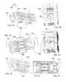
- FIGS. 1A-1Iillustrate components of the graft distribution system, according to some embodiments.
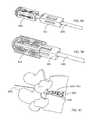
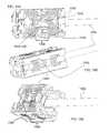
- FIGS. 2A-2Fillustrate a method of using a bidirectionally-expandable cage, according to some embodiments.
- FIGS. 3A-3Dillustrate a bidirectionally-expandable cage for fusing an intervertebral disc space, according to some embodiments.
- FIGS. 4A and 4Billustrate collapsed and expanded views of a bidirectionally-expandable cage having a bone graft window on each wall for fusing an intervertebral disc space, according to some embodiments.
- FIGS. 5A-5Dillustrate system for fusing an intervertebral disc space, according to some embodiments.
- FIG. 6is a diagram of a method of using a bidirectionally-expandable cage, according to some embodiments.
- FIGS. 7A-7Fillustrate some additional features of graft distribution systems, according to some embodiments.
- FIGS. 8A-8Dillustrate components of a graft distribution kit, according to some embodiments.
- FIGS. 9A-9Cillustrate the expansion of a laterovertically-expandable frame in an intervertebral space, according to some embodiments.
- FIGS. 10A-10Cillustrate profiles of an expanded graft distribution system to highlight the exit ports and bone graft windows, according to some embodiments.
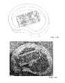
- FIGS. 11A and 11Bcompare an illustration of the graft distribution in place to a test placement in a cadaver to show relative size, according to some embodiments.
- FIGS. 12A-12Cshow x-rays of a placement in a cadaver, according to some embodiments.
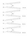
- FIGS. 13A-13Dshow orientations of the first top beam relative to the second top beam, first bottom beam relative to the second bottom beam, first top beam relative to the first bottom beam, and the second top beam relative to the second bottom beam, according to some embodiments.
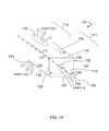
- FIGS. 14A-14Dillustrate components of a system having a stabilizer, wherein the stabilizer is in an X-configuration, according to some embodiments.
- FIGS. 15A-15Dillustrate components of a system having a stabilizer, wherein the stabilizer is in an H-configuration, according to some embodiments.
- the teachings hereinare directed to intervertebral scaffolding systems having a stabilizer for stabilizing and/or retaining support beams upon expansion of the scaffolding in an intervertebral disc space.
- the systemscan have, for example, a central beam having a proximal portion having an end, a grafting portion having a top and a bottom, a distal portion having a end, a central beam axis, a graft distribution channel having an entry port at the end of the proximal portion, a top exit port at the top of the grafting portion, and a bottom exit port at the bottom of the grafting portion.
- These systemscan also include a laterovertically-expanding frame having a lumen, a first top beam, a second top beam, a first bottom beam, and a second bottom beam, each having a proximal portion and a distal portion, and each operably connected to each other at their respective proximal portions and distal portions with connector elements to form the laterovertically-expanding frame that is operable for a reversible collapse from an expanded state into a collapsed state.
- the expanded statefor example, can be configured to have an open graft distribution window that at least substantially closes upon the reversible collapse.
- the laterovertically-expanding frameis adapted for receiving an insertion of the central beam to form the graft distribution system.
- the systemscan also include a laterovertically-expanding frame having a first top beam, a second top beam, a first bottom beam, and a second bottom beam; wherein, the beams are in an at least substantially parallel arrangement with each other, each having a proximal portion, a grafting portion, and a distal portion, and each operably connected to each other at their respective proximal portions and distal portions to form the laterovertically-expanding frame in a square, cylindrical shape that is operable for a reversible collapse from an expanded state into a collapsed state.
- the expanded statefor example, can be configured to have an open graft distribution window that at least substantially closes upon the reversible collapse.
- the laterovertically-expanding frameis adapted for receiving an insertion of the central beam to form the graft distribution system.
- subject and patientcan be used interchangeably in some embodiments and refer to an animal such as a mammal including, but not limited to, non-primates such as, for example, a cow, pig, horse, cat, dog; and primates such as, for example, a monkey or a human.
- non-primatessuch as, for example, a cow, pig, horse, cat, dog
- primatessuch as, for example, a monkey or a human.
- non-primatessuch as, for example, a cow, pig, horse, cat, dog
- primatessuch as, for example, a monkey or a human.
- the terms “subject” and “patient”can also be applied to non-human biologic applications including, but not limited to, veterinary, companion animals, commercial livestock, and the like.
- terms of degreeare used herein to provide relative relationships between the position and/or movements of components of the systems taught herein.
- the phrase “at least substantially parallel”is used to refer to a position of one component relative to another.
- An axis that is at least substantially parallel to another axisrefers to an orientation that is intended, for all practical purposes to be parallel, but it is understood that this is just a convenient reference and that there can be variations due to stresses internal to the system and imperfections in the devices and systems.
- the phrase “at least substantially on a . . . plane”refers to an orientation or movement that is intended, for all practical purposes to be on or near the plane as a convenient measure of the orientation or movement, but it is understood that this is just a convenient reference and that there can be variations due to stresses internal to the system and imperfections in the devices and systems.
- the phrase “at least substantially coincident”refers to an orientation or movement that is intended, for all practical purposes to be on or near, for example, an axis or a plane as a convenient measure of the orientation or movement, but it is understood that this is just a convenient reference and that there can be variations due to stresses internal to the system and imperfections in the devices and systems.
- FIGS. 1A-1Iillustrate components of the system, according to some embodiments.
- the graft distribution systems 100can have a central beam 101 with a central beam axis 105 , a graft distribution channel with an entry port 135 in fluid communication with a top exit port 140 , and a bottom exit port 141 .
- the central beam 101can also have a proximal portion 111 having and end with the entry port 135 , a grafting portion 112 having the top exit port 140 and the bottom exit port 141 , and a distal portion (not shown).
- the central beam 101can also be sized to have a transverse cross-section 110 having a maximum dimension ranging from 5 mm to 15 mm for placing the central beam 101 into an intervertebral space through an annular opening having a maximum lateral dimension ranging from 5 mm to 15 mm, the intervertebral space having a top vertebral plate and a bottom vertebral plate.
- the central beam 101can also have a top surface 115 with a first top-lateral surface 117 and a second top-lateral surface 119 , a bottom surface 120 with a first bottom-lateral surface 122 and a second bottom-lateral surface 124 , a first side surface 125 with a first top-side surface 127 and a first bottom-side surface 129 , and a second side surface 130 with a second top-side surface 132 and a second bottom-side surface 134 .
- the central beamcan have transverse cross-sectional lateral dimension ranging from about 5 mm to about 15 mm.
- the vertical dimension of the central beamcan range from about 4 mm to about 12 mm, about 5 mm to about 11 mm, about 6 mm to about 10 mm, and about 7 mm to about 9 mm, about 6 mm to about 8 mm, about 6 mm, or any range or amount therein in increments of 1 mm.
- the lateral dimension of the central beamcan range from about 5 mm to about 15 mm, about 6 mm to about 14 mm, about 7 mm to about 13 mm, about 8 mm to about 12 mm, about 10 mm, or any range or amount therein in increments of 1 mm.
- transverse cross-section of the central beamhas an area with an effective diameter ranging from about 2 mm to about 20 mm, from about 3 mm to about 18 mm, from about 4 mm to about 16 mm, from about 5 mm to about 14 mm, from about 6 mm to about 12 mm, from about 7 mm to about 10 mm, or any range therein.
- the low profilehas an area with a diameter of 2 mm, 4 mm, 6 mm, 8 mm, 10 mm, 12 mm, 14 mm, 16 mm, 18 mm, or any range therein, including any increment of 1 mm in any such diameter or range therein.
- the width (mm) ⁇ height (mm) of the central beamcan be 9.0 ⁇ 5.0, 9.0 ⁇ 6.0, 9.0 ⁇ 7.0, 9.0 ⁇ 8.0, 9.0 ⁇ 9.0, and 9.0 ⁇ 10.0, or any deviation in dimension therein in increments of +/ ⁇ 0.1 mm.
- the central beamcan have a transverse cross-sectional lateral or vertical dimension that ranges from 6.5 mm to 14.0 mm.
- the system 100can also comprise a laterovertically-expanding frame 149 configured for operably contacting the central beam 101 to create a graft distribution system 100 in vivo, the frame 149 having a collapsed state 149 c with a transverse cross section 149 ct having a maximum dimension ranging from 5 mm to 15 mm for placing the frame 149 in the intervertebral space through the annular opening for expansion.
- the frame 149can also have an expanded state 149 e with a transverse cross section 149 et having a maximum dimension ranging from 6.5 mm to 18 mm for retaining the frame 149 in the intervertebral space, the expanded state operably contacting with the central beam 101 in the intervertebral space.
- the frame 149can be defined as including a proximal portion 111 having an end, a grafting portion 112 , a distal portion (not shown) having an end, and a central frame axis 113 of the expanded state 149 e.
- the framecan have transverse cross-sectional lateral dimension in the collapsed state ranging from about 5 mm to about 15 mm.
- the vertical dimension of the frame in the collapsed statecan range from about 4 mm to about 12 mm, about 5 mm to about 11 mm, about 6 mm to about 10 mm, and about 7 mm to about 9 mm, about 6 mm to about 8 mm, about 6 mm, or any range or amount therein in increments of 1 mm.
- the lateral dimension of the frame in the collapsed statecan range from about 5 mm to about 15 mm, about 6 mm to about 14 mm, about 7 mm to about 13 mm, about 8 mm to about 12 mm, about 10 mm, or any range or amount therein in increments of 1 mm.
- transverse cross-section of the frame in the collapsed statehas an area with an effective diameter ranging from about 2 mm to about 20 mm, from about 3 mm to about 18 mm, from about 4 mm to about 16 mm, from about 5 mm to about 14 mm, from about 6 mm to about 12 mm, from about 7 mm to about 10 mm, or any range therein.
- the low profilehas an area with a diameter of 2 mm, 4 mm, 6 mm, 8 mm, 10 mm, 12 mm, 14 mm, 16 mm, 18 mm, or any range therein, including any increment of 1 mm in any such diameter or range therein.
- the width (mm) ⁇ height (mm) of the frame in the collapsed statecan be 9.0 ⁇ 5.0, 9.0 ⁇ 6.0, 9.0 ⁇ 7.0, 9.0 ⁇ 8.0, 9.0 ⁇ 9.0, and 9.0 ⁇ 10.0, or any deviation in dimension therein in increments of +/ ⁇ 0.1 mm.
- the framecan have a transverse cross-sectional dimension, lateral or vertical in the expanded state ranging from 4.0 mm to 18 mm, from 5.0 mm to 19.0 mm, from 6.0 mm to 17.5 mm, from 7.0 mm to 17.0 mm, from 8.0 mm to 16.5 mm, from 9.0 mm to 16.0 mm, from 9.0 mm to 15.5 mm, from 6.5 mm to 15.5 mm, or any range or amount therein in increments of +/ ⁇ 0.1 mm.
- the frameis expanded at least “substantially” beyond the collapsed state when a bone graft window of the frame has opened by at least a 15%, 20%, 25%, 30%, 35%, 40%, 45%, 50%, 60%, 70%, 80%, 90%, 100%, 150%, 200%, 250%, 300%, or more when compared to the bone graft window from the collapsed state.
- the frameis expanded at least “substantially” beyond the collapsed state when a bone graft window of the frame has opened by at least 2 ⁇ , 3 ⁇ , 5 ⁇ , 10 ⁇ , 15 ⁇ , 20 ⁇ , or more when compared to the bone graft window from the collapsed state.
- the laterovertically expandable framesare created in an expanded state.
- the expanded statecan include a state that is at least 30%, at least 40%, at least 50%, at least 60%, at least 70%, at least 80%, at least 90%, or at least 95% of the full expansion.
- full expansioncan be used to refer to an extent of expansion upon which a connector element begins to fatigue, fail, or crack; or, in some embodiments, strain beyond 10%, 20%, or 30%.
- the frame 149can be configured to have a first top beam 150 including a proximal portion 111 having an end, a grafting portion 112 , and a distal portion (not shown) having an end, the first top beam 150 configured for contacting the first top-lateral surface 117 of the central beam and the first top-side surface 127 of the central beam 101 in the expanded state 149 e , the central axis of the first top beam at least substantially on (i) a top plane containing the central axis of the first top beam and the central axis of a second top beam and (ii) a first side plane containing the central axis of the first top beam and the central axis of a first bottom beam.
- the frame 149can be configured to have a second top beam 160 including a proximal portion 111 having an end, a grafting portion 112 having an end, and a distal portion (not shown) having an end, the second top beam 160 configured for contacting the second top-lateral surface 119 of the central beam 101 and the second top-side surface 132 of the central beam 101 in the expanded state 149 e , the central axis of the second top beam at least substantially on (i) the top plane and (ii) a second side plane containing the central axis of the second top beam and the central axis of a second bottom beam.
- the frame 149can be configured to have a first bottom beam 170 including a proximal portion 111 having an end, a grafting portion 112 , and a distal portion (not shown) having an end, the first bottom beam 170 configured for contacting the first bottom-lateral surface 122 of the central beam 101 and the first bottom-side surface 129 of the central beam 101 in the expanded state 149 e , the central axis of the first bottom beam at least substantially on (i) a bottom plane containing the central axis of the first bottom beam and the central axis of a second top beam and (ii) the first side plane.
- the frame 149can be configured to have a second bottom beam 180 including a proximal portion 111 having an end, a grafting portion 112 having an end, and a distal region (not shown) having an end, the second bottom beam 160 configured for contacting the second bottom-lateral surface 124 of the central beam 101 and the second bottom-side surface 134 of the central beam 101 in the expanded state 149 e , the central axis of the second bottom beam being at least substantially on (i) the bottom plane and (ii) a second side plane containing the central axis of the second bottom beam and the second top beam.
- the central axis of the first top beam 150can be at least substantially parallel to the central beam axis 105 .
- the frame 149can be configured to have a second top beam 160 including a proximal portion 111 having an end, a grafting portion 112 having an end, and a distal portion (not shown) having an end, the second top beam 160 configured for contacting the second top-lateral surface 119 of the central beam 101 and the second top-side surface 132 of the central beam 101 in the expanded state 149 e , the central axis of the second top beam 160 being at least substantially parallel to the central beam axis 105 .
- the frame 149can be configured to have a first bottom beam 170 including a proximal portion 111 having an end, a grafting portion 112 , and a distal portion (not shown) having an end, the first bottom beam 170 configured for contacting the first bottom-lateral surface 122 of the central beam 101 and the first bottom-side surface 129 of the central beam 101 in the expanded state 149 e , the central axis of the first bottom beam 170 being at least substantially parallel to the central beam axis 105 .
- the frame 149can be configured to have a second bottom beam 180 including a proximal portion 111 having an end, a grafting portion 112 having an end, and a distal region (not shown) having an end, the second bottom beam 160 configured for contacting the second bottom-lateral surface 124 of the central beam 101 and the second bottom-side surface 134 of the central beam 101 in the expanded state 149 e , the central axis of the second bottom beam 180 being at least substantially parallel to the central beam axis 105 .
- the systems provided hereinhave the layered effect from the frame on the central beam that provides an additive dimension, both laterally and vertically.
- the added dimensionallows for a low profile entry of the system into the intervertebral disc space, a wide lateral profile after expansion in vivo to avoid backout, as well as a sleeve for safe insertion of the central beam between the top endplate and bottom endplate in the intervertebral space.
- the first top beam, second top beam, first bottom beam, and second bottom beamcan each have a transverse cross-sectional wall thickness adding to the respective central beam dimension, the thickness ranging from about 0.5 mm to about 5.0 mm, from about 0.75 mm to about 4.75 mm, from about 1.0 mm to about 4.5 mm, from about 1.25 mm to about 4.25 mm, from about 1.5 mm to about 4.0 mm, from about 1.75 mm to about 3.75 mm, from about 2.0 mm to about 3.5 mm, from about 2.25 mm to about 3.25 mm, or any range therein in increments of 0.05 mm.
- first top beam, second top beam, first bottom beam, and second bottom beamcan each have a transverse cross-sectional wall thickness adding to the respective central beam dimension, the thickness ranging from about 1.5 mm to about 2.5 mm, including 1.5, 1.75, 2.0, 2.25, 2.5, or an amount therein in increments of 0.05 mm.
- the beams of the laterovertically-expanding frame 149can be operably connected through connector elements.
- the frame 149can include a plurality of proximal top connector elements 191 configured to expandably connect the proximal portion 111 of the first top beam 150 to the proximal portion 111 of the second top beam 160 , the expanding consisting of a flexing at least substantially on a top plane containing the central axis of the first top beam 150 and the central axis of the second top beam 160 .
- the frame 149can be configured to have a plurality of distal top connector elements (not shown) configured to expandably connect the distal portion of the first top beam 150 to the distal portion of the second top beam 160 , the expanding consisting of a flexing at least substantially on the top plane.
- the frame 149can be configured to have a plurality of proximal bottom connector elements 193 configured to expandably connect the proximal portion 111 of the first bottom beam 170 to the proximal portion 111 of the second bottom beam 180 , the expanding consisting of a flexing at least substantially on a bottom plane containing the central axis of the first bottom beam 170 and the central axis of the second bottom beam 180 .
- the frame 149can be configured to have a plurality of distal bottom connector elements (not shown) configured to expandably connect the distal portion of the first bottom beam 170 to the distal portion of the second bottom beam 180 , the expanding consisting of a flexing at least substantially on the bottom plane.
- the frame 149can be configured to have a plurality of proximal first side connector elements 195 configured to expandably connect the proximal portion 111 of the first top beam 150 to the proximal portion 111 of the first bottom beam 170 , the expanding consisting of a flexing at least substantially on a first side plane containing the central axis of the first top beam 150 and the central axis of the first bottom beam 170 ; a plurality of distal first side connector elements (not shown) configured to expandably connect the distal portion of the first top beam 150 to the distal portion of the first bottom beam 170 , the expanding consisting of a flexing at least substantially on the first side plane.
- the frame 149can be configured to have a plurality of proximal second side connector elements 197 configured to expandably connect the proximal portion 111 of the second top beam 160 to the proximal portion 111 of the second bottom beam 170 , the expanding consisting of a flexing at least substantially on a second side plane containing the central axis of the second top beam 160 and the central axis of the second bottom beam 180 ; a plurality of distal second side connector elements (not shown) configured to expandably connect the distal portion of the second top beam 160 to the distal portion of the second bottom beam 180 , the expanding consisting of a flexing at least substantially on the second side plane.
- each plurality of proximal connector elementscan be configured as proximal struts in an at least substantially parallel alignment in the expanded state and the collapsed state; and, each plurality distal connector elements are distal struts can be configured in an at least substantially parallel alignment in the expanded state and the collapsed state.
- the proximal top strutscan be configured monolithically integral to the first top beam and the second top beam and adapted to flex toward the distal top struts during collapse; and, the distal top struts can be configured monolithically integral to the first top beam and the second top beam and adapted to flex toward the proximal top struts during collapse.
- proximal bottom strutscan be configured monolithically integral to the first bottom beam and the second bottom beam and adapted to flex toward the distal bottom struts during collapse; and, the distal bottom struts can be configured monolithically integral to the first bottom beam and the second bottom beam and adapted to flex toward the proximal bottom struts during collapse.
- the proximal first side strutscan be configured monolithically integral to the first top beam and the first bottom beam and adapted to flex toward the distal first side struts during collapse; and, the distal first side struts can be configured monolithically integral to the first top beam and the first bottom beam and adapted to flex toward the proximal first side struts during collapse.
- the proximal second side strutscan be configured monolithically integral to the second top beam and the second bottom beam and adapted to flex toward the distal second side struts during collapse; and, the distal second side struts can be configured monolithically integral to the second top beam and the second bottom beam and adapted to flex toward the proximal second side struts during collapse.
- the frame 149can be configured for slidably engaging with the central beam 101 in vivo following placement of the central beam 101 in the intervertebral space through the annular opening, the slidably engaging including translating the central beam 101 into the frame 149 from the proximal end 11 of the frame 149 toward the distal end of the frame 149 in vivo; the translating including keeping the central beam axis 105 at least substantially coincident with the central frame axis 113 during the translating to create the graft distribution system 100 in vivo through the annular opening.
- the system 100can also be configured to form a top graft-slab depth 199 t between the top surface 115 of the central beam 101 and the top vertebral endplate; and, a bottom graft-slab depth 199 b (not shown) between the bottom surface 120 of the central beam 101 and the bottom vertebral endplate in vivo.
- the transverse cross-section 110 of the system 100 in vivois greater than the maximum lateral dimension of the annular opening to avoid backout.
- the central beamcan have any configuration that would be operable with the teachings provided herein.
- criteria for a suitable central beammay include a combination of a material and configuration that provides a suitable stiffness.
- the central beamcan comprise an I-beam. An example of an I-beam configuration and a complementary laterovertically expandable cage are shown in FIGS. 1E and 1F .
- the central beamcan have any one or any combination of graft port configurations that would be operable with the teachings provided herein.
- criteria for a suitable graft port configurationmay include a combination of port size, number of ports, and placement of ports.
- the central beamcan comprise a side graft port.
- each of the connector elements 191 , 193 , 195 , 197can have a cross-sectional aspect ratio of longitudinal thickness to transverse thickness ranging from 1:2 to 1:8.
- a section of a connector elementis shown in FIG. 1G .
- the systemscan also include an improved, low-profile, intervertebral disc cage that expands bidirectionally.
- the cagesoffer several improvements to the art that include, for example, preventing the cage from backing out of the annulus fibrosis after expansion in an intervertebral disc space.
- the terms “cage,” “scaffold” and “scaffolding”, for examplecan be used interchangeably with “laterovertically expandable frame”, “expandable frame”, or “frame”, in some embodiments.
- the cageshave the ability to at least (i) laterally expand within the intervertebral space to avoid backout of the device through the annulotomy, (ii) vertically expand for distraction of the intervertebral space, (iii) provide additional space within the device in the annulus for the introduction of graft materials; (iv) maintain a large, footprint to distribute load over a larger area against the endplate, for example, by not contracting in length to expand in height and/or width; and, (v) insert into the annulus in a minimally-invasive manner using only a unilateral approach.
- FIGS. 2A-2Fillustrate a method of using a bidirectionally-expandable cage, according to some embodiments.
- an annulus 205is prepared with an annulotomy serving as a single point of entry 210 and an intervertebral space 215 for insertion of a bidirectionally expandable cage system 250 .
- FIGS. 2A-2Fillustrate a method of using a bidirectionally-expandable cage, according to some embodiments.
- an annulus 205is prepared with an annulotomy serving as a single point of entry 210 and an intervertebral space 215 for insertion of a bidirectionally expandable cage system 250 .
- the system 250has a cage 255 having a proximal end 256 , a distal end 257 , and a lumen 258 that communicates with the intervertebral space 215 through an expandable/collapsible bone graft window 259 ; a shim core 260 having a tapered nose 262 at the distal end of the shim core 260 ; a releasably attachable rail beam 265 ; a pusher 270 that slidably translates over the shim core 260 and the rail beam 265 ; a trial shim 275 having a shoulder 277 and slidably translating over the rail beam 265 and shim core 260 into the lumen 258 of the cage 255 , and a permanent shim 280 having a shoulder 282 and slidably translating over the rail beam 265 and shim core 260 into the lumen 258 of the cage 255 .
- the procedure for implanting the cage 255begins in FIG. 2A , including inserting a cannula (not shown) with a bullet-nosed obturator through the single point of entry 210 and inside the intervertebral disc space 215 until contacting the opposing wall of the annulus 205 .
- the cannula (not shown) depthis used to select the desired length of the cage 255 .
- the shim core 260is loaded with bone graft material and the rail beam 265 is releasably attached to the shim core 260 .
- the cage 255is loaded onto the rail beam 265 and pushed onto the shim core 260 and into the cannula (not shown) using the pusher 270 until the distal end 257 of the cage 255 contacts the back of the tapered nose 262 of the shim core 260 as shown in FIG. 2A .
- the assembly of the shim core 260 and the cage 255are inserted into the intervertebral space 215 , and the cannula (not shown) is removed as shown in FIG. 2B .
- the lumen 258 of the cage 255is loaded with bone graft material, and the trial shim 275 is slidably translated over the rail beam 265 and the shim core 260 into the lumen 258 of the cage 255 as shown in FIG. 2C .
- a variety of sizes of the trial shim 275can be tested until the largest trial shim 275 that will fit is found, or until the trial shim having the desired vertical and lateral dimensions for expansion is used, in order to laterovertically expand the cage 255 as desired.
- the trial shim 275is then removed, and the lumen 258 of the cage 255 is again filled with bone graft material with the shim core 260 remaining in place as shown in FIG. 2D .
- the permanent shim 280is then slidably translated along the rail beam 265 and the shim core 260 into the intervertebral space 215 using the pusher 270 until the distal end 257 of the cage 255 contacts the back of the tapered nose 262 of the shim core 260 to maintain the desired laterovertical expansion of the cage 255 as shown in FIG. 2E .
- the rail beam 265is then disconnected from the shim core 260 as shown in FIG. 2F .
- the annulotomycan have nearly any dimension considered desirable to one of skill in the art.
- the annulotomycan have a vertical dimension, for example, that is the distance between a top vertebral plate and a bottom vertebral plate, the top vertebral plate and the bottom vertebral plate defining the upper and lower borders of the intervertebral disc space.
- the vertical dimensioncan range from about 4 mm to about 12 mm, about 5 mm to about 11 mm, about 6 mm to about 10 mm, and about 7 mm to about 9 mm, about 6 mm to about 8 mm, about 6 mm, or any range or amount therein in increments of 1 mm.
- the lateral dimension of the single point of entrycan range from about 5 mm to about 15 mm, about 6 mm to about 14 mm, about 7 mm to about 13 mm, about 8 mm to about 12 mm, about 10 mm, or any range or amount therein in increments of 1 mm.
- the single point of entryhas an area with a diameter ranging from about 2 mm to about 20 mm, from about 3 mm to about 18 mm, from about 4 mm to about 16 mm, from about 5 mm to about 14 mm, from about 6 mm to about 12 mm, from about 7 mm to about 10 mm, or any range therein.
- the low profilehas an area with a diameter of 2 mm, 4 mm, 6 mm, 8 mm, 10 mm, 12 mm, 14 mm, 16 mm, 18 mm, or any range therein, including any increment of 1 mm in any such diameter or range therein.
- the low profile dimensions of the cages taught hereinare designed to fit within these dimensions.
- the expandingincludes using a means for (i) laterovertically expanding the cage and (ii) creating a convex surface that at least substantially complements the concavity of a surface of a vertebral endplate that contacts the pair of top beams or the pair of bottom beams.
- the expandingincludes introducing a laterovertical expansion member into the intervertebral space through the single point of entry and into the cage, the laterovertical expansion member configured to provide a vertical force through the cage and into the top vertical endplate and bottom vertical endplate to distract the intervertebral space; and, a lateral force on the first side wall and the second side wall to expand the cage to a width that is greater than the lateral dimension of the single point of entry to prevent the bidirectionally-expandable cage from backing out of the annulus fibrosis after the expanding.
- the laterovertical expansion membercan include a port for introducing the grafting material into the intervertebral space.
- the methods and systems provided hereininclude the use of bone graft materials known to one of skill.
- Materials which may be placed or injected into the intervertebral spaceinclude solid or semi-solid grafting materials, bone from removed from patient's facet, an iliac crest harvest from the patient, and bone graft extenders such as hydroxyapatite, demineralized bone matrix, and bone morphogenic protein.
- solid or semi-solid grafting material componentsinclude solid fibrous collagen or other suitable hard hydrophilic biocompatible material. Some materials may also include swelling for further vertical expansion of the intervertebral disc space.
- the introducingcan include engaging a ratchet mechanism comprising a protuberance on the laterovertical expansion member that engages with a strut of the cage to prevent the cage from backing out of the annulus fibrosis after the expanding.
- the ratchet mechanismcan be, for example, similar to a zip-tie ratchet mechanism having a gear component and a pawl component.
- the cagehas the gear component, for example, including the struts; and, the laterovertical expansion member is a shim device having the pawl component, for example, a projection that can angle toward the proximal end of the expansion member or away from the direction of insertion of the shim device.
- the cagehas the pawl component, for example, including the struts; and, the laterovertical expansion member is a shim device having the gear component, for example, a series of projections.
- a projectioncan angle from about 5° to about 75° toward the proximal end of the expansion member or away from the direction of insertion of the shim device.
- the expandingincludes selecting a shim configured to create a convex surface on the top surface of the top wall to at least substantially complement the concavity of the respective top vertebral plate, and/or the bottom surface of the bottom wall to at least substantially complement the concavity of the respective bottom vertebral plate.
- the expandingincludes selecting a shim configured to vertically expand the distal end of the cage more than the proximal end of the cage.
- the expandingincludes selecting a shim configured to laterally expand the distal end of the cage more than the proximal end of the cage.
- FIGS. 3A-3Dillustrate collapsed and expanded views of a bidirectionally-expandable cage for fusing an intervertebral disc space, according to some embodiments.
- FIGS. 3A and 3Cshow an expanded configuration
- FIGS. 3B and 3Dshow a collapsed configuration.
- the cage 300can comprise at least 4 walls 302 , 304 , 306 , 308 that form a cylinder having a long axis 309 , the at least 4 walls 302 , 304 , 306 , 308 including a top wall 302 forming a top plane and having a top surface with protuberances (not shown) adapted to contact the top vertebral plate (not shown); a bottom wall 304 forming a bottom plane and having a bottom surface with protuberances (not shown) adapted to contact the bottom vertebral plate (not shown); a first side wall 306 forming a first side wall plane; and, a second side wall 308 forming a second side wall plane.
- each of the walls 302 , 304 , 306 , 308can have at least 2 longitudinal beams, such that a rectangular cylinder can have a total of 4 longitudinal beams 312 , 314 , 316 , 318 ; and, a plurality of struts 333 that (i) stack in the collapsed state of the cage 300 , as shown in FIGS.
- the cage 300can be configured to expand laterally in the intervertebral space (not shown) to a size greater than a lateral dimension of the single point of entry (not shown to prevent the bidirectionally-expandable cage 300 from backing out of the annulus fibrosis (not shown) after the expanding shown in FIGS. 3A and 3C .
- the collapsed configurationincludes the design of a low profile entry through the annulus fibrosis to allow for a minimally-invasive procedure.
- the low profile entry of the collapsed configurationshould be a substantially small area of entry having a diameter ranging, for example, from about 5 mm to about 12 mm for the single point of entry through the annulus fibrosis.
- the low profilehas an area with a diameter ranging from about 2 mm to about 20 mm, from about 3 mm to about 18 mm, from about 4 mm to about 16 mm, from about 5 mm to about 14 mm, from about 6 mm to about 12 mm, from about 7 mm to about 10 mm, or any range therein. In some embodiments, the low profile has an area with a diameter of 2 mm, 4 mm, 6 mm, 8 mm, 10 mm, 12 mm, 14 mm, 16 mm, 18 mm, or any range therein, including any increment of 1 mm in any such diameter or range therein.
- each wall of the cagehas a series of v-shaped struts 333 that (i) stack in a closed-complementary configuration 344 in the collapsed state to minimize void space in their respective wall for the low profile entry of the cage both vertically and laterally into the intervertebral space, and (ii) deflect upon expansion in a plane that is at least substantially parallel to the plane of their respective wall to an open-complementary configuration 355 to separate the at least 2 longitudinal beams of the total of 4 longitudinal beams 312 , 314 , 316 , 318 in the rectangular cylinder in their respective wall and open a bone graft window 366 to pass a bone graft material into the intervertebral space in the expanded configuration.
- the cage 300is configured to accommodate the lateral dimension of the single point of entry ranging from about
- the v-shaped strutscan be “V” shaped slots projected through each of the cage walls starting at a distance of 2 mm (0.5-4) from each corner of the cage to effectively render the “V” shaped struts in the mid region of the wall faces, in which the struts can be fabricated as continuous with L shaped beams on the corners.
- the slotscan be cut such that they are projected perpendicular to the faces or angled distally from the outside of the cage to the inside of the cage.
- the distally angled projectioncan facilitate insertion of the shims taught herein.
- the proximal faces of the corners of the beamscan also have inward, distally angled chamfers to facilitate insertion of the shims taught herein.
- the strutscan be uniform in thickness in the proximal-distal direction. In some embodiments, the struts range from about 0.2 mm to about 1.0 mm, from about 0.3 mm to about 0.9 mm, from about 0.4 mm to about 0.8 mm, from about 0.5 mm to about 0.7 mm in thickness, or any range therein in increments of about 0.1 mm.
- the vertex of the “V” strutcan trace along the center axis of the each of the side faces and can be radiused to dimension of 0.031′′ (0.005-0.062′′), in some embodiments, to prevent stress cracking.
- the shape of the strut or the slot projectionscan also be C, U, or W, in some embodiments.
- the strutscan be 4 times thicker in the direction perpendicular to the long axis of the cage than in the direction of the long axis of the cage. In some embodiments, this thickness ratio can range from about 2 ⁇ to about 8 ⁇ , from about 3 ⁇ to about 7 ⁇ , from about 4 ⁇ to about 6 ⁇ , about 5 ⁇ , or any range therein in increments of 1 ⁇ . This thickness can help maintain a high structural stiffness and strength in the direction perpendicular to the proximal-distal axis so that the transverse cross section (perpendicular to the proximal-distal axis) shape is maintained during and after insertion of the cage into the intervertebral disc space.
- the angle of each strutcan range from about 140°-170° as measured at the vertex in the non-stressed state. In these embodiments, the angle facilitates flexion of the legs of each strut towards each other upon moderate inward pressure to collapse the cage for insertion into the disc space. Furthermore the angled strut lies in a plane at least substantially parallel to the plane of it's respective wall, and in some embodiments to the long axis of the cage, so that the flexion does not alter the side wall thickness. This helps to maintain the low profile for insertion while maximizing the lumen size.
- This geometry combined with the solid beams on the cornershelps ensure that the implant has a minimal change in length, less than 15% reduction in length as measured along the long axis, when expanded more than 20% vertically and/or horizontally. As such, the top and bottom of the cage that support the vertebra remain at least substantially constant in length regardless of expansion.
- the cage 300has v-shaped struts 333 and a bone graft window 366 that (i) complements the v-shaped struts 333 in the collapsed configuration and (ii) opens upon expansion to pass a bone graft material into the intervertebral space in the open-complementary configuration 355 , which can also be referred to as an expanded configuration.
- the cage 300has a proximal region 311 , a proximal end 322 , a distal region 388 , a distal end 399 , and at least one of the at least 4 walls 302 , 304 , 306 , 308 having a first series of v-shaped struts 333 that are configured to stack in a closed-complementary configuration 344 in the collapsed state to minimize void space for the low profile entry of the cage 300 into the intervertebral space; and, deflect upon expansion to an open-complementary configuration 355 to separate the at least 2 longitudinal beams of the total of 4 longitudinal beams 312 , 314 , 316 , 318 in the rectangular cylinder in their respective wall and open a bone graft window 366 adapted to pass a bone graft material into the intervertebral space in the expanded configuration; wherein, the first series of v-shaped struts 333 F is located in the proximal region of the
- the cage 300can further comprise a second series of v-shaped struts 333 S that stack in a closed-complementary configuration 344 in the collapsed state to minimize void space for the low profile entry of the cage 300 into the intervertebral space; and, deflect upon expansion to an open-complementary configuration 355 to separate the at least 2 longitudinal beams of the total of 4 longitudinal beams 312 , 314 , 316 , 318 in the rectangular cylinder in their respective wall and open a bone graft window 366 adapted to pass a bone graft material into the intervertebral space in the expanded configuration; wherein, the second series of v-shaped struts 333 S is located in the distal region 388 of the cage 300 , the vertices of the second series of v-shaped struts 333 S pointing away from the distal end 399 of the cage 300 and toward the proximal end 322 of the cage 300 .
- the strut configurationcan result in the expansion of the first series of v-shaped struts 333 F and the second series of v-shaped struts 333 S creating a bone graft window 366 that opens to the bow-tie configuration shown in FIGS. 3A and 3C .
- the cage designprovides flexibility in the relative amounts of lateral expansion and vertical expansion, as well as the relative amounts of expansion proximally and distally across the cage in either the lateral or vertical expansions.
- the cageis configured such that the ratio of the amount of lateral expansion to the amount of vertical expansion is variable.
- the cageis configured such that the ratio of the amount of proximal expansion to the amount of distal expansion is variable for lateral expansion or vertical expansion.
- FIGS. 4A and 4Billustrate collapsed and expanded views of a bidirectionally-expandable cage having a bone graft window on each wall for fusing an intervertebral disc space, according to some embodiments.
- FIG. 4Ashows the cage 400 in the collapsed configuration for a low-profile entry 405 into to single point of entry into an intervertebral disc space
- FIG. 4Bshows the cage 400 in the expanded configuration to distract the intervertebral disc space and avoid back-out of the cage through the single point of entry after the expansion.
- each wallcontains a bone graft window 466 for passing bone graft material into the intervertebral disc space.
- FIGS. 5A-5Dillustrate system for fusing an intervertebral disc space, according to some embodiments.
- the system 550has a cage 555 having an expandable/collapsible bone graft window 566 ; a shim core 560 having a tapered nose 562 at the distal end of the shim core 560 and a bone graft window 566 ; a releasably attachable rail beam 565 ; a pusher (not shown) that slidably translates over the shim core 560 and the rail beam 565 ; a trial shim 575 having a shoulder 577 and slidably translating over the rail beam 565 and shim core 560 into the cage 555 , and a permanent shim 580 having a shoulder 582 and slidably translating over the rail beam 565 and shim core 560 into the cage 555 .
- the systemcan comprise a bidirectionally-expandable cage having at least 4 walls that form a cylinder having a long axis.
- the at least 4 wallscan include, for example, a top wall forming a top plane and having a top surface with protuberances adapted to contact the top vertebral plate; a bottom wall forming a bottom plane and having a bottom surface with protuberances adapted to contact the bottom vertebral plate; and, a first side wall forming a first side wall plane, and a second side wall forming a second side wall plane.
- Each of the wallscan have at least 2 longitudinal beams; and, a plurality of struts that (i) stack in the collapsed state to minimize void space in their respective wall for a low profile entry of the cage both vertically and laterally into a single point of entry into an intervertebral disc; and, (ii) deflect upon expansion to separate the at least 2 longitudinal beams in their respective wall.
- the cagecan be configured to expand laterally in the intervertebral space to a size greater than a lateral dimension of the single point of entry to prevent the bidirectionally-expandable cage from backing out of the annulus fibrosis after the expanding.
- the systemcan include a laterovertical expansion member configured to induce the laterally expanding and the vertically expanding of the cage; and, a core configured to guide the laterovertical expansion member into the cage to induce the laterally expanding and the vertically expanding of the cage.
- the laterovertical expansion membercan also be configured to slidably engage with the core to translationally enter the cage in along the long axis of the cage.
- the lateral expansioncan occur concurrent with the vertical expansion and, in some embodiments, the lateral expansion can occur prior to the vertical expansion, for example, to reduce frictional stress on the cage during the lateral expansion.
- a two stage shimfor example, can be used.
- a first stage shimcan be inserted to expand the cage laterally before inserting a second stage shim to expand the cage vertically.
- the second stage shimcan slidably translate along the first stage shim.
- the shimcan be made of any material considered desirable to one of skill, for example, a metal or a polymer.
- the shimcan comprise a non-resorbable polymer material, an inorganic material, a metal, an alloy, or bone.
- a systemcan include all or any combination of the above.
- the teachingsalso include system for fusing an intervertebral disc space, the system comprising a bidirectionally-expandable cage having a proximal region, a proximal end, a distal region, a distal end, and at least 4 walls, the cage fabricated as a continuous single piece.
- the at least 4 wallsform a cylinder having a long axis and include a top wall forming a top plane and having a top surface with protuberances adapted to contact the top vertebral plate; a bottom wall forming a bottom plane and having a bottom surface with protuberances adapted to contact the bottom vertebral plate; and, a first side wall forming a first side wall plane, and a second side wall forming a second side wall plane.
- Each of the wallscan have at least 2 longitudinal beams and a plurality of struts.
- At least one of the wallscan have a first series of v-shaped struts that are configured to stack in a closed-complementary configuration in the collapsed state to minimize void space for a low profile entry of the cage through a single point of entry into an intervertebral disc space; and, deflect upon expansion to an open-complementary configuration to separate the at least 2 longitudinal beams in their respective wall and open a bone graft window adapted to pass a bone graft material into the intervertebral space in the expanded configuration.
- the first series of v-shaped strutscan be located in the proximal region of the cage, the vertices of the first series of v-shaped struts pointing away from the proximal end of the cage and toward the distal end of the cage; and, the cage can be configured to expand laterally in the intervertebral space to a size greater than a lateral dimension of the single point of entry to prevent the bidirectionally-expandable cage from backing out of the annulus fibrosis after the expanding.
- a laterovertical expansion membercan be configured to induce the laterally expanding and the vertically expanding of the cage; and, a core can be configured to guide the laterovertical expansion member into the proximal end of the cage, and along the long axis of the cage, to expand the cage laterally and vertically. Moreover, the laterovertical expansion member can slidably engage with the core to translationally enter the cage along the long axis of the cage.
- the systems and system componentscan be manufactured using any method known to one of skill in the manufacture of such intricate metal and/or polymeric components.
- the cagecan be fabricated in a partially expanded state or a fully expanded state.
- the cagecan be manufactured to have no internal stress or strain in the partially or fully expanded state when no external loading is applied.
- the system componentscan comprise any suitable material, or any combination of materials, known to one of skill.
- all componentscan be metal, all components can be plastic, or the components can be a combination of metal and plastic.
- the cagescan have performance characteristics that are near that of a bone structure, in some embodiments, such that the scaffoldings are not too stiff or hard, resulting in a localized loading issue in which the scaffolding puts too much pressure on native bone tissue, and likewise such that the scaffoldings are too flexible or soft, resulting in a localized loading issue in which the bone tissue puts too much pressure on the scaffolding.
- a radio-opaque materialcan be employed to facilitate identifying the location and position of the scaffolding in the spinal disc space. Examples of such materials can include, but are not limited to, platinum, tungsten, iridium, gold, or bismuth.
- One of skillcan select materials on the basis of desired material performance characteristics. For example, one of skill will look to performance characteristics that can include static compression loading, dynamic compression loading, static torsion loading, dynamic torsion loading, static shear testing, dynamic shear testing, expulsion testing, and subsidence testing. The parameters for upper and lower limits of performance for these characteristics can fall within the range of existing such spinal devices that bear the same or similar environmental conditions during use.
- a desired static compression loadingcan be approximately 5000N.
- a desired dynamic compression loadingcan have an asymptotic load level of 3000N at 5 ⁇ 10 6 cycles or ⁇ 1500N at 10 ⁇ 10 6 cycles.
- the desired load levelcan range, for example, from about 1.0 ⁇ to about 2.0 ⁇ , from about 1.25 ⁇ to about 1.75 ⁇ , or any range therein in increments of 0.1 ⁇ , the vertebral body compression strength.
- Examples of standard procedures used to test such performance characteristicsinclude ASTM F2077 and ASTM F2624.
- suitable materialscan include non-reinforced polymers, carbon-reinforced polymer composites, PEEK (polyether ketone) and PEEK composites, polyetherimide (ULTEM), polyimide, polyamide or carbon fiber.
- Other examplesinclude metals and alloys comprising any one or more components including, but not limited to, shape-memory alloys, nickel, titanium, titanium alloys, cobalt chrome alloys, stainless steel, ceramics and combinations thereof.
- the componentsare all titanium or titanium alloy; all PEEK; or a combination of titanium or titanium alloy and PEEK.
- the cagecomprises titanium or titanium alloy
- the shimcomprises PEEK.
- the scaffoldingcan comprise a metal frame and cover made of PEEK or ULTEM.
- titanium alloyscan include alloys of titanium, aluminum, and vanadium, such as Ti 6 Al 4 V in some embodiments.
- the cagecan be fabricated from strong and ductile polymers having a tensile modulus of about 400,000 psi or more, and a tensile strength of about 14,000 psi or more. Such polymers may also have the ability to strain more than 4% to break, and perhaps at least 20% to break in some embodiments.
- the materialscan be stiffened by being filled with glass fibers or carbon fibers in some embodiments.
- the scaffoldingcan comprise materials that contain holes or slots to allow for such bone ingrowth.
- the scaffoldingscan be coated with hydroxyapatite, or other bone conducting surface, for example, bone morphogenic protein, to facilitate bone ingrowth.
- the surfaces of the scaffoldingscan be formed as rough surfaces with protuberances, insets, or projections of any type known to one of skill, such as teeth or pyramids, for example, to grip vertebral endplates, avoid migration of the scaffolding, and encourage engagement with bone ingrowth.
- the methods and systems provided hereininclude the use of bone graft materials known to one of skill.
- Materials which may be placed or injected into the intevertebral spaceinclude solid or semi-solid grafting materials, bone from removed from patient's facet, an iliac crest harvest from the patient, and bone graft extenders such as hydroxyapatite, demineralized bone matrix, and bone morphogenic protein.
- bone graft extenderssuch as hydroxyapatite, demineralized bone matrix, and bone morphogenic protein.
- solid or semi-solid grafting material componentsinclude solid fibrous collagen or other suitable hard hydrophilic biocompatible material. Some materials may also include swelling for further vertical expansion of the intervertebral disc space.
- kitscan contain, for example, a cage, a vertical expansion member, and a bone graft material.
- the kitwill contain an instruction for use.
- the vertical expansion membercan be any vertical expansion mechanism or means taught herein.
- the vertical expansion membercan be a shim.
- the kitincludes a graft-injection shim for temporarily distracting the intervertebral space, the graft-injection shim having a port for receiving and distributing the bone graft material in the intervertebral space.
- the graft-injection shimcan remain as a permanent shim or be removed and replaced with a permanent shim.
- FIG. 6is a flowchart of a method of using a bidirectionally-expandable cage, according to some embodiments.
- the methodscan include creating 605 a single point of entry into an intervertebral disc, the intervertebral disc having a nucleus pulposus surrounded by an annulus fibrosis, and the single point of entry having a lateral dimension created through the annulus fibrosis.
- the methodscan also include removing 615 the nucleus pulposus from within the intervertebral through the single point of entry, leaving an intervertebral space for expansion of a bidirectionally-expandable cage within the annulus fibrosis, the intervertebral space having a top vertebral plate and a bottom vertebral plate.
- the methodscan also include inserting 625 a bidirectionally-expandable cage through the single point of entry into the intervertebral space. Moreover, the methods can include expanding 635 the cage in the intervertebral space both laterally and vertically, adding 645 a grafting material to the intervertebral space through the single point of entry, and inserting 665 a permanent shim into the cage.
- the expanding 635includes selecting 655 an amount of lateral expansion independent of an amount of vertical expansion.
- the lateral expanding of the cagecan be selected, for example, to exceed the lateral dimension of the single point of entry through an annulotomy by a desired amount to avoid, or prevent, the cage from backing out of the intervertebral space after expansion.
- the methodscan include creating a single point of entry into an intervertebral disc, the intervertebral disc having a nucleus pulposus surrounded by an annulus fibrosis, and the single point of entry having the maximum lateral dimension created through the annulus fibrosis.
- the methodscan also include removing the nucleus pulposus from within the intervertebral disc through the single point of entry, leaving the intervertebral space for expansion of the graft distribution system within the annulus fibrosis, the intervertebral space having the top vertebral plate and the bottom vertebral plate.
- the methodscan also include inserting the laterovertically expanding frame in the collapsed state through the single point of entry into the intervertebral space; and, inserting the central beam into the frame to form the graft distribution system. Moreover, the methods can also include adding a grafting material to the intervertebral space through the entry port.
- FIGS. 7A-7Fillustrate some additional features of graft distribution systems, according to some embodiments.
- the graft distribution systems 700 provided hereinhave at least a top exit port 740 and a bottom exit port 741 in the grafting portion of the central beam 701 , but they can also contain side ports 742 , 743 , such that there at least 4 graft distribution ports in some embodiments.
- the central beam 701further comprises a first side graft port 742 and a second side graft port 743 , in addition to a locking clip 702 at the proximal end of the central beam.
- the laterovertically-expanding frame 749can be a monolithically integral frame, optionally having a “bullet nose” 703 at the distal end of the frame for safe position of the cage against the anterior inner annulus in vivo, and adapted to open a graft distribution window 788 on at least the top and bottom sides, as well as the first side and second side in some embodiments containing side ports, upon expansion of the connector elements to facilitate graft distribution within the intervertebral space.
- the distal end of the frame 749can be configured to have a laterovertically operable connection with a guide plate 707 that restricts the first top beam, the first bottom beam, the second top beam, and the second bottom beam to laterovertical movement relative to the guide plate when converting the frame from the collapsed state to the expanded state in vivo.
- the laterovertically-expandable framehas a lumen
- the guide platehas a luminal side with a connector 708 for reversibly receiving a guide wire for inserting the laterovertically-expandable frame into the intervertebral space.
- the framehas a chamfer inside the proximal end of the frame beams to facilitate insertion of central beam.
- the frameshave means for creating friction between the vertebral endplates and the frame, such as protuberances, for example cleat-type structures 704 , to further avoid backout.
- the bone graft distribution systemsinclude bone graft windows defined by the connector elements, the bone graft windows opening upon expansion of the laterovertically expanding frame.
- the methodfurther comprises opening a bone graft window, wherein the connector elements include v-shaped struts that (i) stack either proximally or distally in a closed-complementary configuration in the collapsed state to minimize void space for a low profile entry of the system both vertically and laterally into the intervertebral space, and (ii) deflect upon expansion to open the bone graft window.
- the bone graft distribution systems provided hereinalso allow for independent expansion laterally and vertically by expanding in steps.
- the expandingincludes selecting an amount of lateral expansion independent of an amount of vertical expansion.
- the lateral expansionexceeds the width of the annular opening that is the single point of entry into the intervertebral space.
- the lateral dimension of the single point of entrycan range from about 5 mm to about 15 mm in some embodiments.
- the expandingincludes expanding the laterovertically expanding frame laterally to a width that exceeds the width of the single point of entry; and, inserting the central beam to expand the laterovertically expanding frame vertically to create the graft distribution system.
- the bone graft distribution systems provided hereinalso have additional means for retaining the central beam in the laterovertically expanding frame.
- the inserting of the central beam into the laterovertically expanding frameincludes engaging a ratchet mechanism comprising a protuberance on the central beam that engages with the laterovertically-expanding frame to prevent the central beam from backing out of the laterovertically-expanding frame after the expanding.
- kitscan include, for example, a graft distribution system taught herein, a cannula for inserting the graft distribution system into the intervertebral space, a guidewire adapted for guiding the central beam into the laterovertically expanding frame, and an expansion handle for inserting the central beam into the laterovertically expanding frame to form the graft distribution system.
- FIGS. 8A-8Dillustrate components of a kit, according to some embodiments.
- FIGS. 8A and 8Billustrate a 4 -sided funnel cannula 805 as taught herein having a shaft 810 forming a channel 815 , a funnel 820 for guiding a laterovertically expandable frame into an annulus in a low-profile configuration, the cannula shown with an obturator 825 in the channel 815 of the cannula 805 , the cannula 805 inserted posterolaterally through an annulotomy 877 in the annulus 888 , into an intervertebral space 899 , with the distal end of the cannula 805 position near the inner anterior wall of the annulus 888 .
- FIG. 8A and 8Billustrate a 4 -sided funnel cannula 805 as taught herein having a shaft 810 forming a channel 815 , a funnel 820 for guiding a laterovertically expandable frame into an annulus in
- FIG. 8Cillustrates FIG. 8A with a guidewire used to insert the laterovertically expandable frame 749 into the funnel 820 of the cannula 805 to guide the frame 749 into the annulus 888 in the low profile, collapsed state of the frame 749 .
- FIG. 8Aillustrates FIG. 8A with a guidewire used to insert the laterovertically expandable frame 749 into the funnel 820 of the cannula 805 to guide the frame 749 into the annulus 888 in the low profile, collapsed state of the frame 749 .
- FIG. 8Dillustrates an expansion handle 855 having trigger 856 that pushes a pushrod 857 along the guidewire 866 while holding the guidewire to push on the proximal end of the central beam 701 to insert the central beam 701 into the frame 749 to expand the frame 749 by applying equal, or substantially equal forces: a proximally-directed force, F p , at the connection 708 between the guide plate 707 and the guide wire 866 onto the distal portion of the beams of the frame 749 , and a distally-directed force, F D , at the proximal end of the central beam 701 .
- F pproximally-directed force
- F Ddistally-directed force
- FIGS. 9A-9Cillustrate the expansion of a laterovertically-expandable frame in an intervertebral space, according to some embodiments.
- FIG. 9Ashows a collapsed frame 949 receiving a central beam 901 along a guidewire 966 .
- FIG. 9Bshows the central beam 901 partially inserted into the frame 949 in an expanded state, the guidewire 966 still in place
- FIG. 9Cshows how the expanded state may appear when inserted posterolaterally and expanded in the intervertebral space in an annulus 988 .
- Side ports 942 , 943 for bone graft distributionare shown through an open bone graft window in the expanded frame 749 .
- FIGS. 10A-10Cillustrate profiles of an expanded graft distribution system to highlight the exit ports and bone graft windows, according to some embodiments.
- the guidewire 1066is shown as remaining in place.
- FIGS. 11A and 11Bcompare an illustration of the graft distribution in place to a test placement in a cadaver to show relative size, according to some embodiments.
- FIGS. 12A-12Cshow x-rays of a placement in a cadaver, according to some embodiments.
- the frame 149can be configured such that the central axis of the first top beam 150 is at least substantially on (i) the top plane and (ii) the first side plane; the central axis of the second top beam 160 is at least substantially on (i) the top plane and (ii) the second side plane; the central axis of the first bottom beam 170 is at least substantially on (i) the bottom plane and (ii) the first side plane; and, the central axis of the second bottom beam being at least substantially on (i) the bottom plane and (ii) the second side plane.
- this configurationprovides a “top face” framed by the first top beam and the second top beam, a “bottom face” framed by the first bottom beam and the second bottom beam, a “first side face” framed by the first top beam and the first bottom beam, and a “second side face” framed by the second top beam and the second bottom beam.
- the frame expandcan be desirable to have the frame expand to shape that is predesigned to fit between the top endplate and the bottom endplate of the intervertebral space in a manner that calls, for example, for opposing faces of the frames to be something other than “at least substantially parallel.”
- the opposing top and bottom sides of the frameexpand such that the central axis of the first top beam is no longer at least substantially parallel to the central axis of the first bottom beam.
- the opposing top and bottom sides of the frameexpand such that the central axis of the second top beam is no longer at least substantially parallel to the central axis of the second bottom beam.
- any combination of the abovemay be desired.
- the laterovertically expandable frames taught hereinenable each of these desirable configurations.
- FIGS. 13A-13Dshow orientations of the first top beam relative to the second top beam, first bottom beam relative to the second bottom beam, first top beam relative to the first bottom beam, and the second top beam relative to the second bottom beam, according to some embodiments.
- FIG. 13Ashows the first top beam 150 relative to the second top beam 160 , in which the angle ⁇ T is formed by the two beams to shape the top face of the frame.
- FIG. 13Bshows the first bottom beam 170 relative to the second bottom beam 180 , in which the angle ⁇ B is formed by the two beams to shape the bottom face of the frame.
- FIG. 13Cshows the first top beam 150 relative to the first bottom beam 170 , in which the angle ⁇ FS is formed by the two beams to shape the first side face of the frame.
- FIG. 13Ashows the first top beam 150 relative to the second top beam 160 , in which the angle ⁇ T is formed by the two beams to shape the top face of the frame.
- FIG. 13Bshows the first bottom beam 170 relative
- each of ⁇ T , ⁇ B , ⁇ FS , and ⁇ SScan be independently selected and each can range from 0° to 32°, from 0.5° to 31.5°, from 0.1° to 31.0°, from 1.5° to 30.5°, from 2.0° to 30.0°, from 2.5° to 29.5°, from 3.0° to 29.0°, from 3.5° to 28.5°, from 4.0° to 28.0°, from 4.5° to 27.5°, from 5.0° to 27°, from 5.5° to 26.5°, from 6.0° to 26.0°, from 6.5° to 25.5°, from 7.0° to 25.0°, from 7.5° to 25.5°, from 8.0° to 26.0°, from 8.5° to 26.5°, from 9.0° to 26.0°, from 9.5° to 25.5°, from
- each of ⁇ T , ⁇ B , ⁇ FS , and ⁇ SScan be independently selected and each can be about 1°, 2°, 3°, 4°, 5°, 6°, 7°, 8°, 9°, 10°, 11°, 12°, 13°, 14°, 15°, 16°, 17°, 18°, 19°, 20°, 21°, 22°, 23°, 24°, 25°, 26°, 27°, 28°, 29°, 30°, 31°, 32°, 33°, 34°, 35°, or any angle therein in increments of 0.1°.
- the beamscan each be independently designed to have its own, independently selected curvature, whether convex or concave, and the curvatures can be the same or different between beams that share a face of the frame. And, the curvatures can be opposing for beams that form opposing faces of the frame. Moreover, the frame can have a mixture of one or more straight and one or more curved beams.
- the framescan be designed according to nearly any opening bordered by the top vertebral endplate and bottom vertebral endplate of an intervertebral space, as well as according to a given clinical treatment regardless of the opening dimensions prior to treatment.
- the top face of the framecan be at least substantially parallel to the bottom face of the frame, whereas the first side face of the frame and the second side face of the frame can be oriented at angles ⁇ T and ⁇ B , wherein ⁇ T and ⁇ B can be independently selected to be the same or different.
- the first side face of the framecan be at least substantially parallel to the second side face of the frame, whereas the top face of the frame and the bottom face of the frame can be oriented at angles ⁇ FS and ⁇ SS , wherein ⁇ FS and ⁇ SS can be independently selected to be the same or different.
- each of ⁇ T , ⁇ B , ⁇ FS , and ⁇ SScan be independently selected to range from about 5° to about 32°, from about 7° to about 22°, and from about 8° to about 16°, in some embodiments.
- any of a variety of framescan be constructed from any of a variety of quadrilateral structures having the angles taught herein.
- the systemsinclude a stabilizer that slidably engages with the distal region of the first top beam, the first bottom beam, the second top beam, the second bottom beam, or a combination thereof.
- the stabilizerserves the function of the guide plate taught herein and can also be configured for retaining the first top beam, the first bottom beam, the second top beam, the second bottom beam, or the combination thereof, from a lateral movement that exceeds the expanded state.
- the framingcan be configured for engaging with the central beam in vivo to support the framing in the expanded state.
- the connector elementscan be struts configured to have a cross-sectional aspect ratio of longitudinal thickness to transverse thickness ranging from 1:2 to 1:8, adapted to maintain structural stiffness in the laterovertically expanding frame in a direction perpendicular to the central frame axis of the expanded state of the frame.
- FIGS. 14A-14Dillustrate components of a system having a stabilizer, wherein the stabilizer is in an X-configuration, according to some embodiments.
- the system 1400can include a stabilizer 1407 that can be in an X-configuration.
- the X-configurationcan have a first top leg TL 1 for slidably-engaging with the first top beam 1450 at an angle ⁇ 1T with the intended lateral movement LM 1T of the first top beam 1450 , first bottom leg BL 1 for slidably engaging with the first bottom beam 1470 at an angle ⁇ 1b with the intended lateral movement LM 1B of the first bottom beam 1470 , a second top leg TL 2 for slidably engaging with the second top beam 1480 at an angle ⁇ 2T with the intended lateral movement LM 2T of the second top beam 1460 , and a second bottom leg BL 2 for slidably engaging with the second bottom beam 1480 at an angle ⁇ 2B with the intended lateral movement LM 2B of the second bottom beam 1480 .
- each of the angles ⁇ 1T , ⁇ 1B , ⁇ 2T , ⁇ 2Brespectively, provide a tensile force for resisting the first top beam 1450 , the first bottom beam 1470 , the second top beam 1460 , and the second bottom beam 1480 from the lateral movement LM 1T , LM 2T , LM 1B , LM 2B that exceeds the expanded state.
- each of the angles ⁇ 1T ⁇ 1B ⁇ 2T ⁇ 2Bcan be independently selected from an amount of angulation ranging from about 15° to about 75°, from about 20° to about 75°, from about 25° to about 75°, from about 30° to about 75°, from about 35° to about 75°, from about 55° to about 75°, from about 15° to about 70°, from about 15° to about 65°, from about 15° to about 60°, from about 15° to about 55°, from about 15° to about 50°, from about 15° to about 45°, or any range therein.
- each of the angles ⁇ 1T ⁇ 1B ⁇ 2T ⁇ 2Bcan be independently selected from an amount of angulation that is about 10°, about 15°, about 20°, about 25°, about 30°, about 35°, about 40°, about 45°, about 50°, about 55°, about 60°, about 65°, about 70°, about 75°, about 80°, or any angulation therein in amounts of 1°.
- the stabilizer 1407further comprises a point of attachment 1408 for releasably attaching a guidewire (not shown) for guiding the central beam 1401 into the laterovertically expanding frame comprising the first top beam 1450 , the second top beam 1460 , the first bottom beam 1470 , and the second bottom beam 1480 .
- the first top leg TL 1 , the first bottom leg BL 1 , the second top leg TL 2 , and the second bottom leg BL 2converge to form a hub 1408 H having a point of attachment 1408 on the posterior surface of the hub 1408 H for releasably attaching a guidewire (not shown) for guiding the central beam 1401 into the laterovertically expanding frame.
- the point of attachmentmight be, for example, a male or female threaded component, or any other releasable connector known to one of skill.
- the beams 1450 , 1460 , 1470 , 1480can be configured with ports TP 1 , TP 2 , BP 1 , BP 2 for passage of the respective legs TL 1 , TL 2 , BL 1 , BL 2 of the stabilizer 1407 .
- FIGS. 14B and 14Cshow the system in a collapsed configuration and expanded side configuration, respectively.
- the central beam 1401can include one or more bone graft distribution ports 1466 .
- the beams 1450 , 1460 , 1470 , 1480can be interconnected using flexible struts 1495 .
- FIGS. 15A-15Dillustrate components of a system having a stabilizer, wherein the stabilizer is in an H-configuration, according to some embodiments.
- the H-configurationcan have a first vertical leg VL 1 , a second vertical leg VL 2 , and a cross-member CM that connects the first vertical leg VL 1 at least substantially parallel to the second vertical leg VL 2 , the first vertical leg VL 1 including a first retaining surface RS 1 for engaging with the first top beam 1550 and the first bottom beam 1570 , the second vertical leg VL 2 including a second retaining surface RS 2 for engaging with the second top beam 1560 and the second bottom beam 1580 , and the cross member CM providing a tensile force for resisting the first top beam 1550 , the first bottom beam 1570 , the second top beam 1560 , and the second bottom beam 1580 from the lateral movement that exceeds the expanded state.
- the central beam 1501has a horizontal groove HG configured complementary to the cross-member CM of the stabilizer 1507 , and the horizontal groove HG of the central beam 1501 slidably connects with the cross-member CM in the expanded state.
- the cross-member CMfurther comprises a vertical support member VSM and the central beam 1501 has a vertical groove VG configured complementary to the vertical support member VSM of the stabilizer, and the vertical groove VG of the central beam 1501 slidably connects with the vertical support member VSM in the expanded state.
- the stabilizer 1507further comprises a point of attachment 1508 at a hub 1508 H for releasably attaching a guidewire (not shown) adapted for guiding the central beam 1501 into the laterovertically expanding frame comprising the first top beam 1550 , the second top beam 1560 , the first bottom beam 1570 , and the second bottom beam 1580 .
- guidewire(not shown) for guiding the central beam 1501 into the laterovertically expanding frame.
- the point of attachmentmight be, for example, a male or female threaded component, or any other releasable connector known to one of skill.
- the beams 1550 , 1560 , 1570 , 1580can be configured with slots S 1 , S 2 in which the vertical legs VL 1 , VL 2 can travel during the lateral expansion of the beams 1550 , 1560 , 1570 , 1580 of the expandable frame.
- cross-member CMincludes a first pillar P 1 and a second pillar P 2 that operably connect at a hub that has the point of attachment 1508 for releasably attaching the guidewire (not shown) for guiding the central beam 1501 into the laterovertically expanding frame.
- the central beam 1501can include one or more bone graft distribution ports 1566 .
- the beams 1550 , 1560 , 1570 , 1580can be interconnected using flexible struts 1595 .
- the teachings provided hereinare directed to basic concepts that can extend beyond any particular embodiment, embodiments, figure, or figures. It should be appreciated that any examples are for purposes of illustration and are not to be construed as otherwise limiting to the teachings.
- the devices provided hereincan also be used as implants in other areas of the body.
- the devices provided hereincan be used, for example, in intravertebral body procedures to support or distract vertebral bodies in the repair of, for example, collapsed, damaged or unstable vertebral bodies suffering from disease or injury.
Landscapes
- Health & Medical Sciences (AREA)
- Engineering & Computer Science (AREA)
- Biomedical Technology (AREA)
- Orthopedic Medicine & Surgery (AREA)
- Neurology (AREA)
- Transplantation (AREA)
- Oral & Maxillofacial Surgery (AREA)
- Cardiology (AREA)
- Heart & Thoracic Surgery (AREA)
- Vascular Medicine (AREA)
- Life Sciences & Earth Sciences (AREA)
- Animal Behavior & Ethology (AREA)
- General Health & Medical Sciences (AREA)
- Public Health (AREA)
- Veterinary Medicine (AREA)
- Physical Education & Sports Medicine (AREA)
- Prostheses (AREA)
- Surgical Instruments (AREA)
Abstract
Description
Claims (20)
Priority Applications (5)
| Application Number | Priority Date | Filing Date | Title |
|---|---|---|---|
| US14/701,013US9402733B1 (en) | 2015-01-20 | 2015-04-30 | Stabilized, laterovertically-expanding fusion cage systems |
| US15/194,463US9999517B2 (en) | 2015-01-20 | 2016-06-27 | Intervertebral scaffolding with stabilized laterovertical expansion |
| US15/979,873US10758368B2 (en) | 2015-01-20 | 2018-05-15 | Stabilized, 4 beam intervertebral scaffolding system |
| US16/932,064US11918484B2 (en) | 2015-01-20 | 2020-07-17 | Methods of stabilizing an inter vertebral scaffolding |
| US18/411,956US12390346B2 (en) | 2015-01-20 | 2024-01-12 | Methods of stabilizing an intervertebral scaffolding system |
Applications Claiming Priority (2)
| Application Number | Priority Date | Filing Date | Title |
|---|---|---|---|
| US14/600,617US9060876B1 (en) | 2015-01-20 | 2015-01-20 | Stabilized intervertebral scaffolding systems |
| US14/701,013US9402733B1 (en) | 2015-01-20 | 2015-04-30 | Stabilized, laterovertically-expanding fusion cage systems |
Related Parent Applications (1)
| Application Number | Title | Priority Date | Filing Date |
|---|---|---|---|
| US14/600,617ContinuationUS9060876B1 (en) | 2015-01-20 | 2015-01-20 | Stabilized intervertebral scaffolding systems |
Related Child Applications (1)
| Application Number | Title | Priority Date | Filing Date |
|---|---|---|---|
| US15/194,463ContinuationUS9999517B2 (en) | 2015-01-20 | 2016-06-27 | Intervertebral scaffolding with stabilized laterovertical expansion |
Publications (2)
| Publication Number | Publication Date |
|---|---|
| US20160206439A1 US20160206439A1 (en) | 2016-07-21 |
| US9402733B1true US9402733B1 (en) | 2016-08-02 |
Family
ID=53396986
Family Applications (6)
| Application Number | Title | Priority Date | Filing Date |
|---|---|---|---|
| US14/600,617ActiveUS9060876B1 (en) | 2015-01-20 | 2015-01-20 | Stabilized intervertebral scaffolding systems |
| US14/701,013ActiveUS9402733B1 (en) | 2015-01-20 | 2015-04-30 | Stabilized, laterovertically-expanding fusion cage systems |
| US15/194,463ActiveUS9999517B2 (en) | 2015-01-20 | 2016-06-27 | Intervertebral scaffolding with stabilized laterovertical expansion |
| US15/979,873Active2035-02-09US10758368B2 (en) | 2015-01-20 | 2018-05-15 | Stabilized, 4 beam intervertebral scaffolding system |
| US16/932,064Active2036-10-09US11918484B2 (en) | 2015-01-20 | 2020-07-17 | Methods of stabilizing an inter vertebral scaffolding |
| US18/411,956Active2035-01-22US12390346B2 (en) | 2015-01-20 | 2024-01-12 | Methods of stabilizing an intervertebral scaffolding system |
Family Applications Before (1)
| Application Number | Title | Priority Date | Filing Date |
|---|---|---|---|
| US14/600,617ActiveUS9060876B1 (en) | 2015-01-20 | 2015-01-20 | Stabilized intervertebral scaffolding systems |
Family Applications After (4)
| Application Number | Title | Priority Date | Filing Date |
|---|---|---|---|
| US15/194,463ActiveUS9999517B2 (en) | 2015-01-20 | 2016-06-27 | Intervertebral scaffolding with stabilized laterovertical expansion |
| US15/979,873Active2035-02-09US10758368B2 (en) | 2015-01-20 | 2018-05-15 | Stabilized, 4 beam intervertebral scaffolding system |
| US16/932,064Active2036-10-09US11918484B2 (en) | 2015-01-20 | 2020-07-17 | Methods of stabilizing an inter vertebral scaffolding |
| US18/411,956Active2035-01-22US12390346B2 (en) | 2015-01-20 | 2024-01-12 | Methods of stabilizing an intervertebral scaffolding system |
Country Status (6)
| Country | Link |
|---|---|
| US (6) | US9060876B1 (en) |
| EP (1) | EP3247315B1 (en) |
| JP (1) | JP2018501942A (en) |
| CN (1) | CN107427371B (en) |
| AU (1) | AU2016209382B2 (en) |
| WO (1) | WO2016118608A1 (en) |
Cited By (36)
| Publication number | Priority date | Publication date | Assignee | Title |
|---|---|---|---|---|
| US20160213483A1 (en)* | 2012-12-13 | 2016-07-28 | Ouroboros Medical, Inc. | Rigid intervertebral scaffolding |
| US9883953B1 (en) | 2016-09-21 | 2018-02-06 | Integrity Implants Inc. | Stabilized laterovertically-expanding fusion cage systems with tensioner |
| US10213317B2 (en) | 2017-03-13 | 2019-02-26 | Institute for Musculoskeletal Science and Education | Implant with supported helical members |
| US10322014B2 (en) | 2013-09-09 | 2019-06-18 | Integrity Implants Inc. | Expandable trial with telescopic stabilizers |
| US10357377B2 (en) | 2017-03-13 | 2019-07-23 | Institute for Musculoskeletal Science and Education, Ltd. | Implant with bone contacting elements having helical and undulating planar geometries |
| US10433979B2 (en) | 2015-04-29 | 2019-10-08 | Institute Of Musculoskeletal Science And Education, Ltd. | Coiled implants and systems and methods of use thereof |
| US10449051B2 (en) | 2015-04-29 | 2019-10-22 | Institute for Musculoskeletal Science and Education, Ltd. | Implant with curved bone contacting elements |
| US10478312B2 (en) | 2016-10-25 | 2019-11-19 | Institute for Musculoskeletal Science and Education, Ltd. | Implant with protected fusion zones |
| US10492921B2 (en) | 2015-04-29 | 2019-12-03 | Institute for Musculoskeletal Science and Education, Ltd. | Implant with arched bone contacting elements |
| US10507116B2 (en) | 2017-01-10 | 2019-12-17 | Integrity Implants Inc. | Expandable intervertebral fusion device |
| US10512549B2 (en) | 2017-03-13 | 2019-12-24 | Institute for Musculoskeletal Science and Education, Ltd. | Implant with structural members arranged around a ring |
| US10667924B2 (en) | 2017-03-13 | 2020-06-02 | Institute for Musculoskeletal Science and Education, Ltd. | Corpectomy implant |
| US10695192B2 (en) | 2018-01-31 | 2020-06-30 | Institute for Musculoskeletal Science and Education, Ltd. | Implant with internal support members |
| US10709570B2 (en) | 2015-04-29 | 2020-07-14 | Institute for Musculoskeletal Science and Education, Ltd. | Implant with a diagonal insertion axis |
| US10709578B2 (en) | 2017-08-25 | 2020-07-14 | Integrity Implants Inc. | Surgical biologics delivery system and related methods |
| US10758368B2 (en) | 2015-01-20 | 2020-09-01 | Integrity Implants Inc. | Stabilized, 4 beam intervertebral scaffolding system |
| US10893945B2 (en) | 2017-09-29 | 2021-01-19 | Luis E Duarte | Bone cage including offset sets of protrusions within a bone ingrowth cavity and related methods |
| US11224522B2 (en) | 2017-07-24 | 2022-01-18 | Integrity Implants Inc. | Surgical implant and related methods |
| US11285018B2 (en) | 2018-03-01 | 2022-03-29 | Integrity Implants Inc. | Expandable fusion device with independent expansion systems |
| US11317950B2 (en) | 2019-08-21 | 2022-05-03 | FloSpine, LLC | Interspinous-interlaminar stabilization systems and methods |
| US11554020B2 (en) | 2020-09-08 | 2023-01-17 | Life Spine, Inc. | Expandable implant with pivoting control assembly |
| US11602439B2 (en) | 2020-04-16 | 2023-03-14 | Life Spine, Inc. | Expandable implant assembly |
| US11602440B2 (en) | 2020-06-25 | 2023-03-14 | Life Spine, Inc. | Expandable implant assembly |
| US11793652B2 (en) | 2017-11-21 | 2023-10-24 | Institute for Musculoskeletal Science and Education, Ltd. | Implant with improved bone contact |
| US11857432B2 (en) | 2020-04-13 | 2024-01-02 | Life Spine, Inc. | Expandable implant assembly |
| US11896494B2 (en) | 2017-07-10 | 2024-02-13 | Life Spine, Inc. | Expandable implant assembly |
| US11951018B2 (en) | 2017-11-21 | 2024-04-09 | Institute for Musculoskeletal Science and Education, Ltd. | Implant with improved flow characteristics |
| US11986398B2 (en) | 2013-03-13 | 2024-05-21 | Life Spine, Inc. | Expandable implant assembly |
| US12042393B2 (en) | 2019-12-19 | 2024-07-23 | FloSpine, LLC | Expandable inter vertebral implant |
| US12042395B2 (en) | 2019-06-11 | 2024-07-23 | Life Spine, Inc. | Expandable implant assembly |
| US12138179B2 (en) | 2019-06-10 | 2024-11-12 | Life Spine, Inc. | Expandable implant assembly with compression features |
| US12193948B2 (en) | 2013-03-13 | 2025-01-14 | Life Spine, Inc. | Expandable implant assembly |
| US12208011B2 (en) | 2016-10-25 | 2025-01-28 | Institute for Musculoskeletal Science and Education, Ltd. | Implant with multi-layer bone interfacing lattice |
| US12318307B2 (en) | 2021-07-16 | 2025-06-03 | Blue Ocean Spine Gmbh | Adjustable spinal implants, associated instruments and methods |
| US12329652B2 (en) | 2020-07-20 | 2025-06-17 | Integrity Implants Inc. | Expandable fusion device with independent expansion systems |
| US12336917B2 (en) | 2020-05-15 | 2025-06-24 | Life Spine, Inc. | Steerable implant assembly |
Families Citing this family (74)
| Publication number | Priority date | Publication date | Assignee | Title |
|---|---|---|---|---|
| US6793678B2 (en) | 2002-06-27 | 2004-09-21 | Depuy Acromed, Inc. | Prosthetic intervertebral motion disc having dampening |
| US9949843B2 (en) | 2004-08-09 | 2018-04-24 | Si-Bone Inc. | Apparatus, systems, and methods for the fixation or fusion of bone |
| US20180228621A1 (en) | 2004-08-09 | 2018-08-16 | Mark A. Reiley | Apparatus, systems, and methods for the fixation or fusion of bone |
| WO2008070863A2 (en) | 2006-12-07 | 2008-06-12 | Interventional Spine, Inc. | Intervertebral implant |
| US8900307B2 (en) | 2007-06-26 | 2014-12-02 | DePuy Synthes Products, LLC | Highly lordosed fusion cage |
| EP2237748B1 (en) | 2008-01-17 | 2012-09-05 | Synthes GmbH | An expandable intervertebral implant |
| US12232975B2 (en)* | 2008-02-22 | 2025-02-25 | Howmedica Osteonics Corp. | Lockable spinal implant |
| US8936641B2 (en) | 2008-04-05 | 2015-01-20 | DePuy Synthes Products, LLC | Expandable intervertebral implant |
| US9526620B2 (en) | 2009-03-30 | 2016-12-27 | DePuy Synthes Products, Inc. | Zero profile spinal fusion cage |
| KR101687435B1 (en) | 2009-07-06 | 2016-12-19 | 신세스 게엠바하 | Expandable fixation assemblies |
| US8979860B2 (en) | 2010-06-24 | 2015-03-17 | DePuy Synthes Products. LLC | Enhanced cage insertion device |
| US8623091B2 (en) | 2010-06-29 | 2014-01-07 | DePuy Synthes Products, LLC | Distractible intervertebral implant |
| US20120078372A1 (en) | 2010-09-23 | 2012-03-29 | Thomas Gamache | Novel implant inserter having a laterally-extending dovetail engagement feature |
| US9402732B2 (en) | 2010-10-11 | 2016-08-02 | DePuy Synthes Products, Inc. | Expandable interspinous process spacer implant |
| US9248028B2 (en) | 2011-09-16 | 2016-02-02 | DePuy Synthes Products, Inc. | Removable, bone-securing cover plate for intervertebral fusion cage |
| US10363140B2 (en) | 2012-03-09 | 2019-07-30 | Si-Bone Inc. | Systems, device, and methods for joint fusion |
| EP2877127B1 (en) | 2012-07-26 | 2019-08-21 | Synthes GmbH | Expandable implant |
| US9717601B2 (en) | 2013-02-28 | 2017-08-01 | DePuy Synthes Products, Inc. | Expandable intervertebral implant, system, kit and method |
| US9522070B2 (en) | 2013-03-07 | 2016-12-20 | Interventional Spine, Inc. | Intervertebral implant |
| US11147688B2 (en) | 2013-10-15 | 2021-10-19 | Si-Bone Inc. | Implant placement |
| US10166033B2 (en) | 2014-09-18 | 2019-01-01 | Si-Bone Inc. | Implants for bone fixation or fusion |
| JP6542362B2 (en)* | 2014-09-18 | 2019-07-10 | エスアイ−ボーン・インコーポレイテッドSi−Bone, Inc. | Matrix implant |
| AU2016200179B2 (en) | 2015-01-14 | 2020-09-17 | Stryker European Operations Holdings Llc | Spinal implant with porous and solid surfaces |
| AU2016200195B2 (en) | 2015-01-14 | 2020-07-02 | Vb Spine Us Opco Llc | Spinal implant with fluid delivery capabilities |
| US11426290B2 (en) | 2015-03-06 | 2022-08-30 | DePuy Synthes Products, Inc. | Expandable intervertebral implant, system, kit and method |
| US10376206B2 (en) | 2015-04-01 | 2019-08-13 | Si-Bone Inc. | Neuromonitoring systems and methods for bone fixation or fusion procedures |
| CA2930123A1 (en) | 2015-05-18 | 2016-11-18 | Stryker European Holdings I, Llc | Partially resorbable implants and methods |
| US9913727B2 (en) | 2015-07-02 | 2018-03-13 | Medos International Sarl | Expandable implant |
| KR101674490B1 (en)* | 2015-07-10 | 2016-11-09 | 주식회사 메드릭스 | Space extension type cage apparatus for minimal invasive surgery |
| US9713536B2 (en)* | 2015-08-12 | 2017-07-25 | Warsaw Orthopedic, Inc. | Expandable spinal implant and method of implanting same |
| JP6949006B2 (en) | 2015-08-25 | 2021-10-13 | アイエムディーエス リミテッド ライアビリティ カンパニー | Expandable facet implant |
| US10285825B2 (en)* | 2016-04-07 | 2019-05-14 | Howmedica Osteonics Corp. | Surgical insertion instruments |
| EP3474784A2 (en) | 2016-06-28 | 2019-05-01 | Eit Emerging Implant Technologies GmbH | Expandable and angularly adjustable intervertebral cages with articulating joint |
| US11510788B2 (en) | 2016-06-28 | 2022-11-29 | Eit Emerging Implant Technologies Gmbh | Expandable, angularly adjustable intervertebral cages |
| WO2018081322A1 (en) | 2016-10-25 | 2018-05-03 | Imds Llc | Methods and instrumentation for intervertebral cage expansion |
| FR3058043B1 (en)* | 2016-10-27 | 2020-11-13 | Ldr Medical | EXPANDABLE INTERSOMATIC CAGE |
| FR3058044A1 (en)* | 2016-10-27 | 2018-05-04 | Ldr Medical | EXPANDABLE INTERSOMATIC CAGE |
| US10537436B2 (en) | 2016-11-01 | 2020-01-21 | DePuy Synthes Products, Inc. | Curved expandable cage |
| US10888433B2 (en) | 2016-12-14 | 2021-01-12 | DePuy Synthes Products, Inc. | Intervertebral implant inserter and related methods |
| US10398563B2 (en) | 2017-05-08 | 2019-09-03 | Medos International Sarl | Expandable cage |
| US11344424B2 (en) | 2017-06-14 | 2022-05-31 | Medos International Sarl | Expandable intervertebral implant and related methods |
| US10940016B2 (en) | 2017-07-05 | 2021-03-09 | Medos International Sarl | Expandable intervertebral fusion cage |
| EP3456297B1 (en) | 2017-09-15 | 2023-10-04 | Howmedica Osteonics Corp. | Instruments for expandable interbody implants |
| EP3459502B1 (en) | 2017-09-20 | 2024-05-22 | Stryker European Operations Holdings LLC | Spinal implants |
| US11116519B2 (en) | 2017-09-26 | 2021-09-14 | Si-Bone Inc. | Systems and methods for decorticating the sacroiliac joint |
| US10945859B2 (en) | 2018-01-29 | 2021-03-16 | Amplify Surgical, Inc. | Expanding fusion cages |
| ES3011907T3 (en) | 2018-03-28 | 2025-04-08 | Si Bone Inc | Threaded implants for use across bone segments |
| US10893951B2 (en)* | 2018-08-07 | 2021-01-19 | Minimally Invasive Spinal Technology, LLC | Device and method for correcting spinal deformities in patients |
| US11446156B2 (en) | 2018-10-25 | 2022-09-20 | Medos International Sarl | Expandable intervertebral implant, inserter instrument, and related methods |
| GB201818847D0 (en) | 2018-11-19 | 2019-01-02 | Axis Spine Tech Ltd | Intervertebral devices |
| GB201818849D0 (en) | 2018-11-19 | 2019-01-02 | Axis Spine Tech Ltd | Intervertebral devices |
| GB201818850D0 (en) | 2018-11-19 | 2019-01-02 | Axis Spine Tech Ltd | Intervertebral devices |
| GB201902002D0 (en) | 2019-02-13 | 2019-04-03 | Axis Spine Tech Ltd | Intervertebral devices |
| US10722380B1 (en)* | 2019-02-04 | 2020-07-28 | Bret Michael Berry | Laterally expandable spinal implant |
| US11369419B2 (en) | 2019-02-14 | 2022-06-28 | Si-Bone Inc. | Implants for spinal fixation and or fusion |
| EP4613244A2 (en) | 2019-02-14 | 2025-09-10 | SI-Bone Inc. | Implants for spinal fixation and or fusion |
| US11173043B1 (en)* | 2019-05-17 | 2021-11-16 | Joseph T. Robbins | Spinal interbody implants |
| GB201910668D0 (en) | 2019-07-25 | 2019-09-11 | Axis Spine Tech Ltd | Assemblies for and methods of determing height and angle of an intervertebral device |
| GB201910640D0 (en) | 2019-07-25 | 2019-09-11 | Axis Spine Tech Ltd | Insertions instruments |
| WO2021092948A1 (en)* | 2019-11-15 | 2021-05-20 | 邹丽敏 | Interbody fusion cage |
| JP7646654B2 (en) | 2019-11-21 | 2025-03-17 | エスアイ-ボーン・インコーポレイテッド | Rod coupling assembly for bone stabilization construct - Patent application |
| AU2020392121B2 (en) | 2019-11-27 | 2025-05-22 | Si-Bone, Inc. | Bone stabilizing implants and methods of placement across SI joints |
| EP4072452A4 (en) | 2019-12-09 | 2023-12-20 | SI-Bone, Inc. | Sacro-iliac joint stabilizing implants and methods of implantation |
| US11426286B2 (en) | 2020-03-06 | 2022-08-30 | Eit Emerging Implant Technologies Gmbh | Expandable intervertebral implant |
| US12036129B2 (en)* | 2020-08-13 | 2024-07-16 | Brigham Young University | Deployable compliant mechanism |
| EP4259015A4 (en) | 2020-12-09 | 2024-09-11 | SI-Bone, Inc. | SACROILIAC JOINT STABILIZATION IMPLANTS AND METHODS OF IMPLANTATION |
| US11850160B2 (en) | 2021-03-26 | 2023-12-26 | Medos International Sarl | Expandable lordotic intervertebral fusion cage |
| US11752009B2 (en) | 2021-04-06 | 2023-09-12 | Medos International Sarl | Expandable intervertebral fusion cage |
| US20230015512A1 (en)* | 2021-07-16 | 2023-01-19 | Blue Ocean Spine Gmbh | Adjustable Spinal Implants, Associated Instruments and Methods |
| US20230277330A1 (en)* | 2021-11-12 | 2023-09-07 | Corelink, Llc | Expandable Interbody Spacer for Spinal Fusion |
| US12090064B2 (en) | 2022-03-01 | 2024-09-17 | Medos International Sarl | Stabilization members for expandable intervertebral implants, and related systems and methods |
| US20240033100A1 (en)* | 2022-07-29 | 2024-02-01 | Warsaw Orthopedic, Inc. | Interbody implant having endplates connected by struts |
| WO2024217848A1 (en)* | 2023-04-18 | 2024-10-24 | Medtronic Holding Company Sàrl | Expandable spinal implant |
| WO2025038769A1 (en) | 2023-08-15 | 2025-02-20 | Si-Bone Inc. | Pelvic stabilization implants, methods of use and manufacture |
Citations (120)
| Publication number | Priority date | Publication date | Assignee | Title |
|---|---|---|---|---|
| US4309777A (en) | 1980-11-13 | 1982-01-12 | Patil Arun A | Artificial intervertebral disc |
| US4733665A (en) | 1985-11-07 | 1988-03-29 | Expandable Grafts Partnership | Expandable intraluminal graft, and method and apparatus for implanting an expandable intraluminal graft |
| US4759766A (en) | 1984-09-04 | 1988-07-26 | Humboldt-Universitaet Zu Berlin | Intervertebral disc endoprosthesis |
| US4820305A (en) | 1986-11-03 | 1989-04-11 | Harms Juergen | Place holder, in particular for a vertebra body |
| US4997432A (en) | 1988-03-23 | 1991-03-05 | Waldemar Link Gmbh & Co. | Surgical instrument set |
| US5192327A (en) | 1991-03-22 | 1993-03-09 | Brantigan John W | Surgical prosthetic implant for vertebrae |
| US5221261A (en) | 1990-04-12 | 1993-06-22 | Schneider (Usa) Inc. | Radially expandable fixation member |
| WO1996040015A1 (en) | 1995-06-07 | 1996-12-19 | Michelson Gary K | Lordotic interbody spinal fusion implants |
| US5976187A (en) | 1997-01-21 | 1999-11-02 | Spinal Innovations, L.L.C. | Fusion implant |
| US5980522A (en) | 1994-07-22 | 1999-11-09 | Koros; Tibor | Expandable spinal implants |
| US5980552A (en) | 1994-03-17 | 1999-11-09 | Medinol Ltd. | Articulated stent |
| US6039761A (en) | 1997-02-12 | 2000-03-21 | Li Medical Technologies, Inc. | Intervertebral spacer and tool and method for emplacement thereof |
| WO2000044319A1 (en) | 1999-01-27 | 2000-08-03 | Disc-O-Tech Medical Technologies, Ltd. | Expandable intervertebral spacer |
| US6193757B1 (en) | 1998-10-29 | 2001-02-27 | Sdgi Holdings, Inc. | Expandable intervertebral spacers |
| WO2001066047A1 (en) | 2000-03-08 | 2001-09-13 | Loubert Suddaby | Expandable intervertebral fusion implant having improved stability |
| US20020040243A1 (en) | 1996-09-13 | 2002-04-04 | David Attali | Method and apparatus for providing proper vertebral spacing |
| US6368351B1 (en) | 2001-03-27 | 2002-04-09 | Bradley J. Glenn | Intervertebral space implant for use in spinal fusion procedures |
| US6409766B1 (en)* | 1998-07-30 | 2002-06-25 | Expanding Concepts, Llc | Collapsible and expandable interbody fusion device |
| US6419705B1 (en) | 1999-06-23 | 2002-07-16 | Sulzer Spine-Tech Inc. | Expandable fusion device and method |
| US6432107B1 (en) | 2000-01-15 | 2002-08-13 | Bret A. Ferree | Enhanced surface area spinal fusion devices |
| US6443989B1 (en) | 2000-12-04 | 2002-09-03 | Roger P. Jackson | Posterior expandable fusion cage |
| US20020138146A1 (en) | 2000-04-18 | 2002-09-26 | Jackson Roger P. | Anterior expandable spinal fusion cage system |
| US6482235B1 (en) | 1999-08-18 | 2002-11-19 | Intrinsic Orthopedics, Inc. | Devices and methods of vertebral disc augmentation |
| US6488710B2 (en) | 1999-07-02 | 2002-12-03 | Petrus Besselink | Reinforced expandable cage and method of deploying |
| US20030074075A1 (en) | 2001-08-27 | 2003-04-17 | Thomas James C. | Expandable implant for partial disc replacement and reinforcement of a disc partially removed in a discectomy and for reduction and maintenance of alignment of cancellous bone fractures and methods and apparatuses for same |
| US20030083746A1 (en) | 2001-10-31 | 2003-05-01 | Kuslich Stephen D. | Vertebral spacer for spinal stabilization |
| US6575899B1 (en) | 1999-10-20 | 2003-06-10 | Sdgi Holdings, Inc. | Methods and instruments for endoscopic interbody surgical techniques |
| US6582467B1 (en) | 2000-10-31 | 2003-06-24 | Vertelink Corporation | Expandable fusion cage |
| US6595998B2 (en) | 2001-03-08 | 2003-07-22 | Spinewave, Inc. | Tissue distraction device |
| US6666891B2 (en) | 2000-11-13 | 2003-12-23 | Frank H. Boehm, Jr. | Device and method for lumbar interbody fusion |
| US20040010315A1 (en) | 2002-03-29 | 2004-01-15 | Song John K. | Self-expanding intervertebral device |
| US20040024463A1 (en) | 2001-08-27 | 2004-02-05 | Thomas James C. | Expandable implant for partial disc replacement and reinforcement of a disc partially removed in a discectomy and for reduction and maintenance of alignment of cancellous bone fractures and methods and apparatuses for same |
| US6821276B2 (en) | 1999-08-18 | 2004-11-23 | Intrinsic Therapeutics, Inc. | Intervertebral diagnostic and manipulation device |
| US6893464B2 (en) | 2002-03-05 | 2005-05-17 | The Regents Of The University Of California | Method and apparatus for providing an expandable spinal fusion cage |
| US7018415B1 (en) | 2002-09-23 | 2006-03-28 | Sdgi Holdings, Inc. | Expandable spinal fusion device and methods of promoting spinal fusion |
| EP1233732B1 (en) | 2000-02-04 | 2006-05-03 | SDGI Holdings, Inc. | Expandable push-in interbody spinal fusion implant |
| US20060100706A1 (en) | 2004-11-10 | 2006-05-11 | Shadduck John H | Stent systems and methods for spine treatment |
| US7083650B2 (en) | 2004-05-13 | 2006-08-01 | Moskowitz Nathan C | Artificial expansile total lumbar and thoracic discs for posterior placement without supplemental instrumentation and its adaptation for anterior placement of artificial cervical, thoracic and lumbar discs |
| US7087055B2 (en) | 2002-06-25 | 2006-08-08 | Sdgi Holdings, Inc. | Minimally invasive expanding spacer and method |
| US20060287729A1 (en) | 2005-06-15 | 2006-12-21 | Jerome Segal | Mechanical apparatus and method for artificial disc replacement |
| US7214243B2 (en) | 2002-10-21 | 2007-05-08 | 3Hbfm, Llc | Intervertebral disk prosthesis |
| US7217293B2 (en) | 2003-11-21 | 2007-05-15 | Warsaw Orthopedic, Inc. | Expandable spinal implant |
| US20070118222A1 (en) | 2005-11-21 | 2007-05-24 | Vertegen, Inc. | Intervertebral devices and methods |
| EP1532949B1 (en) | 2003-11-20 | 2007-07-18 | Kyungwon Medical Co., Ltd. | Expandable intervertebral fusion cage |
| US20070173939A1 (en) | 2005-12-23 | 2007-07-26 | The Board Of Trustees Of The Leland Stanford Junior University | Systems and methods for fixation of bone with an expandable device |
| US20070219634A1 (en) | 2004-09-21 | 2007-09-20 | Greenhalgh E S | Expandable support device and method of use |
| US20070265627A1 (en) | 1999-08-26 | 2007-11-15 | Dorchak John D | Devices and methods for implanting fusion cages |
| WO2008005627A2 (en) | 2006-07-06 | 2008-01-10 | Lanx, Llc | Expandable spinal fusion cage |
| US20080009876A1 (en) | 2006-07-07 | 2008-01-10 | Meera Sankaran | Medical device with expansion mechanism |
| US20080021556A1 (en) | 2006-07-21 | 2008-01-24 | Edie Jason A | Expandable vertebral implant and methods of use |
| WO2008035849A1 (en) | 2006-09-23 | 2008-03-27 | Nam Soo Song | Expandable jacking curette for bone fusion surgery |
| US20080147193A1 (en) | 2006-11-23 | 2008-06-19 | Wilfried Matthis | Expandable intervertebral implant |
| WO2008089252A2 (en) | 2007-01-16 | 2008-07-24 | Mi4Spine, Llc | Minimally invasive interbody device assembly |
| US20080234687A1 (en) | 2005-08-16 | 2008-09-25 | Laurent Schaller | Devices for treating the spine |
| WO2008121162A1 (en) | 2006-11-29 | 2008-10-09 | Mi4Spine, Llc | Disc space preparation device for spinal surgery |
| US20080281346A1 (en) | 2005-12-19 | 2008-11-13 | Stout Medical Group, L.P. | Expandable support device |
| US20090018524A1 (en) | 2005-12-19 | 2009-01-15 | Stout Medical Group, L.P. | Expandable delivery device |
| US20090076607A1 (en) | 2007-09-19 | 2009-03-19 | Arthur Martinus Aalsma | Collapsible and Expandable Device and Methods of Using Same |
| EP1011503B1 (en) | 1997-02-06 | 2009-04-22 | Howmedica Osteonics Corp. | Expandable non-threaded spinal fusion device |
| US20090138083A1 (en) | 2006-09-14 | 2009-05-28 | Ashok Biyani | Variable height vertebral body replacement implant |
| US7544208B1 (en) | 2004-05-03 | 2009-06-09 | Theken Spine, Llc | Adjustable corpectomy apparatus |
| US20090222100A1 (en) | 2008-02-28 | 2009-09-03 | Stryker Spine | Tool for implanting expandable intervertebral implant |
| US20090222043A1 (en) | 2004-10-20 | 2009-09-03 | Moti Altarac | Interspinous process spacer instrument system with deployment indicator |
| US20090234389A1 (en) | 2008-03-11 | 2009-09-17 | Fong-Ying Chuang | Interspinous spinal fixation apparatus |
| US7621950B1 (en) | 1999-01-27 | 2009-11-24 | Kyphon Sarl | Expandable intervertebral spacer |
| US20100010633A1 (en) | 2008-07-10 | 2010-01-14 | Kyphon Sarl | Deployable Arc Fusion Cage and Methods Associated Therewith |
| US7655046B2 (en) | 2005-01-20 | 2010-02-02 | Warsaw Orthopedic, Inc. | Expandable spinal fusion cage and associated instrumentation |
| US7678148B2 (en) | 2004-07-23 | 2010-03-16 | Warsaw Orthopedic, Inc. | Expandable spinal implant having interlocking geometry for structural support |
| US20100198352A1 (en) | 2006-07-21 | 2010-08-05 | Warsaw Orthopedic, Inc. | Implant with Nested Members and Methods of Use |
| US7771473B2 (en) | 2006-07-06 | 2010-08-10 | Lanx, Inc. | Expandable spinal fusion cage |
| US20100217325A1 (en) | 2008-11-03 | 2010-08-26 | Hochschuler Stephen H | Expandable spinal support device with attachable members and methods of use |
| US20100222884A1 (en) | 2008-11-12 | 2010-09-02 | Stout Medical Group, L.P. | Fixation device and method |
| US20100234956A1 (en) | 2007-03-28 | 2010-09-16 | David Attia | Expanding cage for vertebral surgery |
| US7819921B2 (en) | 2005-08-12 | 2010-10-26 | Coalign Innovations, Inc. | Linearly expanding spine cage for enhanced spinal fusion |
| US7828845B2 (en) | 2000-10-25 | 2010-11-09 | Warsaw Orthopedic, Inc. | Laterally expanding intervertebral fusion device |
| US20100286783A1 (en) | 2008-01-17 | 2010-11-11 | Synthes Usa, Llc | Expandable intervertebral implant and associated method of manufacturing the same |
| US20100292796A1 (en) | 2009-05-14 | 2010-11-18 | Stout Medical Group, L.P. | Expandable support device and method of use |
| US7846206B2 (en) | 2004-06-09 | 2010-12-07 | Vexim Sas | Methods and apparatuses for bone restoration |
| US7850733B2 (en) | 2004-02-10 | 2010-12-14 | Atlas Spine, Inc. | PLIF opposing wedge ramp |
| US7862618B2 (en) | 2006-07-19 | 2011-01-04 | Warsaw Orthopedic, Inc. | Expandable vertebral body implants and methods of use |
| US20110022090A1 (en) | 2009-06-23 | 2011-01-27 | Osteomed, L.P. | Spinous process fusion implants |
| US7879098B1 (en) | 2005-10-19 | 2011-02-01 | Simmons Jr James W | Expandable lordosis stabilizing cage |
| US20110029082A1 (en) | 2008-03-14 | 2011-02-03 | Synthes Usa, Llc | Nested expandable sleeve implant |
| US20110046748A1 (en) | 2006-09-12 | 2011-02-24 | Orthocare Innovations, Llc | Pump system for prosthesis |
| US7909872B2 (en) | 2005-06-03 | 2011-03-22 | Zipnick Richard I | Minimally invasive apparatus to manipulate and revitalize spinal column disc |
| US20110093074A1 (en) | 2009-10-15 | 2011-04-21 | Chad Glerum | Expandable Fusion Device and Method of Installation Thereof |
| US20110130835A1 (en) | 2008-12-10 | 2011-06-02 | Innvotec Surgical, Inc. | Adjustable Distraction Cage With Linked Locking Mechanisms |
| US20110172774A1 (en) | 2010-01-11 | 2011-07-14 | Armando Varela | Expandable intervertebral implant and associated surgical method |
| US20110190816A1 (en) | 2010-02-04 | 2011-08-04 | Ebi, Llc | Interspinous spacer with deployable members and related method |
| US20110282453A1 (en) | 2010-05-13 | 2011-11-17 | Stout Medical Group, L.P. | Fixation device and method |
| US8070813B2 (en) | 2005-09-26 | 2011-12-06 | Coalign Innovations, Inc. | Selectively expanding spine cage, hydraulically controllable in three dimensions for vertebral body replacement |
| US8070754B2 (en) | 2007-05-31 | 2011-12-06 | Fabian Henry F | Spine surgery method and instrumentation |
| US20110301712A1 (en) | 2010-06-02 | 2011-12-08 | Warsaw Orthopedic, Inc. | System and methods for a laterally expanding implant |
| US20110319997A1 (en) | 2010-06-25 | 2011-12-29 | Chad Glerum | Expandable Fusion Device and Method of Installation Thereof |
| US8088163B1 (en) | 2008-02-06 | 2012-01-03 | Kleiner Jeffrey B | Tools and methods for spinal fusion |
| US8105382B2 (en) | 2006-12-07 | 2012-01-31 | Interventional Spine, Inc. | Intervertebral implant |
| US20120029636A1 (en) | 2010-08-02 | 2012-02-02 | Ragab Ashraf A | Bone Cage with Components for Controlled Expansion |
| US8110004B2 (en) | 2008-08-21 | 2012-02-07 | The Trustees Of The Stevens Institute Of Technology | Expandable interbody fusion cage with rotational insert |
| US20120046748A1 (en) | 2010-02-24 | 2012-02-23 | Mark Weiman | Expandable Intervertebral Spacer and Method of Posterior Insertion Thereof |
| US20120059470A1 (en) | 2010-09-03 | 2012-03-08 | Mark Weiman | Expandable Fusion Device and Method of Installation Thereof |
| EP2327377B1 (en) | 2001-03-27 | 2012-03-14 | Warsaw Orthopedic, Inc. | Radially expanding interbody spinal fusion implants and instrumentation for insertion thereof |
| US20120083889A1 (en) | 2010-10-05 | 2012-04-05 | Alphatec Spine, Inc. | Intervertebral device and methods of use |
| US20120089185A1 (en) | 2010-10-11 | 2012-04-12 | Josef Gabelberger | Expandable interspinous process spacer implant |
| US8167950B2 (en) | 2007-10-11 | 2012-05-01 | International Spinal Innovations, Llc | Minimally invasive lateral intervertbral fixation system, device and method |
| US20120109319A1 (en) | 2009-07-14 | 2012-05-03 | Michael Perisic | Interbody cage |
| US8182538B2 (en) | 2007-10-31 | 2012-05-22 | Depuy Spine, Inc. | Expandable fusion cage |
| US8187332B2 (en) | 2004-11-03 | 2012-05-29 | Mcluen Design, Inc. | Bone fusion device |
| US8236058B2 (en) | 2005-09-27 | 2012-08-07 | Fabian Henry F | Spine surgery method and implant |
| US8241363B2 (en) | 2007-12-19 | 2012-08-14 | Depuy Spine, Inc. | Expandable corpectomy spinal fusion cage |
| US20120209386A1 (en) | 2011-02-14 | 2012-08-16 | Medicinelodge, Inc. Dba Imds Co-Innovation | Expandable intervertebral implants and instruments |
| US20120271396A1 (en) | 2007-01-19 | 2012-10-25 | Elixir Medical Corporation | Biodegradable endoprostheses and methods for their fabrication |
| US20120290090A1 (en) | 2009-10-15 | 2012-11-15 | Chad Glerum | Expandable Fusion Device and Method of Installation Thereof |
| US20120303126A1 (en) | 2003-09-30 | 2012-11-29 | X-Spine Systems, Inc.. | Fusion system and method for fusing spinal bones |
| US8353963B2 (en) | 2010-01-12 | 2013-01-15 | Globus Medical | Expandable spacer and method for use thereof |
| US8353961B2 (en) | 2008-02-07 | 2013-01-15 | K2M, Inc. | Expandable vertebral device with cam lock |
| US20130023996A1 (en) | 2008-06-06 | 2013-01-24 | Providence Medical Technology, Inc. | Vertebral joint implants and delivery tools |
| US20130184822A1 (en) | 2009-09-18 | 2013-07-18 | Jeffrey B. Kleiner | Fusion Cage With Combined Biological Delivery System |
| US20140039625A1 (en) | 2012-07-31 | 2014-02-06 | Ouroboros Medical, Inc | A minimally-invasive, laterovertically expanding, intervertebral disc scaffolding |
| US8663332B1 (en) | 2012-12-13 | 2014-03-04 | Ouroboros Medical, Inc. | Bone graft distribution system |
| US20150073555A1 (en) | 2013-09-09 | 2015-03-12 | Ouroboros Medical, Inc. | Staged, bilaterally expandable trial |
Family Cites Families (150)
| Publication number | Priority date | Publication date | Assignee | Title |
|---|---|---|---|---|
| US5658336A (en)* | 1994-03-18 | 1997-08-19 | Pisharodi; Madhavan | Rotating, locking, middle-expanded intervertebral disk stabilizer |
| US5653762A (en)* | 1994-03-18 | 1997-08-05 | Pisharodi; Madhavan | Method of stabilizing adjacent vertebrae with rotating, lockable, middle-expanded intervertebral disk stabilizer |
| DE19807236C2 (en) | 1998-02-20 | 2000-06-21 | Biedermann Motech Gmbh | Intervertebral implant |
| US6102950A (en) | 1999-01-19 | 2000-08-15 | Vaccaro; Alex | Intervertebral body fusion device |
| US6491724B1 (en) | 1999-08-13 | 2002-12-10 | Bret Ferree | Spinal fusion cage with lordosis correction |
| US6436119B1 (en) | 1999-09-30 | 2002-08-20 | Raymedica, Inc. | Adjustable surgical dilator |
| US7918888B2 (en) | 1999-10-13 | 2011-04-05 | Hamada James S | Spinal fusion instrumentation, implant and method |
| US6582441B1 (en) | 2000-02-24 | 2003-06-24 | Advanced Bionics Corporation | Surgical insertion tool |
| US20020035400A1 (en) | 2000-08-08 | 2002-03-21 | Vincent Bryan | Implantable joint prosthesis |
| US10729469B2 (en) | 2006-01-09 | 2020-08-04 | Roger P. Jackson | Flexible spinal stabilization assembly with spacer having off-axis core member |
| US6375682B1 (en)* | 2001-08-06 | 2002-04-23 | Lewis W. Fleischmann | Collapsible, rotatable and expandable spinal hydraulic prosthetic device |
| US20030105466A1 (en) | 2001-11-30 | 2003-06-05 | Ralph James D. | Spacer device and insertion instrument for use in anterior cervical fixation surgery |
| US6582439B1 (en) | 2001-12-28 | 2003-06-24 | Yacmur Llc | Vertebroplasty system |
| US7828849B2 (en) | 2003-02-03 | 2010-11-09 | Warsaw Orthopedic, Inc. | Expanding interbody implant and articulating inserter and method |
| AU2004212942A1 (en) | 2003-02-14 | 2004-09-02 | Depuy Spine, Inc. | In-situ formed intervertebral fusion device |
| US7753958B2 (en) | 2003-08-05 | 2010-07-13 | Gordon Charles R | Expandable intervertebral implant |
| US7204853B2 (en) | 2003-08-05 | 2007-04-17 | Flexuspine, Inc. | Artificial functional spinal unit assemblies |
| US8273129B2 (en) | 2004-02-10 | 2012-09-25 | Atlas Spine, Inc. | PLIF opposing wedge ramp |
| US7931688B2 (en) | 2004-08-25 | 2011-04-26 | Spine Wave, Inc. | Expandable interbody fusion device |
| US20060122701A1 (en) | 2004-11-23 | 2006-06-08 | Kiester P D | Posterior lumbar interbody fusion expandable cage with lordosis and method of deploying the same |
| US20060167547A1 (en) | 2005-01-21 | 2006-07-27 | Loubert Suddaby | Expandable intervertebral fusion implants having hinged sidewalls |
| US7643884B2 (en) | 2005-01-31 | 2010-01-05 | Warsaw Orthopedic, Inc. | Electrically insulated surgical needle assembly |
| US9801733B2 (en) | 2005-03-31 | 2017-10-31 | Life Spine, Inc. | Expandable spinal interbody and intravertebral body devices |
| US9034041B2 (en) | 2005-03-31 | 2015-05-19 | Life Spine, Inc. | Expandable spinal interbody and intravertebral body devices |
| US7731751B2 (en) | 2005-03-31 | 2010-06-08 | Life Spine, Inc. | Expandable spinal devices and method of insertion |
| US8940048B2 (en) | 2005-03-31 | 2015-01-27 | Life Spine, Inc. | Expandable spinal interbody and intravertebral body devices |
| EP1903949A2 (en)* | 2005-07-14 | 2008-04-02 | Stout Medical Group, L.P. | Expandable support device and method of use |
| WO2007076374A2 (en) | 2005-12-19 | 2007-07-05 | Stout Medical Group, L.P. | Expandable support device and method of using the same |
| WO2008065450A1 (en) | 2006-11-29 | 2008-06-05 | Surgicraft Limited | Orthopaedic implants and prostheses |
| US10251759B2 (en) | 2007-03-29 | 2019-04-09 | Life Spine, Inc. | Radially expandable spinal interbody device and implantation tool |
| US9138328B2 (en) | 2007-03-29 | 2015-09-22 | Life Spine, Inc. | Radially expandable spinal interbody device and implantation tool |
| US8900307B2 (en) | 2007-06-26 | 2014-12-02 | DePuy Synthes Products, LLC | Highly lordosed fusion cage |
| US8992620B2 (en) | 2008-12-10 | 2015-03-31 | Coalign Innovations, Inc. | Adjustable distraction cage with linked locking mechanisms |
| US8936641B2 (en)* | 2008-04-05 | 2015-01-20 | DePuy Synthes Products, LLC | Expandable intervertebral implant |
| CA2722918C (en) | 2008-05-07 | 2014-07-15 | George A. Frey | Methods and apparatus for insertion of intervertebral implants and devices therefor |
| JP2012500058A (en) | 2008-08-13 | 2012-01-05 | スメド−ティーエイ/ティーディー・エルエルシー | Orthopedic implant with a porous structural member |
| US20100082109A1 (en) | 2008-09-22 | 2010-04-01 | Stout Medical Group, L.P. | Expandable intervertebral implant |
| US20100211176A1 (en) | 2008-11-12 | 2010-08-19 | Stout Medical Group, L.P. | Fixation device and method |
| US9060808B2 (en) | 2008-12-05 | 2015-06-23 | DePuy Synthes Products, Inc. | Anchor-in-anchor system for use in bone fixation |
| WO2010077359A1 (en) | 2008-12-30 | 2010-07-08 | Mitchell Hardenbrook | Expandable interbody implant and method |
| US8523944B2 (en) | 2008-12-31 | 2013-09-03 | Spinex Tec, Llc | Methods and apparatus for vertebral body distraction and fusion employing flexure members |
| US9050194B2 (en) | 2009-05-06 | 2015-06-09 | Stryker Spine | Expandable spinal implant apparatus and method of use |
| US8906099B2 (en) | 2009-10-13 | 2014-12-09 | Nicholas Poulos | Expandable interbody implant and method |
| US9216095B2 (en) | 2009-10-15 | 2015-12-22 | Globus Medical, Inc. | Expandable fusion device and method of installation thereof |
| US10327917B2 (en) | 2009-10-15 | 2019-06-25 | Globus Medical, Inc. | Expandable fusion device and method of installation thereof |
| US8556979B2 (en) | 2009-10-15 | 2013-10-15 | Globus Medical, Inc. | Expandable fusion device and method of installation thereof |
| US9155628B2 (en) | 2009-10-15 | 2015-10-13 | Globus Medical, Inc. | Expandable fusion device and method of installation thereof |
| US8894712B2 (en) | 2010-01-11 | 2014-11-25 | Innova Spinal Technologies, Llc | Expandable intervertebral implant and associated surgical method |
| US9907560B2 (en) | 2010-06-24 | 2018-03-06 | DePuy Synthes Products, Inc. | Flexible vertebral body shavers |
| US9597200B2 (en) | 2010-06-25 | 2017-03-21 | Globus Medical, Inc | Expandable fusion device and method of installation thereof |
| US9480576B2 (en) | 2010-08-27 | 2016-11-01 | Thompson Mis | Methods and systems for interbody implant and bone graft delivery |
| US9474625B2 (en) | 2010-09-03 | 2016-10-25 | Globus Medical, Inc | Expandable fusion device and method of installation thereof |
| US9566168B2 (en)* | 2010-09-03 | 2017-02-14 | Globus Medical, Inc. | Expandable fusion device and method of installation thereof |
| US10758367B2 (en) | 2010-09-03 | 2020-09-01 | Globus Medical Inc. | Expandable fusion device and method of installation thereof |
| US10842644B2 (en) | 2010-09-03 | 2020-11-24 | Globus Medical, Inc. | Expandable fusion device and method of installation thereof |
| US8435298B2 (en) | 2010-09-03 | 2013-05-07 | Globus Medical, Inc. | Expandable fusion device and method of installation thereof |
| US10085849B2 (en) | 2010-09-03 | 2018-10-02 | Globus Medical, Inc. | Expandable fusion device and method of installation thereof |
| US8632595B2 (en) | 2010-09-03 | 2014-01-21 | Globus Medical, Inc. | Expandable fusion device and method of installation thereof |
| US8398713B2 (en) | 2010-09-03 | 2013-03-19 | Globus Medical, Inc. | Expandable fusion device and method of installation thereof |
| US9907673B2 (en) | 2010-09-03 | 2018-03-06 | Globus Medical, Inc. | Expandable fusion device and method of installation thereof |
| US9351848B2 (en) | 2010-09-03 | 2016-05-31 | Globus Medical, Inc. | Expandable fusion device and method of installation thereof |
| US8491659B2 (en) | 2010-09-03 | 2013-07-23 | Globus Medical, Inc. | Expandable fusion device and method of installation thereof |
| US8852279B2 (en) | 2010-09-03 | 2014-10-07 | Globus Medical, Inc. | Expandable fusion device and method of installation thereof |
| AU2012236149B2 (en) | 2011-03-30 | 2016-05-19 | Trinity Orthopedics, Llc | Articulating interbody cage and methods thereof |
| US9066813B2 (en) | 2011-06-03 | 2015-06-30 | Biomet Spine, Llc | Unidirectional dynamic interbody fusion device and method of use |
| EP2729092B1 (en) | 2011-08-16 | 2016-09-21 | Stryker European Holdings I, LLC | Expandable implant |
| US9241806B2 (en) | 2011-09-26 | 2016-01-26 | Globus Medical, Inc. | Flexible anchoring and fusion devices and methods of using the same |
| WO2013052807A2 (en) | 2011-10-05 | 2013-04-11 | H. Lee Moffitt Cancer Center And Research Institute, Inc. | Bone fusion system |
| US9198765B1 (en) | 2011-10-31 | 2015-12-01 | Nuvasive, Inc. | Expandable spinal fusion implants and related methods |
| US8628578B2 (en) | 2011-12-19 | 2014-01-14 | Warsaw Orthopedic, Inc. | Expandable interbody implant and methods of use |
| US9463052B2 (en) | 2012-01-12 | 2016-10-11 | Integrity Implants Inc. | Access assembly for anterior and lateral spinal procedures |
| EP2830542B1 (en) | 2012-03-28 | 2021-10-27 | Innova Spinal Technologies, LLC | Expandable intervertebral implant |
| EP2849686B1 (en) | 2012-05-18 | 2019-06-26 | Trinity Orthopedics, LLC | Articulating interbody cage |
| CN104582639A (en) | 2012-05-29 | 2015-04-29 | Nlt-脊椎有限公司 | Laterally deflectable implant |
| US9278008B2 (en) | 2012-05-30 | 2016-03-08 | Globus Medical, Inc. | Expandable interbody spacer |
| US9044342B2 (en) | 2012-05-30 | 2015-06-02 | Globus Medical, Inc. | Expandable interbody spacer |
| US11253327B2 (en) | 2012-06-21 | 2022-02-22 | Globus Medical, Inc. | Systems and methods for automatically changing an end-effector on a surgical robot |
| EP2877127B1 (en) | 2012-07-26 | 2019-08-21 | Synthes GmbH | Expandable implant |
| US9445918B1 (en) | 2012-10-22 | 2016-09-20 | Nuvasive, Inc. | Expandable spinal fusion implants and related instruments and methods |
| US9492288B2 (en) | 2013-02-20 | 2016-11-15 | Flexuspine, Inc. | Expandable fusion device for positioning between adjacent vertebral bodies |
| US10117754B2 (en)* | 2013-02-25 | 2018-11-06 | Globus Medical, Inc. | Expandable intervertebral implant |
| US9717601B2 (en) | 2013-02-28 | 2017-08-01 | DePuy Synthes Products, Inc. | Expandable intervertebral implant, system, kit and method |
| JP6412551B2 (en) | 2013-03-11 | 2018-10-24 | グローバス メディカル インコーポレイティッド | Expandable fusion device and installation method thereof |
| US10342675B2 (en) | 2013-03-11 | 2019-07-09 | Stryker European Holdings I, Llc | Expandable implant |
| US11304818B2 (en) | 2013-03-13 | 2022-04-19 | Life Spine, Inc. | Expandable spinal interbody assembly |
| US10154911B2 (en) | 2013-03-13 | 2018-12-18 | Life Spine, Inc. | Expandable implant assembly |
| US10426632B2 (en) | 2013-03-13 | 2019-10-01 | Life Spine, Inc. | Expandable spinal interbody assembly |
| US10383741B2 (en) | 2013-03-13 | 2019-08-20 | Life Spine, Inc. | Expandable spinal interbody assembly |
| US9480574B2 (en) | 2013-03-14 | 2016-11-01 | Benvenue Medical, Inc. | Spinal fusion implants and devices and methods for deploying such implants |
| US9987143B2 (en) | 2013-03-15 | 2018-06-05 | Spectrum Spine Ip Holdings, Llc | Expandable inter-body fusion devices and methods |
| CA2906531C (en) | 2013-03-15 | 2020-10-06 | Neuropro Technologies, Inc. | Bodiless bone fusion device, apparatus and method |
| US9889020B2 (en) | 2013-03-15 | 2018-02-13 | Atlas Spine, Inc. | PLIF hinged spacer |
| US9795493B1 (en) | 2013-03-15 | 2017-10-24 | Nuvasive, Inc. | Expandable intervertebral implant and methods of use thereof |
| US9421110B2 (en) | 2013-05-10 | 2016-08-23 | Sidewinder Medical Products Llc | Expandable spinal fusion cage |
| US10265192B2 (en) | 2013-07-03 | 2019-04-23 | Spine Innovation, Llc | Methods and apparatus for implanting an interbody device |
| US9801734B1 (en) | 2013-08-09 | 2017-10-31 | Nuvasive, Inc. | Lordotic expandable interbody implant |
| JP6664324B2 (en) | 2013-08-29 | 2020-03-13 | スパインイーエックス・インコーポレーテッド | Expandable and adjustable lordosis interbody fusion system |
| EP3068347B1 (en) | 2013-11-11 | 2021-02-17 | 41medical AG | Expandable spinal implant |
| WO2015081240A1 (en) | 2013-11-27 | 2015-06-04 | Coalign Innovations, Inc. | Structurally supporting insert for spinal fusion cage |
| US9668876B2 (en) | 2013-12-05 | 2017-06-06 | Spinal Elements, Inc. | Expandable interbody device |
| US9737411B2 (en) | 2013-12-11 | 2017-08-22 | Nlt Spine Ltd. | Worm-gear actuated orthopedic implants and methods |
| US9839528B2 (en) | 2014-02-07 | 2017-12-12 | Globus Medical, Inc. | Variable lordosis spacer and related methods of use |
| US9662224B2 (en) | 2014-02-07 | 2017-05-30 | Globus Medical, Inc. | Variable lordosis spacer and related methods of use |
| US9402739B2 (en) | 2014-02-07 | 2016-08-02 | Globus Medical, Inc. | Variable lordosis spacer and related methods of use |
| US10278831B2 (en) | 2014-06-02 | 2019-05-07 | Zimmer Biomet Spine, Inc. | Expandable intervertebral fusion device |
| AU2015269383B2 (en) | 2014-06-04 | 2017-12-07 | Wenzel Spine, Inc. | Bilaterally expanding intervertebral body fusion device |
| US10322009B2 (en) | 2014-08-01 | 2019-06-18 | H. Lee Moffitt Cancer Center And Research Institute, Inc. | Expandable intervertebral cage |
| AU2014100879A4 (en) | 2014-08-05 | 2014-09-11 | D'Urso, Paul Steven MR | It is the intension of this invention to provide an expandable interbody fusion cage which will expand in all three planes to allow the incorporation of a larger amount of bone graft in the expanded state and facilitate a higher surface area of contact of such bone graft and the fusion cage itself with the vertebral bodies. |
| US20180042735A1 (en) | 2014-10-04 | 2018-02-15 | Mis Ip Holdings Llc | System and method for spinal surgery utilizing a low-diameter sheathed portal shielding an oblique lateral approach through kambin's triangle |
| WO2016063283A1 (en) | 2014-10-21 | 2016-04-28 | Nlt Spine Ltd. | Adjustable implant |
| WO2016069796A1 (en) | 2014-10-28 | 2016-05-06 | Spectrum Spine Ip Holdings, Llc | Expandable, adjustable inter-body fusion devices and methods |
| WO2016077610A1 (en) | 2014-11-12 | 2016-05-19 | Grotz Robert Thomas | Universally expanding cage |
| KR20170088402A (en) | 2014-11-24 | 2017-08-01 | 에프비씨디바이스 에이피에스 | Angulating bone plate |
| US9060876B1 (en) | 2015-01-20 | 2015-06-23 | Ouroboros Medical, Inc. | Stabilized intervertebral scaffolding systems |
| US11426290B2 (en) | 2015-03-06 | 2022-08-30 | DePuy Synthes Products, Inc. | Expandable intervertebral implant, system, kit and method |
| US9913727B2 (en) | 2015-07-02 | 2018-03-13 | Medos International Sarl | Expandable implant |
| JP6949006B2 (en) | 2015-08-25 | 2021-10-13 | アイエムディーエス リミテッド ライアビリティ カンパニー | Expandable facet implant |
| US10058350B2 (en) | 2015-09-24 | 2018-08-28 | Integrity Implants, Inc. | Access assembly for anterior and lateral spinal procedures |
| EP3393404A4 (en) | 2015-12-21 | 2019-08-07 | Southern Spine, LLC | Expandable interbody devices and related instruments and methods for spinal fusion surgery |
| US10076423B2 (en) | 2016-01-04 | 2018-09-18 | Warsaw Orthopedic, Inc. | Pivoting wedge expanding spinal implant and method of implanting same |
| US10137006B2 (en) | 2016-01-28 | 2018-11-27 | Warsaw Orthopedic, Inc. | Geared cam expandable interbody implant and method of implanting same |
| WO2017147340A1 (en) | 2016-02-23 | 2017-08-31 | Life Spine, Inc. (A Delaware Corporation) | Expandable lateral spine cage with reverse dovetail configuration |
| US10137007B2 (en) | 2016-05-05 | 2018-11-27 | Warsaw Orthopedic, Inc. | Geared cam expandable interbody implant and method of implanting same |
| US10052215B2 (en) | 2016-06-29 | 2018-08-21 | Globus Medical, Inc. | Expandable fusion device and method of installation thereof |
| US9974662B2 (en) | 2016-06-29 | 2018-05-22 | Globus Medical, Inc. | Expandable fusion device and method of installation thereof |
| AU2017228529B2 (en) | 2016-09-12 | 2022-03-10 | Vb Spine Us Opco Llc | Interbody implant with independent control of expansion at multiple locations |
| US9883953B1 (en) | 2016-09-21 | 2018-02-06 | Integrity Implants Inc. | Stabilized laterovertically-expanding fusion cage systems with tensioner |
| AU2017251734B2 (en) | 2016-10-26 | 2022-10-20 | Vb Spine Us Opco Llc | Expandable interbody implant with lateral articulation |
| FR3058044A1 (en) | 2016-10-27 | 2018-05-04 | Ldr Medical | EXPANDABLE INTERSOMATIC CAGE |
| FR3058043B1 (en) | 2016-10-27 | 2020-11-13 | Ldr Medical | EXPANDABLE INTERSOMATIC CAGE |
| US10238503B2 (en) | 2016-11-01 | 2019-03-26 | Warsaw Orthopedic, Inc. | Expandable spinal implant system with a biased tip and method of using same |
| EP3345575B1 (en) | 2017-01-06 | 2023-08-16 | Ke Ling Biotech Limited | Expandable spinal interbody cage |
| JP7085554B2 (en) | 2017-01-10 | 2022-06-16 | インテグリティ インプランツ インコーポレイテッド | Deployable intervertebral fusion device |
| US10470894B2 (en) | 2017-04-06 | 2019-11-12 | Warsaw Orthopedic, Inc. | Expanding interbody implant and articulating inserter and methods of use |
| US10716684B2 (en) | 2017-06-14 | 2020-07-21 | Vertebration, Inc. | Spine surgery method and instrumentation |
| US11896494B2 (en) | 2017-07-10 | 2024-02-13 | Life Spine, Inc. | Expandable implant assembly |
| CN111031969A (en) | 2017-07-24 | 2020-04-17 | 整体植入有限公司 | Surgical implants and related methods |
| US10441430B2 (en) | 2017-07-24 | 2019-10-15 | K2M, Inc. | Expandable spinal implants |
| US10709578B2 (en) | 2017-08-25 | 2020-07-14 | Integrity Implants Inc. | Surgical biologics delivery system and related methods |
| US11219532B2 (en) | 2017-09-18 | 2022-01-11 | Loubert S. Suddaby | Stand-alone expandable interbody spinal fusion device with locking mechanism |
| WO2019079090A1 (en) | 2017-10-18 | 2019-04-25 | Spine Wave, Inc. | Expandable anterior lumbar interbody fusion device |
| US20190117827A1 (en) | 2017-10-25 | 2019-04-25 | Mirus Llc | Medical Devices |
| US10278830B1 (en) | 2018-02-07 | 2019-05-07 | Zavation, Llc | Expandable orthopedic implant |
| EP3755273B1 (en) | 2018-02-22 | 2025-04-30 | Warsaw Orthopedic, Inc. | Expandable spinal implant system |
| JP7572857B2 (en) | 2018-03-01 | 2024-10-24 | インテグリティ インプランツ インコーポレイテッド | Expandable Fusion Device with Independent Deployment System |
| US10869769B2 (en) | 2018-03-06 | 2020-12-22 | Eit Emerging Implant Technologies Gmbh | Intervertebral cages with integrated expansion and angular adjustment mechanism |
| DE102018206693B3 (en) | 2018-05-01 | 2019-02-14 | I-Pego Ug (Haftungsbeschränkt) | Placeholder for spine surgery |
| US10842649B2 (en) | 2018-07-15 | 2020-11-24 | Spineex, Inc. | Surgical operating instrument for expandable and adjustable lordosis interbody fusion systems |
| US11446156B2 (en) | 2018-10-25 | 2022-09-20 | Medos International Sarl | Expandable intervertebral implant, inserter instrument, and related methods |
| US10426634B1 (en) | 2019-02-05 | 2019-10-01 | King Saud University | Expandable intervertebral cage |
- 2015
- 2015-01-20USUS14/600,617patent/US9060876B1/enactiveActive
- 2015-04-30USUS14/701,013patent/US9402733B1/enactiveActive
- 2016
- 2016-01-20JPJP2017556793Apatent/JP2018501942A/enactivePending
- 2016-01-20AUAU2016209382Apatent/AU2016209382B2/enactiveActive
- 2016-01-20CNCN201680016847.6Apatent/CN107427371B/enactiveActive
- 2016-01-20WOPCT/US2016/014100patent/WO2016118608A1/ennot_activeCeased
- 2016-01-20EPEP16740662.8Apatent/EP3247315B1/enactiveActive
- 2016-06-27USUS15/194,463patent/US9999517B2/enactiveActive
- 2018
- 2018-05-15USUS15/979,873patent/US10758368B2/enactiveActive
- 2020
- 2020-07-17USUS16/932,064patent/US11918484B2/enactiveActive
- 2024
- 2024-01-12USUS18/411,956patent/US12390346B2/enactiveActive
Patent Citations (138)
| Publication number | Priority date | Publication date | Assignee | Title |
|---|---|---|---|---|
| US4309777A (en) | 1980-11-13 | 1982-01-12 | Patil Arun A | Artificial intervertebral disc |
| US4759766A (en) | 1984-09-04 | 1988-07-26 | Humboldt-Universitaet Zu Berlin | Intervertebral disc endoprosthesis |
| US4733665A (en) | 1985-11-07 | 1988-03-29 | Expandable Grafts Partnership | Expandable intraluminal graft, and method and apparatus for implanting an expandable intraluminal graft |
| US4733665B1 (en) | 1985-11-07 | 1994-01-11 | Expandable Grafts Partnership | Expandable intraluminal graft,and method and apparatus for implanting an expandable intraluminal graft |
| US4733665C2 (en) | 1985-11-07 | 2002-01-29 | Expandable Grafts Partnership | Expandable intraluminal graft and method and apparatus for implanting an expandable intraluminal graft |
| US4820305A (en) | 1986-11-03 | 1989-04-11 | Harms Juergen | Place holder, in particular for a vertebra body |
| US4997432A (en) | 1988-03-23 | 1991-03-05 | Waldemar Link Gmbh & Co. | Surgical instrument set |
| US5609635A (en) | 1988-06-28 | 1997-03-11 | Michelson; Gary K. | Lordotic interbody spinal fusion implants |
| US5221261A (en) | 1990-04-12 | 1993-06-22 | Schneider (Usa) Inc. | Radially expandable fixation member |
| US5192327A (en) | 1991-03-22 | 1993-03-09 | Brantigan John W | Surgical prosthetic implant for vertebrae |
| US5980552A (en) | 1994-03-17 | 1999-11-09 | Medinol Ltd. | Articulated stent |
| US5980522A (en) | 1994-07-22 | 1999-11-09 | Koros; Tibor | Expandable spinal implants |
| WO1996040015A1 (en) | 1995-06-07 | 1996-12-19 | Michelson Gary K | Lordotic interbody spinal fusion implants |
| US20020040243A1 (en) | 1996-09-13 | 2002-04-04 | David Attali | Method and apparatus for providing proper vertebral spacing |
| US5976187A (en) | 1997-01-21 | 1999-11-02 | Spinal Innovations, L.L.C. | Fusion implant |
| EP1011503B1 (en) | 1997-02-06 | 2009-04-22 | Howmedica Osteonics Corp. | Expandable non-threaded spinal fusion device |
| US6039761A (en) | 1997-02-12 | 2000-03-21 | Li Medical Technologies, Inc. | Intervertebral spacer and tool and method for emplacement thereof |
| US6409766B1 (en)* | 1998-07-30 | 2002-06-25 | Expanding Concepts, Llc | Collapsible and expandable interbody fusion device |
| US6395031B1 (en) | 1998-10-29 | 2002-05-28 | Sdgi Holdings, Inc. | Expandable intervertebral spacers |
| US6193757B1 (en) | 1998-10-29 | 2001-02-27 | Sdgi Holdings, Inc. | Expandable intervertebral spacers |
| WO2000044319A1 (en) | 1999-01-27 | 2000-08-03 | Disc-O-Tech Medical Technologies, Ltd. | Expandable intervertebral spacer |
| US7621950B1 (en) | 1999-01-27 | 2009-11-24 | Kyphon Sarl | Expandable intervertebral spacer |
| US6419705B1 (en) | 1999-06-23 | 2002-07-16 | Sulzer Spine-Tech Inc. | Expandable fusion device and method |
| US6488710B2 (en) | 1999-07-02 | 2002-12-03 | Petrus Besselink | Reinforced expandable cage and method of deploying |
| US6482235B1 (en) | 1999-08-18 | 2002-11-19 | Intrinsic Orthopedics, Inc. | Devices and methods of vertebral disc augmentation |
| US6821276B2 (en) | 1999-08-18 | 2004-11-23 | Intrinsic Therapeutics, Inc. | Intervertebral diagnostic and manipulation device |
| US20070265627A1 (en) | 1999-08-26 | 2007-11-15 | Dorchak John D | Devices and methods for implanting fusion cages |
| US8083744B2 (en) | 1999-08-26 | 2011-12-27 | Warsaw Orthopedic, Inc. | Devices and methods for implanting fusion cages |
| US6575899B1 (en) | 1999-10-20 | 2003-06-10 | Sdgi Holdings, Inc. | Methods and instruments for endoscopic interbody surgical techniques |
| US6432107B1 (en) | 2000-01-15 | 2002-08-13 | Bret A. Ferree | Enhanced surface area spinal fusion devices |
| EP1233732B1 (en) | 2000-02-04 | 2006-05-03 | SDGI Holdings, Inc. | Expandable push-in interbody spinal fusion implant |
| WO2001066047A1 (en) | 2000-03-08 | 2001-09-13 | Loubert Suddaby | Expandable intervertebral fusion implant having improved stability |
| US20020138146A1 (en) | 2000-04-18 | 2002-09-26 | Jackson Roger P. | Anterior expandable spinal fusion cage system |
| US7828845B2 (en) | 2000-10-25 | 2010-11-09 | Warsaw Orthopedic, Inc. | Laterally expanding intervertebral fusion device |
| US6582467B1 (en) | 2000-10-31 | 2003-06-24 | Vertelink Corporation | Expandable fusion cage |
| US6666891B2 (en) | 2000-11-13 | 2003-12-23 | Frank H. Boehm, Jr. | Device and method for lumbar interbody fusion |
| US6443989B1 (en) | 2000-12-04 | 2002-09-03 | Roger P. Jackson | Posterior expandable fusion cage |
| US6595998B2 (en) | 2001-03-08 | 2003-07-22 | Spinewave, Inc. | Tissue distraction device |
| US8123755B2 (en) | 2001-03-08 | 2012-02-28 | Spine Wave, Inc. | Tissue distraction device |
| US6368351B1 (en) | 2001-03-27 | 2002-04-09 | Bradley J. Glenn | Intervertebral space implant for use in spinal fusion procedures |
| EP2327377B1 (en) | 2001-03-27 | 2012-03-14 | Warsaw Orthopedic, Inc. | Radially expanding interbody spinal fusion implants and instrumentation for insertion thereof |
| US20030074075A1 (en) | 2001-08-27 | 2003-04-17 | Thomas James C. | Expandable implant for partial disc replacement and reinforcement of a disc partially removed in a discectomy and for reduction and maintenance of alignment of cancellous bone fractures and methods and apparatuses for same |
| US20040024463A1 (en) | 2001-08-27 | 2004-02-05 | Thomas James C. | Expandable implant for partial disc replacement and reinforcement of a disc partially removed in a discectomy and for reduction and maintenance of alignment of cancellous bone fractures and methods and apparatuses for same |
| US20030083746A1 (en) | 2001-10-31 | 2003-05-01 | Kuslich Stephen D. | Vertebral spacer for spinal stabilization |
| US6893464B2 (en) | 2002-03-05 | 2005-05-17 | The Regents Of The University Of California | Method and apparatus for providing an expandable spinal fusion cage |
| US20040010315A1 (en) | 2002-03-29 | 2004-01-15 | Song John K. | Self-expanding intervertebral device |
| US7087055B2 (en) | 2002-06-25 | 2006-08-08 | Sdgi Holdings, Inc. | Minimally invasive expanding spacer and method |
| US20060149385A1 (en) | 2002-09-23 | 2006-07-06 | Mckay William F | Expandable spinal fusion device and methods of promoting spinal fusion |
| US7018415B1 (en) | 2002-09-23 | 2006-03-28 | Sdgi Holdings, Inc. | Expandable spinal fusion device and methods of promoting spinal fusion |
| US7214243B2 (en) | 2002-10-21 | 2007-05-08 | 3Hbfm, Llc | Intervertebral disk prosthesis |
| US20120303126A1 (en) | 2003-09-30 | 2012-11-29 | X-Spine Systems, Inc.. | Fusion system and method for fusing spinal bones |
| EP1532949B1 (en) | 2003-11-20 | 2007-07-18 | Kyungwon Medical Co., Ltd. | Expandable intervertebral fusion cage |
| US7217293B2 (en) | 2003-11-21 | 2007-05-15 | Warsaw Orthopedic, Inc. | Expandable spinal implant |
| US7850733B2 (en) | 2004-02-10 | 2010-12-14 | Atlas Spine, Inc. | PLIF opposing wedge ramp |
| US7544208B1 (en) | 2004-05-03 | 2009-06-09 | Theken Spine, Llc | Adjustable corpectomy apparatus |
| US7083650B2 (en) | 2004-05-13 | 2006-08-01 | Moskowitz Nathan C | Artificial expansile total lumbar and thoracic discs for posterior placement without supplemental instrumentation and its adaptation for anterior placement of artificial cervical, thoracic and lumbar discs |
| US7846206B2 (en) | 2004-06-09 | 2010-12-07 | Vexim Sas | Methods and apparatuses for bone restoration |
| US7678148B2 (en) | 2004-07-23 | 2010-03-16 | Warsaw Orthopedic, Inc. | Expandable spinal implant having interlocking geometry for structural support |
| US8303658B2 (en) | 2004-07-23 | 2012-11-06 | Warsaw Orthopedic, Inc. | Expandable spinal implant having interlocking geometry for structural support |
| US20070219634A1 (en) | 2004-09-21 | 2007-09-20 | Greenhalgh E S | Expandable support device and method of use |
| US20090222043A1 (en) | 2004-10-20 | 2009-09-03 | Moti Altarac | Interspinous process spacer instrument system with deployment indicator |
| US8187332B2 (en) | 2004-11-03 | 2012-05-29 | Mcluen Design, Inc. | Bone fusion device |
| US20060100706A1 (en) | 2004-11-10 | 2006-05-11 | Shadduck John H | Stent systems and methods for spine treatment |
| US7655046B2 (en) | 2005-01-20 | 2010-02-02 | Warsaw Orthopedic, Inc. | Expandable spinal fusion cage and associated instrumentation |
| US7909872B2 (en) | 2005-06-03 | 2011-03-22 | Zipnick Richard I | Minimally invasive apparatus to manipulate and revitalize spinal column disc |
| US20060287729A1 (en) | 2005-06-15 | 2006-12-21 | Jerome Segal | Mechanical apparatus and method for artificial disc replacement |
| US7819921B2 (en) | 2005-08-12 | 2010-10-26 | Coalign Innovations, Inc. | Linearly expanding spine cage for enhanced spinal fusion |
| US20080234687A1 (en) | 2005-08-16 | 2008-09-25 | Laurent Schaller | Devices for treating the spine |
| US8070813B2 (en) | 2005-09-26 | 2011-12-06 | Coalign Innovations, Inc. | Selectively expanding spine cage, hydraulically controllable in three dimensions for vertebral body replacement |
| US8236058B2 (en) | 2005-09-27 | 2012-08-07 | Fabian Henry F | Spine surgery method and implant |
| US7879098B1 (en) | 2005-10-19 | 2011-02-01 | Simmons Jr James W | Expandable lordosis stabilizing cage |
| US20070118222A1 (en) | 2005-11-21 | 2007-05-24 | Vertegen, Inc. | Intervertebral devices and methods |
| US20080281346A1 (en) | 2005-12-19 | 2008-11-13 | Stout Medical Group, L.P. | Expandable support device |
| US20090018524A1 (en) | 2005-12-19 | 2009-01-15 | Stout Medical Group, L.P. | Expandable delivery device |
| US20070173939A1 (en) | 2005-12-23 | 2007-07-26 | The Board Of Trustees Of The Leland Stanford Junior University | Systems and methods for fixation of bone with an expandable device |
| WO2008005627A2 (en) | 2006-07-06 | 2008-01-10 | Lanx, Llc | Expandable spinal fusion cage |
| US7771473B2 (en) | 2006-07-06 | 2010-08-10 | Lanx, Inc. | Expandable spinal fusion cage |
| US20080021559A1 (en) | 2006-07-06 | 2008-01-24 | Lanx, Llc | Expandable spinal fusion cage |
| US20080009876A1 (en) | 2006-07-07 | 2008-01-10 | Meera Sankaran | Medical device with expansion mechanism |
| US7862618B2 (en) | 2006-07-19 | 2011-01-04 | Warsaw Orthopedic, Inc. | Expandable vertebral body implants and methods of use |
| US20080021556A1 (en) | 2006-07-21 | 2008-01-24 | Edie Jason A | Expandable vertebral implant and methods of use |
| US20100198352A1 (en) | 2006-07-21 | 2010-08-05 | Warsaw Orthopedic, Inc. | Implant with Nested Members and Methods of Use |
| US20110046748A1 (en) | 2006-09-12 | 2011-02-24 | Orthocare Innovations, Llc | Pump system for prosthesis |
| US20090138083A1 (en) | 2006-09-14 | 2009-05-28 | Ashok Biyani | Variable height vertebral body replacement implant |
| WO2008035849A1 (en) | 2006-09-23 | 2008-03-27 | Nam Soo Song | Expandable jacking curette for bone fusion surgery |
| US20080147193A1 (en) | 2006-11-23 | 2008-06-19 | Wilfried Matthis | Expandable intervertebral implant |
| WO2008121162A1 (en) | 2006-11-29 | 2008-10-09 | Mi4Spine, Llc | Disc space preparation device for spinal surgery |
| US8105382B2 (en) | 2006-12-07 | 2012-01-31 | Interventional Spine, Inc. | Intervertebral implant |
| WO2008089252A2 (en) | 2007-01-16 | 2008-07-24 | Mi4Spine, Llc | Minimally invasive interbody device assembly |
| US20120271396A1 (en) | 2007-01-19 | 2012-10-25 | Elixir Medical Corporation | Biodegradable endoprostheses and methods for their fabrication |
| US20100234956A1 (en) | 2007-03-28 | 2010-09-16 | David Attia | Expanding cage for vertebral surgery |
| US8070754B2 (en) | 2007-05-31 | 2011-12-06 | Fabian Henry F | Spine surgery method and instrumentation |
| US20090076607A1 (en) | 2007-09-19 | 2009-03-19 | Arthur Martinus Aalsma | Collapsible and Expandable Device and Methods of Using Same |
| US8167950B2 (en) | 2007-10-11 | 2012-05-01 | International Spinal Innovations, Llc | Minimally invasive lateral intervertbral fixation system, device and method |
| US8182538B2 (en) | 2007-10-31 | 2012-05-22 | Depuy Spine, Inc. | Expandable fusion cage |
| US8241363B2 (en) | 2007-12-19 | 2012-08-14 | Depuy Spine, Inc. | Expandable corpectomy spinal fusion cage |
| US20120277878A1 (en) | 2007-12-19 | 2012-11-01 | Robert Sommerich | Expandable Corpectomy Spinal Fusion Cage |
| US20100286783A1 (en) | 2008-01-17 | 2010-11-11 | Synthes Usa, Llc | Expandable intervertebral implant and associated method of manufacturing the same |
| US8551173B2 (en)* | 2008-01-17 | 2013-10-08 | DePuy Synthes Products, LLC | Expandable intervertebral implant and associated method of manufacturing the same |
| EP2237748B1 (en) | 2008-01-17 | 2012-09-05 | Synthes GmbH | An expandable intervertebral implant |
| US8088163B1 (en) | 2008-02-06 | 2012-01-03 | Kleiner Jeffrey B | Tools and methods for spinal fusion |
| US8353961B2 (en) | 2008-02-07 | 2013-01-15 | K2M, Inc. | Expandable vertebral device with cam lock |
| US20090222100A1 (en) | 2008-02-28 | 2009-09-03 | Stryker Spine | Tool for implanting expandable intervertebral implant |
| USD626233S1 (en) | 2008-02-28 | 2010-10-26 | Stryker Spine | Expandable intervertebral implant |
| US8267939B2 (en) | 2008-02-28 | 2012-09-18 | Stryker Spine | Tool for implanting expandable intervertebral implant |
| US20090234389A1 (en) | 2008-03-11 | 2009-09-17 | Fong-Ying Chuang | Interspinous spinal fixation apparatus |
| US20110029082A1 (en) | 2008-03-14 | 2011-02-03 | Synthes Usa, Llc | Nested expandable sleeve implant |
| US20130023996A1 (en) | 2008-06-06 | 2013-01-24 | Providence Medical Technology, Inc. | Vertebral joint implants and delivery tools |
| US20100010633A1 (en) | 2008-07-10 | 2010-01-14 | Kyphon Sarl | Deployable Arc Fusion Cage and Methods Associated Therewith |
| US8110004B2 (en) | 2008-08-21 | 2012-02-07 | The Trustees Of The Stevens Institute Of Technology | Expandable interbody fusion cage with rotational insert |
| US20100217325A1 (en) | 2008-11-03 | 2010-08-26 | Hochschuler Stephen H | Expandable spinal support device with attachable members and methods of use |
| US20100222884A1 (en) | 2008-11-12 | 2010-09-02 | Stout Medical Group, L.P. | Fixation device and method |
| US20110130835A1 (en) | 2008-12-10 | 2011-06-02 | Innvotec Surgical, Inc. | Adjustable Distraction Cage With Linked Locking Mechanisms |
| US20100292796A1 (en) | 2009-05-14 | 2010-11-18 | Stout Medical Group, L.P. | Expandable support device and method of use |
| US20110022090A1 (en) | 2009-06-23 | 2011-01-27 | Osteomed, L.P. | Spinous process fusion implants |
| US20120109319A1 (en) | 2009-07-14 | 2012-05-03 | Michael Perisic | Interbody cage |
| US20130184822A1 (en) | 2009-09-18 | 2013-07-18 | Jeffrey B. Kleiner | Fusion Cage With Combined Biological Delivery System |
| US20110093074A1 (en) | 2009-10-15 | 2011-04-21 | Chad Glerum | Expandable Fusion Device and Method of Installation Thereof |
| US20120290090A1 (en) | 2009-10-15 | 2012-11-15 | Chad Glerum | Expandable Fusion Device and Method of Installation Thereof |
| US20120035729A1 (en) | 2009-10-15 | 2012-02-09 | Chad Glerum | Expandable Fusion Device and Method of Installation Thereof |
| US8062375B2 (en) | 2009-10-15 | 2011-11-22 | Globus Medical, Inc. | Expandable fusion device and method of installation thereof |
| US20110172774A1 (en) | 2010-01-11 | 2011-07-14 | Armando Varela | Expandable intervertebral implant and associated surgical method |
| US8353963B2 (en) | 2010-01-12 | 2013-01-15 | Globus Medical | Expandable spacer and method for use thereof |
| US20110190816A1 (en) | 2010-02-04 | 2011-08-04 | Ebi, Llc | Interspinous spacer with deployable members and related method |
| US20120046748A1 (en) | 2010-02-24 | 2012-02-23 | Mark Weiman | Expandable Intervertebral Spacer and Method of Posterior Insertion Thereof |
| US20110282453A1 (en) | 2010-05-13 | 2011-11-17 | Stout Medical Group, L.P. | Fixation device and method |
| US20110301712A1 (en) | 2010-06-02 | 2011-12-08 | Warsaw Orthopedic, Inc. | System and methods for a laterally expanding implant |
| US20110319997A1 (en) | 2010-06-25 | 2011-12-29 | Chad Glerum | Expandable Fusion Device and Method of Installation Thereof |
| US20120029636A1 (en) | 2010-08-02 | 2012-02-02 | Ragab Ashraf A | Bone Cage with Components for Controlled Expansion |
| US20120059470A1 (en) | 2010-09-03 | 2012-03-08 | Mark Weiman | Expandable Fusion Device and Method of Installation Thereof |
| US20120083889A1 (en) | 2010-10-05 | 2012-04-05 | Alphatec Spine, Inc. | Intervertebral device and methods of use |
| US20120089185A1 (en) | 2010-10-11 | 2012-04-12 | Josef Gabelberger | Expandable interspinous process spacer implant |
| US20120209386A1 (en) | 2011-02-14 | 2012-08-16 | Medicinelodge, Inc. Dba Imds Co-Innovation | Expandable intervertebral implants and instruments |
| US20140039625A1 (en) | 2012-07-31 | 2014-02-06 | Ouroboros Medical, Inc | A minimally-invasive, laterovertically expanding, intervertebral disc scaffolding |
| US8663332B1 (en) | 2012-12-13 | 2014-03-04 | Ouroboros Medical, Inc. | Bone graft distribution system |
| US20140172106A1 (en) | 2012-12-13 | 2014-06-19 | Ouroboros Medical, Inc. | Intervertebral scaffolding system |
| US20150073555A1 (en) | 2013-09-09 | 2015-03-12 | Ouroboros Medical, Inc. | Staged, bilaterally expandable trial |
| US8986387B1 (en) | 2013-09-09 | 2015-03-24 | Ouroboros Medical, Inc. | Staged, bilaterally expandable trial |
Non-Patent Citations (28)
| Title |
|---|
| Basho, R. et al. Lateral interbody fusion: Indications and techniques. Operative techniques in orthopaedics 21(3): 204-207 (Sep. 2011). |
| Caliber. www.globusmedical.com [online] URL: http://www.globusmedical.com/mis/166-caliber [retrieved on Jul. 27, 2012]. |
| Capstone® Peek spinal system PLIF anf TLIF surgical technique. Medtronic Sofamor Danek 1-36 (2009). |
| Chapman, C. A. Design of an expandable intervertebral cage utilizing shape memory alloys. University of Toledo and OhioLINK, 2011. [online] URL: http://etd.ohiolink.edu/view.cgi?acc-num=toledo1302226375 [retrieved Feb. 13, 2013]. |
| Coalign. Introducing AccuLIF expandable lumbar interbody fusion technology. [online] URL: http://www.coalign.com [retrieved on Jul. 27, 2012]. |
| Cole, D. et al. Comparison of low back fusion techniques: transforaminal lumbar interbody fusio (TLIF) or posterior lumbar interbody fusion (PLIF) approaches. Curr rev Musculoskelet med 2(2): 118-126 published online Apr. 29, 2009 Doi: 1007/s12178-009-9053-B10 [retrieved Jun. 2009]. |
| Dorso-Lumbar Vertebral Body Cages DSC, Sintea Plustek. [online] URL: http://www.sinteaplustek.com/spine-dsc-eng.html [retrieved on Feb. 13, 2013]. |
| Interbody Fusion Cage (Neo IC) Source, www.tradekorea.com [online] URL: http://www.tradekorea.com/product-detail/P00015150/Interbody-Fusion-Cage-Neo-IC-.html [retrieved Feb. 13, 2013]. |
| Kaech, D.L. et al. Spinal restabilization procedures, diagnostic and therapeutic aspects of intervertebral fusion cages, artificial discs and mobile implants. Elsevier Science B.V. Part II: 121-204(2002). |
| Kiapour, A. et al. A biomechanical finite element study of subsidence and migration tendencies in stand-alone fusion procedures-comparison of an in situ expandable device with a rigid device. J Spine 1(4): 5 pages (2012). |
| Le Huec, J.C. et al. Endoscope surgery of the spine, a review of 4 years? Practice, maltrise orthopaedique. Jan. 1999 [online] URL: http://www.maitrise-orthop.com/viewPage-us.do?id=435 [retrieved on Feb. 5, 2013]. |
| Powerbuilt. Powerbuilt 940378 medium tailpipe expander set. [online] URL: http://www.amazon.com/Powerbuilt-940377-Tailpipi-Expander-Series/dp/B004KED6A [retrieved on Feb. 17, 2013]. |
| PR Newswire. Benvenue Medical starts enrolling patients in the post-market lift study on the luna interbody spacer system for degenerative disc disease. Mar. 20, 2012, [online] URL: http://www.prnewswire.com/news-releases/benvenue-medical-starts-enrolling-patients-in-the-post-market-lift-study-on-the-luna-interbody-spacer-system-for-degenerative-disc-disease-143441246.html [retrieved on Jan. 27, 2013]. |
| Sasani, M. et al. Single-stage posterior corpectomy and expandable cage placement for treatment of thoracic or lumbar burst fractures. Spine 34(1): E33-E40 (Jan. 1, 2009). |
| Search report for PCT/US2013/052799, Dec. 2, 2012. |
| Spineology. OptiMesh 1500E deploying grafting system. [online] URL: http://www.spineology.com/fb/intl/products/products/optimesh-1500e.html (retrieved Jun. 3, 2013). |
| Staxx XD, www.spinewave.com. [online] URL: http://www.spinewave.com/products/xd-us.html [retrieved on Jan. 27, 2013]. |
| Synfix-LR System. Instruments and implants for stand-alone anterior lumbar interbody fusion (ALIF). Synthes SynFix-LR system technique guide 52 pages (2010). |
| Transforaminal Lumbar Interbody Fusion (TLIF). Virgina spine institute, Reston Virgina. [online] URL: http://www.spinemd.com/operative-treatments/tlif-transforaminal-lumbat-interbody-fusion.com 1-6 (2013). [retrieved on Jun. 16, 2013]. |
| U.S. Appl. No. 14/600,617, filed Jan. 20, 2015. |
| U.S. Appl. No. 14/622,864, filed Feb. 26, 2014. |
| U.S. Appl. No. 61/737,054, filed Dec. 15, 2013. |
| U.S. Appl. No. 61/875,688, filed Oct. 4, 2013. |
| Uchida, K. et al. Anterior expandable strut cage replacement for osteoporotic thoracolumbar vertebral collapse. J Neurosurg Spine 4(6): 454-462 (Jun. 2006). |
| Written opinion and search report for PCT/US2013/073435, Apr. 30, 2012. |
| Written opinion and search report for PCT/US2014/054337, Jan. 6, 2015. |
| Xenos. Cage mesh system for spine. Biotek Chetan Meditech Pvt. Ltd. [online] URL: http://www.biotekortho.net/spine-treatment.html [retrieved on Feb. 13, 2013]. |
| Zeus-O, [online] URL: http://www.amendia.com/zeuso.html [retrieved on Jan. 27, 2013]. |
Cited By (67)
| Publication number | Priority date | Publication date | Assignee | Title |
|---|---|---|---|---|
| US11234837B2 (en) | 2012-12-13 | 2022-02-01 | Integrity Implants Inc | Staged laterovertical expansion |
| US10149773B2 (en)* | 2012-12-13 | 2018-12-11 | Integrity Implants Inc. | Rigid intervertebral scaffolding |
| US12390344B2 (en) | 2012-12-13 | 2025-08-19 | Integrity Implants Inc. | Distributing graft material from an expandable cage |
| US20160213483A1 (en)* | 2012-12-13 | 2016-07-28 | Ouroboros Medical, Inc. | Rigid intervertebral scaffolding |
| US11076968B2 (en)* | 2012-12-13 | 2021-08-03 | Integrity Implants Inc. | Expandable scaffolding with a rigid, central beam |
| US10786366B2 (en) | 2012-12-13 | 2020-09-29 | Integrity Implants Inc. | Angled, rigid intervertebral scaffolding |
| US11986398B2 (en) | 2013-03-13 | 2024-05-21 | Life Spine, Inc. | Expandable implant assembly |
| US12193948B2 (en) | 2013-03-13 | 2025-01-14 | Life Spine, Inc. | Expandable implant assembly |
| US11253376B2 (en) | 2013-09-09 | 2022-02-22 | Integrity Implants Inc. | System for distracting and measuring an intervertebral space |
| US10322014B2 (en) | 2013-09-09 | 2019-06-18 | Integrity Implants Inc. | Expandable trial with telescopic stabilizers |
| US10758368B2 (en) | 2015-01-20 | 2020-09-01 | Integrity Implants Inc. | Stabilized, 4 beam intervertebral scaffolding system |
| US11918484B2 (en) | 2015-01-20 | 2024-03-05 | Integrity Implants Inc. | Methods of stabilizing an inter vertebral scaffolding |
| US12097123B2 (en) | 2015-04-29 | 2024-09-24 | Institute for Musculoskeletal Science and Education, Ltd. | Implant with arched bone contacting elements |
| US11826261B2 (en) | 2015-04-29 | 2023-11-28 | Institute for Musculoskeletal Science and Education, Ltd. | Coiled implants and systems and methods of use thereof |
| US10492921B2 (en) | 2015-04-29 | 2019-12-03 | Institute for Musculoskeletal Science and Education, Ltd. | Implant with arched bone contacting elements |
| US10709570B2 (en) | 2015-04-29 | 2020-07-14 | Institute for Musculoskeletal Science and Education, Ltd. | Implant with a diagonal insertion axis |
| US11819419B2 (en) | 2015-04-29 | 2023-11-21 | Institute for Musculoskeletal Science and Education, Ltd. | Implant with curved bone contacting elements |
| US10449051B2 (en) | 2015-04-29 | 2019-10-22 | Institute for Musculoskeletal Science and Education, Ltd. | Implant with curved bone contacting elements |
| US10433979B2 (en) | 2015-04-29 | 2019-10-08 | Institute Of Musculoskeletal Science And Education, Ltd. | Coiled implants and systems and methods of use thereof |
| US11717415B2 (en) | 2016-09-21 | 2023-08-08 | Integrity Implants Inc. | Scaffolding with locking expansion member |
| US10912653B2 (en) | 2016-09-21 | 2021-02-09 | Integrity Implants Inc. | Stabilized laterovertically-expanding fusion cage systems with tensioner |
| US10383743B2 (en) | 2016-09-21 | 2019-08-20 | Integrity Implants Inc. | Laterovertically-expanding fusion cage systems |
| US9883953B1 (en) | 2016-09-21 | 2018-02-06 | Integrity Implants Inc. | Stabilized laterovertically-expanding fusion cage systems with tensioner |
| US10478312B2 (en) | 2016-10-25 | 2019-11-19 | Institute for Musculoskeletal Science and Education, Ltd. | Implant with protected fusion zones |
| US12042399B2 (en) | 2016-10-25 | 2024-07-23 | Institute for Musculoskeletal Science and Education, Ltd. | Implant with protected fusion zones |
| US11452611B2 (en) | 2016-10-25 | 2022-09-27 | Institute for Musculoskeletal Science and Education, Ltd. | Implant with protected fusion zones |
| US12208011B2 (en) | 2016-10-25 | 2025-01-28 | Institute for Musculoskeletal Science and Education, Ltd. | Implant with multi-layer bone interfacing lattice |
| US11331197B2 (en) | 2017-01-10 | 2022-05-17 | Integrity Implants Inc. | Spinal fusion device with staged expansion |
| US10507116B2 (en) | 2017-01-10 | 2019-12-17 | Integrity Implants Inc. | Expandable intervertebral fusion device |
| US11951016B2 (en) | 2017-01-10 | 2024-04-09 | Integrity Implants Inc. | Spinal fusion device with staged expansion |
| US11033401B2 (en) | 2017-01-10 | 2021-06-15 | Integrity Implants Inc. | Expandable intervertebral fusion device |
| US12279968B2 (en) | 2017-03-13 | 2025-04-22 | Institute for Musculoskeletal Science and Education, Ltd. | Implant with bone contacting elements having helical and undulating planar geometries |
| US10856999B2 (en) | 2017-03-13 | 2020-12-08 | Institute for Musculoskeletal Science and Education, Ltd. | Implant with supported helical members |
| US10667924B2 (en) | 2017-03-13 | 2020-06-02 | Institute for Musculoskeletal Science and Education, Ltd. | Corpectomy implant |
| US10512549B2 (en) | 2017-03-13 | 2019-12-24 | Institute for Musculoskeletal Science and Education, Ltd. | Implant with structural members arranged around a ring |
| US10357377B2 (en) | 2017-03-13 | 2019-07-23 | Institute for Musculoskeletal Science and Education, Ltd. | Implant with bone contacting elements having helical and undulating planar geometries |
| US11213405B2 (en) | 2017-03-13 | 2022-01-04 | Institute for Musculoskeletal Science and Education, Ltd. | Implant with structural members arranged around a ring |
| US10213317B2 (en) | 2017-03-13 | 2019-02-26 | Institute for Musculoskeletal Science and Education | Implant with supported helical members |
| US12303400B2 (en) | 2017-03-13 | 2025-05-20 | Institute for Musculoskeletal Science and Education, Ltd. | Implant with structural members arranged around a ring |
| US11938039B2 (en) | 2017-03-13 | 2024-03-26 | Institute for Musculoskeletal Science and Education, Ltd. | Implant with structural members arranged around a ring |
| US11160668B2 (en) | 2017-03-13 | 2021-11-02 | Institute for Musculoskeletal Science and Education, Ltd. | Implant with bone contacting elements having helical and undulating planar geometries |
| US11896494B2 (en) | 2017-07-10 | 2024-02-13 | Life Spine, Inc. | Expandable implant assembly |
| US11850165B2 (en) | 2017-07-24 | 2023-12-26 | Integrity Implants Inc. | Asymmetrically expandable cage |
| US11224522B2 (en) | 2017-07-24 | 2022-01-18 | Integrity Implants Inc. | Surgical implant and related methods |
| US10709578B2 (en) | 2017-08-25 | 2020-07-14 | Integrity Implants Inc. | Surgical biologics delivery system and related methods |
| US10893945B2 (en) | 2017-09-29 | 2021-01-19 | Luis E Duarte | Bone cage including offset sets of protrusions within a bone ingrowth cavity and related methods |
| US11596518B2 (en) | 2017-09-29 | 2023-03-07 | Luis E. Duarte | Bone cage including offset sets of protrusions within a bone ingrowth cavity and related methods |
| US12186200B2 (en) | 2017-11-21 | 2025-01-07 | Institute for Musculoskeletal Science and Education, Ltd. | Implant with improved bone contact |
| US11793652B2 (en) | 2017-11-21 | 2023-10-24 | Institute for Musculoskeletal Science and Education, Ltd. | Implant with improved bone contact |
| US11951018B2 (en) | 2017-11-21 | 2024-04-09 | Institute for Musculoskeletal Science and Education, Ltd. | Implant with improved flow characteristics |
| US10695192B2 (en) | 2018-01-31 | 2020-06-30 | Institute for Musculoskeletal Science and Education, Ltd. | Implant with internal support members |
| US11684484B2 (en) | 2018-03-01 | 2023-06-27 | Integrity Implants Inc. | Expandable fusion device with interdigitating fingers |
| US11285018B2 (en) | 2018-03-01 | 2022-03-29 | Integrity Implants Inc. | Expandable fusion device with independent expansion systems |
| US12138179B2 (en) | 2019-06-10 | 2024-11-12 | Life Spine, Inc. | Expandable implant assembly with compression features |
| US12042395B2 (en) | 2019-06-11 | 2024-07-23 | Life Spine, Inc. | Expandable implant assembly |
| US11317950B2 (en) | 2019-08-21 | 2022-05-03 | FloSpine, LLC | Interspinous-interlaminar stabilization systems and methods |
| US12042393B2 (en) | 2019-12-19 | 2024-07-23 | FloSpine, LLC | Expandable inter vertebral implant |
| US11857432B2 (en) | 2020-04-13 | 2024-01-02 | Life Spine, Inc. | Expandable implant assembly |
| US11602439B2 (en) | 2020-04-16 | 2023-03-14 | Life Spine, Inc. | Expandable implant assembly |
| US12138178B2 (en) | 2020-04-16 | 2024-11-12 | Life Spine, Inc. | Expandable implant assembly |
| US12336917B2 (en) | 2020-05-15 | 2025-06-24 | Life Spine, Inc. | Steerable implant assembly |
| US11602440B2 (en) | 2020-06-25 | 2023-03-14 | Life Spine, Inc. | Expandable implant assembly |
| US12427033B2 (en) | 2020-06-25 | 2025-09-30 | Life Spine, Inc. | Expandable implant assembly |
| US12329652B2 (en) | 2020-07-20 | 2025-06-17 | Integrity Implants Inc. | Expandable fusion device with independent expansion systems |
| US11554020B2 (en) | 2020-09-08 | 2023-01-17 | Life Spine, Inc. | Expandable implant with pivoting control assembly |
| US12364610B2 (en) | 2020-09-08 | 2025-07-22 | Life Spine, Inc. | Expandable implant with pivoting control assembly |
| US12318307B2 (en) | 2021-07-16 | 2025-06-03 | Blue Ocean Spine Gmbh | Adjustable spinal implants, associated instruments and methods |
Also Published As
| Publication number | Publication date |
|---|---|
| EP3247315A1 (en) | 2017-11-29 |
| US9060876B1 (en) | 2015-06-23 |
| WO2016118608A1 (en) | 2016-07-28 |
| US20200352732A1 (en) | 2020-11-12 |
| EP3247315B1 (en) | 2021-05-12 |
| CN107427371A (en) | 2017-12-01 |
| JP2018501942A (en) | 2018-01-25 |
| US12390346B2 (en) | 2025-08-19 |
| US20160206439A1 (en) | 2016-07-21 |
| US20240299185A1 (en) | 2024-09-12 |
| US11918484B2 (en) | 2024-03-05 |
| EP3247315A4 (en) | 2018-09-05 |
| US9999517B2 (en) | 2018-06-19 |
| US10758368B2 (en) | 2020-09-01 |
| US20180256357A1 (en) | 2018-09-13 |
| CN107427371B (en) | 2019-07-09 |
| AU2016209382B2 (en) | 2020-01-30 |
| US20160302940A1 (en) | 2016-10-20 |
| AU2016209382A1 (en) | 2017-08-10 |
Similar Documents
| Publication | Publication Date | Title |
|---|---|---|
| US12390346B2 (en) | Methods of stabilizing an intervertebral scaffolding system | |
| US12390344B2 (en) | Distributing graft material from an expandable cage | |
| US10383743B2 (en) | Laterovertically-expanding fusion cage systems | |
| HK40013750A (en) | A bone graft distribution system | |
| HK1216139B (en) | A bone graft distribution system |
Legal Events
| Date | Code | Title | Description |
|---|---|---|---|
| AS | Assignment | Owner name:INTEGRITY IMPLANTS INC., FLORIDA Free format text:ASSIGNMENT OF ASSIGNORS INTEREST;ASSIGNOR:OUROBOROS MEDICAL, INC.;REEL/FRAME:038381/0811 Effective date:20160421 | |
| STCF | Information on status: patent grant | Free format text:PATENTED CASE | |
| AS | Assignment | Owner name:HERITAGE BANK OF COMMERCE, CALIFORNIA Free format text:SECURITY INTEREST;ASSIGNOR:INTEGRITY IMPLANTS, INC.;REEL/FRAME:051393/0643 Effective date:20191231 | |
| MAFP | Maintenance fee payment | Free format text:PAYMENT OF MAINTENANCE FEE, 4TH YR, SMALL ENTITY (ORIGINAL EVENT CODE: M2551); ENTITY STATUS OF PATENT OWNER: SMALL ENTITY Year of fee payment:4 | |
| AS | Assignment | Owner name:INTEGRITY IMPLANTS INC., FLORIDA Free format text:RELEASE BY SECURED PARTY;ASSIGNOR:HERITAGE BANK OF COMMERCE;REEL/FRAME:056500/0116 Effective date:20210607 | |
| AS | Assignment | Owner name:EASTWARD FUND MANAGEMENT, LLC, MASSACHUSETTS Free format text:SECURITY INTEREST;ASSIGNOR:INTEGRITY IMPLANTS INC.;REEL/FRAME:057079/0965 Effective date:20210528 | |
| AS | Assignment | Owner name:INTEGRITY IMPLANTS INC., FLORIDA Free format text:RELEASE BY SECURED PARTY;ASSIGNOR:EASTWARD FUND MANAGEMENT, LLC;REEL/FRAME:065536/0632 Effective date:20231107 | |
| AS | Assignment | Owner name:SYMBIOTIC CAPITAL AGENCY LLC, AS ADMINISTRATIVE AGENT, CALIFORNIA Free format text:PATENT SECURITY AGREEMENT;ASSIGNOR:INTEGRITY IMPLANTS INC.;REEL/FRAME:066090/0832 Effective date:20231221 | |
| MAFP | Maintenance fee payment | Free format text:PAYMENT OF MAINTENANCE FEE, 8TH YR, SMALL ENTITY (ORIGINAL EVENT CODE: M2552); ENTITY STATUS OF PATENT OWNER: SMALL ENTITY Year of fee payment:8 | |
| AS | Assignment | Owner name:OUROBOROS MEDICAL, INC., CALIFORNIA Free format text:ASSIGNMENT OF ASSIGNORS INTEREST;ASSIGNORS:TO, JOHN;FLYNN, JOHN J;REEL/FRAME:069926/0086 Effective date:20150119 | |
| AS | Assignment | Owner name:HIGHRIDGE MEDICAL LLC, COLORADO Free format text:ASSIGNMENT OF ASSIGNORS INTEREST;ASSIGNOR:INTEGRITY IMPLANTS INC.;REEL/FRAME:072281/0955 Effective date:20250828 |