US9401540B2 - Spatial location presentation in head worn computing - Google Patents
Spatial location presentation in head worn computingDownload PDFInfo
- Publication number
- US9401540B2 US9401540B2US14/451,566US201414451566AUS9401540B2US 9401540 B2US9401540 B2US 9401540B2US 201414451566 AUS201414451566 AUS 201414451566AUS 9401540 B2US9401540 B2US 9401540B2
- Authority
- US
- United States
- Prior art keywords
- light
- hwc
- micro
- illustrates
- user
- Prior art date
- Legal status (The legal status is an assumption and is not a legal conclusion. Google has not performed a legal analysis and makes no representation as to the accuracy of the status listed.)
- Active
Links
Images


Classifications
- H—ELECTRICITY
- H01—ELECTRIC ELEMENTS
- H01Q—ANTENNAS, i.e. RADIO AERIALS
- H01Q1/00—Details of, or arrangements associated with, antennas
- H01Q1/27—Adaptation for use in or on movable bodies
- H01Q1/273—Adaptation for carrying or wearing by persons or animals
- H01Q1/276—Adaptation for carrying or wearing by persons or animals for mounting on helmets
- H—ELECTRICITY
- H01—ELECTRIC ELEMENTS
- H01Q—ANTENNAS, i.e. RADIO AERIALS
- H01Q1/00—Details of, or arrangements associated with, antennas
- H01Q1/27—Adaptation for use in or on movable bodies
- H01Q1/273—Adaptation for carrying or wearing by persons or animals
- G—PHYSICS
- G02—OPTICS
- G02B—OPTICAL ELEMENTS, SYSTEMS OR APPARATUS
- G02B27/00—Optical systems or apparatus not provided for by any of the groups G02B1/00 - G02B26/00, G02B30/00
- G02B27/01—Head-up displays
- G02B27/017—Head mounted
Definitions
- This inventionrelates to head worn computing. More particularly, this invention relates to stabilization of mobile micro-Doppler antennas.
- aspects of the present inventionrelate to methods and systems for the stabilization of mobile micro-Doppler antennas.
- FIG. 1illustrates a head worn computing system in accordance with the principles of the present invention.
- FIG. 2illustrates a head worn computing system with optical system in accordance with the principles of the present invention.
- FIG. 3 aillustrates a large prior art optical arrangement.
- FIG. 3 billustrates an upper optical module in accordance with the principles of the present invention.
- FIG. 4illustrates an upper optical module in accordance with the principles of the present invention.
- FIG. 4 aillustrates an upper optical module in accordance with the principles of the present invention.
- FIG. 4 billustrates an upper optical module in accordance with the principles of the present invention.
- FIG. 5illustrates an upper optical module in accordance with the principles of the present invention.
- FIG. 5 aillustrates an upper optical module in accordance with the principles of the present invention.
- FIG. 5 billustrates an upper optical module and dark light trap according to the principles of the present invention.
- FIG. 5 cillustrates an upper optical module and dark light trap according to the principles of the present invention.
- FIG. 5 dillustrates an upper optical module and dark light trap according to the principles of the present invention.
- FIG. 5 eillustrates an upper optical module and dark light trap according to the principles of the present invention.
- FIG. 6illustrates upper and lower optical modules in accordance with the principles of the present invention.
- FIG. 7illustrates angles of combiner elements in accordance with the principles of the present invention.
- FIG. 8illustrates upper and lower optical modules in accordance with the principles of the present invention.
- FIG. 8 aillustrates upper and lower optical modules in accordance with the principles of the present invention.
- FIG. 8 billustrates upper and lower optical modules in accordance with the principles of the present invention.
- FIG. 8 cillustrates upper and lower optical modules in accordance with the principles of the present invention.
- FIG. 9illustrates an eye imaging system in accordance with the principles of the present invention.
- FIG. 10illustrates a light source in accordance with the principles of the present invention.
- FIG. 10 aillustrates a back lighting system in accordance with the principles of the present invention.
- FIG. 10 billustrates a back lighting system in accordance with the principles of the present invention.
- FIGS. 11 a to 11 dillustrate light source and filters in accordance with the principles of the present invention.
- FIGS. 12 a to 12 cillustrate light source and quantum dot systems in accordance with the principles of the present invention.
- FIGS. 13 a to 13 cillustrate peripheral lighting systems in accordance with the principles of the present invention.
- FIGS. 14 a to 14 cillustrate a light suppression systems in accordance with the principles of the present invention.
- FIG. 15illustrates an external user interface in accordance with the principles of the present invention.
- FIGS. 16 a to 16 cillustrate distance control systems in accordance with the principles of the present invention.
- FIGS. 17 a to 17 cillustrate force interpretation systems in accordance with the principles of the present invention.
- FIGS. 18 a to 18 cillustrate user interface mode selection systems in accordance with the principles of the present invention.
- FIG. 19illustrates interaction systems in accordance with the principles of the present invention.
- FIG. 20illustrates external user interfaces in accordance with the principles of the present invention.
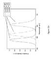
- FIG. 21illustrates mD trace representations presented in accordance with the principles of the present invention.
- FIG. 22illustrates mD trace representations presented in accordance with the principles of the present invention.
- FIG. 23illustrates an mD scanned environment in accordance with the principles of the present invention.
- FIG. 23 aillustrates mD trace representations presented in accordance with the principles of the present invention.
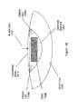
- FIG. 24illustrates a communication network in accordance with the principles of the present invention.
- FIG. 25illustrates a sharing FOV in accordance with the principles of the present invention.
- FIG. 26illustrates a sharing technology in accordance with the principles of the present invention.
- FIG. 26illustrates a sharing technology in accordance with the principles of the present invention.
- FIG. 27illustrates a sharing technology in accordance with the principles of the present invention.
- FIG. 28illustrates a sharing technology in accordance with the principles of the present invention.
- FIG. 29illustrates a sharing technology in accordance with the principles of the present invention.
- FIG. 30illustrates a sharing technology in accordance with the principles of the present invention.
- FIG. 31illustrates a sharing technology in accordance with the principles of the present invention.
- FIG. 32illustrates a sharing technology in accordance with the principles of the present invention.
- FIG. 33illustrates a sharing technology in accordance with the principles of the present invention.
- FIG. 34illustrates an object shadowing technology in accordance with the principles of the present invention.
- FIG. 35illustrates location marking and visualization technologies in accordance with the principles of the present invention.
- FIG. 36illustrates location marking and visualization technologies in accordance with the principles of the present invention.
- FIG. 37illustrates location marking and visualization technologies in accordance with the principles of the present invention.
- FIG. 38illustrates location marking and visualization technologies in accordance with the principles of the present invention.
- FIG. 39illustrates location marking, tracking and visualization based in part on a tactical plan in accordance with the principles of the present invention.
- FIG. 40illustrates location marking, tracking and visualization based in part on a directional antenna signal in accordance with the principles of the present invention.
- FIG. 41illustrates location marking, and visualization of a health condition of a person at an identified location in accordance with the principles of the present invention.
- FIG. 42illustrates location marking, tracking and visualization of past activities in accordance with the principles of the present invention.
- FIG. 43illustrates a stabilized head-worn mD antenna in accordance with the principles of the present invention.
- FIG. 44illustrates a stabilized head-worn mD antenna in accordance with the principles of the present invention.
- FIG. 45illustrates a stabilized head-worn mD antenna in accordance with the principles of the present invention.
- HWChead-worn computing
- the glassesmay be a fully developed computing platform, such as including computer displays presented in each of the lenses of the glasses to the eyes of the user.
- the lenses and displaysmay be configured to allow a person wearing the glasses to see the environment through the lenses while also seeing, simultaneously, digital imagery, which forms an overlaid image that is perceived by the person as a digitally augmented image of the environment, or augmented reality (“AR”).
- ARaugmented reality
- HWCinvolves more than just placing a computing system on a person's head.
- the systemmay need to be designed as a lightweight, compact and fully functional computer display, such as wherein the computer display includes a high resolution digital display that provides a high level of emersion comprised of the displayed digital content and the see-through view of the environmental surroundings.
- User interfaces and control systems suited to the HWC devicemay be required that are unlike those used for a more conventional computer such as a laptop.
- the glassesmay be equipped with sensors to determine environmental conditions, geographic location, relative positioning to other points of interest, objects identified by imaging and movement by the user or other users in a connected group, and the like.
- the HWCmay then change the mode of operation to match the conditions, location, positioning, movements, and the like, in a method generally referred to as a contextually aware HWC.
- the glassesalso may need to be connected, wirelessly or otherwise, to other systems either locally or through a network. Controlling the glasses may be achieved through the use of an external device, automatically through contextually gathered information, through user gestures captured by the glasses sensors, and the like. Each technique may be further refined depending on the software application being used in the glasses.
- the glassesmay further be used to control or coordinate with external devices that are associated with the glasses.
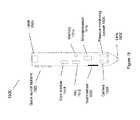
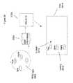
- the HWC system 100comprises a HWC 102 , which in this instance is configured as glasses to be worn on the head with sensors such that the HWC 102 is aware of the objects and conditions in the environment 114 .
- the HWC 102also receives and interprets control inputs such as gestures and movements 116 .
- the HWC 102may communicate with external user interfaces 104 .
- the external user interfaces 104may provide a physical user interface to take control instructions from a user of the HWC 102 and the external user interfaces 104 and the HWC 102 may communicate bi-directionally to affect the user's command and provide feedback to the external device 108 .
- the HWC 102may also communicate bi-directionally with externally controlled or coordinated local devices 108 .
- an external user interface 104may be used in connection with the HWC 102 to control an externally controlled or coordinated local device 108 .
- the externally controlled or coordinated local device 108may provide feedback to the HWC 102 and a customized GUI may be presented in the HWC 102 based on the type of device or specifically identified device 108 .
- the HWC 102may also interact with remote devices and information sources 112 through a network connection 110 .
- the external user interface 104may be used in connection with the HWC 102 to control or otherwise interact with any of the remote devices 108 and information sources 112 in a similar way as when the external user interfaces 104 are used to control or otherwise interact with the externally controlled or coordinated local devices 108 .
- HWC 102may interpret gestures 116 (e.g captured from forward, downward, upward, rearward facing sensors such as camera(s), range finders, IR sensors, etc.) or environmental conditions sensed in the environment 114 to control either local or remote devices 108 or 112 .
- the HWC 102is a computing platform intended to be worn on a person's head.
- the HWC 102may take many different forms to fit many different functional requirements.
- the HWC 102will be designed in the form of conventional glasses.
- the glassesmay or may not have active computer graphics displays.
- the displaysmay be configured as see-through displays such that the digital imagery can be overlaid with respect to the user's view of the environment 114 .
- see-through optical designsincluding ones that have a reflective display (e.g. LCoS, DLP), emissive displays (e.g. OLED, LED), hologram, TIR waveguides, and the like.
- lighting systems used in connection with the display opticsmay be solid state lighting systems, such as LED, OLED, quantum dot, quantum dot LED, etc.
- the optical configurationmay be monocular or binocular. It may also include vision corrective optical components.
- the opticsmay be packaged as contact lenses.
- the HWC 102may be in the form of a helmet with a see-through shield, sunglasses, safety glasses, goggles, a mask, fire helmet with see-through shield, police helmet with see through shield, military helmet with see-through shield, utility form customized to a certain work task (e.g. inventory control, logistics, repair, maintenance, etc.), and the like.
- the HWC 102may also have a number of integrated computing facilities, such as an integrated processor, integrated power management, communication structures (e.g. cell net, WiFi, Bluetooth, local area connections, mesh connections, remote connections (e.g. client server, etc.)), and the like.
- the HWC 102may also have a number of positional awareness sensors, such as GPS, electronic compass, altimeter, tilt sensor, IMU, and the like. It may also have other sensors such as a camera, rangefinder, hyper-spectral camera, Geiger counter, microphone, spectral illumination detector, temperature sensor, chemical sensor, biologic sensor, moisture sensor, ultrasonic sensor, and the like.
- the HWC 102may also have integrated control technologies.
- the integrated control technologiesmay be contextual based control, passive control, active control, user control, and the like.
- the HWC 102may have an integrated sensor (e.g. camera) that captures user hand or body gestures 116 such that the integrated processing system can interpret the gestures and generate control commands for the HWC 102 .
- the HWC 102may have sensors that detect movement (e.g. a nod, head shake, and the like) including accelerometers, gyros and other inertial measurements, where the integrated processor may interpret the movement and generate a control command in response.
- the HWC 102may also automatically control itself based on measured or perceived environmental conditions.
- the HWC 102may increase the brightness or contrast of the displayed image.
- the integrated control technologiesmay be mounted on the HWC 102 such that a user can interact with it directly.
- the HWC 102may have a button(s), touch capacitive interface, and the like.
- the HWC 102may be in communication with external user interfaces 104 .
- the external user interfacesmay come in many different forms.
- a cell phone screenmay be adapted to take user input for control of an aspect of the HWC 102 .
- the external user interfacemay be a dedicated UI, such as a keyboard, touch surface, button(s), joy stick, and the like.
- the external controllermay be integrated into another device such as a ring, watch, bike, car, and the like.
- the external user interface 104may include sensors (e.g. IMU, accelerometers, compass, altimeter, and the like) to provide additional input for controlling the HWD 104 .
- sensorse.g. IMU, accelerometers, compass, altimeter, and the like
- the HWC 102may control or coordinate with other local devices 108 .
- the external devices 108may be an audio device, visual device, vehicle, cell phone, computer, and the like.
- the local external device 108may be another HWC 102 , where information may then be exchanged between the separate HWCs 108 .
- the HWC 102may control or coordinate with remote devices 112 , such as the HWC 102 communicating with the remote devices 112 through a network 110 .
- the form of the remote device 112may have many forms. Included in these forms is another HWC 102 .
- each HWC 102may communicate its GPS position such that all the HWCs 102 know where all of HWC 102 are located.
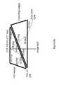
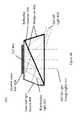
- FIG. 2illustrates a HWC 102 with an optical system that includes an upper optical module 202 and a lower optical module 204 .
- the upper and lower optical modules 202 and 204will generally be described as separate modules, it should be understood that this is illustrative only and the present invention includes other physical configurations, such as that when the two modules are combined into a single module or where the elements making up the two modules are configured into more than two modules.
- the upper module 202includes a computer controlled display (e.g. LCoS, DLP, OLED, etc.) and image light delivery optics.
- the lower moduleincludes eye delivery optics that are configured to receive the upper module's image light and deliver the image light to the eye of a wearer of the HWC.
- FIG. 1illustrates a HWC 102 with an optical system that includes an upper optical module 202 and a lower optical module 204 .
- the upper and lower optical modules 202 and 204will generally be described as separate modules, it should be understood that this is illustrative
- FIG. 3 billustrates an upper optical module 202 in accordance with the principles of the present invention.
- the upper optical module 202includes a DLP (also known as DMD or digital micromirror device) computer operated display 304 which includes pixels comprised of rotatable mirrors (such as, for example, the DLP3000 available from Texas Instruments), polarized light source 302 , 1 ⁇ 4wave retarder film 308 , reflective polarizer 310 and a field lens 312 .
- the polarized light source 302provides substantially uniform polarized light that is generally directed towards the reflective polarizer 310 .
- the reflective polarizerreflects light of one polarization state (e.g.
- the polarized light source 302 and the reflective polarizer 310are oriented so that the polarized light from the polarized light source 302 is reflected generally towards the DLP 304 .
- the lightthen passes through the 1 ⁇ 4 wave film 308 once before illuminating the pixels of the DLP 304 and then again after being reflected by the pixels of the DLP 304 .
- the lightis converted from one polarization state to the other polarization state (e.g. the light is converted from S to P polarized light).
- the lightthen passes through the reflective polarizer 310 .
- the DLP pixel(s)are in the “on” state (i.e. the mirrors are positioned to reflect light towards the field lens 312 , the “on” pixels reflect the light generally along the optical axis and into the field lens 312 .
- This light that is reflected by “on” pixels and which is directed generally along the optical axis of the field lens 312will be referred to as image light 316 .
- the image light 316then passes through the field lens to be used by a lower optical module 204 .
- the light that is provided by the polarized light source 302 , which is subsequently reflected by the reflective polarizer 310 before it reflects from the DLP 304 ,will generally be referred to as illumination light.
- the light that is reflected by the “off” pixels of the DLP 304is reflected at a different angle than the light reflected by the ‘on” pixels, so that the light from the “off” pixels is generally directed away from the optical axis of the field lens 312 and toward the side of the upper optical module 202 as shown in FIG. 3 .
- the light that is reflected by the “off” pixels of the DLP 304will be referred to as dark state light 314 .
- the DLP 304operates as a computer controlled display and is generally thought of as a MEMs device.
- the DLP pixelsare comprised of small mirrors that can be directed. The mirrors generally flip from one angle to another angle. The two angles are generally referred to as states. When light is used to illuminate the DLP the mirrors will reflect the light in a direction depending on the state. In embodiments herein, we generally refer to the two states as “on” and “off,” which is intended to depict the condition of a display pixel. “On” pixels will be seen by a viewer of the display as emitting light because the light is directed along the optical axis and into the field lens and the associated remainder of the display system.
- “Off” pixelswill be seen by a viewer of the display as not emitting light because the light from these pixels is directed to the side of the optical housing and into a light trap or light dump where the light is absorbed.
- the pattern of “on” and “off” pixelsproduces image light that is perceived by a viewer of the display as a computer generated image.
- Full color imagescan be presented to a user by sequentially providing illumination light with complimentary colors such as red, green and blue. Where the sequence is presented in a recurring cycle that is faster than the user can perceive as separate images and as a result the user perceives a full color image comprised of the sum of the sequential images.
- Bright pixels in the imageare provided by pixels that remain in the “on” state for the entire time of the cycle, while dimmer pixels in the image are provided by pixels that switch between the “on” state and “off” state within the time of the cycle, or frame time when in a video sequence of images.
- FIG. 3 ashows an illustration of a system for a DLP 304 in which the unpolarized light source 350 is pointed directly at the DLP 304 .
- the angle required for the illumination lightis such that the field lens 352 must be positioned substantially distant from the DLP 304 to avoid the illumination light from being clipped by the field lens 352 .
- the large distance between the field lens 352 and the DLP 304 along with the straight path of the dark state light 354means that the light trap for the dark state light 354 is also located at a substantial distance from the DLP. For these reasons, this configuration is larger in size compared to the upper optics module 202 of the preferred embodiments.
- the configuration illustrated in FIG. 3 bcan be lightweight and compact such that it fits into a small portion of a HWC.
- the upper modules 202 illustrated hereincan be physically adapted to mount in an upper frame of a HWC such that the image light can be directed into a lower optical module 204 for presentation of digital content to a wearer's eye.
- the package of components that combine to generate the image lighti.e. the polarized light source 302 , DLP 304 , reflective polarizer 310 and 1 ⁇ 4 wave film 308 ) is very light and is compact.
- the height of the system, excluding the field lensmay be less than 8 mm.
- the width (i.e. from front to back)may be less than 8 mm.
- the weightmay be less than 2 grams.
- the compactness of this upper optical module 202allows for a compact mechanical design of the HWC and the light weight nature of these embodiments help make the HWC lightweight to provide for a HWC that is comfortable for a wearer of the HWC.
- the configuration illustrated in FIG. 3 bcan produce sharp contrast, high brightness and deep blacks, especially when compared to LCD or LCoS displays used in HWC.
- the “on” and “off” states of the DLPprovide for a strong differentiator in the light reflection path representing an “on” pixel and an “off” pixel.
- the dark state light from the “off” pixel reflectionscan be managed to reduce stray light in the display system to produce images with high contrast.
- FIG. 4illustrates another embodiment of an upper optical module 202 in accordance with the principles of the present invention.
- This embodimentincludes a light source 404 , but in this case, the light source can provide unpolarized illumination light.
- the illumination light from the light source 404is directed into a TIR wedge 418 such that the illumination light is incident on an internal surface of the TIR wedge 418 (shown as the angled lower surface of the TRI wedge 418 in FIG. 4 ) at an angle that is beyond the critical angle as defined by Eqn 1.
- Critical anglearc-sin(1 /n )
- Eqn 1secasin(1 /n )
- illumination lightis turned toward the DLP 402 at an angle suitable for providing image light 414 as reflected from “on” pixels.
- the illumination lightis provided to the DLP 402 at approximately twice the angle of the pixel mirrors in the DLP 402 that are in the “on” state, such that after reflecting from the pixel mirrors, the image light 414 is directed generally along the optical axis of the field lens.
- the illumination light from “on” pixelsmay be reflected as image light 414 which is directed towards a field lens and a lower optical module 204 , while illumination light reflected from “off” pixels (generally referred to herein as “dark” state light, “off” pixel light or “off” state light) 410 is directed in a separate direction, which may be trapped and not used for the image that is ultimately presented to the wearer's eye.
- the light trap for the dark state light 410may be located along the optical axis defined by the direction of the dark state light 410 and in the side of the housing, with the function of absorbing the dark state light.
- the light trapmay be comprised of an area outside of the cone of image light 414 from the “on” pixels.
- the light trapis typically made up of materials that absorb light including coatings of black paints or other light absorbing materials to prevent light scattering from the dark state light degrading the image perceived by the user.
- the light trapmay be recessed into the wall of the housing or include masks or guards to block scattered light and prevent the light trap from being viewed adjacent to the displayed image.
- the embodiment of FIG. 4also includes a corrective wedge 420 to correct the effect of refraction of the image light 414 as it exits the TIR wedge 418 .
- a corrective wedge 420to correct the effect of refraction of the image light 414 as it exits the TIR wedge 418 .
- the image light from the “on” pixelscan be maintained generally in a direction along the optical axis of the field lens (i.e. the same direction as that defined by the image light 414 ) so it passes into the field lens and the lower optical module 204 .
- the image light 414 from the “on” pixelsexits the corrective wedge 420 generally perpendicular to the surface of the corrective wedge 420 while the dark state light exits at an oblique angle.
- the direction of the image light 414 from the “on” pixelsis largely unaffected by refraction as it exits from the surface of the corrective wedge 420 .
- the dark state light 410is substantially changed in direction by refraction when the dark state light 410 exits the corrective wedge 420 .
- the embodiment illustrated in FIG. 4has the similar advantages of those discussed in connection with the embodiment of FIG. 3 b .
- the dimensions and weight of the upper module 202 depicted in FIG. 4may be approximately 8 ⁇ 8 mm with a weight of less than 3 grams.
- a difference in overall performance between the configuration illustrated in FIG. 3 b and the configuration illustrated in FIG. 4is that the embodiment of FIG. 4 doesn't require the use of polarized light as supplied by the light source 404 . This can be an advantage in some situations as will be discussed in more detail below (e.g. increased see-through transparency of the HWC optics from the user's perspective). Polarized light may be used in connection with the embodiment depicted in FIG. 4 , in embodiments.
- the dark state light(shown as DLP off light 410 ) is directed at a steeper angle away from the optical axis of the image light 414 due to the added refraction encountered when the dark state light 410 exits the corrective wedge 420 .
- This steeper angle of the dark state light 410allows for the light trap to be positioned closer to the DLP 402 so that the overall size of the upper module 202 can be reduced.
- the light trapcan also be made larger since the light trap doesn't interfere with the field lens, thereby the efficiency of the light trap can be increased and as a result, stray light can be reduced and the contrast of the image perceived by the user can be increased.
- FIG. 4 aillustrates the embodiment described in connection with FIG. 4 with an example set of corresponding angles at the various surfaces with the reflected angles of a ray of light passing through the upper optical module 202 .
- the DLP mirrorsare provided at 17 degrees to the surface of the DLP device.
- the angles of the TIR wedgeare selected in correspondence to one another to provide TIR reflected illumination light at the correct angle for the DLP mirrors while allowing the image light and dark state light to pass through the thin air gap, various combinations of angles are possible to achieve this.
- FIG. 5illustrates yet another embodiment of an upper optical module 202 in accordance with the principles of the present invention.
- the embodiment shown in FIG. 5does not require the use of polarized light. Polarized light may be used in connection with this embodiment, but it is not required.
- the optical module 202 depicted in FIG. 5is similar to that presented in connection with FIG. 4 ; however, the embodiment of FIG. 5 includes an off light redirection wedge 502 . As can be seen from the illustration, the off light redirection wedge 502 allows the image light 414 to continue generally along the optical axis toward the field lens and into the lower optical module 204 (as illustrated).
- the off light 504is redirected substantially toward the side of the corrective wedge 420 where it passes into the light trap.
- This configurationmay allow further height compactness in the HWC because the light trap (not illustrated) that is intended to absorb the off light 504 can be positioned laterally adjacent the upper optical module 202 as opposed to below it.
- the light trap(not illustrated) that is intended to absorb the off light 504 can be positioned laterally adjacent the upper optical module 202 as opposed to below it.
- there is a thin air gap between the TIR wedge 418 and the corrective wedge 420similar to the embodiment of FIG. 4 .
- There is also a thin air gap between the corrective wedge 420 and the off light redirection wedge 502There may be HWC mechanical configurations that warrant the positioning of a light trap for the dark state light elsewhere and the illustration depicted in FIG.
- FIG. 5should be considered illustrative of the concept that the off light can be redirected to create compactness of the overall HWC.
- FIG. 5 aillustrates an example of the embodiment described in connection with FIG. 5 with the addition of more details on the relative angles at the various surfaces and a light ray trace for image light and a light ray trace for dark light are shown as it passes through the upper optical module 202 . Again, various combinations of angles are possible.
- FIG. 4 bshows an illustration of a further embodiment in which a solid transparent matched set of wedges 456 is provided with a reflective polarizer 450 at the interface between the wedges.
- the interface between the wedges in the wedge set 456is provided at an angle so that illumination light 452 from the polarized light source 458 is reflected at the proper angle (e.g. 34 degrees for a 17 degree DLP mirror) for the DLP mirror “on” state so that the reflected image light 414 is provided along the optical axis of the field lens.
- the general geometry of the wedges in the wedge set 456is similar to that shown in FIGS. 4 and 4 a .
- a quarter wave film 454is provided on the DLP 402 surface so that the illumination light 452 is one polarization state (e.g. S polarization state) while in passing through the quarter wave film 454 , reflecting from the DLP mirror and passing back through the quarter wave film 454 , the image light 414 is converted to the other polarization state (e.g. P polarization state).
- the reflective polarizeris oriented such that the illumination light 452 with it's polarization state is reflected and the image light 414 with it's other polarization state is transmitted. Since the dark state light from the “off pixels 410 also passes through the quarter wave film 454 twice, it is also the other polarization state (e.g. P polarization state) so that it is transmitted by the reflective polarizer 450 .
- the angles of the faces of the wedge set 450correspond to the needed angles to provide illumination light 452 at the angle needed by the DLP mirrors when in the “on” state so that the reflected image light 414 is reflected from the DLP along the optical axis of the field lens.
- the wedge set 456provides an interior interface where a reflective polarizer film can be located to redirect the illumination light 452 toward the mirrors of the DLP 402 .
- the wedge setalso provides a matched wedge on the opposite side of the reflective polarizer 450 so that the image light 414 from the “on” pixels exits the wedge set 450 substantially perpendicular to the exit surface, while the dark state light from the ‘off’ pixels 410 exits at an oblique angle to the exit surface.
- the image light 414is substantially unrefracted upon exiting the wedge set 456
- the dark state light from the “off” pixels 410is substantially refracted upon exiting the wedge set 456 as shown in FIG. 4 b.
- the flatness of the interfaceis reduced, because variations in the flatness have a negligible effect as long as they are within the cone angle of the illuminating light 452 .
- whichcan be f#2.2 with a 26 degree cone angle.
- the reflective polarizeris bonded between the matched internal surfaces of the wedge set 456 using an optical adhesive so that Fresnel reflections at the interfaces on either side of the reflective polarizer 450 are reduced.
- the optical adhesivecan be matched in refractive index to the material of the wedge set 456 and the pieces of the wedge set 456 can be all made from the same material such as BK7 glass or cast acrylic.
- the wedge materialcan be selected to have low birefringence as well to reduce non-uniformities in brightness.
- the wedge set 456 and the quarter wave film 454can also be bonded to the DLP 402 to further reduce Fresnel reflections at the DLP interface losses.
- the flatness of the surfaceis not critical to maintain the wavefront of the image light 414 so that high image quality can be obtained in the displayed image without requiring very tightly toleranced flatness on the exit surface.
- a yet further embodiment of the inventionthat is not illustrated, combines the embodiments illustrated in FIG. 4 b and FIG. 5 .
- the wedge set 456is comprised of three wedges with the general geometry of the wedges in the wedge set corresponding to that shown in FIGS. 5 and 5 a .
- a reflective polarizeris bonded between the first and second wedges similar to that shown in FIG. 4 b , however, a third wedge is provided similar to the embodiment of FIG. 5 .
- there is an angled thin air gap between the second and third wedgesso that the dark state light is reflected by TIR toward the side of the second wedge where it is absorbed in a light trap.
- This embodimentlike the embodiment shown in FIG. 4 b , uses a polarized light source as has been previously described. The difference in this embodiment is that the image light is transmitted through the reflective polarizer and is transmitted through the angled thin air gap so that it exits normal to the exit surface of the third wedge.
- FIG. 5 billustrates an upper optical module 202 with a dark light trap 514 a .
- image lightcan be generated from a DLP when using a TIR and corrective lens configuration.
- the upper modulemay be mounted in a HWC housing 510 and the housing 510 may include a dark light trap 514 a .
- the dark light trap 514 ais generally positioned/constructed/formed in a position that is optically aligned with the dark light optical axis 512 .
- the dark light trapmay have depth such that the trap internally reflects dark light in an attempt to further absorb the light and prevent the dark light from combining with the image light that passes through the field lens.
- the dark light trapmay be of a shape and depth such that it absorbs the dark light.
- the dark light trap 514 bin embodiments, may be made of light absorbing materials or coated with light absorbing materials.
- the recessed light trap 514 amay include baffles to block a view of the dark state light. This may be combined with black surfaces and textured or fiberous surfaces to help absorb the light.
- the bafflescan be part of the light trap, associated with the housing, or field lens, etc.
- FIG. 5 cillustrates another embodiment with a light trap 514 b .
- the shape of the trapis configured to enhance internal reflections within the light trap 514 b to increase the absorption of the dark light 512 .
- FIG. 5 dillustrates another embodiment with a light trap 514 c .
- the shape of the trap 514 cis configured to enhance internal reflections to increase the absorption of the dark light 512 .
- FIG. 5 eillustrates another embodiment of an upper optical module 202 with a dark light trap 514 d .
- This embodiment of upper module 202includes an off light reflection wedge 502 , as illustrated and described in connection with the embodiment of FIGS. 5 and 5 a .
- the light trap 514 dis positioned along the optical path of the dark light 512 .
- the dark light trap 514 dmay be configured as described in other embodiments herein.
- the embodiment of the light trap 514 d illustrated in figure Seincludes a black area on the side wall of the wedge, wherein the side wall is located substantially away from the optical axis of the image light 414 .
- baffles 5252may be added to one or more edges of the field lens 312 to block the view of the light trap 514 d adjacent to the displayed image seen by the user.
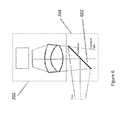
- FIG. 6illustrates a combination of an upper optical module 202 with a lower optical module 204 .
- the image light projected from the upper optical module 202may or may not be polarized.
- the image lightis reflected off a flat combiner element 602 such that it is directed towards the user's eye.
- the combiner element 602is a partial mirror that reflects image light while transmitting a substantial portion of light from the environment so the user can look through the combiner element and see the environment surrounding the HWC.
- the combiner 602may include a holographic pattern, to form a holographic mirror. If a monochrome image is desired, there may be a single wavelength reflection design for the holographic pattern on the surface of the combiner 602 . If the intention is to have multiple colors reflected from the surface of the combiner 602 , a multiple wavelength holographic mirror maybe included on the combiner surface. For example, in a three-color embodiment, where red, green and blue pixels are generated in the image light, the holographic mirror may be reflective to wavelengths substantially matching the wavelengths of the red, green and blue light provided by the light source. This configuration can be used as a wavelength specific mirror where pre-determined wavelengths of light from the image light are reflected to the user's eye.
- This configurationmay also be made such that substantially all other wavelengths in the visible pass through the combiner element 602 so the user has a substantially clear view of the surroundings when looking through the combiner element 602 .
- the transparency between the user's eye and the surroundingmay be approximately 80% when using a combiner that is a holographic mirror.
- holographic mirrorscan be made using lasers to produce interference patterns in the holographic material of the combiner where the wavelengths of the lasers correspond to the wavelengths of light that are subsequently reflected by the holographic mirror.
- the combiner element 602may include a notch mirror comprised of a multilayer coated substrate wherein the coating is designed to substantially reflect the wavelengths of light provided by the light source and substantially transmit the remaining wavelengths in the visible spectrum.
- the notch mirroris a tristimulus notch mirror wherein the multilayer coating is designed to reflect narrow bands of red, green and blue light that are matched to the what is provided by the light source and the remaining visible wavelengths are transmitted through the coating to enable a view of the environment through the combiner.
- the notch mirroris designed to reflect a single narrow band of light that is matched to the wavelength range of the light provided by the light source while transmitting the remaining visible wavelengths to enable a see-thru view of the environment.
- the combiner 602 with the notch mirrorwould operate, from the user's perspective, in a manner similar to the combiner that includes a holographic pattern on the combiner element 602 .
- the combiner, with the tristimulus notch mirrorwould reflect the “on” pixels to the eye because of the match between the reflective wavelengths of the notch mirror and the color of the image light, and the wearer would be able to see with high clarity the surroundings.
- the transparency between the user's eye and the surroundingmay be approximately 80% when using the tristimulus notch mirror.
- the image provided by the upper optical module 202 with the notch mirror combinercan provide higher contrast images than the holographic mirror combiner due to less scattering of the imaging light by the combiner.
- Lightcan escape through the combiner 602 and may produce face glow as the light is generally directed downward onto the cheek of the user.
- the escaping lightcan be trapped to avoid face glow.
- a linear polarizercan be laminated, or otherwise associated, to the combiner, with the transmission axis of the polarizer oriented relative to the polarized image light so that any escaping image light is absorbed by the polarizer.
- the image lightwould be polarized to provide S polarized light to the combiner for better reflection.
- the linear polarizer on the combinerwould be oriented to absorb S polarized light and pass P polarized light. This provides the preferred orientation of polarized sunglasses as well.
- a microlouvered filmsuch as a privacy filter can be used to absorb the escaping image light while providing the user with a see-thru view of the environment.
- the absorbance or transmittance of the microlouvered filmis dependent on the angle of the light. Where steep angle light is absorbed and light at less of an angle is transmitted.
- the combiner with the microlouver filmis angled at greater than 45 degrees to the optical axis of the image light (e.g. the combiner can be oriented at 50 degrees so the image light from the file lens is incident on the combiner at an oblique angle.
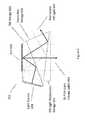
- FIG. 7illustrates an embodiment of a combiner element 602 at various angles when the combiner element 602 includes a holographic mirror.
- a mirrored surfacereflects light at an angle equal to the angle that the light is incident to the mirrored surface.
- the combiner elementbe at 45 degrees, 602 a , if the light is presented vertically to the combiner so the light can be reflected horizontally towards the wearer's eye.
- the incident lightcan be presented at angles other than vertical to enable the mirror surface to be oriented at other than 45 degrees, but in all cases wherein a mirrored surface is employed (including the tristimulus notch mirror described previously), the incident angle equals the reflected angle.
- a holographic mirror combinerincluded in embodiments, can be made such that light is reflected at a different angle from the angle that the light is incident onto the holographic mirrored surface. This allows freedom to select the angle of the combiner element 602 b independent of the angle of the incident image light and the angle of the light reflected into the wearer's eye.
- the angle of the combiner element 602 bis greater than 45 degrees (shown in FIG. 7 ) as this allows a more laterally compact HWC design.
- the increased angle of the combiner element 602 bdecreases the front to back width of the lower optical module 204 and may allow for a thinner HWC display (i.e. the furthest element from the wearer's eye can be closer to the wearer's face).
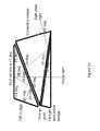
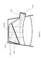
- FIG. 8illustrates another embodiment of a lower optical module 204 .
- polarized image lightprovided by the upper optical module 202 , is directed into the lower optical module 204 .
- the image lightreflects off a polarized mirror 804 and is directed to a focusing partially reflective mirror 802 , which is adapted to reflect the polarized light.
- An optical elementsuch as a 1 ⁇ 4 wave film located between the polarized mirror 804 and the partially reflective mirror 802 , is used to change the polarization state of the image light such that the light reflected by the partially reflective mirror 802 is transmitted by the polarized mirror 804 to present image light to the eye of the wearer.
- the usercan also see through the polarized mirror 804 and the partially reflective mirror 802 to see the surrounding environment. As a result, the user perceives a combined image comprised of the displayed image light overlaid onto the see-thru view of the environment.
- the image light and dark light production and management functions described in connection with the upper modulemay be arranged to direct light in other directions (e.g. upward, sideward, etc.).
- the lower optical moduleis generally configured to deliver the image light to the wearer's eye and allow the wearer to see through the lower optical module, which may be accomplished through a variety of optical components.
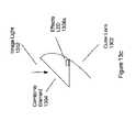
- FIG. 8 aillustrates an embodiment of the present invention where the upper optical module 202 is arranged to direct image light into a TIR waveguide 810 .
- the upper optical module 202is positioned above the wearer's eye 812 and the light is directed horizontally into the TIR waveguide 810 .
- the TIR waveguideis designed to internally reflect the image light in a series of downward TIR reflections until it reaches the portion in front of the wearer's eye, where the light passes out of the TIR waveguide 812 into the wearer's eye.
- an outer shield 814is positioned in front of the TIR waveguide 810 .
- FIG. 8 billustrates an embodiment of the present invention where the upper optical module 202 is arranged to direct image light into a TIR waveguide 818 .
- the upper optical module 202is arranged on the side of the TIR waveguide 818 .
- the upper optical modulemay be positioned in the arm or near the arm of the HWC when configured as a pair of head worn glasses.
- the TIR waveguide 818is designed to internally reflect the image light in a series of TIR reflections until it reaches the portion in front of the wearer's eye, where the light passes out of the TIR waveguide 812 into the wearer's eye.
- FIG. 8 cillustrates yet further embodiments of the present invention where an upper optical module 202 is directing polarized image light into an optical guide 828 where the image light passes through a polarized reflector 824 , changes polarization state upon reflection of the optical element 822 which includes a 1 ⁇ 4 wave film for example and then is reflected by the polarized reflector 824 towards the wearer's eye, due to the change in polarization of the image light.
- the upper optical module 202may be positioned to direct light to a mirror 820 , to position the upper optical module 202 laterally, in other embodiments, the upper optical module 202 may direct the image light directly towards the polarized reflector 824 . It should be understood that the present invention comprises other optical arrangements intended to direct image light into the wearer's eye.
- FIG. 9illustrates a system where the eye imaging camera 802 is mounted and angled such that the field of view of the eye imaging camera 802 is redirected toward the wearer's eye by the mirror pixels of the DLP 402 that are in the “off” state. In this way, the eye imaging camera 802 can be used to image the wearer's eye along the same optical axis as the displayed image that is presented to the wearer.
- image light that is presented to the wearer's eyeilluminates the wearer's eye so that the eye can be imaged by the eye imaging camera 802 .
- the light reflected by the eyepasses back though the optical train of the lower optical module 204 and a portion of the upper optical module to where the light is reflected by the “off” pixels of the DLP 402 toward the eye imaging camera 802 .
- the eye imaging cameramay image the wearer's eye at a moment in time where there are enough “off” pixels to achieve the required eye image resolution.
- the eye imaging cameracollects eye image information from “off” pixels over time and forms a time lapsed image.
- a modified imageis presented to the user wherein enough “off” state pixels are included that the camera can obtain the desired resolution and brightness for imaging the wearer's eye and the eye image capture is synchronized with the presentation of the modified image.
- the eye imaging systemmay be used for security systems.
- the HWCmay not allow access to the HWC or other system if the eye is not recognized (e.g. through eye characteristics including retina or iris characteristics, etc.).
- the HWCmay be used to provide constant security access in some embodiments.
- the eye security confirmationmay be a continuous, near-continuous, real-time, quasi real-time, periodic, etc. process so the wearer is effectively constantly being verified as known.
- the HWCmay be worn and eye security tracked for access to other computer systems.
- the eye imaging systemmay be used for control of the HWC.
- a blink, wink, or particular eye movementmay be used as a control mechanism for a software application operating on the HWC or associated device.
- the eye imaging systemmay be used in a process that determines how or when the HWC 102 delivers digitally displayed content to the wearer. For example, the eye imaging system may determine that the user is looking in a direction and then HWC may change the resolution in an area of the display or provide some content that is associated with something in the environment that the user may be looking at. Alternatively, the eye imaging system may identify different user's and change the displayed content or enabled features provided to the user. User's may be identified from a database of users eye characteristics either located on the HWC 102 or remotely located on the network 110 or on a server 112 .
- the HWCmay identify a primary user or a group of primary users from eye characteristics wherein the primary user(s) are provided with an enhanced set of features and all other user's are provided with a different set of features.
- the HWC 102uses identified eye characteristics to either enable features or not and eye characteristics need only be analyzed in comparison to a relatively small database of individual eye characteristics.
- FIG. 10illustrates a light source that may be used in association with the upper optics module 202 (e.g. polarized light source if the light from the solid state light source is polarized such as polarized light source 302 and 458 ), and light source 404 .
- the solid state light source 1002may be projected into a backlighting optical system 1004 .
- the solid state light source 1002may be one or more LEDs, laser diodes, OLEDs.
- the backlighting optical system 1004includes an extended section with a length/distance ratio of greater than 3, wherein the light undergoes multiple reflections from the sidewalls to mix of homogenize the light as supplied by the solid state light source 1002 .
- the backlighting optical system 1004can also include structures on the surface opposite (on the left side as shown in FIG. 10 ) to where the uniform light 1008 exits the backlight 1004 to change the direction of the light toward the DLP 302 and the reflective polarizer 310 or the DLP 402 and the TIR wedge 418 .
- the backlighting optical system 1004may also include structures to collimate the uniform light 1008 to provide light to the DLP with a smaller angular distribution or narrower cone angle.
- Diffusers or polarizerscan be used on the entrance or exit surface of the backlighting optical system. Diffusers can be used to spread or uniformize the exiting light from the backlight to improve the uniformity or increase the angular spread of the uniform light 1008 . Elliptical diffusers that diffuse the light more in some directions and less in others can be used to improve the uniformity or spread of the uniform light 1008 in directions orthogonal to the optical axis of the uniform light 1008 . Linear polarizers can be used to convert unpolarized light as supplied by the solid state light source 1002 to polarized light so the uniform light 1008 is polarized with a desired polarization state.
- a reflective polarizercan be used on the exit surface of the backlight 1004 to polarize the uniform light 1008 to the desired polarization state, while reflecting the other polarization state back into the backlight where it is recycled by multiple reflections within the backlight 1004 and at the solid state light source 1002 . Therefore by including a reflective polarizer at the exit surface of the backlight 1004 , the efficiency of the polarized light source is improved.
- FIGS. 10 a and 10 bshow illustrations of structures in backlight optical systems 1004 that can be used to change the direction of the light provided to the entrance face 1045 by the light source and then collimates the light in a direction lateral to the optical axis of the exiting uniform light 1008 .
- Structure 1060includes an angled sawtooth pattern in a transparent waveguide wherein the left edge of each sawtooth clips the steep angle rays of light thereby limiting the angle of the light being redirected. The steep surface at the right (as shown) of each sawtooth then redirects the light so that it reflects off the left angled surface of each sawtooth and is directed toward the exit surface 1040 .
- Structure 1050can be smooth and coated (e.g. with an aluminum coating or a dielectric mirror coating) to provide a high level of reflectivity without scattering.
- Structure 1050includes a curved face on the left side (as shown) to focus the rays after they pass through the exit surface 1040 , thereby providing a mechanism for collimating the uniform light 1008 .
- a diffusercan be provided between the solid state light source 1002 and the entrance face 1045 to homogenize the light provided by the solid state light source 1002 .
- a polarizercan be used between the diffuser and the entrance face 1045 of the backlight 1004 to provide a polarized light source.
- the polarization state of the lightcan be preserved from the entrance face 1045 to the exit face 1040 .
- the light entering the backlight from the solid state light source 1002passes through the polarizer so that it is polarized with the desired polarization state. If the polarizer is an absorptive linear polarizer, the light of the desired polarization state is transmitted while the light of the other polarization state is absorbed. If the polarizer is a reflective polarizer, the light of the desired polarization state is transmitted into the backlight 1004 while the light of the other polarization state is reflected back into the solid state light source 1002 where it can be recycled as previously described, to increase the efficiency of the polarized light source.
- FIG. 11 aillustrates a light source 1100 that may be used in association with the upper optics module 202 .
- the light source 1100may provide light to a backlighting optical system 1004 as described above in connection with FIG. 10 .
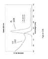
- the light source 1100includes a tristimulus notch filter 1102 .
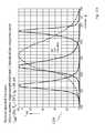
- the tristimulus notch filter 1102has narrow band pass filters for three wavelengths, as indicated in FIG. 11 c in a transmission graph 1108 .
- the graph shown in FIG. 11 b , as 1104illustrates an output of three different colored LEDs. One can see that the bandwidths of emission are narrow, but they have long tails.
- the tristimulus notch filter 1102can be used in connection with such LEDs to provide a light source 1100 that emits narrow filtered wavelengths of light as shown in FIG. 11 d as the transmission graph 1110 . Wherein the clipping effects of the tristimulus notch filter 1102 can be seen to have cut the tails from the LED emission graph 1104 to provide narrower wavelength bands of light to the upper optical module 202 .
- the light source 1100can be used in connection with a combiner 602 with a holographic mirror or tristimulus notch mirror to provide narrow bands of light that are reflected toward the wearer's eye with less waste light that does not get reflected by the combiner, thereby improving efficiency and reducing escaping light that can cause faceglow.
- FIG. 12 aillustrates another light source 1200 that may be used in association with the upper optics module 202 .
- the light source 1200may provide light to a backlighting optical system 1004 as described above in connection with FIG. 10 .
- the light source 1200includes a quantum dot cover glass 1202 . Where the quantum dots absorb light of a shorter wavelength and emit light of a longer wavelength ( FIG. 12 b shows an example wherein a UV spectrum 1202 applied to a quantum dot results in the quantum dot emitting a narrow band shown as a PL spectrum 1204 ) that is dependent on the material makeup and size of the quantum dot.
- quantum dots in the quantum dot cover glass 1202can be tailored to provide one or more bands of narrow bandwidth light (e.g. red, green and blue emissions dependent on the different quantum dots included as illustrated in the graph shown in FIG. 12 c where three different quantum dots are used.
- the LED driver lightemits UV light, deep blue or blue light.
- multiple light sources 1200would be used where each light source 1200 would include a quantum dot cover glass 1202 with a quantum dot selected to emit at one of the desired colors.
- the light source 1100can be used in connection with a combiner 602 with a holographic mirror or tristimulus notch mirror to provide narrow transmission bands of light that are reflected toward the wearer's eye with less waste light that does not get reflected.
- a solid state lighting systeme.g. LED, OLED, etc
- the solid state lighting systemmay be included inside the optical elements of an lower optical module 204 .
- the solid state lighting systemmay be arranged such that lighting effects outside of a field of view (FOV) of the presented digital content is presented to create an emersive effect for the person wearing the HWC.
- FOVfield of view
- the lighting effectsmay be presented to any portion of the HWC that is visible to the wearer.
- the solid state lighting systemmay be digitally controlled by an integrated processor on the HWC.
- the integrated processorwill control the lighting effects in coordination with digital content that is presented within the FOV of the HWC.
- a movie, picture, game, or other contentmay be displayed or playing within the FOV of the HWC.
- the contentmay show a bomb blast on the right side of the FOV and at the same moment, the solid state lighting system inside of the upper module optics may flash quickly in concert with the FOV image effect.
- the effectmay not be fast, it may be more persistent to indicate, for example, a general glow or color on one side of the user.
- the solid state lighting systemmay be color controlled, with red, green and blue LEDs, for example, such that color control can be coordinated with the digitally presented content within the field of view.
- FIG. 13 aillustrates optical components of a lower optical module 204 together with an outer lens 1302 .
- FIG. 13 aalso shows an embodiment including effects LED's 1308 a and 1308 b .
- FIG. 13 aillustrates image light 1312 , as described herein elsewhere, directed into the upper optical module where it will reflect off of the combiner element 1304 , as described herein elsewhere.
- the combiner element 1304 in this embodimentis angled towards the wearer's eye at the top of the module and away from the wearer's eye at the bottom of the module, as also illustrated and described in connection with FIG. 8 (e.g. at a 45 degree angle).
- the image light 1312provided by an upper optical module 202 (not shown in FIG.
- the wearer 13 areflects off of the combiner element 1304 towards the collimating mirror 1310 , away from the wearer's eye, as described herein elsewhere.
- the image light 1312then reflects and focuses off of the collimating mirror 1304 , passes back through the combiner element 1304 , and is directed into the wearer's eye.
- the wearercan also view the surrounding environment through the transparency of the combiner element 1304 , collimating mirror 1310 , and outer lens 1302 (if it is included).
- various surfacesare polarized to create the optical path for the image light and to provide transparency of the elements such that the wearer can view the surrounding environment. The wearer will generally perceive that the image light forms an image in the FOV 1305 .
- the outer lens 1302may be included.
- the outer lens 1302is an outer lens that may or may not be corrective and it may be designed to conceal the lower optical module components in an effort to make the HWC appear to be in a form similar to standard glasses or sunglasses.
- the effects LEDs 1308 a and 1308 bare positioned at the sides of the combiner element 1304 and the outer lens 1302 and/or the collimating mirror 1310 .
- the effects LEDs 1308 aare positioned within the confines defined by the combiner element 1304 and the outer lens 1302 and/or the collimating mirror.
- the effects LEDs 1308 a and 1308 bare also positioned outside of the FOV 1305 . In this arrangement, the effects LEDs 1308 a and 1308 b can provide lighting effects within the lower optical module outside of the FOV 1305 .
- the light emitted from the effects LEDs 1308 a and 1308 bmay be polarized such that the light passes through the combiner element 1304 toward the wearer's eye and does not pass through the outer lens 1302 and/or the collimating mirror 1310 .
- This arrangementprovides peripheral lighting effects to the wearer in a more private setting by not transmitting the lighting effects through the front of the HWC into the surrounding environment.
- the effects LEDs 1308 a and 1308 bmay be unpolarized so the lighting effects provided are made to be purposefully viewable by others in the environment for entertainment such as giving the effect of the wearer's eye glowing in correspondence to the image content being viewed by the wearer.
- FIG. 13 billustrates a cross section of the embodiment described in connection with FIG. 13 a .
- the effects LED 1308 ais located in the upper-front area inside of the optical components of the lower optical module. It should be understood that the effects LED 1308 a position in the described embodiments is only illustrative and alternate placements are encompassed by the present invention. Additionally, in embodiments, there may be one or more effects LEDs 1308 a in each of the two sides of HWC to provide peripheral lighting effects near one or both eyes of the wearer.
- FIG. 13 cillustrates an embodiment where the combiner element 1304 is angled away from the eye at the top and towards the eye at the bottom (e.g. in accordance with the holographic or notch filter embodiments described herein).
- the effects LED 1308 ais located on the outer lens 1302 side of the combiner element 1304 to provide a concealed appearance of the lighting effects.
- the effects LED 1308 a of FIG. 13 cmay include a polarizer such that the emitted light can pass through a polarized element associated with the combiner element 1304 and be blocked by a polarized element associated with the outer lens 1302 .
- Another aspect of the present inventionrelates to the mitigation of light escaping from the space between the wearer's face and the HWC itself.
- Another aspect of the present inventionrelates to maintaining a controlled lighting environment in proximity to the wearer's eyes.
- both the maintenance of the lighting environment and the mitigation of light escapeare accomplished by including a removable and replaceable flexible shield for the HWC.
- the removable and replaceable shieldcan be provided for one eye or both eyes in correspondence to the use of the displays for each eye. For example, in a night vision application, the display to only one eye could be used for night vision while the display to the other eye is turned off to provide good see-thru when moving between areas where visible light is available and dark areas where night vision enhancement is needed.
- FIG. 14 aillustrates a removable and replaceable flexible eye cover 1402 with an opening 1408 that can be attached and removed quickly from the HWC 102 through the use of magnets.
- magnetsmay be included in the eye cover 1402 and magnets of an opposite polarity may be included (e.g. embedded) in the frame of the HWC 102 .
- the magnets of the two elementswould attract quite strongly with the opposite polarity configuration.
- one of the elementsmay have a magnet and the other side may have metal for the attraction.
- the eye cover 1402is a flexible elastomeric shield.
- the eye cover 1402may be an elastomeric bellows design to accommodate flexibility and more closely align with the wearer's face.
- FIG. 14 billustrates a removable and replaceable flexible eye cover 1404 that is adapted as a single eye cover.
- a single eye covermay be used for each side of the HWC to cover both eyes of the wearer.
- the single eye covermay be used in connection with a HWC that includes only one computer display for one eye. These configurations prevent light that is generated and directed generally towards the wearer's face by covering the space between the wearer's face and the HWC.
- the opening 1408allows the wearer to look through the opening 1408 to view the displayed content and the surrounding environment through the front of the HWC.
- the image light in the lower optical module 204can be prevented from emitting from the front of the HWC through internal optics polarization schemes, as described herein, for example.
- FIG. 14 cillustrates another embodiment of a light suppression system.
- the eye cover 1410may be similar to the eye cover 1402 , but eye cover 1410 includes a front light shield 1412 .
- the front light shield 1412may be opaque to prevent light from escaping the front lens of the HWC.
- the front light shield 1412is polarized to prevent light from escaping the front lens.
- the internal optical elements of the HWCe.g. of the lower optical module 204
- the front light shield 1412may be polarized to prevent the light from transmitting through the front light shield 1412 .
- an opaque front light shield 1412may be included and the digital content may include images of the surrounding environment such that the wearer can visualize the surrounding environment.
- One eyemay be presented with night vision environmental imagery and this eye's surrounding environment optical path may be covered using an opaque front light shield 1412 .
- this arrangementmay be associated with both eyes.
- the display lighting and/or effects lightingmay be controlled in a manner suitable for when an eye cover 1408 is attached or removed from the HWC 102 .
- the lighting system(s) in the HWCmay go into a low light mode to further control any amounts of stray light escaping from the HWC and the areas around the HWC.
- Covert operations at night, while using night vision or standard vision,may require a solution which prevents as much escaping light as possible so a user may clip on the eye cover(s) 1408 and then the HWC may go into a low light mode.
- the low light modemay, in some embodiments, only go into a low light mode when the eye cover 1408 is attached if the HWC identifies that the environment is in low light conditions (e.g. through environment light level sensor detection).
- the low light levelmay be determined to be at an intermediate point between full and low light dependent on environmental conditions.
- Another aspect of the present inventionrelates to automatically controlling the type of content displayed in the HWC when eye covers 1408 are attached or removed from the HWC.
- the displayed contentmay be restricted in amount or in color amounts.
- the display(s)may go into a simple content delivery mode to restrict the amount of information displayed. This may be done to reduce the amount of light produced by the display(s).
- the display(s)may change from color displays to monochrome displays to reduce the amount of light produced.
- the monochrome lightingmay be red to limit the impact on the wearer's eyes to maintain an ability to see better in the dark.
- the pen 1500is a specially designed external user interface 104 and can operate as a user interface, such as to many different styles of HWC 102 .
- the pen 1500generally follows the form of a conventional pen, which is a familiar user handled device and creates an intuitive physical interface for many of the operations to be carried out in the HWC system 100 .
- the pen 1500may be one of several user interfaces 104 used in connection with controlling operations within the HWC system 100 .
- the HWC 102may watch for and interpret hand gestures 116 as control signals, where the pen 1500 may also be used as a user interface with the same HWC 102 .
- a remote keyboardmay be used as an external user interface 104 in concert with the pen 1500 .
- the combination of user interfaces or the use of just one control systemgenerally depends on the operation(s) being executed in the HWC's system 100 .
- the pen 1500may follow the general form of a conventional pen, it contains numerous technologies that enable it to function as an external user interface 104 .
- FIG. 15illustrates technologies comprised in the pen 1500 .
- the pen 1500may include a camera 1508 , which is arranged to view through lens 1502 . The camera may then be focused, such as through lens 1502 , to image a surface upon which a user is writing or making other movements to interact with the HWC 102 .
- the pen 1500will also have an ink, graphite, or other system such that what is being written can be seen on the writing surface.
- the pen 1500may include a sensor, such as an IMU 1512 .
- the IMUcould be included in the pen 1500 in its separate parts (e.g. gyro, accelerometer, etc.) or an IMU could be included as a single unit.
- the IMU 1512is used to measure and predict the motion of the pen 1500 .
- the integrated microprocessor 1510would take the IMU information and camera information as inputs and process the information to form a prediction of the pen tip movement.
- the pen 1500may also include a pressure monitoring system 1504 , such as to measure the pressure exerted on the lens 1502 .
- the pressure measurementcan be used to predict the user's intention for changing the weight of a line, type of a line, type of brush, click, double click, and the like.
- the pressure sensormay be constructed using any force or pressure measurement sensor located behind the lens 1502 , including for example, a resistive sensor, a current sensor, a capacitive sensor, a voltage sensor such as a piezoelectric sensor, and the like.
- the pen 1500may also include a communications module 1518 , such as for bi-directional communication with the HWC 102 .
- the communications module 1518may be a short distance communication module (e.g. Bluetooth).
- the communications module 1518may be security matched to the HWC 102 .
- the communications module 1518may be arranged to communicate data and commands to and from the microprocessor 1510 of the pen 1500 .
- the microprocessor 1510may be programmed to interpret data generated from the camera 1508 , IMU 1512 , and pressure sensor 1504 , and the like, and then pass a command onto the HWC 102 through the communications module 1518 , for example.
- the data collected from any of the input sourcese.g.
- the microprocessormay be communicated by the communication module 1518 to the HWC 102 , and the HWC 102 may perform data processing and prediction of the user's intention when using the pen 1500 .
- the datamay be further passed on through a network 110 to a remote device 112 , such as a server, for the data processing and prediction.
- the commandsmay then be communicated back to the HWC 102 for execution (e.g. display writing in the glasses display, make a selection within the UI of the glasses display, control a remote external device 112 , control a local external device 108 ), and the like.
- the penmay also include memory 1514 for long or short term uses.
- the pen 1500may also include a number of physical user interfaces, such as quick launch buttons 1522 , a touch sensor 1520 , and the like.
- the quick launch buttons 1522may be adapted to provide the user with a fast way of jumping to a software application in the HWC system 100 .
- the usermay be a frequent user of communication software packages (e.g. email, text, Twitter, Instagram, Facebook, Google+, and the like), and the user may program a quick launch button 1522 to command the HWC 102 to launch an application.
- the pen 1500may be provided with several quick launch buttons 1522 , which may be user programmable or factory programmable.
- the quick launch button 1522may be programmed to perform an operation.
- buttonsmay be programmed to clear the digital display of the HWC 102 . This would create a fast way for the user to clear the screens on the HWC 102 for any reason, such as for example to better view the environment.
- the quick launch button functionalitywill be discussed in further detail below.
- the touch sensor 1520may be used to take gesture style input from the user. For example, the user may be able to take a single finger and run it across the touch sensor 1520 to affect a page scroll.
- the pen 1500may also include a laser pointer 1524 .
- the laser pointer 1524may be coordinated with the IMU 1512 to coordinate gestures and laser pointing.
- a usermay use the laser 1524 in a presentation to help with guiding the audience with the interpretation of graphics and the IMU 1512 may, either simultaneously or when the laser 1524 is off, interpret the user's gestures as commands or data input.
- FIGS. 16A-Cillustrate several embodiments of lens and camera arrangements 1600 for the pen 1500 .
- One aspectrelates to maintaining a constant distance between the camera and the writing surface to enable the writing surface to be kept in focus for better tracking of movements of the pen 1500 over the writing surface.
- Another aspectrelates to maintaining an angled surface following the circumference of the writing tip of the pen 1500 such that the pen 1500 can be rolled or partially rolled in the user's hand to create the feel and freedom of a conventional writing instrument.
- FIG. 16Aillustrates an embodiment of the writing lens end of the pen 1500 .
- the configurationincludes a ball lens 1604 , a camera or image capture surface 1602 , and a domed cover lens 1608 .
- the cameraviews the writing surface through the ball lens 1604 and dome cover lens 1608 .
- the ball lens 1604causes the camera to focus such that the camera views the writing surface when the pen 1500 is held in the hand in a natural writing position, such as with the pen 1500 in contact with a writing surface.
- the ball lens 1604should be separated from the writing surface to obtain the highest resolution of the writing surface at the camera 1602 .
- the ball lens 1604is separated by approximately 1 to 3 mm.
- the domed cover lens 1608provides a surface that can keep the ball lens 1604 separated from the writing surface at a constant distance, such as substantially independent of the angle used to write on the writing surface. For instance, in embodiments the field of view of the camera in this arrangement would be approximately 60 degrees.
- the domed cover lens, or other lens 1608 used to physically interact with the writing surfacewill be transparent or transmissive within the active bandwidth of the camera 1602 .
- the domed cover lens 1608may be spherical or other shape and comprised of glass, plastic, sapphire, diamond, and the like. In other embodiments where low resolution imaging of the surface is acceptable.
- the pen 1500can omit the domed cover lens 1608 and the ball lens 1604 can be in direct contact with the surface.
- FIG. 16Billustrates another structure where the construction is somewhat similar to that described in connection with FIG. 16A ; however this embodiment does not use a dome cover lens 1608 , but instead uses a spacer 1610 to maintain a predictable distance between the ball lens 1604 and the writing surface, wherein the spacer may be spherical, cylindrical, tubular or other shape that provides spacing while allowing for an image to be obtained by the camera 1602 through the lens 1604 .
- the spacer 1610is transparent.
- the spacer 1610is shown as spherical, other shapes such as an oval, doughnut shape, half sphere, cone, cylinder or other form may be used.
- FIG. 16Cillustrates yet another embodiment, where the structure includes a post 1614 , such as running through the center of the lensed end of the pen 1500 .
- the post 1614may be an ink deposition system (e.g. ink cartridge), graphite deposition system (e.g. graphite holder), or a dummy post whose purpose is mainly only that of alignment.
- the selection of the post typeis dependent on the pen's use. For instance, in the event the user wants to use the pen 1500 as a conventional ink depositing pen as well as a fully functional external user interface 104 , the ink system post would be the best selection. If there is no need for the ‘writing’ to be visible on the writing surface, the selection would be the dummy post.
- the 16Cincludes camera(s) 1602 and an associated lens 1612 , where the camera 1602 and lens 1612 are positioned to capture the writing surface without substantial interference from the post 1614 .
- the pen 1500may include multiple cameras 1602 and lenses 1612 such that more or all of the circumference of the tip 1614 can be used as an input system.
- the pen 1500includes a contoured grip that keeps the pen aligned in the user's hand so that the camera 1602 and lens 1612 remains pointed at the surface.
- the force measurementmay be used in a number of ways.
- the force measurementmay be used as a discrete value, or discontinuous event tracking, and compared against a threshold in a process to determine a user's intent.
- the usermay want the force interpreted as a ‘click’ in the selection of an object, for instance.
- the usermay intend multiple force exertions interpreted as multiple clicks. There may be times when the user holds the pen 1500 in a certain position or holds a certain portion of the pen 1500 (e.g. a button or touch pad) while clicking to affect a certain operation (e.g. a ‘right click’).
- the force measurementmay be used to track force and force trends.
- the force trendsmay be tracked and compared to threshold limits, for example. There may be one such threshold limit, multiple limits, groups of related limits, and the like.
- threshold limitsfor example. There may be one such threshold limit, multiple limits, groups of related limits, and the like.
- the microprocessor 1510may interpret the force trend as an indication that the user desires to maintain the current writing style, writing tip type, line weight, brush type, and the like.
- the microprocessormay interpret the action as an indication that the user wants to change the current writing style, writing tip type, line weight, brush type, and the like.
- a change in the current writing style, writing tip type, line weight, brush type, and the likemay be executed.
- the changemay be noted to the user (e.g. in a display of the HWC 102 ), and the user may be presented with an opportunity to accept the change.
- FIG. 17Aillustrates an embodiment of a force sensing surface tip 1700 of a pen 1500 .
- the force sensing surface tip 1700comprises a surface connection tip 1702 (e.g. a lens as described herein elsewhere) in connection with a force or pressure monitoring system 1504 .
- a force monitoring system 1504measures the force or pressure the user applies to the writing surface and the force monitoring system communicates data to the microprocessor 1510 for processing.
- the microprocessor 1510receives force data from the force monitoring system 1504 and processes the data to make predictions of the user's intent in applying the particular force that is currently being applied.
- the processingmay be provided at a location other than on the pen (e.g. at a server in the HWC system 100 , on the HWC 102 ).
- the processing of informationcontemplates processing the information at a location other than on the pen.
- the microprocessor 1510may be programmed with force threshold(s), force signature(s), force signature library and/or other characteristics intended to guide an inference program in determining the user's intentions based on the measured force or pressure.
- the microprocessor 1510may be further programmed to make inferences from the force measurements as to whether the user has attempted to initiate a discrete action (e.g. a user interface selection ‘click’) or is performing a constant action (e.g. writing within a particular writing style).
- the inferencing processis important as it causes the pen 1500 to act as an intuitive external user interface 104 .
- FIG. 17Billustrates a force 1708 versus time 1710 trend chart with a single threshold 1718 .
- the threshold 1718may be set at a level that indicates a discrete force exertion indicative of a user's desire to cause an action (e.g. select an object in a GUI).
- Event 1712may be interpreted as a click or selection command because the force quickly increased from below the threshold 1718 to above the threshold 1718 .
- the event 1714may be interpreted as a double click because the force quickly increased above the threshold 1718 , decreased below the threshold 1718 and then essentially repeated quickly.
- the usermay also cause the force to go above the threshold 1718 and hold for a period indicating that the user is intending to select an object in the GUI (e.g. a GUI presented in the display of the HWC 102 ) and ‘hold’ for a further operation (e.g. moving the object).
- a threshold valuemay be used to assist in the interpretation of the user's intention
- a signature force event trendmay also be used.
- the threshold and signaturemay be used in combination or either method may be used alone.
- a single-click signaturemay be represented by a certain force trend signature or set of signatures.
- the single-click signature(s)may require that the trend meet a criteria of a rise time between x any y values, a hold time of between a and b values and a fall time of between c and d values, for example.
- Signaturesmay be stored for a variety of functions such as click, double click, right click, hold, move, etc.
- the microprocessor 1510may compare the real-time force or pressure tracking against the signatures from a signature library to make a decision and issue a command to the software application executing in the GUI.
- FIG. 17Cillustrates a force 1708 versus time 1710 trend chart with multiple thresholds 1718 .
- the force trendis plotted on the chart with several pen force or pressure events.
- the two thresholds 1718 of FIG. 4Ccreate three zones of force: a lower, middle and higher range.
- the beginning of the trendindicates that the user is placing a lower zone amount of force. This may mean that the user is writing with a given line weight and does not intend to change the weight, the user is writing.
- the trendshows a significant increase 1720 in force into the middle force range. This force change appears, from the trend to have been sudden and thereafter it is sustained.
- the microprocessor 1510may interpret this as an intentional change and as a result change the operation in accordance with preset rules (e.g. change line width, increase line weight, etc.).
- preset rulese.g. change line width, increase line weight, etc.
- the trendthen continues with a second apparently intentional event 1720 into the higher-force range.
- the forcedips below the upper threshold 1718 . This may indicate an unintentional force change and the microprocessor may detect the change in range however not affect a change in the operations being coordinated by the pen 1500 .
- the trend analysismay be done with thresholds and/or signatures.
- instrument stroke parameter changesmay be referred to as a change in line type, line weight, tip type, brush type, brush width, brush pressure, color, and other forms of writing, coloring, painting, and the like.
- the pen 1500may have several operating modes. For instance, the pen 1500 may have a writing mode where the user interface(s) of the pen 1500 (e.g. the writing surface end, quick launch buttons 1522 , touch sensor 1520 , motion based gesture, and the like) is optimized or selected for tasks associated with writing. As another example, the pen 1500 may have a wand mode where the user interface(s) of the pen is optimized or selected for tasks associated with software or device control (e.g. the HWC 102 , external local device, remote device 112 , and the like).
- software or device controle.g. the HWC 102 , external local device, remote device 112 , and the like.
- the pen 1500may have a presentation mode where the user interface(s) is optimized or selected to assist a user with giving a presentation (e.g. pointing with the laser pointer 1524 while using the button(s) 1522 and/or gestures to control the presentation or applications relating to the presentation).
- the penmay, for example, have a mode that is optimized or selected for a particular device that a user is attempting to control.
- the pen 1500may have a number of other modes and an aspect of the present invention relates to selecting such modes.
- FIG. 18Aillustrates an automatic user interface(s) mode selection based on contextual information.
- the microprocessor 1510may be programmed with IMU thresholds 1814 and 1812 .
- the thresholds 1814 and 1812may be used as indications of upper and lower bounds of an angle 1804 and 1802 of the pen 1500 for certain expected positions during certain predicted modes.
- the microprocessor 1510may then institute a writing mode for the pen's user interfaces. Similarly, if the microprocessor 1510 determines (e.g.
- the microprocessormay institute a wand mode for the pen's user interface.
- a wand mode for the pen's user interfaceBoth of these examples may be referred to as context based user interface mode selection as the mode selection is based on contextual information (e.g. position) collected automatically and then used through an automatic evaluation process to automatically select the pen's user interface(s) mode.
- the microprocessor 1510may monitor the contextual trend (e.g. the angle of the pen over time) in an effort to decide whether to stay in a mode or change modes. For example, through signatures, thresholds, trend analysis, and the like, the microprocessor may determine that a change is an unintentional change and therefore no user interface mode change is desired.
- the contextual trende.g. the angle of the pen over time
- the microprocessormay determine that a change is an unintentional change and therefore no user interface mode change is desired.
- FIG. 18Billustrates an automatic user interface(s) mode selection based on contextual information.
- the pen 1500is monitoring (e.g. through its microprocessor) whether or not the camera at the writing surface end 1508 is imaging a writing surface in close proximity to the writing surface end of the pen 1500 . If the pen 1500 determines that a writing surface is within a predetermined relatively short distance, the pen 1500 may decide that a writing surface is present 1820 and the pen may go into a writing mode user inteface(s) mode. In the event that the pen 1500 does not detect a relatively close writing surface 1822 , the pen may predict that the pen is not currently being used to as a writing instrument and the pen may go into a non-writing user interface(s) mode.
- FIG. 18Cillustrates a manual user interface(s) mode selection.
- the user interface(s) modemay be selected based on a twist of a section 1824 of the pen 1500 housing, clicking an end button 1828 , pressing a quick launch button 1522 , interacting with touch sensor 1520 , detecting a predetermined action at the pressure monitoring system (e.g. a click), detecting a gesture (e.g. detected by the IMU), etc.
- the manual mode selectionmay involve selecting an item in a GUI associated with the pen 1500 (e.g. an image presented in the display of HWC 102 ).
- a confirmation selectionmay be presented to the user in the event a mode is going to change.
- the presentationmay be physical (e.g. a vibration in the pen 1500 ), through a GUI, through a light indicator, etc.
- FIG. 19illustrates a couple pen use-scenarios 1900 and 1901 .
- FIG. 19illustrates a couple pen use-scenarios 1900 and 1901 .
- Use scenario 1900is a writing scenario where the pen 1500 is used as a writing instrument.
- quick launch button 122 Ais pressed to launch a note application 1910 in the GUI 1908 of the HWC 102 display 1904 .
- the HWC 102launches the note program 1910 and puts the pen into a writing mode.
- the useruses the pen 1500 to scribe symbols 1902 on a writing surface, the pen records the scribing and transmits the scribing to the HWC 102 where symbols representing the scribing are displayed 1912 within the note application 1910 .
- Use scenario 1901is a gesture scenario where the pen 1500 is used as a gesture capture and command device.
- the quick launch button 122 Bis activated and the pen 1500 activates a wand mode such that an application launched on the HWC 102 can be controlled.
- the usersees an application chooser 1918 in the display(s) of the HWC 102 where different software applications can be chosen by the user.
- the user gesturese.g. swipes, spins, turns, etc.
- the usermay gesture or click or otherwise interact with the pen 1500 such that the identified application is selected and launched.
- the wand modemay be used to scroll, rotate, change applications, select items, initiate processes, and the like, for example.
- the quick launch button 122 Amay be activated and the HWC 102 may launch an application chooser presenting to the user a set of applications.
- the quick launch buttonmay launch a chooser to show all communication programs (e.g. SMS, Twitter, Instagram, Facebook, email, etc.) available for selection such that the user can select the program the user wants and then go into a writing mode.
- the launchermay bring up selections for various other groups that are related or categorized as generally being selected at a given time (e.g. Microsoft Office products, communication products, productivity products, note products, organizational products, and the like)
- FIG. 20illustrates yet another embodiment of the present invention.
- FIG. 2000illustrates a watchband clip on controller 2000 .
- the watchband clip on controllermay be a controller used to control the HWC 102 or devices in the HWC system 100 .
- the watchband clip on controller 2000has a fastener 2018 (e.g. rotatable clip) that is mechanically adapted to attach to a watchband, as illustrated at 2004 .
- the watchband controller 2000may have quick launch interfaces 2008 (e.g. to launch applications and choosers as described herein), a touch pad 2014 (e.g. to be used as a touch style mouse for GUI control in a HWC 102 display) and a display 2012 .
- the clip 2018may be adapted to fit a wide range of watchbands so it can be used in connection with a watch that is independently selected for its function.
- the clipin embodiments, is rotatable such that a user can position it in a desirable manner.
- the clipmay be a flexible strap.
- the flexible strapmay be adapted to be stretched to attach to a hand, wrist, finger, device, weapon, and the like.
- the watchband controllermay be configured as a removable and replaceable watchband.
- the controllermay be incorporated into a band with a certain width, segment spacing's, etc. such that the watchband, with its incorporated controller, can be attached to a watch body.
- the attachmentin embodiments, may be mechanically adapted to attach with a pin upon which the watchband rotates.
- the watchband controllermay be electrically connected to the watch and/or watch body such that the watch, watch body and/or the watchband controller can communicate data between them.
- the watchband controllermay have 3-axis motion monitoring (e.g. through an IMU, accelerometers, magnetometers, gyroscopes, etc.) to capture user motion. The user motion may then be interpreted for gesture control.
- 3-axis motion monitoringe.g. through an IMU, accelerometers, magnetometers, gyroscopes, etc.
- the watchband controllermay comprise fitness sensors and a fitness computer.
- the sensorsmay track heart rate, calories burned, strides, distance covered, and the like. The data may then be compared against performance goals and/or standards for user feedback.
- mDmicro Doppler
- mD signaturestarget tracking signatures
- mDis a radar technique that uses a series of angle dependent electromagnetic pulses that are broadcast into an environment and return pulses are captured. Changes between the broadcast pulse and return pulse are indicative of changes in the shape, distance and angular location of objects or targets in the environment. These changes provide signals that can be used to track a target and identify the target through the mD signature.
- Each target or target typehas a unique mD signature. Shifts in the radar pattern can be analyzed in the time domain and frequency domain based on mD techniques to derive information about the types of targets present (e.g.
- the pulsecan penetrate the known objects to enable information about targets to be gathered even when the targets are visually blocked by the known objects.
- pulse frequenciescan be used that will penetrate concrete buildings to enable people to be identified inside the building.
- Multiple pulse frequenciescan be used as well in the mD radar to enable different types of information to be gathered about the objects in the environment.
- the mD radar informationcan be combined with other information such as distance measurements or images captured of the environment that are analyzed jointly to provide improved object identification and improved target identification and tracking.
- the analysiscan be performed on the HWC or the information can be transmitted to a remote network for analysis and results transmitted back to the HWC.
- Distance measurementscan be provided by laser range finding, structured lighting, stereoscopic depth maps or sonar measurements. Images of the environment can be captured using one or more cameras capable of capturing images from visible, ultraviolet or infrared light.
- the mD radarcan be attached to the HWC, located adjacently (e.g. in a vehicle) and associated wirelessly with the HWC or located remotely. Maps or other previously determined information about the environment can also be used in the analysis of the mD radar information. Embodiments of the present invention relate to visualizing the mD signatures in useful ways.
- FIG. 21illustrates a FOV 2102 of a HWC 102 from a wearer's perspective.
- the weareras described herein elsewhere, has a see-through FOV 2102 wherein the wearer views adjacent surroundings, such as the buildings illustrated in FIG. 21 .
- the weareras described herein elsewhere, can also see displayed digital content presented within a portion of the FOV 2102 .
- the embodiment illustrated in FIG. 21is indicating that the wearer can see the buildings and other surrounding elements in the environment and digital content representing traces, or travel paths, of bullets being fired by different people in the area.
- the surroundingsare viewed through the transparency of the FOV 2102 .
- the tracesare presented via the digital computer display, as described herein elsewhere.
- the trace presentedis based on a mD signature that is collected and communicated to the HWC in real time.
- the mD radaritself may be on or near the wearer of the HWC 102 or it may be located remote from the wearer. In embodiments, the mD radar scans the area, tracks and identifies targets, such as bullets, and communicates traces, based on locations, to the HWC 102 .
- the traces communicated from the mD radarmay be associated with GPS locations and the GPS locations may be associated with objects in the environment, such as people, buildings, vehicles, etc, both in latitude and longitude perspective and an elevation perspective.
- the locationsmay be used as markers for the HWC such that the traces, as presented in the FOV, can be associated, or fixed in space relative to the markers. For example, if the friendly fire trace 2108 is determined, by the mD radar, to have originated from the upper right window of the building on the left, as illustrated in FIG. 21 , then a virtual marker may be set on or near the window.
- the tracemay then virtually anchor with the virtual marker on the window.
- a markermay be set near the termination position or other flight position of the friendly fire trace 2108 , such as the upper left window of the center building on the right, as illustrated in FIG. 21 .
- This techniquefixes in space the trace such that the trace appears fixed to the environmental positions independent of where the wearer is looking. So, for example, as the wearer's head turns, the trace appears fixed to the marked locations.
- certain user positionsmay be known and thus identified in the FOV.
- the shooter of the friendly fire trace 2108may be from a known friendly combatant and as such his location may be known.
- the positionmay be known based on his GPS location based on a mobile communication system on him, such as another HWC 102 .
- the friendly combatantmay be marked by another friendly.
- a wearer of the HWC 102may use a gesture or external user interface 104 to mark the location.
- the originating position of the friendly fire trace 2108may be color coded or otherwise distinguished from unidentified traces on the displayed digital content.
- enemy fire traces 2104may be color coded or otherwise distinguished on the displayed digital content.
- the trace colors or appearancemay be different from the originating position to the terminating position.
- This path appearance changemay be based on the mD signature.
- the mD signaturemay indicate that the bullet, for example, is slowing as it propagates and this slowing pattern may be reflected in the FOV 2102 as a color or pattern change. This can create an intuitive understanding of wear the shooter is located.
- the originating colormay be red, indicative of high speed, and it may change over the course of the trace to yellow, indicative of a slowing trace.
- This pattern changingmay also be different for a friendly, enemy and unknown combatant. The enemy may go blue to green for a friendly trace, for example.
- FIG. 21illustrates an embodiment where the user sees the environment through the FOV and may also see color coded traces, which are dependent on bullet speed and combatant type, where the traces are fixed in environmental positions independent on the wearer's perspective.
- FIG. 22illustrates a through wall mD visualization technique according to the principles of the present invention.
- the mD radar scanning the environmentmay be local or remote from the wearer of a HWC 102 .
- the mD radarmay identify a target (e.g. a person) that is visible 2204 and then track the target as he goes behind a wall 2208 .
- the trackingmay then be presented to the wearer of a HWC 102 such that digital content reflective of the target and the target's movement, even behind the wall, is presented in the FOV 2202 of the HWC 102 .
- the targetwhen out of visible sight, may be represented by an avatar in the FOV to provide the wearer with imagery representing the target.
- mD target recognition methodscan identify the identity of a target based on the vibrations and other small movements of the target. This can provide a personal signature for the target. In the case of humans, this may result in a personal identification of a target that has been previously characterized.
- the cardio, heart beat, lung expansion and other small movements within the bodymay be unique to a person and if those attributes are pre-identified they may be matched in real time to provide a personal identification of a person in the FOV 2202 .
- the person's mD signaturesmay be determined based on the position of the person.
- the database of personal mD signature attributesmay include mD signatures for a person standing, sitting, laying down, running, walking, jumping, etc.
- a specific indication of the person's identitymay be presented in the FOV 2202 .
- the indicationmay be a color, shape, shade, name, indication of the type of person (e.g. enemy, friendly, etc.), etc. to provide the wearer with intuitive real time information about the person being tracked. This may be very useful in a situation where there is more than one person in an area of the person being tracked. If just one person in the area is personally identified, that person or the avatar of that person can be presented differently than other people in the area.
- the mD radarmay be mounted on a person (e.g. soldier, security person, or other person).
- the mD radarmay be configured to be small enough such that it can be mounted on a helmet of a combatant (e.g. an NVG Mount of a Soldier's Helmet).
- the configurationmay be approximately 5 inches by 3 inches and an inch thick such that it mounts conveniently on the NVG mount.
- the mD signature captured by the NVG mounted, or otherwise personnel mounted, mD radarmay be directly produced into an image and displayed in the FOV of the HWC 102 .
- the field of view for the mD radarmay be similar to that of the FOV of the HWC 102 allowing for a more straightforward translation of the mD signatures into display content for the HWC 102 .
- the mD signaturemay be presented as digital content as an image or video in the FOV of the HWC 102 .
- Another aspect of the present inventionrelates to reducing errors in mD target tracking through the stabilization and positional feedback of head-mounted mD antennas during the radar pulse associated with the measurement.
- mD systemscan detect and measure, whether Pulsed, signal processed, omni-directional, directional (e.g. through panel antennas), signal antenna, multi-antenna, etc. small movements of target objects. Errors in the mD system's assessment of the target object's movement may be introduced if the mD antenna moves during the target signal acquisition. Head-worn antennas are prone to such movement and, as described herein, stabilization, position compensation and/or motion detection feedback during the pulse and relating to the position of the antenna of the head-worn device relative to the environment can reduce such errors. Signals obtained and processed through such antenna systems may be used to present augmented reality content in a head-worn see-through computer display, as described herein elsewhere.
- a stabilized antennamay be an antenna that has a stable position assisted by mechanical gyroscopes that prevent movement, an antenna that is position corrected through the use of a position detection sensor system and position correction motor system, an antenna that is monitored for movements where indications of the movement are used in the signal processing of the captured signal, or other antenna that generates stabilized output information.
- FIG. 43illustrates a helmet mounted mD antenna 4302 in accordance with the principles of the present invention.
- the mD antenna 4302is mounted to the helmet 4312 via a helmet mount 4310 that allows the removal and re-attachment of the mD antenna (e.g. an NVG mount).
- the systemalso includes an inertial sensor 4304 that may include gyro-sensors and accelerometers and an actuator such as one or more piezo motors 4308 (the actuator may also be an electrostrictive motor, a magnetostrictive motor, an artificial muscle or a voice coil motor) to monitor and quickly adjust the location of the mD antenna 4302 such that it maintains a corrected position during target acquisition.
- an inertial sensor 4304may include gyro-sensors and accelerometers and an actuator such as one or more piezo motors 4308 (the actuator may also be an electrostrictive motor, a magnetostrictive motor, an artificial muscle or a voice coil motor) to monitor and quickly adjust the location of the
- the piezo motor 4308moves the mD antenna 4302 quickly and over relatively small distances based on motion detection feedback from the piezo sensor 4304 .
- the piezo motormay be adapted to move the mD antenna forward, backward, lateral, vertical, rotationally, multi-directional, etc.
- more than one antennamay be used in the head-worn mD antenna configuration and each antenna may be separately positionally stabilized.
- the mD systemcan better calculate the distance to the target, but the multiple antenna's can introduce more error.
- the separate antennasare tied together in a rotational or lateral motion, there will be error in the measurement due to the second sensor being in motion after the signal gets to the first sensor.
- the errormay show up as frequency noise in the velocity data, positional noise in the distance and increased angular noise depending on how far away the source is from normal to the plane between the detectors.
- FIG. 44illustrates a dual stabilization system for a multi-antenna mD system in accordance with the principles of the present invention.
- two mD antennas 4402 and 4404are provided.
- Each antennais separately stabilized through a respective piezo motor and piezo sensor.
- the piezo sensor B 4414provides gyroscopic or accelerometer feedback to the piezo motor B 4410 to stabilize mD antenna B 4402 .
- the piezo sensor A 4412provides gyroscopic or accelerometer feedback to the piezo motor A 4408 to stabilize mD antenna A 4404 .
- This configurationallows for independent positional stabilization of the two antennas in an attempt to reduce errors in the signal acquisition and processing.
- each antennamay also be independently monitored for position during target acquisition to establish positional error metrics that can be used during the signal processing to further reduce the errors caused by antenna movement during acquisition.
- an IMUor other position or motion sensor
- the motion informationmay be used in connection with signal processing.
- the motion informationmay be matched in time with signal acquisition such that the motion information can be subtracted out or otherwise used during the signal processing to remove the physical motion of the antenna(s) from the acquisition signal.
- FIG. 45illustrates a head-worn mD antenna system in accordance with the principles of the present invention.
- the mD antennamay be associated with an IMU 4502 such that the IMU can assess the antenna's motion.
- the IMU 4502may send, in real-time, the motion information to a mD signal processing system so the physical motion of the antenna can be used in adjusting the acquisition signals to reduce errors associated with the physical motion.
- mechanical gyroscopesmay be used to stabilize the position of the head mounted mD antenna(s).
- the mechanical gyroscopesmay be used in a pulsed operation such that the gyroscopes spin only when needed for mD measurements.
- the gyroscopemay be actively stopped after the measurement. This method reduces the power needed to run the gyroscopes while also making it more comfortable for the user by reducing the forces applied to the helmet by the gyroscope to stabilize the mD antenna.
- mechanical gyroscopesmay be used with sensors and position correction motors to compensate for the movement of the antenna(s) or monitor the error movement of the antenna(s).
- power management technologiesmay be included in the head-worn stabilized mD antenna system.
- the power management systemmay control the stabilizing functions with pulse width modulation or other control technique such that the active stabilization, which requires power, is only activated when the antenna is actively collecting signals. For example, in a pulsed antenna mode, where short bursts of detection signal are used, the system may only stabilize or correct the position of the antenna(s) through the use of the sensor and motor systems during the signal acquisition period. This can result in a significant power savings, which may be advantageous for the mobile system.
- the stabilized mD antenna(s)may be body mounted.
- the stabilized mD antennamay be mounted on the chest or back of a person.
- heartbeat, cardio, lung movements and the like of all known friendly combatantsmay be tracked in an effort to identify anyone in stress or injury situations.
- the friendly combatant trackingmay be accomplished through mD signatures.
- the friendly combatant trackingmay be accomplished through personally worn sensors (e.g. the watch clip controller as described herein elsewhere), and the data may be communicated from the personally worn sensors.
- FIG. 23illustrates an mD scanned environment 2300 .
- An mD radarmay scan an environment in an attempt to identify objects in the environment.
- the mD scanned environmentreveals two vehicles 2302 a and 2302 b , en enemy combatant 2309 , two friendly combatants 2308 a and 2308 b and a shot trace 2318 .
- Each of these objectsmay be personally identified or type identified.
- the vehicles 2302 a and 2302 bmay be identified through the mD signatures as a tank and heavy truck.
- the enemy combatant 2309may be identified as a type (e.g. enemy combatant) or more personally (e.g. by name).
- the friendly combatantsmay be identified as a type (e.g. friendly combatant) or more personally (e.g. by name).
- the shot trace 2318may be characterized by type of projectile or weapon type for the projectile, for example.
- FIG. 23 aillustrates two separate HWC 102 FOV display techniques according to the principles of the present invention.
- FOV 2312illustrates a map view 2310 where the mD scanned environment is presented.
- the wearerhas a perspective on the mapped area so he can understand all tracked targets in the area. This allows the wearer to traverse the area with knowledge of the targets.
- FOV 2312illustrates a heads-up view to provide the wearer with an augmented reality style view of the environment that is in proximity of the wearer.
- HWC's 102may be on local area networks, wide area networks, cell networks, WiFi networks, close proximity networks, etc. or may otherwise be connected with devices to enable sharing.
- intuitive methodsare deployed to enable the wearer of a HWC to identify a person or device for sharing. Once identified, information may be transferred between devices and/or confirmation of proper identification may be made before any information is transferred.
- FIG. 24illustrates a generalized form of network topology 2400 , which may be deployed in connection with linking and sharing methods as is discussed in more detail herein.
- each device in the network 2400e.g. each HWC 102
- each node 2402 and 2404may communicate directly with any other node 2402 and 2404 .
- Each nodemay also communicate indirectly; through another node.
- the network 2400may be a self healing ad hoc network, WiFi network, cell network, local network, wide area network, close proximity network, etc. Any node 2402 and 2404 may link and/or share information with any other node 2402 and 2404 of the network 2400 .
- FIG. 25illustrates an embodiment of a sharing interface presented in the FOV 2508 of a HWC 102 .
- the sharing interfacemay have a representation of a file or stream 2502 that is capable of being shared along with several options for sharing method 2504 (e.g. share via sms message, text message, email, social network, posting, direct file transfer, etc.).
- the sharing interfacemay also interoperate with a user interface to allow the wearer of the HWC to select the file or stream 2502 and sharing option 2504 .
- a cursor 2510is illustrated to indicate that an external user interface, gesture, eye tracking control, etc. may be used to assist the wearer with selecting items within the FOV 2508 .
- FIG. 26illustrates a method of identifying a person with whom a wearer of a HWC 102 may want to link or share information.
- the sharing zonemay be indicative of a predetermined area that provides confidence that anyone in the zone is in close enough proximity to one another that they can identify one another for linking and/or sharing.
- identification of the people's viewing angles 2604may be established. This is to find two viewing angles that are substantially aligned and opposite to determine if two people are looking at one another.
- person 2602 a and person 2602 chave substantially aligned and opposite viewing angles so the system may assume that, since they are in the sharing zone and apparently looking at one another, if one of the two has initiated a share command (e.g. via sharing option 2504 ) that the two intend to share information and/or become linked.
- a share commande.g. via sharing option 2504
- the viewing angle of a person 2604may be determined by an electronic compass in the HWC, through examination of camera images, or otherwise.
- the substantial alignment and opposite nature of the viewing angles 2604may be determined by comparing each person's individual viewing angles 2604 as determined by internal electronic compasses in the HWCs.
- itmay be determined by determining each person's viewing angle 2604 through a determination of environmental images captured by the two people when the environment is a known environment such that a comparison of the images and the known features in the environment can be made.
- the HWC'smay take images to form an understanding if the desired sharing pair are looking at one another by estimating the person's direction in the image.
- user information of the two people 2608may be obtained such that device identification 2610 (e.g. IP address, hardware serial number, security code, etc.) may be obtained. In embodiments, user information may not be required and device identification may be obtained.
- device identification 2610e.g. IP address, hardware serial number, security code, etc.
- an indication confirming the interactionmay be presented in the FOV 2614 of the sender's HWC 102 .
- the sendermay then interact with the indication (e.g. through an external UI, gesture, eye movement, wink, etc.).
- the usermay use an external user interface, as described herein elsewhere, to interact with the content in the FOV 2614 with a cursor.
- the sendermay gesture (e.g. a thumbs up sign) and the gesture may be captured and interpreted by the sender's HWC 102 as an indication confirming the interaction with the receiver.
- FIG. 27illustrates another embodiment where linking and sharing partners are established.
- a sender 2704may capture facial images, or other biometric information, of potential recipients 2702 in the area by scanning the area.
- the facial imagesmay be processed remotely or locally to obtain facial recognition information from a database 2708 when it is available.
- user information 2710 and device ID 2712may be obtained.
- Each of the recognized peoplemay be represented in the FOV 2718 of the sender's HWC 102 .
- the recognized peoplemay be presented in a facial recognition pallet 2714 , through augmented reality where identifications are augmented in a way that identifies the people as the sender views them through the FOV 2718 or otherwise presented.
- the sendercan select one or more of the people to link to and/or share with through techniques described herein.
- FIG. 28illustrates another embodiment where linking and sharing partners are established.
- the range of acceptable recipientsmay be in very close proximity and a near field communication (NFC) zone 2802 may be established and anyone within the NFC zone 2802 may be identified, or an attempt may be made to identify anyone in the zone.
- NFCnear field communication
- user information and/or device informationmay be retrieved such that they can be presented to the sender in his FOV 2812 .
- the identified peoplemay be represented in a NFC pallet 2814 , through augmented reality where identifications are augmented in a way that identifies the people as the sender views them through the FOV 2812 , or otherwise presented.
- the sendercan select one or more of the people to link to and/or share with through techniques described herein.
- FIG. 29illustrates a linking/sharing embodiment that includes the sender communicating a request for identifications within the proximity of the sender (a “proximity request”) 2902 .
- the proximity request 2902may be sent through a communication protocol that has a restricted distance (e.g. NFC request) such that the only recipients of the request are in close proximity to the sender.
- the proximity request 2902may require confirmation of the location of the potential recipients (e.g. a GPS location) to confirm that the potential recipients are in the proximity of the sender.
- user information 2904 and/or device information 2908may be obtained and presented in the FOV 2912 of the sender.
- the presentation and sender interactions with the content in the FOVmay be as described herein.
- FIG. 29illustrates a position or AR map of the region with the identified people and/or devices.
- FIG. 30illustrates another embodiment of share/linking.
- a recipient and/or sendermay gesture 3002 to indicate the desire to share/link.
- the other's HWC sensor(s)e.g. camera
- the sharing gesturesmay be securely maintained and periodically changed to maintain security.
- the gesturesmay be complicated motions including several different motions. Similar to the other embodiments described herein elsewhere, once identified, user and/or device information may be obtained and indications of same may be presented in the FOV 3014 for interaction.
- the usermay transfer files/streaming information or make other transfers by activating items in the HWC FOV user interface (e.g. by using a gesture, external user interface, etc.), gesturing (e.g. making a throwing motion to indicate the transfer, etc.
- activating items in the HWC FOV user interfacee.g. by using a gesture, external user interface, etc.
- gesturinge.g. making a throwing motion to indicate the transfer, etc.
- FIG. 31illustrates another embodiment of share/linking.
- a recipient and/or sendermay make a voice command 3102 to indicate the desire to share/link.
- the other's HWC sensor(s)e.g. microphone
- the sharing voice commandsmay be securely maintained and periodically changed to maintain security.
- voice recognitionmay be used to identify the person making the voice command. This may be of particular need in a secure environment. Similar to other embodiments described herein elsewhere, once identified, user and/or device information may be obtained and indications of same may be presented in the FOV 3114 for interaction.
- FIG. 32illustrates another embodiment of share/linking.
- a recipient and/or sendermay send a light signal 3202 to indicate the desire to share/link.
- the other's HWC sensor(s)e.g. camera
- People or groupsmay have preset light signals 3202 that indicate acceptable sharing.
- the light transmissionmay be coded to be read automatically by the other party.
- the sharing light signals 3202may be securely maintained and periodically changed to maintain security. Similar to the other embodiments described herein elsewhere, once identified, user and/or device information may be obtained and indications of same may be presented in the FOV 3214 for interaction.
- FIG. 33illustrates another embodiment of share/linking.
- a recipient and/or sendermay read RFID or other short-range identification markers 3302 to indicate an acceptable person for sharing/linking. Similar to the other embodiments described herein elsewhere, once identified, user and/or device information may be obtained and indications of same may be presented in the FOV 3014 for interaction.
- the linking and sharing embodiments described hereinmay be used to establish secure and known nodes in a communication network. For example, users may want to share photos, videos, files, data, information, streams, communications, etc., and the users may want to be sure that they know who they are sharing with so they may use a technique or combination of techniques described herein. In combat situations, users may want to share similar types of information but want to also keep the sharing from any enemy combatants so the security provided by the identification and confirmation techniques described herein may have added security value. Feeds from drones, mD information as described herein, other combatants' camera views, etc. may be shared via techniques and combination of techniques described herein.
- Another aspect of the present inventionrelates to shadowing digitally presented content in an FOV of a HWC such that the content appears to have substantially similar lighting as objects in the surrounding environment that the wearer can view through the FOV.
- FIG. 34illustrates a digital object 3402 presented in connection with a digital shadow 3404 in a FOV 3408 of an HWC 102 .
- the digital shadow 3404is positioned such that the wearer of the HWC 102 perceives that it is associated with the digital object 3402 and that the lighting conditions in the surrounding environment are causing the shadow from the object.
- the GPS location, compass heading, time of year and time of day relating to the HWC's positionmay be known and the shadow may be positioned and sized based thereon such that the object appears to be lit by the sun.
- the lighting conditions in the environmentmay be evaluated (e.g. through imaging of the environment) such that the lighting conditions in the environment can be mimicked.
- a camera in the HWC 102may image the environment and a processor, either onboard or remote from the HWC 102 , may interpret the general position of the dominate lighting to then determine position of the digital shadow 3404 .
- a processoreither onboard or remote from the HWC 102 , may interpret the general position of the dominate lighting to then determine position of the digital shadow 3404 .
- there may be more than one light sourcee.g. in an auditorium, stadium, inside a building, on a lighted street, etc.
- the digital shadowmay be several shadows indicative of the several light sources. In embodiments this may include determining shadow effects at a certain position in the environment because the digital object 3402 is positioned in the FOV 3408 to be perceived by the wearer at the certain position in the environment. This may be accomplished by deciphering images taken in connection with certain positions in the environment.
- the artificial lighting systemsmay be of known or predictable positions and the digital shadow may be positioned based on the known or predictable positions.
- Another aspect of the present inventionrelates to visual presentations, within a field of view of a HWC 102 , indicative of a person or object at a known location.
- Embodimentsinvolve presenting an indication of another person's (“other person”) known location to a person wearing a see-through display of a head-worn computer (“first person”).
- the processmay be embodied in computer media in one or more parts.
- the method employedmay involve receiving geo-spatial coordinates corresponding to the other person's known location; receiving geo-spatial coordinates corresponding to a location of the first person; receiving a compass heading for the first person that is indicative of a direction in which the first person is looking; generating a virtual target line between a see-through visual plane of the head-worn computer and the other person such that the target line describes a distance and angle between the known location and the location and the looking direction of the first person; and presenting, in the field of view of the head-worn computer 102 , digital content to augment the first person's view of an environment seen through the see-through display of the head-worn computer, wherein the digital content is positioned within the field of view along the virtual target line such that the first person perceives the digital content in a position within the environment that represents the known location.
- FIG. 35illustrates an environmentally position locked digital content 3512 that is indicative of a person's location 3502 .
- the term “BlueForce”is generally used to indicate team members or members for which geo-spatial locations are known and can be used.
- “BlueForce”is a term to indicate members of a tactical arms team (e.g. a police force, secret service force, security force, military force, national security force, intelligence force, etc.).
- one membermay be referred to as the primary or first BlueForce member and it is this member, in many described embodiments, that is wearing the HWC.
- a first personis wearing a head-worn computer 102 that has a see through field of view (“FOV”) 3514 .
- the first personcan see through the FOV to view the surrounding environment through the FOV and digital content can also be presented in the FOV such that the first person can view the actual surroundings, through the FOV, in a digitally augmented view.
- the other BlueForce person's locationis known and is indicated at a position inside of a building at point 3502 .
- This locationis known in three dimensions, longitude, latitude and altitude, which may have been determined by GPS along with an altimeter associated with the other Blueforce person.
- the location of the first person wearing the HWC 102is also known, as indicated in FIG. 35 as point 3508 .
- the compass heading 3510 of the first personis also known. With the compass heading 3510 known, the angle in which the first person is viewing the surroundings can be estimated.
- a virtual target line between the location of the first person 3508 and the other person's location 3502can be established in three dimensional space and emanating from the HWC 102 proximate the FOV 3514 .
- the three dimensionally oriented virtual target linecan then be used to present environmentally position locked digital content in the FOV 3514 , which is indicative of the other person's location 3502 .
- the environmentally position locked digital content 3502can be positioned within the FOV 3514 such that the first person, who is wearing the HWC 102 , perceives the content 3502 as locked in position within the environment and marking the location of the other person 3502 .
- the three dimensionally positioned virtual target linecan be recalculated periodically (e.g. every millisecond, second, minute, etc.) to reposition the environmentally position locked content 3512 to remain in-line with the virtual target line. This can create the illusion that the content 3512 is staying positioned within the environment at a point that is associated with the other person's location 3502 independent of the location of the first person 3508 wearing the HWC 102 and independent of the compass heading of the HWC 102 .
- the environmentally locked digital content 3512may be positioned with an object 3504 that is between the first person's location 3508 and the other person's location 3502 .
- the virtual target linemay intersect the object 3504 before intersecting with the other person's location 3502 .
- the environmentally locked digital content 3512may be associated with the object intersection point 3504 .
- the intersecting object 3504may be identified by comparing the two person's locations 3502 and 3508 with obstructions identified on a map.
- the intersecting object 3504may be identified by processing images captured from a camera, or other sensor, associated with the HWC 102 .
- the digital content 3512has an appearance that is indicative of being at the location of the other person 3502 and/or at the location of the intersecting object 3504 to provide a more clear indication of the position of the other person's position 3502 in the FOV 3514 .
- FIG. 36illustrates how and where digital content may be positioned within the FOV 3608 based on a virtual target line between the location of the first person 3508 , who's wearing the HWC 102 , and the other person 3502 .
- the digital contentmay be presented such that it comes into focus by the first person when the first person focuses at a certain plane or distance in the environment.
- Presented object A 3618is digitally generated content that is presented as an image at content position A 3612 .
- the position 3612is based on the virtual target line.
- the presented object A 3618is presented not only along the virtual target line but also at a focal plane B 3614 such that the content at position A 3612 in the FOV 3608 comes into focus by the first person when the first person's eye 3602 focuses at something in the surrounding environment at the focal plane B 3614 distance.
- Setting the focal plane of the presented contentprovides content that does not come into focus until the eye 3602 focuses at the set focal plane. In embodiments, this allows the content at position A to be presented when the HWC's compass is indicative of the first person looking in the direction of the other person 3502 but it will only come into focus when the first person focuses on in the direction of the other person 3502 and at the focal plane of the other person 3502 .
- Presented object B 3620is aligned with a different virtual target line then presented object A 3618 .
- Presented object B 3620is also presented at content position B 3604 at a different focal plane than the content position A 3612 .
- Presented content B 3620is presented at a further focal plane, which is indicative that the other person 3502 is physically located at a further distance. If the focal planes are sufficiently different, the content at position A will come into focus at a different time than the content at position B because the two focal planes require different focus from the eye 3602 .
- FIG. 37illustrates several BlueForce members at locations with various points of view from the first person's perspective.
- the relative positions, distances and obstaclesmay cause the digital content indicative of the other person's location to be altered. For example, if the other person can be seen by the first person through the first person's FOV, the digital content may be locked at the location of the other person and the digital content may be of a type that indicates the other person's position is being actively marked and tracked. If the other person is in relatively close proximity, but cannot be seen by the first person, the digital content may be locked to an intersecting object or area and the digital content may indicate that the actual location of the other person cannot be seen but the mark is generally tracking the other person's general position.
- the digital contentmay generally indicate a direction or area where the other person is located and the digital content may indicate that the other person's location is not closely identified or tracked by the digital content, but that the other person is in the general area.
- the primary BlueForce member 3702(also referred to generally as the first person, or the person wherein the HWC with the FOV for example purposes) can directly see the BlueForce member in the open field 3704 .
- the digital content provided in the FOV of the primary BlueForce membermay be based on a virtual target line and virtually locked in an environment position that is indicative of the open field position of the BlueForce member 3704 .
- the digital contentmay also indicate that the location of the open field BlueForce member is marked and is being tracked. The digital content may change forms if the BlueForce member becomes obscured from the vision of the primary BlueForce member or otherwise becomes unavailable for direct viewing.
- BlueForce member 3708is obscured from the primary BlueForce member's 3702 view by an obstacle that is in close proximity to the obscured member 3708 .
- the obscured member 3708is in a building but close to one of the front walls.
- the digital content provided in the FOV of the primary member 3702may be indicative of the general position of the obscured member 3708 and the digital content may indicate that, while the other person's location is fairly well marked, it is obscured so it is not as precise as if the person was in direct view.
- the digital contentmay be virtually positionally locked to some feature on the outside of the building that the obscured member is in. This may make the environmental locking more stable and also provide an indication that the location of the person is somewhat unknown.
- BlueForce member 3710is obscured by multiple obstacles.
- the member 3710is in a building and there is another building 3712 in between the primary member 3702 and the obscured member 3710 .
- the digital content in the FOV of the primary memberwill be spatially quite short of the actual obscured member and as such the digital content may need to be presented in a way that indicates that the obscured member 3710 is in a general direction but that the digital marker is not a reliable source of information for the particular location of obscured member 3710 .
- FIG. 38illustrates yet another method for positioning digital content within the FOV of a HWC where the digital content is intended to indicate a position of another person.
- the main additional element in this embodimentis the additional step of verifying the distance between the first person 3508 , the one wearing the HWC with the FOV digital content presentation of location, and the other person at location 3502 .
- a range findermay be included in the HWC and measure a distance at an angle that is represented by the virtual target line.
- the digital content presentation in the FOVmay indicate such (e.g. as described herein elsewhere).
- the digital contentmay represent that the proper location has been marked, as described herein elsewhere.
- FIG. 39illustrates a situation where the primary BlueForce member 3902 is tracking the locations of the other BlueForce members through an augmented environment using a HWC 102 , as described herein elsewhere (e.g. as described in connection with the above figures).
- the primary BlueForce member 3902may have knowledge of the tactical movement plan 3908 .
- the tactical movement planmaybe maintained locally (e.g. on the HWCs 102 with sharing of the plan between the BlueForce members) or remotely (e.g. on a server and communicated to the HWC's 102 , or communicated to a subset of HWC's 102 for HWC 102 sharing).
- the tactical planinvolves the BlueForce group generally moving in the direction of the arrow 3908 .
- the tactical planmay influence the presentations of digital content in the FOV of the HWC 102 of the primary BlueForce member.
- the tactical planmay assist in the prediction of the location of the other BlueForce member and the virtual target line may be adjusted accordingly.
- the area in the tactical movement planmay be shaded or colored or otherwise marked with digital content in the FOV such that the primary BlueForce member can manage his activities with respect to the tactical plan. For example, he may be made aware that one or more BlueForce members are moving towards the tactical path 3908 . He may also be made aware of movements in the tactical path that do not appear associated with BlueForce members.
- FIG. 39also illustrates that internal IMU sensors in the HWCs worn by the BlueForce members may provide guidance on the movement of the members 3904 . This may be helpful in identifying when a GPS location should be updated and hence updating the position of the virtual marker in the FOV. This may also be helpful in assessing the validity of the GPS location. For example, if the GPS location has not updated but there is significant IMU sensor activity, the system may call into question the accuracy of the identified location. The IMU information may also be useful to help track the position of a member in the event the GPS information is unavailable. For example, dead reckoning may be used if the GPS signal is lost and the virtual marker in the FOV may indicate both indicated movements of the team member and indicate that the location identification is not ideal.
- the current tactical plan 3908may be updated periodically and the updated plans may further refine what is presented in the FOV of the HWC 102 .
- FIG. 40illustrates a BlueForce tracking system in accordance with the principles of the present invention.
- the BlueForce HWC's 102may have directional antenna's that emit relatively low power directional RF signals such that other BlueForce members within the range of the relatively low power signal can receive and assess it's direction and/or distance based on the strength and varying strength of the signals.
- the tracking of such RF signalscan be used to alter the presentation of the virtual markers of persons locations within the FOV of HWC 102 .
- Each BlueForce membermay be automatically monitored for health and stress events.
- the membersmay have a watchband as described herein elsewhere or other wearable biometric monitoring device and the device may continually monitor the biometric information and predict health concerns or stress events.
- the eye imaging systems described herein elsewheremay be used to monitor pupil dilatations as compared to normal conditions to predict head trama. Each eye may be imaged to check for differences in pupil dilation for indications of head trama.
- an IMU in the HWC 102may monitor a person's walking gate looking for changes in pattern, which may be an indication of head or other trama.
- Biometric feedback from a member indicative of a health or stress concernmay be uploaded to a server for sharing with other members or the information may be shared with local members, for example.
- the digital content in the FOV that indicates the location of the person having the health or stress eventmay include an indication of the health event.
- FIG. 41illustrates a situation where the primary BlueForce member 4102 is monitoring the location of the BlueForce member 4104 that has had a heath event and caused a health alert to be transmitted from the HWC 102 .
- the FOV of the HWC 102 of the primary BlueForce membermay include an indication of the location of the BlueForce member with the health concern 4104 .
- the digital content in the FOVmay also include an indication of the health condition in association with the location indication.
- non-biometric sensorse.g. IMU, camera, ranger finder, accelerometer, altimeter, etc.
- an altermay be sent as an indication of a fall, the person is in trouble and had to drop down, was shot, etc.
- Another aspect of the present inventionrelates to virtually marking various prior acts and events.
- the techniques described herein elsewheremay be used to construct a virtual prior movement path 4204 of a BlueForce member.
- the virtual pathmay be displayed as digital content in the FOV of the primary BlueForce member 4202 using methods described herein elsewhere.
- an event marker 4208such that when another member views the location the mark can be displayed as digital content.
- the BlueForce membermay inspect and clear an area and then use an external user interface or gesture to indicate that the area has been cleared and then the location would be virtually marked and shared with BlueForce members.
- the digital contentmay be displayed in a way that indicates the specific location and if the location is not visible from the person's perspective, the digital content may be somewhat different in that it may not specifically mark the location.
Abstract
Description
Critical angle=arc-sin(1/n)
Claims (5)
Priority Applications (2)
| Application Number | Priority Date | Filing Date | Title |
|---|---|---|---|
| US14/451,566US9401540B2 (en) | 2014-02-11 | 2014-08-05 | Spatial location presentation in head worn computing |
| US15/210,957US9843093B2 (en) | 2014-02-11 | 2016-07-15 | Spatial location presentation in head worn computing |
Applications Claiming Priority (6)
| Application Number | Priority Date | Filing Date | Title |
|---|---|---|---|
| US14/178,047US9229233B2 (en) | 2014-02-11 | 2014-02-11 | Micro Doppler presentations in head worn computing |
| US14/181,473US9299194B2 (en) | 2014-02-14 | 2014-02-14 | Secure sharing in head worn computing |
| US14/185,990US9928019B2 (en) | 2014-02-14 | 2014-02-21 | Object shadowing in head worn computing |
| US14/185,988US9229234B2 (en) | 2014-02-11 | 2014-02-21 | Micro doppler presentations in head worn computing |
| US14/205,313US20150228119A1 (en) | 2014-02-11 | 2014-03-11 | Spatial location presentation in head worn computing |
| US14/451,566US9401540B2 (en) | 2014-02-11 | 2014-08-05 | Spatial location presentation in head worn computing |
Related Parent Applications (1)
| Application Number | Title | Priority Date | Filing Date |
|---|---|---|---|
| US14/178,047Continuation-In-PartUS9229233B2 (en) | 2008-12-16 | 2014-02-11 | Micro Doppler presentations in head worn computing |
Related Child Applications (1)
| Application Number | Title | Priority Date | Filing Date |
|---|---|---|---|
| US15/210,957ContinuationUS9843093B2 (en) | 2014-02-11 | 2016-07-15 | Spatial location presentation in head worn computing |
Publications (2)
| Publication Number | Publication Date |
|---|---|
| US20150229019A1 US20150229019A1 (en) | 2015-08-13 |
| US9401540B2true US9401540B2 (en) | 2016-07-26 |
Family
ID=53775753
Family Applications (2)
| Application Number | Title | Priority Date | Filing Date |
|---|---|---|---|
| US14/451,566ActiveUS9401540B2 (en) | 2014-02-11 | 2014-08-05 | Spatial location presentation in head worn computing |
| US15/210,957ActiveUS9843093B2 (en) | 2014-02-11 | 2016-07-15 | Spatial location presentation in head worn computing |
Family Applications After (1)
| Application Number | Title | Priority Date | Filing Date |
|---|---|---|---|
| US15/210,957ActiveUS9843093B2 (en) | 2014-02-11 | 2016-07-15 | Spatial location presentation in head worn computing |
Country Status (1)
| Country | Link |
|---|---|
| US (2) | US9401540B2 (en) |
Cited By (62)
| Publication number | Priority date | Publication date | Assignee | Title |
|---|---|---|---|---|
| US20160077202A1 (en)* | 2014-09-16 | 2016-03-17 | Teknologian Tutkimuskeskus Vtt | Navigational aid with adaptive radar |
| US20160327946A1 (en)* | 2015-05-08 | 2016-11-10 | Fujitsu Limited | Information processing device, information processing method, terminal device, and setting method |
| US9529195B2 (en) | 2014-01-21 | 2016-12-27 | Osterhout Group, Inc. | See-through computer display systems |
| US9529192B2 (en) | 2014-01-21 | 2016-12-27 | Osterhout Group, Inc. | Eye imaging in head worn computing |
| US20170001113A1 (en)* | 2014-03-17 | 2017-01-05 | Tencent Technology (Shenzhen) Company Limited | Data processing method, terminal and server |
| US9547465B2 (en) | 2014-02-14 | 2017-01-17 | Osterhout Group, Inc. | Object shadowing in head worn computing |
| US20170017323A1 (en)* | 2015-07-17 | 2017-01-19 | Osterhout Group, Inc. | External user interface for head worn computing |
| US9575321B2 (en) | 2014-06-09 | 2017-02-21 | Osterhout Group, Inc. | Content presentation in head worn computing |
| US9615742B2 (en) | 2014-01-21 | 2017-04-11 | Osterhout Group, Inc. | Eye imaging in head worn computing |
| US9651784B2 (en) | 2014-01-21 | 2017-05-16 | Osterhout Group, Inc. | See-through computer display systems |
| US9651788B2 (en) | 2014-01-21 | 2017-05-16 | Osterhout Group, Inc. | See-through computer display systems |
| US9651787B2 (en) | 2014-04-25 | 2017-05-16 | Osterhout Group, Inc. | Speaker assembly for headworn computer |
| US9651783B2 (en) | 2014-01-21 | 2017-05-16 | Osterhout Group, Inc. | See-through computer display systems |
| US9672210B2 (en) | 2014-04-25 | 2017-06-06 | Osterhout Group, Inc. | Language translation with head-worn computing |
| US9684172B2 (en) | 2014-12-03 | 2017-06-20 | Osterhout Group, Inc. | Head worn computer display systems |
| USD792400S1 (en) | 2014-12-31 | 2017-07-18 | Osterhout Group, Inc. | Computer glasses |
| US9715112B2 (en) | 2014-01-21 | 2017-07-25 | Osterhout Group, Inc. | Suppression of stray light in head worn computing |
| US9720234B2 (en) | 2014-01-21 | 2017-08-01 | Osterhout Group, Inc. | See-through computer display systems |
| US9720227B2 (en) | 2014-01-21 | 2017-08-01 | Osterhout Group, Inc. | See-through computer display systems |
| USD794637S1 (en) | 2015-01-05 | 2017-08-15 | Osterhout Group, Inc. | Air mouse |
| US9740280B2 (en) | 2014-01-21 | 2017-08-22 | Osterhout Group, Inc. | Eye imaging in head worn computing |
| US9746686B2 (en) | 2014-05-19 | 2017-08-29 | Osterhout Group, Inc. | Content position calibration in head worn computing |
| US9753288B2 (en) | 2014-01-21 | 2017-09-05 | Osterhout Group, Inc. | See-through computer display systems |
| US9766463B2 (en) | 2014-01-21 | 2017-09-19 | Osterhout Group, Inc. | See-through computer display systems |
| US9784973B2 (en) | 2014-02-11 | 2017-10-10 | Osterhout Group, Inc. | Micro doppler presentations in head worn computing |
| US9810906B2 (en) | 2014-06-17 | 2017-11-07 | Osterhout Group, Inc. | External user interface for head worn computing |
| US9811152B2 (en) | 2014-01-21 | 2017-11-07 | Osterhout Group, Inc. | Eye imaging in head worn computing |
| US9829707B2 (en) | 2014-08-12 | 2017-11-28 | Osterhout Group, Inc. | Measuring content brightness in head worn computing |
| US9836122B2 (en) | 2014-01-21 | 2017-12-05 | Osterhout Group, Inc. | Eye glint imaging in see-through computer display systems |
| US9841599B2 (en) | 2014-06-05 | 2017-12-12 | Osterhout Group, Inc. | Optical configurations for head-worn see-through displays |
| US9843093B2 (en) | 2014-02-11 | 2017-12-12 | Osterhout Group, Inc. | Spatial location presentation in head worn computing |
| US9939934B2 (en) | 2014-01-17 | 2018-04-10 | Osterhout Group, Inc. | External user interface for head worn computing |
| US9939646B2 (en) | 2014-01-24 | 2018-04-10 | Osterhout Group, Inc. | Stray light suppression for head worn computing |
| US9952664B2 (en) | 2014-01-21 | 2018-04-24 | Osterhout Group, Inc. | Eye imaging in head worn computing |
| US9958749B2 (en) | 2016-09-12 | 2018-05-01 | Disney Enterprises, Inc. | Optical assemblies that are both brightly backlit and transparent for use in costumed characters |
| US9965681B2 (en) | 2008-12-16 | 2018-05-08 | Osterhout Group, Inc. | Eye imaging in head worn computing |
| US10062182B2 (en) | 2015-02-17 | 2018-08-28 | Osterhout Group, Inc. | See-through computer display systems |
| US10139966B2 (en) | 2015-07-22 | 2018-11-27 | Osterhout Group, Inc. | External user interface for head worn computing |
| US10152141B1 (en) | 2017-08-18 | 2018-12-11 | Osterhout Group, Inc. | Controller movement tracking with light emitters |
| US10191279B2 (en) | 2014-03-17 | 2019-01-29 | Osterhout Group, Inc. | Eye imaging in head worn computing |
| US10254856B2 (en) | 2014-01-17 | 2019-04-09 | Osterhout Group, Inc. | External user interface for head worn computing |
| US10283850B2 (en)* | 2017-03-27 | 2019-05-07 | Intel Corporation | Wireless wearable devices having self-steering antennas |
| US10424203B2 (en)* | 2016-01-29 | 2019-09-24 | Toyota Motor Engineering & Manufacturing North America, Inc. | System and method for driving hazard estimation using vehicle-to-vehicle communication |
| US10466491B2 (en) | 2016-06-01 | 2019-11-05 | Mentor Acquisition One, Llc | Modular systems for head-worn computers |
| US10558050B2 (en) | 2014-01-24 | 2020-02-11 | Mentor Acquisition One, Llc | Haptic systems for head-worn computers |
| US10649220B2 (en) | 2014-06-09 | 2020-05-12 | Mentor Acquisition One, Llc | Content presentation in head worn computing |
| US10663740B2 (en) | 2014-06-09 | 2020-05-26 | Mentor Acquisition One, Llc | Content presentation in head worn computing |
| US10684687B2 (en) | 2014-12-03 | 2020-06-16 | Mentor Acquisition One, Llc | See-through computer display systems |
| US10684478B2 (en) | 2016-05-09 | 2020-06-16 | Mentor Acquisition One, Llc | User interface systems for head-worn computers |
| US10824253B2 (en) | 2016-05-09 | 2020-11-03 | Mentor Acquisition One, Llc | User interface systems for head-worn computers |
| US10853589B2 (en) | 2014-04-25 | 2020-12-01 | Mentor Acquisition One, Llc | Language translation with head-worn computing |
| US11003246B2 (en) | 2015-07-22 | 2021-05-11 | Mentor Acquisition One, Llc | External user interface for head worn computing |
| US11104272B2 (en) | 2014-03-28 | 2021-08-31 | Mentor Acquisition One, Llc | System for assisted operator safety using an HMD |
| US11103122B2 (en) | 2014-07-15 | 2021-08-31 | Mentor Acquisition One, Llc | Content presentation in head worn computing |
| US11227294B2 (en) | 2014-04-03 | 2022-01-18 | Mentor Acquisition One, Llc | Sight information collection in head worn computing |
| US11269182B2 (en) | 2014-07-15 | 2022-03-08 | Mentor Acquisition One, Llc | Content presentation in head worn computing |
| US11487110B2 (en) | 2014-01-21 | 2022-11-01 | Mentor Acquisition One, Llc | Eye imaging in head worn computing |
| US11669163B2 (en) | 2014-01-21 | 2023-06-06 | Mentor Acquisition One, Llc | Eye glint imaging in see-through computer display systems |
| US11737666B2 (en) | 2014-01-21 | 2023-08-29 | Mentor Acquisition One, Llc | Eye imaging in head worn computing |
| US11892644B2 (en) | 2014-01-21 | 2024-02-06 | Mentor Acquisition One, Llc | See-through computer display systems |
| US12093453B2 (en) | 2014-01-21 | 2024-09-17 | Mentor Acquisition One, Llc | Eye glint imaging in see-through computer display systems |
| US12443294B2 (en) | 2024-06-24 | 2025-10-14 | Mentor Acquisition One, Llc | External user interface for head worn computing |
Families Citing this family (22)
| Publication number | Priority date | Publication date | Assignee | Title |
|---|---|---|---|---|
| US20150205111A1 (en) | 2014-01-21 | 2015-07-23 | Osterhout Group, Inc. | Optical configurations for head worn computing |
| US20130339859A1 (en) | 2012-06-15 | 2013-12-19 | Muzik LLC | Interactive networked headphones |
| US9671613B2 (en) | 2014-09-26 | 2017-06-06 | Osterhout Group, Inc. | See-through computer display systems |
| US20150277118A1 (en) | 2014-03-28 | 2015-10-01 | Osterhout Group, Inc. | Sensor dependent content position in head worn computing |
| US9448409B2 (en) | 2014-11-26 | 2016-09-20 | Osterhout Group, Inc. | See-through computer display systems |
| US12105281B2 (en) | 2014-01-21 | 2024-10-01 | Mentor Acquisition One, Llc | See-through computer display systems |
| US9423842B2 (en) | 2014-09-18 | 2016-08-23 | Osterhout Group, Inc. | Thermal management for head-worn computer |
| USD743963S1 (en) | 2014-12-22 | 2015-11-24 | Osterhout Group, Inc. | Air mouse |
| GB201501510D0 (en)* | 2015-01-29 | 2015-03-18 | Apical Ltd | System |
| EP3885882A1 (en)* | 2015-04-30 | 2021-09-29 | Google LLC | Rf-based micro-motion tracking for gesture tracking and recognition |
| US10118696B1 (en) | 2016-03-31 | 2018-11-06 | Steven M. Hoffberg | Steerable rotating projectile |
| US10499228B2 (en) | 2016-11-11 | 2019-12-03 | Carnival Corporation | Wireless guest engagement system |
| US11671807B2 (en)* | 2016-11-11 | 2023-06-06 | Carnival Corporation | Wireless device and methods for making and using the same |
| US10045184B2 (en) | 2016-11-11 | 2018-08-07 | Carnival Corporation | Wireless guest engagement system |
| US10437070B2 (en) | 2016-12-23 | 2019-10-08 | Realwear, Inc. | Interchangeable optics for a head-mounted display |
| US10393312B2 (en) | 2016-12-23 | 2019-08-27 | Realwear, Inc. | Articulating components for a head-mounted display |
| US10620910B2 (en)* | 2016-12-23 | 2020-04-14 | Realwear, Inc. | Hands-free navigation of touch-based operating systems |
| US10365493B2 (en) | 2016-12-23 | 2019-07-30 | Realwear, Incorporated | Modular components for a head-mounted display |
| US11507216B2 (en) | 2016-12-23 | 2022-11-22 | Realwear, Inc. | Customizing user interfaces of binary applications |
| US10936872B2 (en) | 2016-12-23 | 2021-03-02 | Realwear, Inc. | Hands-free contextually aware object interaction for wearable display |
| US11099716B2 (en) | 2016-12-23 | 2021-08-24 | Realwear, Inc. | Context based content navigation for wearable display |
| US11712637B1 (en) | 2018-03-23 | 2023-08-01 | Steven M. Hoffberg | Steerable disk or ball |
Citations (447)
| Publication number | Priority date | Publication date | Assignee | Title |
|---|---|---|---|---|
| US3305294A (en) | 1964-12-03 | 1967-02-21 | Optical Res & Dev Corp | Two-element variable-power spherical lens |
| US4034401A (en) | 1975-04-22 | 1977-07-05 | Smiths Industries Limited | Observer-identification of a target or other point of interest in a viewing field |
| US4668155A (en) | 1984-09-24 | 1987-05-26 | Asea Ab | Industrial robot |
| US4852988A (en) | 1988-09-12 | 1989-08-01 | Applied Science Laboratories | Visor and camera providing a parallax-free field-of-view image for a head-mounted eye movement measurement system |
| US4928301A (en) | 1988-12-30 | 1990-05-22 | Bell Communications Research, Inc. | Teleconferencing terminal with camera behind display screen |
| EP0368898A1 (en) | 1987-06-12 | 1990-05-23 | Hughes Flight Dynamics, Inc. | Windshield display system for an automobile |
| USD327674S (en) | 1990-02-21 | 1992-07-07 | Primax Electronics Ltd. | Video display control or similar article |
| US5151722A (en) | 1990-11-05 | 1992-09-29 | The Johns Hopkins University | Video display on spectacle-like frame |
| US5257094A (en) | 1991-07-30 | 1993-10-26 | Larussa Joseph | Helmet mounted display system |
| USD352930S (en) | 1993-10-29 | 1994-11-29 | Hunter Fan Company | Remote control for a ceiling fan |
| JPH07110735A (en) | 1993-10-14 | 1995-04-25 | Nippon Telegr & Teleph Corp <Ntt> | Wearable pen input device |
| USD375748S (en) | 1995-11-03 | 1996-11-19 | Hartman William M | Hand held remote |
| USD376790S (en) | 1995-12-21 | 1996-12-24 | Goulet Matthew G | Computer hand controller |
| US5621424A (en) | 1992-08-24 | 1997-04-15 | Olympus Optical Co., Ltd. | Head mount display apparatus allowing easy switching operation from electronic image to external field image |
| EP0777867A1 (en) | 1994-08-24 | 1997-06-11 | James L. Fergason | Head mounted display and viewing system using a remote retro-reflector and method of displaying and viewing an image |
| US5699057A (en) | 1995-06-16 | 1997-12-16 | Fuji Jukogyo Kabushiki Kaisha | Warning system for vehicle |
| US5699194A (en) | 1996-02-13 | 1997-12-16 | Olympus Optical Co., Ltd. | Image display apparatus comprising an internally reflecting ocular optical system |
| US5717422A (en) | 1994-01-25 | 1998-02-10 | Fergason; James L. | Variable intensity high contrast passive display |
| US5729242A (en) | 1996-05-08 | 1998-03-17 | Hughes Electronics | Dual PDLC-projection head-up display |
| USD392959S (en) | 1997-02-26 | 1998-03-31 | Kensington Microware Limited | Computer pointing device |
| US5767841A (en) | 1995-11-03 | 1998-06-16 | Hartman; William M. | Two-sided trackball |
| US5788195A (en) | 1993-08-09 | 1998-08-04 | Rice; Gregory H. | Ergonomic data entry device |
| USD410638S (en) | 1998-05-08 | 1999-06-08 | Logitech Incorporated | Optical trackball |
| US5914818A (en) | 1996-11-29 | 1999-06-22 | Texas Instruments Incorporated | Offset projection lens for use with reflective spatial light modulators |
| US5949583A (en) | 1992-02-07 | 1999-09-07 | I-O Display Systems Llc | Head-mounted display with image generator, fold mirror and mirror for transmission to the eye position of the user |
| US6028608A (en) | 1997-05-09 | 2000-02-22 | Jenkins; Barry | System and method of perception-based image generation and encoding |
| US6034653A (en) | 1997-08-01 | 2000-03-07 | Colorado Microdisplay, Inc. | Head-set display device |
| US6046712A (en) | 1996-07-23 | 2000-04-04 | Telxon Corporation | Head mounted communication system for providing interactive visual communications with a remote system |
| JP2000102036A (en) | 1998-09-22 | 2000-04-07 | Mr System Kenkyusho:Kk | Mixed reality presentation system, mixed reality presentation method, man-machine interface device, and man-machine interface method |
| US6160552A (en) | 1997-01-09 | 2000-12-12 | Sun Microsystems, Inc. | Method and apparatus for managing multiple hierarchical lists within a browser |
| US6222677B1 (en) | 1999-04-12 | 2001-04-24 | International Business Machines Corporation | Compact optical system for use in virtual display applications |
| US20010019240A1 (en) | 1999-12-09 | 2001-09-06 | Kenji Takahashi | Display apparatus |
| USD451892S1 (en) | 1999-11-19 | 2001-12-11 | Tefal S.A. | Switch with a light |
| US20010050817A1 (en) | 2000-06-08 | 2001-12-13 | Paul Travers | Two stage optical magnification and image correction system |
| US20020005108A1 (en) | 1998-05-15 | 2002-01-17 | Ludwig Lester Frank | Tactile, visual, and array controllers for real-time control of music signal processing, mixing, video, and lighting |
| US6384982B1 (en) | 1996-10-08 | 2002-05-07 | The Microoptical Corporation | Compact image display system for eyeglasses or other head-borne frames |
| US20020109903A1 (en) | 2000-12-21 | 2002-08-15 | Toshiyuki Kaeriyama | Micro-electromechanical system |
| US6456438B1 (en) | 1999-08-12 | 2002-09-24 | Honeywell Inc. | Variable immersion vignetting display |
| US6461000B1 (en) | 1999-06-29 | 2002-10-08 | U.S. Precision Lens Incorporated | Optical systems for projection displays |
| US20020148655A1 (en) | 2001-04-12 | 2002-10-17 | Samsung Electronics Co., Ltd. | Electronic pen input device and coordinate detecting method therefor |
| US20020149545A1 (en) | 1999-11-15 | 2002-10-17 | Ryotaro Hanayama | Head mounted display system |
| US6480174B1 (en) | 1999-10-09 | 2002-11-12 | Optimize Incorporated | Eyeglass-mount display having personalized fit module |
| US6478429B1 (en) | 1998-10-29 | 2002-11-12 | Fujitsu Limited | Reflective projector |
| US20020183101A1 (en) | 2001-05-31 | 2002-12-05 | Oh Sang Hoon | Compact hands-free adapter for use with a cellular telephone |
| US6491389B2 (en) | 2000-07-05 | 2002-12-10 | Nikon Eyewear Co., Ltd. | Spectacle frame with adjustable ear bends |
| USD470144S1 (en) | 2002-04-18 | 2003-02-11 | Huixia Li | Computer mouse |
| US20030030912A1 (en) | 2000-10-20 | 2003-02-13 | Gleckman Philip Landon | Compact wide field of view imaging system |
| US6535182B2 (en) | 1998-12-07 | 2003-03-18 | Koninklijke Philips Electronics N.V. | Head-mounted projection display system |
| USD473871S1 (en) | 2002-07-08 | 2003-04-29 | Mar Santos | Desktop/hand-held trackball |
| US6563626B1 (en) | 1999-02-25 | 2003-05-13 | Brother Kogyo Kabushiki Kaisha | Display device |
| EP1326121A2 (en) | 1993-08-12 | 2003-07-09 | Seiko Epson Corporation | Head-mounted image display device and data processing apparatus including the same |
| USD478052S1 (en) | 2002-07-12 | 2003-08-05 | Hunter Fan Company | Ceiling fan remote control |
| US20030151834A1 (en) | 2001-12-31 | 2003-08-14 | Penn Steven M. | Prism for high contrast projection |
| US6642945B1 (en) | 2000-05-04 | 2003-11-04 | Microsoft Corporation | Method and system for optimizing a visual display for handheld computer systems |
| US20030209953A1 (en) | 2002-05-08 | 2003-11-13 | Pohang University Of Science And Technology Foundation | Multi-mode vibration damping device and method using negative capacitance shunt circuits |
| US20030234823A1 (en) | 2002-05-17 | 2003-12-25 | Shigemi Sato | Image processing apparatus and image processing method, and image processing program and recording medium of the same |
| US20040024287A1 (en) | 2002-08-05 | 2004-02-05 | Eastman Kodak Company | System and method for conditioning the psychological state of a subject using an adaptive autostereoscopic display |
| US20040027312A1 (en) | 2002-03-27 | 2004-02-12 | Norio Owada | Portable information device |
| US20040032392A1 (en) | 2002-08-19 | 2004-02-19 | Topseed Technology Corp. | Mouse pen device having remote-control function |
| US20040066547A1 (en) | 2002-10-04 | 2004-04-08 | William Parker | Full color holographic image combiner system |
| US20040130522A1 (en) | 2003-01-08 | 2004-07-08 | Wen-Po Lin | System and method for presenting real handwriting trace |
| US20040150631A1 (en) | 2003-01-31 | 2004-08-05 | David Fleck | Method of triggering functions in a computer application using a digitizer having a stylus and a digitizer system |
| US6795041B2 (en) | 2000-03-31 | 2004-09-21 | Hitachi Zosen Corporation | Mixed reality realizing system |
| US6847336B1 (en) | 1996-10-02 | 2005-01-25 | Jerome H. Lemelson | Selectively controllable heads-up display system |
| JP2005138755A (en) | 2003-11-07 | 2005-06-02 | Denso Corp | Virtual image display device and program |
| US20050156915A1 (en) | 2004-01-16 | 2005-07-21 | Fisher Edward N. | Handwritten character recording and recognition device |
| US20050212980A1 (en) | 2004-03-23 | 2005-09-29 | Fuji Photo Film Co., Ltd. | Display and display method |
| USD512027S1 (en) | 2004-03-15 | 2005-11-29 | Nokia Corporation | Remote control |
| USD513233S1 (en) | 2004-02-28 | 2005-12-27 | Hunter Fan Company | Ceiling fan remote |
| US6987787B1 (en) | 2004-06-28 | 2006-01-17 | Rockwell Collins | LED brightness control system for a wide-range of luminance control |
| USD514525S1 (en) | 2004-02-28 | 2006-02-07 | Hunter Fan Company | Ceiling fan wall controller |
| US7003308B1 (en) | 2000-09-12 | 2006-02-21 | At&T Corp. | Method and system for handwritten electronic messaging |
| US20060047386A1 (en) | 2004-08-31 | 2006-03-02 | International Business Machines Corporation | Touch gesture based interface for motor vehicle |
| US7016116B2 (en) | 1996-08-16 | 2006-03-21 | Eugene Dolgoff | Three-dimensional display system |
| US7030925B1 (en) | 1978-04-23 | 2006-04-18 | Canon, Inc. | Camera system having converting means, recording means, reproduction means, plate-shaped display and protection means |
| US20060092131A1 (en) | 2004-10-28 | 2006-05-04 | Canon Kabushiki Kaisha | Image processing method and apparatus |
| US20060098293A1 (en) | 2004-09-08 | 2006-05-11 | John Garoutte | Wearable display system |
| USD521493S1 (en) | 2005-01-21 | 2006-05-23 | Koninklikjke Philips Electronics, N.V. | Gaming headphone |
| US20060119794A1 (en) | 2004-12-03 | 2006-06-08 | Hillis W D | Vision modification with reflected image |
| US20060132457A1 (en) | 2004-12-21 | 2006-06-22 | Microsoft Corporation | Pressure sensitive controls |
| US20060170652A1 (en) | 2005-01-31 | 2006-08-03 | Canon Kabushiki Kaisha | System, image processing apparatus, and information processing method |
| US7088234B2 (en) | 2001-11-27 | 2006-08-08 | Matsushita Electric Industrial Co., Ltd. | Wearing information notifying unit |
| USD529467S1 (en) | 2005-06-01 | 2006-10-03 | Research In Motion Limited | Handset |
| US20060224238A1 (en) | 2005-04-04 | 2006-10-05 | Azar Dimitri T | Adaptively focusing extra-ocular vision prostheses |
| US20060250322A1 (en) | 2005-05-09 | 2006-11-09 | Optics 1, Inc. | Dynamic vergence and focus control for head-mounted displays |
| US20060288233A1 (en) | 2005-04-25 | 2006-12-21 | Douglas Kozlay | Attachable biometric authentication apparatus for watchbands and other personal items |
| US20070004451A1 (en) | 2005-06-30 | 2007-01-04 | C Anderson Eric | Controlling functions of a handheld multifunction device |
| US20070003168A1 (en) | 2005-06-29 | 2007-01-04 | Microsoft Corporation | Computer input device |
| US20070024823A1 (en) | 2005-07-29 | 2007-02-01 | Optoma Technology, Inc. | Methods and systems for improving operation of a video projector |
| US20070024764A1 (en) | 2005-07-29 | 2007-02-01 | Optoma Technology, Inc. | Methods and systems that compensate for distortion introduced by anamorphic lenses in a video projector |
| US20070025273A1 (en) | 2005-07-29 | 2007-02-01 | Chung Yau W | Methods and systems for detecting video signals and sources |
| US20070024820A1 (en) | 2005-07-29 | 2007-02-01 | Optoma Technology, Inc. | Methods and systems for calibrating rear projection video |
| US20070024750A1 (en) | 2005-07-29 | 2007-02-01 | Yau Wing Chung | Methods and systems for displaying video in multiple aspect ratios |
| US20070024763A1 (en) | 2005-07-29 | 2007-02-01 | Chung Yau W | Methods and systems for displaying video on an adjustable screen |
| US20070030456A1 (en) | 2005-07-29 | 2007-02-08 | Duncan John E | Polarizing beam splitter |
| US20070035563A1 (en) | 2005-08-12 | 2007-02-15 | The Board Of Trustees Of Michigan State University | Augmented reality spatial interaction and navigational system |
| US20070038960A1 (en) | 1998-10-19 | 2007-02-15 | Sony Corporation | Information processing apparatus and method, information processing system, and providing medium |
| US20070058868A1 (en) | 2005-09-14 | 2007-03-15 | Kabushiki Kaisha Toshiba | Character reader, character reading method, and character reading program |
| US7199934B2 (en) | 2004-05-06 | 2007-04-03 | Olympus Corporation | Head-mounted display apparatus |
| USD541226S1 (en) | 2004-12-21 | 2007-04-24 | Kabushiki Kaisha Toshiba | Controller for forceps for medical robot |
| US20070100637A1 (en) | 2005-10-13 | 2007-05-03 | Integrated Wave Technology, Inc. | Autonomous integrated headset and sound processing system for tactical applications |
| US20070120836A1 (en) | 2005-11-22 | 2007-05-31 | Sony Corporation | Inputting apparatus, inputting method and fabrication method for inputting apparatus |
| US20070132662A1 (en) | 2004-05-27 | 2007-06-14 | Canon Kabushiki Kaisha | Information processing method, information processing apparatus, and image sensing apparatus |
| US20070178950A1 (en) | 2006-01-19 | 2007-08-02 | International Business Machines Corporation | Wearable multimodal computing device with hands-free push to talk |
| US20070233376A1 (en) | 2006-04-04 | 2007-10-04 | Yariv Gershony | Device, system and method for displaying a cell phone control signal in front of a driver |
| US20070263174A1 (en) | 2006-05-09 | 2007-11-15 | Young Optics Inc. | Opitcal projection and image sensing apparatus |
| US20070273611A1 (en) | 2004-04-01 | 2007-11-29 | Torch William C | Biosensors, communicators, and controllers monitoring eye movement and methods for using them |
| US20080005702A1 (en) | 2006-05-31 | 2008-01-03 | Abb Technology Ltd. | Virtual work place |
| USD559793S1 (en) | 2006-10-25 | 2008-01-15 | Hannspree, Inc. | Remote control |
| US20080066973A1 (en) | 2006-09-19 | 2008-03-20 | Fuji Xerox Co., Ltd. | Writing information processing system, writing information generating device and computer readable storage medium |
| US20080121441A1 (en) | 2006-05-12 | 2008-05-29 | Velosum, Inc. | Systems and methods for mutually exclusive options on a paper form for use with a digital pen |
| USD571816S1 (en) | 2006-06-19 | 2008-06-24 | Logitech Europe S.A. | Computer mouse topcase |
| US20080186255A1 (en) | 2006-12-07 | 2008-08-07 | Cohen Philip R | Systems and methods for data annotation, recordation, and communication |
| US20080191965A1 (en) | 2007-02-09 | 2008-08-14 | Raffaele Martini Pandozy | Apparatus and method for eye exercises |
| US7414791B2 (en) | 2004-10-08 | 2008-08-19 | Canon Kabushiki Kaisha | Eye detection apparatus and image display apparatus |
| US7417617B2 (en) | 1999-05-18 | 2008-08-26 | Dimension Technologies, Inc. | Enhanced resolution for image generation |
| US20080219025A1 (en) | 2007-03-07 | 2008-09-11 | Spitzer Mark B | Bi-directional backlight assembly |
| US20080266645A1 (en) | 2006-11-07 | 2008-10-30 | Agency For Science, Technology And Research | Device and method to realize a light processor |
| US7457040B2 (en) | 2002-03-21 | 2008-11-25 | Lumus Ltd. | Light guide optical device |
| US20080291277A1 (en) | 2007-01-12 | 2008-11-27 | Jacobsen Jeffrey J | Monocular display device |
| US20090015735A1 (en) | 2005-11-10 | 2009-01-15 | Michael David Simmonds | Display source |
| US20090040296A1 (en) | 2007-08-06 | 2009-02-12 | Moscato Jonathan D | Head mounted display assembly |
| US7522344B1 (en) | 2005-12-14 | 2009-04-21 | University Of Central Florida Research Foundation, Inc. | Projection-based head-mounted display with eye-tracking capabilities |
| US20090108837A1 (en) | 2007-10-31 | 2009-04-30 | Sony Ericsson Mobile Communications Ab | Magnetic audio volume control, connector system with magnetic audio volume control, and method |
| US20090110241A1 (en) | 2007-10-30 | 2009-04-30 | Canon Kabushiki Kaisha | Image processing apparatus and method for obtaining position and orientation of imaging apparatus |
| US7542210B2 (en) | 2006-06-29 | 2009-06-02 | Chirieleison Sr Anthony | Eye tracking head mounted display |
| US7543943B1 (en) | 2005-10-28 | 2009-06-09 | Hewlett-Packard Development Company, L.P. | Color permuting light projector |
| US20090183929A1 (en) | 2005-06-08 | 2009-07-23 | Guanglie Zhang | Writing system with camera |
| JP2009171505A (en) | 2008-01-21 | 2009-07-30 | Nikon Corp | Head mounted display |
| US20090251441A1 (en) | 2008-04-03 | 2009-10-08 | Livescribe, Inc. | Multi-Modal Controller |
| US20090279180A1 (en) | 2004-06-17 | 2009-11-12 | Yaakov Amitai | High brightness optical device |
| US20100007852A1 (en) | 2008-07-11 | 2010-01-14 | Bietry Joseph R | Laser illuminated micro-mirror projector |
| US20100056274A1 (en) | 2008-08-28 | 2010-03-04 | Nokia Corporation | Visual cognition aware display and visual data transmission architecture |
| US20100060713A1 (en) | 2008-09-10 | 2010-03-11 | Eastman Kodak Company | System and Method for Enhancing Noverbal Aspects of Communication |
| US7690799B2 (en) | 2008-08-26 | 2010-04-06 | Microvision, Inc. | Optical relay for compact head up display |
| US20100085325A1 (en) | 2008-10-02 | 2010-04-08 | Wacom Co., Ltd. | Combination touch and transducer input system and method |
| US20100094161A1 (en) | 2008-10-09 | 2010-04-15 | Neuro Kinetics, Inc. | Quantitative, non-invasive, clinical diagnosis of traumatic brain injury using simulated distance visual stimulus device for neurologic testing |
| US20100097580A1 (en) | 2007-11-21 | 2010-04-22 | Panasonic Corporation | Display apparatus |
| US20100103075A1 (en) | 2008-10-24 | 2010-04-29 | Yahoo! Inc. | Reconfiguring reality using a reality overlay device |
| US20100130140A1 (en) | 2007-03-29 | 2010-05-27 | Kyocera Corporation | Portable wireless device |
| US7728799B2 (en) | 2001-06-15 | 2010-06-01 | Apple Inc. | Active enclosure for computing device |
| US20100149073A1 (en) | 2008-11-02 | 2010-06-17 | David Chaum | Near to Eye Display System and Appliance |
| EP2207164A2 (en) | 2007-07-31 | 2010-07-14 | Kopin Corporation | Mobile wireless display providing speech to speech translation and avatar simulating human attributes |
| US20100178101A1 (en) | 2009-01-10 | 2010-07-15 | Hon Hai Precision Industry Co., Ltd. | Joint mechanism for robot |
| US20100194682A1 (en) | 2009-01-30 | 2010-08-05 | Research In Motion Limited | Method for tap detection and for interacting with a handheld electronic device, and a handheld electronic device configured therefor |
| US7777960B2 (en) | 2007-09-10 | 2010-08-17 | Microvision, Inc. | Wide field of view head-up display system |
| US7777723B2 (en) | 2006-06-28 | 2010-08-17 | Tosiki Namiki | Mouse |
| US7777690B2 (en) | 2007-03-30 | 2010-08-17 | Itt Manufacturing Enterprises, Inc. | Radio frequency lens and method of suppressing side-lobes |
| US20100240988A1 (en) | 2009-03-19 | 2010-09-23 | Kenneth Varga | Computer-aided system for 360 degree heads up display of safety/mission critical data |
| US7812842B2 (en) | 2003-03-13 | 2010-10-12 | Sony Corporation | Mobile motion capture cameras |
| US7830370B2 (en) | 2000-06-06 | 2010-11-09 | Semiconductor Energy Laboratory Co., Ltd. | Display device and method of manufacturing the same |
| US20100283774A1 (en) | 2008-01-11 | 2010-11-11 | Essilor International (Compagnie Generale D'optique) | Transparent component with switchable reflecting elements, and devices including such component |
| US7850301B2 (en) | 2006-01-13 | 2010-12-14 | Liberty Sport, Inc. | Eyewear frames with magnetic lens attachements |
| US7855743B2 (en) | 2006-09-08 | 2010-12-21 | Sony Corporation | Image capturing and displaying apparatus and image capturing and displaying method |
| US20110006982A1 (en) | 2009-07-07 | 2011-01-13 | Samsung Electronics Co., Ltd. | Pen type input device and input method using the same |
| US20110012874A1 (en) | 2008-04-30 | 2011-01-20 | Akira Kurozuka | Scanning image display apparatus, goggle-shaped head-mounted display, and automobile |
| USD631881S1 (en) | 2006-03-28 | 2011-02-01 | Quinn Bryan C | Computer mouse |
| USD631882S1 (en) | 2010-01-31 | 2011-02-01 | Swiftpoint Limited | Computer interface device |
| US7928926B2 (en) | 2006-06-27 | 2011-04-19 | Panasonic Corporation | Display apparatus and method for hands free operation that selects a function when window is within field of view |
| US20110089325A1 (en) | 2005-07-01 | 2011-04-21 | Ottney Joseph C | Fusion night vision system |
| US20110102234A1 (en) | 2009-11-03 | 2011-05-05 | Vawd Applied Science And Technology Corporation | Standoff range sense through obstruction radar system |
| US20110130958A1 (en) | 2009-11-30 | 2011-06-02 | Apple Inc. | Dynamic alerts for calendar events |
| US20110131495A1 (en) | 2007-09-06 | 2011-06-02 | Apple Inc. | Graphical representation of assets stored on a portable media device |
| US20110157236A1 (en) | 2009-12-24 | 2011-06-30 | Brother Kogyo Kabushiki Kaisha | Head-mounted display |
| US20110164047A1 (en) | 2010-01-06 | 2011-07-07 | Apple Inc. | Transparent electronic device |
| US20110164221A1 (en) | 2010-01-04 | 2011-07-07 | Elbit Systems Of America, Llc | System and Method for Efficiently Delivering Rays from a Light Source to Create an Image |
| US20110164163A1 (en) | 2010-01-05 | 2011-07-07 | Apple Inc. | Synchronized, interactive augmented reality displays for multifunction devices |
| US20110176106A1 (en) | 2006-05-01 | 2011-07-21 | Christopher Paul Lewkowski | Portable eye monitoring device and methods for using the same |
| US20110196610A1 (en) | 2010-02-05 | 2011-08-11 | Apple Inc. | Schematic maps |
| US20110199171A1 (en) | 2007-06-07 | 2011-08-18 | Apple Inc. | Multi-Position Magnetic Detents |
| US20110202823A1 (en) | 2007-08-06 | 2011-08-18 | Apple Inc. | Pasting a set of cells |
| US20110201213A1 (en) | 2010-02-18 | 2011-08-18 | Apple Inc. | Low profile connector system |
| US20110213664A1 (en) | 2010-02-28 | 2011-09-01 | Osterhout Group, Inc. | Local advertising content on an interactive head-mounted eyepiece |
| US8018579B1 (en) | 2005-10-21 | 2011-09-13 | Apple Inc. | Three-dimensional imaging and display system |
| US20110221896A1 (en) | 2010-02-28 | 2011-09-15 | Osterhout Group, Inc. | Displayed content digital stabilization |
| KR20110101944A (en) | 2010-03-10 | 2011-09-16 | 삼성전자주식회사 | 3D glasses, driving method of 3D glasses and 3D image providing system |
| US20110234631A1 (en) | 2010-03-25 | 2011-09-29 | Bizmodeline Co., Ltd. | Augmented reality systems |
| US20110248963A1 (en) | 2008-12-24 | 2011-10-13 | Lawrence Nicholas A | Touch Sensitive Image Display |
| WO2011143655A1 (en) | 2010-05-14 | 2011-11-17 | Advitech, Inc. | System and method for prevention and control of the effects of spatial disorientation |
| US20110285638A1 (en) | 2010-05-21 | 2011-11-24 | Microsoft Corporation | Computing Device Notes |
| US8092007B2 (en) | 2006-01-13 | 2012-01-10 | Switch Vision, Llc | Eyewear frames with magnetic lens attachments |
| US20120035934A1 (en) | 2010-08-06 | 2012-02-09 | Dynavox Systems Llc | Speech generation device with a projected display and optical inputs |
| US20120050493A1 (en) | 2010-08-24 | 2012-03-01 | Siemens Corporation | Geometric calibration of head-worn multi-camera eye tracking system |
| US20120050140A1 (en) | 2010-08-25 | 2012-03-01 | Border John N | Head-mounted display control |
| US20120062444A1 (en) | 2010-09-09 | 2012-03-15 | Cok Ronald S | Switchable head-mounted display transition |
| US20120062594A1 (en) | 2010-09-15 | 2012-03-15 | Richard John Campbell | Methods and Systems for Collaborative-Writing-Surface Image Formation |
| US20120069413A1 (en) | 2010-09-22 | 2012-03-22 | Vuzix Corporation | Near-eye display with on-axis symmetry |
| US20120068913A1 (en) | 2010-09-21 | 2012-03-22 | Avi Bar-Zeev | Opacity filter for see-through head mounted display |
| US20120078628A1 (en) | 2010-09-28 | 2012-03-29 | Ghulman Mahmoud M | Head-mounted text display system and method for the hearing impaired |
| WO2012040030A2 (en) | 2010-09-20 | 2012-03-29 | Kopin Corporation | Bluetooth or other wireless interface with power management for head mounted display |
| US20120075168A1 (en) | 2010-09-14 | 2012-03-29 | Osterhout Group, Inc. | Eyepiece with uniformly illuminated reflective display |
| US20120092328A1 (en) | 2010-10-15 | 2012-04-19 | Jason Flaks | Fusing virtual content into real content |
| US20120092329A1 (en) | 2010-10-13 | 2012-04-19 | Qualcomm Incorporated | Text-based 3d augmented reality |
| US8166421B2 (en) | 2008-01-14 | 2012-04-24 | Primesense Ltd. | Three-dimensional user interface |
| WO2012058175A1 (en) | 2010-10-28 | 2012-05-03 | Eastman Kodak Company | Method of operating a head-mounted display for prevention of motion sickness |
| US20120113514A1 (en) | 2010-11-08 | 2012-05-10 | Polycom, Inc. | Picoprojector with Image Stabilization [Image-Stabilized Projector] |
| US20120119978A1 (en) | 2010-02-28 | 2012-05-17 | Osterhout Group, Inc. | Light control in head mounted displays |
| US20120120103A1 (en) | 2010-02-28 | 2012-05-17 | Osterhout Group, Inc. | Alignment control in an augmented reality headpiece |
| WO2012064546A1 (en) | 2010-11-08 | 2012-05-18 | Microsoft Corporation | Automatic variable virtual focus for augmented reality displays |
| US20120127284A1 (en) | 2010-11-18 | 2012-05-24 | Avi Bar-Zeev | Head-mounted display device which provides surround video |
| WO2012082807A2 (en) | 2010-12-17 | 2012-06-21 | Microsoft Corporation | Optimized focal area for augmented reality displays |
| US20120163013A1 (en) | 2010-12-22 | 2012-06-28 | Energy Focus, Inc. | Elongated LED Lighting Arrangement |
| US8212859B2 (en) | 2006-10-13 | 2012-07-03 | Apple Inc. | Peripheral treatment for head-mounted displays |
| US20120176682A1 (en) | 2011-01-10 | 2012-07-12 | Microvision, Inc. | Substrate Guided Relay Having A Homogenizing Layer |
| US8228315B1 (en) | 2011-07-12 | 2012-07-24 | Google Inc. | Methods and systems for a virtual input device |
| US20120188245A1 (en) | 2011-01-20 | 2012-07-26 | Apple Inc. | Display resolution increase with mechanical actuation |
| US20120194553A1 (en) | 2010-02-28 | 2012-08-02 | Osterhout Group, Inc. | Ar glasses with sensor and user action based control of external devices with feedback |
| US8235529B1 (en) | 2011-11-30 | 2012-08-07 | Google Inc. | Unlocking a screen using eye tracking information |
| US20120200935A1 (en) | 2011-02-04 | 2012-08-09 | Seiko Epson Corporation | Virtual image display apparatus |
| EP2486450A1 (en) | 2008-11-02 | 2012-08-15 | David Chaum | Near to eye display system and appliance |
| US20120212593A1 (en) | 2011-02-17 | 2012-08-23 | Orcam Technologies Ltd. | User wearable visual assistance system |
| US20120212398A1 (en) | 2010-02-28 | 2012-08-23 | Osterhout Group, Inc. | See-through near-eye display glasses including a partially reflective, partially transmitting optical element |
| US20120212499A1 (en) | 2010-02-28 | 2012-08-23 | Osterhout Group, Inc. | System and method for display content control during glasses movement |
| JP5017989B2 (en) | 2006-09-27 | 2012-09-05 | ソニー株式会社 | Imaging apparatus and imaging method |
| US20120223885A1 (en) | 2011-03-02 | 2012-09-06 | Microsoft Corporation | Immersive display experience |
| WO2012118575A2 (en) | 2011-02-28 | 2012-09-07 | Osterhout Group, Inc. | Alignment control in an augmented reality headpiece |
| US20120233000A1 (en) | 2011-03-07 | 2012-09-13 | Jon Fisher | Systems and methods for analytic data gathering from image providers at an event or geographic location |
| US20120229367A1 (en) | 2009-11-21 | 2012-09-13 | Douglas Peter Magyari | Head mounted display device |
| US20120237085A1 (en) | 2009-10-19 | 2012-09-20 | Metaio Gmbh | Method for determining the pose of a camera and for recognizing an object of a real environment |
| EP2502410A1 (en) | 2009-11-19 | 2012-09-26 | eSight Corporation | Image magnification on a head mounted display |
| US20120242251A1 (en) | 2009-12-18 | 2012-09-27 | Koninklijke Philips Electronics N.V. | Ambience lighting system using global content characteristics |
| US20120249741A1 (en) | 2011-03-29 | 2012-10-04 | Giuliano Maciocci | Anchoring virtual images to real world surfaces in augmented reality systems |
| US20120250152A1 (en) | 2011-03-31 | 2012-10-04 | Honeywell International Inc. | Variable focus stereoscopic display system and method |
| US20120264510A1 (en) | 2011-04-12 | 2012-10-18 | Microsoft Corporation | Integrated virtual environment |
| JP2012212990A (en) | 2011-03-30 | 2012-11-01 | Brother Ind Ltd | Head-mounted display |
| US20120287398A1 (en) | 2011-03-25 | 2012-11-15 | Carl Zeiss Meditec Ag | Heads-up vision analyzer |
| US20120293548A1 (en) | 2011-05-20 | 2012-11-22 | Microsoft Corporation | Event augmentation with real-time information |
| US20120294478A1 (en) | 2011-05-20 | 2012-11-22 | Eye-Com Corporation | Systems and methods for identifying gaze tracking scene reference locations |
| US20120306850A1 (en) | 2011-06-02 | 2012-12-06 | Microsoft Corporation | Distributed asynchronous localization and mapping for augmented reality |
| US20120327040A1 (en) | 2011-06-22 | 2012-12-27 | Simon David I | Identifiable stylus |
| US20120326948A1 (en) | 2011-06-22 | 2012-12-27 | Microsoft Corporation | Environmental-light filter for see-through head-mounted display device |
| US20120327116A1 (en) | 2011-06-23 | 2012-12-27 | Microsoft Corporation | Total field of view classification for head-mounted display |
| US20130009366A1 (en) | 2007-10-23 | 2013-01-10 | Weatherford/Lamb, Inc. | Low Profile Rotating Control Device |
| US20130009907A1 (en) | 2009-07-31 | 2013-01-10 | Rosenberg Ilya D | Magnetic Stylus |
| US20130069985A1 (en) | 2011-09-21 | 2013-03-21 | Google Inc. | Wearable Computer with Superimposed Controls and Instructions for External Device |
| US20130070344A1 (en) | 2011-09-15 | 2013-03-21 | Seiko Epson Corporation | Virtual image display device and manufacturing method of virtual image display device |
| US20130077049A1 (en) | 2011-09-26 | 2013-03-28 | David D. Bohn | Integrated eye tracking and display system |
| WO2013049248A2 (en) | 2011-09-26 | 2013-04-04 | Osterhout Group, Inc. | Video display modification based on sensor input for a see-through near-to-eye display |
| US20130083055A1 (en) | 2011-09-30 | 2013-04-04 | Apple Inc. | 3D Position Tracking for Panoramic Imagery Navigation |
| US20130083009A1 (en) | 2011-09-30 | 2013-04-04 | Kevin A. Geisner | Exercising applications for personal audio/visual system |
| US20130088413A1 (en) | 2011-10-05 | 2013-04-11 | Google Inc. | Method to Autofocus on Near-Eye Display |
| WO2013050650A1 (en) | 2011-10-06 | 2013-04-11 | Nokia Corporation | Method and apparatus for controlling the visual representation of information upon a see-through display |
| USD680112S1 (en) | 2008-07-25 | 2013-04-16 | Michael J. Monahan | Movement filtered mouse |
| US8427396B1 (en) | 2012-07-16 | 2013-04-23 | Lg Electronics Inc. | Head mounted display and method of outputting a content using the same in which the same identical content is displayed |
| US20130100259A1 (en) | 2011-10-21 | 2013-04-25 | Arun Ramaswamy | Methods and apparatus to identify exposure to 3d media presentations |
| US20130106674A1 (en) | 2011-11-02 | 2013-05-02 | Google Inc. | Eye Gaze Detection to Determine Speed of Image Movement |
| US20130120841A1 (en) | 2008-01-21 | 2013-05-16 | Primesense Ltd. | Optical pattern projection |
| US20130120224A1 (en) | 2011-11-11 | 2013-05-16 | Elmer S. Cajigas | Recalibration of a flexible mixed reality device |
| US20130127980A1 (en) | 2010-02-28 | 2013-05-23 | Osterhout Group, Inc. | Video display modification based on sensor input for a see-through near-to-eye display |
| US20130135198A1 (en) | 2008-09-30 | 2013-05-30 | Apple Inc. | Electronic Devices With Gaze Detection Capabilities |
| US20130141434A1 (en) | 2011-12-01 | 2013-06-06 | Ben Sugden | Virtual light in augmented reality |
| US20130154913A1 (en) | 2010-12-16 | 2013-06-20 | Siemens Corporation | Systems and methods for a gaze and gesture interface |
| US20130162632A1 (en) | 2009-07-20 | 2013-06-27 | Real Time Companies, LLC | Computer-Aided System for 360º Heads Up Display of Safety/Mission Critical Data |
| US20130176533A1 (en) | 2012-01-06 | 2013-07-11 | Hayes Solos Raffle | Structured Light for Eye-Tracking |
| WO2013103825A1 (en) | 2012-01-05 | 2013-07-11 | Google Inc. | Wearable device assembly with input and output structures |
| US8489326B1 (en) | 2010-02-09 | 2013-07-16 | Google Inc. | Placemarked based navigation and ad auction based on placemarks |
| US8487838B2 (en) | 2011-08-29 | 2013-07-16 | John R. Lewis | Gaze detection in a see-through, near-eye, mixed reality display |
| US20130185052A1 (en) | 2007-03-29 | 2013-07-18 | Microsoft Corporation | Language translation of visual and audio input |
| US8494215B2 (en) | 2009-03-05 | 2013-07-23 | Microsoft Corporation | Augmenting a field of view in connection with vision-tracking |
| US20130196757A1 (en) | 2012-01-30 | 2013-08-01 | Microsoft Corporation | Multiplayer gaming with head-mounted display |
| US20130194389A1 (en) | 2012-01-31 | 2013-08-01 | Ben Vaught | Head-mounted display device to measure attentiveness |
| WO2013110846A1 (en) | 2012-01-26 | 2013-08-01 | Nokia Corporation | Capacitive eye tracking sensor |
| US20130201080A1 (en) | 2012-02-06 | 2013-08-08 | Allan T. Evans | Image Generation Systems And Image Generation Methods |
| US20130201081A1 (en) | 2012-02-06 | 2013-08-08 | Battelle Memorial Institute | Image generation systems and image generation methods |
| US20130207970A1 (en) | 2012-02-15 | 2013-08-15 | Primesense Ltd. | Scanning depth engine |
| US20130215149A1 (en) | 2010-09-30 | 2013-08-22 | Fujifilm Corporation | Information presentation device, digital camera, head mount display, projector, information presentation method and non-transitory computer readable medium |
| US20130230215A1 (en) | 2010-05-31 | 2013-09-05 | Primesense Ltd. | Identifying components of a humanoid form in three-dimensional scenes |
| US8531394B2 (en) | 2010-07-23 | 2013-09-10 | Gregory A. Maltz | Unitized, vision-controlled, wireless eyeglasses transceiver |
| US20130234914A1 (en) | 2012-03-07 | 2013-09-12 | Seiko Epson Corporation | Head-mounted display device and control method for the head-mounted display device |
| USD689862S1 (en) | 2012-08-15 | 2013-09-17 | Kye Systems Corp. | Ring mouse |
| US20130242405A1 (en) | 2012-03-19 | 2013-09-19 | Google Inc. | Optical beam tilt for offset head mounted display |
| US20130241948A1 (en) | 2012-03-16 | 2013-09-19 | Seiko Epson Corporation | Head mounted display apparatus and method of controlling head mounted display apparatus |
| US20130241805A1 (en) | 2012-03-15 | 2013-09-19 | Google Inc. | Using Convergence Angle to Select Among Different UI Elements |
| US20130250503A1 (en) | 2012-03-21 | 2013-09-26 | Google Inc. | Wearable computing device frame |
| US20130249778A1 (en) | 2012-03-22 | 2013-09-26 | Sony Corporation | Head-mounted display |
| US20130249787A1 (en) | 2012-03-23 | 2013-09-26 | Sony Corporation | Head-mounted display |
| US20130250430A1 (en) | 2012-03-21 | 2013-09-26 | Steve Robbins | Increasing field of view of reflective waveguide |
| US20130248691A1 (en) | 2012-03-23 | 2013-09-26 | Google Inc. | Methods and Systems for Sensing Ambient Light |
| US20130250207A1 (en) | 2012-03-21 | 2013-09-26 | David D. Bohn | Freeform-prism eyepiece with illumination waveguide |
| USD690684S1 (en) | 2012-05-30 | 2013-10-01 | Samsung Electronics Co., Ltd. | Remote controller |
| US20130257622A1 (en) | 2012-03-30 | 2013-10-03 | Honeywell International Inc. | Personal protection equipment verification |
| US8553910B1 (en) | 2011-11-17 | 2013-10-08 | Jianchun Dong | Wearable computing device with behind-ear bone-conduction speaker |
| US20130265227A1 (en) | 2012-04-06 | 2013-10-10 | Apple Inc. | Systems and methods for counteracting a perceptual fading of a movable indicator |
| US20130265212A1 (en) | 2003-12-03 | 2013-10-10 | Nikon Corporation | Information display device and wireless remote controller |
| US8564883B2 (en) | 2011-02-04 | 2013-10-22 | Seiko Epson Corporation | Virtual image display device |
| US8570273B1 (en) | 2010-05-20 | 2013-10-29 | Lockheed Martin Corporation | Input device configured to control a computing device |
| US8570656B1 (en) | 2009-04-06 | 2013-10-29 | Paul Weissman | See-through optical system |
| US8576491B2 (en) | 2011-02-04 | 2013-11-05 | Seiko Epson Corporation | Virtual image display device |
| US20130293530A1 (en) | 2012-05-04 | 2013-11-07 | Kathryn Stone Perez | Product augmentation and advertising in see through displays |
| US20130300637A1 (en) | 2010-10-04 | 2013-11-14 | G Dirk Smits | System and method for 3-d projection and enhancements for interactivity |
| WO2013170073A1 (en) | 2012-05-09 | 2013-11-14 | Nokia Corporation | Method and apparatus for determining representations of displayed information based on focus distance |
| US8587869B2 (en) | 2011-02-04 | 2013-11-19 | Seiko Epson Corporation | Virtual image display device |
| US8594467B2 (en) | 2008-12-19 | 2013-11-26 | Microsoft Corporation | Interactive virtual display system for ubiquitous devices |
| US8593795B1 (en) | 2011-08-09 | 2013-11-26 | Google Inc. | Weight distribution for wearable computing device |
| WO2013176079A1 (en) | 2012-05-21 | 2013-11-28 | オリンパス株式会社 | Eyeglasses-shaped wearable device and front and temple parts of eyeglasses-shaped wearable device |
| US20130321271A1 (en) | 2011-02-09 | 2013-12-05 | Primesense Ltd | Pointing-based display interaction |
| US20130321932A1 (en) | 2012-06-05 | 2013-12-05 | Largan Precision Co., Ltd. | Image capturing optical lens assembly |
| US8611015B2 (en) | 2011-11-22 | 2013-12-17 | Google Inc. | User interface |
| US20130336528A1 (en) | 2012-05-25 | 2013-12-19 | Atheer, Inc. | Method and apparatus for identifying input features for later recognition |
| US20130335301A1 (en) | 2011-10-07 | 2013-12-19 | Google Inc. | Wearable Computer with Nearby Object Response |
| US20130336629A1 (en) | 2012-06-19 | 2013-12-19 | Qualcomm Incorporated | Reactive user interface for head-mounted display |
| US20130335461A1 (en) | 2012-06-14 | 2013-12-19 | Sony Corporation | Control device, display device, control method, illumination control method, and program |
| US20130342981A1 (en) | 2012-06-22 | 2013-12-26 | Cape Evolution Limited | Wearable electronic device |
| US20130342571A1 (en) | 2012-06-25 | 2013-12-26 | Peter Tobias Kinnebrew | Mixed reality system learned input and functions |
| US20140028704A1 (en) | 2012-07-30 | 2014-01-30 | Lenovo (Beijing) Co., Ltd. | Display Device |
| US20140043682A1 (en) | 2010-10-21 | 2014-02-13 | Patrick Hussey | Flip Up Interchangeable System |
| US8662686B2 (en) | 2010-09-03 | 2014-03-04 | Seiko Epson Corporation | Light guide plate and virtual image display apparatus having the same |
| US20140062854A1 (en) | 2012-08-31 | 2014-03-06 | Lg Electronics Inc. | Head mounted display and method of controlling digital device using the same |
| US20140063473A1 (en) | 2012-08-31 | 2014-03-06 | Stmicroelectronics S.R.L. | Stabilized pico-projector device and related image stabilization method |
| US20140063054A1 (en) | 2010-02-28 | 2014-03-06 | Osterhout Group, Inc. | Ar glasses specific control interface based on a connected external device type |
| US8670183B2 (en) | 2011-03-07 | 2014-03-11 | Microsoft Corporation | Augmented view of advertisements |
| US20140078043A1 (en) | 2012-09-14 | 2014-03-20 | Lg Electronics Inc. | Apparatus and method of providing user interface on head mounted display and head mounted display thereof |
| US20140078282A1 (en) | 2012-09-14 | 2014-03-20 | Fujitsu Limited | Gaze point detection device and gaze point detection method |
| US20140091984A1 (en) | 2012-09-28 | 2014-04-03 | Nokia Corporation | Method and apparatus for providing an indication regarding content presented to another user |
| US20140101608A1 (en) | 2012-10-05 | 2014-04-10 | Google Inc. | User Interfaces for Head-Mountable Devices |
| US8698157B2 (en) | 2011-10-03 | 2014-04-15 | Seiko Epson Corporation | Electro-optical apparatus and electronic apparatus |
| US20140104692A1 (en) | 2012-10-11 | 2014-04-17 | Sony Computer Entertainment Europe Limited | Head mountable display |
| US20140129328A1 (en) | 2012-11-07 | 2014-05-08 | Microsoft Corporation | Providing augmented purchase schemes |
| US20140125785A1 (en) | 2012-11-08 | 2014-05-08 | Samsung Electronics Co., Ltd. | Head-mounted display apparatus and control method thereof |
| US8730129B2 (en) | 1990-12-07 | 2014-05-20 | Dennis J Solomon | Advanced immersive visual display system |
| US20140146394A1 (en) | 2012-11-28 | 2014-05-29 | Nigel David Tout | Peripheral display for a near-eye display device |
| US20140147829A1 (en) | 2012-11-29 | 2014-05-29 | Robert Jerauld | Wearable food nutrition feedback system |
| US8743052B1 (en) | 2012-11-24 | 2014-06-03 | Eric Jeffrey Keller | Computing interface system |
| US8745058B1 (en) | 2012-02-21 | 2014-06-03 | Google Inc. | Dynamic data item searching |
| US20140153173A1 (en) | 2012-04-25 | 2014-06-05 | Kopin Corporation | Spring-loaded supports for head set computer |
| US20140152530A1 (en) | 2012-12-03 | 2014-06-05 | Honeywell International Inc. | Multimedia near to eye display system |
| US20140152558A1 (en) | 2012-11-30 | 2014-06-05 | Tom Salter | Direct hologram manipulation using imu |
| US20140152676A1 (en) | 2012-11-30 | 2014-06-05 | Dave Rohn | Low latency image display on multi-display device |
| US8750541B1 (en) | 2012-10-31 | 2014-06-10 | Google Inc. | Parametric array for a head-mountable device |
| US20140160170A1 (en) | 2012-12-06 | 2014-06-12 | Nokia Corporation | Provision of an Image Element on a Display Worn by a User |
| US20140160157A1 (en) | 2012-12-11 | 2014-06-12 | Adam G. Poulos | People-triggered holographic reminders |
| US20140160055A1 (en) | 2012-12-12 | 2014-06-12 | Jeffrey Margolis | Wearable multi-modal input device for augmented reality |
| US20140159995A1 (en) | 2012-12-12 | 2014-06-12 | Aditha May Adams | Head mounted display having temple arms to provide long axis compression |
| US8752963B2 (en) | 2011-11-04 | 2014-06-17 | Microsoft Corporation | See-through display brightness control |
| US20140168735A1 (en) | 2012-12-19 | 2014-06-19 | Sheng Yuan | Multiplexed hologram tiling in a waveguide display |
| US20140168716A1 (en) | 2004-04-19 | 2014-06-19 | Google Inc. | Handheld device for capturing text from both a document printed on paper and a document displayed on a dynamic display device |
| US20140168266A1 (en) | 2012-12-13 | 2014-06-19 | Seiko Epson Corporation | Head-mounted display device, control method for head-mounted display device, and work supporting system |
| US20140176603A1 (en) | 2012-12-20 | 2014-06-26 | Sri International | Method and apparatus for mentoring via an augmented reality assistant |
| US20140177023A1 (en) | 2012-04-05 | 2014-06-26 | Augmented Vision Inc. | Apparatus for optical see-through head mounted display with mutual occlusion and opaqueness control capability |
| US20140176591A1 (en) | 2012-12-26 | 2014-06-26 | Georg Klein | Low-latency fusing of color image data |
| US8767306B1 (en) | 2011-09-22 | 2014-07-01 | Google Inc. | Display system |
| US8787006B2 (en) | 2011-01-31 | 2014-07-22 | Apple Inc. | Wrist-worn electronic device and methods therefor |
| US8786675B2 (en) | 2008-01-23 | 2014-07-22 | Michael F. Deering | Systems using eye mounted displays |
| US8786686B1 (en) | 2011-09-16 | 2014-07-22 | Google Inc. | Head mounted display eyepiece with integrated depth sensing |
| US20140204759A1 (en) | 2013-01-21 | 2014-07-24 | Mitsubishi Electric Research Laboratories, Inc. | Load Balanced Routing for Low Power and Lossy Networks |
| US8803867B2 (en) | 2011-09-28 | 2014-08-12 | Seiko Epson Corporation | Electro-optical device and electronic apparatus |
| US20140225814A1 (en) | 2013-02-14 | 2014-08-14 | Apx Labs, Llc | Method and system for representing and interacting with geo-located markers |
| US20140232651A1 (en) | 2013-02-15 | 2014-08-21 | Google Inc. | Cascading optics in optical combiners of head mounted displays |
| US8823071B2 (en) | 2011-09-28 | 2014-09-02 | Seiko Epson Corporation | Electro-optical device and electronic apparatus |
| US8824779B1 (en) | 2011-12-20 | 2014-09-02 | Christopher Charles Smyth | Apparatus and method for determining eye gaze from stereo-optic views |
| US20140247286A1 (en) | 2012-02-20 | 2014-09-04 | Google Inc. | Active Stabilization for Heads-Up Displays |
| US8832557B2 (en) | 2007-05-04 | 2014-09-09 | Apple Inc. | Adjusting media display in a personal display system based on perspective |
| US20140253588A1 (en) | 2013-03-06 | 2014-09-11 | Qualcomm Incorporated | Disabling augmented reality (ar) devices at speed |
| US8836768B1 (en) | 2012-09-04 | 2014-09-16 | Aquifi, Inc. | Method and system enabling natural user interface gestures with user wearable glasses |
| US8837880B2 (en) | 2010-10-08 | 2014-09-16 | Seiko Epson Corporation | Virtual image display device |
| US8854433B1 (en) | 2012-02-03 | 2014-10-07 | Aquifi, Inc. | Method and system enabling natural user interface gestures with an electronic system |
| US20140306866A1 (en) | 2013-03-11 | 2014-10-16 | Magic Leap, Inc. | System and method for augmented and virtual reality |
| US8867139B2 (en) | 2012-11-30 | 2014-10-21 | Google Inc. | Dual axis internal optical beam tilt for eyepiece of an HMD |
| US8878749B1 (en) | 2012-01-06 | 2014-11-04 | Google Inc. | Systems and methods for position estimation |
| USD716813S1 (en) | 2014-07-28 | 2014-11-04 | Jianbo Deng | Computer mouse |
| US20140363797A1 (en) | 2013-05-28 | 2014-12-11 | Lark Technologies, Inc. | Method for providing wellness-related directives to a user |
| US20140361957A1 (en) | 2012-01-24 | 2014-12-11 | The Arizonia Board Of Regents On Behalf Of The University Of Arizonz | Compact eye-tracked head-mounted display |
| USD719568S1 (en) | 2012-09-25 | 2014-12-16 | Google Inc. | Wearable display device |
| US20140372957A1 (en) | 2013-06-18 | 2014-12-18 | Brian E. Keane | Multi-step virtual object selection |
| US20140375542A1 (en) | 2013-06-25 | 2014-12-25 | Steve Robbins | Adjusting a near-eye display device |
| US20140375683A1 (en) | 2013-06-25 | 2014-12-25 | Thomas George Salter | Indicating out-of-view augmented reality images |
| US8922530B2 (en) | 2010-01-06 | 2014-12-30 | Apple Inc. | Communicating stylus |
| US8947323B1 (en) | 2012-03-20 | 2015-02-03 | Hayes Solos Raffle | Content display methods |
| USD724083S1 (en) | 2012-03-22 | 2015-03-10 | Google Inc. | Wearable display device |
| US8982471B1 (en) | 2012-01-04 | 2015-03-17 | Google Inc. | HMD image source as dual-purpose projector/near-eye display |
| US20150097719A1 (en) | 2013-10-03 | 2015-04-09 | Sulon Technologies Inc. | System and method for active reference positioning in an augmented reality environment |
| USD727317S1 (en) | 2011-10-24 | 2015-04-21 | Google Inc. | Wearable display device |
| US9024842B1 (en) | 2011-07-08 | 2015-05-05 | Google Inc. | Hand gestures to signify what is important |
| USD728573S1 (en) | 2013-09-20 | 2015-05-05 | Jianbo Deng | Computer input device |
| US9033502B2 (en) | 2011-03-18 | 2015-05-19 | Sensomotoric Instruments Gesellschaft Fur Innovative Sensorik Mbh | Optical measuring device and method for capturing at least one parameter of at least one eye wherein an illumination characteristic is adjustable |
| US20150143297A1 (en) | 2011-11-22 | 2015-05-21 | Google Inc. | Input detection for a head mounted device |
| US20150146004A1 (en) | 2013-11-27 | 2015-05-28 | International Business Machines Corporation | Centralized video surveillance data in head mounted device |
| US9046999B1 (en) | 2010-06-08 | 2015-06-02 | Google Inc. | Dynamic input at a touch-based interface based on pressure |
| US20150161913A1 (en) | 2013-12-10 | 2015-06-11 | At&T Mobility Ii Llc | Method, computer-readable storage device and apparatus for providing a recommendation in a vehicle |
| USD732025S1 (en) | 2012-09-25 | 2015-06-16 | Google Inc. | Wearable display device |
| US20150169953A1 (en) | 2008-12-16 | 2015-06-18 | Osterhout Group, Inc. | Eye imaging in head worn computing |
| US9063563B1 (en) | 2012-09-25 | 2015-06-23 | Amazon Technologies, Inc. | Gesture actions for interface elements |
| USD733709S1 (en) | 2014-05-21 | 2015-07-07 | Kabushiki Kaisha Toshiba | Wearable image display apparatus |
| US20150205384A1 (en) | 2014-01-17 | 2015-07-23 | Osterhout Group, Inc. | External user interface for head worn computing |
| US20150205129A1 (en) | 2014-01-21 | 2015-07-23 | Osterhout Group, Inc. | See-through computer display systems |
| US20150205120A1 (en) | 2014-01-21 | 2015-07-23 | Osterhout Group, Inc. | Optical configurations for head worn computing |
| US20150205346A1 (en) | 2014-01-21 | 2015-07-23 | Osterhout Group, Inc. | Eye imaging in head worn computing |
| US20150206173A1 (en) | 2014-01-21 | 2015-07-23 | Osterhout Group, Inc. | Eye imaging in head worn computing |
| US20150205351A1 (en) | 2014-01-17 | 2015-07-23 | Osterhout Group, Inc. | External user interface for head worn computing |
| US20150205125A1 (en) | 2014-01-21 | 2015-07-23 | Osterhout Group, Inc. | Optical configurations for head worn computing |
| US20150201836A1 (en) | 2014-01-21 | 2015-07-23 | Osterhout Group, Inc. | Eye imaging in head worn computing |
| US20150205135A1 (en) | 2014-01-21 | 2015-07-23 | Osterhout Group, Inc. | See-through computer display systems |
| US20150205130A1 (en) | 2014-01-21 | 2015-07-23 | Osterhout Group, Inc. | See-through computer display systems |
| US20150205388A1 (en) | 2014-01-17 | 2015-07-23 | Osterhout Group, Inc. | External user interface for head worn computing |
| US20150205132A1 (en) | 2014-01-21 | 2015-07-23 | Osterhout Group, Inc. | See-through computer display systems |
| US20150205494A1 (en) | 2014-01-23 | 2015-07-23 | Jason Scott | Gaze swipe selection |
| WO2015109145A1 (en) | 2014-01-17 | 2015-07-23 | Osterhout Group, Inc. | See-through computer display systems |
| US20150205112A1 (en) | 2014-01-21 | 2015-07-23 | Osterhout Group, Inc. | Suppression of stray light in head worn computing |
| US20150205126A1 (en) | 2013-11-27 | 2015-07-23 | Magic Leap, Inc. | Virtual and augmented reality systems and methods |
| US20150212327A1 (en) | 2014-01-24 | 2015-07-30 | Osterhout Group, Inc. | Stray light suppression for head worn computing |
| US20150213650A1 (en) | 2014-01-24 | 2015-07-30 | Avaya Inc. | Presentation of enhanced communication between remote participants using augmented and virtual reality |
| US20150226967A1 (en) | 2014-02-11 | 2015-08-13 | Osterhout Group, Inc. | Spatial location presentation in head worn computing |
| US20150228099A1 (en) | 2014-02-11 | 2015-08-13 | Osterhout Group, Inc. | Micro doppler presentations in head worn computing |
| US20150228120A1 (en) | 2014-02-11 | 2015-08-13 | Osterhout Group, Inc. | Spatial location presentation in head worn computing |
| US9107622B2 (en) | 2011-03-18 | 2015-08-18 | Sensomotoric Instruments Gesellschaft Fur Innovative Sensorik Mbh | Optical measuring device and system |
| US20150234508A1 (en) | 2014-02-17 | 2015-08-20 | Lg Electronics Inc. | Display system for displaying augmented reality image and control method for the same |
| US20150235622A1 (en) | 2014-02-14 | 2015-08-20 | Osterhout Group, Inc. | Secure sharing in head worn computing |
| US20150241965A1 (en) | 2014-01-21 | 2015-08-27 | Osterhout Group, Inc. | Eye imaging in head worn computing |
| US20150243039A1 (en) | 2012-01-17 | 2015-08-27 | Leap Motion, Inc. | Systems and Methods of Constructing Three-Dimensional (3D) Model of an Object Using Image Cross-Sections |
| US9129295B2 (en) | 2010-02-28 | 2015-09-08 | Microsoft Technology Licensing, Llc | See-through near-eye display glasses with a fast response photochromic film system for quick transition from dark to clear |
| US9129157B2 (en) | 2013-04-30 | 2015-09-08 | Qualcomm Incorporated | Method for image-based status determination |
| USD738373S1 (en) | 2013-08-09 | 2015-09-08 | Kopin Corporation | Eyewear viewing device |
| US20150260986A1 (en) | 2014-03-17 | 2015-09-17 | Osterhout Group, Inc. | Eye imaging in head worn computing |
| US9143693B1 (en) | 2014-06-10 | 2015-09-22 | Google Inc. | Systems and methods for push-button slow motion |
| US20150279107A1 (en) | 2014-03-28 | 2015-10-01 | Osterhout Group, Inc. | Sensor dependent content position in head worn computing |
| US20150287048A1 (en) | 2014-04-03 | 2015-10-08 | Osterhout Group, Inc. | Sight information collection in head worn computing |
| US9158116B1 (en) | 2014-04-25 | 2015-10-13 | Osterhout Group, Inc. | Temple and ear horn assembly for headworn computer |
| US9158115B1 (en) | 2013-09-16 | 2015-10-13 | Amazon Technologies, Inc. | Touch control for immersion in a tablet goggles accessory |
| US20150294156A1 (en) | 2014-04-14 | 2015-10-15 | Osterhout Group, Inc. | Sight information collection in head worn computing |
| US20150302647A1 (en) | 2014-02-11 | 2015-10-22 | Osterhout Group, Inc. | Spatial location presentation in head worn computing |
| US20150301593A1 (en) | 2014-01-21 | 2015-10-22 | Osterhout Group, Inc. | Eye imaging in head worn computing |
| US20150309995A1 (en) | 2014-04-25 | 2015-10-29 | Osterhout Group, Inc. | Language translation with head-worn computing |
| US20150309534A1 (en) | 2014-04-25 | 2015-10-29 | Osterhout Group, Inc. | Ear horn assembly for headworn computer |
| US20150309562A1 (en) | 2014-04-25 | 2015-10-29 | Osterhout Group, Inc. | In-vehicle use in head worn computing |
| US9176582B1 (en) | 2013-04-10 | 2015-11-03 | Google Inc. | Input system |
| US20150331241A1 (en) | 2014-05-19 | 2015-11-19 | Osterhout Group, Inc. | Content position calibration in head worn computing |
| USD743963S1 (en) | 2014-12-22 | 2015-11-24 | Osterhout Group, Inc. | Air mouse |
| WO2015179877A2 (en) | 2014-05-19 | 2015-11-26 | Osterhout Group, Inc. | External user interface for head worn computing |
| US20150346496A1 (en) | 2014-04-25 | 2015-12-03 | Osterhout Group, Inc. | Speaker assembly for headworn computer |
| US20150356776A1 (en) | 2014-06-09 | 2015-12-10 | Osterhout Group, Inc. | Content presentation in head worn computing |
| US20150355466A1 (en) | 2014-06-05 | 2015-12-10 | Osterhout Group, Inc. | Optical configurations for head-worn see-through displays |
| US20150356772A1 (en) | 2014-06-09 | 2015-12-10 | Osterhout Group, Inc. | Content presentation in head worn computing |
| US20150363975A1 (en) | 2014-06-17 | 2015-12-17 | Osterhout Group, Inc. | External user interface for head worn computing |
| WO2015195444A1 (en) | 2014-06-17 | 2015-12-23 | Osterhout Group, Inc. | External user interface for head worn computing |
| US20160011417A1 (en) | 2014-07-08 | 2016-01-14 | Osterhout Group, Inc. | Optical configurations for head-worn see-through displays |
| US20160018649A1 (en) | 2014-01-21 | 2016-01-21 | Osterhout Group, Inc. | See-through computer display systems |
| US20160019719A1 (en) | 2014-07-15 | 2016-01-21 | Osterhout Group, Inc. | Content presentation in head worn computing |
| US20160018650A1 (en) | 2014-01-24 | 2016-01-21 | Osterhout Group, Inc. | See-through computer display systems |
| US20160015470A1 (en) | 2014-07-15 | 2016-01-21 | Osterhout Group, Inc. | Content presentation in head worn computing |
| US20160027211A1 (en) | 2014-07-22 | 2016-01-28 | Osterhout Group, Inc. | External user interface for head worn computing |
| US20160026239A1 (en) | 2014-08-28 | 2016-01-28 | Osterhout Group, Inc. | External user interface for head worn computing |
| US20160025977A1 (en) | 2014-07-22 | 2016-01-28 | Osterhout Group, Inc. | External user interface for head worn computing |
| US20160048023A1 (en) | 2014-08-12 | 2016-02-18 | Osterhout Group, Inc. | Content presentation in head worn computing |
| US20160048021A1 (en) | 2014-08-12 | 2016-02-18 | Osterhout Group, Inc. | Measuring content brightness in head worn computing |
| US20160062118A1 (en) | 2014-07-22 | 2016-03-03 | Osterhout Group, Inc. | External user interface for head worn computing |
| US20160062121A1 (en) | 2014-01-21 | 2016-03-03 | Osterhout Group, Inc. | See-through computer display systems |
| USD751552S1 (en) | 2014-12-31 | 2016-03-15 | Osterhout Group, Inc. | Computer glasses |
Family Cites Families (323)
| Publication number | Priority date | Publication date | Assignee | Title |
|---|---|---|---|---|
| US1897833A (en) | 1931-01-26 | 1933-02-14 | William G G Benway | Audiphone |
| US2064604A (en) | 1934-04-04 | 1936-12-15 | Hempel Paul | Spectacle frame |
| US3531190A (en) | 1969-06-18 | 1970-09-29 | Foster Grant Co Inc | Spectacle frame assembly |
| US3671111A (en) | 1970-10-12 | 1972-06-20 | Standard Optical Mfg Co | Biased hinge for spectacle frames |
| US4145125A (en) | 1977-07-20 | 1979-03-20 | Hani Chika | Eyeglass lens with indicia and method of making same |
| US4513812A (en) | 1981-06-25 | 1985-04-30 | Papst-Motoren Gmbh & Co. Kg | Heat sink for electronic devices |
| US4811739A (en) | 1982-09-03 | 1989-03-14 | Silver Robert H | Method and apparatus for the determination of substances in human fluids |
| US4788535A (en) | 1983-11-10 | 1988-11-29 | Matsushita Electric Industrial Co., Ltd. | Display apparatus |
| US5579026A (en) | 1993-05-14 | 1996-11-26 | Olympus Optical Co., Ltd. | Image display apparatus of head mounted type |
| US7310072B2 (en) | 1993-10-22 | 2007-12-18 | Kopin Corporation | Portable communication display device |
| US6160666A (en) | 1994-02-07 | 2000-12-12 | I-O Display Systems Llc | Personal visual display system |
| US6147805A (en) | 1994-08-24 | 2000-11-14 | Fergason; James L. | Head mounted display and viewing system using a remote retro-reflector and method of displaying and viewing an image |
| US5808589A (en) | 1994-08-24 | 1998-09-15 | Fergason; James L. | Optical system for a head mounted display combining high and low resolution images |
| US5483307A (en) | 1994-09-29 | 1996-01-09 | Texas Instruments, Inc. | Wide field of view head-mounted display |
| US5625372A (en) | 1994-12-21 | 1997-04-29 | Siliscape, Inc. | Compact compound magnified virtual image electronic display |
| US5808800A (en) | 1994-12-22 | 1998-09-15 | Displaytech, Inc. | Optics arrangements including light source arrangements for an active matrix liquid crystal image generator |
| US5596451A (en) | 1995-01-30 | 1997-01-21 | Displaytech, Inc. | Miniature image generator including optics arrangement |
| US6369952B1 (en) | 1995-07-14 | 2002-04-09 | I-O Display Systems Llc | Head-mounted personal visual display apparatus with image generator and holder |
| US6379009B1 (en) | 1996-04-24 | 2002-04-30 | James L. Fergason | Conjugate optics projection display with image enhancement |
| US5808802A (en) | 1996-11-15 | 1998-09-15 | Daewoo Electronics Co. Ltd. | Head-mounted display apparatus with a single image display device |
| US6650357B1 (en) | 1997-04-09 | 2003-11-18 | Richardson Technologies, Inc. | Color translating UV microscope |
| US5954642A (en) | 1997-12-23 | 1999-09-21 | Honeywell Inc. | Adjustable head mounted display and system |
| US5991084A (en) | 1998-02-04 | 1999-11-23 | Inviso | Compact compound magnified virtual image display with a reflective/transmissive optic |
| US20040080541A1 (en) | 1998-03-20 | 2004-04-29 | Hisashi Saiga | Data displaying device |
| JPH11327492A (en) | 1998-05-20 | 1999-11-26 | Mitsubishi Electric Corp | Screen sequential color image display apparatus and screen sequential color image display method |
| US20030034874A1 (en) | 1998-10-29 | 2003-02-20 | W. Stephen G. Mann | System or architecture for secure mail transport and verifiable delivery, or apparatus for mail security |
| US6297749B1 (en) | 1998-11-06 | 2001-10-02 | Eric S. Smith | Emergency operating system for piloting an aircraft in a smoke filled cockpit |
| US6433760B1 (en) | 1999-01-14 | 2002-08-13 | University Of Central Florida | Head mounted display with eyetracking capability |
| US6771294B1 (en) | 1999-12-29 | 2004-08-03 | Petri Pulli | User interface |
| JP2001311904A (en) | 2000-04-28 | 2001-11-09 | Canon Inc | Image display device and image display system |
| US6747611B1 (en) | 2000-07-27 | 2004-06-08 | International Business Machines Corporation | Compact optical system and packaging for head mounted display |
| AU2001288292A1 (en) | 2000-08-21 | 2002-03-04 | Euroceltique S.A. | Near infrared blood glucose monitoring system |
| US7737933B2 (en) | 2000-09-26 | 2010-06-15 | Toshiba Matsushita Display Technology Co., Ltd. | Display unit and drive system thereof and an information display unit |
| US6542307B2 (en) | 2000-10-20 | 2003-04-01 | Three-Five Systems, Inc. | Compact near-eye illumination system |
| US6347764B1 (en) | 2000-11-13 | 2002-02-19 | The United States Of America As Represented By The Secretary Of The Army | Gun hardened, rotary winged, glide and descent device |
| USD460071S1 (en) | 2001-03-01 | 2002-07-09 | Logitech Europe S.A. | Mouse with side gap |
| US6529331B2 (en) | 2001-04-20 | 2003-03-04 | Johns Hopkins University | Head mounted display with full field of view and high resolution |
| US6562466B2 (en) | 2001-07-02 | 2003-05-13 | Essilor International Compagnie Generale D'optique | Process for transferring a coating onto a surface of a lens blank |
| US20030030597A1 (en) | 2001-08-13 | 2003-02-13 | Geist Richard Edwin | Virtual display apparatus for mobile activities |
| US20040162211A1 (en) | 2001-09-27 | 2004-08-19 | Domey Jeffrey J. | Fused silica having high internal transmission and low birefringence |
| US20050010091A1 (en) | 2003-06-10 | 2005-01-13 | Woods Joe W. | Non-invasive measurement of blood glucose using retinal imaging |
| US20030142065A1 (en) | 2002-01-28 | 2003-07-31 | Kourosh Pahlavan | Ring pointer device with inertial sensors |
| US20040030448A1 (en) | 2002-04-22 | 2004-02-12 | Neal Solomon | System, methods and apparatus for managing external computation and sensor resources applied to mobile robotic network |
| TW594658B (en) | 2002-07-01 | 2004-06-21 | Leadtek Research Inc | Helmet-mounted display |
| US7409234B2 (en) | 2003-03-07 | 2008-08-05 | Cardo Systems, Inc. | Wireless communication headset with exchangeable attachments |
| US8106911B2 (en) | 2003-03-13 | 2012-01-31 | Sony Corporation | Mobile motion capture cameras |
| JP2004298461A (en) | 2003-03-31 | 2004-10-28 | Topcon Corp | Refractometer |
| US7380936B2 (en) | 2003-10-09 | 2008-06-03 | Ipventure, Inc. | Eyeglasses with a clock or other electrical component |
| US7806525B2 (en) | 2003-10-09 | 2010-10-05 | Ipventure, Inc. | Eyeglasses having a camera |
| US7500746B1 (en) | 2004-04-15 | 2009-03-10 | Ip Venture, Inc. | Eyewear with radiation detection system |
| US8465151B2 (en) | 2003-04-15 | 2013-06-18 | Ipventure, Inc. | Eyewear with multi-part temple for supporting one or more electrical components |
| US7500747B2 (en) | 2003-10-09 | 2009-03-10 | Ipventure, Inc. | Eyeglasses with electrical components |
| US7922321B2 (en) | 2003-10-09 | 2011-04-12 | Ipventure, Inc. | Eyewear supporting after-market electrical components |
| US8109629B2 (en) | 2003-10-09 | 2012-02-07 | Ipventure, Inc. | Eyewear supporting electrical components and apparatus therefor |
| US7255437B2 (en) | 2003-10-09 | 2007-08-14 | Howell Thomas A | Eyeglasses with activity monitoring |
| US7792552B2 (en) | 2003-04-15 | 2010-09-07 | Ipventure, Inc. | Eyeglasses for wireless communications |
| US20050010563A1 (en) | 2003-05-15 | 2005-01-13 | William Gross | Internet search application |
| US20040227994A1 (en) | 2003-05-16 | 2004-11-18 | Jiaying Ma | Polarizing beam splitter and projection systems using the polarizing beam splitter |
| US7401920B1 (en) | 2003-05-20 | 2008-07-22 | Elbit Systems Ltd. | Head mounted eye tracking and display system |
| US20050041289A1 (en) | 2003-08-22 | 2005-02-24 | Arthur Berman | Advanced prism assemblies and prism assemblies using cholesteric reflectors |
| US20130258111A1 (en) | 2009-03-02 | 2013-10-03 | Flir Systems, Inc. | Device attachment with infrared imaging sensor |
| US20050157949A1 (en) | 2003-09-30 | 2005-07-21 | Seiji Aiso | Generation of still image |
| US7677723B2 (en) | 2003-10-09 | 2010-03-16 | Ipventure, Inc. | Eyeglasses with a heart rate monitor |
| GB0325849D0 (en) | 2003-11-05 | 2003-12-10 | Microsharp Corp Ltd | Rear projection screen,and rear projection system using the screen |
| US7528825B2 (en) | 2003-12-08 | 2009-05-05 | Fujitsu Component Limited | Input pen and input device |
| US20050129286A1 (en) | 2003-12-16 | 2005-06-16 | Hekimian Christopher D. | Technique using eye position and state of closure for increasing the effectiveness of iris recognition authentication systems |
| US7561966B2 (en) | 2003-12-17 | 2009-07-14 | Denso Corporation | Vehicle information display system |
| WO2005076869A2 (en) | 2004-02-04 | 2005-08-25 | Displaytech, Inc. | Compact electronic viewfinder |
| EP1748305A4 (en) | 2004-05-17 | 2009-01-14 | Nikon Corp | Optical element, combiner optical system, and image display unit |
| US8337013B2 (en) | 2004-07-28 | 2012-12-25 | Ipventure, Inc. | Eyeglasses with RFID tags or with a strap |
| US7450310B2 (en) | 2005-05-03 | 2008-11-11 | Optical Research Associates | Head mounted display devices |
| US20060061542A1 (en) | 2004-09-23 | 2006-03-23 | Stokic Dragan Z | Dynamic character display input device |
| US20060152686A1 (en) | 2004-12-09 | 2006-07-13 | Serdar Yeralan | Short arc lamp light engine for video projection |
| US7053866B1 (en) | 2004-12-18 | 2006-05-30 | Emile Mimran | Portable adaptor and software for use with a heads-up display unit |
| US20060173351A1 (en) | 2005-01-03 | 2006-08-03 | Ronald Marcotte | System and method for inserting a needle into a blood vessel |
| JP4642497B2 (en) | 2005-02-10 | 2011-03-02 | クラリオン株式会社 | Navigation device |
| US20060183986A1 (en) | 2005-02-11 | 2006-08-17 | Rice Mark J | Intraocular lens measurement of blood glucose |
| US20060238550A1 (en) | 2005-03-17 | 2006-10-26 | Symagery Microsystems Inc. | Hands-free data acquisition system |
| US7430358B2 (en) | 2005-04-20 | 2008-09-30 | Wavefront Technology, Inc. | Elliptical diffusers used in displays |
| US8187481B1 (en) | 2005-05-05 | 2012-05-29 | Coho Holdings, Llc | Random texture anti-reflection optical surface treatment |
| US7508384B2 (en) | 2005-06-08 | 2009-03-24 | Daka Research Inc. | Writing system |
| US20060285315A1 (en) | 2005-06-20 | 2006-12-21 | Welch Allyn, Inc. | Hybrid surgical headlight |
| JP2007041385A (en) | 2005-08-04 | 2007-02-15 | Seiko Epson Corp | Display device and control method thereof |
| US20070109284A1 (en) | 2005-08-12 | 2007-05-17 | Semiconductor Energy Laboratory Co., Ltd. | Display device |
| IL173361A (en) | 2005-09-12 | 2012-03-29 | Elbit Systems Ltd | Near eye display system |
| US20070069976A1 (en) | 2005-09-26 | 2007-03-29 | Willins Bruce A | Method and system for interface between head mounted display and handheld device |
| US9093041B2 (en) | 2005-11-28 | 2015-07-28 | Honeywell International Inc. | Backlight variation compensated display |
| US20070153639A1 (en) | 2005-12-02 | 2007-07-05 | Ronald Lafever | Flexible band with clip-on watch |
| US7810750B2 (en) | 2006-12-13 | 2010-10-12 | Marcio Marc Abreu | Biologically fit wearable electronics apparatus and methods |
| IL172797A (en) | 2005-12-25 | 2012-09-24 | Elbit Systems Ltd | Real-time image scanning and processing |
| US7942526B2 (en) | 2006-01-23 | 2011-05-17 | Zeavision, Llc. | Diagnostic, prescriptive, and data-gathering system and method for macular pigment deficits and other eye disorders |
| US7637609B1 (en) | 2006-02-24 | 2009-12-29 | Chic Optic, Inc. | Resilient hinge for eyeglasses |
| US8033692B2 (en) | 2006-05-23 | 2011-10-11 | Cree, Inc. | Lighting device |
| US20070282682A1 (en) | 2006-06-02 | 2007-12-06 | Paul Dietz | Method for metered advertising based on face time |
| US7605795B2 (en) | 2006-06-21 | 2009-10-20 | Intel Corporation | Power efficient screens through display size reduction |
| US8368034B2 (en) | 2006-06-29 | 2013-02-05 | Cdex, Inc. | Substance detection, inspection and classification system using enhanced photoemission spectroscopy |
| US7813743B1 (en) | 2006-07-10 | 2010-10-12 | Loeb Enterprises Llc | Location dependent non-commercial messaging |
| KR101090648B1 (en) | 2006-11-10 | 2011-12-07 | 가부시끼가이샤 오까무라세이사꾸쇼 | Chair backrest device |
| US20100073376A1 (en) | 2006-11-30 | 2010-03-25 | Koninklijke Philips Electronics N.V. | Electronic imaging device and method of electronically rendering a wavefront |
| US9217868B2 (en) | 2007-01-12 | 2015-12-22 | Kopin Corporation | Monocular display device |
| KR101341494B1 (en) | 2007-02-13 | 2013-12-16 | 엘지전자 주식회사 | Apparatus for providing location information of hand-held devices and method thereof |
| WO2008118079A1 (en) | 2007-03-23 | 2008-10-02 | Anoto Ab | Printing of a position-coding pattern |
| US9171399B2 (en) | 2013-03-12 | 2015-10-27 | Autodesk, Inc. | Shadow rendering in a 3D scene based on physical light sources |
| US8068700B2 (en) | 2007-05-28 | 2011-11-29 | Sanyo Electric Co., Ltd. | Image processing apparatus, image processing method, and electronic appliance |
| WO2008153992A2 (en) | 2007-06-08 | 2008-12-18 | Sorensen Associates Inc. | Shopper view tracking and analysis system and method |
| US8156363B2 (en) | 2007-07-02 | 2012-04-10 | Panasonic Corporation | Information processing device and mobile phone including comparison of power consumption information and remaining power |
| US7733571B1 (en) | 2007-07-24 | 2010-06-08 | Rockwell Collins, Inc. | Phosphor screen and displays systems |
| EP2175309B1 (en) | 2007-08-08 | 2012-04-04 | Sharp Kabushiki Kaisha | A method of manufacturing a liquid crystal display device |
| US20110118870A1 (en) | 2007-09-06 | 2011-05-19 | Olympus Corporation | Robot control system, robot, program, and information storage medium |
| US7656585B1 (en) | 2008-08-19 | 2010-02-02 | Microvision, Inc. | Embedded relay lens for head-up displays or the like |
| EP2044884B1 (en) | 2007-10-02 | 2015-12-09 | Brainlab AG | Detection and determination of changes in position of structural parts of a body |
| EP2242453B1 (en) | 2008-02-20 | 2018-11-28 | Mako Surgical Corp. | Implant planning using corrected captured joint motion information |
| US10488660B2 (en) | 2008-03-13 | 2019-11-26 | Everysight Ltd. | Wearable optical display system for unobstructed viewing |
| US20100045928A1 (en) | 2008-08-25 | 2010-02-25 | Tri-Specs, Inc. | Fashion eyewear frame that houses circuitry to effect wireless audio communication while providing extraneous background noise cancellation capability |
| US8520309B2 (en) | 2008-09-04 | 2013-08-27 | Innovega Inc. | Method and apparatus to process display and non-display information |
| US7738190B2 (en) | 2008-09-27 | 2010-06-15 | Meistream International Optical Ltd. | Optical engine and wide angle projection lens module thereof |
| US20100082368A1 (en) | 2008-09-29 | 2010-04-01 | Corquality Systems, Inc. | Wrong site surgery prevention system |
| US8957835B2 (en) | 2008-09-30 | 2015-02-17 | Apple Inc. | Head-mounted display apparatus for retaining a portable electronic device with display |
| KR100920252B1 (en) | 2008-11-07 | 2009-10-05 | 서창수 | Mouse controlled by finger movement in the air |
| US20140240313A1 (en) | 2009-03-19 | 2014-08-28 | Real Time Companies | Computer-aided system for 360° heads up display of safety/mission critical data |
| US8629784B2 (en) | 2009-04-02 | 2014-01-14 | GM Global Technology Operations LLC | Peripheral salient feature enhancement on full-windshield head-up display |
| US8159751B2 (en) | 2009-04-05 | 2012-04-17 | Miguel Marques Martins | Apparatus for head mounted image display |
| WO2010123934A1 (en) | 2009-04-20 | 2010-10-28 | The Arizona Board Of Regents On Behalf Of The University Of Arizona | Optical see-through free-form head-mounted display |
| WO2010123521A1 (en) | 2009-04-21 | 2010-10-28 | The Trustees Of Columbia University In The City Of New York | Sensors for long-term and continuous monitoring of biochemicals |
| US20100280904A1 (en) | 2009-05-01 | 2010-11-04 | Sumit Pradeep Ahuja | Social marketing and networking tool with user matching and content broadcasting / receiving capabilities |
| US8094377B2 (en) | 2009-05-13 | 2012-01-10 | Nvis, Inc. | Head-mounted optical apparatus using an OLED display |
| EP2430883A1 (en) | 2009-05-13 | 2012-03-21 | Koninklijke Philips Electronics N.V. | User interface with circular light guided ring with adaptive appearance depending on function |
| US8282274B2 (en) | 2009-06-30 | 2012-10-09 | Autovision Technology Limited | Remote temperature sensing device |
| KR101158715B1 (en) | 2009-07-24 | 2012-06-22 | 삼성전자주식회사 | Image forming apparatus and method for controlling lower power thereof |
| US8473241B2 (en) | 2009-08-03 | 2013-06-25 | Thales Visionix, Inc. | Navigation trajectory matching |
| CA3011940C (en) | 2009-09-09 | 2019-06-11 | Aerovironment, Inc. | Systems and devices for remotely operated unmanned aerial vehicle report-suppressing launcher with portable rf transparent launch tube |
| US9460601B2 (en) | 2009-09-20 | 2016-10-04 | Tibet MIMAR | Driver distraction and drowsiness warning and sleepiness reduction for accident avoidance |
| US8089568B1 (en) | 2009-10-02 | 2012-01-03 | Rockwell Collins, Inc. | Method of and system for providing a head up display (HUD) |
| KR20110055337A (en) | 2009-11-18 | 2011-05-25 | 삼성전자주식회사 | Display device |
| US8244311B2 (en) | 2009-12-29 | 2012-08-14 | International Business Machines Corporation | Time-related power systems |
| CN105786268B (en) | 2010-02-19 | 2019-03-12 | 株式会社半导体能源研究所 | Display device and driving method thereof |
| US9097890B2 (en) | 2010-02-28 | 2015-08-04 | Microsoft Technology Licensing, Llc | Grating in a light transmissive illumination system for see-through near-eye display glasses |
| US20120249797A1 (en) | 2010-02-28 | 2012-10-04 | Osterhout Group, Inc. | Head-worn adaptive display |
| US8472120B2 (en) | 2010-02-28 | 2013-06-25 | Osterhout Group, Inc. | See-through near-eye display glasses with a small scale image source |
| US20120194550A1 (en) | 2010-02-28 | 2012-08-02 | Osterhout Group, Inc. | Sensor-based command and control of external devices with feedback from the external device to the ar glasses |
| US8467133B2 (en) | 2010-02-28 | 2013-06-18 | Osterhout Group, Inc. | See-through display with an optical assembly including a wedge-shaped illumination system |
| US8488246B2 (en) | 2010-02-28 | 2013-07-16 | Osterhout Group, Inc. | See-through near-eye display glasses including a curved polarizing film in the image source, a partially reflective, partially transmitting optical element and an optically flat film |
| US9182596B2 (en) | 2010-02-28 | 2015-11-10 | Microsoft Technology Licensing, Llc | See-through near-eye display glasses with the optical assembly including absorptive polarizers or anti-reflective coatings to reduce stray light |
| US20130278631A1 (en) | 2010-02-28 | 2013-10-24 | Osterhout Group, Inc. | 3d positioning of augmented reality information |
| US20120242698A1 (en) | 2010-02-28 | 2012-09-27 | Osterhout Group, Inc. | See-through near-eye display glasses with a multi-segment processor-controlled optical layer |
| US8482859B2 (en) | 2010-02-28 | 2013-07-09 | Osterhout Group, Inc. | See-through near-eye display glasses wherein image light is transmitted to and reflected from an optically flat film |
| US20140063055A1 (en) | 2010-02-28 | 2014-03-06 | Osterhout Group, Inc. | Ar glasses specific user interface and control interface based on a connected external device type |
| US20120212484A1 (en) | 2010-02-28 | 2012-08-23 | Osterhout Group, Inc. | System and method for display content placement using distance and location information |
| CN101800816B (en) | 2010-04-08 | 2012-10-17 | 华为终端有限公司 | Horizontal and vertical screen switching method of touch screen of mobile terminal and mobile terminal |
| WO2011130374A1 (en) | 2010-04-13 | 2011-10-20 | PixelOptics | Attachable electro-active lens systems |
| US9124692B2 (en) | 2010-04-14 | 2015-09-01 | Adesh Bhargava | System and method for optimizing communication |
| WO2011130752A1 (en) | 2010-04-16 | 2011-10-20 | Mastandrea Nicholas J | Wearable motion sensing computing interface |
| WO2011136784A1 (en) | 2010-04-29 | 2011-11-03 | Hewlett-Packard Development Company, L.P. | Participant collaboration on a displayed version of an object |
| JP2011242685A (en) | 2010-05-20 | 2011-12-01 | Hitachi Consumer Electronics Co Ltd | Image display device |
| US9103956B2 (en) | 2010-07-28 | 2015-08-11 | Flex Lighting Ii, Llc | Light emitting device with optical redundancy |
| US20120026088A1 (en) | 2010-08-01 | 2012-02-02 | T-Mobile Usa, Inc. | Handheld device with projected user interface and interactive image |
| JP5499985B2 (en) | 2010-08-09 | 2014-05-21 | ソニー株式会社 | Display assembly |
| KR101315399B1 (en) | 2010-08-20 | 2013-10-07 | 주식회사 팬택 | Terminal device and method for providing object information |
| US8649099B2 (en) | 2010-09-13 | 2014-02-11 | Vuzix Corporation | Prismatic multiple waveguide for near-eye display |
| US8582206B2 (en) | 2010-09-15 | 2013-11-12 | Microsoft Corporation | Laser-scanning virtual image display |
| US9202233B1 (en) | 2010-09-30 | 2015-12-01 | Imdb.Com, Inc. | Event attendance determinations |
| US9632315B2 (en) | 2010-10-21 | 2017-04-25 | Lockheed Martin Corporation | Head-mounted display apparatus employing one or more fresnel lenses |
| US9304319B2 (en) | 2010-11-18 | 2016-04-05 | Microsoft Technology Licensing, Llc | Automatic focus improvement for augmented reality displays |
| CN103348278A (en) | 2010-12-16 | 2013-10-09 | 洛克希德马丁公司 | Collimated display with pixel lens |
| US9185352B1 (en) | 2010-12-22 | 2015-11-10 | Thomas Jacques | Mobile eye tracking system |
| US9280938B2 (en) | 2010-12-23 | 2016-03-08 | Microsoft Technology Licensing, Llc | Timed sequence mixed color display |
| US8665214B2 (en) | 2010-12-29 | 2014-03-04 | Qualcomm Incorporated | Extending battery life of a portable electronic device |
| BR112013017234A2 (en) | 2011-01-04 | 2016-10-25 | Samsung Electronics Co Ltd | 3d display device, and 3d display method |
| US8366273B2 (en) | 2011-01-31 | 2013-02-05 | National Chiao Tung University | Iris image definition estimation system using the astigmatism of the corneal reflection of a non-coaxial light source |
| US20120224060A1 (en) | 2011-02-10 | 2012-09-06 | Integrated Night Vision Systems Inc. | Reducing Driver Distraction Using a Heads-Up Display |
| KR101889838B1 (en) | 2011-02-10 | 2018-08-20 | 삼성전자주식회사 | Portable device having touch screen display and method for controlling thereof |
| JP5720290B2 (en) | 2011-02-16 | 2015-05-20 | セイコーエプソン株式会社 | Virtual image display device |
| EP3674964B1 (en) | 2011-02-18 | 2024-05-01 | Malikie Innovations Limited | Quick text entry on a portable electronic device |
| US9081416B2 (en) | 2011-03-24 | 2015-07-14 | Seiko Epson Corporation | Device, head mounted display, control method of device and control method of head mounted display |
| US10061997B2 (en) | 2011-04-11 | 2018-08-28 | Apple Inc. | Handwriting capture techniques |
| US8766819B2 (en) | 2011-06-17 | 2014-07-01 | The Boeing Company | Crew allertness monitoring of biowaves |
| IL213727A (en) | 2011-06-22 | 2015-01-29 | Elbit Systems Ltd | Helmet mounted display system adjustable for bright ambient light conditions |
| US8963068B2 (en) | 2011-07-28 | 2015-02-24 | The United States Of America As Represented By The Administrator Of The National Aeronautics Space Administration | System and method for nanostructure apodization mask for transmitter signal suppression in a duplex telescope |
| US9285592B2 (en) | 2011-08-18 | 2016-03-15 | Google Inc. | Wearable device with input and output structures |
| US8817002B2 (en) | 2011-09-01 | 2014-08-26 | Blackberry Limited | Data display adapted for bright ambient light |
| US9324250B2 (en) | 2011-09-09 | 2016-04-26 | Dolby Laboratories Licensing Corporation | High dynamic range displays comprising MEMS/IMOD components |
| TW201312200A (en) | 2011-09-14 | 2013-03-16 | Hon Hai Prec Ind Co Ltd | Glass adjust structure |
| US9354445B1 (en) | 2011-09-16 | 2016-05-31 | Google Inc. | Information processing on a head-mountable device |
| US20130083003A1 (en) | 2011-09-30 | 2013-04-04 | Kathryn Stone Perez | Personal audio/visual system |
| US20150153572A1 (en) | 2011-10-05 | 2015-06-04 | Google Inc. | Adjustment of Location of Superimposed Image |
| JP5783885B2 (en) | 2011-11-11 | 2015-09-24 | 株式会社東芝 | Information presentation apparatus, method and program thereof |
| US9292195B2 (en) | 2011-12-29 | 2016-03-22 | Apple Inc. | Device, method, and graphical user interface for configuring and implementing restricted interactions for applications |
| US9075453B2 (en) | 2011-12-29 | 2015-07-07 | Khalifa University of Science, Technology & Research (KUSTAR) | Human eye controlled computer mouse interface |
| US10013053B2 (en) | 2012-01-04 | 2018-07-03 | Tobii Ab | System for gaze interaction |
| US9230501B1 (en) | 2012-01-06 | 2016-01-05 | Google Inc. | Device control utilizing optical flow |
| US8384999B1 (en) | 2012-01-09 | 2013-02-26 | Cerr Limited | Optical modules |
| US9001030B2 (en) | 2012-02-15 | 2015-04-07 | Google Inc. | Heads up display |
| US20130214909A1 (en) | 2012-02-22 | 2013-08-22 | Qualcomm Incorporated | Airplane mode for wireless transmitter device and system using short-range wireless broadcasts |
| CN103293675A (en) | 2012-02-24 | 2013-09-11 | 精工爱普生株式会社 | Virtual image display device |
| US9569986B2 (en) | 2012-02-27 | 2017-02-14 | The Nielsen Company (Us), Llc | System and method for gathering and analyzing biometric user feedback for use in social media and advertising applications |
| US8947382B2 (en) | 2012-02-28 | 2015-02-03 | Motorola Mobility Llc | Wearable display device, corresponding systems, and method for presenting output on the same |
| US9075249B2 (en) | 2012-03-07 | 2015-07-07 | Google Inc. | Eyeglass frame with input and output functionality |
| US8970495B1 (en) | 2012-03-09 | 2015-03-03 | Google Inc. | Image stabilization for color-sequential displays |
| US8866702B1 (en) | 2012-03-13 | 2014-10-21 | Google Inc. | Use of optical display system as a visual indicator for a wearable computing device |
| US9147297B2 (en) | 2012-03-14 | 2015-09-29 | Flextronics Ap, Llc | Infotainment system based on user profile |
| US9116337B1 (en) | 2012-03-21 | 2015-08-25 | Google Inc. | Increasing effective eyebox size of an HMD |
| US9096920B1 (en) | 2012-03-22 | 2015-08-04 | Google Inc. | User interface method |
| US20150316766A1 (en) | 2012-03-23 | 2015-11-05 | Google Inc. | Enhancing Readability on Head-Mounted Display |
| US9128522B2 (en) | 2012-04-02 | 2015-09-08 | Google Inc. | Wink gesture input for a head-mountable device |
| JP6060512B2 (en) | 2012-04-02 | 2017-01-18 | セイコーエプソン株式会社 | Head-mounted display device |
| US20130293580A1 (en) | 2012-05-01 | 2013-11-07 | Zambala Lllp | System and method for selecting targets in an augmented reality environment |
| US8893164B1 (en) | 2012-05-16 | 2014-11-18 | Google Inc. | Audio system |
| EP2675173A1 (en) | 2012-06-15 | 2013-12-18 | Thomson Licensing | Method and apparatus for fusion of images |
| US9374655B1 (en) | 2012-06-18 | 2016-06-21 | Amazon Technologies, Inc. | Managing a transmission power level |
| US9398844B2 (en) | 2012-06-18 | 2016-07-26 | Microsoft Technology Licensing, Llc | Color vision deficit correction |
| US9645394B2 (en) | 2012-06-25 | 2017-05-09 | Microsoft Technology Licensing, Llc | Configured virtual environments |
| US20130346245A1 (en) | 2012-06-26 | 2013-12-26 | Ebay, Inc. | System and Method for Conducting Delegated Payments |
| JP2014013320A (en) | 2012-07-04 | 2014-01-23 | Sony Corp | Head-mounted type display device and optical unit |
| US9122966B2 (en) | 2012-09-07 | 2015-09-01 | Lawrence F. Glaser | Communication device |
| US9798144B2 (en) | 2012-09-12 | 2017-10-24 | Sony Corporation | Wearable image display device to control display of image |
| US8994614B2 (en) | 2012-10-11 | 2015-03-31 | Sony Computer Entertainment Europe Limited | Head mountable display |
| KR20140052294A (en) | 2012-10-24 | 2014-05-07 | 삼성전자주식회사 | Method for providing user with virtual image in head-mounted display device, machine-readable storage medium and head-mounted display device |
| US9524585B2 (en) | 2012-11-05 | 2016-12-20 | Microsoft Technology Licensing, Llc | Constructing augmented reality environment with pre-computed lighting |
| EP2741141B1 (en) | 2012-12-10 | 2016-05-04 | Airbus Operations GmbH | Autostereoscopic projection screen |
| USD685019S1 (en) | 2012-12-11 | 2013-06-25 | Weihua Li | Sunglasses camera |
| US20140160137A1 (en) | 2012-12-12 | 2014-06-12 | Qualcomm Mems Technologies, Inc. | Field-sequential color mode transitions |
| US9996150B2 (en) | 2012-12-19 | 2018-06-12 | Qualcomm Incorporated | Enabling augmented reality using eye gaze tracking |
| KR102004265B1 (en) | 2012-12-28 | 2019-07-26 | 엘지전자 주식회사 | Head mounted display and the method of video communication |
| US8948935B1 (en) | 2013-01-02 | 2015-02-03 | Google Inc. | Providing a medical support device via an unmanned aerial vehicle |
| US20160089272A1 (en) | 2013-01-18 | 2016-03-31 | Conghua Li | Methods and apparatus for partial obstruction of vision for treating forward head posture and related conditions |
| US9370302B2 (en) | 2014-07-08 | 2016-06-21 | Wesley W. O. Krueger | System and method for the measurement of vestibulo-ocular reflex to improve human performance in an occupational environment |
| US8989773B2 (en) | 2013-01-29 | 2015-03-24 | Apple Inc. | Sharing location information among devices |
| US20140222929A1 (en) | 2013-02-06 | 2014-08-07 | Brent Grossman | System, Method And Device For Creation And Notification Of Contextual Messages |
| US20160005003A1 (en) | 2013-02-19 | 2016-01-07 | Rubeyes Intangible Holdings, Llc | Continuous Proximity and Relational Analysis of User Devices in a Network |
| CN105190578A (en) | 2013-02-22 | 2015-12-23 | 赛尔米克实验室公司 | Method and apparatus for combining muscle activity sensor signals and inertial sensor signals for gesture-based control |
| US20140253605A1 (en) | 2013-03-05 | 2014-09-11 | John N. Border | Controlling brightness of a displayed image |
| US9898866B2 (en) | 2013-03-13 | 2018-02-20 | The University Of North Carolina At Chapel Hill | Low latency stabilization for head-worn displays |
| KR20140112207A (en) | 2013-03-13 | 2014-09-23 | 삼성전자주식회사 | Augmented reality imaging display system and surgical robot system comprising the same |
| US20140279528A1 (en) | 2013-03-15 | 2014-09-18 | Motorola Mobility Llc | Wearable Authentication Device |
| US20140362195A1 (en) | 2013-03-15 | 2014-12-11 | Honda Motor, Co., Ltd. | Enhanced 3-dimensional (3-d) navigation |
| US9685001B2 (en) | 2013-03-15 | 2017-06-20 | Blackberry Limited | System and method for indicating a presence of supplemental information in augmented reality |
| USD696668S1 (en) | 2013-03-18 | 2013-12-31 | Asustek Computer Inc. | Input device |
| US9889367B2 (en) | 2013-03-18 | 2018-02-13 | Zvi Minkovitch | Sports match refereeing system |
| US10165255B2 (en) | 2013-03-20 | 2018-12-25 | Trimble Inc. | Indoor navigation via multi-beam laser projection |
| US9983408B2 (en) | 2013-03-26 | 2018-05-29 | Lusospace, Projectos Engenharia Lda | Display device |
| EP2983137B1 (en) | 2013-04-04 | 2019-05-22 | Sony Corporation | Information processing device, information processing method and program |
| US9069115B2 (en) | 2013-04-25 | 2015-06-30 | Google Inc. | Edge configurations for reducing artifacts in eyepieces |
| US9443354B2 (en) | 2013-04-29 | 2016-09-13 | Microsoft Technology Licensing, Llc | Mixed reality interactions |
| WO2014186620A1 (en) | 2013-05-15 | 2014-11-20 | The Johns Hopkins University | Eye tracking and gaze fixation detection systems, components and methods using polarized light |
| US20140341441A1 (en) | 2013-05-20 | 2014-11-20 | Motorola Mobility Llc | Wearable device user authentication |
| US20140347736A1 (en) | 2013-05-23 | 2014-11-27 | Omnivision Technologies, Inc. | Systems And Methods For Aligning A Near-Eye Display Device |
| US9189095B2 (en) | 2013-06-06 | 2015-11-17 | Microsoft Technology Licensing, Llc | Calibrating eye tracking system by touch input |
| US10019057B2 (en) | 2013-06-07 | 2018-07-10 | Sony Interactive Entertainment Inc. | Switching mode of operation in a head mounted display |
| US9235051B2 (en) | 2013-06-18 | 2016-01-12 | Microsoft Technology Licensing, Llc | Multi-space connected virtual data objects |
| US9256987B2 (en) | 2013-06-24 | 2016-02-09 | Microsoft Technology Licensing, Llc | Tracking head movement when wearing mobile device |
| US8988345B2 (en) | 2013-06-25 | 2015-03-24 | Microsoft Technology Licensing, Llc | Adaptive event recognition |
| US9664905B2 (en) | 2013-06-28 | 2017-05-30 | Microsoft Technology Licensing, Llc | Display efficiency optimization by color filtering |
| US9058763B2 (en) | 2013-07-01 | 2015-06-16 | Symbol Technologies, Llc | System and method for automatic aggregation of multiple physical display devices into a single logical display surface |
| KR102090755B1 (en) | 2013-07-02 | 2020-03-19 | 삼성전자주식회사 | Method for controlling function and an electronic device thereof |
| JP6364715B2 (en) | 2013-07-18 | 2018-08-01 | セイコーエプソン株式会社 | Transmission display device and control method of transmission display device |
| KR102086511B1 (en) | 2013-07-25 | 2020-03-09 | 엘지전자 주식회사 | Head Mounted Display and controlling method thereof |
| US10345903B2 (en) | 2013-07-30 | 2019-07-09 | Microsoft Technology Licensing, Llc | Feedback for optic positioning in display devices |
| USD746288S1 (en) | 2013-08-02 | 2015-12-29 | Sanofi-Aventis Deutschland Gmbh | Display for use with pen-type injection device |
| KR102138511B1 (en) | 2013-08-28 | 2020-07-28 | 엘지전자 주식회사 | Apparatus and Method for Portable Device transmitting marker information for videotelephony of Head Mounted Display |
| US9851568B2 (en) | 2013-09-25 | 2017-12-26 | Logitech Europe S.A. | Retinal display projection device |
| US20150134143A1 (en) | 2013-10-04 | 2015-05-14 | Jim Willenborg | Novel tracking system using unmanned aerial vehicles |
| US20150104002A1 (en) | 2013-10-10 | 2015-04-16 | Elwha Llc | Methods, systems, and devices for handling image data from captured images |
| US9390649B2 (en) | 2013-11-27 | 2016-07-12 | Universal Display Corporation | Ruggedized wearable display |
| US9498125B2 (en) | 2013-12-09 | 2016-11-22 | Sensomotoric Instruments Gesellschaft Fur Innovative Sensorik Mbh | Method for operating an eye tracking device and eye tracking device for providing an active illumination control for improved eye tracking robustness |
| WO2015094371A1 (en) | 2013-12-20 | 2015-06-25 | Intel Corporation | Systems and methods for augmented reality in a head-up display |
| US9870375B2 (en) | 2013-12-20 | 2018-01-16 | Nvidia Corporation | Image analysis of display content for dynamic adjustment of a continuous scan display |
| US20150181383A1 (en) | 2013-12-20 | 2015-06-25 | Egan Schulz | Location-based messages |
| US9684778B2 (en) | 2013-12-28 | 2017-06-20 | Intel Corporation | Extending user authentication across a trust group of smart devices |
| USD716808S1 (en) | 2014-01-06 | 2014-11-04 | Lg Electronics Inc. | Head mounted display device |
| US10684687B2 (en) | 2014-12-03 | 2020-06-16 | Mentor Acquisition One, Llc | See-through computer display systems |
| US20160085071A1 (en) | 2014-09-18 | 2016-03-24 | Osterhout Group, Inc. | See-through computer display systems |
| US9366868B2 (en) | 2014-09-26 | 2016-06-14 | Osterhout Group, Inc. | See-through computer display systems |
| US9671613B2 (en) | 2014-09-26 | 2017-06-06 | Osterhout Group, Inc. | See-through computer display systems |
| US20160147063A1 (en) | 2014-11-26 | 2016-05-26 | Osterhout Group, Inc. | See-through computer display systems |
| US9448409B2 (en) | 2014-11-26 | 2016-09-20 | Osterhout Group, Inc. | See-through computer display systems |
| US9766463B2 (en) | 2014-01-21 | 2017-09-19 | Osterhout Group, Inc. | See-through computer display systems |
| US9651784B2 (en) | 2014-01-21 | 2017-05-16 | Osterhout Group, Inc. | See-through computer display systems |
| US9836122B2 (en) | 2014-01-21 | 2017-12-05 | Osterhout Group, Inc. | Eye glint imaging in see-through computer display systems |
| US9753288B2 (en) | 2014-01-21 | 2017-09-05 | Osterhout Group, Inc. | See-through computer display systems |
| US9550419B2 (en) | 2014-01-21 | 2017-01-24 | Honda Motor Co., Ltd. | System and method for providing an augmented reality vehicle interface |
| US9846308B2 (en) | 2014-01-24 | 2017-12-19 | Osterhout Group, Inc. | Haptic systems for head-worn computers |
| JP6421445B2 (en) | 2014-01-24 | 2018-11-14 | 株式会社リコー | Projection system, image processing apparatus, calibration method, system, and program |
| US20150213754A1 (en) | 2014-01-27 | 2015-07-30 | Emagin Corporation | High efficiency beam combiner coating |
| US9401540B2 (en) | 2014-02-11 | 2016-07-26 | Osterhout Group, Inc. | Spatial location presentation in head worn computing |
| EP3109854B1 (en) | 2014-02-20 | 2024-09-18 | Sony Group Corporation | Display control device, display control method, and computer program |
| US9544675B2 (en) | 2014-02-21 | 2017-01-10 | Earlens Corporation | Contact hearing system with wearable communication apparatus |
| GB2524068B (en) | 2014-03-13 | 2018-09-05 | Thermoteknix Systems Ltd | Improvements in or relating to optical data insertion devices |
| EP2927735B1 (en) | 2014-03-14 | 2017-10-25 | LG Electronics Inc. | Head Mounted Display clipped on spectacles frame |
| US10490167B2 (en) | 2014-03-25 | 2019-11-26 | Intel Corporation | Techniques for image enhancement using a tactile display |
| US20160187651A1 (en) | 2014-03-28 | 2016-06-30 | Osterhout Group, Inc. | Safety for a vehicle operator with an hmd |
| US9465215B2 (en) | 2014-03-28 | 2016-10-11 | Google Inc. | Lightguide with multiple in-coupling holograms for head wearable display |
| KR101933289B1 (en) | 2014-04-01 | 2018-12-27 | 애플 인크. | Devices and methods for a ring computing device |
| US10051209B2 (en) | 2014-04-09 | 2018-08-14 | Omnivision Technologies, Inc. | Combined visible and non-visible projection system |
| US9342147B2 (en) | 2014-04-10 | 2016-05-17 | Microsoft Technology Licensing, Llc | Non-visual feedback of visual change |
| KR102353766B1 (en) | 2014-04-15 | 2022-01-20 | 삼성전자 주식회사 | Apparatus and method for controlling display |
| US9823724B2 (en) | 2014-04-16 | 2017-11-21 | Facebook, Inc. | Power management of mobile clients using location-based services |
| US9423842B2 (en) | 2014-09-18 | 2016-08-23 | Osterhout Group, Inc. | Thermal management for head-worn computer |
| US20160137312A1 (en) | 2014-05-06 | 2016-05-19 | Osterhout Group, Inc. | Unmanned aerial vehicle launch system |
| US9710629B2 (en) | 2014-05-13 | 2017-07-18 | Google Technology Holdings LLC | Electronic device with method for controlling access to same |
| WO2015175681A1 (en) | 2014-05-15 | 2015-11-19 | Fenwal, Inc. | Head-mounted display device for use in a medical facility |
| US9323983B2 (en) | 2014-05-29 | 2016-04-26 | Comcast Cable Communications, Llc | Real-time image and audio replacement for visual acquisition devices |
| US20150358594A1 (en) | 2014-06-06 | 2015-12-10 | Carl S. Marshall | Technologies for viewer attention area estimation |
| USD751551S1 (en) | 2014-06-06 | 2016-03-15 | Alpha Primitus, Inc. | Pair of temple arms for an eyeglass frame with mount |
| TWD183012S (en) | 2014-06-24 | 2017-05-11 | 谷歌公司 | Wearable hinged display device |
| US20150382305A1 (en) | 2014-06-27 | 2015-12-31 | Sony Corporation | Silent mode for submerged devices |
| US9582076B2 (en) | 2014-09-17 | 2017-02-28 | Microsoft Technology Licensing, Llc | Smart ring |
| US20160098086A1 (en) | 2014-10-06 | 2016-04-07 | Chien-Wen Li | Wearable smart type input and control device |
| US20160131904A1 (en) | 2014-11-07 | 2016-05-12 | Osterhout Group, Inc. | Power management for head worn computing |
| US9406211B2 (en) | 2014-11-19 | 2016-08-02 | Medical Wearable Solutions Ltd. | Wearable posture regulation system and method to regulate posture |
| US9684172B2 (en) | 2014-12-03 | 2017-06-20 | Osterhout Group, Inc. | Head worn computer display systems |
| US9741215B2 (en) | 2014-12-11 | 2017-08-22 | Elwha Llc | Wearable haptic feedback devices and methods of fabricating wearable haptic feedback devices |
| US9728010B2 (en) | 2014-12-30 | 2017-08-08 | Microsoft Technology Licensing, Llc | Virtual representations of real-world objects |
| USD753114S1 (en) | 2015-01-05 | 2016-04-05 | Osterhout Group, Inc. | Air mouse |
| US20160239985A1 (en) | 2015-02-17 | 2016-08-18 | Osterhout Group, Inc. | See-through computer display systems |
| CN113671703B (en) | 2015-02-17 | 2025-08-29 | 曼托第一收购有限责任公司 | Perspective computer display system |
| US10878775B2 (en) | 2015-02-17 | 2020-12-29 | Mentor Acquisition One, Llc | See-through computer display systems |
| US20160274365A1 (en) | 2015-03-17 | 2016-09-22 | Thalmic Labs Inc. | Systems, devices, and methods for wearable heads-up displays with heterogeneous display quality |
| US20160286177A1 (en) | 2015-03-27 | 2016-09-29 | Osterhout Group, Inc. | See-through computer display systems |
| US10025119B2 (en) | 2015-06-18 | 2018-07-17 | Osterhout Group, Inc. | Mechanical arrangement for head-worn computer |
| US11003246B2 (en) | 2015-07-22 | 2021-05-11 | Mentor Acquisition One, Llc | External user interface for head worn computing |
| US10139966B2 (en) | 2015-07-22 | 2018-11-27 | Osterhout Group, Inc. | External user interface for head worn computing |
| WO2017015093A1 (en) | 2015-07-17 | 2017-01-26 | Osterhout Group, Inc. | External user interface for head worn computing |
| US20170017323A1 (en) | 2015-07-17 | 2017-01-19 | Osterhout Group, Inc. | External user interface for head worn computing |
- 2014
- 2014-08-05USUS14/451,566patent/US9401540B2/enactiveActive
- 2016
- 2016-07-15USUS15/210,957patent/US9843093B2/enactiveActive
Patent Citations (570)
| Publication number | Priority date | Publication date | Assignee | Title |
|---|---|---|---|---|
| US3305294A (en) | 1964-12-03 | 1967-02-21 | Optical Res & Dev Corp | Two-element variable-power spherical lens |
| US4034401A (en) | 1975-04-22 | 1977-07-05 | Smiths Industries Limited | Observer-identification of a target or other point of interest in a viewing field |
| US7030925B1 (en) | 1978-04-23 | 2006-04-18 | Canon, Inc. | Camera system having converting means, recording means, reproduction means, plate-shaped display and protection means |
| US4668155A (en) | 1984-09-24 | 1987-05-26 | Asea Ab | Industrial robot |
| EP0368898A1 (en) | 1987-06-12 | 1990-05-23 | Hughes Flight Dynamics, Inc. | Windshield display system for an automobile |
| US4852988A (en) | 1988-09-12 | 1989-08-01 | Applied Science Laboratories | Visor and camera providing a parallax-free field-of-view image for a head-mounted eye movement measurement system |
| US4928301A (en) | 1988-12-30 | 1990-05-22 | Bell Communications Research, Inc. | Teleconferencing terminal with camera behind display screen |
| USD327674S (en) | 1990-02-21 | 1992-07-07 | Primax Electronics Ltd. | Video display control or similar article |
| US5151722A (en) | 1990-11-05 | 1992-09-29 | The Johns Hopkins University | Video display on spectacle-like frame |
| US8730129B2 (en) | 1990-12-07 | 2014-05-20 | Dennis J Solomon | Advanced immersive visual display system |
| US5257094A (en) | 1991-07-30 | 1993-10-26 | Larussa Joseph | Helmet mounted display system |
| US5949583A (en) | 1992-02-07 | 1999-09-07 | I-O Display Systems Llc | Head-mounted display with image generator, fold mirror and mirror for transmission to the eye position of the user |
| US5621424A (en) | 1992-08-24 | 1997-04-15 | Olympus Optical Co., Ltd. | Head mount display apparatus allowing easy switching operation from electronic image to external field image |
| US5788195A (en) | 1993-08-09 | 1998-08-04 | Rice; Gregory H. | Ergonomic data entry device |
| EP1326121A2 (en) | 1993-08-12 | 2003-07-09 | Seiko Epson Corporation | Head-mounted image display device and data processing apparatus including the same |
| JPH07110735A (en) | 1993-10-14 | 1995-04-25 | Nippon Telegr & Teleph Corp <Ntt> | Wearable pen input device |
| USD352930S (en) | 1993-10-29 | 1994-11-29 | Hunter Fan Company | Remote control for a ceiling fan |
| US5717422A (en) | 1994-01-25 | 1998-02-10 | Fergason; James L. | Variable intensity high contrast passive display |
| EP0777867A1 (en) | 1994-08-24 | 1997-06-11 | James L. Fergason | Head mounted display and viewing system using a remote retro-reflector and method of displaying and viewing an image |
| US5699057A (en) | 1995-06-16 | 1997-12-16 | Fuji Jukogyo Kabushiki Kaisha | Warning system for vehicle |
| US5767841A (en) | 1995-11-03 | 1998-06-16 | Hartman; William M. | Two-sided trackball |
| USD375748S (en) | 1995-11-03 | 1996-11-19 | Hartman William M | Hand held remote |
| USD376790S (en) | 1995-12-21 | 1996-12-24 | Goulet Matthew G | Computer hand controller |
| US5699194A (en) | 1996-02-13 | 1997-12-16 | Olympus Optical Co., Ltd. | Image display apparatus comprising an internally reflecting ocular optical system |
| US5729242A (en) | 1996-05-08 | 1998-03-17 | Hughes Electronics | Dual PDLC-projection head-up display |
| US6046712A (en) | 1996-07-23 | 2000-04-04 | Telxon Corporation | Head mounted communication system for providing interactive visual communications with a remote system |
| US7016116B2 (en) | 1996-08-16 | 2006-03-21 | Eugene Dolgoff | Three-dimensional display system |
| US7646540B2 (en) | 1996-08-16 | 2010-01-12 | Gene Dolgoff | Wide-angle glasses-free 3-D image display system without ghosting providing real depth and agreement between accommodation and convergence |
| US6847336B1 (en) | 1996-10-02 | 2005-01-25 | Jerome H. Lemelson | Selectively controllable heads-up display system |
| US6384982B1 (en) | 1996-10-08 | 2002-05-07 | The Microoptical Corporation | Compact image display system for eyeglasses or other head-borne frames |
| US5914818A (en) | 1996-11-29 | 1999-06-22 | Texas Instruments Incorporated | Offset projection lens for use with reflective spatial light modulators |
| US6160552A (en) | 1997-01-09 | 2000-12-12 | Sun Microsystems, Inc. | Method and apparatus for managing multiple hierarchical lists within a browser |
| USD392959S (en) | 1997-02-26 | 1998-03-31 | Kensington Microware Limited | Computer pointing device |
| US6028608A (en) | 1997-05-09 | 2000-02-22 | Jenkins; Barry | System and method of perception-based image generation and encoding |
| US6034653A (en) | 1997-08-01 | 2000-03-07 | Colorado Microdisplay, Inc. | Head-set display device |
| USD410638S (en) | 1998-05-08 | 1999-06-08 | Logitech Incorporated | Optical trackball |
| US20020005108A1 (en) | 1998-05-15 | 2002-01-17 | Ludwig Lester Frank | Tactile, visual, and array controllers for real-time control of music signal processing, mixing, video, and lighting |
| JP2000102036A (en) | 1998-09-22 | 2000-04-07 | Mr System Kenkyusho:Kk | Mixed reality presentation system, mixed reality presentation method, man-machine interface device, and man-machine interface method |
| US20070038960A1 (en) | 1998-10-19 | 2007-02-15 | Sony Corporation | Information processing apparatus and method, information processing system, and providing medium |
| US6478429B1 (en) | 1998-10-29 | 2002-11-12 | Fujitsu Limited | Reflective projector |
| US6535182B2 (en) | 1998-12-07 | 2003-03-18 | Koninklijke Philips Electronics N.V. | Head-mounted projection display system |
| US6563626B1 (en) | 1999-02-25 | 2003-05-13 | Brother Kogyo Kabushiki Kaisha | Display device |
| US6222677B1 (en) | 1999-04-12 | 2001-04-24 | International Business Machines Corporation | Compact optical system for use in virtual display applications |
| US7417617B2 (en) | 1999-05-18 | 2008-08-26 | Dimension Technologies, Inc. | Enhanced resolution for image generation |
| US6461000B1 (en) | 1999-06-29 | 2002-10-08 | U.S. Precision Lens Incorporated | Optical systems for projection displays |
| US6456438B1 (en) | 1999-08-12 | 2002-09-24 | Honeywell Inc. | Variable immersion vignetting display |
| US6480174B1 (en) | 1999-10-09 | 2002-11-12 | Optimize Incorporated | Eyeglass-mount display having personalized fit module |
| US20020149545A1 (en) | 1999-11-15 | 2002-10-17 | Ryotaro Hanayama | Head mounted display system |
| USD451892S1 (en) | 1999-11-19 | 2001-12-11 | Tefal S.A. | Switch with a light |
| US20010019240A1 (en) | 1999-12-09 | 2001-09-06 | Kenji Takahashi | Display apparatus |
| US6795041B2 (en) | 2000-03-31 | 2004-09-21 | Hitachi Zosen Corporation | Mixed reality realizing system |
| US6642945B1 (en) | 2000-05-04 | 2003-11-04 | Microsoft Corporation | Method and system for optimizing a visual display for handheld computer systems |
| US7830370B2 (en) | 2000-06-06 | 2010-11-09 | Semiconductor Energy Laboratory Co., Ltd. | Display device and method of manufacturing the same |
| US20010050817A1 (en) | 2000-06-08 | 2001-12-13 | Paul Travers | Two stage optical magnification and image correction system |
| US6491389B2 (en) | 2000-07-05 | 2002-12-10 | Nikon Eyewear Co., Ltd. | Spectacle frame with adjustable ear bends |
| US7003308B1 (en) | 2000-09-12 | 2006-02-21 | At&T Corp. | Method and system for handwritten electronic messaging |
| US20030030912A1 (en) | 2000-10-20 | 2003-02-13 | Gleckman Philip Landon | Compact wide field of view imaging system |
| US20020109903A1 (en) | 2000-12-21 | 2002-08-15 | Toshiyuki Kaeriyama | Micro-electromechanical system |
| US20020148655A1 (en) | 2001-04-12 | 2002-10-17 | Samsung Electronics Co., Ltd. | Electronic pen input device and coordinate detecting method therefor |
| US20020183101A1 (en) | 2001-05-31 | 2002-12-05 | Oh Sang Hoon | Compact hands-free adapter for use with a cellular telephone |
| US7728799B2 (en) | 2001-06-15 | 2010-06-01 | Apple Inc. | Active enclosure for computing device |
| US7088234B2 (en) | 2001-11-27 | 2006-08-08 | Matsushita Electric Industrial Co., Ltd. | Wearing information notifying unit |
| US20030151834A1 (en) | 2001-12-31 | 2003-08-14 | Penn Steven M. | Prism for high contrast projection |
| US7457040B2 (en) | 2002-03-21 | 2008-11-25 | Lumus Ltd. | Light guide optical device |
| US8004765B2 (en) | 2002-03-21 | 2011-08-23 | Lumus Ltd. | Light guide optical device |
| US20040027312A1 (en) | 2002-03-27 | 2004-02-12 | Norio Owada | Portable information device |
| USD470144S1 (en) | 2002-04-18 | 2003-02-11 | Huixia Li | Computer mouse |
| US20030209953A1 (en) | 2002-05-08 | 2003-11-13 | Pohang University Of Science And Technology Foundation | Multi-mode vibration damping device and method using negative capacitance shunt circuits |
| US20030234823A1 (en) | 2002-05-17 | 2003-12-25 | Shigemi Sato | Image processing apparatus and image processing method, and image processing program and recording medium of the same |
| USD473871S1 (en) | 2002-07-08 | 2003-04-29 | Mar Santos | Desktop/hand-held trackball |
| USD478052S1 (en) | 2002-07-12 | 2003-08-05 | Hunter Fan Company | Ceiling fan remote control |
| US20040024287A1 (en) | 2002-08-05 | 2004-02-05 | Eastman Kodak Company | System and method for conditioning the psychological state of a subject using an adaptive autostereoscopic display |
| US20040032392A1 (en) | 2002-08-19 | 2004-02-19 | Topseed Technology Corp. | Mouse pen device having remote-control function |
| US6906836B2 (en) | 2002-10-04 | 2005-06-14 | William Parker | Full color holographic image combiner system |
| US20040066547A1 (en) | 2002-10-04 | 2004-04-08 | William Parker | Full color holographic image combiner system |
| US20040130522A1 (en) | 2003-01-08 | 2004-07-08 | Wen-Po Lin | System and method for presenting real handwriting trace |
| US20040150631A1 (en) | 2003-01-31 | 2004-08-05 | David Fleck | Method of triggering functions in a computer application using a digitizer having a stylus and a digitizer system |
| US7812842B2 (en) | 2003-03-13 | 2010-10-12 | Sony Corporation | Mobile motion capture cameras |
| JP2005138755A (en) | 2003-11-07 | 2005-06-02 | Denso Corp | Virtual image display device and program |
| US20130265212A1 (en) | 2003-12-03 | 2013-10-10 | Nikon Corporation | Information display device and wireless remote controller |
| US20050156915A1 (en) | 2004-01-16 | 2005-07-21 | Fisher Edward N. | Handwritten character recording and recognition device |
| USD513233S1 (en) | 2004-02-28 | 2005-12-27 | Hunter Fan Company | Ceiling fan remote |
| USD514525S1 (en) | 2004-02-28 | 2006-02-07 | Hunter Fan Company | Ceiling fan wall controller |
| USD512027S1 (en) | 2004-03-15 | 2005-11-29 | Nokia Corporation | Remote control |
| US20050212980A1 (en) | 2004-03-23 | 2005-09-29 | Fuji Photo Film Co., Ltd. | Display and display method |
| US20070273611A1 (en) | 2004-04-01 | 2007-11-29 | Torch William C | Biosensors, communicators, and controllers monitoring eye movement and methods for using them |
| US20140168716A1 (en) | 2004-04-19 | 2014-06-19 | Google Inc. | Handheld device for capturing text from both a document printed on paper and a document displayed on a dynamic display device |
| US7199934B2 (en) | 2004-05-06 | 2007-04-03 | Olympus Corporation | Head-mounted display apparatus |
| US20070132662A1 (en) | 2004-05-27 | 2007-06-14 | Canon Kabushiki Kaisha | Information processing method, information processing apparatus, and image sensing apparatus |
| US20090279180A1 (en) | 2004-06-17 | 2009-11-12 | Yaakov Amitai | High brightness optical device |
| US6987787B1 (en) | 2004-06-28 | 2006-01-17 | Rockwell Collins | LED brightness control system for a wide-range of luminance control |
| US20060047386A1 (en) | 2004-08-31 | 2006-03-02 | International Business Machines Corporation | Touch gesture based interface for motor vehicle |
| US20060098293A1 (en) | 2004-09-08 | 2006-05-11 | John Garoutte | Wearable display system |
| US7414791B2 (en) | 2004-10-08 | 2008-08-19 | Canon Kabushiki Kaisha | Eye detection apparatus and image display apparatus |
| US20060092131A1 (en) | 2004-10-28 | 2006-05-04 | Canon Kabushiki Kaisha | Image processing method and apparatus |
| US20060119794A1 (en) | 2004-12-03 | 2006-06-08 | Hillis W D | Vision modification with reflected image |
| US20060132457A1 (en) | 2004-12-21 | 2006-06-22 | Microsoft Corporation | Pressure sensitive controls |
| USD541226S1 (en) | 2004-12-21 | 2007-04-24 | Kabushiki Kaisha Toshiba | Controller for forceps for medical robot |
| USD521493S1 (en) | 2005-01-21 | 2006-05-23 | Koninklikjke Philips Electronics, N.V. | Gaming headphone |
| US20060170652A1 (en) | 2005-01-31 | 2006-08-03 | Canon Kabushiki Kaisha | System, image processing apparatus, and information processing method |
| US20060224238A1 (en) | 2005-04-04 | 2006-10-05 | Azar Dimitri T | Adaptively focusing extra-ocular vision prostheses |
| US20060288233A1 (en) | 2005-04-25 | 2006-12-21 | Douglas Kozlay | Attachable biometric authentication apparatus for watchbands and other personal items |
| US20060250322A1 (en) | 2005-05-09 | 2006-11-09 | Optics 1, Inc. | Dynamic vergence and focus control for head-mounted displays |
| USD529467S1 (en) | 2005-06-01 | 2006-10-03 | Research In Motion Limited | Handset |
| US20090183929A1 (en) | 2005-06-08 | 2009-07-23 | Guanglie Zhang | Writing system with camera |
| US20070003168A1 (en) | 2005-06-29 | 2007-01-04 | Microsoft Corporation | Computer input device |
| US20070004451A1 (en) | 2005-06-30 | 2007-01-04 | C Anderson Eric | Controlling functions of a handheld multifunction device |
| US20110089325A1 (en) | 2005-07-01 | 2011-04-21 | Ottney Joseph C | Fusion night vision system |
| US20070024823A1 (en) | 2005-07-29 | 2007-02-01 | Optoma Technology, Inc. | Methods and systems for improving operation of a video projector |
| US20070025273A1 (en) | 2005-07-29 | 2007-02-01 | Chung Yau W | Methods and systems for detecting video signals and sources |
| US20070024750A1 (en) | 2005-07-29 | 2007-02-01 | Yau Wing Chung | Methods and systems for displaying video in multiple aspect ratios |
| US20070024820A1 (en) | 2005-07-29 | 2007-02-01 | Optoma Technology, Inc. | Methods and systems for calibrating rear projection video |
| US20070030456A1 (en) | 2005-07-29 | 2007-02-08 | Duncan John E | Polarizing beam splitter |
| US20070024764A1 (en) | 2005-07-29 | 2007-02-01 | Optoma Technology, Inc. | Methods and systems that compensate for distortion introduced by anamorphic lenses in a video projector |
| US20070024763A1 (en) | 2005-07-29 | 2007-02-01 | Chung Yau W | Methods and systems for displaying video on an adjustable screen |
| US20070035563A1 (en) | 2005-08-12 | 2007-02-15 | The Board Of Trustees Of Michigan State University | Augmented reality spatial interaction and navigational system |
| US20070058868A1 (en) | 2005-09-14 | 2007-03-15 | Kabushiki Kaisha Toshiba | Character reader, character reading method, and character reading program |
| US20070100637A1 (en) | 2005-10-13 | 2007-05-03 | Integrated Wave Technology, Inc. | Autonomous integrated headset and sound processing system for tactical applications |
| US8018579B1 (en) | 2005-10-21 | 2011-09-13 | Apple Inc. | Three-dimensional imaging and display system |
| US7543943B1 (en) | 2005-10-28 | 2009-06-09 | Hewlett-Packard Development Company, L.P. | Color permuting light projector |
| US20090015735A1 (en) | 2005-11-10 | 2009-01-15 | Michael David Simmonds | Display source |
| US20070120836A1 (en) | 2005-11-22 | 2007-05-31 | Sony Corporation | Inputting apparatus, inputting method and fabrication method for inputting apparatus |
| US7522344B1 (en) | 2005-12-14 | 2009-04-21 | University Of Central Florida Research Foundation, Inc. | Projection-based head-mounted display with eye-tracking capabilities |
| US8092007B2 (en) | 2006-01-13 | 2012-01-10 | Switch Vision, Llc | Eyewear frames with magnetic lens attachments |
| US7850301B2 (en) | 2006-01-13 | 2010-12-14 | Liberty Sport, Inc. | Eyewear frames with magnetic lens attachements |
| US20070178950A1 (en) | 2006-01-19 | 2007-08-02 | International Business Machines Corporation | Wearable multimodal computing device with hands-free push to talk |
| USD631881S1 (en) | 2006-03-28 | 2011-02-01 | Quinn Bryan C | Computer mouse |
| US20070233376A1 (en) | 2006-04-04 | 2007-10-04 | Yariv Gershony | Device, system and method for displaying a cell phone control signal in front of a driver |
| US20110176106A1 (en) | 2006-05-01 | 2011-07-21 | Christopher Paul Lewkowski | Portable eye monitoring device and methods for using the same |
| US20070263174A1 (en) | 2006-05-09 | 2007-11-15 | Young Optics Inc. | Opitcal projection and image sensing apparatus |
| US20080121441A1 (en) | 2006-05-12 | 2008-05-29 | Velosum, Inc. | Systems and methods for mutually exclusive options on a paper form for use with a digital pen |
| US20080005702A1 (en) | 2006-05-31 | 2008-01-03 | Abb Technology Ltd. | Virtual work place |
| USD571816S1 (en) | 2006-06-19 | 2008-06-24 | Logitech Europe S.A. | Computer mouse topcase |
| US7928926B2 (en) | 2006-06-27 | 2011-04-19 | Panasonic Corporation | Display apparatus and method for hands free operation that selects a function when window is within field of view |
| US7777723B2 (en) | 2006-06-28 | 2010-08-17 | Tosiki Namiki | Mouse |
| US7542210B2 (en) | 2006-06-29 | 2009-06-02 | Chirieleison Sr Anthony | Eye tracking head mounted display |
| US7855743B2 (en) | 2006-09-08 | 2010-12-21 | Sony Corporation | Image capturing and displaying apparatus and image capturing and displaying method |
| US20080066973A1 (en) | 2006-09-19 | 2008-03-20 | Fuji Xerox Co., Ltd. | Writing information processing system, writing information generating device and computer readable storage medium |
| JP5017989B2 (en) | 2006-09-27 | 2012-09-05 | ソニー株式会社 | Imaging apparatus and imaging method |
| US8212859B2 (en) | 2006-10-13 | 2012-07-03 | Apple Inc. | Peripheral treatment for head-mounted displays |
| USD559793S1 (en) | 2006-10-25 | 2008-01-15 | Hannspree, Inc. | Remote control |
| US20080266645A1 (en) | 2006-11-07 | 2008-10-30 | Agency For Science, Technology And Research | Device and method to realize a light processor |
| US20080186255A1 (en) | 2006-12-07 | 2008-08-07 | Cohen Philip R | Systems and methods for data annotation, recordation, and communication |
| US8378924B2 (en) | 2007-01-12 | 2013-02-19 | Kopin Corporation | Monocular display device |
| US20080291277A1 (en) | 2007-01-12 | 2008-11-27 | Jacobsen Jeffrey J | Monocular display device |
| US20080191965A1 (en) | 2007-02-09 | 2008-08-14 | Raffaele Martini Pandozy | Apparatus and method for eye exercises |
| US20080219025A1 (en) | 2007-03-07 | 2008-09-11 | Spitzer Mark B | Bi-directional backlight assembly |
| US20100130140A1 (en) | 2007-03-29 | 2010-05-27 | Kyocera Corporation | Portable wireless device |
| US20130185052A1 (en) | 2007-03-29 | 2013-07-18 | Microsoft Corporation | Language translation of visual and audio input |
| US7777690B2 (en) | 2007-03-30 | 2010-08-17 | Itt Manufacturing Enterprises, Inc. | Radio frequency lens and method of suppressing side-lobes |
| US8832557B2 (en) | 2007-05-04 | 2014-09-09 | Apple Inc. | Adjusting media display in a personal display system based on perspective |
| US20110199171A1 (en) | 2007-06-07 | 2011-08-18 | Apple Inc. | Multi-Position Magnetic Detents |
| EP2207164A2 (en) | 2007-07-31 | 2010-07-14 | Kopin Corporation | Mobile wireless display providing speech to speech translation and avatar simulating human attributes |
| US20110202823A1 (en) | 2007-08-06 | 2011-08-18 | Apple Inc. | Pasting a set of cells |
| US20090040296A1 (en) | 2007-08-06 | 2009-02-12 | Moscato Jonathan D | Head mounted display assembly |
| US20110131495A1 (en) | 2007-09-06 | 2011-06-02 | Apple Inc. | Graphical representation of assets stored on a portable media device |
| US7777960B2 (en) | 2007-09-10 | 2010-08-17 | Microvision, Inc. | Wide field of view head-up display system |
| US20130009366A1 (en) | 2007-10-23 | 2013-01-10 | Weatherford/Lamb, Inc. | Low Profile Rotating Control Device |
| US20090110241A1 (en) | 2007-10-30 | 2009-04-30 | Canon Kabushiki Kaisha | Image processing apparatus and method for obtaining position and orientation of imaging apparatus |
| US20090108837A1 (en) | 2007-10-31 | 2009-04-30 | Sony Ericsson Mobile Communications Ab | Magnetic audio volume control, connector system with magnetic audio volume control, and method |
| US8246170B2 (en) | 2007-11-21 | 2012-08-21 | Panasonic Corporation | Display apparatus |
| US20100097580A1 (en) | 2007-11-21 | 2010-04-22 | Panasonic Corporation | Display apparatus |
| US20100283774A1 (en) | 2008-01-11 | 2010-11-11 | Essilor International (Compagnie Generale D'optique) | Transparent component with switchable reflecting elements, and devices including such component |
| US8166421B2 (en) | 2008-01-14 | 2012-04-24 | Primesense Ltd. | Three-dimensional user interface |
| US20130120841A1 (en) | 2008-01-21 | 2013-05-16 | Primesense Ltd. | Optical pattern projection |
| JP2009171505A (en) | 2008-01-21 | 2009-07-30 | Nikon Corp | Head mounted display |
| US8786675B2 (en) | 2008-01-23 | 2014-07-22 | Michael F. Deering | Systems using eye mounted displays |
| US20090251441A1 (en) | 2008-04-03 | 2009-10-08 | Livescribe, Inc. | Multi-Modal Controller |
| US20110012874A1 (en) | 2008-04-30 | 2011-01-20 | Akira Kurozuka | Scanning image display apparatus, goggle-shaped head-mounted display, and automobile |
| US20100007852A1 (en) | 2008-07-11 | 2010-01-14 | Bietry Joseph R | Laser illuminated micro-mirror projector |
| USD680112S1 (en) | 2008-07-25 | 2013-04-16 | Michael J. Monahan | Movement filtered mouse |
| US7690799B2 (en) | 2008-08-26 | 2010-04-06 | Microvision, Inc. | Optical relay for compact head up display |
| US20100056274A1 (en) | 2008-08-28 | 2010-03-04 | Nokia Corporation | Visual cognition aware display and visual data transmission architecture |
| US20100060713A1 (en) | 2008-09-10 | 2010-03-11 | Eastman Kodak Company | System and Method for Enhancing Noverbal Aspects of Communication |
| US20130135198A1 (en) | 2008-09-30 | 2013-05-30 | Apple Inc. | Electronic Devices With Gaze Detection Capabilities |
| US20100085325A1 (en) | 2008-10-02 | 2010-04-08 | Wacom Co., Ltd. | Combination touch and transducer input system and method |
| US20100094161A1 (en) | 2008-10-09 | 2010-04-15 | Neuro Kinetics, Inc. | Quantitative, non-invasive, clinical diagnosis of traumatic brain injury using simulated distance visual stimulus device for neurologic testing |
| US20100103075A1 (en) | 2008-10-24 | 2010-04-29 | Yahoo! Inc. | Reconfiguring reality using a reality overlay device |
| EP2486450A1 (en) | 2008-11-02 | 2012-08-15 | David Chaum | Near to eye display system and appliance |
| US20100149073A1 (en) | 2008-11-02 | 2010-06-17 | David Chaum | Near to Eye Display System and Appliance |
| US20150169953A1 (en) | 2008-12-16 | 2015-06-18 | Osterhout Group, Inc. | Eye imaging in head worn computing |
| US8594467B2 (en) | 2008-12-19 | 2013-11-26 | Microsoft Corporation | Interactive virtual display system for ubiquitous devices |
| US20110248963A1 (en) | 2008-12-24 | 2011-10-13 | Lawrence Nicholas A | Touch Sensitive Image Display |
| US20100178101A1 (en) | 2009-01-10 | 2010-07-15 | Hon Hai Precision Industry Co., Ltd. | Joint mechanism for robot |
| US20100194682A1 (en) | 2009-01-30 | 2010-08-05 | Research In Motion Limited | Method for tap detection and for interacting with a handheld electronic device, and a handheld electronic device configured therefor |
| US8494215B2 (en) | 2009-03-05 | 2013-07-23 | Microsoft Corporation | Augmenting a field of view in connection with vision-tracking |
| US20100240988A1 (en) | 2009-03-19 | 2010-09-23 | Kenneth Varga | Computer-aided system for 360 degree heads up display of safety/mission critical data |
| US8570656B1 (en) | 2009-04-06 | 2013-10-29 | Paul Weissman | See-through optical system |
| US20110006982A1 (en) | 2009-07-07 | 2011-01-13 | Samsung Electronics Co., Ltd. | Pen type input device and input method using the same |
| US20130162632A1 (en) | 2009-07-20 | 2013-06-27 | Real Time Companies, LLC | Computer-Aided System for 360º Heads Up Display of Safety/Mission Critical Data |
| US20130009907A1 (en) | 2009-07-31 | 2013-01-10 | Rosenberg Ilya D | Magnetic Stylus |
| US20120237085A1 (en) | 2009-10-19 | 2012-09-20 | Metaio Gmbh | Method for determining the pose of a camera and for recognizing an object of a real environment |
| US20110102234A1 (en) | 2009-11-03 | 2011-05-05 | Vawd Applied Science And Technology Corporation | Standoff range sense through obstruction radar system |
| EP2502410A1 (en) | 2009-11-19 | 2012-09-26 | eSight Corporation | Image magnification on a head mounted display |
| US20120229367A1 (en) | 2009-11-21 | 2012-09-13 | Douglas Peter Magyari | Head mounted display device |
| US20110130958A1 (en) | 2009-11-30 | 2011-06-02 | Apple Inc. | Dynamic alerts for calendar events |
| US20120242251A1 (en) | 2009-12-18 | 2012-09-27 | Koninklijke Philips Electronics N.V. | Ambience lighting system using global content characteristics |
| US20110157236A1 (en) | 2009-12-24 | 2011-06-30 | Brother Kogyo Kabushiki Kaisha | Head-mounted display |
| US20110164221A1 (en) | 2010-01-04 | 2011-07-07 | Elbit Systems Of America, Llc | System and Method for Efficiently Delivering Rays from a Light Source to Create an Image |
| US20110164163A1 (en) | 2010-01-05 | 2011-07-07 | Apple Inc. | Synchronized, interactive augmented reality displays for multifunction devices |
| US8922530B2 (en) | 2010-01-06 | 2014-12-30 | Apple Inc. | Communicating stylus |
| US20110164047A1 (en) | 2010-01-06 | 2011-07-07 | Apple Inc. | Transparent electronic device |
| USD631882S1 (en) | 2010-01-31 | 2011-02-01 | Swiftpoint Limited | Computer interface device |
| US20110196610A1 (en) | 2010-02-05 | 2011-08-11 | Apple Inc. | Schematic maps |
| US8489326B1 (en) | 2010-02-09 | 2013-07-16 | Google Inc. | Placemarked based navigation and ad auction based on placemarks |
| US20110201213A1 (en) | 2010-02-18 | 2011-08-18 | Apple Inc. | Low profile connector system |
| US20140063054A1 (en) | 2010-02-28 | 2014-03-06 | Osterhout Group, Inc. | Ar glasses specific control interface based on a connected external device type |
| US20110213664A1 (en) | 2010-02-28 | 2011-09-01 | Osterhout Group, Inc. | Local advertising content on an interactive head-mounted eyepiece |
| US20130127980A1 (en) | 2010-02-28 | 2013-05-23 | Osterhout Group, Inc. | Video display modification based on sensor input for a see-through near-to-eye display |
| US20120119978A1 (en) | 2010-02-28 | 2012-05-17 | Osterhout Group, Inc. | Light control in head mounted displays |
| US9129295B2 (en) | 2010-02-28 | 2015-09-08 | Microsoft Technology Licensing, Llc | See-through near-eye display glasses with a fast response photochromic film system for quick transition from dark to clear |
| US20120194553A1 (en) | 2010-02-28 | 2012-08-02 | Osterhout Group, Inc. | Ar glasses with sensor and user action based control of external devices with feedback |
| US8964298B2 (en) | 2010-02-28 | 2015-02-24 | Microsoft Corporation | Video display modification based on sensor input for a see-through near-to-eye display |
| US20110221672A1 (en) | 2010-02-28 | 2011-09-15 | Osterhout Group, Inc. | Hand-worn control device in an augmented reality eyepiece |
| US8814691B2 (en) | 2010-02-28 | 2014-08-26 | Microsoft Corporation | System and method for social networking gaming with an augmented reality |
| US20120120103A1 (en) | 2010-02-28 | 2012-05-17 | Osterhout Group, Inc. | Alignment control in an augmented reality headpiece |
| US20110221896A1 (en) | 2010-02-28 | 2011-09-15 | Osterhout Group, Inc. | Displayed content digital stabilization |
| US20120212398A1 (en) | 2010-02-28 | 2012-08-23 | Osterhout Group, Inc. | See-through near-eye display glasses including a partially reflective, partially transmitting optical element |
| US20120212499A1 (en) | 2010-02-28 | 2012-08-23 | Osterhout Group, Inc. | System and method for display content control during glasses movement |
| US20110227820A1 (en) | 2010-02-28 | 2011-09-22 | Osterhout Group, Inc. | Lock virtual keyboard position in an augmented reality eyepiece |
| KR20110101944A (en) | 2010-03-10 | 2011-09-16 | 삼성전자주식회사 | 3D glasses, driving method of 3D glasses and 3D image providing system |
| US20110234631A1 (en) | 2010-03-25 | 2011-09-29 | Bizmodeline Co., Ltd. | Augmented reality systems |
| WO2011143655A1 (en) | 2010-05-14 | 2011-11-17 | Advitech, Inc. | System and method for prevention and control of the effects of spatial disorientation |
| US8570273B1 (en) | 2010-05-20 | 2013-10-29 | Lockheed Martin Corporation | Input device configured to control a computing device |
| US20110285638A1 (en) | 2010-05-21 | 2011-11-24 | Microsoft Corporation | Computing Device Notes |
| US20130230215A1 (en) | 2010-05-31 | 2013-09-05 | Primesense Ltd. | Identifying components of a humanoid form in three-dimensional scenes |
| US9046999B1 (en) | 2010-06-08 | 2015-06-02 | Google Inc. | Dynamic input at a touch-based interface based on pressure |
| US8531394B2 (en) | 2010-07-23 | 2013-09-10 | Gregory A. Maltz | Unitized, vision-controlled, wireless eyeglasses transceiver |
| US20120035934A1 (en) | 2010-08-06 | 2012-02-09 | Dynavox Systems Llc | Speech generation device with a projected display and optical inputs |
| US20120050493A1 (en) | 2010-08-24 | 2012-03-01 | Siemens Corporation | Geometric calibration of head-worn multi-camera eye tracking system |
| US20120050140A1 (en) | 2010-08-25 | 2012-03-01 | Border John N | Head-mounted display control |
| US8662686B2 (en) | 2010-09-03 | 2014-03-04 | Seiko Epson Corporation | Light guide plate and virtual image display apparatus having the same |
| US20120062444A1 (en) | 2010-09-09 | 2012-03-15 | Cok Ronald S | Switchable head-mounted display transition |
| US9128281B2 (en) | 2010-09-14 | 2015-09-08 | Microsoft Technology Licensing, Llc | Eyepiece with uniformly illuminated reflective display |
| US20120075168A1 (en) | 2010-09-14 | 2012-03-29 | Osterhout Group, Inc. | Eyepiece with uniformly illuminated reflective display |
| US20120062594A1 (en) | 2010-09-15 | 2012-03-15 | Richard John Campbell | Methods and Systems for Collaborative-Writing-Surface Image Formation |
| WO2012040030A2 (en) | 2010-09-20 | 2012-03-29 | Kopin Corporation | Bluetooth or other wireless interface with power management for head mounted display |
| US20120068913A1 (en) | 2010-09-21 | 2012-03-22 | Avi Bar-Zeev | Opacity filter for see-through head mounted display |
| US8376548B2 (en) | 2010-09-22 | 2013-02-19 | Vuzix Corporation | Near-eye display with on-axis symmetry |
| US20120069413A1 (en) | 2010-09-22 | 2012-03-22 | Vuzix Corporation | Near-eye display with on-axis symmetry |
| US20120078628A1 (en) | 2010-09-28 | 2012-03-29 | Ghulman Mahmoud M | Head-mounted text display system and method for the hearing impaired |
| US20130215149A1 (en) | 2010-09-30 | 2013-08-22 | Fujifilm Corporation | Information presentation device, digital camera, head mount display, projector, information presentation method and non-transitory computer readable medium |
| US20130300637A1 (en) | 2010-10-04 | 2013-11-14 | G Dirk Smits | System and method for 3-d projection and enhancements for interactivity |
| US8837880B2 (en) | 2010-10-08 | 2014-09-16 | Seiko Epson Corporation | Virtual image display device |
| US20120092329A1 (en) | 2010-10-13 | 2012-04-19 | Qualcomm Incorporated | Text-based 3d augmented reality |
| US20120092328A1 (en) | 2010-10-15 | 2012-04-19 | Jason Flaks | Fusing virtual content into real content |
| US20140043682A1 (en) | 2010-10-21 | 2014-02-13 | Patrick Hussey | Flip Up Interchangeable System |
| WO2012058175A1 (en) | 2010-10-28 | 2012-05-03 | Eastman Kodak Company | Method of operating a head-mounted display for prevention of motion sickness |
| US20120113514A1 (en) | 2010-11-08 | 2012-05-10 | Polycom, Inc. | Picoprojector with Image Stabilization [Image-Stabilized Projector] |
| WO2012064546A1 (en) | 2010-11-08 | 2012-05-18 | Microsoft Corporation | Automatic variable virtual focus for augmented reality displays |
| US20120127284A1 (en) | 2010-11-18 | 2012-05-24 | Avi Bar-Zeev | Head-mounted display device which provides surround video |
| US8576276B2 (en) | 2010-11-18 | 2013-11-05 | Microsoft Corporation | Head-mounted display device which provides surround video |
| US20130154913A1 (en) | 2010-12-16 | 2013-06-20 | Siemens Corporation | Systems and methods for a gaze and gesture interface |
| WO2012082807A2 (en) | 2010-12-17 | 2012-06-21 | Microsoft Corporation | Optimized focal area for augmented reality displays |
| US20120163013A1 (en) | 2010-12-22 | 2012-06-28 | Energy Focus, Inc. | Elongated LED Lighting Arrangement |
| US20120176682A1 (en) | 2011-01-10 | 2012-07-12 | Microvision, Inc. | Substrate Guided Relay Having A Homogenizing Layer |
| US20120188245A1 (en) | 2011-01-20 | 2012-07-26 | Apple Inc. | Display resolution increase with mechanical actuation |
| US8787006B2 (en) | 2011-01-31 | 2014-07-22 | Apple Inc. | Wrist-worn electronic device and methods therefor |
| US8564883B2 (en) | 2011-02-04 | 2013-10-22 | Seiko Epson Corporation | Virtual image display device |
| US8576491B2 (en) | 2011-02-04 | 2013-11-05 | Seiko Epson Corporation | Virtual image display device |
| US20120200935A1 (en) | 2011-02-04 | 2012-08-09 | Seiko Epson Corporation | Virtual image display apparatus |
| US8587869B2 (en) | 2011-02-04 | 2013-11-19 | Seiko Epson Corporation | Virtual image display device |
| US20130321265A1 (en) | 2011-02-09 | 2013-12-05 | Primesense Ltd. | Gaze-Based Display Control |
| US20130321271A1 (en) | 2011-02-09 | 2013-12-05 | Primesense Ltd | Pointing-based display interaction |
| US20120212593A1 (en) | 2011-02-17 | 2012-08-23 | Orcam Technologies Ltd. | User wearable visual assistance system |
| WO2012118573A1 (en) | 2011-02-28 | 2012-09-07 | Osterhout Group, Inc. | Light control in head mounted displays |
| WO2012118575A2 (en) | 2011-02-28 | 2012-09-07 | Osterhout Group, Inc. | Alignment control in an augmented reality headpiece |
| US20120223885A1 (en) | 2011-03-02 | 2012-09-06 | Microsoft Corporation | Immersive display experience |
| US20120233000A1 (en) | 2011-03-07 | 2012-09-13 | Jon Fisher | Systems and methods for analytic data gathering from image providers at an event or geographic location |
| US9020832B2 (en) | 2011-03-07 | 2015-04-28 | KBA2 Inc. | Systems and methods for analytic data gathering from image providers at an event or geographic location |
| US8670183B2 (en) | 2011-03-07 | 2014-03-11 | Microsoft Corporation | Augmented view of advertisements |
| US9107622B2 (en) | 2011-03-18 | 2015-08-18 | Sensomotoric Instruments Gesellschaft Fur Innovative Sensorik Mbh | Optical measuring device and system |
| US9033502B2 (en) | 2011-03-18 | 2015-05-19 | Sensomotoric Instruments Gesellschaft Fur Innovative Sensorik Mbh | Optical measuring device and method for capturing at least one parameter of at least one eye wherein an illumination characteristic is adjustable |
| US20120287398A1 (en) | 2011-03-25 | 2012-11-15 | Carl Zeiss Meditec Ag | Heads-up vision analyzer |
| US20120249741A1 (en) | 2011-03-29 | 2012-10-04 | Giuliano Maciocci | Anchoring virtual images to real world surfaces in augmented reality systems |
| JP2012212990A (en) | 2011-03-30 | 2012-11-01 | Brother Ind Ltd | Head-mounted display |
| US20120250152A1 (en) | 2011-03-31 | 2012-10-04 | Honeywell International Inc. | Variable focus stereoscopic display system and method |
| US20120264510A1 (en) | 2011-04-12 | 2012-10-18 | Microsoft Corporation | Integrated virtual environment |
| US20120294478A1 (en) | 2011-05-20 | 2012-11-22 | Eye-Com Corporation | Systems and methods for identifying gaze tracking scene reference locations |
| US20120293548A1 (en) | 2011-05-20 | 2012-11-22 | Microsoft Corporation | Event augmentation with real-time information |
| US20120306850A1 (en) | 2011-06-02 | 2012-12-06 | Microsoft Corporation | Distributed asynchronous localization and mapping for augmented reality |
| US20120327040A1 (en) | 2011-06-22 | 2012-12-27 | Simon David I | Identifiable stylus |
| US20120326948A1 (en) | 2011-06-22 | 2012-12-27 | Microsoft Corporation | Environmental-light filter for see-through head-mounted display device |
| US20120327116A1 (en) | 2011-06-23 | 2012-12-27 | Microsoft Corporation | Total field of view classification for head-mounted display |
| US9024842B1 (en) | 2011-07-08 | 2015-05-05 | Google Inc. | Hand gestures to signify what is important |
| US8228315B1 (en) | 2011-07-12 | 2012-07-24 | Google Inc. | Methods and systems for a virtual input device |
| US8593795B1 (en) | 2011-08-09 | 2013-11-26 | Google Inc. | Weight distribution for wearable computing device |
| US8487838B2 (en) | 2011-08-29 | 2013-07-16 | John R. Lewis | Gaze detection in a see-through, near-eye, mixed reality display |
| US8711487B2 (en) | 2011-09-15 | 2014-04-29 | Seiko Epson Corporation | Virtual image display device and manufacturing method of virtual image display device |
| US20130070344A1 (en) | 2011-09-15 | 2013-03-21 | Seiko Epson Corporation | Virtual image display device and manufacturing method of virtual image display device |
| US8786686B1 (en) | 2011-09-16 | 2014-07-22 | Google Inc. | Head mounted display eyepiece with integrated depth sensing |
| US20130069985A1 (en) | 2011-09-21 | 2013-03-21 | Google Inc. | Wearable Computer with Superimposed Controls and Instructions for External Device |
| WO2013043288A2 (en) | 2011-09-21 | 2013-03-28 | Google Inc. | Wearable computer with superimposed controls and instructions for external device |
| US8767306B1 (en) | 2011-09-22 | 2014-07-01 | Google Inc. | Display system |
| US20130077049A1 (en) | 2011-09-26 | 2013-03-28 | David D. Bohn | Integrated eye tracking and display system |
| WO2013049248A2 (en) | 2011-09-26 | 2013-04-04 | Osterhout Group, Inc. | Video display modification based on sensor input for a see-through near-to-eye display |
| US8823071B2 (en) | 2011-09-28 | 2014-09-02 | Seiko Epson Corporation | Electro-optical device and electronic apparatus |
| US8803867B2 (en) | 2011-09-28 | 2014-08-12 | Seiko Epson Corporation | Electro-optical device and electronic apparatus |
| US20130083055A1 (en) | 2011-09-30 | 2013-04-04 | Apple Inc. | 3D Position Tracking for Panoramic Imagery Navigation |
| US20130083009A1 (en) | 2011-09-30 | 2013-04-04 | Kevin A. Geisner | Exercising applications for personal audio/visual system |
| US8698157B2 (en) | 2011-10-03 | 2014-04-15 | Seiko Epson Corporation | Electro-optical apparatus and electronic apparatus |
| US20130088413A1 (en) | 2011-10-05 | 2013-04-11 | Google Inc. | Method to Autofocus on Near-Eye Display |
| WO2013050650A1 (en) | 2011-10-06 | 2013-04-11 | Nokia Corporation | Method and apparatus for controlling the visual representation of information upon a see-through display |
| US20130335301A1 (en) | 2011-10-07 | 2013-12-19 | Google Inc. | Wearable Computer with Nearby Object Response |
| US20130100259A1 (en) | 2011-10-21 | 2013-04-25 | Arun Ramaswamy | Methods and apparatus to identify exposure to 3d media presentations |
| USD727317S1 (en) | 2011-10-24 | 2015-04-21 | Google Inc. | Wearable display device |
| US20130106674A1 (en) | 2011-11-02 | 2013-05-02 | Google Inc. | Eye Gaze Detection to Determine Speed of Image Movement |
| US8752963B2 (en) | 2011-11-04 | 2014-06-17 | Microsoft Corporation | See-through display brightness control |
| US20130120224A1 (en) | 2011-11-11 | 2013-05-16 | Elmer S. Cajigas | Recalibration of a flexible mixed reality device |
| US9031273B2 (en) | 2011-11-17 | 2015-05-12 | Google Inc. | Wearable computing device with behind-ear bone-conduction speaker |
| US8553910B1 (en) | 2011-11-17 | 2013-10-08 | Jianchun Dong | Wearable computing device with behind-ear bone-conduction speaker |
| US8611015B2 (en) | 2011-11-22 | 2013-12-17 | Google Inc. | User interface |
| US20150143297A1 (en) | 2011-11-22 | 2015-05-21 | Google Inc. | Input detection for a head mounted device |
| US20130300652A1 (en) | 2011-11-30 | 2013-11-14 | Google, Inc. | Unlocking a Screen Using Eye Tracking Information |
| US8235529B1 (en) | 2011-11-30 | 2012-08-07 | Google Inc. | Unlocking a screen using eye tracking information |
| US20130141434A1 (en) | 2011-12-01 | 2013-06-06 | Ben Sugden | Virtual light in augmented reality |
| US8824779B1 (en) | 2011-12-20 | 2014-09-02 | Christopher Charles Smyth | Apparatus and method for determining eye gaze from stereo-optic views |
| US8982471B1 (en) | 2012-01-04 | 2015-03-17 | Google Inc. | HMD image source as dual-purpose projector/near-eye display |
| WO2013103825A1 (en) | 2012-01-05 | 2013-07-11 | Google Inc. | Wearable device assembly with input and output structures |
| US8955973B2 (en) | 2012-01-06 | 2015-02-17 | Google Inc. | Method and system for input detection using structured light projection |
| US20130176533A1 (en) | 2012-01-06 | 2013-07-11 | Hayes Solos Raffle | Structured Light for Eye-Tracking |
| US8878749B1 (en) | 2012-01-06 | 2014-11-04 | Google Inc. | Systems and methods for position estimation |
| US20150243039A1 (en) | 2012-01-17 | 2015-08-27 | Leap Motion, Inc. | Systems and Methods of Constructing Three-Dimensional (3D) Model of an Object Using Image Cross-Sections |
| US20140361957A1 (en) | 2012-01-24 | 2014-12-11 | The Arizonia Board Of Regents On Behalf Of The University Of Arizonz | Compact eye-tracked head-mounted display |
| WO2013110846A1 (en) | 2012-01-26 | 2013-08-01 | Nokia Corporation | Capacitive eye tracking sensor |
| US20130196757A1 (en) | 2012-01-30 | 2013-08-01 | Microsoft Corporation | Multiplayer gaming with head-mounted display |
| US20130194389A1 (en) | 2012-01-31 | 2013-08-01 | Ben Vaught | Head-mounted display device to measure attentiveness |
| US8854433B1 (en) | 2012-02-03 | 2014-10-07 | Aquifi, Inc. | Method and system enabling natural user interface gestures with an electronic system |
| US20130201080A1 (en) | 2012-02-06 | 2013-08-08 | Allan T. Evans | Image Generation Systems And Image Generation Methods |
| US20130201081A1 (en) | 2012-02-06 | 2013-08-08 | Battelle Memorial Institute | Image generation systems and image generation methods |
| US9076368B2 (en) | 2012-02-06 | 2015-07-07 | Battelle Memorial Institute | Image generation systems and image generation methods |
| US20130207970A1 (en) | 2012-02-15 | 2013-08-15 | Primesense Ltd. | Scanning depth engine |
| US20140247286A1 (en) | 2012-02-20 | 2014-09-04 | Google Inc. | Active Stabilization for Heads-Up Displays |
| US8745058B1 (en) | 2012-02-21 | 2014-06-03 | Google Inc. | Dynamic data item searching |
| US20130234914A1 (en) | 2012-03-07 | 2013-09-12 | Seiko Epson Corporation | Head-mounted display device and control method for the head-mounted display device |
| US20130241805A1 (en) | 2012-03-15 | 2013-09-19 | Google Inc. | Using Convergence Angle to Select Among Different UI Elements |
| US20130241948A1 (en) | 2012-03-16 | 2013-09-19 | Seiko Epson Corporation | Head mounted display apparatus and method of controlling head mounted display apparatus |
| US20130242405A1 (en) | 2012-03-19 | 2013-09-19 | Google Inc. | Optical beam tilt for offset head mounted display |
| US8760765B2 (en) | 2012-03-19 | 2014-06-24 | Google Inc. | Optical beam tilt for offset head mounted display |
| US8947323B1 (en) | 2012-03-20 | 2015-02-03 | Hayes Solos Raffle | Content display methods |
| US20130250430A1 (en) | 2012-03-21 | 2013-09-26 | Steve Robbins | Increasing field of view of reflective waveguide |
| US20130250207A1 (en) | 2012-03-21 | 2013-09-26 | David D. Bohn | Freeform-prism eyepiece with illumination waveguide |
| US20130250503A1 (en) | 2012-03-21 | 2013-09-26 | Google Inc. | Wearable computing device frame |
| US8971023B2 (en) | 2012-03-21 | 2015-03-03 | Google Inc. | Wearable computing device frame |
| US20130249778A1 (en) | 2012-03-22 | 2013-09-26 | Sony Corporation | Head-mounted display |
| USD724083S1 (en) | 2012-03-22 | 2015-03-10 | Google Inc. | Wearable display device |
| US20130248691A1 (en) | 2012-03-23 | 2013-09-26 | Google Inc. | Methods and Systems for Sensing Ambient Light |
| US20130249787A1 (en) | 2012-03-23 | 2013-09-26 | Sony Corporation | Head-mounted display |
| US20130257622A1 (en) | 2012-03-30 | 2013-10-03 | Honeywell International Inc. | Personal protection equipment verification |
| US20140177023A1 (en) | 2012-04-05 | 2014-06-26 | Augmented Vision Inc. | Apparatus for optical see-through head mounted display with mutual occlusion and opaqueness control capability |
| US20130265227A1 (en) | 2012-04-06 | 2013-10-10 | Apple Inc. | Systems and methods for counteracting a perceptual fading of a movable indicator |
| US20140153173A1 (en) | 2012-04-25 | 2014-06-05 | Kopin Corporation | Spring-loaded supports for head set computer |
| US20130293530A1 (en) | 2012-05-04 | 2013-11-07 | Kathryn Stone Perez | Product augmentation and advertising in see through displays |
| WO2013170073A1 (en) | 2012-05-09 | 2013-11-14 | Nokia Corporation | Method and apparatus for determining representations of displayed information based on focus distance |
| US20150042544A1 (en) | 2012-05-21 | 2015-02-12 | Olympus Corporation | Eyeglass-type wearable device, and front part and temple part of eyeglass-type wearable device |
| WO2013176079A1 (en) | 2012-05-21 | 2013-11-28 | オリンパス株式会社 | Eyeglasses-shaped wearable device and front and temple parts of eyeglasses-shaped wearable device |
| US20130336528A1 (en) | 2012-05-25 | 2013-12-19 | Atheer, Inc. | Method and apparatus for identifying input features for later recognition |
| USD690684S1 (en) | 2012-05-30 | 2013-10-01 | Samsung Electronics Co., Ltd. | Remote controller |
| US20130321932A1 (en) | 2012-06-05 | 2013-12-05 | Largan Precision Co., Ltd. | Image capturing optical lens assembly |
| US20130335461A1 (en) | 2012-06-14 | 2013-12-19 | Sony Corporation | Control device, display device, control method, illumination control method, and program |
| US20130336629A1 (en) | 2012-06-19 | 2013-12-19 | Qualcomm Incorporated | Reactive user interface for head-mounted display |
| US20130342981A1 (en) | 2012-06-22 | 2013-12-26 | Cape Evolution Limited | Wearable electronic device |
| US20130342571A1 (en) | 2012-06-25 | 2013-12-26 | Peter Tobias Kinnebrew | Mixed reality system learned input and functions |
| US8427396B1 (en) | 2012-07-16 | 2013-04-23 | Lg Electronics Inc. | Head mounted display and method of outputting a content using the same in which the same identical content is displayed |
| US20140028704A1 (en) | 2012-07-30 | 2014-01-30 | Lenovo (Beijing) Co., Ltd. | Display Device |
| USD689862S1 (en) | 2012-08-15 | 2013-09-17 | Kye Systems Corp. | Ring mouse |
| US20140062854A1 (en) | 2012-08-31 | 2014-03-06 | Lg Electronics Inc. | Head mounted display and method of controlling digital device using the same |
| US20140063473A1 (en) | 2012-08-31 | 2014-03-06 | Stmicroelectronics S.R.L. | Stabilized pico-projector device and related image stabilization method |
| US8836768B1 (en) | 2012-09-04 | 2014-09-16 | Aquifi, Inc. | Method and system enabling natural user interface gestures with user wearable glasses |
| US20140078282A1 (en) | 2012-09-14 | 2014-03-20 | Fujitsu Limited | Gaze point detection device and gaze point detection method |
| US20140078043A1 (en) | 2012-09-14 | 2014-03-20 | Lg Electronics Inc. | Apparatus and method of providing user interface on head mounted display and head mounted display thereof |
| US9063563B1 (en) | 2012-09-25 | 2015-06-23 | Amazon Technologies, Inc. | Gesture actions for interface elements |
| USD719568S1 (en) | 2012-09-25 | 2014-12-16 | Google Inc. | Wearable display device |
| USD719570S1 (en) | 2012-09-25 | 2014-12-16 | Google Inc. | Wearable display device |
| USD719569S1 (en) | 2012-09-25 | 2014-12-16 | Google Inc. | Wearable display device |
| USD732025S1 (en) | 2012-09-25 | 2015-06-16 | Google Inc. | Wearable display device |
| US20140091984A1 (en) | 2012-09-28 | 2014-04-03 | Nokia Corporation | Method and apparatus for providing an indication regarding content presented to another user |
| US20140101608A1 (en) | 2012-10-05 | 2014-04-10 | Google Inc. | User Interfaces for Head-Mountable Devices |
| US20140104692A1 (en) | 2012-10-11 | 2014-04-17 | Sony Computer Entertainment Europe Limited | Head mountable display |
| US8750541B1 (en) | 2012-10-31 | 2014-06-10 | Google Inc. | Parametric array for a head-mountable device |
| US20140129328A1 (en) | 2012-11-07 | 2014-05-08 | Microsoft Corporation | Providing augmented purchase schemes |
| US20140125785A1 (en) | 2012-11-08 | 2014-05-08 | Samsung Electronics Co., Ltd. | Head-mounted display apparatus and control method thereof |
| US8743052B1 (en) | 2012-11-24 | 2014-06-03 | Eric Jeffrey Keller | Computing interface system |
| US20140146394A1 (en) | 2012-11-28 | 2014-05-29 | Nigel David Tout | Peripheral display for a near-eye display device |
| US20140147829A1 (en) | 2012-11-29 | 2014-05-29 | Robert Jerauld | Wearable food nutrition feedback system |
| US20140152676A1 (en) | 2012-11-30 | 2014-06-05 | Dave Rohn | Low latency image display on multi-display device |
| US8867139B2 (en) | 2012-11-30 | 2014-10-21 | Google Inc. | Dual axis internal optical beam tilt for eyepiece of an HMD |
| US20140152558A1 (en) | 2012-11-30 | 2014-06-05 | Tom Salter | Direct hologram manipulation using imu |
| US20140152530A1 (en) | 2012-12-03 | 2014-06-05 | Honeywell International Inc. | Multimedia near to eye display system |
| US20140160170A1 (en) | 2012-12-06 | 2014-06-12 | Nokia Corporation | Provision of an Image Element on a Display Worn by a User |
| US20140160157A1 (en) | 2012-12-11 | 2014-06-12 | Adam G. Poulos | People-triggered holographic reminders |
| US20140160055A1 (en) | 2012-12-12 | 2014-06-12 | Jeffrey Margolis | Wearable multi-modal input device for augmented reality |
| US20140159995A1 (en) | 2012-12-12 | 2014-06-12 | Aditha May Adams | Head mounted display having temple arms to provide long axis compression |
| US20140168266A1 (en) | 2012-12-13 | 2014-06-19 | Seiko Epson Corporation | Head-mounted display device, control method for head-mounted display device, and work supporting system |
| US20140168735A1 (en) | 2012-12-19 | 2014-06-19 | Sheng Yuan | Multiplexed hologram tiling in a waveguide display |
| US20140176603A1 (en) | 2012-12-20 | 2014-06-26 | Sri International | Method and apparatus for mentoring via an augmented reality assistant |
| US20140176591A1 (en) | 2012-12-26 | 2014-06-26 | Georg Klein | Low-latency fusing of color image data |
| US20140204759A1 (en) | 2013-01-21 | 2014-07-24 | Mitsubishi Electric Research Laboratories, Inc. | Load Balanced Routing for Low Power and Lossy Networks |
| US20140225814A1 (en) | 2013-02-14 | 2014-08-14 | Apx Labs, Llc | Method and system for representing and interacting with geo-located markers |
| US20140232651A1 (en) | 2013-02-15 | 2014-08-21 | Google Inc. | Cascading optics in optical combiners of head mounted displays |
| US20140253588A1 (en) | 2013-03-06 | 2014-09-11 | Qualcomm Incorporated | Disabling augmented reality (ar) devices at speed |
| US20140306866A1 (en) | 2013-03-11 | 2014-10-16 | Magic Leap, Inc. | System and method for augmented and virtual reality |
| US9176582B1 (en) | 2013-04-10 | 2015-11-03 | Google Inc. | Input system |
| US9129157B2 (en) | 2013-04-30 | 2015-09-08 | Qualcomm Incorporated | Method for image-based status determination |
| US20140363797A1 (en) | 2013-05-28 | 2014-12-11 | Lark Technologies, Inc. | Method for providing wellness-related directives to a user |
| US20140372957A1 (en) | 2013-06-18 | 2014-12-18 | Brian E. Keane | Multi-step virtual object selection |
| US20140375542A1 (en) | 2013-06-25 | 2014-12-25 | Steve Robbins | Adjusting a near-eye display device |
| US20140375683A1 (en) | 2013-06-25 | 2014-12-25 | Thomas George Salter | Indicating out-of-view augmented reality images |
| USD738373S1 (en) | 2013-08-09 | 2015-09-08 | Kopin Corporation | Eyewear viewing device |
| US9158115B1 (en) | 2013-09-16 | 2015-10-13 | Amazon Technologies, Inc. | Touch control for immersion in a tablet goggles accessory |
| USD728573S1 (en) | 2013-09-20 | 2015-05-05 | Jianbo Deng | Computer input device |
| US20150097719A1 (en) | 2013-10-03 | 2015-04-09 | Sulon Technologies Inc. | System and method for active reference positioning in an augmented reality environment |
| US20150146004A1 (en) | 2013-11-27 | 2015-05-28 | International Business Machines Corporation | Centralized video surveillance data in head mounted device |
| US20150205126A1 (en) | 2013-11-27 | 2015-07-23 | Magic Leap, Inc. | Virtual and augmented reality systems and methods |
| US20150161913A1 (en) | 2013-12-10 | 2015-06-11 | At&T Mobility Ii Llc | Method, computer-readable storage device and apparatus for providing a recommendation in a vehicle |
| WO2015109145A1 (en) | 2014-01-17 | 2015-07-23 | Osterhout Group, Inc. | See-through computer display systems |
| US20150205351A1 (en) | 2014-01-17 | 2015-07-23 | Osterhout Group, Inc. | External user interface for head worn computing |
| US20150205378A1 (en) | 2014-01-17 | 2015-07-23 | Osterhout Group, Inc. | External user interface for head worn computing |
| US20150205384A1 (en) | 2014-01-17 | 2015-07-23 | Osterhout Group, Inc. | External user interface for head worn computing |
| WO2015109145A9 (en) | 2014-01-17 | 2015-09-11 | Osterhout Group, Inc. | See-through computer display systems |
| US20150205385A1 (en) | 2014-01-17 | 2015-07-23 | Osterhout Design Group, Inc. | External user interface for head worn computing |
| US20150205566A1 (en) | 2014-01-17 | 2015-07-23 | Osterhout Group, Inc. | External user interface for head worn computing |
| US20150205401A1 (en) | 2014-01-17 | 2015-07-23 | Osterhout Group, Inc. | External user interface for head worn computing |
| US20150205402A1 (en) | 2014-01-17 | 2015-07-23 | Osterhout Group, Inc. | External user interface for head worn computing |
| US20150205373A1 (en) | 2014-01-17 | 2015-07-23 | Osterhout Group, Inc. | External user interface for head worn computing |
| US20150205388A1 (en) | 2014-01-17 | 2015-07-23 | Osterhout Group, Inc. | External user interface for head worn computing |
| US20150205387A1 (en) | 2014-01-17 | 2015-07-23 | Osterhout Group, Inc. | External user interface for head worn computing |
| US20150205119A1 (en) | 2014-01-21 | 2015-07-23 | Osterhout Group, Inc. | Optical configurations for head worn computing |
| US20150205102A1 (en) | 2014-01-21 | 2015-07-23 | Osterhout Group, Inc. | Eye imaging in head worn computing |
| US20150205125A1 (en) | 2014-01-21 | 2015-07-23 | Osterhout Group, Inc. | Optical configurations for head worn computing |
| US20150201836A1 (en) | 2014-01-21 | 2015-07-23 | Osterhout Group, Inc. | Eye imaging in head worn computing |
| US20150205135A1 (en) | 2014-01-21 | 2015-07-23 | Osterhout Group, Inc. | See-through computer display systems |
| US20150205108A1 (en) | 2014-01-21 | 2015-07-23 | Osterhout Group, Inc. | Optical configurations for head worn computing |
| US20150205115A1 (en) | 2014-01-21 | 2015-07-23 | Osterhout Group, Inc. | Optical configurations for head worn computing |
| US20150205130A1 (en) | 2014-01-21 | 2015-07-23 | Osterhout Group, Inc. | See-through computer display systems |
| US20150205121A1 (en) | 2014-01-21 | 2015-07-23 | Osterhout Group, Inc. | Optical configurations for head worn computing |
| US20150205348A1 (en) | 2014-01-21 | 2015-07-23 | Osterhout Group, Inc. | Eye imaging in head worn computing |
| US20150205118A1 (en) | 2014-01-21 | 2015-07-23 | Osterhout Group, Inc. | Optical configurations for head worn computing |
| US20150205127A1 (en) | 2014-01-21 | 2015-07-23 | Osterhout Group, Inc. | See-through computer display systems |
| US20150205035A1 (en) | 2014-01-21 | 2015-07-23 | Osterhout Group, Inc. | See-through computer display systems |
| US20150205111A1 (en) | 2014-01-21 | 2015-07-23 | Osterhout Group, Inc. | Optical configurations for head worn computing |
| US20150205103A1 (en) | 2014-01-21 | 2015-07-23 | Osterhout Group, Inc. | Eye imaging in head worn computing |
| US20150205132A1 (en) | 2014-01-21 | 2015-07-23 | Osterhout Group, Inc. | See-through computer display systems |
| US20150205100A1 (en) | 2014-01-21 | 2015-07-23 | Osterhout Group, Inc. | Eye imaging in head worn computing |
| US20150301593A1 (en) | 2014-01-21 | 2015-10-22 | Osterhout Group, Inc. | Eye imaging in head worn computing |
| US20150206173A1 (en) | 2014-01-21 | 2015-07-23 | Osterhout Group, Inc. | Eye imaging in head worn computing |
| US20150205101A1 (en) | 2014-01-21 | 2015-07-23 | Osterhout Group, Inc. | Eye imaging in head worn computing |
| US20150201835A1 (en) | 2014-01-21 | 2015-07-23 | Osterhout Group, Inc. | Eye imaging in head worn computing |
| US20150205116A1 (en) | 2014-01-21 | 2015-07-23 | Osterhout Group, Inc. | Optical configurations for head worn computing |
| US20150205114A1 (en) | 2014-01-21 | 2015-07-23 | Osterhout Group, Inc. | Optical configurations for head worn computing |
| US20150205131A1 (en) | 2014-01-21 | 2015-07-23 | Osterhout Group, Inc. | See-through computer display systems |
| US20150205349A1 (en) | 2014-01-21 | 2015-07-23 | Osterhout Group, Inc. | Eye imaging in head worn computing |
| US20150206008A1 (en) | 2014-01-21 | 2015-07-23 | Osterhout Group, Inc. | Eye imaging in head worn computing |
| US20150205122A1 (en) | 2014-01-21 | 2015-07-23 | Osterhout Group, Inc. | Optical configurations for head worn computing |
| US20150205123A1 (en) | 2014-01-21 | 2015-07-23 | Osterhout Group, Inc. | Eye imaging in head worn computing |
| US20150201834A1 (en) | 2014-01-21 | 2015-07-23 | Osterhout Group, Inc. | Eye imaging in head worn computing |
| US20150205117A1 (en) | 2014-01-21 | 2015-07-23 | Osterhout Group, Inc. | Optical configurations for head worn computing |
| US20150205128A1 (en) | 2014-01-21 | 2015-07-23 | Osterhout Group, Inc. | See-through computer display systems |
| US20150205113A1 (en) | 2014-01-21 | 2015-07-23 | Osterhout Group, Inc. | Optical configurations for head worn computing |
| US20150205112A1 (en) | 2014-01-21 | 2015-07-23 | Osterhout Group, Inc. | Suppression of stray light in head worn computing |
| US20150205124A1 (en) | 2014-01-21 | 2015-07-23 | Osterhout Group, Inc. | Eye imaging in head worn computing |
| US20150309313A1 (en) | 2014-01-21 | 2015-10-29 | Osterhout Group, Inc. | See-through computer display systems |
| US20150309314A1 (en) | 2014-01-21 | 2015-10-29 | Osterhout Group, Inc. | See-through computer display systems |
| US20150316772A1 (en) | 2014-01-21 | 2015-11-05 | Osterhout Group, Inc. | See-through computer display systems |
| US20160062121A1 (en) | 2014-01-21 | 2016-03-03 | Osterhout Group, Inc. | See-through computer display systems |
| US20150316770A1 (en) | 2014-01-21 | 2015-11-05 | Osterhout Group, Inc. | See-through computer display systems |
| US20150316771A1 (en) | 2014-01-21 | 2015-11-05 | Osterhout Group, Inc. | See-through computer display systems |
| US20160018648A1 (en) | 2014-01-21 | 2016-01-21 | Osterhout Group, Inc. | See-through computer display systems |
| US20150277120A1 (en) | 2014-01-21 | 2015-10-01 | Osterhout Group, Inc. | Optical configurations for head worn computing |
| US20150205105A1 (en) | 2014-01-21 | 2015-07-23 | Osterhout Group, Inc. | Eye imaging in head worn computing |
| US20150316769A1 (en) | 2014-01-21 | 2015-11-05 | Osterhout Group, Inc. | See-through computer display systems |
| US20160018649A1 (en) | 2014-01-21 | 2016-01-21 | Osterhout Group, Inc. | See-through computer display systems |
| US20160018647A1 (en) | 2014-01-21 | 2016-01-21 | Osterhout Group, Inc. | See-through computer display systems |
| US20150241965A1 (en) | 2014-01-21 | 2015-08-27 | Osterhout Group, Inc. | Eye imaging in head worn computing |
| US20150205347A1 (en) | 2014-01-21 | 2015-07-23 | Osterhout Group, Inc. | Eye imaging in head worn computing |
| US20160018644A1 (en) | 2014-01-21 | 2016-01-21 | Osterhout Group, Inc. | See-through computer display systems |
| US20150241966A1 (en) | 2014-01-21 | 2015-08-27 | Osterhout Group, Inc. | Eye imaging in head worn computing |
| US20160018646A1 (en) | 2014-01-21 | 2016-01-21 | Osterhout Group, Inc. | See-through computer display systems |
| US20150205129A1 (en) | 2014-01-21 | 2015-07-23 | Osterhout Group, Inc. | See-through computer display systems |
| US20150205107A1 (en) | 2014-01-21 | 2015-07-23 | Osterhout Group, Inc. | See-through computer display systems |
| US20150205104A1 (en) | 2014-01-21 | 2015-07-23 | Osterhout Group, Inc. | Eye imaging in head worn computing |
| US20150205346A1 (en) | 2014-01-21 | 2015-07-23 | Osterhout Group, Inc. | Eye imaging in head worn computing |
| US20150205120A1 (en) | 2014-01-21 | 2015-07-23 | Osterhout Group, Inc. | Optical configurations for head worn computing |
| US20150205494A1 (en) | 2014-01-23 | 2015-07-23 | Jason Scott | Gaze swipe selection |
| US9122054B2 (en) | 2014-01-24 | 2015-09-01 | Osterhout Group, Inc. | Stray light suppression for head worn computing |
| US20160018650A1 (en) | 2014-01-24 | 2016-01-21 | Osterhout Group, Inc. | See-through computer display systems |
| US20160018654A1 (en) | 2014-01-24 | 2016-01-21 | Osterhout Group, Inc. | See-through computer display systems |
| US20150338661A1 (en) | 2014-01-24 | 2015-11-26 | Osterhout Group, Inc. | Stray light suppression for head worn computing |
| US20160018653A1 (en) | 2014-01-24 | 2016-01-21 | Osterhout Group, Inc. | See-through computer display systems |
| US20160018651A1 (en) | 2014-01-24 | 2016-01-21 | Osterhout Group, Inc. | See-through computer display systems |
| US20160018645A1 (en) | 2014-01-24 | 2016-01-21 | Osterhout Group, Inc. | See-through computer display systems |
| US20160018652A1 (en) | 2014-01-24 | 2016-01-21 | Osterhout Group, Inc. | See-through computer display systems |
| US20150213650A1 (en) | 2014-01-24 | 2015-07-30 | Avaya Inc. | Presentation of enhanced communication between remote participants using augmented and virtual reality |
| US20150212324A1 (en) | 2014-01-24 | 2015-07-30 | Osterhout Group, Inc. | Peripheral lighting for head worn computing |
| US20150212327A1 (en) | 2014-01-24 | 2015-07-30 | Osterhout Group, Inc. | Stray light suppression for head worn computing |
| US20150302646A1 (en) | 2014-02-11 | 2015-10-22 | Osterhout Group, Inc. | Spatial location presentation in head worn computing |
| US20160077342A1 (en) | 2014-02-11 | 2016-03-17 | Osterhout Group, Inc. | Micro doppler presentations in head worn computing |
| US9229233B2 (en) | 2014-02-11 | 2016-01-05 | Osterhout Group, Inc. | Micro Doppler presentations in head worn computing |
| US20150302647A1 (en) | 2014-02-11 | 2015-10-22 | Osterhout Group, Inc. | Spatial location presentation in head worn computing |
| US9229234B2 (en) | 2014-02-11 | 2016-01-05 | Osterhout Group, Inc. | Micro doppler presentations in head worn computing |
| US20150241964A1 (en) | 2014-02-11 | 2015-08-27 | Osterhout Group, Inc. | Eye imaging in head worn computing |
| US20150241963A1 (en) | 2014-02-11 | 2015-08-27 | Osterhout Group, Inc. | Eye imaging in head worn computing |
| US20150226967A1 (en) | 2014-02-11 | 2015-08-13 | Osterhout Group, Inc. | Spatial location presentation in head worn computing |
| US20160054566A1 (en) | 2014-02-11 | 2016-02-25 | Osterhout Group, Inc. | Micro doppler presentations in head worn computing |
| US20150228099A1 (en) | 2014-02-11 | 2015-08-13 | Osterhout Group, Inc. | Micro doppler presentations in head worn computing |
| US20150228119A1 (en) | 2014-02-11 | 2015-08-13 | Osterhout Group, Inc. | Spatial location presentation in head worn computing |
| US20150226966A1 (en) | 2014-02-11 | 2015-08-13 | Osterhout Group, Inc. | Micro doppler presentations in head worn computing |
| US20150228120A1 (en) | 2014-02-11 | 2015-08-13 | Osterhout Group, Inc. | Spatial location presentation in head worn computing |
| US9286728B2 (en) | 2014-02-11 | 2016-03-15 | Osterhout Group, Inc. | Spatial location presentation in head worn computing |
| US20150235622A1 (en) | 2014-02-14 | 2015-08-20 | Osterhout Group, Inc. | Secure sharing in head worn computing |
| US20150235422A1 (en) | 2014-02-14 | 2015-08-20 | Osterhout Group, Inc. | Object shadowing in head worn computing |
| US20150234508A1 (en) | 2014-02-17 | 2015-08-20 | Lg Electronics Inc. | Display system for displaying augmented reality image and control method for the same |
| US20150260986A1 (en) | 2014-03-17 | 2015-09-17 | Osterhout Group, Inc. | Eye imaging in head worn computing |
| US20150279108A1 (en) | 2014-03-28 | 2015-10-01 | Osterhout Group, Inc. | Sensor dependent content position in head worn computing |
| US20150277549A1 (en) | 2014-03-28 | 2015-10-01 | Osterhout Group, Inc. | Sensor dependent content position in head worn computing |
| US20150279107A1 (en) | 2014-03-28 | 2015-10-01 | Osterhout Group, Inc. | Sensor dependent content position in head worn computing |
| US20150279104A1 (en) | 2014-03-28 | 2015-10-01 | Osterhout Group, Inc. | Sensor dependent content position in head worn computing |
| US20150277113A1 (en) | 2014-03-28 | 2015-10-01 | Osterhout Group, Inc. | Sensor dependent content position in head worn computing |
| US20150277118A1 (en) | 2014-03-28 | 2015-10-01 | Osterhout Group, Inc. | Sensor dependent content position in head worn computing |
| US20150277122A1 (en) | 2014-03-28 | 2015-10-01 | Osterhout Group, Inc. | Sensor dependent content position in head worn computing |
| US20150287048A1 (en) | 2014-04-03 | 2015-10-08 | Osterhout Group, Inc. | Sight information collection in head worn computing |
| US20150294156A1 (en) | 2014-04-14 | 2015-10-15 | Osterhout Group, Inc. | Sight information collection in head worn computing |
| US20150346496A1 (en) | 2014-04-25 | 2015-12-03 | Osterhout Group, Inc. | Speaker assembly for headworn computer |
| WO2015164276A1 (en) | 2014-04-25 | 2015-10-29 | Osterhout Group, Inc. | Head-worn computing systems |
| US20150309562A1 (en) | 2014-04-25 | 2015-10-29 | Osterhout Group, Inc. | In-vehicle use in head worn computing |
| US20150309534A1 (en) | 2014-04-25 | 2015-10-29 | Osterhout Group, Inc. | Ear horn assembly for headworn computer |
| US20150309995A1 (en) | 2014-04-25 | 2015-10-29 | Osterhout Group, Inc. | Language translation with head-worn computing |
| US20150309317A1 (en) | 2014-04-25 | 2015-10-29 | Osterhout Group, Inc. | Temple and ear horn assembly for headworn computer |
| US9158116B1 (en) | 2014-04-25 | 2015-10-13 | Osterhout Group, Inc. | Temple and ear horn assembly for headworn computer |
| US20150346511A1 (en) | 2014-04-25 | 2015-12-03 | Osterhout Group, Inc. | Temple and ear horn assembly for headworn computer |
| US20150331241A1 (en) | 2014-05-19 | 2015-11-19 | Osterhout Group, Inc. | Content position calibration in head worn computing |
| WO2015179877A3 (en) | 2014-05-19 | 2016-01-14 | Osterhout Group, Inc. | External user interface for head worn computing |
| WO2015179877A2 (en) | 2014-05-19 | 2015-11-26 | Osterhout Group, Inc. | External user interface for head worn computing |
| USD733709S1 (en) | 2014-05-21 | 2015-07-07 | Kabushiki Kaisha Toshiba | Wearable image display apparatus |
| US20150355466A1 (en) | 2014-06-05 | 2015-12-10 | Osterhout Group, Inc. | Optical configurations for head-worn see-through displays |
| US20160062122A1 (en) | 2014-06-05 | 2016-03-03 | Osterhout Group, Inc. | Optical configurations for head-worn see-through displays |
| US20150356775A1 (en) | 2014-06-09 | 2015-12-10 | Osterhout Group, Inc. | Content presentation in head worn computing |
| US20150356778A1 (en) | 2014-06-09 | 2015-12-10 | Osterhout Group, Inc. | Content presentation in head worn computing |
| US20150356777A1 (en) | 2014-06-09 | 2015-12-10 | Osterhout Group, Inc. | Content presentation in head worn computing |
| US20150356776A1 (en) | 2014-06-09 | 2015-12-10 | Osterhout Group, Inc. | Content presentation in head worn computing |
| US20150355468A1 (en) | 2014-06-09 | 2015-12-10 | Osterhout Group, Inc. | Content presentation in head worn computing |
| US20150356779A1 (en) | 2014-06-09 | 2015-12-10 | Osterhout Group, Inc. | Content presentation in head worn computing |
| US20150356772A1 (en) | 2014-06-09 | 2015-12-10 | Osterhout Group, Inc. | Content presentation in head worn computing |
| US9143693B1 (en) | 2014-06-10 | 2015-09-22 | Google Inc. | Systems and methods for push-button slow motion |
| WO2015195444A1 (en) | 2014-06-17 | 2015-12-23 | Osterhout Group, Inc. | External user interface for head worn computing |
| US20150363975A1 (en) | 2014-06-17 | 2015-12-17 | Osterhout Group, Inc. | External user interface for head worn computing |
| US20160011417A1 (en) | 2014-07-08 | 2016-01-14 | Osterhout Group, Inc. | Optical configurations for head-worn see-through displays |
| US20160015470A1 (en) | 2014-07-15 | 2016-01-21 | Osterhout Group, Inc. | Content presentation in head worn computing |
| US20160018641A1 (en) | 2014-07-15 | 2016-01-21 | Osterhout Group, Inc. | Content presentation in head worn computing |
| US20160019715A1 (en) | 2014-07-15 | 2016-01-21 | Osterhout Group, Inc. | Content presentation in head worn computing |
| US20160018640A1 (en) | 2014-07-15 | 2016-01-21 | Osterhout Group, Inc. | Content presentation in head worn computing |
| US20160018642A1 (en) | 2014-07-15 | 2016-01-21 | Osterhout Group, Inc. | Content presentation in head worn computing |
| US20160019719A1 (en) | 2014-07-15 | 2016-01-21 | Osterhout Group, Inc. | Content presentation in head worn computing |
| US20160021304A1 (en) | 2014-07-15 | 2016-01-21 | Osterhout Group, Inc. | Content presentation in head worn computing |
| US20160027414A1 (en) | 2014-07-22 | 2016-01-28 | Osterhout Group, Inc. | External user interface for head worn computing |
| US20160025977A1 (en) | 2014-07-22 | 2016-01-28 | Osterhout Group, Inc. | External user interface for head worn computing |
| US20160025974A1 (en) | 2014-07-22 | 2016-01-28 | Osterhout Group, Inc. | External user interface for head worn computing |
| US20160025980A1 (en) | 2014-07-22 | 2016-01-28 | Osterhout Group, Inc. | External user interface for head worn computing |
| US20160027211A1 (en) | 2014-07-22 | 2016-01-28 | Osterhout Group, Inc. | External user interface for head worn computing |
| US20160062118A1 (en) | 2014-07-22 | 2016-03-03 | Osterhout Group, Inc. | External user interface for head worn computing |
| USD716813S1 (en) | 2014-07-28 | 2014-11-04 | Jianbo Deng | Computer mouse |
| US20160048023A1 (en) | 2014-08-12 | 2016-02-18 | Osterhout Group, Inc. | Content presentation in head worn computing |
| US20160048160A1 (en) | 2014-08-12 | 2016-02-18 | Osterhout Group, Inc. | Content presentation in head worn computing |
| US20160049008A1 (en) | 2014-08-12 | 2016-02-18 | Osterhout Group, Inc. | Content presentation in head worn computing |
| US20160048019A1 (en) | 2014-08-12 | 2016-02-18 | Osterhout Group, Inc. | Content presentation in head worn computing |
| US20160048021A1 (en) | 2014-08-12 | 2016-02-18 | Osterhout Group, Inc. | Measuring content brightness in head worn computing |
| US20160026239A1 (en) | 2014-08-28 | 2016-01-28 | Osterhout Group, Inc. | External user interface for head worn computing |
| US20160025979A1 (en) | 2014-08-28 | 2016-01-28 | Osterhout Group, Inc. | External user interface for head worn computing |
| USD743963S1 (en) | 2014-12-22 | 2015-11-24 | Osterhout Group, Inc. | Air mouse |
| USD751552S1 (en) | 2014-12-31 | 2016-03-15 | Osterhout Group, Inc. | Computer glasses |
Non-Patent Citations (96)
| Title |
|---|
| "Audio Spotlight", by Holosonics, http://www.holosonics.com, accessed Jul. 3, 2014, 3 pages. |
| "Genius Ring Mice", http://www.geniusnet.com/Genius/wSite/productCompare/compare.jsp, Dec. 23, 2014, 1 page. |
| "Help Requested! Comments and input needed for new coaxial UAS-DIY Drones", http://diydrones.com/profiles/blogs/help-requested-comments-and-input-needed-for-new-coaxial-uas, Mar. 5, 2015, pp. 1-3. |
| "How Ascent AeroSystems is looking to add to your outdoor adventure", http://droneblog.com/2015/03/23/how-ascent-aerosystems-is-looking-to-add-to-your-outdoor-adventure/#!prettyPhoto, Mar. 23, 2015, pp. 1-10. |
| "Meet Nod, the Bluetooth Ring That Wants to Replace Your Mouse", http://www.pcmag.com/article2/0,2817,2457238,00.asp, Apr. 29, 2014, 6 pages. |
| "Sound from Ultrasound", Wikipedia entry, http://en.m.wikipedia.org/wiki/Sound-from-ultrasound, accessed Jul. 3, 2014, 13 pages. |
| Allison, Robert S. et al., ""Tolerance of Temporal Delay in Virtual Environments"", VR '01 Proceedings of the Virtual Reality 2001 Conference (VR'01), Centre for Vision Research and Departments of Computer Science and Psychology, Mar. 2001, 2-8. |
| Bezryadin, Sergey et al., "Brightness Calculation in Digital Image Processing", Technologies for Digital Fulfillment 2007, Las Vegas, NV, 2007, pp. 1-6. |
| Huang, Jin-Bin, "Image Completion Using Planar Structure Guidelines", ACM Transactions on Graphics, vol. 33, No. 4, Article 129, Jul. 2014, pp. 1-10. |
| Janin, Adam L. et al., "Calibration of Head-Mounted Displays for Augmented Reality Applications", Research and Technology, Boeing Computer Services, MS 7L-48 P.O. Box 24346, Seattle, WA 98124-0346, Virtual Reality Annual International Symposium, 1993., 1993 IEEE, 1993, 10 Pages. |
| Lang, Manuel et al., "Nonlinear Disparity Mapping for Stereoscopic 3D", Jul. 2010, pp. 1-10. |
| Logbar Inc., "Ring: Shortcut Everything", https://www.kickstarter.com/projects/1761670738/ring-shortcut-everything, Jun. 2012, 1 page. |
| Mastandrea, Nick, "Mycestro, The Next Generation 3D Mouse", https://www.kickstarter.com/projects/mycestro/mycestrotm-the-next-generation-3d-mouse, Dec. 2014, 22 pages. |
| Pamplona, Vitor R. et al., "Photorealistic Models for Pupil Light Reflex and Iridal Pattern Deformation", ACM Transactions on Graphics, vol. 28, No. 4, Article 106, Publication date: Aug. 2009, pp. 1-12. |
| PCT/US2015/011697, International Application Serial No. PCT/US2015/011697, International Search Report and Written Opinion mailed Apr. 13, 2015, Osterhout Group, Inc., 14 pages. |
| PCT/US2015/026704, International Search Report and Written Opinion, Osterhout Group, Inc., 15 pages. |
| PCT/US2015/035192, International Application Serial No. PCT/US2015/035192, International Search Report and Written Opinion mailed Sep. 3, 2015, Osterhout Group, Inc., 11 pages. |
| PCT/US2015/059264, filed Nov. 5, 2015. |
| PCT/US2015/059264, International Application Serial No. PCT/US2015/059264, International Search Report and Written Opinion mailed Feb. 19, 2016, Osterhout Group, Inc., 11 Pages. |
| PCT/US2016/018040, filed Feb. 16, 2016. |
| PCTUS2015033379, International Application Serial No. PCT/US2015/033379, International Search Report and Written Opinion mailed Nov. 30, 2015, Osterhout Group, Inc., 12 Pages. |
| Plainis, Sotiris et al., "The Physiologic Mechanism of Accommodation", Cataract & Refractive Surgery Today Europe, Apr. 2014, pp. 23-29. |
| Schedwill, "Bidirectional OLED Microdisplay", Fraunhofer Research Institution for Organics, Materials and Electronic Device Comedd, Apr. 11, 2014, 2 pages. |
| U.S. Appl. No. 14/271,028, filed May 6, 2014. |
| U.S. Appl. No. 14/489,706, filed Sep. 18, 2014. |
| U.S. Appl. No. 14/489,765, filed Sep. 26, 2014. |
| U.S. Appl. No. 14/490,586, filed Sep. 18, 2014. |
| U.S. Appl. No. 14/504,723, filed Oct. 2, 2014. |
| U.S. Appl. No. 14/517,425, filed Oct. 17, 2014. |
| U.S. Appl. No. 14/535,578, filed Nov. 7, 2014. |
| U.S. Appl. No. 14/544,044, filed Nov. 26, 2014. |
| U.S. Appl. No. 14/554,039, filed Nov. 26, 2014. |
| U.S. Appl. No. 14/559,126, filed Dec. 3, 2014. |
| U.S. Appl. No. 14/618,674, filed Feb. 10, 2015. |
| U.S. Appl. No. 14/618,806, filed Feb. 10, 2015. |
| U.S. Appl. No. 14/623,932, filed Feb. 17, 2015. |
| U.S. Appl. No. 14/659,781, filed Mar. 17, 2015. |
| U.S. Appl. No. 14/670,677, filed Mar. 27, 2015. |
| U.S. Appl. No. 14/671,885, filed Mar. 27, 2015. |
| U.S. Appl. No. 14/671,899, filed Mar. 27, 2015. |
| U.S. Appl. No. 14/671,906, filed Mar. 27, 2015. |
| U.S. Appl. No. 14/741,432, filed Jun. 16, 2015. |
| U.S. Appl. No. 14/741,435, filed Jun. 16, 2015. |
| U.S. Appl. No. 14/741,438, filed Jun. 16, 2015. |
| U.S. Appl. No. 14/742,514, filed Jun. 17, 2015. |
| U.S. Appl. No. 14/742,530, filed Jun. 17, 2015. |
| U.S. Appl. No. 14/742,534, filed Jun. 17, 2015. |
| U.S. Appl. No. 14/743,047, filed Jun. 18, 2015. |
| U.S. Appl. No. 14/802,878, filed Jul. 17, 2015. |
| U.S. Appl. No. 14/806,385, filed Jul. 22, 2015. |
| U.S. Appl. No. 14/806,410, filed Jul. 22, 2015. |
| U.S. Appl. No. 14/834,729, filed Aug. 25, 2015. |
| U.S. Appl. No. 14/834,748, filed Aug. 25, 2015. |
| U.S. Appl. No. 14/834,774, filed Aug. 25, 2015. |
| U.S. Appl. No. 14/834,795, filed Aug. 25, 2015. |
| U.S. Appl. No. 14/851,755, filed Sep. 11, 2015. |
| U.S. Appl. No. 14/856,718, filed Sep. 17, 2015. |
| U.S. Appl. No. 14/856,720, filed Sep. 17, 2015. |
| U.S. Appl. No. 14/861,496, filed Sep. 22, 2015. |
| U.S. Appl. No. 14/880,809, filed Oct. 12, 2015. |
| U.S. Appl. No. 14/884,567, filed Oct. 15, 2015. |
| U.S. Appl. No. 14/884,598, filed Oct. 15, 2015. |
| U.S. Appl. No. 14/919,523, filed Oct. 21, 2015. |
| U.S. Appl. No. 14/919,981, filed Oct. 22, 2015. |
| U.S. Appl. No. 14/936,722, filed Nov. 10, 2015. |
| U.S. Appl. No. 14/955,615, filed Dec. 1, 2015. |
| U.S. Appl. No. 14/956,590, filed Dec. 2, 2015. |
| U.S. Appl. No. 14/966,103, filed Dec. 11, 2015. |
| U.S. Appl. No. 14/966,586, filed Dec. 11, 2015. |
| U.S. Appl. No. 14/970,635, filed Dec. 16, 2015. |
| U.S. Appl. No. 14/970,639, filed Dec. 16, 2015. |
| U.S. Appl. No. 14/970,647, filed Dec. 16, 2015. |
| U.S. Appl. No. 14/970,653, filed Dec. 16, 2015. |
| U.S. Appl. No. 15/047,110, filed Feb. 18, 2016. |
| U.S. Appl. No. 15/047,712, filed Feb. 19, 2016. |
| U.S. Appl. No. 15/051,365, filed Feb. 23, 2016. |
| U.S. Appl. No. 15/053,054, filed Feb. 25, 2016. |
| U.S. Appl. No. 15/053,110, filed Feb. 25, 2016. |
| U.S. Appl. No. 15/053,383, filed Mar. 2, 2016. |
| U.S. Appl. No. 15/053,832, filed Feb. 25, 2016. |
| U.S. Appl. No. 15/056,573, filed Feb. 29, 2016. |
| U.S. Appl. No. 15/058,835, filed Mar. 2, 2016. |
| U.S. Appl. No. 15/063,667, filed Mar. 8, 2016. |
| U.S. Appl. No. 15/063,682, filed Mar. 8, 2016. |
| U.S. Appl. No. 15/063,691, filed Mar. 8, 2016. |
| U.S. Appl. No. 15/063,702, filed Mar. 8, 2016. |
| U.S. Appl. No. 15/063,714, filed Mar. 8, 2016. |
| U.S. Appl. No. 29/513,677, filed Jan. 5, 2015. |
| U.S. Appl. No. 29/553,028, filed Jan. 28, 2016. |
| U.S. Appl. No. 29/555,129,filed Feb. 18, 2016. |
| US 8,743,465, 06/2014, Totani et al. (withdrawn) |
| US 8,792,178, 07/2014, Totani et al. (withdrawn) |
| US 9,195,056, 11/2015, Border et al. (withdrawn) |
| Vogel, et al., "Data glasses controlled by eye movements", Information and communication, Fraunhofer-Gesellschaft, Sep. 22, 2013, 2 pages. |
| Walton, Zach, "Wear This Smartphone Controller on Your Finger", http://www.webpronews.com/wear-this-smartphone-controller-on-your-finger-2012-06, 5 pages. |
| Ye, Hui et al., "High Quality Voice Morphing", Cambridge University Engineering Department Trumpington Street, Cambridge, England, CB2 1PZ, 2004, pp. I-9-I-11. |
Cited By (161)
| Publication number | Priority date | Publication date | Assignee | Title |
|---|---|---|---|---|
| US9965681B2 (en) | 2008-12-16 | 2018-05-08 | Osterhout Group, Inc. | Eye imaging in head worn computing |
| US9939934B2 (en) | 2014-01-17 | 2018-04-10 | Osterhout Group, Inc. | External user interface for head worn computing |
| US12045401B2 (en) | 2014-01-17 | 2024-07-23 | Mentor Acquisition One, Llc | External user interface for head worn computing |
| US11782529B2 (en) | 2014-01-17 | 2023-10-10 | Mentor Acquisition One, Llc | External user interface for head worn computing |
| US11507208B2 (en) | 2014-01-17 | 2022-11-22 | Mentor Acquisition One, Llc | External user interface for head worn computing |
| US11231817B2 (en) | 2014-01-17 | 2022-01-25 | Mentor Acquisition One, Llc | External user interface for head worn computing |
| US11169623B2 (en) | 2014-01-17 | 2021-11-09 | Mentor Acquisition One, Llc | External user interface for head worn computing |
| US10254856B2 (en) | 2014-01-17 | 2019-04-09 | Osterhout Group, Inc. | External user interface for head worn computing |
| US11737666B2 (en) | 2014-01-21 | 2023-08-29 | Mentor Acquisition One, Llc | Eye imaging in head worn computing |
| US11126003B2 (en) | 2014-01-21 | 2021-09-21 | Mentor Acquisition One, Llc | See-through computer display systems |
| US11054902B2 (en) | 2014-01-21 | 2021-07-06 | Mentor Acquisition One, Llc | Eye glint imaging in see-through computer display systems |
| US12386186B2 (en) | 2014-01-21 | 2025-08-12 | Mentor Acquisition One, Llc | See-through computer display systems |
| US9651789B2 (en) | 2014-01-21 | 2017-05-16 | Osterhout Group, Inc. | See-Through computer display systems |
| US9651783B2 (en) | 2014-01-21 | 2017-05-16 | Osterhout Group, Inc. | See-through computer display systems |
| US9658457B2 (en) | 2014-01-21 | 2017-05-23 | Osterhout Group, Inc. | See-through computer display systems |
| US9658458B2 (en) | 2014-01-21 | 2017-05-23 | Osterhout Group, Inc. | See-through computer display systems |
| US12333069B2 (en) | 2014-01-21 | 2025-06-17 | Mentor Acquisition One, Llc | Eye glint imaging in see-through computer display systems |
| US12204097B2 (en) | 2014-01-21 | 2025-01-21 | Mentor Acquisition One, Llc | Eye imaging in head worn computing |
| US9684171B2 (en) | 2014-01-21 | 2017-06-20 | Osterhout Group, Inc. | See-through computer display systems |
| US12108989B2 (en) | 2014-01-21 | 2024-10-08 | Mentor Acquisition One, Llc | Eye imaging in head worn computing |
| US9715112B2 (en) | 2014-01-21 | 2017-07-25 | Osterhout Group, Inc. | Suppression of stray light in head worn computing |
| US9720234B2 (en) | 2014-01-21 | 2017-08-01 | Osterhout Group, Inc. | See-through computer display systems |
| US9720227B2 (en) | 2014-01-21 | 2017-08-01 | Osterhout Group, Inc. | See-through computer display systems |
| US12093453B2 (en) | 2014-01-21 | 2024-09-17 | Mentor Acquisition One, Llc | Eye glint imaging in see-through computer display systems |
| US9720235B2 (en) | 2014-01-21 | 2017-08-01 | Osterhout Group, Inc. | See-through computer display systems |
| US11947126B2 (en) | 2014-01-21 | 2024-04-02 | Mentor Acquisition One, Llc | See-through computer display systems |
| US9740280B2 (en) | 2014-01-21 | 2017-08-22 | Osterhout Group, Inc. | Eye imaging in head worn computing |
| US11892644B2 (en) | 2014-01-21 | 2024-02-06 | Mentor Acquisition One, Llc | See-through computer display systems |
| US9740012B2 (en) | 2014-01-21 | 2017-08-22 | Osterhout Group, Inc. | See-through computer display systems |
| US11796805B2 (en) | 2014-01-21 | 2023-10-24 | Mentor Acquisition One, Llc | Eye imaging in head worn computing |
| US9746676B2 (en) | 2014-01-21 | 2017-08-29 | Osterhout Group, Inc. | See-through computer display systems |
| US9753288B2 (en) | 2014-01-21 | 2017-09-05 | Osterhout Group, Inc. | See-through computer display systems |
| US9766463B2 (en) | 2014-01-21 | 2017-09-19 | Osterhout Group, Inc. | See-through computer display systems |
| US9772492B2 (en) | 2014-01-21 | 2017-09-26 | Osterhout Group, Inc. | Eye imaging in head worn computing |
| US9529195B2 (en) | 2014-01-21 | 2016-12-27 | Osterhout Group, Inc. | See-through computer display systems |
| US9811159B2 (en) | 2014-01-21 | 2017-11-07 | Osterhout Group, Inc. | Eye imaging in head worn computing |
| US11669163B2 (en) | 2014-01-21 | 2023-06-06 | Mentor Acquisition One, Llc | Eye glint imaging in see-through computer display systems |
| US9811152B2 (en) | 2014-01-21 | 2017-11-07 | Osterhout Group, Inc. | Eye imaging in head worn computing |
| US11619820B2 (en) | 2014-01-21 | 2023-04-04 | Mentor Acquisition One, Llc | See-through computer display systems |
| US9829703B2 (en) | 2014-01-21 | 2017-11-28 | Osterhout Group, Inc. | Eye imaging in head worn computing |
| US9836122B2 (en) | 2014-01-21 | 2017-12-05 | Osterhout Group, Inc. | Eye glint imaging in see-through computer display systems |
| US11622426B2 (en) | 2014-01-21 | 2023-04-04 | Mentor Acquisition One, Llc | See-through computer display systems |
| US9529192B2 (en) | 2014-01-21 | 2016-12-27 | Osterhout Group, Inc. | Eye imaging in head worn computing |
| US11487110B2 (en) | 2014-01-21 | 2022-11-01 | Mentor Acquisition One, Llc | Eye imaging in head worn computing |
| US9885868B2 (en) | 2014-01-21 | 2018-02-06 | Osterhout Group, Inc. | Eye imaging in head worn computing |
| US9927612B2 (en) | 2014-01-21 | 2018-03-27 | Osterhout Group, Inc. | See-through computer display systems |
| US11353957B2 (en) | 2014-01-21 | 2022-06-07 | Mentor Acquisition One, Llc | Eye glint imaging in see-through computer display systems |
| US9933622B2 (en) | 2014-01-21 | 2018-04-03 | Osterhout Group, Inc. | See-through computer display systems |
| US9615742B2 (en) | 2014-01-21 | 2017-04-11 | Osterhout Group, Inc. | Eye imaging in head worn computing |
| US11099380B2 (en) | 2014-01-21 | 2021-08-24 | Mentor Acquisition One, Llc | Eye imaging in head worn computing |
| US9952664B2 (en) | 2014-01-21 | 2018-04-24 | Osterhout Group, Inc. | Eye imaging in head worn computing |
| US9958674B2 (en) | 2014-01-21 | 2018-05-01 | Osterhout Group, Inc. | Eye imaging in head worn computing |
| US11103132B2 (en) | 2014-01-21 | 2021-08-31 | Mentor Acquisition One, Llc | Eye imaging in head worn computing |
| US9651784B2 (en) | 2014-01-21 | 2017-05-16 | Osterhout Group, Inc. | See-through computer display systems |
| US10001644B2 (en) | 2014-01-21 | 2018-06-19 | Osterhout Group, Inc. | See-through computer display systems |
| US9651788B2 (en) | 2014-01-21 | 2017-05-16 | Osterhout Group, Inc. | See-through computer display systems |
| US10866420B2 (en) | 2014-01-21 | 2020-12-15 | Mentor Acquisition One, Llc | See-through computer display systems |
| US10698223B2 (en) | 2014-01-21 | 2020-06-30 | Mentor Acquisition One, Llc | See-through computer display systems |
| US10579140B2 (en) | 2014-01-21 | 2020-03-03 | Mentor Acquisition One, Llc | Eye glint imaging in see-through computer display systems |
| US12158592B2 (en) | 2014-01-24 | 2024-12-03 | Mentor Acquisition One, Llc | Haptic systems for head-worn computers |
| US9939646B2 (en) | 2014-01-24 | 2018-04-10 | Osterhout Group, Inc. | Stray light suppression for head worn computing |
| US10558050B2 (en) | 2014-01-24 | 2020-02-11 | Mentor Acquisition One, Llc | Haptic systems for head-worn computers |
| US11822090B2 (en) | 2014-01-24 | 2023-11-21 | Mentor Acquisition One, Llc | Haptic systems for head-worn computers |
| US9843093B2 (en) | 2014-02-11 | 2017-12-12 | Osterhout Group, Inc. | Spatial location presentation in head worn computing |
| US9841602B2 (en) | 2014-02-11 | 2017-12-12 | Osterhout Group, Inc. | Location indicating avatar in head worn computing |
| US9784973B2 (en) | 2014-02-11 | 2017-10-10 | Osterhout Group, Inc. | Micro doppler presentations in head worn computing |
| US9547465B2 (en) | 2014-02-14 | 2017-01-17 | Osterhout Group, Inc. | Object shadowing in head worn computing |
| US9928019B2 (en) | 2014-02-14 | 2018-03-27 | Osterhout Group, Inc. | Object shadowing in head worn computing |
| US9737806B2 (en)* | 2014-03-17 | 2017-08-22 | Tencent Technology (Shenzhen) Company Limited | Data processing method, terminal and server |
| US10191279B2 (en) | 2014-03-17 | 2019-01-29 | Osterhout Group, Inc. | Eye imaging in head worn computing |
| US20170001113A1 (en)* | 2014-03-17 | 2017-01-05 | Tencent Technology (Shenzhen) Company Limited | Data processing method, terminal and server |
| US12145505B2 (en) | 2014-03-28 | 2024-11-19 | Mentor Acquisition One, Llc | System for assisted operator safety using an HMD |
| US11104272B2 (en) | 2014-03-28 | 2021-08-31 | Mentor Acquisition One, Llc | System for assisted operator safety using an HMD |
| US11227294B2 (en) | 2014-04-03 | 2022-01-18 | Mentor Acquisition One, Llc | Sight information collection in head worn computing |
| US12353841B2 (en) | 2014-04-25 | 2025-07-08 | Mentor Acquisition One, Llc | Language translation with head-worn computing |
| US11880041B2 (en) | 2014-04-25 | 2024-01-23 | Mentor Acquisition One, Llc | Speaker assembly for headworn computer |
| US12210164B2 (en) | 2014-04-25 | 2025-01-28 | Mentor Acquisition One, Llc | Speaker assembly for headworn computer |
| US12050884B2 (en) | 2014-04-25 | 2024-07-30 | Mentor Acquisition One, Llc | Language translation with head-worn computing |
| US11727223B2 (en) | 2014-04-25 | 2023-08-15 | Mentor Acquisition One, Llc | Language translation with head-worn computing |
| US11474360B2 (en) | 2014-04-25 | 2022-10-18 | Mentor Acquisition One, Llc | Speaker assembly for headworn computer |
| US10853589B2 (en) | 2014-04-25 | 2020-12-01 | Mentor Acquisition One, Llc | Language translation with head-worn computing |
| US10634922B2 (en) | 2014-04-25 | 2020-04-28 | Mentor Acquisition One, Llc | Speaker assembly for headworn computer |
| US9651787B2 (en) | 2014-04-25 | 2017-05-16 | Osterhout Group, Inc. | Speaker assembly for headworn computer |
| US9672210B2 (en) | 2014-04-25 | 2017-06-06 | Osterhout Group, Inc. | Language translation with head-worn computing |
| US9746686B2 (en) | 2014-05-19 | 2017-08-29 | Osterhout Group, Inc. | Content position calibration in head worn computing |
| US12436395B2 (en) | 2014-06-05 | 2025-10-07 | Mentor Acquisition One, Llc | Optical configurations for head-worn see-through displays |
| US9841599B2 (en) | 2014-06-05 | 2017-12-12 | Osterhout Group, Inc. | Optical configurations for head-worn see-through displays |
| US12174388B2 (en) | 2014-06-05 | 2024-12-24 | Mentor Acquisition One, Llc | Optical configurations for head-worn see-through displays |
| US11960089B2 (en) | 2014-06-05 | 2024-04-16 | Mentor Acquisition One, Llc | Optical configurations for head-worn see-through displays |
| US11402639B2 (en) | 2014-06-05 | 2022-08-02 | Mentor Acquisition One, Llc | Optical configurations for head-worn see-through displays |
| US10877270B2 (en) | 2014-06-05 | 2020-12-29 | Mentor Acquisition One, Llc | Optical configurations for head-worn see-through displays |
| US11887265B2 (en) | 2014-06-09 | 2024-01-30 | Mentor Acquisition One, Llc | Content presentation in head worn computing |
| US11790617B2 (en) | 2014-06-09 | 2023-10-17 | Mentor Acquisition One, Llc | Content presentation in head worn computing |
| US9720241B2 (en) | 2014-06-09 | 2017-08-01 | Osterhout Group, Inc. | Content presentation in head worn computing |
| US12154240B2 (en) | 2014-06-09 | 2024-11-26 | Mentor Acquisition One, Llc | Content presentation in head worn computing |
| US11663794B2 (en) | 2014-06-09 | 2023-05-30 | Mentor Acquisition One, Llc | Content presentation in head worn computing |
| US9575321B2 (en) | 2014-06-09 | 2017-02-21 | Osterhout Group, Inc. | Content presentation in head worn computing |
| US10649220B2 (en) | 2014-06-09 | 2020-05-12 | Mentor Acquisition One, Llc | Content presentation in head worn computing |
| US12205230B2 (en) | 2014-06-09 | 2025-01-21 | Mentor Acquisition One, Llc | Content presentation in head worn computing |
| US10139635B2 (en) | 2014-06-09 | 2018-11-27 | Osterhout Group, Inc. | Content presentation in head worn computing |
| US11022810B2 (en) | 2014-06-09 | 2021-06-01 | Mentor Acquisition One, Llc | Content presentation in head worn computing |
| US11327323B2 (en) | 2014-06-09 | 2022-05-10 | Mentor Acquisition One, Llc | Content presentation in head worn computing |
| US10663740B2 (en) | 2014-06-09 | 2020-05-26 | Mentor Acquisition One, Llc | Content presentation in head worn computing |
| US11360318B2 (en) | 2014-06-09 | 2022-06-14 | Mentor Acquisition One, Llc | Content presentation in head worn computing |
| US10976559B2 (en) | 2014-06-09 | 2021-04-13 | Mentor Acquisition One, Llc | Content presentation in head worn computing |
| US11054645B2 (en) | 2014-06-17 | 2021-07-06 | Mentor Acquisition One, Llc | External user interface for head worn computing |
| US9810906B2 (en) | 2014-06-17 | 2017-11-07 | Osterhout Group, Inc. | External user interface for head worn computing |
| US10698212B2 (en) | 2014-06-17 | 2020-06-30 | Mentor Acquisition One, Llc | External user interface for head worn computing |
| US11789267B2 (en) | 2014-06-17 | 2023-10-17 | Mentor Acquisition One, Llc | External user interface for head worn computing |
| US11294180B2 (en) | 2014-06-17 | 2022-04-05 | Mentor Acquisition One, Llc | External user interface for head worn computing |
| US12174378B2 (en) | 2014-06-17 | 2024-12-24 | Mentor Acquisition One, Llc | External user interface for head worn computing |
| US12232688B2 (en) | 2014-07-15 | 2025-02-25 | Mentor Acquisition One, Llc | Content presentation in head worn computing |
| US11103122B2 (en) | 2014-07-15 | 2021-08-31 | Mentor Acquisition One, Llc | Content presentation in head worn computing |
| US11269182B2 (en) | 2014-07-15 | 2022-03-08 | Mentor Acquisition One, Llc | Content presentation in head worn computing |
| US11786105B2 (en) | 2014-07-15 | 2023-10-17 | Mentor Acquisition One, Llc | Content presentation in head worn computing |
| US10908422B2 (en) | 2014-08-12 | 2021-02-02 | Mentor Acquisition One, Llc | Measuring content brightness in head worn computing |
| US9829707B2 (en) | 2014-08-12 | 2017-11-28 | Osterhout Group, Inc. | Measuring content brightness in head worn computing |
| US11630315B2 (en) | 2014-08-12 | 2023-04-18 | Mentor Acquisition One, Llc | Measuring content brightness in head worn computing |
| US11360314B2 (en) | 2014-08-12 | 2022-06-14 | Mentor Acquisition One, Llc | Measuring content brightness in head worn computing |
| US11137490B2 (en)* | 2014-09-16 | 2021-10-05 | Teknologian Tutkimuskeskus Vtt | Navigational aid with adaptive radar |
| US20160077202A1 (en)* | 2014-09-16 | 2016-03-17 | Teknologian Tutkimuskeskus Vtt | Navigational aid with adaptive radar |
| US9684172B2 (en) | 2014-12-03 | 2017-06-20 | Osterhout Group, Inc. | Head worn computer display systems |
| US12164693B2 (en) | 2014-12-03 | 2024-12-10 | Mentor Acquisition One, Llc | See-through computer display systems |
| US10684687B2 (en) | 2014-12-03 | 2020-06-16 | Mentor Acquisition One, Llc | See-through computer display systems |
| US11809628B2 (en) | 2014-12-03 | 2023-11-07 | Mentor Acquisition One, Llc | See-through computer display systems |
| US11262846B2 (en) | 2014-12-03 | 2022-03-01 | Mentor Acquisition One, Llc | See-through computer display systems |
| USD792400S1 (en) | 2014-12-31 | 2017-07-18 | Osterhout Group, Inc. | Computer glasses |
| USD794637S1 (en) | 2015-01-05 | 2017-08-15 | Osterhout Group, Inc. | Air mouse |
| US10062182B2 (en) | 2015-02-17 | 2018-08-28 | Osterhout Group, Inc. | See-through computer display systems |
| US20160327946A1 (en)* | 2015-05-08 | 2016-11-10 | Fujitsu Limited | Information processing device, information processing method, terminal device, and setting method |
| US20170017323A1 (en)* | 2015-07-17 | 2017-01-19 | Osterhout Group, Inc. | External user interface for head worn computing |
| US11886638B2 (en) | 2015-07-22 | 2024-01-30 | Mentor Acquisition One, Llc | External user interface for head worn computing |
| US12216821B2 (en) | 2015-07-22 | 2025-02-04 | Mentor Acquisition One, Llc | External user interface for head worn computing |
| US10139966B2 (en) | 2015-07-22 | 2018-11-27 | Osterhout Group, Inc. | External user interface for head worn computing |
| US11209939B2 (en) | 2015-07-22 | 2021-12-28 | Mentor Acquisition One, Llc | External user interface for head worn computing |
| US12271560B2 (en) | 2015-07-22 | 2025-04-08 | Mentor Acquisition One, Llc | External user interface for head worn computing |
| US11003246B2 (en) | 2015-07-22 | 2021-05-11 | Mentor Acquisition One, Llc | External user interface for head worn computing |
| US11816296B2 (en) | 2015-07-22 | 2023-11-14 | Mentor Acquisition One, Llc | External user interface for head worn computing |
| US10424203B2 (en)* | 2016-01-29 | 2019-09-24 | Toyota Motor Engineering & Manufacturing North America, Inc. | System and method for driving hazard estimation using vehicle-to-vehicle communication |
| US12320982B2 (en) | 2016-05-09 | 2025-06-03 | Mentor Acquisition One, Llc | User interface systems for head-worn computers |
| US10824253B2 (en) | 2016-05-09 | 2020-11-03 | Mentor Acquisition One, Llc | User interface systems for head-worn computers |
| US12050321B2 (en) | 2016-05-09 | 2024-07-30 | Mentor Acquisition One, Llc | User interface systems for head-worn computers |
| US11226691B2 (en) | 2016-05-09 | 2022-01-18 | Mentor Acquisition One, Llc | User interface systems for head-worn computers |
| US11320656B2 (en) | 2016-05-09 | 2022-05-03 | Mentor Acquisition One, Llc | User interface systems for head-worn computers |
| US10684478B2 (en) | 2016-05-09 | 2020-06-16 | Mentor Acquisition One, Llc | User interface systems for head-worn computers |
| US11500212B2 (en) | 2016-05-09 | 2022-11-15 | Mentor Acquisition One, Llc | User interface systems for head-worn computers |
| US11586048B2 (en) | 2016-06-01 | 2023-02-21 | Mentor Acquisition One, Llc | Modular systems for head-worn computers |
| US12174393B2 (en) | 2016-06-01 | 2024-12-24 | Mentor Acquisition One, Llc | Modular systems for head-worn computers |
| US11754845B2 (en) | 2016-06-01 | 2023-09-12 | Mentor Acquisition One, Llc | Modular systems for head-worn computers |
| US10466491B2 (en) | 2016-06-01 | 2019-11-05 | Mentor Acquisition One, Llc | Modular systems for head-worn computers |
| US11460708B2 (en) | 2016-06-01 | 2022-10-04 | Mentor Acquisition One, Llc | Modular systems for head-worn computers |
| US11022808B2 (en) | 2016-06-01 | 2021-06-01 | Mentor Acquisition One, Llc | Modular systems for head-worn computers |
| US11977238B2 (en) | 2016-06-01 | 2024-05-07 | Mentor Acquisition One, Llc | Modular systems for head-worn computers |
| US9958749B2 (en) | 2016-09-12 | 2018-05-01 | Disney Enterprises, Inc. | Optical assemblies that are both brightly backlit and transparent for use in costumed characters |
| US10283850B2 (en)* | 2017-03-27 | 2019-05-07 | Intel Corporation | Wireless wearable devices having self-steering antennas |
| US10971804B2 (en) | 2017-03-27 | 2021-04-06 | Intel Corporation | Wireless wearable devices having self-steering antennas |
| US10152141B1 (en) | 2017-08-18 | 2018-12-11 | Osterhout Group, Inc. | Controller movement tracking with light emitters |
| US11079858B2 (en) | 2017-08-18 | 2021-08-03 | Mentor Acquisition One, Llc | Controller movement tracking with light emitters |
| US11947735B2 (en) | 2017-08-18 | 2024-04-02 | Mentor Acquisition One, Llc | Controller movement tracking with light emitters |
| US11474619B2 (en) | 2017-08-18 | 2022-10-18 | Mentor Acquisition One, Llc | Controller movement tracking with light emitters |
| US12443294B2 (en) | 2024-06-24 | 2025-10-14 | Mentor Acquisition One, Llc | External user interface for head worn computing |
Also Published As
| Publication number | Publication date |
|---|---|
| US20150229019A1 (en) | 2015-08-13 |
| US9843093B2 (en) | 2017-12-12 |
| US20160329634A1 (en) | 2016-11-10 |
Similar Documents
| Publication | Publication Date | Title |
|---|---|---|
| US11599326B2 (en) | Spatial location presentation in head worn computing | |
| US9843093B2 (en) | Spatial location presentation in head worn computing | |
| US11960089B2 (en) | Optical configurations for head-worn see-through displays | |
| US10140079B2 (en) | Object shadowing in head worn computing | |
| US9852545B2 (en) | Spatial location presentation in head worn computing | |
| US20150228120A1 (en) | Spatial location presentation in head worn computing | |
| US9841602B2 (en) | Location indicating avatar in head worn computing | |
| US9423612B2 (en) | Sensor dependent content position in head worn computing | |
| US20150294156A1 (en) | Sight information collection in head worn computing | |
| US20240427548A1 (en) | Spatial location presentation in head worn computing |
Legal Events
| Date | Code | Title | Description |
|---|---|---|---|
| AS | Assignment | Owner name:OSTERHOUT GROUP, INC., CALIFORNIA Free format text:ASSIGNMENT OF ASSIGNORS INTEREST;ASSIGNORS:OSTERHOUT, RALPH F.;LOHSE, ROBERT MICHAEL;HADDICK, JOHN D.;AND OTHERS;SIGNING DATES FROM 20150422 TO 20150424;REEL/FRAME:035501/0001 | |
| STCF | Information on status: patent grant | Free format text:PATENTED CASE | |
| CC | Certificate of correction | ||
| AS | Assignment | Owner name:21ST CENTURY FOX AMERICA, INC., NEW YORK Free format text:SECURITY INTEREST;ASSIGNOR:OSTERHOUT GROUP, INC.;REEL/FRAME:044052/0367 Effective date:20170928 | |
| AS | Assignment | Owner name:O-FILM GLOBAL (HK) TRADING LIMITED, CHINA Free format text:SECURITY INTEREST;ASSIGNOR:OSTERHOUT GROUP, INC.;REEL/FRAME:044127/0501 Effective date:20170929 | |
| AS | Assignment | Owner name:JGB COLLATERAL, LLC, CONNECTICUT Free format text:SECURITY INTEREST;ASSIGNOR:OSTERHOUT GROUP, INC.;REEL/FRAME:045606/0295 Effective date:20180313 | |
| AS | Assignment | Owner name:MENTOR ACQUISITION ONE, LLC, FLORIDA Free format text:ASSIGNMENT OF PATENTS AND PATENT APPLICATIONS;ASSIGNOR:JGB COLLATERAL, LLC;REEL/FRAME:048945/0939 Effective date:20190118 Owner name:JGB COLLATERAL, LLC, CONNECTICUT Free format text:SECURED PARTY BILL OF SALE;ASSIGNOR:OSTERHOUT GROUP, INC.;REEL/FRAME:051018/0883 Effective date:20190118 | |
| AS | Assignment | Owner name:JP MORGAN CHASE BANK, N.A., NEW YORK Free format text:PATENT SECURITY AGREEMENT;ASSIGNORS:MAGIC LEAP, INC.;MOLECULAR IMPRINTS, INC.;MENTOR ACQUISITION ONE, LLC;REEL/FRAME:050138/0287 Effective date:20190820 | |
| AS | Assignment | Owner name:CITIBANK, N.A., NEW YORK Free format text:ASSIGNMENT OF SECURITY INTEREST IN PATENTS;ASSIGNOR:JPMORGAN CHASE BANK, N.A.;REEL/FRAME:050967/0138 Effective date:20191106 | |
| MAFP | Maintenance fee payment | Free format text:PAYMENT OF MAINTENANCE FEE, 4TH YR, SMALL ENTITY (ORIGINAL EVENT CODE: M2551); ENTITY STATUS OF PATENT OWNER: SMALL ENTITY Year of fee payment:4 | |
| FEPP | Fee payment procedure | Free format text:ENTITY STATUS SET TO UNDISCOUNTED (ORIGINAL EVENT CODE: BIG.); ENTITY STATUS OF PATENT OWNER: LARGE ENTITY | |
| MAFP | Maintenance fee payment | Free format text:PAYMENT OF MAINTENANCE FEE, 8TH YEAR, LARGE ENTITY (ORIGINAL EVENT CODE: M1552); ENTITY STATUS OF PATENT OWNER: LARGE ENTITY Year of fee payment:8 |