US9401078B2 - Systems and methods for muting visual indicators in an information handling system - Google Patents
Systems and methods for muting visual indicators in an information handling systemDownload PDFInfo
- Publication number
- US9401078B2 US9401078B2US14/190,767US201414190767AUS9401078B2US 9401078 B2US9401078 B2US 9401078B2US 201414190767 AUS201414190767 AUS 201414190767AUS 9401078 B2US9401078 B2US 9401078B2
- Authority
- US
- United States
- Prior art keywords
- drawer
- chassis
- visual indicator
- slots
- selecting
- Prior art date
- Legal status (The legal status is an assumption and is not a legal conclusion. Google has not performed a legal analysis and makes no representation as to the accuracy of the status listed.)
- Active, expires
Links
Images

Classifications
- G—PHYSICS
- G08—SIGNALLING
- G08B—SIGNALLING OR CALLING SYSTEMS; ORDER TELEGRAPHS; ALARM SYSTEMS
- G08B5/00—Visible signalling systems, e.g. personal calling systems, remote indication of seats occupied
- G08B5/22—Visible signalling systems, e.g. personal calling systems, remote indication of seats occupied using electric transmission; using electromagnetic transmission
- G08B5/36—Visible signalling systems, e.g. personal calling systems, remote indication of seats occupied using electric transmission; using electromagnetic transmission using visible light sources
- G—PHYSICS
- G06—COMPUTING OR CALCULATING; COUNTING
- G06F—ELECTRIC DIGITAL DATA PROCESSING
- G06F1/00—Details not covered by groups G06F3/00 - G06F13/00 and G06F21/00
- G06F1/16—Constructional details or arrangements
- G06F1/18—Packaging or power distribution
- G06F1/181—Enclosures
- G—PHYSICS
- G06—COMPUTING OR CALCULATING; COUNTING
- G06F—ELECTRIC DIGITAL DATA PROCESSING
- G06F1/00—Details not covered by groups G06F3/00 - G06F13/00 and G06F21/00
- G06F1/16—Constructional details or arrangements
- G06F1/18—Packaging or power distribution
- G06F1/181—Enclosures
- G06F1/182—Enclosures with special features, e.g. for use in industrial environments; grounding or shielding against radio frequency interference [RFI] or electromagnetical interference [EMI]
- G—PHYSICS
- G08—SIGNALLING
- G08B—SIGNALLING OR CALLING SYSTEMS; ORDER TELEGRAPHS; ALARM SYSTEMS
- G08B5/00—Visible signalling systems, e.g. personal calling systems, remote indication of seats occupied
- G08B5/22—Visible signalling systems, e.g. personal calling systems, remote indication of seats occupied using electric transmission; using electromagnetic transmission
- G08B5/36—Visible signalling systems, e.g. personal calling systems, remote indication of seats occupied using electric transmission; using electromagnetic transmission using visible light sources
- G08B5/38—Visible signalling systems, e.g. personal calling systems, remote indication of seats occupied using electric transmission; using electromagnetic transmission using visible light sources using flashing light
Definitions
- the present disclosurerelates to modular information handling systems. More specifically, embodiments of the disclosure provide systems and methods for muting visual indicators in an information handling system chassis in order to assist a user in determining which system or component of the chassis is being selected in response to a user action.
- An information handling systemgenerally processes, compiles, stores, and/or communicates information or data for business, personal, or other purposes thereby allowing users to take advantage of the value of the information.
- information handling systemsmay also vary regarding what information is handled, how the information is handled, how much information is processed, stored, or communicated, and how quickly and efficiently the information may be processed, stored, or communicated.
- the variations in information handling systemsallow for information handling systems to be general or configured for a specific user or specific use such as financial transaction processing, airline reservations, enterprise data storage, or global communications.
- information handling systemsmay include a variety of hardware and software components that may be configured to process, store, and communicate information and may include one or more computer systems, data storage systems, and networking systems.
- a system chassis with multiple information handling systems with various peripheral and I/O capabilities common to the chassis as a wholemay provide advantages, as it allows a blade server chassis in a small form factor, thereby providing a blade server chassis with a size comparable to the size of a monolithic server.
- Implementation of a system chassis with multiple information handling systems with various peripheral and I/O capabilities common to the chassis as a wholepresents numerous challenges.
- various modular information handling systems and components of the information handling systemmay include visual indicators, including for example, light-emitting diodes (LEDs), that may provide indication of numerous statuses and/or events associated with the various modular information handling systems and components.
- one or more visual indicatorsmay provide a visual indication (e.g., illumination, flashing, change in color, etc.) indicating selection of an information handling system or components in response to a user action (e.g., pressing of a keyboard-video-mouse selection button, selection of a node identifier button, etc.)
- a user actione.g., pressing of a keyboard-video-mouse selection button, selection of a node identifier button, etc.
- the systemmay include numerous visual indicators, each simultaneously providing indication of status or event information. Such volume of visual indicators may cause a large amount of visual “noise” from the perception of a user, rendering it difficult to determine which indicator is providing an indication in response to a user action.
- the disadvantages and problems associated with traditional approaches to identifying information handling resources in a modular chassismay be substantially reduced or eliminated.
- a methodmay comprise, in a chassis comprising a plurality of slots each configured to receive a module and electrically and communicatively couple the module to other components of the chassis, receiving an electrical signal indicative of a user action associated with the chassis.
- the methodmay also comprise, responsive to the electrical signal causing a first visual indicator associated with a first module received in the chassis to indicate a selection; for a period of time following receipt of the electrical signal, causing at least one second visual indicator of modules received in the chassis to mute; and at the conclusion of the period of time, causing the at least one second visual indicator to unmute.
- a chassismay include a plurality of slots each configured to receive a module having one or more information handling resources, wherein each slot is configured to electrically and communicatively couple the module to other components of the chassis.
- the chassismay also include a controller communicatively coupled to the plurality of slots. The controller may be configured to receive an electrical signal indicative of a user action associated with the chassis.
- the controllermay also be configured to, responsive to the electrical signal: cause a first visual indicator associated with a first module received in the chassis to indicate a selection; for a period of time following receipt of the electrical signal, cause at least one second visual indicator of modules received in the chassis to mute; and at the conclusion of the period of time, cause the at least one second visual indicator to unmute.
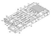
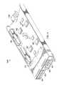
- FIG. 1illustrates a cut-away perspective view of a chassis for receiving modular information handling resources, in accordance with embodiments of the present disclosure
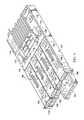
- FIG. 2illustrates a perspective view of an example chassis drawer for carrying modular information handling resources, the drawer in an open position, in accordance with embodiments of the present disclosure
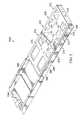
- FIG. 3illustrates a perspective view of an example chassis drawer for carrying modular information handling resources, the drawer in a closed position, in accordance with embodiments of the present disclosure
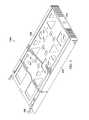
- FIG. 4illustrates a perspective view of another example chassis drawer for carrying information handling resources, in accordance with embodiments of the present disclosure.
- FIG. 5illustrates a plan view of the chassis depicted in FIG. 1 , in accordance with embodiments of the present disclosure.
- FIGS. 1-5wherein like numbers are used to indicate like and corresponding parts.
- an information handling systemmay include any instrumentality or aggregate of instrumentalities operable to compute, classify, process, transmit, receive, retrieve, originate, switch, store, display, manifest, detect, record, reproduce, handle, or utilize any form of information, intelligence, or data for business, scientific, control, entertainment, or other purposes.
- an information handling systemmay be a personal computer, a personal digital assistant (PDA), a consumer electronic device, a network storage device, or any other suitable device and may vary in size, shape, performance, functionality, and price.
- the information handling systemmay include memory, one or more processing resources such as a central processing unit (CPU) or hardware or software control logic.
- Additional components of the information handling systemmay include one or more storage devices, one or more communications ports for communicating with external devices as well as various input and output (I/O) devices, such as a keyboard, a mouse, and a video display.
- the information handling systemmay also include one or more buses operable to transmit communication between the various hardware components.
- Computer-readable mediamay include any instrumentality or aggregation of instrumentalities that may retain data and/or instructions for a period of time.
- Computer-readable mediamay include, without limitation, storage media such as a direct access storage device (e.g., a hard disk drive or floppy disk), a sequential access storage device (e.g., a tape disk drive), compact disk, CD-ROM, DVD, random access memory (RAM), read-only memory (ROM), electrically erasable programmable read-only memory (EEPROM), and/or flash memory; as well as communications media such as wires, optical fibers, microwaves, radio waves, and other electromagnetic and/or optical carriers; and/or any combination of the foregoing.
- storage mediasuch as a direct access storage device (e.g., a hard disk drive or floppy disk), a sequential access storage device (e.g., a tape disk drive), compact disk, CD-ROM, DVD, random access memory (RAM), read-only memory (ROM), electrically erasable programmable read-
- information handling resourcemay broadly refer to any component system, device or apparatus of an information handling system, including without limitation processors, buses, memories, input-output devices and/or interfaces, storage resources, network interfaces, motherboards, electro-mechanical devices (e.g., fans), displays, and power supplies.
- FIG. 1illustrates a perspective view of a chassis 100 for receiving modular information handling resources, in accordance with embodiments of the present disclosure, with certain elements (e.g., walls for enclosing components within chassis 100 ) cut-away or removed in order to show information handling resources internal to chassis 100 .
- Chassis 100may be an enclosure that serves as a container for various information handling systems and information handling resources, and may be constructed from steel, aluminum, plastic, and/or any other suitable material. Although the term “chassis” is used, chassis 100 may also be referred to as a case, cabinet, tower, box, enclosure, and/or housing. In certain embodiments, chassis 100 may be configured to hold and/or provide power to a plurality of information handling systems and/or information handling resources. As depicted in FIG.
- chassis 100may include one or more slots 106 configured to receive drawers 104 for carrying information handling resources, as described in greater detail below.
- some drawers 104may include one or more information handling systems.
- some drawers 104may include one or more peripherals (e.g., hard disk drives, graphics processing units, etc.) associated with information handling systems disposed in another drawer 104 .
- Each drawer 104may include an interface connector 118 configured to electrically couple to a midplane 108 , thus providing electrical coupling between information handling resources carried on the various drawers 104 to each other and/or one or more networks or devices external to chassis 100 .
- Midplane 108may comprise any system, device, or apparatus configured to interconnect information handling resources of chassis 100 with each other. Accordingly, midplane 108 may include slots, pads, and/or other connectors configured to receive corresponding electrical connectors of information handling resources in order to electrically couple information handling systems disposed in drawers 104 and/or information handling resources to each other.
- a chassis management controller (CMC) 112may be communicatively coupled to midplane 108 and may comprise any system, device, or apparatus configured to facilitate management and/or control of components of chassis 100 , information handling systems modularly coupled within, and/or one or more of its component information handling resources. CMC 112 may be configured to issue commands and/or other signals to manage and/or control information handling systems coupled to slots 106 and/or information handling resources of chassis 100 . CMC 112 may comprise a microprocessor, microcontroller, DSP, ASIC, field programmable gate array (“FPGA”), EEPROM, or any combination thereof.
- FPGAfield programmable gate array
- CMC 112may also provide a management console for user/administrator access to these functions.
- CMC 112may provide for communication with a user interface (e.g., user interface 116 ), permitting a user to interact with CMC 112 and configure control and management of components of chassis 100 by CMC 112 .
- CMC 112may implement Web Services Management (“WS-MAN”) or another suitable management protocol permitting a user to remotely access a CMC 112 to configure chassis 100 and its various information handling resources.
- WS-MANWeb Services Management
- a CMC 112may interface with a network interface separate from a traditional network interface of chassis 100 , thus allowing for “out-of-band” control of chassis 100 , such that communications to and from CMC 112 are communicated via a management channel physically isolated from an “in band” communication channel with the traditional network interface.
- CMC 112may allow an administrator to remotely manage one or more parameters associated with operation of chassis 100 and its various information handling resources (e.g., power usage, processor allocation, memory allocation, security privileges, etc.).
- One or more air movers 110may be communicatively coupled to CMC 112 , and may include any mechanical or electro-mechanical system, apparatus, or device operable to move air and/or other gasses.
- an air mover 110may comprise a fan (e.g., a rotating arrangement of vanes or blades which act on the air).
- an air mover 110may comprise a blower (e.g., a centrifugal fan that employs rotating impellers to accelerate air received at its intake and change the direction of the airflow).
- rotating and other moving components of an air mover 110may be driven by a motor. The rotational speed of such motor may be controlled by one or more control signals communicated from CMC 112 .
- an air mover 110may cool information handling systems and information handling resources of chassis 100 by drawing cool air into chassis 100 from outside chassis 100 , expelling warm air from inside chassis 100 to the outside of chassis 100 , and/or moving air across one or more heatsinks (not explicitly shown) internal to chassis 100 to cool one or more information handling systems and/or information handling resources.
- FIG. 1depicts chassis 100 as having two air movers 110 , chassis 100 may include any suitable number of air movers 110 .
- chassis 100may include one or more power supplies 114 .
- a power supply 114may include any system, device, or apparatus configured to supply electrical current to one or more information handling resources within chassis 100 .
- a user interface 116may include any system, apparatus, or device via which a user may interact with chassis 100 and its various components by facilitating input from a user allowing the user to manipulate chassis 100 and output to a user allowing chassis 100 to indicate effects of the user's manipulation.
- user interface 116may include a display suitable for creating graphic images and/or alphanumeric characters recognizable to a user, and may include, for example, a liquid crystal display, a cathode ray tube, a plasma screen, and/or a digital light processor projection monitor.
- a displaymay be an integral part of chassis 100 and receive power from one or more power supplies 114 of chassis 100 , rather than being coupled to chassis 100 via a cable.
- such displaymay comprise a touch screen device capable of receiving user input
- a touch sensormay be mechanically coupled or overlaid upon the display and may comprise any system, apparatus, or device suitable for detecting the presence and/or location of a tactile touch, including, for example, a resistive sensor, capacitive sensor, surface acoustic wave sensor, projected capacitance sensor, infrared sensor, strain gauge sensor, optical imaging sensor, dispersive signal technology sensor, and/or acoustic pulse recognition sensor.
- user interface 116may include other user interface elements (e.g., a keypad, buttons, and/or switches placed in proximity to a display) allowing a user to provide input to chassis 100 .
- user interface 116may include one or more visual indicators, such as light-emitting diodes, for example, for communicating information to a user.
- User interface 116may be coupled to CMC 112 and/or other components of chassis 100 , and thus may allow a user to configure various information handling systems and/or information handling resources of chassis 100 .
- FIGS. 2 and 3depict various views of an example chassis drawer 104 A for carrying modular information handling resources, in accordance with embodiments of the present disclosure.
- FIG. 2illustrates a perspective view of an example chassis drawer 104 A for carrying modular information handling resources, wherein drawer 104 A is in an open position drawn from chassis 100 , in accordance with embodiments of the present disclosure.
- FIG. 3illustrates a perspective view of chassis drawer 104 A for carrying modular information handling resources, wherein drawer 104 A is in a closed position relative to chassis 100 , in accordance with embodiments of the present disclosure.
- chassis drawer 104 Amay comprise an inner member 204 , an intermediate member 206 mechanically coupled to inner member 204 , and a carrier member 208 mechanically coupled to intermediate member 206 .
- Inner member 204may be constructed from steel, aluminum, plastic, and/or any other suitable material. Although inner member 204 may have any suitable size and/or shape, inner member 204 is depicted in the embodiments of FIGS. 2 and 3 as having two substantially planar and parallel opposite sides defining a drawer height coupled to each other by a substantially planar bottom generally perpendicular to the sides defining a drawer width and a guide flange extending from and running perpendicular to and along the length of each side such that the flanges project towards each other. In some embodiments, inner member 204 may be mechanically coupled to the internal mechanical structure of chassis 100 , such that inner member 204 is fixed relative to chassis 100 .
- Intermediate member 206may be constructed from steel, aluminum, plastic, and/or any other suitable material. Although intermediate member 206 may have any suitable size and/or shape, intermediate member 206 is depicted in the embodiments of FIGS. 2 and 3 as having two generally parallel and planar opposite sides coupled to each other by a substantially planar bottom generally perpendicular to the sides. The height of the sides and the width of the bottom may be such that the corresponding sides and bottom of inner member 204 provide a mechanical guide for intermediate member 206 as chassis drawer 104 A is opened and closed.
- Intermediate member 206may be mechanically coupled to inner member 204 via bearings and/or other mechanical components such that intermediate member 206 may slide relative to inner member 204 in a direction perpendicular to the drawer height and drawer width defined by inner member 204 .
- intermediate member 206may be limited in the distance it may be drawn from chassis 100 through any combination of suitable structural elements.
- other mechanical componentsmay restrict motion of intermediate member 206 relative to inner member 204 as chassis drawer 104 A is translated from the open position to the closed position.
- Carrier member 208may be constructed from steel, aluminum, plastic, and/or any other suitable material. Although carrier member 208 may have any suitable size and/or shape, carrier member 208 is depicted in the embodiments of FIGS. 2 and 3 as having a substantially planar top 214 and a substantially planar bottom 216 generally parallel to each other defining a width and depth of carrier member 208 , the top 214 and bottom 216 mechanically coupled to each other by one or more structural elements defining a height of carrier member 208 , such that top 214 and bottom 216 are generally perpendicular to the sides of intermediate member 206 . Carrier member 208 may also include a face 210 mechanically affixed to top 214 and/or bottom 216 . As shown in FIGS.
- top 214may include one or more openings (e.g., above bays 212 ) allowing for gaseous fluid to pass through.
- bottom 216may also include one or more openings (e.g., below bays 212 ) allowing for gaseous fluid to pass through.
- face 210may be substantially equal in width to the width of carrier member 208 and substantially equal to the height of carrier member 208 .
- face 210may include handles, pull tabs, and/or other features allowing a person to pull on face 210 in order to translate chassis drawer 104 A from a closed position to an open position in a direction generally parallel to the depth of top 214 and bottom 216 .
- face 210may include a grill, vent, and/or other opening allowing gaseous fluid to enter and/or exit through face 210 .
- each side of carrier member 208may include a web 230 configured to mechanically couple carrier member 208 to intermediate member 206 , as well as openings for a plurality of bays 212 .
- Each of the various bays 212 defined by drawer 104 Amay include one or more electrical components for coupling an information handling resource (e.g., a hard disk drive) inserted into such bay 212 to other information handling resources of chassis 100 .
- an information handling resourcee.g., a hard disk drive
- a backplanemay couple a modular information handling resource disposed in a bay 212 to interface connector 118 A, which, as described above, may in turn be coupled to midplane 108 .
- the various information handling resourcesmay be coupled to interface connector 118 A such that when chassis drawer 104 A is drawn open relative to chassis 100 , such information handling resources maintain electrical conductivity to interface connector 118 A and interface connector 118 A may maintain electrical conductivity to midplane 108 , thus permitting insertion or removal of an information handling resource without affecting operation of other information handling resources carried by chassis drawer 104 A.
- interface connector 118 Amay only be decoupled from midplane 108 when the entirety of chassis drawer 104 A is removed from chassis 100 .
- FIG. 4illustrates a perspective view of another example chassis drawer 104 B for carrying information handling resources, in accordance with embodiments of the present disclosure.
- chassis drawer 104 Bmay include one or more mechanical and/or structural elements (e.g., similar or identical to inner member 204 , intermediate member 206 , and carrier member 208 ) for translating chassis drawer 104 B between open and closed positions relative to chassis 100 .
- chassis drawer 104 Bmay be coupled to interface connector 118 B such that when chassis drawer 104 B is drawn open relative to chassis 100 , such information handling resources maintain electrical conductivity to interface connector 118 B and interface connector 118 B may maintain electrical conductivity to midplane 108 , thus permitting insertion or removal of an information handling resource without affecting operation of other information handling resources carried by chassis drawer 104 B.
- interface connector 118 Bmay only be decoupled from midplane 108 when the entirety of chassis drawer 104 B is removed from chassis 100 .
- a backplane 408may have thereon a plurality (e.g., four) of processors 402 and a chipset associated with each processor 402 , thus defining four independent information handling systems carried by chassis drawer 104 B.
- Interface connector 118 Bmay also be coupled to backplane 408 , thus coupling processors 402 to information handling resources of chassis 100 external to chassis drawer 104 B.
- the particular chassis drawer 104 B depicted in FIG. 4may include a plurality (e.g., four) of hard disk drives 404 communicatively coupled to backplane 408 (and thus one or more of processors 402 ) via a drive backplane 410 .
- chassis drawer 104 Bmay comprise a user interface 412 .
- User interface 412may include any system, apparatus, or device via which a user may interact with compute nodes (e.g., via a remote access controller such as an Integrated Dell Remote Access Controller or “iDRAC” for example) of chassis drawer 104 B and its various components by facilitating input from a user allowing the user to compute nodes and to indicate effects of the user's manipulation.
- compute nodese.g., via a remote access controller such as an Integrated Dell Remote Access Controller or “iDRAC” for example
- user interface 412may include a display suitable for creating graphic images and/or alphanumeric characters recognizable to a user, and may include, for example, a liquid crystal display, a cathode ray tube, a plasma screen, and/or a digital light processor projection monitor.
- such displaymay comprise a touch screen device capable of receiving user input, wherein a touch sensor may be mechanically coupled or overlaid upon the display and may comprise any system, apparatus, or device suitable for detecting the presence and/or location of a tactile touch, including, for example, a resistive sensor, capacitive sensor, surface acoustic wave sensor, projected capacitance sensor, infrared sensor, strain gauge sensor, optical imaging sensor, dispersive signal technology sensor, and/or acoustic pulse recognition sensor.
- user interface 412may include other user interface elements (e.g., a keypad, buttons, and/or switches placed in proximity to a display) allowing a user to provide input to one or more compute nodes of chassis drawer 104 B.
- user interface 412may include one or more visual indicators, such as light-emitting diodes, for example, for communicating information to a user.
- FIGS. 2-4depict particular example chassis drawers 104
- chassis drawers 104 with other configurationsmay be employed consistent with the systems and methods herein disclosed.
- a chassis drawer 104 similar to that of chassis drawer 104 Bmay include only one processor, such that the chassis drawer includes one compute node.
- a usermay create a multitude of different configurations of computing systems. For example, associations may be configured between information handling resources carried on a peripheral chassis drawer 104 to a compute node carried on a compute node chassis drawer 104 .
- a compute node chassis drawer 104may comprise a chassis drawer 104 carrying one or more processors, such that one or more information handling systems, or compute nodes, are carried on the compute node chassis drawer.
- a peripheral chassis drawer 104may comprise a chassis drawer 104 which does not carry a compute node, but carries one or more information handling resources (e.g., hard disk drives) for use by a compute node.
- a usermay create one or more independent computing systems, each computing system comprising a compute node chassis drawer 104 and a peripheral chassis drawer 104 .
- FIG. 5illustrates a plan view of chassis 100 having chassis drawers 104 disposed therein, in accordance with embodiments of the present disclosure.
- user interface 116 of chassis 100may include interface buttons 502 and 503 .
- Interface buttons 502 and 503may each include any electromechanical device, system, or apparatus configured to actuate an electronic signal to be communicated to one or more other components of chassis 100 (e.g., CMC 112 ), in response to a user interaction with such interface button 502 or 503 (e.g., interface button 502 or 503 being depressed by a user or otherwise manipulated).
- a compute node of emphasis for KVMincluding a compute node of emphasis for a display coupled to connector 510
- a compute node of emphasis for KVMmay be modified, such that the user may select a desired compute node for emphasis by interacting with interface button 502 until the desired compute node has emphasis.
- interface button 503may comprise a “node select” button, such that responsive to user interaction with interface button 503 , a selected compute node or information handling resource may change and cycle among such compute nodes or information handling resources as interface button 503 is pressed.
- interface button 502may include a visual indicator 504 .
- interface button 503may include a visual indicator 505 .
- Visual indicators 504 and 505may each include any device, system, or apparatus for providing a human-perceptible visual indication to a user of an event related to its associated interface button 502 or 504 , as described in greater detail below.
- visual indicator 504may comprise an LED.
- visual indicator 504is shown as integral to interface button 502 , in some embodiments visual indicator 504 may be separate from, but proximate to interface button 502 .
- chassis 100may include a connector 510 .
- Connector 510may include any device, system, or apparatus configured to communicatively couple a peripheral device external to chassis 100 (e.g., a display monitor) to components internal to chassis 100 .
- a peripheral device external to chassis 100e.g., a display monitor
- connector 510may comprise a Video Graphics Array (VGA) connector.
- VGAVideo Graphics Array
- One or more of the various chassis drawers 104 configured for use with chassis 100may each include one or more visual indicators 506 and 508 .
- Each of visual indicators 506 and 508may include any device, system, or apparatus for providing a human-perceptible visual indication to a user of an event related to its associated chassis drawer 104 , as described in greater detail below.
- chassis drawer 104comprising multiple compute nodes (e.g., chassis drawer 104 B of FIG. 4 )
- chassis drawer 104may include multiple of one or more of visual indicators 506 and 508 (e.g., one for each compute node) and/or may have a visual indicator 506 or 508 configured to display a different visual indication for each compute node (e.g., different color).
- chassis drawer 104may include multiple visual indicators 506 and/or 508 (e.g., one for each hard disk drive or other peripheral) or may have a visual indicator 506 configured to display a different visual indication for each hard disk drive or other peripheral (e.g., different color).
- components of chassis 100 and one or more chassis drawers 104 disposed thereinmay be configured such that visual indicators 506 of compute node chassis drawers 104 may display an indication indicating that a particular chassis drawer 104 and/or indicating that a particular compute node within a chassis drawer 104 has KVM emphasis.
- KVM emphasismay change from one chassis drawer 104 /compute node to another, and the visual indicator 506 associated with the chassis drawer 104 /compute node to which emphasis has been switched may display an indication indicating that the chassis drawer 104 /compute node has KVM emphasis.
- components of chassis 100 and one or more chassis drawers 104 disposed thereinmay be configured such that visual indicators 506 and visual indicators 508 of compute node chassis drawers 104 may display an indication of a status other than KVM emphasis, such as an error alert, an indication of normal operation without an error, a node being selected for an emphasis other than KVM emphasis, or any other suitable indications.
- the indication for indicating KVM emphasismay be different than the indication for identifying a chassis drawer 104 /compute node as a component of a computing system.
- a visual indicator 506may display one color for indicating KVM emphasis and display another color for indicating identity as a component of a computing system.
- a visual indicator 506may blink at one frequency for indicating KVM emphasis and blink at another frequency for indicating identity as a component of a computing system.
- a visual indicator 506may display the indication for indicating KVM emphasis for a period of time immediately following the chassis drawer 104 /compute node associated with the visual indicator 506 being selected for KVM emphasis, after which the visual indicator may then display the indicator for indicating identity as a component of a computing system, if applicable.
- visual indicators 508may indicate a different event or status from visual indicators 506 , such as hard disk drive activity.
- components of chassis 100 and one or more chassis drawers 104 disposed thereinmay be configured such that visual indicator 504 associated with interface button 502 may display an indication (e.g., illuminate, blink, or other suitable indication) responsive to a display device being coupled to connector 510 .
- visual indicator 504 associated with interface button 502may display an indication (e.g., illuminate, blink, or other suitable indication) responsive to a display device being coupled to connector 510 .
- a visual indicationis given of the interaction the user may perform (e.g., interacting with interface button 502 or 503 ) in order to select a desired compute node for KVM emphasis, as well as indicating, via a visual indicator 506 , of the then-selected compute node for KVM emphasis.
- chassis drawers 104 disposed in chassis 100all with various visual indicators 506 and 508 providing indication of different events and statuses, such volume of visual indicators may cause a large amount of visual “noise” from the perception of a user, rendering it difficult for such to determine which indicator is providing an indication in response to a user action.
- a visual indicator 506 or 508 within chassis 100may indicate selection of a compute node or peripheral in response to such user action, while one or more other visual indicators 506 and 508 of the chassis may “mute” for a period of time after such user interaction, thus limiting the amount of visual noise from the perception of the user. After such period of time, the muted visual indicators may again provide their associated indications.
- muteas applied to a visual indicator 506 or 508 shall mean that the visual indicator ceases or is disabled from, during the period of such muting, providing a visual indication it would have otherwise given in absence of such muting.
- the LEDmay mute by remaining unilluminated during the period of such muting.
- a visual indicator 506 associated with selection of a particular compute node or information handling resourcemay provide indication of selection (e.g., in the case of an LED, the LED may flash).
- one or more of other visual indicators 506 and 508may mute, and then unmute after such period of time.
- all visual indicators 506 and 508 other than the visual indicator 506 indicating selection of the particular compute node or information handling resourcemay mute.
- only certain visual indicators 506 and 508may mute (e.g., other visual indicators 506 indicating node health and selection may mute, while visual indicators 508 indicating hard disk drive activity may remain active and ummuted).
Landscapes
- Engineering & Computer Science (AREA)
- Physics & Mathematics (AREA)
- Theoretical Computer Science (AREA)
- General Physics & Mathematics (AREA)
- Computer Hardware Design (AREA)
- Power Engineering (AREA)
- Human Computer Interaction (AREA)
- General Engineering & Computer Science (AREA)
- Electromagnetism (AREA)
- User Interface Of Digital Computer (AREA)
Abstract
Description
Claims (10)
Priority Applications (1)
| Application Number | Priority Date | Filing Date | Title |
|---|---|---|---|
| US14/190,767US9401078B2 (en) | 2014-02-26 | 2014-02-26 | Systems and methods for muting visual indicators in an information handling system |
Applications Claiming Priority (1)
| Application Number | Priority Date | Filing Date | Title |
|---|---|---|---|
| US14/190,767US9401078B2 (en) | 2014-02-26 | 2014-02-26 | Systems and methods for muting visual indicators in an information handling system |
Publications (2)
| Publication Number | Publication Date |
|---|---|
| US20150243140A1 US20150243140A1 (en) | 2015-08-27 |
| US9401078B2true US9401078B2 (en) | 2016-07-26 |
Family
ID=53882739
Family Applications (1)
| Application Number | Title | Priority Date | Filing Date |
|---|---|---|---|
| US14/190,767Active2034-04-19US9401078B2 (en) | 2014-02-26 | 2014-02-26 | Systems and methods for muting visual indicators in an information handling system |
Country Status (1)
| Country | Link |
|---|---|
| US (1) | US9401078B2 (en) |
Cited By (12)
| Publication number | Priority date | Publication date | Assignee | Title |
|---|---|---|---|---|
| US20160351025A1 (en)* | 2015-05-28 | 2016-12-01 | Lenovo Enterprise Solutions (Singapore) Pte. Ltd. | Identification of ports from which cables have been recently removed and that have the same physical form factor using existing visual port indicators |
| US10188890B2 (en) | 2013-12-26 | 2019-01-29 | Icon Health & Fitness, Inc. | Magnetic resistance mechanism in a cable machine |
| US10220259B2 (en) | 2012-01-05 | 2019-03-05 | Icon Health & Fitness, Inc. | System and method for controlling an exercise device |
| US10226396B2 (en) | 2014-06-20 | 2019-03-12 | Icon Health & Fitness, Inc. | Post workout massage device |
| US10272317B2 (en) | 2016-03-18 | 2019-04-30 | Icon Health & Fitness, Inc. | Lighted pace feature in a treadmill |
| US10279212B2 (en) | 2013-03-14 | 2019-05-07 | Icon Health & Fitness, Inc. | Strength training apparatus with flywheel and related methods |
| US10391361B2 (en) | 2015-02-27 | 2019-08-27 | Icon Health & Fitness, Inc. | Simulating real-world terrain on an exercise device |
| US10426989B2 (en) | 2014-06-09 | 2019-10-01 | Icon Health & Fitness, Inc. | Cable system incorporated into a treadmill |
| US10433612B2 (en) | 2014-03-10 | 2019-10-08 | Icon Health & Fitness, Inc. | Pressure sensor to quantify work |
| US10493349B2 (en) | 2016-03-18 | 2019-12-03 | Icon Health & Fitness, Inc. | Display on exercise device |
| US10625137B2 (en) | 2016-03-18 | 2020-04-21 | Icon Health & Fitness, Inc. | Coordinated displays in an exercise device |
| US10671705B2 (en) | 2016-09-28 | 2020-06-02 | Icon Health & Fitness, Inc. | Customizing recipe recommendations |
Families Citing this family (7)
| Publication number | Priority date | Publication date | Assignee | Title |
|---|---|---|---|---|
| GB2523839B (en)* | 2014-03-07 | 2018-08-08 | Xyratex Tech Limited | A solid state storage carrier and a storage system |
| US10642603B2 (en) | 2018-01-16 | 2020-05-05 | Nutanix, Inc. | Scheduling upgrades in distributed computing systems |
| US20190332409A1 (en)* | 2018-04-26 | 2019-10-31 | Nutanix, Inc. | Identification and storage of logical to physical address associations for components in virtualized systems |
| US10838754B2 (en) | 2018-04-27 | 2020-11-17 | Nutanix, Inc. | Virtualized systems having hardware interface services for controlling hardware |
| CN110543220B (en)* | 2019-09-03 | 2021-04-16 | 英业达科技有限公司 | Server device |
| US11682274B2 (en)* | 2020-07-16 | 2023-06-20 | Dell Products L.P. | Programmable dynamic information handling system rack lighting system |
| TWI768882B (en)* | 2021-05-07 | 2022-06-21 | 緯穎科技服務股份有限公司 | Server case with telescopic device and the telescopic device |
Citations (28)
| Publication number | Priority date | Publication date | Assignee | Title |
|---|---|---|---|---|
| US3986203A (en)* | 1975-12-03 | 1976-10-12 | Davis John C | Method and apparatus for testing television receivers |
| US4481512A (en)* | 1982-12-29 | 1984-11-06 | Audio Systems, Inc. | Theft-resistant audio system for vehicle |
| US5144441A (en)* | 1989-03-23 | 1992-09-01 | Thomson Consumer Electronics, Inc. | Quieting receiver during power interruption |
| US5489249A (en)* | 1991-07-02 | 1996-02-06 | Proform Fitness Products, Inc. | Video exercise control system |
| US5645509A (en)* | 1991-07-02 | 1997-07-08 | Icon Health & Fitness, Inc. | Remote exercise control system |
| US5708417A (en)* | 1993-12-16 | 1998-01-13 | Phone Alert Corp. | Monitoring system for remote units |
| US6104423A (en)* | 1998-04-24 | 2000-08-15 | Soundview Technologies, Inc. | Receiver apparatus and method for providing conditional access to received television programs |
| US6216263B1 (en)* | 1998-04-24 | 2001-04-10 | Soundview Technologies Incorporated | Receiver apparatus and method for providing conditional access to received televison programs |
| US6295567B1 (en)* | 1998-01-26 | 2001-09-25 | Dell Usa, L.P. | Chassis type determination in an electronic system |
| US6593851B1 (en)* | 2000-11-21 | 2003-07-15 | Aimee Bornstein | Two-way parent-child paging system |
| US20040109193A1 (en)* | 2002-12-04 | 2004-06-10 | Brett Smith | Image forming device having a transmission control and method of operating an image forming device |
| US20040128562A1 (en)* | 2002-12-31 | 2004-07-01 | International Business Machines Corporation | Non-disruptive power management indication method, system and apparatus for server |
| US20040133072A1 (en)* | 2002-09-13 | 2004-07-08 | Kennedy Bruce L. | Video recording and image capture device |
| US20050052856A1 (en)* | 2003-09-04 | 2005-03-10 | Sun Microsystems, Inc. | Method and apparatus having field replaceable units with electrical connectors |
| US7129851B1 (en)* | 2003-09-29 | 2006-10-31 | Sun Microsystems, Inc. | Indicator feedback mechanism |
| US20070208766A1 (en)* | 2006-03-02 | 2007-09-06 | Dale Malik | Apparatuses and methods for interactive communication concerning multimedia content |
| US20070266192A1 (en)* | 2006-05-12 | 2007-11-15 | Edoardo Campini | Enabling ports on a module received in a slot in a chassis |
| US20080126630A1 (en)* | 2006-08-30 | 2008-05-29 | Dell Products L.P. | System and Method for Automatic Module Selection |
| US20090319896A1 (en)* | 2008-06-03 | 2009-12-24 | The Directv Group, Inc. | Visual indicators associated with a media presentation system |
| US20100058234A1 (en)* | 2008-08-29 | 2010-03-04 | Contactual, Inc. | Networked contact center user interface |
| US20110161877A1 (en)* | 2009-12-31 | 2011-06-30 | John Chapra | System, method, and computer-readable medium for providing a dynamic view and testing tool of power cabling of a multi-chassis computer system |
| US20110156862A1 (en)* | 2009-12-30 | 2011-06-30 | Echostar Technologies Llc | Systems, methods and apparatus for locating a lost remote control |
| US20120098343A1 (en)* | 2010-10-26 | 2012-04-26 | Microsoft Corporation | Chassis slots accepting battery modules and other module types |
| US20120194350A1 (en)* | 2011-01-28 | 2012-08-02 | Crisp Richard A | Equipment module indicator handle and methods for indicating equipment module status |
| US8666026B1 (en)* | 2010-12-07 | 2014-03-04 | Adtran, Inc. | Systems and methods for providing notifications of hazardous ground conditions in telecommunication equipment |
| US20140298067A1 (en)* | 2013-03-28 | 2014-10-02 | Juniper Networks, Inc. | Methods and apparatus for reducing energy consumption of network equipment |
| US20140380334A1 (en)* | 2013-06-25 | 2014-12-25 | Microsoft Corporation | Hardware management communication protocol |
| US20150057976A1 (en)* | 2013-08-22 | 2015-02-26 | Ford Global Technologies, Llc | Signal classification |
- 2014
- 2014-02-26USUS14/190,767patent/US9401078B2/enactiveActive
Patent Citations (31)
| Publication number | Priority date | Publication date | Assignee | Title |
|---|---|---|---|---|
| US3986203A (en)* | 1975-12-03 | 1976-10-12 | Davis John C | Method and apparatus for testing television receivers |
| US4481512A (en)* | 1982-12-29 | 1984-11-06 | Audio Systems, Inc. | Theft-resistant audio system for vehicle |
| US5144441A (en)* | 1989-03-23 | 1992-09-01 | Thomson Consumer Electronics, Inc. | Quieting receiver during power interruption |
| US5489249A (en)* | 1991-07-02 | 1996-02-06 | Proform Fitness Products, Inc. | Video exercise control system |
| US5645509A (en)* | 1991-07-02 | 1997-07-08 | Icon Health & Fitness, Inc. | Remote exercise control system |
| US5708417A (en)* | 1993-12-16 | 1998-01-13 | Phone Alert Corp. | Monitoring system for remote units |
| US6295567B1 (en)* | 1998-01-26 | 2001-09-25 | Dell Usa, L.P. | Chassis type determination in an electronic system |
| US6104423A (en)* | 1998-04-24 | 2000-08-15 | Soundview Technologies, Inc. | Receiver apparatus and method for providing conditional access to received television programs |
| US6216263B1 (en)* | 1998-04-24 | 2001-04-10 | Soundview Technologies Incorporated | Receiver apparatus and method for providing conditional access to received televison programs |
| US6593851B1 (en)* | 2000-11-21 | 2003-07-15 | Aimee Bornstein | Two-way parent-child paging system |
| US20060015008A1 (en)* | 2002-09-13 | 2006-01-19 | Kennedy Bruce L | Video recording and image capture device |
| US20040133072A1 (en)* | 2002-09-13 | 2004-07-08 | Kennedy Bruce L. | Video recording and image capture device |
| US20060050144A1 (en)* | 2002-09-13 | 2006-03-09 | Kennedy Bruce L | Video recording and image capture device |
| US20040109193A1 (en)* | 2002-12-04 | 2004-06-10 | Brett Smith | Image forming device having a transmission control and method of operating an image forming device |
| US20040128562A1 (en)* | 2002-12-31 | 2004-07-01 | International Business Machines Corporation | Non-disruptive power management indication method, system and apparatus for server |
| US20050052856A1 (en)* | 2003-09-04 | 2005-03-10 | Sun Microsystems, Inc. | Method and apparatus having field replaceable units with electrical connectors |
| US7129851B1 (en)* | 2003-09-29 | 2006-10-31 | Sun Microsystems, Inc. | Indicator feedback mechanism |
| US20070208766A1 (en)* | 2006-03-02 | 2007-09-06 | Dale Malik | Apparatuses and methods for interactive communication concerning multimedia content |
| US20070266192A1 (en)* | 2006-05-12 | 2007-11-15 | Edoardo Campini | Enabling ports on a module received in a slot in a chassis |
| US20080126630A1 (en)* | 2006-08-30 | 2008-05-29 | Dell Products L.P. | System and Method for Automatic Module Selection |
| US20090319896A1 (en)* | 2008-06-03 | 2009-12-24 | The Directv Group, Inc. | Visual indicators associated with a media presentation system |
| US20100058234A1 (en)* | 2008-08-29 | 2010-03-04 | Contactual, Inc. | Networked contact center user interface |
| US20110156862A1 (en)* | 2009-12-30 | 2011-06-30 | Echostar Technologies Llc | Systems, methods and apparatus for locating a lost remote control |
| US20130099905A1 (en)* | 2009-12-30 | 2013-04-25 | Echostar Technologies Llc | Systems, methods and apparatus for locating a lost remote control |
| US20110161877A1 (en)* | 2009-12-31 | 2011-06-30 | John Chapra | System, method, and computer-readable medium for providing a dynamic view and testing tool of power cabling of a multi-chassis computer system |
| US20120098343A1 (en)* | 2010-10-26 | 2012-04-26 | Microsoft Corporation | Chassis slots accepting battery modules and other module types |
| US8666026B1 (en)* | 2010-12-07 | 2014-03-04 | Adtran, Inc. | Systems and methods for providing notifications of hazardous ground conditions in telecommunication equipment |
| US20120194350A1 (en)* | 2011-01-28 | 2012-08-02 | Crisp Richard A | Equipment module indicator handle and methods for indicating equipment module status |
| US20140298067A1 (en)* | 2013-03-28 | 2014-10-02 | Juniper Networks, Inc. | Methods and apparatus for reducing energy consumption of network equipment |
| US20140380334A1 (en)* | 2013-06-25 | 2014-12-25 | Microsoft Corporation | Hardware management communication protocol |
| US20150057976A1 (en)* | 2013-08-22 | 2015-02-26 | Ford Global Technologies, Llc | Signal classification |
Cited By (13)
| Publication number | Priority date | Publication date | Assignee | Title |
|---|---|---|---|---|
| US10220259B2 (en) | 2012-01-05 | 2019-03-05 | Icon Health & Fitness, Inc. | System and method for controlling an exercise device |
| US10279212B2 (en) | 2013-03-14 | 2019-05-07 | Icon Health & Fitness, Inc. | Strength training apparatus with flywheel and related methods |
| US10188890B2 (en) | 2013-12-26 | 2019-01-29 | Icon Health & Fitness, Inc. | Magnetic resistance mechanism in a cable machine |
| US10433612B2 (en) | 2014-03-10 | 2019-10-08 | Icon Health & Fitness, Inc. | Pressure sensor to quantify work |
| US10426989B2 (en) | 2014-06-09 | 2019-10-01 | Icon Health & Fitness, Inc. | Cable system incorporated into a treadmill |
| US10226396B2 (en) | 2014-06-20 | 2019-03-12 | Icon Health & Fitness, Inc. | Post workout massage device |
| US10391361B2 (en) | 2015-02-27 | 2019-08-27 | Icon Health & Fitness, Inc. | Simulating real-world terrain on an exercise device |
| US9569940B2 (en)* | 2015-05-28 | 2017-02-14 | Lenovo Enterprise Solutions (Singapore) Pte. Ltd. | Identification of ports from which cables have been recently removed and that have the same physical form factor using existing visual port indicators |
| US20160351025A1 (en)* | 2015-05-28 | 2016-12-01 | Lenovo Enterprise Solutions (Singapore) Pte. Ltd. | Identification of ports from which cables have been recently removed and that have the same physical form factor using existing visual port indicators |
| US10272317B2 (en) | 2016-03-18 | 2019-04-30 | Icon Health & Fitness, Inc. | Lighted pace feature in a treadmill |
| US10493349B2 (en) | 2016-03-18 | 2019-12-03 | Icon Health & Fitness, Inc. | Display on exercise device |
| US10625137B2 (en) | 2016-03-18 | 2020-04-21 | Icon Health & Fitness, Inc. | Coordinated displays in an exercise device |
| US10671705B2 (en) | 2016-09-28 | 2020-06-02 | Icon Health & Fitness, Inc. | Customizing recipe recommendations |
Also Published As
| Publication number | Publication date |
|---|---|
| US20150243140A1 (en) | 2015-08-27 |
Similar Documents
| Publication | Publication Date | Title |
|---|---|---|
| US9401078B2 (en) | Systems and methods for muting visual indicators in an information handling system | |
| US9887856B2 (en) | Methods and systems for network switch configuration for a modular component carrying one or more information handling systems | |
| EP3077886B1 (en) | Methods and systems for monitoring and management in a distributed architecture information handling system chassis | |
| US9258913B2 (en) | Multi-stage information handling resource release latch for use in a modular information handling system chassis | |
| US9250649B2 (en) | Displaying recommended placement of information handling systems based on impedance ranking | |
| US10353453B2 (en) | Methods and systems for multiple module power regulation in a modular chassis | |
| US10430351B2 (en) | Systems and methods for virtual service processor data bridging | |
| US8694693B2 (en) | Methods and systems for providing user selection of associations between information handling resources and information handling systems in an integrated chassis | |
| US8880766B2 (en) | Methods and systems for removal of information handling resources in a shared input/output infrastructure | |
| US10082848B2 (en) | Systems and methods for thermal adaptation for virtual thermal inputs in a chassis infrastructure | |
| US8819779B2 (en) | Methods and systems for managing multiple information handling systems with a virtual keyboard-video-mouse interface | |
| US10126798B2 (en) | Systems and methods for autonomously adapting powering budgeting in a multi-information handling system passive chassis environment | |
| US9519607B2 (en) | Methods and systems for virtualization of storage services in an integrated chassis | |
| US10430251B2 (en) | Systems and methods for load balancing based on thermal parameters | |
| US10642672B2 (en) | Systems and methods for dynamic thermal excursion timeout determination and predictive failure notification based on airflow escape detection | |
| US9740650B2 (en) | Methods and systems for associating peripheral information handling resources to compute nodes in a modular information system chassis | |
| US20150170484A1 (en) | Systems and methods for sensing and identifying information handling resources in a disaggregated server | |
| US9148339B2 (en) | Methods and systems for deploying network configuration information for multiple information handling systems | |
| US10153225B1 (en) | Systems and methods for optimizing information handling system component temperature for performance |
Legal Events
| Date | Code | Title | Description |
|---|---|---|---|
| AS | Assignment | Owner name:DELL PRODUCTS L.P., TEXAS Free format text:ASSIGNMENT OF ASSIGNORS INTEREST;ASSIGNOR:BARRETT, ROBERT;REEL/FRAME:032304/0344 Effective date:20140221 | |
| AS | Assignment | Owner name:BANK OF AMERICA, N.A., AS ADMINISTRATIVE AGENT, NORTH CAROLINA Free format text:SUPPLEMENT TO PATENT SECURITY AGREEMENT (ABL);ASSIGNORS:DELL PRODUCTS L.P.;DELL SOFTWARE INC.;SECUREWORKS, INC.;REEL/FRAME:032810/0023 Effective date:20140402 Owner name:THE BANK OF NEW YORK MELLON TRUST COMPANY N.A., AS NOTES COLLATERAL AGENT, TEXAS Free format text:SUPPLEMENT TO PATENT SECURITY AGREEMENT (NOTES);ASSIGNORS:DELL PRODUCTS L.P.;DELL SOFTWARE INC.;SECUREWORKS, INC.;REEL/FRAME:032809/0987 Effective date:20140402 Owner name:BANK OF AMERICA, N.A., AS COLLATERAL AGENT, NORTH CAROLINA Free format text:SUPPLEMENT TO PATENT SECURITY AGREEMENT (TERM LOAN);ASSIGNORS:DELL PRODUCTS L.P.;DELL SOFTWARE INC.;SECUREWORKS, INC.;REEL/FRAME:032810/0038 Effective date:20140402 Owner name:BANK OF AMERICA, N.A., AS ADMINISTRATIVE AGENT, NO Free format text:SUPPLEMENT TO PATENT SECURITY AGREEMENT (ABL);ASSIGNORS:DELL PRODUCTS L.P.;DELL SOFTWARE INC.;SECUREWORKS, INC.;REEL/FRAME:032810/0023 Effective date:20140402 Owner name:BANK OF AMERICA, N.A., AS COLLATERAL AGENT, NORTH Free format text:SUPPLEMENT TO PATENT SECURITY AGREEMENT (TERM LOAN);ASSIGNORS:DELL PRODUCTS L.P.;DELL SOFTWARE INC.;SECUREWORKS, INC.;REEL/FRAME:032810/0038 Effective date:20140402 Owner name:THE BANK OF NEW YORK MELLON TRUST COMPANY N.A., AS Free format text:SUPPLEMENT TO PATENT SECURITY AGREEMENT (NOTES);ASSIGNORS:DELL PRODUCTS L.P.;DELL SOFTWARE INC.;SECUREWORKS, INC.;REEL/FRAME:032809/0987 Effective date:20140402 | |
| FEPP | Fee payment procedure | Free format text:PAYOR NUMBER ASSIGNED (ORIGINAL EVENT CODE: ASPN); ENTITY STATUS OF PATENT OWNER: LARGE ENTITY | |
| STCF | Information on status: patent grant | Free format text:PATENTED CASE | |
| AS | Assignment | Owner name:DELL SOFTWARE INC., CALIFORNIA Free format text:RELEASE OF REEL 032810 FRAME 0023 (ABL);ASSIGNOR:BANK OF AMERICA, N.A., AS ADMINISTRATIVE AGENT;REEL/FRAME:040014/0320 Effective date:20160907 Owner name:DELL PRODUCTS L.P., TEXAS Free format text:RELEASE OF REEL 032810 FRAME 0023 (ABL);ASSIGNOR:BANK OF AMERICA, N.A., AS ADMINISTRATIVE AGENT;REEL/FRAME:040014/0320 Effective date:20160907 Owner name:SECUREWORKS, INC., GEORGIA Free format text:RELEASE OF REEL 032810 FRAME 0023 (ABL);ASSIGNOR:BANK OF AMERICA, N.A., AS ADMINISTRATIVE AGENT;REEL/FRAME:040014/0320 Effective date:20160907 | |
| AS | Assignment | Owner name:DELL PRODUCTS L.P., TEXAS Free format text:RELEASE OF REEL 032809 FRAME 0987 (NOTE);ASSIGNOR:BANK OF NEW YORK MELLON TRUST COMPANY, N.A., AS COLLATERAL AGENT;REEL/FRAME:040026/0953 Effective date:20160907 Owner name:DELL SOFTWARE INC., CALIFORNIA Free format text:RELEASE OF REEL 032809 FRAME 0987 (NOTE);ASSIGNOR:BANK OF NEW YORK MELLON TRUST COMPANY, N.A., AS COLLATERAL AGENT;REEL/FRAME:040026/0953 Effective date:20160907 Owner name:SECUREWORKS, INC., GEORGIA Free format text:RELEASE OF REEL 032809 FRAME 0987 (NOTE);ASSIGNOR:BANK OF NEW YORK MELLON TRUST COMPANY, N.A., AS COLLATERAL AGENT;REEL/FRAME:040026/0953 Effective date:20160907 Owner name:SECUREWORKS, INC., GEORGIA Free format text:RELEASE OF REEL 032810 FRAME 0038 (TL);ASSIGNOR:BANK OF AMERICA, N.A., AS COLLATERAL AGENT;REEL/FRAME:040027/0686 Effective date:20160907 Owner name:DELL SOFTWARE INC., CALIFORNIA Free format text:RELEASE OF REEL 032810 FRAME 0038 (TL);ASSIGNOR:BANK OF AMERICA, N.A., AS COLLATERAL AGENT;REEL/FRAME:040027/0686 Effective date:20160907 Owner name:DELL PRODUCTS L.P., TEXAS Free format text:RELEASE OF REEL 032810 FRAME 0038 (TL);ASSIGNOR:BANK OF AMERICA, N.A., AS COLLATERAL AGENT;REEL/FRAME:040027/0686 Effective date:20160907 | |
| AS | Assignment | Owner name:THE BANK OF NEW YORK MELLON TRUST COMPANY, N.A., AS NOTES COLLATERAL AGENT, TEXAS Free format text:SECURITY AGREEMENT;ASSIGNORS:ASAP SOFTWARE EXPRESS, INC.;AVENTAIL LLC;CREDANT TECHNOLOGIES, INC.;AND OTHERS;REEL/FRAME:040136/0001 Effective date:20160907 Owner name:CREDIT SUISSE AG, CAYMAN ISLANDS BRANCH, AS COLLATERAL AGENT, NORTH CAROLINA Free format text:SECURITY AGREEMENT;ASSIGNORS:ASAP SOFTWARE EXPRESS, INC.;AVENTAIL LLC;CREDANT TECHNOLOGIES, INC.;AND OTHERS;REEL/FRAME:040134/0001 Effective date:20160907 Owner name:CREDIT SUISSE AG, CAYMAN ISLANDS BRANCH, AS COLLAT Free format text:SECURITY AGREEMENT;ASSIGNORS:ASAP SOFTWARE EXPRESS, INC.;AVENTAIL LLC;CREDANT TECHNOLOGIES, INC.;AND OTHERS;REEL/FRAME:040134/0001 Effective date:20160907 Owner name:THE BANK OF NEW YORK MELLON TRUST COMPANY, N.A., A Free format text:SECURITY AGREEMENT;ASSIGNORS:ASAP SOFTWARE EXPRESS, INC.;AVENTAIL LLC;CREDANT TECHNOLOGIES, INC.;AND OTHERS;REEL/FRAME:040136/0001 Effective date:20160907 | |
| AS | Assignment | Owner name:THE BANK OF NEW YORK MELLON TRUST COMPANY, N.A., T Free format text:SECURITY AGREEMENT;ASSIGNORS:CREDANT TECHNOLOGIES, INC.;DELL INTERNATIONAL L.L.C.;DELL MARKETING L.P.;AND OTHERS;REEL/FRAME:049452/0223 Effective date:20190320 Owner name:THE BANK OF NEW YORK MELLON TRUST COMPANY, N.A., TEXAS Free format text:SECURITY AGREEMENT;ASSIGNORS:CREDANT TECHNOLOGIES, INC.;DELL INTERNATIONAL L.L.C.;DELL MARKETING L.P.;AND OTHERS;REEL/FRAME:049452/0223 Effective date:20190320 | |
| MAFP | Maintenance fee payment | Free format text:PAYMENT OF MAINTENANCE FEE, 4TH YEAR, LARGE ENTITY (ORIGINAL EVENT CODE: M1551); ENTITY STATUS OF PATENT OWNER: LARGE ENTITY Year of fee payment:4 | |
| AS | Assignment | Owner name:THE BANK OF NEW YORK MELLON TRUST COMPANY, N.A., TEXAS Free format text:SECURITY AGREEMENT;ASSIGNORS:CREDANT TECHNOLOGIES INC.;DELL INTERNATIONAL L.L.C.;DELL MARKETING L.P.;AND OTHERS;REEL/FRAME:053546/0001 Effective date:20200409 | |
| AS | Assignment | Owner name:WYSE TECHNOLOGY L.L.C., CALIFORNIA Free format text:RELEASE BY SECURED PARTY;ASSIGNOR:CREDIT SUISSE AG, CAYMAN ISLANDS BRANCH;REEL/FRAME:058216/0001 Effective date:20211101 Owner name:SCALEIO LLC, MASSACHUSETTS Free format text:RELEASE BY SECURED PARTY;ASSIGNOR:CREDIT SUISSE AG, CAYMAN ISLANDS BRANCH;REEL/FRAME:058216/0001 Effective date:20211101 Owner name:MOZY, INC., WASHINGTON Free format text:RELEASE BY SECURED PARTY;ASSIGNOR:CREDIT SUISSE AG, CAYMAN ISLANDS BRANCH;REEL/FRAME:058216/0001 Effective date:20211101 Owner name:MAGINATICS LLC, CALIFORNIA Free format text:RELEASE BY SECURED PARTY;ASSIGNOR:CREDIT SUISSE AG, CAYMAN ISLANDS BRANCH;REEL/FRAME:058216/0001 Effective date:20211101 Owner name:FORCE10 NETWORKS, INC., CALIFORNIA Free format text:RELEASE BY SECURED PARTY;ASSIGNOR:CREDIT SUISSE AG, CAYMAN ISLANDS BRANCH;REEL/FRAME:058216/0001 Effective date:20211101 Owner name:EMC IP HOLDING COMPANY LLC, TEXAS Free format text:RELEASE BY SECURED PARTY;ASSIGNOR:CREDIT SUISSE AG, CAYMAN ISLANDS BRANCH;REEL/FRAME:058216/0001 Effective date:20211101 Owner name:EMC CORPORATION, MASSACHUSETTS Free format text:RELEASE BY SECURED PARTY;ASSIGNOR:CREDIT SUISSE AG, CAYMAN ISLANDS BRANCH;REEL/FRAME:058216/0001 Effective date:20211101 Owner name:DELL SYSTEMS CORPORATION, TEXAS Free format text:RELEASE BY SECURED PARTY;ASSIGNOR:CREDIT SUISSE AG, CAYMAN ISLANDS BRANCH;REEL/FRAME:058216/0001 Effective date:20211101 Owner name:DELL SOFTWARE INC., CALIFORNIA Free format text:RELEASE BY SECURED PARTY;ASSIGNOR:CREDIT SUISSE AG, CAYMAN ISLANDS BRANCH;REEL/FRAME:058216/0001 Effective date:20211101 Owner name:DELL PRODUCTS L.P., TEXAS Free format text:RELEASE BY SECURED PARTY;ASSIGNOR:CREDIT SUISSE AG, CAYMAN ISLANDS BRANCH;REEL/FRAME:058216/0001 Effective date:20211101 Owner name:DELL MARKETING L.P., TEXAS Free format text:RELEASE BY SECURED PARTY;ASSIGNOR:CREDIT SUISSE AG, CAYMAN ISLANDS BRANCH;REEL/FRAME:058216/0001 Effective date:20211101 Owner name:DELL INTERNATIONAL, L.L.C., TEXAS Free format text:RELEASE BY SECURED PARTY;ASSIGNOR:CREDIT SUISSE AG, CAYMAN ISLANDS BRANCH;REEL/FRAME:058216/0001 Effective date:20211101 Owner name:DELL USA L.P., TEXAS Free format text:RELEASE BY SECURED PARTY;ASSIGNOR:CREDIT SUISSE AG, CAYMAN ISLANDS BRANCH;REEL/FRAME:058216/0001 Effective date:20211101 Owner name:CREDANT TECHNOLOGIES, INC., TEXAS Free format text:RELEASE BY SECURED PARTY;ASSIGNOR:CREDIT SUISSE AG, CAYMAN ISLANDS BRANCH;REEL/FRAME:058216/0001 Effective date:20211101 Owner name:AVENTAIL LLC, CALIFORNIA Free format text:RELEASE BY SECURED PARTY;ASSIGNOR:CREDIT SUISSE AG, CAYMAN ISLANDS BRANCH;REEL/FRAME:058216/0001 Effective date:20211101 Owner name:ASAP SOFTWARE EXPRESS, INC., ILLINOIS Free format text:RELEASE BY SECURED PARTY;ASSIGNOR:CREDIT SUISSE AG, CAYMAN ISLANDS BRANCH;REEL/FRAME:058216/0001 Effective date:20211101 | |
| AS | Assignment | Owner name:SCALEIO LLC, MASSACHUSETTS Free format text:RELEASE OF SECURITY INTEREST IN PATENTS PREVIOUSLY RECORDED AT REEL/FRAME (040136/0001);ASSIGNOR:THE BANK OF NEW YORK MELLON TRUST COMPANY, N.A., AS NOTES COLLATERAL AGENT;REEL/FRAME:061324/0001 Effective date:20220329 Owner name:EMC IP HOLDING COMPANY LLC (ON BEHALF OF ITSELF AND AS SUCCESSOR-IN-INTEREST TO MOZY, INC.), TEXAS Free format text:RELEASE OF SECURITY INTEREST IN PATENTS PREVIOUSLY RECORDED AT REEL/FRAME (040136/0001);ASSIGNOR:THE BANK OF NEW YORK MELLON TRUST COMPANY, N.A., AS NOTES COLLATERAL AGENT;REEL/FRAME:061324/0001 Effective date:20220329 Owner name:EMC CORPORATION (ON BEHALF OF ITSELF AND AS SUCCESSOR-IN-INTEREST TO MAGINATICS LLC), MASSACHUSETTS Free format text:RELEASE OF SECURITY INTEREST IN PATENTS PREVIOUSLY RECORDED AT REEL/FRAME (040136/0001);ASSIGNOR:THE BANK OF NEW YORK MELLON TRUST COMPANY, N.A., AS NOTES COLLATERAL AGENT;REEL/FRAME:061324/0001 Effective date:20220329 Owner name:DELL MARKETING CORPORATION (SUCCESSOR-IN-INTEREST TO FORCE10 NETWORKS, INC. AND WYSE TECHNOLOGY L.L.C.), TEXAS Free format text:RELEASE OF SECURITY INTEREST IN PATENTS PREVIOUSLY RECORDED AT REEL/FRAME (040136/0001);ASSIGNOR:THE BANK OF NEW YORK MELLON TRUST COMPANY, N.A., AS NOTES COLLATERAL AGENT;REEL/FRAME:061324/0001 Effective date:20220329 Owner name:DELL PRODUCTS L.P., TEXAS Free format text:RELEASE OF SECURITY INTEREST IN PATENTS PREVIOUSLY RECORDED AT REEL/FRAME (040136/0001);ASSIGNOR:THE BANK OF NEW YORK MELLON TRUST COMPANY, N.A., AS NOTES COLLATERAL AGENT;REEL/FRAME:061324/0001 Effective date:20220329 Owner name:DELL INTERNATIONAL L.L.C., TEXAS Free format text:RELEASE OF SECURITY INTEREST IN PATENTS PREVIOUSLY RECORDED AT REEL/FRAME (040136/0001);ASSIGNOR:THE BANK OF NEW YORK MELLON TRUST COMPANY, N.A., AS NOTES COLLATERAL AGENT;REEL/FRAME:061324/0001 Effective date:20220329 Owner name:DELL USA L.P., TEXAS Free format text:RELEASE OF SECURITY INTEREST IN PATENTS PREVIOUSLY RECORDED AT REEL/FRAME (040136/0001);ASSIGNOR:THE BANK OF NEW YORK MELLON TRUST COMPANY, N.A., AS NOTES COLLATERAL AGENT;REEL/FRAME:061324/0001 Effective date:20220329 Owner name:DELL MARKETING L.P. (ON BEHALF OF ITSELF AND AS SUCCESSOR-IN-INTEREST TO CREDANT TECHNOLOGIES, INC.), TEXAS Free format text:RELEASE OF SECURITY INTEREST IN PATENTS PREVIOUSLY RECORDED AT REEL/FRAME (040136/0001);ASSIGNOR:THE BANK OF NEW YORK MELLON TRUST COMPANY, N.A., AS NOTES COLLATERAL AGENT;REEL/FRAME:061324/0001 Effective date:20220329 Owner name:DELL MARKETING CORPORATION (SUCCESSOR-IN-INTEREST TO ASAP SOFTWARE EXPRESS, INC.), TEXAS Free format text:RELEASE OF SECURITY INTEREST IN PATENTS PREVIOUSLY RECORDED AT REEL/FRAME (040136/0001);ASSIGNOR:THE BANK OF NEW YORK MELLON TRUST COMPANY, N.A., AS NOTES COLLATERAL AGENT;REEL/FRAME:061324/0001 Effective date:20220329 | |
| AS | Assignment | Owner name:SCALEIO LLC, MASSACHUSETTS Free format text:RELEASE OF SECURITY INTEREST IN PATENTS PREVIOUSLY RECORDED AT REEL/FRAME (045455/0001);ASSIGNOR:THE BANK OF NEW YORK MELLON TRUST COMPANY, N.A., AS NOTES COLLATERAL AGENT;REEL/FRAME:061753/0001 Effective date:20220329 Owner name:EMC IP HOLDING COMPANY LLC (ON BEHALF OF ITSELF AND AS SUCCESSOR-IN-INTEREST TO MOZY, INC.), TEXAS Free format text:RELEASE OF SECURITY INTEREST IN PATENTS PREVIOUSLY RECORDED AT REEL/FRAME (045455/0001);ASSIGNOR:THE BANK OF NEW YORK MELLON TRUST COMPANY, N.A., AS NOTES COLLATERAL AGENT;REEL/FRAME:061753/0001 Effective date:20220329 Owner name:EMC CORPORATION (ON BEHALF OF ITSELF AND AS SUCCESSOR-IN-INTEREST TO MAGINATICS LLC), MASSACHUSETTS Free format text:RELEASE OF SECURITY INTEREST IN PATENTS PREVIOUSLY RECORDED AT REEL/FRAME (045455/0001);ASSIGNOR:THE BANK OF NEW YORK MELLON TRUST COMPANY, N.A., AS NOTES COLLATERAL AGENT;REEL/FRAME:061753/0001 Effective date:20220329 Owner name:DELL MARKETING CORPORATION (SUCCESSOR-IN-INTEREST TO FORCE10 NETWORKS, INC. AND WYSE TECHNOLOGY L.L.C.), TEXAS Free format text:RELEASE OF SECURITY INTEREST IN PATENTS PREVIOUSLY RECORDED AT REEL/FRAME (045455/0001);ASSIGNOR:THE BANK OF NEW YORK MELLON TRUST COMPANY, N.A., AS NOTES COLLATERAL AGENT;REEL/FRAME:061753/0001 Effective date:20220329 Owner name:DELL PRODUCTS L.P., TEXAS Free format text:RELEASE OF SECURITY INTEREST IN PATENTS PREVIOUSLY RECORDED AT REEL/FRAME (045455/0001);ASSIGNOR:THE BANK OF NEW YORK MELLON TRUST COMPANY, N.A., AS NOTES COLLATERAL AGENT;REEL/FRAME:061753/0001 Effective date:20220329 Owner name:DELL INTERNATIONAL L.L.C., TEXAS Free format text:RELEASE OF SECURITY INTEREST IN PATENTS PREVIOUSLY RECORDED AT REEL/FRAME (045455/0001);ASSIGNOR:THE BANK OF NEW YORK MELLON TRUST COMPANY, N.A., AS NOTES COLLATERAL AGENT;REEL/FRAME:061753/0001 Effective date:20220329 Owner name:DELL USA L.P., TEXAS Free format text:RELEASE OF SECURITY INTEREST IN PATENTS PREVIOUSLY RECORDED AT REEL/FRAME (045455/0001);ASSIGNOR:THE BANK OF NEW YORK MELLON TRUST COMPANY, N.A., AS NOTES COLLATERAL AGENT;REEL/FRAME:061753/0001 Effective date:20220329 Owner name:DELL MARKETING L.P. (ON BEHALF OF ITSELF AND AS SUCCESSOR-IN-INTEREST TO CREDANT TECHNOLOGIES, INC.), TEXAS Free format text:RELEASE OF SECURITY INTEREST IN PATENTS PREVIOUSLY RECORDED AT REEL/FRAME (045455/0001);ASSIGNOR:THE BANK OF NEW YORK MELLON TRUST COMPANY, N.A., AS NOTES COLLATERAL AGENT;REEL/FRAME:061753/0001 Effective date:20220329 Owner name:DELL MARKETING CORPORATION (SUCCESSOR-IN-INTEREST TO ASAP SOFTWARE EXPRESS, INC.), TEXAS Free format text:RELEASE OF SECURITY INTEREST IN PATENTS PREVIOUSLY RECORDED AT REEL/FRAME (045455/0001);ASSIGNOR:THE BANK OF NEW YORK MELLON TRUST COMPANY, N.A., AS NOTES COLLATERAL AGENT;REEL/FRAME:061753/0001 Effective date:20220329 | |
| AS | Assignment | Owner name:DELL MARKETING L.P. (ON BEHALF OF ITSELF AND AS SUCCESSOR-IN-INTEREST TO CREDANT TECHNOLOGIES, INC.), TEXAS Free format text:RELEASE OF SECURITY INTEREST IN PATENTS PREVIOUSLY RECORDED AT REEL/FRAME (053546/0001);ASSIGNOR:THE BANK OF NEW YORK MELLON TRUST COMPANY, N.A., AS NOTES COLLATERAL AGENT;REEL/FRAME:071642/0001 Effective date:20220329 Owner name:DELL INTERNATIONAL L.L.C., TEXAS Free format text:RELEASE OF SECURITY INTEREST IN PATENTS PREVIOUSLY RECORDED AT REEL/FRAME (053546/0001);ASSIGNOR:THE BANK OF NEW YORK MELLON TRUST COMPANY, N.A., AS NOTES COLLATERAL AGENT;REEL/FRAME:071642/0001 Effective date:20220329 Owner name:DELL PRODUCTS L.P., TEXAS Free format text:RELEASE OF SECURITY INTEREST IN PATENTS PREVIOUSLY RECORDED AT REEL/FRAME (053546/0001);ASSIGNOR:THE BANK OF NEW YORK MELLON TRUST COMPANY, N.A., AS NOTES COLLATERAL AGENT;REEL/FRAME:071642/0001 Effective date:20220329 Owner name:DELL USA L.P., TEXAS Free format text:RELEASE OF SECURITY INTEREST IN PATENTS PREVIOUSLY RECORDED AT REEL/FRAME (053546/0001);ASSIGNOR:THE BANK OF NEW YORK MELLON TRUST COMPANY, N.A., AS NOTES COLLATERAL AGENT;REEL/FRAME:071642/0001 Effective date:20220329 Owner name:EMC CORPORATION, MASSACHUSETTS Free format text:RELEASE OF SECURITY INTEREST IN PATENTS PREVIOUSLY RECORDED AT REEL/FRAME (053546/0001);ASSIGNOR:THE BANK OF NEW YORK MELLON TRUST COMPANY, N.A., AS NOTES COLLATERAL AGENT;REEL/FRAME:071642/0001 Effective date:20220329 Owner name:DELL MARKETING CORPORATION (SUCCESSOR-IN-INTEREST TO FORCE10 NETWORKS, INC. AND WYSE TECHNOLOGY L.L.C.), TEXAS Free format text:RELEASE OF SECURITY INTEREST IN PATENTS PREVIOUSLY RECORDED AT REEL/FRAME (053546/0001);ASSIGNOR:THE BANK OF NEW YORK MELLON TRUST COMPANY, N.A., AS NOTES COLLATERAL AGENT;REEL/FRAME:071642/0001 Effective date:20220329 Owner name:EMC IP HOLDING COMPANY LLC, TEXAS Free format text:RELEASE OF SECURITY INTEREST IN PATENTS PREVIOUSLY RECORDED AT REEL/FRAME (053546/0001);ASSIGNOR:THE BANK OF NEW YORK MELLON TRUST COMPANY, N.A., AS NOTES COLLATERAL AGENT;REEL/FRAME:071642/0001 Effective date:20220329 | |
| MAFP | Maintenance fee payment | Free format text:PAYMENT OF MAINTENANCE FEE, 8TH YEAR, LARGE ENTITY (ORIGINAL EVENT CODE: M1552); ENTITY STATUS OF PATENT OWNER: LARGE ENTITY Year of fee payment:8 |