US9399263B2 - Portable battery powered welder - Google Patents
Portable battery powered welderDownload PDFInfo
- Publication number
- US9399263B2 US9399263B2US11/848,874US84887407AUS9399263B2US 9399263 B2US9399263 B2US 9399263B2US 84887407 AUS84887407 AUS 84887407AUS 9399263 B2US9399263 B2US 9399263B2
- Authority
- US
- United States
- Prior art keywords
- suitcase
- battery
- battery powered
- access panel
- powered welder
- Prior art date
- Legal status (The legal status is an assumption and is not a legal conclusion. Google has not performed a legal analysis and makes no representation as to the accuracy of the status listed.)
- Active, expires
Links
Images


Classifications
- B—PERFORMING OPERATIONS; TRANSPORTING
- B23—MACHINE TOOLS; METAL-WORKING NOT OTHERWISE PROVIDED FOR
- B23K—SOLDERING OR UNSOLDERING; WELDING; CLADDING OR PLATING BY SOLDERING OR WELDING; CUTTING BY APPLYING HEAT LOCALLY, e.g. FLAME CUTTING; WORKING BY LASER BEAM
- B23K9/00—Arc welding or cutting
- B23K9/32—Accessories
- B—PERFORMING OPERATIONS; TRANSPORTING
- B23—MACHINE TOOLS; METAL-WORKING NOT OTHERWISE PROVIDED FOR
- B23K—SOLDERING OR UNSOLDERING; WELDING; CLADDING OR PLATING BY SOLDERING OR WELDING; CUTTING BY APPLYING HEAT LOCALLY, e.g. FLAME CUTTING; WORKING BY LASER BEAM
- B23K9/00—Arc welding or cutting
- B23K9/10—Other electric circuits therefor; Protective circuits; Remote controls
- B23K9/1006—Power supply
Definitions
- the inventiongenerally relates to portable welding systems. More specifically, embodiments of the invention relate to a portable battery powered welder having various welding components integrally mounted in a suitcase.
- Portable welding systemsmay be used in field applications where it is not practical or convenient to send a work piece to a welding shop for repair or fabrication.
- One specific group of portable weldersare designed for light welding applications (low output requirements of about 200 amps or less), and are well suited for shops and garages where only single-phase power is available. These welders find applications in the farming and ranching industry; off-road applications; food and beverage industry; restaurant and kitchen repair; petroleum and chemical fabrication; shipboard installation and repair; and many other maintenance and repair applications.
- Embodiments of the present inventionprovide a portable battery powered welder.
- the portable battery powered weldermay include a battery coupled to a welding circuit and a wire feeder.
- the portable battery powered weldermay include a suitcase to integrally support and completely enclose the welding circuit, the battery, and the wire feeder.
- the suitcasemay include a lateral access door having a hinge and a latch.
- the wire feeder and a wire spool that includes consumable welding wiremay be disposed in a region accessible by the lateral access door.
- the suitcasemay also include an access panel disposed over a region containing the battery. The access panel may be mounted to the case via a snap mount and/or secured via fasteners.
- the suitcasemay include a top handle and may be made of a lightweight, impact resistant, and flame retardant material, such as a polymer.
- the battery powered weldermay also include a power conversion and/or conditioning circuit that may be disposed in the suitcase and coupled to the battery. Further, a cooling system may be disposed in the suitcase for dissipating heat from the welding circuit, power conversion circuit, and/or conditioning circuit. The cooling system may include a wind tunnel, a front louver, a rear louver, and a fan that are disposed inside the suitcase or form a part of the enclosure. Finally, a work clamp and a welding gun may be coupled to the wire feeder and the welding circuit.
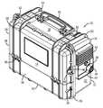
- FIG. 1is a perspective view of an embodiment of a portable battery powered welder in accordance with embodiments of the invention, illustrating a hinged lateral access door and an access panel that form part of the portable enclosure of the portable battery powered welder;
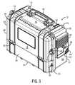
- FIG. 2is a front elevational view of an embodiment of the portable battery powered welder of FIG. 1 ;
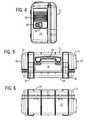
- FIG. 3is a right side elevational view of an embodiment of the portable battery powered welder of FIG. 2 , viewed along line 3 - 3 , illustrating an external control panel, front louver, and welding wire outlet;
- FIG. 4is a left side elevational view of an embodiment of the portable battery powered welder of FIG. 2 , viewed along line 4 - 4 , illustrating a rear louver, a power switch, and an electrical plug interface;
- FIG. 5is a top elevational view of an embodiment of the portable battery powered welder of FIG. 2 , viewed along line 5 - 5 , illustrating a handle and a latch coupled to the lateral access door;
- FIG. 6is a bottom elevational view of an embodiment of the portable battery powered welder of FIG. 2 , viewed along line 6 - 6 ;
- FIG. 7is a perspective view of an embodiment of the portable battery powered welder of FIG. 1 , illustrating a lateral access door rotated away from the body to an open position to reveal a first internal compartment that includes a wire spool mount and a wire feeder;
- FIG. 8is a perspective view of an embodiment of the portable battery powered welder of FIGS. 1 and 7 with the lateral access door removed and not shown for clarity, further illustrating the access panel removed from the body to reveal a second internal compartment that includes a battery storage region having a first battery and a second battery;
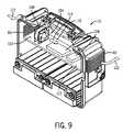
- FIG. 9is a perspective view of an embodiment of the portable battery powered welder of FIG. 8 , with the access panel removed and not shown for clarity, further illustrating a cooling system and a welding circuit disposed in a third internal compartment;
- FIG. 10is a diagrammatical representation of an embodiment of a portable battery powered welder, illustrating a number of individual components that may be completely enclosed and supported by the suitcase;
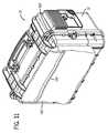
- FIG. 11is a perspective view of an embodiment of a portable battery powered welder, illustrating an accessory bag coupled to an external surface of the suitcase.
- Embodiments of the present inventionprovide a rugged and portable welding system that is configured to operate without an external power source.
- a suitcaseto support and completely enclose a plurality of welding or system components that may be used to perform a welding operation.
- the suitcaseprovides a portable enclosure that protects the welding components which are disposed within the shell of the suitcase or are generally flush with an exterior of the suitcase.
- the suitcasefurther provides structural ribs and recesses to protect the system components that are generally flush with the exterior of the suitcase.
- the suitcaseincludes external features for securing the suitcase during transport, such as a handle and other features configured to interface tie-down ropes or cords. All of these features provide the benefit of facilitating transport of the portable battery powered welder.
- embodiments of the portable welding systemincrease reliability because the system components are protected and supported by the suitcase. In other word, the likelihood of damaging a system component is greatly reduced because the components are not protruding from the exterior of the suitcase.
- the suitcaseis also configured to house a battery to provide power for the welding operation. This has the benefit of enabling an operator to perform a welding operation in a remote location where an external power source may not be available.
- the suitcasemay include a weld circuit, a wire feeder, and a cooling system to facilitate the welding operation.
- the systemmay include a battery charging circuit to enable an operator to recharge the batteries located in the case.
- the illustrated suitcaseincludes hinged access doors and panels integrated into the external shell of the case that provide quick access to the welding and system components. This has the benefit of facilitating both the welding operation and the maintenance and repair of the system or welding components.
- Portable battery powered welder 10includes a case, suitcase, portable enclosure, or shell 12 having a front side 14 , back side 16 , top side 18 , bottom side 20 , right side 22 , and a left side 24 .
- the suitcase 12may be made from a light weight, impact resistant, and flame retardant material, for example, a polymer.
- the caseis not limited to this type of material and may also be made, in whole or in part, from other structural materials, such as metal alloys or composite material.
- the suitcase 12may include structural ribs 26 to reinforce the case and provide protection to external features incorporated into the case 12 .
- the structural rib 26may be used to secure the case during transport.
- the structural ribs 26provide upsets for securing ropes or cords about. These upsets enable the cords to provide both a downward force on the case and also support side loads to the case via the shoulders provided by the structural ribs 26 .
- the suitcase 12may also include a lateral access door 28 that includes a hinge 30 .
- the hinge 30enables the lateral access door 28 to rotate between an open and a closed position over a first compartment that includes a wire feeder and a wire spool.
- the lateral access door 28further includes a pair of latches 32 to secure the door in place.
- the hinge 30may be configured to enable the lateral access door 28 to be completely disengaged and removed from the body of the case 12 .
- the suitcase 12may include an access panel 34 that is snap-mounted and/or secured to the body of the case 12 via fasteners 36 .
- the access panel 34may be configured to open and close over a second compartment that includes at least one battery.
- an external control panel 38may also be included on the right side 22 of the suitcase 12 .
- the external control panel 38generally provides an interface to the battery powered welding circuit to enable an operator to control the welding process.
- a front louver 40may be integrated into the suitcase 12 and positioned on the right side 22 of the case 12 .
- the front louver 40is part of a cooling system that may be incorporated into the battery powered welder 10 to dissipate heat from the electronics.
- FIG. 1further illustrates one embodiment of a structural rib 42 that provides protection for the controls and other input devices located on the external control panel 38 .
- a work cable connection 44may also be located on the front right side 22 of the suitcase 12 .
- a welding wire outlet 46 and welding gun connection point 48may also be located on the front ride side 22 of the suitcase 12 .
- the work cable connection 44enables an operator to couple a work cable and clamp to the portable battery welder 10 .
- the welding wire outlet 46 and welding gun connection point 48enables an operator to couple a welding gun to the portable battery powered welder 10 .
- connection points 44 and 48enable a closed-loop circuit between a work piece and the portable battery powered welder 10 to perform a welding operation.
- the portable battery powered welder 10may be configured for multiple welding operations, such as Flux Cored Arc Welding (FCAW), Gas Metal Arc Welding (MIG), or Shielded Metal Arc Welding (Stick Electrode).
- FCAWFlux Cored Arc Welding
- MIGGas Metal Arc Welding
- Stick ElectrodeShielded Metal Arc Welding
- Suitcase 12may also include a plurality of features to facilitate transport of the portable battery powered welder 10 .
- the suitcase 12may include a handle 50 that is large enough for single hand transport of the welder 10 .
- the handle 50may be rotatably coupled to the suitcase 12 and rotated flush with the case 12 when not used by the operator.
- the structural ribs 26may include features to secure the battery powered welder 10 to a vehicle or other structure during transport.
- the suitcase 12may include one or more locking and/or tie-down features 52 (e.g., a pair of lock receptacles) located in or on the structural ribs 26 as illustrated in FIG. 1 .
- the locking feature 52may provide redundancy for latch 32 by ensuring the lateral access door 28 does not open even if the latch 32 is disengaged. The redundancy may be achieved by securing a padlock or other securing mechanism through locking feature 52 .
- the feature 52may also be used to secure the portable battery powered welder 10 in place during transport. For example, a hook on the end of a bungee cord could engage securing feature 52 to secure the case 12 .
- structural ribs 26may include securing feature 54 (e.g., a pair of receptacles) to mount an accessory bag to the case 12 .
- FIG. 2is a front elevational view of the portable battery powered welder 10 of FIG. 1 .
- the figureillustrates the front side 14 of the case 12 and will be generally referenced to orient the views of FIGS. 3-6 .
- FIG. 2illustrates that all of the system components of the battery powered welder 10 are either flush with the suitcase 12 and/or completely enclosed within the case 12 . In other words, in the illustrated embodiment, none of the components are protruding from the exterior of the case 12 .
- FIG. 3is a right side elevational view of the portable battery powered welder of FIG. 2 , viewed along line 3 - 3 .
- the figureillustrates the front louver 40 , work cable connection 44 , welding wire outlet 46 , and welding gun connection point 48 when viewed from the right side of the suitcase 12 .
- the figurealso illustrates features and controls that may be included in the external control panel 38 .
- external control panel 38may include an output control 56 along with a number of other indicators.
- the output control 56may enable an operator to control the voltage, wire speed, and/or power used during the welding operation. This enables an operator to use the portable battery powered welder 10 for a number of different welding applications.
- the external control panel 38may include a ready indicator 58 , a low battery indicator 60 , an over temperature indicator 62 , and a battery charge indicator 64 . These indicators facilitate the operation of the portable battery powered welder 10 .
- the ready indicatormay communicate to an operator that the portable battery powered welder 10 is capable of providing the power needed for the welding operation.
- the low battery indicator 60may communicate to an operator that the portable battery powered welder 10 is not capable of supplying the necessary weld power.
- the over temperature indicator 62may communicate to an operator that the portable battery powered welder 10 has surpassed a desired temperature level and can not provide the required weld power.
- the external control panel 38is not limited to the controls and indicators illustrated and may include a wire speed control, a purge switch, trigger hold switch, a digital meter, a polarity switch, and so forth.
- FIG. 4is a left side elevational view of the portable battery powered welder of FIG. 2 , viewed along line 4 - 4 .
- the figureillustrates a rear louver 66 , a power switch 68 , and an external power interface 70 that may be located on the left side 24 of the battery powered welder 10 .
- the rear louver 66forms part of the cooling system.
- the power switch 68may include a rocker style switch that enables an operator to power off the welder to conserve battery power.
- the power interface 70may be configured to couple to a detachable cord that connects to an external power source. This enables an operator to charge a battery enclosed in the case 12 via connecting cord between the power interface 70 and an external power source.
- the left side 24 of the battery powered welder 10is not limited to these features and may include a gas port and/or other features.
- FIG. 5is a top elevational view of the portable battery powered welder of FIG. 2 , viewed along line 5 - 5 .
- the figureillustrates the handle 50 and latches 32 that are coupled to the hinged lateral access door 28 . Further, the figure illustrates that the rear louver 66 , power switch 68 , and power interface 70 are generally flush with the exterior of the suitcase 12 and are further protected by structural rib 72 .
- structural rib 72provides a protective recess for power switch 68 and power interface 70 .
- FIG. 6is a bottom elevational view of the portable battery powered welder of FIG. 2 , viewed along line 6 - 6 .
- FIGS. 1-6generally illustrate that all of the welding and system components of the portable battery powered welder 10 are either generally flush with the suitcase 12 and/or completely enclosed within the suitcase 12 .
- the suitcase 12provides a portable enclosure that supports the components and completely surrounds the components disposed therein.
- the components disposed within the casemay include a welding circuit, a power conversion circuit, a battery charging circuit, a wire feeder, a wire spool, one or more batteries, shock absorbent material (e.g., foam interior lining), a cooling system (e.g., fans, heat sinks, heat pipes, ducts, etc.), and so forth.
- shock absorbent materiale.g., foam interior lining
- cooling systeme.g., fans, heat sinks, heat pipes, ducts, etc.
- FIG. 7is a perspective view of an embodiment of the portable battery powered welder 10 .
- the figureillustrates the lateral access door 28 rotated away from the body of the case 12 to an open position revealing a first internal compartment 74 .
- the lateral access door 28may be rotated to the illustrated position by disengaging a pair of latches 76 , located on the door 28 , from the mating latch shoulders 78 , located on the body of the case 12 .
- lateral access door 28may include a groove 80 extending around the perimeter of the door 28 that is configured to engage a mating protrusion 82 located on the body of the case 12 .
- groove 80 with protrusion 82provides an orientation and sealing feature of the lateral access door 28 to the body of the case 12 .
- This interfacemay include a rubber seal to provide a generally hermitic environment and general barrier that excludes dirt and debris from the internal compartment 74 of the suitcase 12 .
- the internal compartment 74includes a wire spool mount 84 , wire spool nut 86 , and a wire feeder 88 positioned on an internal wall 89 of the suitcase 12 .
- a wire spoolmay be mounted on the wire spool mount 84 and secured to the spool mount 84 via the spool nut 86 .
- the wire spool mount 84may be an integral part of the internal wall 89 that is formed during the molding process of the wall.
- the molded wire spool mount 84may include a component that is entirely plastic and/or may include other components, such as metal hubs, threaded inserts, or sleeves.
- the wire spool mount 84may include a separate metal and/or plastic piece that is secured to the internal wall 89 via an attachment mechanism (e.g., screw threads). Wire from the wire spool may then be fed to the wire feeder 88 which supplies the wire to a welding gun via the welding gun connection point 48 . The wire is then fed through the welding gun and out through the case via welding wire outlet 46 .
- embodiments of the system 10completely enclose the components within the suitcase 12 and/or position the components generally flush with the suitcase 12 , thereby limiting exposure of the components to accidental damage.
- the suitcase 12acts as a barrier and provides protection and structural support to the wire feeder 88 and wire spool.
- FIG. 8is a perspective view of an embodiment of the portable battery powered welder 10 where the lateral access door 28 (See FIG. 7 ) is not shown for clarity.
- the figurealso illustrates access panel 34 removed from the body of the case 12 to reveal a second internal compartment 90 .
- the internal compartment 90includes a battery storage region having a first battery 92 and a second battery 94 disposed therein.
- the batteries 92 , 94may include two 12 Volt, sealed, lead acid batteries or any other type of suitable battery.
- the batteriesinclude a positive terminal 98 and a negative terminal 100 .
- the batteriesare connected in series via a coupling bracket 102 that extends from the negative terminal 100 of the first battery 92 to the positive terminal 98 of the second battery 94 to provide a potential 24 Volts that may be used for the welding operation.
- a coupling bracket 102that extends from the negative terminal 100 of the first battery 92 to the positive terminal 98 of the second battery 94 to provide a potential 24 Volts that may be used for the welding operation.
- embodiments of the welding system 10are not limited to this configuration, or even to two batteries. Therefore, embodiments of the welding system 10 may include a single battery, or three or more batteries connected in series, parallel, or a combination thereof.
- FIG. 8also illustrates both the snap-mounting features 96 , 97 and the fastening features 36 that may be included on access panel 34 to secure the panel 34 to the body of the suitcase 12 .
- This configurationis advantageous because it facilitates access to the batteries for maintenance and repair.
- the snap-mounting features 96 , 97e.g., snap-fit latches
- the fastening features 36may incorporate the use of thumb-screws, snap-fit latches, or other tool-free fasteners to further simplify the mounting and removal of the panel 34 .
- FIG. 9is a perspective view of an embodiment of the portable battery powered welder 10 where both the lateral access door 28 (See FIG. 7 ) and access panel 34 (See FIG. 8 ) are not shown for clarity. Additionally, the internal wall 89 (See FIGS. 7 and 8 ) has also been removed to reveal a cooling system 104 and a welding circuit 106 disposed in an internal compartment 107 of the suitcase 12 .
- the cooling systemgenerally includes a cooling fan 108 that is configured to pass a forced airflow through a wind tunnel 110 and over the welding circuit 106 .
- the force airflow pathincludes air entering through the rear louver 66 , generally represented by reference numeral 112 , through the fan 108 and over the weld circuit 106 , generally represented by reference numeral 114 , and out through the front louver 40 , generally represented by reference numeral 116 .
- the forced airflowgenerally acts to dissipate heat or cool the weld circuit 106 via convection cooling.
- the cooling system 104may further include one or more heat sinks, heat pipes, liquid cooling radiators, liquid pumps, additional fans in series or in parallel, or a combination thereof.
- FIG. 9further illustrates that the weld circuit 106 is supported by an internal wall 117 .
- the weld circuitmay be positioned on the external walls of the suitcase 12 or supported by multiple internal walls.
- the weld circuit 106may include multiple circuit boards that may be positioned in multiple locations with respect to the cooling system 104 .
- embodimentsprovide that the components are disposed and completely enclosed within the suitcase 12 and/or are generally flush with the suitcase 12 .
- the suitcase 12acts as a barrier (e.g., substantially keeps out moisture, rain, mud, or other debris) and provides protection and structural support to the cooling system 104 and weld circuit 106 illustrated in FIG. 9 .
- FIG. 10is a diagrammatical representation of a portable battery powered welder 10 in accordance with embodiments of the invention.
- the figureillustrates a plurality of welding or system components that may be completely enclosed and supported by the suitcase 12 .
- weld circuit 106may include a number of circuits.
- weld circuit 106may include a control and monitoring circuit 118 , a battery charger circuit 120 , and an interface circuit 122 .
- the control and monitoring circuit 118may include a power conversion and/or conditioning circuit 124 and a wire feed circuit 126 .
- the portable battery powered welder 10may include a wire spool 128 that includes a consumable welding wire 130 .
- the consumable welding wire 130is supplied to a weld gun 132 via the wire feeder 88 .
- a work cable 134 and work clamp 136may be coupled to the portable battery powered welder 10 and a work piece 138 .
- a welding operationmay then be initiated by activating trigger 140 on the welding gun 132 to complete an electrical circuit between the work piece 138 and the portable battery powered welder 10 .
- the welder 10may be powered by an external power source 143 .
- the external power source 143may be any independent source and may include 115 VAC source or even another battery power source (e.g., an automobile battery). Additionally, the external power source 143 may be used to recharge the battery power source 142 .
- the external power source 143may be engaged via a cord 144 that may be detached from the suitcase 12 to facilitate transport and storage of the welder 10 .
- the cord 144may include a three conductor configuration for engaging standard electrical outlets or may include a two conductor configuration for engaging power outlets provided in motor vehicles.
- the welding gun 132 , work cable 134 , and work clamp 136are also detachable from the suitcase 12 to facilitate transport and storage of the welder 10 .
- a gas supply system 148may be included in the suitcase 12 to be used with certain welding operations.
- the gas supply system 148may provide the inert gas required for a MIG welding operation.
- the gas supply system 148may include a gas cylinder, gas valve, flow meter, regulator, associated plumbing, etc.
- the portable battery powered welder 10includes a weld circuit 106 that further includes specific circuits.
- the control and monitoring circuit 118may include hardware and software used to control the power conversion circuit 124 , the battery charger circuit 120 , and wire feeder circuit 126 .
- the control and monitoring circuit 118may control the battery charge circuit 120 by providing a battery recharge algorithm based on battery voltage, current, time of charge, temperature of battery, etc.
- the battery charge circuit 120may be configured to convert AC line power (e.g., 115 VAC) to the proper voltage and current levels to recharge the battery power source 142 .
- the battery charge circuit 120may also supply power to the power conversion circuit 124 when the portable battery powered welder 10 is electrically coupled to an external power source 143 .
- the control and monitoring circuit 118may also control the welding output power to provide the proper output voltage and current via the power conversion circuit 124 .
- the power conversion circuit 124may be configured to condition and convert power provided by the battery power source 142 and/or the external power source 143 . In other words, the power conversion circuit provides the proper regulated output weld voltage and current levels suitable for the weld process and control settings. Additionally, the power conversion circuit 124 may be coupled to a voltage polarity unit 145 that can switch the positive and negative voltage potential between the welding wire 130 and work cable 134 .
- the control and monitoring circuit 118may also include a number of monitoring circuits to protect the portable battery welder 10 and its internal components from over-temperature or thermal overload.
- temperature sensor 146may monitor the temperature of the system or welding components (e.g., power devices, a battery, the enclosure ambient temperature, etc.). The measured temperature of the respective component may then be used by the control and monitoring circuit 118 to prevent thermal overload of the welder 10 .
- the control and monitoring circuitmay activate the fan 108 located in the cooling system 104 to dissipate heat from a power component of the weld circuit 106 .
- the control and monitoring circuit 118may automatically shut down the welder 10 if the duty cycle is exceeded or the air flow required for cooling is restricted.
- control and monitoring circuit 118may also protect the battery from over discharge that may result in low battery shutdown.
- control and monitoring circuit 124may control the wire feed circuit 126 and interface circuit 122 .
- the wire feed circuit 126provides power and control signals to drive the wire feeder 88 .
- the interface circuit 122controls the indicators located on the external control panel 38 .
- one of the advantages of the disclosed embodimentsis that the components of the portable battery powered welder 10 are completely enclosed within the suitcase 12 and/or are generally flush with an exterior of the suitcase 12 . In other words, the components are protected by the enclosure and/or the structural ribs 26 of the suitcase 12 and do not protrude outside of the suitcase 12 .
- the welding circuit 106 , the wire feeder 88 , the wire spool 128 , the battery power supply 142 , and the cooling system 104may be disposed in the suitcase 12 and protected by the shell of the case 12 .
- the suitcase 12may be substantially sealed from the environment.
- the louvers 40 and 66may be oriented with downward angled horizontal slats, such that rain cannot enter the suitcase 12 .
- FIG. 11is a perspective view of an embodiment of the portable battery powered welder 10 that includes an accessory bag 150 coupled to the exterior of the suitcase 12 .
- the accessory bag 150may be attached to either the front side 14 or the back side 16 of the suitcase 12 and may be secured to the suitcase 12 via securing feature 52 , 54 (see FIG. 1 ).
- the accessory bag 150may include an internal pocket 152 accessible via flap 154 .
- the accessory bag 150may be used to store the power cord 144 , welding gun 132 , work cable 134 , work clamp 136 , and other welding tools and supplies. Again, the accessory bag 150 and suitcase 12 help to facilitate transport of the portable battery powered welder 10 .
Landscapes
- Engineering & Computer Science (AREA)
- Physics & Mathematics (AREA)
- Plasma & Fusion (AREA)
- Mechanical Engineering (AREA)
- Purses, Travelling Bags, Baskets, Or Suitcases (AREA)
- Battery Mounting, Suspending (AREA)
Abstract
Description
Claims (26)
Priority Applications (6)
| Application Number | Priority Date | Filing Date | Title |
|---|---|---|---|
| US11/848,874US9399263B2 (en) | 2007-08-31 | 2007-08-31 | Portable battery powered welder |
| CA2697700ACA2697700A1 (en) | 2007-08-31 | 2008-07-22 | Portable battery powered welder |
| MX2010001223AMX2010001223A (en) | 2007-08-31 | 2008-07-22 | Portable battery powered welder. |
| CN2008800249568ACN101743087B (en) | 2007-08-31 | 2008-07-22 | Portable battery powered welder |
| PCT/US2008/070698WO2009029360A1 (en) | 2007-08-31 | 2008-07-22 | Portable battery powered welder |
| EP08782171AEP2183074A1 (en) | 2007-08-31 | 2008-07-22 | Portable battery powered welder |
Applications Claiming Priority (1)
| Application Number | Priority Date | Filing Date | Title |
|---|---|---|---|
| US11/848,874US9399263B2 (en) | 2007-08-31 | 2007-08-31 | Portable battery powered welder |
Publications (2)
| Publication Number | Publication Date |
|---|---|
| US20090057285A1 US20090057285A1 (en) | 2009-03-05 |
| US9399263B2true US9399263B2 (en) | 2016-07-26 |
Family
ID=40387686
Family Applications (1)
| Application Number | Title | Priority Date | Filing Date |
|---|---|---|---|
| US11/848,874Active2034-04-20US9399263B2 (en) | 2007-08-31 | 2007-08-31 | Portable battery powered welder |
Country Status (6)
| Country | Link |
|---|---|
| US (1) | US9399263B2 (en) |
| EP (1) | EP2183074A1 (en) |
| CN (1) | CN101743087B (en) |
| CA (1) | CA2697700A1 (en) |
| MX (1) | MX2010001223A (en) |
| WO (1) | WO2009029360A1 (en) |
Cited By (8)
| Publication number | Priority date | Publication date | Assignee | Title |
|---|---|---|---|---|
| US20170021440A1 (en)* | 2015-07-23 | 2017-01-26 | Ammon Nazareth Balaster | Portable Arc Welder |
| US10862176B2 (en) | 2018-06-15 | 2020-12-08 | Florida Power & Light Company | Portable rechargeable battery pack with a selectable battery switch and state of charge display for cordless power tools |
| USD914071S1 (en) | 2018-11-02 | 2021-03-23 | Esab Ab | Welding device enclosure |
| USD951188S1 (en)* | 2020-09-23 | 2022-05-10 | Gehr Power Systems Llc | Portable power distribution box |
| USD951189S1 (en)* | 2020-09-23 | 2022-05-10 | Gehr Power Systems Llc | Portable power distribution box |
| US11738914B2 (en) | 2021-11-18 | 2023-08-29 | Yeti Coolers, Llc | Container and latching system |
| US12005948B2 (en)* | 2019-05-13 | 2024-06-11 | Illinois Tool Works Inc. | Method and apparatus for reconfigurable handles for a work equipment |
| US12194575B2 (en) | 2020-01-13 | 2025-01-14 | Milwaukee Electric Tool Corporation | Portable battery pack-powered welder |
Families Citing this family (72)
| Publication number | Priority date | Publication date | Assignee | Title |
|---|---|---|---|---|
| US8350182B2 (en) | 2006-09-11 | 2013-01-08 | Hypertherm, Inc. | Portable autonomous material processing system |
| US7615719B2 (en)* | 2006-09-11 | 2009-11-10 | Hypertherm, Inc. | Autonomous plasma cutting system |
| USD611074S1 (en) | 2007-08-31 | 2010-03-02 | Illinois Tool Works Inc. | Portable battery powered welder |
| US8426773B2 (en)* | 2008-02-27 | 2013-04-23 | Illinois Tool Works Inc. | Dual power pin connector assembly for a MIG welding machine |
| WO2009146359A1 (en) | 2008-05-28 | 2009-12-03 | Illinois Tool Works Inc. | Welding training system |
| US9474185B2 (en)* | 2008-07-15 | 2016-10-18 | Illinois Tool Works, Inc. | Air flow methods and systems for a welder-generator |
| AT508288B1 (en)* | 2009-05-18 | 2011-02-15 | Fronius Int Gmbh | DEVICE FOR PROTECTING A HOUSING OF A WELDING COMPONENT |
| US8735775B2 (en)* | 2009-06-11 | 2014-05-27 | Illinois Tool Works Inc. | Hybrid wire feeder systems and methods |
| US8405001B2 (en)* | 2009-07-13 | 2013-03-26 | Illinois Tool Works Inc | Hybrid welding systems and devices |
| US9089922B2 (en) | 2010-01-22 | 2015-07-28 | Illinois Tool Works Inc. | Welding system having a power grid interface |
| US10737348B2 (en)* | 2010-07-09 | 2020-08-11 | Illinois Tool Works Inc. | Battery powered welding system |
| US9545687B2 (en)* | 2010-12-17 | 2017-01-17 | Hobart Brothers Company | Spool gun adapter |
| MD4185C1 (en)* | 2011-03-03 | 2013-06-30 | Институт Энергетики Академии Наук Молдовы | Electric-arc welding unit |
| US11123814B2 (en)* | 2011-03-25 | 2021-09-21 | Illinois Tool Works Inc. | Battery powered compact wire feeder |
| USD653271S1 (en) | 2011-06-22 | 2012-01-31 | Lincoln Global, Inc. | Wire feeder enclosure |
| CN102896443A (en)* | 2011-07-27 | 2013-01-30 | 河南科隆集团有限公司 | Portable smalls-sized energy-storage electric welder |
| US9101994B2 (en) | 2011-08-10 | 2015-08-11 | Illinois Tool Works Inc. | System and device for welding training |
| FI124216B (en) | 2011-11-23 | 2014-05-15 | Kemppi Oy | Accumulator driven welding and / or cutting firing device |
| ITPD20120058A1 (en)* | 2012-03-02 | 2013-09-03 | Segala Bruno S R L | PORTABLE EQUIPMENT PERFECTLY PERFECTED FOR WELDING OR PLASMA CUTTING |
| CN102684538A (en)* | 2012-05-30 | 2012-09-19 | 河北工业大学 | Field emergency arc welding power source |
| US11179794B2 (en) | 2012-06-29 | 2021-11-23 | Illinois Tool Works Inc | Welding system utilizing a distributed power bus |
| AT513230A1 (en)* | 2012-08-10 | 2014-02-15 | Fronius Int Gmbh | PORTABLE WELDING ARRANGEMENT AND METHOD FOR OPERATING A PORTABLE WELDING ASSEMBLY |
| US10046411B2 (en)* | 2012-09-07 | 2018-08-14 | Illinois Tool Works Inc. | Modular welding system |
| US9522438B2 (en) | 2012-11-09 | 2016-12-20 | Hypertherm, Inc. | Battery-controlled plasma arc torch system |
| US9583014B2 (en) | 2012-11-09 | 2017-02-28 | Illinois Tool Works Inc. | System and device for welding training |
| CN103128419B (en)* | 2013-01-18 | 2015-02-25 | 浙江容大电力工程有限公司 | Portable rechargeable electric welding machine |
| US9583023B2 (en) | 2013-03-15 | 2017-02-28 | Illinois Tool Works Inc. | Welding torch for a welding training system |
| JP6084523B2 (en)* | 2013-06-25 | 2017-02-22 | 株式会社マキタ | Charger |
| DE102013109894A1 (en)* | 2013-09-10 | 2015-03-12 | Lorch Schweißtechnik GmbH | Power supply unit for welding power source |
| US9302339B2 (en) | 2013-09-20 | 2016-04-05 | Lincoln Global, Inc. | Hybrid welder with detachable energy storage device |
| US20150129569A1 (en)* | 2013-11-12 | 2015-05-14 | Lincoln Global, Inc. | Portable welding wire feeder with on-board tool box |
| US10056010B2 (en) | 2013-12-03 | 2018-08-21 | Illinois Tool Works Inc. | Systems and methods for a weld training system |
| US10105782B2 (en) | 2014-01-07 | 2018-10-23 | Illinois Tool Works Inc. | Feedback from a welding torch of a welding system |
| US9589481B2 (en) | 2014-01-07 | 2017-03-07 | Illinois Tool Works Inc. | Welding software for detection and control of devices and for analysis of data |
| US10170019B2 (en)* | 2014-01-07 | 2019-01-01 | Illinois Tool Works Inc. | Feedback from a welding torch of a welding system |
| US9925613B2 (en) | 2014-03-28 | 2018-03-27 | Hobart Brothers Company | Inverter-based generator and welding system |
| US9550251B2 (en) | 2014-03-28 | 2017-01-24 | Hypertherm, Inc. | Power supply assembly for a plasma arc torch system |
| US9937578B2 (en) | 2014-06-27 | 2018-04-10 | Illinois Tool Works Inc. | System and method for remote welding training |
| US9862049B2 (en) | 2014-06-27 | 2018-01-09 | Illinois Tool Works Inc. | System and method of welding system operator identification |
| US10665128B2 (en) | 2014-06-27 | 2020-05-26 | Illinois Tool Works Inc. | System and method of monitoring welding information |
| US10307853B2 (en) | 2014-06-27 | 2019-06-04 | Illinois Tool Works Inc. | System and method for managing welding data |
| US11014183B2 (en) | 2014-08-07 | 2021-05-25 | Illinois Tool Works Inc. | System and method of marking a welding workpiece |
| US10417934B2 (en) | 2014-11-05 | 2019-09-17 | Illinois Tool Works Inc. | System and method of reviewing weld data |
| US10373304B2 (en) | 2014-11-05 | 2019-08-06 | Illinois Tool Works Inc. | System and method of arranging welding device markers |
| US10210773B2 (en) | 2014-11-05 | 2019-02-19 | Illinois Tool Works Inc. | System and method for welding torch display |
| US10490098B2 (en) | 2014-11-05 | 2019-11-26 | Illinois Tool Works Inc. | System and method of recording multi-run data |
| US10204406B2 (en) | 2014-11-05 | 2019-02-12 | Illinois Tool Works Inc. | System and method of controlling welding system camera exposure and marker illumination |
| US10402959B2 (en) | 2014-11-05 | 2019-09-03 | Illinois Tool Works Inc. | System and method of active torch marker control |
| EP3017902B1 (en)* | 2014-11-07 | 2017-03-29 | The Esab Group, Inc. | Ruggedized casing for a portable welding system |
| US10150173B2 (en) | 2014-11-07 | 2018-12-11 | Illinois Tool Works Inc. | Welding type power supply with wind tunnel |
| US10427239B2 (en) | 2015-04-02 | 2019-10-01 | Illinois Tool Works Inc. | Systems and methods for tracking weld training arc parameters |
| US10456851B2 (en)* | 2015-07-17 | 2019-10-29 | Illinois Tool Works Inc. | Welding system with potted circuit board and method of making thereof |
| US10279414B2 (en)* | 2015-08-06 | 2019-05-07 | Lincoln Global, Inc. | Engine drive welder and methods and systems of controlling the same |
| US10373517B2 (en) | 2015-08-12 | 2019-08-06 | Illinois Tool Works Inc. | Simulation stick welding electrode holder systems and methods |
| US10593230B2 (en) | 2015-08-12 | 2020-03-17 | Illinois Tool Works Inc. | Stick welding electrode holder systems and methods |
| US10657839B2 (en) | 2015-08-12 | 2020-05-19 | Illinois Tool Works Inc. | Stick welding electrode holders with real-time feedback features |
| US10438505B2 (en) | 2015-08-12 | 2019-10-08 | Illinois Tool Works | Welding training system interface |
| US10894296B2 (en)* | 2015-08-20 | 2021-01-19 | Nelson Stud Welding, Inc. | Light weight cordless stud welder |
| DE102015012486A1 (en) | 2015-09-24 | 2017-03-30 | G. Zehnder Mergers & Acquisitions GmbH | Apparatus for connecting to an accumulator; Process for the mobile electrochemical machining of metallic surfaces, mobile soldering and / or mobile electroplating |
| US10946466B1 (en) | 2015-11-02 | 2021-03-16 | American Innovative Manufacturing, Llc | Welder apparatus and methods |
| CN105834556A (en)* | 2016-06-21 | 2016-08-10 | 胡俊 | Novel intelligent electric welding machine with remote control function |
| CA3039817A1 (en)* | 2016-10-21 | 2018-04-26 | Hypertherm, Inc. | Plasma power tool |
| US10449615B2 (en)* | 2016-10-31 | 2019-10-22 | Illinois Tool Works Inc. | Hybrid welding modules |
| US11223220B2 (en) | 2016-10-31 | 2022-01-11 | Illinois Tool Works Inc. | Hybrid welding systems and portable hybrid welding modules |
| CN107009037A (en)* | 2017-05-23 | 2017-08-04 | 江苏圣泰防腐设备东台有限公司 | A kind of easy-to-mount outer belt electrogas welding connects equipment |
| CN107598338A (en)* | 2017-09-21 | 2018-01-19 | 浙江雅创机电科技有限公司 | A kind of MIG electric welding machines |
| US11288978B2 (en) | 2019-07-22 | 2022-03-29 | Illinois Tool Works Inc. | Gas tungsten arc welding training systems |
| US11776423B2 (en) | 2019-07-22 | 2023-10-03 | Illinois Tool Works Inc. | Connection boxes for gas tungsten arc welding training systems |
| USD969070S1 (en)* | 2020-08-14 | 2022-11-08 | Shenzhen Intelligent Energy Co., Ltd | Power supply |
| CN112139644B (en)* | 2020-11-25 | 2021-10-01 | 浙江劲博科技有限公司 | Portable pipeline electric welding machine |
| CN113953614B (en)* | 2021-10-28 | 2023-08-11 | 国网山东省电力公司淄博供电公司 | Portable carbon resistance welding device |
| CN118720328B (en)* | 2024-09-03 | 2024-12-31 | 淮安宝开电器有限公司 | Duplex position electric welding mechanism |
Citations (69)
| Publication number | Priority date | Publication date | Assignee | Title |
|---|---|---|---|---|
| US1354211A (en)* | 1920-05-06 | 1920-09-28 | Hugh T Reed | Pocket-case |
| US2833912A (en) | 1955-06-06 | 1958-05-06 | Union Carbide Corp | Arc welding apparatus |
| US3309497A (en)* | 1966-01-21 | 1967-03-14 | Milo M Kensrue | Welding back pack |
| US3322299A (en)* | 1965-09-02 | 1967-05-30 | Clark Mfg Co J L | Sheet metal container with plastic closure |
| US3417897A (en)* | 1967-12-29 | 1968-12-24 | Procter & Gamble | Hinged overcap |
| US3480221A (en) | 1966-08-19 | 1969-11-25 | Osaka Transformer Co Ltd | Wire feed apparatus |
| US3582606A (en)* | 1968-06-21 | 1971-06-01 | Elecktriska Svetsningaktiebola | Gas-shielded consumable electrode arc welding |
| US4034885A (en)* | 1976-08-12 | 1977-07-12 | Hunckler Products, Inc. | Parts storage and dispensing container |
| DE2811940A1 (en) | 1978-03-18 | 1979-09-20 | Lorch Schweisstech Gmbh | Gas shielded arc welding appts. - with connections for hand torch or portable set with separate wire feed |
| US4182949A (en) | 1976-07-21 | 1980-01-08 | The United States Of America As Represented By The Secretary Of The Navy | Self-contained, portable underwater stud welder |
| US4465920A (en) | 1978-09-22 | 1984-08-14 | Teledyne-Walterboro, A Division Of Teledyne Industries, Inc. | Electric welder with current-voltage feedback circuit that provides desired slope curve |
| US4508954A (en) | 1984-05-18 | 1985-04-02 | Oxo Welding Equipment Co., Inc. | Portable arc voltage wirefeed welding system |
| US4640435A (en)* | 1986-01-23 | 1987-02-03 | Sun Coast Plastics, Inc. | Plastic closure for beverage container |
| USD294080S (en) | 1984-08-06 | 1988-02-09 | Golia Kenneth R | Two-piece transport case for portable embroidery machinery |
| US4815596A (en) | 1988-02-04 | 1989-03-28 | Minnesota Mining And Manufacturing Company | Dip carrier |
| US4911296A (en)* | 1989-04-13 | 1990-03-27 | Hart Jr Charles R | Utility chest for vehicles |
| USD333484S (en) | 1990-04-23 | 1993-02-23 | Alexander Neumeister | Portable printer |
| US5222683A (en) | 1992-05-15 | 1993-06-29 | Blackshire Glen M | Wire dispensing apparatus |
| USD337657S (en) | 1991-09-04 | 1993-07-27 | Platt Luggage, Inc. | Carrying case |
| GB2264924A (en) | 1992-03-14 | 1993-09-15 | Edward Albert Duckworth | Collapsible support rack |
| USD342159S (en) | 1991-09-17 | 1993-12-14 | Antar Daouk | Container |
| US5307979A (en) | 1992-11-20 | 1994-05-03 | Hyundai Heavy Industries Co., Ltd. | Apparatus for carrying out MIG welding on three-dimensional curved surface, and milling apparatus for automatically forming welding grooves |
| USD357263S (en) | 1992-11-11 | 1995-04-11 | Esab Aktiebolag | Welding apparatus |
| US5599470A (en)* | 1995-09-11 | 1997-02-04 | Miller Electric Manufacturing Company | Battery box for engine driven welder |
| USD386148S (en) | 1994-12-06 | 1997-11-11 | Sansaha Electric Manufacturing Co., Ltd. | Portable power supply unit with AC-DC converter |
| US5734148A (en) | 1995-09-11 | 1998-03-31 | Miller Electric Manufacturing Co. | Retention means for side panels for welding machine |
| USD415614S (en) | 1998-08-28 | 1999-10-26 | Hakuba Shashin Sangyo Kabushiki Kaisha | Trunk case |
| USD416030S (en) | 1998-03-05 | 1999-11-02 | Century Manufacturing Company | Portable welder |
| DE19855033A1 (en) | 1998-11-28 | 2000-05-31 | Abb Patent Gmbh | Apparatus for conveying a welding wire has a spool with a drive that can be switched on or off depending on the amount of wire conveyed by the wire feed device |
| WO2000076709A1 (en) | 1999-06-15 | 2000-12-21 | Arc Kinetics Limited | Improved welding system |
| US6225596B1 (en) | 1996-03-20 | 2001-05-01 | Century Mfg. Co. | Portable welding unit |
| US6243913B1 (en)* | 1997-10-27 | 2001-06-12 | Alfred Karcher Gmbh & Co. | Cleaning device |
| USD454578S1 (en) | 2001-02-15 | 2002-03-19 | Nelson Stud Welding, Inc. | Stud welding unit |
| USD462519S1 (en) | 2001-08-16 | 2002-09-10 | Hardigg Industries, Inc. | Case |
| US6479795B1 (en)* | 2000-10-11 | 2002-11-12 | Illinois Tool Works Inc. | Portable welding wire feeder and housing |
| USD467257S1 (en) | 2000-11-15 | 2002-12-17 | Esab Ab | Welding apparatus |
| USD467425S1 (en) | 2002-01-31 | 2002-12-24 | Hardigg Industries, Inc. | Transport case |
| US20030052109A1 (en) | 2001-09-19 | 2003-03-20 | Illinois Tool Works Inc. | Pendant control for a welding-type system |
| USD472384S1 (en) | 2001-11-28 | 2003-04-01 | Otter Products, Llc | Weather proof box |
| US20040178183A1 (en)* | 2002-11-18 | 2004-09-16 | Cigelske James J. | Electrical shield for welding apparatus |
| US6818860B1 (en) | 2003-06-26 | 2004-11-16 | Lincoln Global, Inc. | Portable welder with integral battery charger |
| US20050000946A1 (en) | 2003-07-02 | 2005-01-06 | Bruce Albrecht | Welder with integrated gas bottle |
| US20050001697A1 (en) | 1999-08-24 | 2005-01-06 | Gould Jerry M. | Electronic filter assembly |
| US6855914B1 (en) | 2003-09-30 | 2005-02-15 | Illinois Tool Works Inc. | Method and apparatus to automatically determine type of gun connected to a wire feeder |
| US6888099B1 (en) | 2003-03-06 | 2005-05-03 | Illinois Tool Works Inc. | Wind tunnel for a welding power supply housing |
| US20050252889A1 (en)* | 2004-05-12 | 2005-11-17 | Stanzel Kenneth A | Gas bottle for welding-type devices |
| WO2005107993A1 (en) | 2004-05-12 | 2005-11-17 | Illinois Tool Works Inc. | Wire feeder incorporating a gas system for providing wire and gas to the welding location |
| US20060027547A1 (en) | 2004-08-04 | 2006-02-09 | Lincoln Global, Inc., A Corporation Of Delaware | Integrated engine welder and hydraulic pump |
| US20060027546A1 (en) | 2003-07-24 | 2006-02-09 | Reynolds Jon O | Remotely controlled welding machine |
| US7023101B2 (en) | 2004-03-29 | 2006-04-04 | Wen-Chang Wang | Air cooling generator |
| USD520237S1 (en) | 2004-12-06 | 2006-05-09 | Chung Lung Cheng | Case |
| USD523242S1 (en) | 2004-12-16 | 2006-06-20 | Hardigg Industries, Inc. | Case |
| US20060169685A1 (en) | 2005-02-03 | 2006-08-03 | Stanzel Kenneth A | Spool gun having unitary shielding gas and weld power connector |
| US20060201923A1 (en) | 2005-03-11 | 2006-09-14 | Hutchison Richard M | Method and system of determining wire feed speed |
| US20060207981A1 (en) | 2005-03-18 | 2006-09-21 | Lincoln Global, Inc., A Delaware Corporation | Interchangeable wire drive for wire feeder and spool gun |
| US7183157B2 (en) | 2002-01-04 | 2007-02-27 | Samsung Electronics Co., Ltd. | Nonvolatile memory devices |
| US20070108174A1 (en) | 2004-04-29 | 2007-05-17 | Lincoln Global, Inc. | Gas-less process and system for girth welding in high strength applications |
| US20070135779A1 (en)* | 2005-12-14 | 2007-06-14 | Stryker Corporation | Medical/surgical waste collection and disposal system including waste containers of different storage volumes with inter-container transfer valve and independently controlled vacuum levels |
| US20070181547A1 (en)* | 2006-02-09 | 2007-08-09 | Illinois Tool Works Inc. | Method and apparatus for welding with battery power |
| US20070251931A1 (en)* | 2006-05-01 | 2007-11-01 | Rod Lambirth | Portable welder |
| US20070257084A1 (en)* | 2006-05-04 | 2007-11-08 | Carrier David A | Cordless Welding Machines |
| US20080047522A1 (en) | 2006-08-28 | 2008-02-28 | Illinois Tool Works Inc. | Low fuel shut off for a portable welder generator |
| US20080073330A1 (en) | 2006-09-21 | 2008-03-27 | Iiiinois Tool Works Inc. | Dual power integrated MIG welder and generator system |
| US20080083709A1 (en)* | 2006-09-11 | 2008-04-10 | Hypertherm, Inc. | Autonomous plasma cutting system |
| US20080149611A1 (en) | 2006-12-22 | 2008-06-26 | Roth Michael W | Wire feeder packaging and transport system |
| US20080156783A1 (en) | 2006-12-29 | 2008-07-03 | Vanden Heuvel Michael L | Portable multi-wire feeder |
| USD611074S1 (en) | 2007-08-31 | 2010-03-02 | Illinois Tool Works Inc. | Portable battery powered welder |
| US20100051596A1 (en) | 2008-08-29 | 2010-03-04 | Illinois Tool Works Inc. | Portable welding wire feed system and method |
| US20100051595A1 (en) | 2008-08-29 | 2010-03-04 | Illinois Tool Works Inc. | Portable welding wire feed and control system and method |
Family Cites Families (3)
| Publication number | Priority date | Publication date | Assignee | Title |
|---|---|---|---|---|
| CN1045364A (en)* | 1989-11-16 | 1990-09-19 | 郭民新 | Portable emergency electric welder |
| US20070039935A1 (en)* | 2005-08-17 | 2007-02-22 | Lincoln Global, Inc. | Contactor for welding wire feeder |
| CN2930943Y (en)* | 2006-08-01 | 2007-08-08 | 成都熊谷电器工业有限公司 | Closure type welding and wire feeding device |
- 2007
- 2007-08-31USUS11/848,874patent/US9399263B2/enactiveActive
- 2008
- 2008-07-22CNCN2008800249568Apatent/CN101743087B/ennot_activeExpired - Fee Related
- 2008-07-22EPEP08782171Apatent/EP2183074A1/ennot_activeWithdrawn
- 2008-07-22MXMX2010001223Apatent/MX2010001223A/enactiveIP Right Grant
- 2008-07-22CACA2697700Apatent/CA2697700A1/ennot_activeAbandoned
- 2008-07-22WOPCT/US2008/070698patent/WO2009029360A1/enactiveApplication Filing
Patent Citations (77)
| Publication number | Priority date | Publication date | Assignee | Title |
|---|---|---|---|---|
| US1354211A (en)* | 1920-05-06 | 1920-09-28 | Hugh T Reed | Pocket-case |
| US2833912A (en) | 1955-06-06 | 1958-05-06 | Union Carbide Corp | Arc welding apparatus |
| US3322299A (en)* | 1965-09-02 | 1967-05-30 | Clark Mfg Co J L | Sheet metal container with plastic closure |
| US3309497A (en)* | 1966-01-21 | 1967-03-14 | Milo M Kensrue | Welding back pack |
| US3480221A (en) | 1966-08-19 | 1969-11-25 | Osaka Transformer Co Ltd | Wire feed apparatus |
| US3417897A (en)* | 1967-12-29 | 1968-12-24 | Procter & Gamble | Hinged overcap |
| US3582606A (en)* | 1968-06-21 | 1971-06-01 | Elecktriska Svetsningaktiebola | Gas-shielded consumable electrode arc welding |
| US4182949A (en) | 1976-07-21 | 1980-01-08 | The United States Of America As Represented By The Secretary Of The Navy | Self-contained, portable underwater stud welder |
| US4034885A (en)* | 1976-08-12 | 1977-07-12 | Hunckler Products, Inc. | Parts storage and dispensing container |
| DE2811940A1 (en) | 1978-03-18 | 1979-09-20 | Lorch Schweisstech Gmbh | Gas shielded arc welding appts. - with connections for hand torch or portable set with separate wire feed |
| US4465920A (en) | 1978-09-22 | 1984-08-14 | Teledyne-Walterboro, A Division Of Teledyne Industries, Inc. | Electric welder with current-voltage feedback circuit that provides desired slope curve |
| US4508954A (en) | 1984-05-18 | 1985-04-02 | Oxo Welding Equipment Co., Inc. | Portable arc voltage wirefeed welding system |
| USD294080S (en) | 1984-08-06 | 1988-02-09 | Golia Kenneth R | Two-piece transport case for portable embroidery machinery |
| US4640435A (en)* | 1986-01-23 | 1987-02-03 | Sun Coast Plastics, Inc. | Plastic closure for beverage container |
| US4815596A (en) | 1988-02-04 | 1989-03-28 | Minnesota Mining And Manufacturing Company | Dip carrier |
| US4911296A (en)* | 1989-04-13 | 1990-03-27 | Hart Jr Charles R | Utility chest for vehicles |
| USD333484S (en) | 1990-04-23 | 1993-02-23 | Alexander Neumeister | Portable printer |
| USD337657S (en) | 1991-09-04 | 1993-07-27 | Platt Luggage, Inc. | Carrying case |
| USD342159S (en) | 1991-09-17 | 1993-12-14 | Antar Daouk | Container |
| GB2264924A (en) | 1992-03-14 | 1993-09-15 | Edward Albert Duckworth | Collapsible support rack |
| US5222683A (en) | 1992-05-15 | 1993-06-29 | Blackshire Glen M | Wire dispensing apparatus |
| USD357263S (en) | 1992-11-11 | 1995-04-11 | Esab Aktiebolag | Welding apparatus |
| US5307979A (en) | 1992-11-20 | 1994-05-03 | Hyundai Heavy Industries Co., Ltd. | Apparatus for carrying out MIG welding on three-dimensional curved surface, and milling apparatus for automatically forming welding grooves |
| US5403133A (en) | 1992-11-20 | 1995-04-04 | Hyundai Heavy Industries Co., Ltd. | Apparatus for carrying out mig welding on three-dimensional curved surface, and milling apparatus for automatically forming welding grooves |
| USD386148S (en) | 1994-12-06 | 1997-11-11 | Sansaha Electric Manufacturing Co., Ltd. | Portable power supply unit with AC-DC converter |
| US5599470A (en)* | 1995-09-11 | 1997-02-04 | Miller Electric Manufacturing Company | Battery box for engine driven welder |
| US5734148A (en) | 1995-09-11 | 1998-03-31 | Miller Electric Manufacturing Co. | Retention means for side panels for welding machine |
| US6225596B1 (en) | 1996-03-20 | 2001-05-01 | Century Mfg. Co. | Portable welding unit |
| US6243913B1 (en)* | 1997-10-27 | 2001-06-12 | Alfred Karcher Gmbh & Co. | Cleaning device |
| USD416030S (en) | 1998-03-05 | 1999-11-02 | Century Manufacturing Company | Portable welder |
| USD415614S (en) | 1998-08-28 | 1999-10-26 | Hakuba Shashin Sangyo Kabushiki Kaisha | Trunk case |
| DE19855033A1 (en) | 1998-11-28 | 2000-05-31 | Abb Patent Gmbh | Apparatus for conveying a welding wire has a spool with a drive that can be switched on or off depending on the amount of wire conveyed by the wire feed device |
| WO2000076709A1 (en) | 1999-06-15 | 2000-12-21 | Arc Kinetics Limited | Improved welding system |
| US20050001697A1 (en) | 1999-08-24 | 2005-01-06 | Gould Jerry M. | Electronic filter assembly |
| US6479795B1 (en)* | 2000-10-11 | 2002-11-12 | Illinois Tool Works Inc. | Portable welding wire feeder and housing |
| USD467257S1 (en) | 2000-11-15 | 2002-12-17 | Esab Ab | Welding apparatus |
| USD454578S1 (en) | 2001-02-15 | 2002-03-19 | Nelson Stud Welding, Inc. | Stud welding unit |
| USD462519S1 (en) | 2001-08-16 | 2002-09-10 | Hardigg Industries, Inc. | Case |
| US20030052109A1 (en) | 2001-09-19 | 2003-03-20 | Illinois Tool Works Inc. | Pendant control for a welding-type system |
| US20040015258A1 (en) | 2001-09-19 | 2004-01-22 | Illinois Tool Works Inc. | Pendant control for a welding-type system |
| USD472384S1 (en) | 2001-11-28 | 2003-04-01 | Otter Products, Llc | Weather proof box |
| US7183157B2 (en) | 2002-01-04 | 2007-02-27 | Samsung Electronics Co., Ltd. | Nonvolatile memory devices |
| USD467425S1 (en) | 2002-01-31 | 2002-12-24 | Hardigg Industries, Inc. | Transport case |
| US20040178183A1 (en)* | 2002-11-18 | 2004-09-16 | Cigelske James J. | Electrical shield for welding apparatus |
| US6888099B1 (en) | 2003-03-06 | 2005-05-03 | Illinois Tool Works Inc. | Wind tunnel for a welding power supply housing |
| US6818860B1 (en) | 2003-06-26 | 2004-11-16 | Lincoln Global, Inc. | Portable welder with integral battery charger |
| US20050000946A1 (en) | 2003-07-02 | 2005-01-06 | Bruce Albrecht | Welder with integrated gas bottle |
| US6977358B2 (en) | 2003-07-02 | 2005-12-20 | Illinois Tool Works Inc. | Welder with integrated gas bottle |
| US20060027546A1 (en) | 2003-07-24 | 2006-02-09 | Reynolds Jon O | Remotely controlled welding machine |
| US20060076335A1 (en) | 2003-07-24 | 2006-04-13 | Reynolds Jon O | Remotely controlled welding machine |
| US6855914B1 (en) | 2003-09-30 | 2005-02-15 | Illinois Tool Works Inc. | Method and apparatus to automatically determine type of gun connected to a wire feeder |
| US20050067396A1 (en) | 2003-09-30 | 2005-03-31 | Kaufman Charles L. | Method and apparatus to automatically determine type of gun connected to a wire feeder |
| US7023101B2 (en) | 2004-03-29 | 2006-04-04 | Wen-Chang Wang | Air cooling generator |
| US20070108174A1 (en) | 2004-04-29 | 2007-05-17 | Lincoln Global, Inc. | Gas-less process and system for girth welding in high strength applications |
| US20050252889A1 (en)* | 2004-05-12 | 2005-11-17 | Stanzel Kenneth A | Gas bottle for welding-type devices |
| WO2005107993A1 (en) | 2004-05-12 | 2005-11-17 | Illinois Tool Works Inc. | Wire feeder incorporating a gas system for providing wire and gas to the welding location |
| US20060027547A1 (en) | 2004-08-04 | 2006-02-09 | Lincoln Global, Inc., A Corporation Of Delaware | Integrated engine welder and hydraulic pump |
| US7642487B2 (en) | 2004-08-04 | 2010-01-05 | Lincoln Global, Inc. | Integrated engine welder and hydraulic pump |
| USD520237S1 (en) | 2004-12-06 | 2006-05-09 | Chung Lung Cheng | Case |
| USD523242S1 (en) | 2004-12-16 | 2006-06-20 | Hardigg Industries, Inc. | Case |
| US20060169685A1 (en) | 2005-02-03 | 2006-08-03 | Stanzel Kenneth A | Spool gun having unitary shielding gas and weld power connector |
| US7208699B2 (en) | 2005-02-03 | 2007-04-24 | Illinois Tool Works Inc. | Spool gun having unitary shielding gas and weld power connector |
| US20070158313A1 (en) | 2005-02-03 | 2007-07-12 | Stanzel Kenneth A | Spool gun having unitary shielding gas and weld power connector |
| US20060201923A1 (en) | 2005-03-11 | 2006-09-14 | Hutchison Richard M | Method and system of determining wire feed speed |
| US20060207981A1 (en) | 2005-03-18 | 2006-09-21 | Lincoln Global, Inc., A Delaware Corporation | Interchangeable wire drive for wire feeder and spool gun |
| US20070135779A1 (en)* | 2005-12-14 | 2007-06-14 | Stryker Corporation | Medical/surgical waste collection and disposal system including waste containers of different storage volumes with inter-container transfer valve and independently controlled vacuum levels |
| US20070181547A1 (en)* | 2006-02-09 | 2007-08-09 | Illinois Tool Works Inc. | Method and apparatus for welding with battery power |
| US20070251931A1 (en)* | 2006-05-01 | 2007-11-01 | Rod Lambirth | Portable welder |
| US20070257084A1 (en)* | 2006-05-04 | 2007-11-08 | Carrier David A | Cordless Welding Machines |
| US20080047522A1 (en) | 2006-08-28 | 2008-02-28 | Illinois Tool Works Inc. | Low fuel shut off for a portable welder generator |
| US20080083709A1 (en)* | 2006-09-11 | 2008-04-10 | Hypertherm, Inc. | Autonomous plasma cutting system |
| US20080073330A1 (en) | 2006-09-21 | 2008-03-27 | Iiiinois Tool Works Inc. | Dual power integrated MIG welder and generator system |
| US20080149611A1 (en) | 2006-12-22 | 2008-06-26 | Roth Michael W | Wire feeder packaging and transport system |
| US20080156783A1 (en) | 2006-12-29 | 2008-07-03 | Vanden Heuvel Michael L | Portable multi-wire feeder |
| USD611074S1 (en) | 2007-08-31 | 2010-03-02 | Illinois Tool Works Inc. | Portable battery powered welder |
| US20100051596A1 (en) | 2008-08-29 | 2010-03-04 | Illinois Tool Works Inc. | Portable welding wire feed system and method |
| US20100051595A1 (en) | 2008-08-29 | 2010-03-04 | Illinois Tool Works Inc. | Portable welding wire feed and control system and method |
Non-Patent Citations (7)
| Title |
|---|
| Glenn R "Broco Inc.'s GOWELDO; Portable Mig Welder" Jul. 1, 2003. Internet document downloaded from http://www.off-road.com/ on Sep. 23, 2008. Paragraph 4, Photographs 1, 2, 3. |
| Miller Electric Mfg Co.; Millermatic 140; www.MillerWelds.com; Issued Sep. 2006, Index No. DC/12.43. |
| Miller Electric Mfg Co.; Millermatic Passport; www.MillerWelds.com; Issued Feb. 2007, Index No. DC/12.53. |
| Miller Electric Mfg Co.; SuitCase 8RC and 12RC; www.MillerWelds.com; Issued Jan. 2007, Index No. M/6.5. |
| Millermatic Passport and M-10 Gun; Owner's Manual; OM-1328 220 073U; Miller. |
| Millermatice Passport and M-10 Gun; Owner's Manual; OM-1328 220 073L; Miller. |
| U.S. Appl. No. 29/284,167, filed Aug. 31, 2007, Bashore et al. |
Cited By (13)
| Publication number | Priority date | Publication date | Assignee | Title |
|---|---|---|---|---|
| US10369653B2 (en)* | 2014-07-23 | 2019-08-06 | Ammon Nazareth Balaster | Portable arc welder |
| US20190358729A1 (en)* | 2014-07-23 | 2019-11-28 | Ammon Nazareth Balaster | Portable Arc Welder |
| US10688590B2 (en)* | 2014-07-23 | 2020-06-23 | Ammon Nazareth Balaster | Portable arc welder |
| US20170021440A1 (en)* | 2015-07-23 | 2017-01-26 | Ammon Nazareth Balaster | Portable Arc Welder |
| US9931707B2 (en)* | 2015-07-23 | 2018-04-03 | Ammon Nazareth Balaster | Portable arc welder |
| US10862176B2 (en) | 2018-06-15 | 2020-12-08 | Florida Power & Light Company | Portable rechargeable battery pack with a selectable battery switch and state of charge display for cordless power tools |
| USD914071S1 (en) | 2018-11-02 | 2021-03-23 | Esab Ab | Welding device enclosure |
| US12005948B2 (en)* | 2019-05-13 | 2024-06-11 | Illinois Tool Works Inc. | Method and apparatus for reconfigurable handles for a work equipment |
| US12194575B2 (en) | 2020-01-13 | 2025-01-14 | Milwaukee Electric Tool Corporation | Portable battery pack-powered welder |
| USD951188S1 (en)* | 2020-09-23 | 2022-05-10 | Gehr Power Systems Llc | Portable power distribution box |
| USD951189S1 (en)* | 2020-09-23 | 2022-05-10 | Gehr Power Systems Llc | Portable power distribution box |
| US11738914B2 (en) | 2021-11-18 | 2023-08-29 | Yeti Coolers, Llc | Container and latching system |
| US12227338B2 (en) | 2021-11-18 | 2025-02-18 | Yeti Coolers, Llc | Container and latching system |
Also Published As
| Publication number | Publication date |
|---|---|
| MX2010001223A (en) | 2010-04-30 |
| EP2183074A1 (en) | 2010-05-12 |
| US20090057285A1 (en) | 2009-03-05 |
| CA2697700A1 (en) | 2009-03-05 |
| CN101743087B (en) | 2013-07-31 |
| WO2009029360A1 (en) | 2009-03-05 |
| CN101743087A (en) | 2010-06-16 |
Similar Documents
| Publication | Publication Date | Title |
|---|---|---|
| US9399263B2 (en) | Portable battery powered welder | |
| US11623295B2 (en) | Ruggedized casing for a portable welding system | |
| US9120182B2 (en) | Integrated consumable storage space within a plasma cutting system | |
| US10894296B2 (en) | Light weight cordless stud welder | |
| US9419456B2 (en) | Battery pack-to-universal serial bus power devices | |
| JP6769031B2 (en) | Electrical equipment | |
| US20220021065A1 (en) | Electric work machine | |
| US20130128560A1 (en) | Handheld tool carrying case | |
| US20080181589A1 (en) | Portable heater and tool box method and apparatus | |
| US20100190052A1 (en) | Battery pack with high and low current discharge terminals | |
| WO2008079487A1 (en) | Wire feeder packaging and transport system | |
| US12308587B2 (en) | Power adapter | |
| JP2013045691A (en) | Power supply device | |
| US20190316588A1 (en) | Multifunction engine-driven generator system | |
| CN112203446A (en) | Information security monitoring storage device with anti-theft function | |
| US20030062723A1 (en) | Portable power generating unit | |
| EP4032672A2 (en) | Chain saw | |
| WO2020031889A1 (en) | Electrical apparatus | |
| US20240039314A1 (en) | Mobile chargers | |
| US20240025340A1 (en) | Lighting system and method | |
| CN115296394A (en) | Uninterruptible power supply apparatus | |
| JPH08241730A (en) | Secondary battery | |
| CN210806798U (en) | Real-time online monitoring device suitable for charge and discharge management and performance of backup battery of multiple devices | |
| US20220379399A1 (en) | Connector assembly for arc process components | |
| US12331917B2 (en) | Heat sink |
Legal Events
| Date | Code | Title | Description |
|---|---|---|---|
| AS | Assignment | Owner name:HOBART BROTHERS COMPANY, OHIO Free format text:ASSIGNMENT OF ASSIGNORS INTEREST;ASSIGNORS:BASHORE, BRIAN S.;SICKELS, DARRELL L.;KRISHER, CALEB R.;AND OTHERS;REEL/FRAME:020208/0457;SIGNING DATES FROM 20071113 TO 20071204 Owner name:ILLINOIS TOOL WORKS INC., ILLINOIS Free format text:ASSIGNMENT OF ASSIGNORS INTEREST;ASSIGNORS:BASHORE, BRIAN S.;SICKELS, DARRELL L.;KRISHER, CALEB R.;AND OTHERS;REEL/FRAME:020208/0457;SIGNING DATES FROM 20071113 TO 20071204 Owner name:ILLINOIS TOOL WORKS INC., ILLINOIS Free format text:ASSIGNMENT OF ASSIGNORS INTEREST;ASSIGNORS:BASHORE, BRIAN S.;SICKELS, DARRELL L.;KRISHER, CALEB R.;AND OTHERS;SIGNING DATES FROM 20071113 TO 20071204;REEL/FRAME:020208/0457 Owner name:HOBART BROTHERS COMPANY, OHIO Free format text:ASSIGNMENT OF ASSIGNORS INTEREST;ASSIGNORS:BASHORE, BRIAN S.;SICKELS, DARRELL L.;KRISHER, CALEB R.;AND OTHERS;SIGNING DATES FROM 20071113 TO 20071204;REEL/FRAME:020208/0457 | |
| AS | Assignment | Owner name:HOBART BROTHERS COMPANY,OHIO Free format text:ASSIGNMENT OF ASSIGNORS INTEREST;ASSIGNOR:ILLINOIS TOOL WORKS INC.;REEL/FRAME:023911/0308 Effective date:20100119 Owner name:HOBART BROTHERS COMPANY, OHIO Free format text:ASSIGNMENT OF ASSIGNORS INTEREST;ASSIGNOR:ILLINOIS TOOL WORKS INC.;REEL/FRAME:023911/0308 Effective date:20100119 | |
| FEPP | Fee payment procedure | Free format text:PAYOR NUMBER ASSIGNED (ORIGINAL EVENT CODE: ASPN); ENTITY STATUS OF PATENT OWNER: LARGE ENTITY | |
| STCF | Information on status: patent grant | Free format text:PATENTED CASE | |
| MAFP | Maintenance fee payment | Free format text:PAYMENT OF MAINTENANCE FEE, 4TH YEAR, LARGE ENTITY (ORIGINAL EVENT CODE: M1551); ENTITY STATUS OF PATENT OWNER: LARGE ENTITY Year of fee payment:4 | |
| MAFP | Maintenance fee payment | Free format text:PAYMENT OF MAINTENANCE FEE, 8TH YEAR, LARGE ENTITY (ORIGINAL EVENT CODE: M1552); ENTITY STATUS OF PATENT OWNER: LARGE ENTITY Year of fee payment:8 |