US9398221B2 - Camera control using ambient light sensors - Google Patents
Camera control using ambient light sensorsDownload PDFInfo
- Publication number
- US9398221B2 US9398221B2US13/932,260US201313932260AUS9398221B2US 9398221 B2US9398221 B2US 9398221B2US 201313932260 AUS201313932260 AUS 201313932260AUS 9398221 B2US9398221 B2US 9398221B2
- Authority
- US
- United States
- Prior art keywords
- ambient light
- light intensity
- alss
- gesture
- camera application
- Prior art date
- Legal status (The legal status is an assumption and is not a legal conclusion. Google has not performed a legal analysis and makes no representation as to the accuracy of the status listed.)
- Active
Links
Images


Classifications
- G—PHYSICS
- G03—PHOTOGRAPHY; CINEMATOGRAPHY; ANALOGOUS TECHNIQUES USING WAVES OTHER THAN OPTICAL WAVES; ELECTROGRAPHY; HOLOGRAPHY
- G03B—APPARATUS OR ARRANGEMENTS FOR TAKING PHOTOGRAPHS OR FOR PROJECTING OR VIEWING THEM; APPARATUS OR ARRANGEMENTS EMPLOYING ANALOGOUS TECHNIQUES USING WAVES OTHER THAN OPTICAL WAVES; ACCESSORIES THEREFOR
- G03B17/00—Details of cameras or camera bodies; Accessories therefor
- G03B17/18—Signals indicating condition of a camera member or suitability of light
- H04N5/23293—
- G—PHYSICS
- G03—PHOTOGRAPHY; CINEMATOGRAPHY; ANALOGOUS TECHNIQUES USING WAVES OTHER THAN OPTICAL WAVES; ELECTROGRAPHY; HOLOGRAPHY
- G03B—APPARATUS OR ARRANGEMENTS FOR TAKING PHOTOGRAPHS OR FOR PROJECTING OR VIEWING THEM; APPARATUS OR ARRANGEMENTS EMPLOYING ANALOGOUS TECHNIQUES USING WAVES OTHER THAN OPTICAL WAVES; ACCESSORIES THEREFOR
- G03B7/00—Control of exposure by setting shutters, diaphragms or filters, separately or conjointly
- G03B7/08—Control effected solely on the basis of the response, to the intensity of the light received by the camera, of a built-in light-sensitive device
- G03B7/099—Arrangement of photoelectric elements in or on the camera
- G03B7/09908—Arrangement of photoelectric elements in or on the camera on the camera or in the objective
- G—PHYSICS
- G06—COMPUTING OR CALCULATING; COUNTING
- G06F—ELECTRIC DIGITAL DATA PROCESSING
- G06F3/00—Input arrangements for transferring data to be processed into a form capable of being handled by the computer; Output arrangements for transferring data from processing unit to output unit, e.g. interface arrangements
- G06F3/01—Input arrangements or combined input and output arrangements for interaction between user and computer
- G06F3/017—Gesture based interaction, e.g. based on a set of recognized hand gestures
- G—PHYSICS
- G06—COMPUTING OR CALCULATING; COUNTING
- G06F—ELECTRIC DIGITAL DATA PROCESSING
- G06F3/00—Input arrangements for transferring data to be processed into a form capable of being handled by the computer; Output arrangements for transferring data from processing unit to output unit, e.g. interface arrangements
- G06F3/01—Input arrangements or combined input and output arrangements for interaction between user and computer
- G06F3/03—Arrangements for converting the position or the displacement of a member into a coded form
- G06F3/041—Digitisers, e.g. for touch screens or touch pads, characterised by the transducing means
- G06F3/042—Digitisers, e.g. for touch screens or touch pads, characterised by the transducing means by opto-electronic means
- H—ELECTRICITY
- H04—ELECTRIC COMMUNICATION TECHNIQUE
- H04N—PICTORIAL COMMUNICATION, e.g. TELEVISION
- H04N23/00—Cameras or camera modules comprising electronic image sensors; Control thereof
- H04N23/60—Control of cameras or camera modules
- H04N23/62—Control of parameters via user interfaces
- H04N5/23216—
- H—ELECTRICITY
- H04—ELECTRIC COMMUNICATION TECHNIQUE
- H04M—TELEPHONIC COMMUNICATION
- H04M2250/00—Details of telephonic subscriber devices
- H04M2250/12—Details of telephonic subscriber devices including a sensor for measuring a physical value, e.g. temperature or motion
- H—ELECTRICITY
- H04—ELECTRIC COMMUNICATION TECHNIQUE
- H04M—TELEPHONIC COMMUNICATION
- H04M2250/00—Details of telephonic subscriber devices
- H04M2250/52—Details of telephonic subscriber devices including functional features of a camera
Definitions
- Many communication and computation devicessuch as tablets, smart phones, laptops, and the like include camera functionality.
- the cameras in these devicestypically rely on an ambient light sensor of the device to detect the available light.
- the information from the ambient light sensorcontrols aspects of the camera functionality such as shutter exposure time, for example.
- inaccurate information from the ambient light sensormay lead to incorrect shutter exposure time and incorrect timing of opening the camera shutter element among other things.
- FIG. 1shows a device including an exemplary arrangement of ambient light sensors
- FIG. 2depicts another view of the device shown in FIG. 1 ;
- FIG. 3shows a device including an exemplary arrangement of ambient light sensors according to another embodiment
- FIG. 4shows a device including an exemplary arrangement of ambient light sensors according to yet another embodiment
- FIG. 5is a block diagram of a system to process gestures
- FIG. 6is a block diagram of a system to control the two or more ambient light sensors
- FIG. 7shows the process flow of a method of detecting a gesture
- FIG. 8is a block diagram of an exemplary device that facilitates touch-less gesture detection as described herein;
- FIG. 9shows exemplary sampling patterns for ambient light sensors
- FIG. 10illustrates a cross-sectional view of one ambient light sensor according to an embodiment
- FIG. 11illustrates two scenarios in which the camera application of a device is used.
- FIG. 12is a process flow of a method of controlling a camera application being executed by a device.
- the ambient light sensor typically used for the camera functionality of many devicesmay pose issues.
- the current ambient light sensorfails to provide information regarding movement of objects or directionality of light.
- an inability to scan, detect, and interpret local peak detections correctlyand differentiate them from global peaks or an overall increase in light level
- Embodiments of the system and method described hereindetail the use of two or more ambient light sensors to detect the movement of objects to perform gesture detection, for example.
- the control of the two or more ambient light sensors to determine the direction of light and to perform processing to recognize temporary or local eventsis also described and discussed in relation to the camera functionality.
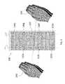
- FIG. 1shows a device 100 including an exemplary arrangement of ambient light sensors 110 .
- the device 100may be any computation, communication, or data storage device such as a tablet, laptop computer, smart phone, music player, storage device, and the like.
- the view depicted by FIG. 1shows the screen 120 (e.g., glass or other transparent surface) of the device 100 on a surface of the body 125 that displays information to a user, which can be based on user selections or generated by the device 100 .
- Information generated by the devicecan include the status of communication connections (mobile network, wifi connection(s), Bluetooth connections, etc.), telephone call, or electronic messages or any combination thereof.
- the screen 120can act as the input/output (I/O) between the device 100 and the user.
- FIG. 1has a screen 120 that occupies most of one surface of the device 100 .
- Other exemplary devices 100may instead include a keyboard or other components such that the relative size of the screen 120 to the size of a surface of the device 100 is smaller than shown in FIG. 1 (see e.g., FIG. 4 ).
- Three ambient light sensors (ALSs) 110 x , 110 y , 110 zare disposed beneath the screen 120 in FIG. 1 .
- the ALSs 110are shown disposed beneath the screen 120 to protect from environmental and accidental damage, the ALSs 110 receive the same intensity of ambient light or at least sufficient ambient light to detect a change in ambient light whether they are disposed above or below the screen 120 , because the screen 120 is a transparent device element that allows ambient light to pass through.
- the screen 120includes a glass or polymer exterior layer that may filter or diffuse some light, e.g., certain ranges of light wavelengths. Sufficient light for detection as described herein passes through the exterior layer of the screen 120 .
- the ambient lightrefers to the available light (brightness and direction of light) in the environment in which the device 100 is being used.
- the ALSs 110are passive devices. In an example, the ALSs 110 do not have and are not associated with emitters on the device 100 to provide the light that is detected by the ALSs 110 . In a further example, the device 100 does not emit light for the purpose of gesture detection. Ambient light is, in an example, the light present in the environment in which the device is present.
- FIG. 2depicts another view of the device 100 shown in FIG. 1 .
- the view shown by FIG. 2includes a light source 210 .
- This light source 210may be the sun, a lamp, or some combination of light sources that provide the available light in a given environment in which the device 100 is being used. If the device 100 is outside during the day, the sun provides the ambient light, which is spread spectrum light. If the device is being used indoors with no exterior windows, the ambient light is generated by indoor lighting systems, e.g. lamps, fluorescent bulbs, incandescent bulbs, LEDs, etc.
- the ambient lightcan also be a combination of natural light (e.g., sunlight) and artificial light (e.g., fluorescent light, incandescent light).
- Each ALS 110outputs a current level corresponding with the measured light intensity 115 (see e.g., FIG. 5 ).
- An analog-to-digital convertermay be used to derive a digital output from the ALSs 110 .
- Each of the ALSs 110may have adjustable sensitivity (adjustable gain setting).
- Each ALS 110may also be a spread spectrum sensor with a selectable range of operation among two or more ranges (wavelength bands or ranges). The process entailed in this selection is discussed further below with reference to FIG. 6 .
- the full range of operation of each ALS 110may be close to the wavelength range of visible light (400 nm to 700 nm).
- a typical commercially available ALSmay detect ambient light in the wavelength range of 350 nm to 700 nm, for example.
- each ALS 110measures the intensity of the available (ambient) light within its zone of reception (see e.g. 230 y and 230 y ′ defining a zone of reception for ALS 110 y and 230 z and 230 z ′ defining a zone of reception for ALS 110 z ), the ALS 110 is a passive sensor that does not require a corresponding emitter or transmitter.
- the zone of receptionis typically cone-shaped with the cone dimensions being determined by an angle of half sensitivity.
- FIG. 2is a cross-sectional view of an exemplary zone of reception.
- Each ALS 110may measure light intensity 115 within its zone of reception in a photometric unit (lux) to provide a measure of lumens per square-meters or in a radiometric unit (irradiance) to provide a measure of watts per square-meters.
- luxphotometric unit
- irradianceradiometric unit
- the three ALSs 110 x , 110 y , 110 zare arranged in a triangular pattern. That is, at least one ALS 110 is offset or not linearly aligned with at least two other ALSs 110 .
- the device 100 shown in FIGS. 1 and 2facilitates detection of a gesture by an object 240 that changes the light intensity 115 (see e.g., FIG. 5 ) in the zone of detection of one or more of the ALSs 110 due to movement of the object 240 .
- the inclusion of three or more ALSs 110 with at least three of the three of more ALSs 110 in a triangular patternsee e.g., FIG. 1 )
- movement of an object 240may be discerned in three dimensions.
- a gestureis detected and identified based on the changes in light intensity 115 measured by each of the ALSs 110 at different time instants or measurement cycles due to the movement of the object 240 . That is, each of the ALSs 110 measures light intensity 115 simultaneously with the other ALSs 110 at a given time instant or in sequence with the other ALSs 110 for a measurement cycle, and the comparison of light intensity 115 measurements for different time instants or measurement cycles is used to detect a gesture. For example, assuming that the ALSs 110 measure light intensity 115 simultaneously (or near-simultaneously), at the time instant illustrated by FIG.
- the object 240is positioned such that the light intensity 115 detected by ALS 110 z is affected but the light intensity 115 detected by ALSs 110 x and 110 y is unaffected by the object 240 . Based on a direction of movement of the object 240 , the light intensity 115 detected by different ones of the ALSs 110 x , 110 y , 110 z may be affected at different times instants by the position of the object 240 .
- the object 240may be a hand, one or more fingers, a wand or another non-transparent item that partially or completely blocks the passage of ambient light so that its position may be detected based on the effect on measured light intensity 115 .
- a touch-free gesturemay mimic a swipe, also known as a flick, which can be a particular type of touch on a touch-sensitive display.
- the swipe or flickmay begin at an origin point and continue to an end point, for example, a concluding end of the gesture.
- a gesturemay be identified by attributes or characteristics of the gesture as discussed further below. These attributes may include the origin point (of detection by an ALS 110 ), the end point, the distance traveled by the object 240 , the duration, the velocity, and the direction, for example.
- a gesturemay be long or short in distance and/or duration. Two points of the gesture may be utilized to determine a direction of the gesture.
- a gesturemay also include a hover.
- a hovermay be non-movement of the object 240 at a location that is generally unchanged over a period of time.
- a minimum distancemay be required among the ALSs 110 x , 110 y , and 110 z (e.g., distance 220 between ALSs 110 y and 110 z ) in order to distinguish the movement of the object 240 .
- This minimum distancemay generally be on the order of 2 centimeters (cm). More specifically, the minimum distance between ALSs 110 is based on an expected size of the object 240 as one factor. For example, when an open hand is used as the object 240 , a greater minimum distance may be required to distinguish a gesture than when one finger is used as the object 240 .
- the open handwould cover all three ALSs 110 x , 110 y , 110 z at more time instants such that a movement of the open hand could only be distinguished when the object 240 is at an edge of the set of ALSs 110 x , 110 y , 110 z .
- the ALSs 110may be positioned at the corners or along the edges of the screen 120 and, thus, the screen 120 size may determine the distance between the ALSs 110 .
- a minimum distance between ALSs 110 of 3.5 cmmay be used.
- the increased distance between ALSs 110facilitates distinguishing the gesture (e.g., direction, speed) more clearly, because all ALSs 110 will not be covered by the open hand object 240 for the majority of the gesture movement.
- the object 240must be between the light source 210 and the ALSs 110 in order to be detected by one or more of the ALSs 110 based on the effect of the object 240 on light intensity 115 detected by one or more of the ALSs 110 . While a minimum distance is generally not required between the object 240 and an ALS 110 (i.e. the object 240 may almost touch the screen 120 surface), the object 240 may generally be 2-3 cm away from the screen 120 while performing the gesture.
- an object 240 that is closer in distance to an ALS 110must also be closer to a center of the ALS 110 (in the perpendicular dimension, along the screen 120 ) in order to enter the zone of reception of the ALS 110 .
- a gesture analogous to a mouse clickmay be made.
- double-click and triple-click gesturesmay be added to available distinguishable gestures.
- FIG. 3shows a device 100 including an exemplary arrangement of ambient light sensors 110 according to another embodiment.
- the exemplary device 100 shown in FIG. 3is similar to the device 100 shown in FIGS. 1 and 2 in that the screen 120 occupies most of one surface of the device 100 .
- the device 100 shown in FIG. 3includes seven ALSs 110 a , 110 b , 110 c , 110 d , 110 e , 110 f , 110 g arranged around the perimeter of the screen 120 . As shown in FIG.
- ALS 110 ais offset from a common axial line 111 of ALSs 110 b , 110 c , and 110 d and also a common axial line 111 ′ of ALSs 110 e , 110 f , and 110 g .
- one or more of the ALSs 110 b , 110 c , and 110 d or the ALSs 110 e , 110 f , and 110 gmay be disposed such that they are not linearly aligned with other ALSs 110 along 111 or 111 ′, respectively.
- both ALS 110 c and ALS 110 fmay be disposed closer to the center of the screen 120 and, thus, offset from the axial line 111 common to ALSs 110 b and 110 d and the axial line 111 ′ common to ALSs 110 e and 110 g , respectively.
- Increasing the number of ALSs 110increases the number of gestures that may be detected by the device 100 .
- one waving gesturemovement of the object 240 from one side of the device 100 to the other
- FIG. 3Because of the number of ALSs 110 around the perimeter of the screen 120 , other waving gestures, distinguishable from the waving gesture shown in FIG. 3 , are also possible.
- the object 240may move from ALSs 110 d and 110 e to ALS 110 a , for example, or from ALS 110 d to ALS 110 g . It bears noting that, if the ALSs 110 were clustered closer together and the object 240 is a hand, as shown in FIG. 3 , fewer distinguishable gestures are possible than when the ALSs 110 are disposed, as shown.
- FIG. 4shows a device 100 including an exemplary arrangement of ambient light sensors 110 according to yet another embodiment.
- the device 100 shown in FIG. 4includes a keyboard or other component in the space 410 such that the screen 120 occupies less of one surface of the device 100 relative to the screen 120 shown in FIGS. 1-3 .
- Three ALSs 110 m , 110 n , 110 oare shown near the perimeter of the screen 120 .
- the ALSs 110 m , 110 n , 110 omay be disposed closer together so that the gestures made by the object 240 are more analogous to gestures a user of a touchpad may make with a finger.
- FIG. 5is a block diagram of a system 500 to process gestures. Functions performed by the system 500 are discussed below with reference to specific components. However, in alternate embodiments, the system 500 may process gestures using one or more processors and one or more memory devices that serve more than one of the functions discussed herein. In addition, the same processors and memory devices that process gestures as discussed below may perform other functions within the device 100 .
- the processor to identify gesturesmay be one of several digital signal processors (DSPs 801 , FIG. 8 ) generally available in a smart phone or tablet.
- DSPs 801 , FIG. 8digital signal processors
- An input to the system 500is the light intensity 115 measured from each of the ALSs 110 .
- the measurementsare received by a data collection engine 510 , which includes both memory and processor functionalities.
- the data collection engine 510outputs a frame of data 520 for each time instant. That is, each frame of data 520 includes the light intensity 115 measurement for every ALS 110 at a given time instant.
- each frame of data 520may generally be discussed as including the light intensity 115 measurement for each ALS 110 at an instant of time, the ALSs 110 may instead sample light intensity 115 in turn (rather than simultaneously) such that a frame of data 520 includes light intensity 115 measurements for a period of time for one cycle of the ALSs 110 .
- a processor functioning as a gesture identifier 530receives each frame of data 520 .
- the gesture identifier 530may operate according to one of several embodiments as discussed below.
- the gesture identifier 530uses a comparison of light intensity 115 measurements of the ALSs 110 , as discussed below, along with a comparison with a gesture template 537 stored in a template memory device 535 .
- a dynamically adjusted minimum change in light intensity 115may be set based on expected noise and errors. That is, a threshold percentage of change in detected light intensity 115 may be required before it is interpreted as a true variation in ambient light.
- the gesture identifier 530may ascertain a position of the object 240 .
- the object 240may be determined to be over the ALS 110 e and, thereby, blocking some of the light from the light source 210 .
- the gesture identifier 530may ascertain characteristics of the (movement) gesture such as a direction of the movement, speed of the movement, and whether the movement is accelerating or decelerating.
- the gesture identifier 530may ascertain that the object 240 moved from a direction of the ALS 110 e toward a direction of the ALSs 110 d and 110 f .
- the gesture identifier 530may identify the gesture among a set of known gestures based on the gesture template 537 .
- the gesture template 537facilitates the association of a movement of the object 240 discerned by the gesture identifier 530 with a particular known gesture.
- the gesture template 537may be regarded as a sample of ideal light intensity 115 measurement data corresponding with each known gesture. More specifically, the gesture template 537 may be regarded as providing the ideal relative light intensity 115 among the ALSs 110 or frames of data 520 or both for a given known gesture.
- the gesture identifier 530identifies the object 240 movement as a known gesture.
- This identification of the gesturemay be done by a process of elimination of the known gestures in the gesture template 537 .
- the gesture identifier 530may identify the gesture using the gesture template 537 , through a process of elimination of available known gestures, before the object 240 movement is complete. In this case, the gesture identifier 530 may continue to process frames of data 520 to verify the detected gesture or, in alternate embodiments, the gesture identifier 530 may stop processing additional frames of data 520 after identifying the gesture and wait for a trigger signal 540 discussed below.
- Each of the ALSs 110may be programmable to provide 10, 20, 50, 10, 125, 15, 200 and 250 samples of light intensity 115 (frames of data 520 ) a second.
- the ALS 110 scanning rateis a factor in determining the speed at which a gesture may be made in order to be recognized. That is, when the ALSs 110 are sampling at a rate of 10 light intensity 115 samples per second, the fastest identifiable gesture is much slower than the fastest identifiable gesture that may be made when the ALSs 110 are sampling at a rate of 250 light intensity 115 samples per second.
- the ALSs 115 sampling at a rate of 10 frames of data 520 per second (10 light intensity 115 samples per second each)may translate to an object 240 travelling 10 cm in 1.5 seconds in order to be recognized and processed properly.
- the system 610( FIG. 6 ) may dynamically calculate and adjust the scanning rate of the ALSs 110 .
- gesture libraries 555are stored in a gesture library storage 550 .
- Each gesture library 555is associated with an application, and the gesture identifier 530 selects the gesture library 555 associated with the application currently being executed by the device 100 .
- a given gesture library 555 associated with a given applicationmay not include every known gesture in the gesture template 537 .
- the gesture identifier 530may narrow down the set of known gestures within the gesture template 537 to compare against the frames of data 520 output by the data collection engine 510 in order to identify the gesture.
- a gesture library 555indicates an action output 560 corresponding with a set of gestures.
- the gesture identifier 530identifies a known gesture based on the movement of the object 240 and the gesture template 537 , and the gesture identifier 530 finds that known gesture among the set of gestures in a gesture library 555 associated with the application currently being run by the device 100 , then the gesture identifier 530 outputs the corresponding action output 560 stemming from the object 240 movement.
- the action output 560 of the gesture identifier 530acts as a command to the application being executed.
- the gestures identified by the gesture identifier 530may correspond with action outputs 560 such as “next page” (wave down), “previous page” (wave up), “zoom in” (bringing fingers together), and “zoom out” (spreading fingers apart). If the device 100 is currently not executing any application or if the application currently being executed by the device 100 does not have a gesture library 555 associated with it, then, even if the gesture identifier 530 uses the gesture template 537 to identify a known gesture based on the movement of the object 240 , no action is taken by the gesture identifier 530 based on identifying the gesture. That is, there is no action output 560 corresponding with the identified gesture, because there is no gesture library 555 to look up.
- action outputs 560such as “next page” (wave down), “previous page” (wave up), “zoom in” (bringing fingers together), and “zoom out” (spreading fingers apart).
- the gesture identifier 530may not use the gesture template 537 to identify a gesture when no application is being executed by the device 100 or when an application without an associated gesture library 555 is being executed by the device 100 . According to another embodiment, the gesture identifier 530 may not begin to process any frames of data 520 before receiving a trigger signal 540 .
- the trigger signal 540is detailed below with reference to FIG. 6 . According to another embodiment, the gesture identifier 530 may process an initial set of frames of data 520 and then not process another set of frames of data 520 needed to identify the gesture until the trigger signal 540 is received.
- the gesture identifier 530may process a particular number of frames of data 520 or a number of frames of data 520 representing a particular length of time (number of time instants) and then stop processing further frames of data 520 until the trigger signal 540 is received.
- the gesture identifier 530may continually process frames of data 520 as they are output from the data collection engine 510 .
- the data collection engine 510still outputs the frames of data 520 . This is because the light intensity 115 measurements may be used for background functions such as adjustment of the screen 120 backlighting, for example, based on the detected ambient light, even if gesture detection is not to be performed. Some of these background functions are detailed below with reference to FIG. 6 .
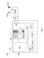
- FIG. 6is a block diagram of a system 610 to control the two or more ambient light sensors 110 .
- the functions described for the system 610may be performed by one or more processors and one or more memory devices, which may also perform other functions within the device 100 .
- the system 610may be regarded as a background processing system, because it may operate continuously to dynamically control the ALSs 110 .
- the system 610receives the light intensity 115 measurements output by the ALSs 110 to the data collection engine 510 as frames of data 520 .
- the ALSs 110may directly output light intensity 115 measurements to the system 610 as well as to the data collection engine 510 .
- the system 610may also receive additional information 620 . This additional information 620 may indicate, for example, whether the device 100 is currently executing an application and, if so, which application the device 100 is currently executing.
- the system 610Based on the light intensity 115 measurements (directly or in the form of frames of data 520 ) and the additional information 620 , the system 610 adjusts the sensitivity or wavelength band or range or both for each ALS 110 . For example, based on the available light (measured ambient light intensity 115 ), the system 610 may change the wavelength range for the ALSs 110 via a control signal 630 from the system 610 to one or more of the ALSs 110 . The change (adjustment of wavelength range) may ensure that the ALSs 110 are focused in the correct wavelength (frequency) band for the current conditions.
- the system 610may change the sensitivity of the ALSs 110 .
- Any order of switching lightsproduces a new range of change in light intensity 115 to which the ALSs 110 must adapt.
- the range of change of light intensity 115 to which the ALSs 110 are sensitivemay be 50-250 lux.
- the range of change of light intensity 115 to which the ALSs 110 are sensitivemay be 2-15 lux.
- the adjustment of the ALSs 110 through the control signal 630may be done continuously, periodically, or based on a trigger event such as, for example, a change in the application being executed by the device 100 . For example, sensitivity adjustment may be done automatically once for every 5 frames of data 520 .
- the system 610may also adjust the order and frequency of light intensity 115 measurements by the ALSs 110 . For example, based on additional information 620 indicating that a particular application is being executed by the device 100 , the system 610 may send control signals 630 to have the ALSs 110 collect light intensity 115 samples for each cycle (frame of data 520 ) in a particular order and with a particular frequency.
- the system 610may provide the trigger signal 540 to the gesture identifier 530 (see FIG. 5 ). Because the system 610 monitors the light intensity 115 measurements in the frames of data 520 to fulfill the background functions described above, the system 610 may additionally identify trigger events that signal when gesture processing should be initiated by the gesture identifier 530 and output the trigger signal 540 accordingly. For example, the system 610 may output a trigger signal 540 to the gesture identifier 530 when it receives a frame of data 520 that indicates a change in light intensity 115 measured by one or more ALSs 110 . The change in light intensity 115 measurement may indicate a start of a movement of an object 240 and, thus, the start of a gesture.
- the change in measured light intensity 115may be 10%+/ ⁇ 3% or higher before the system 610 outputs a trigger signal 540 . In an embodiment, the change in measured light intensity 115 may be 20%+/ ⁇ 5% or higher before the system 610 outputs a trigger signal 540 . In an embodiment, the change in measured light intensity may be 25%+/ ⁇ 5% or higher before the system 610 outputs a trigger signal 540 .
- FIG. 7shows the process flow of a method 700 of detecting a gesture according to embodiments discussed above.
- arranging two or more ALSs 110 under the screen 120 of a device 100may be according to the embodiments shown in FIGS. 1, 3, and 4 or in alternate arrangements according to the guidelines discussed above.
- Obtaining light intensity 115 measurements from the ALSs 110(block 720 ) may be in photometric or radiometric units as discussed above.
- Obtaining (receiving) the light intensity 115 measurementsmay also include dynamically controlling the ALSs 110 with the system 610 to modify the wavelength range or spectral sensitivity of each ALS 110 , for example.
- FIG. 7shows the process flow of a method 700 of detecting a gesture according to embodiments discussed above.
- arranging two or more ALSs 110 under the screen 120 of a device 100may be according to the embodiments shown in FIGS. 1, 3, and 4 or in alternate arrangements according to the guidelines discussed above.
- Obtaining light intensity 115 measurements from the ALSs 110(block
- the control by the system 610may be based on light intensity 115 measurements by the ALSs 110 , for example. Determining what, if any, application is being executed by the device 100 , at block 730 , may be done by the gesture identifier 530 and may be part of the additional information 620 provided to the system 610 .
- the processincludes storing a gesture library 555 associated with each application that may be operated using touch-less gestures in the gesture library storage 550 . Selecting the gesture library 555 associated with the application being executed by the device 100 may be done by the gesture identifier 530 at block 750 .
- Block 750may also include the gesture identifier 530 determining that no gesture library 555 is applicable because the device 100 is not executing any application or is executing an application without an associated gesture library 555 .
- processing the light intensity 115 measurements and identifying a gestureinvolves the data collection engine 510 outputting the frames of data 520 and the gesture identifier 530 using a comparison of light intensity 115 measurements in addition to the gesture template 537 .
- Block 760may also include the system 610 sending a trigger signal 540 to the gesture identifier 530 to begin or continue the gesture processing.
- Block 760may further include the gesture identifier 530 not identifying the gesture at all based on not having a gesture library 555 available.
- outputting an action signal 560 corresponding with the gesture based on the gesture library 555is done by the gesture identifier 530 as detailed above.
- FIG. 8is a block diagram of an exemplary device 100 that facilitates touch-less gesture detection as described in embodiments above. While various components of the device 100 are depicted, alternate embodiments of the device 100 may include a subset of the components shown or include additional components not shown in FIG. 8 .
- the device 100includes a DSP 801 and a memory 802 .
- the DSP 801 and memory 802may provide, in part or in whole, the functionality of the system 500 ( FIG. 5 ).
- the device 100may further include an antenna and front-end unit 803 , a radio frequency (RF) transceiver 804 , an analog baseband processing unit 805 , a microphone 806 , an earpiece speaker 807 , a headset port 808 , a bus 809 , such as a system bus or an input/output (I/O) interface bus, a removable memory card 810 , a universal serial bus (USB) port 811 , an alert 812 , a keypad 813 , a short range wireless communication sub-system 814 , a liquid crystal display (LCD) 815 , which may include a touch sensitive surface, an LCD controller 816 , a charge-coupled device (CCD) camera 817 , a camera controller 818 , and a global positioning system (GPS) sensor 819 , and a power management module 820 operably coupled to a power storage unit, such as a battery 826 .
- the device 100may include another kind of display
- the DSP 801or some other form of controller or central processing unit (CPU) operates to control the various components of the device 100 in accordance with embedded software or firmware stored in memory 802 or stored in memory contained within the DSP 801 itself.
- the DSP 801may execute other applications stored in the memory 802 or made available via information media such as portable data storage media like the removable memory card 810 or via wired or wireless network communications.
- the application softwaremay comprise a compiled set of machine-readable instructions that configure the DSP 801 to provide the desired functionality, or the application software may be high-level software instructions to be processed by an interpreter or compiler to indirectly configure the DSP 801 .
- the antenna and front-end unit 803may be provided to convert between wireless signals and electrical signals, enabling the device 100 to send and receive information from a cellular network or some other available wireless communications network or from a peer device 100 .
- the antenna and front-end unit 803may include multiple antennas to support beam forming and/or multiple input multiple output (MIMO) operations.
- MIMO operationsmay provide spatial diversity, which can be used to overcome difficult channel conditions or to increase channel throughput.
- the antenna and front-end unit 803may include antenna tuning or impedance matching components, RF power amplifiers, or low noise amplifiers.
- the RF transceiver 804facilitates frequency shifting, converting received RF signals to baseband and converting baseband transmit signals to RF.
- a radio transceiver or RF transceivermay be understood to include other signal processing functionality such as modulation/demodulation, coding/decoding, interleaving/deinterleaving, spreading/despreading, inverse fast Fourier transforming (IFFT)/fast Fourier transforming (FFT), cyclic prefix appending/removal, and other signal processing functions.
- IFFTinverse fast Fourier transforming
- FFTfast Fourier transforming
- cyclic prefix appending/removaland other signal processing functions.
- the description hereseparates the description of this signal processing from the RF and/or radio stage and conceptually allocates that signal processing to the analog baseband processing unit 805 or the DSP 801 or other central processing unit.
- the radio access technology (RAT) RAT 1 and RAT 2 transceivers 821 , 822 , the IXRF 823 , the IRSL 824 and Multi-RAT subsystem 825are operably coupled to the RF transceiver 804 and analog baseband processing unit 805 and then also coupled to the antenna and front-end unit 803 via the RF transceiver 804 .
- RATradio access technology
- the radio access technology (RAT) RAT 1 and RAT 2 transceivers 821 , 822 , the IXRF 823 , the IRSL 824 and Multi-RAT subsystem 825are operably coupled to the RF transceiver 804 and analog baseband processing unit 805 and then also coupled to the antenna and front-end unit 803 via the RF transceiver 804 .
- RAT transceivers 804there may be multiple RAT transceivers, there will typically be multiple antennas or front ends 803 or RF transceivers 804 , one for each RAT or band of operation.
- the analog baseband processing unit 805may provide various analog processing of inputs and outputs for the RF transceivers 804 and the speech interfaces ( 806 , 807 , 808 ).
- the analog baseband processing unit 805receives inputs from the microphone 806 and the headset 808 and provides outputs to the earpiece 807 and the headset 808 .
- the analog baseband processing unit 805may have ports for connecting to the built-in microphone 806 and the earpiece speaker 807 that enable the device 100 to be used as a cell phone.
- the analog baseband processing unit 805may further include a port for connecting to a headset or other hands-free microphone and speaker configuration.
- the analog baseband processing unit 805may provide digital-to-analog conversion in one signal direction and analog-to-digital conversion in the opposing signal direction. In various embodiments, at least some of the functionality of the analog baseband processing unit 805 may be provided by digital processing components, for example by the DSP 801 or by other central processing units.
- the DSP 801may perform modulation, coding, interleaving, inverse fast Fourier transforming, and cyclic prefix appending, and for a receiver function the DSP 801 may perform cyclic prefix removal, fast Fourier transforming, deinterleaving, decoding, and demodulation.
- OFDMAorthogonal frequency division multiplex access
- the DSP 801may communicate with a wireless network via the analog baseband processing unit 805 .
- the communicationmay provide Internet connectivity, enabling a user to gain access to content on the Internet and to send and receive e-mail or text messages.
- the input/output interface (“Bus”) 809interconnects the DSP 801 and various memories and interfaces.
- the memory 802 and the removable memory card 810may provide software and data to configure the operation of the DSP 801 .
- the interfacesmay be the USB interface 811 and the short range wireless communication sub-system 814 .
- the USB interface 811may be used to charge the device 100 and may also enable the device 100 to function as a peripheral device to exchange information with a personal computer or other computer system.
- the short range wireless communication sub-system 814may include an infrared port, a Bluetooth interface, an IEEE 802.11 compliant wireless interface, or any other short range wireless communication sub-system, which may enable the device to communicate wirelessly with other nearby client nodes and access nodes.
- the short-range wireless communication sub-system 814may also include suitable RF Transceiver, Antenna and Front End subsystems.
- the input/output interface (“Bus”) 809may further connect the DSP 801 to the alert 812 that, when triggered, causes the device 100 to provide a notice to the user, for example, by ringing, playing a melody, or vibrating.
- the alert 812may serve as a mechanism for alerting the user to any of various events such as an incoming call, a new text message, and an appointment reminder by silently vibrating, or by playing a specific pre-assigned melody for a particular caller.
- the keypad 813couples to the DSP 801 via the I/O interface (“Bus”) 809 to provide one mechanism for the user to make selections, enter information, and otherwise provide input to the device 100 .
- the keypad 813may be a full or reduced alphanumeric keyboard such as QWERTY, DVORAK, AZERTY and sequential types, or a traditional numeric keypad with alphabet letters associated with a telephone keypad.
- the input keysmay likewise include a track wheel, track pad, an exit or escape key, a trackball, and other navigational or functional keys, which may be inwardly depressed to provide further input function.
- Another input mechanismmay be the LCD 815 , which may include touch screen capability and also display text and/or graphics to the user.
- the LCD controller 816couples the DSP 801 to the LCD 815 .
- the CCD camera 817if equipped, enables the device 100 to make digital pictures.
- the DSP 801communicates with the CCD camera 817 via the camera controller 818 .
- a camera operating according to a technology other than Charge Coupled Device camerasmay be employed.
- the GPS sensor 819is coupled to the DSP 801 to decode global positioning system signals or other navigational signals, thereby enabling the device 100 to determine its position.
- the GPS sensor 819may be coupled to an antenna and front end (not shown) suitable for its band of operation.
- Various other peripheralsmay also be included to provide additional functions, such as radio and television reception.
- device 100comprises a first Radio Access Technology (RAT) transceiver 821 and a second RAT transceiver 822 .
- RATRadio Access Technology
- the RAT transceivers ‘ 1 ’ 821 and ‘ 2 ’ 822are in turn coupled to a multi-RAT communications subsystem 825 by an Inter-RAT Supervisory Layer Module 824 .
- the multi-RAT communications subsystem 825is operably coupled to the Bus 809 .
- the respective radio protocol layers of the first Radio Access Technology (RAT) transceiver 821 and the second RAT transceiver 822are operably coupled to one another through an Inter-RAT eXchange Function (IRXF) Module 823 .
- IXFInter-RAT eXchange Function
- the arrangement and combined use of two or more ALSs 110facilitates the detection of characteristics of movement of an object 240 . These characteristics may be used by the gesture identifier 530 to identify a gesture made by the object 240 , for example. Further embodiments, discussed below, detail the control of ALSs 110 that facilitates addressing issues associated with traditional ALS 110 arrangements and uses (e.g., flicker or smudge effects).
- FIG. 9shows exemplary sampling patterns 910 for ALSs 110 .
- the system 610 and, more particularly, one or more processors of the system 610may control the ALSs 110 .
- the system 610may adjust the order and frequency of light intensity 115 measurements by each of the ALSs 110 in addition to controlling their sensitivity and waveform band.
- the exemplary sampling patterns 910 shown in FIG. 9include light intensity 115 w , 115 x , 115 y , 115 z measurements from four ALSs 110 .
- fewer or more ALSs 110may be arranged within the device 100 according to various embodiments. While four exemplary patterns 910 a , 910 b , 910 c , 910 d are detailed herein, any combination or variation on the patterns 910 is also contemplated.
- One exemplary pattern 910 ainvolves each of the four ALSs obtaining light intensity 115 w , 115 x , 115 y , 115 z measurements in immediate succession from one another for each measurement cycle (frame of data 520 a ) with a period of time 920 - 1 or 920 - 2 between each frame of data 520 a resulting from each measurement cycle of the ALSs 110 .
- the periods of time 920 - 1 and 920 - 2 between the frames of data 520 aare controllable by the system 610 .
- the periods of time 920 - 1 and 920 - 2may be the same or may be different.
- the time period 930 between light intensity 115 measurements within a frame of data 520 bis the same as the time period 940 between the last light intensity 115 z measurement of a frame of data 520 b and the first light intensity 115 w measurement of the next frame of data 520 b .
- the exemplary pattern 910 cillustrates that the period between light intensity 115 measurements within a frame of data 520 as well as between frames of data 520 is adjustable by the system 610 .
- the exemplary pattern 910 dfurther illustrates that the system 610 may change the sampling of light intensity 115 by each of the ALSs 110 between or during execution of a particular application by the device 100 .
- all four ALSs 110simultaneously measure light intensity 115 w , 115 x , 115 y , 115 z to provide the first two frames of data 520 d .
- two of the light intensity 115 w , 115 x measurementsare taken simultaneously.
- the illustrative patterns 910 in FIG. 9indicate some of the types of sampling parameters the system 610 may control.
- the arrangement and control of ALSs 110according to embodiments discussed herein address factors to which traditional ALS 110 arrangement and use has been susceptible. For example, when two or more ALSs 110 are used and are controlled to sample light intensity 115 at different times (though they may be used simultaneously), ac flicker is not likely to affect the light intensity 115 measurements from both ALSs 110 . As a result, the flicker is recognizable and can be ignored.
- the frequency of sampling of light intensity 115 by each ALS 110may be increased to ascertain the movement affecting each of the ALSs 110 differently.
- the additional processing based on movementwould be the gesture detection process described above.
- the movementmay be ignored.
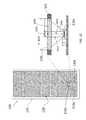
- FIG. 10illustrates a cross-sectional view of one ALS 110 according to an embodiment.
- FIG. 10shows a device 100 similar to the one shown in FIG. 1 with the ALS 110 x shown in a cross-sectional view.
- the view of the ALS 110 xshows a narrowed viewing angle (pipe diameter 1010 or pd) based on a pipe 1015 structure as compared to the zone of reception (window width 1020 or w), which is also shown and discussed with reference to FIG. 2 , for example.
- This pipe diameter 1010 (pd)may be 0.75 millimeters (mm), for example, and the ALS 110 x may have a height (h) of 0.85 mm, for example.
- xis the distance 1030
- dis the distance from the top of the ALS 110 x to the surface of the screen 120 ( 1050 )
- ⁇is the angle 1040 , which is the half-angle of the cone-shaped region.
- the distance 1030 xis (1.73)*d according to Equation 1.
- the distance 1030 xis (0.84)*d according to Equation 1.
- Equation 1indicates, as the half-angle of the cone-shaped region ( 1040 ) decreases and the distance 1050 ( d ) decreases, the distance 1030 x decreases proportionately. Accordingly, even without the pipe 1015 structure, ALSs 110 arranged in proximity to each other may not have overlapping zones of reception in some cases.
- the narrower (cylindrical rather than cone-shaped) viewing angleensures that the zones of reception of the ALSs 110 do not overlap.
- the direction of the source of ambient lightmay be determined. That is, for example, when the ALSs 110 x , 110 y , 110 z shown in FIG.
- a comparison of the light intensity 115 measured by each ALS 110 x , 110 y , 110 zmay indicate a position of a light source. For example, when a lamp is positioned next to ALS 110 z , the light intensity 115 measured by ALS 110 z may be higher than the light intensity 115 measured by the other ALSs 110 x , 110 y.
- FIG. 11illustrates two scenarios 1110 , 1120 in which the camera application of a device 100 is used.
- the exemplary device 100 shown in FIG. 11includes a plurality (e.g., three) ALSs 110 in each of the scenarios 1110 , 1120 .
- the ALSs 110are assumed to be on the same surface of the device 100 as the camera lens 1100 .
- the side of the device 100 that includes the ALSs 110 and the camera lens 1100is assumed to face the scene 1111 , 1121 being photographed.
- the light source 210(sunlight) is on an opposite side of the device 100 from the scene 1111 being captured by the camera application of the device 100 .
- Another processor associated with the camera applicationmay receive the information in the action output 560 and determine an adjustment to the camera functionality based on the information.
- the system 610which also receives the light intensity 115 measurements, may provide the information to the processor associated with the camera application.
- the ALSs 110facilitate determining the position of the light source 210 relative to the device 100 , as discussed with reference to FIG. 10 .
- the processor controlling the camera applicationmay control the camera functionality based on knowing the direction of the light source 210 relative to the scene 1111 , 1121 to address shadow and other effects.
- a localized peak in the light(e.g., a reflection or light source 210 within a scene (e.g., 1111 , 1121 ) may be distinguished from a global change in the available light based on a comparison of the light intensity 115 measured by each of the ALSs 110 .
- distance to the subject 1112 , 1122 in a scene 1111 , 1121 and movement of the subject 1112 , 1122 within the scene 1111 , 1121may be estimated.
- the direction, speed, and inertia (mass) of the subject 1112 , 1122may be estimated based on the ALS 110 measurements of light intensity 115 .
- the subject 1112 in the first scene 1111may move closer or farther from the device 100 that is taking the picture.
- the subject 1122may move laterally from the device 100 .
- this movementmay also be distinguished based on a comparison of light intensity 115 measurements taken by the multiple ALSs 110 .
- the information obtained from the ALSs 110may be used in one or more ways by the processor of the device 100 that controls the camera functionality.
- the processor controlling the camera functionalitymay use information obtained from the ALSs 110 to automatically adjust the camera operation based on selected user preferences in what may be referred to as an automatic mode.
- one or more processorsmay provide a tutorial to the user of the device 100 based on information obtained from the ALSs 110 in what may be referred to as a tutorial mode.
- the tutorialmay be in the form of text displayed on the screen 120 .
- the information provided to the usermay alternately or additionally be presented in the form of audio output.
- the automatic mode and the tutorial modemay be combined.
- the processor controlling the camera functionalitymay automatically adjust camera operation based on the information from the ALSs 110 , and the same or a different processor may additionally provide information to the user regarding the adjustments made to the camera functionality.
- the tutorial modemay be selected by a user who wishes to learn about photography. Because the multiple ALSs 110 provide information that includes determining a direction of the light source 210 , the tutorial mode facilitates a thorough and specific discussion of the different options particular to the existing lighting conditions.
- FIG. 12is a process flow of a method of controlling a camera application being executed by a device 100 .
- the processis implemented by using the ALSs 110 and one or more of the processors of the device 100 discussed above.
- the arrangement of the ALSs 110 and the processing of light intensity 115 measurements from the ALSs 110may be according to one of the embodiments discussed above or may be a variation thereof.
- activating the camera applicationmay cause the gesture identifier 530 to use the gesture library 555 associated with the camera application.
- the gesture library 555 associated with the camera applicationmay cause the gesture identifier 530 to output (action output 560 ) informational rather than control signals.
- a gesture detected based on information from the ALSs 110may launch the camera application and, thereafter, the direction of light may be determined and provided to the camera module or processor (e.g., DSP 801 ) in the form of an action output 560 .
- the system 610may output the information used to determine adjustments to the camera application.
- Measuring light intensity 115 using the two or more ALSs 110 arranged at or below the surface of the device 100 at block 1220includes obtaining the light intensity 115 measurements according to the control of the system 610 .
- One or more of the processors of the device 100are involved in the processes of determining the direction of light ( 1230 ), tracking movement within a field of the camera lens ( 1240 ), and determining any local peaks in light ( 1250 ) based on the light intensity measurements 115 by the ALSs 110 .
- Determining adjustments to camera functionality at block 1260includes taking into account the information provided by the ALSs 110 as well as user selections of preferences. For example, a user selection may indicate an override of camera control suggested by the information obtained from the ALSs 110 .
- the adjustments determined at block 1260may be used for providing a tutorial to a user ( 1270 ), controlling the camera application automatically ( 1280 ), or a combination of the two.
- the ALSs 110may be used to make adjustments to the display of photos on the screen 120 of the device 120 .
- the automatic control of the camera functionality ( 1280 )may also include determining a camera function control gesture as determined from the gesture library 555 to instruct the camera to take a picture (e.g., in an automatic mode).
- the gestureis the command that mimics the shutter release button to cause the imager circuitry of the camera to capture an image.
- the image capturecan be automatically adjusted by the information from the two or more ALSs 110 .
Landscapes
- Engineering & Computer Science (AREA)
- General Engineering & Computer Science (AREA)
- Theoretical Computer Science (AREA)
- Physics & Mathematics (AREA)
- General Physics & Mathematics (AREA)
- Human Computer Interaction (AREA)
- Multimedia (AREA)
- Signal Processing (AREA)
- Telephone Function (AREA)
Abstract
Description
x=d*tan(α) [EQ. 1]
where x is the
Claims (22)
Priority Applications (1)
| Application Number | Priority Date | Filing Date | Title |
|---|---|---|---|
| US13/932,260US9398221B2 (en) | 2013-07-01 | 2013-07-01 | Camera control using ambient light sensors |
Applications Claiming Priority (1)
| Application Number | Priority Date | Filing Date | Title |
|---|---|---|---|
| US13/932,260US9398221B2 (en) | 2013-07-01 | 2013-07-01 | Camera control using ambient light sensors |
Publications (2)
| Publication Number | Publication Date |
|---|---|
| US20150002720A1 US20150002720A1 (en) | 2015-01-01 |
| US9398221B2true US9398221B2 (en) | 2016-07-19 |
Family
ID=52115251
Family Applications (1)
| Application Number | Title | Priority Date | Filing Date |
|---|---|---|---|
| US13/932,260ActiveUS9398221B2 (en) | 2013-07-01 | 2013-07-01 | Camera control using ambient light sensors |
Country Status (1)
| Country | Link |
|---|---|
| US (1) | US9398221B2 (en) |
Cited By (3)
| Publication number | Priority date | Publication date | Assignee | Title |
|---|---|---|---|---|
| US9865227B2 (en) | 2013-07-01 | 2018-01-09 | Blackberry Limited | Performance control of ambient light sensors |
| US10200676B2 (en)* | 2015-12-17 | 2019-02-05 | H.P.B. Optoelectronic Co., Ltd | Image detection system of vehicle |
| WO2023027696A1 (en)* | 2021-08-24 | 2023-03-02 | Hewlett-Packard Development Company, L.P. | Locations identifications |
Families Citing this family (7)
| Publication number | Priority date | Publication date | Assignee | Title |
|---|---|---|---|---|
| US9342671B2 (en) | 2013-07-01 | 2016-05-17 | Blackberry Limited | Password by touch-less gesture |
| US9405461B2 (en) | 2013-07-09 | 2016-08-02 | Blackberry Limited | Operating a device using touchless and touchscreen gestures |
| US20150054846A1 (en)* | 2013-08-22 | 2015-02-26 | Lenovo (Singapore) Pte, Ltd | Mobile electronic device with orientation dependent ambient light sensitivity |
| JP6281313B2 (en)* | 2014-02-24 | 2018-02-21 | 株式会社リコー | Image projection device |
| EP3062519A1 (en) | 2015-02-27 | 2016-08-31 | Novabase Digital TV Technologies GmbH | Ambient surround information system for a media presentation |
| WO2020106629A1 (en)* | 2018-11-19 | 2020-05-28 | Intuitive Surgical Operations, Inc. | Systems and methods for emulating far-range lighting for an operational scene illuminated by close-range light |
| CN110806781A (en)* | 2019-10-30 | 2020-02-18 | 维沃移动通信有限公司 | Electronic equipment |
Citations (129)
| Publication number | Priority date | Publication date | Assignee | Title |
|---|---|---|---|---|
| EP0538705A1 (en) | 1991-10-21 | 1993-04-28 | International Business Machines Corporation | Graphical user interface with gesture recognition in a multiapplication environment |
| US5554912A (en) | 1995-05-15 | 1996-09-10 | Delco Electronics Corporation | Adaptive instrument display brightness control system |
| US5594469A (en) | 1995-02-21 | 1997-01-14 | Mitsubishi Electric Information Technology Center America Inc. | Hand gesture machine control system |
| US20020093491A1 (en) | 1992-06-08 | 2002-07-18 | David W. Gillespie | Object position detector with edge motion feature and gesture recognition |
| US20030156100A1 (en) | 2002-02-19 | 2003-08-21 | Palm, Inc. | Display system |
| US6693612B1 (en) | 1999-11-18 | 2004-02-17 | Hitachi, Ltd. | Liquid crystal display apparatus and its luminance control method |
| US20040190776A1 (en) | 2003-03-31 | 2004-09-30 | Honda Motor Co., Ltd. | Gesture recognition apparatus, gesture recognition method, and gesture recognition program |
| US20060013440A1 (en) | 1998-08-10 | 2006-01-19 | Cohen Charles J | Gesture-controlled interfaces for self-service machines and other applications |
| US20060139185A1 (en) | 2002-03-29 | 2006-06-29 | Pierre Bonnat | Input device for a computer system that utilizes ambient light, and a method of manufacturing the same |
| US20060187214A1 (en) | 1992-06-08 | 2006-08-24 | Synaptics, Inc, A California Corporation | Object position detector with edge motion feature and gesture recognition |
| US20060279548A1 (en) | 2005-06-08 | 2006-12-14 | Geaghan Bernard O | Touch location determination involving multiple touch location processes |
| US20070075965A1 (en) | 2005-09-30 | 2007-04-05 | Brian Huppi | Automated response to and sensing of user activity in portable devices |
| US20070120996A1 (en)* | 2005-11-28 | 2007-05-31 | Navisense, Llc | Method and device for touchless control of a camera |
| US20070130547A1 (en) | 2005-12-01 | 2007-06-07 | Navisense, Llc | Method and system for touchless user interface control |
| US20070259716A1 (en) | 2004-06-18 | 2007-11-08 | Igt | Control of wager-based game using gesture recognition |
| US20070259717A1 (en) | 2004-06-18 | 2007-11-08 | Igt | Gesture controlled casino gaming system |
| US20070296867A1 (en) | 2006-06-27 | 2007-12-27 | Lg Electronics Inc. | Method of controlling display characteristic and television receiver using the same |
| US20080005703A1 (en) | 2006-06-28 | 2008-01-03 | Nokia Corporation | Apparatus, Methods and computer program products providing finger-based and hand-based gesture commands for portable electronic device applications |
| US20080048997A1 (en) | 1992-06-08 | 2008-02-28 | Synaptics Incorporated | Object position detector with edge motion feature and gesture recognition |
| US20080122803A1 (en) | 2006-11-27 | 2008-05-29 | Microsoft Corporation | Touch Sensing Using Shadow and Reflective Modes |
| US20080134102A1 (en) | 2006-12-05 | 2008-06-05 | Sony Ericsson Mobile Communications Ab | Method and system for detecting movement of an object |
| US20080168402A1 (en) | 2007-01-07 | 2008-07-10 | Christopher Blumenberg | Application Programming Interfaces for Gesture Operations |
| US20080165160A1 (en) | 2007-01-07 | 2008-07-10 | Kenneth Kocienda | Portable Multifunction Device, Method, and Graphical User Interface for Interpreting a Finger Gesture on a Touch Screen Display |
| US20080165145A1 (en) | 2007-01-07 | 2008-07-10 | Scott Herz | Portable Multifunction Device, Method, and Graphical User Interface for Interpreting a Finger Swipe Gesture |
| US20080266083A1 (en) | 2007-04-30 | 2008-10-30 | Sony Ericsson Mobile Communications Ab | Method and algorithm for detecting movement of an object |
| US20090031258A1 (en) | 2007-07-26 | 2009-01-29 | Nokia Corporation | Gesture activated close-proximity communication |
| US20090051648A1 (en) | 2007-08-20 | 2009-02-26 | Gesturetek, Inc. | Gesture-based mobile interaction |
| US20090058830A1 (en)* | 2007-01-07 | 2009-03-05 | Scott Herz | Portable multifunction device, method, and graphical user interface for interpreting a finger gesture |
| US20090077504A1 (en) | 2007-09-14 | 2009-03-19 | Matthew Bell | Processing of Gesture-Based User Interactions |
| US20090100383A1 (en) | 2007-10-16 | 2009-04-16 | Microsoft Corporation | Predictive gesturing in graphical user interface |
| US20090139778A1 (en) | 2007-11-30 | 2009-06-04 | Microsoft Corporation | User Input Using Proximity Sensing |
| US20090146982A1 (en) | 2007-12-05 | 2009-06-11 | Jeff Thielman | Lighting Calibration System and Method |
| US20090189858A1 (en) | 2008-01-30 | 2009-07-30 | Jeff Lev | Gesture Identification Using A Structured Light Pattern |
| US20090195497A1 (en) | 2008-02-01 | 2009-08-06 | Pillar Ventures, Llc | Gesture-based power management of a wearable portable electronic device with display |
| US7618323B2 (en) | 2003-02-26 | 2009-11-17 | Wms Gaming Inc. | Gaming machine system having a gesture-sensing mechanism |
| US20100027843A1 (en) | 2004-08-10 | 2010-02-04 | Microsoft Corporation | Surface ui for gesture-based interaction |
| US20100060611A1 (en) | 2008-09-05 | 2010-03-11 | Sony Ericsson Mobile Communication Ab | Touch display with switchable infrared illumination for touch position determination and methods thereof |
| US20100090947A1 (en) | 2005-02-08 | 2010-04-15 | Oblong Industries, Inc. | System and Method for Gesture Based Control System |
| US20100153996A1 (en) | 2008-12-17 | 2010-06-17 | Migos Charles J | Gesture based electronic program management system |
| US20100150399A1 (en) | 2008-12-12 | 2010-06-17 | Miroslav Svajda | Apparatus and method for optical gesture recognition |
| US20100156676A1 (en) | 2008-12-22 | 2010-06-24 | Pillar Ventures, Llc | Gesture-based user interface for a wearable portable device |
| US20100177060A1 (en)* | 2009-01-14 | 2010-07-15 | Perceptive Pixel Inc. | Touch-Sensitive Display |
| US20100188328A1 (en) | 2009-01-29 | 2010-07-29 | Microsoft Corporation | Environmental gesture recognition |
| US20100192105A1 (en) | 2009-01-29 | 2010-07-29 | Samsung Electronics Co., Ltd. | System and method for controlling function of a device |
| EP2226710A2 (en) | 2009-03-06 | 2010-09-08 | Sharp Kabushiki Kaisha | Position detection device |
| US20100244751A1 (en) | 2007-10-26 | 2010-09-30 | Lite-On It Corporation | Menu Control for 1D Gesture Light Control System |
| US20100245289A1 (en) | 2009-03-31 | 2010-09-30 | Miroslav Svajda | Apparatus and method for optical proximity sensing and touch input control |
| US20100253241A1 (en) | 2007-10-26 | 2010-10-07 | Tony Petrus Van Endert | Low Cost System Concept for Gesture Light Control |
| US20100277073A1 (en) | 2007-10-26 | 2010-11-04 | Tony Petrus Van Endert | 1d gesture light control |
| US20100313050A1 (en) | 2009-06-05 | 2010-12-09 | Qualcomm Incorporated | Controlling power consumption of a mobile device based on gesture recognition |
| US20100325575A1 (en) | 2007-01-07 | 2010-12-23 | Andrew Platzer | Application programming interfaces for scrolling operations |
| US20110010626A1 (en) | 2009-07-09 | 2011-01-13 | Jorge Fino | Device and Method for Adjusting a Playback Control with a Finger Gesture |
| US20110029913A1 (en) | 2005-11-12 | 2011-02-03 | Marc Boillot | Navigation System and User Interface For Directing a Control Action |
| US20110096009A1 (en) | 2009-10-26 | 2011-04-28 | Semiconductor Energy Laboratory Co., Ltd. | Display device and semiconductor device |
| US20110140610A1 (en) | 2007-10-26 | 2011-06-16 | Tony Petrus Van Endert | Sound Pressure Level Calibration for Ultrasound Based Gesture Light Controlled System |
| US20110157016A1 (en) | 2009-12-28 | 2011-06-30 | Hon Hai Precision Industry Co., Ltd. | Gesture recognition input device |
| US20110167391A1 (en) | 2010-01-06 | 2011-07-07 | Brian Momeyer | User interface methods and systems for providing force-sensitive input |
| US20110163947A1 (en) | 2009-01-07 | 2011-07-07 | Shaw Kevin A | Rolling Gesture Detection Using a Multi-Dimensional Pointing Device |
| US20110185309A1 (en) | 2009-10-27 | 2011-07-28 | Harmonix Music Systems, Inc. | Gesture-based user interface |
| US20110180709A1 (en) | 2010-01-27 | 2011-07-28 | Intersil Americas Inc. | Serial-chaining proximity sensors for gesture recognition |
| US20110187640A1 (en) | 2009-05-08 | 2011-08-04 | Kopin Corporation | Wireless Hands-Free Computing Headset With Detachable Accessories Controllable by Motion, Body Gesture and/or Vocal Commands |
| US20110205186A1 (en) | 2009-12-04 | 2011-08-25 | John David Newton | Imaging Methods and Systems for Position Detection |
| US20110211073A1 (en) | 2010-02-26 | 2011-09-01 | Research In Motion Limited | Object detection and selection using gesture recognition |
| US20110215733A1 (en) | 2007-10-26 | 2011-09-08 | Tony Petrus Van Endert | Robust 1d gesture light control algorithm |
| US20110221669A1 (en) | 2010-02-28 | 2011-09-15 | Osterhout Group, Inc. | Gesture control in an augmented reality eyepiece |
| US20110221666A1 (en) | 2009-11-24 | 2011-09-15 | Not Yet Assigned | Methods and Apparatus For Gesture Recognition Mode Control |
| US8035614B2 (en) | 2002-05-28 | 2011-10-11 | Intellectual Ventures Holding 67 Llc | Interactive video window |
| US20110248961A1 (en)* | 2010-04-13 | 2011-10-13 | Miroslav Svajda | Device Including Multi-Function Circuitry Having Optical Detectors and Method of Flip-Chip Assembly Therefor |
| US20110254864A1 (en) | 2010-04-15 | 2011-10-20 | Rohm Co., Ltd. | Calculation device, movement detection device, and electronic instrument |
| US20110296353A1 (en) | 2009-05-29 | 2011-12-01 | Canesta, Inc. | Method and system implementing user-centric gesture control |
| US20110291988A1 (en) | 2009-09-22 | 2011-12-01 | Canesta, Inc. | Method and system for recognition of user gesture interaction with passive surface video displays |
| US20110298754A1 (en) | 2008-12-08 | 2011-12-08 | Thomas Bove | Gesture Input Using an Optical Input Device |
| US20110306304A1 (en) | 2010-06-10 | 2011-12-15 | Qualcomm Incorporated | Pre-fetching information based on gesture and/or location |
| US20110310005A1 (en) | 2010-06-17 | 2011-12-22 | Qualcomm Incorporated | Methods and apparatus for contactless gesture recognition |
| US20120007821A1 (en) | 2010-07-11 | 2012-01-12 | Lester F. Ludwig | Sequential classification recognition of gesture primitives and window-based parameter smoothing for high dimensional touchpad (hdtp) user interfaces |
| US20120007833A1 (en) | 2010-07-09 | 2012-01-12 | Chi Mei Communication Systems, Inc. | Portable electronic device and control method thereof |
| US20120013540A1 (en) | 2010-07-13 | 2012-01-19 | Hogan Edward P A | Table editing systems with gesture-based insertion and deletion of columns and rows |
| US20120013529A1 (en) | 2009-01-05 | 2012-01-19 | Smart Technologies Ulc. | Gesture recognition method and interactive input system employing same |
| US20120013539A1 (en) | 2010-07-13 | 2012-01-19 | Hogan Edward P A | Systems with gesture-based editing of tables |
| US20120050007A1 (en) | 2010-08-24 | 2012-03-01 | Babak Forutanpour | Methods and apparatus for interacting with an electronic device application by moving an object in the air over an electronic device display |
| US20120089948A1 (en) | 2010-10-11 | 2012-04-12 | Third Wave Power Pte Ltd | Gesture controlled user interface |
| US20120133580A1 (en) | 2010-11-30 | 2012-05-31 | Cisco Technology, Inc. | System and method for gesture interface control |
| US20120162636A1 (en) | 2010-12-23 | 2012-06-28 | Silicon Laboratories, Inc. | Proximity detector including anti-falsing mechanism |
| US20120176401A1 (en) | 2011-01-11 | 2012-07-12 | Apple Inc. | Gesture Mapping for Image Filter Input Parameters |
| US20120176303A1 (en) | 2010-05-28 | 2012-07-12 | Yuichi Miyake | Gesture recognition apparatus and method of gesture recognition |
| US20120200486A1 (en) | 2011-02-09 | 2012-08-09 | Texas Instruments Incorporated | Infrared gesture recognition device and method |
| US20120206339A1 (en) | 2009-07-07 | 2012-08-16 | Elliptic Laboratories As | Control using movements |
| US20120245886A1 (en) | 2011-03-21 | 2012-09-27 | Hon Hai Precision Industry Co., Ltd. | Electronic device having proximity sensor and method for controlling the same |
| US20120242852A1 (en) | 2011-03-21 | 2012-09-27 | Apple Inc. | Gesture-Based Configuration of Image Processing Techniques |
| US20120242584A1 (en) | 2011-03-22 | 2012-09-27 | Nokia Corporation | Method and apparatus for providing sight independent activity reports responsive to a touch gesture |
| WO2012140593A2 (en) | 2011-04-13 | 2012-10-18 | Nokia Corporation | A method, apparatus and computer program for user control of a state of an apparatus |
| US20120280904A1 (en)* | 2011-05-05 | 2012-11-08 | Maxim Integrated Products, Inc. | Method for detecting gestures using a multi-segment photodiode and one or fewer illumination sources |
| US20120280107A1 (en) | 2011-05-05 | 2012-11-08 | Maxim Integrated Products, Inc. | Optical gesture sensor using a single illumination source |
| US20120282974A1 (en)* | 2011-05-03 | 2012-11-08 | Green Robert M | Mobile device controller application for any security system |
| US20120280900A1 (en) | 2011-05-06 | 2012-11-08 | Nokia Corporation | Gesture recognition using plural sensors |
| US20120280905A1 (en) | 2011-05-05 | 2012-11-08 | Net Power And Light, Inc. | Identifying gestures using multiple sensors |
| US20120281129A1 (en)* | 2011-05-06 | 2012-11-08 | Nokia Corporation | Camera control |
| US20120293404A1 (en) | 2011-05-19 | 2012-11-22 | Panasonic Corporation | Low Cost Embedded Touchless Gesture Sensor |
| US20120306815A1 (en) | 2011-06-02 | 2012-12-06 | Omnivision Technologies, Inc. | Optical touchpad for touch and gesture recognition |
| US20120317511A1 (en) | 2008-03-07 | 2012-12-13 | Intellectual Ventures Holding 67 Llc | Display with built in 3d sensing capability and gesture control of tv |
| US20120312956A1 (en) | 2011-06-11 | 2012-12-13 | Tom Chang | Light sensor system for object detection and gesture recognition, and object detection method |
| US20130004016A1 (en) | 2011-06-29 | 2013-01-03 | Karakotsios Kenneth M | User identification by gesture recognition |
| US20130002601A1 (en) | 2011-07-01 | 2013-01-03 | Mccracken David Harold | Touch device gesture recognition |
| US20130009896A1 (en) | 2011-07-09 | 2013-01-10 | Lester F. Ludwig | 3d finger posture detection and gesture recognition on touch surfaces |
| US20130022214A1 (en) | 2011-07-19 | 2013-01-24 | Dolby International Ab | Method and System for Touch Gesture Detection in Response to Microphone Output |
| US8363157B1 (en) | 2010-12-15 | 2013-01-29 | Google Inc. | Mobile communication device with multiple flashpoints |
| US20130034265A1 (en) | 2011-08-05 | 2013-02-07 | Toshiaki Nakasu | Apparatus and method for recognizing gesture, and non-transitory computer readable medium thereof |
| US20130033418A1 (en) | 2011-08-05 | 2013-02-07 | Qualcomm Incorporated | Gesture detection using proximity or light sensors |
| US20130053007A1 (en) | 2011-08-24 | 2013-02-28 | Microsoft Corporation | Gesture-based input mode selection for mobile devices |
| US20130067419A1 (en) | 2011-09-08 | 2013-03-14 | Motorola Mobility, Inc. | Gesture-Enabled Settings |
| US20130083252A1 (en) | 2011-10-04 | 2013-04-04 | David John Boyes | Gesture recognition capable picture video frame |
| US20130091561A1 (en) | 2011-10-11 | 2013-04-11 | Keisey L. Bruso | Executing commands provided during user authentication |
| US20130093727A1 (en) | 2002-11-04 | 2013-04-18 | Neonode, Inc. | Light-based finger gesture user interface |
| US20130100036A1 (en) | 2011-10-19 | 2013-04-25 | Matthew Nicholas Papakipos | Composite Touch Gesture Control with Touch Screen Input Device and Secondary Touch Input Device |
| US20130102366A1 (en) | 2009-03-30 | 2013-04-25 | Microsoft Corporation | Unlock Screen |
| US20130145535A1 (en) | 2002-12-04 | 2013-06-13 | Natan E. Parsons | Passive sensors for automatic faucets and bathroom flushers |
| US20130167221A1 (en) | 2011-12-24 | 2013-06-27 | LogMeln, Inc. | Motion-based authentication for a gesture-based computing device |
| US20130182246A1 (en) | 2012-01-12 | 2013-07-18 | Maxim Integrated Products, Inc. | Ambient light based gesture detection |
| US20130307949A1 (en) | 2012-05-17 | 2013-11-21 | Hong Kong Applied Science And Technology Research Institute Co. Ltd. | Structured light for touch or gesture detection |
| US20130328761A1 (en)* | 2012-06-12 | 2013-12-12 | Microsoft Corporation | Photosensor array gesture detection |
| US20130328842A1 (en) | 2012-06-08 | 2013-12-12 | Apple Inc. | Electronic Device With Display Brightness Control |
| US8694062B2 (en)* | 2010-10-21 | 2014-04-08 | Sony Corporation | Electronic devices having multiple keypads and related methods |
| US20140118257A1 (en)* | 2012-10-29 | 2014-05-01 | Amazon Technologies, Inc. | Gesture detection systems |
| US20140237432A1 (en) | 2011-09-15 | 2014-08-21 | Koninklijke Philips Electronics N.V. | Gesture-based user-interface with user-feedback |
| US20140253427A1 (en) | 2013-03-06 | 2014-09-11 | Qualcomm Mems Technologies, Inc. | Gesture based commands |
| US20140306877A1 (en) | 2011-08-11 | 2014-10-16 | Itay Katz | Gesture Based Interface System and Method |
| US20150009290A1 (en) | 2013-07-05 | 2015-01-08 | Peter MANKOWSKI | Compact light module for structured-light 3d scanning |
| US8964062B1 (en)* | 2012-12-18 | 2015-02-24 | Amazon Technologies, Inc. | Integrated light sensor for dynamic exposure adjustment |
| US9063574B1 (en)* | 2012-03-14 | 2015-06-23 | Amazon Technologies, Inc. | Motion detection systems for electronic devices |
- 2013
- 2013-07-01USUS13/932,260patent/US9398221B2/enactiveActive
Patent Citations (148)
| Publication number | Priority date | Publication date | Assignee | Title |
|---|---|---|---|---|
| US5252951A (en) | 1989-04-28 | 1993-10-12 | International Business Machines Corporation | Graphical user interface with gesture recognition in a multiapplication environment |
| EP0538705A1 (en) | 1991-10-21 | 1993-04-28 | International Business Machines Corporation | Graphical user interface with gesture recognition in a multiapplication environment |
| US20080048997A1 (en) | 1992-06-08 | 2008-02-28 | Synaptics Incorporated | Object position detector with edge motion feature and gesture recognition |
| US20060187214A1 (en) | 1992-06-08 | 2006-08-24 | Synaptics, Inc, A California Corporation | Object position detector with edge motion feature and gesture recognition |
| US20020093491A1 (en) | 1992-06-08 | 2002-07-18 | David W. Gillespie | Object position detector with edge motion feature and gesture recognition |
| US20030112228A1 (en) | 1992-06-08 | 2003-06-19 | Gillespie David W. | Object position detector with edge motion feature and gesture recognition |
| US20080042994A1 (en) | 1992-06-08 | 2008-02-21 | Synaptics Incorporated | Object position detector with edge motion feature and gesture recognition |
| US20040178997A1 (en) | 1992-06-08 | 2004-09-16 | Synaptics, Inc., A California Corporation | Object position detector with edge motion feature and gesture recognition |
| US20080041640A1 (en) | 1992-06-08 | 2008-02-21 | Synaptics Incorporated | Object position detector with edge motion feature and gesture recognition |
| US20060092142A1 (en) | 1992-06-08 | 2006-05-04 | Synaptics, Inc., A California Corporation | Object position detector with edge motion feature and gesture recognition |
| US5594469A (en) | 1995-02-21 | 1997-01-14 | Mitsubishi Electric Information Technology Center America Inc. | Hand gesture machine control system |
| US5554912A (en) | 1995-05-15 | 1996-09-10 | Delco Electronics Corporation | Adaptive instrument display brightness control system |
| US20060013440A1 (en) | 1998-08-10 | 2006-01-19 | Cohen Charles J | Gesture-controlled interfaces for self-service machines and other applications |
| US20090074248A1 (en) | 1998-08-10 | 2009-03-19 | Cybernet Systems Corporation | Gesture-controlled interfaces for self-service machines and other applications |
| US6693612B1 (en) | 1999-11-18 | 2004-02-17 | Hitachi, Ltd. | Liquid crystal display apparatus and its luminance control method |
| US20030156100A1 (en) | 2002-02-19 | 2003-08-21 | Palm, Inc. | Display system |
| US20060139185A1 (en) | 2002-03-29 | 2006-06-29 | Pierre Bonnat | Input device for a computer system that utilizes ambient light, and a method of manufacturing the same |
| US8035614B2 (en) | 2002-05-28 | 2011-10-11 | Intellectual Ventures Holding 67 Llc | Interactive video window |
| US20130093727A1 (en) | 2002-11-04 | 2013-04-18 | Neonode, Inc. | Light-based finger gesture user interface |
| US20130145535A1 (en) | 2002-12-04 | 2013-06-13 | Natan E. Parsons | Passive sensors for automatic faucets and bathroom flushers |
| US7618323B2 (en) | 2003-02-26 | 2009-11-17 | Wms Gaming Inc. | Gaming machine system having a gesture-sensing mechanism |
| US20040190776A1 (en) | 2003-03-31 | 2004-09-30 | Honda Motor Co., Ltd. | Gesture recognition apparatus, gesture recognition method, and gesture recognition program |
| US20070259716A1 (en) | 2004-06-18 | 2007-11-08 | Igt | Control of wager-based game using gesture recognition |
| US20070259717A1 (en) | 2004-06-18 | 2007-11-08 | Igt | Gesture controlled casino gaming system |
| US20100027843A1 (en) | 2004-08-10 | 2010-02-04 | Microsoft Corporation | Surface ui for gesture-based interaction |
| US20100090947A1 (en) | 2005-02-08 | 2010-04-15 | Oblong Industries, Inc. | System and Method for Gesture Based Control System |
| US20060279548A1 (en) | 2005-06-08 | 2006-12-14 | Geaghan Bernard O | Touch location determination involving multiple touch location processes |
| US20070075965A1 (en) | 2005-09-30 | 2007-04-05 | Brian Huppi | Automated response to and sensing of user activity in portable devices |
| US20110029913A1 (en) | 2005-11-12 | 2011-02-03 | Marc Boillot | Navigation System and User Interface For Directing a Control Action |
| US20070120996A1 (en)* | 2005-11-28 | 2007-05-31 | Navisense, Llc | Method and device for touchless control of a camera |
| US7620316B2 (en)* | 2005-11-28 | 2009-11-17 | Navisense | Method and device for touchless control of a camera |
| US20070130547A1 (en) | 2005-12-01 | 2007-06-07 | Navisense, Llc | Method and system for touchless user interface control |
| US20070296867A1 (en) | 2006-06-27 | 2007-12-27 | Lg Electronics Inc. | Method of controlling display characteristic and television receiver using the same |
| US20120056804A1 (en) | 2006-06-28 | 2012-03-08 | Nokia Corporation | Apparatus, Methods And Computer Program Products Providing Finger-Based And Hand-Based Gesture Commands For Portable Electronic Device Applications |
| US20080005703A1 (en) | 2006-06-28 | 2008-01-03 | Nokia Corporation | Apparatus, Methods and computer program products providing finger-based and hand-based gesture commands for portable electronic device applications |
| US20080122803A1 (en) | 2006-11-27 | 2008-05-29 | Microsoft Corporation | Touch Sensing Using Shadow and Reflective Modes |
| US20080134102A1 (en) | 2006-12-05 | 2008-06-05 | Sony Ericsson Mobile Communications Ab | Method and system for detecting movement of an object |
| US20110314429A1 (en) | 2007-01-07 | 2011-12-22 | Christopher Blumenberg | Application programming interfaces for gesture operations |
| US20090058830A1 (en)* | 2007-01-07 | 2009-03-05 | Scott Herz | Portable multifunction device, method, and graphical user interface for interpreting a finger gesture |
| US20120023460A1 (en) | 2007-01-07 | 2012-01-26 | Christopher Blumenberg | Application programming interfaces for gesture operations |
| US20120023509A1 (en) | 2007-01-07 | 2012-01-26 | Christopher Blumenberg | Application programming interfaces for gesture operations |
| US20080168402A1 (en) | 2007-01-07 | 2008-07-10 | Christopher Blumenberg | Application Programming Interfaces for Gesture Operations |
| US20100325575A1 (en) | 2007-01-07 | 2010-12-23 | Andrew Platzer | Application programming interfaces for scrolling operations |
| US20080165145A1 (en) | 2007-01-07 | 2008-07-10 | Scott Herz | Portable Multifunction Device, Method, and Graphical User Interface for Interpreting a Finger Swipe Gesture |
| US20120023461A1 (en) | 2007-01-07 | 2012-01-26 | Christopher Blumenberg | Application programming interfaces for gesture operations |
| US20080165160A1 (en) | 2007-01-07 | 2008-07-10 | Kenneth Kocienda | Portable Multifunction Device, Method, and Graphical User Interface for Interpreting a Finger Gesture on a Touch Screen Display |
| US20120023443A1 (en) | 2007-01-07 | 2012-01-26 | Christopher Blumenberg | Application programming interfaces for gesture operations |
| US20110314430A1 (en) | 2007-01-07 | 2011-12-22 | Christopher Blumenberg | Application programming interfaces for gesture operations |
| US20080266083A1 (en) | 2007-04-30 | 2008-10-30 | Sony Ericsson Mobile Communications Ab | Method and algorithm for detecting movement of an object |
| US20090031258A1 (en) | 2007-07-26 | 2009-01-29 | Nokia Corporation | Gesture activated close-proximity communication |
| US20090051648A1 (en) | 2007-08-20 | 2009-02-26 | Gesturetek, Inc. | Gesture-based mobile interaction |
| US20120287044A1 (en) | 2007-09-14 | 2012-11-15 | Intellectual Ventures Holding 67 Llc | Processing of gesture-based user interactions using volumetric zones |
| US20090077504A1 (en) | 2007-09-14 | 2009-03-19 | Matthew Bell | Processing of Gesture-Based User Interactions |
| US20090100383A1 (en) | 2007-10-16 | 2009-04-16 | Microsoft Corporation | Predictive gesturing in graphical user interface |
| US20110215733A1 (en) | 2007-10-26 | 2011-09-08 | Tony Petrus Van Endert | Robust 1d gesture light control algorithm |
| US20100277073A1 (en) | 2007-10-26 | 2010-11-04 | Tony Petrus Van Endert | 1d gesture light control |
| US20100244751A1 (en) | 2007-10-26 | 2010-09-30 | Lite-On It Corporation | Menu Control for 1D Gesture Light Control System |
| US20110140610A1 (en) | 2007-10-26 | 2011-06-16 | Tony Petrus Van Endert | Sound Pressure Level Calibration for Ultrasound Based Gesture Light Controlled System |
| US20100253241A1 (en) | 2007-10-26 | 2010-10-07 | Tony Petrus Van Endert | Low Cost System Concept for Gesture Light Control |
| US20090139778A1 (en) | 2007-11-30 | 2009-06-04 | Microsoft Corporation | User Input Using Proximity Sensing |
| US20090146982A1 (en) | 2007-12-05 | 2009-06-11 | Jeff Thielman | Lighting Calibration System and Method |
| US20090189858A1 (en) | 2008-01-30 | 2009-07-30 | Jeff Lev | Gesture Identification Using A Structured Light Pattern |
| US20090195497A1 (en) | 2008-02-01 | 2009-08-06 | Pillar Ventures, Llc | Gesture-based power management of a wearable portable electronic device with display |
| US20120317511A1 (en) | 2008-03-07 | 2012-12-13 | Intellectual Ventures Holding 67 Llc | Display with built in 3d sensing capability and gesture control of tv |
| US20100060611A1 (en) | 2008-09-05 | 2010-03-11 | Sony Ericsson Mobile Communication Ab | Touch display with switchable infrared illumination for touch position determination and methods thereof |
| US20110298754A1 (en) | 2008-12-08 | 2011-12-08 | Thomas Bove | Gesture Input Using an Optical Input Device |
| US20100150399A1 (en) | 2008-12-12 | 2010-06-17 | Miroslav Svajda | Apparatus and method for optical gesture recognition |
| US20100153996A1 (en) | 2008-12-17 | 2010-06-17 | Migos Charles J | Gesture based electronic program management system |
| US20100156676A1 (en) | 2008-12-22 | 2010-06-24 | Pillar Ventures, Llc | Gesture-based user interface for a wearable portable device |
| US20130002538A1 (en) | 2008-12-22 | 2013-01-03 | Mooring David J | Gesture-based user interface for a wearable portable device |
| US20120013529A1 (en) | 2009-01-05 | 2012-01-19 | Smart Technologies Ulc. | Gesture recognition method and interactive input system employing same |
| US20110163947A1 (en) | 2009-01-07 | 2011-07-07 | Shaw Kevin A | Rolling Gesture Detection Using a Multi-Dimensional Pointing Device |
| US20100177060A1 (en)* | 2009-01-14 | 2010-07-15 | Perceptive Pixel Inc. | Touch-Sensitive Display |
| US20100188328A1 (en) | 2009-01-29 | 2010-07-29 | Microsoft Corporation | Environmental gesture recognition |
| US20100192105A1 (en) | 2009-01-29 | 2010-07-29 | Samsung Electronics Co., Ltd. | System and method for controlling function of a device |
| EP2226710A2 (en) | 2009-03-06 | 2010-09-08 | Sharp Kabushiki Kaisha | Position detection device |
| US20130102366A1 (en) | 2009-03-30 | 2013-04-25 | Microsoft Corporation | Unlock Screen |
| US20100245289A1 (en) | 2009-03-31 | 2010-09-30 | Miroslav Svajda | Apparatus and method for optical proximity sensing and touch input control |
| US20110187640A1 (en) | 2009-05-08 | 2011-08-04 | Kopin Corporation | Wireless Hands-Free Computing Headset With Detachable Accessories Controllable by Motion, Body Gesture and/or Vocal Commands |
| US20110296353A1 (en) | 2009-05-29 | 2011-12-01 | Canesta, Inc. | Method and system implementing user-centric gesture control |
| US20100313050A1 (en) | 2009-06-05 | 2010-12-09 | Qualcomm Incorporated | Controlling power consumption of a mobile device based on gesture recognition |
| US20120206339A1 (en) | 2009-07-07 | 2012-08-16 | Elliptic Laboratories As | Control using movements |
| US20110010626A1 (en) | 2009-07-09 | 2011-01-13 | Jorge Fino | Device and Method for Adjusting a Playback Control with a Finger Gesture |
| US20110291988A1 (en) | 2009-09-22 | 2011-12-01 | Canesta, Inc. | Method and system for recognition of user gesture interaction with passive surface video displays |
| US20110096009A1 (en) | 2009-10-26 | 2011-04-28 | Semiconductor Energy Laboratory Co., Ltd. | Display device and semiconductor device |
| US20110185309A1 (en) | 2009-10-27 | 2011-07-28 | Harmonix Music Systems, Inc. | Gesture-based user interface |
| US20110221666A1 (en) | 2009-11-24 | 2011-09-15 | Not Yet Assigned | Methods and Apparatus For Gesture Recognition Mode Control |
| US20110205186A1 (en) | 2009-12-04 | 2011-08-25 | John David Newton | Imaging Methods and Systems for Position Detection |
| US20110157016A1 (en) | 2009-12-28 | 2011-06-30 | Hon Hai Precision Industry Co., Ltd. | Gesture recognition input device |
| US20110167391A1 (en) | 2010-01-06 | 2011-07-07 | Brian Momeyer | User interface methods and systems for providing force-sensitive input |
| US20110180709A1 (en) | 2010-01-27 | 2011-07-28 | Intersil Americas Inc. | Serial-chaining proximity sensors for gesture recognition |
| US20110182519A1 (en) | 2010-01-27 | 2011-07-28 | Intersil Americas Inc. | Gesture recognition with principal component anaysis |
| US20110211073A1 (en) | 2010-02-26 | 2011-09-01 | Research In Motion Limited | Object detection and selection using gesture recognition |
| US20110221669A1 (en) | 2010-02-28 | 2011-09-15 | Osterhout Group, Inc. | Gesture control in an augmented reality eyepiece |
| US20110248151A1 (en) | 2010-04-13 | 2011-10-13 | Holcombe Wayne T | System and Circuit Including Multiple Photo Detectors |
| US20110248961A1 (en)* | 2010-04-13 | 2011-10-13 | Miroslav Svajda | Device Including Multi-Function Circuitry Having Optical Detectors and Method of Flip-Chip Assembly Therefor |
| US20110254864A1 (en) | 2010-04-15 | 2011-10-20 | Rohm Co., Ltd. | Calculation device, movement detection device, and electronic instrument |
| US20120176303A1 (en) | 2010-05-28 | 2012-07-12 | Yuichi Miyake | Gesture recognition apparatus and method of gesture recognition |
| US20110306304A1 (en) | 2010-06-10 | 2011-12-15 | Qualcomm Incorporated | Pre-fetching information based on gesture and/or location |
| US20110310005A1 (en) | 2010-06-17 | 2011-12-22 | Qualcomm Incorporated | Methods and apparatus for contactless gesture recognition |
| US20120007833A1 (en) | 2010-07-09 | 2012-01-12 | Chi Mei Communication Systems, Inc. | Portable electronic device and control method thereof |
| US20120007821A1 (en) | 2010-07-11 | 2012-01-12 | Lester F. Ludwig | Sequential classification recognition of gesture primitives and window-based parameter smoothing for high dimensional touchpad (hdtp) user interfaces |
| US20120013539A1 (en) | 2010-07-13 | 2012-01-19 | Hogan Edward P A | Systems with gesture-based editing of tables |
| US20120013540A1 (en) | 2010-07-13 | 2012-01-19 | Hogan Edward P A | Table editing systems with gesture-based insertion and deletion of columns and rows |
| US20120050007A1 (en) | 2010-08-24 | 2012-03-01 | Babak Forutanpour | Methods and apparatus for interacting with an electronic device application by moving an object in the air over an electronic device display |
| US20120089948A1 (en) | 2010-10-11 | 2012-04-12 | Third Wave Power Pte Ltd | Gesture controlled user interface |
| US8694062B2 (en)* | 2010-10-21 | 2014-04-08 | Sony Corporation | Electronic devices having multiple keypads and related methods |
| US20120133580A1 (en) | 2010-11-30 | 2012-05-31 | Cisco Technology, Inc. | System and method for gesture interface control |
| US8363157B1 (en) | 2010-12-15 | 2013-01-29 | Google Inc. | Mobile communication device with multiple flashpoints |
| US20120162636A1 (en) | 2010-12-23 | 2012-06-28 | Silicon Laboratories, Inc. | Proximity detector including anti-falsing mechanism |
| US20120176401A1 (en) | 2011-01-11 | 2012-07-12 | Apple Inc. | Gesture Mapping for Image Filter Input Parameters |
| US20120200486A1 (en) | 2011-02-09 | 2012-08-09 | Texas Instruments Incorporated | Infrared gesture recognition device and method |
| US20120242852A1 (en) | 2011-03-21 | 2012-09-27 | Apple Inc. | Gesture-Based Configuration of Image Processing Techniques |
| US20120245886A1 (en) | 2011-03-21 | 2012-09-27 | Hon Hai Precision Industry Co., Ltd. | Electronic device having proximity sensor and method for controlling the same |
| US20120242584A1 (en) | 2011-03-22 | 2012-09-27 | Nokia Corporation | Method and apparatus for providing sight independent activity reports responsive to a touch gesture |
| WO2012140593A2 (en) | 2011-04-13 | 2012-10-18 | Nokia Corporation | A method, apparatus and computer program for user control of a state of an apparatus |
| US20120282974A1 (en)* | 2011-05-03 | 2012-11-08 | Green Robert M | Mobile device controller application for any security system |
| US20120280107A1 (en) | 2011-05-05 | 2012-11-08 | Maxim Integrated Products, Inc. | Optical gesture sensor using a single illumination source |
| US20120280904A1 (en)* | 2011-05-05 | 2012-11-08 | Maxim Integrated Products, Inc. | Method for detecting gestures using a multi-segment photodiode and one or fewer illumination sources |
| US20120280905A1 (en) | 2011-05-05 | 2012-11-08 | Net Power And Light, Inc. | Identifying gestures using multiple sensors |
| US20120281129A1 (en)* | 2011-05-06 | 2012-11-08 | Nokia Corporation | Camera control |
| US20120280900A1 (en) | 2011-05-06 | 2012-11-08 | Nokia Corporation | Gesture recognition using plural sensors |
| US20120293404A1 (en) | 2011-05-19 | 2012-11-22 | Panasonic Corporation | Low Cost Embedded Touchless Gesture Sensor |
| US20120306815A1 (en) | 2011-06-02 | 2012-12-06 | Omnivision Technologies, Inc. | Optical touchpad for touch and gesture recognition |
| US20120312956A1 (en) | 2011-06-11 | 2012-12-13 | Tom Chang | Light sensor system for object detection and gesture recognition, and object detection method |
| US20130004016A1 (en) | 2011-06-29 | 2013-01-03 | Karakotsios Kenneth M | User identification by gesture recognition |
| US20130002601A1 (en) | 2011-07-01 | 2013-01-03 | Mccracken David Harold | Touch device gesture recognition |
| US20130009896A1 (en) | 2011-07-09 | 2013-01-10 | Lester F. Ludwig | 3d finger posture detection and gesture recognition on touch surfaces |
| US20130022214A1 (en) | 2011-07-19 | 2013-01-24 | Dolby International Ab | Method and System for Touch Gesture Detection in Response to Microphone Output |
| US20130033418A1 (en) | 2011-08-05 | 2013-02-07 | Qualcomm Incorporated | Gesture detection using proximity or light sensors |
| US20130034265A1 (en) | 2011-08-05 | 2013-02-07 | Toshiaki Nakasu | Apparatus and method for recognizing gesture, and non-transitory computer readable medium thereof |
| US20140306877A1 (en) | 2011-08-11 | 2014-10-16 | Itay Katz | Gesture Based Interface System and Method |
| US20130053007A1 (en) | 2011-08-24 | 2013-02-28 | Microsoft Corporation | Gesture-based input mode selection for mobile devices |
| US20130067419A1 (en) | 2011-09-08 | 2013-03-14 | Motorola Mobility, Inc. | Gesture-Enabled Settings |
| US20140237432A1 (en) | 2011-09-15 | 2014-08-21 | Koninklijke Philips Electronics N.V. | Gesture-based user-interface with user-feedback |
| US20130083252A1 (en) | 2011-10-04 | 2013-04-04 | David John Boyes | Gesture recognition capable picture video frame |
| US20130091561A1 (en) | 2011-10-11 | 2013-04-11 | Keisey L. Bruso | Executing commands provided during user authentication |
| US20130100036A1 (en) | 2011-10-19 | 2013-04-25 | Matthew Nicholas Papakipos | Composite Touch Gesture Control with Touch Screen Input Device and Secondary Touch Input Device |
| US20130167221A1 (en) | 2011-12-24 | 2013-06-27 | LogMeln, Inc. | Motion-based authentication for a gesture-based computing device |
| US20130182246A1 (en) | 2012-01-12 | 2013-07-18 | Maxim Integrated Products, Inc. | Ambient light based gesture detection |
| US9063574B1 (en)* | 2012-03-14 | 2015-06-23 | Amazon Technologies, Inc. | Motion detection systems for electronic devices |
| US20130307949A1 (en) | 2012-05-17 | 2013-11-21 | Hong Kong Applied Science And Technology Research Institute Co. Ltd. | Structured light for touch or gesture detection |
| US20130328842A1 (en) | 2012-06-08 | 2013-12-12 | Apple Inc. | Electronic Device With Display Brightness Control |
| US20130328761A1 (en)* | 2012-06-12 | 2013-12-12 | Microsoft Corporation | Photosensor array gesture detection |
| US20140118257A1 (en)* | 2012-10-29 | 2014-05-01 | Amazon Technologies, Inc. | Gesture detection systems |
| US8964062B1 (en)* | 2012-12-18 | 2015-02-24 | Amazon Technologies, Inc. | Integrated light sensor for dynamic exposure adjustment |
| US20140253427A1 (en) | 2013-03-06 | 2014-09-11 | Qualcomm Mems Technologies, Inc. | Gesture based commands |
| US20150009290A1 (en) | 2013-07-05 | 2015-01-08 | Peter MANKOWSKI | Compact light module for structured-light 3d scanning |
Non-Patent Citations (71)
| Title |
|---|
| Advisory Action dated Apr. 26, 2016; U.S. Appl. No. 13/932,250, filed Jul. 1, 2013; 5 pages. |
| Advisory Action dated Dec. 31, 2015; U.S. Appl. No. 13/949,727, filed Jul. 24, 2013; 13 pages. |
| Advisory Action dated Feb. 25, 2016; U.S. Appl. No. 13/949,727, filed Jul. 24, 2013; 2 pages. |
| Advisory Action dated Jun. 8, 2015; U.S. Appl. No. 13/937,444, filed Jul. 9, 2013; 6 pages. |
| Advisory Action dated Mar. 2, 2016; U.S. Appl. No. 13/932,250, filed Jul. 1, 2013; 3 pages. |
| Advisory Action dated Oct. 27, 2015; U.S. Appl. No. 13/949,727, filed Jul. 24, 2013; 3 pages. |
| Advisory Action dated Sep. 10, 2015; U.S. Appl. No. 13/932,271, filed Jul. 1, 2013; 3 pages. |
| Carmel-Veilleux, Tennessee; U.S. Appl. No. 14/019,740, filed Sep. 6, 2013; Title: Device Having Light Intensity Measurement in Presence of Shadows; 27 pages. |
| Cheng, Heng-Tze, et al.; "Contactiess Gesture Recognition System Using Proximity Sensors"; Carnegie Mellon University; http://repository.cmu.edu/silicon-valley/17/; 2010; 2 pages. |
| EE Times; "Ambient Light Sensors Adjust LCD Brightness to Save Battery Power"; http://www.eetimes.com/document.asp?doc-id=1302779&print=yes; Dec. 26, 2006; 2 pages. |
| European Examination Report; Application No. 13174565.5; Feb. 18, 2016; 8 pages. |
| European Extended Search Report; Application No. 14178207.8; Dec. 23, 2014; 6 pages. |
| European Extended Search Report; Application No. 14183709.6; Jan. 26, 2015; 7 pages. |
| Extended European Search Report for EP Application No. 13174557.2-1956, dated Dec. 13, 2013, pp. 1-7. |
| Extended European Search Report for EP Application No. 13174558.0-1960, dated Jan. 3, 2014, pp. 1-10. |
| Extended European Search Report for EP Application No. 13174560.6-1960, dated Jan. 3, 2014, pp. 1-10. |
| Extended European Search Report for EP Application No. 13174561.4-1960, dated Jan. 3, 2014, pp. 1-8. |
| Extended European Search Report for EP Application No. 13174565.5-1959, dated Dec. 6, 2013, pp. 1-7. |
| Extended European Search Report for EP Application No. 13174575.4-1960, dated Jan. 3, 2014, pp. 1-9. |
| Extended European Search Report for EP Application No. 13174576.2-1960, dated Jan. 3, 2014, pp. 1-12. |
| Extended European Search Report for EP Application No. 13174577.0-1560 dated Dec. 13, 2013, pp. 1-7. |
| Extended European Search Report for EP Application No. 13175807.0-1960, dated Jan. 15, 2014, pp. 1-7. |
| Final Office Action dated Aug. 21, 2015; U.S. Appl. No. 13/949,727, filed Jul. 24, 2013; 17 pages. |
| Final Office Action dated Dec. 21, 2015; U.S. Appl. No. 13/932,250, filed Jul. 1, 2013; 31 pages. |
| Final Office Action dated Jan. 20, 2016; U.S. Appl. No. 13/932,235, filed Jul. 1, 2013; 16 pages. |
| Final Office Action dated Jun. 18, 2015; U.S. Appl. No. 13/932,271, filed Jul. 1, 2013; 34 pages. |
| Final Office Action dated Jun. 5, 2015; U.S Appl. No. 13/932,243, filed Jul. 1, 2013; 10 pages. |
| Final Office Action dated Mar. 31, 2015; U.S. Appl. No. 13/937,444, filed Jul. 9, 2013; 20 pages. |
| Final Office Action dated Nov. 20, 2015; U.S. Appl. No. 13/949,748, filed Jul. 24, 2013; 19 pages. |
| Final Office Action dated Sep. 8, 2015; U.S. Appl. No. 13/932,243, filed Jul. 1, 2013; 14 pages. |
| Holenarsipur, Prashanth, et al.; "Ambient-Light Sensing Optimizes Visibility and Battery Life of Portable Displays"; Maxim; Application Note 5051; Jun. 20, 2011; 7 pages. |
| Liao et al., "PACER: Fine-grained Interactive Paper via Camera-touch Hybrid Gestures on a Cell Phone", CHI 2010: Displays Where You Least Expect Them, Apr. 10-15, 2010, pp. 1-10. |
| Mankowski, Peter, et al.; U.S. Appl. No. 13/932,235, filed Jul. 1, 2013; Title: Performance Control of Ambient Light Sensors. |
| Mankowski, Peter, et al.; U.S. Appl. No. 13/932,271, filed Jul. 1, 2013; Title: Display Navigation Using Touch-Less Gestures. |
| Mankowski, Peter, et al.; U.S. Appl. No. 13/932,470, filed Jul. 1, 2013; Title: Gesture Detection Using Ambient Light Sensors. |
| Mankowski, Peter, et al.; U.S. Appl. No. 13/932,487, filed Jul. 1, 2013; Title: Gesture Detection Using Ambient Light Sensors. |
| Mankowski, Peter, et al.; U.S. Appl. No. 13/937,444, filed Jul. 9, 2013; Title: Operating a Device Using Touchless and Touchscreen Gestures. |
| Mankowski, Peter, et al.; U.S. Appl. No. 13/949,727, filed Jul. 24, 2013; Title: Backlight for Touchless Gesture Detection. |
| Mankowski, Peter, et al.; U.S. Appl. No. 13/949,747, filed Jul. 24, 2013; Title: Backlight for Touchless Gesture Detection. |
| Mankowski, Peter, et al.; U.S. Appl. No. 13/949,748, filed Jul. 24, 2013 Title: Backlight for Touchless Gesture Detection. |
| Mankowski, Peter, et al.; U.S. Appl. No. 13/949,748, filed Jul. 24, 2013; Title: Backlight for Touchless Gesture Detection. |
| Mankowski, Peter; U.S. Appl. No. 13/932,243, filed Jul. 1, 2013; Title: Password by Touch-Less Gesture. |
| Mankowski, Peter; U.S. Appl. No. 13/932,250, filed Jul. 1, 2013; Title: Touch-Less User Interface Using Ambient Light Sensors. |
| Mankowski, Peter; U.S. Appl. No. 13/932,280, filed Jul. 1, 2013; Title: Alarm Operation by Touch-Less Gesture. |
| Mankowski, Peter; U.S. Appl. No. 15/142,944, filed Apr. 29, 2016; Title: Password by Touch-Less Gesture; 47 pages. |
| Notice of Allowance dated Apr. 5, 2016; U.S. Appl. No. 13/932,235, filed Jul. 1, 2013; 8 pages. |
| Notice of Allowance dated Feb. 1, 2016; U.S. Appl. No. 13/949,748, filed Jul. 24, 2013; 13 pages. |
| Notice of Allowance dated Feb. 17, 2016; U.S. Appl. No. 13/932,280, filed Jul. 1, 2013; 12 pages. |
| Notice of Allowance dated Jan. 11, 2016; U.S. Appl. No. 13/932,243, filed Jul. 1, 2013; 25 pages. |
| Notice of Allowance dated Jul. 22, 2015; U.S. Appl. No. 14/019,740, filed Sep. 6, 2013; 39 pages. |
| Notice of Allowance dated Mar. 18, 2016; U.S. Appl. No. 13/937,444, filed Jul. 9, 2013; 15 pages. |
| Notice of Allowance dated Nov. 6, 2015; U.S. Appl. No. 13/932,470, filed Jul. 1, 2013; 13 pages. |
| Notice of Allowance dated Sep. 29, 2015; U.S. Appl. No. 13/932,487, filed Jul. 1, 2013; 16 pages. |
| Office Action dated Apr. 14, 2015; U.S. Appl. No. 13/949,727, filed Jul. 24, 2013; 44 pages. |
| Office Action dated Dec. 15, 2014; U.S. Appl. No. 13/932,243, filed Jul. 1, 2013; 29 pages. |
| Office Action dated Jun. 11, 2015; U.S. Appl. No. 13/932,250, filed Jul. 1, 2013; 53 pages. |
| Office Action dated Jun. 18, 2015; U.S. Appl. No. 13/932,235, filed Jul. 1, 2013; 41 pages. |
| Office Action dated Jun. 2, 2015; U.S. Appl. No. 13/932,487, filed Jul. 1, 2013; 47 pages. |
| Office Action dated Jun. 29, 2015; U.S. Appl. No. 13/932,280, filed Jul. 1, 2013; 45 pages. |
| Office Action dated Jun. 30, 2015; U.S. Appl. No. 13/932,470, filed Jul. 1, 2013; 51 pages. |
| Office Action dated Mar. 9, 2016; U.S. Appl. No. 13/949,727, filed Jul. 24, 2013; 10 pages. |
| Office Action dated May 14, 2015; U.S. Appl. No. 13/949,748, filed Jul. 24, 2013; 50 pages. |
| Office Action dated Nov. 20, 2014; U.S. Appl. No. 13/932,271, filed Jul. 1, 2013; 35 pages. |
| Office Action dated Nov. 4, 2015; U.S Appl. No. 13/932,271, filed Jul. 1, 2013; 21 pages. |
| Office Action dated Oct. 29, 2014; U.S. Appl. No. 13/937,444, filed Jul. 9, 2013; 28 pages. |
| Office Action dated Oct. 9, 2015; U.S. Appl. No. 13/932,280, filed Jul. 1, 2013; 13 pages. |
| Office Action dated Sep. 18, 2015; U.S. Appl. No. 13/937,444, filed Jul. 9, 2013; 18 pages. |
| Pyreos, "Pioneering Low Power Gesture Sensor Enabling Touchless Control for Mobile Devices" [online]; retrieved Jun. 27, 2013; retrieved from http://www.pyreos.com/images/downloads/Applications/Touchless%20Gesture%20Control/Gesture%20Sensor%20FAQs.pdf pp. 1-2. |
| Rohm Semiconductor; "Ambient Light Sensor (ALS) Applications in Portable Electronics"; http://www.rohm.com/documents/11303/41217/CNA09016-wp.pdf; Jul. 24, 2013; 9 pages. |
| Silicon Labs, "Touchless Gesturing Brings New Innovation to Electronic Product Designs" [online]; retrieved June 27, 2013; retrieved from http://www.silabs.com/Support%20Documents/TechnicalDocs/TouchlessSensorIC-WP.pdf pp. 1-4. |
| TAOS, "Light-to-Digital Converter" The LUMENOLOGY Company, TAOS132, Mar. 2012, pp. 1-24. |
Cited By (3)
| Publication number | Priority date | Publication date | Assignee | Title |
|---|---|---|---|---|
| US9865227B2 (en) | 2013-07-01 | 2018-01-09 | Blackberry Limited | Performance control of ambient light sensors |
| US10200676B2 (en)* | 2015-12-17 | 2019-02-05 | H.P.B. Optoelectronic Co., Ltd | Image detection system of vehicle |
| WO2023027696A1 (en)* | 2021-08-24 | 2023-03-02 | Hewlett-Packard Development Company, L.P. | Locations identifications |
Also Published As
| Publication number | Publication date |
|---|---|
| US20150002720A1 (en) | 2015-01-01 |
Similar Documents
| Publication | Publication Date | Title |
|---|---|---|
| US9398221B2 (en) | Camera control using ambient light sensors | |
| US9256290B2 (en) | Gesture detection using ambient light sensors | |
| US9928356B2 (en) | Password by touch-less gesture | |
| US9865227B2 (en) | Performance control of ambient light sensors | |
| US9489051B2 (en) | Display navigation using touch-less gestures | |
| US9304596B2 (en) | Backlight for touchless gesture detection | |
| EP2821888B1 (en) | Gesture detection using ambient light sensors | |
| US9367137B2 (en) | Alarm operation by touch-less gesture | |
| US20150002383A1 (en) | Touch-less user interface using ambient light sensors | |
| US9323336B2 (en) | Gesture detection using ambient light sensors | |
| CA2857450C (en) | Backlight for touchless gesture detection | |
| US9405461B2 (en) | Operating a device using touchless and touchscreen gestures | |
| EP2821889B1 (en) | Performance control of ambient light sensors | |
| EP2821886A1 (en) | Touch-less user interface using ambient light sensors | |
| EP2821890A1 (en) | Alarm operation by touch-less gesture | |
| EP2821852B1 (en) | Camera control using ambient light sensors | |
| CA2856430C (en) | Operating a device using touchless and touchscreen gestures | |
| EP2821885B1 (en) | Password by touch-less gesture | |
| EP2821891B1 (en) | Gesture detection using ambient light sensors | |
| EP2821887B1 (en) | Display navigation using touch-less gestures | |
| HK1205810B (en) | Performance control of ambient light sensors |
Legal Events
| Date | Code | Title | Description |
|---|---|---|---|
| AS | Assignment | Owner name:BLACKBERRY LIMITED, CANADA Free format text:ASSIGNMENT OF ASSIGNORS INTEREST;ASSIGNOR:MANKOWSKI, PETER;REEL/FRAME:031165/0641 Effective date:20130903 | |
| STCF | Information on status: patent grant | Free format text:PATENTED CASE | |
| MAFP | Maintenance fee payment | Free format text:PAYMENT OF MAINTENANCE FEE, 4TH YEAR, LARGE ENTITY (ORIGINAL EVENT CODE: M1551); ENTITY STATUS OF PATENT OWNER: LARGE ENTITY Year of fee payment:4 | |
| AS | Assignment | Owner name:MALIKIE INNOVATIONS LIMITED, IRELAND Free format text:ASSIGNMENT OF ASSIGNORS INTEREST;ASSIGNOR:BLACKBERRY LIMITED;REEL/FRAME:064104/0103 Effective date:20230511 | |
| AS | Assignment | Owner name:MALIKIE INNOVATIONS LIMITED, IRELAND Free format text:NUNC PRO TUNC ASSIGNMENT;ASSIGNOR:BLACKBERRY LIMITED;REEL/FRAME:064271/0199 Effective date:20230511 | |
| MAFP | Maintenance fee payment | Free format text:PAYMENT OF MAINTENANCE FEE, 8TH YEAR, LARGE ENTITY (ORIGINAL EVENT CODE: M1552); ENTITY STATUS OF PATENT OWNER: LARGE ENTITY Year of fee payment:8 |