US9394772B2 - Systems and methods for in situ resistive heating of organic matter in a subterranean formation - Google Patents
Systems and methods for in situ resistive heating of organic matter in a subterranean formationDownload PDFInfo
- Publication number
- US9394772B2 US9394772B2US14/489,113US201414489113AUS9394772B2US 9394772 B2US9394772 B2US 9394772B2US 201414489113 AUS201414489113 AUS 201414489113AUS 9394772 B2US9394772 B2US 9394772B2
- Authority
- US
- United States
- Prior art keywords
- generation
- resistive heating
- heating element
- electrode
- region
- Prior art date
- Legal status (The legal status is an assumption and is not a legal conclusion. Google has not performed a legal analysis and makes no representation as to the accuracy of the status listed.)
- Expired - Fee Related, expires
Links
- 238000010438heat treatmentMethods0.000titleclaimsabstractdescription242
- 238000011065in-situ storageMethods0.000titleclaimsabstractdescription201
- 230000015572biosynthetic processEffects0.000titleclaimsabstractdescription147
- 238000000034methodMethods0.000titleclaimsabstractdescription69
- 239000005416organic matterSubstances0.000titleclaimsabstractdescription46
- 229930195733hydrocarbonNatural products0.000claimsdescription30
- 150000002430hydrocarbonsChemical class0.000claimsdescription30
- 239000000571cokeSubstances0.000claimsdescription12
- 230000001105regulatory effectEffects0.000claimsdescription9
- 239000003079shale oilSubstances0.000claimsdescription8
- 239000010426asphaltSubstances0.000claimsdescription6
- 239000007788liquidSubstances0.000claimsdescription6
- 230000035699permeabilityEffects0.000claimsdescription6
- 239000000203mixtureSubstances0.000claimsdescription5
- 230000001276controlling effectEffects0.000claimsdescription4
- 238000012544monitoring processMethods0.000claimsdescription4
- 239000002802bituminous coalSubstances0.000claimsdescription3
- 230000003247decreasing effectEffects0.000claims1
- 238000005755formation reactionMethods0.000description126
- 238000000197pyrolysisMethods0.000description26
- 238000004519manufacturing processMethods0.000description18
- 239000004215Carbon black (E152)Substances0.000description11
- 239000011435rockSubstances0.000description9
- 230000008569processEffects0.000description8
- 230000006870functionEffects0.000description7
- 238000000354decomposition reactionMethods0.000description6
- 239000012530fluidSubstances0.000description6
- 239000007789gasSubstances0.000description6
- OKTJSMMVPCPJKN-UHFFFAOYSA-NCarbonChemical compound[C]OKTJSMMVPCPJKN-UHFFFAOYSA-N0.000description5
- 239000000463materialSubstances0.000description5
- 239000004058oil shaleSubstances0.000description5
- 229910001748carbonate mineralInorganic materials0.000description4
- 229910052799carbonInorganic materials0.000description3
- 238000006243chemical reactionMethods0.000description3
- 238000005553drillingMethods0.000description3
- 230000002452interceptive effectEffects0.000description3
- 239000003921oilSubstances0.000description3
- 238000000638solvent extractionMethods0.000description3
- 229910021532CalciteInorganic materials0.000description2
- CURLTUGMZLYLDI-UHFFFAOYSA-NCarbon dioxideChemical compoundO=C=OCURLTUGMZLYLDI-UHFFFAOYSA-N0.000description2
- 230000004075alterationEffects0.000description2
- 230000008901benefitEffects0.000description2
- 239000012141concentrateSubstances0.000description2
- 238000010586diagramMethods0.000description2
- 238000004090dissolutionMethods0.000description2
- 239000010459dolomiteSubstances0.000description2
- 229910000514dolomiteInorganic materials0.000description2
- 239000010439graphiteSubstances0.000description2
- 229910002804graphiteInorganic materials0.000description2
- 238000005984hydrogenation reactionMethods0.000description2
- 239000002923metal particleSubstances0.000description2
- 238000012986modificationMethods0.000description2
- 230000004048modificationEffects0.000description2
- 238000013021overheatingMethods0.000description2
- -1pyrobitumenSubstances0.000description2
- 239000000126substanceSubstances0.000description2
- XLYOFNOQVPJJNP-UHFFFAOYSA-NwaterSubstancesOXLYOFNOQVPJJNP-UHFFFAOYSA-N0.000description2
- UFHFLCQGNIYNRP-UHFFFAOYSA-NHydrogenChemical compound[H][H]UFHFLCQGNIYNRP-UHFFFAOYSA-N0.000description1
- 238000013459approachMethods0.000description1
- QVGXLLKOCUKJST-UHFFFAOYSA-Natomic oxygenChemical compound[O]QVGXLLKOCUKJST-UHFFFAOYSA-N0.000description1
- 230000009286beneficial effectEffects0.000description1
- 238000009835boilingMethods0.000description1
- 229910002092carbon dioxideInorganic materials0.000description1
- 239000001569carbon dioxideSubstances0.000description1
- 125000005587carbonate groupChemical group0.000description1
- 239000003245coalSubstances0.000description1
- 238000002485combustion reactionMethods0.000description1
- 239000004020conductorSubstances0.000description1
- 238000007796conventional methodMethods0.000description1
- 230000000694effectsEffects0.000description1
- 230000005611electricityEffects0.000description1
- 239000000295fuel oilSubstances0.000description1
- 239000000852hydrogen donorSubstances0.000description1
- 238000010348incorporationMethods0.000description1
- 230000000977initiatory effectEffects0.000description1
- 239000011159matrix materialSubstances0.000description1
- 239000002184metalSubstances0.000description1
- 239000001301oxygenSubstances0.000description1
- 229910052760oxygenInorganic materials0.000description1
- 238000005192partitionMethods0.000description1
- 230000001737promoting effectEffects0.000description1
- 230000005855radiationEffects0.000description1
- 238000011084recoveryMethods0.000description1
- 238000012552reviewMethods0.000description1
- 239000002904solventSubstances0.000description1
- 230000000638stimulationEffects0.000description1
- 239000011269tarSubstances0.000description1
Images


Classifications
- E—FIXED CONSTRUCTIONS
- E21—EARTH OR ROCK DRILLING; MINING
- E21B—EARTH OR ROCK DRILLING; OBTAINING OIL, GAS, WATER, SOLUBLE OR MELTABLE MATERIALS OR A SLURRY OF MINERALS FROM WELLS
- E21B43/00—Methods or apparatus for obtaining oil, gas, water, soluble or meltable materials or a slurry of minerals from wells
- E21B43/16—Enhanced recovery methods for obtaining hydrocarbons
- E21B43/24—Enhanced recovery methods for obtaining hydrocarbons using heat, e.g. steam injection
- E21B43/2401—Enhanced recovery methods for obtaining hydrocarbons using heat, e.g. steam injection by means of electricity
- E—FIXED CONSTRUCTIONS
- E21—EARTH OR ROCK DRILLING; MINING
- E21B—EARTH OR ROCK DRILLING; OBTAINING OIL, GAS, WATER, SOLUBLE OR MELTABLE MATERIALS OR A SLURRY OF MINERALS FROM WELLS
- E21B36/00—Heating, cooling or insulating arrangements for boreholes or wells, e.g. for use in permafrost zones
- E21B36/04—Heating, cooling or insulating arrangements for boreholes or wells, e.g. for use in permafrost zones using electrical heaters
Definitions
- the present disclosureis directed generally to systems and methods for in situ resistive heating of organic matter in a subterranean formation, and more particularly to systems and methods for controlling the growth of in situ resistive heating elements in the subterranean formation.
- Certain subterranean formationsmay include organic matter, such as shale oil, bitumen, and/or kerogen, which have material and chemical properties that may complicate production of fluid hydrocarbons from the subterranean formation.
- organic mattersuch as shale oil, bitumen, and/or kerogen
- the organic mattermay not flow at a rate sufficient for production.
- the organic mattermay not include sufficient quantities of desired chemical compositions (typically smaller hydrocarbons). Hence, recovery of useful hydrocarbons from such subterranean formations may be uneconomical or impractical.
- organic matteris subject to decompose upon exposure to heat over a period of time, via a process called pyrolysis.
- organic mattersuch as kerogen
- Coke formed by pyrolysistypically has a richer carbon content than the source organic matter from which it was formed. Small amounts of water also may be generated via the pyrolysis reaction.
- the oil, gas, and water fluidsmay become mobile within the rock or other subterranean matrix, while the residue coke remains essentially immobile.
- One method of heating and causing pyrolysisincludes using electrically resistive heaters, such as wellbore heaters, placed within the subterranean formation.
- electrically resistive heatershave a limited heating range. Though heating may occur by radiation and/or conduction to heat materials far from the well, to do so, a heater typically will heat the region near the well to very high temperatures for very long times.
- conventional methods for heating regions of a subterranean formation far from a wellmay involve overheating the nearby material in an attempt to heat the distant material. Such uneven application of heat may result in suboptimal production from the subterranean formation.
- using wellbore heaters in a dense array to mitigate the limited heating distancemay be cumbersome and expensive. Thus, there exists a need for more economical and efficient heating of subterranean organic matter to pyrolyze the organic matter.
- the present disclosureprovides systems and methods for in situ resistive heating of organic matter in a subterranean formation to enhance hydrocarbon production.
- a method for pyrolyzing organic matter in a subterranean formationmay comprise powering a first generation in situ resistive heating element within an aggregate electrically conductive zone at least partially in a first region of the subterranean formation by transmitting an electrical current between a first electrode pair in electrical contact with the first generation in situ resistive heating element to pyrolyze a second region of the subterranean formation, adjacent the first region, to expand the aggregate electrically conductive zone into the second region, wherein the expanding creates a second generation in situ resistive heating element within the second region and powering the second generation in situ resistive heating element by transmitting an electrical current between a second electrode pair in electrical contact with the second generation in situ resistive heating element to generate heat with the second generation in situ resistive heating element within the second region, wherein at least one electrode of the second electrode pair extends within the second region.
- a method for pyrolyzing organic matter in a subterranean formationmay comprise transmitting a first electrical current in the subterranean formation between a first electrode pair in electrical contact with a first generation in situ resistive heating element, powering a first generation in situ resistive heating element, within an aggregate electrically conductive zone at least partially in a first region of the subterranean formation, with the first electrical current, and expanding the aggregate electrically conductive zone into a second region, adjacent the first region of the subterranean formation, with the first electrical current.
- the expandingmay create a second generation in situ resistive heating element within the second region.
- the methodfurther may comprise transmitting a second electrical current in the subterranean formation between a second electrode pair in electrical contact with the second generation in situ resistive heating element, powering the second generation in situ resistive heating element with the second electrical current, and generating heat with the second generation in situ resistive heating element within the second region, wherein at least one electrode of the second electrode pair extends within the second region.
- FIG. 1is a schematic view of a subterranean formation with electrodes.
- FIG. 2is a schematic view of the subterranean formation of FIG. 1 after powering a first generation in situ resistive heating element.
- FIG. 3is a schematic view of the subterranean formation of FIG. 2 identifying at least one second region.
- FIG. 4is a schematic view of the subterranean formation of FIG. 3 after powering a second generation in situ resistive heating element.
- FIG. 5is a schematic view of the subterranean formation of FIG. 4 identifying at least one third region.
- FIG. 6is a flowchart depicting methods for in situ resistive heating of organic matter in a subterranean formation.
- FIG. 7is a schematic view of an arrangement of electrodes within a subterranean formation.
- FIG. 8is a schematic view of an arrangement of electrodes within a subterranean formation.
- FIG. 9is a schematic view of an arrangement of electrodes within a subterranean formation.
- FIG. 10is a schematic view of an arrangement of electrodes within a subterranean formation.
- FIG. 11is a schematic cross-sectional view of a system for in situ resistive heating of organic matter in a subterranean formation.
- Thermal generation and stimulation techniquesmay be used to produce subterranean hydrocarbons within, for example, subterranean regions within a subterranean formation that contain and/or include organic matter, and which may include large hydrocarbon molecules (e.g., heavy oil, bitumen, and/or kerogen). Hydrocarbons may be produced by heating for a sufficient period of time. In some instances, it may be desirable to perform in situ upgrading of the hydrocarbons, i.e., conversion of the organic matter to more mobile forms (e.g., gas or liquid) and/or to more useful forms (e.g., smaller, energy-dense molecules).
- mobile formse.g., gas or liquid
- useful formse.g., smaller, energy-dense molecules
- In situ upgradingmay include performing at least one of a shale oil retort process, a shale oil heat treating process, a hydrogenation reaction, a thermal dissolution process, and an in situ shale oil conversion process.
- An shale oil retort processwhich also may be referred to as destructive distillation, involves heating oil shale in the absence of oxygen until kerogen within the oil shale decomposes into liquid and/or gaseous hydrocarbons.
- In situ upgrading via a hydrogenation reactionincludes reacting organic matter with molecular hydrogen to reduce, or saturate, hydrocarbons within the organic matter.
- In situ upgrading via a thermal dissolution processincludes using hydrogen donors and/or solvents to dissolve organic matter and to crack kerogen and more complex hydrocarbons in the organic matter into shorter hydrocarbons.
- the in situ upgradingmay result in liquid and/or gaseous hydrocarbons that may be extracted from the subterranean formation.
- a residue of carbonaceous cokemay be produced in the subterranean formation.
- Pyrolysis of organic mattermay produce at least one of liquid hydrocarbons, gaseous hydrocarbons, shale oil, bitumen, pyrobitumen, bituminous coal, and coke.
- pyrolysis of kerogenmay result in hydrocarbon gas, shale oil, and/or coke.
- pyrolysisoccurs at elevated temperatures.
- pyrolysismay occur at temperatures of at least 250° C., at least 350° C., at least 450° C., at least 550° C., at least 700° C., at least 800° C., at least 900° C., and/or within a range that includes or is bounded by any of the preceding examples of pyrolyzation temperatures. As additional examples, it may be desirable not to overheat the region to be pyrolyzed.
- pyrolyzation temperaturesinclude temperatures that are less than 1000° C., less than 900° C., less than 800° C., less than 700° C., less than 550° C., less than 450° C., less than 350° C., less than 270° C., and/or within a range that includes or is bounded by any of the preceding examples of pyrolyzation temperatures.
- Bulk rock in a subterranean formation 28may contain organic matter.
- Bulk rockgenerally has a low electrical conductivity (equivalently, a high electrical resistivity), typically on the order of 10 ⁇ 7 -10 ⁇ 4 S/m (a resistivity of about 10 4 -10 7 ⁇ m).
- the average electrical conductivity within a subterranean formation, or a region within the subterranean formationmay be less than 10 ⁇ 3 S/m, less than 10 ⁇ 4 S/m, less than 10 ⁇ 5 S/m, less than 10 ⁇ 6 S/m, and/or within a range that includes or is bounded by any of the preceding examples of average electrical conductivities.
- Green River oil shale(a rock including kerogen) may have an average electrical conductivity in ambient conditions of about 10 ⁇ 7 -10 ⁇ 6 S/m. As the Green River oil shale is heated to between about 300° C. and about 600° C., the average electrical conductivity may rise to greater than 10 ⁇ 5 S/m, greater than 1 S/m, greater than 100 S/m, greater than 1,000 S/m, even greater than 10,000 S/m, or within a range that includes or is bounded by any of the preceding examples of electrical conductivities. This increased electrical conductivity may remain even after the rock returns to lower temperatures.
- Continued heatingmay not result in further increases of the electrical conductivity of a subterranean region.
- Other components of the subterranean formatione.g., carbonate minerals such as dolomite and calcite, may decompose at a temperature similar to useful pyrolysis temperatures.
- dolomitemay decompose at about 550° C.
- calcitemay decompose at about 700° C.
- Decomposition of carbonate mineralsgenerally results in carbon dioxide, which may reduce the electrical conductivity of subterranean regions neighboring the decomposition.
- decompositionmay result in an average electrical conductivity in the subterranean regions of less than 0.1 S/m, less than 0.01 S/m, less than 10 ⁇ 3 S/m, less than 10 ⁇ 4 S/m, less than 10 ⁇ 5 S/m, and/or within a range that includes or is bounded by any of the preceding examples of average electrical conductivities.
- An electrically conductive zonemay include bitumen, pyrobitumen, bituminous coal, and/or coke produced by pyrolysis.
- An electrically conductive zoneis a region within a subterranean formation that has an electrical conductivity greater than, typically significantly greater than, the unaffected bulk rock of the subterranean formation.
- the average electrical conductivity of an electrically conductive zonemay be at least 10 ⁇ 5 S/m, at least 10 ⁇ 4 S/m, at least 10 ⁇ 3 S/m, at least 0.01 S/m, at least 0.1 S/m, at least 1 S/m, at least 10 S/m, at least 100 S/m, at least 300 S/m, at least 1,000 S/m, at least 3,000 S/m, at least 10,000 S/m, and/or within a range that includes or is bounded by any of the preceding examples of average electrical conductivities.
- the residual coke after pyrolysismay form an electrically conductive zone that may be used to conduct electricity and act as an in situ resistive heating element for continued upgrading of the hydrocarbons.
- An in situ resistive heating elementmay include an electrically conductive zone that has a conductivity sufficient to cause ohmic losses, and thus resistive heating, when electrically powered by at least two electrodes.
- the average electrical conductivity of an in situ resistive heating element 40may be at least 10 ⁇ 5 S/m, at least 10 ⁇ 4 S/m, at least 10 ⁇ 3 S/m, at least 0.01 S/m, at least 0.1 S/m, at least 1 S/m, at least 10 S/m, at least 100 S/m, at least 300 S/m, at least 1,000 S/m, at least 3,000 S/m, and/or at least 10,000 S/m, and/or within a range that includes or is bounded by any of the preceding examples of average electrical conductivities.
- An in situ resistive heating element 40 that can expand, such as due to the heat produced by the resistive heating elementalso may be referred to as a self-amplifying heating element.
- resistive heatingheats the heating element.
- Neighboring (i.e., adjacent, contiguous, and/or abutting) regions of the subterranean formationmay be heated primarily by conduction of the heat from the in situ resistive heating element.
- the heating of the subterranean formation, including the organic matter,may cause pyrolysis and consequent increase in conductivity of the subterranean region.
- voltage-limited conditionse.g., approximately constant voltage conditions
- an increase in conductivitycauses increased resistive heating.
- the heating of neighboring regionscreates more electrically conductive zones.
- These zonesmay become a part of a growing, or expanding, electrically conductive zone and in situ resistive heating element, provided that sufficient current can continue to be supplied to the (expanding) in situ resistive heating element.
- the electrical current pathbegins to spread to these newly conductive regions and thereby expands the extent of the in situ resistive heating element.
- the pyrolysis and the expansion of the in situ resistive heating elementmay be accompanied by a local decrease in electrical conductivity (e.g., resulting from the decomposition of carbonate in the carbonate minerals and/or other interfering components).
- decomposition of any such interfering componentsoccurs in the hottest part of the expanding in situ resistive heating element, e.g., the central volume, or core, of the heating element.
- a shell-shaped in situ resistive heating elementmay be beneficial because the active heating would be concentrated in the shell, generally a zone near unpyrolyzed regions of the subterranean formation.
- the central volumewhich was already pyrolyzed, may have little to no further active heating.
- the shell configurationalso may reduce the total electrical power requirements to power the shell-shaped in situ resistive heating element as compared to a full-volume in situ resistive heating element.
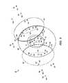
- FIGS. 1-5are schematic views of a subterranean formation 28 including organic matter. These figures show various electrodes 50 within the subterranean formation 28 along with in situ resistive heating elements 40 at various points in time, such as before, during, and/or after performance of methods 10 .
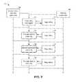
- FIG. 6is a flowchart illustrating methods 10 for pyrolyzing organic matter in a subterranean formation 28 , namely, by in situ resistive heating of the organic matter within the subterranean formation.
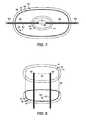
- FIGS. 7-10are schematic views of various electrode arrangements. The various electrode arrangements illustrate some of the options for configuring and/or placing electrodes 50 within a subterranean formation 28 .
- FIG. 11is a schematic cross-sectional view of a system for pyrolyzing organic matter within a subterranean formation 28 .
- FIGS. 1-5 and 7-11provide examples of systems and configurations that contain an in situ resistive heating element 40 , which may be a self-amplifying in situ heating element, and/or which are formed via methods 10 .
- Elements that serve a similar, or at least substantially similar, purposeare labeled with like numbers in each of FIGS. 1-5 and 7-11 . Each of these elements may not be discussed in detail with reference to each of FIGS. 1-5 and 7-11 . Similarly, all elements may not be labeled in each of FIGS. 1-5 and 7-11 , but reference numerals associated therewith may be used for consistency. Elements that are discussed with reference to one or more of FIGS. 1-5 and 7-11 may be included in and/or used with any of FIGS.
- FIGS. 1-5 and 7-11schematically illustrate the control and growth of in situ resistive heating elements 40 to pyrolyze organic matter within a subterranean formation 28 , such as via methods 10 .
- a subterranean formation 28may include a first region 41 which may enclose a first generation in situ resistive heating element 44 .
- a first generation in situ resistive heating element 44is an electrically conductive zone within the first region 41 .
- First region 41is in electrical contact with at least two electrodes 50 , which may be referred to as a first electrode pair 51 .
- the subterranean formation 28also may include one or more electrodes 50 that are not in electrical contact with the first generation in situ resistive heating element 44 , at least not at the time point illustrated in FIG. 1 .
- FIG. 2illustrates the subterranean formation 28 and electrode 50 arrangement of FIG. 1 after electrically powering the first generation in situ resistive heating element 44 to heat a portion of the subterranean formation 28 that includes the first generation in situ resistive heating element 44 .
- the first generation in situ resistive heating element 44may be powered via the first electrode pair 51 .
- the heatingmay cause pyrolysis of organic matter contained within the heated portion and consequently may increase the average electrical conductivity of the heated portion.
- the poweringhas resulted in an expansion of the electrically conductive zone, which may be referred to as an aggregate electrically conductive zone 48 .
- the electrically conductive zonewas coextensive with the first generation in situ resistive heating element 44 .
- the aggregate electrically conductive zone 48may be larger, i.e., expanded.
- the aggregate electrically conductive zone 48may expand sufficiently to electrically contact one or more electrodes 50 that were not initially contacted by the in situ resistive heating element 40 , i.e., prior to the expansion of the aggregate electrically conductive zone 48 . Hence, the expansion of the aggregate electrically conductive zone 48 results in the electrical contact of a pair of electrodes 50 that is distinct from the first electrode pair 51 .
- FIG. 3illustrates one or more second regions 42 that intersect the (expanded) aggregate electrically conductive zone 48 .
- Second regions 42are generally subterranean regions, adjacent to the first region 41 .
- Each second region 42encloses a portion of the aggregate electrically conductive zone 48 but is distinct/separate from first region 41 and, when present, other second region(s) 42 .
- Second region 42may intersect and/or adjoin the first region 41 .
- Second region 42may be spaced apart from the first region 41 and/or at least one other second region 42 .
- Each second region 42may include a second generation in situ resistive heating element 45 , a portion of the aggregate electrically conductive zone 48 within the second region 42 that is electrically contacted by a second electrode pair 52 .
- Each second electrode pair 52may be distinct from the first electrode pair 51 , as well as other second electrode pairs 52 .
- the second generation in situ resistive heating element 45may be used to heat the second region 42 and neighboring regions of the subterranean formation 28 . Electrically powering the second generation in situ resistive heating element 45 may heat a portion of the subterranean formation 28 that includes the second generation in situ resistive heating element 45 . The second generation in situ resistive heating element 45 may be powered via the second electrode pair 52 . The heating may cause pyrolysis of organic matter contained within the heated portion. The heating may increase the average electrical conductivity of the heated portion. In FIG. 4 , the powering has resulted in further expansion of the electrically conductive zone, resulting in an aggregate electrically conductive zone 48 that is larger than the aggregate electrically conductive zone 48 of FIG. 3 .
- FIG. 4illustrates the (further expanded) aggregate electrically conductive zone 48 after it has expanded sufficiently to electrically contact one or more electrodes 50 that were not contacted by the aggregate electrically conductive zone 48 prior to the expansion.
- the expansion of the aggregate electrically conductive zone 48results in the electrical contact of a pair of electrodes 50 that is distinct from the second electrode pair 52 .
- FIG. 4also illustrates continued expansion of the aggregate electrically conductive zone 48 as a result of continued powering of the first generation in situ resistive heating element 44 .
- Any pair of electrodes 50 within the aggregate electrically conductive zone 48may be operated independently to electrically power one or more of the first generation in situ resistive heating element 44 and the second generation in situ resistive heating element(s) 45 .
- FIG. 5illustrates one or more third regions 43 that intersect the (further expanded) aggregate electrically conductive zone 48 .
- Third regions 43are generally subterranean regions, adjacent to a second region 42 .
- Each third region 43encloses a portion of the aggregate electrically conductive zone 48 but is distinct/separate from first region 41 , second region(s) 42 , and (when present) other third region(s) 43 .
- Third region 43may intersect and/or adjoin at least one of the first region 41 and the second region(s) 42 .
- Third region 43may be spaced apart from at least one of the first region 41 , the second region(s) 42 , and/or at least one other third region 43 .
- Each third region 43may include a third generation in situ resistive heating element 46 , a portion of the aggregate electrically conductive zone 48 within the third region 43 that is electrically contacted by a third electrode pair 53 .
- Each third electrode pair 53may be distinct from the first electrode pair 51 , second pairs of electrodes 52 , and other third electrode pairs 53 .
- the third generation in situ resistive heating element 46may be used to heat the third zone 43 . Electrically powering the third generation in situ resistive heating element 46 may heat a portion of the subterranean formation 28 including the third generation in situ resistive heating element 46 .
- the third generation in situ resistive heating element 46may be powered via the third electrode pair 53 . The heating may cause pyrolysis of organic matter contained within the heated portion and consequently may increase the average electrical conductivity of the portion. The powering may result in further expansion of the aggregate electrically conductive zone 48 , potentially contacting further electrodes 50 .
- a subterranean formation 28may be any suitable structure that includes and/or contains organic matter ( FIGS. 1-5 ).
- the subterranean formation 28may contain at least one of oil shale, shale gas, coal, tar sands, organic-rich rock, kerogen, and bitumen.
- the subterranean formation 28may be a geological formation, a geological member, a geological bed, a rock stratum, a lithostratigraphic unit, a chemostratigraphic unit, and/or a biostratigraphic unit, or groups thereof.
- the subterranean formation 28may have a thickness less than 2000 m, less than 1500 m, less than 1000 m, less than 500 m, less than 250 m, less than 100 m, less than 80 m, less than 60 m, less than 40 m, less than 30 m, less than 20 m, and/or less than 10 m.
- the subterranean formation 28may have a thickness that is greater than 5 m, greater than 10 m, greater than 20 m, greater than 30 m, greater than 40 m, greater than 60 m, greater than 80 m, greater than 100 m, greater than 250 m, greater than 500 m, greater than 1000 m, and/or greater than 1500 m.
- the subterranean formationmay have a thickness of any of the preceding examples of maximum and minimum thicknesses and/or a thickness in a range that is bounded by any of the preceding examples of maximum and minimum values.
- Electrodes 50may be electrically conductive elements, typically including metal and/or carbon, that may be in electrical contact with a portion of the subterranean formation 28 . Electrical contact includes contact sufficient to transmit electrical power, including AC and DC power. Electrical contact may be established between two elements by direct contact between the elements. Two elements may be in electrical contact when indirectly linked by intervening elements, provided that the intervening elements are at least as conductive as the least conductive of the two connected elements, i.e., the intervening elements do not dominate current flow between the elements in contact.
- the conductance of an elementis proportional to its conductivity and its cross sectional area, and inversely proportional to its current path length. Hence, small elements with low conductivities may have high conductance.
- an electrode 50may be in electrical contact with the subterranean region by direct contact between the electrode 50 and the region and/or by indirect contact via suitable conductive intervening elements.
- suitable conductive intervening elementsFor example, remnants from drilling fluid (mud), though typically not highly electrically conductive (typical conductivities range from 10 ⁇ 5 S/m to 1 S/m), may be sufficiently electrically conductive to provide suitable electrical contact between an electrode 50 and a subterranean region.
- an electrode 50may be engaged directly against the wellbore, or an electrically conductive portion of the casing of the wellbore, thus causing electrical contact between the electrode and the subterranean region surrounding the wellbore.
- An electrode 50may be in electrical contact with a subterranean region through subterranean spaces (e.g., natural and/or manmade fractures; voids created by hydrocarbon production) filled with electrically conductive materials (e.g., graphite, coke, and/or metal particles).
- Electrodes 50may be operated in spaced-apart pairs (two or more electrodes), for example, a first electrode pair 51 , a second electrode pair 52 , a third electrode pair 53 , etc.
- a pair of electrodes 50may be used to electrically power an in situ resistive heating element in electrical contact with each of the electrodes 50 of the pair. Electrical power may be transmitted between more than two electrodes 50 .
- Two electrodes 50may be held at the same electrical potential while a third electrode 50 is held at a different potential.
- Two or more electrodesmay transmit AC power with each electrode transmitting a different phase of the power signal.
- Each of the first electrode pair 51 , the second electrode pair 52 , and the third electrode pair 53may be distinct, meaning each pair includes an electrode not shared with another pair.
- Electrode pairs(the first electrode pair 51 , the second electrode pair 52 , and the third electrode pair 53 ) may include at least one shared electrode 50 , provided that less than all electrodes 50 are shared with one other electrode pair.
- Electrodes 50may be contained at least partially within an electrode well 60 in the subterranean formation 28 . Electrodes 50 may be placed at least partially within an electrode well 60 . Electrode wells 60 may include one or more electrodes 50 . In the case of multiple electrodes 50 contained within one electrode well 60 , the electrodes 50 may be spaced apart and insulated from each other. One electrode well 60 may be placed for each electrode 50 , for each electrode of the first electrode pair 51 , for each electrode of the second electrode pair 52 , and/or for each electrode of the third electrode pair 53 . An electrode 50 may extend outside of an electrode well 60 and into the subterranean formation 28 , for example, through a natural and/or manmade fracture.
- An electrode well 60may include an end portion that contains at least one electrode 50 . End portions of electrode wells 60 may have a specific orientation relative to the subterranean formation 28 , regions of the subterranean formation 28 , and/or other electrode wells 60 . For example, the end portion of one of the electrode wells 60 may be co-linear with, and spaced apart from, the end portion of another of the electrode wells 60 . The end portion of one of the electrode wells 60 may be at least one of substantially parallel, parallel, substantially co-planar, and co-planar to the end portion of another of the electrode wells 60 . The end portion of one of the electrode wells 60 may converge towards or diverge away from the end portion of another of the electrode wells 60 .
- the end portion of one of the electrode wells 60may be at least one of substantially parallel, parallel, oblique, substantially perpendicular, and perpendicular to the elongate direction.
- Electrode wells 60may include a portion, optionally including the end portion, that may be at least one of horizontal, substantially horizontal, inclined, vertical, and substantially vertical. Electrode wells 60 also may include a differently oriented portion, which may be at least one of horizontal, substantially horizontal, inclined, vertical, and substantially vertical.
- a subterranean formation 28may include a production well 64 , from which hydrocarbons and/or other fluids are extracted or otherwise removed from the subterranean formation 28 .
- a production well 64may extract mobile hydrocarbons produced in the subterranean formation 28 by in situ pyrolysis.
- a production well 64may be placed in fluidic contact with at least one of the subterranean formation 28 , the first region 41 , the first generation in situ resistive heating element 44 , the second region(s) 42 , the second generation in situ resistive heating element(s) 45 , the third region(s) 43 , and the third generation in situ resistive heating element(s) 46 .
- a production well 64may be placed prior to the generation of at least one of the in situ resistive heating elements 40 .
- an electrode well 60may also serve as a production well 64 , in which case the electrode well 60 may extract mobile components from the subterranean formation 28 .
- FIG. 6illustrates methods 10 , which describe the process of iteratively expanding an aggregate electrically conductive zone 48 into electrical contact with one or more electrodes 50 that were not previously contacted by the aggregate electrically conductive zone 48 (i.e., prior to the expansion of the aggregate electrically conductive zone 48 ).
- Methods 10may comprise a first generation powering 11 of a first generation in situ resistive heating element 44 to expand an aggregate electrically conductive zone 48 .
- Methodsmay include a second generation powering 12 to heat a second generation in situ resistive heating element 45 resulting from the expanding aggregate electrically conductive zone 48 .
- First generation powering 11may include transmitting an electrical current between a first electrode pair 51 in electrical contact with the first generation in situ resistive heating element 44 .
- First generation powering 11may cause resistive heating within the first generation in situ resistive heating element 44 and consequently pyrolysis within the first region 41 and neighboring regions within the subterranean formation 28 .
- one or more second regions 42each adjacent the first region 41 , may be heated and pyrolyzed by the first generation powering 11 .
- Pyrolyzing a second region 42 by the first generation powering 11may include increasing an average electrical conductivity of the second region 42 sufficiently to expand the aggregate electrically conductive zone 48 into the second region 42 .
- the expansion of the aggregate electrically conductive zone 48may cause electrical contact with an electrode 50 that extends within the second region 42 and/or that is outside the first region 41 .
- the electrode 50may extend within the second region 42 and/or be outside the first region 41 before, during, or after the expansion of the aggregate electrically conductive zone 48 .
- Second generation powering 12may include electrically powering a second generation in situ resistive heating element 45 using a second electrode pair 52 , by transmitting an electrical current between the electrodes 50 .
- Second generation powering 12may cause resistive heating within the second generation in situ resistive heating element 45 and consequently pyrolysis within the second region 42 and neighboring regions within the subterranean formation 28 .
- one or more third regions 43adjacent at least one second region 42 , may be heated and pyrolyzed by the second generation powering 12 .
- Pyrolyzing a third region 43 by the second generation powering 12may include increasing an average electrical conductivity of the third region 43 sufficiently to expand the aggregate electrically conductive zone 48 into the third region 43 .
- the expansion of the aggregate electrically conductive zone 48may cause electrical contact with an electrode 50 that extends within the third region 43 and/or that is outside the first region 41 and the second region(s) 42 .
- the electrode 50may extend within the third region 43 and/or be outside the first region 41 and the second region(s) 42 before, during, or after the expansion of the aggregate electrically conductive zone 48 .
- Third generation powering 13may include electrically powering a third generation in situ resistive heating element 46 using a third electrode pair 53 , by transmitting an electrical current between the electrodes 50 .
- Third generation powering 13may cause resistive heating within the third generation in situ resistive heating element 46 .
- Third generation powering 13may cause pyrolysis within the third region 43 .
- Third generating powering 13may cause pyrolysis within neighboring regions within the subterranean formation 28 . For example, one or more fourth regions, adjacent at least one third region 43 , may be heated and pyrolyzed by the third generation powering 13 .
- the iterative cycle of powering an in situ resistive heating element 40 , thereby expanding the aggregate electrically conductive zone 48 , and powering another in situ resistive heating element 40 within the expanded aggregate electrically conductive zone 48may continue to a fourth generation, a fifth generation, etc., as indicated by the continuation lines at the bottom of FIG. 6 .
- each in situ resistive heating element 40may be independent and/or may be independently controlled.
- First generation powering 11 , second generation powering 12 , third generation powering 13 , etc.may occur at least partially concurrently and/or at least partially sequentially.
- second generation powering 12may sequentially follow the completion of first generation powering 11 .
- Third generation poweringmay sequentially follow the completion of second generation powering 12 .
- First generation powering 11may cease before, during, or after either of second generation powering 12 and third generation powering 13 .
- Second generation powering 12may include at least partially sequentially and/or at least partially concurrently powering each of the second generation in situ resistive heating element(s) 45 .
- Third generation powering 13may include at least partially sequentially and/or at least partially concurrently powering each of the third generation in situ resistive heating element(s) 46 .
- Concurrently poweringmay include at least partially concurrently performing the first generation powering 11 , the second generation powering 12 , and/or the third generation powering 13 ; or at least partially concurrently powering two or more second generation in situ resistive heating element(s) 45 and/or third generation in situ resistive heating element(s) 46 .
- Concurrently poweringmay include partitioning electrical power between the active (powered) in situ resistive heating elements 40 .
- beginning the second generation powering 12may include reducing power to the first generation in situ resistive heating element 44 and/or ceasing the first generation powering 11 .
- Second generation powering 12may include powering two second generation in situ resistive heating element(s) 46 with unequal electrical powers.
- Third generation powering 13may include reducing power to one or more second generation in situ resistive heating element(s) 45 and/or the first generation in situ resistive heating element 44 .
- independent control of in situ resistive heating elements 40effectively may be utilized to split and/or partition the aggregate electrically conductive zone 48 into several independent active in situ resistive heating elements 40 .
- These independently-controlled in situ resistive heating elements 40may remain in electrical contact with each other, or, because of changing conductivity due to heating (and/or overheating), may not be in electrical contact with at least one other in situ resistive heating element 40 .
- First generation powering 11 , second generation powering 12 , and/or third generation powering 13may include transmitting electrical current for a suitable time to pyrolyze organic matter within the corresponding region of the subterranean formation 28 and to expand the in situ resistive heating element 40 into a produced electrically conductive zone in an adjacent region of the subterranean formation.
- first generation powering 11 , second generation powering 12 , and/or third generation powering 13each independently may include transmitting electrical current for at least one day, at least one week, at least two weeks, at least three weeks, at least one month, at least two months, at least three months, at least four months, at least five months, at least six months, at least one year, at least two years, at least three years, at least four years, or within a range that includes or is bounded by any of the preceding examples of time.
- Methods 10may comprise pyrolyzing 14 at least a portion of the first region 41 , for example, to generate an aggregate electrically conductive zone 48 and/or a first generation in situ resistive heating element 44 within the first region 41 .
- the pyrolyzing 14may include heating the first region 41 . Heating may be accomplished, for example, using a conventional heating element 58 or initiating combustion within the subterranean formation 28 .
- a conventional heating element 58may be or include a wellbore heater and/or a granular resistive heater (a heater formed with resistive materials placed within a wellbore or the subterranean formation 28 ).
- Pyrolyzing 14 the first region 41may include transmitting electrical current between electrodes 50 (e.g., a first electrode pair 51 ) in electrical contact with the first region 41 (e.g., by electrolinking). Pyrolyzing 14 the first region 41 may include transmitting electrical current between electrodes 50 (e.g., a first electrode pair 51 ) in electrical contact with the first generation in situ resistive heating element 44 , once the first generation in situ resistive heating element 44 begins to form. Pyrolyzing 14 the first region 41 may include generating heat with the first generation in situ resistive heating element 44 to heat the first region 41 . Pyrolyzing the first region 41 may include increasing an average electrical conductivity of the first region 41 .
- Methods 10may comprise determining 15 a desired geometry of an in situ resistive heating element 40 and/or the aggregate electrically conductive zone 48 .
- the determining 15may occur prior to first generation powering 11 , the second generation powering 12 , and/or the third generation powering 13 .
- the determining 15may be at least partially based on data relating to at least one of the subterranean formation 28 and the organic matter in the subterranean formation 28 .
- the determining 15may be based upon geophysical data relating to a shape, an extent, a volume, a composition, a density, a porosity, a permeability, and/or an electrical conductivity of the subterranean formation 28 and/or a region of the subterranean formation 28 .
- Determining 15may include estimating, modeling, forecasting and/or measuring the heating, pyrolyzing, electrical conductivity, permeability, and/or hydrocarbon production of the subterranean formation 28 and/or a region of the subterranean formation 28 .
- Methods 10may comprise placing 16 electrodes 50 into electrical contact with at least a portion of the subterranean formation 28 .
- placing 16may include placing the first electrode pair 51 into electrical contact with the first generation in situ resistive heating element 44 and/or the first region 41 .
- Placing 16may include placing at least one of the second electrode pair 52 into electrical contact with the second region 42 .
- placing 16may include placing at least one of the second electrode pair 52 within the subterranean formation 28 outside of the first generation in situ resistive heating element 44 .
- Electrodes 50may be placed in anticipation of growth of the aggregate electrically conductive zone 48 .
- Electrodes 50may be placed to guide and/or direct the aggregate electrically conductive zone 48 toward subterranean regions of potentially higher productivity and/or of higher organic matter content.
- Placing 16may occur at any time. Placing 16 an electrode 50 may be more convenient and/or practical before heating the portion of the subterranean formation 28 that will neighbor (i.e., be adjacent to), much less include, the placed electrode 50 .
- the first electrode pair 51may be placed 16 into electrical contact with the first region 41 prior to the creation of the first generation in situ resistive heating element 44 .
- the second electrode pair 52may be placed into electrical contact with the second region 42 prior to the creation of the first generation in situ resistive heating element 44 and/or the second generation in situ resistive heating element 45 .
- the second electrode pair 52may be placed within the subterranean formation 28 outside of the first region 41 prior to the creation of the first generation in situ resistive heating element 44 and/or the second generation in situ resistive heating element 45 . Placing 16 may occur after determining 15 a desired geometry for an in situ resistive heating element 40 and/or the aggregate electrically conductive zone 48 .
- Placing 16 electrodes 50 into electrical contact with at least a portion of the subterranean formation 28may include placing an electrode well 60 that contains at least one electrode 50 . Placing 16 also may include placing an electrode 50 into an electrode well 60 . Placing electrode wells 60 may occur at any time prior to electrical contact of the electrodes 50 with the subterranean formation 28 . In particular, similar to the placing 16 of electrodes 50 , placing an electrode well 60 may be more convenient and/or practical before heating the portion of the subterranean formation 28 that will neighbor and/or include the placed electrode well 60 . For example, drilling a well may be difficult at temperatures above the boiling point of drilling fluid components.
- An electrode well 60may be placed into the subterranean formation 28 prior to the creation of the first generation in situ resistive heating element 44 and/or the second generation in situ resistive heating element 45 .
- An electrode well 60may be placed within the subterranean formation 28 outside of the first region 41 prior to the creation of the first generation in situ resistive heating element 44 and/or the second generation in situ resistive heating element 45 .
- An electrode well 60may be placed within the subterranean formation 28 after the determining 15 a desired geometry.
- Methods 10may comprise regulating 17 the creation of an in situ resistive heating element 40 and/or pyrolyzation of a subterranean region.
- Regulating 17may include monitoring a parameter before, during, and/or after powering (e.g., first generation powering 11 , second generation powering 12 , third generation powering 13 , etc.).
- Regulating 17may include monitoring a parameter before, during, and/or after pyrolyzing.
- the monitored parametermay relate to at least one of the subterranean formation 28 and the organic matter in the subterranean formation 28 .
- the monitored parametermay include geophysical data relating to a shape, an extent, a volume, a composition, a density, a porosity, a permeability, an electrical conductivity, an electrical property, a temperature, and/or a pressure of the subterranean formation 28 and/or a region of the subterranean formation 28 .
- the monitored parametermay relate to the production of mobile components within the subterranean formation 28 (e.g., hydrocarbon production).
- the monitored parametermay relate to the electrical power applied to at least a portion of the subterranean formation 28 .
- the monitored parametermay include at least one of the duration of applied electrical power, the magnitude of electrical power applied, and the magnitude of electrical current transmitted.
- the magnitudemay include the average value, the peak value, and/or the integrated total value.
- Regulating 17may include adjusting subsequent powering and/or pyrolyzing based upon a monitored parameter and/or based upon a priori data relating to the subterranean formation 28 .
- a priori datamay relate to estimates, models, and/or forecasts of the heating, pyrolyzing, electrical conductivity, permeability, and/or hydrocarbon production of the subterranean formation 28 and/or a region of the subterranean formation 28 .
- Regulating 17may include adjusting subsequent powering and/or pyrolyzing when a monitored parameter and/or a priori data are greater than, equal to, or less than a predetermined threshold.
- the adjustingmay include starting, stopping, and/or continuing the powering of at least one in situ resistive heating element 40 .
- the adjustingmay include powering with an adjusted electrical power, electrical current, electrical polarity, and/or electrical power phase.
- Regulating 17may include partitioning electrical power among a plurality of in situ resistive heating elements 40 .
- first generation powering 11 , second generation powering 12 , and/or third generation powering 13may be regulated to control the growth of the aggregate electrically conductive zone 48 .
- Partitioning the electrical powermay include controlling at least one of the duration of applied electrical power, the magnitude of electrical power applied, and the magnitude of electrical current transmitted.
- the magnitudemay include the average value, the peak value, and/or the integrated total value.
- FIGS. 7-10illustrate arrangements of electrodes 50 within a subterranean formation 28 that may be suitable for systems 30 and/or for carrying out methods 10 . Any of the electrodes 50 illustrated in FIGS. 7-10 may be substituted for any one or more electrodes 50 illustrated in FIGS. 1-5 and 11 . Moreover, though the FIGS. 7-10 illustrate a first region 41 and a second region 42 (and corresponding components), the electrode arrangements of FIGS. 7-10 are equally applicable to any subterranean region and/or any in situ resistive heating element 40 .
- FIG. 7illustrates a collinear, spaced-apart first electrode pair 51 .
- the in situ resistive heating element 40may heat and pyrolyze neighboring subterranean regions. The heating and pyrolyzing may cause an aggregate electrically conductive zone 48 to expand along the elongated dimension of each of the electrodes 50 . As the aggregate electrically conductive zone 48 expands, the degree and/or extent of electrical contact between the aggregate electrically conductive zone 48 and at least one of the electrodes 50 may increase.
- Electrodes 50may be configured for extended electrical contact when. Electrodes may be configured for extended electrical contact when an electrode is contained within a porous and/or perforated electrode well 60 . Electrodes 50 at least partially contained within a natural and/or manmade fracture within the subterranean formation 28 may have extended electrical contact with a portion of the subterranean formation 28 .
- FIG. 7illustrates a structure that may be used to generate an initial in situ resistive heating element 40 within the subterranean formation 28 .
- An electrode well 60or generally the subterranean formation 28 , may contain a conventional heating element 58 , such as a wellbore heater.
- the conventional heating element 58is schematically depicted as being located in an electrode well 60 within a horizontal portion of the well, although conventional heating element 58 also may be located within a vertical or other angularly oriented portion of the well.
- On either side of the conventional heating element 58within the same electrode well 60 , may be an electrode 50 , such as one formed from graphite, coke, and/or metal particles packed into the electrode well 60 .
- the conventional heating element 58 and the two electrodes 50may have independent electrical connections to one or more electrical power sources.
- a first region 41 of the subterranean formation 28may be heated and pyrolyzed to generate a first generation in situ resistive heating element 44 .
- the first generation in situ resistive heating element 44may be electrically powered via the first electrode pair 51 .
- FIG. 8illustrates a first electrode pair 51 with a parallel portion, each electrode 50 of the pair configured for extended electrical contact.
- the in situ resistive heating element 40may heat and pyrolyze neighboring subterranean regions, causing an aggregate electrically conductive zone 48 to expand along the length of the parallel electrodes, generally perpendicular to the shortest direction between the electrodes 50 .
- the aggregate electrically conductive zone 48expands, the degree and/or extent of electrical contact between the aggregate electrically conductive zone 48 and at least one of the electrodes 50 may increase.
- FIG. 9illustrates a first electrode pair 51 with a diverging portion, each electrode 50 of the pair configured for extended electrical contact.
- a portion of a pair of electrodes 50may be considered diverging if the portion is not generally parallel, e.g., the distance between the electrodes 50 at one end is greater than the distance between the electrodes 50 at another end.
- the distance between the first electrode pair 51 within the first generation in situ resistive heating element 44may be greater than the distance between the same electrodes 50 within the second generation in situ resistive heating element 45 .
- the in situ resistive heating element 40When an in situ resistive heating element 40 in electrical contact with a diverging pair of electrodes 50 is electrically powered, the in situ resistive heating element 40 may heat and pyrolyze neighboring subterranean regions, causing an aggregate electrically conductive zone 48 to expand along the length of the diverging electrodes. Where the electrodes 50 converge away from the in situ resistive heating element 40 (i.e., the closest approach of the electrodes 50 is not within the in situ resistive heating element 40 ), the electrical current passing through the expanding aggregate electrically conductive zone 48 , and thus the greatest resistive heating, may concentrate away from the in situ resistive heating element 40 .
- the electrical current and the greatest resistive heatingmay concentrate within the in situ resistive heating element 40 .
- the greater heating at a shorter electrode spacingmay increase the speed of the pyrolysis and expansion of the aggregate electrically conductive zone 48 .
- FIG. 10illustrates two second generation in situ resistive heating elements 45 at a point when both might be powered simultaneously.
- the electrical polarity and/or electrical phase of the second pairs of electrodes 52may be configured to avoid crosstalk between the upper and lower second generation in situ resistive heating elements 45 .
- the left electrode 50 of each second electrode pair 52may share a similar electrical polarity and/or electrical phase, as indicated by the circled plus signs.
- the right electrode 50 of each second electrode pair 52may share a similar electrical polarity and/or electrical phase, as indicated by the circled minus signs.
- left electrodes 50had roughly opposite polarities and/or phases (e.g., 180° out of phase), electrical current would tend to flow predominantly between the left electrodes 50 instead of between either of the two second electrode pairs 52 , owing to the shorter electrical path length (and hence likely lesser resistance and higher conductance) between the left electrodes 50 than either second electrode pair 52 .
- upper, lower, left, and rightrefer to the figure on the page, not to the subterranean formation 28 .
- FIG. 11schematically depicts examples of systems 30 for pyrolyzing organic matter within a subterranean formation 28 .
- Systems 30may comprise a first electrode pair 51 electrically connected to a first generation in situ resistive heating element 44 in a first region 41 within the subterranean formation 28 .
- Systems 30may comprise a second electrode pair 52 electrically connected to a second region 42 within the subterranean formation 28 , where the second region 42 is adjacent the first region 41 .
- Systems 30may comprise at least one second region 42 , and optionally a plurality of second regions 42 , each adjacent the first region 41 and each electrically connected to a distinct second electrode pair 52 .
- each second region 42may comprise a second generation in situ resistive heating element 45 .
- Systems 30may comprise at least one third region 43 , each adjacent at least one second region 42 and each electrically connected to a distinct third electrode pair 53 .
- each third region 43may comprise a third generation in situ resistive heating element 46 .
- Each electrode 50may be contained at least partially within an electrode well 60 .
- An electrode 50may extend into the subterranean formation 28 , outside of an electrode well 60 , for example, through a natural and/or manmade fracture.
- An electrode well 60may contain one or more electrodes 50 and other active components, such as a conventional heating element 58 .
- Systems 30may comprise an electrical power source 31 electrically connected through the first electrode pair 51 to the first generation in situ resistive heating element 44 . Further, systems 30 may comprise an electrical power switch 33 that electrically connects (potentially sequentially or simultaneously) the electrical power source 31 to the first electrode pair 51 and the second electrode pair 52 .
- Systems 30may comprise a sensor 32 to monitor a monitored parameter relating to at least one of the subterranean formation 28 and the organic matter in the subterranean formation 28 .
- the monitored parametermay include geophysical data relating to a shape, an extent, a volume, a composition, a density, a porosity, a permeability, an electrical conductivity, an electrical property, a temperature, and/or a pressure of the subterranean formation 28 and/or a region of the subterranean formation 28 .
- the monitored parametermay relate to the production of mobile components within the subterranean formation 28 (e.g., hydrocarbon production).
- the monitored parametermay relate to the electrical power applied to at least a portion of the subterranean formation 28 .
- the monitored parametermay include the at least one of the duration of applied electrical power, the magnitude of electrical power applied, and the magnitude of electrical current transmitted.
- the magnitudemay include the average value, the peak value, and/or the integrated total value.
- Systems 30may comprise a production well 64 , from which mobile components (e.g., hydrocarbon fluids) are extracted or otherwise removed from at least one of the first region 41 , the second region(s) 42 , the third region(s) 43 , and/or the subterranean formation 28 .
- the production well 64may be fluidically connected to at least one of the first region 41 , the second region(s) 42 , the third region(s) 43 , and/or the subterranean formation 28 .
- Systems 30may comprise a controller 34 that is programmed or otherwise configured to control, or regulate, at least a portion of the operation of system 30 .
- controller 34may control the electrical power source 31 , record the sensor 32 output, and/or regulate the system 30 , the first generation in situ resistive heating element 44 , the second generation in situ resistive heating element 45 , and/or the third generation in situ resistive heating element 46 .
- the controller 34may be programmed or otherwise configured to control system 30 according to any of the methods described herein.
- the term “and/or” placed between a first entity and a second entitymeans one of (1) the first entity, (2) the second entity, and (3) the first entity and the second entity.
- Multiple entities listed with “and/or”should be construed in the same manner, i.e., “one or more” of the entities so conjoined.
- Other entitiesmay optionally be present other than the entities specifically identified by the “and/or” clause, whether related or unrelated to those entities specifically identified.
- the phrase “at least one,” in reference to a list of one or more entitiesshould be understood to mean at least one entity selected from any one or more of the entity in the list of entities, but not necessarily including at least one of each and every entity specifically listed within the list of entities and not excluding any combinations of entities in the list of entities.
- This definitionalso allows that entities may optionally be present other than the entities specifically identified within the list of entities to which the phrase “at least one” refers, whether related or unrelated to those entities specifically identified.
- adaptedand “configured” mean that the element, component, or other subject matter is designed and/or intended to perform a given function.
- the use of the terms “adapted” and “configured”should not be construed to mean that a given element, component, or other subject matter is simply “capable of” performing a given function but that the element, component, and/or other subject matter is specifically selected, created, implemented, utilized, programmed, and/or designed for the purpose of performing the function.
- elements, components, and/or other recited subject matter that is recited as being adapted to perform a particular functionmay additionally or alternatively be described as being configured to perform that function, and vice versa.
Landscapes
- Life Sciences & Earth Sciences (AREA)
- Engineering & Computer Science (AREA)
- Geology (AREA)
- Mining & Mineral Resources (AREA)
- Physics & Mathematics (AREA)
- Environmental & Geological Engineering (AREA)
- Fluid Mechanics (AREA)
- General Life Sciences & Earth Sciences (AREA)
- Geochemistry & Mineralogy (AREA)
- Resistance Heating (AREA)
- Geophysics (AREA)
Abstract
Description
This application claims the priority benefit of U.S. Provisional Patent Application 61/901,234 filed Nov. 7, 2013 entitled SYSTEMS AND METHODS FOR IN SITU RESISTIVE HEATING OF ORGANIC MATTER IN A SUBTERRANEAN FORMATION, the entirety of which is incorporated by reference herein.
The present disclosure is directed generally to systems and methods for in situ resistive heating of organic matter in a subterranean formation, and more particularly to systems and methods for controlling the growth of in situ resistive heating elements in the subterranean formation.
Certain subterranean formations may include organic matter, such as shale oil, bitumen, and/or kerogen, which have material and chemical properties that may complicate production of fluid hydrocarbons from the subterranean formation. For example, the organic matter may not flow at a rate sufficient for production. Moreover, the organic matter may not include sufficient quantities of desired chemical compositions (typically smaller hydrocarbons). Hence, recovery of useful hydrocarbons from such subterranean formations may be uneconomical or impractical.
Generally, organic matter is subject to decompose upon exposure to heat over a period of time, via a process called pyrolysis. Upon pyrolysis, organic matter, such as kerogen, may decompose chemically to produce hydrocarbon oil, hydrocarbon gas, and carbonaceous residue (the residue may be referred to generally as coke). Coke formed by pyrolysis typically has a richer carbon content than the source organic matter from which it was formed. Small amounts of water also may be generated via the pyrolysis reaction. The oil, gas, and water fluids may become mobile within the rock or other subterranean matrix, while the residue coke remains essentially immobile.
One method of heating and causing pyrolysis includes using electrically resistive heaters, such as wellbore heaters, placed within the subterranean formation. However, electrically resistive heaters have a limited heating range. Though heating may occur by radiation and/or conduction to heat materials far from the well, to do so, a heater typically will heat the region near the well to very high temperatures for very long times. In essence, conventional methods for heating regions of a subterranean formation far from a well may involve overheating the nearby material in an attempt to heat the distant material. Such uneven application of heat may result in suboptimal production from the subterranean formation. Additionally, using wellbore heaters in a dense array to mitigate the limited heating distance may be cumbersome and expensive. Thus, there exists a need for more economical and efficient heating of subterranean organic matter to pyrolyze the organic matter.
The present disclosure provides systems and methods for in situ resistive heating of organic matter in a subterranean formation to enhance hydrocarbon production.
A method for pyrolyzing organic matter in a subterranean formation may comprise powering a first generation in situ resistive heating element within an aggregate electrically conductive zone at least partially in a first region of the subterranean formation by transmitting an electrical current between a first electrode pair in electrical contact with the first generation in situ resistive heating element to pyrolyze a second region of the subterranean formation, adjacent the first region, to expand the aggregate electrically conductive zone into the second region, wherein the expanding creates a second generation in situ resistive heating element within the second region and powering the second generation in situ resistive heating element by transmitting an electrical current between a second electrode pair in electrical contact with the second generation in situ resistive heating element to generate heat with the second generation in situ resistive heating element within the second region, wherein at least one electrode of the second electrode pair extends within the second region.
A method for pyrolyzing organic matter in a subterranean formation may comprise transmitting a first electrical current in the subterranean formation between a first electrode pair in electrical contact with a first generation in situ resistive heating element, powering a first generation in situ resistive heating element, within an aggregate electrically conductive zone at least partially in a first region of the subterranean formation, with the first electrical current, and expanding the aggregate electrically conductive zone into a second region, adjacent the first region of the subterranean formation, with the first electrical current. The expanding may create a second generation in situ resistive heating element within the second region. The method further may comprise transmitting a second electrical current in the subterranean formation between a second electrode pair in electrical contact with the second generation in situ resistive heating element, powering the second generation in situ resistive heating element with the second electrical current, and generating heat with the second generation in situ resistive heating element within the second region, wherein at least one electrode of the second electrode pair extends within the second region.
The foregoing has broadly outlined the features of the present disclosure so that the detailed description that follows may be better understood. Additional features will also be described herein.
These and other features, aspects and advantages of the disclosure will become apparent from the following description, appending claims and the accompanying drawings, which are briefly described below.
It should be noted that the figures are merely examples and no limitations on the scope of the present disclosure are intended thereby. Further, the figures are generally not drawn to scale, but are drafted for purposes of convenience and clarity in illustrating various aspects of the disclosure.
For the purpose of promoting an understanding of the principles of the disclosure, reference will now be made to the features illustrated in the drawings and specific language will be used to describe the same. It will nevertheless be understood that no limitation of the scope of the disclosure is thereby intended. Any alterations and further modifications, and any further applications of the principles of the disclosure as described herein are contemplated as would normally occur to one skilled in the art to which the disclosure relates. It will be apparent to those skilled in the relevant art that some features that are not relevant to the present disclosure may not be shown in the drawings for the sake of clarity.
Thermal generation and stimulation techniques may be used to produce subterranean hydrocarbons within, for example, subterranean regions within a subterranean formation that contain and/or include organic matter, and which may include large hydrocarbon molecules (e.g., heavy oil, bitumen, and/or kerogen). Hydrocarbons may be produced by heating for a sufficient period of time. In some instances, it may be desirable to perform in situ upgrading of the hydrocarbons, i.e., conversion of the organic matter to more mobile forms (e.g., gas or liquid) and/or to more useful forms (e.g., smaller, energy-dense molecules). In situ upgrading may include performing at least one of a shale oil retort process, a shale oil heat treating process, a hydrogenation reaction, a thermal dissolution process, and an in situ shale oil conversion process. An shale oil retort process, which also may be referred to as destructive distillation, involves heating oil shale in the absence of oxygen until kerogen within the oil shale decomposes into liquid and/or gaseous hydrocarbons. In situ upgrading via a hydrogenation reaction includes reacting organic matter with molecular hydrogen to reduce, or saturate, hydrocarbons within the organic matter. In situ upgrading via a thermal dissolution process includes using hydrogen donors and/or solvents to dissolve organic matter and to crack kerogen and more complex hydrocarbons in the organic matter into shorter hydrocarbons. Ultimately, the in situ upgrading may result in liquid and/or gaseous hydrocarbons that may be extracted from the subterranean formation.
When the in situ upgrading includes pyrolysis (thermochemical decomposition), in addition to producing liquid and/or gaseous hydrocarbons, a residue of carbonaceous coke may be produced in the subterranean formation. Pyrolysis of organic matter may produce at least one of liquid hydrocarbons, gaseous hydrocarbons, shale oil, bitumen, pyrobitumen, bituminous coal, and coke. For example, pyrolysis of kerogen may result in hydrocarbon gas, shale oil, and/or coke. Generally, pyrolysis occurs at elevated temperatures. For example, pyrolysis may occur at temperatures of at least 250° C., at least 350° C., at least 450° C., at least 550° C., at least 700° C., at least 800° C., at least 900° C., and/or within a range that includes or is bounded by any of the preceding examples of pyrolyzation temperatures. As additional examples, it may be desirable not to overheat the region to be pyrolyzed. Examples of pyrolyzation temperatures include temperatures that are less than 1000° C., less than 900° C., less than 800° C., less than 700° C., less than 550° C., less than 450° C., less than 350° C., less than 270° C., and/or within a range that includes or is bounded by any of the preceding examples of pyrolyzation temperatures.
Bulk rock in asubterranean formation 28 may contain organic matter. Bulk rock generally has a low electrical conductivity (equivalently, a high electrical resistivity), typically on the order of 10−7-10−4S/m (a resistivity of about 104-107Ωm). For example, the average electrical conductivity within a subterranean formation, or a region within the subterranean formation, may be less than 10−3S/m, less than 10−4S/m, less than 10−5S/m, less than 10−6S/m, and/or within a range that includes or is bounded by any of the preceding examples of average electrical conductivities. Most types of organic matter found in subterranean formations have similarly low conductivities. However, the residual coke resulting from pyrolysis is relatively enriched in carbon and has a relatively higher electrical conductivity. For example, Green River oil shale (a rock including kerogen) may have an average electrical conductivity in ambient conditions of about 10−7-10−6S/m. As the Green River oil shale is heated to between about 300° C. and about 600° C., the average electrical conductivity may rise to greater than 10−5S/m, greater than 1 S/m, greater than 100 S/m, greater than 1,000 S/m, even greater than 10,000 S/m, or within a range that includes or is bounded by any of the preceding examples of electrical conductivities. This increased electrical conductivity may remain even after the rock returns to lower temperatures.
Continued heating (increasing temperature and/or longer duration) may not result in further increases of the electrical conductivity of a subterranean region. Other components of the subterranean formation, e.g., carbonate minerals such as dolomite and calcite, may decompose at a temperature similar to useful pyrolysis temperatures. For example, dolomite may decompose at about 550° C., while calcite may decompose at about 700° C. Decomposition of carbonate minerals generally results in carbon dioxide, which may reduce the electrical conductivity of subterranean regions neighboring the decomposition. For example, decomposition may result in an average electrical conductivity in the subterranean regions of less than 0.1 S/m, less than 0.01 S/m, less than 10−3S/m, less than 10−4S/m, less than 10−5S/m, and/or within a range that includes or is bounded by any of the preceding examples of average electrical conductivities.
If a pyrolyzed subterranean region has sufficient electrical conductivity, generally greater than about 10−5S/m, the region may be described as an electrically conductive zone. An electrically conductive zone may include bitumen, pyrobitumen, bituminous coal, and/or coke produced by pyrolysis. An electrically conductive zone is a region within a subterranean formation that has an electrical conductivity greater than, typically significantly greater than, the unaffected bulk rock of the subterranean formation. For example, the average electrical conductivity of an electrically conductive zone may be at least 10−5S/m, at least 10−4S/m, at least 10−3S/m, at least 0.01 S/m, at least 0.1 S/m, at least 1 S/m, at least 10 S/m, at least 100 S/m, at least 300 S/m, at least 1,000 S/m, at least 3,000 S/m, at least 10,000 S/m, and/or within a range that includes or is bounded by any of the preceding examples of average electrical conductivities.
The residual coke after pyrolysis may form an electrically conductive zone that may be used to conduct electricity and act as an in situ resistive heating element for continued upgrading of the hydrocarbons. An in situ resistive heating element may include an electrically conductive zone that has a conductivity sufficient to cause ohmic losses, and thus resistive heating, when electrically powered by at least two electrodes. For example, the average electrical conductivity of an in situresistive heating element 40 may be at least 10−5S/m, at least 10−4S/m, at least 10−3S/m, at least 0.01 S/m, at least 0.1 S/m, at least 1 S/m, at least 10 S/m, at least 100 S/m, at least 300 S/m, at least 1,000 S/m, at least 3,000 S/m, and/or at least 10,000 S/m, and/or within a range that includes or is bounded by any of the preceding examples of average electrical conductivities. An in situresistive heating element 40 that can expand, such as due to the heat produced by the resistive heating element, also may be referred to as a self-amplifying heating element.
When electrical power is applied to the in situ resistive heating element, resistive heating heats the heating element. Neighboring (i.e., adjacent, contiguous, and/or abutting) regions of the subterranean formation may be heated primarily by conduction of the heat from the in situ resistive heating element. The heating of the subterranean formation, including the organic matter, may cause pyrolysis and consequent increase in conductivity of the subterranean region. Under voltage-limited conditions (e.g., approximately constant voltage conditions), an increase in conductivity (decrease in resistivity) causes increased resistive heating. Hence, as electrical power is applied to the in situ resistive heating element, the heating of neighboring regions creates more electrically conductive zones. These zones may become a part of a growing, or expanding, electrically conductive zone and in situ resistive heating element, provided that sufficient current can continue to be supplied to the (expanding) in situ resistive heating element. Alternatively expressed, as the subterranean regions adjacent to the actively heated in situ resistive heating element become progressively more conductive, the electrical current path begins to spread to these newly conductive regions and thereby expands the extent of the in situ resistive heating element.
For subterranean regions that contain interfering components such as carbonate minerals, the pyrolysis and the expansion of the in situ resistive heating element may be accompanied by a local decrease in electrical conductivity (e.g., resulting from the decomposition of carbonate in the carbonate minerals and/or other interfering components). Generally, decomposition of any such interfering components occurs in the hottest part of the expanding in situ resistive heating element, e.g., the central volume, or core, of the heating element. These two effects, an expanding exterior of the in situ resistive heating element and an expanding low conductivity core, may combine to form a shell of rock that is actively heating. A shell-shaped in situ resistive heating element may be beneficial because the active heating would be concentrated in the shell, generally a zone near unpyrolyzed regions of the subterranean formation. The central volume, which was already pyrolyzed, may have little to no further active heating. Aside from concentrating the heating on a more useful (such as a partially or to-be-pyrolyzed) subterranean region, the shell configuration also may reduce the total electrical power requirements to power the shell-shaped in situ resistive heating element as compared to a full-volume in situ resistive heating element.
Generally,FIGS. 1-5 and 7-11 schematically illustrate the control and growth of in situresistive heating elements 40 to pyrolyze organic matter within asubterranean formation 28, such as viamethods 10. As viewed inFIG. 1 , asubterranean formation 28 may include afirst region 41 which may enclose a first generation in situresistive heating element 44. A first generation in situresistive heating element 44 is an electrically conductive zone within thefirst region 41.First region 41 is in electrical contact with at least twoelectrodes 50, which may be referred to as afirst electrode pair 51. Thesubterranean formation 28 also may include one ormore electrodes 50 that are not in electrical contact with the first generation in situresistive heating element 44, at least not at the time point illustrated inFIG. 1 .
The aggregate electricallyconductive zone 48 may expand sufficiently to electrically contact one ormore electrodes 50 that were not initially contacted by the in situresistive heating element 40, i.e., prior to the expansion of the aggregate electricallyconductive zone 48. Hence, the expansion of the aggregate electricallyconductive zone 48 results in the electrical contact of a pair ofelectrodes 50 that is distinct from thefirst electrode pair 51.
Once electrical contact between thesecond electrode pair 52 and the aggregate electricallyconductive zone 48 is established, forming a second generation in situresistive heating element 45, the second generation in situresistive heating element 45 may be used to heat thesecond region 42 and neighboring regions of thesubterranean formation 28. Electrically powering the second generation in situresistive heating element 45 may heat a portion of thesubterranean formation 28 that includes the second generation in situresistive heating element 45. The second generation in situresistive heating element 45 may be powered via thesecond electrode pair 52. The heating may cause pyrolysis of organic matter contained within the heated portion. The heating may increase the average electrical conductivity of the heated portion. InFIG. 4 , the powering has resulted in further expansion of the electrically conductive zone, resulting in an aggregate electricallyconductive zone 48 that is larger than the aggregate electricallyconductive zone 48 ofFIG. 3 .
Once electrical contact between thethird electrode pair 53 and the aggregate electricallyconductive zone 48 is established, forming a third generation in situresistive heating element 46, the third generation in situresistive heating element 46 may be used to heat thethird zone 43. Electrically powering the third generation in situresistive heating element 46 may heat a portion of thesubterranean formation 28 including the third generation in situresistive heating element 46. The third generation in situresistive heating element 46 may be powered via thethird electrode pair 53. The heating may cause pyrolysis of organic matter contained within the heated portion and consequently may increase the average electrical conductivity of the portion. The powering may result in further expansion of the aggregate electricallyconductive zone 48, potentially contactingfurther electrodes 50.
Asubterranean formation 28 may be any suitable structure that includes and/or contains organic matter (FIGS. 1-5 ). For example, thesubterranean formation 28 may contain at least one of oil shale, shale gas, coal, tar sands, organic-rich rock, kerogen, and bitumen. Thesubterranean formation 28 may be a geological formation, a geological member, a geological bed, a rock stratum, a lithostratigraphic unit, a chemostratigraphic unit, and/or a biostratigraphic unit, or groups thereof. Thesubterranean formation 28 may have a thickness less than 2000 m, less than 1500 m, less than 1000 m, less than 500 m, less than 250 m, less than 100 m, less than 80 m, less than 60 m, less than 40 m, less than 30 m, less than 20 m, and/or less than 10 m. Thesubterranean formation 28 may have a thickness that is greater than 5 m, greater than 10 m, greater than 20 m, greater than 30 m, greater than 40 m, greater than 60 m, greater than 80 m, greater than 100 m, greater than 250 m, greater than 500 m, greater than 1000 m, and/or greater than 1500 m. Additionally, the subterranean formation may have a thickness of any of the preceding examples of maximum and minimum thicknesses and/or a thickness in a range that is bounded by any of the preceding examples of maximum and minimum values.
Whether a subterranean region is poorly electrically conductive (e.g., having an electrical conductivity below 10−4S/m) or not poorly electrically conductive (e.g., having an electrical conductivity above 10−4S/m and alternatively referred to as highly electrically conductive), anelectrode 50 may be in electrical contact with the subterranean region by direct contact between theelectrode 50 and the region and/or by indirect contact via suitable conductive intervening elements. For example, remnants from drilling fluid (mud), though typically not highly electrically conductive (typical conductivities range from 10−5S/m to 1 S/m), may be sufficiently electrically conductive to provide suitable electrical contact between anelectrode 50 and a subterranean region. Where anelectrode 50 is situated within a wellbore, the electrode may be engaged directly against the wellbore, or an electrically conductive portion of the casing of the wellbore, thus causing electrical contact between the electrode and the subterranean region surrounding the wellbore. Anelectrode 50 may be in electrical contact with a subterranean region through subterranean spaces (e.g., natural and/or manmade fractures; voids created by hydrocarbon production) filled with electrically conductive materials (e.g., graphite, coke, and/or metal particles).
An electrode well60 may include an end portion that contains at least oneelectrode 50. End portions ofelectrode wells 60 may have a specific orientation relative to thesubterranean formation 28, regions of thesubterranean formation 28, and/orother electrode wells 60. For example, the end portion of one of theelectrode wells 60 may be co-linear with, and spaced apart from, the end portion of another of theelectrode wells 60. The end portion of one of theelectrode wells 60 may be at least one of substantially parallel, parallel, substantially co-planar, and co-planar to the end portion of another of theelectrode wells 60. The end portion of one of theelectrode wells 60 may converge towards or diverge away from the end portion of another of theelectrode wells 60. Where at least one of thesubterranean formation 28, a region of thesubterranean formation 28, and an in situresistive heating element 40 is elongate with an elongate direction, the end portion of one of theelectrode wells 60 may be at least one of substantially parallel, parallel, oblique, substantially perpendicular, and perpendicular to the elongate direction.
Asubterranean formation 28 may include aproduction well 64, from which hydrocarbons and/or other fluids are extracted or otherwise removed from thesubterranean formation 28. A production well64 may extract mobile hydrocarbons produced in thesubterranean formation 28 by in situ pyrolysis. A production well64 may be placed in fluidic contact with at least one of thesubterranean formation 28, thefirst region 41, the first generation in situresistive heating element 44, the second region(s)42, the second generation in situ resistive heating element(s)45, the third region(s)43, and the third generation in situ resistive heating element(s)46. A production well64 may be placed prior to the generation of at least one of the in situresistive heating elements 40. When present, an electrode well60 may also serve as aproduction well 64, in which case the electrode well60 may extract mobile components from thesubterranean formation 28.
First generation powering11 may include transmitting an electrical current between afirst electrode pair 51 in electrical contact with the first generation in situresistive heating element 44. First generation powering11 may cause resistive heating within the first generation in situresistive heating element 44 and consequently pyrolysis within thefirst region 41 and neighboring regions within thesubterranean formation 28. For example, one or moresecond regions 42, each adjacent thefirst region 41, may be heated and pyrolyzed by the first generation powering11.
Pyrolyzing asecond region 42 by the first generation powering11 may include increasing an average electrical conductivity of thesecond region 42 sufficiently to expand the aggregate electricallyconductive zone 48 into thesecond region 42. The expansion of the aggregate electricallyconductive zone 48 may cause electrical contact with anelectrode 50 that extends within thesecond region 42 and/or that is outside thefirst region 41. Theelectrode 50 may extend within thesecond region 42 and/or be outside thefirst region 41 before, during, or after the expansion of the aggregate electricallyconductive zone 48.
Once the first generation powering11 establishes electrical contact between the aggregate electricallyconductive zone 48 and at least oneelectrode 50 that was not in prior contact, the second generation powering12 may begin. Second generation powering12, analogous to first generation powering11, may include electrically powering a second generation in situresistive heating element 45 using asecond electrode pair 52, by transmitting an electrical current between theelectrodes 50. Second generation powering12 may cause resistive heating within the second generation in situresistive heating element 45 and consequently pyrolysis within thesecond region 42 and neighboring regions within thesubterranean formation 28. For example, one or morethird regions 43, adjacent at least onesecond region 42, may be heated and pyrolyzed by the second generation powering12.
Pyrolyzing athird region 43 by the second generation powering12 may include increasing an average electrical conductivity of thethird region 43 sufficiently to expand the aggregate electricallyconductive zone 48 into thethird region 43. The expansion of the aggregate electricallyconductive zone 48 may cause electrical contact with anelectrode 50 that extends within thethird region 43 and/or that is outside thefirst region 41 and the second region(s)42. Theelectrode 50 may extend within thethird region 43 and/or be outside thefirst region 41 and the second region(s)42 before, during, or after the expansion of the aggregate electricallyconductive zone 48.
Once the second generation powering12 establishes electrical contact between the aggregate electricallyconductive zone 48 and at least oneelectrode 50 that was not in prior contact, a third generation powering13 may begin. Third generation powering13, analogous to first generation powering11 and second generation powering12, may include electrically powering a third generation in situresistive heating element 46 using athird electrode pair 53, by transmitting an electrical current between theelectrodes 50. Third generation powering13 may cause resistive heating within the third generation in situresistive heating element 46. Third generation powering13 may cause pyrolysis within thethird region 43. Third generating powering13 may cause pyrolysis within neighboring regions within thesubterranean formation 28. For example, one or more fourth regions, adjacent at least onethird region 43, may be heated and pyrolyzed by the third generation powering13.
The iterative cycle of powering an in situresistive heating element 40, thereby expanding the aggregate electricallyconductive zone 48, and powering another in situresistive heating element 40 within the expanded aggregate electricallyconductive zone 48 may continue to a fourth generation, a fifth generation, etc., as indicated by the continuation lines at the bottom ofFIG. 6 .
Once electrical contact is established with an in situresistive heating element 40, powering of that in situresistive heating element 40 may begin regardless of whether the powering that generated the electrical contact continues. Electrical powering of each in situresistive heating element 40 may be independent and/or may be independently controlled.
First generation powering11, second generation powering12, third generation powering13, etc. may occur at least partially concurrently and/or at least partially sequentially. As examples, second generation powering12 may sequentially follow the completion of first generation powering11. Third generation powering may sequentially follow the completion of second generation powering12. First generation powering11 may cease before, during, or after either of second generation powering12 and third generation powering13. Second generation powering12 may include at least partially sequentially and/or at least partially concurrently powering each of the second generation in situ resistive heating element(s)45. Third generation powering13 may include at least partially sequentially and/or at least partially concurrently powering each of the third generation in situ resistive heating element(s)46.
Concurrently powering may include at least partially concurrently performing the first generation powering11, the second generation powering12, and/or the third generation powering13; or at least partially concurrently powering two or more second generation in situ resistive heating element(s)45 and/or third generation in situ resistive heating element(s)46. Concurrently powering may include partitioning electrical power between the active (powered) in situresistive heating elements 40. As examples, beginning the second generation powering12 may include reducing power to the first generation in situresistive heating element 44 and/or ceasing the first generation powering11. Second generation powering12 may include powering two second generation in situ resistive heating element(s)46 with unequal electrical powers. Third generation powering13 may include reducing power to one or more second generation in situ resistive heating element(s)45 and/or the first generation in situresistive heating element 44.
Further, although not required, independent control of in situresistive heating elements 40 effectively may be utilized to split and/or partition the aggregate electricallyconductive zone 48 into several independent active in situresistive heating elements 40. These independently-controlled in situresistive heating elements 40 may remain in electrical contact with each other, or, because of changing conductivity due to heating (and/or overheating), may not be in electrical contact with at least one other in situresistive heating element 40.
First generation powering11, second generation powering12, and/or third generation powering13 may include transmitting electrical current for a suitable time to pyrolyze organic matter within the corresponding region of thesubterranean formation 28 and to expand the in situresistive heating element 40 into a produced electrically conductive zone in an adjacent region of the subterranean formation. For example, first generation powering11, second generation powering12, and/or third generation powering13 each independently may include transmitting electrical current for at least one day, at least one week, at least two weeks, at least three weeks, at least one month, at least two months, at least three months, at least four months, at least five months, at least six months, at least one year, at least two years, at least three years, at least four years, or within a range that includes or is bounded by any of the preceding examples of time.
Placing16 may occur at any time. Placing16 anelectrode 50 may be more convenient and/or practical before heating the portion of thesubterranean formation 28 that will neighbor (i.e., be adjacent to), much less include, the placedelectrode 50. Thefirst electrode pair 51 may be placed16 into electrical contact with thefirst region 41 prior to the creation of the first generation in situresistive heating element 44. Thesecond electrode pair 52 may be placed into electrical contact with thesecond region 42 prior to the creation of the first generation in situresistive heating element 44 and/or the second generation in situresistive heating element 45. Thesecond electrode pair 52 may be placed within thesubterranean formation 28 outside of thefirst region 41 prior to the creation of the first generation in situresistive heating element 44 and/or the second generation in situresistive heating element 45. Placing16 may occur after determining15 a desired geometry for an in situresistive heating element 40 and/or the aggregate electricallyconductive zone 48.
Placing16electrodes 50 into electrical contact with at least a portion of thesubterranean formation 28 may include placing an electrode well60 that contains at least oneelectrode 50. Placing16 also may include placing anelectrode 50 into anelectrode well 60. Placingelectrode wells 60 may occur at any time prior to electrical contact of theelectrodes 50 with thesubterranean formation 28. In particular, similar to the placing16 ofelectrodes 50, placing an electrode well60 may be more convenient and/or practical before heating the portion of thesubterranean formation 28 that will neighbor and/or include the placed electrode well60. For example, drilling a well may be difficult at temperatures above the boiling point of drilling fluid components. An electrode well60 may be placed into thesubterranean formation 28 prior to the creation of the first generation in situresistive heating element 44 and/or the second generation in situresistive heating element 45. An electrode well60 may be placed within thesubterranean formation 28 outside of thefirst region 41 prior to the creation of the first generation in situresistive heating element 44 and/or the second generation in situresistive heating element 45. An electrode well60 may be placed within thesubterranean formation 28 after the determining15 a desired geometry.
Regulating17 may include adjusting subsequent powering and/or pyrolyzing based upon a monitored parameter and/or based upon a priori data relating to thesubterranean formation 28. A priori data may relate to estimates, models, and/or forecasts of the heating, pyrolyzing, electrical conductivity, permeability, and/or hydrocarbon production of thesubterranean formation 28 and/or a region of thesubterranean formation 28. Regulating17 may include adjusting subsequent powering and/or pyrolyzing when a monitored parameter and/or a priori data are greater than, equal to, or less than a predetermined threshold. The adjusting may include starting, stopping, and/or continuing the powering of at least one in situresistive heating element 40. The adjusting may include powering with an adjusted electrical power, electrical current, electrical polarity, and/or electrical power phase.
Regulating17 may include partitioning electrical power among a plurality of in situresistive heating elements 40. For example, first generation powering11, second generation powering12, and/or third generation powering13 may be regulated to control the growth of the aggregate electricallyconductive zone 48. Partitioning the electrical power may include controlling at least one of the duration of applied electrical power, the magnitude of electrical power applied, and the magnitude of electrical current transmitted. The magnitude may include the average value, the peak value, and/or the integrated total value.
When an in situresistive heating element 40 in electrical contact with a diverging pair ofelectrodes 50 is electrically powered, the in situresistive heating element 40 may heat and pyrolyze neighboring subterranean regions, causing an aggregate electricallyconductive zone 48 to expand along the length of the diverging electrodes. Where theelectrodes 50 converge away from the in situ resistive heating element40 (i.e., the closest approach of theelectrodes 50 is not within the in situ resistive heating element40), the electrical current passing through the expanding aggregate electricallyconductive zone 48, and thus the greatest resistive heating, may concentrate away from the in situresistive heating element 40. Where theelectrodes 50 converge towards the in situresistive heating element 40, the electrical current and the greatest resistive heating may concentrate within the in situresistive heating element 40. The greater heating at a shorter electrode spacing may increase the speed of the pyrolysis and expansion of the aggregate electricallyconductive zone 48.
Eachelectrode 50 may be contained at least partially within anelectrode well 60. Anelectrode 50 may extend into thesubterranean formation 28, outside of an electrode well60, for example, through a natural and/or manmade fracture. An electrode well60 may contain one ormore electrodes 50 and other active components, such as aconventional heating element 58.
In the present disclosure, several of the illustrative, non-exclusive examples have been discussed and/or presented in the context of flow diagrams, or flow charts, in which the methods are shown and described as a series of blocks, or steps. Unless specifically set forth in the accompanying description, the order of the blocks may vary from the illustrated order in the flow diagram, including with two or more of the blocks (or steps) occurring in a different order and/or concurrently.
As used herein, the term “and/or” placed between a first entity and a second entity means one of (1) the first entity, (2) the second entity, and (3) the first entity and the second entity. Multiple entities listed with “and/or” should be construed in the same manner, i.e., “one or more” of the entities so conjoined. Other entities may optionally be present other than the entities specifically identified by the “and/or” clause, whether related or unrelated to those entities specifically identified.
As used herein, the phrase “at least one,” in reference to a list of one or more entities should be understood to mean at least one entity selected from any one or more of the entity in the list of entities, but not necessarily including at least one of each and every entity specifically listed within the list of entities and not excluding any combinations of entities in the list of entities. This definition also allows that entities may optionally be present other than the entities specifically identified within the list of entities to which the phrase “at least one” refers, whether related or unrelated to those entities specifically identified.
In the event that any patents, patent applications, or other references are incorporated by reference herein and (1) define a term in a manner that is inconsistent with and/or (2) are otherwise inconsistent with, either the non-incorporated portion of the present disclosure or any of the other incorporated references, the non-incorporated portion of the present disclosure shall control, and the term or incorporated disclosure therein shall only control with respect to the reference in which the term is defined and/or the incorporated disclosure was present originally.
As used herein the terms “adapted” and “configured” mean that the element, component, or other subject matter is designed and/or intended to perform a given function. Thus, the use of the terms “adapted” and “configured” should not be construed to mean that a given element, component, or other subject matter is simply “capable of” performing a given function but that the element, component, and/or other subject matter is specifically selected, created, implemented, utilized, programmed, and/or designed for the purpose of performing the function. It is also within the scope of the present disclosure that elements, components, and/or other recited subject matter that is recited as being adapted to perform a particular function may additionally or alternatively be described as being configured to perform that function, and vice versa.
As utilized herein, the terms “approximately,” “about,” “substantially,” and similar terms are intended to have a broad meaning in harmony with the common and accepted usage by those of ordinary skill in the art to which the subject matter of this disclosure pertains. It should be understood by those of skill in the art who review this disclosure that these terms are intended to allow a description of certain features described and claimed without restricting the scope of these features to the precise numeral ranges provided. Accordingly, these terms should be interpreted as indicating that insubstantial or inconsequential modifications or alterations of the subject matter described and are considered to be within the scope of the disclosure.
The systems and methods disclosed herein are applicable to the oil and gas industry.
The subject matter of the disclosure includes all novel and non-obvious combinations and subcombinations of the various elements, features, functions and/or properties disclosed herein. Similarly, where the claims recite “a” or “a first” element or the equivalent thereof, such claims should be understood to include incorporation of one or more such elements, neither requiring nor excluding two or more such elements.
It is believed that the following claims particularly point out certain combinations and subcombinations that are novel and non-obvious. Other combinations and subcombinations of features, functions, elements and/or properties may be claimed through amendment of the present claims or presentation of new claims in this or a related application. Such amended or new claims, whether different, broader, narrower, or equal in scope to the original claims, are also regarded as included within the subject matter of the present disclosure.
Claims (30)
1. A method for pyrolyzing organic matter in a subterranean formation, the method comprising:
powering a first generation in situ resistive heating element within an aggregate electrically conductive zone at least partially in a first region of the subterranean formation by transmitting an electrical current between a first electrode and a second electrode of a first electrode pair in electrical contact with the first generation in situ resistive heating element to pyrolyze a second region of the subterranean formation, adjacent the first region, to expand the aggregate electrically conductive zone into the second region, wherein the expanding creates a second generation in situ resistive heating element within the second region; and
powering the second generation in situ resistive heating element by transmitting an electrical current between a first and a second electrode of a second electrode pair in electrical contact with the second generation in situ resistive heating element to generate heat with the second generation in situ resistive heating element within the second region, wherein the first electrode of the second electrode pair extends within the second region, and the second electrode of the second electrode pair is the first electrode of the first electrode pair or the second electrode of the first electrode pair.
2. The method ofclaim 1 , further comprising pyrolyzing the first region of the subterranean formation to create the first generation in situ resistive heating element within the first region.
3. The method ofclaim 2 , further comprising placing in the subterranean formation at least one electrode well prior to creating the first generation in situ resistive heating element, wherein the electrode well is configured to contain at least one electrode of the first electrode pair or the second electrode pair.
4. The method ofclaim 3 , wherein the placing in the subterranean formation at least one electrode well includes placing two electrodes within the electrode well, and wherein the electrode well includes a wellbore heater between the two electrodes.
5. The method ofclaim 2 , further comprising placing at least one electrode of the second electrode pair into electrical contact with the second region prior to creating the first generation in situ resistive heating element.
6. The method ofclaim 2 , wherein the pyrolyzing the first region includes increasing an average electrical conductivity of the first region.
7. The method ofclaim 2 , wherein the pyrolyzing the first region results in an average electrical conductivity of the first region of at least 10−4S/m.
8. The method ofclaim 1 , further comprising placing at least one electrode of the second electrode pair into electrical contact with the second region prior to creating the second generation in situ resistive heating element.
9. The method ofclaim 1 , further comprising placing in the subterranean formation at least one electrode well prior to creating the second generation in situ resistive heating element, wherein the electrode well is configured to contain at least one electrode of the first electrode pair or the second electrode pair.
10. The method ofclaim 1 , wherein the powering the first generation in situ resistive heating element includes expanding the aggregate electrically conductive zone into electrical contact with at least one electrode of the second electrode pair.
11. The method ofclaim 1 , wherein the powering the first generation in situ resistive heating element includes establishing electrical contact between the aggregate electrically conductive zone and at least one electrode of the second electrode pair.
12. The method ofclaim 1 , wherein the powering the first generation in situ resistive heating element includes increasing a degree of electrical contact between the aggregate electrically conductive zone and at least one electrode of the second electrode pair.
13. The method ofclaim 1 , wherein at least one electrode of the first electrode pair includes an elongated contact portion, wherein the powering the first generation in situ resistive heating element includes expanding the aggregate electrically conductive zone along a length of the elongated contact portion.
14. The method ofclaim 1 , further comprising ceasing the powering the first generation in situ resistive heating element before the powering the second generation in situ resistive heating element.
15. The method ofclaim 1 , further comprising ceasing the powering the first generation in situ resistive heating element during the powering the second generation in situ resistive heating element.
16. The method ofclaim 1 , wherein the powering the first generation in situ resistive heating element includes regulating expansion of the aggregate electrically conductive zone by controlling at least one of a duration of the powering, a magnitude of electrical power, and a magnitude of electrical current.
17. The method ofclaim 1 , wherein the powering the second generation in situ resistive heating element includes regulating expansion of the aggregate electrically conductive zone by controlling at least one of a duration of the powering, a magnitude of electrical power, and a magnitude of electrical current.
18. The method ofclaim 1 , wherein the powering the first generation in situ resistive heating element includes pyrolyzing a plurality of second regions of the subterranean formation, each adjacent the first region, to create a second generation in situ resistive heating element within each second region, wherein the pyrolyzing the plurality of second regions expands the aggregate electrically conductive zone into each of the second regions; and
wherein the powering the second generation in situ resistive heating element includes powering at least two second generation in situ resistive heating elements by transmitting an electrical current between at least two second electrode pairs, each second electrode pair in electrical contact with a distinct second generation in situ resistive heating element, to heat the second regions.
19. The method ofclaim 18 , wherein the pyrolyzing the plurality of second regions includes expanding the aggregate electrically conductive zone into electrical contact with at least one electrode of each second electrode pair.
20. The method ofclaim 18 , wherein the pyrolyzing the plurality of second regions includes establishing electrical contact between the aggregate electrically conductive zone and at least one electrode of each second electrode pair.
21. The method ofclaim 18 , wherein the pyrolyzing the plurality of second regions includes increasing a degree of electrical contact between the aggregate electrically conductive zone and at least one electrode of each second electrode pair.
22. The method ofclaim 1 , further comprising determining a desired geometry of the aggregate electrically conductive zone prior to the powering the first generation in situ resistive heating element, at least partially based on data relating to at least one of the subterranean formation and an organic matter in the subterranean formation.
23. The method ofclaim 1 , further comprising determining a desired geometry of the aggregate electrically conductive zone prior to the powering the first generation in situ resistive heating element, at least partially based on data relating to an organic matter in the subterranean formation.
24. The method ofclaim 1 , further comprising monitoring a parameter while powering the first generation in situ resistive heating element, wherein the parameter includes geophysical data relating to at least one of a shape, a volume, a composition, a density, a porosity, a permeability, an electrical conductivity, an electrical property, a temperature, and a pressure of at least a portion of the subterranean formation; and further wherein the method includes ceasing powering the first generation in situ resistive heating element at least partially based on the parameter.
25. The method ofclaim 1 , further comprising monitoring a parameter while powering the first generation in situ resistive heating element, wherein the parameter includes at least one of a duration of applied electrical power, a magnitude of electrical power applied, and a magnitude of electrical current transmitted, and further wherein the method includes ceasing powering the first generation in situ resistive heating element at least partially based on the parameter.
26. The method ofclaim 1 , wherein the powering the first generation in situ resistive heating element and the powering the second generation in situ resistive heating element include producing at least one of liquid hydrocarbons, gaseous hydrocarbons, shale oil, bitumen, pyrobitumen, bituminous coal, and coke.
27. The method ofclaim 1 , wherein the pyrolyzing the second region includes increasing an average electrical conductivity of the second region.
28. The method ofclaim 1 , wherein the pyrolyzing the second region results in an average electrical conductivity of the second region of at least 10−4S/m.
29. The method ofclaim 1 , wherein the pyrolyzing the second region includes decreasing an average electrical conductivity of the first generation in situ resistive heating element.
30. A method for pyrolyzing organic matter in a subterranean formation, the method comprising:
transmitting a first electrical current in the subterranean formation between a first electrode and a second electrode of a first electrode pair in electrical contact with a first generation in situ resistive heating element;
powering a first generation in situ resistive heating element, within an aggregate electrically conductive zone at least partially in a first region of the subterranean formation, with the first electrical current;
expanding the aggregate electrically conductive zone into a second region, adjacent the first region of the subterranean formation, with the first electrical current, wherein the expanding creates a second generation in situ resistive heating element within the second region;
transmitting a second electrical current in the subterranean formation between a first electrode and a second electrode of a second electrode pair in electrical contact with the second generation in situ resistive heating element;
powering the second generation in situ resistive heating element with the second electrical current; and
generating heat with the second generation in situ resistive heating element within the second region, wherein the first electrode of the second electrode pair extends within the second region, and the second electrode of the second electrode pair is the first electrode of the first electrode pair or the second electrode of the first electrode pair.
Priority Applications (1)
| Application Number | Priority Date | Filing Date | Title |
|---|---|---|---|
| US14/489,113US9394772B2 (en) | 2013-11-07 | 2014-09-17 | Systems and methods for in situ resistive heating of organic matter in a subterranean formation |
Applications Claiming Priority (2)
| Application Number | Priority Date | Filing Date | Title |
|---|---|---|---|
| US201361901234P | 2013-11-07 | 2013-11-07 | |
| US14/489,113US9394772B2 (en) | 2013-11-07 | 2014-09-17 | Systems and methods for in situ resistive heating of organic matter in a subterranean formation |
Publications (2)
| Publication Number | Publication Date |
|---|---|
| US20150122491A1 US20150122491A1 (en) | 2015-05-07 |
| US9394772B2true US9394772B2 (en) | 2016-07-19 |
Family
ID=53006141
Family Applications (1)
| Application Number | Title | Priority Date | Filing Date |
|---|---|---|---|
| US14/489,113Expired - Fee RelatedUS9394772B2 (en) | 2013-11-07 | 2014-09-17 | Systems and methods for in situ resistive heating of organic matter in a subterranean formation |
Country Status (1)
| Country | Link |
|---|---|
| US (1) | US9394772B2 (en) |
Cited By (2)
| Publication number | Priority date | Publication date | Assignee | Title |
|---|---|---|---|---|
| US20230235651A1 (en)* | 2020-06-24 | 2023-07-27 | Acceleware Ltd. | Methods of providing wellbores for electromagnetic heating of underground hydrocarbon formations and apparatus thereof |
| US11920448B2 (en) | 2016-04-13 | 2024-03-05 | Acceleware Ltd. | Apparatus and methods for electromagnetic heating of hydrocarbon formations |
Families Citing this family (1)
| Publication number | Priority date | Publication date | Assignee | Title |
|---|---|---|---|---|
| WO2016081104A1 (en)* | 2014-11-21 | 2016-05-26 | Exxonmobil Upstream Research Company | Method of recovering hydrocarbons within a subsurface formation |
Citations (444)
| Publication number | Priority date | Publication date | Assignee | Title |
|---|---|---|---|---|
| US363419A (en) | 1887-05-24 | Friedrich hermann poetscii | ||
| US895612A (en) | 1902-06-11 | 1908-08-11 | Delos R Baker | Apparatus for extracting the volatilizable contents of sedimentary strata. |
| US1342780A (en) | 1919-06-09 | 1920-06-08 | Dwight G Vedder | Method and apparatus for shutting water out of oil-wells |
| US1422204A (en) | 1919-12-19 | 1922-07-11 | Wilson W Hoover | Method for working oil shales |
| US1666488A (en) | 1927-02-05 | 1928-04-17 | Crawshaw Richard | Apparatus for extracting oil from shale |
| US1701884A (en) | 1927-09-30 | 1929-02-12 | John E Hogle | Oil-well heater |
| US1872906A (en) | 1925-08-08 | 1932-08-23 | Henry L Doherty | Method of developing oil fields |
| US2033560A (en) | 1932-11-12 | 1936-03-10 | Technicraft Engineering Corp | Refrigerating packer |
| US2033561A (en) | 1932-11-12 | 1936-03-10 | Technicraft Engineering Corp | Method of packing wells |
| US2534737A (en) | 1947-06-14 | 1950-12-19 | Standard Oil Dev Co | Core analysis and apparatus therefor |
| US2584605A (en) | 1948-04-14 | 1952-02-05 | Edmund S Merriam | Thermal drive method for recovery of oil |
| US2634961A (en) | 1946-01-07 | 1953-04-14 | Svensk Skifferolje Aktiebolage | Method of electrothermal production of shale oil |
| US2732195A (en) | 1956-01-24 | Ljungstrom | ||
| US2777679A (en) | 1952-03-07 | 1957-01-15 | Svenska Skifferolje Ab | Recovering sub-surface bituminous deposits by creating a frozen barrier and heating in situ |
| US2780450A (en) | 1952-03-07 | 1957-02-05 | Svenska Skifferolje Ab | Method of recovering oil and gases from non-consolidated bituminous geological formations by a heating treatment in situ |
| US2795279A (en)* | 1952-04-17 | 1957-06-11 | Electrotherm Res Corp | Method of underground electrolinking and electrocarbonization of mineral fuels |
| US2812160A (en) | 1953-06-30 | 1957-11-05 | Exxon Research Engineering Co | Recovery of uncontaminated cores |
| US2813583A (en) | 1954-12-06 | 1957-11-19 | Phillips Petroleum Co | Process for recovery of petroleum from sands and shale |
| US2847071A (en) | 1955-09-20 | 1958-08-12 | California Research Corp | Methods of igniting a gas air-burner utilizing pelletized phosphorus |
| US2887160A (en) | 1955-08-01 | 1959-05-19 | California Research Corp | Apparatus for well stimulation by gas-air burners |
| US2895555A (en) | 1956-10-02 | 1959-07-21 | California Research Corp | Gas-air burner with check valve |
| US2923535A (en) | 1955-02-11 | 1960-02-02 | Svenska Skifferolje Ab | Situ recovery from carbonaceous deposits |
| US2944803A (en) | 1959-02-24 | 1960-07-12 | Dow Chemical Co | Treatment of subterranean formations containing water-soluble minerals |
| US2952450A (en) | 1959-04-30 | 1960-09-13 | Phillips Petroleum Co | In situ exploitation of lignite using steam |
| GB855408A (en) | 1958-03-05 | 1960-11-30 | Geoffrey Cotton | Improved methods of and apparatus for excavating wells, shafts, tunnels and similar excavations |
| US2974937A (en) | 1958-11-03 | 1961-03-14 | Jersey Prod Res Co | Petroleum recovery from carbonaceous formations |
| US3004601A (en) | 1958-05-09 | 1961-10-17 | Albert G Bodine | Method and apparatus for augmenting oil recovery from wells by refrigeration |
| US3013609A (en) | 1958-06-11 | 1961-12-19 | Texaco Inc | Method for producing hydrocarbons in an in situ combustion operation |
| US3095031A (en) | 1959-12-09 | 1963-06-25 | Eurenius Malte Oscar | Burners for use in bore holes in the ground |
| US3106244A (en) | 1960-06-20 | 1963-10-08 | Phillips Petroleum Co | Process for producing oil shale in situ by electrocarbonization |
| US3109482A (en) | 1961-03-02 | 1963-11-05 | Pure Oil Co | Well-bore gas burner |
| US3127936A (en) | 1957-07-26 | 1964-04-07 | Svenska Skifferolje Ab | Method of in situ heating of subsurface preferably fuel containing deposits |
| US3137347A (en)* | 1960-05-09 | 1964-06-16 | Phillips Petroleum Co | In situ electrolinking of oil shale |
| US3149672A (en) | 1962-05-04 | 1964-09-22 | Jersey Prod Res Co | Method and apparatus for electrical heating of oil-bearing formations |
| US3170815A (en) | 1961-08-10 | 1965-02-23 | Dow Chemical Co | Removal of calcium sulfate deposits |
| US3180411A (en) | 1962-05-18 | 1965-04-27 | Phillips Petroleum Co | Protection of well casing for in situ combustion |
| US3183675A (en) | 1961-11-02 | 1965-05-18 | Conch Int Methane Ltd | Method of freezing an earth formation |
| US3183971A (en) | 1962-01-12 | 1965-05-18 | Shell Oil Co | Prestressing a pipe string in a well cementing method |
| US3194315A (en) | 1962-06-26 | 1965-07-13 | Charles D Golson | Apparatus for isolating zones in wells |
| US3205942A (en) | 1963-02-07 | 1965-09-14 | Socony Mobil Oil Co Inc | Method for recovery of hydrocarbons by in situ heating of oil shale |
| US3225829A (en) | 1962-10-24 | 1965-12-28 | Chevron Res | Apparatus for burning a combustible mixture in a well |
| US3228869A (en) | 1964-05-19 | 1966-01-11 | Union Oil Co | Oil shale retorting with shale oil recycle |
| US3241615A (en) | 1963-06-27 | 1966-03-22 | Chevron Res | Downhole burner for wells |
| US3241611A (en) | 1963-04-10 | 1966-03-22 | Equity Oil Company | Recovery of petroleum products from oil shale |
| US3254721A (en) | 1963-12-20 | 1966-06-07 | Gulf Research Development Co | Down-hole fluid fuel burner |
| US3256935A (en) | 1963-03-21 | 1966-06-21 | Socony Mobil Oil Co Inc | Method and system for petroleum recovery |
| US3263211A (en) | 1963-06-24 | 1966-07-26 | Jr William A Heidman | Automatic safety flasher signal for automobiles |
| US3267680A (en) | 1963-04-18 | 1966-08-23 | Conch Int Methane Ltd | Constructing a frozen wall within the ground |
| US3271962A (en) | 1964-07-16 | 1966-09-13 | Pittsburgh Plate Glass Co | Mining process |
| US3284281A (en) | 1964-08-31 | 1966-11-08 | Phillips Petroleum Co | Production of oil from oil shale through fractures |
| US3285335A (en) | 1963-12-11 | 1966-11-15 | Exxon Research Engineering Co | In situ pyrolysis of oil shale formations |
| US3288648A (en) | 1963-02-04 | 1966-11-29 | Pan American Petroleum Corp | Process for producing electrical energy from geological liquid hydrocarbon formation |
| US3294167A (en) | 1964-04-13 | 1966-12-27 | Shell Oil Co | Thermal oil recovery |
| US3295328A (en) | 1963-12-05 | 1967-01-03 | Phillips Petroleum Co | Reservoir for storage of volatile liquids and method of forming the same |
| US3323840A (en) | 1965-02-01 | 1967-06-06 | Halliburton Co | Aeration blanket |
| US3358756A (en) | 1965-03-12 | 1967-12-19 | Shell Oil Co | Method for in situ recovery of solid or semi-solid petroleum deposits |
| US3372550A (en) | 1966-05-03 | 1968-03-12 | Carl E. Schroeder | Method of and apparatus for freezing water-bearing materials |
| US3376403A (en) | 1964-11-12 | 1968-04-02 | Mini Petrolului | Bottom-hole electric heater |
| US3382922A (en) | 1966-08-31 | 1968-05-14 | Phillips Petroleum Co | Production of oil shale by in situ pyrolysis |
| US3400762A (en) | 1966-07-08 | 1968-09-10 | Phillips Petroleum Co | In situ thermal recovery of oil from an oil shale |
| US3436919A (en) | 1961-12-04 | 1969-04-08 | Continental Oil Co | Underground sealing |
| US3439744A (en) | 1967-06-23 | 1969-04-22 | Shell Oil Co | Selective formation plugging |
| US3455392A (en) | 1968-02-28 | 1969-07-15 | Shell Oil Co | Thermoaugmentation of oil production from subterranean reservoirs |
| US3461957A (en) | 1966-05-27 | 1969-08-19 | Shell Oil Co | Underwater wellhead installation |
| US3468376A (en) | 1967-02-10 | 1969-09-23 | Mobil Oil Corp | Thermal conversion of oil shale into recoverable hydrocarbons |
| US3494640A (en) | 1967-10-13 | 1970-02-10 | Kobe Inc | Friction-type joint with stress concentration relief |
| US3500913A (en) | 1968-10-30 | 1970-03-17 | Shell Oil Co | Method of recovering liquefiable components from a subterranean earth formation |
| US3501201A (en) | 1968-10-30 | 1970-03-17 | Shell Oil Co | Method of producing shale oil from a subterranean oil shale formation |
| US3502372A (en) | 1968-10-23 | 1970-03-24 | Shell Oil Co | Process of recovering oil and dawsonite from oil shale |
| US3513914A (en) | 1968-09-30 | 1970-05-26 | Shell Oil Co | Method for producing shale oil from an oil shale formation |
| US3515213A (en) | 1967-04-19 | 1970-06-02 | Shell Oil Co | Shale oil recovery process using heated oil-miscible fluids |
| US3516495A (en) | 1967-11-29 | 1970-06-23 | Exxon Research Engineering Co | Recovery of shale oil |
| US3521709A (en) | 1967-04-03 | 1970-07-28 | Phillips Petroleum Co | Producing oil from oil shale by heating with hot gases |
| US3528252A (en) | 1968-01-29 | 1970-09-15 | Charles P Gail | Arrangement for solidifications of earth formations |
| US3528501A (en) | 1967-08-04 | 1970-09-15 | Phillips Petroleum Co | Recovery of oil from oil shale |
| US3547193A (en) | 1969-10-08 | 1970-12-15 | Electrothermic Co | Method and apparatus for recovery of minerals from sub-surface formations using electricity |
| US3559737A (en) | 1968-05-06 | 1971-02-02 | James F Ralstin | Underground fluid storage in permeable formations |
| US3572838A (en) | 1969-07-07 | 1971-03-30 | Shell Oil Co | Recovery of aluminum compounds and oil from oil shale formations |
| US3592263A (en) | 1969-06-25 | 1971-07-13 | Acf Ind Inc | Low profile protective enclosure for wellhead apparatus |
| US3599714A (en) | 1969-09-08 | 1971-08-17 | Roger L Messman | Method of recovering hydrocarbons by in situ combustion |
| US3602310A (en) | 1970-01-15 | 1971-08-31 | Tenneco Oil Co | Method of increasing the permeability of a subterranean hydrocarbon bearing formation |
| US3613785A (en) | 1970-02-16 | 1971-10-19 | Shell Oil Co | Process for horizontally fracturing subsurface earth formations |
| US3620300A (en) | 1970-04-20 | 1971-11-16 | Electrothermic Co | Method and apparatus for electrically heating a subsurface formation |
| US3642066A (en) | 1969-11-13 | 1972-02-15 | Electrothermic Co | Electrical method and apparatus for the recovery of oil |
| US3661423A (en) | 1970-02-12 | 1972-05-09 | Occidental Petroleum Corp | In situ process for recovery of carbonaceous materials from subterranean deposits |
| US3692111A (en) | 1970-07-14 | 1972-09-19 | Shell Oil Co | Stair-step thermal recovery of oil |
| US3695354A (en) | 1970-03-30 | 1972-10-03 | Shell Oil Co | Halogenating extraction of oil from oil shale |
| US3700280A (en) | 1971-04-28 | 1972-10-24 | Shell Oil Co | Method of producing oil from an oil shale formation containing nahcolite and dawsonite |
| US3724225A (en) | 1970-02-25 | 1973-04-03 | Exxon Research Engineering Co | Separation of carbon dioxide from a natural gas stream |
| US3724543A (en) | 1971-03-03 | 1973-04-03 | Gen Electric | Electro-thermal process for production of off shore oil through on shore walls |
| US3730270A (en) | 1971-03-23 | 1973-05-01 | Marathon Oil Co | Shale oil recovery from fractured oil shale |
| US3729965A (en) | 1971-04-29 | 1973-05-01 | K Gartner | Multiple part key for conventional locks |
| US3739851A (en) | 1971-11-24 | 1973-06-19 | Shell Oil Co | Method of producing oil from an oil shale formation |
| US3741306A (en) | 1971-04-28 | 1973-06-26 | Shell Oil Co | Method of producing hydrocarbons from oil shale formations |
| US3759574A (en) | 1970-09-24 | 1973-09-18 | Shell Oil Co | Method of producing hydrocarbons from an oil shale formation |
| US3759329A (en) | 1969-05-09 | 1973-09-18 | Shuffman O | Cryo-thermal process for fracturing rock formations |
| US3759328A (en) | 1972-05-11 | 1973-09-18 | Shell Oil Co | Laterally expanding oil shale permeabilization |
| US3779601A (en) | 1970-09-24 | 1973-12-18 | Shell Oil Co | Method of producing hydrocarbons from an oil shale formation containing nahcolite |
| US3880238A (en) | 1974-07-18 | 1975-04-29 | Shell Oil Co | Solvent/non-solvent pyrolysis of subterranean oil shale |
| US3882937A (en) | 1973-09-04 | 1975-05-13 | Union Oil Co | Method and apparatus for refrigerating wells by gas expansion |
| US3882941A (en) | 1973-12-17 | 1975-05-13 | Cities Service Res & Dev Co | In situ production of bitumen from oil shale |
| US3888307A (en) | 1974-08-29 | 1975-06-10 | Shell Oil Co | Heating through fractures to expand a shale oil pyrolyzing cavern |
| US3924680A (en) | 1975-04-23 | 1975-12-09 | In Situ Technology Inc | Method of pyrolysis of coal in situ |
| US3943722A (en) | 1970-12-31 | 1976-03-16 | Union Carbide Canada Limited | Ground freezing method |
| US3948319A (en) | 1974-10-16 | 1976-04-06 | Atlantic Richfield Company | Method and apparatus for producing fluid by varying current flow through subterranean source formation |
| US3950029A (en) | 1975-06-12 | 1976-04-13 | Mobil Oil Corporation | In situ retorting of oil shale |
| US3954140A (en) | 1975-08-13 | 1976-05-04 | Hendrick Robert P | Recovery of hydrocarbons by in situ thermal extraction |
| US3958636A (en) | 1975-01-23 | 1976-05-25 | Atlantic Richfield Company | Production of bitumen from a tar sand formation |
| US3967853A (en) | 1975-06-05 | 1976-07-06 | Shell Oil Company | Producing shale oil from a cavity-surrounded central well |
| US3978920A (en) | 1975-10-24 | 1976-09-07 | Cities Service Company | In situ combustion process for multi-stratum reservoirs |
| GB1454324A (en) | 1974-08-14 | 1976-11-03 | Iniex | Recovering combustible gases from underground deposits of coal or bituminous shale |
| US3999607A (en) | 1976-01-22 | 1976-12-28 | Exxon Research And Engineering Company | Recovery of hydrocarbons from coal |
| US4003432A (en) | 1975-05-16 | 1977-01-18 | Texaco Development Corporation | Method of recovery of bitumen from tar sand formations |
| US4005750A (en) | 1975-07-01 | 1977-02-01 | The United States Of America As Represented By The United States Energy Research And Development Administration | Method for selectively orienting induced fractures in subterranean earth formations |
| GB1463444A (en) | 1975-06-13 | 1977-02-02 | ||
| US4007786A (en) | 1975-07-28 | 1977-02-15 | Texaco Inc. | Secondary recovery of oil by steam stimulation plus the production of electrical energy and mechanical power |
| US4008762A (en) | 1976-02-26 | 1977-02-22 | Fisher Sidney T | Extraction of hydrocarbons in situ from underground hydrocarbon deposits |
| US4008769A (en) | 1975-04-30 | 1977-02-22 | Mobil Oil Corporation | Oil recovery by microemulsion injection |
| US4014575A (en) | 1974-07-26 | 1977-03-29 | Occidental Petroleum Corporation | System for fuel and products of oil shale retort |
| US4030549A (en) | 1976-01-26 | 1977-06-21 | Cities Service Company | Recovery of geothermal energy |
| GB1478880A (en) | 1975-09-26 | 1977-07-06 | Moppes & Sons Ltd L Van | Reaming shells for drilling apparatus |
| US4037655A (en) | 1974-04-19 | 1977-07-26 | Electroflood Company | Method for secondary recovery of oil |
| US4043393A (en) | 1976-07-29 | 1977-08-23 | Fisher Sidney T | Extraction from underground coal deposits |
| US4047760A (en) | 1975-11-28 | 1977-09-13 | Occidental Oil Shale, Inc. | In situ recovery of shale oil |
| US4057510A (en) | 1975-09-29 | 1977-11-08 | Texaco Inc. | Production of nitrogen rich gas mixtures |
| US4065183A (en) | 1976-11-15 | 1977-12-27 | Trw Inc. | Recovery system for oil shale deposits |
| US4067390A (en) | 1976-07-06 | 1978-01-10 | Technology Application Services Corporation | Apparatus and method for the recovery of fuel products from subterranean deposits of carbonaceous matter using a plasma arc |
| US4069868A (en) | 1975-07-14 | 1978-01-24 | In Situ Technology, Inc. | Methods of fluidized production of coal in situ |
| US4071278A (en) | 1975-01-27 | 1978-01-31 | Carpenter Neil L | Leaching methods and apparatus |
| GB1501310A (en) | 1975-07-31 | 1978-02-15 | Iniex | Process for the underground gasification of a deposit |
| US4096034A (en) | 1976-12-16 | 1978-06-20 | Combustion Engineering, Inc. | Holddown structure for a nuclear reactor core |
| US4125159A (en) | 1977-10-17 | 1978-11-14 | Vann Roy Randell | Method and apparatus for isolating and treating subsurface stratas |
| US4140180A (en) | 1977-08-29 | 1979-02-20 | Iit Research Institute | Method for in situ heat processing of hydrocarbonaceous formations |
| US4148359A (en) | 1978-01-30 | 1979-04-10 | Shell Oil Company | Pressure-balanced oil recovery process for water productive oil shale |
| US4149595A (en) | 1977-12-27 | 1979-04-17 | Occidental Oil Shale, Inc. | In situ oil shale retort with variations in surface area corresponding to kerogen content of formation within retort site |
| US4160479A (en) | 1978-04-24 | 1979-07-10 | Richardson Reginald D | Heavy oil recovery process |
| US4163475A (en) | 1978-04-21 | 1979-08-07 | Occidental Oil Shale, Inc. | Determining the locus of a processing zone in an in situ oil shale retort |
| US4167291A (en) | 1977-12-29 | 1979-09-11 | Occidental Oil Shale, Inc. | Method of forming an in situ oil shale retort with void volume as function of kerogen content of formation within retort site |
| US4169506A (en) | 1977-07-15 | 1979-10-02 | Standard Oil Company (Indiana) | In situ retorting of oil shale and energy recovery |
| US4185693A (en) | 1978-06-07 | 1980-01-29 | Conoco, Inc. | Oil shale retorting from a high porosity cavern |
| GB1559948A (en) | 1977-05-23 | 1980-01-30 | British Petroleum Co | Treatment of a viscous oil reservoir |
| US4186801A (en) | 1978-12-18 | 1980-02-05 | Gulf Research And Development Company | In situ combustion process for the recovery of liquid carbonaceous fuels from subterranean formations |
| US4193451A (en) | 1976-06-17 | 1980-03-18 | The Badger Company, Inc. | Method for production of organic products from kerogen |
| US4202168A (en) | 1977-04-28 | 1980-05-13 | Gulf Research & Development Company | Method for the recovery of power from LHV gas |
| US4239283A (en) | 1979-03-05 | 1980-12-16 | Occidental Oil Shale, Inc. | In situ oil shale retort with intermediate gas control |
| US4241952A (en) | 1979-06-06 | 1980-12-30 | Standard Oil Company (Indiana) | Surface and subsurface hydrocarbon recovery |
| US4246966A (en) | 1979-11-19 | 1981-01-27 | Stoddard Xerxes T | Production and wet oxidation of heavy crude oil for generation of power |
| US4250230A (en) | 1979-12-10 | 1981-02-10 | In Situ Technology, Inc. | Generating electricity from coal in situ |
| US4265310A (en) | 1978-10-03 | 1981-05-05 | Continental Oil Company | Fracture preheat oil recovery process |
| US4271905A (en) | 1978-11-16 | 1981-06-09 | Alberta Oil Sands Technology And Research Authority | Gaseous and solvent additives for steam injection for thermal recovery of bitumen from tar sands |
| US4272127A (en) | 1979-12-03 | 1981-06-09 | Occidental Oil Shale, Inc. | Subsidence control at boundaries of an in situ oil shale retort development region |
| GB1595082A (en) | 1977-06-17 | 1981-08-05 | Carpenter N L | Method and apparatus for generating gases in a fluid-bearing earth formation |
| US4285401A (en) | 1980-06-09 | 1981-08-25 | Kobe, Inc. | Electric and hydraulic powered thermal stimulation and recovery system and method for subterranean wells |
| USRE30738E (en) | 1980-02-06 | 1981-09-08 | Iit Research Institute | Apparatus and method for in situ heat processing of hydrocarbonaceous formations |
| US4318723A (en) | 1979-11-14 | 1982-03-09 | Koch Process Systems, Inc. | Cryogenic distillative separation of acid gases from methane |
| US4319635A (en) | 1980-02-29 | 1982-03-16 | P. H. Jones Hydrogeology, Inc. | Method for enhanced oil recovery by geopressured waterflood |
| US4320801A (en) | 1977-09-30 | 1982-03-23 | Raytheon Company | In situ processing of organic ore bodies |
| US4324291A (en) | 1980-04-28 | 1982-04-13 | Texaco Inc. | Viscous oil recovery method |
| WO1982001408A1 (en) | 1980-10-15 | 1982-04-29 | Andrew L Smith | Hazardous materials control |
| US4340934A (en) | 1971-09-07 | 1982-07-20 | Schlumberger Technology Corporation | Method of generating subsurface characteristic models |
| US4344840A (en) | 1981-02-09 | 1982-08-17 | Hydrocarbon Research, Inc. | Hydrocracking and hydrotreating shale oil in multiple catalytic reactors |
| US4344485A (en) | 1979-07-10 | 1982-08-17 | Exxon Production Research Company | Method for continuously producing viscous hydrocarbons by gravity drainage while injecting heated fluids |
| US4353418A (en) | 1980-10-20 | 1982-10-12 | Standard Oil Company (Indiana) | In situ retorting of oil shale |
| US4358222A (en) | 1979-01-16 | 1982-11-09 | Landau Richard E | Methods for forming supported cavities by surface cooling |
| US4362213A (en) | 1978-12-29 | 1982-12-07 | Hydrocarbon Research, Inc. | Method of in situ oil extraction using hot solvent vapor injection |
| US4368921A (en) | 1981-03-02 | 1983-01-18 | Occidental Oil Shale, Inc. | Non-subsidence method for developing an in situ oil shale retort |
| US4369842A (en) | 1981-02-09 | 1983-01-25 | Occidental Oil Shale, Inc. | Analyzing oil shale retort off-gas for carbon dioxide to determine the combustion zone temperature |
| US4372615A (en) | 1979-09-14 | 1983-02-08 | Occidental Oil Shale, Inc. | Method of rubbling oil shale |
| US4375302A (en) | 1980-03-03 | 1983-03-01 | Nicholas Kalmar | Process for the in situ recovery of both petroleum and inorganic mineral content of an oil shale deposit |
| US4384614A (en) | 1981-05-11 | 1983-05-24 | Justheim Pertroleum Company | Method of retorting oil shale by velocity flow of super-heated air |
| US4396211A (en) | 1981-06-10 | 1983-08-02 | Baker International Corporation | Insulating tubular conduit apparatus and method |
| US4397502A (en) | 1981-02-09 | 1983-08-09 | Occidental Oil Shale, Inc. | Two-pass method for developing a system of in situ oil shale retorts |
| US4401162A (en) | 1981-10-13 | 1983-08-30 | Synfuel (An Indiana Limited Partnership) | In situ oil shale process |
| US4412585A (en)* | 1982-05-03 | 1983-11-01 | Cities Service Company | Electrothermal process for recovering hydrocarbons |
| US4415034A (en)* | 1982-05-03 | 1983-11-15 | Cities Service Company | Electrode well completion |
| US4417449A (en) | 1982-01-15 | 1983-11-29 | Air Products And Chemicals, Inc. | Process for separating carbon dioxide and acid gases from a carbonaceous off-gas |
| US4449585A (en) | 1982-01-29 | 1984-05-22 | Iit Research Institute | Apparatus and method for in situ controlled heat processing of hydrocarbonaceous formations |
| US4468376A (en) | 1982-05-03 | 1984-08-28 | Texaco Development Corporation | Disposal process for halogenated organic material |
| US4470459A (en) | 1983-05-09 | 1984-09-11 | Halliburton Company | Apparatus and method for controlled temperature heating of volumes of hydrocarbonaceous materials in earth formations |
| US4473114A (en) | 1981-03-10 | 1984-09-25 | Electro-Petroleum, Inc. | In situ method for yielding a gas from a subsurface formation of hydrocarbon material |
| US4472935A (en) | 1978-08-03 | 1984-09-25 | Gulf Research & Development Company | Method and apparatus for the recovery of power from LHV gas |
| US4474238A (en) | 1982-11-30 | 1984-10-02 | Phillips Petroleum Company | Method and apparatus for treatment of subsurface formations |
| US4476926A (en) | 1982-03-31 | 1984-10-16 | Iit Research Institute | Method and apparatus for mitigation of radio frequency electric field peaking in controlled heat processing of hydrocarbonaceous formations in situ |
| US4483398A (en) | 1983-01-14 | 1984-11-20 | Exxon Production Research Co. | In-situ retorting of oil shale |
| US4485869A (en) | 1982-10-22 | 1984-12-04 | Iit Research Institute | Recovery of liquid hydrocarbons from oil shale by electromagnetic heating in situ |
| US4487257A (en) | 1976-06-17 | 1984-12-11 | Raytheon Company | Apparatus and method for production of organic products from kerogen |
| US4487260A (en) | 1984-03-01 | 1984-12-11 | Texaco Inc. | In situ production of hydrocarbons including shale oil |
| US4495056A (en) | 1982-04-16 | 1985-01-22 | Standard Oil Company (Indiana) | Oil shale retorting and retort water purification process |
| US4511382A (en) | 1983-09-15 | 1985-04-16 | Exxon Production Research Co. | Method of separating acid gases, particularly carbon dioxide, from methane by the addition of a light gas such as helium |
| US4533372A (en) | 1983-12-23 | 1985-08-06 | Exxon Production Research Co. | Method and apparatus for separating carbon dioxide and other acid gases from methane by the use of distillation and a controlled freezing zone |
| US4532991A (en) | 1984-03-22 | 1985-08-06 | Standard Oil Company (Indiana) | Pulsed retorting with continuous shale oil upgrading |
| US4537067A (en) | 1982-11-18 | 1985-08-27 | Wilson Industries, Inc. | Inertial borehole survey system |
| US4545435A (en) | 1983-04-29 | 1985-10-08 | Iit Research Institute | Conduction heating of hydrocarbonaceous formations |
| US4546829A (en) | 1981-03-10 | 1985-10-15 | Mason & Hanger-Silas Mason Co., Inc. | Enhanced oil recovery process |
| US4550779A (en) | 1983-09-08 | 1985-11-05 | Zakiewicz Bohdan M Dr | Process for the recovery of hydrocarbons for mineral oil deposits |
| US4552214A (en) | 1984-03-22 | 1985-11-12 | Standard Oil Company (Indiana) | Pulsed in situ retorting in an array of oil shale retorts |
| US4567945A (en) | 1983-12-27 | 1986-02-04 | Atlantic Richfield Co. | Electrode well method and apparatus |
| US4585063A (en) | 1982-04-16 | 1986-04-29 | Standard Oil Company (Indiana) | Oil shale retorting and retort water purification process |
| US4589491A (en) | 1984-08-24 | 1986-05-20 | Atlantic Richfield Company | Cold fluid enhancement of hydraulic fracture well linkage |
| US4589973A (en) | 1985-07-15 | 1986-05-20 | Breckinridge Minerals, Inc. | Process for recovering oil from raw oil shale using added pulverized coal |
| US4602144A (en) | 1984-09-18 | 1986-07-22 | Pace Incorporated | Temperature controlled solder extractor electrically heated tip assembly |
| US4607488A (en) | 1984-06-01 | 1986-08-26 | L'air Liquide, Societe Anonyme Pour L'etude Et L'exploitation Des Procedes Georges Claude | Ground congelation process and installation |
| US4626665A (en) | 1985-06-24 | 1986-12-02 | Shell Oil Company | Metal oversheathed electrical resistance heater |
| US4633948A (en) | 1984-10-25 | 1987-01-06 | Shell Oil Company | Steam drive from fractured horizontal wells |
| US4634315A (en) | 1985-08-22 | 1987-01-06 | Terra Tek, Inc. | Forced refreezing method for the formation of high strength ice structures |
| US4637464A (en) | 1984-03-22 | 1987-01-20 | Amoco Corporation | In situ retorting of oil shale with pulsed water purge |
| US4640352A (en) | 1983-03-21 | 1987-02-03 | Shell Oil Company | In-situ steam drive oil recovery process |
| US4671863A (en) | 1985-10-28 | 1987-06-09 | Tejeda Alvaro R | Reversible electrolytic system for softening and dealkalizing water |
| US4694907A (en) | 1986-02-21 | 1987-09-22 | Carbotek, Inc. | Thermally-enhanced oil recovery method and apparatus |
| US4704514A (en) | 1985-01-11 | 1987-11-03 | Egmond Cor F Van | Heating rate variant elongated electrical resistance heater |
| US4705108A (en) | 1986-05-27 | 1987-11-10 | The United States Of America As Represented By The United States Department Of Energy | Method for in situ heating of hydrocarbonaceous formations |
| US4706751A (en) | 1986-01-31 | 1987-11-17 | S-Cal Research Corp. | Heavy oil recovery process |
| US4730671A (en) | 1983-06-30 | 1988-03-15 | Atlantic Richfield Company | Viscous oil recovery using high electrical conductive layers |
| US4737267A (en) | 1986-11-12 | 1988-04-12 | Duo-Ex Coproration | Oil shale processing apparatus and method |
| US4747642A (en) | 1985-02-14 | 1988-05-31 | Amoco Corporation | Control of subsidence during underground gasification of coal |
| US4754808A (en) | 1986-06-20 | 1988-07-05 | Conoco Inc. | Methods for obtaining well-to-well flow communication |
| US4776638A (en) | 1987-07-13 | 1988-10-11 | University Of Kentucky Research Foundation | Method and apparatus for conversion of coal in situ |
| US4779680A (en) | 1987-05-13 | 1988-10-25 | Marathon Oil Company | Hydraulic fracturing process using a polymer gel |
| US4815790A (en) | 1988-05-13 | 1989-03-28 | Natec, Ltd. | Nahcolite solution mining process |
| US4817711A (en) | 1987-05-27 | 1989-04-04 | Jeambey Calhoun G | System for recovery of petroleum from petroleum impregnated media |
| US4828031A (en) | 1987-10-13 | 1989-05-09 | Chevron Research Company | In situ chemical stimulation of diatomite formations |
| US4860544A (en) | 1988-12-08 | 1989-08-29 | Concept R.K.K. Limited | Closed cryogenic barrier for containment of hazardous material migration in the earth |
| US4886118A (en) | 1983-03-21 | 1989-12-12 | Shell Oil Company | Conductively heating a subterranean oil shale to create permeability and subsequently produce oil |
| US4923493A (en) | 1988-08-19 | 1990-05-08 | Exxon Production Research Company | Method and apparatus for cryogenic separation of carbon dioxide and other acid gases from methane |
| US4926941A (en) | 1989-10-10 | 1990-05-22 | Shell Oil Company | Method of producing tar sand deposits containing conductive layers |
| US4928765A (en) | 1988-09-27 | 1990-05-29 | Ramex Syn-Fuels International | Method and apparatus for shale gas recovery |
| US4929341A (en) | 1984-07-24 | 1990-05-29 | Source Technology Earth Oils, Inc. | Process and system for recovering oil from oil bearing soil such as shale and tar sands and oil produced by such process |
| WO1990006480A1 (en) | 1988-12-08 | 1990-06-14 | Concept R.K.K. Limited | Closed cryogenic barrier for containment of hazardous material in the earth |
| US4954140A (en) | 1988-02-09 | 1990-09-04 | Tokyo Magnetic Printing Co., Ltd. | Abrasives, abrasive tools, and grinding method |
| EP0387846A1 (en) | 1989-03-14 | 1990-09-19 | Uentech Corporation | Power sources for downhole electrical heating |
| US5016709A (en) | 1988-06-03 | 1991-05-21 | Institut Francais Du Petrole | Process for assisted recovery of heavy hydrocarbons from an underground formation using drilled wells having an essentially horizontal section |
| US5036918A (en) | 1989-12-06 | 1991-08-06 | Mobil Oil Corporation | Method for improving sustained solids-free production from heavy oil reservoirs |
| CA1288043C (en) | 1986-12-15 | 1991-08-27 | Peter Van Meurs | Conductively heating a subterranean oil shale to create permeabilityand subsequently produce oil |
| US5051811A (en) | 1987-08-31 | 1991-09-24 | Texas Instruments Incorporated | Solder or brazing barrier |
| US5050386A (en) | 1989-08-16 | 1991-09-24 | Rkk, Limited | Method and apparatus for containment of hazardous material migration in the earth |
| US5055180A (en) | 1984-04-20 | 1991-10-08 | Electromagnetic Energy Corporation | Method and apparatus for recovering fractions from hydrocarbon materials, facilitating the removal and cleansing of hydrocarbon fluids, insulating storage vessels, and cleansing storage vessels and pipelines |
| US5055030A (en) | 1982-03-04 | 1991-10-08 | Phillips Petroleum Company | Method for the recovery of hydrocarbons |
| US5082055A (en) | 1990-01-24 | 1992-01-21 | Indugas, Inc. | Gas fired radiant tube heater |
| US5085276A (en) | 1990-08-29 | 1992-02-04 | Chevron Research And Technology Company | Production of oil from low permeability formations by sequential steam fracturing |
| US5117908A (en) | 1988-03-31 | 1992-06-02 | Ksb Aktiengsellschaft | Method and equipment for obtaining energy from oil wells |
| US5120338A (en) | 1991-03-14 | 1992-06-09 | Exxon Production Research Company | Method for separating a multi-component feed stream using distillation and controlled freezing zone |
| US5217076A (en) | 1990-12-04 | 1993-06-08 | Masek John A | Method and apparatus for improved recovery of oil from porous, subsurface deposits (targevcir oricess) |
| US5236039A (en) | 1992-06-17 | 1993-08-17 | General Electric Company | Balanced-line RF electrode system for use in RF ground heating to recover oil from oil shale |
| US5255742A (en) | 1992-06-12 | 1993-10-26 | Shell Oil Company | Heat injection process |
| US5275063A (en) | 1992-07-27 | 1994-01-04 | Exxon Production Research Company | Measurement of hydration behavior of geologic materials |
| US5277062A (en) | 1992-06-11 | 1994-01-11 | Halliburton Company | Measuring in situ stress, induced fracture orientation, fracture distribution and spacial orientation of planar rock fabric features using computer tomography imagery of oriented core |
| US5297626A (en) | 1992-06-12 | 1994-03-29 | Shell Oil Company | Oil recovery process |
| US5297420A (en) | 1993-05-19 | 1994-03-29 | Mobil Oil Corporation | Apparatus and method for measuring relative permeability and capillary pressure of porous rock |
| US5305829A (en) | 1992-09-25 | 1994-04-26 | Chevron Research And Technology Company | Oil production from diatomite formations by fracture steamdrive |
| US5325918A (en) | 1993-08-02 | 1994-07-05 | The United States Of America As Represented By The United States Department Of Energy | Optimal joule heating of the subsurface |
| US5346307A (en) | 1993-06-03 | 1994-09-13 | Regents Of The University Of California | Using electrical resistance tomography to map subsurface temperatures |
| US5372708A (en) | 1992-01-29 | 1994-12-13 | A.F.S.K. Electrical & Control Engineering Ltd. | Method for the exploitation of oil shales |
| US5377756A (en) | 1993-10-28 | 1995-01-03 | Mobil Oil Corporation | Method for producing low permeability reservoirs using a single well |
| US5392854A (en) | 1992-06-12 | 1995-02-28 | Shell Oil Company | Oil recovery process |
| US5411089A (en) | 1993-12-20 | 1995-05-02 | Shell Oil Company | Heat injection process |
| US5416257A (en) | 1994-02-18 | 1995-05-16 | Westinghouse Electric Corporation | Open frozen barrier flow control and remediation of hazardous soil |
| US5539853A (en) | 1994-08-01 | 1996-07-23 | Noranda, Inc. | Downhole heating system with separate wiring cooling and heating chambers and gas flow therethrough |
| US5620049A (en) | 1995-12-14 | 1997-04-15 | Atlantic Richfield Company | Method for increasing the production of petroleum from a subterranean formation penetrated by a wellbore |
| US5621844A (en) | 1995-03-01 | 1997-04-15 | Uentech Corporation | Electrical heating of mineral well deposits using downhole impedance transformation networks |
| US5621845A (en) | 1992-02-05 | 1997-04-15 | Iit Research Institute | Apparatus for electrode heating of earth for recovery of subsurface volatiles and semi-volatiles |
| US5635712A (en) | 1995-05-04 | 1997-06-03 | Halliburton Company | Method for monitoring the hydraulic fracturing of a subterranean formation |
| US5661977A (en) | 1995-06-07 | 1997-09-02 | Shnell; James H. | System for geothermal production of electricity |
| US5724805A (en) | 1995-08-21 | 1998-03-10 | University Of Massachusetts-Lowell | Power plant with carbon dioxide capture and zero pollutant emissions |
| US5730550A (en) | 1995-08-15 | 1998-03-24 | Board Of Trustees Operating Michigan State University | Method for placement of a permeable remediation zone in situ |
| US5753010A (en) | 1996-10-28 | 1998-05-19 | Air Products And Chemicals, Inc. | Hydrogen recovery by pressure swing adsorption integrated with adsorbent membranes |
| EP0866212A1 (en) | 1997-03-18 | 1998-09-23 | Elf Exploration Production | Installation for production well |
| US5838634A (en) | 1996-04-04 | 1998-11-17 | Exxon Production Research Company | Method of generating 3-D geologic models incorporating geologic and geophysical constraints |
| US5844799A (en) | 1996-01-26 | 1998-12-01 | Institut Francais Du Petrole | Method for simulating the filling of a sedimentary basin |
| US5868202A (en) | 1997-09-22 | 1999-02-09 | Tarim Associates For Scientific Mineral And Oil Exploration Ag | Hydrologic cells for recovery of hydrocarbons or thermal energy from coal, oil-shale, tar-sands and oil-bearing formations |
| US5899269A (en) | 1995-12-27 | 1999-05-04 | Shell Oil Company | Flameless combustor |
| US5905657A (en) | 1996-12-19 | 1999-05-18 | Schlumberger Technology Corporation | Performing geoscience interpretation with simulated data |
| US5907662A (en) | 1997-01-30 | 1999-05-25 | Regents Of The University Of California | Electrode wells for powerline-frequency electrical heating of soils |
| US5938800A (en) | 1997-11-13 | 1999-08-17 | Mcdermott Technology, Inc. | Compact multi-fuel steam reformer |
| US5956971A (en) | 1997-07-01 | 1999-09-28 | Exxon Production Research Company | Process for liquefying a natural gas stream containing at least one freezable component |
| WO1999067504A1 (en) | 1998-06-24 | 1999-12-29 | World Energy Systems, Incorporated | Production of heavy hydrocarbons by in-situ hydrovisbreaking |
| US6015015A (en) | 1995-06-20 | 2000-01-18 | Bj Services Company U.S.A. | Insulated and/or concentric coiled tubing |
| US6016867A (en) | 1998-06-24 | 2000-01-25 | World Energy Systems, Incorporated | Upgrading and recovery of heavy crude oils and natural bitumens by in situ hydrovisbreaking |
| US6023554A (en) | 1997-05-20 | 2000-02-08 | Shell Oil Company | Electrical heater |
| US6056057A (en) | 1996-10-15 | 2000-05-02 | Shell Oil Company | Heater well method and apparatus |
| US6055803A (en) | 1997-12-08 | 2000-05-02 | Combustion Engineering, Inc. | Gas turbine heat recovery steam generator and method of operation |
| US6079499A (en) | 1996-10-15 | 2000-06-27 | Shell Oil Company | Heater well method and apparatus |
| US6112808A (en) | 1997-09-19 | 2000-09-05 | Isted; Robert Edward | Method and apparatus for subterranean thermal conditioning |
| US6148911A (en) | 1999-03-30 | 2000-11-21 | Atlantic Richfield Company | Method of treating subterranean gas hydrate formations |
| US6148602A (en) | 1998-08-12 | 2000-11-21 | Norther Research & Engineering Corporation | Solid-fueled power generation system with carbon dioxide sequestration and method therefor |
| US6158517A (en) | 1997-05-07 | 2000-12-12 | Tarim Associates For Scientific Mineral And Oil Exploration | Artificial aquifers in hydrologic cells for primary and enhanced oil recoveries, for exploitation of heavy oil, tar sands and gas hydrates |
| US6246963B1 (en) | 1999-01-29 | 2001-06-12 | Timothy A. Cross | Method for predicting stratigraphy |
| US6247358B1 (en) | 1998-05-27 | 2001-06-19 | Petroleo Brasilleiro S.A. Petrobas | Method for the evaluation of shale reactivity |
| WO2001081505A1 (en) | 2000-04-19 | 2001-11-01 | Exxonmobil Upstream Research Company | Method for production of hydrocarbons from organic-rich rock |
| US6319395B1 (en) | 1995-10-31 | 2001-11-20 | Chattanooga Corporation | Process and apparatus for converting oil shale or tar sands to oil |
| WO2001078914A8 (en) | 2000-04-14 | 2001-11-22 | Shell Int Research | Heater element for use in an situ thermal desorption soil remediation system |
| US20020013687A1 (en) | 2000-03-27 | 2002-01-31 | Ortoleva Peter J. | Methods and systems for simulation-enhanced fracture detections in sedimentary basins |
| US20020023751A1 (en) | 2000-08-28 | 2002-02-28 | Neuroth David H. | Live well heater cable |
| US20020029882A1 (en) | 2000-04-24 | 2002-03-14 | Rouffignac Eric Pierre De | In situ thermal processing of a hydrocarbon containing formation leaving one or more selected unprocessed areas |
| US20020056665A1 (en) | 2000-09-15 | 2002-05-16 | Haldor Topsoe A/S | Process for the catalytic hydrotreating of silicon containing naphtha |
| US6409226B1 (en) | 1999-05-05 | 2002-06-25 | Noetic Engineering Inc. | “Corrugated thick-walled pipe for use in wellbores” |
| US20020099504A1 (en) | 1999-01-29 | 2002-07-25 | Cross Timothy A. | Method of predicting three-dimensional stratigraphy using inverse optimization techniques |
| US6434436B1 (en) | 1997-10-24 | 2002-08-13 | Siemens Ag | Process and system for setting controller parameters of a state controller |
| US6434435B1 (en) | 1997-02-21 | 2002-08-13 | Baker Hughes Incorporated | Application of adaptive object-oriented optimization software to an automatic optimization oilfield hydrocarbon production management system |
| WO2002085821A2 (en) | 2001-04-24 | 2002-10-31 | Shell International Research Maatschappij B.V. | In situ recovery from a relatively permeable formation containing heavy hydrocarbons |
| US6480790B1 (en) | 1999-10-29 | 2002-11-12 | Exxonmobil Upstream Research Company | Process for constructing three-dimensional geologic models having adjustable geologic interfaces |
| US6540018B1 (en) | 1998-03-06 | 2003-04-01 | Shell Oil Company | Method and apparatus for heating a wellbore |
| US6547956B1 (en) | 2000-04-20 | 2003-04-15 | Abb Lummus Global Inc. | Hydrocracking of vacuum gas and other oils using a post-treatment reactive distillation system |
| US20030070808A1 (en) | 2001-10-15 | 2003-04-17 | Conoco Inc. | Use of syngas for the upgrading of heavy crude at the wellhead |
| US20030080604A1 (en) | 2001-04-24 | 2003-05-01 | Vinegar Harold J. | In situ thermal processing and inhibiting migration of fluids into or out of an in situ oil shale formation |
| US20030085570A1 (en) | 1999-12-03 | 2003-05-08 | Siderca S.A.I.C. | Assembly of hollow torque transmitting sucker rods |
| WO2003035811A9 (en) | 2001-10-24 | 2003-07-03 | Shelloil Company | Remediation of a hydrocarbon containing formation |
| US6589303B1 (en) | 1999-12-23 | 2003-07-08 | Membrane Technology And Research, Inc. | Hydrogen production by process including membrane gas separation |
| US20030131995A1 (en) | 2001-04-24 | 2003-07-17 | De Rouffignac Eric Pierre | In situ thermal processing of a relatively impermeable formation to increase permeability of the formation |
| US6607036B2 (en) | 2001-03-01 | 2003-08-19 | Intevep, S.A. | Method for heating subterranean formation, particularly for heating reservoir fluids in near well bore zone |
| US6609761B1 (en) | 1999-01-08 | 2003-08-26 | American Soda, Llp | Sodium carbonate and sodium bicarbonate production from nahcolitic oil shale |
| US6609735B1 (en) | 1998-07-29 | 2003-08-26 | Grant Prideco, L.P. | Threaded and coupled connection for improved fatigue resistance |
| US20030178195A1 (en) | 2002-03-20 | 2003-09-25 | Agee Mark A. | Method and system for recovery and conversion of subsurface gas hydrates |
| US6659650B2 (en) | 2002-01-28 | 2003-12-09 | The Timken Company | Wheel bearing with improved cage |
| US6659690B1 (en) | 2000-10-19 | 2003-12-09 | Abb Vetco Gray Inc. | Tapered stress joint configuration |
| US6668922B2 (en) | 2001-02-16 | 2003-12-30 | Schlumberger Technology Corporation | Method of optimizing the design, stimulation and evaluation of matrix treatment in a reservoir |
| US6684948B1 (en) | 2002-01-15 | 2004-02-03 | Marshall T. Savage | Apparatus and method for heating subterranean formations using fuel cells |
| US6684644B2 (en) | 1999-12-13 | 2004-02-03 | Exxonmobil Chemical Patents Inc. | Method for utilizing gas reserves with low methane concentrations and high inert gas concentrations for fueling gas turbines |
| US20040020642A1 (en) | 2001-10-24 | 2004-02-05 | Vinegar Harold J. | In situ recovery from a hydrocarbon containing formation using conductor-in-conduit heat sources with an electrically conductive material in the overburden |
| US6709573B2 (en) | 2002-07-12 | 2004-03-23 | Anthon L. Smith | Process for the recovery of hydrocarbon fractions from hydrocarbonaceous solids |
| US6715546B2 (en) | 2000-04-24 | 2004-04-06 | Shell Oil Company | In situ production of synthesis gas from a hydrocarbon containing formation through a heat source wellbore |
| US6740226B2 (en) | 2002-01-16 | 2004-05-25 | Saudi Arabian Oil Company | Process for increasing hydrogen partial pressure in hydroprocessing processes |
| US20040140095A1 (en) | 2002-10-24 | 2004-07-22 | Vinegar Harold J. | Staged and/or patterned heating during in situ thermal processing of a hydrocarbon containing formation |
| US6796139B2 (en) | 2003-02-27 | 2004-09-28 | Layne Christensen Company | Method and apparatus for artificial ground freezing |
| US20040198611A1 (en) | 2001-09-28 | 2004-10-07 | Stephen Atkinson | Method for the recovery of hydrocarbons from hydrates |
| US20040200618A1 (en) | 2002-12-04 | 2004-10-14 | Piekenbrock Eugene J. | Method of sequestering carbon dioxide while producing natural gas |
| US6820689B2 (en) | 2002-07-18 | 2004-11-23 | Production Resources, Inc. | Method and apparatus for generating pollution free electrical energy from hydrocarbons |
| US6832485B2 (en) | 2001-11-26 | 2004-12-21 | Ormat Industries Ltd. | Method of and apparatus for producing power using a reformer and gas turbine unit |
| WO2005010320A1 (en) | 2003-06-24 | 2005-02-03 | Exxonmobil Upstream Research Company | Methods of treating a subterranean formation to convert organic matter into producible hydrocarbons |
| US6854929B2 (en) | 2001-10-24 | 2005-02-15 | Board Of Regents, The University Of Texas System | Isolation of soil with a low temperature barrier prior to conductive thermal treatment of the soil |
| US6858049B2 (en) | 1999-12-13 | 2005-02-22 | Exxonmobil Chemical Patents Inc. | Method for utilizing gas reserves with low methane concentrations for fueling gas turbines |
| US20050051327A1 (en) | 2003-04-24 | 2005-03-10 | Vinegar Harold J. | Thermal processes for subsurface formations |
| US6887369B2 (en) | 2001-09-17 | 2005-05-03 | Southwest Research Institute | Pretreatment processes for heavy oil and carbonaceous materials |
| WO2005045192A1 (en) | 2003-11-03 | 2005-05-19 | Exxonmobil Upstream Research Company | Hydrocarbon recovery from impermeable oil shales |
| US6896707B2 (en) | 2002-07-02 | 2005-05-24 | Chevron U.S.A. Inc. | Methods of adjusting the Wobbe Index of a fuel and compositions thereof |
| US20050194132A1 (en) | 2004-03-04 | 2005-09-08 | Dudley James H. | Borehole marking devices and methods |
| US20050211569A1 (en) | 2003-10-10 | 2005-09-29 | Botte Gerardine G | Electro-catalysts for the oxidation of ammonia in alkaline media |
| US20050211434A1 (en) | 2004-03-24 | 2005-09-29 | Gates Ian D | Process for in situ recovery of bitumen and heavy oil |
| US20050229491A1 (en) | 2004-02-03 | 2005-10-20 | Nu Element, Inc. | Systems and methods for generating hydrogen from hycrocarbon fuels |
| US20050252833A1 (en) | 2004-05-14 | 2005-11-17 | Doyle James A | Process and apparatus for converting oil shale or oil sand (tar sand) to oil |
| US20050252832A1 (en) | 2004-05-14 | 2005-11-17 | Doyle James A | Process and apparatus for converting oil shale or oil sand (tar sand) to oil |
| US20050252656A1 (en) | 2004-05-14 | 2005-11-17 | Maguire James Q | In-situ method of producing oil shale and gas (methane) hydrates, on-shore and off-shore |
| US6969123B2 (en) | 2001-10-24 | 2005-11-29 | Shell Oil Company | Upgrading and mining of coal |
| US20050269088A1 (en) | 2004-04-23 | 2005-12-08 | Vinegar Harold J | Inhibiting effects of sloughing in wellbores |
| WO2005091883A3 (en) | 2004-03-15 | 2006-01-12 | Dwight Eric Kinzer | Extracting and processing hydrocarbon-bearing formations |
| US6988549B1 (en) | 2003-11-14 | 2006-01-24 | John A Babcock | SAGD-plus |
| US20060021752A1 (en) | 2004-07-29 | 2006-02-02 | De St Remey Edward E | Subterranean electro-thermal heating system and method |
| US7001519B2 (en) | 2002-02-07 | 2006-02-21 | Greenfish Ab | Integrated closed loop system for industrial water purification |
| US7004985B2 (en) | 2001-09-05 | 2006-02-28 | Texaco, Inc. | Recycle of hydrogen from hydroprocessing purge gas |
| US7011154B2 (en) | 2000-04-24 | 2006-03-14 | Shell Oil Company | In situ recovery from a kerogen and liquid hydrocarbon containing formation |
| US7028543B2 (en) | 2003-01-21 | 2006-04-18 | Weatherford/Lamb, Inc. | System and method for monitoring performance of downhole equipment using fiber optic based sensors |
| US20060100837A1 (en) | 2004-11-10 | 2006-05-11 | Symington William A | Method for calibrating a model of in-situ formation stress distribution |
| US7043920B2 (en) | 1995-06-07 | 2006-05-16 | Clean Energy Systems, Inc. | Hydrocarbon combustion power generation system with CO2 sequestration |
| US20060102345A1 (en) | 2004-10-04 | 2006-05-18 | Mccarthy Scott M | Method of estimating fracture geometry, compositions and articles used for the same |
| US20060106119A1 (en) | 2004-01-12 | 2006-05-18 | Chang-Jie Guo | Novel integration for CO and H2 recovery in gas to liquid processes |
| US7048051B2 (en) | 2003-02-03 | 2006-05-23 | Gen Syn Fuels | Recovery of products from oil shale |
| US7066254B2 (en) | 2001-04-24 | 2006-06-27 | Shell Oil Company | In situ thermal processing of a tar sands formation |
| US7077199B2 (en) | 2001-10-24 | 2006-07-18 | Shell Oil Company | In situ thermal processing of an oil reservoir formation |
| US7090013B2 (en) | 2001-10-24 | 2006-08-15 | Shell Oil Company | In situ thermal processing of a hydrocarbon containing formation to produce heated fluids |
| US7096953B2 (en) | 2000-04-24 | 2006-08-29 | Shell Oil Company | In situ thermal processing of a coal formation using a movable heating element |
| US7103479B2 (en) | 2004-04-30 | 2006-09-05 | Ch2M Hill, Inc. | Method and system for evaluating water usage |
| US20060199987A1 (en) | 2005-01-31 | 2006-09-07 | Kuechler Keith H | Olefin Oligomerization |
| US7104319B2 (en) | 2001-10-24 | 2006-09-12 | Shell Oil Company | In situ thermal processing of a heavy oil diatomite formation |
| US7124029B2 (en) | 2000-09-30 | 2006-10-17 | Schlumberger Technology Corporation | Method for evaluating formation properties |
| WO2006115943A1 (en) | 2005-04-22 | 2006-11-02 | Shell Internationale Research Maatschappij B.V. | Grouped exposed metal heaters |
| US7143572B2 (en) | 2001-11-09 | 2006-12-05 | Kawasaki Jukogyo Kabushiki Kaisha | Gas turbine system comprising closed system of fuel and combustion gas using underground coal layer |
| US7181380B2 (en) | 2002-12-20 | 2007-02-20 | Geomechanics International, Inc. | System and process for optimal selection of hydrocarbon well completion type and design |
| US20070045265A1 (en) | 2005-04-22 | 2007-03-01 | Mckinzie Billy J Ii | Low temperature barriers with heat interceptor wells for in situ processes |
| CA2560223A1 (en) | 2005-09-20 | 2007-03-20 | Alphonsus Forgeron | Recovery of hydrocarbons using electrical stimulation |
| US20070084418A1 (en) | 2005-10-13 | 2007-04-19 | Gurevich Arkadiy M | Steam generator with hybrid circulation |
| WO2007050479A1 (en) | 2005-10-24 | 2007-05-03 | Shell Internationale Research Maatschappij B.V. | Solution mining systems and methods for treating hydrocarbon containing formations |
| US20070102359A1 (en) | 2005-04-27 | 2007-05-10 | Lombardi John A | Treating produced waters |
| WO2007033371A3 (en) | 2005-09-14 | 2007-05-18 | Kevin Shurtleff | Apparatus, system, and method for in-situ extraction of oil from oil shale |
| US20070137869A1 (en) | 2005-12-21 | 2007-06-21 | Schlumberger Technology Corporation | Subsurface Safety Valve |
| US7255727B2 (en) | 2002-06-19 | 2007-08-14 | L'Air Liquide, Société Anonyme à Directoire et Conseil de Surveillance pour l'Etude et l'Exploitation des Procédés Georges Claude | Method for treating at least one feed gas mixture by pressure swing adsorption |
| US20070246994A1 (en) | 2006-04-21 | 2007-10-25 | Exxon Mobil Upstream Research Company | In situ co-development of oil shale with mineral recovery |
| US20080087421A1 (en) | 2006-10-13 | 2008-04-17 | Kaminsky Robert D | Method of developing subsurface freeze zone |
| US20080087420A1 (en) | 2006-10-13 | 2008-04-17 | Kaminsky Robert D | Optimized well spacing for in situ shale oil development |
| US20080087427A1 (en) | 2006-10-13 | 2008-04-17 | Kaminsky Robert D | Combined development of oil shale by in situ heating with a deeper hydrocarbon resource |
| US20080087422A1 (en) | 2006-10-16 | 2008-04-17 | Osum Oil Sands Corp. | Method of collecting hydrocarbons using a barrier tunnel |
| US20080087428A1 (en) | 2006-10-13 | 2008-04-17 | Exxonmobil Upstream Research Company | Enhanced shale oil production by in situ heating using hydraulically fractured producing wells |
| US20080127632A1 (en) | 2006-11-30 | 2008-06-05 | General Electric Company | Carbon dioxide capture systems and methods |
| US20080173443A1 (en) | 2003-06-24 | 2008-07-24 | Symington William A | Methods of treating a subterranean formation to convert organic matter into producible hydrocarbons |
| US20080173442A1 (en) | 2006-04-21 | 2008-07-24 | Vinegar Harold J | Sulfur barrier for use with in situ processes for treating formations |
| US7405243B2 (en) | 2004-03-08 | 2008-07-29 | Chevron U.S.A. Inc. | Hydrogen recovery from hydrocarbon synthesis processes |
| US20080185145A1 (en) | 2007-02-05 | 2008-08-07 | Carney Peter R | Methods for extracting oil from tar sand |
| US20080207970A1 (en) | 2006-10-13 | 2008-08-28 | Meurer William P | Heating an organic-rich rock formation in situ to produce products with improved properties |
| US20080230219A1 (en) | 2007-03-22 | 2008-09-25 | Kaminsky Robert D | Resistive heater for in situ formation heating |
| US20080271885A1 (en) | 2007-03-22 | 2008-11-06 | Kaminsky Robert D | Granular electrical connections for in situ formation heating |
| US20080277317A1 (en) | 2005-01-21 | 2008-11-13 | Benoit Touffait | Two Stage Hydrotreating of Distillates with Improved Hydrogen Management |
| US20080283241A1 (en) | 2007-05-15 | 2008-11-20 | Kaminsky Robert D | Downhole burner wells for in situ conversion of organic-rich rock formations |
| CA2377467C (en) | 1999-06-23 | 2008-11-25 | Schlumberger Canada Limited | Cavity stability prediction method for wellbores |
| US20080290719A1 (en) | 2007-05-25 | 2008-11-27 | Kaminsky Robert D | Process for producing Hydrocarbon fluids combining in situ heating, a power plant and a gas plant |
| US20080289819A1 (en) | 2007-05-25 | 2008-11-27 | Kaminsky Robert D | Utilization of low BTU gas generated during in situ heating of organic-rich rock |
| US7472748B2 (en) | 2006-12-01 | 2009-01-06 | Halliburton Energy Services, Inc. | Methods for estimating properties of a subterranean formation and/or a fracture therein |
| US7484561B2 (en) | 2006-02-21 | 2009-02-03 | Pyrophase, Inc. | Electro thermal in situ energy storage for intermittent energy sources to recover fuel from hydro carbonaceous earth formations |
| US20090032251A1 (en) | 2007-08-01 | 2009-02-05 | Cavender Travis W | Drainage of heavy oil reservoir via horizontal wellbore |
| US20090050319A1 (en) | 2007-05-15 | 2009-02-26 | Kaminsky Robert D | Downhole burners for in situ conversion of organic-rich rock formations |
| US7516786B2 (en) | 2004-03-12 | 2009-04-14 | Stinger Wellhead Protection, Inc. | Wellhead and control stack pressure test plug tool |
| US20090133935A1 (en) | 2007-11-27 | 2009-05-28 | Chevron U.S.A. Inc. | Olefin Metathesis for Kerogen Upgrading |
| US20090145598A1 (en) | 2007-12-10 | 2009-06-11 | Symington William A | Optimization of untreated oil shale geometry to control subsidence |
| US20090194282A1 (en)* | 2007-10-19 | 2009-08-06 | Gary Lee Beer | In situ oxidation of subsurface formations |
| US20090211754A1 (en) | 2007-06-25 | 2009-08-27 | Turbo-Chem International, Inc. | WirelessTag Tracer Method and Apparatus |
| US7591879B2 (en) | 2005-01-21 | 2009-09-22 | Exxonmobil Research And Engineering Company | Integration of rapid cycle pressure swing adsorption with refinery process units (hydroprocessing, hydrocracking, etc.) |
| US7604054B2 (en) | 2006-02-27 | 2009-10-20 | Geosierra Llc | Enhanced hydrocarbon recovery by convective heating of oil sand formations |
| US20090308608A1 (en) | 2008-05-23 | 2009-12-17 | Kaminsky Robert D | Field Managment For Substantially Constant Composition Gas Generation |
| US7637984B2 (en) | 2006-09-29 | 2009-12-29 | Uop Llc | Integrated separation and purification process |
| WO2010011402A2 (en) | 2008-05-20 | 2010-01-28 | Oxane Materials, Inc. | Method of manufacture and the use of a functional proppant for determination of subterranean fracture geometries |
| US7654320B2 (en) | 2006-04-07 | 2010-02-02 | Occidental Energy Ventures Corp. | System and method for processing a mixture of hydrocarbon and CO2 gas produced from a hydrocarbon reservoir |
| US20100038083A1 (en) | 2008-08-15 | 2010-02-18 | Sun Drilling Corporation | Proppants coated by piezoelectric or magnetostrictive materials, or by mixtures or combinations thereof, to enable their tracking in a downhole environment |
| US20100095742A1 (en) | 2006-10-13 | 2010-04-22 | Symington William A | Testing Apparatus For Applying A Stress To A Test Sample |
| WO2010047859A1 (en) | 2008-10-20 | 2010-04-29 | Exxonmobil Upstream Research Company | Method for modeling deformation in subsurface strata |
| US20100101793A1 (en)* | 2008-10-29 | 2010-04-29 | Symington William A | Electrically Conductive Methods For Heating A Subsurface Formation To Convert Organic Matter Into Hydrocarbon Fluids |
| US7743826B2 (en) | 2006-01-20 | 2010-06-29 | American Shale Oil, Llc | In situ method and system for extraction of oil from shale |
| US20100218946A1 (en) | 2009-02-23 | 2010-09-02 | Symington William A | Water Treatment Following Shale Oil Production By In Situ Heating |
| US20100276983A1 (en) | 2007-11-09 | 2010-11-04 | James Andrew Dunn | Integration of an in-situ recovery operation with a mining operation |
| US20100282460A1 (en) | 2009-05-05 | 2010-11-11 | Stone Matthew T | Converting Organic Matter From A Subterranean Formation Into Producible Hydrocarbons By Controlling Production Operations Based On Availability Of One Or More Production Resources |
| US7832483B2 (en) | 2008-01-23 | 2010-11-16 | New Era Petroleum, Llc. | Methods of recovering hydrocarbons from oil shale and sub-surface oil shale recovery arrangements for recovering hydrocarbons from oil shale |
| US20100307744A1 (en) | 2009-06-03 | 2010-12-09 | Schlumberger Technology Corporation | Use of encapsulated chemical during fracturing |
| US20100314108A1 (en) | 2004-05-13 | 2010-12-16 | Baker Hughes Incorporated | Dual-Function Nano-Sized Particles |
| US20110000671A1 (en) | 2008-03-28 | 2011-01-06 | Frank Hershkowitz | Low Emission Power Generation and Hydrocarbon Recovery Systems and Methods |
| US20110000221A1 (en) | 2008-03-28 | 2011-01-06 | Moses Minta | Low Emission Power Generation and Hydrocarbon Recovery Systems and Methods |
| US20110100873A1 (en) | 2005-01-21 | 2011-05-05 | Viets John W | Hydrocracking of Heavy Feedstocks with Improved Hydrogen Management |
| US20110146981A1 (en) | 2008-08-29 | 2011-06-23 | Dirk Diehl | Method and Device for the "In-Situ" Conveying of Bitumen or Very Heavy Oil |
| US20110146982A1 (en) | 2009-12-17 | 2011-06-23 | Kaminsky Robert D | Enhanced Convection For In Situ Pyrolysis of Organic-Rich Rock Formations |
| US20110186295A1 (en) | 2010-01-29 | 2011-08-04 | Kaminsky Robert D | Recovery of Hydrocarbons Using Artificial Topseals |
| WO2011116148A2 (en) | 2010-03-16 | 2011-09-22 | Dana Todd C | Systems, apparatus and methods for extraction of hydrocarbons from organic materials |
| US20110257944A1 (en) | 2010-03-05 | 2011-10-20 | Schlumberger Technology Corporation | Modeling hydraulic fracturing induced fracture networks as a dual porosity system |
| WO2011153339A1 (en) | 2010-06-02 | 2011-12-08 | William Marsh Rice University | Magnetic particles for determining reservoir parameters |
| US20110309834A1 (en) | 2010-06-16 | 2011-12-22 | Dean Homan | Determination of conductive formation orientation by making wellbore sonde error correction |
| US20120012302A1 (en) | 2009-04-08 | 2012-01-19 | Cameron International Corporation | Compact Surface Wellhead System and Method |
| US8127865B2 (en) | 2006-04-21 | 2012-03-06 | Osum Oil Sands Corp. | Method of drilling from a shaft for underground recovery of hydrocarbons |
| US8176982B2 (en) | 2008-02-06 | 2012-05-15 | Osum Oil Sands Corp. | Method of controlling a recovery and upgrading operation in a reservoir |
| US20120325458A1 (en) | 2011-06-23 | 2012-12-27 | El-Rabaa Abdel Madood M | Electrically Conductive Methods For In Situ Pyrolysis of Organic-Rich Rock Formations |
| US8356935B2 (en) | 2009-10-09 | 2013-01-22 | Shell Oil Company | Methods for assessing a temperature in a subsurface formation |
| US20130106117A1 (en) | 2011-10-26 | 2013-05-02 | Omar Angus Sites | Low Emission Heating of A Hydrocarbon Formation |
| US20130112403A1 (en) | 2011-11-04 | 2013-05-09 | William P. Meurer | Multiple Electrical Connections To Optimize Heating For In Situ Pyrolysis |
| US20130277045A1 (en) | 2012-04-19 | 2013-10-24 | Harris Corporation | Method of heating a hydrocarbon resource including lowering a settable frequency based upon impedance |
| US20130292114A1 (en) | 2012-05-04 | 2013-11-07 | Michael W. Lin | Methods For Containment and Improved Recovery in Heated Hydrocarbon Containing Formations By Optimal Placement of Fractures and Production Wells |
| US20130292177A1 (en) | 2012-05-04 | 2013-11-07 | William P. Meurer | Systems and Methods Of Detecting an Intersection Between A Wellbore and A Subterranean Structure That Includes A Marker Material |
| US20130319662A1 (en) | 2012-05-29 | 2013-12-05 | Emilio Alvarez | Systems and Methods For Hydrotreating A Shale Oil Stream Using Hydrogen Gas That Is Concentrated From The Shale Oil Stream |
| US8616280B2 (en) | 2010-08-30 | 2013-12-31 | Exxonmobil Upstream Research Company | Wellbore mechanical integrity for in situ pyrolysis |
| US8622127B2 (en) | 2010-08-30 | 2014-01-07 | Exxonmobil Upstream Research Company | Olefin reduction for in situ pyrolysis oil generation |
| WO2014028834A1 (en) | 2012-08-17 | 2014-02-20 | Schlumberger Canada Limited | Wide frequency range modeling of electromagnetic heating for heavy oil recovery |
| US8662175B2 (en) | 2007-04-20 | 2014-03-04 | Shell Oil Company | Varying properties of in situ heat treatment of a tar sands formation based on assessed viscosities |
- 2014
- 2014-09-17USUS14/489,113patent/US9394772B2/ennot_activeExpired - Fee Related
Patent Citations (572)
| Publication number | Priority date | Publication date | Assignee | Title |
|---|---|---|---|---|
| US2732195A (en) | 1956-01-24 | Ljungstrom | ||
| US363419A (en) | 1887-05-24 | Friedrich hermann poetscii | ||
| US895612A (en) | 1902-06-11 | 1908-08-11 | Delos R Baker | Apparatus for extracting the volatilizable contents of sedimentary strata. |
| US1342780A (en) | 1919-06-09 | 1920-06-08 | Dwight G Vedder | Method and apparatus for shutting water out of oil-wells |
| US1422204A (en) | 1919-12-19 | 1922-07-11 | Wilson W Hoover | Method for working oil shales |
| US1872906A (en) | 1925-08-08 | 1932-08-23 | Henry L Doherty | Method of developing oil fields |
| US1666488A (en) | 1927-02-05 | 1928-04-17 | Crawshaw Richard | Apparatus for extracting oil from shale |
| US1701884A (en) | 1927-09-30 | 1929-02-12 | John E Hogle | Oil-well heater |
| US2033560A (en) | 1932-11-12 | 1936-03-10 | Technicraft Engineering Corp | Refrigerating packer |
| US2033561A (en) | 1932-11-12 | 1936-03-10 | Technicraft Engineering Corp | Method of packing wells |
| US2634961A (en) | 1946-01-07 | 1953-04-14 | Svensk Skifferolje Aktiebolage | Method of electrothermal production of shale oil |
| US2534737A (en) | 1947-06-14 | 1950-12-19 | Standard Oil Dev Co | Core analysis and apparatus therefor |
| US2584605A (en) | 1948-04-14 | 1952-02-05 | Edmund S Merriam | Thermal drive method for recovery of oil |
| US2777679A (en) | 1952-03-07 | 1957-01-15 | Svenska Skifferolje Ab | Recovering sub-surface bituminous deposits by creating a frozen barrier and heating in situ |
| US2780450A (en) | 1952-03-07 | 1957-02-05 | Svenska Skifferolje Ab | Method of recovering oil and gases from non-consolidated bituminous geological formations by a heating treatment in situ |
| US2795279A (en)* | 1952-04-17 | 1957-06-11 | Electrotherm Res Corp | Method of underground electrolinking and electrocarbonization of mineral fuels |
| US2812160A (en) | 1953-06-30 | 1957-11-05 | Exxon Research Engineering Co | Recovery of uncontaminated cores |
| US2813583A (en) | 1954-12-06 | 1957-11-19 | Phillips Petroleum Co | Process for recovery of petroleum from sands and shale |
| US2923535A (en) | 1955-02-11 | 1960-02-02 | Svenska Skifferolje Ab | Situ recovery from carbonaceous deposits |
| US2887160A (en) | 1955-08-01 | 1959-05-19 | California Research Corp | Apparatus for well stimulation by gas-air burners |
| US2847071A (en) | 1955-09-20 | 1958-08-12 | California Research Corp | Methods of igniting a gas air-burner utilizing pelletized phosphorus |
| US2895555A (en) | 1956-10-02 | 1959-07-21 | California Research Corp | Gas-air burner with check valve |
| US3127936A (en) | 1957-07-26 | 1964-04-07 | Svenska Skifferolje Ab | Method of in situ heating of subsurface preferably fuel containing deposits |
| GB855408A (en) | 1958-03-05 | 1960-11-30 | Geoffrey Cotton | Improved methods of and apparatus for excavating wells, shafts, tunnels and similar excavations |
| US3004601A (en) | 1958-05-09 | 1961-10-17 | Albert G Bodine | Method and apparatus for augmenting oil recovery from wells by refrigeration |
| US3013609A (en) | 1958-06-11 | 1961-12-19 | Texaco Inc | Method for producing hydrocarbons in an in situ combustion operation |
| US2974937A (en) | 1958-11-03 | 1961-03-14 | Jersey Prod Res Co | Petroleum recovery from carbonaceous formations |
| US2944803A (en) | 1959-02-24 | 1960-07-12 | Dow Chemical Co | Treatment of subterranean formations containing water-soluble minerals |
| US2952450A (en) | 1959-04-30 | 1960-09-13 | Phillips Petroleum Co | In situ exploitation of lignite using steam |
| US3095031A (en) | 1959-12-09 | 1963-06-25 | Eurenius Malte Oscar | Burners for use in bore holes in the ground |
| US3137347A (en)* | 1960-05-09 | 1964-06-16 | Phillips Petroleum Co | In situ electrolinking of oil shale |
| US3106244A (en) | 1960-06-20 | 1963-10-08 | Phillips Petroleum Co | Process for producing oil shale in situ by electrocarbonization |
| US3109482A (en) | 1961-03-02 | 1963-11-05 | Pure Oil Co | Well-bore gas burner |
| US3170815A (en) | 1961-08-10 | 1965-02-23 | Dow Chemical Co | Removal of calcium sulfate deposits |
| US3183675A (en) | 1961-11-02 | 1965-05-18 | Conch Int Methane Ltd | Method of freezing an earth formation |
| US3436919A (en) | 1961-12-04 | 1969-04-08 | Continental Oil Co | Underground sealing |
| US3183971A (en) | 1962-01-12 | 1965-05-18 | Shell Oil Co | Prestressing a pipe string in a well cementing method |
| US3149672A (en) | 1962-05-04 | 1964-09-22 | Jersey Prod Res Co | Method and apparatus for electrical heating of oil-bearing formations |
| US3180411A (en) | 1962-05-18 | 1965-04-27 | Phillips Petroleum Co | Protection of well casing for in situ combustion |
| US3194315A (en) | 1962-06-26 | 1965-07-13 | Charles D Golson | Apparatus for isolating zones in wells |
| US3225829A (en) | 1962-10-24 | 1965-12-28 | Chevron Res | Apparatus for burning a combustible mixture in a well |
| US3288648A (en) | 1963-02-04 | 1966-11-29 | Pan American Petroleum Corp | Process for producing electrical energy from geological liquid hydrocarbon formation |
| US3205942A (en) | 1963-02-07 | 1965-09-14 | Socony Mobil Oil Co Inc | Method for recovery of hydrocarbons by in situ heating of oil shale |
| US3256935A (en) | 1963-03-21 | 1966-06-21 | Socony Mobil Oil Co Inc | Method and system for petroleum recovery |
| US3241611A (en) | 1963-04-10 | 1966-03-22 | Equity Oil Company | Recovery of petroleum products from oil shale |
| US3267680A (en) | 1963-04-18 | 1966-08-23 | Conch Int Methane Ltd | Constructing a frozen wall within the ground |
| US3263211A (en) | 1963-06-24 | 1966-07-26 | Jr William A Heidman | Automatic safety flasher signal for automobiles |
| US3241615A (en) | 1963-06-27 | 1966-03-22 | Chevron Res | Downhole burner for wells |
| US3295328A (en) | 1963-12-05 | 1967-01-03 | Phillips Petroleum Co | Reservoir for storage of volatile liquids and method of forming the same |
| US3285335A (en) | 1963-12-11 | 1966-11-15 | Exxon Research Engineering Co | In situ pyrolysis of oil shale formations |
| US3254721A (en) | 1963-12-20 | 1966-06-07 | Gulf Research Development Co | Down-hole fluid fuel burner |
| US3294167A (en) | 1964-04-13 | 1966-12-27 | Shell Oil Co | Thermal oil recovery |
| US3228869A (en) | 1964-05-19 | 1966-01-11 | Union Oil Co | Oil shale retorting with shale oil recycle |
| US3271962A (en) | 1964-07-16 | 1966-09-13 | Pittsburgh Plate Glass Co | Mining process |
| US3284281A (en) | 1964-08-31 | 1966-11-08 | Phillips Petroleum Co | Production of oil from oil shale through fractures |
| US3376403A (en) | 1964-11-12 | 1968-04-02 | Mini Petrolului | Bottom-hole electric heater |
| US3323840A (en) | 1965-02-01 | 1967-06-06 | Halliburton Co | Aeration blanket |
| US3358756A (en) | 1965-03-12 | 1967-12-19 | Shell Oil Co | Method for in situ recovery of solid or semi-solid petroleum deposits |
| US3372550A (en) | 1966-05-03 | 1968-03-12 | Carl E. Schroeder | Method of and apparatus for freezing water-bearing materials |
| US3461957A (en) | 1966-05-27 | 1969-08-19 | Shell Oil Co | Underwater wellhead installation |
| US3400762A (en) | 1966-07-08 | 1968-09-10 | Phillips Petroleum Co | In situ thermal recovery of oil from an oil shale |
| US3382922A (en) | 1966-08-31 | 1968-05-14 | Phillips Petroleum Co | Production of oil shale by in situ pyrolysis |
| US3468376A (en) | 1967-02-10 | 1969-09-23 | Mobil Oil Corp | Thermal conversion of oil shale into recoverable hydrocarbons |
| US3521709A (en) | 1967-04-03 | 1970-07-28 | Phillips Petroleum Co | Producing oil from oil shale by heating with hot gases |
| US3515213A (en) | 1967-04-19 | 1970-06-02 | Shell Oil Co | Shale oil recovery process using heated oil-miscible fluids |
| US3439744A (en) | 1967-06-23 | 1969-04-22 | Shell Oil Co | Selective formation plugging |
| US3528501A (en) | 1967-08-04 | 1970-09-15 | Phillips Petroleum Co | Recovery of oil from oil shale |
| US3494640A (en) | 1967-10-13 | 1970-02-10 | Kobe Inc | Friction-type joint with stress concentration relief |
| US3516495A (en) | 1967-11-29 | 1970-06-23 | Exxon Research Engineering Co | Recovery of shale oil |
| US3528252A (en) | 1968-01-29 | 1970-09-15 | Charles P Gail | Arrangement for solidifications of earth formations |
| US3455392A (en) | 1968-02-28 | 1969-07-15 | Shell Oil Co | Thermoaugmentation of oil production from subterranean reservoirs |
| US3559737A (en) | 1968-05-06 | 1971-02-02 | James F Ralstin | Underground fluid storage in permeable formations |
| US3513914A (en) | 1968-09-30 | 1970-05-26 | Shell Oil Co | Method for producing shale oil from an oil shale formation |
| US3502372A (en) | 1968-10-23 | 1970-03-24 | Shell Oil Co | Process of recovering oil and dawsonite from oil shale |
| US3501201A (en) | 1968-10-30 | 1970-03-17 | Shell Oil Co | Method of producing shale oil from a subterranean oil shale formation |
| US3500913A (en) | 1968-10-30 | 1970-03-17 | Shell Oil Co | Method of recovering liquefiable components from a subterranean earth formation |
| US3759329A (en) | 1969-05-09 | 1973-09-18 | Shuffman O | Cryo-thermal process for fracturing rock formations |
| US3592263A (en) | 1969-06-25 | 1971-07-13 | Acf Ind Inc | Low profile protective enclosure for wellhead apparatus |
| US3572838A (en) | 1969-07-07 | 1971-03-30 | Shell Oil Co | Recovery of aluminum compounds and oil from oil shale formations |
| US3599714A (en) | 1969-09-08 | 1971-08-17 | Roger L Messman | Method of recovering hydrocarbons by in situ combustion |
| US3547193A (en) | 1969-10-08 | 1970-12-15 | Electrothermic Co | Method and apparatus for recovery of minerals from sub-surface formations using electricity |
| US3642066A (en) | 1969-11-13 | 1972-02-15 | Electrothermic Co | Electrical method and apparatus for the recovery of oil |
| US3602310A (en) | 1970-01-15 | 1971-08-31 | Tenneco Oil Co | Method of increasing the permeability of a subterranean hydrocarbon bearing formation |
| US3661423A (en) | 1970-02-12 | 1972-05-09 | Occidental Petroleum Corp | In situ process for recovery of carbonaceous materials from subterranean deposits |
| US3613785A (en) | 1970-02-16 | 1971-10-19 | Shell Oil Co | Process for horizontally fracturing subsurface earth formations |
| US3724225A (en) | 1970-02-25 | 1973-04-03 | Exxon Research Engineering Co | Separation of carbon dioxide from a natural gas stream |
| US3695354A (en) | 1970-03-30 | 1972-10-03 | Shell Oil Co | Halogenating extraction of oil from oil shale |
| US3620300A (en) | 1970-04-20 | 1971-11-16 | Electrothermic Co | Method and apparatus for electrically heating a subsurface formation |
| US3692111A (en) | 1970-07-14 | 1972-09-19 | Shell Oil Co | Stair-step thermal recovery of oil |
| US3759574A (en) | 1970-09-24 | 1973-09-18 | Shell Oil Co | Method of producing hydrocarbons from an oil shale formation |
| US3779601A (en) | 1970-09-24 | 1973-12-18 | Shell Oil Co | Method of producing hydrocarbons from an oil shale formation containing nahcolite |
| US3943722A (en) | 1970-12-31 | 1976-03-16 | Union Carbide Canada Limited | Ground freezing method |
| US3724543A (en) | 1971-03-03 | 1973-04-03 | Gen Electric | Electro-thermal process for production of off shore oil through on shore walls |
| US3730270A (en) | 1971-03-23 | 1973-05-01 | Marathon Oil Co | Shale oil recovery from fractured oil shale |
| US3700280A (en) | 1971-04-28 | 1972-10-24 | Shell Oil Co | Method of producing oil from an oil shale formation containing nahcolite and dawsonite |
| US3741306A (en) | 1971-04-28 | 1973-06-26 | Shell Oil Co | Method of producing hydrocarbons from oil shale formations |
| US3729965A (en) | 1971-04-29 | 1973-05-01 | K Gartner | Multiple part key for conventional locks |
| US4340934A (en) | 1971-09-07 | 1982-07-20 | Schlumberger Technology Corporation | Method of generating subsurface characteristic models |
| US3739851A (en) | 1971-11-24 | 1973-06-19 | Shell Oil Co | Method of producing oil from an oil shale formation |
| US3759328A (en) | 1972-05-11 | 1973-09-18 | Shell Oil Co | Laterally expanding oil shale permeabilization |
| US3882937A (en) | 1973-09-04 | 1975-05-13 | Union Oil Co | Method and apparatus for refrigerating wells by gas expansion |
| US3882941A (en) | 1973-12-17 | 1975-05-13 | Cities Service Res & Dev Co | In situ production of bitumen from oil shale |
| US4037655A (en) | 1974-04-19 | 1977-07-26 | Electroflood Company | Method for secondary recovery of oil |
| US3880238A (en) | 1974-07-18 | 1975-04-29 | Shell Oil Co | Solvent/non-solvent pyrolysis of subterranean oil shale |
| US4014575A (en) | 1974-07-26 | 1977-03-29 | Occidental Petroleum Corporation | System for fuel and products of oil shale retort |
| GB1454324A (en) | 1974-08-14 | 1976-11-03 | Iniex | Recovering combustible gases from underground deposits of coal or bituminous shale |
| US3888307A (en) | 1974-08-29 | 1975-06-10 | Shell Oil Co | Heating through fractures to expand a shale oil pyrolyzing cavern |
| US3948319A (en) | 1974-10-16 | 1976-04-06 | Atlantic Richfield Company | Method and apparatus for producing fluid by varying current flow through subterranean source formation |
| US3958636A (en) | 1975-01-23 | 1976-05-25 | Atlantic Richfield Company | Production of bitumen from a tar sand formation |
| US4071278A (en) | 1975-01-27 | 1978-01-31 | Carpenter Neil L | Leaching methods and apparatus |
| US3924680A (en) | 1975-04-23 | 1975-12-09 | In Situ Technology Inc | Method of pyrolysis of coal in situ |
| US4008769A (en) | 1975-04-30 | 1977-02-22 | Mobil Oil Corporation | Oil recovery by microemulsion injection |
| US4003432A (en) | 1975-05-16 | 1977-01-18 | Texaco Development Corporation | Method of recovery of bitumen from tar sand formations |
| US3967853A (en) | 1975-06-05 | 1976-07-06 | Shell Oil Company | Producing shale oil from a cavity-surrounded central well |
| US3950029A (en) | 1975-06-12 | 1976-04-13 | Mobil Oil Corporation | In situ retorting of oil shale |
| GB1463444A (en) | 1975-06-13 | 1977-02-02 | ||
| US4005750A (en) | 1975-07-01 | 1977-02-01 | The United States Of America As Represented By The United States Energy Research And Development Administration | Method for selectively orienting induced fractures in subterranean earth formations |
| US4093025A (en) | 1975-07-14 | 1978-06-06 | In Situ Technology, Inc. | Methods of fluidized production of coal in situ |
| US4069868A (en) | 1975-07-14 | 1978-01-24 | In Situ Technology, Inc. | Methods of fluidized production of coal in situ |
| US4007786A (en) | 1975-07-28 | 1977-02-15 | Texaco Inc. | Secondary recovery of oil by steam stimulation plus the production of electrical energy and mechanical power |
| GB1501310A (en) | 1975-07-31 | 1978-02-15 | Iniex | Process for the underground gasification of a deposit |
| US3954140A (en) | 1975-08-13 | 1976-05-04 | Hendrick Robert P | Recovery of hydrocarbons by in situ thermal extraction |
| GB1478880A (en) | 1975-09-26 | 1977-07-06 | Moppes & Sons Ltd L Van | Reaming shells for drilling apparatus |
| US4057510A (en) | 1975-09-29 | 1977-11-08 | Texaco Inc. | Production of nitrogen rich gas mixtures |
| US3978920A (en) | 1975-10-24 | 1976-09-07 | Cities Service Company | In situ combustion process for multi-stratum reservoirs |
| US4047760A (en) | 1975-11-28 | 1977-09-13 | Occidental Oil Shale, Inc. | In situ recovery of shale oil |
| US3999607A (en) | 1976-01-22 | 1976-12-28 | Exxon Research And Engineering Company | Recovery of hydrocarbons from coal |
| US4030549A (en) | 1976-01-26 | 1977-06-21 | Cities Service Company | Recovery of geothermal energy |
| US4008762A (en) | 1976-02-26 | 1977-02-22 | Fisher Sidney T | Extraction of hydrocarbons in situ from underground hydrocarbon deposits |
| US4193451A (en) | 1976-06-17 | 1980-03-18 | The Badger Company, Inc. | Method for production of organic products from kerogen |
| US4487257A (en) | 1976-06-17 | 1984-12-11 | Raytheon Company | Apparatus and method for production of organic products from kerogen |
| US4067390A (en) | 1976-07-06 | 1978-01-10 | Technology Application Services Corporation | Apparatus and method for the recovery of fuel products from subterranean deposits of carbonaceous matter using a plasma arc |
| US4043393A (en) | 1976-07-29 | 1977-08-23 | Fisher Sidney T | Extraction from underground coal deposits |
| US4065183A (en) | 1976-11-15 | 1977-12-27 | Trw Inc. | Recovery system for oil shale deposits |
| US4096034A (en) | 1976-12-16 | 1978-06-20 | Combustion Engineering, Inc. | Holddown structure for a nuclear reactor core |
| US4202168A (en) | 1977-04-28 | 1980-05-13 | Gulf Research & Development Company | Method for the recovery of power from LHV gas |
| GB1559948A (en) | 1977-05-23 | 1980-01-30 | British Petroleum Co | Treatment of a viscous oil reservoir |
| GB1595082A (en) | 1977-06-17 | 1981-08-05 | Carpenter N L | Method and apparatus for generating gases in a fluid-bearing earth formation |
| US4169506A (en) | 1977-07-15 | 1979-10-02 | Standard Oil Company (Indiana) | In situ retorting of oil shale and energy recovery |
| US4140180A (en) | 1977-08-29 | 1979-02-20 | Iit Research Institute | Method for in situ heat processing of hydrocarbonaceous formations |
| US4320801A (en) | 1977-09-30 | 1982-03-23 | Raytheon Company | In situ processing of organic ore bodies |
| US4125159A (en) | 1977-10-17 | 1978-11-14 | Vann Roy Randell | Method and apparatus for isolating and treating subsurface stratas |
| US4149595A (en) | 1977-12-27 | 1979-04-17 | Occidental Oil Shale, Inc. | In situ oil shale retort with variations in surface area corresponding to kerogen content of formation within retort site |
| US4167291A (en) | 1977-12-29 | 1979-09-11 | Occidental Oil Shale, Inc. | Method of forming an in situ oil shale retort with void volume as function of kerogen content of formation within retort site |
| US4148359A (en) | 1978-01-30 | 1979-04-10 | Shell Oil Company | Pressure-balanced oil recovery process for water productive oil shale |
| US4163475A (en) | 1978-04-21 | 1979-08-07 | Occidental Oil Shale, Inc. | Determining the locus of a processing zone in an in situ oil shale retort |
| US4160479A (en) | 1978-04-24 | 1979-07-10 | Richardson Reginald D | Heavy oil recovery process |
| US4185693A (en) | 1978-06-07 | 1980-01-29 | Conoco, Inc. | Oil shale retorting from a high porosity cavern |
| US4472935A (en) | 1978-08-03 | 1984-09-25 | Gulf Research & Development Company | Method and apparatus for the recovery of power from LHV gas |
| US4265310A (en) | 1978-10-03 | 1981-05-05 | Continental Oil Company | Fracture preheat oil recovery process |
| US4271905A (en) | 1978-11-16 | 1981-06-09 | Alberta Oil Sands Technology And Research Authority | Gaseous and solvent additives for steam injection for thermal recovery of bitumen from tar sands |
| US4186801A (en) | 1978-12-18 | 1980-02-05 | Gulf Research And Development Company | In situ combustion process for the recovery of liquid carbonaceous fuels from subterranean formations |
| US4362213A (en) | 1978-12-29 | 1982-12-07 | Hydrocarbon Research, Inc. | Method of in situ oil extraction using hot solvent vapor injection |
| US4358222A (en) | 1979-01-16 | 1982-11-09 | Landau Richard E | Methods for forming supported cavities by surface cooling |
| US4239283A (en) | 1979-03-05 | 1980-12-16 | Occidental Oil Shale, Inc. | In situ oil shale retort with intermediate gas control |
| US4241952A (en) | 1979-06-06 | 1980-12-30 | Standard Oil Company (Indiana) | Surface and subsurface hydrocarbon recovery |
| US4344485A (en) | 1979-07-10 | 1982-08-17 | Exxon Production Research Company | Method for continuously producing viscous hydrocarbons by gravity drainage while injecting heated fluids |
| US4372615A (en) | 1979-09-14 | 1983-02-08 | Occidental Oil Shale, Inc. | Method of rubbling oil shale |
| US4318723A (en) | 1979-11-14 | 1982-03-09 | Koch Process Systems, Inc. | Cryogenic distillative separation of acid gases from methane |
| US4246966A (en) | 1979-11-19 | 1981-01-27 | Stoddard Xerxes T | Production and wet oxidation of heavy crude oil for generation of power |
| US4272127A (en) | 1979-12-03 | 1981-06-09 | Occidental Oil Shale, Inc. | Subsidence control at boundaries of an in situ oil shale retort development region |
| US4250230A (en) | 1979-12-10 | 1981-02-10 | In Situ Technology, Inc. | Generating electricity from coal in situ |
| USRE30738E (en) | 1980-02-06 | 1981-09-08 | Iit Research Institute | Apparatus and method for in situ heat processing of hydrocarbonaceous formations |
| US4319635A (en) | 1980-02-29 | 1982-03-16 | P. H. Jones Hydrogeology, Inc. | Method for enhanced oil recovery by geopressured waterflood |
| US4375302A (en) | 1980-03-03 | 1983-03-01 | Nicholas Kalmar | Process for the in situ recovery of both petroleum and inorganic mineral content of an oil shale deposit |
| US4324291A (en) | 1980-04-28 | 1982-04-13 | Texaco Inc. | Viscous oil recovery method |
| US4285401A (en) | 1980-06-09 | 1981-08-25 | Kobe, Inc. | Electric and hydraulic powered thermal stimulation and recovery system and method for subterranean wells |
| WO1982001408A1 (en) | 1980-10-15 | 1982-04-29 | Andrew L Smith | Hazardous materials control |
| US4353418A (en) | 1980-10-20 | 1982-10-12 | Standard Oil Company (Indiana) | In situ retorting of oil shale |
| US4344840A (en) | 1981-02-09 | 1982-08-17 | Hydrocarbon Research, Inc. | Hydrocracking and hydrotreating shale oil in multiple catalytic reactors |
| US4397502A (en) | 1981-02-09 | 1983-08-09 | Occidental Oil Shale, Inc. | Two-pass method for developing a system of in situ oil shale retorts |
| US4369842A (en) | 1981-02-09 | 1983-01-25 | Occidental Oil Shale, Inc. | Analyzing oil shale retort off-gas for carbon dioxide to determine the combustion zone temperature |
| US4368921A (en) | 1981-03-02 | 1983-01-18 | Occidental Oil Shale, Inc. | Non-subsidence method for developing an in situ oil shale retort |
| US4546829A (en) | 1981-03-10 | 1985-10-15 | Mason & Hanger-Silas Mason Co., Inc. | Enhanced oil recovery process |
| US4473114A (en) | 1981-03-10 | 1984-09-25 | Electro-Petroleum, Inc. | In situ method for yielding a gas from a subsurface formation of hydrocarbon material |
| US4384614A (en) | 1981-05-11 | 1983-05-24 | Justheim Pertroleum Company | Method of retorting oil shale by velocity flow of super-heated air |
| US4396211A (en) | 1981-06-10 | 1983-08-02 | Baker International Corporation | Insulating tubular conduit apparatus and method |
| US4401162A (en) | 1981-10-13 | 1983-08-30 | Synfuel (An Indiana Limited Partnership) | In situ oil shale process |
| US4417449A (en) | 1982-01-15 | 1983-11-29 | Air Products And Chemicals, Inc. | Process for separating carbon dioxide and acid gases from a carbonaceous off-gas |
| US4449585A (en) | 1982-01-29 | 1984-05-22 | Iit Research Institute | Apparatus and method for in situ controlled heat processing of hydrocarbonaceous formations |
| US5055030A (en) | 1982-03-04 | 1991-10-08 | Phillips Petroleum Company | Method for the recovery of hydrocarbons |
| US4476926A (en) | 1982-03-31 | 1984-10-16 | Iit Research Institute | Method and apparatus for mitigation of radio frequency electric field peaking in controlled heat processing of hydrocarbonaceous formations in situ |
| US4495056A (en) | 1982-04-16 | 1985-01-22 | Standard Oil Company (Indiana) | Oil shale retorting and retort water purification process |
| US4585063A (en) | 1982-04-16 | 1986-04-29 | Standard Oil Company (Indiana) | Oil shale retorting and retort water purification process |
| US4468376A (en) | 1982-05-03 | 1984-08-28 | Texaco Development Corporation | Disposal process for halogenated organic material |
| US4415034A (en)* | 1982-05-03 | 1983-11-15 | Cities Service Company | Electrode well completion |
| US4412585A (en)* | 1982-05-03 | 1983-11-01 | Cities Service Company | Electrothermal process for recovering hydrocarbons |
| US4485869A (en) | 1982-10-22 | 1984-12-04 | Iit Research Institute | Recovery of liquid hydrocarbons from oil shale by electromagnetic heating in situ |
| US4537067A (en) | 1982-11-18 | 1985-08-27 | Wilson Industries, Inc. | Inertial borehole survey system |
| US4474238A (en) | 1982-11-30 | 1984-10-02 | Phillips Petroleum Company | Method and apparatus for treatment of subsurface formations |
| US4483398A (en) | 1983-01-14 | 1984-11-20 | Exxon Production Research Co. | In-situ retorting of oil shale |
| US4886118A (en) | 1983-03-21 | 1989-12-12 | Shell Oil Company | Conductively heating a subterranean oil shale to create permeability and subsequently produce oil |
| US4640352A (en) | 1983-03-21 | 1987-02-03 | Shell Oil Company | In-situ steam drive oil recovery process |
| US4545435A (en) | 1983-04-29 | 1985-10-08 | Iit Research Institute | Conduction heating of hydrocarbonaceous formations |
| US4470459A (en) | 1983-05-09 | 1984-09-11 | Halliburton Company | Apparatus and method for controlled temperature heating of volumes of hydrocarbonaceous materials in earth formations |
| US4730671A (en) | 1983-06-30 | 1988-03-15 | Atlantic Richfield Company | Viscous oil recovery using high electrical conductive layers |
| US4550779A (en) | 1983-09-08 | 1985-11-05 | Zakiewicz Bohdan M Dr | Process for the recovery of hydrocarbons for mineral oil deposits |
| US4511382A (en) | 1983-09-15 | 1985-04-16 | Exxon Production Research Co. | Method of separating acid gases, particularly carbon dioxide, from methane by the addition of a light gas such as helium |
| US4533372A (en) | 1983-12-23 | 1985-08-06 | Exxon Production Research Co. | Method and apparatus for separating carbon dioxide and other acid gases from methane by the use of distillation and a controlled freezing zone |
| US4567945A (en) | 1983-12-27 | 1986-02-04 | Atlantic Richfield Co. | Electrode well method and apparatus |
| US4487260A (en) | 1984-03-01 | 1984-12-11 | Texaco Inc. | In situ production of hydrocarbons including shale oil |
| US4532991A (en) | 1984-03-22 | 1985-08-06 | Standard Oil Company (Indiana) | Pulsed retorting with continuous shale oil upgrading |
| US4552214A (en) | 1984-03-22 | 1985-11-12 | Standard Oil Company (Indiana) | Pulsed in situ retorting in an array of oil shale retorts |
| US4637464A (en) | 1984-03-22 | 1987-01-20 | Amoco Corporation | In situ retorting of oil shale with pulsed water purge |
| US5055180A (en) | 1984-04-20 | 1991-10-08 | Electromagnetic Energy Corporation | Method and apparatus for recovering fractions from hydrocarbon materials, facilitating the removal and cleansing of hydrocarbon fluids, insulating storage vessels, and cleansing storage vessels and pipelines |
| US4607488A (en) | 1984-06-01 | 1986-08-26 | L'air Liquide, Societe Anonyme Pour L'etude Et L'exploitation Des Procedes Georges Claude | Ground congelation process and installation |
| US4929341A (en) | 1984-07-24 | 1990-05-29 | Source Technology Earth Oils, Inc. | Process and system for recovering oil from oil bearing soil such as shale and tar sands and oil produced by such process |
| US4589491A (en) | 1984-08-24 | 1986-05-20 | Atlantic Richfield Company | Cold fluid enhancement of hydraulic fracture well linkage |
| US4602144A (en) | 1984-09-18 | 1986-07-22 | Pace Incorporated | Temperature controlled solder extractor electrically heated tip assembly |
| US4633948A (en) | 1984-10-25 | 1987-01-06 | Shell Oil Company | Steam drive from fractured horizontal wells |
| US4704514A (en) | 1985-01-11 | 1987-11-03 | Egmond Cor F Van | Heating rate variant elongated electrical resistance heater |
| US4747642A (en) | 1985-02-14 | 1988-05-31 | Amoco Corporation | Control of subsidence during underground gasification of coal |
| US4626665A (en) | 1985-06-24 | 1986-12-02 | Shell Oil Company | Metal oversheathed electrical resistance heater |
| US4589973A (en) | 1985-07-15 | 1986-05-20 | Breckinridge Minerals, Inc. | Process for recovering oil from raw oil shale using added pulverized coal |
| US4634315A (en) | 1985-08-22 | 1987-01-06 | Terra Tek, Inc. | Forced refreezing method for the formation of high strength ice structures |
| US4671863A (en) | 1985-10-28 | 1987-06-09 | Tejeda Alvaro R | Reversible electrolytic system for softening and dealkalizing water |
| US4706751A (en) | 1986-01-31 | 1987-11-17 | S-Cal Research Corp. | Heavy oil recovery process |
| US4694907A (en) | 1986-02-21 | 1987-09-22 | Carbotek, Inc. | Thermally-enhanced oil recovery method and apparatus |
| US4705108A (en) | 1986-05-27 | 1987-11-10 | The United States Of America As Represented By The United States Department Of Energy | Method for in situ heating of hydrocarbonaceous formations |
| US4754808A (en) | 1986-06-20 | 1988-07-05 | Conoco Inc. | Methods for obtaining well-to-well flow communication |
| US4737267A (en) | 1986-11-12 | 1988-04-12 | Duo-Ex Coproration | Oil shale processing apparatus and method |
| CA1288043C (en) | 1986-12-15 | 1991-08-27 | Peter Van Meurs | Conductively heating a subterranean oil shale to create permeabilityand subsequently produce oil |
| US4779680A (en) | 1987-05-13 | 1988-10-25 | Marathon Oil Company | Hydraulic fracturing process using a polymer gel |
| US4817711A (en) | 1987-05-27 | 1989-04-04 | Jeambey Calhoun G | System for recovery of petroleum from petroleum impregnated media |
| US4776638A (en) | 1987-07-13 | 1988-10-11 | University Of Kentucky Research Foundation | Method and apparatus for conversion of coal in situ |
| US5051811A (en) | 1987-08-31 | 1991-09-24 | Texas Instruments Incorporated | Solder or brazing barrier |
| US4828031A (en) | 1987-10-13 | 1989-05-09 | Chevron Research Company | In situ chemical stimulation of diatomite formations |
| US4954140A (en) | 1988-02-09 | 1990-09-04 | Tokyo Magnetic Printing Co., Ltd. | Abrasives, abrasive tools, and grinding method |
| US5117908A (en) | 1988-03-31 | 1992-06-02 | Ksb Aktiengsellschaft | Method and equipment for obtaining energy from oil wells |
| US4815790A (en) | 1988-05-13 | 1989-03-28 | Natec, Ltd. | Nahcolite solution mining process |
| US5016709A (en) | 1988-06-03 | 1991-05-21 | Institut Francais Du Petrole | Process for assisted recovery of heavy hydrocarbons from an underground formation using drilled wells having an essentially horizontal section |
| US4923493A (en) | 1988-08-19 | 1990-05-08 | Exxon Production Research Company | Method and apparatus for cryogenic separation of carbon dioxide and other acid gases from methane |
| US4928765A (en) | 1988-09-27 | 1990-05-29 | Ramex Syn-Fuels International | Method and apparatus for shale gas recovery |
| US4974425A (en) | 1988-12-08 | 1990-12-04 | Concept Rkk, Limited | Closed cryogenic barrier for containment of hazardous material migration in the earth |
| WO1990006480A1 (en) | 1988-12-08 | 1990-06-14 | Concept R.K.K. Limited | Closed cryogenic barrier for containment of hazardous material in the earth |
| US4860544A (en) | 1988-12-08 | 1989-08-29 | Concept R.K.K. Limited | Closed cryogenic barrier for containment of hazardous material migration in the earth |
| EP0387846A1 (en) | 1989-03-14 | 1990-09-19 | Uentech Corporation | Power sources for downhole electrical heating |
| US5050386A (en) | 1989-08-16 | 1991-09-24 | Rkk, Limited | Method and apparatus for containment of hazardous material migration in the earth |
| US4926941A (en) | 1989-10-10 | 1990-05-22 | Shell Oil Company | Method of producing tar sand deposits containing conductive layers |
| US5036918A (en) | 1989-12-06 | 1991-08-06 | Mobil Oil Corporation | Method for improving sustained solids-free production from heavy oil reservoirs |
| US5082055A (en) | 1990-01-24 | 1992-01-21 | Indugas, Inc. | Gas fired radiant tube heater |
| US5085276A (en) | 1990-08-29 | 1992-02-04 | Chevron Research And Technology Company | Production of oil from low permeability formations by sequential steam fracturing |
| US5217076A (en) | 1990-12-04 | 1993-06-08 | Masek John A | Method and apparatus for improved recovery of oil from porous, subsurface deposits (targevcir oricess) |
| US5120338A (en) | 1991-03-14 | 1992-06-09 | Exxon Production Research Company | Method for separating a multi-component feed stream using distillation and controlled freezing zone |
| US5372708A (en) | 1992-01-29 | 1994-12-13 | A.F.S.K. Electrical & Control Engineering Ltd. | Method for the exploitation of oil shales |
| US5621845A (en) | 1992-02-05 | 1997-04-15 | Iit Research Institute | Apparatus for electrode heating of earth for recovery of subsurface volatiles and semi-volatiles |
| US5277062A (en) | 1992-06-11 | 1994-01-11 | Halliburton Company | Measuring in situ stress, induced fracture orientation, fracture distribution and spacial orientation of planar rock fabric features using computer tomography imagery of oriented core |
| US5297626A (en) | 1992-06-12 | 1994-03-29 | Shell Oil Company | Oil recovery process |
| US5255742A (en) | 1992-06-12 | 1993-10-26 | Shell Oil Company | Heat injection process |
| US5392854A (en) | 1992-06-12 | 1995-02-28 | Shell Oil Company | Oil recovery process |
| US5236039A (en) | 1992-06-17 | 1993-08-17 | General Electric Company | Balanced-line RF electrode system for use in RF ground heating to recover oil from oil shale |
| US5275063A (en) | 1992-07-27 | 1994-01-04 | Exxon Production Research Company | Measurement of hydration behavior of geologic materials |
| US5305829A (en) | 1992-09-25 | 1994-04-26 | Chevron Research And Technology Company | Oil production from diatomite formations by fracture steamdrive |
| US5297420A (en) | 1993-05-19 | 1994-03-29 | Mobil Oil Corporation | Apparatus and method for measuring relative permeability and capillary pressure of porous rock |
| US5346307A (en) | 1993-06-03 | 1994-09-13 | Regents Of The University Of California | Using electrical resistance tomography to map subsurface temperatures |
| US5325918A (en) | 1993-08-02 | 1994-07-05 | The United States Of America As Represented By The United States Department Of Energy | Optimal joule heating of the subsurface |
| US5377756A (en) | 1993-10-28 | 1995-01-03 | Mobil Oil Corporation | Method for producing low permeability reservoirs using a single well |
| US5411089A (en) | 1993-12-20 | 1995-05-02 | Shell Oil Company | Heat injection process |
| US5416257A (en) | 1994-02-18 | 1995-05-16 | Westinghouse Electric Corporation | Open frozen barrier flow control and remediation of hazardous soil |
| US5539853A (en) | 1994-08-01 | 1996-07-23 | Noranda, Inc. | Downhole heating system with separate wiring cooling and heating chambers and gas flow therethrough |
| US5621844A (en) | 1995-03-01 | 1997-04-15 | Uentech Corporation | Electrical heating of mineral well deposits using downhole impedance transformation networks |
| US5635712A (en) | 1995-05-04 | 1997-06-03 | Halliburton Company | Method for monitoring the hydraulic fracturing of a subterranean formation |
| US5661977A (en) | 1995-06-07 | 1997-09-02 | Shnell; James H. | System for geothermal production of electricity |
| US7043920B2 (en) | 1995-06-07 | 2006-05-16 | Clean Energy Systems, Inc. | Hydrocarbon combustion power generation system with CO2 sequestration |
| US6015015A (en) | 1995-06-20 | 2000-01-18 | Bj Services Company U.S.A. | Insulated and/or concentric coiled tubing |
| US5730550A (en) | 1995-08-15 | 1998-03-24 | Board Of Trustees Operating Michigan State University | Method for placement of a permeable remediation zone in situ |
| US5724805A (en) | 1995-08-21 | 1998-03-10 | University Of Massachusetts-Lowell | Power plant with carbon dioxide capture and zero pollutant emissions |
| US6319395B1 (en) | 1995-10-31 | 2001-11-20 | Chattanooga Corporation | Process and apparatus for converting oil shale or tar sands to oil |
| US5620049A (en) | 1995-12-14 | 1997-04-15 | Atlantic Richfield Company | Method for increasing the production of petroleum from a subterranean formation penetrated by a wellbore |
| US5899269A (en) | 1995-12-27 | 1999-05-04 | Shell Oil Company | Flameless combustor |
| US5844799A (en) | 1996-01-26 | 1998-12-01 | Institut Francais Du Petrole | Method for simulating the filling of a sedimentary basin |
| US5838634A (en) | 1996-04-04 | 1998-11-17 | Exxon Production Research Company | Method of generating 3-D geologic models incorporating geologic and geophysical constraints |
| US6056057A (en) | 1996-10-15 | 2000-05-02 | Shell Oil Company | Heater well method and apparatus |
| US6079499A (en) | 1996-10-15 | 2000-06-27 | Shell Oil Company | Heater well method and apparatus |
| US5753010A (en) | 1996-10-28 | 1998-05-19 | Air Products And Chemicals, Inc. | Hydrogen recovery by pressure swing adsorption integrated with adsorbent membranes |
| US5905657A (en) | 1996-12-19 | 1999-05-18 | Schlumberger Technology Corporation | Performing geoscience interpretation with simulated data |
| US5907662A (en) | 1997-01-30 | 1999-05-25 | Regents Of The University Of California | Electrode wells for powerline-frequency electrical heating of soils |
| US6434435B1 (en) | 1997-02-21 | 2002-08-13 | Baker Hughes Incorporated | Application of adaptive object-oriented optimization software to an automatic optimization oilfield hydrocarbon production management system |
| EP0866212A1 (en) | 1997-03-18 | 1998-09-23 | Elf Exploration Production | Installation for production well |
| US6158517A (en) | 1997-05-07 | 2000-12-12 | Tarim Associates For Scientific Mineral And Oil Exploration | Artificial aquifers in hydrologic cells for primary and enhanced oil recoveries, for exploitation of heavy oil, tar sands and gas hydrates |
| US6023554A (en) | 1997-05-20 | 2000-02-08 | Shell Oil Company | Electrical heater |
| US5956971A (en) | 1997-07-01 | 1999-09-28 | Exxon Production Research Company | Process for liquefying a natural gas stream containing at least one freezable component |
| US6112808A (en) | 1997-09-19 | 2000-09-05 | Isted; Robert Edward | Method and apparatus for subterranean thermal conditioning |
| US5868202A (en) | 1997-09-22 | 1999-02-09 | Tarim Associates For Scientific Mineral And Oil Exploration Ag | Hydrologic cells for recovery of hydrocarbons or thermal energy from coal, oil-shale, tar-sands and oil-bearing formations |
| US6434436B1 (en) | 1997-10-24 | 2002-08-13 | Siemens Ag | Process and system for setting controller parameters of a state controller |
| US5938800A (en) | 1997-11-13 | 1999-08-17 | Mcdermott Technology, Inc. | Compact multi-fuel steam reformer |
| US6055803A (en) | 1997-12-08 | 2000-05-02 | Combustion Engineering, Inc. | Gas turbine heat recovery steam generator and method of operation |
| US6540018B1 (en) | 1998-03-06 | 2003-04-01 | Shell Oil Company | Method and apparatus for heating a wellbore |
| US6247358B1 (en) | 1998-05-27 | 2001-06-19 | Petroleo Brasilleiro S.A. Petrobas | Method for the evaluation of shale reactivity |
| US6016867A (en) | 1998-06-24 | 2000-01-25 | World Energy Systems, Incorporated | Upgrading and recovery of heavy crude oils and natural bitumens by in situ hydrovisbreaking |
| US6328104B1 (en) | 1998-06-24 | 2001-12-11 | World Energy Systems Incorporated | Upgrading and recovery of heavy crude oils and natural bitumens by in situ hydrovisbreaking |
| WO1999067504A1 (en) | 1998-06-24 | 1999-12-29 | World Energy Systems, Incorporated | Production of heavy hydrocarbons by in-situ hydrovisbreaking |
| US6609735B1 (en) | 1998-07-29 | 2003-08-26 | Grant Prideco, L.P. | Threaded and coupled connection for improved fatigue resistance |
| US6148602A (en) | 1998-08-12 | 2000-11-21 | Norther Research & Engineering Corporation | Solid-fueled power generation system with carbon dioxide sequestration and method therefor |
| US6609761B1 (en) | 1999-01-08 | 2003-08-26 | American Soda, Llp | Sodium carbonate and sodium bicarbonate production from nahcolitic oil shale |
| US6246963B1 (en) | 1999-01-29 | 2001-06-12 | Timothy A. Cross | Method for predicting stratigraphy |
| US6754588B2 (en) | 1999-01-29 | 2004-06-22 | Platte River Associates, Inc. | Method of predicting three-dimensional stratigraphy using inverse optimization techniques |
| US20020099504A1 (en) | 1999-01-29 | 2002-07-25 | Cross Timothy A. | Method of predicting three-dimensional stratigraphy using inverse optimization techniques |
| US6148911A (en) | 1999-03-30 | 2000-11-21 | Atlantic Richfield Company | Method of treating subterranean gas hydrate formations |
| US6409226B1 (en) | 1999-05-05 | 2002-06-25 | Noetic Engineering Inc. | “Corrugated thick-walled pipe for use in wellbores” |
| CA2377467C (en) | 1999-06-23 | 2008-11-25 | Schlumberger Canada Limited | Cavity stability prediction method for wellbores |
| US6480790B1 (en) | 1999-10-29 | 2002-11-12 | Exxonmobil Upstream Research Company | Process for constructing three-dimensional geologic models having adjustable geologic interfaces |
| US6764108B2 (en) | 1999-12-03 | 2004-07-20 | Siderca S.A.I.C. | Assembly of hollow torque transmitting sucker rods |
| US20030085570A1 (en) | 1999-12-03 | 2003-05-08 | Siderca S.A.I.C. | Assembly of hollow torque transmitting sucker rods |
| US6684644B2 (en) | 1999-12-13 | 2004-02-03 | Exxonmobil Chemical Patents Inc. | Method for utilizing gas reserves with low methane concentrations and high inert gas concentrations for fueling gas turbines |
| US6858049B2 (en) | 1999-12-13 | 2005-02-22 | Exxonmobil Chemical Patents Inc. | Method for utilizing gas reserves with low methane concentrations for fueling gas turbines |
| US6589303B1 (en) | 1999-12-23 | 2003-07-08 | Membrane Technology And Research, Inc. | Hydrogen production by process including membrane gas separation |
| US20020013687A1 (en) | 2000-03-27 | 2002-01-31 | Ortoleva Peter J. | Methods and systems for simulation-enhanced fracture detections in sedimentary basins |
| WO2001078914A8 (en) | 2000-04-14 | 2001-11-22 | Shell Int Research | Heater element for use in an situ thermal desorption soil remediation system |
| US20010049342A1 (en) | 2000-04-19 | 2001-12-06 | Passey Quinn R. | Method for production of hydrocarbons from organic-rich rock |
| WO2001081505A1 (en) | 2000-04-19 | 2001-11-01 | Exxonmobil Upstream Research Company | Method for production of hydrocarbons from organic-rich rock |
| US6918444B2 (en) | 2000-04-19 | 2005-07-19 | Exxonmobil Upstream Research Company | Method for production of hydrocarbons from organic-rich rock |
| US6547956B1 (en) | 2000-04-20 | 2003-04-15 | Abb Lummus Global Inc. | Hydrocracking of vacuum gas and other oils using a post-treatment reactive distillation system |
| US7096953B2 (en) | 2000-04-24 | 2006-08-29 | Shell Oil Company | In situ thermal processing of a coal formation using a movable heating element |
| US6913078B2 (en) | 2000-04-24 | 2005-07-05 | Shell Oil Company | In Situ thermal processing of hydrocarbons within a relatively impermeable formation |
| US6581684B2 (en) | 2000-04-24 | 2003-06-24 | Shell Oil Company | In Situ thermal processing of a hydrocarbon containing formation to produce sulfur containing formation fluids |
| US6591906B2 (en) | 2000-04-24 | 2003-07-15 | Shell Oil Company | In situ thermal processing of a hydrocarbon containing formation with a selected oxygen content |
| US6745831B2 (en) | 2000-04-24 | 2004-06-08 | Shell Oil Company | In situ thermal processing of a hydrocarbon containing formation by controlling a pressure of the formation |
| US6745832B2 (en) | 2000-04-24 | 2004-06-08 | Shell Oil Company | Situ thermal processing of a hydrocarbon containing formation to control product composition |
| US7036583B2 (en) | 2000-04-24 | 2006-05-02 | Shell Oil Company | In situ thermal processing of a hydrocarbon containing formation to increase a porosity of the formation |
| US6742588B2 (en) | 2000-04-24 | 2004-06-01 | Shell Oil Company | In situ thermal processing of a hydrocarbon containing formation to produce formation fluids having a relatively low olefin content |
| US20090101346A1 (en) | 2000-04-24 | 2009-04-23 | Shell Oil Company, Inc. | In situ recovery from a hydrocarbon containing formation |
| US7798221B2 (en) | 2000-04-24 | 2010-09-21 | Shell Oil Company | In situ recovery from a hydrocarbon containing formation |
| US7011154B2 (en) | 2000-04-24 | 2006-03-14 | Shell Oil Company | In situ recovery from a kerogen and liquid hydrocarbon containing formation |
| US6994160B2 (en) | 2000-04-24 | 2006-02-07 | Shell Oil Company | In situ thermal processing of a hydrocarbon containing formation to produce hydrocarbons having a selected carbon number range |
| US6953087B2 (en) | 2000-04-24 | 2005-10-11 | Shell Oil Company | Thermal processing of a hydrocarbon containing formation to increase a permeability of the formation |
| US6923258B2 (en) | 2000-04-24 | 2005-08-02 | Shell Oil Company | In situ thermal processsing of a hydrocarbon containing formation to produce a mixture with a selected hydrogen content |
| US20020077515A1 (en) | 2000-04-24 | 2002-06-20 | Wellington Scott Lee | In situ thermal processing of a hydrocarbon containing formation to produce hydrocarbons having a selected carbon number range |
| US6745837B2 (en) | 2000-04-24 | 2004-06-08 | Shell Oil Company | In situ thermal processing of a hydrocarbon containing formation using a controlled heating rate |
| US20030213594A1 (en) | 2000-04-24 | 2003-11-20 | Shell Oil Company | In situ thermal processing of a hydrocarbon containing formation to produce a mixture with a selected hydrogen content |
| US6896053B2 (en) | 2000-04-24 | 2005-05-24 | Shell Oil Company | In situ thermal processing of a hydrocarbon containing formation using repeating triangular patterns of heat sources |
| US6722429B2 (en) | 2000-04-24 | 2004-04-20 | Shell Oil Company | In situ thermal processing of a hydrocarbon containing formation leaving one or more selected unprocessed areas |
| US6715546B2 (en) | 2000-04-24 | 2004-04-06 | Shell Oil Company | In situ production of synthesis gas from a hydrocarbon containing formation through a heat source wellbore |
| US6712136B2 (en) | 2000-04-24 | 2004-03-30 | Shell Oil Company | In situ thermal processing of a hydrocarbon containing formation using a selected production well spacing |
| US20020049360A1 (en) | 2000-04-24 | 2002-04-25 | Wellington Scott Lee | In situ thermal processing of a hydrocarbon containing formation to produce a mixture including ammonia |
| US20020029882A1 (en) | 2000-04-24 | 2002-03-14 | Rouffignac Eric Pierre De | In situ thermal processing of a hydrocarbon containing formation leaving one or more selected unprocessed areas |
| US6752210B2 (en) | 2000-04-24 | 2004-06-22 | Shell Oil Company | In situ thermal processing of a coal formation using heat sources positioned within open wellbores |
| US6708758B2 (en) | 2000-04-24 | 2004-03-23 | Shell Oil Company | In situ thermal processing of a coal formation leaving one or more selected unprocessed areas |
| US20020023751A1 (en) | 2000-08-28 | 2002-02-28 | Neuroth David H. | Live well heater cable |
| US6585046B2 (en) | 2000-08-28 | 2003-07-01 | Baker Hughes Incorporated | Live well heater cable |
| US20020056665A1 (en) | 2000-09-15 | 2002-05-16 | Haldor Topsoe A/S | Process for the catalytic hydrotreating of silicon containing naphtha |
| US7124029B2 (en) | 2000-09-30 | 2006-10-17 | Schlumberger Technology Corporation | Method for evaluating formation properties |
| US6659690B1 (en) | 2000-10-19 | 2003-12-09 | Abb Vetco Gray Inc. | Tapered stress joint configuration |
| US6668922B2 (en) | 2001-02-16 | 2003-12-30 | Schlumberger Technology Corporation | Method of optimizing the design, stimulation and evaluation of matrix treatment in a reservoir |
| US6607036B2 (en) | 2001-03-01 | 2003-08-19 | Intevep, S.A. | Method for heating subterranean formation, particularly for heating reservoir fluids in near well bore zone |
| US20060213657A1 (en) | 2001-04-24 | 2006-09-28 | Shell Oil Company | In situ thermal processing of an oil shale formation using a pattern of heat sources |
| US6880633B2 (en) | 2001-04-24 | 2005-04-19 | Shell Oil Company | In situ thermal processing of an oil shale formation to produce a desired product |
| US20030131994A1 (en) | 2001-04-24 | 2003-07-17 | Vinegar Harold J. | In situ thermal processing and solution mining of an oil shale formation |
| US7096942B1 (en) | 2001-04-24 | 2006-08-29 | Shell Oil Company | In situ thermal processing of a relatively permeable formation while controlling pressure |
| US7066254B2 (en) | 2001-04-24 | 2006-06-27 | Shell Oil Company | In situ thermal processing of a tar sands formation |
| US7055600B2 (en) | 2001-04-24 | 2006-06-06 | Shell Oil Company | In situ thermal recovery from a relatively permeable formation with controlled production rate |
| US6782947B2 (en) | 2001-04-24 | 2004-08-31 | Shell Oil Company | In situ thermal processing of a relatively impermeable formation to increase permeability of the formation |
| US7051807B2 (en) | 2001-04-24 | 2006-05-30 | Shell Oil Company | In situ thermal recovery from a relatively permeable formation with quality control |
| US7051811B2 (en) | 2001-04-24 | 2006-05-30 | Shell Oil Company | In situ thermal processing through an open wellbore in an oil shale formation |
| US20030111223A1 (en) | 2001-04-24 | 2003-06-19 | Rouffignac Eric Pierre De | In situ thermal processing of an oil shale formation using horizontal heat sources |
| US20040211557A1 (en) | 2001-04-24 | 2004-10-28 | Cole Anthony Thomas | Conductor-in-conduit heat sources for in situ thermal processing of an oil shale formation |
| US20040211554A1 (en)* | 2001-04-24 | 2004-10-28 | Vinegar Harold J. | Heat sources with conductive material for in situ thermal processing of an oil shale formation |
| US20030131995A1 (en) | 2001-04-24 | 2003-07-17 | De Rouffignac Eric Pierre | In situ thermal processing of a relatively impermeable formation to increase permeability of the formation |
| US7040397B2 (en) | 2001-04-24 | 2006-05-09 | Shell Oil Company | Thermal processing of an oil shale formation to increase permeability of the formation |
| US8608249B2 (en) | 2001-04-24 | 2013-12-17 | Shell Oil Company | In situ thermal processing of an oil shale formation |
| US7040399B2 (en) | 2001-04-24 | 2006-05-09 | Shell Oil Company | In situ thermal processing of an oil shale formation using a controlled heating rate |
| US20030141067A1 (en) | 2001-04-24 | 2003-07-31 | Rouffignac Eric Pierre De | In situ thermal processing of an oil shale formation to increase permeability of the formation |
| US7032660B2 (en) | 2001-04-24 | 2006-04-25 | Shell Oil Company | In situ thermal processing and inhibiting migration of fluids into or out of an in situ oil shale formation |
| US6877555B2 (en) | 2001-04-24 | 2005-04-12 | Shell Oil Company | In situ thermal processing of an oil shale formation while inhibiting coking |
| US6964300B2 (en) | 2001-04-24 | 2005-11-15 | Shell Oil Company | In situ thermal recovery from a relatively permeable formation with backproduction through a heater wellbore |
| US7013972B2 (en) | 2001-04-24 | 2006-03-21 | Shell Oil Company | In situ thermal processing of an oil shale formation using a natural distributed combustor |
| WO2002085821A2 (en) | 2001-04-24 | 2002-10-31 | Shell International Research Maatschappij B.V. | In situ recovery from a relatively permeable formation containing heavy hydrocarbons |
| US7004251B2 (en) | 2001-04-24 | 2006-02-28 | Shell Oil Company | In situ thermal processing and remediation of an oil shale formation |
| US7004247B2 (en) | 2001-04-24 | 2006-02-28 | Shell Oil Company | Conductor-in-conduit heat sources for in situ thermal processing of an oil shale formation |
| US20030209348A1 (en) | 2001-04-24 | 2003-11-13 | Ward John Michael | In situ thermal processing and remediation of an oil shale formation |
| US6915850B2 (en) | 2001-04-24 | 2005-07-12 | Shell Oil Company | In situ thermal processing of an oil shale formation having permeable and impermeable sections |
| US6918443B2 (en) | 2001-04-24 | 2005-07-19 | Shell Oil Company | In situ thermal processing of an oil shale formation to produce hydrocarbons having a selected carbon number range |
| US6918442B2 (en) | 2001-04-24 | 2005-07-19 | Shell Oil Company | In situ thermal processing of an oil shale formation in a reducing environment |
| US20030080604A1 (en) | 2001-04-24 | 2003-05-01 | Vinegar Harold J. | In situ thermal processing and inhibiting migration of fluids into or out of an in situ oil shale formation |
| US6923257B2 (en) | 2001-04-24 | 2005-08-02 | Shell Oil Company | In situ thermal processing of an oil shale formation to produce a condensate |
| US6997518B2 (en) | 2001-04-24 | 2006-02-14 | Shell Oil Company | In situ thermal processing and solution mining of an oil shale formation |
| US6929067B2 (en) | 2001-04-24 | 2005-08-16 | Shell Oil Company | Heat sources with conductive material for in situ thermal processing of an oil shale formation |
| US6994169B2 (en) | 2001-04-24 | 2006-02-07 | Shell Oil Company | In situ thermal processing of an oil shale formation with a selected property |
| US6991032B2 (en) | 2001-04-24 | 2006-01-31 | Shell Oil Company | In situ thermal processing of an oil shale formation using a pattern of heat sources |
| US6948562B2 (en) | 2001-04-24 | 2005-09-27 | Shell Oil Company | Production of a blending agent using an in situ thermal process in a relatively permeable formation |
| US20080314593A1 (en) | 2001-04-24 | 2008-12-25 | Shell Oil Company | In situ thermal processing of an oil shale formation using a pattern of heat sources |
| US6991033B2 (en) | 2001-04-24 | 2006-01-31 | Shell Oil Company | In situ thermal processing while controlling pressure in an oil shale formation |
| US6951247B2 (en) | 2001-04-24 | 2005-10-04 | Shell Oil Company | In situ thermal processing of an oil shale formation using horizontal heat sources |
| US7225866B2 (en) | 2001-04-24 | 2007-06-05 | Shell Oil Company | In situ thermal processing of an oil shale formation using a pattern of heat sources |
| US7004985B2 (en) | 2001-09-05 | 2006-02-28 | Texaco, Inc. | Recycle of hydrogen from hydroprocessing purge gas |
| US6887369B2 (en) | 2001-09-17 | 2005-05-03 | Southwest Research Institute | Pretreatment processes for heavy oil and carbonaceous materials |
| US7093655B2 (en) | 2001-09-28 | 2006-08-22 | Stephen Atkinson | Method for the recovery of hydrocarbons from hydrates |
| US20040198611A1 (en) | 2001-09-28 | 2004-10-07 | Stephen Atkinson | Method for the recovery of hydrocarbons from hydrates |
| US20030070808A1 (en) | 2001-10-15 | 2003-04-17 | Conoco Inc. | Use of syngas for the upgrading of heavy crude at the wellhead |
| US20070209799A1 (en) | 2001-10-24 | 2007-09-13 | Shell Oil Company | In situ recovery from a hydrocarbon containing formation |
| US6932155B2 (en) | 2001-10-24 | 2005-08-23 | Shell Oil Company | In situ thermal processing of a hydrocarbon containing formation via backproducing through a heater well |
| US6969123B2 (en) | 2001-10-24 | 2005-11-29 | Shell Oil Company | Upgrading and mining of coal |
| US7090013B2 (en) | 2001-10-24 | 2006-08-15 | Shell Oil Company | In situ thermal processing of a hydrocarbon containing formation to produce heated fluids |
| US7165615B2 (en) | 2001-10-24 | 2007-01-23 | Shell Oil Company | In situ recovery from a hydrocarbon containing formation using conductor-in-conduit heat sources with an electrically conductive material in the overburden |
| US7461691B2 (en) | 2001-10-24 | 2008-12-09 | Shell Oil Company | In situ recovery from a hydrocarbon containing formation |
| US20040040715A1 (en) | 2001-10-24 | 2004-03-04 | Wellington Scott Lee | In situ production of a blending agent from a hydrocarbon containing formation |
| US6854929B2 (en) | 2001-10-24 | 2005-02-15 | Board Of Regents, The University Of Texas System | Isolation of soil with a low temperature barrier prior to conductive thermal treatment of the soil |
| US20030183390A1 (en) | 2001-10-24 | 2003-10-02 | Peter Veenstra | Methods and systems for heating a hydrocarbon containing formation in situ with an opening contacting the earth's surface at two locations |
| US20030192691A1 (en) | 2001-10-24 | 2003-10-16 | Vinegar Harold J. | In situ recovery from a hydrocarbon containing formation using barriers |
| US20030196788A1 (en) | 2001-10-24 | 2003-10-23 | Vinegar Harold J. | Producing hydrocarbons and non-hydrocarbon containing materials when treating a hydrocarbon containing formation |
| US7077198B2 (en) | 2001-10-24 | 2006-07-18 | Shell Oil Company | In situ recovery from a hydrocarbon containing formation using barriers |
| US20030196789A1 (en) | 2001-10-24 | 2003-10-23 | Wellington Scott Lee | In situ thermal processing of a hydrocarbon containing formation and upgrading of produced fluids prior to further treatment |
| US7077199B2 (en) | 2001-10-24 | 2006-07-18 | Shell Oil Company | In situ thermal processing of an oil reservoir formation |
| US20040020642A1 (en) | 2001-10-24 | 2004-02-05 | Vinegar Harold J. | In situ recovery from a hydrocarbon containing formation using conductor-in-conduit heat sources with an electrically conductive material in the overburden |
| US7063145B2 (en) | 2001-10-24 | 2006-06-20 | Shell Oil Company | Methods and systems for heating a hydrocarbon containing formation in situ with an opening contacting the earth's surface at two locations |
| US7104319B2 (en) | 2001-10-24 | 2006-09-12 | Shell Oil Company | In situ thermal processing of a heavy oil diatomite formation |
| US7100994B2 (en) | 2001-10-24 | 2006-09-05 | Shell Oil Company | Producing hydrocarbons and non-hydrocarbon containing materials when treating a hydrocarbon containing formation |
| WO2003035811A9 (en) | 2001-10-24 | 2003-07-03 | Shelloil Company | Remediation of a hydrocarbon containing formation |
| US7143572B2 (en) | 2001-11-09 | 2006-12-05 | Kawasaki Jukogyo Kabushiki Kaisha | Gas turbine system comprising closed system of fuel and combustion gas using underground coal layer |
| US6832485B2 (en) | 2001-11-26 | 2004-12-21 | Ormat Industries Ltd. | Method of and apparatus for producing power using a reformer and gas turbine unit |
| US6684948B1 (en) | 2002-01-15 | 2004-02-03 | Marshall T. Savage | Apparatus and method for heating subterranean formations using fuel cells |
| US6740226B2 (en) | 2002-01-16 | 2004-05-25 | Saudi Arabian Oil Company | Process for increasing hydrogen partial pressure in hydroprocessing processes |
| US6659650B2 (en) | 2002-01-28 | 2003-12-09 | The Timken Company | Wheel bearing with improved cage |
| US7001519B2 (en) | 2002-02-07 | 2006-02-21 | Greenfish Ab | Integrated closed loop system for industrial water purification |
| US20030178195A1 (en) | 2002-03-20 | 2003-09-25 | Agee Mark A. | Method and system for recovery and conversion of subsurface gas hydrates |
| US7255727B2 (en) | 2002-06-19 | 2007-08-14 | L'Air Liquide, Société Anonyme à Directoire et Conseil de Surveillance pour l'Etude et l'Exploitation des Procédés Georges Claude | Method for treating at least one feed gas mixture by pressure swing adsorption |
| US6896707B2 (en) | 2002-07-02 | 2005-05-24 | Chevron U.S.A. Inc. | Methods of adjusting the Wobbe Index of a fuel and compositions thereof |
| US6709573B2 (en) | 2002-07-12 | 2004-03-23 | Anthon L. Smith | Process for the recovery of hydrocarbon fractions from hydrocarbonaceous solids |
| US6820689B2 (en) | 2002-07-18 | 2004-11-23 | Production Resources, Inc. | Method and apparatus for generating pollution free electrical energy from hydrocarbons |
| US20130043029A1 (en) | 2002-10-24 | 2013-02-21 | Shell Oil Company | High voltage temperature limited heaters |
| US20040140095A1 (en) | 2002-10-24 | 2004-07-22 | Vinegar Harold J. | Staged and/or patterned heating during in situ thermal processing of a hydrocarbon containing formation |
| US7073578B2 (en) | 2002-10-24 | 2006-07-11 | Shell Oil Company | Staged and/or patterned heating during in situ thermal processing of a hydrocarbon containing formation |
| US7219734B2 (en) | 2002-10-24 | 2007-05-22 | Shell Oil Company | Inhibiting wellbore deformation during in situ thermal processing of a hydrocarbon containing formation |
| US7121341B2 (en) | 2002-10-24 | 2006-10-17 | Shell Oil Company | Conductor-in-conduit temperature limited heaters |
| US20040200618A1 (en) | 2002-12-04 | 2004-10-14 | Piekenbrock Eugene J. | Method of sequestering carbon dioxide while producing natural gas |
| US7181380B2 (en) | 2002-12-20 | 2007-02-20 | Geomechanics International, Inc. | System and process for optimal selection of hydrocarbon well completion type and design |
| US7028543B2 (en) | 2003-01-21 | 2006-04-18 | Weatherford/Lamb, Inc. | System and method for monitoring performance of downhole equipment using fiber optic based sensors |
| US7048051B2 (en) | 2003-02-03 | 2006-05-23 | Gen Syn Fuels | Recovery of products from oil shale |
| US6796139B2 (en) | 2003-02-27 | 2004-09-28 | Layne Christensen Company | Method and apparatus for artificial ground freezing |
| GB2430454B (en) | 2003-04-24 | 2007-07-18 | Shell Int Research | Method of treating a hydrocarbon containing formation |
| US20050051327A1 (en) | 2003-04-24 | 2005-03-10 | Vinegar Harold J. | Thermal processes for subsurface formations |
| US7121342B2 (en) | 2003-04-24 | 2006-10-17 | Shell Oil Company | Thermal processes for subsurface formations |
| US7631691B2 (en) | 2003-06-24 | 2009-12-15 | Exxonmobil Upstream Research Company | Methods of treating a subterranean formation to convert organic matter into producible hydrocarbons |
| WO2005010320A1 (en) | 2003-06-24 | 2005-02-03 | Exxonmobil Upstream Research Company | Methods of treating a subterranean formation to convert organic matter into producible hydrocarbons |
| US7331385B2 (en) | 2003-06-24 | 2008-02-19 | Exxonmobil Upstream Research Company | Methods of treating a subterranean formation to convert organic matter into producible hydrocarbons |
| US8596355B2 (en) | 2003-06-24 | 2013-12-03 | Exxonmobil Upstream Research Company | Optimized well spacing for in situ shale oil development |
| US20080173443A1 (en) | 2003-06-24 | 2008-07-24 | Symington William A | Methods of treating a subterranean formation to convert organic matter into producible hydrocarbons |
| US20100078169A1 (en) | 2003-06-24 | 2010-04-01 | Symington William A | Methods of Treating Suberranean Formation To Convert Organic Matter Into Producible Hydrocarbons |
| US20070000662A1 (en) | 2003-06-24 | 2007-01-04 | Symington William A | Methods of treating a subterranean formation to convert organic matter into producible hydrocarbons |
| US20050211569A1 (en) | 2003-10-10 | 2005-09-29 | Botte Gerardine G | Electro-catalysts for the oxidation of ammonia in alkaline media |
| US7857056B2 (en) | 2003-11-03 | 2010-12-28 | Exxonmobil Upstream Research Company | Hydrocarbon recovery from impermeable oil shales using sets of fluid-heated fractures |
| US7441603B2 (en) | 2003-11-03 | 2008-10-28 | Exxonmobil Upstream Research Company | Hydrocarbon recovery from impermeable oil shales |
| WO2005045192A1 (en) | 2003-11-03 | 2005-05-19 | Exxonmobil Upstream Research Company | Hydrocarbon recovery from impermeable oil shales |
| US20070023186A1 (en) | 2003-11-03 | 2007-02-01 | Kaminsky Robert D | Hydrocarbon recovery from impermeable oil shales |
| US20090038795A1 (en) | 2003-11-03 | 2009-02-12 | Kaminsky Robert D | Hydrocarbon Recovery From Impermeable Oil Shales Using Sets of Fluid-Heated Fractures |
| US6988549B1 (en) | 2003-11-14 | 2006-01-24 | John A Babcock | SAGD-plus |
| US20060106119A1 (en) | 2004-01-12 | 2006-05-18 | Chang-Jie Guo | Novel integration for CO and H2 recovery in gas to liquid processes |
| US20050229491A1 (en) | 2004-02-03 | 2005-10-20 | Nu Element, Inc. | Systems and methods for generating hydrogen from hycrocarbon fuels |
| US20050194132A1 (en) | 2004-03-04 | 2005-09-08 | Dudley James H. | Borehole marking devices and methods |
| US7405243B2 (en) | 2004-03-08 | 2008-07-29 | Chevron U.S.A. Inc. | Hydrogen recovery from hydrocarbon synthesis processes |
| US7516786B2 (en) | 2004-03-12 | 2009-04-14 | Stinger Wellhead Protection, Inc. | Wellhead and control stack pressure test plug tool |
| US20070215613A1 (en)* | 2004-03-15 | 2007-09-20 | Kinzer Dwight E | Extracting And Processing Hydrocarbon-Bearing Formations |
| WO2005091883A3 (en) | 2004-03-15 | 2006-01-12 | Dwight Eric Kinzer | Extracting and processing hydrocarbon-bearing formations |
| US20050211434A1 (en) | 2004-03-24 | 2005-09-29 | Gates Ian D | Process for in situ recovery of bitumen and heavy oil |
| US20050269088A1 (en) | 2004-04-23 | 2005-12-08 | Vinegar Harold J | Inhibiting effects of sloughing in wellbores |
| US20050269077A1 (en) | 2004-04-23 | 2005-12-08 | Sandberg Chester L | Start-up of temperature limited heaters using direct current (DC) |
| US7357180B2 (en) | 2004-04-23 | 2008-04-15 | Shell Oil Company | Inhibiting effects of sloughing in wellbores |
| US7353872B2 (en) | 2004-04-23 | 2008-04-08 | Shell Oil Company | Start-up of temperature limited heaters using direct current (DC) |
| US7103479B2 (en) | 2004-04-30 | 2006-09-05 | Ch2M Hill, Inc. | Method and system for evaluating water usage |
| US20100314108A1 (en) | 2004-05-13 | 2010-12-16 | Baker Hughes Incorporated | Dual-Function Nano-Sized Particles |
| US7198107B2 (en) | 2004-05-14 | 2007-04-03 | James Q. Maguire | In-situ method of producing oil shale and gas (methane) hydrates, on-shore and off-shore |
| US20050252833A1 (en) | 2004-05-14 | 2005-11-17 | Doyle James A | Process and apparatus for converting oil shale or oil sand (tar sand) to oil |
| US20050252832A1 (en) | 2004-05-14 | 2005-11-17 | Doyle James A | Process and apparatus for converting oil shale or oil sand (tar sand) to oil |
| US20050252656A1 (en) | 2004-05-14 | 2005-11-17 | Maguire James Q | In-situ method of producing oil shale and gas (methane) hydrates, on-shore and off-shore |
| US20060021752A1 (en) | 2004-07-29 | 2006-02-02 | De St Remey Edward E | Subterranean electro-thermal heating system and method |
| US7322415B2 (en) | 2004-07-29 | 2008-01-29 | Tyco Thermal Controls Llc | Subterranean electro-thermal heating system and method |
| US20060102345A1 (en) | 2004-10-04 | 2006-05-18 | Mccarthy Scott M | Method of estimating fracture geometry, compositions and articles used for the same |
| US20060100837A1 (en) | 2004-11-10 | 2006-05-11 | Symington William A | Method for calibrating a model of in-situ formation stress distribution |
| US20080277317A1 (en) | 2005-01-21 | 2008-11-13 | Benoit Touffait | Two Stage Hydrotreating of Distillates with Improved Hydrogen Management |
| US7591879B2 (en) | 2005-01-21 | 2009-09-22 | Exxonmobil Research And Engineering Company | Integration of rapid cycle pressure swing adsorption with refinery process units (hydroprocessing, hydrocracking, etc.) |
| US20110100873A1 (en) | 2005-01-21 | 2011-05-05 | Viets John W | Hydrocracking of Heavy Feedstocks with Improved Hydrogen Management |
| US20060199987A1 (en) | 2005-01-31 | 2006-09-07 | Kuechler Keith H | Olefin Oligomerization |
| US20070045265A1 (en) | 2005-04-22 | 2007-03-01 | Mckinzie Billy J Ii | Low temperature barriers with heat interceptor wells for in situ processes |
| US20070144732A1 (en) | 2005-04-22 | 2007-06-28 | Kim Dong S | Low temperature barriers for use with in situ processes |
| US7860377B2 (en) | 2005-04-22 | 2010-12-28 | Shell Oil Company | Subsurface connection methods for subsurface heaters |
| US20070045267A1 (en) | 2005-04-22 | 2007-03-01 | Vinegar Harold J | Subsurface connection methods for subsurface heaters |
| WO2006115943A1 (en) | 2005-04-22 | 2006-11-02 | Shell Internationale Research Maatschappij B.V. | Grouped exposed metal heaters |
| US7546873B2 (en) | 2005-04-22 | 2009-06-16 | Shell Oil Company | Low temperature barriers for use with in situ processes |
| US20070102359A1 (en) | 2005-04-27 | 2007-05-10 | Lombardi John A | Treating produced waters |
| WO2007033371A3 (en) | 2005-09-14 | 2007-05-18 | Kevin Shurtleff | Apparatus, system, and method for in-situ extraction of oil from oil shale |
| CA2560223A1 (en) | 2005-09-20 | 2007-03-20 | Alphonsus Forgeron | Recovery of hydrocarbons using electrical stimulation |
| US7243618B2 (en) | 2005-10-13 | 2007-07-17 | Gurevich Arkadiy M | Steam generator with hybrid circulation |
| US20070084418A1 (en) | 2005-10-13 | 2007-04-19 | Gurevich Arkadiy M | Steam generator with hybrid circulation |
| WO2007050479A1 (en) | 2005-10-24 | 2007-05-03 | Shell Internationale Research Maatschappij B.V. | Solution mining systems and methods for treating hydrocarbon containing formations |
| WO2007050445A1 (en) | 2005-10-24 | 2007-05-03 | Shell Internationale Research Maatschapij B.V. | Cogeneration systems and processes for treating hydrocarbon containing formations |
| US20070095537A1 (en) | 2005-10-24 | 2007-05-03 | Vinegar Harold J | Solution mining dawsonite from hydrocarbon containing formations with a chelating agent |
| US20070131415A1 (en) | 2005-10-24 | 2007-06-14 | Vinegar Harold J | Solution mining and heating by oxidation for treating hydrocarbon containing formations |
| US7556095B2 (en) | 2005-10-24 | 2009-07-07 | Shell Oil Company | Solution mining dawsonite from hydrocarbon containing formations with a chelating agent |
| US7549470B2 (en) | 2005-10-24 | 2009-06-23 | Shell Oil Company | Solution mining and heating by oxidation for treating hydrocarbon containing formations |
| US20070137869A1 (en) | 2005-12-21 | 2007-06-21 | Schlumberger Technology Corporation | Subsurface Safety Valve |
| US7743826B2 (en) | 2006-01-20 | 2010-06-29 | American Shale Oil, Llc | In situ method and system for extraction of oil from shale |
| US7484561B2 (en) | 2006-02-21 | 2009-02-03 | Pyrophase, Inc. | Electro thermal in situ energy storage for intermittent energy sources to recover fuel from hydro carbonaceous earth formations |
| US7604054B2 (en) | 2006-02-27 | 2009-10-20 | Geosierra Llc | Enhanced hydrocarbon recovery by convective heating of oil sand formations |
| US7654320B2 (en) | 2006-04-07 | 2010-02-02 | Occidental Energy Ventures Corp. | System and method for processing a mixture of hydrocarbon and CO2 gas produced from a hydrocarbon reservoir |
| US20100089575A1 (en) | 2006-04-21 | 2010-04-15 | Kaminsky Robert D | In Situ Co-Development of Oil Shale With Mineral Recovery |
| US7644993B2 (en) | 2006-04-21 | 2010-01-12 | Exxonmobil Upstream Research Company | In situ co-development of oil shale with mineral recovery |
| US20070246994A1 (en) | 2006-04-21 | 2007-10-25 | Exxon Mobil Upstream Research Company | In situ co-development of oil shale with mineral recovery |
| US20100133143A1 (en) | 2006-04-21 | 2010-06-03 | Shell Oil Company | Compositions produced using an in situ heat treatment process |
| US20080173442A1 (en) | 2006-04-21 | 2008-07-24 | Vinegar Harold J | Sulfur barrier for use with in situ processes for treating formations |
| US8127865B2 (en) | 2006-04-21 | 2012-03-06 | Osum Oil Sands Corp. | Method of drilling from a shaft for underground recovery of hydrocarbons |
| US7637984B2 (en) | 2006-09-29 | 2009-12-29 | Uop Llc | Integrated separation and purification process |
| US20100319909A1 (en) | 2006-10-13 | 2010-12-23 | Symington William A | Enhanced Shale Oil Production By In Situ Heating Using Hydraulically Fractured Producing Wells |
| US20080087427A1 (en) | 2006-10-13 | 2008-04-17 | Kaminsky Robert D | Combined development of oil shale by in situ heating with a deeper hydrocarbon resource |
| US20080087421A1 (en) | 2006-10-13 | 2008-04-17 | Kaminsky Robert D | Method of developing subsurface freeze zone |
| US20090107679A1 (en) | 2006-10-13 | 2009-04-30 | Kaminsky Robert D | Subsurface Freeze Zone Using Formation Fractures |
| US20080087420A1 (en) | 2006-10-13 | 2008-04-17 | Kaminsky Robert D | Optimized well spacing for in situ shale oil development |
| US20080087426A1 (en) | 2006-10-13 | 2008-04-17 | Kaminsky Robert D | Method of developing a subsurface freeze zone using formation fractures |
| US20120267110A1 (en) | 2006-10-13 | 2012-10-25 | Meurer William P | Heating An Organic-Rich Rock Formation In Situ To Produce Products With Improved Properties |
| US20090101348A1 (en) | 2006-10-13 | 2009-04-23 | Kaminsky Robert D | Method of Developing Subsurface Freeze Zone |
| US7516785B2 (en) | 2006-10-13 | 2009-04-14 | Exxonmobil Upstream Research Company | Method of developing subsurface freeze zone |
| US7669657B2 (en) | 2006-10-13 | 2010-03-02 | Exxonmobil Upstream Research Company | Enhanced shale oil production by in situ heating using hydraulically fractured producing wells |
| US7516787B2 (en) | 2006-10-13 | 2009-04-14 | Exxonmobil Upstream Research Company | Method of developing a subsurface freeze zone using formation fractures |
| US20100089585A1 (en) | 2006-10-13 | 2010-04-15 | Kaminsky Robert D | Method of Developing Subsurface Freeze Zone |
| US20080087428A1 (en) | 2006-10-13 | 2008-04-17 | Exxonmobil Upstream Research Company | Enhanced shale oil production by in situ heating using hydraulically fractured producing wells |
| US20100095742A1 (en) | 2006-10-13 | 2010-04-22 | Symington William A | Testing Apparatus For Applying A Stress To A Test Sample |
| US7647971B2 (en) | 2006-10-13 | 2010-01-19 | Exxonmobil Upstream Research Company | Method of developing subsurface freeze zone |
| US7647972B2 (en) | 2006-10-13 | 2010-01-19 | Exxonmobil Upstream Research Company | Subsurface freeze zone using formation fractures |
| US20080207970A1 (en) | 2006-10-13 | 2008-08-28 | Meurer William P | Heating an organic-rich rock formation in situ to produce products with improved properties |
| US20080087422A1 (en) | 2006-10-16 | 2008-04-17 | Osum Oil Sands Corp. | Method of collecting hydrocarbons using a barrier tunnel |
| US20080127632A1 (en) | 2006-11-30 | 2008-06-05 | General Electric Company | Carbon dioxide capture systems and methods |
| US7472748B2 (en) | 2006-12-01 | 2009-01-06 | Halliburton Energy Services, Inc. | Methods for estimating properties of a subterranean formation and/or a fracture therein |
| US20080185145A1 (en) | 2007-02-05 | 2008-08-07 | Carney Peter R | Methods for extracting oil from tar sand |
| US7617869B2 (en) | 2007-02-05 | 2009-11-17 | Superior Graphite Co. | Methods for extracting oil from tar sand |
| US20080230219A1 (en) | 2007-03-22 | 2008-09-25 | Kaminsky Robert D | Resistive heater for in situ formation heating |
| US8087460B2 (en) | 2007-03-22 | 2012-01-03 | Exxonmobil Upstream Research Company | Granular electrical connections for in situ formation heating |
| US20080271885A1 (en) | 2007-03-22 | 2008-11-06 | Kaminsky Robert D | Granular electrical connections for in situ formation heating |
| US8662175B2 (en) | 2007-04-20 | 2014-03-04 | Shell Oil Company | Varying properties of in situ heat treatment of a tar sands formation based on assessed viscosities |
| US20090050319A1 (en) | 2007-05-15 | 2009-02-26 | Kaminsky Robert D | Downhole burners for in situ conversion of organic-rich rock formations |
| US20080283241A1 (en) | 2007-05-15 | 2008-11-20 | Kaminsky Robert D | Downhole burner wells for in situ conversion of organic-rich rock formations |
| US20110290490A1 (en) | 2007-05-25 | 2011-12-01 | Kaminsky Robert D | Process For Producing Hydrocarbon Fluids Combining In Situ Heating, A Power Plant And A Gas Plant |
| US20080289819A1 (en) | 2007-05-25 | 2008-11-27 | Kaminsky Robert D | Utilization of low BTU gas generated during in situ heating of organic-rich rock |
| US20080290719A1 (en) | 2007-05-25 | 2008-11-27 | Kaminsky Robert D | Process for producing Hydrocarbon fluids combining in situ heating, a power plant and a gas plant |
| US20090211754A1 (en) | 2007-06-25 | 2009-08-27 | Turbo-Chem International, Inc. | WirelessTag Tracer Method and Apparatus |
| US20090032251A1 (en) | 2007-08-01 | 2009-02-05 | Cavender Travis W | Drainage of heavy oil reservoir via horizontal wellbore |
| US20090194282A1 (en)* | 2007-10-19 | 2009-08-06 | Gary Lee Beer | In situ oxidation of subsurface formations |
| US20090200290A1 (en) | 2007-10-19 | 2009-08-13 | Paul Gregory Cardinal | Variable voltage load tap changing transformer |
| US20100276983A1 (en) | 2007-11-09 | 2010-11-04 | James Andrew Dunn | Integration of an in-situ recovery operation with a mining operation |
| US20090133935A1 (en) | 2007-11-27 | 2009-05-28 | Chevron U.S.A. Inc. | Olefin Metathesis for Kerogen Upgrading |
| US7905288B2 (en) | 2007-11-27 | 2011-03-15 | Los Alamos National Security, Llc | Olefin metathesis for kerogen upgrading |
| US20090145598A1 (en) | 2007-12-10 | 2009-06-11 | Symington William A | Optimization of untreated oil shale geometry to control subsidence |
| US7832483B2 (en) | 2008-01-23 | 2010-11-16 | New Era Petroleum, Llc. | Methods of recovering hydrocarbons from oil shale and sub-surface oil shale recovery arrangements for recovering hydrocarbons from oil shale |
| US8176982B2 (en) | 2008-02-06 | 2012-05-15 | Osum Oil Sands Corp. | Method of controlling a recovery and upgrading operation in a reservoir |
| US20110000671A1 (en) | 2008-03-28 | 2011-01-06 | Frank Hershkowitz | Low Emission Power Generation and Hydrocarbon Recovery Systems and Methods |
| US20110000221A1 (en) | 2008-03-28 | 2011-01-06 | Moses Minta | Low Emission Power Generation and Hydrocarbon Recovery Systems and Methods |
| WO2010011402A2 (en) | 2008-05-20 | 2010-01-28 | Oxane Materials, Inc. | Method of manufacture and the use of a functional proppant for determination of subterranean fracture geometries |
| US20090308608A1 (en) | 2008-05-23 | 2009-12-17 | Kaminsky Robert D | Field Managment For Substantially Constant Composition Gas Generation |
| US20100038083A1 (en) | 2008-08-15 | 2010-02-18 | Sun Drilling Corporation | Proppants coated by piezoelectric or magnetostrictive materials, or by mixtures or combinations thereof, to enable their tracking in a downhole environment |
| US20110146981A1 (en) | 2008-08-29 | 2011-06-23 | Dirk Diehl | Method and Device for the "In-Situ" Conveying of Bitumen or Very Heavy Oil |
| WO2010047859A1 (en) | 2008-10-20 | 2010-04-29 | Exxonmobil Upstream Research Company | Method for modeling deformation in subsurface strata |
| US20100101793A1 (en)* | 2008-10-29 | 2010-04-29 | Symington William A | Electrically Conductive Methods For Heating A Subsurface Formation To Convert Organic Matter Into Hydrocarbon Fluids |
| US20100218946A1 (en) | 2009-02-23 | 2010-09-02 | Symington William A | Water Treatment Following Shale Oil Production By In Situ Heating |
| US20120012302A1 (en) | 2009-04-08 | 2012-01-19 | Cameron International Corporation | Compact Surface Wellhead System and Method |
| US8540020B2 (en) | 2009-05-05 | 2013-09-24 | Exxonmobil Upstream Research Company | Converting organic matter from a subterranean formation into producible hydrocarbons by controlling production operations based on availability of one or more production resources |
| US20100282460A1 (en) | 2009-05-05 | 2010-11-11 | Stone Matthew T | Converting Organic Matter From A Subterranean Formation Into Producible Hydrocarbons By Controlling Production Operations Based On Availability Of One Or More Production Resources |
| US20100307744A1 (en) | 2009-06-03 | 2010-12-09 | Schlumberger Technology Corporation | Use of encapsulated chemical during fracturing |
| US8356935B2 (en) | 2009-10-09 | 2013-01-22 | Shell Oil Company | Methods for assessing a temperature in a subsurface formation |
| US20110146982A1 (en) | 2009-12-17 | 2011-06-23 | Kaminsky Robert D | Enhanced Convection For In Situ Pyrolysis of Organic-Rich Rock Formations |
| US20110186295A1 (en) | 2010-01-29 | 2011-08-04 | Kaminsky Robert D | Recovery of Hydrocarbons Using Artificial Topseals |
| US20110257944A1 (en) | 2010-03-05 | 2011-10-20 | Schlumberger Technology Corporation | Modeling hydraulic fracturing induced fracture networks as a dual porosity system |
| WO2011116148A2 (en) | 2010-03-16 | 2011-09-22 | Dana Todd C | Systems, apparatus and methods for extraction of hydrocarbons from organic materials |
| WO2011153339A1 (en) | 2010-06-02 | 2011-12-08 | William Marsh Rice University | Magnetic particles for determining reservoir parameters |
| US20110309834A1 (en) | 2010-06-16 | 2011-12-22 | Dean Homan | Determination of conductive formation orientation by making wellbore sonde error correction |
| US8622127B2 (en) | 2010-08-30 | 2014-01-07 | Exxonmobil Upstream Research Company | Olefin reduction for in situ pyrolysis oil generation |
| US8616280B2 (en) | 2010-08-30 | 2013-12-31 | Exxonmobil Upstream Research Company | Wellbore mechanical integrity for in situ pyrolysis |
| US20120325458A1 (en) | 2011-06-23 | 2012-12-27 | El-Rabaa Abdel Madood M | Electrically Conductive Methods For In Situ Pyrolysis of Organic-Rich Rock Formations |
| US20130106117A1 (en) | 2011-10-26 | 2013-05-02 | Omar Angus Sites | Low Emission Heating of A Hydrocarbon Formation |
| US20130112403A1 (en) | 2011-11-04 | 2013-05-09 | William P. Meurer | Multiple Electrical Connections To Optimize Heating For In Situ Pyrolysis |
| US20130277045A1 (en) | 2012-04-19 | 2013-10-24 | Harris Corporation | Method of heating a hydrocarbon resource including lowering a settable frequency based upon impedance |
| US20130292177A1 (en) | 2012-05-04 | 2013-11-07 | William P. Meurer | Systems and Methods Of Detecting an Intersection Between A Wellbore and A Subterranean Structure That Includes A Marker Material |
| US20130292114A1 (en) | 2012-05-04 | 2013-11-07 | Michael W. Lin | Methods For Containment and Improved Recovery in Heated Hydrocarbon Containing Formations By Optimal Placement of Fractures and Production Wells |
| US20130319662A1 (en) | 2012-05-29 | 2013-12-05 | Emilio Alvarez | Systems and Methods For Hydrotreating A Shale Oil Stream Using Hydrogen Gas That Is Concentrated From The Shale Oil Stream |
| WO2014028834A1 (en) | 2012-08-17 | 2014-02-20 | Schlumberger Canada Limited | Wide frequency range modeling of electromagnetic heating for heavy oil recovery |
Non-Patent Citations (142)
| Title |
|---|
| "Encyclopedia of Chemical Technology" (4th ed.), Alkali and Chlorine Products, pp. 1025-1039 (1998). |
| Ali, A.H.A, et al, (2003) "Watching Rocks Change-Mechanical Earth Modeling", Oilfield Review, pp. 22-39. |
| Allred, (1964) "Some Characteristic Properties of Colorado Oil Shale Which May Influence In Situ Processing," Quarterly Colo. School of Mines, 1st Symposium Oil Shale, v.59. No. 3, pp. 47-75. |
| Anderson, R., et al (2003) "Power Generation with 100% Carbon Capture Sequestration" 2nd Annual Conference on Carbon Sequestration, Alexandria, VA. |
| Asquith, G., et al., (2004) Basic Well Log Analysis, Second Ed., Chapter 1, pp. 1-20. |
| Ball, J.S., et al. (1949) "Composition of Colorado Shale-Oil Naphtha", Industrial and Engineering Chemistry, vol. 41, No. 3 pp. 581-587. |
| Barnes, A. L. et al. (1968) "A Look at in Situ Oil Shale Retorting Methods Based on Limited Heat Transfer Contact Surfaces" Quarterly of the Colorado School of Mines Fifth Symposium on Oil Shale, v. 63(4), Oct. 1968, pp. 827-852. |
| Bastow, T.P., (1998) Sedimentary Processes Involving Aromatic Hydrocarbons >>. Thesis (PhD in Applied Chemistry) Curtin University of Technology (Australia), December, p. 1-92. |
| Baughman, G. L. (1978) Synthetic Fuels Data Handbook, Second Edition, Cameron Engineers Inc. pp. 3-145. |
| Berry, K. L., et al. (1982) "Modified in situ retorting results of two field retorts", Gary, J. H., ed., 15th Oil Shale Symp., CSM, pp. 385-396. |
| Blanton, T. L. et al, (1999) "Stress Magnitudes from Logs: Effects of Tectonic Strains and Temperature", SPE Reservoir Eval. & Eng. 2, vol. 1, February, pp. 62-68. |
| Bondarenko, S.T., et al., (1959) "Application of electrical current for direct action on a seam of fuel in shaftless underground gasification," Academy of Sciences of the USSR, Translated for Lawrence Livermore Laboratory by Addis Translations International in Mar. 1976, pp. 25-41. |
| Boyer, H. E. et al. (1985) "Chapter 16: Heat-Resistant Materials," Metals Handbook, American Society for Metals, pp. 16-1-16-26. |
| Brandt, A. R., (2008) "Converting Oil Shale to Liquid Fuels: Energy Inputs and Greenhouse Gas Emissions of the Shell in Situ Conversion Process," Environ. Sci. Technol. 2008, 42, pp. 7489-7495. |
| Brandt, H. et al. (1965) "Stimulating Heavy Oil Reservoirs With Downhole Air-Gas Burners," World Oil, (Sep. 1965), pp. 91-95. |
| Braun, R.L. et al. (1990) "Mathematical model of oil generation, degradation, and expulsion," Energy Fuels, vol. 4, No. 2, pp. 132-146. |
| Bridges, J. E., et al. (1983) "The IITRI in situ fuel recovery process", J. Microwave Power, v. 18, pp. 3-14. |
| Bridges, J.E., (2007) "Wind Power Energy Storage for in Situ Shale Oil Recovery With Minimal CO2 Emissions", IEEE Transactions on Energy Conversion, vol. 22, No. 1 Mar. 2007, pp. 103-109. |
| Burnham, A. K. et al. (1983) "High-Pressure Pyrolysis of Green River Oil Shale" in Geochemistry and Chemistry of Oil Shales: ACS Symposium Series, pp. 335-351. |
| Burnham, A.K. (1979) "Reaction kinetics between CO2 and oil-shale residual carbon 1. Effect of heating rate on reactivity," Fuel, vol. 58, pp. 285-292. |
| Burwell, E. L. et al. (1970) "Shale Oil Recovery by In-Situ Retorting-A Pilot Study" Journal of Petroleum Engr., Dec. 1970, pp. 1520-1524. |
| Campbell, J.H. (1978) "The Kinetics of decomposition of Colorado oil shale II. Carbonate minerals," Lawrence Livermore Laboratory UCRL-52089. |
| Charlier, R. et al, (2002) "Numerical Simulation of the Coupled Behavior of Faults During the Depletion of a High-Pressure/High-Temperature Reservoir", Society of Petroleum Engineers, SPE 78199, pp. 1-12. |
| Chute, F. S. and Vermeulen, F.E., (1989) "Electrical heating of reservoirs", Hepler, L., and Hsi, C., eds., AOSTRA Technical Handbook on Oil Sands, Bitumens, and Heavy Oils, Chapt. 13, pp. 339-376. |
| Chute, F. S., and Vermeulen, F. E., (1988) "Present and potential applications of electromagnetic heating in the In-Situ recovery of oil", AOSTRA J. Res., v. 4, pp. 19-33. |
| Cipolla, C.L., et al. (1994), "Practical Application of in-situ Stress Profiles", Society of Petroleum Engineers, SPE 28607, pp. 487-499. |
| Cook, G. L. et al. (1968) "The Composition of Green River Shale Oils" United Nations Symposium of the Development and Utilization of Oil Shale Resources, pp. 3-23. |
| Covell, J. R., et al. (1984) "Indirect in situ retorting of oil shale using the TREE process", Gary, J. H., ed., 17th Oil Shale Symposium Proceedings, Colorado School of Mines, pp. 46-58. |
| Cummins, J. J. et al. (1972) Thermal Degradation of Green River Kerogen at 150 to 350C: Rate of Product Formation, Report of Investigation 7620, US Bureau of Mines, 1972, pp. 1-15. |
| Day, R. L., (1998) "Solution Mining of Colorado Nahcolite," Wyoming State Geological Survey Public Information Circular 40, Proceedings of the First International Soda Ash Conference, V.II (Rock Springs, Wyoming, Jun. 10-12) pp. 121-130. |
| DePriester, C. et al. (1963) "Well Stimulation by Downhole Gas-Air Burner," Jml. Petro. Tech., (Dec. 1963), pp. 1297-1302. |
| Domine, F. et al. (2002) "Up to What Temperature is Petroleum Stable? New Insights from a 5200 Free Radical Reactions Model", Organic Chemistry, 33, pp. 1487-1499. |
| Dougan, P. M. (1979) "The Bx in Situ Oil Shale Project," Chem. Engr. Progress, pp. 81-84. |
| Dougan, P. M. et al. (1981) "BX in Situ Oil Shale Project," Colorado School of Mines; Fourteenth Oil Shale Symposium Proceedings, 1981, pp. 118-127. |
| Duba, A. (1983) "Electrical conductivity of Colorado oil shale to 900C," Fuel, vol. 62, pp. 966-972. |
| Duba, A.G. (1977) "Electrical conductivity of coal and coal char," Fuel, vol. 56, pp. 441-443. |
| Duncan, D. C., (1967) "Geologic Setting of Oil Shale Deposits and World Prospects," in Proceedings of the Seventh World Petroleum Congress, v.3, Elsevier Publishing, pp. 659-667. |
| Dunks, G. et al. (1983) "Electrochemical Studies of Molten Sodium Carbonate," Inorg. Chem., 22, pp. 2168-2177. |
| Dusseault, M.B. (1998) "Casing Shear: Causes, Cases, Cures", Society of Petroleum Engineers, SPE 48,864 pp. 337-349. |
| Dyni, J. R., (1974) "Stratigraphy and Nahcolite Resources of the Saline Facies of the Green River Formation in Northwest Colorado," in D.K. Murray (ed.), Guidebook to the Energy Resources of the Piceance Creek Basin Colorado, Rocky Mountain Association of Geologists, Guidebook, pp. 111-122. |
| Fainberg, V. et al. (1998) "Integrated Oil Shale Processing Into Energy and Chemicals Using Combined-Cycle Technology," Energy Sources, v.20.6, pp. 465-481. |
| Farouq Ali, S. M., (1994), "Redeeming features of in situ combustion", DOE/NIPER Symposium on In Situ Combustion Practices-Past, Present, and Future Application, Tulsa, OK, Apr. 21-22, No. ISC 1, p. 3-8. |
| Fisher, S. T. (1980) "A Comparison of Eleven Processes for Production of Energy from the Solid Fossil Fuels of North America," SPE 9098, pp. 1-27. |
| Fox, J. P, (1980) "Water Quality Effects of LeachatesFrom an In-Situ Oil Shale Industry," California Univ., Berkeley, Lawrence Berkeley Lab, Chapters 6-7. |
| Fox, J. P., et al. (1979) "Partitioning of major, minor, and trace elements during simulated in situ oil shale retorting in a controlled-state retort", Twelfth Oil Shale Symposium Proceedings, Colorado School of Mines, Golden Colorado, Apr. 18-20, 1979. |
| Frederiksen, S. et al, (2000) "A Numerical Dynamic Model for the Norwegian-Danish Basin", Tectonophysics, 343, 2001, pp. 165-183. |
| Fredrich, J. T. et al, (1996) "Three-Dimensional Geomechanical Simulation of Reservoir Compaction and Implications for Well Failures in the Belridge Diatomite", Society of Petroleum Engineers SPE 36698, pp. 195-210. |
| Fredrich, J. T. et al, (2000) "Geomechanical Modeling of Reservoir Compaction, Surface Subsidence, and Casing Damage at the Belridge Diatomite Field", SPE Reservoir Eval. & Eng.3, vol. 4, August, pp. 348-359. |
| Fredrich, J. T. et al, (2003) "Stress Perturbations Adjacent to Salt Bodies in the Deepwater Gulf of Mexico", Society of Petroleum Engineers SPE 84554, pp. 1-14. |
| Freund, H. et al., (1989) "Low-Temperature Pyrolysis of Green River Kerogen", The American Association of Petroleum Geologists Bulletin, v. 73, No. 8 (August) pp. 1011-1017. |
| Garland, T. R., et al. (1979) "Influence of irrigation and weathering reactions on the composition of percolates from retorted oil shale in field lysimeters", Twelfth Oil Shale Symposium Proceedings, Colorado School of Mines, Golden Colorado, Apr. 18-20, 1979, pp. 52-57. |
| Garthoffner, E. H., (1998), "Combustion front and burned zone growth in successful California ISC projects", SPE 46244. |
| Gatens III, J. M. et al, (1990) "In-Situ Stress Tests and Acoustic Logs Determine Mechanical Properties and Stress Profiles in the Devonian Shales", SPE Formation Evaluation SPE 18523, pp. 248-254. |
| Greaves, M., et al. (1994) "In situ combustion (ISC) processes: 3D studies of vertical and horizontal wells", Europe Comm. Heavy Oil Technology in a Wider Europe Symposium, Berlin, Jun. 7-8, p. 89-112. |
| Hansen, K. S. et al, (1989) "Earth Stress Measurements in the South Belridge Oil Field, Kern County, California", SPE Formation Evaluation, December pp. 541-549. |
| Hansen, K. S. et al, (1993) "Finite-Element Modeling of Depletion-Induced Reservoir Compaction and Surface Subsidence in the South Belridge Oil Field, California", SPE 26074, pp. 437-452. |
| Hansen, K. S. et al, (1995) "Modeling of Reservoir Compaction and Surface Subsidence at South Belridge", SPE Production & Facilities, August pp. 134-143. |
| Hardy, M., et al. (2003) "Solution Mining of Nahcolite at American Soda's Yankee Gulch Project," Mining Engineering, Oct. 2003, pp. 23-31. |
| Henderson, W, et al. (1968) "Thermal Alteration as a Contributory Process to the Genesis of Petroleum", Nature vol. 219, pp. 1012-1016. |
| Hilbert, L. B. et al, (1999) "Field-Scale and Wellbore Modeling of Compaction-Induced Casing Failures", SPE Drill. & Completion, 14(2), June pp. 92-101. |
| Hill, G. R. et al. (1967) "Direct Production of a Low Pour Point High Gravity Shale Oil", I&EC Product Research and Development, 6(1), March pp. 52-59. |
| Hill, G.R. et al. (1967) "The Characteristics of a Low Temperature In Situ Shale Oil," 4th Symposium on Oil Shale, Quarterly of the Colorado Schools of Mines, v.62(3), pp. 641-656. |
| Holditch, S. A., (1989) "Pretreatment Formation Evaluation", Recent Advances in Hydraulic Fracturing, SPE Monograph vol. 12, Chapter 2 (Henry L. Doherty Series), pp. 39-56. |
| Holmes, A. S. et al. (1982) "Process Improves Acid Gas Separation," Hydrocarbon Processing, pp. 131-136. |
| Holmes, A. S. et al. (1983) "Pilot Tests Prove Out Cryogenic Acid-Gas/Hydrocarbon Separation Processes," Oil & Gas Journal, pp. 85-86 and 89-91. |
| Humphrey, J. P. (1978) "Energy from in situ processing of Antrim oil shale", DOE Report FE-2346-29. |
| Ingram, L. L. et al. (1983) "Comparative Study of Oil Shales and Shale Oils from the Mahogany Zone, Green River Formation (USA) and Kerosene Creek Seam, Rundle Formation (Australia)," Chemical Geology, 38, pp. 185-212. |
| Ireson, A. T. (1990) "Review of the Soluble Salt Process for In-Situ Recovery of Hydrocarbons from Oil Shale with Emphasis on Leaching and Possible Beneficiation," 23rd Colorado School of Mines Oil Shale Symposium (Golden, Colorado), 152-161. |
| Jacobs, H. R. (1983) "Analysis of the Effectiveness of Steam Retorting of Oil Shale", AlChE Symposium Series-Heat Transfer-Seattle 1983 pp. 373-382. |
| Johnson, D. J. (1966) "Decomposition Studies of Oil Shale," University of Utah, May 1966. |
| Katz, D.L. et al. (1978) "Predicting Phase Behavior of Condensate/Crude-Oil Systems Using Methane Interaction Coefficients, J. Petroleum Technology", pp. 1649-1655. |
| Kenter, C. J. et al, (2004) "Geomechanics and 4D: Evaluation of Reservoir Characteristics from Timeshifts in the Overburden", Gulf Rocks 2004, 6th North America Rock Mechanics Symposium (NARMS): Rock Mechanics Across Borders and Disciplines, Houston, Texas, Jun. 5-9, ARMA/NARMS 04-627. |
| Kilkelly, M. K., et al. (1981), "Field Studies on Paraho Retorted Oil Shale Lysimeters: Leachate, Vegetation, Moisture, Salinity and Runoff, 1977-1980", prepared for Industrial Environmental Research Laboratory, U. S. Environmental Protection Agency, Cincinnati, OH. |
| Kuo, M. C. T. et al (1979) "Inorganics leaching of spent shale from modified in situ processing," J. H. Gary (ed.) Twelfth Oil Shale Symposium Proceedings, Colorado School of Mines, Golden CO., Apr. 18-20, pp. 81-93. |
| Laughrey, C. D. et al. (2003) "Some Applications of Isotope Geochemistry for Determining Sources of Stray Carbon Dioxide Gas," Environmental Geosciences, 10(3), pp. 107-122. |
| Le Pourhiet, L. et al, (2003) "Initial Crustal Thickness Geometry Controls on the Extension in a Back Arc Domain: Case of the Gulf of Corinth", Tectonics, vol. 22, No. 4, pp. 6-1-6-14. |
| Lekas, M. A. et al. (1991) "Initial evaluation of fracturing oil shale with propellants for in situ retorting-Phase 2", DOE Report DOE/MC/11076-3064. |
| Lundquist, L. (1951) "Refining of Swedish Shale Oil", Oil Shale Cannel Coal Conference, vol./Issue: 2, pp. 621-627. |
| M. et al. (2003) "Solution Mining of Nahcolite at the American Soda Project, Piceance Creek, Colorado," SME Annual Mtg., Feb. 24-26, Cincinnati, Ohio, Preprint 03-105. |
| Marotta, A. M. et al, (2003) "Numerical Models of Tectonic Deformation at the Baltica-Avalonia Transition Zone During the Paleocene Phase of Inversion", Tectonophysics, 373, pp. 25-37. |
| Miknis, F.P, et al (1985) "Isothermal Decomposition of Colorado Oil Shale", DOE/FE/60177-2288 (DE87009043) May 1985. |
| Mohammed, Y.A., et al (2001) "A Mathematical Algorithm for Modeling Geomechanical Rock Properties of the Khuff and PreKhuff Reservoirs in Ghawar Field", Society of Petroleum Engineers SPE 68194, pp. 1-8. |
| Molenaar, M. M. et al, (2004) "Applying Geo-Mechanics and 4D: '4D In-Situ Stress' as a Complementary Tool for Optimizing Field Management", Gulf Rocks 2004, 6th North America Rock Mechanics Symposium (NARMS): Rock Mechanics Across Borders and Disciplines, Houston, Texas, Jun. 5-9, ARMA/NARMS 04-639, pp. 1-8. |
| Moschovidis, Z. (1989) "Interwell Communication by Concurrent Fracturing-a New Stimulation Technique", Journ. of Canadian Petro. Tech. 28(5), pp. 42-48. |
| Motzfeldt, K. (1954) "The Thermal Decomposition of Sodium Carbonate by the Effusion Method," Jrnl. Phys. Chem., v. LIX, pp. 139-147. |
| Mut, Stephen (2005) "The Potential of Oil Shale," Shell Oil Presentation at National Academies, Trends in Oil Supply Demand, in Washington, DC, Oct. 20-21, 2005, 11 pages. |
| Needham, et al (1976) "Oil Yield and Quality from Simulated In-Situ Retorting of Green River Oil Shale", Society of Petroleum Engineers of American Institute of Mining, Metallurgical and Petroleum Engineers, Inc. SPE 6069. |
| Newkirk, A. E. et al. (1958) "Drying and Decomposition of Sodium Carbonate," Anal. Chem., 30(5), pp. 982-984. |
| Nielsen, K. R., (1995) "Colorado Nahcolite: A Low Cost Source of Sodium Chemicals," 7th Annual Canadian Conference on Markets for Industrial Minerals, (Vancouver, Canada, Oct. 17-18) pp. 1-9. |
| Nordin, J. S, et al. (1988), "Groundwater studies at Rio Blanco Oil Shale Company's retort 1 at Tract C-a", DOE/MC/11076-2458. |
| Nottenburg, R.N. et al. (1979) "Temperature and stress dependence of electrical and mechanical properties of Green River oil shale," Fuel, 58, pp. 144-148. |
| Nowacki, P. (ed.), (1981) Oil Shale Technical Handbook, Noyes Data Corp. pp. 4-23, 80-83 & 160-183. |
| Oil & Gas Journal, 1998, "Aussie oil shale project moves to Stage 2", Oct. 26, p. 42. |
| Pattillo, P. D. et al, (1998) "Reservoir Compaction and Seafloor Subsidence at Valhall", SPE 47274, 1998, pp. 377-386. |
| Pattillo, P. D. et al, (2002) "Analysis of Horizontal Casing Integrity in the Valhall Field", SPE 78204, pp. 1-10. |
| Persoff, P. et al. (1979) "Control strategies for abandoned in situ oil shale retorts," J. H. Gary (ed.), 12th Oil Shale Symposium Proceedings, Colorado School of Mines, Golden, CO., Apr. 18-20, pp. 72-80. |
| Peters, G., (1990) "The Beneficiation of Oil Shale by the Solution Mining of Nahcolite," 23rd Colorado School of Mines Oil Shale Symposium (Golden, CO) pp. 142-151. |
| Plischke, B., (1994) "Finite Element Analysis of Compaction and Subsidence-Experience Gained from Several Chalk Fields", Society of Petroleum Engineers, SPE 28129, 1994, pp. 795-802. |
| Pope, M.I. et al. (1961) "The specific electrical conductivity of coals," Fuel, vol. 40, pp. 123-129. |
| Poulson, R. E., et al. (1985), "Organic Solute Profile of Water from Rio Blanco Retort 1", DOE/FE/60177-2366. |
| Prats, M. et al. (1975) "The Thermal Conductivity and Diffusivity of Green River Oil Shales", Journal of Petroleum Technology, pp. 97-106, Jan. 1975. |
| Prats, M., et al. (1977) "Soluble-Salt Processes for In-Situ Recovery of Hydrocarbons from Oil Shale," Journal of Petrol. Technol., pp. 1078-1088. |
| Rajeshwar, K. et al. (1979) "Review: Thermophysical Properties of Oil Shales", Journal of Materials Science, v.14, pp. 2025-2052. |
| Ramey, M. et al. (2004) "The History and Performance of Vertical Well Solution Mining of Nahcolite (NaHCO3) in the Piceance Basin, Northwestern, Colorado, USA," Solution Mining Research Institute: Fall 2004 Technical Meeting (Berlin, Germany). |
| Reade Advanced Materials; 2006 About.com Electrical resistivity of materials. [Retrieved on Oct. 15, 2009] Retrieved from internet: URL: http://www.reade.com/Particle%5FBriefings/elec%5Fres.html. Entire Document. |
| Rio Blanco Oil Shale Company, (1986), "MIS Retort Abandonment Program" Jun. 1986 Pumpdown Operation. |
| Riva, D. et al. (1998) "Suncor down under: the Stuart Oil Shale Project", Annual Meeting of the Canadian Inst. Of Mining, Metallurgy, and Petroleum, Montreal, May 3-7. |
| Robson, S. G. et al., (1981), "Hydrogeochemistry and simulated solute transport, Piceance Basin, northwestern Colorado", U. S. G. S. Prof. Paper 1196. |
| Rupprecht, R. (1979) "Application of the Ground-Freezing Method to Penetrate a Sequence of Water-Bearing and Dry Formations-Three Construction Cases," Engineering Geology, 13, pp. 541-546. |
| Ruzicka, D.J. et al. (1987) "Modified Method Measures Bromine Number of Heavy Fuel Oils", Oil & Gas Journal, 85(31), Aug. 3, pp. 48-50. |
| Sahu, D. et al. (1988) "Effect of Benzene and Thiophene on Rate of Coke Formation During Naphtha Pyrolysis", Canadian Journ. of Chem. Eng., 66, Oct. pp. 808-816. |
| Salamonsson, G. (1951) "The Ljungstrom in Situ Method for Shale-Oil Recovery," 2nd Oil Shale and Cannel Coal Conference, 2, Glasgow, Scotland, Inst. of Petrol., London, pp. 260-280. |
| Sandberg, C. R. et al. (1962) "In-Situ Recovery of Oil from Oil Shale-A Review and Summary of Field and Laboratory Studies," RR62.039FR, Nov. 1962. |
| Sierra, R. et al. (2001) "Promising Progress in Field Application of Reservoir Electrical Heating Methods," SPE 69709, SPE Int'l Thermal Operations and Heavy Oil Symposium, Venezuela, Mar. 2001. |
| Siskin, M. et al. (1995) "Detailed Structural Characterization of the Organic Material in Rundel Ramsay Crossing and Green River Oil Shales," Kluwer Academic Publishers, pp. 143-158. |
| Smart, K. J. et al, (2004) "Integrated Structural Analysis and Geomechanical Modeling: an Aid to Reservoir Exploration and Development", Gulf Rocks 2004, 6th North America Rock Mechanics Symposium (NARMS): Rock Mechanics Across Borders and Disciplines, Houston, Texas, Jun. 5-9, ARMA/NARMS 04-470. |
| Smith, F. M. (1966) "A Down-hole Burner-Versatile Tool for Well Heating," 25th Tech. Conf. on Petroleum Production, Pennsylvania State Univ., pp. 275-285. |
| Sresty, G. C.; et al. (1982) "Kinetics of Low-Temperature Pyrolysis of Oil Shale by the IITRI RF Process," Colorado School of Mines; Fifteenth Oil Shale Symposium Proceedings, Aug. 1982, pp. 411-423. |
| Stanford University, (2008) "Transformation of Resources to Reserves: Next Generation Heavy-Oil Recovery Techniques", Prepared for U.S. Department of Energy, National Energy Technology Laboratory, DOE Award No. DE-FC26-04NT15526, Mar. 28, 2008. |
| Stevens, A. L., and Zahradnik, R. L. (1983) "Results from the simultaneous processing of modified in situ retorts 7& 8", Gary, J. H., ed., 16th Oil Shale Symp., CSM, p. 267-280. |
| Stoss, K. et al. (1979) "Uses and Limitations of Ground Freezing With Liquid Nitrogen," Engineering Geology, 13, pp. 485-494. |
| Symington, W.A., et al (2006) "ExxonMobil's electrofrac process for in situ oil shale conversion," 26th Oil Shale Symposium, Colorado School of Mines. |
| Syunyaev, Z.I. et al. (1965) "Change in the Resistivity of Petroleum Coke on Calcination," Chemistry and Technology of Fuels and Oils, 1(4), pp. 292-295. |
| Taylor, O. J., (1987), "Oil Shale, Water Resources and Valuable Minerals of the Piceance Basin, Colorado: The Challenge and Choices of Development". U. S. Geol. Survey Prof. Paper 1310, pp. 63-76. |
| Templeton, C. C. (1978) "Pressure-Temperature Relationship for Decomposition of Sodium Bicarbonate from 200 to 600° F," J. of Chem. and Eng. Data, 23(1), pp. 7-8. |
| Thomas, A. M. (1963) "Thermal Decomposition of Sodium Carbonate Solutions," J. of Chem. and Eng. Data, 8(1), pp. 51-54. |
| Thomas, G. W. (1964) "A Simplified Model of Conduction Heating in Systems of Limited Permeability," Soc.Pet. Engineering Journal, Dec. 1964, pp. 335-344. |
| Thomas, G. W. (1966) "Some Effects of Overburden Pressure on Oil Shale During Underground Retorting," Society of Petroleum Engineers Journal, pp. 1-8, Mar. 1966. |
| Tihen, S. S. Et al. (1967) "Thermal Conductivity and Thermal Diffusivity of Green River Oil Shale," Thermal Conductivity: Proceedings of the Seventh Conference (Nov. 13-16, 1967), NBS Special Publication 302, pp. 529-535, 1968. |
| Tisot, P. R. (1975) "Structural Response of Propped Fractures in Green River Oil Shale as It Relates to Underground Retorting," US Bureau of Mines Report of Investigations 8021. |
| Tisot, P. R. et al. (1970) "Structural Response of Rich Green River Oil Shales to Heat and Stress and Its Relationship to Induced Permeability," Journal of Chemical Engineering Data, v. 15(3), pp. 425-434. |
| Tisot, P. R. et al. (1971) "Structural Deformation of Green River Oil Shale as It Relates to In Situ Retorting," US Bureau of Mines Report of Investigations 7576, 1971. |
| Tissot, B. P., and Welte, D. H. (1984) Petroleum Formation and Occurrence, New York, Springer-Verlag, p. 160-198 and 254-266. |
| Tissot, B. P., and Welte, D. H. (1984) Petroleum Formation and Occurrence, New York, Springer-Verlag, p. 267-289 and 470-492. |
| Turta, A., (1994), "In situ combustion-from pilot to commercial application", DOE/NIPER Symposium on In Situ Combustion Practices-Past, Present, and Future Application, Tulsa, OK, Apr. 21-22, No. ISC 3, p. 15-39. |
| Tyner, C. E. et al. (1982) "Sandia/Geokinetics Retort 23: a horizontal in situ retorting experiment", Gary, J. H., ed., 15th Oil Shale Symp., CSM, p. 370-384. |
| Tzanco, E. T., et al. (1990), "Laboratory Combustion Behavior of Countess B Light Oil", Petroleum Soc. of CIM and SPE, Calgary, Jun. 10-13, No. CIM/SPE 90-63, p. 63.1-63.16. |
| Veatch, Jr. R.W. and Martinez, S.J., et al. (1990) "Hydraulic Fracturing: SPE Reprint Series No. 28", Soc. of Petroleum Engineers SPE 14085, Part I, Overview, pp. 12-44. |
| Vermeulen, F.E., et al. (1983) "Electromagnetic Techniques in the In-Situ Recovery of Heavy Oils", Journal of Microwave Power, 18(1) pp. 15-29. |
| Warpinski, N.R., (1989) "Elastic and Viscoelastic Calculations of Stresses in Sedimentary Basins", SPE Formation Evaluation, vol. 4, pp. 522-530. |
| Yen, T. F. et al. (1976) Oil Shale, Amsterdam, Elsevier, p. 215-267. |
| Yoon, E. et al. (1996) "High-Temperature Stabilizers for Jet Fuels and Similar Hydrocarbon Mixtures. 1. Comparative Studies of Hydrogen Donors", Energy & Fuels, 10, pp. 806-811. |
Cited By (3)
| Publication number | Priority date | Publication date | Assignee | Title |
|---|---|---|---|---|
| US11920448B2 (en) | 2016-04-13 | 2024-03-05 | Acceleware Ltd. | Apparatus and methods for electromagnetic heating of hydrocarbon formations |
| US20230235651A1 (en)* | 2020-06-24 | 2023-07-27 | Acceleware Ltd. | Methods of providing wellbores for electromagnetic heating of underground hydrocarbon formations and apparatus thereof |
| US12071837B2 (en)* | 2020-06-24 | 2024-08-27 | Acceleware Ltd. | Methods of providing wellbores for electromagnetic heating of underground hydrocarbon formations and apparatus thereof |
Also Published As
| Publication number | Publication date |
|---|---|
| US20150122491A1 (en) | 2015-05-07 |
Similar Documents
| Publication | Publication Date | Title |
|---|---|---|
| JP5611963B2 (en) | System and method for treating a ground underlayer with a conductor | |
| US9784084B2 (en) | Method for heating oil shale subsurface in-situ | |
| US8875788B2 (en) | Low temperature inductive heating of subsurface formations | |
| AU2008242797B2 (en) | In situ recovery from residually heated sections in a hydrocarbon containing formation | |
| CA2929610C (en) | Steam-injecting mineral insulated heater design | |
| US5042579A (en) | Method and apparatus for producing tar sand deposits containing conductive layers | |
| US8631866B2 (en) | Leak detection in circulated fluid systems for heating subsurface formations | |
| US9739122B2 (en) | Mitigating the effects of subsurface shunts during bulk heating of a subsurface formation | |
| US20130269935A1 (en) | Treating hydrocarbon formations using hybrid in situ heat treatment and steam methods | |
| US9394772B2 (en) | Systems and methods for in situ resistive heating of organic matter in a subterranean formation | |
| US20130008651A1 (en) | Method for hydrocarbon recovery using sagd and infill wells with rf heating | |
| CN1717532A (en) | Method for preventing wellbore deformation during in situ thermal treatment of hydrocarbon containing formations | |
| Das | Electro-magnetic heating in viscous oil reservoir | |
| Ali et al. | Electrical Heating—Doing the Same Thing Over and Over Again… | |
| AU2014347209B2 (en) | Systems and methods of controlling in situ resistive heating elements | |
| US20160160624A1 (en) | Bulk Heating a Subsurface Formation | |
| US20170183949A1 (en) | Controlled Delivery of Heat Applied To A Subsurface Formation | |
| Ahmadi | Critical Review of Improved oil Recovery by Electro Magnetic Heating |
Legal Events
| Date | Code | Title | Description |
|---|---|---|---|
| STCF | Information on status: patent grant | Free format text:PATENTED CASE | |
| FEPP | Fee payment procedure | Free format text:MAINTENANCE FEE REMINDER MAILED (ORIGINAL EVENT CODE: REM.); ENTITY STATUS OF PATENT OWNER: LARGE ENTITY | |
| LAPS | Lapse for failure to pay maintenance fees | Free format text:PATENT EXPIRED FOR FAILURE TO PAY MAINTENANCE FEES (ORIGINAL EVENT CODE: EXP.); ENTITY STATUS OF PATENT OWNER: LARGE ENTITY | |
| STCH | Information on status: patent discontinuation | Free format text:PATENT EXPIRED DUE TO NONPAYMENT OF MAINTENANCE FEES UNDER 37 CFR 1.362 | |
| FP | Expired due to failure to pay maintenance fee | Effective date:20200719 |