US9394716B2 - Utility or meter pole top reinforcement method and apparatus - Google Patents
Utility or meter pole top reinforcement method and apparatusDownload PDFInfo
- Publication number
- US9394716B2 US9394716B2US14/737,779US201514737779AUS9394716B2US 9394716 B2US9394716 B2US 9394716B2US 201514737779 AUS201514737779 AUS 201514737779AUS 9394716 B2US9394716 B2US 9394716B2
- Authority
- US
- United States
- Prior art keywords
- elongate
- base support
- pole
- elongate base
- aperture
- Prior art date
- Legal status (The legal status is an assumption and is not a legal conclusion. Google has not performed a legal analysis and makes no representation as to the accuracy of the status listed.)
- Active
Links
- 238000000034methodMethods0.000titledescription4
- 230000002787reinforcementEffects0.000titledescription4
- 230000003014reinforcing effectEffects0.000abstractdescription5
- 239000012212insulatorSubstances0.000description8
- 238000005728strengtheningMethods0.000description3
- 238000010276constructionMethods0.000description2
- 230000002542deteriorative effectEffects0.000description2
- 230000006870functionEffects0.000description2
- 230000005540biological transmissionEffects0.000description1
- 230000000694effectsEffects0.000description1
- GOLXNESZZPUPJE-UHFFFAOYSA-NspiromesifenChemical compoundCC1=CC(C)=CC(C)=C1C(C(O1)=O)=C(OC(=O)CC(C)(C)C)C11CCCC1GOLXNESZZPUPJE-UHFFFAOYSA-N0.000description1
Images
Classifications
- E—FIXED CONSTRUCTIONS
- E04—BUILDING
- E04H—BUILDINGS OR LIKE STRUCTURES FOR PARTICULAR PURPOSES; SWIMMING OR SPLASH BATHS OR POOLS; MASTS; FENCING; TENTS OR CANOPIES, IN GENERAL
- E04H12/00—Towers; Masts or poles; Chimney stacks; Water-towers; Methods of erecting such structures
- E04H12/24—Cross arms
- E—FIXED CONSTRUCTIONS
- E04—BUILDING
- E04H—BUILDINGS OR LIKE STRUCTURES FOR PARTICULAR PURPOSES; SWIMMING OR SPLASH BATHS OR POOLS; MASTS; FENCING; TENTS OR CANOPIES, IN GENERAL
- E04H12/00—Towers; Masts or poles; Chimney stacks; Water-towers; Methods of erecting such structures
- E04H12/02—Structures made of specified materials
- E04H12/04—Structures made of specified materials of wood
- E—FIXED CONSTRUCTIONS
- E04—BUILDING
- E04H—BUILDINGS OR LIKE STRUCTURES FOR PARTICULAR PURPOSES; SWIMMING OR SPLASH BATHS OR POOLS; MASTS; FENCING; TENTS OR CANOPIES, IN GENERAL
- E04H12/00—Towers; Masts or poles; Chimney stacks; Water-towers; Methods of erecting such structures
- E04H12/22—Sockets or holders for poles or posts
- E04H12/2292—Holders used for protection, repair or reinforcement of the post or pole
- E—FIXED CONSTRUCTIONS
- E04—BUILDING
- E04B—GENERAL BUILDING CONSTRUCTIONS; WALLS, e.g. PARTITIONS; ROOFS; FLOORS; CEILINGS; INSULATION OR OTHER PROTECTION OF BUILDINGS
- E04B1/00—Constructions in general; Structures which are not restricted either to walls, e.g. partitions, or floors or ceilings or roofs
- E04B1/38—Connections for building structures in general
- E04B1/388—Separate connecting elements
- E04B2001/389—Brackets
- E04B2001/405—
- H—ELECTRICITY
- H02—GENERATION; CONVERSION OR DISTRIBUTION OF ELECTRIC POWER
- H02G—INSTALLATION OF ELECTRIC CABLES OR LINES, OR OF COMBINED OPTICAL AND ELECTRIC CABLES OR LINES
- H02G7/00—Overhead installations of electric lines or cables
- H02G7/20—Spatial arrangements or dispositions of lines or cables on poles, posts or towers
Definitions
- This inventionrelates, generally, to repair of upstanding poles such as utility poles. More particularly, it relates to methods and apparatuses for strengthening the tops of poles that have structurally deteriorated over time to avoid or delay the cost of replacing such poles.
- Utility polesbecome degraded over time near the ground and also at their upper end.
- Meter polesare smaller versions of utility poles; they are positioned near structures such as mobile homes where laws forbid the direct attachment of permanent lines.
- polerefers to utility as well as meter poles or any other type of pole that may be in need of upper end reinforcement.
- the inventive structureis an apparatus for reinforcing an upstanding pole having an upper end that is worn, rotted, damaged, or otherwise in a deteriorated state.
- the novel structureincludes an elongate brace and at least two bolt-accommodating openings formed in the elongate brace. Each bolt-accommodating opening is centered on a longitudinal axis of symmetry of the elongate brace.
- the elongate braceis adapted to bear against the upstanding pole near the worn upper end of the upstanding pole.
- At least two washer platesare disposed in overlying relation to the elongate brace and a bolt-accommodating opening is formed in each washer plate.
- the bolt-accommodating openingis centered on a longitudinal axis of symmetry of each washer plate and is aligned with a bolt-receiving opening formed in the elongate brace.
- At least two elongate boltsare adapted to extend diametrically through the upstanding pole. Each elongate bolt extends through a preselected bolt-accommodating opening formed in the elongate brace and through the bolt-accommodating opening formed in the associated washer plate.
- Each elongate bolthas a tool-engageable head and a free end that extends outwardly from the upstanding pole diametrically opposite from the tool-engageable head.
- the elongate bracehas a base and a pair of laterally spaced apart legs are formed integrally with the base. The legs are adapted to bear against the upstanding pole.
- At least one cavity for accommodating a pre-existing, conventional washeris formed in the elongate brace in open communication with each bolt-accommodating opening.
- Each elongate boltextends through the conventional washer-accommodating opening when the nut secures said washer plate to said elongate brace.
- each washer platehas a recessed channel formed therein, centered on the longitudinal axis of symmetry of the washer plate.
- the recessed channelextends into an associated bolt-receiving opening and a spring lock is disposed in overlying relation to a bottom wall of the recessed channel.
- a nutscrew-threadedly engages the free end of the elongate bolt in bearing relation to the spring lock so that advancing the nut increasingly urges the washer plate towards the elongate brace and therefore increasingly presses the elongate brace against the upper end of the upstanding pole.
- each washer platehas a raised ridge formed therein, centered on the longitudinal axis of symmetry of the washer plate, said longitudinal axis of symmetry being coincident with the longitudinal axis of symmetry of the elongate brace.
- a first spring lockis disposed in each bolt-accommodating opening formed in the elongate brace and a first nut is screw-threadedly engaged to the free end of the elongate bolt in bearing relation to the first spring lock.
- the elongate ridgeis disposed in overlying relation to the first nut and a second spring lock is disposed in overlying relation to the elongate ridge.
- a second nutscrew-threadedly engages the free end of the elongate bolt in bearing engagement to the second spring lock so that advancement of the first and second nuts enables each washer plate to bear increasingly against the elongate brace and thus cause the elongate brace to bear increasingly against the upper end of the pole, thereby reinforcing it.
- All three embodimentsinclude an elongate front support member that is arcuate in transverse section to conform to the surface of the pole and which is mounted on the upper end of the pole in diametric relation to the elongate brace so that the damaged upper end of the upstanding pole is sandwiched between the front support member and the elongate brace.
- At least two openingsare formed in the front support member to accommodate the elongate bolts that secure the front support member to the upstanding pole.
- the elongate bolt that extends through the elongate brace and washer plateis the same elongate bolt that extends through the preselected opening formed in the front support member, i.e., the elongate bolts secure the front support member to a first side of the pole and secure the elongate brace to a second, diametrically opposed side of the pole so that the upper end of the pole is sandwiched between the front support member and the elongate brace.
- a fourth embodiment of the inventionis an apparatus for supporting a horizontally disposed cross arm mounted to an upstanding pole. It includes a vertical cross arm support member adapted to be secured to both the pole and the existing cross arm of the pole to provide pole attachment strength and stability.
- An elongate braceis adapted to abut the pole in diametrically opposed relation to the cross arm support member.
- An apertureis formed in the elongate brace and aligned with an aperture formed in the elongate base support of the cross arm support member to receive a bolt that extends diametrically through the pole to secure the vertical cross arm support member to the pole.
- the vertical cross arm support membercomprises an elongate base support with two flanges extending outward in opposite direction from the longitudinal axis of the vertical cross arm support member.
- the flangesare intended to extend parallel with the existing cross arm on the pole.
- Each flangeincludes one or more apertures adapted to receive a bolt extending diametrically through the existing cross arm on the pole.
- the attachment of the flanges to the existing cross armprevents rotation of the existing cross arm in a horizontal plane about a longitudinal axis of the pole.
- the elongate structure in conjunction with the flangesprevents rotation in a vertical plane.
- a fifth embodiment of the inventionis a prosthetic apparatus for reinforcing a deteriorating top of an upstanding pole. It includes a cylindrical main body having an upper rim at a first end of the main body. A pair of legs depend from a second end of the main body in diametrically opposed relation to one another.
- a plurality of aperturesis formed in the cylindrical main body in circumferentially and longitudinally spaced relation to one another to facilitate attachment of the cylindrical main body and the legs to the pole.
- the upper rimprojects above an uppermost end of the upstanding pole when the uppermost end is ensleeved by the cylindrical main body.
- a top caphas a skirt having a length substantially equal to a distance of the upper rim above the uppermost end of the upstanding pole so that the skirt fits within the hollow interior of the cylindrical main body when the top cap engages the cylindrical main body.
- a general object of this inventionis to lengthen the lifetime of upstanding poles such as a utility poles owned by a public or private utility company or meter poles of the type used in connection with mobile homes.
- a more specific objectis to reinforce the upper end of such poles at a cost that is much less than the cost of replacing such a pole.
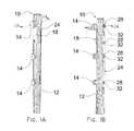
- FIG. 1Ais a front perspective view of a first embodiment
- FIG. 1Bis a rear perspective view of the first embodiment
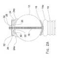
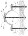
- FIG. 2Ais a sectional view taken along line 2 A- 2 A in FIGS. 1A and 1B ;
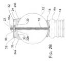
- FIG. 2Bis a view similar to the sectional view of FIG. 2A but depicts a second embodiment
- FIG. 2Cis a view similar to the sectional view of FIG. 2A but depicts a third embodiment
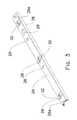
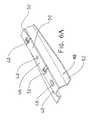
- FIG. 3is a perspective view of the back support brace of the first, second, and third embodiments
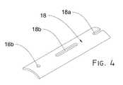
- FIG. 4is a perspective view of the elongate front support that is common to the first three embodiments;
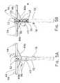
- FIG. 5Ais a front elevational view of the fourth embodiment
- FIG. 5Bis a rear elevational view of the fourth embodiment
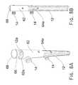
- FIG. 6Ais a perspective view of a certain embodiment of the vertical cross arm support member
- FIG. 6Bis a sectional view taken along line 6 B- 6 B in FIGS. 5A and 5B ;
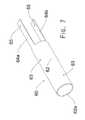
- FIG. 7is a perspective view of the cylindrical prosthesis of the fifth embodiment.
- FIG. 8Ais a partially exploded perspective view of the fifth embodiment when installed on a pole.
- FIG. 8Bis a perspective view of the fifth embodiment when installed on a pole.
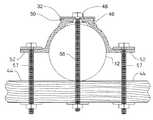
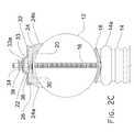
- FIGS. 1A and 1Bdepict a first illustrative embodiment of the novel structure, denoted 10 as a whole, when installed on a utility or meter pole 12 having at least one insulator 14 secured thereto.
- the structureis perhaps more fully disclosed in FIG. 2 .
- FIG. 2Aconventional insulator 14 having base 14 a is secured to pole 12 near the uppermost end thereof by elongate bolt 16 .
- Front support 18conforms to the shape of pole 12 and its upper end provides support for insulator base 14 a .
- Front support 18has an elongate vertical extent as depicted in FIGS. 1A and 1B .
- Conventional, pre-existing washer 20 near the top of FIG. 2Ahas an arcuate shape to conform to the shape of pole 12 and is held against the pole by conventional, pre-existing nut 22 . Said washer and nut are diametrically opposed to conventional, pre-existing insulator base 14 a.
- the novel structureincludes elongate brace 24 having laterally spaced apart legs 24 a , 24 b that bear against the top of pole 12 in diametrically opposed relation to elongate front plate 18 as depicted.
- Legs 24 a , 24 bare formed integrally with base 26 of elongate brace 24 .
- At least two bolt-accommodating openings 28are formed in said base 26 , said openings being centered on a longitudinal axis of symmetry of said elongate brace.
- Each opening 28is in open communication with an associated washer-accommodating opening 30 .
- a plurality of openings 28is formed along the vertical extent of elongate brace 24 as indicated in FIG. 1B .
- Each opening 28may be provided as a circular opening or as an elongate slot as indicated in said FIG. 1B and as indicated in FIG. 3 as well.
- Reinforcing base 26is square at its outer or outboard surface, i.e., the surface that does not contact pole 12 .
- Washer plate 32conforms to that square configuration and overlies said outer surface as depicted.
- Nut 34screw-threadedly engages bolt 16 and secures washer plate 32 and hence brace 24 to the top of the pole in diametric opposition to insulator 14 and elongate front support 18 .
- Each washer plate 32thus performs the function of a washer.
- Openings 28are provided in plural locations in both circular and slotted form to accommodate various pole structures. Open slots 28 a at the opposite ends of elongate brace 24 are used to accommodate pre-existing bolts as needed.
- each nut 34is provided at the time of pole repair, i.e., conventional nut 22 remains in its original position.
- Novel front support 18depicted in FIGS. 1A, 1B, and 4 has an elongate structure. It has a first end that underlies insulator 14 and a second end that is longitudinally spaced apart from the first end and which therefore does not underlie the insulator.
- Front support 18is arcuate in transverse section and its upper end is slotted as at 18 a to accommodate elongate bolt 16 which is not depicted in FIG. 4 .
- Circular or slotted openings 18 bare formed therein as depicted to accommodate bolts as needed for fastening front support 18 to the front or insulator side of pole 12 .
- Front support 18 and elongate brace 24which provides back support, are disposed in diametrically opposed relation to one another and hold pole 12 in sandwiched relation between them.
- FIG. 2Bdepicts a second embodiment where conventional nut 22 is removed from bolt 16 and then re-engaged thereto.
- each washer plate 32has a recessed channel 32 a formed in the center thereof as depicted.
- Channel 32 aincludes centrally-apertured bottom wall 32 b and said bottom wall is substantially flush with washer-accommodating opening 30 .
- Bottom wall 32 bthus performs the function of a washer and reinforces conventional washer 20
- Each spring lock 36fits within channel 32 a and abuts channel bottom plate 32 b
- Conventional nut 22is returned to its screw-threaded engagement with bolt 16 to bear against spring lock 36 .
- This second embodimenthas the advantage of not requiring second nut 34 of the first embodiment.
- FIG. 2Cdepicts a third embodiment where conventional nut 22 remains as in the first embodiment in screw-threaded engagement with bolt 16 , and where additional nut 34 of the first embodiment is also used.
- each washer plate 32has a raised ridge 33 that includes centrally-apertured top wall 33 a as depicted in FIG. 2C .
- Conventional nut 22 and spring lock 36are disposed in bearing relation to conventional washer 20 .
- Each washer plate 32is then placed into overlying relation to base 26 of elongate brace 24 in registration with each opening 28 as needed.
- a second spring lock 38is placed into overlying relation to each top wall 33 a and is secured thereto by a nut 34 .
- FIGS. 5A, 5B, 6A, and 6BA fourth embodiment is depicted in FIGS. 5A, 5B, 6A, and 6B .
- This embodimenthas utility in connection with upstanding poles 12 having a cross arm 44 , with or without braces 44 a .
- the perspective view of FIG. 6Adepicts a certain embodiment of cross arm support member 46 .
- Apertures 48are formed in elongate support base 50 and may take the form of a circular opening or an elongated slot as depicted.
- a ninety degree bendforms vertical flange 52 enabling attachment of vertical cross arm support member 46 to cross arm 44 as depicted in FIGS. 5A and 5B .
- through bolts 57pass through apertures 48 on flanges 52 into cross arm 44 to secure vertical cross arm support member 46 to cross arm 44 .
- cross arm support member 46is positioned on pole 12 so that flange 52 serves as a support surface for cross arm 44 at generally the mid-length region of said cross arm. Flanges 52 provide support for cross arm 44 and inhibits rotation of said cross arm in a vertical and horizontal plane.
- bolts 56which secure cross arm support member 46 to pole 12 preferably extend diametrically through the pole and when used with suitable nuts and washers secure cross arm support member 46 to pole 12 . Further bolts may be used to further secure said cross arm support member 46 to pole 12 , said cross arm support member 46 being provided with multiple apertures along its extent and slots at its opposite ends for that purpose.
- a certain embodimentmay include an elongate brace, similar to elongate brace 24 shown in FIG. 3 , diametrically opposed from cross arm support member 46 to sandwich pole 12 . The sandwiching of pole 12 between cross arm support member 46 and the elongate brace provides additional support for flanges 52 .
- FIGS. 7, 8A and 8BA fifth embodiment is depicted in FIGS. 7, 8A and 8B .
- Main body 62 of brace 60is cylindrical. Legs 64 a , 64 b depend from cylindrical main body 62 in diametrically opposed relation to one another. The upper rim of main body 62 is denoted 62 a . Apertures collectively denoted 63 are formed in cylindrical main body 62 in circumferentially and longitudinally spaced relation to one another and apertures collectively denoted 65 are formed in legs 64 a , 64 b.
- upper rim 62 a of cylindrical main body 62projects above the uppermost end 12 a of pole 12 when brace 60 is properly installed in ensleeving relation to a pole top.
- Skirt 66 of top cap 68has a length equal to or just slightly less than the distance of rim 62 a above pole top 12 A so that said skirt fits within the hollow interior of cylindrical main body 62 when top cap 68 is in its functional position as depicted in FIG. 8B .
- the diameter of skirt 66causes it to fit tightly with a good friction fit within said hollow interior so that high winds cannot cause it to separate from said functional position.
- Various bolts or screwsextend through apertures 63 and 65 to secure brace 60 to pole 12 .
Landscapes
- Engineering & Computer Science (AREA)
- Architecture (AREA)
- Civil Engineering (AREA)
- Structural Engineering (AREA)
- Life Sciences & Earth Sciences (AREA)
- Wood Science & Technology (AREA)
- Chemical & Material Sciences (AREA)
- Materials Engineering (AREA)
- Suspension Of Electric Lines Or Cables (AREA)
- Electric Cable Installation (AREA)
Abstract
Description
This nonprovisional application is a continuation-in-part of and claims priority to nonprovisional application Ser. No. 14/624,845, entitled “UTILITY OR METER POLE TOP REINFORCEMENT METHOD AND APPARATUS,” filed Feb. 18, 2015, which is a divisional and claim priority to nonprovisional application Ser. No. 14/082,824, entitled “UTILITY OR METER POLE TOP REINFORCEMENT METHOD AND APPARATUS,” filed Nov. 18, 2013, by the same inventor.
1. Field of the Invention
This invention relates, generally, to repair of upstanding poles such as utility poles. More particularly, it relates to methods and apparatuses for strengthening the tops of poles that have structurally deteriorated over time to avoid or delay the cost of replacing such poles.
2. Description of the Prior Art
Utility poles become degraded over time near the ground and also at their upper end. There are many patented devices for strengthening such poles at or near the ground so that they don't fall over but there has been little inventive activity for strengthening the upper end of such poles to which are connected dedicated voltage transmission/distribution lines as well as telephone/CATV lines.
Meter poles are smaller versions of utility poles; they are positioned near structures such as mobile homes where laws forbid the direct attachment of permanent lines. As used herein, the term “pole” refers to utility as well as meter poles or any other type of pole that may be in need of upper end reinforcement.
The current cost of replacing a utility pole that has lost its structural integrity is about three thousand dollars per pole. Every U.S. state has millions of such poles. There are between one hundred thirty to one hundred eighty million utility poles in use in North America and most utility companies replace about six thousand poles per year. The cost of course is passed along to the consumer.
The upper ends of many pressure-treated poles that were installed in the decade of the 1970s are now losing their structural integrity and are in need of replacement. The same will of course hold true in the future of poles installed in later decades as well. However, it would save companies and consumers substantial monies if those poles could be reinforced instead of replaced.
However, in view of the art considered as a whole at the time the present invention was made, it was not obvious to those of ordinary skill in the art how the upper ends of such poles could be reinforced at a cost substantially less than pole-replacement costs.
The long-standing but heretofore unfulfilled need for a device that reinforces deteriorating utility poles, meter poles, and the like is now met by a new, useful, and non-obvious invention.
The inventive structure is an apparatus for reinforcing an upstanding pole having an upper end that is worn, rotted, damaged, or otherwise in a deteriorated state.
The novel structure includes an elongate brace and at least two bolt-accommodating openings formed in the elongate brace. Each bolt-accommodating opening is centered on a longitudinal axis of symmetry of the elongate brace. The elongate brace is adapted to bear against the upstanding pole near the worn upper end of the upstanding pole.
At least two washer plates are disposed in overlying relation to the elongate brace and a bolt-accommodating opening is formed in each washer plate. The bolt-accommodating opening is centered on a longitudinal axis of symmetry of each washer plate and is aligned with a bolt-receiving opening formed in the elongate brace.
At least two elongate bolts are adapted to extend diametrically through the upstanding pole. Each elongate bolt extends through a preselected bolt-accommodating opening formed in the elongate brace and through the bolt-accommodating opening formed in the associated washer plate.
Each elongate bolt has a tool-engageable head and a free end that extends outwardly from the upstanding pole diametrically opposite from the tool-engageable head. A nut screw-threadedly engages the free end of each elongate bolt and advancement of the nut increasingly secures the associated washer plate to the elongate brace and therefore increasingly secures the elongate brace to the upstanding pole so that the upper end of the upstanding pole is reinforced by the elongate brace.
The elongate brace has a base and a pair of laterally spaced apart legs are formed integrally with the base. The legs are adapted to bear against the upstanding pole.
At least one cavity for accommodating a pre-existing, conventional washer is formed in the elongate brace in open communication with each bolt-accommodating opening. Each elongate bolt extends through the conventional washer-accommodating opening when the nut secures said washer plate to said elongate brace.
In a second embodiment, each washer plate has a recessed channel formed therein, centered on the longitudinal axis of symmetry of the washer plate. The recessed channel extends into an associated bolt-receiving opening and a spring lock is disposed in overlying relation to a bottom wall of the recessed channel. A nut screw-threadedly engages the free end of the elongate bolt in bearing relation to the spring lock so that advancing the nut increasingly urges the washer plate towards the elongate brace and therefore increasingly presses the elongate brace against the upper end of the upstanding pole.
In a third embodiment, each washer plate has a raised ridge formed therein, centered on the longitudinal axis of symmetry of the washer plate, said longitudinal axis of symmetry being coincident with the longitudinal axis of symmetry of the elongate brace.
In the third embodiment, a first spring lock is disposed in each bolt-accommodating opening formed in the elongate brace and a first nut is screw-threadedly engaged to the free end of the elongate bolt in bearing relation to the first spring lock. The elongate ridge is disposed in overlying relation to the first nut and a second spring lock is disposed in overlying relation to the elongate ridge. A second nut screw-threadedly engages the free end of the elongate bolt in bearing engagement to the second spring lock so that advancement of the first and second nuts enables each washer plate to bear increasingly against the elongate brace and thus cause the elongate brace to bear increasingly against the upper end of the pole, thereby reinforcing it.
All three embodiments include an elongate front support member that is arcuate in transverse section to conform to the surface of the pole and which is mounted on the upper end of the pole in diametric relation to the elongate brace so that the damaged upper end of the upstanding pole is sandwiched between the front support member and the elongate brace.
At least two openings are formed in the front support member to accommodate the elongate bolts that secure the front support member to the upstanding pole. The elongate bolt that extends through the elongate brace and washer plate is the same elongate bolt that extends through the preselected opening formed in the front support member, i.e., the elongate bolts secure the front support member to a first side of the pole and secure the elongate brace to a second, diametrically opposed side of the pole so that the upper end of the pole is sandwiched between the front support member and the elongate brace.
A fourth embodiment of the invention is an apparatus for supporting a horizontally disposed cross arm mounted to an upstanding pole. It includes a vertical cross arm support member adapted to be secured to both the pole and the existing cross arm of the pole to provide pole attachment strength and stability.
An elongate brace is adapted to abut the pole in diametrically opposed relation to the cross arm support member. An aperture is formed in the elongate brace and aligned with an aperture formed in the elongate base support of the cross arm support member to receive a bolt that extends diametrically through the pole to secure the vertical cross arm support member to the pole.
In an embodiment, the vertical cross arm support member comprises an elongate base support with two flanges extending outward in opposite direction from the longitudinal axis of the vertical cross arm support member. The flanges are intended to extend parallel with the existing cross arm on the pole. Each flange includes one or more apertures adapted to receive a bolt extending diametrically through the existing cross arm on the pole. The attachment of the flanges to the existing cross arm prevents rotation of the existing cross arm in a horizontal plane about a longitudinal axis of the pole. Additionally, the elongate structure in conjunction with the flanges prevents rotation in a vertical plane.
A fifth embodiment of the invention is a prosthetic apparatus for reinforcing a deteriorating top of an upstanding pole. It includes a cylindrical main body having an upper rim at a first end of the main body. A pair of legs depend from a second end of the main body in diametrically opposed relation to one another.
A plurality of apertures is formed in the cylindrical main body in circumferentially and longitudinally spaced relation to one another to facilitate attachment of the cylindrical main body and the legs to the pole.
The upper rim projects above an uppermost end of the upstanding pole when the uppermost end is ensleeved by the cylindrical main body.
A top cap has a skirt having a length substantially equal to a distance of the upper rim above the uppermost end of the upstanding pole so that the skirt fits within the hollow interior of the cylindrical main body when the top cap engages the cylindrical main body.
A general object of this invention is to lengthen the lifetime of upstanding poles such as a utility poles owned by a public or private utility company or meter poles of the type used in connection with mobile homes.
A more specific object is to reinforce the upper end of such poles at a cost that is much less than the cost of replacing such a pole.
These and other important objects, advantages, and features of the invention will become clear as this disclosure proceeds.
The invention accordingly comprises the features of construction, combination of elements, and arrangement of parts that will be exemplified in the disclosure set forth hereinafter and the scope of the invention will be indicated in the claims.
For a fuller understanding of the nature and objects of the invention, reference should be made to the following detailed disclosure, taken in connection with the accompanying drawings, in which:
InFIG. 2A ,conventional insulator 14 havingbase 14ais secured topole 12 near the uppermost end thereof byelongate bolt 16.Front support 18 conforms to the shape ofpole 12 and its upper end provides support forinsulator base 14a.Front support 18 has an elongate vertical extent as depicted inFIGS. 1A and 1B .
Conventional,pre-existing washer 20 near the top ofFIG. 2A has an arcuate shape to conform to the shape ofpole 12 and is held against the pole by conventional,pre-existing nut 22. Said washer and nut are diametrically opposed to conventional,pre-existing insulator base 14a.
The novel structure includeselongate brace 24 having laterally spaced apartlegs pole 12 in diametrically opposed relation to elongatefront plate 18 as depicted.Legs base 26 ofelongate brace 24. At least two bolt-accommodatingopenings 28 are formed in saidbase 26, said openings being centered on a longitudinal axis of symmetry of said elongate brace. Eachopening 28 is in open communication with an associated washer-accommodatingopening 30. A plurality ofopenings 28 is formed along the vertical extent ofelongate brace 24 as indicated inFIG. 1B . Eachopening 28 may be provided as a circular opening or as an elongate slot as indicated in saidFIG. 1B and as indicated inFIG. 3 as well.
Reinforcingbase 26 is square at its outer or outboard surface, i.e., the surface that does not contactpole 12.Washer plate 32 conforms to that square configuration and overlies said outer surface as depicted.Nut 34 screw-threadedly engagesbolt 16 and secureswasher plate 32 and hence brace24 to the top of the pole in diametric opposition toinsulator 14 and elongatefront support 18. Eachwasher plate 32 thus performs the function of a washer.
Saidelongate brace 24 andwasher plates 32 are depicted in perspective view inFIGS. 1A and 3 .Openings 28 are provided in plural locations in both circular and slotted form to accommodate various pole structures.Open slots 28aat the opposite ends ofelongate brace 24 are used to accommodate pre-existing bolts as needed.
It will be observed in the embodiment ofFIG. 2A that eachnut 34 is provided at the time of pole repair, i.e.,conventional nut 22 remains in its original position.
Novelfront support 18, depicted inFIGS. 1A, 1B, and 4 has an elongate structure. It has a first end that underliesinsulator 14 and a second end that is longitudinally spaced apart from the first end and which therefore does not underlie the insulator.
Eachspring lock 36 fits withinchannel 32aand abutschannel bottom plate 32bConventional nut 22 is returned to its screw-threaded engagement withbolt 16 to bear againstspring lock 36. This second embodiment has the advantage of not requiringsecond nut 34 of the first embodiment.
In this third embodiment, eachwasher plate 32 has a raisedridge 33 that includes centrally-aperturedtop wall 33aas depicted inFIG. 2C .Conventional nut 22 andspring lock 36 are disposed in bearing relation toconventional washer 20. Eachwasher plate 32 is then placed into overlying relation tobase 26 ofelongate brace 24 in registration with each opening28 as needed. Asecond spring lock 38 is placed into overlying relation to eachtop wall 33aand is secured thereto by anut 34.
A fourth embodiment is depicted inFIGS. 5A, 5B, 6A, and 6B . This embodiment has utility in connection withupstanding poles 12 having across arm 44, with or withoutbraces 44a. The perspective view ofFIG. 6A depicts a certain embodiment of crossarm support member 46.Apertures 48 are formed inelongate support base 50 and may take the form of a circular opening or an elongated slot as depicted. A ninety degree bend formsvertical flange 52 enabling attachment of vertical crossarm support member 46 to crossarm 44 as depicted inFIGS. 5A and 5B . As illustrated inFIG. 6B , throughbolts 57 pass throughapertures 48 onflanges 52 intocross arm 44 to secure vertical crossarm support member 46 to crossarm 44.
As depicted inFIG. 5A ,bolt 56 is inserted intopole 12 throughaperture 48 to secure crossarm support member 46 to said pole. Crossarm support member 46 is positioned onpole 12 so thatflange 52 serves as a support surface forcross arm 44 at generally the mid-length region of said cross arm.Flanges 52 provide support forcross arm 44 and inhibits rotation of said cross arm in a vertical and horizontal plane.
As depicted inFIG. 5B ,bolts 56, which secure crossarm support member 46 topole 12 preferably extend diametrically through the pole and when used with suitable nuts and washers secure crossarm support member 46 topole 12. Further bolts may be used to further secure said crossarm support member 46 topole 12, said crossarm support member 46 being provided with multiple apertures along its extent and slots at its opposite ends for that purpose. A certain embodiment may include an elongate brace, similar toelongate brace 24 shown inFIG. 3 , diametrically opposed from crossarm support member 46 tosandwich pole 12. The sandwiching ofpole 12 between crossarm support member 46 and the elongate brace provides additional support forflanges 52.
A fifth embodiment is depicted inFIGS. 7, 8A and 8B .Main body 62 ofbrace 60 is cylindrical.Legs main body 62 in diametrically opposed relation to one another. The upper rim ofmain body 62 is denoted62a. Apertures collectively denoted63 are formed in cylindricalmain body 62 in circumferentially and longitudinally spaced relation to one another and apertures collectively denoted65 are formed inlegs
As depicted inFIG. 8A ,upper rim 62aof cylindricalmain body 62 projects above theuppermost end 12aofpole 12 whenbrace 60 is properly installed in ensleeving relation to a pole top.Skirt 66 oftop cap 68 has a length equal to or just slightly less than the distance ofrim 62aabove pole top12A so that said skirt fits within the hollow interior of cylindricalmain body 62 whentop cap 68 is in its functional position as depicted inFIG. 8B . The diameter ofskirt 66 causes it to fit tightly with a good friction fit within said hollow interior so that high winds cannot cause it to separate from said functional position. Various bolts or screws extend throughapertures brace 60 topole 12.
It will thus be seen that the objects set forth above, and those made apparent from the foregoing disclosure, are efficiently attained and since certain changes may be made in the above construction without departing from the scope of the invention, it is intended that all matters contained in the foregoing disclosure or shown in the accompanying drawings shall be interpreted as illustrative and not in a limiting sense.
It is also to be understood that the following claims are intended to cover all of the generic and specific features of the invention herein described, and all statements of the scope of the invention that, as a matter of language, might be said to fall therebetween.
Claims (13)
1. An apparatus for supporting a horizontally disposed cross arm mounted to an upstanding utility pole, comprising:
an elongate base support mounted and secured proximate an upper end of said upstanding utility pole, wherein
said elongate base support has a semi-circular cross-sectional shape extending between a first end and a second end of said semi-circular cross-sectional shape;
a pair of planar flanges, wherein a first flange is integrated into said elongate base support at said first end of said semi-circular cross-sectional shape of said base support and extends outward therefrom, and a second flange is integrated into said elongate base support at said second end of said semi-circular cross-sectional shape of said base support and extends outward therefrom;
each flange extending in an outwardly direction with respect to a longitudinal axis of said elongate base support on opposite sides of said elongate base structure in a lateral direction and in the same plane as one another;
said elongate base support having an aperture;
said pair of flanges each having an aperture, whereby said aperture in each flange is near an upper end of said apparatus and adapted to align with said cross arm mounted to said upstanding utility pole,
a flat elongate ridge extending outwardly from a mid-point of said semi-circular cross-sectional shape of said elongate base support; and
a washer plate mounted to and spanning a distance equivalent to a width of said flat elongate ridge, said washer plate further including a bolt-accommodating aperture.
2. The apparatus ofclaim 1 , further comprising said elongate base support secured to said upstanding utility pole through a bolt extending diametrically through said pole and said aperture in said elongate base structure.
3. The apparatus ofclaim 2 , further comprising an elongate brace having an aperture and a longitudinal axis extending in a same direction as said longitudinal axis of said elongate support base, said elongate brace abutting said pole in diametrically opposed relation to said elongate base support, such that said bolt extending diametrically through said pole is received by said aperture in said elongate brace as well as said aperture in said elongate base support.
4. The apparatus ofclaim 1 , wherein said elongate base support further includes a semi-circular cross-section to allow said elongate base support to mate with a curvature of said pole.
5. The apparatus ofclaim 1 , wherein said pair of flanges each taper towards said longitudinal axis of said elongate base support from said apertures of said flanges to a bottom end of said elongate base support.
6. The apparatus ofclaim 1 , wherein said elongate base support is disposed on said upstanding utility pole in a diametrically opposed relation to said cross arm of said upstanding utility pole.
7. The apparatus ofclaim 1 , wherein said elongate base support further includes:
wherein said flat elongate ridge extends outwardly such that a channel is formed on an internal lateral surface of said elongate base support; and
said washer plate includes perpendicularly disposed engagement legs thereby providing guides to maintain the location of said washer plate along said flat elongate ridge.
8. An apparatus for supporting a horizontally disposed cross arm mounted to an upstanding utility pole, comprising:
an elongate base support secured to an upper end of said upstanding utility pole, wherein said elongate base support has a semi-circular cross-sectional shape extending between a first end and a second end of said semi-circular cross-sectional shape;
a pair of flanges, wherein each flange extends outward from a longitudinal axis of said elongate base support on opposite side of said elongate base structure in a lateral direction and in the same plane as one another;
said elongate base support having an aperture; and
said pair of flanges each having an aperture, whereby said aperture in each flange is secured to said cross arm mounted to said upstanding utility pole;
a flat elongate ridge extending outwardly from a mid-point of said semi-circular cross-sectional shape of said elongate base support; and
a washer plate mounted to and spanning a distance equivalent to a width of said flat elongate ridge, said washer plate further including a bolt-accommodating aperture.
9. The apparatus ofclaim 8 , further comprising said elongate base support secured to said upstanding utility pole through a bolt extending diametrically through said pole and said aperture in said elongate base structure.
10. The apparatus ofclaim 9 , further comprising an elongate brace having an aperture and abutted to said pole in diametrically opposed relation to said elongate base support, such that said bolt extending diametrically through said pole is received by said aperture in said elongate brace as well as said aperture in said elongate base support.
11. The apparatus ofclaim 8 , wherein said elongate base support further includes a semi-circular cross-section that mates with a curvature of said pole.
12. The apparatus ofclaim 8 , wherein said pair of flanges each taper towards said longitudinal axis of said elongate base support from said apertures of said flanges to a bottom end of said elongate base support.
13. The apparatus ofclaim 8 , wherein said elongate base support is disposed on said upstanding utility pole in a diametrically opposed relation to said cross arm of said upstanding utility pole.
Priority Applications (3)
| Application Number | Priority Date | Filing Date | Title |
|---|---|---|---|
| US14/737,779US9394716B2 (en) | 2013-11-18 | 2015-06-12 | Utility or meter pole top reinforcement method and apparatus |
| CA3131704ACA3131704C (en) | 2015-06-12 | 2016-06-09 | Utility or meter pole top reinforcement method and apparatus |
| CA2932801ACA2932801C (en) | 2015-06-12 | 2016-06-09 | Utility or meter pole top reinforcement method and apparatus |
Applications Claiming Priority (5)
| Application Number | Priority Date | Filing Date | Title |
|---|---|---|---|
| US14/082,824US8984834B1 (en) | 2013-11-18 | 2013-11-18 | Utility or meter pole top reinforcement method and apparatus |
| CA2870894ACA2870894C (en) | 2013-11-18 | 2014-11-14 | Utility or meter pole top reinforcement method and apparatus |
| CA2870894 | 2014-11-14 | ||
| US14/624,845US20150159396A1 (en) | 2013-11-18 | 2015-02-18 | Utility or meter pole top reinforcement method and apparatus |
| US14/737,779US9394716B2 (en) | 2013-11-18 | 2015-06-12 | Utility or meter pole top reinforcement method and apparatus |
Related Parent Applications (1)
| Application Number | Title | Priority Date | Filing Date |
|---|---|---|---|
| US14/624,845Continuation-In-PartUS20150159396A1 (en) | 2013-11-18 | 2015-02-18 | Utility or meter pole top reinforcement method and apparatus |
Publications (2)
| Publication Number | Publication Date |
|---|---|
| US20150275504A1 US20150275504A1 (en) | 2015-10-01 |
| US9394716B2true US9394716B2 (en) | 2016-07-19 |
Family
ID=54189552
Family Applications (1)
| Application Number | Title | Priority Date | Filing Date |
|---|---|---|---|
| US14/737,779ActiveUS9394716B2 (en) | 2013-11-18 | 2015-06-12 | Utility or meter pole top reinforcement method and apparatus |
Country Status (1)
| Country | Link |
|---|---|
| US (1) | US9394716B2 (en) |
Cited By (116)
| Publication number | Priority date | Publication date | Assignee | Title |
|---|---|---|---|---|
| US9674711B2 (en) | 2013-11-06 | 2017-06-06 | At&T Intellectual Property I, L.P. | Surface-wave communications and methods thereof |
| US9685992B2 (en) | 2014-10-03 | 2017-06-20 | At&T Intellectual Property I, L.P. | Circuit panel network and methods thereof |
| US9705561B2 (en) | 2015-04-24 | 2017-07-11 | At&T Intellectual Property I, L.P. | Directional coupling device and methods for use therewith |
| US9705610B2 (en) | 2014-10-21 | 2017-07-11 | At&T Intellectual Property I, L.P. | Transmission device with impairment compensation and methods for use therewith |
| US9729197B2 (en) | 2015-10-01 | 2017-08-08 | At&T Intellectual Property I, L.P. | Method and apparatus for communicating network management traffic over a network |
| US9735833B2 (en) | 2015-07-31 | 2017-08-15 | At&T Intellectual Property I, L.P. | Method and apparatus for communications management in a neighborhood network |
| US9742462B2 (en) | 2014-12-04 | 2017-08-22 | At&T Intellectual Property I, L.P. | Transmission medium and communication interfaces and methods for use therewith |
| US9742521B2 (en) | 2014-11-20 | 2017-08-22 | At&T Intellectual Property I, L.P. | Transmission device with mode division multiplexing and methods for use therewith |
| US9748626B2 (en) | 2015-05-14 | 2017-08-29 | At&T Intellectual Property I, L.P. | Plurality of cables having different cross-sectional shapes which are bundled together to form a transmission medium |
| US9749013B2 (en) | 2015-03-17 | 2017-08-29 | At&T Intellectual Property I, L.P. | Method and apparatus for reducing attenuation of electromagnetic waves guided by a transmission medium |
| US9749053B2 (en) | 2015-07-23 | 2017-08-29 | At&T Intellectual Property I, L.P. | Node device, repeater and methods for use therewith |
| US9769128B2 (en) | 2015-09-28 | 2017-09-19 | At&T Intellectual Property I, L.P. | Method and apparatus for encryption of communications over a network |
| US9768833B2 (en) | 2014-09-15 | 2017-09-19 | At&T Intellectual Property I, L.P. | Method and apparatus for sensing a condition in a transmission medium of electromagnetic waves |
| US9769020B2 (en) | 2014-10-21 | 2017-09-19 | At&T Intellectual Property I, L.P. | Method and apparatus for responding to events affecting communications in a communication network |
| US9780834B2 (en) | 2014-10-21 | 2017-10-03 | At&T Intellectual Property I, L.P. | Method and apparatus for transmitting electromagnetic waves |
| US9787412B2 (en) | 2015-06-25 | 2017-10-10 | At&T Intellectual Property I, L.P. | Methods and apparatus for inducing a fundamental wave mode on a transmission medium |
| US9793954B2 (en) | 2015-04-28 | 2017-10-17 | At&T Intellectual Property I, L.P. | Magnetic coupling device and methods for use therewith |
| US9793955B2 (en) | 2015-04-24 | 2017-10-17 | At&T Intellectual Property I, Lp | Passive electrical coupling device and methods for use therewith |
| US9800327B2 (en) | 2014-11-20 | 2017-10-24 | At&T Intellectual Property I, L.P. | Apparatus for controlling operations of a communication device and methods thereof |
| US9820146B2 (en) | 2015-06-12 | 2017-11-14 | At&T Intellectual Property I, L.P. | Method and apparatus for authentication and identity management of communicating devices |
| US9838896B1 (en) | 2016-12-09 | 2017-12-05 | At&T Intellectual Property I, L.P. | Method and apparatus for assessing network coverage |
| US9838078B2 (en) | 2015-07-31 | 2017-12-05 | At&T Intellectual Property I, L.P. | Method and apparatus for exchanging communication signals |
| US9847850B2 (en) | 2014-10-14 | 2017-12-19 | At&T Intellectual Property I, L.P. | Method and apparatus for adjusting a mode of communication in a communication network |
| US9847566B2 (en) | 2015-07-14 | 2017-12-19 | At&T Intellectual Property I, L.P. | Method and apparatus for adjusting a field of a signal to mitigate interference |
| US9853342B2 (en) | 2015-07-14 | 2017-12-26 | At&T Intellectual Property I, L.P. | Dielectric transmission medium connector and methods for use therewith |
| US9860075B1 (en) | 2016-08-26 | 2018-01-02 | At&T Intellectual Property I, L.P. | Method and communication node for broadband distribution |
| US9866276B2 (en) | 2014-10-10 | 2018-01-09 | At&T Intellectual Property I, L.P. | Method and apparatus for arranging communication sessions in a communication system |
| US9866309B2 (en) | 2015-06-03 | 2018-01-09 | At&T Intellectual Property I, Lp | Host node device and methods for use therewith |
| US9865911B2 (en) | 2015-06-25 | 2018-01-09 | At&T Intellectual Property I, L.P. | Waveguide system for slot radiating first electromagnetic waves that are combined into a non-fundamental wave mode second electromagnetic wave on a transmission medium |
| US9871558B2 (en) | 2014-10-21 | 2018-01-16 | At&T Intellectual Property I, L.P. | Guided-wave transmission device and methods for use therewith |
| US9871283B2 (en) | 2015-07-23 | 2018-01-16 | At&T Intellectual Property I, Lp | Transmission medium having a dielectric core comprised of plural members connected by a ball and socket configuration |
| US9871282B2 (en) | 2015-05-14 | 2018-01-16 | At&T Intellectual Property I, L.P. | At least one transmission medium having a dielectric surface that is covered at least in part by a second dielectric |
| US9876571B2 (en) | 2015-02-20 | 2018-01-23 | At&T Intellectual Property I, Lp | Guided-wave transmission device with non-fundamental mode propagation and methods for use therewith |
| US9876264B2 (en) | 2015-10-02 | 2018-01-23 | At&T Intellectual Property I, Lp | Communication system, guided wave switch and methods for use therewith |
| US9876605B1 (en) | 2016-10-21 | 2018-01-23 | At&T Intellectual Property I, L.P. | Launcher and coupling system to support desired guided wave mode |
| US9882257B2 (en) | 2015-07-14 | 2018-01-30 | At&T Intellectual Property I, L.P. | Method and apparatus for launching a wave mode that mitigates interference |
| US9887447B2 (en) | 2015-05-14 | 2018-02-06 | At&T Intellectual Property I, L.P. | Transmission medium having multiple cores and methods for use therewith |
| US9893795B1 (en) | 2016-12-07 | 2018-02-13 | At&T Intellectual Property I, Lp | Method and repeater for broadband distribution |
| US9906269B2 (en) | 2014-09-17 | 2018-02-27 | At&T Intellectual Property I, L.P. | Monitoring and mitigating conditions in a communication network |
| US9904535B2 (en) | 2015-09-14 | 2018-02-27 | At&T Intellectual Property I, L.P. | Method and apparatus for distributing software |
| US9912382B2 (en) | 2015-06-03 | 2018-03-06 | At&T Intellectual Property I, Lp | Network termination and methods for use therewith |
| US9912027B2 (en) | 2015-07-23 | 2018-03-06 | At&T Intellectual Property I, L.P. | Method and apparatus for exchanging communication signals |
| US9913139B2 (en) | 2015-06-09 | 2018-03-06 | At&T Intellectual Property I, L.P. | Signal fingerprinting for authentication of communicating devices |
| US9912033B2 (en) | 2014-10-21 | 2018-03-06 | At&T Intellectual Property I, Lp | Guided wave coupler, coupling module and methods for use therewith |
| US9911020B1 (en) | 2016-12-08 | 2018-03-06 | At&T Intellectual Property I, L.P. | Method and apparatus for tracking via a radio frequency identification device |
| US9917341B2 (en) | 2015-05-27 | 2018-03-13 | At&T Intellectual Property I, L.P. | Apparatus and method for launching electromagnetic waves and for modifying radial dimensions of the propagating electromagnetic waves |
| US9929755B2 (en) | 2015-07-14 | 2018-03-27 | At&T Intellectual Property I, L.P. | Method and apparatus for coupling an antenna to a device |
| US9927517B1 (en) | 2016-12-06 | 2018-03-27 | At&T Intellectual Property I, L.P. | Apparatus and methods for sensing rainfall |
| US20180100323A1 (en)* | 2016-10-12 | 2018-04-12 | Geotek, Llc | Support member for supporting electrical power lines |
| US9948333B2 (en) | 2015-07-23 | 2018-04-17 | At&T Intellectual Property I, L.P. | Method and apparatus for wireless communications to mitigate interference |
| US9954286B2 (en) | 2014-10-21 | 2018-04-24 | At&T Intellectual Property I, L.P. | Guided-wave transmission device with non-fundamental mode propagation and methods for use therewith |
| US9954287B2 (en) | 2014-11-20 | 2018-04-24 | At&T Intellectual Property I, L.P. | Apparatus for converting wireless signals and electromagnetic waves and methods thereof |
| US9967173B2 (en) | 2015-07-31 | 2018-05-08 | At&T Intellectual Property I, L.P. | Method and apparatus for authentication and identity management of communicating devices |
| US9973416B2 (en) | 2014-10-02 | 2018-05-15 | At&T Intellectual Property I, L.P. | Method and apparatus that provides fault tolerance in a communication network |
| US9973940B1 (en) | 2017-02-27 | 2018-05-15 | At&T Intellectual Property I, L.P. | Apparatus and methods for dynamic impedance matching of a guided wave launcher |
| US9991580B2 (en) | 2016-10-21 | 2018-06-05 | At&T Intellectual Property I, L.P. | Launcher and coupling system for guided wave mode cancellation |
| US9999038B2 (en) | 2013-05-31 | 2018-06-12 | At&T Intellectual Property I, L.P. | Remote distributed antenna system |
| US9998870B1 (en) | 2016-12-08 | 2018-06-12 | At&T Intellectual Property I, L.P. | Method and apparatus for proximity sensing |
| US9997819B2 (en) | 2015-06-09 | 2018-06-12 | At&T Intellectual Property I, L.P. | Transmission medium and method for facilitating propagation of electromagnetic waves via a core |
| US10009067B2 (en) | 2014-12-04 | 2018-06-26 | At&T Intellectual Property I, L.P. | Method and apparatus for configuring a communication interface |
| US10020844B2 (en) | 2016-12-06 | 2018-07-10 | T&T Intellectual Property I, L.P. | Method and apparatus for broadcast communication via guided waves |
| US10027397B2 (en) | 2016-12-07 | 2018-07-17 | At&T Intellectual Property I, L.P. | Distributed antenna system and methods for use therewith |
| US10044409B2 (en) | 2015-07-14 | 2018-08-07 | At&T Intellectual Property I, L.P. | Transmission medium and methods for use therewith |
| US10051630B2 (en) | 2013-05-31 | 2018-08-14 | At&T Intellectual Property I, L.P. | Remote distributed antenna system |
| US10069535B2 (en) | 2016-12-08 | 2018-09-04 | At&T Intellectual Property I, L.P. | Apparatus and methods for launching electromagnetic waves having a certain electric field structure |
| US10069185B2 (en) | 2015-06-25 | 2018-09-04 | At&T Intellectual Property I, L.P. | Methods and apparatus for inducing a non-fundamental wave mode on a transmission medium |
| US10090606B2 (en) | 2015-07-15 | 2018-10-02 | At&T Intellectual Property I, L.P. | Antenna system with dielectric array and methods for use therewith |
| US10090594B2 (en) | 2016-11-23 | 2018-10-02 | At&T Intellectual Property I, L.P. | Antenna system having structural configurations for assembly |
| US10103422B2 (en) | 2016-12-08 | 2018-10-16 | At&T Intellectual Property I, L.P. | Method and apparatus for mounting network devices |
| US10135145B2 (en) | 2016-12-06 | 2018-11-20 | At&T Intellectual Property I, L.P. | Apparatus and methods for generating an electromagnetic wave along a transmission medium |
| US10139820B2 (en) | 2016-12-07 | 2018-11-27 | At&T Intellectual Property I, L.P. | Method and apparatus for deploying equipment of a communication system |
| US10148016B2 (en) | 2015-07-14 | 2018-12-04 | At&T Intellectual Property I, L.P. | Apparatus and methods for communicating utilizing an antenna array |
| US10168695B2 (en) | 2016-12-07 | 2019-01-01 | At&T Intellectual Property I, L.P. | Method and apparatus for controlling an unmanned aircraft |
| US10178445B2 (en) | 2016-11-23 | 2019-01-08 | At&T Intellectual Property I, L.P. | Methods, devices, and systems for load balancing between a plurality of waveguides |
| US10205655B2 (en) | 2015-07-14 | 2019-02-12 | At&T Intellectual Property I, L.P. | Apparatus and methods for communicating utilizing an antenna array and multiple communication paths |
| US10224634B2 (en) | 2016-11-03 | 2019-03-05 | At&T Intellectual Property I, L.P. | Methods and apparatus for adjusting an operational characteristic of an antenna |
| US10225025B2 (en) | 2016-11-03 | 2019-03-05 | At&T Intellectual Property I, L.P. | Method and apparatus for detecting a fault in a communication system |
| US10243784B2 (en) | 2014-11-20 | 2019-03-26 | At&T Intellectual Property I, L.P. | System for generating topology information and methods thereof |
| US10243270B2 (en) | 2016-12-07 | 2019-03-26 | At&T Intellectual Property I, L.P. | Beam adaptive multi-feed dielectric antenna system and methods for use therewith |
| US10264586B2 (en) | 2016-12-09 | 2019-04-16 | At&T Mobility Ii Llc | Cloud-based packet controller and methods for use therewith |
| US10291334B2 (en) | 2016-11-03 | 2019-05-14 | At&T Intellectual Property I, L.P. | System for detecting a fault in a communication system |
| US10298293B2 (en) | 2017-03-13 | 2019-05-21 | At&T Intellectual Property I, L.P. | Apparatus of communication utilizing wireless network devices |
| US10305190B2 (en) | 2016-12-01 | 2019-05-28 | At&T Intellectual Property I, L.P. | Reflecting dielectric antenna system and methods for use therewith |
| US10312567B2 (en) | 2016-10-26 | 2019-06-04 | At&T Intellectual Property I, L.P. | Launcher with planar strip antenna and methods for use therewith |
| US10326689B2 (en) | 2016-12-08 | 2019-06-18 | At&T Intellectual Property I, L.P. | Method and system for providing alternative communication paths |
| US10326494B2 (en) | 2016-12-06 | 2019-06-18 | At&T Intellectual Property I, L.P. | Apparatus for measurement de-embedding and methods for use therewith |
| US10340573B2 (en) | 2016-10-26 | 2019-07-02 | At&T Intellectual Property I, L.P. | Launcher with cylindrical coupling device and methods for use therewith |
| US10340601B2 (en) | 2016-11-23 | 2019-07-02 | At&T Intellectual Property I, L.P. | Multi-antenna system and methods for use therewith |
| US10340983B2 (en) | 2016-12-09 | 2019-07-02 | At&T Intellectual Property I, L.P. | Method and apparatus for surveying remote sites via guided wave communications |
| US10340603B2 (en) | 2016-11-23 | 2019-07-02 | At&T Intellectual Property I, L.P. | Antenna system having shielded structural configurations for assembly |
| US10355367B2 (en) | 2015-10-16 | 2019-07-16 | At&T Intellectual Property I, L.P. | Antenna structure for exchanging wireless signals |
| US10359749B2 (en) | 2016-12-07 | 2019-07-23 | At&T Intellectual Property I, L.P. | Method and apparatus for utilities management via guided wave communication |
| US10361489B2 (en) | 2016-12-01 | 2019-07-23 | At&T Intellectual Property I, L.P. | Dielectric dish antenna system and methods for use therewith |
| US10374316B2 (en) | 2016-10-21 | 2019-08-06 | At&T Intellectual Property I, L.P. | System and dielectric antenna with non-uniform dielectric |
| US10382976B2 (en) | 2016-12-06 | 2019-08-13 | At&T Intellectual Property I, L.P. | Method and apparatus for managing wireless communications based on communication paths and network device positions |
| US10389037B2 (en) | 2016-12-08 | 2019-08-20 | At&T Intellectual Property I, L.P. | Apparatus and methods for selecting sections of an antenna array and use therewith |
| US10389029B2 (en) | 2016-12-07 | 2019-08-20 | At&T Intellectual Property I, L.P. | Multi-feed dielectric antenna system with core selection and methods for use therewith |
| US10411356B2 (en) | 2016-12-08 | 2019-09-10 | At&T Intellectual Property I, L.P. | Apparatus and methods for selectively targeting communication devices with an antenna array |
| US10439675B2 (en) | 2016-12-06 | 2019-10-08 | At&T Intellectual Property I, L.P. | Method and apparatus for repeating guided wave communication signals |
| US10446936B2 (en) | 2016-12-07 | 2019-10-15 | At&T Intellectual Property I, L.P. | Multi-feed dielectric antenna system and methods for use therewith |
| US10498044B2 (en) | 2016-11-03 | 2019-12-03 | At&T Intellectual Property I, L.P. | Apparatus for configuring a surface of an antenna |
| US10530505B2 (en) | 2016-12-08 | 2020-01-07 | At&T Intellectual Property I, L.P. | Apparatus and methods for launching electromagnetic waves along a transmission medium |
| US10535928B2 (en) | 2016-11-23 | 2020-01-14 | At&T Intellectual Property I, L.P. | Antenna system and methods for use therewith |
| US10547348B2 (en) | 2016-12-07 | 2020-01-28 | At&T Intellectual Property I, L.P. | Method and apparatus for switching transmission mediums in a communication system |
| US10601494B2 (en) | 2016-12-08 | 2020-03-24 | At&T Intellectual Property I, L.P. | Dual-band communication device and method for use therewith |
| US10637149B2 (en) | 2016-12-06 | 2020-04-28 | At&T Intellectual Property I, L.P. | Injection molded dielectric antenna and methods for use therewith |
| US10650940B2 (en) | 2015-05-15 | 2020-05-12 | At&T Intellectual Property I, L.P. | Transmission medium having a conductive material and methods for use therewith |
| US10694379B2 (en) | 2016-12-06 | 2020-06-23 | At&T Intellectual Property I, L.P. | Waveguide system with device-based authentication and methods for use therewith |
| US10727599B2 (en) | 2016-12-06 | 2020-07-28 | At&T Intellectual Property I, L.P. | Launcher with slot antenna and methods for use therewith |
| US10755542B2 (en) | 2016-12-06 | 2020-08-25 | At&T Intellectual Property I, L.P. | Method and apparatus for surveillance via guided wave communication |
| US10777873B2 (en) | 2016-12-08 | 2020-09-15 | At&T Intellectual Property I, L.P. | Method and apparatus for mounting network devices |
| US10797781B2 (en) | 2015-06-03 | 2020-10-06 | At&T Intellectual Property I, L.P. | Client node device and methods for use therewith |
| US10811767B2 (en) | 2016-10-21 | 2020-10-20 | At&T Intellectual Property I, L.P. | System and dielectric antenna with convex dielectric radome |
| US10819035B2 (en) | 2016-12-06 | 2020-10-27 | At&T Intellectual Property I, L.P. | Launcher with helical antenna and methods for use therewith |
| US10916969B2 (en) | 2016-12-08 | 2021-02-09 | At&T Intellectual Property I, L.P. | Method and apparatus for providing power using an inductive coupling |
| US10938108B2 (en) | 2016-12-08 | 2021-03-02 | At&T Intellectual Property I, L.P. | Frequency selective multi-feed dielectric antenna system and methods for use therewith |
Families Citing this family (6)
| Publication number | Priority date | Publication date | Assignee | Title |
|---|---|---|---|---|
| US20160258177A1 (en)* | 2014-01-31 | 2016-09-08 | Trinity Meyer Utility Structures, Llc | Transmission Pole Arm Bracket Reinforcing System |
| CN105350817A (en)* | 2015-10-28 | 2016-02-24 | 国家电网公司 | Iron tower vacuum switch cross arm |
| CN105350818A (en)* | 2015-10-28 | 2016-02-24 | 国家电网公司 | Single pole seat support |
| CN105421863B (en)* | 2015-11-20 | 2019-06-25 | 国家电网公司 | Multiple loop transmission line steel tube tower |
| CN108321745A (en)* | 2018-01-30 | 2018-07-24 | 浙江金塔电力线路器材有限公司 | A kind of insulator bracket for being easily installed and dismantling |
| CN111608465A (en)* | 2020-06-24 | 2020-09-01 | 固力发电气有限公司 | Composite insulation cross arm for power distribution |
Citations (36)
| Publication number | Priority date | Publication date | Assignee | Title |
|---|---|---|---|---|
| US868591A (en)* | 1906-06-04 | 1907-10-15 | Steel Gain Mfg Company | Support for cross-arms. |
| US1420430A (en)* | 1920-03-01 | 1922-06-20 | Jaeckle Friedrich | Means for securing the sections of a mast or pole together |
| US1802995A (en)* | 1930-03-10 | 1931-04-28 | Malleable Iron Fittings Co | Gain fixture for poles |
| US1817342A (en)* | 1929-10-03 | 1931-08-04 | Eldridge M Beecher | Pole reenforcement |
| US2265452A (en)* | 1939-01-14 | 1941-12-09 | Line Material Company Of Penns | Pole reinforcement |
| US2327681A (en)* | 1940-10-21 | 1943-08-24 | Jewell W Vanderveer | Pole reinforcement device |
| US2392222A (en)* | 1943-01-08 | 1946-01-01 | American Steel & Wire Co | Pole |
| US2704586A (en)* | 1955-03-22 | Spar arm supporting gain | ||
| USRE24133E (en)* | 1950-12-22 | 1956-03-20 | Thread coupling | |
| US2884670A (en)* | 1956-02-27 | 1959-05-05 | Doane Agricultural Service Inc | Bracket |
| US3555747A (en)* | 1969-06-12 | 1971-01-19 | Mif Ind Inc | Lightweight crossarm assemblies |
| US3568968A (en)* | 1969-04-16 | 1971-03-09 | Mif Ind Inc | Utility wire supporting bracket |
| US3625463A (en)* | 1970-02-19 | 1971-12-07 | Julian W Scholz | Utility bracket for power poles and the like |
| US3856250A (en)* | 1970-12-09 | 1974-12-24 | Aluma Form Inc | Interengaged component electrical equipment mount |
| US3921949A (en)* | 1973-11-21 | 1975-11-25 | Western Power Products Inc | Pole top insulator mounting bracket |
| USD243926S (en)* | 1976-04-05 | 1977-04-05 | Utilities Hardware, Inc. | Utility pole side insulator bracket |
| US4407601A (en)* | 1980-11-03 | 1983-10-04 | Commonwealth Edison Co. | Cross-arm brace |
| US4575904A (en)* | 1984-11-21 | 1986-03-18 | Bell Communications Research, Inc. | Guy hook |
| US4598512A (en)* | 1982-11-12 | 1986-07-08 | Fencemender Corp. | Single bracket support and method |
| US4697396A (en)* | 1983-05-04 | 1987-10-06 | R.F.D. Consultants Pty. Ltd. | Utility pole support |
| US4932623A (en)* | 1988-05-06 | 1990-06-12 | Hughes Brothers, Inc. | Bracket |
| US5228260A (en)* | 1992-03-16 | 1993-07-20 | Aluma-Form, Inc. | Cross brace and support arm |
| US5605017A (en)* | 1994-01-13 | 1997-02-25 | Pupi Enterprises L.L.C. | Pultruded utility line support structure and method |
| US5661946A (en)* | 1996-04-09 | 1997-09-02 | Davis; Kenneth | Pole top extension |
| US5799918A (en)* | 1995-05-08 | 1998-09-01 | Martin Engineering Company | Vibrator mounting arrangement |
| US5815994A (en)* | 1994-12-16 | 1998-10-06 | Powerbeam Pty, Ltd. | Strengthening of poles |
| US6079165A (en)* | 1997-05-22 | 2000-06-27 | Osmose Wood Preserving, Inc. | Apparatus and method for bracing vertical structures |
| US6595477B2 (en)* | 2001-09-25 | 2003-07-22 | Hubbell Incorporated | Mounting bracket for an insulator assembly |
| US20040084582A1 (en)* | 2002-07-08 | 2004-05-06 | Kralic John Frank | Utility pole cross-arm and associated pole-top hardware |
| US6834469B2 (en)* | 2001-01-24 | 2004-12-28 | Geotek, Inc. | Utility line support member |
| US7278247B2 (en)* | 2004-05-07 | 2007-10-09 | Gary Baumgartner | Method and apparatus for replacing a utility pole |
| US7815157B2 (en)* | 2004-10-25 | 2010-10-19 | Andoria Pty. Ltd. | Reinforcing poles |
| US20110083399A1 (en)* | 2009-10-13 | 2011-04-14 | Dish Network L.L.C. | Structures and methods for mounting an object |
| US8122652B2 (en)* | 2004-01-13 | 2012-02-28 | Andoria Pty Ltd | Bridging beam |
| US20140131525A1 (en)* | 2010-08-31 | 2014-05-15 | British Columbia Hydro And Power Authority | Transmission cross arm |
| US8756874B2 (en)* | 2011-03-21 | 2014-06-24 | The Texas A&M University System | Traffic signal supporting structures and methods |
- 2015
- 2015-06-12USUS14/737,779patent/US9394716B2/enactiveActive
Patent Citations (36)
| Publication number | Priority date | Publication date | Assignee | Title |
|---|---|---|---|---|
| US2704586A (en)* | 1955-03-22 | Spar arm supporting gain | ||
| US868591A (en)* | 1906-06-04 | 1907-10-15 | Steel Gain Mfg Company | Support for cross-arms. |
| US1420430A (en)* | 1920-03-01 | 1922-06-20 | Jaeckle Friedrich | Means for securing the sections of a mast or pole together |
| US1817342A (en)* | 1929-10-03 | 1931-08-04 | Eldridge M Beecher | Pole reenforcement |
| US1802995A (en)* | 1930-03-10 | 1931-04-28 | Malleable Iron Fittings Co | Gain fixture for poles |
| US2265452A (en)* | 1939-01-14 | 1941-12-09 | Line Material Company Of Penns | Pole reinforcement |
| US2327681A (en)* | 1940-10-21 | 1943-08-24 | Jewell W Vanderveer | Pole reinforcement device |
| US2392222A (en)* | 1943-01-08 | 1946-01-01 | American Steel & Wire Co | Pole |
| USRE24133E (en)* | 1950-12-22 | 1956-03-20 | Thread coupling | |
| US2884670A (en)* | 1956-02-27 | 1959-05-05 | Doane Agricultural Service Inc | Bracket |
| US3568968A (en)* | 1969-04-16 | 1971-03-09 | Mif Ind Inc | Utility wire supporting bracket |
| US3555747A (en)* | 1969-06-12 | 1971-01-19 | Mif Ind Inc | Lightweight crossarm assemblies |
| US3625463A (en)* | 1970-02-19 | 1971-12-07 | Julian W Scholz | Utility bracket for power poles and the like |
| US3856250A (en)* | 1970-12-09 | 1974-12-24 | Aluma Form Inc | Interengaged component electrical equipment mount |
| US3921949A (en)* | 1973-11-21 | 1975-11-25 | Western Power Products Inc | Pole top insulator mounting bracket |
| USD243926S (en)* | 1976-04-05 | 1977-04-05 | Utilities Hardware, Inc. | Utility pole side insulator bracket |
| US4407601A (en)* | 1980-11-03 | 1983-10-04 | Commonwealth Edison Co. | Cross-arm brace |
| US4598512A (en)* | 1982-11-12 | 1986-07-08 | Fencemender Corp. | Single bracket support and method |
| US4697396A (en)* | 1983-05-04 | 1987-10-06 | R.F.D. Consultants Pty. Ltd. | Utility pole support |
| US4575904A (en)* | 1984-11-21 | 1986-03-18 | Bell Communications Research, Inc. | Guy hook |
| US4932623A (en)* | 1988-05-06 | 1990-06-12 | Hughes Brothers, Inc. | Bracket |
| US5228260A (en)* | 1992-03-16 | 1993-07-20 | Aluma-Form, Inc. | Cross brace and support arm |
| US5605017A (en)* | 1994-01-13 | 1997-02-25 | Pupi Enterprises L.L.C. | Pultruded utility line support structure and method |
| US5815994A (en)* | 1994-12-16 | 1998-10-06 | Powerbeam Pty, Ltd. | Strengthening of poles |
| US5799918A (en)* | 1995-05-08 | 1998-09-01 | Martin Engineering Company | Vibrator mounting arrangement |
| US5661946A (en)* | 1996-04-09 | 1997-09-02 | Davis; Kenneth | Pole top extension |
| US6079165A (en)* | 1997-05-22 | 2000-06-27 | Osmose Wood Preserving, Inc. | Apparatus and method for bracing vertical structures |
| US6834469B2 (en)* | 2001-01-24 | 2004-12-28 | Geotek, Inc. | Utility line support member |
| US6595477B2 (en)* | 2001-09-25 | 2003-07-22 | Hubbell Incorporated | Mounting bracket for an insulator assembly |
| US20040084582A1 (en)* | 2002-07-08 | 2004-05-06 | Kralic John Frank | Utility pole cross-arm and associated pole-top hardware |
| US8122652B2 (en)* | 2004-01-13 | 2012-02-28 | Andoria Pty Ltd | Bridging beam |
| US7278247B2 (en)* | 2004-05-07 | 2007-10-09 | Gary Baumgartner | Method and apparatus for replacing a utility pole |
| US7815157B2 (en)* | 2004-10-25 | 2010-10-19 | Andoria Pty. Ltd. | Reinforcing poles |
| US20110083399A1 (en)* | 2009-10-13 | 2011-04-14 | Dish Network L.L.C. | Structures and methods for mounting an object |
| US20140131525A1 (en)* | 2010-08-31 | 2014-05-15 | British Columbia Hydro And Power Authority | Transmission cross arm |
| US8756874B2 (en)* | 2011-03-21 | 2014-06-24 | The Texas A&M University System | Traffic signal supporting structures and methods |
Cited By (132)
| Publication number | Priority date | Publication date | Assignee | Title |
|---|---|---|---|---|
| US9999038B2 (en) | 2013-05-31 | 2018-06-12 | At&T Intellectual Property I, L.P. | Remote distributed antenna system |
| US10051630B2 (en) | 2013-05-31 | 2018-08-14 | At&T Intellectual Property I, L.P. | Remote distributed antenna system |
| US9674711B2 (en) | 2013-11-06 | 2017-06-06 | At&T Intellectual Property I, L.P. | Surface-wave communications and methods thereof |
| US9768833B2 (en) | 2014-09-15 | 2017-09-19 | At&T Intellectual Property I, L.P. | Method and apparatus for sensing a condition in a transmission medium of electromagnetic waves |
| US9906269B2 (en) | 2014-09-17 | 2018-02-27 | At&T Intellectual Property I, L.P. | Monitoring and mitigating conditions in a communication network |
| US10063280B2 (en) | 2014-09-17 | 2018-08-28 | At&T Intellectual Property I, L.P. | Monitoring and mitigating conditions in a communication network |
| US9973416B2 (en) | 2014-10-02 | 2018-05-15 | At&T Intellectual Property I, L.P. | Method and apparatus that provides fault tolerance in a communication network |
| US9685992B2 (en) | 2014-10-03 | 2017-06-20 | At&T Intellectual Property I, L.P. | Circuit panel network and methods thereof |
| US9866276B2 (en) | 2014-10-10 | 2018-01-09 | At&T Intellectual Property I, L.P. | Method and apparatus for arranging communication sessions in a communication system |
| US9847850B2 (en) | 2014-10-14 | 2017-12-19 | At&T Intellectual Property I, L.P. | Method and apparatus for adjusting a mode of communication in a communication network |
| US9871558B2 (en) | 2014-10-21 | 2018-01-16 | At&T Intellectual Property I, L.P. | Guided-wave transmission device and methods for use therewith |
| US9960808B2 (en) | 2014-10-21 | 2018-05-01 | At&T Intellectual Property I, L.P. | Guided-wave transmission device and methods for use therewith |
| US9912033B2 (en) | 2014-10-21 | 2018-03-06 | At&T Intellectual Property I, Lp | Guided wave coupler, coupling module and methods for use therewith |
| US9705610B2 (en) | 2014-10-21 | 2017-07-11 | At&T Intellectual Property I, L.P. | Transmission device with impairment compensation and methods for use therewith |
| US9769020B2 (en) | 2014-10-21 | 2017-09-19 | At&T Intellectual Property I, L.P. | Method and apparatus for responding to events affecting communications in a communication network |
| US9780834B2 (en) | 2014-10-21 | 2017-10-03 | At&T Intellectual Property I, L.P. | Method and apparatus for transmitting electromagnetic waves |
| US9954286B2 (en) | 2014-10-21 | 2018-04-24 | At&T Intellectual Property I, L.P. | Guided-wave transmission device with non-fundamental mode propagation and methods for use therewith |
| US9876587B2 (en) | 2014-10-21 | 2018-01-23 | At&T Intellectual Property I, L.P. | Transmission device with impairment compensation and methods for use therewith |
| US9800327B2 (en) | 2014-11-20 | 2017-10-24 | At&T Intellectual Property I, L.P. | Apparatus for controlling operations of a communication device and methods thereof |
| US9749083B2 (en) | 2014-11-20 | 2017-08-29 | At&T Intellectual Property I, L.P. | Transmission device with mode division multiplexing and methods for use therewith |
| US9742521B2 (en) | 2014-11-20 | 2017-08-22 | At&T Intellectual Property I, L.P. | Transmission device with mode division multiplexing and methods for use therewith |
| US9954287B2 (en) | 2014-11-20 | 2018-04-24 | At&T Intellectual Property I, L.P. | Apparatus for converting wireless signals and electromagnetic waves and methods thereof |
| US10243784B2 (en) | 2014-11-20 | 2019-03-26 | At&T Intellectual Property I, L.P. | System for generating topology information and methods thereof |
| US9742462B2 (en) | 2014-12-04 | 2017-08-22 | At&T Intellectual Property I, L.P. | Transmission medium and communication interfaces and methods for use therewith |
| US10009067B2 (en) | 2014-12-04 | 2018-06-26 | At&T Intellectual Property I, L.P. | Method and apparatus for configuring a communication interface |
| US9876570B2 (en) | 2015-02-20 | 2018-01-23 | At&T Intellectual Property I, Lp | Guided-wave transmission device with non-fundamental mode propagation and methods for use therewith |
| US9876571B2 (en) | 2015-02-20 | 2018-01-23 | At&T Intellectual Property I, Lp | Guided-wave transmission device with non-fundamental mode propagation and methods for use therewith |
| US9749013B2 (en) | 2015-03-17 | 2017-08-29 | At&T Intellectual Property I, L.P. | Method and apparatus for reducing attenuation of electromagnetic waves guided by a transmission medium |
| US9831912B2 (en) | 2015-04-24 | 2017-11-28 | At&T Intellectual Property I, Lp | Directional coupling device and methods for use therewith |
| US9793955B2 (en) | 2015-04-24 | 2017-10-17 | At&T Intellectual Property I, Lp | Passive electrical coupling device and methods for use therewith |
| US9705561B2 (en) | 2015-04-24 | 2017-07-11 | At&T Intellectual Property I, L.P. | Directional coupling device and methods for use therewith |
| US10224981B2 (en) | 2015-04-24 | 2019-03-05 | At&T Intellectual Property I, Lp | Passive electrical coupling device and methods for use therewith |
| US9793954B2 (en) | 2015-04-28 | 2017-10-17 | At&T Intellectual Property I, L.P. | Magnetic coupling device and methods for use therewith |
| US9887447B2 (en) | 2015-05-14 | 2018-02-06 | At&T Intellectual Property I, L.P. | Transmission medium having multiple cores and methods for use therewith |
| US9871282B2 (en) | 2015-05-14 | 2018-01-16 | At&T Intellectual Property I, L.P. | At least one transmission medium having a dielectric surface that is covered at least in part by a second dielectric |
| US9748626B2 (en) | 2015-05-14 | 2017-08-29 | At&T Intellectual Property I, L.P. | Plurality of cables having different cross-sectional shapes which are bundled together to form a transmission medium |
| US10650940B2 (en) | 2015-05-15 | 2020-05-12 | At&T Intellectual Property I, L.P. | Transmission medium having a conductive material and methods for use therewith |
| US9917341B2 (en) | 2015-05-27 | 2018-03-13 | At&T Intellectual Property I, L.P. | Apparatus and method for launching electromagnetic waves and for modifying radial dimensions of the propagating electromagnetic waves |
| US10050697B2 (en) | 2015-06-03 | 2018-08-14 | At&T Intellectual Property I, L.P. | Host node device and methods for use therewith |
| US9967002B2 (en) | 2015-06-03 | 2018-05-08 | At&T Intellectual I, Lp | Network termination and methods for use therewith |
| US10797781B2 (en) | 2015-06-03 | 2020-10-06 | At&T Intellectual Property I, L.P. | Client node device and methods for use therewith |
| US9935703B2 (en) | 2015-06-03 | 2018-04-03 | At&T Intellectual Property I, L.P. | Host node device and methods for use therewith |
| US9912381B2 (en) | 2015-06-03 | 2018-03-06 | At&T Intellectual Property I, Lp | Network termination and methods for use therewith |
| US10812174B2 (en) | 2015-06-03 | 2020-10-20 | At&T Intellectual Property I, L.P. | Client node device and methods for use therewith |
| US9866309B2 (en) | 2015-06-03 | 2018-01-09 | At&T Intellectual Property I, Lp | Host node device and methods for use therewith |
| US9912382B2 (en) | 2015-06-03 | 2018-03-06 | At&T Intellectual Property I, Lp | Network termination and methods for use therewith |
| US9997819B2 (en) | 2015-06-09 | 2018-06-12 | At&T Intellectual Property I, L.P. | Transmission medium and method for facilitating propagation of electromagnetic waves via a core |
| US9913139B2 (en) | 2015-06-09 | 2018-03-06 | At&T Intellectual Property I, L.P. | Signal fingerprinting for authentication of communicating devices |
| US9820146B2 (en) | 2015-06-12 | 2017-11-14 | At&T Intellectual Property I, L.P. | Method and apparatus for authentication and identity management of communicating devices |
| US10069185B2 (en) | 2015-06-25 | 2018-09-04 | At&T Intellectual Property I, L.P. | Methods and apparatus for inducing a non-fundamental wave mode on a transmission medium |
| US9787412B2 (en) | 2015-06-25 | 2017-10-10 | At&T Intellectual Property I, L.P. | Methods and apparatus for inducing a fundamental wave mode on a transmission medium |
| US9865911B2 (en) | 2015-06-25 | 2018-01-09 | At&T Intellectual Property I, L.P. | Waveguide system for slot radiating first electromagnetic waves that are combined into a non-fundamental wave mode second electromagnetic wave on a transmission medium |
| US9929755B2 (en) | 2015-07-14 | 2018-03-27 | At&T Intellectual Property I, L.P. | Method and apparatus for coupling an antenna to a device |
| US9882257B2 (en) | 2015-07-14 | 2018-01-30 | At&T Intellectual Property I, L.P. | Method and apparatus for launching a wave mode that mitigates interference |
| US10148016B2 (en) | 2015-07-14 | 2018-12-04 | At&T Intellectual Property I, L.P. | Apparatus and methods for communicating utilizing an antenna array |
| US10205655B2 (en) | 2015-07-14 | 2019-02-12 | At&T Intellectual Property I, L.P. | Apparatus and methods for communicating utilizing an antenna array and multiple communication paths |
| US10044409B2 (en) | 2015-07-14 | 2018-08-07 | At&T Intellectual Property I, L.P. | Transmission medium and methods for use therewith |
| US9847566B2 (en) | 2015-07-14 | 2017-12-19 | At&T Intellectual Property I, L.P. | Method and apparatus for adjusting a field of a signal to mitigate interference |
| US9853342B2 (en) | 2015-07-14 | 2017-12-26 | At&T Intellectual Property I, L.P. | Dielectric transmission medium connector and methods for use therewith |
| US10090606B2 (en) | 2015-07-15 | 2018-10-02 | At&T Intellectual Property I, L.P. | Antenna system with dielectric array and methods for use therewith |
| US9948333B2 (en) | 2015-07-23 | 2018-04-17 | At&T Intellectual Property I, L.P. | Method and apparatus for wireless communications to mitigate interference |
| US9806818B2 (en) | 2015-07-23 | 2017-10-31 | At&T Intellectual Property I, Lp | Node device, repeater and methods for use therewith |
| US9912027B2 (en) | 2015-07-23 | 2018-03-06 | At&T Intellectual Property I, L.P. | Method and apparatus for exchanging communication signals |
| US9871283B2 (en) | 2015-07-23 | 2018-01-16 | At&T Intellectual Property I, Lp | Transmission medium having a dielectric core comprised of plural members connected by a ball and socket configuration |
| US9749053B2 (en) | 2015-07-23 | 2017-08-29 | At&T Intellectual Property I, L.P. | Node device, repeater and methods for use therewith |
| US9735833B2 (en) | 2015-07-31 | 2017-08-15 | At&T Intellectual Property I, L.P. | Method and apparatus for communications management in a neighborhood network |
| US9967173B2 (en) | 2015-07-31 | 2018-05-08 | At&T Intellectual Property I, L.P. | Method and apparatus for authentication and identity management of communicating devices |
| US9838078B2 (en) | 2015-07-31 | 2017-12-05 | At&T Intellectual Property I, L.P. | Method and apparatus for exchanging communication signals |
| US9904535B2 (en) | 2015-09-14 | 2018-02-27 | At&T Intellectual Property I, L.P. | Method and apparatus for distributing software |
| US9769128B2 (en) | 2015-09-28 | 2017-09-19 | At&T Intellectual Property I, L.P. | Method and apparatus for encryption of communications over a network |
| US9729197B2 (en) | 2015-10-01 | 2017-08-08 | At&T Intellectual Property I, L.P. | Method and apparatus for communicating network management traffic over a network |
| US9876264B2 (en) | 2015-10-02 | 2018-01-23 | At&T Intellectual Property I, Lp | Communication system, guided wave switch and methods for use therewith |
| US10355367B2 (en) | 2015-10-16 | 2019-07-16 | At&T Intellectual Property I, L.P. | Antenna structure for exchanging wireless signals |
| US9860075B1 (en) | 2016-08-26 | 2018-01-02 | At&T Intellectual Property I, L.P. | Method and communication node for broadband distribution |
| US10597894B2 (en)* | 2016-10-12 | 2020-03-24 | Geotek, Llc | Support member for supporting electrical power lines |
| US20180100323A1 (en)* | 2016-10-12 | 2018-04-12 | Geotek, Llc | Support member for supporting electrical power lines |
| US10968656B2 (en) | 2016-10-12 | 2021-04-06 | Geotek, Llc | Support member for supporting electrical power lines |
| US9876605B1 (en) | 2016-10-21 | 2018-01-23 | At&T Intellectual Property I, L.P. | Launcher and coupling system to support desired guided wave mode |
| US10811767B2 (en) | 2016-10-21 | 2020-10-20 | At&T Intellectual Property I, L.P. | System and dielectric antenna with convex dielectric radome |
| US10374316B2 (en) | 2016-10-21 | 2019-08-06 | At&T Intellectual Property I, L.P. | System and dielectric antenna with non-uniform dielectric |
| US9991580B2 (en) | 2016-10-21 | 2018-06-05 | At&T Intellectual Property I, L.P. | Launcher and coupling system for guided wave mode cancellation |
| US10312567B2 (en) | 2016-10-26 | 2019-06-04 | At&T Intellectual Property I, L.P. | Launcher with planar strip antenna and methods for use therewith |
| US10340573B2 (en) | 2016-10-26 | 2019-07-02 | At&T Intellectual Property I, L.P. | Launcher with cylindrical coupling device and methods for use therewith |
| US10225025B2 (en) | 2016-11-03 | 2019-03-05 | At&T Intellectual Property I, L.P. | Method and apparatus for detecting a fault in a communication system |
| US10498044B2 (en) | 2016-11-03 | 2019-12-03 | At&T Intellectual Property I, L.P. | Apparatus for configuring a surface of an antenna |
| US10224634B2 (en) | 2016-11-03 | 2019-03-05 | At&T Intellectual Property I, L.P. | Methods and apparatus for adjusting an operational characteristic of an antenna |
| US10291334B2 (en) | 2016-11-03 | 2019-05-14 | At&T Intellectual Property I, L.P. | System for detecting a fault in a communication system |
| US10178445B2 (en) | 2016-11-23 | 2019-01-08 | At&T Intellectual Property I, L.P. | Methods, devices, and systems for load balancing between a plurality of waveguides |
| US10340603B2 (en) | 2016-11-23 | 2019-07-02 | At&T Intellectual Property I, L.P. | Antenna system having shielded structural configurations for assembly |
| US10340601B2 (en) | 2016-11-23 | 2019-07-02 | At&T Intellectual Property I, L.P. | Multi-antenna system and methods for use therewith |
| US10535928B2 (en) | 2016-11-23 | 2020-01-14 | At&T Intellectual Property I, L.P. | Antenna system and methods for use therewith |
| US10090594B2 (en) | 2016-11-23 | 2018-10-02 | At&T Intellectual Property I, L.P. | Antenna system having structural configurations for assembly |
| US10305190B2 (en) | 2016-12-01 | 2019-05-28 | At&T Intellectual Property I, L.P. | Reflecting dielectric antenna system and methods for use therewith |
| US10361489B2 (en) | 2016-12-01 | 2019-07-23 | At&T Intellectual Property I, L.P. | Dielectric dish antenna system and methods for use therewith |
| US10326494B2 (en) | 2016-12-06 | 2019-06-18 | At&T Intellectual Property I, L.P. | Apparatus for measurement de-embedding and methods for use therewith |
| US10020844B2 (en) | 2016-12-06 | 2018-07-10 | T&T Intellectual Property I, L.P. | Method and apparatus for broadcast communication via guided waves |
| US9927517B1 (en) | 2016-12-06 | 2018-03-27 | At&T Intellectual Property I, L.P. | Apparatus and methods for sensing rainfall |
| US10727599B2 (en) | 2016-12-06 | 2020-07-28 | At&T Intellectual Property I, L.P. | Launcher with slot antenna and methods for use therewith |
| US10439675B2 (en) | 2016-12-06 | 2019-10-08 | At&T Intellectual Property I, L.P. | Method and apparatus for repeating guided wave communication signals |
| US10694379B2 (en) | 2016-12-06 | 2020-06-23 | At&T Intellectual Property I, L.P. | Waveguide system with device-based authentication and methods for use therewith |
| US10382976B2 (en) | 2016-12-06 | 2019-08-13 | At&T Intellectual Property I, L.P. | Method and apparatus for managing wireless communications based on communication paths and network device positions |
| US10637149B2 (en) | 2016-12-06 | 2020-04-28 | At&T Intellectual Property I, L.P. | Injection molded dielectric antenna and methods for use therewith |
| US10819035B2 (en) | 2016-12-06 | 2020-10-27 | At&T Intellectual Property I, L.P. | Launcher with helical antenna and methods for use therewith |
| US10755542B2 (en) | 2016-12-06 | 2020-08-25 | At&T Intellectual Property I, L.P. | Method and apparatus for surveillance via guided wave communication |
| US10135145B2 (en) | 2016-12-06 | 2018-11-20 | At&T Intellectual Property I, L.P. | Apparatus and methods for generating an electromagnetic wave along a transmission medium |
| US10359749B2 (en) | 2016-12-07 | 2019-07-23 | At&T Intellectual Property I, L.P. | Method and apparatus for utilities management via guided wave communication |
| US10027397B2 (en) | 2016-12-07 | 2018-07-17 | At&T Intellectual Property I, L.P. | Distributed antenna system and methods for use therewith |
| US9893795B1 (en) | 2016-12-07 | 2018-02-13 | At&T Intellectual Property I, Lp | Method and repeater for broadband distribution |
| US10139820B2 (en) | 2016-12-07 | 2018-11-27 | At&T Intellectual Property I, L.P. | Method and apparatus for deploying equipment of a communication system |
| US10389029B2 (en) | 2016-12-07 | 2019-08-20 | At&T Intellectual Property I, L.P. | Multi-feed dielectric antenna system with core selection and methods for use therewith |
| US10547348B2 (en) | 2016-12-07 | 2020-01-28 | At&T Intellectual Property I, L.P. | Method and apparatus for switching transmission mediums in a communication system |
| US10243270B2 (en) | 2016-12-07 | 2019-03-26 | At&T Intellectual Property I, L.P. | Beam adaptive multi-feed dielectric antenna system and methods for use therewith |
| US10446936B2 (en) | 2016-12-07 | 2019-10-15 | At&T Intellectual Property I, L.P. | Multi-feed dielectric antenna system and methods for use therewith |
| US10168695B2 (en) | 2016-12-07 | 2019-01-01 | At&T Intellectual Property I, L.P. | Method and apparatus for controlling an unmanned aircraft |
| US10389037B2 (en) | 2016-12-08 | 2019-08-20 | At&T Intellectual Property I, L.P. | Apparatus and methods for selecting sections of an antenna array and use therewith |
| US10103422B2 (en) | 2016-12-08 | 2018-10-16 | At&T Intellectual Property I, L.P. | Method and apparatus for mounting network devices |
| US10411356B2 (en) | 2016-12-08 | 2019-09-10 | At&T Intellectual Property I, L.P. | Apparatus and methods for selectively targeting communication devices with an antenna array |
| US9911020B1 (en) | 2016-12-08 | 2018-03-06 | At&T Intellectual Property I, L.P. | Method and apparatus for tracking via a radio frequency identification device |
| US10601494B2 (en) | 2016-12-08 | 2020-03-24 | At&T Intellectual Property I, L.P. | Dual-band communication device and method for use therewith |
| US10530505B2 (en) | 2016-12-08 | 2020-01-07 | At&T Intellectual Property I, L.P. | Apparatus and methods for launching electromagnetic waves along a transmission medium |
| US9998870B1 (en) | 2016-12-08 | 2018-06-12 | At&T Intellectual Property I, L.P. | Method and apparatus for proximity sensing |
| US10069535B2 (en) | 2016-12-08 | 2018-09-04 | At&T Intellectual Property I, L.P. | Apparatus and methods for launching electromagnetic waves having a certain electric field structure |
| US10326689B2 (en) | 2016-12-08 | 2019-06-18 | At&T Intellectual Property I, L.P. | Method and system for providing alternative communication paths |
| US10938108B2 (en) | 2016-12-08 | 2021-03-02 | At&T Intellectual Property I, L.P. | Frequency selective multi-feed dielectric antenna system and methods for use therewith |
| US10777873B2 (en) | 2016-12-08 | 2020-09-15 | At&T Intellectual Property I, L.P. | Method and apparatus for mounting network devices |
| US10916969B2 (en) | 2016-12-08 | 2021-02-09 | At&T Intellectual Property I, L.P. | Method and apparatus for providing power using an inductive coupling |
| US10224595B2 (en) | 2016-12-08 | 2019-03-05 | At&T Intellectual Property I, L.P. | Method and apparatus for mounting network devices |
| US10340983B2 (en) | 2016-12-09 | 2019-07-02 | At&T Intellectual Property I, L.P. | Method and apparatus for surveying remote sites via guided wave communications |
| US10264586B2 (en) | 2016-12-09 | 2019-04-16 | At&T Mobility Ii Llc | Cloud-based packet controller and methods for use therewith |
| US9838896B1 (en) | 2016-12-09 | 2017-12-05 | At&T Intellectual Property I, L.P. | Method and apparatus for assessing network coverage |
| US9973940B1 (en) | 2017-02-27 | 2018-05-15 | At&T Intellectual Property I, L.P. | Apparatus and methods for dynamic impedance matching of a guided wave launcher |
| US10298293B2 (en) | 2017-03-13 | 2019-05-21 | At&T Intellectual Property I, L.P. | Apparatus of communication utilizing wireless network devices |
Also Published As
| Publication number | Publication date |
|---|---|
| US20150275504A1 (en) | 2015-10-01 |
Similar Documents
| Publication | Publication Date | Title |
|---|---|---|
| US9394716B2 (en) | Utility or meter pole top reinforcement method and apparatus | |
| US8984834B1 (en) | Utility or meter pole top reinforcement method and apparatus | |
| US8984843B2 (en) | Dome cover supporter | |
| US20170301265A1 (en) | Sign Post Mounting Apparatus | |
| US8918959B2 (en) | Hinge connection for a transport container made of plastic | |
| US9574598B1 (en) | Split nut for screw connection | |
| GB2447784A (en) | Metal framing fitting | |
| US9528290B2 (en) | Utility or meter pole top reinforcement method and apparatus | |
| AU2017294579A1 (en) | A strength enhancing structure | |
| US9869108B2 (en) | Utility or meter pole top reinforcement method and apparatus | |
| CA2995184A1 (en) | Utility or meter pole top reinforcement method and apparatus | |
| US9451830B1 (en) | Retrofitting canopy assembly for a chair and methods of manufacturing same | |
| US10081935B2 (en) | Brace support device | |
| US9580926B1 (en) | Utility or meter pole top reinforcement method and apparatus | |
| CA2932801C (en) | Utility or meter pole top reinforcement method and apparatus | |
| CA2985584C (en) | Utility or meter pole top reinforcement method and apparatus | |
| AU2016371258A1 (en) | Weighing bar assembly | |
| US10935400B2 (en) | Laser alignment tool | |
| JP2015017330A (en) | Barrel equipment for plating | |
| US3408028A (en) | Support bracket | |
| US2351855A (en) | Ceramic bubble cap | |
| CN204341204U (en) | A kind of vehicle body fixed seat structure connected for subframe | |
| CN109818324B (en) | Grounding protection assembly and rat-proof structure thereof | |
| CN207194668U (en) | Multi-point fixed lock | |
| CN216304808U (en) | Tap structure of swift installation |
Legal Events
| Date | Code | Title | Description |
|---|---|---|---|
| AS | Assignment | Owner name:PLS TECHNOLOGIES, INC., FLORIDA Free format text:ASSIGNMENT OF ASSIGNORS INTEREST;ASSIGNOR:BUTLER, ROBERT P.;REEL/FRAME:035883/0759 Effective date:20150611 | |
| STCF | Information on status: patent grant | Free format text:PATENTED CASE | |
| MAFP | Maintenance fee payment | Free format text:PAYMENT OF MAINTENANCE FEE, 4TH YR, SMALL ENTITY (ORIGINAL EVENT CODE: M2551); ENTITY STATUS OF PATENT OWNER: SMALL ENTITY Year of fee payment:4 | |
| MAFP | Maintenance fee payment | Free format text:PAYMENT OF MAINTENANCE FEE, 8TH YR, SMALL ENTITY (ORIGINAL EVENT CODE: M2552); ENTITY STATUS OF PATENT OWNER: SMALL ENTITY Year of fee payment:8 |