US9393662B2 - Apparatus and method for grinding rotary blades - Google Patents
Apparatus and method for grinding rotary bladesDownload PDFInfo
- Publication number
- US9393662B2 US9393662B2US13/486,683US201213486683AUS9393662B2US 9393662 B2US9393662 B2US 9393662B2US 201213486683 AUS201213486683 AUS 201213486683AUS 9393662 B2US9393662 B2US 9393662B2
- Authority
- US
- United States
- Prior art keywords
- grinding
- wheel
- blade
- pivot
- deburring
- Prior art date
- Legal status (The legal status is an assumption and is not a legal conclusion. Google has not performed a legal analysis and makes no representation as to the accuracy of the status listed.)
- Active, expires
Links
Images


Classifications
- B—PERFORMING OPERATIONS; TRANSPORTING
- B24—GRINDING; POLISHING
- B24B—MACHINES, DEVICES, OR PROCESSES FOR GRINDING OR POLISHING; DRESSING OR CONDITIONING OF ABRADING SURFACES; FEEDING OF GRINDING, POLISHING, OR LAPPING AGENTS
- B24B3/00—Sharpening cutting edges, e.g. of tools; Accessories therefor, e.g. for holding the tools
- B24B3/36—Sharpening cutting edges, e.g. of tools; Accessories therefor, e.g. for holding the tools of cutting blades
- B24B3/40—Processes or apparatus specially adapted for sharpening curved edges
- B—PERFORMING OPERATIONS; TRANSPORTING
- B24—GRINDING; POLISHING
- B24B—MACHINES, DEVICES, OR PROCESSES FOR GRINDING OR POLISHING; DRESSING OR CONDITIONING OF ABRADING SURFACES; FEEDING OF GRINDING, POLISHING, OR LAPPING AGENTS
- B24B3/00—Sharpening cutting edges, e.g. of tools; Accessories therefor, e.g. for holding the tools
- B24B3/36—Sharpening cutting edges, e.g. of tools; Accessories therefor, e.g. for holding the tools of cutting blades
- B24B3/46—Sharpening cutting edges, e.g. of tools; Accessories therefor, e.g. for holding the tools of cutting blades of disc blades
- B24B3/463—Sharpening cutting edges, e.g. of tools; Accessories therefor, e.g. for holding the tools of cutting blades of disc blades of slicing machine disc blades
- B—PERFORMING OPERATIONS; TRANSPORTING
- B24—GRINDING; POLISHING
- B24B—MACHINES, DEVICES, OR PROCESSES FOR GRINDING OR POLISHING; DRESSING OR CONDITIONING OF ABRADING SURFACES; FEEDING OF GRINDING, POLISHING, OR LAPPING AGENTS
- B24B49/00—Measuring or gauging equipment for controlling the feed movement of the grinding tool or work; Arrangements of indicating or measuring equipment, e.g. for indicating the start of the grinding operation
- B24B49/12—Measuring or gauging equipment for controlling the feed movement of the grinding tool or work; Arrangements of indicating or measuring equipment, e.g. for indicating the start of the grinding operation involving optical means
- B—PERFORMING OPERATIONS; TRANSPORTING
- B26—HAND CUTTING TOOLS; CUTTING; SEVERING
- B26D—CUTTING; DETAILS COMMON TO MACHINES FOR PERFORATING, PUNCHING, CUTTING-OUT, STAMPING-OUT OR SEVERING
- B26D7/00—Details of apparatus for cutting, cutting-out, stamping-out, punching, perforating, or severing by means other than cutting
- B26D7/08—Means for treating work or cutting member to facilitate cutting
- B26D7/12—Means for treating work or cutting member to facilitate cutting by sharpening the cutting member
- G—PHYSICS
- G01—MEASURING; TESTING
- G01B—MEASURING LENGTH, THICKNESS OR SIMILAR LINEAR DIMENSIONS; MEASURING ANGLES; MEASURING AREAS; MEASURING IRREGULARITIES OF SURFACES OR CONTOURS
- G01B11/00—Measuring arrangements characterised by the use of optical techniques
- G01B11/24—Measuring arrangements characterised by the use of optical techniques for measuring contours or curvatures
- G01B11/2433—Measuring arrangements characterised by the use of optical techniques for measuring contours or curvatures for measuring outlines by shadow casting
- B—PERFORMING OPERATIONS; TRANSPORTING
- B26—HAND CUTTING TOOLS; CUTTING; SEVERING
- B26D—CUTTING; DETAILS COMMON TO MACHINES FOR PERFORATING, PUNCHING, CUTTING-OUT, STAMPING-OUT OR SEVERING
- B26D1/00—Cutting through work characterised by the nature or movement of the cutting member or particular materials not otherwise provided for; Apparatus or machines therefor; Cutting members therefor
- B26D1/01—Cutting through work characterised by the nature or movement of the cutting member or particular materials not otherwise provided for; Apparatus or machines therefor; Cutting members therefor involving a cutting member which does not travel with the work
- B26D1/12—Cutting through work characterised by the nature or movement of the cutting member or particular materials not otherwise provided for; Apparatus or machines therefor; Cutting members therefor involving a cutting member which does not travel with the work having a cutting member moving about an axis
- B26D1/14—Cutting through work characterised by the nature or movement of the cutting member or particular materials not otherwise provided for; Apparatus or machines therefor; Cutting members therefor involving a cutting member which does not travel with the work having a cutting member moving about an axis with a circular cutting member, e.g. disc cutter
- B—PERFORMING OPERATIONS; TRANSPORTING
- B26—HAND CUTTING TOOLS; CUTTING; SEVERING
- B26D—CUTTING; DETAILS COMMON TO MACHINES FOR PERFORATING, PUNCHING, CUTTING-OUT, STAMPING-OUT OR SEVERING
- B26D2210/00—Machines or methods used for cutting special materials
- B26D2210/02—Machines or methods used for cutting special materials for cutting food products, e.g. food slicers
Definitions
- the present inventionrelates to an apparatus for grinding rotary blades, in particular scythe-like blades or circular blades, in particular for machines for slicing food products, as well as to a method for grinding rotary blades.
- Rotary bladesare used in machines for slicing food products which are also called slicers.
- the rotary bladeswear in this process and become blunt so that they have to be ground.
- a copy plateis used which is a copy of the blade type to be ground.
- To grind a rotary blade belonging to a blade typethe blade edge present at the copy plate is traveled along. This “travel movement” is transferred via a copying device to a grinding tool which correspondingly travels along the blade edge of the rotary blade and grinds the rotary blade in so doing.
- An apparatus in accordance with the invention for grinding rotary blades, in particular scythe-like blades or circular blades, in particular for machines for slicing food productsincludes at least one mount for a rotary blade to which the rotary blade is attachable; at least one grinding tool, with the grinding tool and the rotary blade attached in the mount being movable relative to one another such that a blade edge extending at the periphery of the rotary blade can be ground by the grinding tool; a measuring device for determining the extent of the blade edge; and a control which is designed to use the determined blade edge extent to control the relative movement between the grinding tool and the rotary blade.
- Blade edge extentis also understood within the framework of this disclosure as the extent of the blade edge angle which can vary along the circumference of the blade, while the cutting edge lies on a circle, for example.
- the measuring apparatusis preferably designed to detect as a blade edge extent a cutting edge or another feature of the rotary blade corresponding to the blade edge extent and/or allowing a deduction of the blade edge extent.
- the cutting edgecan be detected particularly easily, for example, by a light barrier, which promotes the determination of the blade edge extent.
- the feature which allows a deduction of the blade edge extentcan, for example, be a plurality of elevated portions or an edge at the transition from one blade edge region to a further inwardly disposed region of the blade which are/is arranged on a side of the blade body following the extent of the blade edge so that the blade edge extent can be deduced from the detected extent of the elevated portions or of the edge.
- a blade having such elevated portionsis known, for example, from DE 10 2009 006 912 A1.
- the measuring devicecan work in a contactless manner.
- the measuring devicecan thereby be protected against contamination and wear.
- the measuring devicehas a detection region with which only a section of the blade edge can be detected.
- the position of the sectioncan thereby be determined relatively precisely and the blade edge extent can be determined with sufficient accuracy from a plurality of detected positions of a plurality of blade edge sections lying along the blade edge extent.
- a point-by-point detection of the blade edgecan also be provided so that the blade edge extent can be determined from a plurality of points detected in this manner, for example, by interpolation.
- the measuring device and the rotary bladeare preferably movable relative to one another such that the blade edge is movable through the detection zone of the measuring device and in so doing can be detected continuously or section-wise.
- the blade edge extentcan thereby be detected simply and fast with a point-by-point or section-wise detection of the blade edge.
- the measuring devicecan be traveled in accordance with a preferred further development of the invention. It is possible in this manner by traveling the measuring device to detect a section of the blade edge intersecting the travel path as soon as said section moves into the detection region of the measuring device.
- the measuring devicepreferably has a light barrier, in particular a forked light barrier.
- a reliable measuring devicecan thereby simultaneously be realized inexpensively.
- the measuring deviceis particularly preferably designed to determine the position at which the light barrier is interrupted or released by a section of the blade edge as a measured value for the position of this section.
- the position of a section detected by means of the light barriercan, for example, thereby be detected with respect to a travel path of the light barrier. This is advantageous since the travel path of the light barrier can be measured particularly simply, for example by means of an encoder which is coupled to a drive for traveling the light barrier.
- the measuring deviceis in a particularly advantageous manner designed to use the set of all positions thus detected at least as a basis for the blade edge extent.
- the positionscan in this respect be assumed directly as the blade edge extent or further positions can be calculated, for example by interpolation, so that the blade edge extent can be determined with a high accuracy.
- the rotary bladeis preferably movable and the measuring device is designed to determine the position of the rotary blade. It is thereby possible to detect the positions in respective dependence on the position of the rotary blade and to determine the blade edge extent, for example, in the form of value pairs, with a value pair including a detected position of a section of the blade edge, that is a part of the blade edge extent, and the associated position of the rotary blade.
- the blade edge extentcan be determined particularly easily when the rotary blade is rotatable about an axis of rotation provided for the cutting operation and when the measuring device can be traveled in a linear manner such that the position of a section of the blade edge of the rotary blade can be determined for a plurality of rotary positions of the rotary blade in each case by means of the measuring device.
- a memorycan be provided for the at least temporary storage of at least one determined blade edge extent. All the required blade edge extents, for example previously taught or input blade edge extents, which correspond to blades to be ground, can be stored in the memory.
- the inventionrelates to an apparatus for grinding rotary blades, in particular scythe-like blades or circular blades, in particular for machines for slicing food products, having at least one mount for a rotary blade to which the rotary blade can be attached; at least one grinding tool, with the grinding tool and the rotary blade attached in the mount being able to be moved relative to one another such that a blade edge extending at the periphery of the rotary blade can be ground: and a pivot device for the grinding tool, with the pivot device being formed so that the grinding tool is pivotable about a pivot axis which extends through a grinding point at which the blade edge and the grinding tool contact one another during the grinding process.
- the grinding toolcan comprise a grinding wheel which contacts the blade edge at the grinding point and which is pivotable about the pivot axis.
- the grinding anglecan be set in a simple manner by the pivotability of the grinding wheel about the pivot axis extending through the grinding point and can in particular also be varied during the grinding process, with the angle between the grinding wheel and the blade edge being called the grinding angle. It is thus possible, for example, to set the grinding angle during the grinding process in dependence on a determined or predefined blade edge extent.
- the grinding toolcan have a deburring tool which forms a V-shaped mount for the rotary blade at least approximately together with the grinding wheel and which contacts the blade edge at a deburring point. Burrs arising due to the grinding process can, for example, be removed from the blade edge by the deburring wheel. It is advantageous in this respect if the deburring wheel is pivotable about the pivot axis together with the grinding wheel and/or independently of the grinding wheel so that the deburring angle the deburring wheel includes with the blade edge can be varied, in particular during the grinding process and so that it can be set, for example, in dependence on the determined blade edge extent. It is particularly advantageous if the deburring point likewise extends through the pivot axis since then the deburring point does not “migrate”, or only migrates slightly, on the deburring wheel when the latter is pivoted.
- the grinding wheel and the deburring wheelare preferably arranged offset from one another along the pivot axis, in particular such that the two wheels are directly opposite one another with respect to the pivot axis.
- the two wheelscan be arranged directly next to one another while forming the V-shaped mount along the pivot axis so that they are always in contact or only have a slight spacing from one another (for example a spacing of less than 5 millimeters).
- the rotary blade and the grinding toolcan be positioned relative to one another such that the pivot axis is aligned tangentially to the cutting edge present at the respective grinding point, in particular during the grinding process. A particularly good grinding result is achieved in this manner.
- the pivot device for the grinding toolpreferably has at least one pivot bearing whose axis of rotation coincides with the pivot axis of the grinding tool.
- the grinding devicecan thereby be pivoted in a simple manner by means of the pivot bearing during grinding and the grinding angle between the grinding wheel and the blade edge can be matched ideally.
- Thisis in particular advantageous with rotary blades whose blade edge has a variable blade edge angle.
- the blade edge angleis in this respect the angle which the blade edge surface of the blade edge includes with a blade edge plane extending perpendicular to the axis of rotation of the rotary blade.
- a blade having a variable blade edge angleis known from WO 2009/027080 A1, for example.
- a pivot bearingwhich includes an axis of rotation coinciding with the pivot axis, has the advantage that the grinding tool can be pivoted extremely precisely and extremely resistantly to disturbance about the grinding point by a rotary movement taking place about the axis of rotation and thus the grinding angle can be matched in a simple manner during the grinding process.
- the grinding wheel and the deburring wheelare preferably each attached to a pivot arm, with both pivot arms being fastened to the pivot bearing.
- the two wheelscan be pivotably fastened to the pivot bearing in a simple construction manner by means of the pivot arms.
- the two wheelsare rotatable about a common axis of rotation of the pivot bearing for the common.
- the grinding wheel and the deburring wheelcan thus pivot with respect to the grinding point and deburring point, which is in turn advantageous on the grinding and deburring of rotary blades with a variable blade edge angle.
- Each pivot armcan also be rotatable about the common axis of rotation of the pivot bearing independently of the respective other pivot arm for pivoting the grinding wheel or deburring wheel independently of the respective other wheel.
- the two wheelscan thus be rotated about the axis of rotation together or independently of one another and can therefore be pivoted about the pivot axis coinciding with the axis of rotation so that the deburring angle or grinding angle is adjustable by rotation of the pivot arms.
- the grinding wheel and the deburring wheelcan have a common pivot drive.
- the grinding toolcan thereby have a compact design so that the principle of the pivot bearing having an axis of rotation coinciding with the pivot axis is utilized in a particularly advantageous manner.
- each pivot armis preferably variable so that the spacing between the wheel arranged at the respective pivot arm is adjustable with respect to the pivot bearing.
- the spacing between the grinding point and the pivot bearingcan thereby be adjusted and adapted, for example, to differently sized blades.
- the grinding toolcan preferably be traveled, in particular in a linear manner, so that the grinding tool and the rotary blade to be ground can be held in contact with one another during the grinding process, in particular if the rotary blade has a varying radius as is the case with a scythe-like blade.
- the grinding apparatuscan include a display which indicates the instantaneous grinding angle and/or deburring angle or other parameters relating to the grinding process.
- the inventionalso relates to a method for grinding rotary blades, in particular scythe-like blades or circular blades, in particular for machines for slicing food products, using an apparatus in accordance with the invention.
- the extent of the blade edge of the rotary bladeis determined and the rotary blade is subsequently ground, with a relative movement between the rotary blade and a grinding tool being controlled by means of the determined blade edge extent.
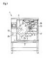
- FIG. 1a lateral view of an apparatus in accordance with the invention for grinding rotary blades
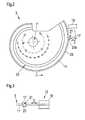
- FIG. 2a lateral view of the rotary blade and of a measuring device of the apparatus of FIG. 1 ;
- FIG. 3a plan view of the rotary blade and of the measuring device of FIG. 2 ;
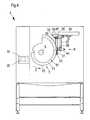
- FIG. 4a further lateral view of the apparatus of FIG. 1 ;
- FIG. 4Aa perspective view of a grinding tool and of a pivot device, for example for a grinding tool of the apparatus of FIGS. 1 and 4 ;
- FIG. 4Ban additional perspective view of the grinding tool and of the pivot device of FIG. 4A ;
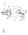
- FIG. 5a lateral view of the rotary blade, of the grinding tool and of the pivot device of the apparatus of FIGS. 1 and 4 .
- the grinding apparatus 1 shownis provided for grinding rotary blades 3 .
- Such rotary blades 3are used, for example, in high-speed cutting machines for slicing food products which are also called slicers.
- a mount 5is provided onto which a mount opening 7 of the rotary blade 3 is placed and to which the rotary blade 3 is fastened (cf. FIGS. 1 and 4 ).
- the grinding apparatus 1has a grinding tool 9 .
- the rotary blade 3 and the grinding tool 9are movable relative to one another so that a blade edge 11 extending at the periphery of the rotary blade 3 can be ground by the grinding tool 9 .
- An automatic determination of the extent of the blade edge 11takes place in the apparatus 1 before the grinding by a measuring device 13 which is coupled with a control 15 so that the determined blade edge extent can be provided to the control 15 .
- the control 15is in turn coupled with the grinding tool 9 and with a drive (not show) for the mount 5 .
- the mount 5 and the rotary blade 3 fastened theretocan be rotated in a direction of rotation I by the drive and the control 15 is designed to use the determined blade edge extent to control the relative movement between the grinding tool 9 and the rotary blade 3 .
- the measuring device 13has a forked light barrier 17 which is coupled with a linear motor 19 (cf. FIGS. 2 and 3 ) and is arranged so that the forked light barrier 17 is located radially outwardly in front of the blade edge 11 , cf. FIG. 2 .
- the forked light barrier 17can be moved along a travel path II (cf. the double arrow in FIGS. 1 to 3 ) by the linear motor 19 so that the forked light barrier 17 is moved toward or away from the rotary blade 3 .
- the forked light barrier 17has a detection zone 21 within which a light path extends between a transmitter and a receiver (both not shown) of the forked light barrier 17 . If the forked light barrier 17 is moved from radially outwardly toward the rotary blade 3 (cf. FIGS. 2 and 3 ), the light path is interrupted by the section 23 a of a radially outwardly disposed cutting edge 23 intersecting the travel path II as soon as the section 23 a moves into the detection zone 21 . On an opposite movement of the forked light barrier 17 , the light path is again released so that the section 23 a again exits the detection zone.
- the rotary blade 3is rotated in the direction of rotation I so that the respective section 23 a of the cutting edge 23 intersecting the travel path II of the forked light barrier 17 can be detected for a plurality of rotational positions of the rotary blade 3 .
- the determination of the extent of the blade edge 11then takes place from the set of the sections 23 a thus detected.
- the respective position of the light barrier 17is determined by the measuring device 13 as the measured value for the position of a detected section 23 a , for example by means of an encoder (not shown) coupled with the linear motor 19 .
- the measuring device 13is designed to determine the respective position of the rotary blade 3 , with respect to the direction of rotation I, in which the respective section 23 a is detected.
- the measuring device 13is coupled with a positional sensor, not shown, which is designed and arranged to detect the position of the rotary blade 3 , for example as an angle of rotation with respect to a zero point.
- the measuring device 13therefore determines a plurality of value pairs in the described embodiment.
- a value pairincludes the position of the respective section 23 a of the cutting edge 23 intersecting the travel path II, said position being determined with respect to the travel path II, and includes the associated rotational position of the rotary blade 3 .
- the thus determined value pairscan be assumed directly as the blade edge extent.
- the measured value which indicates the position of a section 23 a with respect to the travel path IIcan be converted for each value pair into an interval value which indicates the interval between the respective section 23 a and the center of the mount 5 or of the mount opening 7 .
- the extent of the cutting edge 23can thus be determined in polar coordinates with the center of the mount 5 or the mount opening 7 as the origin. Further value pairs can be calculated by interpolation depending on the number of the value pairs determined in this manner.
- the measuring devicecould, for example, be formed so that an edge 51 of the rotary blade 3 extending in accordance with the blade edge 11 (cf. FIGS. 1 and 2 ) is detected. It is in principle also conceivable to determine the blade edge extent by means of a camera and by image evaluation. A relative movement between the blade 3 and the measuring device 13 is therefore not necessary for the determination of the blade edge extent.
- the blade edge extent thus determinedis transmitted by the measuring device 13 to the control 15 and is there stored at least temporarily in a memory 25 .
- the forked light barrier 21is moved away from the rotary blade 3 after the determination of the blade edge extent.
- the machining of the blade edge 11takes place in a manner known per se by a grinding wheel and deburring wheel 29 , 31 of the grinding tool 9 .
- the blade edge 11is contacted by the grinding wheel 29 at a grinding point 27 and by the deburring wheel 31 at a deburring point 53 (cf. FIG. 5 ).
- the grinding tool 9can in this respect be positionable relative to the rotary blade 3 such that, in particular during the total grinding process, the pivot axis 45 is aligned tangentially to the cutting edge 23 extending through the respective grinding point 27 .
- the rotary blade 3is rotated in the direction of rotation I and is thus moved past the grinding tool 9 .
- the control 15is—as mentioned—designed to control the relative movement between the rotary blade 3 and the grinding tool 9 such that the blade edge 11 is “traveled along” by the grinding tool 9 in accordance with the determined blade edge extent.
- the grinding tool 9can be traveled by means of a linear motor along a travel path III (cf. FIG. 4 ) to hold the grinding point 27 and the deburring point 53 in contact with the blade edge 11 while the rotary blade 3 is moved past the grinding tool 9 .
- the grinding tool 9is thus tracked to compensate the changing radius of the rotary blade 3 .
- the grinding tool 9 shown in more detail in FIGS. 4A and 4Bis fastened to the apparatus 1 via a pivot device 33 .
- the pivot device 33has a pivot bearing 35 at which a first and second pivot arm 37 , 39 are rotatably arranged.
- a drive 41 for the grinding wheel 29is arranged at the first pivot arm 37 and a drive 43 for the deburring wheel 31 at the second pivot arm 39 .
- the grinding wheel and deburring wheel 29 , 31are pivotable by the pivot device 33 about a pivot axis 45 which extends through the grinding point 27 and the deburring point 53 and which coincides with the axis of rotation 47 of the pivot bearing 35 (cf. FIG.
- the two wheels 29 , 31form a V-shaped mount for the cutting blade 3 .
- the two wheels 29 , 31are therefore arranged at different sides of the blade 3 , i.e. the one blade at the front side and the other blade at the rear side of the blade 3 .
- the two wheels 29 , 31are in this respect arranged offset from one another with respect to the pivot axis 45 .
- the two wheels 29 , 31are arranged directly above one another with respect to the pivot axis 45 so that they are directly opposite one another, i.e. are arranged in direct proximity to one another while forming the V-shaped mount.
- the two wheels 29 , 31can thus contact one another or only have a small spacing from one another.
- the grinding point 27 and the deburring point 53are likewise offset from one another along the pivot axis 45 due to the offset arrangement of the wheels 29 , 31 .
- the pivot bearing 35is coupled with a pivot drive 49 , in particular controllable by the control 15 , so that both wheels 29 , 31 can be pivoted by the pivot drive 49 during the grinding and the grinding angle and the deburring angle can thus be matched to the blade edge angle of the blade 3 .
- This type of pivotingis extremely precise and additionally particularly resistant to disturbance due to the axis of rotation 47 of the pivot bearing 35 which coincides with the pivot axis 45 . An exact positioning of the grinding point 27 can thus also be ensured on a change of the grinding angle.
- the wheels 29 , 31can be pivoted about the pivot axis 45 independently of one another, in particular during the grinding, so that the grinding angle and the deburring angle can be adjusted independently of one another.
- each pivot arm 37 , 39can be variable so that the spacing between the wheel 29 , 31 arranged at the respective pivot arm and the pivot bearing 35 is adjustable.
- the spacing between the grinding point 27 and the pivot bearing 35can thus be adjusted and adapted to differently sized blades.
Landscapes
- Engineering & Computer Science (AREA)
- Mechanical Engineering (AREA)
- Life Sciences & Earth Sciences (AREA)
- Forests & Forestry (AREA)
- Physics & Mathematics (AREA)
- General Physics & Mathematics (AREA)
- Finish Polishing, Edge Sharpening, And Grinding By Specific Grinding Devices (AREA)
- Constituent Portions Of Griding Lathes, Driving, Sensing And Control (AREA)
Abstract
Description
- 1 grinding apparatus
- 3 rotary blade
- 5 mount
- 7 mount opening
- 9 grinding tool
- 11 blade edge
- 13 measuring device
- 15 control
- 17 forked light barrier
- 19 linear motor
- 21 detection zone of the forked light barrier
- 23 cutting edge
- 23asection of the cutting edge
- 25 memory
- 27 grinding point
- 29 grinding wheel
- 31 deburring wheel
- 33 pivoting device
- 35 pivot bearing
- 37,39 pivot arm
- 41 drive of the grinding wheel
- 43 drive of the deburring wheel
- 45 pivot axis
- 47 pivot axis of the pivot bearing
- 49 pivot drive
- 51 edge
- 53 deburring point
- 55 linear motor
- I direction of rotation of the blade and of the mount
- II travel path of the light barrier
- III travel path of the grinding tool
Claims (9)
Applications Claiming Priority (6)
| Application Number | Priority Date | Filing Date | Title |
|---|---|---|---|
| DE102011103418.1 | 2011-06-06 | ||
| DE102011103418ADE102011103418A1 (en) | 2011-06-06 | 2011-06-06 | Device for sharpening rotary blades, particularly sickle- or circular blades, has receptacle, in which rotary blade and sharpening tool are fixed, where rotary blade and sharpening tool are moved relative to each other |
| DE102011103418 | 2011-06-06 | ||
| DE102012005566.8 | 2012-03-20 | ||
| DE201210005566DE102012005566A1 (en) | 2012-03-20 | 2012-03-20 | Device for sharpening e.g. sickle or circle knives, for slice for slicing food products, has controlling unit utilizing determined cutting course for controlling relative movement between sharpening tools and rotatable knife |
| DE102012005566 | 2012-03-20 |
Publications (2)
| Publication Number | Publication Date |
|---|---|
| US20120309266A1 US20120309266A1 (en) | 2012-12-06 |
| US9393662B2true US9393662B2 (en) | 2016-07-19 |
Family
ID=46318872
Family Applications (1)
| Application Number | Title | Priority Date | Filing Date |
|---|---|---|---|
| US13/486,683Active2034-10-20US9393662B2 (en) | 2011-06-06 | 2012-06-01 | Apparatus and method for grinding rotary blades |
Country Status (4)
| Country | Link |
|---|---|
| US (1) | US9393662B2 (en) |
| EP (2) | EP3175952B1 (en) |
| CA (1) | CA2779421C (en) |
| DE (1) | DE202012012624U1 (en) |
Cited By (5)
| Publication number | Priority date | Publication date | Assignee | Title |
|---|---|---|---|---|
| US20170021521A1 (en)* | 2013-11-30 | 2017-01-26 | Futura S.P.A. | Device for controlling the sharpening state of a blade |
| US20170182616A1 (en)* | 2015-12-29 | 2017-06-29 | Citic Dicastal Co., Ltd | Online general vehicle wheel deburring device |
| US10035235B2 (en)* | 2013-12-02 | 2018-07-31 | Futura S.P.A. | Device for sharpening blades |
| US20200171615A1 (en)* | 2017-07-18 | 2020-06-04 | Fabio Perini S.P.A. | Grinding unit for a cutting blade, machine comprising said unit and related method |
| US11504873B2 (en)* | 2013-05-09 | 2022-11-22 | Fuzion Llc | Dynamic regulation of contact pressures in a blade sharpening system |
Families Citing this family (12)
| Publication number | Priority date | Publication date | Assignee | Title |
|---|---|---|---|---|
| DE102013007275A1 (en)* | 2013-04-26 | 2014-11-13 | Weber Maschinenbau Gmbh Breidenbach | Food slicing knife with a radio transponder |
| DE102013013498A1 (en)* | 2013-08-16 | 2015-02-19 | Dipl.-Ing. Schindler & Wagner Gmbh & Co. Kg | Device for sharpening rotary blades |
| DE102013217137A1 (en)* | 2013-08-28 | 2015-03-05 | Weber Maschinenbau Gmbh Breidenbach | Apparatus and method for grinding rotary blades |
| ITUA20161489A1 (en) | 2016-03-10 | 2017-09-10 | Gd Spa | Cutting head for cutting rod-shaped pieces in machines for the production of smoking articles. |
| EP3366439A1 (en)* | 2017-02-27 | 2018-08-29 | Bizerba SE & Co. KG | Slicer with a device for supervising the condition of the knife |
| CN109986639A (en)* | 2019-05-14 | 2019-07-09 | 南通科诚橡塑机械有限公司 | A kind of rubber slitting device with synchronous handwheel |
| CN110370150B (en)* | 2019-07-30 | 2020-06-23 | 南京宜邦金属制品有限公司 | Safe type cutting machine convenient to blade is changed |
| US12427593B2 (en)* | 2021-05-27 | 2025-09-30 | Ford Gin Services LLC | Gin blade sharpening system and method of use |
| DE102021116847A1 (en) | 2021-06-30 | 2023-01-19 | Multivac Sepp Haggenmüller Se & Co. Kg | slicing machine |
| CN113552845B (en)* | 2021-07-29 | 2022-06-21 | 重庆博张机电设备有限公司 | Measurement control method and flaker |
| DE102022112000A1 (en)* | 2022-05-12 | 2023-11-16 | Dipl.Ing. S c h i n d l e r & Wagner GmbH & Co KG | Device for sheep and method for operating the device |
| US20250135593A1 (en)* | 2022-11-10 | 2025-05-01 | Illinois Tool Works Inc. | Food product slicer with optical knife edge evaluation |
Citations (23)
| Publication number | Priority date | Publication date | Assignee | Title |
|---|---|---|---|---|
| US2207433A (en)* | 1938-03-14 | 1940-07-09 | Harry H Straus | Means for sharpening a circular knife |
| US2429300A (en)* | 1945-10-15 | 1947-10-21 | Martin H Wilbert | Saw-tooth grinder |
| US2716908A (en)* | 1954-07-19 | 1955-09-06 | Roland O Lundberg | Automatic grinder for circular saws |
| US2766566A (en)* | 1953-08-26 | 1956-10-16 | Gilbertville Woven Label Corp | Sharpening device for cutting wheels |
| DE1933993U (en) | 1965-07-07 | 1966-03-03 | Rohde & Doerrenberg | CONTROL DEVICE FOR GRINDING MACHINES FOR MULTI-BLADE TOOLS, IN PARTICULAR FOR KNIFE HEADS. |
| US4173846A (en)* | 1978-01-23 | 1979-11-13 | Paper Converting Machine Company | Orbital saw sharpening device |
| US5152203A (en)* | 1991-08-19 | 1992-10-06 | Paper Converting Machine Company | Apparatus and method for sharpening saw blades having planetary motion in transverse cutting |
| US5327686A (en)* | 1991-04-24 | 1994-07-12 | Kyung Park | Chamfering width maintaining and glass plate shape sensing apparatus for use in a glass plate chamfering machine |
| DE4408566A1 (en) | 1993-03-19 | 1994-09-22 | Taihei Seisakusho Komaki Kk | Method and apparatus for grinding a long knife |
| DE4316789A1 (en) | 1993-05-19 | 1994-11-24 | August Heinr Schmidt Gmbh & Co | Method and device for sharpening a circular saw blade |
| US5632666A (en)* | 1994-10-28 | 1997-05-27 | Memc Electronic Materials, Inc. | Method and apparatus for automated quality control in wafer slicing |
| US5941148A (en)* | 1998-01-16 | 1999-08-24 | Tidland Corporation | Automatic slitter blade sharpener |
| JP2001038598A (en) | 1999-07-26 | 2001-02-13 | Prima Meat Packers Ltd | Automatic polisher |
| US6224468B1 (en)* | 1999-07-15 | 2001-05-01 | Paper Converting Machine Company | Apparatus and method for sharpening a disc blade |
| DE10035743A1 (en) | 2000-07-22 | 2002-04-04 | Deere & Co | grinder |
| DE10205146A1 (en) | 2002-02-07 | 2003-08-21 | Hauni Maschinenbau Ag | Sharpening of rotating cutting knife for use in cigarette production, involves scanning knife blade to measure amount of blade wear so that sharpening is only carried out as necessary |
| DE20314680U1 (en) | 2003-09-20 | 2003-11-20 | Oerlikon Geartec AG, Zürich | Grinding machine with measuring system and control to provide a master knife |
| US20050159079A1 (en)* | 2002-03-26 | 2005-07-21 | Danobat, S. Coop, | Rotor-grinding machine comprising a rotary head with two grinding wheels |
| EP1598159A1 (en) | 2004-05-13 | 2005-11-23 | ASTOR Schneidwerkzeuge GmbH | Rotary knife |
| DE102005013363A1 (en) | 2004-05-13 | 2005-12-08 | Astor Schneidwerkzeuge Gmbh | Sharpening machine for rotary blade used in food machines e.g. meat processing machines has linear axles that are coupled to frame within housing |
| WO2007097724A2 (en) | 2006-02-24 | 2007-08-30 | Lms Makina Sanayi Ve Ticaret Limited Sirketi | Technique for automatic sharpening of cleaning paper cutting machine |
| DE102009006912A1 (en) | 2009-01-30 | 2010-08-05 | Weber Maschinenbau Gmbh Breidenbach | cutting blade |
| US20120184186A1 (en)* | 2011-01-14 | 2012-07-19 | Graham Jr Dave | Blade sharpening system and method |
Family Cites Families (10)
| Publication number | Priority date | Publication date | Assignee | Title |
|---|---|---|---|---|
| CH659790A5 (en) | 1983-06-09 | 1987-02-27 | Paul Kocher Ag | DEVICE FOR POSITIONING DRILLS. |
| DE9321251U1 (en)* | 1993-05-19 | 1996-11-14 | August Heinr. Schmidt GmbH & Co. KG Maschinenfabrik, 70469 Stuttgart | Device for sharpening a circular saw blade |
| DE19840801B4 (en) | 1998-09-08 | 2005-09-15 | Walter Maschinenbau Gmbh | Machine tool with automatic process control / monitoring and process for editing |
| DE19924904A1 (en)* | 1999-05-31 | 2000-12-07 | Fritsch Sondermaschinen Gmbh D | Radius grinding device with feed device, with height registering device for each curved tool segment |
| DE10012445A1 (en) | 2000-03-15 | 2001-09-27 | Hubert Haller | Machining centre; has horizontal working plate and machining head for machining tool pivoting about vertical machining column by rotary plate and has carrying arms and holder device |
| JP4590058B2 (en)* | 2000-04-12 | 2010-12-01 | 株式会社ディスコ | Cutting blade detection mechanism of cutting equipment |
| DE10021302A1 (en) | 2000-05-02 | 2001-11-08 | Heinz Berger Maschinenfabrik G | Grinder machine has magazine, feeder unit, withdrawal unit, two grinder discs, robot, manipulator, gripper head and holder. |
| FR2847841B1 (en) | 2002-11-28 | 2005-08-19 | Alain Aveline | IMPROVED WHEEL CUTTING DEVICE |
| DE102007040350A1 (en) | 2007-08-27 | 2009-03-05 | Weber Maschinenbau Gmbh Breidenbach | cutting blade |
| JP2009231760A (en)* | 2008-03-25 | 2009-10-08 | Tokyo Seimitsu Co Ltd | Device for detecting breakage/abrasion of blade |
- 2012
- 2012-06-01EPEP16202450.9Apatent/EP3175952B1/enactiveActive
- 2012-06-01EPEP12170398.7Apatent/EP2532477B1/enactiveActive
- 2012-06-01DEDE202012012624Upatent/DE202012012624U1/ennot_activeExpired - Lifetime
- 2012-06-01USUS13/486,683patent/US9393662B2/enactiveActive
- 2012-06-05CACA2779421Apatent/CA2779421C/enactiveActive
Patent Citations (27)
| Publication number | Priority date | Publication date | Assignee | Title |
|---|---|---|---|---|
| US2207433A (en)* | 1938-03-14 | 1940-07-09 | Harry H Straus | Means for sharpening a circular knife |
| US2429300A (en)* | 1945-10-15 | 1947-10-21 | Martin H Wilbert | Saw-tooth grinder |
| US2766566A (en)* | 1953-08-26 | 1956-10-16 | Gilbertville Woven Label Corp | Sharpening device for cutting wheels |
| US2716908A (en)* | 1954-07-19 | 1955-09-06 | Roland O Lundberg | Automatic grinder for circular saws |
| DE1933993U (en) | 1965-07-07 | 1966-03-03 | Rohde & Doerrenberg | CONTROL DEVICE FOR GRINDING MACHINES FOR MULTI-BLADE TOOLS, IN PARTICULAR FOR KNIFE HEADS. |
| US4173846A (en)* | 1978-01-23 | 1979-11-13 | Paper Converting Machine Company | Orbital saw sharpening device |
| US5327686A (en)* | 1991-04-24 | 1994-07-12 | Kyung Park | Chamfering width maintaining and glass plate shape sensing apparatus for use in a glass plate chamfering machine |
| US5152203A (en)* | 1991-08-19 | 1992-10-06 | Paper Converting Machine Company | Apparatus and method for sharpening saw blades having planetary motion in transverse cutting |
| DE4408566A1 (en) | 1993-03-19 | 1994-09-22 | Taihei Seisakusho Komaki Kk | Method and apparatus for grinding a long knife |
| US5556321A (en) | 1993-03-19 | 1996-09-17 | Kabushiki Kaisha Taihei Seisakusho | Method and apparatus for grinding elongated knife blade |
| DE4316789A1 (en) | 1993-05-19 | 1994-11-24 | August Heinr Schmidt Gmbh & Co | Method and device for sharpening a circular saw blade |
| US5632666A (en)* | 1994-10-28 | 1997-05-27 | Memc Electronic Materials, Inc. | Method and apparatus for automated quality control in wafer slicing |
| US5941148A (en)* | 1998-01-16 | 1999-08-24 | Tidland Corporation | Automatic slitter blade sharpener |
| US6224468B1 (en)* | 1999-07-15 | 2001-05-01 | Paper Converting Machine Company | Apparatus and method for sharpening a disc blade |
| JP2001038598A (en) | 1999-07-26 | 2001-02-13 | Prima Meat Packers Ltd | Automatic polisher |
| DE10035743A1 (en) | 2000-07-22 | 2002-04-04 | Deere & Co | grinder |
| US6503135B2 (en) | 2000-07-22 | 2003-01-07 | Deere & Company | Grinding device |
| DE10205146A1 (en) | 2002-02-07 | 2003-08-21 | Hauni Maschinenbau Ag | Sharpening of rotating cutting knife for use in cigarette production, involves scanning knife blade to measure amount of blade wear so that sharpening is only carried out as necessary |
| US20050159079A1 (en)* | 2002-03-26 | 2005-07-21 | Danobat, S. Coop, | Rotor-grinding machine comprising a rotary head with two grinding wheels |
| US7125312B2 (en)* | 2002-03-26 | 2006-10-24 | Danabat, S. Coop | Rotor-grinding machine comprising a rotary head with two grinding wheels |
| DE20314680U1 (en) | 2003-09-20 | 2003-11-20 | Oerlikon Geartec AG, Zürich | Grinding machine with measuring system and control to provide a master knife |
| US6955584B2 (en) | 2003-09-20 | 2005-10-18 | Klingelnberg Ag | Grinding machine comprising a measuring system and control for providing a master blade and method for providing a bar blade |
| EP1598159A1 (en) | 2004-05-13 | 2005-11-23 | ASTOR Schneidwerkzeuge GmbH | Rotary knife |
| DE102005013363A1 (en) | 2004-05-13 | 2005-12-08 | Astor Schneidwerkzeuge Gmbh | Sharpening machine for rotary blade used in food machines e.g. meat processing machines has linear axles that are coupled to frame within housing |
| WO2007097724A2 (en) | 2006-02-24 | 2007-08-30 | Lms Makina Sanayi Ve Ticaret Limited Sirketi | Technique for automatic sharpening of cleaning paper cutting machine |
| DE102009006912A1 (en) | 2009-01-30 | 2010-08-05 | Weber Maschinenbau Gmbh Breidenbach | cutting blade |
| US20120184186A1 (en)* | 2011-01-14 | 2012-07-19 | Graham Jr Dave | Blade sharpening system and method |
Non-Patent Citations (3)
| Title |
|---|
| German Search Report for Corresponding German Application No. DE102011103418.1, dated Mar. 16, 2012; 5 Pages. |
| Translation of German Search Report for Corresponding German Application No. DE102011103418.1, dated Mar. 16, 2012; 6 Pages. |
| Translation of German Search Report relating to German Patent Application No. 102012005566.8 dated Jan. 11, 2013 (5 pgs). |
Cited By (12)
| Publication number | Priority date | Publication date | Assignee | Title |
|---|---|---|---|---|
| US11504873B2 (en)* | 2013-05-09 | 2022-11-22 | Fuzion Llc | Dynamic regulation of contact pressures in a blade sharpening system |
| US20230226711A1 (en)* | 2013-05-09 | 2023-07-20 | Lawrence E Baker | Dynamic regulation of contact pressures in a blade sharpening system |
| US11833704B2 (en)* | 2013-05-09 | 2023-12-05 | Fuzion Llc | Dynamic regulation of contact pressures in a blade sharpening system |
| US20170021521A1 (en)* | 2013-11-30 | 2017-01-26 | Futura S.P.A. | Device for controlling the sharpening state of a blade |
| US20170021520A1 (en)* | 2013-11-30 | 2017-01-26 | Futura S.P.A. | Control device for blades sharpening |
| US10029380B2 (en)* | 2013-11-30 | 2018-07-24 | Futura S.P.A. | Control device for blades sharpening |
| US10029381B2 (en)* | 2013-11-30 | 2018-07-24 | Futura S.P.A. | Device for controlling the sharpening state of a blade |
| US10035235B2 (en)* | 2013-12-02 | 2018-07-31 | Futura S.P.A. | Device for sharpening blades |
| US20170182616A1 (en)* | 2015-12-29 | 2017-06-29 | Citic Dicastal Co., Ltd | Online general vehicle wheel deburring device |
| US10065284B2 (en)* | 2015-12-29 | 2018-09-04 | Citic Dicastal Co., Ltd | Online general vehicle wheel deburring device |
| US20200171615A1 (en)* | 2017-07-18 | 2020-06-04 | Fabio Perini S.P.A. | Grinding unit for a cutting blade, machine comprising said unit and related method |
| US12011798B2 (en)* | 2017-07-18 | 2024-06-18 | Fabio Perini S.P.A. | Grinding unit for a cutting blade, machine comprising said unit and related method |
Also Published As
| Publication number | Publication date |
|---|---|
| EP2532477A3 (en) | 2015-09-09 |
| EP2532477B1 (en) | 2019-04-24 |
| CA2779421C (en) | 2019-12-03 |
| DE202012012624U1 (en) | 2013-06-28 |
| EP2532477A2 (en) | 2012-12-12 |
| CA2779421A1 (en) | 2012-12-06 |
| EP3175952A3 (en) | 2017-06-28 |
| EP3175952A2 (en) | 2017-06-07 |
| EP3175952B1 (en) | 2024-07-31 |
| US20120309266A1 (en) | 2012-12-06 |
Similar Documents
| Publication | Publication Date | Title |
|---|---|---|
| US9393662B2 (en) | Apparatus and method for grinding rotary blades | |
| US9863247B2 (en) | Floor milling machine | |
| US7715024B2 (en) | Method of and apparatus for determining geometrical dimensions of a wheel rim, in particular when fitting and/or removing a motor vehicle tyre | |
| US9125342B2 (en) | Method and device for the state detection of a cutting device | |
| WO2003043077A1 (en) | Wafer positioning method and apparatus, processing system, and method for positioning wafer seat rotating axis of wafer positioning apparatus | |
| US20090025233A1 (en) | Hand-held jigsaw | |
| EP2930505B1 (en) | Machine tool including affected layer detection sensor | |
| CN112533743B (en) | Hand-held power tool | |
| CN109483326B (en) | Method for positioning a center point on a geometric axis in a machine tool | |
| US9475242B2 (en) | Eyeglass lens processing apparatus | |
| WO2017043931A1 (en) | Hybrid cutting apparatus and grooving method using same | |
| EP3067137B1 (en) | Cutting tool | |
| US20120227271A1 (en) | Tool Device | |
| JP2015085424A (en) | Broach cutter grinder and method to align position of grindstone therein | |
| US11858161B2 (en) | Cutting machine for transversely cutting logs of paper material | |
| CN109277647A (en) | A kind of Double-cutter head radiusing machine | |
| JP5736946B2 (en) | Adjusting device between blade gaps of cutting apparatus and adjusting method between blade gaps using the same | |
| JP5790355B2 (en) | Cutting apparatus and cutting method | |
| JP2020104183A (en) | Machine tool, and origin detection method of tool magazine | |
| JP2004243468A (en) | Surface grinding machine with touch probe sensor | |
| JP2013123758A (en) | Mechanical rigidity measuring method and machine tool | |
| CN219053873U (en) | Glass edge grinding amount detection device | |
| JP6576769B2 (en) | Workpiece origin detection method and origin detection device | |
| CN206435813U (en) | The wheel stand of band sawing machine | |
| KR101620741B1 (en) | Apparatus for guiding and Cutter having the same |
Legal Events
| Date | Code | Title | Description |
|---|---|---|---|
| AS | Assignment | Owner name:WEBER MASCHINENBAU GMBH BREIDENBACH, GERMANY Free format text:ASSIGNMENT OF ASSIGNORS INTEREST;ASSIGNORS:SCHROEDER, JENS;SPILLNER, SABINE;LISCHINSKI, GERD;AND OTHERS;SIGNING DATES FROM 20120709 TO 20120726;REEL/FRAME:028781/0525 | |
| FEPP | Fee payment procedure | Free format text:PAYOR NUMBER ASSIGNED (ORIGINAL EVENT CODE: ASPN); ENTITY STATUS OF PATENT OWNER: LARGE ENTITY | |
| STCF | Information on status: patent grant | Free format text:PATENTED CASE | |
| FEPP | Fee payment procedure | Free format text:PAYOR NUMBER ASSIGNED (ORIGINAL EVENT CODE: ASPN); ENTITY STATUS OF PATENT OWNER: LARGE ENTITY Free format text:PAYER NUMBER DE-ASSIGNED (ORIGINAL EVENT CODE: RMPN); ENTITY STATUS OF PATENT OWNER: LARGE ENTITY | |
| MAFP | Maintenance fee payment | Free format text:PAYMENT OF MAINTENANCE FEE, 4TH YEAR, LARGE ENTITY (ORIGINAL EVENT CODE: M1551); ENTITY STATUS OF PATENT OWNER: LARGE ENTITY Year of fee payment:4 | |
| MAFP | Maintenance fee payment | Free format text:PAYMENT OF MAINTENANCE FEE, 8TH YEAR, LARGE ENTITY (ORIGINAL EVENT CODE: M1552); ENTITY STATUS OF PATENT OWNER: LARGE ENTITY Year of fee payment:8 | |
| AS | Assignment | Owner name:WEBER FOOD TECHNOLOGY GMBH, GERMANY Free format text:CHANGE OF NAME;ASSIGNOR:WEBER MASCHINENBAU GMBH BREIDENBACH;REEL/FRAME:066382/0233 Effective date:20231222 | |
| AS | Assignment | Owner name:WEBER FOOD TECHNOLOGY SE & CO. KG, GERMANY Free format text:CHANGE OF NAME;ASSIGNOR:WEBER FOOD TECHNOLOGY GMBH;REEL/FRAME:070251/0522 Effective date:20250128 |