US9393126B2 - Bilaterally placed disc prosthesis for spinal implant and method of bilateral placement - Google Patents
Bilaterally placed disc prosthesis for spinal implant and method of bilateral placementDownload PDFInfo
- Publication number
- US9393126B2 US9393126B2US13/845,810US201313845810AUS9393126B2US 9393126 B2US9393126 B2US 9393126B2US 201313845810 AUS201313845810 AUS 201313845810AUS 9393126 B2US9393126 B2US 9393126B2
- Authority
- US
- United States
- Prior art keywords
- prosthesis
- end cap
- components
- disc
- elongated tube
- Prior art date
- Legal status (The legal status is an assumption and is not a legal conclusion. Google has not performed a legal analysis and makes no representation as to the accuracy of the status listed.)
- Active, expires
Links
- 238000000034methodMethods0.000titleclaimsabstractdescription14
- 239000007943implantSubstances0.000titledescription17
- 230000002146bilateral effectEffects0.000titledescription2
- 238000003780insertionMethods0.000claimsabstractdescription6
- 230000037431insertionEffects0.000claimsabstractdescription6
- 230000008878couplingEffects0.000claimsdescription2
- 238000010168coupling processMethods0.000claimsdescription2
- 238000005859coupling reactionMethods0.000claimsdescription2
- FGUUSXIOTUKUDN-IBGZPJMESA-NC1(=CC=CC=C1)N1C2=C(NC([C@H](C1)NC=1OC(=NN=1)C1=CC=CC=C1)=O)C=CC=C2Chemical compoundC1(=CC=CC=C1)N1C2=C(NC([C@H](C1)NC=1OC(=NN=1)C1=CC=CC=C1)=O)C=CC=C2FGUUSXIOTUKUDN-IBGZPJMESA-N0.000claims1
- 230000013011matingEffects0.000abstractdescription4
- 210000005036nerveAnatomy0.000description9
- 208000002193PainDiseases0.000description7
- 206010037779RadiculopathyDiseases0.000description5
- 208000003618Intervertebral Disc DisplacementDiseases0.000description4
- 238000012800visualizationMethods0.000description4
- 208000031481Pathologic ConstrictionDiseases0.000description3
- 230000008569processEffects0.000description3
- 230000036262stenosisEffects0.000description3
- 208000037804stenosisDiseases0.000description3
- 208000008558OsteophyteDiseases0.000description2
- 210000000988bone and boneAnatomy0.000description2
- 230000003412degenerative effectEffects0.000description2
- 238000002059diagnostic imagingMethods0.000description2
- 238000005259measurementMethods0.000description2
- 231100000862numbnessToxicity0.000description2
- 206010061928radiculitisDiseases0.000description2
- 230000035939shockEffects0.000description2
- 210000000278spinal cordAnatomy0.000description2
- 230000000087stabilizing effectEffects0.000description2
- 238000011282treatmentMethods0.000description2
- 0C*[C@](C)*NC1PC(C)C1Chemical compoundC*[C@](C)*NC1PC(C)C10.000description1
- 208000000094Chronic PainDiseases0.000description1
- 108090001069ChymopapainProteins0.000description1
- 206010050296Intervertebral disc protrusionDiseases0.000description1
- 102000001621MucoproteinsHuman genes0.000description1
- 108010093825MucoproteinsProteins0.000description1
- 206010028570MyelopathyDiseases0.000description1
- 208000008457Neurologic ManifestationsDiseases0.000description1
- ISWQCIVKKSOKNN-UHFFFAOYSA-LTironChemical compound[Na+].[Na+].OC1=CC(S([O-])(=O)=O)=CC(S([O-])(=O)=O)=C1OISWQCIVKKSOKNN-UHFFFAOYSA-L0.000description1
- 208000027418Wounds and injuryDiseases0.000description1
- 239000006096absorbing agentSubstances0.000description1
- 230000001154acute effectEffects0.000description1
- 208000005298acute painDiseases0.000description1
- 238000005452bendingMethods0.000description1
- 239000012620biological materialSubstances0.000description1
- 210000000845cartilageAnatomy0.000description1
- 210000003164cauda equinaAnatomy0.000description1
- 206010007821cauda equina syndromeDiseases0.000description1
- 230000008859changeEffects0.000description1
- 229960002976chymopapainDrugs0.000description1
- 230000006835compressionEffects0.000description1
- 238000007906compressionMethods0.000description1
- 210000002808connective tissueAnatomy0.000description1
- 230000006378damageEffects0.000description1
- 238000013461designMethods0.000description1
- 210000003414extremityAnatomy0.000description1
- 238000001125extrusionMethods0.000description1
- 239000000835fiberSubstances0.000description1
- 210000000968fibrocartilageAnatomy0.000description1
- 230000004927fusionEffects0.000description1
- 230000001771impaired effectEffects0.000description1
- 238000002347injectionMethods0.000description1
- 239000007924injectionSubstances0.000description1
- 208000014674injuryDiseases0.000description1
- 210000003041ligamentAnatomy0.000description1
- 239000000463materialSubstances0.000description1
- 239000012528membraneSubstances0.000description1
- 238000012986modificationMethods0.000description1
- 230000004048modificationEffects0.000description1
- 230000000921morphogenic effectEffects0.000description1
- 230000001537neural effectEffects0.000description1
- 230000009251neurologic dysfunctionEffects0.000description1
- 230000000926neurological effectEffects0.000description1
- 210000000056organAnatomy0.000description1
- 108090000623proteins and genesProteins0.000description1
- 102000004169proteins and genesHuman genes0.000description1
- 238000007674radiofrequency ablationMethods0.000description1
- 230000001953sensory effectEffects0.000description1
- 210000001032spinal nerveAnatomy0.000description1
- 208000024891symptomDiseases0.000description1
- 210000001519tissueAnatomy0.000description1
- 210000002517zygapophyseal jointAnatomy0.000description1
Images


Classifications
- A—HUMAN NECESSITIES
- A61—MEDICAL OR VETERINARY SCIENCE; HYGIENE
- A61F—FILTERS IMPLANTABLE INTO BLOOD VESSELS; PROSTHESES; DEVICES PROVIDING PATENCY TO, OR PREVENTING COLLAPSING OF, TUBULAR STRUCTURES OF THE BODY, e.g. STENTS; ORTHOPAEDIC, NURSING OR CONTRACEPTIVE DEVICES; FOMENTATION; TREATMENT OR PROTECTION OF EYES OR EARS; BANDAGES, DRESSINGS OR ABSORBENT PADS; FIRST-AID KITS
- A61F2/00—Filters implantable into blood vessels; Prostheses, i.e. artificial substitutes or replacements for parts of the body; Appliances for connecting them with the body; Devices providing patency to, or preventing collapsing of, tubular structures of the body, e.g. stents
- A61F2/02—Prostheses implantable into the body
- A61F2/30—Joints
- A61F2/44—Joints for the spine, e.g. vertebrae, spinal discs
- A61F2/442—Intervertebral or spinal discs, e.g. resilient
- A61F2/4425—Intervertebral or spinal discs, e.g. resilient made of articulated components
- A—HUMAN NECESSITIES
- A61—MEDICAL OR VETERINARY SCIENCE; HYGIENE
- A61F—FILTERS IMPLANTABLE INTO BLOOD VESSELS; PROSTHESES; DEVICES PROVIDING PATENCY TO, OR PREVENTING COLLAPSING OF, TUBULAR STRUCTURES OF THE BODY, e.g. STENTS; ORTHOPAEDIC, NURSING OR CONTRACEPTIVE DEVICES; FOMENTATION; TREATMENT OR PROTECTION OF EYES OR EARS; BANDAGES, DRESSINGS OR ABSORBENT PADS; FIRST-AID KITS
- A61F2/00—Filters implantable into blood vessels; Prostheses, i.e. artificial substitutes or replacements for parts of the body; Appliances for connecting them with the body; Devices providing patency to, or preventing collapsing of, tubular structures of the body, e.g. stents
- A61F2/02—Prostheses implantable into the body
- A61F2/30—Joints
- A61F2/44—Joints for the spine, e.g. vertebrae, spinal discs
- A61F2/442—Intervertebral or spinal discs, e.g. resilient
- A—HUMAN NECESSITIES
- A61—MEDICAL OR VETERINARY SCIENCE; HYGIENE
- A61F—FILTERS IMPLANTABLE INTO BLOOD VESSELS; PROSTHESES; DEVICES PROVIDING PATENCY TO, OR PREVENTING COLLAPSING OF, TUBULAR STRUCTURES OF THE BODY, e.g. STENTS; ORTHOPAEDIC, NURSING OR CONTRACEPTIVE DEVICES; FOMENTATION; TREATMENT OR PROTECTION OF EYES OR EARS; BANDAGES, DRESSINGS OR ABSORBENT PADS; FIRST-AID KITS
- A61F2/00—Filters implantable into blood vessels; Prostheses, i.e. artificial substitutes or replacements for parts of the body; Appliances for connecting them with the body; Devices providing patency to, or preventing collapsing of, tubular structures of the body, e.g. stents
- A61F2/02—Prostheses implantable into the body
- A61F2/30—Joints
- A61F2/46—Special tools for implanting artificial joints
- A61F2/4603—Special tools for implanting artificial joints for insertion or extraction of endoprosthetic joints or of accessories thereof
- A61F2/4611—Special tools for implanting artificial joints for insertion or extraction of endoprosthetic joints or of accessories thereof of spinal prostheses
- A—HUMAN NECESSITIES
- A61—MEDICAL OR VETERINARY SCIENCE; HYGIENE
- A61F—FILTERS IMPLANTABLE INTO BLOOD VESSELS; PROSTHESES; DEVICES PROVIDING PATENCY TO, OR PREVENTING COLLAPSING OF, TUBULAR STRUCTURES OF THE BODY, e.g. STENTS; ORTHOPAEDIC, NURSING OR CONTRACEPTIVE DEVICES; FOMENTATION; TREATMENT OR PROTECTION OF EYES OR EARS; BANDAGES, DRESSINGS OR ABSORBENT PADS; FIRST-AID KITS
- A61F2/00—Filters implantable into blood vessels; Prostheses, i.e. artificial substitutes or replacements for parts of the body; Appliances for connecting them with the body; Devices providing patency to, or preventing collapsing of, tubular structures of the body, e.g. stents
- A61F2/02—Prostheses implantable into the body
- A61F2/30—Joints
- A61F2002/30001—Additional features of subject-matter classified in A61F2/28, A61F2/30 and subgroups thereof
- A61F2002/30108—Shapes
- A61F2002/30199—Three-dimensional shapes
- A61F2002/30224—Three-dimensional shapes cylindrical
- A61F2002/30235—Three-dimensional shapes cylindrical tubular, e.g. sleeves
- A—HUMAN NECESSITIES
- A61—MEDICAL OR VETERINARY SCIENCE; HYGIENE
- A61F—FILTERS IMPLANTABLE INTO BLOOD VESSELS; PROSTHESES; DEVICES PROVIDING PATENCY TO, OR PREVENTING COLLAPSING OF, TUBULAR STRUCTURES OF THE BODY, e.g. STENTS; ORTHOPAEDIC, NURSING OR CONTRACEPTIVE DEVICES; FOMENTATION; TREATMENT OR PROTECTION OF EYES OR EARS; BANDAGES, DRESSINGS OR ABSORBENT PADS; FIRST-AID KITS
- A61F2/00—Filters implantable into blood vessels; Prostheses, i.e. artificial substitutes or replacements for parts of the body; Appliances for connecting them with the body; Devices providing patency to, or preventing collapsing of, tubular structures of the body, e.g. stents
- A61F2/02—Prostheses implantable into the body
- A61F2/30—Joints
- A61F2002/30001—Additional features of subject-matter classified in A61F2/28, A61F2/30 and subgroups thereof
- A61F2002/30108—Shapes
- A61F2002/30199—Three-dimensional shapes
- A61F2002/30286—Three-dimensional shapes barrel-shaped
- A—HUMAN NECESSITIES
- A61—MEDICAL OR VETERINARY SCIENCE; HYGIENE
- A61F—FILTERS IMPLANTABLE INTO BLOOD VESSELS; PROSTHESES; DEVICES PROVIDING PATENCY TO, OR PREVENTING COLLAPSING OF, TUBULAR STRUCTURES OF THE BODY, e.g. STENTS; ORTHOPAEDIC, NURSING OR CONTRACEPTIVE DEVICES; FOMENTATION; TREATMENT OR PROTECTION OF EYES OR EARS; BANDAGES, DRESSINGS OR ABSORBENT PADS; FIRST-AID KITS
- A61F2/00—Filters implantable into blood vessels; Prostheses, i.e. artificial substitutes or replacements for parts of the body; Appliances for connecting them with the body; Devices providing patency to, or preventing collapsing of, tubular structures of the body, e.g. stents
- A61F2/02—Prostheses implantable into the body
- A61F2/30—Joints
- A61F2002/30001—Additional features of subject-matter classified in A61F2/28, A61F2/30 and subgroups thereof
- A61F2002/30316—The prosthesis having different structural features at different locations within the same prosthesis; Connections between prosthetic parts; Special structural features of bone or joint prostheses not otherwise provided for
- A61F2002/30329—Connections or couplings between prosthetic parts, e.g. between modular parts; Connecting elements
- A61F2002/30405—Connections or couplings between prosthetic parts, e.g. between modular parts; Connecting elements made by screwing complementary threads machined on the parts themselves
- A—HUMAN NECESSITIES
- A61—MEDICAL OR VETERINARY SCIENCE; HYGIENE
- A61F—FILTERS IMPLANTABLE INTO BLOOD VESSELS; PROSTHESES; DEVICES PROVIDING PATENCY TO, OR PREVENTING COLLAPSING OF, TUBULAR STRUCTURES OF THE BODY, e.g. STENTS; ORTHOPAEDIC, NURSING OR CONTRACEPTIVE DEVICES; FOMENTATION; TREATMENT OR PROTECTION OF EYES OR EARS; BANDAGES, DRESSINGS OR ABSORBENT PADS; FIRST-AID KITS
- A61F2/00—Filters implantable into blood vessels; Prostheses, i.e. artificial substitutes or replacements for parts of the body; Appliances for connecting them with the body; Devices providing patency to, or preventing collapsing of, tubular structures of the body, e.g. stents
- A61F2/02—Prostheses implantable into the body
- A61F2/30—Joints
- A61F2002/30001—Additional features of subject-matter classified in A61F2/28, A61F2/30 and subgroups thereof
- A61F2002/30316—The prosthesis having different structural features at different locations within the same prosthesis; Connections between prosthetic parts; Special structural features of bone or joint prostheses not otherwise provided for
- A61F2002/30329—Connections or couplings between prosthetic parts, e.g. between modular parts; Connecting elements
- A61F2002/30476—Connections or couplings between prosthetic parts, e.g. between modular parts; Connecting elements locked by an additional locking mechanism
- A61F2002/30507—Connections or couplings between prosthetic parts, e.g. between modular parts; Connecting elements locked by an additional locking mechanism using a threaded locking member, e.g. a locking screw or a set screw
- A—HUMAN NECESSITIES
- A61—MEDICAL OR VETERINARY SCIENCE; HYGIENE
- A61F—FILTERS IMPLANTABLE INTO BLOOD VESSELS; PROSTHESES; DEVICES PROVIDING PATENCY TO, OR PREVENTING COLLAPSING OF, TUBULAR STRUCTURES OF THE BODY, e.g. STENTS; ORTHOPAEDIC, NURSING OR CONTRACEPTIVE DEVICES; FOMENTATION; TREATMENT OR PROTECTION OF EYES OR EARS; BANDAGES, DRESSINGS OR ABSORBENT PADS; FIRST-AID KITS
- A61F2/00—Filters implantable into blood vessels; Prostheses, i.e. artificial substitutes or replacements for parts of the body; Appliances for connecting them with the body; Devices providing patency to, or preventing collapsing of, tubular structures of the body, e.g. stents
- A61F2/02—Prostheses implantable into the body
- A61F2/30—Joints
- A61F2002/30001—Additional features of subject-matter classified in A61F2/28, A61F2/30 and subgroups thereof
- A61F2002/30316—The prosthesis having different structural features at different locations within the same prosthesis; Connections between prosthetic parts; Special structural features of bone or joint prostheses not otherwise provided for
- A61F2002/30535—Special structural features of bone or joint prostheses not otherwise provided for
- A61F2002/30579—Special structural features of bone or joint prostheses not otherwise provided for with mechanically expandable devices, e.g. fixation devices
- A—HUMAN NECESSITIES
- A61—MEDICAL OR VETERINARY SCIENCE; HYGIENE
- A61F—FILTERS IMPLANTABLE INTO BLOOD VESSELS; PROSTHESES; DEVICES PROVIDING PATENCY TO, OR PREVENTING COLLAPSING OF, TUBULAR STRUCTURES OF THE BODY, e.g. STENTS; ORTHOPAEDIC, NURSING OR CONTRACEPTIVE DEVICES; FOMENTATION; TREATMENT OR PROTECTION OF EYES OR EARS; BANDAGES, DRESSINGS OR ABSORBENT PADS; FIRST-AID KITS
- A61F2/00—Filters implantable into blood vessels; Prostheses, i.e. artificial substitutes or replacements for parts of the body; Appliances for connecting them with the body; Devices providing patency to, or preventing collapsing of, tubular structures of the body, e.g. stents
- A61F2/02—Prostheses implantable into the body
- A61F2/30—Joints
- A61F2002/30001—Additional features of subject-matter classified in A61F2/28, A61F2/30 and subgroups thereof
- A61F2002/30316—The prosthesis having different structural features at different locations within the same prosthesis; Connections between prosthetic parts; Special structural features of bone or joint prostheses not otherwise provided for
- A61F2002/30535—Special structural features of bone or joint prostheses not otherwise provided for
- A61F2002/30594—Special structural features of bone or joint prostheses not otherwise provided for slotted, e.g. radial or meridian slot ending in a polar aperture, non-polar slots, horizontal or arcuate slots
- A—HUMAN NECESSITIES
- A61—MEDICAL OR VETERINARY SCIENCE; HYGIENE
- A61F—FILTERS IMPLANTABLE INTO BLOOD VESSELS; PROSTHESES; DEVICES PROVIDING PATENCY TO, OR PREVENTING COLLAPSING OF, TUBULAR STRUCTURES OF THE BODY, e.g. STENTS; ORTHOPAEDIC, NURSING OR CONTRACEPTIVE DEVICES; FOMENTATION; TREATMENT OR PROTECTION OF EYES OR EARS; BANDAGES, DRESSINGS OR ABSORBENT PADS; FIRST-AID KITS
- A61F2/00—Filters implantable into blood vessels; Prostheses, i.e. artificial substitutes or replacements for parts of the body; Appliances for connecting them with the body; Devices providing patency to, or preventing collapsing of, tubular structures of the body, e.g. stents
- A61F2/02—Prostheses implantable into the body
- A61F2/30—Joints
- A61F2/44—Joints for the spine, e.g. vertebrae, spinal discs
- A61F2/442—Intervertebral or spinal discs, e.g. resilient
- A61F2002/444—Intervertebral or spinal discs, e.g. resilient for replacing the nucleus pulposus
- A—HUMAN NECESSITIES
- A61—MEDICAL OR VETERINARY SCIENCE; HYGIENE
- A61F—FILTERS IMPLANTABLE INTO BLOOD VESSELS; PROSTHESES; DEVICES PROVIDING PATENCY TO, OR PREVENTING COLLAPSING OF, TUBULAR STRUCTURES OF THE BODY, e.g. STENTS; ORTHOPAEDIC, NURSING OR CONTRACEPTIVE DEVICES; FOMENTATION; TREATMENT OR PROTECTION OF EYES OR EARS; BANDAGES, DRESSINGS OR ABSORBENT PADS; FIRST-AID KITS
- A61F2/00—Filters implantable into blood vessels; Prostheses, i.e. artificial substitutes or replacements for parts of the body; Appliances for connecting them with the body; Devices providing patency to, or preventing collapsing of, tubular structures of the body, e.g. stents
- A61F2/02—Prostheses implantable into the body
- A61F2/30—Joints
- A61F2/46—Special tools for implanting artificial joints
- A61F2/4603—Special tools for implanting artificial joints for insertion or extraction of endoprosthetic joints or of accessories thereof
- A61F2002/4629—Special tools for implanting artificial joints for insertion or extraction of endoprosthetic joints or of accessories thereof connected to the endoprosthesis or implant via a threaded connection
Definitions
- This inventionrelates to a disc prosthesis for spinal implant as shown and described in related application U.S. Provisional Patent Application Ser. No. 61/636,230 filed Apr. 19, 2012, the contents of which are here incorporated in their entirety.
- the benefits of 35 U.S.C, ⁇ 120are claimed.
- Intervertebral discslie between adjacent vertebrae in the spine. Each disc forms a cartilaginous joint to allow slight movement of the vertebrae and acts as a ligament to hold the vertebrae together.
- Discsinclude an outer annulus fibrosus, which surrounds the inner nucleus pulposus.
- the annulus fibrosusincludes several layers of fibrocartilage.
- the nucleus pulposuscontains loose fibers suspended in a mucoprotein gel, which has the consistency of semi-hard and slightly fibrous connective tissue or cartilage.
- the nucleus of the discacts as a shock absorber for distributing pressure evenly across the disc and for absorbing the impact of bending and twisting of the spine while keeping the two abutting vertebrae separated. When one develops a prolapsed disc, the nucleus pulposus is forced out resulting in pressure being put on nerves located near the disc. This can cause severe pain and neurological problems.
- the atlasis the first cervical (neck) vertebra which is just under the head.
- the axisis the second cervical vertebra.
- the axisacts as a post around which the atlas can rotate, allowing the neck to rotate.
- the discsare most commonly identified by specifying the particular vertebrae they separate. For example, the disc between the fifth and sixth cervical vertebrae is designated “C5-6”.
- C5-6As people age, intervertebral discs tend to degenerate. Two typical processes can occur. The nucleus pulposus dehydrates and flattens, which limits its ability to absorb shock.
- the annulus fibrosusgets weaker with age and develops fissures or tears. As the discs dehydrate, the disc spaces change and the space for adjacent nerves narrows. In the neural foramens, this is called foraminal stenosis; in the spinal canal, this is called central stenosis.
- the discsbulge outward, and bone spurs (osteophytes) form along the bulging disc surfaces that also pinch adjacent nerves (spinal cord, cauda equina, and nerve roots).
- a flattening disccauses stress to the posterior elements of the spine and also the facet joints. Although these conditions may not cause pain in some people, others experience acute and chronic pain.
- radiculopathyPain, weakness, and numbness due to pinching of the nerves protruding from the spine are called radiculopathy or radiculitis. Pain, weakness, and numbness due to pinching of the nerves inside the spinal canal is known as radiculopathy, radiculitis, cauda equina syndrome or myelopathy, depending on the level of the spine and the type of symptoms.
- radiculopathyPain, weakness, and numbness due to pinching of the nerves inside the spinal canal
- radiculopathyPain, weakness, and numbness due to pinching of the nerves inside the spinal canal is known as radiculopathy, radiculitis, cauda equina syndrome or myelopathy, depending on the level of the spine and the type of symptoms.
- the nucleus pulposusmay begin to extrude through the tear. This is called disc herniation. Near the posterior aspect of each disc, at each vertebral level or segment, a pair of major spinal nerves extend
- Herniated discsoften press against these nerves (pinched nerve) and the spinal cord causing neurologic dysfunction including sensory and/or motor loss and/or pain.
- Herniated disc, ruptured disc, bulging disc, degenerative disc, protrusion, extrusionall refer to related processes and are used more-or-less synonymously, depending on the medical professional. There is no true standard nomenclature, and the various terms mean different things to different people. Also, the degree to which there is pressure on the nerves (e.g. stenosis, pinching, nerve root elevation, cord compression, effacement, and many other descriptions) also varies. To treat impaired discs, many techniques and devices have been used. Some treatments remove, dissolve, or vaporize disc material (e.g.
- a spinal prosthesisfor insertion bilaterally into an annulotomy hole created laterally in a spinal disc between two abutting vertebrae comprising a first elongated member having first threading at one end and an end cap at its other end, a second elongated member having an end cap with a threaded hole fixed to one end of a hollow tube open-ended at its other end.
- the membersare telescoped together following separate bilateral implanting via a wire.
- the threading of said first memberis mated with the threaded hole of said second member and the open end of said hollow tube is disengageably engaged with the end cap of said first member for rotation together.
- a methodis provided for implanting a disc prosthesis in a disc space between two abutting vertebrae.
- the prosthesisis composed of two longitudinally divided components that telescope together.
- Each componentconsists of a main load-bearing body portion with an end cap.
- the methodincludes the steps of using a wire and dilators to form a tract in a disc space, separately bilaterally spinally implanting each component in the tract formed in the spinal disc, and then coupling the components together (via telescoping) between the two abutting vertebrae.
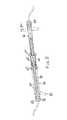
- FIG. 1is a perspective view of an expansible prosthesis with implanting tools coupled
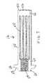
- FIG. 2is a sectional view taken through the mid-plane of the prosthesis of FIG. 1 ;
- FIG. 3is an enlarged sectional view of the central portion of FIG. 2 ;
- FIG. 4is a perspective view of a member of the prosthesis
- FIG. 5is another perspective view of the member shown in FIG. 4 ;
- FIG. 6is a sectional view of the member shown in FIG. 4 through its mid-plane
- FIG. 7is another sectional view of the member shown in FIG. 4 through its mid-plane
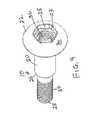
- FIG. 8is a perspective view of a second member of the prosthesis
- FIG. 9is another perspective view of the second member shown in FIG. 8 ;
- FIG. 10is still another perspective view of the second member shown in FIG. 8 ;
- FIG. 11is a perspective view of a hex tool for implanting one member of the prosthesis
- FIG. 12is another perspective view of the hex tool of FIG. 11 ;
- FIG. 13is a perspective view of a hex tool for implanting the other member of the prosthesis
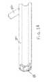
- FIG. 14is a sectional view of the hex tool shown in FIG. 13 taken along its mid-plane;
- FIGS. 15 and 16are perspective views of a stabilizing tool for implanting and explanting the prosthesis
- FIG. 17is perspective view of an expansible prosthesis with tools coupled, the prosthesis having both proximal and distal flanged end caps;
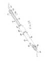
- FIG. 18is a perspective view like FIG. 17 showing the prosthesis using one end cap without a flange
- FIG. 19is a perspective view like FIG. 17 showing the prosthesis using both end caps without flanges;
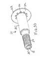
- FIG. 20is perspective view of a cylindrical prosthesis with tool coupled, the prosthesis having flanged end caps;
- FIG. 21is a perspective view of one member of the prosthesis shown in FIG. 20 ;
- FIG. 22is a sectional view of the member shown in FIG. 21 taken along the mid-plane;
- FIG. 23is a perspective view of the other member of the prosthesis shown in FIG. 20 .
- FIG. 24is a sectional view of the other member shown in FIG. 23 taken along the mid-plane;
- FIG. 25is perspective view of a prolate spheroid prosthesis with tool coupled, the prosthesis having flanged end caps;
- FIG. 26is a perspective view of one member of the prosthesis shown in FIG. 25 ;
- FIG. 27is another perspective view of the one member of the prosthesis shown in FIG. 25
- FIGS. 1-10An expandable spinal prosthesis for insertion into an annulotomy hole created laterally in a spinal disc between two abutting vertebrae is shown in FIGS. 1-10 .
- the novel spinal prosthesis deviceis in repose or at rest condition.
- FIGS. 17-19show the novel spinal prosthesis device expanded to distract intentionally the abutting vertebrae.
- the prosthesisconsists of a two mating load bearing members, a first member 10 as shown in FIGS. 8-10 and a second member 12 as shown in FIGS. 4-7 .
- the first member 10consists of a shaft 20 having a through hole 18 , an end cap 22 on one end 23 and a thread 24 on its other end 25 .
- the diameter of the threaded portion 24is reduced or less than the diameter of the shaft 20 , and a shoulder 26 is defined therebetween.
- the end cap 22has a hexagonal recess 28 formed in its convex end face 30 , and a deeper threaded recess 36 .
- An annular array of projections 34are formed on the inner face 32 of end cap 22 .
- the second member 12consists of an end cap 40 fixed to a hollow tube 42 composed of spaced rings 44 and 46 interconnected by longitudinally extending bands 48 peripherally spaced around the tube 42 .
- the end face 50 of the ring 46is open and is provided with a plurality of spaced cutouts 52 that are shaped to mate with projections 34 .
- the shape and design of the cutouts 52 and the projections 34is such that they will hold the two members fixed together up to a preselected torque, beyond which the members will relatively rotate one with respect to the other.
- the inner diameter of tube 42is sized to be received over shaft 20 .
- the end cap 40defines a threaded recess 54 to mate with threaded portion 24 of the first member 10 .
- the two members 10 and 12are assembled by sliding the end 25 of shaft 20 inside tube 42 from the open end of tube 42 where the cutouts 52 are.
- the threaded portion 24is mated with the threads in recess 54 .
- the projections 34 on end cap 22are mated with the cutouts 52 .
- the end cap 40has a convex exterior, radially outer surface 56 and a flat exterior, radially inner surface 58 .
- a raised annular projection 60 having a hexagonal perimeterextends from exterior surface 58 .
- the implant toolsare shown in FIGS. 11-16 and consist of an implant tool 70 for member 10 , an implant tool 72 for member 12 , and an implant tool 74 used for both members 10 and 12 .
- the tool 70is shown in FIGS. 11 and 12 and consists of a hollow, open-ended tube 80 the exterior shape of which is hexagonal. The end of tube 80 is sized to fit into the recess 28 of member 10 . Handles 82 are fixed to one end of the tube 80 in a manner not to intrude into the interior.
- FIGS. 13 and 14show implant tool 72 for engaging the hexagonal projection 60 of member 12 .
- Tool 72consists of a hollow, open-ended tube 84 having non-intrusive handles 86 fixed on one end and a hexagonal cutout 88 in its other end for engaging the hexagonal projection 60 .
- Stabilizing tool 74is shown in FIGS. 15 and 16 and consists of a shaft 90 having a through-hole 92 with threading 94 at one end and a knurled knob 96 with a through hole 98 aligned with through hole 92 at the other end.
- the threading 94is sized to mate with the threads 36 in member 10 and with threads 54 in member 12 .
- the prosthesis as describedis shown coupled to implant tools.
- the bands 48are in their repose or at rest condition.
- the prosthesisis implanted according to the following. To Implant:
- end caps 102 and 104are structurally like end caps 22 and 40 but without flanges.
- the expansible prosthesishas been replaced by a prosthesis similar in structure except that a member 12 a replaces member 12 with member 12 a being composed of an end cap 40 a fixed to an open-ended, unbroken, hollow, cylindrical tube 42 a .
- the tube diameteris slightly greater than the height of the disc into which it will be placed.
- the open-end face 50 a of tube 42 ais provided with a plurality of spaced cutouts 52 a that are shaped to mate with projections 34 of member 10 .
- the end cap 40 ahas a convex exterior, radially outer surface 56 a and a flat exterior, radially inner surface 58 a .
- a raised annular projection 60 a having a hexagonal perimeterextends from exterior surface 58 a .
- the inner diameter of tube 42 ais sized to be received over shaft 20 .
- the end cap 40 adefines a threaded recess 54 a to mate with threaded portion 24 of the first member 10 .
- threaded portion 24 of the first member 10is shown again in FIGS. 23-24 .
- the expansible prosthesishas been replaced by a prosthesis similar in structure except that a member 12 b replaces member 12 with member 12 b being composed of an end cap 40 b fixed to an open-ended, unbroken, hollow, prolate spheroid tube 42 b .
- the maximal diameter of the prolate spheroid that of its midpoint,is slightly greater than the height of the disc into which it will be placed.
- the open-end face 50 b of tube 42 bis provided with a plurality of spaced cutouts 52 b that are shaped to mate with projections 34 of member 10 .
- the end cap 40 bhas a convex exterior, radially outer surface 56 b and a flat exterior, radially inner surface 58 b .
- a raised annular projection 60 b having a hexagonal perimeterextends from exterior surface 58 b .
- the inner diameter of tube 42 bis sized to be received over shaft 20 .
- the end cap 40 bdefines a threaded recess 54 b to mate with threaded portion 24 of the first member 10 , which is unchanged.
- both structures described in FIGS. 20-24 and 25-27can use end caps that are flanged or not as described above. Also, it is possible to use a conical structure for member 12 .
- the prosthesesare coupled to implant tools in the manner described and are implanted according to the following. To Implant:
Landscapes
- Health & Medical Sciences (AREA)
- Engineering & Computer Science (AREA)
- Biomedical Technology (AREA)
- Orthopedic Medicine & Surgery (AREA)
- Neurology (AREA)
- Transplantation (AREA)
- Oral & Maxillofacial Surgery (AREA)
- Cardiology (AREA)
- Heart & Thoracic Surgery (AREA)
- Vascular Medicine (AREA)
- Life Sciences & Earth Sciences (AREA)
- Animal Behavior & Ethology (AREA)
- General Health & Medical Sciences (AREA)
- Public Health (AREA)
- Veterinary Medicine (AREA)
- Physical Education & Sports Medicine (AREA)
- Prostheses (AREA)
Abstract
Description
This invention relates to a disc prosthesis for spinal implant as shown and described in related application U.S. Provisional Patent Application Ser. No. 61/636,230 filed Apr. 19, 2012, the contents of which are here incorporated in their entirety. The benefits of 35 U.S.C, §120 are claimed.
Intervertebral discs (or more simply “discs”) lie between adjacent vertebrae in the spine. Each disc forms a cartilaginous joint to allow slight movement of the vertebrae and acts as a ligament to hold the vertebrae together.
Discs include an outer annulus fibrosus, which surrounds the inner nucleus pulposus. The annulus fibrosus includes several layers of fibrocartilage. The nucleus pulposus contains loose fibers suspended in a mucoprotein gel, which has the consistency of semi-hard and slightly fibrous connective tissue or cartilage. The nucleus of the disc acts as a shock absorber for distributing pressure evenly across the disc and for absorbing the impact of bending and twisting of the spine while keeping the two abutting vertebrae separated. When one develops a prolapsed disc, the nucleus pulposus is forced out resulting in pressure being put on nerves located near the disc. This can cause severe pain and neurological problems. There is one disc between each pair of adjacent vertebrae, except between the first and second cervical vertebrae. The atlas is the first cervical (neck) vertebra which is just under the head. The axis is the second cervical vertebra. The axis acts as a post around which the atlas can rotate, allowing the neck to rotate. There are a total of twenty-three discs in the spine. The discs are most commonly identified by specifying the particular vertebrae they separate. For example, the disc between the fifth and sixth cervical vertebrae is designated “C5-6”. As people age, intervertebral discs tend to degenerate. Two typical processes can occur. The nucleus pulposus dehydrates and flattens, which limits its ability to absorb shock. The annulus fibrosus gets weaker with age and develops fissures or tears. As the discs dehydrate, the disc spaces change and the space for adjacent nerves narrows. In the neural foramens, this is called foraminal stenosis; in the spinal canal, this is called central stenosis. The discs bulge outward, and bone spurs (osteophytes) form along the bulging disc surfaces that also pinch adjacent nerves (spinal cord, cauda equina, and nerve roots). A flattening disc causes stress to the posterior elements of the spine and also the facet joints. Although these conditions may not cause pain in some people, others experience acute and chronic pain. Pain, weakness, and numbness due to pinching of the nerves protruding from the spine are called radiculopathy or radiculitis. Pain, weakness, and numbness due to pinching of the nerves inside the spinal canal is known as radiculopathy, radiculitis, cauda equina syndrome or myelopathy, depending on the level of the spine and the type of symptoms. When the annulus fibrosus tears due to an injury or the degenerative process, the nucleus pulposus may begin to extrude through the tear. This is called disc herniation. Near the posterior aspect of each disc, at each vertebral level or segment, a pair of major spinal nerves extends outward, to different organs, tissues, extremities, etc. Herniated discs often press against these nerves (pinched nerve) and the spinal cord causing neurologic dysfunction including sensory and/or motor loss and/or pain. Herniated disc, ruptured disc, bulging disc, degenerative disc, protrusion, extrusion, all refer to related processes and are used more-or-less synonymously, depending on the medical professional. There is no true standard nomenclature, and the various terms mean different things to different people. Also, the degree to which there is pressure on the nerves (e.g. stenosis, pinching, nerve root elevation, cord compression, effacement, and many other descriptions) also varies. To treat impaired discs, many techniques and devices have been used. Some treatments remove, dissolve, or vaporize disc material (e.g. chymopapain injection, microsurgical discectomy, nucleotomy, laser discectomy, radiofrequency ablation, and others). Other treatments fuse the disc (e.g. cages, screws, bone grafts, bone morphogenic protein, and others). Disc removal procedures remove the disc. Fusion procedures result in loss of motion of the disc and juxtaposed vertebrae. Accordingly, there is a need for an implantable prosthesis that treats the conditions noted above in a more efficacious manner to restore to a damaged disc area the original natural body motion function.
This existing need is met by the implantable prosthesis of the present invention, which is bilaterally easily and quickly implantable by insertion into a damaged intervertebral disc.
A spinal prosthesis is provided for insertion bilaterally into an annulotomy hole created laterally in a spinal disc between two abutting vertebrae comprising a first elongated member having first threading at one end and an end cap at its other end, a second elongated member having an end cap with a threaded hole fixed to one end of a hollow tube open-ended at its other end. The members are telescoped together following separate bilateral implanting via a wire. The threading of said first member is mated with the threaded hole of said second member and the open end of said hollow tube is disengageably engaged with the end cap of said first member for rotation together. Also a method is provided for implanting a disc prosthesis in a disc space between two abutting vertebrae. The prosthesis is composed of two longitudinally divided components that telescope together. Each component consists of a main load-bearing body portion with an end cap. The method includes the steps of using a wire and dilators to form a tract in a disc space, separately bilaterally spinally implanting each component in the tract formed in the spinal disc, and then coupling the components together (via telescoping) between the two abutting vertebrae.
An expandable spinal prosthesis for insertion into an annulotomy hole created laterally in a spinal disc between two abutting vertebrae is shown inFIGS. 1-10 . As shown, the novel spinal prosthesis device is in repose or at rest condition.FIGS. 17-19 show the novel spinal prosthesis device expanded to distract intentionally the abutting vertebrae. Structurally, the prosthesis consists of a two mating load bearing members, afirst member 10 as shown inFIGS. 8-10 and asecond member 12 as shown inFIGS. 4-7 . Thefirst member 10 consists of ashaft 20 having a throughhole 18, anend cap 22 on oneend 23 and athread 24 on itsother end 25. The diameter of the threadedportion 24 is reduced or less than the diameter of theshaft 20, and ashoulder 26 is defined therebetween. Theend cap 22 has ahexagonal recess 28 formed in itsconvex end face 30, and a deeper threadedrecess 36. An annular array ofprojections 34 are formed on the inner face32 ofend cap 22. Thesecond member 12 consists of an end cap40 fixed to ahollow tube 42 composed of spacedrings bands 48 peripherally spaced around thetube 42. The end face50 of thering 46 is open and is provided with a plurality of spacedcutouts 52 that are shaped to mate withprojections 34. The shape and design of thecutouts 52 and theprojections 34 is such that they will hold the two members fixed together up to a preselected torque, beyond which the members will relatively rotate one with respect to the other. The inner diameter oftube 42 is sized to be received overshaft 20. The end cap40 defines a threadedrecess 54 to mate with threadedportion 24 of thefirst member 10. The twomembers end 25 ofshaft 20 insidetube 42 from the open end oftube 42 where thecutouts 52 are. The threadedportion 24 is mated with the threads inrecess 54. Theprojections 34 onend cap 22 are mated with thecutouts 52. The end cap40 has a convex exterior, radially outer surface56 and a flat exterior, radially inner surface58. A raisedannular projection 60 having a hexagonal perimeter extends from exterior surface58. Whenmembers resilient membrane 66 composed of a suitable biomaterial.
The implant tools are shown inFIGS. 11-16 and consist of animplant tool 70 formember 10, animplant tool 72 formember 12, and animplant tool 74 used for bothmembers tool 70 is shown inFIGS. 11 and 12 and consists of a hollow, open-endedtube 80 the exterior shape of which is hexagonal. The end oftube 80 is sized to fit into therecess 28 ofmember 10.Handles 82 are fixed to one end of thetube 80 in a manner not to intrude into the interior.FIGS. 13 and 14 show implant tool 72 for engaging thehexagonal projection 60 ofmember 12.Tool 72 consists of a hollow, open-endedtube 84 havingnon-intrusive handles 86 fixed on one end and ahexagonal cutout 88 in its other end for engaging thehexagonal projection 60. Stabilizingtool 74 is shown inFIGS. 15 and 16 and consists of ashaft 90 having a through-hole 92 with threading94 at one end and aknurled knob 96 with a throughhole 98 aligned with throughhole 92 at the other end. The threading94 is sized to mate with thethreads 36 inmember 10 and withthreads 54 inmember 12.
Referring back toFIGS. 1-3 , the prosthesis as described is shown coupled to implant tools. Thebands 48 are in their repose or at rest condition. The prosthesis is implanted according to the following. To Implant:
- 1. Length and diameter of prosthesis is chosen pre-operatively based on diagnostic imaging measurements such that the diameter of the prosthesis is slightly greater than the height of the disc.
- 2. A patient is placed prone on the operating table.
- 3. A tube retractor or similar retractor is placed from the right side to bear upon and allow visualization of the right lateral part of the spinal disc.
- 4. A second tube retractor or similar retractor is then placed from the left side to bear upon and allow visualization of the left lateral aspect of the same disc.
- 5. A
wire 100 is passed through-and-through the disc from one side to the other. - 6. A tract is therefore created through the disc and is controllable from both sides.
- 7. The tract is dilated with a series of dilators—the dilators are passed down the
wire 100 from either or both sides and then removed. - 8. From the right side, the first “half” of a main load-bearing center piece,
member 10, is placed, with theright end cap 22 attached using implant tools. - 9. From the left side, the second “half” of the load-bearing center piece,
member 12, greater diameter than the right “half,” with end cap40 is placed using implant tools, mating with the first half. - 10.
Tools FIG. 17 . - 11. The tools and wire are now removed leaving the prosthesis in place.
Although the prosthesis is shown with two flanged end caps, it is possible for the prosthesis to have only one flanged end cap40 and end cap102 without a flange or both end caps102 and104 without flanges, seeFIGS. 18 and 19 , respectively. End caps102 and104 are structurally like end caps22 and40 but without flanges.
As shown inFIGS. 20-24 , the expansible prosthesis has been replaced by a prosthesis similar in structure except that amember 12areplacesmember 12 withmember 12abeing composed of an end cap40afixed to an open-ended, unbroken, hollow, cylindrical tube42a. The tube diameter is slightly greater than the height of the disc into which it will be placed. The open-end face50aof tube42ais provided with a plurality of spaced cutouts52athat are shaped to mate withprojections 34 ofmember 10. The end cap40ahas a convex exterior, radially outer surface56aand a flat exterior, radially inner surface58a. A raised annular projection60ahaving a hexagonal perimeter extends from exterior surface58a. The inner diameter of tube42ais sized to be received overshaft 20. The end cap40adefines a threaded recess54ato mate with threadedportion 24 of thefirst member 10. Forclarity member 10 is shown again inFIGS. 23-24 .
As shown inFIGS. 25-27 , the expansible prosthesis has been replaced by a prosthesis similar in structure except that a member12breplacesmember 12 with member12bbeing composed of anend cap 40bfixed to an open-ended, unbroken, hollow,prolate spheroid tube 42b. The maximal diameter of the prolate spheroid that of its midpoint, is slightly greater than the height of the disc into which it will be placed. The open-end face50boftube 42bis provided with a plurality of spaced cutouts52bthat are shaped to mate withprojections 34 ofmember 10. Theend cap 40bhas a convex exterior, radially outer surface56band a flat exterior, radially inner surface58b. A raised annular projection60bhaving a hexagonal perimeter extends from exterior surface58b. The inner diameter oftube 42bis sized to be received overshaft 20. Theend cap 40bdefines a threaded recess54bto mate with threadedportion 24 of thefirst member 10, which is unchanged.
Both structures described inFIGS. 20-24 and 25-27 can use end caps that are flanged or not as described above. Also, it is possible to use a conical structure formember 12. To implant the structures shown in these figures and described above, including conical structures, the prostheses are coupled to implant tools in the manner described and are implanted according to the following. To Implant:
- 1. Length and diameter of prosthesis is chosen pre-operatively based diagnostic imaging measurements such that the maximal diameter of the prosthesis is slightly greater than the height of the disc into which it will be placed.
- 2. A patient is placed prone on the operating table.
- 3. A tube retractor or similar retractor is placed from the right side to bear upon and allow visualization of the right lateral part of the spinal disc.
- 4. A second tube retractor or similar retractor is then placed from the left side to bear upon and allow visualization of the left lateral aspect of the same disc.
- 5. A
wire 100 is passed through-and-through the disc from one side to the other. - 6. A tract is therefore created through the disc and is controllable from both sides.
- 7. The tract is dilated with a series of dilators—the dilators are passed down the wire from either or both sides and then removed.
- 8. From the right side, the first “half” of a main load-bearing center piece,
member 10, is placed using implant tools, with theright end cap 22 attached. - 9. From the left side, the second “half” of the load-bearing center piece,
member 12aor12b, greater diameter than the right “half,” withend cap 40aor40b, is placed using implant tools, mating with the first half. - 10. The implant tools and
wire 100 are now removed leaving the prosthesis in place.
To explant the prosthesis in either case the following procedure is followed.
- 1. Tube retractors or similar retractors are placed against both right and left lateral aspects of the intervertebral disc in which the prosthesis is implanted.
- 2.
Tools opening 28,projection 60 andopenings - 3.
Tools - 4. Both halves are now pulled apart and out of the body.
Although the invention has been described in specific embodiments, changes and modifications will be evident to persons skilled in the art, which do not depart from the spirit and scope of the teachings herein. Such changes are deemed to fall within the purview of the invention as claimed.
Claims (10)
1. An elongated spinal prosthesis composed of first and second parts each having a proximal end and a distal end, said first and second parts configured to be inserted bilaterally into opposite ends of a through-and-through annulotomy hole created laterally in a spinal disc between two abutting vertebrae;
said first part composed of an elongated shaft having a proximal end and a distal end for insertion into one end of the through-and-through annulotomy hole;
said elongated shaft defining a central axial hole therethrough;
a first end cap fixed to said elongated shaft at its proximal end;
said first end cap (i) defining a non-circular recess to receive a driver, (ii) a through bore and (iii) a first portion of a two portion disengageable engagement structure on the distal side of said first end cap;
the distal end of said elongated shaft defining first threading; and
the second part composed of a hollow elongated tube having a proximal end and a distal end for insertion into the other end of the through-and-through annulotomy hole;
said hollow elongated tube being of greater diameter than the elongated shaft and having a second end cap defining a non-circular recess for receiving a driver fixed to said hollow elongated tube at its proximal end;
the distal end of said hollow elongated tube being open-ended and defining a second portion of the two portion disengageable engagement structure to coact with said first portion of the two portion disengageable engagement structure; and
the proximal end of said hollow elongated tube defining second threading to mesh with the first threading;
whereby said two parts, when inserted into the through-and-through annulotomy hole will telescope together and the first and second threading will mesh and the two portions of the two portion disengageable engagement structure will engage to hold the first end cap and the distal end of the hollow elongated tube together up to a preselected torque beyond which the first end cap and the hollow elongated tube will rotate relative to each other,
wherein the hollow elongated tube includes a plurality of resilient bands peripherally spaced and extending longitudinally between the first and second end caps, said bands being outwardly bendable without exceeding their elastic limit below said preselected torque.
2. The spinal prosthesis according toclaim 1 wherein the hollow elongated tube has a shape of one of cylindrical, prolate spheroid and conical.
3. The spinal prosthesis according toclaim 1 wherein relative rotation of the first and second parts in one direction will cause the first and second end caps to move toward each other to cause the resilient bands to bend outwardly to expand the prosthesis and in an opposite direction will cause the first and second end caps to move apart to cause the resilient bands to become unbent and collapse the prosthesis.
4. The spinal prosthesis according toclaim 1 wherein the two parts collectively define a longitudinal through hole through the prosthesis to enable a wire to pass through the prosthesis.
5. The spinal prosthesis according toclaim 1 wherein the first and second end caps are flanged to enable said first end cap and said second end cap to engage the two abutting vertebrae to hold the prosthesis in position when inserted into the through-and-through annulotomy hole.
6. The spinal prosthesis according toclaim 1 wherein the two portions of the two portion disengageable engagement structure comprise cutouts on one of the first end cap and hollow elongated tube and projections on the other of the first end cap and hollow elongated tube.
7. The spinal prosthesis according toclaim 1 wherein the diameter of said elongated shaft at its proximal end is greater than the diameter at its distal end.
8. A method for implanting a disc prosthesis in a disc space between two abutting vertebrae, the prosthesis composed of two components, each component consisting of a main load-bearing body portion and an end cap fixed to one end of the main load-bearing body portion wherein the main load-bearing body portions of the two components are of different diameter to enable telescoping together, the two components of said disc prosthesis including distinct portions of a two portion disengageable engagement structure that are engageable to hold the two components together up to a preselected torque beyond which the two components will rotate relative to each other, comprising the steps of:
a. forming a through-and-through tract in a disc space between two abutting vertebrae;
b. inserting a wire into the through-and-through tract in the disc space so that the wire projects out of opposite ends of the through-and-through tract;
c. mounting the two components on the wire projecting out of opposite ends of the through-and-through tract by inserting the projecting wire into and through through-holes in the two components;
d. introducing bilaterally spinally toward one another the wire-mounted two components into the through-and-through tract; and
e. coupling the components together between the two abutting vertebrae by telescoping the two components together until distinct portions of the two portion disengageable engagement structure become engaged to hold the two components together,
wherein the greater diameter main load-bearing component defines peripherally spaced, longitudinally extending resilient bands having a preselected elastic limit, and including the further step f. of manipulating the two end caps of the coupled main load-bearing components in one direction to cause the resilient bands to bend outwardly without exceeding the preselected elastic limit.
9. The method according toclaim 8 wherein the greater diameter main load-bearing body portion of the prosthesis has one of a conical, cylindrical and prolate spheroid shape.
10. The method ofclaim 8 including the further steps of g. manipulating the two end caps of the coupled main load-bearing components in an opposite direction to cause the resilient bands to collapse inwardly; and h. decoupling the two components and withdrawing them from the through-and-through tract to explant the prosthesis.
Priority Applications (1)
| Application Number | Priority Date | Filing Date | Title |
|---|---|---|---|
| US13/845,810US9393126B2 (en) | 2012-04-20 | 2013-03-18 | Bilaterally placed disc prosthesis for spinal implant and method of bilateral placement |
Applications Claiming Priority (2)
| Application Number | Priority Date | Filing Date | Title |
|---|---|---|---|
| US201261636230P | 2012-04-20 | 2012-04-20 | |
| US13/845,810US9393126B2 (en) | 2012-04-20 | 2013-03-18 | Bilaterally placed disc prosthesis for spinal implant and method of bilateral placement |
Publications (2)
| Publication Number | Publication Date |
|---|---|
| US20130310936A1 US20130310936A1 (en) | 2013-11-21 |
| US9393126B2true US9393126B2 (en) | 2016-07-19 |
Family
ID=49581942
Family Applications (1)
| Application Number | Title | Priority Date | Filing Date |
|---|---|---|---|
| US13/845,810Active2034-06-24US9393126B2 (en) | 2012-04-20 | 2013-03-18 | Bilaterally placed disc prosthesis for spinal implant and method of bilateral placement |
Country Status (1)
| Country | Link |
|---|---|
| US (1) | US9393126B2 (en) |
Cited By (2)
| Publication number | Priority date | Publication date | Assignee | Title |
|---|---|---|---|---|
| US20140370460A1 (en)* | 2008-11-06 | 2014-12-18 | Zimmer Dental, Inc. | Expandable bone implant |
| US20150313650A1 (en)* | 2007-11-02 | 2015-11-05 | Lanx, Inc. | Interspinous implants with adjustable height spacer |
Families Citing this family (3)
| Publication number | Priority date | Publication date | Assignee | Title |
|---|---|---|---|---|
| US9393126B2 (en)* | 2012-04-20 | 2016-07-19 | Peter L. Mayer | Bilaterally placed disc prosthesis for spinal implant and method of bilateral placement |
| US9364339B2 (en)* | 2012-04-30 | 2016-06-14 | Peter L. Mayer | Unilaterally placed expansile spinal prosthesis |
| WO2015168478A1 (en)* | 2014-05-01 | 2015-11-05 | Lorio Morgan Packard | Sacroiliac joint fastener, systems, and methods of using the same |
Citations (210)
| Publication number | Priority date | Publication date | Assignee | Title |
|---|---|---|---|---|
| US725874A (en)* | 1903-02-02 | 1903-04-21 | Charles Riley | Plumber's clamp for wiping joints. |
| US2485531A (en)* | 1948-01-13 | 1949-10-18 | Dzus William | Surgical toggle bolt |
| US3986383A (en)* | 1974-01-02 | 1976-10-19 | Petteys Howard A | Expander tool |
| US4041939A (en) | 1975-04-28 | 1977-08-16 | Downs Surgical Limited | Surgical implant spinal screw |
| EP0042271A1 (en) | 1980-06-13 | 1981-12-23 | David J. Kuntz | Intervertebral disc prosthesis |
| US4465220A (en)* | 1979-11-05 | 1984-08-14 | The Boeing Company | Device for supporting weld underbead |
| US4772287A (en) | 1987-08-20 | 1988-09-20 | Cedar Surgical, Inc. | Prosthetic disc and method of implanting |
| US4863476A (en)* | 1986-08-29 | 1989-09-05 | Shepperd John A N | Spinal implant |
| US4865604A (en)* | 1987-04-27 | 1989-09-12 | Chaim Rogozinski | Prosthetic bone joint |
| FR2639823A1 (en) | 1988-12-06 | 1990-06-08 | Garcia Alain | Replacement of the nucleus of the intervertebral disc by a polyurethane polymerised in situ |
| US4944753A (en) | 1988-09-26 | 1990-07-31 | Burgess Frank M | Method for producing retro-sternal space |
| US4973301A (en)* | 1989-07-11 | 1990-11-27 | Israel Nissenkorn | Catheter and method of using same |
| US5047055A (en) | 1990-12-21 | 1991-09-10 | Pfizer Hospital Products Group, Inc. | Hydrogel intervertebral disc nucleus |
| US5059193A (en)* | 1989-11-20 | 1991-10-22 | Spine-Tech, Inc. | Expandable spinal implant and surgical method |
| US5100405A (en)* | 1990-09-07 | 1992-03-31 | Mclaren Alexander C | Locking cap for medical implants |
| US5171278A (en)* | 1991-02-22 | 1992-12-15 | Madhavan Pisharodi | Middle expandable intervertebral disk implants |
| DE4208116A1 (en) | 1992-03-13 | 1993-09-23 | Link Waldemar Gmbh Co | DISC ENDOPROTHESIS |
| US5298254A (en) | 1989-09-21 | 1994-03-29 | Osteotech, Inc. | Shaped, swollen demineralized bone and its use in bone repair |
| US5390683A (en)* | 1991-02-22 | 1995-02-21 | Pisharodi; Madhavan | Spinal implantation methods utilizing a middle expandable implant |
| US5454365A (en)* | 1990-11-05 | 1995-10-03 | Bonutti; Peter M. | Mechanically expandable arthroscopic retractors |
| US5456667A (en)* | 1993-05-20 | 1995-10-10 | Advanced Cardiovascular Systems, Inc. | Temporary stenting catheter with one-piece expandable segment |
| FR2723841A1 (en) | 1994-08-23 | 1996-03-01 | Fabien Gauchet | Lumbar vertebral disc prosthesis |
| US5514180A (en) | 1994-01-14 | 1996-05-07 | Heggeness; Michael H. | Prosthetic intervertebral devices |
| US5545229A (en) | 1988-08-18 | 1996-08-13 | University Of Medicine And Dentistry Of Nj | Functional and biocompatible intervertebral disc spacer containing elastomeric material of varying hardness |
| US5562735A (en) | 1992-11-09 | 1996-10-08 | Hospital For Joint Diseases | Spinal stabilization system and improved method |
| US5571189A (en) | 1994-05-20 | 1996-11-05 | Kuslich; Stephen D. | Expandable fabric implant for stabilizing the spinal motion segment |
| US5653763A (en)* | 1996-03-29 | 1997-08-05 | Fastenetix, L.L.C. | Intervertebral space shape conforming cage device |
| US5662657A (en) | 1996-01-17 | 1997-09-02 | Sunmed, Inc. | Intramedullary bone plug |
| US5693100A (en)* | 1991-02-22 | 1997-12-02 | Pisharodi; Madhavan | Middle expandable intervertebral disk implant |
| US5865846A (en) | 1994-11-14 | 1999-02-02 | Bryan; Vincent | Human spinal disc prosthesis |
| FR2772594A1 (en) | 1997-12-19 | 1999-06-25 | Henry Graf | Partial posterior intervertebral disc prosthesis |
| US5919194A (en)* | 1997-07-21 | 1999-07-06 | Anderson; David L. | Orthopaedic implant |
| US5951553A (en) | 1997-07-14 | 1999-09-14 | Sdgi Holdings, Inc. | Methods and apparatus for fusionless treatment of spinal deformities |
| US5964807A (en) | 1996-08-08 | 1999-10-12 | Trustees Of The University Of Pennsylvania | Compositions and methods for intervertebral disc reformation |
| WO2000013691A2 (en) | 1998-09-03 | 2000-03-16 | Kerckhoff-Klinik Gesellschaft MIT Beschränkter Haftung | 3-deazaadenosine prevents atherosclerosis and graft vasculopathy |
| WO2000013620A1 (en) | 1998-09-04 | 2000-03-16 | Spinal Dynamics Corporation | Cylindrical hemi-lunar parallel array threaded disc prosthesis |
| US6048342A (en) | 1997-01-02 | 2000-04-11 | St. Francis Medical Technologies, Inc. | Spine distraction implant |
| US6063121A (en) | 1998-07-29 | 2000-05-16 | Xavier; Ravi | Vertebral body prosthesis |
| US6093205A (en) | 1997-06-25 | 2000-07-25 | Bridport-Gundry Plc C/O Pearsalls Implants | Surgical implant |
| US6110210A (en) | 1999-04-08 | 2000-08-29 | Raymedica, Inc. | Prosthetic spinal disc nucleus having selectively coupled bodies |
| US6126688A (en) | 1998-12-21 | 2000-10-03 | Surgical Dynamics Inc. | Apparatus for fusion of adjacent bone structures |
| US6146420A (en) | 1997-12-10 | 2000-11-14 | Sdgi Holdings, Inc. | Osteogenic fusion device |
| US6146422A (en) | 1999-01-25 | 2000-11-14 | Lawson; Kevin Jon | Prosthetic nucleus replacement for surgical reconstruction of intervertebral discs and treatment method |
| US6214012B1 (en) | 1998-11-13 | 2001-04-10 | Harrington Arthritis Research Center | Method and apparatus for delivering material to a desired location |
| US6224600B1 (en)* | 1996-07-10 | 2001-05-01 | G. Constantine Protogirou | Intramedullary, flexible fracture fixation device, using bi-axial prestressing |
| US6264695B1 (en) | 1999-09-30 | 2001-07-24 | Replication Medical, Inc. | Spinal nucleus implant |
| US6287308B1 (en) | 1997-07-14 | 2001-09-11 | Sdgi Holdings, Inc. | Methods and apparatus for fusionless treatment of spinal deformities |
| US6319255B1 (en)* | 1996-12-18 | 2001-11-20 | Eska Implants Gmbh & Co. | Prophylactic implant against fracture of osteoporosis-affected bone segments |
| US20020022887A1 (en)* | 1999-05-11 | 2002-02-21 | Huene Donald R. | Expandable implant for inter-vertebral stabilization, and a method of stabilizing vertebrae |
| US6368319B1 (en) | 1999-05-06 | 2002-04-09 | Bernd Schaefer | Pedicle screw |
| US6395034B1 (en) | 1999-11-24 | 2002-05-28 | Loubert Suddaby | Intervertebral disc prosthesis |
| US6419704B1 (en) | 1999-10-08 | 2002-07-16 | Bret Ferree | Artificial intervertebral disc replacement methods and apparatus |
| US20020120334A1 (en) | 1997-04-25 | 2002-08-29 | Yves Crozet | Intersomatic implants in two parts |
| US6451020B1 (en) | 1997-01-02 | 2002-09-17 | St. Francis Medical Technologies, Inc. | Spine distraction implant and method |
| US6451057B1 (en)* | 2001-10-29 | 2002-09-17 | Chen Po-Quang | Spinal plate element adjusting device having a threaded engagement |
| US20020183848A1 (en) | 1999-04-05 | 2002-12-05 | Raymedica, Inc. | Prosthetic spinal disc nucleus having a shape change characteristic |
| US6494883B1 (en)* | 2000-05-26 | 2002-12-17 | Bret A. Ferree | Bone reinforcers |
| US6500206B1 (en) | 2000-09-15 | 2002-12-31 | Donald W. Bryan | Instruments for inserting spinal vertebral implant |
| US6500182B2 (en)* | 1998-03-27 | 2002-12-31 | Cook Urological, Incorporated | Minimally-invasive medical retrieval device |
| US6554833B2 (en)* | 1998-10-26 | 2003-04-29 | Expanding Orthopedics, Inc. | Expandable orthopedic device |
| US6582467B1 (en)* | 2000-10-31 | 2003-06-24 | Vertelink Corporation | Expandable fusion cage |
| US20030176921A1 (en) | 2002-03-13 | 2003-09-18 | Lawson Kevin Jon | Two-part prosthetic nucleus replacement for surgical reconstruction of intervertebral discs |
| US20030181979A1 (en)* | 2002-01-23 | 2003-09-25 | Ferree Bret A. | Bone reinforcers |
| US6632224B2 (en) | 1996-11-12 | 2003-10-14 | Triage Medical, Inc. | Bone fixation system |
| US20030204260A1 (en) | 2002-04-30 | 2003-10-30 | Ferree Bret A. | Methods and apparatus for preventing the migration of intradiscal devices |
| US6676665B2 (en)* | 2000-08-11 | 2004-01-13 | Sdgi Holdings, Inc. | Surgical instrumentation and method for treatment of the spine |
| US20040010317A1 (en) | 1999-08-18 | 2004-01-15 | Gregory Lambrecht | Devices and method for augmenting a vertebral disc |
| US6733531B1 (en) | 2000-10-20 | 2004-05-11 | Sdgi Holdings, Inc. | Anchoring devices and implants for intervertebral disc augmentation |
| US20040097927A1 (en)* | 2001-02-13 | 2004-05-20 | Yeung Jeffrey E. | Intervertebral disc repair |
| US20040133204A1 (en)* | 2001-01-27 | 2004-07-08 | Davies John Bruce Clayfield | Expandable bone nails |
| WO2004064692A2 (en) | 2003-01-17 | 2004-08-05 | Manoj Krishna | Articulating spinal disc prosthesis |
| US6780175B1 (en)* | 1996-02-23 | 2004-08-24 | Memory Medical Systems, Inc. | Medical instrument with slotted memory metal tube |
| US20040204763A1 (en)* | 2001-07-16 | 2004-10-14 | Ralph James D | Intervertebral spacer device having a wave washer force restoring element |
| WO2004089240A2 (en) | 2003-04-04 | 2004-10-21 | Theken Disc, Llc | Artificial disc prosthesis |
| US6821298B1 (en)* | 2000-04-18 | 2004-11-23 | Roger P. Jackson | Anterior expandable spinal fusion cage system |
| US20040258732A1 (en) | 2001-11-27 | 2004-12-23 | Yasuo Shikinami | Implant material and process for producing the same |
| US20040260297A1 (en) | 2001-03-22 | 2004-12-23 | Martin Padget | Tool for bone fixation device |
| US20050015150A1 (en) | 2003-07-17 | 2005-01-20 | Lee Casey K. | Intervertebral disk and nucleus prosthesis |
| US20050015152A1 (en) | 2003-07-15 | 2005-01-20 | Spinal Generations | Spinal disc prosthesis system |
| US20050113923A1 (en) | 2003-10-03 | 2005-05-26 | David Acker | Prosthetic spinal disc nucleus |
| US20050113929A1 (en) | 2000-02-16 | 2005-05-26 | Cragg Andrew H. | Spinal mobility preservation apparatus |
| FR2862866A1 (en) | 2003-11-28 | 2005-06-03 | Gilles Voydeville | POSTERO-LATERAL INTERVERTEBRAL DISCSTRATE |
| US20050143827A1 (en)* | 1999-01-27 | 2005-06-30 | Disco-O-Tech Medical Technologies Ltd. | Expandable intervertebral spacer |
| US6929640B1 (en) | 1996-07-16 | 2005-08-16 | Arthrocare Corporation | Methods for electrosurgical tissue contraction within the spine |
| US20050182414A1 (en) | 2004-01-08 | 2005-08-18 | Richard Manzi | Apparatus and method for injecting fluent material at a distracted tissue site |
| US20050187559A1 (en) | 2003-03-31 | 2005-08-25 | Raymond Spanky A. | Tissue distraction device |
| WO2005084589A1 (en) | 2004-03-05 | 2005-09-15 | Cervitech, Inc. | Cervical intervertebral disc prosthesis comprising an anti-dislocation device and instruments |
| US20050222681A1 (en)* | 2002-06-17 | 2005-10-06 | Richard Richley | Devices and methods for minimally invasive treatment of degenerated spinal discs |
| US20050234557A1 (en)* | 1999-08-18 | 2005-10-20 | Lambrecht Gregory H | Stabilized intervertebral disc barrier |
| US6966930B2 (en)* | 2003-10-20 | 2005-11-22 | Impliant Ltd. | Facet prosthesis |
| US20050261781A1 (en)* | 2004-04-15 | 2005-11-24 | Sennett Andrew R | Cement-directing orthopedic implants |
| US20050273166A1 (en)* | 2004-06-08 | 2005-12-08 | Sweeney Patrick J | Expandable spinal stabilization device |
| US6974479B2 (en) | 2002-12-10 | 2005-12-13 | Sdgi Holdings, Inc. | System and method for blocking and/or retaining a prosthetic spinal implant |
| US20050278028A1 (en)* | 2004-06-09 | 2005-12-15 | Mujwid James R | Expandable helical cage |
| US20050278036A1 (en)* | 2004-06-09 | 2005-12-15 | Ceravic | Method for restoration of human or animal bone anatomy, and expansible prosthetic implant allowing implementation of this method |
| US6997929B2 (en) | 2003-05-16 | 2006-02-14 | Spine Wave, Inc. | Tissue distraction device |
| US7001431B2 (en) | 1994-05-06 | 2006-02-21 | Disc Dynamics, Inc. | Intervertebral disc prosthesis |
| US7004971B2 (en) | 2002-12-31 | 2006-02-28 | Depuy Acromed, Inc. | Annular nucleus pulposus replacement |
| US7048764B2 (en) | 2003-01-07 | 2006-05-23 | Ferree Bret A | Artificial disc replacements with articulating components |
| US20060161166A1 (en) | 2001-03-08 | 2006-07-20 | Spine Wave, Inc. | Tissue distraction device |
| WO2006078663A2 (en) | 2005-01-19 | 2006-07-27 | Nexgen Spine, Inc. | Elastomeric intervertebral disc prosthesis |
| US7101400B2 (en) | 2002-08-19 | 2006-09-05 | Jeffery Thramann | Shaped memory artificial disc and methods of engrafting the same |
| US20060235417A1 (en)* | 2004-05-19 | 2006-10-19 | Giuseppe Sala | Intravertebral Widening Device, Injection Device, and kit and method for kyphoplasty |
| US20060235534A1 (en) | 2005-04-15 | 2006-10-19 | Gertzman Arthur A | Vertebral disc repair |
| US20060253132A1 (en) | 2005-05-06 | 2006-11-09 | International Business Machines Corporation | System and devices for the repair of a vertebral disc defect |
| US20060253198A1 (en) | 2005-05-03 | 2006-11-09 | Disc Dynamics, Inc. | Multi-lumen mold for intervertebral prosthesis and method of using same |
| US20060271061A1 (en)* | 2001-07-25 | 2006-11-30 | Disc-O-Tech, Ltd. | Deformable tools and implants |
| US20060276790A1 (en)* | 2005-06-02 | 2006-12-07 | Zimmer Spine, Inc. | Minimally invasive facet joint repair |
| US20060276902A1 (en) | 2005-06-03 | 2006-12-07 | Zipnick Richard I | Minimally invasive apparatus to manipulate and revitalize spinal column disc |
| US20060276901A1 (en) | 2005-06-03 | 2006-12-07 | Zipnick Richard I | Minimally invasive apparatus to manipulate and revitalize spinal column disc |
| US20060276897A1 (en) | 2004-12-13 | 2006-12-07 | St. Francis Medical Technologies, Inc. | Implant for stabilizing a bone graft during spinal fusion |
| US20060287730A1 (en) | 2005-06-15 | 2006-12-21 | Jerome Segal | Mechanical apparatus and method for artificial disc replacement |
| US20070010889A1 (en) | 2005-07-06 | 2007-01-11 | Sdgi Holdings, Inc. | Foldable nucleus replacement device |
| US20070027546A1 (en) | 2005-03-09 | 2007-02-01 | Palm Eric E | Multi-composite disc prosthesis |
| US20070038222A1 (en) | 2005-04-29 | 2007-02-15 | Jmea Corporation | Tissue Repair System |
| US20070038301A1 (en) | 2005-08-10 | 2007-02-15 | Zimmer Spine, Inc. | Devices and methods for disc nucleus replacement |
| US20070043440A1 (en)* | 2003-09-19 | 2007-02-22 | William Michael S | Method and apparatus for treating diseased or fractured bone |
| US20070050037A1 (en) | 2002-10-08 | 2007-03-01 | Ranier Technology Ltd. | High precision manufacture of polyurethane products such as spinal disc implants having gradual modulus variation |
| US20070061012A1 (en) | 1999-10-20 | 2007-03-15 | Cauthen Joseph C Iii | Intervertebral disc annulus stent |
| US20070067039A1 (en) | 1999-08-18 | 2007-03-22 | Lambrecbt Greg H | Intervertebral disc herniation repair |
| US20070067034A1 (en)* | 2005-08-31 | 2007-03-22 | Chirico Paul E | Implantable devices and methods for treating micro-architecture deterioration of bone tissue |
| US20070073402A1 (en) | 2005-08-26 | 2007-03-29 | Edward Vresilovic | Hydrogel balloon prosthesis for nucleus pulposus |
| US7204853B2 (en) | 2003-08-05 | 2007-04-17 | Flexuspine, Inc. | Artificial functional spinal unit assemblies |
| US20070088436A1 (en)* | 2005-09-29 | 2007-04-19 | Matthew Parsons | Methods and devices for stenting or tamping a fractured vertebral body |
| WO2007048252A2 (en) | 2005-10-27 | 2007-05-03 | Kinetic Spine Technologies Inc. | Intervertebral implant |
| US7238206B2 (en) | 2003-10-17 | 2007-07-03 | Co-Ligne Ag | Fusion implant |
| US20070173826A1 (en)* | 2006-01-20 | 2007-07-26 | Alpha Orthopaedics | Intramedullar devices and methods to reduce and/or fix damaged bone |
| US20070173939A1 (en)* | 2005-12-23 | 2007-07-26 | The Board Of Trustees Of The Leland Stanford Junior University | Systems and methods for fixation of bone with an expandable device |
| US7250060B2 (en) | 2004-01-27 | 2007-07-31 | Sdgi Holdings, Inc. | Hybrid intervertebral disc system |
| US7261738B2 (en) | 2004-06-30 | 2007-08-28 | Depuy Spine, Inc. | C-shaped disc prosthesis |
| US7270682B2 (en) | 2002-12-17 | 2007-09-18 | Synthes (U.S.A.) | Intervertebral implant |
| US20070219634A1 (en)* | 2004-09-21 | 2007-09-20 | Greenhalgh E S | Expandable support device and method of use |
| US20070239280A1 (en) | 2000-04-04 | 2007-10-11 | Anulex Technologies, Inc. | Devices and methods for annular repair of intervertebral discs |
| US20080009875A1 (en)* | 2006-07-07 | 2008-01-10 | Meera Sankaran | Medical device with dual expansion mechanism |
| US20080039944A1 (en)* | 2005-02-17 | 2008-02-14 | Malandain Hugues F | Percutaneous Spinal Implants and Methods |
| US20080051895A1 (en)* | 2005-02-17 | 2008-02-28 | Malandain Hugues F | Percutaneous spinal implants and methods |
| US20080051893A1 (en)* | 2005-02-17 | 2008-02-28 | Malandain Hugues F | Percutaneous spinal implants and methods |
| US20080051894A1 (en)* | 2005-02-17 | 2008-02-28 | Malandain Hugues F | Percutaneous spinal implants and methods |
| US20080058934A1 (en)* | 2005-02-17 | 2008-03-06 | Malandain Hugues F | Percutaneous spinal implants and methods |
| US20080071356A1 (en)* | 2005-04-27 | 2008-03-20 | Stout Medical Group, L.P. | Expandable support device and methods of use |
| US7371238B2 (en) | 2001-02-16 | 2008-05-13 | Queen's University At Kingston | Method and device for treating scoliosis |
| US20080183204A1 (en)* | 2005-07-14 | 2008-07-31 | Stout Medical Group, L.P. | Expandable support device and method of use |
| US20080221624A1 (en)* | 2005-10-17 | 2008-09-11 | Gooch Hubert L | Systems and Methods for the Medical Treatment of Structural Tissue |
| US20080262617A1 (en)* | 2007-04-19 | 2008-10-23 | Zimmer Gmbh | Interspinous spacer |
| US20080281364A1 (en)* | 2007-05-08 | 2008-11-13 | Spineworks Medical, Inc. | Systems, devices and methods for stabilizing bone |
| US20080281346A1 (en)* | 2005-12-19 | 2008-11-13 | Stout Medical Group, L.P. | Expandable support device |
| US7452369B2 (en)* | 2004-10-18 | 2008-11-18 | Barry Richard J | Spine microsurgery techniques, training aids and implants |
| US20090005821A1 (en)* | 2007-06-29 | 2009-01-01 | Spineworks Medical, Inc. | Methods and devices for stabilizing bone compatible for use with bone screws |
| US20090012564A1 (en)* | 2007-03-07 | 2009-01-08 | Spineworks Medical, Inc. | Transdiscal interbody fusion device and method |
| US20090024157A1 (en)* | 2007-07-18 | 2009-01-22 | Abbott Laboratories | Embolic protection device with open cell design |
| US20090054935A1 (en)* | 2004-04-16 | 2009-02-26 | Kyphon Sarl | Spinal Diagnostic Methods and Apparatus |
| US7569055B2 (en)* | 2002-12-19 | 2009-08-04 | Stryker Trauma Gmbh | Osteosynthetic aid |
| US20090204216A1 (en)* | 2007-12-28 | 2009-08-13 | Lutz Biedermann | Implant for stabilizing vertebrae or bones |
| US7601152B2 (en)* | 1998-10-26 | 2009-10-13 | Expanding Orthopedics, Inc. | Expandable orthopedic device |
| US7621950B1 (en)* | 1999-01-27 | 2009-11-24 | Kyphon Sarl | Expandable intervertebral spacer |
| US20090292323A1 (en)* | 2008-05-20 | 2009-11-26 | Chirico Paul E | Systems, devices and methods for posterior lumbar interbody fusion |
| US20100070035A1 (en)* | 2008-09-18 | 2010-03-18 | Mayer Peter L | Intervertebral disc prosthesis and method for implanting and explanting |
| US7758644B2 (en)* | 2002-11-21 | 2010-07-20 | Warsaw Orthopedic, Inc. | Systems and techniques for intravertebral spinal stabilization with expandable devices |
| US20100185287A1 (en)* | 2009-01-21 | 2010-07-22 | Warsaw Orthopedic, Inc. | Spinal nucleus replacement implants |
| US20100185291A1 (en)* | 2008-12-31 | 2010-07-22 | Jimenez Omar F | Methods and apparatus for vertebral body distraction and fusion employing flexure members |
| US7763074B2 (en)* | 2004-10-20 | 2010-07-27 | The Board Of Trustees Of The Leland Stanford Junior University | Systems and methods for posterior dynamic stabilization of the spine |
| US20100217325A1 (en)* | 2008-11-03 | 2010-08-26 | Hochschuler Stephen H | Expandable spinal support device with attachable members and methods of use |
| US20100228301A1 (en)* | 2009-03-09 | 2010-09-09 | Greenhalgh E Skott | Attachment device and methods of use |
| US7799056B2 (en)* | 2007-12-31 | 2010-09-21 | Warsaw Orthopedic, Inc. | Bone fusion device and methods |
| US7799081B2 (en)* | 2004-09-14 | 2010-09-21 | Aeolin, Llc | System and method for spinal fusion |
| US7824429B2 (en)* | 2002-07-19 | 2010-11-02 | Interventional Spine, Inc. | Method and apparatus for spinal fixation |
| US20110029082A1 (en)* | 2008-03-14 | 2011-02-03 | Synthes Usa, Llc | Nested expandable sleeve implant |
| WO2011048140A1 (en)* | 2009-10-20 | 2011-04-28 | Tpl Technology Patents Licenses Kilian Kraus | Implant, method and tool for kyphoplasty |
| US7959652B2 (en)* | 2005-04-18 | 2011-06-14 | Kyphon Sarl | Interspinous process implant having deployable wings and method of implantation |
| US20110230965A1 (en)* | 2010-03-22 | 2011-09-22 | Gerald Schell | Percutaneous arthrodesis method and system |
| US20110270396A1 (en)* | 2010-04-29 | 2011-11-03 | Warsaw Orthopedic, Inc | Expandable implants for stabilizing adjacent anatomical structures |
| US20120004732A1 (en)* | 2009-03-13 | 2012-01-05 | University Of Toledo | Minimally Invasive Collapsible Cage |
| US8092459B2 (en)* | 2005-02-17 | 2012-01-10 | Kyphon Sarl | Percutaneous spinal implants and methods |
| US8097018B2 (en)* | 2005-02-17 | 2012-01-17 | Kyphon Sarl | Percutaneous spinal implants and methods |
| US8096994B2 (en)* | 2005-02-17 | 2012-01-17 | Kyphon Sarl | Percutaneous spinal implants and methods |
| US8100943B2 (en)* | 2005-02-17 | 2012-01-24 | Kyphon Sarl | Percutaneous spinal implants and methods |
| US8105358B2 (en)* | 2008-02-04 | 2012-01-31 | Kyphon Sarl | Medical implants and methods |
| US20120046748A1 (en)* | 2010-02-24 | 2012-02-23 | Mark Weiman | Expandable Intervertebral Spacer and Method of Posterior Insertion Thereof |
| US8241335B2 (en)* | 2004-11-10 | 2012-08-14 | Dfine, Inc. | Bone treatment systems and methods for introducing an abrading structure to abrade bone |
| US8262736B2 (en)* | 2001-03-27 | 2012-09-11 | Warsaw Orthopedic, Inc. | Radially expanding implants |
| US20120265304A1 (en)* | 2008-09-18 | 2012-10-18 | Mayer Peter L | Intervertebral disc prosthesis, method for assembling, method for implanting prosthesis, and method for explanting |
| US8323344B2 (en)* | 2006-03-24 | 2012-12-04 | Ebi, Llc | Expandable spinal prosthesis |
| US8409282B2 (en)* | 2004-10-20 | 2013-04-02 | Vertiflex, Inc. | Systems and methods for posterior dynamic stabilization of the spine |
| US20130158669A1 (en)* | 2012-02-13 | 2013-06-20 | Arno Sungarian | Expandable Self-Anchoring Interbody Cage for Orthopedic Applications |
| US20130190877A1 (en)* | 2012-01-23 | 2013-07-25 | Mark Patrick Medina | Implant apparatus and method including tee and screw mechanism for spinal fusion |
| US20130197642A1 (en)* | 2012-01-28 | 2013-08-01 | Mark J. Ernst | Expandable implant for mammalian bony segment stabilization |
| US20130197647A1 (en)* | 2005-03-31 | 2013-08-01 | Life Spine, Inc. | Expandable spinal interbody and intravertebral body devices |
| US8512407B2 (en)* | 2005-03-31 | 2013-08-20 | Life Spine, Inc. | Expandable spinal interbody and intravertebral body devices |
| US8518115B2 (en)* | 2007-11-16 | 2013-08-27 | DePuy Synthes Products, LLC | Porous containment device and associated method for stabilization of vertebral compression fractures |
| US20130226251A1 (en)* | 2012-02-28 | 2013-08-29 | Synthes Usa, Llc | Expandable fastener |
| US8529628B2 (en)* | 2009-06-17 | 2013-09-10 | Trinity Orthopedics, Llc | Expanding intervertebral device and methods of use |
| US8556949B2 (en)* | 2007-11-14 | 2013-10-15 | DePuy Synthes Products, LLC | Hybrid bone fixation element and methods of using the same |
| US20130310936A1 (en)* | 2012-04-20 | 2013-11-21 | Peter L. Mayer | Bilaterally placed disc prosthesis for spinal implant and method of bilateral placement |
| US20130310883A1 (en)* | 2012-05-16 | 2013-11-21 | Mark M. Levy | Expandable bone fixation element |
| US20130317617A1 (en)* | 2012-04-30 | 2013-11-28 | Peter L. Mayer | Unilaterally placed expansile spinal prosthesis |
| US20140012336A1 (en)* | 2012-06-18 | 2014-01-09 | Biedermann Technologies Gmbh & Co. Kg | Bone anchor |
| US20140031940A1 (en)* | 2011-04-07 | 2014-01-30 | Ezzine Banouskou | Expandable Orthopedic Device |
| US8641769B2 (en)* | 2010-07-15 | 2014-02-04 | Spine Wave, Inc. | Plastically deformable inter-osseous device |
| US20140121775A1 (en)* | 2008-12-30 | 2014-05-01 | Mitchell Hardenbrook | Expandable interbody implant and method |
| US8814908B2 (en)* | 2010-07-26 | 2014-08-26 | Warsaw Orthopedic, Inc. | Injectable flexible interspinous process device system |
| US20140243982A1 (en)* | 2013-02-28 | 2014-08-28 | William Miller | Expandable Intervertebral Implant, System, Kit and Method |
| US8821497B2 (en)* | 2009-10-27 | 2014-09-02 | Howard D. Stupak | Method and apparatus for maxillo-mandibular fixation |
| US20140257484A1 (en)* | 2013-03-07 | 2014-09-11 | Interventional Spine, Inc. | Intervertebral implant |
| US20140350608A1 (en)* | 2012-01-31 | 2014-11-27 | The University Of Toledo | Bioactive Fusion Device |
| US8906022B2 (en)* | 2010-03-08 | 2014-12-09 | Conventus Orthopaedics, Inc. | Apparatus and methods for securing a bone implant |
| US20150012098A1 (en)* | 2013-07-03 | 2015-01-08 | Spine Innovation, Inc. | Methods and apparatus for implanting an interbody device |
| US8940048B2 (en)* | 2005-03-31 | 2015-01-27 | Life Spine, Inc. | Expandable spinal interbody and intravertebral body devices |
| US8961518B2 (en)* | 2010-01-20 | 2015-02-24 | Conventus Orthopaedics, Inc. | Apparatus and methods for bone access and cavity preparation |
| US8986386B2 (en)* | 2009-03-12 | 2015-03-24 | Vexim Sas | Apparatus for bone restoration of the spine and methods of use |
| US9039742B2 (en)* | 2004-10-20 | 2015-05-26 | The Board Of Trustees Of The Leland Stanford Junior University | Systems and methods for posterior dynamic stabilization of the spine |
- 2013
- 2013-03-18USUS13/845,810patent/US9393126B2/enactiveActive
Patent Citations (221)
| Publication number | Priority date | Publication date | Assignee | Title |
|---|---|---|---|---|
| US725874A (en)* | 1903-02-02 | 1903-04-21 | Charles Riley | Plumber's clamp for wiping joints. |
| US2485531A (en)* | 1948-01-13 | 1949-10-18 | Dzus William | Surgical toggle bolt |
| US3986383A (en)* | 1974-01-02 | 1976-10-19 | Petteys Howard A | Expander tool |
| US4041939A (en) | 1975-04-28 | 1977-08-16 | Downs Surgical Limited | Surgical implant spinal screw |
| US4465220A (en)* | 1979-11-05 | 1984-08-14 | The Boeing Company | Device for supporting weld underbead |
| EP0042271A1 (en) | 1980-06-13 | 1981-12-23 | David J. Kuntz | Intervertebral disc prosthesis |
| US4349921A (en) | 1980-06-13 | 1982-09-21 | Kuntz J David | Intervertebral disc prosthesis |
| US4863476A (en)* | 1986-08-29 | 1989-09-05 | Shepperd John A N | Spinal implant |
| US4865604A (en)* | 1987-04-27 | 1989-09-12 | Chaim Rogozinski | Prosthetic bone joint |
| US4772287A (en) | 1987-08-20 | 1988-09-20 | Cedar Surgical, Inc. | Prosthetic disc and method of implanting |
| US5545229A (en) | 1988-08-18 | 1996-08-13 | University Of Medicine And Dentistry Of Nj | Functional and biocompatible intervertebral disc spacer containing elastomeric material of varying hardness |
| US4944753A (en) | 1988-09-26 | 1990-07-31 | Burgess Frank M | Method for producing retro-sternal space |
| FR2639823A1 (en) | 1988-12-06 | 1990-06-08 | Garcia Alain | Replacement of the nucleus of the intervertebral disc by a polyurethane polymerised in situ |
| US4973301A (en)* | 1989-07-11 | 1990-11-27 | Israel Nissenkorn | Catheter and method of using same |
| US5298254A (en) | 1989-09-21 | 1994-03-29 | Osteotech, Inc. | Shaped, swollen demineralized bone and its use in bone repair |
| US5059193A (en)* | 1989-11-20 | 1991-10-22 | Spine-Tech, Inc. | Expandable spinal implant and surgical method |
| US5100405A (en)* | 1990-09-07 | 1992-03-31 | Mclaren Alexander C | Locking cap for medical implants |
| US5454365A (en)* | 1990-11-05 | 1995-10-03 | Bonutti; Peter M. | Mechanically expandable arthroscopic retractors |
| US5047055A (en) | 1990-12-21 | 1991-09-10 | Pfizer Hospital Products Group, Inc. | Hydrogel intervertebral disc nucleus |
| US5693100A (en)* | 1991-02-22 | 1997-12-02 | Pisharodi; Madhavan | Middle expandable intervertebral disk implant |
| US5171278A (en)* | 1991-02-22 | 1992-12-15 | Madhavan Pisharodi | Middle expandable intervertebral disk implants |
| US5390683A (en)* | 1991-02-22 | 1995-02-21 | Pisharodi; Madhavan | Spinal implantation methods utilizing a middle expandable implant |
| DE4208116A1 (en) | 1992-03-13 | 1993-09-23 | Link Waldemar Gmbh Co | DISC ENDOPROTHESIS |
| US5562735A (en) | 1992-11-09 | 1996-10-08 | Hospital For Joint Diseases | Spinal stabilization system and improved method |
| US5456667A (en)* | 1993-05-20 | 1995-10-10 | Advanced Cardiovascular Systems, Inc. | Temporary stenting catheter with one-piece expandable segment |
| US5514180A (en) | 1994-01-14 | 1996-05-07 | Heggeness; Michael H. | Prosthetic intervertebral devices |
| US7001431B2 (en) | 1994-05-06 | 2006-02-21 | Disc Dynamics, Inc. | Intervertebral disc prosthesis |
| US5571189A (en) | 1994-05-20 | 1996-11-05 | Kuslich; Stephen D. | Expandable fabric implant for stabilizing the spinal motion segment |
| FR2723841A1 (en) | 1994-08-23 | 1996-03-01 | Fabien Gauchet | Lumbar vertebral disc prosthesis |
| US5865846A (en) | 1994-11-14 | 1999-02-02 | Bryan; Vincent | Human spinal disc prosthesis |
| US5662657A (en) | 1996-01-17 | 1997-09-02 | Sunmed, Inc. | Intramedullary bone plug |
| US6780175B1 (en)* | 1996-02-23 | 2004-08-24 | Memory Medical Systems, Inc. | Medical instrument with slotted memory metal tube |
| US5653763A (en)* | 1996-03-29 | 1997-08-05 | Fastenetix, L.L.C. | Intervertebral space shape conforming cage device |
| US6224600B1 (en)* | 1996-07-10 | 2001-05-01 | G. Constantine Protogirou | Intramedullary, flexible fracture fixation device, using bi-axial prestressing |
| US6929640B1 (en) | 1996-07-16 | 2005-08-16 | Arthrocare Corporation | Methods for electrosurgical tissue contraction within the spine |
| US6240926B1 (en) | 1996-08-08 | 2001-06-05 | The Trustees Of The University Of Pennsylvania | Compositions and methods for intervertebral disc reformation |
| US5964807A (en) | 1996-08-08 | 1999-10-12 | Trustees Of The University Of Pennsylvania | Compositions and methods for intervertebral disc reformation |
| US6632224B2 (en) | 1996-11-12 | 2003-10-14 | Triage Medical, Inc. | Bone fixation system |
| US6319255B1 (en)* | 1996-12-18 | 2001-11-20 | Eska Implants Gmbh & Co. | Prophylactic implant against fracture of osteoporosis-affected bone segments |
| US6048342A (en) | 1997-01-02 | 2000-04-11 | St. Francis Medical Technologies, Inc. | Spine distraction implant |
| US6500178B2 (en) | 1997-01-02 | 2002-12-31 | St. Francis Medical Technologies, Inc. | Spine distraction implant and method |
| US6451020B1 (en) | 1997-01-02 | 2002-09-17 | St. Francis Medical Technologies, Inc. | Spine distraction implant and method |
| US20020120334A1 (en) | 1997-04-25 | 2002-08-29 | Yves Crozet | Intersomatic implants in two parts |
| US6093205A (en) | 1997-06-25 | 2000-07-25 | Bridport-Gundry Plc C/O Pearsalls Implants | Surgical implant |
| US5951553A (en) | 1997-07-14 | 1999-09-14 | Sdgi Holdings, Inc. | Methods and apparatus for fusionless treatment of spinal deformities |
| US6287308B1 (en) | 1997-07-14 | 2001-09-11 | Sdgi Holdings, Inc. | Methods and apparatus for fusionless treatment of spinal deformities |
| US5919194A (en)* | 1997-07-21 | 1999-07-06 | Anderson; David L. | Orthopaedic implant |
| US6146420A (en) | 1997-12-10 | 2000-11-14 | Sdgi Holdings, Inc. | Osteogenic fusion device |
| US6419706B1 (en) | 1997-12-19 | 2002-07-16 | Sofamor S.N.C. | Partial disc prosthesis |
| FR2772594A1 (en) | 1997-12-19 | 1999-06-25 | Henry Graf | Partial posterior intervertebral disc prosthesis |
| US6500182B2 (en)* | 1998-03-27 | 2002-12-31 | Cook Urological, Incorporated | Minimally-invasive medical retrieval device |
| US6063121A (en) | 1998-07-29 | 2000-05-16 | Xavier; Ravi | Vertebral body prosthesis |
| WO2000013691A2 (en) | 1998-09-03 | 2000-03-16 | Kerckhoff-Klinik Gesellschaft MIT Beschränkter Haftung | 3-deazaadenosine prevents atherosclerosis and graft vasculopathy |
| WO2000013620A1 (en) | 1998-09-04 | 2000-03-16 | Spinal Dynamics Corporation | Cylindrical hemi-lunar parallel array threaded disc prosthesis |
| US6554833B2 (en)* | 1998-10-26 | 2003-04-29 | Expanding Orthopedics, Inc. | Expandable orthopedic device |
| US7601152B2 (en)* | 1998-10-26 | 2009-10-13 | Expanding Orthopedics, Inc. | Expandable orthopedic device |
| US6214012B1 (en) | 1998-11-13 | 2001-04-10 | Harrington Arthritis Research Center | Method and apparatus for delivering material to a desired location |
| US6126688A (en) | 1998-12-21 | 2000-10-03 | Surgical Dynamics Inc. | Apparatus for fusion of adjacent bone structures |
| US6146422A (en) | 1999-01-25 | 2000-11-14 | Lawson; Kevin Jon | Prosthetic nucleus replacement for surgical reconstruction of intervertebral discs and treatment method |
| US7621950B1 (en)* | 1999-01-27 | 2009-11-24 | Kyphon Sarl | Expandable intervertebral spacer |
| US20050143827A1 (en)* | 1999-01-27 | 2005-06-30 | Disco-O-Tech Medical Technologies Ltd. | Expandable intervertebral spacer |
| US20020183848A1 (en) | 1999-04-05 | 2002-12-05 | Raymedica, Inc. | Prosthetic spinal disc nucleus having a shape change characteristic |
| US6110210A (en) | 1999-04-08 | 2000-08-29 | Raymedica, Inc. | Prosthetic spinal disc nucleus having selectively coupled bodies |
| US6368319B1 (en) | 1999-05-06 | 2002-04-09 | Bernd Schaefer | Pedicle screw |
| US20020022887A1 (en)* | 1999-05-11 | 2002-02-21 | Huene Donald R. | Expandable implant for inter-vertebral stabilization, and a method of stabilizing vertebrae |
| US20050234557A1 (en)* | 1999-08-18 | 2005-10-20 | Lambrecht Gregory H | Stabilized intervertebral disc barrier |
| US20040010317A1 (en) | 1999-08-18 | 2004-01-15 | Gregory Lambrecht | Devices and method for augmenting a vertebral disc |
| US20070067039A1 (en) | 1999-08-18 | 2007-03-22 | Lambrecbt Greg H | Intervertebral disc herniation repair |
| US6264695B1 (en) | 1999-09-30 | 2001-07-24 | Replication Medical, Inc. | Spinal nucleus implant |
| US6419704B1 (en) | 1999-10-08 | 2002-07-16 | Bret Ferree | Artificial intervertebral disc replacement methods and apparatus |
| US20070061012A1 (en) | 1999-10-20 | 2007-03-15 | Cauthen Joseph C Iii | Intervertebral disc annulus stent |
| US6395034B1 (en) | 1999-11-24 | 2002-05-28 | Loubert Suddaby | Intervertebral disc prosthesis |
| US7491236B2 (en)* | 2000-02-16 | 2009-02-17 | Trans1, Inc. | Dual anchor prosthetic nucleus apparatus |
| US20050113919A1 (en) | 2000-02-16 | 2005-05-26 | Cragg Andrew H. | Prosthetic nucleus apparatus |
| US20050113929A1 (en) | 2000-02-16 | 2005-05-26 | Cragg Andrew H. | Spinal mobility preservation apparatus |
| US20070239280A1 (en) | 2000-04-04 | 2007-10-11 | Anulex Technologies, Inc. | Devices and methods for annular repair of intervertebral discs |
| US6821298B1 (en)* | 2000-04-18 | 2004-11-23 | Roger P. Jackson | Anterior expandable spinal fusion cage system |
| US6494883B1 (en)* | 2000-05-26 | 2002-12-17 | Bret A. Ferree | Bone reinforcers |
| US6676665B2 (en)* | 2000-08-11 | 2004-01-13 | Sdgi Holdings, Inc. | Surgical instrumentation and method for treatment of the spine |
| US6500206B1 (en) | 2000-09-15 | 2002-12-31 | Donald W. Bryan | Instruments for inserting spinal vertebral implant |
| US6733531B1 (en) | 2000-10-20 | 2004-05-11 | Sdgi Holdings, Inc. | Anchoring devices and implants for intervertebral disc augmentation |
| US6582467B1 (en)* | 2000-10-31 | 2003-06-24 | Vertelink Corporation | Expandable fusion cage |
| US20040133204A1 (en)* | 2001-01-27 | 2004-07-08 | Davies John Bruce Clayfield | Expandable bone nails |
| US20040097927A1 (en)* | 2001-02-13 | 2004-05-20 | Yeung Jeffrey E. | Intervertebral disc repair |
| US7371238B2 (en) | 2001-02-16 | 2008-05-13 | Queen's University At Kingston | Method and device for treating scoliosis |
| US20070179612A1 (en) | 2001-03-08 | 2007-08-02 | Spine Wave, Inc. | Tissue Distraction Device |
| US7153305B2 (en) | 2001-03-08 | 2006-12-26 | Spine Wave, Inc. | Method for treating tibial plateau compression fractures |
| US20060161166A1 (en) | 2001-03-08 | 2006-07-20 | Spine Wave, Inc. | Tissue distraction device |
| US20040260297A1 (en) | 2001-03-22 | 2004-12-23 | Martin Padget | Tool for bone fixation device |
| US8262736B2 (en)* | 2001-03-27 | 2012-09-11 | Warsaw Orthopedic, Inc. | Radially expanding implants |
| US20040204763A1 (en)* | 2001-07-16 | 2004-10-14 | Ralph James D | Intervertebral spacer device having a wave washer force restoring element |
| US20060271061A1 (en)* | 2001-07-25 | 2006-11-30 | Disc-O-Tech, Ltd. | Deformable tools and implants |
| US6451057B1 (en)* | 2001-10-29 | 2002-09-17 | Chen Po-Quang | Spinal plate element adjusting device having a threaded engagement |
| US20040258732A1 (en) | 2001-11-27 | 2004-12-23 | Yasuo Shikinami | Implant material and process for producing the same |
| US20030181979A1 (en)* | 2002-01-23 | 2003-09-25 | Ferree Bret A. | Bone reinforcers |
| US20030176921A1 (en) | 2002-03-13 | 2003-09-18 | Lawson Kevin Jon | Two-part prosthetic nucleus replacement for surgical reconstruction of intervertebral discs |
| US20030204260A1 (en) | 2002-04-30 | 2003-10-30 | Ferree Bret A. | Methods and apparatus for preventing the migration of intradiscal devices |
| US20050222681A1 (en)* | 2002-06-17 | 2005-10-06 | Richard Richley | Devices and methods for minimally invasive treatment of degenerated spinal discs |
| US7824429B2 (en)* | 2002-07-19 | 2010-11-02 | Interventional Spine, Inc. | Method and apparatus for spinal fixation |
| US7101400B2 (en) | 2002-08-19 | 2006-09-05 | Jeffery Thramann | Shaped memory artificial disc and methods of engrafting the same |
| US20070050037A1 (en) | 2002-10-08 | 2007-03-01 | Ranier Technology Ltd. | High precision manufacture of polyurethane products such as spinal disc implants having gradual modulus variation |
| US7758644B2 (en)* | 2002-11-21 | 2010-07-20 | Warsaw Orthopedic, Inc. | Systems and techniques for intravertebral spinal stabilization with expandable devices |
| US6974479B2 (en) | 2002-12-10 | 2005-12-13 | Sdgi Holdings, Inc. | System and method for blocking and/or retaining a prosthetic spinal implant |
| US7270682B2 (en) | 2002-12-17 | 2007-09-18 | Synthes (U.S.A.) | Intervertebral implant |
| US7569055B2 (en)* | 2002-12-19 | 2009-08-04 | Stryker Trauma Gmbh | Osteosynthetic aid |
| US7004971B2 (en) | 2002-12-31 | 2006-02-28 | Depuy Acromed, Inc. | Annular nucleus pulposus replacement |
| US7048764B2 (en) | 2003-01-07 | 2006-05-23 | Ferree Bret A | Artificial disc replacements with articulating components |
| WO2004064692A2 (en) | 2003-01-17 | 2004-08-05 | Manoj Krishna | Articulating spinal disc prosthesis |
| US20050187559A1 (en) | 2003-03-31 | 2005-08-25 | Raymond Spanky A. | Tissue distraction device |
| US20060136061A1 (en) | 2003-04-04 | 2006-06-22 | Theken Disc, Llc | Artificial disc prosthesis |
| WO2004089240A2 (en) | 2003-04-04 | 2004-10-21 | Theken Disc, Llc | Artificial disc prosthesis |
| US6997929B2 (en) | 2003-05-16 | 2006-02-14 | Spine Wave, Inc. | Tissue distraction device |
| US20050015152A1 (en) | 2003-07-15 | 2005-01-20 | Spinal Generations | Spinal disc prosthesis system |
| US20050015150A1 (en) | 2003-07-17 | 2005-01-20 | Lee Casey K. | Intervertebral disk and nucleus prosthesis |
| US7204853B2 (en) | 2003-08-05 | 2007-04-17 | Flexuspine, Inc. | Artificial functional spinal unit assemblies |
| US20070043440A1 (en)* | 2003-09-19 | 2007-02-22 | William Michael S | Method and apparatus for treating diseased or fractured bone |
| US20050113923A1 (en) | 2003-10-03 | 2005-05-26 | David Acker | Prosthetic spinal disc nucleus |
| US7238206B2 (en) | 2003-10-17 | 2007-07-03 | Co-Ligne Ag | Fusion implant |
| US6966930B2 (en)* | 2003-10-20 | 2005-11-22 | Impliant Ltd. | Facet prosthesis |
| FR2862866A1 (en) | 2003-11-28 | 2005-06-03 | Gilles Voydeville | POSTERO-LATERAL INTERVERTEBRAL DISCSTRATE |
| US20050182414A1 (en) | 2004-01-08 | 2005-08-18 | Richard Manzi | Apparatus and method for injecting fluent material at a distracted tissue site |
| US7250060B2 (en) | 2004-01-27 | 2007-07-31 | Sdgi Holdings, Inc. | Hybrid intervertebral disc system |
| WO2005084589A1 (en) | 2004-03-05 | 2005-09-15 | Cervitech, Inc. | Cervical intervertebral disc prosthesis comprising an anti-dislocation device and instruments |
| US20050261781A1 (en)* | 2004-04-15 | 2005-11-24 | Sennett Andrew R | Cement-directing orthopedic implants |
| US20090054935A1 (en)* | 2004-04-16 | 2009-02-26 | Kyphon Sarl | Spinal Diagnostic Methods and Apparatus |
| US20060235417A1 (en)* | 2004-05-19 | 2006-10-19 | Giuseppe Sala | Intravertebral Widening Device, Injection Device, and kit and method for kyphoplasty |
| US20050273166A1 (en)* | 2004-06-08 | 2005-12-08 | Sweeney Patrick J | Expandable spinal stabilization device |
| US20050278036A1 (en)* | 2004-06-09 | 2005-12-15 | Ceravic | Method for restoration of human or animal bone anatomy, and expansible prosthetic implant allowing implementation of this method |
| US20050278028A1 (en)* | 2004-06-09 | 2005-12-15 | Mujwid James R | Expandable helical cage |
| US7261738B2 (en) | 2004-06-30 | 2007-08-28 | Depuy Spine, Inc. | C-shaped disc prosthesis |
| US7799081B2 (en)* | 2004-09-14 | 2010-09-21 | Aeolin, Llc | System and method for spinal fusion |
| US20070219634A1 (en)* | 2004-09-21 | 2007-09-20 | Greenhalgh E S | Expandable support device and method of use |
| US7452369B2 (en)* | 2004-10-18 | 2008-11-18 | Barry Richard J | Spine microsurgery techniques, training aids and implants |
| US7763074B2 (en)* | 2004-10-20 | 2010-07-27 | The Board Of Trustees Of The Leland Stanford Junior University | Systems and methods for posterior dynamic stabilization of the spine |
| US9039742B2 (en)* | 2004-10-20 | 2015-05-26 | The Board Of Trustees Of The Leland Stanford Junior University | Systems and methods for posterior dynamic stabilization of the spine |
| US8409282B2 (en)* | 2004-10-20 | 2013-04-02 | Vertiflex, Inc. | Systems and methods for posterior dynamic stabilization of the spine |
| US8241335B2 (en)* | 2004-11-10 | 2012-08-14 | Dfine, Inc. | Bone treatment systems and methods for introducing an abrading structure to abrade bone |
| US20060276897A1 (en) | 2004-12-13 | 2006-12-07 | St. Francis Medical Technologies, Inc. | Implant for stabilizing a bone graft during spinal fusion |
| WO2006078663A2 (en) | 2005-01-19 | 2006-07-27 | Nexgen Spine, Inc. | Elastomeric intervertebral disc prosthesis |
| US20080051895A1 (en)* | 2005-02-17 | 2008-02-28 | Malandain Hugues F | Percutaneous spinal implants and methods |
| US8092459B2 (en)* | 2005-02-17 | 2012-01-10 | Kyphon Sarl | Percutaneous spinal implants and methods |
| US8100943B2 (en)* | 2005-02-17 | 2012-01-24 | Kyphon Sarl | Percutaneous spinal implants and methods |
| US20080039944A1 (en)* | 2005-02-17 | 2008-02-14 | Malandain Hugues F | Percutaneous Spinal Implants and Methods |
| US8096994B2 (en)* | 2005-02-17 | 2012-01-17 | Kyphon Sarl | Percutaneous spinal implants and methods |
| US20080051893A1 (en)* | 2005-02-17 | 2008-02-28 | Malandain Hugues F | Percutaneous spinal implants and methods |
| US20080051894A1 (en)* | 2005-02-17 | 2008-02-28 | Malandain Hugues F | Percutaneous spinal implants and methods |
| US20080058934A1 (en)* | 2005-02-17 | 2008-03-06 | Malandain Hugues F | Percutaneous spinal implants and methods |
| US8097018B2 (en)* | 2005-02-17 | 2012-01-17 | Kyphon Sarl | Percutaneous spinal implants and methods |
| US20070027546A1 (en) | 2005-03-09 | 2007-02-01 | Palm Eric E | Multi-composite disc prosthesis |
| US8940048B2 (en)* | 2005-03-31 | 2015-01-27 | Life Spine, Inc. | Expandable spinal interbody and intravertebral body devices |
| US20130197647A1 (en)* | 2005-03-31 | 2013-08-01 | Life Spine, Inc. | Expandable spinal interbody and intravertebral body devices |
| US8512407B2 (en)* | 2005-03-31 | 2013-08-20 | Life Spine, Inc. | Expandable spinal interbody and intravertebral body devices |
| US20060235534A1 (en) | 2005-04-15 | 2006-10-19 | Gertzman Arthur A | Vertebral disc repair |
| US7959652B2 (en)* | 2005-04-18 | 2011-06-14 | Kyphon Sarl | Interspinous process implant having deployable wings and method of implantation |
| US20080071356A1 (en)* | 2005-04-27 | 2008-03-20 | Stout Medical Group, L.P. | Expandable support device and methods of use |
| US20070038222A1 (en) | 2005-04-29 | 2007-02-15 | Jmea Corporation | Tissue Repair System |
| US20060253198A1 (en) | 2005-05-03 | 2006-11-09 | Disc Dynamics, Inc. | Multi-lumen mold for intervertebral prosthesis and method of using same |
| US20060253132A1 (en) | 2005-05-06 | 2006-11-09 | International Business Machines Corporation | System and devices for the repair of a vertebral disc defect |
| US20060276790A1 (en)* | 2005-06-02 | 2006-12-07 | Zimmer Spine, Inc. | Minimally invasive facet joint repair |
| US20060276901A1 (en) | 2005-06-03 | 2006-12-07 | Zipnick Richard I | Minimally invasive apparatus to manipulate and revitalize spinal column disc |
| US20060276902A1 (en) | 2005-06-03 | 2006-12-07 | Zipnick Richard I | Minimally invasive apparatus to manipulate and revitalize spinal column disc |
| US20060287730A1 (en) | 2005-06-15 | 2006-12-21 | Jerome Segal | Mechanical apparatus and method for artificial disc replacement |
| US20070010889A1 (en) | 2005-07-06 | 2007-01-11 | Sdgi Holdings, Inc. | Foldable nucleus replacement device |
| US20080183204A1 (en)* | 2005-07-14 | 2008-07-31 | Stout Medical Group, L.P. | Expandable support device and method of use |
| US20070038301A1 (en) | 2005-08-10 | 2007-02-15 | Zimmer Spine, Inc. | Devices and methods for disc nucleus replacement |
| US20070073402A1 (en) | 2005-08-26 | 2007-03-29 | Edward Vresilovic | Hydrogel balloon prosthesis for nucleus pulposus |
| US20070067034A1 (en)* | 2005-08-31 | 2007-03-22 | Chirico Paul E | Implantable devices and methods for treating micro-architecture deterioration of bone tissue |
| US20070088436A1 (en)* | 2005-09-29 | 2007-04-19 | Matthew Parsons | Methods and devices for stenting or tamping a fractured vertebral body |
| US20080221624A1 (en)* | 2005-10-17 | 2008-09-11 | Gooch Hubert L | Systems and Methods for the Medical Treatment of Structural Tissue |
| WO2007048252A2 (en) | 2005-10-27 | 2007-05-03 | Kinetic Spine Technologies Inc. | Intervertebral implant |
| US20080281346A1 (en)* | 2005-12-19 | 2008-11-13 | Stout Medical Group, L.P. | Expandable support device |
| US20070173939A1 (en)* | 2005-12-23 | 2007-07-26 | The Board Of Trustees Of The Leland Stanford Junior University | Systems and methods for fixation of bone with an expandable device |
| US20070173826A1 (en)* | 2006-01-20 | 2007-07-26 | Alpha Orthopaedics | Intramedullar devices and methods to reduce and/or fix damaged bone |
| US8323344B2 (en)* | 2006-03-24 | 2012-12-04 | Ebi, Llc | Expandable spinal prosthesis |
| US20080009875A1 (en)* | 2006-07-07 | 2008-01-10 | Meera Sankaran | Medical device with dual expansion mechanism |
| US20090012564A1 (en)* | 2007-03-07 | 2009-01-08 | Spineworks Medical, Inc. | Transdiscal interbody fusion device and method |
| US20080262617A1 (en)* | 2007-04-19 | 2008-10-23 | Zimmer Gmbh | Interspinous spacer |
| US20080281364A1 (en)* | 2007-05-08 | 2008-11-13 | Spineworks Medical, Inc. | Systems, devices and methods for stabilizing bone |
| US20090005821A1 (en)* | 2007-06-29 | 2009-01-01 | Spineworks Medical, Inc. | Methods and devices for stabilizing bone compatible for use with bone screws |
| US20090024157A1 (en)* | 2007-07-18 | 2009-01-22 | Abbott Laboratories | Embolic protection device with open cell design |
| US8556949B2 (en)* | 2007-11-14 | 2013-10-15 | DePuy Synthes Products, LLC | Hybrid bone fixation element and methods of using the same |
| US8518115B2 (en)* | 2007-11-16 | 2013-08-27 | DePuy Synthes Products, LLC | Porous containment device and associated method for stabilization of vertebral compression fractures |
| US20090204216A1 (en)* | 2007-12-28 | 2009-08-13 | Lutz Biedermann | Implant for stabilizing vertebrae or bones |
| US8784491B2 (en)* | 2007-12-28 | 2014-07-22 | Biedermann Technologies Gmbh & Co. Kg | Implant for stabilizing vertebrae or bones |
| US7799056B2 (en)* | 2007-12-31 | 2010-09-21 | Warsaw Orthopedic, Inc. | Bone fusion device and methods |
| US8105358B2 (en)* | 2008-02-04 | 2012-01-31 | Kyphon Sarl | Medical implants and methods |
| US20110029082A1 (en)* | 2008-03-14 | 2011-02-03 | Synthes Usa, Llc | Nested expandable sleeve implant |
| US20090292323A1 (en)* | 2008-05-20 | 2009-11-26 | Chirico Paul E | Systems, devices and methods for posterior lumbar interbody fusion |
| US8187333B2 (en) | 2008-09-18 | 2012-05-29 | Mayer Peter L | Intervertebral disc prosthesis and method for implanting and explanting |
| US20100070035A1 (en)* | 2008-09-18 | 2010-03-18 | Mayer Peter L | Intervertebral disc prosthesis and method for implanting and explanting |
| US20120265304A1 (en)* | 2008-09-18 | 2012-10-18 | Mayer Peter L | Intervertebral disc prosthesis, method for assembling, method for implanting prosthesis, and method for explanting |
| US20100217325A1 (en)* | 2008-11-03 | 2010-08-26 | Hochschuler Stephen H | Expandable spinal support device with attachable members and methods of use |
| US20140121775A1 (en)* | 2008-12-30 | 2014-05-01 | Mitchell Hardenbrook | Expandable interbody implant and method |
| US20100185291A1 (en)* | 2008-12-31 | 2010-07-22 | Jimenez Omar F | Methods and apparatus for vertebral body distraction and fusion employing flexure members |
| US20100185287A1 (en)* | 2009-01-21 | 2010-07-22 | Warsaw Orthopedic, Inc. | Spinal nucleus replacement implants |
| US20100228301A1 (en)* | 2009-03-09 | 2010-09-09 | Greenhalgh E Skott | Attachment device and methods of use |
| US8986386B2 (en)* | 2009-03-12 | 2015-03-24 | Vexim Sas | Apparatus for bone restoration of the spine and methods of use |
| US20120004732A1 (en)* | 2009-03-13 | 2012-01-05 | University Of Toledo | Minimally Invasive Collapsible Cage |
| US8529628B2 (en)* | 2009-06-17 | 2013-09-10 | Trinity Orthopedics, Llc | Expanding intervertebral device and methods of use |
| WO2011048140A1 (en)* | 2009-10-20 | 2011-04-28 | Tpl Technology Patents Licenses Kilian Kraus | Implant, method and tool for kyphoplasty |
| US8821497B2 (en)* | 2009-10-27 | 2014-09-02 | Howard D. Stupak | Method and apparatus for maxillo-mandibular fixation |
| US8961518B2 (en)* | 2010-01-20 | 2015-02-24 | Conventus Orthopaedics, Inc. | Apparatus and methods for bone access and cavity preparation |
| US20120046748A1 (en)* | 2010-02-24 | 2012-02-23 | Mark Weiman | Expandable Intervertebral Spacer and Method of Posterior Insertion Thereof |
| US8906022B2 (en)* | 2010-03-08 | 2014-12-09 | Conventus Orthopaedics, Inc. | Apparatus and methods for securing a bone implant |
| US20110230965A1 (en)* | 2010-03-22 | 2011-09-22 | Gerald Schell | Percutaneous arthrodesis method and system |
| US20110270396A1 (en)* | 2010-04-29 | 2011-11-03 | Warsaw Orthopedic, Inc | Expandable implants for stabilizing adjacent anatomical structures |
| US8641769B2 (en)* | 2010-07-15 | 2014-02-04 | Spine Wave, Inc. | Plastically deformable inter-osseous device |
| US8814908B2 (en)* | 2010-07-26 | 2014-08-26 | Warsaw Orthopedic, Inc. | Injectable flexible interspinous process device system |
| US20140031940A1 (en)* | 2011-04-07 | 2014-01-30 | Ezzine Banouskou | Expandable Orthopedic Device |
| US20130190877A1 (en)* | 2012-01-23 | 2013-07-25 | Mark Patrick Medina | Implant apparatus and method including tee and screw mechanism for spinal fusion |
| US20130197642A1 (en)* | 2012-01-28 | 2013-08-01 | Mark J. Ernst | Expandable implant for mammalian bony segment stabilization |
| US20140350608A1 (en)* | 2012-01-31 | 2014-11-27 | The University Of Toledo | Bioactive Fusion Device |
| US20130158669A1 (en)* | 2012-02-13 | 2013-06-20 | Arno Sungarian | Expandable Self-Anchoring Interbody Cage for Orthopedic Applications |
| US20130226251A1 (en)* | 2012-02-28 | 2013-08-29 | Synthes Usa, Llc | Expandable fastener |
| US20130310936A1 (en)* | 2012-04-20 | 2013-11-21 | Peter L. Mayer | Bilaterally placed disc prosthesis for spinal implant and method of bilateral placement |
| US20130317617A1 (en)* | 2012-04-30 | 2013-11-28 | Peter L. Mayer | Unilaterally placed expansile spinal prosthesis |
| US20130310883A1 (en)* | 2012-05-16 | 2013-11-21 | Mark M. Levy | Expandable bone fixation element |
| US20140012336A1 (en)* | 2012-06-18 | 2014-01-09 | Biedermann Technologies Gmbh & Co. Kg | Bone anchor |
| US20140243982A1 (en)* | 2013-02-28 | 2014-08-28 | William Miller | Expandable Intervertebral Implant, System, Kit and Method |
| US20140257484A1 (en)* | 2013-03-07 | 2014-09-11 | Interventional Spine, Inc. | Intervertebral implant |
| US20150012098A1 (en)* | 2013-07-03 | 2015-01-08 | Spine Innovation, Inc. | Methods and apparatus for implanting an interbody device |
Non-Patent Citations (2)
| Title |
|---|
| International Preliminary Report on Patentability and Written Opinion dated Mar. 22, 2011 for PCT/US2009/057369 filed Sep. 17, 2009. |
| International Search Report dated May 4, 2010 for PCT/US2009/057369 filed Sep. 17, 2009. |
Cited By (4)
| Publication number | Priority date | Publication date | Assignee | Title |
|---|---|---|---|---|
| US20150313650A1 (en)* | 2007-11-02 | 2015-11-05 | Lanx, Inc. | Interspinous implants with adjustable height spacer |
| US9561060B2 (en)* | 2007-11-02 | 2017-02-07 | Zimmer Biomet Spine, Inc. | Interspinous implants with adjustable height spacer |
| US20140370460A1 (en)* | 2008-11-06 | 2014-12-18 | Zimmer Dental, Inc. | Expandable bone implant |
| US9744007B2 (en)* | 2008-11-06 | 2017-08-29 | Zimmer Dental, Inc. | Expandable bone implant |
Also Published As
| Publication number | Publication date |
|---|---|
| US20130310936A1 (en) | 2013-11-21 |
Similar Documents
| Publication | Publication Date | Title |
|---|---|---|
| US9364339B2 (en) | Unilaterally placed expansile spinal prosthesis | |
| US11759331B2 (en) | Stabilized expandable intervertebral spacer | |
| US10327912B1 (en) | Expandable interbody spinal fusion device capable of being deployed endoscopically | |
| US11701239B2 (en) | Stand-alone expandable interbody spinal fusion device with integrated fixation mechanism | |
| US11219532B2 (en) | Stand-alone expandable interbody spinal fusion device with locking mechanism | |
| US11207192B2 (en) | Stand-alone expandable interbody spinal fusion device with integrated fixation mechanism | |
| US8187333B2 (en) | Intervertebral disc prosthesis and method for implanting and explanting | |
| US7803188B2 (en) | Systems and methods for intravertebral reduction | |
| US7351261B2 (en) | Multi-joint implant | |
| US7060097B2 (en) | Method and apparatus for implant stability | |
| US9566167B2 (en) | Expandable spinal implant | |
| US9393126B2 (en) | Bilaterally placed disc prosthesis for spinal implant and method of bilateral placement | |
| US20070270822A1 (en) | Bone fixation grommet | |
| US9468539B2 (en) | Vertebral body replacement and method of use | |
| US9675384B2 (en) | Spinal stabilization system | |
| US8814937B2 (en) | Intervertebral disc prosthesis, method for assembling, method for implanting prosthesis, and method for explanting | |
| US10596010B2 (en) | Stand-alone expandable interbody spinal fusion device with locking mechanism | |
| US11026805B2 (en) | Expandable intervertebral fusion implant | |
| US20230181334A1 (en) | Expandable intervertebral fusion implant | |
| US9504501B2 (en) | Systems and methods for reducing pressure within a spinal disc |
Legal Events
| Date | Code | Title | Description |
|---|---|---|---|
| STCF | Information on status: patent grant | Free format text:PATENTED CASE | |
| MAFP | Maintenance fee payment | Free format text:PAYMENT OF MAINTENANCE FEE, 4TH YR, SMALL ENTITY (ORIGINAL EVENT CODE: M2551); ENTITY STATUS OF PATENT OWNER: SMALL ENTITY Year of fee payment:4 | |
| MAFP | Maintenance fee payment | Free format text:PAYMENT OF MAINTENANCE FEE, 8TH YR, SMALL ENTITY (ORIGINAL EVENT CODE: M2552); ENTITY STATUS OF PATENT OWNER: SMALL ENTITY Year of fee payment:8 |