US9393119B2 - Variable length device and method - Google Patents
Variable length device and methodDownload PDFInfo
- Publication number
- US9393119B2 US9393119B2US14/667,620US201514667620AUS9393119B2US 9393119 B2US9393119 B2US 9393119B2US 201514667620 AUS201514667620 AUS 201514667620AUS 9393119 B2US9393119 B2US 9393119B2
- Authority
- US
- United States
- Prior art keywords
- housing
- long bone
- bone
- variable length
- distraction
- Prior art date
- Legal status (The legal status is an assumption and is not a legal conclusion. Google has not performed a legal analysis and makes no representation as to the accuracy of the status listed.)
- Active
Links
- 238000000034methodMethods0.000titleclaimsabstractdescription50
- 210000000988bone and boneAnatomy0.000claimsabstractdescription151
- 230000008859changeEffects0.000claimsabstractdescription11
- 230000006835compressionEffects0.000claimsdescription14
- 238000007906compressionMethods0.000claimsdescription14
- 206010020649HyperkeratosisDiseases0.000claimsdescription11
- 125000004122cyclic groupChemical group0.000claimsdescription9
- 238000001356surgical procedureMethods0.000claimsdescription7
- 230000004044responseEffects0.000claimsdescription5
- 230000001351cycling effectEffects0.000claimsdescription3
- 230000001186cumulative effectEffects0.000claims2
- 230000004323axial lengthEffects0.000abstractdescription5
- 210000000689upper legAnatomy0.000description24
- 206010017076FractureDiseases0.000description21
- 208000010392Bone FracturesDiseases0.000description15
- 208000014674injuryDiseases0.000description15
- 238000012937correctionMethods0.000description12
- 210000003414extremityAnatomy0.000description12
- 235000012489doughnutsNutrition0.000description11
- 230000008733traumaEffects0.000description11
- 230000033001locomotionEffects0.000description9
- 230000011164ossificationEffects0.000description9
- 239000012634fragmentSubstances0.000description8
- 230000002354daily effectEffects0.000description7
- 239000007943implantSubstances0.000description7
- 210000002303tibiaAnatomy0.000description7
- 238000006073displacement reactionMethods0.000description6
- 238000003780insertionMethods0.000description6
- 230000037431insertionEffects0.000description6
- 230000009467reductionEffects0.000description6
- 210000001519tissueAnatomy0.000description6
- 239000000463materialSubstances0.000description5
- 230000008569processEffects0.000description5
- 230000008878couplingEffects0.000description4
- 238000010168coupling processMethods0.000description4
- 238000005859coupling reactionMethods0.000description4
- 238000013461designMethods0.000description4
- 238000005553drillingMethods0.000description4
- 230000035876healingEffects0.000description4
- 210000002758humerusAnatomy0.000description4
- 230000000670limiting effectEffects0.000description4
- 238000000926separation methodMethods0.000description4
- 238000003466weldingMethods0.000description4
- 239000004593EpoxySubstances0.000description3
- 208000027418Wounds and injuryDiseases0.000description3
- 238000007596consolidation processMethods0.000description3
- 230000006378damageEffects0.000description3
- 239000012530fluidSubstances0.000description3
- 238000002513implantationMethods0.000description3
- 230000007246mechanismEffects0.000description3
- 230000036407painEffects0.000description3
- 229920002545silicone oilPolymers0.000description3
- 229920002943EPDM rubberPolymers0.000description2
- 238000004026adhesive bondingMethods0.000description2
- 230000015572biosynthetic processEffects0.000description2
- 239000002537cosmeticSubstances0.000description2
- 210000005069earsAnatomy0.000description2
- 230000000694effectsEffects0.000description2
- 229920001971elastomerPolymers0.000description2
- 238000007373indentationMethods0.000description2
- 208000015181infectious diseaseDiseases0.000description2
- 238000005304joiningMethods0.000description2
- 210000002414legAnatomy0.000description2
- 229920001296polysiloxanePolymers0.000description2
- 229910052761rare earth metalInorganic materials0.000description2
- 150000002910rare earth metalsChemical class0.000description2
- 230000002829reductive effectEffects0.000description2
- 210000004872soft tissueAnatomy0.000description2
- 239000010935stainless steelSubstances0.000description2
- 229910001220stainless steelInorganic materials0.000description2
- 230000003068static effectEffects0.000description2
- 206010002091AnaesthesiaDiseases0.000description1
- 206010005949Bone cancerDiseases0.000description1
- 208000018084Bone neoplasmDiseases0.000description1
- 206010007710Cartilage injuryDiseases0.000description1
- 206010008723ChondrodystrophyDiseases0.000description1
- 208000032170Congenital AbnormalitiesDiseases0.000description1
- 206010010356Congenital anomalyDiseases0.000description1
- 206010013883DwarfismDiseases0.000description1
- IAYPIBMASNFSPL-UHFFFAOYSA-NEthylene oxideChemical compoundC1CO1IAYPIBMASNFSPL-UHFFFAOYSA-N0.000description1
- 206010016454Femur fractureDiseases0.000description1
- 208000034970Heterotopic OssificationDiseases0.000description1
- 206010023230Joint stiffnessDiseases0.000description1
- 206010027543MicrognathiaDiseases0.000description1
- 208000002598MicrognathismDiseases0.000description1
- 239000004721Polyphenylene oxideSubstances0.000description1
- 208000020221Short statureDiseases0.000description1
- 229910001069Ti alloyInorganic materials0.000description1
- RTAQQCXQSZGOHL-UHFFFAOYSA-NTitaniumChemical compound[Ti]RTAQQCXQSZGOHL-UHFFFAOYSA-N0.000description1
- 208000024248Vascular System injuryDiseases0.000description1
- 208000012339Vascular injuryDiseases0.000description1
- 208000008919achondroplasiaDiseases0.000description1
- 230000000996additive effectEffects0.000description1
- 239000000853adhesiveSubstances0.000description1
- 230000001070adhesive effectEffects0.000description1
- 230000037005anaesthesiaEffects0.000description1
- 230000004596appetite lossEffects0.000description1
- 230000003416augmentationEffects0.000description1
- 230000002146bilateral effectEffects0.000description1
- 230000005540biological transmissionEffects0.000description1
- 239000002639bone cementSubstances0.000description1
- 230000037118bone strengthEffects0.000description1
- 230000000052comparative effectEffects0.000description1
- 238000010276constructionMethods0.000description1
- 230000001054cortical effectEffects0.000description1
- 230000007423decreaseEffects0.000description1
- 230000001934delayEffects0.000description1
- 230000000881depressing effectEffects0.000description1
- 208000037265diseases, disorders, signs and symptomsDiseases0.000description1
- 208000035475disorderDiseases0.000description1
- 238000005516engineering processMethods0.000description1
- 230000003203everyday effectEffects0.000description1
- 239000004519greaseSubstances0.000description1
- 230000007941heterotopic ossificationEffects0.000description1
- 230000001788irregularEffects0.000description1
- 210000001847jawAnatomy0.000description1
- 210000000629knee jointAnatomy0.000description1
- 239000007788liquidSubstances0.000description1
- 235000021266loss of appetiteNutrition0.000description1
- 208000019017loss of appetiteDiseases0.000description1
- 210000003141lower extremityAnatomy0.000description1
- 210000004373mandibleAnatomy0.000description1
- 238000004519manufacturing processMethods0.000description1
- 239000003550markerSubstances0.000description1
- 238000012986modificationMethods0.000description1
- 230000004048modificationEffects0.000description1
- 229910001172neodymium magnetInorganic materials0.000description1
- 230000001537neural effectEffects0.000description1
- 231100000862numbnessToxicity0.000description1
- 230000000399orthopedic effectEffects0.000description1
- 201000008968osteosarcomaDiseases0.000description1
- 230000036961partial effectEffects0.000description1
- 230000000737periodic effectEffects0.000description1
- 229920000052poly(p-xylylene)Polymers0.000description1
- 229920000570polyetherPolymers0.000description1
- 239000011253protective coatingSubstances0.000description1
- 230000001681protective effectEffects0.000description1
- 238000011084recoveryMethods0.000description1
- 238000007789sealingMethods0.000description1
- 230000009528severe injuryEffects0.000description1
- 230000001954sterilising effectEffects0.000description1
- 238000004659sterilization and disinfectionMethods0.000description1
- 206010043827tibia fractureDiseases0.000description1
- 229910052719titaniumInorganic materials0.000description1
- 239000010936titaniumSubstances0.000description1
- 238000013519translationMethods0.000description1
- 230000000007visual effectEffects0.000description1
- 230000003442weekly effectEffects0.000description1
Images


Classifications
- A—HUMAN NECESSITIES
- A61—MEDICAL OR VETERINARY SCIENCE; HYGIENE
- A61B—DIAGNOSIS; SURGERY; IDENTIFICATION
- A61B17/00—Surgical instruments, devices or methods
- A61B17/56—Surgical instruments or methods for treatment of bones or joints; Devices specially adapted therefor
- A61B17/58—Surgical instruments or methods for treatment of bones or joints; Devices specially adapted therefor for osteosynthesis, e.g. bone plates, screws or setting implements
- A61B17/68—Internal fixation devices, including fasteners and spinal fixators, even if a part thereof projects from the skin
- A61B17/72—Intramedullary devices, e.g. pins or nails
- A61B17/7216—Intramedullary devices, e.g. pins or nails for bone lengthening or compression
- A—HUMAN NECESSITIES
- A61—MEDICAL OR VETERINARY SCIENCE; HYGIENE
- A61B—DIAGNOSIS; SURGERY; IDENTIFICATION
- A61B17/00—Surgical instruments, devices or methods
- A61B17/16—Instruments for performing osteoclasis; Drills or chisels for bones; Trepans
- A61B17/17—Guides or aligning means for drills, mills, pins or wires
- A61B17/1725—Guides or aligning means for drills, mills, pins or wires for applying transverse screws or pins through intramedullary nails or pins
- A—HUMAN NECESSITIES
- A61—MEDICAL OR VETERINARY SCIENCE; HYGIENE
- A61B—DIAGNOSIS; SURGERY; IDENTIFICATION
- A61B17/00—Surgical instruments, devices or methods
- A61B17/56—Surgical instruments or methods for treatment of bones or joints; Devices specially adapted therefor
- A61B17/58—Surgical instruments or methods for treatment of bones or joints; Devices specially adapted therefor for osteosynthesis, e.g. bone plates, screws or setting implements
- A61B17/68—Internal fixation devices, including fasteners and spinal fixators, even if a part thereof projects from the skin
- A61B17/72—Intramedullary devices, e.g. pins or nails
- A61B17/7233—Intramedullary devices, e.g. pins or nails with special means of locking the nail to the bone
- A61B17/725—Intramedullary devices, e.g. pins or nails with special means of locking the nail to the bone with locking pins or screws of special form
- A—HUMAN NECESSITIES
- A61—MEDICAL OR VETERINARY SCIENCE; HYGIENE
- A61B—DIAGNOSIS; SURGERY; IDENTIFICATION
- A61B17/00—Surgical instruments, devices or methods
- A61B17/56—Surgical instruments or methods for treatment of bones or joints; Devices specially adapted therefor
- A61B17/58—Surgical instruments or methods for treatment of bones or joints; Devices specially adapted therefor for osteosynthesis, e.g. bone plates, screws or setting implements
- A61B17/88—Osteosynthesis instruments; Methods or means for implanting or extracting internal or external fixation devices
- A61B17/8875—Screwdrivers, spanners or wrenches
- A61B17/8886—Screwdrivers, spanners or wrenches holding the screw head
- A61B17/8888—Screwdrivers, spanners or wrenches holding the screw head at its central region
- A—HUMAN NECESSITIES
- A61—MEDICAL OR VETERINARY SCIENCE; HYGIENE
- A61B—DIAGNOSIS; SURGERY; IDENTIFICATION
- A61B17/00—Surgical instruments, devices or methods
- A61B17/56—Surgical instruments or methods for treatment of bones or joints; Devices specially adapted therefor
- A61B17/58—Surgical instruments or methods for treatment of bones or joints; Devices specially adapted therefor for osteosynthesis, e.g. bone plates, screws or setting implements
- A61B17/88—Osteosynthesis instruments; Methods or means for implanting or extracting internal or external fixation devices
- A61B17/92—Impactors or extractors, e.g. for removing intramedullary devices
- A61B17/921—Impactors or extractors, e.g. for removing intramedullary devices for intramedullary devices
- A—HUMAN NECESSITIES
- A61—MEDICAL OR VETERINARY SCIENCE; HYGIENE
- A61B—DIAGNOSIS; SURGERY; IDENTIFICATION
- A61B50/00—Containers, covers, furniture or holders specially adapted for surgical or diagnostic appliances or instruments, e.g. sterile covers
- A61B50/20—Holders specially adapted for surgical or diagnostic appliances or instruments
- A—HUMAN NECESSITIES
- A61—MEDICAL OR VETERINARY SCIENCE; HYGIENE
- A61B—DIAGNOSIS; SURGERY; IDENTIFICATION
- A61B50/00—Containers, covers, furniture or holders specially adapted for surgical or diagnostic appliances or instruments, e.g. sterile covers
- A61B50/30—Containers specially adapted for packaging, protecting, dispensing, collecting or disposing of surgical or diagnostic appliances or instruments
- A61B50/34—Baskets
- A—HUMAN NECESSITIES
- A61—MEDICAL OR VETERINARY SCIENCE; HYGIENE
- A61F—FILTERS IMPLANTABLE INTO BLOOD VESSELS; PROSTHESES; DEVICES PROVIDING PATENCY TO, OR PREVENTING COLLAPSING OF, TUBULAR STRUCTURES OF THE BODY, e.g. STENTS; ORTHOPAEDIC, NURSING OR CONTRACEPTIVE DEVICES; FOMENTATION; TREATMENT OR PROTECTION OF EYES OR EARS; BANDAGES, DRESSINGS OR ABSORBENT PADS; FIRST-AID KITS
- A61F2/00—Filters implantable into blood vessels; Prostheses, i.e. artificial substitutes or replacements for parts of the body; Appliances for connecting them with the body; Devices providing patency to, or preventing collapsing of, tubular structures of the body, e.g. stents
- A61F2/02—Prostheses implantable into the body
- A61F2/28—Bones
- A—HUMAN NECESSITIES
- A61—MEDICAL OR VETERINARY SCIENCE; HYGIENE
- A61B—DIAGNOSIS; SURGERY; IDENTIFICATION
- A61B17/00—Surgical instruments, devices or methods
- A61B17/56—Surgical instruments or methods for treatment of bones or joints; Devices specially adapted therefor
- A61B17/58—Surgical instruments or methods for treatment of bones or joints; Devices specially adapted therefor for osteosynthesis, e.g. bone plates, screws or setting implements
- A61B17/68—Internal fixation devices, including fasteners and spinal fixators, even if a part thereof projects from the skin
- A61B17/84—Fasteners therefor or fasteners being internal fixation devices
- A61B17/86—Pins or screws or threaded wires; nuts therefor
- A61B17/8605—Heads, i.e. proximal ends projecting from bone
- A61B17/861—Heads, i.e. proximal ends projecting from bone specially shaped for gripping driver
- A61B17/8615—Heads, i.e. proximal ends projecting from bone specially shaped for gripping driver at the central region of the screw head
- A—HUMAN NECESSITIES
- A61—MEDICAL OR VETERINARY SCIENCE; HYGIENE
- A61B—DIAGNOSIS; SURGERY; IDENTIFICATION
- A61B17/00—Surgical instruments, devices or methods
- A61B17/56—Surgical instruments or methods for treatment of bones or joints; Devices specially adapted therefor
- A61B17/58—Surgical instruments or methods for treatment of bones or joints; Devices specially adapted therefor for osteosynthesis, e.g. bone plates, screws or setting implements
- A61B17/68—Internal fixation devices, including fasteners and spinal fixators, even if a part thereof projects from the skin
- A61B17/84—Fasteners therefor or fasteners being internal fixation devices
- A61B17/86—Pins or screws or threaded wires; nuts therefor
- A61B17/8625—Shanks, i.e. parts contacting bone tissue
- A61B17/863—Shanks, i.e. parts contacting bone tissue with thread interrupted or changing its form along shank, other than constant taper
- A—HUMAN NECESSITIES
- A61—MEDICAL OR VETERINARY SCIENCE; HYGIENE
- A61B—DIAGNOSIS; SURGERY; IDENTIFICATION
- A61B17/00—Surgical instruments, devices or methods
- A61B17/56—Surgical instruments or methods for treatment of bones or joints; Devices specially adapted therefor
- A61B17/58—Surgical instruments or methods for treatment of bones or joints; Devices specially adapted therefor for osteosynthesis, e.g. bone plates, screws or setting implements
- A61B17/88—Osteosynthesis instruments; Methods or means for implanting or extracting internal or external fixation devices
- A61B17/8875—Screwdrivers, spanners or wrenches
- A—HUMAN NECESSITIES
- A61—MEDICAL OR VETERINARY SCIENCE; HYGIENE
- A61B—DIAGNOSIS; SURGERY; IDENTIFICATION
- A61B17/00—Surgical instruments, devices or methods
- A61B2017/00367—Details of actuation of instruments, e.g. relations between pushing buttons, or the like, and activation of the tool, working tip, or the like
- A61B2017/00411—Details of actuation of instruments, e.g. relations between pushing buttons, or the like, and activation of the tool, working tip, or the like actuated by application of energy from an energy source outside the body
- A—HUMAN NECESSITIES
- A61—MEDICAL OR VETERINARY SCIENCE; HYGIENE
- A61B—DIAGNOSIS; SURGERY; IDENTIFICATION
- A61B17/00—Surgical instruments, devices or methods
- A61B2017/00831—Material properties
- A61B2017/0084—Material properties low friction
- A61B2017/00845—Material properties low friction of moving parts with respect to each other
- A—HUMAN NECESSITIES
- A61—MEDICAL OR VETERINARY SCIENCE; HYGIENE
- A61B—DIAGNOSIS; SURGERY; IDENTIFICATION
- A61B17/00—Surgical instruments, devices or methods
- A61B2017/00831—Material properties
- A61B2017/00876—Material properties magnetic
- A—HUMAN NECESSITIES
- A61—MEDICAL OR VETERINARY SCIENCE; HYGIENE
- A61B—DIAGNOSIS; SURGERY; IDENTIFICATION
- A61B17/00—Surgical instruments, devices or methods
- A61B17/56—Surgical instruments or methods for treatment of bones or joints; Devices specially adapted therefor
- A61B17/58—Surgical instruments or methods for treatment of bones or joints; Devices specially adapted therefor for osteosynthesis, e.g. bone plates, screws or setting implements
- A61B17/68—Internal fixation devices, including fasteners and spinal fixators, even if a part thereof projects from the skin
- A61B2017/681—Alignment, compression, or distraction mechanisms
- A—HUMAN NECESSITIES
- A61—MEDICAL OR VETERINARY SCIENCE; HYGIENE
- A61B—DIAGNOSIS; SURGERY; IDENTIFICATION
- A61B90/00—Instruments, implements or accessories specially adapted for surgery or diagnosis and not covered by any of the groups A61B1/00 - A61B50/00, e.g. for luxation treatment or for protecting wound edges
- A61B90/03—Automatic limiting or abutting means, e.g. for safety
- A61B2090/031—Automatic limiting or abutting means, e.g. for safety torque limiting
- A—HUMAN NECESSITIES
- A61—MEDICAL OR VETERINARY SCIENCE; HYGIENE
- A61B—DIAGNOSIS; SURGERY; IDENTIFICATION
- A61B90/00—Instruments, implements or accessories specially adapted for surgery or diagnosis and not covered by any of the groups A61B1/00 - A61B50/00, e.g. for luxation treatment or for protecting wound edges
- A61B90/03—Automatic limiting or abutting means, e.g. for safety
- A61B2090/033—Abutting means, stops, e.g. abutting on tissue or skin
- A61B2090/034—Abutting means, stops, e.g. abutting on tissue or skin abutting on parts of the device itself
- A—HUMAN NECESSITIES
- A61—MEDICAL OR VETERINARY SCIENCE; HYGIENE
- A61B—DIAGNOSIS; SURGERY; IDENTIFICATION
- A61B50/00—Containers, covers, furniture or holders specially adapted for surgical or diagnostic appliances or instruments, e.g. sterile covers
- A61B50/30—Containers specially adapted for packaging, protecting, dispensing, collecting or disposing of surgical or diagnostic appliances or instruments
- A61B50/33—Trays
Definitions
- the field of the inventiongenerally relates to medical devices for treating conditions involving the skeletal system and in particular bone fracture applications.
- Distraction osteogenesisalso known as distraction callotasis and osteodistraction has been used successfully to lengthen long bones of the body.
- the boneif not already fractured, is purposely fractured by means of a corticotomy, and the two segments of bone are gradually distracted apart, which allows new bone to form in the gap. If the distraction rate is too high, there is a risk of nonunion, if the rate is too low, there is a risk that the two segments will completely fuse to each other before the distraction period is complete. When the desired length of the bone is achieved using this process, the bone is allowed to consolidate.
- Distraction osteogenesis applicationsare mainly focused on the growth of the femur or tibia, but may also include the humerus, the jaw bone (micrognathia), or other bones.
- the reasons for lengthening or growing bonesare multifold, the applications including, but not limited to: post osteosarcoma bone cancer, cosmetic lengthening (both legs—femur and/or tibia) in short stature or dwarfism/achondroplasia, lengthening of one limb to match the other (congenital, post-trauma, post-skeletal disorder, prosthetic knee joint), non-unions.
- intramedullary distraction nailshave been surgically implanted which are contained entirely within the bone. Some are automatically lengthened via repeated rotation of the patient's limb. This can sometimes be painful to the patient, and can often proceed in an uncontrolled fashion. This therefore makes it difficult to follow the strict daily or weekly lengthening regime that avoids nonunion (if too fast) or early consolidation (if too slow). Lower limb distraction rates are on the order of one millimeter per day.
- Other intramedullary nailshave been developed which have an implanted motor and are remotely controlled. The motorized intramedullary nails have an antenna which needs to be implanted subcutaneously, thus complicating the surgical procedure, and making it more invasive.
- Fracture of long bonesis often treated with trauma nails. These implants are placed intramedullary to hold the bones together. Often in cases of complex fracture having an irregular break geometry or having multiple bone fragments, it is difficult to secure the nail so that the bone is held at the correct length. Other times it is desired to hold the bone in a manner that apply compression. Every year in the United States, more than 90,000 tibia and femur shaft fractures are defined as complex. Many of these fractures are treated with trauma nails with varying results. Some of the possible complications from the treatment of these complex fractures include: infection, vascular injuries, non-union, neural injury, associated injuries to other bone or joint locations and heterotopic ossification. Also included in the possible complications is the possibility of unmatched bilateral bone lengths.
- a method for treating a complex fracture with a variable length nailcomprising a housing and a distraction shaft, the housing containing a rotatable permanent magnet mechanically coupled to a lead screw, the lead screw interfacing with a nut such that rotation of the lead screw in a first direction causes the distraction shaft to axially retract within the housing and rotation of the lead screw in a second direction causes the distraction shaft to axially extend from the housing, wherein the nail is configured for at least 5 mm of axial length change in each direction.
- the methodincludes making a first hole or incision in the skin of the patient in proximity to a fractured long bone and at least partially clearing a canal through the center of the long bone and inserting the variable length nail into the canal and securing the housing and distraction shaft to separate portions of the fractured long bone.
- the hole or incisionis caused or allowed to close and an external adjustment device is placed in proximity to the patient's skin.
- the external adjustment deviceincludes at least one rotatable magnet. The external adjustment device is operated so that a magnetic field of the at least one rotatable magnet causes the rotatable permanent magnet of the variable length nail to rotate, causing the distraction shaft to either retract into or extend from the housing.
- a variable length nail systemin another embodiment, includes a nail that includes distraction shaft and a housing, the housing containing a rotatable permanent magnet mechanically coupled to a lead screw, the lead screw interfacing with a nut such that rotation of the lead screw in a first direction causes the distraction shaft to axially retract within the housing and rotation of the lead screw in a second direction causes the distraction shaft to axially extend from the housing, wherein the nail is configured for at least 5 mm of axial length change in each direction.
- the systemfurther includes an external adjustment device that has at least one rotatable magnet, wherein the rotatable permanent magnet of the nail is configured to be rotated by a moving magnetic field of the at least one rotatable magnet of the external adjustment device, and wherein rotation of the at least one rotatable magnet of the external adjustment device in a first rotational direction retracts the distraction shaft into the housing and rotation of the at least one rotatable magnet of the external adjustment device in a second rotational direction, opposite of the first rotational direction, extends the distraction shaft from the housing.
- an external adjustment devicethat has at least one rotatable magnet, wherein the rotatable permanent magnet of the nail is configured to be rotated by a moving magnetic field of the at least one rotatable magnet of the external adjustment device, and wherein rotation of the at least one rotatable magnet of the external adjustment device in a first rotational direction retracts the distraction shaft into the housing and rotation of the at least one rotatable magnet of the external adjustment device in a second rotational direction, opposite of the
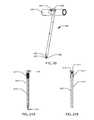
- FIG. 1illustrates side view of an intramedullary lengthening device in place within a bone according to one embodiment.
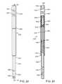
- FIG. 2illustrates a side view of the intramedullary lengthening device of FIG. 1 .
- FIG. 3Aillustrates a cross-sectional view of the intramedullary lengthening device of FIGS. 1 and 2 taken along the line 3 A- 3 A of FIG. 2 .
- FIG. 3Billustrates a detailed view of the intramedullary lengthening device of FIG. 3A from the area of circle 3 B.
- FIG. 3Cillustrates a cross-sectional view of the intramedullary lengthening device of FIGS. 1 and 2 taken along the line 3 C in FIG. 2 .
- FIG. 4Aillustrates a view of several of the internal components of the intramedullary lengthening device of the prior FIGS.
- FIG. 4Billustrates a lip seal configured for use in the intramedullary lengthening device of the prior FIGS.
- FIG. 5illustrates a detailed view of several internal components of the drive mechanism of the intramedullary lengthening device of the prior figures.
- FIG. 6illustrates a perspective view of an external adjustment device.
- FIG. 7illustrates an exploded view of the magnetic handpiece of the external adjustment device of FIG. 6 .
- FIG. 8illustrates a cross-sectional representation of a prior art electromagnetic external device being positioned around a patient's lower thigh.
- FIG. 9illustrates a cross-sectional representation of the external adjustment device handpiece of FIGS. 6 and 7 being positioned on a patient's lower thigh.
- FIG. 10illustrates a sterilizable kit for use with a modular intramedullary lengthening device.
- FIG. 11illustrates a modular intramedullary lengthening device according to one embodiment.
- FIG. 12illustrates one end of the actuator of the intramedullary lengthening device of FIG. 11 .
- FIG. 13illustrates an extension rod of the modular intramedullary lengthening device.
- FIG. 14illustrates a second view of the extension rod of FIG. 13 .
- FIG. 15illustrates a proximal drill guide for insertion and attachment of the modular intramedullary lengthening device.
- FIG. 16illustrates a removal tool for removal of the modular intramedullary lengthening device.
- FIG. 17illustrates a torque limiting driver for attaching the extension rod to the actuator of the modular intramedullary device.
- FIG. 18illustrates a section of the actuator of the modular intramedullary lengthening device.
- FIG. 19illustrates a gap (G) between a magnetic handpiece and an intramedullary lengthening device.
- FIG. 20illustrates a locking screw driver for use with the intramedullary lengthening device.
- FIG. 21Aillustrates a locking screw for use with the intramedullary lengthening device.
- FIG. 21Billustrates the locking screw of FIG. 21A taken along line 21 B- 21 B of FIG. 21A .
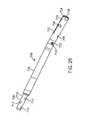
- FIG. 22illustrates a side view of a variable length nail.
- FIG. 23illustrates a cross-section of the variable length nail of FIG. 22 taken along line 23 - 23 ′.
- FIGS. 24A through 24Fillustrate the several steps of implantation, compression and distraction of a variable length nail implanted in a fractured femur.
- FIG. 24Gillustrates cyclic micromovement being applied by a variable length nail to a fractured femur.
- FIG. 24Hillustrates a non-movement period between applications of the cyclic micromovement of FIG. 24G .
- FIG. 25illustrates an intramedullary rotational correction device according to one embodiment.
- FIG. 26illustrates a partial sectional view of the rotational correction device of FIG. 25 .
- FIG. 27illustrates a longitudinal section of FIG. 26 , taken along the line 27 - 27 ′.
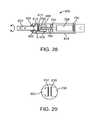
- FIG. 28illustrates a lockable and un-lockable rotational implant according to another embodiment.
- FIG. 29illustrates a detailed view of region A of FIG. 28 .
- FIG. 30illustrates a perspective view of an alternative interface between a rotary nut and a housing of an intramedullary rotational correction device like that illustrated in FIGS. 25-27 .
- FIG. 31illustrates a perspective view of the interface after axial and rotational translation of the rotary nut with respect to the housing.
- FIG. 32illustrates a perspective view of the rotary nut with the housing removed for illustration purposes.
- FIG. 1illustrates the side view of an intramedullary lengthening device 110 which has been placed through a hole or bore 108 contained within a bone 100 .
- the hole or bore 108may be made by drilling, reaming and the like and may extend through both cortical bone (at the end) and through cancellous (spongy) bone.
- the intramedullary lengthening device 110 illustrated in FIG. 1includes a housing 112 and a distraction shaft 114 .
- the bone 100In order to grow or lengthen the bone 100 , the bone 100 either has a pre-existing separation 106 or is purposely cut or broken to create this separation 106 , dividing the bone into a first section 102 and a second section 104 .
- the cutmay be done prior to inserting and securing the intramedullary lengthening device 110 , or may be done after the device 110 is inserted, for example by use of a flexible Gigli saw.
- the distraction shaft 114 of the intramedullary lengthening device 110is attached to the first section 102 using one or more attachment fasteners 118 such as screws. Fasteners 118 other than screws known to those skilled in the art may also be used to secure the distraction shaft 114 to the first section 102 of the bone 100 .
- the housing 112 of the intramedullary lengthening device 110is secured to the second section 104 of bone 100 using one or more attachment fasteners 116 such as screws. Again, fasteners 116 other than screws may be used to secure the housing 112 to the second section 104 of bone 100 .
- the bone 100is regularly distracted, creating a new separation 106 , into which osteogenesis can occur.
- Regularly distractedis meant to indicate that distraction occurs on a regular or periodic basis which may be on the order of every day or every few days.
- An exemplary distraction rateis one millimeter per day although other distraction rates may be employed. That is to say, a typical distraction regimen may include a daily increase in the length of the intramedullary lengthening device 110 by about one millimeter. This may be done, for example, by four lengthening periods per day, each having 0.25 mm of lengthening.
- the intramedullary lengthening device 110has a magnetic drive system, which allows the distraction shaft 114 to be telescopically extended from the housing 112 , thus forcing the first section 102 and the second section 104 of the bone 100 apart from one another. As the distraction process is performed, a portion of the housing 112 is able to slide within the hole or bore 108 of the first section 102 if the housing 112 is located within a displacement section 120 as illustrated in FIG. 1 . Alternatively, if the housing 112 is completely contained in second section 104 then there is no sliding of the housing 112 relative to the hole or bore 108 .
- the orientation of the intramedullary lengthening device 110 within the bone 100may be opposite of that shown in FIG.
- the distraction shaft 114may be coupled to the second section 104 of the bone 100 and the housing 112 may be coupled to the first section 102 of the bone 100 .
- the intramedullary lengthening device 110may be placed retrograde, from a hole or bore starting at the distal end of the bone 100 .
- the intramedullary lengthening device 110has one or more apertures 122 in the distraction shaft 114 through which the fasteners 118 may be placed.
- the housing 112is attached to or otherwise integrated with an end cap 130 which has one or more apertures 124 through which the fasteners 116 may be placed.
- the housing 112 of the intramedullary lengthening device 110includes a magnet housing 128 and a splined housing 126 . These housings 126 , 128 may be attached to each other by means of welding, adhesive bonding or other joining techniques.
- the magnet housing 128is sealably closed at one end (the end opposite the interface with the splined housing 126 ) by the attachment of the end cap 130 .
- the end cap 130may be attached to the magnet housing 128 by means of welding, adhesive bonding or other joining techniques.
- the distraction shaft 114is driven from the housing 112 by means of a lead screw 136 which turns inside a nut 140 that is secured to an inner surface adjacent to a cavity 137 of the distraction shaft 114 .
- the lead screw 136is mechanically coupled, in an indirect manner, to cylindrical permanent magnet 134 contained within the magnet housing 128 .
- rotation of the cylindrical permanent magnet 134which is magnetically driven by an external adjustment device 180 as illustrated in FIG. 6 , effectuates rotation of the lead screw 136 .
- Rotation of the lead screw 136then translates into axial movement of the distraction shaft 114 relative to the housing 128 .
- Cylindrical magnet 134is fixedly contained within a magnet casing 158 using, for example, an adhesive such as an epoxy.
- the magnet casing 158 and cylindrical magnet 134 contained thereinrotate relative to the stationary magnet housing 128 .
- the cylindrical magnet 134may be a rare earth magnet such as Nd—Fe—B and may be coated with Parylene or other protective coatings in addition to being protected within the magnet casing 158 , for example hermetically potted with epoxy.
- the magnet casing 158contains an axle 160 on one end thereof which attaches to the interior of a radial bearing 132 .
- the outer diameter of the radial bearing 132is secured to the interior of the end cap 130 . This arrangement allows the cylindrical magnet 134 to rotate with minimal torsional resistance.
- the magnet housing 158includes an axle 161 , which is mechanically coupled to a first planetary gear set 154 .
- the axle 161includes the sun gear of the first planetary gear set 154 , the sun gear turning the planetary gears of the first planetary gear set 154 .
- the first planetary gear set 154serves to reduce the rotational speed and increase the resultant torque delivery from the cylindrical magnet 134 to the lead screw 136 .
- a second planetary gear set 156is also illustrated mechanically interposed between the first planetary gear set 154 and the lead screw 136 , for further speed reduction and torque augmentation.
- the number of planetary gear sets and/or the number of teeth in the gearsmay be adjusted, in order to achieve the desired speed and torque delivery.
- a lead screw 136 with eighty (80) threads per inch attached to two planetary gear sets of 4:1 gear ratio each inside a 9 mm device with magnet location in the distal femurcan achieve at least 100 lb. of distraction force at a greater than average distance or gap from the external device ( FIG. 9 or FIG. 19 ).
- the planetary gear sets 154 , 156output to a planetary gear output shaft 144 .
- the planetary gear output shaft 144extends through a thrust bearing 138 and is secured (by welding and the like) to a lead screw coupling cap 146 .
- the lead screw 136is secured to the lead screw coupling cap 146 by a locking pin 142 , which extends transversely through a hole in the lead screw 136 and corresponding holes in the lead screw coupling cap 146 .
- a cylindrical locking pin retainer 148surrounds the locking pin 142 , holding this assembly together. Attaching the lead screw 136 to the rest of the magnet/gear assembly in this manner, assures that the design is not over-constrained, and thus that the lead screw 136 does not gall with the nut 140 .
- biocompatible greasefor example KRYTOX, may be used on the moving parts (lead screw, nut, bearings, housing, and distraction shaft) in order to minimize frictional losses.
- the lead screw 136is able to freely rotate within a cavity 137 of the distraction shaft 114 and thus only needs to engage with the short length of the nut 140 . This feature advantageously minimizes frictional losses.
- the thrust bearing 138serves to protect the magnet/gear assembly of the drive from any significant compressive or tensile stresses.
- the thrust bearing 138consists of two separate races with ball bearings between the two races. When there is a compressive force on the device, for example, when distracting a bone 100 , and thus resisting the tensile strength of the soft tissues, the thrust bearing 138 abuts against a magnet housing abutment or lip 150 located in the magnet housing 128 . Additionally, though the device is not typically intended for pulling bones together, there may be some applications where this is desired. For example, in certain compressive nail applications it is the goal to hold two fractured sections of a bone together.
- the bone 100may have fractured in a non-uniform or shattered pattern, it may be difficult to determine the desired length of the nail until after it is implanted and fully attached. In these situations, it can be easy to misjudge the length, and so a gap may exist between the separate sections or fragments of bone 100 .
- the device 110may be retracted magnetically, after it has been secured within the bone fragments, so that it applies the desired compression between the two fragments. In these compressive nail applications, there would be tensile force on the device 110 and the thrust bearing 138 would abut against a splined housing abutment or lip 152 .
- the thrust bearing 138 and a rigid portion of one of the housing sections(e.g., lips 150 , 152 ) take the large stresses, not the magnet/gear assembly of the drive system.
- the thrust bearing 138is sandwiched between the abutment or lip 150 and the abutment or lip 152 .
- Distraction shaft 114contains several axial grooves 166 as best seen in FIG. 3C and FIG. 4A .
- the grooves 166have semi-circular indentation cross-sections which allow several balls 164 to roll within them.
- the balls 164are trapped within the linear ball cage 162 .
- the splined housing 126which fits over the balls 164 and linear ball cage 162 has axial grooves 163 ( FIG.
- the balls 164 and the ball cage 162are interposed between the distraction shaft 114 and the splined housing 126 . Therefore, the balls 164 are held in place by the linear ball cage 162 , and mechanically lock the respective grooves to each other, thus impeding rotation of the distraction shaft 114 within the housing 112 . However, the balls 164 are able to roll within the linear ball cage 162 , thus allowing axial displacement of the distraction shaft 114 in relation to the splined housing 126 of the housing 112 with very low friction.
- the lip seal flange 168as seen in FIG.
- the lip seal 169contains a lip seal 169 as seen in FIG. 4B which allows a sliding seal between the distraction shaft 114 and the splined housing 126 , thus protecting the inner contents of the entire assembly from the external (e.g., body) environment.
- the lip seal 169includes a base portion 173 , which seals against the inner diameter of the lip seal flange 168 (and thus the splined housing 126 which is attached to the lip seal flange 168 ).
- the lip seal 169also includes protrusions 171 which slidingly seal against the axial grooves 166 of the distraction shaft 114 . Inner surface 175 of the lip seal 169 slidingly seals against the overall outer diameter of the distraction shaft 114 .
- the lip seal 169may be made from silicone. EPDM or other rubber materials, and may be coated with silicone oil, to aid in lubricity. Also, the balls, grooves and ball cage may be coated with silicone oil or a liquid perfluorinated polyether such as KRYTOX to aid in lubricity.
- FIG. 5shows a portion of the magnet casing 158 removed so that the South pole 170 and North pole 172 of the cylindrical magnet 134 may be illustrated.
- FIG. 6illustrates an external adjustment device 180 which is used to non-invasively distract the intramedullary lengthening device 110 by means of a magnetic coupling which transmits torque.
- the external adjustment device 180comprises a magnetic handpiece 178 , a control box 176 and a power supply 174 .
- the control box 176includes a control panel 182 having one or more controls (buttons, switches or tactile, motion, audio or light sensors) and a display 184 .
- the display 184may be visual, auditory, tactile, the like or some combination of the aforementioned features.
- the external adjustment device 180may contain software which allows programming by the physician.
- the physicianmay desire that the patient take home the external adjustment device 180 in order that the patient or member of the patient's family or friends make daily distractions of the intramedullary lengthening device 110 implanted in the patient.
- the physicianis able to keep the person operating the external adjustment device 180 from over distracting the patient by programming this into the control box 176 .
- the physicianmay pre-program the control 176 box so that only one (1) mm of distraction is allowed per day.
- the physicianmay additionally pre-program the control box 176 so that no more than 0.5 mm may be distracted during any two hour period, or that no more than 0.25 mm may be retracted during a five minute period. Settings such as these may serve to assure that the patient not be capable of causing severe damage to the bone or tissue, nor disrupt the lengthening process.
- such instructions or limitsmay be pre-programmed by the physician or even the manufacturer in a secure fashion such that user cannot alter the pre-programmed setting(s).
- a security codemay be used to pre-program and change the daily distraction limit (or other parameters).
- the person operating the external adjustment device 180will not be able to distract more than one (1) mm in a day (or more than two mm in a day), and will not have the security code to be able to change this function of the external adjustment device 180 .
- Thisserves as a useful lockout feature to prevent accidental over-extension of the intramedullary lengthening device 110 .
- the safety featuremay monitor, for example, rotational movement of magnets 186 ( FIG. 7 ) of the external adjustment device 180 , described in more detail below, or the safety feature may monitor rotation of the cylindrical magnet 134 in the intramedullary lengthening device 110 , via non-invasive sensing means.
- FIG. 7shows an exploded view of the magnetic handpiece 178 of the external adjustment device 180 , in order to elucidate the manner that the magnets 186 of the external adjustment device 180 serve to cause the cylindrical magnet 134 of the intramedullary lengthening device 110 to turn.
- the magnets 186are made from rare earth magnets.
- the magnets 186may have the same radial two pole configuration as the cylindrical magnet 134 seen in FIG. 5 .
- the magnets 186are bonded or otherwise secured within magnetic cups 187 .
- the magnetic cups 187include a shaft 198 which is attached to a first magnet gear 212 and a second magnet gear 214 , respectively.
- each the two magnets 186are maintained in relation to each other by means of the gearing system (by use of center gear 210 , which meshes with both first magnet gear 212 and second magnet gear 214 ).
- center gear 210which meshes with both first magnet gear 212 and second magnet gear 214 .
- the south pole of one of the magnets 186is facing up whenever the south pole of the other magnet 186 is facing down. This arrangement, for example, maximizes the torque that can be placed on the cylindrical magnet 134 of the intramedullary lengthening device 110 .
- the components of the magnetic handpiece 178are held together between a magnet plate 190 and a front plate 192 . Most of the components are protected by a cover 216 .
- the magnets 186rotate within a static magnet cover 188 , so that the magnetic handpiece 178 may be rested directly on the patient, while not imparting any motion to the external surfaces of the patient.
- the operatorPrior to distracting the intramedullary lengthening device 110 , the operator places the magnetic handpiece 178 over the patient near the location of the cylindrical magnet 134 as seen in FIG. 9 .
- a magnet standoff 194 that is interposed between the two magnets 186contains a viewing window 196 , to aid in the placement.
- a mark made on the patient's skin at the appropriate location with an indelible markermay be viewed through the viewing window 196 .
- the operatorholds the magnetic handpiece 178 by its handles 200 and depresses a distract switch 228 , causing motor 202 to drive in a first direction.
- the motor 202has a gear box 206 which causes the rotational speed of an output gear 204 to be different from the rotational speed of the motor 202 (for example, a slower speed).
- the output gear 204then turns a reduction gear 208 which meshes with center gear 210 , causing it to turn at a different rotational speed than the reduction gear 208 .
- the center gear 210meshes with both the first magnet gear 212 and the second magnet gear 214 turning them at a rate which is identical to each other.
- this ratebe controlled, to minimize the resulting induced current density imparted by magnets 186 and cylindrical magnet 134 though the tissues and fluids of the body.
- a magnet rotational speed of 60 RPM or lessis contemplated although other speeds may be used such as 35 RPM or less.
- the distractionmay be lessened by depressing the retract switch 230 . For example, if the patient feels significant pain, or numbness in the area being lengthened.
- the external adjustment device 180is illustrated herein as including a motor 202 that is used to rotate or drive the magnets 186 in an alternative embodiment, the magnets 186 may be rotated manually.
- the external adjustment device 180may include a hand crank or the like that can be manipulated to rotate the magnets 186 .
- the external adjustment device 180may include a single magnet (e.g., permanent magnet) that is manually rotated about an axis by hand.
- the single magnetmay include a hand-held cylindrical magnet that is manually rotated by the user.
- FIGS. 8 and 9A cross section of a patient's lower thigh 218 with the intramedullary lengthening device 110 implanted within the femur 220 is shown in FIGS. 8 and 9 .
- the magnetic handpiece 178 of the external adjustment device 180 of the inventionis shown in position to adjust the cylindrical magnet 134 of the intramedullary lengthening device 110 .
- a scale depiction of a prior art magnetic stator “donut” 222demonstrates the comparative efficiency of the two designs ( FIG. 8 illustrates an intramedullary lengthening device 110 of the type described herein placed in a “prior art” magnetic stator “donut” 222 ).
- FIG. 8illustrates an intramedullary lengthening device 110 of the type described herein placed in a “prior art” magnetic stator “donut” 222 ).
- the prior art magnetic stator “donut” 222is large, expensive, and difficult to transport to a patient's home for daily adjustments.
- the use of a circular cross-section as a one-size-fits-all deviceis not very efficient because of several reasons: the cross section of most limbs is not circular, the bone is usually not centered within the limb and patients' limbs come in many different sizes.
- the thighhas been placed through the circular hole in the magnetic stator “donut” and the posterior portion 232 of the thigh rests at the lower portion 226 of the magnetic stator “donut” 222 .
- the strength of a magnetic fielddecreases in accordance with a power (such as the inverse square) of the distance, depending on the complexity of the specific field geometry. Therefore, in any magnetic design, making the distance between the driving magnetic field and the driven magnet as small as possible is desirable.
- the size of the patient's lower thigh 218 and the decision to how it is placed within the magnetic stator “donut” 222 in FIG. 8create a geometry so that the distance L 1 between the cylindrical magnet 134 and the upper portion 224 of the magnetic stator “donut” 222 is about the same as the distance L 2 between the cylindrical magnet 134 and the lower portion 226 of the magnetic stator “donut” 222 .
- the length L 1would become less while the length L 2 would become greater.
- the magnetic stator “donut” 222 of FIG. 8is almost impossible to optimize. Therefore, an extra-large magnetic field needs to be generated as the standard magnetic field of the device, thus requiring more expense (for the hardware to power this larger field). This in turn means that each patient will be exposed to a larger magnetic field and larger tissue and fluid current density than is really required.
- the intramedullary lengthening device 110may be secured to the bone 100 , unnecessarily large magnetic fields may cause unwanted motion of the bone 100 , for example in any of the radial directions of the cylindrical magnet 134 . If the magnetic field is too high, the patient's leg may be moved out of ideal position, and may even cause the patient some annoyance, including pain.
- the configuration of the magnetic handpiece 178 of the external adjustment device 180 as shown in FIG. 9optimizes the ability of the magnets 186 to deliver torque to the cylindrical magnet 134 of the intramedullary lengthening device 110 , without exposing the patient to large magnetic fields. This also allows the cylindrical magnet 134 of the intramedullary lengthening device 110 to be designed as small as possible, lowering the implant profile so that it may fit into the humerus, or the tibia and femurs of small stature patients, such as those who might desire cosmetic limb lengthening. As mentioned, a 9 mm diameter intramedullary lengthening device 110 can deliver 100 lb. distraction force, and even 8 mm and 7 mm devices are possible.
- the alternating orientation of the two magnets 186creates an additive effect of torque delivery to cylindrical magnet 134 , and thus maximizes distraction force for any specific cylindrical magnet 134 size.
- the separation (S) between the centers of the two magnets 186match with the curvature of the outer surfaces of the majority of limbs, thus making the distances L 3 and L 4 between each of the magnets 186 and the cylindrical magnet 134 as small as possible. This is especially aided by the concave contour 238 of the magnetic handpiece 178 .
- skin and fatmay be compressed by the magnet covers 188 causing an indentation 236 on one or both sides which allows the distances L 3 and L 4 between each of the magnets 186 and the cylindrical magnet 134 to be yet smaller.
- FIG. 10illustrates a sterilizable kit 400 containing a plurality of extension rods 406 which are configured to be attached to an actuator 412 seen in FIG. 11 in order to construct a modular intramedullary lengthening device 410 .
- the actuator 412is supplied sterile, and the extension rods 406 and the remainder of the contents of the sterilizable kit 400 are sterilizable by autoclave (e.g., steam). Ethylene Oxide or other methods known to those skilled in the art.
- the sterilizable kit 400 contentsincludes one or more of the extension rods 406 and accessories 408 for use in the insertion, attachment, adjustment and removal of the modular intramedullary lengthening device 410 .
- first sterilizable tray 402The contents are located within a first sterilizable tray 402 and a second sterilizable tray 404 .
- Second sterilizable tray 404 and first sterilizable tray 402have a plurality of holes 405 to allow gas to enter.
- Other items in the kit 400will be described in several of the following figures.
- FIG. 1the assembly of the modular intramedullary lengthening device 410 is shown.
- the actuator 412is designed to be placed in the bone of the patient in the opposite orientation than that of the intramedullary lengthening device 10 of FIG. 1 . Therefore, the distraction shaft 413 is orientated towards the distal end of the bone (distal is the down direction in the case of FIG. 11 ). Distal apertures 415 in the distraction shaft 413 allow the placement of distal locking screws 420 or other fasteners.
- the distal locking screws 420( FIGS. 21A and 21B ) have proximal threads 417 for engaging the bone, while the remainder of the shaft 419 of the distal locking screws 420 is of a constant diameter for maximum strength and stability.
- the extension rod 406( FIGS. 13 and 14 ) has a corresponding hexagonal hole 428 or female end into which the hexagonal male hub 414 of the actuator 412 is placed.
- the transverse set screw 416is nested within the threaded hole 429 of the hexagonal male hub 414 so that it does not interfere with the hexagonal hole 428 of the extension rod 406 , when they are placed together.
- the actuator 412 and extension rod 406are placed together so that the set screw holes 422 extend coaxially with the set screw 416 .
- a male hex 490 of a set screw tightening driversuch as the torque limiting driver 488 of FIGS. 10 and 17 , to be inserted into a hex hole of the set screw 416 .
- the torque limiting driver 488is tightened and ratchets at its set control torque
- the other end of the set screw 416which is either threaded or a non-threaded peg, inserts into the opposite set screw hole 422 , thus tightly securing the actuator 412 to the extension rod 406 .
- the set screw holes 422are sized to allow the male hex 490 to smoothly clear, but the non-threaded peg of the set screw 416 clear very slightly, making a static connection that cannot be easily loosened during implantation.
- bone cementmay be placed in annulus of set screw hole 422 , to even further bond set screw 416 .
- a second screwmay be screwed in behind the head of the set screw into the female thread that the set screw 416 was originally nested in. The head of this second screw will add additional resistance to shear failure of the set screw 416 .
- the second screwcan be tightened so that it jams into the set screw 416 , thus making back-out of the set screw 416 unlikely.
- Any non-circular cross-sectionmay be used in place of the hex cross-section, for example a square or oval cross-section.
- Proximal locking screws 418insert through locking screw apertures 430 in the extension rod 406 .
- the extension rod 406may be straight, or may have a specific curve 432 , for example, for matching the proximal end of the femur or tibia. It can be appreciated that the modular arrangement allows the actuator 412 to be attached to one of numerous different models of extension rods 406 , having different lengths, curves (including straight), diameters, hole diameters, and angulations.
- the first sterilization tray 402may include many of these different extension rods 406 , which may be selected as appropriate, and attached to the actuator 412 . Because the actuator 412 is supplied sterile, this arrangement is also desirable, as only a single model need be supplied.
- actuatorsmay exist, for example, different diameters (10.5 mm, 12.0 mm, 9 mm, 7.5 mm) or with different distal screw aperture diameters, configurations or angulations.
- the preferred configuration for a multitude of patients and different bone types and sizescan be available, with a minimum number of sterile actuator models.
- a proximal drill guide 434is illustrated and is configured for attaching to the modular intramedullary lengthening device 410 to ease its insertion into the intramedullary canal, the drilling of holes in the bone and the attachment of the proximal locking screws 418 to the bone.
- the proximal drill guide 434comprises an extension arm 436 attached to a connection tube 446 through which a locking rod 448 is inserted.
- the locking rod 448has a locking knob 450 at the proximal end and a male thread 452 at the distal end.
- a locking tab 454 of the proximal drill guide 434is inserted into a locking groove 424 of the extension rod 406 and the locking knob 450 is turned, threading the male thread 452 of the locking rod 448 into a female thread 426 of the extension rod 406 .
- a drill guide extension 438is attached via a knob 440 to the extension arm 436 .
- the modular intramedullary lengthening device 410After reaming the medullary canal of the bone to a diameter slightly larger than the outer diameter of the modular intramedullary lengthening device 410 (for example 11 mm), distal end of the modular intramedually lengthening device 410 is inserted into the medullary canal and the flat proximal surface of the locking knob 450 is hammered with a mallet, allowing the modular intramedullary lengthening device 410 to be inserted to the correct depth.
- Dimension Xis sufficient to clear large thighs or hips (in the worst case femoral application). For example, 8 to 10 cm is appropriate.
- the proximal drill guide 434is left attached and a guide sleeve 442 is placed through one of the holes 456 , 458 , 460 , 462 and slid so that the distal end 443 reaches the skin of the patient.
- the drill guide extension 438 , extension arm 436 and holes 456 , 458 , 460 , 462are dimensioned and oriented so that the guide sleeve 442 is oriented at the exact angle to allow drilling and placement of screws through the locking screws holes 430 of the extension rod 406 and through the bone.
- a drill bushing 444is placed through the incision, with the tapered tip 445 passing through tissue and reaching the bone to be drilled.
- drills and locking screwsmay be inserted down the drill bushing 444 , or alternatively, drills may be inserted down the drill bushing 444 and then, after the drilling is complete, the drill bushing 444 is removed and proximal locking screw 418 is inserted down the guide sleeve 442 .
- Alternative guide sleeves 464 and drill bushings 466can be placed through holes 460 and 462 , as seen in FIG. 10 .
- a removal tool 468is illustrated.
- the removal tool 468is used after the distraction period and consolidation period are complete.
- the skinis incised and bone exposed at the locations of the proximal and distal locking screws 418 , 420 and at the proximal end of the modular intramedullary lengthening device 410 .
- a removal rod 470is connected to the female thread 426 of the extension rod 406 of the modular intramedullary lengthening device 410 by inserting the engagement tip 476 and screwing the male thread 474 into the female thread 426 , holding onto the locking knob 472 .
- the locking knob 472contains a female thread 478 which allows the attachment of a male thread 486 of a removal extension 480 , which has an impact knob 482 and removal hammer 484 .
- the male thread 486is coupled to the removal extension 480 by a pivot 477 of a pivoting base 479 .
- the male thread 486is secured to the female thread 478 by grasping and turning the impact knob 482 .
- the proximal and distal locking screws 418 , 420Prior to removing the modular intramedullary lengthening device 410 , the proximal and distal locking screws 418 , 420 are removed. They may be removed with the use of the locking screw driver 498 ( FIGS.
- FIGS. 10 and 20which has a male hex tip 497 to engage the proximal ends of the locking screws 418 , 420 .
- a screw capture rod 500( FIGS. 10 and 20 ) inserts down the center of the locking screw driver 498 and has a male threaded tip 501 .
- At a deeper portion past the female hex 513 in the locking screws 418 , 420is a female thread 511 .
- the male threaded tip 501 of the screw capture rod 500threads into the female thread 511 of the locking screws 418 , 420 , and tightened by using the tightening handle 503 of the screw capture rod 500 which sits at the handle end 509 of the locking screw driver 498 so that once the locking screws 418 , 420 are removed from the bone, they are still secured to the locking screw driver 498 , and will not become prematurely displaced. For example, the locking screws 418 , 420 will not be lost or dropped into the patient.
- the modular intramedullary lengthening device 410may now be removed from the medullary canal by grasping the removal hammer 484 , and moving it quickly in the direction (D) so that hammer impact surface 485 strikes knob impact surface 483 . This is done until the modular intramedullary lengthening device 410 is completely removed. It should be noted that locking knob 450 of the proximal drill guide 434 of FIG.
- the 15also has a female thread (not pictured) so that during the insertion of the modular intramedullary lengthening device 410 , if it is desired to remove the device for any reason, the male thread 486 of the removal tool 468 may be attached to the female thread of the locking knob 450 , and the removal hammer 484 can be used against the impact knob 482 to remove the modular intramedullary lengthening device 410 .
- the torque limiting driver 488 of FIG. 17comprises a handle 496 and a shaft 492 having a torque-specific ratchet 494 connecting them.
- the male hex tip 490fits into the hex hole of the set screw 416 , or even into the female hex 513 of the locking screws 418 , 420 .
- An exemplary ratcheting torque for the set screw 416is 9 inch-pounds (1.0 Newton-meter), and an exemplary hex size is 1/16′′ (1.59 mm).
- FIG. 18illustrates the actuator 412 of FIG. 11I in a sectional view.
- the distal screw holes 415are visible in the distraction shaft 413 .
- the distraction shaft 413is shown in a fully extended position in relation to the housing 312 .
- the cavity 337has opened to its maximum length.
- the distraction shaft 413has a purely cylindrical surface, and is dynamically sealed to the housing 312 by two o-ring seals 502 .
- the o-ring seals 502may be made of silicone, EPDM, or other rubber materials, and may be coated with silicone oil, to aid in lubricity.
- Tabs 504 on the end of the distraction shaft 413fit into these grooves 326 to keep the distraction shaft 413 from being able to rotate with respect to the housing 312 .
- the housing 312is welded to a magnet housing 328 and the magnet housing 328 is welded to hexagonal male hub 414 .
- the set screw 416 on the hexagonal male hub 414is used to attach the actuator 412 to the extension rod 406 .
- the cylindrical permanent magnet 334is cased with epoxy inside magnet casing 358 having an end pin 360 .
- the end pin 360inserts through radial bearing 332 , allowing it to rotate with low friction.
- first planetary gear set 354As the magnet 334 is rotated by the external magnets, first planetary gear set 354 , second planetary gear set 356 and third planetary gear set 357 allow a total reduction of 64:1 (4 ⁇ 4 ⁇ 4). Each gear set allows a 4:1 reduction.
- Planetary gear output shaft 344is attached to lead screw 336 by locking pin 342 , and locking pin 342 is held in place by cylindrical locking pin retainer 348 .
- Thrust bearing 338abuts housing abutment or lip 352 and magnet housing abutment or lip 350 (thrust bearing 338 is sandwiched between housing abutment or lip 352 and magnet housing abutment or lip 350 ).
- thrust bearing 338abuts housing abutment or lip 352 in tension and magnet housing abutment or lip 350 in compression. It should be noted that the sandwich arrangement allows for some slop or play between the thrust bearing 338 and the housing abutment or lip 352 and the magnet housing abutment or lip 350 .
- Lead screw 336engages with nut 340 , which is secured within distraction shaft 413 .
- distraction forcesof greater than 300 pounds (1334 Newtons) have been consistently achieved with a gap (G in FIG. 19 ) of 2 inches (5.08 cm) between the magnetic hand piece 178 and the intramedullary lengthening device 110 . This is sufficient for distracting a large range of typical patients.
- any of these embodimentsmay be used with the distraction shaft pointing distally or proximally.
- the inventionmay also be applied to distractable bone plates that are not located within the intramedullary canal, but are external to the bone.
- one alternative lengthening schemeincludes the purposeful over-lengthening (to further stimulate growth) followed by some retraction (to minimize pain).
- each of four daily 0.25 mm lengthening periodsmay consist of 0.35 mm of lengthening, followed by 0.10 mm of retraction.
- the materials of the accessories 408are medical grade stainless steel, though other materials of varying densities may be used depending on the desired weight and the required size.
- the majority of the components of the intramedullary lengthening devicesare preferably Titanium or Titanium alloys although some of the internal components may be made from stainless steel.
- Intramedullary placed nailsare commonly used in trauma of the long bones. Most nails are secured in place with transverse locking screws, much in a similar way to that described in the intramedullary lengthening device described here. In simple fractures it is relatively easy for the orthopedic trauma surgeon to place standard trauma nails correctly, so that the resulting fixture bone is close to the same length and configuration of the bone prior to fracture. However, in complex fractures, it is much more difficult to visually and physically “put the puzzle pieces back together” due to the nature of the fracture and the surrounding soft tissue trauma. Complex fractures many identified using a commonly used classification system such as the Muller AO Classification of Fractures.
- the lengthening processmay be restarted, until the limb length is judged satisfactory. At this point, the nail length would be held constant until ossification is completed.
- FIGS. 22, 23, and 24A-24Hillustrate a variable length nail 616 according to one embodiment.
- the variable length nail 616is configured for treating complex fractures of long bones, such as the femur, tibia and humerus.
- the variable length nail 616comprises a first end 618 having holes 624 , 626 for accommodating locking screws.
- the variable length nail 616also comprises a shaft 652 with a second end 620 having screw holes 628 , 630 , 632 for accommodating locking screws.
- the variable length nail 616also comprises a housing 622 that is secured to or otherwise integrated at one thereof to first end 618 . As seen in FIG. 22 and FIG.
- shaft 652is telescopically moveable within the housing 622 .
- the shaft 652is thus able to extend from or retract into the housing 622 .
- a dynamic seal between the housing 622 and the shaft 652is provided by two o-ring seals 634 as seen in FIG. 23 .
- tabs 654 on the shaft 652slide within grooves 636 within the housing 622 .
- a cylindrical, permanent magnet 638 within a magnet casing 650is located within the housing 622 and is rotatable between a thrust bearing 640 and a radial bearing 642 .
- variable length nail 616is supplied to the user neither in its most retracted (shortest) configuration nor in its most distracted (longest) configuration.
- FIGS. 22 and 23the variable length nail 616 is depicted in the middle of its axial displacement.
- the variable length nail 616 of FIGS. 22 and 23has a 10.5 mm housing 622 diameter and a 65 mm total axial displacement.
- the variable length nail 616is configured for at least 5 mm of axial length change in each direction, and in at least some embodiments it is configured for at least 20 mm of axial length change in each direction. It is supplied so that it is about 50% distracted (32.5 mm in the case of FIGS. 22 and 23 ).
- a model of devicemay be supplied that is 75% distraction, for example, specifically for patients who require more potential compression than lengthening.
- variable length nail 616is inserted by making a first hole or incision in the skin of the patient in proximity to the fractured long bone and a canal is at least partially cleared through the center of the long bone.
- the variable length nail 616is inserted into the canal and the first and second ends 618 , 620 thereof are secured to the different portions of the fractured long bone.
- the different portions of the fractured long bonemay be physically separate from one another prior to insertion.
- the variable length nail 616may be inserted into the bone while the different portions are connected to one another.
- the bonemay be subsequent cut using, for instance, a Gigli type wire saw.
- the proximal drill guide 434may be used for insertion of the variable length nail 616 .
- the locking tab 454 of the proximal drill guide 434is inserted into a locking groove 656 of the variable length nail 616 . Additionally, the male thread 452 of the locking rod 448 is tightened into the female thread 658 of the variable length nail 616 .
- the variable length nail 616can be removed as described in other embodiments using the removal tool 468 .
- FIG. 24Aillustrates the variable length nail 616 implanted in a canal 668 of a fractured femur 660 .
- the fracture site 662is between the proximal end 664 and distal end 666 of the femur 660 .
- the variable length nail 616is secured to the femur 660 at the proximal 664 and distal ends 666 with locking screws (not shown). After the surgery, the hole or incision is allowed to close.
- the external adjustment device 180After closure, and with the patient awake, the external adjustment device 180 is placed on the thigh of the patient and operated so that the length of the variable length nail 616 is reduced, placing compression on the fracture site 662 as seen in FIG. 24B . This may be done, for example, the day after surgery, when the patient has recovered from anesthesia. Or it may be done a week or so after surgery, when the patient has fully recovered from the surgical procedure. It may also be done after several weeks, after significant tissue healing has occurred.
- distraction osteogenesiscan be started by lengthening the variable length nail 616 (for example 1 mm per day) with the external adjustment device 180 . As the distraction period progresses as seen in FIG.
- the bonebegins to fill in between the distracted portions.
- distraction osteogenesismay be resumed as illustrated in FIG. 24F , and may be continued until the target length of the femur 660 is reached.
- FIGS. 24G and 24HAn alternative method for using the variable length nail 616 and external adjustment device 180 is depicted in FIGS. 24G and 24H .
- a technique known as dynamizationalso known as controlled early cyclic micromovement
- FIG. 24Hrepresents the rest period between applications of the micromovement.
- Micromovementhas been shown with external fixation devices to enhance callus formation to promote rapid healing and return of bone strength.
- the userprograms the control box 176 of the external adjustment device 180 to cause the magnets 186 of the external adjustment device 180 to cycle in one direction and then the other, such that the variable length nail 616 is lengthened and shortened cyclically ( FIG. 24G ).
- a strain of 30%can be achieved by cycling from a 1.0 mm gap between bone sections to a 1.3 mm gap and back again, many times. For example, 500 cycles may be desired over short periods (for example 17 minutes per day). The period should be between 10 minutes per day and one hour per day, to be both feasible in practice and worth performing. It is desirable to keep the strain between 5% and 60%, because at these extremes, the cyclic process has been shown to actually inhibit healing. In between the applications of the cyclic micromovement, the sections of bone are held in place without movement as illustrated in FIG. 24H . It may be desired to perform the cyclic micromovements at a relatively high rate, but a rate of greater than 30 cycles per minute can be effective. It is typically desired to perform some micromovement at the fracture site within the first two weeks after the injury.
- the femur depicted in FIGS. 24A-24Hcould be treated using a retrograde placed variable length nail 616 , where the device is inserted through a drilled hole which starts at the distal end of the femur and extends proximally.
- the same methodscan be used on tibia, humerus or even smaller bones.
- FIGS. 25 through 27discloses an intramedullary rotational correction device 700 having a first section 702 which is configured to be rotated in relation to a second section 708 .
- the first section 702comprises a housing 728 and an extension rod 720 which contains holes 704 , 706 for placement of fasteners such as locking screws (not shown).
- the second section 708comprises a shaft 718 and contains holes 710 , 712 , 714 for placement of locking fasteners such as screws (not shown).
- the extension rod 720is attached to the housing 728 by means of set screw 716 , which is accessible through one or more screw holes 722 .
- a locking groove 724is configured to engage with locking tab 454 of the proximal drill guide 434 of FIG. 15 .
- a female thread 726is configured to engage with male thread 452 of the locking rod 448 of the proximal drill guide 434 .
- the mechanismis similar in some ways to the axial distraction mechanisms of other embodiments disclosed herein, but additional features allow the rotation of a lead screw 746 to create controlled angular displacement of the second section 708 (and shaft 718 ) instead of axial displacement.
- a radially-poled cylindrical magnet 730 and three gear sets 734 , 736 , 738are held in the housing 728 (which is exposed in FIG. 26 ) between a radial bearing 740 and a thrust bearing 742 .
- the radial bearing 740is held within a hollow portion 774 of an end cap 762 as seen in FIG. 27 , with the end cap 762 being secured to the assembly with a weld 776 .
- the cylindrical magnet 730is contained within a protective magnet casing 732 as seen in FIG. 26 . Rotation of the cylindrical magnet 730 causes rotation of each successive gear set 734 , 736 , 738 .
- An external adjustment device 180such as those described herein (e.g., FIGS. 6 and 7 ) may be used rotate the cylindrical magnet 730 .
- a hand crank or the likecan be used to rotate the cylindrical magnet 730 .
- the external adjustment device 180may include a single magnet (e.g., permanent magnet) that is manually rotated about an axis by hand to impart rotational movement to the cylindrical magnet 730 .
- FIGS. 26 and 27Depicted in FIGS. 26 and 27 are three 4:1 planetary gear sets, which create an overall 64:1 gear ratio. Other gear ratios and numbers of gears sets, however, may be used. The design may also be used without any gear sets or with no gear sets in which case the cylindrical magnet 730 drives the lead screw 746 in a one-to-one fashion. As shown in FIGS. 26 and 27 , the output of the third gear set 738 is coupled to the lead screw 746 with a pin 764 which is held in place by a circumferential pin retainer 752 ( FIG. 26 ). The lead screw 746 is engaged with an internal thread 772 of a rotary nut 744 .
- the rotary nut 744includes a screw engagement portion 766 and an axial sliding hex portion 768 .
- the screw engagement portion 766 of the rotary nut 744includes one or more non-linear splines 748 which are configured to slide along non-linear grooves 750 within the internal wall of the housing 728 .
- the screw engagement portion 766 of the rotary nut 744includes the internal thread 772 and a cavity 778 for clearance and free passage of the lead screw 746 .
- the rotary nut 744extends axially, i.e. away from the cylindrical magnet 730 . Because both the non-linear splines 748 and the non-linear grooves 750 have matched helical curve shapes, the rotary nut 744 rotates slightly as it axially extends.
- the non-linear spines 748may be configured to extend around the rotary nut 744 a quarter of a turn for every 9.5 mm of length.
- the non-linear grooves 750may be configured to extend around the interior of the wall of the housing 728 a quarter of a turn for every 9.5 mm of length.
- the non-linear grooves 750may be configured to extend a quarter turn for every 18 mm of length. In yet another alternative, the non-linear grooves 750 may be configured to expand a quarter of a turn every 6 mm of length. In this regard, the relative pitch of the non-linear grooves 570 may be adjusted to modify the degree of rotational movement. As yet another alternative embodiment (not shown), the non-linear grooves 750 may be disposed on the external surface of the rotary nut 744 and the non-linear splines 748 may disposed on the internal wall of the housing 728 .
- the axial sliding hex portion 768slides inside a female hex receptacle 770 of the shaft 718 .
- the axial sliding hex portion 768 and the female hex receptacle 770are rotationally keyed, each having a hexagonal shape, so that when the axial sliding hex portion 768 turns, the female hex receptacle 770 is turned with it thus turning the shaft 718 .
- This constructionallows relative axial sliding, namely, the shaft 718 rotates without any axial extension.
- the cross sectional shapemay be any non-circular shape that is conducive to keying. For example, alternatives include a square shape or an elliptical shape.
- the shaft 718is held axially on one end by a retaining collar 754 and on the other end by a lip 780 , which in this embodiment is shown integral to the shaft 718 , though alternatively, it can be made from a separate piece.
- An o-ring flange cap 756is secured to the housing 728 (for example by welding or other direct boding technique) and contains one or more o-ring seals 758 within one or more o-ring flanges 760 , thus sealing the internal contents of the housing 728 .
- the intramedullary rotational correction device 700is preferably supplied to the customer in a sterile condition (for example by Gamma irradiation), and it may be supplied to the customer in numerous configurations. Three specific configurations will now be described. The supplier may supply the device in each of these configurations, or the supplier may supply the device in a single configuration, and the user may adjust the device into their desired configuration.
- the intramedullary rotational correction device 700may be supplied with the internal thread 772 positioned towards a first end 782 of the lead screw 746 (near the pin 764 ). In this condition, the maximum amount of clockwise rotation may be applied to the second section 708 and shaft 718 .
- the intramedullary rotational correction device 700may be supplied with the internal thread 772 positioned towards a second end 784 of the lead screw 746 . In this condition, the maximum amount of counter-clockwise rotation may be applied to the second section 708 and shaft 718 . If it is not known at time of implantation, which direction a rotational discrepancy is possible (or probable), it may be desired to supply (or adjust) the intramedullary rotational correction device 700 so that the internal thread 772 is positioned at an intermediate section 786 of the lead screw 746 . In this configuration, either clockwise rotation or counter-clockwise rotation will be available to the user.
- a patientis implanted with the intramedullary rotational correction device 700 and locking screws are used to secure the first section 702 and second section 708 to the bone to be treated.
- the implantis chosen with the correct amount of either clockwise or counter-clockwise rotation available, for example, as in the first two conditions described.
- the intramedullary rotational correction device 700is being used as a trauma nail, knowing that the specific type of trauma may cause imprecise fixation, and thus a rotational discrepancy, it may be desired to have both clockwise and counter-clockwise rotation available. In this case, the third condition (allowing both clockwise and counter-clockwise rotation) would be the one desired.
- the deviceafter the device is implanted, if the rotational discrepancy is discovered early, before consolidation of the bone fragments, the device may be operated as described to change the rotational orientation of the fragments gradually. If, however, the rotational discrepancy is discovered after the bone fragments have consolidated, an osteotomy may be made to allow the rotation between the fragments to be imparted.
- FIGS. 28 and 29illustrate a lockable and un-lockable rotational implant device 800 according to another embodiment.
- the implant 800has a similar cylindrical magnet/lead screw/nut arrangement to other embodiments described here, except the magnet 788 , held between a thrust bearing 790 and a radial ball bearing 792 , turns a lead screw 794 , moving a nut 796 , the nut 796 having teeth 810 on an axial face at the end which interlock with teeth 812 at a matching end of a rotation rod 802 (as best seen in detail section in FIG. 29 ).
- the rotation rod 802is dynamically sealed to a housing 814 by an o-ring seal 806 , and held axially in relation to the housing 814 by a retaining collar 804 .
- the nut 796has anti-rotation ears 808 to keep the nut 796 aligned rotationally with the housing 814 .
- the anti-rotation ears 808may interface with corresponding grooves or recesses in the interior surface of the housing 814 . If it is desired to manually change the rotational orientation of two bone pieces of a patient, the magnet 788 is rotated by a moving magnetic field of an external adjustment device (e.g., external adjustment device 180 ), so that the teeth 810 of the nut 796 move away from the teeth 812 of the rotation rod 802 .
- an external adjustment devicee.g., external adjustment device 180
- the teeth 810 , 812are disengaged from each other, the limb can be grasped and one bone piece may be manually rotated with respect to the other bone piece.
- the magnet 788is turned in the opposite direction by the external adjustment device 180 , so that the teeth 810 of the nut 796 move towards and engage with the teeth 812 of the rotation rod 802 , thereby locking the housing 814 and the rotation rod 802 together.
- An optional slip clutch(not shown) located between the magnet 788 and the lead screw 794 may be used to prevent binding.
- FIGS. 30-32illustrate an alternative embodiment of the interface between a rotary nut 900 and a housing 902 of an intramedullary rotational correction device like that illustrated in FIGS. 25-27 .
- non-linear splines 748 located on the rotary nut 744interface with corresponding grooves 750 disposed along an inner surface of the housing 728 .
- the rotary nut 900includes one or more non-linear grooves 904 disposed along all or a portion of an exterior surface of the rotary nut 900 .
- both the non-linear grooves 904 disposed on the rotary nut 900 and the non-linear grooves 906 disposed on the inner surface of the housing 902may be helical.
- a plurality of ball bearings 908are interposed between the non-linear grooves 904 of the rotary nut 900 and the non-linear grooves 906 of the housing 902 . As seen in FIG. 32 , the plurality of ball bearings 908 may be held stationary by respective cages 910 .
- the cages 910may include a strip of material substantially aligned with the non-linear grooves 904 , 906 and have a plurality of circular pockets 912 that surround and retain individual ball bearings 908 .
- the ball bearings 908are held in a stationary position (for example, in relation to the housing 902 ) but allowed to spin or rotate within the non-linear grooves 904 , 906 .
- the ends of the cages 910may be clipped to the ends of the non-linear grooves 906 disposed along the interior surface of the housing 902 .
- other features of the intramedullary rotational correction device described with respect to FIGS. 25-27remain the same.
Landscapes
- Health & Medical Sciences (AREA)
- Life Sciences & Earth Sciences (AREA)
- Surgery (AREA)
- Orthopedic Medicine & Surgery (AREA)
- General Health & Medical Sciences (AREA)
- Public Health (AREA)
- Heart & Thoracic Surgery (AREA)
- Biomedical Technology (AREA)
- Veterinary Medicine (AREA)
- Animal Behavior & Ethology (AREA)
- Engineering & Computer Science (AREA)
- Nuclear Medicine, Radiotherapy & Molecular Imaging (AREA)
- Molecular Biology (AREA)
- Medical Informatics (AREA)
- Neurology (AREA)
- Oral & Maxillofacial Surgery (AREA)
- Dentistry (AREA)
- Cardiology (AREA)
- Transplantation (AREA)
- Vascular Medicine (AREA)
- Surgical Instruments (AREA)
- Orthopedics, Nursing, And Contraception (AREA)
Abstract
Description
Claims (30)
Priority Applications (1)
| Application Number | Priority Date | Filing Date | Title |
|---|---|---|---|
| US14/667,620US9393119B2 (en) | 2011-02-14 | 2015-03-24 | Variable length device and method |
Applications Claiming Priority (5)
| Application Number | Priority Date | Filing Date | Title |
|---|---|---|---|
| US201161442658P | 2011-02-14 | 2011-02-14 | |
| US201161472055P | 2011-04-05 | 2011-04-05 | |
| US13/370,966US8715282B2 (en) | 2011-02-14 | 2012-02-10 | System and method for altering rotational alignment of bone sections |
| US14/146,336US9393117B2 (en) | 2011-02-14 | 2014-01-02 | System and method for altering rotational alignment of bone sections |
| US14/667,620US9393119B2 (en) | 2011-02-14 | 2015-03-24 | Variable length device and method |
Related Parent Applications (1)
| Application Number | Title | Priority Date | Filing Date |
|---|---|---|---|
| US14/146,336ContinuationUS9393117B2 (en) | 2011-02-14 | 2014-01-02 | System and method for altering rotational alignment of bone sections |
Publications (2)
| Publication Number | Publication Date |
|---|---|
| US20150196332A1 US20150196332A1 (en) | 2015-07-16 |
| US9393119B2true US9393119B2 (en) | 2016-07-19 |
Family
ID=46637459
Family Applications (9)
| Application Number | Title | Priority Date | Filing Date |
|---|---|---|---|
| US13/371,012Active2032-03-06US8852187B2 (en) | 2011-02-14 | 2012-02-10 | Variable length device and method |
| US13/370,966ActiveUS8715282B2 (en) | 2011-02-14 | 2012-02-10 | System and method for altering rotational alignment of bone sections |
| US14/146,336ActiveUS9393117B2 (en) | 2011-02-14 | 2014-01-02 | System and method for altering rotational alignment of bone sections |
| US14/667,620ActiveUS9393119B2 (en) | 2011-02-14 | 2015-03-24 | Variable length device and method |
| US15/207,763ActiveUS10105167B2 (en) | 2011-02-14 | 2016-07-12 | System and method for altering rotational alignment of bone sections |
| US15/989,672ActiveUS10646262B2 (en) | 2011-02-14 | 2018-05-25 | System and method for altering rotational alignment of bone sections |
| US16/841,925Active2032-08-25US11406432B2 (en) | 2011-02-14 | 2020-04-07 | System and method for altering rotational alignment of bone sections |
| US17/810,469Active2033-03-01US12290290B2 (en) | 2011-02-14 | 2022-07-01 | System and method for altering rotational alignment of bone sections |
| US19/194,378PendingUS20250255651A1 (en) | 2011-02-14 | 2025-04-30 | System and method for altering rotational alignment of bone sections |
Family Applications Before (3)
| Application Number | Title | Priority Date | Filing Date |
|---|---|---|---|
| US13/371,012Active2032-03-06US8852187B2 (en) | 2011-02-14 | 2012-02-10 | Variable length device and method |
| US13/370,966ActiveUS8715282B2 (en) | 2011-02-14 | 2012-02-10 | System and method for altering rotational alignment of bone sections |
| US14/146,336ActiveUS9393117B2 (en) | 2011-02-14 | 2014-01-02 | System and method for altering rotational alignment of bone sections |
Family Applications After (5)
| Application Number | Title | Priority Date | Filing Date |
|---|---|---|---|
| US15/207,763ActiveUS10105167B2 (en) | 2011-02-14 | 2016-07-12 | System and method for altering rotational alignment of bone sections |
| US15/989,672ActiveUS10646262B2 (en) | 2011-02-14 | 2018-05-25 | System and method for altering rotational alignment of bone sections |
| US16/841,925Active2032-08-25US11406432B2 (en) | 2011-02-14 | 2020-04-07 | System and method for altering rotational alignment of bone sections |
| US17/810,469Active2033-03-01US12290290B2 (en) | 2011-02-14 | 2022-07-01 | System and method for altering rotational alignment of bone sections |
| US19/194,378PendingUS20250255651A1 (en) | 2011-02-14 | 2025-04-30 | System and method for altering rotational alignment of bone sections |
Country Status (2)
| Country | Link |
|---|---|
| US (9) | US8852187B2 (en) |
| WO (1) | WO2012112396A2 (en) |
Cited By (3)
| Publication number | Priority date | Publication date | Assignee | Title |
|---|---|---|---|---|
| US11766278B2 (en) | 2017-11-30 | 2023-09-26 | Nuvasive, Inc. | Implantable distraction device |
| US12426869B2 (en) | 2022-08-10 | 2025-09-30 | Indius Medical Technologies Private Limited | Constant distraction force driven self actuating growing rod systems |
| US12433649B2 (en) | 2019-02-13 | 2025-10-07 | The Trustees Of The University Of Pennsylvania | Systems and methods for a smart, implantable cranio-maxillo-facial distractor |
Families Citing this family (89)
| Publication number | Priority date | Publication date | Assignee | Title |
|---|---|---|---|---|
| EP2254492B1 (en)* | 2008-02-27 | 2014-07-02 | MedShape, Inc. | Intramedullary medical device and methods of manufacture |
| FI123247B (en)* | 2008-03-19 | 2013-01-15 | Aalto Korkeakoulusaeaetioe | Intracorporeal bone distribution device |
| US11241257B2 (en) | 2008-10-13 | 2022-02-08 | Nuvasive Specialized Orthopedics, Inc. | Spinal distraction system |
| AU2009310439B2 (en)* | 2008-10-31 | 2016-05-26 | Implantica Patent Ltd. | Device and method for bone adjustment with anchoring function |
| JP5751642B2 (en) | 2009-09-04 | 2015-07-22 | エリプス テクノロジーズ, インク.Ellipse Technologies, Inc. | Bone growth apparatus and method |
| US20110178520A1 (en) | 2010-01-15 | 2011-07-21 | Kyle Taylor | Rotary-rigid orthopaedic rod |
| WO2011112615A1 (en)* | 2010-03-08 | 2011-09-15 | Krinke Todd A | Apparatus and methods for securing a bone implant |
| US9308080B2 (en) | 2010-03-10 | 2016-04-12 | Smith & Nephew Inc. | Composite interference screws and drivers |
| US9775702B2 (en) | 2010-03-10 | 2017-10-03 | Smith & Nephew, Inc. | Composite interference screws and drivers |
| US8777947B2 (en) | 2010-03-19 | 2014-07-15 | Smith & Nephew, Inc. | Telescoping IM nail and actuating mechanism |
| EP2468216B1 (en)* | 2010-12-23 | 2014-05-14 | Baumgart, Rainer, Dipl.-Ing. Dr. med. | Implantable prosthesis for replacing human hip or knee joints and the adjoining bone sections |
| WO2012112396A2 (en) | 2011-02-14 | 2012-08-23 | Ellipse Technologies, Inc. | Device and method for treating fractured bones |
| US9387013B1 (en) | 2011-03-01 | 2016-07-12 | Nuvasive, Inc. | Posterior cervical fixation system |
| MX344606B (en) | 2011-03-11 | 2016-12-20 | Smith & Nephew Inc | Trephine. |
| BR112013029376A2 (en) | 2011-05-16 | 2017-01-31 | Smith & Nephew Inc | skeleton extension measurement |
| US9216086B2 (en)* | 2012-02-01 | 2015-12-22 | Zimmer, Inc. | Adjustable provisional component of a medical device |
| US20130338714A1 (en) | 2012-06-15 | 2013-12-19 | Arvin Chang | Magnetic implants with improved anatomical compatibility |
| WO2014018624A1 (en)* | 2012-07-27 | 2014-01-30 | Spinal Usa, Inc. | Minimally invasive devices, systems and methods for treating the spine |
| EP2911616B1 (en) | 2012-10-29 | 2020-10-07 | NuVasive Specialized Orthopedics, Inc. | Adjustable devices for treating arthritis of the knee |
| FR3001122B1 (en)* | 2013-01-23 | 2015-02-27 | Euros Sa | AUTOMATIC ELONGATION IMPLANT |
| UA81852U (en)* | 2013-02-07 | 2013-07-10 | Игорь Георгиевич Киселев | Veterinary orthopedic set vosis |
| US9179938B2 (en) | 2013-03-08 | 2015-11-10 | Ellipse Technologies, Inc. | Distraction devices and method of assembling the same |
| US9526488B2 (en) | 2013-03-15 | 2016-12-27 | Smith & Nephew, Inc. | Fenestrated locking suture anchor assembly |
| US9155531B2 (en) | 2013-03-15 | 2015-10-13 | Smith & Nephew, Inc. | Miniaturized dual drive open architecture suture anchor |
| WO2014169058A1 (en) | 2013-04-09 | 2014-10-16 | Smith & Nephew, Inc | Open-architecture interference screw |
| US9615864B2 (en)* | 2013-05-31 | 2017-04-11 | Rehabilitation Institute Of Chicago | Limb lengthening system for residual limb |
| WO2014194965A1 (en) | 2013-06-07 | 2014-12-11 | Stryker Trauma Gmbh | Targeting adjustment system for an intramedullary nail |
| CZ304755B6 (en)* | 2013-08-01 | 2014-09-24 | Prospon, S.R.O. | Distraction device of length adjustable surgical implants |
| US20150105834A1 (en)* | 2013-10-11 | 2015-04-16 | Ellipse Technologies, Inc. | Methods and apparatus for bone reshaping |
| US9289238B2 (en) | 2014-04-23 | 2016-03-22 | Texas Scottish Rite Hospital For Children | Dynamization module for external fixation strut |
| CN106456215B (en) | 2014-04-28 | 2020-04-10 | 诺威适骨科专科公司 | External adjustment device for adjusting a medical implant |
| US10238436B2 (en)* | 2014-05-16 | 2019-03-26 | University Of Kentucky Research Foundation | Temporary fracture stabilization device |
| DE102014112573A1 (en)* | 2014-09-01 | 2016-03-03 | Wittenstein Ag | Mark Nagel |
| US9931138B2 (en)* | 2014-10-15 | 2018-04-03 | Globus Medical, Inc. | Orthopedic extendable rods |
| CN104287874B (en)* | 2014-10-22 | 2017-05-03 | 广州新诚生物科技有限公司 | Extendable prosthesis for children |
| ES2908064T3 (en) | 2014-12-26 | 2022-04-27 | Nuvasive Specialized Orthopedics Inc | distraction systems |
| WO2016131094A1 (en)* | 2015-02-17 | 2016-08-25 | The Sydney Children's Hospitals Network (Randwick And Westmead) | A bone rod |
| US10433886B2 (en)* | 2015-04-29 | 2019-10-08 | Tst Rakor Ve Tibbi Aletler Sanayi Ve Ticaret Limit | Telescopic nail |
| US10226281B2 (en)* | 2015-10-05 | 2019-03-12 | Globus Medical, Inc. | Growing rod for treating spinal deformities and method for using same |
| BR112018007347A2 (en) | 2015-10-16 | 2018-10-23 | Nuvasive Specialized Orthopedics, Inc. | adjustable devices for the treatment of knee arthritis |
| US9974581B2 (en) | 2015-11-20 | 2018-05-22 | Globus Medical, Inc. | Expandable intramedullary systems and methods of using the same |
| US9827025B2 (en) | 2015-11-20 | 2017-11-28 | Globus Medical, Inc. | Expandable intramedullary systems and methods of using the same |
| US10111691B2 (en) | 2015-11-20 | 2018-10-30 | Globus Medical, Inc. | Expandable intramedullary systems and methods of using the same |
| CN108601611B (en) | 2015-12-10 | 2021-11-02 | 诺威适骨科专科公司 | External adjustment device for stretcher |
| BR112018015504A2 (en)* | 2016-01-28 | 2018-12-18 | Nuvasive Specialized Orthopedics, Inc. | bone transport systems |
| US9717530B1 (en) | 2016-02-03 | 2017-08-01 | Texas Scottish Rite Hospital For Children | External fixation struts |
| US10603076B2 (en) | 2016-02-03 | 2020-03-31 | Texas Scottish Rite Hospital For Children | Dynamization device for orthopedic fixation device |
| WO2017139548A1 (en) | 2016-02-10 | 2017-08-17 | Nuvasive Specialized Orthopedics, Inc. | Systems and methods for controlling multiple surgical variables |
| US11446063B2 (en) | 2016-02-12 | 2022-09-20 | Nuvasive, Inc. | Post-operatively adjustable angled rod |
| US10456172B2 (en) | 2016-02-12 | 2019-10-29 | Nuvasive, Inc. | Magnetically actuateable rod insertion for minimally invasive surgery |
| WO2017139782A1 (en) | 2016-02-12 | 2017-08-17 | Nuvasive, Inc. | Post-operatively adjustable angled rod |
| EP3413820B1 (en) | 2016-02-12 | 2024-04-10 | Nuvasive, Inc. | Post-operatively adjustable spinal fixation devices |
| WO2017181174A1 (en)* | 2016-04-15 | 2017-10-19 | Arthrex, Inc. | Arthrodesis devices for generating and applying compression within joints |
| EP3484352B1 (en) | 2016-07-18 | 2024-01-03 | NuVasive Specialized Orthopedics, Inc. | System comprising an implant and an implantable device configured to transmit data transcutaneously |
| WO2019010252A2 (en) | 2017-07-04 | 2019-01-10 | Conventus Orthopaedics, Inc. | APPARATUS AND METHODS FOR TREATING BONES |
| CN107260368B (en)* | 2017-08-04 | 2020-01-24 | 上海微创医疗器械(集团)有限公司 | Prosthesis |
| US10667850B2 (en) | 2017-08-17 | 2020-06-02 | Spinal Generations, Llc | Modular femoral nail and method of use thereof |
| US10639484B2 (en)* | 2017-10-19 | 2020-05-05 | Pacesetter, Inc. | Implantable electronic device employing coated lead retaining setscrews |
| USD894385S1 (en) | 2017-10-27 | 2020-08-25 | Orthopediatrics Corp. | Orthopedic tool |
| US10912652B2 (en) | 2018-07-09 | 2021-02-09 | Arthrex, Inc. | Arthroplasty implant systems for generating and applying dynamic compression |
| CN109276298B (en)* | 2018-08-09 | 2020-12-18 | 盐城日升月恒智能科技有限公司 | Intramedullary and extramedullary combined rope sheave bone lengthening device |
| CN109276301B (en)* | 2018-08-09 | 2020-12-18 | 盐城日升月恒智能科技有限公司 | Intramedullary and extramedullary combined electric bone lengthening device |
| CN109276349A (en)* | 2018-08-10 | 2019-01-29 | 北京麦宝克斯科技有限公司 | A kind of 3D printing can extend tibial prosthesis and production method |
| US11344316B2 (en)* | 2018-08-13 | 2022-05-31 | Covidien Lp | Elongated assemblies for surgical clip appliers and surgical clip appliers incorporating the same |
| CN113242722A (en)* | 2018-12-19 | 2021-08-10 | G·H·达多里安 | Pressurized intramedullary rod |
| JP2022519380A (en) | 2019-02-07 | 2022-03-23 | ニューベイシブ スペシャライズド オーソペディックス,インコーポレイテッド | Ultrasonic communication in medical devices |
| WO2021045946A1 (en)* | 2019-09-03 | 2021-03-11 | Nuvasive Specialized Orthopedics, Inc. | Acoustic reporting for dynamic implants |
| US20210186643A1 (en)* | 2019-12-20 | 2021-06-24 | Endotact | Distraction device with reflector |
| KR20220146511A (en)* | 2020-02-25 | 2022-11-01 | 발데마르 링크 게엠베하 운트 코.카게 | Extracorporeal length-adjustable implant systems and length-adjustable implant components |
| US11376044B2 (en)* | 2020-02-28 | 2022-07-05 | Set Point Solutions, LLC | Systems and methods using micro-electromagnets secured to bone structure for stabilization, fixation, and accelerated healing |
| US11826077B2 (en) | 2020-03-23 | 2023-11-28 | Texas Scottish Rite Hospital For Children | External fixation strut |
| NL2025981B1 (en)* | 2020-07-03 | 2022-03-11 | Osseointegration Int B V | Bone nail device |
| US20220021467A1 (en) | 2020-07-15 | 2022-01-20 | Nuvasive Specialized Orthopedics, Inc. | Ultrasonic Communication Phased Array |
| US20220015811A1 (en) | 2020-07-15 | 2022-01-20 | Nuvasive Specialized Orthopedics, Inc. | Ultrasonic communication in adjustable implants |
| WO2022049546A1 (en)* | 2020-09-04 | 2022-03-10 | DePuy Synthes Products, Inc. | Temporary antimicrobial cement spacer, assembly, kit, and method of manufacture |
| US12213708B2 (en) | 2020-09-08 | 2025-02-04 | Nuvasive Specialized Orthopedics, Inc. | Remote control module for adjustable implants |
| KR102225080B1 (en)* | 2020-10-13 | 2021-03-09 | (주)한국원자력 엔지니어링 | Nail for the treatment of bone fractures |
| US20220265326A1 (en)* | 2021-02-23 | 2022-08-25 | Nuvasive Specialized Orthopedics, Inc. | Adjustable implant, system and methods |
| US11737787B1 (en) | 2021-05-27 | 2023-08-29 | Nuvasive, Inc. | Bone elongating devices and methods of use |
| US11986223B2 (en)* | 2021-06-04 | 2024-05-21 | Nuvasive Specialized Orthopedics, Inc. | Adjustable implant with advanced sealing and retention |
| EP4380480A1 (en) | 2021-08-03 | 2024-06-12 | NuVasive Specialized Orthopedics, Inc. | Adjustable implant |
| US20230190342A1 (en)* | 2021-12-17 | 2023-06-22 | Mark Robert BRINKER | Surgical device |
| DE102022000228A1 (en) | 2022-01-22 | 2023-07-27 | Trauma-Stiftung gemeinnützige Gesellschaft für Klinik - Forschung - Lehre mbH | Rotationally adaptive bone marrow nail |
| US20230397935A1 (en)* | 2022-06-13 | 2023-12-14 | Nuvasive Specialized Orthopedics, Inc. | Distraction loss magnet on-off mechanism |
| WO2024025719A1 (en) | 2022-07-26 | 2024-02-01 | Nuvasive Specialized Orthopedics, Inc. | Bone transport implant |
| US12232790B2 (en) | 2022-12-30 | 2025-02-25 | IvyTech Design LLC | Adjustable angle orthopedic distractor, compressor, and distractor-compressor |
| CN116211428A (en)* | 2023-03-22 | 2023-06-06 | 中国人民解放军战略支援部队特色医学中心 | Sliding nail and spine orthopedic fixator |
| IL305408A (en) | 2023-08-22 | 2025-03-01 | Synthes Gmbh | Accordion maneuver with a bone fixation device |
| WO2025093360A1 (en)* | 2023-10-31 | 2025-05-08 | Orthofix S.R.L. | Motorized intramedullary nail for bone lengthening or transport |
Citations (161)
| Publication number | Priority date | Publication date | Assignee | Title |
|---|---|---|---|---|
| US3810259A (en) | 1971-01-25 | 1974-05-14 | Fairchild Industries | Implantable urinary control apparatus |
| US3976060A (en) | 1974-04-09 | 1976-08-24 | Messerschmitt-Bolkow-Blohm Gmbh | Extension apparatus, especially for osteotomic surgery |
| US4522501A (en) | 1984-04-06 | 1985-06-11 | Northern Telecom Limited | Monitoring magnetically permeable particles in admixture with a fluid carrier |
| US4940467A (en) | 1988-02-03 | 1990-07-10 | Tronzo Raymond G | Variable length fixation device |
| US5074882A (en) | 1988-06-09 | 1991-12-24 | Medinov Sarl | Progressive elongation centro-medullar nail |
| US5263955A (en) | 1989-07-04 | 1993-11-23 | Rainer Baumgart | Medullary nail |
| US5364396A (en) | 1993-03-29 | 1994-11-15 | Robinson Randolph C | Distraction method and apparatus |
| US5403322A (en) | 1993-07-08 | 1995-04-04 | Smith & Nephew Richards Inc. | Drill guide and method for avoiding intramedullary nails in the placement of bone pins |
| US5429638A (en) | 1993-02-12 | 1995-07-04 | The Cleveland Clinic Foundation | Bone transport and lengthening system |
| US5466261A (en) | 1992-11-19 | 1995-11-14 | Wright Medical Technology, Inc. | Non-invasive expandable prosthesis for growing children |
| US5516335A (en) | 1993-03-24 | 1996-05-14 | Hospital For Joint Diseases Orthopaedic Institute | Intramedullary nail for femoral lengthening |
| US5527309A (en) | 1993-04-21 | 1996-06-18 | The Trustees Of Columbia University In The City Of New York | Pelvo-femoral fixator |
| US5536269A (en) | 1993-02-18 | 1996-07-16 | Genesis Orthopedics | Bone and tissue lengthening device |
| US5549610A (en) | 1994-10-31 | 1996-08-27 | Smith & Nephew Richards Inc. | Femoral intramedullary nail |
| US5575790A (en) | 1995-03-28 | 1996-11-19 | Rensselaer Polytechnic Institute | Shape memory alloy internal linear actuator for use in orthopedic correction |
| US5620445A (en) | 1994-07-15 | 1997-04-15 | Brosnahan; Robert | Modular intramedullary nail |
| US5620449A (en) | 1994-07-28 | 1997-04-15 | Orthofix, S.R.L. | Mechanical system for blind nail-hole alignment of bone screws |
| US5626579A (en) | 1993-02-12 | 1997-05-06 | The Cleveland Clinic Foundation | Bone transport and lengthening system |
| US5672177A (en) | 1996-01-31 | 1997-09-30 | The General Hospital Corporation | Implantable bone distraction device |
| US5704938A (en) | 1996-03-27 | 1998-01-06 | Volunteers For Medical Engineering | Implantable bone lengthening apparatus using a drive gear mechanism |
| US5704939A (en) | 1996-04-09 | 1998-01-06 | Justin; Daniel F. | Intramedullary skeletal distractor and method |
| US5720746A (en) | 1994-11-16 | 1998-02-24 | Soubeiran; Arnaud Andre | Device for displacing two bodies relative to each other |
| US5762599A (en) | 1994-05-02 | 1998-06-09 | Influence Medical Technologies, Ltd. | Magnetically-coupled implantable medical devices |
| US5827286A (en) | 1997-02-14 | 1998-10-27 | Incavo; Stephen J. | Incrementally adjustable tibial osteotomy fixation device and method |
| US5935127A (en) | 1997-12-17 | 1999-08-10 | Biomet, Inc. | Apparatus and method for treatment of a fracture in a long bone |
| US5961553A (en) | 1995-02-13 | 1999-10-05 | Medinov-Amp | Long bone elongation device |
| WO1999051160A1 (en) | 1998-04-02 | 1999-10-14 | The University Of Birmingham | Distraction device |
| US5976138A (en) | 1997-02-28 | 1999-11-02 | Baumgart; Rainer | Distraction system for long bones |
| US6022349A (en) | 1997-02-12 | 2000-02-08 | Exogen, Inc. | Method and system for therapeutically treating bone fractures and osteoporosis |
| US6033412A (en) | 1997-04-03 | 2000-03-07 | Losken; H. Wolfgang | Automated implantable bone distractor for incremental bone adjustment |
| US6106525A (en) | 1997-09-22 | 2000-08-22 | Sachse; Hans | Fully implantable bone expansion device |
| US6126661A (en) | 1997-01-20 | 2000-10-03 | Orthofix S.R.L. | Intramedullary cavity nail and kit for the treatment of fractures of the hip |
| US6200317B1 (en) | 1996-12-23 | 2001-03-13 | Universiteit Twente And Technologiestichting Stw | Device for moving two objects relative to each other |
| US6234956B1 (en) | 1999-08-11 | 2001-05-22 | Hongping He | Magnetic actuation urethral valve |
| US6245075B1 (en) | 1997-01-07 | 2001-06-12 | Wittenstein Motion Control Gmbh | Distraction device for moving apart two bone sections |
| US20010034524A1 (en) | 2000-02-03 | 2001-10-25 | Bales Joel Patrick | Intramedullary interlock screw |
| US6336929B1 (en) | 1998-01-05 | 2002-01-08 | Orthodyne, Inc. | Intramedullary skeletal distractor and method |
| US6358283B1 (en) | 1999-06-21 | 2002-03-19 | Hoegfors Christian | Implantable device for lengthening and correcting malpositions of skeletal bones |
| US6375682B1 (en) | 2001-08-06 | 2002-04-23 | Lewis W. Fleischmann | Collapsible, rotatable and expandable spinal hydraulic prosthetic device |
| US20020050112A1 (en) | 2000-11-02 | 2002-05-02 | Okin Gesselschaft Fur Antriebstechnik Mbh & Co. Kg | Telescopic column |
| US6402753B1 (en) | 1999-06-10 | 2002-06-11 | Orthodyne, Inc. | Femoral intramedullary rod system |
| US6416516B1 (en) | 1999-02-16 | 2002-07-09 | Wittenstein Gmbh & Co. Kg | Active intramedullary nail for the distraction of bone parts |
| US20020111629A1 (en) | 1999-05-27 | 2002-08-15 | Jonathan Phillips | Pediatric intramedullary nail and method |
| US20020143344A1 (en) | 2001-03-16 | 2002-10-03 | Finsbury (Development) Limited | Tissue Distractor |
| US20020151898A1 (en) | 1999-10-21 | 2002-10-17 | Sohngen Gary W. | Modular intramedullary nail |
| US20020151978A1 (en) | 1996-07-22 | 2002-10-17 | Fred Zacouto | Skeletal implant |
| US20020183750A1 (en) | 2001-05-25 | 2002-12-05 | Buhler Daniel W. | Femur marrow nail for insertion at the knee joint |
| US6510345B1 (en) | 2000-04-24 | 2003-01-21 | Medtronic, Inc. | System and method of bridging a transreceiver coil of an implantable medical device during non-communication periods |
| US20030053855A1 (en) | 1998-02-24 | 2003-03-20 | Franz Baur | Magnetic drive device for a releasable connection |
| US6565573B1 (en) | 2001-04-16 | 2003-05-20 | Smith & Nephew, Inc. | Orthopedic screw and method of use |
| US6565576B1 (en) | 1998-12-04 | 2003-05-20 | Wittenstein Gmbh & Co. Kg | Distraction assembly |
| US20030144669A1 (en) | 2001-12-05 | 2003-07-31 | Robinson Randolph C. | Limb lengthener |
| US20040023623A1 (en) | 2000-11-09 | 2004-02-05 | Roman Stauch | Device for controlling, regulating and/or putting an active implant into operation |
| US20040030395A1 (en) | 2000-04-13 | 2004-02-12 | Gordon Blunn | Surgical distraction device |
| US20040138663A1 (en)* | 2001-05-23 | 2004-07-15 | Yona Kosashvili | Magnetically-actuable intramedullary device |
| US6796984B2 (en) | 2000-02-29 | 2004-09-28 | Soubeiran Andre Arnaud | Device for relative displacement of two bodies |
| US20040193266A1 (en) | 2003-03-31 | 2004-09-30 | Meyer Rudolf Xaver | Expansible prosthesis and magnetic apparatus |
| US20050012617A1 (en) | 2003-07-11 | 2005-01-20 | Mark Disilvestro | Orthopaedic components with data storage element |
| US20050065529A1 (en) | 2003-09-11 | 2005-03-24 | Mingyan Liu | Impulsive percussion instruments for endplate preparation |
| US20050090823A1 (en) | 2003-10-28 | 2005-04-28 | Bartimus Christopher S. | Posterior fixation system |
| US20050107787A1 (en) | 2002-02-18 | 2005-05-19 | Kutsenko Sergey N. | Bliskunov device for elongating long bones |
| US6918910B2 (en) | 2002-12-16 | 2005-07-19 | John T. Smith | Implantable distraction device |
| US20050159754A1 (en) | 2004-01-21 | 2005-07-21 | Odrich Ronald B. | Periosteal distraction bone growth |
| US20050234448A1 (en) | 2004-03-19 | 2005-10-20 | Mccarthy James | Implantable bone-lengthening device |
| US20050246034A1 (en) | 2002-08-30 | 2005-11-03 | Arnaud Soubeiran | Implantable mechanical device with adjustable geometry |
| US20050261779A1 (en) | 2003-11-17 | 2005-11-24 | Meyer Rudolf X | Expansible rod-type prosthesis and external magnetic apparatus |
| US20060004459A1 (en) | 2004-06-30 | 2006-01-05 | Hazebrouck Stephen A | Adjustable orthopaedic prosthesis and associated method |
| US20060009767A1 (en) | 2004-07-02 | 2006-01-12 | Kiester P D | Expandable rod system to treat scoliosis and method of using the same |
| US20060036324A1 (en) | 2004-08-03 | 2006-02-16 | Dan Sachs | Adjustable spinal implant device and method |
| US20060036259A1 (en) | 2004-08-03 | 2006-02-16 | Carl Allen L | Spine treatment devices and methods |
| US20060036323A1 (en) | 2004-08-03 | 2006-02-16 | Carl Alan L | Facet device and method |
| US20060047282A1 (en) | 2004-08-30 | 2006-03-02 | Vermillion Technologies, Llc | Implant for correction of spinal deformity |
| US20060052782A1 (en) | 2004-06-07 | 2006-03-09 | Chad Morgan | Orthopaedic implant with sensors |
| US20060058792A1 (en) | 2004-09-16 | 2006-03-16 | Hynes Richard A | Intervertebral support device with bias adjustment and related methods |
| US20060069447A1 (en) | 2004-09-30 | 2006-03-30 | Disilvestro Mark R | Adjustable, remote-controllable orthopaedic prosthesis and associated method |
| US20060074448A1 (en) | 2004-09-29 | 2006-04-06 | The Regents Of The University Of California | Apparatus and methods for magnetic alteration of deformities |
| US20060079897A1 (en) | 2004-09-29 | 2006-04-13 | Harrison Michael R | Apparatus and methods for magnetic alteration of anatomical features |
| US20060085043A1 (en) | 2004-04-15 | 2006-04-20 | Greatbatch-Sierra, Inc. | Apparatus and process for reducing the susceptibility of active implantable medical devices to medical procedures such as magentic resonance imaging |
| US7063706B2 (en)* | 2001-11-19 | 2006-06-20 | Wittenstein Ag | Distraction device |
| US20060235424A1 (en) | 2005-04-01 | 2006-10-19 | Foster-Miller, Inc. | Implantable bone distraction device and method |
| US20060271107A1 (en) | 2004-09-29 | 2006-11-30 | Harrison Michael R | Apparatus and methods for magnetic alteration of anatomical features |
| US20060293683A1 (en) | 2003-04-16 | 2006-12-28 | Roman Stauch | Device for lengthening bones or bone parts |
| US20070010814A1 (en) | 2003-08-28 | 2007-01-11 | Roman Stauch | Device for extending bones |
| US20070016202A1 (en) | 2005-07-12 | 2007-01-18 | David Kraft | Intramedullar distraction device with user actuated distraction |
| US20070015622A1 (en) | 2003-08-28 | 2007-01-18 | Roman Stauch | Planetary roll system, in particular for a device for extending bones |
| US20070043376A1 (en) | 2003-02-21 | 2007-02-22 | Osteobiologics, Inc. | Bone and cartilage implant delivery device |
| WO2007025191A1 (en) | 2005-08-23 | 2007-03-01 | Smith & Nephew, Inc. | Telemetric orthopaedic implant |
| WO2006090380A3 (en) | 2005-02-22 | 2007-04-05 | Orthogon Technologies 2003 Ltd | Device and method for vertebral column distraction and oscillation |
| DE102005045070A1 (en) | 2005-09-21 | 2007-04-05 | Siemens Ag | Bone implant, in particular femoral neck prosthesis |
| US20070173837A1 (en) | 2005-11-18 | 2007-07-26 | William Marsh Rice University | Bone fixation and dynamization devices and methods |
| US20070233098A1 (en) | 2004-06-30 | 2007-10-04 | Brooke Mastrorio | Adjustable Posterior Spinal Column Positioner |
| US20070239161A1 (en) | 2006-04-06 | 2007-10-11 | Lukas Giger | Remotely Adjustable Tissue Displacement Device |
| US20070239159A1 (en) | 2005-07-22 | 2007-10-11 | Vertiflex, Inc. | Systems and methods for stabilization of bone structures |
| US20070244488A1 (en) | 2006-03-03 | 2007-10-18 | Robert Metzger | Tensor for use in surgical navigation |
| WO2007118179A2 (en) | 2006-04-06 | 2007-10-18 | Synthes (U.S.A.) | Remotely adjustable tissue displacement device |
| US20070264605A1 (en) | 2005-05-19 | 2007-11-15 | Theodore Belfor | System and method to bioengineer facial form in adults |
| US20070276378A1 (en) | 2004-09-29 | 2007-11-29 | The Regents Of The University Of California | Apparatus and methods for magnetic alteration of anatomical features |
| FR2901991A1 (en) | 2006-06-13 | 2007-12-14 | Arnaud Andre Soubeiran | INTRACORPOREAL LENGTH DEVICE WITH TENSIONED SCREW |
| WO2008003952A1 (en) | 2006-07-04 | 2008-01-10 | The University Of Birmingham | Distraction device |
| WO2007015239A3 (en) | 2005-08-01 | 2008-01-24 | Orthogon Technologies 2003 Ltd | An implantable magnetically activated actuator |
| US20080048855A1 (en) | 2004-05-07 | 2008-02-28 | Berger J L | Medical implant device with RFID tag and method of identification of device |
| US20080065181A1 (en) | 2001-04-13 | 2008-03-13 | Greatbatch, Ltd. | Rfid detection and identification system for implantable medical lead systems |
| WO2008040880A2 (en) | 2006-10-03 | 2008-04-10 | Arnaud Soubeiran | Intracorporeal elongation device with a permanent magnet |
| US7357635B2 (en) | 2004-05-19 | 2008-04-15 | Orthovisage Inc. | System and method to bioengineer facial form in adults |
| US20080108995A1 (en) | 2006-11-06 | 2008-05-08 | Janet Conway | Internal bone transport |
| US20080161933A1 (en) | 2005-09-26 | 2008-07-03 | Innvotec Surgical, Inc. | Selectively expanding spine cage, hydraulically controllable in three dimensions for vertebral body replacement |
| US20080167685A1 (en) | 2007-01-05 | 2008-07-10 | Warsaw Orthopedic, Inc. | System and Method For Percutanously Curing An Implantable Device |
| US20080228186A1 (en) | 2005-04-01 | 2008-09-18 | The Regents Of The University Of Colorado | Graft Fixation Device |
| US20080255615A1 (en) | 2007-03-27 | 2008-10-16 | Warsaw Orthopedic, Inc. | Treatments for Correcting Spinal Deformities |
| US7458981B2 (en) | 2004-03-09 | 2008-12-02 | The Board Of Trustees Of The Leland Stanford Junior University | Spinal implant and method for restricting spinal flexion |
| US20090030462A1 (en) | 2007-07-26 | 2009-01-29 | Glenn R. Buttermann, M.D. | Segmental Orthopaedic device for spinal elongation and for treatment of Scoliosis |
| US20090062798A1 (en) | 2006-11-06 | 2009-03-05 | Janet Conway | Internal bone transport |
| US20090076597A1 (en) | 2007-09-19 | 2009-03-19 | Jonathan Micheal Dahlgren | System for mechanical adjustment of medical implants |
| US20090093890A1 (en) | 2007-10-04 | 2009-04-09 | Daniel Gelbart | Precise control of orthopedic actuators |
| US20090112263A1 (en) | 2007-10-30 | 2009-04-30 | Scott Pool | Skeletal manipulation system |
| US7531002B2 (en) | 2004-04-16 | 2009-05-12 | Depuy Spine, Inc. | Intervertebral disc with monitoring and adjusting capabilities |
| US20090171356A1 (en) | 2008-01-02 | 2009-07-02 | International Business Machines Corporation | Bone Repositioning Apparatus and System |
| US20090192514A1 (en) | 2007-10-09 | 2009-07-30 | Feinberg Stephen E | Implantable distraction osteogenesis device and methods of using same |
| US7611526B2 (en) | 2004-08-03 | 2009-11-03 | K Spine, Inc. | Spinous process reinforcement device and method |
| US20090275984A1 (en) | 2008-05-02 | 2009-11-05 | Gabriel Min Kim | Reforming device |
| US20100100185A1 (en) | 2008-10-22 | 2010-04-22 | Warsaw Orthopedic, Inc. | Intervertebral Disc Prosthesis Having Viscoelastic Properties |
| US20100121323A1 (en) | 2008-11-10 | 2010-05-13 | Ellipse Technologies, Inc. | External adjustment device for distraction device |
| US7753915B1 (en) | 2007-06-14 | 2010-07-13 | August Eksler | Bi-directional bone length adjustment system |
| US20100228357A1 (en) | 2009-03-04 | 2010-09-09 | Wittenstein Ag | Growing prosthesis |
| US7794476B2 (en) | 2003-08-08 | 2010-09-14 | Warsaw Orthopedic, Inc. | Implants formed of shape memory polymeric material for spinal fixation |
| US20100249847A1 (en) | 2006-06-29 | 2010-09-30 | Searete Llc, A Limited Liability Corporation Of The State Of Delaware | Position augmenting mechanism |
| US7811328B2 (en) | 2005-04-29 | 2010-10-12 | Warsaw Orthopedic, Inc. | System, device and methods for replacing the intervertebral disc with a magnetic or electromagnetic prosthesis |
| WO2011018778A1 (en) | 2009-08-13 | 2011-02-17 | Cork Institute Of Technology | Intramedullary nails for long bone fracture setting |
| US20110060336A1 (en) | 2009-09-04 | 2011-03-10 | Ellipse Technologies, Inc. | Bone growth device and method |
| US20110137347A1 (en) | 2009-12-01 | 2011-06-09 | Synthes Usa, Llc | Non-fusion scoliosis expandable spinal rod |
| US20110196371A1 (en) | 2008-10-31 | 2011-08-11 | Milux Holdings SA | Device and method for bone adjustment with anchoring function |
| US20110230883A1 (en) | 2010-03-19 | 2011-09-22 | Smith & Nephew, Inc. | Telescoping im nail and actuating mechanism |
| US20110238126A1 (en) | 2010-03-23 | 2011-09-29 | Arnaud Soubeiran | Device for the displacement of tissues, especially bone tissues |
| US20110257655A1 (en) | 2008-10-02 | 2011-10-20 | Copf Jr Franz | Instrument for measuring the distraction pressure between vertebral bodies |
| EP1905388B1 (en) | 2006-09-29 | 2012-01-11 | DePuy Products, Inc. | Monitoring orthopaedic implant data over a cellular network |
| US20120035661A1 (en) | 2010-08-09 | 2012-02-09 | Ellipse Technologies, Inc. | Maintenance feature in magnetic implant |
| US20120053633A1 (en) | 2010-08-26 | 2012-03-01 | Wittenstein Ag | Actuator for correcting scoliosis |
| US8147549B2 (en) | 2008-11-24 | 2012-04-03 | Warsaw Orthopedic, Inc. | Orthopedic implant with sensor communications antenna and associated diagnostics measuring, monitoring, and response system |
| US8147517B2 (en) | 2006-05-23 | 2012-04-03 | Warsaw Orthopedic, Inc. | Systems and methods for adjusting properties of a spinal implant |
| US20120088953A1 (en) | 2010-10-08 | 2012-04-12 | Jerry King | Fractured Bone Treatment Methods And Fractured Bone Treatment Assemblies |
| US20120109207A1 (en) | 2010-10-29 | 2012-05-03 | Warsaw Orthopedic, Inc. | Enhanced Interfacial Conformance for a Composite Rod for Spinal Implant Systems with Higher Modulus Core and Lower Modulus Polymeric Sleeve |
| US8177789B2 (en) | 2007-10-01 | 2012-05-15 | The General Hospital Corporation | Distraction osteogenesis methods and devices |
| US8221420B2 (en) | 2009-02-16 | 2012-07-17 | Aoi Medical, Inc. | Trauma nail accumulator |
| US20120203282A1 (en) | 2007-06-06 | 2012-08-09 | K Spine, Inc. | Medical device and method to correct deformity |
| US8241331B2 (en) | 2007-11-08 | 2012-08-14 | Spine21 Ltd. | Spinal implant having a post-operative adjustable dimension |
| US8282671B2 (en) | 2010-10-25 | 2012-10-09 | Orthonex | Smart device for non-invasive skeletal adjustment |
| US20120283781A1 (en) | 2009-11-25 | 2012-11-08 | Uri Arnin | Spinal rod having a post-operative adjustable dimension |
| US20130072932A1 (en) | 2011-09-15 | 2013-03-21 | Wittenstein Ag | Intramedullary nail |
| US20130138017A1 (en) | 2010-03-24 | 2013-05-30 | Jonathon Jundt | Ultrasound guided automated wireless distraction osteogenesis |
| US8469908B2 (en) | 2007-04-06 | 2013-06-25 | Wilson T. Asfora | Analgesic implant device and system |
| US8529606B2 (en) | 2009-03-10 | 2013-09-10 | Simpirica Spine, Inc. | Surgical tether apparatus and methods of use |
| US8562653B2 (en) | 2009-03-10 | 2013-10-22 | Simpirica Spine, Inc. | Surgical tether apparatus and methods of use |
| US20140005788A1 (en) | 2010-05-24 | 2014-01-02 | Aalto University Foundation | Implantable treatment device fixed or interlinked to bone |
| US8632544B2 (en) | 2008-03-19 | 2014-01-21 | Synoste Oy | Internal osteodistraction device |
| US8641723B2 (en) | 2010-06-03 | 2014-02-04 | Orthonex LLC | Skeletal adjustment device |
| US8663285B2 (en) | 2009-09-03 | 2014-03-04 | Dalmatic Lystrup A/S | Expansion devices |
| US8715282B2 (en) | 2011-02-14 | 2014-05-06 | Ellipse Technologies, Inc. | System and method for altering rotational alignment of bone sections |
| US8870959B2 (en) | 2009-11-24 | 2014-10-28 | Spine21 Ltd. | Spinal fusion cage having post-operative adjustable dimensions |
| US8961567B2 (en) | 2010-11-22 | 2015-02-24 | DePuy Synthes Products, LLC | Non-fusion scoliosis expandable spinal rod |
| US8992527B2 (en) | 2009-06-24 | 2015-03-31 | Jean-Marc Guichet | Elongation nail for long bone or similar |
| US20150105824A1 (en) | 2005-04-12 | 2015-04-16 | Nathan C. Moskowitz | Bi-directional fixating transvertebral body screws, zero-profile horizontal intervertebral miniplates, total intervertebral body fusion devices, and posterior motion-calibrating interarticulating joint stapling device for spinal fusion |
Family Cites Families (683)
| Publication number | Priority date | Publication date | Assignee | Title |
|---|---|---|---|---|
| US1599538A (en) | 1919-12-06 | 1926-09-14 | Mintrop Ludger | Geological testing method |
| US2702031A (en) | 1953-09-25 | 1955-02-15 | Wenger Herman Leslie | Method and apparatus for treatment of scoliosis |
| US3111945A (en) | 1961-01-05 | 1963-11-26 | Solbrig Charles R Von | Bone band and process of applying the same |
| US3377576A (en) | 1965-05-03 | 1968-04-09 | Metcom Inc | Gallium-wetted movable electrode switch |
| US3397928A (en) | 1965-11-08 | 1968-08-20 | Edward M. Galle | Seal means for drill bit bearings |
| SE344275B (en) | 1966-02-10 | 1972-04-10 | R Gruenert | |
| US3372476A (en) | 1967-04-05 | 1968-03-12 | Amp Inc | Method of making permanent connections between interfitting parts |
| FR1556730A (en) | 1967-06-05 | 1969-02-07 | ||
| USRE28907E (en) | 1967-06-05 | 1976-07-20 | Self-tapping threaded bushings | |
| US3866510A (en) | 1967-06-05 | 1975-02-18 | Carl B H Eibes | Self-tapping threaded bushings |
| US3512901A (en) | 1967-07-28 | 1970-05-19 | Carrier Corp | Magnetically coupled pump with slip detection means |
| US3527220A (en) | 1968-06-28 | 1970-09-08 | Fairchild Hiller Corp | Implantable drug administrator |
| FR2086747A5 (en) | 1970-04-07 | 1971-12-31 | Cotton De Bennetot M | |
| US3726279A (en) | 1970-10-08 | 1973-04-10 | Carolina Medical Electronics I | Hemostatic vascular cuff |
| US3750194A (en) | 1971-03-16 | 1973-08-07 | Fairchild Industries | Apparatus and method for reversibly closing a natural or implanted body passage |
| US3840018A (en) | 1973-01-31 | 1974-10-08 | M Heifetz | Clamp for occluding tubular conduits in the human body |
| DE2314573C2 (en) | 1973-03-23 | 1986-12-18 | Werner Dipl.-Ing. 8000 München Kraus | Device for promoting healing processes |
| GB1467248A (en) | 1973-07-30 | 1977-03-16 | Horstmann Magnetics Ltd | Electric motors |
| US3900025A (en) | 1974-04-24 | 1975-08-19 | Jr Walter P Barnes | Apparatus for distracting or compressing longitudinal bone segments |
| FI53062C (en) | 1975-05-30 | 1978-02-10 | Erkki Einari Nissinen | |
| US4010758A (en) | 1975-09-03 | 1977-03-08 | Medtronic, Inc. | Bipolar body tissue electrode |
| US4068821A (en) | 1976-09-13 | 1978-01-17 | Acf Industries, Incorporated | Valve seat ring having a corner groove to receive an elastic seal ring |
| SU715082A1 (en) | 1977-01-24 | 1980-02-15 | Всесоюзный научно-исследовательский и испытательный институт медицинской техники | Surgical suturing apparatus |
| US4118805A (en) | 1977-02-28 | 1978-10-10 | Codman & Shurtleff, Inc. | Artificial sphincter |
| CH625384B (en) | 1977-12-20 | Ebauches Electroniques Sa | STEP MOTOR NON-ROTATION DETECTION DEVICE FOR CLOCKWORK PART AND LOST STEPS CATCHING UP. | |
| US4286584A (en) | 1978-06-16 | 1981-09-01 | Infusaid Corporation | Septum locating apparatus |
| US4222374A (en) | 1978-06-16 | 1980-09-16 | Metal Bellows Corporation | Septum locating apparatus |
| US4235246A (en) | 1979-02-05 | 1980-11-25 | Arco Medical Products Company | Epicardial heart lead and assembly and method for optimal fixation of same for cardiac pacing |
| US4256094A (en) | 1979-06-18 | 1981-03-17 | Kapp John P | Arterial pressure control system |
| US4357946A (en) | 1980-03-24 | 1982-11-09 | Medtronic, Inc. | Epicardial pacing lead with stylet controlled helical fixation screw |
| DE3035670A1 (en) | 1980-09-22 | 1982-04-29 | Siemens AG, 1000 Berlin und 8000 München | DEVICE FOR INFUSING LIQUIDS IN HUMAN OR ANIMAL BODIES |
| US4386603A (en) | 1981-03-23 | 1983-06-07 | Mayfield Jack K | Distraction device for spinal distraction systems |
| US4448191A (en) | 1981-07-07 | 1984-05-15 | Rodnyansky Lazar I | Implantable correctant of a spinal curvature and a method for treatment of a spinal curvature |
| FR2514250A1 (en) | 1981-10-08 | 1983-04-15 | Artus | HANDPIECE WITH INTEGRATED MOTOR |
| FR2523232B1 (en) | 1982-03-09 | 1985-09-20 | Thomson Csf | TELESCOPIC COLUMN WITH CYLINDRICAL TUBES |
| CH648723GA3 (en) | 1982-09-10 | 1985-04-15 | ||
| DE3340596A1 (en) | 1982-11-16 | 1984-05-24 | Tokyo Electric Co., Ltd., Tokyo | MATRIX PRINTER |
| IL67773A (en) | 1983-01-28 | 1985-02-28 | Antebi E | Tie for tying live tissue and an instrument for performing said tying operation |
| DE3306657C2 (en) | 1983-02-25 | 1986-12-11 | Fa. Heinrich C. Ulrich, 7900 Ulm | Spine correction implant with a distraction rod |
| US4501266A (en) | 1983-03-04 | 1985-02-26 | Biomet, Inc. | Knee distraction device |
| US4595007A (en) | 1983-03-14 | 1986-06-17 | Ethicon, Inc. | Split ring type tissue fastener |
| FR2551350B1 (en) | 1983-09-02 | 1985-10-25 | Buffet Jacques | FLUID INJECTION DEVICE, SUITABLE FOR IMPLANTATION |
| US4573454A (en) | 1984-05-17 | 1986-03-04 | Hoffman Gregory A | Spinal fixation apparatus |
| SE448812B (en) | 1985-02-01 | 1987-03-23 | Astra Meditec Ab | SURGICAL DEVICE FOR CONNECTING THE TAGS OF A PATIENT |
| DE8515687U1 (en) | 1985-05-29 | 1985-10-24 | Aesculap-Werke Ag Vormals Jetter & Scheerer, 7200 Tuttlingen | Distraction device for extension osteotomy |
| US4592339A (en) | 1985-06-12 | 1986-06-03 | Mentor Corporation | Gastric banding device |
| US4642257A (en) | 1985-06-13 | 1987-02-10 | Michael Chase | Magnetic occluding device |
| US4696288A (en) | 1985-08-14 | 1987-09-29 | Kuzmak Lubomyr I | Calibrating apparatus and method of using same for gastric banding surgery |
| US4931055A (en) | 1986-05-30 | 1990-06-05 | John Bumpus | Distraction rods |
| US4700091A (en) | 1986-08-22 | 1987-10-13 | Timex Corporation | Bipolar stepping motor rotor with drive pinion and method of manufacture |
| SE460301B (en) | 1986-10-15 | 1989-09-25 | Sandvik Ab | CUTTING ROD FOR STOCKING DRILLING MACHINE |
| US4760837A (en) | 1987-02-19 | 1988-08-02 | Inamed Development Company | Apparatus for verifying the position of needle tip within the injection reservoir of an implantable medical device |
| DE8704134U1 (en) | 1987-03-19 | 1987-07-16 | Zielke, Klaus, Dr.med., 3590 Bad Wildungen | Implant designed as a distraction and compression rod |
| DE3711091A1 (en) | 1987-04-02 | 1988-10-13 | Kluger Patrick | DEVICE FOR SETTING UP A SPINE WITH A DAMAGED SPINE |
| DE3728686A1 (en) | 1987-08-27 | 1989-03-09 | Draenert Klaus | PREDICTABLE SURGICAL NETWORK |
| WO1989006940A1 (en) | 1988-02-03 | 1989-08-10 | Biomet, Inc. | Variable length fixation device |
| US4998013A (en) | 1988-12-27 | 1991-03-05 | Hewlett-Packard Company | Optical encoder with inactive photodetectors |
| US4904861A (en) | 1988-12-27 | 1990-02-27 | Hewlett-Packard Company | Optical encoder using sufficient inactive photodetectors to make leakage current equal throughout |
| US5180380A (en) | 1989-03-08 | 1993-01-19 | Autogenesis Corporation | Automatic compression-distraction-torsion method and apparatus |
| US4973331A (en) | 1989-03-08 | 1990-11-27 | Autogenesis Corporation | Automatic compression-distraction-torsion method and apparatus |
| JPH0620466B2 (en) | 1989-03-31 | 1994-03-23 | 有限会社田中医科器械製作所 | Spinal column correction device |
| US5092889A (en) | 1989-04-14 | 1992-03-03 | Campbell Robert M Jr | Expandable vertical prosthetic rib |
| US5053047A (en) | 1989-05-16 | 1991-10-01 | Inbae Yoon | Suture devices particularly useful in endoscopic surgery and methods of suturing |
| US5222976A (en) | 1989-05-16 | 1993-06-29 | Inbae Yoon | Suture devices particularly useful in endoscopic surgery |
| US4978323A (en) | 1989-08-10 | 1990-12-18 | George Freedman | System and method for preventing closure of passageways |
| US5176618A (en) | 1989-08-10 | 1993-01-05 | George Freedman | System for preventing closure of passageways |
| IT1236172B (en) | 1989-11-30 | 1993-01-11 | Franco Mingozzi | EXTERNAL FIXER FOR THE TREATMENT OF LONG BONE FRACTURES OF THE LIMBS. |
| US5142407A (en) | 1989-12-22 | 1992-08-25 | Donnelly Corporation | Method of reducing leakage current in electrochemichromic solutions and solutions based thereon |
| SE464558B (en) | 1990-03-22 | 1991-05-13 | Hepar Ab | IMPLANTABLE DEVICE FOR SUSPENSION OF A CHANNEL IN THE BODY OF A LIVE BEING |
| US5030235A (en) | 1990-04-20 | 1991-07-09 | Campbell Robert M Jr | Prosthetic first rib |
| US5290289A (en) | 1990-05-22 | 1994-03-01 | Sanders Albert E | Nitinol spinal instrumentation and method for surgically treating scoliosis |
| US5156605A (en) | 1990-07-06 | 1992-10-20 | Autogenesis Corporation | Automatic internal compression-distraction-method and apparatus |
| US5074868A (en) | 1990-08-03 | 1991-12-24 | Inamed Development Company | Reversible stoma-adjustable gastric band |
| US5133716A (en) | 1990-11-07 | 1992-07-28 | Codespi Corporation | Device for correction of spinal deformities |
| US5226429A (en) | 1991-06-20 | 1993-07-13 | Inamed Development Co. | Laparoscopic gastric band and method |
| US5399168A (en) | 1991-08-29 | 1995-03-21 | C. R. Bard, Inc. | Implantable plural fluid cavity port |
| US5360407A (en) | 1991-08-29 | 1994-11-01 | C. R. Bard, Inc. | Implantable dual access port with tactile ridge for position sensing |
| JP3068683B2 (en) | 1991-10-21 | 2000-07-24 | マグネット製造株式会社 | Non-magnetic metal separator |
| US5433721A (en) | 1992-01-17 | 1995-07-18 | Ethicon, Inc. | Endoscopic instrument having a torsionally stiff drive shaft for applying fasteners to tissue |
| AU4630393A (en) | 1992-06-08 | 1994-01-04 | Robert M. Campbell Jr. | Segmental rib carriage instrumentation and associated methods |
| DE4221692A1 (en) | 1992-07-02 | 1994-01-05 | Siemens Ag | Method and device for determining a mixture proportion of a gas mixture |
| US5437266A (en) | 1992-07-02 | 1995-08-01 | Mcpherson; William | Coil screw surgical retractor |
| US5676651A (en) | 1992-08-06 | 1997-10-14 | Electric Boat Corporation | Surgically implantable pump arrangement and method for pumping body fluids |
| US5601224A (en) | 1992-10-09 | 1997-02-11 | Ethicon, Inc. | Surgical instrument |
| US5381943A (en) | 1992-10-09 | 1995-01-17 | Ethicon, Inc. | Endoscopic surgical stapling instrument with pivotable and rotatable staple cartridge |
| US5306275A (en) | 1992-12-31 | 1994-04-26 | Bryan Donald W | Lumbar spine fixation apparatus and method |
| US5498262A (en) | 1992-12-31 | 1996-03-12 | Bryan; Donald W. | Spinal fixation apparatus and method |
| US5336223A (en) | 1993-02-04 | 1994-08-09 | Rogers Charles L | Telescoping spinal fixator |
| US5356424A (en) | 1993-02-05 | 1994-10-18 | American Cyanamid Co. | Laparoscopic suturing device |
| US5356411A (en) | 1993-02-18 | 1994-10-18 | Spievack Alan R | Bone transporter |
| US5449368A (en) | 1993-02-18 | 1995-09-12 | Kuzmak; Lubomyr I. | Laparoscopic adjustable gastric banding device and method for implantation and removal thereof |
| US5334202A (en) | 1993-04-06 | 1994-08-02 | Carter Michael A | Portable bone distraction apparatus |
| FR2709246B1 (en) | 1993-08-27 | 1995-09-29 | Martin Jean Raymond | Dynamic implanted spinal orthosis. |
| US5468030A (en) | 1994-01-04 | 1995-11-21 | Caterpillar Inc. | Tube clamp and coupling |
| AU1011595A (en) | 1994-01-13 | 1995-07-20 | Ethicon Inc. | Spiral surgical tack |
| WO1998008454A1 (en) | 1994-05-25 | 1998-03-05 | Jackson Roger P | Apparatus and method for spinal fixation and correction of spinal deformities |
| US6217847B1 (en) | 1994-07-01 | 2001-04-17 | The Board Of Trustees Of The Leland Stanford Junior University | Non-invasive localization of a light-emitting conjugate in a mammal |
| US7255851B2 (en) | 1994-07-01 | 2007-08-14 | The Board Of Trustees Of The Leland Stanford Junior University | Non-invasive localization of a light-emitting conjugate in a mammal |
| EP0769928B1 (en) | 1994-07-11 | 1999-02-24 | Dacomed Corporation | Vessel occlusive apparatus |
| US5509888A (en) | 1994-07-26 | 1996-04-23 | Conceptek Corporation | Controller valve device and method |
| US5582616A (en) | 1994-08-05 | 1996-12-10 | Origin Medsystems, Inc. | Surgical helical fastener with applicator |
| US5573012A (en) | 1994-08-09 | 1996-11-12 | The Regents Of The University Of California | Body monitoring and imaging apparatus and method |
| US5874796A (en) | 1995-02-10 | 1999-02-23 | Petersen; Christian C. | Permanent magnet D.C. motor having a radially-disposed working flux gap |
| US5659217A (en) | 1995-02-10 | 1997-08-19 | Petersen; Christian C. | Permanent magnet d.c. motor having a radially-disposed working flux gap |
| US5536296A (en) | 1995-05-03 | 1996-07-16 | Alumax Inc. | Process for treating molten aluminum with chlorine gas and sulfur hexafluoride to remove impurities |
| US5626613A (en) | 1995-05-04 | 1997-05-06 | Arthrex, Inc. | Corkscrew suture anchor and driver |
| US5628888A (en) | 1996-03-28 | 1997-05-13 | Rscecat, Usa, Inc. | Apparatus for electrochemical treatment of water and/or water solutions |
| US5662683A (en) | 1995-08-22 | 1997-09-02 | Ortho Helix Limited | Open helical organic tissue anchor and method of facilitating healing |
| JP3338944B2 (en) | 1995-08-25 | 2002-10-28 | 有限会社田中医科器械製作所 | Spinal deformity correction device |
| EP0769282B1 (en) | 1995-09-22 | 2000-05-03 | Kirk Promotions Limited | Device for reducing the food intake of a patient |
| US6102922A (en) | 1995-09-22 | 2000-08-15 | Kirk Promotions Limited | Surgical method and device for reducing the food intake of patient |
| EP0865258B1 (en) | 1995-12-01 | 2000-06-21 | David A. Walker | Telescopic bone plate for use in bone lengthening by distraction osteogenesis |
| WO1998050309A1 (en) | 1996-03-27 | 1998-11-12 | Bakhir Vitold M | Apparatus for electrochemical treatment of water and/or water solutions |
| US5985110A (en) | 1996-03-28 | 1999-11-16 | Bakhir; Vitold M. | Apparatus for electrochemical treatment of water and/or water solutions |
| US5979456A (en) | 1996-04-22 | 1999-11-09 | Magovern; George J. | Apparatus and method for reversibly reshaping a body part |
| US5954915A (en) | 1996-05-24 | 1999-09-21 | Voorwood Company | Surface finishing apparatus |
| WO1997048438A2 (en) | 1996-06-17 | 1997-12-24 | Lucent Medical Systems, Inc. | Medical tube for insertion and detection within the body of a patient |
| US5700263A (en) | 1996-06-17 | 1997-12-23 | Schendel; Stephen A. | Bone distraction apparatus |
| DE19626230A1 (en) | 1996-06-29 | 1998-01-02 | Inst Physikalische Hochtech Ev | Device for determining the position of magnetic marker through Magen-Darm tract |
| US6500110B1 (en) | 1996-08-15 | 2002-12-31 | Neotonus, Inc. | Magnetic nerve stimulation seat device |
| US5830221A (en) | 1996-09-20 | 1998-11-03 | United States Surgical Corporation | Coil fastener applier |
| US5810815A (en) | 1996-09-20 | 1998-09-22 | Morales; Jose A. | Surgical apparatus for use in the treatment of spinal deformities |
| US6058323A (en) | 1996-11-05 | 2000-05-02 | Lemelson; Jerome | System and method for treating select tissue in a living being |
| US5743910A (en) | 1996-11-14 | 1998-04-28 | Xomed Surgical Products, Inc. | Orthopedic prosthesis removal instrument |
| DE19652608C1 (en) | 1996-12-18 | 1998-08-27 | Eska Implants Gmbh & Co | Prophylaxis implant against fractures of osteoporotically affected bone segments |
| US6034296A (en) | 1997-03-11 | 2000-03-07 | Elvin; Niell | Implantable bone strain telemetry sensing system and method |
| FR2761876B1 (en) | 1997-04-09 | 1999-08-06 | Materiel Orthopedique En Abreg | INSTRUMENTATION OF LUMBAR OSTEOSYNTHESIS FOR CORRECTION OF SPONDYLOLISTHESIS BY POSTERIOR PATHWAY |
| US5938669A (en) | 1997-05-07 | 1999-08-17 | Klasamed S.A. | Adjustable gastric banding device for contracting a patient's stomach |
| DE19751733A1 (en) | 1997-06-09 | 1998-12-10 | Arnold Dipl Ing Dr Med Pier | Gastric band that can be used laparoscopically |
| GB9713018D0 (en) | 1997-06-20 | 1997-08-27 | Secr Defence | Optical fibre bend sensor |
| DE69827680D1 (en) | 1997-07-16 | 2004-12-23 | Syngenta Ltd | Tetrazolinone herbicide compositions and antidotes therefor |
| US6138681A (en) | 1997-10-13 | 2000-10-31 | Light Sciences Limited Partnership | Alignment of external medical device relative to implanted medical device |
| DE19745654A1 (en) | 1997-10-16 | 1999-04-22 | Hans Peter Prof Dr Med Zenner | Port for subcutaneous infusion |
| GB9723194D0 (en) | 1997-11-03 | 1998-01-07 | Isis Innovation | Electromechanical transducer |
| FR2771280B1 (en) | 1997-11-26 | 2001-01-26 | Albert P Alby | RESILIENT VERTEBRAL CONNECTION DEVICE |
| KR20010033867A (en) | 1998-01-05 | 2001-04-25 | 오르토다인 인코포레이티드 | Intramedullary Skeletal Distractor And Method |
| US5945762A (en) | 1998-02-10 | 1999-08-31 | Light Sciences Limited Partnership | Movable magnet transmitter for inducing electrical current in an implanted coil |
| US6331744B1 (en) | 1998-02-10 | 2001-12-18 | Light Sciences Corporation | Contactless energy transfer apparatus |
| US7468060B2 (en) | 1998-02-19 | 2008-12-23 | Respiratory Diagnostic, Inc. | Systems and methods for treating obesity and other gastrointestinal conditions |
| US6343568B1 (en) | 1998-03-25 | 2002-02-05 | Mcclasky David R. | Non-rotating telescoping pole |
| US6009837A (en) | 1998-03-25 | 2000-01-04 | Mcclasky; David R. | Purple martin birdhouse and telescoping pole |
| US6074341A (en) | 1998-06-09 | 2000-06-13 | Timm Medical Technologies, Inc. | Vessel occlusive apparatus and method |
| US6283156B1 (en) | 1998-06-17 | 2001-09-04 | Halliburton Energy Services, Inc. | Expandable O-ring seal, method of sealing and apparatus having such seals |
| DE29811479U1 (en) | 1998-06-26 | 1998-09-03 | orto MAQUET GmbH & Co. KG, 76437 Rastatt | Plate arrangement for osteosynthesis |
| DE19829523A1 (en) | 1998-07-02 | 2000-01-05 | Michael Butsch | Distraction device for moving apart a one- or two-part, possibly separate bone |
| US6126660A (en) | 1998-07-29 | 2000-10-03 | Sofamor Danek Holdings, Inc. | Spinal compression and distraction devices and surgical methods |
| US6210347B1 (en) | 1998-08-13 | 2001-04-03 | Peter Forsell | Remote control food intake restriction device |
| US6460543B1 (en) | 1998-08-13 | 2002-10-08 | Obtech Medical Ag | Non-injection port food intake restriction device |
| US6067991A (en) | 1998-08-13 | 2000-05-30 | Forsell; Peter | Mechanical food intake restriction device |
| FR2783153B1 (en) | 1998-09-14 | 2000-12-01 | Jerome Dargent | GASTRIC CONSTRICTION DEVICE |
| US6494879B2 (en) | 1998-10-15 | 2002-12-17 | Scimed Life Systems, Inc. | Treating urinary retention |
| US6139316A (en) | 1999-01-26 | 2000-10-31 | Sachdeva; Rohit C. L. | Device for bone distraction and tooth movement |
| US6315784B1 (en) | 1999-02-03 | 2001-11-13 | Zarija Djurovic | Surgical suturing unit |
| IL129032A (en) | 1999-03-17 | 2006-12-31 | Moshe Dudai | Gastric band |
| US6162223A (en) | 1999-04-09 | 2000-12-19 | Smith & Nephew, Inc. | Dynamic wrist fixation apparatus for early joint motion in distal radius fractures |
| US6325805B1 (en) | 1999-04-23 | 2001-12-04 | Sdgi Holdings, Inc. | Shape memory alloy staple |
| US6299613B1 (en) | 1999-04-23 | 2001-10-09 | Sdgi Holdings, Inc. | Method for the correction of spinal deformities through vertebral body tethering without fusion |
| US6296643B1 (en) | 1999-04-23 | 2001-10-02 | Sdgi Holdings, Inc. | Device for the correction of spinal deformities through vertebral body tethering without fusion |
| FR2794357B1 (en) | 1999-06-01 | 2001-09-14 | Frederic Fortin | DISTRACTION DEVICE FOR BONES OF CHILDREN HAVING HANGING AND ADJUSTMENT MEANS FOR TRACKING GROWTH |
| US7018380B2 (en) | 1999-06-10 | 2006-03-28 | Cole J Dean | Femoral intramedullary rod system |
| JP3962254B2 (en) | 1999-06-21 | 2007-08-22 | フィッシャー アンド ペイケル アプライアンシーズ リミテッド | Linear motor |
| AU5884400A (en) | 1999-06-25 | 2001-01-31 | Vahid Saadat | Apparatus and methods for treating tissue |
| US7160312B2 (en) | 1999-06-25 | 2007-01-09 | Usgi Medical, Inc. | Implantable artificial partition and methods of use |
| US20050192629A1 (en) | 1999-06-25 | 2005-09-01 | Usgi Medical Inc. | Methods and apparatus for creating and regulating a gastric stoma |
| US6626899B2 (en) | 1999-06-25 | 2003-09-30 | Nidus Medical, Llc | Apparatus and methods for treating tissue |
| US6587719B1 (en) | 1999-07-01 | 2003-07-01 | Cyberonics, Inc. | Treatment of obesity by bilateral vagus nerve stimulation |
| US6409175B1 (en) | 1999-07-13 | 2002-06-25 | Grant Prideco, Inc. | Expandable joint connector |
| EP1072282A1 (en) | 1999-07-19 | 2001-01-31 | EndoArt S.A. | Flow control device |
| AUPQ202699A0 (en) | 1999-08-04 | 1999-08-26 | University Of Melbourne, The | Prosthetic device for incontinence |
| FR2797181B1 (en) | 1999-08-05 | 2002-05-03 | Richard Cancel | REMOTE GASTRIC BAND DEVICE FOR FORMING A RESTRICTED STOMA OPENING IN THE ESTOMAC |
| US6464628B1 (en) | 1999-08-12 | 2002-10-15 | Obtech Medical Ag | Mechanical anal incontinence |
| US6471635B1 (en) | 2000-02-10 | 2002-10-29 | Obtech Medical Ag | Anal incontinence disease treatment with controlled wireless energy supply |
| EP1211988B1 (en) | 1999-08-12 | 2010-02-17 | Potencia Medical AG | Stoma opening forming apparatus |
| US6454699B1 (en) | 2000-02-11 | 2002-09-24 | Obtech Medical Ag | Food intake restriction with controlled wireless energy supply |
| US6454698B1 (en) | 1999-08-12 | 2002-09-24 | Obtech Medical Ag | Anal incontinence treatment with energy transfer device |
| US6453907B1 (en) | 1999-08-12 | 2002-09-24 | Obtech Medical Ag | Food intake restriction with energy transfer device |
| US6450173B1 (en) | 1999-08-12 | 2002-09-17 | Obtech Medical Ag | Heartburn and reflux disease treatment with controlled wireless energy supply |
| IL147963A0 (en) | 1999-08-12 | 2002-09-12 | Potencia Medical Ag | Medical implant apparatus with wireless energy transmission |
| US6454701B1 (en) | 1999-08-12 | 2002-09-24 | Obtech Medical Ag | Heartburn and reflux disease treatment apparatus with energy transfer device |
| US6482145B1 (en) | 2000-02-14 | 2002-11-19 | Obtech Medical Ag | Hydraulic anal incontinence treatment |
| US6673079B1 (en) | 1999-08-16 | 2004-01-06 | Washington University | Device for lengthening and reshaping bone by distraction osteogenesis |
| FR2799118B1 (en) | 1999-10-01 | 2002-07-12 | Medical Innovation Dev | ADJUSTABLE GASTRIC IMPLANT |
| WO2001024697A1 (en) | 1999-10-06 | 2001-04-12 | Orthodyne, Inc. | Device and method for measuring skeletal distraction |
| US6626917B1 (en) | 1999-10-26 | 2003-09-30 | H. Randall Craig | Helical suture instrument |
| US6583630B2 (en) | 1999-11-18 | 2003-06-24 | Intellijoint Systems Ltd. | Systems and methods for monitoring wear and/or displacement of artificial joint members, vertebrae, segments of fractured bones and dental implants |
| IT1315260B1 (en) | 1999-12-07 | 2003-02-03 | Valerio Cigaina | REMOVABLE GASTRIC BANDAGE |
| US20030208212A1 (en) | 1999-12-07 | 2003-11-06 | Valerio Cigaina | Removable gastric band |
| FR2802406B1 (en) | 1999-12-21 | 2002-12-13 | Rc Medical | PNEUMATIC CLOSING GASTROPLASTY RING |
| FR2802407B1 (en) | 1999-12-21 | 2002-12-13 | Rc Medical | DESERRABLE GASTROPLASTY RING |
| US6702732B1 (en) | 1999-12-22 | 2004-03-09 | Paracor Surgical, Inc. | Expandable cardiac harness for treating congestive heart failure |
| US6386083B1 (en) | 1999-12-23 | 2002-05-14 | Ber-Fong Hwang | Vertically movable foam sponge cutting apparatus |
| US7296577B2 (en) | 2000-01-31 | 2007-11-20 | Edwards Lifescience Ag | Transluminal mitral annuloplasty with active anchoring |
| US6527702B2 (en) | 2000-02-01 | 2003-03-04 | Abbeymoor Medical, Inc. | Urinary flow control device and method |
| US6454700B1 (en) | 2000-02-09 | 2002-09-24 | Obtech Medical Ag | Heartburn and reflux disease treatment apparatus with wireless energy supply |
| EP1253881B1 (en) | 2000-02-10 | 2005-09-14 | Potencia Medical AG | Anal incontinence treatment with controlled wireless energy supply |
| CN1679453B (en) | 2000-02-10 | 2010-12-01 | 阿布多米卡股份公司 | Anal incontinence treatment apparatus |
| US6463935B1 (en) | 2000-02-10 | 2002-10-15 | Obtech Medical Ag | Controlled heartburn and reflux disease treatment |
| ATE391468T1 (en) | 2000-02-10 | 2008-04-15 | Potencia Medical Ag | MECHANICAL DEVICE FOR IMPOTENCY TREATMENT |
| DE60136183D1 (en) | 2000-02-10 | 2008-11-27 | Obtech Medical Ag | CONTROLLED DEVICE FOR THE TREATMENT OF SODBRENCES AND ACIDES |
| US6470892B1 (en) | 2000-02-10 | 2002-10-29 | Obtech Medical Ag | Mechanical heartburn and reflux treatment |
| EP1284691B1 (en) | 2000-02-11 | 2006-12-20 | Potencia Medical AG | Urinary incontinence treatment apparatus |
| US6450946B1 (en) | 2000-02-11 | 2002-09-17 | Obtech Medical Ag | Food intake restriction with wireless energy transfer |
| ATE293941T1 (en) | 2000-02-14 | 2005-05-15 | Potencia Medical Ag | HYDRAULIC DEVICE FOR TREATING URINARY INCONTINENCE |
| US6475136B1 (en) | 2000-02-14 | 2002-11-05 | Obtech Medical Ag | Hydraulic heartburn and reflux treatment |
| US20070260270A1 (en) | 2000-02-16 | 2007-11-08 | Trans1 Inc. | Cutter for preparing intervertebral disc space |
| US7776068B2 (en) | 2003-10-23 | 2010-08-17 | Trans1 Inc. | Spinal motion preservation assemblies |
| US7938836B2 (en) | 2003-10-23 | 2011-05-10 | Trans1, Inc. | Driver assembly for simultaneous axial delivery of spinal implants |
| US7601171B2 (en) | 2003-10-23 | 2009-10-13 | Trans1 Inc. | Spinal motion preservation assemblies |
| US20030220644A1 (en) | 2002-05-23 | 2003-11-27 | Thelen Sarah L. | Method and apparatus for reducing femoral fractures |
| WO2001067985A1 (en) | 2000-03-10 | 2001-09-20 | Paracor Surgical, Inc. | Expandable cardiac harness for treating congestive heart failure |
| US6423061B1 (en) | 2000-03-14 | 2002-07-23 | Amei Technologies Inc. | High tibial osteotomy method and apparatus |
| US6309391B1 (en) | 2000-03-15 | 2001-10-30 | Sdgi Holding, Inc. | Multidirectional pivoting bone screw and fixation system |
| US7241300B2 (en) | 2000-04-29 | 2007-07-10 | Medtronic, Inc, | Components, systems and methods for forming anastomoses using magnetism or other coupling means |
| US20020072758A1 (en) | 2000-12-13 | 2002-06-13 | Reo Michael L. | Processes for producing anastomotic components having magnetic properties |
| US8518062B2 (en) | 2000-04-29 | 2013-08-27 | Medtronic, Inc. | Devices and methods for forming magnetic anastomoses between vessels |
| US7232449B2 (en) | 2000-04-29 | 2007-06-19 | Medtronic, Inc. | Components, systems and methods for forming anastomoses using magnetism or other coupling means |
| US20050080439A1 (en) | 2000-04-29 | 2005-04-14 | Carson Dean F. | Devices and methods for forming magnetic anastomoses and ports in vessels |
| US6802847B1 (en) | 2000-04-29 | 2004-10-12 | Ventrica, Inc. | Devices and methods for forming magnetic anastomoses and ports in vessels |
| US6656135B2 (en) | 2000-05-01 | 2003-12-02 | Southwest Research Institute | Passive and wireless displacement measuring device |
| US7114501B2 (en) | 2000-08-14 | 2006-10-03 | Spine Wave, Inc. | Transverse cavity device and method |
| US6554831B1 (en) | 2000-09-01 | 2003-04-29 | Hopital Sainte-Justine | Mobile dynamic system for treating spinal disorder |
| FR2813786B1 (en) | 2000-09-11 | 2003-03-14 | Medical Innovation Dev | METHOD AND DEVICE FOR CONTROLLING THE INFLATION OF AN INFLATABLE PROSTHETIC BODY AND PROSTHESIS USING THE SAME |
| US6432040B1 (en) | 2000-09-14 | 2002-08-13 | Nizam N. Meah | Implantable esophageal sphincter apparatus for gastroesophageal reflux disease and method |
| DE10142544B4 (en) | 2000-09-15 | 2010-05-27 | Heidelberger Druckmaschinen Ag | Gear transmission stage with tensioning moment |
| US20090287179A1 (en) | 2003-10-01 | 2009-11-19 | Ample Medical, Inc. | Devices, systems, and methods for reshaping a heart valve annulus, including the use of magnetic tools |
| US7691144B2 (en) | 2003-10-01 | 2010-04-06 | Mvrx, Inc. | Devices, systems, and methods for reshaping a heart valve annulus |
| US7381220B2 (en) | 2000-09-20 | 2008-06-03 | Ample Medical, Inc. | Devices, systems, and methods for supplementing, repairing, or replacing a native heart valve leaflet |
| US20080091264A1 (en) | 2002-11-26 | 2008-04-17 | Ample Medical, Inc. | Devices, systems, and methods for reshaping a heart valve annulus, including the use of magnetic tools |
| US8784482B2 (en) | 2000-09-20 | 2014-07-22 | Mvrx, Inc. | Method of reshaping a heart valve annulus using an intravascular device |
| US8956407B2 (en) | 2000-09-20 | 2015-02-17 | Mvrx, Inc. | Methods for reshaping a heart valve annulus using a tensioning implant |
| US6527701B1 (en) | 2000-09-29 | 2003-03-04 | Precision Medical Devices, Inc. | Body fluid flow control device |
| US7011621B2 (en) | 2000-09-29 | 2006-03-14 | Precision Medical Devices, Inc. | Body fluid flow control method and device |
| US6537196B1 (en) | 2000-10-24 | 2003-03-25 | Stereotaxis, Inc. | Magnet assembly with variable field directions and methods of magnetically navigating medical objects |
| US6582313B2 (en) | 2000-12-22 | 2003-06-24 | Delphi Technologies, Inc. | Constant velocity stroking joint having recirculating spline balls |
| US6609025B2 (en) | 2001-01-02 | 2003-08-19 | Cyberonics, Inc. | Treatment of obesity by bilateral sub-diaphragmatic nerve stimulation |
| JP3910020B2 (en) | 2001-03-08 | 2007-04-25 | 敏行 ▲高▼木 | Artificial sphincter |
| US6802844B2 (en) | 2001-03-26 | 2004-10-12 | Nuvasive, Inc | Spinal alignment apparatus and methods |
| SE523852C2 (en) | 2001-04-10 | 2004-05-25 | Azad Al-Najjar | Heart prosthesis |
| FR2823663B1 (en) | 2001-04-18 | 2004-01-02 | Cousin Biotech | DEVICE FOR TREATING MORBID OBESITY |
| US20040173222A1 (en) | 2001-04-24 | 2004-09-09 | Kim Young D. | Magnetic pellets and external electromagnetic device for assisting left ventricular contraction, method of pellet insertion, and method of ventricular electromagnetic assistance |
| US8439926B2 (en) | 2001-05-25 | 2013-05-14 | Conformis, Inc. | Patient selectable joint arthroplasty devices and surgical tools |
| US6558400B2 (en) | 2001-05-30 | 2003-05-06 | Satiety, Inc. | Obesity treatment tools and methods |
| US7083629B2 (en) | 2001-05-30 | 2006-08-01 | Satiety, Inc. | Overtube apparatus for insertion into a body |
| FR2825264B1 (en) | 2001-06-01 | 2004-04-02 | Surgical Diffusion | GASTROPLASTY RING |
| US7041105B2 (en) | 2001-06-06 | 2006-05-09 | Sdgi Holdings, Inc. | Dynamic, modular, multilock anterior cervical plate system having detachably fastened assembleable and moveable segments |
| US6511490B2 (en) | 2001-06-22 | 2003-01-28 | Antoine Jean Henri Robert | Gastric banding device and method |
| SE0102313D0 (en) | 2001-06-28 | 2001-06-28 | Obtech Medical Ag | Intestine dysfunction treatment apparatus |
| CA2494237C (en) | 2001-06-28 | 2008-03-25 | Halliburton Energy Services, Inc. | Drill tool shaft-to-housing locking device |
| US6627206B2 (en) | 2001-07-25 | 2003-09-30 | Greg A. Lloyd | Method and apparatus for treating obesity and for delivering time-released medicaments |
| FR2827756B1 (en) | 2001-07-25 | 2005-01-14 | Patrick Rat | IMPROVED LAKES AND ASSOCIATED APPLICATORS USED IN ENDOSCOPIC SURGERY |
| JP2003059558A (en) | 2001-08-09 | 2003-02-28 | Tokai Rika Co Ltd | Connector for printed circuit board |
| EP1435884A1 (en) | 2001-09-05 | 2004-07-14 | Potencia Medical AG | Stoma opening forming apparatus with connection device |
| US20040172040A1 (en) | 2001-10-19 | 2004-09-02 | Heggeness Michael H. | Bone compression devices and systems and methods of contouring and using same |
| AU2002349962B2 (en) | 2001-10-19 | 2006-04-06 | Baylor College Of Medicine | Bone compression devices and systems and methods of contouring and using same |
| US7194297B2 (en) | 2001-11-13 | 2007-03-20 | Boston Scientific Scimed, Inc. | Impedance-matching apparatus and construction for intravascular device |
| US7001346B2 (en) | 2001-11-14 | 2006-02-21 | Michael R. White | Apparatus and methods for making intraoperative orthopedic measurements |
| DE10158545B4 (en) | 2001-11-29 | 2004-05-19 | Gkn Driveline Deutschland Gmbh | Longitudinal displacement unit with hollow profile pin |
| US20030114731A1 (en) | 2001-12-14 | 2003-06-19 | Cadeddu Jeffrey A. | Magnetic positioning system for trocarless laparoscopic instruments |
| US6852113B2 (en) | 2001-12-14 | 2005-02-08 | Orthopaedic Designs, Llc | Internal osteotomy fixation device |
| FR2834631B1 (en) | 2002-01-15 | 2004-10-22 | Cie Euro Etude Rech Paroscopie | GASTROPLASTY RING IN VARIABLE HARDNESS ELASTOMERIC MATERIAL |
| US20040019353A1 (en) | 2002-02-01 | 2004-01-29 | Freid James M. | Spinal plate system for stabilizing a portion of a spine |
| US9101422B2 (en) | 2002-02-01 | 2015-08-11 | Zimmer Spine, Inc. | Spinal plate system for stabilizing a portion of a spine |
| US7105029B2 (en) | 2002-02-04 | 2006-09-12 | Zimmer Spine, Inc. | Skeletal fixation device with linear connection |
| US7678136B2 (en) | 2002-02-04 | 2010-03-16 | Spinal, Llc | Spinal fixation assembly |
| FR2835734B1 (en) | 2002-02-11 | 2004-10-29 | Scient X | CONNECTION SYSTEM BETWEEN A SPINAL ROD AND A CROSS BAR |
| US20040006342A1 (en) | 2002-02-13 | 2004-01-08 | Moti Altarac | Posterior polyaxial plate system for the spine |
| US7163538B2 (en) | 2002-02-13 | 2007-01-16 | Cross Medical Products, Inc. | Posterior rod system |
| US6607363B1 (en) | 2002-02-20 | 2003-08-19 | Terumo Cardiovascular Systems Corporation | Magnetic detent for rotatable knob |
| US7311690B2 (en) | 2002-02-25 | 2007-12-25 | Novashunt Ag | Implantable fluid management system for the removal of excess fluid |
| US7011658B2 (en) | 2002-03-04 | 2006-03-14 | Sdgi Holdings, Inc. | Devices and methods for spinal compression and distraction |
| EP1343112A1 (en) | 2002-03-08 | 2003-09-10 | EndoArt S.A. | Implantable device |
| US20100168751A1 (en) | 2002-03-19 | 2010-07-01 | Anderson D Greg | Method, Implant & Instruments for Percutaneous Expansion of the Spinal Canal |
| US6774624B2 (en) | 2002-03-27 | 2004-08-10 | Ge Medical Systems Global Technology Company, Llc | Magnetic tracking system |
| US7717959B2 (en) | 2002-03-30 | 2010-05-18 | Lytton William | Intervertebral device and method of use |
| US6761503B2 (en) | 2002-04-24 | 2004-07-13 | Torque-Traction Technologies, Inc. | Splined member for use in a slip joint and method of manufacturing the same |
| US7445010B2 (en) | 2003-01-29 | 2008-11-04 | Torax Medical, Inc. | Use of magnetic implants to treat issue structures |
| US6749556B2 (en) | 2002-05-10 | 2004-06-15 | Scimed Life Systems, Inc. | Electroactive polymer based artificial sphincters and artificial muscle patches |
| US20030220643A1 (en) | 2002-05-24 | 2003-11-27 | Ferree Bret A. | Devices to prevent spinal extension |
| FR2840193B1 (en) | 2002-05-31 | 2005-02-11 | Textile Hi Tec | GASTRIC BAND |
| US20050165440A1 (en) | 2002-06-13 | 2005-07-28 | Richard Cancel | System for treating obesity and implant for a system of this type |
| US7175589B2 (en) | 2002-07-02 | 2007-02-13 | The Foundry Inc. | Methods and devices for luminal and sphincter augmentation |
| WO2004005872A2 (en) | 2002-07-10 | 2004-01-15 | Orthodata Technologies Llc | Strain sensing system |
| US7357037B2 (en) | 2002-07-10 | 2008-04-15 | Orthodata Technologies Llc | Strain sensing system |
| US7060075B2 (en) | 2002-07-18 | 2006-06-13 | Biosense, Inc. | Distal targeting of locking screws in intramedullary nails |
| US20040133219A1 (en) | 2002-07-29 | 2004-07-08 | Peter Forsell | Multi-material constriction device for forming stoma opening |
| ATE551971T1 (en) | 2002-08-13 | 2012-04-15 | Allergan Inc | REMOTELY ADJUSTABLE GASTRIC BANDING DEVICE |
| US7338433B2 (en) | 2002-08-13 | 2008-03-04 | Allergan, Inc. | Remotely adjustable gastric banding method |
| FR2843538B1 (en) | 2002-08-13 | 2005-08-12 | Frederic Fortin | DEVICE FOR DISTRACTING AND DAMPING ADJUSTABLE TO THE GROWTH OF THE RACHIS |
| EP1389453B1 (en) | 2002-08-16 | 2007-03-07 | AMI Agency for Medical Innovations GmbH | Band to produce an artificial reduction in the gastrointestinal tract |
| US6667725B1 (en) | 2002-08-20 | 2003-12-23 | The United States Of America As Represented By The Administrator Of The National Aeronautics And Space Administration | Radio frequency telemetry system for sensors and actuators |
| JP4423197B2 (en) | 2002-08-25 | 2010-03-03 | ザ ユニヴァーシティ オブ ホンコン | Spinal deformity correction device |
| DK1553878T3 (en) | 2002-08-28 | 2010-05-31 | Allergan Inc | Fatigue resistant gastric banding device |
| EP1531762B1 (en) | 2002-08-29 | 2010-04-14 | St. Jude Medical, Cardiology Division, Inc. | Implantable devices for controlling the internal circumference of an anatomic orifice or lumen |
| US8758372B2 (en) | 2002-08-29 | 2014-06-24 | St. Jude Medical, Cardiology Division, Inc. | Implantable devices for controlling the size and shape of an anatomical structure or lumen |
| US7972346B2 (en) | 2002-09-04 | 2011-07-05 | Allergan Medical S.A. | Telemetrically controlled band for regulating functioning of a body organ or duct, and methods of making, implantation and use |
| ES2291405T3 (en) | 2002-09-04 | 2008-03-01 | Endoart S.A. | SURGICAL RING PROVIDED WITH A REMOTE CONTROL SYSTEM AND REVERSIBLE IN THE VARIATION OF YOUR DIAMETER. |
| US7901419B2 (en) | 2002-09-04 | 2011-03-08 | Allergan, Inc. | Telemetrically controlled band for regulating functioning of a body organ or duct, and methods of making, implantation and use |
| ES2295272T3 (en) | 2002-09-04 | 2008-04-16 | Endoart S.A. | CLOSURE SYSTEM FOR SURGICAL RING. |
| US7360542B2 (en) | 2002-09-06 | 2008-04-22 | Apneon, Inc. | Devices, systems, and methods to fixate tissue within the regions of body, such as the pharyngeal conduit |
| US8707959B2 (en) | 2002-09-06 | 2014-04-29 | Koninklijke Philips N.V. | Implantable devices, systems, and methods for maintaining desired orientations in targeted tissue regions |
| US20080066764A1 (en) | 2002-09-06 | 2008-03-20 | Apneon, Inc. | Implantable devices, systems, and methods for maintaining desired orientations in targeted tissue regions |
| US20070256693A1 (en) | 2002-09-06 | 2007-11-08 | Apneon, Inc. | Devices, systems, and methods using magnetic force systems in or on soft palate tissue |
| US20060289014A1 (en) | 2002-09-06 | 2006-12-28 | Apneon, Inc. | Devices, systems, and methods using magnetic force systems in or on tissue in an airway |
| US7845356B2 (en) | 2002-09-06 | 2010-12-07 | Koninklijke Philips Electronics N.V. | Implantable devices, systems, and methods for maintaining desired orientations in targeted tissue regions |
| US8522790B2 (en) | 2002-09-06 | 2013-09-03 | Koninklijke Philips N.V. | Stabilized magnetic force devices, systems and methods |
| US8074654B2 (en) | 2002-09-06 | 2011-12-13 | Koninklijke Philips Electronics N.V. | Implantable devices, systems, and methods for maintaining desired orientations in targeted tissue regions |
| US7216648B2 (en) | 2002-09-06 | 2007-05-15 | Apneon, Inc. | Systems and methods for moving and/or restraining tissue in the upper respiratory system |
| US7188627B2 (en) | 2002-09-06 | 2007-03-13 | Apneon, Inc. | Magnetic force devices, systems, and methods for resisting tissue collapse within the pharyngeal conduit |
| US7441559B2 (en) | 2002-09-06 | 2008-10-28 | Koninklijke Philips Electronics N.V. | Devices, systems, and methods to fixate tissue within the regions of body, such as the pharyngeal conduit |
| US20120312307A1 (en) | 2002-09-06 | 2012-12-13 | Koninklijke Philips Electronics N.V. | Implantable devices, systems, and methods for maintaining desired orientations in targeted tissue regions |
| WO2004021870A2 (en) | 2002-09-06 | 2004-03-18 | Apneon, Inc. | Magnetic force devices, systems, and methods for resisting tissue collapse within the pharyngal conduit |
| DE60319106T2 (en) | 2002-09-20 | 2009-02-05 | Potencia Medical Ag | HARMLESS WIRELESS ENERGY TRANSMISSION TO AN IMPLANT |
| US20040055610A1 (en) | 2002-09-25 | 2004-03-25 | Peter Forsell | Detection of implanted wireless energy receiving device |
| US20040064030A1 (en) | 2002-10-01 | 2004-04-01 | Peter Forsell | Detection of implanted injection port |
| AU2003277118A1 (en) | 2002-10-01 | 2004-04-23 | Ample Medical, Inc. | Devices for retaining native heart valve leaflet |
| US20100228258A1 (en) | 2003-10-03 | 2010-09-09 | Durham Alfred A | Intramedullary nail targeting device |
| CA2500845C (en) | 2002-10-03 | 2012-07-31 | Virginia Tech Intellectual Properties, Inc. | Magnetic targeting device |
| US20100249782A1 (en) | 2002-10-03 | 2010-09-30 | Durham Alfred A | Intramedullary nail targeting device |
| US7794447B2 (en) | 2002-11-01 | 2010-09-14 | Valentx, Inc. | Gastrointestinal sleeve device and methods for treatment of morbid obesity |
| US9060844B2 (en) | 2002-11-01 | 2015-06-23 | Valentx, Inc. | Apparatus and methods for treatment of morbid obesity |
| US7837669B2 (en) | 2002-11-01 | 2010-11-23 | Valentx, Inc. | Devices and methods for endolumenal gastrointestinal bypass |
| US6656194B1 (en) | 2002-11-05 | 2003-12-02 | Satiety, Inc. | Magnetic anchoring devices |
| EP1560525B1 (en) | 2002-11-07 | 2009-01-14 | NMT Medical, Inc. | Patent foramen ovale (pfo) closure with magnetic force |
| US8187324B2 (en) | 2002-11-15 | 2012-05-29 | Advanced Cardiovascular Systems, Inc. | Telescoping apparatus for delivering and adjusting a medical device in a vessel |
| AU2003292221A1 (en) | 2002-12-11 | 2004-06-30 | Christoph Miethke Gmbh And Co Kg | Adjustable hydrocephalus valve |
| KR100498951B1 (en) | 2003-01-02 | 2005-07-04 | 삼성전자주식회사 | Method of Motion Estimation for Video Coding in MPEG-4/H.263 Standards |
| US7481224B2 (en) | 2003-01-22 | 2009-01-27 | Koninklijke Philips Electronics N.V. | Magnetic force device, systems, and methods for resisting tissue collapse within the pharyngeal conduit |
| US6752754B1 (en) | 2003-02-04 | 2004-06-22 | Imagine Enterprise, Inc. | Artificial rectum and related method |
| US20040158254A1 (en) | 2003-02-12 | 2004-08-12 | Sdgi Holdings, Inc. | Instrument and method for milling a path into bone |
| US7618435B2 (en) | 2003-03-04 | 2009-11-17 | Nmt Medical, Inc. | Magnetic attachment systems |
| IL155222A0 (en) | 2003-04-03 | 2003-11-23 | Hadasit Med Res Service | An implant for treating idiopathic scoliosis and a method for using the same |
| US6961553B2 (en) | 2003-04-11 | 2005-11-01 | Motorola, Inc. | Bidirectional distributed amplifier |
| US7713287B2 (en) | 2003-05-02 | 2010-05-11 | Applied Spine Technologies, Inc. | Dynamic spine stabilizer |
| US20050177164A1 (en) | 2003-05-02 | 2005-08-11 | Carmen Walters | Pedicle screw devices, systems and methods having a preloaded set screw |
| US20050171543A1 (en) | 2003-05-02 | 2005-08-04 | Timm Jens P. | Spine stabilization systems and associated devices, assemblies and methods |
| CA2524145A1 (en) | 2003-05-02 | 2004-11-18 | Yale University | Dynamic spine stabilizer |
| US8652175B2 (en) | 2003-05-02 | 2014-02-18 | Rachiotek, Llc | Surgical implant devices and systems including a sheath member |
| US7635379B2 (en) | 2003-05-02 | 2009-12-22 | Applied Spine Technologies, Inc. | Pedicle screw assembly with bearing surfaces |
| US20050182401A1 (en) | 2003-05-02 | 2005-08-18 | Timm Jens P. | Systems and methods for spine stabilization including a dynamic junction |
| US7615068B2 (en) | 2003-05-02 | 2009-11-10 | Applied Spine Technologies, Inc. | Mounting mechanisms for pedicle screws and related assemblies |
| JP4391762B2 (en) | 2003-05-08 | 2009-12-24 | オリンパス株式会社 | Surgical instrument |
| AT413475B (en) | 2003-06-04 | 2006-03-15 | Ami Gmbh | DEVICE FOR GENERATING ARTIFICIAL FENCING IN THE GASTRO-INTESTINAL TRACT |
| US7561916B2 (en) | 2005-06-24 | 2009-07-14 | Ethicon Endo-Surgery, Inc. | Implantable medical device with indicator |
| US8715243B2 (en) | 2003-06-16 | 2014-05-06 | Ethicon Endo-Surgery, Inc. | Injection port applier with downward force actuation |
| US20050131352A1 (en) | 2003-06-16 | 2005-06-16 | Conlon Sean P. | Subcutaneous injection port for applied fasteners |
| US7862546B2 (en) | 2003-06-16 | 2011-01-04 | Ethicon Endo-Surgery, Inc. | Subcutaneous self attaching injection port with integral moveable retention members |
| US7374557B2 (en) | 2003-06-16 | 2008-05-20 | Ethicon Endo-Surgery, Inc. | Subcutaneous self attaching injection port with integral fasteners |
| US7850660B2 (en) | 2003-12-19 | 2010-12-14 | Ethicon Endo-Surgery, Inc. | Implantable medical device with simultaneous attachment mechanism and method |
| US20060184240A1 (en) | 2003-06-25 | 2006-08-17 | Georgia Tech Research Corporation | Annuloplasty chain |
| US7494459B2 (en) | 2003-06-26 | 2009-02-24 | Biophan Technologies, Inc. | Sensor-equipped and algorithm-controlled direct mechanical ventricular assist device |
| US20050002984A1 (en) | 2003-06-27 | 2005-01-06 | Byrum Randal T. | Implantable band with attachment mechanism having dissimilar material properties |
| US7951067B2 (en) | 2003-06-27 | 2011-05-31 | Ethicon Endo-Surgery, Inc. | Implantable band having improved attachment mechanism |
| EP1646332B1 (en) | 2003-07-18 | 2015-06-17 | Edwards Lifesciences AG | Remotely activated mitral annuloplasty system |
| US9700450B2 (en) | 2003-07-28 | 2017-07-11 | Baronova, Inc. | Devices and methods for gastrointestinal stimulation |
| US9498366B2 (en) | 2003-07-28 | 2016-11-22 | Baronova, Inc. | Devices and methods for pyloric anchoring |
| US20090259236A2 (en) | 2003-07-28 | 2009-10-15 | Baronova, Inc. | Gastric retaining devices and methods |
| US8048169B2 (en) | 2003-07-28 | 2011-11-01 | Baronova, Inc. | Pyloric valve obstructing devices and methods |
| US8037871B2 (en) | 2003-08-12 | 2011-10-18 | Cameron International Corporation | Seal assembly for a pressurized fuel feed system for an internal combustion engine |
| US7371244B2 (en) | 2003-08-25 | 2008-05-13 | Ethicon, Inc. | Deployment apparatus for suture anchoring device |
| CA2537761A1 (en) | 2003-09-04 | 2005-03-17 | Texas Scottish Rite Hospital For Children | Method for the correction of spinal deformities using rod-plates anterior system |
| US7901381B2 (en) | 2003-09-15 | 2011-03-08 | Allergan, Inc. | Implantable device fastening system and methods of use |
| JP4722850B2 (en) | 2003-09-15 | 2011-07-13 | アラーガン、インコーポレイテッド | Implantable device clamping system and method of use |
| US8026729B2 (en) | 2003-09-16 | 2011-09-27 | Cardiomems, Inc. | System and apparatus for in-vivo assessment of relative position of an implant |
| US7255714B2 (en) | 2003-09-30 | 2007-08-14 | Michel H. Malek | Vertically adjustable intervertebral disc prosthesis |
| US20050070937A1 (en) | 2003-09-30 | 2005-03-31 | Jambor Kristin L. | Segmented gastric band |
| US7485149B1 (en) | 2003-10-06 | 2009-02-03 | Biomet Manufacturing Corporation | Method and apparatus for use of a non-invasive expandable implant |
| WO2005051292A2 (en) | 2003-11-20 | 2005-06-09 | Apneon, Inc. | Devices systems, and methods to fixate tissue within the regions of the body, such as the pharyngeal conduit |
| US7775099B2 (en) | 2003-11-20 | 2010-08-17 | Schlumberger Technology Corporation | Downhole tool sensor system and method |
| US7862586B2 (en) | 2003-11-25 | 2011-01-04 | Life Spine, Inc. | Spinal stabilization systems |
| US7429259B2 (en) | 2003-12-02 | 2008-09-30 | Cadeddu Jeffrey A | Surgical anchor and system |
| AU2004235622A1 (en) | 2003-12-17 | 2005-07-07 | Ethicon Endo-Surgery, Inc. | Mechanically adjustable gastric band |
| US8162897B2 (en) | 2003-12-19 | 2012-04-24 | Ethicon Endo-Surgery, Inc. | Audible and tactile feedback |
| US7833228B1 (en) | 2004-01-05 | 2010-11-16 | Biomet Manufacturing Corp. | Method and instrumentation for performing minimally invasive hip arthroplasty |
| US7789912B2 (en) | 2004-01-08 | 2010-09-07 | Spine Wave, Inc. | Apparatus and method for injecting fluent material at a distracted tissue site |
| FR2865129B1 (en) | 2004-01-16 | 2006-05-19 | Medical Innovation Dev | GASTRIC BELT |
| US20050159755A1 (en) | 2004-01-21 | 2005-07-21 | Odrich Ronald B. | Bone growth via periosteal distraction |
| JP2007527279A (en) | 2004-01-23 | 2007-09-27 | アラーガン、インコーポレイテッド | One-piece adjustable gastric band that can be fixed removably |
| US7442196B2 (en) | 2004-02-06 | 2008-10-28 | Synvasive Technology, Inc. | Dynamic knee balancer |
| US8758355B2 (en) | 2004-02-06 | 2014-06-24 | Synvasive Technology, Inc. | Dynamic knee balancer with pressure sensing |
| US8328854B2 (en) | 2004-02-10 | 2012-12-11 | Atlas Spine, Inc. | Cervical plate ratchet pedicle screws |
| US8002809B2 (en) | 2004-02-10 | 2011-08-23 | Atlas Spine, Inc. | Dynamic cervical plate |
| US8636802B2 (en) | 2004-03-06 | 2014-01-28 | DePuy Synthes Products, LLC | Dynamized interspinal implant |
| US20050272976A1 (en) | 2004-03-15 | 2005-12-08 | Olympus Corporation | Endoscope insertion aiding device |
| DK1613388T3 (en) | 2004-03-27 | 2008-03-25 | Christoph Miethke Gmbh & Co Kg | Adjustable hydrocephalus valve |
| US7909852B2 (en) | 2004-03-31 | 2011-03-22 | Depuy Spine Sarl | Adjustable-angle spinal fixation element |
| US7993397B2 (en) | 2004-04-05 | 2011-08-09 | Edwards Lifesciences Ag | Remotely adjustable coronary sinus implant |
| US7678139B2 (en) | 2004-04-20 | 2010-03-16 | Allez Spine, Llc | Pedicle screw assembly |
| FR2869218B1 (en) | 2004-04-21 | 2006-06-09 | Europlak Sa | GASTRIC CERCLING DEVICE OR MOTORIZED "GASTRIC RING" HAVING AT LEAST ONE RECEIVED ANTENNA FOR DELIVERY, REMOTE CONTROL AND DATA SENDING BY INDUCTION |
| US7763080B2 (en) | 2004-04-30 | 2010-07-27 | Depuy Products, Inc. | Implant system with migration measurement capacity |
| US20080091059A1 (en) | 2004-05-14 | 2008-04-17 | Ample Medical, Inc. | Devices, systems, and methods for reshaping a heart valve annulus, including the use of a bridge implant having an adjustable bridge stop |
| US7909839B2 (en) | 2004-05-26 | 2011-03-22 | Bariatec Corporation | Gastric bypass band and surgical method |
| US7390294B2 (en) | 2004-05-28 | 2008-06-24 | Ethicon Endo-Surgery, Inc. | Piezo electrically driven bellows infuser for hydraulically controlling an adjustable gastric band |
| US7351240B2 (en) | 2004-05-28 | 2008-04-01 | Ethicon Endo—Srugery, Inc. | Thermodynamically driven reversible infuser pump for use as a remotely controlled gastric band |
| US7481763B2 (en) | 2004-05-28 | 2009-01-27 | Ethicon Endo-Surgery, Inc. | Metal bellows position feedback for hydraulic control of an adjustable gastric band |
| US7351198B2 (en) | 2004-06-02 | 2008-04-01 | Ethicon Endo-Surgery, Inc. | Implantable adjustable sphincter system |
| US7243719B2 (en) | 2004-06-07 | 2007-07-17 | Pathfinder Energy Services, Inc. | Control method for downhole steering tool |
| US7191007B2 (en) | 2004-06-24 | 2007-03-13 | Ethicon Endo-Surgery, Inc | Spatially decoupled twin secondary coils for optimizing transcutaneous energy transfer (TET) power transfer characteristics |
| US20070135913A1 (en) | 2004-06-29 | 2007-06-14 | Micardia Corporation | Adjustable annuloplasty ring activation system |
| WO2006010037A2 (en) | 2004-07-08 | 2006-01-26 | Deborah Schenberger | Strain monitoring system and apparatus |
| US7402134B2 (en) | 2004-07-15 | 2008-07-22 | Micardia Corporation | Magnetic devices and methods for reshaping heart anatomy |
| DE602005020304D1 (en) | 2004-07-15 | 2010-05-12 | Micardia Corp | FORM MEMORY DEVICES FOR SHAPING THE HEART ANATOMY |
| US7285087B2 (en) | 2004-07-15 | 2007-10-23 | Micardia Corporation | Shape memory devices and methods for reshaping heart anatomy |
| US7875033B2 (en) | 2004-07-19 | 2011-01-25 | Synthes Usa, Llc | Bone distraction apparatus |
| GB0417005D0 (en) | 2004-07-29 | 2004-09-01 | Finsbury Dev Ltd | Auto-extensible device |
| US8114158B2 (en) | 2004-08-03 | 2012-02-14 | Kspine, Inc. | Facet device and method |
| US8470004B2 (en) | 2004-08-09 | 2013-06-25 | Si-Bone Inc. | Apparatus, systems, and methods for stabilizing a spondylolisthesis |
| US8414648B2 (en) | 2004-08-09 | 2013-04-09 | Si-Bone Inc. | Apparatus, systems, and methods for achieving trans-iliac lumbar fusion |
| US20060036251A1 (en) | 2004-08-09 | 2006-02-16 | Reiley Mark A | Systems and methods for the fixation or fusion of bone |
| US8425570B2 (en) | 2004-08-09 | 2013-04-23 | Si-Bone Inc. | Apparatus, systems, and methods for achieving anterior lumbar interbody fusion |
| US8388667B2 (en) | 2004-08-09 | 2013-03-05 | Si-Bone, Inc. | Systems and methods for the fixation or fusion of bone using compressive implants |
| US8444693B2 (en) | 2004-08-09 | 2013-05-21 | Si-Bone Inc. | Apparatus, systems, and methods for achieving lumbar facet fusion |
| US9717537B2 (en) | 2004-08-30 | 2017-08-01 | Globus Medical, Inc. | Device and method for treatment of spinal deformity |
| US7255682B1 (en) | 2004-09-09 | 2007-08-14 | Bartol Jr Robert J | Spot locator device |
| US7302858B2 (en) | 2004-09-24 | 2007-12-04 | Kevin Walsh | MEMS capacitive cantilever strain sensor, devices, and formation methods |
| US7776061B2 (en) | 2004-09-28 | 2010-08-17 | Garner Dean L | Fluid adjustable band |
| US8915915B2 (en) | 2004-09-29 | 2014-12-23 | The Regents Of The University Of California | Apparatus and methods for magnetic alteration of anatomical features |
| US8142454B2 (en) | 2004-09-29 | 2012-03-27 | The Regents Of The University Of California, San Francisco | Apparatus and method for magnetic alteration of anatomical features |
| US8623036B2 (en) | 2004-09-29 | 2014-01-07 | The Regents Of The University Of California | Magnamosis |
| US20100004654A1 (en) | 2008-07-01 | 2010-01-07 | Schmitz Gregory P | Access and tissue modification systems and methods |
| US20100331883A1 (en) | 2004-10-15 | 2010-12-30 | Schmitz Gregory P | Access and tissue modification systems and methods |
| US8226690B2 (en) | 2005-07-22 | 2012-07-24 | The Board Of Trustees Of The Leland Stanford Junior University | Systems and methods for stabilization of bone structures |
| US8267969B2 (en) | 2004-10-20 | 2012-09-18 | Exactech, Inc. | Screw systems and methods for use in stabilization of bone structures |
| AU2005302633A1 (en) | 2004-10-28 | 2006-05-11 | Axial Biotech, Inc. | Apparatus and method for concave scoliosis expansion |
| US7105968B2 (en) | 2004-12-03 | 2006-09-12 | Edward William Nissen | Magnetic transmission |
| US20060136062A1 (en) | 2004-12-17 | 2006-06-22 | Dinello Alexandre | Height-and angle-adjustable motion disc implant |
| US20060142767A1 (en) | 2004-12-27 | 2006-06-29 | Green Daniel W | Orthopedic device and method for correcting angular bone deformity |
| US7601162B2 (en) | 2005-01-14 | 2009-10-13 | Ethicon Endo-Surgery, Inc. | Actuator for an implantable band |
| US8496662B2 (en) | 2005-01-31 | 2013-07-30 | Arthrex, Inc. | Method and apparatus for forming a wedge-like opening in a bone for an open wedge osteotomy |
| US7942908B2 (en) | 2005-02-02 | 2011-05-17 | Depuy Spine, Inc. | Adjustable length implant |
| US7927357B2 (en) | 2005-02-02 | 2011-04-19 | Depuy Spine, Inc. | Adjustable length implant |
| WO2006086627A2 (en) | 2005-02-11 | 2006-08-17 | Micardia Corporation | Dynamically adjustable gastric implants and methods of treating obesity using dynamically adjustable gastric implants |
| US20070276493A1 (en) | 2005-02-17 | 2007-11-29 | Malandain Hugues F | Percutaneous spinal implants and methods |
| US8029567B2 (en) | 2005-02-17 | 2011-10-04 | Kyphon Sarl | Percutaneous spinal implants and methods |
| US8097018B2 (en) | 2005-02-17 | 2012-01-17 | Kyphon Sarl | Percutaneous spinal implants and methods |
| US7993342B2 (en) | 2005-02-17 | 2011-08-09 | Kyphon Sarl | Percutaneous spinal implants and methods |
| WO2006089085A2 (en) | 2005-02-17 | 2006-08-24 | Kyphon Inc. | Percutaneous spinal implants and methods |
| US20060184248A1 (en) | 2005-02-17 | 2006-08-17 | Edidin Avram A | Percutaneous spinal implants and methods |
| US7998174B2 (en) | 2005-02-17 | 2011-08-16 | Kyphon Sarl | Percutaneous spinal implants and methods |
| US8057513B2 (en) | 2005-02-17 | 2011-11-15 | Kyphon Sarl | Percutaneous spinal implants and methods |
| US7988709B2 (en) | 2005-02-17 | 2011-08-02 | Kyphon Sarl | Percutaneous spinal implants and methods |
| US8038698B2 (en) | 2005-02-17 | 2011-10-18 | Kphon Sarl | Percutaneous spinal implants and methods |
| US20070055237A1 (en) | 2005-02-17 | 2007-03-08 | Edidin Avram A | Percutaneous spinal implants and methods |
| US20070276373A1 (en) | 2005-02-17 | 2007-11-29 | Malandain Hugues F | Percutaneous Spinal Implants and Methods |
| US8092459B2 (en) | 2005-02-17 | 2012-01-10 | Kyphon Sarl | Percutaneous spinal implants and methods |
| US20070276372A1 (en) | 2005-02-17 | 2007-11-29 | Malandain Hugues F | Percutaneous Spinal Implants and Methods |
| US20060195102A1 (en) | 2005-02-17 | 2006-08-31 | Malandain Hugues F | Apparatus and method for treatment of spinal conditions |
| US8034080B2 (en) | 2005-02-17 | 2011-10-11 | Kyphon Sarl | Percutaneous spinal implants and methods |
| US8157841B2 (en) | 2005-02-17 | 2012-04-17 | Kyphon Sarl | Percutaneous spinal implants and methods |
| US8100943B2 (en) | 2005-02-17 | 2012-01-24 | Kyphon Sarl | Percutaneous spinal implants and methods |
| US8096995B2 (en) | 2005-02-17 | 2012-01-17 | Kyphon Sarl | Percutaneous spinal implants and methods |
| US7927354B2 (en) | 2005-02-17 | 2011-04-19 | Kyphon Sarl | Percutaneous spinal implants and methods |
| US7998208B2 (en) | 2005-02-17 | 2011-08-16 | Kyphon Sarl | Percutaneous spinal implants and methods |
| WO2008024937A2 (en) | 2006-08-23 | 2008-02-28 | Pioneer Surgical Technology, Inc. | Minimally invasive surgical system |
| US7775215B2 (en) | 2005-02-24 | 2010-08-17 | Ethicon Endo-Surgery, Inc. | System and method for determining implanted device positioning and obtaining pressure data |
| US7699770B2 (en) | 2005-02-24 | 2010-04-20 | Ethicon Endo-Surgery, Inc. | Device for non-invasive measurement of fluid pressure in an adjustable restriction device |
| US20070021644A1 (en) | 2005-03-02 | 2007-01-25 | Woolson Steven T | Noninvasive methods, apparatus, kits, and systems for intraoperative position and length determination |
| JP2006250178A (en) | 2005-03-08 | 2006-09-21 | Nsk Ltd | Wheel support bearing unit and manufacturing method thereof |
| US7189005B2 (en) | 2005-03-14 | 2007-03-13 | Borgwarner Inc. | Bearing system for a turbocharger |
| EP2767260B1 (en) | 2005-03-25 | 2019-07-03 | St. Jude Medical, Cardiology Division, Inc. | Apparatus for controlling the internal circumference of an anatomic orifice or lumen |
| US8864823B2 (en) | 2005-03-25 | 2014-10-21 | StJude Medical, Cardiology Division, Inc. | Methods and apparatus for controlling the internal circumference of an anatomic orifice or lumen |
| DE202005009809U1 (en) | 2005-03-31 | 2005-08-25 | Stryker Trauma Gmbh | Patient data transmission system for use with implant, has downlink between internal transmission and receiving units, and uplink between external transmission and receiving units controlling measurement and internal transmission units |
| JP4647365B2 (en) | 2005-03-31 | 2011-03-09 | 日本シャーウッド株式会社 | Medical connection device |
| US20060276812A1 (en) | 2005-04-04 | 2006-12-07 | Hill James W | Dynamic reinforcement of the lower esophageal sphincter |
| US7708762B2 (en) | 2005-04-08 | 2010-05-04 | Warsaw Orthopedic, Inc. | Systems, devices and methods for stabilization of the spinal column |
| US7972363B2 (en) | 2005-04-12 | 2011-07-05 | Moskowitz Ahmnon D | Bi-directional fixating/locking transvertebral body screw/intervertebral cage stand-alone constructs and posterior cervical and lumbar interarticulating joint stapling guns and devices for spinal fusion |
| US8257370B2 (en) | 2005-04-12 | 2012-09-04 | Moskowitz Ahmnon D | Posterior cervical and lumbar interarticulating joint staples, stapling guns, and devices for spinal fusion |
| US7704279B2 (en) | 2005-04-12 | 2010-04-27 | Moskowitz Mosheh T | Bi-directional fixating transvertebral body screws, zero-profile horizontal intervertebral miniplates, expansile intervertebral body fusion devices, and posterior motion-calibrating interarticulating joint stapling device for spinal fusion |
| US7942903B2 (en) | 2005-04-12 | 2011-05-17 | Moskowitz Ahmnon D | Bi-directional fixating transvertebral body screws and posterior cervical and lumbar interarticulating joint calibrated stapling devices for spinal fusion |
| US9848993B2 (en) | 2005-04-12 | 2017-12-26 | Nathan C. Moskowitz | Zero-profile expandable intervertebral spacer devices for distraction and spinal fusion and a universal tool for their placement and expansion |
| US8251888B2 (en) | 2005-04-13 | 2012-08-28 | Mitchell Steven Roslin | Artificial gastric valve |
| US20060235299A1 (en) | 2005-04-13 | 2006-10-19 | Martinelli Michael A | Apparatus and method for intravascular imaging |
| US20060241746A1 (en) | 2005-04-21 | 2006-10-26 | Emanuel Shaoulian | Magnetic implants and methods for reshaping tissue |
| US7799080B2 (en) | 2005-04-22 | 2010-09-21 | Doty Keith L | Spinal disc prosthesis and methods of use |
| US7361192B2 (en) | 2005-04-22 | 2008-04-22 | Doty Keith L | Spinal disc prosthesis and methods of use |
| US7727141B2 (en) | 2005-05-04 | 2010-06-01 | Ethicon Endo-Surgery, Inc. | Magnetic resonance imaging (MRI) safe remotely adjustable artifical sphincter |
| US20060249914A1 (en) | 2005-05-06 | 2006-11-09 | Dulin Robert D | Enhanced reliability sealing system |
| US7390007B2 (en) | 2005-06-06 | 2008-06-24 | Ibis Tek, Llc | Towbar system |
| WO2006138439A2 (en) | 2005-06-14 | 2006-12-28 | Fell Barry M | System and method for joint restoration by extracapsular means |
| US7918844B2 (en) | 2005-06-24 | 2011-04-05 | Ethicon Endo-Surgery, Inc. | Applier for implantable medical device |
| US7651483B2 (en) | 2005-06-24 | 2010-01-26 | Ethicon Endo-Surgery, Inc. | Injection port |
| US8298133B2 (en) | 2005-07-15 | 2012-10-30 | Ethicon Endo-Surgery, Inc. | Gastric band composed of different hardness materials |
| US7367937B2 (en) | 2005-07-15 | 2008-05-06 | Ethicon Endo-Surgey, Inc. | Gastric band |
| US7416528B2 (en) | 2005-07-15 | 2008-08-26 | Ethicon Endo-Surgery, Inc. | Latching device for gastric band |
| US7364542B2 (en) | 2005-07-15 | 2008-04-29 | Ethicon Endo-Surgery, Inc. | Gastric band suture tab extender |
| US8182411B2 (en) | 2005-07-15 | 2012-05-22 | Ethicon Endo-Surgery, Inc. | Gastric band with mating end profiles |
| US7615001B2 (en) | 2005-07-15 | 2009-11-10 | Ethicon Endo-Surgery, Inc. | Precurved gastric band |
| US20070015955A1 (en) | 2005-07-15 | 2007-01-18 | Mark Tsonton | Accordion-like gastric band |
| US8523865B2 (en) | 2005-07-22 | 2013-09-03 | Exactech, Inc. | Tissue splitter |
| AU2006273679B2 (en) | 2005-07-26 | 2012-05-03 | Menachem P. Weiss | Extending intrabody capsule |
| US7766815B2 (en) | 2005-07-28 | 2010-08-03 | Ethicon Endo-Surgery, Inc. | Electroactive polymer actuated gastric band |
| US7353747B2 (en) | 2005-07-28 | 2008-04-08 | Ethicon Endo-Surgery, Inc. | Electroactive polymer-based pump |
| US20070031131A1 (en) | 2005-08-04 | 2007-02-08 | Mountain Engineering Ii, Inc. | System for measuring the position of an electric motor |
| JP5258153B2 (en) | 2005-08-17 | 2013-08-07 | 柴田科学株式会社 | Organic synthesizer |
| US20070050030A1 (en) | 2005-08-23 | 2007-03-01 | Kim Richard C | Expandable implant device with interchangeable spacer |
| US20070055368A1 (en) | 2005-09-07 | 2007-03-08 | Richard Rhee | Slotted annuloplasty ring |
| US9028550B2 (en) | 2005-09-26 | 2015-05-12 | Coalign Innovations, Inc. | Selectively expanding spine cage with enhanced bone graft infusion |
| US7985256B2 (en) | 2005-09-26 | 2011-07-26 | Coalign Innovations, Inc. | Selectively expanding spine cage, hydraulically controllable in three dimensions for enhanced spinal fusion |
| US20070123989A1 (en) | 2005-10-21 | 2007-05-31 | Synthes (U.S.A.) | Method and instruments to treat spondylolisthesis by an anterior minimally invasive approach of the spine |
| FR2892617B1 (en) | 2005-11-02 | 2008-09-26 | Frederic Fortin | DAMPING DISPLACEMENT DEVICE AND CORRECTION ADJUSTABLE TO THE GROWTH OF THE RACHIS |
| JP2007136199A (en) | 2005-11-16 | 2007-06-07 | Micardia Corp | Device with magnetically engaged catheter which can be embedded |
| WO2007061890A2 (en) | 2005-11-17 | 2007-05-31 | Calypso Medical Technologies, Inc. | Apparatus and methods for using an electromagnetic transponder in orthopedic procedures |
| US8494805B2 (en) | 2005-11-28 | 2013-07-23 | Orthosensor | Method and system for assessing orthopedic alignment using tracking sensors |
| US7749224B2 (en) | 2005-12-08 | 2010-07-06 | Ebi, Llc | Foot plate fixation |
| US7798954B2 (en) | 2006-01-04 | 2010-09-21 | Allergan, Inc. | Hydraulic gastric band with collapsible reservoir |
| CN101495061A (en) | 2006-01-04 | 2009-07-29 | 阿勒根公司 | Self-interacting stomach belt |
| US8043206B2 (en) | 2006-01-04 | 2011-10-25 | Allergan, Inc. | Self-regulating gastric band with pressure data processing |
| EP1971282A2 (en) | 2006-01-10 | 2008-09-24 | Life Spine, Inc. | Pedicle screw constructs and spinal rod attachment assemblies |
| WO2007084416A2 (en) | 2006-01-13 | 2007-07-26 | Kim Richard C | Magnetic spinal implant device |
| US20070185374A1 (en) | 2006-01-17 | 2007-08-09 | Ellipse Technologies, Inc. | Two-way adjustable implant |
| EP1983917B1 (en) | 2006-01-27 | 2014-06-25 | Spinal Ventures, LLC | Low pressure delivery system for delivering a solid and liquid mixture into a target site for medical treatment |
| US7776075B2 (en) | 2006-01-31 | 2010-08-17 | Warsaw Orthopedic, Inc. | Expandable spinal rods and methods of use |
| US8241293B2 (en) | 2006-02-27 | 2012-08-14 | Biomet Manufacturing Corp. | Patient specific high tibia osteotomy |
| US9173661B2 (en) | 2006-02-27 | 2015-11-03 | Biomet Manufacturing, Llc | Patient specific alignment guide with cutting surface and laser indicator |
| US7431692B2 (en) | 2006-03-09 | 2008-10-07 | Edwards Lifesciences Corporation | Apparatus, system, and method for applying and adjusting a tensioning element to a hollow body organ |
| US20070213751A1 (en) | 2006-03-13 | 2007-09-13 | Scirica Paul A | Transdermal magnetic coupling gastric banding |
| US20070255088A1 (en) | 2006-04-11 | 2007-11-01 | Jacobson Andrew D | Implantable, magnetic actuator |
| WO2007121320A2 (en) | 2006-04-12 | 2007-10-25 | Spinalmotion, Inc. | Posterior spinal device and method |
| JP2009535161A (en) | 2006-04-29 | 2009-10-01 | ボード・オブ・リージエンツ,ザ・ユニバーシテイ・オブ・テキサス・システム | Device for use in transmural and intraluminal surgery |
| US7708779B2 (en) | 2006-05-01 | 2010-05-04 | Warsaw Orthopedic, Inc. | Expandable intervertebral spacers and methods of use |
| FR2900563B1 (en) | 2006-05-05 | 2008-08-08 | Frederic Fortin | ADJUSTABLE SCOLIOSIS RECTIFIER DEVICE |
| US20070276369A1 (en) | 2006-05-26 | 2007-11-29 | Sdgi Holdings, Inc. | In vivo-customizable implant |
| US7780590B2 (en) | 2006-05-31 | 2010-08-24 | Allergan, Inc. | Method for locating an implanted fluid access port |
| US7727143B2 (en) | 2006-05-31 | 2010-06-01 | Allergan, Inc. | Locator system for implanted access port with RFID tag |
| US20070288024A1 (en) | 2006-06-06 | 2007-12-13 | Sohrab Gollogly | Bone fixation |
| WO2007146075A2 (en) | 2006-06-07 | 2007-12-21 | Cherik Bulkes | Analog signal transition detector |
| CA2654294C (en) | 2006-06-22 | 2016-09-20 | Ams Research Corporation | Adjustable tension incontinence sling assemblies |
| US20100179601A1 (en) | 2006-06-29 | 2010-07-15 | Jung Edward K Y | Threadless position augmenting mechanism |
| US8241292B2 (en) | 2006-06-30 | 2012-08-14 | Howmedica Osteonics Corp. | High tibial osteotomy system |
| US20080015577A1 (en) | 2006-07-11 | 2008-01-17 | Alexander Loeb | Spinal Correction Device |
| US8475499B2 (en) | 2006-07-14 | 2013-07-02 | DePuy Synthes Products, LLC. | Rod to rod connectors and methods of adjusting the length of a spinal rod construct |
| US20080021455A1 (en) | 2006-07-21 | 2008-01-24 | Depuy Spine, Inc. | Articulating Sacral or Iliac Connector |
| US20080021454A1 (en) | 2006-07-21 | 2008-01-24 | Depuy Spine, Inc. | Sacral or iliac connector |
| US20080021456A1 (en) | 2006-07-21 | 2008-01-24 | Depuy Spine, Inc. | Sacral or iliac cross connector |
| WO2008015679A2 (en) | 2006-08-03 | 2008-02-07 | Intellimedi Ltd. | System and method for monitoring displacements of in vivo objects |
| US20080051784A1 (en) | 2006-08-03 | 2008-02-28 | Sohrab Gollogly | Bone repositioning apparatus and methodology |
| US8403958B2 (en) | 2006-08-21 | 2013-03-26 | Warsaw Orthopedic, Inc. | System and method for correcting spinal deformity |
| US20080086128A1 (en) | 2006-09-07 | 2008-04-10 | David Warren Lewis | Method and apparatus for treatment of scoliosis |
| US8246533B2 (en) | 2006-10-20 | 2012-08-21 | Ellipse Technologies, Inc. | Implant system with resonant-driven actuator |
| US7862502B2 (en) | 2006-10-20 | 2011-01-04 | Ellipse Technologies, Inc. | Method and apparatus for adjusting a gastrointestinal restriction device |
| US20100145462A1 (en) | 2006-10-24 | 2010-06-10 | Trans1 Inc. | Preformed membranes for use in intervertebral disc spaces |
| CA2568078C (en) | 2006-11-14 | 2014-03-18 | Unifor S.P.A. | Telescopic table support |
| US20100286791A1 (en) | 2006-11-21 | 2010-11-11 | Goldsmith David S | Integrated system for the ballistic and nonballistic infixion and retrieval of implants |
| US20140163664A1 (en) | 2006-11-21 | 2014-06-12 | David S. Goldsmith | Integrated system for the ballistic and nonballistic infixion and retrieval of implants with or without drug targeting |
| US7793583B2 (en) | 2006-12-06 | 2010-09-14 | Schaeffler Kg | Mechanical tappet in particular for a fuel pump of an internal combustion engine |
| US20080177319A1 (en) | 2006-12-09 | 2008-07-24 | Helmut Schwab | Expansion Rod, Self-Adjusting |
| DE102006059225A1 (en) | 2006-12-13 | 2008-06-26 | Wittenstein Ag | Medical device for determining the position of intracorporeal implants |
| US8435268B2 (en) | 2007-01-19 | 2013-05-07 | Reduction Technologies, Inc. | Systems, devices and methods for the correction of spinal deformities |
| US20080177326A1 (en) | 2007-01-19 | 2008-07-24 | Matthew Thompson | Orthosis to correct spinal deformities |
| US8523866B2 (en) | 2007-02-09 | 2013-09-03 | Christopher G. Sidebotham | Modular tapered hollow reamer for medical applications |
| US8409281B2 (en) | 2007-05-01 | 2013-04-02 | Moximed, Inc. | Adjustable absorber designs for implantable device |
| US8709090B2 (en) | 2007-05-01 | 2014-04-29 | Moximed, Inc. | Adjustable absorber designs for implantable device |
| US20080275567A1 (en) | 2007-05-01 | 2008-11-06 | Exploramed Nc4, Inc. | Extra-Articular Implantable Mechanical Energy Absorbing Systems |
| US7655041B2 (en) | 2007-05-01 | 2010-02-02 | Moximed, Inc. | Extra-articular implantable mechanical energy absorbing systems and implantation method |
| US8123805B2 (en) | 2007-05-01 | 2012-02-28 | Moximed, Inc. | Adjustable absorber designs for implantable device |
| US9907645B2 (en) | 2007-05-01 | 2018-03-06 | Moximed, Inc. | Adjustable absorber designs for implantable device |
| US20080272928A1 (en) | 2007-05-03 | 2008-11-06 | Shuster Gary S | Signaling light with motion-sensing light control circuit |
| WO2008140756A2 (en) | 2007-05-09 | 2008-11-20 | Vertiflex, Inc. | Systems and methods for posterior dynamic stabilization of the spine |
| FR2916622B1 (en) | 2007-05-28 | 2009-09-04 | Arnaud Andre Soubeiran | IMPLANTABLE DISTRACTOR WITH MODIFIABLE LENGTH WITHOUT REOPERATION IN J-SHAPE |
| US8366628B2 (en) | 2007-06-07 | 2013-02-05 | Kenergy, Inc. | Signal sensing in an implanted apparatus with an internal reference |
| US9204908B2 (en) | 2007-07-26 | 2015-12-08 | Dynamic Spine, Llc | Segmental orthopedic device for spinal elongation and for treatment of scoliosis |
| US20090082815A1 (en) | 2007-09-20 | 2009-03-26 | Zimmer Gmbh | Spinal stabilization system with transition member |
| WO2009042721A1 (en) | 2007-09-25 | 2009-04-02 | Neosync, Inc. | Systems and methods for neuro-eeg synchronization therapy |
| US20090088803A1 (en) | 2007-10-01 | 2009-04-02 | Warsaw Orthopedic, Inc. | Flexible members for correcting spinal deformities |
| US20090093820A1 (en) | 2007-10-09 | 2009-04-09 | Warsaw Orthopedic, Inc. | Adjustable spinal stabilization systems |
| AU2008318535B2 (en) | 2007-10-31 | 2014-06-19 | Wright Medical Technology, Inc. | Orthopedic device |
| DE102007053362B4 (en) | 2007-11-06 | 2014-06-05 | Universität Rostock | Magnetically stored artificial joint |
| US7983763B2 (en) | 2007-11-20 | 2011-07-19 | Greatbatch Ltd. | Implanted lead sleeve having RFID tag |
| JP5366974B2 (en) | 2007-12-21 | 2013-12-11 | マイクロベンション インコーポレイテッド | System and method for determining the position of a separation zone of a separable implant |
| US20090177203A1 (en) | 2008-01-04 | 2009-07-09 | Inbone Technologies, Inc. | Devices, systems and methods for re-alignment of bone |
| US8092499B1 (en) | 2008-01-11 | 2012-01-10 | Roth Herbert J | Skeletal flexible/rigid rod for treating skeletal curvature |
| US8425608B2 (en) | 2008-01-18 | 2013-04-23 | Warsaw Orthopedic, Inc. | Lordotic expanding vertebral body spacer |
| CN101981821B (en) | 2008-02-01 | 2015-06-03 | 史密夫和内修有限公司 | System and method for communicating with an implant |
| JP2011511676A (en) | 2008-02-07 | 2011-04-14 | ケー2エム, インコーポレイテッド | Automatic expansion bone fixation device |
| WO2009146089A2 (en) | 2008-04-01 | 2009-12-03 | Cardiomems, Inc. | System and apparatus for in-vivo assessment of relative position of an implant |
| US8211149B2 (en) | 2008-05-12 | 2012-07-03 | Warsaw Orthopedic | Elongated members with expansion chambers for treating bony members |
| EP2293727A1 (en) | 2008-05-28 | 2011-03-16 | Kerflin Orthopedic Innovations, Llc | Fluid-powered elongation instrumentation for correcting orthopedic deformities |
| US8414584B2 (en) | 2008-07-09 | 2013-04-09 | Icon Orthopaedic Concepts, Llc | Ankle arthrodesis nail and outrigger assembly |
| EP2339976B1 (en) | 2008-07-09 | 2016-03-16 | Icon Orthopaedic Concepts, LLC | Ankle arthrodesis nail and outrigger assembly |
| EP2304445B1 (en) | 2008-07-09 | 2020-06-10 | Micropoint Bioscience Inc | Analytical cartridge with fluid flow control |
| WO2010017649A1 (en) | 2008-08-15 | 2010-02-18 | Ao Technology Ag | Bone fixation device |
| US20100057127A1 (en) | 2008-08-26 | 2010-03-04 | Mcguire Brian | Expandable Laminoplasty Fixation System |
| ES2557496T3 (en) | 2008-09-02 | 2016-01-26 | Innovative In Vivo Sensing, Llc | Microelectromechanical system sensor used in the biological field (BIOMEMS) and related devices and procedures |
| US8790343B2 (en) | 2008-10-11 | 2014-07-29 | Epix Orthopaedics, Inc. | Intramedullary rod with pivotable and fixed fasteners and method for using same |
| US20100094303A1 (en) | 2008-10-13 | 2010-04-15 | Arvin Chang | Spinal distraction system |
| US7987241B2 (en) | 2008-10-15 | 2011-07-26 | Xerox Corporation | Sharing EIP service applications across a fleet of multi-function document reproduction devices in a peer-aware network |
| US8095317B2 (en) | 2008-10-22 | 2012-01-10 | Gyrodata, Incorporated | Downhole surveying utilizing multiple measurements |
| WO2010048396A2 (en) | 2008-10-23 | 2010-04-29 | Linares Maedical Devices, Llc | Support insert associated with spinal vertebrae |
| US20100106193A1 (en) | 2008-10-27 | 2010-04-29 | Barry Mark A | System and method for aligning vertebrae in the amelioration of aberrant spinal column deviation conditions in patients requiring the accomodation of spinal column growth or elongation |
| US20100106192A1 (en) | 2008-10-27 | 2010-04-29 | Barry Mark A | System and method for aligning vertebrae in the amelioration of aberrant spinal column deviation condition in patients requiring the accomodation of spinal column growth or elongation |
| US20100114103A1 (en) | 2008-11-06 | 2010-05-06 | The Regents Of The University Of California | Apparatus and methods for alteration of anatomical features |
| EG25692A (en) | 2008-11-11 | 2012-05-20 | Hazem Bayoumi Elsebaie | Self expandable vertebral instrumentation system with apical deformity control |
| US8828058B2 (en) | 2008-11-11 | 2014-09-09 | Kspine, Inc. | Growth directed vertebral fixation system with distractible connector(s) and apical control |
| US8043338B2 (en) | 2008-12-03 | 2011-10-25 | Zimmer Spine, Inc. | Adjustable assembly for correcting spinal abnormalities |
| US20100137872A1 (en) | 2008-12-03 | 2010-06-03 | Linvatec Corporation | Drill guide for cruciate ligament repair |
| US8133280B2 (en) | 2008-12-19 | 2012-03-13 | Depuy Spine, Inc. | Methods and devices for expanding a spinal canal |
| US8556911B2 (en) | 2009-01-27 | 2013-10-15 | Vishal M. Mehta | Arthroscopic tunnel guide for rotator cuff repair |
| WO2010088621A1 (en) | 2009-02-02 | 2010-08-05 | Simpirica Spine, Inc. | Sacral tether anchor and methods of use |
| US8197490B2 (en) | 2009-02-23 | 2012-06-12 | Ellipse Technologies, Inc. | Non-invasive adjustable distraction system |
| EP2405840B1 (en) | 2009-03-10 | 2024-02-21 | Empirical Spine, Inc. | Surgical tether apparatus |
| US8357182B2 (en) | 2009-03-26 | 2013-01-22 | Kspine, Inc. | Alignment system with longitudinal support features |
| US8668719B2 (en) | 2009-03-30 | 2014-03-11 | Simpirica Spine, Inc. | Methods and apparatus for improving shear loading capacity of a spinal segment |
| EP2413832A1 (en) | 2009-04-02 | 2012-02-08 | Avedro, INC. | Eye therapy system |
| WO2010117572A2 (en) | 2009-04-08 | 2010-10-14 | Virginia Commonwealth University | Combining predictive capabilities of transcranial doppler (tcd) with electrocardiogram (ecg) to predict hemorrhagic shock |
| US9095436B2 (en) | 2009-04-14 | 2015-08-04 | The Invention Science Fund I, Llc | Adjustable orthopedic implant and method for treating an orthopedic condition in a subject |
| US20100318129A1 (en) | 2009-06-16 | 2010-12-16 | Kspine, Inc. | Deformity alignment system with reactive force balancing |
| US8394124B2 (en) | 2009-06-18 | 2013-03-12 | The University Of Toledo | Unidirectional rotatory pedicle screw and spinal deformity correction device for correction of spinal deformity in growing children |
| US8105360B1 (en) | 2009-07-16 | 2012-01-31 | Orthonex LLC | Device for dynamic stabilization of the spine |
| WO2011011626A2 (en)* | 2009-07-22 | 2011-01-27 | Spinex Tec, Llc | Coaxial screw gear sleeve mechanism |
| US20130079776A1 (en)* | 2009-08-25 | 2013-03-28 | Paul Zwirkoski | Bone compression system |
| WO2014040013A1 (en) | 2012-09-10 | 2014-03-13 | Cotera, Inc. | Method and apparatus for treating canine cruciate ligament disease |
| US9278004B2 (en) | 2009-08-27 | 2016-03-08 | Cotera, Inc. | Method and apparatus for altering biomechanics of the articular joints |
| US9668868B2 (en) | 2009-08-27 | 2017-06-06 | Cotera, Inc. | Apparatus and methods for treatment of patellofemoral conditions |
| CA2771332C (en) | 2009-08-27 | 2020-11-10 | Cotera, Inc. | Method and apparatus for force redistribution in articular joints |
| US8657856B2 (en) | 2009-08-28 | 2014-02-25 | Pioneer Surgical Technology, Inc. | Size transition spinal rod |
| US20110057756A1 (en) | 2009-09-04 | 2011-03-10 | Electron Energy Corporation | Rare Earth Composite Magnets with Increased Resistivity |
| FR2949662B1 (en) | 2009-09-09 | 2011-09-30 | Arnaud Soubeiran | INTRA-BODY DEVICE FOR MOVING TISSUE |
| US9168071B2 (en) | 2009-09-15 | 2015-10-27 | K2M, Inc. | Growth modulation system |
| PL215752B1 (en) | 2009-09-28 | 2014-01-31 | Lfc Spolka Z Ograniczona Odpowiedzialnoscia | Equipment for surgical vertebra movement |
| MX2009010782A (en) | 2009-10-05 | 2010-05-03 | Ruben Fernando Sayago | Remote control hydraulic internal distractor for correcting backbone deformities or for lengthening of long human bones. |
| US20110098748A1 (en) | 2009-10-26 | 2011-04-28 | Warsaw Orthopedic, Inc. | Adjustable vertebral rod system and methods of use |
| US8470003B2 (en) | 2009-10-30 | 2013-06-25 | DePuy Synthes Products, LLC | Laminoplasty plates and methods of expanding the spinal canal |
| US8211151B2 (en) | 2009-10-30 | 2012-07-03 | Warsaw Orthopedic | Devices and methods for dynamic spinal stabilization and correction of spinal deformities |
| US8506569B2 (en) | 2009-12-31 | 2013-08-13 | DePuy Synthes Products, LLC | Reciprocating rasps for use in an orthopaedic surgical procedure |
| US8556901B2 (en) | 2009-12-31 | 2013-10-15 | DePuy Synthes Products, LLC | Reciprocating rasps for use in an orthopaedic surgical procedure |
| US8585740B1 (en) | 2010-01-12 | 2013-11-19 | AMB Surgical, LLC | Automated growing rod device |
| US8632547B2 (en) | 2010-02-26 | 2014-01-21 | Biomet Sports Medicine, Llc | Patient-specific osteotomy devices and methods |
| US8758347B2 (en) | 2010-03-19 | 2014-06-24 | Nextremity Solutions, Inc. | Dynamic bone plate |
| CN102917659B (en) | 2010-03-19 | 2016-04-20 | 史密夫和内修有限公司 | Telescoping Intramedullary Nails and Actuation Mechanisms |
| GB201006173D0 (en) | 2010-04-14 | 2010-06-02 | Depuy Ireland | A distractor |
| US20110257487A1 (en)* | 2010-04-15 | 2011-10-20 | John Thalgott | Lateral and Anterior Lateral Retractor System |
| US20110284014A1 (en) | 2010-05-19 | 2011-11-24 | The Board Of Regents Of The University Of Texas System | Medical Devices That Include Removable Magnet Units and Related Methods |
| CN105877829B (en) | 2010-06-07 | 2018-06-22 | 卡波菲克斯整形有限公司 | Composite material bone implant |
| FR2960766B1 (en) | 2010-06-07 | 2012-06-15 | Tornier Sa | MODULAR PROSTHESIS AND SURGICAL KIT COMPRISING AT LEAST ONE SUCH MODULAR PROSTHESIS |
| US8287540B2 (en) | 2010-06-18 | 2012-10-16 | Kettering University | Easily implantable and stable nail-fastener for skeletal fixation and method |
| US8771272B2 (en) | 2010-06-18 | 2014-07-08 | Kettering University | Easily implantable and stable nail-fastener for skeletal fixation and method |
| FR2961386B1 (en) | 2010-06-21 | 2012-07-27 | Arnaud Soubeiran | INTRA-MEDALLIC DEVICE FOR THE RELATIVE MOVEMENT OF TWO LOCKED BONE PORTIONS BY THE MEDULLARY CHANNEL. |
| US20120019341A1 (en) | 2010-07-21 | 2012-01-26 | Alexandr Gabay | Composite permanent magnets made from nanoflakes and powders |
| US20120019342A1 (en) | 2010-07-21 | 2012-01-26 | Alexander Gabay | Magnets made from nanoflake precursors |
| US20120271353A1 (en) | 2010-08-16 | 2012-10-25 | Mark Barry | System and method for aligning vertebrae in the amelioration of aberrant spinal column deviation conditions in patients requiring the accomodation of spinal column growth or elongation |
| US8636771B2 (en) | 2010-11-29 | 2014-01-28 | Life Spine, Inc. | Spinal implants for lumbar vertebra to sacrum fixation |
| DE102010055431B4 (en) | 2010-12-10 | 2014-09-11 | Celgen Ag | Distraction device for bone regeneration in the jaw area |
| WO2012083101A1 (en) | 2010-12-17 | 2012-06-21 | Synthes Usa, Llc | Methods and systems for minimally invasive posterior arch expansion |
| US9168076B2 (en) | 2011-01-25 | 2015-10-27 | Bridging Medical, Llc | Bone compression screw |
| US8585595B2 (en) | 2011-01-27 | 2013-11-19 | Biomet Manufacturing, Llc | Method and apparatus for aligning bone screw holes |
| US8486076B2 (en) | 2011-01-28 | 2013-07-16 | DePuy Synthes Products, LLC | Oscillating rasp for use in an orthopaedic surgical procedure |
| CA2825444C (en) | 2011-02-08 | 2016-01-12 | Stryker Trauma Gmbh | Implant system for bone fixation |
| US8591549B2 (en) | 2011-04-08 | 2013-11-26 | Warsaw Orthopedic, Inc. | Variable durometer lumbar-sacral implant |
| PL218347B1 (en) | 2011-05-12 | 2014-11-28 | Lfc Spółka Z Ograniczoną Odpowiedzialnością | Intervertebral implant for positioning of adjacent vertebrae |
| BR112013029376A2 (en) | 2011-05-16 | 2017-01-31 | Smith & Nephew Inc | skeleton extension measurement |
| US9572910B2 (en) | 2011-05-19 | 2017-02-21 | Northwestern University | pH responsive self-healing hydrogels formed by boronate-catechol complexation |
| JP6158176B2 (en) | 2011-06-03 | 2017-07-05 | ケイツーエム インコーポレイテッドK2M,Inc. | Spine correction system |
| US9173715B2 (en) | 2011-06-22 | 2015-11-03 | DePuy Synthes Products, Inc. | Ultrasound CT registration for positioning |
| US9308089B2 (en) | 2011-06-27 | 2016-04-12 | University Of Cape Town | Endoprosthesis |
| US20130013066A1 (en) | 2011-07-06 | 2013-01-10 | Moximed, Inc. | Methods and Devices for Joint Load Control During Healing of Joint Tissue |
| US20130178903A1 (en) | 2011-07-07 | 2013-07-11 | Samy Abdou | Devices and methods to prevent or limit spondlylolisthesis and other aberrant movements of the vertebral bones |
| US8636770B2 (en) | 2011-08-08 | 2014-01-28 | Zimmer Spine, Inc. | Bone anchoring device |
| US8920422B2 (en) | 2011-09-16 | 2014-12-30 | Stryker Trauma Gmbh | Method for tibial nail insertion |
| US8968402B2 (en) | 2011-10-18 | 2015-03-03 | Arthrocare Corporation | ACL implants, instruments, and methods |
| ES2676696T3 (en) | 2011-10-21 | 2018-07-24 | Innovative Surgical Designs Inc. | Surgical implants for percutaneous lengthening of the spinal pedicles to correct spinal stenosis |
| US9022917B2 (en) | 2012-07-16 | 2015-05-05 | Sophono, Inc. | Magnetic spacer systems, devices, components and methods for bone conduction hearing aids |
| US9949761B2 (en) | 2011-12-12 | 2018-04-24 | Children's Hospital Medical Center Of Akron | Noninvasive device for adjusting fastener |
| US10016226B2 (en) | 2011-12-12 | 2018-07-10 | Children's Hospital Medical Center Of Akron | Noninvasive device for adjusting fastener |
| US8617220B2 (en) | 2012-01-04 | 2013-12-31 | Warsaw Orthopedic, Inc. | System and method for correction of a spinal disorder |
| US9848894B2 (en) | 2012-01-05 | 2017-12-26 | Pivot Medical, Inc. | Flexible drill bit and angled drill guide for use with the same |
| WO2013119528A1 (en) | 2012-02-07 | 2013-08-15 | Io Surgical, Llc | Sensor system, implantable sensor and method for remote sensing of a stimulus in vivo |
| US20140052134A1 (en) | 2012-02-08 | 2014-02-20 | Bruce Orisek | Limb lengthening apparatus and methods |
| US9561062B2 (en) | 2012-03-19 | 2017-02-07 | Alphatec Spine, Inc. | Spondylolisthesis reduction system |
| US20130253587A1 (en) | 2012-03-20 | 2013-09-26 | Warsaw Orthopedic, Inc. | Spinal systems and methods for correction of spinal disorders |
| US9339197B2 (en) | 2012-03-26 | 2016-05-17 | Medtronic, Inc. | Intravascular implantable medical device introduction |
| US8945188B2 (en) | 2012-04-06 | 2015-02-03 | William Alan Rezach | Spinal correction system and method |
| US8870881B2 (en) | 2012-04-06 | 2014-10-28 | Warsaw Orthopedic, Inc. | Spinal correction system and method |
| AU2013249305B2 (en) | 2012-04-17 | 2017-05-11 | Aurora Spine, Llc | A dynamic and non-dynamic interspinous fusion implant and bone growth stimulation system |
| US20130325006A1 (en) | 2012-05-30 | 2013-12-05 | Acumed Llc | Articulated intramedullary nail |
| US20130325071A1 (en) | 2012-05-30 | 2013-12-05 | Marcin Niemiec | Aligning Vertebral Bodies |
| US9393123B2 (en) | 2012-07-17 | 2016-07-19 | Clemson University Research Foundation | Lockable implants |
| US20140058450A1 (en) | 2012-08-22 | 2014-02-27 | Warsaw Orthopedic, Inc. | Spinal correction system and method |
| US9339300B2 (en) | 2012-11-05 | 2016-05-17 | University of Medical Center of Johannes Guten University Mainz | Dynamic stabilizing device for bones |
| US8790409B2 (en) | 2012-12-07 | 2014-07-29 | Cochlear Limited | Securable implantable component |
| WO2014150786A1 (en) | 2013-03-15 | 2014-09-25 | Moximed, Inc. | Implantation approach and instrumentality for an energy absorbing system |
| US10420666B2 (en) | 2013-04-08 | 2019-09-24 | Elwha Llc | Apparatus, system, and method for controlling movement of an orthopedic joint prosthesis in a mammalian subject |
| US9439797B2 (en) | 2013-04-08 | 2016-09-13 | Elwha Llc | Apparatus, system, and method for controlling movement of an orthopedic joint prosthesis in a mammalian subject |
| US20140358150A1 (en) | 2013-05-29 | 2014-12-04 | Children's National Medical Center | Surgical distraction device with external activation |
| WO2015057814A1 (en) | 2013-10-15 | 2015-04-23 | XpandOrtho, Inc. | Actuated positioning device for arthroplasty and methods of use |
- 2012
- 2012-02-10WOPCT/US2012/024691patent/WO2012112396A2/enactiveApplication Filing
- 2012-02-10USUS13/371,012patent/US8852187B2/enactiveActive
- 2012-02-10USUS13/370,966patent/US8715282B2/enactiveActive
- 2014
- 2014-01-02USUS14/146,336patent/US9393117B2/enactiveActive
- 2015
- 2015-03-24USUS14/667,620patent/US9393119B2/enactiveActive
- 2016
- 2016-07-12USUS15/207,763patent/US10105167B2/enactiveActive
- 2018
- 2018-05-25USUS15/989,672patent/US10646262B2/enactiveActive
- 2020
- 2020-04-07USUS16/841,925patent/US11406432B2/enactiveActive
- 2022
- 2022-07-01USUS17/810,469patent/US12290290B2/enactiveActive
- 2025
- 2025-04-30USUS19/194,378patent/US20250255651A1/enactivePending
Patent Citations (197)
| Publication number | Priority date | Publication date | Assignee | Title |
|---|---|---|---|---|
| US3810259A (en) | 1971-01-25 | 1974-05-14 | Fairchild Industries | Implantable urinary control apparatus |
| US3976060A (en) | 1974-04-09 | 1976-08-24 | Messerschmitt-Bolkow-Blohm Gmbh | Extension apparatus, especially for osteotomic surgery |
| US4522501A (en) | 1984-04-06 | 1985-06-11 | Northern Telecom Limited | Monitoring magnetically permeable particles in admixture with a fluid carrier |
| US4940467A (en) | 1988-02-03 | 1990-07-10 | Tronzo Raymond G | Variable length fixation device |
| US5074882A (en) | 1988-06-09 | 1991-12-24 | Medinov Sarl | Progressive elongation centro-medullar nail |
| US5263955A (en) | 1989-07-04 | 1993-11-23 | Rainer Baumgart | Medullary nail |
| US5466261A (en) | 1992-11-19 | 1995-11-14 | Wright Medical Technology, Inc. | Non-invasive expandable prosthesis for growing children |
| US5429638A (en) | 1993-02-12 | 1995-07-04 | The Cleveland Clinic Foundation | Bone transport and lengthening system |
| US5626579A (en) | 1993-02-12 | 1997-05-06 | The Cleveland Clinic Foundation | Bone transport and lengthening system |
| US5536269A (en) | 1993-02-18 | 1996-07-16 | Genesis Orthopedics | Bone and tissue lengthening device |
| US5516335A (en) | 1993-03-24 | 1996-05-14 | Hospital For Joint Diseases Orthopaedic Institute | Intramedullary nail for femoral lengthening |
| US5364396A (en) | 1993-03-29 | 1994-11-15 | Robinson Randolph C | Distraction method and apparatus |
| US5527309A (en) | 1993-04-21 | 1996-06-18 | The Trustees Of Columbia University In The City Of New York | Pelvo-femoral fixator |
| US5403322A (en) | 1993-07-08 | 1995-04-04 | Smith & Nephew Richards Inc. | Drill guide and method for avoiding intramedullary nails in the placement of bone pins |
| US6417750B1 (en) | 1994-05-02 | 2002-07-09 | Srs Medical Systems, Inc. | Magnetically-coupled implantable medical devices |
| US5762599A (en) | 1994-05-02 | 1998-06-09 | Influence Medical Technologies, Ltd. | Magnetically-coupled implantable medical devices |
| US5620445A (en) | 1994-07-15 | 1997-04-15 | Brosnahan; Robert | Modular intramedullary nail |
| US5620449A (en) | 1994-07-28 | 1997-04-15 | Orthofix, S.R.L. | Mechanical system for blind nail-hole alignment of bone screws |
| US5549610A (en) | 1994-10-31 | 1996-08-27 | Smith & Nephew Richards Inc. | Femoral intramedullary nail |
| US5720746A (en) | 1994-11-16 | 1998-02-24 | Soubeiran; Arnaud Andre | Device for displacing two bodies relative to each other |
| US5961553A (en) | 1995-02-13 | 1999-10-05 | Medinov-Amp | Long bone elongation device |
| US5575790A (en) | 1995-03-28 | 1996-11-19 | Rensselaer Polytechnic Institute | Shape memory alloy internal linear actuator for use in orthopedic correction |
| US5672177A (en) | 1996-01-31 | 1997-09-30 | The General Hospital Corporation | Implantable bone distraction device |
| US5704938A (en) | 1996-03-27 | 1998-01-06 | Volunteers For Medical Engineering | Implantable bone lengthening apparatus using a drive gear mechanism |
| US5704939A (en) | 1996-04-09 | 1998-01-06 | Justin; Daniel F. | Intramedullary skeletal distractor and method |
| US20020151978A1 (en) | 1996-07-22 | 2002-10-17 | Fred Zacouto | Skeletal implant |
| US6835207B2 (en) | 1996-07-22 | 2004-12-28 | Fred Zacouto | Skeletal implant |
| US20050055025A1 (en) | 1996-07-22 | 2005-03-10 | Fred Zacouto | Skeletal implant |
| US6200317B1 (en) | 1996-12-23 | 2001-03-13 | Universiteit Twente And Technologiestichting Stw | Device for moving two objects relative to each other |
| US6245075B1 (en) | 1997-01-07 | 2001-06-12 | Wittenstein Motion Control Gmbh | Distraction device for moving apart two bone sections |
| US6126661A (en) | 1997-01-20 | 2000-10-03 | Orthofix S.R.L. | Intramedullary cavity nail and kit for the treatment of fractures of the hip |
| US6022349A (en) | 1997-02-12 | 2000-02-08 | Exogen, Inc. | Method and system for therapeutically treating bone fractures and osteoporosis |
| US5827286A (en) | 1997-02-14 | 1998-10-27 | Incavo; Stephen J. | Incrementally adjustable tibial osteotomy fixation device and method |
| US5976138A (en) | 1997-02-28 | 1999-11-02 | Baumgart; Rainer | Distraction system for long bones |
| US6033412A (en) | 1997-04-03 | 2000-03-07 | Losken; H. Wolfgang | Automated implantable bone distractor for incremental bone adjustment |
| US6106525A (en) | 1997-09-22 | 2000-08-22 | Sachse; Hans | Fully implantable bone expansion device |
| US5935127A (en) | 1997-12-17 | 1999-08-10 | Biomet, Inc. | Apparatus and method for treatment of a fracture in a long bone |
| US6336929B1 (en) | 1998-01-05 | 2002-01-08 | Orthodyne, Inc. | Intramedullary skeletal distractor and method |
| US20030053855A1 (en) | 1998-02-24 | 2003-03-20 | Franz Baur | Magnetic drive device for a releasable connection |
| WO1999051160A1 (en) | 1998-04-02 | 1999-10-14 | The University Of Birmingham | Distraction device |
| US6565576B1 (en) | 1998-12-04 | 2003-05-20 | Wittenstein Gmbh & Co. Kg | Distraction assembly |
| US6416516B1 (en) | 1999-02-16 | 2002-07-09 | Wittenstein Gmbh & Co. Kg | Active intramedullary nail for the distraction of bone parts |
| US20020111629A1 (en) | 1999-05-27 | 2002-08-15 | Jonathan Phillips | Pediatric intramedullary nail and method |
| US6402753B1 (en) | 1999-06-10 | 2002-06-11 | Orthodyne, Inc. | Femoral intramedullary rod system |
| US6358283B1 (en) | 1999-06-21 | 2002-03-19 | Hoegfors Christian | Implantable device for lengthening and correcting malpositions of skeletal bones |
| US6234956B1 (en) | 1999-08-11 | 2001-05-22 | Hongping He | Magnetic actuation urethral valve |
| US20020151898A1 (en) | 1999-10-21 | 2002-10-17 | Sohngen Gary W. | Modular intramedullary nail |
| US20030195515A1 (en) | 1999-10-21 | 2003-10-16 | Sohngen Gary W. | Modular intramedullary nail |
| US20010034524A1 (en) | 2000-02-03 | 2001-10-25 | Bales Joel Patrick | Intramedullary interlock screw |
| US6796984B2 (en) | 2000-02-29 | 2004-09-28 | Soubeiran Andre Arnaud | Device for relative displacement of two bodies |
| US20040030395A1 (en) | 2000-04-13 | 2004-02-12 | Gordon Blunn | Surgical distraction device |
| US6510345B1 (en) | 2000-04-24 | 2003-01-21 | Medtronic, Inc. | System and method of bridging a transreceiver coil of an implantable medical device during non-communication periods |
| US20020050112A1 (en) | 2000-11-02 | 2002-05-02 | Okin Gesselschaft Fur Antriebstechnik Mbh & Co. Kg | Telescopic column |
| US20040023623A1 (en) | 2000-11-09 | 2004-02-05 | Roman Stauch | Device for controlling, regulating and/or putting an active implant into operation |
| US6706042B2 (en) | 2001-03-16 | 2004-03-16 | Finsbury (Development) Limited | Tissue distractor |
| US20020143344A1 (en) | 2001-03-16 | 2002-10-03 | Finsbury (Development) Limited | Tissue Distractor |
| US20080065181A1 (en) | 2001-04-13 | 2008-03-13 | Greatbatch, Ltd. | Rfid detection and identification system for implantable medical lead systems |
| US6565573B1 (en) | 2001-04-16 | 2003-05-20 | Smith & Nephew, Inc. | Orthopedic screw and method of use |
| US20040138663A1 (en)* | 2001-05-23 | 2004-07-15 | Yona Kosashvili | Magnetically-actuable intramedullary device |
| US20020183750A1 (en) | 2001-05-25 | 2002-12-05 | Buhler Daniel W. | Femur marrow nail for insertion at the knee joint |
| US6375682B1 (en) | 2001-08-06 | 2002-04-23 | Lewis W. Fleischmann | Collapsible, rotatable and expandable spinal hydraulic prosthetic device |
| US7063706B2 (en)* | 2001-11-19 | 2006-06-20 | Wittenstein Ag | Distraction device |
| US7601156B2 (en) | 2001-12-05 | 2009-10-13 | Randolph C. Robinson | Limb lengthener |
| US20030144669A1 (en) | 2001-12-05 | 2003-07-31 | Robinson Randolph C. | Limb lengthener |
| US20050107787A1 (en) | 2002-02-18 | 2005-05-19 | Kutsenko Sergey N. | Bliskunov device for elongating long bones |
| US20050246034A1 (en) | 2002-08-30 | 2005-11-03 | Arnaud Soubeiran | Implantable mechanical device with adjustable geometry |
| US20050251109A1 (en) | 2002-08-30 | 2005-11-10 | Arnaud Soubeiran | Device for locking/unlocking rotation in the organism |
| US6918910B2 (en) | 2002-12-16 | 2005-07-19 | John T. Smith | Implantable distraction device |
| US20070043376A1 (en) | 2003-02-21 | 2007-02-22 | Osteobiologics, Inc. | Bone and cartilage implant delivery device |
| US20040193266A1 (en) | 2003-03-31 | 2004-09-30 | Meyer Rudolf Xaver | Expansible prosthesis and magnetic apparatus |
| US20060293683A1 (en) | 2003-04-16 | 2006-12-28 | Roman Stauch | Device for lengthening bones or bone parts |
| US20050012617A1 (en) | 2003-07-11 | 2005-01-20 | Mark Disilvestro | Orthopaedic components with data storage element |
| US7794476B2 (en) | 2003-08-08 | 2010-09-14 | Warsaw Orthopedic, Inc. | Implants formed of shape memory polymeric material for spinal fixation |
| US20070010814A1 (en) | 2003-08-28 | 2007-01-11 | Roman Stauch | Device for extending bones |
| US7666184B2 (en) | 2003-08-28 | 2010-02-23 | Wittenstein Ag | Planetary roll system, in particular for a device for extending bones |
| US20070015622A1 (en) | 2003-08-28 | 2007-01-18 | Roman Stauch | Planetary roll system, in particular for a device for extending bones |
| US20050065529A1 (en) | 2003-09-11 | 2005-03-24 | Mingyan Liu | Impulsive percussion instruments for endplate preparation |
| US20050090823A1 (en) | 2003-10-28 | 2005-04-28 | Bartimus Christopher S. | Posterior fixation system |
| US20050261779A1 (en) | 2003-11-17 | 2005-11-24 | Meyer Rudolf X | Expansible rod-type prosthesis and external magnetic apparatus |
| US20050159754A1 (en) | 2004-01-21 | 2005-07-21 | Odrich Ronald B. | Periosteal distraction bone growth |
| US8216275B2 (en) | 2004-03-09 | 2012-07-10 | The Board Of Trustees Of The Leland Stanford Junior University | Spinal implant and method for restricting spinal flexion |
| US8486110B2 (en) | 2004-03-09 | 2013-07-16 | The Board Of Trustees Of The Leland Stanford Junior University | Spinal implant and method for restricting spinal flexion |
| US8105363B2 (en) | 2004-03-09 | 2012-01-31 | The Board Of Trustees Of The Leland Stanford Junior University | Spinal implant and method for restricting spinal flexion |
| US7458981B2 (en) | 2004-03-09 | 2008-12-02 | The Board Of Trustees Of The Leland Stanford Junior University | Spinal implant and method for restricting spinal flexion |
| US20050234448A1 (en) | 2004-03-19 | 2005-10-20 | Mccarthy James | Implantable bone-lengthening device |
| US20060085043A1 (en) | 2004-04-15 | 2006-04-20 | Greatbatch-Sierra, Inc. | Apparatus and process for reducing the susceptibility of active implantable medical devices to medical procedures such as magentic resonance imaging |
| US7531002B2 (en) | 2004-04-16 | 2009-05-12 | Depuy Spine, Inc. | Intervertebral disc with monitoring and adjusting capabilities |
| US20080048855A1 (en) | 2004-05-07 | 2008-02-28 | Berger J L | Medical implant device with RFID tag and method of identification of device |
| US7357635B2 (en) | 2004-05-19 | 2008-04-15 | Orthovisage Inc. | System and method to bioengineer facial form in adults |
| US20060052782A1 (en) | 2004-06-07 | 2006-03-09 | Chad Morgan | Orthopaedic implant with sensors |
| US20060004459A1 (en) | 2004-06-30 | 2006-01-05 | Hazebrouck Stephen A | Adjustable orthopaedic prosthesis and associated method |
| US20070233098A1 (en) | 2004-06-30 | 2007-10-04 | Brooke Mastrorio | Adjustable Posterior Spinal Column Positioner |
| US7776091B2 (en) | 2004-06-30 | 2010-08-17 | Depuy Spine, Inc. | Adjustable posterior spinal column positioner |
| US20060009767A1 (en) | 2004-07-02 | 2006-01-12 | Kiester P D | Expandable rod system to treat scoliosis and method of using the same |
| US7611526B2 (en) | 2004-08-03 | 2009-11-03 | K Spine, Inc. | Spinous process reinforcement device and method |
| US20060036259A1 (en) | 2004-08-03 | 2006-02-16 | Carl Allen L | Spine treatment devices and methods |
| US20060036323A1 (en) | 2004-08-03 | 2006-02-16 | Carl Alan L | Facet device and method |
| US20060036324A1 (en) | 2004-08-03 | 2006-02-16 | Dan Sachs | Adjustable spinal implant device and method |
| US20060047282A1 (en) | 2004-08-30 | 2006-03-02 | Vermillion Technologies, Llc | Implant for correction of spinal deformity |
| US7887566B2 (en) | 2004-09-16 | 2011-02-15 | Hynes Richard A | Intervertebral support device with bias adjustment and related methods |
| US20060058792A1 (en) | 2004-09-16 | 2006-03-16 | Hynes Richard A | Intervertebral support device with bias adjustment and related methods |
| US20070276378A1 (en) | 2004-09-29 | 2007-11-29 | The Regents Of The University Of California | Apparatus and methods for magnetic alteration of anatomical features |
| US8439915B2 (en) | 2004-09-29 | 2013-05-14 | The Regents Of The University Of California | Apparatus and methods for magnetic alteration of anatomical features |
| US20060079897A1 (en) | 2004-09-29 | 2006-04-13 | Harrison Michael R | Apparatus and methods for magnetic alteration of anatomical features |
| US20060271107A1 (en) | 2004-09-29 | 2006-11-30 | Harrison Michael R | Apparatus and methods for magnetic alteration of anatomical features |
| US20060074448A1 (en) | 2004-09-29 | 2006-04-06 | The Regents Of The University Of California | Apparatus and methods for magnetic alteration of deformities |
| US8419801B2 (en) | 2004-09-30 | 2013-04-16 | DePuy Synthes Products, LLC | Adjustable, remote-controllable orthopaedic prosthesis and associated method |
| US20060069447A1 (en) | 2004-09-30 | 2006-03-30 | Disilvestro Mark R | Adjustable, remote-controllable orthopaedic prosthesis and associated method |
| WO2006090380A3 (en) | 2005-02-22 | 2007-04-05 | Orthogon Technologies 2003 Ltd | Device and method for vertebral column distraction and oscillation |
| US20080228186A1 (en) | 2005-04-01 | 2008-09-18 | The Regents Of The University Of Colorado | Graft Fixation Device |
| US20060235424A1 (en) | 2005-04-01 | 2006-10-19 | Foster-Miller, Inc. | Implantable bone distraction device and method |
| US20150105824A1 (en) | 2005-04-12 | 2015-04-16 | Nathan C. Moskowitz | Bi-directional fixating transvertebral body screws, zero-profile horizontal intervertebral miniplates, total intervertebral body fusion devices, and posterior motion-calibrating interarticulating joint stapling device for spinal fusion |
| US7811328B2 (en) | 2005-04-29 | 2010-10-12 | Warsaw Orthopedic, Inc. | System, device and methods for replacing the intervertebral disc with a magnetic or electromagnetic prosthesis |
| US8211179B2 (en) | 2005-04-29 | 2012-07-03 | Warsaw Orthopedic | System, device and methods for replacing the intervertebral disc with a magnetic or electromagnetic prosthesis |
| US20070264605A1 (en) | 2005-05-19 | 2007-11-15 | Theodore Belfor | System and method to bioengineer facial form in adults |
| US20070016202A1 (en) | 2005-07-12 | 2007-01-18 | David Kraft | Intramedullar distraction device with user actuated distraction |
| US20070239159A1 (en) | 2005-07-22 | 2007-10-11 | Vertiflex, Inc. | Systems and methods for stabilization of bone structures |
| WO2007015239A3 (en) | 2005-08-01 | 2008-01-24 | Orthogon Technologies 2003 Ltd | An implantable magnetically activated actuator |
| US20100228167A1 (en) | 2005-08-01 | 2010-09-09 | Mordechay Ilovich | Implantable Magnetically Activated Actuator |
| WO2007025191A1 (en) | 2005-08-23 | 2007-03-01 | Smith & Nephew, Inc. | Telemetric orthopaedic implant |
| DE102005045070A1 (en) | 2005-09-21 | 2007-04-05 | Siemens Ag | Bone implant, in particular femoral neck prosthesis |
| US20080161933A1 (en) | 2005-09-26 | 2008-07-03 | Innvotec Surgical, Inc. | Selectively expanding spine cage, hydraulically controllable in three dimensions for vertebral body replacement |
| US20070173837A1 (en) | 2005-11-18 | 2007-07-26 | William Marsh Rice University | Bone fixation and dynamization devices and methods |
| US20070244488A1 (en) | 2006-03-03 | 2007-10-18 | Robert Metzger | Tensor for use in surgical navigation |
| WO2007118179A2 (en) | 2006-04-06 | 2007-10-18 | Synthes (U.S.A.) | Remotely adjustable tissue displacement device |
| US8298240B2 (en) | 2006-04-06 | 2012-10-30 | Synthes (Usa) | Remotely adjustable tissue displacement device |
| US20070239161A1 (en) | 2006-04-06 | 2007-10-11 | Lukas Giger | Remotely Adjustable Tissue Displacement Device |
| US20070270803A1 (en) | 2006-04-06 | 2007-11-22 | Lukas Giger | Remotely Adjustable Tissue Displacement Device |
| US8894663B2 (en) | 2006-04-06 | 2014-11-25 | DePuy Synthes Products, LLC | Remotely adjustable tissue displacement device |
| US8147517B2 (en) | 2006-05-23 | 2012-04-03 | Warsaw Orthopedic, Inc. | Systems and methods for adjusting properties of a spinal implant |
| CA2655093A1 (en) | 2006-06-13 | 2007-12-21 | Arnaud Soubeiran | Intra-corporal expandable device incorporating a screw operating under traction |
| US20090254088A1 (en) | 2006-06-13 | 2009-10-08 | Arnaud Soubeiran | Device for intrabody extension with screws working in traction |
| FR2901991A1 (en) | 2006-06-13 | 2007-12-14 | Arnaud Andre Soubeiran | INTRACORPOREAL LENGTH DEVICE WITH TENSIONED SCREW |
| WO2007144489A9 (en) | 2006-06-13 | 2008-04-10 | Arnaud Soubeiran | Device for intrabody extension with screws working in traction |
| US20100249847A1 (en) | 2006-06-29 | 2010-09-30 | Searete Llc, A Limited Liability Corporation Of The State Of Delaware | Position augmenting mechanism |
| WO2008003952A1 (en) | 2006-07-04 | 2008-01-10 | The University Of Birmingham | Distraction device |
| EP1905388B1 (en) | 2006-09-29 | 2012-01-11 | DePuy Products, Inc. | Monitoring orthopaedic implant data over a cellular network |
| WO2008040880A2 (en) | 2006-10-03 | 2008-04-10 | Arnaud Soubeiran | Intracorporeal elongation device with a permanent magnet |
| US20100049204A1 (en) | 2006-10-03 | 2010-02-25 | Arnaud Soubeiran | Intracorporeal elongation device with a permanent magnet |
| US20080108995A1 (en) | 2006-11-06 | 2008-05-08 | Janet Conway | Internal bone transport |
| US8043299B2 (en) | 2006-11-06 | 2011-10-25 | Janet Conway | Internal bone transport |
| US20090062798A1 (en) | 2006-11-06 | 2009-03-05 | Janet Conway | Internal bone transport |
| US20080167685A1 (en) | 2007-01-05 | 2008-07-10 | Warsaw Orthopedic, Inc. | System and Method For Percutanously Curing An Implantable Device |
| US20080255615A1 (en) | 2007-03-27 | 2008-10-16 | Warsaw Orthopedic, Inc. | Treatments for Correcting Spinal Deformities |
| US8469908B2 (en) | 2007-04-06 | 2013-06-25 | Wilson T. Asfora | Analgesic implant device and system |
| US20120203282A1 (en) | 2007-06-06 | 2012-08-09 | K Spine, Inc. | Medical device and method to correct deformity |
| US7753915B1 (en) | 2007-06-14 | 2010-07-13 | August Eksler | Bi-directional bone length adjustment system |
| US20090030462A1 (en) | 2007-07-26 | 2009-01-29 | Glenn R. Buttermann, M.D. | Segmental Orthopaedic device for spinal elongation and for treatment of Scoliosis |
| US20090076597A1 (en) | 2007-09-19 | 2009-03-19 | Jonathan Micheal Dahlgren | System for mechanical adjustment of medical implants |
| US8177789B2 (en) | 2007-10-01 | 2012-05-15 | The General Hospital Corporation | Distraction osteogenesis methods and devices |
| US20090093890A1 (en) | 2007-10-04 | 2009-04-09 | Daniel Gelbart | Precise control of orthopedic actuators |
| US20090192514A1 (en) | 2007-10-09 | 2009-07-30 | Feinberg Stephen E | Implantable distraction osteogenesis device and methods of using same |
| US20090112262A1 (en) | 2007-10-30 | 2009-04-30 | Scott Pool | Skeletal manipulation system |
| US20090112263A1 (en) | 2007-10-30 | 2009-04-30 | Scott Pool | Skeletal manipulation system |
| US8968406B2 (en) | 2007-11-08 | 2015-03-03 | Spine21 Ltd. | Spinal implant having a post-operative adjustable dimension |
| US8241331B2 (en) | 2007-11-08 | 2012-08-14 | Spine21 Ltd. | Spinal implant having a post-operative adjustable dimension |
| US20090171356A1 (en) | 2008-01-02 | 2009-07-02 | International Business Machines Corporation | Bone Repositioning Apparatus and System |
| US8632544B2 (en) | 2008-03-19 | 2014-01-21 | Synoste Oy | Internal osteodistraction device |
| US20090275984A1 (en) | 2008-05-02 | 2009-11-05 | Gabriel Min Kim | Reforming device |
| US20110257655A1 (en) | 2008-10-02 | 2011-10-20 | Copf Jr Franz | Instrument for measuring the distraction pressure between vertebral bodies |
| US20100100185A1 (en) | 2008-10-22 | 2010-04-22 | Warsaw Orthopedic, Inc. | Intervertebral Disc Prosthesis Having Viscoelastic Properties |
| US20110196435A1 (en) | 2008-10-31 | 2011-08-11 | Milux Holding Sa | Device and method for bone adjustment operating with wireless transmission energy |
| US20110196371A1 (en) | 2008-10-31 | 2011-08-11 | Milux Holdings SA | Device and method for bone adjustment with anchoring function |
| US20100121323A1 (en) | 2008-11-10 | 2010-05-13 | Ellipse Technologies, Inc. | External adjustment device for distraction device |
| US8147549B2 (en) | 2008-11-24 | 2012-04-03 | Warsaw Orthopedic, Inc. | Orthopedic implant with sensor communications antenna and associated diagnostics measuring, monitoring, and response system |
| US8221420B2 (en) | 2009-02-16 | 2012-07-17 | Aoi Medical, Inc. | Trauma nail accumulator |
| US20100228357A1 (en) | 2009-03-04 | 2010-09-09 | Wittenstein Ag | Growing prosthesis |
| US8252063B2 (en) | 2009-03-04 | 2012-08-28 | Wittenstein Ag | Growing prosthesis |
| US8529606B2 (en) | 2009-03-10 | 2013-09-10 | Simpirica Spine, Inc. | Surgical tether apparatus and methods of use |
| US8562653B2 (en) | 2009-03-10 | 2013-10-22 | Simpirica Spine, Inc. | Surgical tether apparatus and methods of use |
| US8992527B2 (en) | 2009-06-24 | 2015-03-31 | Jean-Marc Guichet | Elongation nail for long bone or similar |
| US20120136356A1 (en) | 2009-08-13 | 2012-05-31 | Cork Institute Of Technology | Intramedullary nails for long bone fracture setting |
| WO2011018778A1 (en) | 2009-08-13 | 2011-02-17 | Cork Institute Of Technology | Intramedullary nails for long bone fracture setting |
| US8663285B2 (en) | 2009-09-03 | 2014-03-04 | Dalmatic Lystrup A/S | Expansion devices |
| US20110060336A1 (en) | 2009-09-04 | 2011-03-10 | Ellipse Technologies, Inc. | Bone growth device and method |
| US8870959B2 (en) | 2009-11-24 | 2014-10-28 | Spine21 Ltd. | Spinal fusion cage having post-operative adjustable dimensions |
| US20120283781A1 (en) | 2009-11-25 | 2012-11-08 | Uri Arnin | Spinal rod having a post-operative adjustable dimension |
| US8568457B2 (en)* | 2009-12-01 | 2013-10-29 | DePuy Synthes Products, LLC | Non-fusion scoliosis expandable spinal rod |
| US20110137347A1 (en) | 2009-12-01 | 2011-06-09 | Synthes Usa, Llc | Non-fusion scoliosis expandable spinal rod |
| US20140142631A1 (en) | 2009-12-01 | 2014-05-22 | DePuy Synthes Products, LLC | Non-fusion scoliosis expandable spinal rod |
| US20140324047A1 (en) | 2010-03-19 | 2014-10-30 | Smith & Nephew, Inc. | Telescoping im nail and actuating mechanism |
| US20110230883A1 (en) | 2010-03-19 | 2011-09-22 | Smith & Nephew, Inc. | Telescoping im nail and actuating mechanism |
| US8777947B2 (en) | 2010-03-19 | 2014-07-15 | Smith & Nephew, Inc. | Telescoping IM nail and actuating mechanism |
| US20110238126A1 (en) | 2010-03-23 | 2011-09-29 | Arnaud Soubeiran | Device for the displacement of tissues, especially bone tissues |
| US20130138017A1 (en) | 2010-03-24 | 2013-05-30 | Jonathon Jundt | Ultrasound guided automated wireless distraction osteogenesis |
| US20140005788A1 (en) | 2010-05-24 | 2014-01-02 | Aalto University Foundation | Implantable treatment device fixed or interlinked to bone |
| US8641723B2 (en) | 2010-06-03 | 2014-02-04 | Orthonex LLC | Skeletal adjustment device |
| US20120035661A1 (en) | 2010-08-09 | 2012-02-09 | Ellipse Technologies, Inc. | Maintenance feature in magnetic implant |
| US20120053633A1 (en) | 2010-08-26 | 2012-03-01 | Wittenstein Ag | Actuator for correcting scoliosis |
| US20120088953A1 (en) | 2010-10-08 | 2012-04-12 | Jerry King | Fractured Bone Treatment Methods And Fractured Bone Treatment Assemblies |
| US8282671B2 (en) | 2010-10-25 | 2012-10-09 | Orthonex | Smart device for non-invasive skeletal adjustment |
| US20120109207A1 (en) | 2010-10-29 | 2012-05-03 | Warsaw Orthopedic, Inc. | Enhanced Interfacial Conformance for a Composite Rod for Spinal Implant Systems with Higher Modulus Core and Lower Modulus Polymeric Sleeve |
| US8961567B2 (en) | 2010-11-22 | 2015-02-24 | DePuy Synthes Products, LLC | Non-fusion scoliosis expandable spinal rod |
| US20140195003A1 (en) | 2011-02-14 | 2014-07-10 | Ellipse Technologies, Inc. | System and method for altering rotational alignment of bone sections |
| US8715282B2 (en) | 2011-02-14 | 2014-05-06 | Ellipse Technologies, Inc. | System and method for altering rotational alignment of bone sections |
| US8852187B2 (en) | 2011-02-14 | 2014-10-07 | Ellipse Technologies, Inc. | Variable length device and method |
| US20130072932A1 (en) | 2011-09-15 | 2013-03-21 | Wittenstein Ag | Intramedullary nail |
Non-Patent Citations (19)
| Title |
|---|
| Cole, J., Paley, D., Dahl, M., "Operative Technique, ISKD. Intramedullary Skeletal Kinetic Distractor Tibial Surgical Technique" IS-0508(A)-OPT-US © Orthofix Inc. Nov. 2005 (28 pages). |
| Dailey H., Daly Co., Galbraith J., Cronin M., Harty J., "A Novel Intramedullary Nail for Micromotion Stiumlation of Tibial Fractures", Clinical Biomechanics, 2012. vol. 27, pp. 182-188. |
| Gebhardt, M., Neel, M., Soubeiran, A., Dubousset, J., "Early clinical experience with a custom made growing endoprosthesis in children with malignant bone tumors of the lower extremity actioned by an external permanent magnet; The Phenix M. system", International Society of Limb Salvage 14th International Symposium on Limb Salvage, Sep. 3, 2007, Hamburg, Germany, (2 pages). |
| Goodship A., Cunningham J., Kentwright J., Strain Rate and Timing of Stimulation in Mechanical Modulation of Fracture Healing, Clinical Orthopaedics and Related Research, 1998. No. 355 Supplement, pp. S105-S115. |
| Grimer, R., Chotel, F., Abudu, S., Tillman, R., Carter, S., "Non-invasive extendable endoprosthesis for children-expensive but worth it!", International Society of Limb Salvage 14th International Symposium on Limb Salvage, Sep. 13, 2007, Hamburg, Germany (1 page). |
| Guichet, J., Deromedis, B., Donnan, L., Peretti, G., Lascombes, P., Bado, F., "Gradual Femoral Lengthening with the Albizzia Intramedullary Nail", Journal of Bone and Joint Surgery American Edition 2003, vol. 85, pp. 838-848 (12 pages). |
| Gupta, A., Meswania, J., Pollock, R., Cannon, S., Briggs, T., Taylor, S. Blunn, G., "Non-Invasive distal Femoral Expanable Endoprosthesis for Limb-Salvage Surgery in Paediatric Tumours", The Journal of Bone and Joint Surgery British Edition, 2006, vol. 88-B, No. 5, pp. 649-654, Churchill Livingstone London, England (6 pages). |
| Hankemeier, S., Gosling, T., Pape, H., Wiebking, U., Krettek, C., "Limb Lengthening with the Intramedullary Skeletal Kinetic Distractor (ISKD)", Operative Orthopädie und Tramatologie, 2005, vol. 17, No. 1, pp. 79-11, Urban & Vogel, Munich, Germany (23 pages). |
| ISR of the International Search Authority for PCT/US2010/047842, dated Nov. 4, 2010 (4 pages). |
| ISR of the International Search Authority for PCT/US2012/024691, dated Aug. 20, 2012 (6 pages). |
| Kent, Matthew E. et al., Assessment and correction of femoral malrotation following intermedullay nailing of the femur, Acta Orthop. Belg., 2010, 76, 580-584. |
| PCT Written Opinon of the International Searching Authority for PCT/US2012/024691, dated Aug. 30, 2012 (6 pages). |
| Sharke, P., "The Machinery of Life", Mechanical Engineering Magazine, Feb. 2004, Printed from Internet Site Oct. 24, 2007 http://www.memagazine.org/contents/current/features/moflife/moflife.html (10 pages). |
| Soubeiran, A., Gebhart, M., Miladi, L., Griffet, J., Neel, M., Dubousset, J., "The Phenix M System. A Fully Implanted Lengthening Device Externally Controllable Through the Skin with a Palm Size Permanent Magnet; Applications to Pediatric Orthopaedics", 6th European Research Conference in Pediatric Orthopaedics, Oct. 6, 2006. Toulouse, France (7 pages). |
| Souberiran, A., Gebhart, M. Miladi, L., Griffet, J., Neel, M., Dubousset, J., "The Phenix M System, a fully implanted non-invasive lengthening device externally controllable through the skin with the palm size permanent magnet. Applications in Limb salvage." International Society of Limb Salvage 14th International Symposium on Limb Salvage. Sep. 13, 2007, Hamburg, Germany, (2 pages). |
| Verkerke, G., Koops, H., Veth, R., Grootenboer, H., De Boer, L., Oldhoff, J., Postma, A. "Development and Test of an Extendable Endoprothesis for Bone Reconstruction in the Leg", The International Journal of Artificial Organs, 1994, vol. 17, No. 3, pp. 155-162. Wichtig Editore, Milan, Italy, (8 pages). |
| Verkerke, G., Koops, H., Veth, R., Oldhoff, J., Nielsen, H., vanden Kroonenberg, H., Grootenboer, H., van Krieken, F., "Design of a Lengthening Element for a Modular Femur Endoprosthetic System", Proceedings of the Institutuion of Mechancial Engineers Part H: Journal of Engineering in Medicine, 1989, vol. 203, No. 2, pp. 97-102, Mechanical Engineering Publications, London, England. (6 pages). |
| Verkerke, G., Koops, H., Veth, R., van den Kroonenberg, H., Grootenboer, H., Nielsen, H., Oldhoff, J., Postma, A., "An Extendable Modular Endoprosthetic System for Bone Tumour Management in the Leg", Journal of Biomedical Engineering, 1990, vol. 12, No. 2, pp. 91-96, Butterfield Scientific Limited, Guilford, England. (6 pages). |
| Written Opinion of the International Search Authority for PCT/US2010/047842, dated Nov. 4, 2010 (6 pages). |
Cited By (3)
| Publication number | Priority date | Publication date | Assignee | Title |
|---|---|---|---|---|
| US11766278B2 (en) | 2017-11-30 | 2023-09-26 | Nuvasive, Inc. | Implantable distraction device |
| US12433649B2 (en) | 2019-02-13 | 2025-10-07 | The Trustees Of The University Of Pennsylvania | Systems and methods for a smart, implantable cranio-maxillo-facial distractor |
| US12426869B2 (en) | 2022-08-10 | 2025-09-30 | Indius Medical Technologies Private Limited | Constant distraction force driven self actuating growing rod systems |
Also Published As
| Publication number | Publication date |
|---|---|
| US20180271568A1 (en) | 2018-09-27 |
| US20250255651A1 (en) | 2025-08-14 |
| US20200229850A1 (en) | 2020-07-23 |
| US20120209269A1 (en) | 2012-08-16 |
| US10646262B2 (en) | 2020-05-12 |
| US8715282B2 (en) | 2014-05-06 |
| US9393117B2 (en) | 2016-07-19 |
| WO2012112396A2 (en) | 2012-08-23 |
| US10105167B2 (en) | 2018-10-23 |
| US20170049489A1 (en) | 2017-02-23 |
| US20150196332A1 (en) | 2015-07-16 |
| WO2012112396A3 (en) | 2012-10-26 |
| US20120209265A1 (en) | 2012-08-16 |
| US20140195003A1 (en) | 2014-07-10 |
| US11406432B2 (en) | 2022-08-09 |
| US20220346846A1 (en) | 2022-11-03 |
| US12290290B2 (en) | 2025-05-06 |
| US8852187B2 (en) | 2014-10-07 |
| US20230233236A9 (en) | 2023-07-27 |
Similar Documents
| Publication | Publication Date | Title |
|---|---|---|
| US12290290B2 (en) | System and method for altering rotational alignment of bone sections | |
| US11944358B2 (en) | Bone growth device and method | |
| RU2575313C2 (en) | Device and method for bone augmentation |
Legal Events
| Date | Code | Title | Description |
|---|---|---|---|
| AS | Assignment | Owner name:ELLIPSE TECHNOLOGIES, INC., CALIFORNIA Free format text:ASSIGNMENT OF ASSIGNORS INTEREST;ASSIGNORS:GREEN, STUART A.;ROSCHAK, EDMUND J.;POOL, SCOTT;SIGNING DATES FROM 20120213 TO 20150813;REEL/FRAME:036438/0360 | |
| AS | Assignment | Owner name:NUVASIVE, INC., CALIFORNIA Free format text:ASSIGNMENT OF ASSIGNORS INTEREST;ASSIGNOR:ELLIPSE TECHNOLOGIES, INC.;REEL/FRAME:038269/0753 Effective date:20160104 | |
| STCF | Information on status: patent grant | Free format text:PATENTED CASE | |
| AS | Assignment | Owner name:NUVASIVE SPECIALIZED ORTHOPEDICS, INC., CALIFORNIA Free format text:CORRECTIVE ASSIGNMENT TO CORRECT THE NATURE OF CONVEYANCE FROM ASSIGNMENT TO MERGER AND CHANGE OF NAME, THE ASSIGNEE NAME, AND THE RECORDED DOCUMENT PREVIOUSLY RECORDED ON REEL 038269 FRAME 0753. ASSIGNOR(S) HEREBY CONFIRMS THE MERGER AND CHANGE OF NAME;ASSIGNOR:ELLIPSE TECHNOLOGIES, INC.;REEL/FRAME:039940/0867 Effective date:20160104 | |
| AS | Assignment | Owner name:BANK OF AMERICA, N.A., AS ADMINISTRATIVE AGENT, CALIFORNIA Free format text:NOTICE OF GRANT OF SECURITY INTEREST IN PATENTS;ASSIGNORS:NUVASIVE, INC.;IMPULSE MONITORING, INC.;REEL/FRAME:040634/0404 Effective date:20160208 Owner name:BANK OF AMERICA, N.A., AS ADMINISTRATIVE AGENT, CA Free format text:NOTICE OF GRANT OF SECURITY INTEREST IN PATENTS;ASSIGNORS:NUVASIVE, INC.;IMPULSE MONITORING, INC.;REEL/FRAME:040634/0404 Effective date:20160208 | |
| MAFP | Maintenance fee payment | Free format text:PAYMENT OF MAINTENANCE FEE, 4TH YEAR, LARGE ENTITY (ORIGINAL EVENT CODE: M1551); ENTITY STATUS OF PATENT OWNER: LARGE ENTITY Year of fee payment:4 | |
| AS | Assignment | Owner name:BANK OF AMERICA, N.A., AS ADMINISTRATIVE AGENT, NORTH CAROLINA Free format text:SECURITY INTEREST;ASSIGNORS:NUVASIVE, INC.;NUVASIVE CLINICAL SERVICES MONITORING, INC.;NUVASIVE CLINICAL SERVICES, INC.;AND OTHERS;REEL/FRAME:052918/0595 Effective date:20200224 | |
| MAFP | Maintenance fee payment | Free format text:PAYMENT OF MAINTENANCE FEE, 8TH YEAR, LARGE ENTITY (ORIGINAL EVENT CODE: M1552); ENTITY STATUS OF PATENT OWNER: LARGE ENTITY Year of fee payment:8 |