US9392322B2 - Method of visually synchronizing differing camera feeds with common subject - Google Patents
Method of visually synchronizing differing camera feeds with common subjectDownload PDFInfo
- Publication number
- US9392322B2 US9392322B2US13/468,098US201213468098AUS9392322B2US 9392322 B2US9392322 B2US 9392322B2US 201213468098 AUS201213468098 AUS 201213468098AUS 9392322 B2US9392322 B2US 9392322B2
- Authority
- US
- United States
- Prior art keywords
- discontinuity
- video
- output video
- feed
- detecting
- Prior art date
- Legal status (The legal status is an assumption and is not a legal conclusion. Google has not performed a legal analysis and makes no representation as to the accuracy of the status listed.)
- Active, expires
Links
Images


Classifications
- H—ELECTRICITY
- H04—ELECTRIC COMMUNICATION TECHNIQUE
- H04N—PICTORIAL COMMUNICATION, e.g. TELEVISION
- H04N21/00—Selective content distribution, e.g. interactive television or video on demand [VOD]
- H04N21/40—Client devices specifically adapted for the reception of or interaction with content, e.g. set-top-box [STB]; Operations thereof
- H04N21/43—Processing of content or additional data, e.g. demultiplexing additional data from a digital video stream; Elementary client operations, e.g. monitoring of home network or synchronising decoder's clock; Client middleware
- H04N21/4302—Content synchronisation processes, e.g. decoder synchronisation
- H04N21/4307—Synchronising the rendering of multiple content streams or additional data on devices, e.g. synchronisation of audio on a mobile phone with the video output on the TV screen
- H04N21/43072—Synchronising the rendering of multiple content streams or additional data on devices, e.g. synchronisation of audio on a mobile phone with the video output on the TV screen of multiple content streams on the same device
- H—ELECTRICITY
- H04—ELECTRIC COMMUNICATION TECHNIQUE
- H04N—PICTORIAL COMMUNICATION, e.g. TELEVISION
- H04N21/00—Selective content distribution, e.g. interactive television or video on demand [VOD]
- H04N21/40—Client devices specifically adapted for the reception of or interaction with content, e.g. set-top-box [STB]; Operations thereof
- H04N21/43—Processing of content or additional data, e.g. demultiplexing additional data from a digital video stream; Elementary client operations, e.g. monitoring of home network or synchronising decoder's clock; Client middleware
- H04N21/439—Processing of audio elementary streams
- H04N21/4394—Processing of audio elementary streams involving operations for analysing the audio stream, e.g. detecting features or characteristics in audio streams
- H—ELECTRICITY
- H04—ELECTRIC COMMUNICATION TECHNIQUE
- H04N—PICTORIAL COMMUNICATION, e.g. TELEVISION
- H04N21/00—Selective content distribution, e.g. interactive television or video on demand [VOD]
- H04N21/40—Client devices specifically adapted for the reception of or interaction with content, e.g. set-top-box [STB]; Operations thereof
- H04N21/43—Processing of content or additional data, e.g. demultiplexing additional data from a digital video stream; Elementary client operations, e.g. monitoring of home network or synchronising decoder's clock; Client middleware
- H04N21/44—Processing of video elementary streams, e.g. splicing a video clip retrieved from local storage with an incoming video stream or rendering scenes according to encoded video stream scene graphs
- H04N21/44008—Processing of video elementary streams, e.g. splicing a video clip retrieved from local storage with an incoming video stream or rendering scenes according to encoded video stream scene graphs involving operations for analysing video streams, e.g. detecting features or characteristics in the video stream
- H—ELECTRICITY
- H04—ELECTRIC COMMUNICATION TECHNIQUE
- H04N—PICTORIAL COMMUNICATION, e.g. TELEVISION
- H04N21/00—Selective content distribution, e.g. interactive television or video on demand [VOD]
- H04N21/40—Client devices specifically adapted for the reception of or interaction with content, e.g. set-top-box [STB]; Operations thereof
- H04N21/45—Management operations performed by the client for facilitating the reception of or the interaction with the content or administrating data related to the end-user or to the client device itself, e.g. learning user preferences for recommending movies, resolving scheduling conflicts
- H04N21/462—Content or additional data management, e.g. creating a master electronic program guide from data received from the Internet and a Head-end, controlling the complexity of a video stream by scaling the resolution or bit-rate based on the client capabilities
- H04N21/4622—Retrieving content or additional data from different sources, e.g. from a broadcast channel and the Internet
Definitions
- Embodiments of the present inventionrelate to streaming media, in particular, synchronizing differing video feeds for a common event or activity streamed from selected camera sources.
- FIG. 1illustrates a conventional media system
- FIG. 2illustrates two video feeds that need to be synchronized
- FIG. 3illustrates two video feeds that need to be synchronized, in accordance with an embodiment of the present invention
- FIG. 4illustrates a processing system, in accordance with an embodiment of the present invention
- FIGS. 5A-5Billustrate a method for aligning different feeds using discontinuities, in accordance with an embodiment of the present invention.
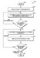
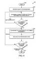
- FIG. 6illustrates a flowchart, in accordance with an embodiment of the present invention.
- Embodiments of the present inventionprovide a system and method for synchronizing differing camera feeds to generate time aligned content.
- a devicefor use with a first video feed and a second video feed.
- the deviceincludes a receiver portion, a determining portion, a synchronization portion and a time aligning portion.
- the receiver portioncan receive both the first and second video feeds, can receive the second video feed, can generate a first output video based on the first video feed and can generate a second output video based on the second video feed.
- the first video feedincludes first discontinuity data corresponding to a first discontinuity and second discontinuity data corresponding to a second discontinuity.
- the second video feedincludes third discontinuity data corresponding to a third discontinuity and fourth discontinuity data corresponding to a fourth discontinuity.
- the determining portioncan detect the first discontinuity, the second discontinuity, the third discontinuity and the fourth discontinuity.
- the synchronization portioncan synchronize the second output video with the first output video based on the first discontinuity and the third discontinuity.
- the time aligning portioncan generate a comparison based on the second discontinuity and the fourth discontinuity.
- the synchronizing portioncan further adjust the synchronization of the first output video and the second output video based on the comparison.
- Coordinating video feeds with multiple views of an event or an activity streamed to a common location from random camera sourcescan be a challenging task.
- camera feeds from real time reception of cellular phone video from news locations or sporting eventsmay have different characteristics.
- Each imager and compression techniquemay have a different delay and encoding mechanism.
- videos recorded with a regular camcorder or a GSM (Global System for Mobile Communications) phone or a CDMA (Code Division Multiple Access) phonehave different characteristics.
- the common consolidation point for all the video feeds streamed from different camera sourcesis that a person has to examine all these feeds and attempt to synchronize and pull out all the information that would be used in order to recreate a best possible video output that can be used to reconstruct a 3-D view of the video feeds or provide the best shot available.
- Digital videos produced professionallytypically contain embedded time codes to facilitate synchronization of different feeds.
- time codesor in place of
- professional producers or savvy amateursuse sound sticks, clapboards, hand claps, strobe flashes, and such to insert deliberate synchronization points into a captured video.
- video editorswill search for eye blinks, sharp sounds, light flashes, or similar short duration events to use as synchronization points.
- Video editing softwaresuch as Adobe Premier Pro® allow a user to insert synchronization markers and time codes, and provide various features to assist in editing a multi-camera sequence.
- Synchronization of multiple video sourcesis now in need.
- camera feeds from real time reception of cellular phone video of a news eventmay have different frame rates, resolutions and orientations.
- non-commercial video sourcesdo not have embedded time codes that could be used as synchronization points.
- streaming video over cellular and IP (Internet Protocol) networkscan disrupt synchronization.
- FIG. 1illustrates a conventional media system 100 .
- conventional media system 100includes a plurality of media feeds streaming from a camcorder 102 , a mobile phone 104 , a mobile phone 106 , a mobile phone 108 and a computer tablet 110 .
- media feedscontain both audio and video and are compressed for storage and streaming. Since each media feed originates from a different source, it may have a different set of delay and encoding mechanisms.
- mobile phone 104is a GSM phone
- mobile phone 106is a CDMA phone, hence, each uses a different media compression codec.
- each media feedmay contain a different perspective or view of the event or the activity.
- Conventional media system 100further includes a processing system 112 and a display device 114 .
- Media feeds from camcorder 102 , mobile phone 104 , mobile phone 106 , mobile phone 108 and computer tablet 110are streamed to processing system 112 via a telecommunication network 116 .
- Any network protocolsuch as, Transmission Control Protocol (TCP), Real-Time Streaming Protocol (RTSP), or Real-time Transport Protocol (RTP) may be used for streaming the media over telecommunication network 116 .
- TCPTransmission Control Protocol
- RTSPReal-Time Streaming Protocol
- RTPReal-time Transport Protocol
- Processing system 112communicates with display device 114 via a communication channel 118 .
- Processing system 112further includes a receiver 120 , a processor 122 , a synchronizer 124 , a memory 126 and a display interface 128 .
- Receiver 120is operable to receive individual streams from camcorder 102 , mobile phone 104 , mobile phone 106 , mobile phone 108 and computer tablet 110 .
- receiver 120includes a decoding system for decoding each individual encoded stream based on the corresponding codec. Additionally, receiver 120 may include a memory buffer to store the incoming streams. Receiver 120 bi-directionally communicates with processor 122 via a signal 130 to exchange data and controls.
- Processor 122is operable to communicate with receiver 120 , synchronizer 124 , memory 126 , and display interface 128 in order to execute a set of instructions that would enable: Receiver 120 to receive various video feeds and decode them as needed; Synchronizer 124 to synchronize the video feeds based on the available synchronization points; Display interface 128 to prepare the video content and forward it for displaying on display device 114 .
- Processor 122is further operable to bi-directionally communicate with memory 126 via a signal 134 .
- Memory 126may include a program memory, a data memory or a combination of both.
- Synchronizer 124is operable to bi-directionally communicate with processor 122 via a signal 136 , with display interface 128 via a signal 138 , and with receiver 120 via a signal 132 . Synchronizer 124 is further operable to receive video streams from receiver 120 , which may have time codes embedded within the video streams, and to use them for synchronizing various camera feeds.
- Display interface 128is operable to receive controls from processor 122 via a signal 140 and to receive synchronized media streams from synchronizer 124 that can be used to create a 3-D image of the video feeds.
- Display device 114is operable to receive the media streams from processing system 112 for displaying the video recreated from various video feeds.
- Some commercial solutionscan provide synchronization time codes with the video streams; however, the cost of these solutions is prohibitive. Additionally, timing synchronization is not incorporated in non-commercial encoders. Capture and delivery delay from multiple sources varies for different feeds. Handheld videos can be delivered at different rates, whereas, delivery delay on 3G (Third Generation) systems has more latency and jitter than is present in 4G/Wi-Fi systems.
- Feature based approachis the most commonly used synchronization method that detects the image features, such as, highly discriminative points or edges in the video frames and attempts relating to corresponding features in other sequences.
- the basic premiseis that the motion of frame features, which corresponds to the same 3-D point, are correlated among the different camera feeds.
- the major disadvantage of this approachis that reliably detecting, matching and tracking the features through the sequences can be a cumbersome process.
- the intensity based approachprocesses the frames pixel-by-pixel by performing mathematical operations on large scale.
- An intensity based approachfocuses on establishing a mapping from every pixel in one video to a pixel in the second one, and, therefore, is very computationally intensive.
- intensity based approachesare not capable of dealing with moving cameras.
- Camera motion based approachcomprises very specialized scenarios with rigidly linked cameras, which is a very restrictive assumption. Camera motion based approaches are fast compared to Feature based and Intensity based; however, they assume a rigid mounting and baseline of the camera.
- FIG. 2illustrates two video feeds that need to be synchronized.
- a scenario 200includes a video feed 202 and a video feed 204 that need to be synchronized.
- Video feed 202contains a sequence of frames 208 - 222 from one camera source.
- Video feed 204contains another sequence of frames 224 - 238 from another camera source.
- the two camera sourcesmay or may not have the same encoding mechanism.
- video feed 202 and video feed 204are shown to contain only eight frames each with different positions of a person 206 .
- a conventional processing systemsuch as processing system 112 , will compare both feeds frame by frame in order to synchronize the feeds.
- frame 208is compared against each of frames 224 - 238 to find a matching frame.
- frame 210is compared against each of frames 224 - 238 and so on.
- frame 210 of video feed 202matches with frame 232 of feed 204 . Therefore, synchronizer 124 will insert synchronization points based on matching frames 210 and 232 .
- another frame of video feed 202matches with a frame of video feed 204 , there will be another synchronization point inserted based on that and so on.
- Embodiments of the present inventionprovide a system and method for inserting synchronization points for synchronizing multiple unsynchronized video feeds to generate time-aligned content by providing a timing reference hidden within the video stream itself for coordination.
- Some non-limiting examples for generating the synch pointsmay be motion detection, face recognition, changes in audio, luminance or chrominance, etc.
- Multiple views of the video feedscan be consolidated for creating a multi-view video montage or feeding into a 3-D correlation program.
- Embodiments of the present inventionaddress synchronization of multiple unsynchronized video sources, such as videos captured and streamed by smart phones for a common event or activity.
- Such videosmay include plurality of video feeds, where each feed may or may not have different views of the videos that need to be synchronized.
- video sourcesmay have different frame rates, resolutions and orientations.
- non-commercial videosdo not have embedded time codes that could be used as synchronization points.
- One possible use of synchronizing video feeds from multiple smart phonescould be in a situation in which several smart phones captured a breaking news event and the resulting video feeds were gathered and redistributed as a montage by a news agency.
- video feeds from various smart phones, camcorders and suchhave different characteristics due to their different encoding mechanism. Additionally different video feeds may have different view of the event recorded. As an example, a video feed may have an image recorded from the front, while another feed may have the same image recorded from a 30° angle, and a third video feed may have the same image recorded from the back.
- a processing systemreceives unsynchronized video feeds for a common event or activity from various video sources, such as, camcorder 102 , mobile phone 104 , mobile phone 106 , mobile phone 108 and computer tablet 110 , and time aligns these video feeds based on a recognized discontinuity.
- a discontinuitymay be considered a change between two frames.
- the discontinuitymay be based on image, motion and/or sound. For example, consider the situation wherein in a video, a person is waving his hand. In this situation, suppose the hand is traveling in a direction from left to right. At some point, the hand will then travel from right to left. This change in motion may be considered a discontinuity in motion. In another example, consider the situation wherein in a video, there is an explosion. In this situation, the discontinuity is between the image before the explosion, when everything is clear, and after the explosion, when the image is bright and colorful. Further, a discontinuity may be a discontinuity in sound.
- a discontinuitycan be determined based on a change in a characteristic of the video feed.
- a processing systemfinds a discontinuity between the frames of one video feed and attempts to find the same discontinuity in other video feeds, in order to synchronize all the video feeds based on the common discontinuity. For a given length of video feeds, the processing system attempts to find a number of discontinuities. Two video feeds for a common event, recorded from different locations and with different camera sources, may have totally different images of the event but may have the same discontinuity in both the video feeds. In contrast to conventional processing systems, where a series of frames need to be compared with another series of frames in order to detect a common image for synchronization, the current approach detects discontinuities between the frames, and, hence, involves fewer computations. This will now be explained with reference to FIG. 3 .
- FIG. 3illustrates two video feeds that need to be synchronized, in accordance with an embodiment of the present invention.
- a scenario 300includes a video feed 302 and a video feed 304 that need to be synchronized.
- Video feed 302contains a sequence of frames 308 - 322 from one camera source.
- Video feed 304contains another sequence of frames 324 - 338 from another camera source recorded from a different viewpoint.
- the two camera sourcesmay or may not have the same encoding mechanism.
- video feed 302 and video feed 304are shown to contain only twenty frames each with different positions of a person 306 .
- frames 308 and 310include images of person 306 walking, facing towards the right direction.
- the difference in images between frames 308 and 310is minimal, and, hence are not good candidates for finding discontinuity.
- person 306is kicking a soccer ball 340 .
- this kicking of soccer ball 340represents a considerable change in the image between frame 310 and frame 312 , and is counted as a discontinuity 348 , as shown by delta 1 .
- the video feedsmay be analyzed in parallel to look for discontinuities.
- the second video feed 304has no discontinuities found in either frame 324 , 326 or 328 since the difference in the images are very minimal.
- person 306is kicking soccer ball 340 , which represents a discontinuity 352 as indicated by delta 3 .
- discontinuity 348 and discontinuity 352are very similar even though the images may be very different.
- Frames 314 and 332are similar and as compared to their preceding frames, the change in images is minimal.
- a processing systemwill insert synchronization points based on discontinuity 348 detected in video feed 302 and discontinuity 352 detected in video feed 304 and attempt to align the video feeds. If the video feeds are not completely aligned, it keeps looking for other common discontinuities in video feeds 302 and 304 .
- the processing systemwill further align video feeds 302 and 304 . If there is acceptable error between the alignments of two video feeds, the consolidated video feed is ready for producing a multi-dimensional model of the common event. If the two video feeds are still not aligned, the processing system will look for more discontinuities based on a pre-determined number. In a non-limiting example embodiment, the pre-determined number is two, wherein the processing system will continuee to look until it finds two consecutive aligned discontinuities.
- the processing systemfirst decodes the video feeds before comparing different video feeds for discontinuity. There may be cues in the image, which may be based on the movement in one embodiment or on the sound in another embodiment, which can be used to determine a discontinuity. As long as the motions or changes are visible from each independent feed, tags can be created to mark those changes for synchronization.
- a random point that is available or visible through almost 360° of viewis preferable for inserting synchronization points.
- motion of that pointcan be used as synchronization point in the video. For example, if it is determined that there is a wrist in the video with the hand moving up or down, it indicates a change in the motion.
- a synchronization pointcan be inserted at the wrist, which will determine the delay in time with respect to each of the feeds. Once a synchronization point is inserted in a video, a delay computation can be performed to align all the feeds.
- the proposed methodprovides a feedback process to look for discontinuities in all the video streams in parallel, while searching for common discontinuity.
- the feedback processattempts to find a pre-determined number of discontinuities in the video feeds.
- the video streamsmay be raw, encoded or decoded.
- the frames with much more information as compared to the other framesare an indication of changes in the image, and are good candidates for finding discontinuities. For example, in the case of MPEG streams having one complete frame and deltas for the rest of the frames, a large delta is an indication of considerable changes.
- the processin accordance with an embodiment of the present invention, keeps searching for common discontinuities in parallel on all the streams and attempts to time align the feeds once the first discontinuity is found.
- the processattempts to keep synchronizing the feeds while looking for more discontinuities. If the feeds are not lined up, the process attempts to re-adjust and keeps performing the discontinuity detection and time adjustment until an acceptable error is achieved. In one embodiment, the acceptable error is based on a pre-determined number. If all the feeds are time aligned, the process has achieved the desired synchronization and a multi-dimensional image can be created.
- a processing system implementing the process, in accordance with an embodiment of the present invention,is described with the help of FIG. 4 .
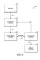
- FIG. 4illustrates a processing system 400 , in accordance with an embodiment of the present invention.
- processing system 400includes a receiver 402 , a determining portion 404 , a synchronizing portion 406 , a time aligning portion 408 and a display interface 410 .
- receiver 402 , determining portion 404 , synchronizing portion 406 , time aligning portion 408 and display interface 410are distinct elements.
- at least two of receiver 402 , determining portion 404 , synchronizing portion 406 , time aligning portion 408 and display interface 410may be combined as a unitary element.
- At least one of receiver 402 , determining portion 404 , synchronizing portion 406 , time aligning portion 408 and display interface 410may be implemented as a computer having stored therein tangible, non-transitory, computer-readable media for carrying or having computer-executable instructions or data structures stored thereon.
- tangible, non-transitory, computer-readable mediacan be any available media that can be accessed by a general purpose or special purpose computer.
- Non-limiting examples of tangible, non-transitory, computer-readable mediainclude physical storage and/or memory media such as RAM, ROM, EEPROM, CD-ROM or other optical disk storage, magnetic disk storage or other magnetic storage devices, or any other medium which can be used to carry or store desired program code means in the form of computer-executable instructions or data structures and which can be accessed by a general purpose or special purpose computer.
- RAMrandom access memory
- ROMread-only memory
- EEPROMelectrically erasable programmable read-only memory
- CD-ROM or other optical disk storagesuch as CD-ROM or other optical disk storage
- magnetic disk storage or other magnetic storage devicessuch as magnetic disks, or any other medium which can be used to carry or store desired program code means in the form of computer-executable instructions or data structures and which can be accessed by a general purpose or special purpose computer.
- a network or another communications connectioneither hardwired, wireless, or a combination of hardwired or wireless
- any such connectionis properly termed a tangible, non-trans
- Receiver 402is operable to receive various video feeds from different camera sources and to generate video outputs via a signal 412 to determining portion 404 .
- the video feeds received by receiver 402may be raw, i.e., without any encoding, or may be encoded with different or same encoding mechanism.
- receiver 402receives video feeds that have been encoded with different formats, such as video feeds from camcorder 102 , mobile phone 104 , mobile phone 106 , mobile phone 108 and computer tablet 110 , and performs decoding of the video streams before forwarding it to determining portion 404 .
- receiver 402decodes the video streams into a common format.
- receiver 402includes a memory for buffering the incoming streams.
- Determining portion 404is operable to detect common discontinuities in the video outputs received from receiver 402 , based on a predetermined criterion.
- the criterioninclude changes in motion, audio, color, brightness, etc. As discussed earlier, feed frames with a lot more information as compared to other frames in the feed are good candidates for spotting discontinuities.
- Determining portion 404keeps comparing different video feeds to find the common discontinuity in each feed until all the feeds are time aligned and a pre-determined number of common discontinuities is reached.
- determining portion 404uses various techniques, such as, centering the object of interest, rotation of the video content, or scaling the object of interest, in order to find discontinuity in the feeds.
- centering the object of interestthe object of interest can be identified by facial recognition or motion detection.
- Rotating the video contentsallows for direct comparison of images once the contents are aligned in the same plane. Scaling the object to similar dimensions provides the user with a point of reference for comparison.
- Synchronizing portion 406is operable to synchronize the video outputs by inserting the synchronization points based on the discontinuity information provided by determining portion 404 via a signal 414 .
- Synchronizing portion 406is further operable to receive a re-adjust signal 416 from time aligning portion 408 in order to adjust the synchronization of the video outputs, if the feeds are not aligned.
- Synchronizing portion 406bi-directionally communicates with time aligning portion 408 via a signal 418 in order to exchange information regarding the synchronization points.
- Time aligning portion 408is operable to compare synchronized video feeds by performing time adjustment in feedback mode with synchronizing portion 406 and determining portion 404 such that the video feeds are aligned based on the synchronization points.
- the contentcan be compared manually and the delays of individual feeds can be adjusted to align the feeds.
- time aligning portion 408provides the synchronized video to display interface 410 via a signal 420 . Alignment of different frames using discontinuities is explained in greater detail below.
- time aligning portion 408designates one feed's discontinuity as a master discontinuity. All the other feeds' discontinuities are referred to as ‘preceding’, ‘now’ and ‘following’ with respect to the master discontinuity. The error between the master discontinuity and each of the ‘preceding’, ‘now’ and ‘following’ discontinuities for other feeds is calculated. Each feed's discontinuity with minimum error is declared as “winner” indicating the closest discontinuity in time with respect to the master discontinuity. Each feed's winner becomes the timing reference when analyzing the next master discontinuity. Time aligning portion 408 keeps analyzing the preceding, now and following discontinuities with respect to the master discontinuity until the convergence occurs. This is further explained with the help of FIGS. 5A-5B .
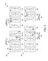
- FIGS. 5A-5Billustrate a method 500 for aligning different feeds using discontinuities, in accordance with an embodiment of the present invention.
- FIG. 5Aincludes a master discontinuity 502 , a preceding discontinuity 504 , a now discontinuity 506 and a following discontinuity 508 for two video feeds, namely first and second video feeds.
- Master discontinuity 502represents the difference in two successive frames of the first video feed. The difference may be based on motion, image and/or sound as discussed earlier.
- Preceding-discontinuity 504represents the difference in two frames of the second video feed, which occurs earlier in time with respect to master discontinuity 502 .
- Now-discontinuity 506represents the difference in two frames of the second video feed, which occurs at the same time as master discontinuity 502 .
- Following-discontinuity 508represents the difference in two frames of the second video feed, which occurs later in time than master discontinuity 508 .
- master discontinuity 502is same as discontinuity 348 for video feed 302 .
- now-discontinuity 506is same as discontinuity 352 and following-discontinuity 508 is same as discontinuity 354 for video feed 304 .
- time aligning portion 408attempts to calculate errors of preceding-discontinuity 504 , now-discontinuity 506 and following-discontinuity 508 from master discontinuity 502 .
- now-discontinuity 506is declared as the ‘winner’ and the second video feed becomes the timing reference for analysis of the next discontinuity, as shown with the help of FIG. 5B .
- a second discontinuity 510 of the second video feedhas been designated as a new master discontinuity and a discontinuity 512 has been designated as the preceding-discontinuity, a discontinuity 514 is designated as a now-discontinuity, and a discontinuity 516 is designated as a following-discontinuity.
- the error of discontinuity 512 , discontinuity 514 and discontinuity 516is calculated from master discontinuity 510 to determine the discontinuity with minimum error.
- discontinuity 354is the new master discontinuity for video feed 304 .
- Discontinuity 348is similar to preceding-discontinuity 512 and discontinuity 350 is similar to now-discontinuity 514 .
- the error of discontinuity 348 and discontinuity 350is calculated from discontinuity 354 and video feed having the discontinuity with minimum error becomes the timing reference when analyzing the next discontinuity.
- Time aligning portion 408keeps analyzing the preceding-, now- and following-discontinuities with respect to the master discontinuity for a pre-determined number of times, until an acceptable error is achieved.
- display interface 410is operable to use the aligned content for recreating a multi-view video montage or feeding it into a 3-D correlation program.
- Different actionssuch as, rotate, twist, or center, can be performed on the multi-dimensional model.
- the information contained in original video feedsis presented as-is to the consumer with varying delays and resolutions.
- a 3-D imagecan be created based on multiple views provided by various camera feeds that can be used for forensic analysis of a catastrophic event.
- a common characteristicis determined given a plurality of random video feeds.
- the common characteristiccan be based on changes in motion, audio, image, etc., between the frames. Synchronization points are inserted in the video feeds based on the common characteristic in order to time align the video feeds. Once the video feeds are time aligned, a multi-dimensional model can be created.
- the feedback processin accordance with an embodiment of the present invention, is described with the help of a flowchart in FIG. 6 .
- FIG. 6illustrates a flowchart of a process 600 , in accordance with an embodiment of the present invention.
- the processbegins (S 602 ), when receiver 402 receives a plurality of random feeds from various camera sources (S 604 ). As discussed earlier, receiver 402 may decode the video streams if needed. In one embodiment, all the video streams are decoded in one common format.
- Determining portion 404analyzes all the video feeds and attempts to find a common discontinuity in each feed based on a characteristic (S 606 ).
- the characteristiccan be based on a pre-determined criterion, such as, motion, audio, image, etc., as discussed earlier with reference to FIG. 4 .
- determining portion 404attempts to find the next common discontinuity between the feeds (S 608 ). In one embodiment, determining portion 404 attempts to find the common discontinuities for a pre-determined number of times.
- synchronizing portion 406synchronizes the feeds by inserting synchronization points based on the common discontinuity (S 610 ).
- Time aligning portion 408attempts to time align the synchronized feeds once the synchronization points are inserted (S 612 ). In one embodiment of the invention, time aligning portion 408 attempts to time align the synchronized feeds by adjusting delays of individual feeds.
- Time aligning portion 408continues to check whether the video feeds are aligned or not in a feedback loop (S 614 ). If the video feeds are not aligned, time aligning portion 408 provides a feedback to synchronizing portion 406 to re-adjust. Synchronizing portion 406 attempts to re-adjust the synchronization by manipulating the synchronization points based on the common discontinuity.
- time aligning portion 408has succeeded in aligning the video content and the process ends (S 616 ).
- the time aligned contentcan be used by display interface portion 410 to generate a video output that can be used to provide the best available shot of an event or to reconstruct an image based on different views of the activity provided by multiple camera sources.
- feedback process 400receives a plurality of random video feeds for synchronization.
- synchronization pointsare inserted in the video outputs based on the common discontinuities found in the video feeds.
- the common discontinuitiescan be based on a pre-determined criterion.
- Synchronized video outputsare time aligned in a feedback mode until the video content is time aligned by re-adjusting the synchronization points.
- Time aligned video outputcan be used for recreating a multi-view video montage or feeding it into a 3-D correlation program.
Landscapes
- Engineering & Computer Science (AREA)
- Multimedia (AREA)
- Signal Processing (AREA)
- Databases & Information Systems (AREA)
- Television Signal Processing For Recording (AREA)
- Image Analysis (AREA)
Abstract
Description
Claims (21)
Priority Applications (2)
| Application Number | Priority Date | Filing Date | Title |
|---|---|---|---|
| US13/468,098US9392322B2 (en) | 2012-05-10 | 2012-05-10 | Method of visually synchronizing differing camera feeds with common subject |
| PCT/US2013/040347WO2013170027A1 (en) | 2012-05-10 | 2013-05-09 | Method of visually synchronizing differing camera feeds with common subject |
Applications Claiming Priority (1)
| Application Number | Priority Date | Filing Date | Title |
|---|---|---|---|
| US13/468,098US9392322B2 (en) | 2012-05-10 | 2012-05-10 | Method of visually synchronizing differing camera feeds with common subject |
Publications (2)
| Publication Number | Publication Date |
|---|---|
| US20130300933A1 US20130300933A1 (en) | 2013-11-14 |
| US9392322B2true US9392322B2 (en) | 2016-07-12 |
Family
ID=48570440
Family Applications (1)
| Application Number | Title | Priority Date | Filing Date |
|---|---|---|---|
| US13/468,098Active2034-07-12US9392322B2 (en) | 2012-05-10 | 2012-05-10 | Method of visually synchronizing differing camera feeds with common subject |
Country Status (2)
| Country | Link |
|---|---|
| US (1) | US9392322B2 (en) |
| WO (1) | WO2013170027A1 (en) |
Cited By (8)
| Publication number | Priority date | Publication date | Assignee | Title |
|---|---|---|---|---|
| US9571727B2 (en) | 2014-05-21 | 2017-02-14 | Google Technology Holdings LLC | Enhanced image capture |
| US9729784B2 (en) | 2014-05-21 | 2017-08-08 | Google Technology Holdings LLC | Enhanced image capture |
| US9774779B2 (en) | 2014-05-21 | 2017-09-26 | Google Technology Holdings LLC | Enhanced image capture |
| US9813611B2 (en) | 2014-05-21 | 2017-11-07 | Google Technology Holdings LLC | Enhanced image capture |
| US9936143B2 (en) | 2007-10-31 | 2018-04-03 | Google Technology Holdings LLC | Imager module with electronic shutter |
| US10110946B2 (en) | 2014-12-25 | 2018-10-23 | Echostar Uraine, L.L.C. | Simultaneously viewing multiple camera angles |
| WO2020197898A1 (en)* | 2019-03-27 | 2020-10-01 | Microsoft Technology Licensing, Llc | Audio synchronization of correlated video feeds |
| US12363359B2 (en) | 2020-04-28 | 2025-07-15 | Arris Enterprises Llc | System for presentation time stamp recovery from a transcoder |
Families Citing this family (16)
| Publication number | Priority date | Publication date | Assignee | Title |
|---|---|---|---|---|
| JP2013171089A (en)* | 2012-02-17 | 2013-09-02 | Toshiba Corp | Voice correction device, method, and program |
| US10971191B2 (en)* | 2012-12-12 | 2021-04-06 | Smule, Inc. | Coordinated audiovisual montage from selected crowd-sourced content with alignment to audio baseline |
| KR20150027934A (en)* | 2013-09-04 | 2015-03-13 | 삼성전자주식회사 | Apparatas and method for generating a file of receiving a shoot image of multi angle in an electronic device |
| TWI505113B (en)* | 2014-03-18 | 2015-10-21 | Vivotek Inc | Monitoring system and related method of searching an image |
| US20160048701A1 (en)* | 2014-08-18 | 2016-02-18 | Spatial Digital Systems, Inc. | Enveloping for remote Digital Camera |
| US20160048371A1 (en)* | 2014-08-18 | 2016-02-18 | Spatial Digital Systems, Inc. | Enveloping via Digital Audio |
| US10362075B2 (en) | 2015-10-14 | 2019-07-23 | Benjamin Nowak | Presenting content captured by a plurality of electronic devices |
| WO2016061261A1 (en)* | 2014-10-15 | 2016-04-21 | Nowak Benjamin | Multiple view-point content capture and composition |
| US11973813B2 (en) | 2014-10-15 | 2024-04-30 | Benjamin Nowak | Systems and methods for multiple device control and content curation |
| EP3142372A1 (en)* | 2015-09-08 | 2017-03-15 | Thomson Licensing | Method and device for robust temporal synchronization of two video contents |
| CN108370454B (en)* | 2015-12-03 | 2020-11-03 | 深圳市大疆创新科技有限公司 | System and method for video processing |
| US10623801B2 (en) | 2015-12-17 | 2020-04-14 | James R. Jeffries | Multiple independent video recording integration |
| GB2552316A (en)* | 2016-07-15 | 2018-01-24 | Sony Corp | Information processing apparatus, method and computer program product |
| US10362340B2 (en) | 2017-04-06 | 2019-07-23 | Burst, Inc. | Techniques for creation of auto-montages for media content |
| WO2019061305A1 (en)* | 2017-09-29 | 2019-04-04 | Intel Corporation | Aligning sensor data with video |
| EP4380170A4 (en)* | 2021-11-09 | 2024-11-27 | Samsung Electronics Co., Ltd. | ELECTRONIC DEVICE AND METHOD FOR AUTOMATICALLY GENERATING EDITED VIDEO |
Citations (84)
| Publication number | Priority date | Publication date | Assignee | Title |
|---|---|---|---|---|
| US4881127A (en) | 1987-02-25 | 1989-11-14 | Konica Corporation | Still video camera with electronic shutter and flash |
| US5294990A (en) | 1989-07-14 | 1994-03-15 | Asahi Kogaku Kogyo Kabushiki Kaisha | Electronic still camera |
| US5505199A (en) | 1994-12-01 | 1996-04-09 | Kim; Bill H. | Sudden infant death syndrome monitor |
| US5909246A (en) | 1995-12-25 | 1999-06-01 | Sony Corporation | Image sensing device and method of adjusting quantity of light |
| US6167356A (en) | 1998-07-01 | 2000-12-26 | Sportvision, Inc. | System for measuring a jump |
| US6347925B1 (en) | 2000-06-29 | 2002-02-19 | Beacon Power Corporation | Flywheel system with parallel pumping arrangement |
| US20020047909A1 (en) | 2000-10-23 | 2002-04-25 | Yasuhiko Hatae | Method of controlling transmission light amount and television camera apparatus using the method |
| US20020080263A1 (en) | 2000-10-26 | 2002-06-27 | Krymski Alexander I. | Wide dynamic range operation for CMOS sensor with freeze-frame shutter |
| US20030007088A1 (en) | 2001-06-01 | 2003-01-09 | Nokia Corporation | Control of a flash unit in a digital camera |
| US6529253B1 (en) | 1999-06-09 | 2003-03-04 | Sony Corporation | Filter for adjusting amount of light |
| US20030052989A1 (en) | 2001-07-18 | 2003-03-20 | Bean Heather Noel | Non-polarizing shutter/CCD module |
| US6614471B1 (en) | 1999-05-10 | 2003-09-02 | Banctec, Inc. | Luminance correction for color scanning using a measured and derived luminance value |
| US20040107103A1 (en)* | 2002-11-29 | 2004-06-03 | Ibm Corporation | Assessing consistency between facial motion and speech signals in video |
| US20050154318A1 (en) | 2003-10-30 | 2005-07-14 | Sony Corporation | Image apparatus and method, and communication terminal device |
| US20050206820A1 (en) | 2002-06-20 | 2005-09-22 | Lc-Tec Displays Ab | Fast optical shutter |
| WO2005099251A1 (en) | 2004-04-07 | 2005-10-20 | Koninklijke Philips Electronics N.V. | Video-audio synchronization |
| US20060156374A1 (en) | 2003-02-14 | 2006-07-13 | Hu Carl C | Automatic synchronization of audio and video based media services of media content |
| KR20070005947A (en) | 2005-07-05 | 2007-01-11 | 엘지전자 주식회사 | Aperture Shutter Device for Small Cameras |
| US7190263B2 (en) | 2004-09-20 | 2007-03-13 | Motorola, Inc. | Utilizing a portable electronic device to detect motion |
| US20070090283A1 (en) | 2005-10-21 | 2007-04-26 | Nokia Corporation | Optical shutter for miniature cameras |
| US20070115459A1 (en) | 2005-10-17 | 2007-05-24 | Funai Electric Co., Ltd. | Compound-Eye Imaging Device |
| US20070201815A1 (en) | 2006-01-06 | 2007-08-30 | Christopher Griffin | Digital video editing system |
| US20070237423A1 (en) | 2006-04-10 | 2007-10-11 | Nokia Corporation | Constructing image panorama using frame selection |
| WO2007128114A1 (en)* | 2006-05-05 | 2007-11-15 | Miranda Technologies Inc. | Method and apparatus for synchronizing a graphics signal according to a reference signal |
| US7301563B1 (en) | 1998-07-28 | 2007-11-27 | Olympus Optical Co., Ltd. | Image pickup apparatus |
| US20080077020A1 (en) | 2006-09-22 | 2008-03-27 | Bam Labs, Inc. | Method and apparatus for monitoring vital signs remotely |
| US7414665B2 (en) | 2002-07-16 | 2008-08-19 | Olympus Corporation | Imaging system |
| US7450187B2 (en) | 2005-11-23 | 2008-11-11 | Hon Hai Precision Industry Co., Ltd. | Liquid crystal shutter device for a camera |
| EP2043360A2 (en) | 2007-09-27 | 2009-04-01 | OmniVision Technologies Inc. | Dual mode camera apparatus, system, and method |
| US20090087099A1 (en) | 2007-09-28 | 2009-04-02 | Fujifilm Corporation | Image processing apparatus, image capturing apparatus, image processing method and recording medium |
| US20090109309A1 (en) | 2007-10-31 | 2009-04-30 | Motorola Inc. | Imager Module With Electronic Shutter |
| US20090189992A1 (en) | 2008-01-30 | 2009-07-30 | Samsung Electronics Co., Ltd. | Apparatus and method for learning photographing profiles of digital imaging device for recording personal life history |
| US20090190803A1 (en) | 2008-01-29 | 2009-07-30 | Fotonation Ireland Limited | Detecting facial expressions in digital images |
| US20100091119A1 (en) | 2008-10-10 | 2010-04-15 | Lee Kang-Eui | Method and apparatus for creating high dynamic range image |
| US20100097491A1 (en) | 2008-10-21 | 2010-04-22 | Stmicroelectronics S.R.L. | Compound camera sensor and related method of processing digital images |
| WO2010068175A2 (en) | 2008-12-10 | 2010-06-17 | Muvee Technologies Pte Ltd | Creating a new video production by intercutting between multiple video clips |
| US20100149393A1 (en) | 2008-05-22 | 2010-06-17 | Panavision Imaging, Llc | Increasing the resolution of color sub-pixel arrays |
| US20100195912A1 (en) | 2009-02-05 | 2010-08-05 | Naohisa Nakada | Imaging device, image composition and display device, and image composition method |
| US20100208082A1 (en) | 2008-12-18 | 2010-08-19 | Band Crashers, Llc | Media systems and methods for providing synchronized multiple streaming camera signals of an event |
| US20100271469A1 (en) | 2009-04-28 | 2010-10-28 | Foxconn Communication Technology Corp. | Site monitoring systems and methods |
| US20100309334A1 (en) | 2009-06-05 | 2010-12-09 | Apple Inc. | Camera image selection based on detected device movement |
| US20100309333A1 (en) | 2009-06-08 | 2010-12-09 | Scott Smith | Image sensors and image reconstruction methods for capturing high dynamic range images |
| US20100309335A1 (en) | 2009-06-05 | 2010-12-09 | Ralph Brunner | Image capturing device having continuous image capture |
| US20110013807A1 (en) | 2009-07-17 | 2011-01-20 | Samsung Electronics Co., Ltd. | Apparatus and method for recognizing subject motion using a camera |
| US20110043691A1 (en) | 2007-10-05 | 2011-02-24 | Vincent Guitteny | Method for synchronizing video streams |
| US20110052136A1 (en)* | 2009-09-01 | 2011-03-03 | Video Clarity, Inc. | Pattern-based monitoring of media synchronization |
| US20110069189A1 (en) | 2008-05-20 | 2011-03-24 | Pelican Imaging Corporation | Capturing and processing of images using monolithic camera array with heterogeneous imagers |
| US20110122315A1 (en) | 2009-11-13 | 2011-05-26 | Ntt Docomo, Inc. | Method and apparatus for synchronizing video data |
| US20110205433A1 (en) | 2010-02-25 | 2011-08-25 | William Conrad Altmann | Video frame synchronization |
| US20120081579A1 (en) | 2010-09-30 | 2012-04-05 | Apple Inc. | High Dynamic Range Transition |
| US20120105584A1 (en) | 2010-10-28 | 2012-05-03 | Gallagher Andrew C | Camera with sensors having different color patterns |
| US8295631B2 (en) | 2010-01-29 | 2012-10-23 | Eastman Kodak Company | Iteratively denoising color filter array images |
| WO2012166044A1 (en) | 2011-05-31 | 2012-12-06 | Scalado Ab | Method and apparatus for capturing images |
| US20120314901A1 (en) | 2011-04-04 | 2012-12-13 | Alarm.Com | Fall Detection and Reporting Technology |
| US20130016251A1 (en) | 2011-07-15 | 2013-01-17 | Kabushiki Kaisha Toshiba | Solid-state imaging device, image processing apparatus, and camera module |
| US20130057713A1 (en) | 2011-09-02 | 2013-03-07 | Microsoft Corporation | Automatic image capture |
| US20130208143A1 (en) | 2012-02-13 | 2013-08-15 | Htc Corporation | Image Capture Method and Image Capture System thereof |
| US20130208138A1 (en) | 2012-02-09 | 2013-08-15 | Aptina Imaging Corporation | Imaging systems and methods for generating auto-exposed high-dynamic-range images |
| EP2645700A1 (en) | 2012-03-27 | 2013-10-02 | BlackBerry Limited | Method and device for motion enhanced image capture |
| US20130271602A1 (en) | 2010-08-26 | 2013-10-17 | Blast Motion, Inc. | Motion event recognition system and method |
| WO2013172335A1 (en) | 2012-05-14 | 2013-11-21 | フリービット株式会社 | Image shooting system |
| US20130314511A1 (en) | 2012-05-24 | 2013-11-28 | Mediatek Inc. | Image capture device controlled according to image capture quality and related image capture method thereof |
| US8619128B2 (en) | 2009-09-30 | 2013-12-31 | Apple Inc. | Systems and methods for an imaging system using multiple image sensors |
| US20140009634A1 (en) | 2012-07-06 | 2014-01-09 | Kabushiki Kaisha Toshiba | Image processing device and image processing system |
| US20140063300A1 (en) | 2012-09-06 | 2014-03-06 | Aptina Imaging Corporation | High dynamic range imaging systems having clear filter pixel arrays |
| US20140074265A1 (en) | 2011-11-18 | 2014-03-13 | Irwin Arginsky | System and method for monitoring the use of an exercise apparatus |
| US20140085495A1 (en) | 2012-09-21 | 2014-03-27 | Research In Motion Limited | Methods and devices for controlling camera image capture |
| US20140160326A1 (en) | 2012-12-06 | 2014-06-12 | Aptina Imaging Corporation | Color filter arrangements for fused array imaging systems |
| US8803985B2 (en) | 2011-05-13 | 2014-08-12 | Sony Corporation | Image processing apparatus, image pickup apparatus, image processing method, and program |
| US20140232929A1 (en) | 2013-02-20 | 2014-08-21 | Canon Kabushiki Kaisha | Image capturing apparatus and method for controlling the same |
| US20140244617A1 (en) | 2013-02-22 | 2014-08-28 | Google Inc. | Suggesting media content based on an image capture |
| US20140358473A1 (en) | 2013-05-31 | 2014-12-04 | Nike, Inc. | Dynamic sampling |
| US20150195482A1 (en) | 2014-01-08 | 2015-07-09 | Nvidia Corporation | Method, system and smartphone that chooses optimal image to reduce shutter shake |
| US9143749B2 (en) | 2011-10-11 | 2015-09-22 | Sony Corporation | Light sensitive, low height, and high dynamic range camera |
| US20150271405A1 (en) | 2014-03-18 | 2015-09-24 | Motorola Mobility Llc | System for auto-hdr capture decision making |
| US20150288869A1 (en) | 2012-12-27 | 2015-10-08 | Olympus Corporation | Server apparatus and photographing apparatus |
| US20150318020A1 (en) | 2014-05-02 | 2015-11-05 | FreshTake Media, Inc. | Interactive real-time video editor and recorder |
| US20150341546A1 (en) | 2014-05-21 | 2015-11-26 | Motorola Mobility Llc | Enhanced image capture |
| US20150341548A1 (en) | 2014-05-21 | 2015-11-26 | Motorola Mobility Llc | Enhanced image capture |
| US20150341549A1 (en) | 2014-05-21 | 2015-11-26 | Motorola Mobility Llc | Enhanced image capture |
| US20150341547A1 (en) | 2014-05-21 | 2015-11-26 | Motorola Mobility Llc | Enhanced image capture |
| US20160037055A1 (en) | 2014-07-31 | 2016-02-04 | Google Technology Holdings LLC | Capturing images of active subjects |
| US20160050354A1 (en) | 2014-08-12 | 2016-02-18 | Google Technology Holdings LLC | High Dynamic Range Array Camera |
| US20160080626A1 (en) | 2014-09-16 | 2016-03-17 | Google Technology Holdings LLC | Computational Camera Using Fusion of Image Sensors |
- 2012
- 2012-05-10USUS13/468,098patent/US9392322B2/enactiveActive
- 2013
- 2013-05-09WOPCT/US2013/040347patent/WO2013170027A1/enactiveApplication Filing
Patent Citations (89)
| Publication number | Priority date | Publication date | Assignee | Title |
|---|---|---|---|---|
| US4881127A (en) | 1987-02-25 | 1989-11-14 | Konica Corporation | Still video camera with electronic shutter and flash |
| US5294990A (en) | 1989-07-14 | 1994-03-15 | Asahi Kogaku Kogyo Kabushiki Kaisha | Electronic still camera |
| US5505199A (en) | 1994-12-01 | 1996-04-09 | Kim; Bill H. | Sudden infant death syndrome monitor |
| US5909246A (en) | 1995-12-25 | 1999-06-01 | Sony Corporation | Image sensing device and method of adjusting quantity of light |
| US6167356A (en) | 1998-07-01 | 2000-12-26 | Sportvision, Inc. | System for measuring a jump |
| US7301563B1 (en) | 1998-07-28 | 2007-11-27 | Olympus Optical Co., Ltd. | Image pickup apparatus |
| US6614471B1 (en) | 1999-05-10 | 2003-09-02 | Banctec, Inc. | Luminance correction for color scanning using a measured and derived luminance value |
| US6529253B1 (en) | 1999-06-09 | 2003-03-04 | Sony Corporation | Filter for adjusting amount of light |
| US6347925B1 (en) | 2000-06-29 | 2002-02-19 | Beacon Power Corporation | Flywheel system with parallel pumping arrangement |
| US20020047909A1 (en) | 2000-10-23 | 2002-04-25 | Yasuhiko Hatae | Method of controlling transmission light amount and television camera apparatus using the method |
| US20020080263A1 (en) | 2000-10-26 | 2002-06-27 | Krymski Alexander I. | Wide dynamic range operation for CMOS sensor with freeze-frame shutter |
| US20030007088A1 (en) | 2001-06-01 | 2003-01-09 | Nokia Corporation | Control of a flash unit in a digital camera |
| US20030052989A1 (en) | 2001-07-18 | 2003-03-20 | Bean Heather Noel | Non-polarizing shutter/CCD module |
| US20050206820A1 (en) | 2002-06-20 | 2005-09-22 | Lc-Tec Displays Ab | Fast optical shutter |
| US7414665B2 (en) | 2002-07-16 | 2008-08-19 | Olympus Corporation | Imaging system |
| US20040107103A1 (en)* | 2002-11-29 | 2004-06-03 | Ibm Corporation | Assessing consistency between facial motion and speech signals in video |
| US20060156374A1 (en) | 2003-02-14 | 2006-07-13 | Hu Carl C | Automatic synchronization of audio and video based media services of media content |
| US20050154318A1 (en) | 2003-10-30 | 2005-07-14 | Sony Corporation | Image apparatus and method, and communication terminal device |
| WO2005099251A1 (en) | 2004-04-07 | 2005-10-20 | Koninklijke Philips Electronics N.V. | Video-audio synchronization |
| US7190263B2 (en) | 2004-09-20 | 2007-03-13 | Motorola, Inc. | Utilizing a portable electronic device to detect motion |
| KR20070005947A (en) | 2005-07-05 | 2007-01-11 | 엘지전자 주식회사 | Aperture Shutter Device for Small Cameras |
| US20070115459A1 (en) | 2005-10-17 | 2007-05-24 | Funai Electric Co., Ltd. | Compound-Eye Imaging Device |
| US20070090283A1 (en) | 2005-10-21 | 2007-04-26 | Nokia Corporation | Optical shutter for miniature cameras |
| US7450187B2 (en) | 2005-11-23 | 2008-11-11 | Hon Hai Precision Industry Co., Ltd. | Liquid crystal shutter device for a camera |
| US20070201815A1 (en) | 2006-01-06 | 2007-08-30 | Christopher Griffin | Digital video editing system |
| US20070237423A1 (en) | 2006-04-10 | 2007-10-11 | Nokia Corporation | Constructing image panorama using frame selection |
| WO2007128114A1 (en)* | 2006-05-05 | 2007-11-15 | Miranda Technologies Inc. | Method and apparatus for synchronizing a graphics signal according to a reference signal |
| US20080077020A1 (en) | 2006-09-22 | 2008-03-27 | Bam Labs, Inc. | Method and apparatus for monitoring vital signs remotely |
| EP2043360A2 (en) | 2007-09-27 | 2009-04-01 | OmniVision Technologies Inc. | Dual mode camera apparatus, system, and method |
| US20090086074A1 (en) | 2007-09-27 | 2009-04-02 | Omnivision Technologies, Inc. | Dual mode camera solution apparatus, system, and method |
| US20090087099A1 (en) | 2007-09-28 | 2009-04-02 | Fujifilm Corporation | Image processing apparatus, image capturing apparatus, image processing method and recording medium |
| US20110043691A1 (en) | 2007-10-05 | 2011-02-24 | Vincent Guitteny | Method for synchronizing video streams |
| US20090109309A1 (en) | 2007-10-31 | 2009-04-30 | Motorola Inc. | Imager Module With Electronic Shutter |
| US20090190803A1 (en) | 2008-01-29 | 2009-07-30 | Fotonation Ireland Limited | Detecting facial expressions in digital images |
| US20090189992A1 (en) | 2008-01-30 | 2009-07-30 | Samsung Electronics Co., Ltd. | Apparatus and method for learning photographing profiles of digital imaging device for recording personal life history |
| US20110069189A1 (en) | 2008-05-20 | 2011-03-24 | Pelican Imaging Corporation | Capturing and processing of images using monolithic camera array with heterogeneous imagers |
| US20100149393A1 (en) | 2008-05-22 | 2010-06-17 | Panavision Imaging, Llc | Increasing the resolution of color sub-pixel arrays |
| US20100091119A1 (en) | 2008-10-10 | 2010-04-15 | Lee Kang-Eui | Method and apparatus for creating high dynamic range image |
| US20100097491A1 (en) | 2008-10-21 | 2010-04-22 | Stmicroelectronics S.R.L. | Compound camera sensor and related method of processing digital images |
| WO2010068175A2 (en) | 2008-12-10 | 2010-06-17 | Muvee Technologies Pte Ltd | Creating a new video production by intercutting between multiple video clips |
| US20100208082A1 (en) | 2008-12-18 | 2010-08-19 | Band Crashers, Llc | Media systems and methods for providing synchronized multiple streaming camera signals of an event |
| US20100195912A1 (en) | 2009-02-05 | 2010-08-05 | Naohisa Nakada | Imaging device, image composition and display device, and image composition method |
| US20100271469A1 (en) | 2009-04-28 | 2010-10-28 | Foxconn Communication Technology Corp. | Site monitoring systems and methods |
| US20100309335A1 (en) | 2009-06-05 | 2010-12-09 | Ralph Brunner | Image capturing device having continuous image capture |
| US20100309334A1 (en) | 2009-06-05 | 2010-12-09 | Apple Inc. | Camera image selection based on detected device movement |
| US20100309333A1 (en) | 2009-06-08 | 2010-12-09 | Scott Smith | Image sensors and image reconstruction methods for capturing high dynamic range images |
| US20110013807A1 (en) | 2009-07-17 | 2011-01-20 | Samsung Electronics Co., Ltd. | Apparatus and method for recognizing subject motion using a camera |
| US20110052136A1 (en)* | 2009-09-01 | 2011-03-03 | Video Clarity, Inc. | Pattern-based monitoring of media synchronization |
| US8619128B2 (en) | 2009-09-30 | 2013-12-31 | Apple Inc. | Systems and methods for an imaging system using multiple image sensors |
| US20110122315A1 (en) | 2009-11-13 | 2011-05-26 | Ntt Docomo, Inc. | Method and apparatus for synchronizing video data |
| US8295631B2 (en) | 2010-01-29 | 2012-10-23 | Eastman Kodak Company | Iteratively denoising color filter array images |
| US20110205433A1 (en) | 2010-02-25 | 2011-08-25 | William Conrad Altmann | Video frame synchronization |
| US20130271602A1 (en) | 2010-08-26 | 2013-10-17 | Blast Motion, Inc. | Motion event recognition system and method |
| US20120081579A1 (en) | 2010-09-30 | 2012-04-05 | Apple Inc. | High Dynamic Range Transition |
| US20120105584A1 (en) | 2010-10-28 | 2012-05-03 | Gallagher Andrew C | Camera with sensors having different color patterns |
| US20120314901A1 (en) | 2011-04-04 | 2012-12-13 | Alarm.Com | Fall Detection and Reporting Technology |
| US8803985B2 (en) | 2011-05-13 | 2014-08-12 | Sony Corporation | Image processing apparatus, image pickup apparatus, image processing method, and program |
| WO2012166044A1 (en) | 2011-05-31 | 2012-12-06 | Scalado Ab | Method and apparatus for capturing images |
| US20130016251A1 (en) | 2011-07-15 | 2013-01-17 | Kabushiki Kaisha Toshiba | Solid-state imaging device, image processing apparatus, and camera module |
| US20130057713A1 (en) | 2011-09-02 | 2013-03-07 | Microsoft Corporation | Automatic image capture |
| US9143749B2 (en) | 2011-10-11 | 2015-09-22 | Sony Corporation | Light sensitive, low height, and high dynamic range camera |
| US20140074265A1 (en) | 2011-11-18 | 2014-03-13 | Irwin Arginsky | System and method for monitoring the use of an exercise apparatus |
| US20130208138A1 (en) | 2012-02-09 | 2013-08-15 | Aptina Imaging Corporation | Imaging systems and methods for generating auto-exposed high-dynamic-range images |
| US20130208143A1 (en) | 2012-02-13 | 2013-08-15 | Htc Corporation | Image Capture Method and Image Capture System thereof |
| EP2645700A1 (en) | 2012-03-27 | 2013-10-02 | BlackBerry Limited | Method and device for motion enhanced image capture |
| EP2852147A1 (en) | 2012-05-14 | 2015-03-25 | Freebit Co., Ltd. | Image shooting system |
| WO2013172335A1 (en) | 2012-05-14 | 2013-11-21 | フリービット株式会社 | Image shooting system |
| US20130314511A1 (en) | 2012-05-24 | 2013-11-28 | Mediatek Inc. | Image capture device controlled according to image capture quality and related image capture method thereof |
| US20140009634A1 (en) | 2012-07-06 | 2014-01-09 | Kabushiki Kaisha Toshiba | Image processing device and image processing system |
| US20140063300A1 (en) | 2012-09-06 | 2014-03-06 | Aptina Imaging Corporation | High dynamic range imaging systems having clear filter pixel arrays |
| US20140085495A1 (en) | 2012-09-21 | 2014-03-27 | Research In Motion Limited | Methods and devices for controlling camera image capture |
| US20140160326A1 (en) | 2012-12-06 | 2014-06-12 | Aptina Imaging Corporation | Color filter arrangements for fused array imaging systems |
| US20150288869A1 (en) | 2012-12-27 | 2015-10-08 | Olympus Corporation | Server apparatus and photographing apparatus |
| US20140232929A1 (en) | 2013-02-20 | 2014-08-21 | Canon Kabushiki Kaisha | Image capturing apparatus and method for controlling the same |
| US20140244617A1 (en) | 2013-02-22 | 2014-08-28 | Google Inc. | Suggesting media content based on an image capture |
| US20140358473A1 (en) | 2013-05-31 | 2014-12-04 | Nike, Inc. | Dynamic sampling |
| US20150195482A1 (en) | 2014-01-08 | 2015-07-09 | Nvidia Corporation | Method, system and smartphone that chooses optimal image to reduce shutter shake |
| US20150271405A1 (en) | 2014-03-18 | 2015-09-24 | Motorola Mobility Llc | System for auto-hdr capture decision making |
| US20150318020A1 (en) | 2014-05-02 | 2015-11-05 | FreshTake Media, Inc. | Interactive real-time video editor and recorder |
| US20150341546A1 (en) | 2014-05-21 | 2015-11-26 | Motorola Mobility Llc | Enhanced image capture |
| US20150341548A1 (en) | 2014-05-21 | 2015-11-26 | Motorola Mobility Llc | Enhanced image capture |
| US20150341561A1 (en) | 2014-05-21 | 2015-11-26 | Motorola Mobility Llc | Enhanced image capture |
| US20150341549A1 (en) | 2014-05-21 | 2015-11-26 | Motorola Mobility Llc | Enhanced image capture |
| US20150341550A1 (en) | 2014-05-21 | 2015-11-26 | Motorola Mobility Llc | Enhanced image capture |
| US20150341547A1 (en) | 2014-05-21 | 2015-11-26 | Motorola Mobility Llc | Enhanced image capture |
| US20160037055A1 (en) | 2014-07-31 | 2016-02-04 | Google Technology Holdings LLC | Capturing images of active subjects |
| US20160050354A1 (en) | 2014-08-12 | 2016-02-18 | Google Technology Holdings LLC | High Dynamic Range Array Camera |
| US9344639B2 (en) | 2014-08-12 | 2016-05-17 | Google Technology Holdings LLC | High dynamic range array camera |
| US20160080626A1 (en) | 2014-09-16 | 2016-03-17 | Google Technology Holdings LLC | Computational Camera Using Fusion of Image Sensors |
Non-Patent Citations (39)
| Title |
|---|
| "Advisory Action", U.S. Appl. No. 11/931,828, May 30, 2014, 3 pages. |
| "Final Office Action", U.S. Appl. No. 11/931,828, Jan. 14, 2014, 14 pages. |
| "Final Office Action", U.S. Appl. No. 11/931,828, Jun. 11, 2015, 16 pages. |
| "Final Office Action", U.S. Appl. No. 11/931,828, May 13, 2010, 17 pages. |
| "International Search Report and Written Opinion", Application No. PCT/US2015/018869, May 20, 2015, 10 pages. |
| "International Search Report and Written Opinion", Application No. PCT/US2015/023238, Jun. 22, 2015, 11 pages. |
| "International Search Report and Written Opinion", Application No. PCT/US2015/023241, Jun. 23, 2015, 12 pages. |
| "International Search Report and Written Opinion", Application No. PCT/US2015/023250, Jun. 22, 2015, 12 pages. |
| "New Blink Apps Even More Creative", Retrieved from: http://research.microsoft.com/en-us/news/features/blink-061813.aspx, Jun. 18, 2013, 4 pages. |
| "Non-Final Office Action", U.S. Appl. No. 11/931,828, Dec. 30, 2009, 14 pages. |
| "Non-Final Office Action", U.S. Appl. No. 11/931,828, Jul. 12, 2013, 21 pages. |
| "Non-Final Office Action", U.S. Appl. No. 11/931,828, Nov. 19, 2014, 20 pages. |
| "Non-Final Office Action", U.S. Appl. No. 11/931,828, Oct. 7, 2015, 22 pages. |
| "Non-Final Office Action", U.S. Appl. No. 14/218,194, Sep. 11, 2015, 7 pages. |
| "Non-Final Office Action", U.S. Appl. No. 14/448,199, Sep. 17, 2015, 14 pages. |
| "Non-Final Office Action", U.S. Appl. No. 14/450,573, Dec. 23, 2015, 10 pages. |
| "Non-Final Office Action", U.S. Appl. No. 14/457,374, Nov. 13, 2015, 12 pages. |
| "Non-Final Office Action", U.S. Appl. No. 14/487,785, Sep. 25, 2015, 8 pages. |
| "Powershot SX700HS Camera User Guide", Retrieved from the Internet: http://gdlp01.c-wss.com/gds/7/0300014407/02/PowerShot-SX700HS-Camer-User-Guide-EN.pdf, Mar. 29, 2014, 196 pages. |
| "Restriction Requirement", U.S. Appl. No. 14/450,390, Dec. 16, 2015, 6 pages. |
| "Restriction Requirement", U.S. Appl. No. 14/450,522, Dec. 24, 2015, 6 pages. |
| "Restriction Requirement", U.S. Appl. No. 14/450,553, Jan. 7, 2016, 6 pages. |
| "Restriction Requirement", U.S. Appl. No. 14/450,573, Sep. 1, 2015, 6 pages. |
| Corrected Notice of Allowance, U.S. Appl. No. 14/487,785, May 3, 2016, 4 pages. |
| Dexter, Emile et al.: "Multi-view Synchronization of Human Actions and Dynamic Scenes", in Proc. British Machine Vision Conference (BMVC'09), London, UK, Sep. 2009, all pages. |
| European Patent Office, International Search Report and the Written Opinion in International Patent Application PCT/US2013/040347 (Jul. 23, 2013). |
| Final Office Action, U.S. Appl. No. 11/931,828, May 6, 2016, 23 pages. |
| Final Office Action, U.S. Appl. No. 14/450,573, May 19, 2016, 12 pages. |
| International Bureau of WIPO, International Preliminary Report on Patentability in International Patent Application PCT/US2013/040347 (Nov. 20, 2014). |
| Non-Final Office Action, U.S. Appl. No. 14/450,390, Apr. 8, 2016, 10 pages. |
| Non-Final Office Action, U.S. Appl. No. 14/450,461, May 6, 2016, 9 pages. |
| Non-Final Office Action, U.S. Appl. No. 14/450,522, May 5, 2016, 13 pages. |
| Notice Of Allowance, U.S. Appl. No. 14/218,194, Feb. 26, 2016, 5 pages. |
| Notice Of Allowance, U.S. Appl. No. 14/448,199, Apr. 5, 2016, 10 pages. |
| Notice Of Allowance, U.S. Appl. No. 14/457,374, Feb. 10, 2016, 15 pages. |
| Notice Of Allowance, U.S. Appl. No. 14/487,785, Feb. 1, 2016, 9 pages. |
| Restriction Requirement, U.S. Appl. No. 14/450,461, Jan. 20, 2016, 6 pages. |
| Supplemental Notice of Allowance, U.S. Appl. No. 14/218,194, May 3, 2016, 2 pages. |
| Whitehead, Anthony et al.: "Temporal Synchronization of Video Sequences in Theory and in Practice", Proceedings WACV-Motion '05 Proceedings of the IEEE Workshop on Motion Video Computing (WACV/Motion'05)-vol. 2-vol. 02, IEEE Computer Society Washington, DC, USA 2005, all pages. |
Cited By (15)
| Publication number | Priority date | Publication date | Assignee | Title |
|---|---|---|---|---|
| US9936143B2 (en) | 2007-10-31 | 2018-04-03 | Google Technology Holdings LLC | Imager module with electronic shutter |
| US11290639B2 (en) | 2014-05-21 | 2022-03-29 | Google Llc | Enhanced image capture |
| US9628702B2 (en) | 2014-05-21 | 2017-04-18 | Google Technology Holdings LLC | Enhanced image capture |
| US9729784B2 (en) | 2014-05-21 | 2017-08-08 | Google Technology Holdings LLC | Enhanced image capture |
| US9774779B2 (en) | 2014-05-21 | 2017-09-26 | Google Technology Holdings LLC | Enhanced image capture |
| US9813611B2 (en) | 2014-05-21 | 2017-11-07 | Google Technology Holdings LLC | Enhanced image capture |
| US9571727B2 (en) | 2014-05-21 | 2017-02-14 | Google Technology Holdings LLC | Enhanced image capture |
| US10250799B2 (en) | 2014-05-21 | 2019-04-02 | Google Technology Holdings LLC | Enhanced image capture |
| US11943532B2 (en) | 2014-05-21 | 2024-03-26 | Google Technology Holdings LLC | Enhanced image capture |
| US11575829B2 (en) | 2014-05-21 | 2023-02-07 | Google Llc | Enhanced image capture |
| US11019252B2 (en) | 2014-05-21 | 2021-05-25 | Google Technology Holdings LLC | Enhanced image capture |
| US10110946B2 (en) | 2014-12-25 | 2018-10-23 | Echostar Uraine, L.L.C. | Simultaneously viewing multiple camera angles |
| US10856024B2 (en) | 2019-03-27 | 2020-12-01 | Microsoft Technology Licensing, Llc | Audio synchronization of correlated video feeds |
| WO2020197898A1 (en)* | 2019-03-27 | 2020-10-01 | Microsoft Technology Licensing, Llc | Audio synchronization of correlated video feeds |
| US12363359B2 (en) | 2020-04-28 | 2025-07-15 | Arris Enterprises Llc | System for presentation time stamp recovery from a transcoder |
Also Published As
| Publication number | Publication date |
|---|---|
| WO2013170027A1 (en) | 2013-11-14 |
| US20130300933A1 (en) | 2013-11-14 |
Similar Documents
| Publication | Publication Date | Title |
|---|---|---|
| US9392322B2 (en) | Method of visually synchronizing differing camera feeds with common subject | |
| CN106170096B (en) | Multi-angle video editing based on cloud video sharing | |
| US10390109B2 (en) | System and method for synchronizing metadata with audiovisual content | |
| US10791356B2 (en) | Synchronisation of streamed content | |
| US10116915B2 (en) | Cleaning of depth data by elimination of artifacts caused by shadows and parallax | |
| US10075758B2 (en) | Synchronizing an augmented reality video stream with a displayed video stream | |
| US9384588B2 (en) | Video playing method and system based on augmented reality technology and mobile terminal | |
| CN104284233B (en) | Data search, parsing and the synchronization of video and telemetry | |
| US20180205963A1 (en) | Encoding Free View Point Data in Movie Data Container | |
| CN108881119B (en) | Method, device and system for video concentration | |
| EP3031205A1 (en) | Systems and methods for providing synchronized content | |
| CN102075668A (en) | Method and apparatus for synchronizing video data | |
| JP2008199557A (en) | Stream synchronization reproducing system, stream synchronization reproducing apparatus, synchronous reproduction method, and program for synchronous reproduction | |
| US20220165306A1 (en) | Playback device | |
| US10412395B2 (en) | Real time frame alignment in video data | |
| CN113711580A (en) | Video processing device, video processing method, and video processing program | |
| KR100800653B1 (en) | Apparatus and method for compressing 3D stereoscopic images | |
| WO2014064321A1 (en) | Personalized media remix | |
| US11568893B2 (en) | Image acquisition system and method | |
| CN116708892A (en) | Sound and picture synchronous detection method, device, equipment and storage medium | |
| US20130254798A1 (en) | Augmented broadcasting stream transmission device and method, and augmented broadcasting service providing device and method | |
| CN113938617A (en) | Multi-channel video display method and equipment, network camera and storage medium | |
| US8330859B2 (en) | Method, system, and program product for eliminating error contribution from production switchers with internal DVEs | |
| WO2007110822A1 (en) | Method and apparatus for synchronising recording of multiple cameras | |
| AU2018230040B2 (en) | Symbology encoding in video data |
Legal Events
| Date | Code | Title | Description |
|---|---|---|---|
| AS | Assignment | Owner name:MOTOROLA MOBILITY, INC., ILLINOIS Free format text:ASSIGNMENT OF ASSIGNORS INTEREST;ASSIGNOR:THORSON, DEAN E.;REEL/FRAME:028186/0251 Effective date:20120508 | |
| AS | Assignment | Owner name:MOTOROLA MOBILITY LLC, ILLINOIS Free format text:CHANGE OF NAME;ASSIGNOR:MOTOROLA MOBILITY, INC.;REEL/FRAME:028561/0557 Effective date:20120622 | |
| AS | Assignment | Owner name:GOOGLE TECHNOLOGY HOLDINGS LLC, CALIFORNIA Free format text:ASSIGNMENT OF ASSIGNORS INTEREST;ASSIGNOR:MOTOROLA MOBILITY LLC;REEL/FRAME:034343/0001 Effective date:20141028 | |
| STCF | Information on status: patent grant | Free format text:PATENTED CASE | |
| CC | Certificate of correction | ||
| MAFP | Maintenance fee payment | Free format text:PAYMENT OF MAINTENANCE FEE, 4TH YEAR, LARGE ENTITY (ORIGINAL EVENT CODE: M1551); ENTITY STATUS OF PATENT OWNER: LARGE ENTITY Year of fee payment:4 | |
| MAFP | Maintenance fee payment | Free format text:PAYMENT OF MAINTENANCE FEE, 8TH YEAR, LARGE ENTITY (ORIGINAL EVENT CODE: M1552); ENTITY STATUS OF PATENT OWNER: LARGE ENTITY Year of fee payment:8 |