US9389431B2 - Contextual image stabilization - Google Patents
Contextual image stabilizationDownload PDFInfo
- Publication number
- US9389431B2 US9389431B2US14/356,065US201214356065AUS9389431B2US 9389431 B2US9389431 B2US 9389431B2US 201214356065 AUS201214356065 AUS 201214356065AUS 9389431 B2US9389431 B2US 9389431B2
- Authority
- US
- United States
- Prior art keywords
- detector
- motion
- components
- information
- electronic processor
- Prior art date
- Legal status (The legal status is an assumption and is not a legal conclusion. Google has not performed a legal analysis and makes no representation as to the accuracy of the status listed.)
- Active, expires
Links
- 230000006641stabilisationEffects0.000titleclaimsabstractdescription12
- 238000011105stabilizationMethods0.000titleclaimsabstractdescription11
- 230000033001locomotionEffects0.000claimsabstractdescription338
- 238000000034methodMethods0.000claimsabstractdescription68
- 238000004891communicationMethods0.000claimsabstractdescription13
- 230000000007visual effectEffects0.000claimsdescription64
- 238000006073displacement reactionMethods0.000claimsdescription27
- 239000007943implantSubstances0.000claimsdescription6
- 230000002747voluntary effectEffects0.000claimsdescription6
- 230000005540biological transmissionEffects0.000claimsdescription5
- 210000003128headAnatomy0.000description55
- 239000011295pitchSubstances0.000description37
- 238000012545processingMethods0.000description19
- 230000004304visual acuityEffects0.000description15
- 238000004458analytical methodMethods0.000description11
- 210000004556brainAnatomy0.000description11
- 230000006870functionEffects0.000description11
- 230000011523angular vestibuloocular reflexEffects0.000description10
- 238000005259measurementMethods0.000description9
- 238000010586diagramMethods0.000description7
- 230000000694effectsEffects0.000description7
- 230000008569processEffects0.000description7
- 230000001419dependent effectEffects0.000description5
- 230000004438eyesightEffects0.000description5
- 238000001228spectrumMethods0.000description5
- 208000012661DyskinesiaDiseases0.000description4
- 230000011525linear vestibuloocular reflexEffects0.000description4
- 230000017311musculoskeletal movement, spinal reflex actionEffects0.000description4
- 230000003287optical effectEffects0.000description4
- 230000004044responseEffects0.000description4
- 230000001953sensory effectEffects0.000description4
- 238000013459approachMethods0.000description3
- 230000008901benefitEffects0.000description3
- 238000003384imaging methodMethods0.000description3
- 239000000463materialSubstances0.000description3
- 230000003595spectral effectEffects0.000description3
- 241000282412HomoSpecies0.000description2
- 206010044565TremorDiseases0.000description2
- 206010047571Visual impairmentDiseases0.000description2
- 230000004075alterationEffects0.000description2
- 238000003491arrayMethods0.000description2
- 238000012937correctionMethods0.000description2
- 238000001514detection methodMethods0.000description2
- 230000003278mimic effectEffects0.000description2
- 238000012544monitoring processMethods0.000description2
- 238000012360testing methodMethods0.000description2
- 208000029257vision diseaseDiseases0.000description2
- 230000004393visual impairmentEffects0.000description2
- 241000283153CetaceaSpecies0.000description1
- 208000015592Involuntary movementsDiseases0.000description1
- 241001465754MetazoaSpecies0.000description1
- 206010052087OscillopsiaDiseases0.000description1
- 206010047513Vision blurredDiseases0.000description1
- 230000001133accelerationEffects0.000description1
- 230000004913activationEffects0.000description1
- 230000003416augmentationEffects0.000description1
- 230000003190augmentative effectEffects0.000description1
- 230000008859changeEffects0.000description1
- 238000010219correlation analysisMethods0.000description1
- 238000000354decomposition reactionMethods0.000description1
- 230000007812deficiencyEffects0.000description1
- 238000013461designMethods0.000description1
- 210000003027ear innerAnatomy0.000description1
- 238000004870electrical engineeringMethods0.000description1
- 230000002708enhancing effectEffects0.000description1
- 238000001914filtrationMethods0.000description1
- 239000011521glassSubstances0.000description1
- 231100001261hazardousToxicity0.000description1
- 238000010191image analysisMethods0.000description1
- 238000003702image correctionMethods0.000description1
- 230000001771impaired effectEffects0.000description1
- 238000007689inspectionMethods0.000description1
- 238000004519manufacturing processMethods0.000description1
- 239000000203mixtureSubstances0.000description1
- 238000012986modificationMethods0.000description1
- 230000004048modificationEffects0.000description1
- 231100000898oscillopsiaToxicity0.000description1
- 238000012805post-processingMethods0.000description1
- 238000003672processing methodMethods0.000description1
- 230000001681protective effectEffects0.000description1
- 230000011514reflexEffects0.000description1
- 230000000087stabilizing effectEffects0.000description1
- 238000006467substitution reactionMethods0.000description1
- 238000013519translationMethods0.000description1
- 230000001720vestibularEffects0.000description1
- 230000016776visual perceptionEffects0.000description1
- 230000021542voluntary musculoskeletal movementEffects0.000description1
Images


Classifications
- G—PHYSICS
- G16—INFORMATION AND COMMUNICATION TECHNOLOGY [ICT] SPECIALLY ADAPTED FOR SPECIFIC APPLICATION FIELDS
- G16H—HEALTHCARE INFORMATICS, i.e. INFORMATION AND COMMUNICATION TECHNOLOGY [ICT] SPECIALLY ADAPTED FOR THE HANDLING OR PROCESSING OF MEDICAL OR HEALTHCARE DATA
- G16H40/00—ICT specially adapted for the management or administration of healthcare resources or facilities; ICT specially adapted for the management or operation of medical equipment or devices
- G16H40/60—ICT specially adapted for the management or administration of healthcare resources or facilities; ICT specially adapted for the management or operation of medical equipment or devices for the operation of medical equipment or devices
- G16H40/63—ICT specially adapted for the management or administration of healthcare resources or facilities; ICT specially adapted for the management or operation of medical equipment or devices for the operation of medical equipment or devices for local operation
- G—PHYSICS
- G02—OPTICS
- G02C—SPECTACLES; SUNGLASSES OR GOGGLES INSOFAR AS THEY HAVE THE SAME FEATURES AS SPECTACLES; CONTACT LENSES
- G02C5/00—Constructions of non-optical parts
- G02C5/001—Constructions of non-optical parts specially adapted for particular purposes, not otherwise provided for or not fully classifiable according to technical characteristics, e.g. therapeutic glasses
- A—HUMAN NECESSITIES
- A61—MEDICAL OR VETERINARY SCIENCE; HYGIENE
- A61F—FILTERS IMPLANTABLE INTO BLOOD VESSELS; PROSTHESES; DEVICES PROVIDING PATENCY TO, OR PREVENTING COLLAPSING OF, TUBULAR STRUCTURES OF THE BODY, e.g. STENTS; ORTHOPAEDIC, NURSING OR CONTRACEPTIVE DEVICES; FOMENTATION; TREATMENT OR PROTECTION OF EYES OR EARS; BANDAGES, DRESSINGS OR ABSORBENT PADS; FIRST-AID KITS
- A61F9/00—Methods or devices for treatment of the eyes; Devices for putting in contact-lenses; Devices to correct squinting; Apparatus to guide the blind; Protective devices for the eyes, carried on the body or in the hand
- A61F9/08—Devices or methods enabling eye-patients to replace direct visual perception by another kind of perception
- A—HUMAN NECESSITIES
- A61—MEDICAL OR VETERINARY SCIENCE; HYGIENE
- A61H—PHYSICAL THERAPY APPARATUS, e.g. DEVICES FOR LOCATING OR STIMULATING REFLEX POINTS IN THE BODY; ARTIFICIAL RESPIRATION; MASSAGE; BATHING DEVICES FOR SPECIAL THERAPEUTIC OR HYGIENIC PURPOSES OR SPECIFIC PARTS OF THE BODY
- A61H3/00—Appliances for aiding patients or disabled persons to walk about
- A61H3/06—Walking aids for blind persons
- A61H3/061—Walking aids for blind persons with electronic detecting or guiding means
- A—HUMAN NECESSITIES
- A61—MEDICAL OR VETERINARY SCIENCE; HYGIENE
- A61N—ELECTROTHERAPY; MAGNETOTHERAPY; RADIATION THERAPY; ULTRASOUND THERAPY
- A61N1/00—Electrotherapy; Circuits therefor
- A61N1/18—Applying electric currents by contact electrodes
- A61N1/32—Applying electric currents by contact electrodes alternating or intermittent currents
- A61N1/36—Applying electric currents by contact electrodes alternating or intermittent currents for stimulation
- A61N1/36046—Applying electric currents by contact electrodes alternating or intermittent currents for stimulation of the eye
- G—PHYSICS
- G02—OPTICS
- G02B—OPTICAL ELEMENTS, SYSTEMS OR APPARATUS
- G02B27/00—Optical systems or apparatus not provided for by any of the groups G02B1/00 - G02B26/00, G02B30/00
- G02B27/64—Imaging systems using optical elements for stabilisation of the lateral and angular position of the image
- G02B27/646—Imaging systems using optical elements for stabilisation of the lateral and angular position of the image compensating for small deviations, e.g. due to vibration or shake
- G—PHYSICS
- G02—OPTICS
- G02C—SPECTACLES; SUNGLASSES OR GOGGLES INSOFAR AS THEY HAVE THE SAME FEATURES AS SPECTACLES; CONTACT LENSES
- G02C11/00—Non-optical adjuncts; Attachment thereof
- G02C11/10—Electronic devices other than hearing aids
- G—PHYSICS
- G16—INFORMATION AND COMMUNICATION TECHNOLOGY [ICT] SPECIALLY ADAPTED FOR SPECIFIC APPLICATION FIELDS
- G16H—HEALTHCARE INFORMATICS, i.e. INFORMATION AND COMMUNICATION TECHNOLOGY [ICT] SPECIALLY ADAPTED FOR THE HANDLING OR PROCESSING OF MEDICAL OR HEALTHCARE DATA
- G16H20/00—ICT specially adapted for therapies or health-improving plans, e.g. for handling prescriptions, for steering therapy or for monitoring patient compliance
- G16H20/70—ICT specially adapted for therapies or health-improving plans, e.g. for handling prescriptions, for steering therapy or for monitoring patient compliance relating to mental therapies, e.g. psychological therapy or autogenous training
- H—ELECTRICITY
- H04—ELECTRIC COMMUNICATION TECHNIQUE
- H04N—PICTORIAL COMMUNICATION, e.g. TELEVISION
- H04N23/00—Cameras or camera modules comprising electronic image sensors; Control thereof
- H04N23/60—Control of cameras or camera modules
- H04N23/68—Control of cameras or camera modules for stable pick-up of the scene, e.g. compensating for camera body vibrations
- H04N23/681—Motion detection
- H04N23/6812—Motion detection based on additional sensors, e.g. acceleration sensors
- H—ELECTRICITY
- H04—ELECTRIC COMMUNICATION TECHNIQUE
- H04N—PICTORIAL COMMUNICATION, e.g. TELEVISION
- H04N23/00—Cameras or camera modules comprising electronic image sensors; Control thereof
- H04N23/60—Control of cameras or camera modules
- H04N23/68—Control of cameras or camera modules for stable pick-up of the scene, e.g. compensating for camera body vibrations
- H04N23/682—Vibration or motion blur correction
- H04N23/683—Vibration or motion blur correction performed by a processor, e.g. controlling the readout of an image memory
- H—ELECTRICITY
- H04—ELECTRIC COMMUNICATION TECHNIQUE
- H04N—PICTORIAL COMMUNICATION, e.g. TELEVISION
- H04N23/00—Cameras or camera modules comprising electronic image sensors; Control thereof
- H04N23/60—Control of cameras or camera modules
- H04N23/68—Control of cameras or camera modules for stable pick-up of the scene, e.g. compensating for camera body vibrations
- H04N23/682—Vibration or motion blur correction
- H04N23/685—Vibration or motion blur correction performed by mechanical compensation
- H04N23/687—Vibration or motion blur correction performed by mechanical compensation by shifting the lens or sensor position
- H04N5/23258—
- H04N5/23267—
- H04N5/23287—
- A—HUMAN NECESSITIES
- A61—MEDICAL OR VETERINARY SCIENCE; HYGIENE
- A61H—PHYSICAL THERAPY APPARATUS, e.g. DEVICES FOR LOCATING OR STIMULATING REFLEX POINTS IN THE BODY; ARTIFICIAL RESPIRATION; MASSAGE; BATHING DEVICES FOR SPECIAL THERAPEUTIC OR HYGIENIC PURPOSES OR SPECIFIC PARTS OF THE BODY
- A61H2201/00—Characteristics of apparatus not provided for in the preceding codes
- A61H2201/01—Constructive details
- A61H2201/0173—Means for preventing injuries
- A61H2201/0184—Means for preventing injuries by raising an alarm
- A—HUMAN NECESSITIES
- A61—MEDICAL OR VETERINARY SCIENCE; HYGIENE
- A61H—PHYSICAL THERAPY APPARATUS, e.g. DEVICES FOR LOCATING OR STIMULATING REFLEX POINTS IN THE BODY; ARTIFICIAL RESPIRATION; MASSAGE; BATHING DEVICES FOR SPECIAL THERAPEUTIC OR HYGIENIC PURPOSES OR SPECIFIC PARTS OF THE BODY
- A61H2201/00—Characteristics of apparatus not provided for in the preceding codes
- A61H2201/16—Physical interface with patient
- A61H2201/1602—Physical interface with patient kind of interface, e.g. head rest, knee support or lumbar support
- A61H2201/165—Wearable interfaces
- A—HUMAN NECESSITIES
- A61—MEDICAL OR VETERINARY SCIENCE; HYGIENE
- A61H—PHYSICAL THERAPY APPARATUS, e.g. DEVICES FOR LOCATING OR STIMULATING REFLEX POINTS IN THE BODY; ARTIFICIAL RESPIRATION; MASSAGE; BATHING DEVICES FOR SPECIAL THERAPEUTIC OR HYGIENIC PURPOSES OR SPECIFIC PARTS OF THE BODY
- A61H2201/00—Characteristics of apparatus not provided for in the preceding codes
- A61H2201/50—Control means thereof
- A61H2201/5007—Control means thereof computer controlled
- A61H2201/501—Control means thereof computer controlled connected to external computer devices or networks
- A—HUMAN NECESSITIES
- A61—MEDICAL OR VETERINARY SCIENCE; HYGIENE
- A61H—PHYSICAL THERAPY APPARATUS, e.g. DEVICES FOR LOCATING OR STIMULATING REFLEX POINTS IN THE BODY; ARTIFICIAL RESPIRATION; MASSAGE; BATHING DEVICES FOR SPECIAL THERAPEUTIC OR HYGIENIC PURPOSES OR SPECIFIC PARTS OF THE BODY
- A61H2201/00—Characteristics of apparatus not provided for in the preceding codes
- A61H2201/50—Control means thereof
- A61H2201/5023—Interfaces to the user
- A61H2201/5025—Activation means
- A61H2201/503—Inertia activation, i.e. activated by movement
- A—HUMAN NECESSITIES
- A61—MEDICAL OR VETERINARY SCIENCE; HYGIENE
- A61H—PHYSICAL THERAPY APPARATUS, e.g. DEVICES FOR LOCATING OR STIMULATING REFLEX POINTS IN THE BODY; ARTIFICIAL RESPIRATION; MASSAGE; BATHING DEVICES FOR SPECIAL THERAPEUTIC OR HYGIENIC PURPOSES OR SPECIFIC PARTS OF THE BODY
- A61H2201/00—Characteristics of apparatus not provided for in the preceding codes
- A61H2201/50—Control means thereof
- A61H2201/5023—Interfaces to the user
- A61H2201/5048—Audio interfaces, e.g. voice or music controlled
- A—HUMAN NECESSITIES
- A61—MEDICAL OR VETERINARY SCIENCE; HYGIENE
- A61H—PHYSICAL THERAPY APPARATUS, e.g. DEVICES FOR LOCATING OR STIMULATING REFLEX POINTS IN THE BODY; ARTIFICIAL RESPIRATION; MASSAGE; BATHING DEVICES FOR SPECIAL THERAPEUTIC OR HYGIENIC PURPOSES OR SPECIFIC PARTS OF THE BODY
- A61H2201/00—Characteristics of apparatus not provided for in the preceding codes
- A61H2201/50—Control means thereof
- A61H2201/5058—Sensors or detectors
- A61H2201/5069—Angle sensors
- A—HUMAN NECESSITIES
- A61—MEDICAL OR VETERINARY SCIENCE; HYGIENE
- A61H—PHYSICAL THERAPY APPARATUS, e.g. DEVICES FOR LOCATING OR STIMULATING REFLEX POINTS IN THE BODY; ARTIFICIAL RESPIRATION; MASSAGE; BATHING DEVICES FOR SPECIAL THERAPEUTIC OR HYGIENIC PURPOSES OR SPECIFIC PARTS OF THE BODY
- A61H2201/00—Characteristics of apparatus not provided for in the preceding codes
- A61H2201/50—Control means thereof
- A61H2201/5058—Sensors or detectors
- A61H2201/5079—Velocity sensors
- A—HUMAN NECESSITIES
- A61—MEDICAL OR VETERINARY SCIENCE; HYGIENE
- A61H—PHYSICAL THERAPY APPARATUS, e.g. DEVICES FOR LOCATING OR STIMULATING REFLEX POINTS IN THE BODY; ARTIFICIAL RESPIRATION; MASSAGE; BATHING DEVICES FOR SPECIAL THERAPEUTIC OR HYGIENIC PURPOSES OR SPECIFIC PARTS OF THE BODY
- A61H2201/00—Characteristics of apparatus not provided for in the preceding codes
- A61H2201/50—Control means thereof
- A61H2201/5058—Sensors or detectors
- A61H2201/5084—Acceleration sensors
- A—HUMAN NECESSITIES
- A61—MEDICAL OR VETERINARY SCIENCE; HYGIENE
- A61H—PHYSICAL THERAPY APPARATUS, e.g. DEVICES FOR LOCATING OR STIMULATING REFLEX POINTS IN THE BODY; ARTIFICIAL RESPIRATION; MASSAGE; BATHING DEVICES FOR SPECIAL THERAPEUTIC OR HYGIENIC PURPOSES OR SPECIFIC PARTS OF THE BODY
- A61H2201/00—Characteristics of apparatus not provided for in the preceding codes
- A61H2201/50—Control means thereof
- A61H2201/5058—Sensors or detectors
- A61H2201/5092—Optical sensor
- A—HUMAN NECESSITIES
- A61—MEDICAL OR VETERINARY SCIENCE; HYGIENE
- A61H—PHYSICAL THERAPY APPARATUS, e.g. DEVICES FOR LOCATING OR STIMULATING REFLEX POINTS IN THE BODY; ARTIFICIAL RESPIRATION; MASSAGE; BATHING DEVICES FOR SPECIAL THERAPEUTIC OR HYGIENIC PURPOSES OR SPECIFIC PARTS OF THE BODY
- A61H2201/00—Characteristics of apparatus not provided for in the preceding codes
- A61H2201/50—Control means thereof
- A61H2201/5097—Control means thereof wireless
- G—PHYSICS
- G03—PHOTOGRAPHY; CINEMATOGRAPHY; ANALOGOUS TECHNIQUES USING WAVES OTHER THAN OPTICAL WAVES; ELECTROGRAPHY; HOLOGRAPHY
- G03B—APPARATUS OR ARRANGEMENTS FOR TAKING PHOTOGRAPHS OR FOR PROJECTING OR VIEWING THEM; APPARATUS OR ARRANGEMENTS EMPLOYING ANALOGOUS TECHNIQUES USING WAVES OTHER THAN OPTICAL WAVES; ACCESSORIES THEREFOR
- G03B2205/00—Adjustment of optical system relative to image or object surface other than for focusing
- G03B2205/0007—Movement of one or more optical elements for control of motion blur
- G—PHYSICS
- G03—PHOTOGRAPHY; CINEMATOGRAPHY; ANALOGOUS TECHNIQUES USING WAVES OTHER THAN OPTICAL WAVES; ELECTROGRAPHY; HOLOGRAPHY
- G03B—APPARATUS OR ARRANGEMENTS FOR TAKING PHOTOGRAPHS OR FOR PROJECTING OR VIEWING THEM; APPARATUS OR ARRANGEMENTS EMPLOYING ANALOGOUS TECHNIQUES USING WAVES OTHER THAN OPTICAL WAVES; ACCESSORIES THEREFOR
- G03B2217/00—Details of cameras or camera bodies; Accessories therefor
- G03B2217/005—Blur detection
- H—ELECTRICITY
- H04—ELECTRIC COMMUNICATION TECHNIQUE
- H04N—PICTORIAL COMMUNICATION, e.g. TELEVISION
- H04N23/00—Cameras or camera modules comprising electronic image sensors; Control thereof
- H04N23/60—Control of cameras or camera modules
- H04N23/68—Control of cameras or camera modules for stable pick-up of the scene, e.g. compensating for camera body vibrations
- H04N23/681—Motion detection
- H04N23/6815—Motion detection by distinguishing pan or tilt from motion
- H04N5/23261—
Definitions
- This disclosurerelates to stabilization of detectors used for imaging, and contextual processing of measurement data.
- the informationcan include artifacts that reflect involuntary movement of the patient rather than intentional positioning of the detector. These artifacts can limit the usefulness of the acquired visual information. Methods for processing acquired images using various software algorithms in an attempt to reduce such artifacts have been described. As the amount of visual information acquired increases, the hardware requirements for implementing such algorithms to produce relatively rapid results also increase.
- the methods and systems disclosed hereincan be used to compensate for motion of a detector while the detector acquires information. While motion of a detector can occur in a variety of circumstances, an important application of the methods and systems disclosed herein involves the use of detectors to provide visual information to persons with reduced visual acuity. In such circumstances, involuntary motion of the detector (as occurs, for example, when a person is wearing the detector while walking or moving their head) can lead to aberrations such as shakiness and blurring of the visual information. As a result, a person receiving the blurred visual information, or other information derived from the visual information, may have difficulty interpreting the information.
- the methods and systems disclosed hereincan compensate for involuntary motion of a detector.
- One or more sensors coupled to the detectordetect and transmit information about linear and/or angular motion of the detector to an electronic processor.
- the processoranalyzes the motion of the detector, separating the motion into one or more components. Each component is assigned to a particular class by the processor.
- a “class”corresponds to a certain category, type, source, or origin of motion.
- certain classes of motioncorrespond to involuntary movement of the detector and are designated for compensation.
- Other classes of motionare recognized by the electronic processor as corresponding to voluntary movement of the detector (e.g., the movement of the detector that occurs when the wearer shifts his or her gaze), and are not designated for compensation.
- the electronic processorcan then generate control signals that drive actuators to compensate for the components of the motion designated for compensation.
- the actuatorscan be coupled to one or more components of the systems including, for example, the detector (e.g., the exterior housing of the detector), one or more sensing elements within the detector (e.g., CCD arrays and/or other sensor elements such as diodes), and one or more optical elements through light from the scene that is being imaged passes (e.g., one or more mirrors, lenses, prisms, optical plates, and/or other such elements).
- Actuatorscan also be coupled to more than one component in the system, including any of the foregoing types of components.
- the disclosurefeatures an image stabilization system that includes a detector configured to detect images, an actuator coupled to the detector, a sensor coupled to the detector and configured to detect motion of the detector, and an electronic processor in communication with the sensor and the actuator, where the electronic processor is configured to: (a) receive information about motion of the detector from the sensor; (b) determine components of the motion of the detector, and associate a class with each of the determined components; (c) identify components to be compensated from among the determined components based on the associated classes; and (d) generate a control signal that causes the actuator to adjust a position of at least a portion of the detector to compensate for the identified components.
- Embodiments of the systemcan include any one or more of the following features.
- the sensorcan include at least one of an accelerometer and a gyroscope.
- the detectorcan include a camera.
- the actuatorcan include at least one of a mechanical actuator and a piezoelectric actuator.
- the motion of the detectorcan include at least one of motion along a linear direction and angular motion about an axis.
- the actuatorcan be configured to adjust the position by at least one of translating and rotating the at least a portion of the detector.
- the systemcan include a support structure to which the detector, actuator, sensor, and electronic processor are attached.
- the support structurecan be eyeglass frames or a hat or cap.
- the systemcan include a receiver in communication with the detector and configured to: (a) receive information from the detector, where the information is derived from one or more images detected by the detector; and (b) transmit a representation of the received information to a human.
- the receivercan include a visual implant positioned in an eye of the human.
- the systemcan include at least one additional sensor coupled to the detector, where each sensor is configured to detect linear motion along any of three orthogonal axes or angular motion about any one of the three orthogonal axes, and where each sensor detects a different motion of the detector.
- the systemcan be worn by a human, and one of the associated classes can include involuntary motion of the detector by the human. Another one of the classes can include voluntary motion of the detector by the human.
- Embodiments of the systemcan also include any of the other features disclosed herein, in any combination, as appropriate.
- the disclosurefeatures a method for image stabilization that includes obtaining image information using a detector, detecting motion of the detector while the image information is obtained, determining components of the motion of the detector and associating a class with each of the determined components, identifying components to be compensated from among the determined components based on the associated classes, and adjusting a position of at least a portion of the detector to compensate for the identified components while the image information is obtained.
- Embodiments of the methodcan include any one or more of the following features, as appropriate.
- Obtaining image informationcan include detecting one or more images.
- Detecting motion of the detectorcan include at least one of detecting a linear displacement of the detector along a direction and detecting an angular displacement of the detector about an axis. Detecting motion of the detector can include at least one of detecting linear displacements of the detector along at least two orthogonal coordinate directions, and detecting angular displacements of the detector about at least two orthogonal axes.
- One of the classescan include involuntary motion of the detector by a wearer of the detector.
- One of the classescan include voluntary motion of the detector by the wearer.
- Adjusting the position of at least a portion of the detector to compensate for the identified componentscan include directing an actuator coupled to the detector to: (a) linearly displace the detector along a direction opposite to a linear displacement corresponding to at least one of the identified components; or (b) angularly displace the detector about an axis in a direction opposite to an angular displacement about the same axis corresponding to at least one of the identified components; or (c) both (a) and (b).
- Determining components of the motion of the detectorcan include detecting a magnitude of a displacement of the detector relative to a reference position, and identifying components of the motion based upon the magnitude of the displacement.
- the methodcan include associating a class with at least some of the determined components based upon the magnitude of the displacement.
- Determining components of the motion of the detectorcan include detecting a magnitude of a displacement of the detector relative to a reference position, determining one or more frequencies associated with the displacement of the detector, and identifying components of the motion based upon the one or more frequencies.
- the methodcan include associating a class with at least some of the determined components based upon the determined frequencies.
- the methodcan include transmitting the image information from the detector to a receiver.
- the detectorcan be worn by a human, and the receiver can be a visual implant positioned in an eye of the human.
- the methodcan include determining a velocity of the detector, and halting transmission of the image information to the receiver when a magnitude of the velocity exceeds a threshold value.
- Embodiments of the methodcan also include any of the other features disclosed herein, in any combination, as appropriate.
- the disclosurefeatures a method for transmitting image information that includes detecting motion of a detector while the detector measures image information, decomposing the detected motion into a plurality of components to identify a portion of the motion to be compensated based on at least one of a magnitude, a frequency, and a velocity of the motion, and while the detector measures image information: (a) moving the detector to offset the identified portion of the motion; and (b) transmitting information derived from the image information to a receiver.
- Embodiments of the methodcan include any one or more of the features disclosed herein, in any combination, as appropriate.
- the disclosurefeatures a method for image correction that includes obtaining an image using a detector, detecting motion of the detector while the image is obtained, transmitting information about the motion of the detector to an electronic processor, and using the electronic processor to correct the image based on the information about the motion of the detector.
- Embodiments of the methodcan include any one or more of the following features.
- Correcting the imagecan include reducing artifacts in the image that arise from the motion of the detector.
- the methodcan include: determining components of the motion of the detector and associating a class with each of the determined components; identifying components to be compensated from among the determined components based on the associated classes; and correcting the image by compensating for the effects of the identified components in the image.
- Embodiments of the methodcan also include any of the other features disclosed herein, in any combination, as appropriate.
- FIG. 1is a schematic diagram of a person undergoing locomotion.
- FIG. 2is a schematic diagram of a system for acquiring information with a detector that is actively compensated.
- FIG. 3is a schematic diagram of a flow chart that includes steps for context-based compensation of the motion of a detector during information acquisition.
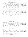
- FIG. 4Ais a graph of pitch angular motion as a function for time for a detector mounted to a person undergoing locomotion.
- FIG. 4Bis a graph of yaw angular motion as a function for time for a detector mounted to a person undergoing locomotion.
- FIG. 4Cis a graph of a compensation signal to counteract the motion of the detector in FIG. 4A .
- FIG. 4Dis a graph of a compensation signal to counteract the motion of the detector in FIG. 4B .
- FIG. 5Ais a graph of pitch angular momentum as a function of time for a detector mounted to a person shaking his or her head.
- FIG. 5Bis a graph of yaw angular momentum as a function of time for a detector mounted to a person shaking his or her head.
- FIG. 5Cis a graph of a compensation signal to counteract the motion of the detector in FIG. 5A .
- FIG. 5Dis a graph of a compensation signal to counteract the motion of the detector in FIG. 5B .
- FIG. 6Ais a graph of pitch angular momentum as a function of time for a detector mounted to a person undertaking a gaze shift.
- FIG. 6Bis a graph of yaw angular momentum as a function of time for a detector mounted to a person undertaking a gaze shift.
- FIG. 6Cis a graph of a compensation signal to counteract the motion of the detector in FIG. 6A .
- FIG. 6Dis a graph of a compensation signal to counteract the motion of the detector in FIG. 6B .
- FIG. 7is a schematic diagram of a vision system integrated within eyeglass frames.
- FIG. 8is a schematic diagram of a hat with a detector for acquiring information that is actively compensated.
- Compensating for the motion of a detector during data acquisitionis a problem that is common to a variety of different applications.
- Visual informationsuch as still or video images is particularly prone to aberrations such as shakiness and blurring that result from motion of the detector as the information is obtained.
- Attempts to compensate for detector motion during the acquisition of visual informationhave generally involved increasingly sophisticated software methods for analyzing and numerically processing images after they are acquired.
- the computing hardware requirements for implementing complex image processing algorithms so that they execute within a reasonable timealso must increase.
- more advanced hardwaretends to be larger, to consume more power, and to be unsuitable for implementation in portable applications.
- alternatives for image stabilization to known image processing algorithmsare needed.
- Human visual impairmentis a significant handicap that dramatically alters the quality of life for an affected person.
- efforts toward enhancing the visual acuity of persons with visual impairmenthave focused on methods for artificially acquiring and conveying visual information in a manner that can be interpreted by such persons.
- This disclosurefeatures systems for providing such visual information, and other types of information derived from visual information, that can be housed in a variety of wearable prosthetics such as eyeglass frames.
- the systemstypically feature one or more detectors configured to acquire visual information and to transmit that information to the wearer of the prosthetic device.
- the methods and systems disclosed hereinprovide for compensation of visual information by directly compensating for the motion of the detector as the visual information is acquired. In this way, the visual information is already compensated when it is acquired, and no post-acquisition processing is necessary.
- the computing hardware requirements and power consumption of the systems disclosed hereinare, in general, significantly reduced compared to systems that rely on software-based post-processing of visual information.
- the present systemscan also be combined with known image stabilization software systems.
- the sensors disclosed hereincan be used to estimate the motion of one or more detectors, rather than using only software-based image processing algorithms to perform this estimation, as is common in conventional motion compensation systems.
- estimation of detector motion using image processing algorithmscreates a feedback “bottleneck,” limiting the rate at which information can be provided to the wearer of such systems.
- the systems and methods disclosed hereinallow this processing bottleneck to be largely circumvented, making real-time or near-real-time motion compensation feasible.
- FIG. 1shows a schematic diagram of the person's head 10 relative to a coordinate system describing the locomotion. Suppose the person in FIG. 1 walks along a direction parallel to the y-coordinate direction.
- involuntary movement of the person's head 10also occurs.
- linear back-and-forth motion of the person's head 10occurs in a direction parallel to the y-coordinate direction.
- Linear up-and-down motion of the person's head 10also generally occurs in a direction parallel to the z-coordinate direction.
- angular side-to-side motion of the person's head 10generally occurs in the x-y plane (referred to as “yaw” motion)
- angular up-and-down motion of the person's head 10generally occurs in the y-z plane (referred to as “pitch” motion). All of these components of the motion of the person's head 10 are typically involuntary.
- a detector in prosthetic device 20 that measures the visual informationshould remain stably fixed upon a particular scene of interest.
- visual information measured by prosthetic device 20will typically include artifacts that result from involuntary motion of the person's head 10 during acquisition of the information. Such artifacts can make the visual information difficult to interpret for the person receiving it.
- oscillopsiahas been observed in sighted persons who lose their ability to stabilize their gaze in space due to the loss of inner ear balance and vestibular function.
- involuntary components of the motion of the detector in prosthetic device 20are compensated by the systems and methods disclosed herein, so that the visual information provided to the person wearing the prosthetic device reflects a “steady gaze” of the detector on a scene of interest.
- the systems and methods disclosed hereinimplement context-dependent compensation of acquired information. That is, the systems and methods measure the motion of one or more detectors used to acquire visual information, analyze the components of the motion of the detectors to determine the context of each component of the motion, and then compensate only the components of motion that are appropriate for compensation. Whether or not it is appropriate to compensate a particular component of motion depends on the context under which that component of motion arises. For example, involuntary movements of a detector are typically compensated, whereas voluntary (e.g., on the part of the wearer of the prosthetic device) movements of the detector are not compensated.
- the systems and methods disclosed hereinbear some similarities to the natural methods by which the brain perceives information.
- the brainensures that involuntary head bobbing and translation are compensated by rapid countervailing movements of the eyes, so that the person's gaze remains fixed on a particular scene.
- a similar type of compensationoccurs when a person nods his or her head to indicate “yes” or “no”—the person's gaze generally remains fixed on a particular scene through compensating movements of the eyes which are initiated by the brain.
- the brainwhen a person rapidly turns his or her head sideways (e.g., to follow a moving object), the brain generally does not compensate the acquired visual information for the motion, and the visual information that is perceived by the person typically is blurred as a result.
- FIG. 2shows a schematic diagram of an embodiment of a system 200 for providing visual information to a person (or even to an animal).
- System 200includes a detector 210 , sensors 220 , actuators 230 , and an electronic processor 240 coupled to detector 210 via communication line 250 .
- System 200can optionally include a receiver 260 .
- Detector 210can generally include one or more detectors configured to acquire visual information. Suitable detectors include CCD cameras, CMOS-based detectors, analog imaging devices, diode arrays, and other detectors capable of obtaining visual information and, more generally, measuring optical signals.
- System 200can include one or more sensors 220 . Although FIG. 2 shows a system with two sensors, more generally system 200 can include any number of sensors. Sensors 220 are configured to detect motion of detector 210 . In particular, referring to FIG. 1 , sensors 220 can be configured to detect linear motion of detector 210 (e.g., back-and-forth linear motion parallel to the y-coordinate direction and/or up-and-down linear motion parallel to the z-coordinate direction). Sensors 220 can also be configured to detect angular motion of detector 210 (e.g., angular yaw motion in the x-y plane and/or angular pitch motion in the y-z plane). Sensors 220 communicate information about the motion of detector 210 to electronic processor 240 via communication line 255 .
- linear motion of detector 210e.g., back-and-forth linear motion parallel to the y-coordinate direction and/or up-and-down linear motion parallel to the z-coordinate direction.
- sensors 220include accelerometers configured to detect linear motion of detector 210 .
- sensors 220include gyroscopes configured to detect angular motion of detector 210 .
- Other sensors that can be used to detect motion of detector 210include: magnetometers, which measure angular yaw motion of detector 210 by sensing magnetic field changes; and global positioning system (GPS) detectors.
- GPSglobal positioning system
- sensors that include multiple different types of detectorscan be used to detect motion of detector 210 .
- IMUsinertial measurement units
- IMUSix Degrees of Freedom Inertial Sensor ADIS16385 (available from Analog Devices Inc., Norwood, Mass.) which includes three accelerometers and three gyroscopes in a single integrated package, and can be used to detect roll, pitch, and yaw angular motions of detector 210 , and also acceleration in each of three orthogonal coordinate directions.
- Other commercially available IMUs that can be used in the systems and methods disclosed hereininclude the MPU-600 Motion Processor, available from InvenSense (Sunnyvale, Calif.), and the Ten Degrees of Freedom Inertial Sensor AIS16407 (available from Analog Devices Inc.).
- Actuators 230are coupled to detector 210 and configured to adjust the position of detector 210 by receiving control signals from electronic processor 240 via communication line 257 .
- system 200 in FIG. 2includes two actuators 230 , more generally system 200 can include any number of actuators (for example, to fully compensate the motion of detector 210 , system 200 can include six actuators, three of which translate detector 210 in mutually orthogonal coordinate directions, and the other three that rotate detector 210 about each of the coordinate directions).
- actuators 230are capable of compensating for involuntary motion of detector 210 when the detector is moved involuntarily, e.g., when worn by a person. Referring to FIG.
- actuators 230are capable of compensating both linear and angular motion of detector 210 when a person wearing detector 210 undergoes locomotion.
- actuators 230can be used in system 200 , including motorized actuators, piezoelectric actuators, electrostrictive actuators, and any other types of actuators that can be controlled by electronic processor 240 .
- motorized actuatorsthat can be used include the E-flite 7.5 Gram Sub-Micro S75 Servo (available from Horizon Hobby, Inc., Champaign, Ill.).
- system 200includes receiver 260 .
- Receiver 260is generally configured to receive acquired visual information from detector 210 , either via a communication line linking detector 210 and receiver 260 , or through another communications interface (such as a wireless communications interface).
- Receiver 260can also be configured to receive information from external sources such as other computing devices; in some embodiments, detector 210 provides visual information to an external device, which then processes the visual information and relays a portion of the processed information to receiver 260 .
- Receiver 260can take a variety of different forms.
- receiver 260can be a visual implant that receives visual information and transforms the visual information into electronic signals that can be interpreted as images by the implant wearer.
- receiver 260can be a device that receives visual or other information and transforms the information into other types of signals such as sounds, speech, vibrations, and/or other non-image visual cues (e.g., flashing lights and other visual signals that convey information or warnings to the wearer). Examples of useful receivers are disclosed, for example, in U.S. Pat. No. 5,935,155, and at the internet address seeingwithsound.com, the entire contents of which are incorporated herein by reference. Certain receivers can also include tactile vibrators such as the C2 tactor (available from EAI, Casselberry, Fla.).
- FIG. 3shows a flow chart 300 that includes a series of steps for context-based compensation for the motion of detector 210 during acquisition of information.
- the steps shown in flow chart 300generally occur while detector 210 acquires information; flow chart 300 therefore represents an active feedback loop that provides dynamic compensation for detector 210 .
- one or more sensors 220detect motion (or the absence of motion) of detector 210 .
- Sensors 220can, in general, detect a variety of different types of motion, including linear motion (e.g., parallel to a particular coordinate direction) and angular motion (e.g., about a stationary axial direction).
- Information about the motion of detector 210 during information acquisitionis transmitted to electronic processor 240 in step 320 .
- Steps 330 , 340 , and 350 in flow chart 300provide for context-based analysis of the motion of detector 210 .
- electronic processor 240analyzes the motion of detector 240 to identify various components of the detector motion.
- the identification of different components of the detector's motionis analogous to identifying the causes or the context underlying the detector's motion.
- Components of the detector's motioncan be identified by analyzing the specific patterns of detector motion detected by sensors 220 .
- high-velocity and small-amplitude motions of detector 210are likely to correspond to involuntary motion as occurs, for example, when the person undergoes locomotion.
- larger-amplitude low-velocity motions of detector 210are likely to correspond to voluntary motion as occurs, for example, when the person intentionally turns his or her head to shift gaze.
- electronic processor 240can analyze the detected motion of detector 210 to identify the various components of the detector's motion in step 330 . Then, in step 340 , the electronic processor can assign the various motion components to classes. For a system configured to acquire visual information, the classes typically correspond to different contexts or causes of the detector motion.
- electronic processor 240can be configured to identify many different components of motion and to assign the identified components to many different classes or contexts.
- the first such class or contextis motion of a detector due to locomotion by a person wearing or carrying the detector on his or her head.
- the person's headtranslates up and down (e.g., parallel to the z-coordinate direction in FIG. 1 ), pitches forward and backward (e.g., undergoes angular motion in the pitch direction), and rotates from side to side (e.g., undergoes angular motion in the yaw direction).
- the braineliminates the blurring effects of locomotion through the linear vestibulo-ocular reflex (lVOR) and the angular vestibulo-ocular reflex (aVOR) to compensate for linear and angular head motion, respectively.
- lVORlinear vestibulo-ocular reflex
- aVORangular vestibulo-ocular reflex
- the relative contributions of the lVOR and aVORdepend upon the distance of the objects that are viewed.
- the aVORis typically more significant for objects in the far field (e.g., more than about 1 meter away), while the lVOR is typically more significant for objects in the near field (e.g., closer than 1 meter).
- System 200is typically configured to acquire information in a far field imaging configuration; as such, compensation for linear motion of detector 210 during locomotion usually provides only a marginal benefit to the wearer. However, compensation for pitch and yaw angular motion of detector 210 (which is analogous to the brain's activation of the aVOR reflex) can significantly reduce blurring of the visual information that is acquired by detector 210 .
- FIGS. 4A and 4Bshow the pitch and yaw angular motion, respectively, of the head of a test subject walking at a speed of approximately 1 m/s.
- the angular displacement of the subject's headis plotted as a function of time.
- the pitch angular motionis nearly sinusoidal, with a regular angular frequency corresponding to the “bobbing” of the subject's head up and down during locomotion.
- the yaw angular motionshows a more complex—but still relatively reproducible—angular displacement pattern corresponding to the side-to-side shaking of the subject's head during locomotion.
- electronic processor 240analyzes the detector motion to identify components of the detector motion.
- electronic processor 240can, in general, analyze either or both of the measured motions in FIGS. 4A and 4B .
- electronic processor 240can perform a Fourier transform analysis or a frequency measurement to determine the frequency of the pitch angular motion, and then identify the motion in FIG. 4A as consisting of a single component.
- electronic processor 240can compare the measured pitch angular motion in FIG. 4A to a stored reference information describing typical pitch angular motion of the subject's head during locomotion to determine that the measured pitch angular motion represents contributions from a single component.
- Electronic processor 240can analyze the yaw angular motion of detector 210 shown in FIG. 4B in similar fashion. For example, electronic processor 240 can perform a Fourier transform analysis and/or frequency measurement on the yaw angular motion.
- the yaw angular motionis more complex than the pitch angular motion, and therefore a Fourier transform analysis or frequency measurement will identify more than one frequency present; nonetheless, by comparing the identified frequencies to stored reference information describing the frequencies of typical yaw angular motion of the subject's head, electronic processor 240 can still determine (e.g., from the numerical values and amplitudes of the frequencies present) that the yaw angular motion represents contributions from a single component.
- electronic processor 240can directly compare the measured yaw angular motion of detector 210 to stored reference information describing typical yaw angular motion of the subject's head during locomotion to determine that the measured motion corresponds to a single motion component.
- step 340electronic processor 240 assigns the identified components of the detector's motion to classes.
- step 340can be performed essentially contemporaneously with step 330 .
- electronic processor 240determines in step 330 that the pitch angular motion of detector 210 contains a single motion component, as disclosed above. By comparing the frequency, the amplitude (which corresponds to the displacement of detector 210 relative to a reference position), or the frequency and amplitude of the pitch angular motion in FIG. 4A to reference information describing pitch angular motion of the subject's head during locomotion, electronic processor 240 can assign the component of motion shown in FIG.
- electronic processor 240can determine that the component of the detector's motion shown in FIG. 4A corresponds to motion that occurs in the context of locomotion by the subject (and not in the context of another type of movement such as head nodding or gaze shifting, for example).
- Electronic processor 240can perform a similar assignment based on the yaw angular motion shown in FIG. 4B .
- determining that the yaw angular motion corresponds to a single component and assigning that component to the class “locomotion”are steps that can be performed contemporaneously.
- Electronic processor 240can, for example, compare the amplitude and/or frequency content of the yaw angular motion in FIG. 4B with reference information and/or stored threshold values for these parameters to determine not only that a single motion component is present, but that the single component arises in the context of locomotion by the subject, and not in the context of another type of movement. Accordingly, electronic processor 240 assigns the motion component plotted in FIG. 4B to the class “locomotion.”
- a second exemplary class or context of motioncorresponds to a subject wearing detector 210 on his or her head and shaking the head from side-to-side to indicate disagreement.
- FIGS. 5A and 5Bshow the measured pitch and yaw angular motion, respectively, in this context. Note that in FIGS. 5A and 5B , the subject is stationary and not undergoing locomotion. As shown in FIG. 5A , head shaking produces very little pitch angular motion—in practical terms, not enough to cause significant artifacts in visual information measured by detector 210 . However, as shown in FIG. 5B , head shaking produces significant yaw angular motion which, if not compensated, will cause substantial distortion of acquired visual information. For a person with ordinary visual acuity, the brain would activate its aVOR to stabilize the person's gaze during head shaking so that the person's eyes could remain clearly fixed on a particular subject or scene as his or her head shakes from side-to-side.
- electronic processor 240analyzes FIGS. 5A and 5B to identify components of the motion of detector 210 , and in step 340 , the electronic processor assigns the identified components to classes.
- electronic processor 240determines that the amount of pitch angular motion is insignificant; that is, there is no component of the detector motion to identify.
- electronic processor 240can analyze both the amplitude and frequency of the yaw angular motion. By comparing the analysis results to stored reference information and/or threshold values, for example, electronic processor 240 can identify a single component of motion present in FIG.
- step 340electronic processor 240 —on the basis of these differences—can assign the yaw angular motion in FIG. 4B to the class “locomotion,” and can assign the yaw angular motion in FIG. 5B to the class “head shaking.”
- a third exemplary class or context of motioncorresponds to a gaze shift (e.g., an intentional rotation of the head) by a subject wearing detector 210 on his or her head.
- FIGS. 6A and 6Bshow measured pitch and yaw angular motion of the detector during a series of gaze shifts. As shown in FIG. 6A , very little motion in the pitch angular direction is detected; this situation is similar to pitch angular motion during the “head shaking” class of motion depicted in FIG. 5A . However, the series of gaze shifts produces a regular pattern of yaw angular motion, as shown in FIG. 6B .
- the motion in FIGS. 6A and 6Bis analyzed in step 330 to identify motion components, and then the motion components are assigned to classes in step 340 .
- electronic processor 240can readily determine that there are no components of motion present in the pitch angular motion.
- electronic processor 240can determine that a single motion component exists in the measured yaw angular motion, and can assign the identified component to the class “gaze shift” (e.g., the motion arises in the context of repeated gaze shifts by the subject).
- the component of yaw angular motion shown in FIG. 6Bcan be distinguished from the components shown in FIGS. 4B and 5B according to multiple criteria. For example, the significantly larger amplitude of the yaw motion in FIG. 6B relative to FIGS. 4B and 5B can be used to distinguish the components. Further, the shape and frequency of the recurring pattern of angular displacements in FIG. 6B (e.g., a “square wave” pattern of relatively low frequency) is readily distinguished from the more sinusoidal, higher-frequency patterns of the yaw angular displacements in FIGS. 4A and 5B .
- electronic processor 240can be configured to identify any number of classes of motion.
- electronic processor 240can identify and distinguish motion components and assign the components to different classes when multiple different classes of motion give rise to the overall motion of detector 210 . For example, in circumstances where the wearer of a head-mounted detector 210 is undergoing locomotion and shaking his or her head from side-to-side at the same time, the measured pitch angular motion of the detector will correspond approximately to a superposition of the motions shown in FIGS.
- electronic processor 240can analyze the pitch and yaw angular motions to identify components contributing to the angular motions, and can assign the identified components to appropriate classes (e.g., “locomotion” and “head shaking”).
- methodssuch as Fourier analysis, frequency measurement, and direct comparison to reference information (e.g., by performing a correlation analysis) can be used to identify motion components. These methods can be used when one or more components contribute to a particular measured motion. Other methods can also be used to identify components, and some methods may be more effective at identifying components as the number of components contributing to the measured motion of the detector increases. For example, more sophisticated methods of identifying components such as wavelet analysis, eigenvector decomposition, and principal components analysis can be used by electronic processor 240 to analyze the detector motion.
- electronic processor 240determines which components of the motion will be compensated based on the classes in step 350 . That is, the compensation that is subsequently applied to detector 210 is dependent upon the contextual analysis of the motion of the detector in steps 330 and 340 .
- the determination as to which of the identified components will be compensatedis facilitated by stored information in system 200 that describes which classes of motion are suitable for compensation and which are not. This type of information corresponds, in essence, to a set of rules that attempts to mimic the response of a person with ordinary visual acuity.
- system 200includes stored information instructing electronic processor 240 to compensate identified components of motion of detector 210 that correspond to the class “locomotion.” In so doing, system 200 mimics the visual response of a person with ordinary visual acuity.
- the person's brainWhen a person with ordinary visual acuity shakes his or her head from side-to-side, the person's brain typically activates its aVOR to counteract the yaw angular motion of the head. However, when the same person shifts his or her gaze from side-to-side, the brain does not typically activate the aVOR (or activates it to a lesser degree). As a result, the vision of even a person with ordinary visual acuity will be blurred somewhat as that person shifts gaze.
- system 200includes stored information instructing electronic processor 240 to compensate identified components of motion of detector 210 that are assigned to the class “head shaking,” but not to compensate components that are assigned to the class “gaze shift.” In this way, system 200 further mimics the visual response of a person with normal visual acuity.
- electronic processor 240adjusts the position of detector 210 in step 360 to compensate for the identified components of motion.
- electronic processor 240generates control signals for actuators 230 and transmits the control signals to the actuators via communication line 257 .
- the control signalsdirect actuators 230 to adjust the position of detector 210 so that some or all of the detector motion (e.g., the components of the motion identified in step 350 ) is counteracted.
- FIGS. 4C and 4Dshow signals generated by electronic processor 240 and transmitted to actuators 230 to compensate for the pitch and yaw angular motions in FIGS. 4A and 4B that correspond to the “locomotion” class. Both the pitch and yaw angular motions were identified for compensation in step 350 , and the compensation signals in FIGS. 4C and 4D , respectively, essentially correspond to the inverses of the motions in FIGS. 4A and 4B .
- the “head shaking” class of motion componentswas identified for compensation in step 350 . Accordingly, the signals shown in FIGS. 5C and 5D transmitted to actuators 230 compensate for the pitch and yaw angular motions shown in FIGS. 5A and 5B , respectively. Because the pitch angular motion is of such small amplitude in FIG. 5A , the corresponding compensation signal in FIG. 5C is also of small amplitude. The compensation signal in FIG. 5D is essentially the inverse of the measured yaw angular motion in FIG. 5B .
- FIGS. 6C and 6Dcorrespond to the compensation signals for the pitch and yaw angular motions associated with the “gaze shift” class in FIGS. 6A and 6B , respectively.
- the pitch angular motion in FIG. 6Ais of small amplitude, and so the corresponding compensation signal in FIG. 6C is also of small amplitude.
- the yaw angular motion in FIG. 6Bis of large amplitude.
- the corresponding compensation signalis of zero amplitude. This situation arises because system 200 is configured to mimic the response of a person with ordinary visual acuity.
- System 200operates in a similar fashion.
- the visual information obtained by detector 210 during a gaze shift by the subject wearing the detectorwill be subject to distortion; the visual information conveyed to the subject will therefore be blurred in a manner similar to the blurring experienced by a person with normal visual acuity.
- system 200can temporarily halt transmission of visual information from detector 210 to the wearer.
- electronic processor 240can be configured to determine the speed at which the detector moves during a gaze shift from the position of detector 210 as a function of time.
- Electronic processor 240can instruct detector 210 to halt transmission of visual information of the speed of the detector exceeds a certain threshold value because at greater speeds, the visual information may be so distorted that it would only confuse the wearer. Transmission of visual information can be resumed when electronic processor 240 determines that the speed at which the detector moves is reduced below the threshold (e.g., when the gaze shift is completed).
- step 370the system determines in step 370 whether acquisition of information by detector 210 is complete. If detector 210 is still acquiring information, control returns to step 310 , where motion of the detector is again detected, and a new compensation cycle begins. If acquisition of information is complete, the process terminates at step 380 .
- FIGS. 4A, 4B, 5A, 5B, 6A, and 6Bshow measured pitch and yaw angular movements of detector 210 .
- Electronic processor 240is configured to analyze these motions of the detector to generate compensation signals. More generally, however, other movements of detector 210 can also be analyzed to identify motion components that can then be assigned to classes and compensated by system 200 .
- linear movements of detector 210such as up-and-down linear motion of detector 210 in a direction parallel to the z-coordinate axis, and forward-and-back linear motion of detector 210 in a direction parallel to the y-coordinate axis—can be analyzed in place of, or in addition to, angular motion of the detector.
- angular and linear motions of detector 210can each include components that correspond to the same class; in such cases, electronic processor 240 can elect to analyze only a subset of these motions; the presence of certain components of motion in the other motions can be inferred, and appropriate compensation signals, if desired, can be generated automatically. Actuators 230 can be instructed by electronic processor 240 to compensate for angular motion of detector 210 , linear motion of detector 210 , or a combination of linear and angular motion of detector 210 .
- System 200can be incorporated into a wide variety of housings for purposes of allowing a person with reduced visual acuity to carry the system. In so doing, system 200 enhances the mobility and quality of life of afflicted persons.
- system 200can be enclosed within a housing to form a wearable prosthetic device that functions as disclosed herein.
- system 200is incorporated into eyeglass frames to form a prosthetic device that bears a strong resemblance to an ordinary pair of glasses.
- FIG. 7shows such a prosthetic device 700 , with a detector 210 , sensors 220 , actuators 230 , and electronic processor 240 embedded into the eyeglass frames.
- the various components of system 200are embedded in the eyeglass frames in FIG. 7 , more generally, some or all of the components can also be attached to the exterior surface of the eyeglass frames as well.
- prosthetic devicescan also be implemented. While prosthetics configured for head mounting have certain desirable features (e.g., the person wearing the prosthetic can effect a gaze shift by turning his or her head), prosthetic devices can also be worn on other parts of the body and/or carried. When the prosthetic devices include a housing, then as above, some or all of the components can be enclosed within the housing, embedded within the housing, or attached to a surface of the housing.
- the disclosure hereindescribes the use of sensors to detect motion of a detector as visual information is acquired by the detector, and then making adjustments to the position of the detector to compensate for its motion.
- the systems disclosed hereincan also be used to compensate detector motion in other ways.
- the sensorscan be used to detect motion of the detector, and information about the detector's motion can be transmitted to an electronic processor that is configured to process images obtained by the detector.
- the processorcan analyze the images and apply correction algorithms that reduce or eliminate artifacts in the images due to detector motion, using as input the information about detector motion acquired by the sensors.
- This mode of operationimplements a “directed” approach to image processing rather than an iterative approach in which algorithms are not applied iteratively, for example, until one or more threshold conditions related to the “quality” the processed images is achieved. Instead, in a directed approach, the image processing algorithms can estimate the nature of the correction needed, increasing the speed at which corrected images can be produced.
- Image processing algorithmsthat can use motion information measured by the sensors disclosed herein to compensate for artifacts in images are disclosed, for example, in the following references, the contents of each of which are incorporated herein by reference in their entirety: J. Chang et al., “Digital image translational and rotational motion stabilization using optical flow technique,” IEEE Transactions on Consumer Electronics 48(1): 108-115 (2002); T.
- FIG. 8shows an embodiment of a hat 800 (e.g., a baseball cap) with a detector 210 mounted to a front surface of the hat.
- Detector 210can receive operating power from a power source (not shown in FIG. 8 ), and can transmit images wirelessly to processor 240 , which can also be integrated into hat 800 .
- hat 800can be of a variety of designs.
- hat 800is a protective helmet configured to be worn by a solider, by a fireman, or by another person engaged in hazardous activity and who benefits from receiving the information transmitted by processor 240 .
- Images (including video signals) captured by detector 210can be transmitted to a remote receiver 260 (e.g., using a wireless communication interface).
- the methods disclosed hereincan be used to correct for motion of the head-mounted detector so that receiver 260 receives a stabilized video signal for display on a variety of devices including computer screens and televisions.
- Monitoring of the stabilized video signalsallows persons at remote locations to visualize the environment of the person wearing the head covering, permitting persons at remote locations to more accurately perceive situations as they arise and to issue instructions to the wearer, for example.
- detector 210can be configured to measure audio information such as sounds and/or speech (e.g., a microphone). Because audio detectors are generally relatively insensitive to orientation, system 200 may not include sensors 220 or actuators 230 . Nonetheless, audio information measured by detector 210 can be transmitted to electronic processor 240 . Electronic processor 240 can process the audio information before transmitting it to a wearer or carrier of system 200 (e.g., via an implanted receiver in the wearer/carrier's ear).
- electronic processor 240can be configured to identify different components of the audio information, and to adjust the processing method or output based on the identified components. For example, electronic processor 240 can process the audio information differently if the identified components of the information indicate that the audio information features spoken words recorded in a quiet room, music recorded in a symphony hall, or a mixture of speech and ambient noise in a room with many voices.
- the audio informationcan be used to control the configuration of the system.
- the audio informationcan be processed to identify components, and when certain components are identified, the system is configured (or re-configured) appropriately. For example, when processing of the audio information reveals that an emergency siren is close by on the left-hand side of the wearer of system 200 , the orientations of one or more detectors configured to detect visual information can be adjusted so that the detectors so that more visual information is acquired from the direction of the emergency siren. Continued monitoring of the intensity and direction of the emergency siren component of the audio information can be used to allow the visual information detectors to “follow” the siren as it moves, and to discontinue following the siren when it is far away. In this manner described above, system 200 can be configured to make context-sensitive decisions with regard to the processing of measured audio information.
- the systems and methods disclosed hereincan be used in sensory substitution devices. Many individuals experience imbalances due to deficiencies in one or more senses.
- the systems and methods disclosed hereincan be used to measure different types of information, to analyze the measured information by identifying different components of the information, and then to process the measured information in a manner that is contextually-dependent on the identified components.
- the processed informationis then conveyed to the individual to assist in compensating for sensory imbalance. Processing of the measured information can depend, for example, on whether the individual is walking, standing, or sitting.
- the systems and methods disclosed hereincan be used in sensory augmentation devices (e.g., devices that measure information that is beyond the capability of unaided humans to detect). Such devices can be used to measure, for example, wavelengths of light in the ultraviolet and/or infrared regions of the electromagnetic spectrum, and sounds in frequency bands that are beyond the ordinary range of human hearing.
- the systems and methods disclosed hereincan associate the information with particular contexts, and tailor processing and delivery of the information to humans accordingly.
- Context-dependent processingcan include, for example, filtering the information to extract portions of interest (e.g., selecting a particular spectral region) within a set of circumstances defined by the context, and discarding irrelevant information.
- the spectral region of interest(e.g., the portion of the spectrum in which subsequent measurements are made) can be changed according to the determined context associated with the initially measured information. For example, if the initially measured information is analyzed and determined to correspond to a context in which high frequency signals are present (e.g., the wearer is engaged in an activity such as whale watching), subsequent measurements of audio information could be made in this high frequency region of the spectrum. The high frequency measured information can then be shifted to a lower frequency region of the spectrum (e.g., within the detection range of the human ear) and presented to the wearer.
- a context in which high frequency signalse.g., the wearer is engaged in an activity such as whale watching
- the systemcan subsequently measure information about objects in the infrared spectral region.
- the measured infrared informationcan be translated into image information in the visible region of the spectrum (so it can be directly observed by the wearer). Alternatively, or in addition, it can be converted into other types of information (such as audio information and/or warnings) which is presented to the wearer. In this manner, the system permits the wearer to perceive information that the wearer would not otherwise detect, augmenting his or her sensory capabilities.
Landscapes
- Health & Medical Sciences (AREA)
- Engineering & Computer Science (AREA)
- Physics & Mathematics (AREA)
- General Health & Medical Sciences (AREA)
- Public Health (AREA)
- Ophthalmology & Optometry (AREA)
- Multimedia (AREA)
- Signal Processing (AREA)
- Veterinary Medicine (AREA)
- Life Sciences & Earth Sciences (AREA)
- Animal Behavior & Ethology (AREA)
- Optics & Photonics (AREA)
- General Physics & Mathematics (AREA)
- Biomedical Technology (AREA)
- Epidemiology (AREA)
- Rehabilitation Therapy (AREA)
- Physical Education & Sports Medicine (AREA)
- Pain & Pain Management (AREA)
- Medical Informatics (AREA)
- Primary Health Care (AREA)
- Nuclear Medicine, Radiotherapy & Molecular Imaging (AREA)
- Radiology & Medical Imaging (AREA)
- Otolaryngology (AREA)
- Acoustics & Sound (AREA)
- Heart & Thoracic Surgery (AREA)
- Vascular Medicine (AREA)
- Social Psychology (AREA)
- Psychiatry (AREA)
- Psychology (AREA)
- Hospice & Palliative Care (AREA)
- Developmental Disabilities (AREA)
- Child & Adolescent Psychology (AREA)
- Business, Economics & Management (AREA)
- General Business, Economics & Management (AREA)
- User Interface Of Digital Computer (AREA)
- Studio Devices (AREA)
- Measurement Of The Respiration, Hearing Ability, Form, And Blood Characteristics Of Living Organisms (AREA)
Abstract
Description
Claims (20)
Priority Applications (1)
| Application Number | Priority Date | Filing Date | Title |
|---|---|---|---|
| US14/356,065US9389431B2 (en) | 2011-11-04 | 2012-11-05 | Contextual image stabilization |
Applications Claiming Priority (4)
| Application Number | Priority Date | Filing Date | Title |
|---|---|---|---|
| US201161555908P | 2011-11-04 | 2011-11-04 | |
| US201161555930P | 2011-11-04 | 2011-11-04 | |
| PCT/US2012/063577WO2013067513A1 (en) | 2011-11-04 | 2012-11-05 | Contextual image stabilization |
| US14/356,065US9389431B2 (en) | 2011-11-04 | 2012-11-05 | Contextual image stabilization |
Publications (2)
| Publication Number | Publication Date |
|---|---|
| US20140303687A1 US20140303687A1 (en) | 2014-10-09 |
| US9389431B2true US9389431B2 (en) | 2016-07-12 |
Family
ID=48192906
Family Applications (2)
| Application Number | Title | Priority Date | Filing Date |
|---|---|---|---|
| US14/356,071Active2033-11-01US10571715B2 (en) | 2011-11-04 | 2012-11-05 | Adaptive visual assistive device |
| US14/356,065Active2033-07-13US9389431B2 (en) | 2011-11-04 | 2012-11-05 | Contextual image stabilization |
Family Applications Before (1)
| Application Number | Title | Priority Date | Filing Date |
|---|---|---|---|
| US14/356,071Active2033-11-01US10571715B2 (en) | 2011-11-04 | 2012-11-05 | Adaptive visual assistive device |
Country Status (4)
| Country | Link |
|---|---|
| US (2) | US10571715B2 (en) |
| CN (2) | CN108014002A (en) |
| HK (1) | HK1208339A1 (en) |
| WO (2) | WO2013067539A1 (en) |
Cited By (5)
| Publication number | Priority date | Publication date | Assignee | Title |
|---|---|---|---|---|
| US10583067B2 (en) | 2018-08-08 | 2020-03-10 | International Business Machines Corporation | Source-of-sound based navigation for a visually-impaired user |
| US20200372767A1 (en)* | 2017-03-08 | 2020-11-26 | Winston Yang | Tactile Feedback Guidance Device |
| US10929774B2 (en)* | 2015-02-12 | 2021-02-23 | Koninklijke Philips N.V. | Robust classifier |
| US10949985B2 (en)* | 2016-06-02 | 2021-03-16 | Stc.Unm | System and methods for parallel processing motion estimation of digital videos |
| US11064118B1 (en)* | 2019-12-18 | 2021-07-13 | Gopro, Inc. | Systems and methods for dynamic stabilization adjustment |
Families Citing this family (134)
| Publication number | Priority date | Publication date | Assignee | Title |
|---|---|---|---|---|
| US8482488B2 (en) | 2004-12-22 | 2013-07-09 | Oakley, Inc. | Data input management system for wearable electronically enabled interface |
| US20120105740A1 (en) | 2000-06-02 | 2012-05-03 | Oakley, Inc. | Eyewear with detachable adjustable electronics module |
| US7013009B2 (en) | 2001-06-21 | 2006-03-14 | Oakley, Inc. | Eyeglasses with wireless communication features |
| US7500746B1 (en) | 2004-04-15 | 2009-03-10 | Ip Venture, Inc. | Eyewear with radiation detection system |
| US8109629B2 (en) | 2003-10-09 | 2012-02-07 | Ipventure, Inc. | Eyewear supporting electrical components and apparatus therefor |
| US7922321B2 (en) | 2003-10-09 | 2011-04-12 | Ipventure, Inc. | Eyewear supporting after-market electrical components |
| US11513371B2 (en) | 2003-10-09 | 2022-11-29 | Ingeniospec, Llc | Eyewear with printed circuit board supporting messages |
| US11630331B2 (en) | 2003-10-09 | 2023-04-18 | Ingeniospec, Llc | Eyewear with touch-sensitive input surface |
| US11644693B2 (en) | 2004-07-28 | 2023-05-09 | Ingeniospec, Llc | Wearable audio system supporting enhanced hearing support |
| US11829518B1 (en) | 2004-07-28 | 2023-11-28 | Ingeniospec, Llc | Head-worn device with connection region |
| US11852901B2 (en) | 2004-10-12 | 2023-12-26 | Ingeniospec, Llc | Wireless headset supporting messages and hearing enhancement |
| US12044901B2 (en) | 2005-10-11 | 2024-07-23 | Ingeniospec, Llc | System for charging embedded battery in wireless head-worn personal electronic apparatus |
| US11733549B2 (en) | 2005-10-11 | 2023-08-22 | Ingeniospec, Llc | Eyewear having removable temples that support electrical components |
| WO2008020362A2 (en)* | 2006-08-15 | 2008-02-21 | Philips Intellectual Property & Standards Gmbh | Assistance system for visually handicapped persons |
| EP2095178B1 (en) | 2006-12-14 | 2015-08-12 | Oakley, Inc. | Wearable high resolution audio visual interface |
| US10571715B2 (en) | 2011-11-04 | 2020-02-25 | Massachusetts Eye And Ear Infirmary | Adaptive visual assistive device |
| US9794701B2 (en) | 2012-08-31 | 2017-10-17 | Starkey Laboratories, Inc. | Gateway for a wireless hearing assistance device |
| WO2014042143A1 (en)* | 2012-09-11 | 2014-03-20 | 株式会社メガチップス | Mobile terminal device, program, image stabilization method, and condition detection method |
| CN103105993B (en)* | 2013-01-25 | 2015-05-20 | 腾讯科技(深圳)有限公司 | Method and system for realizing interaction based on augmented reality technology |
| US10424292B1 (en)* | 2013-03-14 | 2019-09-24 | Amazon Technologies, Inc. | System for recognizing and responding to environmental noises |
| EP2973533A4 (en) | 2013-03-15 | 2016-11-30 | Oakley Inc | ELECTRONIC ORNAMENTATION FOR EYEWEAR |
| EP3000243A2 (en)* | 2013-05-22 | 2016-03-30 | Starkey Laboratories, Inc. | Augmented reality multisensory display device incorporated with hearing assistance device features |
| CN205691887U (en) | 2013-06-12 | 2016-11-16 | 奥克利有限公司 | Modular communication system and glasses communication system |
| US9721161B2 (en)* | 2013-08-14 | 2017-08-01 | Infineon Technologies Ag | Dynamic adjustment of imaging parameters |
| US20150162000A1 (en)* | 2013-12-10 | 2015-06-11 | Harman International Industries, Incorporated | Context aware, proactive digital assistant |
| US9195124B2 (en)* | 2013-12-20 | 2015-11-24 | Plantronics, Inc. | Automatic projector safety protocols |
| US9622322B2 (en)* | 2013-12-23 | 2017-04-11 | Sharp Laboratories Of America, Inc. | Task light based system and gesture control |
| US10360907B2 (en) | 2014-01-14 | 2019-07-23 | Toyota Motor Engineering & Manufacturing North America, Inc. | Smart necklace with stereo vision and onboard processing |
| US9629774B2 (en) | 2014-01-14 | 2017-04-25 | Toyota Motor Engineering & Manufacturing North America, Inc. | Smart necklace with stereo vision and onboard processing |
| US10248856B2 (en) | 2014-01-14 | 2019-04-02 | Toyota Motor Engineering & Manufacturing North America, Inc. | Smart necklace with stereo vision and onboard processing |
| US10024679B2 (en) | 2014-01-14 | 2018-07-17 | Toyota Motor Engineering & Manufacturing North America, Inc. | Smart necklace with stereo vision and onboard processing |
| US9578307B2 (en) | 2014-01-14 | 2017-02-21 | Toyota Motor Engineering & Manufacturing North America, Inc. | Smart necklace with stereo vision and onboard processing |
| US9915545B2 (en) | 2014-01-14 | 2018-03-13 | Toyota Motor Engineering & Manufacturing North America, Inc. | Smart necklace with stereo vision and onboard processing |
| US9351060B2 (en) | 2014-02-14 | 2016-05-24 | Sonic Blocks, Inc. | Modular quick-connect A/V system and methods thereof |
| KR101659027B1 (en)* | 2014-05-15 | 2016-09-23 | 엘지전자 주식회사 | Mobile terminal and apparatus for controlling a vehicle |
| US10318016B2 (en)* | 2014-06-03 | 2019-06-11 | Harman International Industries, Incorporated | Hands free device with directional interface |
| US10024667B2 (en) | 2014-08-01 | 2018-07-17 | Toyota Motor Engineering & Manufacturing North America, Inc. | Wearable earpiece for providing social and environmental awareness |
| US9526896B2 (en)* | 2014-08-12 | 2016-12-27 | Second Sight Medical Products, Inc. | Pattern detection and location indication for a visual prosthesis |
| US10867527B2 (en)* | 2014-09-01 | 2020-12-15 | 5Lion Horus Tech Llc. | Process and wearable device equipped with stereoscopic vision for helping the user |
| US10024678B2 (en) | 2014-09-17 | 2018-07-17 | Toyota Motor Engineering & Manufacturing North America, Inc. | Wearable clip for providing social and environmental awareness |
| US9922236B2 (en) | 2014-09-17 | 2018-03-20 | Toyota Motor Engineering & Manufacturing North America, Inc. | Wearable eyeglasses for providing social and environmental awareness |
| USD768024S1 (en) | 2014-09-22 | 2016-10-04 | Toyota Motor Engineering & Manufacturing North America, Inc. | Necklace with a built in guidance device |
| CN104306102B (en)* | 2014-10-10 | 2017-10-24 | 上海交通大学 | For the wear-type vision-aided system of dysopia patient |
| US10819959B2 (en)* | 2014-11-05 | 2020-10-27 | Jason Christopher Palazzolo | Firearm environmental recording apparatus and system |
| CN104375623B (en)* | 2014-11-28 | 2017-08-15 | 北京华网汇通技术服务有限公司 | A kind of wearable intelligent equipment and its power-saving control method |
| CN104473717A (en)* | 2014-12-04 | 2015-04-01 | 上海交通大学 | Wearable guide apparatus for totally blind people |
| US9576460B2 (en)* | 2015-01-21 | 2017-02-21 | Toyota Motor Engineering & Manufacturing North America, Inc. | Wearable smart device for hazard detection and warning based on image and audio data |
| US10037712B2 (en) | 2015-01-30 | 2018-07-31 | Toyota Motor Engineering & Manufacturing North America, Inc. | Vision-assist devices and methods of detecting a classification of an object |
| US10217379B2 (en)* | 2015-01-30 | 2019-02-26 | Toyota Motor Engineering & Manufacturing North America, Inc. | Modifying vision-assist device parameters based on an environment classification |
| US10490102B2 (en) | 2015-02-10 | 2019-11-26 | Toyota Motor Engineering & Manufacturing North America, Inc. | System and method for braille assistance |
| US9904504B2 (en) | 2015-02-24 | 2018-02-27 | Toyota Motor Engineering & Manufacturing North America, Inc. | Systems and methods for providing environmental feedback based on received gestural input |
| US9586318B2 (en) | 2015-02-27 | 2017-03-07 | Toyota Motor Engineering & Manufacturing North America, Inc. | Modular robot with smart device |
| US9591447B2 (en) | 2015-02-27 | 2017-03-07 | Toyota Motor Engineering & Manufacturing North America, Inc. | Systems and methods for providing contextual environmental information |
| US9811752B2 (en) | 2015-03-10 | 2017-11-07 | Toyota Motor Engineering & Manufacturing North America, Inc. | Wearable smart device and method for redundant object identification |
| US9677901B2 (en) | 2015-03-10 | 2017-06-13 | Toyota Motor Engineering & Manufacturing North America, Inc. | System and method for providing navigation instructions at optimal times |
| US9972216B2 (en) | 2015-03-20 | 2018-05-15 | Toyota Motor Engineering & Manufacturing North America, Inc. | System and method for storing and playback of information for blind users |
| CN107407826B (en)* | 2015-03-20 | 2020-09-01 | 依视路国际公司 | Ophthalmic lens and method of determining the same |
| US20160321880A1 (en)* | 2015-04-28 | 2016-11-03 | Immersion Corporation | Systems And Methods For Tactile Guidance |
| FR3036614A1 (en)* | 2015-05-26 | 2016-12-02 | Alpes Techniques Ind | DEVICE FOR DETECTING OBSTACLES FOR BLIND AND MALVOYANTS |
| EP3286619B1 (en)* | 2015-06-29 | 2024-08-21 | Essilor International | A scene image analysis module |
| US9898039B2 (en) | 2015-08-03 | 2018-02-20 | Toyota Motor Engineering & Manufacturing North America, Inc. | Modular smart necklace |
| US10806658B2 (en)* | 2015-09-08 | 2020-10-20 | Sony Corporation | Information processing apparatus and information processing method |
| US9940928B2 (en)* | 2015-09-24 | 2018-04-10 | Starkey Laboratories, Inc. | Method and apparatus for using hearing assistance device as voice controller |
| US20180272965A1 (en)* | 2015-10-27 | 2018-09-27 | Ford Global Technologies, Llc | Enhanced vehicle system notification |
| NL2015918B1 (en)* | 2015-12-07 | 2017-06-28 | Lambweston/Meijer Vof | A packet for french fries and a plano for assembling such packet. |
| CN105435379B (en)* | 2015-12-29 | 2018-11-02 | 深圳先进技术研究院 | Retina stimulation apparatus based on two-dimensional array probe |
| CA3193007A1 (en) | 2016-01-12 | 2017-07-20 | Esight Corp. | Language element vision augmentation methods and devices |
| US10438609B2 (en)* | 2016-01-14 | 2019-10-08 | George Brandon Foshee | System and device for audio translation to tactile response |
| US10024680B2 (en)* | 2016-03-11 | 2018-07-17 | Toyota Motor Engineering & Manufacturing North America, Inc. | Step based guidance system |
| US9996730B2 (en)* | 2016-03-18 | 2018-06-12 | Toyota Motor Engineering & Manufacturing North America, Inc. | Vision-assist systems adapted for inter-device communication session |
| US9756249B1 (en)* | 2016-04-27 | 2017-09-05 | Gopro, Inc. | Electronic image stabilization frequency estimator |
| US9958275B2 (en) | 2016-05-31 | 2018-05-01 | Toyota Motor Engineering & Manufacturing North America, Inc. | System and method for wearable smart device communications |
| JP6726032B2 (en)* | 2016-06-01 | 2020-07-22 | キヤノン株式会社 | Image blur correction device, control method thereof, program, and storage medium |
| US10238571B2 (en) | 2016-06-22 | 2019-03-26 | Toyota Motor Engineering & Manufacturing North America, Inc. | Vision-assist devices and methods of calibrating image data of a vision-assist device |
| US10062353B2 (en)* | 2016-06-27 | 2018-08-28 | Intel Corporation | System to compensate for visual impairment |
| US10353950B2 (en)* | 2016-06-28 | 2019-07-16 | Google Llc | Visual recognition using user tap locations |
| US20180012377A1 (en)* | 2016-07-08 | 2018-01-11 | Toyota Motor Engineering & Manufacturing North America, Inc. | Vision-assist devices and methods of calibrating vision-assist devices |
| US10561519B2 (en) | 2016-07-20 | 2020-02-18 | Toyota Motor Engineering & Manufacturing North America, Inc. | Wearable computing device having a curved back to reduce pressure on vertebrae |
| WO2018021962A1 (en)* | 2016-07-29 | 2018-02-01 | Emmanuel Lusinchi | Methods and systems for controlling a displacement of a virtual point of view in a virtual reality environment |
| CN106375448A (en)* | 2016-09-05 | 2017-02-01 | 腾讯科技(深圳)有限公司 | Image processing method, device and system |
| KR102737708B1 (en)* | 2016-09-13 | 2024-12-02 | 매직 립, 인코포레이티드 | Sensory eyewear |
| US10512585B2 (en)* | 2016-09-30 | 2019-12-24 | Sung-Yong Park | Device for exercising muscles in eyes |
| ES2979050T3 (en)* | 2016-09-30 | 2024-09-24 | Edenlux Corp | Visual training device to train eye muscles according to the user's visual characteristics |
| DE102016221123A1 (en)* | 2016-10-26 | 2018-04-26 | Bayerische Motoren Werke Aktiengesellschaft | Method and device for operating a display system with data glasses |
| US10432851B2 (en) | 2016-10-28 | 2019-10-01 | Toyota Motor Engineering & Manufacturing North America, Inc. | Wearable computing device for detecting photography |
| KR102466890B1 (en) | 2016-11-01 | 2022-11-14 | 스냅 인코포레이티드 | Fast video capture and sensor adjustment |
| US10436593B2 (en)* | 2016-11-08 | 2019-10-08 | Reem Jafar ALATAAS | Augmented reality assistance system for the visually impaired |
| US10012505B2 (en) | 2016-11-11 | 2018-07-03 | Toyota Motor Engineering & Manufacturing North America, Inc. | Wearable system for providing walking directions |
| US10521669B2 (en) | 2016-11-14 | 2019-12-31 | Toyota Motor Engineering & Manufacturing North America, Inc. | System and method for providing guidance or feedback to a user |
| US20180144554A1 (en) | 2016-11-18 | 2018-05-24 | Eyedaptic, LLC | Systems for augmented reality visual aids and tools |
| JP6181278B1 (en)* | 2016-12-22 | 2017-08-16 | Jig−Saw株式会社 | Head-mounted image presentation device having a visible light wavelength converter |
| US11041952B2 (en)* | 2016-12-27 | 2021-06-22 | Texas Instruments Incorporated | Phase-based ultrasonic ranging |
| US10172760B2 (en) | 2017-01-19 | 2019-01-08 | Jennifer Hendrix | Responsive route guidance and identification system |
| RU175011U1 (en)* | 2017-03-03 | 2017-11-15 | Владимир Владиславович Евдокимов | DEVICE FOR HELP FOR VISUAL PERSONS |
| WO2018168570A1 (en)* | 2017-03-13 | 2018-09-20 | 三井化学株式会社 | Eyewear |
| US11045089B2 (en)* | 2017-05-19 | 2021-06-29 | Alcon Inc. | Automatic lens to cornea standoff control for non-contact visualization |
| US10983753B2 (en)* | 2017-06-09 | 2021-04-20 | International Business Machines Corporation | Cognitive and interactive sensor based smart home solution |
| US20190012841A1 (en) | 2017-07-09 | 2019-01-10 | Eyedaptic, Inc. | Artificial intelligence enhanced system for adaptive control driven ar/vr visual aids |
| EP3438606A1 (en)* | 2017-08-04 | 2019-02-06 | Essilor International | Method for determining an optical system, and ophthalmic lens and ophthalmic filter determined by said method |
| US10984508B2 (en) | 2017-10-31 | 2021-04-20 | Eyedaptic, Inc. | Demonstration devices and methods for enhancement for low vision users and systems improvements |
| KR102056696B1 (en)* | 2017-11-09 | 2019-12-17 | 숭실대학교 산학협력단 | Terminal device for generating user behavior data, Method for generating user behavior data and recording medium |
| KR102546547B1 (en)* | 2018-01-11 | 2023-06-22 | 삼성전자주식회사 | Method and apparatus for assisting walking |
| US11563885B2 (en) | 2018-03-06 | 2023-01-24 | Eyedaptic, Inc. | Adaptive system for autonomous machine learning and control in wearable augmented reality and virtual reality visual aids |
| US10747500B2 (en) | 2018-04-03 | 2020-08-18 | International Business Machines Corporation | Aural delivery of environmental visual information |
| US10777048B2 (en) | 2018-04-12 | 2020-09-15 | Ipventure, Inc. | Methods and apparatus regarding electronic eyewear applicable for seniors |
| US11187906B2 (en) | 2018-05-29 | 2021-11-30 | Eyedaptic, Inc. | Hybrid see through augmented reality systems and methods for low vision users |
| CN108717192A (en)* | 2018-07-09 | 2018-10-30 | Oppo(重庆)智能科技有限公司 | The method of obstacle detecting apparatus and detection of obstacles |
| KR20210058964A (en)* | 2018-09-24 | 2021-05-24 | 아이답틱 인코포레이티드 | Improved autonomous hands-free control in electronic visual aids |
| PE20211044A1 (en) | 2018-09-24 | 2021-06-03 | Ecolab Usa Inc | METHODS AND COMPOSITIONS FOR THE BENEFIT OF MINES PRIOR TO EXTRACTION |
| CN109646008A (en)* | 2018-11-08 | 2019-04-19 | 华南理工大学 | A kind of optical health smart health glasses |
| US11282259B2 (en) | 2018-11-26 | 2022-03-22 | International Business Machines Corporation | Non-visual environment mapping |
| US12216339B2 (en)* | 2018-12-12 | 2025-02-04 | Solos Technology Limited | Eyewear systems, apparatus, and methods for providing assistance to a user |
| US12264931B1 (en)* | 2019-02-12 | 2025-04-01 | Apple Inc. | Navigation assistance using spatial audio |
| EP3930572A1 (en) | 2019-02-27 | 2022-01-05 | Starkey Laboratories, Inc. | Hearing assistance devices with motion sickness prevention and mitigation features |
| EP3958963A4 (en)* | 2019-04-25 | 2023-01-11 | Cochlear Limited | Activity classification of balance prosthesis recipient |
| CN110584590A (en)* | 2019-08-16 | 2019-12-20 | 中国农业大学 | Auxiliary glasses for identifying obstacles through color vision based on augmented reality technology |
| WO2021128278A1 (en)* | 2019-12-27 | 2021-07-01 | Intel Corporation | Driving safety systems |
| WO2021146140A1 (en) | 2020-01-14 | 2021-07-22 | Starkey Laboratories, Inc. | Light sensor in hearing instrument |
| EP3851797A1 (en)* | 2020-01-14 | 2021-07-21 | Tata Consultancy Services Limited | Systems and methods for performing inclusive indoor navigation |
| BR112022019447A2 (en)* | 2020-05-18 | 2022-12-13 | Essilor Int | A FRAME OF GLASSES |
| US11444488B2 (en)* | 2020-05-28 | 2022-09-13 | Microsoft Technology Licensing, Llc | Wireless charging for optical device |
| JPWO2022004374A1 (en)* | 2020-06-30 | 2022-01-06 | ||
| CN111968376B (en)* | 2020-08-28 | 2022-06-28 | 北京市商汤科技开发有限公司 | Road condition prompting method and device, electronic equipment and storage medium |
| KR102592583B1 (en) | 2020-11-16 | 2023-10-23 | 한국전자통신연구원 | Apparatus and method for sensory substitution based on depth-time mapping |
| CN112669679B (en)* | 2020-11-26 | 2023-08-15 | 厦门理工学院 | Social contact device and method for visually impaired people and mobile terminal |
| TR202022823A2 (en)* | 2020-12-31 | 2021-01-21 | Cukurova Ueniversitesi Rektoerluegue | STIMULATOR DEVICE WORKING WITH ARTIFICIAL INTELLIGENCE SUPPORTED SENSORY REPLACEMENT FOR PROSOPAGNOSIA PATIENTS |
| EP4272423A4 (en)* | 2021-01-04 | 2024-10-09 | Qualcomm Incorporated | INTEGRATED VISUAL-INERTIAL ODOMETRY AND IMAGE STABILIZATION FOR IMAGE PROCESSING |
| US20220237904A1 (en)* | 2021-01-25 | 2022-07-28 | Qatar University | Assistive system for people with visual impairments |
| US11435857B1 (en)* | 2021-04-29 | 2022-09-06 | Google Llc | Content access and navigation using a head-mounted device |
| JP2023064568A (en)* | 2021-10-26 | 2023-05-11 | キヤノン株式会社 | Imaging apparatus and method for controlling the same as well as program |
| CN114272090A (en)* | 2021-12-07 | 2022-04-05 | 浙江时空道宇科技有限公司 | A kind of intelligent guide glasses |
| WO2024207191A1 (en)* | 2023-04-04 | 2024-10-10 | 瑞声科技(南京)有限公司 | Wearable device |
| GB2640340A (en)* | 2024-07-22 | 2025-10-15 | Mavis Tech Limited | Walking aid |
| CN120335182B (en)* | 2025-06-20 | 2025-09-02 | 杭州宝尔科技有限公司 | Zoom glasses adjusting and controlling method and device based on artificial intelligence |
Citations (213)
| Publication number | Priority date | Publication date | Assignee | Title |
|---|---|---|---|---|
| US3383682A (en) | 1966-10-24 | 1968-05-14 | Univ Utah | Radar glasses for the blind |
| US4992998A (en) | 1986-10-03 | 1991-02-12 | Federal Industries Industrial Group Inc. | Acoustic range finding system |
| US5159927A (en) | 1989-07-26 | 1992-11-03 | Ferdinand Schmid | Visual prosthesis apparatus and method |
| US5411540A (en) | 1993-06-03 | 1995-05-02 | Massachusetts Institute Of Technology | Method and apparatus for preferential neuron stimulation |
| US5476494A (en) | 1992-09-11 | 1995-12-19 | Massachusetts Institute Of Technology | Low pressure neural contact structure |
| US5521957A (en) | 1994-03-15 | 1996-05-28 | Hansen; Steven J. | X-ray imaging system |
| US5554187A (en) | 1995-08-18 | 1996-09-10 | Rizzo, Iii; Joseph | Medication dispensing intra-ocular lens system |
| US5597381A (en) | 1993-06-03 | 1997-01-28 | Massachusetts Eye And Ear Infirmary | Methods for epi-retinal implantation |
| WO1997017043A1 (en) | 1995-11-08 | 1997-05-15 | Marta Marangoni | Eyeglasses provided with sensors for blind and/or deaf-blind people |
| US5636038A (en) | 1996-06-24 | 1997-06-03 | Lynt; Ingrid H. | Apparatus for converting visual images into tactile representations for use by a person who is visually impaired |
| US5642431A (en) | 1995-06-07 | 1997-06-24 | Massachusetts Institute Of Technology | Network-based system and method for detection of faces and the like |
| WO1997018523A3 (en) | 1995-11-14 | 1997-07-24 | Moshe Razon | Computer stereo vision system and method |
| US5777715A (en) | 1997-01-21 | 1998-07-07 | Allen Vision Systems, Inc. | Low vision rehabilitation system |
| WO1998037691A1 (en) | 1997-02-21 | 1998-08-27 | Rolf Eckmiller | Adaptive active camera system |
| WO1998036796A1 (en) | 1997-02-25 | 1998-08-27 | Radi Medical Systems Ab | Miniaturized source of ionizing radiation and method of delivering same |
| WO1998036795A1 (en) | 1997-02-21 | 1998-08-27 | Rolf Eckmiller | Adaptive senso-motor encoder for visual or acoustic prosthesis |
| US5800530A (en) | 1995-08-18 | 1998-09-01 | Rizzo, Iii; Joseph | Intra-ocular lens system including microelectric components |
| US5835616A (en) | 1994-02-18 | 1998-11-10 | University Of Central Florida | Face detection using templates |
| WO1998036793A3 (en) | 1997-02-21 | 1998-11-19 | Rolf Eckmiller | Adaptive senso-motor encoder for neuroprostheses |
| WO1998055833A1 (en) | 1997-06-03 | 1998-12-10 | Stephen Bide | Portable navigation system comprising direction detector, position detector and database |
| US5850470A (en) | 1995-08-30 | 1998-12-15 | Siemens Corporate Research, Inc. | Neural network for locating and recognizing a deformable object |
| US5875018A (en) | 1994-05-20 | 1999-02-23 | Lamprecht; Juergen | Process and device for the projection of image information for persons with visual impairment caused by deviation of the position of their optical axis |
| US5935155A (en) | 1998-03-13 | 1999-08-10 | John Hopkins University, School Of Medicine | Visual prosthesis and method of using same |
| US6104671A (en) | 1996-03-28 | 2000-08-15 | Reed W. Hoyt | Apparatus and method for measuring the relative velocity and true distance between two objects |
| US6115482A (en) | 1996-02-13 | 2000-09-05 | Ascent Technology, Inc. | Voice-output reading system with gesture-based navigation |
| US6161091A (en) | 1997-03-18 | 2000-12-12 | Kabushiki Kaisha Toshiba | Speech recognition-synthesis based encoding/decoding method, and speech encoding/decoding system |
| WO2001003635A1 (en) | 1999-07-07 | 2001-01-18 | Fekete Janos | Device for aiding the orientation of the blind |
| US6230057B1 (en) | 1995-06-06 | 2001-05-08 | Optobionics Corporation | Multi-phasic microphotodiode retinal implant and adaptive imaging retinal stimulation system |
| US6324429B1 (en) | 1998-05-08 | 2001-11-27 | Massachusetts Eye And Ear Infirmary | Chronically implantable retinal prosthesis |
| US20010056342A1 (en) | 2000-02-24 | 2001-12-27 | Piehn Thomas Barry | Voice enabled digital camera and language translator |
| US6368349B1 (en) | 2000-11-21 | 2002-04-09 | Massachusetts Institute Of Technology | Inflatable neural prosthesis |
| US6389317B1 (en) | 2000-03-31 | 2002-05-14 | Optobionics Corporation | Multi-phasic microphotodetector retinal implant with variable voltage and current capability |
| US6411327B1 (en) | 1998-02-02 | 2002-06-25 | Korea Advanced Institute Science And Technology | Stereo camera system for obtaining a stereo image of an object, and system and method for measuring distance between the stereo camera system and the object using the stereo image |
| JP2002219142A (en) | 2001-01-25 | 2002-08-06 | Hiroo Mine | Instrument for guiding visually impaired person |
| US20020111739A1 (en) | 2000-08-24 | 2002-08-15 | Fast Location. Net, Llc, A Texas Corporation | Method and apparatus for rapidly estimating the doppler-error and other receiver frequency errors of global positioning system satellite signals weakened by obstructions in the signal path |
| US20020111655A1 (en) | 2000-08-09 | 2002-08-15 | Dean Scribner | Permanent retinal implant device |
| US6446041B1 (en) | 1999-10-27 | 2002-09-03 | Microsoft Corporation | Method and system for providing audio playback of a multi-source document |
| US20020148607A1 (en) | 2001-04-16 | 2002-10-17 | Pabst James E. | Zonal isolation tool with same trip pressure test |
| WO2002089053A1 (en) | 2001-04-26 | 2002-11-07 | Koninklijke Philips Electronics N.V. | Data carrier comprising an integrated circuit with an integrated main capacitor and integrated additional capacitors |
| KR20030015936A (en) | 2001-08-18 | 2003-02-26 | 양철호 | Guide apparatus for the blind |
| US6549122B2 (en) | 2000-08-22 | 2003-04-15 | Fujitsu Siemens Computers Gmbh | Portable orientation system |
| WO2003078929A1 (en) | 2002-03-20 | 2003-09-25 | Visuaide Inc. | Wireless handheld navigation system for visually impaired pedestrians |
| US6671618B2 (en) | 2000-12-20 | 2003-12-30 | Nokia Corporation | Navigation system |
| US20040107010A1 (en) | 2002-08-12 | 2004-06-03 | King William A. | Planning support system and method |
| US6774788B1 (en) | 2002-10-07 | 2004-08-10 | Thomas J. Balfe | Navigation device for use by the visually impaired |
| US6920358B2 (en) | 2000-05-26 | 2005-07-19 | Second Sight Medical Products, Inc. | Video processing methods for improving visual acuity and/or perceived image resolution |
| US6948937B2 (en) | 2002-01-15 | 2005-09-27 | Tretiakoff Oleg B | Portable print reading device for the blind |
| WO2003107039A3 (en) | 2002-06-13 | 2005-11-10 | I See Tech Ltd | Method and apparatus for a multisensor imaging and scene interpretation system to aid the visually impaired |
| US20050251223A1 (en) | 2001-11-09 | 2005-11-10 | Intelligent Acquisition, Llc | Retinal implant with improved implantation and working properties |
| US6976998B2 (en) | 2002-01-17 | 2005-12-20 | Massachusetts Institute Of Technology | Minimally invasive retinal prosthesis |
| US20060050933A1 (en) | 2004-06-21 | 2006-03-09 | Hartwig Adam | Single image based multi-biometric system and method |
| US20060129308A1 (en) | 2004-12-10 | 2006-06-15 | Lawrence Kates | Management and navigation system for the blind |
| KR20060071507A (en) | 2004-12-22 | 2006-06-27 | 주식회사 팬택앤큐리텔 | Walking aids and methods |
| WO2006085310A1 (en) | 2005-02-10 | 2006-08-17 | Lumus Ltd. | Substrate-guided optical device particularly for vision enhanced optical systems |
| WO2006083508A3 (en) | 2005-01-10 | 2006-12-28 | Metaphore Pharmaceuticals Inc | Combinations of superoxide dismutase mimetics and nonsteroidal analgesic/anti-inflammatory drugs |
| US20070025512A1 (en) | 2005-07-27 | 2007-02-01 | Physical Optics Corporation | Lobster eye X-ray imaging system and method of fabrication thereof |
| WO2007063360A1 (en) | 2005-11-30 | 2007-06-07 | Nokia Corporation | Method and system for image stabilization |
| WO2007095621A2 (en) | 2006-02-15 | 2007-08-23 | Berkun Kenneth A | Systems and methods for generating, reading and transfering identifiers |
| US20070211947A1 (en) | 2006-03-07 | 2007-09-13 | Peter Thomas Tkacik | System for seeing using auditory feedback |
| US7295872B2 (en) | 2001-10-10 | 2007-11-13 | Massachusetts Institute Of Technology | System for and method of power efficient electrical tissue stimulation |
| US20070273708A1 (en) | 2006-05-24 | 2007-11-29 | Markus Andreasson | Reading glasses for the color blind |
| CN200984304Y (en) | 2006-04-29 | 2007-12-05 | 刘银叶 | Intelligent voice walking stick |
| US20070279497A1 (en)* | 2006-04-28 | 2007-12-06 | Konica Minolta Opto, Inc. | Drive apparatus, image pickup unit and image pickup apparatus |
| US7307575B2 (en) | 2004-09-14 | 2007-12-11 | Bae Systems Information And Electronic Systems Integration Inc. | Through-the-wall frequency stepped imaging system utilizing near field multiple antenna positions, clutter rejection and corrections for frequency dependent wall effects |
| US7308315B2 (en) | 2001-02-15 | 2007-12-11 | Nidek Co., Ltd. | Vision regeneration assisting apparatus |
| US20080037727A1 (en) | 2006-07-13 | 2008-02-14 | Clas Sivertsen | Audio appliance with speech recognition, voice command control, and speech generation |
| WO2008020362A2 (en) | 2006-08-15 | 2008-02-21 | Philips Intellectual Property & Standards Gmbh | Assistance system for visually handicapped persons |
| US20080077196A1 (en) | 1999-03-24 | 2008-03-27 | Greenberg Robert J | Motion Compensation for a Visual Prosthesis |
| US20080120029A1 (en) | 2006-02-16 | 2008-05-22 | Zelek John S | Wearable tactile navigation system |
| US20080136923A1 (en) | 2004-11-14 | 2008-06-12 | Elbit Systems, Ltd. | System And Method For Stabilizing An Image |
| US20080154337A1 (en) | 2006-12-22 | 2008-06-26 | Mcclure Kelly H | Visual Prosthetic Apparatus for Retinal Stimulation |
| WO2008052166A3 (en) | 2006-10-26 | 2008-07-03 | Wicab Inc | Systems and methods for altering brain and body functions an treating conditions and diseases |
| US20080187104A1 (en) | 2006-12-11 | 2008-08-07 | Poskom Co., Ltd. | Battery-powered portable x-ray imaging apparatus |
| WO2008109781A2 (en) | 2007-03-06 | 2008-09-12 | Cognitive Code Corp. | Artificial intelligence system |
| WO2008116288A1 (en) | 2007-03-23 | 2008-10-02 | Keigo Iizuka | Divergence ratio distance mapping camera |
| US20080275527A1 (en) | 2004-05-25 | 2008-11-06 | Greenberg Robert J | Retinal Prosthesis with a New Configuration |
| US20080288067A1 (en) | 2007-05-10 | 2008-11-20 | Newcyte, Inc. | Artificial retinal implant |
| US20090002500A1 (en)* | 2007-06-28 | 2009-01-01 | Olympus Imaging Corp. | Drive device and image stabilizer |
| US7565139B2 (en) | 2004-02-20 | 2009-07-21 | Google Inc. | Image-based search engine for mobile phones with camera |
| US20090186321A1 (en) | 2007-11-30 | 2009-07-23 | Beyo Gmgh | Reading Device for Blind or Visually Impaired Persons |
| US7627142B2 (en) | 2004-04-02 | 2009-12-01 | K-Nfb Reading Technology, Inc. | Gesture processing with low resolution images with high resolution processing for optical character recognition for a reading machine |
| US20090312817A1 (en) | 2003-11-26 | 2009-12-17 | Wicab, Inc. | Systems and methods for altering brain and body functions and for treating conditions and diseases of the same |
| WO2009154438A1 (en) | 2008-06-16 | 2009-12-23 | Optelec Development B.V. | Method and apparatus for automatically magnifying a text based image of an object |
| US7642949B2 (en) | 2006-08-03 | 2010-01-05 | Lockheed Martin Corporation | Illumination source for millimeter wave imaging |
| US20100002204A1 (en) | 2008-06-17 | 2010-01-07 | Searete Llc, A Limited Liability Corporation Of The State Of Delaware | Motion responsive devices and systems |
| US20100013612A1 (en) | 2005-08-22 | 2010-01-21 | Zachman James M | Electro-Mechanical Systems for Enabling the Hearing Impaired and the Visually Impaired |
| US7659915B2 (en) | 2004-04-02 | 2010-02-09 | K-Nfb Reading Technology, Inc. | Portable reading device with mode processing |
| EP2065871B1 (en) | 2007-11-30 | 2010-05-26 | beyo GmbH | Reading device for blind or visually impaired persons |
| DE102008059175A1 (en) | 2008-11-25 | 2010-05-27 | Stefan Guder | Electronic vision aid for assisting visually-impaired persons suffering from age-related macular degeneration, has batteries charged by charging device, and handy device provided for user and either held in hand or hanged by shoulder strap |
| US20100177179A1 (en) | 2009-01-15 | 2010-07-15 | International Business Machines Corporation | Apparatus and method for enhancing field of vision of the visually impaired |
| CN101791259A (en) | 2010-01-07 | 2010-08-04 | 北京大学深圳研究生院 | Design of high-density microelectrode array outer-layer artificial retina front-end system |
| US7782251B2 (en) | 2007-10-06 | 2010-08-24 | Trex Enterprises Corp. | Mobile millimeter wave imaging radar system |
| US7788032B2 (en) | 2007-09-14 | 2010-08-31 | Palm, Inc. | Targeting location through haptic feedback signals |
| US7805307B2 (en) | 2003-09-30 | 2010-09-28 | Sharp Laboratories Of America, Inc. | Text to speech conversion system |
| US7817855B2 (en) | 2005-09-02 | 2010-10-19 | The Blindsight Corporation | System and method for detecting text in real-world color images |
| WO2010142689A2 (en) | 2009-06-08 | 2010-12-16 | Kieran O'callaghan | An object detection device |
| WO2010145013A1 (en) | 2009-06-19 | 2010-12-23 | Andrew Mahoney | System and method for alerting visually impaired users of nearby objects |
| US20110013896A1 (en)* | 2009-07-15 | 2011-01-20 | Canon Kabushiki Kaisha | Image stabilization apparatus, image sensing apparatus and image stabilization method |
| WO2011017653A1 (en) | 2009-08-07 | 2011-02-10 | Google Inc. | Facial recognition with social network aiding |
| US20110034176A1 (en) | 2009-05-01 | 2011-02-10 | Lord John D | Methods and Systems for Content Processing |
| US20110043644A1 (en) | 2008-04-02 | 2011-02-24 | Esight Corp. | Apparatus and Method for a Dynamic "Region of Interest" in a Display System |
| US7898468B2 (en) | 2008-02-14 | 2011-03-01 | Raytheon Company | Radar imaging of buildings using model-based focusing and data-based focusing |
| US20110050546A1 (en) | 2009-08-29 | 2011-03-03 | Swartz Jr Peter John | Eyewear for people with low vision or impaired vision |
| US7925354B2 (en) | 2000-05-26 | 2011-04-12 | Second Sight Medical Products, Inc. | Video processing methods for improving visual acuity and/or perceived image resolution |
| US20110092249A1 (en) | 2009-10-21 | 2011-04-21 | Xerox Corporation | Portable blind aid device |
| US20110143816A1 (en) | 2008-06-10 | 2011-06-16 | Frank Fischer | Portable device including warning system and method |
| US7965196B2 (en) | 2003-07-02 | 2011-06-21 | Raanan Liebermann | Devices for use by deaf and/or blind people |
| DE102009059820A1 (en) | 2009-12-21 | 2011-06-22 | Dietrich, Karl Werner, Dr., 51519 | Method for recognizing of surrounding for visually impaired, involves recording portion of surrounding of visually impaired by optical recording device, particularly laser scanner or camera |
| US7967439B2 (en) | 2005-05-19 | 2011-06-28 | The Johns Hopkins University | Wireless scleral search coil including systems for measuring eye movement and methods related thereto |
| US7983920B2 (en) | 2003-11-18 | 2011-07-19 | Microsoft Corporation | Adaptive computing environment |
| US20110181745A1 (en) | 2010-01-27 | 2011-07-28 | Elmo Company, Limited | Presentation system |
| US7991576B2 (en) | 2006-09-20 | 2011-08-02 | Regents Of The University Of Minnesota | Indoor navigation system and method |
| US8009928B1 (en) | 2008-01-23 | 2011-08-30 | A9.Com, Inc. | Method and system for detecting and recognizing text in images |
| US20110213664A1 (en) | 2010-02-28 | 2011-09-01 | Osterhout Group, Inc. | Local advertising content on an interactive head-mounted eyepiece |
| US20110214082A1 (en) | 2010-02-28 | 2011-09-01 | Osterhout Group, Inc. | Projection triggering through an external marker in an augmented reality eyepiece |
| US8014604B2 (en) | 2008-04-16 | 2011-09-06 | International Business Machines Corporation | OCR of books by word recognition |
| US8015132B2 (en) | 2008-05-16 | 2011-09-06 | Samsung Electronics Co., Ltd. | System and method for object detection and classification with multiple threshold adaptive boosting |
| US20110216179A1 (en) | 2010-02-24 | 2011-09-08 | Orang Dialameh | Augmented Reality Panorama Supporting Visually Impaired Individuals |
| US8018580B2 (en) | 2007-06-25 | 2011-09-13 | Asia Optical Co., Inc. | Laser range finding device and distance measurement method thereof |
| US20110221669A1 (en) | 2010-02-28 | 2011-09-15 | Osterhout Group, Inc. | Gesture control in an augmented reality eyepiece |
| US20110222735A1 (en) | 2010-03-10 | 2011-09-15 | Nintendo Co., Ltd. | Image processing program, image processing apparatus, image processing method and image processing system |
| US8021045B2 (en) | 2008-10-27 | 2011-09-20 | Carestream Health, Inc. | Integrated portable digital X-ray imaging system |
| US20110229023A1 (en) | 2002-11-01 | 2011-09-22 | Tenebraex Corporation | Technique for enabling color blind persons to distinguish between various colors |
| EP2371339A1 (en) | 2010-04-02 | 2011-10-05 | POZOR 360 d.o.o. | Surroundings recognition & describing device for blind people |
| US8036895B2 (en) | 2004-04-02 | 2011-10-11 | K-Nfb Reading Technology, Inc. | Cooperative processing for portable reading machine |
| US8049680B2 (en) | 2004-12-08 | 2011-11-01 | Carl Zeiss Ag | Method for improving vision of a low-vision person and viewing aid |
| US20110267490A1 (en) | 2010-04-30 | 2011-11-03 | Beyo Gmbh | Camera based method for text input and keyword detection |
| US20110279222A1 (en) | 2010-04-23 | 2011-11-17 | Legree Franklin | Travel assistant for the visually impaired |
| US20110295742A1 (en) | 2000-11-06 | 2011-12-01 | Nant Holdings Ip Llc | Object Information Derived from Object Images |
| US20110298723A1 (en) | 2010-06-07 | 2011-12-08 | Christopher Brian Fleizach | Devices, Methods, and Graphical User Interfaces for Accessibility via a Touch-Sensitive Surface |
| US20110298939A1 (en) | 2010-06-03 | 2011-12-08 | Recognition Robotics, Inc. | System and method for visual recognition |
| EP2395495A2 (en) | 2010-06-11 | 2011-12-14 | Tata Consultancy Services Ltd. | Hand-held navigation aid for individuals with visual impairment |
| US20120001932A1 (en) | 2010-07-02 | 2012-01-05 | Burnett William R | Systems and methods for assisting visually-impaired users to view visual content |
| US20120002872A1 (en) | 2000-11-06 | 2012-01-05 | Boncyk Wayne C | Image Capture and Identification System and Process |
| US20120028577A1 (en) | 2010-07-09 | 2012-02-02 | Rodriguez Tony R | Mobile devices and methods employing haptics |
| US8115831B2 (en) | 2008-08-04 | 2012-02-14 | Freedom Scientific, Inc. | Portable multi position magnifier camera |
| US20120046947A1 (en) | 2010-08-18 | 2012-02-23 | Fleizach Christopher B | Assisted Reader |
| US20120044338A1 (en) | 2010-08-18 | 2012-02-23 | Electronics And Telecommunications Research Institute | Visual aiding system based on analysis of visual attention and visual aiding method for using analysis of visual attention |
| US20120053826A1 (en) | 2009-08-29 | 2012-03-01 | Milan Slamka | Assisted guidance navigation |
| US20120054796A1 (en) | 2009-03-03 | 2012-03-01 | Langis Gagnon | Adaptive videodescription player |
| US8135217B2 (en) | 2009-12-10 | 2012-03-13 | Beyo Gmbh | Method for optimized camera position finding for system with optical character recognition |
| US8135227B2 (en) | 2007-04-02 | 2012-03-13 | Esight Corp. | Apparatus and method for augmenting sight |
| US20120062357A1 (en) | 2010-08-27 | 2012-03-15 | Echo-Sense Inc. | Remote guidance system |
| US8139894B2 (en) | 2007-12-20 | 2012-03-20 | Intel Corporation | Automatic dominant orientation estimation in text images based on steerable filters |
| US20120075168A1 (en) | 2010-09-14 | 2012-03-29 | Osterhout Group, Inc. | Eyepiece with uniformly illuminated reflective display |
| US20120081282A1 (en) | 2008-05-17 | 2012-04-05 | Chin David H | Access of an application of an electronic device based on a facial gesture |
| US20120080523A1 (en) | 2009-06-10 | 2012-04-05 | Electricite De France | Aiming assistance for sport competitions for visually challenged or blind persons |
| US8154771B2 (en) | 2008-01-29 | 2012-04-10 | K-Nfb Reading Technology, Inc. | Training a user on an accessiblity device |
| US8160880B2 (en) | 2007-04-30 | 2012-04-17 | K-Nfb Reading Technology, Inc. | Generalized object recognition for portable reading machine |
| US20120092460A1 (en) | 2009-06-19 | 2012-04-19 | Andrew Mahoney | System And Method For Alerting Visually Impaired Users Of Nearby Objects |
| US20120098764A1 (en) | 2009-09-14 | 2012-04-26 | Mohammed Asad | Attention Assistance and Monitoring |
| US8174931B2 (en) | 2010-10-08 | 2012-05-08 | HJ Laboratories, LLC | Apparatus and method for providing indoor location, position, or tracking of a mobile computer using building information |
| US8175802B2 (en) | 2007-06-28 | 2012-05-08 | Apple Inc. | Adaptive route guidance based on preferences |
| US20120113019A1 (en) | 2010-11-10 | 2012-05-10 | Anderson Michelle B | Portable e-reader and method of use |
| US20120120103A1 (en) | 2010-02-28 | 2012-05-17 | Osterhout Group, Inc. | Alignment control in an augmented reality headpiece |
| US20120119978A1 (en) | 2010-02-28 | 2012-05-17 | Osterhout Group, Inc. | Light control in head mounted displays |
| US8185398B2 (en) | 2007-12-31 | 2012-05-22 | Intel-Ge Care Innovations Llc | Reading device with shortcut read function |
| US8186581B2 (en) | 2004-04-02 | 2012-05-29 | K-Nfb Reading Technology, Inc. | Device and method to assist user in conducting a transaction with a machine |
| US20120143495A1 (en) | 2010-10-14 | 2012-06-07 | The University Of North Texas | Methods and systems for indoor navigation |
| US20120147163A1 (en) | 2010-11-08 | 2012-06-14 | DAN KAMINSKY HOLDINGS LLC, a corporation of the State of Delaware | Methods and systems for creating augmented reality for color blindness |
| US8204684B2 (en) | 2007-06-28 | 2012-06-19 | Apple Inc. | Adaptive mobile device navigation |
| US20120154561A1 (en) | 2009-06-26 | 2012-06-21 | Venkatesh Rajagopalan Chari | Compact assistive reading device |
| US20120154144A1 (en) | 2006-02-01 | 2012-06-21 | Innovation Specialists, Llc | Sensory Enhancement Systems and Methods in Personal Electronic Devices |
| US8208729B2 (en) | 2006-03-30 | 2012-06-26 | Loquitur, Inc. | Capturing and presenting text using video image capture for optical character recognition |
| US8210848B1 (en) | 2005-03-07 | 2012-07-03 | Avaya Inc. | Method and apparatus for determining user feedback by facial expression |
| US8218874B2 (en) | 2000-11-06 | 2012-07-10 | Nant Holdings Ip, Llc | Object information derived from object images |
| US8218020B2 (en) | 2008-11-21 | 2012-07-10 | Beyo Gmbh | Providing camera-based services using a portable communication device |
| US20120183941A1 (en) | 2005-10-07 | 2012-07-19 | Barcoding, Inc. | Apparatus, Method, Device And Computer Program Product For Audibly Communicating Medicine Identity, Dosage And Intake Instruction |
| US8233671B2 (en) | 2007-12-27 | 2012-07-31 | Intel-Ge Care Innovations Llc | Reading device with hierarchal navigation |
| US8234277B2 (en) | 2006-12-29 | 2012-07-31 | Intel Corporation | Image-based retrieval for high quality visual or acoustic rendering |
| US20120194418A1 (en) | 2010-02-28 | 2012-08-02 | Osterhout Group, Inc. | Ar glasses with user action control and event input based control of eyepiece application |
| US20120194552A1 (en) | 2010-02-28 | 2012-08-02 | Osterhout Group, Inc. | Ar glasses with predictive control of external device based on event input |
| US20120194420A1 (en) | 2010-02-28 | 2012-08-02 | Osterhout Group, Inc. | Ar glasses with event triggered user action control of ar eyepiece facility |
| US20120194553A1 (en) | 2010-02-28 | 2012-08-02 | Osterhout Group, Inc. | Ar glasses with sensor and user action based control of external devices with feedback |
| US20120194550A1 (en) | 2010-02-28 | 2012-08-02 | Osterhout Group, Inc. | Sensor-based command and control of external devices with feedback from the external device to the ar glasses |
| US20120194419A1 (en) | 2010-02-28 | 2012-08-02 | Osterhout Group, Inc. | Ar glasses with event and user action control of external applications |
| US20120194549A1 (en) | 2010-02-28 | 2012-08-02 | Osterhout Group, Inc. | Ar glasses specific user interface based on a connected external device type |
| US20120194551A1 (en) | 2010-02-28 | 2012-08-02 | Osterhout Group, Inc. | Ar glasses with user-action based command and control of external devices |
| US8239032B2 (en) | 2006-08-29 | 2012-08-07 | David Charles Dewhurst | Audiotactile vision substitution system |
| US20120200488A1 (en) | 2010-02-28 | 2012-08-09 | Osterhout Group, Inc. | Ar glasses with sensor and user action based control of eyepiece applications with feedback |
| US20120200724A1 (en) | 2011-02-03 | 2012-08-09 | Umang Dua | Video Magnification Device |
| US20120200499A1 (en) | 2010-02-28 | 2012-08-09 | Osterhout Group, Inc. | Ar glasses with event, sensor, and user action based control of applications resident on external devices with feedback |
| US20120200601A1 (en) | 2010-02-28 | 2012-08-09 | Osterhout Group, Inc. | Ar glasses with state triggered eye control interaction with advertising facility |
| US20120206323A1 (en) | 2010-02-28 | 2012-08-16 | Osterhout Group, Inc. | Ar glasses with event and sensor triggered ar eyepiece interface to external devices |
| US20120206322A1 (en) | 2010-02-28 | 2012-08-16 | Osterhout Group, Inc. | Ar glasses with event and sensor input triggered user action capture device control of ar eyepiece facility |
| US20120206334A1 (en) | 2010-02-28 | 2012-08-16 | Osterhout Group, Inc. | Ar glasses with event and user action capture device control of external applications |
| US20120206335A1 (en) | 2010-02-28 | 2012-08-16 | Osterhout Group, Inc. | Ar glasses with event, sensor, and user action based direct control of external devices with feedback |
| US20120206485A1 (en) | 2010-02-28 | 2012-08-16 | Osterhout Group, Inc. | Ar glasses with event and sensor triggered user movement control of ar eyepiece facilities |
| US20120212399A1 (en) | 2010-02-28 | 2012-08-23 | Osterhout Group, Inc. | See-through near-eye display glasses wherein image light is transmitted to and reflected from an optically flat film |
| US20120212414A1 (en) | 2010-02-28 | 2012-08-23 | Osterhout Group, Inc. | Ar glasses with event and sensor triggered control of ar eyepiece applications |
| US20120212484A1 (en) | 2010-02-28 | 2012-08-23 | Osterhout Group, Inc. | System and method for display content placement using distance and location information |
| US20120212400A1 (en) | 2010-02-28 | 2012-08-23 | Osterhout Group, Inc. | See-through near-eye display glasses including a curved polarizing film in the image source, a partially reflective, partially transmitting optical element and an optically flat film |
| US20120212406A1 (en) | 2010-02-28 | 2012-08-23 | Osterhout Group, Inc. | Ar glasses with event and sensor triggered ar eyepiece command and control facility of the ar eyepiece |
| US20120212499A1 (en) | 2010-02-28 | 2012-08-23 | Osterhout Group, Inc. | System and method for display content control during glasses movement |
| US20120212398A1 (en) | 2010-02-28 | 2012-08-23 | Osterhout Group, Inc. | See-through near-eye display glasses including a partially reflective, partially transmitting optical element |
| US20120218301A1 (en) | 2010-02-28 | 2012-08-30 | Osterhout Group, Inc. | See-through display with an optical assembly including a wedge-shaped illumination system |
| US20120218172A1 (en) | 2010-02-28 | 2012-08-30 | Osterhout Group, Inc. | See-through near-eye display glasses with a small scale image source |
| US20120227813A1 (en) | 2007-09-26 | 2012-09-13 | Cameron International Corporation | Choke Assembly |
| US20120227812A1 (en) | 2011-03-07 | 2012-09-13 | Jordan Quinn | Naphthobisthiadiazole polymers for use in organic semiconductor devices |
| US20120227820A1 (en) | 2009-11-16 | 2012-09-13 | Bell Gelicopter Textron Inc. | Emergency Subsystem for a Fluid System |
| US20120235885A1 (en) | 2010-02-28 | 2012-09-20 | Osterhout Group, Inc. | Grating in a light transmissive illumination system for see-through near-eye display glasses |
| US20120235886A1 (en) | 2010-02-28 | 2012-09-20 | Osterhout Group, Inc. | See-through near-eye display glasses with a small scale image source |
| US20120236030A1 (en) | 2010-02-28 | 2012-09-20 | Osterhout Group, Inc. | See-through near-eye display glasses including a modular image source |
| US20120235900A1 (en) | 2010-02-28 | 2012-09-20 | Osterhout Group, Inc. | See-through near-eye display glasses with a fast response photochromic film system for quick transition from dark to clear |
| US20120235884A1 (en) | 2010-02-28 | 2012-09-20 | Osterhout Group, Inc. | Optical imperfections in a light transmissive illumination system for see-through near-eye display glasses |
| US20120235883A1 (en) | 2010-02-28 | 2012-09-20 | Osterhout Group, Inc. | See-through near-eye display glasses with a light transmissive wedge shaped illumination system |
| US20120235887A1 (en) | 2010-02-28 | 2012-09-20 | Osterhout Group, Inc. | See-through near-eye display glasses including a partially reflective, partially transmitting optical element and an optically flat film |
| US20120236031A1 (en) | 2010-02-28 | 2012-09-20 | Osterhout Group, Inc. | System and method for delivering content to a group of see-through near eye display eyepieces |
| US20120242697A1 (en) | 2010-02-28 | 2012-09-27 | Osterhout Group, Inc. | See-through near-eye display glasses with the optical assembly including absorptive polarizers or anti-reflective coatings to reduce stray light |
| US20120242698A1 (en) | 2010-02-28 | 2012-09-27 | Osterhout Group, Inc. | See-through near-eye display glasses with a multi-segment processor-controlled optical layer |
| US20120242678A1 (en) | 2010-02-28 | 2012-09-27 | Osterhout Group, Inc. | See-through near-eye display glasses including an auto-brightness control for the display brightness based on the brightness in the environment |
| US20120249797A1 (en) | 2010-02-28 | 2012-10-04 | Osterhout Group, Inc. | Head-worn adaptive display |
| WO2013067539A1 (en) | 2011-11-04 | 2013-05-10 | Massachusetts Eye & Ear Infirmary | Adaptive visual assistive device |
Family Cites Families (2)
| Publication number | Priority date | Publication date | Assignee | Title |
|---|---|---|---|---|
| US4712003A (en)* | 1983-07-27 | 1987-12-08 | Itsuki Ban | Blind person guide device |
| KR100546416B1 (en)* | 2004-07-08 | 2006-01-26 | 삼성전자주식회사 | Semiconductor device having a plurality of temperature sensors and a semiconductor device control method using the same |
- 2012
- 2012-11-05USUS14/356,071patent/US10571715B2/enactiveActive
- 2012-11-05WOPCT/US2012/063619patent/WO2013067539A1/enactiveApplication Filing
- 2012-11-05HKHK15109209.1Apatent/HK1208339A1/enunknown
- 2012-11-05CNCN201710998905.6Apatent/CN108014002A/enactivePending
- 2012-11-05USUS14/356,065patent/US9389431B2/enactiveActive
- 2012-11-05CNCN201280066158.8Apatent/CN104427960B/ennot_activeExpired - Fee Related
- 2012-11-05WOPCT/US2012/063577patent/WO2013067513A1/enactiveApplication Filing
Patent Citations (261)
| Publication number | Priority date | Publication date | Assignee | Title |
|---|---|---|---|---|
| US3383682A (en) | 1966-10-24 | 1968-05-14 | Univ Utah | Radar glasses for the blind |
| US4992998A (en) | 1986-10-03 | 1991-02-12 | Federal Industries Industrial Group Inc. | Acoustic range finding system |
| US5159927A (en) | 1989-07-26 | 1992-11-03 | Ferdinand Schmid | Visual prosthesis apparatus and method |
| US5476494A (en) | 1992-09-11 | 1995-12-19 | Massachusetts Institute Of Technology | Low pressure neural contact structure |
| US5575813A (en) | 1992-09-11 | 1996-11-19 | Massachusetts Institute Of Technology | Low-pressure neural contact structure |
| US5597381A (en) | 1993-06-03 | 1997-01-28 | Massachusetts Eye And Ear Infirmary | Methods for epi-retinal implantation |
| US5411540A (en) | 1993-06-03 | 1995-05-02 | Massachusetts Institute Of Technology | Method and apparatus for preferential neuron stimulation |
| US5835616A (en) | 1994-02-18 | 1998-11-10 | University Of Central Florida | Face detection using templates |
| US5521957A (en) | 1994-03-15 | 1996-05-28 | Hansen; Steven J. | X-ray imaging system |
| US5875018A (en) | 1994-05-20 | 1999-02-23 | Lamprecht; Juergen | Process and device for the projection of image information for persons with visual impairment caused by deviation of the position of their optical axis |
| US6230057B1 (en) | 1995-06-06 | 2001-05-08 | Optobionics Corporation | Multi-phasic microphotodiode retinal implant and adaptive imaging retinal stimulation system |
| US5642431A (en) | 1995-06-07 | 1997-06-24 | Massachusetts Institute Of Technology | Network-based system and method for detection of faces and the like |
| US5554187A (en) | 1995-08-18 | 1996-09-10 | Rizzo, Iii; Joseph | Medication dispensing intra-ocular lens system |
| US6120538A (en) | 1995-08-18 | 2000-09-19 | Massachusetts Eye And Ear Infirmary | Intra-ocular lens system including microelectric components |
| US5800530A (en) | 1995-08-18 | 1998-09-01 | Rizzo, Iii; Joseph | Intra-ocular lens system including microelectric components |
| US5850470A (en) | 1995-08-30 | 1998-12-15 | Siemens Corporate Research, Inc. | Neural network for locating and recognizing a deformable object |
| WO1997017043A1 (en) | 1995-11-08 | 1997-05-15 | Marta Marangoni | Eyeglasses provided with sensors for blind and/or deaf-blind people |
| WO1997018523A3 (en) | 1995-11-14 | 1997-07-24 | Moshe Razon | Computer stereo vision system and method |
| US6115482A (en) | 1996-02-13 | 2000-09-05 | Ascent Technology, Inc. | Voice-output reading system with gesture-based navigation |
| US6104671A (en) | 1996-03-28 | 2000-08-15 | Reed W. Hoyt | Apparatus and method for measuring the relative velocity and true distance between two objects |
| US5636038A (en) | 1996-06-24 | 1997-06-03 | Lynt; Ingrid H. | Apparatus for converting visual images into tactile representations for use by a person who is visually impaired |
| US5777715A (en) | 1997-01-21 | 1998-07-07 | Allen Vision Systems, Inc. | Low vision rehabilitation system |
| WO1998032044A3 (en) | 1997-01-21 | 1998-11-12 | Allen Vision Systems Inc | Low vision rehabilitation system |
| WO1998036795A1 (en) | 1997-02-21 | 1998-08-27 | Rolf Eckmiller | Adaptive senso-motor encoder for visual or acoustic prosthesis |
| WO1998036793A3 (en) | 1997-02-21 | 1998-11-19 | Rolf Eckmiller | Adaptive senso-motor encoder for neuroprostheses |
| WO1998037691A1 (en) | 1997-02-21 | 1998-08-27 | Rolf Eckmiller | Adaptive active camera system |
| WO1998036796A1 (en) | 1997-02-25 | 1998-08-27 | Radi Medical Systems Ab | Miniaturized source of ionizing radiation and method of delivering same |
| US6161091A (en) | 1997-03-18 | 2000-12-12 | Kabushiki Kaisha Toshiba | Speech recognition-synthesis based encoding/decoding method, and speech encoding/decoding system |
| WO1998055833A1 (en) | 1997-06-03 | 1998-12-10 | Stephen Bide | Portable navigation system comprising direction detector, position detector and database |
| US6470264B2 (en) | 1997-06-03 | 2002-10-22 | Stephen Bide | Portable information-providing apparatus |
| US6411327B1 (en) | 1998-02-02 | 2002-06-25 | Korea Advanced Institute Science And Technology | Stereo camera system for obtaining a stereo image of an object, and system and method for measuring distance between the stereo camera system and the object using the stereo image |
| US5935155A (en) | 1998-03-13 | 1999-08-10 | John Hopkins University, School Of Medicine | Visual prosthesis and method of using same |
| US6324429B1 (en) | 1998-05-08 | 2001-11-27 | Massachusetts Eye And Ear Infirmary | Chronically implantable retinal prosthesis |
| US20080077196A1 (en) | 1999-03-24 | 2008-03-27 | Greenberg Robert J | Motion Compensation for a Visual Prosthesis |
| WO2001003635A1 (en) | 1999-07-07 | 2001-01-18 | Fekete Janos | Device for aiding the orientation of the blind |
| US6446041B1 (en) | 1999-10-27 | 2002-09-03 | Microsoft Corporation | Method and system for providing audio playback of a multi-source document |
| US20010056342A1 (en) | 2000-02-24 | 2001-12-27 | Piehn Thomas Barry | Voice enabled digital camera and language translator |
| US6389317B1 (en) | 2000-03-31 | 2002-05-14 | Optobionics Corporation | Multi-phasic microphotodetector retinal implant with variable voltage and current capability |
| US8019428B2 (en) | 2000-05-26 | 2011-09-13 | Second Sight Medical Products, Inc. | Video processing methods for improving visual acuity and/or perceived image resolution |
| US7925354B2 (en) | 2000-05-26 | 2011-04-12 | Second Sight Medical Products, Inc. | Video processing methods for improving visual acuity and/or perceived image resolution |
| US6920358B2 (en) | 2000-05-26 | 2005-07-19 | Second Sight Medical Products, Inc. | Video processing methods for improving visual acuity and/or perceived image resolution |
| US20020111655A1 (en) | 2000-08-09 | 2002-08-15 | Dean Scribner | Permanent retinal implant device |
| US6549122B2 (en) | 2000-08-22 | 2003-04-15 | Fujitsu Siemens Computers Gmbh | Portable orientation system |
| US20020111739A1 (en) | 2000-08-24 | 2002-08-15 | Fast Location. Net, Llc, A Texas Corporation | Method and apparatus for rapidly estimating the doppler-error and other receiver frequency errors of global positioning system satellite signals weakened by obstructions in the signal path |
| US8224078B2 (en) | 2000-11-06 | 2012-07-17 | Nant Holdings Ip, Llc | Image capture and identification system and process |
| US20120163722A1 (en) | 2000-11-06 | 2012-06-28 | Nant Holdings Ip, Llc | Image Capture and Identification System and Process |
| US20120195467A1 (en) | 2000-11-06 | 2012-08-02 | Nant Holdings Ip, Llc | Object Information Derived from Object Images |
| US20110295742A1 (en) | 2000-11-06 | 2011-12-01 | Nant Holdings Ip Llc | Object Information Derived from Object Images |
| US20110292204A1 (en) | 2000-11-06 | 2011-12-01 | Nant Holdings Ip Llc | Object Information Derived from Object Images |
| US8224079B2 (en) | 2000-11-06 | 2012-07-17 | Nant Holdings Ip, Llc | Image capture and identification system and process |
| US20120002872A1 (en) | 2000-11-06 | 2012-01-05 | Boncyk Wayne C | Image Capture and Identification System and Process |
| US20120195468A1 (en) | 2000-11-06 | 2012-08-02 | Nant Holdings Ip Llc | Object Information Derived from Object Images |
| US20120163667A1 (en) | 2000-11-06 | 2012-06-28 | Nant Holdings Ip, Llc | Image Capture and Identification System and Process |
| US8218874B2 (en) | 2000-11-06 | 2012-07-10 | Nant Holdings Ip, Llc | Object information derived from object images |
| US8218873B2 (en) | 2000-11-06 | 2012-07-10 | Nant Holdings Ip, Llc | Object information derived from object images |
| US6368349B1 (en) | 2000-11-21 | 2002-04-09 | Massachusetts Institute Of Technology | Inflatable neural prosthesis |
| US6671618B2 (en) | 2000-12-20 | 2003-12-30 | Nokia Corporation | Navigation system |
| JP2002219142A (en) | 2001-01-25 | 2002-08-06 | Hiroo Mine | Instrument for guiding visually impaired person |
| US7308315B2 (en) | 2001-02-15 | 2007-12-11 | Nidek Co., Ltd. | Vision regeneration assisting apparatus |
| US20020148607A1 (en) | 2001-04-16 | 2002-10-17 | Pabst James E. | Zonal isolation tool with same trip pressure test |
| WO2002089053A1 (en) | 2001-04-26 | 2002-11-07 | Koninklijke Philips Electronics N.V. | Data carrier comprising an integrated circuit with an integrated main capacitor and integrated additional capacitors |
| KR20030015936A (en) | 2001-08-18 | 2003-02-26 | 양철호 | Guide apparatus for the blind |
| US7295872B2 (en) | 2001-10-10 | 2007-11-13 | Massachusetts Institute Of Technology | System for and method of power efficient electrical tissue stimulation |
| US20050251223A1 (en) | 2001-11-09 | 2005-11-10 | Intelligent Acquisition, Llc | Retinal implant with improved implantation and working properties |
| US6948937B2 (en) | 2002-01-15 | 2005-09-27 | Tretiakoff Oleg B | Portable print reading device for the blind |
| US6976998B2 (en) | 2002-01-17 | 2005-12-20 | Massachusetts Institute Of Technology | Minimally invasive retinal prosthesis |
| US20030179133A1 (en) | 2002-03-20 | 2003-09-25 | Gilles Pepin | Wireless handheld portabel navigation system and method for visually impaired pedestrians |
| WO2003078929A1 (en) | 2002-03-20 | 2003-09-25 | Visuaide Inc. | Wireless handheld navigation system for visually impaired pedestrians |
| US7598976B2 (en) | 2002-06-13 | 2009-10-06 | I See Tech Ltd. | Method and apparatus for a multisensor imaging and scene interpretation system to aid the visually impaired |
| WO2003107039A3 (en) | 2002-06-13 | 2005-11-10 | I See Tech Ltd | Method and apparatus for a multisensor imaging and scene interpretation system to aid the visually impaired |
| US20040107010A1 (en) | 2002-08-12 | 2004-06-03 | King William A. | Planning support system and method |
| US6774788B1 (en) | 2002-10-07 | 2004-08-10 | Thomas J. Balfe | Navigation device for use by the visually impaired |
| US20110229023A1 (en) | 2002-11-01 | 2011-09-22 | Tenebraex Corporation | Technique for enabling color blind persons to distinguish between various colors |
| US7965196B2 (en) | 2003-07-02 | 2011-06-21 | Raanan Liebermann | Devices for use by deaf and/or blind people |
| US7805307B2 (en) | 2003-09-30 | 2010-09-28 | Sharp Laboratories Of America, Inc. | Text to speech conversion system |
| US7983920B2 (en) | 2003-11-18 | 2011-07-19 | Microsoft Corporation | Adaptive computing environment |
| US20090312817A1 (en) | 2003-11-26 | 2009-12-17 | Wicab, Inc. | Systems and methods for altering brain and body functions and for treating conditions and diseases of the same |
| US7565139B2 (en) | 2004-02-20 | 2009-07-21 | Google Inc. | Image-based search engine for mobile phones with camera |
| US20100201793A1 (en) | 2004-04-02 | 2010-08-12 | K-NFB Reading Technology, Inc. a Delaware corporation | Portable reading device with mode processing |
| US7627142B2 (en) | 2004-04-02 | 2009-12-01 | K-Nfb Reading Technology, Inc. | Gesture processing with low resolution images with high resolution processing for optical character recognition for a reading machine |
| US8036895B2 (en) | 2004-04-02 | 2011-10-11 | K-Nfb Reading Technology, Inc. | Cooperative processing for portable reading machine |
| US7659915B2 (en) | 2004-04-02 | 2010-02-09 | K-Nfb Reading Technology, Inc. | Portable reading device with mode processing |
| US20120029920A1 (en) | 2004-04-02 | 2012-02-02 | K-NFB Reading Technology, Inc., a Delaware corporation | Cooperative Processing For Portable Reading Machine |
| US8150107B2 (en) | 2004-04-02 | 2012-04-03 | K-Nfb Reading Technology, Inc. | Gesture processing with low resolution images with high resolution processing for optical character recognition for a reading machine |
| US8186581B2 (en) | 2004-04-02 | 2012-05-29 | K-Nfb Reading Technology, Inc. | Device and method to assist user in conducting a transaction with a machine |
| US20080275527A1 (en) | 2004-05-25 | 2008-11-06 | Greenberg Robert J | Retinal Prosthesis with a New Configuration |
| US20060050933A1 (en) | 2004-06-21 | 2006-03-09 | Hartwig Adam | Single image based multi-biometric system and method |
| US7307575B2 (en) | 2004-09-14 | 2007-12-11 | Bae Systems Information And Electronic Systems Integration Inc. | Through-the-wall frequency stepped imaging system utilizing near field multiple antenna positions, clutter rejection and corrections for frequency dependent wall effects |
| US20080136923A1 (en) | 2004-11-14 | 2008-06-12 | Elbit Systems, Ltd. | System And Method For Stabilizing An Image |
| US8049680B2 (en) | 2004-12-08 | 2011-11-01 | Carl Zeiss Ag | Method for improving vision of a low-vision person and viewing aid |
| CN101076841A (en) | 2004-12-10 | 2007-11-21 | L·凯特斯 | Management and navigation system for the blind |
| US20060129308A1 (en) | 2004-12-10 | 2006-06-15 | Lawrence Kates | Management and navigation system for the blind |
| KR20060071507A (en) | 2004-12-22 | 2006-06-27 | 주식회사 팬택앤큐리텔 | Walking aids and methods |
| WO2006083508A3 (en) | 2005-01-10 | 2006-12-28 | Metaphore Pharmaceuticals Inc | Combinations of superoxide dismutase mimetics and nonsteroidal analgesic/anti-inflammatory drugs |
| WO2006085310A1 (en) | 2005-02-10 | 2006-08-17 | Lumus Ltd. | Substrate-guided optical device particularly for vision enhanced optical systems |
| US8210848B1 (en) | 2005-03-07 | 2012-07-03 | Avaya Inc. | Method and apparatus for determining user feedback by facial expression |
| US20070272738A1 (en) | 2005-05-06 | 2007-11-29 | Berkun Kenneth A | Systems and Methods for Generating, Reading and Transferring Identifiers |
| US7967439B2 (en) | 2005-05-19 | 2011-06-28 | The Johns Hopkins University | Wireless scleral search coil including systems for measuring eye movement and methods related thereto |
| US20070025512A1 (en) | 2005-07-27 | 2007-02-01 | Physical Optics Corporation | Lobster eye X-ray imaging system and method of fabrication thereof |
| US20100013612A1 (en) | 2005-08-22 | 2010-01-21 | Zachman James M | Electro-Mechanical Systems for Enabling the Hearing Impaired and the Visually Impaired |
| US20110091098A1 (en) | 2005-09-02 | 2011-04-21 | Alan Yuille | System and Method for Detecting Text in Real-World Color Images |
| US7817855B2 (en) | 2005-09-02 | 2010-10-19 | The Blindsight Corporation | System and method for detecting text in real-world color images |
| US20120183941A1 (en) | 2005-10-07 | 2012-07-19 | Barcoding, Inc. | Apparatus, Method, Device And Computer Program Product For Audibly Communicating Medicine Identity, Dosage And Intake Instruction |
| WO2007063360A1 (en) | 2005-11-30 | 2007-06-07 | Nokia Corporation | Method and system for image stabilization |
| US20120154144A1 (en) | 2006-02-01 | 2012-06-21 | Innovation Specialists, Llc | Sensory Enhancement Systems and Methods in Personal Electronic Devices |
| WO2007095621A2 (en) | 2006-02-15 | 2007-08-23 | Berkun Kenneth A | Systems and methods for generating, reading and transfering identifiers |
| US20080120029A1 (en) | 2006-02-16 | 2008-05-22 | Zelek John S | Wearable tactile navigation system |
| US8068644B2 (en) | 2006-03-07 | 2011-11-29 | Peter Thomas Tkacik | System for seeing using auditory feedback |
| US20070211947A1 (en) | 2006-03-07 | 2007-09-13 | Peter Thomas Tkacik | System for seeing using auditory feedback |
| US8208729B2 (en) | 2006-03-30 | 2012-06-26 | Loquitur, Inc. | Capturing and presenting text using video image capture for optical character recognition |
| US20070279497A1 (en)* | 2006-04-28 | 2007-12-06 | Konica Minolta Opto, Inc. | Drive apparatus, image pickup unit and image pickup apparatus |
| CN200984304Y (en) | 2006-04-29 | 2007-12-05 | 刘银叶 | Intelligent voice walking stick |
| US20070273708A1 (en) | 2006-05-24 | 2007-11-29 | Markus Andreasson | Reading glasses for the color blind |
| WO2007138378A3 (en) | 2006-05-24 | 2008-03-27 | Sony Ericsson Mobile Comm Ab | Reading glasses for the color blind |
| US20080037727A1 (en) | 2006-07-13 | 2008-02-14 | Clas Sivertsen | Audio appliance with speech recognition, voice command control, and speech generation |
| US7642949B2 (en) | 2006-08-03 | 2010-01-05 | Lockheed Martin Corporation | Illumination source for millimeter wave imaging |
| WO2008020362A2 (en) | 2006-08-15 | 2008-02-21 | Philips Intellectual Property & Standards Gmbh | Assistance system for visually handicapped persons |
| US8239032B2 (en) | 2006-08-29 | 2012-08-07 | David Charles Dewhurst | Audiotactile vision substitution system |
| US7991576B2 (en) | 2006-09-20 | 2011-08-02 | Regents Of The University Of Minnesota | Indoor navigation system and method |
| US20090306741A1 (en) | 2006-10-26 | 2009-12-10 | Wicab, Inc. | Systems and methods for altering brain and body functions and for treating conditions and diseases of the same |
| WO2008052166A3 (en) | 2006-10-26 | 2008-07-03 | Wicab Inc | Systems and methods for altering brain and body functions an treating conditions and diseases |
| US20080187104A1 (en) | 2006-12-11 | 2008-08-07 | Poskom Co., Ltd. | Battery-powered portable x-ray imaging apparatus |
| US20080154337A1 (en) | 2006-12-22 | 2008-06-26 | Mcclure Kelly H | Visual Prosthetic Apparatus for Retinal Stimulation |
| US20080154336A1 (en) | 2006-12-22 | 2008-06-26 | Mcclure Kelly H | Visual prosthetic apparatus for retinal stimulation |
| US8234277B2 (en) | 2006-12-29 | 2012-07-31 | Intel Corporation | Image-based retrieval for high quality visual or acoustic rendering |
| WO2008109781A2 (en) | 2007-03-06 | 2008-09-12 | Cognitive Code Corp. | Artificial intelligence system |
| WO2008116288A1 (en) | 2007-03-23 | 2008-10-02 | Keigo Iizuka | Divergence ratio distance mapping camera |
| US20120200595A1 (en) | 2007-04-02 | 2012-08-09 | Esight Corporation | Apparatus and method for augmenting sight |
| US8135227B2 (en) | 2007-04-02 | 2012-03-13 | Esight Corp. | Apparatus and method for augmenting sight |
| US8160880B2 (en) | 2007-04-30 | 2012-04-17 | K-Nfb Reading Technology, Inc. | Generalized object recognition for portable reading machine |
| US20080288067A1 (en) | 2007-05-10 | 2008-11-20 | Newcyte, Inc. | Artificial retinal implant |
| US8018580B2 (en) | 2007-06-25 | 2011-09-13 | Asia Optical Co., Inc. | Laser range finding device and distance measurement method thereof |
| US8175802B2 (en) | 2007-06-28 | 2012-05-08 | Apple Inc. | Adaptive route guidance based on preferences |
| US8204684B2 (en) | 2007-06-28 | 2012-06-19 | Apple Inc. | Adaptive mobile device navigation |
| US20090002500A1 (en)* | 2007-06-28 | 2009-01-01 | Olympus Imaging Corp. | Drive device and image stabilizer |
| US7788032B2 (en) | 2007-09-14 | 2010-08-31 | Palm, Inc. | Targeting location through haptic feedback signals |
| US20120227813A1 (en) | 2007-09-26 | 2012-09-13 | Cameron International Corporation | Choke Assembly |
| US7782251B2 (en) | 2007-10-06 | 2010-08-24 | Trex Enterprises Corp. | Mobile millimeter wave imaging radar system |
| US8113841B2 (en) | 2007-11-30 | 2012-02-14 | Beyo Gmbh | Reading device for blind or visually impaired persons |
| EP2096614B1 (en) | 2007-11-30 | 2015-11-25 | beyo GmbH | Reading device for blind or visually impaired persons |
| US20090186321A1 (en) | 2007-11-30 | 2009-07-23 | Beyo Gmgh | Reading Device for Blind or Visually Impaired Persons |
| EP2065871B1 (en) | 2007-11-30 | 2010-05-26 | beyo GmbH | Reading device for blind or visually impaired persons |
| US20120179468A1 (en) | 2007-12-20 | 2012-07-12 | Oscar Nestares | Automatic Dominant Orientation Estimation In Text Images Based On Steerable Filters |
| US8139894B2 (en) | 2007-12-20 | 2012-03-20 | Intel Corporation | Automatic dominant orientation estimation in text images based on steerable filters |
| US8233671B2 (en) | 2007-12-27 | 2012-07-31 | Intel-Ge Care Innovations Llc | Reading device with hierarchal navigation |
| US8185398B2 (en) | 2007-12-31 | 2012-05-22 | Intel-Ge Care Innovations Llc | Reading device with shortcut read function |
| US8009928B1 (en) | 2008-01-23 | 2011-08-30 | A9.Com, Inc. | Method and system for detecting and recognizing text in images |
| US8154771B2 (en) | 2008-01-29 | 2012-04-10 | K-Nfb Reading Technology, Inc. | Training a user on an accessiblity device |
| US7898468B2 (en) | 2008-02-14 | 2011-03-01 | Raytheon Company | Radar imaging of buildings using model-based focusing and data-based focusing |
| US20110043644A1 (en) | 2008-04-02 | 2011-02-24 | Esight Corp. | Apparatus and Method for a Dynamic "Region of Interest" in a Display System |
| US8014604B2 (en) | 2008-04-16 | 2011-09-06 | International Business Machines Corporation | OCR of books by word recognition |
| US8015132B2 (en) | 2008-05-16 | 2011-09-06 | Samsung Electronics Co., Ltd. | System and method for object detection and classification with multiple threshold adaptive boosting |
| US20120081282A1 (en) | 2008-05-17 | 2012-04-05 | Chin David H | Access of an application of an electronic device based on a facial gesture |
| US20110143816A1 (en) | 2008-06-10 | 2011-06-16 | Frank Fischer | Portable device including warning system and method |
| WO2009154438A1 (en) | 2008-06-16 | 2009-12-23 | Optelec Development B.V. | Method and apparatus for automatically magnifying a text based image of an object |
| US20110224967A1 (en) | 2008-06-16 | 2011-09-15 | Michiel Jeroen Van Schaik | Method and apparatus for automatically magnifying a text based image of an object |
| US20100002204A1 (en) | 2008-06-17 | 2010-01-07 | Searete Llc, A Limited Liability Corporation Of The State Of Delaware | Motion responsive devices and systems |
| US8115831B2 (en) | 2008-08-04 | 2012-02-14 | Freedom Scientific, Inc. | Portable multi position magnifier camera |
| US8021045B2 (en) | 2008-10-27 | 2011-09-20 | Carestream Health, Inc. | Integrated portable digital X-ray imaging system |
| US8218020B2 (en) | 2008-11-21 | 2012-07-10 | Beyo Gmbh | Providing camera-based services using a portable communication device |
| DE102008059175A1 (en) | 2008-11-25 | 2010-05-27 | Stefan Guder | Electronic vision aid for assisting visually-impaired persons suffering from age-related macular degeneration, has batteries charged by charging device, and handy device provided for user and either held in hand or hanged by shoulder strap |
| US8130262B2 (en) | 2009-01-15 | 2012-03-06 | International Business Machines Corporation | Apparatus and method for enhancing field of vision of the visually impaired |
| US20100177179A1 (en) | 2009-01-15 | 2010-07-15 | International Business Machines Corporation | Apparatus and method for enhancing field of vision of the visually impaired |
| US20120054796A1 (en) | 2009-03-03 | 2012-03-01 | Langis Gagnon | Adaptive videodescription player |
| US20110034176A1 (en) | 2009-05-01 | 2011-02-10 | Lord John D | Methods and Systems for Content Processing |
| WO2010142689A2 (en) | 2009-06-08 | 2010-12-16 | Kieran O'callaghan | An object detection device |
| US20120080523A1 (en) | 2009-06-10 | 2012-04-05 | Electricite De France | Aiming assistance for sport competitions for visually challenged or blind persons |
| WO2010145013A1 (en) | 2009-06-19 | 2010-12-23 | Andrew Mahoney | System and method for alerting visually impaired users of nearby objects |
| US20120092460A1 (en) | 2009-06-19 | 2012-04-19 | Andrew Mahoney | System And Method For Alerting Visually Impaired Users Of Nearby Objects |
| US20120154561A1 (en) | 2009-06-26 | 2012-06-21 | Venkatesh Rajagopalan Chari | Compact assistive reading device |
| US20110013896A1 (en)* | 2009-07-15 | 2011-01-20 | Canon Kabushiki Kaisha | Image stabilization apparatus, image sensing apparatus and image stabilization method |
| WO2011017653A1 (en) | 2009-08-07 | 2011-02-10 | Google Inc. | Facial recognition with social network aiding |
| US20110050546A1 (en) | 2009-08-29 | 2011-03-03 | Swartz Jr Peter John | Eyewear for people with low vision or impaired vision |
| US20120053826A1 (en) | 2009-08-29 | 2012-03-01 | Milan Slamka | Assisted guidance navigation |
| US20120098764A1 (en) | 2009-09-14 | 2012-04-26 | Mohammed Asad | Attention Assistance and Monitoring |
| US20110092249A1 (en) | 2009-10-21 | 2011-04-21 | Xerox Corporation | Portable blind aid device |
| US20120227820A1 (en) | 2009-11-16 | 2012-09-13 | Bell Gelicopter Textron Inc. | Emergency Subsystem for a Fluid System |
| US8135217B2 (en) | 2009-12-10 | 2012-03-13 | Beyo Gmbh | Method for optimized camera position finding for system with optical character recognition |
| DE102009059820A1 (en) | 2009-12-21 | 2011-06-22 | Dietrich, Karl Werner, Dr., 51519 | Method for recognizing of surrounding for visually impaired, involves recording portion of surrounding of visually impaired by optical recording device, particularly laser scanner or camera |
| CN101791259A (en) | 2010-01-07 | 2010-08-04 | 北京大学深圳研究生院 | Design of high-density microelectrode array outer-layer artificial retina front-end system |
| US20110181745A1 (en) | 2010-01-27 | 2011-07-28 | Elmo Company, Limited | Presentation system |
| US20110216179A1 (en) | 2010-02-24 | 2011-09-08 | Orang Dialameh | Augmented Reality Panorama Supporting Visually Impaired Individuals |
| US20110221670A1 (en) | 2010-02-28 | 2011-09-15 | Osterhout Group, Inc. | Method and apparatus for visual biometric data capture |
| US20120194551A1 (en) | 2010-02-28 | 2012-08-02 | Osterhout Group, Inc. | Ar glasses with user-action based command and control of external devices |
| US20110221896A1 (en) | 2010-02-28 | 2011-09-15 | Osterhout Group, Inc. | Displayed content digital stabilization |
| US20110231757A1 (en) | 2010-02-28 | 2011-09-22 | Osterhout Group, Inc. | Tactile control in an augmented reality eyepiece |
| US20120249797A1 (en) | 2010-02-28 | 2012-10-04 | Osterhout Group, Inc. | Head-worn adaptive display |
| US20120242678A1 (en) | 2010-02-28 | 2012-09-27 | Osterhout Group, Inc. | See-through near-eye display glasses including an auto-brightness control for the display brightness based on the brightness in the environment |
| US20110221668A1 (en) | 2010-02-28 | 2011-09-15 | Osterhout Group, Inc. | Partial virtual keyboard obstruction removal in an augmented reality eyepiece |
| US20120242698A1 (en) | 2010-02-28 | 2012-09-27 | Osterhout Group, Inc. | See-through near-eye display glasses with a multi-segment processor-controlled optical layer |
| US20120120103A1 (en) | 2010-02-28 | 2012-05-17 | Osterhout Group, Inc. | Alignment control in an augmented reality headpiece |
| US20120119978A1 (en) | 2010-02-28 | 2012-05-17 | Osterhout Group, Inc. | Light control in head mounted displays |
| US20110221656A1 (en) | 2010-02-28 | 2011-09-15 | Osterhout Group, Inc. | Displayed content vision correction with electrically adjustable lens |
| US20110221658A1 (en) | 2010-02-28 | 2011-09-15 | Osterhout Group, Inc. | Augmented reality eyepiece with waveguide having a mirrored surface |
| US20120242697A1 (en) | 2010-02-28 | 2012-09-27 | Osterhout Group, Inc. | See-through near-eye display glasses with the optical assembly including absorptive polarizers or anti-reflective coatings to reduce stray light |
| US20120236031A1 (en) | 2010-02-28 | 2012-09-20 | Osterhout Group, Inc. | System and method for delivering content to a group of see-through near eye display eyepieces |
| US20110222745A1 (en) | 2010-02-28 | 2011-09-15 | Osterhout Group, Inc. | Method and apparatus for biometric data capture |
| US20110221897A1 (en) | 2010-02-28 | 2011-09-15 | Osterhout Group, Inc. | Eyepiece with waveguide for rectilinear content display with the long axis approximately horizontal |
| US20110221669A1 (en) | 2010-02-28 | 2011-09-15 | Osterhout Group, Inc. | Gesture control in an augmented reality eyepiece |
| US20120062445A1 (en) | 2010-02-28 | 2012-03-15 | Osterhout Group, Inc. | Adjustable wrap around extendable arm for a head-mounted display |
| US20110214082A1 (en) | 2010-02-28 | 2011-09-01 | Osterhout Group, Inc. | Projection triggering through an external marker in an augmented reality eyepiece |
| US20110213664A1 (en) | 2010-02-28 | 2011-09-01 | Osterhout Group, Inc. | Local advertising content on an interactive head-mounted eyepiece |
| US20120235887A1 (en) | 2010-02-28 | 2012-09-20 | Osterhout Group, Inc. | See-through near-eye display glasses including a partially reflective, partially transmitting optical element and an optically flat film |
| US20110221671A1 (en) | 2010-02-28 | 2011-09-15 | Osterhout Group, Inc. | Method and apparatus for audio biometric data capture |
| US20120235883A1 (en) | 2010-02-28 | 2012-09-20 | Osterhout Group, Inc. | See-through near-eye display glasses with a light transmissive wedge shaped illumination system |
| US20120235884A1 (en) | 2010-02-28 | 2012-09-20 | Osterhout Group, Inc. | Optical imperfections in a light transmissive illumination system for see-through near-eye display glasses |
| US20110221672A1 (en) | 2010-02-28 | 2011-09-15 | Osterhout Group, Inc. | Hand-worn control device in an augmented reality eyepiece |
| US20110221659A1 (en) | 2010-02-28 | 2011-09-15 | Osterhout Group, Inc. | Augmented reality eyepiece with freeform optic, image source, and optical display |
| US20120235900A1 (en) | 2010-02-28 | 2012-09-20 | Osterhout Group, Inc. | See-through near-eye display glasses with a fast response photochromic film system for quick transition from dark to clear |
| US20110225536A1 (en) | 2010-02-28 | 2011-09-15 | Osterhout Group, Inc. | Sliding keyboard input control in an augmented reality eyepiece |
| US20120236030A1 (en) | 2010-02-28 | 2012-09-20 | Osterhout Group, Inc. | See-through near-eye display glasses including a modular image source |
| US20120235886A1 (en) | 2010-02-28 | 2012-09-20 | Osterhout Group, Inc. | See-through near-eye display glasses with a small scale image source |
| US20120194418A1 (en) | 2010-02-28 | 2012-08-02 | Osterhout Group, Inc. | Ar glasses with user action control and event input based control of eyepiece application |
| US20120194552A1 (en) | 2010-02-28 | 2012-08-02 | Osterhout Group, Inc. | Ar glasses with predictive control of external device based on event input |
| US20120194420A1 (en) | 2010-02-28 | 2012-08-02 | Osterhout Group, Inc. | Ar glasses with event triggered user action control of ar eyepiece facility |
| US20120194553A1 (en) | 2010-02-28 | 2012-08-02 | Osterhout Group, Inc. | Ar glasses with sensor and user action based control of external devices with feedback |
| US20120235885A1 (en) | 2010-02-28 | 2012-09-20 | Osterhout Group, Inc. | Grating in a light transmissive illumination system for see-through near-eye display glasses |
| US20120218172A1 (en) | 2010-02-28 | 2012-08-30 | Osterhout Group, Inc. | See-through near-eye display glasses with a small scale image source |
| US20120194550A1 (en) | 2010-02-28 | 2012-08-02 | Osterhout Group, Inc. | Sensor-based command and control of external devices with feedback from the external device to the ar glasses |
| US20120194419A1 (en) | 2010-02-28 | 2012-08-02 | Osterhout Group, Inc. | Ar glasses with event and user action control of external applications |
| US20120194549A1 (en) | 2010-02-28 | 2012-08-02 | Osterhout Group, Inc. | Ar glasses specific user interface based on a connected external device type |
| US20110221793A1 (en) | 2010-02-28 | 2011-09-15 | Osterhout Group, Inc. | Adjustable display characteristics in an augmented reality eyepiece |
| US20110221657A1 (en) | 2010-02-28 | 2011-09-15 | Osterhout Group, Inc. | Optical stabilization of displayed content with a variable lens |
| US20120200488A1 (en) | 2010-02-28 | 2012-08-09 | Osterhout Group, Inc. | Ar glasses with sensor and user action based control of eyepiece applications with feedback |
| US20120218301A1 (en) | 2010-02-28 | 2012-08-30 | Osterhout Group, Inc. | See-through display with an optical assembly including a wedge-shaped illumination system |
| US20120200499A1 (en) | 2010-02-28 | 2012-08-09 | Osterhout Group, Inc. | Ar glasses with event, sensor, and user action based control of applications resident on external devices with feedback |
| US20120212398A1 (en) | 2010-02-28 | 2012-08-23 | Osterhout Group, Inc. | See-through near-eye display glasses including a partially reflective, partially transmitting optical element |
| US20120200601A1 (en) | 2010-02-28 | 2012-08-09 | Osterhout Group, Inc. | Ar glasses with state triggered eye control interaction with advertising facility |
| US20120206323A1 (en) | 2010-02-28 | 2012-08-16 | Osterhout Group, Inc. | Ar glasses with event and sensor triggered ar eyepiece interface to external devices |
| US20120206322A1 (en) | 2010-02-28 | 2012-08-16 | Osterhout Group, Inc. | Ar glasses with event and sensor input triggered user action capture device control of ar eyepiece facility |
| US20120206334A1 (en) | 2010-02-28 | 2012-08-16 | Osterhout Group, Inc. | Ar glasses with event and user action capture device control of external applications |
| US20120206335A1 (en) | 2010-02-28 | 2012-08-16 | Osterhout Group, Inc. | Ar glasses with event, sensor, and user action based direct control of external devices with feedback |
| US20120206485A1 (en) | 2010-02-28 | 2012-08-16 | Osterhout Group, Inc. | Ar glasses with event and sensor triggered user movement control of ar eyepiece facilities |
| US20120212399A1 (en) | 2010-02-28 | 2012-08-23 | Osterhout Group, Inc. | See-through near-eye display glasses wherein image light is transmitted to and reflected from an optically flat film |
| US20120212414A1 (en) | 2010-02-28 | 2012-08-23 | Osterhout Group, Inc. | Ar glasses with event and sensor triggered control of ar eyepiece applications |
| US20120212484A1 (en) | 2010-02-28 | 2012-08-23 | Osterhout Group, Inc. | System and method for display content placement using distance and location information |
| US20120212400A1 (en) | 2010-02-28 | 2012-08-23 | Osterhout Group, Inc. | See-through near-eye display glasses including a curved polarizing film in the image source, a partially reflective, partially transmitting optical element and an optically flat film |
| US20120212406A1 (en) | 2010-02-28 | 2012-08-23 | Osterhout Group, Inc. | Ar glasses with event and sensor triggered ar eyepiece command and control facility of the ar eyepiece |
| US20120212499A1 (en) | 2010-02-28 | 2012-08-23 | Osterhout Group, Inc. | System and method for display content control during glasses movement |
| US20110222735A1 (en) | 2010-03-10 | 2011-09-15 | Nintendo Co., Ltd. | Image processing program, image processing apparatus, image processing method and image processing system |
| EP2371339A1 (en) | 2010-04-02 | 2011-10-05 | POZOR 360 d.o.o. | Surroundings recognition & describing device for blind people |
| US20110279222A1 (en) | 2010-04-23 | 2011-11-17 | Legree Franklin | Travel assistant for the visually impaired |
| US20110267490A1 (en) | 2010-04-30 | 2011-11-03 | Beyo Gmbh | Camera based method for text input and keyword detection |
| US20110298939A1 (en) | 2010-06-03 | 2011-12-08 | Recognition Robotics, Inc. | System and method for visual recognition |
| US20110298723A1 (en) | 2010-06-07 | 2011-12-08 | Christopher Brian Fleizach | Devices, Methods, and Graphical User Interfaces for Accessibility via a Touch-Sensitive Surface |
| EP2395495A2 (en) | 2010-06-11 | 2011-12-14 | Tata Consultancy Services Ltd. | Hand-held navigation aid for individuals with visual impairment |
| US20120001932A1 (en) | 2010-07-02 | 2012-01-05 | Burnett William R | Systems and methods for assisting visually-impaired users to view visual content |
| US20120028577A1 (en) | 2010-07-09 | 2012-02-02 | Rodriguez Tony R | Mobile devices and methods employing haptics |
| US20120046947A1 (en) | 2010-08-18 | 2012-02-23 | Fleizach Christopher B | Assisted Reader |
| US20120044338A1 (en) | 2010-08-18 | 2012-02-23 | Electronics And Telecommunications Research Institute | Visual aiding system based on analysis of visual attention and visual aiding method for using analysis of visual attention |
| US20120062357A1 (en) | 2010-08-27 | 2012-03-15 | Echo-Sense Inc. | Remote guidance system |
| US20120075168A1 (en) | 2010-09-14 | 2012-03-29 | Osterhout Group, Inc. | Eyepiece with uniformly illuminated reflective display |
| US8174931B2 (en) | 2010-10-08 | 2012-05-08 | HJ Laboratories, LLC | Apparatus and method for providing indoor location, position, or tracking of a mobile computer using building information |
| US20120143495A1 (en) | 2010-10-14 | 2012-06-07 | The University Of North Texas | Methods and systems for indoor navigation |
| US20120147163A1 (en) | 2010-11-08 | 2012-06-14 | DAN KAMINSKY HOLDINGS LLC, a corporation of the State of Delaware | Methods and systems for creating augmented reality for color blindness |
| US20120113019A1 (en) | 2010-11-10 | 2012-05-10 | Anderson Michelle B | Portable e-reader and method of use |
| US20120200724A1 (en) | 2011-02-03 | 2012-08-09 | Umang Dua | Video Magnification Device |
| US20120227812A1 (en) | 2011-03-07 | 2012-09-13 | Jordan Quinn | Naphthobisthiadiazole polymers for use in organic semiconductor devices |
| WO2013067539A1 (en) | 2011-11-04 | 2013-05-10 | Massachusetts Eye & Ear Infirmary | Adaptive visual assistive device |
| US20140303687A1 (en)* | 2011-11-04 | 2014-10-09 | Massachusetts Eye & Ear Infirmary | Contextual image stabilization |
| US20150002808A1 (en) | 2011-11-04 | 2015-01-01 | Massachusetts Eye & Ear Infirmary | Adaptive visual assistive device |
Non-Patent Citations (31)
| Title |
|---|
| Adjouadi, "A man-machine vision interface for sensing the environment," J. Rehabilitation Res. 29(2): 57-76 (1992). |
| Censi et al., "Image Stabilization by Features Trading," IEEE International Conference on Image Analysis and Processing, 1999, pp. 665-667. |
| Chang et al., "Digital image translational and rotational motion stabilization using optimal flow technique," IEEE Transactions on Consumer Electronics 48(1): 108-115 (2002). |
| Chen et al., "Video Stabilization Using a Block-Based Parametric Motion Model," Stanford University Department of Electrical Engineering Technical Report, 2000, 32 pages. |
| Chinese Office Action in Chinese Application No. 201280066158.8, dated Oct. 8, 2015, 28 pages (with English Translation). |
| Crawford, "Living Without a Balancing Mechanism," Brit. J. Ophthal. 48: 357-360 (1964). |
| Drahansky et al., "Accelerometer Based Digital Video Stabilization for General Security Surveillance Systems," Int. J. of Security and Its Applications, 4(1): 1-10 (2010). |
| Grossman and Leigh, "Instability of Gaze during Locomotion in Patients with Deficient Vestibular Function," Ann. Neurol. 27(5): 528-532 (1990). |
| Grossman et al., "Frequency and velocity of rotational head perturbations during locomotion," Exp. Brain Res. 70: 470-476 (1988). |
| Grossman et al., "Performance of the Human Vestibuloocular Reflex During Locomotion," J. Neurophys. 62(1): 264-272 (1989). |
| Hirasaki et al., "Effects of walking velocity on vertical head and body movements during locomotion," Exp. Brain Research 127: 117-130 (1999). |
| Horn et al., "Hierarchical framework for direct gradient-based time-to-contact estimation," IEEE Intelligent Vehicles Symposium 1-2: 1394-1400 (2009). |
| Horn et al., "Time to contact relative to a planar surface," IEEE Intelligent Vehicles Symposium 1-3: 45-51 (2007). |
| International Preliminary Report on Patentability in International Application No. PCT/US2012/063577, mailed May 15, 2014, 8 pages. |
| International Preliminary Report on Patentability in International Application No. PCT/US2012/063619, mailed May 15, 2014, 9 pages. |
| International Search Report and Written Opinion in International Application No. PCT/US2012/063577, mailed Feb. 20, 2013, 12 pages. |
| International Search Report and Written Opinion in International Application No. PCT/US2012/063619, mailed Mar. 29, 2013, 14 pages. |
| Itti et al., "Computational modelling of visual attention," Nat. Rev. Neurosci. 2(3): 194-203 (2001). |
| Karacs et al., "Bionic Eyeglass: an Audio Guide for Visually Impaired," IEEE Biomedical Circuits and Systems Conference, 2006, pp. 190-193. |
| Quattoni et al., "Recognizing Indoor Scenes," IEEE Conference on Computer Vision and Pattern Recognition, 2009, pp. 413-420. |
| Roska et al., "System aspects of a bionic eyeglass," Proceedings of the IEEE International Symposium on Circuits and Systems, 2006, pp. 164-167. |
| Sachs et al., "Image Stabilization Technology Overview," 2011, downloaded from internet address http://www.invensense.com/mems/gyro/documents/whitepapers/ImageStabilization Whitepaper-051606.pdf, 18 pages. |
| Turk et al., "Eigenfaces for Recognition," J. Cognitive Neuroscience 31(3): 71-86 (1991). |
| Unknown, "Augmented Reality for the Totally Blind," 2011, downloaded from internet address http://www.seeingwithsound.com, 1 page. |
| Unknown, "LiDAR Glasses for Blind People," 2011, downloaded from internet address http://blog.lidarnews.com/lidar-glasses-for-blind-people, 1 page. |
| Uomori et al., "Automatic image stabilizing system by full-digital signal processing," IEEE Transactions on Consumer Electronics 36(3): 510-519 (1990). |
| Viola et al., "Rapid Object Detection using a Boosted Cascade of Simple Features," IEEE Conference on Computer Vision and Pattern Recognition, 2001, pp. 511-518. |
| Wagner et al., "Color Processing in Wearable Bionic Eyeglass," Proceedings of the 10th IEEE International Workshop on Cellular Neural Networks and Their Applications, 2006, pp. 1-6. |
| Xiao et al., "SUN Database: Large Scale Scene Recognition from Abbey to Zoo," IEEE Conference on Computer Vision and Pattern Recognition, 2010, pp. 3485-3492. |
| Zijlstra et al., "Assessment of spatio-temporal gait parameters from trunk accelerations during human walking," Gait & Posture 18: 1-10 (2003). |
| Zöllner et al., "NAVI-Navigational Aids for the Visually Impaired," 2011, downloaded from Internet address http://hci.uni-konstanz.de/blog/2011/03/15/navi/?lang=en, 2 pages. |
Cited By (7)
| Publication number | Priority date | Publication date | Assignee | Title |
|---|---|---|---|---|
| US10929774B2 (en)* | 2015-02-12 | 2021-02-23 | Koninklijke Philips N.V. | Robust classifier |
| US10949985B2 (en)* | 2016-06-02 | 2021-03-16 | Stc.Unm | System and methods for parallel processing motion estimation of digital videos |
| US20200372767A1 (en)* | 2017-03-08 | 2020-11-26 | Winston Yang | Tactile Feedback Guidance Device |
| US10583067B2 (en) | 2018-08-08 | 2020-03-10 | International Business Machines Corporation | Source-of-sound based navigation for a visually-impaired user |
| US11064118B1 (en)* | 2019-12-18 | 2021-07-13 | Gopro, Inc. | Systems and methods for dynamic stabilization adjustment |
| US11671707B2 (en) | 2019-12-18 | 2023-06-06 | Gopro, Inc. | Systems and methods for dynamic stabilization adjustment |
| US12284439B2 (en) | 2019-12-18 | 2025-04-22 | Gopro, Inc. | Systems and methods for dynamic stabilization adjustment |
Also Published As
| Publication number | Publication date |
|---|---|
| HK1208339A1 (en) | 2016-03-04 |
| CN104427960B (en) | 2017-11-24 |
| US20150002808A1 (en) | 2015-01-01 |
| CN104427960A (en) | 2015-03-18 |
| US10571715B2 (en) | 2020-02-25 |
| WO2013067539A1 (en) | 2013-05-10 |
| CN108014002A (en) | 2018-05-11 |
| WO2013067513A1 (en) | 2013-05-10 |
| US20140303687A1 (en) | 2014-10-09 |
Similar Documents
| Publication | Publication Date | Title |
|---|---|---|
| US9389431B2 (en) | Contextual image stabilization | |
| US11914762B2 (en) | Controller position tracking using inertial measurement units and machine learning | |
| US10342428B2 (en) | Monitoring pulse transmissions using radar | |
| CN108170279B (en) | Eye movement and head movement interaction method of head display equipment | |
| US7106204B2 (en) | Shared attention detection system and method | |
| US11157078B2 (en) | Information processing apparatus, information processing method, and program | |
| US20170108918A1 (en) | Second Screen Devices Utilizing Data from Ear Worn Device System and Method | |
| KR102483503B1 (en) | Secure wearable computer interface | |
| CN116643408A (en) | Headset with tension adjustment | |
| US20150212576A1 (en) | Radial selection by vestibulo-ocular reflex fixation | |
| CN120145455A (en) | Audio profiles for personalized audio enhancement | |
| US11353723B2 (en) | Saccade detection and endpoint prediction for electronic contact lenses | |
| US20230065296A1 (en) | Eye-tracking using embedded electrodes in a wearable device | |
| JP2022548462A (en) | Selecting spatial locations for audio personalization | |
| US12272092B2 (en) | Self-tracked controller | |
| US20210072824A1 (en) | Contextual awareness based on eye motion tracking by an eye-mounted system | |
| JP2020154569A (en) | Display device, display control method, and display system | |
| US20210297805A1 (en) | Information processing apparatus, information processing method, program, and information processing system | |
| US9704414B2 (en) | Blind aid device | |
| EP3910403B1 (en) | Gaze tracking apparatus and systems | |
| JP2025026601A (en) | Wearable device and display method | |
| CN110998673A (en) | Information processing apparatus, information processing method, and computer program | |
| US11988901B2 (en) | Two-eye tracking based on measurements from a pair of electronic contact lenses | |
| WO2022146858A1 (en) | Controller position tracking using inertial measurement units and machine learning | |
| US11518036B2 (en) | Service providing system, service providing method and management apparatus for service providing system |
Legal Events
| Date | Code | Title | Description |
|---|---|---|---|
| AS | Assignment | Owner name:MASSACHUSETTS EYE & EAR INFIRMARY, MASSACHUSETTS Free format text:ASSIGNMENT OF ASSIGNORS INTEREST;ASSIGNOR:WALL, CONRAD, III;REEL/FRAME:038171/0377 Effective date:20160301 Owner name:MASSACHUSETTS EYE & EAR INFIRMARY, MASSACHUSETTS Free format text:ASSIGNMENT OF ASSIGNORS INTEREST;ASSIGNOR:XU, MINNAN;REEL/FRAME:038171/0321 Effective date:20140916 | |
| AS | Assignment | Owner name:THE UNITED STATES GOVERNMENT AS REPRESENTED BY THE Free format text:ASSIGNMENT OF ASSIGNORS INTEREST;ASSIGNOR:RIZZO, JOSEPH F., III;REEL/FRAME:038915/0483 Effective date:20160111 Owner name:MASSACHUSETTS EYE & EAR INFIRMARY, MASSACHUSETTS Free format text:ASSIGNMENT OF ASSIGNORS INTEREST;ASSIGNOR:RIZZO, JOSEPH F., III;REEL/FRAME:038915/0483 Effective date:20160111 | |
| STCF | Information on status: patent grant | Free format text:PATENTED CASE | |
| FEPP | Fee payment procedure | Free format text:SURCHARGE FOR LATE PAYMENT, SMALL ENTITY (ORIGINAL EVENT CODE: M2554); ENTITY STATUS OF PATENT OWNER: SMALL ENTITY | |
| MAFP | Maintenance fee payment | Free format text:PAYMENT OF MAINTENANCE FEE, 4TH YR, SMALL ENTITY (ORIGINAL EVENT CODE: M2551); ENTITY STATUS OF PATENT OWNER: SMALL ENTITY Year of fee payment:4 | |
| MAFP | Maintenance fee payment | Free format text:PAYMENT OF MAINTENANCE FEE, 8TH YR, SMALL ENTITY (ORIGINAL EVENT CODE: M2552); ENTITY STATUS OF PATENT OWNER: SMALL ENTITY Year of fee payment:8 |