US9388998B2 - Battery holder for an electronic device - Google Patents
Battery holder for an electronic deviceDownload PDFInfo
- Publication number
- US9388998B2 US9388998B2US14/214,301US201414214301AUS9388998B2US 9388998 B2US9388998 B2US 9388998B2US 201414214301 AUS201414214301 AUS 201414214301AUS 9388998 B2US9388998 B2US 9388998B2
- Authority
- US
- United States
- Prior art keywords
- battery
- housing
- printed circuit
- circuit board
- coin cell
- Prior art date
- Legal status (The legal status is an assumption and is not a legal conclusion. Google has not performed a legal analysis and makes no representation as to the accuracy of the status listed.)
- Active, expires
Links
Images


Classifications
- F24F11/0086—
- F—MECHANICAL ENGINEERING; LIGHTING; HEATING; WEAPONS; BLASTING
- F24—HEATING; RANGES; VENTILATING
- F24F—AIR-CONDITIONING; AIR-HUMIDIFICATION; VENTILATION; USE OF AIR CURRENTS FOR SCREENING
- F24F11/00—Control or safety arrangements
- F24F11/30—Control or safety arrangements for purposes related to the operation of the system, e.g. for safety or monitoring
- F24F11/32—Responding to malfunctions or emergencies
- G—PHYSICS
- G01—MEASURING; TESTING
- G01K—MEASURING TEMPERATURE; MEASURING QUANTITY OF HEAT; THERMALLY-SENSITIVE ELEMENTS NOT OTHERWISE PROVIDED FOR
- G01K7/00—Measuring temperature based on the use of electric or magnetic elements directly sensitive to heat ; Power supply therefor, e.g. using thermoelectric elements
- G01K7/42—Circuits effecting compensation of thermal inertia; Circuits for predicting the stationary value of a temperature
- G—PHYSICS
- G02—OPTICS
- G02F—OPTICAL DEVICES OR ARRANGEMENTS FOR THE CONTROL OF LIGHT BY MODIFICATION OF THE OPTICAL PROPERTIES OF THE MEDIA OF THE ELEMENTS INVOLVED THEREIN; NON-LINEAR OPTICS; FREQUENCY-CHANGING OF LIGHT; OPTICAL LOGIC ELEMENTS; OPTICAL ANALOGUE/DIGITAL CONVERTERS
- G02F1/00—Devices or arrangements for the control of the intensity, colour, phase, polarisation or direction of light arriving from an independent light source, e.g. switching, gating or modulating; Non-linear optics
- G02F1/01—Devices or arrangements for the control of the intensity, colour, phase, polarisation or direction of light arriving from an independent light source, e.g. switching, gating or modulating; Non-linear optics for the control of the intensity, phase, polarisation or colour
- G02F1/13—Devices or arrangements for the control of the intensity, colour, phase, polarisation or direction of light arriving from an independent light source, e.g. switching, gating or modulating; Non-linear optics for the control of the intensity, phase, polarisation or colour based on liquid crystals, e.g. single liquid crystal display cells
- G02F1/133—Constructional arrangements; Operation of liquid crystal cells; Circuit arrangements
- G02F1/1333—Constructional arrangements; Manufacturing methods
- G02F1/133308—Support structures for LCD panels, e.g. frames or bezels
- G—PHYSICS
- G05—CONTROLLING; REGULATING
- G05D—SYSTEMS FOR CONTROLLING OR REGULATING NON-ELECTRIC VARIABLES
- G05D23/00—Control of temperature
- G05D23/19—Control of temperature characterised by the use of electric means
- G—PHYSICS
- G05—CONTROLLING; REGULATING
- G05D—SYSTEMS FOR CONTROLLING OR REGULATING NON-ELECTRIC VARIABLES
- G05D23/00—Control of temperature
- G05D23/19—Control of temperature characterised by the use of electric means
- G05D23/1902—Control of temperature characterised by the use of electric means characterised by the use of a variable reference value
- G05D23/1905—Control of temperature characterised by the use of electric means characterised by the use of a variable reference value associated with tele control
- G—PHYSICS
- G05—CONTROLLING; REGULATING
- G05D—SYSTEMS FOR CONTROLLING OR REGULATING NON-ELECTRIC VARIABLES
- G05D23/00—Control of temperature
- G05D23/19—Control of temperature characterised by the use of electric means
- G05D23/30—Automatic controllers with an auxiliary heating device affecting the sensing element, e.g. for anticipating change of temperature
- G05D23/32—Automatic controllers with an auxiliary heating device affecting the sensing element, e.g. for anticipating change of temperature with provision for adjustment of the effect of the auxiliary heating device, e.g. a function of time
- H—ELECTRICITY
- H01—ELECTRIC ELEMENTS
- H01R—ELECTRICALLY-CONDUCTIVE CONNECTIONS; STRUCTURAL ASSOCIATIONS OF A PLURALITY OF MUTUALLY-INSULATED ELECTRICAL CONNECTING ELEMENTS; COUPLING DEVICES; CURRENT COLLECTORS
- H01R4/00—Electrically-conductive connections between two or more conductive members in direct contact, i.e. touching one another; Means for effecting or maintaining such contact; Electrically-conductive connections having two or more spaced connecting locations for conductors and using contact members penetrating insulation
- H01R4/28—Clamped connections, spring connections
- H01R4/30—Clamped connections, spring connections utilising a screw or nut clamping member
- H01R4/34—Conductive members located under head of screw
- H—ELECTRICITY
- H02—GENERATION; CONVERSION OR DISTRIBUTION OF ELECTRIC POWER
- H02G—INSTALLATION OF ELECTRIC CABLES OR LINES, OR OF COMBINED OPTICAL AND ELECTRIC CABLES OR LINES
- H02G3/00—Installations of electric cables or lines or protective tubing therefor in or on buildings, equivalent structures or vehicles
- H02G3/02—Details
- H02G3/08—Distribution boxes; Connection or junction boxes
- H02G3/14—Fastening of cover or lid to box
- H—ELECTRICITY
- H02—GENERATION; CONVERSION OR DISTRIBUTION OF ELECTRIC POWER
- H02H—EMERGENCY PROTECTIVE CIRCUIT ARRANGEMENTS
- H02H9/00—Emergency protective circuit arrangements for limiting excess current or voltage without disconnection
- H02H9/005—Emergency protective circuit arrangements for limiting excess current or voltage without disconnection avoiding undesired transient conditions
- H—ELECTRICITY
- H02—GENERATION; CONVERSION OR DISTRIBUTION OF ELECTRIC POWER
- H02H—EMERGENCY PROTECTIVE CIRCUIT ARRANGEMENTS
- H02H9/00—Emergency protective circuit arrangements for limiting excess current or voltage without disconnection
- H02H9/04—Emergency protective circuit arrangements for limiting excess current or voltage without disconnection responsive to excess voltage
- H—ELECTRICITY
- H05—ELECTRIC TECHNIQUES NOT OTHERWISE PROVIDED FOR
- H05F—STATIC ELECTRICITY; NATURALLY-OCCURRING ELECTRICITY
- H05F3/00—Carrying-off electrostatic charges
- H—ELECTRICITY
- H05—ELECTRIC TECHNIQUES NOT OTHERWISE PROVIDED FOR
- H05K—PRINTED CIRCUITS; CASINGS OR CONSTRUCTIONAL DETAILS OF ELECTRIC APPARATUS; MANUFACTURE OF ASSEMBLAGES OF ELECTRICAL COMPONENTS
- H05K1/00—Printed circuits
- H05K1/02—Details
- H05K1/0213—Electrical arrangements not otherwise provided for
- H05K1/0254—High voltage adaptations; Electrical insulation details; Overvoltage or electrostatic discharge protection ; Arrangements for regulating voltages or for using plural voltages
- H—ELECTRICITY
- H05—ELECTRIC TECHNIQUES NOT OTHERWISE PROVIDED FOR
- H05K—PRINTED CIRCUITS; CASINGS OR CONSTRUCTIONAL DETAILS OF ELECTRIC APPARATUS; MANUFACTURE OF ASSEMBLAGES OF ELECTRICAL COMPONENTS
- H05K1/00—Printed circuits
- H05K1/02—Details
- H05K1/11—Printed elements for providing electric connections to or between printed circuits
- H05K1/111—Pads for surface mounting, e.g. lay-out
- H—ELECTRICITY
- H05—ELECTRIC TECHNIQUES NOT OTHERWISE PROVIDED FOR
- H05K—PRINTED CIRCUITS; CASINGS OR CONSTRUCTIONAL DETAILS OF ELECTRIC APPARATUS; MANUFACTURE OF ASSEMBLAGES OF ELECTRICAL COMPONENTS
- H05K13/00—Apparatus or processes specially adapted for manufacturing or adjusting assemblages of electric components
- H05K13/0015—Orientation; Alignment; Positioning
- H—ELECTRICITY
- H05—ELECTRIC TECHNIQUES NOT OTHERWISE PROVIDED FOR
- H05K—PRINTED CIRCUITS; CASINGS OR CONSTRUCTIONAL DETAILS OF ELECTRIC APPARATUS; MANUFACTURE OF ASSEMBLAGES OF ELECTRICAL COMPONENTS
- H05K3/00—Apparatus or processes for manufacturing printed circuits
- H05K3/30—Assembling printed circuits with electric components, e.g. with resistor
- H05K3/32—Assembling printed circuits with electric components, e.g. with resistor electrically connecting electric components or wires to printed circuits
- H—ELECTRICITY
- H05—ELECTRIC TECHNIQUES NOT OTHERWISE PROVIDED FOR
- H05K—PRINTED CIRCUITS; CASINGS OR CONSTRUCTIONAL DETAILS OF ELECTRIC APPARATUS; MANUFACTURE OF ASSEMBLAGES OF ELECTRICAL COMPONENTS
- H05K5/00—Casings, cabinets or drawers for electric apparatus
- H05K5/0017—Casings, cabinets or drawers for electric apparatus with operator interface units
- H05K5/0018—Casings, cabinets or drawers for electric apparatus with operator interface units having an electronic display
- H—ELECTRICITY
- H05—ELECTRIC TECHNIQUES NOT OTHERWISE PROVIDED FOR
- H05K—PRINTED CIRCUITS; CASINGS OR CONSTRUCTIONAL DETAILS OF ELECTRIC APPARATUS; MANUFACTURE OF ASSEMBLAGES OF ELECTRICAL COMPONENTS
- H05K7/00—Constructional details common to different types of electric apparatus
- H05K7/14—Mounting supporting structure in casing or on frame or rack
- H05K7/1422—Printed circuit boards receptacles, e.g. stacked structures, electronic circuit modules or box like frames
- H05K7/1427—Housings
- H—ELECTRICITY
- H05—ELECTRIC TECHNIQUES NOT OTHERWISE PROVIDED FOR
- H05K—PRINTED CIRCUITS; CASINGS OR CONSTRUCTIONAL DETAILS OF ELECTRIC APPARATUS; MANUFACTURE OF ASSEMBLAGES OF ELECTRICAL COMPONENTS
- H05K9/00—Screening of apparatus or components against electric or magnetic fields
- H05K9/0007—Casings
- H05K9/002—Casings with localised screening
- H05K9/0022—Casings with localised screening of components mounted on printed circuit boards [PCB]
- H05K9/0037—Housings with compartments containing a PCB, e.g. partitioning walls
- H—ELECTRICITY
- H05—ELECTRIC TECHNIQUES NOT OTHERWISE PROVIDED FOR
- H05K—PRINTED CIRCUITS; CASINGS OR CONSTRUCTIONAL DETAILS OF ELECTRIC APPARATUS; MANUFACTURE OF ASSEMBLAGES OF ELECTRICAL COMPONENTS
- H05K9/00—Screening of apparatus or components against electric or magnetic fields
- H05K9/0007—Casings
- H05K9/0054—Casings specially adapted for display applications
- F—MECHANICAL ENGINEERING; LIGHTING; HEATING; WEAPONS; BLASTING
- F24—HEATING; RANGES; VENTILATING
- F24F—AIR-CONDITIONING; AIR-HUMIDIFICATION; VENTILATION; USE OF AIR CURRENTS FOR SCREENING
- F24F11/00—Control or safety arrangements
- F24F11/50—Control or safety arrangements characterised by user interfaces or communication
- F24F11/52—Indication arrangements, e.g. displays
- F24F2011/0091—
- G—PHYSICS
- G02—OPTICS
- G02F—OPTICAL DEVICES OR ARRANGEMENTS FOR THE CONTROL OF LIGHT BY MODIFICATION OF THE OPTICAL PROPERTIES OF THE MEDIA OF THE ELEMENTS INVOLVED THEREIN; NON-LINEAR OPTICS; FREQUENCY-CHANGING OF LIGHT; OPTICAL LOGIC ELEMENTS; OPTICAL ANALOGUE/DIGITAL CONVERTERS
- G02F1/00—Devices or arrangements for the control of the intensity, colour, phase, polarisation or direction of light arriving from an independent light source, e.g. switching, gating or modulating; Non-linear optics
- G02F1/01—Devices or arrangements for the control of the intensity, colour, phase, polarisation or direction of light arriving from an independent light source, e.g. switching, gating or modulating; Non-linear optics for the control of the intensity, phase, polarisation or colour
- G02F1/13—Devices or arrangements for the control of the intensity, colour, phase, polarisation or direction of light arriving from an independent light source, e.g. switching, gating or modulating; Non-linear optics for the control of the intensity, phase, polarisation or colour based on liquid crystals, e.g. single liquid crystal display cells
- G02F1/133—Constructional arrangements; Operation of liquid crystal cells; Circuit arrangements
- G02F1/1333—Constructional arrangements; Manufacturing methods
- G02F1/133308—Support structures for LCD panels, e.g. frames or bezels
- G02F1/133314—Back frames
- G02F2001/133314—
- G—PHYSICS
- G05—CONTROLLING; REGULATING
- G05D—SYSTEMS FOR CONTROLLING OR REGULATING NON-ELECTRIC VARIABLES
- G05D23/00—Control of temperature
- G05D23/19—Control of temperature characterised by the use of electric means
- G05D23/1902—Control of temperature characterised by the use of electric means characterised by the use of a variable reference value
- G05D23/1904—Control of temperature characterised by the use of electric means characterised by the use of a variable reference value variable in time
- H—ELECTRICITY
- H02—GENERATION; CONVERSION OR DISTRIBUTION OF ELECTRIC POWER
- H02G—INSTALLATION OF ELECTRIC CABLES OR LINES, OR OF COMBINED OPTICAL AND ELECTRIC CABLES OR LINES
- H02G3/00—Installations of electric cables or lines or protective tubing therefor in or on buildings, equivalent structures or vehicles
- H02G3/02—Details
- H02G3/08—Distribution boxes; Connection or junction boxes
- H02G3/10—Distribution boxes; Connection or junction boxes for surface mounting on a wall
- Y—GENERAL TAGGING OF NEW TECHNOLOGICAL DEVELOPMENTS; GENERAL TAGGING OF CROSS-SECTIONAL TECHNOLOGIES SPANNING OVER SEVERAL SECTIONS OF THE IPC; TECHNICAL SUBJECTS COVERED BY FORMER USPC CROSS-REFERENCE ART COLLECTIONS [XRACs] AND DIGESTS
- Y10—TECHNICAL SUBJECTS COVERED BY FORMER USPC
- Y10T—TECHNICAL SUBJECTS COVERED BY FORMER US CLASSIFICATION
- Y10T29/00—Metal working
- Y10T29/49—Method of mechanical manufacture
- Y10T29/49002—Electrical device making
- Y10T29/49117—Conductor or circuit manufacturing
- Y10T29/49124—On flat or curved insulated base, e.g., printed circuit, etc.
- Y10T29/4913—Assembling to base an electrical component, e.g., capacitor, etc.
- Y—GENERAL TAGGING OF NEW TECHNOLOGICAL DEVELOPMENTS; GENERAL TAGGING OF CROSS-SECTIONAL TECHNOLOGIES SPANNING OVER SEVERAL SECTIONS OF THE IPC; TECHNICAL SUBJECTS COVERED BY FORMER USPC CROSS-REFERENCE ART COLLECTIONS [XRACs] AND DIGESTS
- Y10—TECHNICAL SUBJECTS COVERED BY FORMER USPC
- Y10T—TECHNICAL SUBJECTS COVERED BY FORMER US CLASSIFICATION
- Y10T29/00—Metal working
- Y10T29/49—Method of mechanical manufacture
- Y10T29/49826—Assembling or joining
Definitions
- This disclosuregenerally relates to electronic devices, and more particularly to improved use, assembly, construction, and reliability of such electronic devices.
- HVACHeating, Ventilation, and Air Conditioning
- This disclosurerelates to electronic devices such as HVAC controllers, and more particularly, to improved use, assembly, construction, and reliability of such electronic devices.
- an HVAC controllermay include a housing and a printed circuit board (PCB) positioned within the housing.
- the PCBmay include a battery seat region and electrical terminals for connecting a battery to the PCB when the battery is placed in the battery seat region.
- the batteryis coin cell battery.
- the housingmay include an opening that may be configured to receive the battery.
- the battery seat region of the PCBmay be at least partially laterally offset relative to the opening, but may be accessible via the opening.
- the housingmay be configured to allow the battery to be inserted into the opening and then moved laterally to the battery seat region.
- the batterymay be at least partially covered and/or protected by the housing when the battery is positioned at the battery seat region. In some cases, the battery may be inserted and/or maintained within the housing without adjusting any part of the housing.
- the housingmay also define a slot that exposes at least part of the battery when the battery is situated in the battery seat region.
- the slotmay be configured to allow a tool to be inserted through the slot and engage the battery, and then be slid along the slot to move the battery from the battery seat region laterally toward the opening for removal of the battery from the housing through the opening in the housing.
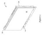
- FIG. 1is a schematic perspective view of an illustrative electronic assembly
- FIG. 2is a schematic exploded perspective view of the illustrative electronic assembly of FIG. 1 ;
- FIG. 3is a schematic perspective view of an illustrative sub-assembly of an illustrative electronic assembly
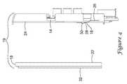
- FIG. 4is a schematic partially exploded side view of the illustrative sub-assembly of the illustrative electronic assembly of FIG. 3 ;
- FIG. 5is a schematic cross-sectional partially-exploded view of the features of the illustrative electronic assembly of FIG. 3 with the electrostatic discharge clip in an original position;
- FIG. 6is a schematic cross-sectional view of the features of the illustrative electronic assembly of FIG. 3 with the electrostatic discharge clip in an articulated position;
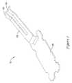
- FIG. 7is a schematic perspective view of an illustrative electrostatic discharge clip of an electronic assembly
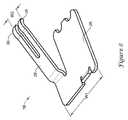
- FIG. 8is a schematic perspective view of another illustrative electrostatic discharge clip of an electronic assembly
- FIG. 9is a schematic flow diagram of an illustrative method of grounding an electronic component of an electronic device
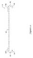
- FIG. 10is a schematic perspective view of an illustrative spacer of an electronic assembly
- FIG. 11is a schematic side view of the illustrative spacer of FIG. 10 ;
- FIG. 12is a further schematic side view of the illustrative spacer of FIG. 10 ;
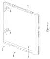
- FIG. 13is a schematic perspective view of an illustrative front cover of an electronic assembly
- FIG. 14is a schematic side view of the illustrative front cover of FIG. 13 ;
- FIG. 15is a further schematic side view of the illustrative front cover of FIG. 13 ;
- FIG. 16Ais a schematic cross-sectional view of the illustrative electronic assembly of FIG. 1 , taken along line 16 A- 16 A of FIG. 1 ;
- FIG. 16Bis a further schematic cross-sectional view of the illustrative electronic assembly of FIG. 1 , take along line 16 A- 16 A of FIG. 1 , enlarging the portion contained in the dotted circle 16 B of FIG. 16A ;
- FIG. 17is a schematic exploded perspective front view of an illustrative front cover, gasket, electronic component, spacer, and printed wiring assembly of an illustrative electronic assembly;
- FIG. 18is a schematic front view of an illustrative spacer engaged with an illustrative printed wiring assembly of an illustrative electronic assembly
- FIG. 19is a schematic exploded perspective back view of an illustrative front cover, electronic component, and spacer of the illustrative electronic assembly of FIG. 17 ;
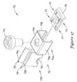
- FIG. 20is a schematic partially exploded view of an illustrative printed wiring assembly exploded from an illustrative front cover, electronic device, and spacer of the illustrative electronic assembly of FIG. 17 ;
- FIG. 21is a schematic exploded perspective view of an illustrative front cover, gasket and electronic component of the illustrative electronic assembly of FIG. 17 ;
- FIG. 22is a schematic back view of the illustrative electronic assembly of FIG. 17 ;
- FIG. 23is a schematic cross-sectional view of the illustrative electronic assembly of FIG. 22 , taken along line 23 - 23 ;
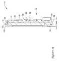
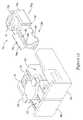
- FIG. 24is a schematic front perspective view of an illustrative back cover and wall plate of an illustrative electronic assembly
- FIG. 25is a schematic exploded back perspective view of an illustrative back cover and wall plate of an illustrative electronic assembly
- FIG. 26Ais a schematic cross-sectional view of an illustratively assembled back cover and wall plate
- FIG. 26Bis a schematic magnified view of illustrative mating walls between an assembled back cover and wall plate, taken from FIG. 26A ;
- FIG. 26Cis a schematic magnified view of illustrative pockets in the assembled back cover and wall plate, taken from FIG. 26A ;
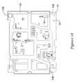
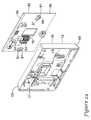
- FIG. 27is a schematic front view of an illustrative back cover of an electronic assembly.
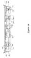
- FIG. 28is a schematic cross-sectional view of an illustrative Printed Wiring Assembly (PWA) and a back cover of an illustrative electronic assembly;
- PWAPrinted Wiring Assembly
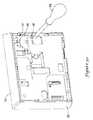
- FIG. 29is a schematic exploded perspective view of an illustrative back cover, printed wiring assembly, and battery of an illustrative electronic assembly
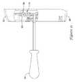
- FIG. 30is a schematic perspective view of an illustrative electronic assembly with a tool inserted therein;
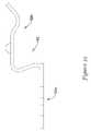
- FIG. 31is a schematic side view of the illustrative electronic assembly with a tool inserted therein, having a portion of the illustrative electronic assembly housing removed;
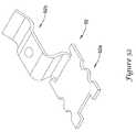
- FIG. 32is a schematic perspective view of an illustrative battery holder
- FIG. 33is a schematic side view of the illustrative battery holder of FIG. 32 ;
- FIG. 34Ais a schematic front view of an illustrative wall plate of an illustrative electronic assembly
- FIG. 34Bis a schematic back view of the illustrative wall plate of FIG. 34A ;
- FIG. 35is a schematic partially exploded view of an illustrative screw terminal of an illustrative electronic assembly
- FIG. 36is a schematic perspective view of an illustrative screw terminal of an electronic assembly
- FIG. 37is a schematic exploded view of the illustrative screw terminal of FIG. 36 ;
- FIG. 38is a schematic side view of the illustrative screw terminal of FIG. 36 ;
- FIG. 39is a schematic diagram of an illustrative electric circuit for an electronic assembly
- FIG. 40is a schematic diagram of another illustrative electric circuit for an electronic assembly
- FIG. 41is a schematic diagram of another illustrative electric circuit for an electronic assembly
- FIG. 42is a schematic graph depicting an illustrative thermal compensation model over time.
- FIG. 43is a schematic flow diagram of an illustrative method of compensating a sensed temperature.
- FIGS. 1 and 2An electronic device or assembly 10 is shown in FIGS. 1 and 2 . It is contemplated that the electronic device or assembly 10 may be, for example, a Heating, Ventilation, and Air Conditioning (HVAC) control panel, security system control panel, lighting control panel, irrigation control panel, or any other suitable device. In one example, the electronic device 10 may be a thermostat, but his is not required.
- HVACHeating, Ventilation, and Air Conditioning
- the illustrative electronic assembly 10may include a housing 12 , a PWA 14 , an electronic component 16 , and an electrically conductive extender or connector 18 , where the PWA 14 and the electronic component 16 may be positioned at least partially within the housing 12 .
- a conductive shieldmay be provided adjacent the PWA 14 , such as between the PWA 14 and the electronic component 16 .
- the electronic component 16may be a touch screen display that itself includes a conductive metal backing which can function as a conductive shield.
- the conductive shieldmay be electrically coupled to the ground feature of the PWA 14 via the connector 18 , as further described below.
- the PWA 14may include a grounding feature, such as a ground plane or other grounding feature (e.g., a grounding point, grounding terminal, ground pad, etc.).
- the grounding feature or grounding planemay be an area of copper foil or other conductive material connected to a grounding point of the PWA 14 .
- the grounding feature or grounding planemay serve as a return path for current from electronic components of the electronic assembly 10 .
- the grounding feature or grounding planeis not specifically identified in the Figures, but may take the form of a conductive layer of the PWA 14 , a terminal or pad on the PWA 14 , or any other form as desired.
- Electronic devices and their electronic assemblies 10may be susceptible to electrostatic discharge (ESD) events.
- ESD eventsmay occur when, for example, the electronic assemblies 10 are contacted by users and static electricity is discharged from the user to the electronic assembly 10 .
- ESD eventsmay be harmful to the electronic assemblies 10 , as the electronic components of the electronic assemblies 10 may be short circuited or otherwise damaged by the ESD events. Providing some level of ESD protection in configuring an electronic assembly 10 is thus desirable in many situations.
- electronic devices and their electronic assemblies 10may be at least partially protected from ESD events by, for example, including a conductive path for passing the electrostatic discharge safely to ground, and bypassing sensitive electronic components of the electronic assemblies 10 .
- the electronic assembly 10may include a printed wiring assembly (PWA) 14 that includes a ground feature, such as a ground plane. When provided, the ground plane may itself help shield sensitive electronic components from an outside ESD event.
- PWAprinted wiring assembly
- the electronic component 16may have a metal backing 22 (e.g., a zinc plating, sheet metal, and/or other metal or conductive material), a portion of a backing that is metal, or a metal feature extending adjacent the back of the electronic component 16 . While a metal backing is used in this example, it is contemplated that any suitable conductive layer or shield may be used, if present.
- a metal backinge.g., a zinc plating, sheet metal, and/or other metal or conductive material
- any suitable conductive layer or shieldmay be used, if present.
- the electronic component 16may be a display 32 (e.g., a liquid crystal display (LCD) or other display) that is at least partially enclosed by a metal box structure, where at least a back side of the display 32 (e.g., a side opposite a front side for viewing the display 32 , where side walls may extending between the front side and the back side) includes a metal backing 22 (see FIG. 4 ).
- a display 32e.g., a liquid crystal display (LCD) or other display
- a back side of the display 32e.g., a side opposite a front side for viewing the display 32 , where side walls may extending between the front side and the back side
- the perimeter sides (e.g., side walls) of the display 32and even a border around the front side of the display 32 , may be covered by the metal box structure.
- an electrically conductive extender or connector 18may provide an electrical connection between the metal backing 22 or the other conductive feature and the ground feature of the PWA 14 .
- Such an electrical connection 18 between the PWA 14 and the electronic component 16may, for example, help ground the metal backing 22 of the electronic component 16 and reduce the chances that an ESD event will cause damage to electronic components mounted on or near the PWA 14 .
- the electronic component 16 and the PWA 14may be spaced apart from each other when mounted in the housing 12 .
- the metal backing 22may be spaced from the PWA 14 and/or from components on the PWA 14 by a distance greater than about two (2) millimeters, greater than about three (3) millimeters, greater than about five (5) millimeters, greater than about ten (10) millimeters, or any other distance as desired.
- Such a spacemay provide sufficient space to accommodate one or more electrical components that may be mounted to the side of the PWA facing a spacer 24 and/or electronic component 16 , and in some cases, may help dissipate or distribute heat generated by the PWA 14 and/or electronic component 16 within the housing.
- the spacer 24may be provided, as shown in for example FIGS. 2-4 and 10-12 .
- the spacer 24may be made from any suitable material(s).
- the spacer 24may be made from one or more polymers or other materials having desirable material properties.
- the spacer 24may be made from an electrically insulating material, such that the spacer 24 does not create a short circuit between any conductive traces or other components on the PWA 14 and the electronic component 16 .
- the spacer 24may be configured to help support the electronic component 16 both when users are interacting with the electronic component 16 and when the electronic component 16 may be operating on its own.
- the spacer 24may take on a web-like form, such as shown best in perhaps FIGS. 2, 10, 17, 19, and 21 , and may have openings 25 (e.g., one or more openings 25 , two or more openings 25 , etc.) between structural portions 48 .
- the openings 25 of the spacer 24may allow for air gaps between the back side of the display 32 and the PCB 34 of the PWA 14 , when the spacer is positioned therebetween (see, discussion of the positioning of the spacer 24 below).
- the spacer 24may have spacer side walls 42 extending from and/or forming one or more edges of the spacer 24 , as best seen in perhaps FIGS. 10-12 .
- the spacer side walls 42may extend in the direction of the PWA 14 and/or may extend along an entire edge of the spacer 24 or may extend a partial distance along an edge of the spacer 24 , as seen in FIGS. 10 and 12 .
- the spacer side walls 42 of the spacer 24may be formed to mate with the housing 12 , which may help provide an ESD path 44 that travels around the ends of the spacer walls 24 , as best shown in perhaps FIGS. 11 and 16B . Because the length of the ESD path 44 is increased by the spacer side walls 42 , the PWA 14 may be better protected from an ESD event originating from outside of the housing 12 .
- the web-like configuration of the spacer 24may allow for a double sided PWA 14 component placement, whereas a spacer 24 without openings 25 may not permit component placement on the side of the PWA 14 adjacent the electronic component 16 .
- the openings 25 in the spacer 24may allow components to be mounted on both sides of the PCB 34 without interfering with the electronic component 16 (e.g., display 32 ) of the electronic assembly 10 , by providing space for the components on the side of the PCB 34 facing the component 16 .
- the electrically conductive extender or connector 18may have one or more portions 26 , 28 , as shown in FIGS. 7 and 8 .
- the electrically conductive extender or connector 18may have a first portion or connector portion 26 , and a second portion or spring portion 28 (e.g., a flexible beam or other feature).
- the first portion or connector portion 26may be integrally formed with the second portion or spring portion 28 , as shown in FIGS. 7 and 8 .
- the first portion or connector portion 26may be formed separate from the second portion or spring portion 28 and combined in any manner, as desired, to form the electrically conductive extender or connector 18 .
- the electrically conductive extender or connector 18may have a form that differs from that of the electrically conductive extender or connector 18 shown in FIG. 7 .
- the electrically conductive extender or connector 18may have first portion 26 with a width W 1 and second portion 28 with a width W 2 , where width W 2 may have a smaller value than width W 1 , as shown in FIG. 8 .
- width W 1is greater than width W 2
- the second portion 28may be located off-center with respect to the first portion 26 , as shown in FIG. 8 , but this is not required.
- the electrically conductive extender or connector 18may have the form of a clip, a spring, a clasp, or other form having a configuration that may be connected to the PWA 14 .
- the electrically conductive extender or connector 18may take on a clip form and may include a first portion or connector portion 26 and second portion or a spring portion 28 .
- the first portion or connector portion 26may be configured to mechanically connect to the PWA 14
- the second portion or of the spring portion 28may be configured to mechanically contact and electrically connect to the metal backing 22 .
- the first portion or connector portion 26 of the electrically conductive extender or connector 18may mechanically connect to the PWA 14 via surface mount technology (“SMT”). In other examples, the first portion or connector portion 26 of the electrically conductive extender or connector 18 may mechanically connect to the PWA 14 via mounting techniques that differ from SMT. In some illustrative instances, the first portion 26 of the electrically conductive extender or connector 18 may be soldered to a surface 15 of the PWA 14 , such that the second portion or spring portion 28 of the electrically conductive extender or connector 18 may extend away from the surface 15 of the PWA 14 and toward the electronic component 16 , as best seen in FIGS. 5-6 . In some cases, the first portion 26 of the electrically conductive extender or connector 18 may be soldered to a conductive pad, such as a ground feature or ground plane.
- SMTsurface mount technology
- the electrically conductive extender or connector 18may have a feature that is configured to contact the metal backing 22 of the electronic component 16 .
- the second portion or spring portion 28 of the electrically conductive extender or connector 18may have a contact portion 30 for contacting the metal backing 22 of the electronic component 16 .
- the contact portion 30 of the second portion or spring portion 28may take on any shape and/or size.
- the contact portion 30may have the shape of a protrusion or a bump that has a peak rising above any other portion of the electrically conductive extender or connector 18 , where, for reference, the electronic component 16 is considered to be above the PWA 14 .
- the electrically conductive extender or connector 18may be resilient, such that the material and/or form of the electrically conductive extender or connector 18 has mechanically resilient properties.
- an electrically conductive resilient extender or connector 18may be configurable between an original configuration or position, as best shown in FIG. 5 , and an articulated configuration or position, as best shown in FIG. 6 , where the electrically conductive resilient extender or connector 18 may provide a spring force back toward the original configuration. Where the electrically conductive resilient extender or connector 18 is in the articulated configuration (see FIG. 6 ), the spring force of the conductive resilient extender or connector 18 may be exerted against the metal backing 22 of the electronic component 16 , the PWA 14 , or the metal backing 22 of the electronic component 16 and the PWA 14 .
- the distance between a top portion or the contact portion 30 of the electrically conductive extender or connector 18 and the PWA 14may vary depending on the configuration.
- the top portion or the contact portion 30 of the electrically conductive extender or connector 18may be 1.0-5.0 millimeters, 2.2-2.8 millimeters, 2.4-2.6 millimeters, 2.0-2.5 millimeters, 2.5-3.0 millimeters, or in any other range of distances D 1 from the PWA 14 , as best shown in FIG. 5 .
- the top portion or the contact portion 30 of the electrically conductive extender or connector 18may be 0.0-2.0 millimeters, 1.0-2.0 millimeters, 1.2-2.8 millimeters, 1.4-1.6 millimeters, 1.0-1.5 millimeters, 1.5-2.0 millimeters, or in any other range of distances D 2 from the PWA 14 , as best shown in FIG. 6 .
- the force between the electrically conductive extender or connector 18 and, for example, the metal backing 22 of the electronic component 16may be relatively small when in the articulated position.
- the force between the electrically conductive extender or connector 18 and the metal backing 22 in the articulated positionmay be such that the performance of the display 32 is not affected by the contact force applied to the metal backing 22 from the electrically conductive extender or connector 18 (e.g., such that display 32 is devoid of any color areas or other display of sensitivity to a force acting on the metal backing 22 of the display).
- ESD eventstypically have relatively high voltage (e.g., approximately 10 kV or other value) and the electric breakdown of the surrounding air is up to 3 kV/mm (e.g., at dry air), an electrostatic discharge may find its way to the electrically conductive extender or connector 18 rather than jump across the space created by the spacer 24 and to an ESD sensitive electrical component mounted on the PWA 14 , despite the relatively low contact force between the metal backing 22 and the electrically conductive extender or connector 18 .
- relatively high voltagee.g., approximately 10 kV or other value
- 3 kV/mme.g., at dry air
- the electrically conductive extender or connector 18may be made from any of one or more materials.
- the electrically conductive extender or connector 18may be made from an electrically conductive material, a resilient material, any other material having desirable properties, and/or any combination of materials having these or other properties.
- the electrically conductive extender or connector 18may be made from a phosphor bronze (e.g., a copper alloy), steel, a conductive polymer, or any other suitable material.
- the electrically conductive extender or connector 18may be used in an illustrative method (S 100 ) of grounding an electronic component 16 of an electronic device or assembly 10 , as depicted in FIG. 9 (where the steps listed may be performed in the order depicted or in another order, if at all, as desired).
- the grounding of the electronic component 16 of the electronic device or assembly 10may help reduce or prevent electrical damage to one or more electrical components of the electronic device or assembly 10 in response to an ESD event.
- the method (S 100 )may include electrically connecting an electrically conductive extender or connector 18 (e.g., a resilient electrically conductive extender or connector) to a grounding connection or feature of a PWA 14 of the electronic device or assembly 10 .
- the method (S 100 )may include mounting the electrically conductive extender or connector 18 to the surface 15 of the PWA 14 (S 110 ).
- the electrically conductive extender or connector 18may be mounted to the surface 15 of the PWA 14 with surface mount technology or any other mounting technique.
- a first portion or connector portion 26 of the electrically conductive extender or connector 18may be mounted directly or indirectly to the PWA 14 .
- the first portion or connector portion 26 of the electrically conductive extender or connector 18may be mounted to the PWA 14 via an interference type connector such as a screw type connector, a bayonet type of connector, or any other type of interference type connector. In some cases, the first portion or connector portion 26 may be soldered to the surface 15 of the PWA 14 . In any event, the electrically conductive extender or connector 18 may be mounted such that the second portion or spring portion 28 thereof may extend away from the surface 15 of the PWA 14 and toward the electronic component 16 .
- the methodmay include providing a spacer 24 between the electronic component 16 and the PWA 14 (S 112 ) and situating the electronic component 16 adjacent the spacer 24 (S 114 ).
- the electronic component 16may be situated such that the electrically conductive extender or connector 18 may extend from the PWA 14 , through an opening 25 in the spacer 24 , and make electrical and mechanical contact with a metal backing 22 or other electrically conductive feature of the electronic component 16 .
- the electrically conductive extender or connector 18may be in a flexed or other configuration such that it exerts a spring force against the metal backing 22 or other electrically conductive feature of the electronic component 16 .
- the spring force of the electrically conductive extender or connector 18 exerted on the metal backing 22 or other electrically conductive feature of the electronic component 16may be configured and/or set to maintain an electrical connection with the metal backing 22 or other electrically conductive feature of the electronic component 16 .
- the spring force exerted by the electrically conductive extender or connector 18may maintain an electrical connection with the metal backing 22 or other electrically conductive feature of the electronic component 16 over a range of spacing between a surface 15 of the PWA 14 and the metal backing 22 of the electronic component 16 .
- the range of spacingmay be 0.0-3.0 millimeters, 0.0-2.8 millimeters, 0.0-2.6 millimeters, 0.0-2.5 millimeters, 0-2.0 millimeters or any other range of spacing between the PWA 14 and the electronic component 16 .
- the method (S 100 )may include securing the PWA 14 , the spacer 24 , and the electronic component 16 together to form a sub-assembly 19 (S 116 ) (see FIGS. 3-4 ).
- Securing the PWA 14 , the spacer 24 , and the electronic component 16 togethermay be performed using any connecting technique and/or connecting features, as desired.
- the spacer 24may clip to the PWA 14 and the electronic component 16
- the spacer 24may be glued to the PWA 14 and the electronic component 16
- the PWA 14 , the spacer 24 , and the electronic component 16may be connected in any other manner as desired to form a sub-assembly 19 (see FIG. 4 ).
- the mounting of the electrically conductive extender or connector 18 to the PWA 14may include performing the mounting before or after the sub-assembly 19 is assembled.
- the contact portion 30 of the electrically conductive extender or connector 18may move laterally along the surface 15 of the metal backing 22 as the electronic component 16 is moved toward the PWA 14 and as the electrically conductive extender or connector 18 moves from the original position (see FIG. 5 ) to the articulated position (see FIG. 6 ).
- the lateral motionmay help the contact portion 30 of the electrically conductive extender or connector 18 make a good electrical contact with the metal backing 22 of the electronic component 16 .
- the electrically conductive extender or connector 18may be mounted to the PWA 14 such that it extends through an opening 25 in the spacer 24 .
- the display 32 or other electronic component 16may be an unintended heat generator, which may heat and/or influence thermistors located at the PWA 14 , if such thermistors are present.
- the spacer 24may be configured to provide an air gap between the display 32 and the PWA 14 due to its, optional, web-like configuration. The web-like configuration may limit the heat transfer to the PWA 14 from the display 32 , while maintaining an overall thin profile of the electronic assembly 10 . Further, to prevent direct heat transfer to the thermistors (if present) on the PWA 14 through the material of the spacer 24 , the material of the spacer 24 may be cut away in, around and/or over any such thermistors.
- the electronic assembly 10may have internal, unintended heat sources (e.g., the display 32 , electronic component on the PWA 14 , and/or other unintended heat sources) that may affect the ability of the electronic assembly 10 (e.g., a thermostat as shown in FIGS. 1-43 ) to accurately sense an ambient temperature.
- the internal heat generated by electronic components of the electronic assembly 10may be related to the input voltage of the electronic assembly 10 .
- the input voltagemay vary, which may cause the internal temperatures to similarly vary regardless of the actual ambient temperature.
- initial conditions of the electronic devicee.g., before, during, and/or after powering up the electronic device of the electronic assembly 10 or a feature thereof
- powering upmay refer to any time a microprocessor of the electronic assembly 10 comes out of reset or powers on after being powered down (e.g., any time the microprocessor receives power after not receiving power, after an error recover reset, after a self-imposed test, etc.).
- An example of when an initial condition may affect sensing of the ambient temperaturemay include when an electronic device 10 is powered up after it has been in an OFF state for an amount of time such that the whole device may have cooled down/warmed up to the surrounding temperature. On the other hand, if the electronic device is quickly re-powered or re-started, the electronic device may not have cooled down/warmed up from its operating temperature. Further, in some instances, where the electronic device was forced into restarting, the electronic device may not have immediate access to temperature histories and has to start temperature compensation for unintended heat over. All of these considerations may affect the sensing of an ambient temperature and the ability of the electronic assembly 10 to compensate a sensed ambient temperature for unintended heat sources inside of the housing.
- a temperature compensation modelmay be developed for steady state conditions (e.g., when unintended heat within an electronic device reaches a steady state, that is, when the electronic device has been powered on for a period of time post-start up). Further, it has been found that using the temperature compensation model that was developed for steady state conditions to calculate compensated sensed ambient temperatures at initial startup (e.g., during an initial transient period), may result in providing sensed temperatures that represent relatively large errors from the actual ambient temperature.
- the electronic assembly 10may use a compensation method upon powering up the electronic device (e.g. during a transient power state) that differs from a compensation method used after running the electronic device for a period of time (e.g. during a steady power state).
- the electronic assembly 10may be configured to read an input voltage and/or sense other conditions and use the input voltage levels and/or other sensed conditions in temperature compensation models to provide offsets configured to be used to provide calculated compensated ambient temperatures for use by the electronic assembly 10 .
- Other sensed conditionsmay include, but are not limited to, an amount of time a screen of the thermostat has been lit over a period of time, a signal from one or more thermistors in the housing, a radio activity status, an LED status, and a power level at user interface buttons.
- Using two or more temperature compensation modelsmay increase the accuracy of temperature compensation.
- a first modelmay be used to accurately resolve or compensate a sensed temperature for initial and/or transient conditions, where this first model may or may not accurately compensate temperatures during steady states
- a second modelmay be used to accurately resolve or compensate a sensed temperature for steady state conditions (e.g. at a time post powering up), where the second model may or may not accurately compensate temperatures during initial transient conditions.
- the two or more modelsmay be used concurrently, such that the initial model may fade out (e.g. may be weighted less) as time and/or voltage input or other conditions change and the second or further model fades in (e.g. may be weighted more) as time and/or voltage input or other conditions change.
- Such a combination of compensation models/methodsmay result in more accurate compensation for sensed temperature calculations under different electronic assembly 10 operating conditions.
- a first “transient” temperature compensation modelmay be used during any transient period, and not just during an initial power up of the electronic assembly 10 .
- the display 32may consume relatively large amounts of power, and thus generate a relatively large amount of heat, when activated by a user.
- the display 32may consume a relatively lower amount of power when in a sleep mode.
- a first “transient” temperature compensation modelmay be used during the transient periods, such as for a period after the user activates the display 32 and/or for a period after the display 32 returns to a sleep mode.
- a second “steady state” temperature compensation modelmay be used during steady state periods between the transient periods.
- a method 220may be utilized to compensate a temperature reading of an electronic assembly 10 (e.g., a thermostat, etc.), wherein the electronic assembly 10 may include a housing 12 and one or more temperature sensors for sensing a temperature within the housing 12 .
- the electronic assembly 10may include a housing 12 and one or more temperature sensors for sensing a temperature within the housing 12 .
- a processor and/or memory of an electronic assemblymay perform compensation of a temperature reading or sensed temperature by the electronic assembly 10 .
- the method 220may include sensing 222 a temperature using the one or more temperature sensors of the electronic assembly 10 .
- the sensed temperaturemay be compensated by a plurality of temperature compensation models.
- the sensed temperaturemay be compensated 224 with a first temperature compensation model and the sensed temperature may be compensated 226 with a second temperature compensation model.
- the method 220may include transitioning 228 through two or more of the plurality of temperature compensation models.
- the transitioning 228may include transitioning from compensating the sensed temperature with the first temperature compensation model to compensating the sensed temperature with the second temperature compensation.
- the transitioning feature 228 of the method 220may include transitioning over time and/or independent of the sensed temperature and/or any other sensed temperature.
- weightsmay be applied to the temperature compensation models to facilitate transitioning from compensating the sensed temperature with the first temperature compensation model to compensating the sensed temperature with the second temperature compensation model.
- the weighting of the temperature compensation models with respect to one anothermay be adjusted over time and/or as a function of some other variable.
- the sensed temperaturemay be compensated with two or more compensation models simultaneously.
- weights applied to the temperature compensation modelsmay be adjusted over time such that the first temperature compensation model may be more heavily weighted than the second temperature compensation model near a time of an initial power on of the electronic assembly 10 and the second temperature compensation model may be more heavily weight near a time when the electronic assembly 10 may be reaching a steady state.
- a weight that is adjusted over time or that changes over timemay be applied to a first temperature compensation model (e.g. an initial condition or transient temperature compensation model), where the weight may have a greater weight at a time of powering up of the electronic assembly 10 than at a time of powering up plus a period of time.
- a weight that is adjusted over time or that changes over timemay be applied to a second temperature compensation model (e.g., a steady state temperature compensation model), where the weight may have a greater weight at a time of powering on plus a period of time than at a time of powering on of the electronic assembly 10 .
- a second temperature compensation modele.g., a steady state temperature compensation model
- FIG. 42depicts a schematic graph 200 , with temperature 202 on the y-axis and time 204 on the x-axis, of a compensated sensed temperature, where the sensed temperature is compensated with only a first (e.g., a transient, startup, power up, and/or initial) temperature compensation model 210 , with only a second (e.g., an original or steady state) temperature compensation model 208 , and with a blended temperature compensation model 206 combining the first and second temperature compensation models 210 , 208 .
- the illustrated temperature from the blended temperature compensation model 206is a result of weighting the first temperature compensation model 210 and the second temperature compensation model 208 with respect to one another and modifying the weights over time.
- a time for the transition from the first temperature compensation model 210 to the second temperature compensation model 208is one hundred twelve (112) minutes, and in the blended temperature compensation model 206 , the weights are linearly transitioned from the first temperature compensation model 210 to the second temperature compensation model 208 over the one hundred twelve (112) minute transition period.
- the temperature compensation modelsmay be weighted with respect to one another as a function of time and the weights may be adjusted over time in any manner to facilitate transitioning from one temperature compensation model to another temperature compensation model.
- the weights applied to the temperature compensation modelsmay be adjusted linearly over a set period of time (e.g., a set transition period of time).
- transitioning from one temperature compensation model to another temperature compensation model over timemay be accomplished by adjusting the weights associated with the temperature compensation models in a non-linear manner over a time period.
- an equation or functionmay be utilized to transition from a first temperature compensation model, F first , (e.g. an initial condition or transient temperature compensation model) to a second temperature compensation model, F second , (e.g., a steady state temperature compensation model).
- F firste.g. an initial condition or transient temperature compensation model
- F seconde.g., a steady state temperature compensation model
- the weightsmay be applied to the temperature compensation models such that the weights are adjusted rapidly over time at times near the startup and near the steady state of the electronic assembly 10 , the weights are adjusted relatively slowly in between times near startup and times near steady state of the electronic assembly 10 .
- a parting line between portions of the housing of an electronic devicemay be a suitable inlet through which ESD may travel to the inside of the electronic device.
- a parting line 40may be formed, as best shown in FIGS. 16A and 16B , and it has been found that ESDs may travel to the inside of the electronic assembly 10 through this parting line 40 .
- ESDsmay carry voltage of up to about 15 kilovolts (kV) or more (although, voltage of an ESD may vary greatly), which is a relatively high voltage.
- kVkilovolts
- the electric breakdown strength of dry air in substantially ideal conditionsis approximate 3 kV/millimeter (mm). This means that in ideal conditions, a gap having a distance greater than 5 mm is needed to prevent a discharge directly from an electronic component 16 to the PWA 14 .
- the ESDmay not dissipate as expected due to materials (e.g., mating walls, dirt, humidity) or other factors slowing the dissipation of the ESD and thus, the ESD may travel farther than it is expected to travel in ideal conditions.
- the parting line 40which may provide an avenue through which ESDs make their path to an interior of the of the electronic assembly 10 to the closest electrically sensitive area, may be extended a distance by the placement of the mating walls of the electronic assembly (e.g., the front cover 38 , the back cover 36 , and the spacer walls 42 of spacer 24 ).
- the spacer 24may be positioned within the housing 12 , such that the spacer 24 contacts the front cover 38 and the back cover 36 .
- Such positioning of the mating surfacesmay extend the distance the ESD must travel to contact an electrically sensitive area within the housing 12 to a distance equal to a length of protective walls 56 of the front cover 38 starting at a gap at an outer surface of the housing 12 between the front cover 38 and the back cover 36 plus a length of the spacer walls 42 .
- the extended distance the ESD may have to travel to an electrically sensitive areamay be set at least 5 mm, at least 8 mm, at least 10 mm, or other distances of travel greater than 10 mm.
- the spacer 24may be situated between the electronic component 16 and the PWA 14 , and in some cases, may engage both the facing surfaces of the electronic component 16 and the PWA 14 .
- a component on the PWA 14may extend through an opening 25 in the spacer 24 .
- the electrically conductive extender or connector 18 extending from the PWA 14may extend through an opening 25 in the spacer 24 , as shown in FIGS. 2, 5 and 6 .
- the electrically conductive extender or connector 18may extend from the PWA 14 , through an opening 25 in the spacer 24 , and may mechanically engage and electrically connect to the metal backing 22 of the electronic component 16 , as best shown in FIG. 6 .
- the front cover walls 56 of the front cover 38may be configured to engage and/or align other features of the electronic assembly 10 .
- wall extensions 58may extend from the front cover walls 56 or other portions of the front cover 38 and interact with the PWA 14 or other feature to align the PWA 14 within housing 12 , and in some cases, to at least partially secure the PWA 14 within the front cover 38 .
- a clip 60 of the front cover 38may extend from a base 39 of the front cover 38 and optionally engage and/or align the PWA with the front cover 38 .
- the front cover walls 56may have beveled or chamfered outside edges (e.g.
- the features of the electronic assembly 10may be configured to give the electronic assembly 10 a slimming look and a thin or minimalist configuration.
- one or more terminal blocks 70 that may receive electrical wiring configured to connect power and/or control signals to the electronic assembly 10may be positioned on a wall plate 80 and recessed into the housing 12 so as to not extend the profile of the electronic assembly 10 away from the wall.
- the electronic assembly 10may be configured to allow plastic material to surround all electronics of the electronic assembly 10 and prevent substantially all of the electronics from being seen by a user from outside of the electronic assembly 10 .
- the opening 52 of the front cover 38may be sized to allow a user to view and/or interact with the display 32 or other electronic component 16 , while protecting the electronic component 16 .
- the opening 52 in the front cover 38may be sized to allow free access to a touch pad of the electronic component 16 , sized to cover the visual area viewing angles, sized to protect the PWA against contamination, sized to prevent the cover from interacting with an active touch pad area of the electronic component 16 , and and/or sized for any other purpose.
- the front cover 38 or display holdermay include a recess 53 for receiving at least part of the display 32 (see, FIG. 19 ).
- the gasket 106may be positioned between the front cover 38 and the display 32 (e.g., the front side of the display 32 ).
- the display 32may be placed within the front cover 38 of the FWA front cover 100 through the recess 53 of the front cover 38 or display holder such that the front cover or display holder may extend adjacent part of the front side of the display 32 and adjacent at least part of the side walls of the display 32 .
- the spacer 24may be positioned adjacent the display 32 , and the sub-assembly 110 may be closed by adding the PWA 14 adjacent to the spacer 24 and securing the PWA 14 to the front cover 38 or display holder adjacent the back side of the display 32 (see, FIG. 20 ). Such a configuration may sandwich the display 32 between the front cover 38 or the display holder and the PCB 34 of the PWA 14 .
- the PCB 34 of the PWA 14may include a front side configured to face the front cover 38 or display holder and/or the display 32 , a back side opposite the front side, and side walls extending between the front side and the back side.
- the spacer 24may have spacer side walls 42 that, when the spacer 24 is positioned between the PCB 34 and the display 32 , may extend adjacent to at least part of the side walls of the PCB 34 and/or beyond the back side of the PCB 34 , when desired.
- the hinges or wall extensions 58 of the front cover 38 or display holdermay hinge the PCB 34 of the PWA 14 with respect to the front cover 38 or display holder until the latch(es) or clip(s) 60 latch or clip the PCB 34 of the PWA 14 relative to the front cover 38 or display holder.
- the sub-assembly 110may be configured such that a flex tail 33 of the display 32 may be inserted into a connector 46 on the PWA 14 , as best shown in FIG. 23 , to place the PWA 14 and the PCB 34 thereof in electrical communication with the display 32 .
- the front cover 38may receive the display 32 therein.
- the display 32e.g., the front of the display
- the gasket 106may have several purposes.
- the gasket 106may prevent liquid from getting into the electronic assembly 10
- the gasket 106may help create a tighter fit for the components of the electronic assembly 10
- the gasket 106may help prevent ESDs from entering the electronic assembly 10 , etc.
- the spacer 24 and the front cover 38 or display holdermay be mating components and may contain several positioning features that do not allow an operator to assemble them in an incorrect orientation.
- orientation featuresinclude, but are not limited to: ribs 108 in the spacer 24 configured to engage pockets 112 in the front cover 38 or display holder to assist or help in aligning the spacer 24 with the front cover 38 or display holder; grooves in the edges of the spacer 24 and/or the front cover 38 ; an alignment feature 114 (e.g., a rib, a pin, or other alignment feature) of the front cover 38 or display holder configured to engage an alignment feature 116 (e.g., a pocket, a pin hole, or other alignment feature) in the spacer 24 to align the spacer and the front cover or the display holder, as best shown in FIG.
- the positioning featuresmay help prevent the spacer 24 from moving until the PWA 14 is assembled and the sub-assembly 110 may be fully assembled and locked together.
- An illustrative method of using the battery 90 with the electronic assembly 10may include inserting the battery 90 through the pocket, opening, or aperture 37 in the back cover 36 of the housing 12 .
- the battery 90Once the battery 90 has been placed in the back cover 36 , it may be positioned against the PCB 34 within the housing 12 and slid down (e.g., in a lateral direction) to the recess 43 in the housing 12 and/or to a battery seat region 35 (see, for example, FIG. 29 ) having electrical terminals for electrically connecting the battery 90 to the PCB 34 when the coin cell battery is place in the battery seat region 35 .
- the battery 90may be removably secured to the PCB 34 when the battery 90 is at least partially positioned on the battery seat region 35 .
- the battery 90may extend along a primary plane and when the battery is positioned in the battery seat region 35 , the primary plane of the battery 90 may be substantially parallel to a surface (e.g., a main or major surface 34 a , as shown in FIG. 29 ) of the PCB 34 .
- the battery seat region 35may at least partially overlap with and/or may be at least partially offset (e.g., laterally offset) from the pocket, opening, or aperture 37 , but the battery 90 may be accessible therethrough when positioned at the battery seat region 35 .
- the battery 90may be held in place on the PCB 34 by a battery holder 92 (e.g., an electrical terminal on the PCB 34 ) having a contact and affixed to the PCB 34 and/or the back cover 36 (see, FIGS. 29, 32-33 ).
- a negative contact or electrical terminalmay be located at the battery seat region 35 of the PCB 34 and a positive contact or electrical terminal may be formed adjacent (e.g., over or otherwise adjacent) the battery seat region 35 of the PCB 34 with the battery holder 92 .
- the contact polaritymay be switched.
- the battery holder 92may include a mounting portion or mounting region 92 a for mounting to the PCB 34 at or adjacent the battery seat region 35 (see FIGS. 32-33 ). Additionally, or alternatively, the battery holder 92 may include an elongated spring region that may extend over and/or electrically contact a battery 90 positioned at least partially on or adjacent the battery seat region 35 . In one illustrative example, as shown in FIGS. 32 and 33 , the battery holder 92 may be a Z-shaped electrical terminal, but this is not required.
- the force from the battery holder 92 and gravitymay help assure that the battery maintains good electrical contact with the connection on the PCB 34 and will remain in its desired position during handling of the electronic assembly 10 .
- Such design for battery 90 insertion into and removal from the electronic assembly 10may simplify the assembly process because the battery may be delivered as a separate part and installed at an area where the electronic assembly 10 will be used as opposed to at a manufacturer or offsite. Additionally, or alternatively, the configuration of the electronic assembly for battery 90 insertion may facilitate placing and maintaining the battery 90 within the housing 12 without adjusting any part of the housing 12 .
- the battery 90may be removed by a user with the assistance of a screwdriver 94 or other tool, as best shown in FIGS. 30 and 31 , or in any other manner.
- a usermay insert the screwdriver 94 or other tool into a slot 96 in the back cover 36 of the housing 12 .
- the slot 96may be configured to expose a portion of the battery 90 (e.g., an edge of the battery 90 when the battery 90 is positioned in the battery seat region 35 ).
- the screwdriver 94may be slid up along the slot 96 to push the battery 90 from below, which may cause the battery 90 to slide up and laterally out from the battery seat region 35 and/or the battery holder 92 toward the pocket, opening, or aperture 37 in the back cover 36 for removal through the pocket, opening, or aperture 37 from the housing 12 by hand or other tool.
- the slot 96may be configured for a particular tool.
- the slotmay be an elongated slot and may be configured to receive a flat head screw drive.
- other slot dimensionsmay be utilized for the slot 96 to accommodate a variety of tools.
- the risk of shorting the PWA 14may be limited by not locating conductive traces and electrical components on the PWA 14 near the slot 96 , so that the screwdriver 94 or tool may not contact any conductive traces and/or electrical components.
- the back cover 36may be configured to support the PWA 14 and/or the electronic component 16 (e.g., display 32 ). Supporting the PWA 14 and/or the electronic component 16 from a back side may assist in preventing unexpected bending of the PWA 14 and/or the electronic component 16 when a user is pressing against the display 32 or other front side features, which could contribute to the electronic device malfunctioning.
- the back cover 36may include an outer shell 73 and one or more inner walls 130 (e.g., inward extending walls or other inner walls) that extend from the outer shell 73 toward the PWA 14 to support the PWA 14 from the back side when it is fully assembled in the electronic assembly 10 .
- the inner walls 130may have one or more functions.
- the inner walls 130may: provide mechanical support for the PWA 14 and/or the electronic component 16 ; help to prevent ESDs from progressing to shielded areas of the PWA 14 ; divide an inner volume between the PWA 14 and the back cover 36 into separate spaces (e.g., pockets and/or areas on the PWA 14 ) and separate colder areas from warmer areas to assist in improving temperature sensing and/or compensation capabilities such as described in U.S. Pat. No. 8,280,637, which is incorporated herein by reference.
- the inner walls 130may have one or more other functions that may or may not be combined with the listed functions of the inner walls 130 .
- the inner walls 130 of the back cover 36may have one or more portions.
- the inner walls 130 of the back cover 36may have: a wall portions 130 a configured to surround the pins 62 on a region of the PWA 14 for connection to terminals 70 in the wall plate 80 (e.g., where the outer shell 73 may include an aperture 71 with wall portions 130 a extending inward toward the PWA 14 to form a sidewall of the aperture 71 extending substantially to the PWA 14 ), which may help prevent users from contacting electronic components on the PWA 14 other than the pins 62 ; wall portions 130 b configured to form thermistor pockets 132 and surround one or more thermistors or temperature sensors (e.g., a first temperature sensor and a second temperature sensor in a first area and/or a first pocket) on the PWA 14 ; wall portions 130 c forming a pocket and/or surrounding the battery aperture or opening 37 (e.g., where the wall portions 130 c form
- the regions on the PWA 14 discussed abovemay be regions including the pins 62 , the battery holder 92 , and/or is substantially devoid of ESD sensitive electronic components, electronic components other than one or more connectors such as a pin or battery connector, or any other electronic component.
- an interior of the back cover 36may have one or more alignment feature 136 configured to engage one or more openings in the PWA 14 and align the back cover 36 with respect to the PWA 14 , which may be within sub-assembly 110 .
- the back cover 36may include one or more PWA supports 134 , which may have the dual purpose of providing a testing opening through back cover 36 .
- the wall portions 130may help support PWA 14 by touching or contacting a back side of the PWA 14 at some or at least substantially all of the positions atop the wall portions 130 when the printed circuit board is enclosed in the housing 12 .
- the wall portions 130may facilitate ESD shielding by, for example, walling off a central opening 71 for connecting pins 62 to terminal 70 on a wall plate 80 .
- the wall portions 130may improve temperature sensing accuracy by at least partially separating cold areas (e.g., an area surrounding the battery 90 ) where there are no, or a limited number of, components generating unintended heat, from other areas.
- cold arease.g., an area surrounding the battery 90
- one or more thermistors and/or one or more humidity sensorsmay be positioned so as to not be affected so much by heat creating electronic components on the PWA 14 .
- the thermistors on the PWA 14may be located at top and bottom edges (or in some cases opposite edges) of the PWA 14 .
- the wall portions 130 of the thermistor pockets 132may substantially entirely surround a thermistor and contact the surface of the PWA 14 . Such direct contact between the wall portions 130 b and the PWA 14 may assist in isolating the thermistor pockets 132 .
- Dividing the inner volume between the PWA 14 and the back cover 36 into separate spaces (e.g., pockets and/or areas on the PWA 14 ) and separate colder areas from warmer areasmay assist in temperature sensing and/or compensation capabilities of the electronic device such as described in U.S. Pat. No. 8,280,637, which is incorporated herein by reference.
- the wall portions 130 d surrounding a humidity sensor at the bottom of the PWA 14may protect the humidity sensor and have vents 138 to help bring humidity changes to this compartment.
- the first thermistor pocket and the second thermistor pocketmay be free from air vents 138 through the housing 12 to the external environment.
- the third pocketwhich may house the humidity sensor, may include an air vent 138 extending through the housing 12 to an exterior environment.
- the back cover 36may be configured to support the PWA 14 and/or the electronic component 16 , protect features on the PWA 14 , and provide an electronic assembly 10 that has robust and accurate electronic sensing capabilities.
- the housing 12may be formed by any desirable manufacturing process and may be made from any desirable material.
- the housing 12may be molded and made from a plastic material.
- the housingmay be made from a different mechanical process and/or a different material.
- the back cover 36may engage a wall plate 80 (e.g., in a releasably connectable manner), where the wall plate 80 may be a portion of the electronic assembly that is used to hang the electronic assembly 10 (e.g., a thermostat) on a wall or other structure.
- the wall plate 80may have a perimeter defined or at least partially defined by side walls 86 , and in some cases, the engaged back cover 36 may partially or substantially enclose the wall plate 80 .
- the wall plate 80may be secured to a wall or other structure with screws 82 or other fastening mechanisms.
- the wall plate 80may include one or more apertures 81 extending through the wall plate 80 that are configured to receive one or more screws or other fastening mechanisms.
- screws 82are used to fasten the wall plate 80 to a wall or other structure
- the wall plate 80 and/or the back cover 36may include pockets 84 (e.g. relief features) in the wall plate 80 and/or pockets 63 (e.g., relief features) in the back cover 36 to accommodate a portion of a screw head to help ensure the heads of the screws 82 do not act as a limiting factor in the thinness or thickness of the electronic assembly 10 .
- the pockets 84 , 63may be aligned with one another.
- the housing 12e.g., the back cover 36 or other portion of the housing 12
- the wall plate 80may be provided and/or configured such that the housing 12 and the wall plate 80 initially engage one another, with the wall plate 80 misaligned relative to the housing 12 .
- the housing 12 and wall plate 80may be guided into alignment with one another.
- the back cover 36may have a raised perimeter 64 at least partially defining a recess that is configured to accept and/or receive at least a part or portion of the wall plate 80 , where the recess may include a recess back wall 65 .
- the recessmay have a depth and the wall plate 80 may have a thickness such that the volume of the recess of the housing 12 may receive at least a majority of the thickness of the wall plate 80 .
- the wall plate 80may have a raised portion in a front wall 91 that at least partially defines a recess that is configured to accept and/or receive at least a part or portion of the back cover 36 or other portions of the housing 12 , where the recess may include a recessed front wall (not explicitly shown).
- engaging and aligning related featuresare discussed herein with respect to the recess being positioned in the back cover 36 of housing 12 , similar engaging and/or aligning related features may be incorporated into the electronic assembly 10 having a recess in the wall plate 80 that receives at least part of the back cover 36 or other portion of the housing 12 .
- the raised perimeter 64 of the back cover 36may have recess side walls 66 that may correspond with wall plate side walls 86 of the wall plate 80 , and may allow at least a part or portion of the side walls 86 of the wall plate 80 to mate with the recess side walls 66 of the back cover 36 of the housing 12 .
- the side walls 86 of the wall plate 80are tilted or slanted at an angle relative to the back wall 65
- the recess side walls 66 of the back cover 36may be similarly titled or slanted at an angle to mate with the side walls 86 of the wall plate 80 .
- the recess side walls 66may have a first perimeter 67 adjacent the recessed back wall 65 and a second perimeter 69 toward the back side of the housing 12 and the wall plate 80 , where the second perimeter 69 is larger than the first perimeter 67 .
- the side walls 86 of the wall plate 80may have a first perimeter 87 adjacent the housing 12 when the wall plate 80 is engaging the housing 12 and a second perimeter 89 closer to a mounting surface 85 of the wall plate than the first perimeter, where the second perimeter 89 is larger than the first perimeter 87 (see, for example, FIG. 26B ).
- the respective walls 66 , 86may be used to self align the back cover 36 with the wall plate 80 .
- the side walls 66 of the housing and the side walls 86 of the wall plate 80may be configured such that the recess in the back of the housing 12 may receive the wall plate 80 with the wall plate 80 misaligned relative to the housing 12 , and then as the housing 12 is moved toward the wall plate 80 , the side walls 66 of the housing and the side walls 86 of the wall plate 80 progressively further align the housing 12 with the wall plate 80 .
- a recess in the wall plate 80in conjunction with the back cover 36 or other portion of the housing 12 may be configured such that the recess of the wall plate 80 may initially receive the back cover 36 or other portion of the housing 12 with the wall plate misaligned relative to the back cover 36 or other portion of the housing 12 , and then progressively further align the back cover 36 or other portion of the housing 12 with the wall plate 80 as the back cover 36 or other portion of the housing 12 are moved closer to one another.
- a method of securing a back cover of a housing 12 and a wall plate 80may include moving the wall plate 80 into engagement with the back cover 36 (or back side of the housing 12 ) and sliding an aligning surface of the wall plate 80 (e.g., tilted, slanted, angled, beveled, chamfered side walls 86 ) along an aligning surface of the housing (e.g., tilted, slanted, angled, beveled, chamfered side walls 66 ) to align the wall plate 80 with the housing 12 as the wall plate 80 is moved further towards the housing 12 .
- an aligning surface of the wall plate 80e.g., tilted, slanted, angled, beveled, chamfered side walls 86
- the tilted, slanted, angled, beveled, or chamfered side walls 66 , 86may be angled at any angle or have any other suitable configuration.
- the side walls 66 , 86may be angled at between zero (0) degrees and ninety (90) degrees, ten (10) degrees and eighty (80) degrees, twenty (20) degrees and seventy (70) degrees, thirty (30) degrees and sixty (60) degrees, forty (40) degrees and fifty (50) degrees relative to the recess back wall 65 or the mounting surface 85 , respectively.
- the side walls 66 , 86may be angled at a forty-five (45) degree angle with respect to the recess back wall 65 or the mounting surface 85 , respectively.
- the side walls 66 , 86may have different angles with respect to one another relative to the respective recess back wall 65 or the mounting surface 85 .
- the back cover 36may be further configured to have a limited profile.
- the side walls 68 of the back cover 36may extend inward, such that the front of the back cover 36 that is adjacent the front cover 38 defines a larger circumference/perimeter than a circumference/perimeter defined by a back of the back cover 36 that is adjacent the wall plate 80 .
- terminals or terminal assembly 70may be built into a wall plate 80 or other feature of the electronic assembly 10 .
- the terminals 70e.g., one terminal 70 , two terminals 70 , as shown in FIG.
- terminals 70may be positioned within the wall plate 80 such that when the housing 12 of the electronic assembly 10 is attached to the wall plate 80 , pins 62 affixed to the PCB 34 of the PWA 14 (where the pins 62 may be connected to the PCB 34 via a soldering technique or other mounting technique) may removably electrically connect to the terminals 70 (e.g., each pin 62 may engage a separate terminal 70 or multiple pins 62 may engage a single terminal). As seen in FIG.
- two terminals 70may be configured to engage plastic or other material of the wall plate 80 , and pins 62 connected to the PCB 34 (not shown) may thereafter engage the terminals 70 (e.g., a first pin 62 may engage a first terminal 70 and a second pin 62 may engage a second terminal 70 ).
- the terminals 70may define a cage 72 (made of metal or other electrically conductive material), a screw 74 , and a nut 76 , as best shown in FIGS. 36-38 .
- the terminals 70may be supported by the material (e.g., plastic or other material) of the wall plate 80 and one or more terminals 70 (e.g., a single terminal) may be placed in (e.g., slid in, snapped in, and/or otherwise positioned in) each of one or more pockets, recesses, or openings 83 in the wall plate 80 .
- the cage 72 of the terminal 70may include a first portion 72 a having an area for receiving a screw 74 and a nut 76 .
- the first portion 72 a of the cage 72may have a first side 75 a , an opposing second side 75 b and a third side 75 c .
- the first side 75 a , the second side 75 b and the third side 75 c of the first portion 72 a of the cage 72may be formed from a single piece of bent metal.
- the first portion 72 a of the cage 72may be used for connecting a wire.
- the wiremay, for example, power the electronic assembly 10 or communicate a control signal.
- a wiremay be wrapped around the screw 74 by an installer, and then the screw 74 may be tightened to secure the wire between the head of the screw and an outside surface of the third side 75 c of the first portion 72 a of the cage 72 .
- a wiremay be inserted between the nut 76 and the first portion 72 a of the cage 72 by the installer, and then the screw 74 may be tightened to secure the wire between the nut 76 and an inside surface of the third side 75 c of the first portion 72 a of the cage 72 .
- the first portion 72 a of the cage 72may be configured to receive an end of a wire (e.g., a power or control wire).
- a second portion 72 b of the cage 72may be positioned adjacent the first portion 72 a of the cage 72 .
- the second portion 72 b of the cage 72may be formed from, or have, flange 78 that may be configured to receive and/or to be placed in electrical contact with the pins 62 soldered, or otherwise connected to, the PCB 34 or other feature of the PWA 14 .
- Flange 78 of the second portion 72 b of the cage 72may be configured to fit within openings 83 in the wall plate 80 that are configured to receive the second portion 72 b of the cage 72 (see, for example, FIG. 35 ).
- the configuration of the first portion 72 a and the second portion 72 b of the cage 72may be configured to electrically connect a pin 62 to a wire.
- the cage 72 of the terminal 70may include a latch 79 (e.g., a one-way latch, a two-way latch, etc.), as best shown in FIG. 38 .
- the latch 79may be configured to engage (e.g. slide into, snap into, etc.) a hole 88 (e.g., a latching hole or other hole) in the wall plate 80 , as best shown in FIG. 34B , or connect to the wall plate 80 in any other manner after or as the terminal 70 is positioned in the opening 83 of the wall plate 80 .
- the latch 79may snap into the hole 88 in the wall plate 80 and lock the terminal 70 in the opening 83 of the wall plate 80 by preventing removal of the terminal.
- the cage 72may be formed form any combination of electrically conductive materials.
- the cage 72may be formed from one or more metal and in one example, the cage 72 may be formed from phosphor bronze, a phosphor bronze alloy, and/or other material.
- the material of the cage 72may be formed into the cage 72 in any manner.
- the material of the cage 72may be bent, molded, welded, and/or otherwise formed into the cage 72 .
- the cage 72may be formed from a single piece of metal (e.g., a metal plate) or formed from a plurality of pieces of metal or other material.
- the first portion 72 a of the cage 72 and the second portion 72 b of the cage 72may be formed from a single piece of bent metal.
- the screw 74 of terminal 70may be a self-locking screw or other screw that extends at least partially through and/or within the first portion 72 a of the cage 72 , where a recess under the screw head and/or special flanges (not shown) extending from the cage 72 may help hold the screw at a desired position (e.g., a desired position for maintaining the nut 76 within the cage 72 ).
- the head of the screw 74may allow for use with any desired tool.
- the head of the screw 74may allow for the use of a flat-head screwdriver, a Phillips head screwdriver (e.g., Phillips PH1, or other Phillips screwdriver), an Allen wrench/hex key tool, or other tool.
- the screw 74may be formed from steel, hardened steel, or any other suitable material.
- the nut 76may be configured to engage the screw 74 in a threaded manner or a different manner at least partially within the first portion 72 a of the cage 72 . In some instances, the nut 76 may be completely unscrewed from the screw 74 , but due to its positioning within the first portion 72 a of the cage 72 the nut may not drop from the terminal 70 and the screw 74 may be engaged by the screw 74 again.
- the nut 76may include features (e.g., grooves 77 , dimples, bumps, or other features) to help engage an end of a wire. This may help protect the electronic assembly 10 from unintended wire pull-out when the screw 74 is tightened to nominal torque (e.g., 1 lb-in-6 lb-in, 2 lb-in-5 lb-in, 3 lb-in-4 lb-in, such as 3.5 lb-in or any other torque level less than 1 lb-in or greater than 6 lb-in).
- nominal torquee.g., 1 lb-in-6 lb-in, 2 lb-in-5 lb-in, 3 lb-in-4 lb-in, such as 3.5 lb-in or any other torque level less than 1 lb-in or greater than 6 lb-in).
- the terminal 70may be placed in a suitable pattern to match the pattern of the pins 62 attached to the PCB 34 of the PWA 14 .
- a nominal pin 62 spacingmay be configured to be a particular distance (e.g., 1 mm, 2 mm, 3 mm, 4 mm, 5 mm, 6 mm, 7 mm, 8 mm, 9 mm, 10 mm, or other distance).
- two pins 62may be connected to the PCB 34 , which may be used to power the electronic assembly with a 24 volt alternate current (AC) or other current, where one wire connected to a terminal 70 may be a ground wire and the other wire connected to a terminal 70 may be live wire (e.g., carrying 24 V AC or other voltage).
- ACalternate current
- the housing 12 and the contents thereinmay be removed from the wall plate 80 without disconnecting the wires from the terminals 70 of the wall plate.
- the terminals 70 of the wall plate 80may be used in a method of electrically connecting a wire to the PCB 34 that may be at least partially or substantially housed in the housing 12 of the electronic assembly 10 .
- the terminal 70may be inserted into an openings 83 in the wall plate 80 , and a latch of the terminal 70 may be snapped into or may otherwise engage a hole 88 in the opening 83 to secure the terminal relative to the wall plate 80 .
- a wiremay be slid adjacent the nut 76 of the first portion 72 a of the cage 72 of the terminal 70 in the wall plate 80 .
- the screw 74extending at least partially through the first portion 72 a of the cage 72 , may then be rotated and tighten the nut 76 so as to capture the wire between the nut 76 and the third side 75 c of the first portion 72 a of the cage 72 .
- the flange 78 of the second portion 72 b of the cage 72may engage the pin 62 , where the pin 62 may extend from the PCB 34 through an aperture in the housing 12 .
- the electronic assemblies 10 powered from line power transformersmay need to be able to withstand surge energy which may come from the power line, through a transformer, to the electronic assembly 10 .
- surge energymay come from the power line, through a transformer, to the electronic assembly 10 .
- a voltage at a loaded transformermay exceed an absolute maximum rating of power supply voltage for the electronic assembly 10 .
- the overall energymay be high.
- suitable over voltage protection components in electrical communication with the pins 62may be utilized on the PWA 14 .
- a first componentmay be one or more varistors 122 (e.g., a small varistor or a large varistor) having a clamping voltage (e.g., a low clamping voltage or a high clamping voltage)
- a second componentmay be one or more resistors 124 (e.g., a serial resistor or a parallel resistor)
- a third componentinclude one or more diodes 126 (e.g., a Transient Voltage Suppressor (TVS) diode or other diode) with a small clamping voltage or a large clamping voltage.
- TVSTransient Voltage Suppressor
- the resistor 124may be the component that allows the surge energy to be split between the varistor 122 and the diode 126 in a suitable ratio.
- some part of the surge voltagemay be absorbed by a first capacitor or a capacitor 128 (e.g., a 47 uF-FK bulk capacitor, other bulk capacitor, or other capacitor) as best shown in FIG. 41 .
- the varistors 122may be any type of varistor. In some instances, one or more of the varistors 122 may be a 56 volt varistor or other type of varistor.
- the resistors 124may be any type of resistor. In some instances, one or more of the resistors 124 may be a thin film resistor or a thick film resistor. In some cases, the resistors 124 may be wire-wound resistors or resistors of other configurations.
- the diodes 126may be any type of diodes. In some instances, the diodes 126 may be Transient Voltage Suppressor (TVS) diodes or any other type of diodes.
- the capacitor 128when present, may be any type of capacitor. In some instances, the capacitors 128 may be bulk capacitors (e.g., 17 uF bulk capacitors) or any other type of capacitor.
- the surge protection circuitmay be configured on a printed circuit/wiring board (e.g., PCB 34 or PWA 14 ).
- a varistor 122 , a resistor 124 , a diode 126 , and/or a capacitor 128may each be separately secured to the printed circuit/wiring board or secured to the printed circuit/wiring board in combination or in any other manner.
- one or more of the varistor 122 , resistor 124 , diodes 126 , and/or capacitor 128may be surface mounted to the printed circuit/wiring board (e.g., PCB 34 or PWA 14 ).
- a varistor 122e.g., a first voltage clamp of the circuit diagrams 120 , 140 , 160 of surge protection circuits may be positioned between a power input terminal 121 at the R node and a common terminal 123 at the C node of the electronic assembly 10 (e.g., an HVAC device).
- a resistor 124 and a diode 126e.g., a second voltage clamp, where the second voltage clamp may be less than the first voltage clamp
- the circuit diagram 120 , 140 , 160may be positioned between the power input terminal 121 and the common terminal 123 of the electronic assembly 10 , in parallel with the varistor 122 .
- the resistor 124may be connected in series with the diode 126 at an output node 125 .
- the output node 125 and common terminal 123may provide a surge delimited power supply to the printed circuit/wiring board (e.g., PCB 34 or PWA 14 ).
- the resistor(s) 124may be connected or located between the power input terminal 121 and the output node 125 , the diode(s) 126 may be positioned between the output node 125 and the common terminal 123 , and the varistor(s) 122 may be positioned between the input terminal 121 and the common terminal 123 .
- a first varistor 122 a , a second varistor 122 b , a first resistor 124 a , and a second resistor 124 bare depicted.
- the first varistor 122 a and the second varistor 122 bare connected in parallel as shown.
- the first resistor 124 a and the second resistor 124 bare connected in parallel.
- the surge protection circuitmay have a first varistor 122 a , a second varistor 122 b , and a single resistor 124 .
- the surge protection circuitmay have a single varistor 122 , and a first resistor 124 a and a second resistor 124 b.
- FIG. 41depicts circuit diagram 160 .
- a first varistor 122 aa second varistor 122 b , a resistor 124 , and a capacitor 128 (e.g., a bulk capacitor) are depicted.
- the first varistor 122 a and the second varistor 122 bmay be connected in parallel as shown.
- the first varistor 122 a and the second varistor 122 bmay be a first voltage clamp positioned and/or connected between the power input terminal 121 and the common terminal 123 .
- the resistor 124is shown connected between the power input terminal 121 and a first terminal of capacitor 128 , and a second terminal of capacitor 128 is shown connected to the common terminal 123 .
- the first terminal of capacitor 128corresponds to the output node 125 of the illustrative power surge protector circuit.
- the capacitor 128when included in the power surge protector circuit, may be configured to absorb voltage spikes at the output port 125 .
- the capacitor 128may include one or a plurality of capacitors 128 .
- the power surge circuit protector 160may include a first capacitor 128 a , a second capacitor 128 b , and a third capacitor 128 c .
- the plurality of capacitors 128may be positioned in series or in parallel with respect to one another.
- Typical maximum peak surge currentmay be around 44 amps (A).
- the protective circuitrymay be analyzable as a direct current (DC) circuit powered from a 44 A current source because energy dissipation is proportional to the actual current value, and the 44 A peak current may represent a worst case scenario.
- the 44 A input currentmay be split at R node 121 (e.g., a power node) into 15 A that travels through a 56V varistor 122 , and 29 A that travels through the resistor 124 and diode 126 .
- Voltage levels between the R node and a C nodemay be limited to the clamping voltage of the varistor 122 , which may be 110V, for example.
- the resistorshould have a value of about 2 ohms.
- the value of resistor 124may be chosen to achieve a desired split of the 44 A input current between the varistor(s) 122 and the diode(s) 126 .
- surge protecting schematic block diagramsare discussed herein and shown in the Figures, other similar and dissimilar circuit layouts may be utilized to help protect the electronic assembly 10 from undesirable surges of energy or power.
- the power surge circuit protectormay include one or more of a varistor 122 , a resistor 124 (e.g., a serially positioned resistor or other resistor), diode 126 (e.g., transient voltage suppressor diode or other diode), and/or a capacitor 128 .
- Surge voltagesmay then be split between two or more electronic components 16 (e.g., a varistor 122 , a diode 126 , and/or a capacitor 128 ) on the printed circuit/wiring board 14 , 34 .
- the value of a resistor 124may determine the split of the surge current between the two or more electronic components in the power surge protector circuit.
Landscapes
- Engineering & Computer Science (AREA)
- Microelectronics & Electronic Packaging (AREA)
- Physics & Mathematics (AREA)
- Chemical & Material Sciences (AREA)
- General Physics & Mathematics (AREA)
- Nonlinear Science (AREA)
- Manufacturing & Machinery (AREA)
- Combustion & Propulsion (AREA)
- General Engineering & Computer Science (AREA)
- Mechanical Engineering (AREA)
- Automation & Control Theory (AREA)
- Crystallography & Structural Chemistry (AREA)
- Optics & Photonics (AREA)
- Mathematical Physics (AREA)
- Architecture (AREA)
- Structural Engineering (AREA)
- Civil Engineering (AREA)
- Devices For Indicating Variable Information By Combining Individual Elements (AREA)
- Cooling Or The Like Of Electrical Apparatus (AREA)
- Elimination Of Static Electricity (AREA)
- Shielding Devices Or Components To Electric Or Magnetic Fields (AREA)
- Electrophotography Configuration And Component (AREA)
- Casings For Electric Apparatus (AREA)
Abstract
Description
Tempcomp=Fblend(TIME)=((T−TIME)/T)*Ffirst+(TIME/T)*Fsecond
- T=time of transition (e.g., a predetermined time of transition, which may be determined for a particular
electronic assembly 10 or other time of transition) from initial power up of the electronic assembly to steady state of the electronic assembly; - TIME=the time from initial power up, where TIME=0;
- Ffirst=function of the first temperature compensation model (e.g., a temperature compensation model based on multiple input sources that may be configured to compensate a sensed temperature during a variety of
electronic assembly 10 startup or power up conditions); - Fsecond=function of the second temperature compensation model (e.g., a temperature compensation model based on multiple input sources that may be configured to compensate a sensed temperature at steady state conditions of the electronic assembly10);
- Fblend=Function resulting in a compensated sensed temperature at a time=TIME; and
- Tempcomp=compensated temperature for a sensed temperature.
Such an illustrative equation may allow the weights associated with the first and second temperature compensation models to be adjusted over time (e.g., linearly adjusted over time) to provide an accurate compensated sensed temperature for the purpose of accounting for unintended heat sources and/or conditions. The multiple inputs or variables may include, but are not limited to, a voltage level at the thermostat, an amount of time a screen of the thermostat has been lit over a period of time, a signal from one or more thermistors in the housing, a radio activity status, an LED status, a power level at user interface buttons, and/or any other variable or input that may affect the temperature at anelectronic assembly 10.
- T=time of transition (e.g., a predetermined time of transition, which may be determined for a particular
Claims (19)
Priority Applications (1)
| Application Number | Priority Date | Filing Date | Title |
|---|---|---|---|
| US14/214,301US9388998B2 (en) | 2013-03-15 | 2014-03-14 | Battery holder for an electronic device |
Applications Claiming Priority (2)
| Application Number | Priority Date | Filing Date | Title |
|---|---|---|---|
| US201361800637P | 2013-03-15 | 2013-03-15 | |
| US14/214,301US9388998B2 (en) | 2013-03-15 | 2014-03-14 | Battery holder for an electronic device |
Publications (2)
| Publication Number | Publication Date |
|---|---|
| US20140262484A1 US20140262484A1 (en) | 2014-09-18 |
| US9388998B2true US9388998B2 (en) | 2016-07-12 |
Family
ID=50487201
Family Applications (13)
| Application Number | Title | Priority Date | Filing Date |
|---|---|---|---|
| US14/214,398AbandonedUS20140262481A1 (en) | 2013-03-15 | 2014-03-14 | Self-aligning back plate for an electronic device |
| US14/214,446Active2036-03-29US9797619B2 (en) | 2013-03-15 | 2014-03-14 | Temperature compensation system for an electronic device |
| US14/214,369Active2034-09-03US9709295B2 (en) | 2013-03-15 | 2014-03-14 | Electronic device and methods |
| US14/214,462Active2035-08-27US9803882B2 (en) | 2013-03-15 | 2014-03-14 | Housing for an electronic device internal walls |
| US14/214,435Active2035-09-28US9851120B2 (en) | 2013-03-15 | 2014-03-14 | Surge protection for an electronic device |
| US14/214,335Active2036-02-05US9964326B2 (en) | 2013-03-15 | 2014-03-14 | Electrostatic discharge connector and method for an electronic device |
| US14/214,423Active2034-10-11US9416988B2 (en) | 2013-03-15 | 2014-03-14 | Self-aligning back plate for an electronic device |
| US14/214,301Active2034-09-24US9388998B2 (en) | 2013-03-15 | 2014-03-14 | Battery holder for an electronic device |
| US14/214,351Active2035-02-27US9625173B2 (en) | 2013-03-15 | 2014-03-14 | Terminal assembly for an electronic device |
| US14/671,854ActiveUS9310095B2 (en) | 2013-03-15 | 2015-03-27 | Thermostat with display and printed circuit board |
| US15/058,198ActiveUS9784467B2 (en) | 2013-03-15 | 2016-03-02 | Thermostat with display and printed circuit board |
| US15/714,778ActiveUS10234161B2 (en) | 2013-03-15 | 2017-09-25 | Thermostat with display and printed circuit board |
| US15/818,423ActiveUS10480805B2 (en) | 2013-03-15 | 2017-11-20 | Thermostat assembly |
Family Applications Before (7)
| Application Number | Title | Priority Date | Filing Date |
|---|---|---|---|
| US14/214,398AbandonedUS20140262481A1 (en) | 2013-03-15 | 2014-03-14 | Self-aligning back plate for an electronic device |
| US14/214,446Active2036-03-29US9797619B2 (en) | 2013-03-15 | 2014-03-14 | Temperature compensation system for an electronic device |
| US14/214,369Active2034-09-03US9709295B2 (en) | 2013-03-15 | 2014-03-14 | Electronic device and methods |
| US14/214,462Active2035-08-27US9803882B2 (en) | 2013-03-15 | 2014-03-14 | Housing for an electronic device internal walls |
| US14/214,435Active2035-09-28US9851120B2 (en) | 2013-03-15 | 2014-03-14 | Surge protection for an electronic device |
| US14/214,335Active2036-02-05US9964326B2 (en) | 2013-03-15 | 2014-03-14 | Electrostatic discharge connector and method for an electronic device |
| US14/214,423Active2034-10-11US9416988B2 (en) | 2013-03-15 | 2014-03-14 | Self-aligning back plate for an electronic device |
Family Applications After (5)
| Application Number | Title | Priority Date | Filing Date |
|---|---|---|---|
| US14/214,351Active2035-02-27US9625173B2 (en) | 2013-03-15 | 2014-03-14 | Terminal assembly for an electronic device |
| US14/671,854ActiveUS9310095B2 (en) | 2013-03-15 | 2015-03-27 | Thermostat with display and printed circuit board |
| US15/058,198ActiveUS9784467B2 (en) | 2013-03-15 | 2016-03-02 | Thermostat with display and printed circuit board |
| US15/714,778ActiveUS10234161B2 (en) | 2013-03-15 | 2017-09-25 | Thermostat with display and printed circuit board |
| US15/818,423ActiveUS10480805B2 (en) | 2013-03-15 | 2017-11-20 | Thermostat assembly |
Country Status (3)
| Country | Link |
|---|---|
| US (13) | US20140262481A1 (en) |
| CN (1) | CN105190413B (en) |
| WO (2) | WO2014145062A1 (en) |
Cited By (5)
| Publication number | Priority date | Publication date | Assignee | Title |
|---|---|---|---|---|
| US9930780B1 (en) | 2016-11-22 | 2018-03-27 | Lear Corporation | Remote control device having motherboard and battery daughterboard connected by interconnect |
| US10317100B2 (en) | 2016-07-22 | 2019-06-11 | Ademco Inc. | Simplified schedule programming of an HVAC controller |
| US10359790B2 (en) | 2016-02-12 | 2019-07-23 | Ademco Inc. | Multi piece HVAC controller housing with latches and guiding features |
| US10480805B2 (en) | 2013-03-15 | 2019-11-19 | Ademco Inc. | Thermostat assembly |
| US12444797B1 (en) | 2025-02-07 | 2025-10-14 | SimpliSafe, Inc. | Battery retaining device |
Families Citing this family (105)
| Publication number | Priority date | Publication date | Assignee | Title |
|---|---|---|---|---|
| US10852025B2 (en) | 2013-04-30 | 2020-12-01 | Ademco Inc. | HVAC controller with fixed segment display having fixed segment icons and animation |
| EP2851620B1 (en)* | 2013-09-19 | 2018-06-27 | Electrolux Appliances Aktiebolag | Touch screen control panel and kitchen appliance comprising such a control panel |
| KR102157072B1 (en) | 2013-12-03 | 2020-09-17 | 삼성전자 주식회사 | Apparatus and method for controlling a comfort temperature in air conditioning device or system |
| US20150163945A1 (en) | 2013-12-11 | 2015-06-11 | Honeywell International Inc. | Hvac controller with thermistor biased against an outer housing |
| JP6384774B2 (en)* | 2014-03-11 | 2018-09-05 | パナソニックIpマネジメント株式会社 | Terminal |
| JP5905510B2 (en)* | 2014-05-29 | 2016-04-20 | ファナック株式会社 | Shield structure of electronic device unit and control panel housing |
| US20160014910A1 (en)* | 2014-07-10 | 2016-01-14 | Peerless Industries, Inc. | Enclosed media device with improved heat transfer capabilities |
| US9748708B2 (en) | 2014-10-14 | 2017-08-29 | Honeywell International Inc. | Poke-in electrical connector |
| WO2016073489A1 (en) | 2014-11-03 | 2016-05-12 | Gary Franklin Bart | Thermostat technology |
| KR102224632B1 (en)* | 2014-11-07 | 2021-03-08 | 엘지전자 주식회사 | Display apparatus |
| CN104507285B (en)* | 2015-01-09 | 2017-06-30 | 上海优裴伺新能源科技有限公司 | A kind of electric power electric cabinet device by fan for cooling |
| US11493220B2 (en)* | 2015-02-06 | 2022-11-08 | Johnson Controls Technology Company | Systems and methods for heat rise compensation |
| US11216020B2 (en) | 2015-05-04 | 2022-01-04 | Johnson Controls Tyco IP Holdings LLP | Mountable touch thermostat using transparent screen technology |
| AU2016257459B2 (en) | 2015-05-04 | 2019-04-04 | Johnson Controls Technology Company | Multi-function home control system with control system hub and remote sensors |
| US10677484B2 (en) | 2015-05-04 | 2020-06-09 | Johnson Controls Technology Company | User control device and multi-function home control system |
| JP2017015911A (en)* | 2015-06-30 | 2017-01-19 | キヤノン株式会社 | Display device |
| US20170017315A1 (en) | 2015-07-14 | 2017-01-19 | Gecko Alliance Group Inc. | Topside control panel for bathing unit system |
| USD769743S1 (en)* | 2015-07-31 | 2016-10-25 | Yi Li | Portion of wall-mounted control panel |
| KR102150695B1 (en)* | 2015-08-13 | 2020-09-01 | 삼성전자주식회사 | Electronic Device Including Multi-Band Antenna |
| US10760809B2 (en) | 2015-09-11 | 2020-09-01 | Johnson Controls Technology Company | Thermostat with mode settings for multiple zones |
| US10410300B2 (en) | 2015-09-11 | 2019-09-10 | Johnson Controls Technology Company | Thermostat with occupancy detection based on social media event data |
| US10546472B2 (en) | 2015-10-28 | 2020-01-28 | Johnson Controls Technology Company | Thermostat with direction handoff features |
| US10655881B2 (en) | 2015-10-28 | 2020-05-19 | Johnson Controls Technology Company | Thermostat with halo light system and emergency directions |
| US10345781B2 (en) | 2015-10-28 | 2019-07-09 | Johnson Controls Technology Company | Multi-function thermostat with health monitoring features |
| US11277893B2 (en) | 2015-10-28 | 2022-03-15 | Johnson Controls Technology Company | Thermostat with area light system and occupancy sensor |
| USD801833S1 (en)* | 2015-11-06 | 2017-11-07 | Siemens Schweiz Ab | Room control unit |
| US10318266B2 (en) | 2015-11-25 | 2019-06-11 | Johnson Controls Technology Company | Modular multi-function thermostat |
| CN205281986U (en)* | 2015-12-31 | 2016-06-01 | 京东方科技集团股份有限公司 | A circuit containing device and a display device |
| US9941183B2 (en) | 2016-02-12 | 2018-04-10 | Honeywell International Inc. | Wall mountable connector with wall covering plate |
| US9989273B2 (en) | 2016-02-12 | 2018-06-05 | Honeywell International Inc. | Wall covering plate for use with an HVAC controller |
| US9960581B2 (en) | 2016-02-12 | 2018-05-01 | Honeywell International Inc. | Adapter plate with mounting features for a wall mountable connector |
| US9735518B1 (en)* | 2016-02-12 | 2017-08-15 | Honeywell International Inc. | Wall mountable connector terminal configuration |
| US10054326B2 (en) | 2016-02-12 | 2018-08-21 | Honeywell International Inc. | Wall mountable connector for an HVAC controller |
| US9780511B2 (en) | 2016-02-12 | 2017-10-03 | Honeywell International Inc. | Jumper switch for an HVAC wall mountable connector |
| US9686880B1 (en) | 2016-02-12 | 2017-06-20 | Honeywell International Inc. | Thermostat housing with pc board locating apertures |
| US9667009B1 (en) | 2016-02-12 | 2017-05-30 | Honeywell International Inc. | HVAC wall mountable connector with movable door |
| US9735482B1 (en) | 2016-02-12 | 2017-08-15 | Honeywell International Inc. | Wall mountable connector with commonly used field wire terminals spaced from one another |
| US9774158B2 (en) | 2016-02-12 | 2017-09-26 | Honeywell International Inc. | Wall mountable connector with built in jumper functionality |
| USD843324S1 (en) | 2016-02-12 | 2019-03-19 | Ademco Inc. | Wall mountable connector with terminal labels |
| US9897339B2 (en) | 2016-02-12 | 2018-02-20 | Honeywell International Inc. | HVAC wall mountable connector with memory |
| US9768564B2 (en) | 2016-02-12 | 2017-09-19 | Honeywell International Inc. | HVAC wall mountable connector with mounting features |
| US10208972B2 (en) | 2016-02-12 | 2019-02-19 | Ademco Inc. | Automatic detection of jumper switch position of a wall mount connector |
| KR101718141B1 (en)* | 2016-02-16 | 2017-03-21 | 제이에스엘씨디(주) | Display apparatus equipped with frame assembly |
| JP6597406B2 (en)* | 2016-03-03 | 2019-10-30 | 富士通コネクテッドテクノロジーズ株式会社 | Electronics |
| CA3014481C (en)* | 2016-03-14 | 2024-01-02 | Sew-Eurodrive Gmbh & Co. Kg | Electrical device, having a housing part and a cover part |
| US10039173B2 (en)* | 2016-07-13 | 2018-07-31 | Abl Ip Holding Llc | Building line power adapter and a device incorporating the same |
| US10488062B2 (en) | 2016-07-22 | 2019-11-26 | Ademco Inc. | Geofence plus schedule for a building controller |
| US10941951B2 (en) | 2016-07-27 | 2021-03-09 | Johnson Controls Technology Company | Systems and methods for temperature and humidity control |
| US10426015B2 (en)* | 2016-08-16 | 2019-09-24 | Rakuten Kobo, Inc. | Device with a plurality of micro laser through holes |
| US10503209B2 (en)* | 2016-08-18 | 2019-12-10 | Lenovo (Singapore) Pte. Ltd. | Electronic device with structural layer |
| US10895883B2 (en) | 2016-08-26 | 2021-01-19 | Ademco Inc. | HVAC controller with a temperature sensor mounted on a flex circuit |
| JP2018054291A (en)* | 2016-09-26 | 2018-04-05 | 日本精機株式会社 | Instrument for vehicle |
| EP3324164B1 (en)* | 2016-11-21 | 2019-01-23 | Sensirion AG | Compensating a sensor signal |
| EP3621167B1 (en) | 2017-02-02 | 2021-06-09 | Lutron Technology Company LLC | Wall box installation tool |
| US10219381B2 (en)* | 2017-03-22 | 2019-02-26 | Carling Technologies, Inc. | Circuit board mounted switch with electro static discharge shield |
| US10458669B2 (en) | 2017-03-29 | 2019-10-29 | Johnson Controls Technology Company | Thermostat with interactive installation features |
| US11162698B2 (en) | 2017-04-14 | 2021-11-02 | Johnson Controls Tyco IP Holdings LLP | Thermostat with exhaust fan control for air quality and humidity control |
| WO2018191510A1 (en) | 2017-04-14 | 2018-10-18 | Johnson Controls Technology Company | Multi-function thermostat with air quality display |
| USD830860S1 (en)* | 2017-05-01 | 2018-10-16 | Emerson Electric Co. | Touchscreen with a curved lens for an electronic device |
| DE102017113644B3 (en)* | 2017-06-21 | 2018-04-19 | Albrecht Jung Gmbh & Co. Kg | Electrical / electronic installation device |
| US10024568B1 (en) | 2017-09-14 | 2018-07-17 | Honeywell International Inc. | Lock box for a building controller |
| JP2019096508A (en)* | 2017-11-24 | 2019-06-20 | 川崎重工業株式会社 | Housing |
| US10998296B2 (en)* | 2017-12-07 | 2021-05-04 | Zkw Group Gmbh | In-vehicle display device using semiconductor light-emitting device |
| US10431907B2 (en)* | 2017-12-22 | 2019-10-01 | Eaton Intelligent Power Limited | Connection apparatus and electrical receptacle |
| USD894844S1 (en)* | 2018-01-05 | 2020-09-01 | Vivint, Inc. | Control panel |
| US11131474B2 (en) | 2018-03-09 | 2021-09-28 | Johnson Controls Tyco IP Holdings LLP | Thermostat with user interface features |
| KR102582689B1 (en)* | 2018-08-13 | 2023-09-26 | 삼성전자주식회사 | Dual contact member and electronic device therewith |
| WO2020051910A1 (en)* | 2018-09-14 | 2020-03-19 | Cobo Global Limited | Secure hardware cryptographic key storage device with detachable battery and anti-tamper security functionality |
| EP3854180B1 (en)* | 2018-09-17 | 2024-05-01 | Johnson Systems Inc. | Lighting system and method thereof |
| WO2020056499A1 (en) | 2018-09-17 | 2020-03-26 | Johnson Systems Inc. | Lighting system and method thereof |
| US10908001B2 (en)* | 2018-10-10 | 2021-02-02 | Ademco Inc. | Wireless sensor with mounting plate |
| US11543300B2 (en)* | 2018-10-30 | 2023-01-03 | Ademco Inc. | Dynamic temperature compensation of a thermostat for an evaporative cooler system |
| US11107390B2 (en) | 2018-12-21 | 2021-08-31 | Johnson Controls Technology Company | Display device with halo |
| US10886727B2 (en) | 2018-12-27 | 2021-01-05 | Rain Bird Corporation | Irrigation controller having transformer with resettable fuse |
| US11437810B2 (en)* | 2019-03-07 | 2022-09-06 | Richard Odenberg | Systems and methods to suppress AC transient voltage and for AC powerline polarity reversal detection and alarm |
| KR102730876B1 (en)* | 2019-06-04 | 2024-11-18 | 삼성전자주식회사 | Display apparatus |
| KR102727436B1 (en) | 2019-07-29 | 2024-11-06 | 삼성전자주식회사 | Solid state drive device |
| IT201900025693A1 (en)* | 2019-12-30 | 2021-06-30 | Bticino Spa | Cover plate for electrical and / or home automation systems |
| USD976222S1 (en)* | 2020-03-18 | 2023-01-24 | Honeywell International Inc. | Mounting plate for a building controller |
| US11578886B2 (en)* | 2020-07-21 | 2023-02-14 | Ademco Inc. | Temperature compensation for low-voltage thermostats |
| JP7448817B2 (en)* | 2020-07-31 | 2024-03-13 | アイコム株式会社 | LCD mounting structure of electronic equipment |
| CN111987709A (en)* | 2020-08-27 | 2020-11-24 | 合肥泰瑞通电力科技有限公司 | Three-phase combined overvoltage protector |
| CN112652254B (en)* | 2020-09-11 | 2022-09-20 | 和辉(深圳)液晶显示技术有限公司 | Anti-electromagnetic interference low-temperature-resistant liquid crystal display screen |
| FR3114655B1 (en)* | 2020-09-30 | 2023-07-14 | Somfy Activites Sa | Method of operation of an electrical device |
| US11411393B2 (en)* | 2020-10-05 | 2022-08-09 | Littelfuse, Inc. | Ultra-low clamping voltage surge protection module using depletion mode MOSFET |
| USD977996S1 (en) | 2020-12-18 | 2023-02-14 | Research Products Corporation | Heating ventilation and air conditioning controller |
| US12063425B2 (en)* | 2021-01-29 | 2024-08-13 | Zebra Technologies Corporation | Interchangeable connector panel system for fixed mount industrial scanners |
| USD977343S1 (en) | 2021-03-09 | 2023-02-07 | Research Products Corporation | Heating ventilation and air conditioning controller |
| USD975031S1 (en)* | 2021-03-12 | 2023-01-10 | Honeywell International Inc. | Building controller |
| GB2605129B (en)* | 2021-03-16 | 2023-10-18 | Colin Smith Matthew | A wireless thermostat receiver |
| US11519625B2 (en) | 2021-04-13 | 2022-12-06 | Emerson Electric Co. | Managing temperature overshoot |
| US20240188262A1 (en)* | 2021-04-26 | 2024-06-06 | Honeywell International Inc. | Building controller with lateral side shielding |
| US12207016B2 (en) | 2021-05-27 | 2025-01-21 | Teledyne Flir Commercial Systems, Inc. | Temperature compensation in infrared imaging systems and methods |
| USD980808S1 (en)* | 2021-06-19 | 2023-03-14 | Hgci, Inc. | Horticultural lighting controller |
| CN113803850B (en)* | 2021-09-17 | 2022-12-20 | 浙江曼瑞德环境技术股份有限公司 | Control interface of indoor environment evaluation method |
| US12086334B2 (en) | 2021-11-01 | 2024-09-10 | Gecko Alliance Group Inc. | Topside control panel and topside control panel system for a bathing unit system and method of operating same |
| CN114501884B (en)* | 2022-01-24 | 2023-07-18 | 浙江警察学院 | An emergency alarm on a street light pole |
| USD1012866S1 (en)* | 2022-03-23 | 2024-01-30 | Arize Corporation | Temperature control device |
| USD980173S1 (en)* | 2022-05-09 | 2023-03-07 | Hgci, Inc. | Horticultural lighting controller |
| US12055310B2 (en)* | 2022-08-09 | 2024-08-06 | Lennox Industries Inc. | HVAC thermostat assembly and wall-plate connector |
| CN117715327A (en)* | 2022-09-06 | 2024-03-15 | 苏州佳世达电通有限公司 | Electronic devices that automatically switch their operating modes |
| FR3140206A1 (en)* | 2022-09-26 | 2024-03-29 | Stmicroelectronics (Tours) Sas | Transistor control circuit |
| CN115899979B (en)* | 2022-11-30 | 2025-03-04 | 小米科技(武汉)有限公司 | Air conditioning temperature compensation control method, device, air conditioner and storage medium |
| FI131567B1 (en)* | 2023-02-28 | 2025-07-07 | Produal Oy | Air flow compensated temperature transmitter and measuring method |
| US20250216228A1 (en)* | 2024-01-03 | 2025-07-03 | Fortifyit Technology Solutions, Llc | Sensor node and assemblies |
Citations (84)
| Publication number | Priority date | Publication date | Assignee | Title |
|---|---|---|---|---|
| US2789160A (en) | 1953-10-29 | 1957-04-16 | Sonotone Corp | Wearable hearing aid with a common casing for amplifier and batteries |
| US4138531A (en) | 1977-12-27 | 1979-02-06 | Honeywell, Inc. | Battery holder for a control device |
| US4152551A (en) | 1977-06-27 | 1979-05-01 | Minisonic Ag | Pocket hearing aid with slideable mechanism for battery replacement and access openings |
| US4391883A (en) | 1981-09-28 | 1983-07-05 | Motorola, Inc. | Housing arrangement with breakaway battery access door |
| US4487820A (en) | 1983-07-25 | 1984-12-11 | Memory Protection Devices, Inc. | Battery holder for coin cells |
| US4506827A (en) | 1983-10-17 | 1985-03-26 | Johnson Service Company | Battery powered thermostat |
| US4623206A (en) | 1984-12-28 | 1986-11-18 | Fuller James T | Spring battery retainer |
| US4641370A (en) | 1983-01-18 | 1987-02-03 | Nec Corporation | Housing assembly for portable radio apparatus with one-piece baseplate and battery container |
| US4885219A (en) | 1988-11-21 | 1989-12-05 | American Telephone And Telegraph Company | Rotatable storage compartment for batteries and the like |
| US4904549A (en) | 1988-11-04 | 1990-02-27 | Motorola, Inc. | Battery housing with integral latch and positive displacement apparatus |
| US4959640A (en) | 1989-03-09 | 1990-09-25 | Pioneer Manufacturing, Inc. | Apparatus for detect missing battery in smoke detector |
| US4972508A (en) | 1989-08-28 | 1990-11-20 | Motorola, Inc. | Housing for a battery powered device |
| US4991225A (en) | 1989-11-20 | 1991-02-05 | Jack N. Holcomb | Slidable battery holder for simulated pager with concealed radio transmitter |
| US5039580A (en) | 1989-10-31 | 1991-08-13 | Sharp Kabushiki Kaisha | Battery storage structure in electric appliance |
| US5188912A (en) | 1990-04-18 | 1993-02-23 | Sony Corporation | Button battery holder |
| US5193051A (en) | 1992-04-22 | 1993-03-09 | Ma Hsi Kuang | Sliding box type pen base computer with LCD and mother board in a base and with battery, power supply, and disk drives in a sliding box |
| US5198638A (en) | 1991-11-22 | 1993-03-30 | Reliance Comm/Tec Corporation | Retractable battery tray |
| US5202197A (en) | 1991-10-17 | 1993-04-13 | International Business Machines Corporation | Data processing device having an improved manually operated battery eject mechanism and a warning light |
| US5240792A (en) | 1991-05-13 | 1993-08-31 | Matsushita Electric Industrial Co., Ltd. | Battery holder for electronic apparatus |
| US5244755A (en) | 1992-10-23 | 1993-09-14 | Motorola, Inc. | Battery compartment door and latch having longitudinal snaps |
| US5280273A (en) | 1992-12-21 | 1994-01-18 | Goldstein Mark K | Toxic gas detector system having convenient battery and sensor replacement |
| US5281954A (en) | 1992-02-25 | 1994-01-25 | Frank Harrison | Device for replacing battery in smoke alarm |
| US5337215A (en) | 1992-07-10 | 1994-08-09 | Sherwood Medical Company | Pivoting battery compartment and door |
| US5586907A (en) | 1995-08-25 | 1996-12-24 | The Whitaker Corporation | Battery connector |
| US5644302A (en) | 1994-12-27 | 1997-07-01 | Najib Hana | Device for remotely changing the set temperature of a thermostat |
| US5654870A (en) | 1995-12-08 | 1997-08-05 | Lucent Technologies Inc. | Battery drawer |
| US5804332A (en) | 1996-01-19 | 1998-09-08 | Asahi Kogaku Kogyo Kabushiki Kaisha | Battery accommodating chamber structure |
| US5805423A (en) | 1996-05-17 | 1998-09-08 | United Technologies Automotive | Battery contact and retention apparatus for printed circuit boards |
| US5843595A (en) | 1995-07-28 | 1998-12-01 | Mitsumi Electric Co., Ltd. | Battery holder attachment structure |
| US5876241A (en) | 1997-04-15 | 1999-03-02 | The Whitaker Corporation | Horizontal battery connector |
| US5922489A (en) | 1996-06-25 | 1999-07-13 | Aue Co. Research Center | Battery holder |
| US5927599A (en) | 1997-03-12 | 1999-07-27 | Marley Electric Heating | Wireless air conditioning control system |
| US5931513A (en) | 1997-10-20 | 1999-08-03 | Motorola | Housing assembly including a latch mechanism and a selective call receiver |
| US5931693A (en) | 1994-12-28 | 1999-08-03 | Matsushita Electric Industrial Co., Ltd. | Structure of terminal for coin-shaped battery |
| US5980309A (en) | 1996-10-31 | 1999-11-09 | The Whitaker Corporation | Battery connector |
| US6042962A (en) | 1998-04-20 | 2000-03-28 | Ling; Meng-Hui | Structure of a button shaped cell holder |
| US6062901A (en) | 1997-11-27 | 2000-05-16 | Hon Hai Precision Ind. Co., Ltd. | Low profile battery holder assembly for printed circuit board |
| US6093056A (en) | 1997-04-15 | 2000-07-25 | Sennheiser Electronic Gmbh & Co. Kg | Battery receptacle |
| US6109530A (en) | 1998-07-08 | 2000-08-29 | Motorola, Inc. | Integrated circuit carrier package with battery coin cell |
| US6117575A (en) | 1997-02-12 | 2000-09-12 | Amei Technologies, Inc. | Battery compartment |
| US6120932A (en) | 1998-11-03 | 2000-09-19 | Motorola, Inc. | Battery mounting assembly for a radio |
| US6225777B1 (en) | 2000-05-25 | 2001-05-01 | Motorola, Inc. | Latching mechanism for removable cell battery pack |
| JP2001273876A (en) | 2000-03-27 | 2001-10-05 | Advanex Inc | Vertical battery holder |
| US20020039676A1 (en) | 2000-10-02 | 2002-04-04 | Alps Electric Co., Ltd | Battery holder for button-type battery |
| US6376109B1 (en) | 1997-12-22 | 2002-04-23 | Matsushita Electric Industrial Co., Ltd. | Method and device for mounting cell |
| US6409042B1 (en) | 1998-12-29 | 2002-06-25 | Sony Corporation | Closure opening/closing apparatus of electronics and electronic apparatus having the same |
| US6428924B1 (en) | 1997-05-29 | 2002-08-06 | Matsushita Electric Industrial Co., Ltd. | Battery storage structure for portable electronic device |
| US20020160255A1 (en) | 2001-04-26 | 2002-10-31 | International Business Machines Corporation | Battery latch and method |
| US6515865B2 (en) | 2000-06-21 | 2003-02-04 | Siemens Vdo Automotive Corporation | Cylindrical battery clip for key fobs |
| US6600525B1 (en) | 1998-11-30 | 2003-07-29 | Omron Corporation | Electronic component having a liquid crystal display and holding a built-in battery |
| US6603670B1 (en) | 2002-12-13 | 2003-08-05 | Giga-Byte Technology Co., Ltd. | Supporting device for coupling batteries to circuit board |
| US6602080B1 (en) | 2000-04-27 | 2003-08-05 | Jing Lu Gu | Apparatus to electrically power a circuit board |
| US6623293B1 (en) | 2002-04-03 | 2003-09-23 | Hon Hai Precision Ind. Co., Ltd. | Battery holder having means for securely retaining battery in position |
| US6636018B2 (en) | 2001-03-02 | 2003-10-21 | Hiroyuki Hirota | Battery module and positioning structure therefor |
| US20040048638A1 (en) | 2001-09-14 | 2004-03-11 | Yoji Inomata | Portable electronic equipment and battery mounting device of the equipment |
| US6722916B2 (en) | 2001-08-30 | 2004-04-20 | Siemens Vdo Automotive Corporation | Surface battery clip |
| US20040076858A1 (en) | 2002-09-05 | 2004-04-22 | Joel Bartholf | Coin cell protection against reverse insertion in cell holder |
| US6733327B2 (en) | 2002-08-23 | 2004-05-11 | Denso Corporation | Connector for button battery contained in electronic device |
| US20040106035A1 (en) | 2002-11-29 | 2004-06-03 | Li-Ming Po | Battery holder for coin cell |
| US6751103B1 (en) | 2003-03-07 | 2004-06-15 | American Megatrends, Inc. | Retainer clip |
| US20040121226A1 (en) | 2002-12-19 | 2004-06-24 | Eta Sa Manufacture Horlogere Suisse | Energy source mounting device for a portable electronic apparatus |
| JP3553326B2 (en) | 1997-08-05 | 2004-08-11 | ローム株式会社 | Mounting device for coin-type battery holder |
| US20040196621A1 (en)* | 2003-03-03 | 2004-10-07 | Takaya Nakamura | Remote control transmitter |
| US6806681B1 (en) | 2002-04-30 | 2004-10-19 | Zinc Matrix Power, Inc. | Battery holder |
| JP2004311298A (en) | 2003-04-09 | 2004-11-04 | Ngk Insulators Ltd | Battery cover and battery storage case using the battery cover |
| US20040262410A1 (en)* | 2003-04-11 | 2004-12-30 | Hull Gerry G. | Graphical thermostat and sensor |
| US20050287423A1 (en) | 2004-06-29 | 2005-12-29 | Jih-Chen Yeh | Battery holder |
| US20050287424A1 (en)* | 2004-06-28 | 2005-12-29 | Schwendinger Paul G | HVAC controller battery tray |
| US20060071087A1 (en) | 2004-10-06 | 2006-04-06 | Lawrence Kates | Electronically-controlled register vent for zone heating and cooling |
| US20060172182A1 (en) | 2005-01-31 | 2006-08-03 | Honeywell International Inc. | Hvac controller with side removable battery holder |
| US20070003826A1 (en) | 2005-07-04 | 2007-01-04 | Hannspree Inc. | Electronic device |
| US7175677B2 (en) | 2002-03-28 | 2007-02-13 | Omron Corporation | Methodology for making electrical contact from a button cell battery to a printed circuit board and a process for manufacturing the same |
| US7217153B2 (en) | 2005-04-28 | 2007-05-15 | Denso Corporation | Electronic circuit apparatus and production method thereof |
| US7431568B2 (en) | 2004-05-17 | 2008-10-07 | Brown Fred A | Draft inducer having a backward curved impeller |
| US7438469B1 (en) | 2005-10-20 | 2008-10-21 | Braeburn Systems Llc | Thermostat with optional advertising door |
| US7556882B2 (en) | 2004-08-20 | 2009-07-07 | Honeywell International Inc. | Impact resistant battery housing with cover |
| US20100083497A1 (en) | 2008-10-06 | 2010-04-08 | Slaton David S | System and method for coupling a battery within an embedded system |
| US7867646B2 (en)* | 2007-01-25 | 2011-01-11 | Emerson Electric, Co. | Thermostat with opening portion for accessing batteries field |
| JP2011216479A (en) | 2010-03-18 | 2011-10-27 | Panasonic Corp | Coin-shaped battery, holder for coin-shaped battery, and coin-shaped battery housing |
| US8057930B2 (en) | 2008-08-19 | 2011-11-15 | Harris Corporation | Battery retainer |
| JP4983184B2 (en) | 2006-09-28 | 2012-07-25 | 横河電機株式会社 | Case battery holder |
| US20120229064A1 (en) | 2008-03-03 | 2012-09-13 | Sntech, Inc. | Time delay logic of motor control |
| US20140319233A1 (en) | 2013-04-30 | 2014-10-30 | Honeywell International Inc. | Battery compartment for an hvac controller |
| US9017844B2 (en) | 2010-04-28 | 2015-04-28 | Makita Corporation | Electric apparatus systems |
Family Cites Families (325)
| Publication number | Priority date | Publication date | Assignee | Title |
|---|---|---|---|---|
| US100039A (en) | 1870-02-22 | Improved compound for cure of coughs, colds | ||
| US2858357A (en) | 1953-10-15 | 1958-10-28 | Gen Electric | Mounting for inductive device |
| US3657683A (en)* | 1970-08-14 | 1972-04-18 | Pass & Seymour Inc | Combination lead wire terminal |
| US3694792A (en) | 1971-01-13 | 1972-09-26 | Wall Able Mfg Corp | Electrical terminal clamp |
| US3800269A (en) | 1972-03-07 | 1974-03-26 | Palmer Ind Ltd | Terminal block and connector assembly |
| US3948441A (en) | 1974-08-13 | 1976-04-06 | Robertshaw Controls Company | Time variable thermostat |
| CA1017387A (en) | 1974-11-18 | 1977-09-13 | Federal Pioneer Limited | Thermostat with coarse and fine calibration means |
| CA1031809A (en) | 1974-12-03 | 1978-05-23 | Federal Pioneer Limited | Controlled droop thermostat |
| US4023071A (en)* | 1975-06-09 | 1977-05-10 | Fussell Gerald W | Transient and surge protection apparatus |
| JPS5226172U (en) | 1975-08-15 | 1977-02-23 | ||
| US4008454A (en) | 1975-11-04 | 1977-02-15 | General Electric Company | Differential expansion rod and tube thermostat |
| US4040700A (en) | 1976-02-24 | 1977-08-09 | Amerace Corporation | Electrical terminating device |
| US4095740A (en) | 1976-04-01 | 1978-06-20 | Wirth Jon C | Condition responsive thermostat control apparatus |
| USRE32960E (en) | 1977-03-17 | 1989-06-20 | Honeywell Inc. | Electronic thermostat |
| US4319711A (en) | 1977-10-11 | 1982-03-16 | Robertshaw Controls Company | Wall thermostat and the like |
| US4358667A (en) | 1977-12-16 | 1982-11-09 | International Telephone And Telegraph Corporation | Cartridge-type electric immersion heating element having an integrally contained thermostat |
| US4154397A (en) | 1978-02-08 | 1979-05-15 | International Telephone And Telegraph Corporation | Night set-back thermostat |
| US4399428A (en) | 1978-03-02 | 1983-08-16 | United Brands Company | Thermostat |
| US4240077A (en) | 1978-03-02 | 1980-12-16 | United Brands Company | Thermostat |
| US4181957A (en) | 1978-03-31 | 1980-01-01 | Honeywell Inc. | Means for correlation of digital display of a setpoint and an actual controlled value |
| US4172555A (en) | 1978-05-22 | 1979-10-30 | Levine Michael R | Adaptive electronic thermostat |
| US4283701A (en) | 1979-04-20 | 1981-08-11 | General Electric Company | Overshoot compensated thermostat |
| US4241872A (en) | 1979-07-02 | 1980-12-30 | Robertshaw Controls Company | Pneumatically operated thermostat construction and method of making the same |
| US4257555A (en) | 1979-08-27 | 1981-03-24 | Teledyne Industries, Inc. | Thermostat assembly |
| US4235368A (en)* | 1979-08-27 | 1980-11-25 | Teledyne Industries, Inc. | Thermostat assembly |
| US4248375A (en) | 1979-08-30 | 1981-02-03 | Honeywell Inc. | Clock thermostat apparatus having means for reducing the setback temperature when the normal temperature selection is turned down |
| US4373664A (en) | 1980-01-30 | 1983-02-15 | Robertshaw Controls Company | Wall thermostat and the like |
| US4341345A (en) | 1980-02-19 | 1982-07-27 | Honeywell Inc. | Method and apparatus for power load shedding |
| US4295180A (en)* | 1980-06-04 | 1981-10-13 | Herron Clifford W | Wall mountable housing for programmable thermostat |
| US4361371A (en) | 1980-12-08 | 1982-11-30 | Amf Incorporated | Packaging of solid state relay |
| US4367467A (en)* | 1981-01-30 | 1983-01-04 | Sangamo Weston, Inc. | LCD Display mount window |
| US4332352A (en) | 1981-01-30 | 1982-06-01 | Honeywell Inc. | Multistage thermostat using integral initiation change means |
| US4460125A (en) | 1981-05-14 | 1984-07-17 | Robertshaw Controls Company | Wall thermostat and the like |
| US4480174A (en) | 1981-09-11 | 1984-10-30 | Acra Electric Corporation | Thermostatically controlled electric compressor sump heater having self-contained thermostat |
| US4387763A (en) | 1981-09-14 | 1983-06-14 | Honeywell Inc. | Multistage thermostat using multirate integral action and exponential setpoint change |
| US4793553A (en) | 1981-11-09 | 1988-12-27 | Berman Herbert L | Infrared thermostat control |
| US4448033A (en) | 1982-03-29 | 1984-05-15 | Carrier Corporation | Thermostat self-test apparatus and method |
| JPS58209777A (en)* | 1982-05-31 | 1983-12-06 | 日本精機株式会社 | liquid crystal display device |
| US4616286A (en)* | 1982-08-02 | 1986-10-07 | Puroflow Corporation | Power line filter |
| US4630163A (en)* | 1982-09-02 | 1986-12-16 | Efi Corporation | Method and apparatus for a transient-suppression network |
| US4670664A (en) | 1983-07-26 | 1987-06-02 | Casio Computer Co., Ltd. | Compact electronic equipment |
| US4586104A (en)* | 1983-12-12 | 1986-04-29 | Rit Research Corp. | Passive overvoltage protection devices, especially for protection of computer equipment connected to data lines |
| US4571656A (en)* | 1984-01-13 | 1986-02-18 | Dynatech Computer Power, Inc. | Electrical circuit for protection against surge overvoltage of transients |
| US4563720A (en)* | 1984-04-17 | 1986-01-07 | General Semiconductor Industries, Inc. | Hybrid AC line transient suppressor |
| US4641012A (en) | 1984-07-23 | 1987-02-03 | Bloomfield Industries, Inc. | Thermostat sensing tube and mounting system for electric beverage making device |
| US5001656A (en) | 1984-09-04 | 1991-03-19 | Chrysler Corporation | Ambient temperature monitoring technique |
| US4571535A (en)* | 1984-11-15 | 1986-02-18 | Westinghouse Electric Corp. | VAR Generator having controlled discharge of thyristor switched capacitors |
| US4630882A (en) | 1985-01-18 | 1986-12-23 | Reed Devices, Inc. | Low profile screw terminal block with split plastic barrel |
| US4695942A (en) | 1985-03-08 | 1987-09-22 | Honeywell Inc. | Manual switch for altering a parameter in opposite directions based on length of time of switch actuation |
| US4730941A (en) | 1985-03-08 | 1988-03-15 | Honeywell Inc. | Temperature range display device for electronic thermostat |
| US4606401A (en) | 1985-03-08 | 1986-08-19 | Honeywell, Inc. | Programmable thermostat |
| US4632177A (en) | 1985-03-29 | 1986-12-30 | Honeywell Inc. | Clock operated thermostat having automatic changeover and optimum start |
| US4577977A (en) | 1985-04-01 | 1986-03-25 | Honeywell Inc. | Energy submetering system |
| IT1202021B (en) | 1985-07-24 | 1989-02-02 | De Longhi Spa | INDEPENDENT ELECTRIC OVEN, FOR DOMESTIC USE, WITH CONTROLLED COOKING COMPARTMENT, IN PARTICULAR, FROM DIRECT THERMOREGULATOR |
| US4703298A (en) | 1986-11-04 | 1987-10-27 | Texas Instruments Incorporated | Thermostat with ceramic mounting pins of resistive material |
| CA1271825A (en) | 1986-11-17 | 1990-07-17 | Brian E. Mcdonnell | Line voltage two wire thermostat |
| US4807083A (en)* | 1987-03-12 | 1989-02-21 | Panamax, Inc. | Surge suppressor for coax cable and AC power lines |
| US4864513A (en) | 1987-07-07 | 1989-09-05 | Honeywell Incorporated | Potentiometer setting detection by measuring the ratio of RC time constants |
| US4741476A (en) | 1987-07-07 | 1988-05-03 | Honeywell Inc. | Digital electronic thermostat with correction for triac self heating |
| US4829458A (en) | 1987-07-07 | 1989-05-09 | Honeywell Incorporated | External constant specification in a digital electronic system |
| US4841458A (en) | 1987-07-07 | 1989-06-20 | Honeywell, Incorporated | Analog to digital conversion by measuring the ratio of RC time constants |
| US4837731A (en) | 1987-07-07 | 1989-06-06 | Honeywell Incorporated | System for time programming of states by communicating time data via a continuously rotatable potentiometer |
| JPH0350569Y2 (en) | 1987-08-26 | 1991-10-29 | ||
| US4916912A (en) | 1988-10-12 | 1990-04-17 | Honeywell, Inc. | Heat pump with adaptive frost determination function |
| US4910966A (en) | 1988-10-12 | 1990-03-27 | Honeywell, Inc. | Heat pump with single exterior temperature sensor |
| US4974417A (en) | 1988-10-12 | 1990-12-04 | Honeywell Inc. | Heat pump defrosting operation |
| US4951473A (en) | 1988-10-12 | 1990-08-28 | Honeywell, Inc. | Heat pump defrosting operation |
| US4974418A (en) | 1988-10-12 | 1990-12-04 | Honeywell Inc. | Heat pump defrosting operation |
| US5153806A (en)* | 1989-06-07 | 1992-10-06 | Corey Lawrence G | Transient surge suppressor and alarm signal circuit |
| FR2656925B1 (en)* | 1990-01-08 | 1992-05-15 | Eg G | MOISTURE SENSOR AND MEASUREMENT INSTALLATION COMPRISING A PLURALITY OF SUCH SENSORS. |
| US5088806A (en) | 1990-01-16 | 1992-02-18 | Honeywell, Inc. | Apparatus and method for temperature compensation of liquid crystal matrix displays |
| US5039010A (en) | 1990-03-20 | 1991-08-13 | Honeywell Inc. | Relay-controlled anticipation in a two switch thermostat |
| US5105366A (en) | 1990-05-03 | 1992-04-14 | Honeywell Inc. | Comfort control system and method factoring mean radiant temperature |
| US5251096A (en) | 1990-05-07 | 1993-10-05 | Kabushiki Kaisha Toshiba | Portable electronic apparatus |
| US5025984A (en) | 1990-06-22 | 1991-06-25 | Honeywell Inc. | Setback thermostat with recovery start time selected non-linearly |
| US5025242A (en) | 1990-07-24 | 1991-06-18 | Robertshaw Controls Company, Inc. | Oven thermostat |
| JPH04109567A (en) | 1990-08-28 | 1992-04-10 | Matsushita Electric Works Ltd | Terminal for printed wiring board |
| US5107918A (en)* | 1991-03-01 | 1992-04-28 | Lennox Industries Inc. | Electronic thermostat |
| DE69227692T2 (en)* | 1991-08-14 | 1999-07-01 | Rosemount Inc., Eden Prairie, Minn. | IMPROVED LIGHTNING PROTECTION FOR INSTRUMENTS INSTALLED IN A WORK ENVIRONMENT |
| US5270952A (en) | 1991-09-30 | 1993-12-14 | Honeywell Inc. | Self-adjusting recovery algorithm for a microprocessor-controlled setback thermostat |
| US6208905B1 (en) | 1991-12-20 | 2001-03-27 | Honeywell International Inc. | System and method for controlling conditions in a space |
| US5197668A (en) | 1991-12-20 | 1993-03-30 | Honeywell Inc. | Communicating thermostat |
| US5203497A (en) | 1991-12-20 | 1993-04-20 | Honeywell Inc. | Communicating thermostat |
| US5170752A (en) | 1992-02-25 | 1992-12-15 | Outboard Marine Corporation | Thermostat cover with snap-in nipple |
| JP2563455Y2 (en) | 1992-02-27 | 1998-02-25 | 本多通信工業株式会社 | Wiring board connector |
| US5199637A (en) | 1992-05-05 | 1993-04-06 | Honeywell Inc. | Electronic thermostat having correction for internally generated heat from load switching |
| JP3015587B2 (en) | 1992-05-11 | 2000-03-06 | 三洋電機株式会社 | Control device for air conditioner |
| US5592058A (en) | 1992-05-27 | 1997-01-07 | General Electric Company | Control system and methods for a multiparameter electronically commutated motor |
| US5315471A (en) | 1992-06-01 | 1994-05-24 | Westinghouse Electric Corp. | Coil current regulator with induced flux compensation in an electromagnetic contactor system |
| US5219119A (en) | 1992-09-21 | 1993-06-15 | Honeywell Inc. | Thermostat-type setback controller having a recovery set point which depends on the time-based value of a sensor signal |
| US5343737A (en) | 1992-09-22 | 1994-09-06 | Joseph Baumoel | Method and apparatus for leak detection and pipeline temperature modelling method and apparatus |
| US5422751A (en) | 1992-10-14 | 1995-06-06 | Apple Computer, Inc. | Liquid crystal display assembly employing front bezel, frame holding liquid crystal cell attached to bezel, and light source and back plate attached to bezel |
| US5269458A (en) | 1993-01-14 | 1993-12-14 | David Sol | Furnace monitoring and thermostat cycling system for recreational vehicles and marine vessels |
| US5461372A (en) | 1993-01-19 | 1995-10-24 | Honeywell Inc. | System and method for modifying security in a security system |
| US5291376A (en) | 1993-03-15 | 1994-03-01 | Texas Instruments Incorporated | System for coupling a high voltage, high current wire to a circuit board |
| US5416728A (en) | 1993-06-01 | 1995-05-16 | Chrysler Corporation | System and method for determining ambient temperature outside of a vehicle |
| US5361983A (en) | 1993-09-28 | 1994-11-08 | Honeywell, Inc. | Method of maximizing the efficiency of an environmental control system including a programmable thermostat |
| FI934871A0 (en) | 1993-11-03 | 1993-11-03 | Instrumentarium Oy | Foerfarande ochordord Foer compensating av vaermekrypningen hos en gasanalysator |
| US5368506A (en)* | 1993-11-12 | 1994-11-29 | Standex International Corporation | Electric street light terminal block assembly |
| JPH07152019A (en) | 1993-11-30 | 1995-06-16 | Matsushita Electric Ind Co Ltd | Liquid crystal display |
| CN1045797C (en) | 1993-12-16 | 1999-10-20 | 中国科学院大连化学物理研究所 | Chlorate electrolytic bath with horizontally placed electrode |
| JP3322468B2 (en) | 1993-12-22 | 2002-09-09 | 松下電工株式会社 | Terminal block for printed circuit boards |
| GB9408326D0 (en)* | 1994-04-27 | 1994-06-15 | Amp Great Britain | Electrical connector for conductive leads |
| US5592989A (en)* | 1994-04-28 | 1997-01-14 | Landis & Gyr Powers, Inc. | Electronic thermostat having high and low voltage control capability |
| JPH07297892A (en)* | 1994-04-28 | 1995-11-10 | Nec Corp | Wall mount device and method for cordless communication connector, cordless communication connector and wall face flush wiring apparatus |
| KR0113849Y1 (en) | 1994-05-07 | 1998-04-15 | 안영숙 | Electrical terminal |
| US5485954A (en) | 1994-06-10 | 1996-01-23 | American Standard Inc. | Reduced profile thermostat |
| JP2791383B2 (en) | 1994-06-10 | 1998-08-27 | ウチヤ・サーモスタット株式会社 | Double safety thermostat |
| US5558436A (en) | 1994-07-14 | 1996-09-24 | Landis & Gyr, Inc. | Thermally isolated room temperature sensing apparatus |
| US5552956A (en) | 1994-08-12 | 1996-09-03 | Honeywell Inc. | Electrical equipment housing with a movable door covering a keypad and having a pushbutton for operating a key when the keypad is covered by the door |
| US5574421A (en) | 1994-09-14 | 1996-11-12 | Trig, Inc. | Snap disc thermostat and self calibrating assembly method |
| US5542279A (en) | 1994-09-30 | 1996-08-06 | Honeywell Inc. | Method of incorporating wide tolerance set point potentiometers into devices with fixed orientation setpoint indicator scales |
| JP3303561B2 (en) | 1994-10-25 | 2002-07-22 | 松下電器産業株式会社 | Earth spring device |
| US5524444A (en) | 1994-12-16 | 1996-06-11 | Robertshaw Controls Company | Temperature control of an appliance using ambient air temperature determination |
| US5533349A (en) | 1994-12-16 | 1996-07-09 | Robertshaw Controls Company | Determination of ambient air temperature outside of an appliance |
| US5657722A (en) | 1996-01-30 | 1997-08-19 | Thomas J. Hollis | System for maintaining engine oil at a desired temperature |
| AU5395096A (en) | 1995-05-01 | 1996-11-21 | Erie Manufacturing Co. (Canada) Limited | Terminal block for establishing electrical communication bet ween a conductor and a circuit board |
| US5615829A (en) | 1995-06-06 | 1997-04-01 | Honeywell Inc. | Air conditioning system thermostat having adjustable cycling rate |
| US5555927A (en) | 1995-06-07 | 1996-09-17 | Honeywell Inc. | Thermostat system having an optimized temperature recovery ramp rate |
| US5950709A (en) | 1995-07-21 | 1999-09-14 | Honeywell Inc. | Temperature control with stored multiple configuration programs |
| NL1000888C2 (en) | 1995-07-26 | 1997-01-28 | Oce Nederland Bv | Temperature measuring system and sensor unit of such a temperature measuring system. |
| JP3136464B2 (en) | 1995-09-22 | 2001-02-19 | オークマ株式会社 | Thermal displacement compensation method for machine tools |
| US5604668A (en)* | 1995-12-06 | 1997-02-18 | Motorola, Inc. | Apparatus for shielding electronic circuit boards |
| EP0811261B1 (en) | 1995-12-14 | 2002-02-13 | Koninklijke Philips Electronics N.V. | Esd clip for protecting an electronic device against electrostatic discharge |
| US5839654A (en) | 1996-02-05 | 1998-11-24 | Innova Patent Trust | Portable air comfort system thermostat enabling personal localized control of room temperature |
| KR0132622Y1 (en) | 1996-03-12 | 1998-12-15 | 노재훈 | Wire connection terminal of electronic circuit board |
| US6040525A (en)* | 1996-04-18 | 2000-03-21 | Erico International Corporation | Electrical clip and method |
| US5697552A (en)* | 1996-05-30 | 1997-12-16 | Mchugh; Thomas K. | Setpoint limiting for thermostat, with tamper resistant temperature comparison |
| US5729442A (en) | 1996-05-31 | 1998-03-17 | The Whitaker Corporation | Thermostat housing with removable terminal block |
| US5623392A (en) | 1996-06-04 | 1997-04-22 | Ma; Hsi-Kuang | LCD assembly with projection function |
| US5812061A (en) | 1997-02-18 | 1998-09-22 | Honeywell Inc. | Sensor condition indicating system |
| DE19728803C1 (en) | 1997-07-05 | 1999-08-26 | Eberle Controls Gmbh | Arrangement for measuring and regulating temperature e.g. for adjusting a heating system |
| JP3739898B2 (en) | 1997-07-09 | 2006-01-25 | 日本サーモスタット株式会社 | Thermostat device |
| JP3043710B2 (en)* | 1997-08-04 | 2000-05-22 | キヤノン株式会社 | A support structure for supporting a panel, a panel device having a panel and a support structure for supporting the panel, and an image forming apparatus using the panel device |
| US5988877A (en)* | 1997-09-15 | 1999-11-23 | C E M Corporation | Method and apparatus for temperature calibration in microwave assisted chemistry |
| US5854730A (en) | 1997-09-15 | 1998-12-29 | Mitchell; Dennis | Transient and voltage surge protection system and method for preventing damage to electrical equipment |
| US6095426A (en)* | 1997-11-07 | 2000-08-01 | Siemens Building Technologies | Room temperature control apparatus having feedforward and feedback control and method |
| US6169937B1 (en) | 1998-04-14 | 2001-01-02 | Honeywell International Inc. | Subbase programmable control system |
| US6032867A (en) | 1998-04-21 | 2000-03-07 | Dushane; Steve | Flat plate thermostat and wall mounting method |
| US6088661A (en) | 1998-09-09 | 2000-07-11 | Chrysler Corporation | Ambient temperature learning algorithm for automotive vehicles |
| US6176747B1 (en) | 1998-12-03 | 2001-01-23 | Eaton Corporation | Terminal block with front to multiple rear fast-on terminations |
| JP2000181362A (en) | 1998-12-17 | 2000-06-30 | Alps Electric Co Ltd | Liquid crystal display device |
| US6502238B1 (en) | 1998-12-31 | 2002-12-31 | Honeywell International Inc. | System for constructing and distributing block-based fragments |
| US6388877B1 (en)* | 1999-02-04 | 2002-05-14 | Palm, Inc. | Handheld computer with open accessory slot |
| US6598056B1 (en) | 1999-02-12 | 2003-07-22 | Honeywell International Inc. | Remotely accessible building information system |
| US6480245B1 (en) | 1999-03-26 | 2002-11-12 | Advanced Display Inc. | LCD in which lamp reflector is grounded to panel housing via screw, pinch fastening, or snap pressing means |
| US6254008B1 (en)* | 1999-05-14 | 2001-07-03 | Honeywell International, Inc. | Board mounted sensor placement into a furnace duct |
| KR200218685Y1 (en) | 1999-06-28 | 2001-04-02 | 김순택 | LCD assembly |
| US6380846B1 (en) | 1999-08-13 | 2002-04-30 | Pittway Corporation | Pull station |
| US6370037B1 (en) | 1999-09-16 | 2002-04-09 | Garmin Corporation | Releasable mount for an electric device |
| FR2798784B1 (en)* | 1999-09-17 | 2002-01-11 | Francois Girard | OVERVOLTAGE PROTECTION DEVICE |
| US6644849B1 (en) | 1999-09-20 | 2003-11-11 | Honeywell International, Inc. | Low precision temperature sensor for aircraft applications |
| JP2001153437A (en) | 1999-11-30 | 2001-06-08 | Daikin Ind Ltd | Remote controller for air conditioner |
| US6362953B1 (en) | 1999-12-27 | 2002-03-26 | Carrier Corporation | Control device assembly |
| US6728600B1 (en) | 2000-06-08 | 2004-04-27 | Honeywell International Inc. | Distributed appliance control system having fault isolation |
| US6384583B1 (en)* | 2000-08-23 | 2002-05-07 | Power Saver Designs, Inc. | Power pod controller system |
| SE523191C2 (en)* | 2000-09-25 | 2004-03-30 | Ericsson Telefon Ab L M | A portable communication device with a first and a second antenna, the radiating portion of the first antenna being integrated with a display in a multilayer structure |
| US6452100B1 (en)* | 2000-09-29 | 2002-09-17 | Siemens Energy & Automation | Electrical enclosure having screw terminals protected by re-useable insulating covers |
| JP3529347B2 (en)* | 2000-10-25 | 2004-05-24 | Nec液晶テクノロジー株式会社 | Circuit board protection structure, method for manufacturing the same, and liquid crystal display device |
| US6595430B1 (en) | 2000-10-26 | 2003-07-22 | Honeywell International Inc. | Graphical user interface system for a thermal comfort controller |
| US6621507B1 (en) | 2000-11-03 | 2003-09-16 | Honeywell International Inc. | Multiple language user interface for thermal comfort controller |
| US6536678B2 (en) | 2000-12-15 | 2003-03-25 | Honeywell International Inc. | Boiler control system and method |
| US6647302B2 (en) | 2000-12-15 | 2003-11-11 | Honeywell International Inc. | Human interface panel for boiler control system |
| JP2002196312A (en) | 2000-12-25 | 2002-07-12 | Hitachi Ltd | Liquid crystal display |
| US6505781B2 (en) | 2001-01-22 | 2003-01-14 | Mitchell Altman | Self-contained, automatic mechanically opening and closing steam head with built-in thermostat |
| US20020145969A1 (en) | 2001-02-28 | 2002-10-10 | Zulfiquar Sayeed | Carrier frequency acquisition method and apparatus having improved reliability for detecting carrier acquisition or loss thereof |
| JP3516341B2 (en) | 2001-03-30 | 2004-04-05 | 松下電器産業株式会社 | LCD module and portable terminal device |
| US6804169B2 (en) | 2001-06-07 | 2004-10-12 | Honeywell International Inc. | Security system with portable timepiece and methods for use therewith |
| JP3812884B2 (en) | 2001-06-27 | 2006-08-23 | 日本電信電話株式会社 | Temperature detection method and temperature detector |
| JP5048188B2 (en) | 2001-06-28 | 2012-10-17 | アイホン株式会社 | Liquid crystal panel conductive connection structure |
| JP2003167235A (en) | 2001-12-03 | 2003-06-13 | Nec Kagoshima Ltd | Assembling structure of liquid crystal display device, and its assembling method |
| US6938432B2 (en) | 2002-01-10 | 2005-09-06 | Espec Corp. | Cooling apparatus and a thermostat with the apparatus installed therein |
| TW570484U (en)* | 2002-01-11 | 2004-01-01 | Hannstar Display Corp | Metal backing plate structure for a liquid crystal display module |
| KR100441526B1 (en)* | 2002-03-27 | 2004-07-23 | 삼성에스디아이 주식회사 | Plasma display device |
| US6595429B1 (en)* | 2002-04-03 | 2003-07-22 | Asi Technologies, Inc. | Apparatus and method for providing continuous real-time conditioned air curtain |
| JP4320421B2 (en) | 2002-05-20 | 2009-08-26 | フジコン株式会社 | Terminal board with connection hardware for terminal board |
| KR100471064B1 (en)* | 2002-06-11 | 2005-03-10 | 삼성전자주식회사 | Displaying apparatus |
| US6850856B1 (en) | 2002-11-18 | 2005-02-01 | Sun Microsystems, Inc. | I/O receiver thermal correction scheme |
| WO2004068614A2 (en) | 2003-01-24 | 2004-08-12 | Tecumseh Products Company | Integrated hvacr control and protection system |
| JP2004251938A (en) | 2003-02-18 | 2004-09-09 | Mitsubishi Electric Corp | LCD display panel protection structure |
| US6694927B1 (en) | 2003-02-18 | 2004-02-24 | Honeywell International Inc. | Cold water draw bypass valve and variable firing boiler control |
| ATE349132T1 (en)* | 2003-02-27 | 2007-01-15 | Sony Ericsson Mobile Comm Ab | COMPACT DISPLAY MODULE |
| US7940506B2 (en) | 2003-03-05 | 2011-05-10 | Dollar Energy Group, Inc. | Automated AC line filter and surge suppression apparatus and method |
| US6974251B2 (en) | 2003-03-18 | 2005-12-13 | General Motors Corporation | Ambient air temperature prediction |
| JP2004317919A (en) | 2003-04-18 | 2004-11-11 | Matsushita Electric Ind Co Ltd | Flat panel display |
| FR2855712B1 (en)* | 2003-05-26 | 2005-07-15 | Valeo Vision | ACTUATOR EQUIPPED WITH AN ELECTRONIC CARD WITH ARRANGEMENT FOR LIMITING ELECTROMAGNETIC RADIATION |
| US7395073B2 (en) | 2003-06-05 | 2008-07-01 | Ntt Docomo Inc. | Method and apparatus for location estimation using region of confidence filtering |
| JP4315422B2 (en)* | 2003-07-02 | 2009-08-19 | パイオニア株式会社 | Flat panel display |
| US6851621B1 (en) | 2003-08-18 | 2005-02-08 | Honeywell International Inc. | PDA diagnosis of thermostats |
| WO2005024366A1 (en) | 2003-09-04 | 2005-03-17 | Quartex | Temperature measuring apparatus |
| DE10344352B4 (en) | 2003-09-24 | 2005-12-22 | Bauer Maschinen Gmbh | Drilling apparatus and method for introducing a drilling element into the ground |
| US20050083628A1 (en)* | 2003-10-17 | 2005-04-21 | Holzenthal Leo L.Jr. | Close tolerance surge suppression circuit |
| US20050112955A1 (en) | 2003-11-21 | 2005-05-26 | Honeywell International, Inc. | PCB mountable staggered terminal block |
| US7417841B2 (en)* | 2003-12-04 | 2008-08-26 | Surge Suppression, Inc. | Apparatus and method for fusing voltage surge and transient anomalies in a surge suppression device |
| JP2005209868A (en)* | 2004-01-22 | 2005-08-04 | Casio Comput Co Ltd | Electronics |
| US7592719B2 (en) | 2004-02-25 | 2009-09-22 | Panamax | Protection of A/V components |
| US7140551B2 (en)* | 2004-03-01 | 2006-11-28 | Honeywell International Inc. | HVAC controller |
| US20050209813A1 (en) | 2004-03-16 | 2005-09-22 | Johnson Controls Technology Company | Temperature sensing device |
| JP4256310B2 (en)* | 2004-06-30 | 2009-04-22 | 株式会社東芝 | Electronics |
| US7617988B2 (en) | 2004-07-09 | 2009-11-17 | International Controls And Measurement Corp. | Intrusion barrier and thermal insulator for thermostat |
| US7129693B2 (en)* | 2004-07-19 | 2006-10-31 | Fieldmetrics, Inc. | Modular voltage sensor |
| US7406397B2 (en) | 2004-09-02 | 2008-07-29 | International Business Machines Corporation | Self heating monitor for SiGe and SOI CMOS devices |
| US7874444B2 (en) | 2004-10-27 | 2011-01-25 | Ranco Incorporated Of Delaware | Thermostatic controller with decorative faceplate |
| US20060098134A1 (en)* | 2004-11-10 | 2006-05-11 | Park Young W | Liquid crystal display device and portable display device |
| US7299996B2 (en) | 2004-11-12 | 2007-11-27 | American Standard International Inc. | Thermostat with energy saving backlit switch actuators and visual display |
| TWI265341B (en) | 2004-12-31 | 2006-11-01 | Benq Corp | LCD apparatus with electrostatic discharge protection member |
| US7364353B2 (en) | 2005-01-26 | 2008-04-29 | Carrier Corporation | Dynamic correction of sensed temperature |
| US7387437B2 (en) | 2005-03-16 | 2008-06-17 | Ford Global Technologies, Llc | Method of determining ambient air temperature |
| TWI258031B (en)* | 2005-04-01 | 2006-07-11 | Benq Corp | Grounding structure of liquid crystal display and method thereof |
| US7482925B2 (en)* | 2005-06-24 | 2009-01-27 | Visa U.S.A. | Apparatus and method to electromagnetically shield portable consumer devices |
| EP1739396B1 (en) | 2005-06-29 | 2010-08-11 | Services Petroliers Schlumberger | Turbine flow meter for measuring flow velocity and direction |
| JP4746931B2 (en)* | 2005-07-22 | 2011-08-10 | 株式会社日立製作所 | Flat display panel module and flat display device |
| US20070052100A1 (en) | 2005-09-07 | 2007-03-08 | Nokia Corporation | Spring clip for a portable electronic device |
| JP4569428B2 (en)* | 2005-09-12 | 2010-10-27 | 株式会社デンソー | Liquid crystal display |
| US20070057079A1 (en)* | 2005-09-13 | 2007-03-15 | Emerson Electric Co. | Thermostat capable of displaying downloaded images |
| US20070086141A1 (en)* | 2005-10-18 | 2007-04-19 | Eaton Corporation | Surge receptacle apparatus and power system including the same |
| US7145110B1 (en) | 2005-10-19 | 2006-12-05 | Howard Rosen | Thermal barrier for a thermistor |
| KR101164822B1 (en) | 2005-12-01 | 2012-07-12 | 삼성전자주식회사 | Information processing apparatus and manufacturing method for the same |
| US7784705B2 (en) | 2006-02-27 | 2010-08-31 | Honeywell International Inc. | Controller with dynamic temperature compensation |
| US8519566B2 (en) | 2006-03-28 | 2013-08-27 | Wireless Environment, Llc | Remote switch sensing in lighting devices |
| US20070295713A1 (en) | 2006-06-15 | 2007-12-27 | John Carlton-Foss | System and method for measuring core body temperature |
| US7633743B2 (en)* | 2006-07-14 | 2009-12-15 | Honeywell International Inc. | Wall mounted controller assembly |
| US7957769B2 (en) | 2006-10-24 | 2011-06-07 | Panasonic Corporation | Electronic device having a supporting frame for a display |
| US7719832B2 (en)* | 2006-10-31 | 2010-05-18 | Hewlett-Packard Development Company, L.P. | Computing device mounting system |
| US7656302B2 (en) | 2006-11-20 | 2010-02-02 | Honeywell International Inc. | Sensing chamber with enhanced ambient atmospheric flow |
| US7864496B2 (en) | 2006-12-04 | 2011-01-04 | Magna Electronics | Load dump protection for power FET device |
| CN101201485A (en)* | 2006-12-15 | 2008-06-18 | 英业达股份有限公司 | display device |
| JP5100317B2 (en) | 2007-01-31 | 2012-12-19 | 株式会社東芝 | Optical scanning apparatus, image forming apparatus, thrust direction force canceling method |
| US8558964B2 (en) | 2007-02-15 | 2013-10-15 | Baxter International Inc. | Dialysis system having display with electromagnetic compliance (“EMC”) seal |
| US7408755B1 (en) | 2007-06-12 | 2008-08-05 | Honeywell International Inc. | Advanced inrush/transient current limit and overload/short circuit protection method and apparatus for DC voltage power supply |
| US7799448B2 (en)* | 2007-06-19 | 2010-09-21 | Black & Decker Inc. | Battery pack for cordless devices |
| JP5173279B2 (en)* | 2007-06-29 | 2013-04-03 | 三洋電機株式会社 | Image display device |
| DE102007035016A1 (en)* | 2007-07-26 | 2009-01-29 | Abb Ag | Screw terminal and method for its manufacture |
| KR101435801B1 (en)* | 2007-08-30 | 2014-08-29 | 엘지전자 주식회사 | Display device |
| KR20090036853A (en) | 2007-10-10 | 2009-04-15 | 삼성에스디아이 주식회사 | Circuit board assembly and plasma display device having same |
| KR101420825B1 (en)* | 2007-10-15 | 2014-07-21 | 삼성디스플레이 주식회사 | Printed circuit board and display device having the same |
| TWI406551B (en) | 2007-11-06 | 2013-08-21 | Lg Electronics Inc | Mobile terminal |
| US8195303B2 (en) | 2007-11-07 | 2012-06-05 | Second Sight Medical Products, Inc. | Video processing unit for a visual prosthetic apparatus |
| US7907402B2 (en)* | 2007-11-09 | 2011-03-15 | Panduit Corp. | Cooling system |
| US8325471B2 (en)* | 2007-11-15 | 2012-12-04 | Panasonic Corporation | Display device |
| US9335769B2 (en) | 2007-12-04 | 2016-05-10 | Honeywell International Inc. | System for determining ambient temperature |
| US8280673B2 (en)* | 2007-12-04 | 2012-10-02 | Honeywell International Inc. | System for determining ambient temperature |
| TWI350027B (en)* | 2007-12-31 | 2011-10-01 | Htc Corp | Electronic apparatus with hidden antenna |
| US7570489B1 (en)* | 2008-01-21 | 2009-08-04 | Wincomm Corporation | Heat dissipation system for digital electronic signboard |
| US7698095B2 (en)* | 2008-01-30 | 2010-04-13 | International Business Machines Corporation | Apparatus, system, and method for detecting fan rotation direction in electronic devices |
| US7623332B2 (en)* | 2008-01-31 | 2009-11-24 | Commscope, Inc. Of North Carolina | Low bypass fine arrestor |
| US8223468B2 (en)* | 2008-03-14 | 2012-07-17 | Leveler Llc | Power conditioning circuit utilizing high oersted rating inductors |
| US8238087B2 (en) | 2010-01-06 | 2012-08-07 | Apple Inc. | Display module |
| JP4450104B2 (en) | 2008-04-30 | 2010-04-14 | ダイキン工業株式会社 | Connection member mounting structure and refrigeration system |
| US8484609B2 (en)* | 2008-07-16 | 2013-07-09 | Apple Inc. | Specification files for call translation and trace |
| US8178802B2 (en)* | 2008-07-31 | 2012-05-15 | Electrolux Home Products, Inc. | Unitized appliance control panel assembly and components of the assembly |
| US8306772B2 (en)* | 2008-10-13 | 2012-11-06 | Apple Inc. | Method for estimating temperature at a critical point |
| US8802981B2 (en)* | 2008-10-27 | 2014-08-12 | Lennox Industries Inc. | Flush wall mount thermostat and in-set mounting plate for a heating, ventilation and air conditioning system |
| US7559810B1 (en) | 2008-11-05 | 2009-07-14 | Shang Tsai Wu | Terminal block structure |
| US7938336B2 (en)* | 2008-11-11 | 2011-05-10 | Emerson Electric Co. | Apparatus and method for isolating a temperature sensing device in a thermostat |
| DE202009010474U1 (en) | 2008-12-19 | 2010-04-29 | Weidmüller Interface GmbH & Co. KG | Connecting device for connecting a multi-strand conductor |
| US20100171889A1 (en)* | 2009-01-06 | 2010-07-08 | Joseph Pantel | Weather-resistant display |
| JP5216602B2 (en)* | 2009-01-08 | 2013-06-19 | 株式会社日立製作所 | Image display device |
| CN102292593A (en)* | 2009-01-27 | 2011-12-21 | 夏普株式会社 | Illuminating device, display device and television receiver |
| WO2010095310A1 (en)* | 2009-02-19 | 2010-08-26 | シャープ株式会社 | Display and damping material attached to display |
| DE102009013145A1 (en) | 2009-03-05 | 2010-09-16 | Hansgrohe Ag | Arrangement of a housing with a lid |
| CN101873791B (en) | 2009-04-21 | 2012-07-18 | 深圳富泰宏精密工业有限公司 | Portable electronic device and protecting structure thereof |
| JP2011028030A (en)* | 2009-07-27 | 2011-02-10 | Panasonic Corp | Image display apparatus |
| TWI403786B (en)* | 2009-09-25 | 2013-08-01 | Innolux Corp | Liquid crystal display and assembly method of the same |
| US8337220B2 (en) | 2009-09-29 | 2012-12-25 | Alcatel Lucent | Interior network ground |
| JP2011077446A (en) | 2009-10-01 | 2011-04-14 | Sanyo Electric Co Ltd | Shield case and image display device |
| JP5310672B2 (en)* | 2009-10-15 | 2013-10-09 | 日亜化学工業株式会社 | Light emitting device and manufacturing method thereof |
| US8105118B2 (en)* | 2009-10-22 | 2012-01-31 | Illinois Tool Works Inc. | Torque resistant terminal block element |
| US8339181B2 (en) | 2009-11-05 | 2012-12-25 | Honeywell International Inc. | Low-side driver high-voltage transient protection circuit |
| JP2011099993A (en)* | 2009-11-06 | 2011-05-19 | Sony Ericsson Mobile Communications Ab | Electronic device and flat display module |
| JP2011107989A (en) | 2009-11-17 | 2011-06-02 | Fujitsu Ltd | Portable device |
| US8744732B2 (en) | 2009-12-28 | 2014-06-03 | Kawasaki Jukogyo Kabushiki Kaisha | Vehicle and engine controlling method |
| US8102483B2 (en) | 2010-03-08 | 2012-01-24 | Peerless Industries, Inc. | Display enclosure |
| US8520373B2 (en) | 2010-04-23 | 2013-08-27 | Psion Inc. | Display assembly for a portable module |
| JP4892078B2 (en)* | 2010-05-11 | 2012-03-07 | 株式会社東芝 | Electronics |
| MX352420B (en)* | 2010-05-18 | 2017-11-23 | Water Tech International Inc Star | Apparatus and method to recover and dispense potable water. |
| TWI402564B (en) | 2010-06-08 | 2013-07-21 | Amtran Technology Co Ltd | Flat panel display and method for assembling the flat panel display |
| KR20120005713A (en)* | 2010-07-09 | 2012-01-17 | 삼성전자주식회사 | Liquid crystal display device and display device set including the same |
| US8520355B2 (en) | 2010-07-27 | 2013-08-27 | Regal Beloit America, Inc. | Methods and systems for transient voltage protection |
| JP2012034064A (en)* | 2010-07-28 | 2012-02-16 | Kyocera Corp | Portable electronic apparatus |
| US8861148B2 (en) | 2010-07-29 | 2014-10-14 | Lennox Industries Inc. | Surge protector, an HVAC unit including the surge protector and a method of testing electrical equipment |
| EP2418738B1 (en) | 2010-08-05 | 2016-07-13 | Tyco Electronics Nederland B.V. | Terminal for connecting wires to printed circuit boards |
| KR20120019140A (en)* | 2010-08-25 | 2012-03-06 | 삼성전자주식회사 | Liquid crystal display device |
| KR101841901B1 (en)* | 2010-08-25 | 2018-03-26 | 삼성전자주식회사 | Liquid crystal display device |
| KR20120019139A (en)* | 2010-08-25 | 2012-03-06 | 삼성전자주식회사 | Liquid crystal display device |
| JP2012049351A (en) | 2010-08-27 | 2012-03-08 | Sanyo Electric Co Ltd | Solid electrolytic capacitor and method for manufacturing the same |
| US9053838B2 (en)* | 2010-08-27 | 2015-06-09 | Fuji Polymer Industries Co., Ltd. | Conductive rubber component and method for mounting same |
| US8508927B2 (en) | 2010-09-24 | 2013-08-13 | Research In Motion Limited | Gasket and display assembly for an electronic mobile device |
| US8393917B2 (en)* | 2010-10-25 | 2013-03-12 | Molex Incorporated | Connector system with airflow control |
| JP5636878B2 (en) | 2010-10-29 | 2014-12-10 | ソニー株式会社 | Display device, lighting device and casing |
| US8195313B1 (en)* | 2010-11-19 | 2012-06-05 | Nest Labs, Inc. | Thermostat user interface |
| JP5626646B2 (en) | 2010-12-17 | 2014-11-19 | ブラザー工業株式会社 | Electronics |
| US8837120B2 (en)* | 2010-12-17 | 2014-09-16 | Bsh Home Appliances Corporation | Transparent display for home appliances |
| US8690074B2 (en) | 2010-12-31 | 2014-04-08 | Braeburn Systems Llc | Switch for multi function control of a thermostat |
| US8792939B2 (en)* | 2011-01-03 | 2014-07-29 | Michelle Fisher | Non-wireless bidirectional communication between a mobile device and associated secure element using an audio port |
| US8531829B2 (en)* | 2011-01-03 | 2013-09-10 | Ems Technologies, Inc. | Quick mount system for computer terminal |
| US8576569B2 (en)* | 2011-01-10 | 2013-11-05 | Apple Inc. | Electronic devices having multi-purpose cowlings and co-axial cable grounding and fixture brackets |
| US8644009B2 (en) | 2011-01-13 | 2014-02-04 | Emerson Electric Co. | Thermostat with interchangeable insert |
| US8929042B2 (en)* | 2011-03-30 | 2015-01-06 | Thomas & Betts International, Inc. | Surge protective device with contoller |
| JP5092034B2 (en) | 2011-04-21 | 2012-12-05 | 三菱電機株式会社 | Terminal block and method for manufacturing terminal block |
| US8730408B2 (en)* | 2011-06-02 | 2014-05-20 | Sharp Kabushiki Kaisha | Lighting device, display device, and television receiver |
| CN202160361U (en) | 2011-06-20 | 2012-03-07 | 深圳富泰宏精密工业有限公司 | Front cover of electronic device and electronic device with same |
| TWI466628B (en)* | 2011-07-07 | 2014-12-21 | Hon Hai Prec Ind Co Ltd | Container data center cooling system |
| KR101886752B1 (en)* | 2011-07-25 | 2018-08-08 | 엘지전자 주식회사 | Mobile terminal |
| US8482908B2 (en) | 2011-10-14 | 2013-07-09 | Badger Meter, Inc. | Electronic meter register and method having a bottom formed by sealing material |
| CA3044757C (en) | 2011-10-21 | 2021-11-09 | Google Llc | User-friendly, network connected learning thermostat and related systems and methods |
| WO2013063691A1 (en)* | 2011-10-31 | 2013-05-10 | Dimplex North America Limited | Method for controlling a heat-generating element |
| CN104115353B (en) | 2011-12-23 | 2017-07-18 | 施耐德电气It公司 | High density connector |
| DE102012202240B4 (en)* | 2012-02-14 | 2018-01-04 | MCQ TECH GmbH | Clamping body for a connection terminal |
| US8922983B1 (en)* | 2012-03-27 | 2014-12-30 | Amazon Technologies, Inc. | Internal metal support structure for mobile device |
| US9052724B2 (en)* | 2012-08-07 | 2015-06-09 | International Business Machines Corporation | Electro-rheological micro-channel anisotropic cooled integrated circuits and methods thereof |
| JP5948702B2 (en) | 2012-08-31 | 2016-07-06 | パナソニックIpマネジメント株式会社 | Pillar terminal and manufacturing method thereof |
| US8630742B1 (en)* | 2012-09-30 | 2014-01-14 | Nest Labs, Inc. | Preconditioning controls and methods for an environmental control system |
| US8795006B2 (en)* | 2012-10-16 | 2014-08-05 | Leviton Manufacturing Co., Inc. | Reconfigurable electrical terminal with multiple configurations employing a clamp and a fastener |
| US8963478B2 (en) | 2012-10-25 | 2015-02-24 | Regal Beloit America, Inc. | Drive circuits and systems for motor controller protection |
| US9420714B2 (en) | 2012-12-17 | 2016-08-16 | Apple Inc. | Electronic device with unified display mounting structures |
| CN203026663U (en) | 2013-02-01 | 2013-06-26 | 宁波赛耐比光电有限公司 | Novel wiring terminal |
| US20140262481A1 (en) | 2013-03-15 | 2014-09-18 | Honeywell International Inc. | Self-aligning back plate for an electronic device |
| US9004956B2 (en)* | 2013-05-21 | 2015-04-14 | Switchlab Inc. | Conducting wire terminal seat |
| CN203491398U (en) | 2013-09-05 | 2014-03-19 | 珠海格力电器股份有限公司 | Wiring board and wiring terminal |
| US20150116161A1 (en)* | 2013-10-28 | 2015-04-30 | Skycross, Inc. | Antenna structures and methods thereof for determining a frequency offset based on a signal magnitude measurement |
| KR102101742B1 (en)* | 2013-11-06 | 2020-04-20 | 엘지전자 주식회사 | Image display device |
| US9958178B2 (en)* | 2014-03-06 | 2018-05-01 | Dell Products, Lp | System and method for providing a server rack management controller |
| US10073504B2 (en)* | 2014-07-28 | 2018-09-11 | Hitachi, Ltd. | Optimization of fan control for storage device |
| TWI564700B (en)* | 2015-03-27 | 2017-01-01 | 佳世達科技股份有限公司 | Display device |
- 2014
- 2014-03-14USUS14/214,398patent/US20140262481A1/ennot_activeAbandoned
- 2014-03-14WOPCT/US2014/029716patent/WO2014145062A1/enactiveApplication Filing
- 2014-03-14USUS14/214,446patent/US9797619B2/enactiveActive
- 2014-03-14USUS14/214,369patent/US9709295B2/enactiveActive
- 2014-03-14USUS14/214,462patent/US9803882B2/enactiveActive
- 2014-03-14USUS14/214,435patent/US9851120B2/enactiveActive
- 2014-03-14USUS14/214,335patent/US9964326B2/enactiveActive
- 2014-03-14WOPCT/US2014/029732patent/WO2014165311A1/enactiveApplication Filing
- 2014-03-14USUS14/214,423patent/US9416988B2/enactiveActive
- 2014-03-14USUS14/214,301patent/US9388998B2/enactiveActive
- 2014-03-14CNCN201480027910.7Apatent/CN105190413B/enactiveActive
- 2014-03-14USUS14/214,351patent/US9625173B2/enactiveActive
- 2015
- 2015-03-27USUS14/671,854patent/US9310095B2/enactiveActive
- 2016
- 2016-03-02USUS15/058,198patent/US9784467B2/enactiveActive
- 2017
- 2017-09-25USUS15/714,778patent/US10234161B2/enactiveActive
- 2017-11-20USUS15/818,423patent/US10480805B2/enactiveActive
Patent Citations (89)
| Publication number | Priority date | Publication date | Assignee | Title |
|---|---|---|---|---|
| US2789160A (en) | 1953-10-29 | 1957-04-16 | Sonotone Corp | Wearable hearing aid with a common casing for amplifier and batteries |
| US4152551A (en) | 1977-06-27 | 1979-05-01 | Minisonic Ag | Pocket hearing aid with slideable mechanism for battery replacement and access openings |
| US4138531A (en) | 1977-12-27 | 1979-02-06 | Honeywell, Inc. | Battery holder for a control device |
| US4391883A (en) | 1981-09-28 | 1983-07-05 | Motorola, Inc. | Housing arrangement with breakaway battery access door |
| US4641370A (en) | 1983-01-18 | 1987-02-03 | Nec Corporation | Housing assembly for portable radio apparatus with one-piece baseplate and battery container |
| US4487820A (en) | 1983-07-25 | 1984-12-11 | Memory Protection Devices, Inc. | Battery holder for coin cells |
| US4506827A (en) | 1983-10-17 | 1985-03-26 | Johnson Service Company | Battery powered thermostat |
| US4623206A (en) | 1984-12-28 | 1986-11-18 | Fuller James T | Spring battery retainer |
| US4904549A (en) | 1988-11-04 | 1990-02-27 | Motorola, Inc. | Battery housing with integral latch and positive displacement apparatus |
| US4885219A (en) | 1988-11-21 | 1989-12-05 | American Telephone And Telegraph Company | Rotatable storage compartment for batteries and the like |
| US4959640A (en) | 1989-03-09 | 1990-09-25 | Pioneer Manufacturing, Inc. | Apparatus for detect missing battery in smoke detector |
| US4972508A (en) | 1989-08-28 | 1990-11-20 | Motorola, Inc. | Housing for a battery powered device |
| US5039580A (en) | 1989-10-31 | 1991-08-13 | Sharp Kabushiki Kaisha | Battery storage structure in electric appliance |
| US4991225A (en) | 1989-11-20 | 1991-02-05 | Jack N. Holcomb | Slidable battery holder for simulated pager with concealed radio transmitter |
| US5188912A (en) | 1990-04-18 | 1993-02-23 | Sony Corporation | Button battery holder |
| US5240792A (en) | 1991-05-13 | 1993-08-31 | Matsushita Electric Industrial Co., Ltd. | Battery holder for electronic apparatus |
| US5202197A (en) | 1991-10-17 | 1993-04-13 | International Business Machines Corporation | Data processing device having an improved manually operated battery eject mechanism and a warning light |
| US5198638A (en) | 1991-11-22 | 1993-03-30 | Reliance Comm/Tec Corporation | Retractable battery tray |
| US5281954A (en) | 1992-02-25 | 1994-01-25 | Frank Harrison | Device for replacing battery in smoke alarm |
| US5193051A (en) | 1992-04-22 | 1993-03-09 | Ma Hsi Kuang | Sliding box type pen base computer with LCD and mother board in a base and with battery, power supply, and disk drives in a sliding box |
| US5337215A (en) | 1992-07-10 | 1994-08-09 | Sherwood Medical Company | Pivoting battery compartment and door |
| US5244755A (en) | 1992-10-23 | 1993-09-14 | Motorola, Inc. | Battery compartment door and latch having longitudinal snaps |
| US5280273A (en) | 1992-12-21 | 1994-01-18 | Goldstein Mark K | Toxic gas detector system having convenient battery and sensor replacement |
| US5644302A (en) | 1994-12-27 | 1997-07-01 | Najib Hana | Device for remotely changing the set temperature of a thermostat |
| US5931693A (en) | 1994-12-28 | 1999-08-03 | Matsushita Electric Industrial Co., Ltd. | Structure of terminal for coin-shaped battery |
| US5843595A (en) | 1995-07-28 | 1998-12-01 | Mitsumi Electric Co., Ltd. | Battery holder attachment structure |
| US5586907A (en) | 1995-08-25 | 1996-12-24 | The Whitaker Corporation | Battery connector |
| US5654870A (en) | 1995-12-08 | 1997-08-05 | Lucent Technologies Inc. | Battery drawer |
| US5804332A (en) | 1996-01-19 | 1998-09-08 | Asahi Kogaku Kogyo Kabushiki Kaisha | Battery accommodating chamber structure |
| US5805423A (en) | 1996-05-17 | 1998-09-08 | United Technologies Automotive | Battery contact and retention apparatus for printed circuit boards |
| US5922489A (en) | 1996-06-25 | 1999-07-13 | Aue Co. Research Center | Battery holder |
| US5980309A (en) | 1996-10-31 | 1999-11-09 | The Whitaker Corporation | Battery connector |
| US6117575A (en) | 1997-02-12 | 2000-09-12 | Amei Technologies, Inc. | Battery compartment |
| US5927599A (en) | 1997-03-12 | 1999-07-27 | Marley Electric Heating | Wireless air conditioning control system |
| US5876241A (en) | 1997-04-15 | 1999-03-02 | The Whitaker Corporation | Horizontal battery connector |
| US6093056A (en) | 1997-04-15 | 2000-07-25 | Sennheiser Electronic Gmbh & Co. Kg | Battery receptacle |
| US6428924B1 (en) | 1997-05-29 | 2002-08-06 | Matsushita Electric Industrial Co., Ltd. | Battery storage structure for portable electronic device |
| JP3553326B2 (en) | 1997-08-05 | 2004-08-11 | ローム株式会社 | Mounting device for coin-type battery holder |
| US5931513A (en) | 1997-10-20 | 1999-08-03 | Motorola | Housing assembly including a latch mechanism and a selective call receiver |
| US6062901A (en) | 1997-11-27 | 2000-05-16 | Hon Hai Precision Ind. Co., Ltd. | Low profile battery holder assembly for printed circuit board |
| US6376109B1 (en) | 1997-12-22 | 2002-04-23 | Matsushita Electric Industrial Co., Ltd. | Method and device for mounting cell |
| US6042962A (en) | 1998-04-20 | 2000-03-28 | Ling; Meng-Hui | Structure of a button shaped cell holder |
| US6109530A (en) | 1998-07-08 | 2000-08-29 | Motorola, Inc. | Integrated circuit carrier package with battery coin cell |
| US6120932A (en) | 1998-11-03 | 2000-09-19 | Motorola, Inc. | Battery mounting assembly for a radio |
| US6600525B1 (en) | 1998-11-30 | 2003-07-29 | Omron Corporation | Electronic component having a liquid crystal display and holding a built-in battery |
| US6409042B1 (en) | 1998-12-29 | 2002-06-25 | Sony Corporation | Closure opening/closing apparatus of electronics and electronic apparatus having the same |
| JP2001273876A (en) | 2000-03-27 | 2001-10-05 | Advanex Inc | Vertical battery holder |
| US6602080B1 (en) | 2000-04-27 | 2003-08-05 | Jing Lu Gu | Apparatus to electrically power a circuit board |
| US6225777B1 (en) | 2000-05-25 | 2001-05-01 | Motorola, Inc. | Latching mechanism for removable cell battery pack |
| US6515865B2 (en) | 2000-06-21 | 2003-02-04 | Siemens Vdo Automotive Corporation | Cylindrical battery clip for key fobs |
| US20020039676A1 (en) | 2000-10-02 | 2002-04-04 | Alps Electric Co., Ltd | Battery holder for button-type battery |
| US6636018B2 (en) | 2001-03-02 | 2003-10-21 | Hiroyuki Hirota | Battery module and positioning structure therefor |
| US20020160255A1 (en) | 2001-04-26 | 2002-10-31 | International Business Machines Corporation | Battery latch and method |
| US6722916B2 (en) | 2001-08-30 | 2004-04-20 | Siemens Vdo Automotive Corporation | Surface battery clip |
| US20040048638A1 (en) | 2001-09-14 | 2004-03-11 | Yoji Inomata | Portable electronic equipment and battery mounting device of the equipment |
| US7175677B2 (en) | 2002-03-28 | 2007-02-13 | Omron Corporation | Methodology for making electrical contact from a button cell battery to a printed circuit board and a process for manufacturing the same |
| US6623293B1 (en) | 2002-04-03 | 2003-09-23 | Hon Hai Precision Ind. Co., Ltd. | Battery holder having means for securely retaining battery in position |
| US6806681B1 (en) | 2002-04-30 | 2004-10-19 | Zinc Matrix Power, Inc. | Battery holder |
| US6733327B2 (en) | 2002-08-23 | 2004-05-11 | Denso Corporation | Connector for button battery contained in electronic device |
| US20040076858A1 (en) | 2002-09-05 | 2004-04-22 | Joel Bartholf | Coin cell protection against reverse insertion in cell holder |
| US6911279B2 (en) | 2002-11-29 | 2005-06-28 | Hon Hai Precision Ind. Co. Ltd. | Battery holder for coin cell |
| US20040106035A1 (en) | 2002-11-29 | 2004-06-03 | Li-Ming Po | Battery holder for coin cell |
| US6603670B1 (en) | 2002-12-13 | 2003-08-05 | Giga-Byte Technology Co., Ltd. | Supporting device for coupling batteries to circuit board |
| US20040121226A1 (en) | 2002-12-19 | 2004-06-24 | Eta Sa Manufacture Horlogere Suisse | Energy source mounting device for a portable electronic apparatus |
| US20040196621A1 (en)* | 2003-03-03 | 2004-10-07 | Takaya Nakamura | Remote control transmitter |
| US7212146B2 (en) | 2003-03-03 | 2007-05-01 | Matsushita Electric Industrial Co., Ltd. | Remote control transmitter |
| US6751103B1 (en) | 2003-03-07 | 2004-06-15 | American Megatrends, Inc. | Retainer clip |
| JP2004311298A (en) | 2003-04-09 | 2004-11-04 | Ngk Insulators Ltd | Battery cover and battery storage case using the battery cover |
| US20040262410A1 (en)* | 2003-04-11 | 2004-12-30 | Hull Gerry G. | Graphical thermostat and sensor |
| US7431568B2 (en) | 2004-05-17 | 2008-10-07 | Brown Fred A | Draft inducer having a backward curved impeller |
| US20050287424A1 (en)* | 2004-06-28 | 2005-12-29 | Schwendinger Paul G | HVAC controller battery tray |
| US7662507B2 (en) | 2004-06-28 | 2010-02-16 | Honeywell International Inc. | HVAC controller battery tray |
| US20050287423A1 (en) | 2004-06-29 | 2005-12-29 | Jih-Chen Yeh | Battery holder |
| US7556882B2 (en) | 2004-08-20 | 2009-07-07 | Honeywell International Inc. | Impact resistant battery housing with cover |
| US20060071087A1 (en) | 2004-10-06 | 2006-04-06 | Lawrence Kates | Electronically-controlled register vent for zone heating and cooling |
| US20060172182A1 (en) | 2005-01-31 | 2006-08-03 | Honeywell International Inc. | Hvac controller with side removable battery holder |
| US7832652B2 (en) | 2005-01-31 | 2010-11-16 | Honeywell International Inc. | HVAC controller with side removable battery holder |
| US7217153B2 (en) | 2005-04-28 | 2007-05-15 | Denso Corporation | Electronic circuit apparatus and production method thereof |
| US20070003826A1 (en) | 2005-07-04 | 2007-01-04 | Hannspree Inc. | Electronic device |
| US7438469B1 (en) | 2005-10-20 | 2008-10-21 | Braeburn Systems Llc | Thermostat with optional advertising door |
| JP4983184B2 (en) | 2006-09-28 | 2012-07-25 | 横河電機株式会社 | Case battery holder |
| US7867646B2 (en)* | 2007-01-25 | 2011-01-11 | Emerson Electric, Co. | Thermostat with opening portion for accessing batteries field |
| US20120229064A1 (en) | 2008-03-03 | 2012-09-13 | Sntech, Inc. | Time delay logic of motor control |
| US8057930B2 (en) | 2008-08-19 | 2011-11-15 | Harris Corporation | Battery retainer |
| US8091224B2 (en) | 2008-10-06 | 2012-01-10 | GE Intelligent Platforms Embedded Systems, Inc. | Method for coupling a battery within an embedded system |
| US20100083497A1 (en) | 2008-10-06 | 2010-04-08 | Slaton David S | System and method for coupling a battery within an embedded system |
| JP2011216479A (en) | 2010-03-18 | 2011-10-27 | Panasonic Corp | Coin-shaped battery, holder for coin-shaped battery, and coin-shaped battery housing |
| US9017844B2 (en) | 2010-04-28 | 2015-04-28 | Makita Corporation | Electric apparatus systems |
| US20140319233A1 (en) | 2013-04-30 | 2014-10-30 | Honeywell International Inc. | Battery compartment for an hvac controller |
Non-Patent Citations (128)
| Title |
|---|
| "CorAccess Systems/In Home," http://web.archive.org/web20011212084427/www.coraccess.com/home.html, 1 page, copyright 2001, printed Aug. 19, 2004. |
| "HAI Company Background," http://www.homeauto.com/AboutHAI/abouthai-main.htm, 2 pages, printed Aug. 19, 2004. |
| "High-tech options take hold in new homes-200-08-28-Dallas Business Journal," http://bizjournals.com/dallas/stories/2000/08/28/focus4, 3 pages, dated Aug. 28, 2000, printed Aug. 19, 2004. |
| "Home Toys Review-TouchLinc", http://www.hometoys.com/htinews/aug99/reviews/touchlinc/touchlinc.htm, 3 pages, dated Aug. 1999, printed Aug. 20, 2004. |
| "HTI News Release," http://www.hometoys.com/htinews/apr99/releases/ha101.htm, 3 pages, Apr. 1999. |
| "Mark of Excellence Award Finalist Announced," http://64.233.167.104/search?Q=cache:ciOA2YtYaBIJ:www.hometoys.com/releases/mar . . . , 6 pages, Leopard Touchscreen on p. 2, dated prior to Mar. 4, 2000, printed Aug. 20, 2004. |
| "Product Review-Philips Pronto Remote Control," http://hometheaterhifi.com/volume-6-2/philipsprontoremotecontrol.html, 5 pages, dated May 1999, printed Aug. 20, 2004. |
| "RC X10 Automation Forum: Control your Heating and Cooling System with Pronto(1/1)," http://www.remotecentral.com/cgi-bin/mboard/rc-x10/thread.cgi?12, 2 pages, dated Apr. 23, 1999, printed Aug. 20, 2004. |
| "Spotlight on integrated systems," Custom Builder, V8, N2, p. 66(6), Mar.-Apr. 1993. |
| "Vantage Expands Controls for Audio/Video, HVAC and Security," http://www.hometoys.com/htinews/aug99/releases/vantage03.htm, 2 pages, dated Aug. 3, 1999, printed Aug. 20, 2004. |
| ADI, "Leopard User Manual," 93 pages, 2001. |
| Adicon 2500, "The Automator," 4 pages, Oct.-Dec. 2000. |
| ADT Security Services, "iCenter Advanced User Interface 8142ADT," Installation and Setup Guide, 4 pages, May 2001; First Sale Feb. 2001. |
| Aprilaire Electronic Thermostats Models 8344, 8346, 8348, 8363, 8365, 8366 Operating Instructions, 8 pages, 2003. |
| Aube Technologies, Electronic Thermostat for Heating System Model TH135-01, 5 pages, Aug. 14, 2001. |
| Aube Technologies, TH140-28 Electronic Programmable Thermostat, Installation Instructions and User Guide, pp. 1-4, Jan. 22, 2004. |
| AutomatedBuildings.com Article-"Thin Client" Solutions, "Pressure, Air Flow, Temperature, Humidity & Valves," Dwyer Instruments, Inc., 5 pages, printed Sep. 20, 2004. |
| Blake et al., "Seng 310 Final Project Demo Program" Illustration, 3 pages, Apr. 6, 2001. |
| Blake et al., "Seng 310 Final Project" Report, dated Apr. 6, 2001. |
| Blister Pack Insert from a Ritetemp 8082 Touch Screen Thermostat Product, 2 pages, 2002. |
| Bose Wave, "Setting up the Remote Control," 1 page, prior to Jun. 28, 2004. |
| Braeburn Model 3000 Owner's Manual, pp. 1-13, 2001. |
| Braeburn Model 5000 Owners Manual, pp. 1-17, 2001. |
| BRK Electronics Maximum Protection Plus Ultimate Convenience Smoke Alarm, 24 pages, Sep. 2000. |
| BRK First Alert, User's Manual, Smoke and Fire Alarms, pp. 1-7, Nov. 2002. |
| Business Wire, "MicroTouch Specialty Products Group to Capitalize on Growing Market for Low-Cost Digital Matrix Touchscreens," p. 1174 (2 pages), Jan. 6, 1999. |
| Cardio Manual, available at http://www.secant.ca/En/Documentation/Cardio2é-Manual.pdf, Cardio Home Automation Inc., 55 pages, printed Sep. 28, 2004. |
| Cardio, by Secant; http://www.hometoys.com/htinews/apr98/reviews/cardio.htm, "HTINews Review," Feb. 1998, 5 pages, printed Sep. 14, 2004. |
| Carrier Microelectronic Programmable Thermostat Owner's Manual, pp. 1-24, May 1994. |
| Carrier TSTATCCRF01 Programmable Digital Thermostat, pp. 1-21, prior to Apr. 21, 2005. |
| Carrier, "Programmable Dual Fuel Thermostats," Installation, Start-Up & Operating Instructions, pp. 1-12, Oct. 1998. |
| Carrier, "Programmable Thermostats," Installation, Start-Up & Operating Instructions, pp. 1-16, Sep. 1998. |
| Carrier, "Standard Programmable Thermostat," Homeowner's Manual, pp. 1-8 pages, 1998. |
| Carrier, "Thermidistat Control, Installation, Start-Up, and Operating Instructions," pp. 1-12, Aug. 1999. |
| Climatouch, User Manual, Climatouch CT03TSB Thermostat, Climatouch CT03TSHB Thermostat with Humidity Control, Outdoor UHF Temperature Transmitter 217S31, 19 pages, Printed Sep. 15, 2004. |
| CorAccess, "Companion 6," User Guide, pp. 1-20, Jun. 17, 2002. |
| Danfoss RT51/51RF & RT52/52RF User Instructions, 2 pages, Jun. 2004. |
| DeKoven et al., "Designing Collaboration in Consumer Products," 2 pages, 2001. |
| DeKoven et al., "Measuring Task Models in Designing Intelligent Products," 2 pages, Jan. 13-16, 2002. |
| Domotique Secant Home Automation-Web Page, available at http://www.secant.ca/En/Company/Default.asp, 1 page, printed Sep. 28, 2004. |
| Firex Smoke Alarm, Ionization Models AD, ADC Photoelectric Model Pad, 4 pages, prior to Apr. 21, 2005. |
| First Alert, "User's Manual Smoke and Fire Alarms," 7 pages, Nov. 2002. M08-0030-000. |
| Freudenthal et al., "Communicating extensive smart home functionality to users of all ages: the design of a mixed-initiative multimodal thermostat-interface," pp. 34-39, Mar. 12-13, 2001. |
| Gentex Corporation, 9000 Series, Photoelectric Type Single Station/Multi-Station Smoke Alarms AC Powered With Battery Backup, Installation Instructions-Owner's Information, pp. 9-1 to 9-6, Jan. 1, 1993. |
| Gentex Corporation, HD135, 135° Fixed Temperature Heat Detector AC Pwered, 120V, 60Hz With Battery Backup, Installation Instructions-Owner's Information, pp. 1-5, Jun. 1, 1998. |
| Honeywell Brivis Deluxe Programmable Thermostat, pp. 1-20, 2002. |
| Honeywell Brivis T8602C Chronotherm IV Deluxe Programmable Thermostats, Installation Instructions, pp. 1-12, 2002. |
| Honeywell CT8602C Professional Fuel Saver Thermostat, pp. 1-6, 1995. |
| Honeywell Electronic Programmable Thermostat, Owner's Guide, pp. 1-20, 2003. |
| Honeywell Electronic Programmable Thermostats, Installation Instructions, pp. 1-8, 2003. |
| Honeywell News Release, "Honeywell's New Sysnet Facilities Integration System for Boiler Plant and Combustion Safety Processes," 4 pages, Dec. 15, 1995. |
| Honeywell T8002 Programmable Thermostat, Installation Instructions, pp. 1-8, 2002. |
| Honeywell T8602A,B,C,D and TS8602A,C Chronotherm III Fuel Saver Thermostats, Installation Instructions, pp. 1-12, 1995. |
| Honeywell T8602D Chronotherm IV Deluxe Programmable Thermostats, Installation Instructions, pp. 1-12, 2002. |
| Honeywell TH8000 Series Programmable Thermostats, Owner's Guide, pp. 1-44, 2004. |
| Honeywell, "Excel Building Supervisor-Integrated R7044 and FS90 Ver. 2.0," Operator Manual, 70 pages, Apr. 1995. |
| Honeywell, "Introduction of the S7350A Honeywell WebPAD Information Appliance," Home and Building Control Bulletin, 2 pages, Aug. 29, 2000; Picture of WebPad Device with touch screen, 1 Page; and screen shots of WebPad Device, 4 pages. |
| Honeywell, "RTH2510/RTH2410 Series Programmable Thermostat, Operating Manual," 48 pages, Revised Nov. 2013. |
| Honeywell, "VisionPro 8000 Touchscreen Programmable Thermostat," Product Data, 40 pages, Revised Mar. 2011. |
| Honeywell, "W7006A Home Controller Gateway User Guide," 31 pages, Jul. 2001. |
| Honeywell, MagicStat® CT3200 Programmable Thermostat, Installation and Programming Instructions, pp. 1-24, 2001. |
| http://www.cc.gatech.edu/computing/classes/cs6751-94-fall/groupc/climate-2/node1.html, "Contents," 53 pages, printed Sep. 20, 2004. |
| http://www.ritetemp.info/rtMenu-13.html, Rite Temp 8082, 6 pages, printed Jun. 20, 2003. |
| http://www.thermostatsales.com, Robertshaw, "9610 Digital Programmable Thermostat," 3 pages, printed Jun. 17, 2004. |
| http://www.thermostatsales.com, Robertshaw, "9700 Deluxe Programmable Thermostat" 3 pages, printed Jun. 17, 2004. |
| http://www.thermostatsales.com, Robertshaw, "9710 Deluxe Programmable Thermostat," 3 pages, printed Jun. 17, 2004. |
| http://www.thermostatsales.com, Robertshaw, "9720 Deluxe Programmable Thermostat," 3 pages, printed Jun. 17, 2004. |
| Hunter, "44200/44250," Owner's Manual, 32 pages, prior to Jul. 7, 2004. |
| Hunter, "44300/44350," Owner's Manual, 35 pages, prior to Jul. 7, 2004. |
| Hunter, "Auto Saver 550", Owner's Manual Model 44550, 44 pages, prior to Jul. 7, 2004. |
| Install Guide for Ritetemp Thermostat 8082, 6 pages, 2002. |
| Invensys(TM), "9700i 9701i 9715i 9720i Deluxe Programmable Thermostats," User's Manual, 21 pages, prior to Jul. 7, 2004. |
| Invensys™, "9700i 9701i 9715i 9720i Deluxe Programmable Thermostats," User's Manual, 21 pages, prior to Jul. 7, 2004. |
| Lennox, "Network Control Panel (NCP)," User's Manual, 18 pages, Nov. 1999. |
| Lux ELV1 Programmable Line Voltage Thermostat, Installation Instructions, 3 pages, prior to Jul. 7, 2004. |
| Lux TX500 Series Smart Temp Electronic Thermostat, 3 pages, prior to Jul. 7, 2004. |
| Lux TX9000 Installation, 3 pages, prior to Apr. 21, 2005. |
| Lux, "511 Series Smart Temp Electronic Thermostat," Owner's Manual, 3 pages, prior to Jul. 7, 2004. |
| Lux, "600 Series Smart Temp Electronic Thermostat," Owner's Manual, 3 pages, prior to Jul. 7, 2004. |
| Lux, "602 Series Multi-Stage Programmable Thermostat," Owner's Manual, 2 pages, prior to Jul. 7, 2004. |
| Lux, "605/2110 Series Programmable Heat Pump Thermostat," Owner's Manual, 3 pages, prior to Jul. 7, 2004. |
| Lux, "700/9000 Series Smart Temp Electronic Thermostat," Owner's Manual, 3 pages, prior to Jul. 7, 2004. |
| Lux, "PSPH521 Series Programmable Heat Pump Thermostat," Owner's Manual, 3 pages, prior to Jul. 7, 2004. |
| Lux, "TX1500 Series Smart Temp Electronic Thermostat," Owner's Manual, 6 pages, prior to Jul. 7, 2004. |
| METASYS, "HVAC PRO for Windows User's Manual," 308 pages, 1998. |
| Mounting Template for Ritetemp Thermostat 8082, 1 page, 2002. |
| Operation Manual for Ritetemp Touch Screen Thermostat 8082, 8 pages, 2002. |
| Proliphix, "Web Enabled IP Thermostats, Intelligent HVAC Control," Proliphix Inc., 2 pages, on or before Aug. 28, 2004. |
| Proliphix, "Web Enabled IP Thermostats, Ultimate in Energy Efficiency!," Proliphix Inc., 2 pages, on or before Aug. 28, 2004. |
| Proliphix, Inc., "NT10e & NT20e," 54 pages, on or before Aug. 30, 2005. |
| Quick Start Guide for Ritetemp Thermostat 8082, 1 page, 2002. |
| Remote Control Power Requirement for Ritetemp Thermostat 8082, 1 page, 2002. |
| Ritetemp Operation 8029, 3 pages, Jun. 19, 2002. |
| Ritetemp Operation 8050, 5 pages, Jun. 26, 2002. |
| Ritetemp Operation 8085, pp. 1-6, prior to Apr. 21, 2005. |
| Sealed Unit Parts Co., Inc., Supco & CTC Thermostats . . . loaded with features, designed for value!, 6 pages, prior to Apr. 21, 2005. |
| Totaline Model P474-1035 Owner's Manual Programmable 5-2 Day Digital Thermostat, pp. 1-21, Apr. 2003. |
| Totaline Star CPE230RF, Commercial Programmable Thermostat Wireless Transmitter, Owner's Manual, pp. 1-16, Oct. 1998. |
| Totaline Star P/N P474-0130 Non-Programmable Digital Thermostat Owner's Manual, pp. 1-22, prior to Apr. 21, 2005. |
| Totaline, "1 for All Programmable Digital Thermostat," Owner's Manual P/N P374-1100, 24 pages, Apr. 2001. |
| Totaline, "1 for All Programmable Digital Thermostat," Owner's Manual P/N P374-1100FM, 23 pages, Nov. 1998. |
| Totaline, "1 for All Programmable Digital Thermostat," Owner's Manual P/N P474-1050, 21 pages, Nov. 1998. |
| Totaline, "Instructions P/N P474-1010", Manual, 2 pages, Dec. 1998. |
| Totaline, "Intellistat Combination Temperature and Humidity Control," Owner's Manual P/N P374-1600, 25 pages, Jun. 2001. |
| Totaline, "Programmable Thermostat Configurable for Advanced Heat Pump or Dual Fuel Operation," Owner's Manual P/N P374-1500, 24 pages, Jun. 1999. |
| Totaline, "Programmable Thermostat", Homeowner's Guide, 27 pages, Dec. 1998. |
| Totaline, "Wireless Programmable Digital Thermostat," Owner's Manual 474-1100RF, 21 pages, 2000. |
| Trane, "System Programming, Tracer Summit Version 14, BMTW-SVP01D-EN," 623 pages, 2002. |
| Trouble Shooting Guide for Ritetemp Thermostat 8082, 1 page, 2002. |
| Visor Handheld User Guide, 280 pages, Copyright 1999-2000. |
| Warmly Yours, "Model TH111GFCI-P (120 VAC)," Manual, pp. 1-4, prior to Jul. 7, 2004. |
| White-Rodgers 1F80-224 Programmable Electronic Digital Thermostat, Installation and Operation Instructions, 8 pages, prior to Apr. 21, 2005. |
| White-Rodgers Comfort-Set III Thermostat, pp. 1-44, prior to Jul. 7, 2004. |
| White-Rodgers Installation Instructions for Heating & Air Conditioning IF78 5/2 Day Programmable Thermostat, 7 pages, prior to Jul. 7, 2004. |
| White-Rodgers Installation Instructions for Heating & Air Conditioning IF78 Non-Programmable Thermostat, 6 pages, prior to Apr. 21, 2005. |
| White-Rodgers, "Comfort-Set 90 Series Thermostat," Manual, pp. 1-24, prior to Jul. 7, 2004. |
| White-Rodgers, "Installation Instructions for Heating & Air Conditioning IF72 5/2 Day Programmable Heat Pump Thermostat," 8 pages, prior to Jul. 7, 2004. |
| White-Rodgers, 1F80-240 "(for Heating Only systems) Programmable Electronic Digital Thermostat," Installation and Operation Instructions, 8 pages, prior to Jul. 7, 2004. |
| White-Rodgers, 1F80-241 "Programmable Electronic Digital Thermostat," Installation and Operation Instructions, 6 pages, prior to Jul. 7, 2004. |
| White-Rodgers, 1F80-261 "Programmable Electronic Digital Thermostat," Installation and Operation Instructions, 8 pages, prior to Jul. 7, 2004. |
| White-Rodgers, 1F81-261 "Programmable Electronic Digital Multi-Stage Thermostat," Installation and Operation Instructions, 8 pages, prior to Jul. 7, 2004. |
| White-Rodgers, 1F82-261 "Programmable Electronic Digital Heat Pump Thermostat," Installation and Operation Instructions, 8 pages, prior to Jul. 7, 2004. |
| White-Rodgers, Comfort-Set 90 Series Premium, 4 pages, prior to Apr. 21, 2005. |
| www.icmcontrols.com, Simplecomfort, SC3000 Single Stage Heat/Single Stage Cool or Single Stage Heat Pump/Manual Changeover, 1 page, prior to Jul. 7, 2004. |
| www.icmcontrols.com, Simplecomfort, SC3001 Single Stage Heat/Single Stage Cool or Single Stage Heat Pump/Manual Changeover, 1 page, prior to Jul. 7, 2004. |
| www.icmcontrols.com, Simplecomfort, SC3006 Single Stage Heat/Single Stage Cool or Single Stage Heat Pump/Manual Changeover, 1 page, prior to Jul. 7, 2004. |
| www.icmcontrols.com, Simplecomfort, SC3201 2 Stage Heat Pump Manual Changeover, 1 page, prior to Jul. 7, 2004. |
| www.icmcontrols.com, Simplecomfort, SC3801 2 Stage Heat/2 Stage Cool 2 Stage Heat Pump/Audio Changeover, 1 page, prior to Jul. 7, 2004. |
Cited By (5)
| Publication number | Priority date | Publication date | Assignee | Title |
|---|---|---|---|---|
| US10480805B2 (en) | 2013-03-15 | 2019-11-19 | Ademco Inc. | Thermostat assembly |
| US10359790B2 (en) | 2016-02-12 | 2019-07-23 | Ademco Inc. | Multi piece HVAC controller housing with latches and guiding features |
| US10317100B2 (en) | 2016-07-22 | 2019-06-11 | Ademco Inc. | Simplified schedule programming of an HVAC controller |
| US9930780B1 (en) | 2016-11-22 | 2018-03-27 | Lear Corporation | Remote control device having motherboard and battery daughterboard connected by interconnect |
| US12444797B1 (en) | 2025-02-07 | 2025-10-14 | SimpliSafe, Inc. | Battery retaining device |
Also Published As
| Publication number | Publication date |
|---|---|
| US20140268600A1 (en) | 2014-09-18 |
| US9851120B2 (en) | 2017-12-26 |
| US10234161B2 (en) | 2019-03-19 |
| CN105190413A (en) | 2015-12-23 |
| US9709295B2 (en) | 2017-07-18 |
| US20140277770A1 (en) | 2014-09-18 |
| US10480805B2 (en) | 2019-11-19 |
| US9964326B2 (en) | 2018-05-08 |
| US9625173B2 (en) | 2017-04-18 |
| US20140262490A1 (en) | 2014-09-18 |
| CN105190413B (en) | 2018-10-26 |
| US9416988B2 (en) | 2016-08-16 |
| US9803882B2 (en) | 2017-10-31 |
| US20140262481A1 (en) | 2014-09-18 |
| US20180092261A1 (en) | 2018-03-29 |
| US20140268470A1 (en) | 2014-09-18 |
| US20140262482A1 (en) | 2014-09-18 |
| US20160178231A1 (en) | 2016-06-23 |
| WO2014145062A1 (en) | 2014-09-18 |
| US20140262484A1 (en) | 2014-09-18 |
| US9784467B2 (en) | 2017-10-10 |
| US20140268452A1 (en) | 2014-09-18 |
| US20180023839A1 (en) | 2018-01-25 |
| US9310095B2 (en) | 2016-04-12 |
| US20140268602A1 (en) | 2014-09-18 |
| US20150204570A1 (en) | 2015-07-23 |
| US9797619B2 (en) | 2017-10-24 |
| WO2014165311A1 (en) | 2014-10-09 |
Similar Documents
| Publication | Publication Date | Title |
|---|---|---|
| US10480805B2 (en) | Thermostat assembly | |
| US7342807B2 (en) | Modules for a measuring device and measuring device | |
| US5204805A (en) | Casing assembly for electronic equipment | |
| US20100320187A1 (en) | Heat Sink and Thermal Plate Apparatus for Electronic Components | |
| KR102312332B1 (en) | Shunt resister module having screw coupling structure | |
| JP5668674B2 (en) | Electronic equipment | |
| US10490788B2 (en) | Battery assembly and method of manufacturing the same | |
| US9288925B2 (en) | Electrical connector and electronic device having the same | |
| WO2015051100A1 (en) | Media device enclosure system | |
| CN100409731C (en) | Measuring device and assembly for a measuring device | |
| CN111446599A (en) | SPD plug-in module, SPD base and plug-in type SPD | |
| CA1170348A (en) | Electronic thermostat with protected circuitry | |
| CN216244822U (en) | Air conditioner and multipurpose wire clip thereof | |
| KR200247738Y1 (en) | Battery pack for contacting both sides | |
| HK1223736B (en) | Battery assembly and method of manufacturing the same |
Legal Events
| Date | Code | Title | Description |
|---|---|---|---|
| AS | Assignment | Owner name:HONEYWELL INTERNATIONAL INC., NEW JERSEY Free format text:ASSIGNMENT OF ASSIGNORS INTEREST;ASSIGNORS:KHOURY, TARIK;MCPHERSON, STEVEN J.;TAKACH, EUGENE J.;AND OTHERS;REEL/FRAME:033191/0766 Effective date:20140403 | |
| STCF | Information on status: patent grant | Free format text:PATENTED CASE | |
| AS | Assignment | Owner name:JPMORGAN CHASE BANK, N.A., AS ADMINISTRATIVE AGENT, NEW YORK Free format text:SECURITY INTEREST;ASSIGNOR:ADEMCO INC.;REEL/FRAME:047337/0577 Effective date:20181025 Owner name:JPMORGAN CHASE BANK, N.A., AS ADMINISTRATIVE AGENT Free format text:SECURITY INTEREST;ASSIGNOR:ADEMCO INC.;REEL/FRAME:047337/0577 Effective date:20181025 | |
| AS | Assignment | Owner name:ADEMCO INC., MINNESOTA Free format text:ASSIGNMENT OF ASSIGNORS INTEREST;ASSIGNOR:HONEYWELL INTERNATIONAL INC.;REEL/FRAME:047785/0166 Effective date:20180729 | |
| MAFP | Maintenance fee payment | Free format text:PAYMENT OF MAINTENANCE FEE, 4TH YEAR, LARGE ENTITY (ORIGINAL EVENT CODE: M1551); ENTITY STATUS OF PATENT OWNER: LARGE ENTITY Year of fee payment:4 | |
| MAFP | Maintenance fee payment | Free format text:PAYMENT OF MAINTENANCE FEE, 8TH YEAR, LARGE ENTITY (ORIGINAL EVENT CODE: M1552); ENTITY STATUS OF PATENT OWNER: LARGE ENTITY Year of fee payment:8 | |
| AS | Assignment | Owner name:RESIDEO LLC, DELAWARE Free format text:CHANGE OF NAME;ASSIGNOR:ADEMCO INC.;REEL/FRAME:071546/0001 Effective date:20241227 |