US9387269B2 - Cold plasma jet hand sanitizer - Google Patents
Cold plasma jet hand sanitizerDownload PDFInfo
- Publication number
- US9387269B2 US9387269B2US13/802,063US201313802063AUS9387269B2US 9387269 B2US9387269 B2US 9387269B2US 201313802063 AUS201313802063 AUS 201313802063AUS 9387269 B2US9387269 B2US 9387269B2
- Authority
- US
- United States
- Prior art keywords
- gas
- output
- conduits
- cold plasma
- conduit
- Prior art date
- Legal status (The legal status is an assumption and is not a legal conclusion. Google has not performed a legal analysis and makes no representation as to the accuracy of the status listed.)
- Active, expires
Links
- 230000005495cold plasmaEffects0.000titleclaimsabstractdescription45
- 239000007789gasSubstances0.000claimsdescription147
- 238000011012sanitizationMethods0.000claimsdescription29
- 238000001514detection methodMethods0.000claims1
- 238000003491arrayMethods0.000abstractdescription17
- 238000000034methodMethods0.000abstractdescription10
- 230000001954sterilising effectEffects0.000abstractdescription7
- 239000001307heliumSubstances0.000description9
- 229910052734heliumInorganic materials0.000description9
- SWQJXJOGLNCZEY-UHFFFAOYSA-Nhelium atomChemical compound[He]SWQJXJOGLNCZEY-UHFFFAOYSA-N0.000description9
- 239000011261inert gasSubstances0.000description8
- 230000000694effectsEffects0.000description7
- XKRFYHLGVUSROY-UHFFFAOYSA-NArgonChemical compound[Ar]XKRFYHLGVUSROY-UHFFFAOYSA-N0.000description6
- 244000005700microbiomeSpecies0.000description6
- 230000006870functionEffects0.000description5
- 229910052786argonInorganic materials0.000description3
- 238000010586diagramMethods0.000description3
- 238000010304firingMethods0.000description3
- 230000008569processEffects0.000description3
- IJGRMHOSHXDMSA-UHFFFAOYSA-NAtomic nitrogenChemical compoundN#NIJGRMHOSHXDMSA-UHFFFAOYSA-N0.000description2
- 241000192091Deinococcus radioduransSpecies0.000description2
- QVGXLLKOCUKJST-UHFFFAOYSA-Natomic oxygenChemical compound[O]QVGXLLKOCUKJST-UHFFFAOYSA-N0.000description2
- 239000003795chemical substances by applicationSubstances0.000description2
- 239000012141concentrateSubstances0.000description2
- 238000011109contaminationMethods0.000description2
- 239000003085diluting agentSubstances0.000description2
- 238000005516engineering processMethods0.000description2
- 208000015181infectious diseaseDiseases0.000description2
- 239000012528membraneSubstances0.000description2
- 239000001301oxygenSubstances0.000description2
- 229910052760oxygenInorganic materials0.000description2
- 230000002285radioactive effectEffects0.000description2
- 238000004659sterilization and disinfectionMethods0.000description2
- 239000003440toxic substanceSubstances0.000description2
- 206010013786Dry skinDiseases0.000description1
- 206010028980NeoplasmDiseases0.000description1
- CBENFWSGALASAD-UHFFFAOYSA-NOzoneChemical compound[O-][O+]=OCBENFWSGALASAD-UHFFFAOYSA-N0.000description1
- 230000001154acute effectEffects0.000description1
- 239000012159carrier gasSubstances0.000description1
- 231100000481chemical toxicantToxicity0.000description1
- 239000000306componentSubstances0.000description1
- 238000010276constructionMethods0.000description1
- 238000001816coolingMethods0.000description1
- 230000007423decreaseEffects0.000description1
- 238000009792diffusion processMethods0.000description1
- 238000009826distributionMethods0.000description1
- 239000003814drugSubstances0.000description1
- 230000037336dry skinEffects0.000description1
- 230000005684electric fieldEffects0.000description1
- 238000004520electroporationMethods0.000description1
- 230000005686electrostatic fieldEffects0.000description1
- 239000001963growth mediumSubstances0.000description1
- 244000052637human pathogenSpecies0.000description1
- 230000003993interactionEffects0.000description1
- 238000010849ion bombardmentMethods0.000description1
- 231100000636lethal doseToxicity0.000description1
- 239000007788liquidSubstances0.000description1
- 238000004519manufacturing processMethods0.000description1
- 239000000463materialSubstances0.000description1
- 230000035772mutationEffects0.000description1
- 229910052757nitrogenInorganic materials0.000description1
- 239000003758nuclear fuelSubstances0.000description1
- 239000003921oilSubstances0.000description1
- 239000002245particleSubstances0.000description1
- 230000010363phase shiftEffects0.000description1
- 238000004064recyclingMethods0.000description1
- 238000003860storageMethods0.000description1
- 239000000126substanceSubstances0.000description1
- 231100000167toxic agentToxicity0.000description1
- 230000007704transitionEffects0.000description1
- 238000005406washingMethods0.000description1
Images


Classifications
- H—ELECTRICITY
- H01—ELECTRIC ELEMENTS
- H01J—ELECTRIC DISCHARGE TUBES OR DISCHARGE LAMPS
- H01J37/00—Discharge tubes with provision for introducing objects or material to be exposed to the discharge, e.g. for the purpose of examination or processing thereof
- H01J37/32—Gas-filled discharge tubes
- H01J37/32009—Arrangements for generation of plasma specially adapted for examination or treatment of objects, e.g. plasma sources
- H01J37/32082—Radio frequency generated discharge
- H01J37/32128—Radio frequency generated discharge using particular waveforms, e.g. polarised waves
- A—HUMAN NECESSITIES
- A61—MEDICAL OR VETERINARY SCIENCE; HYGIENE
- A61L—METHODS OR APPARATUS FOR STERILISING MATERIALS OR OBJECTS IN GENERAL; DISINFECTION, STERILISATION OR DEODORISATION OF AIR; CHEMICAL ASPECTS OF BANDAGES, DRESSINGS, ABSORBENT PADS OR SURGICAL ARTICLES; MATERIALS FOR BANDAGES, DRESSINGS, ABSORBENT PADS OR SURGICAL ARTICLES
- A61L2/00—Methods or apparatus for disinfecting or sterilising materials or objects other than foodstuffs or contact lenses; Accessories therefor
- A61L2/02—Methods or apparatus for disinfecting or sterilising materials or objects other than foodstuffs or contact lenses; Accessories therefor using physical phenomena
- A61L2/14—Plasma, i.e. ionised gases
- B—PERFORMING OPERATIONS; TRANSPORTING
- B01—PHYSICAL OR CHEMICAL PROCESSES OR APPARATUS IN GENERAL
- B01J—CHEMICAL OR PHYSICAL PROCESSES, e.g. CATALYSIS OR COLLOID CHEMISTRY; THEIR RELEVANT APPARATUS
- B01J19/00—Chemical, physical or physico-chemical processes in general; Their relevant apparatus
- B01J19/08—Processes employing the direct application of electric or wave energy, or particle radiation; Apparatus therefor
- B01J19/087—Processes employing the direct application of electric or wave energy, or particle radiation; Apparatus therefor employing electric or magnetic energy
- B01J19/088—Processes employing the direct application of electric or wave energy, or particle radiation; Apparatus therefor employing electric or magnetic energy giving rise to electric discharges
- H—ELECTRICITY
- H01—ELECTRIC ELEMENTS
- H01J—ELECTRIC DISCHARGE TUBES OR DISCHARGE LAMPS
- H01J37/00—Discharge tubes with provision for introducing objects or material to be exposed to the discharge, e.g. for the purpose of examination or processing thereof
- H01J37/02—Details
- H01J37/244—Detectors; Associated components or circuits therefor
- H—ELECTRICITY
- H01—ELECTRIC ELEMENTS
- H01J—ELECTRIC DISCHARGE TUBES OR DISCHARGE LAMPS
- H01J37/00—Discharge tubes with provision for introducing objects or material to be exposed to the discharge, e.g. for the purpose of examination or processing thereof
- H01J37/32—Gas-filled discharge tubes
- H01J37/32009—Arrangements for generation of plasma specially adapted for examination or treatment of objects, e.g. plasma sources
- H01J37/32082—Radio frequency generated discharge
- H01J37/32174—Circuits specially adapted for controlling the RF discharge
- H—ELECTRICITY
- H01—ELECTRIC ELEMENTS
- H01J—ELECTRIC DISCHARGE TUBES OR DISCHARGE LAMPS
- H01J37/00—Discharge tubes with provision for introducing objects or material to be exposed to the discharge, e.g. for the purpose of examination or processing thereof
- H01J37/32—Gas-filled discharge tubes
- H01J37/32431—Constructional details of the reactor
- H01J37/3244—Gas supply means
- H01J37/32449—Gas control, e.g. control of the gas flow
- H—ELECTRICITY
- H01—ELECTRIC ELEMENTS
- H01J—ELECTRIC DISCHARGE TUBES OR DISCHARGE LAMPS
- H01J37/00—Discharge tubes with provision for introducing objects or material to be exposed to the discharge, e.g. for the purpose of examination or processing thereof
- H01J37/32—Gas-filled discharge tubes
- H01J37/32431—Constructional details of the reactor
- H01J37/32458—Vessel
- H01J37/32513—Sealing means, e.g. sealing between different parts of the vessel
- H—ELECTRICITY
- H01—ELECTRIC ELEMENTS
- H01J—ELECTRIC DISCHARGE TUBES OR DISCHARGE LAMPS
- H01J37/00—Discharge tubes with provision for introducing objects or material to be exposed to the discharge, e.g. for the purpose of examination or processing thereof
- H01J37/32—Gas-filled discharge tubes
- H01J37/32431—Constructional details of the reactor
- H01J37/32532—Electrodes
- H01J37/32568—Relative arrangement or disposition of electrodes; moving means
- H—ELECTRICITY
- H05—ELECTRIC TECHNIQUES NOT OTHERWISE PROVIDED FOR
- H05H—PLASMA TECHNIQUE; PRODUCTION OF ACCELERATED ELECTRICALLY-CHARGED PARTICLES OR OF NEUTRONS; PRODUCTION OR ACCELERATION OF NEUTRAL MOLECULAR OR ATOMIC BEAMS
- H05H1/00—Generating plasma; Handling plasma
- H05H1/24—Generating plasma
- H05H1/46—Generating plasma using applied electromagnetic fields, e.g. high frequency or microwave energy
- H05H1/4645—Radiofrequency discharges
- H05H1/466—Radiofrequency discharges using capacitive coupling means, e.g. electrodes
- H—ELECTRICITY
- H05—ELECTRIC TECHNIQUES NOT OTHERWISE PROVIDED FOR
- H05H—PLASMA TECHNIQUE; PRODUCTION OF ACCELERATED ELECTRICALLY-CHARGED PARTICLES OR OF NEUTRONS; PRODUCTION OR ACCELERATION OF NEUTRAL MOLECULAR OR ATOMIC BEAMS
- H05H1/00—Generating plasma; Handling plasma
- H05H1/24—Generating plasma
- H05H1/47—Generating plasma using corona discharges
- H05H1/471—Pointed electrodes
- A—HUMAN NECESSITIES
- A61—MEDICAL OR VETERINARY SCIENCE; HYGIENE
- A61B—DIAGNOSIS; SURGERY; IDENTIFICATION
- A61B18/00—Surgical instruments, devices or methods for transferring non-mechanical forms of energy to or from the body
- A61B2018/00571—Surgical instruments, devices or methods for transferring non-mechanical forms of energy to or from the body for achieving a particular surgical effect
- A61B2018/00577—Ablation
- A61B2018/00583—Coblation, i.e. ablation using a cold plasma
- A—HUMAN NECESSITIES
- A61—MEDICAL OR VETERINARY SCIENCE; HYGIENE
- A61L—METHODS OR APPARATUS FOR STERILISING MATERIALS OR OBJECTS IN GENERAL; DISINFECTION, STERILISATION OR DEODORISATION OF AIR; CHEMICAL ASPECTS OF BANDAGES, DRESSINGS, ABSORBENT PADS OR SURGICAL ARTICLES; MATERIALS FOR BANDAGES, DRESSINGS, ABSORBENT PADS OR SURGICAL ARTICLES
- A61L2/00—Methods or apparatus for disinfecting or sterilising materials or objects other than foodstuffs or contact lenses; Accessories therefor
- A61L2/0005—Methods or apparatus for disinfecting or sterilising materials or objects other than foodstuffs or contact lenses; Accessories therefor for pharmaceuticals, biologicals or living parts
- A61L2/0011—Methods or apparatus for disinfecting or sterilising materials or objects other than foodstuffs or contact lenses; Accessories therefor for pharmaceuticals, biologicals or living parts using physical methods
- A—HUMAN NECESSITIES
- A61—MEDICAL OR VETERINARY SCIENCE; HYGIENE
- A61L—METHODS OR APPARATUS FOR STERILISING MATERIALS OR OBJECTS IN GENERAL; DISINFECTION, STERILISATION OR DEODORISATION OF AIR; CHEMICAL ASPECTS OF BANDAGES, DRESSINGS, ABSORBENT PADS OR SURGICAL ARTICLES; MATERIALS FOR BANDAGES, DRESSINGS, ABSORBENT PADS OR SURGICAL ARTICLES
- A61L2202/00—Aspects relating to methods or apparatus for disinfecting or sterilising materials or objects
- A61L2202/10—Apparatus features
- A61L2202/11—Apparatus for generating biocidal substances, e.g. vaporisers, UV lamps
- B—PERFORMING OPERATIONS; TRANSPORTING
- B01—PHYSICAL OR CHEMICAL PROCESSES OR APPARATUS IN GENERAL
- B01J—CHEMICAL OR PHYSICAL PROCESSES, e.g. CATALYSIS OR COLLOID CHEMISTRY; THEIR RELEVANT APPARATUS
- B01J2219/00—Chemical, physical or physico-chemical processes in general; Their relevant apparatus
- B01J2219/08—Processes employing the direct application of electric or wave energy, or particle radiation; Apparatus therefor
- B01J2219/0803—Processes employing the direct application of electric or wave energy, or particle radiation; Apparatus therefor employing electric or magnetic energy
- B01J2219/0805—Processes employing the direct application of electric or wave energy, or particle radiation; Apparatus therefor employing electric or magnetic energy giving rise to electric discharges
- B01J2219/0807—Processes employing the direct application of electric or wave energy, or particle radiation; Apparatus therefor employing electric or magnetic energy giving rise to electric discharges involving electrodes
- B01J2219/0809—Processes employing the direct application of electric or wave energy, or particle radiation; Apparatus therefor employing electric or magnetic energy giving rise to electric discharges involving electrodes employing two or more electrodes
- B—PERFORMING OPERATIONS; TRANSPORTING
- B01—PHYSICAL OR CHEMICAL PROCESSES OR APPARATUS IN GENERAL
- B01J—CHEMICAL OR PHYSICAL PROCESSES, e.g. CATALYSIS OR COLLOID CHEMISTRY; THEIR RELEVANT APPARATUS
- B01J2219/00—Chemical, physical or physico-chemical processes in general; Their relevant apparatus
- B01J2219/08—Processes employing the direct application of electric or wave energy, or particle radiation; Apparatus therefor
- B01J2219/0803—Processes employing the direct application of electric or wave energy, or particle radiation; Apparatus therefor employing electric or magnetic energy
- B01J2219/0805—Processes employing the direct application of electric or wave energy, or particle radiation; Apparatus therefor employing electric or magnetic energy giving rise to electric discharges
- B01J2219/0807—Processes employing the direct application of electric or wave energy, or particle radiation; Apparatus therefor employing electric or magnetic energy giving rise to electric discharges involving electrodes
- B01J2219/0824—Details relating to the shape of the electrodes
- B01J2219/0826—Details relating to the shape of the electrodes essentially linear
- B01J2219/0828—Wires
- B—PERFORMING OPERATIONS; TRANSPORTING
- B01—PHYSICAL OR CHEMICAL PROCESSES OR APPARATUS IN GENERAL
- B01J—CHEMICAL OR PHYSICAL PROCESSES, e.g. CATALYSIS OR COLLOID CHEMISTRY; THEIR RELEVANT APPARATUS
- B01J2219/00—Chemical, physical or physico-chemical processes in general; Their relevant apparatus
- B01J2219/08—Processes employing the direct application of electric or wave energy, or particle radiation; Apparatus therefor
- B01J2219/0894—Processes carried out in the presence of a plasma
- B01J2219/0896—Cold plasma
- H05H2001/466—
- H05H2001/4682—
- H05H2001/483—
- H—ELECTRICITY
- H05—ELECTRIC TECHNIQUES NOT OTHERWISE PROVIDED FOR
- H05H—PLASMA TECHNIQUE; PRODUCTION OF ACCELERATED ELECTRICALLY-CHARGED PARTICLES OR OF NEUTRONS; PRODUCTION OR ACCELERATION OF NEUTRAL MOLECULAR OR ATOMIC BEAMS
- H05H2240/00—Testing
- H05H2240/10—Testing at atmospheric pressure
- H—ELECTRICITY
- H05—ELECTRIC TECHNIQUES NOT OTHERWISE PROVIDED FOR
- H05H—PLASMA TECHNIQUE; PRODUCTION OF ACCELERATED ELECTRICALLY-CHARGED PARTICLES OR OF NEUTRONS; PRODUCTION OR ACCELERATION OF NEUTRAL MOLECULAR OR ATOMIC BEAMS
- H05H2240/00—Testing
- H05H2240/20—Non-thermal plasma
- H—ELECTRICITY
- H05—ELECTRIC TECHNIQUES NOT OTHERWISE PROVIDED FOR
- H05H—PLASMA TECHNIQUE; PRODUCTION OF ACCELERATED ELECTRICALLY-CHARGED PARTICLES OR OF NEUTRONS; PRODUCTION OR ACCELERATION OF NEUTRAL MOLECULAR OR ATOMIC BEAMS
- H05H2242/00—Auxiliary systems
- H05H2242/20—Power circuits
- H05H2245/1225—
- H—ELECTRICITY
- H05—ELECTRIC TECHNIQUES NOT OTHERWISE PROVIDED FOR
- H05H—PLASMA TECHNIQUE; PRODUCTION OF ACCELERATED ELECTRICALLY-CHARGED PARTICLES OR OF NEUTRONS; PRODUCTION OR ACCELERATION OF NEUTRAL MOLECULAR OR ATOMIC BEAMS
- H05H2245/00—Applications of plasma devices
- H05H2245/30—Medical applications
- H05H2245/36—Sterilisation of objects, liquids, volumes or surfaces
Definitions
- the present disclosurerelates generally to sanitizing systems and apparatuses, and more particularly, to a cold plasma jet hand sanitizer.
- the present disclosurerelates to a cold plasma jet hand sanitizer and method of use.
- a pair of opposing two-dimensional arrays of atmospheric pressure cold plasma jetsis used to create a sterilizing volume. Any object, e.g., a human hand, placed into the volume, i.e., between the opposing two-dimensional arrays of atmospheric pressure cold plasma jets, will have its surface sterilized.
- the opposing arrays of plasma jetsare operated electrically 180 degrees out of phase so that the opposing arrays of plasma jets essentially fire into each other in the absence of an intervening object, or directly impinge on the surface of an intervening object.
- the systemcan be operated continuously, or in an on-demand mode.
- the electrically 180 degrees out of phase plasma jetscan be achieved by two separate power supplies operated in synchronization with one 180 degrees out-of-phase with the other, or with a low power master oscillator feeding two power driver output stages, where one of these drivers is preceded by a 180 degree phase shift network.
- Other devices, systems and methods to generate electrically 180 degrees out of phase plasma jetsare contemplated to be within the scope of the present disclosure.
- a gas recycling sub-system or gas reclamation unitconfigured to reclaim or scavenge the inert gas used to generate the plasma jets, re-concentrate the reclaimed gas by rejecting atmospheric gas diluents, and then store this recycled gas in, for example, a small compressed gas cylinder for later use.
- a small door or flapcan be used to automatically close an entrance or opening of a housing of the sanitizer while the used helium is being recycled to prevent additional loss through the entrance or opening.
- a cold plasma hand sanitizerincludes a first gas manifold including a first plurality of output channels formed on at least one surface of the first gas manifold, each of the first plurality of output channels including an individual wire electrode disposed therein, wherein a plasma jet is formed at each output channel when gas is supplied to the output channels and a first common power supply of high voltage at high frequency is applied to the electrodes of the first gas manifold; and a second gas manifold including a second plurality of output channels formed on at least one surface of the second gas manifold, each of the second plurality of output channels including an individual wire electrode disposed therein, wherein arrays of plasma jets are formed at each output channel when gas is supplied to the output channels and a second common power supply of high voltage at high frequency is applied to the electrodes of the second gas manifold, each of the second plurality of output channels being configured to face and aligned with a corresponding output channel of the first plurality of output channels; wherein the first common power supply
- FIG. 1is an illustration of an array of plasma jets in accordance with an embodiment of the present disclosure
- FIGS. 2A-Bare illustrations of the effect of in-phase ( FIG. 2A ) and out-of-phase (FIG. 2 B) voltage waveforms on a pair of opposing plasma jets in accordance with an embodiment of the present disclosure
- FIG. 3is a cross sectional view of a cold plasma jet hand sanitizer in accordance with an embodiment of the present disclosure
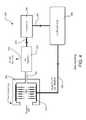
- FIG. 4is an illustration of a cold plasma jet hand sanitizer in accordance with another embodiment of the present disclosure
- FIGS. 5A-Bare illustrations of a cold plasma jet hand sanitizer in accordance with a further embodiment of the present disclosure.
- FIGS. 6A-Bare illustrations of a cold plasma jet hand sanitizer in accordance with yet another embodiment of the present disclosure.
- proximalwill refer to the end of the device, e.g., instrument, apparatus, applicator, handpiece, forceps, etc., which is closer to the user, while the term “distal” will refer to the end which is further from the user.
- distalwill refer to the end which is further from the user.
- the phrase “coupled”is defined to mean directly connected to or indirectly connected with through one or more intermediate components. Such intermediate components may include both hardware and software based components.
- non-thermal, cold plasma discharge jetsare formed by passing a stream of inert gas, typically either helium or argon, over a sharp conductive point that is held at high voltage and high frequency. A small fraction of the flowing gas is ionized, producing a luminous discharge jet at atmospheric pressure. Typically, between one gas molecule in 10 3 and one in 10 6 is ionized, and most of the energy is carried by the electrons in this plasma discharge. Consequently, the bulk of the gas flowing in the plasma jet is at or near ambient temperature, qualifying it for the terms non-thermal and cold plasma discharge.
- inert gastypically either helium or argon
- the system 10includes a gas manifold 12 including a plurality of output channels 14 formed on at least one surface of the gas manifold 12 .
- Each output channel 14includes an individual wire electrode 16 with a sharp conductive point 18 concentrically disposed therein.
- Arrays of plasma jets 20are formed at each output channel 14 when gas is supplied from a common gas supply via a gas manifold input 22 and common power supply of high voltage at high frequency is applied to the electrodes 16 with the sharp conductive points 18 .
- the common gas supplyfeeds gas from a single source to the plurality of output channels and the common power supply supplies voltage to each of the electrodes at the same potential and phase.
- a plasma beamcan be formed by passing the gas over the sharp conductive point, which is held at a relatively high voltage, generally greater than 1 KV, and at a relatively high frequency, generally in the range of approximately 10 KHz to approximately 10 GHz.
- the sharp conductive pointcreates a strong electric field gradient which helps pull electrons off the inert gas molecules and ionize the electrons.
- plasma jet dischargesexhibit a dynamic negative resistance.
- the voltage drop across itdecreases since more of the flowing gas becomes ionized, providing more conductive paths and reducing the equivalent plasma resistance.
- a ballast resistor R 1 , R 2 . . . Rnis placed in series with each conductive point 18 , balancing the voltage distribution among them, and ensuring that all points will fire and produce an array of plasma jets.
- the plasma jetswill “avoid” each other, as shown in FIG. 2A . Since the electrodes are connected to the same power supply, through ballast resistors, the plasma jets will be firing in-phase, e.g., in-phase voltage waveforms of FIG. 2A . In one half cycle of the high voltage high frequency power supply, both plasma jets will be positively charged, for example, and during the next half cycle, both will be negatively charged. Since like-charges repel, these in-phase plasma jets will avoid each other.
- phase shifted by 180 degreesrefers to the driving voltage waveforms at each electrode generating the respective plasma beams or jets, although the current waveforms are also 180 degrees out of phase relative to each other.
- the out-of-phase voltage waveformsare illustrated in FIG. 2B .
- ballast resistorsAs described above, arbitrarily large arrays of plasma jets can be formed using ballast resistors. They can be assembled into a linear line array, or a 2-dimensional planar array. A pair of planar arrays can be set in opposition and operated electrically out-of-phase so that a dense network of plasma jets firing into and interconnecting with opposing jets will be formed, as shown in FIG. 3 .
- Cold plasma jetshave two independently controllable variables, permitting a wide range of effects.
- Oneis the electrical power to create the plasma jet, and the other is the gas flow rate.
- the electrical poweris high and the gas flow rate is low, an intense burning beam results. This has been used in medical applications to ablate tumors, for example.
- the electrical poweris low, and the gas flow rate is high, a gentle sterilizing beam results which is effective on a wide range of microorganisms, including human pathogens.
- the sterilization effectis produced by a concert of plasma beam effects including ion bombardment, electron bombardment, free radicals, localized UV exposure, thermal effects, localized ozone production, electroporation and disruption of microorganism outer membranes by electrostatic fields.
- the sanitizer 100includes a pair of opposing two-dimensional arrays 102 , 104 of atmospheric pressure cold plasma jets to create a sterilizing volume 105 . Any object placed into that volume 105 will have its surface sterilized.
- the sanitizer 100includes a gas manifold 112 configured with a pair of opposing two-dimensional arrays 106 , 108 of output channels 114 . It is to be appreciated that the output channels 114 of each array 106 , 108 are aligned with each other to align the plasma jets when fired. It is further to be appreciated that although the gas manifold is shown as a single unit with a single gas input 122 , the arrays may be configured as two separate manifolds each with a gas input.
- the opposing arrays 106 , 108 of plasma jetsare operated electrically 180 degrees out of phase so that the opposing arrays essentially fire into each other in the absence of an intervening object, or directly impinge on the surface of an intervening object.
- a master oscillator 124is provided to provide high frequency, high voltage to each electrode 116 disposed in each output channel 114 .
- the output from the master oscillator 124is split into two paths 132 , 134 .
- the output of the first path 132is transmitted to a phase shifter 136 which shifts the phase of the voltage signal a predetermined amount, e.g., about 180 degrees.
- the shifted voltage signalis then provided to driver 138 which transmits the shifted voltage signal to the electrodes 116 of the first array 106 .
- the output of the second path 134is transmitted to driver 140 which transmits the non-shifted voltage signal to the electrodes 116 of the second array 108 .
- Other systems, circuits and methods for generating at least two voltage waveforms 180 degrees out of phase relative to each otherare contemplated by the present disclosure.
- the master oscillator 124 , phase shifter 136 and drivers 138 , 140may be configured as a power or electrosurgical generator, as shown and described in copending U.S. patent application Ser. No. 13/015,834, the contents of which are hereby incorporated by reference in its entirety.
- heliumis the preferred carrier gas
- inert gasessuch as argon, or air may be used individually, or in combination.
- the addition of a small amount of oxygen to an inert gassignificantly enhances its effectiveness.
- Gas consumptionis an important issue, particularly at a remote site. While argon may be scavenged from the atmosphere, where it contributes approximately 0.9% by volume, helium is much rarer, typically only about 5 ppm. Since the helium gas released into the sterilizing volume will be at a high concentration in that volume, a means may be provided to collect and re-concentrate it, and then store it for later use, e.g., a reclamation unit.
- the hand sanitizer 202includes substantially the same components as described above for hand sanitizer 100 shown in FIG. 3 .
- the hand sanitizer 202includes a housing 204 for containing gas discharged during the sanitizing process.
- the housing 204may be generally rectangular or cubical in shape including an opening or entrance 207 for allowing an object, e.g., a hand, to pass through. It is to be appreciated that other shapes for the housing are contemplated to be within the scope of the present disclosure.
- the housing 204further includes a channel or conduit 250 configured for withdrawing gas used during a sanitizing process from the volume 205 within the housing 204 .
- the channel 250is coupled to a gas separator 252 .
- Heliumdue to its small molecular diameter, is especially amenable to re-concentration through a diffusion membrane of the gas separator 252 which allows the helium to pass through, but rejects the diluent atmospheric gases, such as nitrogen and oxygen, via output port 254 .
- a compressor 256receives the reclaimed gas from the gas separator 252 via conduit 253 then stores this recycled inert gas in a gas reserve tank 258 , e.g., a small pressure cylinder, via conduit 257 for later use.
- the recycled inert gascan then be provided to the gas manifold 212 of the hand sanitizer via conduit 259 for subsequent sanitizing procedures.
- the reclamation unitmay be configured as a external unit including the gas separator 252 , compressor 256 , gas reserve tank 258 and various conduits.
- a sanitizing system 300is configured with a generally rectangular housing 304 with at least one opening 306 to allow an object, for example, a human hand, to be disposed between the two plasma jets arrays to be sanitized.
- a photosensor or proximity detector 308is disposed adjacent the opening 306 so that the system is activated only as needed. The detector 308 is configured to detect an object and initiate gas flow and power supplied to the electrodes.
- the detector 308may be hardwired to initiate the gas flow and supplying of power.
- the detector 308may generate a signal that is supplied to a controller 310 that initiates the gas flow via the gas reclamation unit 312 and supplying of power via the master oscillator 314 .
- a sanitizing system 400includes a small door or flap member 402 that automatically closes an entrance or opening 406 of the housing 404 after the hand or object is removed, isolating the volume 405 of concentrated helium while it is being recycled, and preventing further escape of helium through the entrance 406 .
- a switch 408may be coupled to the door or flap member 402 to determine use of the hand sanitizer creating an on-demand mode. For example, upon placing an object in the opening 406 , the door or flap member 402 will open causing the switch 408 to close.
- a controller 410Upon closure of the switch 408 , a controller 410 initiates the gas flow via the gas reclamation unit 412 and supplying of power via the master oscillator 414 causing the plasma jets to fire.
- the door or flap member 402Upon removal of the object, the door or flap member 402 will close and the switch 408 will open.
- the master oscillator 414Upon the switch 408 opening, the master oscillator 414 will be de-energized, via the controller 410 , and the compressor of the reclamation unit 412 will be energized for a predetermined period of time to recycle the gas in the volume 405 . After the predetermined period of time has expired, the compressor will be de-energized.
- cold plasma dischargeshave been used to decontaminate various toxic chemicals and agents, including chemical and biological warfare agents.
- Cold plasma dischargescan also be useful in assisting in the clean up of radiological agents such as a “dirty bomb” by helping to liberate radioactive particles from contaminated surfaces, which are subsequently collected and disposed of.
- such a systemcan be used to sterilize and decontaminate a variety of objects such as surgical instruments, tools, components, growth media, pharmaceuticals, and so on.
- processoror “controller” should not be construed to refer exclusively to hardware capable of executing software, and may implicitly include, without limitation, digital signal processor (“DSP”) hardware, read only memory (“ROM”) for storing software, random access memory (“RAM”), and nonvolatile storage.
- DSPdigital signal processor
- ROMread only memory
- RAMrandom access memory
- any switches shown in the figuresare conceptual only. Their function may be carried out through the operation of program logic, through dedicated logic, through the interaction of program control and dedicated logic, or even manually, the particular technique being selectable by the implementer as more specifically understood from the context.
Landscapes
- Physics & Mathematics (AREA)
- Engineering & Computer Science (AREA)
- Plasma & Fusion (AREA)
- Chemical & Material Sciences (AREA)
- Analytical Chemistry (AREA)
- Health & Medical Sciences (AREA)
- General Health & Medical Sciences (AREA)
- Life Sciences & Earth Sciences (AREA)
- Public Health (AREA)
- Animal Behavior & Ethology (AREA)
- Epidemiology (AREA)
- Veterinary Medicine (AREA)
- Spectroscopy & Molecular Physics (AREA)
- Electromagnetism (AREA)
- Organic Chemistry (AREA)
- Toxicology (AREA)
- Chemical Kinetics & Catalysis (AREA)
- Biomedical Technology (AREA)
- Medicinal Chemistry (AREA)
- Molecular Biology (AREA)
- Plasma Technology (AREA)
- Apparatus For Disinfection Or Sterilisation (AREA)
Abstract
Description
Claims (18)
Priority Applications (2)
| Application Number | Priority Date | Filing Date | Title |
|---|---|---|---|
| US13/802,063US9387269B2 (en) | 2011-01-28 | 2013-03-13 | Cold plasma jet hand sanitizer |
| US15/191,565US9601317B2 (en) | 2011-01-28 | 2016-06-24 | Cold plasma sanitizing device |
Applications Claiming Priority (3)
| Application Number | Priority Date | Filing Date | Title |
|---|---|---|---|
| US13/015,834US8795265B2 (en) | 2010-01-28 | 2011-01-28 | Electrosurgical apparatus to generate a dual plasma stream and method thereof |
| US201261645646P | 2012-05-11 | 2012-05-11 | |
| US13/802,063US9387269B2 (en) | 2011-01-28 | 2013-03-13 | Cold plasma jet hand sanitizer |
Related Parent Applications (1)
| Application Number | Title | Priority Date | Filing Date |
|---|---|---|---|
| US13/015,834Continuation-In-PartUS8795265B2 (en) | 2010-01-28 | 2011-01-28 | Electrosurgical apparatus to generate a dual plasma stream and method thereof |
Related Child Applications (1)
| Application Number | Title | Priority Date | Filing Date |
|---|---|---|---|
| US15/191,565ContinuationUS9601317B2 (en) | 2011-01-28 | 2016-06-24 | Cold plasma sanitizing device |
Publications (2)
| Publication Number | Publication Date |
|---|---|
| US20130202496A1 US20130202496A1 (en) | 2013-08-08 |
| US9387269B2true US9387269B2 (en) | 2016-07-12 |
Family
ID=48903057
Family Applications (2)
| Application Number | Title | Priority Date | Filing Date |
|---|---|---|---|
| US13/802,063Active2031-11-19US9387269B2 (en) | 2011-01-28 | 2013-03-13 | Cold plasma jet hand sanitizer |
| US15/191,565ActiveUS9601317B2 (en) | 2011-01-28 | 2016-06-24 | Cold plasma sanitizing device |
Family Applications After (1)
| Application Number | Title | Priority Date | Filing Date |
|---|---|---|---|
| US15/191,565ActiveUS9601317B2 (en) | 2011-01-28 | 2016-06-24 | Cold plasma sanitizing device |
Country Status (1)
| Country | Link |
|---|---|
| US (2) | US9387269B2 (en) |
Cited By (5)
| Publication number | Priority date | Publication date | Assignee | Title |
|---|---|---|---|---|
| US9681907B2 (en) | 2010-01-28 | 2017-06-20 | Bovie Medical Corporation | Electrosurgical apparatus to generate a dual plasma stream and method thereof |
| CN111629508A (en)* | 2020-05-26 | 2020-09-04 | 华中科技大学 | A plasma generator |
| CN111920973A (en)* | 2020-08-12 | 2020-11-13 | 北京航空航天大学 | An integrated method, process and device for extermination of planetary protection microorganisms |
| RU2737280C2 (en)* | 2016-09-30 | 2020-11-26 | Сайноджи Гмбх | Electrode structure for formation of dielectric barrier plasma discharge |
| RU2748931C1 (en)* | 2021-04-05 | 2021-06-01 | Общество С Ограниченной Отвественностью «Эдвансд Пропалшн Системс» | Device for disinfection of hands, surfaces of objects and air |
Families Citing this family (12)
| Publication number | Priority date | Publication date | Assignee | Title |
|---|---|---|---|---|
| US10716611B2 (en) | 2015-05-15 | 2020-07-21 | ClearIt, LLC | Systems and methods for tattoo removal using cold plasma |
| US11490947B2 (en) | 2015-05-15 | 2022-11-08 | Clear Intradermal Technologies, Inc. | Tattoo removal using a liquid-gas mixture with plasma gas bubbles |
| WO2017065235A1 (en)* | 2015-10-13 | 2017-04-20 | サントリーホールディングス株式会社 | Sterilization method |
| DE102015119446B3 (en)* | 2015-11-11 | 2017-03-02 | Hochschule Für Angewandte Wissenschaft Und Kunst Hildesheim/Holzminden/Göttingen | Method and device for drying and plasma-assisted disinfection of hands |
| WO2017197071A1 (en) | 2016-05-12 | 2017-11-16 | EP Technologies LLC | Methods and systems for trans-tissue substance delivery using plasmaporation |
| EP3490476A4 (en)* | 2016-08-01 | 2020-03-25 | Drexel University | DEVICES AND METHODS FOR TREATING SKIN DISEASES |
| US10692704B2 (en) | 2016-11-10 | 2020-06-23 | Gojo Industries Inc. | Methods and systems for generating plasma activated liquid |
| AU2018312113B2 (en)* | 2017-08-04 | 2023-09-14 | U.S. Patent Innovations Llc | Diffusive applicator for cold atmospheric plasma system |
| AU2019402973B2 (en) | 2018-12-19 | 2024-10-24 | Clear Intradermal Technologies, Inc. | Systems and methods for tattoo removal using an applied electric field |
| KR102481599B1 (en)* | 2020-01-17 | 2022-12-27 | (주)펨토사이언스 | Plasma device having exchangeable handpiece |
| IT202100005849A1 (en) | 2021-03-12 | 2022-09-12 | Ht Plasma S R L | PLASMA SANITATION DEVICE |
| CN113490322B (en)* | 2021-06-23 | 2022-08-02 | 武汉海思普莱生命科技有限公司 | Portable large-area plasma jet device and system |
Citations (81)
| Publication number | Priority date | Publication date | Assignee | Title |
|---|---|---|---|---|
| US1889609A (en) | 1928-07-21 | 1932-11-29 | Wappler Electric Company Inc | Electric system for energizing cutting electrodes |
| US2835254A (en) | 1953-12-17 | 1958-05-20 | William A Coles | Device for performing surgical incisions by electronic energy |
| US3299384A (en) | 1964-07-01 | 1967-01-17 | Ibm | Wide-band transformer having neutralizing winding |
| US3577030A (en) | 1967-10-30 | 1971-05-04 | Us Navy | Inductive energizing circuit for arc plasma generator |
| US3601126A (en) | 1969-01-08 | 1971-08-24 | Electro Medical Systems Inc | High frequency electrosurgical apparatus |
| US3949266A (en) | 1972-06-05 | 1976-04-06 | Metco, Inc. | Circuit means for automatically establishing an arc in a plasma flame spraying gun |
| US3970088A (en) | 1974-08-28 | 1976-07-20 | Valleylab, Inc. | Electrosurgical devices having sesquipolar electrode structures incorporated therein |
| US4040426A (en) | 1976-01-16 | 1977-08-09 | Valleylab, Inc. | Electrosurgical method and apparatus for initiating an electrical discharge in an inert gas flow |
| US4041952A (en) | 1976-03-04 | 1977-08-16 | Valleylab, Inc. | Electrosurgical forceps |
| US4043342A (en) | 1974-08-28 | 1977-08-23 | Valleylab, Inc. | Electrosurgical devices having sesquipolar electrode structures incorporated therein |
| US4060088A (en) | 1976-01-16 | 1977-11-29 | Valleylab, Inc. | Electrosurgical method and apparatus for establishing an electrical discharge in an inert gas flow |
| US4255735A (en) | 1977-12-15 | 1981-03-10 | Liautaud James P | Precision injection-molded coil form |
| US4429694A (en) | 1981-07-06 | 1984-02-07 | C. R. Bard, Inc. | Electrosurgical generator |
| US4492231A (en) | 1982-09-17 | 1985-01-08 | Auth David C | Non-sticking electrocautery system and forceps |
| US4547721A (en) | 1980-12-01 | 1985-10-15 | Drapp Joseph W | Transformer structure |
| US4559943A (en) | 1981-09-03 | 1985-12-24 | C. R. Bard, Inc. | Electrosurgical generator |
| US4781175A (en) | 1986-04-08 | 1988-11-01 | C. R. Bard, Inc. | Electrosurgical conductive gas stream technique of achieving improved eschar for coagulation |
| US4818916A (en) | 1987-03-06 | 1989-04-04 | The Perkin-Elmer Corporation | Power system for inductively coupled plasma torch |
| US4887005A (en) | 1987-09-15 | 1989-12-12 | Rough J Kirkwood H | Multiple electrode plasma reactor power distribution system |
| US4890610A (en) | 1988-05-15 | 1990-01-02 | Kirwan Sr Lawrence T | Bipolar forceps |
| US4897285A (en) | 1988-06-14 | 1990-01-30 | Max-Planck-Gesellschaft Zur Foerderung Der Wissenschaften E.V. | Method and apparatus for PCVD internal coating a metallic pipe by means of a microwave plasma |
| US4901719A (en) | 1986-04-08 | 1990-02-20 | C. R. Bard, Inc. | Electrosurgical conductive gas stream equipment |
| US4901720A (en) | 1986-04-08 | 1990-02-20 | C. R. Bard, Inc. | Power control for beam-type electrosurgical unit |
| US4999597A (en) | 1990-02-16 | 1991-03-12 | Motorola, Inc. | Bifilar planar inductor |
| US5088997A (en) | 1990-03-15 | 1992-02-18 | Valleylab, Inc. | Gas coagulation device |
| US5302881A (en) | 1992-06-08 | 1994-04-12 | The United States Of America As Represented By The Secretary Of The Air Force | High energy cathode device with elongated operating cycle time |
| US5325019A (en) | 1992-08-21 | 1994-06-28 | Sematech, Inc. | Control of plasma process by use of harmonic frequency components of voltage and current |
| US5669904A (en) | 1995-03-07 | 1997-09-23 | Valleylab Inc. | Surgical gas plasma ignition apparatus and method |
| US5710486A (en) | 1995-05-08 | 1998-01-20 | Applied Materials, Inc. | Inductively and multi-capacitively coupled plasma reactor |
| US5717293A (en) | 1995-10-20 | 1998-02-10 | Eni Technologies, Inc. | Strike enhancement circuit for a plasma generator |
| US5720745A (en) | 1992-11-24 | 1998-02-24 | Erbe Electromedizin Gmbh | Electrosurgical unit and method for achieving coagulation of biological tissue |
| US5776092A (en) | 1994-03-23 | 1998-07-07 | Erbe Elektromedizin Gmbh | Multifunctional surgical instrument |
| US5801489A (en) | 1996-02-07 | 1998-09-01 | Paul E. Chism, Jr. | Three-phase alternating current plasma generator |
| US5815047A (en) | 1993-10-29 | 1998-09-29 | Applied Materials, Inc. | Fast transition RF impedance matching network for plasma reactor ignition |
| US5909086A (en) | 1996-09-24 | 1999-06-01 | Jump Technologies Limited | Plasma generator for generating unipolar plasma |
| US5917286A (en) | 1996-05-08 | 1999-06-29 | Advanced Energy Industries, Inc. | Pulsed direct current power supply configurations for generating plasmas |
| US6046546A (en) | 1992-04-16 | 2000-04-04 | Advanced Energy Industries, Inc. | Stabilizer for switch-mode powered RF plasma |
| US6099523A (en) | 1995-06-27 | 2000-08-08 | Jump Technologies Limited | Cold plasma coagulator |
| US6135998A (en) | 1999-03-16 | 2000-10-24 | Board Of Trustees Of The Leland Stanford Junior University | Method and apparatus for pulsed plasma-mediated electrosurgery in liquid media |
| US6154376A (en) | 1997-01-16 | 2000-11-28 | Dan-Harry; Dawari D. | High frequency, high density power conversion system |
| US6161227A (en)* | 1999-08-17 | 2000-12-19 | Bargenquast; Scott | Portable hand cleaning device |
| US6170668B1 (en) | 1998-05-01 | 2001-01-09 | Mse Technology Applications, Inc. | Apparatus for extraction of contaminants from a gas |
| US6181068B1 (en) | 1998-05-15 | 2001-01-30 | Dae Won Paptin Form Co., Ltd. | Plasma generating apparatus |
| US6213999B1 (en) | 1995-03-07 | 2001-04-10 | Sherwood Services Ag | Surgical gas plasma ignition apparatus and method |
| US6262538B1 (en) | 1999-08-26 | 2001-07-17 | International Business Machines Corporation | High density plasma tool with adjustable uniformity and stochastic electron heating for reduced gas cracking |
| US20010034519A1 (en) | 2000-02-22 | 2001-10-25 | Goble Colin C. O. | Tissue resurfacing |
| US6328760B1 (en) | 1999-12-20 | 2001-12-11 | Robert G. James | Pulsed plasma radiation device for emitting light in biologically significant spectral bands |
| US6387088B1 (en) | 1999-06-30 | 2002-05-14 | John H. Shattuck | Photoionization enabled electrochemical material removal techniques for use in biomedical fields |
| US20020161362A1 (en) | 2000-02-22 | 2002-10-31 | Gyrus Medical Limited | Tissue treatment method |
| US6492951B1 (en) | 1998-10-06 | 2002-12-10 | The Australian National University | Plasma antenna |
| US20020187066A1 (en) | 2001-06-07 | 2002-12-12 | Skion Corporation | Apparatus and method using capillary discharge plasma shower for sterilizing and disinfecting articles |
| US6529389B2 (en) | 2000-04-06 | 2003-03-04 | Aria Corporation | Universal input miniature power supply with a single split transformer primary winding |
| US20030155332A1 (en)* | 2001-12-21 | 2003-08-21 | Saswati Datta | Portable apparatus and method for treating a workpiece |
| US6627163B1 (en) | 1998-02-17 | 2003-09-30 | Ruediger Haaga Gmbh | Process for sterilizing containers |
| US6632323B2 (en) | 2001-01-31 | 2003-10-14 | Plasmion Corporation | Method and apparatus having pin electrode for surface treatment using capillary discharge plasma |
| US6764658B2 (en) | 2002-01-08 | 2004-07-20 | Wisconsin Alumni Research Foundation | Plasma generator |
| US6807069B2 (en) | 1999-05-18 | 2004-10-19 | Nokia Corporation | Direct current converter with integrated transformer windings and output voltage filtering coils on the same magnetic core |
| US6852112B2 (en) | 1999-10-05 | 2005-02-08 | Sherwood Services Ag | Multi-port side-fire coagulator |
| US6890332B2 (en) | 1999-05-24 | 2005-05-10 | Csaba Truckai | Electrical discharge devices and techniques for medical procedures |
| US20050118350A1 (en) | 2002-03-28 | 2005-06-02 | Pavel Koulik | Atmospheric plasma surface treatment method and device for same |
| US20050234442A1 (en) | 1999-09-01 | 2005-10-20 | Michael Spears | Electrosurgical cutting and cauterizing device |
| US20050241768A1 (en)* | 2002-10-01 | 2005-11-03 | Mitsubishi Heavy Industries, Ltd | High frequency plasma generator and high frequency plasma generating method |
| US20060005545A1 (en) | 2003-09-02 | 2006-01-12 | Mohammad Samimy | Localized arc filament plasma actuators for noise mitigation and mixing enhancement |
| US7070144B1 (en) | 2003-01-03 | 2006-07-04 | Orbital Research Inc. | Aircraft and missile afterbody flow control device and method of controlling flow |
| WO2006100030A1 (en) | 2005-03-21 | 2006-09-28 | Universiteit Gent | Method and system for plasma treatment under high pressure |
| US20070089795A1 (en) | 2005-10-17 | 2007-04-26 | Jacob Jamey D | Plasma actuator |
| US7275013B1 (en) | 2004-09-20 | 2007-09-25 | University Of Notre Dame Duloc | Plasma anemometer and method for using same |
| US20080000497A1 (en)* | 2006-06-30 | 2008-01-03 | Applied Materials, Inc. | Removal of organic-containing layers from large surface areas |
| US7316682B2 (en) | 2002-12-17 | 2008-01-08 | Aaron Medical Industries, Inc. | Electrosurgical device to generate a plasma stream |
| US20090119942A1 (en) | 2007-11-14 | 2009-05-14 | Invent Resources, Inc. | Hand dryer |
| US20090188626A1 (en)* | 2008-01-25 | 2009-07-30 | Xinpei Lu | Plasma jet device |
| US7615933B2 (en) | 2005-05-02 | 2009-11-10 | International Technology Center | Pulsed dielectric barrier discharge |
| US20090304553A1 (en) | 2006-06-06 | 2009-12-10 | Germgard Lighting, Llc | Tool and tray sanitation |
| US20100296977A1 (en) | 2007-11-06 | 2010-11-25 | Microoncology Limited | Microwave plasma sterilisation system and applicators therefor |
| US20110171188A1 (en) | 2008-08-27 | 2011-07-14 | Max-Planck-Gesellschaft Zur Foerderung Der Wissenschaften E.V | Non-thermal plasma for wound treatment and associated apparatus and method |
| US20110184408A1 (en) | 2010-01-28 | 2011-07-28 | Bovie Medical Corporation | Electrosurgical apparatus to generate a dual plasma stream and method thereof |
| US20110277342A1 (en) | 2009-02-06 | 2011-11-17 | Hikoya Ishii | Hand dryer |
| US20120039747A1 (en) | 2009-02-17 | 2012-02-16 | Max-Planck-Gesellschaft Zur Forderung Der Wissenschaften E.V. | Treating device for treating a body part of a patient with a non-thermal plasma |
| US20120046602A1 (en) | 2008-09-25 | 2012-02-23 | Gregor Morfill | Plasma Applicator and Corresponding Method |
| US8377388B2 (en) | 2008-02-02 | 2013-02-19 | Bovie Medical Corporation | Cold plasma decontamination device |
| US8388615B2 (en) | 2008-10-28 | 2013-03-05 | Smith & Nephew, Inc. | Electrosurgical device with controllable electric field profile |
Family Cites Families (4)
| Publication number | Priority date | Publication date | Assignee | Title |
|---|---|---|---|---|
| FR2611132B1 (en) | 1987-02-19 | 1994-06-17 | Descartes Universite Rene | BISTOURI A PLASMA |
| US5669907A (en) | 1995-02-10 | 1997-09-23 | Valleylab Inc. | Plasma enhanced bipolar electrosurgical system |
| US8267884B1 (en) | 2005-10-07 | 2012-09-18 | Surfx Technologies Llc | Wound treatment apparatus and method |
| US9283029B2 (en) | 2007-01-31 | 2016-03-15 | Alma Lasers Ltd. | Skin treatment using a multi-discharge applicator |
- 2013
- 2013-03-13USUS13/802,063patent/US9387269B2/enactiveActive
- 2016
- 2016-06-24USUS15/191,565patent/US9601317B2/enactiveActive
Patent Citations (85)
| Publication number | Priority date | Publication date | Assignee | Title |
|---|---|---|---|---|
| US1889609A (en) | 1928-07-21 | 1932-11-29 | Wappler Electric Company Inc | Electric system for energizing cutting electrodes |
| US2835254A (en) | 1953-12-17 | 1958-05-20 | William A Coles | Device for performing surgical incisions by electronic energy |
| US3299384A (en) | 1964-07-01 | 1967-01-17 | Ibm | Wide-band transformer having neutralizing winding |
| US3577030A (en) | 1967-10-30 | 1971-05-04 | Us Navy | Inductive energizing circuit for arc plasma generator |
| US3601126A (en) | 1969-01-08 | 1971-08-24 | Electro Medical Systems Inc | High frequency electrosurgical apparatus |
| US3949266A (en) | 1972-06-05 | 1976-04-06 | Metco, Inc. | Circuit means for automatically establishing an arc in a plasma flame spraying gun |
| US4043342A (en) | 1974-08-28 | 1977-08-23 | Valleylab, Inc. | Electrosurgical devices having sesquipolar electrode structures incorporated therein |
| US3970088A (en) | 1974-08-28 | 1976-07-20 | Valleylab, Inc. | Electrosurgical devices having sesquipolar electrode structures incorporated therein |
| US3987795A (en) | 1974-08-28 | 1976-10-26 | Valleylab, Inc. | Electrosurgical devices having sesquipolar electrode structures incorporated therein |
| US4040426A (en) | 1976-01-16 | 1977-08-09 | Valleylab, Inc. | Electrosurgical method and apparatus for initiating an electrical discharge in an inert gas flow |
| US4060088A (en) | 1976-01-16 | 1977-11-29 | Valleylab, Inc. | Electrosurgical method and apparatus for establishing an electrical discharge in an inert gas flow |
| US4041952A (en) | 1976-03-04 | 1977-08-16 | Valleylab, Inc. | Electrosurgical forceps |
| US4255735A (en) | 1977-12-15 | 1981-03-10 | Liautaud James P | Precision injection-molded coil form |
| US4547721A (en) | 1980-12-01 | 1985-10-15 | Drapp Joseph W | Transformer structure |
| US4429694A (en) | 1981-07-06 | 1984-02-07 | C. R. Bard, Inc. | Electrosurgical generator |
| US4559943A (en) | 1981-09-03 | 1985-12-24 | C. R. Bard, Inc. | Electrosurgical generator |
| US4492231A (en) | 1982-09-17 | 1985-01-08 | Auth David C | Non-sticking electrocautery system and forceps |
| US4901719A (en) | 1986-04-08 | 1990-02-20 | C. R. Bard, Inc. | Electrosurgical conductive gas stream equipment |
| US4781175A (en) | 1986-04-08 | 1988-11-01 | C. R. Bard, Inc. | Electrosurgical conductive gas stream technique of achieving improved eschar for coagulation |
| US4901720A (en) | 1986-04-08 | 1990-02-20 | C. R. Bard, Inc. | Power control for beam-type electrosurgical unit |
| US4818916A (en) | 1987-03-06 | 1989-04-04 | The Perkin-Elmer Corporation | Power system for inductively coupled plasma torch |
| US4887005A (en) | 1987-09-15 | 1989-12-12 | Rough J Kirkwood H | Multiple electrode plasma reactor power distribution system |
| US4890610A (en) | 1988-05-15 | 1990-01-02 | Kirwan Sr Lawrence T | Bipolar forceps |
| US4897285A (en) | 1988-06-14 | 1990-01-30 | Max-Planck-Gesellschaft Zur Foerderung Der Wissenschaften E.V. | Method and apparatus for PCVD internal coating a metallic pipe by means of a microwave plasma |
| US4999597A (en) | 1990-02-16 | 1991-03-12 | Motorola, Inc. | Bifilar planar inductor |
| US5088997A (en) | 1990-03-15 | 1992-02-18 | Valleylab, Inc. | Gas coagulation device |
| US6046546A (en) | 1992-04-16 | 2000-04-04 | Advanced Energy Industries, Inc. | Stabilizer for switch-mode powered RF plasma |
| US5302881A (en) | 1992-06-08 | 1994-04-12 | The United States Of America As Represented By The Secretary Of The Air Force | High energy cathode device with elongated operating cycle time |
| US5325019A (en) | 1992-08-21 | 1994-06-28 | Sematech, Inc. | Control of plasma process by use of harmonic frequency components of voltage and current |
| US5720745A (en) | 1992-11-24 | 1998-02-24 | Erbe Electromedizin Gmbh | Electrosurgical unit and method for achieving coagulation of biological tissue |
| US5815047A (en) | 1993-10-29 | 1998-09-29 | Applied Materials, Inc. | Fast transition RF impedance matching network for plasma reactor ignition |
| US5776092A (en) | 1994-03-23 | 1998-07-07 | Erbe Elektromedizin Gmbh | Multifunctional surgical instrument |
| US5669904A (en) | 1995-03-07 | 1997-09-23 | Valleylab Inc. | Surgical gas plasma ignition apparatus and method |
| US6213999B1 (en) | 1995-03-07 | 2001-04-10 | Sherwood Services Ag | Surgical gas plasma ignition apparatus and method |
| US5710486A (en) | 1995-05-08 | 1998-01-20 | Applied Materials, Inc. | Inductively and multi-capacitively coupled plasma reactor |
| US6099523A (en) | 1995-06-27 | 2000-08-08 | Jump Technologies Limited | Cold plasma coagulator |
| US5717293A (en) | 1995-10-20 | 1998-02-10 | Eni Technologies, Inc. | Strike enhancement circuit for a plasma generator |
| US5801489A (en) | 1996-02-07 | 1998-09-01 | Paul E. Chism, Jr. | Three-phase alternating current plasma generator |
| US5917286A (en) | 1996-05-08 | 1999-06-29 | Advanced Energy Industries, Inc. | Pulsed direct current power supply configurations for generating plasmas |
| US6222321B1 (en) | 1996-05-08 | 2001-04-24 | Advanced Energy Industries, Inc. | Plasma generator pulsed direct current supply in a bridge configuration |
| US5909086A (en) | 1996-09-24 | 1999-06-01 | Jump Technologies Limited | Plasma generator for generating unipolar plasma |
| US6154376A (en) | 1997-01-16 | 2000-11-28 | Dan-Harry; Dawari D. | High frequency, high density power conversion system |
| US6627163B1 (en) | 1998-02-17 | 2003-09-30 | Ruediger Haaga Gmbh | Process for sterilizing containers |
| US6170668B1 (en) | 1998-05-01 | 2001-01-09 | Mse Technology Applications, Inc. | Apparatus for extraction of contaminants from a gas |
| US6181068B1 (en) | 1998-05-15 | 2001-01-30 | Dae Won Paptin Form Co., Ltd. | Plasma generating apparatus |
| US6492951B1 (en) | 1998-10-06 | 2002-12-10 | The Australian National University | Plasma antenna |
| US6135998A (en) | 1999-03-16 | 2000-10-24 | Board Of Trustees Of The Leland Stanford Junior University | Method and apparatus for pulsed plasma-mediated electrosurgery in liquid media |
| US6807069B2 (en) | 1999-05-18 | 2004-10-19 | Nokia Corporation | Direct current converter with integrated transformer windings and output voltage filtering coils on the same magnetic core |
| US6890332B2 (en) | 1999-05-24 | 2005-05-10 | Csaba Truckai | Electrical discharge devices and techniques for medical procedures |
| US6387088B1 (en) | 1999-06-30 | 2002-05-14 | John H. Shattuck | Photoionization enabled electrochemical material removal techniques for use in biomedical fields |
| US6161227A (en)* | 1999-08-17 | 2000-12-19 | Bargenquast; Scott | Portable hand cleaning device |
| US6262538B1 (en) | 1999-08-26 | 2001-07-17 | International Business Machines Corporation | High density plasma tool with adjustable uniformity and stochastic electron heating for reduced gas cracking |
| US20050234442A1 (en) | 1999-09-01 | 2005-10-20 | Michael Spears | Electrosurgical cutting and cauterizing device |
| US6852112B2 (en) | 1999-10-05 | 2005-02-08 | Sherwood Services Ag | Multi-port side-fire coagulator |
| US6328760B1 (en) | 1999-12-20 | 2001-12-11 | Robert G. James | Pulsed plasma radiation device for emitting light in biologically significant spectral bands |
| US20020161362A1 (en) | 2000-02-22 | 2002-10-31 | Gyrus Medical Limited | Tissue treatment method |
| US6629974B2 (en) | 2000-02-22 | 2003-10-07 | Gyrus Medical Limited | Tissue treatment method |
| US20010034519A1 (en) | 2000-02-22 | 2001-10-25 | Goble Colin C. O. | Tissue resurfacing |
| US6529389B2 (en) | 2000-04-06 | 2003-03-04 | Aria Corporation | Universal input miniature power supply with a single split transformer primary winding |
| US6632323B2 (en) | 2001-01-31 | 2003-10-14 | Plasmion Corporation | Method and apparatus having pin electrode for surface treatment using capillary discharge plasma |
| US20020187066A1 (en) | 2001-06-07 | 2002-12-12 | Skion Corporation | Apparatus and method using capillary discharge plasma shower for sterilizing and disinfecting articles |
| US20030155332A1 (en)* | 2001-12-21 | 2003-08-21 | Saswati Datta | Portable apparatus and method for treating a workpiece |
| US6764658B2 (en) | 2002-01-08 | 2004-07-20 | Wisconsin Alumni Research Foundation | Plasma generator |
| US20050118350A1 (en) | 2002-03-28 | 2005-06-02 | Pavel Koulik | Atmospheric plasma surface treatment method and device for same |
| US20050241768A1 (en)* | 2002-10-01 | 2005-11-03 | Mitsubishi Heavy Industries, Ltd | High frequency plasma generator and high frequency plasma generating method |
| US7316682B2 (en) | 2002-12-17 | 2008-01-08 | Aaron Medical Industries, Inc. | Electrosurgical device to generate a plasma stream |
| US7070144B1 (en) | 2003-01-03 | 2006-07-04 | Orbital Research Inc. | Aircraft and missile afterbody flow control device and method of controlling flow |
| US20060005545A1 (en) | 2003-09-02 | 2006-01-12 | Mohammad Samimy | Localized arc filament plasma actuators for noise mitigation and mixing enhancement |
| US7275013B1 (en) | 2004-09-20 | 2007-09-25 | University Of Notre Dame Duloc | Plasma anemometer and method for using same |
| WO2006100030A1 (en) | 2005-03-21 | 2006-09-28 | Universiteit Gent | Method and system for plasma treatment under high pressure |
| US7615933B2 (en) | 2005-05-02 | 2009-11-10 | International Technology Center | Pulsed dielectric barrier discharge |
| US20070089795A1 (en) | 2005-10-17 | 2007-04-26 | Jacob Jamey D | Plasma actuator |
| US20090304553A1 (en) | 2006-06-06 | 2009-12-10 | Germgard Lighting, Llc | Tool and tray sanitation |
| US20080000497A1 (en)* | 2006-06-30 | 2008-01-03 | Applied Materials, Inc. | Removal of organic-containing layers from large surface areas |
| US20100296977A1 (en) | 2007-11-06 | 2010-11-25 | Microoncology Limited | Microwave plasma sterilisation system and applicators therefor |
| US20090119942A1 (en) | 2007-11-14 | 2009-05-14 | Invent Resources, Inc. | Hand dryer |
| US20090188626A1 (en)* | 2008-01-25 | 2009-07-30 | Xinpei Lu | Plasma jet device |
| US8377388B2 (en) | 2008-02-02 | 2013-02-19 | Bovie Medical Corporation | Cold plasma decontamination device |
| US20110171188A1 (en) | 2008-08-27 | 2011-07-14 | Max-Planck-Gesellschaft Zur Foerderung Der Wissenschaften E.V | Non-thermal plasma for wound treatment and associated apparatus and method |
| US20120046602A1 (en) | 2008-09-25 | 2012-02-23 | Gregor Morfill | Plasma Applicator and Corresponding Method |
| US8388615B2 (en) | 2008-10-28 | 2013-03-05 | Smith & Nephew, Inc. | Electrosurgical device with controllable electric field profile |
| US20110277342A1 (en) | 2009-02-06 | 2011-11-17 | Hikoya Ishii | Hand dryer |
| US20120039747A1 (en) | 2009-02-17 | 2012-02-16 | Max-Planck-Gesellschaft Zur Forderung Der Wissenschaften E.V. | Treating device for treating a body part of a patient with a non-thermal plasma |
| US20120046597A1 (en) | 2009-02-17 | 2012-02-23 | Max-Planck-Gesellschaft Zur Forderung Der Wissenschaften E.V | Electrode arrangement for generating a non-thermal plasma |
| US20110184408A1 (en) | 2010-01-28 | 2011-07-28 | Bovie Medical Corporation | Electrosurgical apparatus to generate a dual plasma stream and method thereof |
Cited By (6)
| Publication number | Priority date | Publication date | Assignee | Title |
|---|---|---|---|---|
| US9681907B2 (en) | 2010-01-28 | 2017-06-20 | Bovie Medical Corporation | Electrosurgical apparatus to generate a dual plasma stream and method thereof |
| RU2737280C2 (en)* | 2016-09-30 | 2020-11-26 | Сайноджи Гмбх | Electrode structure for formation of dielectric barrier plasma discharge |
| CN111629508A (en)* | 2020-05-26 | 2020-09-04 | 华中科技大学 | A plasma generator |
| CN111920973A (en)* | 2020-08-12 | 2020-11-13 | 北京航空航天大学 | An integrated method, process and device for extermination of planetary protection microorganisms |
| CN111920973B (en)* | 2020-08-12 | 2021-12-17 | 北京航空航天大学 | An integrated method, process and device for extermination of planetary protection microorganisms |
| RU2748931C1 (en)* | 2021-04-05 | 2021-06-01 | Общество С Ограниченной Отвественностью «Эдвансд Пропалшн Системс» | Device for disinfection of hands, surfaces of objects and air |
Also Published As
| Publication number | Publication date |
|---|---|
| US9601317B2 (en) | 2017-03-21 |
| US20130202496A1 (en) | 2013-08-08 |
| US20160307735A1 (en) | 2016-10-20 |
Similar Documents
| Publication | Publication Date | Title |
|---|---|---|
| US9601317B2 (en) | Cold plasma sanitizing device | |
| Shintani et al. | Gas plasma sterilization of microorganisms and mechanisms of action | |
| Weltmann et al. | Antimicrobial treatment of heat sensitive products by miniaturized atmospheric pressure plasma jets (APPJs) | |
| Moreau et al. | Non-thermal plasma technologies: new tools for bio-decontamination | |
| Montie et al. | An overview of research using the one atmosphere uniform glow discharge plasma (OAUGDP) for sterilization of surfaces and materials | |
| De Geyter et al. | Nonthermal plasma sterilization of living and nonliving surfaces | |
| Laroussi | Sterilization of contaminated matter with an atmospheric pressure plasma | |
| Morent et al. | Inactivation of bacteria by non-thermal plasmas | |
| Moisan et al. | Low-temperature sterilization using gas plasmas: a review of the experiments and an analysis of the inactivation mechanisms | |
| US6113851A (en) | Apparatus and process for dry sterilization of medical and dental devices and materials | |
| JP2003501147A (en) | Atmospheric pressure plasma purification / disinfection chamber | |
| JP5403753B2 (en) | Plasma sterilization method | |
| Adesina et al. | A review of dielectric barrier discharge cold atmospheric plasma for surface sterilization and decontamination | |
| Shintani | Inactivation of bacterial spore, endotoxin, lipid A, normal prion and abnormal prion by exposures to several sorts of gases plasma | |
| KR101409390B1 (en) | Apoptosis method of abnormal cell useing atmospheric pressure plasma for bio-medical applications | |
| Ekem et al. | Sterilization of Staphylococcus aureus by atmospheric pressure pulsed plasma | |
| Pervez et al. | Plasma based sterilization: Overview and the stepwise inactivation process of microbial by non-thermal atmospheric pressure plasma jet | |
| US20040161361A1 (en) | Apparatus and method for sterilization of medical equipments, pharmaceutical products and biologically contaminated articles | |
| JP4386650B2 (en) | Sterilizer | |
| Rossi et al. | Sterilization and decontamination of surfaces by plasma discharges | |
| Akishev et al. | Inactivation of microorganisms in model biofilms by an atmospheric pressure pulsed non-thermal plasma | |
| Benterrouche et al. | Inactivation of E. coli bacteria by atmospheric dielectric barrier discharge | |
| Abbas | Influence of Distance and Argon Flow rate on Pseudomonas aeruginosa Bacteria Exposed to Non thermal Plasma at Atmospheric Pressure | |
| Konesky | Dwell time considerations for large area Cold Plasma decontamination | |
| Spirov et al. | Effect of plasma and UV radiation of multigap sliding discharge in air on bacteria |
Legal Events
| Date | Code | Title | Description |
|---|---|---|---|
| AS | Assignment | Owner name:BOVIE MEDICAL CORPORATION, FLORIDA Free format text:ASSIGNMENT OF ASSIGNORS INTEREST;ASSIGNOR:KONESKY, GREGORY A.;REEL/FRAME:029990/0381 Effective date:20130313 | |
| STCF | Information on status: patent grant | Free format text:PATENTED CASE | |
| AS | Assignment | Owner name:APYX MEDICAL CORPORATION, FLORIDA Free format text:CHANGE OF NAME;ASSIGNOR:BOVIE MEDICAL CORPORATION;REEL/FRAME:049165/0557 Effective date:20190109 | |
| MAFP | Maintenance fee payment | Free format text:PAYMENT OF MAINTENANCE FEE, 4TH YR, SMALL ENTITY (ORIGINAL EVENT CODE: M2551); ENTITY STATUS OF PATENT OWNER: SMALL ENTITY Year of fee payment:4 | |
| AS | Assignment | Owner name:MIDCAP FUNDING IV TRUST, MARYLAND Free format text:SECURITY INTEREST;ASSIGNOR:APYX MEDICAL CORPORATION;REEL/FRAME:062913/0001 Effective date:20230217 | |
| AS | Assignment | Owner name:PERCEPTIVE CREDIT HOLDINGS IV, LP, AS ADMINISTRATIVE AGENT, NEW YORK Free format text:SECURITY INTEREST;ASSIGNOR:APYX MEDICAL CORPORATION;REEL/FRAME:065523/0013 Effective date:20231108 | |
| AS | Assignment | Owner name:APYX MEDICAL CORPORATION, FLORIDA Free format text:RELEASE BY SECURED PARTY;ASSIGNOR:MIDCAP FUNDING IV TRUST;REEL/FRAME:065612/0105 Effective date:20231108 | |
| FEPP | Fee payment procedure | Free format text:MAINTENANCE FEE REMINDER MAILED (ORIGINAL EVENT CODE: REM.); ENTITY STATUS OF PATENT OWNER: SMALL ENTITY | |
| FEPP | Fee payment procedure | Free format text:7.5 YR SURCHARGE - LATE PMT W/IN 6 MO, SMALL ENTITY (ORIGINAL EVENT CODE: M2555); ENTITY STATUS OF PATENT OWNER: SMALL ENTITY | |
| MAFP | Maintenance fee payment | Free format text:PAYMENT OF MAINTENANCE FEE, 8TH YR, SMALL ENTITY (ORIGINAL EVENT CODE: M2552); ENTITY STATUS OF PATENT OWNER: SMALL ENTITY Year of fee payment:8 |