US9387148B2 - Dosage form package and a frangible electrical circuit sheet therefor - Google Patents
Dosage form package and a frangible electrical circuit sheet thereforDownload PDFInfo
- Publication number
- US9387148B2 US9387148B2US12/578,214US57821409AUS9387148B2US 9387148 B2US9387148 B2US 9387148B2US 57821409 AUS57821409 AUS 57821409AUS 9387148 B2US9387148 B2US 9387148B2
- Authority
- US
- United States
- Prior art keywords
- package
- cavities
- electrical
- circuit
- cavity
- Prior art date
- Legal status (The legal status is an assumption and is not a legal conclusion. Google has not performed a legal analysis and makes no representation as to the accuracy of the status listed.)
- Active
Links
- 239000002552dosage formSubstances0.000titleabstractdescription69
- 239000003814drugSubstances0.000claimsdescription12
- 239000000463materialSubstances0.000claimsdescription11
- 238000001514detection methodMethods0.000claimsdescription7
- 239000007787solidSubstances0.000claims3
- 230000001419dependent effectEffects0.000claims1
- 239000000825pharmaceutical preparationSubstances0.000claims1
- 229940127557pharmaceutical productDrugs0.000claims1
- 229940079593drugDrugs0.000description11
- 238000000034methodMethods0.000description11
- 238000012544monitoring processMethods0.000description11
- 235000005911dietNutrition0.000description10
- 230000000378dietary effectEffects0.000description10
- 238000012545processingMethods0.000description10
- 238000003860storageMethods0.000description10
- 230000008859changeEffects0.000description7
- 238000004891communicationMethods0.000description6
- 238000005259measurementMethods0.000description6
- 238000002483medicationMethods0.000description6
- 230000008569processEffects0.000description5
- 239000000126substanceSubstances0.000description5
- 239000002184metalSubstances0.000description3
- 239000003990capacitorSubstances0.000description2
- 235000015872dietary supplementNutrition0.000description2
- 238000009826distributionMethods0.000description2
- 238000005516engineering processMethods0.000description2
- 239000011888foilSubstances0.000description2
- 230000006870functionEffects0.000description2
- 239000011810insulating materialSubstances0.000description2
- 239000000758substrateSubstances0.000description2
- 239000000853adhesiveSubstances0.000description1
- 230000001070adhesive effectEffects0.000description1
- QVGXLLKOCUKJST-UHFFFAOYSA-Natomic oxygenChemical compound[O]QVGXLLKOCUKJST-UHFFFAOYSA-N0.000description1
- 230000004888barrier functionEffects0.000description1
- 239000007894capletSubstances0.000description1
- 239000002775capsuleSubstances0.000description1
- 230000001413cellular effectEffects0.000description1
- 238000012512characterization methodMethods0.000description1
- 239000004020conductorSubstances0.000description1
- 238000010586diagramMethods0.000description1
- 230000008713feedback mechanismEffects0.000description1
- 229920002457flexible plasticPolymers0.000description1
- 230000036541healthEffects0.000description1
- 238000003475laminationMethods0.000description1
- 239000007788liquidSubstances0.000description1
- 230000007246mechanismEffects0.000description1
- 229910052760oxygenInorganic materials0.000description1
- 239000001301oxygenSubstances0.000description1
- 239000006187pillSubstances0.000description1
- 229920003023plasticPolymers0.000description1
- 238000007639printingMethods0.000description1
- 230000004044responseEffects0.000description1
- 230000000717retained effectEffects0.000description1
- 238000005096rolling processMethods0.000description1
- 239000000829suppositorySubstances0.000description1
- 239000003826tabletSubstances0.000description1
Images


Classifications
- A—HUMAN NECESSITIES
- A61—MEDICAL OR VETERINARY SCIENCE; HYGIENE
- A61J—CONTAINERS SPECIALLY ADAPTED FOR MEDICAL OR PHARMACEUTICAL PURPOSES; DEVICES OR METHODS SPECIALLY ADAPTED FOR BRINGING PHARMACEUTICAL PRODUCTS INTO PARTICULAR PHYSICAL OR ADMINISTERING FORMS; DEVICES FOR ADMINISTERING FOOD OR MEDICINES ORALLY; BABY COMFORTERS; DEVICES FOR RECEIVING SPITTLE
- A61J1/00—Containers specially adapted for medical or pharmaceutical purposes
- A61J1/03—Containers specially adapted for medical or pharmaceutical purposes for pills or tablets
- A61J1/035—Blister-type containers
- H—ELECTRICITY
- H05—ELECTRIC TECHNIQUES NOT OTHERWISE PROVIDED FOR
- H05K—PRINTED CIRCUITS; CASINGS OR CONSTRUCTIONAL DETAILS OF ELECTRIC APPARATUS; MANUFACTURE OF ASSEMBLAGES OF ELECTRICAL COMPONENTS
- H05K1/00—Printed circuits
- H05K1/02—Details
- H05K1/0286—Programmable, customizable or modifiable circuits
- A61J2007/0436—
- A—HUMAN NECESSITIES
- A61—MEDICAL OR VETERINARY SCIENCE; HYGIENE
- A61J—CONTAINERS SPECIALLY ADAPTED FOR MEDICAL OR PHARMACEUTICAL PURPOSES; DEVICES OR METHODS SPECIALLY ADAPTED FOR BRINGING PHARMACEUTICAL PRODUCTS INTO PARTICULAR PHYSICAL OR ADMINISTERING FORMS; DEVICES FOR ADMINISTERING FOOD OR MEDICINES ORALLY; BABY COMFORTERS; DEVICES FOR RECEIVING SPITTLE
- A61J2200/00—General characteristics or adaptations
- A61J2200/30—Compliance analysis for taking medication
- A—HUMAN NECESSITIES
- A61—MEDICAL OR VETERINARY SCIENCE; HYGIENE
- A61J—CONTAINERS SPECIALLY ADAPTED FOR MEDICAL OR PHARMACEUTICAL PURPOSES; DEVICES OR METHODS SPECIALLY ADAPTED FOR BRINGING PHARMACEUTICAL PRODUCTS INTO PARTICULAR PHYSICAL OR ADMINISTERING FORMS; DEVICES FOR ADMINISTERING FOOD OR MEDICINES ORALLY; BABY COMFORTERS; DEVICES FOR RECEIVING SPITTLE
- A61J7/00—Devices for administering medicines orally, e.g. spoons; Pill counting devices; Arrangements for time indication or reminder for taking medicine
- A61J7/04—Arrangements for time indication or reminder for taking medicine, e.g. programmed dispensers
- A61J7/0409—Arrangements for time indication or reminder for taking medicine, e.g. programmed dispensers with timers
- A61J7/0481—Arrangements for time indication or reminder for taking medicine, e.g. programmed dispensers with timers working on a schedule basis
- H—ELECTRICITY
- H05—ELECTRIC TECHNIQUES NOT OTHERWISE PROVIDED FOR
- H05K—PRINTED CIRCUITS; CASINGS OR CONSTRUCTIONAL DETAILS OF ELECTRIC APPARATUS; MANUFACTURE OF ASSEMBLAGES OF ELECTRICAL COMPONENTS
- H05K1/00—Printed circuits
- H05K1/02—Details
- H05K1/0286—Programmable, customizable or modifiable circuits
- H05K1/0293—Individual printed conductors which are adapted for modification, e.g. fusable or breakable conductors, printed switches
- H—ELECTRICITY
- H05—ELECTRIC TECHNIQUES NOT OTHERWISE PROVIDED FOR
- H05K—PRINTED CIRCUITS; CASINGS OR CONSTRUCTIONAL DETAILS OF ELECTRIC APPARATUS; MANUFACTURE OF ASSEMBLAGES OF ELECTRICAL COMPONENTS
- H05K1/00—Printed circuits
- H05K1/16—Printed circuits incorporating printed electric components, e.g. printed resistor, capacitor, inductor
- H05K1/167—Printed circuits incorporating printed electric components, e.g. printed resistor, capacitor, inductor incorporating printed resistors
- H—ELECTRICITY
- H05—ELECTRIC TECHNIQUES NOT OTHERWISE PROVIDED FOR
- H05K—PRINTED CIRCUITS; CASINGS OR CONSTRUCTIONAL DETAILS OF ELECTRIC APPARATUS; MANUFACTURE OF ASSEMBLAGES OF ELECTRICAL COMPONENTS
- H05K2203/00—Indexing scheme relating to apparatus or processes for manufacturing printed circuits covered by H05K3/00
- H05K2203/16—Inspection; Monitoring; Aligning
- H05K2203/162—Testing a finished product, e.g. heat cycle testing of solder joints
- H—ELECTRICITY
- H05—ELECTRIC TECHNIQUES NOT OTHERWISE PROVIDED FOR
- H05K—PRINTED CIRCUITS; CASINGS OR CONSTRUCTIONAL DETAILS OF ELECTRIC APPARATUS; MANUFACTURE OF ASSEMBLAGES OF ELECTRICAL COMPONENTS
- H05K2203/00—Indexing scheme relating to apparatus or processes for manufacturing printed circuits covered by H05K3/00
- H05K2203/17—Post-manufacturing processes
- H05K2203/175—Configurations of connections suitable for easy deletion, e.g. modifiable circuits or temporary conductors for electroplating; Processes for deleting connections
- H—ELECTRICITY
- H05—ELECTRIC TECHNIQUES NOT OTHERWISE PROVIDED FOR
- H05K—PRINTED CIRCUITS; CASINGS OR CONSTRUCTIONAL DETAILS OF ELECTRIC APPARATUS; MANUFACTURE OF ASSEMBLAGES OF ELECTRICAL COMPONENTS
- H05K3/00—Apparatus or processes for manufacturing printed circuits
- H05K3/0011—Working of insulating substrates or insulating layers
- H05K3/0044—Mechanical working of the substrate, e.g. drilling or punching
- H05K3/005—Punching of holes
Definitions
- the present inventionrelates generally to storage, dispensing, control, and monitoring of dosage forms of varying or identical forms, and more particularly, to devices for same.
- dosage formsthat may comprise, for example, capsules, pills, caplets, suppositories, ampoules of liquid, and/or any other forms for dispensing medications or other health-related items or substances, such as a nutritional supplement
- dosage formsmay require a complex set of manual procedures to be undertaken before a particular dosage form reaches and is administered to a patient. Errors in administration of the medication or other item can and do occur, even when the procedures incorporate safeguards to protect against such errors. Further, such procedures and systems implementing those procedures have suffered from the disadvantage that the tracking of dispensing and accounting for patient billing purposes are not ideally implemented.
- Many healthcare facilitiesutilize distribution centers at which employees inventory, process, package, and distribute medical and dietary dosage forms in blister packages, vials, or other containers.
- medical and dietary dosage formsare requested for an automated dispensing system typically disposed at a location remote from the distribution center.
- the packaged medical or dietary dosage formsare transported to the requesting healthcare provider and must thereafter be correctly loaded into the automated dispensing system.
- the dosage formsmust be associated with patients. In such a setting, human error at any point in this process can result in incorrect distribution and administration of dosages, at times, with undesirable results.
- existing dispensing systems and devicesmay be inefficient in situations where several medications must be dispensed at scheduled times and/or when immediate dispensing is needed, such as in an emergency room or in the case of a new patient.
- Some facilitiesemploy a system having medications for multiple patients therein, wherein the dispensing of medications is monitored by the system.
- a device used in such a systemincludes a number of compartments therein, wherein when a compartment is opened and one or more medication(s) or other item(s) or substance(s) are removed from the compartment, the system stores time of opening, an identification of the medication(s), item(s), and/or substance(s) that were stored in such compartment, and information regarding the patient associated with the medication(s), item(s), and/or substance(s) that were stored in the compartment.
- a frangible electrical circuit sheet for a dosage form packageincludes a first plurality of electrically conductive trace subnetworks interconnected with one another to form a network of electrically conductive traces disposed on the sheet.
- the sheetfurther includes a second plurality of circuit elements connected to the network of electrically conductive traces such that each circuit element is associated with one of the subnetworks. At least some of the circuit elements have element values that differ from one another.
- a dosage form packageincludes a sheet of material defining a first plurality of cavities and a frangible electrical circuit sheet disposed adjacent the sheet of material such that the cavities are fully enclosed at least in part by the circuit sheet.
- the frangible electrical circuit sheetincludes a second plurality of electrically conductive trace subnetworks interconnected with one another to form a network of electrically conductive traces and each subnetwork is aligned with one of the cavities.
- a third plurality of circuit elementsis connected to the network of electrically conductive traces such that each circuit element is associated with one of the subnetworks. At least some of the circuit elements have element values that differ from one another and the sheet of material and the frangible electrical circuit sheet form a unitary package.
- a dosage form packageincludes a first sheet having a first plurality of openings therethrough and a second sheet having a second plurality of openings therethrough.
- the packagefurther includes a third sheet having a third plurality of protrusions defining cavities wherein each protrusion extends through an associated one of the first plurality of openings.
- a frangible electrical circuit sheetis disposed adjacent the third sheet such that the cavities are enclosed at least in part by the circuit sheet.
- the second sheetis disposed adjacent the circuit sheet on a side of the circuit sheet opposite the first and third sheets.
- the frangible electrical circuit sheetincludes a fourth plurality of electrically conductive trace subnetworks interconnected with one another to form a network of electrically conductive traces wherein each subnetwork is aligned with one of the cavities.
- a fifth plurality of circuit elementsis connected to the network of electrically conductive traces such that each circuit element is associated with one of the subnetworks. At least some of the circuit elements have element values that differ from one another. Further, at least two of the first, second, third, and circuit sheets are secured together to form a unitary package.
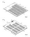
- FIG. 1is a top isometric view showing a first or front side of a medical or dietary dosage form package
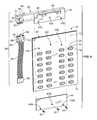
- FIG. 2is a bottom isometric view showing a second or rear side of the package of FIG. 1 ;
- FIG. 3is a plan view of an electrically conductive trace pattern on an electrical circuit sheet, wherein the electrical circuit sheet may be incorporated into the package of FIG. 1 ;
- FIG. 4is an exploded isometric view of the package of FIGS. 1 and 2 and an associated electrical interface device;
- FIG. 5is a front isometric view of a dosage form control and monitoring system for storing and monitoring dispensing of dosage forms from one or more dosage form packages stored therein;
- FIG. 6is a front isometric view of a storage/dispenser unit of the system of FIG. 5 for containing one or more dosage form packages therein;
- FIG. 7is a front isometric view of an alternative storage/dispenser unit that may be used in place of the storage/dispenser unit of FIG. 6 ;
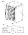
- FIG. 8is a block diagram of hardware for collecting date from one or more control and monitoring systems.
- FIG. 9is a flow chart depicting programming executed by the computer of FIG. 5 to implement the control and monitoring system.
- the dosage form package 10includes a first or front sheet 12 and a second or rear sheet 14 .
- the front and rear sheets 12 , 14are preferably constructed of cardboard, but alternatively may be constructed of any durable material, such as plastic or the like.
- a sheet of material 16is disposed between the front and rear sheets 12 , 14 , wherein the sheet 16 includes a plurality of protrusions defining blister cavities 18 .
- the blister cavities 18are preferably, although not necessarily, arranged in a regular pattern of rows and columns.
- FIGS. 1 and 4illustrate seven rows and four columns, it being understood that different numbers of rows and/or columns may alternatively be provided.
- the blister cavities 18need not be arranged in a regular pattern, but could be irregularly spaced.
- the sheet 16is preferably, although not necessarily, made of clear flexible plastic so that the contents of the blister cavities 18 may be viewed. Also, while the sheet 16 is preferably unitary, the sheet 16 could instead comprise separated sections that are arranged together to form the desired arrangement of blister cavities 18 .
- the dosage form package 10is used to store individual or multiple dosage forms in one or more of the plurality of blister cavities 18 .
- the front sheet 12includes a plurality of first openings 20 extending therethrough, wherein the first openings 20 are aligned with the plurality of protrusions forming the blister cavities 18 and the blister cavities 18 extend through the first openings 20 .
- the rear sheet 14includes a plurality of second openings 22 aligned evenly with the first openings of the front cover 12 and the plurality of protrusions forming the blister cavities 18 .
- the front and rear sheets 14 , 16are preferably identical and the openings 20 , 22 , respectively, therethrough are preferably symmetric.
- the front and rear sheets 14 , 16may be separate sheets, but alternatively may be formed of a single sheet folded in half to form the front and rear sheets 14 , 16 .
- a frangible electrical circuit sheet 24is disposed between the rear sheet 14 and the sheet 16 to provide a barrier to the release of dosage forms from one or more of the blister cavities 18 .
- FIG. 2also shows that the circuit sheet 24 carries individual bi-state elements or switch elements 26 a - 1 - 26 g - 4 in the form of frangible electrically conductive traces, which are connected together in a network and each of which may be broken and open-circuited when one or multiple dosage forms is expelled from a specific blister cavity 18 .
- FIG. 2also illustrates electrical terminals 28 a - 28 i of the circuit sheet 24 left uncovered by a corresponding opening in the rear sheet 14 .
- the sheet 24may be secured to a rear face of the rear sheet 14 .
- a side of the circuit sheet 24 opposite the bi-state elements 26 a - 1 - 26 g - 4may be formed of a thin metal foil to limit an amount of moisture and/or oxygen that can travel through the sheet 24 and therefore to dosage forms contained within the blister cavities 18 .
- FIG. 3illustrates a network of electrically conductive traces carried by the electrical circuit sheet 24 in greater detail.
- the networkincluding the bi-state elements 26 a - 1 - 26 g - 4 , the electrical terminals 28 a - 28 i , a plurality of conductive electrical traces 30 a - 30 i , insulating material 31 a - 31 f , and circuit elements in the form of resistive elements 32 a - 32 g , 34 a - 34 g , 36 a - 36 g , and 38 a - 38 g may be printed, etched, mechanically attached, or otherwise placed using one or more of these and/or other techniques on an electrically non-conductive substrate material forming the electrical circuit sheet 24 .
- the substrate materialmay be a single sheet of material as shown in FIG. 3 or may be multi-layered.
- the electrically conductive traces 30 a - 30 iterminate at the electrical terminals 28 a - 28 i , which are used to connect the dosage form package 10 to a suitable dosage form control system, as described in further detail below.
- the electrically conductive traces 30 a - 30 imay be made of any suitable electrically conducting material.
- the electrical terminals 28 a - 28 g of the electrical circuit sheet 24include a first end terminal 28 a at a first position, a second end terminal 28 i at a second position, and subnetwork terminals 28 b - 28 h preferably, but not necessarily, arranged between the first and second end terminals 28 a and 28 i .
- the first end terminal 28 a and each of the subnetwork terminals 28 b - 28 iare connected to form subnetworks 27 a - 27 g , respectively.
- a first subnetwork 27 awill be described in detail, it being understood that the other subnetworks 27 b - 27 g are formed in the same manner.
- the traces 30 a , 30 bconnect the terminals 28 a , 28 b , respectively, to a first row 29 a of resistive elements 32 a , 34 a , 36 a , 38 a and bi-state elements 26 a - 1 - 26 a - 4 .
- the resistive elements 32 b - 32 g , 34 b - 34 g , 36 b - 36 g , 38 b - 38 g and the bi-state elements 26 b - 26 gform rows 29 b - 29 g .
- the bi-state elements 26 a - 1 , 26 a - 2 , 26 a - 3 , 26 a - 4 and the resistive elements 32 a , 34 a , 36 a , 38 a of the first row 29 aare interconnected by traces 37 a - 1 , 37 a - 2 , 37 a - 3 , 37 a - 4 , 37 a - 5 , 37 a - 6 .
- the terminal 28 bis connected to the trace 30 b , which in turn is coupled to a junction 41 a between the resistors 38 a and 39 a .
- the other subcircuitsare formed by connecting the terminals 28 b - 28 h to respective traces 30 b - 30 h , which are coupled to junctions 41 b - 41 g , respectively.
- Each of the resistive elements 32 a - 32 g , 34 a - 34 g , 36 a - 36 g , and 38 a - 38 gis connected in parallel with an associated bi-state element 26 a - 1 - 26 a - 4 , 26 b - 1 - 26 b - 4 , 26 c - 1 - 26 c - 4 , 26 d - 1 - 26 d - 4 , 26 e - 1 - 26 e - 4 , 26 f - 1 - 26 f - 4 , and 26 g - 1 - 26 g - 4 , respectively.
- resistive elements 32 a - 32 g , 34 a - 34 g , 36 a - 36 g , and 38 a - 38 gmay all have different resistive values, or may have resistive values that bear a predetermined relationship to one another. As shown in the exemplary embodiment of FIG.
- the resistive elements 32 a - 32 ghave a resistive value of n ohms
- the resistive elements 34 a - 34 ghave a resistive value of 2 n ohms
- the resistive elements 36 a - 36 ghave a resistive value of 4 n ohms
- each subnetworkis shown as comprising multiple bi-state elements in a single row, e.g. the elements 26 a - 1 through 26 a - 4 , etc. in the row 29 a
- subnetworkscan otherwise be formed by any number or combination of bi-state elements.
- any other bi-state elementsthat change state in response to removal of a dosage form from a cavity may be utilized.
- Some examplesinclude mechanical switches, transistors, electrically conductive traces of different shape or form, or combinations thereof.
- circuit elements in the form of resistance elementsare utilized herein, any combination of resistance elements and other circuit elements, such as capacitors, inductors, diodes, and/or transistors may be utilized as circuit elements herein.
- the values of the resistive elements 32 a - 32 g , 34 a - 34 g , 36 a - 36 g , and 38 a - 38 gmay have any combination of resistive values that permits identification of exactly which bi-state element(s) 26 a - 1 - 26 g - 4 have been broken and a voltage is applied across the traces 30 a and 30 i . Any change in current magnitude is detected and an associated computer 106 ( FIG.
- the resistance of some or all of the subnetworks 27 a - 27 gcan be determined. This is accomplished by separately applying a voltage between the first end terminal 28 a and each of the subnetwork terminals 28 b - 28 h on a time-shared (i.e., multiplexed) basis. The current flowing through each subnetwork 27 a - 27 g is measured to obtain separate measurements of the resistances of the subnetworks 27 a - 27 g .
- the computer 106then checks the separate subnetwork resistances against a table of resistive values stored in a backup table to determine exactly which bi-state elements 26 a - 1 - 26 g - 4 are broken. In either embodiment, the computer 106 determines which dosage forms have been removed. The computer 106 can also track other information, such as the time the bi-state elements 26 a - 1 - 26 g - 4 were broken, the patient(s) associated with the contents of the broken bi-state elements 26 a - 1 - 26 g - 4 , etc.
- This embodimentcan be implemented when all of the resistive elements 32 a - 32 g , 34 a - 34 g , 36 a - 36 g , and 38 a - 38 g have different resistive values or when the resistive values have a predetermined relationship to one another, such as the relationship described above.
- the computer 106may check for resistances within a pre-determined range, thereby reducing the detection of events beyond the breakage of bi-state elements 26 a - 1 - 26 g - 4 , such as a short in the thin metal foil forming a side of the circuit sheet 24 .
- the insulating material 31 a - 31 fis provided over the traces 30 c - 30 h so that the trace 30 i can extend over the traces 30 c - 30 h to connect with electrical traces forming each row 29 a - 29 g of a subnetwork 27 a - 27 g , such that the traces 30 a and 30 i can conduct current to measure the overall resistance of the network.
- token resistors 39 a - 39 gare provided in each subnetwork 27 a - 27 g to provide a nominal minimum resistance thereto.
- the bi-state element 26 a - 1 in the first row, first column position as shown in FIG. 3has been broken, the current passing through the network from the first end terminal 28 a to the second end terminal 28 i is reduced by the addition of the resistive element 32 a to the resistance of the subnetwork 27 a .
- the resistance of the subnetwork 27 a measured between the traces 30 a and 30 bincreases by n ohms as compared to the resistance of the subnetworks 27 b - 27 g before breaking the first row, first column bi-state element 26 a - 1 .
- the resistance of the subnetwork 27 a measured between the traces 30 a and 30 b after breakagewill be increased by 2 n ohms.
- Another change in electrical current magnitude through the first subnetwork 27 awill occur after the breakage of the bi-state element 26 a - 3 in the third column, due to the addition of the resistive element 36 a of value 4 n to the resistance of the subnetwork 27 a .
- breaking the bi-state element 26 a - 4 in the fourth columnresults in addition of the resistive element 38 a of value 8 n ohms to the resistance of the subnetwork 27 a .
- each subnetwork 27 a - 27 gcan be detected in a multiplexed fashion to measure the drop in resistance for the individual subnetworks 27 a - 27 g so that the computer 106 can determine exactly which bi-state elements 26 a - 1 - 26 g - 4 were broken.
- FIG. 4illustrates the medical or dietary dosage form package 10 in combination with an electrical interface device 40 that may be secured to the package 10 by a variety of means, including but not limited to one or more of adhesives, lamination, rivets, and other fasteners.
- the electrical interface device 40includes front and back members 44 , 46 connected to the dosage form package 10 by rivets 42 that extend through a plurality of holes 43 a , 43 b in the front and back members 44 , 46 , respectively, and through a plurality of holes 43 c in at least the front and back sheets 12 , 14 of the package 10 .
- the rivets 42may also extend through aligned holes in the sheet 16 if the sheet 16 extends to the area of the package 10 where the rivets 42 are located.
- a plurality of electrical contacts 48preferably, although not necessarily, in the form of bifurcated fingers, bear against and are thus connected to the terminals 28 a - 28 i ( FIGS. 2 and 3 ) on the back of electrical circuit sheet 24 .
- the metal forming these contacts 48extends along the electrical interface device 40 to a point where it is electrically connected to pins 50 of a first portion 47 of a connector 49 disposed at a head 51 of the electrical interface device 40 .
- a light pipe 52 and a lever 54may be disposed in the head 51 of device 40 .
- the lever 54is operatively coupled to the first portion 47 of the connector 49 and when moved inwardly toward the package 10 , moves latches 55 (only one shown) on opposite sides of the first portion 47 inwardly out of interference with arms 59 that extend upwardly from opposite sides of a second portion 53 of the connector 49 . Movement of the latches 55 permits detachment of the first portion 47 of the connector from a second portion 53 of the connector 49 .
- the second portion 53 of the connector 49is mounted by any suitable means to a structure within which the form package 10 is to be retained, such as a drawer, as described in greater detail hereinafter.
- the electrical connectioncontinues through a plurality of wires 60 that terminate in a further connector portion 62 .
- a lamp 64is provided on the connector 49 as a feedback mechanism which may be utilized to indicate a proper electrical connection through the connector portions 47 , 53 , and 62 , wires 60 , pins 50 , electrical contacts 48 , and the electrical terminals 28 , when all of these components are electrically connected to a power source for a dosage form control and monitoring system, as discussed and shown in greater detail hereinafter.
- a medical or dietary dosage form control and monitoring system 100 for storage, dispensing, control, and compliance monitoring of medical or dietary dosage formpreferably includes a wheeled cabinet 102 .
- the cabinet 102includes a number of accessible storage/dispensing units, such as lockable drawers 104 , in which a plurality of dosage form packages 10 with attached electrical interface devices 40 may be placed.
- the connector portions 47 , 53 , 62 of FIG. 4are mechanically and electrically coupled to matching connector portions of a drawer interface circuit (not shown) disposed within or adjacent each drawer 104 .
- a programmed computer 106with suitable storage capacity to accommodate a database relating to the multiple dosage form packages 10 is included.
- the computer 106includes an output display 108 and input devices, such as a keyboard 110 and mouse 112 .
- the computer 106may be capable of undertaking multiple functions such as accessing and processing information that may be related to patient dosing requirements, monitoring access to the dosage forms stored in the packages 10 , developing inventory data, and the like.
- the computer 106may be a stand-alone device, or may also be connected, physically or wirelessly, to a network wherein the network may include one or more servers connected thereto and wherein processing to undertake system functions might be distributed or reside solely within a single computer on the network, as described in greater detail hereinafter in connection with FIG. 8 .
- the computer 106may alternately be any device capable of storing, retrieving, and processing information regarding patients, dosage forms, and inventory, such as a laptop computer, a tablet computer, a personal digital assistant, a cellular phone, or any other device including a microprocessor.
- a laptop computera tablet computer
- a personal digital assistanta cellular phone
- microprocessorany other device including a microprocessor.
- a computer or other device 106is capable of processing data based on user inputs or pre-defined requests, as well as communicating with other auxiliary systems through suitable data ports.
- the computer or similar processing device 106is connected to the cabinet 102 via a data connection such as a direct wired connection, the Internet, an intranet, wireless, or infrared technology, Bluetooth, or any other communications protocol.
- the dosage form control system 100may advantageously provide a user with convenient access to patient records concerning medical and/or dietary dosage form requirements by accessing such records through the interface of the computer or other device 106 .
- the drawer interface circuit of each drawer 104 of the cabinet 102is connected to the computer 106 via a direct electrical connection 114 such as a ribbon cable, a SCSI, EIDE, SATA, eSATA, or USB connection.
- a direct electrical connection 114such as a ribbon cable, a SCSI, EIDE, SATA, eSATA, or USB connection.
- Each dosage form package 10 with attached electrical interface device 40is placed in an appropriate associated and addressable location, or slot, within an associated drawer 104 of the cabinet 102 , as shown in FIGS. 5 and 6 .
- the connector portion 62 that is attached to each dosage form package 10is connected to the drawer interface circuit of the associated drawer 104 as noted above.
- a power source(not shown) provides power via the direct electrical connection 114 to components of the packages 10 .
- the lamp 64 disposed on each connector 49is lit when this completed direct electrical connection is made. Alternatively or in addition, the lamp 64 may be used to indicate the desired dosage form package 10 to be removed from the dosage form control system 100 for administration of a dosage form(s) to a patient or to indicate an issue with a particular dosage form package 10 in the dosage form control system 100 .
- the light pipe 52 on the electrical interface device 40overlays and transmits light from the lamp 64 so that the light may be visible along the edge of the drawer 104 , for example, as indicated the light emanating from the light pipe 52 of one of the form packages 10 as shown in FIG. 6 .
- control system 100is used to administer a patient prescription contained within the cabinet 102 .
- the system 100may allow unlocking and opening of an appropriate drawer 104 that contains the dosage form package 10 that is desired for use.
- the desired dosage form package 10 and its attached electrical interface device 40are removed from the drawer 104 using the lever 54 .
- the lever 54is moved inwardly toward the package 10 , thereby permitting the first portion 47 of the connector 49 to be detached from the second portion 53 of the connector 49 .
- the second portion 53 of the connector 49is preferably mounted to the drawer 104 or to a structure carried within the drawer 104 in a stationary manner so that the first and second portions 47 and 53 of the connector 49 can be conveniently rejoined and locked together by upward movement of the arms 59 of the second portion 53 of the connector 49 into engagement with the latches 55 of the first portion 47 of the connector 49 .
- each measurementinforms the system 100 exactly which bi-state elements 26 a - 1 - 26 g - 4 have been broken. This enables the system 100 to monitor whether the correct medications or dietary supplements have been administered at the correct times.
- the dosage control system 100may include additional intermediate mechanisms, controls, data channels, outputs, or inputs to allow for additional interface with the dosage control system 100 by a user or any other data processing apparatus.
- the cabinet 102 and drawer 104 configuration of the dosage control system 100may be embodied as individual slots within a larger cabinet, a carousel-type cabinet, multiple storage cabinets/frames, or any other suitable compartment capable of storing and allowing access to individually addressable dosage form packages 10 .
- a dosage form control system 200that includes a storage/dispensing cabinet 202 and a plurality of medical or dietary dosage form packages 10 with connected electrical interface devices 40 arranged in rows and columns is illustrated in FIG. 7 .
- the cabinet 202may be used in conjunction with the computer 106 (not shown in FIG. 7 ).
- An upwardly/downwardly rolling door 204may be closed and locked, or may be selectively positioned to allow access to particular rows of dosage form packages 10 , or the door 204 may be in a fully upward position to provide access to all rows, as shown in FIG. 7 .
- the dosage form packages 10may be mechanically and electrically interconnected with the cabinet 202 as in the previous embodiment of FIGS. 5 and 6 .
- the dosage form control system 200may also be connected via a wired or wireless network to provide control and monitoring for the individual dosage form packages 10 .
- each electrical interface device 40may include a variety of elements and technologies for connecting, either through direct electrical connection or wirelessly, to any of a variety of suitable dosage form control systems.
- each electrical interface device 40may incorporate its own power source, such as a battery, and may also incorporate an integrated circuit that may contain a timer and memory.
- each electrical interface device 40may include active or passive RFID tags, wired or wireless transceivers, and input and output devices such as buttons, lights, or speakers.
- each electrical interface device 40may be placed at a location away from the computer or similar processing device 106 and directly transmit to and receive data from the computer or similar processing device 106 regarding the electrical circuit current and resistance changes that occur when the contents of an individual flexible blister cavity 18 are expelled and an individual switch 26 a - 1 - 26 g - 4 is broken.
- FIG. 8depicts a further dosage form control system 300 having a transceiver 302 that is electrically connected to or formed as a part of a dosage form package 10 .
- the control system 300is utilized to monitor patient dosage retrieval in locations where a larger control system, such as the control systems 100 , 200 of FIGS. 5 and 7 , is not be feasible, such as in a patient's home.
- Data from a dosage form package 10may be stored locally at the transceiver 302 through use of sufficient memory to retain the detectable electrical changes to circuit current and resistance when dosage forms are removed from their flexible blister cavities 18 and bi-state elements 26 a - 1 - 26 g - 4 are broken on the electrical circuit sheet 24 .
- the transceiver 302communicates directly with a central server 308 over a communication channel 303 , wherein the server 308 stores information for that dosage form package 10 .
- the transceiver 302may also include a power source and one or more input/output devices such as a keypad/keyboard, display screen, light, speaker, or other devices known in the art.
- a hub 304may be included in the dosage control system 300 , as shown in FIG. 8 , to act as a relay to transmit or receive data to or from the transceiver 302 across a first communication channel 306 .
- the hub 304may communicate with a server 308 through a second communication channel 310 .
- Each of the communication channels 303 , 306 , 310may be any suitable conduit, such as the Internet or a direct wired or wireless connection.
- the server 308may be a computer, a web server, or any similar processing device capable of maintaining a database of electrical circuit data received from the dosage form packages 10 connected to the transceivers 302 .
- the transceiver 302 of the control system 300uses low power and complies with requisite allowable power and frequency regulations, both federal and international.
- FIG. 9depicts programming for the computer or similar processing device 106 of FIG. 5 when one or more dosage form packages 10 ( FIGS. 1 and 2 ) are connected to the dosage form control system 100 ( FIG. 5 ) or 200 ( FIG. 7 ) by one or more electrical interface devices 40 ( FIG. 4 ).
- Trigger eventsare set within the computer 106 , wherein when such trigger events occur, the process of FIG. 9 is initiated.
- Such trigger eventsinclude, but are not limited to, scanning of a dosage form package 10 , opening of a cabinet or drawer within the system 100 , or a timed event (e.g., running the process of FIG. 9 every second or fraction thereof, minute, 10 minutes, 30 minutes, 1 hour, 1 day, 1 week, etc.).
- the first subcircuit 27 a resistanceis measured by a block 400 , as discussed above.
- the overall first subnetwork 27 a resistance valueis compared by a block 402 to a previously recorded subnetwork 27 a resistance value. If a block 404 determines that the two resistance values are different, a block 406 saves the current subnetwork 27 a resistance value and/or an identification of which bi-state element(s) 26 a - 1 - 26 a - 4 have been replaced.
- other parameter(s)may be updated in the database(s), such as time, type of dosage, forms removed, accounting information, patient information, and the like.
- the block 404determines that there is no change in the resistive value of the subnetwork 27 a , the block 406 is skipped.
- Subsequent blocks 408 , 416 , 424 , 432 , 440 , and 448check the resistances of the remaining subnetworks 27 b - 27 g , blocks 410 , 418 , 426 , 434 , 442 , and 450 compare the resistances, and blocks 414 , 422 , 430 , 438 , 446 , and 454 optionally saves the current subnetwork 27 a - 27 g resistance value and/or an identification of which bi-state element(s) 26 b - 1 - 26 g - 4 have been replace in an identical fashion and thereafter the process terminates at block 456 .
- the inventorshave now also determined that alternate circuit arrangements are also possible which can be utilized in accordance with the present invention. Specifically, for example, the inventors now recognize that it is possible to eliminate the requirement of forming a separate resistor element as described above. Additionally, it is now also recognized that alternate circuit elements may be utilized in place of the resistor elements described in the embodiments set forth above. More particularly, the inventors note that in its broadest characterization, the present invention relies upon changes in at least one measurable circuit parameter which is advantageously initiated by breaking the blister package cavity seal and eliminating a parallel connection between circuit nodes. The measurement of the at least one circuit characteristic or parameter can be utilized to determine whether certain individual blister packages have been opened.
- parallel connected printed conductive signal lines having a predetermined or known resistance value per linear dimensionmay be provided in place of the parallel connection of a single conductive trace and a resistor element as described above.
- the conductive signal lines having a known resistance per linear dimensionare formed such that each pair of signal lines forming a parallel connection between the nodes has a least one signal line formed across the backing material that closes the blister package. Consequently, when the blister package cavity is opened, the resistance value between the signal nodes changes in a known way by altering the resistance between the nodes from being the effective parallel connection of two resistors to a series connection of the single remaining resistance having a known resistance per linear dimension.
- a simple resistance measurement, current measurement or voltage drop determinationcan be used to determine which one or ones of the individual package cavities have been opened.
- the principle of operation for this alternate embodimentis essentially the same as the systems and methods described above. Significantly, however, the previous requirement for forming a special resistor element is eliminated and parallel connected conductive traces having known resistance values are utilized. Alternatively, the two embodiments may be combined such that a conductive signal line provides a short-circuit between nodes but the resistive element is replaced with a signal line having a known resistance value.
- the resistance or resistor element placed between each nodeis replaced with an alternate electronic component such as, for example, a capacitor and/or inductor.
- an alternate electronic componentsuch as, for example, a capacitor and/or inductor.
Landscapes
- Health & Medical Sciences (AREA)
- Engineering & Computer Science (AREA)
- Microelectronics & Electronic Packaging (AREA)
- Pharmacology & Pharmacy (AREA)
- Life Sciences & Earth Sciences (AREA)
- Animal Behavior & Ethology (AREA)
- General Health & Medical Sciences (AREA)
- Public Health (AREA)
- Veterinary Medicine (AREA)
- Medical Preparation Storing Or Oral Administration Devices (AREA)
Abstract
Description
Claims (17)
Priority Applications (2)
| Application Number | Priority Date | Filing Date | Title |
|---|---|---|---|
| PCT/US2009/060497WO2010045227A1 (en) | 2008-10-14 | 2009-10-13 | Dosage form package and a frangible electrical circuit sheet therefor |
| US12/578,214US9387148B2 (en) | 2008-10-14 | 2009-10-13 | Dosage form package and a frangible electrical circuit sheet therefor |
Applications Claiming Priority (2)
| Application Number | Priority Date | Filing Date | Title |
|---|---|---|---|
| US12/288,003US20100089789A1 (en) | 2008-10-14 | 2008-10-14 | Dosage form package and a frangible electrical circuit sheet therefor |
| US12/578,214US9387148B2 (en) | 2008-10-14 | 2009-10-13 | Dosage form package and a frangible electrical circuit sheet therefor |
Related Parent Applications (1)
| Application Number | Title | Priority Date | Filing Date |
|---|---|---|---|
| US12/288,003Continuation-In-PartUS20100089789A1 (en) | 2008-10-14 | 2008-10-14 | Dosage form package and a frangible electrical circuit sheet therefor |
Publications (2)
| Publication Number | Publication Date |
|---|---|
| US20100089791A1 US20100089791A1 (en) | 2010-04-15 |
| US9387148B2true US9387148B2 (en) | 2016-07-12 |
Family
ID=42097900
Family Applications (1)
| Application Number | Title | Priority Date | Filing Date |
|---|---|---|---|
| US12/578,214ActiveUS9387148B2 (en) | 2008-10-14 | 2009-10-13 | Dosage form package and a frangible electrical circuit sheet therefor |
Country Status (2)
| Country | Link |
|---|---|
| US (1) | US9387148B2 (en) |
| WO (1) | WO2010045227A1 (en) |
Cited By (7)
| Publication number | Priority date | Publication date | Assignee | Title |
|---|---|---|---|---|
| US20150041355A1 (en)* | 2011-11-08 | 2015-02-12 | Isish Healthcare System, S.L. | Tube for Storing Unit Doses of a Drug, Method and Device for Filling Same and Dispensing Cabinet Using Same |
| US20180075331A1 (en)* | 2013-06-26 | 2018-03-15 | Vypin, LLC | Sensor array, method of making same, and related medication compliance monitoring techniques |
| US10108892B2 (en) | 2013-06-26 | 2018-10-23 | Vypin, LLC | Wireless tag apparatus and related medication compliance monitoring techniques |
| US10427819B2 (en) | 2015-08-25 | 2019-10-01 | Chudy Group, LLC | Plural-mode automatic medicament packaging system |
| US10709642B2 (en) | 2016-06-18 | 2020-07-14 | Totusrx Inc. | Smart pack system for medicines |
| US20210039851A1 (en)* | 2019-08-07 | 2021-02-11 | International Business Machines Corporation | Medication Counterfeit Detection |
| USD958653S1 (en)* | 2019-10-29 | 2022-07-26 | Jones Packaging Inc. | Medication package |
Families Citing this family (34)
| Publication number | Priority date | Publication date | Assignee | Title |
|---|---|---|---|---|
| US7502666B2 (en)* | 2004-05-14 | 2009-03-10 | Mts Medication Technologies, Inc. | Systems and methods for storing and dispensing medication |
| WO2008115722A1 (en)* | 2007-03-16 | 2008-09-25 | University Of Pittsburgh - Of The Commonwealth System Of Higher Education | Security for blister packs |
| WO2010045227A1 (en)* | 2008-10-14 | 2010-04-22 | Mts Medication Technologies, Inc. | Dosage form package and a frangible electrical circuit sheet therefor |
| US20120145585A1 (en) | 2010-12-08 | 2012-06-14 | Id-Con, Llc | Packaging systems and methods |
| FI125491B (en)* | 2011-02-15 | 2015-10-30 | Stora Enso Oyj | Control system for checking the use of the contents of an intelligent packaging |
| FI128670B (en)* | 2011-02-15 | 2020-10-15 | Stora Enso Oyj | Substrate for pieces to be removed from the substrate and procedure for its manufacture |
| US9351907B2 (en) | 2011-07-19 | 2016-05-31 | Id-Con, Llc | Packaging systems and methods |
| CA2775546A1 (en)* | 2012-04-25 | 2013-10-25 | Intelligent Devices Inc. | A disposable content use monitoring package with indicator and method of making same |
| GB201218140D0 (en)* | 2012-10-10 | 2012-11-21 | Future Technology Uk Ltd | Devices for use with blister packs |
| JP5555801B1 (en)* | 2013-09-20 | 2014-07-23 | 株式会社カナエ | Detector |
| US8960440B1 (en)* | 2013-12-27 | 2015-02-24 | Verimed Holdings, LLC | Blister pack content usage monitoring |
| US10678382B2 (en)* | 2014-04-22 | 2020-06-09 | Avery Dennison Retail Information Services, Llc | Methods and systems for monitoring medication compliance |
| WO2016007344A1 (en)* | 2014-07-08 | 2016-01-14 | Avery Dennison | Methods and systems for monitoring a plurality of medication-containing cells of a medication container |
| US9452255B2 (en)* | 2014-07-21 | 2016-09-27 | Medtronic Minimed, Inc. | Smart connection interface |
| EP3021245A1 (en)* | 2014-10-06 | 2016-05-18 | Carebay Europe Ltd. | Information provider system |
| US10952927B2 (en) | 2014-10-10 | 2021-03-23 | QuantaEd, LLC | Apparatus for monitoring the content of a container and method therefor |
| US10375847B2 (en)* | 2014-10-10 | 2019-08-06 | QuantaEd, LLC | Connected packaging |
| US10322064B2 (en) | 2014-10-10 | 2019-06-18 | QuantaEd, LLC | Connected packaging |
| US10762753B2 (en) | 2014-12-12 | 2020-09-01 | Avery Dennison Retail Information Services, Llc | Methods and systems for determining the time at which a seal was broken |
| CN104546452A (en)* | 2014-12-30 | 2015-04-29 | 深圳市汇顶科技股份有限公司 | Medicine box detection device and method and intelligent medicine box |
| EP3061438A1 (en)* | 2015-02-26 | 2016-08-31 | Abbott Healthcare Pvt. Ltd. | Electronic drug packaging for improved compliance |
| US10930383B2 (en)* | 2015-07-03 | 2021-02-23 | Cuepath Innovation Inc. | Connected sensor substrate for blister packs |
| EP3316847B1 (en)* | 2015-07-03 | 2020-05-06 | Cuepath Innovation Inc. | Connected sensor substrate for blister packs |
| US10896301B2 (en) | 2015-07-07 | 2021-01-19 | Avery Dennison Retail Information Services, Llc | RFID-based methods and systems for monitoring medication compliance |
| US10913594B2 (en) | 2015-07-07 | 2021-02-09 | Avery Dennison Retail Information Services, Llc | Smart ejection trays for use with medication containers |
| US10650661B2 (en) | 2016-04-08 | 2020-05-12 | QuantaEd, LLC | Apparatus and method for improved drug dosing-regimen compliance |
| US10083594B2 (en) | 2016-04-08 | 2018-09-25 | QuantaEd, LLC | Apparatus and method for improved drug regimen compliance |
| EP3585348A1 (en) | 2017-02-22 | 2020-01-01 | Quantaed, LLC | Modular medication case for improved regimen compliance |
| US10759591B2 (en)* | 2017-07-26 | 2020-09-01 | Oes, Inc. | Dosage monitoring based on signal presence |
| US10634633B2 (en) | 2017-10-10 | 2020-04-28 | QuantaEd, LLC | Smart packaging for improved medication regimen compliance |
| WO2020069608A1 (en)* | 2018-10-01 | 2020-04-09 | Cuepath Innovation Inc. | Connected sensor substrate for blister packs |
| US10786428B1 (en) | 2019-04-02 | 2020-09-29 | Automated Assembly Corporation | Method of making a blister package lid |
| US11357700B2 (en)* | 2020-03-04 | 2022-06-14 | 9155-0020 Quebec Inc. | Wireless medication blister pack system and blister pack attachment |
| WO2023135418A1 (en)* | 2022-01-13 | 2023-07-20 | Yourmedpack Limited | Container and uses thereof |
Citations (34)
| Publication number | Priority date | Publication date | Assignee | Title |
|---|---|---|---|---|
| US4526474A (en)* | 1983-06-25 | 1985-07-02 | Udo Simon | Device for storing and dispensing drug doses |
| US4616316A (en) | 1982-07-01 | 1986-10-07 | The United States Of America As Represented By The Administrator Of Veterans Affairs | Medication compliance monitoring device having conductive traces upon a frangible backing of a medication compartment |
| US4617557A (en)* | 1984-11-08 | 1986-10-14 | National Patent Development Corporation | Medication compliance aid for unit dose packaging |
| US4660991A (en) | 1985-02-09 | 1987-04-28 | Udo Simon | Device for storing and signalling the time for taking drugs |
| US5181189A (en)* | 1985-05-23 | 1993-01-19 | Dieter Hafner | Device for the storage and time-regulated dispensing of drugs |
| US5412372A (en)* | 1992-09-21 | 1995-05-02 | Medical Microsystems, Inc. | Article dispenser for monitoring dispensing times |
| US5622652A (en)* | 1995-06-07 | 1997-04-22 | Img Group Limited | Electrically-conductive liquid for directly printing an electrical circuit component onto a substrate, and a method for making such a liquid |
| US5836474A (en)* | 1993-11-26 | 1998-11-17 | Novatelligence Ab | Storage means specially intended for medicaments |
| US5856195A (en)* | 1996-10-30 | 1999-01-05 | Bayer Corporation | Method and apparatus for calibrating a sensor element |
| US5883806A (en) | 1994-09-28 | 1999-03-16 | Kvm Technologies, Inc. | Secure medication storage and retrieval system |
| US6011999A (en) | 1997-12-05 | 2000-01-04 | Omnicell Technologies, Inc. | Apparatus for controlled dispensing of pharmaceutical and medical supplies |
| US6175779B1 (en) | 1998-09-29 | 2001-01-16 | J. Todd Barrett | Computerized unit dose medication dispensing cart |
| US6335907B1 (en) | 1999-07-23 | 2002-01-01 | Robert Momich | Package with integrated circuit chip embedded therein and system for using same |
| US6411567B1 (en)* | 2000-07-07 | 2002-06-25 | Mark A. Niemiec | Drug delivery management system |
| US6539281B2 (en) | 2001-04-23 | 2003-03-25 | Accenture Global Services Gmbh | Online medicine cabinet |
| US20040047764A1 (en)* | 2002-09-10 | 2004-03-11 | Bayer Healthcare Llc | Auto-calibration label and apparatus comprising same |
| US6771174B2 (en) | 2001-01-24 | 2004-08-03 | Intel Corporation | Digital pillbox |
| US20050162979A1 (en)* | 2002-06-27 | 2005-07-28 | Ostergaard John K. | Blister label |
| US20050225445A1 (en)* | 2002-10-25 | 2005-10-13 | Intelligent Devices, Inc. | Electronic tampering detection system |
| US20050256830A1 (en) | 2004-05-14 | 2005-11-17 | Todd Siegel | Systems and methods for storing and dispensing medication |
| US20050288082A1 (en)* | 2004-06-15 | 2005-12-29 | Carlos De La Huerga | Word puzzle assembly and methods related thereto |
| US7113101B2 (en)* | 2001-12-31 | 2006-09-26 | Intelligent Devices, Inc. | Blister package with electronic content monitoring system |
| US7126879B2 (en)* | 2003-03-10 | 2006-10-24 | Healthtrac Systems, Inc. | Medication package and method |
| US20080223936A1 (en)* | 2007-03-16 | 2008-09-18 | University Of Pittsburgh-Of The Commonwealth System Of Higher Education | Security for blister packs |
| US7475784B2 (en)* | 2002-02-14 | 2009-01-13 | Udo Simon | Device for detecting the removal of a product from a packing system by an electronic unit |
| US7489594B2 (en)* | 2002-02-14 | 2009-02-10 | Udo Simon | Blister pack system |
| US7552824B2 (en)* | 2003-06-10 | 2009-06-30 | Meadwestvaco Corporation | Package with electronic circuitry |
| US7612662B2 (en)* | 2000-07-07 | 2009-11-03 | Infologix - Ddms, Inc. | Drug delivery management system |
| US20100089791A1 (en)* | 2008-10-14 | 2010-04-15 | Mts Medical Technologies, Inc. | Dosage form package and a frangible electrical circuit sheet therefor |
| US7726485B2 (en)* | 2005-12-12 | 2010-06-01 | International Paper Company | Momentary switch integrated in packaging of an article |
| US7878367B2 (en)* | 2003-06-16 | 2011-02-01 | Udo Simon | Blister pack system which assures a reliable contact making when an item is removed |
| US8151990B2 (en)* | 2003-12-19 | 2012-04-10 | Simon Udo | Blister package arrangement |
| US20140231518A1 (en)* | 2012-03-26 | 2014-08-21 | Murata Manufacturing Co., Ltd. | Wireless communication device |
| US8960440B1 (en)* | 2013-12-27 | 2015-02-24 | Verimed Holdings, LLC | Blister pack content usage monitoring |
Family Cites Families (1)
| Publication number | Priority date | Publication date | Assignee | Title |
|---|---|---|---|---|
| DK9200109Y6 (en)* | 1992-08-28 | 1992-09-25 | Gn Danavox As | Hearing aid device |
- 2009
- 2009-10-13WOPCT/US2009/060497patent/WO2010045227A1/enactiveApplication Filing
- 2009-10-13USUS12/578,214patent/US9387148B2/enactiveActive
Patent Citations (38)
| Publication number | Priority date | Publication date | Assignee | Title |
|---|---|---|---|---|
| US4616316A (en) | 1982-07-01 | 1986-10-07 | The United States Of America As Represented By The Administrator Of Veterans Affairs | Medication compliance monitoring device having conductive traces upon a frangible backing of a medication compartment |
| US4526474A (en)* | 1983-06-25 | 1985-07-02 | Udo Simon | Device for storing and dispensing drug doses |
| US4617557A (en)* | 1984-11-08 | 1986-10-14 | National Patent Development Corporation | Medication compliance aid for unit dose packaging |
| US4660991A (en) | 1985-02-09 | 1987-04-28 | Udo Simon | Device for storing and signalling the time for taking drugs |
| US5181189A (en)* | 1985-05-23 | 1993-01-19 | Dieter Hafner | Device for the storage and time-regulated dispensing of drugs |
| US5412372A (en)* | 1992-09-21 | 1995-05-02 | Medical Microsystems, Inc. | Article dispenser for monitoring dispensing times |
| US5836474A (en)* | 1993-11-26 | 1998-11-17 | Novatelligence Ab | Storage means specially intended for medicaments |
| US5883806A (en) | 1994-09-28 | 1999-03-16 | Kvm Technologies, Inc. | Secure medication storage and retrieval system |
| US5763058A (en)* | 1995-06-07 | 1998-06-09 | Paramount Packaging Corporation | Electrical circuit component formed of a conductive liquid printed directly onto a substrate |
| US5622652A (en)* | 1995-06-07 | 1997-04-22 | Img Group Limited | Electrically-conductive liquid for directly printing an electrical circuit component onto a substrate, and a method for making such a liquid |
| US5856195A (en)* | 1996-10-30 | 1999-01-05 | Bayer Corporation | Method and apparatus for calibrating a sensor element |
| US6011999A (en) | 1997-12-05 | 2000-01-04 | Omnicell Technologies, Inc. | Apparatus for controlled dispensing of pharmaceutical and medical supplies |
| US6175779B1 (en) | 1998-09-29 | 2001-01-16 | J. Todd Barrett | Computerized unit dose medication dispensing cart |
| US6335907B1 (en) | 1999-07-23 | 2002-01-01 | Robert Momich | Package with integrated circuit chip embedded therein and system for using same |
| US6411567B1 (en)* | 2000-07-07 | 2002-06-25 | Mark A. Niemiec | Drug delivery management system |
| US7612662B2 (en)* | 2000-07-07 | 2009-11-03 | Infologix - Ddms, Inc. | Drug delivery management system |
| US6574166B2 (en)* | 2000-07-07 | 2003-06-03 | Ddms Holdings, L.L.C. | Drug delivery management system |
| US6771174B2 (en) | 2001-01-24 | 2004-08-03 | Intel Corporation | Digital pillbox |
| US6539281B2 (en) | 2001-04-23 | 2003-03-25 | Accenture Global Services Gmbh | Online medicine cabinet |
| US7113101B2 (en)* | 2001-12-31 | 2006-09-26 | Intelligent Devices, Inc. | Blister package with electronic content monitoring system |
| US7489594B2 (en)* | 2002-02-14 | 2009-02-10 | Udo Simon | Blister pack system |
| US7475784B2 (en)* | 2002-02-14 | 2009-01-13 | Udo Simon | Device for detecting the removal of a product from a packing system by an electronic unit |
| US20050162979A1 (en)* | 2002-06-27 | 2005-07-28 | Ostergaard John K. | Blister label |
| US20040047764A1 (en)* | 2002-09-10 | 2004-03-11 | Bayer Healthcare Llc | Auto-calibration label and apparatus comprising same |
| US20050225445A1 (en)* | 2002-10-25 | 2005-10-13 | Intelligent Devices, Inc. | Electronic tampering detection system |
| US7126879B2 (en)* | 2003-03-10 | 2006-10-24 | Healthtrac Systems, Inc. | Medication package and method |
| US7552824B2 (en)* | 2003-06-10 | 2009-06-30 | Meadwestvaco Corporation | Package with electronic circuitry |
| US7878367B2 (en)* | 2003-06-16 | 2011-02-01 | Udo Simon | Blister pack system which assures a reliable contact making when an item is removed |
| US8151990B2 (en)* | 2003-12-19 | 2012-04-10 | Simon Udo | Blister package arrangement |
| US7502666B2 (en)* | 2004-05-14 | 2009-03-10 | Mts Medication Technologies, Inc. | Systems and methods for storing and dispensing medication |
| US20050256830A1 (en) | 2004-05-14 | 2005-11-17 | Todd Siegel | Systems and methods for storing and dispensing medication |
| US20050288082A1 (en)* | 2004-06-15 | 2005-12-29 | Carlos De La Huerga | Word puzzle assembly and methods related thereto |
| US7726485B2 (en)* | 2005-12-12 | 2010-06-01 | International Paper Company | Momentary switch integrated in packaging of an article |
| US20080223936A1 (en)* | 2007-03-16 | 2008-09-18 | University Of Pittsburgh-Of The Commonwealth System Of Higher Education | Security for blister packs |
| US8091790B2 (en)* | 2007-03-16 | 2012-01-10 | University Of Pittsburgh - Of The Commonwealth System Of Higher Education | Security for blister packs |
| US20100089791A1 (en)* | 2008-10-14 | 2010-04-15 | Mts Medical Technologies, Inc. | Dosage form package and a frangible electrical circuit sheet therefor |
| US20140231518A1 (en)* | 2012-03-26 | 2014-08-21 | Murata Manufacturing Co., Ltd. | Wireless communication device |
| US8960440B1 (en)* | 2013-12-27 | 2015-02-24 | Verimed Holdings, LLC | Blister pack content usage monitoring |
Cited By (21)
| Publication number | Priority date | Publication date | Assignee | Title |
|---|---|---|---|---|
| US9968517B2 (en)* | 2011-11-08 | 2018-05-15 | Isish Healthcare System, S.L. | Tube for storing unit doses of a drug, method and device for filling same and dispensing cabinet using same |
| US20150041355A1 (en)* | 2011-11-08 | 2015-02-12 | Isish Healthcare System, S.L. | Tube for Storing Unit Doses of a Drug, Method and Device for Filling Same and Dispensing Cabinet Using Same |
| US10719672B2 (en) | 2013-06-26 | 2020-07-21 | Vypin, LLC | Wireless tag apparatus and related methods |
| US20180075331A1 (en)* | 2013-06-26 | 2018-03-15 | Vypin, LLC | Sensor array, method of making same, and related medication compliance monitoring techniques |
| US10108893B2 (en)* | 2013-06-26 | 2018-10-23 | Vypin, LLC | Sensor array, method of making same, and related medication compliance monitoring techniques |
| US10108892B2 (en) | 2013-06-26 | 2018-10-23 | Vypin, LLC | Wireless tag apparatus and related medication compliance monitoring techniques |
| US10121028B2 (en) | 2013-06-26 | 2018-11-06 | Vypin, LLC | Asset tag apparatus and related methods |
| US10318769B2 (en) | 2013-06-26 | 2019-06-11 | Vypin, LLC | Wireless tag apparatus and related methods |
| US11027872B2 (en) | 2015-08-25 | 2021-06-08 | Chudy Group, LLC | Plural-mode automatic medicament packaging system |
| US10427819B2 (en) | 2015-08-25 | 2019-10-01 | Chudy Group, LLC | Plural-mode automatic medicament packaging system |
| US12384588B2 (en) | 2015-08-25 | 2025-08-12 | Chudy Group, LLC | Plural-mode automatic medicament packaging system |
| US11542054B2 (en) | 2015-08-25 | 2023-01-03 | Chudy Group, LLC | Plural-mode automatic medicament packaging system |
| US11981472B2 (en) | 2015-08-25 | 2024-05-14 | Chudy Group, LLC | Plural-mode automatic medicament packaging system |
| US10709642B2 (en) | 2016-06-18 | 2020-07-14 | Totusrx Inc. | Smart pack system for medicines |
| US20210161769A1 (en)* | 2016-06-18 | 2021-06-03 | TotusRx. Inc. | Smart Pack System for Medicines |
| US20240252402A1 (en)* | 2016-06-18 | 2024-08-01 | Swyft Inc. | Smart Pack for Medicines |
| US12310924B2 (en)* | 2016-06-18 | 2025-05-27 | Swyft Inc. | Smart pack for medicines |
| US11931318B2 (en)* | 2016-06-18 | 2024-03-19 | Swyft Inc. | Smart pack system for medicines |
| US20210039851A1 (en)* | 2019-08-07 | 2021-02-11 | International Business Machines Corporation | Medication Counterfeit Detection |
| US11685580B2 (en)* | 2019-08-07 | 2023-06-27 | International Business Machines Corporation | Medication counterfeit detection |
| USD958653S1 (en)* | 2019-10-29 | 2022-07-26 | Jones Packaging Inc. | Medication package |
Also Published As
| Publication number | Publication date |
|---|---|
| US20100089791A1 (en) | 2010-04-15 |
| WO2010045227A1 (en) | 2010-04-22 |
Similar Documents
| Publication | Publication Date | Title |
|---|---|---|
| US9387148B2 (en) | Dosage form package and a frangible electrical circuit sheet therefor | |
| US20100089789A1 (en) | Dosage form package and a frangible electrical circuit sheet therefor | |
| US7502666B2 (en) | Systems and methods for storing and dispensing medication | |
| CN109119139B (en) | Variable dose dispensing system | |
| US8600548B2 (en) | Remote medication management system | |
| US9317663B2 (en) | Method of using a medication reminder and compliance system including an electronic pill box | |
| DE68918454T2 (en) | MEDICINE DISPENSER WITH DISPENSING CONTROL DEVICE. | |
| US7113101B2 (en) | Blister package with electronic content monitoring system | |
| US9311452B2 (en) | Electronic pill box and medication reminder and compliance system incorporating same | |
| US7295890B2 (en) | Prescription drug compliance monitoring system | |
| US7828147B2 (en) | Multi-layer medication carrier | |
| US6335907B1 (en) | Package with integrated circuit chip embedded therein and system for using same | |
| US20060079994A1 (en) | Unit-dose medication dispensing cart and method of operating the same | |
| US20050162979A1 (en) | Blister label | |
| US20080059228A1 (en) | Operation Of A Remote Medication Management System | |
| US20080054007A1 (en) | System and method for distributing medication and monitoring medication protocol compliance | |
| US20060079996A1 (en) | Unit dose compliance monitoring & reporting device & system | |
| JP2002516228A (en) | Drug dispensing systems and devices | |
| JP7440807B2 (en) | A manual drug dispensing device, a support program for the manual drug dispensing device, and a recording medium that records the support program. | |
| JP2019524391A5 (en) | ||
| CN114206296A (en) | Smart containers, sensors and methods for drug management | |
| US9717653B2 (en) | Conductive grid sensor for smart packaging | |
| CA2353350A1 (en) | Packaging device and content use monitoring system | |
| CA2404805A1 (en) | Analog packaging device and content use monitoring system | |
| US20210280285A1 (en) | System, device and method for medication compliance management |
Legal Events
| Date | Code | Title | Description |
|---|---|---|---|
| AS | Assignment | Owner name:MTS MEDICATION TECHNOLOGIES, INC.,FLORIDA Free format text:ASSIGNMENT OF ASSIGNORS INTEREST;ASSIGNORS:ROSENBAUM, RONALD;D'AUGUSTINO, VINCENT G.;DEPKE, ROBERT J.;SIGNING DATES FROM 20091012 TO 20091013;REEL/FRAME:023365/0615 Owner name:MTS MEDICATION TECHNOLOGIES, INC., FLORIDA Free format text:ASSIGNMENT OF ASSIGNORS INTEREST;ASSIGNORS:ROSENBAUM, RONALD;D'AUGUSTINO, VINCENT G.;DEPKE, ROBERT J.;SIGNING DATES FROM 20091012 TO 20091013;REEL/FRAME:023365/0615 | |
| AS | Assignment | Owner name:GCI CAPITAL MARKETS LLC, AS ADMINISTRATIVE AGENT, Free format text:SECURITY AGREEMENT;ASSIGNOR:MTS MEDICATION TECHNOLOGIES, INC.;REEL/FRAME:026464/0285 Effective date:20110615 | |
| AS | Assignment | Owner name:MTS MEDICATIONS TECHNOLOGIES, INC., DISTRICT OF CO Free format text:RELEASE BY SECURED PARTY;ASSIGNOR:GCI CAPITAL MARKETS LLC;REEL/FRAME:028272/0563 Effective date:20120521 | |
| AS | Assignment | Owner name:WELLS FARGO BANK, NATIONAL ASSOCIATION, AS ADMINIS Free format text:SECURITY AGREEMENT;ASSIGNOR:MTS MEDICATION TECHNOLOGIES, INC.;REEL/FRAME:031301/0958 Effective date:20130925 | |
| AS | Assignment | Owner name:MTS MEDICATION TECHNOLOGIES, INC., FLORIDA Free format text:RELEASE BY SECURED PARTY;ASSIGNOR:WELLS FARGO BANK, NATIONAL ASSOCIATION, AS ADMINISTRATIVE AGENT;REEL/FRAME:037424/0971 Effective date:20160105 | |
| AS | Assignment | Owner name:WELLS FARGO BANK, NATIONAL ASSOCIATION, AS ADMINIS Free format text:SECURITY INTEREST;ASSIGNOR:MTS MEDICATION TECHNOLOGIES, INC.;REEL/FRAME:037434/0818 Effective date:20160105 | |
| STCF | Information on status: patent grant | Free format text:PATENTED CASE | |
| FEPP | Fee payment procedure | Free format text:PAT HOLDER NO LONGER CLAIMS SMALL ENTITY STATUS, ENTITY STATUS SET TO UNDISCOUNTED (ORIGINAL EVENT CODE: STOL); ENTITY STATUS OF PATENT OWNER: LARGE ENTITY | |
| FEPP | Fee payment procedure | Free format text:PETITION RELATED TO MAINTENANCE FEES GRANTED (ORIGINAL EVENT CODE: PTGR) | |
| MAFP | Maintenance fee payment | Free format text:PAYMENT OF MAINTENANCE FEE, 4TH YEAR, LARGE ENTITY (ORIGINAL EVENT CODE: M1551); ENTITY STATUS OF PATENT OWNER: LARGE ENTITY Year of fee payment:4 | |
| MAFP | Maintenance fee payment | Free format text:PAYMENT OF MAINTENANCE FEE, 8TH YEAR, LARGE ENTITY (ORIGINAL EVENT CODE: M1552); ENTITY STATUS OF PATENT OWNER: LARGE ENTITY Year of fee payment:8 |