US9387016B2 - Expandable interspinous device - Google Patents
Expandable interspinous deviceDownload PDFInfo
- Publication number
- US9387016B2 US9387016B2US13/761,031US201313761031AUS9387016B2US 9387016 B2US9387016 B2US 9387016B2US 201313761031 AUS201313761031 AUS 201313761031AUS 9387016 B2US9387016 B2US 9387016B2
- Authority
- US
- United States
- Prior art keywords
- post
- spinous process
- plate
- pad
- spinous
- Prior art date
- Legal status (The legal status is an assumption and is not a legal conclusion. Google has not performed a legal analysis and makes no representation as to the accuracy of the status listed.)
- Active, expires
Links
Images


Classifications
- A—HUMAN NECESSITIES
- A61—MEDICAL OR VETERINARY SCIENCE; HYGIENE
- A61B—DIAGNOSIS; SURGERY; IDENTIFICATION
- A61B17/00—Surgical instruments, devices or methods
- A61B17/56—Surgical instruments or methods for treatment of bones or joints; Devices specially adapted therefor
- A61B17/58—Surgical instruments or methods for treatment of bones or joints; Devices specially adapted therefor for osteosynthesis, e.g. bone plates, screws or setting implements
- A61B17/68—Internal fixation devices, including fasteners and spinal fixators, even if a part thereof projects from the skin
- A61B17/70—Spinal positioners or stabilisers, e.g. stabilisers comprising fluid filler in an implant
- A61B17/7062—Devices acting on, attached to, or simulating the effect of, vertebral processes, vertebral facets or ribs ; Tools for such devices
- A61B17/7068—Devices comprising separate rigid parts, assembled in situ, to bear on each side of spinous processes; Tools therefor
- A—HUMAN NECESSITIES
- A61—MEDICAL OR VETERINARY SCIENCE; HYGIENE
- A61B—DIAGNOSIS; SURGERY; IDENTIFICATION
- A61B17/00—Surgical instruments, devices or methods
- A61B17/56—Surgical instruments or methods for treatment of bones or joints; Devices specially adapted therefor
- A61B17/58—Surgical instruments or methods for treatment of bones or joints; Devices specially adapted therefor for osteosynthesis, e.g. bone plates, screws or setting implements
- A61B17/68—Internal fixation devices, including fasteners and spinal fixators, even if a part thereof projects from the skin
- A61B17/70—Spinal positioners or stabilisers, e.g. stabilisers comprising fluid filler in an implant
- A61B17/7062—Devices acting on, attached to, or simulating the effect of, vertebral processes, vertebral facets or ribs ; Tools for such devices
- A61B17/7065—Devices with changeable shape, e.g. collapsible or having retractable arms to aid implantation; Tools therefor
- A—HUMAN NECESSITIES
- A61—MEDICAL OR VETERINARY SCIENCE; HYGIENE
- A61F—FILTERS IMPLANTABLE INTO BLOOD VESSELS; PROSTHESES; DEVICES PROVIDING PATENCY TO, OR PREVENTING COLLAPSING OF, TUBULAR STRUCTURES OF THE BODY, e.g. STENTS; ORTHOPAEDIC, NURSING OR CONTRACEPTIVE DEVICES; FOMENTATION; TREATMENT OR PROTECTION OF EYES OR EARS; BANDAGES, DRESSINGS OR ABSORBENT PADS; FIRST-AID KITS
- A61F2/00—Filters implantable into blood vessels; Prostheses, i.e. artificial substitutes or replacements for parts of the body; Appliances for connecting them with the body; Devices providing patency to, or preventing collapsing of, tubular structures of the body, e.g. stents
- A61F2/02—Prostheses implantable into the body
- A61F2/30—Joints
- A61F2/44—Joints for the spine, e.g. vertebrae, spinal discs
- A—HUMAN NECESSITIES
- A61—MEDICAL OR VETERINARY SCIENCE; HYGIENE
- A61B—DIAGNOSIS; SURGERY; IDENTIFICATION
- A61B17/00—Surgical instruments, devices or methods
- A61B17/56—Surgical instruments or methods for treatment of bones or joints; Devices specially adapted therefor
- A61B17/58—Surgical instruments or methods for treatment of bones or joints; Devices specially adapted therefor for osteosynthesis, e.g. bone plates, screws or setting implements
- A61B17/68—Internal fixation devices, including fasteners and spinal fixators, even if a part thereof projects from the skin
- A61B2017/681—Alignment, compression, or distraction mechanisms
- A—HUMAN NECESSITIES
- A61—MEDICAL OR VETERINARY SCIENCE; HYGIENE
- A61F—FILTERS IMPLANTABLE INTO BLOOD VESSELS; PROSTHESES; DEVICES PROVIDING PATENCY TO, OR PREVENTING COLLAPSING OF, TUBULAR STRUCTURES OF THE BODY, e.g. STENTS; ORTHOPAEDIC, NURSING OR CONTRACEPTIVE DEVICES; FOMENTATION; TREATMENT OR PROTECTION OF EYES OR EARS; BANDAGES, DRESSINGS OR ABSORBENT PADS; FIRST-AID KITS
- A61F2220/00—Fixations or connections for prostheses classified in groups A61F2/00 - A61F2/26 or A61F2/82 or A61F9/00 or A61F11/00 or subgroups thereof
- A61F2220/0008—Fixation appliances for connecting prostheses to the body
- A61F2220/0016—Fixation appliances for connecting prostheses to the body with sharp anchoring protrusions, e.g. barbs, pins, spikes
Definitions
- back paindue to any of a variety of factors.
- Such back paincan sometime be treated by introducing interspinous implants between the spinous processes of adjacent vertebral bodies in a patient's spine. This can maintain the stability of the vertebral column to increase the size of the spinal canal and allow the patient to have normal mobility.
- a spinal implant devicecomprises: a spacer region adapted to be positioned between first and second spinous processes of first and second vertebral bodies to limit movement of the first spinous process and the second spinous process toward one another; and an attachment region attached to the spacer region, the attachment region adapted to attach to the first spinous process via a fastener, the attachment region comprising a pair of pads having attachment elements that are configured to attach onto the spinous process.
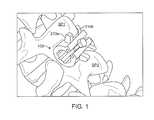
- FIG. 1shows a perspective view of a device that is configured for placement between the spinous processes of two adjacent vertebral bodies.
- FIG. 2shows an enlarged, perspective view of the device of FIG. 1 .
- FIG. 3shows a side view of the device of FIG. 1 .
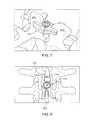
- FIG. 4shows the device positioned between a pair of spinous processes.
- FIGS. 5-6show another embodiment of an interspinous device.
- FIGS. 6-10Ashow another embodiment of an interspinous device.
- FIGS. 10B-11show another embodiment of an interspinous device.
- FIG. 12shows another embodiment of an interspinous device.
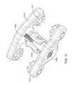
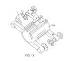
- FIG. 13shows another embodiment of an interspinous device.
- FIG. 1shows a perspective view of a device 105 that is configured for placement between the spinous processes SP 1 and SP 2 of two adjacent vertebral bodies.
- FIG. 2shows an enlarged, perspective view of the device 105 and
- FIG. 3shows a side view of the device 105 .
- the device 105includes a spacer or central region 205 that is sized and shaped to fit between the spinous processes of the two adjacent vertebral bodies.
- the device 105further includes a pair of protrusions 210 that extend outward from the central region. The protrusions are size and shaped to couple to the spinous processes, as described more fully below.
- the central region 205comprises a cylindrical body having one or more openings that extend through the walls of the body.
- the central region 205is cylindrical and substantially circular when viewed from the side (as shown in FIG. 3 ).
- a central shaft 305extends through the central region 205 .
- an elongated gap 208is formed, which is sized and shaped to receive a locking member 215 , as described below. It should be appreciated that the central region 205 can have other shapes.
- the protrusions 210comprise outwardly extending bodies or tabs. A pair of such protrusions extends outwardly from the central region 205 on each side of the gap 208 . A space between each of the protrusions is sized and shaped to receive at least a portion of a spinous process. For example, as shown in FIG. 1 , the protrusions 210 a and 210 b define a space therebetween that is sized and shaped to receive the spinous process SP 1 . In this manner, the device 105 can be positioned between the spinous processes SP 1 and SP 2 with the protrusions 210 coupling to respective spinous processes to thereby serve anchoring or stabilizing functions.
- the locking member 215is sized and shaped to fit within the elongated gap 215 .
- the elongated gap 215forms a pair of slots that are sized and shaped to receive complementary-shaped tabs on the locking member 215 .
- locking membermay be rotated to cause a cam portion of the locking member to outwardly separate the central region along opposite sides of the gap 215 and thereby lock the central region onto the spinous processes.
- FIG. 4shows the central region 205 of the device 105 positioned between a pair of spinous processes SP 1 and SP 2 .
- the locking member 215is not coupled to the central region 205 .
- the locking member 215can now be slid into the central region and rotated to cause the cam to expand the central region such that it exerts a force onto the spinous processes and fixes thereto.
- a series of slots 220FIG. 2 .
- the slotsare sized and shaped to receive at least a portion of a spinous process when the device 105 is implanted.
- FIG. 5shows another embodiment of the ISP device, referred to as device 505 .
- the device 505includes four members including a first member 510 , second member 515 , third member 520 , and fourth member 525 .
- Each of the second, third, and fourth memberhas a central shaft or opening that is sized and shaped to receive an elongated shank 530 such that the members may be coupled to one another by inserting the shank 530 through the central openings of the other members.
- the fourth member 525serves as a cap with internal threads that couple to external threads on the shank 530 . In this manner, the fourth member 525 can be secured to the shank 530 with the second and third members 515 and 520 secured along the shank 530 between the fourth member 525 and an enlarged head 535 of the first member 510 .
- the second member 515 and third member 520may be positioned with a space S therebetween.
- Each of the second member and third memberare sized and shaped to be positioned adjacent or juxtaposed with a spinous process of a respective vertebra.
- the spinous processcan be positioned within the space S and the second and third members tightened about the spinous process.
- the cap of the fourth membercan then be tightened to secure the spinous process within the space S.
- FIG. 6shows another embodiment of the ISP device, referred to as device 605 .
- the device 605includes a main body 610 that is sized and shaped to be positioned within the space between a pair of spinous processes.
- the main bodymay be coupled to an expander member 615 that threadably inserts into an opening 625 in the main body 610 .
- the main body 610has a substantially tubular configuration with an internal shaft and an out wall that forms a substantially cylindrical shape. A plurality of openings extend through the outer wall and communicate with the internal shaft.
- the expander member 615is elongated in shape and has a threaded shank that fits into the opening 625 of the main body.
- the expander member 615can be rotated to engage with threads inside the opening 625 to engage the expander member 615 with the main body 610 .
- any of the device embodimentscan be made of any biologically adaptable or compatible materials such as Polyether ether ketone (PEEK). Additional materials considered acceptable for biological implantation are well known and include, but are not limited to, stainless steel, titanium, tantalum, combination metallic alloys, various plastics, resins, ceramics, biologically absorbable materials and the like. In addition, any of the devices may be packed with a bone graft or other suitable material for fusing to adjacent bone.
- PEEKPolyether ether ketone
- FIGS. 7 and 8show another embodiment of a device 705 that is configured for placement between the spinous processes SP 1 and SP 2 of two adjacent vertebral bodies.
- the device 705includes two pairs of arms including a first pair with first and second arms 710 a and 710 b , as well as a second pair with third and fourth arms 710 c and 710 d .
- the arms 710 a and 710 b in the first pair of armsare sized and shaped to grasp or otherwise couple to the spinous process SP 1 .
- the arms 710 c and 710 d in the second pair of armsare sized and shaped to grasp or otherwise couple to the spinous process SP 2 .
- the relative positions of the armscan be adjusted by rotating actuator 715 .
- Rotation of the actuator 715causes the arms in a respective pair to rotate about an axis of rotation of the actuator 715 . That is, the arms rotate about the axis in a scissor-like manner. This permits the arms to be opened up to a size that would accept a respective spinous process and then closed to a size that grasps the respective spinous process.
- each armhas a flat inner surface with projections that are configured to increase a frictional hold with the spinous process to which the arm is coupled, as shown in FIGS. 9 and 10 .
- FIG. 9shows a perspective view of the device 705 in an assembled state
- FIG. 10Ashows the device 705 in an exploded state
- the device 705includes a first arm member 905 that includes a pair of arms.
- a second arm member 910includes another pair of arms.
- Each arm memberincludes a central shaft in which a coupler member 915 and a screw member 920 may be co-axially positioned.
- the screw member 920couples to a cap 925 that is positioned on an opposite end of the screw member 920 to secure the device 705 in an assembled state.
- the coupler member 915 and screw memberrotatably attach to the arm members 905 and 910 . When the screw member is rotated, it causes the arm members 905 and 910 to also rotate such that the arms may be rotated toward and away from another.
- FIGS. 10B and 11show another embodiment of the ISP device, referred to as device 1005 .
- the device 505includes a pair of opposed members 1010 that define a space S therebetween.
- Each of the members 1005is sized and shaped to be positioned adjacent or juxtaposed with a spinous process of a respective vertebra.
- the spinous processcan be positioned within the space S.
- each of the members 1010includes one or more pads 1017 having attachment elements, such as spikes, that are configured to attach onto the spinous process.
- the padsare attached to the members in a ball and socket manner such that the pads are configured to rotate and pivot about the ball and socket attachment.
- a connector 1020connects the two members 1010 to one another.
- the connector 1010is an elongated shaft having a first end with a head 1025 that sits in a seat in one of the members 1010 .
- a second end region of the connector 1010extends through a hole in the second member 1010 .
- the connector 1020 and holemay be threaded such that rotation of the connector 1010 causes the two members 1010 to move toward or away from one another depending on the direction of rotation. In this manner, the spinous process may be secured between the two members 1010 .
- An outer housing 1030is positioned around the connector 1020 .
- the outer housingis sized and shaped to receive bone material for fusing with the spine.
- the devicein another embodiment, shown in FIG. 12 , includes a pair of members 1005 and a connector 1010 therebetween.
- the connectoris formed of a first connector member 1205 and a second connector member 1210 that coupled to one another such as in a male-female relationship.
- the connector membersinclude a ratchet interface that permits the two connector members to be pushed toward one another in an interlocking fashion.
- the ratchet interfacepermits the two members 1005 to be successively moved toward one another and locked in successively closer positions so as to vary the size of the space S.
- the configuration of the ratchetcan be varied to permit various increments of relative movement between the two members 1005 .
- the devicein yet another embodiment, shown in FIG. 13 , includes a pair of members 1005 that are monolithically coupled to one another via a connector 1305 that is monolithically attached to the two members.
- a set of pads 1317are positioned on the members wherein the pads 1317 include attachment elements such as spikes.
- the pads 1317define a space therebetween that is sized to receive an interspinous process. The positions of at least some of the pads can be moveably adjusted to vary the size of the space S between facing pads.
Landscapes
- Health & Medical Sciences (AREA)
- Orthopedic Medicine & Surgery (AREA)
- Neurology (AREA)
- Life Sciences & Earth Sciences (AREA)
- Surgery (AREA)
- Engineering & Computer Science (AREA)
- Biomedical Technology (AREA)
- General Health & Medical Sciences (AREA)
- Veterinary Medicine (AREA)
- Heart & Thoracic Surgery (AREA)
- Public Health (AREA)
- Animal Behavior & Ethology (AREA)
- Nuclear Medicine, Radiotherapy & Molecular Imaging (AREA)
- Medical Informatics (AREA)
- Molecular Biology (AREA)
- Vascular Medicine (AREA)
- Transplantation (AREA)
- Oral & Maxillofacial Surgery (AREA)
- Cardiology (AREA)
- Prostheses (AREA)
Abstract
Description
Claims (7)
Priority Applications (3)
| Application Number | Priority Date | Filing Date | Title |
|---|---|---|---|
| US13/761,031US9387016B2 (en) | 2011-06-17 | 2013-02-06 | Expandable interspinous device |
| US15/151,336US10143501B2 (en) | 2011-06-17 | 2016-05-10 | Expandable interspinous device |
| US15/499,626US20170224390A1 (en) | 2011-06-17 | 2017-04-27 | Expandable interspinous device |
Applications Claiming Priority (4)
| Application Number | Priority Date | Filing Date | Title |
|---|---|---|---|
| US201161498354P | 2011-06-17 | 2011-06-17 | |
| US201161515541P | 2011-08-05 | 2011-08-05 | |
| US13/526,277US20120323276A1 (en) | 2011-06-17 | 2012-06-18 | Expandable interspinous device |
| US13/761,031US9387016B2 (en) | 2011-06-17 | 2013-02-06 | Expandable interspinous device |
Related Parent Applications (1)
| Application Number | Title | Priority Date | Filing Date |
|---|---|---|---|
| US13/526,277ContinuationUS20120323276A1 (en) | 2011-06-17 | 2012-06-18 | Expandable interspinous device |
Related Child Applications (1)
| Application Number | Title | Priority Date | Filing Date |
|---|---|---|---|
| US15/151,336ContinuationUS10143501B2 (en) | 2011-06-17 | 2016-05-10 | Expandable interspinous device |
Publications (2)
| Publication Number | Publication Date |
|---|---|
| US20130158604A1 US20130158604A1 (en) | 2013-06-20 |
| US9387016B2true US9387016B2 (en) | 2016-07-12 |
Family
ID=47354284
Family Applications (4)
| Application Number | Title | Priority Date | Filing Date |
|---|---|---|---|
| US13/526,277AbandonedUS20120323276A1 (en) | 2011-06-17 | 2012-06-18 | Expandable interspinous device |
| US13/761,031Active2032-08-14US9387016B2 (en) | 2011-06-17 | 2013-02-06 | Expandable interspinous device |
| US15/151,336ActiveUS10143501B2 (en) | 2011-06-17 | 2016-05-10 | Expandable interspinous device |
| US15/499,626AbandonedUS20170224390A1 (en) | 2011-06-17 | 2017-04-27 | Expandable interspinous device |
Family Applications Before (1)
| Application Number | Title | Priority Date | Filing Date |
|---|---|---|---|
| US13/526,277AbandonedUS20120323276A1 (en) | 2011-06-17 | 2012-06-18 | Expandable interspinous device |
Family Applications After (2)
| Application Number | Title | Priority Date | Filing Date |
|---|---|---|---|
| US15/151,336ActiveUS10143501B2 (en) | 2011-06-17 | 2016-05-10 | Expandable interspinous device |
| US15/499,626AbandonedUS20170224390A1 (en) | 2011-06-17 | 2017-04-27 | Expandable interspinous device |
Country Status (1)
| Country | Link |
|---|---|
| US (4) | US20120323276A1 (en) |
Cited By (7)
| Publication number | Priority date | Publication date | Assignee | Title |
|---|---|---|---|---|
| US20160015432A1 (en)* | 2014-06-06 | 2016-01-21 | Aurora Spine, Inc. | Polyaxial interspinous fusion implant and bone growth stimulation system |
| US9757165B2 (en)* | 2015-10-23 | 2017-09-12 | Warsaw Orthopedic, Inc. | Spinal implant system and method |
| US20170311993A1 (en)* | 2010-12-13 | 2017-11-02 | Globus Medical, Inc. | Spinous process fusion devices and methods thereof |
| US10143501B2 (en) | 2011-06-17 | 2018-12-04 | Aurora Spine, Inc. | Expandable interspinous device |
| US11026805B2 (en) | 2019-07-30 | 2021-06-08 | Loubert S. Suddaby | Expandable intervertebral fusion implant |
| US11331199B2 (en)* | 2019-04-29 | 2022-05-17 | Aurora Spine, Inc. | Spinal implant for motion preservation or fusion |
| US20220401224A1 (en)* | 2012-12-31 | 2022-12-22 | Zimmer Biomet Spine, Inc. | Interspinous implants |
Families Citing this family (21)
| Publication number | Priority date | Publication date | Assignee | Title |
|---|---|---|---|---|
| EP2323574B1 (en) | 2008-08-13 | 2012-02-15 | Synthes GmbH | Interspinous spacer assembly |
| USD757943S1 (en) | 2011-07-14 | 2016-05-31 | Nuvasive, Inc. | Spinous process plate |
| US8882805B1 (en) | 2011-08-02 | 2014-11-11 | Lawrence Maccree | Spinal fixation system |
| EP2800532B1 (en) | 2012-01-05 | 2019-12-11 | Lanx, Inc. | Telescoping interspinous fixation device |
| US10448977B1 (en) | 2012-03-31 | 2019-10-22 | Ali H. MESIWALA | Interspinous device and related methods |
| AU2013249305B2 (en)* | 2012-04-17 | 2017-05-11 | Aurora Spine, Llc | A dynamic and non-dynamic interspinous fusion implant and bone growth stimulation system |
| US9198697B2 (en)* | 2013-03-13 | 2015-12-01 | Globus Medical, Inc. | Spinous process fixation system and methods thereof |
| US9011493B2 (en)* | 2012-12-31 | 2015-04-21 | Globus Medical, Inc. | Spinous process fixation system and methods thereof |
| US9486251B2 (en)* | 2012-12-31 | 2016-11-08 | Globus Medical, Inc. | Spinous process fixation system and methods thereof |
| US9168073B2 (en)* | 2013-03-15 | 2015-10-27 | DePuy Synthes Products, Inc. | Spinous process fixator |
| US9480502B2 (en) | 2013-05-16 | 2016-11-01 | Smokey Mountain Spine, Llc | Expansion interspinous fixation device and method |
| US9259249B2 (en) | 2013-11-26 | 2016-02-16 | Globus Medical, Inc. | Spinous process fixation system and methods thereof |
| US9763706B2 (en)* | 2014-08-14 | 2017-09-19 | FloSpine, LLC | Interspinous fusion device |
| KR101647446B1 (en)* | 2014-10-20 | 2016-08-10 | 주식회사 메드릭스 | Interspinous fusion implant |
| US9763707B2 (en)* | 2015-07-21 | 2017-09-19 | Asfora Ip, Llc | Interspinous process device and method |
| US12144742B2 (en) | 2020-06-15 | 2024-11-19 | Foundation Surgical Group, Inc. | Implant system and methods of use |
| US11259936B2 (en) | 2020-06-15 | 2022-03-01 | Nofusco Corporation | Intravertebral implant system and methods of use |
| US11723778B1 (en) | 2021-09-23 | 2023-08-15 | Nofusco Corporation | Vertebral implant system and methods of use |
| US11883300B2 (en) | 2020-06-15 | 2024-01-30 | Nofusco Corporation | Orthopedic implant system and methods of use |
| US11896268B2 (en)* | 2022-01-24 | 2024-02-13 | Linares Spinal Devices, Llc | Expandable spinal rack gear jack for installation between upper and lower succeeding superior articular processes |
| TWI819504B (en)* | 2022-02-25 | 2023-10-21 | 寶億生技股份有限公司 | Interspinous process device and device for stabilizing thereof |
Citations (147)
| Publication number | Priority date | Publication date | Assignee | Title |
|---|---|---|---|---|
| US5011484A (en)* | 1987-11-16 | 1991-04-30 | Breard Francis H | Surgical implant for restricting the relative movement of vertebrae |
| US5496318A (en)* | 1993-01-08 | 1996-03-05 | Advanced Spine Fixation Systems, Inc. | Interspinous segmental spine fixation device |
| US5645599A (en)* | 1994-07-26 | 1997-07-08 | Fixano | Interspinal vertebral implant |
| US5876404A (en)* | 1997-01-02 | 1999-03-02 | St. Francis Medical Technologies, Llc | Spine distraction implant and method |
| US6099527A (en)* | 1998-04-30 | 2000-08-08 | Spinal Concepts, Inc. | Bone protector and method |
| US6238397B1 (en)* | 1997-01-02 | 2001-05-29 | St. Francis Technologies, Inc. | Spine distraction implant and method |
| US6312431B1 (en)* | 2000-04-24 | 2001-11-06 | Wilson T. Asfora | Vertebrae linking system |
| US6585739B2 (en)* | 2001-01-16 | 2003-07-01 | Medtronic Ps Medical, Inc. | Apparatus for attaching a cranial flap |
| US6626944B1 (en)* | 1998-02-20 | 2003-09-30 | Jean Taylor | Interspinous prosthesis |
| US6695842B2 (en)* | 1997-10-27 | 2004-02-24 | St. Francis Medical Technologies, Inc. | Interspinous process distraction system and method with positionable wing and method |
| US6761720B1 (en)* | 1999-10-15 | 2004-07-13 | Spine Next | Intervertebral implant |
| US20050075634A1 (en)* | 2002-10-29 | 2005-04-07 | Zucherman James F. | Interspinous process implant with radiolucent spacer and lead-in tissue expander |
| US20050203512A1 (en)* | 2004-03-09 | 2005-09-15 | Depuy Spine, Inc. | Posterior process dynamic spacer |
| US6946000B2 (en)* | 2000-12-22 | 2005-09-20 | Spine Next | Intervertebral implant with deformable wedge |
| US20060015181A1 (en)* | 2004-07-19 | 2006-01-19 | Biomet Merck France (50% Interest) | Interspinous vertebral implant |
| US7048736B2 (en)* | 2002-05-17 | 2006-05-23 | Sdgi Holdings, Inc. | Device for fixation of spinous processes |
| US7087083B2 (en)* | 2001-03-13 | 2006-08-08 | Abbott Spine | Self locking fixable intervertebral implant |
| US20060235532A1 (en)* | 2003-01-20 | 2006-10-19 | Abbott Spine | Unit for treatment of the degeneration of an intervertebral disc |
| US20060235387A1 (en)* | 2005-04-15 | 2006-10-19 | Sdgi Holdings, Inc. | Transverse process/laminar spacer |
| US20060241601A1 (en)* | 2005-04-08 | 2006-10-26 | Trautwein Frank T | Interspinous vertebral and lumbosacral stabilization devices and methods of use |
| US20060241613A1 (en)* | 2005-04-12 | 2006-10-26 | Sdgi Holdings, Inc. | Implants and methods for inter-transverse process dynamic stabilization of a spinal motion segment |
| US20060247623A1 (en)* | 2005-04-29 | 2006-11-02 | Sdgi Holdings, Inc. | Local delivery of an active agent from an orthopedic implant |
| US20060247634A1 (en)* | 2005-05-02 | 2006-11-02 | Warner Kenneth D | Spinous Process Spacer Implant and Technique |
| US20060247640A1 (en) | 2005-04-29 | 2006-11-02 | Sdgi Holdings, Inc. | Spinous process stabilization devices and methods |
| US20060271044A1 (en)* | 2003-03-28 | 2006-11-30 | Piero Petrini | Interlaminar vertebral prosthesis |
| US20070093823A1 (en)* | 2005-09-29 | 2007-04-26 | Nuvasive, Inc. | Spinal distraction device and methods of manufacture and use |
| US20070093830A1 (en)* | 2002-10-29 | 2007-04-26 | St. Francis Medical Technologies, Inc. | Interspinous process apparatus and method with a selectably expandable spacer |
| US20070106298A1 (en)* | 2005-08-04 | 2007-05-10 | Olivier Carli | Invertebral implant with two shapes |
| US7238204B2 (en)* | 2000-07-12 | 2007-07-03 | Abbott Spine | Shock-absorbing intervertebral implant |
| US20070162004A1 (en)* | 2005-12-07 | 2007-07-12 | Alain Tornier | Device for the lateral stabilization of the spine |
| US20070162001A1 (en)* | 2005-12-14 | 2007-07-12 | Spinefrontier Lls | Spinous process fixation implant |
| US20070167945A1 (en)* | 2006-01-18 | 2007-07-19 | Sdgi Holdings, Inc. | Intervertebral prosthetic device for spinal stabilization and method of manufacturing same |
| US20070203494A1 (en)* | 2003-11-07 | 2007-08-30 | Uri Arnin | Spinal prostheses |
| US20080114455A1 (en)* | 2006-11-15 | 2008-05-15 | Warsaw Orthopedic, Inc. | Rotating Interspinous Process Devices and Methods of Use |
| US20080140125A1 (en)* | 2001-07-20 | 2008-06-12 | Mitchell Margaret E | Spinal stabilization system and method |
| US20080161856A1 (en)* | 2006-10-06 | 2008-07-03 | Mingyan Liu | Spinal stabilization system |
| US20080167657A1 (en)* | 2006-12-31 | 2008-07-10 | Stout Medical Group, L.P. | Expandable support device and method of use |
| US20080183218A1 (en)* | 2007-01-31 | 2008-07-31 | Nuvasive, Inc. | System and Methods for Spinous Process Fusion |
| US7442208B2 (en)* | 2001-08-20 | 2008-10-28 | Synthes (U.S.A.) | Interspinal prosthesis |
| US20080275511A1 (en)* | 2007-04-23 | 2008-11-06 | Marcus Weinacker | Cranium fixing device |
| US20080294200A1 (en)* | 2007-05-25 | 2008-11-27 | Andrew Kohm | Spinous process implants and methods of using the same |
| US7510567B2 (en)* | 1997-01-02 | 2009-03-31 | Kyphon Sarl | Spinal implants, insertion instruments, and methods of use |
| US7520888B2 (en)* | 2006-02-14 | 2009-04-21 | Warsaw Orthopedic, Inc. | Treatment of the vertebral column |
| US20090138087A1 (en)* | 2005-07-28 | 2009-05-28 | Carlo Miglietta | Apparatus for the Neurosurgical-Orthopedic Treatment of Human Spinal Column Pathologies |
| US7585313B2 (en)* | 2005-12-22 | 2009-09-08 | Depuy Spine, Inc. | Rotatable interspinous spacer |
| US7585316B2 (en)* | 2004-05-21 | 2009-09-08 | Warsaw Orthopedic, Inc. | Interspinous spacer |
| US20090264927A1 (en)* | 2008-04-14 | 2009-10-22 | Howard Joeseph Ginsberg | Spinous process stabilization device and method |
| US20090270918A1 (en)* | 2005-04-08 | 2009-10-29 | David Attia | Surgical Intervertebral Implant Forming a Swivel Joint |
| US20090270919A1 (en)* | 2008-04-25 | 2009-10-29 | Gm Dos Reis Junior | Interspinous device |
| USD606195S1 (en)* | 2008-09-04 | 2009-12-15 | Paradigm Spine, Llc | Interspinous implant |
| US20090318967A1 (en)* | 2007-01-23 | 2009-12-24 | Dong Myung Jeon | Spacer for use in a surgical operation for spinous process of spine |
| US20100010548A1 (en)* | 2008-07-11 | 2010-01-14 | Elias Humberto Hermida Ochoa | Instruments and Method of Use for Minimally Invasive Spine Surgery in Interspine Space Through Only One Side |
| US20100069965A1 (en)* | 2008-07-05 | 2010-03-18 | Abdou M Samy | Device and method for the prevention of multi-level vertebral extension |
| US7682376B2 (en)* | 2006-01-27 | 2010-03-23 | Warsaw Orthopedic, Inc. | Interspinous devices and methods of use |
| US7691130B2 (en)* | 2006-01-27 | 2010-04-06 | Warsaw Orthopedic, Inc. | Spinal implants including a sensor and methods of use |
| US20100087869A1 (en)* | 2008-08-18 | 2010-04-08 | Abdou M Samy | Devices and methods to limit aberrant movement of the vertebral bones |
| US20100121379A1 (en)* | 2006-01-27 | 2010-05-13 | U.S. Spinal Technologies, Llc | Pedicle and non-pedicle based interspinous and lateral spacers |
| US20100204732A1 (en)* | 2007-09-14 | 2010-08-12 | Felix Aschmann | Interspinous spacer |
| US7776069B2 (en)* | 2002-09-10 | 2010-08-17 | Kyphon SÀRL | Posterior vertebral support assembly |
| US20100217320A1 (en)* | 2005-06-22 | 2010-08-26 | Tutogen Medical Gmbh | Vertebral implant made from bone material for relief of a narrowed vertebral channel |
| US20100241167A1 (en)* | 2007-01-11 | 2010-09-23 | Lanx, Inc. | Spinous process implants and associated methods |
| US7837688B2 (en)* | 2005-06-13 | 2010-11-23 | Globus Medical | Spinous process spacer |
| US20100305619A1 (en)* | 2007-12-14 | 2010-12-02 | Stryker Leibinger Gmbh & Co. Kg | Implant for use for adjacently arranged bone plates |
| US20110004248A1 (en)* | 2007-02-26 | 2011-01-06 | Samy Abdou | Spinal stabilization systems and methods of use |
| US7871426B2 (en)* | 2006-03-21 | 2011-01-18 | Spinefrontier, LLS | Spinous process fixation device |
| US20110022090A1 (en)* | 2009-06-23 | 2011-01-27 | Osteomed, L.P. | Spinous process fusion implants |
| US7879073B2 (en)* | 2004-05-11 | 2011-02-01 | Zimmer Spine | Self-locking device for fastening an intervertebral implant |
| US7879104B2 (en)* | 2006-11-15 | 2011-02-01 | Warsaw Orthopedic, Inc. | Spinal implant system |
| US20110040330A1 (en)* | 2007-05-09 | 2011-02-17 | Ebi, Llc | Interspinous implant |
| US20110066186A1 (en)* | 2009-09-11 | 2011-03-17 | Boyer Ii Michael Lee | Spinous Process Fusion Devices |
| US7922750B2 (en)* | 2006-11-30 | 2011-04-12 | Paradigm Spine, Llc | Interlaminar-interspinous vertebral stabilization system |
| US20110087285A1 (en)* | 2009-10-14 | 2011-04-14 | Kaveh Khajavi | Spinous process fixation plate and minimally invasive method for placement |
| US20110098745A1 (en)* | 2009-10-28 | 2011-04-28 | Kyphon Sarl | Interspinous process implant and method of implantation |
| US7955392B2 (en)* | 2006-12-14 | 2011-06-07 | Warsaw Orthopedic, Inc. | Interspinous process devices and methods |
| US20110144692A1 (en)* | 2008-08-13 | 2011-06-16 | Synthes Usa, Llc | Interspinous spacer assembly |
| US20110160772A1 (en)* | 2009-12-28 | 2011-06-30 | Arcenio Gregory B | Systems and methods for performing spinal fusion |
| US20110166600A1 (en)* | 2007-01-11 | 2011-07-07 | Lanx, Inc. | Interspinsous implants and methods |
| US7985246B2 (en)* | 2006-03-31 | 2011-07-26 | Warsaw Orthopedic, Inc. | Methods and instruments for delivering interspinous process spacers |
| US7988708B2 (en)* | 2006-04-07 | 2011-08-02 | Biomed Ltd. | Interspinous process distraction device |
| US20110190818A1 (en)* | 2010-02-01 | 2011-08-04 | Zimmer Spine | Intervertebral device |
| US20110224731A1 (en)* | 2010-03-12 | 2011-09-15 | Southern Spine, Llc | Interspinous Process Spacing Device |
| US8021395B2 (en)* | 2007-05-22 | 2011-09-20 | Eden Spine, Llc | Interspinous vertebral implant |
| US8034079B2 (en)* | 2005-04-12 | 2011-10-11 | Warsaw Orthopedic, Inc. | Implants and methods for posterior dynamic stabilization of a spinal motion segment |
| US20110264221A1 (en)* | 2010-04-24 | 2011-10-27 | Custom Spine, Inc. | Interspinous Fusion Device and Method |
| US8048077B2 (en)* | 2006-09-22 | 2011-11-01 | Aesculap Ag | Sternum closure device |
| US8048120B1 (en)* | 2006-05-31 | 2011-11-01 | Medicine Lodge, Inc. | System and method for segmentally modular spinal plating |
| US8070779B2 (en)* | 2007-06-04 | 2011-12-06 | K2M, Inc. | Percutaneous interspinous process device and method |
| US20110313458A1 (en)* | 2010-06-16 | 2011-12-22 | Butler Michael S | Spinal Clips For Interspinous Decompression |
| US20110319936A1 (en)* | 2009-06-23 | 2011-12-29 | Osteomed Llc | Spinous process fusion implants and insertion, compression, and locking instrumentation |
| US20120016418A1 (en)* | 2010-07-15 | 2012-01-19 | Spinefrontier Inc | Interspinous fixation implant |
| US8100945B2 (en)* | 2006-01-18 | 2012-01-24 | Warsaw Orthopedic, Inc. | Intervertebral prosthetic device for spinal stabilization and method of implanting same |
| US8114132B2 (en)* | 2010-01-13 | 2012-02-14 | Kyphon Sarl | Dynamic interspinous process device |
| US8114136B2 (en)* | 2008-03-18 | 2012-02-14 | Warsaw Orthopedic, Inc. | Implants and methods for inter-spinous process dynamic stabilization of a spinal motion segment |
| US8118839B2 (en)* | 2006-11-08 | 2012-02-21 | Kyphon Sarl | Interspinous implant |
| US8133227B2 (en)* | 2006-09-22 | 2012-03-13 | Aesculap Ag | Sternum closure device |
| US20120065683A1 (en)* | 2010-09-13 | 2012-03-15 | Fan-Ching Kuo | Interspinous process distraction device |
| US20120083844A1 (en)* | 2008-10-23 | 2012-04-05 | Linares Medical Devices, Llc | Inter-vertebral support kit including main insert jack and dual secondary auxiliary support jacks located between succeeding transverse processes |
| US20120089184A1 (en)* | 2010-10-08 | 2012-04-12 | Chung-Chun Yeh | Device for tightly gripping on the spinous process of the spine |
| US8157842B2 (en)* | 2009-06-12 | 2012-04-17 | Kyphon Sarl | Interspinous implant and methods of use |
| US20120101528A1 (en)* | 2010-07-26 | 2012-04-26 | Souza John J | Spinous process implant and method of fixation |
| US8167915B2 (en)* | 2005-09-28 | 2012-05-01 | Nuvasive, Inc. | Methods and apparatus for treating spinal stenosis |
| US20120109198A1 (en)* | 2010-11-01 | 2012-05-03 | Warsaw Orthopedic, Inc. | Spinous process implant with a post and an enlarged boss |
| US20120109203A1 (en)* | 2010-11-01 | 2012-05-03 | Warsaw Orthopedic, Inc. | Spinous process implant with extended post |
| US8187306B2 (en)* | 2007-04-10 | 2012-05-29 | Medicine Ledge Inc | Interspinous process spacers |
| US20120136390A1 (en)* | 2010-11-29 | 2012-05-31 | Butler Michael S | Spinal Implants For Lumbar Vertebra To Sacrum Fixation |
| US20120143252A1 (en)* | 2010-12-05 | 2012-06-07 | Robinson James C | Spinous process fixation apparatus and method |
| US20120150228A1 (en)* | 2010-12-13 | 2012-06-14 | Jason Zappacosta | Spinous Process Fusion Devices and Methods Thereof |
| US8206420B2 (en)* | 2008-08-08 | 2012-06-26 | Alphatec Spine, Inc | Spinous process device and method of use |
| US8221462B2 (en)* | 2005-08-01 | 2012-07-17 | Globus Medical, Inc. | Interspinous internal fixation/distraction device |
| US8221464B2 (en)* | 2007-09-25 | 2012-07-17 | Zimmer Spine, S.A.S. | Device for clamping two portions of a braid and an intervertebral implant comprising a spacer, a braid, and such a clamping device |
| US20120191135A1 (en)* | 2011-01-24 | 2012-07-26 | Samy Abdou | Spinous process fixation devices and methods of use |
| US8236031B2 (en)* | 2009-01-26 | 2012-08-07 | Life Spine, Inc. | Flexible and static interspinous/inter-laminar spinal spacers |
| US8241330B2 (en)* | 2007-01-11 | 2012-08-14 | Lanx, Inc. | Spinous process implants and associated methods |
| US8241332B2 (en)* | 2005-09-19 | 2012-08-14 | Blackstone Medical Inc. | Distance-keeping inter-process implant |
| US8246655B2 (en)* | 2009-01-09 | 2012-08-21 | Pioneer Surgical Technology, Inc. | Intervertebral implant devices and methods for insertion thereof |
| US20120215261A1 (en)* | 2011-02-23 | 2012-08-23 | Farzad Massoudi | Spinal implant device with fusion cage and fixation plates and method of implanting |
| US20120221050A1 (en)* | 2009-09-11 | 2012-08-30 | Aditya Ingalhalikar | Spinous Process Fusion Devices |
| US20120221051A1 (en)* | 2010-12-05 | 2012-08-30 | Robinson James C | Spinous process fixation apparatus |
| US20120226314A1 (en)* | 2011-03-04 | 2012-09-06 | Spinefrontier Inc | Interspinous spacer implant |
| US20120226313A1 (en)* | 2011-03-01 | 2012-09-06 | Warsaw Orthopedic, Inc. | Percutaneous spinous process fusion plate assembly and method |
| US8262697B2 (en)* | 2010-01-14 | 2012-09-11 | X-Spine Systems, Inc. | Modular interspinous fixation system and method |
| US20120239089A1 (en)* | 2011-03-17 | 2012-09-20 | Kyphon Sarl | Interspinous process implant and method of implantation |
| US20120253393A1 (en)* | 2011-03-31 | 2012-10-04 | Warsaw Orthopedic, Inc. | Spinous process fusion plate assembly |
| US20120259368A1 (en)* | 2011-04-06 | 2012-10-11 | Chang-Hwa You | Spacer apparatus for manintaining interspinous spacing |
| US8287569B1 (en)* | 2007-11-15 | 2012-10-16 | Powell N Garrett | Modular system and method for fixation of spinous processes |
| US8303629B1 (en)* | 2009-03-19 | 2012-11-06 | Abdou M Samy | Spinous process fusion and orthopedic implants and methods |
| US8308769B2 (en)* | 2008-05-07 | 2012-11-13 | Innovative Spine LLC. | Implant device and method for interspinous distraction |
| US8313513B2 (en)* | 2006-12-08 | 2012-11-20 | Aesculap Ag | Implant and implant system |
| US20120296378A1 (en)* | 2007-04-10 | 2012-11-22 | Life Spine, Inc. | Adjustable spine distraction implant |
| US8343190B1 (en)* | 2008-03-26 | 2013-01-01 | Nuvasive, Inc. | Systems and methods for spinous process fixation |
| US20130012995A1 (en)* | 2009-12-23 | 2013-01-10 | Qspine Limited | Interspinous Implant |
| US20130012996A1 (en)* | 2011-06-21 | 2013-01-10 | Seaspine, Inc. | Spinous process device |
| US8357181B2 (en)* | 2005-10-27 | 2013-01-22 | Warsaw Orthopedic, Inc. | Intervertebral prosthetic device for spinal stabilization and method of implanting same |
| US8372117B2 (en)* | 2009-06-05 | 2013-02-12 | Kyphon Sarl | Multi-level interspinous implants and methods of use |
| US8372118B2 (en)* | 2006-12-12 | 2013-02-12 | Spinefrontier Inc | Spinous process fixation implant |
| US20130041408A1 (en)* | 2011-06-30 | 2013-02-14 | Hervé Dinville | Interspinous Implant and Implantation Instrument |
| US8377097B2 (en)* | 2009-06-23 | 2013-02-19 | Osteomed, Llc | Bone tissue clamp |
| US8382801B2 (en)* | 2007-01-11 | 2013-02-26 | Lanx, Inc. | Spinous process implants, instruments, and methods |
| US8388656B2 (en)* | 2010-02-04 | 2013-03-05 | Ebi, Llc | Interspinous spacer with deployable members and related method |
| US20130072979A1 (en)* | 2010-11-29 | 2013-03-21 | Life Spine, Inc. | Spinal implant for lumbar vertebra to sacrum fixation |
| US8403959B2 (en)* | 2004-12-16 | 2013-03-26 | Med-Titan Spine Gmbh | Implant for the treatment of lumbar spinal canal stenosis |
| US8414615B2 (en)* | 2008-12-30 | 2013-04-09 | Industrial Technology Research Institute | Spinal dynamic stabilization device, surgical method utilizing thereof and clamping apparatus |
| US20130090689A1 (en)* | 2011-10-07 | 2013-04-11 | Alan Villavicencio | Spinal fixation device |
| US8425560B2 (en)* | 2011-03-09 | 2013-04-23 | Farzad Massoudi | Spinal implant device with fixation plates and lag screws and method of implanting |
| US20130103088A1 (en)* | 2011-09-16 | 2013-04-25 | Lanx, Inc. | Segmental Spinous Process Anchor System and Methods of Use |
| US20130184752A1 (en)* | 2011-12-27 | 2013-07-18 | Binder Biomedical, Inc. | Spinous process fusion device |
| US20130296940A1 (en) | 2012-04-17 | 2013-11-07 | Aurora Spine, Llc | Dynamic and non-dynamic interspinous fusion implant and bone growth stimulation system |
Family Cites Families (2)
| Publication number | Priority date | Publication date | Assignee | Title |
|---|---|---|---|---|
| US7871397B2 (en) | 2006-12-26 | 2011-01-18 | Stat Medical Devices, Inc. | Pen needle tip |
| US20120323276A1 (en) | 2011-06-17 | 2012-12-20 | Bryan Okamoto | Expandable interspinous device |
- 2012
- 2012-06-18USUS13/526,277patent/US20120323276A1/ennot_activeAbandoned
- 2013
- 2013-02-06USUS13/761,031patent/US9387016B2/enactiveActive
- 2016
- 2016-05-10USUS15/151,336patent/US10143501B2/enactiveActive
- 2017
- 2017-04-27USUS15/499,626patent/US20170224390A1/ennot_activeAbandoned
Patent Citations (173)
| Publication number | Priority date | Publication date | Assignee | Title |
|---|---|---|---|---|
| US5011484A (en)* | 1987-11-16 | 1991-04-30 | Breard Francis H | Surgical implant for restricting the relative movement of vertebrae |
| US5496318A (en)* | 1993-01-08 | 1996-03-05 | Advanced Spine Fixation Systems, Inc. | Interspinous segmental spine fixation device |
| US5645599A (en)* | 1994-07-26 | 1997-07-08 | Fixano | Interspinal vertebral implant |
| US7510567B2 (en)* | 1997-01-02 | 2009-03-31 | Kyphon Sarl | Spinal implants, insertion instruments, and methods of use |
| US5876404A (en)* | 1997-01-02 | 1999-03-02 | St. Francis Medical Technologies, Llc | Spine distraction implant and method |
| US6238397B1 (en)* | 1997-01-02 | 2001-05-29 | St. Francis Technologies, Inc. | Spine distraction implant and method |
| US6451020B1 (en)* | 1997-01-02 | 2002-09-17 | St. Francis Medical Technologies, Inc. | Spine distraction implant and method |
| US6695842B2 (en)* | 1997-10-27 | 2004-02-24 | St. Francis Medical Technologies, Inc. | Interspinous process distraction system and method with positionable wing and method |
| US6626944B1 (en)* | 1998-02-20 | 2003-09-30 | Jean Taylor | Interspinous prosthesis |
| US6099527A (en)* | 1998-04-30 | 2000-08-08 | Spinal Concepts, Inc. | Bone protector and method |
| US6761720B1 (en)* | 1999-10-15 | 2004-07-13 | Spine Next | Intervertebral implant |
| US6312431B1 (en)* | 2000-04-24 | 2001-11-06 | Wilson T. Asfora | Vertebrae linking system |
| US20070213829A1 (en)* | 2000-07-12 | 2007-09-13 | Abbott Spine | Shock-absorbing intervertebral implant |
| US7238204B2 (en)* | 2000-07-12 | 2007-07-03 | Abbott Spine | Shock-absorbing intervertebral implant |
| US8349016B2 (en)* | 2000-07-12 | 2013-01-08 | Zimmer Spine | Shock-absorbing intervertebral implant |
| US6946000B2 (en)* | 2000-12-22 | 2005-09-20 | Spine Next | Intervertebral implant with deformable wedge |
| US6585739B2 (en)* | 2001-01-16 | 2003-07-01 | Medtronic Ps Medical, Inc. | Apparatus for attaching a cranial flap |
| US7087083B2 (en)* | 2001-03-13 | 2006-08-08 | Abbott Spine | Self locking fixable intervertebral implant |
| US20080140125A1 (en)* | 2001-07-20 | 2008-06-12 | Mitchell Margaret E | Spinal stabilization system and method |
| US7442208B2 (en)* | 2001-08-20 | 2008-10-28 | Synthes (U.S.A.) | Interspinal prosthesis |
| US7048736B2 (en)* | 2002-05-17 | 2006-05-23 | Sdgi Holdings, Inc. | Device for fixation of spinous processes |
| US8043336B2 (en)* | 2002-09-10 | 2011-10-25 | Warsaw Orthopedic, Inc. | Posterior vertebral support assembly |
| US7776069B2 (en)* | 2002-09-10 | 2010-08-17 | Kyphon SÀRL | Posterior vertebral support assembly |
| US20070093830A1 (en)* | 2002-10-29 | 2007-04-26 | St. Francis Medical Technologies, Inc. | Interspinous process apparatus and method with a selectably expandable spacer |
| US20050075634A1 (en)* | 2002-10-29 | 2005-04-07 | Zucherman James F. | Interspinous process implant with radiolucent spacer and lead-in tissue expander |
| US20060235532A1 (en)* | 2003-01-20 | 2006-10-19 | Abbott Spine | Unit for treatment of the degeneration of an intervertebral disc |
| US20060271044A1 (en)* | 2003-03-28 | 2006-11-30 | Piero Petrini | Interlaminar vertebral prosthesis |
| US20070203494A1 (en)* | 2003-11-07 | 2007-08-30 | Uri Arnin | Spinal prostheses |
| US7763073B2 (en)* | 2004-03-09 | 2010-07-27 | Depuy Spine, Inc. | Posterior process dynamic spacer |
| US20050203512A1 (en)* | 2004-03-09 | 2005-09-15 | Depuy Spine, Inc. | Posterior process dynamic spacer |
| US7879073B2 (en)* | 2004-05-11 | 2011-02-01 | Zimmer Spine | Self-locking device for fastening an intervertebral implant |
| US8216276B2 (en)* | 2004-05-21 | 2012-07-10 | Warsaw Orthopedic, Inc. | Interspinous spacer |
| US7585316B2 (en)* | 2004-05-21 | 2009-09-08 | Warsaw Orthopedic, Inc. | Interspinous spacer |
| US20060015181A1 (en)* | 2004-07-19 | 2006-01-19 | Biomet Merck France (50% Interest) | Interspinous vertebral implant |
| US8403959B2 (en)* | 2004-12-16 | 2013-03-26 | Med-Titan Spine Gmbh | Implant for the treatment of lumbar spinal canal stenosis |
| US20060241601A1 (en)* | 2005-04-08 | 2006-10-26 | Trautwein Frank T | Interspinous vertebral and lumbosacral stabilization devices and methods of use |
| US20090270918A1 (en)* | 2005-04-08 | 2009-10-29 | David Attia | Surgical Intervertebral Implant Forming a Swivel Joint |
| US8034079B2 (en)* | 2005-04-12 | 2011-10-11 | Warsaw Orthopedic, Inc. | Implants and methods for posterior dynamic stabilization of a spinal motion segment |
| US20060241613A1 (en)* | 2005-04-12 | 2006-10-26 | Sdgi Holdings, Inc. | Implants and methods for inter-transverse process dynamic stabilization of a spinal motion segment |
| US20060235387A1 (en)* | 2005-04-15 | 2006-10-19 | Sdgi Holdings, Inc. | Transverse process/laminar spacer |
| US20060247623A1 (en)* | 2005-04-29 | 2006-11-02 | Sdgi Holdings, Inc. | Local delivery of an active agent from an orthopedic implant |
| US8226653B2 (en)* | 2005-04-29 | 2012-07-24 | Warsaw Orthopedic, Inc. | Spinous process stabilization devices and methods |
| US20060247640A1 (en) | 2005-04-29 | 2006-11-02 | Sdgi Holdings, Inc. | Spinous process stabilization devices and methods |
| US7727233B2 (en)* | 2005-04-29 | 2010-06-01 | Warsaw Orthopedic, Inc. | Spinous process stabilization devices and methods |
| US20060247634A1 (en)* | 2005-05-02 | 2006-11-02 | Warner Kenneth D | Spinous Process Spacer Implant and Technique |
| US7837688B2 (en)* | 2005-06-13 | 2010-11-23 | Globus Medical | Spinous process spacer |
| US8388657B2 (en)* | 2005-06-13 | 2013-03-05 | Globus Medical, Inc | Spinous process spacer |
| US20100217320A1 (en)* | 2005-06-22 | 2010-08-26 | Tutogen Medical Gmbh | Vertebral implant made from bone material for relief of a narrowed vertebral channel |
| US20090138087A1 (en)* | 2005-07-28 | 2009-05-28 | Carlo Miglietta | Apparatus for the Neurosurgical-Orthopedic Treatment of Human Spinal Column Pathologies |
| US8221462B2 (en)* | 2005-08-01 | 2012-07-17 | Globus Medical, Inc. | Interspinous internal fixation/distraction device |
| US20120245639A1 (en)* | 2005-08-01 | 2012-09-27 | Dwyer James W | Interspinous Internal Fixation/Distraction Device |
| US20070106298A1 (en)* | 2005-08-04 | 2007-05-10 | Olivier Carli | Invertebral implant with two shapes |
| US8241332B2 (en)* | 2005-09-19 | 2012-08-14 | Blackstone Medical Inc. | Distance-keeping inter-process implant |
| US20120296377A1 (en)* | 2005-09-28 | 2012-11-22 | Nuvasive Inc. | Methods and Apparatus for Treating Spinal Stenosis |
| US8167915B2 (en)* | 2005-09-28 | 2012-05-01 | Nuvasive, Inc. | Methods and apparatus for treating spinal stenosis |
| US20070093823A1 (en)* | 2005-09-29 | 2007-04-26 | Nuvasive, Inc. | Spinal distraction device and methods of manufacture and use |
| US8357181B2 (en)* | 2005-10-27 | 2013-01-22 | Warsaw Orthopedic, Inc. | Intervertebral prosthetic device for spinal stabilization and method of implanting same |
| US20070162004A1 (en)* | 2005-12-07 | 2007-07-12 | Alain Tornier | Device for the lateral stabilization of the spine |
| US20070162001A1 (en)* | 2005-12-14 | 2007-07-12 | Spinefrontier Lls | Spinous process fixation implant |
| US8430911B2 (en)* | 2005-12-14 | 2013-04-30 | Spinefrontier Inc | Spinous process fixation implant |
| US20070179500A1 (en)* | 2005-12-14 | 2007-08-02 | Spinefrontier Lls | Spinous process fixation implant |
| US7585313B2 (en)* | 2005-12-22 | 2009-09-08 | Depuy Spine, Inc. | Rotatable interspinous spacer |
| US8100945B2 (en)* | 2006-01-18 | 2012-01-24 | Warsaw Orthopedic, Inc. | Intervertebral prosthetic device for spinal stabilization and method of implanting same |
| US20070167945A1 (en)* | 2006-01-18 | 2007-07-19 | Sdgi Holdings, Inc. | Intervertebral prosthetic device for spinal stabilization and method of manufacturing same |
| US7691130B2 (en)* | 2006-01-27 | 2010-04-06 | Warsaw Orthopedic, Inc. | Spinal implants including a sensor and methods of use |
| US8216279B2 (en)* | 2006-01-27 | 2012-07-10 | Warsaw Orthopedic, Inc. | Spinal implant kits with multiple interchangeable modules |
| US7682376B2 (en)* | 2006-01-27 | 2010-03-23 | Warsaw Orthopedic, Inc. | Interspinous devices and methods of use |
| US20100121379A1 (en)* | 2006-01-27 | 2010-05-13 | U.S. Spinal Technologies, Llc | Pedicle and non-pedicle based interspinous and lateral spacers |
| US7520888B2 (en)* | 2006-02-14 | 2009-04-21 | Warsaw Orthopedic, Inc. | Treatment of the vertebral column |
| US7871426B2 (en)* | 2006-03-21 | 2011-01-18 | Spinefrontier, LLS | Spinous process fixation device |
| US7985246B2 (en)* | 2006-03-31 | 2011-07-26 | Warsaw Orthopedic, Inc. | Methods and instruments for delivering interspinous process spacers |
| US7988708B2 (en)* | 2006-04-07 | 2011-08-02 | Biomed Ltd. | Interspinous process distraction device |
| US20120010660A1 (en)* | 2006-05-31 | 2012-01-12 | Medicinelodge, Inc. Dba Imds Co-Innovation | System and method for segmentally modular spinal plating |
| US8048120B1 (en)* | 2006-05-31 | 2011-11-01 | Medicine Lodge, Inc. | System and method for segmentally modular spinal plating |
| US8133227B2 (en)* | 2006-09-22 | 2012-03-13 | Aesculap Ag | Sternum closure device |
| US8048077B2 (en)* | 2006-09-22 | 2011-11-01 | Aesculap Ag | Sternum closure device |
| US20080161856A1 (en)* | 2006-10-06 | 2008-07-03 | Mingyan Liu | Spinal stabilization system |
| US8118839B2 (en)* | 2006-11-08 | 2012-02-21 | Kyphon Sarl | Interspinous implant |
| US7879104B2 (en)* | 2006-11-15 | 2011-02-01 | Warsaw Orthopedic, Inc. | Spinal implant system |
| US20080114455A1 (en)* | 2006-11-15 | 2008-05-15 | Warsaw Orthopedic, Inc. | Rotating Interspinous Process Devices and Methods of Use |
| US7922750B2 (en)* | 2006-11-30 | 2011-04-12 | Paradigm Spine, Llc | Interlaminar-interspinous vertebral stabilization system |
| US20110190819A1 (en)* | 2006-11-30 | 2011-08-04 | Paradigm Spine, Llc | Interlaminar-interspinous vertebral stabilization system |
| US8313513B2 (en)* | 2006-12-08 | 2012-11-20 | Aesculap Ag | Implant and implant system |
| US8372118B2 (en)* | 2006-12-12 | 2013-02-12 | Spinefrontier Inc | Spinous process fixation implant |
| US7955392B2 (en)* | 2006-12-14 | 2011-06-07 | Warsaw Orthopedic, Inc. | Interspinous process devices and methods |
| US20080167657A1 (en)* | 2006-12-31 | 2008-07-10 | Stout Medical Group, L.P. | Expandable support device and method of use |
| US8382801B2 (en)* | 2007-01-11 | 2013-02-26 | Lanx, Inc. | Spinous process implants, instruments, and methods |
| US20110166600A1 (en)* | 2007-01-11 | 2011-07-07 | Lanx, Inc. | Interspinsous implants and methods |
| US8241330B2 (en)* | 2007-01-11 | 2012-08-14 | Lanx, Inc. | Spinous process implants and associated methods |
| US20100241167A1 (en)* | 2007-01-11 | 2010-09-23 | Lanx, Inc. | Spinous process implants and associated methods |
| US20090318967A1 (en)* | 2007-01-23 | 2009-12-24 | Dong Myung Jeon | Spacer for use in a surgical operation for spinous process of spine |
| US20080183218A1 (en)* | 2007-01-31 | 2008-07-31 | Nuvasive, Inc. | System and Methods for Spinous Process Fusion |
| US20110004248A1 (en)* | 2007-02-26 | 2011-01-06 | Samy Abdou | Spinal stabilization systems and methods of use |
| US8187306B2 (en)* | 2007-04-10 | 2012-05-29 | Medicine Ledge Inc | Interspinous process spacers |
| US8192465B2 (en)* | 2007-04-10 | 2012-06-05 | Medicinelodge. Inc. | Interspinous process spacers |
| US20120296378A1 (en)* | 2007-04-10 | 2012-11-22 | Life Spine, Inc. | Adjustable spine distraction implant |
| US20080275511A1 (en)* | 2007-04-23 | 2008-11-06 | Marcus Weinacker | Cranium fixing device |
| US20110040330A1 (en)* | 2007-05-09 | 2011-02-17 | Ebi, Llc | Interspinous implant |
| US8021395B2 (en)* | 2007-05-22 | 2011-09-20 | Eden Spine, Llc | Interspinous vertebral implant |
| US20080294200A1 (en)* | 2007-05-25 | 2008-11-27 | Andrew Kohm | Spinous process implants and methods of using the same |
| US20080294199A1 (en)* | 2007-05-25 | 2008-11-27 | Andrew Kohm | Spinous process implants and methods of using the same |
| US8070779B2 (en)* | 2007-06-04 | 2011-12-06 | K2M, Inc. | Percutaneous interspinous process device and method |
| US20100204732A1 (en)* | 2007-09-14 | 2010-08-12 | Felix Aschmann | Interspinous spacer |
| US8221464B2 (en)* | 2007-09-25 | 2012-07-17 | Zimmer Spine, S.A.S. | Device for clamping two portions of a braid and an intervertebral implant comprising a spacer, a braid, and such a clamping device |
| US8287569B1 (en)* | 2007-11-15 | 2012-10-16 | Powell N Garrett | Modular system and method for fixation of spinous processes |
| US20100305619A1 (en)* | 2007-12-14 | 2010-12-02 | Stryker Leibinger Gmbh & Co. Kg | Implant for use for adjacently arranged bone plates |
| US8114136B2 (en)* | 2008-03-18 | 2012-02-14 | Warsaw Orthopedic, Inc. | Implants and methods for inter-spinous process dynamic stabilization of a spinal motion segment |
| US8343190B1 (en)* | 2008-03-26 | 2013-01-01 | Nuvasive, Inc. | Systems and methods for spinous process fixation |
| US8128659B2 (en)* | 2008-04-14 | 2012-03-06 | Howard Joeseph Ginsberg | Spinous process stabilization device and method |
| US20090264927A1 (en)* | 2008-04-14 | 2009-10-22 | Howard Joeseph Ginsberg | Spinous process stabilization device and method |
| US20090270919A1 (en)* | 2008-04-25 | 2009-10-29 | Gm Dos Reis Junior | Interspinous device |
| US8308769B2 (en)* | 2008-05-07 | 2012-11-13 | Innovative Spine LLC. | Implant device and method for interspinous distraction |
| US20100069965A1 (en)* | 2008-07-05 | 2010-03-18 | Abdou M Samy | Device and method for the prevention of multi-level vertebral extension |
| US20100010548A1 (en)* | 2008-07-11 | 2010-01-14 | Elias Humberto Hermida Ochoa | Instruments and Method of Use for Minimally Invasive Spine Surgery in Interspine Space Through Only One Side |
| US20120253396A1 (en)* | 2008-08-08 | 2012-10-04 | Alphatec Spine, Inc. | Spinous process device and method of use |
| US8206420B2 (en)* | 2008-08-08 | 2012-06-26 | Alphatec Spine, Inc | Spinous process device and method of use |
| US20110144692A1 (en)* | 2008-08-13 | 2011-06-16 | Synthes Usa, Llc | Interspinous spacer assembly |
| US20100087869A1 (en)* | 2008-08-18 | 2010-04-08 | Abdou M Samy | Devices and methods to limit aberrant movement of the vertebral bones |
| USD606195S1 (en)* | 2008-09-04 | 2009-12-15 | Paradigm Spine, Llc | Interspinous implant |
| US20120253395A1 (en)* | 2008-10-23 | 2012-10-04 | Linares Medical Devices, Llc | Two piece spinal jack incorporating varying mechanical and fluidic lift mechanisms for establishing a desired spacing between succeeding vertebrae |
| US20120109204A1 (en)* | 2008-10-23 | 2012-05-03 | Linares Medical Devices, Llc | Assembleable jack braces for seating and supporting angular processes |
| US20120083844A1 (en)* | 2008-10-23 | 2012-04-05 | Linares Medical Devices, Llc | Inter-vertebral support kit including main insert jack and dual secondary auxiliary support jacks located between succeeding transverse processes |
| US20130103089A1 (en)* | 2008-12-23 | 2013-04-25 | Osteomed, Llc | Bone Tissue Clamp |
| US8414615B2 (en)* | 2008-12-30 | 2013-04-09 | Industrial Technology Research Institute | Spinal dynamic stabilization device, surgical method utilizing thereof and clamping apparatus |
| US8246655B2 (en)* | 2009-01-09 | 2012-08-21 | Pioneer Surgical Technology, Inc. | Intervertebral implant devices and methods for insertion thereof |
| US8236031B2 (en)* | 2009-01-26 | 2012-08-07 | Life Spine, Inc. | Flexible and static interspinous/inter-laminar spinal spacers |
| US20130060285A1 (en)* | 2009-01-26 | 2013-03-07 | Life Spine, Inc. | Flexible and static interspinous/inter-laminar spinal spacers |
| US8303629B1 (en)* | 2009-03-19 | 2012-11-06 | Abdou M Samy | Spinous process fusion and orthopedic implants and methods |
| US8372117B2 (en)* | 2009-06-05 | 2013-02-12 | Kyphon Sarl | Multi-level interspinous implants and methods of use |
| US8157842B2 (en)* | 2009-06-12 | 2012-04-17 | Kyphon Sarl | Interspinous implant and methods of use |
| US20110319936A1 (en)* | 2009-06-23 | 2011-12-29 | Osteomed Llc | Spinous process fusion implants and insertion, compression, and locking instrumentation |
| US20110022090A1 (en)* | 2009-06-23 | 2011-01-27 | Osteomed, L.P. | Spinous process fusion implants |
| US8377097B2 (en)* | 2009-06-23 | 2013-02-19 | Osteomed, Llc | Bone tissue clamp |
| US20110066186A1 (en)* | 2009-09-11 | 2011-03-17 | Boyer Ii Michael Lee | Spinous Process Fusion Devices |
| US20120221050A1 (en)* | 2009-09-11 | 2012-08-30 | Aditya Ingalhalikar | Spinous Process Fusion Devices |
| US20110087285A1 (en)* | 2009-10-14 | 2011-04-14 | Kaveh Khajavi | Spinous process fixation plate and minimally invasive method for placement |
| US20110098745A1 (en)* | 2009-10-28 | 2011-04-28 | Kyphon Sarl | Interspinous process implant and method of implantation |
| US20130012995A1 (en)* | 2009-12-23 | 2013-01-10 | Qspine Limited | Interspinous Implant |
| US20110160772A1 (en)* | 2009-12-28 | 2011-06-30 | Arcenio Gregory B | Systems and methods for performing spinal fusion |
| US8114132B2 (en)* | 2010-01-13 | 2012-02-14 | Kyphon Sarl | Dynamic interspinous process device |
| US20120290008A1 (en)* | 2010-01-14 | 2012-11-15 | X-Spine Systems, Inc. | Modular interspinous fixation system and method |
| US8262697B2 (en)* | 2010-01-14 | 2012-09-11 | X-Spine Systems, Inc. | Modular interspinous fixation system and method |
| US20110190818A1 (en)* | 2010-02-01 | 2011-08-04 | Zimmer Spine | Intervertebral device |
| US8388656B2 (en)* | 2010-02-04 | 2013-03-05 | Ebi, Llc | Interspinous spacer with deployable members and related method |
| US20110224731A1 (en)* | 2010-03-12 | 2011-09-15 | Southern Spine, Llc | Interspinous Process Spacing Device |
| US8419738B2 (en)* | 2010-03-12 | 2013-04-16 | Southern Spine, Llc | Implantation tools for interspinous process spacing device |
| US20110264221A1 (en)* | 2010-04-24 | 2011-10-27 | Custom Spine, Inc. | Interspinous Fusion Device and Method |
| US20110313458A1 (en)* | 2010-06-16 | 2011-12-22 | Butler Michael S | Spinal Clips For Interspinous Decompression |
| US20120016418A1 (en)* | 2010-07-15 | 2012-01-19 | Spinefrontier Inc | Interspinous fixation implant |
| US20120101528A1 (en)* | 2010-07-26 | 2012-04-26 | Souza John J | Spinous process implant and method of fixation |
| US20120065683A1 (en)* | 2010-09-13 | 2012-03-15 | Fan-Ching Kuo | Interspinous process distraction device |
| US20120089184A1 (en)* | 2010-10-08 | 2012-04-12 | Chung-Chun Yeh | Device for tightly gripping on the spinous process of the spine |
| US20120109198A1 (en)* | 2010-11-01 | 2012-05-03 | Warsaw Orthopedic, Inc. | Spinous process implant with a post and an enlarged boss |
| US20120109203A1 (en)* | 2010-11-01 | 2012-05-03 | Warsaw Orthopedic, Inc. | Spinous process implant with extended post |
| US20120136390A1 (en)* | 2010-11-29 | 2012-05-31 | Butler Michael S | Spinal Implants For Lumbar Vertebra To Sacrum Fixation |
| US20130072979A1 (en)* | 2010-11-29 | 2013-03-21 | Life Spine, Inc. | Spinal implant for lumbar vertebra to sacrum fixation |
| US20120221051A1 (en)* | 2010-12-05 | 2012-08-30 | Robinson James C | Spinous process fixation apparatus |
| US20120143252A1 (en)* | 2010-12-05 | 2012-06-07 | Robinson James C | Spinous process fixation apparatus and method |
| US20120150228A1 (en)* | 2010-12-13 | 2012-06-14 | Jason Zappacosta | Spinous Process Fusion Devices and Methods Thereof |
| US20120191135A1 (en)* | 2011-01-24 | 2012-07-26 | Samy Abdou | Spinous process fixation devices and methods of use |
| US20120215261A1 (en)* | 2011-02-23 | 2012-08-23 | Farzad Massoudi | Spinal implant device with fusion cage and fixation plates and method of implanting |
| US20120226313A1 (en)* | 2011-03-01 | 2012-09-06 | Warsaw Orthopedic, Inc. | Percutaneous spinous process fusion plate assembly and method |
| US20120226314A1 (en)* | 2011-03-04 | 2012-09-06 | Spinefrontier Inc | Interspinous spacer implant |
| US8425560B2 (en)* | 2011-03-09 | 2013-04-23 | Farzad Massoudi | Spinal implant device with fixation plates and lag screws and method of implanting |
| US20120239089A1 (en)* | 2011-03-17 | 2012-09-20 | Kyphon Sarl | Interspinous process implant and method of implantation |
| US20120253393A1 (en)* | 2011-03-31 | 2012-10-04 | Warsaw Orthopedic, Inc. | Spinous process fusion plate assembly |
| US20120259368A1 (en)* | 2011-04-06 | 2012-10-11 | Chang-Hwa You | Spacer apparatus for manintaining interspinous spacing |
| US20130012996A1 (en)* | 2011-06-21 | 2013-01-10 | Seaspine, Inc. | Spinous process device |
| US20130041408A1 (en)* | 2011-06-30 | 2013-02-14 | Hervé Dinville | Interspinous Implant and Implantation Instrument |
| US20130103088A1 (en)* | 2011-09-16 | 2013-04-25 | Lanx, Inc. | Segmental Spinous Process Anchor System and Methods of Use |
| US20130090689A1 (en)* | 2011-10-07 | 2013-04-11 | Alan Villavicencio | Spinal fixation device |
| US20130184752A1 (en)* | 2011-12-27 | 2013-07-18 | Binder Biomedical, Inc. | Spinous process fusion device |
| US20130296940A1 (en) | 2012-04-17 | 2013-11-07 | Aurora Spine, Llc | Dynamic and non-dynamic interspinous fusion implant and bone growth stimulation system |
Non-Patent Citations (1)
| Title |
|---|
| dictionary.com definition of "cylinder" http://dictionary.reference.com/browse/cylinder?s=t.* |
Cited By (15)
| Publication number | Priority date | Publication date | Assignee | Title |
|---|---|---|---|---|
| US20190142479A1 (en)* | 2010-12-13 | 2019-05-16 | Globus Medical, Inc. | Spinous process fusion devices and methods thereof |
| US10213235B2 (en)* | 2010-12-13 | 2019-02-26 | Globus Medical, Inc. | Spinous process fusion devices and methods thereof |
| US10722277B2 (en)* | 2010-12-13 | 2020-07-28 | Globus Medical Inc. | Spinous process fusion devices and methods thereof |
| US20170311993A1 (en)* | 2010-12-13 | 2017-11-02 | Globus Medical, Inc. | Spinous process fusion devices and methods thereof |
| US10143501B2 (en) | 2011-06-17 | 2018-12-04 | Aurora Spine, Inc. | Expandable interspinous device |
| US20220401224A1 (en)* | 2012-12-31 | 2022-12-22 | Zimmer Biomet Spine, Inc. | Interspinous implants |
| US12295855B2 (en)* | 2012-12-31 | 2025-05-13 | Zimmer Biomet Spine, Inc. | Interspinous implants |
| US9603637B2 (en)* | 2014-06-06 | 2017-03-28 | Aurora Spine, Inc. | Polyaxial interspinous fusion implant and bone growth stimulation system |
| US20160015432A1 (en)* | 2014-06-06 | 2016-01-21 | Aurora Spine, Inc. | Polyaxial interspinous fusion implant and bone growth stimulation system |
| US9757165B2 (en)* | 2015-10-23 | 2017-09-12 | Warsaw Orthopedic, Inc. | Spinal implant system and method |
| US20220304818A1 (en)* | 2019-04-29 | 2022-09-29 | Aurora Spine, Inc. | Spinal implant for motion preservation or fusion |
| US11331199B2 (en)* | 2019-04-29 | 2022-05-17 | Aurora Spine, Inc. | Spinal implant for motion preservation or fusion |
| US12016598B2 (en)* | 2019-04-29 | 2024-06-25 | Aurora Spine, Inc. | Spinal implant for motion preservation or fusion |
| US20240315739A1 (en)* | 2019-04-29 | 2024-09-26 | Aurora Spine, Inc. | Spinal implant for motion preservation or fusion |
| US11026805B2 (en) | 2019-07-30 | 2021-06-08 | Loubert S. Suddaby | Expandable intervertebral fusion implant |
Also Published As
| Publication number | Publication date |
|---|---|
| US20130158604A1 (en) | 2013-06-20 |
| US20160249961A1 (en) | 2016-09-01 |
| US20120323276A1 (en) | 2012-12-20 |
| US20170224390A1 (en) | 2017-08-10 |
| US10143501B2 (en) | 2018-12-04 |
Similar Documents
| Publication | Publication Date | Title |
|---|---|---|
| US10143501B2 (en) | Expandable interspinous device | |
| US12396763B2 (en) | Spinous process fixation system and methods thereof | |
| US12364518B2 (en) | Spinous process fixation system and methods thereof | |
| US11813175B2 (en) | Spinous process fixation system and methods thereof | |
| US11399872B2 (en) | Articulating spinal rod system | |
| US8685065B1 (en) | Tools for implantation of interspinous implants and methods thereof | |
| US7819902B2 (en) | Medialised rod pedicle screw assembly | |
| US7621957B2 (en) | Porous interbody fusion device having integrated polyaxial locking interference screws | |
| US7722646B2 (en) | Polyaxial pedicle screw having a rotating locking element | |
| US9468467B2 (en) | Bone support apparatus | |
| EP2747686B1 (en) | Laminoplasty plates, systems, and devices | |
| US9980825B2 (en) | Adjustable interbody fusion devices | |
| US8496693B2 (en) | Bone screw retaining and removal system | |
| EP2185090A1 (en) | Spinal fixation assembly | |
| US8870932B2 (en) | Bone screw retaining system with pinned retainer | |
| US8535328B2 (en) | Medical device insertion instrument |
Legal Events
| Date | Code | Title | Description |
|---|---|---|---|
| AS | Assignment | Owner name:PHYGEN, LLC, CALIFORNIA Free format text:ASSIGNMENT OF ASSIGNORS INTEREST;ASSIGNOR:OKAMOTO, BRYAN;REEL/FRAME:030130/0054 Effective date:20120831 | |
| AS | Assignment | Owner name:PHYGEN LLC, CALIFORNIA Free format text:ASSIGNMENT OF ASSIGNORS INTEREST;ASSIGNOR:GARNER, EBUN;REEL/FRAME:035615/0797 Effective date:20150506 | |
| AS | Assignment | Owner name:PHYGEN, LLC, CALIFORNIA Free format text:ASSIGNMENT OF ASSIGNORS INTEREST;ASSIGNOR:GARAMSZEGI, LASZLO;REEL/FRAME:038307/0124 Effective date:20110129 | |
| STCF | Information on status: patent grant | Free format text:PATENTED CASE | |
| AS | Assignment | Owner name:GLOBUS MEDICAL, INC., PENNSYLVANIA Free format text:INTELLECTUAL PROPERTY SECURITY AGREEMENT;ASSIGNORS:ALPHATEC HOLDINGS, INC.;ALPHATEC SPINE, INC.;REEL/FRAME:040108/0202 Effective date:20160901 | |
| AS | Assignment | Owner name:AURORA SPINE, INC., CALIFORNIA Free format text:ASSIGNMENT OF ASSIGNORS INTEREST;ASSIGNORS:NORTHCUTT, TRENT JAMES;GARAMSZEGI, LASZLO;REEL/FRAME:043347/0493 Effective date:20170818 Owner name:AURORA SPINE, INC., CALIFORNIA Free format text:ASSIGNMENT OF ASSIGNORS INTEREST;ASSIGNOR:PHYGEN, LLC;REEL/FRAME:043348/0110 Effective date:20170322 | |
| AS | Assignment | Owner name:ALPHATEC HOLDINGS, INC., CALIFORNIA Free format text:RELEASE BY SECURED PARTY;ASSIGNOR:GLOBUS MEDICAL, INC.;REEL/FRAME:047485/0084 Effective date:20181107 Owner name:ALPHATEC SPINE, INC., CALIFORNIA Free format text:RELEASE BY SECURED PARTY;ASSIGNOR:GLOBUS MEDICAL, INC.;REEL/FRAME:047485/0084 Effective date:20181107 | |
| FEPP | Fee payment procedure | Free format text:MAINTENANCE FEE REMINDER MAILED (ORIGINAL EVENT CODE: REM.); ENTITY STATUS OF PATENT OWNER: SMALL ENTITY | |
| FEPP | Fee payment procedure | Free format text:SURCHARGE FOR LATE PAYMENT, SMALL ENTITY (ORIGINAL EVENT CODE: M2554); ENTITY STATUS OF PATENT OWNER: SMALL ENTITY | |
| MAFP | Maintenance fee payment | Free format text:PAYMENT OF MAINTENANCE FEE, 4TH YR, SMALL ENTITY (ORIGINAL EVENT CODE: M2551); ENTITY STATUS OF PATENT OWNER: SMALL ENTITY Year of fee payment:4 | |
| MAFP | Maintenance fee payment | Free format text:PAYMENT OF MAINTENANCE FEE, 8TH YR, SMALL ENTITY (ORIGINAL EVENT CODE: M2552); ENTITY STATUS OF PATENT OWNER: SMALL ENTITY Year of fee payment:8 |