US9387014B2 - Systems and methods for decompressing a spinal canal - Google Patents
Systems and methods for decompressing a spinal canalDownload PDFInfo
- Publication number
- US9387014B2 US9387014B2US14/547,855US201414547855AUS9387014B2US 9387014 B2US9387014 B2US 9387014B2US 201414547855 AUS201414547855 AUS 201414547855AUS 9387014 B2US9387014 B2US 9387014B2
- Authority
- US
- United States
- Prior art keywords
- lateral mass
- bone anchor
- connecting plate
- vertebra
- posterior element
- Prior art date
- Legal status (The legal status is an assumption and is not a legal conclusion. Google has not performed a legal analysis and makes no representation as to the accuracy of the status listed.)
- Expired - Fee Related
Links
- 238000000034methodMethods0.000titleclaimsabstract28
- 210000000988bone and boneAnatomy0.000claimsabstract53
- 230000008878couplingEffects0.000claimsabstract20
- 238000010168coupling processMethods0.000claimsabstract20
- 238000005859coupling reactionMethods0.000claimsabstract20
- 238000002224dissectionMethods0.000claims4
- 230000000087stabilizing effectEffects0.000abstract2
Images


Classifications
- A—HUMAN NECESSITIES
- A61—MEDICAL OR VETERINARY SCIENCE; HYGIENE
- A61B—DIAGNOSIS; SURGERY; IDENTIFICATION
- A61B17/00—Surgical instruments, devices or methods
- A61B17/56—Surgical instruments or methods for treatment of bones or joints; Devices specially adapted therefor
- A61B17/58—Surgical instruments or methods for treatment of bones or joints; Devices specially adapted therefor for osteosynthesis, e.g. bone plates, screws or setting implements
- A61B17/68—Internal fixation devices, including fasteners and spinal fixators, even if a part thereof projects from the skin
- A61B17/70—Spinal positioners or stabilisers, e.g. stabilisers comprising fluid filler in an implant
- A61B17/7049—Connectors, not bearing on the vertebrae, for linking longitudinal elements together
- A—HUMAN NECESSITIES
- A61—MEDICAL OR VETERINARY SCIENCE; HYGIENE
- A61B—DIAGNOSIS; SURGERY; IDENTIFICATION
- A61B17/00—Surgical instruments, devices or methods
- A61B17/16—Instruments for performing osteoclasis; Drills or chisels for bones; Trepans
- A61B17/1662—Instruments for performing osteoclasis; Drills or chisels for bones; Trepans for particular parts of the body
- A61B17/1671—Instruments for performing osteoclasis; Drills or chisels for bones; Trepans for particular parts of the body for the spine
- A—HUMAN NECESSITIES
- A61—MEDICAL OR VETERINARY SCIENCE; HYGIENE
- A61B—DIAGNOSIS; SURGERY; IDENTIFICATION
- A61B17/00—Surgical instruments, devices or methods
- A61B17/56—Surgical instruments or methods for treatment of bones or joints; Devices specially adapted therefor
- A61B17/58—Surgical instruments or methods for treatment of bones or joints; Devices specially adapted therefor for osteosynthesis, e.g. bone plates, screws or setting implements
- A61B17/68—Internal fixation devices, including fasteners and spinal fixators, even if a part thereof projects from the skin
- A61B17/70—Spinal positioners or stabilisers, e.g. stabilisers comprising fluid filler in an implant
- A61B17/7001—Screws or hooks combined with longitudinal elements which do not contact vertebrae
- A61B17/7002—Longitudinal elements, e.g. rods
- A61B17/7004—Longitudinal elements, e.g. rods with a cross-section which varies along its length
- A61B17/7007—Parts of the longitudinal elements, e.g. their ends, being specially adapted to fit around the screw or hook heads
- A—HUMAN NECESSITIES
- A61—MEDICAL OR VETERINARY SCIENCE; HYGIENE
- A61B—DIAGNOSIS; SURGERY; IDENTIFICATION
- A61B17/00—Surgical instruments, devices or methods
- A61B17/56—Surgical instruments or methods for treatment of bones or joints; Devices specially adapted therefor
- A61B17/58—Surgical instruments or methods for treatment of bones or joints; Devices specially adapted therefor for osteosynthesis, e.g. bone plates, screws or setting implements
- A61B17/68—Internal fixation devices, including fasteners and spinal fixators, even if a part thereof projects from the skin
- A61B17/70—Spinal positioners or stabilisers, e.g. stabilisers comprising fluid filler in an implant
- A61B17/7001—Screws or hooks combined with longitudinal elements which do not contact vertebrae
- A61B17/7002—Longitudinal elements, e.g. rods
- A61B17/7004—Longitudinal elements, e.g. rods with a cross-section which varies along its length
- A61B17/7008—Longitudinal elements, e.g. rods with a cross-section which varies along its length with parts of, or attached to, the longitudinal elements, bearing against an outside of the screw or hook heads, e.g. nuts on threaded rods
- A—HUMAN NECESSITIES
- A61—MEDICAL OR VETERINARY SCIENCE; HYGIENE
- A61B—DIAGNOSIS; SURGERY; IDENTIFICATION
- A61B17/00—Surgical instruments, devices or methods
- A61B17/56—Surgical instruments or methods for treatment of bones or joints; Devices specially adapted therefor
- A61B17/58—Surgical instruments or methods for treatment of bones or joints; Devices specially adapted therefor for osteosynthesis, e.g. bone plates, screws or setting implements
- A61B17/68—Internal fixation devices, including fasteners and spinal fixators, even if a part thereof projects from the skin
- A61B17/70—Spinal positioners or stabilisers, e.g. stabilisers comprising fluid filler in an implant
- A61B17/7001—Screws or hooks combined with longitudinal elements which do not contact vertebrae
- A61B17/7002—Longitudinal elements, e.g. rods
- A61B17/701—Longitudinal elements with a non-circular, e.g. rectangular, cross-section
- A—HUMAN NECESSITIES
- A61—MEDICAL OR VETERINARY SCIENCE; HYGIENE
- A61B—DIAGNOSIS; SURGERY; IDENTIFICATION
- A61B17/00—Surgical instruments, devices or methods
- A61B17/56—Surgical instruments or methods for treatment of bones or joints; Devices specially adapted therefor
- A61B17/58—Surgical instruments or methods for treatment of bones or joints; Devices specially adapted therefor for osteosynthesis, e.g. bone plates, screws or setting implements
- A61B17/68—Internal fixation devices, including fasteners and spinal fixators, even if a part thereof projects from the skin
- A61B17/70—Spinal positioners or stabilisers, e.g. stabilisers comprising fluid filler in an implant
- A61B17/7001—Screws or hooks combined with longitudinal elements which do not contact vertebrae
- A61B17/7002—Longitudinal elements, e.g. rods
- A61B17/7011—Longitudinal element being non-straight, e.g. curved, angled or branched
- A—HUMAN NECESSITIES
- A61—MEDICAL OR VETERINARY SCIENCE; HYGIENE
- A61B—DIAGNOSIS; SURGERY; IDENTIFICATION
- A61B17/00—Surgical instruments, devices or methods
- A61B17/56—Surgical instruments or methods for treatment of bones or joints; Devices specially adapted therefor
- A61B17/58—Surgical instruments or methods for treatment of bones or joints; Devices specially adapted therefor for osteosynthesis, e.g. bone plates, screws or setting implements
- A61B17/68—Internal fixation devices, including fasteners and spinal fixators, even if a part thereof projects from the skin
- A61B17/70—Spinal positioners or stabilisers, e.g. stabilisers comprising fluid filler in an implant
- A61B17/7001—Screws or hooks combined with longitudinal elements which do not contact vertebrae
- A61B17/7032—Screws or hooks with U-shaped head or back through which longitudinal rods pass
- A—HUMAN NECESSITIES
- A61—MEDICAL OR VETERINARY SCIENCE; HYGIENE
- A61B—DIAGNOSIS; SURGERY; IDENTIFICATION
- A61B17/00—Surgical instruments, devices or methods
- A61B17/56—Surgical instruments or methods for treatment of bones or joints; Devices specially adapted therefor
- A61B17/58—Surgical instruments or methods for treatment of bones or joints; Devices specially adapted therefor for osteosynthesis, e.g. bone plates, screws or setting implements
- A61B17/68—Internal fixation devices, including fasteners and spinal fixators, even if a part thereof projects from the skin
- A61B17/70—Spinal positioners or stabilisers, e.g. stabilisers comprising fluid filler in an implant
- A61B17/7001—Screws or hooks combined with longitudinal elements which do not contact vertebrae
- A61B17/7035—Screws or hooks, wherein a rod-clamping part and a bone-anchoring part can pivot relative to each other
- A61B17/7037—Screws or hooks, wherein a rod-clamping part and a bone-anchoring part can pivot relative to each other wherein pivoting is blocked when the rod is clamped
- A—HUMAN NECESSITIES
- A61—MEDICAL OR VETERINARY SCIENCE; HYGIENE
- A61B—DIAGNOSIS; SURGERY; IDENTIFICATION
- A61B17/00—Surgical instruments, devices or methods
- A61B17/56—Surgical instruments or methods for treatment of bones or joints; Devices specially adapted therefor
- A61B17/58—Surgical instruments or methods for treatment of bones or joints; Devices specially adapted therefor for osteosynthesis, e.g. bone plates, screws or setting implements
- A61B17/68—Internal fixation devices, including fasteners and spinal fixators, even if a part thereof projects from the skin
- A61B17/70—Spinal positioners or stabilisers, e.g. stabilisers comprising fluid filler in an implant
- A61B17/7071—Implants for expanding or repairing the vertebral arch or wedged between laminae or pedicles; Tools therefor
- A—HUMAN NECESSITIES
- A61—MEDICAL OR VETERINARY SCIENCE; HYGIENE
- A61B—DIAGNOSIS; SURGERY; IDENTIFICATION
- A61B17/00—Surgical instruments, devices or methods
- A61B17/56—Surgical instruments or methods for treatment of bones or joints; Devices specially adapted therefor
- A61B2017/564—Methods for bone or joint treatment
Definitions
- Spinal fixation devicesare used in orthopedic surgery to align and/or fix a desired relationship between adjacent vertebral bodies.
- Such devicestypically include a spinal fixation element, such as a relatively rigid fixation rod, that is coupled to adjacent vertebrae by attaching the element to various anchoring devices, such as hooks, bolts, wires, or screws.
- various anchoring devicessuch as hooks, bolts, wires, or screws.
- two rodscan be disposed on the lateral or anterior surface of the vertebral body in a substantially parallel relationship.
- the fixation rodscan have a predetermined contour that has been designed according to the properties of the target implantation site, and once installed, the rods hold the vertebrae in a desired spatial relationship, either until desired healing or spinal fusion has taken place, or for some longer period of time.
- Spinal cross connectorsare often used in conjunction with spinal fixation devices to provide additional stability to the devices. For example, it has been found that when a pair of spinal rods are fastened in parallel on either side of the spinous process, the assembly can be significantly strengthened by using a cross connector to bridge the pair of spinal rods.
- the connectorsare typically in the form of a rod having a clamp formed on each end thereof for mating with a spinal rod.
- the present inventionrelates to spinal fixation systems and method for stabilizing vertebrae in a patient's spine.
- methods and deviceare provided for coupling one or more bone anchors, such as hooks, screws, etc., and/or one or more spinal fixation elements, such as spinal rods, cables, plates, etc.
- a cross connectoris provided for connecting and stabilizing two bone anchors, a bone anchor and a spinal fixation element, or a bone anchor and bone.
- a spinal fixation systemhaving a cross connector that is configured to span between opposed lateral sides of a vertebra and having first and second ends.
- a coupling memberis configured to mate to the first end of the cross connector and it can include a rod-receiving recess formed therein for coupling to a spinal rod.
- the coupling memberis preferably configured to couple to a spinal rod without anchoring to bone.
- the systemcan also include a bone anchor having a shaft for engaging bone and a head configured to mate to the second end of the connector and having a rod-receiving recess formed therein for coupling to a spinal rod.
- the coupling membercan have a variety of configurations, and in one embodiment it can have a side-loading rod-receiving recess, i.e., the coupling member is loaded onto a spinal rod from the side.
- the rod-receiving recess formed in the coupling membercan be defined by a top wall, a bottom wall, and a side wall connecting the top and bottom walls.
- the top wallincludes a thru-bore formed therein for receiving a fastening element adapted to mate the coupling member to the cross connector.
- the systemcan also include a fastening element that is adapted to extend through an opening formed in the first end of the cross connector and to extend into the thru-bore formed in the top wall of the coupling member for mating the coupling member to the cross connector.
- the fastening elementcan also extend into the rod-receiving recess to lock a spinal rod disposed therein to the coupling member.
- the coupling membercan have a top-loading rod-receiving recess, i.e., the coupling member is loaded onto a spinal rod from the top.
- the rod-receiving recess formed in the coupling membercan be defined by a top wall and first and second side walls extending from opposed sides of the top wall.
- the top wallincludes a thru-bore formed therein for receiving a fastening element adapted to mate the coupling member to the cross connector.
- the coupling membercan include features to facilitate locking of a spinal rod therein.
- the coupling membercan include a locking arm extending into the rod-receiving recess and adapted to extend around at least a portion of a rod disposed within the rod-receiving recess.
- the locking armextends through one of the first and second side walls of the coupling member.
- a fastening elementcan extend through an opening formed in the first end of the cross connector and into the thru-bore formed in the top wall of the coupling member to abut against the locking arm and thereby lock a rod within the rod-receiving recess of the cross connector.
- the coupling membercan include at least one movable member adapted to move in response to a force applied thereto by the fastening element to engage a rod disposed within the rod-receiving recess.
- the movable membercan be one or more pivoting or sliding wedges.
- the coupling membercan include a wedge disposed therein and adapted to be engaged by the fastening element such that the wedge moves to engage a rod disposed within the rod receiving recess of the coupling member.
- the methodcan include coupling a first end of a cross connector to a head of a bone anchor to anchor the first end of the cross connector to a first vertebra, the bone anchor having a first spinal rod extending therethrough, and coupling a second end of the cross connector to a second spinal rod without anchoring the second end of the cross connector to the first vertebra.
- the second spinal rodis positioned within a rod receiving recess of a coupling member, and a fastening element is inserted through the second end of the cross connector and into an opening formed in the coupling member to lock the spinal rod, coupling member, and cross connector to one another.
- the spinal rodcan be side-loaded into a rod-receiving recess formed in a sidewall of the coupling member, or it can be bottom-loaded into a rod-receiving recess formed in a bottom wall of the coupling member.
- the fastening elementcan then be inserted into an opening formed in a top wall of the coupling member to lock the rod therein and to mate the coupling member to the cross connector.
- FIG. 1Ais an exploded perspective view of one embodiment of a spinal fixation system
- FIG. 1Bis a cross-sectional view of the spinal fixation system shown in FIG. 1A in an assembled configuration
- FIG. 2Ais a perspective view of the connecting plate of the spinal fixation system shown in FIGS. 1A and 1B ;
- FIG. 2Bis a top view of the connecting plate shown in FIG. 2A ;
- FIG. 2Cis a side view of the connecting plate shown in FIG. 2A ;
- FIG. 3Ais a perspective view of a set screw of the spinal fixation system shown in FIGS. 1A and 1B ;
- FIG. 3Bis a side view of the set screw shown in FIG. 3A ;
- FIG. 3Cis a top view of the set screw shown in FIG. 3A ;
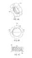
- FIG. 4Ais a perspective view of the cap of the spinal fixation system shown in FIGS. 1A and 1B ;
- FIG. 4Bis a top view of the cap shown in FIG. 4A ;
- FIG. 4Cis a side view of the cap shown in FIG. 4A ;
- FIG. 5Ais a cross-sectional, partially assembled view of the first end of the spinal fixation system shown in FIGS. 1A and 1B , showing domed bearing surfaces;
- FIG. 5Bis a cross-sectional view of another embodiment of a partially assembled end portion of a spinal fixation system having bearing surfaces;
- FIG. 6Ais a cross-sectional view of an end portion of another embodiment of a spinal stabilization system
- FIG. 6Bis a cross-sectional view of an end portion of yet another embodiment of a spinal stabilization system
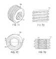
- FIG. 7Ais a perspective view of the set screw of the spinal stabilization system shown in FIG. 6B ;
- FIG. 7Bis a side view of the set screw shown in FIG. 7A ;
- FIG. 7Cis a top view of the set screw shown in FIG. 7A ;
- FIG. 7Dis a cross-section view of the set screw shown in FIG. 7A ;
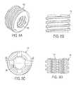
- FIG. 8Ais a perspective view of yet another embodiment of a set screw
- FIG. 8Bis a side view of the set screw shown in FIG. 8A ;
- FIG. 8Cis a top view of the set screw shown in FIG. 8A ;
- FIG. 8Dis a cross-section view of the set screw shown in FIG. 8A ;
- FIG. 9is a cross-sectional view of another embodiment of a cap having a threaded post extending therefrom;
- FIG. 10is an exploded perspective view of another embodiment of a spinal fixation system that includes a floating washer
- FIG. 11Ais a perspective view of the floating washer of the spinal fixation system shown in FIG. 10 ;
- FIG. 11Bis a side view of the floating washer shown in FIG. 11A ;
- FIG. 11Cis a top view of the floating washer shown in FIG. 11A ;
- FIG. 12Ais a perspective view of one embodiment of a connecting plate
- FIG. 12Bis a top view of the connecting plate shown in FIG. 12A ;
- FIG. 12Cis a side view of the connecting plate shown in FIG. 12A ;
- FIG. 13Ais a perspective view of another embodiment of a connecting plate
- FIG. 13Bis a top view of the connecting plate shown in FIG. 13A ;
- FIG. 13Cis a side view of the connecting plate shown in FIG. 13A ;
- FIG. 14Ais a perspective view of yet another embodiment of a connecting plate
- FIG. 14Bis a top view of the connecting plate shown in FIG. 14A ;
- FIG. 14Cis a side view of the connecting plate shown in FIG. 14A ;
- FIG. 15Ais a perspective view of yet another embodiment of a spinal fixation system
- FIG. 15Bis an exploded view of the spinal fixation system shown in FIG. 15A ;
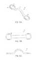
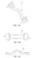
- FIG. 16Ais a perspective view of another embodiment of a connecting plate
- FIG. 16Bis a top view of the connecting plate shown in FIG. 16A ;
- FIG. 16Cis a side view of the connecting plate shown in FIG. 16A ;
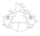
- FIG. 17Ais an illustration of the connecting plate shown in FIG. 16A mated to a vertebra in a patient's spine for supporting the spinous process in the rotated position during a partial laminoplasty;
- FIG. 17Bis an illustration of the connecting plate shown in FIG. 16 and a second connecting plate mated to opposed lateral sides of a vertebra in a patient's spine for supporting the spinous process during a total laminoplasty;
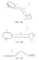
- FIG. 18Ais a cross-sectional view of another embodiment of a spinal stabilization system having a connecting plate with a first end mated to a bone anchor and a second end with a side-loading coupling member mated directly to a spinal fixation element;
- FIG. 18Bis an exploded view of the spinal stabilization system shown in FIG. 18A ;
- FIG. 18Cis a side view of the side-loading coupling member of the spinal stabilization system shown in FIG. 18A ;
- FIG. 19Ais a cross-sectional view of another embodiment of a spinal stabilization system having a connecting plate with a first end mated to a bone anchor and a second end with a top-loading coupling member mated directly to a spinal fixation element;
- FIG. 19Bis an exploded view of the spinal stabilization system shown in FIG. 19A ;
- FIG. 19Cis a side view of the top-loading coupling member of the spinal stabilization system shown in FIG. 19A ;
- FIG. 20is a side view of another embodiment of a top-loading coupling member having wedges disposed therein and adapted to engage a spinal fixation element;
- FIG. 21Ais an exploded view of another embodiment of a top-loading coupling member having an offset wedge that is adapted to engage a spinal fixation element;
- FIG. 21Bis a cross-sectional, assembled view of the top-loading coupling member shown in FIG. 21A .
- the spinal fixation systemincludes one or more bone anchors, such as bone screws, one or more spinal fixation elements, such as spinal rods, plate, or cables, and one or more connecting plates.
- one or more bone anchorscan be implanted in one or more adjacent vertebrae, for example in the pedicle, lamina, or lateral mass of a vertebra, and the spinal fixation element(s) can extend generally along the axis of the spine between one or more bone anchors.
- the connecting plate(s)can couple to and extend between two bone anchors, or a bone anchor and a spinal fixation element, positioned on opposed sides of the spine, thus providing additional stability to the assembly.
- the connecting platecan protect the spinal cord after a full or partial laminectomy.
- FIGS. 1A and 1Billustrate one exemplary embodiment of a spinal fixation system 100 having a connecting plate that is adapted to extend between two bone anchors.
- the system 100generally includes first and second bone anchors in the form of bone screws 102 a , 102 b , first and second spinal fixation elements in the form of spinal rods 104 a , 104 b that are connected to the first and second bone anchors 102 a , 102 b , respectively, and a connecting plate 106 extending between the first and second bone anchors 102 a , 102 b .
- the spinal fixation system 100includes first and second set screws 116 a , 116 b that threadably engage a rod receiving portion 114 a , 114 b of each bone anchor 102 a , 102 b to mate the spinal fixation rods 104 a , 104 b to the bone anchors 102 a , 102 b , and first and second caps 118 a , 118 b that threadably engage the set screws 116 a , 116 b to fix the connecting plate 106 to the rod-receiving portion 114 a , 114 b of each bone anchor 102 a , 102 b .
- the bone anchors 102 a , 102 bcan be implanted in opposed lateral sides of a vertebra, and the spinal rods 104 a , 104 b can extend through the bone anchors 102 a , 102 b to couple the bone anchors 102 a , 102 b to one or more spinal anchors implanted in adjacent vertebrae.
- the connecting plate 106can be mated to the first and second bone anchors 102 a , 102 b using the set screws 116 a , 116 b and the caps 118 a , 118 b , thereby providing additional stability to the spinal stabilization system 100 .
- Each bone anchor 102 a , 102 bcan have a variety of configurations, and various bone anchors known in the art may be used with the spinal stabilization system 100 , including, for example, monoaxial bone screws, polyaxial bone screws, bolts, hooks, or any other implant or combination of implants designed to engage bone and connect to a spinal fixation element, such as a spinal rod 104 a , 104 b .
- the bone anchors 102 a , 102 bare polyaxial bone screws, each having a distal portion 110 a , 110 b that is adapted to be disposed within bone, and rod receiving portion 114 a , 114 b that is adapted to seat a spinal rod 104 a , 104 b , or other spinal fixation element therein.
- the rod receiving portion 114 a , 114 b of each bone anchor 102 a , 102 bcan include a proximal bearing surface 108 a , 108 b that has a shape or configuration that is adapted to match the shape or configuration of the connecting plate 106 , as will be described in more detail below.
- each bone anchor 102 a , 102 bcan include a threaded shaft 192 a , 192 b and head 190 a , 190 b formed thereon and adapted to sit within and pivot related to the rod receiving portion 114 a , 114 b .
- a threaded shaft 192 a , 192 b and head 190 a , 190 b formed thereon and adapted to sit within and pivot related to the rod receiving portion 114 a , 114 bAs previously indicated, a person skilled in the art will appreciate that a variety of bone anchors known in the art can be used with the spinal fixation system 100 .
- the connecting plate 106 of the system 100can also have a variety of configurations, but it is preferably adapted to span laterally across a vertebra such that the connecting plate 106 can extend between and couple to the bone anchors 102 a , 102 b implanted in opposed lateral sides of a vertebra.
- the connecting plate 106is shown in more detail in FIGS. 2A-2C , and as shown the connecting plate 106 has a generally elongate shape with a spanning portion 124 having opposed ends 122 a , 112 b.
- the spanning portion 124can have a variety of configurations, including a planar configuration, or an arcuate shape as shown. In one exemplary embodiment, the spanning portion 124 can have a radius of curvature in a range of between about 5 mm and 15 mm, and more preferably about 8 mm and 12 mm.
- the spanning portion 124 of the connecting plate 106can also vary with respect to thickness a, as indicated in FIG. 2C . In an exemplary embodiment, the thickness a is less that a width b of the plate, as indicated in FIG. 2B .
- Such a configurationallows for intraoperative contouring of the plate to accommodate patient anatomy yet also provides geometric stiffness to impart torsional rigidity to the plate and spinal construct. As is further shown in FIGS.
- the spanning portion 124can also be offset from a plane defined by the ends 122 a , 122 b of the connecting plate 106 .
- the spanning portion 124can be offset by at least about 3 mm from a plane defined by the end 122 a , 112 b of the connecting plate 106 , and more preferably the spanning portion 124 can be offset by between about 5 mm to 10 mm from a plane defined by the ends 122 a , 122 b of the connecting plate 106 .
- the connecting plate 106can also include an opening 120 a , 120 b formed in each end 122 a , 122 b thereof for receiving a set screw 116 a , 116 b that mates to the rod-receiving portion 114 a , 114 b of each bone screw 102 a , 102 b .
- the openings 120 a , 120 b defined by the connecting plate 106may circular, elliptical, polygonal, or have any other shape, as will be discussed in more detail below with respect to FIGS. 12A-14C .
- each end 122 a , 122 bis adapted to be positioned on top of the rod-receiving portion 114 a , 114 b of each bone screw 102 a , 102 b , as shown in FIG. 1B .
- the ends 122 a , 122 b and the rod-receiving portion 114 a , 114 b of each bone screw 102 a , 102 bcan thus include bearing surfaces that are shaped to facilitate mating of the components, as will be discussed in more detail below.
- the device 100can also include a closure mechanism, such as a set screw 116 a , 116 b for mating the rods 104 a , 104 b to the bone anchors 102 a , 102 b .
- a closure mechanismsuch as a set screw 116 a , 116 b for mating the rods 104 a , 104 b to the bone anchors 102 a , 102 b .
- One of the sets screwse.g., set screw 116 a
- the set screw 116 ahas a generally cylindrical shape with threads formed therearound for mating with corresponding threads formed within the rod-receiving portion 114 a of the bone anchor 102 a .
- the set screw 116 acan be threaded into the bone anchor 102 a to lock the rod 104 a within the rod receiving portion 114 a of the anchor 102 a , as shown in FIG. 1B .
- a person skilled in the artwill appreciate that a variety of techniques can be used to mate the set screw 116 a to the bone anchor 102 a including, for example, a twist-lock mechanism or other non-threaded closure mechanism.
- the device 100can also include one or more fastening elements for mating the connecting plate 106 to one or more bone anchors 102 a , 102 b .
- the spinal fixation system 100includes a locking nut or cap 118 a , 118 b that mates to each set screw 116 a , 116 b , which in turn are mated to the bone anchors 102 a , 102 b .
- Each cap 118 a , 118 bcan have a variety of configurations.
- FIGS. 4A-4Cillustrate cap 118 a in more detail. As shown, the cap 118 a has a generally circular shape with an opening formed therethrough and adapted to receive the set screw 116 a .
- the openingcan include threads 152 a , or other mating features, formed therein and adapted to mate with corresponding threads, or other mating features, formed on the set screw 116 a .
- the caps 118 a , 118 bare mated to the set screw 116 a after the opening 120 a , 120 b in the ends of the connecting plate 106 are positioned over the set screws 116 a , 116 b .
- each cap 118 a , 118 bwill thus engage the ends 122 a , 112 b of the connecting plate 106 , locking the connecting plate 106 to the bone anchors 102 a , 102 b.
- the rod-receiving portion 114 a , 114 b of each bone screw 102 a , 102 b and the ends 122 a , 112 b of the connecting plate 106 , as well as the caps 118 a , 118 b ,can each have bearing surfaces that are shaped to facilitate mating of the components, and in particular to facilitate locking of the components in a fixed position relative to one another.
- the connecting plate 106can have an inferior bearing surface 138 b that is conical or spherical.
- a proximal surface 108 b of the bone anchor 102 b that mates with the connecting plate 106can have a corresponding spherical or conical shape that bears against the inferior bearing surface 138 b on the connecting plate 106 .
- the bearing surfacecan have different shapes.
- FIG. 5Billustrates a connecting plate 106 ′ having an inferior bearing surface 138 b ′ that is conical while the bearing surface 108 b ′ on the rod-receiving portion 114 b ′ of the bone anchor is spherical.
- Each cap 118 a , 118 bcan also have a bearing surface that is shaped to match a corresponding bearing surface formed on a superior bearing surface 142 a , 142 b of the connecting plate 106 .
- FIGS. 4A and 4Cillustrate cap 118 a having a distal bearing surface 140 that is concave to mate with a corresponding convex bearing surface formed on the superior bearing surface 142 a , 142 b of the connecting plate 106 .
- the bearing surfacesmay be spherical, convex, concave, flat, variations or combinations thereof, or they may have any other shape sufficient to facilitate coupling of the plate to the bone anchor.
- the radius of curvature of the bearing surfacescan also vary. As shown in FIG. 5A , the spherical superior surface 108 b of the rod receiving portion 114 b can have a radius of curvature R1 that extends from the point about which the bone screw portion pivots.
- the bearing surface 140 b of cap 118 bcan have a radius of curvature R4 that extends from the point about which the bone screw portion pivots.
- the inferior and superior bearing surfaces 138 b , 142 b of the connecting plate 106can also have radii of curvature R2 and R3 that extends from the point about which the bone screw portion pivots. In other embodiments, the radii may extend from a point distinct from the pivot point of the bone screw. In certain exemplary embodiments, each of the radii R1, R2, R3 and R4 can be in a range between about 5 mm and 15 mm.
- FIGS. 6A and 6Billustrate another embodiment of a spinal fixation system.
- each bone anchor 102 a , 102 bincludes a compression member 196 a , 196 b disposed within the rod-receiving portion 114 a , 114 b and that defines a rod seat 198 a , 198 b adjacent to the head 190 a , 190 b of the bone screw portion 110 a , 110 b .
- the compression member 196 a , 196 bis disposed between the rod 104 a , 104 b and the head 190 a , 190 b of each bone anchor portion 110 a , 110 b.
- the cap 119 a , 119 b used to lock the connecting plate 106 ′′has a threaded post that extends into and mates with corresponding threads formed in the set screw 154 a , 154 b mated to each bone anchor 102 a , 102 b .
- Set screw 154 ais shown in more detail in FIGS. 7A-7D , and as shown the set screw 154 a has a threaded bore 156 a for mating with cap 119 b .
- the set screw 154 aalso has a length that is less than a length of the set screws 116 a , 116 b illustrated in FIGS. 1A and 1B .
- An alternative embodiment of a set screw 154 ′ having a threaded bore 156 ′ for mating with cap 119 a , 119 bis shown in FIGS. 8A-8D .
- FIGS. 6A and 6Balso illustrate various embodiments of bearing surfaces on the various components.
- the inferior bearing surface 139 b on the cap 119 bis flat and it is received with a conical or concave bearing surface 142 b ′′ formed in the connecting plate 106 ′′.
- FIG. 6Balso illustrates a cap 119 a having a flat bearing surface 139 a , however the cap 119 a rests against the superior surface of the connecting plate 106 ′′.
- FIG. 9Another embodiment of a cap 119 ′ with a threaded shaft is shown in FIG. 9 , and in this embodiment the bearing surface 139 ′ is concave.
- FIG. 10illustrates another embodiment of a spinal fixation system 100 ′.
- spinal fixation 100 ′includes a floating washer 144 to allow the connecting plate 150 to be used with bone anchors 110 a , 110 b positioned at various distances from one another.
- the floating washer 144includes a bearing surface 146 that mates with a distal bearing surface 140 of cap 118 , and rails 148 that slidably engage the connecting plate 150 .
- the floating washer 144can be slide onto the connecting plate 150 , which as shown in FIG. 10 has an elongate slot formed thereon.
- the floating washer 144can be positioned as desired relative to the elongated slot, and then mated to the bone anchor 102 b using cap 118 b and set screw 116 b .
- the connecting plate 150is thereby fixed to the bone anchor 102 b by compression between the floating washer 144 and the bone anchor 102 b.
- the connecting platecan have a variety of other configurations.
- the connecting plate 150 shown in FIG. 10has one end with an elongate slot formed therein for allowing the bone anchor 102 b to be mated to the connecting plate 150 at a selected position.
- FIGS. 12A-14Cillustrate various other exemplary embodiments of a connecting plate.
- the connecting plate 160includes a spanning portion 164 extending between opposed ends, each end having an elongated opening 166 , 166 ′ formed therein. The ends can also includes rails 162 configured to mate with a washer 144 .
- FIGS. 13A-13Cillustrate another embodiment of a connecting plate 170 .
- the spanning portion 174extends between a first end 172 having an elongate slot 176 formed therein and having side rails configured to mate with a washer 144 , and a second end 172 ′ having a circular opening 176 ′ formed therein.
- the connecting plate 180can include a spanning portion 184 extending between a first end 182 with a circular opening 186 , and a second end 182 ′ with an open-ended opening 186 ′.
- the connecting membercan be in the form of a rod rather than a plate.
- a band clamp or other fastening elementcan be used to mate the rod to the bone anchors.
- FIGS. 15A-Billustrate a spinal fixation system 500 having first and second bone anchors 502 a , 502 b , first and second band clamps 504 a , 504 b , a connecting rod 506 , and first and second dovetail threaded post subassemblies 508 a , 508 b .
- the threaded post subassemblies 508 a , 508 bmate to the bone anchors 502 a , 502 b , respectively, and the band clamps 504 a , 504 b mate the connecting rod 506 to the subassemblies 508 a , 508 b , respectively.
- Other features and methods of operation of system 500are substantially similar to those disclosed herein for system 100 .
- the first and second bone anchors 102 a , 102 bcan be implanted in opposed lateral sides of a vertebra.
- One or more additional bone anchorscan be implanted in one or more adjacent vertebra.
- a spinal fixation element, such as spinal rods 104 a , 104 bcan be positioned within the rod-receiving portion 114 a , 114 b of each bone anchor 102 a , 102 b , and optionally within the rod-receiving portion of one or more bone anchors implanted in one or more adjacent vertebrae.
- the sets screws 116 a , 116 bare then mated to the bone anchors 102 a , 102 b to lock the rod therein.
- the connecting plate 106can then be positioned to span between the bone anchors 102 a , 102 b .
- the first end 122 a of the connecting plate 106can be positioned over the first set screw 116 a
- the second end 122 b of the connecting plate 106can be positioned over the second set screw 116 b .
- Caps 118 a , 118 bcan then be threaded onto the set screws 116 a , 116 b to lock the connecting plate 106 to the bone anchors 102 a , 102 b , thereby stabilizing the bone anchors 102 a , 102 b.
- the connecting platecan be adapted to span between a bone anchor and a posterior element of a vertebra.
- FIGS. 16A-16Cillustrate a connecting plate 130 having a spanning portion 136 with a buttress 132 formed on an inferior surface 134 .
- the connecting plate 160can be used to decompress the spinal canal.
- a first dissection 204is made in a posterior element 200 of a vertebra, and the posterior element 200 is then moved to expand the spinal canal 202 .
- the connecting plate 130is then coupled to a bone anchor 102 b implanted in the vertebra and to the posterior element 200 to maintain the posterior element 200 in a fixed position.
- the posterior element 200can be a portion of the lamina of the vertebra.
- the posterior element 200can be the spinous process of the vertebra.
- the methodcan also include making a second dissection 206 on the contralateral side of the posterior element 200 opposite to the first cut 204 , as shown in FIG. 17B .
- the posterior element 200is then moved to expand the second cut 206 , and a second connecting plate 130 ′ is then coupled to a second bone anchor 102 ′ and the posterior element 200 ′ to maintain the second cut 206 in the expanded position.
- the spinal canalis enlarged.
- the bone anchors 102 a , 102 bare implanted in the lateral mass 208 of the vertebra, for example in the pedicles.
- a cross-connectoris provided for mating a bone anchor to a spinal fixation element, such as a rod, cable, tether, etc.
- a spinal fixation elementsuch as a rod, cable, tether, etc.
- a head-to-rod cross connectorfor coupling a bone anchor implanted on a first lateral side of a vertebra to a spinal fixation element, such as a spinal rod, spanning across an opposed lateral side of the vertebra.
- FIGS. 18A-18Cillustrate one exemplary embodiment of a spinal stabilization system 10 having a head-to-rod cross connector 12 .
- the spinal stabilization system 10is similar to the previously described systems, except that one end of the cross connector can mate directly to a spinal fixation element, such as a spinal rod, without anchoring to bone.
- the second end 12 b of the cross connector 12includes a coupling member 20 for mating the second end 12 b of the cross connector 12 directly to a spinal fixation element, such as spinal rod 40 b as shown.
- the first end 12 a of the cross connector 12as well as the bone screw 30 , spinal rod 40 a , and fastening element, which includes set screw 14 a and locking cap 16 a , are similar to previously described embodiments, and thus they will not be discussed in detail with respect to FIGS. 18A-18B .
- the cross connector 12can also include floating washers 18 a , 18 b , as shown, to facilitate mating of the cross connector 12 to the first and second spinal rods 40 a , 40 b at a particular location. Exemplary floating washers were previously described with respect to FIGS. 10-11C .
- the coupling member 20can have a variety of configurations, and it can be adapted to mate to a spinal rod 40 a and to the second end 12 b of the cross connector 12 using a variety of techniques.
- the coupling member 20is in the form of a housing having a rod-receiving recess 20 a formed therein for seating a spinal fixation element, such as spinal rod 40 b .
- the illustrated rod-receiving recess 20 ahas a substantially concave shape to seat a cylindrical rod 40 b extending therethrough, and it is defined by a top wall 20 t , a bottom wall 20 b , and a sidewall 20 s connecting the top and bottom walls 20 t , 20 b .
- the coupling member 20is a side-loading coupling member 20 , i.e., it loads onto a spinal rod 40 b from the side.
- the coupling member 20can mate to the second end 12 of the cross connector 12 using a variety of mating techniques.
- the coupling member 20includes an opening 20 c formed in the top wall 20 t thereof for receiving a fastening element, such as set screw 12 b .
- the opening 20 ccan extend into the rod-receiving recess 20 a to allow the set screw 12 b to abut against a spinal rod 40 b disposed therein, thereby locking the rod 40 b to the coupling member 20 , and thus to the cross connector 12 .
- the fastening elementcan also including a locking cap 16 b , similar to those previously described, that mates to the set screw 14 b and that bears against the cross connector 12 to lock the cross connector 12 to the coupling member 20 .
- a locking cap 16 bsimilar to those previously described, that mates to the set screw 14 b and that bears against the cross connector 12 to lock the cross connector 12 to the coupling member 20 .
- the fastening elementcan have a variety of other configurations, including those described herein as well as those known in the art.
- the cross connector 12can also have a variety of other configurations, and it can include other features to facilitate mating to the coupling member 20 .
- the first end 12 a of the coupling member 20can be mated to a bone anchor 30 that is implanted in a lateral side of a first vertebra.
- a set screw 14 acan be inserted through a thru-bore or opening 13 a formed in the first end 12 a of the cross connector 12 , and it can be threaded into the rod-receiving portion 32 of the bone screw 30 to lock a spinal rod 40 a in the rod-receiving recess 32 a .
- a locking cap 16 acan be threaded onto an opposed end of the set screw 14 a to lock the cross connector 12 to the bone anchor 30 .
- the second end 12 b of the cross connector 12can be mated to a spinal rod 40 b that extends substantially parallel to spinal rod 40 a on an opposed lateral side of the first vertebra, and that is not anchored to the first vertebra.
- the coupling member 20can be side loaded onto the spinal rod 40 b , and a set screw 14 b can be inserted through an opening or thru-bore 13 b formed in the first end of the cross connector 12 and into the opening 20 c formed in the coupling member 20 to lock the rod 40 b within the rod receiving recess 20 a of the coupling member 20 .
- the cross connector 12can alternatively be placed over the set screw 14 b after the set screw 14 b is mated to the coupling member 20 .
- the locking cap 16 bcan be threaded onto an opposed end of the set screw 14 b to lock the cross connector 12 to the coupling member 20 .
- the coupling memberthus provides additional support to a spinal stabilization system implanted in a patient's spine without requiring both ends of the cross connector to anchor to bone.
- both end of the cross connectorcan mate to first and second spinal fixation elements, such as spinal rods, without anchoring to bone.
- first and second coupling membercan be used to mate a cross connector to first and second spinal rods extending along opposed lateral sides of a vertebra.
- FIGS. 19A-19Cillustrate another embodiment of coupling member 320 .
- the coupling member 320is illustrated as part of a spinal stabilization system 300 which, like previous embodiments, generally includes a cross connector 312 having a first end 312 a that is adapted to mate to a bone anchor 330 , and a second end 312 b that is adapted to mate to a coupling member 320 .
- a first fastening elementwhich includes a set screw 314 a and a locking cap 316 a , is provided for locking the first end 312 a of the cross connector 312 to the bone screw 330 , and for locking a spinal rod 140 a in the rod-receiving portion of the bone screw 330
- a second fastening elementwhich includes a set screw 314 b and a locking cap 316 b , is provided for locking the second end 312 b of the cross connector 312 to the coupling member 320 .
- the set screw 14 awas effective to directly contact the spinal rod 40 a to lock the spinal rod 40 a in the rod-receiving recess 20 a of the coupling member 20 .
- the set screw 314 adoes not directly engage the spinal rod 340 a , but rather the coupling member 320 includes a locking arm 322 disposed therein for engaging the spinal rod 340 a .
- the coupling member 320is also top loading, rather than side loading.
- the locking arm 322which is best shown in FIG. 19A , can have a variety of shapes and sizes, but in an exemplary embodiment it is adapted to extend around at least a portion of a spinal rod 340 a disposed within the rod-receiving recess 320 a , and it is adapted to engage the rod 340 a when the set screw 314 b is mated to the coupling member 320 a .
- the locking arm 322can have an elongate configuration with a first end 322 a that is adapted to be pivotally disposed within an elongate opening 321 formed in a sidewall 320 s of the coupling member 320 , and a second or terminal end 322 b that is curved and that extends into the rod-receiving recess 320 a of the coupling member 320 a .
- the locking arm 322can also extend across the path of the opening formed in the top wall 320 t of the coupling member 320 that receives the set screw 314 b .
- the coupling member 320 ais inserted over the spinal rod 340 b , i.e., the spinal rod 340 b is bottom loaded into the rod-receiving recess 320 a of the coupling member 320 .
- the set screw 314 bis then inserted through the opening formed in the second end 312 b of the cross connector 312 and into the opening formed in the coupling member 320 a to bear against the locking arm 322 , thereby causing the locking arm 322 to engage and lock the spinal rod 340 a within the rod-receiving recess 320 a of the coupling member 320 .
- the cross connector 312can alternatively be placed over the set screw 314 b after the set screw 314 b is mated to the coupling member 320 .
- the locking cap 316 bcan then be threaded onto the set screw 314 b to lock the cross connector 312 to the coupling member 320 .
- FIG. 20illustrates yet another embodiment of a coupling member 420 .
- the coupling member 420includes two rod-engaging members or wedges 422 a , 422 b slidably disposed within the coupling member 420 .
- the wedges 422 a , 422 bcan have a variety of configurations and they can be mated to or disposed within the coupling member 420 using a variety of techniques, but they are preferably effective to move linearly in response to a force applied thereto by a set screw 414 to lock a spinal fixation rod 420 within the rod-receiving recess 420 a of the coupling member 420 .
- the coupling member 42includes first and second receiving cavities (not shown) formed therein for slidably seating the wedges 422 a , 422 b .
- the first and second cavitiespreferably extend between the opening 420 o formed in the top wall 420 s of the coupling member 420 that receives the set screw 414 , and the rod-receiving recess 420 a .
- the cavitiesare also preferably spaced a distance apart from a bottom surface 420 b of the coupling member 420 to allow the wedges 422 a , 422 b to be retained within the coupling member 420 .
- the coupling member 420can be top loaded onto a spinal rod 420 a , and the set screw 414 can be inserted, e.g., threaded, into the opening 420 o in the coupling member 420 .
- the set screw 414will thus bear against the opposed wedges 422 a , 422 b , thereby driving the wedges 422 a , 422 b linearly such that the extend into the rod-receiving recess 420 a .
- the wedges 422 a , 422 bwill engage the spinal rod 440 , thereby locking the rod 420 a to the coupling member 420 .
- a cross connectorcan be mated to the coupling member 420 using a locking cap of other locking mechanism.
- FIGS. 21A-21Billustrate yet another embodiment of a coupling member 520 that can be used to couple a cross connector to a spinal rod without anchoring the cross connector to bone.
- the coupling member 520includes a single wedge or shoe 522 disposed therein.
- the shoe 522is disposed within a cavity 521 that is laterally offset from the rod receiving recess 520 a formed in the coupling member 520 .
- the cavity 512extends from a top wall 520 t toward a bottom wall 520 b .
- the cavity 512can terminate prior to the bottom wall 520 b such that the bottom wall 520 is effective to retain the shoe 522 therein.
- the shoe 522is adapted to sit within the cavity 521 and is movable from a distal position to a proximal position, i.e., the shoe 522 moves from a resting position adjacent to the bottom wall 520 b toward the top wall 520 a . Movement of the shoe 522 can be achieved using a set screw 514 that is inserted through an opening 520 o formed in the top surface 520 t of the coupling member 520 , and through an opening 522 a formed in the shoe 522 . As the set screw 514 is threaded or otherwise mated to the shoe 522 , the set screw 514 can pull the shoe 522 toward the top wall 520 t .
- the set screw 514can include a proximal portion 514 a that is adapted to mate with and engage the coupling member 520 , and a distal portion 514 b that is adapted to mate with and engage the shoe 522 .
- the proximal and distal portions 514 a , 514 bcan have a different size, e.g., diameter, thread pitch, etc. Such a configuration allows the set screw 514 to move the shoe 522 proximally while maintaining the coupling member 520 in a substantially fixed position.
- a wedge-shaped protrusion 522 b extending into the rod-receiving recess 502 a of the coupling member 520will move toward the top wall 520 t , thereby engaging a spinal rod 540 disposed within the rod-receiving recess 520 a , as shown in FIG. 21B .
- a locking cap 516can then be applied to the proximal portion 514 a of the set screw 514 to mate a cross connector to the coupling member 520 .
Landscapes
- Health & Medical Sciences (AREA)
- Orthopedic Medicine & Surgery (AREA)
- Life Sciences & Earth Sciences (AREA)
- Surgery (AREA)
- Neurology (AREA)
- Heart & Thoracic Surgery (AREA)
- Engineering & Computer Science (AREA)
- Biomedical Technology (AREA)
- Nuclear Medicine, Radiotherapy & Molecular Imaging (AREA)
- Medical Informatics (AREA)
- Molecular Biology (AREA)
- Animal Behavior & Ethology (AREA)
- General Health & Medical Sciences (AREA)
- Public Health (AREA)
- Veterinary Medicine (AREA)
- Dentistry (AREA)
- Oral & Maxillofacial Surgery (AREA)
- Surgical Instruments (AREA)
Abstract
Description
This application is a continuation of U.S. patent application Ser. No. 14/063,412 filed on Oct. 25, 2013, and entitled “Rod Attachment for Head to Head Cross Connector,” which is a continuation of U.S. patent application Ser. No. 13/342,484 (now U.S. Pat. No. 8,591,550) filed on Jan. 3, 2012, and entitled “Rod Attachment for Head to Head Cross Connector,” which is a continuation of U.S. patent application Ser. No. 12/752,729 (now U.S. Pat. No. 8,192,471) filed on Apr. 1, 2010, and entitled “Rod Attachment for Head to Head Cross Connector,” which is a continuation of U.S. patent application Ser. No. 11/162,934 (now U.S. Pat. No. 7,717,939) filed on Sep. 28, 2005, and entitled “Rod Attachment for Head to Head Cross Connector,” which is a continuation-in-part of U.S. patent application Ser. No. 10/813,904 (now U.S. Pat. No. 7,645,294) filed on Mar. 31, 2004, and entitled “Head-To-Head Connector Spinal Fixation System.”
The present application also relates to U.S. application Ser. No. 12/581,410 (now U.S. Pat. No. 7,967,845) filed on Oct. 19, 2009, and entitled “Head-to-Head Connector Spinal Fixation System,” which is a continuation of U.S. patent application Ser. No. 10/813,904 (now U.S. Pat. No. 7,645,294) filed on Mar. 31, 2004, and entitled “Head-To-Head Connector Spinal Fixation System.”
These references are hereby incorporated by reference in their entireties.
Spinal fixation devices are used in orthopedic surgery to align and/or fix a desired relationship between adjacent vertebral bodies. Such devices typically include a spinal fixation element, such as a relatively rigid fixation rod, that is coupled to adjacent vertebrae by attaching the element to various anchoring devices, such as hooks, bolts, wires, or screws. Alternatively, two rods can be disposed on the lateral or anterior surface of the vertebral body in a substantially parallel relationship. The fixation rods can have a predetermined contour that has been designed according to the properties of the target implantation site, and once installed, the rods hold the vertebrae in a desired spatial relationship, either until desired healing or spinal fusion has taken place, or for some longer period of time.
Spinal cross connectors are often used in conjunction with spinal fixation devices to provide additional stability to the devices. For example, it has been found that when a pair of spinal rods are fastened in parallel on either side of the spinous process, the assembly can be significantly strengthened by using a cross connector to bridge the pair of spinal rods. The connectors are typically in the form of a rod having a clamp formed on each end thereof for mating with a spinal rod.
While current spinal cross connectors have proven effective, difficulties have been encountered in mounting the cross connectors, and maintaining them in a desired position and orientation with respect to the spinal rod, or other spinal fixation device to which they are attached. In particular, the clamp assemblies often consist of several parts which make surgical application tedious, and which can also increase the manufacturing costs. Since the cross connector is often applied as the last step in a lengthy surgical procedure, ease of application is paramount. Fixation of the cross connector to spinal rods can also be difficult where the rods are not parallel to one another, or they are diverging/converging with respect to one another, or where other spinal fixation devices interfere with proper placement.
Accordingly, there exists a need for an improved spinal cross connector that can be easily installed and that securely mates to and connects spinal fixation devices.
The present invention relates to spinal fixation systems and method for stabilizing vertebrae in a patient's spine. In an exemplary embodiment, methods and device are provided for coupling one or more bone anchors, such as hooks, screws, etc., and/or one or more spinal fixation elements, such as spinal rods, cables, plates, etc. In certain exemplary embodiments, a cross connector is provided for connecting and stabilizing two bone anchors, a bone anchor and a spinal fixation element, or a bone anchor and bone.
In one exemplary embodiment, a spinal fixation system is provided having a cross connector that is configured to span between opposed lateral sides of a vertebra and having first and second ends. A coupling member is configured to mate to the first end of the cross connector and it can include a rod-receiving recess formed therein for coupling to a spinal rod. The coupling member is preferably configured to couple to a spinal rod without anchoring to bone. The system can also include a bone anchor having a shaft for engaging bone and a head configured to mate to the second end of the connector and having a rod-receiving recess formed therein for coupling to a spinal rod.
The coupling member can have a variety of configurations, and in one embodiment it can have a side-loading rod-receiving recess, i.e., the coupling member is loaded onto a spinal rod from the side. For example, the rod-receiving recess formed in the coupling member can be defined by a top wall, a bottom wall, and a side wall connecting the top and bottom walls. In an exemplary embodiment, the top wall includes a thru-bore formed therein for receiving a fastening element adapted to mate the coupling member to the cross connector. The system can also include a fastening element that is adapted to extend through an opening formed in the first end of the cross connector and to extend into the thru-bore formed in the top wall of the coupling member for mating the coupling member to the cross connector. The fastening element can also extend into the rod-receiving recess to lock a spinal rod disposed therein to the coupling member.
In another embodiment, the coupling member can have a top-loading rod-receiving recess, i.e., the coupling member is loaded onto a spinal rod from the top. For example, the rod-receiving recess formed in the coupling member can be defined by a top wall and first and second side walls extending from opposed sides of the top wall. In an exemplary embodiment, the top wall includes a thru-bore formed therein for receiving a fastening element adapted to mate the coupling member to the cross connector.
In other embodiments, the coupling member can include features to facilitate locking of a spinal rod therein. For example, the coupling member can include a locking arm extending into the rod-receiving recess and adapted to extend around at least a portion of a rod disposed within the rod-receiving recess. In an exemplary embodiment, the locking arm extends through one of the first and second side walls of the coupling member. A fastening element can extend through an opening formed in the first end of the cross connector and into the thru-bore formed in the top wall of the coupling member to abut against the locking arm and thereby lock a rod within the rod-receiving recess of the cross connector.
In other embodiments, the coupling member can include at least one movable member adapted to move in response to a force applied thereto by the fastening element to engage a rod disposed within the rod-receiving recess. The movable member can be one or more pivoting or sliding wedges. For example, the coupling member can include a wedge disposed therein and adapted to be engaged by the fastening element such that the wedge moves to engage a rod disposed within the rod receiving recess of the coupling member.
Exemplary methods for spinal stabilization are also provided. In one embodiment, the method can include coupling a first end of a cross connector to a head of a bone anchor to anchor the first end of the cross connector to a first vertebra, the bone anchor having a first spinal rod extending therethrough, and coupling a second end of the cross connector to a second spinal rod without anchoring the second end of the cross connector to the first vertebra. In an exemplary embodiment, the second spinal rod is positioned within a rod receiving recess of a coupling member, and a fastening element is inserted through the second end of the cross connector and into an opening formed in the coupling member to lock the spinal rod, coupling member, and cross connector to one another. Depending on the configuration of the coupling member, the spinal rod can be side-loaded into a rod-receiving recess formed in a sidewall of the coupling member, or it can be bottom-loaded into a rod-receiving recess formed in a bottom wall of the coupling member. The fastening element can then be inserted into an opening formed in a top wall of the coupling member to lock the rod therein and to mate the coupling member to the cross connector.
The invention will be more fully understood from the following detailed description taken in conjunction with the accompanying drawings, in which:
Certain exemplary embodiments will now be described to provide an overall understanding of the principles of the structure, function, manufacture, and use of the devices and methods disclosed herein. One or more examples of these embodiments are illustrated in the accompanying drawings. Those skilled in the art will understand that the devices and methods specifically described herein and illustrated in the accompanying drawings are non-limiting exemplary embodiments and that the scope of the present invention is defined solely by the claims. The features illustrated or described in connection with one exemplary embodiment may be combined with the features of other embodiments. Such modifications and variations are intended to be included within the scope of the present invention.
In general, various spinal fixation systems are provided for aligning and/or fixing a desired relationship between adjacent vertebral bodies. In one exemplary embodiment, the spinal fixation system includes one or more bone anchors, such as bone screws, one or more spinal fixation elements, such as spinal rods, plate, or cables, and one or more connecting plates. In use, one or more bone anchors can be implanted in one or more adjacent vertebrae, for example in the pedicle, lamina, or lateral mass of a vertebra, and the spinal fixation element(s) can extend generally along the axis of the spine between one or more bone anchors. The connecting plate(s) can couple to and extend between two bone anchors, or a bone anchor and a spinal fixation element, positioned on opposed sides of the spine, thus providing additional stability to the assembly. In one embodiment, the connecting plate can protect the spinal cord after a full or partial laminectomy.
Eachbone anchor spinal stabilization system 100, including, for example, monoaxial bone screws, polyaxial bone screws, bolts, hooks, or any other implant or combination of implants designed to engage bone and connect to a spinal fixation element, such as aspinal rod distal portion rod receiving portion spinal rod rod receiving portion bone anchor proximal bearing surface plate 106, as will be described in more detail below. Thedistal portion bone anchor shaft head rod receiving portion spinal fixation system 100.
The connectingplate 106 of thesystem 100 can also have a variety of configurations, but it is preferably adapted to span laterally across a vertebra such that the connectingplate 106 can extend between and couple to the bone anchors102a,102bimplanted in opposed lateral sides of a vertebra. The connectingplate 106 is shown in more detail inFIGS. 2A-2C , and as shown the connectingplate 106 has a generally elongate shape with a spanningportion 124 having opposed ends122a,112b.
The spanningportion 124 can have a variety of configurations, including a planar configuration, or an arcuate shape as shown. In one exemplary embodiment, the spanningportion 124 can have a radius of curvature in a range of between about 5 mm and 15 mm, and more preferably about 8 mm and 12 mm. The spanningportion 124 of the connectingplate 106 can also vary with respect to thickness a, as indicated inFIG. 2C . In an exemplary embodiment, the thickness a is less that a width b of the plate, as indicated inFIG. 2B . Such a configuration allows for intraoperative contouring of the plate to accommodate patient anatomy yet also provides geometric stiffness to impart torsional rigidity to the plate and spinal construct. As is further shown inFIGS. 2A-2C , the spanningportion 124 can also be offset from a plane defined by theends plate 106. For example, in one exemplary embodiment the spanningportion 124 can be offset by at least about 3 mm from a plane defined by theend 122a,112bof the connectingplate 106, and more preferably the spanningportion 124 can be offset by between about 5 mm to 10 mm from a plane defined by theends plate 106.
As is further shown, the connectingplate 106 can also include anopening end set screw portion bone screw openings plate 106 may circular, elliptical, polygonal, or have any other shape, as will be discussed in more detail below with respect toFIGS. 12A-14C . In operation, eachend portion bone screw FIG. 1B . The ends122a,122band the rod-receivingportion bone screw
As previously explained, thedevice 100 can also include a closure mechanism, such as aset screw rods screw 116a, is shown in more detail inFIGS. 3A-3B . As shown, theset screw 116ahas a generally cylindrical shape with threads formed therearound for mating with corresponding threads formed within the rod-receivingportion 114aof thebone anchor 102a. In use, theset screw 116acan be threaded into thebone anchor 102ato lock therod 104awithin therod receiving portion 114aof theanchor 102a, as shown inFIG. 1B . A person skilled in the art will appreciate that a variety of techniques can be used to mate theset screw 116ato thebone anchor 102aincluding, for example, a twist-lock mechanism or other non-threaded closure mechanism.
Thedevice 100 can also include one or more fastening elements for mating the connectingplate 106 to one or more bone anchors102a,102b. In an exemplary embodiment, thespinal fixation system 100 includes a locking nut or cap118a,118bthat mates to eachset screw cap FIGS. 4A-4C illustratecap 118ain more detail. As shown, thecap 118ahas a generally circular shape with an opening formed therethrough and adapted to receive theset screw 116a. The opening can includethreads 152a, or other mating features, formed therein and adapted to mate with corresponding threads, or other mating features, formed on theset screw 116a. In use, as previously shown inFIG. 1B , thecaps set screw 116aafter theopening plate 106 are positioned over theset screws inferior bearing surface cap ends 122a,112bof the connectingplate 106, locking the connectingplate 106 to the bone anchors102a,102b.
As previously indicated, the rod-receivingportion bone screw ends 122a,112bof the connectingplate 106, as well as thecaps FIG. 2C , the connectingplate 106 can have aninferior bearing surface 138bthat is conical or spherical. Aproximal surface 108bof thebone anchor 102bthat mates with the connectingplate 106 can have a corresponding spherical or conical shape that bears against theinferior bearing surface 138bon the connectingplate 106. In other embodiments, the bearing surface can have different shapes. For example,FIG. 5B illustrates a connectingplate 106′ having aninferior bearing surface 138b′ that is conical while the bearingsurface 108b′ on the rod-receivingportion 114b′ of the bone anchor is spherical.
Eachcap superior bearing surface plate 106. For example,FIGS. 4A and 4C illustratecap 118ahaving a distal bearing surface140 that is concave to mate with a corresponding convex bearing surface formed on thesuperior bearing surface plate 106.
In other embodiments, the bearing surfaces may be spherical, convex, concave, flat, variations or combinations thereof, or they may have any other shape sufficient to facilitate coupling of the plate to the bone anchor.
The radius of curvature of the bearing surfaces can also vary. As shown inFIG. 5A , the sphericalsuperior surface 108bof therod receiving portion 114bcan have a radius of curvature R1 that extends from the point about which the bone screw portion pivots. The bearingsurface 140bofcap 118bcan have a radius of curvature R4 that extends from the point about which the bone screw portion pivots. The inferior and superior bearing surfaces138b,142bof the connectingplate 106 can also have radii of curvature R2 and R3 that extends from the point about which the bone screw portion pivots. In other embodiments, the radii may extend from a point distinct from the pivot point of the bone screw. In certain exemplary embodiments, each of the radii R1, R2, R3 and R4 can be in a range between about 5 mm and 15 mm.
As is further shown inFIGS. 6A and 6B , thecap plate 106″ has a threaded post that extends into and mates with corresponding threads formed in theset screw bone anchor screw 154ais shown in more detail inFIGS. 7A-7D , and as shown theset screw 154ahas a threadedbore 156afor mating withcap 119b. Theset screw 154aalso has a length that is less than a length of theset screws FIGS. 1A and 1B . An alternative embodiment of aset screw 154′ having a threadedbore 156′ for mating withcap FIGS. 8A-8D .
As previously indicated, the connecting plate can have a variety of other configurations. For example, as indicated above, the connectingplate 150 shown inFIG. 10 has one end with an elongate slot formed therein for allowing thebone anchor 102bto be mated to the connectingplate 150 at a selected position.FIGS. 12A-14C illustrate various other exemplary embodiments of a connecting plate. In the embodiment shown inFIGS. 12A-12C , the connectingplate 160 includes a spanningportion 164 extending between opposed ends, each end having anelongated opening rails 162 configured to mate with awasher 144.FIGS. 13A-13C illustrate another embodiment of a connectingplate 170. In this embodiment, the spanningportion 174 extends between afirst end 172 having anelongate slot 176 formed therein and having side rails configured to mate with awasher 144, and asecond end 172′ having acircular opening 176′ formed therein. In yet another embodiment, as shown inFIGS. 14A-14C , the connectingplate 180 can include a spanningportion 184 extending between afirst end 182 with acircular opening 186, and asecond end 182′ with an open-endedopening 186′.
In other embodiments, the connecting member can be in the form of a rod rather than a plate. A band clamp or other fastening element can be used to mate the rod to the bone anchors.FIGS. 15A-B illustrate aspinal fixation system 500 having first and second bone anchors502a,502b, first and second band clamps504a,504b, a connectingrod 506, and first and second dovetail threadedpost subassemblies post subassemblies rod 506 to thesubassemblies system 500 are substantially similar to those disclosed herein forsystem 100.
During operation, referring back to the embodiment shown inFIGS. 1A and 1B , for example, the first and second bone anchors102a,102bcan be implanted in opposed lateral sides of a vertebra. One or more additional bone anchors can be implanted in one or more adjacent vertebra. A spinal fixation element, such asspinal rods portion bone anchor plate 106 can then be positioned to span between the bone anchors102a,102b. In particular, thefirst end 122aof the connectingplate 106 can be positioned over thefirst set screw 116a, and thesecond end 122bof the connectingplate 106 can be positioned over thesecond set screw 116b.Caps set screws plate 106 to the bone anchors102a,102b, thereby stabilizing the bone anchors102a,102b.
In another embodiment the connecting plate can be adapted to span between a bone anchor and a posterior element of a vertebra. For example,FIGS. 16A-16C illustrate a connectingplate 130 having a spanningportion 136 with a buttress132 formed on aninferior surface 134. In use, as shown inFIG. 17A , the connectingplate 160 can be used to decompress the spinal canal. As shown, afirst dissection 204 is made in aposterior element 200 of a vertebra, and theposterior element 200 is then moved to expand thespinal canal 202. The connectingplate 130 is then coupled to abone anchor 102bimplanted in the vertebra and to theposterior element 200 to maintain theposterior element 200 in a fixed position. In one embodiment, theposterior element 200 can be a portion of the lamina of the vertebra. In another embodiment, theposterior element 200 can be the spinous process of the vertebra.
The method can also include making asecond dissection 206 on the contralateral side of theposterior element 200 opposite to thefirst cut 204, as shown inFIG. 17B . Theposterior element 200 is then moved to expand thesecond cut 206, and a second connectingplate 130′ is then coupled to a second bone anchor102′ and theposterior element 200′ to maintain thesecond cut 206 in the expanded position. As a result, the spinal canal is enlarged. In an exemplary embodiment, the bone anchors102a,102bare implanted in thelateral mass 208 of the vertebra, for example in the pedicles.
While the previous embodiments relate to cross connectors for mating two bone anchors, or for mating a bone anchor to a posterior element, in another embodiment a cross-connector is provided for mating a bone anchor to a spinal fixation element, such as a rod, cable, tether, etc. Some injuries allow only a single bone anchor to be implanted on a lateral side of a vertebra, preventing a second bone anchoring from being implanted on an opposed lateral side of the vertebra. However, it may be desirable to provide additional support to the bone anchor that is implanted in the vertebra. Accordingly, a head-to-rod cross connector is provided for coupling a bone anchor implanted on a first lateral side of a vertebra to a spinal fixation element, such as a spinal rod, spanning across an opposed lateral side of the vertebra.
Thecoupling member 20 can have a variety of configurations, and it can be adapted to mate to aspinal rod 40aand to thesecond end 12bof thecross connector 12 using a variety of techniques. In the illustrated embodiment, as shown inFIG. 18A-18C , thecoupling member 20 is in the form of a housing having a rod-receivingrecess 20aformed therein for seating a spinal fixation element, such asspinal rod 40b. The illustrated rod-receivingrecess 20ahas a substantially concave shape to seat acylindrical rod 40bextending therethrough, and it is defined by a top wall20t, abottom wall 20b, and asidewall 20sconnecting the top andbottom walls 20t,20b. As a result, thecoupling member 20 is a side-loading coupling member 20, i.e., it loads onto aspinal rod 40bfrom the side.
Thecoupling member 20 can mate to thesecond end 12 of thecross connector 12 using a variety of mating techniques. In the illustrated exemplary embodiment, thecoupling member 20 includes anopening 20cformed in the top wall20tthereof for receiving a fastening element, such asset screw 12b. Theopening 20ccan extend into the rod-receivingrecess 20ato allow theset screw 12bto abut against aspinal rod 40bdisposed therein, thereby locking therod 40bto thecoupling member 20, and thus to thecross connector 12. The fastening element can also including a locking cap16b, similar to those previously described, that mates to theset screw 14band that bears against thecross connector 12 to lock thecross connector 12 to thecoupling member 20. A person skilled in the art will appreciate that the fastening element can have a variety of other configurations, including those described herein as well as those known in the art. Thecross connector 12 can also have a variety of other configurations, and it can include other features to facilitate mating to thecoupling member 20.
In use, as shown inFIG. 18A , thefirst end 12aof thecoupling member 20 can be mated to abone anchor 30 that is implanted in a lateral side of a first vertebra. In particular, aset screw 14acan be inserted through a thru-bore or opening13aformed in thefirst end 12aof thecross connector 12, and it can be threaded into the rod-receivingportion 32 of thebone screw 30 to lock aspinal rod 40ain the rod-receiving recess32a. A lockingcap 16acan be threaded onto an opposed end of theset screw 14ato lock thecross connector 12 to thebone anchor 30. Thesecond end 12bof thecross connector 12 can be mated to aspinal rod 40bthat extends substantially parallel tospinal rod 40aon an opposed lateral side of the first vertebra, and that is not anchored to the first vertebra. In particular, thecoupling member 20 can be side loaded onto thespinal rod 40b, and aset screw 14bcan be inserted through an opening or thru-bore 13bformed in the first end of thecross connector 12 and into theopening 20cformed in thecoupling member 20 to lock therod 40bwithin therod receiving recess 20aof thecoupling member 20. Thecross connector 12 can alternatively be placed over theset screw 14bafter theset screw 14bis mated to thecoupling member 20. The locking cap16bcan be threaded onto an opposed end of theset screw 14bto lock thecross connector 12 to thecoupling member 20. The coupling member thus provides additional support to a spinal stabilization system implanted in a patient's spine without requiring both ends of the cross connector to anchor to bone. A person skilled in the art will appreciate that both end of the cross connector can mate to first and second spinal fixation elements, such as spinal rods, without anchoring to bone. For example, first and second coupling member can be used to mate a cross connector to first and second spinal rods extending along opposed lateral sides of a vertebra.
As indicated above, the coupling member can have a variety of other configurations, and various techniques can be used to mate the coupling member to a spinal fixation element, such as a spinal rod, and to the cross connector.FIGS. 19A-19C illustrate another embodiment ofcoupling member 320. Thecoupling member 320 is illustrated as part of aspinal stabilization system 300 which, like previous embodiments, generally includes across connector 312 having afirst end 312athat is adapted to mate to abone anchor 330, and asecond end 312bthat is adapted to mate to acoupling member 320. A first fastening element, which includes aset screw 314aand alocking cap 316a, is provided for locking thefirst end 312aof thecross connector 312 to thebone screw 330, and for locking aspinal rod 140ain the rod-receiving portion of thebone screw 330, and a second fastening element, which includes aset screw 314band alocking cap 316b, is provided for locking thesecond end 312bof thecross connector 312 to thecoupling member 320. In the embodiment shown inFIGS. 18a -18C, theset screw 14awas effective to directly contact thespinal rod 40ato lock thespinal rod 40ain the rod-receivingrecess 20aof thecoupling member 20. In this embodiment, theset screw 314adoes not directly engage thespinal rod 340a, but rather the couplingmember 320 includes alocking arm 322 disposed therein for engaging thespinal rod 340a. Thecoupling member 320 is also top loading, rather than side loading.
The lockingarm 322, which is best shown inFIG. 19A , can have a variety of shapes and sizes, but in an exemplary embodiment it is adapted to extend around at least a portion of aspinal rod 340adisposed within the rod-receivingrecess 320a, and it is adapted to engage therod 340awhen theset screw 314bis mated to thecoupling member 320a. In particular, the lockingarm 322 can have an elongate configuration with afirst end 322athat is adapted to be pivotally disposed within anelongate opening 321 formed in asidewall 320sof thecoupling member 320, and a second orterminal end 322bthat is curved and that extends into the rod-receivingrecess 320aof thecoupling member 320a. The lockingarm 322 can also extend across the path of the opening formed in the top wall320tof thecoupling member 320 that receives theset screw 314b. As a result, when theset screw 314bis inserted through the opening in the top wall320tof thecoupling member 320 it will bear down on thelocking arm 322, thereby causing the curved terminal end of thelocking arm 322 to pivot downward and engage thespinal rod 340b.
In use, thecoupling member 320ais inserted over thespinal rod 340b, i.e., thespinal rod 340bis bottom loaded into the rod-receivingrecess 320aof thecoupling member 320. Theset screw 314bis then inserted through the opening formed in thesecond end 312bof thecross connector 312 and into the opening formed in thecoupling member 320ato bear against the lockingarm 322, thereby causing thelocking arm 322 to engage and lock thespinal rod 340awithin the rod-receivingrecess 320aof thecoupling member 320. Thecross connector 312 can alternatively be placed over theset screw 314bafter theset screw 314bis mated to thecoupling member 320. The lockingcap 316bcan then be threaded onto theset screw 314bto lock thecross connector 312 to thecoupling member 320.
In use, thecoupling member 420 can be top loaded onto aspinal rod 420a, and theset screw 414 can be inserted, e.g., threaded, into the opening420oin thecoupling member 420. Theset screw 414 will thus bear against the opposedwedges 422a,422b, thereby driving thewedges 422a,422blinearly such that the extend into the rod-receivingrecess 420a. As a result, thewedges 422a,422bwill engage thespinal rod 440, thereby locking therod 420ato thecoupling member 420. As previously described, a cross connector can be mated to thecoupling member 420 using a locking cap of other locking mechanism.
One of ordinary skill in the art will appreciate further features and advantages of the invention based on the above-described embodiments. Accordingly, the invention is not to be limited by what has been particularly shown and described, except as indicated by the appended claims. All publications and references cited herein are expressly incorporated herein by reference in their entirety.
Claims (37)
1. A spinal fixation system, comprising:
a bone anchor having a bone-engaging portion and a head; and
a connecting member having first and second ends with a spanning portion extending therebetween, the spanning portion extending at an oblique angle with respect to the first end and at an oblique angle with respect to the second end, at least one of the first and second ends having an opening formed therein, and a portion of the opening being configured to engage a portion of the head at a locked position such that the connecting member is at a fixed location with respect to the bone anchor,
wherein a distal surface of the first end of the connecting member bears against a proximal terminal end surface of each of opposed arms of the head of the bone anchor.
2. The system ofclaim 1 , wherein the first and second ends are not co-planar.
3. The system ofclaim 1 , further comprising a buttress extending distally from a distal surface of the connecting member, towards the bone anchor when the connecting member is coupled to the bone anchor, and proximate to an opening formed in the second end.
4. A spinal fixation system, comprising:
a bone anchor having a bone-engaging portion and a head;
a connecting member having first and second ends with a spanning portion extending therebetween, the spanning portion extending at an oblique angle with respect to the first end and at an oblique angle with respect to the second end, at least one of the first and second ends having an opening formed therein, and a portion of the opening being configured to engage a portion of the head at a locked position such that the connecting member is at a fixed location with respect to the bone anchor; and
locking member configured to extend through the opening of the first or second end of the connecting member and engage opposed inner walls of opposed arms of the head of the bone anchor in the locked position.
5. The system ofclaim 4 , wherein the first and second ends are not co-planar.
6. The system ofclaim 4 , further comprising a buttress extending distally from a distal surface of the connecting member, towards the bone anchor when the connecting member is coupled to the bone anchor, and proximate to an opening formed in the second end.
7. A method for decompressing a spinal canal, comprising:
moving a posterior element of a vertebra that is separated from a first portion of a lateral mass of the vertebra away from the first portion of the lateral mass to expand a spinal canal disposed between the posterior element and the first portion of the lateral mass;
implanting a first bone anchor into the first portion of the lateral mass;
coupling a first end of a first connecting plate to the first bone anchor; and
coupling a second end of the first connecting plate to the posterior element to maintain the posterior element in a fixed position with respect to the first portion of the lateral mass,
wherein the second end of the first connecting plate comprises a buttress formed on an inferior, vertebra-facing surface of the first connecting plate, and first sidewall of the buttress contacts the posterior element when the second end of the first connecting plate is coupled to the posterior element while a second side-wall that is opposed to the first sidewall is a distance apart from the first portion of the lateral mass.
8. The method ofclaim 7 , further comprising dissecting the posterior element from the first portion of the lateral mass of the vertebra.
9. The method ofclaim 7 , wherein the first bone anchor includes a head, and coupling a first end of a first connecting plate to the first bone anchor comprises contacting the head to an opening formed in the first end of the first connecting plate.
10. The method ofclaim 9 , wherein the opening formed in the first end of the first connecting plate is disposed between a distal end of the head and a first cap element coupled to a proximal end of the head when the first end of the first connecting plate is coupled to the first bone anchor.
11. The method ofclaim 9 , wherein the head includes opposed arms that each have a proximal terminal end surface, and contacting the head to the opening formed in the first end of the first connecting plate further comprises positioning a distal surface of the first connecting plate on the proximal terminal end surfaces of each of the opposed arms of the head of the first bone anchor.
12. The method ofclaim 9 , wherein the head includes opposed arms, and coupling a first end of a first connecting plate to the first bone anchor comprises positioning a first locking member within an opening formed in the first end of the first connecting plate such that a distal portion of the first locking member engages opposed inner walls of the opposed arms to maintain a location of the first connecting plate with respect to the first bone anchor.
13. The method ofclaim 12 , further comprising attaching a first cap element to a proximal portion of the first locking member such that the first connecting plate is disposed between a proximal end of the first bone anchor and the first cap element.
14. The method ofclaim 7 , further comprising:
moving the posterior element of a vertebra that is separated from a second portion of the lateral mass of the vertebra away from the second portion of the lateral mass to expand a spinal canal disposed between the posterior element and the second portion of the lateral mass, the second portion of the lateral mass being on a contralateral side of the vertebra than the first portion of the lateral mass;
implanting a second bone anchor into the second portion of the lateral mass;
coupling a first end of a second connecting plate to the second bone anchor; and
coupling a second end of the second connecting plate to the posterior element to maintain the posterior element in a fixed position with respect to the second portion of the lateral mass.
15. The method ofclaim 14 , further comprising:
dissecting the posterior element from the first portion of the lateral mass of the vertebra; and
dissecting the posterior element from the second portion of the lateral mass of the vertebra, the location of the two dissections being at different locations of the posterior element.
16. The method ofclaim 14 , wherein the second end of the second connecting plate comprises a buttress formed on an inferior, vertebra-facing surface of the second connecting plate, and the buttress contacts the posterior element when the second end of the second connecting plate is coupled to the posterior element.
17. The method ofclaim 7 , wherein the posterior element comprises either a portion of a lamina of the vertebra or a spinous process of the vertebra, and the lateral mass comprises a pedicle of the vertebra.
18. A spinal fixation system, comprising:
a bone anchor having a bone-engaging portion and a head;
a connecting member having first and second ends with a spanning portion extending therebetween, the spanning portion extending at an oblique angle with respect to the first end and at an oblique angle with respect to the second end, at least one of the first and second ends having an opening formed therein, and a portion of the opening being configured to engage a portion of the head at a locked position such that the connecting member is at a fixed location with respect to the bone anchor; and
a buttress extending distally from a portion of the distal surface of the connecting member that is substantially more proximate to the second end than the first end, the buttress extending towards the bone anchor when the connecting member is coupled to the bone anchor,
wherein the buttress includes a substantially flat first sidewall configured to engage a posterior element of a vertebra and a second sidewall that is opposed to the first sidewall, each of the first and second sidewalls being more proximate to the second end than the first end.
19. The system ofclaim 18 , wherein the first and second ends are not co-planar.
20. The system ofclaim 18 , wherein the opening is elongate.
21. The system ofclaim 18 , wherein the opening is an open-ended opening.
22. The system ofclaim 18 , wherein a distal surface of the first end of the connecting member bears against a proximal terminal end surface of each of opposed arms of the head of the bone anchor.
23. The system ofclaim 18 , further comprising a locking member configured to extend through the opening of the first or second end of the connecting member and engage opposed inner walls of opposed arms of the head of the bone anchor in the locked position.
24. The system ofclaim 18 , wherein the bone anchor is a polyaxial screw.
25. A method for decompressing a spinal canal, comprising:
moving a posterior element of a vertebra that is separated from a first portion of a lateral mass of the vertebra away from the first portion of the lateral mass to expand a spinal canal disposed between the posterior element and the first portion of the lateral mass;
implanting a first bone anchor into the first portion of lateral mass, the bone anchor including ahead;
coupling a first end of a first connecting plate to the first bone anchor by contacting the head to an opening formed in the first end with the opening being disposed between a distal end of the head and a first cap element coupled to a proximal end of the head when the first end is coupled to the first bone anchor; and
coupling a second end of the first connecting plate to the posterior element to maintain the posterior element in a fixed position with respect to the first portion of the lateral mass.
26. The method ofclaim 25 , further comprising dissecting the posterior element from the first portion of the lateral mass of the vertebra.
27. The method ofclaim 25 , further comprising:
moving the posterior element of a vertebra that is separated from a second portion of the lateral mass of the vertebra away from the second portion of the lateral mass to expand a spinal canal disposed between the posterior element and the second portion of the lateral mass, the second portion of the lateral mass being on a contralateral side of the vertebra than the first portion of the lateral mass;
implanting a second bone anchor into the second portion of the lateral mass;
coupling a first end of a second connecting plate to the second bone anchor; and
coupling a second end of the second connecting plate to the posterior element to maintain the posterior element in a fixed position with respect to the second portion of the lateral mass.
28. The method ofclaim 27 , further comprising:
dissecting the posterior element from the first portion of the lateral mass of the vertebra; and
dissecting the posterior element from the second portion of the lateral mass of the vertebra, the location of the two dissections being at different locations of the posterior element.
29. A method for decompressing a spinal canal, comprising:
moving a posterior element of a vertebra that is separated from a first portion of a lateral mass of the vertebra away from the first portion of the lateral mass to expand a spinal canal disposed between the posterior element and the first portion of the lateral mass;
implanting a first bone anchor into the first portion of the lateral mass, the bone anchor including a head having opposed arms that each have a proximal terminal end surface;
coupling a first end of a first connecting plate to the first bone anchor by positioning a distal surface of the first connecting plate on the proximal terminal end surfaces of each of the opposed arms of the head of the bone anchor; and
coupling a second end of the first connecting plate to the posterior element to maintain the posterior element in a fixed position with respect to the first portion of the lateral mass.
30. The method ofclaim 29 , further comprising dissecting the posterior element from the first portion of the lateral mass of the vertebra.
31. The method ofclaim 29 , further comprising:
moving the posterior element of a vertebra that is separated from a second portion of the lateral mass of the vertebra away from the second portion of the lateral mass to expand a spinal canal disposed between the posterior element and the second portion of the lateral mass, the second portion of the lateral mass being on a contralateral side of the vertebra than the first portion of the lateral mass;
implanting a second bone anchor into the second portion of the lateral mass;
coupling a first end of a second connecting plate to the second bone anchor; and
coupling a second end of the second connecting plate to the posterior element to maintain the posterior element in a fixed position with respect to the second portion of the lateral mass.
32. The method ofclaim 31 , further comprising:
dissecting the posterior element from the first portion of the lateral mass of the vertebra; and
dissecting the posterior element from the second portion of the lateral mass of the vertebra, the location of the two dissections being at different locations of the posterior element.
33. A method for decompressing a spinal canal, comprising:
moving a posterior element of a vertebra that is separated from a first portion of a lateral mass of the vertebra away from the first portion of the lateral mass to expand a spinal canal disposed between the posterior element and the first portion of the lateral mass;
implanting a first bone anchor into the first portion of the lateral mass, the bone anchor including a head having opposed arms;
coupling a first end of a first connecting plate to the first bone anchor by contacting the head to an opening formed in the first end; and
coupling a second end of the first connecting plate to the posterior element to maintain the posterior element in a fixed position with respect to the first portion of the lateral mass,
wherein coupling a first end of a first connecting plate to the first bone anchor comprises positioning a first locking member within an opening formed in the first end of the first connecting plate such that a distal portion of the first locking member engages opposed inner walls of the opposed arms to maintain a location of the first connecting plate with respect to the first bone anchor.
34. The method ofclaim 33 , further comprising dissecting the posterior element from the first portion of the lateral mass of the vertebra.
35. The method ofclaim 33 , further comprising attaching a first cap element to a proximal portion of the first locking member such that the first connecting plate is disposed between a proximal end of the first bone anchor and the first cap element.
36. The method ofclaim 33 , further comprising:
moving the posterior element of a vertebra that is separated from a second portion of the lateral mass of the vertebra away from the second portion of the lateral mass to expand a spinal canal disposed between the posterior element and the second portion of the lateral mass, the second portion of the lateral mass being on a contralateral side of the vertebra than the first portion of the lateral mass;
implanting a second bone anchor into the second portion of the lateral mass;
coupling a first end of a second connecting plate to the second bone anchor; and
coupling a second end of the second connecting plate to the posterior element to maintain the posterior element in a fixed position with respect to the second portion of the lateral mass.
37. The method ofclaim 36 , further comprising:
dissecting the posterior element from the first portion of the lateral mass of the vertebra; and
dissecting the posterior element from the second portion of the lateral mass of the vertebra, the location of the two dissections being at different locations of the posterior element.
Priority Applications (3)
| Application Number | Priority Date | Filing Date | Title |
|---|---|---|---|
| US14/547,855US9387014B2 (en) | 2004-03-31 | 2014-11-19 | Systems and methods for decompressing a spinal canal |
| US14/854,142US9486247B2 (en) | 2004-03-31 | 2015-09-15 | Rod attachment for head to head cross connector |
| US15/267,265US9629663B2 (en) | 2004-03-31 | 2016-09-16 | Rod attachment for head to head cross connector |
Applications Claiming Priority (6)
| Application Number | Priority Date | Filing Date | Title |
|---|---|---|---|
| US10/813,904US7645294B2 (en) | 2004-03-31 | 2004-03-31 | Head-to-head connector spinal fixation system |
| US11/162,934US7717939B2 (en) | 2004-03-31 | 2005-09-28 | Rod attachment for head to head cross connector |
| US12/752,729US8192471B2 (en) | 2004-03-31 | 2010-04-01 | Rod attachment for head to head cross connector |
| US13/342,484US8591550B2 (en) | 2004-03-31 | 2012-01-03 | Rod attachement for head to head connector |
| US14/063,412US8920470B2 (en) | 2004-03-31 | 2013-10-25 | Rod attachment for head to head cross connector |
| US14/547,855US9387014B2 (en) | 2004-03-31 | 2014-11-19 | Systems and methods for decompressing a spinal canal |
Related Parent Applications (1)
| Application Number | Title | Priority Date | Filing Date |
|---|---|---|---|
| US14/063,412ContinuationUS8920470B2 (en) | 2004-03-31 | 2013-10-25 | Rod attachment for head to head cross connector |
Related Child Applications (1)
| Application Number | Title | Priority Date | Filing Date |
|---|---|---|---|
| US14/854,142ContinuationUS9486247B2 (en) | 2004-03-31 | 2015-09-15 | Rod attachment for head to head cross connector |
Publications (2)
| Publication Number | Publication Date |
|---|---|
| US20150073482A1 US20150073482A1 (en) | 2015-03-12 |
| US9387014B2true US9387014B2 (en) | 2016-07-12 |
Family
ID=37906630
Family Applications (9)
| Application Number | Title | Priority Date | Filing Date |
|---|---|---|---|
| US11/162,934Active2027-03-08US7717939B2 (en) | 2004-03-31 | 2005-09-28 | Rod attachment for head to head cross connector |
| US12/752,729Expired - Fee RelatedUS8192471B2 (en) | 2004-03-31 | 2010-04-01 | Rod attachment for head to head cross connector |
| US13/342,484Expired - LifetimeUS8591550B2 (en) | 2004-03-31 | 2012-01-03 | Rod attachement for head to head connector |
| US13/470,597Expired - LifetimeUS8556937B2 (en) | 2004-03-31 | 2012-05-14 | Rod attachment for head to head cross connector |
| US14/026,541Expired - LifetimeUS8920469B2 (en) | 2004-03-31 | 2013-09-13 | Rod attachment for head to head cross connector |
| US14/063,412Expired - LifetimeUS8920470B2 (en) | 2004-03-31 | 2013-10-25 | Rod attachment for head to head cross connector |
| US14/547,855Expired - Fee RelatedUS9387014B2 (en) | 2004-03-31 | 2014-11-19 | Systems and methods for decompressing a spinal canal |
| US14/854,142Expired - Fee RelatedUS9486247B2 (en) | 2004-03-31 | 2015-09-15 | Rod attachment for head to head cross connector |
| US15/267,265Expired - Fee RelatedUS9629663B2 (en) | 2004-03-31 | 2016-09-16 | Rod attachment for head to head cross connector |
Family Applications Before (6)
| Application Number | Title | Priority Date | Filing Date |
|---|---|---|---|
| US11/162,934Active2027-03-08US7717939B2 (en) | 2004-03-31 | 2005-09-28 | Rod attachment for head to head cross connector |
| US12/752,729Expired - Fee RelatedUS8192471B2 (en) | 2004-03-31 | 2010-04-01 | Rod attachment for head to head cross connector |
| US13/342,484Expired - LifetimeUS8591550B2 (en) | 2004-03-31 | 2012-01-03 | Rod attachement for head to head connector |
| US13/470,597Expired - LifetimeUS8556937B2 (en) | 2004-03-31 | 2012-05-14 | Rod attachment for head to head cross connector |
| US14/026,541Expired - LifetimeUS8920469B2 (en) | 2004-03-31 | 2013-09-13 | Rod attachment for head to head cross connector |
| US14/063,412Expired - LifetimeUS8920470B2 (en) | 2004-03-31 | 2013-10-25 | Rod attachment for head to head cross connector |
Family Applications After (2)
| Application Number | Title | Priority Date | Filing Date |
|---|---|---|---|
| US14/854,142Expired - Fee RelatedUS9486247B2 (en) | 2004-03-31 | 2015-09-15 | Rod attachment for head to head cross connector |
| US15/267,265Expired - Fee RelatedUS9629663B2 (en) | 2004-03-31 | 2016-09-16 | Rod attachment for head to head cross connector |
Country Status (6)
| Country | Link |
|---|---|
| US (9) | US7717939B2 (en) |
| EP (1) | EP1928358A2 (en) |
| JP (1) | JP2009509631A (en) |
| AU (1) | AU2006297663A1 (en) |
| CA (1) | CA2624006A1 (en) |
| WO (1) | WO2007040824A2 (en) |
Cited By (2)
| Publication number | Priority date | Publication date | Assignee | Title |
|---|---|---|---|---|
| US9629663B2 (en) | 2004-03-31 | 2017-04-25 | DePuy Synthes Products, Inc. | Rod attachment for head to head cross connector |
| US10413331B2 (en) | 2016-12-21 | 2019-09-17 | Spine Wave, Inc. | Spinal stabilization system with head to head cross connector |
Families Citing this family (234)
| Publication number | Priority date | Publication date | Assignee | Title |
|---|---|---|---|---|
| US7833250B2 (en) | 2004-11-10 | 2010-11-16 | Jackson Roger P | Polyaxial bone screw with helically wound capture connection |
| US7862587B2 (en) | 2004-02-27 | 2011-01-04 | Jackson Roger P | Dynamic stabilization assemblies, tool set and method |
| US8292926B2 (en) | 2005-09-30 | 2012-10-23 | Jackson Roger P | Dynamic stabilization connecting member with elastic core and outer sleeve |
| US8353932B2 (en) | 2005-09-30 | 2013-01-15 | Jackson Roger P | Polyaxial bone anchor assembly with one-piece closure, pressure insert and plastic elongate member |
| US10729469B2 (en) | 2006-01-09 | 2020-08-04 | Roger P. Jackson | Flexible spinal stabilization assembly with spacer having off-axis core member |
| US10258382B2 (en) | 2007-01-18 | 2019-04-16 | Roger P. Jackson | Rod-cord dynamic connection assemblies with slidable bone anchor attachment members along the cord |
| FR2831048B1 (en) | 2001-10-18 | 2004-09-17 | Ldr Medical | PROGRESSIVE APPROACH OSTEOSYNTHESIS DEVICE AND PRE-ASSEMBLY PROCESS |
| FR2831049B1 (en) | 2001-10-18 | 2004-08-13 | Ldr Medical | PLATE FOR OSTEOSYNTHESIS DEVICE AND PRE-ASSEMBLY METHOD |
| US9480503B2 (en)* | 2002-01-03 | 2016-11-01 | Rohit Khanna | Universal laminoplasty implant |
| CN1304618C (en)* | 2002-04-05 | 2007-03-14 | 新日本制铁株式会社 | Pealite based rail excellent in wear resistance and ductility and method for production thereof |
| US8876868B2 (en) | 2002-09-06 | 2014-11-04 | Roger P. Jackson | Helical guide and advancement flange with radially loaded lip |
| WO2006052796A2 (en) | 2004-11-10 | 2006-05-18 | Jackson Roger P | Helical guide and advancement flange with break-off extensions |
| WO2004084742A1 (en) | 2003-03-24 | 2004-10-07 | Theken Surgical Llc | Spinal implant adjustment device |
| US20060200128A1 (en)* | 2003-04-04 | 2006-09-07 | Richard Mueller | Bone anchor |
| US8540753B2 (en) | 2003-04-09 | 2013-09-24 | Roger P. Jackson | Polyaxial bone screw with uploaded threaded shank and method of assembly and use |
| US7621918B2 (en) | 2004-11-23 | 2009-11-24 | Jackson Roger P | Spinal fixation tool set and method |
| US7377923B2 (en) | 2003-05-22 | 2008-05-27 | Alphatec Spine, Inc. | Variable angle spinal screw assembly |
| US8366753B2 (en) | 2003-06-18 | 2013-02-05 | Jackson Roger P | Polyaxial bone screw assembly with fixed retaining structure |
| US7967850B2 (en) | 2003-06-18 | 2011-06-28 | Jackson Roger P | Polyaxial bone anchor with helical capture connection, insert and dual locking assembly |
| US8092500B2 (en) | 2007-05-01 | 2012-01-10 | Jackson Roger P | Dynamic stabilization connecting member with floating core, compression spacer and over-mold |
| US7766915B2 (en) | 2004-02-27 | 2010-08-03 | Jackson Roger P | Dynamic fixation assemblies with inner core and outer coil-like member |
| US8926670B2 (en) | 2003-06-18 | 2015-01-06 | Roger P. Jackson | Polyaxial bone screw assembly |
| US7776067B2 (en) | 2005-05-27 | 2010-08-17 | Jackson Roger P | Polyaxial bone screw with shank articulation pressure insert and method |
| US7179261B2 (en) | 2003-12-16 | 2007-02-20 | Depuy Spine, Inc. | Percutaneous access devices and bone anchor assemblies |
| US11419642B2 (en) | 2003-12-16 | 2022-08-23 | Medos International Sarl | Percutaneous access devices and bone anchor assemblies |
| US7527638B2 (en) | 2003-12-16 | 2009-05-05 | Depuy Spine, Inc. | Methods and devices for minimally invasive spinal fixation element placement |
| US8480712B1 (en) | 2004-01-06 | 2013-07-09 | Nuvasive, Inc. | System and method for performing spinal fixation |
| US11241261B2 (en) | 2005-09-30 | 2022-02-08 | Roger P Jackson | Apparatus and method for soft spinal stabilization using a tensionable cord and releasable end structure |
| US7160300B2 (en) | 2004-02-27 | 2007-01-09 | Jackson Roger P | Orthopedic implant rod reduction tool set and method |
| JP2007525274A (en) | 2004-02-27 | 2007-09-06 | ロジャー・ピー・ジャクソン | Orthopedic implant rod reduction instrument set and method |
| US8152810B2 (en) | 2004-11-23 | 2012-04-10 | Jackson Roger P | Spinal fixation tool set and method |
| US7931675B2 (en)* | 2004-06-23 | 2011-04-26 | Yale University | Dynamic stabilization device including overhanging stabilizing member |
| US8114158B2 (en)* | 2004-08-03 | 2012-02-14 | Kspine, Inc. | Facet device and method |
| US7658753B2 (en)* | 2004-08-03 | 2010-02-09 | K Spine, Inc. | Device and method for correcting a spinal deformity |
| US7717938B2 (en) | 2004-08-27 | 2010-05-18 | Depuy Spine, Inc. | Dual rod cross connectors and inserter tools |
| US7651502B2 (en) | 2004-09-24 | 2010-01-26 | Jackson Roger P | Spinal fixation tool set and method for rod reduction and fastener insertion |
| US7794477B2 (en)* | 2004-10-05 | 2010-09-14 | Warsaw Orthopedic, Inc. | Spinal implants and methods with extended multi-axial anchor assemblies |
| US20070225713A1 (en)* | 2004-10-20 | 2007-09-27 | Moti Altarac | Systems and methods for posterior dynamic stabilization of the spine |
| US8926672B2 (en) | 2004-11-10 | 2015-01-06 | Roger P. Jackson | Splay control closure for open bone anchor |
| WO2006057837A1 (en) | 2004-11-23 | 2006-06-01 | Jackson Roger P | Spinal fixation tool attachment structure |
| US9216041B2 (en) | 2009-06-15 | 2015-12-22 | Roger P. Jackson | Spinal connecting members with tensioned cords and rigid sleeves for engaging compression inserts |
| US8444681B2 (en) | 2009-06-15 | 2013-05-21 | Roger P. Jackson | Polyaxial bone anchor with pop-on shank, friction fit retainer and winged insert |
| US9980753B2 (en) | 2009-06-15 | 2018-05-29 | Roger P Jackson | pivotal anchor with snap-in-place insert having rotation blocking extensions |
| US9168069B2 (en) | 2009-06-15 | 2015-10-27 | Roger P. Jackson | Polyaxial bone anchor with pop-on shank and winged insert with lower skirt for engaging a friction fit retainer |
| WO2006058221A2 (en) | 2004-11-24 | 2006-06-01 | Abdou Samy M | Devices and methods for inter-vertebral orthopedic device placement |
| US7901437B2 (en) | 2007-01-26 | 2011-03-08 | Jackson Roger P | Dynamic stabilization member with molded connection |
| US10076361B2 (en) | 2005-02-22 | 2018-09-18 | Roger P. Jackson | Polyaxial bone screw with spherical capture, compression and alignment and retention structures |
| US8496686B2 (en)* | 2005-03-22 | 2013-07-30 | Gmedelaware 2 Llc | Minimally invasive spine restoration systems, devices, methods and kits |
| WO2007022790A1 (en)* | 2005-08-23 | 2007-03-01 | Synthes Gmbh | An osteosynthetic clamp for attaching a bone anchor to a support rod |
| US8105368B2 (en) | 2005-09-30 | 2012-01-31 | Jackson Roger P | Dynamic stabilization connecting member with slitted core and outer sleeve |
| US8100946B2 (en) | 2005-11-21 | 2012-01-24 | Synthes Usa, Llc | Polyaxial bone anchors with increased angulation |
| US7704271B2 (en) | 2005-12-19 | 2010-04-27 | Abdou M Samy | Devices and methods for inter-vertebral orthopedic device placement |
| US20130131729A1 (en)* | 2006-01-25 | 2013-05-23 | Marshall Stauber | Surgical fixation system and method |
| US7837714B2 (en)* | 2006-04-10 | 2010-11-23 | Warsaw Orthopedic, Inc. | Methods and devices for the interconnection of bone attachment devices |
| US7722648B2 (en)* | 2006-04-10 | 2010-05-25 | Warsaw Orthopedic, Inc. | Crosslink interconnection of bone attachment devices |
| US20080058808A1 (en) | 2006-06-14 | 2008-03-06 | Spartek Medical, Inc. | Implant system and method to treat degenerative disorders of the spine |
| US20080058805A1 (en)* | 2006-08-28 | 2008-03-06 | Microdexterity Systems, Inc. | Spinal fusion implant |
| CA2664591C (en) | 2006-09-26 | 2014-12-02 | Synthes Usa, Llc | Transconnector |
| US7976567B2 (en)* | 2006-10-18 | 2011-07-12 | Warsaw Orthopedic, Inc. | Orthopedic revision connector |
| US8926664B1 (en)* | 2006-11-07 | 2015-01-06 | Globus Medical, Inc. | Laminoplasty fixaction devices |
| US8361117B2 (en) | 2006-11-08 | 2013-01-29 | Depuy Spine, Inc. | Spinal cross connectors |
| CA2670988C (en)* | 2006-12-08 | 2014-03-25 | Roger P. Jackson | Tool system for dynamic spinal implants |
| ES2395948T3 (en)* | 2006-12-22 | 2013-02-18 | Biedermann Technologies Gmbh & Co. Kg | Bone anchoring device |
| US8475498B2 (en) | 2007-01-18 | 2013-07-02 | Roger P. Jackson | Dynamic stabilization connecting member with cord connection |
| US8366745B2 (en) | 2007-05-01 | 2013-02-05 | Jackson Roger P | Dynamic stabilization assembly having pre-compressed spacers with differential displacements |
| US8012177B2 (en) | 2007-02-12 | 2011-09-06 | Jackson Roger P | Dynamic stabilization assembly with frusto-conical connection |
| JP4221033B2 (en)* | 2007-02-14 | 2009-02-12 | 昭和医科工業株式会社 | Vertebral connecting member and nut driver |
| JP4221032B2 (en)* | 2007-02-14 | 2009-02-12 | 昭和医科工業株式会社 | connector |
| US20080255619A1 (en)* | 2007-04-10 | 2008-10-16 | Schneiderman Gary A | Posterior spinal fixation with colinear facet screw |
| US8979904B2 (en) | 2007-05-01 | 2015-03-17 | Roger P Jackson | Connecting member with tensioned cord, low profile rigid sleeve and spacer with torsion control |
| US10383660B2 (en) | 2007-05-01 | 2019-08-20 | Roger P. Jackson | Soft stabilization assemblies with pretensioned cords |
| US8353937B2 (en)* | 2007-05-22 | 2013-01-15 | Warsaw Orthopedic, Inc. | Spinal stabilization systems and methods |
| CA2690038C (en) | 2007-05-31 | 2012-11-27 | Roger P. Jackson | Dynamic stabilization connecting member with pre-tensioned solid core |
| US8083772B2 (en) | 2007-06-05 | 2011-12-27 | Spartek Medical, Inc. | Dynamic spinal rod assembly and method for dynamic stabilization of the spine |
| US8048128B2 (en) | 2007-06-05 | 2011-11-01 | Spartek Medical, Inc. | Revision system and method for a dynamic stabilization and motion preservation spinal implantation system and method |
| US8092501B2 (en) | 2007-06-05 | 2012-01-10 | Spartek Medical, Inc. | Dynamic spinal rod and method for dynamic stabilization of the spine |
| US8109970B2 (en) | 2007-06-05 | 2012-02-07 | Spartek Medical, Inc. | Deflection rod system with a deflection contouring shield for a spine implant and method |
| US8048115B2 (en) | 2007-06-05 | 2011-11-01 | Spartek Medical, Inc. | Surgical tool and method for implantation of a dynamic bone anchor |
| US8052722B2 (en) | 2007-06-05 | 2011-11-08 | Spartek Medical, Inc. | Dual deflection rod system for a dynamic stabilization and motion preservation spinal implantation system and method |
| US8114134B2 (en) | 2007-06-05 | 2012-02-14 | Spartek Medical, Inc. | Spinal prosthesis having a three bar linkage for motion preservation and dynamic stabilization of the spine |
| US8021396B2 (en) | 2007-06-05 | 2011-09-20 | Spartek Medical, Inc. | Configurable dynamic spinal rod and method for dynamic stabilization of the spine |
| US8048123B2 (en) | 2007-06-05 | 2011-11-01 | Spartek Medical, Inc. | Spine implant with a deflection rod system and connecting linkages and method |
| EP2155086B1 (en) | 2007-06-06 | 2016-05-04 | K2M, Inc. | Medical device to correct deformity |
| FR2916956B1 (en) | 2007-06-08 | 2012-12-14 | Ldr Medical | INTERSOMATIC CAGE, INTERVERTEBRAL PROSTHESIS, ANCHORING DEVICE AND IMPLANTATION INSTRUMENTATION |
| US20080312697A1 (en)* | 2007-06-15 | 2008-12-18 | Robert Reid, Inc. | System and Method for Polyaxially Adjustable Bone Anchorage |
| FR2918555B1 (en) | 2007-07-12 | 2010-04-02 | Ldr Medical | DEVICE AND SYSTEM FOR TRANSVERSE SPINACH CONNECTION |
| US20090024171A1 (en)* | 2007-07-19 | 2009-01-22 | Vincent Leone | Anatomical Anterior Vertebral Plating System |
| US9439681B2 (en) | 2007-07-20 | 2016-09-13 | DePuy Synthes Products, Inc. | Polyaxial bone fixation element |
| US8790380B2 (en) | 2007-07-26 | 2014-07-29 | Dynamic Spine, Llc | Segmental orthopaedic device for spinal elongation and for treatment of scoliosis |
| US9204908B2 (en)* | 2007-07-26 | 2015-12-08 | Dynamic Spine, Llc | Segmental orthopedic device for spinal elongation and for treatment of scoliosis |
| BRPI0815259A2 (en)* | 2007-08-27 | 2015-09-01 | Sushrut Surgicals Pvt Ltd | Bone plates and bone plate assemblies |
| US20090105755A1 (en)* | 2007-10-22 | 2009-04-23 | Warsaw Orthopedics, Inc. | Apparatus and method for connecting spinal fixation systems together |
| US8911477B2 (en) | 2007-10-23 | 2014-12-16 | Roger P. Jackson | Dynamic stabilization member with end plate support and cable core extension |
| US7857835B2 (en) | 2008-02-22 | 2010-12-28 | Depuy Spine, Inc. | Method and system for trans-lamina spinal fixation |
| US8007518B2 (en) | 2008-02-26 | 2011-08-30 | Spartek Medical, Inc. | Load-sharing component having a deflectable post and method for dynamic stabilization of the spine |
| US8333792B2 (en) | 2008-02-26 | 2012-12-18 | Spartek Medical, Inc. | Load-sharing bone anchor having a deflectable post and method for dynamic stabilization of the spine |
| US8083775B2 (en) | 2008-02-26 | 2011-12-27 | Spartek Medical, Inc. | Load-sharing bone anchor having a natural center of rotation and method for dynamic stabilization of the spine |
| US8048125B2 (en) | 2008-02-26 | 2011-11-01 | Spartek Medical, Inc. | Versatile offset polyaxial connector and method for dynamic stabilization of the spine |
| US8267979B2 (en) | 2008-02-26 | 2012-09-18 | Spartek Medical, Inc. | Load-sharing bone anchor having a deflectable post and axial spring and method for dynamic stabilization of the spine |
| US8337536B2 (en) | 2008-02-26 | 2012-12-25 | Spartek Medical, Inc. | Load-sharing bone anchor having a deflectable post with a compliant ring and method for stabilization of the spine |
| US8097024B2 (en) | 2008-02-26 | 2012-01-17 | Spartek Medical, Inc. | Load-sharing bone anchor having a deflectable post and method for stabilization of the spine |
| US8211155B2 (en) | 2008-02-26 | 2012-07-03 | Spartek Medical, Inc. | Load-sharing bone anchor having a durable compliant member and method for dynamic stabilization of the spine |
| US8057517B2 (en) | 2008-02-26 | 2011-11-15 | Spartek Medical, Inc. | Load-sharing component having a deflectable post and centering spring and method for dynamic stabilization of the spine |
| US9060813B1 (en) | 2008-02-29 | 2015-06-23 | Nuvasive, Inc. | Surgical fixation system and related methods |
| US8419771B2 (en)* | 2008-03-17 | 2013-04-16 | Partnership Of David A. Poirier And Robert A. Rovner | Implantable spinal fixation crosslink |
| US20090259254A1 (en)* | 2008-04-15 | 2009-10-15 | Madhavan Pisharodi | Apparatus ans method for aligning and/or stabilizing the spine |
| US8303631B2 (en)* | 2008-06-20 | 2012-11-06 | Neil Duggal | Systems and methods for posterior dynamic stabilization |
| AU2010260521C1 (en) | 2008-08-01 | 2013-08-01 | Roger P. Jackson | Longitudinal connecting member with sleeved tensioned cords |
| US8870924B2 (en)* | 2008-09-04 | 2014-10-28 | Zimmer Spine, Inc. | Dynamic vertebral fastener |
| EP2484300B1 (en)* | 2008-09-05 | 2015-05-20 | Biedermann Technologies GmbH & Co. KG | Stabilization device for bones, in particular for the spinal column |
| JP5815407B2 (en) | 2008-09-12 | 2015-11-17 | ジンテス ゲゼルシャフト ミット ベシュレンクテル ハフツング | Spinal stabilization and guided fixation system |
| US20100069960A1 (en)* | 2008-09-17 | 2010-03-18 | Chaput Christopher D | Spinous Process Based Laminoplasty |
| KR20110081208A (en) | 2008-09-29 | 2011-07-13 | 신세스 게엠바하 | Multi-Axis Bottom-Loading Screw and Rod Assemblies |
| US20100087867A1 (en)* | 2008-10-03 | 2010-04-08 | Assaf Klein | Fastener assembly that fastens to pedicle screw |
| US20100087864A1 (en)* | 2008-10-03 | 2010-04-08 | Assaf Klein | Fastener assembly that fastens to polyaxial pedicle screw |
| CA2742399A1 (en) | 2008-11-03 | 2010-06-03 | Dustin M. Harvey | Uni-planar bone fixation assembly |
| US8828058B2 (en) | 2008-11-11 | 2014-09-09 | Kspine, Inc. | Growth directed vertebral fixation system with distractible connector(s) and apical control |
| WO2010077939A2 (en)* | 2008-12-16 | 2010-07-08 | Daniel Scodary | Improved device for spinal fusion |
| US8357182B2 (en) | 2009-03-26 | 2013-01-22 | Kspine, Inc. | Alignment system with longitudinal support features |
| KR20120013312A (en) | 2009-04-15 | 2012-02-14 | 신세스 게엠바하 | Orthodontic Connectors for Spinal Structures |
| EP2421454A4 (en)* | 2009-04-23 | 2013-12-11 | Spinal Elements Inc | Transverse connectors |
| US11229457B2 (en) | 2009-06-15 | 2022-01-25 | Roger P. Jackson | Pivotal bone anchor assembly with insert tool deployment |
| US8998959B2 (en) | 2009-06-15 | 2015-04-07 | Roger P Jackson | Polyaxial bone anchors with pop-on shank, fully constrained friction fit retainer and lock and release insert |
| US9668771B2 (en) | 2009-06-15 | 2017-06-06 | Roger P Jackson | Soft stabilization assemblies with off-set connector |
| CN103826560A (en) | 2009-06-15 | 2014-05-28 | 罗杰.P.杰克逊 | Polyaxial Bone Anchor with Socket Stem and Winged Inserts with Friction Fit Compression Collars |
| US20100318129A1 (en)* | 2009-06-16 | 2010-12-16 | Kspine, Inc. | Deformity alignment system with reactive force balancing |
| CA2764841A1 (en)* | 2009-06-17 | 2010-12-23 | Synthes Usa, Llc | Revision connector for spinal constructs |
| US8246657B1 (en) | 2009-06-29 | 2012-08-21 | Nuvasive, Inc. | Spinal cross connector |
| CN101612054B (en)* | 2009-07-24 | 2011-01-05 | 王铁铸 | External-distraction pedicle screw-rod bracket of vertebral body |
| WO2011022723A1 (en) | 2009-08-21 | 2011-02-24 | K2M, Inc. | Transverse rod connector |
| US9211144B2 (en) | 2009-09-09 | 2015-12-15 | Globus Medical, Inc. | Spine surgery device and method |
| US9168071B2 (en) | 2009-09-15 | 2015-10-27 | K2M, Inc. | Growth modulation system |
| GB2486608B (en) | 2009-10-03 | 2016-03-30 | Nuvasive Inc | Laminoplasty bone plate system and template tool |
| EP2485654B1 (en) | 2009-10-05 | 2021-05-05 | Jackson P. Roger | Polyaxial bone anchor with non-pivotable retainer and pop-on shank, some with friction fit |
| US8425520B2 (en) | 2009-10-30 | 2013-04-23 | Depuy Spine, Inc. | Bone plate holder |
| US8425515B2 (en)* | 2009-10-30 | 2013-04-23 | Depuy Spine, Inc. | Bone graft loading instruments and methods of connecting a bone graft to a bone plate |
| US8470003B2 (en)* | 2009-10-30 | 2013-06-25 | DePuy Synthes Products, LLC | Laminoplasty plates and methods of expanding the spinal canal |
| US9078701B2 (en)* | 2009-11-09 | 2015-07-14 | Centinel Spine, Inc. | System and method for stabilizing a posterior fusion over motion segments |
| CN102695465A (en) | 2009-12-02 | 2012-09-26 | 斯帕泰克医疗股份有限公司 | Low profile spinal prosthesis incorporating a bone anchor having a deflectable post and a compound spinal rod |
| US8764806B2 (en) | 2009-12-07 | 2014-07-01 | Samy Abdou | Devices and methods for minimally invasive spinal stabilization and instrumentation |
| US20110245871A1 (en)* | 2010-04-06 | 2011-10-06 | Williams Lytton A | Crosslink element and bender for spine surgery procedures |
| US20110257685A1 (en)* | 2010-04-15 | 2011-10-20 | Hay J Scott | Pre-stressed spinal stabilization system |
| US9198696B1 (en) | 2010-05-27 | 2015-12-01 | Nuvasive, Inc. | Cross-connector and related methods |
| US9113960B2 (en)* | 2010-06-08 | 2015-08-25 | Globus Medical, Inc. | Conforming bone stabilization receiver |
| AU2011264818B2 (en) | 2010-06-10 | 2015-06-18 | Globus Medical, Inc. | Low-profile, uniplanar bone screw |
| US20110307015A1 (en) | 2010-06-10 | 2011-12-15 | Spartek Medical, Inc. | Adaptive spinal rod and methods for stabilization of the spine |
| US8920471B2 (en) | 2010-07-12 | 2014-12-30 | K2M, Inc. | Transverse connector |
| AU2011299558A1 (en) | 2010-09-08 | 2013-05-02 | Roger P. Jackson | Dynamic stabilization members with elastic and inelastic sections |
| AU2011324058A1 (en) | 2010-11-02 | 2013-06-20 | Roger P. Jackson | Polyaxial bone anchor with pop-on shank and pivotable retainer |
| US9358122B2 (en) | 2011-01-07 | 2016-06-07 | K2M, Inc. | Interbody spacer |
| US9387013B1 (en) | 2011-03-01 | 2016-07-12 | Nuvasive, Inc. | Posterior cervical fixation system |
| US9247964B1 (en) | 2011-03-01 | 2016-02-02 | Nuasive, Inc. | Spinal Cross-connector |
| US8672978B2 (en) | 2011-03-04 | 2014-03-18 | Zimmer Spine, Inc. | Transverse connector |
| JP5865479B2 (en) | 2011-03-24 | 2016-02-17 | ロジャー・ピー・ジャクソン | Multiaxial bone anchor with compound joint and pop-mounted shank |
| CA2831081A1 (en) | 2011-04-07 | 2012-10-11 | Mike Hammer | Clamp for spinal cross connecting device |
| JP6158176B2 (en) | 2011-06-03 | 2017-07-05 | ケイツーエム インコーポレイテッドK2M,Inc. | Spine correction system |
| US8845728B1 (en) | 2011-09-23 | 2014-09-30 | Samy Abdou | Spinal fixation devices and methods of use |
| US20130085534A1 (en)* | 2011-09-30 | 2013-04-04 | Nicolas Hainard | Connectors for a secondary bone anchor |
| US20130096618A1 (en)* | 2011-10-14 | 2013-04-18 | Thibault Chandanson | Bone anchor assemblies |
| US8920472B2 (en) | 2011-11-16 | 2014-12-30 | Kspine, Inc. | Spinal correction and secondary stabilization |
| US9451987B2 (en) | 2011-11-16 | 2016-09-27 | K2M, Inc. | System and method for spinal correction |
| US9468469B2 (en) | 2011-11-16 | 2016-10-18 | K2M, Inc. | Transverse coupler adjuster spinal correction systems and methods |
| WO2014172632A2 (en) | 2011-11-16 | 2014-10-23 | Kspine, Inc. | Spinal correction and secondary stabilization |
| US9468468B2 (en) | 2011-11-16 | 2016-10-18 | K2M, Inc. | Transverse connector for spinal stabilization system |
| US8945186B2 (en) | 2011-12-30 | 2015-02-03 | Blackstone Medical, Inc. | Multi-axial spinal cross connecting device |
| US8556942B2 (en) | 2011-12-30 | 2013-10-15 | Blackstone Medical, Inc. | Occipito-cervical fixation assembly and method for constructing same |
| US8562681B2 (en) | 2012-01-31 | 2013-10-22 | Styker Spine | Laminoplasty implant, method and instrumentation |
| US8430916B1 (en) | 2012-02-07 | 2013-04-30 | Spartek Medical, Inc. | Spinal rod connectors, methods of use, and spinal prosthesis incorporating spinal rod connectors |
| US20130226240A1 (en) | 2012-02-22 | 2013-08-29 | Samy Abdou | Spinous process fixation devices and methods of use |
| FR2989264B1 (en)* | 2012-04-11 | 2014-05-09 | Medicrea International | MATERIAL OF VERTEBRAL OSTEOSYNTHESIS |
| US9295488B2 (en) | 2012-08-09 | 2016-03-29 | Wilson T. Asfora | Joint fusion |
| US9510866B2 (en)* | 2012-08-15 | 2016-12-06 | Blackstone Medical, Inc. | Pivoting spinal fixation devices |
| US9198767B2 (en) | 2012-08-28 | 2015-12-01 | Samy Abdou | Devices and methods for spinal stabilization and instrumentation |
| US9055982B2 (en)* | 2012-09-25 | 2015-06-16 | Warsaw Orthopedic, Inc. | Spinal implant system and methods of use |
| US9339309B1 (en) | 2012-10-11 | 2016-05-17 | Nuvasive, Inc. | Systems and methods for inserting cross-connectors |
| US9320617B2 (en) | 2012-10-22 | 2016-04-26 | Cogent Spine, LLC | Devices and methods for spinal stabilization and instrumentation |
| EP2724679A1 (en)* | 2012-10-23 | 2014-04-30 | Nexus Spine, L.L.C. | Transverse connector and related methods |
| US9023087B2 (en)* | 2012-11-09 | 2015-05-05 | Blackstone Medical, Inc. | Percutaneous modular head-to-head cross connector |
| US8911478B2 (en) | 2012-11-21 | 2014-12-16 | Roger P. Jackson | Splay control closure for open bone anchor |
| US10058354B2 (en) | 2013-01-28 | 2018-08-28 | Roger P. Jackson | Pivotal bone anchor assembly with frictional shank head seating surfaces |
| US8852239B2 (en) | 2013-02-15 | 2014-10-07 | Roger P Jackson | Sagittal angle screw with integral shank and receiver |
| US10548644B2 (en)* | 2013-03-05 | 2020-02-04 | Globus Medical, Inc. | Elastic member clamps |
| US9179941B2 (en) | 2013-03-14 | 2015-11-10 | Blackstone Medical, Inc. | Surgical cross connector |
| US9259247B2 (en) | 2013-03-14 | 2016-02-16 | Medos International Sarl | Locking compression members for use with bone anchor assemblies and methods |
| WO2015023420A2 (en) | 2013-07-25 | 2015-02-19 | Latitude Holdings, Llc | Percutaneous pedicle screw revision system |
| US10786283B2 (en)* | 2013-08-01 | 2020-09-29 | Musc Foundation For Research Development | Skeletal bone fixation mechanism |
| US9468471B2 (en) | 2013-09-17 | 2016-10-18 | K2M, Inc. | Transverse coupler adjuster spinal correction systems and methods |
| US9566092B2 (en) | 2013-10-29 | 2017-02-14 | Roger P. Jackson | Cervical bone anchor with collet retainer and outer locking sleeve |
| US9717533B2 (en) | 2013-12-12 | 2017-08-01 | Roger P. Jackson | Bone anchor closure pivot-splay control flange form guide and advancement structure |
| US9451993B2 (en) | 2014-01-09 | 2016-09-27 | Roger P. Jackson | Bi-radial pop-on cervical bone anchor |
| US10064658B2 (en) | 2014-06-04 | 2018-09-04 | Roger P. Jackson | Polyaxial bone anchor with insert guides |
| US9597119B2 (en) | 2014-06-04 | 2017-03-21 | Roger P. Jackson | Polyaxial bone anchor with polymer sleeve |
| US9717541B2 (en) | 2015-04-13 | 2017-08-01 | DePuy Synthes Products, Inc. | Lamina implants and methods for spinal decompression |
| US9763703B2 (en) | 2015-05-05 | 2017-09-19 | Degen Medical, Inc. | Cross connectors, kits, and methods |
| US9855078B2 (en)* | 2015-10-05 | 2018-01-02 | Globus Medical, Inc. | Spinal anchoring system |
| US10857003B1 (en) | 2015-10-14 | 2020-12-08 | Samy Abdou | Devices and methods for vertebral stabilization |
| US9603634B1 (en) | 2015-11-13 | 2017-03-28 | Amendia, Inc. | Percutaneous rod-to-rod cross connector |
| WO2017107883A1 (en)* | 2015-12-23 | 2017-06-29 | 马向阳 | Screw-rod fixation device specially used for posterior atlantoaxial vertebrae |
| CN106175898B (en)* | 2016-07-18 | 2020-08-07 | 中国人民解放军南部战区总医院 | Posterior spinal fixation device |
| US9962192B2 (en)* | 2016-03-17 | 2018-05-08 | Medos International Sarl | Multipoint fixation implants |
| US10517647B2 (en) | 2016-05-18 | 2019-12-31 | Medos International Sarl | Implant connectors and related methods |
| US10321939B2 (en) | 2016-05-18 | 2019-06-18 | Medos International Sarl | Implant connectors and related methods |
| US10413330B2 (en)* | 2016-08-09 | 2019-09-17 | Warsaw Orthopedic, Inc. | Spinal implant system and method |
| US10973648B1 (en) | 2016-10-25 | 2021-04-13 | Samy Abdou | Devices and methods for vertebral bone realignment |
| US10744000B1 (en) | 2016-10-25 | 2020-08-18 | Samy Abdou | Devices and methods for vertebral bone realignment |
| US10966760B2 (en)* | 2016-10-28 | 2021-04-06 | Warsaw Orthopedic, Inc. | Spinal implant system and method |
| US10398476B2 (en) | 2016-12-13 | 2019-09-03 | Medos International Sàrl | Implant adapters and related methods |
| US10492835B2 (en) | 2016-12-19 | 2019-12-03 | Medos International Sàrl | Offset rods, offset rod connectors, and related methods |
| US10238432B2 (en)* | 2017-02-10 | 2019-03-26 | Medos International Sàrl | Tandem rod connectors and related methods |
| US10736665B2 (en)* | 2017-02-24 | 2020-08-11 | Warsaw Orthopedic, Inc. | Spinal implant system and method |
| US10966761B2 (en) | 2017-03-28 | 2021-04-06 | Medos International Sarl | Articulating implant connectors and related methods |
| US10561454B2 (en) | 2017-03-28 | 2020-02-18 | Medos International Sarl | Articulating implant connectors and related methods |
| US10456174B2 (en) | 2017-07-31 | 2019-10-29 | Medos International Sarl | Connectors for use in systems and methods for reducing the risk of proximal junctional kyphosis |
| US10463403B2 (en) | 2017-07-31 | 2019-11-05 | Medos International Sarl | Systems and methods for reducing the risk of proximal junctional kyphosis using a bone anchor or other attachment point |
| US20190117272A1 (en)* | 2017-10-22 | 2019-04-25 | Astura Medical Inc. | Variable screw top cross connector |
| US10950955B2 (en)* | 2017-11-08 | 2021-03-16 | Hubbell Incorporated | Insulation piercing connector |
| US11076890B2 (en) | 2017-12-01 | 2021-08-03 | Medos International Sàrl | Rod-to-rod connectors having robust rod closure mechanisms and related methods |
| US10695100B2 (en) | 2017-12-15 | 2020-06-30 | Warsaw Orthopedic, Inc. | Spinal implant system and methods of use |
| US10898232B2 (en) | 2018-03-20 | 2021-01-26 | Medos International Sàrl | Multipoint fixation implants and related methods |
| US10993746B2 (en) | 2018-05-03 | 2021-05-04 | K2M, Inc. | Head to head transverse connector |
| US11179248B2 (en) | 2018-10-02 | 2021-11-23 | Samy Abdou | Devices and methods for spinal implantation |
| US10842540B2 (en) | 2018-11-01 | 2020-11-24 | Medos International Sarl | Methods, devices, and systems related to a surgical driver |
| US11571244B2 (en)* | 2019-05-22 | 2023-02-07 | Nuvasive, Inc. | Posterior spinal fixation screws |
| US11426210B2 (en) | 2019-09-25 | 2022-08-30 | Medos International Sàrl | Multipoint angled fixation implants for multiple screws and related methods |
| US11134994B2 (en)* | 2020-01-30 | 2021-10-05 | Warsaw Orthopedic, Inc. | Spinal-correction system having threaded extender tabs and reduction tab extenders |
| EP4103083B1 (en) | 2020-02-14 | 2024-10-23 | Medos International Sàrl | Integrated multipoint fixation screw |
| CN112006766A (en)* | 2020-08-31 | 2020-12-01 | 上海三友医疗器械股份有限公司 | Hook rod connecting assembly and internal fixing system |
| US11627995B2 (en) | 2020-12-21 | 2023-04-18 | Warsaw Orthopedic, Inc. | Locking-cap module and connector |
| US11627992B2 (en) | 2020-12-21 | 2023-04-18 | Warsaw Orthopedic, Inc. | Locking-cap module and connector |
| US12364515B2 (en) | 2021-03-05 | 2025-07-22 | Medos International Sàrl | Multi-feature polyaxial screw |
| WO2022184797A1 (en) | 2021-03-05 | 2022-09-09 | Medos International Sarl | Selectively locking polyaxial screw |
| US11331125B1 (en) | 2021-10-07 | 2022-05-17 | Ortho Inventions, Llc | Low profile rod-to-rod coupler |
| US11957391B2 (en) | 2021-11-01 | 2024-04-16 | Warsaw Orthopedic, Inc. | Bone screw having an overmold of a shank |
| JP2025529435A (en)* | 2022-09-13 | 2025-09-04 | メドス・インターナショナル・エスエイアールエル | Modular Connector Assembly |
Citations (285)
| Publication number | Priority date | Publication date | Assignee | Title |
|---|---|---|---|---|
| US457964A (en) | 1891-08-18 | Frank h | ||
| US483342A (en) | 1892-09-27 | bolte | ||
| US596729A (en) | 1898-01-04 | Support for electric lamps | ||
| US900717A (en) | 1907-09-26 | 1908-10-13 | Edward B Feaster | Cable fastener or clamp. |
| US1180881A (en) | 1914-11-12 | 1916-04-25 | Fiore Ricciardelli | Percolator-support. |
| GB167228A (en) | 1920-04-26 | 1921-07-26 | Stanley Watkin Darker | Improvements in or relating to nut locks |
| US1455441A (en) | 1920-05-03 | 1923-05-15 | Hodny William La | Bracket for supporting mirrors and the like |
| DE867422C (en) | 1951-11-13 | 1953-02-16 | Alfred Dr Med Abel | Screw-on bone plate for the healing of broken bones |
| US2638301A (en) | 1947-01-28 | 1953-05-12 | Donald M Smith | Attachment structure for laboratory clamps |
| US3012091A (en) | 1959-10-20 | 1961-12-05 | Schiffmann Alois | Electrical connector |
| US3019504A (en) | 1959-04-29 | 1962-02-06 | Burroughs Corp | Tape and terminal fitting assembly |
| US3499222A (en) | 1965-08-17 | 1970-03-10 | Leonard I Linkow | Intra-osseous pins and posts and their use and techniques thereof |
| US3752203A (en) | 1971-07-28 | 1973-08-14 | Hill Fastener Corp | Lock-screw fasteners |
| US4011602A (en) | 1975-10-06 | 1977-03-15 | Battelle Memorial Institute | Porous expandable device for attachment to bone tissue |
| US4085744A (en) | 1977-01-31 | 1978-04-25 | David Warren Lewis | Spinal column prostheses orthoses |
| US4179905A (en) | 1977-04-07 | 1979-12-25 | Gelenkwellenbau Gmbh | Bearing system in a universal joint |
| US4289124A (en) | 1978-09-18 | 1981-09-15 | Zickel Robert E | Surgical appliance for the fixation of fractured bones |
| US4404967A (en) | 1982-01-18 | 1983-09-20 | Wyzsza Szkola Inzynierska Im. Jurija Gagarina | Surgical strut for treatment of the back-bone |
| US4411259A (en) | 1980-02-04 | 1983-10-25 | Drummond Denis S | Apparatus for engaging a hook assembly to a spinal column |
| DE3219575A1 (en) | 1982-05-25 | 1983-12-01 | Patrick Dr.med. 3590 Bad Wildungen Kluger | Implant system for correction of the position and stabilisation of the spine |
| EP0128058A1 (en) | 1983-05-04 | 1984-12-12 | SOCIETE DE FABRICATION DE MATERIEL ORTHOPEDIQUE SOFAMOR Société à responsabilité limitée dite: | Spinal fixation device |
| US4611580A (en) | 1983-11-23 | 1986-09-16 | Henry Ford Hospital | Intervertebral body stabilization |
| US4611582A (en) | 1983-12-27 | 1986-09-16 | Wisconsin Alumni Research Foundation | Vertebral clamp |
| US4611581A (en) | 1983-12-16 | 1986-09-16 | Acromed Corporation | Apparatus for straightening spinal columns |
| GB2173104A (en) | 1984-02-28 | 1986-10-08 | Peter John Webb | Spinal fixation apparatus |
| WO1987000160A1 (en) | 1985-07-04 | 1987-01-15 | Svenska Utvecklings Ab | Apparatus for desalinating salt water by membrane distillation |
| US4648388A (en) | 1985-11-01 | 1987-03-10 | Acromed Corporation | Apparatus and method for maintaining vertebrae in a desired relationship |
| US4653481A (en) | 1985-07-24 | 1987-03-31 | Howland Robert S | Advanced spine fixation system and method |
| US4655199A (en) | 1985-03-29 | 1987-04-07 | Acromed Corporation | Spinal column straightening apparatus |
| US4658809A (en) | 1983-02-25 | 1987-04-21 | Firma Heinrich C. Ulrich | Implantable spinal distraction splint |
| US4696290A (en) | 1983-12-16 | 1987-09-29 | Acromed Corporation | Apparatus for straightening spinal columns |
| EP0242708A2 (en) | 1986-04-25 | 1987-10-28 | Jürgen Prof. Dr. Harms | Pedicle screw |
| US4719905A (en) | 1985-11-01 | 1988-01-19 | Acromed Corporation | Apparatus and method for maintaining vertebrae in a desired relationship |
| US4743260A (en) | 1985-06-10 | 1988-05-10 | Burton Charles V | Method for a flexible stabilization system for a vertebral column |
| DE3639810A1 (en) | 1986-11-21 | 1988-05-26 | Heinrich Ulrich | Implant for correction and/or stabilisation of the spine |
| US4759769A (en) | 1987-02-12 | 1988-07-26 | Health & Research Services Inc. | Artificial spinal disc |
| US4771767A (en) | 1986-02-03 | 1988-09-20 | Acromed Corporation | Apparatus and method for maintaining vertebrae in a desired relationship |
| US4773402A (en) | 1985-09-13 | 1988-09-27 | Isola Implants, Inc. | Dorsal transacral surgical implant |
| FR2615095A1 (en) | 1987-05-15 | 1988-11-18 | Fabrication Materiel Orthopedi | Osteosynthesis instrumentation for the correction of lumbar scoliosis through the posterior |
| US4805602A (en) | 1986-11-03 | 1989-02-21 | Danninger Medical Technology | Transpedicular screw and rod system |
| GB2208476A (en) | 1987-08-07 | 1989-04-05 | Seyed Mohammad Hossein Mehdian | Improvements in or relating to apparatus for use in the treatment of spinal disorders |
| FR2624720A1 (en) | 1987-12-21 | 1989-06-23 | Fabrication Materiel Orthopedi | Implant for osteosynthesis device, in particular for the spine |
| US4887595A (en) | 1987-07-29 | 1989-12-19 | Acromed Corporation | Surgically implantable device for spinal columns |
| US4913134A (en) | 1987-07-24 | 1990-04-03 | Biotechnology, Inc. | Spinal fixation system |
| WO1990004948A1 (en) | 1988-11-04 | 1990-05-17 | Surgicraft Limited | Pedicle engaging means |
| US4950269A (en) | 1988-06-13 | 1990-08-21 | Acromed Corporation | Spinal column fixation device |
| US4957495A (en) | 1987-04-01 | 1990-09-18 | Patrick Kluger | Device for setting the spinal column |
| FR2645427A1 (en) | 1989-04-11 | 1990-10-12 | Cotrel Yves | Transverse fixing bar for spinal osteosynthesis device |
| US5002542A (en) | 1989-10-30 | 1991-03-26 | Synthes U.S.A. | Pedicle screw clamp |
| US5005562A (en) | 1988-06-24 | 1991-04-09 | Societe De Fabrication De Material Orthopedique | Implant for spinal osteosynthesis device, in particular in traumatology |
| US5010879A (en) | 1989-03-31 | 1991-04-30 | Tanaka Medical Instrument Manufacturing Co. | Device for correcting spinal deformities |
| US5024213A (en) | 1989-02-08 | 1991-06-18 | Acromed Corporation | Connector for a corrective device |
| US5030220A (en) | 1990-03-29 | 1991-07-09 | Advanced Spine Fixation Systems Incorporated | Spine fixation system |
| WO1991016020A1 (en) | 1990-04-26 | 1991-10-31 | Danninger Medical Technology, Inc. | Transpedicular screw system and method of use |
| US5067955A (en) | 1989-04-13 | 1991-11-26 | Societe De Fabrication De Material Orthopedique | Vertebral implant for osteosynthesis device |
| US5084049A (en) | 1989-02-08 | 1992-01-28 | Acromed Corporation | Transverse connector for spinal column corrective devices |
| US5092866A (en) | 1989-02-03 | 1992-03-03 | Breard Francis H | Flexible inter-vertebral stabilizer as well as process and apparatus for determining or verifying its tension before installation on the spinal column |
| US5092893A (en) | 1990-09-04 | 1992-03-03 | Smith Thomas E | Human orthopedic vertebra implant |
| US5102412A (en) | 1990-06-19 | 1992-04-07 | Chaim Rogozinski | System for instrumentation of the spine in the treatment of spinal deformities |
| US5113685A (en) | 1991-01-28 | 1992-05-19 | Acromed Corporation | Apparatus for contouring spine plates and/or rods |
| US5116334A (en) | 1988-12-21 | 1992-05-26 | Zimmer, Inc. | Posterior spinal system and method |
| US5120171A (en) | 1990-11-27 | 1992-06-09 | Stuart Surgical | Bone screw with improved threads |
| US5127912A (en) | 1990-10-05 | 1992-07-07 | R. Charles Ray | Sacral implant system |
| US5129900A (en) | 1990-07-24 | 1992-07-14 | Acromed Corporation | Spinal column retaining method and apparatus |
| US5129899A (en) | 1991-03-27 | 1992-07-14 | Smith & Nephew Richards Inc. | Bone fixation apparatus |
| US5133716A (en) | 1990-11-07 | 1992-07-28 | Codespi Corporation | Device for correction of spinal deformities |
| US5147360A (en) | 1990-02-19 | 1992-09-15 | Societe De Fabrication De Materiel Orthopedique | Osteosynthesis device for the correction of spinal curvatures |
| US5147359A (en) | 1988-12-21 | 1992-09-15 | Zimmer, Inc. | Spinal hook body |
| US5154718A (en) | 1988-12-21 | 1992-10-13 | Zimmer, Inc. | Spinal coupler assembly |
| US5176680A (en) | 1990-02-08 | 1993-01-05 | Vignaud Jean Louis | Device for the adjustable fixing of spinal osteosynthesis rods |
| US5176678A (en) | 1991-03-14 | 1993-01-05 | Tsou Paul M | Orthopaedic device with angularly adjustable anchor attachments to the vertebrae |
| US5190543A (en) | 1990-11-26 | 1993-03-02 | Synthes (U.S.A.) | Anchoring device |
| US5207678A (en) | 1989-07-20 | 1993-05-04 | Prufer | Pedicle screw and receiver member therefore |
| US5234431A (en) | 1991-04-03 | 1993-08-10 | Waldemar Link Gmbh & Co. | Bone plate arrangement |
| US5242443A (en) | 1991-08-15 | 1993-09-07 | Smith & Nephew Dyonics, Inc. | Percutaneous fixation of vertebrae |
| US5261907A (en) | 1991-05-17 | 1993-11-16 | Vignaud Jean L | Interconnecting device able to lock spinal osteosynthesis fasteners |
| US5261913A (en) | 1989-07-26 | 1993-11-16 | J.B.S. Limited Company | Device for straightening, securing, compressing and elongating the spinal column |
| US5275600A (en) | 1992-10-05 | 1994-01-04 | Zimmer, Inc. | Telescoping rod to rod coupler for a spinal system |
| US5282801A (en) | 1993-02-17 | 1994-02-01 | Danek Medical, Inc. | Top tightening clamp assembly for a spinal fixation system |
| US5304177A (en) | 1992-06-26 | 1994-04-19 | Dietmar Pennig | Auxiliary device for osteosynthesis |
| US5306275A (en) | 1992-12-31 | 1994-04-26 | Bryan Donald W | Lumbar spine fixation apparatus and method |
| FR2697743A1 (en) | 1992-11-09 | 1994-05-13 | Fabrication Mat Orthopedique S | Spinal osteosynthesis device applicable in particular to degenerative vertebrae. |
| US5312405A (en) | 1992-07-06 | 1994-05-17 | Zimmer, Inc. | Spinal rod coupler |
| US5330473A (en) | 1993-03-04 | 1994-07-19 | Advanced Spine Fixation Systems, Inc. | Branch connector for spinal fixation systems |
| US5334203A (en) | 1992-09-30 | 1994-08-02 | Amei Technologies Inc. | Spinal fixation system and methods |
| US5368594A (en) | 1991-09-30 | 1994-11-29 | Fixano S.A. | Vertebral osteosynthesis device |
| US5387213A (en) | 1991-02-05 | 1995-02-07 | Safir S.A.R.L. | Osseous surgical implant particularly for an intervertebral stabilizer |
| US5395370A (en) | 1991-10-18 | 1995-03-07 | Pina Vertriebs Ag | Vertebral compression clamp for surgical repair to damage to the spine |
| US5397363A (en) | 1992-08-11 | 1995-03-14 | Gelbard; Steven D. | Spinal stabilization implant system |
| DE4330837A1 (en) | 1993-09-11 | 1995-03-16 | Michael Hahn | Pedicle screw and internal fixator |
| US5403316A (en) | 1993-12-02 | 1995-04-04 | Danek Medical, Inc. | Triangular construct for spinal fixation |
| US5415661A (en) | 1993-03-24 | 1995-05-16 | University Of Miami | Implantable spinal assist device |
| WO1995013754A1 (en) | 1993-11-19 | 1995-05-26 | Cross Medical Products, Inc. | Transverse link for spinal implant system |
| US5419522A (en) | 1992-05-06 | 1995-05-30 | New Focus, Inc. | Universal optical mount |
| US5423818A (en) | 1993-02-17 | 1995-06-13 | Danek Medical, Inc. | Clamp for attaching a vertebral fixation element to a spinal rod |
| FR2714590A1 (en) | 1994-01-05 | 1995-07-07 | Lenfant Jean Pierre | Transverse fixing member for spinal column supporting rods |
| US5437671A (en) | 1992-03-10 | 1995-08-01 | Zimmer, Inc. | Perpendicular rod connector for spinal fixation device |
| US5439463A (en) | 1993-11-12 | 1995-08-08 | Lin; Chih-I | Spinal clamping device |
| EP0669109A1 (en) | 1994-02-28 | 1995-08-30 | SULZER Medizinaltechnik AG | Stabilizer for adjacent vertebrae |
| US5454812A (en) | 1993-11-12 | 1995-10-03 | Lin; Chih-I | Spinal clamping device having multiple distance adjusting strands |
| US5458642A (en) | 1994-01-18 | 1995-10-17 | Beer; John C. | Synthetic intervertebral disc |
| US5470333A (en) | 1993-03-11 | 1995-11-28 | Danek Medical, Inc. | System for stabilizing the cervical and the lumbar region of the spine |
| US5474086A (en) | 1992-07-07 | 1995-12-12 | Chattanooga Group, Inc. | Apparatus for monitoring the motion of the lumbar spine |
| US5476462A (en) | 1992-06-30 | 1995-12-19 | Zimmer, Inc. | Spinal implant system |
| US5487742A (en) | 1990-03-08 | 1996-01-30 | Sofamore Danek Group | Transverse fixation device for a spinal osteosynthesis system |
| US5496321A (en) | 1993-11-19 | 1996-03-05 | Cross Medical Products, Inc. | Rod anchor seat having a sliding interlocking rod connector |
| US5498263A (en) | 1994-06-28 | 1996-03-12 | Acromed Corporation | Transverse connector for spinal column corrective devices |
| US5514132A (en) | 1993-01-19 | 1996-05-07 | Jbs S.A. | Spinal osteosynthesis device |
| US5522816A (en) | 1994-03-09 | 1996-06-04 | Acromed Corporation | Transverse connection for spinal column corrective devices |
| US5527314A (en) | 1993-01-04 | 1996-06-18 | Danek Medical, Inc. | Spinal fixation system |
| US5531745A (en) | 1993-03-11 | 1996-07-02 | Danek Medical, Inc. | System for stabilizing the spine and reducing spondylolisthesis |
| US5540688A (en) | 1991-05-30 | 1996-07-30 | Societe "Psi" | Intervertebral stabilization device incorporating dampers |
| US5549607A (en) | 1993-02-19 | 1996-08-27 | Alphatec Manufacturing, Inc, | Apparatus for spinal fixation system |
| US5556431A (en) | 1992-03-13 | 1996-09-17 | B+E,Uml U+Ee Ttner-Janz; Karin | Intervertebral disc endoprosthesis |
| US5562737A (en) | 1993-11-18 | 1996-10-08 | Henry Graf | Extra-discal intervertebral prosthesis |
| US5562663A (en) | 1995-06-07 | 1996-10-08 | Danek Medical, Inc. | Implant interconnection mechanism |
| US5571191A (en) | 1995-03-16 | 1996-11-05 | Fitz; William R. | Artificial facet joint |
| US5582612A (en) | 1995-05-01 | 1996-12-10 | Lin; Chih-I | Vertebral fixing and retrieving device having centrally two fixation |
| US5584831A (en) | 1993-07-09 | 1996-12-17 | September 28, Inc. | Spinal fixation device and method |
| US5586983A (en) | 1990-05-22 | 1996-12-24 | Sanders; Albert E. | Bone clamp of shape memory material |
| US5601552A (en) | 1994-03-18 | 1997-02-11 | Sofamor, S.N.C. | Fixing device for a rigid transverse connection device between rods of a spinal osteosynthesis system |
| US5616142A (en) | 1994-07-20 | 1997-04-01 | Yuan; Hansen A. | Vertebral auxiliary fixation device |
| US5620444A (en) | 1993-09-03 | 1997-04-15 | Sofamor S.N.C. | Clamp for stabilizing a cervical spine segment |
| US5630816A (en) | 1995-05-01 | 1997-05-20 | Kambin; Parviz | Double barrel spinal fixation system and method |
| US5662853A (en) | 1993-08-05 | 1997-09-02 | Minnesota Mining Manufacturing Company | Affixation member for decorating or protecting structures and methods of making same |
| US5667506A (en) | 1992-10-22 | 1997-09-16 | Danek Medical, Inc. | Spinal rod transverse connector for supporting vertebral fixation elements |
| US5667507A (en) | 1995-12-04 | 1997-09-16 | Fastenetix, Llc | Compression locking variable length cross-link device for use with dual rod apparatus |
| US5669910A (en) | 1996-01-02 | 1997-09-23 | Pioneer Laboratories, Inc. | Crosslink for implantable rods |
| US5672175A (en) | 1993-08-27 | 1997-09-30 | Martin; Jean Raymond | Dynamic implanted spinal orthosis and operative procedure for fitting |
| US5676703A (en) | 1994-05-11 | 1997-10-14 | Gelbard; Steven D. | Spinal stabilization implant system |
| US5683393A (en) | 1996-12-23 | 1997-11-04 | Third Millennium Engineering, Llc | Bidirectional rod-hook locking mechanism |
| US5688272A (en) | 1995-03-30 | 1997-11-18 | Danek Medical, Inc. | Top-tightening transverse connector for a spinal fixation system |
| US5700292A (en) | 1992-11-09 | 1997-12-23 | Hospital For Joint Diseases | Spinal stabilization system and method |
| US5704936A (en) | 1992-04-10 | 1998-01-06 | Eurosurgical | Spinal osteosynthesis device |
| US5707372A (en) | 1996-07-11 | 1998-01-13 | Third Millennium Engineering, Llc. | Multiple node variable length cross-link device |
| US5709685A (en) | 1996-05-21 | 1998-01-20 | Sdgi Holdings, Inc. | Positionable clip for provisionally capturing a component on a spinal rod |
| US5709684A (en) | 1995-12-04 | 1998-01-20 | Fastenetix, Llc | Advanced compression locking variable length cross-link device |
| EP0820722A1 (en) | 1996-07-02 | 1998-01-28 | Société Etudes et Developpements S.E.D. S.à.r.l. | Medical screw and installation tool for use in surgery |
| US5716355A (en) | 1995-04-10 | 1998-02-10 | Sofamor Danek Group, Inc. | Transverse connection for spinal rods |
| US5752955A (en) | 1995-10-30 | 1998-05-19 | Fastenetix, L.L.C. | Sliding shaft variable length cross-link device for use with dual rod apparatus |
| US5776135A (en) | 1996-12-23 | 1998-07-07 | Third Millennium Engineering, Llc | Side mounted polyaxial pedicle screw |
| EP0878170A2 (en) | 1997-05-15 | 1998-11-18 | Surgical Dynamics, Inc. | Transverse spinal rod connector clip |
| US5876403A (en) | 1996-09-06 | 1999-03-02 | Robert Reid Inc. | Bone-fixing devices |
| WO1999009903A1 (en) | 1997-08-27 | 1999-03-04 | Synthes Ag Chur | Locking ring with bayonet for plate osteosynthesis |
| US5885284A (en) | 1996-07-11 | 1999-03-23 | Third Millennium Engineering, L.L.C. | Hinged variable length cross-link device |
| USRE36221E (en) | 1989-02-03 | 1999-06-01 | Breard; Francis Henri | Flexible inter-vertebral stabilizer as well as process and apparatus for determining or verifying its tension before installation on the spinal column |
| US5928232A (en) | 1994-11-16 | 1999-07-27 | Advanced Spine Fixation Systems, Incorporated | Spinal fixation system |
| US5937363A (en) | 1996-06-24 | 1999-08-10 | Institut Français Du Petrole | Method for calculating the distribution of fluids in a reservoir |
| US5934818A (en) | 1997-04-12 | 1999-08-10 | Wago Verwaltungsgesellschaft Mbh | Screen connector |
| US5947966A (en) | 1995-06-06 | 1999-09-07 | Sdgi Holdings, Inc. | Device for linking adjacent rods in spinal instrumentation |
| JPH11244299A (en) | 1998-03-03 | 1999-09-14 | Robert Reed Shokai:Kk | Bone fixing device |
| US5961516A (en) | 1996-08-01 | 1999-10-05 | Graf; Henry | Device for mechanically connecting and assisting vertebrae with respect to one another |
| US5980523A (en) | 1998-01-08 | 1999-11-09 | Jackson; Roger | Transverse connectors for spinal rods |
| EP0956829A2 (en) | 1998-05-13 | 1999-11-17 | Howmedica GmbH | Means for interconnecting two spaced elongated rods of a human spine implant |
| US5989250A (en) | 1996-10-24 | 1999-11-23 | Spinal Concepts, Inc. | Method and apparatus for spinal fixation |
| US5989251A (en) | 1998-06-17 | 1999-11-23 | Surgical Dynamics, Inc. | Apparatus for spinal stabilization |
| JP2000033091A (en) | 1998-07-06 | 2000-02-02 | Solco Surgical Instr Co Ltd | Spine fixing device |
| US6083226A (en) | 1998-04-22 | 2000-07-04 | Fiz; Daniel | Bone fixation device and transverse linking bridge |
| US6110173A (en) | 1998-09-15 | 2000-08-29 | Advanced Spine Fixation Systems, Inc. | Transverse connector for spinal fixation systems |
| US6113600A (en) | 1995-06-06 | 2000-09-05 | Denek Medical, Inc. | Device for linking adjacent rods in spinal instrumentation |
| US6126660A (en) | 1998-07-29 | 2000-10-03 | Sofamor Danek Holdings, Inc. | Spinal compression and distraction devices and surgical methods |
| WO2000057801A1 (en) | 1999-03-30 | 2000-10-05 | Surgical Dynamics, Inc. | Apparatus for spinal stabilization |
| WO2000059387A1 (en) | 1999-04-06 | 2000-10-12 | Synthes Ag Chur | Transconnector for coupling spinal rods |
| US6132464A (en) | 1994-06-24 | 2000-10-17 | Paulette Fairant | Vertebral joint facets prostheses |
| FR2795622A1 (en) | 1999-07-01 | 2001-01-05 | Gerard Vanacker | CONNECTOR FOR OSTEOSYNTHESIS SYSTEM FOR PROVIDING RIGID BOND BETWEEN TWO RODS OF SPINAL OSTEOSYNTHESIS SYSTEM, OSTEOSYNTHESIS SYSTEM USING SUCH CONNECTOR |
| US6171311B1 (en) | 1996-10-18 | 2001-01-09 | Marc Richelsoph | Transverse connector |
| WO2001024718A1 (en) | 1999-10-07 | 2001-04-12 | Blackstone Medical, Inc. | A surgical cross-connecting apparatus and related methods |
| US6217578B1 (en) | 1999-10-19 | 2001-04-17 | Stryker Spine S.A. | Spinal cross connector |
| US6234705B1 (en) | 1999-04-06 | 2001-05-22 | Synthes (Usa) | Transconnector for coupling spinal rods |
| WO2001045576A1 (en) | 1999-12-20 | 2001-06-28 | Synthes Ag Chur | Device for the stabilisation of two adjacent verterbral bodies of the spine |
| WO2001047425A1 (en) | 1999-12-24 | 2001-07-05 | Societe De Fabrication De Materiel Orthopedique (Sofamor) | Pedicle screws with inclined channels to hold support rods |
| US6267764B1 (en) | 1996-11-15 | 2001-07-31 | Stryker France S.A. | Osteosynthesis system with elastic deformation for spinal column |
| US6273888B1 (en) | 1999-05-28 | 2001-08-14 | Sdgi Holdings, Inc. | Device and method for selectively preventing the locking of a shape-memory alloy coupling system |
| US6283967B1 (en) | 1999-12-17 | 2001-09-04 | Synthes (U.S.A.) | Transconnector for coupling spinal rods |
| US6287309B1 (en) | 1997-09-23 | 2001-09-11 | Dimso (Distribution Medicale Du Sudouest) | Screw and plate system for backbone osteosynthesis |
| US6315779B1 (en) | 1999-04-16 | 2001-11-13 | Sdgi Holdings, Inc. | Multi-axial bone anchor system |
| WO2002017803A2 (en) | 2000-09-01 | 2002-03-07 | Hôpital Sainte-Justine | Mobile dynamic system for treating spinal disorder |
| US6355038B1 (en) | 1998-09-25 | 2002-03-12 | Perumala Corporation | Multi-axis internal spinal fixation |
| US20020032442A1 (en) | 2000-06-09 | 2002-03-14 | Moti Altarac | Adjustable transverse connector for use with a spinal implant system |
| FR2813782A1 (en) | 2000-09-13 | 2002-03-15 | Eurosurgical | Ancillary fastening for spinal osteosynthesis apparatus has transverse link connecting pairs of anchoring screws and/or hooks |
| WO2002030307A2 (en) | 2000-10-06 | 2002-04-18 | Spinal Concepts, Inc. | Orthopedic transverse connector with cam activated engagers |
| FR2816195A1 (en) | 2000-11-07 | 2002-05-10 | Medicrea | Vertebral arthrodesis apparatus with stay rods and anchors has sectional cross-members with engaging spherical heads and cups fixed by nuts |
| US20020065557A1 (en) | 2000-11-29 | 2002-05-30 | Goble E. Marlowe | Facet joint replacement |
| WO2002043603A1 (en) | 2000-12-01 | 2002-06-06 | Sdgi Holdings Inc. | Intervertebral stabilising device |
| US20020072800A1 (en) | 2000-12-13 | 2002-06-13 | Goble E. Marlowe | Multiple facet joint replacement |
| US6413257B1 (en) | 1997-05-15 | 2002-07-02 | Surgical Dynamics, Inc. | Clamping connector for spinal fixation systems |
| US6413258B1 (en) | 1999-08-12 | 2002-07-02 | Osteotech, Inc. | Rod-to-rod coupler |
| US6419703B1 (en) | 2001-03-01 | 2002-07-16 | T. Wade Fallin | Prosthesis for the replacement of a posterior element of a vertebra |
| US20020095154A1 (en) | 2000-04-04 | 2002-07-18 | Atkinson Robert E. | Devices and methods for the treatment of spinal disorders |
| US6432108B1 (en) | 2000-01-24 | 2002-08-13 | Depuy Orthopaedics, Inc. | Transverse connector |
| US20020111625A1 (en) | 2001-02-12 | 2002-08-15 | Marc Richelsoph | Rod to rod connector |
| US6440169B1 (en) | 1998-02-10 | 2002-08-27 | Dimso | Interspinous stabilizer to be fixed to spinous processes of two vertebrae |
| US20020123806A1 (en) | 1999-10-22 | 2002-09-05 | Total Facet Technologies, Inc. | Facet arthroplasty devices and methods |
| US20020133155A1 (en) | 2000-02-25 | 2002-09-19 | Ferree Bret A. | Cross-coupled vertebral stabilizers incorporating spinal motion restriction |
| US20020138077A1 (en) | 2001-03-26 | 2002-09-26 | Ferree Bret A. | Spinal alignment apparatus and methods |
| US20020143330A1 (en) | 2001-04-02 | 2002-10-03 | Endius Incorporated | Polyaxial transverse connector |
| US20020143327A1 (en) | 2001-03-27 | 2002-10-03 | Endius Incorporated | Transverse connector for use in spinal corrective surgery |
| US20020151892A1 (en) | 1999-10-21 | 2002-10-17 | Walulik Stephen B. | Clamp assembly for an external fixation system |
| US20020169448A1 (en) | 1999-07-01 | 2002-11-14 | Vanacker Gerard M. | Connector for an osteosynthesis system intended to provide a connection between two rods of a spinal osteosynthesis system, osteosynthesis system using such a connector, and method of implanting such an osteosynthesis system |
| WO2002102259A2 (en) | 2001-06-16 | 2002-12-27 | Dilip Kumar Sengupta | An assembly for the stabilisation of vertebral bodies of the spine |
| US20030004572A1 (en) | 2001-03-02 | 2003-01-02 | Goble E. Marlowe | Method and apparatus for spine joint replacement |
| WO2003007828A1 (en) | 2001-07-18 | 2003-01-30 | Frederic Fortin | Flexible vertebral linking device |
| US20030028250A1 (en) | 1999-10-22 | 2003-02-06 | Archus Orthopedics, Inc. | Prostheses, systems and methods for replacement of natural facet joints with artifical facet joint surfaces |
| US20030028192A1 (en) | 2000-01-13 | 2003-02-06 | Manuel Schar | Device for releasably clamping a longitudinal member within a surgical implant |
| WO2003009737A1 (en) | 2001-07-20 | 2003-02-06 | Sdgi Holdings, Inc. | Intervertebral linking device |
| US6524310B1 (en) | 2000-08-18 | 2003-02-25 | Blackstone Medical, Inc. | Surgical cross-connecting apparatus having locking lever |
| US20030045874A1 (en) | 2001-08-31 | 2003-03-06 | Thomas James C. | Transverse connector assembly for spine fixation system |
| US20030050640A1 (en) | 2001-09-10 | 2003-03-13 | Solco Biomedical Co., Ltd. | Spine fixing apparatus |
| US20030055427A1 (en) | 1999-12-01 | 2003-03-20 | Henry Graf | Intervertebral stabilising device |
| EP1295566A1 (en) | 1999-06-30 | 2003-03-26 | Surgival Co., S.A. | Polyaxial vertebral fixing system |
| US6551318B1 (en) | 2000-07-26 | 2003-04-22 | Stahurski Consulting Inc. | Spinal column retaining apparatus |
| US20030083657A1 (en) | 2001-10-30 | 2003-05-01 | Drewry Troy D. | Flexible spinal stabilization system and method |
| US20030109880A1 (en) | 2001-08-01 | 2003-06-12 | Showa Ika Kohgyo Co., Ltd. | Bone connector |
| US20030114853A1 (en) | 2001-10-12 | 2003-06-19 | Ian Burgess | Polyaxial cross connector |
| US20030135277A1 (en) | 2001-11-26 | 2003-07-17 | Sdgi Holdings, Inc. | Implantable joint prosthesis and associated instrumentation |
| US6595992B1 (en) | 1996-10-24 | 2003-07-22 | Spinal Concepts, Inc. | Method and apparatus for spinal fixation |
| WO2003063715A1 (en) | 2002-01-31 | 2003-08-07 | Sdgi Holdings, Inc. | Spinal osteosynthesis connector and instrumentation |
| US20030153914A1 (en) | 2002-02-08 | 2003-08-14 | Showa Ika Kohgyo Co., Ltd. | Rod distance retainer |
| US20030153912A1 (en) | 2000-06-30 | 2003-08-14 | Henry Graf | Intervertebral connecting device |
| US6610091B1 (en) | 1999-10-22 | 2003-08-26 | Archus Orthopedics Inc. | Facet arthroplasty devices and methods |
| US6616669B2 (en) | 1999-04-23 | 2003-09-09 | Sdgi Holdings, Inc. | Method for the correction of spinal deformities through vertebral body tethering without fusion |
| US20030171750A1 (en) | 2002-03-08 | 2003-09-11 | Chin Kingsley Richard | Apparatus and method for the replacement of posterior vertebral elements |
| US20030171749A1 (en) | 2000-07-25 | 2003-09-11 | Regis Le Couedic | Semirigid linking piece for stabilizing the spine |
| US20030191470A1 (en) | 2002-04-05 | 2003-10-09 | Stephen Ritland | Dynamic fixation device and method of use |
| US6641583B2 (en) | 2001-03-29 | 2003-11-04 | Endius Incorporated | Apparatus for retaining bone portions in a desired spatial relationship |
| US6645207B2 (en) | 2000-05-08 | 2003-11-11 | Robert A. Dixon | Method and apparatus for dynamized spinal stabilization |
| US20030212398A1 (en) | 2002-05-09 | 2003-11-13 | Jackson Roger P. | Multiple diameter tangential set screw |
| US20030220643A1 (en) | 2002-05-24 | 2003-11-27 | Ferree Bret A. | Devices to prevent spinal extension |
| US20030220642A1 (en) | 2002-05-21 | 2003-11-27 | Stefan Freudiger | Elastic stabilization system for vertebral columns |
| US6660007B2 (en)* | 2002-01-03 | 2003-12-09 | Rohit K. Khanna | Laminoplasty fixation system |
| US20040002708A1 (en) | 2002-05-08 | 2004-01-01 | Stephen Ritland | Dynamic fixation device and method of use |
| US6673073B1 (en) | 1999-11-29 | 2004-01-06 | Schaefer Bernd | Transverse connector |
| US20040006342A1 (en) | 2002-02-13 | 2004-01-08 | Moti Altarac | Posterior polyaxial plate system for the spine |
| US20040039385A1 (en) | 2000-12-07 | 2004-02-26 | Keyvan Mazda | Device for fixing a rod and a spherical symmetry screw head |
| US20040049189A1 (en) | 2000-07-25 | 2004-03-11 | Regis Le Couedic | Flexible linking piece for stabilising the spine |
| US20040049188A1 (en) | 2002-09-09 | 2004-03-11 | Depuy Acromed, Inc. | Snap-on spinal rod connector |
| US20040049190A1 (en) | 2002-08-09 | 2004-03-11 | Biedermann Motech Gmbh | Dynamic stabilization device for bones, in particular for vertebrae |
| WO2004024011A1 (en) | 2002-09-11 | 2004-03-25 | Spinevision | Linking element for dynamically stabilizing a spinal fixing system and spinal fixing system comprising same |
| US20040073215A1 (en) | 2002-10-14 | 2004-04-15 | Scient ' X | Dynamic intervertebral connection device with controlled multidirectional deflection |
| US20040087949A1 (en) | 2002-10-31 | 2004-05-06 | Bono Frank S. | Snap-in washers and assemblies thereof |
| US20040116928A1 (en) | 2002-10-28 | 2004-06-17 | Young J. Stewart | Multi-axial, cross-link connector system for spinal implants |
| US20040127904A1 (en) | 2002-12-31 | 2004-07-01 | Konieczynski David D. | Bone plate and resilient screw system allowing bi-directional assembly |
| US20040133203A1 (en) | 2002-10-28 | 2004-07-08 | Young J Stewart | Multi-axial, cross-link connector system for spinal implants |
| US20040143264A1 (en) | 2002-08-23 | 2004-07-22 | Mcafee Paul C. | Metal-backed UHMWPE rod sleeve system preserving spinal motion |
| US20040167526A1 (en) | 2002-09-06 | 2004-08-26 | Roger P. Jackson | Closure for rod receiving orthopedic implant having left handed thread removal |
| US20040172024A1 (en) | 2002-07-22 | 2004-09-02 | Gorek Josef E. | System and method for stabilizing the spine by securing spine stabilization rods in crossed disposition |
| US20040186474A1 (en) | 2002-12-02 | 2004-09-23 | Biedermann Motech Gmbh | Implant having a shaft and a holding element connected therewith for connecting with a rod |
| US20040186475A1 (en) | 2003-03-20 | 2004-09-23 | Falahee Mark H. | Posterior spinal reconstruction system |
| US20040236328A1 (en) | 2003-05-23 | 2004-11-25 | Paul David C. | Spine stabilization system |
| US20040236329A1 (en) | 2003-05-02 | 2004-11-25 | Panjabi Manohar M. | Dynamic spine stabilizer |
| US20040254574A1 (en) | 2003-06-11 | 2004-12-16 | Morrison Matthew M. | Variable offset spinal fixation system |
| US20050010222A1 (en) | 2003-07-01 | 2005-01-13 | Cordaro Nicholas M. | Transverse connector system |
| US20050033439A1 (en) | 2003-08-05 | 2005-02-10 | Charles Gordon | Artificial functional spinal unit assemblies |
| US20050033432A1 (en) | 2003-08-05 | 2005-02-10 | Charles Gordon | Artificial spinal unit assemblies |
| US20050033431A1 (en) | 2003-08-05 | 2005-02-10 | Charles Gordon | Artificial functional spinal unit assemblies |
| US6872208B1 (en) | 2000-10-06 | 2005-03-29 | Spinal Concepts, Inc. | Adjustable transverse connector |
| US20050080416A1 (en) | 2003-10-09 | 2005-04-14 | Ryan Christopher J. | Linking transconnector for coupling spinal rods |
| US20050090821A1 (en) | 2003-10-22 | 2005-04-28 | Gregory Berrevoets | Crosslink for securing spinal rods |
| US20050090823A1 (en) | 2003-10-28 | 2005-04-28 | Bartimus Christopher S. | Posterior fixation system |
| US6887241B1 (en) | 2000-10-06 | 2005-05-03 | Spinal Concepts, Inc. | Adjustable transverse connector with cam activated engagers |
| US20050101956A1 (en) | 2003-11-10 | 2005-05-12 | Simonson Peter M. | Artificial facet joint and method |
| US20050102028A1 (en) | 2003-11-07 | 2005-05-12 | Uri Arnin | Spinal prostheses |
| US20050101954A1 (en) | 2003-11-10 | 2005-05-12 | Simonson Peter M. | Artificial facet joint and method |
| US20050113927A1 (en) | 2003-11-25 | 2005-05-26 | Malek Michel H. | Spinal stabilization systems |
| US20050113831A1 (en) | 2002-02-11 | 2005-05-26 | Bruno Franck | Connection system between a spinal rod and a transverse bar |
| US20050119657A1 (en) | 2003-10-28 | 2005-06-02 | Goldsmith Michael E. | Facet triangle spinal fixation device and method of use |
| US20050177152A1 (en) | 2004-02-10 | 2005-08-11 | Baynham Bret O. | Cross link system |
| US20050228326A1 (en) | 2004-03-31 | 2005-10-13 | Depuy Spine, Inc. | Head-to-head connector spinal fixation system |
| US20050228377A1 (en) | 2004-04-07 | 2005-10-13 | Depuy Spine, Inc. | Spinal cross-connectors |
| US20050228376A1 (en) | 2004-03-31 | 2005-10-13 | Boomer Mark C | Adjustable-angle spinal fixation element |
| US20060058791A1 (en) | 2004-08-18 | 2006-03-16 | Richard Broman | Implantable spinal device revision system |
| US20060058789A1 (en) | 2004-08-27 | 2006-03-16 | Depuy Spine, Inc. | Dual rod cross connectors and inserter tools |
| US20060064093A1 (en) | 2004-09-03 | 2006-03-23 | Jeffery Thramann | Spinal rod cross connector |
| US20060064091A1 (en) | 2004-03-31 | 2006-03-23 | Depuy Spine, Inc. | Rod attachment for head to head cross connector |
| US20060142759A1 (en) | 2004-12-23 | 2006-06-29 | Impliant Ltd. | Adjustable spinal prosthesis |
| US20060200130A1 (en) | 2005-02-18 | 2006-09-07 | Hawkins Nathaniel E | Spinal fixation device and associated method |
| US20060241757A1 (en) | 2005-03-31 | 2006-10-26 | Sdgi Holdings, Inc. | Intervertebral prosthetic device for spinal stabilization and method of manufacturing same |
| US20060271045A1 (en) | 2005-05-27 | 2006-11-30 | Depuy Spine, Inc. | Spinal cross-connector |
| US20070043356A1 (en) | 2005-07-26 | 2007-02-22 | Timm Jens P | Dynamic spine stabilization device with travel-limiting functionality |
| US20070049936A1 (en) | 2005-08-26 | 2007-03-01 | Dennis Colleran | Alignment instrument for dynamic spinal stabilization systems |
| US20070073396A1 (en) | 2005-09-14 | 2007-03-29 | Impliant Ltd. | Adjustable spinal prostheses |
| US20070073289A1 (en) | 2005-09-27 | 2007-03-29 | Depuy Spine, Inc. | Posterior dynamic stabilization systems and methods |
| US20080109039A1 (en) | 2006-11-08 | 2008-05-08 | Depuy Spine, Inc. | Spinal cross connectors |
| US7717940B2 (en) | 2005-05-23 | 2010-05-18 | K2M, Inc. | Cross-connector assembly |
| US8246660B2 (en)* | 2003-10-20 | 2012-08-21 | Blackstone Medical, Inc. | Bone plate and method for using bone plate |
Family Cites Families (15)
| Publication number | Priority date | Publication date | Assignee | Title |
|---|---|---|---|---|
| US457984A (en) | 1891-08-18 | Fire-proof building material | ||
| US180881A (en) | 1876-08-08 | Improvement in ball-and-socket supports | ||
| US463342A (en) | 1891-11-17 | Semi-elliptic spring | ||
| US1800881A (en)* | 1928-09-15 | 1931-04-14 | Smith Corp A O | Corrosion-retarding compound and process of making the same |
| RU1823791C (en) | 1991-06-17 | 1993-06-23 | Юрий Андреевич Селезнев | Spine locator and device for superposition |
| US5282601A (en)* | 1991-06-20 | 1994-02-01 | General Electric Company | Isolation system for medical imaging equipment |
| JP3917171B2 (en) | 1991-12-31 | 2007-05-23 | スリーエム カンパニー | Method for adhesion to hard tissue |
| JP2001037767A (en)* | 1999-08-02 | 2001-02-13 | Kyowa Tokei Kogyo Kk | Bone adjuster |
| JP4054521B2 (en)* | 1999-11-29 | 2008-02-27 | キヤノン株式会社 | Developer supply cartridge and developer supply system |
| FR2804314B1 (en)* | 2000-01-27 | 2003-01-31 | Scientx | INTERVERTEBRAL CONNECTION DEVICE WITH A CONNECTION BAR FOR FIXING A CONNECTING ROD |
| JP3632634B2 (en)* | 2001-07-18 | 2005-03-23 | 日産自動車株式会社 | Control device for hybrid vehicle |
| US6736617B2 (en) | 2002-02-20 | 2004-05-18 | Terumo Cardiovascular Systems Corporation | Peristaltic pump having automatically adjusting bushing |
| US7585285B2 (en) | 2004-04-01 | 2009-09-08 | Arnis Pone | Ankle stress relief device |
| US9247964B1 (en)* | 2011-03-01 | 2016-02-02 | Nuasive, Inc. | Spinal Cross-connector |
| US10226284B2 (en) | 2011-09-01 | 2019-03-12 | Globus Medical, Inc. | Laminoplasty plates, systems, and devices, and methods relating to the same |
- 2005
- 2005-09-28USUS11/162,934patent/US7717939B2/enactiveActive
- 2006
- 2006-08-09AUAU2006297663Apatent/AU2006297663A1/ennot_activeAbandoned
- 2006-08-09JPJP2008533347Apatent/JP2009509631A/enactivePending
- 2006-08-09WOPCT/US2006/031000patent/WO2007040824A2/enactiveApplication Filing
- 2006-08-09EPEP06789611Apatent/EP1928358A2/ennot_activeWithdrawn
- 2006-08-09CACA002624006Apatent/CA2624006A1/ennot_activeAbandoned
- 2010
- 2010-04-01USUS12/752,729patent/US8192471B2/ennot_activeExpired - Fee Related
- 2012
- 2012-01-03USUS13/342,484patent/US8591550B2/ennot_activeExpired - Lifetime
- 2012-05-14USUS13/470,597patent/US8556937B2/ennot_activeExpired - Lifetime
- 2013
- 2013-09-13USUS14/026,541patent/US8920469B2/ennot_activeExpired - Lifetime
- 2013-10-25USUS14/063,412patent/US8920470B2/ennot_activeExpired - Lifetime
- 2014
- 2014-11-19USUS14/547,855patent/US9387014B2/ennot_activeExpired - Fee Related
- 2015
- 2015-09-15USUS14/854,142patent/US9486247B2/ennot_activeExpired - Fee Related
- 2016
- 2016-09-16USUS15/267,265patent/US9629663B2/ennot_activeExpired - Fee Related
Patent Citations (380)
| Publication number | Priority date | Publication date | Assignee | Title |
|---|---|---|---|---|
| US457964A (en) | 1891-08-18 | Frank h | ||
| US483342A (en) | 1892-09-27 | bolte | ||
| US596729A (en) | 1898-01-04 | Support for electric lamps | ||
| US900717A (en) | 1907-09-26 | 1908-10-13 | Edward B Feaster | Cable fastener or clamp. |
| US1180881A (en) | 1914-11-12 | 1916-04-25 | Fiore Ricciardelli | Percolator-support. |
| GB167228A (en) | 1920-04-26 | 1921-07-26 | Stanley Watkin Darker | Improvements in or relating to nut locks |
| US1455441A (en) | 1920-05-03 | 1923-05-15 | Hodny William La | Bracket for supporting mirrors and the like |
| US2638301A (en) | 1947-01-28 | 1953-05-12 | Donald M Smith | Attachment structure for laboratory clamps |
| DE867422C (en) | 1951-11-13 | 1953-02-16 | Alfred Dr Med Abel | Screw-on bone plate for the healing of broken bones |
| US3019504A (en) | 1959-04-29 | 1962-02-06 | Burroughs Corp | Tape and terminal fitting assembly |
| US3012091A (en) | 1959-10-20 | 1961-12-05 | Schiffmann Alois | Electrical connector |
| US3499222A (en) | 1965-08-17 | 1970-03-10 | Leonard I Linkow | Intra-osseous pins and posts and their use and techniques thereof |
| US3752203A (en) | 1971-07-28 | 1973-08-14 | Hill Fastener Corp | Lock-screw fasteners |
| US4011602A (en) | 1975-10-06 | 1977-03-15 | Battelle Memorial Institute | Porous expandable device for attachment to bone tissue |
| US4085744A (en) | 1977-01-31 | 1978-04-25 | David Warren Lewis | Spinal column prostheses orthoses |
| US4179905A (en) | 1977-04-07 | 1979-12-25 | Gelenkwellenbau Gmbh | Bearing system in a universal joint |
| US4289124A (en) | 1978-09-18 | 1981-09-15 | Zickel Robert E | Surgical appliance for the fixation of fractured bones |
| US4411259A (en) | 1980-02-04 | 1983-10-25 | Drummond Denis S | Apparatus for engaging a hook assembly to a spinal column |
| US4404967A (en) | 1982-01-18 | 1983-09-20 | Wyzsza Szkola Inzynierska Im. Jurija Gagarina | Surgical strut for treatment of the back-bone |
| DE3219575A1 (en) | 1982-05-25 | 1983-12-01 | Patrick Dr.med. 3590 Bad Wildungen Kluger | Implant system for correction of the position and stabilisation of the spine |
| US4658809A (en) | 1983-02-25 | 1987-04-21 | Firma Heinrich C. Ulrich | Implantable spinal distraction splint |
| US4815453A (en) | 1983-05-04 | 1989-03-28 | Societe De Fabrication De Materiel Orthopedique (Sofamor) | Device for supporting the rachis |
| EP0128058A1 (en) | 1983-05-04 | 1984-12-12 | SOCIETE DE FABRICATION DE MATERIEL ORTHOPEDIQUE SOFAMOR Société à responsabilité limitée dite: | Spinal fixation device |
| US4641636A (en) | 1983-05-04 | 1987-02-10 | Cotrel Yves P C A | Device for supporting the rachis |
| US4611580A (en) | 1983-11-23 | 1986-09-16 | Henry Ford Hospital | Intervertebral body stabilization |
| US4696290A (en) | 1983-12-16 | 1987-09-29 | Acromed Corporation | Apparatus for straightening spinal columns |
| US4611581A (en) | 1983-12-16 | 1986-09-16 | Acromed Corporation | Apparatus for straightening spinal columns |
| US4611582A (en) | 1983-12-27 | 1986-09-16 | Wisconsin Alumni Research Foundation | Vertebral clamp |
| US4763644A (en) | 1984-02-28 | 1988-08-16 | Webb Peter J | Spinal fixation |
| GB2173104A (en) | 1984-02-28 | 1986-10-08 | Peter John Webb | Spinal fixation apparatus |
| US4655199A (en) | 1985-03-29 | 1987-04-07 | Acromed Corporation | Spinal column straightening apparatus |
| US4743260A (en) | 1985-06-10 | 1988-05-10 | Burton Charles V | Method for a flexible stabilization system for a vertebral column |
| US5282863A (en) | 1985-06-10 | 1994-02-01 | Charles V. Burton | Flexible stabilization system for a vertebral column |
| WO1987000160A1 (en) | 1985-07-04 | 1987-01-15 | Svenska Utvecklings Ab | Apparatus for desalinating salt water by membrane distillation |
| US4653481A (en) | 1985-07-24 | 1987-03-31 | Howland Robert S | Advanced spine fixation system and method |
| US4773402A (en) | 1985-09-13 | 1988-09-27 | Isola Implants, Inc. | Dorsal transacral surgical implant |
| US4719905A (en) | 1985-11-01 | 1988-01-19 | Acromed Corporation | Apparatus and method for maintaining vertebrae in a desired relationship |
| US4648388A (en) | 1985-11-01 | 1987-03-10 | Acromed Corporation | Apparatus and method for maintaining vertebrae in a desired relationship |
| US4719905B1 (en) | 1985-11-01 | 1995-10-31 | Acromed Corp | Apparatus and method for maintaining vertebrae in a desired relationship |
| US4648388B1 (en) | 1985-11-01 | 1995-10-31 | Acromed Corp | Apparatus and method for maintaining vertebrae in a desired relationship |
| US4771767A (en) | 1986-02-03 | 1988-09-20 | Acromed Corporation | Apparatus and method for maintaining vertebrae in a desired relationship |
| EP0242708A2 (en) | 1986-04-25 | 1987-10-28 | Jürgen Prof. Dr. Harms | Pedicle screw |
| US4805602A (en) | 1986-11-03 | 1989-02-21 | Danninger Medical Technology | Transpedicular screw and rod system |
| DE3639810A1 (en) | 1986-11-21 | 1988-05-26 | Heinrich Ulrich | Implant for correction and/or stabilisation of the spine |
| US4759769A (en) | 1987-02-12 | 1988-07-26 | Health & Research Services Inc. | Artificial spinal disc |
| US4957495A (en) | 1987-04-01 | 1990-09-18 | Patrick Kluger | Device for setting the spinal column |
| FR2615095A1 (en) | 1987-05-15 | 1988-11-18 | Fabrication Materiel Orthopedi | Osteosynthesis instrumentation for the correction of lumbar scoliosis through the posterior |
| US4913134A (en) | 1987-07-24 | 1990-04-03 | Biotechnology, Inc. | Spinal fixation system |
| US4887595A (en) | 1987-07-29 | 1989-12-19 | Acromed Corporation | Surgically implantable device for spinal columns |
| GB2208476A (en) | 1987-08-07 | 1989-04-05 | Seyed Mohammad Hossein Mehdian | Improvements in or relating to apparatus for use in the treatment of spinal disorders |
| FR2624720A1 (en) | 1987-12-21 | 1989-06-23 | Fabrication Materiel Orthopedi | Implant for osteosynthesis device, in particular for the spine |
| US4950269A (en) | 1988-06-13 | 1990-08-21 | Acromed Corporation | Spinal column fixation device |
| US5005562A (en) | 1988-06-24 | 1991-04-09 | Societe De Fabrication De Material Orthopedique | Implant for spinal osteosynthesis device, in particular in traumatology |
| WO1990004948A1 (en) | 1988-11-04 | 1990-05-17 | Surgicraft Limited | Pedicle engaging means |
| US5366455A (en) | 1988-11-04 | 1994-11-22 | Surgicraft Limited | Pedicle engaging means |
| US5147359A (en) | 1988-12-21 | 1992-09-15 | Zimmer, Inc. | Spinal hook body |
| US5154718A (en) | 1988-12-21 | 1992-10-13 | Zimmer, Inc. | Spinal coupler assembly |
| US5116334A (en) | 1988-12-21 | 1992-05-26 | Zimmer, Inc. | Posterior spinal system and method |
| US5092866A (en) | 1989-02-03 | 1992-03-03 | Breard Francis H | Flexible inter-vertebral stabilizer as well as process and apparatus for determining or verifying its tension before installation on the spinal column |
| USRE36221E (en) | 1989-02-03 | 1999-06-01 | Breard; Francis Henri | Flexible inter-vertebral stabilizer as well as process and apparatus for determining or verifying its tension before installation on the spinal column |
| US5084049A (en) | 1989-02-08 | 1992-01-28 | Acromed Corporation | Transverse connector for spinal column corrective devices |
| US5024213A (en) | 1989-02-08 | 1991-06-18 | Acromed Corporation | Connector for a corrective device |
| US5010879A (en) | 1989-03-31 | 1991-04-30 | Tanaka Medical Instrument Manufacturing Co. | Device for correcting spinal deformities |
| FR2645427A1 (en) | 1989-04-11 | 1990-10-12 | Cotrel Yves | Transverse fixing bar for spinal osteosynthesis device |
| US5067955A (en) | 1989-04-13 | 1991-11-26 | Societe De Fabrication De Material Orthopedique | Vertebral implant for osteosynthesis device |
| US5207678A (en) | 1989-07-20 | 1993-05-04 | Prufer | Pedicle screw and receiver member therefore |
| US5261913A (en) | 1989-07-26 | 1993-11-16 | J.B.S. Limited Company | Device for straightening, securing, compressing and elongating the spinal column |
| US5002542A (en) | 1989-10-30 | 1991-03-26 | Synthes U.S.A. | Pedicle screw clamp |
| US5176680A (en) | 1990-02-08 | 1993-01-05 | Vignaud Jean Louis | Device for the adjustable fixing of spinal osteosynthesis rods |
| US5147360A (en) | 1990-02-19 | 1992-09-15 | Societe De Fabrication De Materiel Orthopedique | Osteosynthesis device for the correction of spinal curvatures |
| US5651789A (en) | 1990-03-08 | 1997-07-29 | Sofamor Danek Group | Transverse fixation device for ensuring a rigid transverse connection between two rods of a spinal osteosynthesis system |
| US5487742A (en) | 1990-03-08 | 1996-01-30 | Sofamore Danek Group | Transverse fixation device for a spinal osteosynthesis system |
| US5030220A (en) | 1990-03-29 | 1991-07-09 | Advanced Spine Fixation Systems Incorporated | Spine fixation system |
| US5360431A (en) | 1990-04-26 | 1994-11-01 | Cross Medical Products | Transpedicular screw system and method of use |
| WO1991016020A1 (en) | 1990-04-26 | 1991-10-31 | Danninger Medical Technology, Inc. | Transpedicular screw system and method of use |
| US5624442A (en) | 1990-04-26 | 1997-04-29 | Cross Medical Products, Inc. | Transverse link for use with a spinal implant system |
| US5586983A (en) | 1990-05-22 | 1996-12-24 | Sanders; Albert E. | Bone clamp of shape memory material |
| US5102412A (en) | 1990-06-19 | 1992-04-07 | Chaim Rogozinski | System for instrumentation of the spine in the treatment of spinal deformities |
| US5743907A (en) | 1990-07-24 | 1998-04-28 | Acromed Corporation | Spinal column retaining method and apparatus |
| US5129900B1 (en) | 1990-07-24 | 1998-12-29 | Acromed Corp | Spinal column retaining method and apparatus |
| US5129900A (en) | 1990-07-24 | 1992-07-14 | Acromed Corporation | Spinal column retaining method and apparatus |
| US5092893A (en) | 1990-09-04 | 1992-03-03 | Smith Thomas E | Human orthopedic vertebra implant |
| US5127912A (en) | 1990-10-05 | 1992-07-07 | R. Charles Ray | Sacral implant system |
| US5133716A (en) | 1990-11-07 | 1992-07-28 | Codespi Corporation | Device for correction of spinal deformities |
| US5190543A (en) | 1990-11-26 | 1993-03-02 | Synthes (U.S.A.) | Anchoring device |
| US5120171A (en) | 1990-11-27 | 1992-06-09 | Stuart Surgical | Bone screw with improved threads |
| US5113685A (en) | 1991-01-28 | 1992-05-19 | Acromed Corporation | Apparatus for contouring spine plates and/or rods |
| US5387213A (en) | 1991-02-05 | 1995-02-07 | Safir S.A.R.L. | Osseous surgical implant particularly for an intervertebral stabilizer |
| US5176678A (en) | 1991-03-14 | 1993-01-05 | Tsou Paul M | Orthopaedic device with angularly adjustable anchor attachments to the vertebrae |
| US5129899A (en) | 1991-03-27 | 1992-07-14 | Smith & Nephew Richards Inc. | Bone fixation apparatus |
| US5234431A (en) | 1991-04-03 | 1993-08-10 | Waldemar Link Gmbh & Co. | Bone plate arrangement |
| US5261907A (en) | 1991-05-17 | 1993-11-16 | Vignaud Jean L | Interconnecting device able to lock spinal osteosynthesis fasteners |
| US5540688A (en) | 1991-05-30 | 1996-07-30 | Societe "Psi" | Intervertebral stabilization device incorporating dampers |
| US5242443A (en) | 1991-08-15 | 1993-09-07 | Smith & Nephew Dyonics, Inc. | Percutaneous fixation of vertebrae |
| US5368594A (en) | 1991-09-30 | 1994-11-29 | Fixano S.A. | Vertebral osteosynthesis device |
| US5395370A (en) | 1991-10-18 | 1995-03-07 | Pina Vertriebs Ag | Vertebral compression clamp for surgical repair to damage to the spine |
| US5437671A (en) | 1992-03-10 | 1995-08-01 | Zimmer, Inc. | Perpendicular rod connector for spinal fixation device |
| US5556431A (en) | 1992-03-13 | 1996-09-17 | B+E,Uml U+Ee Ttner-Janz; Karin | Intervertebral disc endoprosthesis |
| US5704936A (en) | 1992-04-10 | 1998-01-06 | Eurosurgical | Spinal osteosynthesis device |
| US5419522A (en) | 1992-05-06 | 1995-05-30 | New Focus, Inc. | Universal optical mount |
| US5304177A (en) | 1992-06-26 | 1994-04-19 | Dietmar Pennig | Auxiliary device for osteosynthesis |
| US5476462A (en) | 1992-06-30 | 1995-12-19 | Zimmer, Inc. | Spinal implant system |
| US5312405A (en) | 1992-07-06 | 1994-05-17 | Zimmer, Inc. | Spinal rod coupler |
| US5474086A (en) | 1992-07-07 | 1995-12-12 | Chattanooga Group, Inc. | Apparatus for monitoring the motion of the lumbar spine |
| US5397363A (en) | 1992-08-11 | 1995-03-14 | Gelbard; Steven D. | Spinal stabilization implant system |
| US5334203A (en) | 1992-09-30 | 1994-08-02 | Amei Technologies Inc. | Spinal fixation system and methods |
| US5275600A (en) | 1992-10-05 | 1994-01-04 | Zimmer, Inc. | Telescoping rod to rod coupler for a spinal system |
| US5667506A (en) | 1992-10-22 | 1997-09-16 | Danek Medical, Inc. | Spinal rod transverse connector for supporting vertebral fixation elements |
| US5591165A (en) | 1992-11-09 | 1997-01-07 | Sofamor, S.N.C. | Apparatus and method for spinal fixation and correction of spinal deformities |
| US5700292A (en) | 1992-11-09 | 1997-12-23 | Hospital For Joint Diseases | Spinal stabilization system and method |
| FR2697743A1 (en) | 1992-11-09 | 1994-05-13 | Fabrication Mat Orthopedique S | Spinal osteosynthesis device applicable in particular to degenerative vertebrae. |
| US5306275A (en) | 1992-12-31 | 1994-04-26 | Bryan Donald W | Lumbar spine fixation apparatus and method |
| US5609592A (en) | 1993-01-04 | 1997-03-11 | Danek Medical, Inc. | Spinal Fixation System |
| US5562662A (en) | 1993-01-04 | 1996-10-08 | Danek Medical Inc. | Spinal fixation system and method |
| US5527314A (en) | 1993-01-04 | 1996-06-18 | Danek Medical, Inc. | Spinal fixation system |
| US5534002A (en) | 1993-01-04 | 1996-07-09 | Danek Medical, Inc. | Spinal fixation system |
| US5514132A (en) | 1993-01-19 | 1996-05-07 | Jbs S.A. | Spinal osteosynthesis device |
| US5282801A (en) | 1993-02-17 | 1994-02-01 | Danek Medical, Inc. | Top tightening clamp assembly for a spinal fixation system |
| US5423818A (en) | 1993-02-17 | 1995-06-13 | Danek Medical, Inc. | Clamp for attaching a vertebral fixation element to a spinal rod |
| US5549607A (en) | 1993-02-19 | 1996-08-27 | Alphatec Manufacturing, Inc, | Apparatus for spinal fixation system |
| US5330473A (en) | 1993-03-04 | 1994-07-19 | Advanced Spine Fixation Systems, Inc. | Branch connector for spinal fixation systems |
| US5531745A (en) | 1993-03-11 | 1996-07-02 | Danek Medical, Inc. | System for stabilizing the spine and reducing spondylolisthesis |
| US5470333A (en) | 1993-03-11 | 1995-11-28 | Danek Medical, Inc. | System for stabilizing the cervical and the lumbar region of the spine |
| US5415661A (en) | 1993-03-24 | 1995-05-16 | University Of Miami | Implantable spinal assist device |
| US5584831A (en) | 1993-07-09 | 1996-12-17 | September 28, Inc. | Spinal fixation device and method |
| US5662853A (en) | 1993-08-05 | 1997-09-02 | Minnesota Mining Manufacturing Company | Affixation member for decorating or protecting structures and methods of making same |
| US5672175A (en) | 1993-08-27 | 1997-09-30 | Martin; Jean Raymond | Dynamic implanted spinal orthosis and operative procedure for fitting |
| US5620444A (en) | 1993-09-03 | 1997-04-15 | Sofamor S.N.C. | Clamp for stabilizing a cervical spine segment |
| DE4330837A1 (en) | 1993-09-11 | 1995-03-16 | Michael Hahn | Pedicle screw and internal fixator |
| US5454812A (en) | 1993-11-12 | 1995-10-03 | Lin; Chih-I | Spinal clamping device having multiple distance adjusting strands |
| US5439463A (en) | 1993-11-12 | 1995-08-08 | Lin; Chih-I | Spinal clamping device |
| US5562737A (en) | 1993-11-18 | 1996-10-08 | Henry Graf | Extra-discal intervertebral prosthesis |
| US5496321A (en) | 1993-11-19 | 1996-03-05 | Cross Medical Products, Inc. | Rod anchor seat having a sliding interlocking rod connector |
| WO1995013754A1 (en) | 1993-11-19 | 1995-05-26 | Cross Medical Products, Inc. | Transverse link for spinal implant system |
| US5403316A (en) | 1993-12-02 | 1995-04-04 | Danek Medical, Inc. | Triangular construct for spinal fixation |
| FR2714590A1 (en) | 1994-01-05 | 1995-07-07 | Lenfant Jean Pierre | Transverse fixing member for spinal column supporting rods |
| US5458642A (en) | 1994-01-18 | 1995-10-17 | Beer; John C. | Synthetic intervertebral disc |
| EP0669109A1 (en) | 1994-02-28 | 1995-08-30 | SULZER Medizinaltechnik AG | Stabilizer for adjacent vertebrae |
| US5522816A (en) | 1994-03-09 | 1996-06-04 | Acromed Corporation | Transverse connection for spinal column corrective devices |
| US5899903A (en) | 1994-03-18 | 1999-05-04 | Sofamor, S.N.C. | Fixing device for a rigid transverse connection device between rods of a spinal osteosynthesis system |
| US5743911A (en) | 1994-03-18 | 1998-04-28 | Sofamor S.N.C. | Fixing device for a rigid transverse connection device between rods of a spinal osteosynthesis system |
| US5601552A (en) | 1994-03-18 | 1997-02-11 | Sofamor, S.N.C. | Fixing device for a rigid transverse connection device between rods of a spinal osteosynthesis system |
| US5676703A (en) | 1994-05-11 | 1997-10-14 | Gelbard; Steven D. | Spinal stabilization implant system |
| US6132464A (en) | 1994-06-24 | 2000-10-17 | Paulette Fairant | Vertebral joint facets prostheses |
| US5498263A (en) | 1994-06-28 | 1996-03-12 | Acromed Corporation | Transverse connector for spinal column corrective devices |
| US5616142A (en) | 1994-07-20 | 1997-04-01 | Yuan; Hansen A. | Vertebral auxiliary fixation device |
| US5928232A (en) | 1994-11-16 | 1999-07-27 | Advanced Spine Fixation Systems, Incorporated | Spinal fixation system |
| US5571191A (en) | 1995-03-16 | 1996-11-05 | Fitz; William R. | Artificial facet joint |
| USRE36758E (en) | 1995-03-16 | 2000-06-27 | Fitz; William R. | Artificial facet joint |
| US5688272A (en) | 1995-03-30 | 1997-11-18 | Danek Medical, Inc. | Top-tightening transverse connector for a spinal fixation system |
| US5980521A (en) | 1995-03-30 | 1999-11-09 | Sdgi Holdings,Inc. | Top-tightening transverse connector for a spinal fixation system |
| US5716355A (en) | 1995-04-10 | 1998-02-10 | Sofamor Danek Group, Inc. | Transverse connection for spinal rods |
| US5630816A (en) | 1995-05-01 | 1997-05-20 | Kambin; Parviz | Double barrel spinal fixation system and method |
| US5582612A (en) | 1995-05-01 | 1996-12-10 | Lin; Chih-I | Vertebral fixing and retrieving device having centrally two fixation |
| US6136003A (en) | 1995-06-06 | 2000-10-24 | Sdgi Holdings, Inc. | Device for linking adjacent rods in spinal instrumentation |
| US6402751B1 (en) | 1995-06-06 | 2002-06-11 | Sdgi Holdings, Inc. | Device for linking adjacent rods in spinal instrumentation |
| US5947966A (en) | 1995-06-06 | 1999-09-07 | Sdgi Holdings, Inc. | Device for linking adjacent rods in spinal instrumentation |
| US6113600A (en) | 1995-06-06 | 2000-09-05 | Denek Medical, Inc. | Device for linking adjacent rods in spinal instrumentation |
| US5562663A (en) | 1995-06-07 | 1996-10-08 | Danek Medical, Inc. | Implant interconnection mechanism |
| US6139548A (en) | 1995-10-30 | 2000-10-31 | Spinal Concepts, Inc. | Sliding shaft variable length cross-link device for use with dual rod apparatus |
| US5752955A (en) | 1995-10-30 | 1998-05-19 | Fastenetix, L.L.C. | Sliding shaft variable length cross-link device for use with dual rod apparatus |
| US5709684A (en) | 1995-12-04 | 1998-01-20 | Fastenetix, Llc | Advanced compression locking variable length cross-link device |
| US5667507A (en) | 1995-12-04 | 1997-09-16 | Fastenetix, Llc | Compression locking variable length cross-link device for use with dual rod apparatus |
| US5669910A (en) | 1996-01-02 | 1997-09-23 | Pioneer Laboratories, Inc. | Crosslink for implantable rods |
| US5709685A (en) | 1996-05-21 | 1998-01-20 | Sdgi Holdings, Inc. | Positionable clip for provisionally capturing a component on a spinal rod |
| US5937363A (en) | 1996-06-24 | 1999-08-10 | Institut Français Du Petrole | Method for calculating the distribution of fluids in a reservoir |
| EP0820722A1 (en) | 1996-07-02 | 1998-01-28 | Société Etudes et Developpements S.E.D. S.à.r.l. | Medical screw and installation tool for use in surgery |
| US5707372A (en) | 1996-07-11 | 1998-01-13 | Third Millennium Engineering, Llc. | Multiple node variable length cross-link device |
| US5885284A (en) | 1996-07-11 | 1999-03-23 | Third Millennium Engineering, L.L.C. | Hinged variable length cross-link device |
| US5961516A (en) | 1996-08-01 | 1999-10-05 | Graf; Henry | Device for mechanically connecting and assisting vertebrae with respect to one another |
| US5876403A (en) | 1996-09-06 | 1999-03-02 | Robert Reid Inc. | Bone-fixing devices |
| US6171311B1 (en) | 1996-10-18 | 2001-01-09 | Marc Richelsoph | Transverse connector |
| US6328741B1 (en) | 1996-10-18 | 2001-12-11 | Spinal Innovations, Llc | Transverse connector |
| US6595992B1 (en) | 1996-10-24 | 2003-07-22 | Spinal Concepts, Inc. | Method and apparatus for spinal fixation |
| US5989250A (en) | 1996-10-24 | 1999-11-23 | Spinal Concepts, Inc. | Method and apparatus for spinal fixation |
| US6267764B1 (en) | 1996-11-15 | 2001-07-31 | Stryker France S.A. | Osteosynthesis system with elastic deformation for spinal column |
| US6063089A (en) | 1996-12-23 | 2000-05-16 | Spinal Concepts, Inc. | Side mounted polyaxial pedicle screw |
| US5683393A (en) | 1996-12-23 | 1997-11-04 | Third Millennium Engineering, Llc | Bidirectional rod-hook locking mechanism |
| US5776135A (en) | 1996-12-23 | 1998-07-07 | Third Millennium Engineering, Llc | Side mounted polyaxial pedicle screw |
| US5934818A (en) | 1997-04-12 | 1999-08-10 | Wago Verwaltungsgesellschaft Mbh | Screen connector |
| US6302882B1 (en) | 1997-05-15 | 2001-10-16 | Surgical Dynamics, Inc. | Transverse rod connector clip |
| US6752807B2 (en) | 1997-05-15 | 2004-06-22 | Howmedica Osteonics Corp. | Transverse rod connector clip |
| US6413257B1 (en) | 1997-05-15 | 2002-07-02 | Surgical Dynamics, Inc. | Clamping connector for spinal fixation systems |
| EP0878170A2 (en) | 1997-05-15 | 1998-11-18 | Surgical Dynamics, Inc. | Transverse spinal rod connector clip |
| WO1999009903A1 (en) | 1997-08-27 | 1999-03-04 | Synthes Ag Chur | Locking ring with bayonet for plate osteosynthesis |
| US6287309B1 (en) | 1997-09-23 | 2001-09-11 | Dimso (Distribution Medicale Du Sudouest) | Screw and plate system for backbone osteosynthesis |
| US5980523A (en) | 1998-01-08 | 1999-11-09 | Jackson; Roger | Transverse connectors for spinal rods |
| US6440169B1 (en) | 1998-02-10 | 2002-08-27 | Dimso | Interspinous stabilizer to be fixed to spinous processes of two vertebrae |
| JPH11244299A (en) | 1998-03-03 | 1999-09-14 | Robert Reed Shokai:Kk | Bone fixing device |
| US6083226A (en) | 1998-04-22 | 2000-07-04 | Fiz; Daniel | Bone fixation device and transverse linking bridge |
| EP0956829A2 (en) | 1998-05-13 | 1999-11-17 | Howmedica GmbH | Means for interconnecting two spaced elongated rods of a human spine implant |
| US5989251A (en) | 1998-06-17 | 1999-11-23 | Surgical Dynamics, Inc. | Apparatus for spinal stabilization |
| US6264658B1 (en) | 1998-07-06 | 2001-07-24 | Solco Surgical Instruments Co., Ltd. | Spine fixing apparatus |
| JP2000033091A (en) | 1998-07-06 | 2000-02-02 | Solco Surgical Instr Co Ltd | Spine fixing device |
| US20020007183A1 (en) | 1998-07-06 | 2002-01-17 | Solco Surgical Instruments Co., Ltd. | Spine fixing apparatus |
| US6126660A (en) | 1998-07-29 | 2000-10-03 | Sofamor Danek Holdings, Inc. | Spinal compression and distraction devices and surgical methods |
| US6110173A (en) | 1998-09-15 | 2000-08-29 | Advanced Spine Fixation Systems, Inc. | Transverse connector for spinal fixation systems |
| US6355038B1 (en) | 1998-09-25 | 2002-03-12 | Perumala Corporation | Multi-axis internal spinal fixation |
| US20020052603A1 (en) | 1999-03-30 | 2002-05-02 | Surgical Dynamics, Inc. | Apparatus for spinal stabilization |
| US6875211B2 (en) | 1999-03-30 | 2005-04-05 | Howmedica Osteonics Corp. | Apparatus for spinal stabilization |
| US20050192569A1 (en) | 1999-03-30 | 2005-09-01 | Howmedica Osteonics Corp. | Apparatus for spinal stabilization |
| WO2000057801A1 (en) | 1999-03-30 | 2000-10-05 | Surgical Dynamics, Inc. | Apparatus for spinal stabilization |
| US6234705B1 (en) | 1999-04-06 | 2001-05-22 | Synthes (Usa) | Transconnector for coupling spinal rods |
| WO2000059387A1 (en) | 1999-04-06 | 2000-10-12 | Synthes Ag Chur | Transconnector for coupling spinal rods |
| US6315779B1 (en) | 1999-04-16 | 2001-11-13 | Sdgi Holdings, Inc. | Multi-axial bone anchor system |
| US6689133B2 (en) | 1999-04-16 | 2004-02-10 | Sdgi Holdings, Inc. | Multi-axial bone anchor system |
| US6616669B2 (en) | 1999-04-23 | 2003-09-09 | Sdgi Holdings, Inc. | Method for the correction of spinal deformities through vertebral body tethering without fusion |
| US6273888B1 (en) | 1999-05-28 | 2001-08-14 | Sdgi Holdings, Inc. | Device and method for selectively preventing the locking of a shape-memory alloy coupling system |
| EP1295566A1 (en) | 1999-06-30 | 2003-03-26 | Surgival Co., S.A. | Polyaxial vertebral fixing system |
| US20020169448A1 (en) | 1999-07-01 | 2002-11-14 | Vanacker Gerard M. | Connector for an osteosynthesis system intended to provide a connection between two rods of a spinal osteosynthesis system, osteosynthesis system using such a connector, and method of implanting such an osteosynthesis system |
| WO2001001872A1 (en) | 1999-07-01 | 2001-01-11 | Spinevision S.A. | Transverse connector for spinal osteosynthesis system |
| FR2795622A1 (en) | 1999-07-01 | 2001-01-05 | Gerard Vanacker | CONNECTOR FOR OSTEOSYNTHESIS SYSTEM FOR PROVIDING RIGID BOND BETWEEN TWO RODS OF SPINAL OSTEOSYNTHESIS SYSTEM, OSTEOSYNTHESIS SYSTEM USING SUCH CONNECTOR |
| US6413258B1 (en) | 1999-08-12 | 2002-07-02 | Osteotech, Inc. | Rod-to-rod coupler |
| WO2001024718A1 (en) | 1999-10-07 | 2001-04-12 | Blackstone Medical, Inc. | A surgical cross-connecting apparatus and related methods |
| US6238396B1 (en) | 1999-10-07 | 2001-05-29 | Blackstone Medical, Inc. | Surgical cross-connecting apparatus and related methods |
| US6217578B1 (en) | 1999-10-19 | 2001-04-17 | Stryker Spine S.A. | Spinal cross connector |
| US20020151892A1 (en) | 1999-10-21 | 2002-10-17 | Walulik Stephen B. | Clamp assembly for an external fixation system |
| US6702814B2 (en) | 1999-10-21 | 2004-03-09 | Ebi, L.P. | Clamp assembly for an external fixation system |
| US20040049275A1 (en) | 1999-10-22 | 2004-03-11 | Archus Orthopedics, Inc. | Facet arthroplasty devices and methods |
| US20040049278A1 (en) | 1999-10-22 | 2004-03-11 | Archus Orthopedics, Inc. | Facet arthroplasty devices and methods |
| US20040049273A1 (en) | 1999-10-22 | 2004-03-11 | Archus Orthopedics, Inc. | Facet Arthroplasty devices and methods |
| US20030028250A1 (en) | 1999-10-22 | 2003-02-06 | Archus Orthopedics, Inc. | Prostheses, systems and methods for replacement of natural facet joints with artifical facet joint surfaces |
| US20040049276A1 (en) | 1999-10-22 | 2004-03-11 | Archus Orthopedics, Inc. | Facet arthroplasty devices and methods |
| US20020123806A1 (en) | 1999-10-22 | 2002-09-05 | Total Facet Technologies, Inc. | Facet arthroplasty devices and methods |
| US20040049272A1 (en) | 1999-10-22 | 2004-03-11 | Archus Orthopedics, Inc. | Facet arthroplasty devices and methods |
| US20040049274A1 (en) | 1999-10-22 | 2004-03-11 | Archus Orthopedics, Inc. | Facet arthroplasty devices and methods |
| US6610091B1 (en) | 1999-10-22 | 2003-08-26 | Archus Orthopedics Inc. | Facet arthroplasty devices and methods |
| US20040049281A1 (en) | 1999-10-22 | 2004-03-11 | Archus Orthopedics, Inc. | Facet arthroplasty devices and methods |
| US20040006391A1 (en) | 1999-10-22 | 2004-01-08 | Archus Orthopedics Inc. | Facet arthroplasty devices and methods |
| US20040111154A1 (en) | 1999-10-22 | 2004-06-10 | Archus Orthopedics, Inc. | Facet arthroplasty devices and methods |
| US6811567B2 (en) | 1999-10-22 | 2004-11-02 | Archus Orthopedics Inc. | Facet arthroplasty devices and methods |
| US20040049277A1 (en) | 1999-10-22 | 2004-03-11 | Archus Orthopedics, Inc. | Facet arthroplasty devices and methods |
| US6673073B1 (en) | 1999-11-29 | 2004-01-06 | Schaefer Bernd | Transverse connector |
| US20030055427A1 (en) | 1999-12-01 | 2003-03-20 | Henry Graf | Intervertebral stabilising device |
| US6283967B1 (en) | 1999-12-17 | 2001-09-04 | Synthes (U.S.A.) | Transconnector for coupling spinal rods |
| US6736817B2 (en) | 1999-12-17 | 2004-05-18 | Thomas N. Troxell | Transconnector for coupling spinal rods |
| US20040176765A1 (en) | 1999-12-17 | 2004-09-09 | Synthes (U.S.A.) | Transconnector for coupling spinal rods |
| WO2001045576A1 (en) | 1999-12-20 | 2001-06-28 | Synthes Ag Chur | Device for the stabilisation of two adjacent verterbral bodies of the spine |
| WO2001047425A1 (en) | 1999-12-24 | 2001-07-05 | Societe De Fabrication De Materiel Orthopedique (Sofamor) | Pedicle screws with inclined channels to hold support rods |
| US20030028192A1 (en) | 2000-01-13 | 2003-02-06 | Manuel Schar | Device for releasably clamping a longitudinal member within a surgical implant |
| US6761721B2 (en) | 2000-01-24 | 2004-07-13 | Depuy Acromed, Inc. | Transverse connector |
| US6432108B1 (en) | 2000-01-24 | 2002-08-13 | Depuy Orthopaedics, Inc. | Transverse connector |
| US20020133155A1 (en) | 2000-02-25 | 2002-09-19 | Ferree Bret A. | Cross-coupled vertebral stabilizers incorporating spinal motion restriction |
| US20020095154A1 (en) | 2000-04-04 | 2002-07-18 | Atkinson Robert E. | Devices and methods for the treatment of spinal disorders |
| US6645207B2 (en) | 2000-05-08 | 2003-11-11 | Robert A. Dixon | Method and apparatus for dynamized spinal stabilization |
| US20020032442A1 (en) | 2000-06-09 | 2002-03-14 | Moti Altarac | Adjustable transverse connector for use with a spinal implant system |
| US6616668B2 (en) | 2000-06-09 | 2003-09-09 | Cross Medical Products, Inc. | Adjustable transverse connector for use with a spinal implant system |
| US20030153912A1 (en) | 2000-06-30 | 2003-08-14 | Henry Graf | Intervertebral connecting device |
| US20030171749A1 (en) | 2000-07-25 | 2003-09-11 | Regis Le Couedic | Semirigid linking piece for stabilizing the spine |
| US20040049189A1 (en) | 2000-07-25 | 2004-03-11 | Regis Le Couedic | Flexible linking piece for stabilising the spine |
| US6551318B1 (en) | 2000-07-26 | 2003-04-22 | Stahurski Consulting Inc. | Spinal column retaining apparatus |
| US6524310B1 (en) | 2000-08-18 | 2003-02-25 | Blackstone Medical, Inc. | Surgical cross-connecting apparatus having locking lever |
| US6554831B1 (en) | 2000-09-01 | 2003-04-29 | Hopital Sainte-Justine | Mobile dynamic system for treating spinal disorder |
| WO2002017803A2 (en) | 2000-09-01 | 2002-03-07 | Hôpital Sainte-Justine | Mobile dynamic system for treating spinal disorder |
| FR2813782A1 (en) | 2000-09-13 | 2002-03-15 | Eurosurgical | Ancillary fastening for spinal osteosynthesis apparatus has transverse link connecting pairs of anchoring screws and/or hooks |
| WO2002030307A2 (en) | 2000-10-06 | 2002-04-18 | Spinal Concepts, Inc. | Orthopedic transverse connector with cam activated engagers |
| US6887241B1 (en) | 2000-10-06 | 2005-05-03 | Spinal Concepts, Inc. | Adjustable transverse connector with cam activated engagers |
| US6872208B1 (en) | 2000-10-06 | 2005-03-29 | Spinal Concepts, Inc. | Adjustable transverse connector |
| FR2816195A1 (en) | 2000-11-07 | 2002-05-10 | Medicrea | Vertebral arthrodesis apparatus with stay rods and anchors has sectional cross-members with engaging spherical heads and cups fixed by nuts |
| US20020065557A1 (en) | 2000-11-29 | 2002-05-30 | Goble E. Marlowe | Facet joint replacement |
| US6579319B2 (en) | 2000-11-29 | 2003-06-17 | Medicinelodge, Inc. | Facet joint replacement |
| US20030191532A1 (en) | 2000-11-29 | 2003-10-09 | Goble E. Marlowe | Facet joint replacement |
| WO2002043603A1 (en) | 2000-12-01 | 2002-06-06 | Sdgi Holdings Inc. | Intervertebral stabilising device |
| US20040116927A1 (en) | 2000-12-01 | 2004-06-17 | Henry Graf | Intervertebral stabilizing device |
| US20040039385A1 (en) | 2000-12-07 | 2004-02-26 | Keyvan Mazda | Device for fixing a rod and a spherical symmetry screw head |
| US6565605B2 (en) | 2000-12-13 | 2003-05-20 | Medicinelodge, Inc. | Multiple facet joint replacement |
| US20020072800A1 (en) | 2000-12-13 | 2002-06-13 | Goble E. Marlowe | Multiple facet joint replacement |
| US6960212B2 (en) | 2001-02-12 | 2005-11-01 | Aesculap Ii, Inc. | Rod to rod connector |
| US20030153917A1 (en) | 2001-02-12 | 2003-08-14 | Marc Richelsoph | Rod to rod connector |
| US6958066B2 (en) | 2001-02-12 | 2005-10-25 | Aesculap Ii, Inc. | Rod to rod connector |
| US7029474B2 (en) | 2001-02-12 | 2006-04-18 | Aesculap Ii, Inc. | Rod to rod connector |
| US20020111625A1 (en) | 2001-02-12 | 2002-08-15 | Marc Richelsoph | Rod to rod connector |
| US20030023244A1 (en) | 2001-02-12 | 2003-01-30 | Marc Richelsoph | Rod to rod connector |
| US6602253B2 (en) | 2001-02-12 | 2003-08-05 | Marc Richelsoph | Rod to rod connector |
| US20030018334A1 (en) | 2001-02-12 | 2003-01-23 | Marc Richelsoph | Rod to rod connector |
| US6419703B1 (en) | 2001-03-01 | 2002-07-16 | T. Wade Fallin | Prosthesis for the replacement of a posterior element of a vertebra |
| US20030004572A1 (en) | 2001-03-02 | 2003-01-02 | Goble E. Marlowe | Method and apparatus for spine joint replacement |
| US20020138077A1 (en) | 2001-03-26 | 2002-09-26 | Ferree Bret A. | Spinal alignment apparatus and methods |
| US20040260287A1 (en) | 2001-03-26 | 2004-12-23 | Nuvasive, Inc. | Spinal alignment system and related methods |
| US6802844B2 (en) | 2001-03-26 | 2004-10-12 | Nuvasive, Inc | Spinal alignment apparatus and methods |
| US20020143327A1 (en) | 2001-03-27 | 2002-10-03 | Endius Incorporated | Transverse connector for use in spinal corrective surgery |
| US6641583B2 (en) | 2001-03-29 | 2003-11-04 | Endius Incorporated | Apparatus for retaining bone portions in a desired spatial relationship |
| US20020143330A1 (en) | 2001-04-02 | 2002-10-03 | Endius Incorporated | Polyaxial transverse connector |
| US6554832B2 (en) | 2001-04-02 | 2003-04-29 | Endius Incorporated | Polyaxial transverse connector |
| WO2002102259A2 (en) | 2001-06-16 | 2002-12-27 | Dilip Kumar Sengupta | An assembly for the stabilisation of vertebral bodies of the spine |
| WO2003007828A1 (en) | 2001-07-18 | 2003-01-30 | Frederic Fortin | Flexible vertebral linking device |
| WO2003009737A1 (en) | 2001-07-20 | 2003-02-06 | Sdgi Holdings, Inc. | Intervertebral linking device |
| US20030109880A1 (en) | 2001-08-01 | 2003-06-12 | Showa Ika Kohgyo Co., Ltd. | Bone connector |
| US20030045874A1 (en) | 2001-08-31 | 2003-03-06 | Thomas James C. | Transverse connector assembly for spine fixation system |
| US20030050640A1 (en) | 2001-09-10 | 2003-03-13 | Solco Biomedical Co., Ltd. | Spine fixing apparatus |
| US20030114853A1 (en) | 2001-10-12 | 2003-06-19 | Ian Burgess | Polyaxial cross connector |
| US20030083657A1 (en) | 2001-10-30 | 2003-05-01 | Drewry Troy D. | Flexible spinal stabilization system and method |
| US20030135277A1 (en) | 2001-11-26 | 2003-07-17 | Sdgi Holdings, Inc. | Implantable joint prosthesis and associated instrumentation |
| US6660007B2 (en)* | 2002-01-03 | 2003-12-09 | Rohit K. Khanna | Laminoplasty fixation system |
| WO2003063715A1 (en) | 2002-01-31 | 2003-08-07 | Sdgi Holdings, Inc. | Spinal osteosynthesis connector and instrumentation |
| US20030153914A1 (en) | 2002-02-08 | 2003-08-14 | Showa Ika Kohgyo Co., Ltd. | Rod distance retainer |
| US20050113831A1 (en) | 2002-02-11 | 2005-05-26 | Bruno Franck | Connection system between a spinal rod and a transverse bar |
| US20040006342A1 (en) | 2002-02-13 | 2004-01-08 | Moti Altarac | Posterior polyaxial plate system for the spine |
| US20030171750A1 (en) | 2002-03-08 | 2003-09-11 | Chin Kingsley Richard | Apparatus and method for the replacement of posterior vertebral elements |
| US6669729B2 (en) | 2002-03-08 | 2003-12-30 | Kingsley Richard Chin | Apparatus and method for the replacement of posterior vertebral elements |
| US20030191470A1 (en) | 2002-04-05 | 2003-10-09 | Stephen Ritland | Dynamic fixation device and method of use |
| US20040002708A1 (en) | 2002-05-08 | 2004-01-01 | Stephen Ritland | Dynamic fixation device and method of use |
| US6699248B2 (en) | 2002-05-09 | 2004-03-02 | Roger P. Jackson | Multiple diameter tangential set screw |
| US20030212398A1 (en) | 2002-05-09 | 2003-11-13 | Jackson Roger P. | Multiple diameter tangential set screw |
| US20030220642A1 (en) | 2002-05-21 | 2003-11-27 | Stefan Freudiger | Elastic stabilization system for vertebral columns |
| US20030220643A1 (en) | 2002-05-24 | 2003-11-27 | Ferree Bret A. | Devices to prevent spinal extension |
| US20040172024A1 (en) | 2002-07-22 | 2004-09-02 | Gorek Josef E. | System and method for stabilizing the spine by securing spine stabilization rods in crossed disposition |
| JP2004073855A (en) | 2002-08-09 | 2004-03-11 | Biedermann Motech Gmbh | Dynamic stabilizer for bone |
| US20040049190A1 (en) | 2002-08-09 | 2004-03-11 | Biedermann Motech Gmbh | Dynamic stabilization device for bones, in particular for vertebrae |
| US20040143264A1 (en) | 2002-08-23 | 2004-07-22 | Mcafee Paul C. | Metal-backed UHMWPE rod sleeve system preserving spinal motion |
| US20040167526A1 (en) | 2002-09-06 | 2004-08-26 | Roger P. Jackson | Closure for rod receiving orthopedic implant having left handed thread removal |
| US7066938B2 (en) | 2002-09-09 | 2006-06-27 | Depuy Spine, Inc. | Snap-on spinal rod connector |
| US20040049188A1 (en) | 2002-09-09 | 2004-03-11 | Depuy Acromed, Inc. | Snap-on spinal rod connector |
| WO2004024011A1 (en) | 2002-09-11 | 2004-03-25 | Spinevision | Linking element for dynamically stabilizing a spinal fixing system and spinal fixing system comprising same |
| US20040073215A1 (en) | 2002-10-14 | 2004-04-15 | Scient ' X | Dynamic intervertebral connection device with controlled multidirectional deflection |
| WO2004034916A1 (en) | 2002-10-14 | 2004-04-29 | Scient'x | Dynamic device for intervertebral linkage with multidirectional controlled displacement |
| US20040116928A1 (en) | 2002-10-28 | 2004-06-17 | Young J. Stewart | Multi-axial, cross-link connector system for spinal implants |
| US20040133203A1 (en) | 2002-10-28 | 2004-07-08 | Young J Stewart | Multi-axial, cross-link connector system for spinal implants |
| US20040087949A1 (en) | 2002-10-31 | 2004-05-06 | Bono Frank S. | Snap-in washers and assemblies thereof |
| US20040186474A1 (en) | 2002-12-02 | 2004-09-23 | Biedermann Motech Gmbh | Implant having a shaft and a holding element connected therewith for connecting with a rod |
| US20040127904A1 (en) | 2002-12-31 | 2004-07-01 | Konieczynski David D. | Bone plate and resilient screw system allowing bi-directional assembly |
| US20040186475A1 (en) | 2003-03-20 | 2004-09-23 | Falahee Mark H. | Posterior spinal reconstruction system |
| US20040236329A1 (en) | 2003-05-02 | 2004-11-25 | Panjabi Manohar M. | Dynamic spine stabilizer |
| US20040236328A1 (en) | 2003-05-23 | 2004-11-25 | Paul David C. | Spine stabilization system |
| US20040254574A1 (en) | 2003-06-11 | 2004-12-16 | Morrison Matthew M. | Variable offset spinal fixation system |
| US20050010222A1 (en) | 2003-07-01 | 2005-01-13 | Cordaro Nicholas M. | Transverse connector system |
| US20050033432A1 (en) | 2003-08-05 | 2005-02-10 | Charles Gordon | Artificial spinal unit assemblies |
| US20050033431A1 (en) | 2003-08-05 | 2005-02-10 | Charles Gordon | Artificial functional spinal unit assemblies |
| US20050033439A1 (en) | 2003-08-05 | 2005-02-10 | Charles Gordon | Artificial functional spinal unit assemblies |
| US20050080416A1 (en) | 2003-10-09 | 2005-04-14 | Ryan Christopher J. | Linking transconnector for coupling spinal rods |
| US8246660B2 (en)* | 2003-10-20 | 2012-08-21 | Blackstone Medical, Inc. | Bone plate and method for using bone plate |
| US20050090821A1 (en) | 2003-10-22 | 2005-04-28 | Gregory Berrevoets | Crosslink for securing spinal rods |
| US20060271051A1 (en) | 2003-10-22 | 2006-11-30 | Pioneer Laboratories, Inc. | Crossllink for securing spinal rods |
| US20050119657A1 (en) | 2003-10-28 | 2005-06-02 | Goldsmith Michael E. | Facet triangle spinal fixation device and method of use |
| US20050090823A1 (en) | 2003-10-28 | 2005-04-28 | Bartimus Christopher S. | Posterior fixation system |
| US20050102028A1 (en) | 2003-11-07 | 2005-05-12 | Uri Arnin | Spinal prostheses |
| US7011685B2 (en) | 2003-11-07 | 2006-03-14 | Impliant Ltd. | Spinal prostheses |
| US20050101954A1 (en) | 2003-11-10 | 2005-05-12 | Simonson Peter M. | Artificial facet joint and method |
| US20050101956A1 (en) | 2003-11-10 | 2005-05-12 | Simonson Peter M. | Artificial facet joint and method |
| US20050113927A1 (en) | 2003-11-25 | 2005-05-26 | Malek Michel H. | Spinal stabilization systems |
| US20050177152A1 (en) | 2004-02-10 | 2005-08-11 | Baynham Bret O. | Cross link system |
| US20120283780A1 (en) | 2004-03-31 | 2012-11-08 | Depuy Spine, Inc. | Rod attachment for head to head cross connector |
| US20050228376A1 (en) | 2004-03-31 | 2005-10-13 | Boomer Mark C | Adjustable-angle spinal fixation element |
| US20060064091A1 (en) | 2004-03-31 | 2006-03-23 | Depuy Spine, Inc. | Rod attachment for head to head cross connector |
| US8556937B2 (en) | 2004-03-31 | 2013-10-15 | DePuy Synthes Products, LLC | Rod attachment for head to head cross connector |
| US20100191289A1 (en) | 2004-03-31 | 2010-07-29 | Depuy Spine, Inc. | Rod attachment for head to head cross connector |
| US20050228326A1 (en) | 2004-03-31 | 2005-10-13 | Depuy Spine, Inc. | Head-to-head connector spinal fixation system |
| US20100036420A1 (en) | 2004-03-31 | 2010-02-11 | Depuy Spine, Inc. | Head-to-head connector spinal fixation system |
| US8192471B2 (en) | 2004-03-31 | 2012-06-05 | Depuy Spine, Inc. | Rod attachment for head to head cross connector |
| US20120101529A1 (en) | 2004-03-31 | 2012-04-26 | Depuy Spine, Inc. | Rod attachement for head to head connector |
| US7717939B2 (en) | 2004-03-31 | 2010-05-18 | Depuy Spine, Inc. | Rod attachment for head to head cross connector |
| US7967845B2 (en) | 2004-03-31 | 2011-06-28 | Depuy Spine, Inc. | Head-to-head connector spinal fixation system |
| US8920470B2 (en) | 2004-03-31 | 2014-12-30 | Depuy Synthes Products Llc | Rod attachment for head to head cross connector |
| US8920469B2 (en) | 2004-03-31 | 2014-12-30 | Depuy Synthes Products Llc | Rod attachment for head to head cross connector |
| US20140088651A1 (en) | 2004-03-31 | 2014-03-27 | Depuy Spine, Inc. | Rod attachment for head to head cross connector |
| US20140012320A1 (en) | 2004-03-31 | 2014-01-09 | Depuy Synthes Products Llc | Rod attachment for head to head cross connector |
| US8591550B2 (en) | 2004-03-31 | 2013-11-26 | Depuy Spine, Inc. | Rod attachement for head to head connector |
| US7645294B2 (en) | 2004-03-31 | 2010-01-12 | Depuy Spine, Inc. | Head-to-head connector spinal fixation system |
| US20050228377A1 (en) | 2004-04-07 | 2005-10-13 | Depuy Spine, Inc. | Spinal cross-connectors |
| US20060058791A1 (en) | 2004-08-18 | 2006-03-16 | Richard Broman | Implantable spinal device revision system |
| US20090036928A1 (en) | 2004-08-27 | 2009-02-05 | Depuy Spine, Inc. | Dual rod cross connectors and inserter tools |
| US7717938B2 (en) | 2004-08-27 | 2010-05-18 | Depuy Spine, Inc. | Dual rod cross connectors and inserter tools |
| US20130131727A1 (en) | 2004-08-27 | 2013-05-23 | Depuy Spine, Inc. | Dual rod cross connectors and inserter tools |
| US20060058789A1 (en) | 2004-08-27 | 2006-03-16 | Depuy Spine, Inc. | Dual rod cross connectors and inserter tools |
| US8372119B2 (en) | 2004-08-27 | 2013-02-12 | Depuy Spine, Inc. | Dual rod cross connectors and inserter tools |
| US20060064093A1 (en) | 2004-09-03 | 2006-03-23 | Jeffery Thramann | Spinal rod cross connector |
| US20060142759A1 (en) | 2004-12-23 | 2006-06-29 | Impliant Ltd. | Adjustable spinal prosthesis |
| US20060200130A1 (en) | 2005-02-18 | 2006-09-07 | Hawkins Nathaniel E | Spinal fixation device and associated method |
| US20060241757A1 (en) | 2005-03-31 | 2006-10-26 | Sdgi Holdings, Inc. | Intervertebral prosthetic device for spinal stabilization and method of manufacturing same |
| US7717940B2 (en) | 2005-05-23 | 2010-05-18 | K2M, Inc. | Cross-connector assembly |
| US20060271045A1 (en) | 2005-05-27 | 2006-11-30 | Depuy Spine, Inc. | Spinal cross-connector |
| US20070043356A1 (en) | 2005-07-26 | 2007-02-22 | Timm Jens P | Dynamic spine stabilization device with travel-limiting functionality |
| US20070049936A1 (en) | 2005-08-26 | 2007-03-01 | Dennis Colleran | Alignment instrument for dynamic spinal stabilization systems |
| US20070073396A1 (en) | 2005-09-14 | 2007-03-29 | Impliant Ltd. | Adjustable spinal prostheses |
| US7879074B2 (en) | 2005-09-27 | 2011-02-01 | Depuy Spine, Inc. | Posterior dynamic stabilization systems and methods |
| US20070073289A1 (en) | 2005-09-27 | 2007-03-29 | Depuy Spine, Inc. | Posterior dynamic stabilization systems and methods |
| US20130116731A1 (en) | 2006-11-08 | 2013-05-09 | Depuy Spine, Inc. | Spinal cross connectors |
| US8361117B2 (en) | 2006-11-08 | 2013-01-29 | Depuy Spine, Inc. | Spinal cross connectors |
| US20080109039A1 (en) | 2006-11-08 | 2008-05-08 | Depuy Spine, Inc. | Spinal cross connectors |
| US8870921B2 (en) | 2006-11-08 | 2014-10-28 | DePuy Synthes Products, LLC | Spinal cross connectors |
Non-Patent Citations (24)
| Title |
|---|
| Asher, et al., "A Modular Spinal Rod Linkage System to Provide Rotational Stability", SPINE, vol. 13, No. 3, pp. 272-277, 1998. |
| Betz, Randall R. et al., DePuy AcroMed Brochure, "Fronterior Anterior Deformity System," Surgical Technique, 21 pages, Aug. 2002. |
| Carson et al., "Internal Forces and Moments in Transpecular Spine Instrumentation", SPINE, vol. 15, No. 9, pp. 893-901 (1999). |
| DePuy AcroMed, "CrossOver CrossConnector" brochure, Apr. 2003. |
| DePuy AcroMed, "Modular Cross Connector (MCC )" brochure, 2000. |
| Dick et al., "Mechanical Evaluation of Cross-Link Designs in Rigid Pedicle Screw Systems", SPINE, vol. 22, No. 4, pp. 370-375, 1997. |
| European Office Action for Application No. 07852912.0 issued Mar. 27, 2014 (5 Pages). |
| European Search Report EP 02257087.3 dated Feb. 19, 2003. |
| Expedium SFX Cross Connector System Surgical Technique. Brochure, print date Nov. 2006. |
| Hitodo, H., "Bone Fixing Device," Patent Abstracts of Japan; Sep. 14, 1999, No. 14; Abstract of JP 11244299. |
| International Search Report and Written Opinion in Pat. App. No. PCT/US07/22505 dated Jul. 11, 2008. |
| International Search Report from PCT/US2005/010513 dated Nov. 8, 2005, 5 pages. |
| International Search Report issued for PCT/US06/31000; mailing date Mar. 20, 2008, 4 pages. |
| Kaneda, Kiyoshi et al., DePuy AcroMed Brochure "Kaneda SR Anterior Spinal System," Surgical Technique, pp. 1-11, 1999. |
| Krag, M.H., "Biomechanics of Thorocolumbar Spinal Fixation," SPINE, vol. 16, No. 3 Supplement, pp. S84-S99 (1991). |
| Lim, et al., "Biomechanics of Transfixation in Pedicle Screw Instrumentation", SPINE, vol. 21, No. 19, pp. 2224-2229, 1996. |
| Materials-Biocompatible non-fouling PEO coating for biomaterials, Biomedical Materials, International Newsletters, 1994, HighBeam Research, May 21, 2009 . |
| Materials-Biocompatible non-fouling PEO coating for biomaterials, Biomedical Materials, International Newsletters, 1994, HighBeam Research, May 21, 2009 <http://www.highbeam.com>. |
| Office Action dated Apr. 20, 2009 issued in U.S. Appl. No. 10/813,904. |
| Office Action in Australian Pat. App. No. 2007318173 dated Apr. 21, 2010. |
| Office Action in Canadian Pat. App. No. 2,668,485 dated Nov. 8, 2010. |
| Ovation(TM) Polyaxial System by Osteotech Inc. (author unknown), description downloaded from http://www.osteotech.com/prodpoly2.htm; pp. 1-6; (Oct. 28, 2003). |
| Ovation™ Polyaxial System by Osteotech Inc. (author unknown), description downloaded from http://www.osteotech.com/prodpoly2.htm; pp. 1-6; (Oct. 28, 2003). |
| SFX Snap-Fit Cross Connector 510(k) Summary, approval date Sep. 11, 2006. |
Cited By (3)
| Publication number | Priority date | Publication date | Assignee | Title |
|---|---|---|---|---|
| US9629663B2 (en) | 2004-03-31 | 2017-04-25 | DePuy Synthes Products, Inc. | Rod attachment for head to head cross connector |
| US10413331B2 (en) | 2016-12-21 | 2019-09-17 | Spine Wave, Inc. | Spinal stabilization system with head to head cross connector |
| US11395684B2 (en) | 2016-12-21 | 2022-07-26 | Spine Wave, Inc. | Head to head cross connector |
Also Published As
| Publication number | Publication date |
|---|---|
| JP2009509631A (en) | 2009-03-12 |
| US7717939B2 (en) | 2010-05-18 |
| US9486247B2 (en) | 2016-11-08 |
| US20120283780A1 (en) | 2012-11-08 |
| US20120101529A1 (en) | 2012-04-26 |
| WO2007040824A3 (en) | 2009-04-30 |
| US20100191289A1 (en) | 2010-07-29 |
| US20140088651A1 (en) | 2014-03-27 |
| EP1928358A2 (en) | 2008-06-11 |
| US20160000473A1 (en) | 2016-01-07 |
| US8920470B2 (en) | 2014-12-30 |
| US20060064091A1 (en) | 2006-03-23 |
| US8192471B2 (en) | 2012-06-05 |
| US9629663B2 (en) | 2017-04-25 |
| AU2006297663A1 (en) | 2007-04-12 |
| US8556937B2 (en) | 2013-10-15 |
| US8920469B2 (en) | 2014-12-30 |
| WO2007040824A2 (en) | 2007-04-12 |
| US20170000526A1 (en) | 2017-01-05 |
| US8591550B2 (en) | 2013-11-26 |
| CA2624006A1 (en) | 2007-04-12 |
| US20140012320A1 (en) | 2014-01-09 |
| US20150073482A1 (en) | 2015-03-12 |
Similar Documents
| Publication | Publication Date | Title |
|---|---|---|
| US9387014B2 (en) | Systems and methods for decompressing a spinal canal | |
| US7967845B2 (en) | Head-to-head connector spinal fixation system | |
| US7585299B2 (en) | Dorsal adjusting spinal connector assembly | |
| US9622790B2 (en) | Rod extension for extending fusion construct | |
| US8915945B2 (en) | Adjustable multi-axial spinal coupling assemblies | |
| US8029546B2 (en) | Variable angle offset spinal connector assembly | |
| US11653956B2 (en) | Cross connection system for strengthening a stabilization construct |
Legal Events
| Date | Code | Title | Description |
|---|---|---|---|
| STCF | Information on status: patent grant | Free format text:PATENTED CASE | |
| MAFP | Maintenance fee payment | Free format text:PAYMENT OF MAINTENANCE FEE, 4TH YEAR, LARGE ENTITY (ORIGINAL EVENT CODE: M1551); ENTITY STATUS OF PATENT OWNER: LARGE ENTITY Year of fee payment:4 | |
| FEPP | Fee payment procedure | Free format text:MAINTENANCE FEE REMINDER MAILED (ORIGINAL EVENT CODE: REM.); ENTITY STATUS OF PATENT OWNER: LARGE ENTITY | |
| LAPS | Lapse for failure to pay maintenance fees | Free format text:PATENT EXPIRED FOR FAILURE TO PAY MAINTENANCE FEES (ORIGINAL EVENT CODE: EXP.); ENTITY STATUS OF PATENT OWNER: LARGE ENTITY | |
| STCH | Information on status: patent discontinuation | Free format text:PATENT EXPIRED DUE TO NONPAYMENT OF MAINTENANCE FEES UNDER 37 CFR 1.362 | |
| FP | Lapsed due to failure to pay maintenance fee | Effective date:20240712 |