US9387013B1 - Posterior cervical fixation system - Google Patents
Posterior cervical fixation systemDownload PDFInfo
- Publication number
- US9387013B1 US9387013B1US13/410,213US201213410213AUS9387013B1US 9387013 B1US9387013 B1US 9387013B1US 201213410213 AUS201213410213 AUS 201213410213AUS 9387013 B1US9387013 B1US 9387013B1
- Authority
- US
- United States
- Prior art keywords
- rod
- occipital
- rotating
- plate member
- elongated spinal
- Prior art date
- Legal status (The legal status is an assumption and is not a legal conclusion. Google has not performed a legal analysis and makes no representation as to the accuracy of the status listed.)
- Active, expires
Links
- 210000000988bone and boneAnatomy0.000claimsabstractdescription27
- 210000000103occipital boneAnatomy0.000claimsabstractdescription21
- 125000006850spacer groupChemical group0.000description17
- 238000004891communicationMethods0.000description12
- 210000003625skullAnatomy0.000description9
- 210000000115thoracic cavityAnatomy0.000description9
- 230000007246mechanismEffects0.000description6
- 230000008901benefitEffects0.000description4
- 238000000034methodMethods0.000description4
- 230000006641stabilisationEffects0.000description4
- 238000011105stabilizationMethods0.000description4
- 210000002517zygapophyseal jointAnatomy0.000description4
- 208000037265diseases, disorders, signs and symptomsDiseases0.000description3
- 230000004927fusionEffects0.000description3
- 230000003993interactionEffects0.000description3
- 230000033001locomotionEffects0.000description3
- 238000005452bendingMethods0.000description2
- 230000006378damageEffects0.000description2
- 238000011161developmentMethods0.000description2
- 208000035475disorderDiseases0.000description2
- 208000014674injuryDiseases0.000description2
- 238000012986modificationMethods0.000description2
- 230000004048modificationEffects0.000description2
- 230000000399orthopedic effectEffects0.000description2
- 230000008569processEffects0.000description2
- 208000037408Device failureDiseases0.000description1
- 229910001200FerrotitaniumInorganic materials0.000description1
- 208000003618Intervertebral Disc DisplacementDiseases0.000description1
- 206010061246Intervertebral disc degenerationDiseases0.000description1
- 206010028980NeoplasmDiseases0.000description1
- 206010058907Spinal deformityDiseases0.000description1
- 208000007103SpondylolisthesisDiseases0.000description1
- 201000006490SpondylolysisDiseases0.000description1
- RTAQQCXQSZGOHL-UHFFFAOYSA-NTitaniumChemical compound[Ti]RTAQQCXQSZGOHL-UHFFFAOYSA-N0.000description1
- 241000722921Tulipa gesnerianaSpecies0.000description1
- 208000027418Wounds and injuryDiseases0.000description1
- 230000005856abnormalityEffects0.000description1
- 230000006978adaptationEffects0.000description1
- 210000003484anatomyAnatomy0.000description1
- 238000013459approachMethods0.000description1
- 206010003246arthritisDiseases0.000description1
- 230000000712assemblyEffects0.000description1
- 238000000429assemblyMethods0.000description1
- 230000008468bone growthEffects0.000description1
- 230000000295complement effectEffects0.000description1
- 210000002808connective tissueAnatomy0.000description1
- 238000012937correctionMethods0.000description1
- 208000018180degenerative disc diseaseDiseases0.000description1
- 201000010099diseaseDiseases0.000description1
- 238000002513implantationMethods0.000description1
- 208000015181infectious diseaseDiseases0.000description1
- 238000009434installationMethods0.000description1
- 208000021600intervertebral disc degenerative diseaseDiseases0.000description1
- 210000003041ligamentAnatomy0.000description1
- 239000000463materialSubstances0.000description1
- 229910052751metalInorganic materials0.000description1
- 239000002184metalSubstances0.000description1
- 210000003205muscleAnatomy0.000description1
- 210000005036nerveAnatomy0.000description1
- 210000004197pelvisAnatomy0.000description1
- 206010039722scoliosisDiseases0.000description1
- 210000000278spinal cordAnatomy0.000description1
- 206010041569spinal fractureDiseases0.000description1
- 229910001220stainless steelInorganic materials0.000description1
- 239000010935stainless steelSubstances0.000description1
- 239000010936titaniumSubstances0.000description1
- 238000012546transferMethods0.000description1
- 230000008733traumaEffects0.000description1
Images


Classifications
- A—HUMAN NECESSITIES
- A61—MEDICAL OR VETERINARY SCIENCE; HYGIENE
- A61B—DIAGNOSIS; SURGERY; IDENTIFICATION
- A61B17/00—Surgical instruments, devices or methods
- A61B17/56—Surgical instruments or methods for treatment of bones or joints; Devices specially adapted therefor
- A61B17/58—Surgical instruments or methods for treatment of bones or joints; Devices specially adapted therefor for osteosynthesis, e.g. bone plates, screws or setting implements
- A61B17/68—Internal fixation devices, including fasteners and spinal fixators, even if a part thereof projects from the skin
- A61B17/70—Spinal positioners or stabilisers, e.g. stabilisers comprising fluid filler in an implant
- A61B17/7049—Connectors, not bearing on the vertebrae, for linking longitudinal elements together
- A61B17/7052—Connectors, not bearing on the vertebrae, for linking longitudinal elements together of variable angle or length
- A—HUMAN NECESSITIES
- A61—MEDICAL OR VETERINARY SCIENCE; HYGIENE
- A61B—DIAGNOSIS; SURGERY; IDENTIFICATION
- A61B17/00—Surgical instruments, devices or methods
- A61B17/56—Surgical instruments or methods for treatment of bones or joints; Devices specially adapted therefor
- A61B17/58—Surgical instruments or methods for treatment of bones or joints; Devices specially adapted therefor for osteosynthesis, e.g. bone plates, screws or setting implements
- A61B17/68—Internal fixation devices, including fasteners and spinal fixators, even if a part thereof projects from the skin
- A61B17/70—Spinal positioners or stabilisers, e.g. stabilisers comprising fluid filler in an implant
- A61B17/7001—Screws or hooks combined with longitudinal elements which do not contact vertebrae
- A61B17/7002—Longitudinal elements, e.g. rods
- A61B17/7011—Longitudinal element being non-straight, e.g. curved, angled or branched
- A61B17/7013—Longitudinal element being non-straight, e.g. curved, angled or branched the shape of the element being adjustable before use
- A—HUMAN NECESSITIES
- A61—MEDICAL OR VETERINARY SCIENCE; HYGIENE
- A61B—DIAGNOSIS; SURGERY; IDENTIFICATION
- A61B17/00—Surgical instruments, devices or methods
- A61B17/56—Surgical instruments or methods for treatment of bones or joints; Devices specially adapted therefor
- A61B17/58—Surgical instruments or methods for treatment of bones or joints; Devices specially adapted therefor for osteosynthesis, e.g. bone plates, screws or setting implements
- A61B17/68—Internal fixation devices, including fasteners and spinal fixators, even if a part thereof projects from the skin
- A61B17/70—Spinal positioners or stabilisers, e.g. stabilisers comprising fluid filler in an implant
- A61B17/7001—Screws or hooks combined with longitudinal elements which do not contact vertebrae
- A61B17/7035—Screws or hooks, wherein a rod-clamping part and a bone-anchoring part can pivot relative to each other
- A61B17/7037—Screws or hooks, wherein a rod-clamping part and a bone-anchoring part can pivot relative to each other wherein pivoting is blocked when the rod is clamped
- A—HUMAN NECESSITIES
- A61—MEDICAL OR VETERINARY SCIENCE; HYGIENE
- A61B—DIAGNOSIS; SURGERY; IDENTIFICATION
- A61B17/00—Surgical instruments, devices or methods
- A61B17/56—Surgical instruments or methods for treatment of bones or joints; Devices specially adapted therefor
- A61B17/58—Surgical instruments or methods for treatment of bones or joints; Devices specially adapted therefor for osteosynthesis, e.g. bone plates, screws or setting implements
- A61B17/68—Internal fixation devices, including fasteners and spinal fixators, even if a part thereof projects from the skin
- A61B17/70—Spinal positioners or stabilisers, e.g. stabilisers comprising fluid filler in an implant
- A61B17/7049—Connectors, not bearing on the vertebrae, for linking longitudinal elements together
- A61B17/705—Connectors, not bearing on the vertebrae, for linking longitudinal elements together for linking adjacent ends of longitudinal elements
- A—HUMAN NECESSITIES
- A61—MEDICAL OR VETERINARY SCIENCE; HYGIENE
- A61B—DIAGNOSIS; SURGERY; IDENTIFICATION
- A61B17/00—Surgical instruments, devices or methods
- A61B17/56—Surgical instruments or methods for treatment of bones or joints; Devices specially adapted therefor
- A61B17/58—Surgical instruments or methods for treatment of bones or joints; Devices specially adapted therefor for osteosynthesis, e.g. bone plates, screws or setting implements
- A61B17/68—Internal fixation devices, including fasteners and spinal fixators, even if a part thereof projects from the skin
- A61B17/70—Spinal positioners or stabilisers, e.g. stabilisers comprising fluid filler in an implant
- A61B17/7055—Spinal positioners or stabilisers, e.g. stabilisers comprising fluid filler in an implant connected to sacrum, pelvis or skull
- A—HUMAN NECESSITIES
- A61—MEDICAL OR VETERINARY SCIENCE; HYGIENE
- A61B—DIAGNOSIS; SURGERY; IDENTIFICATION
- A61B17/00—Surgical instruments, devices or methods
- A61B17/56—Surgical instruments or methods for treatment of bones or joints; Devices specially adapted therefor
- A61B17/58—Surgical instruments or methods for treatment of bones or joints; Devices specially adapted therefor for osteosynthesis, e.g. bone plates, screws or setting implements
- A61B17/68—Internal fixation devices, including fasteners and spinal fixators, even if a part thereof projects from the skin
- A61B17/70—Spinal positioners or stabilisers, e.g. stabilisers comprising fluid filler in an implant
- A61B17/7056—Hooks with specially-designed bone-contacting part
- A—HUMAN NECESSITIES
- A61—MEDICAL OR VETERINARY SCIENCE; HYGIENE
- A61B—DIAGNOSIS; SURGERY; IDENTIFICATION
- A61B17/00—Surgical instruments, devices or methods
- A61B17/56—Surgical instruments or methods for treatment of bones or joints; Devices specially adapted therefor
- A61B17/58—Surgical instruments or methods for treatment of bones or joints; Devices specially adapted therefor for osteosynthesis, e.g. bone plates, screws or setting implements
- A61B17/68—Internal fixation devices, including fasteners and spinal fixators, even if a part thereof projects from the skin
- A61B17/70—Spinal positioners or stabilisers, e.g. stabilisers comprising fluid filler in an implant
- A61B17/7062—Devices acting on, attached to, or simulating the effect of, vertebral processes, vertebral facets or ribs ; Tools for such devices
- A61B17/7064—Devices acting on, attached to, or simulating the effect of, vertebral facets; Tools therefor
- A—HUMAN NECESSITIES
- A61—MEDICAL OR VETERINARY SCIENCE; HYGIENE
- A61B—DIAGNOSIS; SURGERY; IDENTIFICATION
- A61B17/00—Surgical instruments, devices or methods
- A61B17/56—Surgical instruments or methods for treatment of bones or joints; Devices specially adapted therefor
- A61B17/58—Surgical instruments or methods for treatment of bones or joints; Devices specially adapted therefor for osteosynthesis, e.g. bone plates, screws or setting implements
- A61B17/68—Internal fixation devices, including fasteners and spinal fixators, even if a part thereof projects from the skin
- A61B17/70—Spinal positioners or stabilisers, e.g. stabilisers comprising fluid filler in an implant
- A61B17/7074—Tools specially adapted for spinal fixation operations other than for bone removal or filler handling
- A61B17/7076—Tools specially adapted for spinal fixation operations other than for bone removal or filler handling for driving, positioning or assembling spinal clamps or bone anchors specially adapted for spinal fixation
- A61B17/7082—Tools specially adapted for spinal fixation operations other than for bone removal or filler handling for driving, positioning or assembling spinal clamps or bone anchors specially adapted for spinal fixation for driving, i.e. rotating, screws or screw parts specially adapted for spinal fixation, e.g. for driving polyaxial or tulip-headed screws
- A—HUMAN NECESSITIES
- A61—MEDICAL OR VETERINARY SCIENCE; HYGIENE
- A61B—DIAGNOSIS; SURGERY; IDENTIFICATION
- A61B17/00—Surgical instruments, devices or methods
- A61B17/56—Surgical instruments or methods for treatment of bones or joints; Devices specially adapted therefor
- A61B17/58—Surgical instruments or methods for treatment of bones or joints; Devices specially adapted therefor for osteosynthesis, e.g. bone plates, screws or setting implements
- A61B17/68—Internal fixation devices, including fasteners and spinal fixators, even if a part thereof projects from the skin
- A61B17/80—Cortical plates, i.e. bone plates; Instruments for holding or positioning cortical plates, or for compressing bones attached to cortical plates
- A61B17/8061—Cortical plates, i.e. bone plates; Instruments for holding or positioning cortical plates, or for compressing bones attached to cortical plates specially adapted for particular bones
Definitions
- the present embodimentrelates in general to spinal fixation systems and, more particularly, to a posterior cervical fixation system configured for attachment to the posterior part of the human spine from the occipital portion of the human to cervical and/or thoracic vertebrae.
- the spinal columnis a bio-mechanical structure composed primarily of ligaments, muscles, bones, and connective tissue that forms a series of vertebral bodies stacked one atop the other and intervertebral discs between each vertebral body.
- the spinal columnprovides support to the body and provides for the transfer of the weight and the bending movements of the head, trunk and arms to the pelvis and legs; complex physiological motion between these parts; and protection of the spinal cord and the nerve roots.
- Common spinal column disordersinclude degenerative disc disease, facet arthritis, and other conditions such as spondylolysis, spondylolisthesis, scoliosis, fractured vertebra, ruptured or slipped discs, tumors, or infections and other disorders caused by abnormalities, disease or trauma. Patients who suffer from one of more of these conditions often experience extreme pain, and can sustain permanent neurologic damage if the conditions are not treated appropriately.
- the stabilization of the vertebra and the treatment for above described conditionsis often aided by a surgically implanted fixation device which holds the vertebral bodies in proper alignment and reduces the patient's pain and prevents neurologic loss of function.
- Spinal fixationis a well-known and frequently used medical procedure.
- Spinal fixation systemsare often surgically implanted into a patient to aid in the stabilization of a damaged spine or to aid in the correction of other spinal deformities.
- Existing systemsoften use a combination of rods, plates, pedicle screws, bone hooks locking screw assemblies and connectors for fixing the system to the affected vertebrae.
- the system componentsmay be rigidly locked together in a variety of configurations to promote fusion for a wide variety of patient anatomies.
- Posterior fusion and fixationmay be the optimal approach for patients in whom the construct requires an extension to the upper cervical or thoracic spine, and to the occiput. Overall, posterior stabilization is generally preferred for posterior and circumferential cervical injuries.
- posterior fixation systemsinclude sublaminar wiring with rod/plate fixation, laminar hook with rod fixation, and pedicle screw with a rod fixation system.
- the sublaminar wiring systemhas a restriction because the lower cervical laminae are smaller and weaker than upper thoracic vertebrae; and, laminar hooks are not preferred because they cannot be fixed in the narrow spinal canal.
- posterior screw fixation systemsprovide excellent stability and strength for patients without any external support.
- the platesare mounted to the skull with several small screws along the full length and width of the plate.
- the spinal rodsmust be bent in multiple planes away from the vertebrae in order to reach the occipital region. This bending of the rod may potentially weaken the overall assembly, and result in longer operations; and also makes it more difficult to reposition the elements of the stabilization system.
- a posterior cervical fixation systemthat includes the easy installation of rods which would reduce the risk of implant failure and loss of alignment; and provide for easy adaptation for extension to the occiput or cervical/thoracic spine.
- the posterior cervical fixation systemcomprises a pair of elongated spinal rods, an occipital plate member, a cross connector and a plurality of polyaxial screws.
- the posterior cervical fixation system of the preferred embodimentis described herein for attachment to the posterior part of the human spine from the occiput to the cervical and/or thoracic vertebrae.
- the posterior cervical fixation systemfacilitates securing of an orthopedic rod to the spine/skull.
- the occipital plate memberis configured for fixing to an occipital bone.
- the occipital plate memberincludes at least one aperture, that receives at least one bone anchor member to secure the occipital plate member to the occipital bone and at least one rod clamping element that is dimensioned to receive the spinal rod.
- Each polyaxial screwincludes an anchor head that is associated with a fastening member.
- the pair of elongated spinal rodsincludes a first elongated spinal rod and a second elongated spinal rod which is configured to extend along vertebral bodies between the occipital plate member and at least one polyaxial screw.
- the cross connectorsecures the first and second elongated spinal rods to the vertebral bodies of the spine.
- the cross connectorincludes a pair of collet connectors and a cross bar which is configured to secure the first and second elongated spinal rods in desired distance.
- the fastening member of the polyaxial screwis inserted in the vertebral bodies by facing the anchor head upwards to receive the elongated spinal rods.
- the elongated spinal rodsare effectively locked in the anchor head by connecting the cross connector in the anchor head.
- the occipital plate member of the posterior cervical fixation systemcomprises an upper surface and a lower surface, in which the lower surface is configured to contact a portion of the occipital bone.
- the occipital plate memberincludes generally a flat main body portion having a first surface, a second surface and a centerline axis. Both first and second surfaces have a recessed portion and an opening and the centerline axis has a plurality of openings.
- the main body portionfurther includes a first end in which at least a portion of the first end extends away from the centerline axis and a second end in which at least a portion of the second end extends away from the centerline axis.
- the occipital plate memberis fixed to the occipital bone by inserting a plurality of bone anchor members through the plurality of openings in the centerline axis and each opening on the first and second surfaces of the main body portion.
- the openings on the first and second surfacesare fitted with a washer that interfaces with the occipital plate member and the bone anchor member.
- the occipital plate memberfurther includes a first rotating housing having a lower portion and a hole adaptable to engage with the recessed portion and the opening of the first surface, a second rotating housing having a lower portion and a hole adaptable to engage with the recessed portion and the opening of the second surface.
- the occipital plate memberfurther includes a first rod clamping element and a second rod clamping element.
- the first rod clamping elementis dimensioned to couple the occipital plate member to a first elongated spinal rod.
- the second rod clamping elementis dimensioned to couple the occipital plate member to a second elongated spinal rod.
- the first rod clamping elementextends laterally from the first end of the main body portion and the second rod clamping element extends laterally from the second end of the main body portion.
- the first rod clamping elementincludes a first clamp portion having a rod receiving end and a hole extending therethrough in communication with the rod receiving end and a first body portion having a pin slot therethrough on a body of the first body portion.
- the second rod clamping elementincludes a second clamp portion having a rod receiving end and a hole extending therethrough in communication with the rod receiving end and a second body portion having a pin slot therethrough on a body of the second body portion.
- the occipital plate memberfurther includes a plurality of pins that is coupled to the first and second rotating housings.
- the pin slots of the first and second rod clamping elementsreceive the pins and enable each of the rod clamping elements to rotate in medially and laterally within each of the rotating housings to achieve a collapsed state and an expanded state.
- the occipital plate memberfurther includes a first locking element to lock the first elongated spinal rod within the rod receiving end of the first rod clamping element and a second locking element to lock the second elongated spinal rod within the rod receiving end of the second rod clamping element.
- the first and second locking elementscomprise a set screw.
- both the locking meanscomprise a lock nut which is dimensioned to interlock the first and second rotating housings and the first and second rod clamping elements with the first and second surfaces of the main body portion.
- the first and second rod clamping elementshave generally C-shaped rod-receiving ends to facilitate side loading of the elongated spinal rods.
- first and second rod clamping elementshave a generally U-shaped rod-receiving ends with threaded side walls extending therethrough in communication with the rod receiving ends respectively, in which the rod receiving ends are dimensioned to face upward.
- first and second locking meansis a locking screw which is positioned vertically offset from center of the rotating housings. The first and second locking means enables the locking of the first and second rod clamping elements and the first and second rotating housings in a desired position.
- the openings in the main body portionare angled such that the bone anchor members are guided into the occipital bone at an oblique angle to the transverse axis of the occipital plate member.
- Still another embodiment of an occipital plate memberis similar to the second embodiment discussed above, but the U-shaped rod-receiving ends with a threaded side walls extending therethrough in communication with the rod receiving ends is attached with rod receiving towers having threaded side walls extending therethrough in communication with the rod receiving towers.
- the cross connector forming part of a posterior cervical fixation systemincludes a first connector, a second connector and a cross bar.
- the cross barincludes a first end that is surrounded with a first ball spring collar and a second end that is surrounded with a second ball spring collar.
- the first connectoris configured to receive the first elongated spinal rod and is adaptable to directly attach with a first polyaxial screw.
- the second connectoris configured to receive a second elongated spinal rod and adaptable to directly attach with a second polyaxial screw.
- the first connectorincludes a first collet head having a recess to receive an anchor head of the first polyaxial screw and a plurality of cutouts to accommodate the first elongated spinal rod, a first clamp having a first spherical pocket to receive the first ball spring collar of the cross bar and a first locking means tightened over the first clamp placed above the first collet head.
- the first locking meansenables a snap-fit engagement of the first connector with the first end of the cross bar and the anchor head.
- the second connectorincludes a second collet head having a recess to receive an anchor head of the second polyaxial screw and a plurality of cutouts to accommodate the second elongated spinal rod, a second clamp having a second spherical pocket to receive the second ball spring collar of the cross bar, a second locking means tightened over the second clamp placed above the second collet head.
- the second locking meansenables a snap-fit engagement of the second connector with the second end of the cross bar and the anchor head.
- the first clampis attached to the first ball spring collar at the first end of the cross bar and the second clamp is attached to the second ball spring collar at the second end of the cross bar.
- the first and second spherical pocketsreceive the first and second ball collars and permit the cross bar to translate in either direction for adjusting to the distance and allow rotational adjustment in the axial plane on both sides of a spinal construct.
- the cross barhas the first end that is surrounded with the first ball spring collar and the second end that is surrounded with the second ball spring collar.
- the first ball spring collar and the second ball spring collar attached on the cross barallows rotational adjustment to the first and second connectors in an axial plane, the rotational adjustment provides stability to the cross-connector when one polyaxial screw is positioned deeper than the other polyaxial screw on the vertebral bodies.
- the cross bartranslates through the first and second spherical pockets through a conical passage which permits the cross bar to be angularly adjusted relative to the first and second clamps.
- a portion of the occipital plate memberis configured to contact the occipital bone on the region of a human skull and another portion of the occipital plate member is configured to extend from the occipital plate member to an area that is adjacent to at least one vertebra.
- the pair of elongated spinal rodsis then secured to the occipital plate member.
- the rodsare then extended along the posterior aspects of the patient's cervical and potentially thoracic spine on either side of the spinous processes for a desired distance.
- cross connectorsmay then be employed to maintain the spinal rods at a desired distance from one another.
- An eyelet connector, an adjustable angle occipital rod, a side-loading laminar hook, a facet spacer and an adjustable offset rod-to-rod connectorare the forming part of the posterior cervical fixation system.
- the eyelet connectorcomprises a rod-receiving element with an open side to allow for rod fixation to the occiput bone.
- the eyelet connectoris fixed to the skull with a bone screw inserted through a screw hole and into an occiput.
- the adjustable angle occipital rodcomprises a first rod portion and a second rod portion which pivot in relation to each other about a hinge.
- the adjustable angle occipital rodfurther includes a locking mechanism that includes a first disc and a second disc coupled to the first rod portion and the second rod portion respectively utilizing a set screw.
- the set screwhas a ratcheted surface which engages a ratcheting washer within a set screw housing of the second rod portion.
- the side-loading laminar hookincludes a hook portion which is dimensioned to hook onto a lamina of a cervical vertebra.
- the facet spaceris dimensioned to be inserted into a facet joint of a vertebra.
- the first and second elongated spinal rodsconnected to each other with an adjustable offset rod-to-rod connector.
- the adjustable offset rod-to-rod connectorincludes a male portion and a female portion that are coupled such that the portions may rotate with respect to each other.
- Each portionincludes a hole for receiving a rod therethrough and a set screw for locking the adjustable offset rod-to-rod connector to the rods.
- a multi-load polyaxial screw driverhaving a handle, a distal end, an outer shaft, a slot for cartridge tab and an inner shaft can be utilized as a storage compartment for polyaxial screws.
- the outer shaft of the drivercan accommodate a plurality of polyaxial screws in tulip heads with a cartridge coupled to each polyaxial screw.
- FIG. 1is a perspective view of an example of a posterior cervical fixation system installed in a spine/skull according to the present embodiment
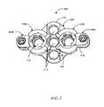
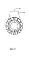
- FIG. 2is a front perspective view of an occipital plate member forming part of the posterior cervical fixation system of FIG. 1 in a collapsed state;
- FIG. 3is a front perspective view of an occipital plate member forming part of the posterior cervical fixation system of FIG. 1 in an expanded state;
- FIG. 4is an exploded view of the occipital plate member of FIG. 2 ;
- FIG. 5is a perspective view of a cross connector engaged with the pair of elongated spinal rods forming part of the posterior cervical fixation system of FIG. 1 ;
- FIG. 6is a perspective view of a cross bar engaged with a first clamp and a second clamp on either end thereof forming part of the cross connector of FIG. 5 ;
- FIG. 7is a perspective view of a cross bar surrounded with a pair of ball spring collar forming part of the cross connector of FIG. 5 ;
- FIG. 8Ais a side perspective view of a first clamp of FIG. 6 ;
- FIG. 8Bis a side perspective view of a second clamp of FIG. 6 ;
- FIG. 9is a plan view of a clamp of FIG. 6 ;
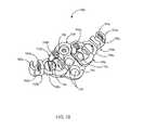
- FIG. 10is a top perspective view of an alternate embodiment of the occipital plate member of FIG. 4 in an expanded state
- FIG. 11is a top perspective view of an alternate embodiment of the occipital plate member of FIG. 4 in a collapsed state
- FIG. 12is a top perspective view of an alternate embodiment of the occipital plate member of FIG. 10 ;
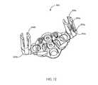
- FIG. 13is a side perspective view of an alternate embodiment of the occipital plate member of FIG. 11 ;
- FIG. 14is a perspective view of an eyelet connector forming part of the posterior cervical fixation system of FIG. 1 for fixing a spinal rod to human occiput;
- FIG. 15is a perspective view of an example of a collet and anchor head connector forming part of a posterior cervical fixation system of FIG. 1 for top loading a second spinal rod;
- FIG. 16is an exploded perspective view of a collet and anchor head connector of FIG. 15 ;
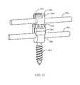
- FIG. 17is a perspective view of an adjustable angle occipital rod attached to a polyaxial screw forming part of the posterior cervical fixation system of FIG. 1 ;
- FIG. 18is a perspective view of the adjustable angle occipital rod of FIG. 17 ;
- FIG. 19Ais a partial sectional view of the adjustable angle occipital rod of FIG. 17 , detailing a locking mechanism
- FIG. 19Bis a sectional close-up view of the locking mechanism in the adjustable angle occipital rod according to FIG. 19A ;
- FIG. 20is a partial sectional view of an alternate embodiment of an adjustable angle occipital rod of FIG. 19A , detailing a set screw housing;
- FIG. 21is an enlarged view of a set screw forming part of an adjustable angle occipital rod of FIG. 20 ;
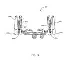
- FIG. 22is a perspective view of an adjustable offset rod-to-rod connector engaged with a pair of elongated spinal rods forming part of the posterior cervical fixation system of FIG. 1 ;
- FIG. 23Ais a perspective view of a male portion forming part of the adjustable offset rod-to-rod connector of FIG. 22 ;
- FIG. 23Bis a perspective view of a female portion forming part of the adjustable offset rod-to-rod connector of FIG. 22 ;
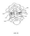
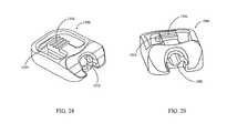
- FIG. 24is a perspective view of a side-loading laminar hook placed onto a lamina of a cervical vertebra forming part of a posterior cervical fixation system of FIG. 1 ;
- FIG. 25is a side perspective view of a side-loading laminar hook of FIG. 24 ;
- FIGS. 26 and 27are perspective views of a facet spacer placed within a facet joint forming part of a posterior cervical fixation system of FIG. 1 ;
- FIGS. 28-30are front and perspective views, respectively, of the facet spacer of FIGS. 26 and 27 , illustrating particularly a graft window, a deformable tab and a locking screw aperture;
- FIG. 31is a perspective view of an alternative embodiment of the facet spacer of FIGS. 28-30 ;
- FIG. 32is a perspective view of another embodiment of the facet spacer of FIGS. 28-30 ;
- FIG. 33is a perspective view of one embodiment of a multi-load polyaxial screw driver, illustrating particularly an outer shaft accommodated with a plurality of polyaxial screws with a cartridge coupled to each polyaxial screw;
- FIG. 34is a perspective view of the multi-load polyaxial screw driver, of FIG. 33 , illustrating particularly an inner shaft drives the plurality of screws and cartridge toward a distal end of the driver;
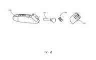
- FIG. 35is an assembling view of polyaxial screws with cartridge forming part of the multi-load polyaxial screw driver of FIG. 33 .
- FIG. 1illustrates an example of a posterior cervical fixation system 100 installed in a spine/skull 200 according to the present embodiment.
- the posterior cervical fixation system 100comprises a pair of elongated spinal rods 300 a , 300 b , an occipital plate member 400 , a cross connector 500 and a plurality of polyaxial screws 600 .
- the posterior cervical fixation system 100 described hereinis for attachment to the posterior part of the human spine from the occiput to the cervical and/or thoracic vertebrae.
- the posterior cervical fixation system 100facilitates securing of an orthopedic rod to the spine/skull 200 .
- the occipital plate member 400is configured for fixing to an occipital bone 202 .
- the occipital plate member 400includes at least one aperture 416 , 418 ( FIG. 2 ) that receives at least one bone anchor member (not shown) to secure the occipital plate member 400 to the occipital bone 202 and a pair of rod clamping elements 440 a , 440 b ( FIG. 2 ) dimensioned to receive the first and second elongated spinal rods 300 a , 300 b respectively.
- the at least one bone anchor member (not shown)may be at least one of a bone screw, nail, pin or hook.
- Each polyaxial screw 600includes an anchor head 602 associated with a fastening member (not shown).
- the pair of elongated spinal rodsincludes a first elongated spinal rod 300 a and a second elongated spinal rod 300 b which is configured to extend along vertebral bodies 204 between the occipital plate member 400 and at least one polyaxial screw 600 .
- the first elongated spinal rod 300 amay be of different diameter than the second elongated spinal rod 300 b.
- the cross connector 500secures the first and second elongated spinal rods 300 a , 300 b to the vertebral bodies 204 of the spine.
- the cross connector 500includes a pair of collet connectors 502 a , 502 b ( FIG. 5 ) and a cross bar 504 which is configured to secure the first and second elongated spinal rods 300 a , 300 b in desired distance.
- the fastening member 606 of the polyaxial screw 600is inserted in the vertebral bodies 204 by facing the anchor head 602 upwards to receive the first and second elongated spinal rods 300 a , 300 b .
- the first and second elongated spinal rods 300 a , 300 bare effectively locked in the anchor head 602 by connecting the cross connector 500 to the anchor head 602 .
- the anchor head 602may include a recess 604 that is adapted to cooperate with a driver (not shown) used to lock the fastening member 606 of the polyaxial screw 600 into the vertebral bodies 204 .
- the recess 604is shown as a hex-head shaped recess for receiving a hex-head driver.
- the anchor head 602is generally spherical in shape and dimensioned to engage with the cross connector 500 .
- polyaxial screw 600is including but not limited to a screw, nail, hook, pin, staple, tack, and/or suture. Any or all of these elements may be made of a biologically inert material; preferably any metal customarily used for surgical devices, such as for example titanium or stainless steel.
- the occipital plate member 400 of the posterior cervical fixation system 100comprises an upper surface 406 and a lower surface (not shown), in which the lower surface (not shown) is configured to contact a portion of the occipital bone 202 .
- the occipital plate member 400includes a generally flat main body portion 408 having a first surface 410 a , a second surface 410 b and a centerline axis 412 . Both first and second surfaces 410 a , 410 b have a recessed portion 414 and an opening 416 and the centerline axis 412 has a plurality of openings 418 .
- 2-4are provided with five openings, with three of the openings 418 aligned along the centerline axis 412 and additional two openings 416 on either first and second surfaces 410 a , 410 b of the main body portion 408 .
- These openings 416 , 418may extend through the occipital plate member 400 at an angle such that the bone anchor members (not shown) are guided into the occipital bone 202 at an oblique angle to the transverse axis of the occipital plate member 400 .
- the main body portion 408further includes a first end 420 a in which at least a portion of the first end 420 a extends away from the centerline axis 412 and a second end 420 b in which at least a portion of the second end 420 b extends away from the centerline axis 412 .
- the occipital plate member 400is fixed to the occipital bone 202 by inserting a plurality of bone anchor members (not shown) through the plurality of openings 418 in the centerline axis and each opening 416 on the first and second surfaces 410 a , 410 b of the main body portion 408 .
- the openings 416 on the first and second surfaces 410 a , 410 bare fitted with a washer 422 that interfaces with the occipital plate member 400 and the bone anchor member (not shown).
- the occipital plate member 400further includes a first rotating housing 430 a having a lower portion 432 a and a hole 434 a adaptable to engage with the recessed portion 414 and the opening 416 of the first surface 410 a , a second rotating housing 430 b having a lower portion 432 b and a hole 434 b adaptable to engage with the recessed portion 414 and the opening 416 of the second surface 410 b .
- the first and second housings 430 a , 430 bare able to freely rotate within the recessed portions of the first and second surfaces until a locking means 480 a , 480 b is deployed to lock the rotating housings 430 a , 430 b in a desired position.
- the occipital plate member 400further includes a first rod clamping element 440 a and a second rod clamping element 440 b .
- the first rod clamping element 440 ais dimensioned to couple the occipital plate member 400 to a first elongated spinal rod 300 a .
- the second rod clamping element 440 bis dimensioned to couple the occipital plate member 400 to a second elongated spinal rod 300 b .
- the first rod clamping element 440 aextends laterally from the first end 420 a of the main body portion 408 and the second rod clamping element 440 b extends laterally from the second end 420 b of the main body portion 408 .
- the first rod clamping element 440 aincludes a first clamp portion 442 a having a rod receiving end 444 a and a hole 446 a extending therethrough in communication with the rod receiving end 444 a and a first body portion 448 a having a pin slot 450 a therethrough on a body of the first body portion 448 a .
- the second rod clamping element 440 bincludes a second clamp portion 442 b having a rod receiving end 444 b and a hole 446 b extending therethrough in communication with the rod receiving end 444 b and a second body portion 448 b having a pin slot 450 b therethrough on a body of the second body portion 448 b.
- the occipital plate member 400further includes a plurality of pins 460 that is coupled to the first and second rotating housings 430 a , 430 b .
- the pin slots 450 a , 450 b of the first and second rod clamping elements 440 a , 440 breceive the pins 460 and enable each of the rod clamping elements 440 a , 440 b to translate medially and laterally within each of the rotating housings 430 a , 430 b to achieve a collapsed state ( FIG. 2 ) and an expanded state ( FIG. 3 ).
- the occipital plate member 400further includes a first locking element 470 a to lock the first elongated spinal rod 300 a within the rod receiving end 444 a of the first rod clamping element 440 a and a second locking element 470 b to lock the second elongated spinal rod 300 b within the rod receiving end 444 b of the second rod clamping element 440 b .
- the first and second locking elements 470 a , 470 bmay comprise, for example, a set screw. According to the embodiment shown in FIGS.
- the set screws 470 a , 470 bthreadedly engage the holes 446 a , 446 b on the first and second clamp portions 442 a , 442 b such that the set screws 470 a , 470 b may be advanced toward the elongated spinal rods 300 a , 300 b until a distal tip of the set screws 470 a , 470 b contacts the elongated spinal rods 300 a , 300 b .
- a first locking means 480 aengages the first rotating housing 430 a and the first rod clamping element 440 a to the first surface 410 a of the main body portion 408 and a second locking means 480 b engages the second rotating housing 430 b and the second rod clamping element 440 b to the second surface 410 b of the main body portion 408 .
- a first locking means 480 aengages the first rotating housing 430 a and the first rod clamping element 440 a to the first surface 410 a of the main body portion 408 and a second locking means 480 b engages the second rotating housing 430 b and the second rod clamping element 440 b to the second surface 410 b of the main body portion 408 .
- both the locking means 480 a , 480 bcomprise a lock nut which is dimensioned to lock the first and second rotating housings 430 a , 430 b and the first and second rod clamping elements 440 a , 440 b with the first and second surfaces 410 a , 410 b of the main body portion 408 when the first and second rotating housings 430 a , 430 b and first and second rod clampling elements 440 a , 440 b are in a desired position.
- the first and second rod clamping elements 440 a , 440 bhave a generally C-shaped rod-receiving ends 450 a , 450 b for facilitating the side-loading of the first and second elongated spinal rods 300 a , 300 b therethrough.
- the occipital plate member 400may be provided in any size suitable for any particular patient.
- the bone anchor members(not shown) may be provided having any diameter and length dimension suitable for implantation into a patient's skull.
- FIGS. 5-9illustrate one of embodiment of a cross connector 500 and its associated components forming part of a posterior cervical fixation system 100 .
- the cross connector 500further includes a first connector 502 a , a second connector 502 b and a cross bar 504 .
- the cross bar 504includes a first end 504 a that is surrounded with a first ball spring collar 506 a ( FIG. 7 ) and a second end 504 b that is surrounded with a second ball spring collar 506 b ( FIG. 7 ).
- the first connector 502 ais configured to receive the first elongated spinal rod 300 a and adaptable to directly attach with a first polyaxial screw 600 a .
- the second connector 502 bis configured to receive a second elongated spinal rod 300 b and adaptable to directly attach with a second polyaxial screw 600 b.
- the first connector 502 aincludes a first collet head 508 a having a recess (not shown) to receive an anchor head 602 a of the first polyaxial screw 600 a and a plurality of cutouts (not shown) to accommodate the first elongated spinal rod 300 a , a first clamp 510 a having a first spherical pocket 512 a to receive the first ball spring collar 506 a of the cross bar 504 and a first locking means 514 a tightened over the first clamp 510 a placed above the first collet head 508 a .
- the first locking means 514 aenables a snap-fit engagement of the first connector 502 a with the first end 504 a of the cross bar 504 and the anchor head 602 a .
- the second connector 502 bincludes a second collet head 508 b having a recess (not shown) to receive an anchor head 602 b of the second polyaxial screw 600 b and a plurality of cutouts (not shown) to accommodate the second elongated spinal rod 300 b , a second clamp 510 b having a second spherical pocket 512 b to receive the second ball spring collar 506 b of the cross bar 504 , a second locking means 514 b tightened over the second clamp 510 b placed above the second collet head 508 b .
- the second locking means 514 benables a snap-fit engagement of the second connector 502 b with the second end 504 b of the cross bar 504 and the anchor head 602 b.
- first clamp 510 aattached to the first ball spring collar 506 a at the first end 504 a of the cross bar 504 and the second clamp 510 a attached to the second ball spring collar 506 b at the second end 504 b of the cross bar 504 .
- the first and second spherical pockets 512 a , 512 breceive the first and second ball collars 506 a , 506 b and permit the cross bar 504 to translate in either direction for adjusting to the distance and allow rotational adjustment in the axial plane on both sides of a spinal construct.
- the cross bar 504has the first end 504 a that is surrounded with the first ball spring collar 506 a and the second end 504 b that is surrounded with the second ball spring collar 506 b .
- the first and the second ball spring collars 506 a , 506 b attached on the cross bar 504allows rotational adjustment to the first and second connectors 502 a , 502 b in an axial plane, the rotational adjustment provides stability to the cross-connector 500 when one polyaxial screw 600 a is positioned deeper than the other polyaxial screw 600 b on the vertebral bodies.
- the cross bar 504translates through the first and second spherical pockets 512 a , 512 b through a conical passage 520 .
- the conical passage 520is larger than the diameter of the cross bar 504 and permits the cross bar 504 to be angularly adjusted relative to the first and second clamps 510 a , 510 b .
- the cross bar 500may be provided in any length suitable for extending between the first and second elongated spinal rods 300 a , 300 b.
- the elongated spinal rods 300 a , 300 bextend along the posterior aspects of the patient's cervical and potentially thoracic spine on either side of the spinous processes for a desired distance.
- Any combination of anchor elementsincluding polyaxial screws and/or laminar hooks as described above may be used to secure the rods to the cervical and/or thoracic vertebrae.
- Any combination of anchor elements, including bone anchors and/or locking screws as described abovemay be used to secure the occipital plate to the occipital bone 202 .
- cross connectors 500may then be employed to maintain the elongated spinal rods 300 a , 300 b at a desired distance from one another.
- FIGS. 10 and 11illustrate an alternative embodiment of the occipital plate of FIG. 2 .
- FIG. 10depicts an occipital plate member attached with U-shaped rod receiving elements in its expanded state.
- FIG. 11depicts an occipital plate member attached with U-shaped rod receiving elements in its collapsed state.
- the occipital plate member 700 in this embodimentis similar structurally and functionally to the embodiment described above, with a difference in that the first and second rod clamping elements 740 a , 740 b have a generally U-shaped rod-receiving ends 792 a , 792 b with a threaded side walls 794 a , 794 b extending therethrough in communication with the rod receiving ends 792 a , 792 b respectively, in which the rod receiving ends 792 a , 792 b are dimensioned to face upward.
- a first locking means 796 a and a second locking means 796 bare locking screws which are positioned vertically offset from center of a first rotating housing 730 a and a second rotating housing 730 b respectively.
- the first and second locking means 796 a , 796 benables the locking of the first rod clamping element 740 a and the second rod clamping element 740 b with the first and second rotating housings 730 a , 730 b in a desired position.
- the openings 716 , 718 in the main body portion 708are angled such that the bone anchor members 790 are guided into the occipital bone 202 at an oblique angle to the transverse axis of the occipital plate member 700 .
- the illustrated embodimentis similar in all other respects to the preferred embodiment described above, and as such similar components and features are numbered similarly, except in the 700 s rather than the 400 s.
- the occipital plate member 700has an upper surface 706 and a lower surface (not shown), in which the lower surface (not shown) is configured to contact a portion of the occipital bone 202 .
- the occipital plate member 700includes a main body portion 708 having a first surface, a second surface and a centerline axis. Both the first and second surfaces have a recessed portion and an opening 716 and the centerline axis has a plurality of openings 718 .
- the main body portion 708further includes a first end and a second end, in which at least a portion of the first and second ends extends away from the centerline axis.
- the occipital plate member 700is fixed to the occipital bone 202 by inserting a plurality of bone anchor members 790 through the plurality of openings 718 in the centerline axis and the opening 716 on the first and second surfaces of the main body portion 708 .
- the occipital plate member 700further includes a first rotating housing 730 a having a lower portion and a hole adaptable to engage with the recessed portion and the opening 716 of the first surface of the main body portion 708 , and a second rotating housing 730 b having a lower portion and a hole adaptable to engage with the recessed portion and the opening 716 of the second surface of the main body portion 708 .
- the first and second housings 730 a , 730 bare able to freely rotate within the recessed portions of the first and second surfaces until a locking means 796 a , 796 b is deployed to lock the rotating housings 730 a , 730 b in a desired position.
- the occipital plate member 700further includes a first rod clamping element 740 a and a second rod clamping element 740 b .
- the first rod clamping element 740 ais dimensioned to couple the occipital plate member 700 to the first elongated spinal rod 300 a .
- the second rod clamping element 740 bis dimensioned to couple the occipital plate member 700 to the second elongated spinal rod 300 b .
- the first and second rod clamping elements 740 a , 740 bextend laterally from the first end and second end of the main body portion 708 respectively.
- the first rod clamping element 740 aincludes a first clamp portion 742 a having the rod receiving end 792 a and the threaded side wall 794 a extending therethrough in communication with the rod receiving end 792 a and a first body portion 748 a having a pin slot therethrough on a body of the first body portion 748 a .
- the second rod clamping element 740 bincludes a second clamp portion 742 b having the rod receiving end 792 b and the threaded side wall 794 b extending therethrough in communication with the rod receiving end 792 a and a second body portion 748 b having a pin slot therethrough on a body of the second body portion 748 b.
- the occipital plate member 700further includes a plurality of pins coupled to the first and second rotating housings 730 a , 730 b .
- the pin slots of first and second rod clamping elements 740 a , 740 breceive the pins and enable the first and second rod clamping elements 740 a , 740 b to translate medially and laterally within the first and second rotating housings 730 a , 730 b to achieve a collapsed state ( FIG. 11 ) and an expanded state ( FIG.
- the occipital plate member 700further includes a first locking element (not shown) to lock the first elongated spinal rod 300 a within the rod receiving end 744 a of the first rod clamping element 740 a and a second locking element (not shown) to lock the second elongated spinal rod 300 b within the rod receiving end 744 b of the second rod clamping element 740 b .
- the first and second locking elementsmay comprise, for example, a set screw.
- the first locking means 796 aengages the first rotating housing 730 a and the first rod clamping element 740 a to the main body portion 708 and the second locking means 796 b engages the second rotating housing 730 b and the second rod clamping element 740 b to the main body portion 708 .
- Deploying the first and second locking means 796 a , 796 burges the rotating housings 730 a , 730 b against the top surface 706 of the plate, thereby locking the rotating housings 730 a , 730 b and rod clamping elements 740 a , 740 b in a desired position.
- FIGS. 12 and 13illustrate an alternative embodiment of the occipital plate member of FIGS. 10 and 11 in an expanded state and a collapsed state.
- the occipital plate member 800 in this embodimentis similar structurally and functionally to the embodiment described above, with a difference in that the U-shaped rod-receiving ends 892 a , 892 b with a threaded side walls 894 a , 894 b extending therethrough in communication with the rod receiving ends 892 a , 892 b that is attached with rod receiving towers 898 a , 898 b having a threaded side walls 899 a , 899 b extending therethrough in communication with the rod receiving towers 898 a , 898 b .
- the illustrated embodimentis similar in all other respects to the embodiment in FIGS. 10 and 11 , and as such similar components and features are numbered similarly, except in the 800 s rather than the 700 s.
- FIG. 14illustrates one example of an eyelet connector 900 forming part of the posterior cervical fixation system 100 .
- the eyelet connector 900is provided for fixing the elongated spinal rods 300 a , 300 b to human occiput.
- the eyelet connector 900comprises a rod receiving element 910 and a screw hole 912 .
- the rod receiving element 910having an open side 910 a facing the occipital bone that allows the elongated spinal rods 300 a , 300 b to pass through and a set screw hole 910 b for the spinal rod fixation to the occiput with a minimal profile.
- the elongated spinal rods 300 a , 300 bare locked with the occipital bone 202 by inserting a set screw 914 through the set screw hole 910 b .
- the eyelet connector 900is fixed to the skull with a bone screw (not shown) inserted through the screw hole 912 and into the occiput.
- FIGS. 15 and 16illustrate an example of a collet and anchor head connector 1000 forming part of a posterior cervical fixation system for top loading a second elongated spinal rod.
- the collet and anchor head connector 1000is engaged with a first elongated spinal rod 300 a and top loaded with a second elongated spinal rod 300 b as shown in FIG. 15 .
- the second elongated spinal rod 300 bis shown as co-linear with the first elongated spinal rod 300 a .
- the first and second elongated spinal rods 300 a , 300 bare secured into the bone with a cross connector 500 and an occipital plate member 400 ( FIGS. 1 and 10 ). According to this example, shown in FIGS.
- a collet connector 1002 and a second anchor head 1004may also be oriented to allow the second elongated spinal rod 300 b to be positioned transverse to the first elongated spinal rod 300 a .
- the collet connector 1002may be coupled to a first anchor head 1006 with a first set screw 1008 and a locking cap 1010 is threaded onto the collet connector 1002 .
- the first set screw 1008is received within apertures (not shown) in the collet connector 1002 and the locking cap 1010 .
- the second elongated spinal rod 300 bmay be secured within the second anchor head 1004 with a second set screw 1012 .
- the second anchor head 1004is inserted into the locking cap 1010 and engaged with the collet connector 1002 .
- a screw shank 1014 attached with the first anchor head 1006is inserted into the bone.
- FIGS. 17-19Billustrate an adjustable angle occipital rod forming part of a posterior cervical fixation system of FIG. 1 .
- FIG. 17depicts an adjustable angle occipital rod attached to a polyaxial screw.
- FIG. 18depicts an adjustable angle occipital rod illustrating a hinge.
- FIGS. 19A and 19Bdepict an adjustable angle occipital rod that includes a locking mechanism.
- the adjustable angle occipital rod 1100comprises a first rod portion 1100 a and a second rod portion 1100 b that pivot in relation to each other about a hinge 1102 .
- the first and second rods 1100 a , 1100 bfurther comprises a locking mechanism 1104 therebetween.
- the locking mechanism 1104includes a first disc 1104 a coupled to the first rod portion 1100 a and a second disc 1104 b coupled to the second rod portion 1100 b .
- the first and second discs 1104 a , 1104 bhave an engagement surface ( 1108 a ) that faces the engagement surface ( 1108 b ) of the other disc, the engagement surfaces 1108 a , 1108 b having a plurality of teeth to allow the first and second rods 1100 a , 1100 b to be rotated and locked in discrete increments of angulation relative to each other.
- the first and second rod portions 1100 a , 1100 bare engaged together with a set screw 1106 .
- the first and second rod portions 1100 a , 1100 bcan rotate freely about the hinge 1002 .
- the set screw 1106can be turned to the locked position, urging the engagement surfaces 1108 a , 1108 b of the first and second discs 1104 a , 1104 b in contact with each other to prevent movement of the first and second rod portions 1100 a , 1100 b.
- FIGS. 20 and 21illustrate an alternative embodiment of an adjustable angle occipital rod of FIGS. 17-19B .
- FIG. 20depicts an adjustable angle occipital rod attached with screw housing.
- FIG. 21depicts a set screw forming part of an adjustable angle occipital rod of FIG. 20 .
- the adjustable angle occipital rod 1200 in this embodimentis similar structurally and functionally to the embodiment described above, with a difference in that a first rod portion 1200 a and a second rod portion 1200 b that pivot in relation to each other about a hinge 1202 .
- the set screw 1206has a ratcheted surface 1208 that engages a ratcheting washer 1210 is secured within set screw housing 1212 of the second rod portion 1200 b .
- the interaction of the ratcheting surface 1208 on the set screw 1206 with the ratcheting washer 1210limits the turning and tightening of the set screw 1206 to only one direction. More particularly, the illustrated embodiment is similar in all other respects to the preferred embodiment described above, and as such similar components and features are numbered similarly, except in the 1200 s rather than the 1100 s.
- FIGS. 22-23Bdemonstrate one embodiment of an adjustable offset rod-to-rod connector.
- FIG. 22depicts the adjustable offset rod-to-rod connector engaged with a pair of elongated spinal rods.
- FIG. 23Adepicts a male portion forming part of the adjustable offset rod-to-rod connector of FIG. 22 .
- FIG. 23Bdepicts a female portion forming part of the adjustable offset rod-to-rod connector of FIG. 22 .
- the adjustable offset rod-to-rod connector 1300facilitates the adjacent engagement of a first elongated spinal rod 1302 a and a second elongated spinal rod 1302 b .
- the adjustable offset rod-to-rod connector 1300includes a male portion 1304 and a female portion 1306 that are coupled such that the male and female portions 1304 , 1306 may rotate with respect to each other.
- the male and female portions 1304 , 1306include a rod receiving hole 1308 for receiving the rods 1302 a , 1302 b therethrough and a set screw 1310 for locking the adjustable offset rod-to-rod connector 1300 to the rods 1302 a , 1302 b.
- FIGS. 24 and 25demonstrate one embodiment of a side-loading laminar hook forming part of a posterior cervical fixation system of FIG. 1 .
- the side-loading laminar hook 1400is dimensioned to hook onto a lamina 1402 of a cervical vertebra 1404 .
- the side-loading laminar hook 1400has a generally C-shaped rod-receiving portion 1406 for receiving spinal rods (not shown) therethrough.
- the first and second elongated spinal rods (not shown)are locked in place within the rod-receiving portion 1406 by a set screw 1408 .
- FIGS. 26-30demonstrate one embodiment of a facet spacer forming part of a posterior cervical fixation system of FIG. 1 .
- the facet spacer 1500is dimensioned to be inserted into a facet joint 1502 of a vertebra.
- the facet spacer 1500includes a graft window 1504 to allow bone growth therethrough to achieve fusion of the facet joint 1502 and a plurality of deformable tabs 1506 extending into the graft window 1504 .
- the plurality of deformable tabs 1506further includes teeth, which will engage the facet spacer 1500 .
- the facet spacer 1500includes a locking screw aperture 1508 for receiving a locking screw 1510 . When the locking screw 1510 is inserted into the locking screw aperture 1508 of the facet spacer 1500 , the plurality of deformable tabs 1506 urges apart ( FIG. 30 ).
- FIG. 31illustrates one embodiment of the facet spacer of FIGS. 26-30 .
- the facet spacer 1600 in this embodimentis similar structurally and functionally to the embodiment described above in FIGS. 26-30 , with a difference in that an anchor head 1602 is coupled to the facet spacer 1600 .
- the anchor head 1602is capable of receiving a spinal rod (not shown).
- the anchor head 1602is attached to a locking screw 1604 which allows the adjustment of the position of the anchor head 1602 to a desired position for receiving the spinal rod (not shown).
- the illustrated embodimentis similar in all other respects to the preferred embodiment described above, and as such similar components and features are numbered similarly, except in the 1600 s rather than the 1500 s.
- FIG. 32illustrates yet another embodiment of the facet spacer of FIGS. 26-30 .
- the facet spacer 1700 in this embodimentis similar structurally and functionally to the embodiment described above in FIGS. 26-30 , with a difference in that an anchor head 1702 is attached to a locking screw 1704 that is having a spherical head 1706 , allowing for adjustment of the position of the anchor head 1702 to a desired position for receiving a spinal rod (not shown).
- the illustrated embodimentis similar in all other respects to the preferred embodiment described above, and as such similar components and features are numbered similarly, except in the 1700 s rather than the 1600 s.
- FIGS. 33-35demonstrate one embodiment of a multi-load polyaxial screw driver.
- the multi-load polyaxial screw driver 1800having a distal end 1802 and a proximal end 1804 .
- the multi-load polyaxial screw driver 1800includes a handle 1806 , an outer shaft 1808 , inner shaft 1810 , cartridge 1812 and slots for cartridge tab 1814 .
- the outer shaft 1808 of the multi-load polyaxial screw driver 1800can accommodate a plurality of polyaxial screws 1816 .
- the cartridge 1812include a hex-shaped end 1818 to mate to a hex-shaped recess 1828 in the anchor head 1826 of the polyaxial screw 1816 and a spherical tip 1820 proximal to the hex-shaped end 1818 that will engage the inside the hex-shaped recess 1828 of the anchor head 1826 .
- the cartridgemay have a shaped end to complement the shape of any anchor head with which the multi-load polyaxial screw driver is used.
- the cartridge 1812is coupled to each polyaxial screw 1816 .
- the hex shaped end 1818 of the cartridge 1812is engaged in the anchor head 1826 of one polyaxial screw 1816 and a screw shank 1830 of other polyaxial screw 1816 is engaged with a head 1824 of the cartridge 1812 and so on in a nested fashion.
- the cartridges 1812further include side tabs 1822 that will engage slots 1814 in the outer shaft 1808 of the driver 1800 when the cartridge 1812 has been advanced to the distal end 1802 of the driver 1800 and the polyaxial screw engaged with that cartridge is exposed distally to the multi-load screwdriver. After the exposed polyaxial screw is deployed into the vertebral bone, the corresponding cartridge 1812 can then be pinched in at the side tabs 1822 and the empty cartridge 1812 along is released from the driver 1800 .
- the cartridge 1812can be removed from the outer shaft 1808 of the driver 1800 once the polyaxial screw 1816 has been driven into and secured in the spine.
- the head 1824 of the cartridge 1812includes an aperture (not shown) for receiving the screw shank 1830 of the next polyaxial screw 1816 .
- the inner shaft 1810 of the driver 1800is spring-loaded which urges the plurality of polyaxial screws 1816 and the cartridges 1812 toward the distal end 1802 of the driver 1800 .
Landscapes
- Health & Medical Sciences (AREA)
- Orthopedic Medicine & Surgery (AREA)
- Neurology (AREA)
- Life Sciences & Earth Sciences (AREA)
- Surgery (AREA)
- Heart & Thoracic Surgery (AREA)
- Engineering & Computer Science (AREA)
- Biomedical Technology (AREA)
- Nuclear Medicine, Radiotherapy & Molecular Imaging (AREA)
- Medical Informatics (AREA)
- Molecular Biology (AREA)
- Animal Behavior & Ethology (AREA)
- General Health & Medical Sciences (AREA)
- Public Health (AREA)
- Veterinary Medicine (AREA)
- Neurosurgery (AREA)
- Surgical Instruments (AREA)
Abstract
Description
Claims (11)
Priority Applications (5)
| Application Number | Priority Date | Filing Date | Title |
|---|---|---|---|
| US13/410,213US9387013B1 (en) | 2011-03-01 | 2012-03-01 | Posterior cervical fixation system |
| US15/182,414US9956009B1 (en) | 2011-03-01 | 2016-06-14 | Posterior cervical fixation system |
| US15/936,107US10368918B2 (en) | 2011-03-01 | 2018-03-26 | Posterior cervical fixation system |
| US16/453,631US11123110B2 (en) | 2011-03-01 | 2019-06-26 | Posterior cervical fixation system |
| US17/409,746US12053211B2 (en) | 2011-03-01 | 2021-08-23 | Posterior cervical fixation system |
Applications Claiming Priority (4)
| Application Number | Priority Date | Filing Date | Title |
|---|---|---|---|
| US201161447702P | 2011-03-01 | 2011-03-01 | |
| US201161450130P | 2011-03-08 | 2011-03-08 | |
| US201161555474P | 2011-11-03 | 2011-11-03 | |
| US13/410,213US9387013B1 (en) | 2011-03-01 | 2012-03-01 | Posterior cervical fixation system |
Related Child Applications (1)
| Application Number | Title | Priority Date | Filing Date |
|---|---|---|---|
| US15/182,414ContinuationUS9956009B1 (en) | 2011-03-01 | 2016-06-14 | Posterior cervical fixation system |
Publications (1)
| Publication Number | Publication Date |
|---|---|
| US9387013B1true US9387013B1 (en) | 2016-07-12 |
Family
ID=56320893
Family Applications (5)
| Application Number | Title | Priority Date | Filing Date |
|---|---|---|---|
| US13/410,213Active2032-07-01US9387013B1 (en) | 2011-03-01 | 2012-03-01 | Posterior cervical fixation system |
| US15/182,414ActiveUS9956009B1 (en) | 2011-03-01 | 2016-06-14 | Posterior cervical fixation system |
| US15/936,107ActiveUS10368918B2 (en) | 2011-03-01 | 2018-03-26 | Posterior cervical fixation system |
| US16/453,631Active2032-07-15US11123110B2 (en) | 2011-03-01 | 2019-06-26 | Posterior cervical fixation system |
| US17/409,746Active2033-04-09US12053211B2 (en) | 2011-03-01 | 2021-08-23 | Posterior cervical fixation system |
Family Applications After (4)
| Application Number | Title | Priority Date | Filing Date |
|---|---|---|---|
| US15/182,414ActiveUS9956009B1 (en) | 2011-03-01 | 2016-06-14 | Posterior cervical fixation system |
| US15/936,107ActiveUS10368918B2 (en) | 2011-03-01 | 2018-03-26 | Posterior cervical fixation system |
| US16/453,631Active2032-07-15US11123110B2 (en) | 2011-03-01 | 2019-06-26 | Posterior cervical fixation system |
| US17/409,746Active2033-04-09US12053211B2 (en) | 2011-03-01 | 2021-08-23 | Posterior cervical fixation system |
Country Status (1)
| Country | Link |
|---|---|
| US (5) | US9387013B1 (en) |
Cited By (12)
| Publication number | Priority date | Publication date | Assignee | Title |
|---|---|---|---|---|
| US20150374413A1 (en)* | 2011-07-15 | 2015-12-31 | Globus Medical, Inc. | Orthopedic fixation devices and methods of installation thereof |
| US9770269B1 (en)* | 2011-03-01 | 2017-09-26 | Nuvasive, Inc. | Spinal Cross-connector |
| US20170290608A1 (en)* | 2016-01-22 | 2017-10-12 | Spinal Usa, Inc. | Spinal fixation systems and methods |
| US20180228516A1 (en)* | 2017-02-14 | 2018-08-16 | Warsaw Orthopedic, Inc. | Spinal implant system and method |
| US20180344361A1 (en)* | 2015-11-20 | 2018-12-06 | Medacta International S.A. | Occipital plate for occipito-cervical fixation and system for occipito-cervical fixation |
| WO2018212734A3 (en)* | 2016-10-25 | 2019-02-21 | Akbas Ragip | A screwless posterior stabilization mechanism |
| US20210290272A1 (en)* | 2015-12-23 | 2021-09-23 | Xiangyang Ma | Customized posterior atlantoaxial reduction fixatorwith screws and rods |
| US11197693B2 (en)* | 2014-11-20 | 2021-12-14 | Biedermann Technologies Gmbh & Co. Kg | Receiving part for coupling a bone anchor to a rod and bone anchoring device with such a receiving part |
| US11364055B2 (en) | 2020-09-02 | 2022-06-21 | Zavation, Llc | Occipital plate and hinged rod assembly |
| US20230240724A1 (en)* | 2019-05-22 | 2023-08-03 | Nuvasive, Inc. | Posterior spinal fixation screws |
| US11950811B2 (en) | 2020-09-22 | 2024-04-09 | Alphatec Spine, Inc. | Occipital plates and related methods |
| US12053211B2 (en)* | 2011-03-01 | 2024-08-06 | Nuvasive Inc. | Posterior cervical fixation system |
Families Citing this family (13)
| Publication number | Priority date | Publication date | Assignee | Title |
|---|---|---|---|---|
| US9827714B1 (en) | 2014-05-16 | 2017-11-28 | Google Llc | Method and system for 3-D printing of 3-D object models in interactive content items |
| US10321939B2 (en) | 2016-05-18 | 2019-06-18 | Medos International Sarl | Implant connectors and related methods |
| US10517647B2 (en) | 2016-05-18 | 2019-12-31 | Medos International Sarl | Implant connectors and related methods |
| US10492835B2 (en) | 2016-12-19 | 2019-12-03 | Medos International Sàrl | Offset rods, offset rod connectors, and related methods |
| US10238432B2 (en)* | 2017-02-10 | 2019-03-26 | Medos International Sàrl | Tandem rod connectors and related methods |
| US10966761B2 (en) | 2017-03-28 | 2021-04-06 | Medos International Sarl | Articulating implant connectors and related methods |
| US10561454B2 (en) | 2017-03-28 | 2020-02-18 | Medos International Sarl | Articulating implant connectors and related methods |
| US11076890B2 (en) | 2017-12-01 | 2021-08-03 | Medos International Sàrl | Rod-to-rod connectors having robust rod closure mechanisms and related methods |
| EP4420855A3 (en)* | 2018-07-24 | 2024-10-30 | Canon Virginia, Inc. | Connection for different structures that slide together |
| US11154337B2 (en) | 2019-02-26 | 2021-10-26 | Medos Iniernational Sarl | Spinal screw handling |
| US11389209B2 (en) | 2019-07-19 | 2022-07-19 | Medos International Sarl | Surgical plating systems, devices, and related methods |
| US11065038B2 (en) | 2019-08-08 | 2021-07-20 | Medos International Sarl | Fracture reduction using implant based solution |
| WO2021034664A1 (en)* | 2019-08-14 | 2021-02-25 | K2M, Inc. | Pedicle fixation system |
Citations (485)
| Publication number | Priority date | Publication date | Assignee | Title |
|---|---|---|---|---|
| US929067A (en) | 1907-10-10 | 1909-07-27 | William J Williamson | Hose-coupling. |
| US1841647A (en) | 1928-06-01 | 1932-01-19 | United Shoe Machinery Corp | Shoe finishing machine |
| US3367326A (en) | 1965-06-15 | 1968-02-06 | Calvin H. Frazier | Intra spinal fixation rod |
| US3610092A (en) | 1968-11-29 | 1971-10-05 | Fairchild Industries | Locking ring for store arming device |
| US4361141A (en) | 1979-07-27 | 1982-11-30 | Zimmer Usa, Inc. | Scoliosis transverse traction assembly |
| US4414966A (en) | 1981-04-09 | 1983-11-15 | Ace Orthopedic Manufacturing, Inc. | Fixation pin |
| US4484570A (en) | 1980-05-28 | 1984-11-27 | Synthes Ltd. | Device comprising an implant and screws for fastening said implant to a bone, and a device for connecting two separated pieces of bone |
| US4537185A (en) | 1983-06-10 | 1985-08-27 | Denis P. Stednitz | Cannulated fixation screw |
| US4569338A (en) | 1984-02-09 | 1986-02-11 | Edwards Charles C | Sacral fixation device |
| US4577837A (en) | 1984-07-30 | 1986-03-25 | Marvin Berg | Locking mechanism for extendible telescoping tubular members |
| US4641636A (en) | 1983-05-04 | 1987-02-10 | Cotrel Yves P C A | Device for supporting the rachis |
| US4648388A (en) | 1985-11-01 | 1987-03-10 | Acromed Corporation | Apparatus and method for maintaining vertebrae in a desired relationship |
| US4771767A (en) | 1986-02-03 | 1988-09-20 | Acromed Corporation | Apparatus and method for maintaining vertebrae in a desired relationship |
| EP0283373A1 (en) | 1987-03-13 | 1988-09-21 | Societe De Fabrication De Materiel Orthopedique | Vertebral screw for an osteosynthesis device, especially for the lumbar and dorsal spine |
| US4805602A (en) | 1986-11-03 | 1989-02-21 | Danninger Medical Technology | Transpedicular screw and rod system |
| DE3841008A1 (en) | 1988-12-06 | 1990-06-07 | Heinrich Ulrich | Implant for correction of the spine |
| US4946458A (en) | 1986-04-25 | 1990-08-07 | Harms Juergen | Pedicle screw |
| US4998936A (en) | 1987-08-07 | 1991-03-12 | Mehdian Seyed M H | Apparatus for use in the treatment of spinal disorders |
| US5002542A (en) | 1989-10-30 | 1991-03-26 | Synthes U.S.A. | Pedicle screw clamp |
| US5005562A (en) | 1988-06-24 | 1991-04-09 | Societe De Fabrication De Material Orthopedique | Implant for spinal osteosynthesis device, in particular in traumatology |
| CA2045502A1 (en) | 1989-11-03 | 1991-05-04 | Lutz Biedermann | Pedicel screw, and correcting and supporting apparatus comprising such screw |
| US5024213A (en) | 1989-02-08 | 1991-06-18 | Acromed Corporation | Connector for a corrective device |
| US5034011A (en) | 1990-08-09 | 1991-07-23 | Advanced Spine Fixation Systems Incorporated | Segmental instrumentation of the posterior spine |
| US5042982A (en) | 1987-07-08 | 1991-08-27 | Harms Juergen | Positioning device |
| DE9004960U1 (en) | 1990-05-02 | 1991-08-29 | Pfeil, Joachim, Dr.Med. | Halo fixator for the treatment of cervical spine diseases and injuries |
| US5047029A (en) | 1988-06-10 | 1991-09-10 | Synthes (U.S.A.) | Clamp and system for internal fixation |
| US5084049A (en) | 1989-02-08 | 1992-01-28 | Acromed Corporation | Transverse connector for spinal column corrective devices |
| US5092893A (en) | 1990-09-04 | 1992-03-03 | Smith Thomas E | Human orthopedic vertebra implant |
| US5092867A (en) | 1988-07-13 | 1992-03-03 | Harms Juergen | Correction and supporting apparatus, in particular for the spinal column |
| US5092866A (en) | 1989-02-03 | 1992-03-03 | Breard Francis H | Flexible inter-vertebral stabilizer as well as process and apparatus for determining or verifying its tension before installation on the spinal column |
| US5129388A (en) | 1989-02-09 | 1992-07-14 | Vignaud Jean Louis | Device for supporting the spinal column |
| US5154718A (en) | 1988-12-21 | 1992-10-13 | Zimmer, Inc. | Spinal coupler assembly |
| US5176680A (en) | 1990-02-08 | 1993-01-05 | Vignaud Jean Louis | Device for the adjustable fixing of spinal osteosynthesis rods |
| US5207678A (en) | 1989-07-20 | 1993-05-04 | Prufer | Pedicle screw and receiver member therefore |
| US5209752A (en) | 1991-12-04 | 1993-05-11 | Danek Medical, Inc. | Lateral offset connector for spinal implant system |
| US5217461A (en) | 1992-02-20 | 1993-06-08 | Acromed Corporation | Apparatus for maintaining vertebrae in a desired spatial relationship |
| US5234431A (en) | 1991-04-03 | 1993-08-10 | Waldemar Link Gmbh & Co. | Bone plate arrangement |
| US5261907A (en) | 1991-05-17 | 1993-11-16 | Vignaud Jean L | Interconnecting device able to lock spinal osteosynthesis fasteners |
| US5275600A (en) | 1992-10-05 | 1994-01-04 | Zimmer, Inc. | Telescoping rod to rod coupler for a spinal system |
| US5288161A (en) | 1992-02-14 | 1994-02-22 | The Wooster Brush Company | Quick release lock mechanisms |
| FR2624720B1 (en) | 1987-12-21 | 1994-04-15 | Fabrication Materiel Orthopediqu | IMPLANT FOR OSTEOSYNTHESIS DEVICE, ESPECIALLY OF THE RACHIS |
| US5312405A (en) | 1992-07-06 | 1994-05-17 | Zimmer, Inc. | Spinal rod coupler |
| FR2687561B1 (en) | 1992-02-20 | 1994-05-27 | Jbs Sa | DEVICE FOR STRAIGHTENING, FIXING, COMPRESSION AND ELONGATION OF CERVICAL VERTEBRES. |
| US5318388A (en) | 1992-04-08 | 1994-06-07 | Sgb Holdings Limited | Improvement in or relating to a shoring leg: a shoring leg with a latch |
| US5330473A (en) | 1993-03-04 | 1994-07-19 | Advanced Spine Fixation Systems, Inc. | Branch connector for spinal fixation systems |
| US5332330A (en) | 1990-10-02 | 1994-07-26 | Yamaichi Electric Co., Ltd. | Connector |
| US5360429A (en) | 1992-02-20 | 1994-11-01 | Jbs Societe Anonyme | Device for straightening, fixing, compressing, and elongating cervical vertebrae |
| US5375823A (en) | 1992-06-25 | 1994-12-27 | Societe Psi | Application of an improved damper to an intervertebral stabilization device |
| US5380323A (en) | 1993-06-16 | 1995-01-10 | Advanced Spine Fixation Systems, Inc. | Clamps for spinal fixation systems |
| US5387213A (en) | 1991-02-05 | 1995-02-07 | Safir S.A.R.L. | Osseous surgical implant particularly for an intervertebral stabilizer |
| US5397363A (en) | 1992-08-11 | 1995-03-14 | Gelbard; Steven D. | Spinal stabilization implant system |
| US5403314A (en) | 1993-02-05 | 1995-04-04 | Acromed Corporation | Apparatus for retaining spinal elements in a desired spatial relationship |
| WO1995013754A1 (en) | 1993-11-19 | 1995-05-26 | Cross Medical Products, Inc. | Transverse link for spinal implant system |
| US5443467A (en) | 1993-03-10 | 1995-08-22 | Biedermann Motech Gmbh | Bone screw |
| US5466237A (en) | 1993-11-19 | 1995-11-14 | Cross Medical Products, Inc. | Variable locking stabilizer anchor seat and screw |
| US5474555A (en) | 1990-04-26 | 1995-12-12 | Cross Medical Products | Spinal implant system |
| US5476464A (en) | 1993-02-25 | 1995-12-19 | Howmedica Gmbh | Device for setting a spine |
| US5478340A (en) | 1992-01-31 | 1995-12-26 | Kluger; Patrick | Vertebral column implant and repositioning instrument |
| US5480401A (en) | 1993-02-17 | 1996-01-02 | Psi | Extra-discal inter-vertebral prosthesis for controlling the variations of the inter-vertebral distance by means of a double damper |
| US5498263A (en) | 1994-06-28 | 1996-03-12 | Acromed Corporation | Transverse connector for spinal column corrective devices |
| US5501684A (en) | 1992-06-25 | 1996-03-26 | Synthes (U.S.A.) | Osteosynthetic fixation device |
| US5505731A (en) | 1993-09-01 | 1996-04-09 | Tornier Sa | Screw for lumbar-sacral fixator |
| US5507745A (en) | 1994-02-18 | 1996-04-16 | Sofamor, S.N.C. | Occipito-cervical osteosynthesis instrumentation |
| US5522816A (en) | 1994-03-09 | 1996-06-04 | Acromed Corporation | Transverse connection for spinal column corrective devices |
| US5536268A (en) | 1992-12-23 | 1996-07-16 | Plus Endoprothetik Ag | System for osteosynthesis at the vertebral column, connecting element for such a system and tool for its placement and removal |
| US5540688A (en) | 1991-05-30 | 1996-07-30 | Societe "Psi" | Intervertebral stabilization device incorporating dampers |
| US5542946A (en) | 1994-05-27 | 1996-08-06 | Sofamor S.N.C. | Hook for an occipito-cervical rod or plate of an occipito-cervical osteosynthesis instrumentation |
| US5545163A (en) | 1991-07-15 | 1996-08-13 | Danek Medical, Inc. | Spinal fixation system |
| US5545166A (en) | 1994-07-14 | 1996-08-13 | Advanced Spine Fixation Systems, Incorporated | Spinal segmental reduction derotational fixation system |
| US5545164A (en)* | 1992-12-28 | 1996-08-13 | Advanced Spine Fixation Systems, Incorporated | Occipital clamp assembly for cervical spine rod fixation |
| US5549608A (en) | 1995-07-13 | 1996-08-27 | Fastenetix, L.L.C. | Advanced polyaxial locking screw and coupling element device for use with rod fixation apparatus |
| US5558674A (en) | 1993-12-17 | 1996-09-24 | Smith & Nephew Richards, Inc. | Devices and methods for posterior spinal fixation |
| US5562661A (en) | 1995-03-16 | 1996-10-08 | Alphatec Manufacturing Incorporated | Top tightening bone fixation apparatus |
| US5569246A (en) | 1993-12-28 | 1996-10-29 | Asahi Kogaku Kogyo Kabushiki Kaisha | Fixing instrument for spinal fusion members |
| US5575791A (en) | 1994-07-27 | 1996-11-19 | Lin; Chih-I | Universal eccentric fixation mechanism for orthopedic surgery |
| US5584831A (en) | 1993-07-09 | 1996-12-17 | September 28, Inc. | Spinal fixation device and method |
| US5593408A (en) | 1994-11-30 | 1997-01-14 | Sofamor S.N.C | Vertebral instrumentation rod |
| US5601554A (en) | 1993-03-04 | 1997-02-11 | Advanced Spine Fixation Systems, Inc. | Branch connector for spinal fixation systems |
| US5607425A (en) | 1993-10-08 | 1997-03-04 | Rogozinski; Chaim | Apparatus, method and system for the treatment of spinal conditions |
| US5609593A (en) | 1995-07-13 | 1997-03-11 | Fastenetix, Llc | Advanced polyaxial locking hook and coupling element device for use with top loading rod fixation devices |
| US5630816A (en) | 1995-05-01 | 1997-05-20 | Kambin; Parviz | Double barrel spinal fixation system and method |
| US5643264A (en) | 1995-09-13 | 1997-07-01 | Danek Medical, Inc. | Iliac screw |
| US5645544A (en) | 1995-09-13 | 1997-07-08 | Danek Medical, Inc. | Variable angle extension rod |
| US5653708A (en) | 1992-12-28 | 1997-08-05 | Advanced Spine Fixation Systems, Inc. | Cervical spine rod fixation system |
| US5665122A (en) | 1995-01-31 | 1997-09-09 | Kambin; Parviz | Expandable intervertebral cage and surgical method |
| US5667508A (en) | 1996-05-01 | 1997-09-16 | Fastenetix, Llc | Unitary locking cap for use with a pedicle screw |
| US5669910A (en) | 1996-01-02 | 1997-09-23 | Pioneer Laboratories, Inc. | Crosslink for implantable rods |
| US5669911A (en) | 1995-04-13 | 1997-09-23 | Fastenetix, L.L.C. | Polyaxial pedicle screw |
| US5672176A (en) | 1995-03-15 | 1997-09-30 | Biedermann; Lutz | Anchoring member |
| US5676703A (en) | 1994-05-11 | 1997-10-14 | Gelbard; Steven D. | Spinal stabilization implant system |
| US5676665A (en) | 1995-06-23 | 1997-10-14 | Bryan; Donald W. | Spinal fixation apparatus and method |
| US5681311A (en) | 1994-09-15 | 1997-10-28 | Smith & Nephew, Inc. | Osteosynthesis apparatus |
| US5681319A (en) | 1995-03-01 | 1997-10-28 | Biedermann; Lutz | Locking tool |
| US5688272A (en) | 1995-03-30 | 1997-11-18 | Danek Medical, Inc. | Top-tightening transverse connector for a spinal fixation system |
| US5693053A (en) | 1995-10-19 | 1997-12-02 | Sdgi Holdings, Inc. | Variable angle and transitional linking member |
| US5697929A (en) | 1995-10-18 | 1997-12-16 | Cross Medical Products, Inc. | Self-limiting set screw for use with spinal implant systems |
| US5702393A (en) | 1995-12-07 | 1997-12-30 | Groupe Lepine | Assembly device for elongate components of osteosynthesis, especially spinal, equipment |
| US5704936A (en) | 1992-04-10 | 1998-01-06 | Eurosurgical | Spinal osteosynthesis device |
| US5714255A (en) | 1989-11-02 | 1998-02-03 | Basf Corporation | Phosphorescent directional signals and manufacturing method |
| US5716355A (en) | 1995-04-10 | 1998-02-10 | Sofamor Danek Group, Inc. | Transverse connection for spinal rods |
| US5725527A (en) | 1992-09-10 | 1998-03-10 | Biedermann Motech Gmbh | Anchoring member |
| US5728097A (en) | 1992-03-17 | 1998-03-17 | Sdgi Holding, Inc. | Method for subcutaneous suprafascial internal fixation |
| US5728098A (en) | 1996-11-07 | 1998-03-17 | Sdgi Holdings, Inc. | Multi-angle bone screw assembly using shape-memory technology |
| US5735852A (en) | 1995-05-22 | 1998-04-07 | Synthes (U.S.A.) | Clamp jaw for a spinal affixation device |
| US5735851A (en) | 1996-10-09 | 1998-04-07 | Third Millennium Engineering, Llc | Modular polyaxial locking pedicle screw |
| US5741255A (en) | 1996-06-05 | 1998-04-21 | Acromed Corporation | Spinal column retaining apparatus |
| US5752957A (en) | 1997-02-12 | 1998-05-19 | Third Millennium Engineering, Llc | Polyaxial mechanism for use with orthopaedic implant devices |
| US5776135A (en) | 1996-12-23 | 1998-07-07 | Third Millennium Engineering, Llc | Side mounted polyaxial pedicle screw |
| US5782831A (en) | 1996-11-06 | 1998-07-21 | Sdgi Holdings, Inc. | Method an device for spinal deformity reduction using a cable and a cable tensioning system |
| WO1998032386A1 (en) | 1997-01-22 | 1998-07-30 | Synthes Ag Chur | Device for connecting a longitudinal bar to a pedicle screw |
| US5800435A (en) | 1996-10-09 | 1998-09-01 | Techsys, Llc | Modular spinal plate for use with modular polyaxial locking pedicle screws |
| US5810818A (en) | 1995-10-23 | 1998-09-22 | Fastenetix, Llc | Spinal hook implant having a low blade and S swivel hook |
| US5816633A (en) | 1997-04-03 | 1998-10-06 | Odom; Anthony K. | Handy dandy |
| WO1998052482A1 (en) | 1997-05-17 | 1998-11-26 | Synthes Ag Chur | Device for connecting a longitudinal support with a pedicle screw |
| US5863293A (en) | 1996-10-18 | 1999-01-26 | Spinal Innovations | Spinal implant fixation assembly |
| US5873878A (en) | 1996-04-30 | 1999-02-23 | Harms; Juergen | Anchoring member |
| US5879350A (en) | 1996-09-24 | 1999-03-09 | Sdgi Holdings, Inc. | Multi-axial bone screw assembly |
| US5885286A (en) | 1996-09-24 | 1999-03-23 | Sdgi Holdings, Inc. | Multi-axial bone screw assembly |
| US5891145A (en) | 1997-07-14 | 1999-04-06 | Sdgi Holdings, Inc. | Multi-axial screw |
| US5928232A (en) | 1994-11-16 | 1999-07-27 | Advanced Spine Fixation Systems, Incorporated | Spinal fixation system |
| US5928237A (en) | 1994-03-29 | 1999-07-27 | Sdgi Holdings, Inc. | Variable angle surgical cable crimp assembly and method |
| US5938663A (en) | 1995-03-06 | 1999-08-17 | Stryker France, S.A. | Spinal instruments, particularly for a rod |
| US5944719A (en) | 1998-11-10 | 1999-08-31 | Millennium Devices, L.L.C. | External fixator |
| US5944720A (en) | 1998-03-25 | 1999-08-31 | Lipton; Glenn E | Posterior spinal fixation system |
| US5947966A (en) | 1995-06-06 | 1999-09-07 | Sdgi Holdings, Inc. | Device for linking adjacent rods in spinal instrumentation |
| US5951555A (en) | 1996-03-27 | 1999-09-14 | Rehak; Lubos | Device for the correction of spinal deformities |
| US5954722A (en) | 1997-07-29 | 1999-09-21 | Depuy Acromed, Inc. | Polyaxial locking plate |
| US5961516A (en) | 1996-08-01 | 1999-10-05 | Graf; Henry | Device for mechanically connecting and assisting vertebrae with respect to one another |
| US5964769A (en) | 1997-08-26 | 1999-10-12 | Spinal Concepts, Inc. | Surgical cable system and method |
| US5976135A (en) | 1997-12-18 | 1999-11-02 | Sdgi Holdings, Inc. | Lateral connector assembly |
| US5980523A (en) | 1998-01-08 | 1999-11-09 | Jackson; Roger | Transverse connectors for spinal rods |
| US6004349A (en) | 1997-01-06 | 1999-12-21 | Jackson; Roger P. | Set screw for use with osteosynthesis apparatus |
| US6004322A (en) | 1994-10-25 | 1999-12-21 | Sdgi Holdings, Inc. | Modular pedicle screw system |
| US6030389A (en) | 1997-08-04 | 2000-02-29 | Spinal Concepts, Inc. | System and method for stabilizing the human spine with a bone plate |
| US6063090A (en) | 1996-12-12 | 2000-05-16 | Synthes (U.S.A.) | Device for connecting a longitudinal support to a pedicle screw |
| US6074391A (en) | 1997-06-16 | 2000-06-13 | Howmedica Gmbh | Receiving part for a retaining component of a vertebral column implant |
| US6083226A (en) | 1998-04-22 | 2000-07-04 | Fiz; Daniel | Bone fixation device and transverse linking bridge |
| US6106526A (en) | 1995-03-15 | 2000-08-22 | Harms; Juergen | Member for stabilizing cervical vertebrae |
| US6113600A (en) | 1995-06-06 | 2000-09-05 | Denek Medical, Inc. | Device for linking adjacent rods in spinal instrumentation |
| US6113601A (en) | 1998-06-12 | 2000-09-05 | Bones Consulting, Llc | Polyaxial pedicle screw having a loosely coupled locking cap |
| US6123706A (en) | 1997-12-17 | 2000-09-26 | Lange; Robert | Apparatus for stabilizing certain vertebrae of the spine |
| US6132432A (en) | 1996-10-18 | 2000-10-17 | Spinal Innovations Llc | Spinal implant fixation assembly |
| US6139548A (en) | 1995-10-30 | 2000-10-31 | Spinal Concepts, Inc. | Sliding shaft variable length cross-link device for use with dual rod apparatus |
| US6146382A (en) | 1998-09-23 | 2000-11-14 | Spinal Concepts, Inc. | Occipito-cervical stabilization system and method |
| US6171311B1 (en) | 1996-10-18 | 2001-01-09 | Marc Richelsoph | Transverse connector |
| US6174110B1 (en) | 1997-12-04 | 2001-01-16 | Sgb Services Plc. | Shoring leg |
| US6179838B1 (en) | 1998-02-24 | 2001-01-30 | Daniel Fiz | Bone fixation arrangements and method |
| US6183473B1 (en) | 1999-04-21 | 2001-02-06 | Richard B Ashman | Variable angle connection assembly for a spinal implant system |
| US6187005B1 (en) | 1998-09-11 | 2001-02-13 | Synthes (Usa) | Variable angle spinal fixation system |
| US6190388B1 (en) | 1995-06-07 | 2001-02-20 | Gary K. Michelson | Anterior spinal instrumentation and method for implantation and revision |
| US6210413B1 (en) | 1999-04-23 | 2001-04-03 | Sdgi Holdings, Inc. | Connecting apparatus using shape-memory technology |
| US6217578B1 (en) | 1999-10-19 | 2001-04-17 | Stryker Spine S.A. | Spinal cross connector |
| DE19950075A1 (en) | 1999-10-18 | 2001-04-19 | Robert Bongartz | Implant holder at a spinal column has a screw driven into the vertebra with a head to take a hollow ball for a link with a free movement to position the angle of the implant |
| US6224596B1 (en) | 1997-01-06 | 2001-05-01 | Roger P. Jackson | Set screw for use with osteosynthesis apparatus |
| US6224598B1 (en) | 2000-02-16 | 2001-05-01 | Roger P. Jackson | Bone screw threaded plug closure with central set screw |
| US6231575B1 (en) | 1998-08-27 | 2001-05-15 | Martin H. Krag | Spinal column retainer |
| US6235033B1 (en) | 2000-04-19 | 2001-05-22 | Synthes (Usa) | Bone fixation assembly |
| US6234705B1 (en) | 1999-04-06 | 2001-05-22 | Synthes (Usa) | Transconnector for coupling spinal rods |
| US6238396B1 (en) | 1999-10-07 | 2001-05-29 | Blackstone Medical, Inc. | Surgical cross-connecting apparatus and related methods |
| US6241730B1 (en) | 1997-11-26 | 2001-06-05 | Scient'x (Societe A Responsabilite Limitee) | Intervertebral link device capable of axial and angular displacement |
| US6248105B1 (en) | 1997-05-17 | 2001-06-19 | Synthes (U.S.A.) | Device for connecting a longitudinal support with a pedicle screw |
| US6251112B1 (en) | 2000-04-18 | 2001-06-26 | Roger P. Jackson | Thin profile closure cap for open ended medical implant |
| US6254532B1 (en) | 1998-05-22 | 2001-07-03 | Coroneo Inc. | Surgical apparatus and method |
| US6258090B1 (en) | 2000-04-28 | 2001-07-10 | Roger P. Jackson | Closure for open ended medical implant and removal tool |
| US6261288B1 (en) | 2000-02-08 | 2001-07-17 | Roger P. Jackson | Implant stabilization and locking system |
| US6261291B1 (en) | 1999-07-08 | 2001-07-17 | David J. Talaber | Orthopedic implant assembly |
| US6264658B1 (en) | 1998-07-06 | 2001-07-24 | Solco Surgical Instruments Co., Ltd. | Spine fixing apparatus |
| US6267765B1 (en) | 1997-06-03 | 2001-07-31 | Jean Taylor | Multidirectional adaptable vertebral osteosyntsis device with reduced space requirement |
| US6273914B1 (en) | 1995-09-28 | 2001-08-14 | Sparta, Inc. | Spinal implant |
| US6280445B1 (en) | 1999-04-16 | 2001-08-28 | Sdgi Holdings, Inc. | Multi-axial bone anchor system |
| US6280442B1 (en) | 1999-09-01 | 2001-08-28 | Sdgi Holdings, Inc. | Multi-axial bone screw assembly |
| US6280422B1 (en) | 1996-08-07 | 2001-08-28 | Maria Sanchez-Browning | Feeding apparatus with replaceable feeding bottle |
| US6283967B1 (en) | 1999-12-17 | 2001-09-04 | Synthes (U.S.A.) | Transconnector for coupling spinal rods |
| US6296644B1 (en) | 1998-08-26 | 2001-10-02 | Jean Saurat | Spinal instrumentation system with articulated modules |
| US20010034521A1 (en) | 2000-02-16 | 2001-10-25 | Bailey Kirk J. | Method and system for spinal fixation |
| US6325802B1 (en) | 1992-08-12 | 2001-12-04 | Synthes (U.S.A.) | Spinal fixation element |
| DE10055888C1 (en) | 2000-11-10 | 2002-04-25 | Biedermann Motech Gmbh | Bone screw, has connector rod receiving part with unsymmetrically arranged end bores |
| US20020049446A1 (en)* | 2000-08-08 | 2002-04-25 | Harkey Haynes Louis | Orthopaedic rod/plate locking mechanisms and surgical methods |
| US20020052603A1 (en) | 1999-03-30 | 2002-05-02 | Surgical Dynamics, Inc. | Apparatus for spinal stabilization |
| US6413258B1 (en) | 1999-08-12 | 2002-07-02 | Osteotech, Inc. | Rod-to-rod coupler |
| US20020120268A1 (en) | 2001-02-21 | 2002-08-29 | Roger Berger | Occipital plate and system for spinal stabilization |
| US20020143330A1 (en) | 2001-04-02 | 2002-10-03 | Endius Incorporated | Polyaxial transverse connector |
| US6471703B1 (en) | 1999-04-21 | 2002-10-29 | Sdgi Holdings, Inc. | Variable angle connection assembly for a spinal implant system |
| US20020169448A1 (en) | 1999-07-01 | 2002-11-14 | Vanacker Gerard M. | Connector for an osteosynthesis system intended to provide a connection between two rods of a spinal osteosynthesis system, osteosynthesis system using such a connector, and method of implanting such an osteosynthesis system |
| US6482207B1 (en) | 2000-07-13 | 2002-11-19 | Fastenetix, Llc | Efficient assembling modular locking pedicle screw |
| US20020173789A1 (en) | 2001-05-17 | 2002-11-21 | Howland Robert S. | Spinal fixation apparatus and methods for use |
| US6485494B1 (en) | 1996-12-20 | 2002-11-26 | Thomas T. Haider | Pedicle screw system for osteosynthesis |
| US6485491B1 (en) | 2000-09-15 | 2002-11-26 | Sdgi Holdings, Inc. | Posterior fixation system |
| US6488681B2 (en) | 2001-01-05 | 2002-12-03 | Stryker Spine S.A. | Pedicle screw assembly |
| US20030023564A1 (en) | 2001-05-31 | 2003-01-30 | Contentguard Holdings, Inc. | Digital rights management of content when content is a future live event |
| US20030023244A1 (en) | 2001-02-12 | 2003-01-30 | Marc Richelsoph | Rod to rod connector |
| US20030028191A1 (en) | 2001-08-02 | 2003-02-06 | Endius Incorporated | Apparatus for retaining bone portions in a desired spatial relationship |
| US6520962B1 (en) | 2000-10-23 | 2003-02-18 | Sdgi Holdings, Inc. | Taper-locked adjustable connector |
| US6524310B1 (en) | 2000-08-18 | 2003-02-25 | Blackstone Medical, Inc. | Surgical cross-connecting apparatus having locking lever |
| US20030045878A1 (en) | 1999-12-03 | 2003-03-06 | Dominique Petit | Connecting assembly for spinal osteosynthesis |
| US6554834B1 (en) | 1999-10-07 | 2003-04-29 | Stryker Spine | Slotted head pedicle screw assembly |
| US20030100896A1 (en) | 2001-11-27 | 2003-05-29 | Lutz Biedermann | Element with a shank and a holding element connected to it for connecting to a rod |
| US20030149432A1 (en) | 2000-08-24 | 2003-08-07 | Robert Frigg | Apparatus for connecting a bone fastener to a longitudinal rod |
| US20030153913A1 (en)* | 2002-02-13 | 2003-08-14 | Moti Altarac | Occipital plate and rod system |
| US20030163133A1 (en) | 2002-02-13 | 2003-08-28 | Moti Altarac | Posterior rod system |
| US6613051B1 (en)* | 1999-11-17 | 2003-09-02 | The University Of Hong Kong | Anterior transpedicular fixation system and method for maintaining a vertebral column |
| US6616668B2 (en) | 2000-06-09 | 2003-09-09 | Cross Medical Products, Inc. | Adjustable transverse connector for use with a spinal implant system |
| US6623485B2 (en) | 2001-10-17 | 2003-09-23 | Hammill Manufacturing Company | Split ring bone screw for a spinal fixation system |
| US6626906B1 (en) | 2000-10-23 | 2003-09-30 | Sdgi Holdings, Inc. | Multi-planar adjustable connector |
| US6626904B1 (en) | 1999-07-27 | 2003-09-30 | Societe Etudes Et Developpements - Sed | Implantable intervertebral connection device |
| US6641583B2 (en) | 2001-03-29 | 2003-11-04 | Endius Incorporated | Apparatus for retaining bone portions in a desired spatial relationship |
| US20030212398A1 (en) | 2002-05-09 | 2003-11-13 | Jackson Roger P. | Multiple diameter tangential set screw |
| US6648887B2 (en) | 2002-01-23 | 2003-11-18 | Richard B. Ashman | Variable angle spinal implant connection assembly |
| US20030225408A1 (en) | 2002-06-04 | 2003-12-04 | Howmedica Osteonics Corp. | Apparatus for securing a spinal rod system |
| US6685705B1 (en) | 2000-10-23 | 2004-02-03 | Sdgi Holdings, Inc. | Six-axis and seven-axis adjustable connector |
| US6709435B2 (en)* | 2002-03-20 | 2004-03-23 | A-Spine Holding Group Corp. | Three-hooked device for fixing spinal column |
| US6716214B1 (en) | 2003-06-18 | 2004-04-06 | Roger P. Jackson | Polyaxial bone screw with spline capture connection |
| US6719759B2 (en) | 1999-03-09 | 2004-04-13 | Synthes Ag Chur | Bone plate |
| US20040087949A1 (en)* | 2002-10-31 | 2004-05-06 | Bono Frank S. | Snap-in washers and assemblies thereof |
| US20040116928A1 (en) | 2002-10-28 | 2004-06-17 | Young J. Stewart | Multi-axial, cross-link connector system for spinal implants |
| US6752807B2 (en) | 1997-05-15 | 2004-06-22 | Howmedica Osteonics Corp. | Transverse rod connector clip |
| US6755830B2 (en) | 2001-07-04 | 2004-06-29 | Sofamor S.N.C. | Connector for a spinal fixation member |
| US6761721B2 (en) | 2000-01-24 | 2004-07-13 | Depuy Acromed, Inc. | Transverse connector |
| US20040138662A1 (en) | 2002-10-30 | 2004-07-15 | Landry Michael E. | Spinal stabilization systems and methods |
| US20040147928A1 (en) | 2002-10-30 | 2004-07-29 | Landry Michael E. | Spinal stabilization system using flexible members |
| US20040153070A1 (en)* | 2003-02-03 | 2004-08-05 | Barker B. Thomas | Midline occipital vertebral fixation system |
| US20040162558A1 (en)* | 2003-02-18 | 2004-08-19 | Hegde Sajan K. | Spinal plate having an integral rod connector portion |
| US6802844B2 (en) | 2001-03-26 | 2004-10-12 | Nuvasive, Inc | Spinal alignment apparatus and methods |
| US20040243126A1 (en) | 2001-09-14 | 2004-12-02 | Stryker Spine | Methods for stabilizing bone using spinal fixation devices |
| US20040260284A1 (en) | 2003-06-23 | 2004-12-23 | Matthew Parker | Anti-splay pedicle screw |
| US6835196B2 (en) | 2001-03-27 | 2004-12-28 | Biedermann Motech Gmbh | Anchoring element |
| US6837889B2 (en) | 2002-03-01 | 2005-01-04 | Endius Incorporated | Apparatus for connecting a longitudinal member to a bone portion |
| US20050010217A1 (en) | 2003-07-07 | 2005-01-13 | Dalton Brian E. | Spinal stabilization implant and method of application |
| US6872209B2 (en) | 2000-03-15 | 2005-03-29 | Sdgi Holdings, Inc. | Spinal implant connection assembly |
| US6872208B1 (en) | 2000-10-06 | 2005-03-29 | Spinal Concepts, Inc. | Adjustable transverse connector |
| US20050070901A1 (en) | 2003-09-26 | 2005-03-31 | Stryker Spine | Bone fixation assembly and method |
| US20050080415A1 (en) | 2003-10-14 | 2005-04-14 | Keyer Thomas R. | Polyaxial bone anchor and method of spinal fixation |
| US20050080416A1 (en) | 2003-10-09 | 2005-04-14 | Ryan Christopher J. | Linking transconnector for coupling spinal rods |
| US20050080417A1 (en) | 2003-10-14 | 2005-04-14 | Eurosurgical Sa | Occipital fixation device |
| US20050080420A1 (en) | 2003-08-20 | 2005-04-14 | Farris Robert A. | Multi-axial orthopedic device and system |
| US20050085813A1 (en) | 2003-10-21 | 2005-04-21 | Innovative Spinal Technologies | System and method for stabilizing of internal structures |
| US20050090821A1 (en) | 2003-10-22 | 2005-04-28 | Gregory Berrevoets | Crosslink for securing spinal rods |
| US6887241B1 (en) | 2000-10-06 | 2005-05-03 | Spinal Concepts, Inc. | Adjustable transverse connector with cam activated engagers |
| US20050101954A1 (en) | 2003-11-10 | 2005-05-12 | Simonson Peter M. | Artificial facet joint and method |
| US20050113927A1 (en) | 2003-11-25 | 2005-05-26 | Malek Michel H. | Spinal stabilization systems |
| US6899714B2 (en) | 2001-10-03 | 2005-05-31 | Vaughan Medical Technologies, Inc. | Vertebral stabilization assembly and method |
| US20050137594A1 (en) | 2002-02-04 | 2005-06-23 | Doubler Robert L. | Spinal fixation assembly |
| US20050154391A1 (en) | 2003-12-30 | 2005-07-14 | Thomas Doherty | Bone anchor assemblies |
| US20050154393A1 (en) | 2003-12-30 | 2005-07-14 | Thomas Doherty | Bone anchor assemblies and methods of manufacturing bone anchor assemblies |
| US20050182409A1 (en) | 2003-05-02 | 2005-08-18 | Ronald Callahan | Systems and methods accommodating relative motion in spine stabilization |
| US20050192572A1 (en) | 2004-02-27 | 2005-09-01 | Custom Spine, Inc. | Medialised rod pedicle screw assembly |
| US20050228382A1 (en) | 2004-04-12 | 2005-10-13 | Marc Richelsoph | Screw and rod fixation assembly and device |
| US20050228326A1 (en) | 2004-03-31 | 2005-10-13 | Depuy Spine, Inc. | Head-to-head connector spinal fixation system |
| US20050240181A1 (en)* | 2004-04-23 | 2005-10-27 | Boomer Mark C | Spinal implant connectors |
| US20050240185A1 (en)* | 2004-04-23 | 2005-10-27 | Depuy Spine Sarl | Spinal fixation plates and plate extensions |
| US6964666B2 (en) | 2003-04-09 | 2005-11-15 | Jackson Roger P | Polyaxial bone screw locking mechanism |
| US20050261690A1 (en) | 2004-04-19 | 2005-11-24 | Binder Lawrence J | Bone fixation plate |
| US20050277928A1 (en) | 2004-06-14 | 2005-12-15 | Boschert Paul F | Spinal implant fixation assembly |
| US20050277923A1 (en) | 2004-06-09 | 2005-12-15 | Sweeney Patrick J | Spinal fixation system |
| US20050277927A1 (en) | 2004-06-14 | 2005-12-15 | Guenther Kevin V | Fastening system for spinal stabilization system |
| US20050283153A1 (en)* | 2004-06-17 | 2005-12-22 | Poyner Jeffrey W | Orthopedic fixation system and method of use |
| US20050288670A1 (en) | 2004-06-23 | 2005-12-29 | Panjabi Manohar M | Dynamic stabilization device including overhanging stabilizing member |
| US20050288669A1 (en)* | 2004-06-14 | 2005-12-29 | Abdou M S | Occipito fixation system and method of use |
| US20060004363A1 (en)* | 2004-05-25 | 2006-01-05 | University Of Utah Research Foundation | Occipitocervical plate |
| US20060025771A1 (en) | 2000-08-23 | 2006-02-02 | Jackson Roger P | Helical reverse angle guide and advancement structure with break-off extensions |
| US20060036252A1 (en) | 2004-08-12 | 2006-02-16 | Baynham Bret O | Polyaxial screw |
| US20060036244A1 (en) | 2003-10-21 | 2006-02-16 | Innovative Spinal Technologies | Implant assembly and method for use in an internal structure stabilization system |
| US20060052786A1 (en) | 2004-08-17 | 2006-03-09 | Zimmer Spine, Inc. | Polyaxial device for spine stabilization during osteosynthesis |
| US20060052783A1 (en) | 2004-08-17 | 2006-03-09 | Dant Jack A | Polyaxial device for spine stabilization during osteosynthesis |
| US20060058789A1 (en) | 2004-08-27 | 2006-03-16 | Depuy Spine, Inc. | Dual rod cross connectors and inserter tools |
| WO2006029373A1 (en) | 2004-09-08 | 2006-03-16 | Nuvasive, Inc. | Systems and methods for performing spinal fixation |
| US20060058787A1 (en) | 2004-08-24 | 2006-03-16 | Stryker Spine | Spinal implant assembly |
| US20060060823A1 (en) | 2004-09-21 | 2006-03-23 | Cooke D W | Flexible composite radiation detector |
| US20060064091A1 (en) | 2004-03-31 | 2006-03-23 | Depuy Spine, Inc. | Rod attachment for head to head cross connector |
| US20060064093A1 (en) | 2004-09-03 | 2006-03-23 | Jeffery Thramann | Spinal rod cross connector |
| US20060084979A1 (en) | 2003-04-09 | 2006-04-20 | Jackson Roger P | Polyaxial bone screw with uploaded threaded shank and method of assembly and use |
| US20060084978A1 (en) | 2004-09-30 | 2006-04-20 | Mokhtar Mourad B | Spinal fixation system and method |
| US20060089651A1 (en) | 2004-10-26 | 2006-04-27 | Trudeau Jeffrey L | Apparatus and method for anchoring a surgical rod |
| US20060095035A1 (en) | 2004-11-03 | 2006-05-04 | Jones Robert J | Instruments and methods for reduction of vertebral bodies |
| US20060095038A1 (en) | 2004-11-03 | 2006-05-04 | Jackson Roger P | Polyaxial bone screw |
| US20060100622A1 (en) | 2004-11-10 | 2006-05-11 | Jackson Roger P | Polyaxial bone screw with helically wound capture connection |
| US20060111715A1 (en) | 2004-02-27 | 2006-05-25 | Jackson Roger P | Dynamic stabilization assemblies, tool set and method |
| US20060111712A1 (en) | 2004-11-23 | 2006-05-25 | Jackson Roger P | Spinal fixation tool set and method |
| US20060111714A1 (en) | 1999-10-20 | 2006-05-25 | Foley Kevin T | Instruments and methods for stabilization of bony structures |
| US20060111713A1 (en) | 2004-11-23 | 2006-05-25 | Jackson Roger P | Spinal fixation tool set and method |
| US20060122604A1 (en) | 2004-12-08 | 2006-06-08 | Depuy Spine, Inc. | Locking bone screw and spinal plate system |
| US7066938B2 (en) | 2002-09-09 | 2006-06-27 | Depuy Spine, Inc. | Snap-on spinal rod connector |
| US7066939B2 (en) | 2001-06-18 | 2006-06-27 | Sdgi Holdings, Inc. | Connection assembly for spinal implant systems |
| US20060149240A1 (en) | 2004-11-23 | 2006-07-06 | Jackson Roger P | Polyaxial bone screw with multi-part shank retainer |
| US20060149229A1 (en) | 2004-12-30 | 2006-07-06 | Kwak Seungkyu Daniel | Artificial facet joint |
| US20060149232A1 (en) | 2004-12-15 | 2006-07-06 | Sasing Jude L | Multi-axial bone screw mechanism |
| US20060149233A1 (en) | 2004-12-16 | 2006-07-06 | Richelsoph Marc E | Locking mechanism |
| US20060155284A1 (en)* | 2005-01-07 | 2006-07-13 | Depuy Spine Sarl | Occipital plate and guide systems |
| US20060155277A1 (en) | 2002-03-21 | 2006-07-13 | Peter Metz-Stavenhagen | Anchoring element for securing a rod of a device for adjusting a human or animal vertrebal column on a vertreba |
| US20060161153A1 (en) | 2004-10-25 | 2006-07-20 | Alphaspine, Inc. | Pedicle screw systems and methods of assembling/installing the same |
| US20060167454A1 (en) | 2004-11-09 | 2006-07-27 | Depuy Spine, Inc. | Minimally invasive spinal fixation guide systems and methods |
| US7083621B2 (en) | 2003-04-25 | 2006-08-01 | Sdgi Holdings, Inc. | Articulating spinal fixation rod and system |
| US7083622B2 (en) | 2003-11-10 | 2006-08-01 | Simonson Peter M | Artificial facet joint and method |
| US20060173456A1 (en) | 2005-01-31 | 2006-08-03 | Hawkes David T | Polyaxial pedicle screw assembly |
| US7087057B2 (en) | 2003-06-27 | 2006-08-08 | Depuy Acromed, Inc. | Polyaxial bone screw |
| US20060179244A1 (en) | 2005-02-10 | 2006-08-10 | International Business Machines Corporation | Cache memory, processing unit, data processing system and method for filtering snooped operations |
| USRE39235E1 (en) | 1999-11-08 | 2006-08-15 | Wcm Industries, Inc. | Freezerless wall hydrant for delivery of hot or cold water through a single discharge conduit |
| US20060200133A1 (en) | 2005-02-22 | 2006-09-07 | Jackson Roger P | Polyaxial bone screw assembly |
| US7104993B2 (en) | 2004-02-10 | 2006-09-12 | Atlas Spine, Inc. | Cross link system |
| US20060217723A1 (en) | 2005-03-11 | 2006-09-28 | Suh Sean S | Translational scissor plate fixation system |
| US20060217710A1 (en)* | 2005-03-07 | 2006-09-28 | Abdou M S | Occipital fixation system and method of use |
| US20060217725A1 (en) | 2005-03-11 | 2006-09-28 | Suh Sean S | Translational plate with spring beam retainer |
| US20060217735A1 (en) | 2005-03-11 | 2006-09-28 | Macdonald Joel | Bone repair device and method |
| US20060217718A1 (en) | 2005-03-28 | 2006-09-28 | Facet Solutions, Inc. | Facet joint implant crosslinking apparatus and method |
| US20060229610A1 (en)* | 2005-03-21 | 2006-10-12 | Zimmer Spine, Inc. | Variable geometry occipital fixation plate |
| US20060229606A1 (en) | 2003-06-27 | 2006-10-12 | Jean-Luc Clement | Vertebral osteosynthesis equipment |
| US20060235393A1 (en) | 2000-09-22 | 2006-10-19 | Depuy Spine, Inc. | Locking cap assembly for spinal fixation instrumentation |
| US20060241601A1 (en) | 2005-04-08 | 2006-10-26 | Trautwein Frank T | Interspinous vertebral and lumbosacral stabilization devices and methods of use |
| US20060241603A1 (en) | 2003-06-18 | 2006-10-26 | Jackson Roger P | Polyaxial bone screw assembly with fixed retaining structure |
| US20060247624A1 (en) | 2005-04-29 | 2006-11-02 | Ezzine Banouskou | Orthopedic implant apparatus |
| US20060247631A1 (en) | 2005-04-27 | 2006-11-02 | Ahn Sae Y | Spinal pedicle screw assembly |
| US20060264933A1 (en) | 2005-05-04 | 2006-11-23 | Baker Daniel R | Multistage spinal fixation locking mechanism |
| US20060271050A1 (en) | 2005-03-30 | 2006-11-30 | Gabriel Piza Vallespir | Instrumentation and methods for reducing spinal deformities |
| US20060271047A1 (en) | 2005-05-10 | 2006-11-30 | Jackson Roger P | Polyaxial bone screw with compound articulation |
| US20060271045A1 (en) | 2005-05-27 | 2006-11-30 | Depuy Spine, Inc. | Spinal cross-connector |
| US20060276789A1 (en) | 2005-05-27 | 2006-12-07 | Jackson Roger P | Polyaxial bone screw with shank articulation pressure insert and method |
| US20060276792A1 (en) | 2005-05-25 | 2006-12-07 | Ensign Michael D | Low profile pedicle screw and rod assembly |
| US20060282074A1 (en) | 2003-09-01 | 2006-12-14 | Christian Renaud | Osseous anchorig implant with a polyazial head and method for installing the implant |
| US20060282077A1 (en) | 2005-06-10 | 2006-12-14 | Depuy Spine, Inc. | Multi-level posterior dynamic stabilization systems and methods |
| US7160301B2 (en) | 2003-07-01 | 2007-01-09 | Seaspine, Inc. | Transverse connector system |
| US7163539B2 (en) | 2004-02-27 | 2007-01-16 | Custom Spine, Inc. | Biased angle polyaxial pedicle screw assembly |
| US20070016200A1 (en) | 2003-04-09 | 2007-01-18 | Jackson Roger P | Dynamic stabilization medical implant assemblies and methods |
| US7179261B2 (en) | 2003-12-16 | 2007-02-20 | Depuy Spine, Inc. | Percutaneous access devices and bone anchor assemblies |
| US20070049932A1 (en) | 2005-08-23 | 2007-03-01 | Aesculap Ag & Co. Kg | Rod to rod connector |
| US20070049933A1 (en) | 2005-08-30 | 2007-03-01 | Ahn Sae Y | Multi-axial spinal pedicle screw |
| US20070055240A1 (en) | 2005-07-08 | 2007-03-08 | Wilfried Matthis | Bone anchoring device |
| US20070055239A1 (en) | 2004-06-09 | 2007-03-08 | Spinal Generations, Llc | Spinal fixation system |
| US20070055241A1 (en) | 2005-07-12 | 2007-03-08 | Wilfried Matthis | Bone anchoring device |
| US20070055244A1 (en) | 2004-02-27 | 2007-03-08 | Jackson Roger P | Dynamic fixation assemblies with inner core and outer coil-like member |
| US20070078460A1 (en) | 2005-08-25 | 2007-04-05 | Robert Frigg | Methods of spinal fixation and instrumentation |
| US20070083201A1 (en) | 2005-09-23 | 2007-04-12 | Jones Robert J | Apparatus and methods for spinal implant with variable link mechanism |
| US7204853B2 (en) | 2003-08-05 | 2007-04-17 | Flexuspine, Inc. | Artificial functional spinal unit assemblies |
| US20070088357A1 (en) | 2005-10-18 | 2007-04-19 | Sdgi Holdings, Inc. | Adjustable bone anchor assembly |
| US20070093818A1 (en) | 2005-08-03 | 2007-04-26 | Lutz Biedermann | Bone anchoring device |
| US20070093827A1 (en) | 2005-10-04 | 2007-04-26 | Warnick David R | Pedicle screw system with provisional locking aspects |
| US20070118123A1 (en) | 2005-11-21 | 2007-05-24 | Strausbaugh William L | Polyaxial bone anchors with increased angulation |
| US20070118121A1 (en)* | 2005-10-07 | 2007-05-24 | Alphatec Spine, Inc. | Adjustable occipital plate |
| US7223268B2 (en) | 2001-11-27 | 2007-05-29 | Biedermann Mötech GmbH | Locking device for securing a rod-shaped element in a holding element connected to a shank |
| US20070123869A1 (en)* | 2003-09-24 | 2007-05-31 | Spinefrontier Lls | Apparatus and method for spine fixation |
| US20070123860A1 (en) | 2005-11-04 | 2007-05-31 | Sdgi Holdings, Inc. | Dorsal adjusting multi-rod connector |
| US20070123870A1 (en) | 2005-07-18 | 2007-05-31 | Jeon Dong M | Bi-polar screw assembly |
| US20070123862A1 (en) | 2004-10-25 | 2007-05-31 | Warnick David R | Bone fixation system and method for using the same |
| US20070149973A1 (en) | 2003-06-27 | 2007-06-28 | Medicrea Technologies | Vertebral osteosynthesis equipment |
| US20070167949A1 (en) | 2004-10-20 | 2007-07-19 | Moti Altarac | Screw systems and methods for use in stabilization of bone structures |
| US20070173825A1 (en) | 2006-01-20 | 2007-07-26 | Stryker Spine | Spinal rod parallel coupler |
| US20070173833A1 (en) | 2006-01-10 | 2007-07-26 | Life Spine, Llc | Pedicle screw constructs and spinal rod attachment assemblies |
| US20070173819A1 (en) | 2006-01-11 | 2007-07-26 | Robin Sandlin | Spinal implant fixation assembly |
| US20070173829A1 (en) | 2006-01-23 | 2007-07-26 | Sdgi Holdings, Inc. | Devices and methods for connecting vertebral rods |
| US7264621B2 (en) | 2004-06-17 | 2007-09-04 | Sdgi Holdings, Inc. | Multi-axial bone attachment assembly |
| US20070213721A1 (en) | 2006-03-10 | 2007-09-13 | Custom Spine, Inc. | Spinal cross-connector |
| US20070213720A1 (en) | 2006-03-08 | 2007-09-13 | Southwest Research Institute | Dynamic interbody device |
| US20070213723A1 (en) | 2006-03-10 | 2007-09-13 | Markworth Aaron D | Spinal cross-connector |
| US20070233119A1 (en) | 2006-03-10 | 2007-10-04 | Markworth Aaron D | Polyaxial occipital plate |
| US20070233090A1 (en) | 2006-02-23 | 2007-10-04 | Naifeh Bill R | Aligning cross-connector |
| US20070233062A1 (en) | 2006-04-04 | 2007-10-04 | Amedica Corporation | Pedicle screw system with offset stabilizer rod |
| WO2007061960A3 (en) | 2005-11-18 | 2007-10-11 | Life Spine Llc | Dynamic spinal stabilization devices and systems |
| WO2007130007A1 (en) | 2006-04-27 | 2007-11-15 | Warsaw Orthopedic, Inc. | Open dorsal adjusting connector |
| US20070265621A1 (en) | 2006-04-06 | 2007-11-15 | Wilfried Matthis | Bone anchoring device |
| US20070270808A1 (en) | 2006-04-10 | 2007-11-22 | Sdgi Holdings, Inc. | Methods and devices for the interconnection of bone attachment devices |
| US20070270842A1 (en) | 2006-04-11 | 2007-11-22 | Bankoski Brian R | Minimally invasive fixation sysyem |
| US20070270810A1 (en) | 2006-04-11 | 2007-11-22 | Sdgi Holdings, Inc. | Pedicle screw spinal rod connector arrangement |
| US20070270809A1 (en) | 2006-04-10 | 2007-11-22 | Sdgi Holdings, Inc. | Crosslink interconnection of bone attachment devices |
| US20070288009A1 (en) | 2006-06-08 | 2007-12-13 | Steven Brown | Dynamic spinal stabilization device |
| US20070299441A1 (en)* | 2006-06-09 | 2007-12-27 | Zachary M. Hoffman | Adjustable Occipital Plate |
| US20080021464A1 (en) | 2006-07-19 | 2008-01-24 | Joshua Morin | System and method for a spinal implant locking assembly |
| US20080021454A1 (en)* | 2006-07-21 | 2008-01-24 | Depuy Spine, Inc. | Sacral or iliac connector |
| WO2008013892A2 (en) | 2006-07-24 | 2008-01-31 | Nuvasive, Inc. | Systems and methods for dynamic spinal stabilization |
| US20080027436A1 (en) | 2006-07-14 | 2008-01-31 | John Cournoyer | Rod to Rod Connectors and Methods of Adjusting The Length Of A Spinal Rod Construct |
| US20080033434A1 (en) | 2004-03-31 | 2008-02-07 | Depuy Spine, Inc. | Adjustable-angle spinal fixation element |
| US20080045955A1 (en) | 2006-08-16 | 2008-02-21 | Berrevoets Gregory A | Spinal Rod Anchor Device and Method |
| US20080051783A1 (en)* | 2006-08-02 | 2008-02-28 | Warsaw Orthopedic Inc. | Occipital plating systems and methods |
| US20080051780A1 (en) | 2006-08-04 | 2008-02-28 | Zimmer Spine, Inc. | Spinal rod connector |
| US20080077143A1 (en) | 2006-09-25 | 2008-03-27 | Zimmer Spine, Inc. | Apparatus for connecting a longitudinal member to a bone portion |
| US20080086124A1 (en)* | 2006-10-04 | 2008-04-10 | Forton Charles R | Occipito-cervical stabilization system and method |
| US20080091213A1 (en) | 2004-02-27 | 2008-04-17 | Jackson Roger P | Tool system for dynamic spinal implants |
| US20080091204A1 (en) | 2004-04-22 | 2008-04-17 | Kuiper Mark K | Crossbar spinal prosthesis having a modular design and related implantation methods |
| US20080109039A1 (en) | 2006-11-08 | 2008-05-08 | Depuy Spine, Inc. | Spinal cross connectors |
| US7377923B2 (en) | 2003-05-22 | 2008-05-27 | Alphatec Spine, Inc. | Variable angle spinal screw assembly |
| US20080125781A1 (en)* | 2006-11-28 | 2008-05-29 | Zimmer Spine, Inc. | Adjustable occipital plate |
| US20080140075A1 (en) | 2006-12-07 | 2008-06-12 | Ensign Michael D | Press-On Pedicle Screw Assembly |
| US20080147123A1 (en)* | 2006-12-14 | 2008-06-19 | Seaspine, Inc. | Occipital plate assembly |
| US20080154277A1 (en) | 2004-10-26 | 2008-06-26 | Scott Machalk | Tool apparatus for locking a spinal rod in an anchoring device therefor |
| US20080161861A1 (en)* | 2006-10-17 | 2008-07-03 | Acumed Llc | Bone fixation with a strut-stabilized bone plate |
| US20080161859A1 (en) | 2006-10-16 | 2008-07-03 | Innovative Delta Technology Llc | Bone Screw and Associated Assembly and Methods of Use Thereof |
| US20080172093A1 (en) | 2007-01-15 | 2008-07-17 | Innovative Delta Technology, Llc | Polyaxial Cross Connector and Methods of Use Thereof |
| US20080177323A1 (en) | 2006-10-18 | 2008-07-24 | Null William B | Orthopedic revision connector |
| US20080177313A1 (en)* | 2006-12-27 | 2008-07-24 | Lemoine Jeremy J | Modular occipital plate |
| US20080177314A1 (en)* | 2006-12-27 | 2008-07-24 | Jeremy Lemoine | Modular occipital plate |
| US20080177315A1 (en) | 2006-12-20 | 2008-07-24 | Aesculap Ii, Inc. | Rod to Rod Connector |
| US20080177260A1 (en) | 2007-01-12 | 2008-07-24 | Lanx, Inc. | Bone fastener assembly |
| US7406775B2 (en) | 2004-04-22 | 2008-08-05 | Archus Orthopedics, Inc. | Implantable orthopedic device component selection instrument and methods |
| US20080208256A1 (en) | 2006-11-10 | 2008-08-28 | Lanx, Llc | Pedicle based spinal stabilization with adjacent vertebral body support |
| WO2008105643A1 (en) | 2007-03-01 | 2008-09-04 | Cuellar Puente Jose Antonio | Securing device with a lateral occipital expansion screw to be included in posterior occipitocervical stabilisation systems |
| US20080234755A1 (en) | 2007-01-29 | 2008-09-25 | Polaris Biotechnology, Inc. | Craniospinal fusion method and apparatus |
| US20080249576A1 (en) | 2005-10-25 | 2008-10-09 | Hawkes David T | Pedicle Screw System Configured to Receive a Straight or Curved Rod |
| US20080255617A1 (en) | 2006-12-21 | 2008-10-16 | Paul Cho | Vertebral Support Device |
| US20080269742A1 (en) | 2007-04-25 | 2008-10-30 | Levy Mark M | Connector assembly for bone anchoring element |
| US20080306525A1 (en) | 2007-06-05 | 2008-12-11 | Spartek Medical, Inc. | Spine implant with a deflection rod system including a deflection limiting shield associated with a bone screw and method |
| US20080306535A1 (en) | 2007-06-05 | 2008-12-11 | Spartek Medical, Inc. | Method for implanting a deflection rod system and customizing the deflection rod system for a particular patient need for dynamic stabilization and motion preservation spinal implantation system |
| US20080312692A1 (en) | 2007-06-15 | 2008-12-18 | Terrence Brennan | Multi-level spinal stabilization system |
| US20090005814A1 (en) | 2007-06-28 | 2009-01-01 | Peter Thomas Miller | Stabilization system and method |
| US20090005815A1 (en) | 2007-06-28 | 2009-01-01 | Scott Ely | Dynamic stabilization system |
| US20090018584A1 (en) | 2007-01-29 | 2009-01-15 | Polaris Biotechnology, Inc. | Vertebra attachment method and system |
| WO2009012247A1 (en) | 2007-07-18 | 2009-01-22 | Abbott Spine Inc. | Spinal stabilization systems with quick-connect sleeve assemblies for use in surgical procedures |
| US20090043338A1 (en) | 2007-02-14 | 2009-02-12 | Showa Ika Kohgyo Co., Ltd. | Vertebra connection member and nut driver |
| US20090062860A1 (en) | 2007-08-31 | 2009-03-05 | Frasier William J | Spinal fixation implants |
| US20090071273A1 (en) | 2006-08-29 | 2009-03-19 | Franklin Products, Inc. | Device for controlling motion |
| US20090082813A1 (en)* | 2007-09-26 | 2009-03-26 | Depuy Products, Inc. | Modular bone plate system |
| US20090082812A1 (en) | 2007-09-21 | 2009-03-26 | Lewis Trevor K | Provisional locking pedicle screw system and method |
| WO2009041923A1 (en) | 2007-09-27 | 2009-04-02 | Medikon Medikal Malzemeler Dagitim Ve Pazarlama Limited Sirketi | Occipito cervical dynamic plaque |
| WO2009055747A1 (en) | 2007-10-24 | 2009-04-30 | Nuvasive, Inc. | Surgical fixation system and related methods |
| US7530992B2 (en) | 2002-03-27 | 2009-05-12 | Biedermann Motech Gmbh | Bone anchoring device for stabilising bone segments and seat part of a bone anchoring device |
| US20090125067A1 (en) | 2007-11-08 | 2009-05-14 | Depuy Spine, Inc. | In-line occipital plate and method of use |
| US20090125065A1 (en) | 2007-02-14 | 2009-05-14 | Showa Ika Kohgyo Co., Ltd. | Vertebra connection member and nut driver |
| US20090138044A1 (en) | 2007-11-28 | 2009-05-28 | Bergeron Brian J | Stabilization system and method |
| US20090157125A1 (en) | 2007-02-14 | 2009-06-18 | Jeffrey Hoffman | Spinal Rod Reducer and Cap Insertion Apparatus |
| US20090198280A1 (en) | 2007-10-24 | 2009-08-06 | Frank Spratt | Assembly for Orthopaedic Surgery |
| US20090204155A1 (en) | 2005-12-19 | 2009-08-13 | Felix Aschmann | Polyaxial bone anchor with headless pedicle screw |
| US20090216277A1 (en) | 2008-02-26 | 2009-08-27 | Clariance | Posterior lumbar joint prosthesis |
| US20090270924A1 (en)* | 2005-09-30 | 2009-10-29 | Wing Charles A | Occipitocervical Fixation System |
| US7625033B2 (en) | 2006-01-30 | 2009-12-01 | Radio Flyer, Inc. | Accessory latching assembly |
| US20090306721A1 (en) | 2008-06-06 | 2009-12-10 | X-Spine Systems, Inc. | Retraction tube for use with capless pedicle screw |
| US7635380B2 (en) | 2007-06-05 | 2009-12-22 | Spartek Medical, Inc. | Bone anchor with a compressor element for receiving a rod for a dynamic stabilization and motion preservation spinal implantation system and method |
| US20090318968A1 (en) | 2008-06-20 | 2009-12-24 | Neil Duggal | Systems and methods for posterior dynamic stabilization |
| WO2010002409A1 (en) | 2008-07-02 | 2010-01-07 | Polaris Biotechnology, Inc. | Craniospinal fusion method and apparatus |
| US7678112B2 (en) | 2005-04-26 | 2010-03-16 | Warsaw Orthopedic, Inc. | Open dorsal adjusting connector |
| US7678137B2 (en) | 2004-01-13 | 2010-03-16 | Life Spine, Inc. | Pedicle screw constructs for spine fixation systems |
| US20100094346A1 (en) | 2008-10-09 | 2010-04-15 | Total Connect Spine, Llc | Spinal connection assembly |
| US20100094306A1 (en) | 2008-10-13 | 2010-04-15 | Arvin Chang | Spinal distraction system |
| US20100094345A1 (en) | 2006-09-26 | 2010-04-15 | Sean Saidha | Transconnector |
| US20100094349A1 (en) | 2004-08-27 | 2010-04-15 | Michael Hammer | Multi-Axial Connection System |
| US20100094351A1 (en)* | 2008-10-10 | 2010-04-15 | K2M, Inc. | Occipital plate for cervical fixation |
| US7699873B2 (en)* | 2005-11-23 | 2010-04-20 | Warsaw Orthopedic, Inc. | Spinous process anchoring systems and methods |
| US20100125299A1 (en)* | 2008-11-17 | 2010-05-20 | Warsaw Orthopedic, Inc. | Translational Occipital Vertebral Fixation System |
| US20100145394A1 (en) | 2008-11-03 | 2010-06-10 | Harvey Dustin M | Uni-planer bone fixation assembly |
| US20100160977A1 (en) | 2008-10-14 | 2010-06-24 | Gephart Matthew P | Low Profile Dual Locking Fixation System and Offset Anchor Member |
| US20100160981A1 (en) | 2008-12-22 | 2010-06-24 | Butler Michael S | Posterior Cervical Cross Connector Assemblies |
| US20100198260A1 (en) | 2006-07-27 | 2010-08-05 | Josef Gabelberger | Outrigger |
| US20100204735A1 (en) | 2009-02-11 | 2010-08-12 | Gephart Matthew P | Wide Angulation Coupling Members For Bone Fixation System |
| US20100204733A1 (en) | 2007-09-25 | 2010-08-12 | Rathbun David S | Transconnector |
| US20100211100A1 (en) | 2009-02-19 | 2010-08-19 | Mack Claudia | Apparatus for spinal-column stabilization |
| US20100222825A1 (en)* | 2009-03-02 | 2010-09-02 | Warsaw Orthopedic, Inc. | Side-loading occipital vertebral fixation system |
| US20100222779A1 (en)* | 2009-02-04 | 2010-09-02 | Terry Ziemek | Occipital plate fixation system |
| US20100234891A1 (en) | 2007-08-31 | 2010-09-16 | University Of South Florida | Translational manipulation polyaxial screw head |
| US20100268279A1 (en) | 2007-07-19 | 2010-10-21 | Josef Gabelberger | Clamps used for interconnecting a bone anchor to a rod |
| US20100324557A1 (en)* | 2009-06-23 | 2010-12-23 | Aesculap Implant Systems, Inc. | Minimal access occipital plate |
| US20100324599A1 (en) | 2009-06-17 | 2010-12-23 | Albert Montello | Revision connector for spinal constructs |
| US7862588B2 (en) | 2005-02-18 | 2011-01-04 | Samy Abdou | Devices and methods for dynamic fixation of skeletal structure |
| US20110004250A1 (en) | 2007-11-29 | 2011-01-06 | Uribe Juan S | Apparatus for Occipital-Cervical Fixation Enabling Supplemental Occipital Bone Fixation |
| US20110034957A1 (en) | 2009-07-28 | 2011-02-10 | Markku Biedermann | Bone anchoring device |
| US20110046675A1 (en) | 2009-08-21 | 2011-02-24 | K2M, Inc. | Transverse rod connector |
| US20110071569A1 (en) | 2009-09-21 | 2011-03-24 | Michael Black | Transverse Connector |
| US20110106178A1 (en) | 2009-10-29 | 2011-05-05 | Warsaw Orthopedic, Inc. | Pedicle screw head extender |
| US20110106085A1 (en)* | 2009-10-30 | 2011-05-05 | Warsaw Orthopedic, Inc. | Adjustable occipital vertebral fixation system |
| WO2011057178A1 (en) | 2009-11-06 | 2011-05-12 | Dean Lin | System and method for stabilizing and fixating lumbar vertebrae |
| US7947065B2 (en) | 2008-11-14 | 2011-05-24 | Ortho Innovations, Llc | Locking polyaxial ball and socket fastener |
| US7955364B2 (en) | 2005-09-21 | 2011-06-07 | Ebi, Llc | Variable angle bone fixation assembly |
| US7955358B2 (en) | 2005-09-19 | 2011-06-07 | Albert Todd J | Bone screw apparatus, system and method |
| DE102009060396A1 (en) | 2009-12-22 | 2011-06-30 | Clasbrummel, Bernhard, Dr. med., 44797 | Bone plate for angle-stable osteo-synthesis of bones of e.g. human body, has plate hole assembly formed such that screws are clamped with respective edges of holes such that angle-stable fixing of screws is provided |
| US20110178559A1 (en) | 2010-01-15 | 2011-07-21 | Ebi, Llc | Uniplanar bone anchor system |
| WO2011088358A2 (en) | 2010-01-15 | 2011-07-21 | Polaris Biotechnology, Inc. | Craniospinal fusion method and apparatus |
| US20110184462A1 (en) | 2010-01-28 | 2011-07-28 | Warsaw Orthopedic, Inc. | Vertebral rod connector and methods of use |
| US20110190824A1 (en) | 2010-01-26 | 2011-08-04 | Gephart Matthew P | Occipital Plate for Spinal Fusion |
| US8002806B2 (en) | 2005-10-20 | 2011-08-23 | Warsaw Orthopedic, Inc. | Bottom loading multi-axial screw assembly |
| US8012177B2 (en) | 2007-02-12 | 2011-09-06 | Jackson Roger P | Dynamic stabilization assembly with frusto-conical connection |
| US8043341B2 (en) | 2002-06-28 | 2011-10-25 | Mayo Foundation For Medical Education And Research | Spinal fixation support device and methods of using |
| US8062339B2 (en) | 2004-08-27 | 2011-11-22 | Blackstone Medical, Inc. | Multi-axial connection system |
| US20110319943A1 (en) | 2007-08-20 | 2011-12-29 | Ryan Donahoe | Surgical Fixation System and Related Methods |
| US20120039566A1 (en) | 2010-02-16 | 2012-02-16 | Jorge Alfonso Ruiz Cruz | Polarisation rotator with multiple bowtie-shaped sections |
| US20120065686A1 (en)* | 2009-09-02 | 2012-03-15 | Michael Black | Spine Stabilization System |
| US20120071926A1 (en) | 2010-09-16 | 2012-03-22 | Jani Mehul R | Transverse Connector |
| US20120078306A1 (en)* | 2010-09-28 | 2012-03-29 | Lynch Bobby S | Bone fixation systems and methods |
| US8162990B2 (en) | 2006-11-16 | 2012-04-24 | Spine Wave, Inc. | Multi-axial spinal fixation system |
| US8167915B2 (en) | 2005-09-28 | 2012-05-01 | Nuvasive, Inc. | Methods and apparatus for treating spinal stenosis |
| US8172847B2 (en) | 2007-03-29 | 2012-05-08 | Depuy Spine, Inc. | In-line rod reduction device and methods |
| US20120130436A1 (en) | 2010-11-23 | 2012-05-24 | Aesculap Implant Systems, Llc | Head to head connector for bone fixation assemblies |
| US8221472B2 (en) | 2005-04-25 | 2012-07-17 | Synthes Usa, Llc | Bone anchor with locking cap and method of spinal fixation |
| US8241341B2 (en) | 2009-03-20 | 2012-08-14 | Spinal Usa, Inc. | Pedicle screws and methods of using the same |
| US20120239090A1 (en) | 2006-08-11 | 2012-09-20 | Abdou M S | Spinal motion preservation devices and methods of use |
| US8287542B2 (en)* | 2006-12-22 | 2012-10-16 | Dietmar Wolter | Repositioning and fixation system for bone fragments |
| US8328853B2 (en)* | 2006-04-03 | 2012-12-11 | Ib Medical, Llc | Static compression device |
| US20130023939A1 (en)* | 2011-07-20 | 2013-01-24 | Pischl Susanne | Bone plate |
| US20130238033A1 (en)* | 2012-03-12 | 2013-09-12 | Michael Black | Occipital plate systems |
| US20130253516A1 (en)* | 2012-03-23 | 2013-09-26 | John L Mackall | Occipital plate |
| US8545500B2 (en)* | 2008-11-19 | 2013-10-01 | Omni Surgical LLC | Bone fixation assembly |
Family Cites Families (95)
| Publication number | Priority date | Publication date | Assignee | Title |
|---|---|---|---|---|
| US1365532A (en)* | 1920-06-08 | 1921-01-11 | Herbert G Mountain | Hinge-joint for artificial limbs |
| US2077844A (en)* | 1934-09-29 | 1937-04-20 | Leighton John Wycliffe | Adjustable hinge joint |
| US3342922A (en) | 1963-10-09 | 1967-09-19 | Dow Chemical Co | Method of preparing re-expandable foam |
| US3385615A (en) | 1966-05-10 | 1968-05-28 | Ashtabula Bow Socket Company | Steering post |
| US3816854A (en)* | 1973-07-03 | 1974-06-18 | A Schlein | Prosthesis for total arthroplasty of the elbow joint |
| DE3121272A1 (en)* | 1981-05-29 | 1982-12-23 | Ulrich, Max Bernhard, 7900 Ulm | CORRECTIONAL IMPLANT FOR LUMBOSACRAL SPONDYLODESIS |
| US4483334A (en)* | 1983-04-11 | 1984-11-20 | Murray William M | External fixation device |
| CH684820A5 (en)* | 1991-05-10 | 1995-01-13 | Synthes Ag | Screw loader. |
| AU659912B2 (en)* | 1992-03-10 | 1995-06-01 | Bristol-Myers Squibb Company | Perpendicular rod connector for spinal fixation device |
| US5405347A (en) | 1993-02-12 | 1995-04-11 | Zimmer, Inc. | Adjustable connector for external fixation rods |
| US5437669A (en)* | 1993-08-12 | 1995-08-01 | Amei Technologies Inc. | Spinal fixation systems with bifurcated connectors |
| US6284014B1 (en) | 1994-01-19 | 2001-09-04 | Alyn Corporation | Metal matrix composite |
| US5474551A (en)* | 1994-11-18 | 1995-12-12 | Smith & Nephew Richards, Inc. | Universal coupler for spinal fixation |
| US5509328A (en) | 1995-02-03 | 1996-04-23 | Lai; Yung-Hsin | Adjustable upright tube of a bicycle handlebar |
| US5643263A (en) | 1995-08-14 | 1997-07-01 | Simonson; Peter Melott | Spinal implant connection assembly |
| US5688275A (en)* | 1996-02-09 | 1997-11-18 | Koros; Tibor | Spinal column rod fixation system |
| US5662653A (en) | 1996-02-22 | 1997-09-02 | Pioneer Laboratories, Inc. | Surgical rod-to-bone attachment |
| FR2748386B1 (en) | 1996-05-09 | 1998-11-20 | Breard Francis Henri | ANTI-TRIP SYSTEM FOR SPINE ARTHRODESIS BAR |
| US5947967A (en) | 1997-10-22 | 1999-09-07 | Sdgt Holdings, Inc. | Variable angle connector |
| CA2330705A1 (en)* | 1998-04-29 | 1999-11-04 | Dimso (Distribution Medicale Du Sud-Ouest) | Backbone osteosynthesis system for anterior fixing |
| ATE256432T1 (en) | 1998-05-19 | 2004-01-15 | Synthes Ag | OSTEOSYNTHETIC IMPLANT WITH EMBEDDED JOINT CONNECTION |
| US6652527B2 (en) | 1998-10-20 | 2003-11-25 | St. Francis Medical Technologies, Inc. | Supplemental spine fixation device and method |
| US6007536A (en) | 1998-11-30 | 1999-12-28 | Yue; James J. | Variable angle blade plate for fixation of cancellous bone |
| US6315779B1 (en) | 1999-04-16 | 2001-11-13 | Sdgi Holdings, Inc. | Multi-axial bone anchor system |
| FR2804314B1 (en)* | 2000-01-27 | 2003-01-31 | Scientx | INTERVERTEBRAL CONNECTION DEVICE WITH A CONNECTION BAR FOR FIXING A CONNECTING ROD |
| US6562038B1 (en) | 2000-03-15 | 2003-05-13 | Sdgi Holdings, Inc. | Spinal implant connection assembly |
| US6551318B1 (en)* | 2000-07-26 | 2003-04-22 | Stahurski Consulting Inc. | Spinal column retaining apparatus |
| US6620164B2 (en) | 2000-09-22 | 2003-09-16 | Showa Ika Kohgyo Co., Ltd. | Rod for cervical vertebra and connecting system thereof |
| US20030045874A1 (en)* | 2001-08-31 | 2003-03-06 | Thomas James C. | Transverse connector assembly for spine fixation system |
| US20030114853A1 (en)* | 2001-10-12 | 2003-06-19 | Ian Burgess | Polyaxial cross connector |
| US6641586B2 (en)* | 2002-02-01 | 2003-11-04 | Depuy Acromed, Inc. | Closure system for spinal fixation instrumentation |
| ATE476930T1 (en) | 2002-02-20 | 2010-08-15 | Stephen Ritland | DEVICE FOR CONNECTING HAND SCREWS |
| ATE552789T1 (en) | 2002-05-08 | 2012-04-15 | Stephen Ritland | DYNAMIC FIXATION DEVICE |
| US20040015166A1 (en) | 2002-07-22 | 2004-01-22 | Gorek Josef E. | System and method for stabilizing the spine by securing spine stabilization rods in crossed disposition |
| US7306603B2 (en) | 2002-08-21 | 2007-12-11 | Innovative Spinal Technologies | Device and method for percutaneous placement of lumbar pedicle screws and connecting rods |
| CA2504215A1 (en)* | 2002-10-28 | 2004-05-13 | Blackstone Medical, Inc. | Bone plate assembly provided with screw locking mechanisms |
| US8029543B2 (en) | 2002-10-28 | 2011-10-04 | Warsaw Othopedic, Inc. | Multi-axial, cross-link connector system for spinal implants |
| US7104992B2 (en)* | 2003-01-14 | 2006-09-12 | Ebi, L.P. | Spinal fixation system |
| US7270665B2 (en)* | 2003-06-11 | 2007-09-18 | Sdgi Holdings, Inc. | Variable offset spinal fixation system |
| FR2856270B1 (en)* | 2003-06-17 | 2006-02-10 | Eurosurgical | PEDICULAR HOOKS FOR SPINAL INK DEVICE. |
| FR2856580B1 (en)* | 2003-06-27 | 2006-03-17 | Medicrea | MATERIAL OF VERTEBRAL OSTEOSYNTHESIS |
| TWI243047B (en)* | 2003-11-03 | 2005-11-11 | A Spine Holding Group Corp | Spigot vertebra fixing and reposition device |
| US7722650B2 (en) | 2003-11-14 | 2010-05-25 | Ashman Richard B | Variable angle spinal implant connection assembly |
| US8480712B1 (en)* | 2004-01-06 | 2013-07-09 | Nuvasive, Inc. | System and method for performing spinal fixation |
| US8562649B2 (en)* | 2004-02-17 | 2013-10-22 | Gmedelaware 2 Llc | System and method for multiple level facet joint arthroplasty and fusion |
| US8333789B2 (en)* | 2007-01-10 | 2012-12-18 | Gmedelaware 2 Llc | Facet joint replacement |
| US8034082B2 (en)* | 2004-07-08 | 2011-10-11 | Globus Medical, Inc. | Transverse fixation device for spinal fixation systems |
| US7591836B2 (en)* | 2004-07-30 | 2009-09-22 | Zimmer Spine, Inc. | Surgical devices and methods for vertebral shifting utilizing spinal fixation systems |
| EP1719468A1 (en)* | 2004-12-17 | 2006-11-08 | Zimmer GmbH | Intervertebral stabilization system |
| WO2006096381A2 (en)* | 2005-03-03 | 2006-09-14 | Accelerated Innovation Llc | Spinal stabilization using bone anchor seat and cross coupling with improved locking feature |
| US8029546B2 (en)* | 2005-12-15 | 2011-10-04 | Warsaw Orthopedic, Inc. | Variable angle offset spinal connector assembly |
| US7517359B2 (en)* | 2005-12-20 | 2009-04-14 | Sdgi Holdings, Inc. | Vertebral rod assemblies and methods |
| US8435267B2 (en)* | 2006-04-24 | 2013-05-07 | Spinefrontier Inc | Spine fixation method and apparatus |
| US7406899B2 (en)* | 2006-07-24 | 2008-08-05 | Walker Douglas W | Automatic feed medical screwdriver |
| WO2008034130A2 (en) | 2006-09-15 | 2008-03-20 | Alpinespine Llc | Dynamic pedicle screw system |
| US7862502B2 (en) | 2006-10-20 | 2011-01-04 | Ellipse Technologies, Inc. | Method and apparatus for adjusting a gastrointestinal restriction device |
| CA2675037A1 (en)* | 2007-01-10 | 2008-07-17 | Facet Solutions, Inc. | Taper-locking fixation system |
| US8105328B2 (en)* | 2007-02-01 | 2012-01-31 | Warsaw Orthopedic, Inc. | Multiple implant dispensing driver |
| US20090112262A1 (en) | 2007-10-30 | 2009-04-30 | Scott Pool | Skeletal manipulation system |
| US8864798B2 (en)* | 2008-01-18 | 2014-10-21 | Globus Medical, Inc. | Transverse connector |
| US8197515B2 (en)* | 2008-02-18 | 2012-06-12 | Expanding Orthopedics Inc. | Cross-connector assembly |
| US20090264931A1 (en)* | 2008-04-18 | 2009-10-22 | Warsaw Orthopedic, Inc. | Implantable Article for Use with an Anchor and a Non-Metal Rod |
| BRPI0801130A2 (en) | 2008-04-25 | 2011-06-14 | Hercules Sacchi | omniaxial connector for surgical treatment of spinal pathologies |
| EP2361046B1 (en)* | 2008-06-06 | 2019-04-24 | Providence Medical Technology, Inc. | Cervical distraction/implant delivery device |
| US8167908B2 (en)* | 2008-08-29 | 2012-05-01 | Zimmer Spine, Inc. | Polyaxial transverse connector |
| JP5815407B2 (en)* | 2008-09-12 | 2015-11-17 | ジンテス ゲゼルシャフト ミット ベシュレンクテル ハフツング | Spinal stabilization and guided fixation system |
| US8382756B2 (en) | 2008-11-10 | 2013-02-26 | Ellipse Technologies, Inc. | External adjustment device for distraction device |
| US8197490B2 (en) | 2009-02-23 | 2012-06-12 | Ellipse Technologies, Inc. | Non-invasive adjustable distraction system |
| US8087325B2 (en)* | 2009-06-29 | 2012-01-03 | Neubardt Seth L | Tool device for inserting fasteners |
| JP5751642B2 (en) | 2009-09-04 | 2015-07-22 | エリプス テクノロジーズ, インク.Ellipse Technologies, Inc. | Bone growth apparatus and method |
| US20110098748A1 (en)* | 2009-10-26 | 2011-04-28 | Warsaw Orthopedic, Inc. | Adjustable vertebral rod system and methods of use |
| BR112012012739B1 (en)* | 2009-12-01 | 2020-05-26 | Synthes Gmbh | SCREW PLACEMENT SYSTEM |
| EP2555696B1 (en)* | 2010-04-08 | 2017-07-26 | Globus Medical, Inc. | Jointed rod |
| US9198696B1 (en)* | 2010-05-27 | 2015-12-01 | Nuvasive, Inc. | Cross-connector and related methods |
| US8920471B2 (en)* | 2010-07-12 | 2014-12-30 | K2M, Inc. | Transverse connector |
| WO2012021378A2 (en) | 2010-08-09 | 2012-02-16 | Ellipse Technologies, Inc. | Maintenance feature in magnetic implant |
| US20120095512A1 (en)* | 2010-10-18 | 2012-04-19 | Raj Nihalani | Cross connectors |
| US20120095511A1 (en)* | 2010-10-18 | 2012-04-19 | Raj Nihalani | Cross connectors |
| EP2468200A1 (en)* | 2010-12-21 | 2012-06-27 | Zimmer Spine | Orthopaedic device and methods for its pre-assembly and assembly |
| WO2012112396A2 (en) | 2011-02-14 | 2012-08-23 | Ellipse Technologies, Inc. | Device and method for treating fractured bones |
| US9247964B1 (en)* | 2011-03-01 | 2016-02-02 | Nuasive, Inc. | Spinal Cross-connector |
| US9387013B1 (en)* | 2011-03-01 | 2016-07-12 | Nuvasive, Inc. | Posterior cervical fixation system |
| US8672978B2 (en)* | 2011-03-04 | 2014-03-18 | Zimmer Spine, Inc. | Transverse connector |
| CA2831081A1 (en)* | 2011-04-07 | 2012-10-11 | Mike Hammer | Clamp for spinal cross connecting device |
| WO2012138852A1 (en) | 2011-04-08 | 2012-10-11 | Aesculap Implant Systems, Llc | Articulating rod assembly |
| US8945186B2 (en)* | 2011-12-30 | 2015-02-03 | Blackstone Medical, Inc. | Multi-axial spinal cross connecting device |
| US8430916B1 (en)* | 2012-02-07 | 2013-04-30 | Spartek Medical, Inc. | Spinal rod connectors, methods of use, and spinal prosthesis incorporating spinal rod connectors |
| US9232966B2 (en)* | 2012-09-24 | 2016-01-12 | Refai Technologies, Llc | Articulating spinal rod system |
| US9044281B2 (en) | 2012-10-18 | 2015-06-02 | Ellipse Technologies, Inc. | Intramedullary implants for replacing lost bone |
| US9023087B2 (en)* | 2012-11-09 | 2015-05-05 | Blackstone Medical, Inc. | Percutaneous modular head-to-head cross connector |
| US9179938B2 (en) | 2013-03-08 | 2015-11-10 | Ellipse Technologies, Inc. | Distraction devices and method of assembling the same |
| US9179941B2 (en)* | 2013-03-14 | 2015-11-10 | Blackstone Medical, Inc. | Surgical cross connector |
| US10751094B2 (en) | 2013-10-10 | 2020-08-25 | Nuvasive Specialized Orthopedics, Inc. | Adjustable spinal implant |
| US10463400B2 (en)* | 2014-02-28 | 2019-11-05 | The General Hospital Corporation | Bone surgical apparatus with ratcheting function |
| US10004538B2 (en)* | 2016-04-27 | 2018-06-26 | Warsaw Orthopedic, Inc. | Surgical instrument and method |
- 2012
- 2012-03-01USUS13/410,213patent/US9387013B1/enactiveActive
- 2016
- 2016-06-14USUS15/182,414patent/US9956009B1/enactiveActive
- 2018
- 2018-03-26USUS15/936,107patent/US10368918B2/enactiveActive
- 2019
- 2019-06-26USUS16/453,631patent/US11123110B2/enactiveActive
- 2021
- 2021-08-23USUS17/409,746patent/US12053211B2/enactiveActive
Patent Citations (599)
| Publication number | Priority date | Publication date | Assignee | Title |
|---|---|---|---|---|
| US929067A (en) | 1907-10-10 | 1909-07-27 | William J Williamson | Hose-coupling. |
| US1841647A (en) | 1928-06-01 | 1932-01-19 | United Shoe Machinery Corp | Shoe finishing machine |
| US3367326A (en) | 1965-06-15 | 1968-02-06 | Calvin H. Frazier | Intra spinal fixation rod |
| US3610092A (en) | 1968-11-29 | 1971-10-05 | Fairchild Industries | Locking ring for store arming device |
| US4361141A (en) | 1979-07-27 | 1982-11-30 | Zimmer Usa, Inc. | Scoliosis transverse traction assembly |
| US4484570A (en) | 1980-05-28 | 1984-11-27 | Synthes Ltd. | Device comprising an implant and screws for fastening said implant to a bone, and a device for connecting two separated pieces of bone |
| US4414966A (en) | 1981-04-09 | 1983-11-15 | Ace Orthopedic Manufacturing, Inc. | Fixation pin |
| US4641636A (en) | 1983-05-04 | 1987-02-10 | Cotrel Yves P C A | Device for supporting the rachis |
| US4537185A (en) | 1983-06-10 | 1985-08-27 | Denis P. Stednitz | Cannulated fixation screw |
| US4569338A (en) | 1984-02-09 | 1986-02-11 | Edwards Charles C | Sacral fixation device |
| US4577837A (en) | 1984-07-30 | 1986-03-25 | Marvin Berg | Locking mechanism for extendible telescoping tubular members |
| US4648388A (en) | 1985-11-01 | 1987-03-10 | Acromed Corporation | Apparatus and method for maintaining vertebrae in a desired relationship |
| US4648388B1 (en) | 1985-11-01 | 1995-10-31 | Acromed Corp | Apparatus and method for maintaining vertebrae in a desired relationship |
| US4771767A (en) | 1986-02-03 | 1988-09-20 | Acromed Corporation | Apparatus and method for maintaining vertebrae in a desired relationship |
| US4946458A (en) | 1986-04-25 | 1990-08-07 | Harms Juergen | Pedicle screw |
| US4805602A (en) | 1986-11-03 | 1989-02-21 | Danninger Medical Technology | Transpedicular screw and rod system |
| EP0283373A1 (en) | 1987-03-13 | 1988-09-21 | Societe De Fabrication De Materiel Orthopedique | Vertebral screw for an osteosynthesis device, especially for the lumbar and dorsal spine |
| US5042982A (en) | 1987-07-08 | 1991-08-27 | Harms Juergen | Positioning device |
| US4998936A (en) | 1987-08-07 | 1991-03-12 | Mehdian Seyed M H | Apparatus for use in the treatment of spinal disorders |
| FR2624720B1 (en) | 1987-12-21 | 1994-04-15 | Fabrication Materiel Orthopediqu | IMPLANT FOR OSTEOSYNTHESIS DEVICE, ESPECIALLY OF THE RACHIS |
| US5047029A (en) | 1988-06-10 | 1991-09-10 | Synthes (U.S.A.) | Clamp and system for internal fixation |
| US5005562A (en) | 1988-06-24 | 1991-04-09 | Societe De Fabrication De Material Orthopedique | Implant for spinal osteosynthesis device, in particular in traumatology |
| US5092867A (en) | 1988-07-13 | 1992-03-03 | Harms Juergen | Correction and supporting apparatus, in particular for the spinal column |
| DE3841008A1 (en) | 1988-12-06 | 1990-06-07 | Heinrich Ulrich | Implant for correction of the spine |
| US5154718A (en) | 1988-12-21 | 1992-10-13 | Zimmer, Inc. | Spinal coupler assembly |
| US5092866A (en) | 1989-02-03 | 1992-03-03 | Breard Francis H | Flexible inter-vertebral stabilizer as well as process and apparatus for determining or verifying its tension before installation on the spinal column |
| US5024213A (en) | 1989-02-08 | 1991-06-18 | Acromed Corporation | Connector for a corrective device |
| US5084049A (en) | 1989-02-08 | 1992-01-28 | Acromed Corporation | Transverse connector for spinal column corrective devices |
| US5129388A (en) | 1989-02-09 | 1992-07-14 | Vignaud Jean Louis | Device for supporting the spinal column |
| US5207678A (en) | 1989-07-20 | 1993-05-04 | Prufer | Pedicle screw and receiver member therefore |
| US5002542A (en) | 1989-10-30 | 1991-03-26 | Synthes U.S.A. | Pedicle screw clamp |
| US5714255A (en) | 1989-11-02 | 1998-02-03 | Basf Corporation | Phosphorescent directional signals and manufacturing method |
| US5196013A (en) | 1989-11-03 | 1993-03-23 | Harms Juergen | Pedicel screw and correcting and supporting apparatus comprising such screw |
| CA2045502A1 (en) | 1989-11-03 | 1991-05-04 | Lutz Biedermann | Pedicel screw, and correcting and supporting apparatus comprising such screw |
| US5176680A (en) | 1990-02-08 | 1993-01-05 | Vignaud Jean Louis | Device for the adjustable fixing of spinal osteosynthesis rods |
| US5624442A (en) | 1990-04-26 | 1997-04-29 | Cross Medical Products, Inc. | Transverse link for use with a spinal implant system |
| US5474555A (en) | 1990-04-26 | 1995-12-12 | Cross Medical Products | Spinal implant system |
| DE9004960U1 (en) | 1990-05-02 | 1991-08-29 | Pfeil, Joachim, Dr.Med. | Halo fixator for the treatment of cervical spine diseases and injuries |
| US5034011A (en) | 1990-08-09 | 1991-07-23 | Advanced Spine Fixation Systems Incorporated | Segmental instrumentation of the posterior spine |
| US5092893A (en) | 1990-09-04 | 1992-03-03 | Smith Thomas E | Human orthopedic vertebra implant |
| US5332330A (en) | 1990-10-02 | 1994-07-26 | Yamaichi Electric Co., Ltd. | Connector |
| US5387213A (en) | 1991-02-05 | 1995-02-07 | Safir S.A.R.L. | Osseous surgical implant particularly for an intervertebral stabilizer |
| US5234431A (en) | 1991-04-03 | 1993-08-10 | Waldemar Link Gmbh & Co. | Bone plate arrangement |
| US5261907A (en) | 1991-05-17 | 1993-11-16 | Vignaud Jean L | Interconnecting device able to lock spinal osteosynthesis fasteners |
| US5540688A (en) | 1991-05-30 | 1996-07-30 | Societe "Psi" | Intervertebral stabilization device incorporating dampers |
| US5545163A (en) | 1991-07-15 | 1996-08-13 | Danek Medical, Inc. | Spinal fixation system |
| US5209752A (en) | 1991-12-04 | 1993-05-11 | Danek Medical, Inc. | Lateral offset connector for spinal implant system |
| US5478340A (en) | 1992-01-31 | 1995-12-26 | Kluger; Patrick | Vertebral column implant and repositioning instrument |
| US5288161A (en) | 1992-02-14 | 1994-02-22 | The Wooster Brush Company | Quick release lock mechanisms |
| US5360429A (en) | 1992-02-20 | 1994-11-01 | Jbs Societe Anonyme | Device for straightening, fixing, compressing, and elongating cervical vertebrae |
| US5217461A (en) | 1992-02-20 | 1993-06-08 | Acromed Corporation | Apparatus for maintaining vertebrae in a desired spatial relationship |
| FR2687561B1 (en) | 1992-02-20 | 1994-05-27 | Jbs Sa | DEVICE FOR STRAIGHTENING, FIXING, COMPRESSION AND ELONGATION OF CERVICAL VERTEBRES. |
| US5728097A (en) | 1992-03-17 | 1998-03-17 | Sdgi Holding, Inc. | Method for subcutaneous suprafascial internal fixation |
| US5318388A (en) | 1992-04-08 | 1994-06-07 | Sgb Holdings Limited | Improvement in or relating to a shoring leg: a shoring leg with a latch |
| US5704936A (en) | 1992-04-10 | 1998-01-06 | Eurosurgical | Spinal osteosynthesis device |
| US5501684A (en) | 1992-06-25 | 1996-03-26 | Synthes (U.S.A.) | Osteosynthetic fixation device |
| US5375823A (en) | 1992-06-25 | 1994-12-27 | Societe Psi | Application of an improved damper to an intervertebral stabilization device |
| US5312405A (en) | 1992-07-06 | 1994-05-17 | Zimmer, Inc. | Spinal rod coupler |
| US5397363A (en) | 1992-08-11 | 1995-03-14 | Gelbard; Steven D. | Spinal stabilization implant system |
| US6325802B1 (en) | 1992-08-12 | 2001-12-04 | Synthes (U.S.A.) | Spinal fixation element |
| US5725527A (en) | 1992-09-10 | 1998-03-10 | Biedermann Motech Gmbh | Anchoring member |
| US5275600A (en) | 1992-10-05 | 1994-01-04 | Zimmer, Inc. | Telescoping rod to rod coupler for a spinal system |
| US5536268A (en) | 1992-12-23 | 1996-07-16 | Plus Endoprothetik Ag | System for osteosynthesis at the vertebral column, connecting element for such a system and tool for its placement and removal |
| US5653708A (en) | 1992-12-28 | 1997-08-05 | Advanced Spine Fixation Systems, Inc. | Cervical spine rod fixation system |
| US5545164A (en)* | 1992-12-28 | 1996-08-13 | Advanced Spine Fixation Systems, Incorporated | Occipital clamp assembly for cervical spine rod fixation |
| US5403314A (en) | 1993-02-05 | 1995-04-04 | Acromed Corporation | Apparatus for retaining spinal elements in a desired spatial relationship |
| US5480401A (en) | 1993-02-17 | 1996-01-02 | Psi | Extra-discal inter-vertebral prosthesis for controlling the variations of the inter-vertebral distance by means of a double damper |
| US5476464A (en) | 1993-02-25 | 1995-12-19 | Howmedica Gmbh | Device for setting a spine |
| US5330473A (en) | 1993-03-04 | 1994-07-19 | Advanced Spine Fixation Systems, Inc. | Branch connector for spinal fixation systems |
| US5601554A (en) | 1993-03-04 | 1997-02-11 | Advanced Spine Fixation Systems, Inc. | Branch connector for spinal fixation systems |
| US5443467A (en) | 1993-03-10 | 1995-08-22 | Biedermann Motech Gmbh | Bone screw |
| US5380323A (en) | 1993-06-16 | 1995-01-10 | Advanced Spine Fixation Systems, Inc. | Clamps for spinal fixation systems |
| US5584831A (en) | 1993-07-09 | 1996-12-17 | September 28, Inc. | Spinal fixation device and method |
| US5505731A (en) | 1993-09-01 | 1996-04-09 | Tornier Sa | Screw for lumbar-sacral fixator |
| US5607425A (en) | 1993-10-08 | 1997-03-04 | Rogozinski; Chaim | Apparatus, method and system for the treatment of spinal conditions |
| US6379354B1 (en) | 1993-10-08 | 2002-04-30 | Chaim Rogozinski | Spinal implant and method |
| US5466237A (en) | 1993-11-19 | 1995-11-14 | Cross Medical Products, Inc. | Variable locking stabilizer anchor seat and screw |
| WO1995013754A1 (en) | 1993-11-19 | 1995-05-26 | Cross Medical Products, Inc. | Transverse link for spinal implant system |
| US5558674A (en) | 1993-12-17 | 1996-09-24 | Smith & Nephew Richards, Inc. | Devices and methods for posterior spinal fixation |
| US5569246A (en) | 1993-12-28 | 1996-10-29 | Asahi Kogaku Kogyo Kabushiki Kaisha | Fixing instrument for spinal fusion members |
| US5507745A (en) | 1994-02-18 | 1996-04-16 | Sofamor, S.N.C. | Occipito-cervical osteosynthesis instrumentation |
| US5522816A (en) | 1994-03-09 | 1996-06-04 | Acromed Corporation | Transverse connection for spinal column corrective devices |
| US5928237A (en) | 1994-03-29 | 1999-07-27 | Sdgi Holdings, Inc. | Variable angle surgical cable crimp assembly and method |
| US5676703A (en) | 1994-05-11 | 1997-10-14 | Gelbard; Steven D. | Spinal stabilization implant system |
| US5542946A (en) | 1994-05-27 | 1996-08-06 | Sofamor S.N.C. | Hook for an occipito-cervical rod or plate of an occipito-cervical osteosynthesis instrumentation |
| US5498263A (en) | 1994-06-28 | 1996-03-12 | Acromed Corporation | Transverse connector for spinal column corrective devices |
| US5545166A (en) | 1994-07-14 | 1996-08-13 | Advanced Spine Fixation Systems, Incorporated | Spinal segmental reduction derotational fixation system |
| US5575791A (en) | 1994-07-27 | 1996-11-19 | Lin; Chih-I | Universal eccentric fixation mechanism for orthopedic surgery |
| US5681311A (en) | 1994-09-15 | 1997-10-28 | Smith & Nephew, Inc. | Osteosynthesis apparatus |
| US6004322A (en) | 1994-10-25 | 1999-12-21 | Sdgi Holdings, Inc. | Modular pedicle screw system |
| US5928232A (en) | 1994-11-16 | 1999-07-27 | Advanced Spine Fixation Systems, Incorporated | Spinal fixation system |
| US5593408A (en) | 1994-11-30 | 1997-01-14 | Sofamor S.N.C | Vertebral instrumentation rod |
| US5665122A (en) | 1995-01-31 | 1997-09-09 | Kambin; Parviz | Expandable intervertebral cage and surgical method |
| US5681319A (en) | 1995-03-01 | 1997-10-28 | Biedermann; Lutz | Locking tool |
| US5938663A (en) | 1995-03-06 | 1999-08-17 | Stryker France, S.A. | Spinal instruments, particularly for a rod |
| US5672176A (en) | 1995-03-15 | 1997-09-30 | Biedermann; Lutz | Anchoring member |
| US6106526A (en) | 1995-03-15 | 2000-08-22 | Harms; Juergen | Member for stabilizing cervical vertebrae |
| US5562661A (en) | 1995-03-16 | 1996-10-08 | Alphatec Manufacturing Incorporated | Top tightening bone fixation apparatus |
| US5980521A (en) | 1995-03-30 | 1999-11-09 | Sdgi Holdings,Inc. | Top-tightening transverse connector for a spinal fixation system |
| US5688272A (en) | 1995-03-30 | 1997-11-18 | Danek Medical, Inc. | Top-tightening transverse connector for a spinal fixation system |
| US5716355A (en) | 1995-04-10 | 1998-02-10 | Sofamor Danek Group, Inc. | Transverse connection for spinal rods |
| US5669911A (en) | 1995-04-13 | 1997-09-23 | Fastenetix, L.L.C. | Polyaxial pedicle screw |
| US5690630A (en) | 1995-04-13 | 1997-11-25 | Fastenetix, Llc | Polyaxial pedicle screw |
| US5630816A (en) | 1995-05-01 | 1997-05-20 | Kambin; Parviz | Double barrel spinal fixation system and method |
| US5735852A (en) | 1995-05-22 | 1998-04-07 | Synthes (U.S.A.) | Clamp jaw for a spinal affixation device |
| US6136003A (en) | 1995-06-06 | 2000-10-24 | Sdgi Holdings, Inc. | Device for linking adjacent rods in spinal instrumentation |
| US5947966A (en) | 1995-06-06 | 1999-09-07 | Sdgi Holdings, Inc. | Device for linking adjacent rods in spinal instrumentation |
| US6113600A (en) | 1995-06-06 | 2000-09-05 | Denek Medical, Inc. | Device for linking adjacent rods in spinal instrumentation |
| US6402751B1 (en) | 1995-06-06 | 2002-06-11 | Sdgi Holdings, Inc. | Device for linking adjacent rods in spinal instrumentation |
| US6190388B1 (en) | 1995-06-07 | 2001-02-20 | Gary K. Michelson | Anterior spinal instrumentation and method for implantation and revision |
| US5676665A (en) | 1995-06-23 | 1997-10-14 | Bryan; Donald W. | Spinal fixation apparatus and method |
| US5609593A (en) | 1995-07-13 | 1997-03-11 | Fastenetix, Llc | Advanced polyaxial locking hook and coupling element device for use with top loading rod fixation devices |
| US5549608A (en) | 1995-07-13 | 1996-08-27 | Fastenetix, L.L.C. | Advanced polyaxial locking screw and coupling element device for use with rod fixation apparatus |
| US5643264A (en) | 1995-09-13 | 1997-07-01 | Danek Medical, Inc. | Iliac screw |
| US5645544A (en) | 1995-09-13 | 1997-07-08 | Danek Medical, Inc. | Variable angle extension rod |
| US6273914B1 (en) | 1995-09-28 | 2001-08-14 | Sparta, Inc. | Spinal implant |
| US5697929A (en) | 1995-10-18 | 1997-12-16 | Cross Medical Products, Inc. | Self-limiting set screw for use with spinal implant systems |
| US5693053A (en) | 1995-10-19 | 1997-12-02 | Sdgi Holdings, Inc. | Variable angle and transitional linking member |
| US5810818A (en) | 1995-10-23 | 1998-09-22 | Fastenetix, Llc | Spinal hook implant having a low blade and S swivel hook |
| US6139548A (en) | 1995-10-30 | 2000-10-31 | Spinal Concepts, Inc. | Sliding shaft variable length cross-link device for use with dual rod apparatus |
| US5702393A (en) | 1995-12-07 | 1997-12-30 | Groupe Lepine | Assembly device for elongate components of osteosynthesis, especially spinal, equipment |
| US5669910A (en) | 1996-01-02 | 1997-09-23 | Pioneer Laboratories, Inc. | Crosslink for implantable rods |
| US5951555A (en) | 1996-03-27 | 1999-09-14 | Rehak; Lubos | Device for the correction of spinal deformities |
| US5873878A (en) | 1996-04-30 | 1999-02-23 | Harms; Juergen | Anchoring member |
| US5667508A (en) | 1996-05-01 | 1997-09-16 | Fastenetix, Llc | Unitary locking cap for use with a pedicle screw |
| US5741255A (en) | 1996-06-05 | 1998-04-21 | Acromed Corporation | Spinal column retaining apparatus |
| US5961516A (en) | 1996-08-01 | 1999-10-05 | Graf; Henry | Device for mechanically connecting and assisting vertebrae with respect to one another |
| US6280422B1 (en) | 1996-08-07 | 2001-08-28 | Maria Sanchez-Browning | Feeding apparatus with replaceable feeding bottle |
| US5879350A (en) | 1996-09-24 | 1999-03-09 | Sdgi Holdings, Inc. | Multi-axial bone screw assembly |
| US5885286A (en) | 1996-09-24 | 1999-03-23 | Sdgi Holdings, Inc. | Multi-axial bone screw assembly |
| US5735851A (en) | 1996-10-09 | 1998-04-07 | Third Millennium Engineering, Llc | Modular polyaxial locking pedicle screw |
| US5800435A (en) | 1996-10-09 | 1998-09-01 | Techsys, Llc | Modular spinal plate for use with modular polyaxial locking pedicle screws |
| US5863293A (en) | 1996-10-18 | 1999-01-26 | Spinal Innovations | Spinal implant fixation assembly |
| US6171311B1 (en) | 1996-10-18 | 2001-01-09 | Marc Richelsoph | Transverse connector |
| US6328741B1 (en) | 1996-10-18 | 2001-12-11 | Spinal Innovations, Llc | Transverse connector |
| US6328740B1 (en) | 1996-10-18 | 2001-12-11 | Spinal Innovations, Llc | Transverse connector |
| US6132432A (en) | 1996-10-18 | 2000-10-17 | Spinal Innovations Llc | Spinal implant fixation assembly |
| US5782831A (en) | 1996-11-06 | 1998-07-21 | Sdgi Holdings, Inc. | Method an device for spinal deformity reduction using a cable and a cable tensioning system |
| US5954725A (en) | 1996-11-07 | 1999-09-21 | Sdgi Holdings, Inc. | Multi-angle bone screw assembly using shape memory technology |
| US5728098A (en) | 1996-11-07 | 1998-03-17 | Sdgi Holdings, Inc. | Multi-angle bone screw assembly using shape-memory technology |
| US6454773B1 (en) | 1996-11-07 | 2002-09-24 | Sdgi Holdings, Inc. | Multi-angle bone screw assembly using shape-memory technology |
| US6063090A (en) | 1996-12-12 | 2000-05-16 | Synthes (U.S.A.) | Device for connecting a longitudinal support to a pedicle screw |
| US6485494B1 (en) | 1996-12-20 | 2002-11-26 | Thomas T. Haider | Pedicle screw system for osteosynthesis |
| US6063089A (en) | 1996-12-23 | 2000-05-16 | Spinal Concepts, Inc. | Side mounted polyaxial pedicle screw |
| US5776135A (en) | 1996-12-23 | 1998-07-07 | Third Millennium Engineering, Llc | Side mounted polyaxial pedicle screw |
| US6224596B1 (en) | 1997-01-06 | 2001-05-01 | Roger P. Jackson | Set screw for use with osteosynthesis apparatus |
| US6004349A (en) | 1997-01-06 | 1999-12-21 | Jackson; Roger P. | Set screw for use with osteosynthesis apparatus |
| US7022122B2 (en) | 1997-01-22 | 2006-04-04 | Synthes (U.S.A.) | Device for connecting a longitudinal bar to a pedicle screw |
| WO1998032386A1 (en) | 1997-01-22 | 1998-07-30 | Synthes Ag Chur | Device for connecting a longitudinal bar to a pedicle screw |
| US5752957A (en) | 1997-02-12 | 1998-05-19 | Third Millennium Engineering, Llc | Polyaxial mechanism for use with orthopaedic implant devices |
| US5816633A (en) | 1997-04-03 | 1998-10-06 | Odom; Anthony K. | Handy dandy |
| US6783526B1 (en) | 1997-05-15 | 2004-08-31 | Howmedica Osteonics Corp. | Transverse rod connector clip |
| US6752807B2 (en) | 1997-05-15 | 2004-06-22 | Howmedica Osteonics Corp. | Transverse rod connector clip |
| WO1998052482A1 (en) | 1997-05-17 | 1998-11-26 | Synthes Ag Chur | Device for connecting a longitudinal support with a pedicle screw |
| US6248105B1 (en) | 1997-05-17 | 2001-06-19 | Synthes (U.S.A.) | Device for connecting a longitudinal support with a pedicle screw |
| AU723894B2 (en) | 1997-05-17 | 2000-09-07 | Synthes Gmbh | Device for connection of a longitudinal rod with a pedicle screw |
| US6267765B1 (en) | 1997-06-03 | 2001-07-31 | Jean Taylor | Multidirectional adaptable vertebral osteosyntsis device with reduced space requirement |
| US6074391A (en) | 1997-06-16 | 2000-06-13 | Howmedica Gmbh | Receiving part for a retaining component of a vertebral column implant |
| US5891145A (en) | 1997-07-14 | 1999-04-06 | Sdgi Holdings, Inc. | Multi-axial screw |
| US5954722A (en) | 1997-07-29 | 1999-09-21 | Depuy Acromed, Inc. | Polyaxial locking plate |
| US6030389A (en) | 1997-08-04 | 2000-02-29 | Spinal Concepts, Inc. | System and method for stabilizing the human spine with a bone plate |
| US5964769A (en) | 1997-08-26 | 1999-10-12 | Spinal Concepts, Inc. | Surgical cable system and method |
| US6241730B1 (en) | 1997-11-26 | 2001-06-05 | Scient'x (Societe A Responsabilite Limitee) | Intervertebral link device capable of axial and angular displacement |
| US6174110B1 (en) | 1997-12-04 | 2001-01-16 | Sgb Services Plc. | Shoring leg |
| US6123706A (en) | 1997-12-17 | 2000-09-26 | Lange; Robert | Apparatus for stabilizing certain vertebrae of the spine |
| US5976135A (en) | 1997-12-18 | 1999-11-02 | Sdgi Holdings, Inc. | Lateral connector assembly |
| US5980523A (en) | 1998-01-08 | 1999-11-09 | Jackson; Roger | Transverse connectors for spinal rods |
| US6179838B1 (en) | 1998-02-24 | 2001-01-30 | Daniel Fiz | Bone fixation arrangements and method |
| US5944720A (en) | 1998-03-25 | 1999-08-31 | Lipton; Glenn E | Posterior spinal fixation system |
| US6083226A (en) | 1998-04-22 | 2000-07-04 | Fiz; Daniel | Bone fixation device and transverse linking bridge |
| US6254532B1 (en) | 1998-05-22 | 2001-07-03 | Coroneo Inc. | Surgical apparatus and method |
| US6113601A (en) | 1998-06-12 | 2000-09-05 | Bones Consulting, Llc | Polyaxial pedicle screw having a loosely coupled locking cap |
| US6264658B1 (en) | 1998-07-06 | 2001-07-24 | Solco Surgical Instruments Co., Ltd. | Spine fixing apparatus |
| US6296644B1 (en) | 1998-08-26 | 2001-10-02 | Jean Saurat | Spinal instrumentation system with articulated modules |
| US6231575B1 (en) | 1998-08-27 | 2001-05-15 | Martin H. Krag | Spinal column retainer |
| US6187005B1 (en) | 1998-09-11 | 2001-02-13 | Synthes (Usa) | Variable angle spinal fixation system |
| US6146382A (en) | 1998-09-23 | 2000-11-14 | Spinal Concepts, Inc. | Occipito-cervical stabilization system and method |
| US5944719A (en) | 1998-11-10 | 1999-08-31 | Millennium Devices, L.L.C. | External fixator |
| US6719759B2 (en) | 1999-03-09 | 2004-04-13 | Synthes Ag Chur | Bone plate |
| US20020052603A1 (en) | 1999-03-30 | 2002-05-02 | Surgical Dynamics, Inc. | Apparatus for spinal stabilization |
| US6875211B2 (en) | 1999-03-30 | 2005-04-05 | Howmedica Osteonics Corp. | Apparatus for spinal stabilization |
| EP1743585B1 (en) | 1999-03-30 | 2007-12-05 | Howmedica Osteonics Corp. | Apparatus for spinal stabilization |
| US6234705B1 (en) | 1999-04-06 | 2001-05-22 | Synthes (Usa) | Transconnector for coupling spinal rods |
| US6306137B2 (en) | 1999-04-06 | 2001-10-23 | Synthes (U.S.A.) | Transconnector for coupling spinal rods |
| US6280445B1 (en) | 1999-04-16 | 2001-08-28 | Sdgi Holdings, Inc. | Multi-axial bone anchor system |
| US6402749B1 (en) | 1999-04-21 | 2002-06-11 | Sdgi Holdings, Inc. | Variable angle connection assembly for a spinal implant system |
| US6183473B1 (en) | 1999-04-21 | 2001-02-06 | Richard B Ashman | Variable angle connection assembly for a spinal implant system |
| US6471703B1 (en) | 1999-04-21 | 2002-10-29 | Sdgi Holdings, Inc. | Variable angle connection assembly for a spinal implant system |
| US6210413B1 (en) | 1999-04-23 | 2001-04-03 | Sdgi Holdings, Inc. | Connecting apparatus using shape-memory technology |
| US20020169448A1 (en) | 1999-07-01 | 2002-11-14 | Vanacker Gerard M. | Connector for an osteosynthesis system intended to provide a connection between two rods of a spinal osteosynthesis system, osteosynthesis system using such a connector, and method of implanting such an osteosynthesis system |
| US7122036B2 (en) | 1999-07-01 | 2006-10-17 | Spinevision, S.A. | Connector for an osteosynthesis system intended to provide a connection between two rods of a spinal osteosynthesis system, osteosynthesis system using such a connector, and method of implanting such an osteosynthesis system |
| US6261291B1 (en) | 1999-07-08 | 2001-07-17 | David J. Talaber | Orthopedic implant assembly |
| US6626904B1 (en) | 1999-07-27 | 2003-09-30 | Societe Etudes Et Developpements - Sed | Implantable intervertebral connection device |
| US6413258B1 (en) | 1999-08-12 | 2002-07-02 | Osteotech, Inc. | Rod-to-rod coupler |
| US7727261B2 (en) | 1999-09-01 | 2010-06-01 | Warsaw Orthopedic, Inc. | Multi-axial bone screw assembly |
| US6660004B2 (en) | 1999-09-01 | 2003-12-09 | Sdgi Holdings, Inc. | Multi-axial bone screw assembly |
| US6280442B1 (en) | 1999-09-01 | 2001-08-28 | Sdgi Holdings, Inc. | Multi-axial bone screw assembly |
| US6238396B1 (en) | 1999-10-07 | 2001-05-29 | Blackstone Medical, Inc. | Surgical cross-connecting apparatus and related methods |
| US6554834B1 (en) | 1999-10-07 | 2003-04-29 | Stryker Spine | Slotted head pedicle screw assembly |
| DE19950075A1 (en) | 1999-10-18 | 2001-04-19 | Robert Bongartz | Implant holder at a spinal column has a screw driven into the vertebra with a head to take a hollow ball for a link with a free movement to position the angle of the implant |
| US6217578B1 (en) | 1999-10-19 | 2001-04-17 | Stryker Spine S.A. | Spinal cross connector |
| US20060111714A1 (en) | 1999-10-20 | 2006-05-25 | Foley Kevin T | Instruments and methods for stabilization of bony structures |
| USRE39235E1 (en) | 1999-11-08 | 2006-08-15 | Wcm Industries, Inc. | Freezerless wall hydrant for delivery of hot or cold water through a single discharge conduit |
| US6613051B1 (en)* | 1999-11-17 | 2003-09-02 | The University Of Hong Kong | Anterior transpedicular fixation system and method for maintaining a vertebral column |
| US20030045878A1 (en) | 1999-12-03 | 2003-03-06 | Dominique Petit | Connecting assembly for spinal osteosynthesis |
| US6283967B1 (en) | 1999-12-17 | 2001-09-04 | Synthes (U.S.A.) | Transconnector for coupling spinal rods |
| US6736817B2 (en) | 1999-12-17 | 2004-05-18 | Thomas N. Troxell | Transconnector for coupling spinal rods |
| US7137986B2 (en) | 1999-12-17 | 2006-11-21 | Synthes (U.S.A.) | Transconnector for coupling spinal rods |
| US6761721B2 (en) | 2000-01-24 | 2004-07-13 | Depuy Acromed, Inc. | Transverse connector |
| US6261288B1 (en) | 2000-02-08 | 2001-07-17 | Roger P. Jackson | Implant stabilization and locking system |
| US20010034521A1 (en) | 2000-02-16 | 2001-10-25 | Bailey Kirk J. | Method and system for spinal fixation |
| US6224598B1 (en) | 2000-02-16 | 2001-05-01 | Roger P. Jackson | Bone screw threaded plug closure with central set screw |
| US6872209B2 (en) | 2000-03-15 | 2005-03-29 | Sdgi Holdings, Inc. | Spinal implant connection assembly |
| US6251112B1 (en) | 2000-04-18 | 2001-06-26 | Roger P. Jackson | Thin profile closure cap for open ended medical implant |
| US6575975B2 (en) | 2000-04-19 | 2003-06-10 | Synthes (U.S.A.) | Bone fixation method |
| US6235033B1 (en) | 2000-04-19 | 2001-05-22 | Synthes (Usa) | Bone fixation assembly |
| US6890334B2 (en) | 2000-04-19 | 2005-05-10 | Synthes (U.S.A.) | Bone fixation assembly |
| US6258090B1 (en) | 2000-04-28 | 2001-07-10 | Roger P. Jackson | Closure for open ended medical implant and removal tool |
| US6616668B2 (en) | 2000-06-09 | 2003-09-09 | Cross Medical Products, Inc. | Adjustable transverse connector for use with a spinal implant system |
| US6482207B1 (en) | 2000-07-13 | 2002-11-19 | Fastenetix, Llc | Efficient assembling modular locking pedicle screw |
| US6547790B2 (en)* | 2000-08-08 | 2003-04-15 | Depuy Acromed, Inc. | Orthopaedic rod/plate locking mechanisms and surgical methods |
| US20020049446A1 (en)* | 2000-08-08 | 2002-04-25 | Harkey Haynes Louis | Orthopaedic rod/plate locking mechanisms and surgical methods |
| US6524315B1 (en)* | 2000-08-08 | 2003-02-25 | Depuy Acromed, Inc. | Orthopaedic rod/plate locking mechanism |
| US6524310B1 (en) | 2000-08-18 | 2003-02-25 | Blackstone Medical, Inc. | Surgical cross-connecting apparatus having locking lever |
| US20060025771A1 (en) | 2000-08-23 | 2006-02-02 | Jackson Roger P | Helical reverse angle guide and advancement structure with break-off extensions |
| US20030149432A1 (en) | 2000-08-24 | 2003-08-07 | Robert Frigg | Apparatus for connecting a bone fastener to a longitudinal rod |
| US20050251141A1 (en)* | 2000-08-24 | 2005-11-10 | Synthes Usa | Apparatus for connecting a bone fastener to a longitudinal rod |
| US6485491B1 (en) | 2000-09-15 | 2002-11-26 | Sdgi Holdings, Inc. | Posterior fixation system |
| US20060235393A1 (en) | 2000-09-22 | 2006-10-19 | Depuy Spine, Inc. | Locking cap assembly for spinal fixation instrumentation |
| US6887241B1 (en) | 2000-10-06 | 2005-05-03 | Spinal Concepts, Inc. | Adjustable transverse connector with cam activated engagers |
| US6872208B1 (en) | 2000-10-06 | 2005-03-29 | Spinal Concepts, Inc. | Adjustable transverse connector |
| US20110125195A1 (en) | 2000-10-11 | 2011-05-26 | Lutz Biedermann | Bone Screw |
| US6685705B1 (en) | 2000-10-23 | 2004-02-03 | Sdgi Holdings, Inc. | Six-axis and seven-axis adjustable connector |
| US6626906B1 (en) | 2000-10-23 | 2003-09-30 | Sdgi Holdings, Inc. | Multi-planar adjustable connector |
| US7211087B2 (en) | 2000-10-23 | 2007-05-01 | Warsaw Orthopedic, Inc. | Multi-planar adjustable connector |
| US6520962B1 (en) | 2000-10-23 | 2003-02-18 | Sdgi Holdings, Inc. | Taper-locked adjustable connector |
| US20110066189A2 (en) | 2000-11-10 | 2011-03-17 | Biedermann Motech Gmbh | Bone screw |
| US20020058942A1 (en) | 2000-11-10 | 2002-05-16 | Biedermann Motech Gmbh | Bone screw |
| US7785354B2 (en) | 2000-11-10 | 2010-08-31 | Biedermann Motech Gmbh | Bone screw |
| US6736820B2 (en) | 2000-11-10 | 2004-05-18 | Biedermann Motech Gmbh | Bone screw |
| US20040153077A1 (en) | 2000-11-10 | 2004-08-05 | Lutz Biedermann | Bone screw |
| DE10055888C1 (en) | 2000-11-10 | 2002-04-25 | Biedermann Motech Gmbh | Bone screw, has connector rod receiving part with unsymmetrically arranged end bores |
| US20060084995A1 (en) | 2000-11-10 | 2006-04-20 | Biedermann Motech Gmbh | Bone screw |
| US6488681B2 (en) | 2001-01-05 | 2002-12-03 | Stryker Spine S.A. | Pedicle screw assembly |
| US6858030B2 (en) | 2001-01-05 | 2005-02-22 | Stryker Spine | Pedicle screw assembly and methods therefor |
| US7029474B2 (en) | 2001-02-12 | 2006-04-18 | Aesculap Ii, Inc. | Rod to rod connector |
| US6960212B2 (en) | 2001-02-12 | 2005-11-01 | Aesculap Ii, Inc. | Rod to rod connector |
| US6958066B2 (en) | 2001-02-12 | 2005-10-25 | Aesculap Ii, Inc. | Rod to rod connector |
| US20030153917A1 (en) | 2001-02-12 | 2003-08-14 | Marc Richelsoph | Rod to rod connector |
| US6602253B2 (en) | 2001-02-12 | 2003-08-05 | Marc Richelsoph | Rod to rod connector |
| US20030023244A1 (en) | 2001-02-12 | 2003-01-30 | Marc Richelsoph | Rod to rod connector |
| US20020120268A1 (en) | 2001-02-21 | 2002-08-29 | Roger Berger | Occipital plate and system for spinal stabilization |
| US20050124994A1 (en)* | 2001-02-21 | 2005-06-09 | Synthes (Usa) | Occipital plate and system for spinal stabilization |
| US6902565B2 (en)* | 2001-02-21 | 2005-06-07 | Synthes (U.S.A.) | Occipital plate and system for spinal stabilization |
| US6802844B2 (en) | 2001-03-26 | 2004-10-12 | Nuvasive, Inc | Spinal alignment apparatus and methods |
| US20040260287A1 (en) | 2001-03-26 | 2004-12-23 | Nuvasive, Inc. | Spinal alignment system and related methods |
| US6835196B2 (en) | 2001-03-27 | 2004-12-28 | Biedermann Motech Gmbh | Anchoring element |
| US6641583B2 (en) | 2001-03-29 | 2003-11-04 | Endius Incorporated | Apparatus for retaining bone portions in a desired spatial relationship |
| US6554832B2 (en) | 2001-04-02 | 2003-04-29 | Endius Incorporated | Polyaxial transverse connector |
| US20020143330A1 (en) | 2001-04-02 | 2002-10-03 | Endius Incorporated | Polyaxial transverse connector |
| US20020173789A1 (en) | 2001-05-17 | 2002-11-21 | Howland Robert S. | Spinal fixation apparatus and methods for use |
| US20030023564A1 (en) | 2001-05-31 | 2003-01-30 | Contentguard Holdings, Inc. | Digital rights management of content when content is a future live event |
| US7066939B2 (en) | 2001-06-18 | 2006-06-27 | Sdgi Holdings, Inc. | Connection assembly for spinal implant systems |
| US6755830B2 (en) | 2001-07-04 | 2004-06-29 | Sofamor S.N.C. | Connector for a spinal fixation member |
| US20030028191A1 (en) | 2001-08-02 | 2003-02-06 | Endius Incorporated | Apparatus for retaining bone portions in a desired spatial relationship |
| US20080132953A1 (en) | 2001-09-14 | 2008-06-05 | Stryker Spine | Methods for stabilizing bone using spinal fixation devices |
| US20040243126A1 (en) | 2001-09-14 | 2004-12-02 | Stryker Spine | Methods for stabilizing bone using spinal fixation devices |
| US6974460B2 (en) | 2001-09-14 | 2005-12-13 | Stryker Spine | Biased angulation bone fixation assembly |
| US6899714B2 (en) | 2001-10-03 | 2005-05-31 | Vaughan Medical Technologies, Inc. | Vertebral stabilization assembly and method |
| US6623485B2 (en) | 2001-10-17 | 2003-09-23 | Hammill Manufacturing Company | Split ring bone screw for a spinal fixation system |
| US20030100896A1 (en) | 2001-11-27 | 2003-05-29 | Lutz Biedermann | Element with a shank and a holding element connected to it for connecting to a rod |
| US7223268B2 (en) | 2001-11-27 | 2007-05-29 | Biedermann Mötech GmbH | Locking device for securing a rod-shaped element in a holding element connected to a shank |
| US6648887B2 (en) | 2002-01-23 | 2003-11-18 | Richard B. Ashman | Variable angle spinal implant connection assembly |
| US20050137594A1 (en) | 2002-02-04 | 2005-06-23 | Doubler Robert L. | Spinal fixation assembly |
| US20030163133A1 (en) | 2002-02-13 | 2003-08-28 | Moti Altarac | Posterior rod system |
| US20030153913A1 (en)* | 2002-02-13 | 2003-08-14 | Moti Altarac | Occipital plate and rod system |
| US7232441B2 (en)* | 2002-02-13 | 2007-06-19 | Cross Medicalproducts, Inc. | Occipital plate and rod system |
| US6837889B2 (en) | 2002-03-01 | 2005-01-04 | Endius Incorporated | Apparatus for connecting a longitudinal member to a bone portion |
| US6709435B2 (en)* | 2002-03-20 | 2004-03-23 | A-Spine Holding Group Corp. | Three-hooked device for fixing spinal column |
| US20060155277A1 (en) | 2002-03-21 | 2006-07-13 | Peter Metz-Stavenhagen | Anchoring element for securing a rod of a device for adjusting a human or animal vertrebal column on a vertreba |
| US7530992B2 (en) | 2002-03-27 | 2009-05-12 | Biedermann Motech Gmbh | Bone anchoring device for stabilising bone segments and seat part of a bone anchoring device |
| US20030212398A1 (en) | 2002-05-09 | 2003-11-13 | Jackson Roger P. | Multiple diameter tangential set screw |
| US20030225408A1 (en) | 2002-06-04 | 2003-12-04 | Howmedica Osteonics Corp. | Apparatus for securing a spinal rod system |
| US8043341B2 (en) | 2002-06-28 | 2011-10-25 | Mayo Foundation For Medical Education And Research | Spinal fixation support device and methods of using |
| US7066938B2 (en) | 2002-09-09 | 2006-06-27 | Depuy Spine, Inc. | Snap-on spinal rod connector |
| US20040116928A1 (en) | 2002-10-28 | 2004-06-17 | Young J. Stewart | Multi-axial, cross-link connector system for spinal implants |
| US7985242B2 (en) | 2002-10-30 | 2011-07-26 | Zimmer Spine, Inc. | Instruments and methods for reduction of vertebral bodies |
| US7914558B2 (en) | 2002-10-30 | 2011-03-29 | Zimmer Spine, Inc. | Spinal stabilization systems and methods using minimally invasive surgical procedures |
| US20040138662A1 (en) | 2002-10-30 | 2004-07-15 | Landry Michael E. | Spinal stabilization systems and methods |
| US20040172022A1 (en) | 2002-10-30 | 2004-09-02 | Landry Michael E. | Bone fastener assembly for a spinal stabilization system |
| US20060084993A1 (en) | 2002-10-30 | 2006-04-20 | Landry Michael E | Spinal stabilization systems and methods |
| US20060142761A1 (en) | 2002-10-30 | 2006-06-29 | Landry Michael E | Spinal stabilization systems and methods |
| US20120123477A1 (en) | 2002-10-30 | 2012-05-17 | Zimmer Spine, Inc. | Spinal stabilization systems and methods |
| US7250052B2 (en) | 2002-10-30 | 2007-07-31 | Abbott Spine Inc. | Spinal stabilization systems and methods |
| US20040147928A1 (en) | 2002-10-30 | 2004-07-29 | Landry Michael E. | Spinal stabilization system using flexible members |
| US20040143265A1 (en) | 2002-10-30 | 2004-07-22 | Landry Michael E. | Spinal stabilization systems and methods using minimally invasive surgical procedures |
| US8034084B2 (en) | 2002-10-30 | 2011-10-11 | Zimmer Spine, Inc. | Spinal stabilization systems and methods |
| US20040087949A1 (en)* | 2002-10-31 | 2004-05-06 | Bono Frank S. | Snap-in washers and assemblies thereof |
| US20040153070A1 (en)* | 2003-02-03 | 2004-08-05 | Barker B. Thomas | Midline occipital vertebral fixation system |
| US20040162558A1 (en)* | 2003-02-18 | 2004-08-19 | Hegde Sajan K. | Spinal plate having an integral rod connector portion |
| US20060084979A1 (en) | 2003-04-09 | 2006-04-20 | Jackson Roger P | Polyaxial bone screw with uploaded threaded shank and method of assembly and use |
| US20070016200A1 (en) | 2003-04-09 | 2007-01-18 | Jackson Roger P | Dynamic stabilization medical implant assemblies and methods |
| US6964666B2 (en) | 2003-04-09 | 2005-11-15 | Jackson Roger P | Polyaxial bone screw locking mechanism |
| US20120035663A1 (en) | 2003-04-09 | 2012-02-09 | Jackson Roger P | Dynamic stabilization medical implant assemblies and methods |
| US20080039844A1 (en) | 2003-04-09 | 2008-02-14 | Jackson Roger P | Polyaxial bone screw with uploaded threaded shank and method of assembly and use |
| US7083621B2 (en) | 2003-04-25 | 2006-08-01 | Sdgi Holdings, Inc. | Articulating spinal fixation rod and system |
| US20050182409A1 (en) | 2003-05-02 | 2005-08-18 | Ronald Callahan | Systems and methods accommodating relative motion in spine stabilization |
| US7377923B2 (en) | 2003-05-22 | 2008-05-27 | Alphatec Spine, Inc. | Variable angle spinal screw assembly |
| US6716214B1 (en) | 2003-06-18 | 2004-04-06 | Roger P. Jackson | Polyaxial bone screw with spline capture connection |
| US20060241603A1 (en) | 2003-06-18 | 2006-10-26 | Jackson Roger P | Polyaxial bone screw assembly with fixed retaining structure |
| US20040260284A1 (en) | 2003-06-23 | 2004-12-23 | Matthew Parker | Anti-splay pedicle screw |
| US20060241599A1 (en) | 2003-06-27 | 2006-10-26 | Konieczynski David D | Polyaxial Bone Screw |
| US20060229606A1 (en) | 2003-06-27 | 2006-10-12 | Jean-Luc Clement | Vertebral osteosynthesis equipment |
| US7087057B2 (en) | 2003-06-27 | 2006-08-08 | Depuy Acromed, Inc. | Polyaxial bone screw |
| US20070149973A1 (en) | 2003-06-27 | 2007-06-28 | Medicrea Technologies | Vertebral osteosynthesis equipment |
| US7160301B2 (en) | 2003-07-01 | 2007-01-09 | Seaspine, Inc. | Transverse connector system |
| US20050010217A1 (en) | 2003-07-07 | 2005-01-13 | Dalton Brian E. | Spinal stabilization implant and method of application |
| US7204853B2 (en) | 2003-08-05 | 2007-04-17 | Flexuspine, Inc. | Artificial functional spinal unit assemblies |
| US8021397B2 (en) | 2003-08-20 | 2011-09-20 | Warsaw Orthopedic, Inc. | Multi-axial orthopedic device and system |
| US20050080420A1 (en) | 2003-08-20 | 2005-04-14 | Farris Robert A. | Multi-axial orthopedic device and system |
| US20060282074A1 (en) | 2003-09-01 | 2006-12-14 | Christian Renaud | Osseous anchorig implant with a polyazial head and method for installing the implant |
| US20070123869A1 (en)* | 2003-09-24 | 2007-05-31 | Spinefrontier Lls | Apparatus and method for spine fixation |
| US20050070901A1 (en) | 2003-09-26 | 2005-03-31 | Stryker Spine | Bone fixation assembly and method |
| US20050080416A1 (en) | 2003-10-09 | 2005-04-14 | Ryan Christopher J. | Linking transconnector for coupling spinal rods |
| US20050080417A1 (en) | 2003-10-14 | 2005-04-14 | Eurosurgical Sa | Occipital fixation device |
| US20050080415A1 (en) | 2003-10-14 | 2005-04-14 | Keyer Thomas R. | Polyaxial bone anchor and method of spinal fixation |
| US20060173454A1 (en) | 2003-10-21 | 2006-08-03 | Innovative Spinal Technologies | Internal structure stabilization system for spanning three or more structures |
| US20050085813A1 (en) | 2003-10-21 | 2005-04-21 | Innovative Spinal Technologies | System and method for stabilizing of internal structures |
| US20060036244A1 (en) | 2003-10-21 | 2006-02-16 | Innovative Spinal Technologies | Implant assembly and method for use in an internal structure stabilization system |
| US20050090821A1 (en) | 2003-10-22 | 2005-04-28 | Gregory Berrevoets | Crosslink for securing spinal rods |
| US20050101954A1 (en) | 2003-11-10 | 2005-05-12 | Simonson Peter M. | Artificial facet joint and method |
| US7083622B2 (en) | 2003-11-10 | 2006-08-01 | Simonson Peter M | Artificial facet joint and method |
| US20050113927A1 (en) | 2003-11-25 | 2005-05-26 | Malek Michel H. | Spinal stabilization systems |
| US7179261B2 (en) | 2003-12-16 | 2007-02-20 | Depuy Spine, Inc. | Percutaneous access devices and bone anchor assemblies |
| US20050154391A1 (en) | 2003-12-30 | 2005-07-14 | Thomas Doherty | Bone anchor assemblies |
| US20050154393A1 (en) | 2003-12-30 | 2005-07-14 | Thomas Doherty | Bone anchor assemblies and methods of manufacturing bone anchor assemblies |
| US7678137B2 (en) | 2004-01-13 | 2010-03-16 | Life Spine, Inc. | Pedicle screw constructs for spine fixation systems |
| US7104993B2 (en) | 2004-02-10 | 2006-09-12 | Atlas Spine, Inc. | Cross link system |
| US20050192572A1 (en) | 2004-02-27 | 2005-09-01 | Custom Spine, Inc. | Medialised rod pedicle screw assembly |
| US20080091213A1 (en) | 2004-02-27 | 2008-04-17 | Jackson Roger P | Tool system for dynamic spinal implants |
| US20060111715A1 (en) | 2004-02-27 | 2006-05-25 | Jackson Roger P | Dynamic stabilization assemblies, tool set and method |
| US20070055244A1 (en) | 2004-02-27 | 2007-03-08 | Jackson Roger P | Dynamic fixation assemblies with inner core and outer coil-like member |
| US7819902B2 (en) | 2004-02-27 | 2010-10-26 | Custom Spine, Inc. | Medialised rod pedicle screw assembly |
| US7163539B2 (en) | 2004-02-27 | 2007-01-16 | Custom Spine, Inc. | Biased angle polyaxial pedicle screw assembly |
| US20050228326A1 (en) | 2004-03-31 | 2005-10-13 | Depuy Spine, Inc. | Head-to-head connector spinal fixation system |
| US20060064091A1 (en) | 2004-03-31 | 2006-03-23 | Depuy Spine, Inc. | Rod attachment for head to head cross connector |
| US20100191289A1 (en) | 2004-03-31 | 2010-07-29 | Depuy Spine, Inc. | Rod attachment for head to head cross connector |
| US20120101529A1 (en) | 2004-03-31 | 2012-04-26 | Depuy Spine, Inc. | Rod attachement for head to head connector |
| US20080033434A1 (en) | 2004-03-31 | 2008-02-07 | Depuy Spine, Inc. | Adjustable-angle spinal fixation element |
| US20050228382A1 (en) | 2004-04-12 | 2005-10-13 | Marc Richelsoph | Screw and rod fixation assembly and device |
| US20050261690A1 (en) | 2004-04-19 | 2005-11-24 | Binder Lawrence J | Bone fixation plate |
| US20080091204A1 (en) | 2004-04-22 | 2008-04-17 | Kuiper Mark K | Crossbar spinal prosthesis having a modular design and related implantation methods |
| US7406775B2 (en) | 2004-04-22 | 2008-08-05 | Archus Orthopedics, Inc. | Implantable orthopedic device component selection instrument and methods |
| US20050240185A1 (en)* | 2004-04-23 | 2005-10-27 | Depuy Spine Sarl | Spinal fixation plates and plate extensions |
| US20100010541A1 (en)* | 2004-04-23 | 2010-01-14 | Depuy Spine Sarl | Spinal fixation plates and plate extensions |
| US20050240181A1 (en)* | 2004-04-23 | 2005-10-27 | Boomer Mark C | Spinal implant connectors |
| US20060004363A1 (en)* | 2004-05-25 | 2006-01-05 | University Of Utah Research Foundation | Occipitocervical plate |
| US20070055239A1 (en) | 2004-06-09 | 2007-03-08 | Spinal Generations, Llc | Spinal fixation system |
| US8021398B2 (en) | 2004-06-09 | 2011-09-20 | Life Spine, Inc. | Spinal fixation system |
| US20050277923A1 (en) | 2004-06-09 | 2005-12-15 | Sweeney Patrick J | Spinal fixation system |
| US20050277928A1 (en) | 2004-06-14 | 2005-12-15 | Boschert Paul F | Spinal implant fixation assembly |
| US20050277927A1 (en) | 2004-06-14 | 2005-12-15 | Guenther Kevin V | Fastening system for spinal stabilization system |
| US7618443B2 (en)* | 2004-06-14 | 2009-11-17 | Abdou M Samy | Occipito fixation system and method of use |
| US7857834B2 (en) | 2004-06-14 | 2010-12-28 | Zimmer Spine, Inc. | Spinal implant fixation assembly |
| US7731736B2 (en) | 2004-06-14 | 2010-06-08 | Zimmer Spine, Inc. | Fastening system for spinal stabilization system |
| US20050288669A1 (en)* | 2004-06-14 | 2005-12-29 | Abdou M S | Occipito fixation system and method of use |
| US7264621B2 (en) | 2004-06-17 | 2007-09-04 | Sdgi Holdings, Inc. | Multi-axial bone attachment assembly |
| US20050283153A1 (en)* | 2004-06-17 | 2005-12-22 | Poyner Jeffrey W | Orthopedic fixation system and method of use |
| US7303563B2 (en)* | 2004-06-17 | 2007-12-04 | Sdgi Holdings, Inc. | Orthopedic fixation system and method of use |
| US20050288670A1 (en) | 2004-06-23 | 2005-12-29 | Panjabi Manohar M | Dynamic stabilization device including overhanging stabilizing member |
| US7186255B2 (en) | 2004-08-12 | 2007-03-06 | Atlas Spine, Inc. | Polyaxial screw |
| US20060036252A1 (en) | 2004-08-12 | 2006-02-16 | Baynham Bret O | Polyaxial screw |
| US20060052783A1 (en) | 2004-08-17 | 2006-03-09 | Dant Jack A | Polyaxial device for spine stabilization during osteosynthesis |
| US20060052786A1 (en) | 2004-08-17 | 2006-03-09 | Zimmer Spine, Inc. | Polyaxial device for spine stabilization during osteosynthesis |
| US20060058787A1 (en) | 2004-08-24 | 2006-03-16 | Stryker Spine | Spinal implant assembly |
| WO2006025919A3 (en) | 2004-08-27 | 2006-05-11 | Depuy Spine Inc | Dual rod cross connectors and inserter tools |
| US20100094349A1 (en) | 2004-08-27 | 2010-04-15 | Michael Hammer | Multi-Axial Connection System |
| US20060058789A1 (en) | 2004-08-27 | 2006-03-16 | Depuy Spine, Inc. | Dual rod cross connectors and inserter tools |
| US8062339B2 (en) | 2004-08-27 | 2011-11-22 | Blackstone Medical, Inc. | Multi-axial connection system |
| US20060064093A1 (en) | 2004-09-03 | 2006-03-23 | Jeffery Thramann | Spinal rod cross connector |
| US20080183214A1 (en) | 2004-09-08 | 2008-07-31 | Matthew Copp | System and Methods For Performing Spinal Fixation |
| WO2006029373A1 (en) | 2004-09-08 | 2006-03-16 | Nuvasive, Inc. | Systems and methods for performing spinal fixation |
| US20060060823A1 (en) | 2004-09-21 | 2006-03-23 | Cooke D W | Flexible composite radiation detector |
| US20060084978A1 (en) | 2004-09-30 | 2006-04-20 | Mokhtar Mourad B | Spinal fixation system and method |
| US20070167949A1 (en) | 2004-10-20 | 2007-07-19 | Moti Altarac | Screw systems and methods for use in stabilization of bone structures |
| US20070123862A1 (en) | 2004-10-25 | 2007-05-31 | Warnick David R | Bone fixation system and method for using the same |
| US20060161153A1 (en) | 2004-10-25 | 2006-07-20 | Alphaspine, Inc. | Pedicle screw systems and methods of assembling/installing the same |
| US20080154277A1 (en) | 2004-10-26 | 2008-06-26 | Scott Machalk | Tool apparatus for locking a spinal rod in an anchoring device therefor |
| US20060089651A1 (en) | 2004-10-26 | 2006-04-27 | Trudeau Jeffrey L | Apparatus and method for anchoring a surgical rod |
| US20060095035A1 (en) | 2004-11-03 | 2006-05-04 | Jones Robert J | Instruments and methods for reduction of vertebral bodies |
| US20060095038A1 (en) | 2004-11-03 | 2006-05-04 | Jackson Roger P | Polyaxial bone screw |
| US20060167454A1 (en) | 2004-11-09 | 2006-07-27 | Depuy Spine, Inc. | Minimally invasive spinal fixation guide systems and methods |
| US20060100622A1 (en) | 2004-11-10 | 2006-05-11 | Jackson Roger P | Polyaxial bone screw with helically wound capture connection |
| US20060149240A1 (en) | 2004-11-23 | 2006-07-06 | Jackson Roger P | Polyaxial bone screw with multi-part shank retainer |
| US20060111713A1 (en) | 2004-11-23 | 2006-05-25 | Jackson Roger P | Spinal fixation tool set and method |
| US20060111712A1 (en) | 2004-11-23 | 2006-05-25 | Jackson Roger P | Spinal fixation tool set and method |
| US20070032162A1 (en) | 2004-11-23 | 2007-02-08 | Jackson Roger P | Spinal fixation tool set and method |
| US20060122604A1 (en) | 2004-12-08 | 2006-06-08 | Depuy Spine, Inc. | Locking bone screw and spinal plate system |
| US20060149232A1 (en) | 2004-12-15 | 2006-07-06 | Sasing Jude L | Multi-axial bone screw mechanism |
| US20060149233A1 (en) | 2004-12-16 | 2006-07-06 | Richelsoph Marc E | Locking mechanism |
| US20060149229A1 (en) | 2004-12-30 | 2006-07-06 | Kwak Seungkyu Daniel | Artificial facet joint |
| US20060155284A1 (en)* | 2005-01-07 | 2006-07-13 | Depuy Spine Sarl | Occipital plate and guide systems |
| US20060155283A1 (en)* | 2005-01-07 | 2006-07-13 | Depuy Spine Sarl | Occipital plate and guide systems |
| US20060173456A1 (en) | 2005-01-31 | 2006-08-03 | Hawkes David T | Polyaxial pedicle screw assembly |
| US20060179244A1 (en) | 2005-02-10 | 2006-08-10 | International Business Machines Corporation | Cache memory, processing unit, data processing system and method for filtering snooped operations |
| US7862588B2 (en) | 2005-02-18 | 2011-01-04 | Samy Abdou | Devices and methods for dynamic fixation of skeletal structure |
| US20060200133A1 (en) | 2005-02-22 | 2006-09-07 | Jackson Roger P | Polyaxial bone screw assembly |
| US20060200136A1 (en) | 2005-02-22 | 2006-09-07 | Jackson Roger P | Bone attachment structure with engagement projections |
| US20060217710A1 (en)* | 2005-03-07 | 2006-09-28 | Abdou M S | Occipital fixation system and method of use |
| WO2006096756A3 (en) | 2005-03-07 | 2007-01-11 | M Samy Abdou | Occipital fixation system |
| US20060217725A1 (en) | 2005-03-11 | 2006-09-28 | Suh Sean S | Translational plate with spring beam retainer |
| US20060217723A1 (en) | 2005-03-11 | 2006-09-28 | Suh Sean S | Translational scissor plate fixation system |
| US20060217735A1 (en) | 2005-03-11 | 2006-09-28 | Macdonald Joel | Bone repair device and method |
| US20100114177A1 (en)* | 2005-03-21 | 2010-05-06 | Zimmer Spine, Inc. | Variable geometry occipital fixation plate |
| US8007499B2 (en)* | 2005-03-21 | 2011-08-30 | Zimmer Spine, Inc. | Variable geometry occipital fixation plate |
| US8337496B2 (en)* | 2005-03-21 | 2012-12-25 | Zimmer Spine, Inc. | Variable geometry occipital fixation plate |
| US20060229610A1 (en)* | 2005-03-21 | 2006-10-12 | Zimmer Spine, Inc. | Variable geometry occipital fixation plate |
| US7621942B2 (en)* | 2005-03-21 | 2009-11-24 | Zimmer Spine, Inc. | Variable geometry occipital fixation plate |
| US20060217718A1 (en) | 2005-03-28 | 2006-09-28 | Facet Solutions, Inc. | Facet joint implant crosslinking apparatus and method |
| US20060271050A1 (en) | 2005-03-30 | 2006-11-30 | Gabriel Piza Vallespir | Instrumentation and methods for reducing spinal deformities |
| US20060241601A1 (en) | 2005-04-08 | 2006-10-26 | Trautwein Frank T | Interspinous vertebral and lumbosacral stabilization devices and methods of use |
| US8221472B2 (en) | 2005-04-25 | 2012-07-17 | Synthes Usa, Llc | Bone anchor with locking cap and method of spinal fixation |
| US7678112B2 (en) | 2005-04-26 | 2010-03-16 | Warsaw Orthopedic, Inc. | Open dorsal adjusting connector |
| US20060247631A1 (en) | 2005-04-27 | 2006-11-02 | Ahn Sae Y | Spinal pedicle screw assembly |
| US20060247624A1 (en) | 2005-04-29 | 2006-11-02 | Ezzine Banouskou | Orthopedic implant apparatus |
| US20060264933A1 (en) | 2005-05-04 | 2006-11-23 | Baker Daniel R | Multistage spinal fixation locking mechanism |
| US7476239B2 (en) | 2005-05-10 | 2009-01-13 | Jackson Roger P | Polyaxial bone screw with compound articulation |
| US20060271047A1 (en) | 2005-05-10 | 2006-11-30 | Jackson Roger P | Polyaxial bone screw with compound articulation |
| US20060276792A1 (en) | 2005-05-25 | 2006-12-07 | Ensign Michael D | Low profile pedicle screw and rod assembly |
| US20060276789A1 (en) | 2005-05-27 | 2006-12-07 | Jackson Roger P | Polyaxial bone screw with shank articulation pressure insert and method |
| US20060271045A1 (en) | 2005-05-27 | 2006-11-30 | Depuy Spine, Inc. | Spinal cross-connector |
| US20060282078A1 (en) | 2005-06-10 | 2006-12-14 | Depuy Spine, Inc. | Posterior dynamic stabilization cross connectors |
| US20060282075A1 (en) | 2005-06-10 | 2006-12-14 | Depuy Spine, Inc. | Posterior dynamic stabilization x-device |
| US20060282076A1 (en) | 2005-06-10 | 2006-12-14 | Depuy Spine, Inc. | Posterior dynamic stabilization y-device |
| US20060282079A1 (en) | 2005-06-10 | 2006-12-14 | Depuy Spine, Inc. | Posterior dynamic stabilization systems and methods |
| US20060282077A1 (en) | 2005-06-10 | 2006-12-14 | Depuy Spine, Inc. | Multi-level posterior dynamic stabilization systems and methods |
| US20070055240A1 (en) | 2005-07-08 | 2007-03-08 | Wilfried Matthis | Bone anchoring device |
| US20070055241A1 (en) | 2005-07-12 | 2007-03-08 | Wilfried Matthis | Bone anchoring device |
| US20070123870A1 (en) | 2005-07-18 | 2007-05-31 | Jeon Dong M | Bi-polar screw assembly |
| US20070093818A1 (en) | 2005-08-03 | 2007-04-26 | Lutz Biedermann | Bone anchoring device |
| US20070049932A1 (en) | 2005-08-23 | 2007-03-01 | Aesculap Ag & Co. Kg | Rod to rod connector |
| US7909830B2 (en) | 2005-08-25 | 2011-03-22 | Synthes Usa, Llc | Methods of spinal fixation and instrumentation |
| US20070078460A1 (en) | 2005-08-25 | 2007-04-05 | Robert Frigg | Methods of spinal fixation and instrumentation |
| US20070049933A1 (en) | 2005-08-30 | 2007-03-01 | Ahn Sae Y | Multi-axial spinal pedicle screw |
| US7955358B2 (en) | 2005-09-19 | 2011-06-07 | Albert Todd J | Bone screw apparatus, system and method |
| US7955364B2 (en) | 2005-09-21 | 2011-06-07 | Ebi, Llc | Variable angle bone fixation assembly |
| US20070083201A1 (en) | 2005-09-23 | 2007-04-12 | Jones Robert J | Apparatus and methods for spinal implant with variable link mechanism |
| US8167915B2 (en) | 2005-09-28 | 2012-05-01 | Nuvasive, Inc. | Methods and apparatus for treating spinal stenosis |
| US20090270924A1 (en)* | 2005-09-30 | 2009-10-29 | Wing Charles A | Occipitocervical Fixation System |
| US20070093827A1 (en) | 2005-10-04 | 2007-04-26 | Warnick David R | Pedicle screw system with provisional locking aspects |
| US20070118121A1 (en)* | 2005-10-07 | 2007-05-24 | Alphatec Spine, Inc. | Adjustable occipital plate |
| US20070088357A1 (en) | 2005-10-18 | 2007-04-19 | Sdgi Holdings, Inc. | Adjustable bone anchor assembly |
| US8002806B2 (en) | 2005-10-20 | 2011-08-23 | Warsaw Orthopedic, Inc. | Bottom loading multi-axial screw assembly |
| US20080249576A1 (en) | 2005-10-25 | 2008-10-09 | Hawkes David T | Pedicle Screw System Configured to Receive a Straight or Curved Rod |
| US20070123860A1 (en) | 2005-11-04 | 2007-05-31 | Sdgi Holdings, Inc. | Dorsal adjusting multi-rod connector |
| WO2007061960A3 (en) | 2005-11-18 | 2007-10-11 | Life Spine Llc | Dynamic spinal stabilization devices and systems |
| US20070118123A1 (en) | 2005-11-21 | 2007-05-24 | Strausbaugh William L | Polyaxial bone anchors with increased angulation |
| US8100946B2 (en) | 2005-11-21 | 2012-01-24 | Synthes Usa, Llc | Polyaxial bone anchors with increased angulation |
| US7699873B2 (en)* | 2005-11-23 | 2010-04-20 | Warsaw Orthopedic, Inc. | Spinous process anchoring systems and methods |
| US20090204155A1 (en) | 2005-12-19 | 2009-08-13 | Felix Aschmann | Polyaxial bone anchor with headless pedicle screw |
| US20070173833A1 (en) | 2006-01-10 | 2007-07-26 | Life Spine, Llc | Pedicle screw constructs and spinal rod attachment assemblies |
| US20070173819A1 (en) | 2006-01-11 | 2007-07-26 | Robin Sandlin | Spinal implant fixation assembly |
| WO2007084900A3 (en) | 2006-01-17 | 2007-12-13 | Spinefrontier Lls | Apparatus and method for spine fixation |
| US20070173825A1 (en) | 2006-01-20 | 2007-07-26 | Stryker Spine | Spinal rod parallel coupler |
| US20070173829A1 (en) | 2006-01-23 | 2007-07-26 | Sdgi Holdings, Inc. | Devices and methods for connecting vertebral rods |
| US7625033B2 (en) | 2006-01-30 | 2009-12-01 | Radio Flyer, Inc. | Accessory latching assembly |
| US20070233090A1 (en) | 2006-02-23 | 2007-10-04 | Naifeh Bill R | Aligning cross-connector |
| US20070213720A1 (en) | 2006-03-08 | 2007-09-13 | Southwest Research Institute | Dynamic interbody device |
| US20070213721A1 (en) | 2006-03-10 | 2007-09-13 | Custom Spine, Inc. | Spinal cross-connector |
| US20070233119A1 (en) | 2006-03-10 | 2007-10-04 | Markworth Aaron D | Polyaxial occipital plate |
| US7695500B2 (en)* | 2006-03-10 | 2010-04-13 | Custom Spine, Inc. | Polyaxial occipital plate |
| US20070213723A1 (en) | 2006-03-10 | 2007-09-13 | Markworth Aaron D | Spinal cross-connector |
| US8328853B2 (en)* | 2006-04-03 | 2012-12-11 | Ib Medical, Llc | Static compression device |
| US20070233062A1 (en) | 2006-04-04 | 2007-10-04 | Amedica Corporation | Pedicle screw system with offset stabilizer rod |
| US20070265621A1 (en) | 2006-04-06 | 2007-11-15 | Wilfried Matthis | Bone anchoring device |
| US20070270809A1 (en) | 2006-04-10 | 2007-11-22 | Sdgi Holdings, Inc. | Crosslink interconnection of bone attachment devices |
| US20070270808A1 (en) | 2006-04-10 | 2007-11-22 | Sdgi Holdings, Inc. | Methods and devices for the interconnection of bone attachment devices |
| US20070270810A1 (en) | 2006-04-11 | 2007-11-22 | Sdgi Holdings, Inc. | Pedicle screw spinal rod connector arrangement |
| US20070270842A1 (en) | 2006-04-11 | 2007-11-22 | Bankoski Brian R | Minimally invasive fixation sysyem |
| WO2007130007A1 (en) | 2006-04-27 | 2007-11-15 | Warsaw Orthopedic, Inc. | Open dorsal adjusting connector |
| US20070288009A1 (en) | 2006-06-08 | 2007-12-13 | Steven Brown | Dynamic spinal stabilization device |
| US20070299441A1 (en)* | 2006-06-09 | 2007-12-27 | Zachary M. Hoffman | Adjustable Occipital Plate |
| US20080027436A1 (en) | 2006-07-14 | 2008-01-31 | John Cournoyer | Rod to Rod Connectors and Methods of Adjusting The Length Of A Spinal Rod Construct |
| US20080021464A1 (en) | 2006-07-19 | 2008-01-24 | Joshua Morin | System and method for a spinal implant locking assembly |
| US20080021454A1 (en)* | 2006-07-21 | 2008-01-24 | Depuy Spine, Inc. | Sacral or iliac connector |
| WO2008013892A2 (en) | 2006-07-24 | 2008-01-31 | Nuvasive, Inc. | Systems and methods for dynamic spinal stabilization |
| US20100198260A1 (en) | 2006-07-27 | 2010-08-05 | Josef Gabelberger | Outrigger |
| US20080051783A1 (en)* | 2006-08-02 | 2008-02-28 | Warsaw Orthopedic Inc. | Occipital plating systems and methods |
| US7776070B2 (en)* | 2006-08-02 | 2010-08-17 | Warsaw Orthopedic, Inc. | Occipital plating systems and methods |
| US20080051780A1 (en) | 2006-08-04 | 2008-02-28 | Zimmer Spine, Inc. | Spinal rod connector |
| US20120239090A1 (en) | 2006-08-11 | 2012-09-20 | Abdou M S | Spinal motion preservation devices and methods of use |
| US20080045955A1 (en) | 2006-08-16 | 2008-02-21 | Berrevoets Gregory A | Spinal Rod Anchor Device and Method |
| US20090071273A1 (en) | 2006-08-29 | 2009-03-19 | Franklin Products, Inc. | Device for controlling motion |
| US20080077143A1 (en) | 2006-09-25 | 2008-03-27 | Zimmer Spine, Inc. | Apparatus for connecting a longitudinal member to a bone portion |
| US20100094345A1 (en) | 2006-09-26 | 2010-04-15 | Sean Saidha | Transconnector |
| US7901433B2 (en)* | 2006-10-04 | 2011-03-08 | Zimmer Spine, Inc. | Occipito-cervical stabilization system and method |
| US20080086124A1 (en)* | 2006-10-04 | 2008-04-10 | Forton Charles R | Occipito-cervical stabilization system and method |
| US20080161859A1 (en) | 2006-10-16 | 2008-07-03 | Innovative Delta Technology Llc | Bone Screw and Associated Assembly and Methods of Use Thereof |
| US20080161861A1 (en)* | 2006-10-17 | 2008-07-03 | Acumed Llc | Bone fixation with a strut-stabilized bone plate |
| US20080177323A1 (en) | 2006-10-18 | 2008-07-24 | Null William B | Orthopedic revision connector |
| US20080109039A1 (en) | 2006-11-08 | 2008-05-08 | Depuy Spine, Inc. | Spinal cross connectors |
| US20080208256A1 (en) | 2006-11-10 | 2008-08-28 | Lanx, Llc | Pedicle based spinal stabilization with adjacent vertebral body support |
| US8162990B2 (en) | 2006-11-16 | 2012-04-24 | Spine Wave, Inc. | Multi-axial spinal fixation system |
| US20120226317A1 (en) | 2006-11-16 | 2012-09-06 | Spine Wave, Inc. | Multi-axial spinal fixation system |
| US8147527B2 (en)* | 2006-11-28 | 2012-04-03 | Zimmer Spine, Inc. | Adjustable occipital plate |
| US20080125781A1 (en)* | 2006-11-28 | 2008-05-29 | Zimmer Spine, Inc. | Adjustable occipital plate |
| US20080140075A1 (en) | 2006-12-07 | 2008-06-12 | Ensign Michael D | Press-On Pedicle Screw Assembly |
| US20080147123A1 (en)* | 2006-12-14 | 2008-06-19 | Seaspine, Inc. | Occipital plate assembly |
| US20080177315A1 (en) | 2006-12-20 | 2008-07-24 | Aesculap Ii, Inc. | Rod to Rod Connector |
| US20080255617A1 (en) | 2006-12-21 | 2008-10-16 | Paul Cho | Vertebral Support Device |
| US8287542B2 (en)* | 2006-12-22 | 2012-10-16 | Dietmar Wolter | Repositioning and fixation system for bone fragments |
| US20080177314A1 (en)* | 2006-12-27 | 2008-07-24 | Jeremy Lemoine | Modular occipital plate |
| US20080177313A1 (en)* | 2006-12-27 | 2008-07-24 | Lemoine Jeremy J | Modular occipital plate |
| US8246662B2 (en)* | 2006-12-27 | 2012-08-21 | Zimmer Spine, Inc. | Modular occipital plate |
| US20080177260A1 (en) | 2007-01-12 | 2008-07-24 | Lanx, Inc. | Bone fastener assembly |
| US20080172093A1 (en) | 2007-01-15 | 2008-07-17 | Innovative Delta Technology, Llc | Polyaxial Cross Connector and Methods of Use Thereof |
| US20080234755A1 (en) | 2007-01-29 | 2008-09-25 | Polaris Biotechnology, Inc. | Craniospinal fusion method and apparatus |
| US20090018584A1 (en) | 2007-01-29 | 2009-01-15 | Polaris Biotechnology, Inc. | Vertebra attachment method and system |
| US8012177B2 (en) | 2007-02-12 | 2011-09-06 | Jackson Roger P | Dynamic stabilization assembly with frusto-conical connection |
| US8308774B2 (en) | 2007-02-14 | 2012-11-13 | Pioneer Surgical Technology, Inc. | Spinal rod reducer and cap insertion apparatus |
| US20090043338A1 (en) | 2007-02-14 | 2009-02-12 | Showa Ika Kohgyo Co., Ltd. | Vertebra connection member and nut driver |
| US20090125065A1 (en) | 2007-02-14 | 2009-05-14 | Showa Ika Kohgyo Co., Ltd. | Vertebra connection member and nut driver |
| US20090157125A1 (en) | 2007-02-14 | 2009-06-18 | Jeffrey Hoffman | Spinal Rod Reducer and Cap Insertion Apparatus |
| WO2008105643A1 (en) | 2007-03-01 | 2008-09-04 | Cuellar Puente Jose Antonio | Securing device with a lateral occipital expansion screw to be included in posterior occipitocervical stabilisation systems |
| US8172847B2 (en) | 2007-03-29 | 2012-05-08 | Depuy Spine, Inc. | In-line rod reduction device and methods |
| US20080269742A1 (en) | 2007-04-25 | 2008-10-30 | Levy Mark M | Connector assembly for bone anchoring element |
| US20080306535A1 (en) | 2007-06-05 | 2008-12-11 | Spartek Medical, Inc. | Method for implanting a deflection rod system and customizing the deflection rod system for a particular patient need for dynamic stabilization and motion preservation spinal implantation system |
| US20080306542A1 (en) | 2007-06-05 | 2008-12-11 | Spartek Medical, Inc. | Spine implant with a deflection rod system and connecting linkages and method |
| US20080306540A1 (en) | 2007-06-05 | 2008-12-11 | Spartek Medical, Inc. | Spine implant with a defelction rod system anchored to a bone anchor and method |
| US20080306534A1 (en) | 2007-06-05 | 2008-12-11 | Spartek Medical, Inc. | Dual deflection rod system for a dynamic stabilization and motion preservation spinal implantation system and method |
| US20080306525A1 (en) | 2007-06-05 | 2008-12-11 | Spartek Medical, Inc. | Spine implant with a deflection rod system including a deflection limiting shield associated with a bone screw and method |
| US20080306541A1 (en) | 2007-06-05 | 2008-12-11 | Spartek Medical, Inc. | Spine implant with a dual deflection rod system including a deflection limiting sheild associated with a bone screw and method |
| US7635380B2 (en) | 2007-06-05 | 2009-12-22 | Spartek Medical, Inc. | Bone anchor with a compressor element for receiving a rod for a dynamic stabilization and motion preservation spinal implantation system and method |
| US20080312692A1 (en) | 2007-06-15 | 2008-12-18 | Terrence Brennan | Multi-level spinal stabilization system |
| US20090005815A1 (en) | 2007-06-28 | 2009-01-01 | Scott Ely | Dynamic stabilization system |
| US20090005814A1 (en) | 2007-06-28 | 2009-01-01 | Peter Thomas Miller | Stabilization system and method |
| WO2009012247A1 (en) | 2007-07-18 | 2009-01-22 | Abbott Spine Inc. | Spinal stabilization systems with quick-connect sleeve assemblies for use in surgical procedures |
| US20100268279A1 (en) | 2007-07-19 | 2010-10-21 | Josef Gabelberger | Clamps used for interconnecting a bone anchor to a rod |
| US20110319943A1 (en) | 2007-08-20 | 2011-12-29 | Ryan Donahoe | Surgical Fixation System and Related Methods |
| US8277490B2 (en) | 2007-08-31 | 2012-10-02 | University Of South Florida | Translational manipulation polyaxial screw head |
| US20100234891A1 (en) | 2007-08-31 | 2010-09-16 | University Of South Florida | Translational manipulation polyaxial screw head |
| US20090062860A1 (en) | 2007-08-31 | 2009-03-05 | Frasier William J | Spinal fixation implants |
| US20090082812A1 (en) | 2007-09-21 | 2009-03-26 | Lewis Trevor K | Provisional locking pedicle screw system and method |
| US20100204733A1 (en) | 2007-09-25 | 2010-08-12 | Rathbun David S | Transconnector |
| US20090082813A1 (en)* | 2007-09-26 | 2009-03-26 | Depuy Products, Inc. | Modular bone plate system |
| WO2009041923A1 (en) | 2007-09-27 | 2009-04-02 | Medikon Medikal Malzemeler Dagitim Ve Pazarlama Limited Sirketi | Occipito cervical dynamic plaque |
| US20110087288A1 (en)* | 2007-10-24 | 2011-04-14 | Tara Stevenson | Surgical Fixation System and Related Methods |
| US20090198280A1 (en) | 2007-10-24 | 2009-08-06 | Frank Spratt | Assembly for Orthopaedic Surgery |
| WO2009055747A1 (en) | 2007-10-24 | 2009-04-30 | Nuvasive, Inc. | Surgical fixation system and related methods |
| US20090125067A1 (en) | 2007-11-08 | 2009-05-14 | Depuy Spine, Inc. | In-line occipital plate and method of use |
| US20090138044A1 (en) | 2007-11-28 | 2009-05-28 | Bergeron Brian J | Stabilization system and method |
| US20110004250A1 (en) | 2007-11-29 | 2011-01-06 | Uribe Juan S | Apparatus for Occipital-Cervical Fixation Enabling Supplemental Occipital Bone Fixation |
| US8012181B2 (en) | 2008-02-26 | 2011-09-06 | Spartek Medical, Inc. | Modular in-line deflection rod and bone anchor system and method for dynamic stabilization of the spine |
| US20090216277A1 (en) | 2008-02-26 | 2009-08-27 | Clariance | Posterior lumbar joint prosthesis |
| US20090306721A1 (en) | 2008-06-06 | 2009-12-10 | X-Spine Systems, Inc. | Retraction tube for use with capless pedicle screw |
| US20090318968A1 (en) | 2008-06-20 | 2009-12-24 | Neil Duggal | Systems and methods for posterior dynamic stabilization |
| WO2010002409A1 (en) | 2008-07-02 | 2010-01-07 | Polaris Biotechnology, Inc. | Craniospinal fusion method and apparatus |
| US20100094346A1 (en) | 2008-10-09 | 2010-04-15 | Total Connect Spine, Llc | Spinal connection assembly |
| US20100094351A1 (en)* | 2008-10-10 | 2010-04-15 | K2M, Inc. | Occipital plate for cervical fixation |
| US20120271360A1 (en)* | 2008-10-10 | 2012-10-25 | K2M, Inc. | Occipital plate for cervical fixation |
| US8226695B2 (en)* | 2008-10-10 | 2012-07-24 | K2M, Inc. | Occipital plate for cervical fixation |
| US20100094306A1 (en) | 2008-10-13 | 2010-04-15 | Arvin Chang | Spinal distraction system |
| WO2010045219A1 (en) | 2008-10-13 | 2010-04-22 | Blackstone Medical, Inc. | Multi-axial connection system |
| US20100160977A1 (en) | 2008-10-14 | 2010-06-24 | Gephart Matthew P | Low Profile Dual Locking Fixation System and Offset Anchor Member |
| US8506601B2 (en) | 2008-10-14 | 2013-08-13 | Pioneer Surgical Technology, Inc. | Low profile dual locking fixation system and offset anchor member |
| US20100145394A1 (en) | 2008-11-03 | 2010-06-10 | Harvey Dustin M | Uni-planer bone fixation assembly |
| US7947065B2 (en) | 2008-11-14 | 2011-05-24 | Ortho Innovations, Llc | Locking polyaxial ball and socket fastener |
| US20100125299A1 (en)* | 2008-11-17 | 2010-05-20 | Warsaw Orthopedic, Inc. | Translational Occipital Vertebral Fixation System |
| US8187277B2 (en)* | 2008-11-17 | 2012-05-29 | Warsaw Orthopedic, Inc. | Translational occipital vertebral fixation system |
| US8545500B2 (en)* | 2008-11-19 | 2013-10-01 | Omni Surgical LLC | Bone fixation assembly |
| US20100160981A1 (en) | 2008-12-22 | 2010-06-24 | Butler Michael S | Posterior Cervical Cross Connector Assemblies |
| US20100222779A1 (en)* | 2009-02-04 | 2010-09-02 | Terry Ziemek | Occipital plate fixation system |
| US8506567B2 (en)* | 2009-02-04 | 2013-08-13 | Lanx, Inc. | Occipital plate fixation system |
| US20100204735A1 (en) | 2009-02-11 | 2010-08-12 | Gephart Matthew P | Wide Angulation Coupling Members For Bone Fixation System |
| US20100211100A1 (en) | 2009-02-19 | 2010-08-19 | Mack Claudia | Apparatus for spinal-column stabilization |
| US20100222825A1 (en)* | 2009-03-02 | 2010-09-02 | Warsaw Orthopedic, Inc. | Side-loading occipital vertebral fixation system |
| US8241341B2 (en) | 2009-03-20 | 2012-08-14 | Spinal Usa, Inc. | Pedicle screws and methods of using the same |
| US20100324599A1 (en) | 2009-06-17 | 2010-12-23 | Albert Montello | Revision connector for spinal constructs |
| US8348981B2 (en)* | 2009-06-23 | 2013-01-08 | Aesculap Implany Systems, LLC | Minimal access occipital plate |
| US20100324557A1 (en)* | 2009-06-23 | 2010-12-23 | Aesculap Implant Systems, Inc. | Minimal access occipital plate |
| US20110034957A1 (en) | 2009-07-28 | 2011-02-10 | Markku Biedermann | Bone anchoring device |
| US20110046675A1 (en) | 2009-08-21 | 2011-02-24 | K2M, Inc. | Transverse rod connector |
| US20120065686A1 (en)* | 2009-09-02 | 2012-03-15 | Michael Black | Spine Stabilization System |
| US20110071569A1 (en) | 2009-09-21 | 2011-03-24 | Michael Black | Transverse Connector |
| US20110106178A1 (en) | 2009-10-29 | 2011-05-05 | Warsaw Orthopedic, Inc. | Pedicle screw head extender |
| US20110106085A1 (en)* | 2009-10-30 | 2011-05-05 | Warsaw Orthopedic, Inc. | Adjustable occipital vertebral fixation system |
| WO2011057178A1 (en) | 2009-11-06 | 2011-05-12 | Dean Lin | System and method for stabilizing and fixating lumbar vertebrae |
| DE102009060396A1 (en) | 2009-12-22 | 2011-06-30 | Clasbrummel, Bernhard, Dr. med., 44797 | Bone plate for angle-stable osteo-synthesis of bones of e.g. human body, has plate hole assembly formed such that screws are clamped with respective edges of holes such that angle-stable fixing of screws is provided |
| WO2011088358A2 (en) | 2010-01-15 | 2011-07-21 | Polaris Biotechnology, Inc. | Craniospinal fusion method and apparatus |
| US20110178559A1 (en) | 2010-01-15 | 2011-07-21 | Ebi, Llc | Uniplanar bone anchor system |
| US20110190824A1 (en) | 2010-01-26 | 2011-08-04 | Gephart Matthew P | Occipital Plate for Spinal Fusion |
| US20110184462A1 (en) | 2010-01-28 | 2011-07-28 | Warsaw Orthopedic, Inc. | Vertebral rod connector and methods of use |
| US20120039566A1 (en) | 2010-02-16 | 2012-02-16 | Jorge Alfonso Ruiz Cruz | Polarisation rotator with multiple bowtie-shaped sections |
| US20120071926A1 (en) | 2010-09-16 | 2012-03-22 | Jani Mehul R | Transverse Connector |
| US20120078306A1 (en)* | 2010-09-28 | 2012-03-29 | Lynch Bobby S | Bone fixation systems and methods |
| US20120130436A1 (en) | 2010-11-23 | 2012-05-24 | Aesculap Implant Systems, Llc | Head to head connector for bone fixation assemblies |
| US20130023939A1 (en)* | 2011-07-20 | 2013-01-24 | Pischl Susanne | Bone plate |
| US20130238033A1 (en)* | 2012-03-12 | 2013-09-12 | Michael Black | Occipital plate systems |
| US20130253516A1 (en)* | 2012-03-23 | 2013-09-26 | John L Mackall | Occipital plate |
Non-Patent Citations (9)
Cited By (17)
| Publication number | Priority date | Publication date | Assignee | Title |
|---|---|---|---|---|
| US12053211B2 (en)* | 2011-03-01 | 2024-08-06 | Nuvasive Inc. | Posterior cervical fixation system |
| US9770269B1 (en)* | 2011-03-01 | 2017-09-26 | Nuvasive, Inc. | Spinal Cross-connector |
| US11478282B2 (en) | 2011-03-01 | 2022-10-25 | Nuvasive, Inc. | Spinal cross connector |
| US9993269B2 (en)* | 2011-07-15 | 2018-06-12 | Globus Medical, Inc. | Orthopedic fixation devices and methods of installation thereof |
| US20150374413A1 (en)* | 2011-07-15 | 2015-12-31 | Globus Medical, Inc. | Orthopedic fixation devices and methods of installation thereof |
| US11197693B2 (en)* | 2014-11-20 | 2021-12-14 | Biedermann Technologies Gmbh & Co. Kg | Receiving part for coupling a bone anchor to a rod and bone anchoring device with such a receiving part |
| US20180344361A1 (en)* | 2015-11-20 | 2018-12-06 | Medacta International S.A. | Occipital plate for occipito-cervical fixation and system for occipito-cervical fixation |
| US10765459B2 (en)* | 2015-11-20 | 2020-09-08 | Medacta International S.A. | Occipital plate for occipito-cervical fixation and system for occipito-cervical fixation |
| US20210290272A1 (en)* | 2015-12-23 | 2021-09-23 | Xiangyang Ma | Customized posterior atlantoaxial reduction fixatorwith screws and rods |
| US12150678B2 (en)* | 2015-12-23 | 2024-11-26 | Xiangyang Ma | Customized posterior atlantoaxial reduction fixatorwith screws and rods |
| US20170290608A1 (en)* | 2016-01-22 | 2017-10-12 | Spinal Usa, Inc. | Spinal fixation systems and methods |
| WO2018212734A3 (en)* | 2016-10-25 | 2019-02-21 | Akbas Ragip | A screwless posterior stabilization mechanism |
| US20180228516A1 (en)* | 2017-02-14 | 2018-08-16 | Warsaw Orthopedic, Inc. | Spinal implant system and method |
| US20230240724A1 (en)* | 2019-05-22 | 2023-08-03 | Nuvasive, Inc. | Posterior spinal fixation screws |
| US11364055B2 (en) | 2020-09-02 | 2022-06-21 | Zavation, Llc | Occipital plate and hinged rod assembly |
| US11950811B2 (en) | 2020-09-22 | 2024-04-09 | Alphatec Spine, Inc. | Occipital plates and related methods |
| US12303172B2 (en) | 2020-09-22 | 2025-05-20 | Alphatec Spine, Inc. | Occipital plates and related methods |
Also Published As
| Publication number | Publication date |
|---|---|
| US20210378717A1 (en) | 2021-12-09 |
| US20190314061A1 (en) | 2019-10-17 |
| US9956009B1 (en) | 2018-05-01 |
| US12053211B2 (en) | 2024-08-06 |
| US20180214187A1 (en) | 2018-08-02 |
| US10368918B2 (en) | 2019-08-06 |
| US11123110B2 (en) | 2021-09-21 |
Similar Documents
| Publication | Publication Date | Title |
|---|---|---|
| US12053211B2 (en) | Posterior cervical fixation system | |
| AU2004220647B2 (en) | Posterior pedicle screw and plate system and methods | |
| US7901433B2 (en) | Occipito-cervical stabilization system and method | |
| AU2003285028B2 (en) | Multi-axial, cross-link connector system for spinal implants | |
| US8029543B2 (en) | Multi-axial, cross-link connector system for spinal implants | |
| US9649133B2 (en) | Supplemental fixation screw | |
| US20140277163A1 (en) | Reinforcement systems for spine stabilization constructs | |
| US20090005813A1 (en) | Apparatus and methods for spinal implants | |
| US20090076549A1 (en) | Orthopedic implant system | |
| US20110230917A1 (en) | Adjustable multi-axial spinal coupling assemblies | |
| US20090182380A1 (en) | Spring-loaded dynamic pedicle screw assembly | |
| US20090125067A1 (en) | In-line occipital plate and method of use | |
| JP2010506684A (en) | Central rod connector and T-rod | |
| US8591551B2 (en) | Linked spinal stabilization elements for spinal fixation | |
| WO2008013625A2 (en) | Sacral or iliac connector | |
| US20240341815A1 (en) | Minimally invasive surgery add on screw system | |
| US20160128734A1 (en) | Threaded Setscrew Crosslink | |
| US20240206918A1 (en) | Minimally invasive surgery add on screw system | |
| AU2003285033B2 (en) | Multi-axial, orthopaedic rod cross-link connector system for correcting spinal defects |
Legal Events
| Date | Code | Title | Description |
|---|---|---|---|
| AS | Assignment | Owner name:NUVASIVE, INC., CALIFORNIA Free format text:ASSIGNMENT OF ASSIGNORS INTEREST;ASSIGNORS:SHOSHTAEV, EUGENE;BANNIGAN, SHAEFFER;BROTMAN, MICHAEL;REEL/FRAME:028218/0555 Effective date:20120516 | |
| STCF | Information on status: patent grant | Free format text:PATENTED CASE | |
| AS | Assignment | Owner name:BANK OF AMERICA, N.A., AS ADMINISTRATIVE AGENT, CALIFORNIA Free format text:NOTICE OF GRANT OF SECURITY INTEREST IN PATENTS;ASSIGNORS:NUVASIVE, INC.;IMPULSE MONITORING, INC.;REEL/FRAME:040634/0404 Effective date:20160208 Owner name:BANK OF AMERICA, N.A., AS ADMINISTRATIVE AGENT, CA Free format text:NOTICE OF GRANT OF SECURITY INTEREST IN PATENTS;ASSIGNORS:NUVASIVE, INC.;IMPULSE MONITORING, INC.;REEL/FRAME:040634/0404 Effective date:20160208 | |
| AS | Assignment | Owner name:BANK OF AMERICA, N.A., AS ADMINISTRATIVE AGENT, TE Free format text:NOTICE OF GRANT OF SECURITY INTEREST IN PATENTS;ASSIGNORS:NUVASIVE, INC.;BIOTRONIC NATIONAL, LLC;NUVASIVE CLINICAL SERVICES MONITORING, INC.;AND OTHERS;REEL/FRAME:042490/0236 Effective date:20170425 Owner name:BANK OF AMERICA, N.A., AS ADMINISTRATIVE AGENT, TEXAS Free format text:NOTICE OF GRANT OF SECURITY INTEREST IN PATENTS;ASSIGNORS:NUVASIVE, INC.;BIOTRONIC NATIONAL, LLC;NUVASIVE CLINICAL SERVICES MONITORING, INC.;AND OTHERS;REEL/FRAME:042490/0236 Effective date:20170425 | |
| MAFP | Maintenance fee payment | Free format text:PAYMENT OF MAINTENANCE FEE, 4TH YEAR, LARGE ENTITY (ORIGINAL EVENT CODE: M1551); ENTITY STATUS OF PATENT OWNER: LARGE ENTITY Year of fee payment:4 | |
| AS | Assignment | Owner name:BANK OF AMERICA, N.A., AS ADMINISTRATIVE AGENT, NORTH CAROLINA Free format text:SECURITY INTEREST;ASSIGNORS:NUVASIVE, INC.;NUVASIVE CLINICAL SERVICES MONITORING, INC.;NUVASIVE CLINICAL SERVICES, INC.;AND OTHERS;REEL/FRAME:052918/0595 Effective date:20200224 | |
| MAFP | Maintenance fee payment | Free format text:PAYMENT OF MAINTENANCE FEE, 8TH YEAR, LARGE ENTITY (ORIGINAL EVENT CODE: M1552); ENTITY STATUS OF PATENT OWNER: LARGE ENTITY Year of fee payment:8 |