US9386994B2 - Patient-matched instruments - Google Patents
Patient-matched instrumentsDownload PDFInfo
- Publication number
- US9386994B2 US9386994B2US13/157,991US201113157991AUS9386994B2US 9386994 B2US9386994 B2US 9386994B2US 201113157991 AUS201113157991 AUS 201113157991AUS 9386994 B2US9386994 B2US 9386994B2
- Authority
- US
- United States
- Prior art keywords
- anatomy
- patient
- portions
- surgical instrument
- contacting portions
- Prior art date
- Legal status (The legal status is an assumption and is not a legal conclusion. Google has not performed a legal analysis and makes no representation as to the accuracy of the status listed.)
- Expired - Fee Related, expires
Links
Images


Classifications
- A—HUMAN NECESSITIES
- A61—MEDICAL OR VETERINARY SCIENCE; HYGIENE
- A61B—DIAGNOSIS; SURGERY; IDENTIFICATION
- A61B17/00—Surgical instruments, devices or methods
- A61B17/14—Surgical saws
- A61B17/15—Guides therefor
- A61B17/154—Guides therefor for preparing bone for knee prosthesis
- A61B17/155—Cutting femur
- A—HUMAN NECESSITIES
- A61—MEDICAL OR VETERINARY SCIENCE; HYGIENE
- A61B—DIAGNOSIS; SURGERY; IDENTIFICATION
- A61B17/00—Surgical instruments, devices or methods
- A61B17/14—Surgical saws
- A61B17/15—Guides therefor
- A61B17/154—Guides therefor for preparing bone for knee prosthesis
- A61B17/157—Cutting tibia
- A61B19/50—
- A—HUMAN NECESSITIES
- A61—MEDICAL OR VETERINARY SCIENCE; HYGIENE
- A61B—DIAGNOSIS; SURGERY; IDENTIFICATION
- A61B34/00—Computer-aided surgery; Manipulators or robots specially adapted for use in surgery
- A61B34/10—Computer-aided planning, simulation or modelling of surgical operations
- A—HUMAN NECESSITIES
- A61—MEDICAL OR VETERINARY SCIENCE; HYGIENE
- A61B—DIAGNOSIS; SURGERY; IDENTIFICATION
- A61B17/00—Surgical instruments, devices or methods
- A61B17/56—Surgical instruments or methods for treatment of bones or joints; Devices specially adapted therefor
- A61B2017/568—Surgical instruments or methods for treatment of bones or joints; Devices specially adapted therefor produced with shape and dimensions specific for an individual patient
- A—HUMAN NECESSITIES
- A61—MEDICAL OR VETERINARY SCIENCE; HYGIENE
- A61B—DIAGNOSIS; SURGERY; IDENTIFICATION
- A61B34/00—Computer-aided surgery; Manipulators or robots specially adapted for use in surgery
- A61B34/10—Computer-aided planning, simulation or modelling of surgical operations
- A61B2034/108—Computer aided selection or customisation of medical implants or cutting guides
Definitions
- Surgical instruments and methods for the treatment of bones or jointsare described herein. Also described are methods of designing and using such surgical instruments.
- anatomy-contacting surfacesthat are substantially “negatives” of distal femoral and proximal tibial articular joint surfaces.
- the anatomy-contacting surfacesare generally large surface areas that conform in a continuous manner to substantial areas of a patient's anatomy.
- the custom surgical instrumentsare provided by obtaining 3D image data of the patient's anatomy (e.g., via an MRI scan), segmenting the 3D image data to clearly delineate surfaces of the bony and/or cartilegeneous anatomy from surrounding tissues, converting the segmented data to a computer model via CAD or other software, performing one or more optional secondary processes (e.g., smoothing functions), using a computer model to customize one or more surfaces of an instrument to the patient's anatomy, and manufacturing the custom instrument such that it is adapted to conform to the patient's anatomy in a single spatial orientation.
- 3D image data of the patient's anatomye.g., via an MRI scan
- segmenting the 3D image datato clearly delineate surfaces of the bony and/or cartilegeneous anatomy from surrounding tissues
- converting the segmented datato a computer model via CAD or other software
- performing one or more optional secondary processese.g., smoothing functions
- substantially all portions of the joint anatomy shown in each 3D image data sliceare segmented and conventional patient-matched instruments are provided with anatomy-contacting portions that contact substantially continuous areas of the patient's anatomy.
- Such anatomy-contacting portionshave large continuous surface areas of contact with the patient's bone and cartilage, and therefore, it is critical that the engineers or automated programs creating the patient-matched instruments maintain a high level of accuracy and precision throughout each step of the entire segmentation process. Even if only one or two points on anatomy-contacting surfaces of a patient-matched instrument are inaccurate, misaligned, or otherwise misrepresent the true unique anatomy of the patient, the patient-matched instrument may not fit well, sit proud, teeter, wobble, or may not fit at all. In such instances, an end user is less likely to use the instrument. In many cases, poor patient-matched instrument fit may be attributed to even a few minor errors in the segmentation process.
- Another drawback to using at least some conventional patient-matched instrumentsis that smooth anatomy-contacting surfaces potentially allow the instruments to slide or slip when engaged with the patient's unique anatomy. For example, in some instances, body fluids in combination with slippery bone and cartilage may work against frictional forces between the instruments and anatomical portions. Moreover, due to the highly-conforming nature of conventional patient-matched instruments, improper seating may be exhibited when used with anatomy having an abundance of osteophytes, legions, or tumors. Lastly, soft tissue (e.g., fatty tissues) may gather between patient-matched blocks and bone or cartilage and create a false impression to a user that the instrument is seated properly, when it is in fact, the contrary.
- soft tissuee.g., fatty tissues
- Embodiments of the present inventioninclude patient-matched instruments, such as cutting guides used in knee arthroplasty procedures, which include one or more anatomy contacting portions that are customized from patient-specific imaging or other types of patient-specific data to match the anatomy of the particular patient, and thus facilitate proper position and orientation of the patient-matched instrument relative to the patient's specific anatomy during a surgical procedure.
- patient-matched instrumentssuch as cutting guides used in knee arthroplasty procedures
- one or more anatomy contacting portionsthat are customized from patient-specific imaging or other types of patient-specific data to match the anatomy of the particular patient, and thus facilitate proper position and orientation of the patient-matched instrument relative to the patient's specific anatomy during a surgical procedure.
- a patient-matched surgical instrument matched to the anatomy of a particular patientcomprising: an anatomy facing side; wherein the anatomy facing side includes a plurality of discrete, physically separate anatomy contacting portions, the plurality of anatomy contacting portions configured to match the anatomy of the particular patient; wherein the anatomy facing side includes a plurality of discrete, physically separate recessed portions, wherein the plurality of recessed portions are recessed relative to parts of the anatomy contacting portions proximate the plurality of recessed portions; wherein the plurality of anatomy contacting portions are at least one of: non-uniform in distribution; non-uniform in shape; or non-uniform in surface area.
- a pliant materiallocated in at least one of the plurality of recessed portions.
- the plurality of anatomy contacting portionsdefines a first total area of the anatomy facing side and wherein the at least one recessed portion defines a second total area of the anatomy facing side; wherein the second total area is greater than the first total area.
- the patient-matched surgical instrumentis a femoral cutting guide, wherein the anatomy facing side includes a patella-femoral groove portion, an intercondylar notch portion, a medial condyle portion, and a lateral condyle portion; wherein the plurality of anatomy contacting portions comprise at least one anatomy contacting portion proximate the patella-femoral groove portion, at least one anatomy contacting portion proximate the intercondylar notch portion, at least one anatomy contacting portion proximate the medial condyle portion, and at least one anatomy contacting portion proximate the lateral condyle portion.
- a total area of the anatomy contacting portions proximate the patella-femoral groove portion and the intercondylar notch portionis greater than a total area of the anatomy contacting portions proximate the medial condyle portion and the lateral condyle portion.
- a total area of the anatomy contacting portions proximate the patella-femoral groove portion and the intercondylar notch portionis less than a total area of the anatomy contacting portions proximate the medial condyle portion and the lateral condyle portion.
- a density of anatomy contacting portions proximate the patella-femoral groove portion and the intercondylar notch portionis greater than a density of anatomy contacting portions proximate the medial condyle portion and the lateral condyle portion.
- the plurality of anatomy contacting portionscomprise at least one anatomy contacting portion defining an area contact.
- the plurality of anatomy contacting portionsfurther comprise at least one anatomy contacting portion defining a substantially linear contact.
- the plurality of anatomy contacting portionsfurther comprise at least one anatomy contacting portion defining a substantially point contact.
- the anatomy facing side of the patient-matched surgical instrumentincludes areas of relatively greater contour and areas of relatively lower contour, wherein a concentration of the plurality of anatomy contacting portions is higher in the areas of relatively greater contour than in the areas of relatively lower contour.
- the anatomy facing side of the patient-matched surgical instrumentincludes areas of relatively greater contour and areas of relatively lower contour, wherein a concentration of the plurality of anatomy contacting portions is lower in the areas of relatively greater contour than in the areas of relatively lower contour.
- At least one of the plurality of anatomy contacting portionsextends along a periphery of the anatomy facing side.
- the patient-matched surgical instrumentis a tibial cutting guide comprising a medial paddle including at least one of the anatomy contacting portions and a lateral paddle including at least one of the anatomy contacting portions.
- a guideextending through the patient-matched surgical instrument.
- the guideis a through slot including at least one planar surface.
- a patient-matched surgical instrument matched to the anatomy of a particular patientcomprising: an anatomy facing side; wherein the anatomy facing side includes a plurality of discrete, physically separate anatomy contacting portions, the plurality of anatomy contacting portions configured to match anatomy of the particular patient; wherein the anatomy facing side includes a plurality of discrete, physically separate recessed portions, wherein the plurality of recessed portions are recessed relative to parts of the anatomy contacting portions proximate the plurality of recessed portions; and wherein the plurality of anatomy contacting portions define a first total area of the anatomy facing side and wherein the plurality of recessed portions define a second total area of the anatomy facing side; wherein the second total area is greater than the first total area.
- the patient-matched surgical instrumentis a femoral cutting guide, wherein the anatomy facing side includes a patella-femoral groove portion, an intercondylar notch portion, a medial condyle portion, and a lateral condyle portion; wherein the plurality of anatomy contacting portions comprise at least one anatomy contacting portion proximate the patella-femoral groove portion, at least one anatomy contacting portion proximate the intercondylar notch portion, at least one anatomy contacting portion proximate the medial condyle portion, and at least one anatomy contacting portion proximate the lateral condyle portion.
- a total area of the anatomy contacting portions proximate the patella-femoral groove portion and the intercondylar notch portionis greater than a total area of the anatomy contacting portions proximate the medial condyle portion and the lateral condyle portion.
- the anatomy facing side of the patient-matched surgical instrumentincludes areas of relatively greater contour and areas of relatively lower contour, wherein a concentration of the plurality of anatomy contacting portions is lower in the areas of relatively greater contour than in the areas of relatively lower contour.
- the anatomy facing side of the patient-matched surgical instrumentincludes areas of relatively greater contour and areas of relatively lower contour, wherein a concentration of the plurality of anatomy contacting portions is higher in the areas of relatively greater contour than in the areas of relatively lower contour.
- a patient-matched surgical instrument matched to the anatomy of a particular patientcomprising: an anatomy facing side; wherein the anatomy facing side includes a plurality of discrete, physically separate anatomy contacting portions, the plurality of anatomy contacting portions configured to match the anatomy of the particular patient; wherein the anatomy facing side includes a plurality of discrete, physically separate recessed portions, wherein the plurality of recessed portions are recessed relative to parts of the anatomy contacting portions proximate the plurality of recessed portions; wherein the plurality of anatomy contacting portions are at least one of: non-uniform in distribution; non-uniform in shape; or non-uniform in surface area; and wherein the plurality of anatomy contacting portions define a first total area of the anatomy facing side and wherein the plurality of recessed portions defines a second total area of the anatomy facing side; wherein the second total area is greater than the first total area.
- a method for making a patient-matched surgical guide matched to the anatomy of a particular patientcomprising: receiving data concerning the anatomy of a particular patient; designing a three-dimensional computer model of the anatomy of the particular patient from the received data; wherein the three-dimensional computer model includes at least one contact portion; positioning a mesh relative to the three-dimensional computer model to define at least one non-anatomy contacting portion; designing the patient-matched surgical guide to match the at least one contact portion and to include a recess avoiding the at least one non-anatomy contacting portion; and manufacturing the designed patient-matched surgical guide.
- positioning the mesh relative to the three-dimensional computer modelcomprises positioning the mesh on the three-dimensional computer model.
- designing the patient-matched surgical guidecomprises intersecting a blank of a surgical guide onto the three-dimensional computer model and the mesh.
- the method for making the patient-matched surgical guidefurther comprises creating an expanded mesh structure from the mesh positioned relative to the three-dimensional computer model.
- positioning the mesh relative to the three-dimensional computer modelcomprises positioning a first mesh relative to an anterior portion of a three-dimensional computer model of a distal femur and positioning a second mesh relative to a distal portion of the three-dimensional computer model of the distal femur.
- a method of designing a surgical instrument matched to a particular anatomic structurewherein the surgical instrument comprises an anatomy facing side including at least one anatomy contacting portion and at least one recessed portion that is recessed relative to parts of the at least one anatomy contacting portion proximate the at least one recessed portion, the method comprising: accessing a three-dimensional computer model of the anatomic structure, the three-dimensional computer model of the anatomic structure including at least one portion corresponding to the at least one anatomy contacting portion of the surgical instrument; using a computer comprising a processor, modifying the three-dimensional computer model of the anatomic structure to create a modified three-dimensional computer model including at least one portion corresponding to the at least one recessed portion of the surgical instrument; and using the modified three-dimensional computer model of the anatomic structure to modify a computer model of an instrument blank to correspond to the surgical instrument.
- modifying the three-dimensional computer model of the anatomic structurecomprises creating a raised portion on the three-dimensional computer model of the anatomic structure.
- modifying the three-dimensional computer model of the anatomic structurecomprises positioning a mesh relative to the three dimensional computer model of the anatomic structure.
- positioning the meshcomprises positioning a first mesh relative to an anterior portion of the three-dimensional computer model of the anatomic structure and positioning a second mesh relative to a distal portion of the three-dimensional computer model of the anatomic structure, wherein the three dimensional computer model is a model of a distal femur.
- positioning the meshcomprises wrapping the mesh around a portion of the three dimensional computer model of the anatomic structure.
- positioning the meshcomprises positioning a mesh having a uniform grid pattern.
- accessing the three-dimensional computer model of the anatomic structurecomprises accessing a three-dimensional computer model of an anatomic structure of a particular patient.
- using the modified three-dimensional computer model of the anatomic structure to modify the computer model of the instrument blankcomprises merging the computer model of the instrument blank with the modified three-dimensional computer model of the anatomic structure.
- using the modified three-dimensional computer model of the anatomic structure to modify the computer model of the instrument blankfurther comprises subtracting an intersecting volume of the modified three-dimensional computer model of the anatomic structure from a volume of the computer model of the instrument blank.
- modifying the computer model of the instrument blankcomprises removing portions from a computer model of an oversized instrument blank.
- modifying the computer model of the instrument blank to correspond to the surgical instrumentcomprises modifying the computer model of the instrument blank to correspond to a surgical instrument comprising a plurality of discrete, physically separate anatomy contacting portions, wherein the plurality of anatomy contacting portions are at least one of: (i) non-uniform in distribution; (ii) non-uniform in shape; or (iii) non-uniform in surface area.
- modifying the computer model of the instrument blank to correspond to the surgical instrumentcomprises modifying the computer model of the instrument blank to correspond to a surgical instrument wherein the at least one anatomy contacting portion defines a first total area of the anatomy facing side and wherein the at least one recessed portion defines a second total area of the anatomy facing side; wherein the second total area is greater than the first total area.
- a method of designing a surgical instrument matched to a particular anatomic structurewherein the surgical instrument comprises an anatomy facing side including at least one anatomy contacting portion and at least one recessed portion that is recessed relative to parts of the at least one anatomy contacting portion proximate the at least one recessed portion, the method comprising: accessing a three-dimensional computer model of the anatomic structure, the three-dimensional computer model of the anatomic structure including at least one portion corresponding to the at least one anatomy contacting portion of the surgical instrument; using a computer comprising a processor, modifying the three-dimensional computer model of the anatomic structure to create a modified three-dimensional computer model including at least one portion corresponding to the at least one recessed portion of the surgical instrument, wherein modifying the three-dimensional computer model of the anatomic structure comprises positioning a mesh relative to the three dimensional computer model of the anatomic structure; and using the modified three-dimensional computer model of the anatomic structure to modify a computer model of an instrument blank to correspond to the surgical instrument.
- positioning the meshcomprises positioning a first mesh relative to an anterior portion of the three-dimensional computer model of the anatomic structure and positioning a second mesh relative to a distal portion of the three-dimensional computer model of the anatomic structure, wherein the three dimensional computer model is a model of a distal femur.
- positioning the meshcomprises positioning a mesh having a uniform grid pattern.
- a method of designing a surgical instrument matched to a particular anatomic structurewherein the surgical instrument comprises an anatomy facing side including at least one anatomy contacting portion and at least one recessed portion that is recessed relative to parts of the at least one anatomy contacting portion proximate the at least one recessed portion, the method comprising: accessing a three-dimensional computer model of the anatomic structure, the three-dimensional computer model of the anatomic structure including at least one portion corresponding to the at least one anatomy contacting portion of the surgical instrument; using a computer comprising a processor, modifying the three-dimensional computer model of the anatomic structure to create a modified three-dimensional computer model including at least one portion corresponding to the at least one recessed portion of the surgical instrument, wherein modifying the three-dimensional computer model of the anatomic structure comprises positioning a mesh relative to the three dimensional computer model of the anatomic structure; using the modified three-dimensional computer model of the anatomic structure to modify a computer model of an instrument blank to correspond to the surgical instrument by: merging the computer model
- FIGS. 1-8illustrate an embodiment of a patient-matched surgical instrument in the form of a femoral cutting guide.
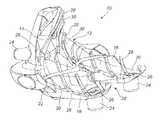
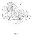
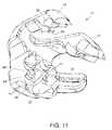
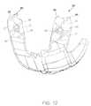
- FIGS. 9-14illustrate an embodiment of a patient-matched surgical instrument in the form of a tibial cutting guide.
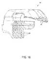
- FIGS. 15-16illustrate an embodiment of a patient-matched surgical instrument in the form of a tibial cutting guide.
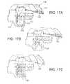
- FIGS. 17A-17Cillustrate additional embodiments of patient-matched surgical instruments.
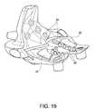
- FIGS. 18A-B and 19illustrate embodiments of a patient-matched surgical instrument in the form of femoral cutting guides, each having anatomy-contacting portions that vary in contact area, shape, and/or distribution.
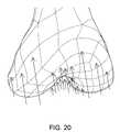
- FIG. 20illustrates potential points of contact between a femur bone and a patient-matched surgical instrument (not shown) according to another embodiment.
- FIGS. 21 and 22illustrate two embodiments of patient-matched surgical instruments in the form of femoral cutting guides, each having anatomy-contacting portions in the shape of substantial line segments.
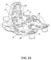
- FIGS. 23 and 24illustrate two embodiments of patient-matched surgical instruments in the form of femoral cutting guides, each having anatomy-contacting portions located generally around the peripheral areas of the instrument and/or guide structures of the instrument.
- FIG. 25illustrates a patient-matched surgical instrument including a pliant material.
- FIG. 26illustrates a method step of creating a three-dimensional patient-specific anatomic model according to one embodiment.
- FIG. 27Aillustrates an embodiment of a method step of creating and applying a first mesh structure to a first portion of a first anatomic model
- FIG. 27Billustrates an embodiment of a method step of creating and applying a second mesh structure to a second portion of the first anatomic model
- FIG. 27Cillustrates an embodiment of a method step of creating a first mesh structure and a second mesh structure, and applying the first and second mesh structures to first and second portions of a first anatomic model, respectively
- FIG. 27Dillustrates the method step of FIG. 27C further including the method step of determining an intersection of a surgical instrument blank with respect to a first anatomic model.
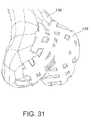
- FIGS. 28-31illustrate an embodiment of a method step of performing one or more sweep functions to a mesh structure, after said mesh structure is applied to an outer portion of a first anatomic model, to create a modified first anatomic model.
- FIGS. 32A and 33Aillustrate a surgical instrument blank for use with a modified first anatomic model according to some embodiments, having superimposed thereon a virtual intersection with the first modified anatomic model.
- FIGS. 32B and 33Billustrate the surgical instrument blank of FIG. 32A , having superimposed thereon a first mesh structure applied to a first portion of a first anatomic model.
- FIGS. 32C and 33Cillustrate the surgical instrument blank of FIG. 32A , having superimposed thereon a second mesh structure applied to a second portion of a first anatomic model.
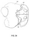
- FIGS. 34 and 35illustrate an embodiment of a method step of merging a surgical instrument blank with a modified first anatomic model, which may, in some embodiments, be followed by subtracting the modified first anatomic model from the surgical instrument blank to define a patient-matched surgical instrument.
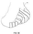
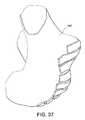
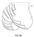
- FIGS. 36-38show another embodiment of a modified first anatomic model.
- FIG. 39illustrates an embodiment of a method step of merging a surgical instrument blank with the modified first anatomic model shown in FIGS. 36-38 , and then subtracting the intersecting portions of the modified first anatomic model from the surgical instrument blank.
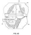
- FIG. 40illustrates an embodiment of a method step of merging first and second surgical instrument blanks with modified first and second anatomic models, respectively.
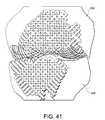
- FIG. 41illustrates an embodiment of modified first and second anatomic models, wherein one or more sweep functions are executed for mesh structures applied to first and second anatomic models.
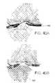
- FIG. 42Aillustrates a second mesh structure created and applied to a second portion of a first anatomic model according to some embodiments
- FIG. 42Billustrates a first mesh structure created and applied to a first portion of a first anatomic model according to some embodiments.
- FIG. 43Aillustrates a second mesh structure created and applied to a first portion of a second anatomic model according to some embodiments
- FIG. 43Billustrates a first mesh structure created and applied to a second portion of a second anatomic model according to some embodiments.
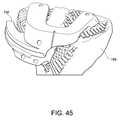
- FIGS. 44 and 45illustrate a method step of merging a second surgical instrument blank with a modified second anatomic model.
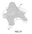
- FIGS. 46 and 47illustrate additional embodiments of patient-matched surgical instruments.
- FIG. 48schematically illustrates one embodiment of a method of designing and manufacturing a surgical instrument.
- FIGS. 1-8illustrate a first embodiment of a patient-matched surgical instrument, which, in this embodiment, is a femoral cutting guide 10 .
- the femoral cutting guide 10has an anatomy facing side 12 including an anterior portion 14 that is configured to face a patello-femoral groove and anterior cortex region of a distal femur.
- the instrumentfurther comprises two condylar portions (a medial condyle portion 16 and a lateral condyle portion 18 ) separated by an intercondylar notch 20 , in which the condylar portions are configured to face distal condylar portions of a patient's femur.
- the cutting guide 10also includes a through slot 22 for guiding a cutting instrument such as a saw blade.
- the cutting guide 10additionally includes a plurality of bosses 24 having apertures 26 extending therethrough to guide one or more stabilizing fasteners or locating pins, which may or may not be pre-drilled using the apertures.
- apertures 26may be located on the condylar portions and determine a rotation or peg hole location of an implanted femoral prosthetic component.
- the through slot 22 and apertures 26are occasionally referred to herein as “guide structures,” although that term may also encompass structures other than just apertures and slots.
- the guide structuresare optional and are not necessarily integrally incorporated into the patient-matched instrument.
- guides, bosses, and other structuremay be included in non-patient-matched, standardized modular components that are later connected to or otherwise associated with the patient-matched instrument.
- the femoral cutting guide of FIGS. 1-8includes a plurality of discrete, physically separate anatomy contacting portions 28 on the anatomy facing side 12 .
- the anatomy contacting portions 28are configured to match the anatomy of a particular patient, and, in some embodiments, may be customized to a particular patient based on pre-operatively obtained imaging data of that patient.
- the patient-matched surgical instrument and its anatomy contacting portionsare matched to a particular patient by using the pre-operatively obtained imaging data of that patient to select a patient-matched surgical instrument from a set of pre-determined instruments.
- the set of pre-determined instrumentsincludes hundreds (e.g. 1200) of pre-determined instruments, such as CAD computer models of instruments, among which automated software or other automated or non-automated functionality may be used to select one instrument from the set that best fits the particular patient, thereby matching the selected surgical instrument to the anatomy of the particular patient.
- the anatomy contacting portions 28define substantially linear contacts (in this particular embodiment, splines). Other substantially linear contacts may be utilized additionally or alternatively, including, but not limited to straight line segments, arcuate line segments, or curvilinear segments such as shown in some of the later described embodiments. Other types of anatomy contacting portions are substantial point contacts and area contacts. Non-limiting examples of anatomy contacting portions include teeth, ridges, undulations, serrations, spines, platforms, posts, nodules, tubes, pads, shapes specific to corresponding anatomical features or portions of such anatomical features, and/or various combinations thereof.
- the anatomy contacting portionsmay be spaced homogenously and evenly across an anatomy-facing side, or the anatomy contacting portions may be selected and distributed in random, non-random, pre-determined, optimized, or other fashion across the anatomy facing side.
- the anatomy-contacting portionsmay create substantial line contacts with areas of bone and/or cartilage, but, in other embodiments, may contact bone, cartilage, and/or other anatomy in other manners (including point and area contacts).
- the locations of the anatomy contacting portionsmay be determined using a random number generator or similar functionality.
- the recessed portions 30are a series of flutes or channels extending between the anatomy contacting portions 28 . These flutes or channels are shown to be generally rectangular or trapezoidal in cross-section, but any cross-section may be used in various embodiments. For example, as shown in FIGS. 9-14 , rounded or partially cylindrically shaped flutes or channels 32 may alternatively provide clearance regions where the instrument is not designed to contact the patient's anatomy. In some instances, the recessed portions may be partially or wholly made up of apertures extending through the surgical instrument.
- the total area of the recessed portions 30 of the anatomy facing side 12 of the instrumentis greater than the total surface area of the anatomy contacting portions 28 of the anatomy facing side 12 .
- the anatomy contacting portions 28make up only a small portion of the anatomy facing side 12 of the femoral cutting guide 10 .
- the recessed portions 34may be provided with a pliant material 26 that partially or completely fills one or more of the “gaps” between the anatomy contacting portions and the recessed portions.
- the anatomy contacting portions 28may extend generally parallel across the anatomy facing side 12 of the femoral cutting guide 10 . In other embodiments, however, the anatomy contacting portions are non-parallel and/or are provided at an angle with respect to one another (perpendicular, acute, or obtuse angles). Additionally, the anatomy contacting portions may be discontinuous so as to create dotted line or partial line or curve segment contacts between the instrument and the patient's unique anatomy.
- the anatomy contacting portionsmay be non-uniform in distribution, non-uniform in shape, and/or non-uniform in contact area. In some embodiments, such non-uniformities may relate to the degree of contour in the particular region of the patient-matched instrument.
- FIG. 18Aillustrates a femoral cutting guide 38 that includes anatomy contacting portions that define area contacts 40 (here, substantially rectangular shaped contacts) as well as anatomy contacting portions that define substantially linear contacts 42 .
- area contacts 40here, substantially rectangular shaped contacts
- anatomy contacting portionsin less contoured areas of the anatomy facing side 44 , the anatomy contacting portions have a larger contact area than anatomy contacting portions in areas having a greater contour.
- the area proximate the femoral condylesis generally less contoured than the areas proximate the patella-femoral groove and intercondylar notch.
- area contacts 40generally have a larger area than substantially linear contacts 42 , which, in some embodiments, may not be “area” contacts at all and be splines, ridges or other structures that contact the anatomy along a discrete line.
- the anatomy contacting portionsmay also vary in height depending on the contour of the surgical instrument. For example, the femoral condyles stand proud whereas the intercondylar notch is more recessed. Thus, anatomy contacting portions proximate the femoral condyles may be generally shorter than anatomy contacting portions proximate the intercondylar notch.
- the substantially linear contact portionsare narrow and tall, and thus approximate a discontinuous ridge that is dimensioned to contact a patient's anatomy along the deepest portion of the trochlear groove to provide internal/external rotational stability as well as stabilize the instrument with respect to the patient's femur in a varus/valgus aspect.
- an anatomy contacting portion shaped like a continuous ridge or line segmentmay be provided in this area.
- larger contacting portionsmay be provided in areas with greater contouring (such as the intercondylar notch or trochlear groove), and smaller contacting portions may be provided in areas with less contouring (such as the femoral condyles).
- the embodiment shown in FIG. 18Bincludes a horseshoe-shaped contacting portion 46 proximate the intercondylar notch, and a large contacting portion 48 proximate the trochlear groove.
- smaller contacting portions 50are provided proximate the condyles where there is less contouring.
- FIG. 19illustrates another embodiment of a patient-matched surgical instrument that includes anatomy contacting portions that vary in shape depending upon the contour of the instrument.
- contacting portions 52 and 54are generally rectangular (but may vary in size and/or height), whereas contacting portions 56 are generally cone-shaped.
- the different shaped contacting portionsprovide for different types of contact between the surgical instrument and a patient's anatomy.
- rectangular contacting portions 52provide for increased area contact with the patient's anatomy
- narrow contacting portions 54provide line contact (or substantial line contact) to nest within the trochlear groove
- cone-shaped contacting portions 56provide for point contact (or substantially point contact) with the patient's anatomy.
- the shapes of the anatomy contacting portionsmay be selected to provide for a particular type of contact with particular portions of the patient's anatomy.
- narrow rectangular and/or wedge-shaped contacting portionssuch as contacting portions 54
- wider rectangular contacting portions 52may be selected to provide maximum area contact against the femoral condyles, albeit in a discrete region or regions of the femoral condyles.
- Cone-shaped contacting portions 56may be selected when it is desired to reduce the amount of segmentation of image data required by the CAD modeling functionality.
- FIG. 19illustrates that the distribution (or density) of the anatomy contacting portions may vary depending on the contour of the instrument.
- a larger number of anatomy contacting portionsare concentrated in areas of the instrument having greater contour.
- contacting portions 54 and 56are positioned proximate to the patello-femoral groove and intercondylar notch portions of the instrument (areas having greater contour), whereas contacting portions 52 are provided proximate to the femoral condyle portions (an area having relatively less contour).
- There are only two contacting portions 52whereas there are more than two contacting portions 54 and 56 .
- FIG. 20shows several arrows conceptually illustrating substantially point contacts between a patient's anatomy and contacting portions of another embodiment of a surgical instrument.
- the arrowsindicate that there are generally more points of contact proximate to areas of the patient's anatomy having more contour.
- a larger number of anatomy contacting portionsmay be concentrated in areas of the instrument having less contour.
- areas proximate to the femoral condyle portions of the instrumentmay be provided with more anatomy contacting portions than in areas proximate to the intercondylar notch portion of the instrument.
- the anatomy contacting portionsare concentrated in areas where segmentation error may be less likely to exist (at least in some embodiments)—the larger, less contoured areas—rather than areas with a greater amount of contour.
- FIGS. 21 and 22illustrate embodiments where the anatomy contacting portions are substantially linear contacts.
- the substantially linear contactsmay be relatively straight (at least in two dimensions), or may have at least one curved segment.
- the anatomy contacting portions 58 and 60 shown in FIG. 21are discreet in that they have a first end and a second end that are not connected to each other.
- the anatomy contacting portionsconnect with each other.
- a “waffle-shaped” contacting portion 62including multiple line segments 64 connected to one another, and “ring-shaped” contacting portions 66 comprising a single curvilinear line segment connected at its ends.
- the ring-shaped contacting portions 66may be located proximate the condylar portions of the instrument, such that the patient's condyles “nest” within the ring-shaped contacting portions 66 .
- the anatomy contacting portions shown and described in FIGS. 21 and 22may match to recessed portions of the patient's anatomy (such as the trochlear groove or intercondylar notch), but may also match portions of the anatomy that sit proud in relation to other anatomy (such as the medial and lateral distal condyles).
- the anatomy contacting portionsmay match either articulating or non-articulating portions of the patient's anatomy.
- one or more discrete substantially point contact portions(such as contacting portions 56 in FIG. 19 ) may be provided along with the line-segment contacting portions shown in FIGS. 21 and 22 .
- FIGS. 23 and 24illustrate embodiments where the anatomy contacting portions 68 are more heavily concentrated in peripheral areas 70 of the instrument and/or guide structures (such as but not limited to apertures 72 to receive fixation pins, or through slots 74 to receive cutting instruments). It is not necessary in all embodiments for the anatomy contacting portions to extend completely around the perimeter of the surgical instrument. Rather, the contacting portions may only extend around a portion of the perimeter. Additionally, it is not necessary for the anatomy contacting portions to extend completely around the guide structures (the contacting portions may only be located on the top of the through-slot, for example), or for the contacting portions to extend around each of the guide structures (only some guide structures may be provided with contacting portions).
- Locating the anatomy contacting portions in such peripheral areasmay increase stability of the instrument when the instrument is placed on the patient's anatomy, or when the surgeon uses the guide structures (for example, when the through-slot receives a cutting instrument for cutting bone).
- the anatomy contacting portions 68are discontinuous ridges that are shaped like rectangles or wedges. (Of course, other shapes may be provided, such as cylinders, cones, spheres, pyramids, or any other shape described herein.)
- FIG. 24there is provided a single almost entirely continuous anatomy contacting portion 68 that extends around the perimeter 70 of the instrument. If desired, additional anatomy contacting portions may be placed in central regions of the patient-matched instrument.
- FIG. 24shows that in certain embodiments, portions (e.g. portion 76 ) of the surgical instrument may be “hollow” such that they are defined by a sidewall 78 , the top edges of which define the contacting portions 68 of the instrument.
- the bottom half of the surgical instrumentis hollow, whereas the top half is non-hollow.
- the anatomy contacting portions 68extend into the surgical instrument and define the sidewalls 78 of the hollow bottom half.
- the bottom half of the instrumentresembles a cup, where the lip of the cup comprises the anatomy contacting portions 68 .
- the entire surgical instrumentmay be hollow.
- any or all of the anatomy contacting portions described hereinmay be textured to improve the overall stability of the patient-matched instrument.
- the texturingmay include serration, points, cross-hatch, grooves, ridges, bumps, or barbs that increase the friction between the patient's anatomy and the patient-matched instrument.
- the texturingat least slightly penetrates the patient's soft tissue or other anatomy, which may, in some embodiments, compensate for segmentation errors that may occur in regions having greater amounts of soft tissue.
- FIG. 25illustrates an embodiment of a patient matched surgical instrument including pliant material 36 located in a recessed (or non-contacting) portion 34 of the instrument.
- pliant material 36located in a recessed (or non-contacting) portion 34 of the instrument.
- the pliant portioncompletely fills the respective recessed area, but in other embodiments, the pliant portion only fills a portion of the recessed area (e.g. as shown in FIG. 25 ).
- the pliant portionmay comprise a silicone material, polymer film, gauze, putty, or dough that presses against and at least partially takes on the shape of the patient's anatomy, filling any gaps that might otherwise be present between the discrete anatomy contacting portions.
- the pliant portions, together with the anatomy contacting portionsmay in some embodiments approximate a continuous mirror-image surface of the patient's anatomy.
- the pliant portionsprovide the benefits of a continuous mirror-image surface (such as stability) to surgical instruments that only have discontinuous anatomy contacting portions.
- the pliant portionsmay be coupled to the surgical instrument either before or during surgery, using adhesive, mechanical fasteners, welding, or the like. Alternatively, the pliant portions may simply be placed within the recessed portions without any structure or substance to couple the pliant portion to the instrument. In some embodiments, a pliant material such as a polymer may be injected into the recesses of the instrument after manufacture.
- Various embodiments of patient-matched surgical instrumentsmay feature different fill depths of a pliant material in the recessed portions.
- the pliant materialmay fill the recessed portions up to the level of the surrounding anatomy contacting portions; however, in other embodiments, the pliant material may be below the level of the surrounding anatomy contacting portions or above the level of the surrounding anatomy contacting portions.
- the fill level of the pliant materialis below the level of the surrounding anatomy contacting portions, it may facilitate visualizing the fit of the instrument on the anatomy.
- the pliant materialmay also contact the anatomy and add at least some degree of stability to the instrument/anatomy interaction.
- pressing the instrument onto the anatomymay cause the pliant material to expand, filling in the recessed portions.
- the pliant materialmay be held in place by pinning the instrument to the anatomy.
- the pliant materialmay provide increased friction between the instrument and anatomy, such that the position and orientation of the instrument on the anatomy is further maintained during the pinning process.
- the pliant materialmay be more localized (partially or entirely) in areas configured for contact with bony anatomy (e.g. relatively superior, anterior portions of the anatomy facing side of a femoral cutting guide) and the anatomy contacting portions may be more localized (partially or entirely) in areas configured for contact with cartilagenous anatomy (e.g. condylar and other areas of a femoral cutting guide).
- bony anatomye.g. relatively superior, anterior portions of the anatomy facing side of a femoral cutting guide
- cartilagenous anatomye.g. condylar and other areas of a femoral cutting guide
- FIGS. 9-14illustrate an embodiment of a patient-matched surgical instrument, in this instance a tibial cutting guide 80 .
- the tibial guide 80 shownincludes a guide 82 for directing a saw blade (or, in other embodiments, for directing other types of surgical tools such as a milling bit, osteotome, drill, wire, or pin).
- the surgical instrumentmay have features for attaching modules for directing surgical tools rather than incorporating a surgical guide directly into the tool.
- the tibial cutting guide 80 shown in FIGS. 9-14also includes several apertures 84 for receiving pins or other fasteners for securing the instrument to the patient.
- the guide portion 82 of the tibial cutting guide 80 shown in FIGS. 9-14is partially cantilevered off of other portions, and may be configured to contact a patient's anatomy to some degree or may be configured to clear the patient's anatomy relative to anatomy contacting portions of the instrument.
- the cantilevered portion of guide 82is not configured to directly contact the patient's anatomy, whereas central portions of the guide 82 do include anatomy contacting portions 86 on the anatomy facing side of the tibial cutting guide 80 .
- the tibial cutting guide 80also includes two paddles 88 , portions of which are for contacting superior portions of a proximal tibia.
- the two paddles 88are provided for contacting points on medial and lateral articular zones of a proximal tibial plateau, adjacent the tibial eminence, although, in other embodiments, the paddles may be designed to contact other portions of the anatomy.
- indicia 90may be provided on the instrument for indicating relative mechanical axis alignment, size, patient data, data relative to the surgery to be performed, data regarding an orientation of the instrument, or surgeon data, without limitation.
- the tibial cutting guide 80 of FIGS. 9-14is similar to the femoral cutting guide of FIGS. 1-8 in that it employs anatomy contacting portions (here ridges 86 ) on the anatomy facing side of the instrument.
- the anatomy contacting portions 86 shownare configured to create spline contacts between the instrument and the patient's tibial bone and/or cartilage, although many other types, arrangements and distributions of anatomy contacting portions are also possible.
- An anterior portion 92 of the instrumentis configured to partially engage cortical bone adjacent the anterior cortex and medial 1 ⁇ 3 of the tibial tubercle.
- FIGS. 15-16illustrate another embodiment of a patient matched tibial cutting guide 94 in which the anatomy contacting portions are several substantially point contacts 96 .
- each point contact 96includes a pad at its peak for contact with a point on the patient's anatomy.
- the padmay be substantially square, and may range in size from 0.1 to 10 mm square (measured along a side of the square) in some embodiments, from 0.5 to 5 mm square in some embodiments, and from 1 to 3 mm square in some embodiments.
- FIGS. 46 and 47schematically show other patient-matched instruments (femoral cutting guides 98 and 100 respectively) having different sized pads ( 102 and 104 respectively).
- the padsare not square shaped, and may take on other shapes such as circles, triangles, rectangles, other polygons, or other shapes.
- the substantially point contactsare not pads, but contact the anatomy at only one or a very limited number of points.
- each substantially point contactmay have a rounded apex or sharp apex (as opposed to the flat apexes shown) that only contacts the anatomy at a single point or very small number of points.
- each substantially point contactmay define multiple peaks that each contacts the anatomy in a limited number or only a single point.
- FIGS. 17A-17Cillustrate additional embodiments of patient matched surgical instruments.
- FIG. 17Aillustrates a tibial cutting guide 106 similar to that shown in FIGS. 15-16 in that anatomy contacting portions 108 are provided on both the paddles 110 and the anterior portion 112 as a plurality of substantial point contacts (which, as mentioned earlier, make take on a variety of forms, including, but not limited to, a series of bumps, domes, spikes, cones, cylinders, polyhedrons (e.g., triangles, diamonds, pyramids), or other geometries or structures which would create substantially point contacts between the instrument and a patient's anatomy). As shown in FIG.
- FIGS. 17B and 17Cillustrate other embodiments of a customized surgical instrument for a tibia—each comprising a first region having one type of anatomy contacting portions, and a second region comprising another type of anatomy contacting portions.
- FIG. 17Aillustrates a customized surgical instrument for a tibia—each comprising a first region having one type of anatomy contacting portions, and a second region comprising another type of anatomy contacting portions.
- FIG. 17Bshows an embodiment in which paddles of the instrument include dimples 118 configured for substantially point contact with a patient's unique anatomy, and the anterior portion of the customized surgical instrument includes raised splines 120 configured to present spline/substantial line contacts with respect to the patient's anatomy.
- FIG. 17Cshows an embodiment in which the anterior portion of the patient-matched surgical instrument includes dimples 122 configured for providing a series of substantially point contacts with a patient's unique anatomy, and the paddles of the customized surgical instrument include raised splines 124 configured to present spline/substantially line contacts with respect to a patient's anatomy.
- FIGS. 26-35illustrate various method steps associated with the creation of some of the patient-matched surgical instruments shown and described herein, according to some embodiments. While the method steps are shown and described in conjunction with a patient's distal femur, it should be noted that the various method steps may be applied to any portion of a patient's anatomy, without limitation.
- the embodiments of the patient-matched surgical instruments discussed above for FIGS. 1-25and other embodiments of patient-matched surgical instruments within the scope of the present disclosure, do not necessarily have to be created using the embodiments of methods illustrated in FIGS. 26-35 and can be created in a variety of other ways.
- the methods shown and described belowmay be used to create patient-matched surgical instruments other than those shown in FIGS. 1-25 .
- the non-limiting embodiment illustrated in FIGS. 26-35involves: (1) creating, obtaining or otherwise accessing a digital or other form of a three dimensional model of the patient's anatomy of interest; (2) applying one or more mesh or grid overlays onto portions of the bone model; (3) performing a sweep function that modifies the mesh or grid overlay(s) to create a geometric construct that defines areas where the anatomy contacting portions are and areas where the anatomy contacting portions are not on the anatomy facing side of the patient specific instrument; (4) merging the modified overlay(s) with the bone model; and (5) applying an oversized blank of the instrument to the modified bone model to identify portions of the blank for removal (in some embodiments, portions of a virtual blank for removal) such that patient-matched anatomy contacting portions are formed or otherwise present or created to define a patient-matched instrument.
- FIG. 26illustrates a method step of creating a first anatomic model 126 utilizing 3D imaging data obtained from a patient as conventionally done, such as by, but not limited to, magnetic resonance imaging, x-ray (including digital x-rays), ultrasound, or other techniques.
- non-image based technologiesmay be use to obtain sufficient data about the 3D structure of the anatomy of interest to allow a patient-matched instrument in accordance with this disclosure to be created.
- the first anatomic modelis not a complete model of the particular portion of the anatomy of interest, but is only a model of certain key or desired anatomical points or portions of the anatomy of interest.
- the first anatomic model 126may be electronically stored in a computer storage memory and imported into a computer assisted design (CAD) software package or other types of design software packages.
- CADcomputer assisted design
- FIG. 27Aillustrates a method step of creating and applying a first mesh structure 128 to a first portion of a first anatomic model 126 .
- the first mesh structure 128(either by itself or in conjunction with other mesh structures) defines or at least roughly corresponds to at least some aspects of the number, position, and/or orientation of the anatomy contacting portions of the patient-matched instrument as well as the recessed portions interspersed among those anatomy contacting portions.
- the mesh structure 128 shown in FIG. 27Amay be characterized as being defined by a square, uniform grid pattern, the mesh structure may have any geometric shape, size, porosity, or density, including a gradient density or porosity.
- the mesh structuremay be evenly distributed, or may be random in nature, or otherwise have a predetermined pattern.
- FIG. 27AShown in FIG. 27A is one embodiment of an anterior mesh structure 128 for application to, or projection onto or “wrapping around” an anterior outer surface of the first model 126 shown in FIG. 26 (which here is a distal femur, the “anterior outer surface” being adjacent the trochlear groove, anterior cortex, and surrounding articular surfaces).
- FIG. 27Billustrates a method step of creating and applying a second mesh structure 130 to a second portion of the first anatomic model 126 of FIG. 26 .
- the mesh structuremay have any geometric shape, size, porosity, or density, including a gradient density or porosity.
- the mesh structuremay be evenly distributed, or may be random in nature, or otherwise have a predetermined pattern.
- Shown in FIG. 27Bis an embodiment of a distal mesh 130 to be applied to or otherwise projected onto or “wrapped around” one or more inferior surfaces of the first model 126 (here, adjacent the condyles and intercondylar notch of the first bone model 126 shown in FIG. 26 ).
- FIG. 27Cillustrates a method step of creating a first mesh structure 128 and a second mesh structure 130 , and applying both the first and second mesh structures to first and second portions of the first anatomic model 126 (e.g. of FIG. 26 ), respectively.
- the first and second mesh structures 128 and 130may be united as one homogenous mesh structure, or the mesh structures may be kept independent and distinct so that different sweep functions may be applied to each mesh structure to form different anatomy-contacting portion profiles on the different portions of the first anatomic model 126 .
- the mesh structures 128 and 130may overlap one another, although, in other embodiments, they may be designed not to overlap when applied to the first anatomic model 126 .
- FIG. 27Dillustrates an embodiment of a method step of determining an intersection of a surgical instrument blank 132 with respect to the first anatomic model 126 .
- the surgical instrument blank 132(which may be sized according to an individual patient or “universal” for all patient sizes) is virtually merged with the first anatomic model 126 which includes the first and/or second mesh structures 128 and 130 (or other numbers and combinations of mesh structures in other embodiments).
- the intersection between the blank 132 and the first anatomic model 126defines an intersection perimeter 134 (i.e., the border of the interface between the virtually merged blank and first anatomic model).
- intersection perimeter 134is shown to be superimposed over the first and second mesh structures 128 and 130 in FIG. 27D .
- the mesh structuresis designed in such a manner (or the method is otherwise altered) to avoid a separate step of determining intersections between the blank and the first anatomic model 126 .
- FIGS. 28-31illustrate a method step of performing one or more sweep functions to the mesh structure(s) to create an expanded mesh structure 136 .
- the one or more sweep functionsmay be executed before or after the mesh structures 128 and 130 are applied to the first anatomic model 126 .
- performing a sweep functionis unnecessary and the geometry of the mesh structure may already include geometries other than simple lines or grids such that “expanding” on a line grid is not necessary.
- the resulting volume of the expanded mesh structure 136 and the first anatomic model 126are united to create a modified first anatomic model 138 . Shown in FIG.
- any cross-sectional geometrymay be applied to mesh structures described herein.
- a triangular, polygonal, circular, oval, irregular, or other cross-sectional shape or profilemay be applied to the mesh structures to obtain a different modified first anatomic model.
- a different sweep functionmay be applied to each line, area, region, strut or segment of a mesh structure to obtain an irregular or asymmetric modified first anatomic model. Therefore, the drawings merely illustrate one particular embodiment of many possible permutations of a modified first bone model.
- FIG. 29illustrates the second (distal) mesh structure 130 of FIG. 27B superimposed on the modified first anatomic model 138 of FIG. 28 .
- FIG. 30illustrates the first (anterior) mesh structure 128 of FIG. 27A superimposed on the modified first anatomic model of FIG. 28 .
- FIG. 31further depicts the modified first anatomic model 138 of FIG. 28 according to some embodiments.
- the steps of applying one or more mesh structures and/or performing one or more sweep functionsare unnecessary and a “modified” anatomic model may be created directly as a result of imaging of the patient's anatomy.
- the software or other mechanisms obtaining, controlling and/or processing data related to the patient's anatomymay be programmed or operate such that only certain, limited portions of the anatomy of interest are imaged, such portions corresponding to areas where anatomy contacting portions of the patient-matched instrument are located.
- the blankmay be generally undersized such that material (or “virtual” material) is not taken away from it to create a patient-matched instrument but that material is added to it to define patient specific anatomy contacting portions on the anatomy facing face or faces of the instrument.
- FIG. 32Ashows a superior view of a patient-matched surgical instrument blank 140
- FIG. 33Ashows a posterior isometric view of the blank 140
- a virtual intersection boundary 142is superimposed, which represents an outer boundary of the volumetric intersection between the blank 140 and the modified first anatomic model 138 of FIG. 28 .
- FIGS. 32B and 33Billustrate the surgical instrument blank 140 of FIG. 32A , but instead of a virtual intersection boundary being superimposed thereon, a first mesh structure 128 is shown to be superimposed in relation to the blank 140 as it is applied to a first portion of the first anatomic model 126 .
- the first mesh structure 128is an anterior mesh structure (as shown in FIG. 27A ) that is applied to a portion of the first anatomic model 126 representing an anterior portion of a distal femur.
- FIGS. 34 and 35illustrate a method step of merging a surgical instrument blank 140 with a modified first anatomic model 138 , and then subtracting the volume of said modified first anatomic model 138 from a volume of the surgical instrument blank 140 .
- the surgical instrument blank 140is essentially transformed into a patient-matched surgical instrument having one or more anatomy-contacting portions as shown and described for instance in FIGS. 1-25 .
- FIG. 39illustrates a method step of merging a surgical instrument blank 146 with the modified first anatomic model 144 shown in FIGS. 36-38 , before subtracting the volume of said modified first anatomic model 144 from the surgical instrument blank 146 .
- the blank 146is transformed into a patient-matched surgical instrument similar to the one shown in FIGS. 1-8 .
- FIG. 40illustrates a method step of simultaneously merging first and second surgical instrument blanks 148 and 150 with modified first and second anatomic models 152 and 154 , respectively.
- the first modified anatomic model 152is a distal femur model integrated with a plurality of expanded mesh structures of closely interwoven cylindrical struts or tubes, the negatives of which define the geometries and locations of patient specific pads on the surgical instrument.
- the second modified anatomic model 154is a proximal tibia model integrated with a plurality of expanded mesh structures of closely interwoven cylindrical struts.
- FIG. 41illustrates modified first and second anatomic models 152 and 154 according to the embodiment shown in FIG. 40 .
- One or more sweep functionsare executed for a plurality of mesh structures which have been applied to, projected onto, or “wrapped” over first and second anatomic models.
- a small-radius cylinderis chosen as the cross-sectional profile to be applied to each strut within the mesh structures
- a distal femurhas been chosen as the first anatomic model
- a proximal tibiahas been chosen as the second anatomic model.
- the sweep functionneed not be applied to an entire mesh structure and/or overlapping sections of mesh structures. Rather, it may be desirable in some instances to perform sweep functions in only select areas of the mesh structures.
- portions of the mesh structurese.g., central areas of the mesh structures
- FIG. 42Billustrates a first mesh structure 158 (in bold) used to create the modified first anatomic model 152 shown in FIGS. 40 and 41 .
- the first mesh structure 158is an anterior femoral mesh structure which is applied to an anterior portion of a distal femoral anatomic model adjacent the anterior femoral cortex and trochlear groove.
- FIG. 43Aillustrates a second mesh structure 160 (in bold) used to create the modified second anatomic model 154 shown in FIGS. 40 and 41 .
- the second mesh structure 160is a proximal tibial mesh structure which is applied to a proximal tibial anatomic model proximate the medial and lateral sulcus portions of the tibial plateau.
- FIG. 43Billustrates a first mesh structure 162 (in bold) used to create the modified first anatomic model 154 shown in FIGS. 40 and 41 .
- the first mesh structure 162is an anterior tibial mesh structure that is applied to an anterior cortex portion of a proximal tibial model adjacent the tibial tubercle.
- FIGS. 44 and 45further illustrate a method step of merging a second surgical instrument blank 150 with a modified second anatomic model 154 , and then subtracting a volume of said modified second anatomic model 154 from the volume of the second surgical instrument blank 150 to create a model of a patient-matched surgical instrument.
- the patient-matched surgical instrumentis a custom tibial cutting jig similar to the one shown in FIGS. 15-16 .
- FIGS. 44 and 45are derived from FIG. 40 , showing only the modified second anatomic model 154 with the second surgical instrument blank 150 for clarity.
- one or more of the above described stepsmay be performed using computer equipment, whether stand alone or networked.
- Such computer equipmentmay include memory, a processor, and input/output features, which may facilitate performing at least some of the above identified steps, including creating one or more bone models, applying a mesh or meshes to such bone models, performing a sweep function on the mesh as applied to the bone model, merging a blank to the modified bone model, performing a subtraction function to define a patient specific instrument, and other functions.
- the computer equipmentmay include or may be associated with a database in which is stored data about one or more mesh constructs, blanks, or other data.
- Some embodimentsmay include communication functionality to allow surgeons to remotely upload information about a patients' anatomy, and/or to participate or be able to provide feedback on a patient specific instrument.
- While the instruments and methods shown and describedare generally shown as configured for use in knee arthroplasty procedures, it is anticipated that the various anatomy-contacting portions and patterns thereof described herein may be applied to surgical instruments configured for use in other procedures. For instance, features of the described instruments and manufacturing methods thereof may be utilized with surgical instruments configured for contacting portions of a femoral head, acetabulum, glenoid, humerus, radius, ulna, fibula, tibia, proximal femur, foot, ankle, wrist, extremity, or other bony or cartilaginous regions.
Landscapes
- Health & Medical Sciences (AREA)
- Surgery (AREA)
- Life Sciences & Earth Sciences (AREA)
- Engineering & Computer Science (AREA)
- Animal Behavior & Ethology (AREA)
- Veterinary Medicine (AREA)
- Biomedical Technology (AREA)
- Heart & Thoracic Surgery (AREA)
- Medical Informatics (AREA)
- Molecular Biology (AREA)
- Nuclear Medicine, Radiotherapy & Molecular Imaging (AREA)
- General Health & Medical Sciences (AREA)
- Public Health (AREA)
- Orthopedic Medicine & Surgery (AREA)
- Physical Education & Sports Medicine (AREA)
- Transplantation (AREA)
- Dentistry (AREA)
- Oral & Maxillofacial Surgery (AREA)
- Robotics (AREA)
- Surgical Instruments (AREA)
- Prostheses (AREA)
- Apparatus For Radiation Diagnosis (AREA)
- Instructional Devices (AREA)
Abstract
Description
Claims (25)
Priority Applications (1)
| Application Number | Priority Date | Filing Date | Title |
|---|---|---|---|
| US13/157,991US9386994B2 (en) | 2010-06-11 | 2011-06-10 | Patient-matched instruments |
Applications Claiming Priority (4)
| Application Number | Priority Date | Filing Date | Title |
|---|---|---|---|
| US35383810P | 2010-06-11 | 2010-06-11 | |
| US40209510P | 2010-08-23 | 2010-08-23 | |
| US39364310P | 2010-10-15 | 2010-10-15 | |
| US13/157,991US9386994B2 (en) | 2010-06-11 | 2011-06-10 | Patient-matched instruments |
Publications (2)
| Publication Number | Publication Date |
|---|---|
| US20120123422A1 US20120123422A1 (en) | 2012-05-17 |
| US9386994B2true US9386994B2 (en) | 2016-07-12 |
Family
ID=45098708
Family Applications (2)
| Application Number | Title | Priority Date | Filing Date |
|---|---|---|---|
| US13/157,991Expired - Fee RelatedUS9386994B2 (en) | 2010-06-11 | 2011-06-10 | Patient-matched instruments |
| US13/158,200Expired - Fee RelatedUS9615834B2 (en) | 2010-06-11 | 2011-06-10 | Systems and methods utilizing patient-matched instruments |
Family Applications After (1)
| Application Number | Title | Priority Date | Filing Date |
|---|---|---|---|
| US13/158,200Expired - Fee RelatedUS9615834B2 (en) | 2010-06-11 | 2011-06-10 | Systems and methods utilizing patient-matched instruments |
Country Status (8)
| Country | Link |
|---|---|
| US (2) | US9386994B2 (en) |
| EP (1) | EP2579796A4 (en) |
| JP (1) | JP2013529968A (en) |
| CN (1) | CN103037789A (en) |
| AU (1) | AU2011265254B2 (en) |
| CA (1) | CA2802190A1 (en) |
| WO (2) | WO2011156755A2 (en) |
| ZA (1) | ZA201209326B (en) |
Cited By (8)
| Publication number | Priority date | Publication date | Assignee | Title |
|---|---|---|---|---|
| US20150245878A1 (en)* | 2014-02-28 | 2015-09-03 | Branislav Jaramaz | System and methods for positioning bone cut guide |
| US20170151019A1 (en)* | 2014-02-28 | 2017-06-01 | Blue Belt Technologies, Inc. | System and methods for positioning bone cut guide |
| US11234720B2 (en) | 2018-03-07 | 2022-02-01 | E. Marlowe Goble | Knee instruments and methods |
| US11246609B2 (en) | 2015-03-25 | 2022-02-15 | E. Marlowe Goble | Knee instruments and methods |
| US12070272B2 (en) | 2013-10-10 | 2024-08-27 | Stryker European Operations Limited | Methods, systems and devices for pre-operatively planned shoulder surgery guides and implants |
| US12097129B2 (en) | 2013-11-13 | 2024-09-24 | Tornier Sas | Shoulder patient specific instrument |
| US12133688B2 (en) | 2013-11-08 | 2024-11-05 | Stryker European Operations Limited | Methods, systems and devices for pre-operatively planned adaptive glenoid implants |
| US12279829B2 (en) | 2013-10-17 | 2025-04-22 | Stryker European Operations Limited | Methods, systems and devices for pre-operatively planned glenoid placement guides and uses thereof |
Families Citing this family (147)
| Publication number | Priority date | Publication date | Assignee | Title |
|---|---|---|---|---|
| US8083745B2 (en) | 2001-05-25 | 2011-12-27 | Conformis, Inc. | Surgical tools for arthroplasty |
| US7534263B2 (en) | 2001-05-25 | 2009-05-19 | Conformis, Inc. | Surgical tools facilitating increased accuracy, speed and simplicity in performing joint arthroplasty |
| US7468075B2 (en) | 2001-05-25 | 2008-12-23 | Conformis, Inc. | Methods and compositions for articular repair |
| US20030055502A1 (en) | 2001-05-25 | 2003-03-20 | Philipp Lang | Methods and compositions for articular resurfacing |
| US8439926B2 (en) | 2001-05-25 | 2013-05-14 | Conformis, Inc. | Patient selectable joint arthroplasty devices and surgical tools |
| US8623026B2 (en)* | 2006-02-06 | 2014-01-07 | Conformis, Inc. | Patient selectable joint arthroplasty devices and surgical tools incorporating anatomical relief |
| CN105030296A (en) | 2006-02-06 | 2015-11-11 | 康复米斯公司 | Patient selectable joint arthroplasty devices and surgical tools |
| US9173661B2 (en) | 2006-02-27 | 2015-11-03 | Biomet Manufacturing, Llc | Patient specific alignment guide with cutting surface and laser indicator |
| US9907659B2 (en) | 2007-04-17 | 2018-03-06 | Biomet Manufacturing, Llc | Method and apparatus for manufacturing an implant |
| US8858561B2 (en) | 2006-06-09 | 2014-10-14 | Blomet Manufacturing, LLC | Patient-specific alignment guide |
| US8407067B2 (en) | 2007-04-17 | 2013-03-26 | Biomet Manufacturing Corp. | Method and apparatus for manufacturing an implant |
| US9289253B2 (en) | 2006-02-27 | 2016-03-22 | Biomet Manufacturing, Llc | Patient-specific shoulder guide |
| US8535387B2 (en) | 2006-02-27 | 2013-09-17 | Biomet Manufacturing, Llc | Patient-specific tools and implants |
| US9113971B2 (en) | 2006-02-27 | 2015-08-25 | Biomet Manufacturing, Llc | Femoral acetabular impingement guide |
| US8864769B2 (en) | 2006-02-27 | 2014-10-21 | Biomet Manufacturing, Llc | Alignment guides with patient-specific anchoring elements |
| US8603180B2 (en) | 2006-02-27 | 2013-12-10 | Biomet Manufacturing, Llc | Patient-specific acetabular alignment guides |
| US8133234B2 (en) | 2006-02-27 | 2012-03-13 | Biomet Manufacturing Corp. | Patient specific acetabular guide and method |
| US9345548B2 (en) | 2006-02-27 | 2016-05-24 | Biomet Manufacturing, Llc | Patient-specific pre-operative planning |
| US8608748B2 (en) | 2006-02-27 | 2013-12-17 | Biomet Manufacturing, Llc | Patient specific guides |
| US8591516B2 (en) | 2006-02-27 | 2013-11-26 | Biomet Manufacturing, Llc | Patient-specific orthopedic instruments |
| US8608749B2 (en) | 2006-02-27 | 2013-12-17 | Biomet Manufacturing, Llc | Patient-specific acetabular guides and associated instruments |
| US8568487B2 (en) | 2006-02-27 | 2013-10-29 | Biomet Manufacturing, Llc | Patient-specific hip joint devices |
| US8377066B2 (en) | 2006-02-27 | 2013-02-19 | Biomet Manufacturing Corp. | Patient-specific elbow guides and associated methods |
| US9339278B2 (en) | 2006-02-27 | 2016-05-17 | Biomet Manufacturing, Llc | Patient-specific acetabular guides and associated instruments |
| US10278711B2 (en) | 2006-02-27 | 2019-05-07 | Biomet Manufacturing, Llc | Patient-specific femoral guide |
| US8241293B2 (en) | 2006-02-27 | 2012-08-14 | Biomet Manufacturing Corp. | Patient specific high tibia osteotomy |
| US9918740B2 (en) | 2006-02-27 | 2018-03-20 | Biomet Manufacturing, Llc | Backup surgical instrument system and method |
| US7967868B2 (en) | 2007-04-17 | 2011-06-28 | Biomet Manufacturing Corp. | Patient-modified implant and associated method |
| US8092465B2 (en) | 2006-06-09 | 2012-01-10 | Biomet Manufacturing Corp. | Patient specific knee alignment guide and associated method |
| US20150335438A1 (en) | 2006-02-27 | 2015-11-26 | Biomet Manufacturing, Llc. | Patient-specific augments |
| US9795399B2 (en) | 2006-06-09 | 2017-10-24 | Biomet Manufacturing, Llc | Patient-specific knee alignment guide and associated method |
| GB2442441B (en) | 2006-10-03 | 2011-11-09 | Biomet Uk Ltd | Surgical instrument |
| WO2008157412A2 (en) | 2007-06-13 | 2008-12-24 | Conformis, Inc. | Surgical cutting guide |
| US8831302B2 (en) | 2007-08-17 | 2014-09-09 | Mohamed Rashwan Mahfouz | Implant design analysis suite |
| CA2753488C (en) | 2009-02-25 | 2014-04-29 | Mohamed Rashwan Mahfouz | Customized orthopaedic implants and related methods |
| US9078755B2 (en) | 2009-02-25 | 2015-07-14 | Zimmer, Inc. | Ethnic-specific orthopaedic implants and custom cutting jigs |
| SG10201401326SA (en) | 2009-04-16 | 2014-10-30 | Conformis Inc | Patient-specific joint arthroplasty devices for ligament repair |
| DE102009028503B4 (en) | 2009-08-13 | 2013-11-14 | Biomet Manufacturing Corp. | Resection template for the resection of bones, method for producing such a resection template and operation set for performing knee joint surgery |
| CA2778057C (en) | 2009-10-29 | 2019-02-19 | Zimmer, Inc. | Patient-specific mill guide |
| US8632547B2 (en) | 2010-02-26 | 2014-01-21 | Biomet Sports Medicine, Llc | Patient-specific osteotomy devices and methods |
| US9271744B2 (en) | 2010-09-29 | 2016-03-01 | Biomet Manufacturing, Llc | Patient-specific guide for partial acetabular socket replacement |
| EP2632349B1 (en) | 2010-10-29 | 2018-03-07 | The Cleveland Clinic Foundation | System for assisting with attachment of a stock implant to a patient tissue |
| US9717508B2 (en) | 2010-10-29 | 2017-08-01 | The Cleveland Clinic Foundation | System of preoperative planning and provision of patient-specific surgical aids |
| US9254155B2 (en) | 2010-10-29 | 2016-02-09 | The Cleveland Clinic Foundation | System and method for assisting with arrangement of a stock instrument with respect to a patient tissue |
| CA3054709C (en) | 2010-10-29 | 2022-04-12 | The Cleveland Clinic Foundation | System and method for association of a guiding aid with a patient tissue |
| US9968376B2 (en) | 2010-11-29 | 2018-05-15 | Biomet Manufacturing, Llc | Patient-specific orthopedic instruments |
| US9241745B2 (en) | 2011-03-07 | 2016-01-26 | Biomet Manufacturing, Llc | Patient-specific femoral version guide |
| US8715289B2 (en) | 2011-04-15 | 2014-05-06 | Biomet Manufacturing, Llc | Patient-specific numerically controlled instrument |
| US8668700B2 (en) | 2011-04-29 | 2014-03-11 | Biomet Manufacturing, Llc | Patient-specific convertible guides |
| US8956364B2 (en) | 2011-04-29 | 2015-02-17 | Biomet Manufacturing, Llc | Patient-specific partial knee guides and other instruments |
| US10130378B2 (en) | 2011-05-11 | 2018-11-20 | The Cleveland Clinic Foundation | Generating patient specific instruments for use as surgical aids |
| GB201108078D0 (en)* | 2011-05-16 | 2011-06-29 | Materialise Nv | Surgical guides and methods for manufacturing thereof |
| CA2836535C (en) | 2011-05-19 | 2019-09-24 | The Cleveland Clinic Foundation | Apparatus and method for providing a reference indication to a patient tissue |
| US8532807B2 (en) | 2011-06-06 | 2013-09-10 | Biomet Manufacturing, Llc | Pre-operative planning and manufacturing method for orthopedic procedure |
| US9084618B2 (en) | 2011-06-13 | 2015-07-21 | Biomet Manufacturing, Llc | Drill guides for confirming alignment of patient-specific alignment guides |
| WO2012176077A1 (en)* | 2011-06-24 | 2012-12-27 | Stryker Global Technology Center | Anatomically matched patient alignment blocks |
| US20130001121A1 (en) | 2011-07-01 | 2013-01-03 | Biomet Manufacturing Corp. | Backup kit for a patient-specific arthroplasty kit assembly |
| US8764760B2 (en) | 2011-07-01 | 2014-07-01 | Biomet Manufacturing, Llc | Patient-specific bone-cutting guidance instruments and methods |
| US8597365B2 (en) | 2011-08-04 | 2013-12-03 | Biomet Manufacturing, Llc | Patient-specific pelvic implants for acetabular reconstruction |
| US9066734B2 (en)* | 2011-08-31 | 2015-06-30 | Biomet Manufacturing, Llc | Patient-specific sacroiliac guides and associated methods |
| US9295497B2 (en) | 2011-08-31 | 2016-03-29 | Biomet Manufacturing, Llc | Patient-specific sacroiliac and pedicle guides |
| US9386993B2 (en) | 2011-09-29 | 2016-07-12 | Biomet Manufacturing, Llc | Patient-specific femoroacetabular impingement instruments and methods |
| US9451973B2 (en) | 2011-10-27 | 2016-09-27 | Biomet Manufacturing, Llc | Patient specific glenoid guide |
| US9301812B2 (en) | 2011-10-27 | 2016-04-05 | Biomet Manufacturing, Llc | Methods for patient-specific shoulder arthroplasty |
| KR20130046337A (en) | 2011-10-27 | 2013-05-07 | 삼성전자주식회사 | Multi-view device and contol method thereof, display apparatus and contol method thereof, and display system |
| US9554910B2 (en) | 2011-10-27 | 2017-01-31 | Biomet Manufacturing, Llc | Patient-specific glenoid guide and implants |
| WO2013062848A1 (en) | 2011-10-27 | 2013-05-02 | Biomet Manufacturing Corporation | Patient-specific glenoid guides |
| EP2806810B1 (en)* | 2012-01-24 | 2018-03-28 | Zimmer, Inc. | Method and system for creating patient-specific instrumentation for chondral graft transfer |
| US9237950B2 (en) | 2012-02-02 | 2016-01-19 | Biomet Manufacturing, Llc | Implant with patient-specific porous structure |
| WO2013136302A1 (en)* | 2012-03-16 | 2013-09-19 | Custom Med Orthopaedics Proprietary Limited | A bone cutting guide and a bone cutting guide system |
| WO2013136303A1 (en)* | 2012-03-16 | 2013-09-19 | Custom Med Orthopaedics Proprietary Limited | A positioning guide for positioning a bone cutting guide assembly and a bone cutting guide system |
| JP6166775B2 (en) | 2012-03-28 | 2017-07-19 | オーソソフト インコーポレイティド | Glenoid implants using patient-specific instruments |
| US9486226B2 (en) | 2012-04-18 | 2016-11-08 | Conformis, Inc. | Tibial guides, tools, and techniques for resecting the tibial plateau |
| US10327786B2 (en) | 2012-05-24 | 2019-06-25 | Zimmer, Inc. | Patient-specific instrumentation and method for articular joint repair |
| US9675471B2 (en) | 2012-06-11 | 2017-06-13 | Conformis, Inc. | Devices, techniques and methods for assessing joint spacing, balancing soft tissues and obtaining desired kinematics for joint implant components |
| EP2872053A4 (en)* | 2012-07-15 | 2016-03-09 | Smith & Nephew Inc | INSTRUMENT ADAPTED TO A PATIENT |
| CA2873074C (en) | 2012-07-23 | 2020-09-22 | Orthosoft Inc. | Patient-specific instrumentation for implant revision surgery |
| AU2013296108B2 (en) | 2012-07-24 | 2017-08-31 | Orthosoft Ulc | Patient specific instrumentation with mems in surgery |
| US20140031665A1 (en)* | 2012-07-25 | 2014-01-30 | Covidien Lp | Telecentric Scale Projection System for Real-Time In-Situ Surgical Metrology |
| CN104684491B (en)* | 2012-08-09 | 2019-02-22 | 史密夫和内修有限公司 | Patient Matched Devices |
| EP2895089B1 (en) | 2012-09-13 | 2017-12-06 | Zimmer, Inc. | Distal femur cutting block |
| US9204977B2 (en) | 2012-12-11 | 2015-12-08 | Biomet Manufacturing, Llc | Patient-specific acetabular guide for anterior approach |
| US9060788B2 (en) | 2012-12-11 | 2015-06-23 | Biomet Manufacturing, Llc | Patient-specific acetabular guide for anterior approach |
| US9839438B2 (en) | 2013-03-11 | 2017-12-12 | Biomet Manufacturing, Llc | Patient-specific glenoid guide with a reusable guide holder |
| US9579107B2 (en) | 2013-03-12 | 2017-02-28 | Biomet Manufacturing, Llc | Multi-point fit for patient specific guide |
| US9826981B2 (en) | 2013-03-13 | 2017-11-28 | Biomet Manufacturing, Llc | Tangential fit of patient-specific guides |
| US9498233B2 (en) | 2013-03-13 | 2016-11-22 | Biomet Manufacturing, Llc. | Universal acetabular guide and associated hardware |
| US9517145B2 (en) | 2013-03-15 | 2016-12-13 | Biomet Manufacturing, Llc | Guide alignment system and method |
| US10124124B2 (en) | 2013-06-11 | 2018-11-13 | Zimmer, Inc. | Computer assisted subchondral injection |
| CN105246433B (en) | 2013-06-11 | 2018-06-05 | 奥尔索夫特公司 | Acetabular cup prosthesis positioning apparatus and method |
| CA2915281C (en)* | 2013-06-13 | 2021-06-29 | Laboratoires Bodycad Inc. | Surgical cut validation tool and method |
| US10667829B2 (en)* | 2013-08-21 | 2020-06-02 | Laboratoires Bodycad Inc. | Bone resection guide and method |
| FR3010628B1 (en) | 2013-09-18 | 2015-10-16 | Medicrea International | METHOD FOR REALIZING THE IDEAL CURVATURE OF A ROD OF A VERTEBRAL OSTEOSYNTHESIS EQUIPMENT FOR STRENGTHENING THE VERTEBRAL COLUMN OF A PATIENT |
| US9924950B2 (en) | 2013-09-25 | 2018-03-27 | Zimmer, Inc. | Patient specific instrumentation (PSI) for orthopedic surgery and systems and methods for using X-rays to produce same |
| FR3012030B1 (en) | 2013-10-18 | 2015-12-25 | Medicrea International | METHOD FOR REALIZING THE IDEAL CURVATURE OF A ROD OF A VERTEBRAL OSTEOSYNTHESIS EQUIPMENT FOR STRENGTHENING THE VERTEBRAL COLUMN OF A PATIENT |
| US20150112349A1 (en) | 2013-10-21 | 2015-04-23 | Biomet Manufacturing, Llc | Ligament Guide Registration |
| GB201402563D0 (en) | 2014-02-13 | 2014-04-02 | Materialise Nv | Adaptive surface surgical guiding apparatuses including stability and/or verification elements |
| US10282488B2 (en) | 2014-04-25 | 2019-05-07 | Biomet Manufacturing, Llc | HTO guide with optional guided ACL/PCL tunnels |
| US10350022B2 (en) | 2014-04-30 | 2019-07-16 | Zimmer, Inc. | Acetabular cup impacting using patient-specific instrumentation |
| US9408616B2 (en) | 2014-05-12 | 2016-08-09 | Biomet Manufacturing, Llc | Humeral cut guide |
| US10217530B2 (en) | 2014-06-03 | 2019-02-26 | Zimmer, Inc. | Patient-specific cutting block and method of manufacturing same |
| US9839436B2 (en) | 2014-06-03 | 2017-12-12 | Biomet Manufacturing, Llc | Patient-specific glenoid depth control |
| US9561040B2 (en) | 2014-06-03 | 2017-02-07 | Biomet Manufacturing, Llc | Patient-specific glenoid depth control |
| US9833245B2 (en) | 2014-09-29 | 2017-12-05 | Biomet Sports Medicine, Llc | Tibial tubercule osteotomy |
| US9826994B2 (en) | 2014-09-29 | 2017-11-28 | Biomet Manufacturing, Llc | Adjustable glenoid pin insertion guide |
| CN107205783B (en) | 2015-02-02 | 2020-04-14 | 奥尔索夫特无限责任公司 | Acetabular rim digitization device and method |
| US20180116804A1 (en)* | 2015-02-08 | 2018-05-03 | Mahmoud Alm EL Din HAFEZ | A tool for custom-made instruments and implant for artificial knee joint of dogs |
| EP3273877B1 (en)* | 2015-03-25 | 2019-05-22 | E. Marlowe Goble | Knee instruments and methods |
| WO2016149824A1 (en) | 2015-03-25 | 2016-09-29 | Orthosoft Inc. | Method and system for assisting implant placement in thin bones such as scapula |
| US9820868B2 (en) | 2015-03-30 | 2017-11-21 | Biomet Manufacturing, Llc | Method and apparatus for a pin apparatus |
| WO2016172313A1 (en)* | 2015-04-22 | 2016-10-27 | Synvasive Technology, Inc. | Universal force sensor for medical applications |
| EP3095398B8 (en) | 2015-05-22 | 2023-08-02 | Medivation AG | Patient-specific instrument for the referencing of body parts |
| US10271858B2 (en) | 2015-05-28 | 2019-04-30 | Zimmer, Inc. | Patient-specific bone grafting system and method |
| US10568647B2 (en) | 2015-06-25 | 2020-02-25 | Biomet Manufacturing, Llc | Patient-specific humeral guide designs |
| US10226262B2 (en) | 2015-06-25 | 2019-03-12 | Biomet Manufacturing, Llc | Patient-specific humeral guide designs |
| AU2016290962B2 (en) | 2015-07-08 | 2021-04-08 | Zimmer, Inc. | Patient-specific instrumentation for implant revision surgery |
| EP3355831A4 (en) | 2015-09-30 | 2020-05-13 | Zimmer, Inc. | Patient-specific instrumentation for patellar resurfacing surgery and method |
| US10456211B2 (en) | 2015-11-04 | 2019-10-29 | Medicrea International | Methods and apparatus for spinal reconstructive surgery and measuring spinal length and intervertebral spacing, tension and rotation |
| US10624764B2 (en) | 2015-11-26 | 2020-04-21 | Orthosoft Ulc | System and method for the registration of an anatomical feature |
| US11386556B2 (en) | 2015-12-18 | 2022-07-12 | Orthogrid Systems Holdings, Llc | Deformed grid based intra-operative system and method of use |
| US10463435B2 (en)* | 2016-06-30 | 2019-11-05 | OrthoGrid Systems, Inc | Surgical instrument positioning system, apparatus and method of use as a noninvasive anatomical reference |
| WO2018013416A1 (en)* | 2016-07-11 | 2018-01-18 | Bullseye Hip Replacement, Llc | Methods to assist with medical procedures by utilizing patient-specific devices |
| WO2018109556A1 (en) | 2016-12-12 | 2018-06-21 | Medicrea International | Systems and methods for patient-specific spinal implants |
| US10251654B2 (en) | 2016-12-30 | 2019-04-09 | DePuy Synthes Products, Inc. | Customized patient-specific surgical instrument with metallic insert |
| US10874404B2 (en) | 2016-12-30 | 2020-12-29 | DePuy Synthes Products, Inc. | Customized patient-specific surgical instruments and method |
| US10722310B2 (en) | 2017-03-13 | 2020-07-28 | Zimmer Biomet CMF and Thoracic, LLC | Virtual surgery planning system and method |
| EP3612122B1 (en) | 2017-04-21 | 2023-12-20 | Medicrea International | A system for developing one or more patient-specific spinal implants |
| TWD192265S (en) | 2017-10-06 | 2018-08-11 | 愛派司生技股份有限公司 | Specific external component osteotomy surgical instrument |
| US10918422B2 (en) | 2017-12-01 | 2021-02-16 | Medicrea International | Method and apparatus for inhibiting proximal junctional failure |
| EP3498197A3 (en) | 2017-12-12 | 2019-10-16 | Orthosoft, Inc. | Patient-specific instrumentation for implant revision surgery |
| US10631878B2 (en) | 2018-01-24 | 2020-04-28 | DePuy Synthes Products, Inc. | Customized patient-specific anterior-posterior chamfer block and method |
| US10537343B2 (en) | 2018-01-24 | 2020-01-21 | DePuy Synthes Products, Inc. | Low-profile metallic customized patient-specific orthopaedic surgical instruments |
| US10716581B2 (en)* | 2018-01-24 | 2020-07-21 | DePuy Synthes Products, Inc. | Method of designing and manufacturing low-profile customized patient-specific orthopaedic surgical instruments |
| US11540794B2 (en) | 2018-09-12 | 2023-01-03 | Orthogrid Systesm Holdings, LLC | Artificial intelligence intra-operative surgical guidance system and method of use |
| WO2020056086A1 (en) | 2018-09-12 | 2020-03-19 | Orthogrid Systems, Inc. | An artificial intelligence intra-operative surgical guidance system and method of use |
| US20220110685A1 (en) | 2019-02-05 | 2022-04-14 | Smith & Nephew, Inc. | Methods for improving robotic surgical systems and devices thereof |
| US11877801B2 (en) | 2019-04-02 | 2024-01-23 | Medicrea International | Systems, methods, and devices for developing patient-specific spinal implants, treatments, operations, and/or procedures |
| US11925417B2 (en) | 2019-04-02 | 2024-03-12 | Medicrea International | Systems, methods, and devices for developing patient-specific spinal implants, treatments, operations, and/or procedures |
| US11944385B2 (en) | 2019-04-02 | 2024-04-02 | Medicrea International | Systems and methods for medical image analysis |
| EP4027922A4 (en) | 2019-09-13 | 2023-10-04 | MIOS Marketing LLC, DBA RedPoint Medical 3D | Patient-specific surgical methods and instrumentation |
| US11986251B2 (en) | 2019-09-13 | 2024-05-21 | Treace Medical Concepts, Inc. | Patient-specific osteotomy instrumentation |
| US11769251B2 (en) | 2019-12-26 | 2023-09-26 | Medicrea International | Systems and methods for medical image analysis |
| US11304710B2 (en)* | 2019-12-28 | 2022-04-19 | DePuy Synthes Products, Inc. | Customized patient-specific contact segments for orthopaedic surgical instrument using bone silhouette curves |
| KR102434951B1 (en)* | 2020-04-29 | 2022-08-25 | 재단법인 아산사회복지재단 | Resection operating guide and manufacturing method thereof |
| CA3116453A1 (en)* | 2020-05-04 | 2021-11-04 | Laboratoires Bodycad Inc. | Osteotomy plate and method for performing an osteotomy procedure using the same |
| US12318144B2 (en) | 2021-06-23 | 2025-06-03 | Medicrea International SA | Systems and methods for planning a patient-specific spinal correction |
| KR102825965B1 (en)* | 2023-01-31 | 2025-06-27 | 주식회사 코렌텍 | Patient Specific Surgical Instrument that is Precisely Placed in a Pre-Planned Position Through Point Contact |
Citations (111)
| Publication number | Priority date | Publication date | Assignee | Title |
|---|---|---|---|---|
| US3407503A (en) | 1965-01-05 | 1968-10-29 | Ney Co J M | Apparatus for restorative dentistry |
| US4436684A (en) | 1982-06-03 | 1984-03-13 | Contour Med Partners, Ltd. | Method of forming implantable prostheses for reconstructive surgery |
| US4528980A (en) | 1983-10-19 | 1985-07-16 | Howmedica, Inc. | Acetabulum sizer and drill guide |
| US4633862A (en) | 1985-05-30 | 1987-01-06 | Petersen Thomas D | Patellar resection sawguide |
| US4841975A (en) | 1987-04-15 | 1989-06-27 | Cemax, Inc. | Preoperative planning of bone cuts and joint replacement using radiant energy scan imaging |
| US4940412A (en) | 1987-12-08 | 1990-07-10 | Elscint Ltd. | Method of manufacturing anatomical models |
| US5129908A (en) | 1990-01-23 | 1992-07-14 | Petersen Thomas D | Method and instruments for resection of the patella |
| US5133660A (en) | 1989-08-07 | 1992-07-28 | Fenick Thomas J | Device for locating the optimum position for a tooth implant |
| US5234433A (en) | 1989-09-26 | 1993-08-10 | Kirschner Medical Corporation | Method and instrumentation for unicompartmental total knee arthroplasty |
| WO1993025157A1 (en) | 1992-06-18 | 1993-12-23 | Klaus Radermacher | Template for treatment tools and method for the treatment of osseous structures |
| WO1994000056A1 (en) | 1992-06-29 | 1994-01-06 | Minnesota Mining And Manufacturing Company | Sizing and cutting guide for resecting the distal end of the femur |
| US5299893A (en) | 1991-03-13 | 1994-04-05 | Othy, Inc. | Disposable surgical cutters |
| US5320529A (en) | 1992-09-09 | 1994-06-14 | Howard C. Weitzman | Method and apparatus for locating an ideal site for a dental implant and for the precise surgical placement of that implant |
| US5360446A (en) | 1992-12-18 | 1994-11-01 | Zimmer, Inc. | Interactive prosthesis design system for implantable prosthesis |
| US5365996A (en) | 1992-06-10 | 1994-11-22 | Amei Technologies Inc. | Method and apparatus for making customized fixation devices |
| US5370692A (en) | 1992-08-14 | 1994-12-06 | Guild Associates, Inc. | Rapid, customized bone prosthesis |
| US5380332A (en) | 1992-11-16 | 1995-01-10 | Wright Medical Technology, Inc. | System and method for profiling an anatomic patella |
| US5425368A (en) | 1993-03-17 | 1995-06-20 | Board Of Regents, The University Of Texas System | Method and apparatus for estimating tissue volumes in magnetic resonance images |
| US5431562A (en) | 1990-01-19 | 1995-07-11 | Ormco Corporation | Method and apparatus for designing and forming a custom orthodontic appliance and for the straightening of teeth therewith |
| WO1996025114A1 (en) | 1995-02-15 | 1996-08-22 | Smith & Nephew Richards Inc. | Distal femoral cutting guide |
| US5556278A (en) | 1994-09-07 | 1996-09-17 | Meitner; Sean W. | Method for making and using a template for a dental implant osteotomy and components relating thereto |
| US5575793A (en) | 1995-02-15 | 1996-11-19 | Smith & Nephew Richards Inc. | Patella clamp apparatus |
| US5613852A (en) | 1995-01-06 | 1997-03-25 | Board Of Regents Univ Of Ne At Lincoln | Dental implant drill guide system |
| US5682886A (en) | 1995-12-26 | 1997-11-04 | Musculographics Inc | Computer-assisted surgical system |
| US5709689A (en) | 1995-09-25 | 1998-01-20 | Wright Medical Technology, Inc. | Distal femur multiple resection guide |
| US5725376A (en) | 1996-02-27 | 1998-03-10 | Poirier; Michel | Methods for manufacturing a dental implant drill guide and a dental implant superstructure |
| US5768134A (en) | 1994-04-19 | 1998-06-16 | Materialise, Naamloze Vennootschap | Method for making a perfected medical model on the basis of digital image information of a part of the body |
| US5798924A (en) | 1993-12-04 | 1998-08-25 | Eufinger; Harald | Process for producing endoprostheses |
| US5800168A (en) | 1993-05-14 | 1998-09-01 | Cascione; Antonio | Adjustable guiding device for positioning dental implants, implantation system comprising it and method employing same |
| US5824085A (en) | 1996-09-30 | 1998-10-20 | Integrated Surgical Systems, Inc. | System and method for cavity generation for surgical planning and initial placement of a bone prosthesis |
| US5951605A (en) | 1996-07-01 | 1999-09-14 | Rose Biomedical Research | Method and apparatus for hip prosthesis |
| US6205411B1 (en) | 1997-02-21 | 2001-03-20 | Carnegie Mellon University | Computer-assisted surgery planner and intra-operative guidance system |
| US20010001120A1 (en) | 1995-11-02 | 2001-05-10 | Medldea, Llc | Apparatus and method for preparing box cuts in a distal femur with a cutting guide attached to an intramedullary stem |
| US6327491B1 (en) | 1998-07-06 | 2001-12-04 | Neutar, Llc | Customized surgical fixture |
| US20020055783A1 (en) | 2000-05-01 | 2002-05-09 | Tallarida Steven J. | System and method for joint resurface repair |
| US6423077B2 (en) | 1994-09-30 | 2002-07-23 | Ohio Medical Instrument Company, Inc. | Apparatus and method for surgical stereotactic procedures |
| US20020115934A1 (en) | 2001-01-25 | 2002-08-22 | Finsbury (Development) Limited | Surgical system |
| US20020180760A1 (en) | 2001-04-13 | 2002-12-05 | Orametrix, Inc. | Method and workstation for generating virtual tooth models from three-dimensional tooth data |
| US20030000535A1 (en) | 2001-06-27 | 2003-01-02 | Vanderbilt University | Method and apparatus for collecting and processing physical space data for use while performing image-guided surgery |
| US6529762B1 (en) | 1999-09-10 | 2003-03-04 | Siemens Aktiengesellschaft | Method for the operation of an MR tomography apparatus |
| US20030045885A1 (en) | 2001-08-28 | 2003-03-06 | Margulies Joseph Y. | Method and apparatus for augmentation of the femoral neck |
| US20030055502A1 (en) | 2001-05-25 | 2003-03-20 | Philipp Lang | Methods and compositions for articular resurfacing |
| US20030060890A1 (en) | 2001-09-24 | 2003-03-27 | Tarabishy Imad Ed. | Joint prosthesis and method for implantation |
| US20030078587A1 (en) | 2001-10-09 | 2003-04-24 | Andre Lechot | Acetabular reamer |
| US6558421B1 (en)* | 2000-09-19 | 2003-05-06 | Barry M. Fell | Surgically implantable knee prosthesis |
| US20030163137A1 (en) | 2002-02-26 | 2003-08-28 | Smucker Donald M. | Patella resection guide |
| US20040030245A1 (en) | 2002-04-16 | 2004-02-12 | Noble Philip C. | Computer-based training methods for surgical procedures |
| US6768486B1 (en) | 2001-05-18 | 2004-07-27 | Autodesk, Inc. | Modifying subobjects of geometry objects based on per-subobject objects |
| US6772026B2 (en) | 2000-04-05 | 2004-08-03 | Therics, Inc. | System and method for rapidly customizing design, manufacture and/or selection of biomedical devices |
| US20040153087A1 (en) | 2003-02-04 | 2004-08-05 | Sanford Adam H. | Provisional orthopedic implant with removable guide |
| US20040153079A1 (en) | 2002-11-07 | 2004-08-05 | Imaging Therapeutics, Inc. | Methods for determining meniscal size and shape and for devising treatment |
| WO2004078078A1 (en) | 2003-03-06 | 2004-09-16 | Fgp Srl | Articulated joint for a knee brace with adjustable angular extension |
| US20040260301A1 (en) | 2003-06-19 | 2004-12-23 | David Lionberger | Cutting guide apparatus and surgical method for use in knee arthroplasty |
| US20050075649A1 (en) | 2003-10-02 | 2005-04-07 | Bova Frank Joseph | Frameless stereotactic guidance of medical procedures |
| US6905514B2 (en) | 2000-03-17 | 2005-06-14 | Kinamed, Inc. | Custom replacement device for resurfacing a femur and method of making the same |
| US20050137599A1 (en) | 2003-12-19 | 2005-06-23 | Masini Michael A. | Instrumentation and methods for refining image-guided and navigation-based surgical procedures |
| US20050148843A1 (en) | 2003-12-30 | 2005-07-07 | Roose Jeffrey R. | System and method of designing and manufacturing customized instrumentation for accurate implantation of prosthesis by utilizing computed tomography data |
| US20050234461A1 (en) | 2001-05-25 | 2005-10-20 | Burdulis Albert G Jr | Surgical tools facilitating increased accuracy, speed and simplicity in performing joint arthroplasty |
| US20060142657A1 (en) | 2002-03-06 | 2006-06-29 | Mako Surgical Corporation | Haptic guidance system and method |
| US20060161051A1 (en) | 2005-01-18 | 2006-07-20 | Lauralan Terrill-Grisoni | Method of computer-assisted ligament balancing and component placement in total knee arthroplasty |
| WO2006078236A1 (en) | 2005-01-18 | 2006-07-27 | Smith & Nephew, Inc. | Computer-assisted ligament balancing in total knee arthroplasty |
| WO2006129087A1 (en) | 2005-06-02 | 2006-12-07 | Depuy International Ltd | Surgical system and method |
| US20060276786A1 (en) | 2005-05-25 | 2006-12-07 | Brinker Mark R | Apparatus for accurately positioning fractured bone fragments toward facilitating use of an external ring fixator system |
| CN1913884A (en) | 2003-09-29 | 2007-02-14 | 希龙公司 | Substituted benzazoles and methods of their use as inhibitors of RAF kinase |
| US20070106299A1 (en) | 2003-06-19 | 2007-05-10 | Sheldon Manspeizer | Internal brace for distraction arthroplasty |
| US7220264B1 (en)* | 2003-03-12 | 2007-05-22 | Biomet Manufacturing Corp. | Minimally invasive reamer |
| US20070123912A1 (en) | 2001-02-27 | 2007-05-31 | Carson Christopher P | Surgical navigation systems and processes for unicompartmental knee arthroplasty |
| US20070198022A1 (en) | 2001-05-25 | 2007-08-23 | Conformis, Inc. | Patient Selectable Joint Arthroplasty Devices and Surgical Tools |
| US20070219639A1 (en) | 2006-03-14 | 2007-09-20 | Mako Surgical Corporation | Prosthetic device and system and method for implanting prosthetic device |
| US20070233266A1 (en)* | 2006-03-20 | 2007-10-04 | Howmedica Osteonics Corp. | Composite joint implant |
| US20070270680A1 (en) | 2006-03-22 | 2007-11-22 | Garrett Sheffer | Modeling method and apparatus for use in surgical navigation |
| US20070276224A1 (en) | 1998-09-14 | 2007-11-29 | The Board Of Trustees Of The Leland Stanford Junior University | Assessing the Condition of a Joint and Devising Treatment |
| US20070288030A1 (en) | 2006-06-09 | 2007-12-13 | Biomet Manufacturing Corp. | Patient Specific Knee Alignment Guide And Associated Method |
| US20080009952A1 (en) | 2006-06-30 | 2008-01-10 | Hodge W A | Precision acetabular machining system and resurfacing acetabular implant |
| US20080088754A1 (en) | 2006-10-16 | 2008-04-17 | Chih-Jen Hu | Transflective liquid crystal display |
| US20080097450A1 (en)* | 2006-09-14 | 2008-04-24 | Zimmer Technology, Inc. | Patella clamp |
| US20080154269A1 (en)* | 2006-12-20 | 2008-06-26 | Howmedica Osteonics Corp. | Femoral cutting block |
| US20080161815A1 (en) | 2006-02-27 | 2008-07-03 | Biomet Manufacturing Corp. | Patient Specific Knee Alignment Guide And Associated Method |
| US20080171932A1 (en) | 2007-01-11 | 2008-07-17 | Siemens Corporate Research, Inc. | Method and System for Lymph Node Detection Using Multiple MR Sequences |
| US20080188855A1 (en)* | 2007-02-06 | 2008-08-07 | Zimmer Technology, Inc. | Femoral trochlea prostheses |
| GB2447702A (en) | 2007-03-23 | 2008-09-24 | Univ Leeds | Surgical bone cutting template |
| US20080243127A1 (en) | 2001-05-25 | 2008-10-02 | Conformis, Inc. | Surgical Tools for Arthroplasty |
| US20080242953A1 (en) | 2007-02-15 | 2008-10-02 | Dew Douglas K | Apparatus, method and software for developing electronic documentation of imaging modalities, other radiological findings and physical examinations |
| US20080262624A1 (en) | 2007-04-17 | 2008-10-23 | Biomet Manufacturing Corp. | Patient-Modified Implant And Associated Method |
| US20080312663A1 (en) | 2007-06-15 | 2008-12-18 | Martin Haimerl | Computer-assisted joint analysis using surface projection |
| US7468075B2 (en) | 2001-05-25 | 2008-12-23 | Conformis, Inc. | Methods and compositions for articular repair |
| US20080319448A1 (en) | 2006-12-12 | 2008-12-25 | Perception Raisonnement Action En Medecine | System and method for determining an optimal type and position of an implant |
| US20080319491A1 (en) | 2007-06-19 | 2008-12-25 | Ryan Schoenefeld | Patient-matched surgical component and methods of use |
| WO2009001083A1 (en)* | 2007-06-25 | 2008-12-31 | Depuy International Ltd | Surgical instrument |
| US20090024131A1 (en) | 2006-02-27 | 2009-01-22 | Biomet Manufacturing Corp. | Patient specific guides |
| US20090088759A1 (en) | 2007-09-30 | 2009-04-02 | Aram Luke J | Customized Patient-Specific Instrumentation and Method for Performing a Bone Re-Cut |
| US20090138020A1 (en) | 2007-11-27 | 2009-05-28 | Otismed Corporation | Generating mri images usable for the creation of 3d bone models employed to make customized arthroplasty jigs |
| US20090157083A1 (en) | 2007-12-18 | 2009-06-18 | Ilwhan Park | System and method for manufacturing arthroplasty jigs |
| WO2009075562A1 (en) | 2007-12-11 | 2009-06-18 | Universiti Malaya | Process to design and fabricate a custom-fit implant |
| US20090163922A1 (en) | 2006-02-27 | 2009-06-25 | Biomet Manufacturing Corp. | Patient Specific Acetabular Guide And Method |
| US20090171184A1 (en) | 2007-09-24 | 2009-07-02 | Surgi-Vision | Mri surgical systems for real-time visualizations using mri image data and predefined data of surgical tools |
| US20090222015A1 (en) | 2008-02-29 | 2009-09-03 | Otismed Corporation | Hip resurfacing surgical guide tool |
| WO2009106816A1 (en) | 2008-02-27 | 2009-09-03 | Depuy International Ltd | Customised surgical apparatus |
| US20090227905A1 (en) | 2008-02-21 | 2009-09-10 | Blaine Warkentine | Calculating the position of body parts, taking into account anatomical symmetry |
| US20090270868A1 (en) | 2008-04-29 | 2009-10-29 | Otismed Corporation | Generation of a computerized bone model representative of a pre-degenerated state and useable in the design and manufacture of arthroplasty devices |
| US20090281415A1 (en) | 2008-01-09 | 2009-11-12 | Cupps Brian P | Method for quantitatively mapping myocardial contractile function with magnetic resonance based multiparametric strain analysis |
| US7618451B2 (en) | 2001-05-25 | 2009-11-17 | Conformis, Inc. | Patient selectable joint arthroplasty devices and surgical tools facilitating increased accuracy, speed and simplicity in performing total and partial joint arthroplasty |
| US20090318976A1 (en) | 2007-05-01 | 2009-12-24 | Moximed, Inc. | Implantable brace for providing joint support |
| US20100023015A1 (en)* | 2008-07-23 | 2010-01-28 | Otismed Corporation | System and method for manufacturing arthroplasty jigs having improved mating accuracy |
| US20100030223A1 (en) | 2006-10-12 | 2010-02-04 | Waldemar Link Gmbh & Co., Kg | Modular patella instrument |
| US20100076563A1 (en) | 2008-09-19 | 2010-03-25 | Smith & Nephew, Inc. | Operatively tuning implants for increased performance |
| US20100185202A1 (en) | 2009-01-16 | 2010-07-22 | Lester Mark B | Customized patient-specific patella resectioning guide |
| WO2010099231A3 (en) | 2009-02-24 | 2010-11-11 | Conformis, Inc. | Automated systems for manufacturing patient-specific orthopedic implants and instrumentation |
| US20110202060A1 (en)* | 2010-02-12 | 2011-08-18 | Greatbatch Ltd. | Disposable Reamer |
| US8702712B2 (en) | 2007-12-06 | 2014-04-22 | Smith & Nephew, Inc. | Systems and methods for determining the mechanical axis of a femur |
| WO2015024130A1 (en)* | 2013-08-21 | 2015-02-26 | Laboratoires Bodycad Inc. | Bone resection guide and method |
Family Cites Families (8)
| Publication number | Priority date | Publication date | Assignee | Title |
|---|---|---|---|---|
| EP0987926B1 (en) | 1997-11-12 | 2004-04-28 | Mitsubishi Denki Kabushiki Kaisha | An electroluminescent light |
| US8439926B2 (en)* | 2001-05-25 | 2013-05-14 | Conformis, Inc. | Patient selectable joint arthroplasty devices and surgical tools |
| US7695477B2 (en) | 2005-05-26 | 2010-04-13 | Zimmer, Inc. | Milling system and methods for resecting a joint articulation surface |
| US8211181B2 (en)* | 2005-12-14 | 2012-07-03 | New York University | Surface guided knee replacement |
| US9808262B2 (en)* | 2006-02-15 | 2017-11-07 | Howmedica Osteonics Corporation | Arthroplasty devices and related methods |
| CA2642615A1 (en) | 2006-02-15 | 2007-08-30 | Otismed Corp | Arthroplasty jigs and related methods |
| US20090149977A1 (en)* | 2007-11-06 | 2009-06-11 | Schendel Stephen A | Methods, systems, and computer program products for shaping medical implants directly from virtual reality models |
| ES2649813T3 (en) | 2008-03-03 | 2018-01-15 | Smith & Nephew, Inc. | Specific low profile patient cutting blocks for a knee joint |
- 2011
- 2011-06-10USUS13/157,991patent/US9386994B2/ennot_activeExpired - Fee Related
- 2011-06-10CACA2802190Apatent/CA2802190A1/ennot_activeAbandoned
- 2011-06-10AUAU2011265254Apatent/AU2011265254B2/ennot_activeCeased
- 2011-06-10WOPCT/US2011/040042patent/WO2011156755A2/enactiveApplication Filing
- 2011-06-10WOPCT/US2011/040031patent/WO2011156748A2/enactiveApplication Filing
- 2011-06-10CNCN2011800393293Apatent/CN103037789A/enactivePending
- 2011-06-10JPJP2013514396Apatent/JP2013529968A/ennot_activeWithdrawn
- 2011-06-10EPEP11793271.5Apatent/EP2579796A4/ennot_activeWithdrawn
- 2011-06-10USUS13/158,200patent/US9615834B2/ennot_activeExpired - Fee Related
- 2012
- 2012-12-10ZAZA2012/09326Apatent/ZA201209326B/enunknown
Patent Citations (129)
| Publication number | Priority date | Publication date | Assignee | Title |
|---|---|---|---|---|
| US3407503A (en) | 1965-01-05 | 1968-10-29 | Ney Co J M | Apparatus for restorative dentistry |
| US4436684A (en) | 1982-06-03 | 1984-03-13 | Contour Med Partners, Ltd. | Method of forming implantable prostheses for reconstructive surgery |
| US4436684B1 (en) | 1982-06-03 | 1988-05-31 | ||
| US4528980A (en) | 1983-10-19 | 1985-07-16 | Howmedica, Inc. | Acetabulum sizer and drill guide |
| US4633862A (en) | 1985-05-30 | 1987-01-06 | Petersen Thomas D | Patellar resection sawguide |
| US4841975A (en) | 1987-04-15 | 1989-06-27 | Cemax, Inc. | Preoperative planning of bone cuts and joint replacement using radiant energy scan imaging |
| US4940412A (en) | 1987-12-08 | 1990-07-10 | Elscint Ltd. | Method of manufacturing anatomical models |
| US5133660A (en) | 1989-08-07 | 1992-07-28 | Fenick Thomas J | Device for locating the optimum position for a tooth implant |
| US5234433A (en) | 1989-09-26 | 1993-08-10 | Kirschner Medical Corporation | Method and instrumentation for unicompartmental total knee arthroplasty |
| US5431562A (en) | 1990-01-19 | 1995-07-11 | Ormco Corporation | Method and apparatus for designing and forming a custom orthodontic appliance and for the straightening of teeth therewith |
| US5129908A (en) | 1990-01-23 | 1992-07-14 | Petersen Thomas D | Method and instruments for resection of the patella |
| US5299893A (en) | 1991-03-13 | 1994-04-05 | Othy, Inc. | Disposable surgical cutters |
| US5365996A (en) | 1992-06-10 | 1994-11-22 | Amei Technologies Inc. | Method and apparatus for making customized fixation devices |
| US5452407A (en) | 1992-06-10 | 1995-09-19 | Amei Technologies Inc. | Method for representing a patient's treatment site as data for use with a CAD or CAM device |
| WO1993025157A1 (en) | 1992-06-18 | 1993-12-23 | Klaus Radermacher | Template for treatment tools and method for the treatment of osseous structures |
| WO1994000056A1 (en) | 1992-06-29 | 1994-01-06 | Minnesota Mining And Manufacturing Company | Sizing and cutting guide for resecting the distal end of the femur |
| US5370692A (en) | 1992-08-14 | 1994-12-06 | Guild Associates, Inc. | Rapid, customized bone prosthesis |
| US5320529A (en) | 1992-09-09 | 1994-06-14 | Howard C. Weitzman | Method and apparatus for locating an ideal site for a dental implant and for the precise surgical placement of that implant |
| US5380332A (en) | 1992-11-16 | 1995-01-10 | Wright Medical Technology, Inc. | System and method for profiling an anatomic patella |
| US5360446A (en) | 1992-12-18 | 1994-11-01 | Zimmer, Inc. | Interactive prosthesis design system for implantable prosthesis |
| US5425368A (en) | 1993-03-17 | 1995-06-20 | Board Of Regents, The University Of Texas System | Method and apparatus for estimating tissue volumes in magnetic resonance images |
| US5800168A (en) | 1993-05-14 | 1998-09-01 | Cascione; Antonio | Adjustable guiding device for positioning dental implants, implantation system comprising it and method employing same |
| US5798924A (en) | 1993-12-04 | 1998-08-25 | Eufinger; Harald | Process for producing endoprostheses |
| US5768134A (en) | 1994-04-19 | 1998-06-16 | Materialise, Naamloze Vennootschap | Method for making a perfected medical model on the basis of digital image information of a part of the body |
| US5556278A (en) | 1994-09-07 | 1996-09-17 | Meitner; Sean W. | Method for making and using a template for a dental implant osteotomy and components relating thereto |
| US6423077B2 (en) | 1994-09-30 | 2002-07-23 | Ohio Medical Instrument Company, Inc. | Apparatus and method for surgical stereotactic procedures |
| US5613852A (en) | 1995-01-06 | 1997-03-25 | Board Of Regents Univ Of Ne At Lincoln | Dental implant drill guide system |
| US5575793A (en) | 1995-02-15 | 1996-11-19 | Smith & Nephew Richards Inc. | Patella clamp apparatus |
| WO1996025114A1 (en) | 1995-02-15 | 1996-08-22 | Smith & Nephew Richards Inc. | Distal femoral cutting guide |
| US5709689A (en) | 1995-09-25 | 1998-01-20 | Wright Medical Technology, Inc. | Distal femur multiple resection guide |
| US20010001120A1 (en) | 1995-11-02 | 2001-05-10 | Medldea, Llc | Apparatus and method for preparing box cuts in a distal femur with a cutting guide attached to an intramedullary stem |
| US5871018A (en) | 1995-12-26 | 1999-02-16 | Delp; Scott L. | Computer-assisted surgical method |
| US5682886A (en) | 1995-12-26 | 1997-11-04 | Musculographics Inc | Computer-assisted surgical system |
| US5725376A (en) | 1996-02-27 | 1998-03-10 | Poirier; Michel | Methods for manufacturing a dental implant drill guide and a dental implant superstructure |
| US5951605A (en) | 1996-07-01 | 1999-09-14 | Rose Biomedical Research | Method and apparatus for hip prosthesis |
| US5824085A (en) | 1996-09-30 | 1998-10-20 | Integrated Surgical Systems, Inc. | System and method for cavity generation for surgical planning and initial placement of a bone prosthesis |
| US6205411B1 (en) | 1997-02-21 | 2001-03-20 | Carnegie Mellon University | Computer-assisted surgery planner and intra-operative guidance system |
| US6327491B1 (en) | 1998-07-06 | 2001-12-04 | Neutar, Llc | Customized surgical fixture |
| US20070276224A1 (en) | 1998-09-14 | 2007-11-29 | The Board Of Trustees Of The Leland Stanford Junior University | Assessing the Condition of a Joint and Devising Treatment |
| US6529762B1 (en) | 1999-09-10 | 2003-03-04 | Siemens Aktiengesellschaft | Method for the operation of an MR tomography apparatus |
| US20080215059A1 (en) | 2000-03-17 | 2008-09-04 | Kinamed, Inc. | Marking template for installing a custom replacement device for resurfacing a femur and associated installation method |
| US7517365B2 (en) | 2000-03-17 | 2009-04-14 | Kinamed, Inc. | Marking template for installing a custom replacement device for resurfacing a femur and associated installation method |
| US6905514B2 (en) | 2000-03-17 | 2005-06-14 | Kinamed, Inc. | Custom replacement device for resurfacing a femur and method of making the same |
| US6772026B2 (en) | 2000-04-05 | 2004-08-03 | Therics, Inc. | System and method for rapidly customizing design, manufacture and/or selection of biomedical devices |
| US20020055783A1 (en) | 2000-05-01 | 2002-05-09 | Tallarida Steven J. | System and method for joint resurface repair |
| US6558421B1 (en)* | 2000-09-19 | 2003-05-06 | Barry M. Fell | Surgically implantable knee prosthesis |
| US20020115934A1 (en) | 2001-01-25 | 2002-08-22 | Finsbury (Development) Limited | Surgical system |
| US20070123912A1 (en) | 2001-02-27 | 2007-05-31 | Carson Christopher P | Surgical navigation systems and processes for unicompartmental knee arthroplasty |
| US20020180760A1 (en) | 2001-04-13 | 2002-12-05 | Orametrix, Inc. | Method and workstation for generating virtual tooth models from three-dimensional tooth data |
| US6768486B1 (en) | 2001-05-18 | 2004-07-27 | Autodesk, Inc. | Modifying subobjects of geometry objects based on per-subobject objects |
| US20080281426A1 (en) | 2001-05-25 | 2008-11-13 | Conformis, Inc. | Patient Selectable Joint Arthroplasty Devices and Surgical Tools |
| US20050234461A1 (en) | 2001-05-25 | 2005-10-20 | Burdulis Albert G Jr | Surgical tools facilitating increased accuracy, speed and simplicity in performing joint arthroplasty |
| US20080281329A1 (en) | 2001-05-25 | 2008-11-13 | Conformis, Inc. | Patient Selectable Joint Arthroplasty Devices and Surgical Tools |
| US7618451B2 (en) | 2001-05-25 | 2009-11-17 | Conformis, Inc. | Patient selectable joint arthroplasty devices and surgical tools facilitating increased accuracy, speed and simplicity in performing total and partial joint arthroplasty |
| US20080243127A1 (en) | 2001-05-25 | 2008-10-02 | Conformis, Inc. | Surgical Tools for Arthroplasty |
| US7468075B2 (en) | 2001-05-25 | 2008-12-23 | Conformis, Inc. | Methods and compositions for articular repair |
| US20030055502A1 (en) | 2001-05-25 | 2003-03-20 | Philipp Lang | Methods and compositions for articular resurfacing |
| US20070198022A1 (en) | 2001-05-25 | 2007-08-23 | Conformis, Inc. | Patient Selectable Joint Arthroplasty Devices and Surgical Tools |
| US7534263B2 (en) | 2001-05-25 | 2009-05-19 | Conformis, Inc. | Surgical tools facilitating increased accuracy, speed and simplicity in performing joint arthroplasty |
| US20030000535A1 (en) | 2001-06-27 | 2003-01-02 | Vanderbilt University | Method and apparatus for collecting and processing physical space data for use while performing image-guided surgery |
| US20030045885A1 (en) | 2001-08-28 | 2003-03-06 | Margulies Joseph Y. | Method and apparatus for augmentation of the femoral neck |
| US20030060890A1 (en) | 2001-09-24 | 2003-03-27 | Tarabishy Imad Ed. | Joint prosthesis and method for implantation |
| US20030078587A1 (en) | 2001-10-09 | 2003-04-24 | Andre Lechot | Acetabular reamer |
| US20030163137A1 (en) | 2002-02-26 | 2003-08-28 | Smucker Donald M. | Patella resection guide |
| US20060142657A1 (en) | 2002-03-06 | 2006-06-29 | Mako Surgical Corporation | Haptic guidance system and method |
| US7427200B2 (en) | 2002-04-16 | 2008-09-23 | Noble Philip C | Computer-based training methods for surgical procedures |
| US20040030245A1 (en) | 2002-04-16 | 2004-02-12 | Noble Philip C. | Computer-based training methods for surgical procedures |
| US20040153079A1 (en) | 2002-11-07 | 2004-08-05 | Imaging Therapeutics, Inc. | Methods for determining meniscal size and shape and for devising treatment |
| US20040153087A1 (en) | 2003-02-04 | 2004-08-05 | Sanford Adam H. | Provisional orthopedic implant with removable guide |
| WO2004078078A1 (en) | 2003-03-06 | 2004-09-16 | Fgp Srl | Articulated joint for a knee brace with adjustable angular extension |
| US7220264B1 (en)* | 2003-03-12 | 2007-05-22 | Biomet Manufacturing Corp. | Minimally invasive reamer |
| US20040260301A1 (en) | 2003-06-19 | 2004-12-23 | David Lionberger | Cutting guide apparatus and surgical method for use in knee arthroplasty |
| US20070106299A1 (en) | 2003-06-19 | 2007-05-10 | Sheldon Manspeizer | Internal brace for distraction arthroplasty |
| CN1913884A (en) | 2003-09-29 | 2007-02-14 | 希龙公司 | Substituted benzazoles and methods of their use as inhibitors of RAF kinase |
| US20050075649A1 (en) | 2003-10-02 | 2005-04-07 | Bova Frank Joseph | Frameless stereotactic guidance of medical procedures |
| US20050137599A1 (en) | 2003-12-19 | 2005-06-23 | Masini Michael A. | Instrumentation and methods for refining image-guided and navigation-based surgical procedures |
| US20050148843A1 (en) | 2003-12-30 | 2005-07-07 | Roose Jeffrey R. | System and method of designing and manufacturing customized instrumentation for accurate implantation of prosthesis by utilizing computed tomography data |
| US20060161051A1 (en) | 2005-01-18 | 2006-07-20 | Lauralan Terrill-Grisoni | Method of computer-assisted ligament balancing and component placement in total knee arthroplasty |
| WO2006078236A1 (en) | 2005-01-18 | 2006-07-27 | Smith & Nephew, Inc. | Computer-assisted ligament balancing in total knee arthroplasty |
| US20060276786A1 (en) | 2005-05-25 | 2006-12-07 | Brinker Mark R | Apparatus for accurately positioning fractured bone fragments toward facilitating use of an external ring fixator system |
| WO2006129087A1 (en) | 2005-06-02 | 2006-12-07 | Depuy International Ltd | Surgical system and method |
| US20100030231A1 (en) | 2005-06-02 | 2010-02-04 | Ian Revie | Surgical system and method |
| US20080161815A1 (en) | 2006-02-27 | 2008-07-03 | Biomet Manufacturing Corp. | Patient Specific Knee Alignment Guide And Associated Method |
| US20090163922A1 (en) | 2006-02-27 | 2009-06-25 | Biomet Manufacturing Corp. | Patient Specific Acetabular Guide And Method |
| US20090024131A1 (en) | 2006-02-27 | 2009-01-22 | Biomet Manufacturing Corp. | Patient specific guides |
| US20070219639A1 (en) | 2006-03-14 | 2007-09-20 | Mako Surgical Corporation | Prosthetic device and system and method for implanting prosthetic device |
| US20070233266A1 (en)* | 2006-03-20 | 2007-10-04 | Howmedica Osteonics Corp. | Composite joint implant |
| US20070270680A1 (en) | 2006-03-22 | 2007-11-22 | Garrett Sheffer | Modeling method and apparatus for use in surgical navigation |
| US20070288030A1 (en) | 2006-06-09 | 2007-12-13 | Biomet Manufacturing Corp. | Patient Specific Knee Alignment Guide And Associated Method |
| US20080009952A1 (en) | 2006-06-30 | 2008-01-10 | Hodge W A | Precision acetabular machining system and resurfacing acetabular implant |
| US20080097450A1 (en)* | 2006-09-14 | 2008-04-24 | Zimmer Technology, Inc. | Patella clamp |
| US20100030223A1 (en) | 2006-10-12 | 2010-02-04 | Waldemar Link Gmbh & Co., Kg | Modular patella instrument |
| US20080088754A1 (en) | 2006-10-16 | 2008-04-17 | Chih-Jen Hu | Transflective liquid crystal display |
| US20080319448A1 (en) | 2006-12-12 | 2008-12-25 | Perception Raisonnement Action En Medecine | System and method for determining an optimal type and position of an implant |
| US20080154269A1 (en)* | 2006-12-20 | 2008-06-26 | Howmedica Osteonics Corp. | Femoral cutting block |
| US20080171932A1 (en) | 2007-01-11 | 2008-07-17 | Siemens Corporate Research, Inc. | Method and System for Lymph Node Detection Using Multiple MR Sequences |
| US20080188855A1 (en)* | 2007-02-06 | 2008-08-07 | Zimmer Technology, Inc. | Femoral trochlea prostheses |
| US20080242953A1 (en) | 2007-02-15 | 2008-10-02 | Dew Douglas K | Apparatus, method and software for developing electronic documentation of imaging modalities, other radiological findings and physical examinations |
| GB2447702A (en) | 2007-03-23 | 2008-09-24 | Univ Leeds | Surgical bone cutting template |
| US20080262624A1 (en) | 2007-04-17 | 2008-10-23 | Biomet Manufacturing Corp. | Patient-Modified Implant And Associated Method |
| US20090318976A1 (en) | 2007-05-01 | 2009-12-24 | Moximed, Inc. | Implantable brace for providing joint support |
| US20080312663A1 (en) | 2007-06-15 | 2008-12-18 | Martin Haimerl | Computer-assisted joint analysis using surface projection |
| US20080319491A1 (en) | 2007-06-19 | 2008-12-25 | Ryan Schoenefeld | Patient-matched surgical component and methods of use |
| WO2009001083A1 (en)* | 2007-06-25 | 2008-12-31 | Depuy International Ltd | Surgical instrument |
| US20090171184A1 (en) | 2007-09-24 | 2009-07-02 | Surgi-Vision | Mri surgical systems for real-time visualizations using mri image data and predefined data of surgical tools |
| US20090099567A1 (en) | 2007-09-30 | 2009-04-16 | Eric Zajac | Customized Patient-Specific Bone Cutting Blocks |
| US20090088755A1 (en) | 2007-09-30 | 2009-04-02 | Chris Aker | Customized Patient-Specific Instrumentation for Use in Orthopaedic Surgical Procedures |
| US20090093816A1 (en)* | 2007-09-30 | 2009-04-09 | Roose Jeffrey R | System and Method for Fabricating a Customized Patient-Specific Surgical Instrument |
| US20090088753A1 (en) | 2007-09-30 | 2009-04-02 | Aram Luke J | Customized Patient-Specific Instrumentation for Use in Orthopaedic Surgical Procedures |
| US8425524B2 (en) | 2007-09-30 | 2013-04-23 | DePuy Synthes Products, LLC | Customized patient-specific multi-cutting blocks |
| US20090088759A1 (en) | 2007-09-30 | 2009-04-02 | Aram Luke J | Customized Patient-Specific Instrumentation and Method for Performing a Bone Re-Cut |
| US20090088763A1 (en) | 2007-09-30 | 2009-04-02 | Aram Luke J | Customized Patient-Specific Bone Cutting Block with External Reference |
| US20090088758A1 (en) | 2007-09-30 | 2009-04-02 | Travis Bennett | Orthopaedic Bone Saw and Method of Use Thereof |
| US20090138020A1 (en) | 2007-11-27 | 2009-05-28 | Otismed Corporation | Generating mri images usable for the creation of 3d bone models employed to make customized arthroplasty jigs |
| US8702712B2 (en) | 2007-12-06 | 2014-04-22 | Smith & Nephew, Inc. | Systems and methods for determining the mechanical axis of a femur |
| WO2009075562A1 (en) | 2007-12-11 | 2009-06-18 | Universiti Malaya | Process to design and fabricate a custom-fit implant |
| US20090157083A1 (en) | 2007-12-18 | 2009-06-18 | Ilwhan Park | System and method for manufacturing arthroplasty jigs |
| US20090281415A1 (en) | 2008-01-09 | 2009-11-12 | Cupps Brian P | Method for quantitatively mapping myocardial contractile function with magnetic resonance based multiparametric strain analysis |
| US20090227905A1 (en) | 2008-02-21 | 2009-09-10 | Blaine Warkentine | Calculating the position of body parts, taking into account anatomical symmetry |
| WO2009106816A1 (en) | 2008-02-27 | 2009-09-03 | Depuy International Ltd | Customised surgical apparatus |
| US20090222016A1 (en)* | 2008-02-29 | 2009-09-03 | Otismed Corporation | Total hip replacement surgical guide tool |
| US20090222015A1 (en) | 2008-02-29 | 2009-09-03 | Otismed Corporation | Hip resurfacing surgical guide tool |
| US20090270868A1 (en) | 2008-04-29 | 2009-10-29 | Otismed Corporation | Generation of a computerized bone model representative of a pre-degenerated state and useable in the design and manufacture of arthroplasty devices |
| US20100023015A1 (en)* | 2008-07-23 | 2010-01-28 | Otismed Corporation | System and method for manufacturing arthroplasty jigs having improved mating accuracy |
| US20100076563A1 (en) | 2008-09-19 | 2010-03-25 | Smith & Nephew, Inc. | Operatively tuning implants for increased performance |
| US20100185202A1 (en) | 2009-01-16 | 2010-07-22 | Lester Mark B | Customized patient-specific patella resectioning guide |
| WO2010099231A3 (en) | 2009-02-24 | 2010-11-11 | Conformis, Inc. | Automated systems for manufacturing patient-specific orthopedic implants and instrumentation |
| US20110202060A1 (en)* | 2010-02-12 | 2011-08-18 | Greatbatch Ltd. | Disposable Reamer |
| WO2015024130A1 (en)* | 2013-08-21 | 2015-02-26 | Laboratoires Bodycad Inc. | Bone resection guide and method |
Non-Patent Citations (31)
| Title |
|---|
| "S-ROM® Noiles(TM) Rotating Hinge: Surgical Technique and Reference Guide," © 2002 DePuy Orthopaedics, Inc. |
| "S-ROM® Noiles™ Rotating Hinge: Surgical Technique and Reference Guide," © 2002 DePuy Orthopaedics, Inc. |
| Extended European Search Report for European Application No. 08859728.1, mailed Oct. 11, 2013. |
| Extended European Search Report for European Application No. 11793271.5, mailed Mar. 23, 2016. |
| International Preliminary Report on Patentability for International Application No. PCT/US2011/040031, mailed Dec. 27, 2012. |
| International Preliminary Report on Patentability for International Application No. PCT/US2011/040042, mailed Dec. 27, 2012. |
| International Preliminary Report on Patentability for International Application No. PCT/US2011/047670, mailed Feb. 19, 2013. |
| International Preliminary Report on Patentability for International Application No. PCT/US2011/047674, mailed Feb. 19, 2013. |
| International Preliminary Report on Patentability for International Application No. PCT/US2011/056380, mailed Apr. 16, 2013. |
| International Preliminary Report on Patentability for International Application No. PCT/US2011/085897, mailed Jun. 8, 2010. |
| International Search Report and Written Opinion for International Application No. PCT/US2008/085897, mailed May 28, 2009. |
| International Search Report and Written Opinion for International Application No. PCT/US2011/040031, mailed Feb. 17, 2012. |
| International Search Report and Written Opinion for International Application No. PCT/US2011/040042, mailed Feb. 17, 2012. |
| International Search Report and Written Opinion for International Application No. PCT/US2011/056380, mailed May 21, 2012. |
| International Search Report for International Application No. PCT/US201/047671, mailed Mar. 28, 2012. |
| International Search Report for International Application No. PCT/US2011/047670, mailed Mar. 19, 2012. |
| International Search Report for International Application No. PCT/US2011/047674, mailed Mar. 5, 2012. |
| International Search Report for International Application No. PCT/US2011/047675, mailed Feb. 29, 2012. |
| International Search Report for International Application No. PCT/US2011/047860,mailed Mar. 19, 2012. |
| International Search Report for International Application No. PCT/US2011/047897, mailed Mar. 27, 2012. |
| International Search Report for International Application No. PCT/US2011/047936, mailed Mar. 26, 2012. |
| International Search Report for International Application No. PCT/US2012/040373, mailed Oct. 23, 2012. |
| Office Action for Chinese Application 201180039329.3, mailed Jul. 16, 2015. |
| Office Action for Chinese Application No. 2011800393293, mailed Oct. 10, 2014. |
| Office Action for U.S. Appl. No. 12/746,272, mailed Jun. 18, 2013. |
| Office Action for U.S. Appl. No. 12/770,532 mailed Oct. 9, 2012. |
| Office Action for U.S. Appl. No. 12/770,532, mailed May 23, 2013. |
| Office Action for U.S. Appl. No. 13/158,200, mailed Mar. 12, 2014. |
| Office Action for U.S. Appl. No. 14/223,400, mailed Jun. 18, 2014. |
| Patent Examination Report No. 1 for Australian Application No. 2011265254, mailed May 18, 2015. |
| Visionaire Patient Matched Instrumentation-A technology from Smith & Nephew Design Rationale, 7 pages (2008). |
Cited By (32)
| Publication number | Priority date | Publication date | Assignee | Title |
|---|---|---|---|---|
| US12070272B2 (en) | 2013-10-10 | 2024-08-27 | Stryker European Operations Limited | Methods, systems and devices for pre-operatively planned shoulder surgery guides and implants |
| US12137982B2 (en) | 2013-10-10 | 2024-11-12 | Stryker European Operations Limited | Methods, systems and devices for pre-operatively planned shoulder surgery guides and implants |
| US12133691B2 (en) | 2013-10-10 | 2024-11-05 | Stryker European Operations Limited | Methods, systems and devices for pre-operatively planned shoulder surgery guides and implants |
| US12279829B2 (en) | 2013-10-17 | 2025-04-22 | Stryker European Operations Limited | Methods, systems and devices for pre-operatively planned glenoid placement guides and uses thereof |
| US12178517B2 (en) | 2013-11-08 | 2024-12-31 | Stryker European Operations Limited | Methods, systems and devices for pre-operatively planned adaptive glenoid implants |
| US12133688B2 (en) | 2013-11-08 | 2024-11-05 | Stryker European Operations Limited | Methods, systems and devices for pre-operatively planned adaptive glenoid implants |
| US12097129B2 (en) | 2013-11-13 | 2024-09-24 | Tornier Sas | Shoulder patient specific instrument |
| US10925673B2 (en)* | 2014-02-28 | 2021-02-23 | Blue Belt Technologies, Inc. | System and methods for positioning bone cut guide |
| US10105152B2 (en) | 2014-02-28 | 2018-10-23 | Blue Belt Technologies, Inc. | System and methods for positioning bone cut guide |
| US10251706B2 (en) | 2014-02-28 | 2019-04-09 | Blue Belt Technologies, Inc. | System and methods for positioning bone cut guide |
| US20200146752A1 (en)* | 2014-02-28 | 2020-05-14 | Blue Belt Technologies, Inc. | System and methods for positioning bone cut guide |
| US10667865B2 (en) | 2014-02-28 | 2020-06-02 | Blue Belt Technologies, Inc. | Systems and methods for patient-based computer aided surgical procedures |
| US10898269B2 (en)* | 2014-02-28 | 2021-01-26 | Blue Belt Technologies, Inc. | System and methods for positioning bone cut guide |
| US10912614B2 (en) | 2014-02-28 | 2021-02-09 | Blue Belt Technologies, Inc. | Systems and methods for patient-based computer aided surgical procedures |
| US10912613B2 (en) | 2014-02-28 | 2021-02-09 | Blue Belt Technologies, Inc. | System and methods for positioning bone cut guide |
| US10918440B2 (en)* | 2014-02-28 | 2021-02-16 | Blue Belt Technologies, Inc. | System and methods for positioning bone cut guide |
| US20150245878A1 (en)* | 2014-02-28 | 2015-09-03 | Branislav Jaramaz | System and methods for positioning bone cut guide |
| US10939961B2 (en)* | 2014-02-28 | 2021-03-09 | Blue Belt Technologies, Inc. | System and methods for positioning bone cut guide |
| US11020185B2 (en)* | 2014-02-28 | 2021-06-01 | Blue Belt Technologies, Inc. | System and methods for positioning bone cut guide |
| US20210251693A1 (en)* | 2014-02-28 | 2021-08-19 | Blue Belt Technologies, Inc. | System and methods for positioning bone cut guide |
| US20170151019A1 (en)* | 2014-02-28 | 2017-06-01 | Blue Belt Technologies, Inc. | System and methods for positioning bone cut guide |
| US10098649B2 (en) | 2014-02-28 | 2018-10-16 | Blue Belt Technologies, Inc. | System and methods for positioning bone cut guide |
| US20180296276A1 (en)* | 2014-02-28 | 2018-10-18 | Smith & Nephew, Inc. | System and methods for positioning bone cut guide |
| US20180296275A1 (en)* | 2014-02-28 | 2018-10-18 | Smith & Nephew, Inc. | System and methods for positioning bone cut guide |
| US12029495B2 (en)* | 2014-02-28 | 2024-07-09 | Blue Belt Technologies, Inc. | System and methods for positioning bone cut guide |
| US20180303554A1 (en)* | 2014-02-28 | 2018-10-25 | Smith & Nephew, Inc. | System and methods for positioning bone cut guide |
| US10130428B2 (en)* | 2014-02-28 | 2018-11-20 | Blue Belt Technologies, Inc. | System and methods for positioning bone cut guide |
| US20180296274A1 (en)* | 2014-02-28 | 2018-10-18 | Smith & Nephew, Inc. | System and methods for positioning bone cut guide |
| US11337711B2 (en) | 2015-03-25 | 2022-05-24 | E. Marlowe Goble | Knee instruments and methods |
| US11266423B2 (en) | 2015-03-25 | 2022-03-08 | E. Marlowe Goble | Knee instruments and methods |
| US11246609B2 (en) | 2015-03-25 | 2022-02-15 | E. Marlowe Goble | Knee instruments and methods |
| US11234720B2 (en) | 2018-03-07 | 2022-02-01 | E. Marlowe Goble | Knee instruments and methods |
Also Published As
| Publication number | Publication date |
|---|---|
| WO2011156755A3 (en) | 2012-04-12 |
| CN103037789A (en) | 2013-04-10 |
| WO2011156748A2 (en) | 2011-12-15 |
| AU2011265254A1 (en) | 2013-01-10 |
| US9615834B2 (en) | 2017-04-11 |
| EP2579796A4 (en) | 2016-04-20 |
| CA2802190A1 (en) | 2011-12-15 |
| WO2011156755A2 (en) | 2011-12-15 |
| AU2011265254B2 (en) | 2016-05-19 |
| JP2013529968A (en) | 2013-07-25 |
| WO2011156748A3 (en) | 2012-05-03 |
| EP2579796A2 (en) | 2013-04-17 |
| ZA201209326B (en) | 2013-09-25 |
| US20120123422A1 (en) | 2012-05-17 |
| US20120116562A1 (en) | 2012-05-10 |
Similar Documents
| Publication | Publication Date | Title |
|---|---|---|
| US10265080B2 (en) | Patient-matched instruments | |
| US9386994B2 (en) | Patient-matched instruments | |
| US20180064449A1 (en) | Patient-specific mill guide | |
| EP2685914B1 (en) | Patient-specific instruments for total ankle arthroplasty | |
| JP5407014B2 (en) | A method for determining the contour of the surface of the bone to be excised and evaluating the fit of the prosthesis to the bone | |
| US9675471B2 (en) | Devices, techniques and methods for assessing joint spacing, balancing soft tissues and obtaining desired kinematics for joint implant components | |
| US20170105841A1 (en) | Patient-specific glenoid guide and implants | |
| WO2011075697A2 (en) | Patient-adapted and improved orthopedic implants, designs and related tools | |
| US20220233203A1 (en) | Customized patient-specific contact segments for orthopaedic surgical instrument using bone silhouette curves | |
| HK1177415A (en) | Patient-adapted and improved orthopedic implants, designs and related tools | |
| HK1177415B (en) | Patient-adapted and improved orthopedic implants, designs and related tools |
Legal Events
| Date | Code | Title | Description |
|---|---|---|---|
| AS | Assignment | Owner name:SMITH & NEPHEW, INC., TENNESSEE Free format text:ASSIGNMENT OF ASSIGNORS INTEREST;ASSIGNORS:AGNIHOTRI, AASHIISH;CONWAY, PATRICK BRIAN;EVANS, DAVID L.;AND OTHERS;SIGNING DATES FROM 20110202 TO 20110209;REEL/FRAME:035873/0635 Owner name:SMITH & NEPHEW, INC., TENNESSEE Free format text:ASSIGNMENT OF ASSIGNORS INTEREST;ASSIGNORS:AGNIHOTRI, AASHIISH;CONWAY, PATRICK BRIAN;GIBSON, LUKE ANDREW;AND OTHERS;SIGNING DATES FROM 20100727 TO 20100811;REEL/FRAME:035873/0584 Owner name:SMITH & NEPHEW, INC., TENNESSEE Free format text:ASSIGNMENT OF ASSIGNORS INTEREST;ASSIGNORS:AGNIHOTRI, AASHIISH;EVANS, DAVID L.;GIBSON, LUKE ANDREW;AND OTHERS;SIGNING DATES FROM 20101008 TO 20110826;REEL/FRAME:035873/0791 | |
| ZAAA | Notice of allowance and fees due | Free format text:ORIGINAL CODE: NOA | |
| ZAAB | Notice of allowance mailed | Free format text:ORIGINAL CODE: MN/=. | |
| ZAAA | Notice of allowance and fees due | Free format text:ORIGINAL CODE: NOA | |
| STCF | Information on status: patent grant | Free format text:PATENTED CASE | |
| MAFP | Maintenance fee payment | Free format text:PAYMENT OF MAINTENANCE FEE, 4TH YEAR, LARGE ENTITY (ORIGINAL EVENT CODE: M1551); ENTITY STATUS OF PATENT OWNER: LARGE ENTITY Year of fee payment:4 | |
| FEPP | Fee payment procedure | Free format text:MAINTENANCE FEE REMINDER MAILED (ORIGINAL EVENT CODE: REM.); ENTITY STATUS OF PATENT OWNER: LARGE ENTITY | |
| LAPS | Lapse for failure to pay maintenance fees | Free format text:PATENT EXPIRED FOR FAILURE TO PAY MAINTENANCE FEES (ORIGINAL EVENT CODE: EXP.); ENTITY STATUS OF PATENT OWNER: LARGE ENTITY | |
| STCH | Information on status: patent discontinuation | Free format text:PATENT EXPIRED DUE TO NONPAYMENT OF MAINTENANCE FEES UNDER 37 CFR 1.362 | |
| FP | Lapsed due to failure to pay maintenance fee | Effective date:20240712 |