US9385793B2 - Multi-beam co-channel Wi-Fi access point - Google Patents
Multi-beam co-channel Wi-Fi access pointDownload PDFInfo
- Publication number
- US9385793B2 US9385793B2US14/658,986US201514658986AUS9385793B2US 9385793 B2US9385793 B2US 9385793B2US 201514658986 AUS201514658986 AUS 201514658986AUS 9385793 B2US9385793 B2US 9385793B2
- Authority
- US
- United States
- Prior art keywords
- beams
- aps
- transmit
- channel
- devices
- Prior art date
- Legal status (The legal status is an assumption and is not a legal conclusion. Google has not performed a legal analysis and makes no representation as to the accuracy of the status listed.)
- Expired - Fee Related
Links
Images


Classifications
- H—ELECTRICITY
- H04—ELECTRIC COMMUNICATION TECHNIQUE
- H04B—TRANSMISSION
- H04B7/00—Radio transmission systems, i.e. using radiation field
- H04B7/02—Diversity systems; Multi-antenna system, i.e. transmission or reception using multiple antennas
- H04B7/04—Diversity systems; Multi-antenna system, i.e. transmission or reception using multiple antennas using two or more spaced independent antennas
- H04B7/0413—MIMO systems
- H04B7/0426—Power distribution
- H04B7/043—Power distribution using best eigenmode, e.g. beam forming or beam steering
- H—ELECTRICITY
- H04—ELECTRIC COMMUNICATION TECHNIQUE
- H04B—TRANSMISSION
- H04B7/00—Radio transmission systems, i.e. using radiation field
- H04B7/02—Diversity systems; Multi-antenna system, i.e. transmission or reception using multiple antennas
- H04B7/04—Diversity systems; Multi-antenna system, i.e. transmission or reception using multiple antennas using two or more spaced independent antennas
- H04B7/0408—Diversity systems; Multi-antenna system, i.e. transmission or reception using multiple antennas using two or more spaced independent antennas using two or more beams, i.e. beam diversity
- H—ELECTRICITY
- H04—ELECTRIC COMMUNICATION TECHNIQUE
- H04B—TRANSMISSION
- H04B7/00—Radio transmission systems, i.e. using radiation field
- H04B7/02—Diversity systems; Multi-antenna system, i.e. transmission or reception using multiple antennas
- H04B7/04—Diversity systems; Multi-antenna system, i.e. transmission or reception using multiple antennas using two or more spaced independent antennas
- H04B7/0413—MIMO systems
- H04B7/0452—Multi-user MIMO systems
- H—ELECTRICITY
- H04—ELECTRIC COMMUNICATION TECHNIQUE
- H04B—TRANSMISSION
- H04B7/00—Radio transmission systems, i.e. using radiation field
- H04B7/02—Diversity systems; Multi-antenna system, i.e. transmission or reception using multiple antennas
- H04B7/04—Diversity systems; Multi-antenna system, i.e. transmission or reception using multiple antennas using two or more spaced independent antennas
- H04B7/06—Diversity systems; Multi-antenna system, i.e. transmission or reception using multiple antennas using two or more spaced independent antennas at the transmitting station
- H04B7/0613—Diversity systems; Multi-antenna system, i.e. transmission or reception using multiple antennas using two or more spaced independent antennas at the transmitting station using simultaneous transmission
- H04B7/0615—Diversity systems; Multi-antenna system, i.e. transmission or reception using multiple antennas using two or more spaced independent antennas at the transmitting station using simultaneous transmission of weighted versions of same signal
- H04B7/0617—Diversity systems; Multi-antenna system, i.e. transmission or reception using multiple antennas using two or more spaced independent antennas at the transmitting station using simultaneous transmission of weighted versions of same signal for beam forming
- H—ELECTRICITY
- H04—ELECTRIC COMMUNICATION TECHNIQUE
- H04B—TRANSMISSION
- H04B7/00—Radio transmission systems, i.e. using radiation field
- H04B7/02—Diversity systems; Multi-antenna system, i.e. transmission or reception using multiple antennas
- H04B7/04—Diversity systems; Multi-antenna system, i.e. transmission or reception using multiple antennas using two or more spaced independent antennas
- H04B7/08—Diversity systems; Multi-antenna system, i.e. transmission or reception using multiple antennas using two or more spaced independent antennas at the receiving station
- H04B7/0837—Diversity systems; Multi-antenna system, i.e. transmission or reception using multiple antennas using two or more spaced independent antennas at the receiving station using pre-detection combining
- H—ELECTRICITY
- H04—ELECTRIC COMMUNICATION TECHNIQUE
- H04W—WIRELESS COMMUNICATION NETWORKS
- H04W36/00—Hand-off or reselection arrangements
- H04W36/16—Performing reselection for specific purposes
- H04W36/22—Performing reselection for specific purposes for handling the traffic
- H—ELECTRICITY
- H04—ELECTRIC COMMUNICATION TECHNIQUE
- H04W—WIRELESS COMMUNICATION NETWORKS
- H04W74/00—Wireless channel access
- H04W74/08—Non-scheduled access, e.g. ALOHA
- H04W74/0808—Non-scheduled access, e.g. ALOHA using carrier sensing, e.g. carrier sense multiple access [CSMA]
- H04W74/0816—Non-scheduled access, e.g. ALOHA using carrier sensing, e.g. carrier sense multiple access [CSMA] with collision avoidance
- H—ELECTRICITY
- H04—ELECTRIC COMMUNICATION TECHNIQUE
- H04W—WIRELESS COMMUNICATION NETWORKS
- H04W84/00—Network topologies
- H04W84/02—Hierarchically pre-organised networks, e.g. paging networks, cellular networks, WLAN [Wireless Local Area Network] or WLL [Wireless Local Loop]
- H04W84/10—Small scale networks; Flat hierarchical networks
- H04W84/12—WLAN [Wireless Local Area Networks]
Definitions
- the present inventionrelates generally to the field of radio frequency (RF) multiple-input-multiple-output (MIMO) systems, Wi-Fi (e.g., 802.11a, b, g, ac, n), and in particular to systems and methods for implementing Multi-Beam base-station architecture for Wi-Fi protocol.
- RFradio frequency
- MIMOmultiple-input-multiple-output
- Wi-Fie.g., 802.11a, b, g, ac, n
- Multi-Beam base-station architecture for Wi-Fi protocole.g., 802.11a, b, g, ac, n
- Wi-Fimay include a wireless communication exchange of data over a computer network, which includes high-speed Internet connections.
- the Wi-Fi Alliancedefines Wi-Fi as any “wireless local area network (WLAN) products that are based on the Institute of Electrical and Electronics Engineers' (IEEE) 802.11 standards”.
- Wi-Fi access pointsAPs are Wi-Fi base stations configured to communicate with the wireless devices and connect with the communication network over wires.
- Wi-Fi User Equipment (UE) devices(which may be referred to as “UEs”) are Wi-Fi devices that connect via Wi-Fi with the Wi-Fi access points.
- UEUser Equipment
- Wi-Fi 802.11While WiMAX and LTE, multi-channel Time-Domain-Duplex (TDD) basestations typically synchronize Transmitter/Receiver time interval amongst themselves, in order to avoid self jamming, the Wi-Fi 802.11 protocol does not normally lend itself to such synchronization, since it is a contention based (e.g., Carrier Sense Multiple Access/Collision avoidance based) protocol with little or no central control, granting independent Transmitter/Receiver switching for each channel.
- contention basede.g., Carrier Sense Multiple Access/Collision avoidance based
- co-location of co-channel Wi-Fi APspresents a challenge since one AP's transmission would block others'; additionally, APs may jam each other's subscribers' acknowledgments, causing excessive retransmissions and loss, rather than gain of capacity.
- Multi-Cell deployment efficiencydepends on significant isolation between Wi-Fi cells, a condition that suits indoors applications, where walls attenuation plays a positive role; residential environments enjoy both such isolation as well as light loading created by relatively few users per AP.
- Embodiments of the present inventionmay facilitate intensive frequency reuse per cell; by addressing the mechanism that hampers co-location of co-channel APs, via introduction of beamforming based super isolation between transmitters' assembly and receivers' assembly of co-located co-channel Access Points (APs).
- APsco-located co-channel Access Points
- Embodiments of the present inventionmay provide intensive attenuation of UE transmissions signals received by non-serving APs, via beamforming means.
- a system for providing multi-beam Wi-Fi access pointsmay enable virtually co-located, co-channel Wi-Fi Access Points (APs) to perform with reduced inter-dependency by separating receive and transmit AP's signals, and by reducing cross talk between AP's receiving beams.
- APsWi-Fi Access Points
- the systemmay include, for example, the following elements: one or more Wi-Fi transmit antennas beamformers; one or more Wi-Fi receive antennas; and a number N of co-channel Wi-Fi access points (APs), and M non co-channel Wi-Fi APs which comply with the IEEE802.11xx standard, connected to the Wi-Fi transmit antennas beamformers, wherein the Wi-Fi transmit antennas beamformers are configured to produce a plurality of directional beams, directed at a plurality of Wi-Fi user equipment (UE) such that non spatially adjacent directional beams are sufficiently isolated from each other, so that at least some of the Wi-Fi UEs communicate simultaneously, concurrently, or substantially at the same time with the plurality of Wi-Fi access points.
- UEWi-Fi user equipment
- Embodiments of the present inventionenable the implementation of a system that facilitates the implementation of Multi-Beam MIMO architecture for Wi-Fi protocol 802.11b, a, g, ac, n, and its future derivatives.
- Wi-Fi clientsare referred to in this text as stations or UEs or UE devices, while Wi-Fi Access Points are referred to as APs
- FIG. 1illustrates an exemplary Municipal Wi-Fi deployment, based on Omni Directional AP mounted on lamppost, according to the prior art (aspects of FIG. 1 may be used with embodiments of the present invention);
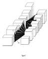
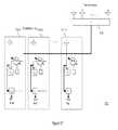
- FIG. 2illustrates a sector Wi-Fi base station mounted on a wall, splitting the sector into multiple beams, each feeding a separate AP, where coverage of both sides of a given street is accomplished by alternating mounting points left side/right side of the street, in accordance with some embodiments of the present invention
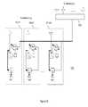
- FIG. 3illustrates another example of sectors deployment in accordance with some embodiments of the present invention
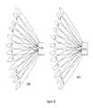
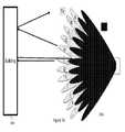
- FIG. 4is an example of beams patterns originated by a beamformer in accordance with embodiments of the present invention.
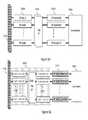
- FIG. 5Ais a block diagram describing a digital beamforming implementation in accordance with embodiments of the present invention.
- FIG. 5Bis a block diagram describing a digital beamforming implementation in accordance with embodiments of the present invention.
- FIG. 6describes a block diagram of digital beamforming implementing closed-loop antenna array's elements tapering in accordance with embodiments of the present invention
- FIG. 7describes a block diagram of digital beamforming implementing closed-loop Tx signal cancellation at RX inputs in accordance with embodiments of the present invention
- FIG. 8is a block diagram illustrating isolation of receiver antenna and a transmitter antenna array in accordance with some embodiments of the present invention.
- FIG. 9is a block diagram illustrating isolation of receiver antenna and a transmitter antenna arrays in accordance with some embodiments of the present invention.
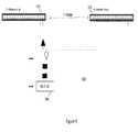
- FIG. 10Ais a block diagram of a multiple APs site using an Omni (or sector) antenna for receiving and a narrow beam antenna for transmitting in accordance with some embodiments of the present invention
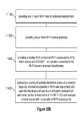
- FIG. 10Bis a high level flowchart illustrating a method according to some embodiments of the present invention.
- FIG. 11is a block diagram of a multiple access points site using a first set of narrow beam antennas for transmitting, and a second set for receiving in accordance with embodiments of the present invention
- FIG. 12illustrates installation of Tx and Rx array according to one embodiment
- FIG. 13illustrates installation of Tx and Rx array according to another embodiment
- FIG. 14describes an antenna element that can be used for a multi-element antenna array in accordance with embodiments of the present invention
- FIG. 15illustrates two proximal antenna elements cross talk
- FIG. 16illustrates cancellation circuit for elimination or reduction of cross talk between two antennas
- FIG. 17illustrates cancellation circuit for elimination or reduction of cross talk between two antenna arrays in accordance with embodiments of the present invention
- FIG. 18is yet an alternative of channel allocations to consecutive beams in accordance with some embodiments of the present invention in accordance with embodiments of the present invention.
- FIG. 19illustrates example of feeding several channels to a beam in accordance with some embodiments of the present invention.
- FIG. 20illustrates Cell area where the AP cluster's Rx beams sidelobe-rejection permits capacity multiplication in accordance with embodiments of the present invention
- FIG. 21is a flowchart illustrating initial operation—selecting transmit channels per beam in accordance with some embodiments of the present invention.
- FIG. 22is a flowchart illustrating estimating beams crosstalk in accordance with some embodiments of the present invention.
- FIG. 23is a block diagram illustrating using crosstalk data to minimize the crosstalk via scheduling, in accordance with some embodiments of the present invention.
- FIG. 24illustrates a flowchart and a block diagram showing optimizing UEs allocation to beams in accordance with some embodiments of the present invention
- FIG. 25describes mitigation of possible issues where tapering and cancellation effectiveness are jeopardized by non-flat channel in accordance with embodiments of the present invention
- FIG. 26describes mitigation of possible issues where the Tx array reflection from close by reflectors is introduced into a receiving beam, surpassing the required isolation threshold in accordance with embodiments of the present invention.
- FIG. 27describes mitigation of possible issues where Tx signal leakage via conductive paths surpasses the required isolation threshold in accordance with embodiments of the present invention.
- FIG. 1shows legacy Wi-Fi APs which are typically implemented with Omni directional antennas, and when deployed outdoors in accordance with the prior art. These Wi-Fi APs are frequently deployed in urban areas over lamppost and produce omni directional coverage 10 .
- FIGS. 2 and 3are high level block diagrams illustrating deployment of multi beam Wi-Fi APs 102 , 104 202 and 204 in accordance with embodiments of the present invention serving UEs 112 , 114 and 212 , 214 respectively.
- the distributed nature of CSMA protocols and 802.11 Wi-Fi in particulargenerates little central control and limited predictability of time slices allocated to AP and its various Clients for transmissions.
- the Wi-Fi protocolprohibits transmission in presence of identified contention, even one with a very low signal level, while Cellular transmission will normally take place regardless of interference and be successful if signal to noise plus interferences (SINR) is sufficient.
- SINRsignal to noise plus interferences
- TDD Multi-User Cellular protocol base stationscan switch simultaneously or concurrently between Transmission and Reception, due to their full control on who does what and when; a cluster of Wi-Fi APs feeding similar co-located set of beams, will each switch between Receiver and Transmitter independently, jamming each other on many occasions; while the former is capable of reusing the spectrum up to N folds, where N is the number of directional beams created by the base station, the latter effort to carry N independent data streams will result in self AP to AP as well as UEs to APs frequent jamming, adversely affecting overall capacity.
- Embodiments of the present inventiondescribe a method of clustering Wi-Fi multiple concurrent APs operating independently using legacy PHY and MAC 802.11 protocol, implementing multi-beam, as described in FIG. 2 and FIG. 3 .
- FIG. 4describes exemplary multi-beam structures 402 and 404 where beams cover a given sector, where each non spatially adjacent beam can reuse the same frequency channel due to low side lobe 405 implementation that may facilitate SINR equal or larger than 30 dB in presence of each other.
- FIGS. 5A and 5Bdescribe two methods of implementing digital beamforming for multiple Access Points;
- FIG. 5Adescribes antennas array 510 A, radio circuitries 520 A, digital beamforming module 530 A baseband processors 540 A and a coordinator 550 A
- This architectureleads to a separation of AP circuitry into processor 540 A and radio 520 A—at the digital interface 530 A that connects them.
- the digital beamformingis performed by using integrated Wi-Fi AP chip, converting all of their transmission RF paths into low frequency and digitizing it, converting all of their receiving RF paths into low frequency and digitizing it, feeding said digital signals into a digital processing module which performs beamforming, tapering and cancellation, and then converting the outputs of the said digital processing module back to RF level and feeding the transmission and the receiving antenna arrays.
- the digital beamformingis performed by separating AP chip sets into two parts, one being the transceiver, the other being the baseband, lining up the latter in groups and connecting them to inputs of a digital processing module which performs beam forming, tapering, and cancellation, the former in similar groups and connecting them to the outputs of the said digital processing module, wherein the RF portion of the said transceivers are connected to a Transmission Antenna Array and a Receiving Antenna Array.
- FIG. 5Bdescribes antennas array 510 B, beamforming module 520 B which includes analog to digital modules 515 B digital beamformers 530 B and digital to analog modules 517 B.
- radio circuitries and baseband processorsare integrated into a monolithic module 540 B and a coordinator 550 B.
- This alternative architecturekeeps the AP's radio and processor in its integrated form 540 B; in that configuration, separation is done between the AP radio and the antennas, and the RF signals are converted to digital and then back to RF, creating a placeholder for digital manipulations.
- FIG. 6describes closed loop tapering implemented for FIG. 5A although the description is similar for FIG. 5B .
- This architectureincludes antennas array 602 A, 602 B radio circuitries 604 A, 604 B, digital beamforming module 606 A, 606 B baseband processors 608 a coordinator 610 a monitoring receiver 612 and a tapering control module 614 .
- Antenna taperingis a technique that manipulates current and voltage distribution across the antenna or antenna array aperture, in order to improve performance; in this invention, tapering manipulates phase and amplitude of signals antenna terminating elements in an array, in order to reduce side lobes.
- Closed loop taperingfurther enhances performance as it is supported by monitoring the results.
- monitoringis performed by measurement of the undesired Tx signal appearing in a given receiving antenna element of a combination of antenna elements (i.e. a receiving beam); tapering of both the Tx and the Rx arrays is done so that the Tx signal at the Rx receiver is minimized
- the directional beamshave a side lobe pattern of approximately ⁇ 30 dB, achieved via digital tapering, implemented by both mathematical calculation and closed loop cancellation using feedback from at least one of: UE devices and calibration transmitters.
- the receive and/or transmit antennascomprise an array of antenna elements and wherein said arrays are implemented with tapering that further reduces side lobe levels of the beams.
- FIG. 7describes closed loop Tx cancellation implemented for FIG. 5A although the description is similar for FIG. 5B .
- This architectureincludes antennas array 702 A, 702 B radio circuitries 704 A, 704 B, digital beamforming module 706 A, 706 B baseband processors 708 a coordinator 710 a monitoring receiver 712 and a tapering and cancellation control module 714 .
- Tx cancellationis a technique that takes a sample of a given Tx signal, and uses it to nullify or to reduce the traces of such signals, which are detected in a receiver; the Tx sample is tuned to create destructive interference with the traces of Tx detected at the Rx.
- Shaping the individual antenna elementsprovides some additional 20 dB of isolation for an individual antenna and some additional 10 dB of isolation for an array;
- Designing the Transmitter antenna array using tapering technologycan provide some 30 dB of side-lobes reduction per array.
- FIG. 8describes isolation buildup 800 for a W-Fi AP 820 between a transmit beamforming array 810 and a receive sector antenna 830 separated by 10 m. The calculation shows 125 dB of isolation can be achieved.
- the isolationis achieved by a spatial separation that attenuates the transmitted signal of the directional beams by at least 100 dB.
- the receive antennas and/or the transmit antennasare positioned so that side lobes are directed to each other, wherein the antennas are designed such that said side lobes are suppressed.
- FIG. 9describes isolation buildup 900 of a Wi-Fi AP 930 between a transmit beamforming array 910 and a receive beamforming array 920 separated by 1 m;
- FIG. 10Adescribes a system apparatus block diagram using a multi-beam array for transmission 1010 and beamforming 1060 , while the reception is done via an Omni (or a Sector) antenna 1020 that covers approximately the same azimuth and elevation angles; a legacy Wi-Fi APs' transmission output is connected to each one of the beams, while its input is fed from the Omni (or sector) antenna 1020 via an RF hub 1030 .
- the drawingshows that more than one AP 1040 can be connected to each beam—as long as it is not using the same frequency channel.
- Each APis equipped with mechanism 1070 to monitor data rate per UE, either internally, or via an external monitoring function than may be local or alternatively in higher levels of the network or application source; such monitoring may be statistical. Additionally, all APs participating in the cluster are connected to a central unit 1050 that coordinates their channels and UE allocations.
- a single APis configured to serve some or all directional beams.
- the Wi-Fi AP protocolhas a basic medium contention IEEE802.11xx in which Wi-Fi devices packets are not synchronized or delayed and where a distributed coordination function is applied via at least one of: carrier sense and random back-off, for collisions avoidance.
- gaps between the spatially separated beams which use a first Wi-Fi frequency channelmay be filled by an omni/sector antenna using a second Wi-Fi frequency channel whose power leakage to the first Wi-Fi frequency channel is guaranteed by the standard, to be lower than approximately ⁇ 90 dBm.
- FIG. 10Bis a high level flowchart illustrating a method 1000 B according to some embodiments of the present invention.
- the methodmay include for example providing one or more Wi-Fi transmit antennas beamformers 1010 ; providing one or more Wi-Fi receive antennas 1020 ; providing a number N of co-channel Wi-Fi access points (APs) which comply with the IEEE802.11xx standard, connected to the Wi-Fi transmit antennas beamformers 1030 ; and producing a plurality of spatially directional beams of a common frequency (i.e., same carrier frequency for the Wi-Fi transmitting), directed at a plurality of Wi-Fi user equipment (UE) such that the directional beams are sufficiently isolated from each other, so that at least some of the Wi-Fi UEs communicate simultaneously, concurrently or substantially at the same time with the plurality of Wi-Fi access points 1040 .
- APsco-channel Wi-Fi access points
- FIG. 11is a block diagram of a system according to some embodiments of the present invention.
- the systemmay include one or more Wi-Fi transmit antennas beamformers 1110 , having one or more Wi-Fi receive antennas, and a number N of co-channel Wi-Fi access points (APs) 1130 which comply with the IEEE802.11xx standard having Wi-Fi transmitters and receivers and, connected to the Wi-Fi transmit antennas beamformers and the Wi-Fi receive antennas 1120 .
- APsco-channel Wi-Fi access points
- the Wi-Fi transmit antennas beamformers 1110are configured to produce and transmit a plurality of directional beams 1170 A of a common frequency, directed at a plurality of Wi-Fi user equipment (UE) devices 1180 A and 1180 B such that the directional beams are sufficiently isolated from each other, so that at least some of the Wi-Fi UE devices communicate concurrently or simultaneously with the plurality of Wi-Fi APS via directional receive beams 1070 B and receive antennas or beamformers 1120 .
- UE devicesmay be any Wi-Fi enabled end user devices such as cellular phones, tablet PC, laptop computers, hand held devices and the like.
- the multi-beam antenna arraysusing approximately the same azimuth and elevation angles, use one array for receiving 1120 and the other for transmitting 1110 of each AP 1130 .
- the use of multi-beam on both Transmitter and Receiverenhances overall capacity not only over uplink, but also for downlink, as the less APs' receivers can detect transmissions of out-of-beam co-channel UE devices, the less they are inhibited from transmitting at will.
- Each AP 1030is equipped with mechanism 1040 to monitor data rate per UE, either internally, or via an external monitoring function that may be local or alternatively in higher levels of the network or application source; such monitoring may be statistical. Additionally, all APs participating in the cluster are connected to a local central unit 1050 that coordinates their channels and UE allocations.
- Additional value of using a multi-beam array for Receiveris the ability to select adjacent beams for the reception of UEs that are otherwise blocked by neighboring beam's UEs; similarly, individual APs may attenuate their sensitivity without violating the standard requirement (as long as their receiving sensitivity+Antenna gain meet ⁇ 90 dBm) thus reducing collisions with out-of-beam UEs.
- the N co-channel Wi-Fi transmittersare sufficiently isolated from their N respective receivers such that the transmission power received by N ⁇ 1 of the N co-channel Wi-Fi transmitters is lower than a white Gaussian noise present in the N respective receivers.
- the receivers and the transmittersare sufficiently spatially separated from each other so that the transmission power decays to a level of a white Gaussian noise.
- the isolation is achieved by the spatial separationis at least 100 dB.
- the receive antennas and/or the transmit antennasare positioned in a way that direct side lobes to each other.
- the antennasare designed such that said side lobes are suppressed.
- traces of transmitted signals originated from said access points and detected at its receiving circuitryare fed into a cancelation process in which samples of the original transmitted signals are subtracted from said traces, in order to nullify or at least reduce them.
- FIG. 12, 13describes example of mounting layout of two arrays showing a first layout 1200 illustrating a transmit beamformer array 1210 and receive beamformer array 1220 and a second layout 1300 illustrating a transmit beamformer array 1310 and receive beamformer array 1320 .
- FIG. 14describes a beam pattern diagram 1400 of a possible antenna element that can be used to build such an antenna array; it outlines a radiation pattern of a patch antenna over ground plane, which has a main lobe pointing towards some bore sight, lower radiation level at +/ ⁇ 90° (which serves the purpose of increasing isolation toward other antennas installed alongside), and back lobes.
- FIG. 15is a beam pattern diagram 1500 illustrating the parasitic impact of back lobes and 90° side lobes which creates crosstalk between a receiving and a transmitting antennas that are virtually co-located; it also indicates that such contributors are coherently combined, so that they provide a single vector equal to E S i which lends itself to cancellation or reduction of transmission traces detected at receiving circuits of the APs.
- FIG. 16describes a circuit 1600 that implements cancellation of Tx components found in the Rx receiver 1620 connected to receive antennas 1610 ; Cancellation is carried out by a combination of nulling module 1650 , summation modules 1630 and 1640 and phase sifter/gain control module 1660 .
- Such cancellation between 2 antennascan be done with a single circuit per antenna pair (for a given frequency) due to the coherency of the summation of all participating sources of leakage. It should be noted that ⁇ ⁇ a is used at off line calibration and ⁇ ⁇ is used during operation.
- the taperingis carried out by monitoring traces of transmitted signals originated from said APs, and manipulating antennas weights to reduce said traces, and wherein said traces are fed or input into a cancellation process in which samples of the original signal are subtracted from said traces.
- FIG. 17describes a circuit 1700 that implements cancellation of Tx for an entire array, element by element based on the same characteristic of the coherency of all participating sources of leakage It is noted that a separate cancellation circuit 1710 - 1 . . . 17010 -N is required per each Tx beam in the transmit beamformer array 1720 . Also noted that the cancellation is done with support of a closed loop mechanism, by monitoring the cancellation success at the receivers' inputs.
- such wide band cancellation or reductioncan be performed via wide band cancellation methods e.g. using Finite Impulse Response (FIR) filtering.
- FIRFinite Impulse Response
- Tx cancellation during real time operation(rather than only at factory and on installation—gaps in transmission of UEs and neighboring APs should be detected; when available, Tx beams should be turned on one-by-one for the calibration/tuning process.
- FIG. 18describes two cases 1800 A and 1800 B where channel allocations per beam uses more than two channels for each Wi-Fi station 1810 A and 1810 B respectively.
- the coordinatorinitiates a handover of a UEs (a victim UE) which is affected by multipath coming from some reflector illuminated by another co-channel beam (the victimizer beam); such a handover may be toward either a the very same victimizing beam—if SINR is sufficient, or towards another lower interference available beam.
- a handovermay be toward either a the very same victimizing beam—if SINR is sufficient, or towards another lower interference available beam.
- Such multipath generated leakage amongst co-channel beamsare referred to as Cross Talk.
- the coordinatorreports the crosstalk table to the both victim UEs and victimizing beams and the scheduler of both access points performs a coordination that facilitates time sharing when victim UEs are served.
- the Wi-Fi APs channelsare associated with at least two frequencies.
- FIG. 19describes cases 1900 A and 1900 B where more than one channel is feeding one beam for the Wi-Fi station 1910 A or 1910 B.
- coverage gaps between the set of spatially separated beams which use a first Wi-Fi frequency channelare filled by the other set of spatially separated beams which use a second Wi-Fi frequency channel.
- the one or more Wi-Fi receive antennasare implemented as one or more beamformed array of antennas.
- the systemsfurther includes a gateway and access point coordinator configured to instruct the beamformers to spatially manipulate the beams, based on data received from the Wi-Fi UEs, so as to maintain the sufficient isolation between the beams, over time.
- a gateway and access point coordinatorconfigured to instruct the beamformers to spatially manipulate the beams, based on data received from the Wi-Fi UEs, so as to maintain the sufficient isolation between the beams, over time.
- side lobes of at least one of the beamsare reduced to a level of approximately 30 dB below their peak. This may be implemented by means of both mathematical calculations and closed loop tapering.
- weights settingmay be based on feedback from UEs or from calibration transmitters located at various points throughout the cell's coverage area
- FIG. 20describes the isolation issue from the uplink point of view: while the intensive isolation created between Tx and Rx of APs, guarantees AP i 's transmission will not prohibit AP j from transmitting, the transmission originated from a close by Wi-Fi Station served by AP i , may be received by AP j 's receiver, and blocks its transmission.
- UEs 2030 & 2050can be served concurrently or simultaneously and independently by their respective serving beams 2010 & 2040 .
- beam 2010is serving UE 2020
- its uplink transmissionis received by the AP receiver of the non serving beam 2050 , causing the AP of beam 2050 to yield and refrain from serving UEs in its coverage.
- the “clean range”is assumed to be 12 dB lower i.e. 18 dB.
- Rx⁇ 42 dBm
- FIG. 20demonstrates that by creating ⁇ 30 dB side lobes and proper tuning of the power to fit the required cell edge, capacity multiplication will preside at some 89% of the Cell's area.
- a coordinatorresiding in the hub or in the gateway which serves the cluster of APs, performs traffic analysis and consequently executes load sharing between adjacent beams by forcing UEs handover per the requirement of load balancing.
- the forcing of the UEs handover between beamsis carried out via Extended Service Set (ESS)—if UEs are support ESS, or via denial of service to a given UE at a given beam.
- ESSExtended Service Set
- cross talk between co-channel beamsis periodically estimated using UEs estimation of alternative or neighboring APs, and the relative power of such neighbors versus the serving AP is reported by the UE to the access point, to be reported to the coordinator, generating for each UE crosstalk values originated by N ⁇ 1 co-channel beams.
- FIG. 21describes a method 2100 for commissioning of such a Multi-Beam MIMO Wi-Fi base station which is deployed into and environment that is already served or partially served by residential or commercial APs. While following legacy procedures of channels selections 2110 , the said Multi-Beam base station has to allocate different channels to adjacent beams even if those are not first choices of the legacy procedure, this is followed up by verification stage 2120 and authorization stage 2130 as illustrated.
- FIG. 22describes a method 2200 using a prior art roaming procedure's Radio-Resources-Management (RRM) to pool UEs' neighbors reports about their neighboring service set identifier (SSIDs).
- RRMRadio-Resources-Management
- SSIDsneighboring service set identifier
- Method 2200may include for example using UE reporting of neighboring APs 2210 .
- thismay be carried out by periodically using Cisco's “Cisco Compatible Extension” (CCX) like S36 RRM request, or like S51 Neighbor List Update message advising 6 best neighboring APs 2220 .
- the methodthen goes on to deriveBeam Cross talk table (All UEs measurements of all neighboring beams) 2230 .
- a coordination hubuses cross talk information to inform schedulers of all beams' APs 2240 .
- the methodthen goes on to a step in which each schedulers will try to avoid or minimize cross talk via a super frame time share structure 2250 and back to the step of using UE reporting of neighboring APs 2220 .
- FIG. 23is a block diagram illustrating a system buildup 2300 using crosstalk information to minimize it via scheduling, in accordance with some embodiments of the present invention.
- Beams 2310 covering UEmay be time multiplexed by their respective AP scheduler 2320 and coordinator 2330 based on the crosstalk information coming from the UEs.
- FIG. 24describes a method 2400 for forcing UEs to roam from its autonomously selected beam into the Multi Beam-AP preferred beam. For each UE grade best and second best beam, (or more) based on neighbors list 2410 . Then a coarse allocation process is carried out by spreading the UEs across the beams as evenly as possible, choosing either first or second best beam for each, by forcing handover 2420 . The fine allocation process is carried out by referring to the Cross Talk table, verifying UE groups in odd/even beams that would be exposed to collision (e.g., that will experience cross talk) referring to the cross talk table, check optional moving of a given UE from first to second best beam of vice versa, that will reduce overall cross talk, again, by forcing handover 2430 .
- Cross Talk tableverifying UE groups in odd/even beams that would be exposed to collision (e.g., that will experience cross talk) referring to the cross talk table, check optional moving of a given UE from first to second best beam of vice versa, that will reduce
- a load balancing processis carried out by estimating, over a given period, a traffic level for each UE, aggregating per beam and comparing all beams traffic, and balancing load by forcing handover 2440 .
- roamingis forced by denying of service to the UE via authentication rejection, forcing it to scan and pick the second best beam 2450 .
- the APwill use handover procedure to force the UE to roam 2460 .
- Channel 3 and 4are then assigned (if available) to loaded beams 2470 . The process then restarts at step 2410 .
- Denial of service to a given UE via authentication processforces it to scan for alternatives, and thus getting it to hook up on the alternative beam; other methods can be based on temporary reduction of its preferred beam's power while maintaining or temporarily increasing the power of the Multi Beam-AP preferred beam, in such a way that will cause the UE to scan for the alternative and roam to it; yet another way is to temporarily interfere with the QoS or Error Rate of Acknowledgment delivered to that UE, forcing it to scan for alternative, and the like.
- FIG. 25addresses an issue of non-flat channel; although BW for Wi-Fi is in the order of 1% in both low and high bands, normally facilitating efficient cancellation and tapering, this invention high isolation requirements can be assisted by super accuracy, which can be provided by separate cancellation circuitry/process for each frequency part independently; such a mechanism can be implemented by segmentation of the bandwidth into subsections and treating each such subsection individually; e.g. with OFDM modulation, it can be done per subcarrier or be Radio Bearer (RB), bringing the cancellation and tapering performance closer to the boundary.
- RBRadio Bearer
- the beam patterns of the transmit antennasexhibit contaminating transmit signals being an accumulated contribution of side lobes and back lobes
- the systemfurther includes amplitude/phase modules associated with said transmit antennas and null transmit module configured to receive a difference between signals received by said receive antenna and said contaminating transmit signals detected in the receiving circuitry and control said amplitude/phase modules so that transmit signal component in the receiver are reduced using accurate destructive interference manifested via closed loop.
- a sample of transmitted signal of each beamis used as a reference for an individual reduction process for each antenna elements of the receiver systems, or for each beam of the receiver.
- the reductionis carried out individually per sub-segments of the bandwidth or via Finite Impulse Response (FIR) filtering
- the APsare configured to have their power level of the transmission, and receiving sensitivity of their receivers, tuned to determine a range of cell's coverage, in a way that sets up most (i.e. more than half) of the UE devices population in an area that is covered by the serving AP receiver's beam, but not covered by non serving APs' receiving side lobes beams.
- FIG. 26addresses issues that may occur when installing the Site facing a close by building; while most beams are squinted to the right or to the left, creating a Snell reflection from the building wall that deflects away, there may be a perpendicular beam that hits the wall with Tx signal which is being reflected directly back to the Site, picked up by an adjacent receiving beam, and ends up blocking the associated APs from transmitting concurrently or simultaneously with such a beam.
- the remedy in such a caseis to reduce power of such a beam to the level that eliminates blocking adjacent beams' receivers; another way is to reduce those adjacent beams' receivers' sensitivity; yet another way is to deflect the victim or the victimized beams slightly if excessive reflected signal is not too great, i.e. few dBs.
- FIG. 27addresses conductive leakage that may occur between the various components of the Site, potentially defeating the high radiated isolation by introducing low isolation via current over cables shield, common power supplies, coupling between APs' Radios and the like.
- the proposed remedymay include a set of precautions as follows:
- a Wi-Fi AP protocolmay exhibit a basic medium contention IEEE802.11xx in which Wi-Fi devices packets are not synchronized or delayed and wherein a distributed coordination function is applied via at least one of: carrier sense and random back-off, for collisions avoidance.
- the signals generated by the N co-channel Wi-Fi transmittersare sufficiently isolated from their N respective receivers such that a transmission power of a signal received by N ⁇ 1 of the N co-channel Wi-Fi transmitters is lower than a white Gaussian noise level present at the N respective receivers.
- the systemfurther include a gateway and an access point coordinator 550 a or 550 configured to instruct the beamformers to spatially manipulate the beams, based on data received from the Wi-Fi UE devices, so as to maintain the sufficient isolation between the beams, over time.
- a population or group of served UE devicesis subdivided into two groups: a first group in which the transmission of a UE device served by a given beam is received by one or more beams' receivers, and a second group in which UE devices' transmission is receivable exclusively by its serving beam.
- the first groupis allocated with one Wi-Fi channel and served by an omni/wide sector antenna
- the second groupis allocated with a second and a third Wi-Fi channel and is served by the directional beams.
- the systemfurther include a coordinator which serves the plurality of APs, and configured to perform traffic analysis and to execute load sharing between beams by forcing UE devices handover based on load balancing requirements.
- a coordinatorwhich serves the plurality of APs, and configured to perform traffic analysis and to execute load sharing between beams by forcing UE devices handover based on load balancing requirements.
- the forcing of the UE devices handover between beamsis carried out via Extended Service Set (ESS), or via AP denial of service to a given UE device at a given beam.
- ESSExtended Service Set
- AP denial of serviceto a given UE device at a given beam.
- the crosstalk between co-channel directional beamsis periodically estimated using UE devices estimation of alternative or neighboring N APs, and a relative power level of such neighbors versus the serving AP is reported by the UE to the AP, to be reported to the coordinator, generating for each UE crosstalk values originated by N ⁇ 1 co channel directional beams.
- the coordinatorinitiates a handover of victim UE devices being affected by victimizing beams which cause crosstalk to said UE devices, to said victimizing beams.
- the coordinatorreports a crosstalk table indicating crosstalk between victimizing beams and victim UE devices to the victimizing beams and the victim UE devices and the APs feeding the victim UE and the victimizing beam perform time sharing when victim UEs are served.
- aspects of the present inventionmay be embodied as a system, method or an apparatus. Accordingly, aspects of the present invention may take the form of an entirely hardware embodiment, an entirely software embodiment (including firmware, resident software, micro-code, etc.) or an embodiment combining software and hardware aspects that may all generally be referred to herein as a “circuit”, “module” or “system.”
- computational modulesmay be implemented by e.g., processors (e.g., a general purpose computer processor or central processing unit executing software), or digital signal processors (DSPs), or other circuitry.
- the baseband modemmay be implanted, for example, as a DSP.
- a beamforming matrixcan be calculated and implemented for example by software running on general purpose processor. Beamformers, gain controllers, switches, combiners, and phase shifters may be implemented, for example using RF circuitries.
- each block in the flowchart or block diagramsmay represent a module, segment, or portion of code, which comprises one or more executable instructions for implementing the specified logical function(s).
- the functions noted in the blockmay occur out of the order noted in the figures. For example, two blocks shown in succession may, in fact, be executed substantially concurrently, or the blocks may sometimes be executed in the reverse order, depending upon the functionality involved.
- methodmay refer to manners, means, techniques and procedures for accomplishing a given task including, but not limited to, those manners, means, techniques and procedures either known to, or readily developed from known manners, means, techniques and procedures by practitioners of the art to which the invention belongs.
- the present inventionmay be implemented in the testing or practice with methods and materials equivalent or similar to those described herein.
Landscapes
- Engineering & Computer Science (AREA)
- Signal Processing (AREA)
- Computer Networks & Wireless Communication (AREA)
- Power Engineering (AREA)
- Mobile Radio Communication Systems (AREA)
- Radio Transmission System (AREA)
Abstract
Description
Claims (28)
Priority Applications (1)
| Application Number | Priority Date | Filing Date | Title |
|---|---|---|---|
| US14/658,986US9385793B2 (en) | 2013-02-13 | 2015-03-16 | Multi-beam co-channel Wi-Fi access point |
Applications Claiming Priority (4)
| Application Number | Priority Date | Filing Date | Title |
|---|---|---|---|
| US201361764209P | 2013-02-13 | 2013-02-13 | |
| US13/858,302US20140226740A1 (en) | 2013-02-13 | 2013-04-08 | Multi-beam co-channel wi-fi access point |
| US14/011,521US8983548B2 (en) | 2013-02-13 | 2013-08-27 | Multi-beam co-channel Wi-Fi access point |
| US14/658,986US9385793B2 (en) | 2013-02-13 | 2015-03-16 | Multi-beam co-channel Wi-Fi access point |
Related Parent Applications (1)
| Application Number | Title | Priority Date | Filing Date |
|---|---|---|---|
| US14/011,521ContinuationUS8983548B2 (en) | 2013-02-13 | 2013-08-27 | Multi-beam co-channel Wi-Fi access point |
Publications (2)
| Publication Number | Publication Date |
|---|---|
| US20150249487A1 US20150249487A1 (en) | 2015-09-03 |
| US9385793B2true US9385793B2 (en) | 2016-07-05 |
Family
ID=51297351
Family Applications (3)
| Application Number | Title | Priority Date | Filing Date |
|---|---|---|---|
| US13/858,302AbandonedUS20140226740A1 (en) | 2013-02-13 | 2013-04-08 | Multi-beam co-channel wi-fi access point |
| US14/011,521Expired - Fee RelatedUS8983548B2 (en) | 2013-02-13 | 2013-08-27 | Multi-beam co-channel Wi-Fi access point |
| US14/658,986Expired - Fee RelatedUS9385793B2 (en) | 2013-02-13 | 2015-03-16 | Multi-beam co-channel Wi-Fi access point |
Family Applications Before (2)
| Application Number | Title | Priority Date | Filing Date |
|---|---|---|---|
| US13/858,302AbandonedUS20140226740A1 (en) | 2013-02-13 | 2013-04-08 | Multi-beam co-channel wi-fi access point |
| US14/011,521Expired - Fee RelatedUS8983548B2 (en) | 2013-02-13 | 2013-08-27 | Multi-beam co-channel Wi-Fi access point |
Country Status (1)
| Country | Link |
|---|---|
| US (3) | US20140226740A1 (en) |
Cited By (1)
| Publication number | Priority date | Publication date | Assignee | Title |
|---|---|---|---|---|
| US11683077B2 (en) | 2018-01-19 | 2023-06-20 | Huawei Technologies Co., Ltd. | Coordinated transmission control method, apparatus, and system |
Families Citing this family (16)
| Publication number | Priority date | Publication date | Assignee | Title |
|---|---|---|---|---|
| US8891598B1 (en) | 2013-11-19 | 2014-11-18 | Magnolia Broadband Inc. | Transmitter and receiver calibration for obtaining the channel reciprocity for time division duplex MIMO systems |
| US9271176B2 (en) | 2014-03-28 | 2016-02-23 | Magnolia Broadband Inc. | System and method for backhaul based sounding feedback |
| US10263331B2 (en) | 2014-10-06 | 2019-04-16 | Kymeta Corporation | Device, system and method to mitigate side lobes with an antenna array |
| US9769594B2 (en)* | 2015-01-30 | 2017-09-19 | Cassia Networks Inc. | Methods, devices and systems for increasing wireless communication range |
| US11071105B2 (en) | 2016-04-26 | 2021-07-20 | Lg Electronics Inc. | Method and apparatus for configuring sensing gap in frame structure for new radio access technology in wireless communication system |
| WO2017194094A1 (en)* | 2016-05-10 | 2017-11-16 | Nokia Solutions And Networks Oy | Method, system and apparatus of beam selection |
| WO2018135982A1 (en)* | 2017-01-18 | 2018-07-26 | Telefonaktiebolaget Lm Ericsson (Publ) | Network node and method performed thereby for scheduling transmissions between the network node and one or more wireless devices |
| CN107294572B (en)* | 2017-07-12 | 2020-06-09 | 西安空间无线电技术研究所 | Large-scale multi-beam rapid station distribution method |
| US10505572B1 (en)* | 2017-08-22 | 2019-12-10 | Rockwell Collins, Inc. | Active canceller for electronically scanned array |
| TWI666824B (en)* | 2018-01-31 | 2019-07-21 | 酷米科技股份有限公司 | Electronic device for controlling intelligent antenna module and method for carrying out intelligent fast antenna steering technology (iFAST) |
| WO2019241436A1 (en)* | 2018-06-14 | 2019-12-19 | Cohere Technologies, Inc. | Co-existence of orthogonal time frequency space and long term evolution systems |
| CN111327371A (en)* | 2018-12-17 | 2020-06-23 | 中兴通讯股份有限公司 | Antenna alignment method, antenna alignment device, phased array antenna system and readable storage medium |
| CN109788519B (en)* | 2019-03-12 | 2021-06-08 | 深圳市网是科技有限公司 | Double-frequency WiFi intelligent switching method based on 2.4G self-adaptive threshold |
| CN113259834B (en)* | 2020-02-10 | 2022-09-02 | 华为技术有限公司 | Positioning method, WLAN device and storage medium |
| CN114126013B (en)* | 2020-08-28 | 2025-02-11 | 中兴通讯股份有限公司 | Wireless standard capability management method and device, electronic device, and storage medium |
| US11558088B1 (en)* | 2021-09-15 | 2023-01-17 | Qualcomm Incorporated | Closed loop spatial interference control in full duplex |
Citations (320)
| Publication number | Priority date | Publication date | Assignee | Title |
|---|---|---|---|---|
| US4044359A (en) | 1962-01-09 | 1977-08-23 | General Electric Company | Multiple intermediate frequency side-lobe canceller |
| US4079318A (en) | 1975-06-23 | 1978-03-14 | Nippon Electric Company, Ltd. | Space diversity receiving system with phase-controlled signal combining at intermediate frequency stage |
| US4359738A (en) | 1974-11-25 | 1982-11-16 | The United States Of America As Represented By The Secretary Of The Navy | Clutter and multipath suppressing sidelobe canceller antenna system |
| US4540985A (en) | 1978-05-23 | 1985-09-10 | Westinghouse Electric Corp. | Angle width discriminator/altitude line detector radar |
| US4628320A (en) | 1964-04-29 | 1986-12-09 | General Electric Company | Cancellation of scatter jamming |
| US5162805A (en) | 1975-02-19 | 1992-11-10 | The United States Of America As Represented By The Secretary Of The Navy | Frequency diversity sidelobe canceller |
| US5363104A (en) | 1974-02-28 | 1994-11-08 | Lockheed Sanders, Inc. | Jamming signal cancellation system |
| US5444762A (en) | 1993-03-08 | 1995-08-22 | Aircell, Inc. | Method and apparatus for reducing interference among cellular telephone signals |
| US5732075A (en) | 1995-02-24 | 1998-03-24 | Alcatel N.V. | Assignment of a carrier frequency in an SDMA radio system |
| US5915215A (en) | 1990-05-02 | 1999-06-22 | Harris Canda, Inc. | Private cellular telephone system |
| US5936577A (en) | 1996-10-18 | 1999-08-10 | Kabushiki Kaisha Toshiba | Adaptive antenna |
| US5940033A (en) | 1998-01-20 | 1999-08-17 | The United States Of America As Represented By The Secretary Of The Army | Apparatus, methods and computer program for evaluating multiple null forming antenna processors and jammers |
| US6018317A (en) | 1995-06-02 | 2000-01-25 | Trw Inc. | Cochannel signal processing system |
| US6026081A (en) | 1996-07-05 | 2000-02-15 | Nec Corporation | Method of controlling power on forward link in a cellular |
| US6046655A (en) | 1997-11-10 | 2000-04-04 | Datron/Transco Inc. | Antenna feed system |
| US6101399A (en) | 1995-02-22 | 2000-08-08 | The Board Of Trustees Of The Leland Stanford Jr. University | Adaptive beam forming for transmitter operation in a wireless communication system |
| US6163695A (en) | 1997-04-16 | 2000-12-19 | Nec Corporation | Mobile communication system and mobile communication method thereof |
| US6167286A (en) | 1997-06-05 | 2000-12-26 | Nortel Networks Corporation | Multi-beam antenna system for cellular radio base stations |
| US6215812B1 (en) | 1999-01-28 | 2001-04-10 | Bae Systems Canada Inc. | Interference canceller for the protection of direct-sequence spread-spectrum communications from high-power narrowband interference |
| US6226507B1 (en) | 1998-02-03 | 2001-05-01 | Ericsson Inc. | Apparatus and method for selecting between a plurality of antennas utilized by a microcellular communications terminal for reception of a signal |
| US6230123B1 (en) | 1997-12-05 | 2001-05-08 | Telefonaktiebolaget Lm Ericsson Publ | Noise reduction method and apparatus |
| US6259683B1 (en) | 1996-11-28 | 2001-07-10 | Oki Electric Industry Co., Ltd. | Mobile communication system for accomplishing handover with phase difference of frame sync signals corrected |
| US6297772B1 (en) | 1974-09-23 | 2001-10-02 | The United States Of America As Represented By The Secretary Of The Navy | Predicting coherent sidelobe canceller |
| US20010029326A1 (en) | 1991-03-07 | 2001-10-11 | Diab Mohamed Kheir | Signal processing apparatus and method |
| US20010038665A1 (en) | 2000-03-03 | 2001-11-08 | Jens Baltersee | Method and rake receiver for phasor estimation in communication systems |
| US6321077B1 (en) | 1998-04-24 | 2001-11-20 | Harada Industry Co., Ltd. | Reception control system for automobile |
| US6335953B1 (en) | 1992-05-08 | 2002-01-01 | Axonn, L.L.C. | Enhanced frequency agile radio |
| US20020024975A1 (en) | 2000-03-14 | 2002-02-28 | Hillel Hendler | Communication receiver with signal processing for beam forming and antenna diversity |
| EP1189303A2 (en) | 2000-09-14 | 2002-03-20 | NTT DoCoMo, Inc. | Beam forming method and apparatus in a wireless communication system |
| US6370378B1 (en) | 1998-06-29 | 2002-04-09 | Nec Corporation | Cellular communicating network and method for locating mobile stations using hierarchically arranged databases |
| US6377783B1 (en) | 1998-12-24 | 2002-04-23 | At&T Wireless Services, Inc. | Method for combining communication beams in a wireless communication system |
| US20020051430A1 (en) | 2000-10-31 | 2002-05-02 | Hideo Kasami | Wireless communication system, weight control apparatus, and weight vector generation method |
| US6393282B1 (en) | 1999-01-14 | 2002-05-21 | Kabushiki Kaisha Toshiba | Mobile radio communication terminal device with base station searching function |
| US20020065107A1 (en) | 2000-10-16 | 2002-05-30 | Wireless Online, Inc. | Method and system for calibrating antenna towers to reduce cell interference |
| US20020085643A1 (en) | 2000-12-28 | 2002-07-04 | Dean Kitchener | MIMO wireless communication system |
| US20020107013A1 (en) | 2001-02-06 | 2002-08-08 | Shane Fitzgerald | Method and apparatus for intelligent dynamic frequency reuse |
| US20020115474A1 (en) | 2001-02-14 | 2002-08-22 | Ntt Docomo, Inc. | Communication control method and apparatus in mobile communication system |
| US20020181437A1 (en) | 2001-04-26 | 2002-12-05 | Ntt Docomo, Inc | Data link transmission control methods, mobile communication systems, data link transmission control apparatus, base stations, mobile stations, mobile station control programs, and computer-readable recording media |
| US20020181426A1 (en) | 2001-03-02 | 2002-12-05 | Sherman Matthew J. | Interference suppression methods for 802.11 |
| US20030087645A1 (en) | 2001-11-08 | 2003-05-08 | Kim Byoung-Jo J. | Frequency assignment for multi-cell IEEE 802.11 wireless networks |
| WO2003047033A1 (en) | 2001-11-21 | 2003-06-05 | Lockheed Martin Corporation | Scaleable antenna array architecture using standard radiating subarrays and amplifying/beamforming assemblies |
| US20030114162A1 (en) | 2001-05-31 | 2003-06-19 | Chheda Ashvin H. | Method and apparatus for orthogonal code management in CDMA systems using smart antenna technology |
| US6584115B1 (en) | 1998-06-25 | 2003-06-24 | Nec Corporation | Multiuser interference canceler for DS-CDMA system |
| US20030153360A1 (en) | 2002-02-08 | 2003-08-14 | Burke Joseph P. | Method and apparatus for transmit pre-correction in wireless communications |
| US20030153322A1 (en) | 2002-02-08 | 2003-08-14 | Burke Joseph P. | Transmit pre-correction in a wireless communication system |
| WO2003073645A1 (en) | 2002-02-26 | 2003-09-04 | Nortel Networks Limited | Radio communications device with adaptive antenna array for mimo systems |
| US20030186653A1 (en) | 1998-05-14 | 2003-10-02 | Behzad Mohebbi | Reducing interference in cellular mobile communication networks |
| US20030203743A1 (en) | 2002-04-22 | 2003-10-30 | Cognio, Inc. | Multiple-Input Multiple-Output Radio Transceiver |
| US20030203717A1 (en) | 1998-04-27 | 2003-10-30 | Chuprun Jeffery Scott | Satellite based data transfer and delivery system |
| US20040023693A1 (en) | 2002-08-01 | 2004-02-05 | Ntt Docomo, Inc. | Base station connection method, radio network controller, and mobile station |
| WO2004015886A1 (en) | 2002-08-07 | 2004-02-19 | Extricom Ltd. | Enhancing wirelass lan capacity using transmission power control |
| US6697633B1 (en) | 1995-06-02 | 2004-02-24 | Northrop Grummar Corporation | Method permitting increased frequency re-use in a communication network, by recovery of transmitted information from multiple cochannel signals |
| US6697622B1 (en) | 1999-09-06 | 2004-02-24 | Nit Docomo, Inc. | Control method of searching neighboring cells, mobile station, and mobile communication system |
| US20040056795A1 (en) | 2001-11-20 | 2004-03-25 | Telefonaktiebolaget Lm Ericsson | Downlink load sharing by beam selection |
| US20040063455A1 (en) | 2002-08-07 | 2004-04-01 | Extricom Ltd. | Wireless LAN with central management of access points |
| US20040081144A1 (en) | 2002-09-17 | 2004-04-29 | Richard Martin | System and method for access point (AP) aggregation and resiliency in a hybrid wired/wireless local area network |
| US20040121810A1 (en) | 2002-12-23 | 2004-06-24 | Bo Goransson | Using beamforming and closed loop transmit diversity in a multi-beam antenna system |
| US20040125899A1 (en) | 2002-12-30 | 2004-07-01 | Yingxue Li | Method and system for adaptively combining signals |
| US20040125900A1 (en) | 2002-12-31 | 2004-07-01 | Jung-Tao Liu | Method of determining the capacity of each transmitter antenna in a multiple input/multiple out/put (MIMO) wireless system |
| US20040142696A1 (en) | 2002-12-10 | 2004-07-22 | Data Flow Systems, Inc. | Radio communication system employing spectral reuse transceivers |
| US20040147266A1 (en) | 2003-01-20 | 2004-07-29 | Samsung Electronics Co., Ltd. | System and method for supporting multimedia broadcast/multicast service in a non-tracking area |
| US20040156399A1 (en) | 2002-08-07 | 2004-08-12 | Extricom Ltd. | Wireless LAN control over a wired network |
| US20040166902A1 (en) | 2003-01-21 | 2004-08-26 | Dan Castellano | Method and system for reducing cell interference using advanced antenna radiation pattern control |
| US6799054B2 (en) | 2002-05-06 | 2004-09-28 | Extricom, Ltd. | Collaboration between wireless LAN access points using wired lan infrastructure |
| US20040198292A1 (en) | 2002-06-27 | 2004-10-07 | Smith Martin S. | Wireless transmitter, transceiver and method |
| US20040228388A1 (en) | 2003-04-25 | 2004-11-18 | Matti Salmenkaita | Data transmission method, system and network element |
| US20040235527A1 (en) | 1999-10-19 | 2004-11-25 | Kathrein-Werke Kg | High speed fixed wireless voice/data systems and methods |
| US6834073B1 (en) | 2000-05-26 | 2004-12-21 | Freescale Semiconductor, Inc. | System and method for baseband removal of narrowband interference in ultra wideband signals |
| US20040264504A1 (en) | 2003-06-24 | 2004-12-30 | Samsung Electronics Co., Ltd. | Apparatus and method for enhancing transfer rate using a direct link protocol (DLP) and multiple channels in a wireless local area network (LAN) using a distributed coordination function (DCF) |
| US6842460B1 (en) | 2001-06-27 | 2005-01-11 | Nokia Corporation | Ad hoc network discovery menu |
| US20050068918A1 (en) | 2003-09-25 | 2005-03-31 | Ashok Mantravadi | Hierarchical coding with multiple antennas in a wireless communication system |
| US20050068230A1 (en) | 2003-09-29 | 2005-03-31 | Munoz Michael S. | Reducing co-channel interference in satellite communications systems by antenna re-pointing |
| US20050075140A1 (en) | 2003-10-02 | 2005-04-07 | Toshiba America Research Inc. | Harmonized Adaptive Arrays |
| US20050129155A1 (en) | 2003-12-12 | 2005-06-16 | Pioneer Corporation | Receiver, receiving method, reception controlling program, and recording medium |
| US6914890B1 (en) | 1999-08-05 | 2005-07-05 | Nokia Corporation | Apparatus, and associated method, for sequencing transmission of data |
| US20050147023A1 (en) | 2003-12-30 | 2005-07-07 | Intel Corporation | Method and apparatus for implementing downlink SDMA in a wireless network |
| US20050163097A1 (en) | 2004-01-28 | 2005-07-28 | Samsung Electronics Co., Ltd | Method of efficiently transmitting data during a handover in a wideband radio access network |
| US6927646B2 (en) | 2002-07-12 | 2005-08-09 | Filtronic Lk Oy | Bypass arrangement for low-noise amplifier |
| US20050195786A1 (en) | 2002-08-07 | 2005-09-08 | Extricom Ltd. | Spatial reuse of frequency channels in a WLAN |
| US20050245224A1 (en) | 2004-02-04 | 2005-11-03 | Fujitsu Ten Limited | Receiver |
| US20050250544A1 (en) | 2004-05-07 | 2005-11-10 | Stephen Grant | Base station, mobile terminal device and method for implementing a selective-per-antenna-rate-control (S-PARC) technique in a wireless communications network |
| US20050254513A1 (en) | 2004-05-14 | 2005-11-17 | Interdigital Technology Corporation | Method of selectively adjusting the configuration of an access point antenna to enhance mobile station coverage |
| US20050265436A1 (en) | 2004-06-01 | 2005-12-01 | Samsung Electronics Co., Ltd. | Method and apparatus for channel state feedback using arithmetic coding |
| US6975582B1 (en) | 1995-07-12 | 2005-12-13 | Ericsson Inc. | Dual mode satellite/cellular terminal |
| US20050286440A1 (en) | 2004-06-24 | 2005-12-29 | Meshnetworks, Inc. | System and method for adaptive rate selection for wireless networks |
| US20050287962A1 (en) | 2004-06-25 | 2005-12-29 | Mehta Neelesh B | RF-based antenna selection in MIMO systems |
| US20060041676A1 (en) | 2001-01-16 | 2006-02-23 | Sherman Matthew J | Interference suppression methods for 802.11 |
| US7035243B2 (en) | 2003-02-18 | 2006-04-25 | Extricom Ltd. | Multiplex communication between access points and hub |
| US20060094372A1 (en) | 2004-10-29 | 2006-05-04 | Samsung Electronics Co., Ltd. | Method for uplink scheduling in communication system using frequency hopping-orthogonal frequency division multiple access scheme |
| US20060092889A1 (en) | 2004-08-25 | 2006-05-04 | Daniel Lyons | High density WLAN system |
| US20060098605A1 (en) | 2003-04-07 | 2006-05-11 | Shaolin Li | Method of secure communications in a wireless distribution system |
| US20060111149A1 (en) | 2001-11-29 | 2006-05-25 | Interdigital Technology Corporation | System and method utilizing dynamic beam forming for wireless communication signals |
| US20060135097A1 (en) | 2003-12-10 | 2006-06-22 | Wang James J | Wireless communication system using a plurality of antenna elements with adaptive weighting and combining techniques |
| US7068628B2 (en) | 2000-05-22 | 2006-06-27 | At&T Corp. | MIMO OFDM system |
| US20060183503A1 (en) | 2002-09-09 | 2006-08-17 | Interdigital Technology Corporation | Reducing the effect of signal interference in null areas caused by overlapping antenna patterns |
| US20060203850A1 (en) | 2005-03-14 | 2006-09-14 | Johnson Walter L | Method and apparatus for distributing timing information in an asynchronous wireless communication system |
| US20060209771A1 (en) | 2005-03-03 | 2006-09-21 | Extricom Ltd. | Wireless LAN with contention avoidance |
| US20060227854A1 (en) | 2005-04-07 | 2006-10-12 | Mccloud Michael L | Soft weighted interference cancellation for CDMA systems |
| US20060264184A1 (en) | 2005-02-17 | 2006-11-23 | Interdigital Technology Corporation | Method and apparatus for selecting a beam combination of multiple-input multiple-output antennas |
| US20060270343A1 (en) | 2005-04-07 | 2006-11-30 | Interdigital Technology Corporation | Method and apparatus for antenna mapping selection in MIMO-OFDM wireless networks |
| US20060271969A1 (en) | 2005-05-18 | 2006-11-30 | Masaaki Takizawa | Wireless communication system, wireless relay unit and wireless terminal constituting the wireless communication system, and wireless communication method |
| US20060285507A1 (en) | 2005-06-17 | 2006-12-21 | Kinder Richard D | Using mini-beacons in a wireless network |
| US7177663B2 (en) | 2003-05-27 | 2007-02-13 | Interdigital Technology Corporation | Multi-mode radio with interference cancellation circuit |
| US20070037595A1 (en) | 2005-08-11 | 2007-02-15 | Extricom Ltd. | Wlan operating on multiple adjacent bands |
| US20070041398A1 (en) | 2000-11-03 | 2007-02-22 | At&T Corp. | Tiered contention multiple access (TCMA): a method for priority-based shared channel access |
| US7190964B2 (en) | 2001-08-20 | 2007-03-13 | Telefonaktiebolaget Lm Ericsson (Publ) | Reverse link power control in 1xEV-DV systems |
| US20070058581A1 (en) | 2001-07-05 | 2007-03-15 | Mathilde Benveniste | Hybrid coordination function (hcf) access through tiered contention and overlapped wireless cell mitigation |
| US20070076675A1 (en) | 2005-10-04 | 2007-04-05 | Via Technologies Inc. | Hyper throughput method for wirless local area network |
| US20070093261A1 (en) | 2005-10-24 | 2007-04-26 | Jilei Hou | Iterative interference cancellation system and method |
| US20070097918A1 (en) | 2005-10-27 | 2007-05-03 | Motorola, Inc. | Mobility enhancement for real time service over high speed downlink packet access (hsdpa) |
| US20070115882A1 (en) | 2005-11-08 | 2007-05-24 | Conexant Systems, Inc | Symmetric transmit opportunity (TXOP) truncation |
| US20070152903A1 (en) | 2005-12-30 | 2007-07-05 | Micro Mobio | Printed circuit board based smart antenna |
| US7257425B2 (en) | 2003-12-02 | 2007-08-14 | Motia | System and method for providing a smart antenna |
| US20070217352A1 (en) | 2006-01-05 | 2007-09-20 | Samsung Electronics Co., Ltd. | Method and apparatus for transmitting control frame to hidden node in wireless LAN |
| US20070223380A1 (en) | 2006-03-22 | 2007-09-27 | Gilbert Jeffrey M | Mechanism for streaming media data over wideband wireless networks |
| US20070249386A1 (en) | 2006-03-22 | 2007-10-25 | Broadcom Corporation, A California Corporation | Client device characterization of other client device transmissions and reporting of signal qualities to access point(s) |
| US7299072B2 (en) | 2003-02-28 | 2007-11-20 | Fujitsu Limited | Apparatus for time division multi-sector wireless LAN |
| US7319688B2 (en) | 2002-05-06 | 2008-01-15 | Extricom Ltd. | LAN with message interleaving |
| US20080043867A1 (en) | 2006-08-18 | 2008-02-21 | Qualcomm Incorporated | Feedback of precoding control indication (pci) and channel quality indication (cqi) in a wireless communication system |
| US20080051037A1 (en) | 2005-12-29 | 2008-02-28 | Molnar Karl J | BASE STATION AND METHOD FOR SELECTING BEST TRANSMIT ANTENNA(s) FOR SIGNALING CONTROL CHANNEL INFORMATION |
| US20080081671A1 (en) | 2006-10-03 | 2008-04-03 | Motorola, Inc. | Mobile assisted downlink beamforming with antenna weight feedback |
| US20080095163A1 (en) | 2006-10-23 | 2008-04-24 | Wai Chen | Method and communication device for routing unicast and multicast messages in an ad-hoc wireless network |
| US20080108352A1 (en) | 2006-10-27 | 2008-05-08 | Michael Montemurro | Link quality measurements based on data rate and received power level |
| US20080112373A1 (en) | 2006-11-14 | 2008-05-15 | Extricom Ltd. | Dynamic BSS allocation |
| US20080125120A1 (en) | 2002-10-18 | 2008-05-29 | Gallagher Michael D | Registration Messaging in an Unlicensed Mobile Access Telecommunications System |
| US20080144737A1 (en) | 2006-12-19 | 2008-06-19 | Qualcomm Incorporated | Beamspace-time coding based on channel quality feedback |
| US7391757B2 (en) | 2002-10-30 | 2008-06-24 | Hewlett-Packard Development Company, L.P. | Wireless LAN |
| US7392015B1 (en) | 2003-02-14 | 2008-06-24 | Calamp Corp. | Calibration methods and structures in wireless communications systems |
| US20080165732A1 (en) | 2001-11-08 | 2008-07-10 | Kim Byoung-Jo J | Frequency assignment for multi-cell IEEE 802.11 wireless networks |
| US20080181146A1 (en) | 2007-01-31 | 2008-07-31 | Airesurf Networks Holdings Inc. | WiFi antenna system and method of operation |
| US20080238808A1 (en) | 2007-02-15 | 2008-10-02 | Mitsubishi Electric Corporation | Diversity receiver |
| US20080240314A1 (en) | 2007-03-27 | 2008-10-02 | Qualcomm Incorporated | Channel estimation with effective co-channel interference suppression |
| US20080247370A1 (en) | 2005-09-30 | 2008-10-09 | Daqing Gu | Training Signals for Selecting Antennas and Beams in Mimo Wireless Lans |
| US20080267142A1 (en) | 2004-06-18 | 2008-10-30 | Stellaris Ltd. | Distributed Antenna Wlan Access-Point System and Method |
| US20080280571A1 (en) | 2007-05-11 | 2008-11-13 | Broadcom Corporation, A California Corporation | RF transceiver with adjustable antenna assembly |
| US20080285637A1 (en) | 2005-11-29 | 2008-11-20 | Interuniversitair Microelektronica Centrum Vzw (Imec) | Device and method for calibrating mimo systems |
| US20090003299A1 (en) | 2004-01-08 | 2009-01-01 | Interdigital Technology Corporation | Method for clear channel assessment optimization in a wireless local area network |
| US7474676B2 (en) | 2004-09-10 | 2009-01-06 | Mitsubishi Electric Research Laboratories, Inc. | Frame aggregation in wireless communications networks |
| US20090028225A1 (en) | 2007-07-17 | 2009-01-29 | Viasat, Inc. | Modular Satellite Transceiver |
| US20090046638A1 (en) | 2003-10-01 | 2009-02-19 | Rappaport Theodore S | Wireless network system and method |
| US7499109B2 (en) | 2003-07-30 | 2009-03-03 | Samsung Electronics Co., Ltd. | Method and apparatus for receiving digital television signals using space diversity and beam-forming |
| US20090058724A1 (en) | 2007-09-05 | 2009-03-05 | Samsung Electronics Co., Ltd. | Method and system for analog beamforming in wireless communication systems |
| US7512083B2 (en) | 2003-04-07 | 2009-03-31 | Shaolin Li | Single chip multi-antenna wireless data processor |
| US20090121935A1 (en) | 2007-11-12 | 2009-05-14 | Samsung Electronics Co., Ltd. | System and method of weighted averaging in the estimation of antenna beamforming coefficients |
| US20090137206A1 (en) | 2007-11-23 | 2009-05-28 | Texas Instruments Incorporated | Apparatus for and method of bluetooth and wireless local area network coexistence using a single antenna in a collocated device |
| US20090154419A1 (en) | 2007-12-17 | 2009-06-18 | Shousei Yoshida | Scheduling method for multi-user mimo |
| US20090190541A1 (en) | 2008-01-28 | 2009-07-30 | Saied Abedi | Communication systems |
| JP2009182441A (en) | 2008-01-29 | 2009-08-13 | Mitsubishi Electric Corp | Communication apparatus and calibration method |
| US20090227255A1 (en) | 2008-03-10 | 2009-09-10 | Telefonaktiebolaget Lm Ericsson (Publ) | Enhanced cell scanning |
| US20090239486A1 (en) | 2002-03-01 | 2009-09-24 | Ipr Licensing, Inc. | Apparatus for antenna diversity using joint maximal ratio combining |
| US7606528B2 (en) | 2006-11-10 | 2009-10-20 | Northrop Grumman Corporation | Distributed conformal adaptive antenna array for SATCOM using decision direction |
| US20090268616A1 (en) | 2005-11-21 | 2009-10-29 | Takahiro Hosomi | Mobile station, downstream transmission rate control method, and downstream transmission rate control program |
| US20090285331A1 (en) | 2002-03-21 | 2009-11-19 | Ipr Licensing, Inc. | Control of power amplifiers in devices using transmit beamforming |
| JP2009278444A (en) | 2008-05-15 | 2009-11-26 | Mitsubishi Electric Corp | Distortion compensation device |
| US7634015B2 (en) | 2006-02-10 | 2009-12-15 | Intel Corporation | Mobile station and method for channel sounding using a single radio frequency transmitter chain in a multiple-input multiple-output (MIMO) system |
| US20090323608A1 (en) | 2008-06-30 | 2009-12-31 | Kabushiki Kaisha Toshiba | Apparatus and method for wireless communication |
| US20090322613A1 (en) | 2008-06-30 | 2009-12-31 | Interdigital Patent Holdings, Inc. | Method and apparatus to support single user (su) and multiuser (mu) beamforming with antenna array groups |
| US20090322610A1 (en) | 2006-11-10 | 2009-12-31 | Philip Edward Hants | Phased array antenna system with electrical tilt control |
| US20100002656A1 (en) | 2008-07-03 | 2010-01-07 | Qualcomm Incorporated | Opportunistic relay scheduling in wireless communications |
| US7646744B2 (en) | 2003-04-07 | 2010-01-12 | Shaolin Li | Method of operating multi-antenna wireless data processing system |
| US20100037111A1 (en) | 2008-08-06 | 2010-02-11 | Sun Microsystems, Inc. | Method and apparatus for testing delay faults |
| US20100040369A1 (en) | 2008-08-13 | 2010-02-18 | Jun Zhao | Time synchronization method and device in passive optical network and passive optical network |
| US20100111039A1 (en) | 2008-11-03 | 2010-05-06 | Samsung Electronics Co., Ltd. | Method and apparatus for controlling discontinuous reception in mobile communication system |
| US20100117890A1 (en) | 2008-11-10 | 2010-05-13 | Motorola, Inc. | Antenna reciprocity calibration |
| US7719993B2 (en) | 2004-12-30 | 2010-05-18 | Intel Corporation | Downlink transmit beamforming |
| US20100135420A1 (en) | 2007-06-29 | 2010-06-03 | China Mobile Communications Corporation | Antenna multiplexing system and method of smart antenna and multiple-input multiple-output antenna |
| US20100150013A1 (en) | 2007-05-29 | 2010-06-17 | Mitsubishi Electric Corporation | Calibration method, communication system, frequency control method, and communication device |
| US7742000B2 (en) | 2005-05-31 | 2010-06-22 | Tialinx, Inc. | Control of an integrated beamforming array using near-field-coupled or far-field-coupled commands |
| US20100172429A1 (en) | 2007-05-29 | 2010-07-08 | Hiroyuki Nagahama | Digital broadcasting receiving apparatus |
| US7769107B2 (en) | 2004-06-10 | 2010-08-03 | Intel Corporation | Semi-blind analog beamforming for multiple-antenna systems |
| WO2010085854A1 (en) | 2009-02-02 | 2010-08-05 | Commonwealth Scientific And Industrial Research Organisation | Hybrid adaptive antenna array |
| US20100195601A1 (en) | 2009-01-29 | 2010-08-05 | Stichting Imec Nederland | Access method and data frame structure for use in body area networks |
| US20100195560A1 (en) | 2009-01-30 | 2010-08-05 | Oki Electric Industry Co., Ltd. | Packet relay system and wireless node |
| US20100208712A1 (en) | 2009-02-17 | 2010-08-19 | Wavion Ltd. | Enhancing WLAN performance in the presence of interference |
| US20100222011A1 (en) | 2005-04-04 | 2010-09-02 | Broadcom Corporation | Gain control in a multiple rf transceiver integrated circuit |
| US20100232355A1 (en) | 2009-03-13 | 2010-09-16 | Harris Corporation | Asymmetric broadband data network |
| US20100234071A1 (en) | 2009-03-12 | 2010-09-16 | Comsys Communication & Signal Processing Ltd. | Vehicle integrated communications system |
| US20100278063A1 (en) | 2009-04-29 | 2010-11-04 | Samsung Electronics Co. Ltd. | Method for controlling interference |
| US20100283692A1 (en) | 2006-04-27 | 2010-11-11 | Rayspan Corporation | Antennas, devices and systems based on metamaterial structures |
| US20100285752A1 (en) | 2009-05-11 | 2010-11-11 | Nec Laboratories America, Inc. | Beamforming methods and systems employing measured power at a receiver to perform channel estimation |
| US20100291931A1 (en) | 2007-10-31 | 2010-11-18 | Mitsubishi Electric Corporation | Mobile communication system, base station, mobile station, and base station installation method |
| US20100303170A1 (en) | 2007-05-10 | 2010-12-02 | Xiaolong Zhu | Method and apparatus for pre-processing data to be transmitted in multiple-input communication system |
| US20100316043A1 (en) | 2007-02-06 | 2010-12-16 | Panasonic Corporation | Radio communication method and radio communication device |
| US20110019639A1 (en)* | 2009-05-22 | 2011-01-27 | Jeyhan Karaoguz | Enterprise Level Management in a Multi-Femtocell Network |
| US20110032849A1 (en)* | 2009-08-07 | 2011-02-10 | Fimax Technology Limited | Systems and methods for mitigating interference between access points |
| US20110032972A1 (en) | 2009-08-07 | 2011-02-10 | Motia, Inc. | Economical, RF transparent, selective code phased array antenna processor |
| US7898478B2 (en) | 2007-02-28 | 2011-03-01 | Samsung Electronics Co., Ltd. | Method and system for analog beamforming in wireless communication systems |
| US7904086B2 (en) | 2006-10-02 | 2011-03-08 | Board Of Regents, The University Of Texas System | Method and computer program for handoff of mobile devices between wireless systems |
| US20110085532A1 (en) | 2002-08-26 | 2011-04-14 | Scherzer Shimon B | Space-time-power scheduling for wireless networks |
| US20110085465A1 (en) | 2008-06-09 | 2011-04-14 | Telefonaktiebolaget L M Ericsson (Publ) | Method and system and device for if/irat measurement allocation |
| US7933255B2 (en) | 2003-04-07 | 2011-04-26 | Bellow Bellows Llc | Multi-antenna wireless data processing system |
| US20110105036A1 (en) | 2009-11-04 | 2011-05-05 | Motorola, Inc. | Method and apparatus for sensing presence of an incumbent signal on a secondary radio channel |
| US20110116489A1 (en) | 2009-11-13 | 2011-05-19 | Interdigital Patent Holdings, Inc. | Method and apparatus for providing vht frequency reuse for wlans |
| WO2011060058A1 (en) | 2009-11-10 | 2011-05-19 | Montana State University | Compact smart antenna for mobile wireless communications |
| US20110134816A1 (en) | 2009-12-09 | 2011-06-09 | Yong Liu | Wireless Communication Signaling for Aggregate Data Units |
| US20110151826A1 (en) | 2009-12-18 | 2011-06-23 | Motorola, Inc. | Method for bearer establishment in a radio access network |
| US20110150050A1 (en) | 2009-12-23 | 2011-06-23 | Hafedh Trigui | Digital integrated antenna array for enhancing coverage and capacity of a wireless network |
| US20110150066A1 (en) | 2008-08-11 | 2011-06-23 | Iwatsu Electric Co., Ltd. | Multi-antenna wireless communication method, multi-antenna wireless communication system, and multi-antenna wireless communication device |
| US20110163913A1 (en) | 2009-05-01 | 2011-07-07 | Dalaware Corporation | Practical Method for Upgrading Existing GNSS User Equipment with Tightly Integrated Nav-Com Capability |
| US20110205883A1 (en) | 2006-11-08 | 2011-08-25 | Sony Corporation | Wireless communication system, and apparatus and method for wireless communication |
| US20110205998A1 (en) | 2010-02-23 | 2011-08-25 | Cisco Technology, Inc. | Scheduling of Isochronous Traffic in Time and Frequency To Reduce Contention |
| US20110228742A1 (en) | 2008-06-13 | 2011-09-22 | Zhi-Chun Honkasalo | Sub Channel Generation for a Wireless Mesh Network |
| US20110249576A1 (en) | 2009-12-21 | 2011-10-13 | Qualcomm Incorporated | Antenna selection based on performance metrics in a wireless device |
| US20110250884A1 (en) | 2008-09-22 | 2011-10-13 | Mitsubishi Electric Corporation | Method and a device for enabling a mobile terminal to access to a wireless cellular telecommunication network |
| US20110273977A1 (en) | 2010-05-04 | 2011-11-10 | Nir Shapira | System and method for channel state related feedback in multi-user multiple-input-multiple-output systems |
| US20110281541A1 (en) | 2010-05-12 | 2011-11-17 | Renesas Electronics Corp. | Reconfigurable Receiver Architectures |
| US20110299437A1 (en) | 2010-06-03 | 2011-12-08 | Broadcom Corporation | Front end module with compensating duplexer |
| US8078109B1 (en) | 2007-04-13 | 2011-12-13 | Wireless Stategies, Inc. | Concurrently coordinated microwave paths in coordinated frequency bands |
| US20110310853A1 (en) | 2010-06-18 | 2011-12-22 | Sharp Laboratories Of America, Inc. | Selecting a codeword and determining a symbol length for uplink control information |
| US20110310827A1 (en) | 2010-06-16 | 2011-12-22 | Sudhir Srinivasa | Alternate feedback types for downlink multiple user mimo configurations |
| US20120014377A1 (en) | 2010-03-02 | 2012-01-19 | Thomas Kirkegaard Joergensen | Distributed packet-based timestamp engine |
| US20120015603A1 (en) | 2010-07-14 | 2012-01-19 | Qualcomm Incorporated | Method in a wireless repeater employing an antenna array including vertical and horizontal feeds for interference reduction |
| US8103284B2 (en) | 2006-03-24 | 2012-01-24 | Alcatel Lucent | Method for reporting uplink load measurements |
| US20120020396A1 (en) | 2007-08-09 | 2012-01-26 | Nokia Corporation | Calibration of smart antenna systems |
| US20120028655A1 (en) | 2010-07-29 | 2012-02-02 | Intel Mobile Communications Technology GmbH | Radio communication devices, information providers, methods for controlling a radio communication device and methods for controlling an information provider |
| US20120028671A1 (en) | 2010-07-28 | 2012-02-02 | Huaning Niu | Power loading in mu-mimo |
| US20120028638A1 (en) | 2010-07-29 | 2012-02-02 | Infineon Technologies Ag | Radio communication devices, information providers, methods for controlling a radio communication device and methods for controlling an information provider |
| US20120034952A1 (en) | 2005-11-14 | 2012-02-09 | Neocific, Inc. | Multiple-antenna system for cellular communication and broadcasting |
| US8115679B2 (en) | 2008-02-07 | 2012-02-14 | Saab Ab | Side lobe suppression |
| US20120045003A1 (en) | 2010-08-23 | 2012-02-23 | Qinghua Li | Communication station and method for efficiently providing channel feedback for mimo communications |
| US20120051287A1 (en) | 2010-08-31 | 2012-03-01 | Qualcomm Incorporated | Implicit and explicit channel sounding for beamforming |
| US20120064838A1 (en) | 2009-05-20 | 2012-03-15 | Telefonaktiebolaget L M Ericsson (Publ) | Automatic Detection of Erroneous Connections Between Antenna Ports and Radio Frequency Paths |
| US20120069828A1 (en) | 2010-09-21 | 2012-03-22 | Kabushiki Kaisha Toshiba | Wireless communication device and communication method thereof |
| US20120076229A1 (en) | 2010-09-23 | 2012-03-29 | Samsung Electronics Co., Ltd. | Method and system of mimo and beamforming transmitter and receiver architecture |
| US20120076028A1 (en) | 2010-09-29 | 2012-03-29 | Hyunsoo Ko | Method and apparatus for performing effective feedback in wireless communication system supporting multiple antennas |
| US8155613B2 (en) | 2004-10-06 | 2012-04-10 | Broadcom Corporation | MIMO Phone |
| US20120088512A1 (en) | 2008-01-25 | 2012-04-12 | Shohei Yamada | Mobile station apparatus, program for controlling thereof and data transmitting method |
| US20120092217A1 (en) | 2009-06-08 | 2012-04-19 | Kenichi Hosoya | Control method of wireless communication system, wireless communication system, wireless communication apparatus, and adjustment method of array weight vector |
| US20120100802A1 (en) | 2009-04-10 | 2012-04-26 | Mohebbi Behzad B | Short-Range Cellular Booster |
| US20120115523A1 (en) | 2010-11-04 | 2012-05-10 | Extricom Ltd. | Mimo search over multiple access points |
| US8194602B2 (en) | 2008-03-19 | 2012-06-05 | Futurewei Technologies, Inc. | System and method for downlink control signal structure for multi-user MIMO |
| US20120155397A1 (en) | 2010-12-17 | 2012-06-21 | Cisco Technology Inc. | Collision Avoidance for Wireless Networks |
| US20120155349A1 (en) | 2010-11-16 | 2012-06-21 | Zeljko Bajic | Rfid applications |
| US20120163257A1 (en) | 2010-12-23 | 2012-06-28 | Electronics And Telecommunications Research Institute | Method and apparatus for transmitting/receiving in mobile wireless network |
| US20120163302A1 (en) | 2003-04-28 | 2012-06-28 | Sony Corporation | Communication system, a communication method, and a communication apparatus |
| US20120170672A1 (en) | 2003-09-03 | 2012-07-05 | Lakshmipathi Sondur | Multicarrier transceiver and method for precoding spatially multiplexed ofdm signals in a wireless access network |
| US20120170453A1 (en) | 2010-12-30 | 2012-07-05 | Kundan Tiwari | Apparatuses and methods for access point name (apn) based congestion control during a packet data protocol (pdp) context activation procedure |
| US20120201153A1 (en) | 2011-02-03 | 2012-08-09 | Dinesh Bharadia | Adaptive techniques for full duplex communications |
| US20120207256A1 (en) | 2009-02-11 | 2012-08-16 | Emad Farag | Interference cancellation with a time-sliced architecture |
| US20120212372A1 (en) | 2009-10-28 | 2012-08-23 | Telefonaktiebolaget L M Ericsson (Publ) | Method of designing weight vectors for a dual beam antenna with orthogonal polarizations |
| US20120213065A1 (en) | 2003-12-26 | 2012-08-23 | Electronics And Telecommunications Research Institute | Media access control apparatus and method for guaranteeing quality of service in wireless lan |
| US20120220331A1 (en) | 2009-11-04 | 2012-08-30 | Qinglin Luo | Method and device for calibrating antenna in a comp-based tdd radio communication system |
| US20120218962A1 (en) | 2009-10-05 | 2012-08-30 | Ntt Docomo, Inc. | Radio base station apparatus, mobile terminal apparatus and radio communication method |
| US20120230380A1 (en) | 2011-03-11 | 2012-09-13 | Fraunhofer-Gesellschaft Zur Foerderung Der Angewandten Forschung E. V. | Method for determining beamforming parameters in a wireless communication system and to a wireless communication system |
| US8275377B2 (en) | 2006-04-20 | 2012-09-25 | Qualcomm Incorporated | Wireless handoffs between multiple networks |
| US8280443B2 (en) | 2004-07-30 | 2012-10-02 | Hong Kong Applied Science And Technology Research Institute Co., Ltd. | WLAN access point with extended coverage area |
| US20120251031A1 (en) | 2008-11-05 | 2012-10-04 | John Suarez | Optical Counter-Phase System And Method Of RF Interference Cancellation |
| US8294625B2 (en) | 2010-02-04 | 2012-10-23 | GM Global Technology Operations LLC | Antenna diversity system |
| US20120270531A1 (en) | 1995-11-14 | 2012-10-25 | Harris Corporation | Wireless ground link-based aircraft data communication system with roaming feature |
| US20120270544A1 (en) | 2004-11-03 | 2012-10-25 | At&T Mobility Ii Llc | System and method for constructing a carrier to interference matrix based on subscriber calls |
| EP2234355B1 (en) | 2009-03-25 | 2012-10-31 | IHP GmbH-Innovations for High Performance Microelectronics / Leibniz-Institut für innovative Mikroelektronik | MIMO Transmission in IEEE802.11 WLAN Systems |
| US8306012B2 (en) | 2007-11-07 | 2012-11-06 | Telefonaktiebolaget L M Ericsson (Publ) | Channel estimation for synchronized cells in a cellular communication system |
| US20120281598A1 (en) | 2001-01-19 | 2012-11-08 | Struhsaker Paul F | Wireless access system using multiple modulation formats in TDD frames and method of operation |
| US8315671B2 (en) | 2006-03-06 | 2012-11-20 | Hitachi, Ltd. | Radio communication method and radio base transmission station |
| US20120314570A1 (en) | 2004-04-02 | 2012-12-13 | Antonio Forenza | System and methods to compensate for doppler effects in distributed-input distributed-output wireless systems |
| US20120321015A1 (en) | 2004-02-13 | 2012-12-20 | Broadcom Corporation | Preamble formats for mimo wireless communications |
| US20120327870A1 (en) | 2011-06-24 | 2012-12-27 | Interdigital Patent Holdings, Inc. | Method and apparatus for supporting wideband and multiple bandwidth transmission protocols |
| US20130010623A1 (en) | 2006-09-26 | 2013-01-10 | Panasonic Corporation | Communication scheme for channel quality information |
| US20130017794A1 (en) | 2011-07-15 | 2013-01-17 | Cisco Technology, Inc. | Mitigating Effects of Identified Interference with Adaptive CCA Threshold |
| US20130023225A1 (en) | 2011-07-21 | 2013-01-24 | Weber Technologies, Inc. | Selective-sampling receiver |
| US8369436B2 (en) | 2006-03-30 | 2013-02-05 | Sony Deutschland Gmbh | Multiple-input multiple-output spatial multiplexing system with dynamic antenna beam combination selection capability |
| US20130044877A1 (en) | 2011-08-15 | 2013-02-21 | Yong Liu | Long range wlan data unit format |
| US20130051283A1 (en) | 2011-08-30 | 2013-02-28 | Chung-Shan Institute of Science and Technology, Armaments, Bureau, Ministry of National Defense | Full-Duplex Wireless Voice Broadcasting Apparatus with Channel-Changing and Interference-Resistance |
| US20130058239A1 (en) | 2010-10-21 | 2013-03-07 | James June-Ming Wang | Integrity and Quality Monitoring and Signaling for Sounding and Reduced Feedback |
| US20130070741A1 (en) | 2011-09-19 | 2013-03-21 | Li Erran Li | Method and apparatus for scheduling transmissions for antenna arrays |
| US20130079048A1 (en) | 2011-09-26 | 2013-03-28 | Research In Motion Limited | Method and System for Small Cell Discovery in Heterogeneous Cellular Networks |
| US20130094437A1 (en) | 2011-10-18 | 2013-04-18 | Collabera Solutions Private Limited | Frame Acknowledgment In A Communication Network |
| US20130094621A1 (en) | 2009-11-09 | 2013-04-18 | Broadcom Corporation | Method and System for Channel Estimation Processing for Interference Suppression |
| US20130095780A1 (en) | 2011-10-13 | 2013-04-18 | Em Microelectronic-Marin Sa | Transponder with receiving means having a low electrical consumption in a listening mode |
| US20130101073A1 (en) | 2011-10-21 | 2013-04-25 | The Johns Hopkins University | Adaptive Interference Canceller in a Digital Phase Array |
| US20130150012A1 (en) | 2011-12-08 | 2013-06-13 | Apple Inc. | Mechanisms to improve mobile device roaming in wireless networks |
| US20130156016A1 (en) | 2011-12-15 | 2013-06-20 | Texas Instruments Incorporated | Wireless network systems |
| US20130156120A1 (en) | 2011-12-19 | 2013-06-20 | Samsung Electronics Co., Ltd | Apparatus and method for reference symbol transmission in an ofdm system |
| US20130170388A1 (en) | 2010-09-15 | 2013-07-04 | Mitsubishi Electric Corporation | Communication apparatus and delay detecting method |
| US20130172029A1 (en) | 2001-01-19 | 2013-07-04 | The Directv Group, Inc. | Communication system for mobile users using adaptive antenna with auxiliary elements |
| US20130190006A1 (en) | 2011-02-15 | 2013-07-25 | Telefonaktiebolaget L M Ericsson (Publ) | Methods and Systems for Enabling User Activity-Aware Positioning |
| US8509190B2 (en) | 2008-02-06 | 2013-08-13 | Broadcom Corporation | Handheld computing unit with power management |
| US20130208587A1 (en) | 2012-01-26 | 2013-08-15 | Interdigital Patent Holdings, Inc. | Dynamic parameter adjustment for lte coexistence |
| US20130208619A1 (en) | 2010-11-16 | 2013-08-15 | Nippon Telegraph And Telephone Corporation | Wireless communication system and wireless communication method |
| US8520657B2 (en) | 2007-01-31 | 2013-08-27 | Broadcom Corporation | RF bus controller |
| US20130223400A1 (en) | 2010-11-12 | 2013-08-29 | Lg Electronics Inc. | Method and device for transmitting and receiving downlink control channel for controlling inter-cell interference in wireless communication system |
| US8526886B2 (en) | 2008-06-19 | 2013-09-03 | Fujitsu Limited | Wireless communication device and method for controlling beam to be transmitted |
| US20130229999A1 (en) | 2002-11-04 | 2013-09-05 | Xr Communications, Llc D/B/A Vivato Technologies | Directed Wireless Communication |
| US20130229996A1 (en) | 2012-03-01 | 2013-09-05 | Interdigital Patent Holdings, Inc. | Multi-user parallel channel access in wlan systems |
| US20130235720A1 (en) | 2012-03-06 | 2013-09-12 | Interdigital Patent Holdings, Inc. | Supporting a large number of devices in wireless communications |
| US20130242965A1 (en) | 2012-03-16 | 2013-09-19 | Qualcomm Incorporated | System and Method of Offloading Traffic to a Wireless Local Area Network |
| US20130242853A1 (en) | 2010-11-08 | 2013-09-19 | Lg Electronics Inc. | Method and device for transmitting and receiving data in wireless communication system |
| US20130242899A1 (en) | 2012-03-13 | 2013-09-19 | Airspan Networks Inc. | Cooperative Components in a Wireless Feeder Network |
| US20130242976A1 (en) | 2009-11-30 | 2013-09-19 | International Business Machines Corporation | Packet communication system, communication method adn program |
| US20130252621A1 (en) | 2012-03-21 | 2013-09-26 | Telefonaktiebolaget L M Ericsson (Publ) | Dynamic resource selection to reduce interference that results from direct device to device communications |
| US20130272437A1 (en) | 2012-04-13 | 2013-10-17 | Xr Communications, Llc | Directed mimo communications |
| US20130301551A1 (en) | 2012-05-09 | 2013-11-14 | Interdigital Patent Holdings, Inc. | Multi-user multiple input multiple output communications in wireless local area networks and wireless transmit and receive units |
| US8599955B1 (en) | 2012-05-29 | 2013-12-03 | Magnolia Broadband Inc. | System and method for distinguishing between antennas in hybrid MIMO RDN systems |
| US20130331136A1 (en) | 2012-06-07 | 2013-12-12 | Kai Yang | Method And Apparatus For Coordinated Beamforming |
| US8611288B1 (en) | 2009-03-05 | 2013-12-17 | Marvell International Ltd | Systems and methods for link adaptation in wireless communication systems |
| US20130343369A1 (en) | 2006-04-27 | 2013-12-26 | Sony Corporation | Wireless communication system, wireless communication apparatus, and wireless communication method |
| WO2013192112A1 (en) | 2012-06-20 | 2013-12-27 | Qualcomm Incorporated | METHODS FOR SIGNALING A MAXIMUM NUMBER OF MSDUs IN A TRANSMISSION |
| US20140010211A1 (en) | 2012-07-09 | 2014-01-09 | Qualcomm Incorporated | Methods and apparatus for requested reverse direction protocol |
| US20140010089A1 (en) | 2012-07-06 | 2014-01-09 | Futurewei Technologies, Inc. | System and Method for Active Scanning in Multi-channel Wi-Fi System |
| US8644413B2 (en) | 2012-05-29 | 2014-02-04 | Magnolia Broadband Inc. | Implementing blind tuning in hybrid MIMO RF beamforming systems |
| US8649458B2 (en) | 2012-05-29 | 2014-02-11 | Magnolia Broadband Inc. | Using antenna pooling to enhance a MIMO receiver augmented by RF beamforming |
| US20140071873A1 (en) | 2012-09-13 | 2014-03-13 | Interdigital Patent Holdings, Inc. | Method, wireless transmit/receive unit (wtru) and base station for transferring small packets |
| US20140086077A1 (en) | 2012-09-26 | 2014-03-27 | Futurewei Technologies, Inc. | Method and Apparatus for Combined Adaptive Beamforming and MIMO in Indoor Wireless LAN |
| US20140086081A1 (en) | 2012-09-24 | 2014-03-27 | Interdigital Patent Holdings, Inc. | Channel quality measurement and transmit power allocation in a dynamic spectrum management system |
| US20140086191A1 (en)* | 2011-05-16 | 2014-03-27 | Kongsberg Seatex As | Method and System for Maritime High Speed Broadband Communication Networking |
| US20140098681A1 (en) | 2012-10-05 | 2014-04-10 | Cisco Technology, Inc. | High Density Deployment Using Transmit or Transmit-Receive Interference Suppression with Selective Channel Dimension Reduction/Attenuation and Other Parameters |
| US20140105054A1 (en)* | 2011-05-16 | 2014-04-17 | Radionor Communication As | Method and System for Long-Range Adaptive Mobile Beam-Forming Ad-Hoc Communication System with Integrated Positioning |
| US20140119288A1 (en) | 2012-10-31 | 2014-05-01 | Samsung Electronics Co., Ltd. | Method and system for uplink multi-user multiple-input-multiple-output communication in wireless networks |
| US8744511B2 (en) | 2009-09-04 | 2014-06-03 | Qualcomm Incorporated | Output power control for advanced WLAN and bluetooth-amp systems |
| US8767862B2 (en) | 2012-05-29 | 2014-07-01 | Magnolia Broadband Inc. | Beamformer phase optimization for a multi-layer MIMO system augmented by radio distribution network |
| US20140185501A1 (en) | 2012-12-29 | 2014-07-03 | Minyoung Park | Methods and arrangements to coordinate communications in a wireless network |
| US20140185535A1 (en) | 2012-04-24 | 2014-07-03 | Minyoung Park | Methods and Arrangements for Adaptive Delay Control |
| US20140192820A1 (en) | 2013-01-08 | 2014-07-10 | Shahrnaz Azizi | Methods and arrangements to mitigate collisions in wireless networks |
| US8780743B2 (en) | 2009-11-20 | 2014-07-15 | Deutsche Telekom Ag | Method and system for improving quality of service in distributed wireless networks |
| US20140204821A1 (en) | 2011-11-23 | 2014-07-24 | Lg Electronic Inc. | Method for transceiving data on basis of service period scheduling in wireless lan system and apparatus for supporting same |
| US8797969B1 (en) | 2013-02-08 | 2014-08-05 | Magnolia Broadband Inc. | Implementing multi user multiple input multiple output (MU MIMO) base station using single-user (SU) MIMO co-located base stations |
| US20140241182A1 (en) | 2013-02-27 | 2014-08-28 | Research In Motion Limited | Access Point And Channel Selection In A Wireless Network For Reduced RF Interference |
| US20140307653A1 (en) | 2013-04-15 | 2014-10-16 | Broadcom Corporation | Multiple narrow bandwidth channel access and MAC operation within wireless communications |
| US8891598B1 (en) | 2013-11-19 | 2014-11-18 | Magnolia Broadband Inc. | Transmitter and receiver calibration for obtaining the channel reciprocity for time division duplex MIMO systems |
| US8942134B1 (en) | 2013-11-20 | 2015-01-27 | Magnolia Broadband Inc. | System and method for selective registration in a multi-beam system |
- 2013
- 2013-04-08USUS13/858,302patent/US20140226740A1/ennot_activeAbandoned
- 2013-08-27USUS14/011,521patent/US8983548B2/ennot_activeExpired - Fee Related
- 2015
- 2015-03-16USUS14/658,986patent/US9385793B2/ennot_activeExpired - Fee Related
Patent Citations (342)
| Publication number | Priority date | Publication date | Assignee | Title |
|---|---|---|---|---|
| US4044359A (en) | 1962-01-09 | 1977-08-23 | General Electric Company | Multiple intermediate frequency side-lobe canceller |
| US4628320A (en) | 1964-04-29 | 1986-12-09 | General Electric Company | Cancellation of scatter jamming |
| US5363104A (en) | 1974-02-28 | 1994-11-08 | Lockheed Sanders, Inc. | Jamming signal cancellation system |
| US6297772B1 (en) | 1974-09-23 | 2001-10-02 | The United States Of America As Represented By The Secretary Of The Navy | Predicting coherent sidelobe canceller |
| US4359738A (en) | 1974-11-25 | 1982-11-16 | The United States Of America As Represented By The Secretary Of The Navy | Clutter and multipath suppressing sidelobe canceller antenna system |
| US5162805A (en) | 1975-02-19 | 1992-11-10 | The United States Of America As Represented By The Secretary Of The Navy | Frequency diversity sidelobe canceller |
| US4079318A (en) | 1975-06-23 | 1978-03-14 | Nippon Electric Company, Ltd. | Space diversity receiving system with phase-controlled signal combining at intermediate frequency stage |
| US4540985A (en) | 1978-05-23 | 1985-09-10 | Westinghouse Electric Corp. | Angle width discriminator/altitude line detector radar |
| US5915215A (en) | 1990-05-02 | 1999-06-22 | Harris Canda, Inc. | Private cellular telephone system |
| US20010029326A1 (en) | 1991-03-07 | 2001-10-11 | Diab Mohamed Kheir | Signal processing apparatus and method |
| US6335953B1 (en) | 1992-05-08 | 2002-01-01 | Axonn, L.L.C. | Enhanced frequency agile radio |
| US5444762A (en) | 1993-03-08 | 1995-08-22 | Aircell, Inc. | Method and apparatus for reducing interference among cellular telephone signals |
| US6101399A (en) | 1995-02-22 | 2000-08-08 | The Board Of Trustees Of The Leland Stanford Jr. University | Adaptive beam forming for transmitter operation in a wireless communication system |
| US5732075A (en) | 1995-02-24 | 1998-03-24 | Alcatel N.V. | Assignment of a carrier frequency in an SDMA radio system |
| US6018317A (en) | 1995-06-02 | 2000-01-25 | Trw Inc. | Cochannel signal processing system |
| US6697633B1 (en) | 1995-06-02 | 2004-02-24 | Northrop Grummar Corporation | Method permitting increased frequency re-use in a communication network, by recovery of transmitted information from multiple cochannel signals |
| US6975582B1 (en) | 1995-07-12 | 2005-12-13 | Ericsson Inc. | Dual mode satellite/cellular terminal |
| US20120270531A1 (en) | 1995-11-14 | 2012-10-25 | Harris Corporation | Wireless ground link-based aircraft data communication system with roaming feature |
| US6026081A (en) | 1996-07-05 | 2000-02-15 | Nec Corporation | Method of controlling power on forward link in a cellular |
| US5936577A (en) | 1996-10-18 | 1999-08-10 | Kabushiki Kaisha Toshiba | Adaptive antenna |
| US6259683B1 (en) | 1996-11-28 | 2001-07-10 | Oki Electric Industry Co., Ltd. | Mobile communication system for accomplishing handover with phase difference of frame sync signals corrected |
| US6163695A (en) | 1997-04-16 | 2000-12-19 | Nec Corporation | Mobile communication system and mobile communication method thereof |
| US6167286A (en) | 1997-06-05 | 2000-12-26 | Nortel Networks Corporation | Multi-beam antenna system for cellular radio base stations |
| US6046655A (en) | 1997-11-10 | 2000-04-04 | Datron/Transco Inc. | Antenna feed system |
| US6230123B1 (en) | 1997-12-05 | 2001-05-08 | Telefonaktiebolaget Lm Ericsson Publ | Noise reduction method and apparatus |
| US5940033A (en) | 1998-01-20 | 1999-08-17 | The United States Of America As Represented By The Secretary Of The Army | Apparatus, methods and computer program for evaluating multiple null forming antenna processors and jammers |
| US6226507B1 (en) | 1998-02-03 | 2001-05-01 | Ericsson Inc. | Apparatus and method for selecting between a plurality of antennas utilized by a microcellular communications terminal for reception of a signal |
| US6321077B1 (en) | 1998-04-24 | 2001-11-20 | Harada Industry Co., Ltd. | Reception control system for automobile |
| US20030203717A1 (en) | 1998-04-27 | 2003-10-30 | Chuprun Jeffery Scott | Satellite based data transfer and delivery system |
| US20030186653A1 (en) | 1998-05-14 | 2003-10-02 | Behzad Mohebbi | Reducing interference in cellular mobile communication networks |
| US6584115B1 (en) | 1998-06-25 | 2003-06-24 | Nec Corporation | Multiuser interference canceler for DS-CDMA system |
| US6370378B1 (en) | 1998-06-29 | 2002-04-09 | Nec Corporation | Cellular communicating network and method for locating mobile stations using hierarchically arranged databases |
| US6377783B1 (en) | 1998-12-24 | 2002-04-23 | At&T Wireless Services, Inc. | Method for combining communication beams in a wireless communication system |
| US6987958B1 (en) | 1998-12-24 | 2006-01-17 | Cingular Wirless Ii, Inc. | Method for combining communication beams in a wireless communication system |
| US6393282B1 (en) | 1999-01-14 | 2002-05-21 | Kabushiki Kaisha Toshiba | Mobile radio communication terminal device with base station searching function |
| US6215812B1 (en) | 1999-01-28 | 2001-04-10 | Bae Systems Canada Inc. | Interference canceller for the protection of direct-sequence spread-spectrum communications from high-power narrowband interference |
| US6914890B1 (en) | 1999-08-05 | 2005-07-05 | Nokia Corporation | Apparatus, and associated method, for sequencing transmission of data |
| US6697622B1 (en) | 1999-09-06 | 2004-02-24 | Nit Docomo, Inc. | Control method of searching neighboring cells, mobile station, and mobile communication system |
| US20040235527A1 (en) | 1999-10-19 | 2004-11-25 | Kathrein-Werke Kg | High speed fixed wireless voice/data systems and methods |
| US20010038665A1 (en) | 2000-03-03 | 2001-11-08 | Jens Baltersee | Method and rake receiver for phasor estimation in communication systems |
| US20020024975A1 (en) | 2000-03-14 | 2002-02-28 | Hillel Hendler | Communication receiver with signal processing for beam forming and antenna diversity |
| US7068628B2 (en) | 2000-05-22 | 2006-06-27 | At&T Corp. | MIMO OFDM system |
| US6834073B1 (en) | 2000-05-26 | 2004-12-21 | Freescale Semiconductor, Inc. | System and method for baseband removal of narrowband interference in ultra wideband signals |
| EP1189303A2 (en) | 2000-09-14 | 2002-03-20 | NTT DoCoMo, Inc. | Beam forming method and apparatus in a wireless communication system |
| US20020065107A1 (en) | 2000-10-16 | 2002-05-30 | Wireless Online, Inc. | Method and system for calibrating antenna towers to reduce cell interference |
| US20020051430A1 (en) | 2000-10-31 | 2002-05-02 | Hideo Kasami | Wireless communication system, weight control apparatus, and weight vector generation method |
| US20070041398A1 (en) | 2000-11-03 | 2007-02-22 | At&T Corp. | Tiered contention multiple access (TCMA): a method for priority-based shared channel access |
| US20020085643A1 (en) | 2000-12-28 | 2002-07-04 | Dean Kitchener | MIMO wireless communication system |
| US20060041676A1 (en) | 2001-01-16 | 2006-02-23 | Sherman Matthew J | Interference suppression methods for 802.11 |
| US20090187661A1 (en) | 2001-01-16 | 2009-07-23 | Sherman Matthew J | Interference suppression methods for 802.11 |
| US20120281598A1 (en) | 2001-01-19 | 2012-11-08 | Struhsaker Paul F | Wireless access system using multiple modulation formats in TDD frames and method of operation |
| US20130172029A1 (en) | 2001-01-19 | 2013-07-04 | The Directv Group, Inc. | Communication system for mobile users using adaptive antenna with auxiliary elements |
| US20020107013A1 (en) | 2001-02-06 | 2002-08-08 | Shane Fitzgerald | Method and apparatus for intelligent dynamic frequency reuse |
| US20020115474A1 (en) | 2001-02-14 | 2002-08-22 | Ntt Docomo, Inc. | Communication control method and apparatus in mobile communication system |
| US20020181426A1 (en) | 2001-03-02 | 2002-12-05 | Sherman Matthew J. | Interference suppression methods for 802.11 |
| US20020181437A1 (en) | 2001-04-26 | 2002-12-05 | Ntt Docomo, Inc | Data link transmission control methods, mobile communication systems, data link transmission control apparatus, base stations, mobile stations, mobile station control programs, and computer-readable recording media |
| US20070115914A1 (en) | 2001-04-26 | 2007-05-24 | Ntt Docomo, Inc | Data link transmission control methods, mobile communication systems, and base stations |
| US20030114162A1 (en) | 2001-05-31 | 2003-06-19 | Chheda Ashvin H. | Method and apparatus for orthogonal code management in CDMA systems using smart antenna technology |
| US6842460B1 (en) | 2001-06-27 | 2005-01-11 | Nokia Corporation | Ad hoc network discovery menu |
| US20070058581A1 (en) | 2001-07-05 | 2007-03-15 | Mathilde Benveniste | Hybrid coordination function (hcf) access through tiered contention and overlapped wireless cell mitigation |
| US7190964B2 (en) | 2001-08-20 | 2007-03-13 | Telefonaktiebolaget Lm Ericsson (Publ) | Reverse link power control in 1xEV-DV systems |
| US20080165732A1 (en) | 2001-11-08 | 2008-07-10 | Kim Byoung-Jo J | Frequency assignment for multi-cell IEEE 802.11 wireless networks |
| US20030087645A1 (en) | 2001-11-08 | 2003-05-08 | Kim Byoung-Jo J. | Frequency assignment for multi-cell IEEE 802.11 wireless networks |
| US20040056795A1 (en) | 2001-11-20 | 2004-03-25 | Telefonaktiebolaget Lm Ericsson | Downlink load sharing by beam selection |
| WO2003047033A1 (en) | 2001-11-21 | 2003-06-05 | Lockheed Martin Corporation | Scaleable antenna array architecture using standard radiating subarrays and amplifying/beamforming assemblies |
| US20060111149A1 (en) | 2001-11-29 | 2006-05-25 | Interdigital Technology Corporation | System and method utilizing dynamic beam forming for wireless communication signals |
| US20030153360A1 (en) | 2002-02-08 | 2003-08-14 | Burke Joseph P. | Method and apparatus for transmit pre-correction in wireless communications |
| US20030153322A1 (en) | 2002-02-08 | 2003-08-14 | Burke Joseph P. | Transmit pre-correction in a wireless communication system |
| WO2003073645A1 (en) | 2002-02-26 | 2003-09-04 | Nortel Networks Limited | Radio communications device with adaptive antenna array for mimo systems |
| US20090239486A1 (en) | 2002-03-01 | 2009-09-24 | Ipr Licensing, Inc. | Apparatus for antenna diversity using joint maximal ratio combining |
| US20090285331A1 (en) | 2002-03-21 | 2009-11-19 | Ipr Licensing, Inc. | Control of power amplifiers in devices using transmit beamforming |
| US20030203743A1 (en) | 2002-04-22 | 2003-10-30 | Cognio, Inc. | Multiple-Input Multiple-Output Radio Transceiver |
| US7319688B2 (en) | 2002-05-06 | 2008-01-15 | Extricom Ltd. | LAN with message interleaving |
| US6799054B2 (en) | 2002-05-06 | 2004-09-28 | Extricom, Ltd. | Collaboration between wireless LAN access points using wired lan infrastructure |
| US6907229B2 (en) | 2002-05-06 | 2005-06-14 | Extricom Ltd. | Enhancing wireless LAN capacity using transmission power control |
| US20040198292A1 (en) | 2002-06-27 | 2004-10-07 | Smith Martin S. | Wireless transmitter, transceiver and method |
| US6927646B2 (en) | 2002-07-12 | 2005-08-09 | Filtronic Lk Oy | Bypass arrangement for low-noise amplifier |
| US20040023693A1 (en) | 2002-08-01 | 2004-02-05 | Ntt Docomo, Inc. | Base station connection method, radio network controller, and mobile station |
| US7697549B2 (en) | 2002-08-07 | 2010-04-13 | Extricom Ltd. | Wireless LAN control over a wired network |
| US20040063455A1 (en) | 2002-08-07 | 2004-04-01 | Extricom Ltd. | Wireless LAN with central management of access points |
| US20040156399A1 (en) | 2002-08-07 | 2004-08-12 | Extricom Ltd. | Wireless LAN control over a wired network |
| EP1529353A4 (en) | 2002-08-07 | 2007-10-03 | Extricom Ltd | Enhancing wirelass lan capacity using transmission power control |
| WO2004015886A1 (en) | 2002-08-07 | 2004-02-19 | Extricom Ltd. | Enhancing wirelass lan capacity using transmission power control |
| US7797016B2 (en) | 2002-08-07 | 2010-09-14 | Extricom Ltd. | Wireless LAN with central management of access points |
| US20050195786A1 (en) | 2002-08-07 | 2005-09-08 | Extricom Ltd. | Spatial reuse of frequency channels in a WLAN |
| US20100165968A1 (en) | 2002-08-07 | 2010-07-01 | Extricom Ltd | Wireless LAN Control over a Wired Network |
| US20110085532A1 (en) | 2002-08-26 | 2011-04-14 | Scherzer Shimon B | Space-time-power scheduling for wireless networks |
| US20060183503A1 (en) | 2002-09-09 | 2006-08-17 | Interdigital Technology Corporation | Reducing the effect of signal interference in null areas caused by overlapping antenna patterns |
| US20040081144A1 (en) | 2002-09-17 | 2004-04-29 | Richard Martin | System and method for access point (AP) aggregation and resiliency in a hybrid wired/wireless local area network |
| US20080125120A1 (en) | 2002-10-18 | 2008-05-29 | Gallagher Michael D | Registration Messaging in an Unlicensed Mobile Access Telecommunications System |
| US7391757B2 (en) | 2002-10-30 | 2008-06-24 | Hewlett-Packard Development Company, L.P. | Wireless LAN |
| US20130229999A1 (en) | 2002-11-04 | 2013-09-05 | Xr Communications, Llc D/B/A Vivato Technologies | Directed Wireless Communication |
| US20040142696A1 (en) | 2002-12-10 | 2004-07-22 | Data Flow Systems, Inc. | Radio communication system employing spectral reuse transceivers |
| US20040121810A1 (en) | 2002-12-23 | 2004-06-24 | Bo Goransson | Using beamforming and closed loop transmit diversity in a multi-beam antenna system |
| US20040125899A1 (en) | 2002-12-30 | 2004-07-01 | Yingxue Li | Method and system for adaptively combining signals |
| US20040125900A1 (en) | 2002-12-31 | 2004-07-01 | Jung-Tao Liu | Method of determining the capacity of each transmitter antenna in a multiple input/multiple out/put (MIMO) wireless system |
| US20040147266A1 (en) | 2003-01-20 | 2004-07-29 | Samsung Electronics Co., Ltd. | System and method for supporting multimedia broadcast/multicast service in a non-tracking area |
| US20040166902A1 (en) | 2003-01-21 | 2004-08-26 | Dan Castellano | Method and system for reducing cell interference using advanced antenna radiation pattern control |
| US7392015B1 (en) | 2003-02-14 | 2008-06-24 | Calamp Corp. | Calibration methods and structures in wireless communications systems |
| US7035243B2 (en) | 2003-02-18 | 2006-04-25 | Extricom Ltd. | Multiplex communication between access points and hub |
| US7299072B2 (en) | 2003-02-28 | 2007-11-20 | Fujitsu Limited | Apparatus for time division multi-sector wireless LAN |
| US7933255B2 (en) | 2003-04-07 | 2011-04-26 | Bellow Bellows Llc | Multi-antenna wireless data processing system |
| US20060098605A1 (en) | 2003-04-07 | 2006-05-11 | Shaolin Li | Method of secure communications in a wireless distribution system |
| US7646744B2 (en) | 2003-04-07 | 2010-01-12 | Shaolin Li | Method of operating multi-antenna wireless data processing system |
| US7512083B2 (en) | 2003-04-07 | 2009-03-31 | Shaolin Li | Single chip multi-antenna wireless data processor |
| US20040228388A1 (en) | 2003-04-25 | 2004-11-18 | Matti Salmenkaita | Data transmission method, system and network element |
| US20120163302A1 (en) | 2003-04-28 | 2012-06-28 | Sony Corporation | Communication system, a communication method, and a communication apparatus |
| US7177663B2 (en) | 2003-05-27 | 2007-02-13 | Interdigital Technology Corporation | Multi-mode radio with interference cancellation circuit |
| US20040264504A1 (en) | 2003-06-24 | 2004-12-30 | Samsung Electronics Co., Ltd. | Apparatus and method for enhancing transfer rate using a direct link protocol (DLP) and multiple channels in a wireless local area network (LAN) using a distributed coordination function (DCF) |
| US7499109B2 (en) | 2003-07-30 | 2009-03-03 | Samsung Electronics Co., Ltd. | Method and apparatus for receiving digital television signals using space diversity and beam-forming |
| US20120170672A1 (en) | 2003-09-03 | 2012-07-05 | Lakshmipathi Sondur | Multicarrier transceiver and method for precoding spatially multiplexed ofdm signals in a wireless access network |
| US20050068918A1 (en) | 2003-09-25 | 2005-03-31 | Ashok Mantravadi | Hierarchical coding with multiple antennas in a wireless communication system |
| US20050068230A1 (en) | 2003-09-29 | 2005-03-31 | Munoz Michael S. | Reducing co-channel interference in satellite communications systems by antenna re-pointing |
| US20090046638A1 (en) | 2003-10-01 | 2009-02-19 | Rappaport Theodore S | Wireless network system and method |
| US20050075140A1 (en) | 2003-10-02 | 2005-04-07 | Toshiba America Research Inc. | Harmonized Adaptive Arrays |
| US7257425B2 (en) | 2003-12-02 | 2007-08-14 | Motia | System and method for providing a smart antenna |
| US20060135097A1 (en) | 2003-12-10 | 2006-06-22 | Wang James J | Wireless communication system using a plurality of antenna elements with adaptive weighting and combining techniques |
| US20050129155A1 (en) | 2003-12-12 | 2005-06-16 | Pioneer Corporation | Receiver, receiving method, reception controlling program, and recording medium |
| US20120213065A1 (en) | 2003-12-26 | 2012-08-23 | Electronics And Telecommunications Research Institute | Media access control apparatus and method for guaranteeing quality of service in wireless lan |
| US20050147023A1 (en) | 2003-12-30 | 2005-07-07 | Intel Corporation | Method and apparatus for implementing downlink SDMA in a wireless network |
| US20100067473A1 (en) | 2004-01-08 | 2010-03-18 | Interdigital Technology Corporation | Method and apparatus for clear channel assessment optimization in wireless communication |
| US20090003299A1 (en) | 2004-01-08 | 2009-01-01 | Interdigital Technology Corporation | Method for clear channel assessment optimization in a wireless local area network |
| US20050163097A1 (en) | 2004-01-28 | 2005-07-28 | Samsung Electronics Co., Ltd | Method of efficiently transmitting data during a handover in a wideband radio access network |
| US20050245224A1 (en) | 2004-02-04 | 2005-11-03 | Fujitsu Ten Limited | Receiver |
| US20120321015A1 (en) | 2004-02-13 | 2012-12-20 | Broadcom Corporation | Preamble formats for mimo wireless communications |
| US20120314570A1 (en) | 2004-04-02 | 2012-12-13 | Antonio Forenza | System and methods to compensate for doppler effects in distributed-input distributed-output wireless systems |
| US20050250544A1 (en) | 2004-05-07 | 2005-11-10 | Stephen Grant | Base station, mobile terminal device and method for implementing a selective-per-antenna-rate-control (S-PARC) technique in a wireless communications network |
| US20050254513A1 (en) | 2004-05-14 | 2005-11-17 | Interdigital Technology Corporation | Method of selectively adjusting the configuration of an access point antenna to enhance mobile station coverage |
| US20050265436A1 (en) | 2004-06-01 | 2005-12-01 | Samsung Electronics Co., Ltd. | Method and apparatus for channel state feedback using arithmetic coding |
| US7769107B2 (en) | 2004-06-10 | 2010-08-03 | Intel Corporation | Semi-blind analog beamforming for multiple-antenna systems |
| US20080267142A1 (en) | 2004-06-18 | 2008-10-30 | Stellaris Ltd. | Distributed Antenna Wlan Access-Point System and Method |
| US20050286440A1 (en) | 2004-06-24 | 2005-12-29 | Meshnetworks, Inc. | System and method for adaptive rate selection for wireless networks |
| US20050287962A1 (en) | 2004-06-25 | 2005-12-29 | Mehta Neelesh B | RF-based antenna selection in MIMO systems |
| US8280443B2 (en) | 2004-07-30 | 2012-10-02 | Hong Kong Applied Science And Technology Research Institute Co., Ltd. | WLAN access point with extended coverage area |
| US20060092889A1 (en) | 2004-08-25 | 2006-05-04 | Daniel Lyons | High density WLAN system |
| US7474676B2 (en) | 2004-09-10 | 2009-01-06 | Mitsubishi Electric Research Laboratories, Inc. | Frame aggregation in wireless communications networks |
| US8155613B2 (en) | 2004-10-06 | 2012-04-10 | Broadcom Corporation | MIMO Phone |
| US20060094372A1 (en) | 2004-10-29 | 2006-05-04 | Samsung Electronics Co., Ltd. | Method for uplink scheduling in communication system using frequency hopping-orthogonal frequency division multiple access scheme |
| US20120270544A1 (en) | 2004-11-03 | 2012-10-25 | At&T Mobility Ii Llc | System and method for constructing a carrier to interference matrix based on subscriber calls |
| US7719993B2 (en) | 2004-12-30 | 2010-05-18 | Intel Corporation | Downlink transmit beamforming |
| US20060264184A1 (en) | 2005-02-17 | 2006-11-23 | Interdigital Technology Corporation | Method and apparatus for selecting a beam combination of multiple-input multiple-output antennas |
| WO2006092801A3 (en) | 2005-03-03 | 2007-12-13 | Extricom Ltd | Wireless lan with contention avoidance |
| US20060209771A1 (en) | 2005-03-03 | 2006-09-21 | Extricom Ltd. | Wireless LAN with contention avoidance |
| US20060203850A1 (en) | 2005-03-14 | 2006-09-14 | Johnson Walter L | Method and apparatus for distributing timing information in an asynchronous wireless communication system |
| US20100222011A1 (en) | 2005-04-04 | 2010-09-02 | Broadcom Corporation | Gain control in a multiple rf transceiver integrated circuit |
| EP1867177B1 (en) | 2005-04-07 | 2010-05-05 | Interdigital Technology Corporation | Method and apparatus for antenna mapping selection in mimo-ofdm wireless networks |
| US20060227854A1 (en) | 2005-04-07 | 2006-10-12 | Mccloud Michael L | Soft weighted interference cancellation for CDMA systems |
| US20060270343A1 (en) | 2005-04-07 | 2006-11-30 | Interdigital Technology Corporation | Method and apparatus for antenna mapping selection in MIMO-OFDM wireless networks |
| US20060271969A1 (en) | 2005-05-18 | 2006-11-30 | Masaaki Takizawa | Wireless communication system, wireless relay unit and wireless terminal constituting the wireless communication system, and wireless communication method |
| US7742000B2 (en) | 2005-05-31 | 2010-06-22 | Tialinx, Inc. | Control of an integrated beamforming array using near-field-coupled or far-field-coupled commands |
| US20060285507A1 (en) | 2005-06-17 | 2006-12-21 | Kinder Richard D | Using mini-beacons in a wireless network |
| US20070037595A1 (en) | 2005-08-11 | 2007-02-15 | Extricom Ltd. | Wlan operating on multiple adjacent bands |
| WO2007017873A3 (en) | 2005-08-11 | 2007-09-13 | Extricom Ltd | Wlan operating on multiple adjacent bands |
| US7813738B2 (en) | 2005-08-11 | 2010-10-12 | Extricom Ltd. | WLAN operating on multiple adjacent bands |
| US20080247370A1 (en) | 2005-09-30 | 2008-10-09 | Daqing Gu | Training Signals for Selecting Antennas and Beams in Mimo Wireless Lans |
| US20070076675A1 (en) | 2005-10-04 | 2007-04-05 | Via Technologies Inc. | Hyper throughput method for wirless local area network |
| US20070093261A1 (en) | 2005-10-24 | 2007-04-26 | Jilei Hou | Iterative interference cancellation system and method |
| US20070097918A1 (en) | 2005-10-27 | 2007-05-03 | Motorola, Inc. | Mobility enhancement for real time service over high speed downlink packet access (hsdpa) |
| US20140029433A1 (en) | 2005-11-08 | 2014-01-30 | Intellectual Ventures I Llc | Symmetric transmit opportunity (txop) truncation |
| US20070115882A1 (en) | 2005-11-08 | 2007-05-24 | Conexant Systems, Inc | Symmetric transmit opportunity (TXOP) truncation |
| US20120027000A1 (en) | 2005-11-08 | 2012-02-02 | Menzo Wentink | Symmetric transmit opportunitty (txop) truncation |
| US20120034952A1 (en) | 2005-11-14 | 2012-02-09 | Neocific, Inc. | Multiple-antenna system for cellular communication and broadcasting |
| US20090268616A1 (en) | 2005-11-21 | 2009-10-29 | Takahiro Hosomi | Mobile station, downstream transmission rate control method, and downstream transmission rate control program |
| US20080285637A1 (en) | 2005-11-29 | 2008-11-20 | Interuniversitair Microelektronica Centrum Vzw (Imec) | Device and method for calibrating mimo systems |
| US20080051037A1 (en) | 2005-12-29 | 2008-02-28 | Molnar Karl J | BASE STATION AND METHOD FOR SELECTING BEST TRANSMIT ANTENNA(s) FOR SIGNALING CONTROL CHANNEL INFORMATION |
| US20070152903A1 (en) | 2005-12-30 | 2007-07-05 | Micro Mobio | Printed circuit board based smart antenna |
| US20070217352A1 (en) | 2006-01-05 | 2007-09-20 | Samsung Electronics Co., Ltd. | Method and apparatus for transmitting control frame to hidden node in wireless LAN |
| US7634015B2 (en) | 2006-02-10 | 2009-12-15 | Intel Corporation | Mobile station and method for channel sounding using a single radio frequency transmitter chain in a multiple-input multiple-output (MIMO) system |
| US8315671B2 (en) | 2006-03-06 | 2012-11-20 | Hitachi, Ltd. | Radio communication method and radio base transmission station |
| US20070223380A1 (en) | 2006-03-22 | 2007-09-27 | Gilbert Jeffrey M | Mechanism for streaming media data over wideband wireless networks |
| US20070249386A1 (en) | 2006-03-22 | 2007-10-25 | Broadcom Corporation, A California Corporation | Client device characterization of other client device transmissions and reporting of signal qualities to access point(s) |
| US8103284B2 (en) | 2006-03-24 | 2012-01-24 | Alcatel Lucent | Method for reporting uplink load measurements |
| US8369436B2 (en) | 2006-03-30 | 2013-02-05 | Sony Deutschland Gmbh | Multiple-input multiple-output spatial multiplexing system with dynamic antenna beam combination selection capability |
| US8275377B2 (en) | 2006-04-20 | 2012-09-25 | Qualcomm Incorporated | Wireless handoffs between multiple networks |
| US20100283692A1 (en) | 2006-04-27 | 2010-11-11 | Rayspan Corporation | Antennas, devices and systems based on metamaterial structures |
| US20130343369A1 (en) | 2006-04-27 | 2013-12-26 | Sony Corporation | Wireless communication system, wireless communication apparatus, and wireless communication method |
| US20080043867A1 (en) | 2006-08-18 | 2008-02-21 | Qualcomm Incorporated | Feedback of precoding control indication (pci) and channel quality indication (cqi) in a wireless communication system |
| US20130010623A1 (en) | 2006-09-26 | 2013-01-10 | Panasonic Corporation | Communication scheme for channel quality information |
| US7904086B2 (en) | 2006-10-02 | 2011-03-08 | Board Of Regents, The University Of Texas System | Method and computer program for handoff of mobile devices between wireless systems |
| US20080081671A1 (en) | 2006-10-03 | 2008-04-03 | Motorola, Inc. | Mobile assisted downlink beamforming with antenna weight feedback |
| US20080095163A1 (en) | 2006-10-23 | 2008-04-24 | Wai Chen | Method and communication device for routing unicast and multicast messages in an ad-hoc wireless network |
| US20080108352A1 (en) | 2006-10-27 | 2008-05-08 | Michael Montemurro | Link quality measurements based on data rate and received power level |
| US20110205883A1 (en) | 2006-11-08 | 2011-08-25 | Sony Corporation | Wireless communication system, and apparatus and method for wireless communication |
| US20090322610A1 (en) | 2006-11-10 | 2009-12-31 | Philip Edward Hants | Phased array antenna system with electrical tilt control |
| US7606528B2 (en) | 2006-11-10 | 2009-10-20 | Northrop Grumman Corporation | Distributed conformal adaptive antenna array for SATCOM using decision direction |
| US20080112373A1 (en) | 2006-11-14 | 2008-05-15 | Extricom Ltd. | Dynamic BSS allocation |
| US20080144737A1 (en) | 2006-12-19 | 2008-06-19 | Qualcomm Incorporated | Beamspace-time coding based on channel quality feedback |
| US8520657B2 (en) | 2007-01-31 | 2013-08-27 | Broadcom Corporation | RF bus controller |
| US20080181146A1 (en) | 2007-01-31 | 2008-07-31 | Airesurf Networks Holdings Inc. | WiFi antenna system and method of operation |
| US20100316043A1 (en) | 2007-02-06 | 2010-12-16 | Panasonic Corporation | Radio communication method and radio communication device |
| US7970366B2 (en) | 2007-02-15 | 2011-06-28 | Mitsubishi Electric Corporation | Diversity receiver |
| US20080238808A1 (en) | 2007-02-15 | 2008-10-02 | Mitsubishi Electric Corporation | Diversity receiver |
| US7898478B2 (en) | 2007-02-28 | 2011-03-01 | Samsung Electronics Co., Ltd. | Method and system for analog beamforming in wireless communication systems |
| US20080240314A1 (en) | 2007-03-27 | 2008-10-02 | Qualcomm Incorporated | Channel estimation with effective co-channel interference suppression |
| US8078109B1 (en) | 2007-04-13 | 2011-12-13 | Wireless Stategies, Inc. | Concurrently coordinated microwave paths in coordinated frequency bands |
| US20100303170A1 (en) | 2007-05-10 | 2010-12-02 | Xiaolong Zhu | Method and apparatus for pre-processing data to be transmitted in multiple-input communication system |
| US20080280571A1 (en) | 2007-05-11 | 2008-11-13 | Broadcom Corporation, A California Corporation | RF transceiver with adjustable antenna assembly |
| US20100150013A1 (en) | 2007-05-29 | 2010-06-17 | Mitsubishi Electric Corporation | Calibration method, communication system, frequency control method, and communication device |
| US20100172429A1 (en) | 2007-05-29 | 2010-07-08 | Hiroyuki Nagahama | Digital broadcasting receiving apparatus |
| US20100135420A1 (en) | 2007-06-29 | 2010-06-03 | China Mobile Communications Corporation | Antenna multiplexing system and method of smart antenna and multiple-input multiple-output antenna |
| US20090028225A1 (en) | 2007-07-17 | 2009-01-29 | Viasat, Inc. | Modular Satellite Transceiver |
| US20120020396A1 (en) | 2007-08-09 | 2012-01-26 | Nokia Corporation | Calibration of smart antenna systems |
| US20090058724A1 (en) | 2007-09-05 | 2009-03-05 | Samsung Electronics Co., Ltd. | Method and system for analog beamforming in wireless communication systems |
| US20100291931A1 (en) | 2007-10-31 | 2010-11-18 | Mitsubishi Electric Corporation | Mobile communication system, base station, mobile station, and base station installation method |
| US8306012B2 (en) | 2007-11-07 | 2012-11-06 | Telefonaktiebolaget L M Ericsson (Publ) | Channel estimation for synchronized cells in a cellular communication system |
| US20090121935A1 (en) | 2007-11-12 | 2009-05-14 | Samsung Electronics Co., Ltd. | System and method of weighted averaging in the estimation of antenna beamforming coefficients |
| US20090137206A1 (en) | 2007-11-23 | 2009-05-28 | Texas Instruments Incorporated | Apparatus for and method of bluetooth and wireless local area network coexistence using a single antenna in a collocated device |
| US20090154419A1 (en) | 2007-12-17 | 2009-06-18 | Shousei Yoshida | Scheduling method for multi-user mimo |
| US20120088512A1 (en) | 2008-01-25 | 2012-04-12 | Shohei Yamada | Mobile station apparatus, program for controlling thereof and data transmitting method |
| US20090190541A1 (en) | 2008-01-28 | 2009-07-30 | Saied Abedi | Communication systems |
| JP2009182441A (en) | 2008-01-29 | 2009-08-13 | Mitsubishi Electric Corp | Communication apparatus and calibration method |
| US8509190B2 (en) | 2008-02-06 | 2013-08-13 | Broadcom Corporation | Handheld computing unit with power management |
| US8115679B2 (en) | 2008-02-07 | 2012-02-14 | Saab Ab | Side lobe suppression |
| US20090227255A1 (en) | 2008-03-10 | 2009-09-10 | Telefonaktiebolaget Lm Ericsson (Publ) | Enhanced cell scanning |
| US8194602B2 (en) | 2008-03-19 | 2012-06-05 | Futurewei Technologies, Inc. | System and method for downlink control signal structure for multi-user MIMO |
| JP2009278444A (en) | 2008-05-15 | 2009-11-26 | Mitsubishi Electric Corp | Distortion compensation device |
| US20110085465A1 (en) | 2008-06-09 | 2011-04-14 | Telefonaktiebolaget L M Ericsson (Publ) | Method and system and device for if/irat measurement allocation |
| US20110228742A1 (en) | 2008-06-13 | 2011-09-22 | Zhi-Chun Honkasalo | Sub Channel Generation for a Wireless Mesh Network |
| US8526886B2 (en) | 2008-06-19 | 2013-09-03 | Fujitsu Limited | Wireless communication device and method for controlling beam to be transmitted |
| US20090323608A1 (en) | 2008-06-30 | 2009-12-31 | Kabushiki Kaisha Toshiba | Apparatus and method for wireless communication |
| US20090322613A1 (en) | 2008-06-30 | 2009-12-31 | Interdigital Patent Holdings, Inc. | Method and apparatus to support single user (su) and multiuser (mu) beamforming with antenna array groups |
| US20100002656A1 (en) | 2008-07-03 | 2010-01-07 | Qualcomm Incorporated | Opportunistic relay scheduling in wireless communications |
| US20100037111A1 (en) | 2008-08-06 | 2010-02-11 | Sun Microsystems, Inc. | Method and apparatus for testing delay faults |
| US20110150066A1 (en) | 2008-08-11 | 2011-06-23 | Iwatsu Electric Co., Ltd. | Multi-antenna wireless communication method, multi-antenna wireless communication system, and multi-antenna wireless communication device |
| US20100040369A1 (en) | 2008-08-13 | 2010-02-18 | Jun Zhao | Time synchronization method and device in passive optical network and passive optical network |
| US20110250884A1 (en) | 2008-09-22 | 2011-10-13 | Mitsubishi Electric Corporation | Method and a device for enabling a mobile terminal to access to a wireless cellular telecommunication network |
| US20100111039A1 (en) | 2008-11-03 | 2010-05-06 | Samsung Electronics Co., Ltd. | Method and apparatus for controlling discontinuous reception in mobile communication system |
| US20120251031A1 (en) | 2008-11-05 | 2012-10-04 | John Suarez | Optical Counter-Phase System And Method Of RF Interference Cancellation |
| US20100117890A1 (en) | 2008-11-10 | 2010-05-13 | Motorola, Inc. | Antenna reciprocity calibration |
| US20100195601A1 (en) | 2009-01-29 | 2010-08-05 | Stichting Imec Nederland | Access method and data frame structure for use in body area networks |
| US20100195560A1 (en) | 2009-01-30 | 2010-08-05 | Oki Electric Industry Co., Ltd. | Packet relay system and wireless node |
| US20120033761A1 (en) | 2009-02-02 | 2012-02-09 | Commonwealth Scientific And Industrial Research Organisation | Hybrid Adaptive Antenna Array |
| WO2010085854A1 (en) | 2009-02-02 | 2010-08-05 | Commonwealth Scientific And Industrial Research Organisation | Hybrid adaptive antenna array |
| US8599979B2 (en) | 2009-02-11 | 2013-12-03 | Alcatel Lucent | Interference cancellation with a time-sliced architecture |
| US20120207256A1 (en) | 2009-02-11 | 2012-08-16 | Emad Farag | Interference cancellation with a time-sliced architecture |
| US20100208712A1 (en) | 2009-02-17 | 2010-08-19 | Wavion Ltd. | Enhancing WLAN performance in the presence of interference |
| US8611288B1 (en) | 2009-03-05 | 2013-12-17 | Marvell International Ltd | Systems and methods for link adaptation in wireless communication systems |
| US20100234071A1 (en) | 2009-03-12 | 2010-09-16 | Comsys Communication & Signal Processing Ltd. | Vehicle integrated communications system |
| US20100232355A1 (en) | 2009-03-13 | 2010-09-16 | Harris Corporation | Asymmetric broadband data network |
| EP2234355B1 (en) | 2009-03-25 | 2012-10-31 | IHP GmbH-Innovations for High Performance Microelectronics / Leibniz-Institut für innovative Mikroelektronik | MIMO Transmission in IEEE802.11 WLAN Systems |
| US20120100802A1 (en) | 2009-04-10 | 2012-04-26 | Mohebbi Behzad B | Short-Range Cellular Booster |
| US20100278063A1 (en) | 2009-04-29 | 2010-11-04 | Samsung Electronics Co. Ltd. | Method for controlling interference |
| US20110163913A1 (en) | 2009-05-01 | 2011-07-07 | Dalaware Corporation | Practical Method for Upgrading Existing GNSS User Equipment with Tightly Integrated Nav-Com Capability |
| US20100285752A1 (en) | 2009-05-11 | 2010-11-11 | Nec Laboratories America, Inc. | Beamforming methods and systems employing measured power at a receiver to perform channel estimation |
| US20120064838A1 (en) | 2009-05-20 | 2012-03-15 | Telefonaktiebolaget L M Ericsson (Publ) | Automatic Detection of Erroneous Connections Between Antenna Ports and Radio Frequency Paths |
| US20110019639A1 (en)* | 2009-05-22 | 2011-01-27 | Jeyhan Karaoguz | Enterprise Level Management in a Multi-Femtocell Network |
| US20120092217A1 (en) | 2009-06-08 | 2012-04-19 | Kenichi Hosoya | Control method of wireless communication system, wireless communication system, wireless communication apparatus, and adjustment method of array weight vector |
| US20110032972A1 (en) | 2009-08-07 | 2011-02-10 | Motia, Inc. | Economical, RF transparent, selective code phased array antenna processor |
| US20110032849A1 (en)* | 2009-08-07 | 2011-02-10 | Fimax Technology Limited | Systems and methods for mitigating interference between access points |
| US8744511B2 (en) | 2009-09-04 | 2014-06-03 | Qualcomm Incorporated | Output power control for advanced WLAN and bluetooth-amp systems |
| US20120218962A1 (en) | 2009-10-05 | 2012-08-30 | Ntt Docomo, Inc. | Radio base station apparatus, mobile terminal apparatus and radio communication method |
| US20120212372A1 (en) | 2009-10-28 | 2012-08-23 | Telefonaktiebolaget L M Ericsson (Publ) | Method of designing weight vectors for a dual beam antenna with orthogonal polarizations |
| EP2498462A1 (en) | 2009-11-04 | 2012-09-12 | Alcatel Lucent | Method and apparatus for antenna calibration in tdd wireless communication system based on coordinated multi-point (comp) |
| US20110105036A1 (en) | 2009-11-04 | 2011-05-05 | Motorola, Inc. | Method and apparatus for sensing presence of an incumbent signal on a secondary radio channel |
| US20120220331A1 (en) | 2009-11-04 | 2012-08-30 | Qinglin Luo | Method and device for calibrating antenna in a comp-based tdd radio communication system |
| US20130094621A1 (en) | 2009-11-09 | 2013-04-18 | Broadcom Corporation | Method and System for Channel Estimation Processing for Interference Suppression |
| WO2011060058A1 (en) | 2009-11-10 | 2011-05-19 | Montana State University | Compact smart antenna for mobile wireless communications |
| US20110116489A1 (en) | 2009-11-13 | 2011-05-19 | Interdigital Patent Holdings, Inc. | Method and apparatus for providing vht frequency reuse for wlans |
| US8780743B2 (en) | 2009-11-20 | 2014-07-15 | Deutsche Telekom Ag | Method and system for improving quality of service in distributed wireless networks |
| US20130242976A1 (en) | 2009-11-30 | 2013-09-19 | International Business Machines Corporation | Packet communication system, communication method adn program |
| US20110134816A1 (en) | 2009-12-09 | 2011-06-09 | Yong Liu | Wireless Communication Signaling for Aggregate Data Units |
| US20110151826A1 (en) | 2009-12-18 | 2011-06-23 | Motorola, Inc. | Method for bearer establishment in a radio access network |
| US20110249576A1 (en) | 2009-12-21 | 2011-10-13 | Qualcomm Incorporated | Antenna selection based on performance metrics in a wireless device |
| US20110150050A1 (en) | 2009-12-23 | 2011-06-23 | Hafedh Trigui | Digital integrated antenna array for enhancing coverage and capacity of a wireless network |
| US8294625B2 (en) | 2010-02-04 | 2012-10-23 | GM Global Technology Operations LLC | Antenna diversity system |
| US20110205998A1 (en) | 2010-02-23 | 2011-08-25 | Cisco Technology, Inc. | Scheduling of Isochronous Traffic in Time and Frequency To Reduce Contention |
| US20120014377A1 (en) | 2010-03-02 | 2012-01-19 | Thomas Kirkegaard Joergensen | Distributed packet-based timestamp engine |
| US20110273977A1 (en) | 2010-05-04 | 2011-11-10 | Nir Shapira | System and method for channel state related feedback in multi-user multiple-input-multiple-output systems |
| US20110281541A1 (en) | 2010-05-12 | 2011-11-17 | Renesas Electronics Corp. | Reconfigurable Receiver Architectures |
| US20110299437A1 (en) | 2010-06-03 | 2011-12-08 | Broadcom Corporation | Front end module with compensating duplexer |
| US20110310827A1 (en) | 2010-06-16 | 2011-12-22 | Sudhir Srinivasa | Alternate feedback types for downlink multiple user mimo configurations |
| US20110310853A1 (en) | 2010-06-18 | 2011-12-22 | Sharp Laboratories Of America, Inc. | Selecting a codeword and determining a symbol length for uplink control information |
| US20120015603A1 (en) | 2010-07-14 | 2012-01-19 | Qualcomm Incorporated | Method in a wireless repeater employing an antenna array including vertical and horizontal feeds for interference reduction |
| US20120028671A1 (en) | 2010-07-28 | 2012-02-02 | Huaning Niu | Power loading in mu-mimo |
| US20120028638A1 (en) | 2010-07-29 | 2012-02-02 | Infineon Technologies Ag | Radio communication devices, information providers, methods for controlling a radio communication device and methods for controlling an information provider |
| US20120028655A1 (en) | 2010-07-29 | 2012-02-02 | Intel Mobile Communications Technology GmbH | Radio communication devices, information providers, methods for controlling a radio communication device and methods for controlling an information provider |
| US20120045003A1 (en) | 2010-08-23 | 2012-02-23 | Qinghua Li | Communication station and method for efficiently providing channel feedback for mimo communications |
| US20120051287A1 (en) | 2010-08-31 | 2012-03-01 | Qualcomm Incorporated | Implicit and explicit channel sounding for beamforming |
| US20130170388A1 (en) | 2010-09-15 | 2013-07-04 | Mitsubishi Electric Corporation | Communication apparatus and delay detecting method |
| US20120069828A1 (en) | 2010-09-21 | 2012-03-22 | Kabushiki Kaisha Toshiba | Wireless communication device and communication method thereof |
| US20120076229A1 (en) | 2010-09-23 | 2012-03-29 | Samsung Electronics Co., Ltd. | Method and system of mimo and beamforming transmitter and receiver architecture |
| US20120076028A1 (en) | 2010-09-29 | 2012-03-29 | Hyunsoo Ko | Method and apparatus for performing effective feedback in wireless communication system supporting multiple antennas |
| US20130058239A1 (en) | 2010-10-21 | 2013-03-07 | James June-Ming Wang | Integrity and Quality Monitoring and Signaling for Sounding and Reduced Feedback |
| US8588844B2 (en) | 2010-11-04 | 2013-11-19 | Extricom Ltd. | MIMO search over multiple access points |
| US20120115523A1 (en) | 2010-11-04 | 2012-05-10 | Extricom Ltd. | Mimo search over multiple access points |
| US20130242853A1 (en) | 2010-11-08 | 2013-09-19 | Lg Electronics Inc. | Method and device for transmitting and receiving data in wireless communication system |
| US20130223400A1 (en) | 2010-11-12 | 2013-08-29 | Lg Electronics Inc. | Method and device for transmitting and receiving downlink control channel for controlling inter-cell interference in wireless communication system |
| US20130208619A1 (en) | 2010-11-16 | 2013-08-15 | Nippon Telegraph And Telephone Corporation | Wireless communication system and wireless communication method |
| US20120155349A1 (en) | 2010-11-16 | 2012-06-21 | Zeljko Bajic | Rfid applications |
| US20120155397A1 (en) | 2010-12-17 | 2012-06-21 | Cisco Technology Inc. | Collision Avoidance for Wireless Networks |
| US20120163257A1 (en) | 2010-12-23 | 2012-06-28 | Electronics And Telecommunications Research Institute | Method and apparatus for transmitting/receiving in mobile wireless network |
| US20120170453A1 (en) | 2010-12-30 | 2012-07-05 | Kundan Tiwari | Apparatuses and methods for access point name (apn) based congestion control during a packet data protocol (pdp) context activation procedure |
| US20120201153A1 (en) | 2011-02-03 | 2012-08-09 | Dinesh Bharadia | Adaptive techniques for full duplex communications |
| US20120201173A1 (en) | 2011-02-03 | 2012-08-09 | Mayank Jain | Single channel full duplex wireless communications |
| US20130190006A1 (en) | 2011-02-15 | 2013-07-25 | Telefonaktiebolaget L M Ericsson (Publ) | Methods and Systems for Enabling User Activity-Aware Positioning |
| US20120230380A1 (en) | 2011-03-11 | 2012-09-13 | Fraunhofer-Gesellschaft Zur Foerderung Der Angewandten Forschung E. V. | Method for determining beamforming parameters in a wireless communication system and to a wireless communication system |
| US20140105054A1 (en)* | 2011-05-16 | 2014-04-17 | Radionor Communication As | Method and System for Long-Range Adaptive Mobile Beam-Forming Ad-Hoc Communication System with Integrated Positioning |
| US20140086191A1 (en)* | 2011-05-16 | 2014-03-27 | Kongsberg Seatex As | Method and System for Maritime High Speed Broadband Communication Networking |
| US20120327870A1 (en) | 2011-06-24 | 2012-12-27 | Interdigital Patent Holdings, Inc. | Method and apparatus for supporting wideband and multiple bandwidth transmission protocols |
| US8666319B2 (en) | 2011-07-15 | 2014-03-04 | Cisco Technology, Inc. | Mitigating effects of identified interference with adaptive CCA threshold |
| US20130017794A1 (en) | 2011-07-15 | 2013-01-17 | Cisco Technology, Inc. | Mitigating Effects of Identified Interference with Adaptive CCA Threshold |
| US20130023225A1 (en) | 2011-07-21 | 2013-01-24 | Weber Technologies, Inc. | Selective-sampling receiver |
| US20130044877A1 (en) | 2011-08-15 | 2013-02-21 | Yong Liu | Long range wlan data unit format |
| US20130051283A1 (en) | 2011-08-30 | 2013-02-28 | Chung-Shan Institute of Science and Technology, Armaments, Bureau, Ministry of National Defense | Full-Duplex Wireless Voice Broadcasting Apparatus with Channel-Changing and Interference-Resistance |
| US20130070741A1 (en) | 2011-09-19 | 2013-03-21 | Li Erran Li | Method and apparatus for scheduling transmissions for antenna arrays |
| US20130079048A1 (en) | 2011-09-26 | 2013-03-28 | Research In Motion Limited | Method and System for Small Cell Discovery in Heterogeneous Cellular Networks |
| US20130095780A1 (en) | 2011-10-13 | 2013-04-18 | Em Microelectronic-Marin Sa | Transponder with receiving means having a low electrical consumption in a listening mode |
| US20130094437A1 (en) | 2011-10-18 | 2013-04-18 | Collabera Solutions Private Limited | Frame Acknowledgment In A Communication Network |
| US20130101073A1 (en) | 2011-10-21 | 2013-04-25 | The Johns Hopkins University | Adaptive Interference Canceller in a Digital Phase Array |
| US20140204821A1 (en) | 2011-11-23 | 2014-07-24 | Lg Electronic Inc. | Method for transceiving data on basis of service period scheduling in wireless lan system and apparatus for supporting same |
| US20130150012A1 (en) | 2011-12-08 | 2013-06-13 | Apple Inc. | Mechanisms to improve mobile device roaming in wireless networks |
| US20130156016A1 (en) | 2011-12-15 | 2013-06-20 | Texas Instruments Incorporated | Wireless network systems |
| US20130156120A1 (en) | 2011-12-19 | 2013-06-20 | Samsung Electronics Co., Ltd | Apparatus and method for reference symbol transmission in an ofdm system |
| US20130208587A1 (en) | 2012-01-26 | 2013-08-15 | Interdigital Patent Holdings, Inc. | Dynamic parameter adjustment for lte coexistence |
| US20130229996A1 (en) | 2012-03-01 | 2013-09-05 | Interdigital Patent Holdings, Inc. | Multi-user parallel channel access in wlan systems |
| US20130235720A1 (en) | 2012-03-06 | 2013-09-12 | Interdigital Patent Holdings, Inc. | Supporting a large number of devices in wireless communications |
| US20130242899A1 (en) | 2012-03-13 | 2013-09-19 | Airspan Networks Inc. | Cooperative Components in a Wireless Feeder Network |
| US20130242965A1 (en) | 2012-03-16 | 2013-09-19 | Qualcomm Incorporated | System and Method of Offloading Traffic to a Wireless Local Area Network |
| US20130252621A1 (en) | 2012-03-21 | 2013-09-26 | Telefonaktiebolaget L M Ericsson (Publ) | Dynamic resource selection to reduce interference that results from direct device to device communications |
| US20130272437A1 (en) | 2012-04-13 | 2013-10-17 | Xr Communications, Llc | Directed mimo communications |
| US20140185535A1 (en) | 2012-04-24 | 2014-07-03 | Minyoung Park | Methods and Arrangements for Adaptive Delay Control |
| US20130301551A1 (en) | 2012-05-09 | 2013-11-14 | Interdigital Patent Holdings, Inc. | Multi-user multiple input multiple output communications in wireless local area networks and wireless transmit and receive units |
| US8644413B2 (en) | 2012-05-29 | 2014-02-04 | Magnolia Broadband Inc. | Implementing blind tuning in hybrid MIMO RF beamforming systems |
| US8649458B2 (en) | 2012-05-29 | 2014-02-11 | Magnolia Broadband Inc. | Using antenna pooling to enhance a MIMO receiver augmented by RF beamforming |
| US8599955B1 (en) | 2012-05-29 | 2013-12-03 | Magnolia Broadband Inc. | System and method for distinguishing between antennas in hybrid MIMO RDN systems |
| US8767862B2 (en) | 2012-05-29 | 2014-07-01 | Magnolia Broadband Inc. | Beamformer phase optimization for a multi-layer MIMO system augmented by radio distribution network |
| US20130331136A1 (en) | 2012-06-07 | 2013-12-12 | Kai Yang | Method And Apparatus For Coordinated Beamforming |
| WO2013192112A1 (en) | 2012-06-20 | 2013-12-27 | Qualcomm Incorporated | METHODS FOR SIGNALING A MAXIMUM NUMBER OF MSDUs IN A TRANSMISSION |
| US20140010089A1 (en) | 2012-07-06 | 2014-01-09 | Futurewei Technologies, Inc. | System and Method for Active Scanning in Multi-channel Wi-Fi System |
| US20140010211A1 (en) | 2012-07-09 | 2014-01-09 | Qualcomm Incorporated | Methods and apparatus for requested reverse direction protocol |
| US20140071873A1 (en) | 2012-09-13 | 2014-03-13 | Interdigital Patent Holdings, Inc. | Method, wireless transmit/receive unit (wtru) and base station for transferring small packets |
| US20140086081A1 (en) | 2012-09-24 | 2014-03-27 | Interdigital Patent Holdings, Inc. | Channel quality measurement and transmit power allocation in a dynamic spectrum management system |
| US20140086077A1 (en) | 2012-09-26 | 2014-03-27 | Futurewei Technologies, Inc. | Method and Apparatus for Combined Adaptive Beamforming and MIMO in Indoor Wireless LAN |
| US20140098681A1 (en) | 2012-10-05 | 2014-04-10 | Cisco Technology, Inc. | High Density Deployment Using Transmit or Transmit-Receive Interference Suppression with Selective Channel Dimension Reduction/Attenuation and Other Parameters |
| US20140119288A1 (en) | 2012-10-31 | 2014-05-01 | Samsung Electronics Co., Ltd. | Method and system for uplink multi-user multiple-input-multiple-output communication in wireless networks |
| US20140185501A1 (en) | 2012-12-29 | 2014-07-03 | Minyoung Park | Methods and arrangements to coordinate communications in a wireless network |
| US20140192820A1 (en) | 2013-01-08 | 2014-07-10 | Shahrnaz Azizi | Methods and arrangements to mitigate collisions in wireless networks |
| US8797969B1 (en) | 2013-02-08 | 2014-08-05 | Magnolia Broadband Inc. | Implementing multi user multiple input multiple output (MU MIMO) base station using single-user (SU) MIMO co-located base stations |
| US20140241182A1 (en) | 2013-02-27 | 2014-08-28 | Research In Motion Limited | Access Point And Channel Selection In A Wireless Network For Reduced RF Interference |
| US20140307653A1 (en) | 2013-04-15 | 2014-10-16 | Broadcom Corporation | Multiple narrow bandwidth channel access and MAC operation within wireless communications |
| US8891598B1 (en) | 2013-11-19 | 2014-11-18 | Magnolia Broadband Inc. | Transmitter and receiver calibration for obtaining the channel reciprocity for time division duplex MIMO systems |
| US8942134B1 (en) | 2013-11-20 | 2015-01-27 | Magnolia Broadband Inc. | System and method for selective registration in a multi-beam system |
Non-Patent Citations (112)
| Title |
|---|
| Ahmadi-Shokouh et al., "Pre-LNA Smart Soft Antenna Selection for MIMO Spatial Multiplexing/Diversity System when Amplifier/Sky Noise Dominates", European Transactions on Telecommunications, Wiley & Sons, Chichester, GB, vol. 21, No. 7, Nov. 1, 2010, pp. 663-677. |
| Alcatel-Lucent Shanghai Bell et al., "Antenna Array Calibration for TDD CoMP", 3GPP Draft; R1-100427, 3rd Generation Partnership Project (3GPP), Mobile Competence Centre; 650, Route Des Lucioles; F-06921 Sophia-Antipolis Cedex; France, vol. RAN WG1, no. Valencia, Spain; Jan. 18, 2010, Jan. 12, 2010, pp. 1-5. |
| Hong et al., "Picasso: Flexible RF and Spectrum Slicing", SIGCOMM'12, Aug. 13-17, 2012, Helsinki, Finland. |
| Huang et al., "Antenna Mismatch and Calibration Problem in Coordinated Multi-point Transmission System," IET Communications, 2012, vol. 6, Issue 3, pp. 289-299. |
| International Search Report and Written Opinion for International Application No. PCT/US14/65958 dated Jan. 13, 2015. |
| International Search Report and Written Opinion for PCT International Application No. PCT/US2014/064185 dated Feb. 5, 2015. |
| International Search Report and Written Opinion for PCT International Application No. PCT/US2014/064346 dated Jan. 29, 2015. |
| International Search Report and Written Opinion for PCT International Application No. PCT/US2014/065635 dated Feb. 13, 2015. |
| Kai Yang et al., "Coordinated Dual-Layer Beamforming for Public Safety Network: Architecture and Algorithms", Communications (ICC), 2012 IEEE International Conference On, IEEE, Jun. 10, 2012, pp. 4095-4099. |
| Mitsubishi Electric, "Discussion on Antenna Calibration in TDD", 3GPP Draft; R1-090043, 3rd Generation Partnership Project (3GPP), Mobile Competence Centre; 650, Route Des Lucioles; F-06921 Sophia-Antipolis Cedex; France, no. Ljubljana; Jan. 7, 2009, pp. 1-4. |
| Notice of Allowance issued by the United States Patent and Trademark Office for U.S. Appl. No. 13/630,146 dated Jul. 31, 2013. |
| Notice of Allowance issued by the United States Patent and Trademark Office for U.S. Appl. No. 13/762,159 dated Jun. 20, 2013. |
| Notice of Allowance issued by the United States Patent and Trademark Office for U.S. Appl. No. 13/762,188 dated Aug. 19, 2013. |
| Notice of Allowance issued by the United States Patent and Trademark Office for U.S. Appl. No. 13/762,191 dated Jul. 19, 2013. |
| Notice of Allowance issued by the United States Patent and Trademark Office for U.S. Appl. No. 13/770,255 dated Sep. 17, 2013. |
| Notice of Allowance issued by the United States Patent and Trademark Office for U.S. Appl. No. 13/776,068 dated May 13, 2014. |
| Notice of Allowance issued by the United States Patent and Trademark Office for U.S. Appl. No. 13/776,204 dated Jan. 31, 2014. |
| Notice of Allowance issued by the United States Patent and Trademark Office for U.S. Appl. No. 13/889,150 dated Jul. 8, 2014. |
| Notice of Allowance issued by the United States Patent and Trademark Office for U.S. Appl. No. 13/889,150 dated Nov. 10, 2014. |
| Notice of Allowance issued by the United States Patent and Trademark Office for U.S. Appl. No. 13/925,454 dated Apr. 14, 2015. |
| Notice of Allowance issued by the United States Patent and Trademark Office for U.S. Appl. No. 13/925,454 dated Feb. 3, 2015. |
| Notice of Allowance issued by the United States Patent and Trademark Office for U.S. Appl. No. 13/955,194 dated Apr. 9, 2014. |
| Notice of Allowance issued by the United States Patent and Trademark Office for U.S. Appl. No. 13/955,320 dated Feb. 21, 2014. |
| Notice of Allowance issued by the United States Patent and Trademark Office for U.S. Appl. No. 14/010,771 dated Aug. 6, 2014. |
| Notice of Allowance issued by the United States Patent and Trademark Office for U.S. Appl. No. 14/011,521 dated Oct. 20, 2014. |
| Notice of Allowance issued by the United States Patent and Trademark Office for U.S. Appl. No. 14/013,190 dated Jul. 25, 2014. |
| Notice of Allowance issued by the United States Patent and Trademark Office for U.S. Appl. No. 14/065,182 dated Mar. 25, 2014. |
| Notice of Allowance issued by the United States Patent and Trademark Office for U.S. Appl. No. 14/068,863 dated Mar. 25, 2014. |
| Notice of Allowance issued by the United States Patent and Trademark Office for U.S. Appl. No. 14/085,252 dated Aug. 27, 2014. |
| Notice of Allowance issued by the United States Patent and Trademark Office for U.S. Appl. No. 14/085,352 dated Jul. 23, 2014. |
| Notice of Allowance issued by the United States Patent and Trademark Office for U.S. Appl. No. 14/087,376 dated May 9, 2014. |
| Notice of Allowance issued by the United States Patent and Trademark Office for U.S. Appl. No. 14/097,765 dated Dec. 31, 2014. |
| Notice of Allowance issued by the United States Patent and Trademark Office for U.S. Appl. No. 14/097,765 dated Sep. 8, 2014. |
| Notice of Allowance issued by the United States Patent and Trademark Office for U.S. Appl. No. 14/102,539 dated Jun. 24, 2014. |
| Notice of Allowance issued by the United States Patent and Trademark Office for U.S. Appl. No. 14/109,904 dated Jul. 2, 2014. |
| Notice of Allowance issued by the United States Patent and Trademark Office for U.S. Appl. No. 14/143,580 dated Sep. 8, 2014. |
| Notice of Allowance issued by the United States Patent and Trademark Office for U.S. Appl. No. 14/171,736 mailed Feb. 20, 2015. |
| Notice of Allowance issued by the United States Patent and Trademark Office for U.S. Appl. No. 14/172,500 dated Mar. 26, 2014. |
| Notice of Allowance issued by the United States Patent and Trademark Office for U.S. Appl. No. 14/198,155 dated Jan. 26, 2015. |
| Notice of Allowance issued by the United States Patent and Trademark Office for U.S. Appl. No. 14/198,280 dated Nov. 18, 2014. |
| Notice of Allowance issued by the United States Patent and Trademark Office for U.S. Appl. No. 14/273,866 dated Mar. 25, 2015. |
| Notice of Allowance issued by the United States Patent and Trademark Office for U.S. Appl. No. 14/281,358 dated Dec. 16, 2014. |
| Notice of Allowance issued by the United States Patent and Trademark Office for U.S. Appl. No. 14/296,209 dated Jan. 27, 2015. |
| Notice of Allowance issued by the United States Patent and Trademark Office for U.S. Appl. No. 14/297,898 dated Dec. 5, 2014. |
| Notice of Allowance issued by the United States Patent and Trademark Office for U.S. Appl. No. 14/449,431 dated Mar. 23, 2015. |
| Office Action issued by the United States Patent and Trademark Office for U.S. Appl. No. 13/630,146 dated Jan. 22, 2013. |
| Office Action issued by the United States Patent and Trademark Office for U.S. Appl. No. 13/630,146 dated Mar. 27, 2013. |
| Office Action issued by the United States Patent and Trademark Office for U.S. Appl. No. 13/762,159 dated Apr. 16, 2013. |
| Office Action issued by the United States Patent and Trademark Office for U.S. Appl. No. 13/762,188 dated May 15, 2013. |
| Office Action issued by the United States Patent and Trademark Office for U.S. Appl. No. 13/762,191 dated May 2, 2013. |
| Office Action issued by the United States Patent and Trademark Office for U.S. Appl. No. 13/770,255 dated Jun. 6, 2013. |
| Office Action issued by the United States Patent and Trademark Office for U.S. Appl. No. 13/775,886 dated Jan. 7, 2014. |
| Office Action issued by the United States Patent and Trademark Office for U.S. Appl. No. 13/775,886 dated Jul. 17, 2013. |
| Office Action issued by the United States Patent and Trademark Office for U.S. Appl. No. 13/775,886 dated Mar. 23, 2015. |
| Office Action issued by the United States Patent and Trademark Office for U.S. Appl. No. 13/775,886 dated Nov. 17, 2014. |
| Office Action issued by the United States Patent and Trademark Office for U.S. Appl. No. 13/776,068 dated Jun. 11, 2013. |
| Office Action issued by the United States Patent and Trademark Office for U.S. Appl. No. 13/776,068 dated Nov. 5, 2013. |
| Office Action issued by the United States Patent and Trademark Office for U.S. Appl. No. 13/776,204 dated May 21, 2013. |
| Office Action issued by the United States Patent and Trademark Office for U.S. Appl. No. 13/776,204 dated Oct. 23, 2013. |
| Office Action issued by the United States Patent and Trademark Office for U.S. Appl. No. 13/858,302 dated Jan. 16, 2014. |
| Office Action issued by the United States Patent and Trademark Office for U.S. Appl. No. 13/888,057 dated Dec. 3, 2014. |
| Office Action issued by the United States Patent and Trademark Office for U.S. Appl. No. 13/889,150 dated Apr. 9, 2014. |
| Office Action issued by the United States Patent and Trademark Office for U.S. Appl. No. 13/889,150 dated Sep. 25, 2013. |
| Office Action issued by the United States Patent and Trademark Office for U.S. Appl. No. 13/925,454 dated Mar. 7, 2014. |
| Office Action issued by the United States Patent and Trademark Office for U.S. Appl. No. 13/925,454 dated Oct. 28, 2013. |
| Office Action issued by the United States Patent and Trademark Office for U.S. Appl. No. 13/955,194 dated Oct. 30, 2013. |
| Office Action issued by the United States Patent and Trademark Office for U.S. Appl. No. 13/955,320 dated Oct. 15, 2013. |
| Office Action issued by the United States Patent and Trademark Office for U.S. Appl. No. 14/010,771 dated Apr. 4, 2014. |
| Office Action issued by the United States Patent and Trademark Office for U.S. Appl. No. 14/010,771 dated Dec. 17, 2013. |
| Office Action issued by the United States Patent and Trademark Office for U.S. Appl. No. 14/011,521 dated Dec. 23, 2013. |
| Office Action issued by the United States Patent and Trademark Office for U.S. Appl. No. 14/011,521 dated Jul. 1, 2014. |
| Office Action issued by the United States Patent and Trademark Office for U.S. Appl. No. 14/013,190 dated May 20, 2014. |
| Office Action issued by the United States Patent and Trademark Office for U.S. Appl. No. 14/013,190 dated Nov. 5, 2013. |
| Office Action issued by the United States Patent and Trademark Office for U.S. Appl. No. 14/018,965 dated Jan. 13, 2014. |
| Office Action issued by the United States Patent and Trademark Office for U.S. Appl. No. 14/042,020 dated Dec. 1, 2014. |
| Office Action issued by the United States Patent and Trademark Office for U.S. Appl. No. 14/042,020 dated Jan. 16, 2014. |
| Office Action issued by the United States Patent and Trademark Office for U.S. Appl. No. 14/042,020 dated Jul. 31, 2014. |
| Office Action issued by the United States Patent and Trademark Office for U.S. Appl. No. 14/065,182 dated Dec. 17, 2013. |
| Office Action issued by the United States Patent and Trademark Office for U.S. Appl. No. 14/068,863 dated Dec. 17, 2013. |
| Office Action issued by the United States Patent and Trademark Office for U.S. Appl. No. 14/085,252 dated Jun. 18, 2014. |
| Office Action issued by the United States Patent and Trademark Office for U.S. Appl. No. 14/085,352 dated Apr. 7, 2014. |
| Office Action issued by the United States Patent and Trademark Office for U.S. Appl. No. 14/087,376 dated Jan. 29, 2014. |
| Office Action issued by the United States Patent and Trademark Office for U.S. Appl. No. 14/094,644 dated Feb. 6, 2014. |
| Office Action issued by the United States Patent and Trademark Office for U.S. Appl. No. 14/094,644 dated Jun. 24, 2014. |
| Office Action issued by the United States Patent and Trademark Office for U.S. Appl. No. 14/097,765 dated Apr. 22, 2014. |
| Office Action issued by the United States Patent and Trademark Office for U.S. Appl. No. 14/102,539 dated Jan. 27, 2014. |
| Office Action issued by the United States Patent and Trademark Office for U.S. Appl. No. 14/109,904 dated Feb. 27, 2014. |
| Office Action issued by the United States Patent and Trademark Office for U.S. Appl. No. 14/143,580 dated May 9, 2014. |
| Office Action issued by the United States Patent and Trademark Office for U.S. Appl. No. 14/171,736 dated Oct. 16, 2014. |
| Office Action issued by the United States Patent and Trademark Office for U.S. Appl. No. 14/173,640 dated Feb. 3, 2015. |
| Office Action issued by the United States Patent and Trademark Office for U.S. Appl. No. 14/173,640 dated Oct. 6, 2014. |
| Office Action issued by the United States Patent and Trademark Office for U.S. Appl. No. 14/181,844 dated Aug. 29, 2014. |
| Office Action issued by the United States Patent and Trademark Office for U.S. Appl. No. 14/181,844 dated Jan. 5, 2015. |
| Office Action issued by the United States Patent and Trademark Office for U.S. Appl. No. 14/198,155 dated Sep. 12, 2014. |
| Office Action issued by the United States Patent and Trademark Office for U.S. Appl. No. 14/198,280 dated Jul. 29, 2014. |
| Office Action issued by the United States Patent and Trademark Office for U.S. Appl. No. 14/250,767 dated Apr. 29, 2015. |
| Office Action issued by the United States Patent and Trademark Office for U.S. Appl. No. 14/250,767 dated Dec. 26, 2014. |
| Office Action issued by the United States Patent and Trademark Office for U.S. Appl. No. 14/250,767 dated Jul. 10, 2014. |
| Office Action issued by the United States Patent and Trademark Office for U.S. Appl. No. 14/273,866 dated Nov. 28, 2014. |
| Office Action issued by the United States Patent and Trademark Office for U.S. Appl. No. 14/296,209 dated Sep. 4, 2014. |
| Office Action issued by the United States Patent and Trademark Office for U.S. Appl. No. 14/297,898 dated Aug. 15, 2014. |
| Office Action issued by the United States Patent and Trademark Office for U.S. Appl. No. 14/306,458 dated Aug. 13, 2014. |
| Office Action issued by the United States Patent and Trademark Office for U.S. Appl. No. 14/306,458 dated Jan. 9, 2015. |
| Office Action issued by the United States Patent and Trademark Office for U.S. Appl. No. 14/320,920 dated Feb. 23, 2015. |
| Office Action issued by the United States Patent and Trademark Office for U.S. Appl. No. 14/320,920 dated Oct. 23, 2014. |
| Office Action issued by the United States Patent and Trademark Office for U.S. Appl. No. 14/449,431 dated Oct. 10, 2014. |
| Office Action issued by the United States Patent and Trademark Office for U.S. Appl. No. 14/450,625 dated Apr. 28, 2015. |
| Office Action issued by the United States Patent and Trademark Office for U.S. Appl. No. 14/480,920 dated Nov. 18, 2014. |
| Office Action issued by the United States Patent and Trademark Office for U.S. Appl. No. 14/481,319 dated Nov. 19, 2014. |
| Office Action issued by the United States Patent and Trademark Office for U.S. Appl. No. 14/517,114 dated Apr. 6, 2015. |
| Office Action issued by the United States Patent and Trademark Office for U.S. Appl. No. 14/543,357 dated Apr. 23, 2015. |
| Songtao et al., "A Distributed Adaptive GSC Beamformer over Coordinated Antenna Arrays Network for Interference Mitigation", Asilomar Conference on Signals, Systems and Computers, Conference Record, IEEE Computer Society, US, Nov. 4, 2012, pp. 237-242. |
Cited By (2)
| Publication number | Priority date | Publication date | Assignee | Title |
|---|---|---|---|---|
| US11683077B2 (en) | 2018-01-19 | 2023-06-20 | Huawei Technologies Co., Ltd. | Coordinated transmission control method, apparatus, and system |
| US12368477B2 (en) | 2018-01-19 | 2025-07-22 | Huawei Technologies Co., Ltd. | Coordinated transmission control method, apparatus, and system |
Also Published As
| Publication number | Publication date |
|---|---|
| US20140226740A1 (en) | 2014-08-14 |
| US20150249487A1 (en) | 2015-09-03 |
| US20140226453A1 (en) | 2014-08-14 |
| US8983548B2 (en) | 2015-03-17 |
Similar Documents
| Publication | Publication Date | Title |
|---|---|---|
| US9385793B2 (en) | Multi-beam co-channel Wi-Fi access point | |
| US11728881B2 (en) | Active repeater device shared by multiple service providers to facilitate communication with customer premises equipment | |
| Koppenborg et al. | 3D beamforming trials with an active antenna array | |
| Lee et al. | Spectrum for 5G: Global status, challenges, and enabling technologies | |
| US11611422B2 (en) | Sub-band-full-duplex adaptive base station transceiver | |
| US9042276B1 (en) | Multiple co-located multi-user-MIMO access points | |
| KR102026256B1 (en) | Scheme for transmitting/receiving rach signal in beamforming systems | |
| US9847962B2 (en) | Device, network, and method for communications with spatial-specific sensing | |
| US8718542B2 (en) | Co-location of a pico eNB and macro up-link repeater | |
| US8437766B2 (en) | Antennae system | |
| JP6639699B2 (en) | System and method for initial attachment in a communication system utilizing beamformed signals | |
| US20170311324A1 (en) | Method and apparatus for transmitting signal in beam forming-based communication system | |
| US8311582B2 (en) | Asymmetrical beams for spectrum efficiency | |
| US20040162115A1 (en) | Wireless antennas, networks, methods, software, and services | |
| US10194335B2 (en) | Wireless communication method using hybrid beamforming and apparatus therefore | |
| WO2014009250A1 (en) | Millimeter wave access architecture with cluster of access points | |
| US10624128B2 (en) | Methods for random access in radio nodes and user equipment | |
| WO2014009246A1 (en) | Millimeterwave access architecture with rapid rerouting | |
| CN103974273B (en) | The acquisition methods and system of interference relationships | |
| EP3155836A1 (en) | Phalanx radio system architecture for high capacity wireless communication | |
| WO2019061294A1 (en) | Access point device and communication method | |
| JPWO2014087835A1 (en) | Wireless communication system | |
| US9306714B2 (en) | Method and apparatuses for configuring a communication channel | |
| Park et al. | Performance Evaluation for NR Coexistence Study: Indoor Office Scenarios at 60 GHz | |
| US12395950B2 (en) | Communication node and method of outputting synchronization signal in the same |
Legal Events
| Date | Code | Title | Description |
|---|---|---|---|
| AS | Assignment | Owner name:MAGNOLIA BROADBAND INC., NEW JERSEY Free format text:ASSIGNMENT OF ASSIGNORS INTEREST;ASSIGNORS:HAREL, HAIM;CHEN, PHIL F.;KLUDT, KENNETH;AND OTHERS;SIGNING DATES FROM 20130407 TO 20130408;REEL/FRAME:036259/0540 | |
| STCF | Information on status: patent grant | Free format text:PATENTED CASE | |
| FEPP | Fee payment procedure | Free format text:MAINTENANCE FEE REMINDER MAILED (ORIGINAL EVENT CODE: REM.); ENTITY STATUS OF PATENT OWNER: SMALL ENTITY | |
| FEPP | Fee payment procedure | Free format text:SURCHARGE FOR LATE PAYMENT, SMALL ENTITY (ORIGINAL EVENT CODE: M2554); ENTITY STATUS OF PATENT OWNER: SMALL ENTITY | |
| MAFP | Maintenance fee payment | Free format text:PAYMENT OF MAINTENANCE FEE, 4TH YR, SMALL ENTITY (ORIGINAL EVENT CODE: M2551); ENTITY STATUS OF PATENT OWNER: SMALL ENTITY Year of fee payment:4 | |
| FEPP | Fee payment procedure | Free format text:MAINTENANCE FEE REMINDER MAILED (ORIGINAL EVENT CODE: REM.); ENTITY STATUS OF PATENT OWNER: SMALL ENTITY | |
| LAPS | Lapse for failure to pay maintenance fees | Free format text:PATENT EXPIRED FOR FAILURE TO PAY MAINTENANCE FEES (ORIGINAL EVENT CODE: EXP.); ENTITY STATUS OF PATENT OWNER: SMALL ENTITY | |
| STCH | Information on status: patent discontinuation | Free format text:PATENT EXPIRED DUE TO NONPAYMENT OF MAINTENANCE FEES UNDER 37 CFR 1.362 | |
| FP | Lapsed due to failure to pay maintenance fee | Effective date:20240705 |