US9384028B1 - System, method, and computer program for preserving service continuity in a network function virtualization (NFV) based communication network - Google Patents
System, method, and computer program for preserving service continuity in a network function virtualization (NFV) based communication networkDownload PDFInfo
- Publication number
- US9384028B1 US9384028B1US14/572,716US201414572716AUS9384028B1US 9384028 B1US9384028 B1US 9384028B1US 201414572716 AUS201414572716 AUS 201414572716AUS 9384028 B1US9384028 B1US 9384028B1
- Authority
- US
- United States
- Prior art keywords
- vnf
- nfv
- instance
- vnf instance
- network
- Prior art date
- Legal status (The legal status is an assumption and is not a legal conclusion. Google has not performed a legal analysis and makes no representation as to the accuracy of the status listed.)
- Active
Links
Images


Classifications
- H—ELECTRICITY
- H04—ELECTRIC COMMUNICATION TECHNIQUE
- H04L—TRANSMISSION OF DIGITAL INFORMATION, e.g. TELEGRAPHIC COMMUNICATION
- H04L45/00—Routing or path finding of packets in data switching networks
- H04L45/58—Association of routers
- H04L45/586—Association of routers of virtual routers
- G—PHYSICS
- G06—COMPUTING OR CALCULATING; COUNTING
- G06F—ELECTRIC DIGITAL DATA PROCESSING
- G06F9/00—Arrangements for program control, e.g. control units
- G06F9/06—Arrangements for program control, e.g. control units using stored programs, i.e. using an internal store of processing equipment to receive or retain programs
- G06F9/44—Arrangements for executing specific programs
- G06F9/455—Emulation; Interpretation; Software simulation, e.g. virtualisation or emulation of application or operating system execution engines
- G06F9/45533—Hypervisors; Virtual machine monitors
- G06F9/45558—Hypervisor-specific management and integration aspects
- H—ELECTRICITY
- H04—ELECTRIC COMMUNICATION TECHNIQUE
- H04L—TRANSMISSION OF DIGITAL INFORMATION, e.g. TELEGRAPHIC COMMUNICATION
- H04L41/00—Arrangements for maintenance, administration or management of data switching networks, e.g. of packet switching networks
- H04L41/50—Network service management, e.g. ensuring proper service fulfilment according to agreements
- H04L41/5003—Managing SLA; Interaction between SLA and QoS
- H04L41/5019—Ensuring fulfilment of SLA
- H04L41/5025—Ensuring fulfilment of SLA by proactively reacting to service quality change, e.g. by reconfiguration after service quality degradation or upgrade
- H—ELECTRICITY
- H04—ELECTRIC COMMUNICATION TECHNIQUE
- H04L—TRANSMISSION OF DIGITAL INFORMATION, e.g. TELEGRAPHIC COMMUNICATION
- H04L67/00—Network arrangements or protocols for supporting network services or applications
- H04L67/01—Protocols
- H04L67/02—Protocols based on web technology, e.g. hypertext transfer protocol [HTTP]
- H—ELECTRICITY
- H04—ELECTRIC COMMUNICATION TECHNIQUE
- H04W—WIRELESS COMMUNICATION NETWORKS
- H04W24/00—Supervisory, monitoring or testing arrangements
- H04W24/02—Arrangements for optimising operational condition
- G—PHYSICS
- G06—COMPUTING OR CALCULATING; COUNTING
- G06F—ELECTRIC DIGITAL DATA PROCESSING
- G06F9/00—Arrangements for program control, e.g. control units
- G06F9/06—Arrangements for program control, e.g. control units using stored programs, i.e. using an internal store of processing equipment to receive or retain programs
- G06F9/44—Arrangements for executing specific programs
- G06F9/455—Emulation; Interpretation; Software simulation, e.g. virtualisation or emulation of application or operating system execution engines
- G06F9/45533—Hypervisors; Virtual machine monitors
- G06F9/45558—Hypervisor-specific management and integration aspects
- G06F2009/45595—Network integration; Enabling network access in virtual machine instances
Definitions
- the present inventionrelates to telecommunications and/or data communications and, more particularly to network function virtualization (NFV) of telecommunications networks.
- NFVnetwork function virtualization
- Network Function Virtualizationis a term or a name of a proposed architecture of telecom services as published by the European Telecommunications Standards Institute (ETSI) in a series of documents available from the ETSI website.
- ETSIEuropean Telecommunications Standards Institute
- NFVuses generic hardware platform and software adapted for the generic hardware platform.
- a Virtual Network Functiondecouples the software implementation of the network function from the infrastructure resources it runs on by virtualization.
- a network serviceis based on one or more VNFs and/or Physical Network Functions (PNFs), their interconnections, and chaining definitions.
- the VNFscan be executed on almost any generic hardware processing facility. Therefore, VNFs may be installed, removed, and moved between hardware facilities, much more easily, less costly and thus, more frequently.
- the flexibility of the NFV-based networkenhances the means available for optimizing the network's capacity and performance.
- current techniques for preserving service continuity in such networksare limited.
- a system, method, and computer program productare provided for preserving service continuity in a Network Function Virtualization based (NFV-based) communication network.
- a first virtual network function (VNF) instance associated with a first VNF in a first hardware unit in a Network Function Virtualization based (NFV-based) communication networkis identified.
- a second VNF instance on a second hardware unitis instantiated, the second VNF instance being compatible with the first VNF instance.
- communication directed to the first VNF instanceis diverted to the second VNF instance on the second hardware unit, in response to initiating the second VNF instance on a second hardware unit.
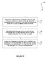
- FIG. 1illustrates a method for preserving service continuity in an NFV-based communication network, in accordance with one embodiment.
- FIG. 2illustrates a simplified diagram of a system associated with an NFV-based communication network, in accordance with one embodiment.
- FIG. 3illustrates a simplified block diagram of a hardware unit of an NFV-based network, in accordance with one embodiment.
- FIG. 4illustrates a simplified diagram of an NFV management system, in accordance with one embodiment.
- FIG. 5illustrates a simplified diagram of a deployed NFV-based network, in accordance with one embodiment.
- FIG. 6illustrates a simplified diagram of a distributed deployment of an NFV-MANO (Management and Orchestration), in accordance with one embodiment.
- NFV-MANOManagement and Orchestration
- FIG. 7is a simplified block diagram of a preventive maintenance database in an NFV-based network, in accordance with one embodiment.
- FIG. 8is a simplified block diagram of a preventive maintenance procedure in an NFV-based network, in accordance with one embodiment.
- FIG. 9is a simplified flow chart of a planning module for scheduling preventive maintenance activities in an NFV-based network, in accordance with one embodiment.
- FIG. 10is a simplified flow chart of a maintenance activation module in an NFV-based network, in accordance with one embodiment.
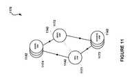
- FIG. 11is a simplified block diagram of an NFV-based sub-network undergoing a preventive maintenance activity, in accordance with one embodiment.
- FIG. 12is a simplified flow chart of a maintenance preparation procedure, in accordance with one embodiment.
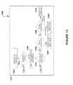
- FIG. 13illustrates a simplified flow chart of a maintenance preparation procedure operating in a multi-NFV-O environment, in accordance with one possible embodiment.
- FIG. 14illustrates a simplified block diagram of an NFV-based sub-network undergoing compatibility verification, in accordance with one embodiment.
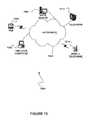
- FIG. 15illustrates a network architecture, in accordance with one possible embodiment.
- FIG. 16illustrates an exemplary system, in accordance with one embodiment.
- FIG. 1illustrates a method 100 for preserving service continuity in a Network Function Virtualization based (NFV-based) communication network, in accordance with one embodiment.
- NFV-basedNetwork Function Virtualization based
- VNFvirtual network function
- a second VNF instance on a second hardware unitis instantiated, the second VNF instance being compatible with the first VNF instance. See operation 104 .
- communication directed to the first VNF instanceis diverted to the second VNF instance on the second hardware unit, in response to initiating the second VNF instance on a second hardware unit. See operation 106 .
- the method 100may be implemented such that continuity of a service associated with the first VNF instance is preserved (i.e. not interrupted).
- the method 100may further include deactivating the first VNF instance in response to diverting the communication.
- a second VNFmay be deployed to the second hardware unit, where the second VNF is compatible with the first VNF.
- the term “compatible”may indicate the same or having the same or similar functionality.
- a system, method, and computer program productfor: disabling initiation of a new instance of a virtual network function in a processing facility before migrating an instance of the virtual network function from the processing facility, initiating an instance of a virtual network function in a first processing facility before deactivating an instance of the virtual network function in a second processing facility, migrating an instance of a virtual network function from a first processing facility to a second processing facility before deactivating the instance of a the virtual network function in the first processing facility, and diverting communication addressed to a first instance of a virtual network function in a first processing facility to a second instance of the virtual network function in second processing facility before deactivating the first instance.
- a system, method, and computer program product for preserving service continuity in an NFV-based communication networkwhere the first processing facility and the second processing facility are the same processing facility.
- a system, method, and computer program product for preserving service continuity in an NFV-based communication networkadditionally including one or more of the steps of: initiating a preventive maintenance activity related to the virtual network function, initiating an optimization activity related to the virtual network function, initiating a product replacement activity related to the virtual network function.
- a system, method, and computer program product for preserving service continuity in an NFV-based communication networkadditionally including one or more of the steps of: deactivating a virtual network function in a first processing facility only after all instances of the virtual network function are migrated from the first processing facility to a second processing facility, replacing a virtual network function in a first processing facility only after all instances of the virtual network function are migrated from the first processing facility to a second processing facility, and updating a virtual network function in a first processing facility only after all instances of the virtual network function are migrated from the first processing facility to a second processing facility.
- a system, method, and computer program product for preserving service continuity in an NFV-based communication networkadditionally including one or more of the steps of: deactivating a first virtual network function in a first processing facility only after all communications incoming to the virtual network function are diverted from the first processing facility to a second virtual network function in a second processing facility, replacing a first virtual network function in a first processing facility only after all communications incoming to the virtual network function are diverted from the first processing facility to a second virtual network function in a second processing facility, and updating a first virtual network function in a first processing facility only after all communications incoming to the virtual network function are diverted from the first processing facility to a second virtual network function in a second processing facility.
- a system, method, and computer program product for preserving service continuity in an NFV-based communication networkadditionally including one or more of the steps of: deactivating a first processing facility only after all instances of virtual network functions operative in the processing facility are migrated from the first processing facility to a second processing facility, replacing a first processing facility only after all instances of virtual network functions operative in the processing facility are migrated from the first processing facility to a second processing facility, and updating a first processing facility only after all instances of virtual network functions operative in the processing facility are migrated from the first processing facility to a second processing facility.
- networkand “communication network” refer to the hardware and software connecting one or more communication elements including wireline networks, wireless networks, and/or combinations thereof.
- VNFnetwork function virtualization
- NFVvirtual network function
- ETSIEuropean Telecommunications Standards Institute
- VNFvirtual network function or feature
- a VNFmay include the software program implementation of the function or feature or service.
- VNF instancerefers to a particular process or task executing the VNF program by a particular virtual machine or processor or computing facility and/or used by a particular customer (or subscriber, end-user, terminal or server, etc.).
- servicerefers to any type of use (such as a use case) that an NFV-based communication network may offer or provide to one or more communication elements.
- a servicemay include switching data or content between any number of elements, providing content from a server to a communication element or between servers, securing and protecting communication and content, processing content provided by the customer or by a third party, providing backup and redundancy, etc.
- a servicemay be using partial functionality of a VNF or may include one or more VNFs and/or one or more VNF instances forming a service sub-network (or interconnection model).
- the term “chain”may refer to such service sub-network, such as a particular plurality of VNFs and/or VNF instances associated with particular service type or a service instance.
- deploymentwhen referring to hardware elements, including processing elements, memory elements, storage elements, connectivity (communication) elements, etc., refer to the configuration or topology of these hardware elements creating the NFV-based network.
- deploymentwhen referring to software elements, such a VNFs and VNF instances, refers to the association between such software elements and hardware elements.
- deployment optimizationsrefers to association of software and hardware elements in a manner that satisfies a particular set of requirements and/or rules, such as load-related and performance-related requirements, or a manner that makes a better use of a particular hardware deployment, such as by reducing operational cost.
- service deployment optimizationor “service optimization” or “chain optimization” refer to optimizing the deployment of a service chain, i.e., optimizing the deployment of one or more VNF instances making a particular service.
- chain optimization and service optimizationmay thus be used interchangeably.
- a sessionrefers to a communication connection between two or more entities that persists for a period of time during which data may be exchanged there between.
- a sessionmay be implemented and managed by a session layer in the corresponding network protocol.
- the term sessionmay include a network session and a logical session.
- the network sessionmay be associated with the devices used to communicate, while the logical session may be associated with the communicating parties (users) and may persist regardless of the communication means that the parties are using.
- service continuityincludes and applies to the terms “session continuity” and “streaming continuity”.
- Streamingrefers to streaming media, session or service, such as sound (including voice), video, multimedia, animation, etc.
- serviceusually applies to a group of VNFs (or the functionality provided by the group of VNFs) but may also apply to a single VNF (or the functionality provided by the VNF).
- continuityindicates that the session or the service is not interrupted, or that an interruption is short enough that a user is not aware of such interruption, or that the interruption does not cause any loss of data, or that the loss is handled in acceptable manner (e.g. a few packets of speech lost, but the conversation can continue, etc.).
- the term “availability” or “service availability”refers to a level of the service, or a characteristic of the service, in which the service provider should provide the service, albeit possible hardware or software faults.
- the service providermay obligate to the customer to provide a particular level of processing power, communication features such as bandwidth, latency, and jitter, database consistency, etc.
- Such level or characteristic of the serviceshould be available to the customer even when a hardware component or a software component providing the service do not function properly.
- Providing availabilitymay therefore require additional resources such as backup resources and/or mirroring.
- availabilitymay also refer to the terms “fault recovery” and “redundancy”.
- fault recoveryrefers to the process of recovering one or more of the network's services, functions, and features after a fault, whether caused by a hardware malfunction, a system crash, a software bug or a security breech or fault.
- a hardware malfunctionincludes, but is not limited to, any type of inadequate performance associated with, for example, power supply, processing units, memory, storage, transmission line, etc.
- fault recoveryalso applies to recovering the functionality of one or more VNFs or VNF instances with respect to any of the above.
- security breech or security faultmay be used interchangeably.
- Redundancyrefers to any type of component of the network that is fully or partly duplicated, provided in standby mode, or otherwise available, to replace another component of the network when that other component stops functioning properly or otherwise indicates some kind of fault. Redundancy may apply, but is not limited to, hardware, software, data and/or content.
- the present embodimentscomprise a system, method, and computer program product for preserving service continuity in a communication network using network function virtualization (NFV), and, more particularly, but not exclusively to managing the migration of a virtual network function (VNF) in NFV-based communication networks while preserving service continuity.
- NFVnetwork function virtualization
- VNFvirtual network function
- the purpose of embodiments of the present inventionis to provide service continuity while migrating VNFs in an NFV-based network.
- Migration of VNFsapplies to several operations carried in a communication network, such as network optimization, preventive maintenance, and product replacement.
- network optimizationa VNF is moved (migrated) from a first computing facility to a second computing facility to improve the overall network performance.
- preventive maintenancea VNF is moved (migrated) from a first computing facility to a backup computing facility to enable maintenance activity in the first computing facility.
- product replacementthe functionality of a VNF is moved (migrated) from a first VNF instance using the replaced product to a second VNF instance using the replacing product.
- the term computing facilityrelates to any type of computing device, including, but not limited to, a processing device, a memory device, a storage device, and/or a communication device, including cloud-based infrastructure.
- a product replacementmay refer to products from different vendors, different products from the same vendor, different releases of the same product, product upgrades, etc.
- a method, system, and computer program product for providing service continuity while migrating VNFs in an NFV-based networkis described herein in terms of a method and a system for automating preventive maintenance in NFV-based communication networks. It is appreciated that providing service continuity while migrating VNFs in an NFV-based network in other cases such as network optimization and product replacement is performed using a similar method and system, etc.
- Preventive maintenanceapplies to any action or activity performed in the network in anticipation of an adverse event, effect or situation.
- the preventive maintenanceprevents the occurrence of such event, effect or situation or any possible degradation of the network performance. Except for preventing unexpected degradation of the network performance, preventive maintenance is considered less costly than fault maintenance.
- Network Function Virtualizationcreates a network much more dynamic than a legacy communication network. Network functions are installed, removed, and moved between hardware facilities much more frequently, and thus, managing preventive maintenance becomes more difficult on one hand, and more critical on the other hand.
- Lifecycle management or workflowrefers to a series of actions executed with regards to a particular virtual network function or feature, or a group of VNFs, such as, for example, a group of VNFs comprising a service, or a component of a service.
- Such actionsmay be, for example, onboarding the VNF, provisioning the VNF, scaling the VNF, preventive maintenance, fault maintenance, tearing the VNF, and deboarding of the VNF (discontinuation).
- One purpose of lifecycle managementis to schedule and execute preventive maintenance activities without affecting the rendered services. Actions or activities of preventive maintenance are typically scheduled ahead of the anticipated event to enable graceful tearing of services while maintaining session continuity. Preventive maintenance activities are costly and therefore their frequency should be reduced to the minimum. Preventive maintenance activities require network resources, and thus may have adverse effect on the network performance. Therefore, the preventive maintenance activities should be scheduled to periods of low load on the relevant resources. Such periods should make available the required resources for the load and time as required by the particular preventive maintenance activity.
- Preventive maintenancerefers to hardware and software and the effect between them.
- the rate of hardware agingnamely, the probability of a hardware fault due to usage
- the rate of hardware agingmay depend on the type of software and the activity.
- a hardware componentmay be associated with several software components, and various number of instances (processes) of the same type of software, and vice versa, there is an intricate relationship between hardware and software. In an NFV-based network this relationship changes continuously.
- preventive maintenance activitiesare typically performed according to the statistical data collected and analyzed for the hardware components, and in an NFV-based network also for any virtual network function/feature (VNF) and any instance of network virtualization function.
- VNFvirtual network function/feature
- Lifecycle management in NFV environmentis different from lifecycle management in legacy networks due to the flexibility of the NFV environment in allocating VNFs to processing resources. Therefore, lifecycle management in a legacy network is quite stable over time, while lifecycle management in NFV environment is changing with the activation of every VNF instance. A method for continuous adaptation of the lifecycle plan to the changing NFV environment is therefore required.
- FIG. 2illustrates a simplified diagram of a system 200 associated with an NFV-based communication network 210 , in accordance with one embodiment.
- the system 200may be implemented in the context of the details of FIG. 1 .
- system 200may be implemented in the context of any desired environment.
- the aforementioned definitionsmay equally apply to the description below.
- the NFV-based communication network 210includes an NFV management system 2111 , an NFV-orchestration (NFV-O) module 212 , and a preventive maintenance module 213 , according to one embodiment.
- NFV-ONFV-orchestration
- the NFV-based network 210may take any form including, but not limited to a telecommunications network, a local area network (LAN), a wireless network, a wide area network (WAN) such as the Internet, peer-to-peer network, cable network, etc. While only one network is shown, it should be understood that two or more similar or different NFV-based networks 210 may be provided.
- LANlocal area network
- WANwide area network
- the NFV-based network 210may include one or more computation facilities 214 , each including one or more hardware units and being interconnected by communication links to form the NFV-based network 210 . At least one of the computation facilities 214 may include the NFV management system 211 .
- the NFV management system 211may include the NFV-O module 212 and the preventive maintenance module 213 .
- the NFV-O module 212may be executed by one or more processors, or servers, such as computation facilities 214 , of theNFV-based network 210 .
- the NFV-O module 212may be executed as an NFV-O instance or component.
- the NFV-O module 212may therefore include a plurality of NFV-O instances or components as will be further explained below.
- the preventive maintenance module 213may be a part or a component of the NFV-O module 212 .
- the preventive maintenance module 213 , the NFV-O module 212 and the NFV management system 211may be separate software programs provided by different vendors.
- the NFV-based network 210may even have a plurality of any of the NFV management systems 211 , the NFV-O modules 212 , and/or the preventive maintenance module 213 .
- a plurality of devices 215are communicatively coupled to the NFV-based network 210 .
- a server computer 216 and a computer or terminal 217may be coupled to the NFV-based network 210 for communication purposes.
- Such end-user computer or terminal 217may include a desktop computer, a lap-top computer, a tablet computer, and/or any other type of logic or data processing device.
- various other devicesmay be coupled to the NFV-based network 210 including a personal digital assistant (PDA) device 218 , a mobile phone device 219 , a television 220 (e.g. cable, aerial, mobile, or satellite television, etc.) 2, etc.
- PDApersonal digital assistant
- These devices 215may be owned and/or operated by end-users, subscribers and/or customers of the NFV-based network 210 .
- Others of the devices 215such as administration station 221 , may be owned and/or operated by the operator of the NFV-based network 210 .
- a network administrator 222may supervise at least some aspects of the operation of the NFV-based network 210 by controlling an NFV infrastructure including the NFV management system 211 , the NFV-O 212 , and the preventive maintenance module 213 .
- FIG. 3illustrates a simplified block diagram 300 of a hardware unit 323 of an NFV-based network, in accordance with one embodiment.
- the block diagram 300may be viewed in the context of the details of the previous Figures. Of course, however, block diagram 300 may be viewed in the context of any desired environment. Further, the aforementioned definitions may equally apply to the description below.
- the hardware unit 323may represent a computing facility 214 of FIG. 2 , or a part of a computing facility 214 .
- the hardware unit 323may include a computing machine.
- the term computing machinerelates to any type or combination of computing devices, or computing-related units, including, but not limited to, a processing device, a memory device, a storage device, and/or a communication device.
- the hardware unit 323may therefore be a network server, and the computing facility 214 may be a plurality of network servers, or a data-center, including cloud-based infrastructure. As an option, the hardware unit 323 may be implemented in the context of any of the devices of the NFV-based network 210 of FIG. 2 and/or FIG. 5 and in any desired communication environment.
- Each hardware unit 323(or computing machine, computing device, computing-related unit, and/or hardware component, etc.), including each communication link between such hardware units, may be associated with one or more performance type and a respective performance rating or value, where the hardware unit and/or communication link is operative to provide the performance value.
- Performance typesare, for example, processing power, cash memory capacity, regular memory capacity (e.g. RAM, dynamic, or volatile memory, etc.), non-volatile memory (e.g. such as flash memory, etc.) capacity, storage capacity, power, cooling, bandwidth, bitrate, latency, jitter, bit error rate, and packet loss, etc.
- Virtual machinesmay run on top of the hardware unit 323 and a VNF may be run on one or more of such virtual machines.
- the hardware unit 323may be operative to provide computing infrastructure and resources for any type and/or instance of software component executed within the NFV-based network 210 of FIG. 2 .
- the hardware unit 323may be operative to process any of the processes described herein, including but not limited to, any NFV-related software component and/or process.
- the hardware unit 323is operative to process virtual network functions (VNFs), VNF instances, network function virtualization orchestration (NFV-O) software, modules and functions, data center management software, and/or cloud management systems (CMS), etc.
- VNFsvirtual network functions
- NFV-Onetwork function virtualization orchestration
- CMScloud management systems
- the hardware unit 323may include at least one processor unit 324 , one or more memory units 325 (e.g. random access memory (RAM), a non-volatile memory such as a Flash memory, etc.), one or more storage units 326 (e.g. including a hard disk drive and/or a removable storage drive, representing a floppy disk drive, a magnetic tape drive, a compact disk drive, etc.), one or more communication units 327 , one or more graphic processors 328 and displays 329 , and one or more communication buses 330 connecting the various units/devices.
- processor unit 324e.g. random access memory (RAM), a non-volatile memory such as a Flash memory, etc.
- memory units 325e.g. random access memory (RAM), a non-volatile memory such as a Flash memory, etc.
- storage units 326e.g. including a hard disk drive and/or a removable storage drive, representing a floppy disk drive, a magnetic tape drive, a
- the hardware unit 323may also include one or more computer programs 331 , or computer control logic algorithms, which may be stored in any of the memory units 325 and/or storage units 326 . Such computer programs, when executed, enable the hardware unit 323 to perform various functions (e.g. as set forth in the context of FIG. 1 , etc.),
- the memory units 325 and/or the storage units 326 and/or any other storageare possible examples of tangible computer-readable media.
- computer program 331may include any of the NFV management system 211 , the NFV-O 212 , and/or the preventive maintenance module 213 of FIG. 2 .
- FIG. 4illustrates a simplified diagram of an NFV management system 411 , in accordance with one embodiment.
- the NFV management system 411may be implemented in the context of the details of the previous Figures.
- the NFV management system 411may represent the NFV management system 211 of FIG. 2 .
- the NFV management system 411may be implemented in the context of any desired environment. Further, the aforementioned definitions may equally apply to the description below.
- the NFV management system 411may include an NFV-O module 412 , and a preventive maintenance module 413 .
- the NFV-O module 412 and the preventive maintenance module 413may represent the NFV-O module 212 and the preventive maintenance module 213 of FIG. 2 , respectively.
- the NFV management system 411may include one or more NFV-O modules 412 .
- each of the NFV-O modules 412may include orchestration and workflow management 432 that is responsible for managing (i.e. orchestrating) and executing all NFV-O processes, including inbound and/or outbound communication and interfaces.
- the NFV management system 411may include a deployment optimization module 433 that enables a user to devise automatic mechanisms for network optimizations.
- the deployment optimization module 433may operate these mechanisms automatically and continuously to optimize the distribution of VNFs 450 and their VNF instances in real-time (or near-real-time) by migrating VNFs 450 and VNF instances (e.g. VNF instances 551 of FIG. 5 , etc.) between hardware units (e.g. hardware units 551 of FIG. 5 , etc.).
- the NFV management system 411may also include a chain optimization module 434 .
- the chain optimization module 434may be a part of deployment optimization module 433 and may enable a user to devise automatic mechanisms for optimizing the deployment of chains or groups of VNFs 450 and VNF instances.
- a service provided by an NFV-based networkis typically made of a particular chain or group of particular VNFs 450 and their respective VNF instances.
- the chain optimization module 434optimizes the deployment of chains or groups of services between hardware units according to the requirements and specifications associated with and/or adapted to the particular service, or chain, or a group.
- the chain optimization module 434may operate these mechanisms automatically and continuously to optimize in real-time the operation of chains or groups of the VNFs 450 and their VNF instances by re-planning their distribution among hardware units and optionally also by migrating the VNFs 450 and associated VNF instances between hardware units.
- the NFV management system 411may also include a service fulfillment module 435 that manages service and resource (e.g. VNF) instance lifecycle activities as part of the process and orchestration activities. This may include on boarding, initiation (e.g. instantiation), installation and configuration, scaling, termination, software update (e.g. of a running VNF, etc.), test environment, and/or rollback procedure. Additionally, the service fulfillment module 435 may also provide decomposition of an order to multiple network services, and the activation of such network service as a single VNF instance, or as a chain of VNF instances.
- service fulfillment module 435may also provide decomposition of an order to multiple network services, and the activation of such network service as a single VNF instance, or as a chain of VNF instances.
- Order decompositionincludes translating business orders into a network oriented service implementation plan. For example, a business order may be decomposed into a plurality of functions, some of which may be provided by different software programs or modules (e.g. such as various VNFs) instantiated as a plurality of VNF instances across one or more data centers.
- the service fulfillment module 435may consult the deployment optimization module 433 for the best deployment option to customer order in a given network and resource condition.
- the service fulfillment module 435may then initiate the service including all its components.
- Order decompositionmay be performed in several locations across an NFV-O hierarchy. For example, initial decomposition may be performed in the root of the NFV-O, and then further decomposition may be performed in the relevant data centers.
- an activation and provisioning modulemay provide the plan for activation and provisioning of the service to the orchestration and workflow management 432 .
- the activation and provisioning modulemay also provide feedback on fulfilment status to an upper layer.
- This upper layermay include the business support services (BSS).
- BSSbusiness support services
- the NFV management system 411may also include an assurance module 436 and a service management module 452 capable of gathering real time data on network elements' status and creating a consolidated view of services and network health.
- the assurance module 436includes assurance functionality and may interact with the service management module 452 to perform assurance related lifecycle management procedures. Lifecycle management can be also triggered by other modules, policies, manual intervention, or from the VNFs themselves, etc.
- the assurance module 436 and the service management module 452may also trigger events associated with lifecycle management and faults.
- the assurance module 436 and the service management module 452may monitor the health of the network and may execute fault recovery activities.
- the assurance module 436 and the service management module 452provide the ability to monitor services' status and performance according to the required criteria.
- the assurance module 436 and the service management module 452may also interact with the network infrastructure (e.g. including computing, storage, and networking, etc.) to receive the required information, analyze the information, and act upon each incident according to the defined policy.
- the assurance module 436 and the service management module 452are able to interact with analytics to enrich a policy assurance module. Interfaces may also be provided for implementation by an external system.
- the NFV management system 411may also include a policy management module 437 that enables a user to define and configure offline and/or real-time policy for controlling VNF and service related rules.
- the policy management module 437may contain the preconfigured policies and activities as well as selection rules for the NFV-O process to determine the preferred policy or activity to be performed for a particular process event.
- the policy managementmay be multi-layered, including vendor policy, service policy, and operator policy, etc.
- the policy mechanismmay trigger the suitable policy layer (vendor/service/operator).
- the NFV management system 411may also include an administration module 438 that provides an overall view of the network, manual lifecycle management and intervention, and manual system administration and configuration.
- the administration module 438may be operable to enable a user such as an administrator (e.g. administrator 222 of FIG. 2 , etc.) to manage, view, and operate the NFV-O system.
- the administration module 438may also provide a view of the network topology and services, the ability to perform specific activities such as manual lifecycle management, and changing service and connectivity configuration.
- the NFV management system 411may also include an inventory management module 439 that maintains a distributed view of deployed services and hardware resources. Inventory catalogues may reflect the current instantiation and allocation of the resources and services within the network mapped into products and/or customer entities.
- the NFV management system 411may also include a big data analytics module 440 that analyzes network and service data to support network decisions involving services and subscribers to improve network performance based on actual usage patterns.
- the big data analytics module 440may also generate what-if scenarios to support business-oriented planning processes. Additionally, the big data analytics module 440 may function to analyze and evaluate the information for various planning aspects (e.g. Virtual Network Capacity Planning, Data Center Capacity Planning, Value based planning, Cost analysis for network deployment alternatives, etc.), deployment and management (e.g. Guided Operator Recommendations, What-if scenario analysis and simulation, application rapid elasticity and resource usage optimization, etc.), and may support business-oriented planning processes.
- various planning aspectse.g. Virtual Network Capacity Planning, Data Center Capacity Planning, Value based planning, Cost analysis for network deployment alternatives, etc.
- deployment and managemente.g. Guided Operator Recommendations, What-if scenario analysis and simulation, application rapid elasticity and resource usage optimization, etc.
- the NFV management system 411may also include a catalog module 441 may include records defining various aspects of the network, such as products, services, and resources such as hardware units and VNFs (e.g. a VNF directory, etc.).
- the catalog module 441may include a collection of centralized, hierarchical information repositories containing resource, service and product definitions with their relationship, versioning, and/or descriptors, etc.
- Such recordsmay include templates enabling a user, such as an administrator, to define particular network components such as resources, products, services, etc.
- a resource templatemay define resources descriptors, attributes, activities, procedures, and/or connectivity, etc.
- a service templatemay define a service variation from resource building blocks.
- a product templatemay define parameters of a sellable product (e.g. prices, rating, etc.) based on service composition (e.g. in one embodiment, this may be part of a BSS catalogue).
- the inventory management module 439 , the big data analytics module 440 , and/or the catalog module 441may support multiple data centers, multiple CMSs and provide a centralized view across the infrastructure.
- the inventory management module 439 , the big data analytics module 440 , and/or the catalog module 441may also support hybrid networks and services maintaining both physical and virtual resources.
- the NFV management system 411may also include an accounting and licensing module 442 that may be operable to record and manage network software usage data for commercial purposes including licensing, accounting, billing, and reconciliation of services with subscribers and providers.
- the accounting and licensing module 442may manage licensing and usage of virtual network applications, including the ability to support complex rating schemes, based on various parameters such as CPU, memory, data, etc.
- the accounting and licensing module 442may enable users to define the pricing of particular VNF modules and provide settlement with vendors.
- the accounting and licensing module 442may also enable the evaluation of internal costs of services provided within the network for calculating return on investment (ROI).
- ROIreturn on investment
- the NFV management system 411may also include a fault recovery module 443 (otherwise named disaster recovery planning module or DRP, etc.) that enables a user to plan and manage disaster recovery procedures for the NFV-O and/or the entire network.
- a fault recovery module 443otherwise named disaster recovery planning module or DRP, etc.
- DRPdisaster recovery planning module
- the NFV management system 411may also include a security management module 444 that provides the authentication authorization and accounting services of application security across the network.
- the security management module 444may include, for example, an authentication module and function.
- the authentication module and functione.g. including identity management, etc.
- the systemmay support password based authentication with flexible password policy. Integration with external authentication providers may be done via additional system enhancements.
- the authorization module and functionmay support a role-based access control (RBAC) mechanism, where each user is assigned with one or more roles according to the business needs based on the least privileges concept (e.g. standard or administrator roles).
- RBACrole-based access control
- the accounting and licensing module 442may provide an audit of security events such as authentication or login events.
- the security management module 444may use rules to protect sensitive information. For example, such rules may be used to ensure the data accessed is used for the specific purposes for which it was collected, sensitive information is encrypted when in storage/transit and masked/truncated on display and logs, and that the entire security system is deployed in the customer's intranet network (i.e. behind network/infrastructure measures), in an independent domain, etc.
- the NFV management system 411may further include a Secure Development Life Cycle (SDLC) module that ensures that security aspects are handled during a project's life cycle, such as security design, security testing, etc.
- SDLCSecure Development Life Cycle
- the NFV management system 411may include a service planning module 445 .
- the service planning module 445may be used by a communication service provider (CSP) sales representative, enterprise, and/or technician, as part of selling engagement process with enterprise/SMB customers.
- CSPcommunication service provider
- the service planning module 445may also provide the ability to interact with catalogues, customer data, network and ordering systems to provide online network service proposals for the enterprise customers with ability to quote update the proposal, validate the serviceability and network inventory, and once done, provide the service order for activation using the northbound interface.
- the preventive maintenance module 413may also be part of the NFV-O module 412 .
- the preventive maintenance module 413is operable to: identify a first VNF instance associated with a first VNF in a first hardware unit; initiate a second VNF instance on a second hardware unit, the second VNF instance being compatible with the first VNF instance; and divert communication directed to the first VNF instance to the second VNF instance on the second hardware unit, in response to initiating the second VNF instance on the second hardware unit.
- the preventive maintenance module 413may implement functionality described in the context of FIG. 1 , etc.
- the preventive maintenance module 413 or the NFV-O module 412may be operable to preserve service continuity when migrating a VNF (or a group of VNFs, or a service) between hardware units, and/or when migrating a VNF functionality (or the functionality of a group of VNFs, or a service) between different VNFs (e.g. between VNF(s) of different VNF vendors).
- the NFV management system 411may also include east/west APIs 446 that include various domains/activities interfaces, including an information source to a big data repository, and interaction capability with a physical network system (OSS).
- east/west APIs 446that include various domains/activities interfaces, including an information source to a big data repository, and interaction capability with a physical network system (OSS).
- OSSphysical network system
- Northbound APIs 447provides application programming interfaces (APIs) to various external software packages, such as business support system (BSS) for service order fulfilment, cancel and update activities, status notification, resource inventory view, monitoring system, assurance system, service planning tool, administration tool for system view and configuration, and big data repository, etc.
- BSSbusiness support system
- APIsapplication programming interfaces
- the southbound APIs 448may provide APIs for external software packages, such as CMS (including service and VNFs lifecycle activities—receiving from the infrastructure status and monitoring information for upstream system and activities [e.g. assurance]), an SDN Controller (or other connectivity system) to configure inter and intra data center connectivity, an EMS to configure the VNF, and a VNF for a direct configuration.
- CMSincluding service and VNFs lifecycle activities—receiving from the infrastructure status and monitoring information for upstream system and activities [e.g. assurance]
- SDN Controlleror other connectivity system
- EMSto configure the VNF
- VNFfor a direct configuration.
- FIG. 5illustrates a simplified diagram 500 of a deployed NFV-based network 510 , in accordance with one embodiment.
- the diagram 500may be viewed in the context of the details of the previous Figures.
- the deployed NFV-based network 510 and associated elementsmay represent the NFV-based networks and associated elements described in the context of the previous Figures.
- the diagram 500may be viewed in the context of any desired environment. Further, the aforementioned definitions may equally apply to the description below.
- the NFV-based network 510may include hardware units 523 connected via transmission lines 549 , and VNFs implemented as software programs 550 installed in hardware units 523 . Some of the hardware units 523 may be directly connected to a customer.
- the customermay be a subscriber, an end-user, or an organization, represented herein as a terminal or a server 552 , or a plurality of terminals and/or servers 552 .
- the NFV-based network 510may also include an NFV management system 511 , an NFV-orchestration (NFV-O) 512 , and a preventive maintenance module 513 (which may all represent elements described in the context of the previous figures, etc.).
- NFV-ONFV-orchestration
- VNFs 550may be installed in the same hardware unit 523 . Additionally, the same VNF 550 may be installed in different hardware units 523 .
- a VNF 550may be executed by a processor of the hardware unit 523 in the form of a VNF instance 551 . Therefore, a particular VNF 550 installed in a particular hardware unit 523 may be “incarnated” in (e.g. initiated, executed as, etc.) any number of VNF instances 551 .
- the VNF instances 551may be independent of each other. Additionally, each VNF instance 551 may serve different terminals and/or servers 552 .
- the NFV-based network 510connects to and between communication terminal devices 552 that may be operated by one or more customers, subscribers, and/or end-users.
- a network operatormay manage one or more services deployed in the customer's premises. Therefore, some of the hardware units 523 may reside within the premises of the network operator, while other hardware units 523 may reside in the customer's premises. Similarly, a server, such as server computer 216 of FIG. 2 , may reside in the premises of the network operator or in the customer's premises. Consequently, when the network operator provides and/or manages one or more services for a customer's terminal devices 552 such as a server computer, the NFV-based network 510 of the network operator may directly manage the VNFs 550 , providing the services and their VNF instances 551 .
- the NFV-based network 510may manage the services irrespectively of the location of the terminal devices 552 (e.g. the server computer 216 , etc.), whether in the premises of the network operator or in the customer's premises.
- the NFV-based network 510may be managing the VNFs 550 and the VNF instances 551 providing the services, as well as the terminal devices 552 (e.g. the server computer 216 , etc.) being co-located within the same computing device (e.g. the hardware unit 523 , etc.), whether in the premises of the network operator or in the customer's premises or in a commercial cloud or any other place.
- a service provided by the communication networkmay be implemented using one or more VNFs.
- the servicemay be a group, or a chain of interconnected VNFs.
- the VNFs making the group, or the servicemay be installed and executed by a single processor, by several processors on the same rack, within several racks in the same data-center, or by processors distributed within two or more data-centers.
- chain optimizationmay be employed by optimizing the deployment of a service in a communication network using network function virtualization, and to optimizing the deployment of a group, or a chain, of virtual network functions in the NFV-based network 510 . Therefore, the term “chain optimization” refers to the planning and/or managing of the deployment of VNFs making a chain, or a group, of VNFs providing a particular service.
- FIG. 5shows a first service 553 , including the VNFs 550 and their respective VNF instances 554 , 555 , 556 , and 557 , and a thick line.
- the group or chain of the VNFs 550 making first service 553are connected as a chain of VNFs 550 .
- the VNFs 550 making a servicemay be connected in any conceivable form such as a star, tree-root, tree-branch, mesh, etc., including combinations thereof.
- the VNFs 550may be executed by two or more VNF instances 551 , such as VNF 554 .
- the deployment of the group or chain of the VNFs 550 making the first service 553is therefore limited by constraints such as the capacity of the communication link 549 bandwidth and/or latency (delay).
- a VNFmay have a list of requirements, or specifications, such as processing power, cash memory capacity, regular memory capacity (e.g. RAM, dynamic, or volatile memory, etc.), non-volatile memory (e.g. such as flash memory, etc.) capacity, storage capacity, power requirements, cooling requirements, etc.
- a particular VNF instance 551 providing a particular functione.g. to a particular customer, entity, etc.
- QoSquality of service
- SLAservice level agreement
- Such requirementsmay include maximum latency or delay, average latency and maximum variance (latency jitter), maximal allowed packet loss, etc.
- Other requirementsmay include service availability, redundancy, backup, provisions for roll-back and/or recovery, fault-tolerance, and/or fail-safe operation, etc.
- a service made of a chain or a group of VNFs 550 and their VNF instances 551may have a similar list of requirements, or specifications, covering the service as a whole. Therefore, such requirements, or specifications, may imply, affect, or include, requirements, or specifications, regarding communication links between the VNFs 550 and/or the VNF instances 551 . Such requirements, or specifications, may include bandwidth, latency, bit-error rate, and/or packet loss, etc. Such communication requirements or specifications may further impose deployment limitations, or constraints, requiring particular VNFs 550 and/or VNF instances 551 to reside in the same data-center, or within the same rack, or even in the same computing device, for example, sharing memory or being executed by the same processor. Security measures may add further requirements, or specifications, such as co-location of some of the VNFs 550 and/or the VNF instances 551 .
- the NFV-based network 510has a hierarchical structure. There may be at least four aspects of the hierarchical structure of the NFV-based network 510 .
- the networking or traffic aspectrefers to the arrangement of the transmission lines between the hardware units 523 .
- the processing aspectrefers to the arrangement of the hardware units 523 .
- the software aspectrefers to the arrangement of the VNFs 550 .
- the operational aspectrefers to the arrangement of the VNF instances 551 .
- the NFV deployment module(e.g. module 433 of FIG. 4 , etc.) may function to enable and manage migration of services between the hardware units 523 , the VNFs 550 , and the VNF instances 551 in real-time, without affecting or with a minimal effect on the availability of a service, and while securing service and session continuity.
- the term “continuous”means that the deployment optimization module and/or a chain optimization module (e.g. the chain optimization module 434 of FIG. 4 , etc.) performs the relevant optimization task or process in run-time, or real-time, or online, or on-the-fly, or repetitively and without adversely affecting the network's functionality and its services.
- a chain optimization modulee.g. the chain optimization module 434 of FIG. 4 , etc.
- the NFV-based networkmay have two topologies: the topology of the hardware devices, and the topology of the VNFs (the distribution of VNFs among the hardware devices).
- the topology of the hardware networkis relatively stable, while the VNF topology can be optimized in real-time.
- Another benefit of the NFV-based networkis that modifying the software topology (e.g. the distribution of VNFs among the hardware devices) is much less costly than any modification of the hardware topology.
- any modification of the networkhas its cost, including the cost of making such modification possible. Added cost may result from the need to process the modification of the topology and the re-distribution of VNF instances and to maintain excess resources for such purpose.
- NFV-O 512it may be desired to localize the NFV-O 512 , and particularly the deployment optimization processes associated with the deployment optimization module and the chain optimization module to reduce the cost, and simultaneously to secure the possibility to expand the scope of the network managed by these processes, if needed.
- FIG. 6illustrates a simplified diagram 600 of a distributed deployment of an NFV-O, in accordance with one embodiment.
- the diagram 600may be viewed in the context of the details of the previous Figures.
- the distributed deployment of the NFV-Omay represent the NFV-based networks and associated elements described in the context of the previous Figures.
- the diagram 600may be viewed in the context of any desired environment. Further, the aforementioned definitions may equally apply to the description below.
- the distributed architecture of an NFV-Oenables faster response to local events on one hand, and improved scalability on the other hand.
- decision processesare performed in self-contained and local decision points, closer to the customer, and closer to the events (e.g. such as network or security faults, etc.).
- the hierarchy of a distributed NFV-Ocan be viewed as a tree of two component types: a core component 658 and a leaf component 659 .
- the NFV-O core component 658can be a child of another core component 658 , and/or a parent of one or more core components 658 or leaf components 659 .
- a leaf component 659cannot be a parent of a core component 658 or a leaf component 659 .
- Orchestration parameters managed by a particular leaf component 659 or core component 658may be reported in real-time to the supervising (parent) core component 658 .
- this continuous updating processenables the supervising component to provide backup, and/or support recovery processes associated with hardware and/or software faults as well as security faults and/or breeches.
- a leaf component 659may be supervised by two or more core components 658 , and child core components 658 may be supervised by two or more parent core components 658 .
- the orchestration parameters managed by a particular core component 658 or leaf component 659may also be mirrored to the backup core components 658 .
- the NFV-O core components 658may have the same fully functional orchestration capabilities, while leaf components may be limited to simple, well defined and localized sub-orchestration tasks, and thus may provide a faster response to demands and changing load.
- a cloud management system (CMS) 660is a software package managing one or more hardware units operating one or more VNFs and executing one or more VNF instances.
- a CMS 660can be managed by one or more leaf components 659 or core components 658 , or combinations thereof.
- a CMS 660can be located in the operator's premises or in the customer's premises or partly in both.
- An NFV-O componentsuch as a core components 658 or a leaf component 659 typically orchestrates a particular, predefined, territory.
- the territorymay be one or more cloud management systems 660 , one or more services, one or more customers, etc. Therefore, there can be an overlap between territories of different NFV-O components.
- one NFV-O componentmay orchestrate a CMS 660
- another NFV-O componentmay orchestrate a service that is at least partly provided by the same CMS 660
- a third NFV-O componentmay orchestrate services for a particular customer connected to that same CMS 660 .
- the first responder NFV-O componentcannot resolve the problem, for example, for lack of adequate or sufficient resources within the territory of the particular NFV-O component, the problem may be escalated above to the supervising or parent NFV-O component.
- the NFV-Ois a central component of the network as a system and thus may present a risk from a security perspective. For example, an attack against the NFV-O may result in a total network outage. Securing the NFV-O is therefore a goal and a challenge.
- a distributed NFV-O architectureenhances the network resilience/endurance. When an attack on a particular instance of the NFV-O is detected the NFV-O instance may be isolated and its functionality may be transferred to one or more other NFV-O instances.
- An NFV-based networkmay include a very large number of hardware elements (e.g. processors, memory units, storage units, communication links, etc.) and an even larger number of VNFs and VNF-instances.
- Each of the VNF-instancesmay have a number of requirements (e.g. such as processing power, memory size, storage size, communication bandwidth, latency and jitter, etc.).
- Each of these hardware elements and software modulesmay produce a number of load values (e.g. corresponding to their respective requirements).
- NFV-O hierarchyenables scalability of the redeployment optimization process by distributing the process in a hierarchical manner.
- Hierarchical deployment optimizationis that higher levels in the NFV-O hierarchy processes deployment optimization in a coarser granularity (or resolution), while lower levels in the NFV-O hierarchy processes deployment optimization in a finer granularity (or resolution).
- a leaf component 659manages its part (territory) of the NFV-based network in terms of particular hardware elements (e.g. processors, memory units, storage units, communication links, etc,) and software elements (e.g. VNFs and VNF-instances)
- a core componentmay manage its part (territory) of the NFV-based network in terms of whole subordinate (child) core components 658 or leaf components 659 it supervises.
- parent core component 658may perform deployment optimization in terms of requirements and load values applied to whole subordinate (child) core components 658 or leaf components 659 .
- a customermay use the services of several telecom operators.
- the customermay be an international company operating in several countries.
- Such a customerusually establishes a virtual private network (VPN) across this plurality of telecom operators.
- VPNvirtual private network
- the customermay establish a service including a plurality of VNFs, where different VNFs are part of different networks. Managing such inter-operator VNF-chains, or services, requires tight coordination across different NFV-based networks.
- the coordinationcan be implemented using various techniques.
- the coordinationmay be implemented by enabling tight coordination between NFV-Os of the different NFV-based networks.
- the coordinationmay be implemented by establishing an inter-network NFV-O module that manages one or more inter-network VNF-chains, or services of a particular customer.
- such inter-network NFV-Omay supervise two or more child or leaf NFV-O modules, each within a particular NFV-based network incorporating an NFV participating in the particular VNF-chain or service. It is appreciated that NFV-Os of different operators may be provided by different NFV-O vendors.
- a single NFV-O modulemay manage the deployment of VNFs and VNF instances throughout the entire NFV-based network.
- a deployment optimization modulee.g. and a chain optimization module
- the NFV-O modulemay continuously investigate the development of loads and provide alternative deployment plans. Consequently, the NFV-O module may redeploy VNFs and VNF instances and reallocate network resources accordingly.
- Deployment optimizationis indicated when one part of the NFV-based network is over-loaded (or approaches an overload situation) while another part of NFV-based network is relatively idle.
- the redeploymentmigrates some of the network entities (e.g. VNFs and VNF instances) from the overloaded part of NFV-based network to the relatively idle part of the NFV-based network to free resources where needed mostly. Therefore, the deployment optimization and redeployment activities may follow the changes of load distribution.
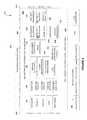
- FIG. 7illustrates a simplified diagram 700 of a preventive maintenance database, in accordance with one embodiment.
- the diagram 700may be viewed in the context of the details of the previous Figures. Of course, however, the diagram 700 may be viewed in the context of any desired environment. Further, the aforementioned definitions may equally apply to the description below.
- the preventive maintenance database 736is a data structure including a template database 737 , a deployment database 740 , a topology database 743 , and an activity database 744 .
- the template database 737includes detailed records of hardware types 738 and software types 739 (i.e. VNF templates).
- the template database 737and particularly the VNF templates 739 , may be part of a virtual function catalog.
- the deployment database 740includes detailed records of hardware instances 741 (i.e. hardware units actually deployed in the network) and software instances 742 (i.e. VNF instances as deployed in the network).
- the topology database 743defines the topology of the NFV-based network.
- the topology database 743may be part of, or interface with, a service view and topology module.
- the activity database 744contains a record for each scheduled activity of preventive maintenance. Every record of the template database 737 includes: a list of all the faults associated with the respective hardware or software (e.g., VNF) component; the fault frequency, or mean time to fault (MTTF, or MTBF (mean time between faults)) for each fault; fault conditions or dependencies, such as the dependency of the MTTF on values such as temperature and humidity (value and period), activation/deactivation, cycles of use, rate of upgrade (such as bug fixes), etc.; preventive maintenance activity required to prevent a particular fault of a particular VNF; and resources associated with a preventive maintenance activity required to prevent a particular fault of a particular VNF (type, quantity and period (Mean Time To Repair—MTTR)).
- VNFhardware or software
- MTTFmean time to fault
- MTBFmean time between faults
- Every record of the deployment database 740includes: network requirements (e.g. SLAs) associated with each hardware instance 741 and VNF instances 742 in use; usage data (e.g. type of load, quantity and period) associated with any particular fault of any particular hardware instance 741 and VNF instances 742 in use; network behavior (actual performance) associated with each hardware instance 741 and VNF instances 742 in use; and a type of preventive maintenance activity and the associated anticipated time by which the preventive maintenance activity should be performed.
- network requirementse.g. SLAs
- usage datae.g. type of load, quantity and period
- network behavioractual performance
- These data structurescan also be grouped as a hardware database 745 of hardware types 738 and instances 741 , and a software database 746 of software (VNF) types 739 and instances 742 .
- VNFsoftware
- the topology database 743contains a record for each hardware instance (unit) 741 , and each VNF instance 742 in the network.
- the recorddefines the location of the hardware instance 741 or VNF instance 742 , the relations, such as connectivity, between the hardware instances 741 , between the VNF instances 742 , and between the VNF instances 742 and hardware instances 741 (e.g. in which they are installed).
- at least one backup unit(such as a hardware instance 741 ) is defined for each hardware instance 741 and VNF instance 742 .
- Every record of the activity database 744includes: the hardware instances 741 or VNF instances 742 for which preventive maintenance activity is scheduled; the scheduled preventive maintenance activity; the time of the scheduled preventive maintenance activity and its anticipated length; and the backup unit scheduled to replace the maintained hardware instance 741 , or to host the maintained VNF instance 742 .
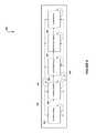
- FIG. 8illustrates a simplified diagram 800 of a preventive maintenance procedure, in accordance with one embodiment.
- the diagram 800may be viewed in the context of the details of the previous Figures. Of course, however, the diagram 800 may be viewed in the context of any desired environment. Further, the aforementioned definitions may equally apply to the description below.
- the goal of the preventive maintenance procedure 847is to schedule preventive maintenance activities while preserving the network's performance, while requiring minimum backup resources.
- the preventive maintenance procedure 847includes various modules (e.g. processed (executed) concurrently).
- the preventive maintenance procedure 847includes tracking module 848 that tracks the network continuously to anticipate the preventive maintenance needs.
- the tracking module 848may be part of, or receive data from, assurance and a performance management module.
- the tracking module 848collects data for each type of hardware unit, SDN module, and VNF module, as well as operating data for each instance of hardware unit, SDN module, and VNF module (e.g. using the records of hardware instances and software (VNF) instances).
- the tracking module 848also calculates statistical data associated with the various faults as defined for each hardware unit, SDN module, and VNF module (e.g. using the records of hardware types and VNF types).
- Operating datarefer to values such as load, time of operation, temperature and humidity, cycles of operations including activation and deactivation, consumption, including memory consumption, etc.
- the tracking module 848also tracks and calculates statistical data regarding the time it takes to prepare a unit or module for maintenance and the time it takes to complete the maintenance activity. According to the collected and calculated data, the tracking module 848 computes the period (earliest time and latest time) in which preventive maintenance should be performed for each type and for each instance of hardware unit, SDN module, and VNF module.
- Planning module 849schedules preventive maintenance activities within the available resources so that the network's performance is secured, typically in coordination with a service policy management module and with a deployment optimization module.
- Activation module 850activates and/or performs preventive maintenance activities according to their schedule as set by the planning module 849 .
- Restoration module 851restores services to their original configuration after all the relevant maintenance activities are completed.
- Alarm module 852analyzes and anticipates potential critical situations and adverse events, their causes and their priority.
- the modules of the preventive maintenance procedure 847may communicate via a maintenance database 853 .
- FIG. 9illustrates a simplified flow chart 900 of a planning module, in accordance with one embodiment.
- the flow chart 900may be viewed in the context of the details of the previous Figures. Of course, however, the flow chart 900 may be viewed in the context of any desired environment. Further, the aforementioned definitions may equally apply to the description below.
- Planning module 948schedules preventive maintenance activities to each and every instance of hardware unit, SDN module, and VNF module according to the accumulated data, statistical analysis, and anticipated usage. Scheduling a preventive maintenance activity includes scheduling one or more backup units to each hardware instance and one or more backup VNF instances associated with particular preventive maintenance activities.
- VNF instancesshould be migrated to their backup units, but not necessarily VNF instances of different VNF types.
- a maintenance activity performed on a particular VNF typemay require shutting down all the VNF instances installed in the same hardware instance, including VNF instances of other VNF types. For example, if the maintenance activity requires maintenance to a shared memory or storage resource, or a shared communication resource.
- Preventive maintenanceis typically associated with a particular hardware device, even if the maintenance activity is confined to software only, such as a soft reset, memory defragmentation (garbage collection), or downloading a new software release.
- the hardware devicemay execute several VNF instances, and even several types of VNFs. Different VNFs may be associated with different services, customers, sessions, etc. Clearing a particular hardware device for maintenance requires migrating all active VNFs to other devices without disrupting or degrading the service.
- a preventive maintenance proceduremay also provide data to the deployment, activation and provisioning modules to ensure that the deployment and/or activation of a new service takes in account the needs for preventive maintenance and leaves available enough resources to enable timely maintenance activities.
- the preventive maintenance proceduremay also provide data to the policy, accounting and billing modules to incorporate the cost of preventive maintenance in the pricing of plans and SLAs in accordance with their respective usage of VNFs, as well as their effect on the network configuration.
- the planning module 948starts with step 954 by loading a hardware instance record and its respective record of a hardware type. From these records, the planning module 948 concludes and selects in step 955 a fault having the earliest predicted time. That is the period for the earliest required preventive maintenance activity.
- the planning module 948selects the maintenance preparation plan associated with the selected fault.
- the maintenance preparation planincludes a list of backup facilities (typically, one or more instances of hardware units and VNF modules).
- the planning module 948then checks that the backup facilities are available as needed (considering processing power, memory and storage space, bandwidth, etc.) and if backup is unavailable notify an alarm module (step 958 ).
- the planning module 948proceeds to step 959 to identify all the VNF instances associated with the fault maintenance plan. Typically, these VNF instances are running on the hardware instance to be maintained. However, in some situations there are other VNF instances that should be relocated or replaced or otherwise require the use of a backup VNF instance.
- the planning module 948then verifies that all these VNF instances have their backup available (step 960 ). If backup is available, the planning module 948 schedules a maintenance preparation activity for each of the VNF instances (step 961 ). Such maintenance preparation activity typically relocates the VNF instance to the respective backup facility. Finally, the planning module 948 activates blocking criteria (step 962 ) to eliminate further activation of any process or instance for these hardware and VNF instances.
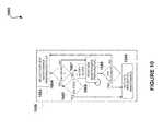
- FIG. 10illustrates a simplified flow chart 1000 of a maintenance activation module, in accordance with one embodiment.
- the flow chart 1000may be viewed in the context of the details of the previous Figures. Of course, however, the flow chart 1000 may be viewed in the context of any desired environment. Further, the aforementioned definitions may equally apply to the description below.
- maintenance activation module 1050may perform the maintenance preparation activities and thereafter activate the maintenance activity itself.
- the activation module 1050starts with step 1063 by selecting the earliest planned maintenance preparation activity.
- the activation module 1050checks if the preparation activity refers to a hardware unit (instance) and then (step 1065 ) verifies that all VNF instances associated with the hardware unit are relocated (so that the hardware unit is “software free”) and then (step 1066 ) activates the preventive maintenance activity. If the hardware unit is not software free, the activation module 1050 aborts and notifies the alarm module (step 1067 ).
- the activation module 1050proceeds to step 1068 to perform the maintenance preparation activity, that is, to migrate the function performed by the VNF instance to the planned backup hardware unit and/or VNF instance. This activity may repeat for all the instances of the particular VNF residing on the particular hardware unit.
- the activation module 1050activates the preventive maintenance activity (step 1066 ).
- FIG. 11illustrates a simplified flow chart of an NFV-based sub-network undergoing preventive maintenance activity, in accordance with one embodiment.
- the flow chartmay be viewed in the context of the details of the previous Figures. Of course, however, the flow chart may be viewed in the context of any desired environment. Further, the aforementioned definitions may equally apply to the description below.
- sub-network 1170includes four types of VNF instances 1142 : a migrating VNF instance indicated by numeral 1171 , a destination VNF instance indicated by numeral 1172 , one or more source VNF instances indicated by numeral 1173 , and one or more addressable VNF instances indicated by numeral 1174 .
- Source VNF 1173represents any number of VNF instances sending data to the migrating VNF 1171 .
- Addressable VNFs 1174represent any number of VNF instances receiving data from the migrating VNF 1171 .
- a maintenance preparation proceduremigrates the functionality of VNF instance 1171 to VNF instance 1172 while preserving service continuity between VNF instances 1173 and VNF instances 1174 .
- FIG. 12illustrates a simplified flow chart 1200 of a maintenance preparation procedure, in accordance with one embodiment.
- the flow chart 1200may be viewed in the context of the details of the previous Figures. Of course, however, the flow chart 1200 may be viewed in the context of any desired environment. Further, the aforementioned definitions may equally apply to the description below.
- Maintenance preparation procedure 1268is an example of migrating a VNF in an NFV-based network. Maintenance preparation procedure 1268 applies to preventive maintenance, however, the process described in maintenance preparation step 1268 also applies to other situations including an activity requiring the preservation of service continuity such as network optimization and product replacement. Maintenance preparation procedure 1268 describes, by way of an example, a method of migrating and deactivating a VNF instance (hereinbelow “replaced VNF instance”) while preserving session continuity.
- maintenance preparation procedure 1268starts with steps 1275 and 1276 by determining the VNF type of the VNF instance to be migrated (replaced VNF instance), and the alternative location, or the target or destination computing facility, to where the VNF instance is to be migrated. It is appreciated that the replaced VNF instance, or the functionality of the replaced VNF instance, can be migrated within the same computing facility.
- VNF functionalitywhen migrating a VNF functionality to an upgraded version of the VNF type, or another product supporting a VNF type of a similar functionality.
- the maintenance preparation procedure 1268proceeds to step 1277 and step 1278 to verify that capacity is available at the destination computing facility (alternative location), and that traffic bandwidth is available from the source VNF to the destination VNF. If capacity or bandwidth is unavailable, the process aborts and notifies the alarm module (step 1279 ).
- Capacityrefers to processing power, memory, storage, etc.
- Bandwidthrefers to the traffic requirements from any source VNF instance to destination VNF instance, as well as traffic requirements from destination VNF instance to any addressable VNF instance.
- step 1280If capacity and bandwidth are available maintenance preparation procedure 1268 cheeks (step 1280 ) if VNF software compatible with the destination VNF is already installed in the destination computing facility and installs the VNF software if necessary (step 1281 ).
- the maintenance preparation procedure 1268proceeds to activate the destination VNF instance (step 1282 ). If the destination VNF instance requires data and/or content (step 1283 ) the maintenance preparation procedure 1268 may load or update the required data and/or content to the destination VNF instance (step 1284 ). Then the maintenance preparation procedure 1268 diverts the communication from the source VNF instances (feeding the replaced VNF instance) to the destination VNF instance (step 1285 ).
- the maintenance preparation procedure 1268may execute a compatibility verification (step 1286 ).
- a compatibility verification proceduremay include comparing the output of the destination VNF instance with the outputs of the replaced VNF instance. It is appreciated that in this case the data flows from the source VNF instances are duplicated so that both the replaced VNF instance and the destination VNF instance receive the inputs substantially simultaneously.
- the compatibilitymay be verified in step 1286 regarding data (and/or content) and transmission and/or timing parameters (e.g., bandwidth, latency, jitter, etc.). If the data of the outputs of the replaced VNF instance and the destination VNF instance is not the same (step 1287 ) the maintenance preparation procedure 1268 may remove the VNF destination instance (step 1288 ) and repeat the installation process. If the transmission or timing parameters of the outputs of the destination VNF instance is incompatible with the requirements (step 1289 ) the maintenance preparation procedure 1268 may seek a different location for the VNF destination instance.
- dataand/or content
- transmission and/or timing parameterse.g., bandwidth, latency, jitter, etc.
- maintenance preparation procedure 1268deactivates the VNF instance (step 1290 ). If there are a plurality of inputs (step 1191 ) maintenance preparation procedure 1268 may repeat steps 1283 to 1290 as necessary.
- steps 1285 and 1286may be executed after data and contents are loaded and/or updated for all the inputs. It is appreciated that the compatibility verification process can be executed for each input independently and/or for any group of inputs.
- a servicemay include a plurality of VNFs and/or VNF instances.
- Such plurality of VNFs and/or VNF instances making a serviceis also named a VNF chain or sub-network.
- Two or more VNFs and/or VNF instances of such VNF chain or sub-networkmay have particular inter-related requirements.
- such two or more VNFs and/or VNF instancesmay require particular bandwidth, latency, jitter, etc. between them.
- a process of VNF migration as described above with reference to maintenance preparation procedure 1268 and/or FIG. 12may affect such two or more VNF instances or the entire chain or sub-network. Consequently, the steps of installing, updating, diverting, verifying compatibility, and deactivating may apply to a plurality of VNF instances taken together.
- embodiments of the present inventioninclude a system, method, and computer program product for preserving service continuity in a communication network using network function virtualization.
- Service continuityis particularly preserved while performing network activities such as preventive maintenance network optimization, and/or product replacement.
- service continuityis preserved for each instance of a virtual network function before initiating any of the above activities relating to the particular VNF, or a service including such VNF.
- the method for preserving service continuitymay include at least one of the following activities: disabling initiation of a new instance of a virtual network function in a processing facility before migrating an instance of the virtual network function from the processing facility; initiating an instance of a virtual network function in a first processing facility before deactivating an instance of the virtual network function in a second processing facility; migrating an instance of a virtual network function from a first processing facility to a second processing facility before deactivating the instance of the virtual network function in the first processing facility; and/or diverting communication addressed to a first instance of a virtual network function in a first processing facility to a second instance of the virtual network function in second processing facility before deactivating the first instance.
- the techniques described aboveapply when the VNF is migrated between different processing facilities or within the same processing facility.
- FIG. 13illustrates a simplified flow chart 1300 of a maintenance preparation procedure operating in a multi-NFV-O environment, in accordance with one possible embodiment.
- FIG. 6An example on the multi-NFV-O environment is provided above with reference to FIG. 6 , describing a hierarchical NFV-O deployment.
- the maintenance preparation procedure(as shown and described with reference to FIG. 12 ) operates within the scope of a single NFV-O, such as an NFV-O leaf component.
- FIG. 13illustrates a simplified flow chart 1300 of a component 1301 of the maintenance preparation procedure operative when the particular NFV-O components, such as a leaf NFV-O component, is unable to migrate one or more VNFs within its territory. That is, between hardware units or other resources assigned to the particular NFV-O.
- the particular NFV-O componentssuch as a leaf NFV-O component
- the flow chart 1300may be viewed in the context of the details of the previous Figures. Of course, however, the flow chart 1300 may be viewed in the context of any desired environment. Further, the aforementioned definitions may equally apply to the description below.
- the NFV-O componentmay apply for additional resources (step 1304 ).
- the NFV-O componentmay request additional resources from its parent NFV-O component.
- a parent NFV-O componentmay then reassign one or more resource from another NFV-O component (e.g., another NFV-O leaf component) to the requesting NFV-O component.
- step 1305there may be the following cases, intra-territorial resource allocation, bilateral inter-territorial resource allocation, and multi-lateral inter-territorial resource allocation.
- Intra-territorial resource allocationtypically means that one or more resources where reallocated from a first territory (typically managed by a first leaf NFV-O component) to a second territory (typically managed by a second leaf NFV-O component).
- the reallocated resourcesare now part for the second territory and the requesting NFV-O may proceed to migrate the VNF instance(s) as shown and described above with reference to FIG. 12 .
- Inter-territorial resource allocationtypically means that one or more resources are assigned to the requesting (second) NFV-O, however, under the management of the providing (first) NFV-O.
- the migrationis typically coordinated.
- each of the NFV-O modules involvedexecutes a part of the process shown and described above with reference to FIG. 12 (steps 1308 and 1309 of FIG. 13 ).
- Multi-lateral inter-territorial resource allocationtypically means that several NFV-Os are involved, or that any other complexity requires that the execution of the process shown and described above with reference to FIG. 12 is delegated to a superior NFV-O module, such as a parent or core NFV-O module.
- NFV-O module of a different hierarchyFor example, from a geographical NFV-O hierarchy to a (module of) service NFVO hierarchy or a (module of) customer NFVO hierarchy.
- the maintenance preparation procedure 1268verifies that the new (destination) VNF is compatible with the old (replaced) VNF.
- the maintenance preparation procedure 1268may verify compatibility by comparing corresponding output data of the new and old VNFs.
- the service provided by the migrated VNFis active at the time of compatibility verification and inputs are available to both the old and new VNFs, producing compatible (or incompatible) outputs.
- the service provided by the migrated VNFis active at the time of compatibility verification and inputs are not available.
- the maintenance preparation procedure 1268may introduce ‘artificial inputs’ to the new and old VNF to generate outputs that can be compared to verify compatibility.
- the artificial inputmay be test data as used to test the particular VNF program.
- the test datais used to check that the data used by the destination VNF instance is compatible with the data used by the replaced VNF instance.
- FIG. 14illustrates a simplified block diagram of an NFV-based sub-network 1400 undergoing compatibility verification, in accordance with one embodiment.
- the block diagrammay be viewed in the context of the details of the previous Figures.
- the flow chartmay be viewed in the context of any desired environment. Further, the aforementioned definitions may equally apply to the description below.
- FIG. 14shows one or more source VNF instances 1401 providing input data to a replaced VNF instance 1402 , which generates output data for one or more VNF instances 1403 .
- a destination VNF instance 1404is provided to replace VNF instance 1402 .
- a compatibility verification VNF instance 1405is provided. Compatibility verification VNF instance 1405 receives the outputs of the replaced VNF instance 1402 and the destination VNF instance 1404 and compares them to verify that the destination VNF instance 1404 is compatible with the replaced VNF instance 1402 . As shown in FIG. 14 , compatibility verification VNF instance 1405 transfers the output (such as the output of the replaced VNF instance 1402 ) to the one or more VNF instances 1403 .
- testing VNF instance 1406is provided, typically also as a part of a compatibility verification process, such as step 1286 shown and described above with reference to FIG. 12 .
- Testing VNF instance 1406is connected to the inputs of the replaced VNF instance 1402 and the destination VNF instance 1404 to provide ‘artificial’ input data to be compared by the compatibility verification VNF instance 1405 .
- the testing VNF instance 1406may add a mark or a tag or a similar means of identification to input data sent to the replaced VNF instance 1402 and the destination VNF instance 1404 to identify the data as ‘testing data’. Thereafter, the replaced VNF instance 1402 and the destination VNF instance 1404 may produce output data bearing the test marks (or tags, or similar means f identification) and send it to the compatibility verification VNF instance 1405 . Thereafter, the compatibility verification VNF instance 1405 may identify the particular output data received from the replaced VNF instance 1402 and the destination VNF instance 1404 as testing data and refrain from forwarding this data downstream (e.g. to the one or more VNF instances 1403 ). This enables the system as described in FIG. 14 to operate the testing VNF instance 1406 while providing service to customers.
- the destination VNF instance 1304is connected directly to the one or more VNF instances 1403 , and the compatibility verification VNF instance 1405 and the testing VNF instance 1406 are removed.
- FIG. 15illustrates a network architecture 1500 , in accordance with one possible embodiment.
- the network 1502may take any form including, but not limited to a telecommunications network, a local area network (LAN), a wireless network, a wide area network (WAN) such as the Internet, peer-to-peer network, cable network, etc. While only one network is shown, it should be understood that two or more similar or different networks 1502 may be provided.
- LANlocal area network
- WANwide area network
- peer-to-peer networksuch as the Internet
- cable networketc. While only one network is shown, it should be understood that two or more similar or different networks 1502 may be provided.
- Coupled to the network 1502is a plurality of devices.
- a server computer 1504 and an end user computer 1506may be coupled to the network 1502 for communication purposes.
- Such end user computer 1506may include a desktop computer, lap-top computer, and/or any other type of logic.
- various other devicesmay be coupled to the network 1502 including a personal digital assistant (PDA) device 1508 , a mobile phone device 1510 , a television 1512 , etc.
- PDApersonal digital assistant
- FIG. 16illustrates an exemplary system 1600 , in accordance with one embodiment.
- the system 1600may be implemented in the context of any of the devices of the network architecture 1500 of FIG. 15 .
- the system 1600may be implemented in any desired environment.
- a system 1600including at least one central processor 1601 which is connected to a communication bus 1602 .
- the system 1600also includes main memory 1604 [e.g. random access memory (RAM), etc.].
- the system 1600also includes a graphics processor 1606 and a display 1608 .
- the system 1600may also include a secondary storage 1610 .
- the secondary storage 1610includes, for example, a hard disk drive and/or a removable storage drive, representing a floppy disk drive, a magnetic tape drive, a compact disk drive, etc.
- the removable storage drivereads from and/or writes to a removable storage unit in a well-known manner.
- Computer programs, or computer control logic algorithmsmay be stored in the main memory 1604 , the secondary storage 1610 , and/or any other memory, for that matter. Such computer programs, when executed, enable the system 1600 to perform various functions (as set forth above, for example).
- Memory 1604 , storage 1610 and/or any other storageare possible examples of tangible computer-readable media.
Landscapes
- Engineering & Computer Science (AREA)
- Computer Networks & Wireless Communication (AREA)
- Signal Processing (AREA)
- Software Systems (AREA)
- Theoretical Computer Science (AREA)
- Physics & Mathematics (AREA)
- General Engineering & Computer Science (AREA)
- General Physics & Mathematics (AREA)
- Quality & Reliability (AREA)
- Data Exchanges In Wide-Area Networks (AREA)
Abstract
Description
Claims (12)
Priority Applications (4)
| Application Number | Priority Date | Filing Date | Title |
|---|---|---|---|
| US14/572,716US9384028B1 (en) | 2013-12-19 | 2014-12-16 | System, method, and computer program for preserving service continuity in a network function virtualization (NFV) based communication network |
| US15/166,186US10355988B1 (en) | 2013-12-19 | 2016-05-26 | System, method, and computer program for preserving service continuity in a network function virtualization (NFV) based communication network |
| US15/586,087US10606718B1 (en) | 2013-12-19 | 2017-05-03 | System, method, and computer program for managing fault recovery in network function virtualization (Nfv) based networks |
| US16/790,981US11474918B1 (en) | 2013-12-19 | 2020-02-14 | System, method, and computer program for managing fault recovery in network function virtualization (NFV) based networks |
Applications Claiming Priority (2)
| Application Number | Priority Date | Filing Date | Title |
|---|---|---|---|
| US201361918597P | 2013-12-19 | 2013-12-19 | |
| US14/572,716US9384028B1 (en) | 2013-12-19 | 2014-12-16 | System, method, and computer program for preserving service continuity in a network function virtualization (NFV) based communication network |
Related Child Applications (1)
| Application Number | Title | Priority Date | Filing Date |
|---|---|---|---|
| US15/166,186ContinuationUS10355988B1 (en) | 2013-12-19 | 2016-05-26 | System, method, and computer program for preserving service continuity in a network function virtualization (NFV) based communication network |
Publications (1)
| Publication Number | Publication Date |
|---|---|
| US9384028B1true US9384028B1 (en) | 2016-07-05 |
Family
ID=56234904
Family Applications (2)
| Application Number | Title | Priority Date | Filing Date |
|---|---|---|---|
| US14/572,716ActiveUS9384028B1 (en) | 2013-12-19 | 2014-12-16 | System, method, and computer program for preserving service continuity in a network function virtualization (NFV) based communication network |
| US15/166,186Active2034-12-22US10355988B1 (en) | 2013-12-19 | 2016-05-26 | System, method, and computer program for preserving service continuity in a network function virtualization (NFV) based communication network |
Family Applications After (1)
| Application Number | Title | Priority Date | Filing Date |
|---|---|---|---|
| US15/166,186Active2034-12-22US10355988B1 (en) | 2013-12-19 | 2016-05-26 | System, method, and computer program for preserving service continuity in a network function virtualization (NFV) based communication network |
Country Status (1)
| Country | Link |
|---|---|
| US (2) | US9384028B1 (en) |
Cited By (50)
| Publication number | Priority date | Publication date | Assignee | Title |
|---|---|---|---|---|
| US20150234725A1 (en)* | 2014-02-20 | 2015-08-20 | International Business Machines Corporation | Testing a virtualized network function in a network |
| US20170052806A1 (en)* | 2014-02-12 | 2017-02-23 | Nec Corporation | Information processing apparatus, communication method, network control apparatus, network control method, communication system, and program |
| US20170063598A1 (en)* | 2014-05-15 | 2017-03-02 | Huawei Technologies Co., Ltd. | Network functions virtualization network system and data processing method, and apparatus |
| US9645899B1 (en)* | 2013-12-19 | 2017-05-09 | Amdocs Software Systems Limited | System, method, and computer program for managing fault recovery in network function virtualization (NFV) based networks |
| US9686240B1 (en) | 2015-07-07 | 2017-06-20 | Sprint Communications Company L.P. | IPv6 to IPv4 data packet migration in a trusted security zone |
| US9749294B1 (en)* | 2015-09-08 | 2017-08-29 | Sprint Communications Company L.P. | System and method of establishing trusted operability between networks in a network functions virtualization environment |
| US9769854B1 (en) | 2013-02-07 | 2017-09-19 | Sprint Communications Company L.P. | Trusted signaling in 3GPP interfaces in a network function virtualization wireless communication system |
| US9781016B1 (en) | 2015-11-02 | 2017-10-03 | Sprint Communications Company L.P. | Dynamic addition of network function services |
| US9794187B1 (en) | 2013-12-19 | 2017-10-17 | Amdocs Software Systems Limited | System, method, and computer program for resource conversion in a network function virtualization (NFV) based communication network |
| US9811686B1 (en) | 2015-10-09 | 2017-11-07 | Sprint Communications Company L.P. | Support systems interactions with virtual network functions in a trusted security zone |
| US20170359231A1 (en)* | 2014-12-23 | 2017-12-14 | Orange | System for generating a virtualized network function |
| US20180013586A1 (en)* | 2015-03-31 | 2018-01-11 | Huawei Technologies Co., Ltd. | Method and Apparatus for Establishing Link Between Virtualized Network Functions |
| WO2018013018A1 (en)* | 2016-07-11 | 2018-01-18 | Telefonaktiebolaget Lm Ericsson (Publ) | Method and arrangement for selectively migrating data of a virtualized network function |
| US9916465B1 (en)* | 2015-12-29 | 2018-03-13 | Palantir Technologies Inc. | Systems and methods for automatic and customizable data minimization of electronic data stores |
| US20180083850A1 (en)* | 2014-12-23 | 2018-03-22 | Telefonaktiebolaget Lm Ericsson (Publ) | Service performance monitoring in a virtualized communication network |
| WO2018099569A1 (en)* | 2016-12-02 | 2018-06-07 | Telefonaktiebolaget Lm Ericsson (Publ) | Configuration control for network |
| US20180191581A1 (en)* | 2015-08-31 | 2018-07-05 | Huawei Technologies Co., Ltd. | Method and Apparatus for Deploying Network Service |
| EP3361381A1 (en)* | 2017-02-10 | 2018-08-15 | NTT DoCoMo, Inc. | Method for migrating a network service and network service arrangement |
| US20180246772A1 (en)* | 2015-11-06 | 2018-08-30 | Huawei Technologies Co., Ltd. | Method and apparatus for allocating a virtual resource in network functions virtualization network |
| US10070344B1 (en) | 2017-07-25 | 2018-09-04 | At&T Intellectual Property I, L.P. | Method and system for managing utilization of slices in a virtual network function environment |
| US10083098B1 (en)* | 2016-06-07 | 2018-09-25 | Sprint Communications Company L.P. | Network function virtualization (NFV) virtual network function (VNF) crash recovery |
| US10149193B2 (en) | 2016-06-15 | 2018-12-04 | At&T Intellectual Property I, L.P. | Method and apparatus for dynamically managing network resources |
| US10250498B1 (en) | 2016-10-03 | 2019-04-02 | Sprint Communications Company L.P. | Session aggregator brokering of data stream communication |
| US10257668B2 (en) | 2017-05-09 | 2019-04-09 | At&T Intellectual Property I, L.P. | Dynamic network slice-switching and handover system and method |
| US10333987B2 (en)* | 2017-05-18 | 2019-06-25 | Bank Of America Corporation | Security enhancement tool for a target computer system operating within a complex web of interconnected systems |
| US20190199780A1 (en)* | 2014-08-13 | 2019-06-27 | Centurylink Intellectual Property Llc | Remoting Application Servers |
| US10341195B1 (en)* | 2016-06-29 | 2019-07-02 | Sprint Communications Company L.P. | Virtual network function (VNF) resource management in a software defined network (SDN) |
| US10348488B1 (en) | 2017-08-25 | 2019-07-09 | Sprint Communications Company L.P. | Tiered distributed ledger technology (DLT) in a network function virtualization (NFV) core network |
| US10355988B1 (en)* | 2013-12-19 | 2019-07-16 | Amdocs Development Limited | System, method, and computer program for preserving service continuity in a network function virtualization (NFV) based communication network |
| US10382903B2 (en) | 2017-05-09 | 2019-08-13 | At&T Intellectual Property I, L.P. | Multi-slicing orchestration system and method for service and/or content delivery |
| US10505870B2 (en) | 2016-11-07 | 2019-12-10 | At&T Intellectual Property I, L.P. | Method and apparatus for a responsive software defined network |
| US10516996B2 (en) | 2017-12-18 | 2019-12-24 | At&T Intellectual Property I, L.P. | Method and apparatus for dynamic instantiation of virtual service slices for autonomous machines |
| US10542115B1 (en) | 2015-10-01 | 2020-01-21 | Sprint Communications Company L.P. | Securing communications in a network function virtualization (NFV) core network |
| US10606718B1 (en)* | 2013-12-19 | 2020-03-31 | Amdocs Development Limited | System, method, and computer program for managing fault recovery in network function virtualization (Nfv) based networks |
| US10673751B2 (en) | 2017-04-27 | 2020-06-02 | At&T Intellectual Property I, L.P. | Method and apparatus for enhancing services in a software defined network |
| US20200210589A1 (en)* | 2015-05-11 | 2020-07-02 | Intel Corporation | Technologies for secure bootstrapping of virtual network functions |
| US10728132B2 (en) | 2017-06-01 | 2020-07-28 | Hewlett Packard Enterprise Development Lp | Network affinity index increase |
| US10749796B2 (en) | 2017-04-27 | 2020-08-18 | At&T Intellectual Property I, L.P. | Method and apparatus for selecting processing paths in a software defined network |
| US10764118B1 (en)* | 2018-01-05 | 2020-09-01 | Open Invention Network Llc | EMS resolution of split-brain virtual network function components |
| US10764394B2 (en) | 2016-11-30 | 2020-09-01 | At&T Intellectual Property I, L.P. | Resource based framework to support service programmability for a 5G or other next generation mobile core network |
| US10819606B2 (en) | 2017-04-27 | 2020-10-27 | At&T Intellectual Property I, L.P. | Method and apparatus for selecting processing paths in a converged network |
| US10915312B2 (en)* | 2019-07-02 | 2021-02-09 | Vmware, Inc. | Lifecycle management of virtual compute templates |
| US10999155B2 (en) | 2017-10-26 | 2021-05-04 | Cisco Technology, Inc. | System and method for hybrid and elastic services |
| US20210182890A1 (en)* | 2015-12-30 | 2021-06-17 | Paypal, Inc. | Data structures for categorizing and filtering content |
| EP3862880A1 (en)* | 2020-02-04 | 2021-08-11 | ADVA Optical Networking SE | Computer-implemented method for reducing service disruption times for a universal customer premise equipment, ucpe, device with resource constraint in a network functions virtualization, nfv, network infrastructure |
| US20230060675A1 (en)* | 2020-01-22 | 2023-03-02 | Telefonaktiebolaget Lm Ericsson (Publ) | Deployment of a virtualized service on a cloud infrastructure based on interoperability requirements between service functions |
| US20230072149A1 (en)* | 2019-03-29 | 2023-03-09 | Panasonic Avionics Corporation | Virtualization of complex networked embedded systems |
| US11665061B2 (en)* | 2015-02-03 | 2023-05-30 | Nec Corporation | Virtual network system, virtual network control method, virtual network function database, orchestration apparatus, control apparatus, and control method and control program of control apparatus |
| US20230344727A1 (en)* | 2022-04-21 | 2023-10-26 | The Mitre Corporation | Computer network platform for routing and virtualization |
| US11847205B1 (en) | 2020-10-26 | 2023-12-19 | T-Mobile Innovations Llc | Trusted 5G network function virtualization of virtual network function elements embedded on a system-on-chip |
Families Citing this family (2)
| Publication number | Priority date | Publication date | Assignee | Title |
|---|---|---|---|---|
| US20180173547A1 (en)* | 2016-12-20 | 2018-06-21 | Intel Corporation | Pinning of virtual network function (vnf) deployments using hardware metrics |
| US11575684B2 (en) | 2020-09-22 | 2023-02-07 | Bank Of America Corporation | System for secure resource allocation communication with a network |
Citations (27)
| Publication number | Priority date | Publication date | Assignee | Title |
|---|---|---|---|---|
| WO2001007170A1 (en) | 1999-07-23 | 2001-02-01 | Tilmar Engineering B.V. | System for coating the inner wall of tubes |
| WO2001017169A2 (en) | 1999-08-31 | 2001-03-08 | Accenture Llp | A system, method and article of manufacture for a network-based predictive fault management system |
| WO2001016849A2 (en) | 1999-08-31 | 2001-03-08 | Accenture Llp | A system, method and article of manufacture for remote demonstration of business capabilities in an e-commerce environment |
| WO2001017313A1 (en) | 1999-08-31 | 2001-03-08 | Accenture Llp | A system, method and article of manufacture for a high speed multi-tier communication network with increased efficiency |
| WO2001046889A2 (en) | 1999-12-22 | 2001-06-28 | Accenture Llp | A method for executing a network-based credit application process |
| WO2001046846A2 (en) | 1999-12-22 | 2001-06-28 | Accenture Llp | A method for a virtual trade financial framework |
| US6427132B1 (en) | 1999-08-31 | 2002-07-30 | Accenture Llp | System, method and article of manufacture for demonstrating E-commerce capabilities via a simulation on a network |
| US6611867B1 (en) | 1999-08-31 | 2003-08-26 | Accenture Llp | System, method and article of manufacture for implementing a hybrid network |
| US6629081B1 (en) | 1999-12-22 | 2003-09-30 | Accenture Llp | Account settlement and financing in an e-commerce environment |
| US6983037B2 (en) | 2003-05-23 | 2006-01-03 | Bellsouth Intellectual Property Corporation | Method, system and computer program product for performing automated unbundled network element migration |
| US7069234B1 (en) | 1999-12-22 | 2006-06-27 | Accenture Llp | Initiating an agreement in an e-commerce environment |
| US7167844B1 (en) | 1999-12-22 | 2007-01-23 | Accenture Llp | Electronic menu document creator in a virtual financial environment |
| US20080095138A1 (en) | 2006-10-24 | 2008-04-24 | Nokia Corporation | Method for performing handovers in a communication system |
| US20080232264A1 (en)* | 2007-03-22 | 2008-09-25 | Yair Horovitz | System and method for simulating dynamic routing of traffic over an IP network |
| US20090138580A1 (en)* | 2004-08-31 | 2009-05-28 | Yoshifumi Takamoto | Method of booting an operating system |
| US7610233B1 (en) | 1999-12-22 | 2009-10-27 | Accenture, Llp | System, method and article of manufacture for initiation of bidding in a virtual trade financial environment |
| US20100085914A1 (en) | 2007-06-28 | 2010-04-08 | Motorola, Inc. | Method and system for providing ims session continuity to a user equipment across a plurality of communication networks |
| US20100191613A1 (en) | 2009-01-28 | 2010-07-29 | Gregory G. Raleigh | Open transaction central billing system |
| US20100208619A1 (en)* | 2005-09-15 | 2010-08-19 | Tp Lab, Inc. | Method to Dynamically Create a Virtual Network |
| US7860232B2 (en) | 2003-11-21 | 2010-12-28 | Verizon Business Global Llc | Method and system for migrating a telephone service from a first local exchange carrier to a second local exchange carrier |
| US20110107364A1 (en) | 2009-10-30 | 2011-05-05 | Lajoie Michael L | Methods and apparatus for packetized content delivery over a content delivery network |
| US8023494B2 (en) | 2006-11-06 | 2011-09-20 | Nec Corporation | Communication service continuation system, communication service continuation method, and program thereof |
| US20120089845A1 (en) | 2009-01-28 | 2012-04-12 | Raleigh Gregory G | Verifiable device assisted service usage billing with integrated accounting, mediation accounting, and multi-account |
| US8166176B2 (en) | 2006-05-31 | 2012-04-24 | Alcatel Lucent | Context-aware migration of communication session |
| US20130182714A1 (en)* | 2012-01-18 | 2013-07-18 | LineRate Systems, Inc. | Redundancy of network services in restricted networks |
| US20130182574A1 (en)* | 2012-01-13 | 2013-07-18 | Verizon Patent And Licensing Inc. | Method and system of congestion control in a mobile virtual network |
| US20130246996A1 (en) | 2012-03-19 | 2013-09-19 | Enterpriseweb Llc | Declarative Software Application Meta-Model and System for Self-Modification |
Family Cites Families (10)
| Publication number | Priority date | Publication date | Assignee | Title |
|---|---|---|---|---|
| US20020103931A1 (en)* | 2001-01-26 | 2002-08-01 | Mott Charles J. | Virtual private networking using domain name service proxy |
| FI20011949A0 (en)* | 2001-10-05 | 2001-10-05 | Stonesoft Corp | Managing a Virtual Private Network |
| US7840996B1 (en)* | 2006-08-03 | 2010-11-23 | Juniper Networks, Inc. | Remote directory browsing through a secure gateway of a virtual private network |
| US8468550B2 (en)* | 2010-06-18 | 2013-06-18 | At&T Intellectual Property I, L.P. | Mobile devices having plurality of virtual interfaces |
| US10192246B2 (en) | 2010-11-24 | 2019-01-29 | Red Hat, Inc. | Generating multi-cloud incremental billing capture and administration |
| JP5618886B2 (en)* | 2011-03-31 | 2014-11-05 | 株式会社日立製作所 | Network system, computer distribution apparatus, and computer distribution method |
| CN105684365B (en)* | 2013-02-12 | 2020-03-24 | 慧与发展有限责任合伙企业 | Network control of network functions using software defined flow mapping and virtualization |
| US9936047B2 (en)* | 2013-10-17 | 2018-04-03 | Ciena Corporation | Method and apparatus for provisioning virtual network functions from a network service provider |
| US9105000B1 (en)* | 2013-12-10 | 2015-08-11 | Palantir Technologies Inc. | Aggregating data from a plurality of data sources |
| US9384028B1 (en)* | 2013-12-19 | 2016-07-05 | Amdocs Software Systems Limited | System, method, and computer program for preserving service continuity in a network function virtualization (NFV) based communication network |
- 2014
- 2014-12-16USUS14/572,716patent/US9384028B1/enactiveActive
- 2016
- 2016-05-26USUS15/166,186patent/US10355988B1/enactiveActive
Patent Citations (89)
| Publication number | Priority date | Publication date | Assignee | Title |
|---|---|---|---|---|
| WO2001007170A1 (en) | 1999-07-23 | 2001-02-01 | Tilmar Engineering B.V. | System for coating the inner wall of tubes |
| US6345239B1 (en) | 1999-08-31 | 2002-02-05 | Accenture Llp | Remote demonstration of business capabilities in an e-commerce environment |
| WO2001016849A2 (en) | 1999-08-31 | 2001-03-08 | Accenture Llp | A system, method and article of manufacture for remote demonstration of business capabilities in an e-commerce environment |
| WO2001017313A1 (en) | 1999-08-31 | 2001-03-08 | Accenture Llp | A system, method and article of manufacture for a high speed multi-tier communication network with increased efficiency |
| US6427132B1 (en) | 1999-08-31 | 2002-07-30 | Accenture Llp | System, method and article of manufacture for demonstrating E-commerce capabilities via a simulation on a network |
| US6611867B1 (en) | 1999-08-31 | 2003-08-26 | Accenture Llp | System, method and article of manufacture for implementing a hybrid network |
| WO2001017169A2 (en) | 1999-08-31 | 2001-03-08 | Accenture Llp | A system, method and article of manufacture for a network-based predictive fault management system |
| WO2001046889A2 (en) | 1999-12-22 | 2001-06-28 | Accenture Llp | A method for executing a network-based credit application process |
| WO2001046846A2 (en) | 1999-12-22 | 2001-06-28 | Accenture Llp | A method for a virtual trade financial framework |
| US7610233B1 (en) | 1999-12-22 | 2009-10-27 | Accenture, Llp | System, method and article of manufacture for initiation of bidding in a virtual trade financial environment |
| US6629081B1 (en) | 1999-12-22 | 2003-09-30 | Accenture Llp | Account settlement and financing in an e-commerce environment |
| US7069234B1 (en) | 1999-12-22 | 2006-06-27 | Accenture Llp | Initiating an agreement in an e-commerce environment |
| US7167844B1 (en) | 1999-12-22 | 2007-01-23 | Accenture Llp | Electronic menu document creator in a virtual financial environment |
| US6983037B2 (en) | 2003-05-23 | 2006-01-03 | Bellsouth Intellectual Property Corporation | Method, system and computer program product for performing automated unbundled network element migration |
| US7860232B2 (en) | 2003-11-21 | 2010-12-28 | Verizon Business Global Llc | Method and system for migrating a telephone service from a first local exchange carrier to a second local exchange carrier |
| US20090138580A1 (en)* | 2004-08-31 | 2009-05-28 | Yoshifumi Takamoto | Method of booting an operating system |
| US20100208619A1 (en)* | 2005-09-15 | 2010-08-19 | Tp Lab, Inc. | Method to Dynamically Create a Virtual Network |
| US8166176B2 (en) | 2006-05-31 | 2012-04-24 | Alcatel Lucent | Context-aware migration of communication session |
| US20080095138A1 (en) | 2006-10-24 | 2008-04-24 | Nokia Corporation | Method for performing handovers in a communication system |
| US8023494B2 (en) | 2006-11-06 | 2011-09-20 | Nec Corporation | Communication service continuation system, communication service continuation method, and program thereof |
| US20080232264A1 (en)* | 2007-03-22 | 2008-09-25 | Yair Horovitz | System and method for simulating dynamic routing of traffic over an IP network |
| US20100085914A1 (en) | 2007-06-28 | 2010-04-08 | Motorola, Inc. | Method and system for providing ims session continuity to a user equipment across a plurality of communication networks |
| WO2010088087A1 (en) | 2009-01-28 | 2010-08-05 | Headwater Partners I Llc | Open development system for access service providers |
| WO2010088100A1 (en) | 2009-01-28 | 2010-08-05 | Headwater Partners I Llc | Service profile management with user preference, adaptive policy, network neutrality and user privacy for intermediate networking devices |
| US20100191576A1 (en) | 2009-01-28 | 2010-07-29 | Gregory G. Raleigh | Verifiable device assisted service usage billing with integrated accounting, mediation accounting, and multi-account |
| US20100191612A1 (en) | 2009-01-28 | 2010-07-29 | Gregory G. Raleigh | Verifiable device assisted service usage monitoring with reporting, synchronization, and notification |
| US20100191575A1 (en) | 2009-01-28 | 2010-07-29 | Gregory G. Raleigh | Network based ambient services |
| US20100188993A1 (en) | 2009-01-28 | 2010-07-29 | Gregory G. Raleigh | Network tools for analysis, design, testing, and production of services |
| US20100188975A1 (en) | 2009-01-28 | 2010-07-29 | Gregory G. Raleigh | Verifiable device assisted service policy implementation |
| US20100188991A1 (en) | 2009-01-28 | 2010-07-29 | Gregory G. Raleigh | Network based service policy implementation with network neutrality and user privacy |
| US20100191846A1 (en) | 2009-01-28 | 2010-07-29 | Gregory G. Raleigh | Verifiable service policy inplementation for intermediate networking devices |
| US20100192170A1 (en) | 2009-01-28 | 2010-07-29 | Gregory G. Raleigh | Device assisted service profile management with user preference, adaptive policy, network neutrality, and user privacy |
| US20100191604A1 (en) | 2009-01-28 | 2010-07-29 | Gregory G. Raleigh | Device assisted ambient services |
| US20100192207A1 (en) | 2009-01-28 | 2010-07-29 | Gregory G. Raleigh | Virtual service provider systems |
| US20100188990A1 (en) | 2009-01-28 | 2010-07-29 | Gregory G. Raleigh | Network based service profile management with user preference, adaptive policy, network neutrality, and user privacy |
| US20100188992A1 (en) | 2009-01-28 | 2010-07-29 | Gregory G. Raleigh | Service profile management with user preference, adaptive policy, network neutrality and user privacy for intermediate networking devices |
| US20100188994A1 (en) | 2009-01-28 | 2010-07-29 | Gregory G. Raleigh | Verifiable service billing for intermediate networking devices |
| WO2010088083A1 (en) | 2009-01-28 | 2010-08-05 | Headwater Partners I Llc | Network based ambient services |
| WO2010088080A1 (en) | 2009-01-28 | 2010-08-05 | Headwater Partners I Llc | Network based service profile management with user preference, adaptive policy, network neutrality, and user privacy |
| WO2010088082A1 (en) | 2009-01-28 | 2010-08-05 | Headwater Partners I Llc | Device assisted ambient services |
| WO2010088076A1 (en) | 2009-01-28 | 2010-08-05 | Headwater Partners I Llc | Network based service policy implementation with network neutrality and user privacy |
| WO2010088075A1 (en) | 2009-01-28 | 2010-08-05 | Headwater Partners I Llc | Verifiable device assisted service usage billing with integrated accounting, mediation accounting, and multi-account |
| WO2010088081A1 (en) | 2009-01-28 | 2010-08-05 | Headwater Partners I Llc | Automated device provisioning and activation |
| WO2010088101A1 (en) | 2009-01-28 | 2010-08-05 | Headwater Partners I Llc | Simplified service network architecture |
| US20100188995A1 (en) | 2009-01-28 | 2010-07-29 | Gregory G. Raleigh | Verifiable and accurate service usage monitoring for intermediate networking devices |
| WO2010088095A1 (en) | 2009-01-28 | 2010-08-05 | Headwater Partners I Llc | Open transaction central billing system |
| WO2010088097A1 (en) | 2009-01-28 | 2010-08-05 | Headwater Partners I Llc | Verifiable service billing for intermediate networking devices |
| WO2010088073A1 (en) | 2009-01-28 | 2010-08-05 | Headwater Partners I Llc | Device assisted service profile management with user preference, adaptive policy, network neutrality, and user privacy |
| WO2010088098A1 (en) | 2009-01-28 | 2010-08-05 | Headwater Partners I Llc | Verifiable service policy implementation for intermediate networking devices |
| WO2010088086A1 (en) | 2009-01-28 | 2010-08-05 | Headwater Partners I Llc | Roaming services network and overlay networks |
| WO2010088096A1 (en) | 2009-01-28 | 2010-08-05 | Headwater Partners I Llc | Verifiable and accurate service usage monitoring for intermediate networking devices |
| WO2010088085A1 (en) | 2009-01-28 | 2010-08-05 | Headwater Partners I Llc | Network tools for analysis, design, testing, and production of services |
| WO2010088094A1 (en) | 2009-01-28 | 2010-08-05 | Headwater Partners I Llc | Virtual service provider systems |
| WO2010088072A1 (en) | 2009-01-28 | 2010-08-05 | Headwater Partners I Llc | Verifiable device assisted service policy implementation |
| WO2010088074A1 (en) | 2009-01-28 | 2010-08-05 | Headwater Partners I Llc | Verifiable device assisted service usage monitoring with reporting, synchronization, and notification |
| US20100192120A1 (en) | 2009-01-28 | 2010-07-29 | Gregory G. Raleigh | Open development system for access service providers |
| US20100190470A1 (en) | 2009-01-28 | 2010-07-29 | Gregory G. Raleigh | Roaming services network and overlay networks |
| US20100192212A1 (en) | 2009-01-28 | 2010-07-29 | Gregory G. Raleigh | Automated device provisioning and activation |
| US8331901B2 (en) | 2009-01-28 | 2012-12-11 | Headwater Partners I, Llc | Device assisted ambient services |
| US8326958B1 (en) | 2009-01-28 | 2012-12-04 | Headwater Partners I, Llc | Service activation tracking system |
| US8321526B2 (en) | 2009-01-28 | 2012-11-27 | Headwater Partners I, Llc | Verifiable device assisted service usage billing with integrated accounting, mediation accounting, and multi-account |
| US8270952B2 (en) | 2009-01-28 | 2012-09-18 | Headwater Partners I Llc | Open development system for access service providers |
| US20100191847A1 (en) | 2009-01-28 | 2010-07-29 | Gregory G. Raleigh | Simplified service network architecture |
| US8023425B2 (en) | 2009-01-28 | 2011-09-20 | Headwater Partners I | Verifiable service billing for intermediate networking devices |
| US20120089845A1 (en) | 2009-01-28 | 2012-04-12 | Raleigh Gregory G | Verifiable device assisted service usage billing with integrated accounting, mediation accounting, and multi-account |
| US20120088470A1 (en) | 2009-01-28 | 2012-04-12 | Raleigh Gregory G | Verifiable device assisted service usage billing with integrated accounting, mediation accounting, and multi-account |
| US20100191613A1 (en) | 2009-01-28 | 2010-07-29 | Gregory G. Raleigh | Open transaction central billing system |
| US20120134291A1 (en) | 2009-01-28 | 2012-05-31 | Headwater Partners I, Llc | Network Based Service Profile Management with User Preference, Adaptive Policy, Network Neutrality, and User Privacy |
| US8229812B2 (en) | 2009-01-28 | 2012-07-24 | Headwater Partners I, Llc | Open transaction central billing system |
| US20120195223A1 (en) | 2009-01-28 | 2012-08-02 | Raleigh Gregory G | Verifiable and Accurate Service Usage Monitoring for Intermediate Networking Devices |
| US20120195206A1 (en) | 2009-01-28 | 2012-08-02 | Raleigh Gregory G | Verifiable and accurate service usage monitoring for intermediate networking devices |
| US20120196565A1 (en) | 2009-01-28 | 2012-08-02 | Raleigh Gregory G | Network tools for analysis, design, testing, and production of services |
| US20120197792A1 (en) | 2009-01-28 | 2012-08-02 | Raleigh Gregory G | Verifiable Service Policy Implementation for Intermediate Networking Devices |
| US20120195222A1 (en) | 2009-01-28 | 2012-08-02 | Raleigh Gregory G | Verifiable and Accurate Service Usage Monitoring for Intermediate Networking Devices |
| US20120203677A1 (en) | 2009-01-28 | 2012-08-09 | Raleigh Gregory G | Network Tools for Analysis, Design, Testing, and Production of Services |
| US20120201133A1 (en) | 2009-01-28 | 2012-08-09 | Raleigh Gregory G | Network Tools for Analysis, Design, Testing, and Production of Services |
| US20120210391A1 (en) | 2009-01-28 | 2012-08-16 | Raleigh Gregory G | Automated Device Provisioning and Activation |
| US20120209750A1 (en) | 2009-01-28 | 2012-08-16 | Raleigh Gregory G | Automated Device Provisioning and Activation |
| US20120208496A1 (en) | 2009-01-28 | 2012-08-16 | Raleigh Gregory G | Automated Device Provisioning and Activation |
| US8250207B2 (en) | 2009-01-28 | 2012-08-21 | Headwater Partners I, Llc | Network based ambient services |
| US20120214441A1 (en) | 2009-01-28 | 2012-08-23 | Raleigh Gregory G | Automated Device Provisioning and Activation |
| US8270310B2 (en) | 2009-01-28 | 2012-09-18 | Headwater Partners I, Llc | Verifiable device assisted service policy implementation |
| US20110107379A1 (en) | 2009-10-30 | 2011-05-05 | Lajoie Michael L | Methods and apparatus for packetized content delivery over a content delivery network |
| WO2011053858A1 (en) | 2009-10-30 | 2011-05-05 | Time Warner Cable Inc. | Methods and apparatus for packetized content delivery over a content delivery network |
| US20110103374A1 (en) | 2009-10-30 | 2011-05-05 | Lajoie Michael L | Methods and apparatus for packetized content delivery over a content delivery network |
| US20110107364A1 (en) | 2009-10-30 | 2011-05-05 | Lajoie Michael L | Methods and apparatus for packetized content delivery over a content delivery network |
| US20130182574A1 (en)* | 2012-01-13 | 2013-07-18 | Verizon Patent And Licensing Inc. | Method and system of congestion control in a mobile virtual network |
| US20130182714A1 (en)* | 2012-01-18 | 2013-07-18 | LineRate Systems, Inc. | Redundancy of network services in restricted networks |
| US20130246996A1 (en) | 2012-03-19 | 2013-09-19 | Enterpriseweb Llc | Declarative Software Application Meta-Model and System for Self-Modification |
Cited By (95)
| Publication number | Priority date | Publication date | Assignee | Title |
|---|---|---|---|---|
| US9769854B1 (en) | 2013-02-07 | 2017-09-19 | Sprint Communications Company L.P. | Trusted signaling in 3GPP interfaces in a network function virtualization wireless communication system |
| US9794187B1 (en) | 2013-12-19 | 2017-10-17 | Amdocs Software Systems Limited | System, method, and computer program for resource conversion in a network function virtualization (NFV) based communication network |
| US9645899B1 (en)* | 2013-12-19 | 2017-05-09 | Amdocs Software Systems Limited | System, method, and computer program for managing fault recovery in network function virtualization (NFV) based networks |
| US10606718B1 (en)* | 2013-12-19 | 2020-03-31 | Amdocs Development Limited | System, method, and computer program for managing fault recovery in network function virtualization (Nfv) based networks |
| US10355988B1 (en)* | 2013-12-19 | 2019-07-16 | Amdocs Development Limited | System, method, and computer program for preserving service continuity in a network function virtualization (NFV) based communication network |
| US20170052806A1 (en)* | 2014-02-12 | 2017-02-23 | Nec Corporation | Information processing apparatus, communication method, network control apparatus, network control method, communication system, and program |
| US20150234725A1 (en)* | 2014-02-20 | 2015-08-20 | International Business Machines Corporation | Testing a virtualized network function in a network |
| US9703660B2 (en)* | 2014-02-20 | 2017-07-11 | International Business Machines Corporation | Testing a virtualized network function in a network |
| US10298439B2 (en)* | 2014-05-15 | 2019-05-21 | Huawei Technologies Co., Ltd. | Network functions virtualization network system and data processing method, and apparatus |
| US20170063598A1 (en)* | 2014-05-15 | 2017-03-02 | Huawei Technologies Co., Ltd. | Network functions virtualization network system and data processing method, and apparatus |
| US10992734B2 (en)* | 2014-08-13 | 2021-04-27 | Centurylink Intellectual Property Llc | Remoting application servers |
| US20190199780A1 (en)* | 2014-08-13 | 2019-06-27 | Centurylink Intellectual Property Llc | Remoting Application Servers |
| US10193768B2 (en)* | 2014-12-23 | 2019-01-29 | Orange | System for generating a virtualized network function |
| US20170359231A1 (en)* | 2014-12-23 | 2017-12-14 | Orange | System for generating a virtualized network function |
| US20180083850A1 (en)* | 2014-12-23 | 2018-03-22 | Telefonaktiebolaget Lm Ericsson (Publ) | Service performance monitoring in a virtualized communication network |
| US11665061B2 (en)* | 2015-02-03 | 2023-05-30 | Nec Corporation | Virtual network system, virtual network control method, virtual network function database, orchestration apparatus, control apparatus, and control method and control program of control apparatus |
| US20180013586A1 (en)* | 2015-03-31 | 2018-01-11 | Huawei Technologies Co., Ltd. | Method and Apparatus for Establishing Link Between Virtualized Network Functions |
| US10819538B2 (en)* | 2015-03-31 | 2020-10-27 | Huawei Technologies Co., Ltd. | Method and apparatus for establishing link between virtualized network functions |
| US10977372B2 (en)* | 2015-05-11 | 2021-04-13 | Intel Corporation | Technologies for secure bootstrapping of virtual network functions |
| US20200210589A1 (en)* | 2015-05-11 | 2020-07-02 | Intel Corporation | Technologies for secure bootstrapping of virtual network functions |
| US9871768B1 (en) | 2015-07-07 | 2018-01-16 | Spring Communications Company L.P. | IPv6 to IPv4 data packet migration in a trusted security zone |
| US9686240B1 (en) | 2015-07-07 | 2017-06-20 | Sprint Communications Company L.P. | IPv6 to IPv4 data packet migration in a trusted security zone |
| US20180191581A1 (en)* | 2015-08-31 | 2018-07-05 | Huawei Technologies Co., Ltd. | Method and Apparatus for Deploying Network Service |
| US10523529B2 (en)* | 2015-08-31 | 2019-12-31 | Huawei Technologies Co., Ltd. | Method and apparatus for deploying network service |
| US9979699B1 (en) | 2015-09-08 | 2018-05-22 | Sprint Communications Company L.P. | System and method of establishing trusted operability between networks in a network functions virtualization environment |
| US9749294B1 (en)* | 2015-09-08 | 2017-08-29 | Sprint Communications Company L.P. | System and method of establishing trusted operability between networks in a network functions virtualization environment |
| US12015687B2 (en) | 2015-10-01 | 2024-06-18 | T-Mobile Innovations Llc | Securing communications in a network function virtualization (NFV) core network |
| US10542115B1 (en) | 2015-10-01 | 2020-01-21 | Sprint Communications Company L.P. | Securing communications in a network function virtualization (NFV) core network |
| US11363114B1 (en) | 2015-10-01 | 2022-06-14 | Sprint Communications Company L.P. | Securing communications in a network function virtualization (NFV) core network |
| US9811686B1 (en) | 2015-10-09 | 2017-11-07 | Sprint Communications Company L.P. | Support systems interactions with virtual network functions in a trusted security zone |
| US9781016B1 (en) | 2015-11-02 | 2017-10-03 | Sprint Communications Company L.P. | Dynamic addition of network function services |
| US10044572B1 (en) | 2015-11-02 | 2018-08-07 | Sprint Communications Company L.P. | Dynamic addition of network function services |
| US20180246772A1 (en)* | 2015-11-06 | 2018-08-30 | Huawei Technologies Co., Ltd. | Method and apparatus for allocating a virtual resource in network functions virtualization network |
| US9916465B1 (en)* | 2015-12-29 | 2018-03-13 | Palantir Technologies Inc. | Systems and methods for automatic and customizable data minimization of electronic data stores |
| US20180196954A1 (en)* | 2015-12-29 | 2018-07-12 | Palantir Technologies Inc. | Systems and methods for automatic and customizable data minimization of electronic data stores |
| US10657273B2 (en)* | 2015-12-29 | 2020-05-19 | Palantir Technologies Inc. | Systems and methods for automatic and customizable data minimization of electronic data stores |
| US20210182890A1 (en)* | 2015-12-30 | 2021-06-17 | Paypal, Inc. | Data structures for categorizing and filtering content |
| US11521224B2 (en)* | 2015-12-30 | 2022-12-06 | Paypal, Inc. | Data structures for categorizing and filtering content |
| US10083098B1 (en)* | 2016-06-07 | 2018-09-25 | Sprint Communications Company L.P. | Network function virtualization (NFV) virtual network function (VNF) crash recovery |
| US10149193B2 (en) | 2016-06-15 | 2018-12-04 | At&T Intellectual Property I, L.P. | Method and apparatus for dynamically managing network resources |
| US11343307B2 (en) | 2016-06-29 | 2022-05-24 | Sprint Communications Company L.P. | Virtual network function (VNF) resource management in a software defined network (SDN) |
| US10341195B1 (en)* | 2016-06-29 | 2019-07-02 | Sprint Communications Company L.P. | Virtual network function (VNF) resource management in a software defined network (SDN) |
| WO2018013018A1 (en)* | 2016-07-11 | 2018-01-18 | Telefonaktiebolaget Lm Ericsson (Publ) | Method and arrangement for selectively migrating data of a virtualized network function |
| US11218452B2 (en)* | 2016-07-11 | 2022-01-04 | Telefonaktiebolaget Lm Ericsson (Publ) | Method and arrangement for selectively migrating data of a virtualized network function |
| US10536373B1 (en) | 2016-10-03 | 2020-01-14 | Sprint Communications Company L.P. | Session aggregator brokering of data stream communication |
| US10250498B1 (en) | 2016-10-03 | 2019-04-02 | Sprint Communications Company L.P. | Session aggregator brokering of data stream communication |
| US10505870B2 (en) | 2016-11-07 | 2019-12-10 | At&T Intellectual Property I, L.P. | Method and apparatus for a responsive software defined network |
| US10764394B2 (en) | 2016-11-30 | 2020-09-01 | At&T Intellectual Property I, L.P. | Resource based framework to support service programmability for a 5G or other next generation mobile core network |
| US11477284B2 (en) | 2016-11-30 | 2022-10-18 | At&T Intellectual Property I, L.P. | Resource based framework to support service programmability for a 5G or other next generation mobile core network |
| US11184228B2 (en) | 2016-12-02 | 2021-11-23 | Telefonaktiebolaget Lm Ericsson (Publ) | Configuration control for network |
| WO2018099569A1 (en)* | 2016-12-02 | 2018-06-07 | Telefonaktiebolaget Lm Ericsson (Publ) | Configuration control for network |
| EP3361381A1 (en)* | 2017-02-10 | 2018-08-15 | NTT DoCoMo, Inc. | Method for migrating a network service and network service arrangement |
| WO2018145894A1 (en)* | 2017-02-10 | 2018-08-16 | Ntt Docomo, Inc. | Method for migrating a network service and network service arrangement |
| JP2019509647A (en)* | 2017-02-10 | 2019-04-04 | 株式会社Nttドコモ | Method and network service apparatus for migrating network service |
| US10749796B2 (en) | 2017-04-27 | 2020-08-18 | At&T Intellectual Property I, L.P. | Method and apparatus for selecting processing paths in a software defined network |
| US11146486B2 (en) | 2017-04-27 | 2021-10-12 | At&T Intellectual Property I, L.P. | Method and apparatus for enhancing services in a software defined network |
| US10673751B2 (en) | 2017-04-27 | 2020-06-02 | At&T Intellectual Property I, L.P. | Method and apparatus for enhancing services in a software defined network |
| US11405310B2 (en) | 2017-04-27 | 2022-08-02 | At&T Intellectual Property I, L.P. | Method and apparatus for selecting processing paths in a software defined network |
| US10819606B2 (en) | 2017-04-27 | 2020-10-27 | At&T Intellectual Property I, L.P. | Method and apparatus for selecting processing paths in a converged network |
| US10602320B2 (en) | 2017-05-09 | 2020-03-24 | At&T Intellectual Property I, L.P. | Multi-slicing orchestration system and method for service and/or content delivery |
| US10382903B2 (en) | 2017-05-09 | 2019-08-13 | At&T Intellectual Property I, L.P. | Multi-slicing orchestration system and method for service and/or content delivery |
| US10952037B2 (en) | 2017-05-09 | 2021-03-16 | At&T Intellectual Property I, L.P. | Multi-slicing orchestration system and method for service and/or content delivery |
| US10945103B2 (en) | 2017-05-09 | 2021-03-09 | At&T Intellectual Property I, L.P. | Dynamic network slice-switching and handover system and method |
| US10555134B2 (en) | 2017-05-09 | 2020-02-04 | At&T Intellectual Property I, L.P. | Dynamic network slice-switching and handover system and method |
| US10257668B2 (en) | 2017-05-09 | 2019-04-09 | At&T Intellectual Property I, L.P. | Dynamic network slice-switching and handover system and method |
| US10333987B2 (en)* | 2017-05-18 | 2019-06-25 | Bank Of America Corporation | Security enhancement tool for a target computer system operating within a complex web of interconnected systems |
| US10728132B2 (en) | 2017-06-01 | 2020-07-28 | Hewlett Packard Enterprise Development Lp | Network affinity index increase |
| US10070344B1 (en) | 2017-07-25 | 2018-09-04 | At&T Intellectual Property I, L.P. | Method and system for managing utilization of slices in a virtual network function environment |
| US10631208B2 (en) | 2017-07-25 | 2020-04-21 | At&T Intellectual Property I, L.P. | Method and system for managing utilization of slices in a virtual network function environment |
| US11115867B2 (en) | 2017-07-25 | 2021-09-07 | At&T Intellectual Property I, L.P. | Method and system for managing utilization of slices in a virtual network function environment |
| US10790965B1 (en) | 2017-08-25 | 2020-09-29 | Sprint Communications Company L.P. | Tiered distributed ledger technology (DLT) in a network function virtualization (NFV) core network |
| US10348488B1 (en) | 2017-08-25 | 2019-07-09 | Sprint Communications Company L.P. | Tiered distributed ledger technology (DLT) in a network function virtualization (NFV) core network |
| US10999155B2 (en) | 2017-10-26 | 2021-05-04 | Cisco Technology, Inc. | System and method for hybrid and elastic services |
| US10516996B2 (en) | 2017-12-18 | 2019-12-24 | At&T Intellectual Property I, L.P. | Method and apparatus for dynamic instantiation of virtual service slices for autonomous machines |
| US11032703B2 (en) | 2017-12-18 | 2021-06-08 | At&T Intellectual Property I, L.P. | Method and apparatus for dynamic instantiation of virtual service slices for autonomous machines |
| US11310101B1 (en) | 2018-01-05 | 2022-04-19 | Open Invention Network Llc | EMS resolution of split-brain virtual network function components |
| US10764115B1 (en)* | 2018-01-05 | 2020-09-01 | Open Invention Network Llc | EMS handling of faults in virtual network function components |
| US11316729B1 (en) | 2018-01-05 | 2022-04-26 | Open Invention Network Llc | EMS resolution of split-brain virtual network function components |
| US11231981B1 (en) | 2018-01-05 | 2022-01-25 | Open Invention Network Llc | EMS assisted fault handling in virtual network function components |
| US11196616B1 (en) | 2018-01-05 | 2021-12-07 | Open Invention Network Llc | EMS resolution of split-brain virtual network function components |
| US10764118B1 (en)* | 2018-01-05 | 2020-09-01 | Open Invention Network Llc | EMS resolution of split-brain virtual network function components |
| US11115317B1 (en) | 2018-01-05 | 2021-09-07 | Open Invention Network Llc | EMS assisted split-brain resolution in virtual network function components |
| US11310100B1 (en) | 2018-01-05 | 2022-04-19 | Open Invention Network Llc | EMS resolution of split-brain virtual network function components |
| US11528183B1 (en) | 2018-01-05 | 2022-12-13 | International Business Machines Corporation | EMS assisted split-brain resolution in virtual network function components |
| US11601329B1 (en) | 2018-01-05 | 2023-03-07 | International Business Machines Corporation | EMS resolution of split-brain virtual network function components |
| US20230072149A1 (en)* | 2019-03-29 | 2023-03-09 | Panasonic Avionics Corporation | Virtualization of complex networked embedded systems |
| US11698850B2 (en)* | 2019-03-29 | 2023-07-11 | Panasonic Avionics Corporation | Virtualization of complex networked embedded systems |
| US20230350787A1 (en)* | 2019-03-29 | 2023-11-02 | Panasonic Avionics Corporation | Virtualization of complex networked embedded systems |
| US12189517B2 (en)* | 2019-03-29 | 2025-01-07 | Panasonic Avionics Corporation | Virtualization of complex networked embedded systems |
| US10915312B2 (en)* | 2019-07-02 | 2021-02-09 | Vmware, Inc. | Lifecycle management of virtual compute templates |
| US20230060675A1 (en)* | 2020-01-22 | 2023-03-02 | Telefonaktiebolaget Lm Ericsson (Publ) | Deployment of a virtualized service on a cloud infrastructure based on interoperability requirements between service functions |
| US11573819B2 (en)* | 2020-02-04 | 2023-02-07 | Adva Optical Networking Se | Computer-implemented method for reducing service disruption times for a universal customer premise equipment, uCPE, device with resource constraint in a network functions virtualization, NFV, network infrastructure |
| EP3862880A1 (en)* | 2020-02-04 | 2021-08-11 | ADVA Optical Networking SE | Computer-implemented method for reducing service disruption times for a universal customer premise equipment, ucpe, device with resource constraint in a network functions virtualization, nfv, network infrastructure |
| US11847205B1 (en) | 2020-10-26 | 2023-12-19 | T-Mobile Innovations Llc | Trusted 5G network function virtualization of virtual network function elements embedded on a system-on-chip |
| US20230344727A1 (en)* | 2022-04-21 | 2023-10-26 | The Mitre Corporation | Computer network platform for routing and virtualization |
Also Published As
| Publication number | Publication date |
|---|---|
| US10355988B1 (en) | 2019-07-16 |
Similar Documents
| Publication | Publication Date | Title |
|---|---|---|
| US10355988B1 (en) | System, method, and computer program for preserving service continuity in a network function virtualization (NFV) based communication network | |
| US9760428B1 (en) | System, method, and computer program for performing preventative maintenance in a network function virtualization (NFV) based communication network | |
| US9645899B1 (en) | System, method, and computer program for managing fault recovery in network function virtualization (NFV) based networks | |
| US9813335B2 (en) | System, method, and computer program for augmenting a physical system utilizing a network function virtualization orchestrator (NFV-O) | |
| US10063633B1 (en) | System, method, and computer program for managing hierarchy and optimization in a network function virtualization (NFV) based communication network | |
| US9912679B1 (en) | System, method, and computer program for managing security in a network function virtualization (NFV) based communication network | |
| US9882828B1 (en) | System, method, and computer program for planning distribution of network resources in a network function virtualization (NFV) based communication network | |
| US9853869B1 (en) | System, method, and computer program for automatically instructing a virtual network function (VNF) to operate in accordance with one of a plurality of function definitions | |
| CN110800000B (en) | System, method and computer program for calculating cost of possession of Virtual Network Functions (VNFs) in Network Function Virtualization (NFV) based communication networks | |
| US10606718B1 (en) | System, method, and computer program for managing fault recovery in network function virtualization (Nfv) based networks | |
| US10116514B1 (en) | System, method and computer program for deploying an orchestration layer for a network based on network function virtualization (NFV) | |
| US9774541B1 (en) | System, method, and computer program for generating an orchestration data tree utilizing a network function virtualization orchestrator (NFV-O) data model | |
| US9853914B1 (en) | System, method, and computer program for selecting at least one new physical element and/or virtual element for use in a system including a network function virtualization orchestrator (NFV-O) | |
| US9716626B1 (en) | System, method, and computer program for adding a new network element to a network function virtualization based (NFV-based) communication network | |
| US10291543B1 (en) | System, method, and computer program for defragmenting a network based on network function virtualization (NFV) | |
| US9667509B1 (en) | System, method, and computer program for secluding a service in a network based on network function virtualization (NFV) | |
| US9660929B1 (en) | System, method, and computer program for segregated policy decision making in the context of network function virtualization orchestration in a communication network | |
| US9912573B1 (en) | System, method, and computer program for testing a network service associated with a communications network | |
| US10848594B1 (en) | System, method, and computer program for multiple orchestrator service fulfillment | |
| US10063453B1 (en) | System, method, and computer program for tag based testing of virtual services | |
| US9755934B1 (en) | System, method, and computer program for testing at least a portion of a network function virtualization based (NFV-based) communication network utilizing at least one virtual service testing element | |
| US10497035B1 (en) | System, method, and computer program for service design and creation | |
| US10064167B1 (en) | System, method, and computer program for coordinating a plurality of networks based on network function virtualization (NFV) | |
| US10027569B1 (en) | System, method, and computer program for testing virtual services | |
| US9749218B1 (en) | System, method, and computer program for routing traffic to a service in a network including at least one virtual network service |
Legal Events
| Date | Code | Title | Description |
|---|---|---|---|
| AS | Assignment | Owner name:AMDOCS SOFTWARE SYSTEMS LIMITED, IRELAND Free format text:ASSIGNMENT OF ASSIGNORS INTEREST;ASSIGNORS:FELSTAINE, EYAL;HERMONI, OFER;SANDLERMAN, NIMROD;SIGNING DATES FROM 20141204 TO 20141214;REEL/FRAME:036051/0616 | |
| STCF | Information on status: patent grant | Free format text:PATENTED CASE | |
| AS | Assignment | Owner name:AMDOCS DEVELOPMENT LIMITED, CYPRUS Free format text:ASSIGNMENT OF ASSIGNORS INTEREST;ASSIGNOR:AMDOCS SOFTWARE SYSTEMS LIMITED;REEL/FRAME:039695/0965 Effective date:20160718 Owner name:AMDOCS SOFTWARE SYSTEMS LIMITED, IRELAND Free format text:ASSIGNMENT OF ASSIGNORS INTEREST;ASSIGNOR:AMDOCS SOFTWARE SYSTEMS LIMITED;REEL/FRAME:039695/0965 Effective date:20160718 | |
| AS | Assignment | Owner name:AMDOCS DEVELOPMENT LIMITED, CYPRUS Free format text:ASSIGNMENT OF ASSIGNORS INTEREST;ASSIGNORS:AMDOCS SOFTWARE SYSTEMS LIMITED;AMDOCS DEVELOPMENT LIMITED;REEL/FRAME:040257/0817 Effective date:20161107 | |
| MAFP | Maintenance fee payment | Free format text:PAYMENT OF MAINTENANCE FEE, 4TH YEAR, LARGE ENTITY (ORIGINAL EVENT CODE: M1551); ENTITY STATUS OF PATENT OWNER: LARGE ENTITY Year of fee payment:4 | |
| FEPP | Fee payment procedure | Free format text:MAINTENANCE FEE REMINDER MAILED (ORIGINAL EVENT CODE: REM.); ENTITY STATUS OF PATENT OWNER: LARGE ENTITY | |
| FEPP | Fee payment procedure | Free format text:7.5 YR SURCHARGE - LATE PMT W/IN 6 MO, LARGE ENTITY (ORIGINAL EVENT CODE: M1555); ENTITY STATUS OF PATENT OWNER: LARGE ENTITY | |
| MAFP | Maintenance fee payment | Free format text:PAYMENT OF MAINTENANCE FEE, 8TH YEAR, LARGE ENTITY (ORIGINAL EVENT CODE: M1552); ENTITY STATUS OF PATENT OWNER: LARGE ENTITY Year of fee payment:8 |