US9382908B2 - Centrifugal pump apparatus - Google Patents
Centrifugal pump apparatusDownload PDFInfo
- Publication number
- US9382908B2 US9382908B2US13/822,220US201113822220AUS9382908B2US 9382908 B2US9382908 B2US 9382908B2US 201113822220 AUS201113822220 AUS 201113822220AUS 9382908 B2US9382908 B2US 9382908B2
- Authority
- US
- United States
- Prior art keywords
- impeller
- hydrodynamic bearing
- magnetic element
- magnetic
- pump apparatus
- Prior art date
- Legal status (The legal status is an assumption and is not a legal conclusion. Google has not performed a legal analysis and makes no representation as to the accuracy of the status listed.)
- Active, expires
Links
Images


Classifications
- F—MECHANICAL ENGINEERING; LIGHTING; HEATING; WEAPONS; BLASTING
- F04—POSITIVE - DISPLACEMENT MACHINES FOR LIQUIDS; PUMPS FOR LIQUIDS OR ELASTIC FLUIDS
- F04D—NON-POSITIVE-DISPLACEMENT PUMPS
- F04D1/00—Radial-flow pumps, e.g. centrifugal pumps; Helico-centrifugal pumps
- F04D1/04—Helico-centrifugal pumps
- A61M1/101—
- A61M1/1015—
- A61M1/1017—
- A—HUMAN NECESSITIES
- A61—MEDICAL OR VETERINARY SCIENCE; HYGIENE
- A61M—DEVICES FOR INTRODUCING MEDIA INTO, OR ONTO, THE BODY; DEVICES FOR TRANSDUCING BODY MEDIA OR FOR TAKING MEDIA FROM THE BODY; DEVICES FOR PRODUCING OR ENDING SLEEP OR STUPOR
- A61M60/00—Blood pumps; Devices for mechanical circulatory actuation; Balloon pumps for circulatory assistance
- A61M60/10—Location thereof with respect to the patient's body
- A61M60/104—Extracorporeal pumps, i.e. the blood being pumped outside the patient's body
- A61M60/117—Extracorporeal pumps, i.e. the blood being pumped outside the patient's body for assisting the heart, e.g. transcutaneous or external ventricular assist devices
- A—HUMAN NECESSITIES
- A61—MEDICAL OR VETERINARY SCIENCE; HYGIENE
- A61M—DEVICES FOR INTRODUCING MEDIA INTO, OR ONTO, THE BODY; DEVICES FOR TRANSDUCING BODY MEDIA OR FOR TAKING MEDIA FROM THE BODY; DEVICES FOR PRODUCING OR ENDING SLEEP OR STUPOR
- A61M60/00—Blood pumps; Devices for mechanical circulatory actuation; Balloon pumps for circulatory assistance
- A61M60/20—Type thereof
- A61M60/205—Non-positive displacement blood pumps
- A61M60/216—Non-positive displacement blood pumps including a rotating member acting on the blood, e.g. impeller
- A61M60/226—Non-positive displacement blood pumps including a rotating member acting on the blood, e.g. impeller the blood flow through the rotating member having mainly radial components
- A61M60/232—Centrifugal pumps
- A—HUMAN NECESSITIES
- A61—MEDICAL OR VETERINARY SCIENCE; HYGIENE
- A61M—DEVICES FOR INTRODUCING MEDIA INTO, OR ONTO, THE BODY; DEVICES FOR TRANSDUCING BODY MEDIA OR FOR TAKING MEDIA FROM THE BODY; DEVICES FOR PRODUCING OR ENDING SLEEP OR STUPOR
- A61M60/00—Blood pumps; Devices for mechanical circulatory actuation; Balloon pumps for circulatory assistance
- A61M60/40—Details relating to driving
- A61M60/403—Details relating to driving for non-positive displacement blood pumps
- A61M60/419—Details relating to driving for non-positive displacement blood pumps the force acting on the blood contacting member being permanent magnetic, e.g. from a rotating magnetic coupling between driving and driven magnets
- A—HUMAN NECESSITIES
- A61—MEDICAL OR VETERINARY SCIENCE; HYGIENE
- A61M—DEVICES FOR INTRODUCING MEDIA INTO, OR ONTO, THE BODY; DEVICES FOR TRANSDUCING BODY MEDIA OR FOR TAKING MEDIA FROM THE BODY; DEVICES FOR PRODUCING OR ENDING SLEEP OR STUPOR
- A61M60/00—Blood pumps; Devices for mechanical circulatory actuation; Balloon pumps for circulatory assistance
- A61M60/40—Details relating to driving
- A61M60/403—Details relating to driving for non-positive displacement blood pumps
- A61M60/422—Details relating to driving for non-positive displacement blood pumps the force acting on the blood contacting member being electromagnetic, e.g. using canned motor pumps
- A—HUMAN NECESSITIES
- A61—MEDICAL OR VETERINARY SCIENCE; HYGIENE
- A61M—DEVICES FOR INTRODUCING MEDIA INTO, OR ONTO, THE BODY; DEVICES FOR TRANSDUCING BODY MEDIA OR FOR TAKING MEDIA FROM THE BODY; DEVICES FOR PRODUCING OR ENDING SLEEP OR STUPOR
- A61M60/00—Blood pumps; Devices for mechanical circulatory actuation; Balloon pumps for circulatory assistance
- A61M60/80—Constructional details other than related to driving
- A61M60/802—Constructional details other than related to driving of non-positive displacement blood pumps
- A61M60/804—Impellers
- A—HUMAN NECESSITIES
- A61—MEDICAL OR VETERINARY SCIENCE; HYGIENE
- A61M—DEVICES FOR INTRODUCING MEDIA INTO, OR ONTO, THE BODY; DEVICES FOR TRANSDUCING BODY MEDIA OR FOR TAKING MEDIA FROM THE BODY; DEVICES FOR PRODUCING OR ENDING SLEEP OR STUPOR
- A61M60/00—Blood pumps; Devices for mechanical circulatory actuation; Balloon pumps for circulatory assistance
- A61M60/80—Constructional details other than related to driving
- A61M60/802—Constructional details other than related to driving of non-positive displacement blood pumps
- A61M60/818—Bearings
- A61M60/82—Magnetic bearings
- A61M60/822—Magnetic bearings specially adapted for being actively controlled
- A—HUMAN NECESSITIES
- A61—MEDICAL OR VETERINARY SCIENCE; HYGIENE
- A61M—DEVICES FOR INTRODUCING MEDIA INTO, OR ONTO, THE BODY; DEVICES FOR TRANSDUCING BODY MEDIA OR FOR TAKING MEDIA FROM THE BODY; DEVICES FOR PRODUCING OR ENDING SLEEP OR STUPOR
- A61M60/00—Blood pumps; Devices for mechanical circulatory actuation; Balloon pumps for circulatory assistance
- A61M60/80—Constructional details other than related to driving
- A61M60/802—Constructional details other than related to driving of non-positive displacement blood pumps
- A61M60/818—Bearings
- A61M60/824—Hydrodynamic or fluid film bearings
- F—MECHANICAL ENGINEERING; LIGHTING; HEATING; WEAPONS; BLASTING
- F04—POSITIVE - DISPLACEMENT MACHINES FOR LIQUIDS; PUMPS FOR LIQUIDS OR ELASTIC FLUIDS
- F04D—NON-POSITIVE-DISPLACEMENT PUMPS
- F04D13/00—Pumping installations or systems
- F04D13/02—Units comprising pumps and their driving means
- F04D13/06—Units comprising pumps and their driving means the pump being electrically driven
- F04D13/0606—Canned motor pumps
- F04D13/064—Details of the magnetic circuit
- F—MECHANICAL ENGINEERING; LIGHTING; HEATING; WEAPONS; BLASTING
- F04—POSITIVE - DISPLACEMENT MACHINES FOR LIQUIDS; PUMPS FOR LIQUIDS OR ELASTIC FLUIDS
- F04D—NON-POSITIVE-DISPLACEMENT PUMPS
- F04D13/00—Pumping installations or systems
- F04D13/02—Units comprising pumps and their driving means
- F04D13/06—Units comprising pumps and their driving means the pump being electrically driven
- F04D13/0666—Units comprising pumps and their driving means the pump being electrically driven the motor being of the plane gap type
- F—MECHANICAL ENGINEERING; LIGHTING; HEATING; WEAPONS; BLASTING
- F04—POSITIVE - DISPLACEMENT MACHINES FOR LIQUIDS; PUMPS FOR LIQUIDS OR ELASTIC FLUIDS
- F04D—NON-POSITIVE-DISPLACEMENT PUMPS
- F04D29/00—Details, component parts, or accessories
- F04D29/04—Shafts or bearings, or assemblies thereof
- F04D29/046—Bearings
- F04D29/047—Bearings hydrostatic; hydrodynamic
- F04D29/0473—Bearings hydrostatic; hydrodynamic for radial pumps
- F—MECHANICAL ENGINEERING; LIGHTING; HEATING; WEAPONS; BLASTING
- F04—POSITIVE - DISPLACEMENT MACHINES FOR LIQUIDS; PUMPS FOR LIQUIDS OR ELASTIC FLUIDS
- F04D—NON-POSITIVE-DISPLACEMENT PUMPS
- F04D29/00—Details, component parts, or accessories
- F04D29/04—Shafts or bearings, or assemblies thereof
- F04D29/046—Bearings
- F04D29/048—Bearings magnetic; electromagnetic
- F—MECHANICAL ENGINEERING; LIGHTING; HEATING; WEAPONS; BLASTING
- F04—POSITIVE - DISPLACEMENT MACHINES FOR LIQUIDS; PUMPS FOR LIQUIDS OR ELASTIC FLUIDS
- F04D—NON-POSITIVE-DISPLACEMENT PUMPS
- F04D29/00—Details, component parts, or accessories
- F04D29/18—Rotors
- F04D29/22—Rotors specially for centrifugal pumps
- F—MECHANICAL ENGINEERING; LIGHTING; HEATING; WEAPONS; BLASTING
- F04—POSITIVE - DISPLACEMENT MACHINES FOR LIQUIDS; PUMPS FOR LIQUIDS OR ELASTIC FLUIDS
- F04D—NON-POSITIVE-DISPLACEMENT PUMPS
- F04D7/00—Pumps adapted for handling specific fluids, e.g. by selection of specific materials for pumps or pump parts
- F04D7/02—Pumps adapted for handling specific fluids, e.g. by selection of specific materials for pumps or pump parts of centrifugal type
- F04D7/04—Pumps adapted for handling specific fluids, e.g. by selection of specific materials for pumps or pump parts of centrifugal type the fluids being viscous or non-homogenous
- H—ELECTRICITY
- H02—GENERATION; CONVERSION OR DISTRIBUTION OF ELECTRIC POWER
- H02K—DYNAMO-ELECTRIC MACHINES
- H02K21/00—Synchronous motors having permanent magnets; Synchronous generators having permanent magnets
- H02K21/12—Synchronous motors having permanent magnets; Synchronous generators having permanent magnets with stationary armatures and rotating magnets
- H02K21/24—Synchronous motors having permanent magnets; Synchronous generators having permanent magnets with stationary armatures and rotating magnets with magnets axially facing the armatures, e.g. hub-type cycle dynamos
- H—ELECTRICITY
- H02—GENERATION; CONVERSION OR DISTRIBUTION OF ELECTRIC POWER
- H02K—DYNAMO-ELECTRIC MACHINES
- H02K7/00—Arrangements for handling mechanical energy structurally associated with dynamo-electric machines, e.g. structural association with mechanical driving motors or auxiliary dynamo-electric machines
- H02K7/08—Structural association with bearings
- H02K7/09—Structural association with bearings with magnetic bearings
- A—HUMAN NECESSITIES
- A61—MEDICAL OR VETERINARY SCIENCE; HYGIENE
- A61M—DEVICES FOR INTRODUCING MEDIA INTO, OR ONTO, THE BODY; DEVICES FOR TRANSDUCING BODY MEDIA OR FOR TAKING MEDIA FROM THE BODY; DEVICES FOR PRODUCING OR ENDING SLEEP OR STUPOR
- A61M60/00—Blood pumps; Devices for mechanical circulatory actuation; Balloon pumps for circulatory assistance
- A61M60/10—Location thereof with respect to the patient's body
- A61M60/122—Implantable pumps or pumping devices, i.e. the blood being pumped inside the patient's body
- A61M60/126—Implantable pumps or pumping devices, i.e. the blood being pumped inside the patient's body implantable via, into, inside, in line, branching on, or around a blood vessel
- A61M60/148—Implantable pumps or pumping devices, i.e. the blood being pumped inside the patient's body implantable via, into, inside, in line, branching on, or around a blood vessel in line with a blood vessel using resection or like techniques, e.g. permanent endovascular heart assist devices
- H—ELECTRICITY
- H02—GENERATION; CONVERSION OR DISTRIBUTION OF ELECTRIC POWER
- H02K—DYNAMO-ELECTRIC MACHINES
- H02K2205/00—Specific aspects not provided for in the other groups of this subclass relating to casings, enclosures, supports
- H02K2205/03—Machines characterised by thrust bearings
- H—ELECTRICITY
- H02—GENERATION; CONVERSION OR DISTRIBUTION OF ELECTRIC POWER
- H02K—DYNAMO-ELECTRIC MACHINES
- H02K2213/00—Specific aspects, not otherwise provided for and not covered by codes H02K2201/00 - H02K2211/00
- H02K2213/03—Machines characterised by numerical values, ranges, mathematical expressions or similar information
- H—ELECTRICITY
- H02—GENERATION; CONVERSION OR DISTRIBUTION OF ELECTRIC POWER
- H02K—DYNAMO-ELECTRIC MACHINES
- H02K5/00—Casings; Enclosures; Supports
- H02K5/04—Casings or enclosures characterised by the shape, form or construction thereof
- H02K5/12—Casings or enclosures characterised by the shape, form or construction thereof specially adapted for operating in liquid or gas
Definitions
- the present inventionrelates to a centrifugal pump apparatus, and particularly to a centrifugal pump apparatus including an impeller for delivering fluid by centrifugal force during rotation.
- canned motorshaving a structure including a motor drive chamber and a rotor chamber separated from each other by a dividing wall have been widely used.
- Such motoris used for a pump for transporting pure water in a semiconductor manufacturing line used in an environment that avoids dust, and a pump for transporting a biological solution, for example.
- Pumps for transporting a biological solutioninclude a centrifugal blood pump apparatus using a direct drive motor for directly transmitting torque to an impeller in a blood chamber.
- This centrifugal blood pump apparatuscan eliminate physical contact between the blood chamber and the outside to prevent invasion of bacteria and the like into blood, and is thus used as an artificial heart. Since an artificial heart is driven by electric power from a battery, enhancement of motor efficiency is critical.
- a centrifugal blood pump in Japanese Patent Laying-Open No. 2004-209240includes a housing having first to third chambers partitioned from one another by first and second dividing walls, an impeller rotatably provided in the second chamber (blood chamber), a magnetic element provided in one surface of the impeller, an electromagnet provided in the first chamber to face the one surface of the impeller, a permanent magnet provided in the other surface of the impeller, a rotor and a motor provided in the third chamber, and a permanent magnet provided in the rotor to face the other surface of the impeller.
- a groove for hydrodynamic bearingis formed in a surface of the second dividing wall facing the other surface of the impeller.
- the impellermoves away from an inner surface of the second chamber and rotates without contacting.
- a centrifugal blood pump in Japanese Patent Laying-Open No. 2006-167173includes a housing having first to third chambers partitioned from one another by first and second dividing walls, an impeller rotatably provided in the second chamber (blood chamber), a magnetic element provided in one surface of the impeller, a first permanent magnet provided in the first chamber to face the one surface of the impeller, a second permanent magnet provided in the other surface of the impeller, a rotor and a motor provided in the third chamber, and a third permanent magnet provided in the rotor to face the other surface of the impeller.
- a first groove for hydrodynamic bearingis formed in a surface of the first dividing wall facing the one surface of the impeller, and a second groove for hydrodynamic bearing is formed in a surface of the second dividing wall facing the other surface of the impeller.
- a turbo-type pump in FIGS. 8 and 9 of Japanese Patent Laying-Open No. 4-91396includes a housing, an impeller rotatably provided in the housing, a first permanent magnet provided in one surface of the impeller, a rotor provided outside the housing, a second permanent magnet provided in the rotor to face the one surface of the impeller, a third permanent magnet provided in the other surface of the impeller, and a magnetic element provided in the housing to face the other surface of the impeller.
- a first groove for hydrodynamic bearingis formed in the one surface of the impeller, and a second groove for hydrodynamic bearing is formed in the other surface of the impeller.
- the impellermoves away from an inner surface of the housing and rotates without contacting.
- a clean pump in Japanese Utility Model Laying-Open No. 6-53790includes a casing, an impeller rotatably provided in the casing, a first permanent magnet provided in one surface of the impeller, a rotor provided outside the casing, a second permanent magnet provided in the rotor to face the one surface of the impeller, a magnetic element provided in the other surface of the impeller, and an electromagnet provided outside the housing to face the other surface of the impeller.
- a groove for hydrodynamic bearingis formed in the one surface of the impeller.
- the electromagnetis actuated when a rotation speed of the impeller is lower than a prescribed rotation speed, and power supply to the electromagnet is stopped when the rotation speed of the impeller becomes higher than the prescribed rotation speed. Owing to attractive force acting on the one surface of the impeller from the second permanent magnet in the rotor and a hydrodynamic bearing effect of the groove for hydrodynamic bearing, the impeller moves away from an inner surface of the housing and rotates without contacting.
- the pumps in PTLs 1 to 4 described aboveare common in the feature of axially supporting the impeller by the grooves for hydrodynamic bearing formed in a portion where the impeller and the housing face each other, and radially supporting the impeller by the attractive force between the permanent magnet provided in the impeller and the permanent magnet provided outside the housing.
- Supporting rigidity of a groove for hydrodynamic bearingis proportionate to a rotation speed of an impeller.
- axial rigidity for the impellerneeds to be enhanced by increasing a normal rotation speed range of the pump.
- the impelleris radially supported by utilizing the attractive force of the permanent magnets, and so the supporting rigidity is low, resulting in inability to rotate the impeller at high speed.
- One way to increase the radial rigidityis to increase the attractive force between the permanent magnet in the impeller and the permanent magnet or a stator provided outside the housing.
- a negative axial rigidity value of the impellerincreases (namely, as the impeller moves axially, the attractive force increases correspondingly).
- One way to further reduce the size of a motoris to minimize a motor gap to increase a torque constant. If the size of this pump structure is reduced, however, increase in axial attractive force and increase in negative rigidity value due to the reduced motor gap makes it difficult to stably rotate an impeller. Furthermore, the area of a hydrodynamic bearing becomes smaller due to the size reduction of the pump, causing a generated hydrodynamic force (positive rigidity) to become extremely small. Therefore, as the size of this pump structure is reduced, the axial attractive force and the negative rigidity value need to be lowered.
- a main object of the present inventionis to provide a small centrifugal pump capable of lowering axial attractive force while securing required motor torque.
- a centrifugal pumpis a centrifugal pump apparatus including a housing having first and second chambers partitioned from each other by a dividing wall, an impeller rotatably provided in the first chamber along the dividing wall, for delivering fluid by centrifugal force during rotation, and a drive unit provided in the second chamber for driving the impeller to rotate with the dividing wall being interposed, and includes a first magnetic element provided in one surface of the impeller, a second magnetic element provided in an inner wall of the first chamber facing the one surface of the impeller, for attracting the first magnetic element, and a plurality of third magnetic elements provided in the other surface of the impeller, arranged in a direction of rotation of the impeller, and attracted by the drive unit.
- the drive unitincludes a plurality of coils provided to face the plurality of third magnetic elements, for generating rotating magnetic field, and a plurality of fourth magnetic elements provided in correspondence with the plurality of coils respectively and each inserted in the corresponding coil, and each fourth magnetic element is shorter than the corresponding coil in a direction of a central axis of the impeller.
- first attractive force between the first and second magnetic elements and second attractive force between the plurality of third magnetic elements and the plurality of fourth magnetic elementsare balanced with each other substantially in a center of a movable range of the impeller in the first chamber.
- a first groove for hydrodynamic bearingis formed in one surface of the impeller or in the inner wall of the first chamber facing the one surface
- a second groove for hydrodynamic bearingis formed in the other surface of the impeller or in the dividing wall facing the other surface.
- the impellercan be rotated at high speed by rotational torque obtained through magnetic coupling between the fourth magnetic elements of the drive unit and the third magnetic elements of the impeller, and rotational torque obtained through magnetic coupling between the coils longer than the fourth magnetic elements and the third magnetic elements.
- required rotational torquecan be generated while the size of the pump is reduced.
- the fourth magnetic elementsare made shorter than the coils, a large gap can be set between the third and fourth magnetic elements, to lower the attractive force between the third and fourth magnetic elements. Therefore, axial attractive force and negative rigidity can be lowered while required torque is satisfied.
- the drive unitfurther includes a disc-shaped fifth magnetic element.
- the plurality of coilsare provided between the dividing wall and the fifth magnetic element, and the plurality of fourth magnetic elements are joined to the fifth magnetic element.
- surfaces facing each other of every two adjacent fourth magnetic elementsare provided substantially in parallel to each other.
- a large space for the coilscan be secured and turns of the coils can be increased.
- a radial length of the coilscan be increased to increase the Lorentz force.
- each fourth magnetic elementis formed in a cylindrical shape.
- a large space for the coilscan be secured and turns of the coils can be increased.
- copper loss that occurs in the motor coilscan be reduced, thereby enhancing energy efficiency when the impeller is driven to rotate.
- each fourth magnetic elementincludes a plurality of steel plates stacked in the direction of rotation of the impeller.
- eddy current loss that occurs in the fourth magnetic elementscan be reduced, thereby enhancing energy efficiency when the impeller is driven to rotate.
- each fourth magnetic elementincludes a plurality of steel plates stacked in a radial direction of the impeller.
- eddy current loss that occurs in the fourth magnetic elementscan be reduced, thereby enhancing energy efficiency when the impeller is driven to rotate.
- each fourth magnetic elementis made of pure iron, soft iron, or ferrosilicon.
- iron loss in the fourth magnetic elementscan be reduced, thereby enhancing energy efficiency when the impeller is driven to rotate.
- each fourth magnetic elementis made of powders of pure iron, soft iron, or ferrosilicon.
- iron loss in the fourth magnetic elementscan further be reduced, thereby enhancing energy efficiency when the impeller is driven to rotate.
- each fourth magnetic elementincludes a strip-shaped magnetic steel plate wound a plurality of times around a center line.
- iron loss in the fourth magnetic elementscan be reduced, thereby enhancing energy efficiency when the impeller is driven to rotate.
- centrifugal pump apparatusincluding a housing having first and second chambers partitioned from each other by a dividing wall, an impeller rotatably provided in the first chamber along the dividing wall, for delivering fluid by centrifugal force during rotation, and a drive unit provided in the second chamber for driving the impeller to rotate with the dividing wall being interposed, and includes a plurality of first magnetic elements provided in the impeller, arranged in a direction of rotation of the impeller, and attracted by the drive unit.
- the drive unitincludes a plurality of coils provided to face the plurality of first magnetic elements, for generating rotating magnetic field, and a plurality of second magnetic elements provided in correspondence with the plurality of coils respectively and each inserted in the corresponding coil, and each second magnetic element is shorter than the corresponding coil in a direction of a central axis of the impeller.
- a first groove for hydrodynamic bearingis formed in one surface of the impeller or in the inner wall of the first chamber facing the one surface
- a second groove for hydrodynamic bearingis formed in the other surface of the impeller or in the dividing wall facing the other surface.
- force which is the sum of hydrodynamic force during rated rotation generated by the first groove for hydrodynamic bearing and attractive force between the plurality of first magnetic elements and the plurality of second magnetic elements, and hydrodynamic force during rated rotation generated by the second groove for hydrodynamic bearingare balanced with each other substantially in a center of a movable range of the impeller in the first chamber.
- the drive unitfurther includes a disc-shaped third magnetic element.
- the plurality of coilsare provided between the dividing wall and the third magnetic element, and the plurality of second magnetic elements are joined to the third magnetic element.
- a third groove for hydrodynamic bearingis formed in an outer circumferential surface of the impeller or in an inner circumferential surface of the first chamber facing the outer circumferential surface.
- centrifugal pump apparatusincluding a housing having first and second dividing walls and a fluid chamber therebetween, an impeller rotatably provided in the fluid chamber along the first and second dividing walls, for delivering fluid by centrifugal force during rotation, and first and second drive units provided outside the fluid chamber, for driving the impeller to rotate with the first and second dividing walls being interposed, respectively, and includes a plurality of first magnetic elements provided in the impeller, arranged in a direction of rotation of the impeller, and attracted by the first and second drive units.
- Each of the first and second drive unitsincludes a plurality of coils provided to face the plurality of first magnetic elements, for generating rotating magnetic field, and a plurality of second magnetic elements provided in correspondence with the plurality of coils respectively and each inserted in the corresponding coil, and each second magnetic element is shorter than the corresponding coil in a direction of a central axis of the impeller.
- first attractive force between the plurality of first magnetic elements and the plurality of second magnetic elements of the first drive unit and second attractive force between the plurality of first magnetic elements and the plurality of second magnetic elements of the second drive unitare balanced with each other substantially in a center of a movable range of the impeller in the fluid chamber.
- a first groove for hydrodynamic bearingis formed in one surface of the impeller or in the first dividing wall facing the one surface
- a second groove for hydrodynamic bearingis formed in the other surface of the impeller or in the second dividing wall facing the other surface.
- each of the first and second drive unitsfurther includes a disc-shaped third magnetic element.
- the plurality of coils of the first drive unitare provided between the first dividing wall and the third magnetic element of the first drive unit.
- the plurality of coils of the second drive unitare provided between the second dividing wall and the third magnetic element of the second drive unit.
- the plurality of second magnetic elementsare joined to the third magnetic element.
- a third groove for hydrodynamic bearingis formed in an outer circumferential surface of the impeller or in an inner circumferential surface of the fluid chamber facing the outer circumferential surface.
- the fluidis blood
- the centrifugal pump apparatusis used for circulating the blood.
- the impelleris smoothly activated to rotate to secure a distance between the impeller and the housing, thus preventing occurrence of hemolysis.
- an impellercan be rotated at high speed while the size of a pump is reduced, to increase force in activating the impeller to rotate. Moreover, axial attractive force acting on the impeller can be suppressed while torque for driving the impeller to rotate is maintained. Furthermore, energy efficiency can be enhanced when the impeller is driven to rotate.
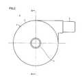
- FIG. 1is a front view showing the appearance of a pump unit of a centrifugal blood pump apparatus according to a first embodiment of the present invention.
- FIG. 2is a side view of the pump unit shown in FIG. 1 .
- FIG. 3is a cross-sectional view along the line III-III in FIG. 2 .
- FIG. 4is a cross-sectional view along the line IV-IV in FIG. 3 .
- FIG. 5is a cross-sectional view showing a state where an impeller has been removed from the cross-sectional view along the line IV-IV in FIG. 3 .
- FIG. 6is a cross-sectional view showing the state where the impeller has been removed from a cross-sectional view along the line VI-VI in FIG. 3 .
- FIG. 7is a cross-sectional view along the line VII-VII in FIG. 3 .
- FIG. 8is a diagram showing a structure of a magnetic element and a coil shown in FIG. 7 .
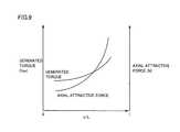
- FIG. 9is a diagram showing relation between x/L shown in FIG. 8 , and generated torque and axial attractive force.
- FIG. 10is a time chart illustrating voltages applied to the plurality of coils shown in FIG. 7 .
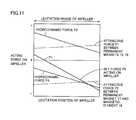
- FIG. 11is a diagram for explaining a levitation position of the impeller shown in FIG. 3 .
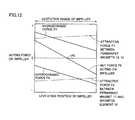
- FIG. 12is another diagram for explaining a levitation position of the impeller shown in FIG. 3 .
- FIG. 13is a block diagram showing a configuration of a controller for controlling the pump unit shown in FIGS. 1 to 7 .
- FIG. 14is a time chart illustrating operation of the controller shown in FIG. 13 .
- FIG. 15is a diagram showing a modification of the first embodiment.
- FIG. 16is a time chart illustrating another modification of the first embodiment.
- FIG. 17is a diagram showing yet another modification of the first embodiment.
- FIG. 18is a diagram showing yet another modification of the first embodiment.
- FIG. 19is a diagram showing yet another modification of the first embodiment.
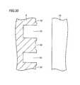
- FIG. 20is a diagram showing yet another modification of the first embodiment.
- FIG. 21is a diagram showing yet another modification of the first embodiment.
- FIG. 22is a diagram showing yet another modification of the first embodiment.
- FIG. 23is a diagram showing yet another modification of the first embodiment.
- FIG. 24is a diagram showing yet another modification of the first embodiment.
- FIG. 25is a diagram showing yet another modification of the first embodiment.
- FIG. 26is a diagram showing yet another modification of the first embodiment.
- FIG. 27is a diagram showing the polarities of permanent magnets 17 , 42 shown in FIG. 26 .
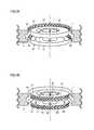
- FIG. 28is a diagram showing grooves for hydrodynamic bearing of a centrifugal blood pump apparatus according to a second embodiment of the present invention.
- FIG. 29is a diagram showing other grooves for hydrodynamic bearing of the centrifugal blood pump apparatus shown in FIG. 28 .
- FIG. 30is a cross-sectional view showing depths of grooves for hydrodynamic bearing 51 , 52 shown in FIG. 28 .
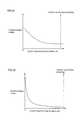
- FIG. 31is a diagram showing relation between a levitation position of the impeller and hydrodynamic force generated by groove for hydrodynamic bearing 51 shown in FIG. 30 .
- FIG. 32is a diagram showing relation between a levitation position of the impeller and hydrodynamic force generated by groove for hydrodynamic bearing 52 shown in FIG. 30 .
- FIG. 33is a diagram of FIGS. 31 and 32 as combined.
- FIG. 34is a diagram showing relation between a ratio between the depths of grooves for hydrodynamic bearing 52 , 51 (or grooves for hydrodynamic bearing 54 , 53 ) and hydrodynamic force.
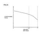
- FIG. 35is a diagram showing relation between a ratio between a width of groove for hydrodynamic bearing 52 and an interval between grooves for hydrodynamic bearing 51 (or a width of groove for hydrodynamic bearing 54 and an interval between grooves for hydrodynamic bearing 53 ) and hydrodynamic force.
- FIG. 36is a diagram showing grooves for hydrodynamic bearing of a centrifugal blood pump apparatus according to a third embodiment of the present invention.
- FIG. 37is a diagram showing a configuration of a permanent magnet shown in FIG. 36 .
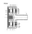
- FIG. 38is a cross-sectional view showing a structure of a centrifugal blood pump apparatus according to a fourth embodiment of the present invention.
- FIG. 39is a diagram illustrating a structure of the grooves for hydrodynamic bearing shown in FIG. 36 .
- FIG. 40is a diagram showing a modification of the fourth embodiment.
- FIG. 41is a diagram showing another modification of the fourth embodiment.
- FIG. 42is a diagram showing yet another modification of the fourth embodiment.
- FIG. 43is a diagram showing yet another modification of the fourth embodiment.
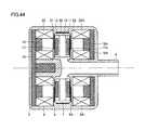
- FIG. 44is a diagram showing yet another modification of the fourth embodiment.
- a pump unit 1 of this centrifugal blood pump apparatusincludes a housing 2 made of a nonmagnetic material.
- Housing 2includes a cylindrical body portion 3 , a cylindrical blood inlet port 4 provided to stand at a center of one end surface of body portion 3 , and a cylindrical blood outlet port 5 provided on an outer circumferential surface of body portion 3 .
- Blood outlet port 5extends in a tangential direction of the outer circumferential surface of body portion 3 .
- a blood chamber 7 and a motor chamber 8 partitioned from each other by a dividing wall 6are provided in housing 2 .
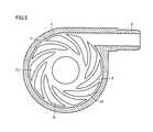
- a disc-shaped impeller 10having a through hole 10 a in a center thereof is rotatably provided in blood chamber 7 .
- Impeller 10includes two shrouds 11 , 12 in a doughnut plate shape, and a plurality of (e.g., six) vanes 13 formed between two shrouds 11 and 12 .
- Shroud 11is arranged on the blood inlet port 4 side
- shroud 12is arranged on the dividing wall 6 side.
- Shrouds 11 , 12 and vanes 13are made of a nonmagnetic material.
- a plurality of (six in this case) blood passages 14 partitioned from one another by the plurality of vanes 13are formed between two shrouds 11 and 12 .
- blood passage 14is in communication with through hole 10 a at the center of impeller 10 , and extends with through hole 10 a of impeller 10 as a starting point to an outer circumference such that blood passage 14 gradually increases in width.
- vane 13is formed between two adjacent blood passages 14 .
- the plurality of vanes 13are provided at regular angular intervals, and they have the same shape.
- the plurality of blood passages 14are provided at regular angular intervals, and they have the same shape.
- a permanent magnet 15is embedded in shroud 11
- a permanent magnet 16 for attracting permanent magnet 15is embedded in an inner wall of blood chamber 7 facing shroud 11 .
- Permanent magnets 15 , 16are provided to attract (in other words, bias) impeller 10 to the side opposite to motor chamber 8 , that is, toward blood inlet port 4 .
- a permanent magnetmay be provided in one of shroud 11 and the inner wall of blood chamber 7 , and a magnetic element may be provided in the other.
- shroud 11itself may be formed of permanent magnet 15 or a magnetic element. Either a soft magnetic element or a hard magnetic element may be used as the magnetic element.
- a single permanent magnet 16 or a plurality of permanent magnets 16may be provided. If a single permanent magnet 16 is provided, permanent magnet 16 is formed in a ring shape. If a plurality of permanent magnets 16 are provided, the plurality of permanent magnets 16 are arranged at regular angular intervals along the same circle. As with permanent magnet 16 , a single permanent magnet 15 or a plurality of permanent magnets 15 may be provided.
- a plurality of (e.g., nine) permanent magnets 17are embedded in shroud 12 .
- the plurality of permanent magnets 17are arranged with a gap therebetween at regular angular intervals along the same circle such that adjacent magnetic polarities thereof are different from each other.
- permanent magnet 17 having the N-pole toward motor chamber 8 and permanent magnet 17 having the S-pole toward motor chamber 8are alternately arranged with a gap therebetween at regular angular intervals along the same circle.
- a plurality of (e.g., nine) magnetic elements 18are provided in motor chamber 8 .
- the plurality of magnetic elements 18are arranged at regular angular intervals along the same circle to face the plurality of permanent magnets 17 in impeller 10 .
- a base end of each of the plurality of magnetic elements 18is joined to one disc-shaped magnetic element 19 .
- a coil 20is wound around each magnetic element 18 .
- the length of magnetic element 18is shorter than that of coil 20 . That is, as shown in FIG. 8 , when an axial length of magnetic element 18 is expressed as x and an axial length of coil 20 is expressed as L relative to the surface of disc-shaped magnetic element 19 , relation of 0 ⁇ x ⁇ L is satisfied.
- a horizontal axis of FIG. 9represents a ratio x/L of the height x of magnetic element 18 to the height L of coil 20 , a left vertical axis represents generated torque (Nm), and a right vertical axis represents axial attractive force (N).
- Ngenerated torque
- Naxial attractive force
- FIG. 9shows that, when the value of x/L is within a certain range, an amount of variation in axial attractive force is greater than an amount of variation in generated torque.
- space for winding coil 20is equally secured around the plurality of magnetic elements 18 , and surfaces facing each other of every two adjacent magnetic elements 18 are provided substantially in parallel to each other.
- a large space for coils 20can be secured and turns of coils 20 can be increased.
- large torque for driving impeller 10 to rotatecan be generated.
- copper loss that occurs in coils 20can be reduced, thereby enhancing energy efficiency when impeller 10 is driven to rotate.
- the plurality of magnetic elements 18may be formed in a cylindrical shape. In this case, a circumferential length of coils 20 can be minimized to reduce copper loss that occurs in coils 20 , thereby enhancing energy efficiency when impeller 10 is driven to rotate.
- An outline surface surrounding the plurality of magnetic elements 18may correspond to an outline surface surrounding the plurality of permanent magnets 17 (a circle surrounding the peripheries of the plurality of magnetic elements 18 in FIG. 4 ), or the outline surface surrounding the plurality of magnetic elements 18 may be larger than the outline surface surrounding the plurality of permanent magnets 17 . Further, it is preferable that magnetic element 18 be designed not to be magnetically saturated at maximum rating of pump 1 (a condition where torque for driving impeller 10 to rotate becomes maximum).
- Voltagesare applied to nine coils 20 in a power distribution system shifted by 120 degrees, for example. That is, nine coils 20 are divided into groups each including three coils. Voltages VU, VV, VW as shown in FIG. 10 are applied to first to third coils 20 of each group, respectively.
- a positive voltageis applied during a period of 0 to 120 degrees
- 0 Vis applied during a period of 120 to 180 degrees
- a negative voltageis applied during a period of 180 to 300 degrees
- 0 Vis applied during a period of 300 to 360 degrees.
- a tip surface of magnetic element 18 having first coil 20 wound therearoundbecomes the N-pole during the period of 0 to 120 degrees, and becomes the S-pole during the period of 180 to 300 degrees.
- Voltage VVis delayed in phase from voltage VU by 120 degrees
- voltage VWis delayed in phase from voltage VV by 120 degrees.
- rotating magnetic fieldcan be formed by applying voltages VU, VV, VW to first to third coils 20 , respectively, so that impeller 10 can be rotated by attractive force and repulsion force between the plurality of magnetic elements 18 and the plurality of permanent magnets 17 in impeller 10 .
- a surface of impeller 10 and a surface of an inner wall of housing 2are not damaged (no projections and recesses in the surfaces) during the relative slide, and moreover, impeller 10 is readily levitated from housing 2 without contacting even when hydrodynamic force is small during low-speed rotation. Accordingly, occurrence of hemolysis/thrombus due to the relative slide between impeller 10 and housing 2 , or occurrence of thrombus due to small damage (projections and recesses) to the surfaces which occurs during the relative slide is avoided.
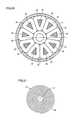
- a plurality of grooves for hydrodynamic bearing 21are formed in a surface of dividing wall 6 facing shroud 12 of impeller 10
- a plurality of grooves for hydrodynamic bearing 22are formed in the inner wall of blood chamber 7 facing shroud 11 .
- the plurality of grooves for hydrodynamic bearing 21are each formed with a size corresponding to shroud 12 of impeller 10 .
- Each groove for hydrodynamic bearing 21has one end on an edge (circumference) of a circular portion slightly distant from a center of dividing wall 6 , and extends spirally (in other words, in a curved manner) toward a portion near an outer edge of dividing wall 6 such that groove for hydrodynamic bearing 21 gradually increases in width.
- the plurality of grooves for hydrodynamic bearing 21have substantially the same shape, and they are arranged at substantially regular intervals.
- Groove for hydrodynamic bearing 21is a concave portion, and it preferably has a depth of about 0.005 to 0.4 mm. It is preferable that about 6 to 36 grooves for hydrodynamic bearing 21 be provided.
- grooves for hydrodynamic bearing 21are equiangularly arranged with respect to the central axis of impeller 10 . Since grooves for hydrodynamic bearing 21 have a so-called inward spiral groove shape, clockwise rotation of impeller 10 causes increase in fluid pressure from an outer diameter portion toward an inner diameter portion of grooves for hydrodynamic bearing 21 . As a result, repulsion force is generated between impeller 10 and dividing wall 6 and it acts as hydrodynamic force.
- grooves for hydrodynamic bearing 21may be provided in a surface of shroud 12 of impeller 10 .
- impeller 10moves away from dividing wall 6 and rotates without contacting. Accordingly, a blood flow path is secured between impeller 10 and dividing wall 6 , thus preventing occurrence of blood accumulation therebetween and the resultant thrombus. Further, in a normal state, grooves for hydrodynamic bearing 21 perform a stirring function between impeller 10 and dividing wall 6 , thus preventing occurrence of partial blood accumulation therebetween.
- a corner portion of each of grooves for hydrodynamic bearing 21be rounded to have R of at least 0.05 mm. As a result, occurrence of hemolysis can further be reduced.
- the plurality of grooves for hydrodynamic bearing 22are each formed with a size corresponding to shroud 11 of impeller 10 .
- Each groove for hydrodynamic bearing 22has one end on an edge (circumference) of a circular portion slightly distant from a center of the inner wall of blood chamber 7 , and extends spirally (in other words, in a curved manner) toward a portion near an outer edge of the inner wall of blood chamber 7 such that groove for hydrodynamic bearing 22 gradually increases in width.
- the plurality of grooves for hydrodynamic bearing 22have substantially the same shape, and they are arranged at substantially regular intervals.
- Groove for hydrodynamic bearing 22is a concave portion, and it preferably has a depth of about 0.005 to 0.4 mm. It is preferable that about 6 to 36 grooves for hydrodynamic bearing 22 be provided. In FIG. 6 , ten grooves for hydrodynamic bearing 22 are equiangularly arranged with respect to the central axis of impeller 10 .
- grooves for hydrodynamic bearing 22may be provided in a surface of shroud 11 of impeller 10 . It is preferable that a corner portion of each of grooves for hydrodynamic bearing 22 be rounded to have R of at least 0.05 mm. As a result, occurrence of hemolysis can further be reduced.
- impeller 10moves away from the inner wall of blood chamber 7 and rotates without contacting.
- impeller 10can be prevented from being in close contact with the inner wall of blood chamber 7 .
- the hydrodynamic force generated by grooves for hydrodynamic bearing 21may be different from the hydrodynamic force generated by grooves for hydrodynamic bearing 22 .
- impeller 10rotate in a state where a gap between shroud 12 of impeller 10 and dividing wall 6 is substantially equal to a gap between shroud 11 of impeller 10 and the inner wall of blood chamber 7 . If one of the gaps becomes narrower due to serious disturbance such as fluid force acting on impeller 10 , it is preferable that grooves for hydrodynamic bearing 21 and 22 have different shapes so that the hydrodynamic force generated by the grooves for hydrodynamic bearing on the narrower side becomes higher than the hydrodynamic force generated by the other grooves for hydrodynamic bearing to make the gaps substantially equal to each other.
- grooves for hydrodynamic bearing 21 , 22While each of grooves for hydrodynamic bearing 21 , 22 has the inward spiral groove shape in FIGS. 5 and 6 , grooves for hydrodynamic bearing 21 , 22 having another shape may be used. Nevertheless, for blood circulation, it is preferable to employ grooves for hydrodynamic bearing 21 , 22 having the inward spiral groove shape that allows a smooth flow of blood.
- FIG. 11is a diagram illustrating forces acting on impeller 10 when magnitude of a resultant force of an attractive force F 1 between permanent magnets 15 and 16 and an attractive force F 2 between permanent magnet 17 and magnetic element 18 is adjusted to zero at a position P 1 other than a central position of the movable range of impeller 10 in blood chamber 7 .
- the rotation speed of impeller 10is kept at a rated value.
- a horizontal axis of FIG. 11represents a position of impeller 10 (the left side in the figure being the dividing wall 6 side), and a vertical axis represents forces acting on impeller 10 .
- Force acting on impeller 10 toward the dividing wall 6 sideis expressed as a negative acting force.
- attractive force F 1 between permanent magnets 15 and 16attractive force F 2 between permanent magnet 17 and magnetic element 18
- a hydrodynamic force F 3generated by grooves for hydrodynamic bearing 21
- a hydrodynamic force F 4 generated by grooves for hydrodynamic bearing 22and a “net force F 5 acting on impeller” which is their resultant force are illustrated.
- FIG. 12illustrates forces acting on impeller 10 when a magnitude of the resultant force of attractive force F 1 between permanent magnets 15 and 16 and attractive force F 2 between permanent magnet 17 and magnetic element 18 is adjusted to zero at a central position P 0 of the movable range of impeller 10 in blood chamber 7 .
- the rotation speed of impeller 10is kept at the rated value in this case as well.
- attractive force F 1 between permanent magnets 15 and 16 and attractive force F 2 between permanent magnet 17 and magnetic element 18are set to be substantially equal to each other.
- grooves for hydrodynamic bearing 21 , 22have the same shape. In this case, supporting rigidity for the levitation position of impeller 10 is higher than in the example shown in FIG. 11 . Further, since net force F 5 acting on impeller 10 is zero at the center of the movable range, impeller 10 is levitated at the central position when a disturbance force is not acting on impeller 10 .
- a levitation position of impeller 10is determined by balance among attractive force F 1 between permanent magnets 15 and 16 , attractive force F 2 between permanent magnet 17 and magnetic element 18 , and hydrodynamic forces F 3 , F 4 generated by grooves for hydrodynamic bearing 21 , 22 during rotation of impeller 10 .
- F 1 and F 2substantially equal to each other and by forming grooves for hydrodynamic bearing 21 , 22 in the same shape, impeller 10 can be levitated substantially in a central portion of blood chamber 7 during rotation of impeller 10 . Since impeller 10 has such a shape that vanes are formed between two discs as shown in FIGS. 3 and 4 , two surfaces facing the inner wall of housing 2 can be formed to have the same shape and the same dimensions. Therefore, it is possible to provide grooves for hydrodynamic bearing 21 , 22 having a function to generate substantially the same hydrodynamic force on both sides of impeller 10 .
- impeller 10is levitated at the central position of blood chamber 7 , and thus held at a position farthest from the inner wall of housing 2 .
- the levitation position of impeller 10is changed due to application of a disturbance force to levitated impeller 10 , the possibility that impeller 10 is brought into contact with the inner wall of housing 2 is lowered, thus also lowering the possibility of occurrence of thrombus and hemolysis resulting from such contact.
- grooves for hydrodynamic bearing 21 , 22may be different from each other in shape and hydrodynamic force generating function.
- performance of a groove for hydrodynamic bearing in the disturbance directionmay be made higher than performance of the other groove for hydrodynamic bearing, thereby levitating and rotating impeller 10 at the central position of housing 2 .
- the probability of contact between impeller 10 and housing 2can be lowered, thereby attaining stable levitation performance of impeller 10 .
- an absolute value of a negative axial supporting rigidity value of impeller 10which is constituted of attractive force F 1 between permanent magnets 15 and 16 and attractive force F 2 between permanent magnet 17 and magnetic element 18 is expressed as Ka
- an absolute value of a positive radial rigidity valueis expressed as Kr
- an absolute value of a positive rigidity value obtained by two grooves for hydrodynamic bearing 21 , 22 in a normal rotation speed range where impeller 10 rotatesis expressed as Kg, it is preferable that relation of Kg>Ka+Kr be satisfied.
- absolute value Kg of the positive rigidity value obtained by two grooves for hydrodynamic bearing 21 , 22 in the rotation speed range where impeller 10 normally rotatesis set to a value higher than 30000 N/m.
- the axial supporting rigidity for impeller 10is a value obtained by subtracting negative rigidity due to the attractive force between the magnetic elements and the like from rigidity resulting from the hydrodynamic force generated by grooves for hydrodynamic bearing 21 , 22 .
- the axial supporting rigidity for impeller 10can be made higher than the radial supporting rigidity. With such setting, movement of impeller 10 can be suppressed more in the axial direction than in the radial direction when a disturbance force acts on impeller 10 , thereby avoiding mechanical contact between impeller 10 and housing 2 in a portion where grooves for hydrodynamic bearing 21 are formed.
- grooves for hydrodynamic bearing 21 , 22are provided as concave portions in planar surfaces as shown in FIGS. 5 and 6 , mechanical contact between housing 2 and impeller 10 in these portions during rotation of impeller 10 may result in damage to one or both of a surface of impeller 10 and a surface of the inner wall of housing 2 (projections and recesses in the surfaces), and blood passage through this portion may cause occurrence of thrombus and hemolysis.
- itis effective to make the axial rigidity higher than the radial rigidity.
- Whirloccurs in unbalanced impeller 10 during rotation, and this whirl is greatest when a natural frequency determined by the mass of impeller 10 and the supporting rigidity value of impeller 10 matches the rotation speed of impeller 10 .
- a maximum rotation speed of impeller 10is equal to or lower than the radial natural frequency. Accordingly, in order to prevent mechanical contact between impeller 10 and housing 2 , when a radial rigidity value of impeller 10 which is constituted of attractive force F 1 between permanent magnets 15 and 16 and attractive force F 2 between permanent magnet 17 and magnetic element 18 is expressed as Kr (N/m), the mass of impeller 10 is expressed as m (kg), and the rotation speed of the impeller is expressed as ⁇ (rad/s), it is preferable that relation of ⁇ (Kr/m) 0.5 be satisfied.
- the maximum rotation speed of impeller 10is set to 258 rad/s (2465 rpm) or lower.
- the maximum rotation speed of impeller 10is set to 366 rad/s (3500 rpm)
- the radial rigidityis set to 4018 N/m or higher.
- the maximum rotation speed of impeller 10it is further preferable to set the maximum rotation speed of impeller 10 to 80% or lower of this ⁇ . Specifically, when the mass of impeller 10 is 0.03 kg and the radial rigidity value is 2000 N/m, the maximum rotation speed is set to 206.4 rad/s (1971 rpm) or lower. Conversely, when it is desired to set the maximum rotation speed of impeller 10 to 366 rad/s (3500 rpm), the radial rigidity value is set to 6279 N/m or higher. By thus setting the maximum rotation speed of impeller 10 , contact between rotating impeller 10 and housing 2 can be suppressed.
- impeller 10When the rigidity due to the hydrodynamic force generated by grooves for hydrodynamic bearing 21 , 22 becomes higher than the negative axial rigidity value of impeller 10 which is constituted of attractive force F 1 between permanent magnets 15 and 16 and attractive force F 2 between permanent magnet 17 and magnetic element 18 , impeller 10 and housing 2 are not in contact with each other. It is thus preferable to minimize this negative rigidity value. In order to minimize the negative rigidity value, it is preferable that surfaces facing each other of permanent magnets 15 , 16 have different sizes.
- impeller 10is in contact with dividing wall 6 before activating impeller 10 to rotate.
- impeller 10when impeller 10 is not rotating, impeller 10 is not supported without contacting by grooves for hydrodynamic bearing 21 , 22 , but is in contact with housing 2 with a high surface pressure due to attractive force F 1 between permanent magnets 15 and 16 and attractive force F 2 between permanent magnet 17 and magnetic element 18 . Further, when impeller 10 is rotated by magnetic interaction between coil 20 and magnetic element 18 in motor chamber 8 and permanent magnet 17 in impeller 10 as in pump unit 1 , starting torque is smaller than in an example where an impeller is driven to rotate through magnetic coupling between permanent magnets as shown in FIG. 3 of PTL 2. It is thus difficult to smoothly activate impeller 10 to rotate.
- this centrifugal blood pump apparatusis provided with means for moving impeller 10 toward dividing wall 6 before activating impeller 10 to rotate. Specifically, a current is fed through the plurality of coils 20 such that attractive force F 2 between permanent magnet 17 and magnetic element 18 becomes higher, to move impeller 10 toward dividing wall 6 .
- FIG. 13is a block diagram showing a configuration of a controller 25 for controlling pump unit 1 .
- controller 25includes a motor control circuit 26 and a power amplifier 27 .
- Motor control circuit 26outputs three-phase control signals in the power distribution system shifted by 120 degrees, for example.
- Power amplifier 27amplifies the three-phase control signals from motor control circuit 26 , and generates three-phase voltages VU, VV, VW shown in FIG. 10 .
- Three-phase voltages VU, VV, VWare applied to first to third coils 20 described with reference to FIGS. 7 and 10 , respectively.
- impeller 10rotates at a prescribed rotation speed at the central position of the movable range.
- FIGS. 14 ( a ) to ( c )are time charts illustrating temporal variations of a coil current I when impeller 10 is activated to rotate, a position of impeller 10 , and a rotation speed of impeller 10 .
- FIGS. 14 ( a ) to ( c )it is assumed that, in an initial state, shroud 11 of impeller 10 is in contact with the inner wall of blood chamber 7 , and impeller 10 is at a position PA.
- a predetermined current I 0is fed through coils 20 .
- coil current Iis gradually increased to a predetermined rated value.
- impeller 10is in contact with dividing wall 6 , and thus smoothly rotates. With the increase in coil current I, impeller 10 moves from position PB on the dividing wall 6 side to the central position of the movable range.
- magnetic elements 18are made shorter than coils 20 in the first embodiment as described above, the axial attractive force can be lowered while required torque is satisfied. Therefore, efficiency enhancement and stable rotation of the impeller can both be attained.
- FIG. 15is a block diagram showing a modification of the first embodiment. This figure shows an example of a configuration where power source supply is switched between during activation of the impeller for rotation and the remaining period.
- power amplifier 27 in FIG. 13is replaced with power amplifiers 30 , 31 and a switch 32 .
- an output signal from motor control circuit 26is provided to power amplifier 30 and an output voltage from power amplifier 30 is applied to coils 20 via switch 32 , causing current I 0 to flow through coils 20 .
- an output signal from motor control circuit 26is provided to power amplifier 31 and an output voltage from power amplifier 31 is applied to coils 20 via switch 32 , causing a current to flow through coils 20 .
- FIGS. 16 ( a ) to ( c )are time charts illustrating another modification of the first embodiment.
- shroud 11 of impeller 10is in contact with the inner wall of blood chamber 7 , and impeller 10 is at position PA.
- a predetermined current I 1is fed through coils 20 .
- Motor control circuit 26outputs three-phase control signals in the power distribution system shifted by 120 degrees, for example.
- Power amplifier 27amplifies the three-phase control signals from motor control circuit 26 and generates three-phase voltages VU, VV, VW shown in FIG. 10 .
- Three-phase voltages VU, VV, VWare applied to first to third coils 20 described with reference to FIG. 7 , respectively. Accordingly, rotating magnetic field is applied to impeller 10 by current I 1 .
- Current I 1is larger than current I 0 in FIG. 14 and it can activate impeller 10 to rotate even when shroud 11 of impeller 10 is in contact with the inner wall of blood chamber 7 . After activation for rotation is confirmed, coil current I is reduced and gradually increased to the predetermined rated value. In this manner, even when impeller 10 is on the position PA side, an overcurrent may be fed through coils 20 only when impeller 10 is activated to rotate.
- a diamond-like carbon (DLC) coatingmay be formed on at least one of the surface of the inner wall of blood chamber 7 and the surface of dividing wall 6 , and the surface of impeller 10 .
- DLCdiamond-like carbon
- a fluorine-based resin coating, a paraxylylene-based resin coating or the likemay be formed instead of the diamond-like carbon coating.
- FIG. 17is a cross-sectional view showing yet another modification of the first embodiment, which is compared to FIG. 3 .
- the surfaces facing each other of permanent magnets 15 and 16have different sizes. While the surfaces facing each other of permanent magnets 15 and 16 have the same size in FIG. 3 , by making the surfaces facing each other of permanent magnets 15 and 16 have different sizes, the amount of variation in attractive force which varies with a distance between the magnets, namely, the negative rigidity, can be minimized, thereby preventing lowering in supporting rigidity for impeller 10 .
- FIG. 18is a cross-sectional view showing yet another modification of the first embodiment, which is compared to FIG. 17 .
- yoke 19is replaced with a yoke 36
- magnetic element 18is replaced with a magnetic element 37 .
- Yoke 36 and magnetic element 37each include a plurality of steel plates stacked in a length direction of a rotation axis of impeller 10 .
- eddy current loss that occurs in yoke 36 and magnetic element 37can be reduced, thereby enhancing energy efficiency when impeller 10 is driven to rotate.
- magnetic element 37may be replaced with a magnetic element 38 including a plurality of steel plates stacked in a rotation direction of impeller 10 .
- magnetic element 37may be replaced with a magnetic element 39 including a plurality of steel plates stacked in a radial direction of impeller 10 .
- the same effect as in the modification in FIG. 18can be obtained in these cases as well.
- each of yoke 19 and magnetic element 18 in FIG. 3may be made of powders of pure iron, soft iron, or ferrosilicon. In this case, iron loss in yoke 19 and magnetic element 18 can be reduced, thereby enhancing energy efficiency when impeller 10 is driven to rotate.
- each magnetic element 18includes a thin strip-shaped magnetic steel plate 18 a wound a plurality of times around a center line L 1 perpendicular to dividing wall 6 .
- Strip-shaped magnetic steel plate 18 ais wound in a length direction, with its width direction toward a direction perpendicular to dividing wall 6 .
- Magnetic steel plate 18 amay be an electromagnetic steel plate having a non-directional or directional magnetic property, or may be made of an amorphous metal or an amorphous alloy.
- Wound magnetic steel plate 18 amay be fixed into a prescribed shape by welding a winding end portion of magnetic steel plate 18 a to magnetic steel plate 18 a itself.
- wound magnetic steel plate 18 amay be fixed into a prescribed shape by immersing the entire magnetic steel plate 18 a in resin and curing the resin.
- magnetic element 18By forming magnetic element 18 using wound, thin strip-shaped magnetic steel plate 18 a in this manner, iron loss in magnetic element 18 can be reduced, and magnetic permeability of a magnetic flux in magnetic element 18 can be increased, thereby enhancing energy efficiency when impeller 10 is driven to rotate. Furthermore, magnetic element 18 can be readily formed, thereby attaining size and cost reductions and productivity enhancement of the apparatus.
- Magnetic steel plate 18 amay be wound in a cylindrical shape, or in a prism shape such as a triangular prism.
- FIG. 21shows a state where magnetic steel plate 18 a has been wound in a cylindrical shape around center line L 1 .
- a circular end surface of magnetic element 18 formed in a cylindrical shape(namely, magnetic steel plate 18 a wound in a cylindrical shape) is arranged to face impeller 10 with dividing wall 6 being interposed.
- Coil 20is wound to surround the entire outer circumferential surface (side surface) of cylindrical magnetic element 18 .
- a circumferential length of coil 20can be minimized to reduce copper loss that occurs in coil 20 , thereby enhancing energy efficiency when impeller 10 is driven to rotate.
- magnetic steel plate 18 acan be wound in a prism shape such as a triangular prism around center line L 1 .
- a triangular end surface of magnetic element 18 formed in a triangular prism shape(namely, magnetic steel plate 18 a wound in a triangular prism shape) is arranged to face impeller 10 with dividing wall 6 being interposed.
- Coil 20is wound to surround the entire side surface of magnetic element 18 in a triangular prism shape.
- space for winding coil 20is equally secured around the plurality of magnetic elements 18 , and surfaces facing each other of every two adjacent magnetic elements 18 are provided substantially in parallel to each other. Thus, a large space for coils 20 can be secured and turns of coils 20 can be increased.
- magnetic element 18be designed not to be magnetically saturated at maximum rating of pump 1 (a condition where torque for driving impeller 10 to rotate becomes maximum).
- FIG. 22is a cross-sectional view showing yet another modification of the first embodiment, which is compared to FIG. 21 .
- a notch 40is formed from an inner circumferential surface toward an outer circumferential surface of magnetic element 18 . That is, magnetic steel plate 18 a is wound a plurality of times around center line L 1 , and constitutes a plurality of tubular members concentrically arranged. Notch 40 cuts each of the plurality of tubular members in a direction parallel to center line L 1 on one side of center line L 1 (right side in FIG. 22 ). In this modification, iron loss in magnetic element 18 can be reduced owing to the provision of notch 40 .
- FIG. 23is a cross-sectional view showing yet another modification of the first embodiment, which is compared to FIG. 21 .
- a rod-like magnetic element 41which is a soft magnetic element is used as a core member in magnetic element 18 .
- Magnetic steel plate 18 ais wound a plurality of times around magnetic element 41 .
- Magnetic steel plate 18 amay be fixed into a prescribed shape by welding one end of magnetic steel plate 18 a to magnetic element 41 and the other end of magnetic steel plate 18 a to magnetic steel plate 18 a itself.
- magnetic steel plate 18 amay be fixed into a prescribed shape by immersing the entire magnetic element 41 and magnetic steel plate 18 a in resin and curing the resin.
- FIG. 24is a diagram showing yet another modification of the first embodiment.
- each magnetic element 18includes magnetic element 41 and magnetic steel plate 18 a .
- the length of rod-like magnetic element 41is longer than the width of magnetic steel plate 18 a .
- Magnetic steel plate 18 ais wound around an upper end portion of magnetic element 41 , with a lower end portion of magnetic element 41 protruding from magnetic steel plate 18 a wound in a cylindrical shape.
- Disc-shaped magnetic element 19has holes 19 a provided in correspondence with magnetic elements 18 .
- the lower end portion of magnetic element 41is inserted in hole 19 a of magnetic element 19 .
- Magnetic element 41is fixed in hole 19 a by bonding, press fitting, or shrink fitting.
- An inner circumferential portion of cylindrical coil 20fits with an outer circumferential portion of magnetic element 18 .
- magnetic element 18can be readily assembled and fixed to magnetic element 19 without using a positioning jig and the like, thus improving workability.
- magnetic element 19may be formed by winding a strip-shaped magnetic steel plate 19 a a plurality of times around a center line L 2 . In this case, iron loss in magnetic element 19 can be reduced, thereby enhancing energy efficiency when impeller 10 is driven to rotate. If magnetic steel plate 19 a having a non-directional or directional magnetic property is used, magnetic permeability of a magnetic flux in magnetic element 19 can be increased, thereby enhancing energy efficiency when impeller 10 is driven to rotate.
- the plurality of permanent magnets 17 and a plurality of permanent magnets 42are embedded in shroud 12 .
- the number of permanent magnets 42is the same as the number of permanent magnets 17 .
- Permanent magnets 42are magnetized in a circumferential direction (the rotation direction of impeller 10 ).
- the plurality of permanent magnets 17 and the plurality of permanent magnets 42are alternately arranged one by one in the Halbach array at regular angular intervals along the same circle.
- permanent magnet 17 having the N-pole toward dividing wall 6 and permanent magnet 17 having the S-pole toward dividing wall 6are alternately arranged with a gap therebetween at regular angular intervals along the same circle.
- the N-pole of each permanent magnet 42is arranged toward permanent magnet 17 having the N-pole toward dividing wall 6
- the S-pole of each permanent magnet 42is arranged toward permanent magnet 17 having the S-pole toward dividing wall 6 .
- the plurality of permanent magnets 17have the same shape, and the plurality of permanent magnets 42 have the same shape.
- Permanent magnets 17may have a shape the same as or different from the shape of permanent magnets 42 .
- FIGS. 28 and 29are diagrams showing a substantial part of a centrifugal blood pump apparatus according to a second embodiment of the present invention, which are compared to FIGS. 5 and 6 , respectively.
- a plurality of grooves for hydrodynamic bearing 51 and a plurality of grooves for hydrodynamic bearing 52are formed in a surface of dividing wall 6 facing shroud 12 of impeller 10
- a plurality of grooves for hydrodynamic bearing 53 and a plurality of grooves for hydrodynamic bearing 54are formed in the inner wall of blood chamber 7 facing shroud 11 .
- the plurality of grooves for hydrodynamic bearing 51 and the plurality of grooves for hydrodynamic bearing 52are each formed with a size corresponding to shroud 12 of impeller 10 .
- the plurality of grooves for hydrodynamic bearing 51 and the plurality of grooves for hydrodynamic bearing 52are alternately arranged one by one, in the direction of rotation of impeller 10 .
- Each of grooves for hydrodynamic bearing 51 , 52has one end on an edge (circumference) of a circular portion slightly distant from a center of dividing wall 6 , and extends spirally (in other words, in a curved manner) toward a portion near an outer edge of dividing wall 6 such that grooves for hydrodynamic bearing 51 , 52 gradually increase in width.
- the plurality of grooves for hydrodynamic bearing 51have substantially the same shape, and they are arranged at regular angular intervals in the direction of rotation of impeller 10 .
- Groove for hydrodynamic bearing 51is a concave portion, and it preferably has a depth of about 0.005 to 0.4 mm. It is preferable that about 6 to 36 grooves for hydrodynamic bearing 51 be provided.
- the plurality of grooves for hydrodynamic bearing 52have substantially the same shape, and they are arranged at regular angular intervals in the direction of rotation of impeller 10 .
- Groove for hydrodynamic bearing 52is a concave portion, and it preferably has a depth of about 0.005 to 0.3 mm.
- groove for hydrodynamic bearing 52is shallower than groove for hydrodynamic bearing 51 .
- Groove for hydrodynamic bearing 52has a depth preferably not greater than one fifth as great as a depth of groove for hydrodynamic bearing 52 .
- groove for hydrodynamic bearing 52has a width preferably not greater than two thirds as great as an interval between two grooves for hydrodynamic bearing 51 .
- the number of grooves for hydrodynamic bearing 52is preferably equal to or smaller than the number of grooves for hydrodynamic bearing 51 .
- each of grooves for hydrodynamic bearing 51 , 52has a so-called inward spiral groove shape, clockwise rotation of impeller 10 causes increase in fluid pressure from an outer diameter portion toward an inner diameter portion of grooves for hydrodynamic bearing 51 , 52 . As a result, repulsion force is generated between impeller 10 and dividing wall 6 and it acts as hydrodynamic force.
- FIG. 31is a diagram showing relation between a levitation position of impeller 10 when viewed from the surface of dividing wall 6 and hydrodynamic force received by impeller 10 from groove for hydrodynamic bearing 51 when impeller 10 is rotated at a prescribed rotation speed.
- FIG. 32is a diagram showing relation between a distance between impeller 10 and dividing wall 6 and hydrodynamic force received by impeller 10 from groove for hydrodynamic bearing 52 when impeller 10 is rotated at a prescribed rotation speed.
- FIG. 33is a diagram of FIGS. 31 and 32 as combined.
- groove for hydrodynamic bearing 51generates hydrodynamic force higher than that generated by groove for hydrodynamic bearing 52 when a distance between impeller 10 and dividing wall 6 is long.
- groove for hydrodynamic bearing 52generates hydrodynamic force higher than that generated by groove for hydrodynamic bearing 51 when a distance between impeller 10 and dividing wall 6 is short. Therefore, in the second embodiment, since both of grooves for hydrodynamic bearing 51 , 52 are provided, high hydrodynamic force can be obtained in both cases of activation for rotation and steady rotation.
- impeller 10moves away from dividing wall 6 and rotates without contacting. Accordingly, impeller 10 is smoothly activated to rotate and a blood flow path is secured between impeller 10 and dividing wall 6 , thus preventing occurrence of blood accumulation therebetween and the resultant thrombus. Further, in a normal state, grooves for hydrodynamic bearing 51 , 52 perform a stirring function between impeller 10 and dividing wall 6 , thus preventing occurrence of partial blood accumulation therebetween.
- grooves for hydrodynamic bearing 51 , 52may be provided in a surface of shroud 12 of impeller 10 .
- a corner portion of each of grooves for hydrodynamic bearing 51 , 52be rounded to have R of at least 0.05 mm. As a result, occurrence of hemolysis can further be reduced.
- FIG. 34is a diagram showing relation between a ratio D 52 /D 51 between a depth D 52 of groove for hydrodynamic bearing 52 and a depth D 51 of groove for hydrodynamic bearing 51 and hydrodynamic force acting on impeller 10 while impeller 10 is located at a steady rotation levitation position.
- FIG. 33in a case where impeller 10 is located at a position proximate to dividing wall 6 , high hydrodynamic force is generated by adding groove for hydrodynamic bearing 52 .
- FIG. 34when impeller 10 is located at a steady rotation levitation position, hydrodynamic force lowers by adding groove for hydrodynamic bearing 52 .
- a depth and a width of groove for hydrodynamic bearing 52should be determined such that lowering in hydrodynamic force or rigidity caused by addition of groove for hydrodynamic bearing 52 does not adversely affect pump performance.
- ratio D 52 /D 51is set to 1/5 or lower.
- FIG. 35is a diagram showing relation between a ratio W 52 /WL 51 between a width W 52 of groove for hydrodynamic bearing 52 and an interval between grooves for hydrodynamic bearing 51 (a width of a land portion between grooves for hydrodynamic bearing 51 ) WL 51 while impeller 10 is located at a steady levitation position and hydrodynamic force acting on impeller 10 .
- ratio W 52 /WL 51is set to 2/3 or lower.
- the plurality of grooves for hydrodynamic bearing 53 and the plurality of grooves for hydrodynamic bearing 54are each formed with a size corresponding to shroud 11 of impeller 10 .
- Each of grooves for hydrodynamic bearing 53 , 54has one end on the edge (circumference) of the circular portion slightly distant from the center of the inner wall of blood chamber 7 , and extends spirally (in other words, in a curved manner) toward the portion near the outer edge of the inner wall of blood chamber 7 such that grooves for hydrodynamic bearing 53 , 54 gradually increase in width.
- the plurality of grooves for hydrodynamic bearing 53have substantially the same shape and they are arranged at substantially regular intervals.
- Groove for hydrodynamic bearing 53is a concave portion and it preferably has a depth of about 0.005 to 0.4 mm. It is preferable that about 6 to 36 grooves for hydrodynamic bearing 53 be provided.
- ten grooves for hydrodynamic bearing 53are equiangularly arranged with respect to the central axis of impeller 10 .
- the plurality of grooves for hydrodynamic bearing 54have substantially the same shape and they are arranged at regular angular intervals in the direction of rotation of impeller 10 .
- Groove for hydrodynamic bearing 54is a concave portion and it preferably has a depth of about 0.005 to 0.3 mm. It is preferable that about 6 to 36 grooves for hydrodynamic bearing 54 be provided.
- groove for hydrodynamic bearing 54is shallower than groove for hydrodynamic bearing 53 .
- Groove for hydrodynamic bearing 54has a depth preferably not greater than one fifth as great as a depth of groove for hydrodynamic bearing 53 .
- groove for hydrodynamic bearing 54has a width preferably not greater than two thirds as great as an interval between two grooves for hydrodynamic bearing 53 .
- the number of grooves for hydrodynamic bearing 54is preferably equal to or smaller than the number of grooves for hydrodynamic bearing 53 .
- each of grooves for hydrodynamic bearing 53 , 54has a so-called inward spiral groove shape, clockwise rotation of impeller 10 causes increase in fluid pressure from an outer diameter portion toward an inner diameter portion of grooves for hydrodynamic bearing 53 , 54 . As a result, repulsion force is generated between impeller 10 and the inner wall of blood chamber 7 and it acts as hydrodynamic force.
- groove for hydrodynamic bearing 53generates hydrodynamic force higher than that generated by groove for hydrodynamic bearing 54 when a distance between impeller 10 and the inner wall of blood chamber 7 is long.
- groove for hydrodynamic bearing 54generates hydrodynamic force higher than that generated by groove for hydrodynamic bearing 53 when a distance between impeller 10 and the inner wall of blood chamber 7 is short. Therefore, in the second embodiment, since both of grooves for hydrodynamic bearing 53 , 54 are provided, high hydrodynamic force can be obtained in both cases of activation for rotation and steady rotation.
- impeller 10moves away from the inner wall of blood chamber 7 and rotates without contacting. Accordingly, impeller 10 is smoothly activated to rotate and a blood flow path is secured between impeller 10 and the inner wall of blood chamber 7 , thus preventing occurrence of blood accumulation therebetween and the resultant thrombus. Further, in a normal state, grooves for hydrodynamic bearing 53 , 54 perform a stirring function between impeller 10 and the inner wall of blood chamber 7 , thus preventing occurrence of partial blood accumulation therebetween.
- impeller 10when pump unit 1 is subjected to external impact or when the hydrodynamic force by grooves for hydrodynamic bearing 51 , 52 becomes excessive, impeller 10 can be prevented from being in close contact with the inner wall of blood chamber 7 .
- the hydrodynamic force generated by grooves for hydrodynamic bearing 51 , 52may be different from the hydrodynamic force generated by grooves for hydrodynamic bearing 53 , 54 .
- grooves for hydrodynamic bearing 53 , 54may be provided in a surface of shroud 11 of impeller 10 .
- a corner portion of each of grooves for hydrodynamic bearing 53 , 54be rounded to have R of at least 0.05 mm. As a result, occurrence of hemolysis can further be reduced.
- a ratio D 54 /D 53 between a depth D 54 of groove for hydrodynamic bearing 54 and a depth D 53 of groove for hydrodynamic bearing 53is set to 1/5 or lower.
- a ratio W 54 /WL 53 between a width W 54 of groove for hydrodynamic bearing 54 and an interval between grooves for hydrodynamic bearing 53 (a width of a land portion between grooves for hydrodynamic bearing 53 ) WL 53is set to 2/3 or lower.
- impeller 10rotate in a state where a gap between shroud 12 of impeller 10 and dividing wall 6 is substantially equal to a gap between shroud 11 of impeller 10 and the inner wall of blood chamber 7 .
- grooves for hydrodynamic bearing 51 , 52 and 53 , 54have different shapes so that hydrodynamic force generated by the grooves for hydrodynamic bearing on the narrower side becomes higher than the hydrodynamic force generated by the other grooves for hydrodynamic bearing to make the gaps substantially equal to each other.
- grooves for hydrodynamic bearing 51 to 54has the inward spiral groove shape in FIGS. 28 and 29
- grooves for hydrodynamic bearing 51 to 54 having another shapemay be used. Nevertheless, for blood circulation, it is preferable to employ grooves for hydrodynamic bearing 51 to 54 having the inward spiral groove shape that allows a smooth flow of blood.
- FIG. 36is a diagram showing a substantial part of a centrifugal blood pump apparatus according to a third embodiment of the present invention, which is compared to FIG. 3 .
- permanent magnet 15is radially divided into two permanent magnets 15 a , 15 b
- permanent magnet 16is radially divided into two permanent magnets 16 a , 16 b . That is, permanent magnets 15 a , 15 b are embedded in shroud 11 , and permanent magnets 16 a , 16 b for attracting permanent magnets 15 a , 15 b , respectively, are embedded in the inner wall of blood chamber 7 facing shroud 11 .
- Permanent magnets 15 a , 15 b , 16 a , 16 bare provided to attract (in other words, bias) impeller 10 to the side opposite to motor chamber 8 , that is, toward blood inlet port 4 .
- FIGS. 37 ( a ) and ( b )are diagrams showing configurations of permanent magnets 15 a , 15 b , 16 a , 16 b
- FIG. 37 ( a )is a cross-sectional view along the line XXXVIIA-XXXVIIA in FIG. 37 ( b )
- each of permanent magnets 15 a , 15 bis formed in an annular ring shape, and an outer diameter of permanent magnet 15 a is smaller than an inner diameter of permanent magnet 15 b .
- Permanent magnets 15 a , 15 bare coaxially provided, with center points of both permanent magnets 15 a , 15 b being arranged on a rotation center line of impeller 10 . Permanent magnets 15 a , 15 b have the N-poles toward the same direction.
- each of permanent magnets 16 a , 16 bis formed in an arc shape, and two permanent magnets 16 a and two permanent magnets 16 b are arranged in the rotation direction of impeller 10 .
- An outer diameter and an inner diameter of two permanent magnets 16 a arranged in an annular ring shapeare equal to the outer diameter and the inner diameter of permanent magnet 15 a .
- An outer diameter and an inner diameter of two permanent magnets 16 b arranged in an annular ring shapeare equal to the outer diameter and the inner diameter of permanent magnet 15 b .
- Permanent magnets 16 a , 16 bhave the N-poles toward the same direction.
- the S-poles of permanent magnets 15 a , 15 bface the N-poles of permanent magnets 16 a , 16 b , respectively.
- an interval between permanent magnets 15 a and 15 b(i.e., an interval between permanent magnets 16 a and 16 b ) D 1 is set to be larger than a distance D 2 which is half the radially movable distance of impeller 10 (i.e., a distance which is the difference between an inner diameter of blood chamber 7 and an outer diameter of impeller 10 ) (D 1 >D 2 ).
- D 1 ⁇ D 2is satisfied and when impeller 10 moves to a radial maximum position, permanent magnets 15 a and 16 b , and permanent magnets 15 b and 16 a interfere with each other, respectively, causing restoring force for restoring impeller 10 to the central position of the pump to be unstable.
- radial supporting rigidity for impeller 10can be made higher than in an example where only one pair of permanent magnets is provided in the radial direction of impeller 10 .
- a permanent magnetmay be provided in one of shroud 11 and the inner wall of blood chamber 7 , and a magnetic element may be provided in the other. Either a soft magnetic element or a hard magnetic element may be used as the magnetic element.
- the surfaces facing each other of permanent magnets 15 a and 16 ahave the same size and the surfaces facing each other of permanent magnets 15 b and 16 b have the same size in FIG. 36 , it is preferable that the surfaces facing each other of permanent magnets 15 a and 16 a have different sizes and the surfaces facing each other of permanent magnets 15 b and 16 b have different sizes in order to prevent lowering in rigidity for impeller 10 resulting from the attractive force between permanent magnets 15 a , 15 b and permanent magnets 16 a , 16 b .
- each of permanent magnets 15 a , 15 bis formed in an annular ring shape and each of permanent magnets 16 a , 16 b is formed in an arc shape, with two permanent magnets 16 a and two permanent magnets 16 b being arranged at regular angular intervals in the rotation direction of impeller 10 in FIGS. 37 ( a ) and ( b )
- each of permanent magnets 16 a , 16 bmay be formed in an annular ring shape and each of permanent magnets 15 a , 15 b may be formed in an arc shape, with two permanent magnets 15 a and two permanent magnets 15 b being arranged at regular angular intervals in the rotation direction of impeller 10 .
- each of permanent magnets 15 a , 15 b or each of permanent magnets 16 a , 16 bmay be formed in a shorter arc shape, and a plurality of them may be arranged at regular angular intervals in the rotation direction of impeller 10 .
- FIG. 38is a cross-sectional view showing a substantial part of a centrifugal blood pump apparatus according to a fourth embodiment of the present invention, which is compared to FIG. 36 .
- this centrifugal blood pump apparatusis different from the centrifugal blood pump apparatus shown in FIG. 36 in that a groove for hydrodynamic bearing 60 is formed in an inner circumferential surface of blood chamber 7 facing an outer circumferential surface of impeller 10 .
- Groove for hydrodynamic bearing 60generates hydrodynamic force for the outer circumferential surface of impeller 10 , to prevent the outer circumferential surface of impeller 10 from making contact with the inner circumferential surface of blood chamber 7 .
- FIG. 39is a diagram illustrating a specific structure of groove for hydrodynamic bearing 60 .
- V-shaped grooves for hydrodynamic bearing 61are formed at a prescribed pitch in the rotation direction of impeller 10 .
- V-shaped groove for hydrodynamic bearing 61has a tip (acute angle portion) toward the rotation direction of impeller 10 .
- V-shaped grooves for hydrodynamic bearing 62are formed at a prescribed pitch in the rotation direction of impeller 10 in an area of the inner circumferential surface of blood chamber 7 facing an outer circumferential surface of shroud 12 .
- V-shaped groove for hydrodynamic bearing 62has a tip (acute angle portion) toward the rotation direction of impeller 10 .
- a groove 63 having a prescribed depthis formed in a ring shape. Rotation of impeller 10 in a direction of an arrow causes increase in fluid pressure toward the tip portions of grooves for hydrodynamic bearing 61 , 62 . As a result, repulsion force is generated between impeller 10 and the inner circumferential surface of blood chamber 7 and it acts as hydrodynamic force.
- FIG. 40is a diagram showing a modification of the fourth embodiment, which is compared to FIG. 39 .
- grooves for hydrodynamic bearing 61 , 62are formed in the outer circumferential surfaces of shrouds 11 , 12 , respectively, instead of being formed in the inner circumferential surface of blood chamber 7 .
- Each of grooves for hydrodynamic bearing 61 , 62has a tip toward a direction opposite to the rotation direction of impeller 10 . Rotation of impeller 10 in a direction of an arrow causes increase in fluid pressure toward the tip portions of grooves for hydrodynamic bearing 61 , 62 . As a result, repulsion force is generated between impeller 10 and the inner circumferential surface of blood chamber 7 and it acts as hydrodynamic force.
- FIG. 41is a diagram showing another modification of the fourth embodiment, which is compared to FIG. 39 .
- grooves for hydrodynamic bearing 61 , 62are replaced with grooves for hydrodynamic bearing 64 , 65 , respectively.
- Each of grooves for hydrodynamic bearing 64 , 65is formed in a strip shape, and extends in the rotation direction of impeller 10 .
- Each of grooves for hydrodynamic bearing 64 , 65has a depth that gradually decreases toward the rotation direction of impeller 10 .
- rotation of impeller 10 in a direction of an arrowcauses increase in fluid pressure toward the tip portions of grooves for hydrodynamic bearing 64 , 65 .
- repulsion forceis generated between impeller 10 and the inner circumferential surface of blood chamber 7 and it acts as hydrodynamic force.
- FIG. 42is a diagram showing yet another modification of the fourth embodiment, which is compared to FIG. 41 .
- grooves for hydrodynamic bearing 64 , 65are formed in the outer circumferential surfaces of shrouds 11 , 12 , respectively, instead of being formed in the inner circumferential surface of blood chamber 7 .
- Each of grooves for hydrodynamic bearing 64 , 65has a depth that gradually decreases toward a direction opposite to the rotation direction of impeller 10 .
- rotation of impeller 10 in a direction of an arrowcauses increase in fluid pressure toward the tip portions of grooves for hydrodynamic bearing 64 , 65 .
- repulsion forceis generated between impeller 10 and the inner circumferential surface of blood chamber 7 and it acts as hydrodynamic force.
- FIG. 43is a diagram showing yet another modification of the fourth embodiment, which is compared to FIG. 38 .
- permanent magnets 15 a , 15 b , 16 a , 16 bhave been removed.
- This structureis possible by making magnetic elements 18 shorter than coils 20 so that the attractive force between permanent magnets 17 and magnetic elements 18 becomes smaller than hydrodynamic force F 3 during rated rotation substantially in the center of the movable range of impeller 10 in blood chamber 7 .
- force which is the sum of hydrodynamic force F 4 during rated rotation generated by grooves for hydrodynamic bearing 22 and attractive force F 2 between magnetic elements 18 and permanent magnets 17 (F 2 +F 4 ) and hydrodynamic force F 3 during rated rotation generated by grooves for hydrodynamic bearing 21are set to be balanced with each other substantially in the center of the movable range of impeller 10 in blood chamber 7 .
- FIG. 44is a diagram showing yet another modification of the fourth embodiment, which is compared to FIG. 43 .
- a plurality of permanent magnets 17 Aare provided in shroud 11 as well, and a motor chamber 8 A is provided on the shroud 11 side as well.
- Motor chamber 8 A and blood chamber 7are partitioned from each other by a dividing wall 6 A.
- a plurality of magnetic elements 18 Aare provided in motor chamber 8 A to face the plurality of permanent magnets 17 A.
- a coil 20 Ais wound around each magnetic element 18 A, which is joined to a disc-shaped magnetic element 19 A. In the direction of the central axis of impeller 10 , magnetic element 18 A is shorter than coil 20 A.
- first attractive force between the plurality of permanent magnets 17 and the plurality of magnetic elements 18 and second attractive force between the plurality of permanent magnets 17 A and the plurality of magnetic elements 18 Bare set to be balanced with each other substantially in the center of the movable range of impeller 10 in blood chamber 7 .
- 1 pump unit2 housing; 3 body portion; 4 blood inlet port; 5 blood outlet port; 6 , 6 A dividing wall; 7 blood chamber; 8 , 8 A motor chamber; 10 impeller; 10 a through hole; 11 , 12 shroud; 13 vane; 14 blood passage; 15 to 17 , 15 a , 15 b , 16 a , 16 b , 42 permanent magnet; 18 , 18 A, 19 , 19 A, 36 to 39 , 41 magnetic element; 18 a , 19 a magnetic steel plate; 20 , 20 A coil; 21 , 22 , 51 , 52 , 60 to 62 , 64 , 65 groove for hydrodynamic bearing; 25 controller; 26 motor control circuit; 27 , 30 , 31 power amplifier; 32 switch; 40 notch; 63 groove.
Landscapes
- Engineering & Computer Science (AREA)
- Health & Medical Sciences (AREA)
- Heart & Thoracic Surgery (AREA)
- Mechanical Engineering (AREA)
- Cardiology (AREA)
- General Health & Medical Sciences (AREA)
- Life Sciences & Earth Sciences (AREA)
- Veterinary Medicine (AREA)
- Public Health (AREA)
- Animal Behavior & Ethology (AREA)
- Anesthesiology (AREA)
- Biomedical Technology (AREA)
- Hematology (AREA)
- General Engineering & Computer Science (AREA)
- Physics & Mathematics (AREA)
- Power Engineering (AREA)
- Fluid Mechanics (AREA)
- Electromagnetism (AREA)
- Structures Of Non-Positive Displacement Pumps (AREA)
- External Artificial Organs (AREA)
Abstract
Description
- PTL 1: Japanese Patent Laying-Open No. 2004-209240
- PTL 2: Japanese Patent Laying-Open No. 2006-167173
- PTL 3: Japanese Patent Laying-Open No. 4-91396
- PTL 4: Japanese Utility Model Laying-Open No. 6-53790
Claims (18)
Applications Claiming Priority (3)
| Application Number | Priority Date | Filing Date | Title |
|---|---|---|---|
| JP2010-205787 | 2010-09-14 | ||
| JP2010205787AJP5577506B2 (en) | 2010-09-14 | 2010-09-14 | Centrifugal pump device |
| PCT/JP2011/070450WO2012036059A1 (en) | 2010-09-14 | 2011-09-08 | Centrifugal pump device |
Related Parent Applications (1)
| Application Number | Title | Priority Date | Filing Date |
|---|---|---|---|
| PCT/JP2011/070450A-371-Of-InternationalWO2012036059A1 (en) | 2010-09-14 | 2011-09-08 | Centrifugal pump device |
Related Child Applications (1)
| Application Number | Title | Priority Date | Filing Date |
|---|---|---|---|
| US15/174,639DivisionUS9638202B2 (en) | 2010-09-14 | 2016-06-06 | Centrifugal pump apparatus |
Publications (2)
| Publication Number | Publication Date |
|---|---|
| US20130170970A1 US20130170970A1 (en) | 2013-07-04 |
| US9382908B2true US9382908B2 (en) | 2016-07-05 |
Family
ID=45831522
Family Applications (2)
| Application Number | Title | Priority Date | Filing Date |
|---|---|---|---|
| US13/822,220Active2032-11-18US9382908B2 (en) | 2010-09-14 | 2011-09-08 | Centrifugal pump apparatus |
| US15/174,639ActiveUS9638202B2 (en) | 2010-09-14 | 2016-06-06 | Centrifugal pump apparatus |
Family Applications After (1)
| Application Number | Title | Priority Date | Filing Date |
|---|---|---|---|
| US15/174,639ActiveUS9638202B2 (en) | 2010-09-14 | 2016-06-06 | Centrifugal pump apparatus |
Country Status (4)
| Country | Link |
|---|---|
| US (2) | US9382908B2 (en) |
| EP (1) | EP2618001B1 (en) |
| JP (1) | JP5577506B2 (en) |
| WO (1) | WO2012036059A1 (en) |
Cited By (29)
| Publication number | Priority date | Publication date | Assignee | Title |
|---|---|---|---|---|
| US20160061209A1 (en)* | 2013-05-23 | 2016-03-03 | Rheinisch-Westfälische Technische Hochschule Aache | Impeller of a centrifugal pump apparatus |
| US20170016449A1 (en)* | 2015-07-14 | 2017-01-19 | Hamilton Sundstrand Corporation | Axial-flux induction motor pump |
| US9623161B2 (en) | 2014-08-26 | 2017-04-18 | Tc1 Llc | Blood pump and method of suction detection |
| US9638202B2 (en) | 2010-09-14 | 2017-05-02 | Tc1 Llc | Centrifugal pump apparatus |
| US9709061B2 (en) | 2013-01-24 | 2017-07-18 | Tc1 Llc | Impeller position compensation using field oriented control |
| US9850906B2 (en) | 2011-03-28 | 2017-12-26 | Tc1 Llc | Rotation drive device and centrifugal pump apparatus employing same |
| US10052420B2 (en) | 2013-04-30 | 2018-08-21 | Tc1 Llc | Heart beat identification and pump speed synchronization |
| US20180252228A1 (en)* | 2015-08-25 | 2018-09-06 | Reinheart Gmbh | Active magnetic bearing |
| US10117983B2 (en) | 2015-11-16 | 2018-11-06 | Tc1 Llc | Pressure/flow characteristic modification of a centrifugal pump in a ventricular assist device |
| US10166318B2 (en) | 2015-02-12 | 2019-01-01 | Tc1 Llc | System and method for controlling the position of a levitated rotor |
| US10245361B2 (en) | 2015-02-13 | 2019-04-02 | Tc1 Llc | Impeller suspension mechanism for heart pump |
| WO2019139686A1 (en) | 2018-01-10 | 2019-07-18 | Tc1 Llc | Bearingless implantable blood pump |
| US10371152B2 (en) | 2015-02-12 | 2019-08-06 | Tc1 Llc | Alternating pump gaps |
| US10506935B2 (en) | 2015-02-11 | 2019-12-17 | Tc1 Llc | Heart beat identification and pump speed synchronization |
| EP3597231A1 (en) | 2018-07-17 | 2020-01-22 | Tc1 Llc | Systems and methods for inertial sensing for vad diagnostics and closed loop control |
| WO2020068333A1 (en) | 2018-09-25 | 2020-04-02 | Tc1 Llc | Adaptive speed control algorithms and controllers for optimizing flow in ventricular assist devices |
| US11712501B2 (en) | 2019-11-12 | 2023-08-01 | Fresenius Medical Care Deutschland Gmbh | Blood treatment systems |
| US11730871B2 (en) | 2019-11-12 | 2023-08-22 | Fresenius Medical Care Deutschland Gmbh | Blood treatment systems |
| WO2023158493A1 (en) | 2022-02-16 | 2023-08-24 | Tc1 Llc | Real time heart rate monitoring for close loop control and/or artificial pulse synchronization of implantable ventricular assist devices |
| US11752247B2 (en) | 2019-11-12 | 2023-09-12 | Fresenius Medical Care Deutschland Gmbh | Blood treatment systems |
| WO2023229899A1 (en) | 2022-05-26 | 2023-11-30 | Tc1 Llc | Tri-axis accelerometers for patient physiologic monitoring and closed loop control of implantable ventricular assist devices |
| WO2023235230A1 (en) | 2022-06-02 | 2023-12-07 | Tc1 Llc | Implanted connector booster sealing for implantable medical devices |
| WO2024050319A1 (en) | 2022-08-29 | 2024-03-07 | Tc1 Llc | Implantable electrical connector assembly |
| US11925736B2 (en) | 2019-11-12 | 2024-03-12 | Fresenius Medical Care Deutschland Gmbh | Blood treatment systems |
| WO2024097236A1 (en) | 2022-11-01 | 2024-05-10 | Tc1 Llc | Assessment and management of adverse event risks in mechanical circulatory support patients |
| US12285553B2 (en) | 2019-11-12 | 2025-04-29 | Fresenius Medical Care Deutschland Gmbh | Blood treatment systems |
| US12329890B2 (en) | 2019-11-12 | 2025-06-17 | Fresenius Medical Care Deutschland Gmbh | Blood treatment systems |
| WO2025137296A1 (en) | 2023-12-22 | 2025-06-26 | Tc1 Llc | Utilization of a left-ventricular pressure sensor for measurement of left-atrial and aortic pressure |
| US20250215878A1 (en)* | 2024-01-03 | 2025-07-03 | Purrsong, Inc. | Water supplier for pets |
Families Citing this family (82)
| Publication number | Priority date | Publication date | Assignee | Title |
|---|---|---|---|---|
| JP5171953B2 (en) | 2008-06-23 | 2013-03-27 | テルモ株式会社 | Blood pump device |
| EP2372160B1 (en) | 2008-12-08 | 2014-07-30 | Thoratec Corporation | Centrifugal pump device |
| JP5378010B2 (en) | 2009-03-05 | 2013-12-25 | ソラテック コーポレーション | Centrifugal pump device |
| CN102341600B (en) | 2009-03-06 | 2014-12-10 | 胸腔科技有限公司 | Centrifugal pump device |
| JP5443197B2 (en) | 2010-02-16 | 2014-03-19 | ソラテック コーポレーション | Centrifugal pump device |
| JP5572832B2 (en) | 2010-03-26 | 2014-08-20 | ソーラテック コーポレイション | Centrifugal blood pump device |
| JP5681403B2 (en) | 2010-07-12 | 2015-03-11 | ソーラテック コーポレイション | Centrifugal pump device |
| JP6083929B2 (en) | 2012-01-18 | 2017-02-22 | ソーラテック コーポレイション | Centrifugal pump device |
| US10857274B2 (en) | 2012-11-06 | 2020-12-08 | Queen Mary University Of London | Mechanical circulatory support device with centrifugal impeller designed for implantation in the descending aorta |
| US12151092B2 (en) | 2012-11-06 | 2024-11-26 | Procardia Llc | Mechanical circulatory support device with centrifugal impeller designed for implantation in the descending aorta |
| US9556873B2 (en) | 2013-02-27 | 2017-01-31 | Tc1 Llc | Startup sequence for centrifugal pump with levitated impeller |
| US9713663B2 (en) | 2013-04-30 | 2017-07-25 | Tc1 Llc | Cardiac pump with speed adapted for ventricle unloading |
| US9694123B2 (en) | 2014-04-15 | 2017-07-04 | Tc1 Llc | Methods and systems for controlling a blood pump |
| US9526818B2 (en) | 2014-04-15 | 2016-12-27 | Thoratec Corporation | Protective cap for driveline cable connector |
| WO2015160994A1 (en) | 2014-04-15 | 2015-10-22 | Thoratec Corporation | Methods and systems for upgrading ventricle assist devices |
| US9744280B2 (en) | 2014-04-15 | 2017-08-29 | Tc1 Llc | Methods for LVAD operation during communication losses |
| WO2015160993A1 (en) | 2014-04-15 | 2015-10-22 | Thoratec Corporation | Methods and systems for providing battery feedback to patient |
| US9849224B2 (en) | 2014-04-15 | 2017-12-26 | Tc1 Llc | Ventricular assist devices |
| JP2016044673A (en)* | 2014-08-22 | 2016-04-04 | 日本電産株式会社 | Dynamic pressure bearing pump |
| JP2016044674A (en)* | 2014-08-22 | 2016-04-04 | 日本電産株式会社 | Hydrodynamic bearing pump |
| JP6228713B1 (en) | 2014-09-03 | 2017-11-08 | ティーシー1 エルエルシー | Triple helical driveline cable and method of assembly and use |
| JP2016188593A (en)* | 2015-03-30 | 2016-11-04 | Ntn株式会社 | Centrifugal pump device |
| JP6698278B2 (en)* | 2015-03-30 | 2020-05-27 | Ntn株式会社 | Centrifugal pump device |
| JP2016188591A (en)* | 2015-03-30 | 2016-11-04 | Ntn株式会社 | Centrifugal pump device |
| JP2016188617A (en)* | 2015-03-30 | 2016-11-04 | Ntn株式会社 | Centrifugal pump device |
| WO2016158172A1 (en)* | 2015-03-30 | 2016-10-06 | Ntn株式会社 | Centrifugal pump device |
| JP2016188590A (en)* | 2015-03-30 | 2016-11-04 | Ntn株式会社 | Centrifugal pump device |
| WO2016187057A1 (en) | 2015-05-15 | 2016-11-24 | Thoratec Corporation | Improved axial flow blood pump |
| US9901666B2 (en) | 2015-07-20 | 2018-02-27 | Tc1 Llc | Flow estimation using hall-effect sensors for measuring impeller eccentricity |
| EP3324840A4 (en) | 2015-07-20 | 2019-03-20 | Tc1 Llc | TENSIOMETER FOR FLOW ESTIMATION |
| EP3325036B1 (en) | 2015-07-21 | 2021-02-24 | Tc1 Llc | Cantilevered rotor pump for axial flow blood pumping |
| EP3340925B1 (en) | 2015-08-28 | 2020-09-23 | Tc1 Llc | Blood pump controllers and methods of use for improved energy efficiency |
| CN105263301B (en)* | 2015-11-12 | 2017-12-19 | 深圳市研派科技有限公司 | A kind of liquid cooling heat radiation system and its liquid radiating row |
| EP3377135B1 (en) | 2015-11-20 | 2020-05-06 | Tc1 Llc | Blood pump controllers having daisy-chained batteries |
| WO2017087728A1 (en) | 2015-11-20 | 2017-05-26 | Tc1 Llc | Improved connectors and cables for use with ventricle assist systems |
| EP3377136B1 (en) | 2015-11-20 | 2020-05-06 | Tc1 Llc | Energy management of blood pump controllers |
| EP3377133B1 (en) | 2015-11-20 | 2021-07-14 | Tc1 Llc | System architecture that allows patient replacement of vad controller/interface module without disconnection of old module |
| US9985374B2 (en) | 2016-05-06 | 2018-05-29 | Tc1 Llc | Compliant implantable connector and methods of use and manufacture |
| WO2018017716A1 (en) | 2016-07-21 | 2018-01-25 | Tc1 Llc | Rotary seal for cantilevered rotor pump and methods for axial flow blood pumping |
| US10660998B2 (en) | 2016-08-12 | 2020-05-26 | Tci Llc | Devices and methods for monitoring bearing and seal performance |
| US10589013B2 (en) | 2016-08-26 | 2020-03-17 | Tci Llc | Prosthetic rib with integrated percutaneous connector for ventricular assist devices |
| WO2018057795A1 (en) | 2016-09-26 | 2018-03-29 | Tc1 Llc | Heart pump driveline power modulation |
| US12090310B2 (en) | 2016-10-03 | 2024-09-17 | Procardia Llc | Mechanical circulatory support device with axial flow turbomachine optimized for heart failure and cardio-renal syndrome by implantation in the descending aorta |
| US11524153B2 (en) | 2016-10-03 | 2022-12-13 | Queen Mary University Of London | Mechanical circulatory support device with axial flow turbomachine optimized for heart failure and cardio-renal syndrome by implantation in the descending aorta |
| US10665080B2 (en) | 2016-10-20 | 2020-05-26 | Tc1 Llc | Methods and systems for bone conduction audible alarms for mechanical circulatory support systems |
| US10894114B2 (en) | 2017-01-12 | 2021-01-19 | Tc1 Llc | Driveline bone anchors and methods of use |
| WO2018132708A1 (en) | 2017-01-12 | 2018-07-19 | Tc1 Llc | Percutaneous driveline anchor devices and methods of use |
| WO2018136592A2 (en) | 2017-01-18 | 2018-07-26 | Tc1 Llc | Systems and methods for transcutaneous power transfer using microneedles |
| WO2018195301A1 (en) | 2017-04-21 | 2018-10-25 | Tc1 Llc | Aortic connectors and methods of use |
| US10737007B2 (en) | 2017-04-28 | 2020-08-11 | Tc1 Llc | Patient adapter for driveline cable and methods |
| EP3630218A4 (en)* | 2017-06-01 | 2021-05-12 | Queen Mary University of London | MECHANICAL CIRCULATORY ASSISTANCE DEVICE WITH CENTRIFUGAL IMPELLER, INTENDED TO BE IMPLANTED IN THE DESCENDING AORTA |
| CA3066361A1 (en) | 2017-06-07 | 2018-12-13 | Shifamed Holdings, Llc | Intravascular fluid movement devices, systems, and methods of use |
| WO2019094963A1 (en) | 2017-11-13 | 2019-05-16 | Shifamed Holdings, Llc | Intravascular fluid movement devices, systems, and methods of use |
| WO2019112825A1 (en) | 2017-12-05 | 2019-06-13 | Heartware, Inc. | Blood pump with impeller rinse operation |
| WO2019135876A1 (en) | 2018-01-02 | 2019-07-11 | Tc1 Llc | Fluid treatment system for a driveline and methods of assembly and use |
| CN108175884B (en)* | 2018-01-11 | 2024-07-30 | 深圳核心医疗科技股份有限公司 | Ventricular assist pump |
| US10701043B2 (en) | 2018-01-17 | 2020-06-30 | Tc1 Llc | Methods for physical authentication of medical devices during wireless pairing |
| CN112004563B (en) | 2018-02-01 | 2024-08-06 | 施菲姆德控股有限责任公司 | Intravascular blood pump and methods of use and manufacture |
| US11529508B2 (en) | 2018-03-02 | 2022-12-20 | Tc1 Llc | Wearable accessory for ventricular assist system |
| WO2019183126A1 (en) | 2018-03-20 | 2019-09-26 | Tc1 Llc | Mechanical gauge for estimating inductance changes in resonant power transfer systems with flexible coils for use with implanted medical devices |
| WO2019182691A1 (en) | 2018-03-21 | 2019-09-26 | Tc1 Llc | Improved driveline connectors and methods for use with heart pump controllers |
| US11389641B2 (en) | 2018-03-21 | 2022-07-19 | Tc1 Llc | Modular flying lead cable and methods for use with heart pump controllers |
| US11076944B2 (en) | 2018-03-26 | 2021-08-03 | Tc1 Llc | Methods and systems for irrigating and capturing particulates during heart pump implantation |
| JP7566724B2 (en) | 2018-04-04 | 2024-10-15 | セオドシオス・アレクサンダー | Removable mechanical circulatory support units for short-term use |
| EP3787707B1 (en) | 2018-04-30 | 2023-12-27 | Tc1 Llc | Improved blood pump connectors |
| US10722627B1 (en)* | 2018-05-24 | 2020-07-28 | RBTS Inc. | Blood pump bearing with integrated fluid diffuser/inducer system |
| WO2019232080A1 (en) | 2018-05-31 | 2019-12-05 | Tc1 Llc | Improved blood pump controllers |
| US10947986B2 (en)* | 2018-07-11 | 2021-03-16 | Ch Biomedical (Usa) Inc. | Compact centrifugal pump with magnetically suspended impeller |
| US12161857B2 (en) | 2018-07-31 | 2024-12-10 | Shifamed Holdings, Llc | Intravascular blood pumps and methods of use |
| WO2020073047A1 (en) | 2018-10-05 | 2020-04-09 | Shifamed Holdings, Llc | Intravascular blood pumps and methods of use |
| EP3990095A4 (en) | 2019-06-28 | 2023-07-12 | Theodosios Alexander | DETACHABLE MECHANICAL CIRCULATION SUPPORT FOR SHORT-TERM USE |
| WO2021011473A1 (en) | 2019-07-12 | 2021-01-21 | Shifamed Holdings, Llc | Intravascular blood pumps and methods of manufacture and use |
| US11654275B2 (en) | 2019-07-22 | 2023-05-23 | Shifamed Holdings, Llc | Intravascular blood pumps with struts and methods of use and manufacture |
| EP4501393A3 (en) | 2019-09-25 | 2025-04-09 | Shifamed Holdings, LLC | Catheter blood pumps and collapsible pump housings |
| US12121713B2 (en) | 2019-09-25 | 2024-10-22 | Shifamed Holdings, Llc | Catheter blood pumps and collapsible blood conduits |
| WO2021062265A1 (en) | 2019-09-25 | 2021-04-01 | Shifamed Holdings, Llc | Intravascular blood pump systems and methods of use and control thereof |
| EP3827852A1 (en) | 2019-11-27 | 2021-06-02 | Berlin Heart GmbH | Blood pump with magnetically levitated rotor |
| EP4072650A4 (en) | 2019-12-11 | 2024-01-10 | Shifamed Holdings, LLC | Descending aorta and vena cava blood pumps |
| TW202218705A (en)* | 2020-09-22 | 2022-05-16 | 德商阿比奥梅德歐洲有限公司 | Blood pump |
| CN112546425B (en)* | 2020-10-29 | 2021-07-23 | 苏州心擎医疗技术有限公司 | Magnetic levitation motor and magnetic levitation blood pump |
| US20220331580A1 (en) | 2021-04-15 | 2022-10-20 | Tc1 Llc | Systems and methods for medical device connectors |
| CN116173395A (en)* | 2022-05-23 | 2023-05-30 | 航天泰心科技有限公司 | Magnetic suspension type centrifugal pump |
Citations (269)
| Publication number | Priority date | Publication date | Assignee | Title |
|---|---|---|---|---|
| US1093868A (en) | 1912-03-11 | 1914-04-21 | Henry W Jacobs | Means for forming couplings or joints. |
| US2684035A (en) | 1947-10-02 | 1954-07-20 | Philip G Kemp | Fluid pump |
| US3510229A (en) | 1968-07-23 | 1970-05-05 | Maytag Co | One-way pump |
| US3932069A (en) | 1974-12-19 | 1976-01-13 | Ford Motor Company | Variable reluctance motor pump |
| US3960468A (en) | 1946-07-16 | 1976-06-01 | The United States Of America As Represented By The United States Energy Research And Development Administration | Fluid lubricated bearing assembly |
| US4149535A (en) | 1976-05-06 | 1979-04-17 | Gist-Brocades N.V. | Catheter holding device |
| JPS589535B2 (en) | 1976-03-08 | 1983-02-21 | 松下電子工業株式会社 | Molding method for tube stems |
| US4382199A (en) | 1980-11-06 | 1983-05-03 | Nu-Tech Industries, Inc. | Hydrodynamic bearing system for a brushless DC motor |
| US4392836A (en) | 1980-05-21 | 1983-07-12 | Kanto Seiki Co., Ltd. | Device for connecting speedometer to flexible shaft |
| US4507048A (en) | 1979-03-16 | 1985-03-26 | Jacques Belenger | Centrifugal clinical blood pump |
| US4540402A (en) | 1982-04-20 | 1985-09-10 | Karl Aigner | Double perfusion catheter |
| US4549860A (en) | 1983-04-04 | 1985-10-29 | Yakich Sam S | Blood pump improvements |
| JPS61293146A (en) | 1984-11-02 | 1986-12-23 | Hitachi Ltd | Axial gap type motor |
| US4686982A (en) | 1985-06-19 | 1987-08-18 | John Nash | Spiral wire bearing for rotating wire drive catheter |
| US4688998A (en) | 1981-03-18 | 1987-08-25 | Olsen Don B | Magnetically suspended and rotated impellor pump apparatus and method |
| US4753221A (en) | 1986-10-22 | 1988-06-28 | Intravascular Surgical Instruments, Inc. | Blood pumping catheter and method of use |
| US4769006A (en) | 1985-05-13 | 1988-09-06 | Kos Medical Technologies, Ltd. | Hydrodynamically propelled pacing catheter |
| US4790843A (en) | 1986-06-16 | 1988-12-13 | Baxter Travenol Laboratories, Inc. | Prosthetic heart valve assembly |
| US4806080A (en) | 1983-07-06 | 1989-02-21 | Ebara Corporation | Pump with shaftless impeller |
| US4817586A (en) | 1987-11-24 | 1989-04-04 | Nimbus Medical, Inc. | Percutaneous bloom pump with mixed-flow output |
| US4846152A (en) | 1987-11-24 | 1989-07-11 | Nimbus Medical, Inc. | Single-stage axial flow blood pump |
| US4895557A (en) | 1987-12-07 | 1990-01-23 | Nimbus Medical, Inc. | Drive mechanism for powering intravascular blood pumps |
| US4900227A (en) | 1988-06-14 | 1990-02-13 | Thomson-Brandt-Armements | Wind power of hydraulic power machine with axial feed, radial outflow, and variable geometry vanes, and projectiles fitted with wind power or hydraulic power machines of this type |
| US4902272A (en) | 1987-06-17 | 1990-02-20 | Abiomed Cardiovascular, Inc. | Intra-arterial cardiac support system |
| US4906229A (en) | 1988-05-03 | 1990-03-06 | Nimbus Medical, Inc. | High-frequency transvalvular axisymmetric blood pump |
| US4908012A (en) | 1988-08-08 | 1990-03-13 | Nimbus Medical, Inc. | Chronic ventricular assist system |
| US4919647A (en) | 1988-10-13 | 1990-04-24 | Kensey Nash Corporation | Aortically located blood pumping catheter and method of use |
| US4930997A (en) | 1987-08-19 | 1990-06-05 | Bennett Alan N | Portable medical suction device |
| US4944722A (en) | 1989-02-23 | 1990-07-31 | Nimbus Medical, Inc. | Percutaneous axial flow blood pump |
| US4957504A (en) | 1988-12-02 | 1990-09-18 | Chardack William M | Implantable blood pump |
| US4969865A (en) | 1989-01-09 | 1990-11-13 | American Biomed, Inc. | Helifoil pump |
| US4985014A (en) | 1989-07-11 | 1991-01-15 | Orejola Wilmo C | Ventricular venting loop |
| US4995857A (en) | 1989-04-07 | 1991-02-26 | Arnold John R | Left ventricular assist device and method for temporary and permanent procedures |
| US5092844A (en) | 1990-04-10 | 1992-03-03 | Mayo Foundation For Medical Education And Research | Intracatheter perfusion pump apparatus and method |
| US5092879A (en) | 1988-02-17 | 1992-03-03 | Jarvik Robert K | Intraventricular artificial hearts and methods of their surgical implantation and use |
| JPH0491396A (en) | 1990-07-31 | 1992-03-24 | Ntn Corp | Turbo type pump |
| US5106263A (en) | 1989-09-22 | 1992-04-21 | Jidosha Denki Kogyo K.K. | Centrifugal pump with high efficiency impeller |
| US5106372A (en) | 1991-05-03 | 1992-04-21 | Sherwood Medical Company | Single use syringe |
| US5106273A (en) | 1990-03-07 | 1992-04-21 | Alcatel Cit | Vacuum pump for producing a clean molecular vacuum |
| US5112202A (en) | 1990-01-31 | 1992-05-12 | Ntn Corporation | Turbo pump with magnetically supported impeller |
| US5112349A (en) | 1988-09-27 | 1992-05-12 | American Biomed, Inc. | Heart assist pump |
| JPH04148094A (en) | 1990-10-11 | 1992-05-21 | Ntn Corp | Turbo-type pump |
| US5129883A (en) | 1990-07-26 | 1992-07-14 | Michael Black | Catheter |
| US5145333A (en) | 1990-03-01 | 1992-09-08 | The Cleveland Clinic Foundation | Fluid motor driven blood pump |
| US5147186A (en) | 1989-08-04 | 1992-09-15 | Bio Medicus, Inc. | Blood pump drive system |
| US5190528A (en) | 1990-10-19 | 1993-03-02 | Boston University | Percutaneous transseptal left atrial cannulation system |
| JPH0521197U (en) | 1991-05-17 | 1993-03-19 | 株式会社荏原製作所 | Canned motor pump |
| US5201679A (en) | 1991-12-13 | 1993-04-13 | Attwood Corporation | Marine propeller with breakaway hub |
| WO1993007388A1 (en) | 1991-10-07 | 1993-04-15 | Kletschka Harold D | Fluid pump with magnetically levitated impeller |
| US5211546A (en) | 1990-05-29 | 1993-05-18 | Nu-Tech Industries, Inc. | Axial flow blood pump with hydrodynamically suspended rotor |
| US5275580A (en) | 1990-03-08 | 1994-01-04 | Kenji Yamazaki | Auxiliary artificial heart of the embedded-in-body type |
| JPH0614538U (en) | 1992-07-29 | 1994-02-25 | 日本ビクター株式会社 | Sliding thrust bearing structure |
| US5290236A (en) | 1991-09-25 | 1994-03-01 | Baxter International Inc. | Low priming volume centrifugal blood pump |
| US5290227A (en) | 1992-08-06 | 1994-03-01 | Pasque Michael K | Method of implanting blood pump in ascending aorta or main pulmonary artery |
| US5306295A (en) | 1992-04-30 | 1994-04-26 | University Of Utah Research Foundation | Electrohydraulic heart with septum mounted pump |
| US5312341A (en) | 1992-08-14 | 1994-05-17 | Wayne State University | Retaining apparatus and procedure for transseptal catheterization |
| JPH0653790U (en) | 1992-12-25 | 1994-07-22 | エヌティエヌ株式会社 | Clean pump |
| US5332374A (en) | 1992-12-30 | 1994-07-26 | Ralph Kricker | Axially coupled flat magnetic pump |
| US5346458A (en) | 1990-06-25 | 1994-09-13 | Klaus Affeld | Electrohydraulic energy converter for cardiac assist devices and artificial hearts |
| US5350283A (en) | 1991-12-04 | 1994-09-27 | Ntn Corporation | Clean pump |
| US5354331A (en) | 1992-07-15 | 1994-10-11 | Schachar Ronald A | Treatment of presbyopia and other eye disorders |
| US5360445A (en) | 1991-11-06 | 1994-11-01 | International Business Machines Corporation | Blood pump actuator |
| US5370509A (en) | 1989-05-08 | 1994-12-06 | The Cleveland Clinic Foundation | Sealless rotodynamic pump with fluid bearing |
| US5385581A (en) | 1982-04-04 | 1995-01-31 | Life Extenders Corporation | Magnetically suspended and rotated rotor |
| JPH0714220U (en) | 1993-08-18 | 1995-03-10 | アスモ株式会社 | Submerged bearing |
| US5405383A (en) | 1992-07-14 | 1995-04-11 | Aai Corporation | Articulated heart pump and method of use |
| JPH0742869U (en) | 1993-12-28 | 1995-08-11 | 象印マホービン株式会社 | Centrifugal pump |
| US5449342A (en) | 1991-09-30 | 1995-09-12 | Nippon Zeon Co., Ltd. | Apparatus for assisting blood circulation |
| US5478222A (en) | 1991-04-10 | 1995-12-26 | Heidelberg; Goetz | Fluid pump having a pressure sealed motor chamber |
| US5504978A (en) | 1994-07-15 | 1996-04-09 | Meyer, Iii; Harold A. | Locking clamp assembly |
| US5507629A (en) | 1994-06-17 | 1996-04-16 | Jarvik; Robert | Artificial hearts with permanent magnet bearings |
| US5533957A (en) | 1994-05-06 | 1996-07-09 | Trustees Of Boston University | Method of tissue retroperfusion |
| WO1996031934A1 (en) | 1995-04-03 | 1996-10-10 | Sulzer Electronics Ag | Rotary machine with an electromagnetic rotary drive |
| US5569111A (en) | 1994-10-11 | 1996-10-29 | The United States Of America As Represented By The Secretary Of The Navy | Permanent magnet torque/force transfer apparatus |
| US5575630A (en) | 1995-08-08 | 1996-11-19 | Kyocera Corporation | Blood pump having magnetic attraction |
| US5595762A (en) | 1992-11-30 | 1997-01-21 | Laboratoires Virbac | Stabilized pulverulent active agents, compositions containing them, process for obtaining them and their applications |
| US5611679A (en) | 1996-04-22 | 1997-03-18 | Eastman Kodak Company | Corrosion-resistant pump |
| US5613935A (en) | 1994-12-16 | 1997-03-25 | Jarvik; Robert | High reliability cardiac assist system |
| JPH09122228A (en) | 1995-10-27 | 1997-05-13 | Terumo Corp | Centrifugal pump drive control device and blood supply device for extracorporeal circulation blood circuit |
| US5643226A (en) | 1993-02-24 | 1997-07-01 | Minnesota Mining And Manufacturing | Low velocity aortic cannula |
| US5678306A (en) | 1993-11-10 | 1997-10-21 | The United States Of America As Represented By The Administrator Of The National Aeronautics And Space Administration | Method for reducing pumping damage to blood |
| WO1997042413A1 (en) | 1996-05-03 | 1997-11-13 | University Of Utah | Hybrid magnetically suspended and rotated centrifugal pumping apparatus and method |
| US5695471A (en) | 1996-02-20 | 1997-12-09 | Kriton Medical, Inc. | Sealless rotary blood pump with passive magnetic radial bearings and blood immersed axial bearings |
| US5725357A (en) | 1995-04-03 | 1998-03-10 | Ntn Corporation | Magnetically suspended type pump |
| US5738649A (en) | 1996-04-16 | 1998-04-14 | Cardeon Corporation | Peripheral entry biventricular catheter system for providing access to the heart for cardiopulmonary surgery or for prolonged circulatory support of the heart |
| US5746575A (en) | 1993-06-25 | 1998-05-05 | Baxter International, Inc. | Blood pump as centrifugal pump |
| US5746709A (en) | 1996-04-25 | 1998-05-05 | Medtronic, Inc. | Intravascular pump and bypass assembly and method for using the same |
| US5749855A (en) | 1992-09-02 | 1998-05-12 | Reitan; Oyvind | Catheter pump |
| US5755784A (en) | 1992-10-30 | 1998-05-26 | Jarvik; Robert | Cannula pumps for temporary cardiac support and methods of their application and use |
| US5776111A (en) | 1996-11-07 | 1998-07-07 | Medical Components, Inc. | Multiple catheter assembly |
| US5795074A (en) | 1996-10-08 | 1998-08-18 | Seagate Technology, Inc. | Grooved hydrodynamic thrust bearing |
| US5800559A (en) | 1994-02-01 | 1998-09-01 | Howmedica Inc. | Coated femoral stem prosthesis |
| US5807311A (en) | 1996-11-29 | 1998-09-15 | Palestrant; Aubrey M. | Dialysis catheter having rigid and collapsible lumens and related method |
| US5814011A (en) | 1996-04-25 | 1998-09-29 | Medtronic, Inc. | Active intravascular lung |
| US5824069A (en) | 1996-09-13 | 1998-10-20 | Medtronic, Inc. | Prosthetic heart valve with suturing member having non-uniform radial width |
| JPH10331841A (en) | 1997-05-27 | 1998-12-15 | Sony Corp | Hydrodynamic bearing device and method of manufacturing hydrodynamic bearing device |
| US5851174A (en) | 1996-09-17 | 1998-12-22 | Robert Jarvik | Cardiac support device |
| US5853394A (en) | 1994-05-09 | 1998-12-29 | Tolkoff; Marc Joshua | Catheter |
| US5868703A (en) | 1996-04-10 | 1999-02-09 | Endoscopic Technologies, Inc. | Multichannel catheter |
| US5868702A (en) | 1991-07-16 | 1999-02-09 | Heartport, Inc. | System for cardiac procedures |
| US5890883A (en) | 1997-03-19 | 1999-04-06 | The Cleveland Clinic Foundation | Rotodynamic pump with non-circular hydrodynamic bearing journal |
| US5924975A (en) | 1995-08-30 | 1999-07-20 | International Business Machines Corporation | Linear pump |
| US5924848A (en) | 1995-06-01 | 1999-07-20 | Advanced Bionics, Inc. | Blood pump having radial vanes with enclosed magnetic drive components |
| US5928131A (en) | 1997-11-26 | 1999-07-27 | Vascor, Inc. | Magnetically suspended fluid pump and control system |
| US5938412A (en) | 1995-06-01 | 1999-08-17 | Advanced Bionics, Inc. | Blood pump having rotor with internal bore for fluid flow |
| US5941813A (en) | 1996-07-23 | 1999-08-24 | Cardiotools Herzchirurgietechnik Gmbh | Cardiac assist device |
| US5947703A (en) | 1996-01-31 | 1999-09-07 | Ntn Corporation | Centrifugal blood pump assembly |
| US5951263A (en) | 1995-04-19 | 1999-09-14 | Nimbus, Inc. | Implantable electric axial-flow blood pump with blood-cooled bearing |
| JPH11244377A (en) | 1998-03-03 | 1999-09-14 | Terumo Corp | Centrifugal blood pump |
| US5964694A (en) | 1997-04-02 | 1999-10-12 | Guidant Corporation | Method and apparatus for cardiac blood flow assistance |
| US6004269A (en) | 1993-07-01 | 1999-12-21 | Boston Scientific Corporation | Catheters for imaging, sensing electrical potentials, and ablating tissue |
| US6007479A (en) | 1996-07-08 | 1999-12-28 | H.D.S. Systems Ltd. | Heart assist system and method |
| US6030188A (en) | 1996-05-28 | 2000-02-29 | Terumo Kabushiki Kaisha | Centrifugal blood pump assembly having magnetic material embedded in impeller vanes |
| US6042347A (en) | 1998-07-27 | 2000-03-28 | Scholl; Frank G. | Pedia-cadio pump |
| US6053705A (en) | 1996-09-10 | 2000-04-25 | Sulzer Electronics Ag | Rotary pump and process to operate it |
| US6066086A (en) | 1996-11-01 | 2000-05-23 | Nimbus, Inc. | Speed control system for implanted blood pumps |
| US6071093A (en) | 1996-10-18 | 2000-06-06 | Abiomed, Inc. | Bearingless blood pump and electronic drive system |
| US6080133A (en) | 1996-02-20 | 2000-06-27 | Kriton Medical, Inc. | Sealless rotary blood pump |
| US6082900A (en) | 1997-02-28 | 2000-07-04 | Sumitomo Electric Industries, Ltd. | Dynamic pressure pneumatic bearing structure and method of manufacturing the same |
| US6086527A (en) | 1998-04-02 | 2000-07-11 | Scimed Life Systems, Inc. | System for treating congestive heart failure |
| US6123659A (en) | 1999-01-26 | 2000-09-26 | Nimbus Inc. | Blood pump with profiled outflow region |
| US6123726A (en) | 1997-07-25 | 2000-09-26 | Seiko Epson Corporation | Portable drive system for artificial heart |
| US6142752A (en) | 1997-09-05 | 2000-11-07 | Ntn Corporation | Centrifugal fluid pump assembly |
| US6143025A (en) | 1996-07-29 | 2000-11-07 | Edwards Lifesciences Corporation | Suture rings for rotatable artificial heart valves |
| US6146325A (en) | 1999-06-03 | 2000-11-14 | Arrow International, Inc. | Ventricular assist device |
| US6149683A (en) | 1998-10-05 | 2000-11-21 | Kriton Medical, Inc. | Power system for an implantable heart pump |
| US6158984A (en) | 1998-12-28 | 2000-12-12 | Kriton Medical, Inc. | Rotary blood pump with ceramic members |
| US6171078B1 (en) | 1997-09-04 | 2001-01-09 | Sulzer Electronics Ag | Centrifugal pump |
| US6176822B1 (en) | 1998-03-31 | 2001-01-23 | Impella Cardiotechnik Gmbh | Intracardiac blood pump |
| US6176848B1 (en) | 1996-04-04 | 2001-01-23 | Impella Cardiotechnik Gmbh | Intravascular blood pump |
| US6190304B1 (en) | 1999-07-13 | 2001-02-20 | University Of North Texas Health Science Center At Fort Worth | Enhanced intra-aortic balloon assist device |
| US6206659B1 (en) | 1995-06-01 | 2001-03-27 | Advanced Bionics, Inc. | Magnetically driven rotor for blood pump |
| US6227820B1 (en) | 1999-10-05 | 2001-05-08 | Robert Jarvik | Axial force null position magnetic bearing and rotary blood pumps which use them |
| US6227797B1 (en) | 1997-09-05 | 2001-05-08 | Ventrassist Pty Ltd And University Of Technology | Rotary pump with hydrodynamically suspended impeller |
| US6234772B1 (en) | 1999-04-28 | 2001-05-22 | Kriton Medical, Inc. | Rotary blood pump |
| US6245007B1 (en) | 1999-01-28 | 2001-06-12 | Terumo Cardiovascular Systems Corporation | Blood pump |
| US6247892B1 (en) | 1999-07-26 | 2001-06-19 | Impsa International Inc. | Continuous flow rotary pump |
| US6254359B1 (en) | 1996-05-10 | 2001-07-03 | The United States Of America As Represented By The Administrator Of The National Aeronautics And Space Administration | Method for providing a jewel bearing for supporting a pump rotor shaft |
| EP1113117A2 (en) | 1999-12-29 | 2001-07-04 | Guido Brohlburg | Method of making a shingle roof and safety hooks for shingle roof |
| US6264635B1 (en) | 1998-12-03 | 2001-07-24 | Kriton Medical, Inc. | Active magnetic bearing system for blood pump |
| US6293901B1 (en) | 1997-11-26 | 2001-09-25 | Vascor, Inc. | Magnetically suspended fluid pump and control system |
| US6295877B1 (en) | 1999-03-30 | 2001-10-02 | A-Med Systems, Inc. | Pressure sensing cannula |
| JP2001309628A (en) | 2000-04-19 | 2001-11-02 | Unisia Jecs Corp | Motor pump |
| US6319231B1 (en) | 1999-02-12 | 2001-11-20 | Abiomed, Inc. | Medical connector |
| US6351048B1 (en) | 1999-06-22 | 2002-02-26 | Levitronix Llc | Electrical rotary drive |
| US20020058994A1 (en) | 2000-11-16 | 2002-05-16 | Hill J Donald | Automatic suture fixation apparatus and method for minimally invasive cardiac surgery |
| US20020095210A1 (en) | 2001-01-16 | 2002-07-18 | Finnegan Michael T. | Heart pump graft connector and system |
| US6422990B1 (en) | 1997-11-26 | 2002-07-23 | Vascor, Inc. | Blood pump flow rate control method and apparatus utilizing multiple sensors |
| US6425007B1 (en) | 1995-06-30 | 2002-07-23 | Sun Microsystems, Inc. | Network navigation and viewing system for network management system |
| US6428464B1 (en) | 1997-10-09 | 2002-08-06 | Orqis Medical Corporation | Implantable heart assist system |
| US6439845B1 (en) | 2000-03-23 | 2002-08-27 | Kidney Replacement Services, P.C. | Blood pump |
| US6447441B1 (en) | 1998-08-07 | 2002-09-10 | Cardiacassist, Inc. | Non-invasive flow indicator for a rotary blood pump |
| US6447266B2 (en) | 1996-06-26 | 2002-09-10 | University Of Pittsburgh | Blood pump having a magnetically suspended rotor |
| US6458163B1 (en) | 2000-07-11 | 2002-10-01 | Prosthetic Design, Inc. | Coupling-socket adapter assembly for a prosthetic limb |
| US6508777B1 (en) | 1998-05-08 | 2003-01-21 | Cardeon Corporation | Circulatory support system and method of use for isolated segmental perfusion |
| US6508787B2 (en) | 1995-09-26 | 2003-01-21 | Fraunhofer-Gesellschaft Zur Foerderung Der Angewandten Forschung E.V. | System for actively supporting the flow of body fluids |
| US20030023302A1 (en) | 2001-07-26 | 2003-01-30 | Riyad Moe | Sewing cuff assembly for heart valves |
| US6532964B2 (en) | 1997-07-11 | 2003-03-18 | A-Med Systems, Inc. | Pulmonary and circulatory blood flow support devices and methods for heart surgery procedures |
| US6533716B1 (en) | 1998-03-07 | 2003-03-18 | Thomas Schmitz-Rode | Self-deploying axial-flow pump introduced intravascularly for temporary cardiac support |
| US6544216B1 (en) | 1998-05-13 | 2003-04-08 | Impella Cardiotechnik Aktiengesellschaft | Intracardiac blood pump |
| US6547519B2 (en) | 2001-04-13 | 2003-04-15 | Hewlett Packard Development Company, L.P. | Blower impeller apparatus with pivotable blades |
| US6547530B2 (en) | 2000-05-19 | 2003-04-15 | Ntn Corporation | Fluid pump apparatus |
| JP2003135592A (en) | 2001-11-02 | 2003-05-13 | Terumo Corp | Medical instrument, its manufacturing method, and centrifugal liquid pump |
| US6623420B2 (en) | 2001-08-16 | 2003-09-23 | Apex Medical, Inc. | Physiological heart pump control |
| US6641558B1 (en) | 1998-09-30 | 2003-11-04 | A-Med Systems, Inc. | Method and apparatus for preventing air embolisms |
| US20040007515A1 (en) | 2002-07-15 | 2004-01-15 | Geyer Frederick J. | Filter assembly having improved sealing features |
| US20040024285A1 (en) | 2002-06-21 | 2004-02-05 | Helmut Muckter | Blood pump with impeller |
| US20040030381A1 (en) | 2002-07-16 | 2004-02-12 | Shu Mark C.S. | Heart valve prosthesis |
| US6692318B2 (en) | 2001-10-26 | 2004-02-17 | The Penn State Research Foundation | Mixed flow pump |
| US6698097B1 (en) | 1999-05-06 | 2004-03-02 | Sankyo Seiki Mfg. Co., Ltd. | Method for manufacturing a tool that is used to form dynamic pressure generating grooves in dynamic pressure bearing devices |
| US6709418B1 (en) | 1997-07-11 | 2004-03-23 | A-Med Systems, Inc. | Apparatus and methods for entering cavities of the body |
| US6716189B1 (en) | 1996-10-04 | 2004-04-06 | United States Surgical Corporation | Circulatory support system |
| JP2004166401A (en) | 2002-11-13 | 2004-06-10 | Matsushita Electric Ind Co Ltd | DC brushless motor and DC pump having the same |
| EP1430919A1 (en) | 2002-12-17 | 2004-06-23 | Terumo Kabushiki Kaisha | Centrifugal blood pump apparatus |
| JP2004209240A (en) | 2002-12-17 | 2004-07-29 | Terumo Corp | Centrifugal type blood pump apparatus |
| US6776578B2 (en) | 2001-05-29 | 2004-08-17 | Hewlett-Packard Development Company, L.P. | Winglet-enhanced fan |
| US6790171B1 (en) | 1999-03-09 | 2004-09-14 | Universitair Medisch Cenrum Utrecht | Method and device for transventricular mechanical circulatory support |
| US6794789B2 (en) | 2000-11-25 | 2004-09-21 | Impella Cardiosystems Ag | Miniature motor |
| US20040210305A1 (en) | 2002-07-16 | 2004-10-21 | Medtronic, Inc. | Suture locking assembly and method of use |
| US6808371B2 (en) | 2001-09-25 | 2004-10-26 | Matsushita Electric Industrial Co., Ltd. | Ultra-thin pump and cooling system including the pump |
| US6817836B2 (en) | 2002-09-10 | 2004-11-16 | Miwatec Incorporated | Methods and apparatus for controlling a continuous flow rotary blood pump |
| JP2004332566A (en) | 2003-04-30 | 2004-11-25 | Yamada Seisakusho Co Ltd | Magnet pump |
| JP2004346925A (en) | 2003-05-20 | 2004-12-09 | Yoshio Yano | Device to ensure non-contact of rotating parts of non-contact pump |
| EP1495773A2 (en) | 2003-07-07 | 2005-01-12 | Terumo Corporation | Centrifugal fluid pump apparatus |
| US6860713B2 (en) | 2002-11-27 | 2005-03-01 | Nidec Corporation | Fan with collapsible blades, redundant fan system, and related method |
| WO2005028000A1 (en) | 2003-09-18 | 2005-03-31 | Myrakelle, Llc | Rotary blood pump |
| JP2005094955A (en) | 2003-09-18 | 2005-04-07 | Toyota Central Res & Dev Lab Inc | Axial permanent magnet motor |
| WO2005034312A2 (en) | 2003-10-02 | 2005-04-14 | Foster-Miller, Inc. | Rotary pump with electromagnetic lcr bearing |
| US20050089422A1 (en) | 2003-10-23 | 2005-04-28 | Ntn Corporation | Magnetically levitated pump utilizing magnetic bearings |
| US6926662B1 (en) | 1998-12-23 | 2005-08-09 | A-Med Systems, Inc. | Left and right side heart support |
| US6935344B1 (en) | 1997-09-19 | 2005-08-30 | A-Med Systems, Inc. | Methods and systems for providing right and/or left heart support during cardiac surgery |
| JP2005245138A (en) | 2004-02-27 | 2005-09-08 | Japan Servo Co Ltd | motor |
| US6942672B2 (en) | 2001-10-23 | 2005-09-13 | Vascor, Inc. | Method and apparatus for attaching a conduit to the heart or a blood vessel |
| US6949066B2 (en) | 2002-08-21 | 2005-09-27 | World Heart Corporation | Rotary blood pump diagnostics and cardiac output controller |
| JP2005270345A (en) | 2004-03-24 | 2005-10-06 | Terumo Corp | Centrifugal type blood pump apparatus |
| JP2005270415A (en) | 2004-03-25 | 2005-10-06 | Terumo Corp | Centrifugal type blood pump apparatus |
| JP2005287599A (en) | 2004-03-31 | 2005-10-20 | Terumo Corp | Centrifugal type blood pump apparatus |
| US20050287022A1 (en) | 2004-03-24 | 2005-12-29 | Terumo Kabushiki Kaisha | Blood pump apparatus |
| US6991595B2 (en) | 2002-04-19 | 2006-01-31 | Thoratec Corporation | Adaptive speed control for blood pump |
| US20060024182A1 (en) | 2004-03-18 | 2006-02-02 | Mustafa Akdis | Pump |
| US7011620B1 (en) | 1999-12-04 | 2006-03-14 | Impella Cardiosystems Ag | Intravascular blood pump |
| US7010954B2 (en) | 2000-12-05 | 2006-03-14 | Impella Cardiosystems Ag | Method for calibrating a pressure sensor or a flow sensor at a rotary pump |
| JP2006070476A (en) | 2004-08-31 | 2006-03-16 | Asahi Glass Matex Co Ltd | Roof member for station building |
| US20060055274A1 (en) | 2004-09-15 | 2006-03-16 | Lg Electronics Inc. | Stator of motor and method of manufacturing the same |
| US7027875B2 (en) | 2000-12-01 | 2006-04-11 | Impella Cardiosystems Ag | Intravascular pump |
| US7048681B2 (en) | 2003-03-28 | 2006-05-23 | Terumo Corporation | Method and apparatus for adjusting a length of the inflow conduit on a ventricular assist device |
| JP2006167173A (en) | 2004-12-16 | 2006-06-29 | Terumo Corp | Centrifugal type blood pump apparatus |
| JP2006245455A (en) | 2005-03-07 | 2006-09-14 | Ricoh Co Ltd | Variable inductor |
| JP2006254619A (en) | 2005-03-11 | 2006-09-21 | Daikin Ind Ltd | Core, armature, motor, compressor, and manufacturing method thereof |
| US7112903B1 (en) | 1997-08-25 | 2006-09-26 | Levitronix Llc | Magnetically journalled rotational arrangement including a rotor for generating a unipolar bias magnetic flux |
| US7160243B2 (en) | 2004-03-25 | 2007-01-09 | Terumo Corporation | Method and system for controlling blood pump flow |
| JP2007002885A (en) | 2005-06-22 | 2007-01-11 | Aisin Takaoka Ltd | Differential gear |
| US7172551B2 (en) | 2004-04-12 | 2007-02-06 | Scimed Life Systems, Inc. | Cyclical pressure coronary assist pump |
| US7175588B2 (en) | 2002-01-08 | 2007-02-13 | Micromed Technology, Inc. | Method and system for detecting ventricular collapse |
| JP2007043821A (en) | 2005-08-03 | 2007-02-15 | Asmo Co Ltd | Motor and water pump |
| US20070078293A1 (en) | 2005-10-05 | 2007-04-05 | Shambaugh Charles R Jr | Impeller for a rotary ventricular assist device |
| JP2007089974A (en) | 2005-09-30 | 2007-04-12 | Terumo Corp | Centrifugal blood pump apparatus |
| JP2007089972A (en) | 2005-09-30 | 2007-04-12 | Terumo Corp | Centrifugal blood pump apparatus |
| US20070134993A1 (en) | 2005-12-08 | 2007-06-14 | Daniel Tamez | Implant connector |
| US7241257B1 (en) | 2002-06-28 | 2007-07-10 | Abbott Cardiovascular Systems, Inc. | Devices and methods to perform minimally invasive surgeries |
| JP2007215292A (en) | 2006-02-08 | 2007-08-23 | Honda Motor Co Ltd | Method and apparatus for manufacturing motor rotor |
| US20070213690A1 (en) | 2006-03-08 | 2007-09-13 | Nickolas Phillips | Blood conduit connector |
| JP2007247489A (en) | 2006-03-15 | 2007-09-27 | Asmo Co Ltd | Motor-driven pump |
| US20070231135A1 (en) | 2006-03-31 | 2007-10-04 | Orqis Medical Corporation | Rotary Blood Pump |
| US20070297923A1 (en)* | 2006-06-23 | 2007-12-27 | Terumo Kabushiki Kaisha | Blood pump device |
| JP2008011611A (en) | 2006-06-28 | 2008-01-17 | Victor Co Of Japan Ltd | Electric motor |
| US20080021394A1 (en) | 2006-01-13 | 2008-01-24 | Larose Jeffrey A | Stabilizing drive for contactless rotary blood pump impeller |
| US20080030895A1 (en) | 2004-05-20 | 2008-02-07 | Rikuro Obara | Fluid Dynamic Pressure Bearing, Spindle Motor and Storage Disk Drive Bearing and a Method of Manufacturing Thereof |
| US7329236B2 (en) | 1999-01-11 | 2008-02-12 | Flowmedica, Inc. | Intra-aortic renal drug delivery catheter |
| US7331921B2 (en) | 2002-02-15 | 2008-02-19 | Orqis Medical Corporation | Implantable heart assist system and method of applying same |
| US7335192B2 (en) | 1999-01-11 | 2008-02-26 | Flowmedica, Inc. | Apparatus and methods for treating congestive heart disease |
| JP2008099453A (en) | 2006-10-12 | 2008-04-24 | Daikin Ind Ltd | Field element and armature core, armature and motor |
| JP2008104278A (en) | 2006-10-18 | 2008-05-01 | Honda Motor Co Ltd | motor |
| US20080124231A1 (en) | 2006-11-28 | 2008-05-29 | Terumo Kabushiki Kaisha | Sensorless Magnetic Bearing Type Blood Pump Apparatus |
| JP2008193838A (en) | 2007-02-06 | 2008-08-21 | Daikin Ind Ltd | Axial gap type motor |
| JP2008297997A (en) | 2007-05-31 | 2008-12-11 | Isamu Aotani | Pump device |
| JP2008301634A (en) | 2007-05-31 | 2008-12-11 | Nidec Sankyo Corp | Motor |
| US7491163B2 (en) | 2001-06-06 | 2009-02-17 | Orqis Medical Corporation | Multilumen catheter for minimizing limb ischemia |
| US20090060743A1 (en) | 2004-09-17 | 2009-03-05 | The Penn State Research Foundation | Expandable impeller pump |
| US20090074336A1 (en) | 2007-09-13 | 2009-03-19 | Martin Engesser | Fluid dynamic bearing pattern and fluid dynamic bearing |
| US20090171136A1 (en) | 2007-12-27 | 2009-07-02 | Shambaugh Jr Charles R | VAD connector plug |
| WO2009157408A1 (en) | 2008-06-23 | 2009-12-30 | テルモ株式会社 | Blood pump apparatus |
| US7645225B2 (en) | 2000-03-27 | 2010-01-12 | Alexander Medvedev | Chronic performance control system for rotodynamic blood pumps |
| US7699586B2 (en) | 2004-12-03 | 2010-04-20 | Heartware, Inc. | Wide blade, axial flow pump |
| US7731675B2 (en) | 1999-09-03 | 2010-06-08 | Maquet Cardiovascular Llc | Guidable intravascular blood pump and related methods |
| WO2010067682A1 (en) | 2008-12-08 | 2010-06-17 | Ntn株式会社 | Centrifugal pump device |
| JP2010133381A (en)* | 2008-12-08 | 2010-06-17 | Ntn Corp | Centrifugal pump device |
| JP2010136863A (en) | 2008-12-11 | 2010-06-24 | Ntn Corp | Centrifugal type pump apparatus |
| WO2010101107A1 (en) | 2009-03-06 | 2010-09-10 | Ntn株式会社 | Centrifugal pump device |
| WO2010101082A1 (en) | 2009-03-05 | 2010-09-10 | Ntn株式会社 | Centrifugal pump device |
| US7841976B2 (en) | 2006-03-23 | 2010-11-30 | Thoratec Corporation | Heart assist device with expandable impeller pump |
| WO2011013483A1 (en) | 2009-07-29 | 2011-02-03 | Ntn株式会社 | Rotation drive device and centrifugal pump device |
| US7888242B2 (en) | 2007-10-29 | 2011-02-15 | Semiconductor Energy Laboratory Co., Ltd. | Formation method of single crystal semiconductor layer, formation method of crystalline semiconductor layer, formation method of polycrystalline layer, and method for manufacturing semiconductor device |
| US7934909B2 (en) | 2001-02-16 | 2011-05-03 | Berlin Heart Gmbh | Device for axially conveying fluids |
| US20110118766A1 (en) | 2009-11-15 | 2011-05-19 | Thoratec Corporation | Attachment System, Device and Method |
| US20110118829A1 (en) | 2009-11-15 | 2011-05-19 | Thoratec Corporation | Attachment device and method |
| US8096935B2 (en) | 2006-05-09 | 2012-01-17 | Thoratec Corporation | Pulsatile control system for a rotary blood pump |
| JP2012021413A (en) | 2010-07-12 | 2012-02-02 | Ntn Corp | Centrifugal pump device |
| US20120035411A1 (en) | 2006-01-13 | 2012-02-09 | Heartware, Inc. | Stabilizing drive for contactless rotary blood pump impeller |
| US8123669B2 (en) | 2005-04-16 | 2012-02-28 | Abiomed Europe Gmbh | Method for controlling a blood pump |
| US20120078030A1 (en) | 2010-09-24 | 2012-03-29 | Kevin Bourque | Generating artificial pulse |
| US20120243759A1 (en) | 2011-03-23 | 2012-09-27 | Toshiba Medical Systems Corporation | Image processing apparatus, x-ray ct apparatus, and image processing method |
| US8282359B2 (en) | 1999-04-23 | 2012-10-09 | Thoratec Corporation | Rotary blood pump and control system therefor |
| US8283829B2 (en) | 2007-06-26 | 2012-10-09 | Honda Motor Co., Ltd. | Axial gap motor |
| US20120308363A1 (en) | 2010-02-16 | 2012-12-06 | Terumo Kabushiki Kaisha | Centrifugal pump apparatus |
| US8403823B2 (en) | 2002-06-26 | 2013-03-26 | Heartware Inc. | Ventricular connector |
| US20130178694A1 (en) | 2012-01-05 | 2013-07-11 | Terumo Kabushiki Kaisha | Apical ring for ventricular assist device |
| US20130243623A1 (en) | 2010-03-26 | 2013-09-19 | Terumo Kabushiki Kaisha | Centrifugal blood pump device |
| US20140030122A1 (en) | 2011-03-28 | 2014-01-30 | Thoratec Corporation | Rotation drive device and centrifugal pump apparatus employing same |
Family Cites Families (136)
| Publication number | Priority date | Publication date | Assignee | Title |
|---|---|---|---|---|
| US3023334A (en) | 1959-05-25 | 1962-02-27 | Printed Motors Inc | Printed circuit armature |
| US3620638A (en) | 1970-08-24 | 1971-11-16 | J Arthur Kaye | Liquid propulsion device |
| NL7213192A (en) | 1972-09-29 | 1974-04-02 | ||
| US4434389A (en) | 1980-10-28 | 1984-02-28 | Kollmorgen Technologies Corporation | Motor with redundant windings |
| JPS589535A (en) | 1981-07-06 | 1983-01-19 | Matsushita Electric Ind Co Ltd | Wound core for axial gap type rotating electric machine |
| US4528485A (en) | 1982-04-13 | 1985-07-09 | General Electric Company | Electronically commutated motor, method of operating such, control circuit, laundry machine and drive therefor |
| US4645961A (en) | 1983-04-05 | 1987-02-24 | The Charles Stark Draper Laboratory, Inc. | Dynamoelectric machine having a large magnetic gap and flexible printed circuit phase winding |
| US4779614A (en) | 1987-04-09 | 1988-10-25 | Nimbus Medical, Inc. | Magnetically suspended rotor axial flow blood pump |
| JP2533475Y2 (en) | 1988-06-27 | 1997-04-23 | 松下電工株式会社 | Stepping motor |
| US4888011A (en) | 1988-07-07 | 1989-12-19 | Abiomed, Inc. | Artificial heart |
| US4857781A (en) | 1988-07-13 | 1989-08-15 | Eastman Kodak Company | High-speed non-contact linear motor with magnetic levitation |
| JPH0233590U (en) | 1988-08-26 | 1990-03-02 | ||
| JPH0321257A (en) | 1989-01-31 | 1991-01-30 | Aisin Seiki Co Ltd | Driving device for blood pump |
| US5021048A (en) | 1989-08-04 | 1991-06-04 | Medtronic, Inc. | Blood pump drive system |
| JPH04275091A (en) | 1991-02-28 | 1992-09-30 | Toshiba Corp | Drive controller for commutatorless motor |
| US5676651A (en) | 1992-08-06 | 1997-10-14 | Electric Boat Corporation | Surgically implantable pump arrangement and method for pumping body fluids |
| US5519270A (en) | 1992-08-19 | 1996-05-21 | Fujitsu Limited | Spindle motor and disk drive having the same |
| JPH08504559A (en) | 1992-12-14 | 1996-05-14 | ハネウエル・インコーポレーテッド | Motor system with individually controlled redundant windings |
| US5313128A (en) | 1993-02-03 | 1994-05-17 | Seagate Technology, Inc. | Lead wire elimination for enclosed spindle motor |
| US5708346A (en) | 1994-01-10 | 1998-01-13 | Sulzer Electronics Ag | Method and control apparatus for controlling an AC-machine |
| US5630836A (en) | 1995-01-19 | 1997-05-20 | Vascor, Inc. | Transcutaneous energy and information transmission apparatus |
| US5588812A (en) | 1995-04-19 | 1996-12-31 | Nimbus, Inc. | Implantable electric axial-flow blood pump |
| EP0845084B1 (en) | 1995-08-18 | 2004-03-03 | LUST ANTRIEBSTECHNIK GmbH | Radial active magnetic bearing device and process for operating it |
| US5917295A (en) | 1996-01-31 | 1999-06-29 | Kaman Electromagnetics Corporation | Motor drive system having a plurality of series connected H-bridges |
| US5911685A (en) | 1996-04-03 | 1999-06-15 | Guidant Corporation | Method and apparatus for cardiac blood flow assistance |
| US6394769B1 (en) | 1996-05-03 | 2002-05-28 | Medquest Products, Inc. | Pump having a magnetically suspended rotor with one active control axis |
| DE59706479D1 (en) | 1996-07-25 | 2002-04-04 | Lust Antriebstechnik Gmbh | Arrangement and method for operating a magnetically levitated, electromotive drive device in the event of a network fault |
| US5984892A (en) | 1996-09-16 | 1999-11-16 | Minnesota Mining And Manufacturing Company | Blood aspirator |
| US6285910B1 (en) | 1997-04-21 | 2001-09-04 | Medtronic, Inc. | Medical electrical lead |
| US5945753A (en) | 1997-02-21 | 1999-08-31 | Canon Kabushiki Kaisha | Motor |
| DE19726351A1 (en) | 1997-06-21 | 1999-01-14 | Wolfgang Dr Amrhein | Electric drive with magnetic bearings with integrated winding system |
| US6250880B1 (en) | 1997-09-05 | 2001-06-26 | Ventrassist Pty. Ltd | Rotary pump with exclusively hydrodynamically suspended impeller |
| US6183412B1 (en) | 1997-10-02 | 2001-02-06 | Micromed Technology, Inc. | Implantable pump system |
| US6387037B1 (en) | 1997-10-09 | 2002-05-14 | Orqis Medical Corporation | Implantable heart assist system and method of applying same |
| JP2002512333A (en) | 1998-04-22 | 2002-04-23 | ユニバーシティ・オブ・ユタ | Implantable centrifugal blood pump with hybrid magnetic bearing |
| EP0971212B1 (en) | 1998-07-10 | 2011-04-20 | Levitronix LLC | Method to determine the pressure loss and the flow rate through a pump |
| DE59914570D1 (en) | 1998-08-24 | 2008-01-17 | Levitronix Llc | Sensor arrangement in an electromagnetic rotary drive |
| DE59915016D1 (en) | 1998-08-24 | 2009-06-18 | Levitronix Llc | Method for determining the radial position of a permanent magnet rotor and electromagnetic rotary drive |
| JP2000199520A (en) | 1999-01-06 | 2000-07-18 | Konica Corp | Rotary device |
| US7122019B1 (en) | 2000-11-28 | 2006-10-17 | Flowmedica Inc. | Intra-aortic renal drug delivery catheter |
| ES2215044T3 (en) | 1999-04-20 | 2004-10-01 | Forschungszentrum Julich Gmbh | ROTOR DEVICE. |
| CA2370755C (en) | 1999-04-23 | 2009-11-24 | Peter Joseph Ayre | A rotary blood pump and control system therefor |
| US20010039369A1 (en) | 1999-12-14 | 2001-11-08 | Terentiev Alexandre N. | Blood pump system |
| DE60006926T2 (en) | 1999-12-27 | 2004-06-17 | Terumo K.K. | Liquid pump with magnetically suspended impeller |
| US6320731B1 (en) | 2000-05-24 | 2001-11-20 | Electric Boat Corporation | Fault tolerant motor drive arrangement with independent phase connections and monitoring system |
| US6589030B2 (en) | 2000-06-20 | 2003-07-08 | Ntn Corporation | Magnetically levitated pump apparatus |
| US6626644B2 (en) | 2000-10-30 | 2003-09-30 | Ntn Corporation | Magnetically levitated pump and controlling circuit |
| DE10123138B4 (en) | 2001-04-30 | 2007-09-27 | Berlin Heart Ag | Method for position control of a permanently magnetically mounted rotating component |
| US6522093B1 (en) | 2001-08-16 | 2003-02-18 | Prolific Technology, Inc. | Method for driving a brushless DC motor |
| US6641378B2 (en) | 2001-11-13 | 2003-11-04 | William D. Davis | Pump with electrodynamically supported impeller |
| US20030144574A1 (en) | 2001-12-19 | 2003-07-31 | Heilman Marlin S. | Method and apparatus for providing limited back-flow in a blood pump during a non-pumping state |
| ITTO20011222A1 (en) | 2001-12-27 | 2003-06-27 | Gambro Lundia Ab | BLOOD FLOW CONTROL EQUIPMENT IN A BLOOD CIRCUIT-EXTRA-BODY. |
| US8323173B2 (en) | 2002-01-07 | 2012-12-04 | Micromed Technology, Inc. | Method and system for physiologic control of an implantable blood pump |
| US7396327B2 (en) | 2002-01-07 | 2008-07-08 | Micromed Technology, Inc. | Blood pump system and method of operation |
| JP3996775B2 (en) | 2002-01-09 | 2007-10-24 | テルモ株式会社 | Centrifugal liquid pump device |
| US6716157B2 (en) | 2002-02-28 | 2004-04-06 | Michael P. Goldowsky | Magnetic suspension blood pump |
| US6884210B2 (en) | 2002-06-12 | 2005-04-26 | Miwatec Incorporated | Blood pump |
| DE50206570D1 (en) | 2002-06-24 | 2006-06-01 | Storz Endoskop Prod Gmbh | Apparatus for flushing a body cavity with a liquid |
| US6997896B2 (en) | 2002-06-24 | 2006-02-14 | Karl Storz Gmbh & Co. Kg | Apparatus for irrigating a body cavity with a liquid |
| US7172625B2 (en) | 2002-07-16 | 2007-02-06 | Medtronic, Inc. | Suturing rings for implantable heart valve prostheses |
| US7284956B2 (en) | 2002-09-10 | 2007-10-23 | Miwatec Co., Ltd. | Methods and apparatus for controlling a continuous flow rotary blood pump |
| AU2002951685A0 (en) | 2002-09-30 | 2002-10-17 | Ventrassist Pty Ltd | Physiological demand responsive control system |
| US7090401B2 (en) | 2003-01-21 | 2006-08-15 | Seagate Technology Llc | Grooving pattern for grooved fluid bearing |
| US7088073B2 (en) | 2003-01-24 | 2006-08-08 | Toshiba Internationl Corporation | Inverter drive system |
| US6950029B2 (en) | 2003-06-24 | 2005-09-27 | Delphi Technologies, Inc. | Airflow blockage detection apparatus for a permanent split-capacitor single-phase fan motor |
| US20060245956A1 (en) | 2003-07-24 | 2006-11-02 | Lacroix Michael C | Electric fluid pump |
| US6949908B2 (en) | 2003-10-06 | 2005-09-27 | Wavecrest Laboratories, Llc | Fault-tolerant electric motor control system |
| WO2005048444A1 (en) | 2003-11-12 | 2005-05-26 | Siemens Aktiengesellschaft | Control of an electric motor with continuous adjustment of the commutation angle |
| DE10355651B4 (en) | 2003-11-28 | 2011-06-01 | Minebea Co., Ltd. | Method for optimizing the efficiency of a motor operated under load |
| EP1578003A1 (en) | 2004-03-08 | 2005-09-21 | Siemens Aktiengesellschaft | Electric machine with a device for connecting coil ends |
| US8133034B2 (en) | 2004-04-09 | 2012-03-13 | Regal Beloit Epc Inc. | Controller for a motor and a method of controlling the motor |
| US20050261543A1 (en) | 2004-05-18 | 2005-11-24 | Yusuke Abe | Implantable artificial ventricular assist device |
| JPWO2006049114A1 (en) | 2004-11-02 | 2008-05-29 | 松下電器産業株式会社 | Thrust dynamic pressure bearing, spindle motor using the same, and information recording / reproducing apparatus using the spindle motor |
| US7972122B2 (en) | 2005-04-29 | 2011-07-05 | Heartware, Inc. | Multiple rotor, wide blade, axial flow pump |
| AU2006255059A1 (en) | 2005-06-06 | 2006-12-14 | Foster-Miller, Inc. | Blood pump |
| US8657875B2 (en) | 2005-09-26 | 2014-02-25 | Abiomed, Inc. | Method and apparatus for pumping blood |
| US20070142923A1 (en) | 2005-11-04 | 2007-06-21 | Ayre Peter J | Control systems for rotary blood pumps |
| US8204568B2 (en) | 2006-03-22 | 2012-06-19 | Panasonic Corporation | Blood inspection device |
| CA2646716A1 (en) | 2006-03-22 | 2007-09-27 | Matsushita Electric Industrial Co. Ltd. | Laser perforation device and laser perforation method |
| KR101058728B1 (en) | 2006-03-22 | 2011-08-22 | 파나소닉 주식회사 | Blood test device and control method thereof |
| WO2007108515A1 (en) | 2006-03-22 | 2007-09-27 | Matsushita Electric Industrial Co., Ltd. | Blood test device |
| EP1847281A1 (en) | 2006-04-20 | 2007-10-24 | Ventrassist Pty Ltd | System and method of controlling a rotary blood pump |
| JP4264906B2 (en) | 2006-06-22 | 2009-05-20 | 株式会社日立製作所 | Induction motor drive |
| US7963905B2 (en) | 2006-10-11 | 2011-06-21 | Thoratec Corporation | Control system for a blood pump |
| JP4333751B2 (en) | 2007-02-15 | 2009-09-16 | 株式会社デンソー | Brushless motor drive device |
| DE102007008860B4 (en) | 2007-02-23 | 2013-10-31 | Minebea Co., Ltd. | Fluid dynamic bearing with pressure generating surface structures |
| US8152493B2 (en) | 2007-04-30 | 2012-04-10 | Hearthware Inc. | Centrifugal rotary blood pump with impeller having a hydrodynamic thrust bearing surface |
| AU2008261926A1 (en) | 2007-06-06 | 2008-12-18 | Worldheart Corporation | Implantable vad with replaceable percutaneous cable |
| EP2020246A1 (en) | 2007-08-03 | 2009-02-04 | Berlin Heart GmbH | Control of rotary blood pump with selectable therapeutic options |
| US9044535B2 (en) | 2007-08-07 | 2015-06-02 | Terumo Cardiovascular Systems Corp. | Extracorporeal blood pump with disposable pump head portion having magnetically levitated impeller |
| JP5250755B2 (en) | 2008-03-25 | 2013-07-31 | 株式会社サンメディカル技術研究所 | Assisted artificial heart pump drive device and assisted artificial heart system |
| US8157447B2 (en) | 2008-04-13 | 2012-04-17 | Seagate Technology Llc | Groove configuration for a fluid dynamic bearing |
| JP5250866B2 (en) | 2008-06-11 | 2013-07-31 | 株式会社サンメディカル技術研究所 | Artificial heart control device and artificial heart system |
| US8449444B2 (en) | 2009-02-27 | 2013-05-28 | Thoratec Corporation | Blood flow meter |
| CN101841291B (en) | 2009-03-20 | 2012-08-22 | 中山大洋电机股份有限公司 | Control method of direct current brushless motor |
| US8167593B2 (en) | 2009-04-16 | 2012-05-01 | The Board Of Regents Of The University Of Texas System | System and method for pump with deformable bearing surface |
| US9782527B2 (en) | 2009-05-27 | 2017-10-10 | Tc1 Llc | Monitoring of redundant conductors |
| CN102481398A (en) | 2009-07-01 | 2012-05-30 | 宾夕法尼亚州研究基金会 | Blood pump with expandable cannula |
| US20110118833A1 (en) | 2009-11-15 | 2011-05-19 | Thoratec Corporation | Attachment device and method |
| WO2011090927A1 (en) | 2010-01-19 | 2011-07-28 | Heartware, Inc. | Physiologically responsive vad |
| CA2791908C (en) | 2010-03-05 | 2015-01-27 | Minnetronix Inc. | Portable controller with integral power source for mechanical circulation support systems |
| WO2012012552A1 (en) | 2010-07-22 | 2012-01-26 | Thoratec Corporation | Controlling implanted blood pumps |
| JP5577506B2 (en) | 2010-09-14 | 2014-08-27 | ソーラテック コーポレイション | Centrifugal pump device |
| JP5852122B2 (en) | 2010-09-24 | 2016-02-03 | ソーラテック コーポレイション | Control of circulation assist device |
| AU2011312606A1 (en) | 2010-10-07 | 2013-05-30 | Everheart Systems, Inc. | Cardiac support systems and methods for chronic use |
| WO2012051454A2 (en) | 2010-10-13 | 2012-04-19 | Thoratec Corporation | Pumping blood |
| US8597350B2 (en) | 2010-12-09 | 2013-12-03 | Heartware, Inc. | Controller and power source for implantable blood pump |
| AU2012207146B2 (en) | 2011-01-21 | 2016-10-06 | Heartware, Inc. | Flow estimation in a blood pump |
| US9492601B2 (en) | 2011-01-21 | 2016-11-15 | Heartware, Inc. | Suction detection on an axial blood pump using BEMF data |
| US8535212B2 (en) | 2011-03-30 | 2013-09-17 | Jarvik Robert | Centrifugal blood pumps with reverse flow washout |
| US8897873B2 (en) | 2011-06-27 | 2014-11-25 | Heartware, Inc. | Flow estimation in a blood pump |
| DE112012002922T5 (en) | 2011-07-11 | 2014-03-27 | Vascor, Inc. | Transcutaneous power transmission and communication for implanted cardiac support and other devices |
| KR102062132B1 (en) | 2011-08-17 | 2020-01-03 | 플로우 포워드 메디컬, 인크. | Blood pump systems and methods |
| US8613739B2 (en) | 2011-12-16 | 2013-12-24 | Baxter International Inc. | Medical tubing connection assembly |
| US8882744B2 (en) | 2012-02-27 | 2014-11-11 | Thoratec Corporation | Quick-connect outflow tube for ventricular assist device |
| EP2890420B1 (en) | 2012-08-31 | 2018-08-29 | Tc1 Llc | Instability detection algorithm for an implantable blood pump |
| US9427510B2 (en) | 2012-08-31 | 2016-08-30 | Thoratec Corporation | Start-up algorithm for an implantable blood pump |
| EP2908880B1 (en) | 2012-10-16 | 2018-12-05 | Paul A. Spence | Devices for facilitating flow from the heart to a blood pump |
| WO2014085806A1 (en) | 2012-11-30 | 2014-06-05 | The Penn State Research Foundation | Smart tip lvad inlet cannula |
| US8968174B2 (en) | 2013-01-16 | 2015-03-03 | Thoratec Corporation | Motor fault monitor for implantable blood pump |
| US8652024B1 (en) | 2013-01-23 | 2014-02-18 | Thoratec Corporation | Sterilizable cable system for implantable blood pump |
| WO2014116671A1 (en) | 2013-01-23 | 2014-07-31 | Thoratec Corporation | Cable system for implantable blood pump with accidental disconnection prevention |
| US9371826B2 (en) | 2013-01-24 | 2016-06-21 | Thoratec Corporation | Impeller position compensation using field oriented control |
| US9556873B2 (en) | 2013-02-27 | 2017-01-31 | Tc1 Llc | Startup sequence for centrifugal pump with levitated impeller |
| US20140275721A1 (en) | 2013-03-14 | 2014-09-18 | Thoratec Corporation | Centrifugal Blood Pump With Partitioned Implantable Device |
| US8882477B2 (en) | 2013-03-14 | 2014-11-11 | Circulite, Inc. | Magnetically levitated and driven blood pump and method for using the same |
| US9919088B2 (en) | 2013-03-14 | 2018-03-20 | Yale University | Implantable heart pump controller |
| US20140309481A1 (en) | 2013-04-11 | 2014-10-16 | Thoratec Corporation | Rotary pump with levitated impeller having thrust bearing for improved startup |
| US9713663B2 (en) | 2013-04-30 | 2017-07-25 | Tc1 Llc | Cardiac pump with speed adapted for ventricle unloading |
| US10052420B2 (en) | 2013-04-30 | 2018-08-21 | Tc1 Llc | Heart beat identification and pump speed synchronization |
| CN107073183A (en) | 2014-06-18 | 2017-08-18 | 心脏器械股份有限公司 | Method and apparatus for recognizing suction event |
| US20160058930A1 (en) | 2014-08-26 | 2016-03-03 | Thoratec Corporation | Blood pump and method of suction detection |
| US9623161B2 (en) | 2014-08-26 | 2017-04-18 | Tc1 Llc | Blood pump and method of suction detection |
| US10371152B2 (en) | 2015-02-12 | 2019-08-06 | Tc1 Llc | Alternating pump gaps |
| EP3256185B1 (en) | 2015-02-12 | 2019-10-30 | Tc1 Llc | System and method for controlling the position of a levitated rotor |
| EP3256184B1 (en) | 2015-02-13 | 2020-04-08 | Tc1 Llc | Impeller suspension mechanism for heart pump |
- 2010
- 2010-09-14JPJP2010205787Apatent/JP5577506B2/ennot_activeExpired - Fee Related
- 2011
- 2011-09-08EPEP11825062.0Apatent/EP2618001B1/ennot_activeNot-in-force
- 2011-09-08WOPCT/JP2011/070450patent/WO2012036059A1/enactiveApplication Filing
- 2011-09-08USUS13/822,220patent/US9382908B2/enactiveActive
- 2016
- 2016-06-06USUS15/174,639patent/US9638202B2/enactiveActive
Patent Citations (312)
| Publication number | Priority date | Publication date | Assignee | Title |
|---|---|---|---|---|
| US1093868A (en) | 1912-03-11 | 1914-04-21 | Henry W Jacobs | Means for forming couplings or joints. |
| US3960468A (en) | 1946-07-16 | 1976-06-01 | The United States Of America As Represented By The United States Energy Research And Development Administration | Fluid lubricated bearing assembly |
| US2684035A (en) | 1947-10-02 | 1954-07-20 | Philip G Kemp | Fluid pump |
| US3510229A (en) | 1968-07-23 | 1970-05-05 | Maytag Co | One-way pump |
| US3932069A (en) | 1974-12-19 | 1976-01-13 | Ford Motor Company | Variable reluctance motor pump |
| JPS589535B2 (en) | 1976-03-08 | 1983-02-21 | 松下電子工業株式会社 | Molding method for tube stems |
| US4149535A (en) | 1976-05-06 | 1979-04-17 | Gist-Brocades N.V. | Catheter holding device |
| US4507048A (en) | 1979-03-16 | 1985-03-26 | Jacques Belenger | Centrifugal clinical blood pump |
| US4392836A (en) | 1980-05-21 | 1983-07-12 | Kanto Seiki Co., Ltd. | Device for connecting speedometer to flexible shaft |
| US4382199A (en) | 1980-11-06 | 1983-05-03 | Nu-Tech Industries, Inc. | Hydrodynamic bearing system for a brushless DC motor |
| US4688998A (en) | 1981-03-18 | 1987-08-25 | Olsen Don B | Magnetically suspended and rotated impellor pump apparatus and method |
| US5385581A (en) | 1982-04-04 | 1995-01-31 | Life Extenders Corporation | Magnetically suspended and rotated rotor |
| US4540402A (en) | 1982-04-20 | 1985-09-10 | Karl Aigner | Double perfusion catheter |
| US4549860A (en) | 1983-04-04 | 1985-10-29 | Yakich Sam S | Blood pump improvements |
| US4806080A (en) | 1983-07-06 | 1989-02-21 | Ebara Corporation | Pump with shaftless impeller |
| JPS61293146A (en) | 1984-11-02 | 1986-12-23 | Hitachi Ltd | Axial gap type motor |
| US4769006A (en) | 1985-05-13 | 1988-09-06 | Kos Medical Technologies, Ltd. | Hydrodynamically propelled pacing catheter |
| US4686982A (en) | 1985-06-19 | 1987-08-18 | John Nash | Spiral wire bearing for rotating wire drive catheter |
| US4790843A (en) | 1986-06-16 | 1988-12-13 | Baxter Travenol Laboratories, Inc. | Prosthetic heart valve assembly |
| US4753221A (en) | 1986-10-22 | 1988-06-28 | Intravascular Surgical Instruments, Inc. | Blood pumping catheter and method of use |
| US4902272A (en) | 1987-06-17 | 1990-02-20 | Abiomed Cardiovascular, Inc. | Intra-arterial cardiac support system |
| US4930997A (en) | 1987-08-19 | 1990-06-05 | Bennett Alan N | Portable medical suction device |
| US4817586A (en) | 1987-11-24 | 1989-04-04 | Nimbus Medical, Inc. | Percutaneous bloom pump with mixed-flow output |
| US4846152A (en) | 1987-11-24 | 1989-07-11 | Nimbus Medical, Inc. | Single-stage axial flow blood pump |
| US4895557A (en) | 1987-12-07 | 1990-01-23 | Nimbus Medical, Inc. | Drive mechanism for powering intravascular blood pumps |
| US5092879A (en) | 1988-02-17 | 1992-03-03 | Jarvik Robert K | Intraventricular artificial hearts and methods of their surgical implantation and use |
| US4906229A (en) | 1988-05-03 | 1990-03-06 | Nimbus Medical, Inc. | High-frequency transvalvular axisymmetric blood pump |
| US4900227A (en) | 1988-06-14 | 1990-02-13 | Thomson-Brandt-Armements | Wind power of hydraulic power machine with axial feed, radial outflow, and variable geometry vanes, and projectiles fitted with wind power or hydraulic power machines of this type |
| US4908012A (en) | 1988-08-08 | 1990-03-13 | Nimbus Medical, Inc. | Chronic ventricular assist system |
| US5112349A (en) | 1988-09-27 | 1992-05-12 | American Biomed, Inc. | Heart assist pump |
| US4919647A (en) | 1988-10-13 | 1990-04-24 | Kensey Nash Corporation | Aortically located blood pumping catheter and method of use |
| US4957504A (en) | 1988-12-02 | 1990-09-18 | Chardack William M | Implantable blood pump |
| US4969865A (en) | 1989-01-09 | 1990-11-13 | American Biomed, Inc. | Helifoil pump |
| US4944722A (en) | 1989-02-23 | 1990-07-31 | Nimbus Medical, Inc. | Percutaneous axial flow blood pump |
| US4995857A (en) | 1989-04-07 | 1991-02-26 | Arnold John R | Left ventricular assist device and method for temporary and permanent procedures |
| US5370509A (en) | 1989-05-08 | 1994-12-06 | The Cleveland Clinic Foundation | Sealless rotodynamic pump with fluid bearing |
| US4985014A (en) | 1989-07-11 | 1991-01-15 | Orejola Wilmo C | Ventricular venting loop |
| US5147186A (en) | 1989-08-04 | 1992-09-15 | Bio Medicus, Inc. | Blood pump drive system |
| US5106263A (en) | 1989-09-22 | 1992-04-21 | Jidosha Denki Kogyo K.K. | Centrifugal pump with high efficiency impeller |
| US5112202A (en) | 1990-01-31 | 1992-05-12 | Ntn Corporation | Turbo pump with magnetically supported impeller |
| US5145333A (en) | 1990-03-01 | 1992-09-08 | The Cleveland Clinic Foundation | Fluid motor driven blood pump |
| US5106273A (en) | 1990-03-07 | 1992-04-21 | Alcatel Cit | Vacuum pump for producing a clean molecular vacuum |
| US5275580A (en) | 1990-03-08 | 1994-01-04 | Kenji Yamazaki | Auxiliary artificial heart of the embedded-in-body type |
| US5092844A (en) | 1990-04-10 | 1992-03-03 | Mayo Foundation For Medical Education And Research | Intracatheter perfusion pump apparatus and method |
| US5211546A (en) | 1990-05-29 | 1993-05-18 | Nu-Tech Industries, Inc. | Axial flow blood pump with hydrodynamically suspended rotor |
| US5346458A (en) | 1990-06-25 | 1994-09-13 | Klaus Affeld | Electrohydraulic energy converter for cardiac assist devices and artificial hearts |
| US5129883A (en) | 1990-07-26 | 1992-07-14 | Michael Black | Catheter |
| JPH0491396A (en) | 1990-07-31 | 1992-03-24 | Ntn Corp | Turbo type pump |
| JPH04148094A (en) | 1990-10-11 | 1992-05-21 | Ntn Corp | Turbo-type pump |
| US5190528A (en) | 1990-10-19 | 1993-03-02 | Boston University | Percutaneous transseptal left atrial cannulation system |
| US5478222A (en) | 1991-04-10 | 1995-12-26 | Heidelberg; Goetz | Fluid pump having a pressure sealed motor chamber |
| US5106372A (en) | 1991-05-03 | 1992-04-21 | Sherwood Medical Company | Single use syringe |
| JPH0521197U (en) | 1991-05-17 | 1993-03-19 | 株式会社荏原製作所 | Canned motor pump |
| US5868702A (en) | 1991-07-16 | 1999-02-09 | Heartport, Inc. | System for cardiac procedures |
| US5290236A (en) | 1991-09-25 | 1994-03-01 | Baxter International Inc. | Low priming volume centrifugal blood pump |
| US5449342A (en) | 1991-09-30 | 1995-09-12 | Nippon Zeon Co., Ltd. | Apparatus for assisting blood circulation |
| WO1993007388A1 (en) | 1991-10-07 | 1993-04-15 | Kletschka Harold D | Fluid pump with magnetically levitated impeller |
| US5360445A (en) | 1991-11-06 | 1994-11-01 | International Business Machines Corporation | Blood pump actuator |
| US5350283A (en) | 1991-12-04 | 1994-09-27 | Ntn Corporation | Clean pump |
| US5201679A (en) | 1991-12-13 | 1993-04-13 | Attwood Corporation | Marine propeller with breakaway hub |
| US5306295A (en) | 1992-04-30 | 1994-04-26 | University Of Utah Research Foundation | Electrohydraulic heart with septum mounted pump |
| US5405383A (en) | 1992-07-14 | 1995-04-11 | Aai Corporation | Articulated heart pump and method of use |
| US5354331A (en) | 1992-07-15 | 1994-10-11 | Schachar Ronald A | Treatment of presbyopia and other eye disorders |
| JPH0614538U (en) | 1992-07-29 | 1994-02-25 | 日本ビクター株式会社 | Sliding thrust bearing structure |
| US5290227A (en) | 1992-08-06 | 1994-03-01 | Pasque Michael K | Method of implanting blood pump in ascending aorta or main pulmonary artery |
| US5312341A (en) | 1992-08-14 | 1994-05-17 | Wayne State University | Retaining apparatus and procedure for transseptal catheterization |
| US5749855A (en) | 1992-09-02 | 1998-05-12 | Reitan; Oyvind | Catheter pump |
| US5755784A (en) | 1992-10-30 | 1998-05-26 | Jarvik; Robert | Cannula pumps for temporary cardiac support and methods of their application and use |
| US5595762A (en) | 1992-11-30 | 1997-01-21 | Laboratoires Virbac | Stabilized pulverulent active agents, compositions containing them, process for obtaining them and their applications |
| JPH0653790U (en) | 1992-12-25 | 1994-07-22 | エヌティエヌ株式会社 | Clean pump |
| US5332374A (en) | 1992-12-30 | 1994-07-26 | Ralph Kricker | Axially coupled flat magnetic pump |
| US5643226A (en) | 1993-02-24 | 1997-07-01 | Minnesota Mining And Manufacturing | Low velocity aortic cannula |
| US5746575A (en) | 1993-06-25 | 1998-05-05 | Baxter International, Inc. | Blood pump as centrifugal pump |
| US6004269A (en) | 1993-07-01 | 1999-12-21 | Boston Scientific Corporation | Catheters for imaging, sensing electrical potentials, and ablating tissue |
| JPH0714220U (en) | 1993-08-18 | 1995-03-10 | アスモ株式会社 | Submerged bearing |
| US5692882A (en) | 1993-11-10 | 1997-12-02 | The United States Of America As Represented By The Administrator Of The National Aeronautics And Space Administration | Axial pump |
| US5678306A (en) | 1993-11-10 | 1997-10-21 | The United States Of America As Represented By The Administrator Of The National Aeronautics And Space Administration | Method for reducing pumping damage to blood |
| JPH0742869U (en) | 1993-12-28 | 1995-08-11 | 象印マホービン株式会社 | Centrifugal pump |
| US5800559A (en) | 1994-02-01 | 1998-09-01 | Howmedica Inc. | Coated femoral stem prosthesis |
| US5533957A (en) | 1994-05-06 | 1996-07-09 | Trustees Of Boston University | Method of tissue retroperfusion |
| US5853394A (en) | 1994-05-09 | 1998-12-29 | Tolkoff; Marc Joshua | Catheter |
| US5507629A (en) | 1994-06-17 | 1996-04-16 | Jarvik; Robert | Artificial hearts with permanent magnet bearings |
| US5504978A (en) | 1994-07-15 | 1996-04-09 | Meyer, Iii; Harold A. | Locking clamp assembly |
| US5569111A (en) | 1994-10-11 | 1996-10-29 | The United States Of America As Represented By The Secretary Of The Navy | Permanent magnet torque/force transfer apparatus |
| US5613935A (en) | 1994-12-16 | 1997-03-25 | Jarvik; Robert | High reliability cardiac assist system |
| US6100618A (en) | 1995-04-03 | 2000-08-08 | Sulzer Electronics Ag | Rotary machine with an electromagnetic rotary drive |
| WO1996031934A1 (en) | 1995-04-03 | 1996-10-10 | Sulzer Electronics Ag | Rotary machine with an electromagnetic rotary drive |
| US5725357A (en) | 1995-04-03 | 1998-03-10 | Ntn Corporation | Magnetically suspended type pump |
| US5951263A (en) | 1995-04-19 | 1999-09-14 | Nimbus, Inc. | Implantable electric axial-flow blood pump with blood-cooled bearing |
| US6206659B1 (en) | 1995-06-01 | 2001-03-27 | Advanced Bionics, Inc. | Magnetically driven rotor for blood pump |
| US5938412A (en) | 1995-06-01 | 1999-08-17 | Advanced Bionics, Inc. | Blood pump having rotor with internal bore for fluid flow |
| US5924848A (en) | 1995-06-01 | 1999-07-20 | Advanced Bionics, Inc. | Blood pump having radial vanes with enclosed magnetic drive components |
| US6425007B1 (en) | 1995-06-30 | 2002-07-23 | Sun Microsystems, Inc. | Network navigation and viewing system for network management system |
| US5575630A (en) | 1995-08-08 | 1996-11-19 | Kyocera Corporation | Blood pump having magnetic attraction |
| US5924975A (en) | 1995-08-30 | 1999-07-20 | International Business Machines Corporation | Linear pump |
| US6508787B2 (en) | 1995-09-26 | 2003-01-21 | Fraunhofer-Gesellschaft Zur Foerderung Der Angewandten Forschung E.V. | System for actively supporting the flow of body fluids |
| JPH09122228A (en) | 1995-10-27 | 1997-05-13 | Terumo Corp | Centrifugal pump drive control device and blood supply device for extracorporeal circulation blood circuit |
| US5947703A (en) | 1996-01-31 | 1999-09-07 | Ntn Corporation | Centrifugal blood pump assembly |
| US6234998B1 (en) | 1996-02-20 | 2001-05-22 | Kriton Medical, Inc. | Sealless rotary blood pump |
| US6080133A (en) | 1996-02-20 | 2000-06-27 | Kriton Medical, Inc. | Sealless rotary blood pump |
| US6688861B2 (en) | 1996-02-20 | 2004-02-10 | Heartware, Inc. | Sealless rotary blood pump |
| US7575423B2 (en) | 1996-02-20 | 2009-08-18 | Heartware, Inc. | Sealless rotary blood pump |
| US5695471A (en) | 1996-02-20 | 1997-12-09 | Kriton Medical, Inc. | Sealless rotary blood pump with passive magnetic radial bearings and blood immersed axial bearings |
| US6176848B1 (en) | 1996-04-04 | 2001-01-23 | Impella Cardiotechnik Gmbh | Intravascular blood pump |
| US5868703A (en) | 1996-04-10 | 1999-02-09 | Endoscopic Technologies, Inc. | Multichannel catheter |
| US5738649A (en) | 1996-04-16 | 1998-04-14 | Cardeon Corporation | Peripheral entry biventricular catheter system for providing access to the heart for cardiopulmonary surgery or for prolonged circulatory support of the heart |
| US5611679A (en) | 1996-04-22 | 1997-03-18 | Eastman Kodak Company | Corrosion-resistant pump |
| US5814011A (en) | 1996-04-25 | 1998-09-29 | Medtronic, Inc. | Active intravascular lung |
| US5746709A (en) | 1996-04-25 | 1998-05-05 | Medtronic, Inc. | Intravascular pump and bypass assembly and method for using the same |
| US6595762B2 (en) | 1996-05-03 | 2003-07-22 | Medquest Products, Inc. | Hybrid magnetically suspended and rotated centrifugal pumping apparatus and method |
| US6074180A (en) | 1996-05-03 | 2000-06-13 | Medquest Products, Inc. | Hybrid magnetically suspended and rotated centrifugal pumping apparatus and method |
| WO1997042413A1 (en) | 1996-05-03 | 1997-11-13 | University Of Utah | Hybrid magnetically suspended and rotated centrifugal pumping apparatus and method |
| US6254359B1 (en) | 1996-05-10 | 2001-07-03 | The United States Of America As Represented By The Administrator Of The National Aeronautics And Space Administration | Method for providing a jewel bearing for supporting a pump rotor shaft |
| US6030188A (en) | 1996-05-28 | 2000-02-29 | Terumo Kabushiki Kaisha | Centrifugal blood pump assembly having magnetic material embedded in impeller vanes |
| US6447266B2 (en) | 1996-06-26 | 2002-09-10 | University Of Pittsburgh | Blood pump having a magnetically suspended rotor |
| US6007479A (en) | 1996-07-08 | 1999-12-28 | H.D.S. Systems Ltd. | Heart assist system and method |
| US5941813A (en) | 1996-07-23 | 1999-08-24 | Cardiotools Herzchirurgietechnik Gmbh | Cardiac assist device |
| US6143025A (en) | 1996-07-29 | 2000-11-07 | Edwards Lifesciences Corporation | Suture rings for rotatable artificial heart valves |
| US6053705A (en) | 1996-09-10 | 2000-04-25 | Sulzer Electronics Ag | Rotary pump and process to operate it |
| US5824069A (en) | 1996-09-13 | 1998-10-20 | Medtronic, Inc. | Prosthetic heart valve with suturing member having non-uniform radial width |
| US5851174A (en) | 1996-09-17 | 1998-12-22 | Robert Jarvik | Cardiac support device |
| US6716189B1 (en) | 1996-10-04 | 2004-04-06 | United States Surgical Corporation | Circulatory support system |
| US5795074A (en) | 1996-10-08 | 1998-08-18 | Seagate Technology, Inc. | Grooved hydrodynamic thrust bearing |
| US6071093A (en) | 1996-10-18 | 2000-06-06 | Abiomed, Inc. | Bearingless blood pump and electronic drive system |
| US6066086A (en) | 1996-11-01 | 2000-05-23 | Nimbus, Inc. | Speed control system for implanted blood pumps |
| US5776111A (en) | 1996-11-07 | 1998-07-07 | Medical Components, Inc. | Multiple catheter assembly |
| US5807311A (en) | 1996-11-29 | 1998-09-15 | Palestrant; Aubrey M. | Dialysis catheter having rigid and collapsible lumens and related method |
| US6082900A (en) | 1997-02-28 | 2000-07-04 | Sumitomo Electric Industries, Ltd. | Dynamic pressure pneumatic bearing structure and method of manufacturing the same |
| US5890883A (en) | 1997-03-19 | 1999-04-06 | The Cleveland Clinic Foundation | Rotodynamic pump with non-circular hydrodynamic bearing journal |
| US6139487A (en) | 1997-04-02 | 2000-10-31 | Impella Cardiotechnik Ag | Intracardiac pump device |
| US5964694A (en) | 1997-04-02 | 1999-10-12 | Guidant Corporation | Method and apparatus for cardiac blood flow assistance |
| US6058593A (en) | 1997-04-02 | 2000-05-09 | Impella Cardiotechnick Gmbh | Method for producing a micro motor |
| US6609883B2 (en) | 1997-05-09 | 2003-08-26 | Ventrassist Pty Ltd | Rotary pump with hydrodynamically suspended impeller |
| JPH10331841A (en) | 1997-05-27 | 1998-12-15 | Sony Corp | Hydrodynamic bearing device and method of manufacturing hydrodynamic bearing device |
| US6532964B2 (en) | 1997-07-11 | 2003-03-18 | A-Med Systems, Inc. | Pulmonary and circulatory blood flow support devices and methods for heart surgery procedures |
| US6709418B1 (en) | 1997-07-11 | 2004-03-23 | A-Med Systems, Inc. | Apparatus and methods for entering cavities of the body |
| US6123726A (en) | 1997-07-25 | 2000-09-26 | Seiko Epson Corporation | Portable drive system for artificial heart |
| US7112903B1 (en) | 1997-08-25 | 2006-09-26 | Levitronix Llc | Magnetically journalled rotational arrangement including a rotor for generating a unipolar bias magnetic flux |
| US6171078B1 (en) | 1997-09-04 | 2001-01-09 | Sulzer Electronics Ag | Centrifugal pump |
| US6227797B1 (en) | 1997-09-05 | 2001-05-08 | Ventrassist Pty Ltd And University Of Technology | Rotary pump with hydrodynamically suspended impeller |
| US8366381B2 (en) | 1997-09-05 | 2013-02-05 | Thoratec Corporation | Rotary pump with hydrodynamically suspended impeller |
| US6142752A (en) | 1997-09-05 | 2000-11-07 | Ntn Corporation | Centrifugal fluid pump assembly |
| US7156802B2 (en) | 1997-09-05 | 2007-01-02 | Ventrassist Pty Ltd. And University Of Technology, Sydney | Rotary pump with hydrodynamically suspended impeller |
| US20120016178A1 (en) | 1997-09-05 | 2012-01-19 | Thoratec Corporation | Rotary Pump with Hydrodynamically Suspended Impeller |
| US6935344B1 (en) | 1997-09-19 | 2005-08-30 | A-Med Systems, Inc. | Methods and systems for providing right and/or left heart support during cardiac surgery |
| US6974436B1 (en) | 1997-09-19 | 2005-12-13 | A-Med Systems, Inc. | Integrated pump and cannula system and related methods |
| US6428464B1 (en) | 1997-10-09 | 2002-08-06 | Orqis Medical Corporation | Implantable heart assist system |
| US6375607B1 (en) | 1997-11-26 | 2002-04-23 | Vascor, Inc. | Magnetically suspended fluid pump and control system |
| US5928131A (en) | 1997-11-26 | 1999-07-27 | Vascor, Inc. | Magnetically suspended fluid pump and control system |
| US6293901B1 (en) | 1997-11-26 | 2001-09-25 | Vascor, Inc. | Magnetically suspended fluid pump and control system |
| US6422990B1 (en) | 1997-11-26 | 2002-07-23 | Vascor, Inc. | Blood pump flow rate control method and apparatus utilizing multiple sensors |
| JPH11244377A (en) | 1998-03-03 | 1999-09-14 | Terumo Corp | Centrifugal blood pump |
| US6533716B1 (en) | 1998-03-07 | 2003-03-18 | Thomas Schmitz-Rode | Self-deploying axial-flow pump introduced intravascularly for temporary cardiac support |
| US6176822B1 (en) | 1998-03-31 | 2001-01-23 | Impella Cardiotechnik Gmbh | Intracardiac blood pump |
| US6086527A (en) | 1998-04-02 | 2000-07-11 | Scimed Life Systems, Inc. | System for treating congestive heart failure |
| US6508777B1 (en) | 1998-05-08 | 2003-01-21 | Cardeon Corporation | Circulatory support system and method of use for isolated segmental perfusion |
| US6544216B1 (en) | 1998-05-13 | 2003-04-08 | Impella Cardiotechnik Aktiengesellschaft | Intracardiac blood pump |
| US6042347A (en) | 1998-07-27 | 2000-03-28 | Scholl; Frank G. | Pedia-cadio pump |
| US6447441B1 (en) | 1998-08-07 | 2002-09-10 | Cardiacassist, Inc. | Non-invasive flow indicator for a rotary blood pump |
| US6641558B1 (en) | 1998-09-30 | 2003-11-04 | A-Med Systems, Inc. | Method and apparatus for preventing air embolisms |
| US6149683A (en) | 1998-10-05 | 2000-11-21 | Kriton Medical, Inc. | Power system for an implantable heart pump |
| US6264635B1 (en) | 1998-12-03 | 2001-07-24 | Kriton Medical, Inc. | Active magnetic bearing system for blood pump |
| US6926662B1 (en) | 1998-12-23 | 2005-08-09 | A-Med Systems, Inc. | Left and right side heart support |
| US6158984A (en) | 1998-12-28 | 2000-12-12 | Kriton Medical, Inc. | Rotary blood pump with ceramic members |
| US7335192B2 (en) | 1999-01-11 | 2008-02-26 | Flowmedica, Inc. | Apparatus and methods for treating congestive heart disease |
| US7329236B2 (en) | 1999-01-11 | 2008-02-12 | Flowmedica, Inc. | Intra-aortic renal drug delivery catheter |
| US6123659A (en) | 1999-01-26 | 2000-09-26 | Nimbus Inc. | Blood pump with profiled outflow region |
| US6245007B1 (en) | 1999-01-28 | 2001-06-12 | Terumo Cardiovascular Systems Corporation | Blood pump |
| US6319231B1 (en) | 1999-02-12 | 2001-11-20 | Abiomed, Inc. | Medical connector |
| US6790171B1 (en) | 1999-03-09 | 2004-09-14 | Universitair Medisch Cenrum Utrecht | Method and device for transventricular mechanical circulatory support |
| US6295877B1 (en) | 1999-03-30 | 2001-10-02 | A-Med Systems, Inc. | Pressure sensing cannula |
| US8282359B2 (en) | 1999-04-23 | 2012-10-09 | Thoratec Corporation | Rotary blood pump and control system therefor |
| US6234772B1 (en) | 1999-04-28 | 2001-05-22 | Kriton Medical, Inc. | Rotary blood pump |
| US6698097B1 (en) | 1999-05-06 | 2004-03-02 | Sankyo Seiki Mfg. Co., Ltd. | Method for manufacturing a tool that is used to form dynamic pressure generating grooves in dynamic pressure bearing devices |
| US6146325A (en) | 1999-06-03 | 2000-11-14 | Arrow International, Inc. | Ventricular assist device |
| US6351048B1 (en) | 1999-06-22 | 2002-02-26 | Levitronix Llc | Electrical rotary drive |
| US6190304B1 (en) | 1999-07-13 | 2001-02-20 | University Of North Texas Health Science Center At Fort Worth | Enhanced intra-aortic balloon assist device |
| US6247892B1 (en) | 1999-07-26 | 2001-06-19 | Impsa International Inc. | Continuous flow rotary pump |
| US7731675B2 (en) | 1999-09-03 | 2010-06-08 | Maquet Cardiovascular Llc | Guidable intravascular blood pump and related methods |
| US6227820B1 (en) | 1999-10-05 | 2001-05-08 | Robert Jarvik | Axial force null position magnetic bearing and rotary blood pumps which use them |
| US7011620B1 (en) | 1999-12-04 | 2006-03-14 | Impella Cardiosystems Ag | Intravascular blood pump |
| EP1113117A2 (en) | 1999-12-29 | 2001-07-04 | Guido Brohlburg | Method of making a shingle roof and safety hooks for shingle roof |
| US6439845B1 (en) | 2000-03-23 | 2002-08-27 | Kidney Replacement Services, P.C. | Blood pump |
| US7645225B2 (en) | 2000-03-27 | 2010-01-12 | Alexander Medvedev | Chronic performance control system for rotodynamic blood pumps |
| JP2001309628A (en) | 2000-04-19 | 2001-11-02 | Unisia Jecs Corp | Motor pump |
| US6547530B2 (en) | 2000-05-19 | 2003-04-15 | Ntn Corporation | Fluid pump apparatus |
| US6458163B1 (en) | 2000-07-11 | 2002-10-01 | Prosthetic Design, Inc. | Coupling-socket adapter assembly for a prosthetic limb |
| US20020058994A1 (en) | 2000-11-16 | 2002-05-16 | Hill J Donald | Automatic suture fixation apparatus and method for minimally invasive cardiac surgery |
| US6794789B2 (en) | 2000-11-25 | 2004-09-21 | Impella Cardiosystems Ag | Miniature motor |
| US7027875B2 (en) | 2000-12-01 | 2006-04-11 | Impella Cardiosystems Ag | Intravascular pump |
| US7010954B2 (en) | 2000-12-05 | 2006-03-14 | Impella Cardiosystems Ag | Method for calibrating a pressure sensor or a flow sensor at a rotary pump |
| US20020095210A1 (en) | 2001-01-16 | 2002-07-18 | Finnegan Michael T. | Heart pump graft connector and system |
| US7934909B2 (en) | 2001-02-16 | 2011-05-03 | Berlin Heart Gmbh | Device for axially conveying fluids |
| US6547519B2 (en) | 2001-04-13 | 2003-04-15 | Hewlett Packard Development Company, L.P. | Blower impeller apparatus with pivotable blades |
| US6776578B2 (en) | 2001-05-29 | 2004-08-17 | Hewlett-Packard Development Company, L.P. | Winglet-enhanced fan |
| US7491163B2 (en) | 2001-06-06 | 2009-02-17 | Orqis Medical Corporation | Multilumen catheter for minimizing limb ischemia |
| US20030023302A1 (en) | 2001-07-26 | 2003-01-30 | Riyad Moe | Sewing cuff assembly for heart valves |
| US6623420B2 (en) | 2001-08-16 | 2003-09-23 | Apex Medical, Inc. | Physiological heart pump control |
| US6808371B2 (en) | 2001-09-25 | 2004-10-26 | Matsushita Electric Industrial Co., Ltd. | Ultra-thin pump and cooling system including the pump |
| US6942672B2 (en) | 2001-10-23 | 2005-09-13 | Vascor, Inc. | Method and apparatus for attaching a conduit to the heart or a blood vessel |
| US6692318B2 (en) | 2001-10-26 | 2004-02-17 | The Penn State Research Foundation | Mixed flow pump |
| JP2003135592A (en) | 2001-11-02 | 2003-05-13 | Terumo Corp | Medical instrument, its manufacturing method, and centrifugal liquid pump |
| US7175588B2 (en) | 2002-01-08 | 2007-02-13 | Micromed Technology, Inc. | Method and system for detecting ventricular collapse |
| US7331921B2 (en) | 2002-02-15 | 2008-02-19 | Orqis Medical Corporation | Implantable heart assist system and method of applying same |
| US6991595B2 (en) | 2002-04-19 | 2006-01-31 | Thoratec Corporation | Adaptive speed control for blood pump |
| US20040024285A1 (en) | 2002-06-21 | 2004-02-05 | Helmut Muckter | Blood pump with impeller |
| US8403823B2 (en) | 2002-06-26 | 2013-03-26 | Heartware Inc. | Ventricular connector |
| US7241257B1 (en) | 2002-06-28 | 2007-07-10 | Abbott Cardiovascular Systems, Inc. | Devices and methods to perform minimally invasive surgeries |
| US20040007515A1 (en) | 2002-07-15 | 2004-01-15 | Geyer Frederick J. | Filter assembly having improved sealing features |
| US20040030381A1 (en) | 2002-07-16 | 2004-02-12 | Shu Mark C.S. | Heart valve prosthesis |
| US20040210305A1 (en) | 2002-07-16 | 2004-10-21 | Medtronic, Inc. | Suture locking assembly and method of use |
| US6949066B2 (en) | 2002-08-21 | 2005-09-27 | World Heart Corporation | Rotary blood pump diagnostics and cardiac output controller |
| US6817836B2 (en) | 2002-09-10 | 2004-11-16 | Miwatec Incorporated | Methods and apparatus for controlling a continuous flow rotary blood pump |
| JP2004166401A (en) | 2002-11-13 | 2004-06-10 | Matsushita Electric Ind Co Ltd | DC brushless motor and DC pump having the same |
| US6860713B2 (en) | 2002-11-27 | 2005-03-01 | Nidec Corporation | Fan with collapsible blades, redundant fan system, and related method |
| US20040143151A1 (en)* | 2002-12-17 | 2004-07-22 | Terumo Kabushiki Kaisha | Centrifugal blood pump apparatus |
| JP2004209240A (en) | 2002-12-17 | 2004-07-29 | Terumo Corp | Centrifugal type blood pump apparatus |
| EP1430919A1 (en) | 2002-12-17 | 2004-06-23 | Terumo Kabushiki Kaisha | Centrifugal blood pump apparatus |
| US7470246B2 (en) | 2002-12-17 | 2008-12-30 | Terumo Kabushiki Kaisha | Centrifugal blood pump apparatus |
| US7048681B2 (en) | 2003-03-28 | 2006-05-23 | Terumo Corporation | Method and apparatus for adjusting a length of the inflow conduit on a ventricular assist device |
| JP2004332566A (en) | 2003-04-30 | 2004-11-25 | Yamada Seisakusho Co Ltd | Magnet pump |
| JP2004346925A (en) | 2003-05-20 | 2004-12-09 | Yoshio Yano | Device to ensure non-contact of rotating parts of non-contact pump |
| EP1495773A2 (en) | 2003-07-07 | 2005-01-12 | Terumo Corporation | Centrifugal fluid pump apparatus |
| US7128538B2 (en) | 2003-07-07 | 2006-10-31 | Terumo Corporation | Centrifugal fluid pump apparatus |
| EP1495773A3 (en) | 2003-07-07 | 2006-11-29 | Terumo Corporation | Centrifugal fluid pump apparatus |
| EP1495773B1 (en) | 2003-07-07 | 2009-02-18 | Terumo Corporation | Centrifugal fluid pump apparatus |
| JP2005094955A (en) | 2003-09-18 | 2005-04-07 | Toyota Central Res & Dev Lab Inc | Axial permanent magnet motor |
| WO2005028000A1 (en) | 2003-09-18 | 2005-03-31 | Myrakelle, Llc | Rotary blood pump |
| US7802966B2 (en) | 2003-09-18 | 2010-09-28 | Thoratec Corporation | Rotary blood pump |
| US7431688B2 (en) | 2003-09-18 | 2008-10-07 | Myrakelle, Llc | Rotary blood pump |
| WO2005034312A2 (en) | 2003-10-02 | 2005-04-14 | Foster-Miller, Inc. | Rotary pump with electromagnetic lcr bearing |
| US20050089422A1 (en) | 2003-10-23 | 2005-04-28 | Ntn Corporation | Magnetically levitated pump utilizing magnetic bearings |
| US7467930B2 (en) | 2003-10-23 | 2008-12-23 | Ntn Corporation | Magnetically levitated pump utilizing magnetic bearings |
| JP2005127222A (en) | 2003-10-23 | 2005-05-19 | Ntn Corp | Magnetic levitating pump |
| JP2005245138A (en) | 2004-02-27 | 2005-09-08 | Japan Servo Co Ltd | motor |
| US20060024182A1 (en) | 2004-03-18 | 2006-02-02 | Mustafa Akdis | Pump |
| US8512012B2 (en) | 2004-03-18 | 2013-08-20 | Circulite, Inc. | Pump |
| US20050287022A1 (en) | 2004-03-24 | 2005-12-29 | Terumo Kabushiki Kaisha | Blood pump apparatus |
| JP2005270345A (en) | 2004-03-24 | 2005-10-06 | Terumo Corp | Centrifugal type blood pump apparatus |
| US7748964B2 (en) | 2004-03-24 | 2010-07-06 | Terumo Kabushiki Kaisha | Blood pump apparatus |
| JP2005270415A (en) | 2004-03-25 | 2005-10-06 | Terumo Corp | Centrifugal type blood pump apparatus |
| US7160243B2 (en) | 2004-03-25 | 2007-01-09 | Terumo Corporation | Method and system for controlling blood pump flow |
| JP2005287599A (en) | 2004-03-31 | 2005-10-20 | Terumo Corp | Centrifugal type blood pump apparatus |
| US7172551B2 (en) | 2004-04-12 | 2007-02-06 | Scimed Life Systems, Inc. | Cyclical pressure coronary assist pump |
| US20080030895A1 (en) | 2004-05-20 | 2008-02-07 | Rikuro Obara | Fluid Dynamic Pressure Bearing, Spindle Motor and Storage Disk Drive Bearing and a Method of Manufacturing Thereof |
| JP2006070476A (en) | 2004-08-31 | 2006-03-16 | Asahi Glass Matex Co Ltd | Roof member for station building |
| US20060055274A1 (en) | 2004-09-15 | 2006-03-16 | Lg Electronics Inc. | Stator of motor and method of manufacturing the same |
| US20090060743A1 (en) | 2004-09-17 | 2009-03-05 | The Penn State Research Foundation | Expandable impeller pump |
| US7699586B2 (en) | 2004-12-03 | 2010-04-20 | Heartware, Inc. | Wide blade, axial flow pump |
| US8007254B2 (en) | 2004-12-03 | 2011-08-30 | Heartware, Inc. | Axial flow pump with multi-grooved rotor |
| JP2006167173A (en) | 2004-12-16 | 2006-06-29 | Terumo Corp | Centrifugal type blood pump apparatus |
| JP2006245455A (en) | 2005-03-07 | 2006-09-14 | Ricoh Co Ltd | Variable inductor |
| JP2006254619A (en) | 2005-03-11 | 2006-09-21 | Daikin Ind Ltd | Core, armature, motor, compressor, and manufacturing method thereof |
| US8123669B2 (en) | 2005-04-16 | 2012-02-28 | Abiomed Europe Gmbh | Method for controlling a blood pump |
| JP2007002885A (en) | 2005-06-22 | 2007-01-11 | Aisin Takaoka Ltd | Differential gear |
| JP2007043821A (en) | 2005-08-03 | 2007-02-15 | Asmo Co Ltd | Motor and water pump |
| JP2007089972A (en) | 2005-09-30 | 2007-04-12 | Terumo Corp | Centrifugal blood pump apparatus |
| JP2007089974A (en) | 2005-09-30 | 2007-04-12 | Terumo Corp | Centrifugal blood pump apparatus |
| US20070078293A1 (en) | 2005-10-05 | 2007-04-05 | Shambaugh Charles R Jr | Impeller for a rotary ventricular assist device |
| US20070134993A1 (en) | 2005-12-08 | 2007-06-14 | Daniel Tamez | Implant connector |
| US20120035411A1 (en) | 2006-01-13 | 2012-02-09 | Heartware, Inc. | Stabilizing drive for contactless rotary blood pump impeller |
| US7997854B2 (en) | 2006-01-13 | 2011-08-16 | Heartware, Inc. | Shrouded thrust bearings |
| US7976271B2 (en) | 2006-01-13 | 2011-07-12 | Heartware, Inc. | Stabilizing drive for contactless rotary blood pump impeller |
| US20080021394A1 (en) | 2006-01-13 | 2008-01-24 | Larose Jeffrey A | Stabilizing drive for contactless rotary blood pump impeller |
| JP2007215292A (en) | 2006-02-08 | 2007-08-23 | Honda Motor Co Ltd | Method and apparatus for manufacturing motor rotor |
| US20070213690A1 (en) | 2006-03-08 | 2007-09-13 | Nickolas Phillips | Blood conduit connector |
| JP2007247489A (en) | 2006-03-15 | 2007-09-27 | Asmo Co Ltd | Motor-driven pump |
| US7841976B2 (en) | 2006-03-23 | 2010-11-30 | Thoratec Corporation | Heart assist device with expandable impeller pump |
| US20070231135A1 (en) | 2006-03-31 | 2007-10-04 | Orqis Medical Corporation | Rotary Blood Pump |
| US8096935B2 (en) | 2006-05-09 | 2012-01-17 | Thoratec Corporation | Pulsatile control system for a rotary blood pump |
| US20070297923A1 (en)* | 2006-06-23 | 2007-12-27 | Terumo Kabushiki Kaisha | Blood pump device |
| JP2008011611A (en) | 2006-06-28 | 2008-01-17 | Victor Co Of Japan Ltd | Electric motor |
| JP2008099453A (en) | 2006-10-12 | 2008-04-24 | Daikin Ind Ltd | Field element and armature core, armature and motor |
| JP2008104278A (en) | 2006-10-18 | 2008-05-01 | Honda Motor Co Ltd | motor |
| US8226373B2 (en) | 2006-11-28 | 2012-07-24 | Terumo Kabushiki Kaisha | Sensorless magnetic bearing type blood pump apparatus |
| JP2008132131A (en) | 2006-11-28 | 2008-06-12 | Terumo Corp | Sensorless magnetic bearing type blood pump apparatus |
| US20080124231A1 (en) | 2006-11-28 | 2008-05-29 | Terumo Kabushiki Kaisha | Sensorless Magnetic Bearing Type Blood Pump Apparatus |
| JP2008193838A (en) | 2007-02-06 | 2008-08-21 | Daikin Ind Ltd | Axial gap type motor |
| JP2008301634A (en) | 2007-05-31 | 2008-12-11 | Nidec Sankyo Corp | Motor |
| JP2008297997A (en) | 2007-05-31 | 2008-12-11 | Isamu Aotani | Pump device |
| US8283829B2 (en) | 2007-06-26 | 2012-10-09 | Honda Motor Co., Ltd. | Axial gap motor |
| US20090074336A1 (en) | 2007-09-13 | 2009-03-19 | Martin Engesser | Fluid dynamic bearing pattern and fluid dynamic bearing |
| US7888242B2 (en) | 2007-10-29 | 2011-02-15 | Semiconductor Energy Laboratory Co., Ltd. | Formation method of single crystal semiconductor layer, formation method of crystalline semiconductor layer, formation method of polycrystalline layer, and method for manufacturing semiconductor device |
| US20090171136A1 (en) | 2007-12-27 | 2009-07-02 | Shambaugh Jr Charles R | VAD connector plug |
| US20110129373A1 (en) | 2008-06-23 | 2011-06-02 | Terumo Kabushiki Kaisha | Blood pump apparatus |
| WO2009157408A1 (en) | 2008-06-23 | 2009-12-30 | テルモ株式会社 | Blood pump apparatus |
| EP2372160A1 (en) | 2008-12-08 | 2011-10-05 | NTN Corporation | Centrifugal pump device |
| US20110243759A1 (en)* | 2008-12-08 | 2011-10-06 | Takayoshi Ozaki | Centrifugal pump apparatus |
| CN102239334A (en) | 2008-12-08 | 2011-11-09 | Ntn株式会社 | Centrifugal pump device |
| JP2010133381A (en)* | 2008-12-08 | 2010-06-17 | Ntn Corp | Centrifugal pump device |
| WO2010067682A1 (en) | 2008-12-08 | 2010-06-17 | Ntn株式会社 | Centrifugal pump device |
| JP2010136863A (en) | 2008-12-11 | 2010-06-24 | Ntn Corp | Centrifugal type pump apparatus |
| WO2010101082A1 (en) | 2009-03-05 | 2010-09-10 | Ntn株式会社 | Centrifugal pump device |
| US20120003108A1 (en) | 2009-03-05 | 2012-01-05 | Terumo Kabushiki Kaisha | Centrifugal pump apparatus |
| CN102341600A (en) | 2009-03-06 | 2012-02-01 | Ntn株式会社 | Centrifugal pump device |
| US20150017030A1 (en) | 2009-03-06 | 2015-01-15 | Thoratec Corporation | Centrifugal pump apparatus |
| WO2010101107A1 (en) | 2009-03-06 | 2010-09-10 | Ntn株式会社 | Centrifugal pump device |
| EP2405140A1 (en) | 2009-03-06 | 2012-01-11 | NTN Corporation | Centrifugal pump device |
| US20110318203A1 (en) | 2009-03-06 | 2011-12-29 | Takayoshi Ozaki | Centrifugal pump apparatus |
| WO2011013483A1 (en) | 2009-07-29 | 2011-02-03 | Ntn株式会社 | Rotation drive device and centrifugal pump device |
| US20120130152A1 (en)* | 2009-07-29 | 2012-05-24 | Takayoshi Ozaki | Rotation drive device and centrifugal pump apparatus using the same |
| EP2461465A1 (en) | 2009-07-29 | 2012-06-06 | NTN Corporation | Rotation drive device and centrifugal pump device |
| US20110118766A1 (en) | 2009-11-15 | 2011-05-19 | Thoratec Corporation | Attachment System, Device and Method |
| US20110118829A1 (en) | 2009-11-15 | 2011-05-19 | Thoratec Corporation | Attachment device and method |
| US20120308363A1 (en) | 2010-02-16 | 2012-12-06 | Terumo Kabushiki Kaisha | Centrifugal pump apparatus |
| US20130243623A1 (en) | 2010-03-26 | 2013-09-19 | Terumo Kabushiki Kaisha | Centrifugal blood pump device |
| US20130121821A1 (en) | 2010-07-12 | 2013-05-16 | Terumo Kabushiki Kaisha | Centrifugal pump apparatus |
| JP2012021413A (en) | 2010-07-12 | 2012-02-02 | Ntn Corp | Centrifugal pump device |
| US20120078030A1 (en) | 2010-09-24 | 2012-03-29 | Kevin Bourque | Generating artificial pulse |
| US20120243759A1 (en) | 2011-03-23 | 2012-09-27 | Toshiba Medical Systems Corporation | Image processing apparatus, x-ray ct apparatus, and image processing method |
| US20140030122A1 (en) | 2011-03-28 | 2014-01-30 | Thoratec Corporation | Rotation drive device and centrifugal pump apparatus employing same |
| US20130178694A1 (en) | 2012-01-05 | 2013-07-11 | Terumo Kabushiki Kaisha | Apical ring for ventricular assist device |
Non-Patent Citations (15)
| Title |
|---|
| Asama, et al., "Suspension Performance of a Two-Axis Actively Regulated Consequent-Pole Bearingless Motor," IEEE Transactions on Energy Conversion, vol. 28, No. 4, Dec. 2013, 8 pages. |
| European Search report Issued in European Patent Application No. 10/748,702.7, mailed Apr. 2, 2013. |
| Extended European Search Report in EP Application No. 11806627.3 mailed on Oct. 8, 2014, 8 pages. |
| Extended European Search Report in EP Application No. 11825062.0 mailed on Jun. 18, 2015, 12 pages. |
| Extended European Search Report issued in European Patent Application No. EP 10748677.1, mailed Nov. 19, 2012. |
| International Search Report (PCT/ISA/210) issued on Jul. 14, 2009, by Japanese Patent Office as the International Searching Authority for International Application No. PCT/JP2009/061318. |
| International Search Report and Written Opinion issued in PCT/JP2011/050925, mailed Apr. 12, 2011. |
| International Search Report and Written Opinion issued in PCT/JP2011/054134, mailed Apr. 12, 2011. |
| International Search Report and Written Opinion issued in PCT/JP2011/064768, mailed Sep. 13, 2011. |
| International Search Report and Written Opinion of PCT/US2014/012448 mailed on Feb. 19, 2014, 8 pages. |
| International Search Report issued in International Patent Application No. PCT/JP2011/070450 dated Dec. 13, 2011. |
| Kosaka, et al.,"Operating Point Control System for a Continuous Flow Artificial Heart: In Vitro Study," ASAIO Journal 2003, 6 pages. |
| Supplementary European Search Report issued in European Application No. 09/831,788.6, dated Jan. 7, 2013, 7 pages. |
| Terumo Heart, Inc., "Handled With Care-Significantly Reduce the Risk of Cell Damage," Terumo brochure, Apr. 2010, 2 pages. |
| Yamazaki, et al., "Development of a Miniature Intraventricular Axial Flow Blood Pump," ASAIO Journal, 1993, 7 pages. |
Cited By (51)
| Publication number | Priority date | Publication date | Assignee | Title |
|---|---|---|---|---|
| US9638202B2 (en) | 2010-09-14 | 2017-05-02 | Tc1 Llc | Centrifugal pump apparatus |
| US9850906B2 (en) | 2011-03-28 | 2017-12-26 | Tc1 Llc | Rotation drive device and centrifugal pump apparatus employing same |
| US9709061B2 (en) | 2013-01-24 | 2017-07-18 | Tc1 Llc | Impeller position compensation using field oriented control |
| US10052420B2 (en) | 2013-04-30 | 2018-08-21 | Tc1 Llc | Heart beat identification and pump speed synchronization |
| US20160061209A1 (en)* | 2013-05-23 | 2016-03-03 | Rheinisch-Westfälische Technische Hochschule Aache | Impeller of a centrifugal pump apparatus |
| US10001129B2 (en)* | 2013-05-23 | 2018-06-19 | Reinheart Gmbh | Impeller of a centrifugal pump apparatus |
| US9623161B2 (en) | 2014-08-26 | 2017-04-18 | Tc1 Llc | Blood pump and method of suction detection |
| US10506935B2 (en) | 2015-02-11 | 2019-12-17 | Tc1 Llc | Heart beat identification and pump speed synchronization |
| US10856748B2 (en) | 2015-02-11 | 2020-12-08 | Tc1 Llc | Heart beat identification and pump speed synchronization |
| US11712167B2 (en) | 2015-02-11 | 2023-08-01 | Tc1 Llc | Heart beat identification and pump speed synchronization |
| US12213766B2 (en) | 2015-02-11 | 2025-02-04 | Tc1 Llc | Heart beat identification and pump speed synchronization |
| US10874782B2 (en) | 2015-02-12 | 2020-12-29 | Tc1 Llc | System and method for controlling the position of a levitated rotor |
| US11015605B2 (en) | 2015-02-12 | 2021-05-25 | Tc1 Llc | Alternating pump gaps |
| US10371152B2 (en) | 2015-02-12 | 2019-08-06 | Tc1 Llc | Alternating pump gaps |
| US11781551B2 (en) | 2015-02-12 | 2023-10-10 | Tc1 Llc | Alternating pump gaps |
| US11724097B2 (en) | 2015-02-12 | 2023-08-15 | Tc1 Llc | System and method for controlling the position of a levitated rotor |
| US12297836B2 (en) | 2015-02-12 | 2025-05-13 | Tc1 Llc | Alternating pump gaps |
| US10166318B2 (en) | 2015-02-12 | 2019-01-01 | Tc1 Llc | System and method for controlling the position of a levitated rotor |
| US12285598B2 (en) | 2015-02-12 | 2025-04-29 | Tc1 Llc | System and method for controlling the position of a levitated rotor |
| US10245361B2 (en) | 2015-02-13 | 2019-04-02 | Tc1 Llc | Impeller suspension mechanism for heart pump |
| US20170016449A1 (en)* | 2015-07-14 | 2017-01-19 | Hamilton Sundstrand Corporation | Axial-flux induction motor pump |
| US10989214B2 (en)* | 2015-08-25 | 2021-04-27 | Reinheart Gmbh | Active magnetic rotor-bearing assembly having an even number of electromagnetic units with a salient connected to inter-yoke portions separated from each other by a permanent magnet structure spacer of defined magnetic permeability |
| US20180252228A1 (en)* | 2015-08-25 | 2018-09-06 | Reinheart Gmbh | Active magnetic bearing |
| US10888645B2 (en) | 2015-11-16 | 2021-01-12 | Tc1 Llc | Pressure/flow characteristic modification of a centrifugal pump in a ventricular assist device |
| US11639722B2 (en) | 2015-11-16 | 2023-05-02 | Tc1 Llc | Pressure/flow characteristic modification of a centrifugal pump in a ventricular assist device |
| US10117983B2 (en) | 2015-11-16 | 2018-11-06 | Tc1 Llc | Pressure/flow characteristic modification of a centrifugal pump in a ventricular assist device |
| US10973967B2 (en) | 2018-01-10 | 2021-04-13 | Tc1 Llc | Bearingless implantable blood pump |
| WO2019139686A1 (en) | 2018-01-10 | 2019-07-18 | Tc1 Llc | Bearingless implantable blood pump |
| EP4275737A2 (en) | 2018-01-10 | 2023-11-15 | Tc1 Llc | Bearingless implantable blood pump |
| US12383725B2 (en) | 2018-01-10 | 2025-08-12 | Tc1 Llc | Bearingless implantable blood pump |
| US11241570B2 (en) | 2018-07-17 | 2022-02-08 | Tc1 Llc | Systems and methods for inertial sensing for VAD diagnostics and closed loop control |
| US12064612B2 (en) | 2018-07-17 | 2024-08-20 | Tc1 Llc | Systems and methods for inertial sensing for VAD diagnostics and closed loop control |
| EP3597231A1 (en) | 2018-07-17 | 2020-01-22 | Tc1 Llc | Systems and methods for inertial sensing for vad diagnostics and closed loop control |
| EP4190392A1 (en) | 2018-07-17 | 2023-06-07 | Tc1 Llc | Systems and methods for inertial sensing for vad diagnostics and closed loop control |
| WO2020068333A1 (en) | 2018-09-25 | 2020-04-02 | Tc1 Llc | Adaptive speed control algorithms and controllers for optimizing flow in ventricular assist devices |
| EP4360691A2 (en) | 2018-09-25 | 2024-05-01 | Tc1 Llc | Adaptive speed control algorithms and controllers for optimizing flow in ventricular assist devices |
| US11241572B2 (en) | 2018-09-25 | 2022-02-08 | Tc1 Llc | Adaptive speed control algorithms and controllers for optimizing flow in ventricular assist devices |
| US11998730B2 (en) | 2018-09-25 | 2024-06-04 | Tc1 Llc | Adaptive speed control algorithms and controllers for optimizing flow in ventricular assist devices |
| US11730871B2 (en) | 2019-11-12 | 2023-08-22 | Fresenius Medical Care Deutschland Gmbh | Blood treatment systems |
| US11925736B2 (en) | 2019-11-12 | 2024-03-12 | Fresenius Medical Care Deutschland Gmbh | Blood treatment systems |
| US11712501B2 (en) | 2019-11-12 | 2023-08-01 | Fresenius Medical Care Deutschland Gmbh | Blood treatment systems |
| US12285553B2 (en) | 2019-11-12 | 2025-04-29 | Fresenius Medical Care Deutschland Gmbh | Blood treatment systems |
| US12329890B2 (en) | 2019-11-12 | 2025-06-17 | Fresenius Medical Care Deutschland Gmbh | Blood treatment systems |
| US11752247B2 (en) | 2019-11-12 | 2023-09-12 | Fresenius Medical Care Deutschland Gmbh | Blood treatment systems |
| WO2023158493A1 (en) | 2022-02-16 | 2023-08-24 | Tc1 Llc | Real time heart rate monitoring for close loop control and/or artificial pulse synchronization of implantable ventricular assist devices |
| WO2023229899A1 (en) | 2022-05-26 | 2023-11-30 | Tc1 Llc | Tri-axis accelerometers for patient physiologic monitoring and closed loop control of implantable ventricular assist devices |
| WO2023235230A1 (en) | 2022-06-02 | 2023-12-07 | Tc1 Llc | Implanted connector booster sealing for implantable medical devices |
| WO2024050319A1 (en) | 2022-08-29 | 2024-03-07 | Tc1 Llc | Implantable electrical connector assembly |
| WO2024097236A1 (en) | 2022-11-01 | 2024-05-10 | Tc1 Llc | Assessment and management of adverse event risks in mechanical circulatory support patients |
| WO2025137296A1 (en) | 2023-12-22 | 2025-06-26 | Tc1 Llc | Utilization of a left-ventricular pressure sensor for measurement of left-atrial and aortic pressure |
| US20250215878A1 (en)* | 2024-01-03 | 2025-07-03 | Purrsong, Inc. | Water supplier for pets |
Also Published As
| Publication number | Publication date |
|---|---|
| US20130170970A1 (en) | 2013-07-04 |
| JP2012062790A (en) | 2012-03-29 |
| WO2012036059A1 (en) | 2012-03-22 |
| US20160281728A1 (en) | 2016-09-29 |
| JP5577506B2 (en) | 2014-08-27 |
| EP2618001A4 (en) | 2015-07-22 |
| EP2618001B1 (en) | 2017-08-02 |
| US9638202B2 (en) | 2017-05-02 |
| EP2618001A1 (en) | 2013-07-24 |
Similar Documents
| Publication | Publication Date | Title |
|---|---|---|
| US9638202B2 (en) | Centrifugal pump apparatus | |
| US8821365B2 (en) | Rotation drive device and centrifugal pump apparatus using the same | |
| EP2405141B1 (en) | Centrifugal pump device | |
| US9132215B2 (en) | Centrifugal pump apparatus | |
| US9068572B2 (en) | Centrifugal pump apparatus | |
| US9850906B2 (en) | Rotation drive device and centrifugal pump apparatus employing same | |
| US9410549B2 (en) | Centrifugal pump apparatus | |
| JP6083929B2 (en) | Centrifugal pump device | |
| US9067005B2 (en) | Centrifugal pump apparatus | |
| JP2012013043A (en) | Rotary drive device and centrifugal pump device using the same |
Legal Events
| Date | Code | Title | Description |
|---|---|---|---|
| AS | Assignment | Owner name:TERUMO KABUSHIKI KAISHA, JAPAN Free format text:ASSIGNMENT OF ASSIGNORS INTEREST;ASSIGNORS:OZAKI, TAKASHI;YAMADA, HIROYUKI;SUGIURA, KEN;REEL/FRAME:029965/0491 Effective date:20130206 Owner name:NTN CORPORATION, JAPAN Free format text:ASSIGNMENT OF ASSIGNORS INTEREST;ASSIGNORS:OZAKI, TAKASHI;YAMADA, HIROYUKI;SUGIURA, KEN;REEL/FRAME:029965/0491 Effective date:20130206 | |
| AS | Assignment | Owner name:TERUMO KABUSHIKI KAISHA, JAPAN Free format text:ASSIGNMENT OF ASSIGNORS INTEREST;ASSIGNOR:NTN CORPORATION;REEL/FRAME:030912/0501 Effective date:20130625 | |
| AS | Assignment | Owner name:THORATEC CORPORATION, CALIFORNIA Free format text:ASSIGNMENT OF ASSIGNORS INTEREST;ASSIGNOR:TERUMO KABUSHIKI KAISHA;REEL/FRAME:031319/0571 Effective date:20130731 | |
| STCF | Information on status: patent grant | Free format text:PATENTED CASE | |
| AS | Assignment | Owner name:THORATEC LLC, CALIFORNIA Free format text:CHANGE OF NAME;ASSIGNOR:THORATEC CORPORATION;REEL/FRAME:041428/0327 Effective date:20151112 Owner name:TC1 LLC, CALIFORNIA Free format text:ASSIGNMENT OF ASSIGNORS INTEREST;ASSIGNOR:THORATEC LLC;REEL/FRAME:041428/0685 Effective date:20161114 | |
| MAFP | Maintenance fee payment | Free format text:PAYMENT OF MAINTENANCE FEE, 4TH YEAR, LARGE ENTITY (ORIGINAL EVENT CODE: M1551); ENTITY STATUS OF PATENT OWNER: LARGE ENTITY Year of fee payment:4 | |
| MAFP | Maintenance fee payment | Free format text:PAYMENT OF MAINTENANCE FEE, 8TH YEAR, LARGE ENTITY (ORIGINAL EVENT CODE: M1552); ENTITY STATUS OF PATENT OWNER: LARGE ENTITY Year of fee payment:8 |