US9382769B2 - Telemetry operated circulation sub - Google Patents
Telemetry operated circulation subDownload PDFInfo
- Publication number
- US9382769B2 US9382769B2US13/979,360US201213979360AUS9382769B2US 9382769 B2US9382769 B2US 9382769B2US 201213979360 AUS201213979360 AUS 201213979360AUS 9382769 B2US9382769 B2US 9382769B2
- Authority
- US
- United States
- Prior art keywords
- sleeve
- mandrel
- closed position
- port
- bore
- Prior art date
- Legal status (The legal status is an assumption and is not a legal conclusion. Google has not performed a legal analysis and makes no representation as to the accuracy of the status listed.)
- Expired - Fee Related, expires
Links
- 238000005553drillingMethods0.000claimsabstractdescription72
- 239000012530fluidSubstances0.000claimsabstractdescription58
- 238000005520cutting processMethods0.000claimsabstractdescription11
- 238000000034methodMethods0.000claimsabstractdescription9
- 238000004891communicationMethods0.000claimsdescription16
- 230000004044responseEffects0.000claimsdescription9
- 230000008878couplingEffects0.000description8
- 238000010168coupling processMethods0.000description8
- 238000005859coupling reactionMethods0.000description8
- 238000004140cleaningMethods0.000description5
- 230000005611electricityEffects0.000description4
- 230000015572biosynthetic processEffects0.000description3
- 238000012790confirmationMethods0.000description3
- 238000005755formation reactionMethods0.000description3
- 238000005259measurementMethods0.000description3
- 229920000642polymerPolymers0.000description3
- 230000004913activationEffects0.000description2
- 229910045601alloyInorganic materials0.000description2
- 239000000956alloySubstances0.000description2
- 230000005540biological transmissionEffects0.000description2
- 239000004568cementSubstances0.000description2
- 229920001971elastomerPolymers0.000description2
- 239000000806elastomerSubstances0.000description2
- 230000005484gravityEffects0.000description2
- 229930195733hydrocarbonNatural products0.000description2
- 150000002430hydrocarbonsChemical group0.000description2
- 238000002347injectionMethods0.000description2
- 239000007924injectionSubstances0.000description2
- 239000000696magnetic materialSubstances0.000description2
- 238000004519manufacturing processMethods0.000description2
- 229910052751metalInorganic materials0.000description2
- 239000002184metalSubstances0.000description2
- VNWKTOKETHGBQD-UHFFFAOYSA-NmethaneChemical compoundCVNWKTOKETHGBQD-UHFFFAOYSA-N0.000description2
- 239000012811non-conductive materialSubstances0.000description2
- 230000002441reversible effectEffects0.000description2
- 239000004215Carbon black (E152)Substances0.000description1
- WHXSMMKQMYFTQS-UHFFFAOYSA-NLithiumChemical compound[Li]WHXSMMKQMYFTQS-UHFFFAOYSA-N0.000description1
- 230000001133accelerationEffects0.000description1
- 230000009471actionEffects0.000description1
- 230000008901benefitEffects0.000description1
- 238000009530blood pressure measurementMethods0.000description1
- 239000000919ceramicSubstances0.000description1
- 239000011195cermetSubstances0.000description1
- 239000002131composite materialSubstances0.000description1
- 239000004020conductorSubstances0.000description1
- 239000010779crude oilSubstances0.000description1
- 230000009977dual effectEffects0.000description1
- 230000003628erosive effectEffects0.000description1
- 230000006870functionEffects0.000description1
- 239000010720hydraulic oilSubstances0.000description1
- 230000001939inductive effectEffects0.000description1
- 230000003993interactionEffects0.000description1
- 238000002955isolationMethods0.000description1
- 229910052744lithiumInorganic materials0.000description1
- 239000000463materialSubstances0.000description1
- 230000004048modificationEffects0.000description1
- 238000012986modificationMethods0.000description1
- 238000012544monitoring processMethods0.000description1
- 239000003345natural gasSubstances0.000description1
- 239000003921oilSubstances0.000description1
- 238000002360preparation methodMethods0.000description1
- 238000005086pumpingMethods0.000description1
- 238000007789sealingMethods0.000description1
- 238000012163sequencing techniqueMethods0.000description1
- 239000007787solidSubstances0.000description1
- 238000012546transferMethods0.000description1
- 238000011144upstream manufacturingMethods0.000description1
Images


Classifications
- E—FIXED CONSTRUCTIONS
- E21—EARTH OR ROCK DRILLING; MINING
- E21B—EARTH OR ROCK DRILLING; OBTAINING OIL, GAS, WATER, SOLUBLE OR MELTABLE MATERIALS OR A SLURRY OF MINERALS FROM WELLS
- E21B21/00—Methods or apparatus for flushing boreholes, e.g. by use of exhaust air from motor
- E21B21/10—Valve arrangements in drilling-fluid circulation systems
- E21B21/103—Down-hole by-pass valve arrangements, i.e. between the inside of the drill string and the annulus
- E—FIXED CONSTRUCTIONS
- E21—EARTH OR ROCK DRILLING; MINING
- E21B—EARTH OR ROCK DRILLING; OBTAINING OIL, GAS, WATER, SOLUBLE OR MELTABLE MATERIALS OR A SLURRY OF MINERALS FROM WELLS
- E21B21/00—Methods or apparatus for flushing boreholes, e.g. by use of exhaust air from motor
- E21B21/10—Valve arrangements in drilling-fluid circulation systems
- E21B47/124—
- E—FIXED CONSTRUCTIONS
- E21—EARTH OR ROCK DRILLING; MINING
- E21B—EARTH OR ROCK DRILLING; OBTAINING OIL, GAS, WATER, SOLUBLE OR MELTABLE MATERIALS OR A SLURRY OF MINERALS FROM WELLS
- E21B47/00—Survey of boreholes or wells
- E21B47/12—Means for transmitting measuring-signals or control signals from the well to the surface, or from the surface to the well, e.g. for logging while drilling
- E21B47/14—Means for transmitting measuring-signals or control signals from the well to the surface, or from the surface to the well, e.g. for logging while drilling using acoustic waves
- E21B47/18—Means for transmitting measuring-signals or control signals from the well to the surface, or from the surface to the well, e.g. for logging while drilling using acoustic waves through the well fluid, e.g. mud pressure pulse telemetry
- E—FIXED CONSTRUCTIONS
- E21—EARTH OR ROCK DRILLING; MINING
- E21B—EARTH OR ROCK DRILLING; OBTAINING OIL, GAS, WATER, SOLUBLE OR MELTABLE MATERIALS OR A SLURRY OF MINERALS FROM WELLS
- E21B47/00—Survey of boreholes or wells
- E21B47/26—Storing data down-hole, e.g. in a memory or on a record carrier
- E21B2034/007—
- E—FIXED CONSTRUCTIONS
- E21—EARTH OR ROCK DRILLING; MINING
- E21B—EARTH OR ROCK DRILLING; OBTAINING OIL, GAS, WATER, SOLUBLE OR MELTABLE MATERIALS OR A SLURRY OF MINERALS FROM WELLS
- E21B2200/00—Special features related to earth drilling for obtaining oil, gas or water
- E21B2200/06—Sleeve valves
Definitions
- Embodiments of the present inventiongenerally relate to a telemetry operated circulation sub.
- a wellboreis formed to access hydrocarbon bearing formations, e.g. crude oil and/or natural gas, by the use of drilling. Drilling is accomplished by utilizing a drill bit that is mounted on the end of a tubular string, such as a drill string. To drill within the wellbore to a predetermined depth, the drill string is often rotated by a top drive or rotary table on a surface platform or rig, and/or by a downhole motor mounted towards the lower end of the drill string. After drilling to a predetermined depth, the drill string and drill bit are removed and a section of casing is lowered into the wellbore. An annulus is thus formed between the string of casing and the formation. The casing string is temporarily hung from the surface of the well.
- the casing stringis cemented into the wellbore by circulating cement into the annulus defined between the outer wall of the casing and the borehole.
- the combination of cement and casingstrengthens the wellbore and facilitates the isolation of certain areas of the formation behind the casing for the production of hydrocarbons.
- a downhole subknown as a circulation sub
- a circulation subthat allows drilling fluid to be diverted on demand from the drill string bore to the annulus in order to facilitate operations, such as hole cleaning.
- Prior art circulation subsare operated by dropping a closure member, such as a ball or dart. These subs are problematic due to the time required for the closure member to reach the sub from surface and reliability issues encountered once the closure member reaches the sub.
- Embodiments of the present inventiongenerally relate to a telemetry operated circulation sub.
- a circulation sub for use in a wellboreincludes a tubular body having a bore therethrough, a port through a wall thereof, and a connector at each longitudinal end thereof.
- the circulation subfurther includes a tubular mandrel longitudinally movable relative to the body between an open position and a closed position, the mandrel having a bore therethrough and a port through a wall thereof corresponding to the body port, the mandrel wall in alignment with the body port in the closed position and the ports being aligned in the open position.
- the circulation subfurther includes a first biasing member operable to move the mandrel to the open position.
- the circulation subfurther includes a sleeve longitudinally movable relative to the body between an open position and a closed position, a wall of the sleeve in alignment with the body port in the closed position and the sleeve wall being clear of the body port in the open position.
- the circulation subfurther includes an actuator selectively operable to restrain the sleeve in the open and closed positions.
- the circulation subfurther includes a piston operable to move the mandrel to the closed position and move the sleeve to the open position.
- the body port and a bore of the sleeveare in fluid communication when both the mandrel and the sleeve are in the open positions.
- a method of drilling a wellboreincludes drilling the wellbore by injecting drilling fluid through a drill string extending into the wellbore from surface and rotating a drill bit of the drill string.
- the drill stringfurther includes a circulation sub having a port closed during drilling.
- the drilling fluidexits the drill bit and carries cuttings from the drill bit.
- the drilling fluid and cuttingsflow to the surface via an annulus formed between an outer surface of the tubular string and an inner surface of the wellbore.
- the methodfurther includes after drilling at least a portion of the wellbore: halting drilling; sending a wireless instruction signal from the surface to a downhole portion of the drill string by articulating the drill string, acoustic signal, or mud pulse, thereby opening the port; and injecting drilling fluid through the drill string and into the annulus via the open port.
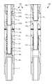
- FIG. 1Ais a cross section of a circulation sub in a closed position, according to one embodiment of the present invention.
- FIG. 1Bis a cross section of the circulation sub in an intermediate position.
- FIG. 1Cis a cross section of the circulation sub in an open position.
- FIGS. 2A-2Care cross-sections of a control module for operating the circulation sub in the closed, intermediate, and open positions, respectively.
- FIGS. 3A-3Care cross sections of a circulation sub in the closed, intermediate, and open positions, respectively, according to another embodiment of the present invention.
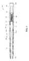
- FIG. 4illustrates a telemetry sub for use with the control module, according to another embodiment of the present invention.
- FIG. 4Aillustrates an electronics package of the telemetry sub.
- FIG. 4Billustrates an active RFID tag and a passive RFID tag for use with the telemetry sub.
- FIG. 4Cillustrates accelerometers of the telemetry sub.
- FIG. 4Dillustrates a mud pulser of the telemetry sub.
- FIG. 5illustrates a drilling system and method utilizing the circulation sub, according to another embodiment of the present invention.
- FIG. 6illustrates a control module for use with the circulation sub, according to another embodiment of the present invention.
- FIG. 1Ais a cross section of a circulation sub 100 in a closed position, according to one embodiment of the present invention.
- FIG. 1Bis a cross section of the circulation sub 100 in an intermediate position.
- FIG. 1Cis a cross section of the circulation sub 100 in an open position.
- the circulation sub 100may include a body 5 , an adapter 7 , a piston 10 , a mandrel 15 , a biasing member, such as spring 20 , and one or more fasteners, such as anti-rotation screws 25 .
- the body 5may be tubular and have a longitudinal bore formed therethrough. Each longitudinal end 5 a,b of the body 5 may be threaded for longitudinal and rotational connection to other members, such as a control module 200 at 5 a and the adapter 7 at 5 b .
- the body 5may have one or more flow ports 5 p formed through a wall thereof.
- the body 5may also have a chamber formed therein at least partially defined by shoulder 5 s for receiving the piston 10 .
- An end of the adapter 7 distal from the bodymay also be threaded for longitudinal and rotational connection to another member of a bottomhole assembly (BHA).
- BHAbottomhole assembly
- the mandrel 15may be a tubular, have a longitudinal bore formed therethrough, and may be disposed in the body bore.
- the mandrel 15may have a flow port 15 p formed through a wall thereof corresponding to each body port 5 p .
- An insert 16may be disposed in each port 15 p and made from an erosion resistant material, such as a metal, alloy, ceramic, or cermet.
- the piston 10may be annular, have a longitudinal bore formed therethrough, and be longitudinally connected to a lower end of the mandrel 15 , such as by a threaded connection.
- the circulation sub 100may be fluid operated by drilling fluid injected through the drill string being at a higher pressure and drilling fluid and cuttings, collectively returns, flowing to surface via the annulus being at a lower pressure.
- a first surface 10 h of the piston 10may be isolated from a second surface 10 w of the piston 10 by a seal 12 c disposed between an outer surface of the piston 10 and an inner surface of the body 5 .
- the higher pressuremay act on the first surface 10 h of the piston 10 via exposure to the mandrel bore and the lower pressure may act on the second surface 10 w of the piston 10 via fluid communication with a vent 5 v formed through the body wall, thereby creating a net actuation force and moving the mandrel 15 from the closed position to the intermediate position.
- seals 12 a,bmay be disposed between the mandrel 15 and the body 5 and may straddle the ports 5 p , 15 p .
- Each of the seals 12 a - cmay be a ring or stack of seals, such as chevron seals, and made from a polymer, such as an elastomer.
- the seals 12 a - cmay be metallic piston rings.
- Various other seals, such as o-rings,may be disposed throughout the circulation sub 100 .
- the spring 20may be disposed in the housing chamber between the piston 10 and the shoulder 5 s , thereby longitudinally pushing the mandrel 15 and the piston away from the shoulder.
- the mandrelmay 15 have one or more slots 15 s formed in an outer surface thereof for each of the fasteners 25 .
- Each fastener 25may be disposed in a hole formed through a wall of the body 5 and have an end extending into each slot 15 s , thereby rotationally connecting the mandrel 15 to the body 5 while allowing longitudinal movement of the mandrel relative to the body. Engagement of each fastener 25 with each end of the respective slot 15 s may serve as longitudinal stops for movement of the mandrel 15 relative to the body 5 .
- FIGS. 2A-2Care cross-sections of a control module 200 for operating the circulation sub 100 in the closed, intermediate, and open positions, respectively.
- the control module 200may include an outer tubular body 241 .
- the lower end of the outer body 241may include a threaded coupling, such as pin 242 , connectable to the threaded end 5 a of the circulation sub 100 .
- the upper end of the outer body 241may include a threaded coupling, such as box 243 , connected to a threaded coupling, such as lower pin 246 , of the retainer 245 .
- the retainer 245may have threaded couplings, such as pins 246 and 247 , formed at its ends.
- the upper pin 247may connect to a threaded coupling, such as box 408 b , of a telemetry sub 400 .
- the outer body 241may house an interior tubular body 250 .
- the inner body 250may be concentrically supported within the tubular body 241 at its ends by support rings 251 .
- the support rings 251may each be ported to allow drilling fluid flow to pass into/from a passage 252 formed between the two bodies 241 , 250 .
- the lower end of inner body 250may slidingly support a follower 255 .
- the follower 255may include an upper piston portion 255 p and a lower stinger portion 255 s extending out of the outer body 241 for engagement with mandrel shoulder 15 a .
- the follower 255may be longitudinally moveable relative to the bodies 241 , 250 .
- the stinger portion 255 smay cover the mandrel port 15 p in the closed position and have a pair of seals 212 a,b ( FIGS. 1A-C ) straddling the mandrel ports 15 p and sealing against an inner surface of the mandrel 15 .
- the seals 212 a,bmay be similar to the seals 12 a - c .
- the stinger portion 255 smay include one or more crossover ports 256 formed through a wall thereof for the flow of drilling fluid from the flow passage 252 .
- the interior of the piston 255may be hollow in order to receive a longitudinal position sensor 260 .
- the position sensor 260may include two telescoping members 261 and 262 .
- the lower member 262may be connected to the piston 255 and be further adapted to travel within the first member 261 . The amount of such travel may be electronically measured.
- the position sensor 260may be a linear potentiometer.
- the upper member 261may be attached to a lower bulkhead 265 which may be fixed within the inner body 250 .
- the lower bulkhead 265may further include a shutoff valve 266 and passage extending therethrough.
- the shutoff valve 266may include an electronic actuator, such as a solenoid (not shown).
- a conduit tube(not shown) may be attached at its lower end to the lower bulkhead 265 and at its upper end to and through an upper bulkhead 269 to provide electrical communication for the position sensor 260 and the solenoid valve 266 to a battery pack 270 located above the upper bulkhead 269 .
- the battery pack 270may include one or more batteries, such as high temperature lithium batteries.
- a compensating piston 271may be slidingly positioned within the inner body 250 between the two bulkheads 265 , 269 .
- a biasing member, such as spring 272may be located between the piston 271 and the upper bulkhead 269 and the chamber containing the spring may be vented 257 to allow the entry/exit of drilling fluid.
- a tube 201may be disposed in the connector sub 245 and may house an electronics package 225 .
- the electronics package 225may include a controller, such as a microprocessor, power regulator, and transceiver. Electrical connections 277 may be provided to interconnect the power regulator to the battery pack 270 .
- a data connector 278may be provided for data communication between the module controller and the telemetry sub 400 .
- the data connector 278may be wireless, such as a short-hop electromagnetic telemetry antenna.
- Hydraulic fluid(not shown), such as oil, may be disposed in a lower chamber defined by the follower piston 255 p , the lower bulkhead 265 , and the inner body 250 and an upper chamber defined by the compensating piston 271 , the lower bulkhead 265 , and the inner body 250 .
- the spring 272may bias the compensating piston 271 to push hydraulic oil from the upper reservoir, through the bulkhead passage and valve 266 , thereby extending the follower 255 into engagement with the circulation sub mandrel 15 and biasing the circulation sub 100 toward the closed position.
- the solenoid valve 266may be operable between a closed position where the valve prevents flow between the lower chamber and the upper chamber (in either direction), thereby fluidly locking the circulation sub 100 , and an open position where the valve allows flow through the passage (in either direction). To allow movement of the circulation sub 100 , the valve 266 may be opened when drilling fluid is flowing. The circulation sub piston 10 may then actuate and push the follower 255 toward the lower bulkhead 265 .
- the position sensor 260may measure the position of the follower 255 .
- the module controllermay monitor the sensor 260 to verify that the follower 255 has been actuated.
- the control module 200may receive a wireless instruction signal from surface (discussed below).
- the instruction signalmay direct the control module 200 to allow movement of the circulation sub 100 to the intermediate position.
- the module controllermay open the solenoid valve 266 . If drilling fluid is being circulated through the BHA, the circulation sub piston 10 may then move the mandrel 15 and the follower 255 to the intermediate position. During movement to the intermediate position, the mandrel ports 15 p may move out of alignment with the body ports 5 p and the stinger 255 s may move clear of the body ports 5 p .
- the module controllermay monitor the circulation sub 100 using the position sensor 260 . Once the mandrel 15 has reached the intermediate position, the module controller may close the valve 266 . The module controller may then report a successful move to the intermediate position or an error.
- Flow of drilling fluidmay then be halted. Pressure between the bore of the circulation sub 100 and the annulus may equalize and the circulation sub spring 20 may push the circulation sub piston 10 and the mandrel 15 to the open position.
- the follower 255may be restrained from following the mandrel 15 by the closed valve 266 and the mandrel port 15 p may re-align with the body port 5 p , thereby opening the ports 5 p , 15 p and providing fluid communication between a bore of the drill string and the annulus formed between the drill string and the wellbore. Once the ports 5 p , 15 p are open, injection of drilling fluid may resume.
- At least a portion of the drilling fluidmay be diverted from flowing through the BHA by the open ports 5 p , 15 p , thereby facilitating a cleanout operation.
- a wireless instruction signalmay be sent from surface to the control module 200 to close the circulation sub 100 .
- the module controllermay then open the valve 266 . Injection of drilling fluid through the drill string may be halted and the control module spring 272 may push the stinger 255 s back into engagement with the mandrel 15 , thereby closing the ports 5 p , 15 p .
- the module controllermay again monitor operation using the sensor 260 , close the valve 266 once the closed position has been reached, and report successful closure to surface or an error message.
- control module and the circulation submay still be operated by statically pressurizing the drill string and relieving the pressure from surface instead of pumping and halting flow of drilling fluid, as discussed above.
- components of the control module 200are disposed in a bore of the body 241 and connector 245 .
- components of the control module 200may be disposed in a wall of the body 241 , similar to the telemetry sub 400 .
- the center configured control module 200may allow for: stronger outer collar connections, a single size usable for different size circulation subs, and easier change-out on the rig floor.
- the annular alternative arranged control modulemay provide a central bore therethrough so that tools, such as a wireline string, may be run-through through the drill string.
- a latch(not shown), such as a collet, may be formed in an outer surface of the follower 255 .
- a corresponding profilemay be formed in an inner surface of the interior body 250 .
- the latchmay engage the profile when the follower is in the closed position.
- the latchmay transfer at least a substantial portion of the circulation sub piston 10 force to the interior body 250 when drilling fluid is injected through the circulation sub 100 , thereby substantially reducing the amount of pressure required in the lower hydraulic chamber to restrain the circulation sub piston 10 .
- the spring 272may be disposed in the lower hydraulic chamber between the bulkhead 265 and the follower 255 .
- FIGS. 3A-3Care cross sections of a circulation sub 300 in the closed, intermediate, and open positions, respectively, according to another embodiment of the present invention.
- the circulation sub 300may operate in a similar fashion as the circulation sub 100 except that the circulation sub 300 may include a bore valve 330 and may be operated by a control module having a modified stinger 355 having a port 355 p for each of the body/mandrel ports.
- the bore valve 330may be operable between an open and a closed position. In the open position, the bore valve 330 may allow flow through the circulation sub 300 to the BHA. In the closed position, the bore valve 330 may seal the circulation sub bore below the body/mandrel/stinger ports, thereby preventing flow to the BHA and diverting all flow through the ports.
- the bore valve 330may be operably coupled to the mandrel 315 and the stinger 355 such that the bore valve is open when the circulation sub 300 is in the closed and intermediate positions and the bore valve is closed when the circulation sub is in the open position.
- the bore valve 330may include a housing, such as a cage 331 u,b , one or more seats (not separately shown), a valve member, such as a ball 332 , and an actuator, such as a cam 333 a,b .
- the cage 331 u,bmay include one or more sections, such as an upper section 331 u and a lower 331 b section.
- the cage 331 u,bmay be disposed within the housing 305 and connected thereto, such as by entrapment between the housing shoulder 305 s and a lower recessed portion 315 r of the mandrel 315 .
- Each seatmay include a seal and a retainer. Each seat retainer may be connected to a respective cage section.
- Each seat sealmay be made from a polymer, such as an elastomer, and may be connected to the respective cage section by the respective seat retainer.
- the ball 332may be disposed between the cage sections 331 u,b and may be rotatable relative thereto.
- the ball 332may be operable between an open position ( FIGS. 3A and 3B ) and a closed position ( FIG. 3C ) by cam 333 a,b .
- the ball 332may have a bore therethrough corresponding to the piston/sleeve bore and aligned therewith in the open position.
- a wall of the ball 332may isolate the piston bore from the sleeve bore in the closed position.
- the cam 333 a,bmay include two or more sections, such as a left half 333 a and a right half 333 b .
- a lower portion of the cam 333 a,bmay be disposed in a pocket formed in the lower cage section 331 b and an upper portion of the cam may be longitudinally and rotationally connected (not shown) to the stringer 355 , such as by a locking profile or fasteners.
- the cam 333 a,bmay interact with the ball 332 , such as by having a cam profile 334 (only partially shown), such as a slot, formed through a wall of each cam half and extending therealong.
- the ball 332may have corresponding followers (not shown) formed in an outer surface thereof and engaged with respective cam profiles or vice versa.
- the ball-cam interactionmay rotate the ball 332 between the open and closed positions in response to longitudinal movement of the ball 332 relative to the cam 333 a,b.
- the piston 310may be separate from the mandrel 315 and have an upper pusher 310 p portion and a lower shoulder 310 s portion.
- the pusher portion 310 pmay drive the bore valve 330 , the mandrel 315 , and the stinger 355 longitudinally upward relative to the body 305 .
- the spring 320may drive the mandrel 315 , the cage 331 a,b , the ball 332 , and the piston 310 longitudinally downward relative to the housing 305 , the stinger 355 , and the cam 333 a,b , thereby causing the ball to be rotated to the closed position.
- FIG. 4illustrates a telemetry sub 400 for use with the control module 200 , according to another embodiment of the present invention.
- the telemetry sub 400may include an upper adapter 401 , one or more auxiliary sensors 402 a,b , an uplink housing 403 , a sensor housing 404 , a pressure sensor 405 , a downlink mandrel 406 , a downlink housing 407 , a lower adapter 408 , one or more data/power couplings 409 a,b , an electronics package 425 , an antenna 426 , a battery 431 , accelerometers 455 , and a mud pulser 475 .
- the housings 403 , 404 , 407may each be modular so that any of the housings 403 , 404 , 407 may be omitted and the rest of the housings may be used together without modification thereof.
- any of the sensors or electronics of the telemetry sub 400may be incorporated into the control module 200 and the telemetry sub 400 may be omitted.
- the adapters 401 , 408may each be tubular and have a threaded coupling 401 p , 408 b formed at a longitudinal end thereof for connection with the control module 200 and another member of the drill string.
- Each housingmay be longitudinally and rotationally connected together by one or more fasteners, such as screws (not shown), and sealed by one or more seals, such as o-rings (not shown).
- the sensor housing 404may include the pressure sensor 405 and a tachometer 455 .
- the pressure sensor 405may be in fluid communication with a bore of the sensor housing via a first port and in fluid communication with the annulus via a second port. Additionally, the pressure sensor 405 may also measure temperature of the drilling fluid and/or returns.
- the sensors 405 , 455may be in data communication with the electronics package 425 by engagement of contacts disposed at a top of the mandrel 406 with corresponding contacts disposed at a bottom of the sensor housing 406 .
- the sensors 405 , 455may also receive electricity via the contacts.
- the sensor housing 404may also relay data between the mud pulser 475 , the auxiliary sensors 402 a,b , and the electronics package 425 via leads and radial contacts 409 a,b.
- the auxiliary sensors 402 a,bmay include magnetometers which may be used with the accelerometers for determining directional information, such as azimuth, inclination, and/or tool face/bent sub angle.
- the auxiliary sensors 402 a,bmay also include strain gages oriented to measure longitudinal load and/or torque such that if the BHA is stuck, exerting tension and/or torque on the drill string may be used to send the instruction signal from surface to the telemetry sub.
- the tension and/or torquemay be exerted according to a predetermined protocol.
- the modulated articulationmay be detected by the auxiliary sensors.
- the controller 430may then demodulate the signal and relay the signal to the module controller, thereby operating the circulation sub 100 .
- the protocolmay represent data by varying the articulation on to off, a lower tension/torque to a higher tension/torque and/or a higher tension/torque to a lower tension/torque, or monotonically increasing from a lower tension/torque to a higher tension/torque and/or a higher tension/torque to a lower tension/torque.
- the antenna 426may include an inner liner, a coil, and an outer sleeve disposed along an inner surface of the downlink mandrel 406 .
- the linermay be made from a non-magnetic and non-conductive material, such as a polymer or composite, have a bore formed longitudinally therethrough, and have a helical groove formed in an outer surface thereof.
- the coilmay be wound in the helical groove and made from an electrically conductive material, such as a metal or alloy.
- the outer sleevemay be made from the non-magnetic and non-conductive material and may be insulate the coil from the downlink mandrel 406 .
- the antenna 426may be longitudinally and rotationally coupled to the downlink mandrel 406 and sealed from a bore of the telemetry sub 400 .
- FIG. 4Aillustrates the electronics package 425 .
- FIG. 4Billustrates an active RFID tag 450 a and a passive RFID tag 450 p .
- the electronics package 425may communicate with a passive RFID tag 450 p or an active RFID tag 450 a . Either of the RFID tags 450 a,p may be individually encased and dropped or pumped through the drill string.
- the electronics package 425may be in electrical communication with the antenna 426 and receive electricity from the battery 431 .
- the data sub 400may include a separate transmitting antenna and a separate receiving antenna.
- the electronics package 425may include an amplifier 427 , a filter and detector 428 , a transceiver 429 , a microprocessor 430 , an RF switch 434 , a pressure switch 433 , and an RF field generator 432 .
- the pressure switch 433may remain open at the surface to prevent the electronics package 425 from becoming an ignition source. Once the data sub 400 is deployed to a sufficient depth in the wellbore, the pressure switch 433 may close.
- the microprocessor 430may also detect deployment in the wellbore using pressure sensor 405 . The microprocessor 430 may delay activation of the transmitter for a predetermined period of time to conserve the battery 431 .
- one of the tags 450 a,pmay be pumped or dropped from the surface to the antenna 426 .
- the microprocessor 430may begin transmitting a signal and monitoring for a response. Once the tag 450 p is deployed into proximity of the antenna 426 , the passive tag 450 p may receive the signal, convert the signal to electricity, and transmit a response signal.
- the antenna 426may receive the response signal and the electronics package 425 may amplify, filter, demodulate, and analyze the signal. If the signal matches a predetermined instruction signal, then the microprocessor 430 may communicate the instruction signal to the circulation sub control module 200 using the antenna 426 and the transmitter circuit.
- the instruction signal carried by the tag 450 a,pmay include an address of a tool (if the drill string includes multiple circulation subs) and a position command.
- the tag 450 amay include its own battery, pressure switch, and timer so that the tag 450 a may perform the function of the components 432 - 434 .
- either of the tags 450 a,pmay include a memory unit (not shown) so that the microprocessor 430 may send a signal to the tag and the tag may record the signal. The signal may then be read at surface. The signal may be confirmation that a previous action was carried out or a measurement by one of the sensors.
- the data written to the RFID tagmay include a date/time stamp, a set position (the command), a measured position (of control module position piston), and a tool address. The written RFID tag may be circulated to the surface via the annulus.
- control module 200may be hard-wired to the telemetry sub 400 and a single controller, such as a microprocessor, disposed in either sub may control both subs.
- the control module 200may be hard-wired by replacing the data connector 378 with contact rings disposed at or near the pin 347 and adding corresponding contact rings to/near the box 408 b of the telemetry sub 400 .
- inductive couplingsmay be used instead of the contact rings.
- a wet or dry pin and socket connectionmay be used instead of the contact rings.
- FIG. 4Cis a schematic cross-sectional view of the sensor sub 404 .
- the tachometer 455may include two diametrically opposed single axis accelerometers 455 a,b .
- the accelerometers 455 a,bmay be piezoelectric, magnetostrictive, servo-controlled, reverse pendular, or microelectromechanical (MEMS).
- MEMSmicroelectromechanical
- the accelerometers 455 a,bmay be radially X oriented to measure the centrifugal acceleration A c due to rotation of the telemetry sub 400 for determining the angular speed.
- the second accelerometermay be used to account for gravity G if the telemetry sub is used in a deviated or horizontal wellbore. The angular speed may then be calculated from the accelerometer measurements.
- the accelerometersmay be tangentially Y oriented, dual axis, and/or asymmetrically arranged (not diametric and/or each accelerometer at a different radial location). Further, the accelerometers may be used to calculate borehole inclination and gravity tool face. Further, the sensor sub may include a longitudinal Z accelerometer. Alternatively, magnetometers may be used instead of accelerometers to determine the angular speed.
- an instruction signalmay be sent to the controller 430 by modulating angular speed of the drill string according to a predetermined protocol.
- the modulated angular speedmay be detected by the tachometer 455 .
- the controller 430may then demodulate the signal and relay the signal to the module controller, thereby operating the circulation sub 100 .
- the protocolmay represent data by varying the angular speed on to off, a lower speed to a higher speed and/or a higher speed to a lower speed, or monotonically increasing from a lower speed to a higher speed and/or a higher speed to a lower speed.
- the sensor submay include an acoustic receiver and an instruction signal may be sent to the controller 430 by modulating an acoustic transmitter located at the surface.
- the acoustic transmittermay be operable to transmit an acoustic signal from the surface through a wall of the deployment string according to a predetermined protocol.
- the modulated acoustic signalmay be detected by the acoustic receiver.
- the controller 430may then demodulate the signal and relay the signal to the module controller, thereby operating the circulation sub 100 .
- the protocolmay represent data by varying the acoustic signal on to off, a lower frequency to a higher frequency and/or a higher frequency to a lower frequency, or monotonically increasing from a lower frequency to a higher frequency and/or a higher frequency to a lower frequency.
- FIG. 4Dillustrates the mud pulser 475 .
- the mud pulser 475may include a valve, such as a poppet 476 , an actuator 477 , a turbine 478 , a generator 479 , and a seat 480 .
- the poppet 476may be longitudinally movable by the actuator 477 relative to the seat 480 between an open position (shown) and a choked position (dashed) for selectively restricting flow through the pulser 475 , thereby creating pressure pulses in drilling fluid pumped through the mud pulser.
- the mud pulsesmay be detected at the surface, thereby communicating data from the microprocessor to the surface.
- the turbine 478may harness fluid energy from the drilling fluid pumped therethrough and rotate the generator 479 , thereby producing electricity to power the mud pulser.
- the mud pulsermay be used to send confirmation of receipt of commands and report successful execution of commands or errors to the surface. The confirmation may be sent during circulation of drilling fluid.
- a negative or sinusoidal mud pulsermay be used instead of the positive mud pulser 475 .
- the microprocessormay also use the turbine 478 and/or pressure sensor as a flow switch and/or flow meter.
- a signalmay be sent to the controller by modulating a flow rate of the rig drilling fluid pump according to a predetermined protocol.
- the telemetry sub controllermay use the turbine and/or pressure sensor as a flow switch and/or flow meter to detect the sequencing of the rig pumps.
- the flow rate protocolmay represent data by varying the flow rate on to off, a lower speed to a higher speed and/or a higher speed to a lower speed, or monotonically increasing from a lower speed to a higher speed and/or a higher speed to a lower speed.
- an orifice flow switch or metermay be used to receive flow rate signals communicated through the drilling fluid from the surface instead of the turbine and/or pressure sensor.
- the sensor submay detect the flow rate signals using the pressure sensor and accelerometers to monitor for BHA vibration caused by the flow rate signal.
- a mud pulser(not shown) may be installed in the rig pump outlet and operated by the surface controller to send pressure pulses from the surface to the telemetry sub controller 430 according to a predetermined protocol.
- the mud pulser alternativemay be especially useful if the BHA is blocked or the bore valve 330 is closed.
- the pressure sensor 405may be used to detect the mud pulses and the telemetry sub controller 430 may then decode the mud pulses and relay the signal to the control sub.
- an electromagnetic (EM) gap sub(not shown) may be used instead of the mud pulser, thereby allowing data to be transmitted to the surface using EM waves.
- an RFID tag launcher(not shown) may be used instead of the mud pulser.
- the tag launchermay include one or more RFID tags.
- the microprocessor 430may then encode the tags with data and the launcher may release the tags to the surface.
- an acoustic transmittermay be used instead of the mud pulser and the acoustic transmitter may be operable to transmit an acoustic signal through a wall of the deployment string.
- RFID tagsmay be periodically pumped through the telemetry sub and the microprocessor may send the data to the tag.
- the tagmay then return to the surface via an annulus formed between the workstring and the wellbore.
- the data from the tagmay then be retrieved at the surface.
- instruction signalsmay be sent to the electronics package using mud pulses, EM waves, or acoustic signals.
- the telemetry sub antennamay be toroidal and communication with surface may be via transverse electromagnetic signals (TEM) along the annulus, as shown in U.S. Pat. No. 4,839,644, which is herein incorporated by reference in its entirety.
- TEMtransverse electromagnetic signals
- the drill stringmay further include a signal repeater (not shown) to prevent attenuation of the transmitted mud pulse, acoustic, or EM/TEM signals.
- the repeatermay detect the mud pulse transmitted from the mud pulser 475 and include its own mud pulser for repeating the signal. As many repeaters may be disposed along the drill string as necessary to transmit the data to the surface, e.g., one repeater every five thousand feet. Each repeater may also be a telemetry sub and add its own measured data to the retransmitted data signal. If the mud pulser is being used, the repeater may wait until the data sub is finished transmitting before retransmitting the signal.
- the repeatersmay be used for any of the mud pulser alternatives, discussed above. Repeating the transmission may increase bandwidth for the particular data transmission.
- multiple telemetry subsmay be deployed in the drill string.
- An RFID tag including a memory unitmay be dropped/pumped through the telemetry subs and record the data from the telemetry subs until the tag reaches a bottom of the data subs. The tag may then transmit the data from the upper subs to the bottom sub and then the bottom sub may transmit all of the data to the surface.
- the mud pulsermay instead be located in a measurement while drilling (MWD) and/or logging while drilling (LWD) tool assembled in the drill string downstream of the circulation sub.
- the MWD/LWD modulemay be located in the BHA to receive written RFID tags from several upstream tools.
- the mud pulse module or MWD/LWD modulemay then pulse a signal to the surface indicating time to shut down pumps to allow passive activation.
- the mud pulse module or MWD/LWD modulemay send a mud-pulse to annulus pressure measurement module (PWD subs) along the drill string.
- the PWD modulemay then upon command, or periodically, write RFID tags and eject the tags into the annulus for telemetry to surface or into the bore for telemetry to the MWD/LWD module.
- control modulemay send and receive instructions via wired drill/casing string.
- FIG. 5illustrates a drilling system and method utilizing the circulation sub 100 / 300 , according to another embodiment of the present invention.
- the drilling systemmay include a drilling derrick 510 .
- the drilling systemmay further include drawworks 524 for supporting a top drive 542 .
- the top drive 542may in turn support and rotate a drill string 500 .
- a Kelly and rotary table(not shown) may be used to rotate the drill string instead of the top drive.
- the drill string 500may include a deployment string 502 and a bottomhole assembly (BHA) 550 .
- the deployment string 502may include joints of threaded drill pipe connected together or coiled tubing.
- the BHA 550may include the telemetry sub 400 , the control module 200 , the circulation sub 100 / 300 , and a drill bit 505 .
- a rig pump 518may pump drilling fluid, such as mud 514 f , out of a pit 520 , passing the mud through a stand pipe and Kelly hose to a top drive 542 .
- the mud 514 fmay continue into the drill string, through a bore of the drill string, through a bore of the BHA, and exit the drill bit 505 .
- the mud 514 fmay lubricate the bit and carry cuttings from the bit.
- the drilling fluid and cuttingscollectively returns 514 r , flow upward along an annulus 517 formed between the drill string and the wall of the wellbore 516 a /casing 519 , through a solids treatment system (not shown) where the cuttings are separated.
- the treated drilling fluidmay then be discharged to the mud pit for recirculation.
- the drilling systemmay further include a launcher 520 , surface controller 525 , and a pressure sensor 528 .
- the pressure sensor 528may detect mud pulses sent from the telemetry sub 400 .
- the surface controller 525may be in data communication with the rig pump 518 , launcher 520 , pressure sensor 528 , and top drive 542 .
- the rig pump 518 and/or top drive 542may include a variable speed drive so that the surface controller 525 may modulate 545 a flow rate of the rig pump 518 and/or an angular speed (RPM) of the top drive 542 .
- the modulation 545may be a square wave, trapezoidal wave, or sinusoidal wave. Alternatively, the controller 545 may modulate the rig pump and/or top drive by simply switching them on and off.
- a first section of a wellbore 516 ahas been drilled.
- a casing string 519has been installed in the wellbore 516 a and cemented 511 in place.
- a casing shoe 519 sremains in the wellbore.
- the drill string 500may then be deployed into the wellbore 516 a until the drill bit 505 is proximate the casing shoe 519 s .
- the drill bit 505may then be rotated by the top drive and mud injected through the drill string by the rig pump. Weight may be exerted on the drill bit 505 , thereby causing the drill bit to drill through the casing shoe 519 s .
- the circulation sub 100 / 300may be restrained in the closed position by the control module 200 .
- a second section of the wellboremay be drilled.
- a sidetrackmay be drilled or the casing shoe may have been drilled during a previous trip.
- An instruction signalmay be sent to the telemetry sub 400 commanding actuation of the circulation sub 100 / 300 to the intermediate position.
- the telemetry sub 400may relay the signal to the control module 200 .
- the circulation sub 100 / 300may then move to the intermediate position, as discussed above.
- the control modulemay confirm successful movement to the intermediate position.
- the rig pump 518may then be shut down, thereby allowing the circulation sub to open.
- the rig pump 518may resume circulation of drilling fluid.
- the cleaning operationmay involve rotation of the drill string 500 at a high angular velocity.
- the drill string 500may be removed from the wellbore 516 a during the cleaning operation. Alternatively or additionally, the cleaning operation may be occasionally or periodically performed during the drilling operation.
- the drill bitmay be rotated at a high speed by a mud motor (not shown) of the BHA and the circulation sub may be rotated at a lower speed by the top drive. Since the bit speed may equal the motor speed plus the top drive speed, the mud motor speed may be equal or substantially equal to the top drive speed.
- the telemetry sub 400may be used as an MWD sub for measuring and transmitting orientation data to the surface.
- the BHAmay include a separate MWD sub.
- the surfacemay need to send instruction signals to the separate MWD sub in addition to the instruction signals to the telemetry sub.
- the protocolmay include an address field or the signals may be multiplexed (e.g., frequency division).
- modulation of the rig pumpmay be used to send MWD instructions and top drive modulation may be used to send circulation sub instructions.
- the circulation sub signalmay be multiplexed with the dynamic steering signal.
- the RFID tag protocolmay include an address field distinguishing the instructions.
- the circulation submay be used in a drilling with casing/liner operation.
- the deployment stringmay include the casing/liner string instead of the drill string.
- the BHAmay be operated by rotation of the casing/liner string from the surface of the wellbore or a motor as part of the BHA. After the casing/liner is drilled and set into the wellbore, the BHA may be retrieved from the wellbore. To facilitate retrieval of the BHA, the BHA may be fastened to the casing/liner string employing a latch. Alternatively, the BHA may be drillable. Once the BHA is retrieved, the casing/liner string may then be cemented into the wellbore.
- the circulation submay be used in an expandable casing/liner operation.
- the casing/linermay be expanded after it is run-into the wellbore.
- multiple circulation subsmay be employed in the drill string at various locations along the drill string.
- the instruction signalmay then include a tool address so that one or more of the circulation subs may be opened without opening one or more other subs. Alternatively, all of the subs may be opened simultaneously. Further one or more of the subs may be the sub 300 and one or more of the subs may be the sub 100 .
- the circulation sub 300may be used to pump kill fluid through the drill string 502 to control a kick while preventing the kill fluid from being pumped through a lower portion of the BHA.
- the BHAmay further include a disconnect sub should the BHA become stuck.
- the disconnect submay be operated by a closure member or by an additional control module 200 .
- the circulation subs 100 , 300allow flexibility to have a closure member operated tool disposed in the BHA above or below the circulation sub.
- the drill stringmay then be disconnected from the stuck BHA, the drill string (and upper portion of the disconnect) retrieved to surface, and redeployed with a fishing BHA including, for example, a jar (single fire or vibratory) and the upper portion of the disconnect, which also may be operated by a closure member or an additional control module 200 .
- a fishing BHAincluding, for example, a jar (single fire or vibratory) and the upper portion of the disconnect, which also may be operated by a closure member or an additional control module 200 .
- FIG. 6illustrates a portion of an alternative control module 600 for use with a simplified circulation sub (not shown), according to another embodiment of the present invention.
- the mandrel, piston, and springmay be omitted from the simplified circulation sub and the stinger 655 s may directly close and open the body ports.
- the simplified circulation submay include a simplified version of the bore valve 330 .
- the rest of the control module 600may be similar to the control module 200 .
- the control module 600may include an inner body and bulkhead 615 .
- the bulkhead and inner bodyare shown as an integral piece 615 .
- the inner body and bulkheadmay be made as separate pieces.
- the control module 600may further include upper 602 u and lower 602 b hydraulic chambers having hydraulic fluid disposed therein and isolated by seals 603 a,b .
- the control module 600may further include an actuator so that the control module 600 may actively move the stinger 655 s while the rig pump 518 is injecting drilling fluid through the control module 600 and the simplified circulation sub.
- the actuatormay be a hydraulic pump 601 in communication with the upper 602 u and lower 602 b hydraulic chambers via a hydraulic passage and operable to pump the hydraulic fluid from the upper chamber 602 u to the lower chamber 602 b to move the stinger 655 s .
- the pumpmay be a hydraulic amplifier on a lead or ball screw being turned by the electric motor.
- the electric motor 604may drive the hydraulic pump 601 .
- the electric motor 604may be reversible to cause the hydraulic pump 601 to pump fluid from the lower chamber 602 b to the upper chamber 602 u .
- the active control module 600may receive an instruction signal from the surface (as discussed above via the telemetry sub 400 ) and operate the circulation sub without having to wait for shut down of the rig pump 518 .
- the control module 600may further include a shutoff valve 616 having an electric actuator, such as a solenoid for locking the stinger in either the open or closed position.
- the control module 600may further include a position sensor, such as a Hall sensor 611 and magnet 612 , which may be monitored by the controller 325 .
- the position sensormay be a linear voltage differential transformer (LVDT).
- the control module 600may further include a compensating piston 621 to equalize pressure between drilling fluid (via port 606 ) and the upper chamber 602 u .
- the control modulemay further include a biasing member, such as a spring 622 , to bias flow of hydraulic fluid from the upper 602 u to the lower 602 b chamber.
Landscapes
- Engineering & Computer Science (AREA)
- Geology (AREA)
- Life Sciences & Earth Sciences (AREA)
- Mining & Mineral Resources (AREA)
- Physics & Mathematics (AREA)
- Environmental & Geological Engineering (AREA)
- Fluid Mechanics (AREA)
- General Life Sciences & Earth Sciences (AREA)
- Geochemistry & Mineralogy (AREA)
- Mechanical Engineering (AREA)
- Geophysics (AREA)
- Acoustics & Sound (AREA)
- Remote Sensing (AREA)
- Earth Drilling (AREA)
Abstract
Description
Claims (17)
Priority Applications (1)
| Application Number | Priority Date | Filing Date | Title |
|---|---|---|---|
| US13/979,360US9382769B2 (en) | 2011-01-21 | 2012-01-23 | Telemetry operated circulation sub |
Applications Claiming Priority (3)
| Application Number | Priority Date | Filing Date | Title |
|---|---|---|---|
| US201161435218P | 2011-01-21 | 2011-01-21 | |
| PCT/US2012/022253WO2012100259A2 (en) | 2011-01-21 | 2012-01-23 | Telemetry operated circulation sub |
| US13/979,360US9382769B2 (en) | 2011-01-21 | 2012-01-23 | Telemetry operated circulation sub |
Publications (2)
| Publication Number | Publication Date |
|---|---|
| US20130319767A1 US20130319767A1 (en) | 2013-12-05 |
| US9382769B2true US9382769B2 (en) | 2016-07-05 |
Family
ID=45567130
Family Applications (1)
| Application Number | Title | Priority Date | Filing Date |
|---|---|---|---|
| US13/979,360Expired - Fee RelatedUS9382769B2 (en) | 2011-01-21 | 2012-01-23 | Telemetry operated circulation sub |
Country Status (5)
| Country | Link |
|---|---|
| US (1) | US9382769B2 (en) |
| EP (1) | EP2665894B1 (en) |
| BR (1) | BR112013018620A2 (en) |
| CA (2) | CA2929158C (en) |
| WO (1) | WO2012100259A2 (en) |
Cited By (14)
| Publication number | Priority date | Publication date | Assignee | Title |
|---|---|---|---|---|
| US20190112918A1 (en)* | 2017-10-13 | 2019-04-18 | Xiaohua Yi | Vertical Seismic Profiling |
| US10502024B2 (en) | 2016-08-19 | 2019-12-10 | Schlumberger Technology Corporation | Systems and techniques for controlling and monitoring downhole operations in a well |
| US10844689B1 (en) | 2019-12-19 | 2020-11-24 | Saudi Arabian Oil Company | Downhole ultrasonic actuator system for mitigating lost circulation |
| US10865620B1 (en) | 2019-12-19 | 2020-12-15 | Saudi Arabian Oil Company | Downhole ultraviolet system for mitigating lost circulation |
| US11078780B2 (en) | 2019-12-19 | 2021-08-03 | Saudi Arabian Oil Company | Systems and methods for actuating downhole devices and enabling drilling workflows from the surface |
| US11091983B2 (en) | 2019-12-16 | 2021-08-17 | Saudi Arabian Oil Company | Smart circulation sub |
| WO2021178126A1 (en) | 2020-03-02 | 2021-09-10 | Weatherford Technology Holdings, Llc | Debris collection tool |
| US11125048B1 (en) | 2020-05-29 | 2021-09-21 | Weatherford Technology Holdings, Llc | Stage cementing system |
| US11230918B2 (en) | 2019-12-19 | 2022-01-25 | Saudi Arabian Oil Company | Systems and methods for controlled release of sensor swarms downhole |
| US11319776B2 (en)* | 2016-06-23 | 2022-05-03 | Vertice Oil Tools Inc. | Methods and systems for a pin point frac sleeves system |
| WO2022187151A1 (en)* | 2021-03-01 | 2022-09-09 | Saudi Arabian Oil Company | Opening an alternate fluid path of a wellbore string |
| US11557985B2 (en)* | 2020-07-31 | 2023-01-17 | Saudi Arabian Oil Company | Piezoelectric and magnetostrictive energy harvesting with pipe-in-pipe structure |
| US11686196B2 (en) | 2019-12-19 | 2023-06-27 | Saudi Arabian Oil Company | Downhole actuation system and methods with dissolvable ball bearing |
| US12098616B2 (en) | 2020-04-03 | 2024-09-24 | Odfjell Technology Invest Ltd. | Hydraulically locked tool |
Families Citing this family (40)
| Publication number | Priority date | Publication date | Assignee | Title |
|---|---|---|---|---|
| US9328579B2 (en) | 2012-07-13 | 2016-05-03 | Weatherford Technology Holdings, Llc | Multi-cycle circulating tool |
| SG11201500031TA (en)* | 2012-08-29 | 2015-02-27 | Halliburton Energy Services Inc | A reclosable sleeve assembly and methods for isolating hydrocarbon production |
| CA2894504C (en)* | 2012-12-21 | 2016-10-11 | Exxonmobil Upstream Research Company | Flow control assemblies for downhole operations and systems and methods including the same |
| US9316071B2 (en) | 2013-01-23 | 2016-04-19 | Weatherford Technology Holdings, Llc | Contingent continuous circulation drilling system |
| US9982530B2 (en) | 2013-03-12 | 2018-05-29 | Halliburton Energy Services, Inc. | Wellbore servicing tools, systems and methods utilizing near-field communication |
| US10221632B2 (en)* | 2013-03-14 | 2019-03-05 | Ge Energy Oilfield Technology, Inc | Composite isolation joint for gap sub or internal gap |
| US10087725B2 (en)* | 2013-04-11 | 2018-10-02 | Weatherford Technology Holdings, Llc | Telemetry operated tools for cementing a liner string |
| US9494018B2 (en) | 2013-09-16 | 2016-11-15 | Baker Hughes Incorporated | Sand control crossover tool with mud pulse telemetry position |
| US9228402B2 (en)* | 2013-10-04 | 2016-01-05 | Bico Drilling Tools, Inc. | Anti-stall bypass system for downhole motor |
| GB2522272A (en) | 2014-01-21 | 2015-07-22 | Tendeka As | Downhole flow control device and method |
| US9810028B2 (en) | 2014-01-27 | 2017-11-07 | Canrig Drilling Technology Ltd. | EM gap sub assembly |
| US9828802B2 (en) | 2014-01-27 | 2017-11-28 | Sjm Designs Pty Ltd. | Fluid pulse drilling tool |
| DK178835B1 (en)* | 2014-03-14 | 2017-03-06 | Advancetech Aps | Circulating sub with activation mechanism and a method thereof |
| DK178108B1 (en) | 2014-03-14 | 2015-05-26 | Yellow Shark Holding Aps | Activation mechanism for a downhole tool and a method thereof |
| US9909390B2 (en)* | 2014-05-29 | 2018-03-06 | Weatherford Technology Holdings, Llc | Stage tool with lower tubing isolation |
| CN105332689B (en) | 2014-06-13 | 2018-10-12 | 通用电气公司 | drilling fluid parameter monitoring system and method |
| MX364012B (en) | 2014-06-23 | 2019-04-11 | Evolution Engineering Inc | Optimizing downhole data communication with at bit sensors and nodes. |
| CA2954789C (en) | 2014-07-24 | 2018-11-20 | Weatherford Technology Holdings, Llc | Reverse cementation of liner string for formation stimulation |
| AU2014414020B2 (en) | 2014-12-18 | 2018-03-15 | Halliburton Energy Services, Inc. | High-efficiency downhole wireless communication |
| US10871033B2 (en) | 2014-12-23 | 2020-12-22 | Halliburton Energy Services, Inc. | Steering assembly position sensing using radio frequency identification |
| DE112014007027T5 (en) | 2014-12-29 | 2017-07-20 | Halliburton Energy Services, Inc. | Electromagnetically coupled bandgap transceivers |
| CA2974724C (en)* | 2015-01-30 | 2021-07-06 | Scientific Drilling International, Inc. | Collaborative telemetry |
| WO2016148964A1 (en) | 2015-03-13 | 2016-09-22 | M-I L.L.C. | Optimization of drilling assembly rate of penetration |
| US9911016B2 (en) | 2015-05-14 | 2018-03-06 | Weatherford Technology Holdings, Llc | Radio frequency identification tag delivery system |
| CA2983662C (en) | 2015-06-17 | 2019-02-26 | Halliburton Energy Services, Inc. | Drive shaft actuation using radio frequency identification |
| US10301907B2 (en) | 2015-09-28 | 2019-05-28 | Weatherford Netherlands, B.V. | Setting tool with pressure shock absorber |
| US9915113B2 (en)* | 2015-10-27 | 2018-03-13 | Russell C. Crawford, III | Well drilling apparatus and method of use |
| US10533388B2 (en)* | 2016-05-31 | 2020-01-14 | Access Downhole Lp | Flow diverter |
| US10392898B2 (en) | 2016-06-16 | 2019-08-27 | Weatherford Technology Holdings, Llc | Mechanically operated reverse cementing crossover tool |
| US11396476B2 (en) | 2016-07-22 | 2022-07-26 | Prysmian S.P.A. | Optical fibre coated with a polyester coating |
| IT201600106357A1 (en) | 2016-10-21 | 2018-04-21 | Eni Spa | AUCTION FOR THE BIDIRECTIONAL CABLELESS DATA TRANSMISSION AND THE CONTINUOUS CIRCULATION OF STABILIZING FLUID IN A WELL FOR THE EXTRACTION OF TRAINING FLUIDS AND BATTERY OF AUCTIONS INCLUDING AT LEAST ONE OF THESE AUCTIONS. |
| US11105183B2 (en) | 2016-11-18 | 2021-08-31 | Halliburton Energy Services, Inc. | Variable flow resistance system for use with a subterranean well |
| CN120719952A (en) | 2016-11-18 | 2025-09-30 | 哈利伯顿能源服务公司 | Variable flow resistance system for use with subterranean wells |
| US10443345B2 (en)* | 2017-05-01 | 2019-10-15 | Comitt Well Solutions LLC | Methods and systems for a complementary valve |
| ES2967433T3 (en) | 2018-01-19 | 2024-04-30 | Prysmian Spa | Fiber optic with cross-linked polyester coating |
| CN108457619B (en)* | 2018-02-14 | 2024-07-23 | 中国石油天然气集团有限公司 | Radio frequency triggering type multiple switch bypass valve device assembly |
| US11125074B2 (en)* | 2018-04-26 | 2021-09-21 | Nabors Drilling Technologies Usa, Inc. | Marker signal for subterranean drilling |
| WO2020102359A1 (en) | 2018-11-13 | 2020-05-22 | Rubicon Oilfield International, Inc. | Three axis vibrating device |
| CN112031686A (en)* | 2020-09-14 | 2020-12-04 | 北京博德世达石油技术股份有限公司 | Circulating valve special for wellhead, drilling equipment adopting circulating valve and drilling method |
| CN113482606B (en)* | 2021-05-14 | 2023-09-22 | 西南石油大学 | Underground signal receiving and transmitting device |
Citations (70)
| Publication number | Priority date | Publication date | Assignee | Title |
|---|---|---|---|---|
| US4113012A (en) | 1977-10-27 | 1978-09-12 | Halliburton Company | Reclosable circulation valve for use in oil well testing |
| US4298077A (en) | 1979-06-11 | 1981-11-03 | Smith International, Inc. | Circulation valve for in-hole motors |
| US4373582A (en) | 1980-12-22 | 1983-02-15 | Exxon Production Research Co. | Acoustically controlled electro-mechanical circulation sub |
| US4406335A (en) | 1980-10-30 | 1983-09-27 | Nick Koot | Special circulation sub |
| US4557333A (en)* | 1983-09-19 | 1985-12-10 | Halliburton Company | Low pressure responsive downhole tool with cam actuated relief valve |
| US4574894A (en) | 1985-07-12 | 1986-03-11 | Smith International, Inc. | Ball actuable circulating dump valve |
| US4633958A (en) | 1985-02-04 | 1987-01-06 | Mouton David E | Downhole fluid supercharger |
| US4657082A (en) | 1985-11-12 | 1987-04-14 | Halliburton Company | Circulation valve and method for operating the same |
| US4889199A (en) | 1987-05-27 | 1989-12-26 | Lee Paul B | Downhole valve for use when drilling an oil or gas well |
| US5146992A (en) | 1991-08-08 | 1992-09-15 | Baker Hughes Incorporated | Pump-through pressure seat for use in a wellbore |
| GB2268770A (en) | 1992-07-17 | 1994-01-19 | Paul Bernard Lee | A valve having releasable latch mechanism |
| US5335731A (en) | 1992-10-22 | 1994-08-09 | Ringgenberg Paul D | Formation testing apparatus and method |
| US5443129A (en) | 1994-07-22 | 1995-08-22 | Smith International, Inc. | Apparatus and method for orienting and setting a hydraulically-actuatable tool in a borehole |
| US5465787A (en) | 1994-07-29 | 1995-11-14 | Camco International Inc. | Fluid circulation apparatus |
| US5791414A (en) | 1996-08-19 | 1998-08-11 | Halliburton Energy Services, Inc. | Early evaluation formation testing system |
| US5890540A (en) | 1995-07-05 | 1999-04-06 | Renovus Limited | Downhole tool |
| US5901796A (en) | 1997-02-03 | 1999-05-11 | Specialty Tools Limited | Circulating sub apparatus |
| US5979572A (en) | 1995-03-24 | 1999-11-09 | Uwg Limited | Flow control tool |
| US6065541A (en) | 1997-03-14 | 2000-05-23 | Ezi-Flow International Limited | Cleaning device |
| US6095249A (en) | 1995-12-07 | 2000-08-01 | Mcgarian; Bruce | Down hole bypass valve |
| US6102060A (en) | 1997-02-04 | 2000-08-15 | Specialised Petroleum Services Ltd. | Detachable locking device for a control valve and method |
| US6152228A (en) | 1996-11-27 | 2000-11-28 | Specialised Petroleum Services Limited | Apparatus and method for circulating fluid in a borehole |
| US6173795B1 (en) | 1996-06-11 | 2001-01-16 | Smith International, Inc. | Multi-cycle circulating sub |
| US6189618B1 (en) | 1998-04-20 | 2001-02-20 | Weatherford/Lamb, Inc. | Wellbore wash nozzle system |
| US6220357B1 (en) | 1997-07-17 | 2001-04-24 | Specialised Petroleum Services Ltd. | Downhole flow control tool |
| US6253861B1 (en) | 1998-02-25 | 2001-07-03 | Specialised Petroleum Services Limited | Circulation tool |
| US6279657B1 (en) | 1997-10-15 | 2001-08-28 | Specialised Petroleum Services Limited | Apparatus and method for circulating fluid in a well bore |
| US6289999B1 (en) | 1998-10-30 | 2001-09-18 | Smith International, Inc. | Fluid flow control devices and methods for selective actuation of valves and hydraulic drilling tools |
| US6378612B1 (en) | 1998-03-14 | 2002-04-30 | Andrew Philip Churchill | Pressure actuated downhole tool |
| WO2002075104A1 (en) | 2001-03-15 | 2002-09-26 | Andergauge Limited | Downhole tool |
| US6543532B2 (en) | 1999-08-20 | 2003-04-08 | Halliburton Energy Services, Inc. | Electrical surface activated downhole circulating sub |
| US20030066652A1 (en)* | 2000-03-02 | 2003-04-10 | Stegemeier George Leo | Wireless downhole well interval inflow and injection control |
| US6725937B1 (en) | 1999-03-08 | 2004-04-27 | Weatherford/Lamb, Inc. | Downhole apparatus |
| GB2394488A (en) | 2002-10-22 | 2004-04-28 | Smith International | Multi-cycle downhole apparatus |
| US6732793B1 (en) | 1999-07-08 | 2004-05-11 | Drilling Systems International Ltd. | Downhole jetting tool |
| US20040163809A1 (en)* | 2003-02-24 | 2004-08-26 | Mayeu Christopher W. | Method and system for determining and controlling position of valve |
| US6820697B1 (en) | 1999-07-15 | 2004-11-23 | Andrew Philip Churchill | Downhole bypass valve |
| US6866100B2 (en) | 2002-08-23 | 2005-03-15 | Weatherford/Lamb, Inc. | Mechanically opened ball seat and expandable ball seat |
| US6920930B2 (en) | 2002-12-10 | 2005-07-26 | Allamon Interests | Drop ball catcher apparatus |
| US7055605B2 (en) | 2001-01-31 | 2006-06-06 | Specialised Petroleum Services Group Ltd. | Downhole circulation valve operated by dropping balls |
| US7281584B2 (en) | 2001-07-05 | 2007-10-16 | Smith International, Inc. | Multi-cycle downhill apparatus |
| US7299880B2 (en) | 2004-07-16 | 2007-11-27 | Weatherford/Lamb, Inc. | Surge reduction bypass valve |
| US20070285275A1 (en) | 2004-11-12 | 2007-12-13 | Petrowell Limited | Remote Actuation of a Downhole Tool |
| US20070284111A1 (en) | 2006-05-30 | 2007-12-13 | Ashy Thomas M | Shear Type Circulation Valve and Swivel with Open Port Reciprocating Feature |
| WO2008005289A2 (en) | 2006-06-30 | 2008-01-10 | Baker Hughes Incorporated | Method for improved well control with a downhole device |
| US7318478B2 (en) | 2005-06-01 | 2008-01-15 | Tiw Corporation | Downhole ball circulation tool |
| US7322419B2 (en) | 2002-04-16 | 2008-01-29 | Specialised Petroleum Services Group Ltd. | Circulating sub and method |
| US7347288B2 (en) | 2002-09-03 | 2008-03-25 | Paul Bernard Lee | Ball operated by-pass tool for use in drillstring |
| US7350598B2 (en) | 2004-07-16 | 2008-04-01 | Hamdeem Incorporated Ltd. | Downhole tool |
| US7357198B2 (en) | 2003-01-24 | 2008-04-15 | Smith International, Inc. | Downhole apparatus |
| US20080093080A1 (en) | 2006-10-19 | 2008-04-24 | Palmer Larry T | Ball drop circulation valve |
| US7383881B2 (en) | 2002-04-05 | 2008-06-10 | Specialised Petroleum Services Group Limited | Stabiliser, jetting and circulating tool |
| US20080190620A1 (en) | 2007-02-12 | 2008-08-14 | Posevina Lisa L | Single cycle dart operated circulation sub |
| US7416029B2 (en) | 2003-04-01 | 2008-08-26 | Specialised Petroleum Services Group Limited | Downhole tool |
| US7441607B2 (en) | 2003-07-01 | 2008-10-28 | Specialised Petroleum Group Services Limited | Circulation tool |
| US20090025923A1 (en)* | 2007-07-23 | 2009-01-29 | Schlumberger Technology Corporation | Technique and system for completing a well |
| US7503398B2 (en) | 2003-06-18 | 2009-03-17 | Weatherford/Lamb, Inc. | Methods and apparatus for actuating a downhole tool |
| US20090095486A1 (en) | 2007-10-11 | 2009-04-16 | Williamson Jr Jimmie R | Circulation control valve and associated method |
| US7520336B2 (en) | 2007-01-16 | 2009-04-21 | Bj Services Company | Multiple dart drop circulating tool |
| US7530400B2 (en) | 2003-04-22 | 2009-05-12 | Specialised Petroleum Services Group Limited | Downhole tool for selectively catching balls in a well bore |
| US7628213B2 (en) | 2003-01-30 | 2009-12-08 | Specialised Petroleum Services Group Limited | Multi-cycle downhole tool with hydraulic damping |
| US7673708B2 (en) | 2005-11-17 | 2010-03-09 | Paul Bernard Lee | Ball-activated mechanism for controlling the operation of a downhole tool |
| US20100065125A1 (en) | 2007-02-16 | 2010-03-18 | Specialised Petroleum Services Group Limited | Valve seat assembly, downhole tool and methods |
| US7681650B2 (en) | 2004-04-30 | 2010-03-23 | Specialised Petroleum Services Group Limited | Valve seat |
| US7766086B2 (en) | 2007-06-08 | 2010-08-03 | Bj Services Company Llc | Fluid actuated circulating sub |
| US7766084B2 (en) | 2003-11-17 | 2010-08-03 | Churchill Drilling Tools Limited | Downhole tool |
| US20100252276A1 (en) | 2007-11-20 | 2010-10-07 | National Oilwell Varco, L.P. | Circulation sub with indexing mechanism |
| US8540305B2 (en) | 2011-03-23 | 2013-09-24 | GM Global Technology Operations LLC | Hollow torque rod for a closure panel |
| US20140014360A1 (en) | 2012-07-13 | 2014-01-16 | Timothy L. Wilson | Multi-cycle circulating tool |
| US8794354B2 (en) | 2008-05-05 | 2014-08-05 | Weatherford/Lamb, Inc. | Extendable cutting tools for use in a wellbore |
- 2012
- 2012-01-23BRBR112013018620Apatent/BR112013018620A2/enactiveSearch and Examination
- 2012-01-23WOPCT/US2012/022253patent/WO2012100259A2/enactiveApplication Filing
- 2012-01-23CACA2929158Apatent/CA2929158C/ennot_activeExpired - Fee Related
- 2012-01-23USUS13/979,360patent/US9382769B2/ennot_activeExpired - Fee Related
- 2012-01-23EPEP12702930.4Apatent/EP2665894B1/ennot_activeNot-in-force
- 2012-01-23CACA2824522Apatent/CA2824522C/ennot_activeExpired - Fee Related
Patent Citations (77)
| Publication number | Priority date | Publication date | Assignee | Title |
|---|---|---|---|---|
| US4113012A (en) | 1977-10-27 | 1978-09-12 | Halliburton Company | Reclosable circulation valve for use in oil well testing |
| US4298077A (en) | 1979-06-11 | 1981-11-03 | Smith International, Inc. | Circulation valve for in-hole motors |
| US4406335A (en) | 1980-10-30 | 1983-09-27 | Nick Koot | Special circulation sub |
| US4373582A (en) | 1980-12-22 | 1983-02-15 | Exxon Production Research Co. | Acoustically controlled electro-mechanical circulation sub |
| US4557333A (en)* | 1983-09-19 | 1985-12-10 | Halliburton Company | Low pressure responsive downhole tool with cam actuated relief valve |
| US4633958A (en) | 1985-02-04 | 1987-01-06 | Mouton David E | Downhole fluid supercharger |
| US4574894A (en) | 1985-07-12 | 1986-03-11 | Smith International, Inc. | Ball actuable circulating dump valve |
| US4657082A (en) | 1985-11-12 | 1987-04-14 | Halliburton Company | Circulation valve and method for operating the same |
| US4889199A (en) | 1987-05-27 | 1989-12-26 | Lee Paul B | Downhole valve for use when drilling an oil or gas well |
| US5499687A (en) | 1987-05-27 | 1996-03-19 | Lee; Paul B. | Downhole valve for oil/gas well |
| US5146992A (en) | 1991-08-08 | 1992-09-15 | Baker Hughes Incorporated | Pump-through pressure seat for use in a wellbore |
| GB2268770A (en) | 1992-07-17 | 1994-01-19 | Paul Bernard Lee | A valve having releasable latch mechanism |
| US5335731A (en) | 1992-10-22 | 1994-08-09 | Ringgenberg Paul D | Formation testing apparatus and method |
| US5443129A (en) | 1994-07-22 | 1995-08-22 | Smith International, Inc. | Apparatus and method for orienting and setting a hydraulically-actuatable tool in a borehole |
| US5465787A (en) | 1994-07-29 | 1995-11-14 | Camco International Inc. | Fluid circulation apparatus |
| US5979572A (en) | 1995-03-24 | 1999-11-09 | Uwg Limited | Flow control tool |
| US5890540A (en) | 1995-07-05 | 1999-04-06 | Renovus Limited | Downhole tool |
| US6095249A (en) | 1995-12-07 | 2000-08-01 | Mcgarian; Bruce | Down hole bypass valve |
| US6173795B1 (en) | 1996-06-11 | 2001-01-16 | Smith International, Inc. | Multi-cycle circulating sub |
| US5791414A (en) | 1996-08-19 | 1998-08-11 | Halliburton Energy Services, Inc. | Early evaluation formation testing system |
| US6152228A (en) | 1996-11-27 | 2000-11-28 | Specialised Petroleum Services Limited | Apparatus and method for circulating fluid in a borehole |
| US5901796A (en) | 1997-02-03 | 1999-05-11 | Specialty Tools Limited | Circulating sub apparatus |
| US6102060A (en) | 1997-02-04 | 2000-08-15 | Specialised Petroleum Services Ltd. | Detachable locking device for a control valve and method |
| US6065541A (en) | 1997-03-14 | 2000-05-23 | Ezi-Flow International Limited | Cleaning device |
| US6220357B1 (en) | 1997-07-17 | 2001-04-24 | Specialised Petroleum Services Ltd. | Downhole flow control tool |
| US6279657B1 (en) | 1997-10-15 | 2001-08-28 | Specialised Petroleum Services Limited | Apparatus and method for circulating fluid in a well bore |
| US6253861B1 (en) | 1998-02-25 | 2001-07-03 | Specialised Petroleum Services Limited | Circulation tool |
| US6378612B1 (en) | 1998-03-14 | 2002-04-30 | Andrew Philip Churchill | Pressure actuated downhole tool |
| US6189618B1 (en) | 1998-04-20 | 2001-02-20 | Weatherford/Lamb, Inc. | Wellbore wash nozzle system |
| US6289999B1 (en) | 1998-10-30 | 2001-09-18 | Smith International, Inc. | Fluid flow control devices and methods for selective actuation of valves and hydraulic drilling tools |
| US6725937B1 (en) | 1999-03-08 | 2004-04-27 | Weatherford/Lamb, Inc. | Downhole apparatus |
| US6732793B1 (en) | 1999-07-08 | 2004-05-11 | Drilling Systems International Ltd. | Downhole jetting tool |
| US6820697B1 (en) | 1999-07-15 | 2004-11-23 | Andrew Philip Churchill | Downhole bypass valve |
| US6543532B2 (en) | 1999-08-20 | 2003-04-08 | Halliburton Energy Services, Inc. | Electrical surface activated downhole circulating sub |
| US20030066652A1 (en)* | 2000-03-02 | 2003-04-10 | Stegemeier George Leo | Wireless downhole well interval inflow and injection control |
| US7055605B2 (en) | 2001-01-31 | 2006-06-06 | Specialised Petroleum Services Group Ltd. | Downhole circulation valve operated by dropping balls |
| WO2002075104A1 (en) | 2001-03-15 | 2002-09-26 | Andergauge Limited | Downhole tool |
| US7168493B2 (en) | 2001-03-15 | 2007-01-30 | Andergauge Limited | Downhole tool |
| US7281584B2 (en) | 2001-07-05 | 2007-10-16 | Smith International, Inc. | Multi-cycle downhill apparatus |
| US7383881B2 (en) | 2002-04-05 | 2008-06-10 | Specialised Petroleum Services Group Limited | Stabiliser, jetting and circulating tool |
| US7322419B2 (en) | 2002-04-16 | 2008-01-29 | Specialised Petroleum Services Group Ltd. | Circulating sub and method |
| US6866100B2 (en) | 2002-08-23 | 2005-03-15 | Weatherford/Lamb, Inc. | Mechanically opened ball seat and expandable ball seat |
| US7347288B2 (en) | 2002-09-03 | 2008-03-25 | Paul Bernard Lee | Ball operated by-pass tool for use in drillstring |
| US20050230119A1 (en)* | 2002-10-22 | 2005-10-20 | Smith International, Inc. | Multi-cycle downhole apparatus |
| US7337847B2 (en) | 2002-10-22 | 2008-03-04 | Smith International, Inc. | Multi-cycle downhole apparatus |
| GB2394488A (en) | 2002-10-22 | 2004-04-28 | Smith International | Multi-cycle downhole apparatus |
| US6920930B2 (en) | 2002-12-10 | 2005-07-26 | Allamon Interests | Drop ball catcher apparatus |
| US7357198B2 (en) | 2003-01-24 | 2008-04-15 | Smith International, Inc. | Downhole apparatus |
| US7628213B2 (en) | 2003-01-30 | 2009-12-08 | Specialised Petroleum Services Group Limited | Multi-cycle downhole tool with hydraulic damping |
| US20040163809A1 (en)* | 2003-02-24 | 2004-08-26 | Mayeu Christopher W. | Method and system for determining and controlling position of valve |
| US7416029B2 (en) | 2003-04-01 | 2008-08-26 | Specialised Petroleum Services Group Limited | Downhole tool |
| US7530400B2 (en) | 2003-04-22 | 2009-05-12 | Specialised Petroleum Services Group Limited | Downhole tool for selectively catching balls in a well bore |
| US7503398B2 (en) | 2003-06-18 | 2009-03-17 | Weatherford/Lamb, Inc. | Methods and apparatus for actuating a downhole tool |
| US7441607B2 (en) | 2003-07-01 | 2008-10-28 | Specialised Petroleum Group Services Limited | Circulation tool |
| US7766084B2 (en) | 2003-11-17 | 2010-08-03 | Churchill Drilling Tools Limited | Downhole tool |
| US7681650B2 (en) | 2004-04-30 | 2010-03-23 | Specialised Petroleum Services Group Limited | Valve seat |
| US7350598B2 (en) | 2004-07-16 | 2008-04-01 | Hamdeem Incorporated Ltd. | Downhole tool |
| US7299880B2 (en) | 2004-07-16 | 2007-11-27 | Weatherford/Lamb, Inc. | Surge reduction bypass valve |
| US20070285275A1 (en) | 2004-11-12 | 2007-12-13 | Petrowell Limited | Remote Actuation of a Downhole Tool |
| US7318478B2 (en) | 2005-06-01 | 2008-01-15 | Tiw Corporation | Downhole ball circulation tool |
| US7673708B2 (en) | 2005-11-17 | 2010-03-09 | Paul Bernard Lee | Ball-activated mechanism for controlling the operation of a downhole tool |
| US20070284111A1 (en) | 2006-05-30 | 2007-12-13 | Ashy Thomas M | Shear Type Circulation Valve and Swivel with Open Port Reciprocating Feature |
| US20080029306A1 (en)* | 2006-06-30 | 2008-02-07 | Baker Hughes Incorporated | Method for Improved Well Control With A Downhole Device |
| WO2008005289A2 (en) | 2006-06-30 | 2008-01-10 | Baker Hughes Incorporated | Method for improved well control with a downhole device |
| US20080093080A1 (en) | 2006-10-19 | 2008-04-24 | Palmer Larry T | Ball drop circulation valve |
| US7661478B2 (en) | 2006-10-19 | 2010-02-16 | Baker Hughes Incorporated | Ball drop circulation valve |
| US7520336B2 (en) | 2007-01-16 | 2009-04-21 | Bj Services Company | Multiple dart drop circulating tool |
| US20080190620A1 (en) | 2007-02-12 | 2008-08-14 | Posevina Lisa L | Single cycle dart operated circulation sub |
| US20100065125A1 (en) | 2007-02-16 | 2010-03-18 | Specialised Petroleum Services Group Limited | Valve seat assembly, downhole tool and methods |
| US7766086B2 (en) | 2007-06-08 | 2010-08-03 | Bj Services Company Llc | Fluid actuated circulating sub |
| US20090025923A1 (en)* | 2007-07-23 | 2009-01-29 | Schlumberger Technology Corporation | Technique and system for completing a well |
| US20090095486A1 (en) | 2007-10-11 | 2009-04-16 | Williamson Jr Jimmie R | Circulation control valve and associated method |
| US20100252276A1 (en) | 2007-11-20 | 2010-10-07 | National Oilwell Varco, L.P. | Circulation sub with indexing mechanism |
| US20100270034A1 (en) | 2007-11-20 | 2010-10-28 | National Oilwell Varco, L.P. | Wired multi-opening circulating sub |
| US8794354B2 (en) | 2008-05-05 | 2014-08-05 | Weatherford/Lamb, Inc. | Extendable cutting tools for use in a wellbore |
| US8540305B2 (en) | 2011-03-23 | 2013-09-24 | GM Global Technology Operations LLC | Hollow torque rod for a closure panel |
| US20140014360A1 (en) | 2012-07-13 | 2014-01-16 | Timothy L. Wilson | Multi-cycle circulating tool |
Non-Patent Citations (5)
| Title |
|---|
| Australian Patent Examination Report dated Jun. 17, 2015, for Australian Patent Application No. 2012207114. |
| Canadian Office Action dated Dec. 4, 2014, Canadian Patent Application No. 2,824,522. |
| International Search Report and Written Opinion for Application No. PCT/US2012/022253 Dated Apr. 25, 2013. |
| PCT Notification of Transmittal of the International Search Report and the Written Opinion of the International Searching Authority for International Application No. PCT/US2012/022253 dated Apr. 25, 2013; 13 total pages. |
| PCT Notification of Transmittal of the International Search Report and the Written Opinion of the International Searching Authority for International Application No. PCT/US2013/049982 dated Jul. 10, 2014; 11 total pages. |
Cited By (18)
| Publication number | Priority date | Publication date | Assignee | Title |
|---|---|---|---|---|
| US11319776B2 (en)* | 2016-06-23 | 2022-05-03 | Vertice Oil Tools Inc. | Methods and systems for a pin point frac sleeves system |
| US10502024B2 (en) | 2016-08-19 | 2019-12-10 | Schlumberger Technology Corporation | Systems and techniques for controlling and monitoring downhole operations in a well |
| US11274522B2 (en) | 2016-08-19 | 2022-03-15 | Schlumberger Technology Corporation | Systems and techniques for controlling and monitoring downhole operations in a well |
| US20190112918A1 (en)* | 2017-10-13 | 2019-04-18 | Xiaohua Yi | Vertical Seismic Profiling |
| US11091983B2 (en) | 2019-12-16 | 2021-08-17 | Saudi Arabian Oil Company | Smart circulation sub |
| US11230918B2 (en) | 2019-12-19 | 2022-01-25 | Saudi Arabian Oil Company | Systems and methods for controlled release of sensor swarms downhole |
| US11078780B2 (en) | 2019-12-19 | 2021-08-03 | Saudi Arabian Oil Company | Systems and methods for actuating downhole devices and enabling drilling workflows from the surface |
| US10865620B1 (en) | 2019-12-19 | 2020-12-15 | Saudi Arabian Oil Company | Downhole ultraviolet system for mitigating lost circulation |
| US10844689B1 (en) | 2019-12-19 | 2020-11-24 | Saudi Arabian Oil Company | Downhole ultrasonic actuator system for mitigating lost circulation |
| US11686196B2 (en) | 2019-12-19 | 2023-06-27 | Saudi Arabian Oil Company | Downhole actuation system and methods with dissolvable ball bearing |
| WO2021178126A1 (en) | 2020-03-02 | 2021-09-10 | Weatherford Technology Holdings, Llc | Debris collection tool |
| EP4223975A1 (en) | 2020-03-02 | 2023-08-09 | Weatherford Technology Holdings, LLC | Debris collection tool |
| US12098616B2 (en) | 2020-04-03 | 2024-09-24 | Odfjell Technology Invest Ltd. | Hydraulically locked tool |
| US11125048B1 (en) | 2020-05-29 | 2021-09-21 | Weatherford Technology Holdings, Llc | Stage cementing system |
| US11713646B2 (en) | 2020-05-29 | 2023-08-01 | Weatherford Technology Holdings, Llc | Stage cementing system |
| US11557985B2 (en)* | 2020-07-31 | 2023-01-17 | Saudi Arabian Oil Company | Piezoelectric and magnetostrictive energy harvesting with pipe-in-pipe structure |
| WO2022187151A1 (en)* | 2021-03-01 | 2022-09-09 | Saudi Arabian Oil Company | Opening an alternate fluid path of a wellbore string |
| US11613962B2 (en) | 2021-03-01 | 2023-03-28 | Saudi Arabian Oil Company | Opening an alternate fluid path of a wellbore string |
Also Published As
| Publication number | Publication date |
|---|---|
| BR112013018620A2 (en) | 2017-09-05 |
| EP2665894B1 (en) | 2016-10-12 |
| WO2012100259A2 (en) | 2012-07-26 |
| CA2824522A1 (en) | 2012-07-26 |
| CA2929158A1 (en) | 2012-07-26 |
| US20130319767A1 (en) | 2013-12-05 |
| CA2824522C (en) | 2016-07-12 |
| AU2012207114A1 (en) | 2013-08-15 |
| WO2012100259A3 (en) | 2013-06-13 |
| CA2929158C (en) | 2018-04-24 |
| EP2665894A2 (en) | 2013-11-27 |
Similar Documents
| Publication | Publication Date | Title |
|---|---|---|
| US9382769B2 (en) | Telemetry operated circulation sub | |
| US10900350B2 (en) | RFID device for use downhole | |
| US10890048B2 (en) | Signal operated isolation valve | |
| US10227826B2 (en) | Method and apparatus for operating a downhole tool | |
| AU2012207114B2 (en) | Telemetry operated circulation sub | |
| AU2015261923B2 (en) | Signal operated isolation valve |
Legal Events
| Date | Code | Title | Description |
|---|---|---|---|
| AS | Assignment | Owner name:WEATHERFORD/LAMB, INC., TEXAS Free format text:ASSIGNMENT OF ASSIGNORS INTEREST;ASSIGNORS:WILSON, TIMOTHY L.;ODELL, ALBERT C., II;REEL/FRAME:031021/0643 Effective date:20130716 | |
| AS | Assignment | Owner name:WEATHERFORD TECHNOLOGY HOLDINGS, LLC, TEXAS Free format text:ASSIGNMENT OF ASSIGNORS INTEREST;ASSIGNOR:WEATHERFORD/LAMB, INC.;REEL/FRAME:034526/0272 Effective date:20140901 | |
| ZAAA | Notice of allowance and fees due | Free format text:ORIGINAL CODE: NOA | |
| ZAAB | Notice of allowance mailed | Free format text:ORIGINAL CODE: MN/=. | |
| STCF | Information on status: patent grant | Free format text:PATENTED CASE | |
| AS | Assignment | Owner name:WELLS FARGO BANK NATIONAL ASSOCIATION AS AGENT, TEXAS Free format text:SECURITY INTEREST;ASSIGNORS:WEATHERFORD TECHNOLOGY HOLDINGS LLC;WEATHERFORD NETHERLANDS B.V.;WEATHERFORD NORGE AS;AND OTHERS;REEL/FRAME:051891/0089 Effective date:20191213 | |
| AS | Assignment | Owner name:DEUTSCHE BANK TRUST COMPANY AMERICAS, AS ADMINISTR Free format text:SECURITY INTEREST;ASSIGNORS:WEATHERFORD TECHNOLOGY HOLDINGS, LLC;WEATHERFORD NETHERLANDS B.V.;WEATHERFORD NORGE AS;AND OTHERS;REEL/FRAME:051419/0140 Effective date:20191213 Owner name:DEUTSCHE BANK TRUST COMPANY AMERICAS, AS ADMINISTRATIVE AGENT, NEW YORK Free format text:SECURITY INTEREST;ASSIGNORS:WEATHERFORD TECHNOLOGY HOLDINGS, LLC;WEATHERFORD NETHERLANDS B.V.;WEATHERFORD NORGE AS;AND OTHERS;REEL/FRAME:051419/0140 Effective date:20191213 | |
| MAFP | Maintenance fee payment | Free format text:PAYMENT OF MAINTENANCE FEE, 4TH YEAR, LARGE ENTITY (ORIGINAL EVENT CODE: M1551); ENTITY STATUS OF PATENT OWNER: LARGE ENTITY Year of fee payment:4 | |
| AS | Assignment | Owner name:PRECISION ENERGY SERVICES, INC., TEXAS Free format text:RELEASE BY SECURED PARTY;ASSIGNOR:WELLS FARGO BANK, NATIONAL ASSOCIATION;REEL/FRAME:053838/0323 Effective date:20200828 Owner name:WEATHERFORD TECHNOLOGY HOLDINGS, LLC, TEXAS Free format text:RELEASE BY SECURED PARTY;ASSIGNOR:WELLS FARGO BANK, NATIONAL ASSOCIATION;REEL/FRAME:053838/0323 Effective date:20200828 Owner name:WEATHERFORD NORGE AS, TEXAS Free format text:RELEASE BY SECURED PARTY;ASSIGNOR:WELLS FARGO BANK, NATIONAL ASSOCIATION;REEL/FRAME:053838/0323 Effective date:20200828 Owner name:WEATHERFORD NETHERLANDS B.V., TEXAS Free format text:RELEASE BY SECURED PARTY;ASSIGNOR:WELLS FARGO BANK, NATIONAL ASSOCIATION;REEL/FRAME:053838/0323 Effective date:20200828 Owner name:WEATHERFORD SWITZERLAND TRADING AND DEVELOPMENT GMBH, TEXAS Free format text:RELEASE BY SECURED PARTY;ASSIGNOR:WELLS FARGO BANK, NATIONAL ASSOCIATION;REEL/FRAME:053838/0323 Effective date:20200828 Owner name:WEATHERFORD CANADA LTD., TEXAS Free format text:RELEASE BY SECURED PARTY;ASSIGNOR:WELLS FARGO BANK, NATIONAL ASSOCIATION;REEL/FRAME:053838/0323 Effective date:20200828 Owner name:WEATHERFORD U.K. LIMITED, TEXAS Free format text:RELEASE BY SECURED PARTY;ASSIGNOR:WELLS FARGO BANK, NATIONAL ASSOCIATION;REEL/FRAME:053838/0323 Effective date:20200828 Owner name:PRECISION ENERGY SERVICES ULC, TEXAS Free format text:RELEASE BY SECURED PARTY;ASSIGNOR:WELLS FARGO BANK, NATIONAL ASSOCIATION;REEL/FRAME:053838/0323 Effective date:20200828 Owner name:HIGH PRESSURE INTEGRITY, INC., TEXAS Free format text:RELEASE BY SECURED PARTY;ASSIGNOR:WELLS FARGO BANK, NATIONAL ASSOCIATION;REEL/FRAME:053838/0323 Effective date:20200828 Owner name:WILMINGTON TRUST, NATIONAL ASSOCIATION, MINNESOTA Free format text:SECURITY INTEREST;ASSIGNORS:WEATHERFORD TECHNOLOGY HOLDINGS, LLC;WEATHERFORD NETHERLANDS B.V.;WEATHERFORD NORGE AS;AND OTHERS;REEL/FRAME:054288/0302 Effective date:20200828 | |
| AS | Assignment | Owner name:WELLS FARGO BANK, NATIONAL ASSOCIATION, NORTH CAROLINA Free format text:PATENT SECURITY INTEREST ASSIGNMENT AGREEMENT;ASSIGNOR:DEUTSCHE BANK TRUST COMPANY AMERICAS;REEL/FRAME:063470/0629 Effective date:20230131 | |
| FEPP | Fee payment procedure | Free format text:MAINTENANCE FEE REMINDER MAILED (ORIGINAL EVENT CODE: REM.); ENTITY STATUS OF PATENT OWNER: LARGE ENTITY | |
| LAPS | Lapse for failure to pay maintenance fees | Free format text:PATENT EXPIRED FOR FAILURE TO PAY MAINTENANCE FEES (ORIGINAL EVENT CODE: EXP.); ENTITY STATUS OF PATENT OWNER: LARGE ENTITY | |
| STCH | Information on status: patent discontinuation | Free format text:PATENT EXPIRED DUE TO NONPAYMENT OF MAINTENANCE FEES UNDER 37 CFR 1.362 | |
| FP | Lapsed due to failure to pay maintenance fee | Effective date:20240705 |