US9381806B2 - Vehicle with multiple drive axle assembly with a raisable and lowerable rear drive axle, and method of operating such a vehicle - Google Patents
Vehicle with multiple drive axle assembly with a raisable and lowerable rear drive axle, and method of operating such a vehicleDownload PDFInfo
- Publication number
- US9381806B2 US9381806B2US14/437,878US201214437878AUS9381806B2US 9381806 B2US9381806 B2US 9381806B2US 201214437878 AUS201214437878 AUS 201214437878AUS 9381806 B2US9381806 B2US 9381806B2
- Authority
- US
- United States
- Prior art keywords
- vehicle
- input shaft
- interaxle differential
- differential input
- shaft
- Prior art date
- Legal status (The legal status is an assumption and is not a legal conclusion. Google has not performed a legal analysis and makes no representation as to the accuracy of the status listed.)
- Active
Links
Images


Classifications
- B—PERFORMING OPERATIONS; TRANSPORTING
- B60—VEHICLES IN GENERAL
- B60K—ARRANGEMENT OR MOUNTING OF PROPULSION UNITS OR OF TRANSMISSIONS IN VEHICLES; ARRANGEMENT OR MOUNTING OF PLURAL DIVERSE PRIME-MOVERS IN VEHICLES; AUXILIARY DRIVES FOR VEHICLES; INSTRUMENTATION OR DASHBOARDS FOR VEHICLES; ARRANGEMENTS IN CONNECTION WITH COOLING, AIR INTAKE, GAS EXHAUST OR FUEL SUPPLY OF PROPULSION UNITS IN VEHICLES
- B60K17/00—Arrangement or mounting of transmissions in vehicles
- B60K17/36—Arrangement or mounting of transmissions in vehicles for driving tandem wheels
- B—PERFORMING OPERATIONS; TRANSPORTING
- B60—VEHICLES IN GENERAL
- B60K—ARRANGEMENT OR MOUNTING OF PROPULSION UNITS OR OF TRANSMISSIONS IN VEHICLES; ARRANGEMENT OR MOUNTING OF PLURAL DIVERSE PRIME-MOVERS IN VEHICLES; AUXILIARY DRIVES FOR VEHICLES; INSTRUMENTATION OR DASHBOARDS FOR VEHICLES; ARRANGEMENTS IN CONNECTION WITH COOLING, AIR INTAKE, GAS EXHAUST OR FUEL SUPPLY OF PROPULSION UNITS IN VEHICLES
- B60K17/00—Arrangement or mounting of transmissions in vehicles
- B60K17/02—Arrangement or mounting of transmissions in vehicles characterised by arrangement, location, or kind of clutch
- B—PERFORMING OPERATIONS; TRANSPORTING
- B60—VEHICLES IN GENERAL
- B60K—ARRANGEMENT OR MOUNTING OF PROPULSION UNITS OR OF TRANSMISSIONS IN VEHICLES; ARRANGEMENT OR MOUNTING OF PLURAL DIVERSE PRIME-MOVERS IN VEHICLES; AUXILIARY DRIVES FOR VEHICLES; INSTRUMENTATION OR DASHBOARDS FOR VEHICLES; ARRANGEMENTS IN CONNECTION WITH COOLING, AIR INTAKE, GAS EXHAUST OR FUEL SUPPLY OF PROPULSION UNITS IN VEHICLES
- B60K17/00—Arrangement or mounting of transmissions in vehicles
- B60K17/04—Arrangement or mounting of transmissions in vehicles characterised by arrangement, location or kind of gearing
- B60K17/16—Arrangement or mounting of transmissions in vehicles characterised by arrangement, location or kind of gearing of differential gearing
- B60K17/165—Arrangement or mounting of transmissions in vehicles characterised by arrangement, location or kind of gearing of differential gearing provided between independent half axles
- B—PERFORMING OPERATIONS; TRANSPORTING
- B60—VEHICLES IN GENERAL
- B60K—ARRANGEMENT OR MOUNTING OF PROPULSION UNITS OR OF TRANSMISSIONS IN VEHICLES; ARRANGEMENT OR MOUNTING OF PLURAL DIVERSE PRIME-MOVERS IN VEHICLES; AUXILIARY DRIVES FOR VEHICLES; INSTRUMENTATION OR DASHBOARDS FOR VEHICLES; ARRANGEMENTS IN CONNECTION WITH COOLING, AIR INTAKE, GAS EXHAUST OR FUEL SUPPLY OF PROPULSION UNITS IN VEHICLES
- B60K23/00—Arrangement or mounting of control devices for vehicle transmissions, or parts thereof, not otherwise provided for
- B60K23/08—Arrangement or mounting of control devices for vehicle transmissions, or parts thereof, not otherwise provided for for changing number of driven wheels, for switching from driving one axle to driving two or more axles
- B—PERFORMING OPERATIONS; TRANSPORTING
- B62—LAND VEHICLES FOR TRAVELLING OTHERWISE THAN ON RAILS
- B62D—MOTOR VEHICLES; TRAILERS
- B62D61/00—Motor vehicles or trailers, characterised by the arrangement or number of wheels, not otherwise provided for, e.g. four wheels in diamond pattern
- B62D61/12—Motor vehicles or trailers, characterised by the arrangement or number of wheels, not otherwise provided for, e.g. four wheels in diamond pattern with variable number of ground engaging wheels, e.g. with some wheels arranged higher than others, or with retractable wheels
- B62D61/125—Motor vehicles or trailers, characterised by the arrangement or number of wheels, not otherwise provided for, e.g. four wheels in diamond pattern with variable number of ground engaging wheels, e.g. with some wheels arranged higher than others, or with retractable wheels the retractable wheel being a part of a set of tandem wheels
- B—PERFORMING OPERATIONS; TRANSPORTING
- B60—VEHICLES IN GENERAL
- B60K—ARRANGEMENT OR MOUNTING OF PROPULSION UNITS OR OF TRANSMISSIONS IN VEHICLES; ARRANGEMENT OR MOUNTING OF PLURAL DIVERSE PRIME-MOVERS IN VEHICLES; AUXILIARY DRIVES FOR VEHICLES; INSTRUMENTATION OR DASHBOARDS FOR VEHICLES; ARRANGEMENTS IN CONNECTION WITH COOLING, AIR INTAKE, GAS EXHAUST OR FUEL SUPPLY OF PROPULSION UNITS IN VEHICLES
- B60K23/00—Arrangement or mounting of control devices for vehicle transmissions, or parts thereof, not otherwise provided for
- B60K23/08—Arrangement or mounting of control devices for vehicle transmissions, or parts thereof, not otherwise provided for for changing number of driven wheels, for switching from driving one axle to driving two or more axles
- B60K2023/085—Arrangement or mounting of control devices for vehicle transmissions, or parts thereof, not otherwise provided for for changing number of driven wheels, for switching from driving one axle to driving two or more axles automatically actuated
- B—PERFORMING OPERATIONS; TRANSPORTING
- B60—VEHICLES IN GENERAL
- B60W—CONJOINT CONTROL OF VEHICLE SUB-UNITS OF DIFFERENT TYPE OR DIFFERENT FUNCTION; CONTROL SYSTEMS SPECIALLY ADAPTED FOR HYBRID VEHICLES; ROAD VEHICLE DRIVE CONTROL SYSTEMS FOR PURPOSES NOT RELATED TO THE CONTROL OF A PARTICULAR SUB-UNIT
- B60W2510/00—Input parameters relating to a particular sub-units
- B60W2510/06—Combustion engines, Gas turbines
- B60W2510/0638—Engine speed
- B—PERFORMING OPERATIONS; TRANSPORTING
- B60—VEHICLES IN GENERAL
- B60W—CONJOINT CONTROL OF VEHICLE SUB-UNITS OF DIFFERENT TYPE OR DIFFERENT FUNCTION; CONTROL SYSTEMS SPECIALLY ADAPTED FOR HYBRID VEHICLES; ROAD VEHICLE DRIVE CONTROL SYSTEMS FOR PURPOSES NOT RELATED TO THE CONTROL OF A PARTICULAR SUB-UNIT
- B60W2510/00—Input parameters relating to a particular sub-units
- B60W2510/06—Combustion engines, Gas turbines
- B60W2510/0657—Engine torque
- B—PERFORMING OPERATIONS; TRANSPORTING
- B60—VEHICLES IN GENERAL
- B60W—CONJOINT CONTROL OF VEHICLE SUB-UNITS OF DIFFERENT TYPE OR DIFFERENT FUNCTION; CONTROL SYSTEMS SPECIALLY ADAPTED FOR HYBRID VEHICLES; ROAD VEHICLE DRIVE CONTROL SYSTEMS FOR PURPOSES NOT RELATED TO THE CONTROL OF A PARTICULAR SUB-UNIT
- B60W2530/00—Input parameters relating to vehicle conditions or values, not covered by groups B60W2510/00 or B60W2520/00
- B60W2530/10—Weight
Definitions
- the present inventionrelates, according to an aspect thereof, to vehicles having multiple drive axles and, more particularly, to such vehicles having one or more raisable and lowerable rear drive axles.
- Multiple drive axle trucks and tractorsare often referred to as 6 ⁇ 4, 6 ⁇ 6, 8 ⁇ 6, 8 ⁇ 8, 10 ⁇ 8, and 10 ⁇ 10 configurations.
- a 6 ⁇ 4 configurationfor example, has three axles, with two of the axles being driven axles.
- Most current commercial trucks and tractors having multiple drive axlesare designed to carry substantial loads. While they may carry heavy loads at or close to their maximum loading from point A to point B, they often carry substantially less than their maximum load after unloading at point B.
- Trucks and tractorsare often designed with, for example, 6 ⁇ 4 configurations instead of 4 ⁇ 2 configurations due to restrictions on axle drivehead load carrying capacities, as well as better maneuverability of 6 ⁇ 4's in adverse weather conditions.
- a 6 ⁇ 4 configurationwill permit input torque from the transmission of the vehicle to be split between the two axle driveheads, thus tending to decrease wear and tear on the drivehead's gears when the truck/tractor carries heavier loads.
- each of the axle driveheadssees less transmission input torque than what they are designed to handle.
- each of the driveheadsrequires energy to drive the drivehead, the driveheads are both subject to wear and tear due to use, and damage such as false Brinell damage or fretting can occur to structures such as universal joint bearings due to prop-shaft vibration and light loads.
- a vehicle having a multiple drive axle assemblycomprises a forward axle assembly comprising a forward interaxle differential, a forward interaxle differential input shaft, a first forward interaxle differential output shaft, and a second forward interaxle differential output shaft, the forward interaxle differential distributing power from the forward interaxle differential input shaft between the first and the second forward interaxle differential output shafts, an intermediate drive shaft connected to the second forward interaxle differential output shaft, a rear axle assembly comprising a rear differential and a rear differential input shaft, and a rear clutch arrangement between the intermediate drive shaft and the rear differential input shaft, the rear clutch arrangement being movable between a first position in which the rear clutch arrangement rotationally locks the intermediate drive shaft and the rear differential input shaft and a second position in which the intermediate drive shaft and the rear differential input shaft are rotationally disconnected.
- a vehicle having a multiple drive axle assemblycomprises a forward axle assembly comprising a forward interaxle differential, a forward interaxle differential input shaft and a forward interaxle differential output shaft, an intermediate drive shaft connected to the forward interaxle differential output shaft, a rear axle assembly comprising a rear differential and a rear differential input shaft, and a rear clutch arrangement between the intermediate drive shaft and the rear differential input shaft, the rear clutch arrangement being movable between a first position in which the rear clutch arrangement rotationally locks the intermediate drive shaft and the rear differential input shaft and a second position in which the intermediate drive shaft and the rear differential input shaft are rotationally disconnected.
- a method of operating a vehicle having a multiple drive axle assemblycomprises dividing power from a forward interaxle differential input shaft between a first forward interaxle differential output shaft associated with a forward axle assembly and a second forward interaxle differential output shaft associated with a rear axle assembly via a forward interaxle differential, transmitting power to a rear differential input shaft of a rear differential of the rear axle assembly via an intermediate drive shaft connected to the second forward interaxle differential output shaft, and rotationally disconnecting the intermediate drive shaft and the rear differential input shaft.
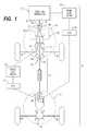
- FIG. 1schematically shows a vehicle with a multiple drive axle assembly according to aspect of the present invention
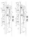
- FIGS. 2A and 28are schematic views show a portion of a multiple drive axle assembly according to an aspect of the present invention in which a rear drive axle is at a normal operating level and in which the rear drive axle is raised above the normal operating level, respectively;
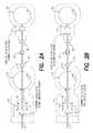
- FIG. 3is a partially cross-sectional side view showing an interaxle differential for a vehicle with a multiple drive axle assembly according to an aspect of the present invention
- FIG. 4is a partially cross-sectional side view showing a rear differential for a vehicle with a multiple drive axle assembly according to an aspect of the present invention.
- FIGS. 5A and 5Bare schematic views showing a rear axle assembly of a vehicle according to an aspect of the present invention in a normal operating position and a raised position, respectively.
- FIG. 1shows a vehicle 21 having a multiple drive axle assembly according to an aspect of the present invention.
- the illustrated vehicleis a so-called 6 ⁇ 4 configuration, i.e., six wheels, four of which are driven wheels, however, the present invention is also applicable to other configurations, such as 6 ⁇ 6, 8 ⁇ 6, 8 ⁇ 8, 10 ⁇ 8, and 10 ⁇ 10 configurations.
- the vehiclemay be a truck or a tractor.
- the vehicle 21includes a forward axle assembly 23 comprising a forward interaxle differential 25 , a forward interaxle differential input shaft 27 , a first forward interaxle differential output shaft 29 , and a second forward interaxle differential output shaft 31 .
- the forward interaxle differentialdistributes power from the forward interaxle differential input shaft 27 between the first and the second forward interaxle differential output shafts 29 and 31 .
- the vehicle 21further includes an intermediate drive shaft 33 that is ordinarily connected to the second forward interaxle differential output shaft 31 via yokes 35 a and 35 b of a universal joint 35 .
- An engine 37 or motor of the vehicledrives a drive shaft 39 that is ordinarily connected to the forward interaxle differential input shaft 27 via yokes 41 a and 41 b of a universal joint 41 .
- the vehicle 21further includes a rear axle assembly 43 comprising a rear differential 45 and a rear differential input shaft 47 .
- a rear clutch arrangement 49is provided between the intermediate drive shaft 33 and the rear differential input shaft 47 .
- the rear clutch arrangement 49is movable between a first position ( FIG. 2A ) in which the rear clutch arrangement rotationally locks the intermediate drive shaft 33 and the rear differential input shaft 47 so that the intermediate drive shaft the rear differential input shaft rotate together, and a second position ( FIG. 2B ) in which the intermediate drive shaft and the rear differential input shaft are rotationally disconnected.
- power transmitted to the first forward interaxle differential output shaft 29is distributed to left and right forward drive axles 51 l and 51 r by a forward differential 53 .
- Power transmitted to the rear differential input shaft 47 via the intermediate drive shaft 33 and the second forward interaxle differential output shaft 31is distributed to left and right rear drive axles 55 l and 55 r by the rear differential 45 .
- an interaxle differentialin the form of the Mack Power Divider, available from Mack Trucks, Inc., Greensboro, N.C., USA.
- an interaxle differentialcomprises a driving member, i.e., the forward interaxle differential input shaft 27 , having at an end thereof a ring or cage 57 that carries a plurality of radially extending plungers 59 in two rows (only one row seen in FIG. 3 ), which are free to slide in holes in the cage inwardly and outwardly a short distance.
- An outer cam 61 and an inner cam 63are connected to or formed at ends of the first forward interaxle differential output shaft 29 and the second forward interaxle differential output shaft 31 , respectively.
- the inner cam 63is placed within the cage 57 and the outer cam 61 surrounds the cage and the inner cam so that the three elements are in concentric relation, with the plungers bearing on both inner and outer cams.
- the two rows of plungers 59are indexed alternately, or staggered, as are two rows of cam lobes 63 a and 63 b on the inner cam 63 .
- the lobes (not visible in FIG. 3 ) of the outer cam 61are indexed uniformly across the width of the outer cam.
- the second forward interaxle differential output shaft 31is typically connected by a splined joint to the inner cam 63 and extends through the first forward interaxle differential output shaft 29 .
- the outer cam 61is typically formed at or attached at an end of the first forward interaxle differential output shaft 29 .
- the first forward interaxle differential output shaft 29typically comprises, at an end opposite the outer cam 61 , a bevel gear 67 that forms part of the forward axle differential 53 ( FIG. 1 ).
- a forward clutch arrangement 69can be provided and is movable between a first position in which the forward clutch arrangement rotationally locks the forward interaxle differential input shaft 27 to the first and second forward interaxle differential output shafts 29 and 31 and a second position in which the forward interaxle differential input shaft is not locked to the first and second forward interaxle differential output shafts.
- An example of a forward clutch arrangement 69 suitable for use with the present inventionis the air lock out arrangement available with the Mack Power Divider from Mack Trucks, Inc., Greensboro, N.C., USA.
- the ring 71is axially movable along the shaft portion 73 but prevented from rotation by a spline.
- a piston arrangement 75is provided for moving the ring 71 back and forth relative to the cage 57 .
- the piston arrangement 75will ordinarily be pneumatically operated, but may be hydraulically or electrically operated instead.
- the outer cam 61comprises internal splines 65 that mate with the external splines on the ring 71 to rotationally lock the forward interaxle differential input shaft 27 to the first forward interaxle differential output shaft 29 to which the outer cam is attached, usually by a splined joint.
- the forward clutch arrangement 69rotationally locks the forward interaxle differential input shaft 27 to the second forward interaxle differential output shaft 31 through the forward interaxle differential 25 , i.e., because relative motion of the outer cam 61 and the cage 57 is not possible, relative motion of the inner cam 53 and the cage is also not possible.
- the forward clutch arrangement 69When the forward clutch arrangement 69 is in the first position, the forward clutch arrangement thus effectively rotationally locks the forward interaxle differential input shaft to the intermediate drive shaft 33 through the second forward interaxle differential output shaft 31 and the universal joint 35 .
- the rear clutch arrangement 49can be similar to the forward clutch arrangement 69 , except that no cams are required, and structures corresponding to the inner cam and cage are omitted.
- An illustrative rear clutch arrangementis seen in FIG. 4 .
- both the rear clutch arrangement 49 and the forward clutch arrangement 69will be non-synchronized clutches, however, they could be or include synchronized clutches.
- an externally splined ring 77is non-rotatable but movable axially, by a piston arrangement 81 mounted on the first input shaft, relative to a first input shaft 79 connected to a yoke 35 b ′ of the universal joint 41 .
- An internally splined sleeve 83is formed at or attached to an end of the rear differential input shaft 47 .
- the externally splined ring 77 of the rear clutch arrangement 49is movable between the first position ( FIG. 2A ) in which the externally splined ring engages with the internal splines 83 ′ of the internally splined sleeve so that the rear clutch arrangement rotationally locks the intermediate drive shaft 33 and the rear differential input shaft 47 so that the intermediate drive shaft the rear differential input shaft rotate together, and a second position ( FIG. 2B ) in which the internal and external splines are disengaged and the intermediate drive shaft and the rear differential input shaft are rotationally disconnected.
- the piston arrangement 81can be the same piston arrangement used in the air lock out arrangement available with the Mack Power Divider from Mack Trucks, Inc., Greensboro, N.C., USA, or any other suitable means for moving the ring 77 relative to the first input shaft 79 may be used.
- FIG. 4shows the input shaft 79 terminating by a forward end of the internally spline sleeve 83 , however, it will be appreciated that a variety of alternative configurations can be provided.
- the input shaft 79can extend all the way through the center of the sleeve 83 and, if desired, the shaft 47 , which can be advantageous in that it can reduce load on inner (usually needle roller) bearings.
- the vehicle 21can include any suitable means for raising the rear axle assembly 43 above a normal operating level ( FIG. 5B ) relative to a frame 85 of the vehicle and for lowering the rear axle assembly to the normal operating level ( FIG. 5A ) relative to the frame.
- the raising and loweringmeans nay be pan of a rear axle assembly suspension array 87 for supporting the rear axle assembly relative to a frame of the vehicle.
- the rear axle assembly suspension arrangement 87can include a spring component 89 and a pneumatically or hydraulically adjustable pressurizable component 91 .
- the spring component 89can be extended or contracted for vice versa, depending upon the configuration of the suspension arrangement) to lower or raise the rear axle assembly 43 relative to the frame 85 .
- the means for raising and loweringmay be independent of the suspension system, such as separate hydraulic or pneumatic pistons attached to the frame that can compress the normal suspension system to raise the rear axle assembly and permit the suspension system to expand to its normal position to lower the rear axle assembly. It is presently believed that substantially any hydraulic, pneumatic or electrically actuated mechanical connection between the vehicle frame and suspension mountings brackets that will permit the suspension bracket(s) height and the frame height to change independent of each other would be suitable.
- the typical sequenceis to, first, cause the raising and lowering means to lower the rear axle assembly to a normal operating level and, second, cause the rear clutch arrangement 49 to move from the second position to the first position.
- the foregoing sequencecan be performed by an operator or by an appropriately programmed control unit.
- the sequencecan be performed when, for example, a vehicle load sensor 93 and/or an engine load sensor 95 senses that a load carried on the vehicle 21 or by the engine 37 is sufficient such that the mar drive axle 43 should be lowered to the normal operating position and transmits this information to a control unit, e.g., a Vehicle Electronic Control Unit (VECU) 97 or an Engine Electronic Control Unit (EECU) 99 .
- VECU and the EECUmay be the same unit or separate units.
- the VECU 97 and/or the EECU 99can then provide appropriate signals to the means for raising and lowering to lower the rear axle assembly 43 and to the rear clutch arrangement 49 to move to the first position.
- a presently preferred sequence of steps for raising the rear axle assembly 43 relative to the frame 85 of the vehiclemay be performed by an operator or under control of control units such as the VECU 97 and/or the EECU 99 in response to load signals from one or both of the vehicle load sensor 93 and the engine load sensor 95 indicating that a load carried on the vehicle 21 or by the engine 37 is sufficiently light such that the rear drive axle 43 should be raised above the normal operating position.
- the forward clutch arrangement 69is first moved to the first position ( FIG.
- the forward clutch arrangementrotationally locks the forward interaxle differential input shaft 27 relative to the first and second forward interaxle differential output shafts 29 and 31 so that, when the rear axle assembly 43 is raised, the forward interaxle differential will continue to transmit power to the forward differential 53 of the forward axle assembly 23 .
- the raising and lowering meansraises the rear axle assembly 43 above the normal operating level.
- the rear clutch arrangement 49is caused to move to the second position so that the intermediate drive shaft 33 and the rear differential input shaft 47 are rotationally disconnected. It is, however, also possible to first rotationally disconnect the intermediate drive shaft 33 and the rear differential input shaft 47 and then raise the rear axle assembly 47 .
- Operation under such ordinary operating conditionsis ordinarily performed when signals from sensors such as one or both of the vehicle load sensor 93 and the engine load sensor 95 indicating that a load carried on the vehicle 21 or by the engine 37 that are read by an operator or received by control units such as the VECU 97 and/or the EECU 99 is sufficiently high such that operation under normal operating conditions is appropriate.
- a sequence of stepscan be performed to rotationally disconnecting the intermediate drive shaft 33 and the rear differential input shaft 47 and raise the rear axle assembly 43 above the normal operating level relative to the frame 85 of the vehicle 21 .
- Signalsmay be obtained from sensors such as one or both of the vehicle load sensor 93 and the engine load sensor 95 indicating that a load carried on the vehicle 21 or by the engine 37 and that are read by an operator or received by control units such as the VECU 97 and/or the EECU 99 may reflect that the load(s) is (are) lower than the load(s) for which the engine or vehicle is designed to operate.
- the sequence of stepsmay be performed while the vehicle 21 is stationary or moving, such as while the vehicle pulls away from a loading dock.
- the forward interaxle differential input shaft 27is locked to the intermediate drive shaft 33 through the forward interaxle differential 25 , such as by locking the forward interaxle differential input shaft relative to the first and second forward interaxle differential output shafts 29 and 31 by moving the forward clutch arrangement 69 to the first position.
- the raising and lowering meansraises the rear axle assembly 43 above the normal operating level.
- the rear clutch arrangement 49is caused to move to the second position so that the intermediate drive shaft 33 and the rear differential input shaft 47 are rotationally disconnected. It is also possible to first rotationally disconnect the intermediate drive shaft 33 and the rear differential input shaft 47 and then raise the rear axle assembly 47 .
- the vehiclefirst be stopped or moving at low speed. With the vehicle 21 stopped or moving at low speed, the rear axle assembly 43 is then lowered to a normal operating level relative to the frame 85 of the vehicle. After lowering the rear axle assembly 43 relative to the frame, then the intermediate drive shaft 33 and the rear differential input shaft 47 are rotationally connected, such as by moving the rear clutch 49 to the first position.
- the illustrated vehicle 21is a so-called 6 ⁇ 4 configuration, i.e., six wheels, four of which are driven wheels, however, the present invention is also applicable to other configurations, such as 6 ⁇ 6, 8 ⁇ 6, 8 ⁇ 8, 10 ⁇ 8, and 10 ⁇ 10 configurations.
- 6 ⁇ 6, 8 ⁇ 6, 8 ⁇ 8, 10 ⁇ 8, and 10 ⁇ 10 configurationsit is possible to permit raising of the rear-most drive axle alone, or together with successive additional drive axles except for the forward-most drive axle.
- each of the intermediate drive axles between the forward-most and the rear-most drive axleswill include an interaxle differential similar to the forward interaxle differential 25
- the rear-most axlewill include a differential, like the rear differential 45 .
- a single rear clutchmight be provided to disengage all of the drive axles except for the forward-most drive axle, or clutches similar to the forward clutch 69 can be provided to individually engage or disengage the intermediate drive axles successively from rear toward front.
- the rear drive axle and the intermediate drive axlesare individually engageable or disengageable, they will ordinarily be raised and disengaged individually from rear toward front, with the rear-most drive axle being raised and disengaged first, the second rear-most intermediate drive axle being raised and disengaged second, etc.
Landscapes
- Engineering & Computer Science (AREA)
- Chemical & Material Sciences (AREA)
- Combustion & Propulsion (AREA)
- Transportation (AREA)
- Mechanical Engineering (AREA)
- Arrangement And Driving Of Transmission Devices (AREA)
- Retarders (AREA)
- Arrangement And Mounting Of Devices That Control Transmission Of Motive Force (AREA)
Abstract
Description
Claims (22)
Applications Claiming Priority (1)
| Application Number | Priority Date | Filing Date | Title |
|---|---|---|---|
| PCT/US2012/067880WO2014088566A1 (en) | 2012-12-05 | 2012-12-05 | Vehicle with multiple drive axle assembly with a raisable and lowerable rear drive axle, and method of neutralizing the rear drive axle and operating such a vehicle |
Publications (2)
| Publication Number | Publication Date |
|---|---|
| US20150266375A1 US20150266375A1 (en) | 2015-09-24 |
| US9381806B2true US9381806B2 (en) | 2016-07-05 |
Family
ID=50883825
Family Applications (1)
| Application Number | Title | Priority Date | Filing Date |
|---|---|---|---|
| US14/437,878ActiveUS9381806B2 (en) | 2012-12-05 | 2012-12-05 | Vehicle with multiple drive axle assembly with a raisable and lowerable rear drive axle, and method of operating such a vehicle |
Country Status (5)
| Country | Link |
|---|---|
| US (1) | US9381806B2 (en) |
| EP (1) | EP2928718B1 (en) |
| AU (1) | AU2012396288B2 (en) |
| BR (1) | BR112015013114B1 (en) |
| WO (1) | WO2014088566A1 (en) |
Cited By (5)
| Publication number | Priority date | Publication date | Assignee | Title |
|---|---|---|---|---|
| WO2020223779A1 (en)* | 2019-05-08 | 2020-11-12 | CNH Industrial Brasil Ltda. | Drive shaft for a vehicle with a first axle and a second axle that is a lifting axle |
| US11007871B2 (en)* | 2016-11-25 | 2021-05-18 | Fpt Industrial S.P.A. | Driveline of two driving tandem axles and vehicle comprising said driveline |
| US11047463B2 (en) | 2016-10-14 | 2021-06-29 | Dana Heavy Vehicle Systems Group, Llc | Differential input shaft with a tapered roller bearing |
| US11091030B2 (en) | 2019-01-09 | 2021-08-17 | Dana Heavy Vehicle Systems Group, Llc | Disconnect mechanism for a tandem axle system |
| US11808342B2 (en) | 2022-02-08 | 2023-11-07 | Dana Automotive Systems Group, Llc | Differential carrier |
Families Citing this family (14)
| Publication number | Priority date | Publication date | Assignee | Title |
|---|---|---|---|---|
| WO2015080722A1 (en)* | 2013-11-27 | 2015-06-04 | Volvo Truck Corporation | Vehicle with rear drive axle assembly and the ability to neutralize |
| US9969327B2 (en)* | 2015-03-04 | 2018-05-15 | Auto Truck Group, Llc | Vehicle improper load sensor |
| GB2530877A (en)* | 2015-08-04 | 2016-04-06 | Daimler Ag | Drivetrain Arrangement for a Commercial Vehicle as well as Method for Operating such a Drivetrain Arrangement |
| CN109963735B (en)* | 2016-12-14 | 2022-06-28 | 依维柯股份有限公司 | Free wheel system for tandem axle |
| US10967927B2 (en) | 2017-09-22 | 2021-04-06 | Link Mfg., Ltd. | Mounting brackets for auxiliary suspension systems |
| BR102017025512B1 (en) | 2017-11-28 | 2022-02-22 | On-Highway Brasil Ltda. | Method for monitoring and controlling the operation of the rear axle of a vehicle |
| EP3868593B1 (en)* | 2018-10-16 | 2025-01-01 | Iveco S.P.A. | Power-transmission axle for vehicle and vehicle |
| US11267563B2 (en)* | 2018-10-29 | 2022-03-08 | Pratt & Whitney Canada Corp. | Aircraft engine with clutch and mechanical lock |
| US10926633B2 (en) | 2018-11-28 | 2021-02-23 | Dana Heavy Vehicle Systems Group, Llc | Method of controlling a tandem axle assembly |
| WO2020210888A1 (en)* | 2019-04-17 | 2020-10-22 | CNH Industrial Brasil Ltda. | Disengagement system for a vehicle with a first shaft and a second shaft |
| US11691612B2 (en) | 2021-02-12 | 2023-07-04 | Dana Heavy Vehicle Systems Group, Llc | Systems and methods for disconnecting tandem axles |
| EP4366962A4 (en)* | 2021-07-08 | 2025-05-07 | Link MFG., Ltd. | DRIVEN LIFTING AXLES AND ASSOCIATED SYSTEMS AND METHODS |
| CN114148139B (en)* | 2021-11-09 | 2023-10-03 | 中国重汽集团济南动力有限公司 | A transaxle-boosting air suspension control system |
| CN115179756A (en)* | 2022-08-15 | 2022-10-14 | 山东巨明机械有限公司 | Six-wheel drive axle box |
Citations (30)
| Publication number | Priority date | Publication date | Assignee | Title |
|---|---|---|---|---|
| US4046210A (en) | 1975-05-22 | 1977-09-06 | Eaton Corporation | Multiple drive axle assembly |
| US4582160A (en) | 1985-05-20 | 1986-04-15 | Chrysler Corporation | Constant four wheel drive vehicle transaxle |
| US4754847A (en) | 1986-12-31 | 1988-07-05 | Dana Corporation | Interaxle differential for tandem axle assembly |
| US4817753A (en) | 1986-09-02 | 1989-04-04 | Mazda Motor Corporation | Interaxle differential restriction device for vehicle four wheel drive systems |
| US4842302A (en) | 1986-09-25 | 1989-06-27 | Oy Sisu-Auto Ab | Lifting bogie for a vehicle |
| US4977972A (en) | 1989-01-03 | 1990-12-18 | Eaton Corporation | Tridem drive axle system |
| US5083986A (en)* | 1989-07-20 | 1992-01-28 | Tochigifujisangyo Kabushiki Kaisha | Coupling apparatus with double clutches |
| US5398792A (en)* | 1990-07-27 | 1995-03-21 | Tochigi Fuji Sangyo Kabushiki Kaisha | Clutch device |
| US5542316A (en) | 1992-11-07 | 1996-08-06 | Automotive Products, Plc | Cam type gearless interaxle differential mechanism |
| US5704443A (en)* | 1994-03-11 | 1998-01-06 | Ab Volvo | Drive unit for motor vehicles |
| US6634446B2 (en)* | 2000-06-08 | 2003-10-21 | Kanzaki Kokyukoki Mfg. Co., Ltd. | Multi-wheel-drive vehicle with a front transaxle device |
| US6790154B1 (en) | 2003-03-21 | 2004-09-14 | Borgwarner, Inc. | Rear axle having electromagnetic clutches and geared differential |
| US6790152B2 (en)* | 2001-09-11 | 2004-09-14 | Honda Giken Kogyo Kabushiki Kaisha | Vehicle front and rear wheels drive system and clutch changeover method |
| US20050009660A1 (en) | 2003-07-10 | 2005-01-13 | Makoto Nishiji | Two-speed torque-splitting interaxle transfer case |
| US6877573B2 (en)* | 1999-12-21 | 2005-04-12 | Toshiyuki Hasegawa | Multi-wheel-driving vehicle |
| US20060172852A1 (en) | 2005-02-03 | 2006-08-03 | Claussen Stephen P | Automated inter-axle differential locking system actuation enhancement |
| WO2008077603A1 (en) | 2006-12-22 | 2008-07-03 | Daimler Ag | Tandem axle with liftable axle |
| DE102008015224A1 (en) | 2008-03-20 | 2009-03-19 | Daimler Ag | Drivetrain for motor vehicle e.g. passenger car, has mechanism aiding half shafts of one of drive axles, where mechanism is coupled and decoupled from drive shaft and formed as shiftable free-wheel differential |
| US20090082934A1 (en) | 2006-06-19 | 2009-03-26 | Magna Powertrain Usa, Inc. | Power Transfer Assembly With Torque Sensors And Torque Control System |
| US7779952B2 (en) | 2004-12-21 | 2010-08-24 | Volvo Construction Equipment Holding Sweden Ab | Drive system and an axle for a vehicle driveline, and a vehicle comprising the driveline |
| US20100248888A1 (en)* | 2006-08-17 | 2010-09-30 | Daimler Ag | Tandem axle having two drivable axles and a drivetrain which can be partially disconnected |
| US7918465B2 (en) | 2008-09-16 | 2011-04-05 | Metzger Donald C | Adjustable height trailer |
| US8042642B2 (en)* | 2008-08-14 | 2011-10-25 | American Axle & Manufacturing, Inc. | Motor vehicle with disconnectable all-wheel drive system |
| US20120234120A1 (en)* | 2011-03-15 | 2012-09-20 | GKN Driveline Japan Ltd. | Power transmission apparatus |
| US8398520B1 (en) | 2011-09-30 | 2013-03-19 | Arvinmeritor Technology, Llc | Drive axle assembly and disengagement system |
| US20130085031A1 (en) | 2011-09-30 | 2013-04-04 | Arvinmeritor Technology, Llc | Drive Axle Assembly and Disengagement System |
| US8608611B2 (en)* | 2009-01-21 | 2013-12-17 | Magna Powertrain Of America, Inc. | AWD vehicle with disconnect system |
| US8721493B2 (en)* | 2010-04-07 | 2014-05-13 | GKN Driveline Newton, LLC | Drive train for a motor vehicle |
| US8851212B2 (en)* | 2011-08-31 | 2014-10-07 | Mack Trucks, Inc. | Forward carrier assembly with a reversible inter-axle differential for a tandem axle vehicle, a powertrain for a tandem axle vehicle, and a tandem axle vehicle |
| US9102232B2 (en)* | 2010-07-20 | 2015-08-11 | Dana Heavy Vehicle Systems Group, Llc | Drive axle system having a clutching device |
- 2012
- 2012-12-05USUS14/437,878patent/US9381806B2/enactiveActive
- 2012-12-05WOPCT/US2012/067880patent/WO2014088566A1/enactiveApplication Filing
- 2012-12-05EPEP12889452.4Apatent/EP2928718B1/enactiveActive
- 2012-12-05BRBR112015013114-0Apatent/BR112015013114B1/enactiveIP Right Grant
- 2012-12-05AUAU2012396288Apatent/AU2012396288B2/enactiveActive
Patent Citations (30)
| Publication number | Priority date | Publication date | Assignee | Title |
|---|---|---|---|---|
| US4046210A (en) | 1975-05-22 | 1977-09-06 | Eaton Corporation | Multiple drive axle assembly |
| US4582160A (en) | 1985-05-20 | 1986-04-15 | Chrysler Corporation | Constant four wheel drive vehicle transaxle |
| US4817753A (en) | 1986-09-02 | 1989-04-04 | Mazda Motor Corporation | Interaxle differential restriction device for vehicle four wheel drive systems |
| US4842302A (en) | 1986-09-25 | 1989-06-27 | Oy Sisu-Auto Ab | Lifting bogie for a vehicle |
| US4754847A (en) | 1986-12-31 | 1988-07-05 | Dana Corporation | Interaxle differential for tandem axle assembly |
| US4977972A (en) | 1989-01-03 | 1990-12-18 | Eaton Corporation | Tridem drive axle system |
| US5083986A (en)* | 1989-07-20 | 1992-01-28 | Tochigifujisangyo Kabushiki Kaisha | Coupling apparatus with double clutches |
| US5398792A (en)* | 1990-07-27 | 1995-03-21 | Tochigi Fuji Sangyo Kabushiki Kaisha | Clutch device |
| US5542316A (en) | 1992-11-07 | 1996-08-06 | Automotive Products, Plc | Cam type gearless interaxle differential mechanism |
| US5704443A (en)* | 1994-03-11 | 1998-01-06 | Ab Volvo | Drive unit for motor vehicles |
| US6877573B2 (en)* | 1999-12-21 | 2005-04-12 | Toshiyuki Hasegawa | Multi-wheel-driving vehicle |
| US6634446B2 (en)* | 2000-06-08 | 2003-10-21 | Kanzaki Kokyukoki Mfg. Co., Ltd. | Multi-wheel-drive vehicle with a front transaxle device |
| US6790152B2 (en)* | 2001-09-11 | 2004-09-14 | Honda Giken Kogyo Kabushiki Kaisha | Vehicle front and rear wheels drive system and clutch changeover method |
| US6790154B1 (en) | 2003-03-21 | 2004-09-14 | Borgwarner, Inc. | Rear axle having electromagnetic clutches and geared differential |
| US20050009660A1 (en) | 2003-07-10 | 2005-01-13 | Makoto Nishiji | Two-speed torque-splitting interaxle transfer case |
| US7779952B2 (en) | 2004-12-21 | 2010-08-24 | Volvo Construction Equipment Holding Sweden Ab | Drive system and an axle for a vehicle driveline, and a vehicle comprising the driveline |
| US20060172852A1 (en) | 2005-02-03 | 2006-08-03 | Claussen Stephen P | Automated inter-axle differential locking system actuation enhancement |
| US20090082934A1 (en) | 2006-06-19 | 2009-03-26 | Magna Powertrain Usa, Inc. | Power Transfer Assembly With Torque Sensors And Torque Control System |
| US20100248888A1 (en)* | 2006-08-17 | 2010-09-30 | Daimler Ag | Tandem axle having two drivable axles and a drivetrain which can be partially disconnected |
| WO2008077603A1 (en) | 2006-12-22 | 2008-07-03 | Daimler Ag | Tandem axle with liftable axle |
| DE102008015224A1 (en) | 2008-03-20 | 2009-03-19 | Daimler Ag | Drivetrain for motor vehicle e.g. passenger car, has mechanism aiding half shafts of one of drive axles, where mechanism is coupled and decoupled from drive shaft and formed as shiftable free-wheel differential |
| US8042642B2 (en)* | 2008-08-14 | 2011-10-25 | American Axle & Manufacturing, Inc. | Motor vehicle with disconnectable all-wheel drive system |
| US7918465B2 (en) | 2008-09-16 | 2011-04-05 | Metzger Donald C | Adjustable height trailer |
| US8608611B2 (en)* | 2009-01-21 | 2013-12-17 | Magna Powertrain Of America, Inc. | AWD vehicle with disconnect system |
| US8721493B2 (en)* | 2010-04-07 | 2014-05-13 | GKN Driveline Newton, LLC | Drive train for a motor vehicle |
| US9102232B2 (en)* | 2010-07-20 | 2015-08-11 | Dana Heavy Vehicle Systems Group, Llc | Drive axle system having a clutching device |
| US20120234120A1 (en)* | 2011-03-15 | 2012-09-20 | GKN Driveline Japan Ltd. | Power transmission apparatus |
| US8851212B2 (en)* | 2011-08-31 | 2014-10-07 | Mack Trucks, Inc. | Forward carrier assembly with a reversible inter-axle differential for a tandem axle vehicle, a powertrain for a tandem axle vehicle, and a tandem axle vehicle |
| US8398520B1 (en) | 2011-09-30 | 2013-03-19 | Arvinmeritor Technology, Llc | Drive axle assembly and disengagement system |
| US20130085031A1 (en) | 2011-09-30 | 2013-04-04 | Arvinmeritor Technology, Llc | Drive Axle Assembly and Disengagement System |
Non-Patent Citations (2)
| Title |
|---|
| International Preliminary Report on Patentability (Jan. 28, 2015) for corresponding International Application PCT/US2012/067880. |
| International Search Report (Feb. 8, 2013) for corresponding International Application PCT/US2012/067880. |
Cited By (8)
| Publication number | Priority date | Publication date | Assignee | Title |
|---|---|---|---|---|
| US11047463B2 (en) | 2016-10-14 | 2021-06-29 | Dana Heavy Vehicle Systems Group, Llc | Differential input shaft with a tapered roller bearing |
| US11007871B2 (en)* | 2016-11-25 | 2021-05-18 | Fpt Industrial S.P.A. | Driveline of two driving tandem axles and vehicle comprising said driveline |
| AU2017365114B2 (en)* | 2016-11-25 | 2022-12-22 | Fpt Industrial S.P.A. | Driveline of two driving tandem axles and vehicle comprising said driveline |
| US11091030B2 (en) | 2019-01-09 | 2021-08-17 | Dana Heavy Vehicle Systems Group, Llc | Disconnect mechanism for a tandem axle system |
| WO2020223779A1 (en)* | 2019-05-08 | 2020-11-12 | CNH Industrial Brasil Ltda. | Drive shaft for a vehicle with a first axle and a second axle that is a lifting axle |
| CN114096431A (en)* | 2019-05-08 | 2022-02-25 | 依维柯股份公司 | Drive shaft for a vehicle having a first axle and a second axle as a lift axle |
| CN114096431B (en)* | 2019-05-08 | 2023-11-03 | 依维柯股份公司 | Drive axle for a vehicle having a first axle and a second axle as a lift axle |
| US11808342B2 (en) | 2022-02-08 | 2023-11-07 | Dana Automotive Systems Group, Llc | Differential carrier |
Also Published As
| Publication number | Publication date |
|---|---|
| AU2012396288A1 (en) | 2015-07-16 |
| BR112015013114A2 (en) | 2017-07-11 |
| US20150266375A1 (en) | 2015-09-24 |
| WO2014088566A1 (en) | 2014-06-12 |
| EP2928718B1 (en) | 2020-08-19 |
| BR112015013114B1 (en) | 2021-05-11 |
| EP2928718A1 (en) | 2015-10-14 |
| EP2928718A4 (en) | 2016-08-17 |
| AU2012396288B2 (en) | 2017-12-21 |
Similar Documents
| Publication | Publication Date | Title |
|---|---|---|
| US9381806B2 (en) | Vehicle with multiple drive axle assembly with a raisable and lowerable rear drive axle, and method of operating such a vehicle | |
| US10350996B2 (en) | Vehicle with rear drive axle assembly and the ability to neutralize | |
| EP3385106B1 (en) | Axle assembly having multiple clutch collars | |
| US8469854B1 (en) | Disconnectable driveline for all-wheel drive vehicle | |
| US8562479B2 (en) | Tandem axle having two drivable axles and a drivetrain which can be partially disconnected | |
| EP3453555B1 (en) | Axle assembly having a drive pinion assembly | |
| US20150011349A1 (en) | Single speed and two-speed disconnecting axle arrangements | |
| CN106891717B (en) | Duplex drive axle capable of realizing lifting and driving of rear axle | |
| US7975796B2 (en) | Reduced friction differential disconnect for a motor vehicle | |
| US20170120739A1 (en) | Utility vehicle, in particular motor truck, having at least one double-axle unit | |
| US11104226B2 (en) | Inter-axle differential assembly, a driving axle assembly and a motor vehicle | |
| CN108495763B (en) | Axle connections for vehicles | |
| US20060272866A1 (en) | Tandem axle system | |
| US10479198B2 (en) | Transfer case with active clutch on front output and pass-thru rear output | |
| CN109982884B (en) | Power transmission assembly for tandem axle | |
| SE540826C2 (en) | An axle gear system, a driving axle system and a motor vehicle | |
| EP2714452B1 (en) | Drive shaft, motor vehicle or trailer comprising such a drive shaft and method for adapting a drive shaft | |
| US20170299036A1 (en) | Vehicle differential assembly | |
| CN117212424A (en) | Gearbox system and working method thereof | |
| RU2808306C2 (en) | Drive shaft for vehicle with first axle and second axle which can be lifted | |
| DE102017125673A1 (en) | Centrally driven axle unit for a trailer axle | |
| CN114096431B (en) | Drive axle for a vehicle having a first axle and a second axle as a lift axle | |
| CN113853321A (en) | Disengagement system for a vehicle having a first shaft and a second shaft | |
| WO2016022292A1 (en) | Tandem axles with disconnects | |
| EP4046818B1 (en) | Wheel hub for mounting a wheel on an axle of a work vehicle |
Legal Events
| Date | Code | Title | Description |
|---|---|---|---|
| AS | Assignment | Owner name:MACK TRUCKS, INC., NORTH CAROLINA Free format text:ASSIGNMENT OF ASSIGNORS INTEREST;ASSIGNORS:TAVVALA, KRISHNA;GORDON, BRIAN;REEL/FRAME:029409/0829 Effective date:20121204 | |
| AS | Assignment | Owner name:MACK TRUCKS, INC., NORTH CAROLINA Free format text:ASSIGNMENT OF ASSIGNORS INTEREST;ASSIGNORS:TAVVALA, KRISHNA;GORDON, BRIAN;REEL/FRAME:035477/0821 Effective date:20150420 | |
| STCF | Information on status: patent grant | Free format text:PATENTED CASE | |
| AS | Assignment | Owner name:AB VOLVO (PUBL.), SWEDEN Free format text:NUNC PRO TUNC ASSIGNMENT;ASSIGNOR:MACK TRUCKS, INC.;REEL/FRAME:042014/0022 Effective date:20170221 Owner name:VOLVO LASTVAGNAR AB, SWEDEN Free format text:NUNC PRO TUNC ASSIGNMENT;ASSIGNOR:AB VOLVO (PUBL.);REEL/FRAME:042015/0858 Effective date:20170307 | |
| MAFP | Maintenance fee payment | Free format text:PAYMENT OF MAINTENANCE FEE, 4TH YEAR, LARGE ENTITY (ORIGINAL EVENT CODE: M1551); ENTITY STATUS OF PATENT OWNER: LARGE ENTITY Year of fee payment:4 | |
| MAFP | Maintenance fee payment | Free format text:PAYMENT OF MAINTENANCE FEE, 8TH YEAR, LARGE ENTITY (ORIGINAL EVENT CODE: M1552); ENTITY STATUS OF PATENT OWNER: LARGE ENTITY Year of fee payment:8 |