US9381297B2 - Sealed infusion device with electrical connector port - Google Patents
Sealed infusion device with electrical connector portDownload PDFInfo
- Publication number
- US9381297B2 US9381297B2US13/827,707US201313827707AUS9381297B2US 9381297 B2US9381297 B2US 9381297B2US 201313827707 AUS201313827707 AUS 201313827707AUS 9381297 B2US9381297 B2US 9381297B2
- Authority
- US
- United States
- Prior art keywords
- electrical connector
- power
- housing
- connector port
- electrical
- Prior art date
- Legal status (The legal status is an assumption and is not a legal conclusion. Google has not performed a legal analysis and makes no representation as to the accuracy of the status listed.)
- Active, expires
Links
- 238000001802infusionMethods0.000titleclaimsabstractdescription32
- 238000002955isolationMethods0.000claimsabstractdescription79
- 239000000463materialSubstances0.000claimsdescription12
- 230000001105regulatory effectEffects0.000claimsdescription10
- 239000012528membraneSubstances0.000claimsdescription5
- 239000012811non-conductive materialSubstances0.000claimsdescription4
- 239000012212insulatorSubstances0.000claimsdescription3
- 238000012546transferMethods0.000abstractdescription7
- 230000002238attenuated effectEffects0.000abstract1
- NOESYZHRGYRDHS-UHFFFAOYSA-NinsulinChemical compoundN1C(=O)C(NC(=O)C(CCC(N)=O)NC(=O)C(CCC(O)=O)NC(=O)C(C(C)C)NC(=O)C(NC(=O)CN)C(C)CC)CSSCC(C(NC(CO)C(=O)NC(CC(C)C)C(=O)NC(CC=2C=CC(O)=CC=2)C(=O)NC(CCC(N)=O)C(=O)NC(CC(C)C)C(=O)NC(CCC(O)=O)C(=O)NC(CC(N)=O)C(=O)NC(CC=2C=CC(O)=CC=2)C(=O)NC(CSSCC(NC(=O)C(C(C)C)NC(=O)C(CC(C)C)NC(=O)C(CC=2C=CC(O)=CC=2)NC(=O)C(CC(C)C)NC(=O)C(C)NC(=O)C(CCC(O)=O)NC(=O)C(C(C)C)NC(=O)C(CC(C)C)NC(=O)C(CC=2NC=NC=2)NC(=O)C(CO)NC(=O)CNC2=O)C(=O)NCC(=O)NC(CCC(O)=O)C(=O)NC(CCCNC(N)=N)C(=O)NCC(=O)NC(CC=3C=CC=CC=3)C(=O)NC(CC=3C=CC=CC=3)C(=O)NC(CC=3C=CC(O)=CC=3)C(=O)NC(C(C)O)C(=O)N3C(CCC3)C(=O)NC(CCCCN)C(=O)NC(C)C(O)=O)C(=O)NC(CC(N)=O)C(O)=O)=O)NC(=O)C(C(C)CC)NC(=O)C(CO)NC(=O)C(C(C)O)NC(=O)C1CSSCC2NC(=O)C(CC(C)C)NC(=O)C(NC(=O)C(CCC(N)=O)NC(=O)C(CC(N)=O)NC(=O)C(NC(=O)C(N)CC=1C=CC=CC=1)C(C)C)CC1=CN=CN1NOESYZHRGYRDHS-UHFFFAOYSA-N0.000description54
- 102000004877InsulinHuman genes0.000description27
- 108090001061InsulinProteins0.000description27
- 229940125396insulinDrugs0.000description27
- 230000007246mechanismEffects0.000description16
- 239000007788liquidSubstances0.000description14
- 238000004891communicationMethods0.000description13
- 238000005516engineering processMethods0.000description11
- 230000003993interactionEffects0.000description10
- 239000004033plasticSubstances0.000description10
- 229920000642polymerPolymers0.000description10
- 239000012530fluidSubstances0.000description9
- 230000006870functionEffects0.000description8
- XLYOFNOQVPJJNP-UHFFFAOYSA-NwaterSubstancesOXLYOFNOQVPJJNP-UHFFFAOYSA-N0.000description8
- 230000035939shockEffects0.000description7
- 230000004888barrier functionEffects0.000description6
- 230000006378damageEffects0.000description6
- 206010012601diabetes mellitusDiseases0.000description6
- 230000005672electromagnetic fieldEffects0.000description6
- 230000004048modificationEffects0.000description6
- 238000012986modificationMethods0.000description6
- 238000005086pumpingMethods0.000description6
- 230000033228biological regulationEffects0.000description5
- 230000001419dependent effectEffects0.000description5
- 238000013461designMethods0.000description5
- 239000003814drugSubstances0.000description5
- 229910052751metalInorganic materials0.000description5
- 239000002184metalSubstances0.000description5
- 230000008878couplingEffects0.000description4
- 238000010168coupling processMethods0.000description4
- 238000005859coupling reactionMethods0.000description4
- 239000000446fuelSubstances0.000description4
- APTZNLHMIGJTEW-UHFFFAOYSA-Npyraflufen-ethylChemical compoundC1=C(Cl)C(OCC(=O)OCC)=CC(C=2C(=C(OC(F)F)N(C)N=2)Cl)=C1FAPTZNLHMIGJTEW-UHFFFAOYSA-N0.000description3
- 238000011282treatmentMethods0.000description3
- 239000011324beadSubstances0.000description2
- 230000008901benefitEffects0.000description2
- 239000003153chemical reaction reagentSubstances0.000description2
- 239000004020conductorSubstances0.000description2
- 238000013480data collectionMethods0.000description2
- 230000000994depressogenic effectEffects0.000description2
- 238000010586diagramMethods0.000description2
- 230000007613environmental effectEffects0.000description2
- 230000003203everyday effectEffects0.000description2
- 230000014509gene expressionEffects0.000description2
- 238000002347injectionMethods0.000description2
- 239000007924injectionSubstances0.000description2
- 238000000034methodMethods0.000description2
- 230000008569processEffects0.000description2
- 230000005855radiationEffects0.000description2
- 238000007789sealingMethods0.000description2
- 238000004804windingMethods0.000description2
- 229910000859α-FeInorganic materials0.000description2
- 229920000049Carbon (fiber)Polymers0.000description1
- WQZGKKKJIJFFOK-GASJEMHNSA-NGlucoseNatural productsOC[C@H]1OC(O)[C@H](O)[C@@H](O)[C@@H]1OWQZGKKKJIJFFOK-GASJEMHNSA-N0.000description1
- HBBGRARXTFLTSG-UHFFFAOYSA-NLithium ionChemical compound[Li+]HBBGRARXTFLTSG-UHFFFAOYSA-N0.000description1
- 229910005813NiMHInorganic materials0.000description1
- 206010067584Type 1 diabetes mellitusDiseases0.000description1
- WYTGDNHDOZPMIW-RCBQFDQVSA-NalstonineNatural productsC1=CC2=C3C=CC=CC3=NC2=C2N1C[C@H]1[C@H](C)OC=C(C(=O)OC)[C@H]1C2WYTGDNHDOZPMIW-RCBQFDQVSA-N0.000description1
- 238000005452bendingMethods0.000description1
- 230000009286beneficial effectEffects0.000description1
- 230000005540biological transmissionEffects0.000description1
- 239000004917carbon fiberSubstances0.000description1
- 230000008859changeEffects0.000description1
- 235000019504cigarettesNutrition0.000description1
- 230000006835compressionEffects0.000description1
- 238000007906compressionMethods0.000description1
- 230000001276controlling effectEffects0.000description1
- 230000002354daily effectEffects0.000description1
- 238000013500data storageMethods0.000description1
- 230000000881depressing effectEffects0.000description1
- 229940079593drugDrugs0.000description1
- 230000009977dual effectEffects0.000description1
- 239000000428dustSubstances0.000description1
- 239000007789gasSubstances0.000description1
- 239000008103glucoseSubstances0.000description1
- 230000036541healthEffects0.000description1
- 230000017525heat dissipationEffects0.000description1
- 230000006872improvementEffects0.000description1
- 229940127560insulin penDrugs0.000description1
- 229910001416lithium ionInorganic materials0.000description1
- 238000012423maintenanceMethods0.000description1
- 230000007257malfunctionEffects0.000description1
- 238000007726management methodMethods0.000description1
- 238000005259measurementMethods0.000description1
- VNWKTOKETHGBQD-UHFFFAOYSA-NmethaneChemical compoundCVNWKTOKETHGBQD-UHFFFAOYSA-N0.000description1
- 238000000465mouldingMethods0.000description1
- 230000000737periodic effectEffects0.000description1
- 230000002093peripheral effectEffects0.000description1
- 239000002861polymer materialSubstances0.000description1
- 238000012545processingMethods0.000description1
- 230000001681protective effectEffects0.000description1
- 230000008439repair processEffects0.000description1
- 239000000565sealantSubstances0.000description1
- 239000007779soft materialSubstances0.000description1
- 210000000352storage cellAnatomy0.000description1
- 238000007920subcutaneous administrationMethods0.000description1
- 239000000126substanceSubstances0.000description1
- 210000004243sweatAnatomy0.000description1
- 238000012360testing methodMethods0.000description1
- 238000002560therapeutic procedureMethods0.000description1
- 208000001072type 2 diabetes mellitusDiseases0.000description1
- 238000013022ventingMethods0.000description1
- 238000004078waterproofingMethods0.000description1
Images


Classifications
- A—HUMAN NECESSITIES
- A61—MEDICAL OR VETERINARY SCIENCE; HYGIENE
- A61M—DEVICES FOR INTRODUCING MEDIA INTO, OR ONTO, THE BODY; DEVICES FOR TRANSDUCING BODY MEDIA OR FOR TAKING MEDIA FROM THE BODY; DEVICES FOR PRODUCING OR ENDING SLEEP OR STUPOR
- A61M5/00—Devices for bringing media into the body in a subcutaneous, intra-vascular or intramuscular way; Accessories therefor, e.g. filling or cleaning devices, arm-rests
- A61M5/14—Infusion devices, e.g. infusing by gravity; Blood infusion; Accessories therefor
- A61M5/142—Pressure infusion, e.g. using pumps
- A61M5/14244—Pressure infusion, e.g. using pumps adapted to be carried by the patient, e.g. portable on the body
- A—HUMAN NECESSITIES
- A61—MEDICAL OR VETERINARY SCIENCE; HYGIENE
- A61M—DEVICES FOR INTRODUCING MEDIA INTO, OR ONTO, THE BODY; DEVICES FOR TRANSDUCING BODY MEDIA OR FOR TAKING MEDIA FROM THE BODY; DEVICES FOR PRODUCING OR ENDING SLEEP OR STUPOR
- A61M39/00—Tubes, tube connectors, tube couplings, valves, access sites or the like, specially adapted for medical use
- A61M39/10—Tube connectors; Tube couplings
- A—HUMAN NECESSITIES
- A61—MEDICAL OR VETERINARY SCIENCE; HYGIENE
- A61M—DEVICES FOR INTRODUCING MEDIA INTO, OR ONTO, THE BODY; DEVICES FOR TRANSDUCING BODY MEDIA OR FOR TAKING MEDIA FROM THE BODY; DEVICES FOR PRODUCING OR ENDING SLEEP OR STUPOR
- A61M5/00—Devices for bringing media into the body in a subcutaneous, intra-vascular or intramuscular way; Accessories therefor, e.g. filling or cleaning devices, arm-rests
- A61M5/14—Infusion devices, e.g. infusing by gravity; Blood infusion; Accessories therefor
- A61M5/142—Pressure infusion, e.g. using pumps
- H—ELECTRICITY
- H01—ELECTRIC ELEMENTS
- H01R—ELECTRICALLY-CONDUCTIVE CONNECTIONS; STRUCTURAL ASSOCIATIONS OF A PLURALITY OF MUTUALLY-INSULATED ELECTRICAL CONNECTING ELEMENTS; COUPLING DEVICES; CURRENT COLLECTORS
- H01R13/00—Details of coupling devices of the kinds covered by groups H01R12/70 or H01R24/00 - H01R33/00
- H01R13/44—Means for preventing access to live contacts
- H01R13/447—Shutter or cover plate
- H—ELECTRICITY
- H01—ELECTRIC ELEMENTS
- H01R—ELECTRICALLY-CONDUCTIVE CONNECTIONS; STRUCTURAL ASSOCIATIONS OF A PLURALITY OF MUTUALLY-INSULATED ELECTRICAL CONNECTING ELEMENTS; COUPLING DEVICES; CURRENT COLLECTORS
- H01R13/00—Details of coupling devices of the kinds covered by groups H01R12/70 or H01R24/00 - H01R33/00
- H01R13/46—Bases; Cases
- H01R13/52—Dustproof, splashproof, drip-proof, waterproof, or flameproof cases
- H01R13/5213—Covers
- H—ELECTRICITY
- H01—ELECTRIC ELEMENTS
- H01R—ELECTRICALLY-CONDUCTIVE CONNECTIONS; STRUCTURAL ASSOCIATIONS OF A PLURALITY OF MUTUALLY-INSULATED ELECTRICAL CONNECTING ELEMENTS; COUPLING DEVICES; CURRENT COLLECTORS
- H01R13/00—Details of coupling devices of the kinds covered by groups H01R12/70 or H01R24/00 - H01R33/00
- H01R13/46—Bases; Cases
- H01R13/52—Dustproof, splashproof, drip-proof, waterproof, or flameproof cases
- H01R13/5224—Dustproof, splashproof, drip-proof, waterproof, or flameproof cases for medical use
- A—HUMAN NECESSITIES
- A61—MEDICAL OR VETERINARY SCIENCE; HYGIENE
- A61M—DEVICES FOR INTRODUCING MEDIA INTO, OR ONTO, THE BODY; DEVICES FOR TRANSDUCING BODY MEDIA OR FOR TAKING MEDIA FROM THE BODY; DEVICES FOR PRODUCING OR ENDING SLEEP OR STUPOR
- A61M39/00—Tubes, tube connectors, tube couplings, valves, access sites or the like, specially adapted for medical use
- A61M39/10—Tube connectors; Tube couplings
- A61M2039/1022—Tube connectors; Tube couplings additionally providing electrical connection
- A—HUMAN NECESSITIES
- A61—MEDICAL OR VETERINARY SCIENCE; HYGIENE
- A61M—DEVICES FOR INTRODUCING MEDIA INTO, OR ONTO, THE BODY; DEVICES FOR TRANSDUCING BODY MEDIA OR FOR TAKING MEDIA FROM THE BODY; DEVICES FOR PRODUCING OR ENDING SLEEP OR STUPOR
- A61M2205/00—General characteristics of the apparatus
- A61M2205/35—Communication
- A61M2205/3546—Range
- A61M2205/3569—Range sublocal, e.g. between console and disposable
- A—HUMAN NECESSITIES
- A61—MEDICAL OR VETERINARY SCIENCE; HYGIENE
- A61M—DEVICES FOR INTRODUCING MEDIA INTO, OR ONTO, THE BODY; DEVICES FOR TRANSDUCING BODY MEDIA OR FOR TAKING MEDIA FROM THE BODY; DEVICES FOR PRODUCING OR ENDING SLEEP OR STUPOR
- A61M2205/00—General characteristics of the apparatus
- A61M2205/35—Communication
- A61M2205/3576—Communication with non implanted data transmission devices, e.g. using external transmitter or receiver
- A61M2205/3584—Communication with non implanted data transmission devices, e.g. using external transmitter or receiver using modem, internet or bluetooth
- A—HUMAN NECESSITIES
- A61—MEDICAL OR VETERINARY SCIENCE; HYGIENE
- A61M—DEVICES FOR INTRODUCING MEDIA INTO, OR ONTO, THE BODY; DEVICES FOR TRANSDUCING BODY MEDIA OR FOR TAKING MEDIA FROM THE BODY; DEVICES FOR PRODUCING OR ENDING SLEEP OR STUPOR
- A61M2205/00—General characteristics of the apparatus
- A61M2205/50—General characteristics of the apparatus with microprocessors or computers
- A61M2205/502—User interfaces, e.g. screens or keyboards
- A61M2205/505—Touch-screens; Virtual keyboard or keypads; Virtual buttons; Soft keys; Mouse touches
- A—HUMAN NECESSITIES
- A61—MEDICAL OR VETERINARY SCIENCE; HYGIENE
- A61M—DEVICES FOR INTRODUCING MEDIA INTO, OR ONTO, THE BODY; DEVICES FOR TRANSDUCING BODY MEDIA OR FOR TAKING MEDIA FROM THE BODY; DEVICES FOR PRODUCING OR ENDING SLEEP OR STUPOR
- A61M2205/00—General characteristics of the apparatus
- A61M2205/82—Internal energy supply devices
- A61M2205/8206—Internal energy supply devices battery-operated
- A—HUMAN NECESSITIES
- A61—MEDICAL OR VETERINARY SCIENCE; HYGIENE
- A61M—DEVICES FOR INTRODUCING MEDIA INTO, OR ONTO, THE BODY; DEVICES FOR TRANSDUCING BODY MEDIA OR FOR TAKING MEDIA FROM THE BODY; DEVICES FOR PRODUCING OR ENDING SLEEP OR STUPOR
- A61M2205/00—General characteristics of the apparatus
- A61M2205/82—Internal energy supply devices
- A61M2205/8237—Charging means
- A—HUMAN NECESSITIES
- A61—MEDICAL OR VETERINARY SCIENCE; HYGIENE
- A61M—DEVICES FOR INTRODUCING MEDIA INTO, OR ONTO, THE BODY; DEVICES FOR TRANSDUCING BODY MEDIA OR FOR TAKING MEDIA FROM THE BODY; DEVICES FOR PRODUCING OR ENDING SLEEP OR STUPOR
- A61M2205/00—General characteristics of the apparatus
- A61M2205/82—Internal energy supply devices
- A61M2205/8262—Internal energy supply devices connectable to external power source, e.g. connecting to automobile battery through the cigarette lighter
Definitions
- Electrically-powered portable devicesoften include portable power sources, such as batteries, that must be recharged periodically. Many such devices also provide communications to a host device or other associated machinery, so as to exchange data relating to device operation, maintenance history, and the like. Recharging a portable device and exchanging data through a host device, which provides a power source, often involves receiving electrical power and communicating data over a single connection. Such connections may comprise, for example, a Universal Serial Bus (USB) connector coupling the portable device to a host computer or a USB hub.
- USBUniversal Serial Bus
- the portable deviceoften must be constructed for operation so it is isolated from the source that provides electrical power for operation and for charging, and often must be isolated as well from the source of data exchange and communications.
- Such portable devicesmay include laboratory devices, portable test equipment, and portable user devices.
- a portable devicesuch as described above is a device that involves the delivery of fluids.
- fluidsincluding liquids and gases
- treatments for many patientsinclude the administration of a known amount of a substance at predetermined intervals.
- the treatment of diabetesinvolves just such a regimented dosage of medicaments such as insulin.
- diabetesis one of a few medical indications wherein the patient routinely administers the medicament (such as insulin) to themselves by a subcutaneous modality, such as, e.g., via a hypodermic syringe injection or an ambulatory infusion device, or pump.
- a subcutaneous modalitysuch as, e.g., via a hypodermic syringe injection or an ambulatory infusion device, or pump.
- a subcutaneous modalitysuch as, e.g., via a hypodermic syringe injection or an ambulatory infusion device, or pump.
- a subcutaneous modalitysuch as, e.g., via a hypodermic syringe injection or an ambulatory infusion device, or pump.
- providing a patient with the safe, reliable, and comfortable administration of required doses of medicationmay be particularly important in order to facilitate patient compliance and accurate treatment of the condition.
- government regulations and industry standardsoften impose requirements for control of electromagnetic emissions, power leakage, and the like.
- Ambulatory insulin infusion pumpshave been developed for the administration of medicaments such as insulin for those diagnosed with both type I and type II diabetes. These pumps offer an alternative to multiple daily injections of insulin by an insulin syringe or an insulin pen. They also allow for continuous insulin therapy.
- some ambulatory infusion devicescan include data collection and storage mechanisms, which allow a diabetic patient/user and/or a caregiver (e.g., doctor, health care worker, family member, and so forth) to easily monitor and adjust insulin intake.
- the infusion devicemay be powered by a rechargeable battery that requires periodic recharging.
- a “user”refers to a person who is operating the medical infusion device, and may comprise a patient, diabetic person, caregiver, and the like. Additionally, the user must be isolated from electrical hazards during everyday use. Such use can result in exposure to water and other liquids, e.g., sweat, which may come into contact with the device. When a conventional device becomes wet, the device can malfunction or shut down completely, or might produce an electrical shock to the user of the device.
- the term “user”will be understood to include a person who is a patient, and may include other persons such as caregivers, clinicians, certified diabetes instructors (CDEs), medical professionals, and the like, depending on the context in which “user” is mentioned.
- a portable deviceincludes a housing having a front surface and back surface that are spaced apart and enclosed by side surfaces to define an internal cavity, and an electrical connector port that is fitted to the housing and extends into the internal cavity.
- the electrical connector portreceives electrical power and data such that the electrical connector port directs the electrical power to a power isolation connector and directs the data to a data isolation connector.
- the housing and electrical connector portare configured to provide a seal that prevents the passage of moisture into the internal cavity.
- the sealis formed between the electrical connector port and the electrical connector port door with an overmold that prevents the passage of moisture into the internal cavity.
- the portable deviceprovides electrical and data isolation and also prevents the passage of moisture into the internal cavity.
- a portable medical devicewhich is capable of being coupled to a dedicated power source, e.g., wall outlet, or to a configured power source, e.g., personal computer.
- the infusion deviceis further designed such that the connection to either of these sources is available during use of the device.
- the infusion deviceis also designed to withstand exposure to water and other liquids, which may otherwise harm the user or alter the functionality of the device.
- FIG. 1depicts a portable device according to an embodiment of the present invention that is coupled to a host device and is electrically isolated from the host.
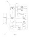
- FIG. 2is a block diagram of circuitry and components for a portable medical device embodiment with electrical power isolation and data isolation.
- FIG. 3is a schematic that depicts the front side of a portable medical device in an embodiment.
- FIG. 4is a schematic that depicts the circuitry and components of a portable medical device with the front side housing removed as in FIG. 3 .
- FIG. 5is a schematic that depicts the circuitry and components of a portable medical device with the front side housing removed as in FIG. 3 .
- FIG. 6is a perspective view of FIG. 5 in which the cartridge side of the portable medical device is shown in one embodiment.
- FIG. 7is a perspective view of FIG. 5 in which a top and side of the portable medical device are shown in one embodiment.
- FIG. 8is a schematic that depicts a cross-sectional view of the portable medical device in FIG. 5 .
- FIG. 9is a schematic that depicts a top perspective view of an electrical connector port assembly used in the portable medical device of FIG. 3 in one embodiment.
- FIG. 10is a schematic that depicts a bottom view of the electrical connector port assembly of FIG. 9 .
- FIG. 11is a schematic that depicts the electrical connector port assembly in FIG. 10 having the overmold removed.
- FIG. 12is a schematic that depicts a front view of the electrical connector port and interface in FIG. 10 .
- FIG. 13is a schematic of a back view of a portable medical device, having the cartridge cover and pump cover removed.
- FIG. 14is a schematic that depicts a perspective view of FIG. 13 in one embodiment.
- FIG. 15is a schematic that depicts an alternative perspective view of FIG. 13 , having the back face of the housing removed.
- FIG. 16A-16Care schematics of various views of an input button shown in FIG. 15
- an electrically-powered portable devicethat is periodically recharged and is capable of operation while also being isolated from a host device from which it receives power and with which it exchanges data.
- the portable deviceincludes components that are physically insulated from outside elements, such as liquids.
- isolation features of the portable deviceare often based on regulations and other requirements to ensure user safety during use of the portable device. Such requirements vary for different portable devices and, in particular, for portable medical devices that provide a more critical function to a patient. For example, isolation from the electrical current provided during charging of the device ensures that the user will not incur an electrical shock during use and details of the isolation are often specified by government regulations or by safety licensing bodies.
- the isolation from outside elementsallows the device to continually function. For example, the isolation ensures that the device will not suffer a short circuit from water damage, ensuring proper insulin delivery to a user and preventing electrical shock to the user. Not only may isolation of certain elements within the device be necessary for regulatory compliance, it also may be important to meet electrical requirements of the device elements.
- FIG. 1shows an electrically-powered portable device 100 that is coupled to a host power source 102 , such as a desktop or laptop computer, through a cable 104 .
- the cablemay comprise, for example, a coupling through which both data and electrical energy are received at the portable device 100 .
- Examples of such combined power and data cablesinclude a Universal Serial Bus (USB) connection, an IEEE 1499 connection, a “THUNDERBOLT” connection (i.e., from Apple, Inc, of Cupertino, Calif., USA), PCI Express, eSATA and Ethernet.
- the host power source 102is a source of electrical energy and can be any type of computing device that includes a port 106 that receives a connector 108 of the cable 104 .
- the port of the host computing devicemay comprise, for example, a USB port, or IEEE 1499 port, or port for THUNDERBOLT, PCI Express, eSATA or Ethernet.
- a compatible connector port 110 of the portable device 100is coupled to the cable 104 at an opposite end 112 of the cable.
- the cable 104is a USB cable and associated connections and ports may support one or more of USB version 1.1, 2.0, or 3.0 data transfer speeds.
- the portable device 100may be coupled to a patient 114 via an infusion port 116 and a connecting tube or cannula 118 .
- the connecting tubeis coupled to the portable device 100 at a fluid dispensing port 120 .
- the portable devicemay include control features, such as buttons or switches 121 to receive user input and control pumping and the like, and may include a display screen 122 on which messages and alerts are displayed.
- the display 122may comprise, for example, a touchscreen on which user inputs may be received.
- a housing 124 of the portable deviceencloses internal components, such as fluid reservoirs, electrical components, battery, and the like.
- ambulatory medical devices and featuresinclude those, e.g., disclosed in U.S. patent application Ser. No. 13/557,163, U.S. patent application Ser. No. 12/714,299, U.S. patent application Ser. No. 12/538,018, U.S. Provisional Patent Application No. 61/655,883, U.S. Provisional Patent Application No. 61/656,967 and U.S. Pat. No. 8,287,495.
- a portable medical deviceof the type worn by a patient 114 such that insulin or other fluid is delivered via the connecting tube 118 and the fluid dispensing port 120 .
- Exemplary ambulatory medical devices and featuresinclude those, e.g., disclosed in U.S. patent application Ser. No. 13/557,163, U.S. patent application Ser. No. 12/714,299, U.S. patent application Ser. No. 12/538,018, U.S. Provisional Patent Application No. 61/655,883, U.S. Provisional Patent Application No
- the portable device 100incorporates an electrical isolation feature in which the circuitry within the portable device for both data and power is electrically isolated from the power source 102 . Additionally, the electrical isolation feature within the portable device 100 allows for circuitry within the device to be protected from outside elements, with which the device may come into contact with during normal every day operation. The operation of the portable device is also controlled so as to reduce radio frequency (RF) emissions.
- RFradio frequency
- the connection of the portable device to a patient 114may be maintained even as the device is connected and disconnected from the source computer 102 , and even as the device is exposed to liquids, such as water, without fear of electrical shock or undue RF emissions to the patient 114 .
- the portable medical device 100 of FIG. 1is designed to operate such that radio frequency (RF) and electromagnetic field (EMF) emissions from the portable device are maintained at safe levels for close human interaction throughout operation of the device, including operating states such as a charging state, power up state, inactive state, e.g., shelf or suspend mode, and active state, such as when all components fully functional. EMF emissions from portable devices are regulated to require such emissions to be within specified levels in order to be considered acceptably safe.
- RFradio frequency
- EMFelectromagnetic field
- a combined data/power connectionsuch as USB, IEEE 1499, THUNDERBOLT, PCI Express, eSATA, and the like must be configured for power delivery before full utilization for recharging of the connected portable device is possible. That is, upon initial coupling of a portable device to a combined data/power connection of a host computer device, only a reduced current flow is available. After communication between the device and the host computer through a connection port has been completed and the connection has been properly configured, then a greater amount of current is available to the device that is sufficient for device operation as well as battery recharging.
- the power cable connector 104may be connected to a power source 102 that is a dedicated power supply (without data exchange capabilities) connected to a source such as a conventional wall outlet, car power outlet (e.g., cigarette lighter connection), or other power-only source.
- the power source 102may comprise a power converter that receives a line AC voltage and produces a DC output voltage at a predetermined voltage level.
- the aforementioned type of power supplywill be referred to herein as a dedicated power source or dedicated power supply.
- the dedicated power sourceIn the case of a dedicated power source, no configuration is necessary to draw full recharging power from the power source, and the available source current is not dependent on configuration, i.e., the dedicated power source is considered a high voltage source upon connection to the portable device 100 .
- FIG. 2shows a block diagram of the components within the portable device 100 of FIG. 1 .
- the portable device 100includes a power management system that is connected to the connector port 110 that receives a combined data/power cable, such as the USB cable 104 illustrated in FIG. 1 . That is, the cable 104 has the capability of simultaneously providing electrical energy for charging and data transmission for communications.
- a connector interface 206supports data exchange and receives electrical power through the connector port 110 , and controls a connector data element 208 and a connector power element 210 .
- the devicemay be powered by battery power in place of or in addition to the connector interface.
- the connector interface 206passes data communications from the connector port 110 through the connector data element 208 to a system bus 212 .
- the connector interface 206passes electrical power from the connector port 110 through the connector power element 210 to a battery charger 214 , which in tum is coupled to a battery 216 and which recharges the battery 216 .
- the connector data element 208is implemented in the FIG. 2 device with a USB Isolation Chip ADUM4160 product from Analog Devices, Inc. of Norwood, Mass., USA
- the connector power element 210is implemented in the FIG. 2 device with a USB Power Isolation Chip LT3573 product from Linear Technology Corporation of Milpitas, Calif., USA.
- Those skilled in the artwill be aware of alternative suitable devices.
- a control processor 218is connected to the system bus 212 and receives the data communications from the connector data element 208 for processing.
- the control processorcontrols operation of the various elements of the portable device 100 that are connected to the system bus 212 .
- the control processoroperates according to program instructions that may be stored in device memory 220 .
- Program instructionsmay be stored in processor memory incorporated in the control processor 218 .
- the control processoralso stores data from its operations in the device memory 220 .
- the control processor 218controls a data communications element 222 that may comprise a receiver/transmitter for wireless RF communications, such as “WiFi” communications or “Bluetooth” communications between the portable device 100 and compatible external systems and networks.
- the device 100includes an output/display element 224 such as a touchscreen display, operating buttons or switches, and the like.
- the device 100 of FIG. 1comprises an infusion pump device, and therefore also includes a drive/pump element 226 such as a pumping mechanism for delivery of fluid such as insulin to the connecting tube 118 , as described above in connection with FIG. 1 .
- a drive/pump element 226such as a pumping mechanism for delivery of fluid such as insulin to the connecting tube 118 , as described above in connection with FIG. 1 .
- the connector data element 208 and the connector power element 210are both electrically isolated from the other device components, so as to provide a device that can be safely connected to the power source and the patient at the same time.
- the memory 220 of the device 100may be any type of memory capable of storing data and retrieving that data for transfer to one or more other components of the device, such as the control processor 218 .
- the memorymay comprise one or more of a Flash memory, SRAM, ROM, DRAM, RAM, EPROM or dynamic storage.
- the device memory 220may be coupled to the control processor 218 and may be configured to receive and store input data and/or store one or more template or predetermined fluid delivery patterns.
- the memorycan be configured to store one or more personalized (e.g., user defined) delivery profiles, such as a profile based on a user's selection and/or grouping of various input factors; past generated delivery profiles; recommended delivery profiles; one or more traditional delivery profiles, e.g., square wave, dual square wave, basal and bolus rate profiles; and/or the like.
- the memorycan also store user information, history of use, glucose measurements, compliance, an accessible calendar of events, and the like.
- the memory 220 of the portable medical device 100may have a data capacity of up to about 10 GB, more specifically, up to about 3 GB, even more specifically, about 1 MB to about 200 MB.
- the memory of the infusion device 100may be up to about 3 GB, more specifically, up to about 500 MB, and even more specifically, about 200 kB to about 200 MB.
- FIG. 3shows a front view of a schematic of a portable medical device 300 , such as the portable device illustrated in FIG. 1 , configured as an infusion pump for delivery of insulin to patients with diabetes.
- the deviceincludes a housing 303 having a front face 304 .
- the front face 304includes an output display element 301 , such as a touchscreen capable of responding to user interaction “touches” as inputs to control the functionality of the device.
- the touchscreen 301can occupy sufficient surface area of the front face 304 of the device to facilitate convenient user interaction with the device.
- the portable medical device 300includes a housing 303 that can be of any suitable shape and size to house the device components.
- the housing 303may be extended and tubular, or in the shape of a square, rectangle, circle, cylinder, or the like.
- the housingmay be dimensioned so as to be comfortably associated with a user and/or hidden from view, for example, the housing may be sized to fit within or beneath the clothes of a user patient.
- the housing 303 of the portable medical devicemay have a width of about 2 inches to about 5 inches, a height of about 1 inch to about 3 inches, and a thickness of about 0.25 inch to about 0.75 inch.
- the housing 303may have a width of about 2.5 inches to about 3.5 inches, a height of about 1.5 inches to about 2.5 inches, and a thickness of about 0.4 inches to about 0.8 inches.
- the housing 303 of the infusion device 300may have a width of about 2.5 inches to about 3.5 inches, a height of about 1 inch to about 2 inches and a thickness of about 0.2 inches to about 0.6 inches.
- the materials of the housingmay vary as well.
- the housing 303may comprise a water-tight, metal housing that may be opened and disassembled for repairs.
- the housingmay be a water-tight, plastic housing.
- a door 305can be located on one side of the device 300 .
- the door 305can provide a cover to protect an interface, e.g., an electrical connector port interface, to which the device can receive a charger.
- the door 305can be located on any side of the device, dependent on the internal configuration of the components. In some embodiments, the door 305 can extend from a first side of the portable medical device housing to a second side of the housing.
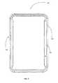
- FIG. 4illustrates a view of the housing 303 along the outer edges of the portable medical device 300 , including an outer shell 400 and an inner shell 401 .
- the outer shell 400can be metal, hard plastic, carbon fiber or another material utilized to externally protect the device from environmental damages.
- the inner shell 401can be utilized to form a seal along the outer shell 400 , such that liquids cannot enter the portable medical device and harm any of the internal components.
- the inner shell 401can be a rubber, plastic or other polymer material capable of forming an impermeable seal under pressure.
- FIG. 5provides a schematic representation of FIG. 3 with the front face of the housing removed and the internal components exposed.
- the portable medical device 300can include a printed circuit board (PCB) assembly including a flex serpentine board 502 , a main board 504 , a connector for the flex board and main board to direct current (DC) 506 , a pressure board 503 , and a connector for the flex board to the pressure board 509 .
- the deviceincludes a Bluetooth PCB assembly 505 for short wave, such as radio frequency (RF) communication.
- RFradio frequency
- FIG. 5shows that the portable medical device 300 also includes an overmold 501 , which thermally and physically separates the PCB assembly from the connector port interface, utilized for charging the device.
- the internal components of the deviceare all separated from the outer shell 507 of the housing in order to prevent any interaction between the internal components and the housing during use of the device, such as when the device may be bumped or jostled by the user.
- the internal componentscan be separated by the distance of at least the inner bezel 508 , described with reference to FIG. 4 .
- the internal componentscan additionally reside in a cavity created by the outer shell 507 , such that the components do not interact with the front face of the device, when assembled.
- the portable medical device 300may have include restrictions imposed on the spacing between other components in the portable medical device and/or the housing 303 in order to properly insulate each printed circuit board (PCB) trace as well as the components and the housing of the device, which can be made of a conductive material.
- PCBprinted circuit board
- Such spacing requirementscan influence the design of the portable medical device, due to the size and number of the components within the device as well as the voltage drop of those components within the device.
- the portable medical device 300includes isolation and emission control features. Additionally, the device includes a defined architecture for how electrical power is delivered to various components of the portable medical device.
- the poweris supplied through the electrical connector port interface (shown in FIGS. 10-11 ), which supplies 4.65 volts (V) and draws a minimum of 100 mA and a maximum of 500 mA of current, depending on the power source and configuration of the connection interface.
- the poweris supplied to a, for example, USB data-isolation integrated circuit (IC) chip 1102 (not illustrated in FIG. 5 ; see 1102 shown in FIG. 11 ) and a USB power isolation IC chip.
- ICUSB data-isolation integrated circuit
- the power isolation chipresides below the overlay 501 , which insulates the electrical current from a user of the device during charging and/or data transfer. Each chip is capable of receiving the maximum power provided when the device is connected to a power supply source.
- the data isolation chip 1102draws more current than the power isolation chip and includes a quiescent current that reduces the charge current of the low mode charging (also referred to as shelf mode or suspend mode) for the battery (not shown).
- the batteryis charged by a battery charger IC chip that checks the battery charge level when the portable medical device detects that it is connected to a power source.
- the output voltage from the USB power isolation chipis coupled to the battery charger chip to supply electrical charge to the battery.
- the output of the battery charger chipwhen the infusion device is connected to a USB power supply source, is coupled to a fuel gauge (not shown), which determines the current battery charge.
- the output of the battery chargeris also supplied to the fuel gauge.
- the fuel gaugeis useful in the case that the portable medical device is not connected to a USB power source, so that no power flows through the battery charger chip, because the fuel gauge permits the battery charge to be known to the system so it may determine which components should be supplied power during startup.
- control of the deviceis provided from a control processor.
- the control processormay be provided as a two-element processor, comprising a data control processor and a power control processor, each part of the main PCB 504 .
- the data isolation chip 1102 and the power isolation chipprovide isolation from the other device components so that the chips reduce EMF emissions and provide a safely functioning device that can be connected to the power supply source and the patient at the same time.
- the data isolation chip 1102is implemented in the FIG. 5 device with a USB Isolation Chip ADUM4160 product from Analog Devices, Inc. of Norwood, Mass., USA
- the power isolation chipis implemented in the FIG. 5 device with a USB Power Isolation Chip LT3573 product from Linear Technology Corporation of Milpitas, Calif., USA.
- Those skilled in the artwill be aware of alternative suitable devices to provide the data and power charging functions with isolation.
- the portable medical device with electrical power isolation and data isolationincludes a slot 601 for receiving a replaceable medicament cartridge for, e.g., insulin.
- the cartridge slotcan be located proximate to one side wall of the device housing such that the cartridge accessibility and removal is facilitated.
- the portable medical devicecan include an input button 602 including an outer shell 603 (shown in FIGS. 16A and 16B ).
- FIG. 7is an alternative perspective view of the portable medical device 300 in one embodiment.
- one side wall of the device housingincludes an electrical connector port door 701 .
- the electrical connector port door 701includes two parts: a plug bezel 705 and a flexible joint 706 .
- the flexible joint 706includes a plug 1104 (shown in FIG. 11 ) that is utilized to affix the door 701 to the portable medical device 300 .
- the plug bezelis a movable portion of the electrical connector port door 701 , which is removed each time that the USB port is utilized.
- the electrical connector port door 701can be made of a rubber or soft polymer, which is capable of bending, flexing, and maintaining shape without breaking from continual use. As shown in FIG. 7 , the electrical connector port door 701 is in a closed position.
- the device 300also includes an input button 700 on one side wall of the housing of the device, which differs from that of the electrical connector port.
- the input button 700can be any suitable size or shape that can facilitate providing user input to the device.
- the input button 700can be utilized to wake the device from a sleep mode, lock the touchscreen of the device, and power-off the device.
- the button 700can be made of any material that is capable of withstanding repeated user interaction, such as a metal, plastic or polymer, or rubber.
- the buttoncan include a bezel 703 , which is illuminated during usage of the button. The input button is further described in the following paragraphs with reference to FIGS. 16A-C .
- the cavity created by the housing of the deviceis shown as the distance 704 from the top of the housing wall to the components within the device. As previously mentioned, this allows for additional protection of the internal components from contacting the front face of the device during usage.
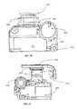
- FIG. 8depicts a cross-sectional perspective view of the portable medical device 300 .
- the electrical connector portsuch as a USB port 801
- the electrical connector port door 800is held in place via an o-ring 810 , which itself is held within grooves 820 of door tabs 822 .
- the door 800is inserted into the housing against a door bezel 824 , against which the o-ring 810 is compressed and forms a seal.
- the seal of the o-ring 810aids in preventing outside elements and debris from entering into the device through the internal cavity of the electrical port. Additionally, the o-ring can aid in securing the door 800 closed.
- the o-ring 810is described in further detail below with reference to FIG. 10 .
- a primary o-ring 826which provides another seal against the entry of outside elements and the like.
- FIG. 8depicts that the overmold 501 previously described with reference to FIG. 5 includes an upper portion 807 and a lower portion 802 that are connected together and wrap around the PCB sides.
- the overmold portions 807 , 802can vary in thickness along the surface of the USB interface in order to accommodate various internal components residing below, such as a DC-to-DC PCB, electrical connector port 801 , transformer (not shown in FIG. 8 ), and power isolation chip (not shown in FIG. 8 ).
- the DC-to-DC PCBcan be flexibly coupled to the main PCB 805 by a flexible PCB 806 , which is also illustrated in FIG. 5 .
- the internal componentscan reside in a cavity formed by the outer shell 811 of the housing.
- the housingcan also include an inner shell, which can be compressed to form a seal preventing water ingress to the portable medical device.
- FIG. 8also depicts that a crush seal occurs with the interaction of the bezel 809 pushing the primary o-ring 826 against an angled sealing surface 828 on the housing. This interaction compresses or crushes the o-ring into the overmold, creating a seal at the interface of the bezel, the enclosure, and the overmold. Sealing due to the overmolding process creates a barrier such that moisture can't penetrate past the discrete connector on the board (i.e., the micro-USB connector). Therefore, no leakage can occur through the micro-USB or passed the interface of the overmold around it, creating the sealed connector port.
- the discrete connector on the boardi.e., the micro-USB connector
- the input mechanism 803forming a connection between the input button (shown in FIG. 7 ) and the main PCB 805 is shown.
- the input button, input mechanism, and surrounding componentsare further described with reference to FIGS. 16A-C in the following paragraphs.
- the cross-sectional view in FIG. 8also shows a rack pushrod 804 , which forms the actuator driving the insulin delivery from the insulin cartridge.
- the rack pushrod 804can be encapsulated by a cover 812 made of flexible material, such as a rubber or soft polymer, which forms a barrier between the cartridge and the rack mechanism.
- the pushrod cover 812can form a barrier, or seal, between the internal components of the portable medical device, e.g., through the rack mechanism, and the cartridge in case any accidental leakage occurs within the cartridge.
- FIG. 9is a schematic representation of the overmold 501 and electrical connector port 902 assembly.
- the overmold 501may be shaped according to the power isolation chip and associated circuitry in order to meet regulatory requirements for a medical device to prevent any harm incurred by a user of the portable medical device and prevent any liquid from contacting the electrical connector input elements of the device.
- the overmold 501may be made of an insulator material, which aids in preventing voltage creepage and emissions from the internal components of the device.
- the overmoldmay be made of a plastic polymer, dielectric, or other non-conductive material that is capable of being pre-formed and can maintain its shape during use. The overmold can be pliable under certain conditions, such as extreme temperatures in order for molding into the preformed shape to occur.
- the overmoldmay be a membrane formed on the components.
- the overmold 501is also capable of maintaining shape and protecting the components over which it is assembled during temperature changes, e.g., due to dissipation from the circuits.
- the overmoldcan be secured to the PCB board and other internal device components utilizing screw fasteners, such as screws (not illustrated) that are threaded into two screw holes 900 .
- the screw holesmay be positioned on the overmold as needed to ensure a seal.
- the screw holes 900guide the screws to pass through the PCB and into corresponding threaded holes in the housing. In this way, the screws are electrically isolated from the PCB.
- the electrical connector port mouth 902can be formed with the overmold 501 or as a separate component from the overmold.
- the electrical connector port mouth 902can be made of a similar non-conductive material as the overmold that is capable of forming a barrier around the electrical connector port and capable of securely receiving a electrical connector plug during charging and data transfer.
- FIG. 10is a schematic representation of the electrical connector port and power isolation assembly from a bottom view perspective.
- the power isolation assemblyincludes the electrical connector port mouth 1005 and the two o-rings 810 , 826 described above in connection with FIG. 8 .
- the o-ring 810helps secure the placement of the door within the housing of the portable medical device and along with the primary o-ring 826 helps to prevent any outside environmental elements, such as liquids, from entering the device.
- the first o-ring 810can provide a lip onto which an electrical connector port door (not shown) can securely hinge while in a closed position.
- FIG. 10is a schematic representation of the electrical connector port and power isolation assembly from a bottom view perspective.
- the power isolation assemblyincludes the electrical connector port mouth 1005 and the two o-rings 810 , 826 described above in connection with FIG. 8 .
- the o-ring 810helps secure the placement of the door within the housing of the portable medical device and along with the primary o-ring 826 helps to prevent any
- the overmold 1004is formed over the entire power isolation assembly to prevent any possible electrical shock to a user of the device and to lower radiation emissions and heat dissipation from the device during charging.
- the overmold 1004can be made of a non-conductive material, such as a plastic polymer, which is capable of absorbing heat and voltage.
- the power isolation assemblycan additionally include a transformer 1002 , which controls the electrical input from the electrical connector.
- the transformer 1002can be customized to maintain a specified output while receiving variable input currents from the electrical connector, dependent on the compatibility of the power supply utilized to charge the device. Accordingly, the transformer 1002 can have a customized coil turns ratio in the toroid core, such as approximately 1.33:1, or 12:9, to provide a more efficient output for the variable input current.
- the coil windingscan additionally be insulated in order to lower emissions to meet UL or IEC 60601-1 regulatory standards requirements. In some embodiments, the windings are double or triple insulated.
- the transformer 1002can include a housing having input leads and output leads, or pins coupled to the coil wires 1003 utilized to the secure placement of the transformer 1002 on the PCB and in order to supply a controlled output to various power isolation assembly components.
- FIG. 11illustrates a schematic view of the electrical connector interface including the power isolation circuit, which controls the incoming current and supplies the power to the other components within the device.
- a power supplycan include four output lines that provide power and supply data from the connector interface with four input points 1107 (shown in FIG. 12 ) to a data isolation chip 1102 and a power isolation chip (not shown).
- the data isolation chipmay be implemented in the portable medical device with a USB Isolation Chip ADUM4160 product from Analog Devices, Inc. of Norwood, Mass., USA, and the power isolation chip may be implemented with a USB Power Isolation Chip LT3573 product from Linear Technology Corporation of Milpitas, Calif., USA.
- USB Isolation Chip ADUM4160 productfrom Analog Devices, Inc. of Norwood, Mass., USA
- the power isolation chipmay be implemented with a USB Power Isolation Chip LT3573 product from Linear Technology Corporation of Milpitas, Calif., USA.
- Those skilled in the artwill be aware of alternative
- a common mode chokecan be coupled to the power supply to lower RF and EMF emissions and to limit high frequency noise on the data signal supplied from the power supply.
- the power supply voltage output and ground linesare fed into two ferrite beads, which behave similarly to the common mode choke, to attenuate high frequency noise signals emitted from the device during use (e.g., during charging/connected operation), while supplying low levels of thermal dissipation and lowering emissions to meet regulatory performance standards.
- a first ferrite beadprovides a voltage output from the power supply directly to the power isolation chip and an isolating device, e.g., a transformer 1103 .
- a flyback switch of the power isolation chipprovides the secondary input to the transformer 1103 in order to control the switched modes (e.g., charging and not charging states) of the infusion device.
- the schematic view of FIG. 11shows the electrical connector interface without the overmold.
- the electrical connector port openingis protected by the electrical connector port door 1101 , which includes a door plug 1104 that allows the door to remain fixed to the device during removal and placement over the electrical connector port.
- the electrical connector door 1101also includes a door insert 1106 , which partially fills the electrical connector port cavity.
- the door insert 1106with the o-ring grooves 820 , can form a pressurized seal around the cavity of the electrical connector port.
- the electrical connector port door 1101can be made from a flexible material, such as rubber or soft polymer, so that repeated removal and placement within the device do not cause breakage.
- a USB DC-to-DC board 1105is also shown.
- the incoming current from the USB interfaceis controlled by a customized transformer 1103 .
- the design of the transformer 1103varies from that typically provided within the art, as the specific size requirements of the portable medical device and minimum inductance requirements of the USB power isolation chip impose constraints for the primary and secondary coils. In some embodiments a 12:9 core turns ratio is utilized along with at least one triple insulated wire. In a further embodiment, the transformer 1103 can be a toriod transformer. However, utilizing the aforementioned embodiments for the transformer and system design, constrains the low current (100 mA) loads at which the power isolation chip functions.
- the power isolation chipdraws less than 100 mA at an input voltage of 4.4V (low voltage) with a low output load current of 50 mA.
- the low output load currentcan then define the high output load current as 250 mA based on the USB specification current limitations of five times the low load current.
- the board area illustrated in FIG. 11can be formed with a stitched capacitance built into the circuit board, such that EMF emissions can be further controlled through attenuation of any high frequency noise provided during use of the infusion device.
- Each chip connectionis shown including any additional circuitry that is utilized to power the portable medical device components while still meeting size and regulatory emission level constraints, such as IEC 60601-1 Safety Standards.
- FIG. 12shows a front cross-sectional view of the electrical connector interface.
- An electrical connector port 1200is securely fit into the housing of the portable medical device through the first, or outer o-ring 810 . That is, the o-ring 810 is located closer to the outside of the device and is seated in the groove 820 of the USB port door.
- the inner, or primary o-ring 826is located closer to the inner cavity of the device.
- the o-ringscan be made of rubber or plastic polymer which is impermeable and can securely be fitted onto the respective locating surfaces 820 , 828 ( FIG. 8 ).
- FIG. 12shows that the overmold 1204 of the power isolation assembly is coupled to the electrical connector interface assembly.
- the couplingis in order to protect the user from experiencing any electrical shock or excessive radiation emissions during use of the portable medical device.
- the overmold 1204can extend around, above and below the electrical connector interface assembly, such that any current drawn from a power source is isolated in the portable medical device prior to usage by, e.g., charging the battery or operating the inner components of the device.
- the overmold 1204can extend across each component of the power isolation assembly, including the power isolation chip (not shown) and the transformer 1203 .
- a molded structure 1205can extend at least partially around the USC connector to protect the USB connector during the overmolding process.
- the back view of the deviceillustrates a back plate 1300 , a pumping mechanism 1301 , a cartridge slot 1302 , an input button 1304 , and a electrical connector port door 1303 .
- the back of the deviceis covered by a back plate 1300 , which can be made of a durable plastic polymer or metal.
- the back plate 1300can be semi-permanently attached to the device, such that removal is only achieved through use of an instrument or tool in order to protect the inner components of the portable medical device.
- the back plate 1300can cover substantially all of the back of the portable medical device, except for a portion of the device which is capable of receiving a cartridge, such as an insulin cartridge.
- the back plate 1300can be sealed along the outer walls of the portable medical device through a membrane or other form of sealant, which can prevent water and other elements (e.g., dust, liquids, etc.) from entering the device.
- a membrane or other form of sealantcan prevent water and other elements (e.g., dust, liquids, etc.) from entering the device.
- the outer walls of the device and the back plate of the deviceare formed as a single component.
- the back plate 1300is one of a plurality of components which, combined, comprise the housing of the portable medical device.
- the back plate 1300can exclude a portion under which an insulin cartridge is received.
- the cartridge slot 1302can include a bump, or ridge 1305 onto which the cartridge can latch to be aligned in the cartridge slot 1302 to facilitate placement of the cartridge by a user of the portable medical device.
- the ridge 1305can instead be a groove, or ridge into which a cartridge can latch in order to be properly aligned. It should be understood that numerous variations to the design of the cartridge slot can be implemented, dependent on the size and shape of the cartridge.
- the cartridge of some embodimentsfits securely into the cartridge slot, having minimal space around the perimeter of the cartridge and between the cartridge and cartridge slot 1302 .
- the inner wall 1306 of the cartridge slot 1302can include a membrane, which forms a water-tight seal around the cartridge slot 1302 when the cartridge door 1505 (shown in FIG. 15 ) is in place. Accordingly, the cartridge slot 1302 can include a locking mechanism, which allows the cartridge door to form a pressurized seal with the inner wall 1306 of the cartridge slot 1302 .
- FIG. 14a perspective view of the back and two side walls of the portable medical device is provided.
- the portable medical deviceas shown includes an input button 1401 , a hinge portion of the electrical connector port door 1402 , a back plate 1400 , a cartridge slot 1405 for receiving an insulin cartridge, a ridge 1406 onto which the cartridge is hinged for alignment into the cartridge slot 1405 , a cartridge receiving port 1404 , which locks the cartridge into place within the cartridge slot 1405 , and a cartridge slot backplate 1408 .
- FIG. 14also illustrates an open view of a pumping mechanism with the back plate 1400 removed.
- the pumping mechanismincludes a rack pushrod 1407 that is utilized to compress the insulin cartridge and cause the insulin to move to the user through a tube or conduit such as a cannula (shown in FIG. 1 ).
- the pushrodcan be made of a metal or other hard, non-pliable material capable of withstanding extreme temperatures and contact with liquids.
- the pushrod 1407additionally includes a pushrod cover 1403 , which is utilized to form an additional barrier between the pumping mechanism and the cartridge.
- the pushrod cover 1403provides an additional layer of waterproofing to prevent any insulin leakage from the cartridge from entering the portable medical device and affecting the inner components.
- the pushrod cover 1403can be made of a pliable plastic or rubber materials which can sustain repeated compression and expansion movements and which is impermeable to liquids.
- an o-ring(not shown) can also be placed around the base of the pushrod 1407 and the top of the pushrod cover 1403 to prevent leakage into the portable medical device.
- FIG. 15shows a schematic view of the back of the portable medical device in FIG. 14 with the rear face removed.
- the devicecan include a speaker 1506 for providing alerts and other sounds indicating a function has been performed on the device.
- the devicecan include a micro-valve assembly 1514 , including, for example, a venting system and a thermal leak platform for the insulin cartridge.
- the insulin cartridgecan be covered by a cartridge door 1505 and the housing of the portable medical device can include a cartridge shroud 1509 in which the connecting tube or cannula that delivers the insulin to the patient may be inserted.
- the devicecan include a power charging system that receives the controlled current from the power isolation chip.
- the power charging systemmay be used to charge a power storage cell such as a rechargeable battery 1500 of the portable medical device.
- a rechargeable batterysuch as a NiCad battery, LiPo battery, NiMH battery, or the like.
- the battery 1500also can be a lithium ion (LiPo) battery or a similar type of battery known in the art that meets both the size and charge requirements of the portable medical device.
- the operation for determining charging of the battery 1500includes various steps which are dependent on the current battery charge and the current operating mode of the portable device.
- the portable medical devicecan be considered to be in different states (e.g., active mode, shelf mode) based on the charge level in the battery and the connection, or lack thereof, to a power supply source.
- the portable medical devicefirst determines if a USB power supply is connected to the device. This determination may occur through the change in current detected as being supplied to both the isolated USB data control chip and the isolated USB power control chip.
- an “always on” current sensor amplifier coupled to a Buck regulatorcan detect the current provided to the device by the connection to the power source. Two types of connections can be made to the power source.
- Oneis a configurable combined data/power source (e.g., a computer) and the other is a dedicated power-only source (e.g., a wall outlet).
- a configurable combined data/power sourcee.g., a computer
- a dedicated power-only sourcee.g., a wall outlet
- each type of connectioncan determine a different type of power-up protocol and can determine how the battery on the device is charged.
- the portable medical deviceAfter determining that a USB power supply has been connected through the USB interface (behind electrical connector port door 1504 ), the portable medical device next determines the type of source device supplying electrical power to the device. If the host power source is a dedicated power source, the electrical connector can supply a high mode current to the portable medical device and charge the battery at a faster rate. Being in a high rate battery charge does not necessarily signify that the portable medical device is in high or active mode.
- the load output load current “low mode” chargingalso referred to as suspended state or shelf mode, occurs when the portable medical device is plugged into a power source such as a desktop, laptop, or, e.g., tablet computer. That is, a power source that is not configured for high current connection with the portable medical device.
- a power sourcesuch as a desktop, laptop, or, e.g., tablet computer. That is, a power source that is not configured for high current connection with the portable medical device.
- the computersupplies only minimal power output (e.g., 100 mA) from the port interfaced with the power supply until a higher current output “high mode” (500 mA) can be negotiated, e.g., through configuration of the power supply.
- the connection portwill shut down and no current will be provided to the portable device.
- the output of the transformer 1103(shown in FIG. 11 ) supplies the aforementioned high mode or low mode current to a battery charger within the power isolation assembly 1503 .
- the battery chargercan be configured for use with the power supply and can include a charge current multiplier in order to charge a battery 1500 coupled to the battery charger even in low mode conditions.
- the power stored in the battery 1500is monitored as well as the amount of power and current being supplied to the device during a charge condition, such as when the power supply is connected to a power supply source.
- the control of the power supply based on the current power within the battery 1500is performed by a power control processor (see FIG.
- the power control processorcan control the power apportioned to the rest of the system components, such as a pump motor 1511 , vibrate 1513 , pump (rack bushing 1501 , rack pushrod 1508 and gear box 1507 ), the output display screen, peripheral devices (e.g., Bluetooth), the data processor, and the like.
- a pump motor 1511vibrate 1513
- pumprack bushing 1501 , rack pushrod 1508 and gear box 1507
- peripheral devicese.g., Bluetooth
- a data control processormay send requests to the power control processor due to an input from the user of the device. For example, if the user decides to remove and discontinue use of the device, the user may “power off” the device by depressing the input button 1502 . If the shelf mode request is received by the power control processor, the power supplied to the data control processor is discontinued.
- the data control processorreads instructions stored in a memory element of the portable medical device for performing the functions of the components in the device, such as providing an output display (see FIG. 3 : 302 ), a Bluetooth transmitter (see FIG. 5 : 505 ), a speaker 1506 , a motor 1511 controlling an insulin pump rack pushrod 1508 (e.g., through gears in gear box 1508 ), a touch control chip, and the like.
- Removal of powerwill not delete data stored in the USB data isolation chip, nor will power removal eliminate the ability to charge, power up, or communicate with the data control processor.
- the data control processortypically remains in an “always on” condition, though the power supplied to the components performing the functions requested by the processor may no longer powered, such that the functionality of the data control processor is effectively terminated.
- FIGS. 16A-16Cexemplary schematic views of a waterproof input button 1600 are illustrated.
- a skeleton view of the outer shell 1601 of the button and the inner components of the input mechanism 1602are illustrated.
- the housing, or outer shell 1601 , of the button 1600can be made of a plastic or other polymer in a pre-formed shape and the side walls can be collapsible such that the input button can be depressed by a user.
- the outer shell 1601can additionally be made of a non-permeable soft material, such as a dense rubber.
- the input mechanism 1602can be located within a central opening of the outer shell 1601 , such that when a user erroneously depresses another area, e.g., side, of the input button, an input is not received.
- FIG. 16Bshows a top view of the input button.
- the input buttoncan have a backplate 1603 , which sits adjacent to the side wall of the portable medical device (e.g., element 1304 in FIG. 13 ).
- the backplate 1603can be made of a hard polymer in order to prevent any voltage leakage from the device during user interaction. Additionally, the backplate can form a protective barrier as a portion of the side wall of the housing of the portable medical device.
- the backplatecan include several soft ridges or bumps 1604 that can absorb the pressure of the input button during depression by the user, such that the input mechanism is not damaged, e.g., due to excessive force during depression, and such that the top portion of the housing, or outer shell 1601 , and the backplate 1603 do not collide.
- the bumps 1604absorb shock and can be made of a rubber or other force-absorbing non-permeable material.
- the bumps 1604can protrude through pre-formed openings in the backplate 1603 or can be formed with the backplate 1603 or on the top plane of the backplate 1603 .
- the input mechanism 1600can include a spring type assembly, such that when the input button is depressed, the button returns to its original position.
- FIG. 16Cshows a cross-sectional view of the button.
- the input mechanism 1600extends through the button housing 1601 to a base point 1606 , which provides a contact point to the PCB within the portable medical device to communicate a signal to wake the device.
- the base 1605 of the input buttoncan be formed from a membrane that is impermeable to water and other liquids.
- the base 1605can be formed with the bumps 1604 in order to prevent any liquid from entering the device. Accordingly, the base 1605 can cover a portion of the side wall of the portable medical device on which the input button is located and can form a seal between the input button housing 1601 of the portable medical device and the inner components.
- the devicecan also include any portable device having a display and a processor.
- the devicecan include a mobile computing device, such as a Smartphone.
- a portable medical device as described hereincan be controlled by a dedicated remote control specifically designed for use with the device.
Landscapes
- Health & Medical Sciences (AREA)
- Heart & Thoracic Surgery (AREA)
- Hematology (AREA)
- Engineering & Computer Science (AREA)
- Anesthesiology (AREA)
- Biomedical Technology (AREA)
- Life Sciences & Earth Sciences (AREA)
- Animal Behavior & Ethology (AREA)
- General Health & Medical Sciences (AREA)
- Public Health (AREA)
- Veterinary Medicine (AREA)
- Vascular Medicine (AREA)
- Pulmonology (AREA)
- Infusion, Injection, And Reservoir Apparatuses (AREA)
Abstract
Description
Claims (14)
Priority Applications (5)
| Application Number | Priority Date | Filing Date | Title |
|---|---|---|---|
| US13/827,707US9381297B2 (en) | 2012-06-07 | 2013-03-14 | Sealed infusion device with electrical connector port |
| PCT/US2013/044289WO2013184784A1 (en) | 2012-06-07 | 2013-06-05 | Sealed infusion device with electrical connector port |
| EP13800289.4AEP2858698A4 (en) | 2012-06-07 | 2013-06-05 | Sealed infusion device with electrical connector port |
| US15/184,422US9750873B2 (en) | 2012-06-07 | 2016-06-16 | Sealed infusion device with electrical connector port |
| US15/676,520US10653828B2 (en) | 2012-06-07 | 2017-08-14 | Sealed infusion device with electrical connector port |
Applications Claiming Priority (2)
| Application Number | Priority Date | Filing Date | Title |
|---|---|---|---|
| US201261656967P | 2012-06-07 | 2012-06-07 | |
| US13/827,707US9381297B2 (en) | 2012-06-07 | 2013-03-14 | Sealed infusion device with electrical connector port |
Related Child Applications (1)
| Application Number | Title | Priority Date | Filing Date |
|---|---|---|---|
| US15/184,422ContinuationUS9750873B2 (en) | 2012-06-07 | 2016-06-16 | Sealed infusion device with electrical connector port |
Publications (2)
| Publication Number | Publication Date |
|---|---|
| US20130331790A1 US20130331790A1 (en) | 2013-12-12 |
| US9381297B2true US9381297B2 (en) | 2016-07-05 |
Family
ID=49712582
Family Applications (3)
| Application Number | Title | Priority Date | Filing Date |
|---|---|---|---|
| US13/827,707Active2033-11-29US9381297B2 (en) | 2012-06-07 | 2013-03-14 | Sealed infusion device with electrical connector port |
| US15/184,422ActiveUS9750873B2 (en) | 2012-06-07 | 2016-06-16 | Sealed infusion device with electrical connector port |
| US15/676,520Active2033-07-27US10653828B2 (en) | 2012-06-07 | 2017-08-14 | Sealed infusion device with electrical connector port |
Family Applications After (2)
| Application Number | Title | Priority Date | Filing Date |
|---|---|---|---|
| US15/184,422ActiveUS9750873B2 (en) | 2012-06-07 | 2016-06-16 | Sealed infusion device with electrical connector port |
| US15/676,520Active2033-07-27US10653828B2 (en) | 2012-06-07 | 2017-08-14 | Sealed infusion device with electrical connector port |
Country Status (3)
| Country | Link |
|---|---|
| US (3) | US9381297B2 (en) |
| EP (1) | EP2858698A4 (en) |
| WO (1) | WO2013184784A1 (en) |
Cited By (27)
| Publication number | Priority date | Publication date | Assignee | Title |
|---|---|---|---|---|
| US9750873B2 (en) | 2012-06-07 | 2017-09-05 | Tandem Diabetes Care, Inc. | Sealed infusion device with electrical connector port |
| US10213547B2 (en) | 2013-12-26 | 2019-02-26 | Tandem Diabetes Care, Inc. | Safety processor for a drug delivery device |
| US10357603B2 (en) | 2017-01-11 | 2019-07-23 | Tandem Diabetes Care, Inc. | Electromagnetic signal-based infusion pump control |
| US10492141B2 (en) | 2015-11-17 | 2019-11-26 | Tandem Diabetes Care, Inc. | Methods for reduction of battery usage in ambulatory infusion pumps |
| US10549051B2 (en) | 2013-06-21 | 2020-02-04 | Tandem Diabetes Care, Inc. | System and method for infusion set dislodgement detection |
| US10569016B2 (en) | 2015-12-29 | 2020-02-25 | Tandem Diabetes Care, Inc. | System and method for switching between closed loop and open loop control of an ambulatory infusion pump |
| US10736037B2 (en) | 2018-12-26 | 2020-08-04 | Tandem Diabetes Care, Inc. | Methods of wireless communication in an infusion pump system |
| EP3742449A1 (en) | 2019-05-21 | 2020-11-25 | Tandem Diabetes Care, Inc. | System and method for incorporating exercise into closed-loop diabetes therapy |
| US10888655B2 (en) | 2019-02-19 | 2021-01-12 | Tandem Diabetes Care, Inc. | System and method of pairing an infusion pump with a remote control device |
| EP3824923A1 (en) | 2019-11-22 | 2021-05-26 | Tandem Diabetes Care, Inc. | Systems and methods for automated insulin delivery for diabetes therapy |
| US11224693B2 (en) | 2018-10-10 | 2022-01-18 | Tandem Diabetes Care, Inc. | System and method for switching between medicament delivery control algorithms |
| US11229743B2 (en) | 2016-11-15 | 2022-01-25 | Eli Lilly And Company | Medication delivery device with mechanical locking system |
| US11278661B2 (en) | 2020-03-10 | 2022-03-22 | Beta Bionics, Inc. | Infusion system and components thereof |
| US11305057B2 (en) | 2019-03-26 | 2022-04-19 | Tandem Diabetes Care, Inc. | Method and system of operating an infusion pump with a remote control device |
| US11331463B2 (en) | 2015-07-08 | 2022-05-17 | Trustees Of Boston University | Infusion system and components thereof |
| US11357911B2 (en) | 2013-10-24 | 2022-06-14 | Trustees Of Boston University | Infusion pump and system for preventing mischanneling of multiple medicaments |
| US11464908B2 (en) | 2019-02-18 | 2022-10-11 | Tandem Diabetes Care, Inc. | Methods and apparatus for monitoring infusion sites for ambulatory infusion pumps |
| US11571507B2 (en) | 2019-07-16 | 2023-02-07 | Beta Bionics, Inc. | Ambulatory device and components thereof |
| US11607492B2 (en)* | 2013-03-13 | 2023-03-21 | Tandem Diabetes Care, Inc. | System and method for integration and display of data of insulin pumps and continuous glucose monitoring |
| US11676694B2 (en) | 2012-06-07 | 2023-06-13 | Tandem Diabetes Care, Inc. | Device and method for training users of ambulatory medical devices |
| US11771821B2 (en) | 2017-01-06 | 2023-10-03 | Trustees Of Boston University | Infusion system and components thereof |
| US11872368B2 (en) | 2018-04-10 | 2024-01-16 | Tandem Diabetes Care, Inc. | System and method for inductively charging a medical device |
| EP4351680A1 (en) | 2021-06-10 | 2024-04-17 | Tandem Diabetes Care, Inc. | User-wearable infusion pump holder |
| US11969576B2 (en) | 2019-07-03 | 2024-04-30 | Tandem Diabetes Care, Inc. | Methods of incorporating CGM data into diabetes therapy |
| USD1031975S1 (en) | 2020-03-10 | 2024-06-18 | Beta Bionics, Inc. | Medicament infusion pump device |
| US12233240B2 (en) | 2018-12-26 | 2025-02-25 | Tandem Diabetes Care, Inc. | Methods of wireless communication in an infusion pump system |
| EP4531051A1 (en) | 2023-09-29 | 2025-04-02 | Tandem Diabetes Care, Inc. | Infusion pump with multi-cgm compatibility |
Families Citing this family (46)
| Publication number | Priority date | Publication date | Assignee | Title |
|---|---|---|---|---|
| US6852104B2 (en) | 2002-02-28 | 2005-02-08 | Smiths Medical Md, Inc. | Programmable insulin pump |
| EP1762259B2 (en) | 2005-09-12 | 2025-01-01 | Unomedical A/S | Inserter for an infusion set with a first and second spring units |
| US20080228056A1 (en) | 2007-03-13 | 2008-09-18 | Michael Blomquist | Basal rate testing using frequent blood glucose input |
| US7751907B2 (en) | 2007-05-24 | 2010-07-06 | Smiths Medical Asd, Inc. | Expert system for insulin pump therapy |
| US8221345B2 (en) | 2007-05-30 | 2012-07-17 | Smiths Medical Asd, Inc. | Insulin pump based expert system |
| US20090177147A1 (en) | 2008-01-07 | 2009-07-09 | Michael Blomquist | Insulin pump with insulin therapy coaching |
| US8882701B2 (en) | 2009-12-04 | 2014-11-11 | Smiths Medical Asd, Inc. | Advanced step therapy delivery for an ambulatory infusion pump and system |
| KR20130018783A (en) | 2010-03-30 | 2013-02-25 | 우노메디컬 에이/에스 | Medical device |
| WO2012123274A1 (en) | 2011-03-14 | 2012-09-20 | Unomedical A/S | Inserter system with transport protection |
| WO2013050277A1 (en) | 2011-10-05 | 2013-04-11 | Unomedical A/S | Inserter for simultaneous insertion of multiple transcutaneous parts |
| EP2583715A1 (en) | 2011-10-19 | 2013-04-24 | Unomedical A/S | Infusion tube system and method for manufacture |
| US20140066731A1 (en)* | 2012-09-05 | 2014-03-06 | Hcl Technologies Limited | Batteryless Portable Medical Devices |
| US9242043B2 (en) | 2013-03-15 | 2016-01-26 | Tandem Diabetes Care, Inc. | Field update of an ambulatory infusion pump system |
| US10016561B2 (en) | 2013-03-15 | 2018-07-10 | Tandem Diabetes Care, Inc. | Clinical variable determination |
| WO2015035304A1 (en) | 2013-09-06 | 2015-03-12 | Tandem Diabetes Care, Inc. | System and method for mitigating risk in automated medicament dosing |
| US10384010B2 (en) | 2013-12-17 | 2019-08-20 | Novo Nordisk A/S | Motorized drug delivery device with charging safety feature |
| EP4250313A3 (en) | 2013-12-26 | 2023-11-22 | Tandem Diabetes Care, Inc. | Integration of infusion pump with remote electronic device |
| US10279105B2 (en) | 2013-12-26 | 2019-05-07 | Tandem Diabetes Care, Inc. | System and method for modifying medicament delivery parameters after a site change |
| US10279106B1 (en) | 2014-05-08 | 2019-05-07 | Tandem Diabetes Care, Inc. | Insulin patch pump |
| US9669160B2 (en) | 2014-07-30 | 2017-06-06 | Tandem Diabetes Care, Inc. | Temporary suspension for closed-loop medicament therapy |
| CN107427635A (en) | 2015-01-26 | 2017-12-01 | 伯克顿迪金森公司 | Intelligent portable infusion pump |
| CN107735121B (en) | 2015-05-08 | 2019-02-15 | 以色列三级跳远有限责任公司 | Systems and devices for infusion of fluids into the body |
| US9993595B2 (en) | 2015-05-18 | 2018-06-12 | Tandem Diabetes Care, Inc. | Patch pump cartridge attachment |
| EP3103505A1 (en)* | 2015-06-12 | 2016-12-14 | Nokia Technologies Oy | Joining unit for detecting needle disconnection |
| US10279107B2 (en) | 2015-08-20 | 2019-05-07 | Tandem Diabetes Care, Inc. | Drive mechanism for infusion pump |
| US9801202B2 (en)* | 2015-09-14 | 2017-10-24 | Uber Technologies, Inc. | Bluetooth device and data scheduler |
| CN108778370B (en) | 2016-01-19 | 2021-10-08 | 优诺医疗有限公司 | Cannula and infusion set |
| US10232107B2 (en)* | 2016-03-11 | 2019-03-19 | Hans Utz | Illuminated medical infusion |
| US10994077B2 (en) | 2016-07-21 | 2021-05-04 | Tandem Diabetes Care, Inc. | Enhanced confirmations for touchscreen infusion pump |
| US10926025B2 (en) | 2016-09-15 | 2021-02-23 | Tandem Diabetes Care, Inc. | Vial supporter for medicament pump |
| CN119868710A (en) | 2017-06-15 | 2025-04-25 | 以色列三级跳远有限责任公司 | Patch pump system and device for managing diabetes and method thereof |
| USD840342S1 (en)* | 2017-07-31 | 2019-02-12 | Tectonica Australia Pty Ltd | Cabling hub |
| US12214156B2 (en) | 2017-08-28 | 2025-02-04 | Triple Jump Israel Ltd. | Systems, methods, apparatuses and devices for drug or substance delivery |
| CN111936182B (en) | 2018-02-05 | 2022-08-23 | 坦德姆糖尿病护理股份有限公司 | Method and system for detecting the condition of an infusion pump |
| US12036382B2 (en)* | 2018-03-08 | 2024-07-16 | Shl Medical Ag | Carrying case for an add-on device of a medicament delivery device |
| US11116901B2 (en) | 2018-05-29 | 2021-09-14 | Tandem Diabetes Care, Inc. | Automatic detection of un-bolused meals |
| US10916896B1 (en)* | 2019-03-13 | 2021-02-09 | Frank Dale Boxberger | Electrical device connector apparatus with power isolation capability |
| US11458292B2 (en) | 2019-05-20 | 2022-10-04 | Unomedical A/S | Rotatable infusion device and methods thereof |
| CA3150523A1 (en)* | 2019-09-10 | 2021-03-18 | Jason A. Demers | Medical device, method and system |
| US20240293250A1 (en)* | 2019-10-04 | 2024-09-05 | Coloplast A/S | A medical device system |
| USD970017S1 (en) | 2020-08-25 | 2022-11-15 | Coloplast A/S | Ostomy appliance monitor |
| USD986164S1 (en) | 2020-09-28 | 2023-05-16 | Coloplast A/S | Charger for an ostomy appliance |
| WO2022147985A1 (en)* | 2021-01-05 | 2022-07-14 | Medtrum Technologies Inc. | A skin patch drug infusion device |
| US12009096B2 (en) | 2021-04-19 | 2024-06-11 | Kevin Brent May | Applied usage count reader and display device that determines a number of applied uses remaining for a limited-use medical device or instrument used by a surgical or robotic system |
| US11529464B1 (en)* | 2021-06-01 | 2022-12-20 | Amf Medical Sa | Systems and methods for monitoring delivery of microdoses of medication |
| CA3170078A1 (en)* | 2021-08-13 | 2023-02-13 | Carefusion 303, Inc. | Medical station with material collection points and channels |
Citations (41)
| Publication number | Priority date | Publication date | Assignee | Title |
|---|---|---|---|---|
| US5338157A (en) | 1992-09-09 | 1994-08-16 | Pharmacia Deltec, Inc. | Systems and methods for communicating with ambulatory medical devices such as drug delivery devices |
| US5368562A (en) | 1993-07-30 | 1994-11-29 | Pharmacia Deltec, Inc. | Systems and methods for operating ambulatory medical devices such as drug delivery devices |
| US5658250A (en) | 1993-07-13 | 1997-08-19 | Sims Deltec, Inc. | Systems and methods for operating ambulatory medical devices such as drug delivery devices |
| US5676651A (en) | 1992-08-06 | 1997-10-14 | Electric Boat Corporation | Surgically implantable pump arrangement and method for pumping body fluids |
| US5688232A (en) | 1995-09-28 | 1997-11-18 | Becton Dickinson And Company | Iontophoretic drug delivery device having an improved controller |
| US5935099A (en) | 1992-09-09 | 1999-08-10 | Sims Deltec, Inc. | Drug pump systems and methods |
| US5941846A (en) | 1995-03-13 | 1999-08-24 | Alaris Medical Systems, Inc. | Method and apparatus for power connection in a modular patient care system |
| US6241704B1 (en) | 1901-11-22 | 2001-06-05 | Sims Deltec, Inc. | Drug pump systems and methods |
| US6254569B1 (en) | 1995-03-17 | 2001-07-03 | Advanced Cardiovascular Systems, Inc. | Automatic engagement and pressure checking system for an inflation control system |
| US6565802B1 (en) | 1999-06-03 | 2003-05-20 | Baxter International Inc. | Apparatus, systems and methods for processing and treating a biological fluid with light |
| US6639381B2 (en) | 2001-10-26 | 2003-10-28 | Medtronic Physio-Control Corp. | Defibrillator with replaceable and rechargeable power packs |
| US6749587B2 (en)* | 2001-02-22 | 2004-06-15 | Insulet Corporation | Modular infusion device and method |
| US20060189895A1 (en) | 2003-12-31 | 2006-08-24 | Neel Gary T | Test strip container with integrated meter having strip coding capability |
| US7136701B2 (en) | 2003-01-24 | 2006-11-14 | Gentcorp Ltd. | Hybrid battery power source for implantable medical use |
| US20070017505A1 (en)* | 2005-07-15 | 2007-01-25 | Lipp Brian A | Dispensing device and method |
| US7187528B2 (en) | 2001-04-19 | 2007-03-06 | Medtronic Minimed, Inc. | Selective potting for controlled failure and electronic devices employing the same |
| US20080103554A1 (en) | 2006-10-24 | 2008-05-01 | Kent Dicks | Systems and methods for medical data interchange via remote command execution |
| US7455552B1 (en)* | 2008-02-06 | 2008-11-25 | Delphi Technologies, Inc. | Overmolded electronic assembly with metal seal ring |
| US7553291B2 (en) | 1995-03-13 | 2009-06-30 | Cardinal Health 303, Inc. | Modular patient care system with interchangeable modules |
| WO2009113060A2 (en) | 2008-03-10 | 2009-09-17 | Medingo Ltd. | Infusion and sensing device with battery charging and data transferring mechanisms |
| US20090256527A1 (en) | 2008-04-10 | 2009-10-15 | Michael Welsch | Ambulatory medical device with electrical isolation from connected peripheral device |
| US20100004595A1 (en)* | 2008-07-01 | 2010-01-07 | Ethicon, Inc. | Balloon catheter systems for treating uterine disorders having fluid line de-gassing assemblies and methods therefor |
| WO2010022136A2 (en) | 2008-08-20 | 2010-02-25 | M2 Group Holdings, Inc. | Infusion pump systems and methods |
| US7753713B2 (en)* | 2007-06-12 | 2010-07-13 | Delphi Technologies, Inc. | Universal serial bus standard interface connections |
| US20100192686A1 (en) | 2007-02-27 | 2010-08-05 | Deka Products Limited Partnership | Blood treatment systems and methods |
| US20100331646A1 (en)* | 2009-06-30 | 2010-12-30 | Abbott Diabetes Care Inc. | Health Management Devices and Methods |
| US20110071465A1 (en) | 2008-01-23 | 2011-03-24 | Deka Research & Development | Fluid volume determination for medical treatment system |
| US20110074120A1 (en)* | 2009-09-28 | 2011-03-31 | Namey Jr David | Rotary centrifuge seal with a phenolic overmold component and method of manufacture |
| US20110093285A1 (en) | 2006-10-24 | 2011-04-21 | Kent Dicks | Methods for sampling and relaying patient medical data |
| US20110119087A1 (en) | 2001-04-02 | 2011-05-19 | Abbott Diabetes Care Inc. | System for managing treatment of a particular health condition that includes graphing accumulated data |
| US20110144586A1 (en) | 2009-07-30 | 2011-06-16 | Tandem Diabetes Care, Inc. | Infusion pump system with disposable cartridge having pressure venting and pressure feedback |
| US20110196248A1 (en) | 2009-06-12 | 2011-08-11 | Bard Access Systems, Inc. | Apparatus and method for catheter navigation and tip location |
| US8030058B1 (en) | 2001-01-23 | 2011-10-04 | Benedict Daniel J | Automated apparatus for pancreatic islet isolation and processing |
| US8118770B2 (en) | 2007-06-29 | 2012-02-21 | Roche Diagnostics Operations, Inc. | Reconciling multiple medical device bolus records for improved accuracy |
| US8126733B2 (en) | 2006-10-24 | 2012-02-28 | Medapps, Inc. | Systems and methods for medical data interchange using mobile computing devices |
| US8126732B2 (en) | 2006-10-24 | 2012-02-28 | Medapps, Inc. | Systems and methods for processing and transmittal of medical data through multiple interfaces |
| US8126734B2 (en) | 2006-10-24 | 2012-02-28 | Medapps, Inc. | Systems and methods for adapter-based communication with a medical device |
| US8126730B2 (en) | 2006-10-24 | 2012-02-28 | Medapps, Inc. | Systems and methods for storage and forwarding of medical data |
| US8126729B2 (en) | 2006-10-24 | 2012-02-28 | Medapps, Inc. | Systems and methods for processing and transmittal of data from a plurality of medical devices |
| US8234128B2 (en) | 2002-04-30 | 2012-07-31 | Baxter International, Inc. | System and method for verifying medical device operational parameters |
| CN202633634U (en)* | 2012-01-13 | 2012-12-26 | 富士康(昆山)电脑接插件有限公司 | electrical connector |
Family Cites Families (67)
| Publication number | Priority date | Publication date | Assignee | Title |
|---|---|---|---|---|
| US3950059A (en)* | 1975-06-27 | 1976-04-13 | International Telephone & Telegraph Corporation | Zero force electrical connector |
| US4619653A (en) | 1979-04-27 | 1986-10-28 | The Johns Hopkins University | Apparatus for detecting at least one predetermined condition and providing an informational signal in response thereto in a medication infusion system |
| US5186431A (en) | 1989-09-22 | 1993-02-16 | Yehuda Tamari | Pressure sensitive valves for extracorporeal circuits |
| US5336051A (en) | 1989-09-22 | 1994-08-09 | Yehuda Tamari | Inline non-invasive pressure monitoring system for pumps |
| US5243983A (en) | 1990-12-14 | 1993-09-14 | Georgia Tech Research Corporation | Non-invasive blood glucose measurement system and method using stimulated raman spectroscopy |
| US5486286A (en) | 1991-04-19 | 1996-01-23 | Althin Medical, Inc. | Apparatus for performing a self-test of kidney dialysis membrane |
| US5247434A (en) | 1991-04-19 | 1993-09-21 | Althin Medical, Inc. | Method and apparatus for kidney dialysis |
| US6330426B2 (en) | 1994-05-23 | 2001-12-11 | Stephen J. Brown | System and method for remote education using a memory card |
| US5344330A (en)* | 1993-01-15 | 1994-09-06 | Hubbell Incorporated | Electrical connector assembly, especially for electric vehicle |
| DE69731472T2 (en) | 1996-08-15 | 2005-10-20 | Deka Products Ltd. Partnership | PUMP AND SYSTEM FOR MEDICAL IRRIGATION |
| US6183412B1 (en) | 1997-10-02 | 2001-02-06 | Micromed Technology, Inc. | Implantable pump system |
| US6158431A (en) | 1998-02-13 | 2000-12-12 | Tsi Incorporated | Portable systems and methods for delivery of therapeutic material to the pulmonary system |
| AU5407899A (en) | 1998-09-02 | 2000-03-27 | Langerhans Aps | Apparatus for isolation of particles, preferably cell clusters |
| US6857572B2 (en) | 1998-12-03 | 2005-02-22 | Metrologic Instruments, Inc. | Automatically-activated hand-supportable laser scanning bar code symbol reading system with omnidirectional and unidirectional scanning modes in addition to a data transmission activation switch |
| IL139457A0 (en) | 1999-11-08 | 2001-11-25 | Pfizer | Compounds for the treatment of female sexual dysfunction |
| US7483743B2 (en) | 2000-01-11 | 2009-01-27 | Cedars-Sinai Medical Center | System for detecting, diagnosing, and treating cardiovascular disease |
| US7500959B2 (en) | 2000-10-05 | 2009-03-10 | Novo Nordisk A/S | Medication delivery system with improved dose accuracy |
| US6553245B1 (en) | 2000-11-02 | 2003-04-22 | Lawrence J. Grace | Method and apparatus for self-diagnostic evaluation of nerve sensory latency |
| EP1456345B1 (en) | 2001-08-22 | 2016-07-20 | Maxcyte, Inc. | Apparatus and method for electroporation of biological samples |
| US6952604B2 (en) | 2001-12-21 | 2005-10-04 | Becton, Dickinson And Company | Minimally-invasive system and method for monitoring analyte levels |
| US8775196B2 (en) | 2002-01-29 | 2014-07-08 | Baxter International Inc. | System and method for notification and escalation of medical data |
| US10155082B2 (en) | 2002-04-10 | 2018-12-18 | Baxter International Inc. | Enhanced signal detection for access disconnection systems |
| US7153286B2 (en) | 2002-05-24 | 2006-12-26 | Baxter International Inc. | Automated dialysis system |
| US8303511B2 (en) | 2002-09-26 | 2012-11-06 | Pacesetter, Inc. | Implantable pressure transducer system optimized for reduced thrombosis effect |
| US7207964B2 (en) | 2003-03-17 | 2007-04-24 | Hemavation, Llc | Apparatus and method for down-regulating immune system mediators in blood |
| US7201730B2 (en) | 2003-03-17 | 2007-04-10 | Hemavation, Llc | Device and method for reducing inflammatory mediators in blood |
| US8065161B2 (en) | 2003-11-13 | 2011-11-22 | Hospira, Inc. | System for maintaining drug information and communicating with medication delivery devices |
| US7344500B2 (en) | 2004-07-27 | 2008-03-18 | Medtronic Minimed, Inc. | Sensing system with auxiliary display |
| US20060042631A1 (en) | 2004-08-31 | 2006-03-02 | Martin James F | Apparatus to deliver oxygen to a patient |
| US7563248B2 (en) | 2005-03-17 | 2009-07-21 | Smisson-Cartledge Biomedical Llc | Infusion fluid heat exchanger and cartridge |
| JP2008546496A (en)* | 2005-06-27 | 2008-12-25 | ノボ・ノルデイスク・エー/エス | User interface of delivery system with shortcut navigation function |
| DK1942726T3 (en) | 2006-04-19 | 2017-04-10 | Transmedics Inc | METHODS FOR EX VIVO ORGANIC CARE |
| US8348885B2 (en) | 2006-04-28 | 2013-01-08 | Medtronic Minimed, Inc. | Remote monitoring for networked fluid infusion systems |
| US20070255126A1 (en) | 2006-04-28 | 2007-11-01 | Moberg Sheldon B | Data communication in networked fluid infusion systems |
| US20070258395A1 (en) | 2006-04-28 | 2007-11-08 | Medtronic Minimed, Inc. | Wireless data communication protocols for a medical device network |
| US20070253021A1 (en) | 2006-04-28 | 2007-11-01 | Medtronic Minimed, Inc. | Identification of devices in a medical device network and wireless data communication techniques utilizing device identifiers |
| US8073008B2 (en) | 2006-04-28 | 2011-12-06 | Medtronic Minimed, Inc. | Subnetwork synchronization and variable transmit synchronization techniques for a wireless medical device network |
| US20070254593A1 (en) | 2006-04-28 | 2007-11-01 | Medtronic Minimed, Inc. | Wireless data communication for a medical device network that supports a plurality of data communication modes |
| US7942844B2 (en) | 2006-04-28 | 2011-05-17 | Medtronic Minimed, Inc. | Remote monitoring for networked fluid infusion systems |
| US20070253380A1 (en) | 2006-04-28 | 2007-11-01 | James Jollota | Data translation device with nonvolatile memory for a networked medical device system |
| US7539533B2 (en) | 2006-05-16 | 2009-05-26 | Bao Tran | Mesh network monitoring appliance |
| US20090107335A1 (en) | 2007-02-27 | 2009-04-30 | Deka Products Limited Partnership | Air trap for a medical infusion device |
| US8562834B2 (en) | 2007-02-27 | 2013-10-22 | Deka Products Limited Partnership | Modular assembly for a portable hemodialysis system |
| US8622991B2 (en) | 2007-03-19 | 2014-01-07 | Insuline Medical Ltd. | Method and device for drug delivery |
| US9220837B2 (en) | 2007-03-19 | 2015-12-29 | Insuline Medical Ltd. | Method and device for drug delivery |
| US8435394B2 (en)* | 2007-03-30 | 2013-05-07 | Novo Nordisk A/S | Electronic device assembly with safety electric connector |
| US7998110B2 (en) | 2007-04-25 | 2011-08-16 | Hong Kong Polytechnic University | Medical device for delivering drug and/or performing physical therapy |
| JP2010526646A (en) | 2007-05-11 | 2010-08-05 | シグメッド,インコーポレーティッド | Non-invasive characterization of physiological parameters |
| ES2693097T3 (en) | 2007-05-30 | 2018-12-07 | Ascensia Diabetes Care Holdings Ag | System and method for managing health data |
| US7828528B2 (en)* | 2007-09-06 | 2010-11-09 | Asante Solutions, Inc. | Occlusion sensing system for infusion pumps |
| US8986253B2 (en) | 2008-01-25 | 2015-03-24 | Tandem Diabetes Care, Inc. | Two chamber pumps and related methods |
| CA2753214C (en) | 2009-02-27 | 2017-07-25 | Tandem Diabetes Care, Inc. | Methods and devices for determination of flow reservoir volume |
| US8597228B2 (en) | 2009-03-09 | 2013-12-03 | Thermedx, Llc | Fluid deficit monitoring in a fluid management system |
| CH701697A1 (en) | 2009-08-27 | 2011-02-28 | Tecpharma Licensing Ag | Uninterruptible power supply for a medical administration device. |
| LT4147999T (en) | 2009-08-31 | 2024-10-10 | Abbott Diabetes Care, Inc. | MEDICAL DEVICE DISPLAYS |
| US7972167B2 (en)* | 2009-09-14 | 2011-07-05 | Better Place GmbH | Electrical connector with a flexible blade-shaped housing with a handle with an opening |
| ES2531951T3 (en) | 2009-12-28 | 2015-03-23 | Gambro Lundia Ab | Method and device to detect a configuration of withdrawal and return devices |
| WO2011080193A1 (en) | 2009-12-28 | 2011-07-07 | Gambro Lundia Ab | Method and device for monitoring the integrity of a connection system |
| US10453157B2 (en) | 2010-01-22 | 2019-10-22 | Deka Products Limited Partnership | System, method, and apparatus for electronic patient care |
| US11244745B2 (en) | 2010-01-22 | 2022-02-08 | Deka Products Limited Partnership | Computer-implemented method, system, and apparatus for electronic patient care |
| CN103108665A (en)* | 2010-04-20 | 2013-05-15 | 迷你泵有限责任公司 | Electrolytically driven drug pump devices |
| US11213226B2 (en) | 2010-10-07 | 2022-01-04 | Abbott Diabetes Care Inc. | Analyte monitoring devices and methods |
| US20130053816A1 (en) | 2011-07-25 | 2013-02-28 | Tandem Diabetes Care, Inc. | Multi-reservoir infusion pump systems and methods |
| US9675756B2 (en) | 2011-12-21 | 2017-06-13 | Deka Products Limited Partnership | Apparatus for infusing fluid |
| US9381297B2 (en) | 2012-06-07 | 2016-07-05 | Tandem Diabetes Care, Inc. | Sealed infusion device with electrical connector port |
| US20130338629A1 (en) | 2012-06-07 | 2013-12-19 | Medtronic Minimed, Inc. | Diabetes therapy management system for recommending basal pattern adjustments |
| WO2018031803A1 (en) | 2016-08-12 | 2018-02-15 | Dexcom, Inc. | Systems and methods for health data visualization and user support tools for continuous glucose monitoring |
- 2013
- 2013-03-14USUS13/827,707patent/US9381297B2/enactiveActive
- 2013-06-05EPEP13800289.4Apatent/EP2858698A4/ennot_activeWithdrawn
- 2013-06-05WOPCT/US2013/044289patent/WO2013184784A1/enactiveApplication Filing
- 2016
- 2016-06-16USUS15/184,422patent/US9750873B2/enactiveActive
- 2017
- 2017-08-14USUS15/676,520patent/US10653828B2/enactiveActive
Patent Citations (67)
| Publication number | Priority date | Publication date | Assignee | Title |
|---|---|---|---|---|
| US6241704B1 (en) | 1901-11-22 | 2001-06-05 | Sims Deltec, Inc. | Drug pump systems and methods |
| US5676651A (en) | 1992-08-06 | 1997-10-14 | Electric Boat Corporation | Surgically implantable pump arrangement and method for pumping body fluids |
| US5338157B1 (en) | 1992-09-09 | 1999-11-02 | Sims Deltec Inc | Systems and methods for communicating with ambulat |
| US6024539A (en) | 1992-09-09 | 2000-02-15 | Sims Deltec, Inc. | Systems and methods for communicating with ambulatory medical devices such as drug delivery devices |
| US5485408A (en) | 1992-09-09 | 1996-01-16 | Sims Deltec, Inc. | Pump simulation apparatus |
| US20080065016A1 (en) | 1992-09-09 | 2008-03-13 | Deltec, Inc. | Drug pump systems and methods |
| US5935099A (en) | 1992-09-09 | 1999-08-10 | Sims Deltec, Inc. | Drug pump systems and methods |
| US7347836B2 (en) | 1992-09-09 | 2008-03-25 | Smiths Medical, Inc. | Drug pump systems and methods |
| US7654976B2 (en) | 1992-09-09 | 2010-02-02 | Smiths Medical Asd, Inc. | Drug pump systems and methods |
| US5338157A (en) | 1992-09-09 | 1994-08-16 | Pharmacia Deltec, Inc. | Systems and methods for communicating with ambulatory medical devices such as drug delivery devices |
| US20080065007A1 (en) | 1992-09-09 | 2008-03-13 | Deltec, Inc. | Drug pump systems and methods |
| US6475180B2 (en) | 1992-09-09 | 2002-11-05 | Sims Deltec, Inc. | Drug pump systems and methods |
| US5658250A (en) | 1993-07-13 | 1997-08-19 | Sims Deltec, Inc. | Systems and methods for operating ambulatory medical devices such as drug delivery devices |
| US5368562A (en) | 1993-07-30 | 1994-11-29 | Pharmacia Deltec, Inc. | Systems and methods for operating ambulatory medical devices such as drug delivery devices |
| US5941846A (en) | 1995-03-13 | 1999-08-24 | Alaris Medical Systems, Inc. | Method and apparatus for power connection in a modular patient care system |
| US7553291B2 (en) | 1995-03-13 | 2009-06-30 | Cardinal Health 303, Inc. | Modular patient care system with interchangeable modules |
| US6254569B1 (en) | 1995-03-17 | 2001-07-03 | Advanced Cardiovascular Systems, Inc. | Automatic engagement and pressure checking system for an inflation control system |
| US5688232A (en) | 1995-09-28 | 1997-11-18 | Becton Dickinson And Company | Iontophoretic drug delivery device having an improved controller |
| US6986867B2 (en) | 1999-06-03 | 2006-01-17 | Baxter International Inc. | Apparatus, systems and methods for processing and treating a biological fluid with light |
| US6565802B1 (en) | 1999-06-03 | 2003-05-20 | Baxter International Inc. | Apparatus, systems and methods for processing and treating a biological fluid with light |
| US8030058B1 (en) | 2001-01-23 | 2011-10-04 | Benedict Daniel J | Automated apparatus for pancreatic islet isolation and processing |
| US6749587B2 (en)* | 2001-02-22 | 2004-06-15 | Insulet Corporation | Modular infusion device and method |
| US20110125530A1 (en) | 2001-04-02 | 2011-05-26 | Abbott Diabetes Care Inc. | Central server system for collecting patient health condition management data |
| US8257652B2 (en) | 2001-04-02 | 2012-09-04 | Abbott Diabetes Care Inc. | System for managing treatment of a particular health condition that includes graphing accumulated data |
| US8236242B2 (en) | 2001-04-02 | 2012-08-07 | Abbott Diabetes Care Inc. | Blood glucose tracking apparatus and methods |
| US20110119087A1 (en) | 2001-04-02 | 2011-05-19 | Abbott Diabetes Care Inc. | System for managing treatment of a particular health condition that includes graphing accumulated data |
| US8257653B2 (en) | 2001-04-02 | 2012-09-04 | Abbott Diabetes Care Inc. | Central server system for collecting patient health condition management data |
| US7976778B2 (en) | 2001-04-02 | 2011-07-12 | Abbott Diabetes Care Inc. | Blood glucose tracking apparatus |
| US8211364B2 (en) | 2001-04-02 | 2012-07-03 | Abbott Diabetes Care Inc. | PDA based system for managing treatment of a patient health condition |
| US7187528B2 (en) | 2001-04-19 | 2007-03-06 | Medtronic Minimed, Inc. | Selective potting for controlled failure and electronic devices employing the same |
| US7460350B2 (en) | 2001-04-19 | 2008-12-02 | Medtronic Minimed, Inc. | Selective potting for controlled failure and electronic devices employing the same |
| US7095210B2 (en) | 2001-10-26 | 2006-08-22 | Medtronic Emergency Response Systems, Inc. | Defibrillator power source with replaceable and rechargeable power packs |
| US6639381B2 (en) | 2001-10-26 | 2003-10-28 | Medtronic Physio-Control Corp. | Defibrillator with replaceable and rechargeable power packs |
| US8234128B2 (en) | 2002-04-30 | 2012-07-31 | Baxter International, Inc. | System and method for verifying medical device operational parameters |
| US7136701B2 (en) | 2003-01-24 | 2006-11-14 | Gentcorp Ltd. | Hybrid battery power source for implantable medical use |
| US20060189895A1 (en) | 2003-12-31 | 2006-08-24 | Neel Gary T | Test strip container with integrated meter having strip coding capability |
| US20070017505A1 (en)* | 2005-07-15 | 2007-01-25 | Lipp Brian A | Dispensing device and method |
| US20110093285A1 (en) | 2006-10-24 | 2011-04-21 | Kent Dicks | Methods for sampling and relaying patient medical data |
| US20080103554A1 (en) | 2006-10-24 | 2008-05-01 | Kent Dicks | Systems and methods for medical data interchange via remote command execution |
| US20110093286A1 (en) | 2006-10-24 | 2011-04-21 | Kent Dicks | System for sampling and relaying patient medical data |
| US8126730B2 (en) | 2006-10-24 | 2012-02-28 | Medapps, Inc. | Systems and methods for storage and forwarding of medical data |
| US8126734B2 (en) | 2006-10-24 | 2012-02-28 | Medapps, Inc. | Systems and methods for adapter-based communication with a medical device |
| US8126729B2 (en) | 2006-10-24 | 2012-02-28 | Medapps, Inc. | Systems and methods for processing and transmittal of data from a plurality of medical devices |
| US8126728B2 (en) | 2006-10-24 | 2012-02-28 | Medapps, Inc. | Systems and methods for processing and transmittal of medical data through an intermediary device |
| US8126732B2 (en) | 2006-10-24 | 2012-02-28 | Medapps, Inc. | Systems and methods for processing and transmittal of medical data through multiple interfaces |
| US8126733B2 (en) | 2006-10-24 | 2012-02-28 | Medapps, Inc. | Systems and methods for medical data interchange using mobile computing devices |
| US8155982B2 (en) | 2006-10-24 | 2012-04-10 | Medapps, Inc. | Methods for sampling and relaying patient medical data |
| US8140356B2 (en) | 2006-10-24 | 2012-03-20 | Medapps, Inc. | System for sampling and relaying patient medical data |
| US20100192686A1 (en) | 2007-02-27 | 2010-08-05 | Deka Products Limited Partnership | Blood treatment systems and methods |
| US7753713B2 (en)* | 2007-06-12 | 2010-07-13 | Delphi Technologies, Inc. | Universal serial bus standard interface connections |
| US8118770B2 (en) | 2007-06-29 | 2012-02-21 | Roche Diagnostics Operations, Inc. | Reconciling multiple medical device bolus records for improved accuracy |
| US8451230B2 (en) | 2007-06-29 | 2013-05-28 | Roche Diagnostics International Ag | Apparatus and method for remotely controlling an ambulatory medical device |
| US20110125085A1 (en) | 2008-01-23 | 2011-05-26 | Deka Research & Development | Disposable components for fluid line autoconnect systems and methods |
| US20110071465A1 (en) | 2008-01-23 | 2011-03-24 | Deka Research & Development | Fluid volume determination for medical treatment system |
| US20110092894A1 (en) | 2008-01-23 | 2011-04-21 | Deka Research & Development | Pump cassette and methods for use in medical treatment system using a plurality of fluid lines |
| US7455552B1 (en)* | 2008-02-06 | 2008-11-25 | Delphi Technologies, Inc. | Overmolded electronic assembly with metal seal ring |
| WO2009113060A2 (en) | 2008-03-10 | 2009-09-17 | Medingo Ltd. | Infusion and sensing device with battery charging and data transferring mechanisms |
| US8030891B2 (en) | 2008-04-10 | 2011-10-04 | Smiths Medical Asd, Inc. | Ambulatory medical device with electrical isolation from connected peripheral device |
| US20120022452A1 (en)* | 2008-04-10 | 2012-01-26 | Michael Welsch | Ambulatory medical device with electrical isolation from connected peripheral device |
| US20090256527A1 (en) | 2008-04-10 | 2009-10-15 | Michael Welsch | Ambulatory medical device with electrical isolation from connected peripheral device |
| US20100004595A1 (en)* | 2008-07-01 | 2010-01-07 | Ethicon, Inc. | Balloon catheter systems for treating uterine disorders having fluid line de-gassing assemblies and methods therefor |
| WO2010022136A2 (en) | 2008-08-20 | 2010-02-25 | M2 Group Holdings, Inc. | Infusion pump systems and methods |
| US20110196248A1 (en) | 2009-06-12 | 2011-08-11 | Bard Access Systems, Inc. | Apparatus and method for catheter navigation and tip location |
| US20100331646A1 (en)* | 2009-06-30 | 2010-12-30 | Abbott Diabetes Care Inc. | Health Management Devices and Methods |
| US20110144586A1 (en) | 2009-07-30 | 2011-06-16 | Tandem Diabetes Care, Inc. | Infusion pump system with disposable cartridge having pressure venting and pressure feedback |
| US20110074120A1 (en)* | 2009-09-28 | 2011-03-31 | Namey Jr David | Rotary centrifuge seal with a phenolic overmold component and method of manufacture |
| CN202633634U (en)* | 2012-01-13 | 2012-12-26 | 富士康(昆山)电脑接插件有限公司 | electrical connector |
Non-Patent Citations (3)
| Title |
|---|
| International Preliminary Report on Patentability dated Dec. 9, 2014 for PCT Application No. PCT/US2013/044289 filed Jun. 5, 2013, 8 pages. |
| Search Report dated Mar. 14, 2016 for European Application No. 13800289.4, 6 pages. |
| Search Report dated Sep. 5, 2013 for PCT Application No. PCT/US2013/044289 filed Jun. 5, 2013, 11 pages. |
Cited By (46)
| Publication number | Priority date | Publication date | Assignee | Title |
|---|---|---|---|---|
| US10653828B2 (en)* | 2012-06-07 | 2020-05-19 | Tandem Diabetes Care, Inc. | Sealed infusion device with electrical connector port |
| US11676694B2 (en) | 2012-06-07 | 2023-06-13 | Tandem Diabetes Care, Inc. | Device and method for training users of ambulatory medical devices |
| US9750873B2 (en) | 2012-06-07 | 2017-09-05 | Tandem Diabetes Care, Inc. | Sealed infusion device with electrical connector port |
| US12251536B2 (en) | 2013-03-13 | 2025-03-18 | Tandem Diabetes Care, Inc. | System and method for integration and display of data of insulin pumps and continuous glucose monitoring |
| US11607492B2 (en)* | 2013-03-13 | 2023-03-21 | Tandem Diabetes Care, Inc. | System and method for integration and display of data of insulin pumps and continuous glucose monitoring |
| US11324898B2 (en) | 2013-06-21 | 2022-05-10 | Tandem Diabetes Care, Inc. | System and method for infusion set dislodgement detection |
| US10549051B2 (en) | 2013-06-21 | 2020-02-04 | Tandem Diabetes Care, Inc. | System and method for infusion set dislodgement detection |
| US11357911B2 (en) | 2013-10-24 | 2022-06-14 | Trustees Of Boston University | Infusion pump and system for preventing mischanneling of multiple medicaments |
| US10806851B2 (en) | 2013-12-26 | 2020-10-20 | Tandem Diabetes Care, Inc. | Wireless control of a drug delivery device |
| US10213547B2 (en) | 2013-12-26 | 2019-02-26 | Tandem Diabetes Care, Inc. | Safety processor for a drug delivery device |
| US11331463B2 (en) | 2015-07-08 | 2022-05-17 | Trustees Of Boston University | Infusion system and components thereof |
| US12201803B2 (en) | 2015-07-08 | 2025-01-21 | Trustees Of Boston University | Infusion system and components thereof |
| US11218968B2 (en) | 2015-11-17 | 2022-01-04 | Tandem Diabetes Care, Inc. | Methods for reduction of battery usage in ambulatory infusion pumps |
| US10492141B2 (en) | 2015-11-17 | 2019-11-26 | Tandem Diabetes Care, Inc. | Methods for reduction of battery usage in ambulatory infusion pumps |
| US12318578B2 (en) | 2015-12-29 | 2025-06-03 | Tandem Diabetes Care, Inc. | System and method for switching between closed loop and open loop control of an ambulatory infusion pump |
| US10569016B2 (en) | 2015-12-29 | 2020-02-25 | Tandem Diabetes Care, Inc. | System and method for switching between closed loop and open loop control of an ambulatory infusion pump |
| US11638781B2 (en) | 2015-12-29 | 2023-05-02 | Tandem Diabetes Care, Inc. | System and method for switching between closed loop and open loop control of an ambulatory infusion pump |
| US11229743B2 (en) | 2016-11-15 | 2022-01-25 | Eli Lilly And Company | Medication delivery device with mechanical locking system |
| US11771828B2 (en) | 2016-11-15 | 2023-10-03 | Eli Lilly And Company | Medication delivery device with mechanical locking system |
| US11771821B2 (en) | 2017-01-06 | 2023-10-03 | Trustees Of Boston University | Infusion system and components thereof |
| US10357603B2 (en) | 2017-01-11 | 2019-07-23 | Tandem Diabetes Care, Inc. | Electromagnetic signal-based infusion pump control |
| US11872368B2 (en) | 2018-04-10 | 2024-01-16 | Tandem Diabetes Care, Inc. | System and method for inductively charging a medical device |
| US11224693B2 (en) | 2018-10-10 | 2022-01-18 | Tandem Diabetes Care, Inc. | System and method for switching between medicament delivery control algorithms |
| US11109316B2 (en) | 2018-12-26 | 2021-08-31 | Tandem Diabetes Care, Inc. | Methods of wireless communication in an infusion pump system |
| US12233240B2 (en) | 2018-12-26 | 2025-02-25 | Tandem Diabetes Care, Inc. | Methods of wireless communication in an infusion pump system |
| US10736037B2 (en) | 2018-12-26 | 2020-08-04 | Tandem Diabetes Care, Inc. | Methods of wireless communication in an infusion pump system |
| US11464908B2 (en) | 2019-02-18 | 2022-10-11 | Tandem Diabetes Care, Inc. | Methods and apparatus for monitoring infusion sites for ambulatory infusion pumps |
| US11464901B2 (en) | 2019-02-19 | 2022-10-11 | Tandem Diabetes Care, Inc. | System and method of pairing an infusion pump with a remote control device |
| US10888655B2 (en) | 2019-02-19 | 2021-01-12 | Tandem Diabetes Care, Inc. | System and method of pairing an infusion pump with a remote control device |
| US11984223B2 (en) | 2019-02-19 | 2024-05-14 | Tandem Diabetes Care, Inc. | System and method of pairing an infusion pump with a remote control device |
| US11305057B2 (en) | 2019-03-26 | 2022-04-19 | Tandem Diabetes Care, Inc. | Method and system of operating an infusion pump with a remote control device |
| EP3742449A1 (en) | 2019-05-21 | 2020-11-25 | Tandem Diabetes Care, Inc. | System and method for incorporating exercise into closed-loop diabetes therapy |
| US12138425B2 (en) | 2019-05-21 | 2024-11-12 | Tandem Diabetes Care, Inc. | System and method for incorporating exercise into closed-loop diabetes therapy |
| EP4372753A2 (en) | 2019-05-21 | 2024-05-22 | Tandem Diabetes Care, Inc. | System and method for incorporating exercise into closed-loop diabetes therapy |
| US11969576B2 (en) | 2019-07-03 | 2024-04-30 | Tandem Diabetes Care, Inc. | Methods of incorporating CGM data into diabetes therapy |
| US11571507B2 (en) | 2019-07-16 | 2023-02-07 | Beta Bionics, Inc. | Ambulatory device and components thereof |
| US11633535B2 (en) | 2019-07-16 | 2023-04-25 | Beta Bionics, Inc. | Ambulatory device and components thereof |
| EP3824923A1 (en) | 2019-11-22 | 2021-05-26 | Tandem Diabetes Care, Inc. | Systems and methods for automated insulin delivery for diabetes therapy |
| US11654236B2 (en) | 2019-11-22 | 2023-05-23 | Tandem Diabetes Care, Inc. | Systems and methods for automated insulin delivery for diabetes therapy |
| US12115338B2 (en) | 2020-03-10 | 2024-10-15 | Beta Bionics, Inc. | Infusion system and components thereof |
| USD1031975S1 (en) | 2020-03-10 | 2024-06-18 | Beta Bionics, Inc. | Medicament infusion pump device |
| USD1022185S1 (en) | 2020-03-10 | 2024-04-09 | Beta Bionics, Inc. | Medicament infusion pump device |
| US11278661B2 (en) | 2020-03-10 | 2022-03-22 | Beta Bionics, Inc. | Infusion system and components thereof |
| USD1086029S1 (en) | 2020-03-10 | 2025-07-29 | Beta Bionics, Inc. | Charging device for medicament infusion pump device |
| EP4351680A1 (en) | 2021-06-10 | 2024-04-17 | Tandem Diabetes Care, Inc. | User-wearable infusion pump holder |
| EP4531051A1 (en) | 2023-09-29 | 2025-04-02 | Tandem Diabetes Care, Inc. | Infusion pump with multi-cgm compatibility |
Also Published As
| Publication number | Publication date |
|---|---|
| EP2858698A1 (en) | 2015-04-15 |
| US10653828B2 (en) | 2020-05-19 |
| US9750873B2 (en) | 2017-09-05 |
| US20180055996A1 (en) | 2018-03-01 |
| US20160287782A1 (en) | 2016-10-06 |
| US20130331790A1 (en) | 2013-12-12 |
| EP2858698A4 (en) | 2016-04-13 |
| WO2013184784A1 (en) | 2013-12-12 |
Similar Documents
| Publication | Publication Date | Title |
|---|---|---|
| US10653828B2 (en) | Sealed infusion device with electrical connector port | |
| CN112386251B (en) | Highly integrated analyte detection system | |
| US11196491B2 (en) | Touch screen interface and infrared communication system integrated into a battery | |
| CN101652094B (en) | Electronic device assembly with safety electric connector | |
| US5718562A (en) | Interface module for use with an NCT-based pumping mechanism and NCT-based cassette | |
| EP3803897A1 (en) | Peripheral venous catheter assemblies with sensors and related methods | |
| US11721939B2 (en) | Modular patient monitoring medical device and connector | |
| EP3438982A1 (en) | Hard drive storage device | |
| US20240261501A1 (en) | Dual mode and hybrid pump and container systems | |
| KR102692515B1 (en) | Disconnection arc prevention in cable-supplied power connections | |
| US9901265B2 (en) | Medical device | |
| US20240307609A1 (en) | Carrying Case for an Add-On Device of a Medicament Delivery Device | |
| CN211577771U (en) | Electronic equipment | |
| CN111920155A (en) | smart ring | |
| CN114680845A (en) | Integrated circuit boards and monitors |
Legal Events
| Date | Code | Title | Description |
|---|---|---|---|
| AS | Assignment | Owner name:TANDEM DIABETES CARE, INC., CALIFORNIA Free format text:ASSIGNMENT OF ASSIGNORS INTEREST;ASSIGNORS:BROWN, JUSTIN;LUDOLPH, DONALD;LAMB, PHILIP;AND OTHERS;SIGNING DATES FROM 20130530 TO 20140318;REEL/FRAME:032483/0303 | |
| AS | Assignment | Owner name:PARALLEL INVESTMENT OPPORTUNITIES PARTNERS II L.P. Free format text:SHORT-FORM PATENT SECURITY AGREEMENT;ASSIGNOR:TANDEM DIABETES CARE, INC.;REEL/FRAME:032608/0780 Effective date:20140404 Owner name:CAPITAL ROYALTY PARTNERS II - PARALLEL FUND "A" L. Free format text:SHORT-FORM PATENT SECURITY AGREEMENT;ASSIGNOR:TANDEM DIABETES CARE, INC.;REEL/FRAME:032608/0780 Effective date:20140404 Owner name:CAPITAL ROYALTY PARTNERS II (CAYMAN) L.P., TEXAS Free format text:SHORT-FORM PATENT SECURITY AGREEMENT;ASSIGNOR:TANDEM DIABETES CARE, INC.;REEL/FRAME:032608/0780 Effective date:20140404 Owner name:CAPITAL ROYALTY PARTNERS II L.P., TEXAS Free format text:SHORT-FORM PATENT SECURITY AGREEMENT;ASSIGNOR:TANDEM DIABETES CARE, INC.;REEL/FRAME:032608/0780 Effective date:20140404 | |
| FEPP | Fee payment procedure | Free format text:ENTITY STATUS SET TO UNDISCOUNTED (ORIGINAL EVENT CODE: BIG.); ENTITY STATUS OF PATENT OWNER: LARGE ENTITY | |
| STCF | Information on status: patent grant | Free format text:PATENTED CASE | |
| AS | Assignment | Owner name:TANDEM DIABETES CARE, INC., CALIFORNIA Free format text:RELEASE BY SECURED PARTY;ASSIGNORS:CAPITAL ROYALTY PARTNERS II L.P.;CAPITAL ROYALTY PARTNERS II L.P. - PARALLEL FUND "A" L.P.;PARALLEL INVESTMENT OPPORTUNITIES PARTNERS II L.P.;AND OTHERS;REEL/FRAME:046761/0843 Effective date:20180808 | |
| MAFP | Maintenance fee payment | Free format text:PAYMENT OF MAINTENANCE FEE, 4TH YEAR, LARGE ENTITY (ORIGINAL EVENT CODE: M1551); ENTITY STATUS OF PATENT OWNER: LARGE ENTITY Year of fee payment:4 | |
| AS | Assignment | Owner name:BANK OF AMERICA, N.A., AS ADMINISTRATIVE AGENT, CALIFORNIA Free format text:SECURITY INTEREST;ASSIGNOR:TANDEM DIABETES CARE, INC.;REEL/FRAME:060179/0100 Effective date:20220518 | |
| MAFP | Maintenance fee payment | Free format text:PAYMENT OF MAINTENANCE FEE, 8TH YEAR, LARGE ENTITY (ORIGINAL EVENT CODE: M1552); ENTITY STATUS OF PATENT OWNER: LARGE ENTITY Year of fee payment:8 | |
| AS | Assignment | Owner name:TANDEM DIABETES CARE, INC., CALIFORNIA Free format text:RELEASE BY SECURED PARTY;ASSIGNOR:BANK OF AMERICA, N.A., AS ADMINISTRATIVE AGENT;REEL/FRAME:066880/0918 Effective date:20240319 |