US9381030B2 - Tunneling tool for implantable leads - Google Patents
Tunneling tool for implantable leadsDownload PDFInfo
- Publication number
- US9381030B2 US9381030B2US13/046,144US201113046144AUS9381030B2US 9381030 B2US9381030 B2US 9381030B2US 201113046144 AUS201113046144 AUS 201113046144AUS 9381030 B2US9381030 B2US 9381030B2
- Authority
- US
- United States
- Prior art keywords
- sheath
- handle
- shaft
- secondary handle
- living body
- Prior art date
- Legal status (The legal status is an assumption and is not a legal conclusion. Google has not performed a legal analysis and makes no representation as to the accuracy of the status listed.)
- Active, expires
Links
Images


Classifications
- A—HUMAN NECESSITIES
- A61—MEDICAL OR VETERINARY SCIENCE; HYGIENE
- A61B—DIAGNOSIS; SURGERY; IDENTIFICATION
- A61B17/00—Surgical instruments, devices or methods
- A61B17/32—Surgical cutting instruments
- A61B17/320016—Endoscopic cutting instruments, e.g. arthroscopes, resectoscopes
- A—HUMAN NECESSITIES
- A61—MEDICAL OR VETERINARY SCIENCE; HYGIENE
- A61B—DIAGNOSIS; SURGERY; IDENTIFICATION
- A61B17/00—Surgical instruments, devices or methods
- A61B2017/00831—Material properties
- A61B2017/00946—Material properties malleable
- A—HUMAN NECESSITIES
- A61—MEDICAL OR VETERINARY SCIENCE; HYGIENE
- A61B—DIAGNOSIS; SURGERY; IDENTIFICATION
- A61B17/00—Surgical instruments, devices or methods
- A61B17/32—Surgical cutting instruments
- A61B2017/320056—Tunnelers
- A—HUMAN NECESSITIES
- A61—MEDICAL OR VETERINARY SCIENCE; HYGIENE
- A61N—ELECTROTHERAPY; MAGNETOTHERAPY; RADIATION THERAPY; ULTRASOUND THERAPY
- A61N1/00—Electrotherapy; Circuits therefor
- A61N1/02—Details
- A61N1/04—Electrodes
- A61N1/05—Electrodes for implantation or insertion into the body, e.g. heart electrode
- A61N1/0551—Spinal or peripheral nerve electrodes
- A61N1/0553—Paddle shaped electrodes, e.g. for laminotomy
Definitions
- the present disclosurerelates to tunneling tool for implanting therapy delivery elements, such as stimulation leads or catheters, within a living body.
- the tunneling toolincludes a primary handle used to pull the shaft out of the living body, while a secondary handle retains an outer sheath on the shaft in the living body.
- Implantable neurostimulation systemshave proven therapeutic in a wide variety of diseases and disorders. Pacemakers and Implantable Cardiac Defibrillators (ICDs) have proven highly effective in the treatment of a number of cardiac conditions (e.g., arrhythmias).
- Spinal Cord Stimulation (SCS) systemshave long been accepted as a therapeutic modality for the treatment of chronic pain syndromes, and the application of tissue stimulation has begun to expand to additional applications such as angina pectoralis and incontinence.
- DBSDeep Brain Stimulation
- DBSDeep Brain Stimulation
- DBSDeep Brain Stimulation
- PNSPeripheral Nerve Stimulation
- FESFunctional Electrical Stimulation
- Each of these implantable neurostimulation systemstypically includes one or more therapy delivery elements implanted at the desired stimulation site and an implantable neurostimulator, such as an implantable pulse generator (IPG), implanted remotely from the stimulation site, but coupled either directly to the therapy delivery elements or indirectly to the therapy delivery elements via one or more extensions in cases where the length of the therapy delivery elements is insufficient to reach the IPG.
- IPGimplantable pulse generator
- the extension leadsmay be used to facilitate coupling of the neurostimulator, which may otherwise be incompatible with the therapy delivery elements or extension leads, thereto.
- electrical pulsescan be delivered from the neurostimulator to the therapy delivery elements to stimulate the tissue and provide the desired efficacious therapy to the patient.
- one or more therapy delivery elementsare introduced through the patient's back into the epidural space under fluoroscopy, such that the electrodes carried by the leads are arranged in a desired pattern and spacing to create an electrode array.
- the specific procedure used to implant the therapy delivery elementswill ultimately depend on the type of therapy delivery elements used.
- a percutaneous leadand a surgical lead.
- a percutaneous leadincludes a cylindrical body with ring electrodes, and can be introduced into contact with the affected spinal tissue through a Touhy-like needle, which passes through the skin, between the desired vertebrae, and into the epidural space above the dura layer.
- a percutaneous leadis placed on the corresponding lateral side of the spinal cord.
- a percutaneous leadis placed down the midline of the spinal cord, or two percutaneous leads are placed down the respective sides of the midline.
- a styletsuch as a metallic wire, is inserted into a lumen running through the center of each of the percutaneous leads to aid in insertion of the lead through the needle and into the epidural space. The stylet gives the lead rigidity during positioning, and once the lead is positioned, the stylet can be removed after which the lead becomes flaccid.
- a surgical leadhas a paddle on which multiple electrodes are arranged in independent columns, and is introduced into contact with the affected spinal tissue using a surgical procedure, and specifically, a laminectomy, which involves removal of the laminar vertebral tissue to allow both access to the dura layer and positioning of the lead.
- the therapy delivery elementsAfter proper placement of the therapy delivery elements at the target area of the spinal cord, the therapy delivery elements are anchored in place at an exit site to prevent movement.
- extension leadsare sometimes used.
- the proximal ends of the therapy delivery elementswhich include terminals respectively coupled to the electrodes on the therapy delivery elements, are inserted into connectors located at the distal ends of extension leads.
- the proximal ends of the therapy delivery elements exiting the spinal column, or alternatively extension leads,are passed through a tunnel or pathway formed subcutaneously along the torso of the patient to a subcutaneous pocket (typically made in the patient's abdominal or buttock area) where a implantable pulse generator is implanted.
- the subcutaneous pathwaycan be formed using a tunneling tool over which a sheath may be threaded.
- the tunneling toolis often bent to a desired shape of the subcutaneous tunnel.
- the tunneling toolis then removed to permit the therapy delivery elements to be threaded through the sheath.
- the bends in the tunneling toolhowever, often interfere with separation of the tunneling tool from the sheath.
- the present disclosurerelates to tunneling tool for implanting therapy delivery elements, such as stimulation leads or catheters, within a living body.
- the tunneling toolincludes a primary handle used to pull the shaft out of the living body, while a secondary handle retains an outer sheath on the shaft in the living body.
- the tunneling toolis used to create a pathway for implanting a therapy delivery element in a living body.
- the tunneling toolincludes a malleable elongated shaft having a distal end.
- a sheath having a lumenis slidably positioned over a portion of the shaft.
- a primary handle secured to proximal end of the shaftpermits a user to advance and manipulate the shaft and the sheath in the living body.
- a secondary handle with an openingis slidably positioned on the shaft between the primary handle and the sheath. The opening has a diameter less than an outside diameter of a proximal end of the sheath, so that the secondary handle abuts, but is not attached to, the sheath.
- a locking mechanismreleasably engages the secondary handle to the primary handle.
- the sheathis retained in a desired location within the living body by securing the secondary handle relative to the living body as the primary handle is used to remove the shaft from the sheath.
- the proximal end of the sheathis preferably releasably attached to the secondary handle.
- the locking mechanismincludes a protrusion with at least one recess formed at a distal end of the primary handle.
- a recess in the proximal end of the secondary handleis sized to fit over the protrusion.
- the recessincludes at least one tab sized to releasably engage with a recess in the protrusion in a locked position. The tabs preferably engage with the recess on the protrusion with a twisting-lock motion.
- the present disclosureis also directed to a neurostimulation system including an implantable pulse generator and a therapy delivery element.
- the therapy delivery elementincludes a proximal end adapted to electrically couple with the implantable pulse generator and a distal end with a plurality of electrodes electrically coupled to the implantable pulse generator.
- An anchoris provided for securing the therapy delivery element in a desired location within a living body.
- the present tunneling toolis used to create a pathway for implanting the therapy delivery element in a living body.
- the sheathis retained in a desired location within the living body by securing the secondary handle as the primary handle is used to remove the shaft from the sheath.
- the present disclosureis also directed to a method of creating a pathway for implanting a therapy delivery element in a living body.
- the methodincludes the steps of inserting distal end of a tunneling tool between skin and muscle tissue in the living body to create the pathway.
- a primary handle of the tunneling toolis disengaged from a secondary handle.
- the secondary handleengages with proximal end of a flexible sheath positioned on shaft of the tunneling tool.
- the secondary handleis retained relative to the living body to secure the flexible sheath located in the pathway, as the primary handle is used to remove the shaft of tunneling tool from the flexible sheath.
- the secondary handleis then separated from the flexible sheath.
- the therapy delivery elementis passed through the flexible sheath. Finally, the flexible sheath is removed from the pathway.
- the shaftis typically shaped in a non-linear configuration before inserting into the living body.
- the present disclosureis also directed to a method of implanting a neurostimulation system within a living body.
- the methodincludes the step of positioning electrodes at distal end of a therapy delivery element through a first incision site to a target location within the living body. Proximal end of the therapy delivery elements is accessible through the first incision site.
- the therapy delivery elementis attached to the living body.
- a subcutaneous pocketis formed for implanting an implantable pulse generator within the living body at a second incision site.
- Distal end of a tunneling toolis inserted between skin and muscle tissue in the living body to create the pathway between the first and second incisions.
- the primary handleis disengaged from a secondary handle of the tunneling tool.
- the secondary handleengages with proximal end of a flexible sheath positioned on shaft of the tunneling tool.
- the secondary handleis retained relative to the living body to secure the flexible sheath along the pathway, while the primary handle is grasped to remove the shaft of tunneling tool from the flexible sheath.
- the secondary handleis separated from the flexible sheath.
- the therapy delivery elementis passed through the flexible sheath.
- the flexible sheathis then removed from the pathway, leaving the therapy delivery element in the living body.
- the proximal end of the therapy delivery elementis electrically coupled to the implantable pulse generator.
- FIG. 1is a schematic illustration of a therapy delivery system.
- FIG. 2is a schematic illustration of an environment for a therapy delivery system in accordance with an embodiment of the present disclosure.
- FIG. 3is an alternate illustration of the environment for an implantable pulse generator with a therapy delivery element in accordance with an embodiment of the present disclosure.
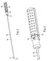
- FIG. 4is a perspective view of a tunneling tool with a two-part handle in accordance with an embodiment of the present disclosure.
- FIG. 5is a perspective view of the tunneling tool of FIG. 4 with the two-part handle in a locked position in accordance with an embodiment of the present disclosure.
- FIG. 6is a perspective view of the tunneling tool of FIG. 4 with the two-part handle in an unlocked position in accordance with an embodiment of the present disclosure.
- FIG. 7is a perspective view of a locking mechanism on a primary handle of FIG. 4 .
- FIG. 8is a perspective view of a locking mechanism on the secondary handle of FIG. 4 .
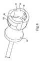
- FIG. 9is a perspective view of the secondary handle advancing a sheath on the tunneling tool of FIG. 4 in accordance with an embodiment of the present disclosure.
- FIG. 10is a schematic illustration of a sheath located in a patient in accordance with an embodiment of the present disclosure.
- FIG. 11is a flow diagram of a method of using a tunneling tool in accordance with an embodiment of the present disclosure.
- SCSspinal cord stimulation
- the present disclosuremay be used as part of a pacemaker, a defibrillator, a cochlear stimulator, a retinal stimulator, a stimulator configured to produce coordinated limb movement, a cortical stimulator, a deep brain stimulator, peripheral nerve stimulator, microstimulator, or in any other neural stimulator configured to treat urinary incontinence, sleep apnea, shoulder sublaxation, headache, etc.
- one or more of the therapy delivery elementsmay be a fluid delivery conduit, such as a catheter, including an inner lumen that is placed to deliver a fluid, such as pharmaceutical agents, insulin, pain relieving agents, gene therapy agents, or the like from a fluid delivery device (e.g., a fluid reservoir and/or pump) to a respective target tissue site in a patient.
- a fluid delivery devicee.g., a fluid reservoir and/or pump
- one or more of the therapy delivery elementsmay be an electrical lead including one or more sensing electrodes to sense physiological parameters (e.g., blood pressure, temperature, cardiac activity, etc.) at a target tissue site within a patient.
- therapymay include stimulation therapy, sensing or monitoring of one or more physiological parameters, fluid delivery, and the like.
- Therapy delivery elementincludes pacing or defibrillation leads, stimulation leads, sensing leads, fluid delivery conduit, any combination thereof
- Target tissue siterefers generally to the target site for implantation of a therapy delivery element, regardless of the type of therapy.
- FIG. 1illustrates a generalized therapy delivery system 10 that may be used in spinal cord stimulation (SCS), as well as other stimulation applications.
- the therapy delivery system 10generally includes an implantable pulse generator 12 , an implantable therapy delivery element 14 , which carries an array of electrodes 18 (shown exaggerated for purposes of illustration), and an optional implantable extension lead 16 . Although only one therapy delivery element 14 is shown, typically two or more therapy delivery elements 14 are used with the therapy delivery system 10 .
- the therapy delivery element 14includes elongated body 40 having a proximal end 36 and a distal end 44 .
- the elongated body 40typically has a diameter of between about 0.03 inches to 0.07 inches and a length within the range of 30 cm to 90 cm for spinal cord stimulation applications.
- the elongated body 40may be composed of a suitable electrically insulative material, such as, a polymer (e.g., polyurethane or silicone), and may be extruded from as a unibody construction.
- proximal end 36 of the therapy delivery element 14is electrically coupled to distal end 38 of the extension lead 16 via a connector 20 , typically associated with the extension lead 16 .
- Proximal end 42 of the extension lead 16is electrically coupled to the implantable pulse generator 12 via connector 22 associated with housing 28 .
- the proximal end 36 of the therapy delivery element 14can be electrically coupled directly to the connector 20 .
- the implantable pulse generator 12includes electronic subassembly 24 (shown schematically), which includes control and pulse generation circuitry (not shown) for delivering electrical stimulation energy to the electrodes 18 of the therapy delivery element 14 in a controlled manner, and a power supply, such as battery 26 .
- the implantable pulse generator 12provides a programmable stimulation signal (e.g., in the form of electrical pulses or substantially continuous-time signals) that is delivered to target stimulation sites by electrodes 18 .
- a programmable stimulation signale.g., in the form of electrical pulses or substantially continuous-time signals
- the implantable pulse generator 12may provide the same or a different signal to the electrodes 18 .
- the implantable pulse generator 12can take the form of an implantable receiver-stimulator in which the power source for powering the implanted receiver, as well as control circuitry to command the receiver-stimulator, are contained in an external controller inductively coupled to the receiver-stimulator via an electromagnetic link.
- the implantable pulse generator 12can take the form of an external trial stimulator (ETS), which has similar pulse generation circuitry as an IPG, but differs in that it is a non-implantable device that is used on a trial basis after the therapy delivery element 14 has been implanted and prior to implantation of the IPG, to test the responsiveness of the stimulation that is to be provided.
- ETSexternal trial stimulator
- the housing 28is composed of a biocompatible material, such as for example titanium, and forms a hermetically sealed compartment containing the electronic subassembly 24 and battery 26 are protected from the body tissue and fluids.
- the connector 22is disposed in a portion of the housing 28 that is, at least initially, not sealed.
- the connector 22carries a plurality of contacts that electrically couple with respective terminals at proximal ends of the therapy delivery element 14 or extension lead 16 . Electrical conductors extend from the connector 22 and connect to the electronic subassembly 24 .
- FIG. 2illustrates the therapy delivery element 14 implanted in the epidural space 30 of a patient in close proximity to the dura, the outer layer that surrounds the spinal cord 32 , to deliver the intended therapeutic effects of spinal cord electrical stimulation.
- the target stimulation sitesmay be anywhere along the spinal cord 32 , such as for example proximate the sacral nerves.
- the implantable pulse generator 12is generally implanted in a surgically-made pocket either in the abdomen or above the buttocks, such as illustrated in FIG. 3 .
- the implantable pulse generator 12may, of course, also be implanted in other locations of the patient's body.
- Use of the extension lead 16facilitates locating the implantable pulse generator 12 away from the lead exit point 34 .
- the extension lead 16serves as a lead adapter if the proximal end 36 of the therapy delivery element 14 is not compatible with the connector 22 of the implantable pulse generator 12 , since different manufacturers use different connectors at the ends of their stimulation leads and are not always compatible with the connector 22 .
- the therapy delivery system 10also may include a clinician programmer 46 and a patient programmer 48 .
- Clinician programmer 46may be a handheld computing device that permits a clinician to program neurostimulation therapy for patient using input keys and a display.
- the clinicianmay specify neurostimulation parameters for use in delivery of neurostimulation therapy.
- Clinician programmer 46supports telemetry (e.g., radio frequency telemetry) with the implantable pulse generator 12 to download neurostimulation parameters and, optionally, upload operational or physiological data stored by implantable pulse generator 12 . In this manner, the clinician may periodically interrogate the implantable pulse generator 12 to evaluate efficacy and, if necessary, modify the stimulation parameters.
- patient programmer 48may be a handheld computing device. Patient programmer 48 may also include a display and input keys to allow patient to interact with patient programmer 48 and the implantable pulse generator 12 . The patient programmer 48 provides patient with an interface for control of neurostimulation therapy provided by the implantable pulse generator 12 . For example, patient may use patient programmer 48 to start, stop or adjust neurostimulation therapy. In particular, patient programmer 48 may permit patient to adjust stimulation parameters such as duration, amplitude, pulse width and pulse rate, within an adjustment range specified by the clinician via clinician programmer 48 , or select from a library of stored stimulation therapy programs.
- stimulation parameterssuch as duration, amplitude, pulse width and pulse rate
- the implantable pulse generator 12 , clinician programmer 46 , and patient programmer 48may communicate via cables or a wireless communication.
- Clinician programmer 46 and patient programmer 48may, for example, communicate via wireless communication with the implantable pulse generator 12 using RF telemetry techniques known in the art.
- Clinician programmer 46 and patient programmer 48also may communicate with each other using any of a variety of local wireless communication techniques, such as RF communication according to the 802.11 or Bluetooth specification sets, infrared communication, e.g., according to the IrDA standard, or other standard or proprietary telemetry protocols.
- FIG. 3also illustrates a general environmental that may benefit from use of a tunneling tool in accordance with an embodiment of the present disclosure. Since the implantable pulse generator 12 is located remotely from target location 50 for therapy, the therapy delivery element 14 and/or the extension lead 16 is typically routed through a pathways 52 subcutaneously formed along the torso of the patient to a subcutaneous pocket 54 where the implantable pulse generator 12 is located.
- FIG. 4is a perspective view of tunneling tool 60 for creating such pathways, such as the pathway 52 of FIG. 3 , to rough implantable therapy delivery elements 14 and/or lead extension 16 subcutaneously from the target stimulation site 50 to the implantable implantable pulse generator 12 , in accordance with an embodiment of the present disclosure.
- the tunneling tool 60includes primary handle 62 , secondary handle 64 , malleable shaft 66 , and flexible sheath 68 .
- Distal end 70 of the shaft 66preferably protrudes beyond distal end 72 of the flexible sheath 68 to bore through subcutaneous tissue.
- Proximal end 74 of the sheath 68is engaged with, but not attached to, the secondary handle 64 .
- the malleable shaft 66permits the surgeon to customize the shape of the tunneling device 60 prior to and/or during insertion of the tunneling device into the anatomy.
- the shape of the malleable shaft 66may be more or less intricate, as may be required by a particular procedure.
- the malleable shaft 66is preferably made of a bendable or flexible material such as stainless steel or titanium or any other suitable material or combination of materials.
- the malleable shaft 66may be any suitable size in shape and is generally sized to be slightly smaller than the size or diameter of a cable or wire connected to an implant device, which is routed through a person's body.
- the flexible sheath 68is preferably constructed from a fluoropolymer material.
- FIGS. 5 and 6illustrate operation of locking mechanism 80 that connects the secondary handle 64 to the primary handle 62 in accordance with an embodiment of the present disclosure.
- the locking mechanism 80is a twist-lock structure.
- FIG. 5illustrates the handles 62 , 64 in locked position 82 and
- FIG. 6illustrates unlocked position 84 .
- the locking mechanism 80secures the two handles 62 , 64 together and allows them to easily separate.
- the optional locking mechanismfacilitates gripping both the primary and secondary handles 62 , 64 while inserting the distal end 70 into the patient.
- FIGS. 7 and 8are perspective views of the locking mechanism 80 in accordance with an embodiment of the present disclosure.
- Primary handle 62includes protrusion 90 with one or more recesses 92 .
- Secondary handle 64include recess 94 sized to fit over the protrusion 90 .
- Tabs 96 formed along inside diameter 98 of the recess 94are sized to interlock with the recesses 92 on the primary handle 62 .
- the tabs 96are located on cantilevered arms 100 molded in the secondary handle 64 .
- the tabs 96are advanced into recesses 92 in direction 102 .
- the secondary handle 64is then rotated in direction 104 , so that the tabs 96 slide over locking ridges 106 located in the recesses 9 .
- the locking ridges 106retain the handles 62 , 64 in the locked position 82 .
- the cantilevered arms 100flex to permit the tabs 96 to pass over the locking ridges 106 .
- the secondary handle 64is separated from the primary handle 62 using the reverse process.
- the secondary handle 64is first rotated in direction 110 to shift the tabs 96 to the opposite side of the locking ridges 106 .
- the secondary handle 64is then moved in direction 112 , parallel to the shaft 66 .
- FIG. 9illustrates the secondary handle 64 separated from the primary handle 62 and advanced along the shaft 66 in direction 112 .
- Proximal end 78 of the shaft 66is fixedly secured to the primary handle 62 .
- the proximal end 74 of the sheath 68abuts, but is not attached to, the secondary handle 64 .
- the secondary handle 64includes an opening 116 with diameter 118 that is greater than outside diameter 120 of the shaft 66 .
- the diameter 118 of the openingis less than outside diameter 122 of the sheath 68 , so the sheath 68 advanced along the shaft 66 as the secondary handle 64 moves in the direction 112 .
- the shaft 66is retracted from the sheath 68 in direction 102 .
- the distal end 70 of the shaft 66is inserted into an incision of a patient.
- the shaft 66can be inserted at an incision site near the therapy delivery element 14 or an incision site near the implantable pulse generator 12 is located, or an intermediate location between the two.
- the tunneling device 60Once the tunneling device 60 has been inserted under the skin, it is directed, usually between the skin and muscle tissue, to the target region within the body.
- the distal end 70 of the shaft 66is blunt in order to inhibit damage to sensitive tissue such as nerves.
- the blunt distal endminimizes coring of tissue as the tunneling device 60 is moved through the anatomy.
- the shaft 66 and sheath 68may be bent by the surgeon, either before or during insertion, to facilitate forming the pathway 52 to the desired location.
- the distal end 70 of the shaft 66bores through the tissue to the desired target site by the force of the surgeon pushing the tool 60 into the patient.
- the surgeonrotates the secondary handle 64 in direction 110 to separate the two handles 62 , 64 .
- the surgeongrasps the handle 62 to withdraw the shaft 66 from the patient, while simultaneously holding the secondary handle 64 to maintain the sheath 68 in the desired location within the pathway 52 .
- the shaft 66is completely removed from the sheath 68 , leaving the hollow sheath 68 in place inside the patient.
- the secondary handle 64is separated from the sheath 68 .
- FIG. 10illustrates the sheath 68 extending into the patient along the pathway 52 , with the shaft 66 removed.
- the shaft 66is optionally configured in a non-linear shape corresponding to the pathway 52 before or during insertion into the patient.
- the sheath 68extends from incision site 130 near where the implantable pulse generator 12 will be implanted to incision site 132 near the therapy delivery element 14 .
- the sheath 68extends from incision site 132 .
- Proximal end 74 of the sheath 68is accessible at incision site 130 and distal end 72 is accessible near incision site 132 .
- the proximal end 74extends outwardly from the living body from the incision site 130 and the distal end 72 extends outwardly from the living body from the incision site 132 .
- the secondary handle 64has already been removed.
- the surgeoninserts proximal end 36 of the therapy delivery elements 14 or proximal end 42 of the lead extension 16 (see FIG. 1 ) into lumen 134 (see FIG. 9 ) of the sheath 68 through distal end 72 .
- the surgeongrasps proximal end 74 of the sheath 68 and pulls it from the patient, leaving the therapy delivery elements 14 in the subcutaneous pathway 52 .
- Proximal end 36 or 42is then electrically coupled to the implantable pulse generator 12 , as illustrated in FIG. 3 .
- lead extension 16is inserted into the lumen 134 of the sheath 68 from either end 72 , 74 .
- the surgeonhas the option to remove the sheath 68 by pulling either end 72 , 74 .
- distal end 38 of the lead extension 16 attached to the therapy delivery element 14 and the proximal end 42 of the lead extension 16is attached to the implantable pulse generator 12 .
- FIG. 11is a flow diagram of a method of implanting a neurostimulation system within a living body in accordance with an embodiment of the present disclosure.
- Electrodes 18 at a distal end 44 of a therapy delivery element 14are inserted through a first incision site 132 to a target location within the living body ( 150 ).
- Proximal ends 36 of the therapy delivery elements 14are accessible at the incision site 130 ( 152 ).
- the surgeonattaches the therapy delivery element 14 to the patient's tissue, such as for example, using staples or an anchor, near the target location ( 154 ).
- a subcutaneous pocket 54 for implanting an implantable pulse generator 12is formed within the living body through a second incision site 130 ( 156 ).
- Distal end 70 of the tunneling tool 60is inserted under the skin between the skin and muscle tissue to create the pathway 52 between the incision sites 130 , 132 ( 158 ).
- Primary handle 62is disengaged from the secondary handle 64 ( 160 ).
- the primary handle 62 and the attached shaft 66are removed from the sheath 68 while the secondary handle 64 retains the sheath 68 in the pathway 52 ( 162 ).
- the secondary handle 64is separated from the sheath 68 ( 164 ).
- the therapy delivery element 14(or an extension thereof) is passed through lumen 134 in the sheath 68 ( 166 ).
- the sheath 68is then removed from the patient ( 168 ).
- the proximal end 36 of the therapy delivery element 14is electrically coupled to the implantable pulse generator 12 and the implantable pulse generator 12 is then implanted in the subcutaneous pocket 54 ( 170 ).
Landscapes
- Health & Medical Sciences (AREA)
- Surgery (AREA)
- Life Sciences & Earth Sciences (AREA)
- Biomedical Technology (AREA)
- Nuclear Medicine, Radiotherapy & Molecular Imaging (AREA)
- Engineering & Computer Science (AREA)
- Orthopedic Medicine & Surgery (AREA)
- Heart & Thoracic Surgery (AREA)
- Medical Informatics (AREA)
- Molecular Biology (AREA)
- Animal Behavior & Ethology (AREA)
- General Health & Medical Sciences (AREA)
- Public Health (AREA)
- Veterinary Medicine (AREA)
- Electrotherapy Devices (AREA)
Abstract
Description
Claims (20)
Priority Applications (3)
| Application Number | Priority Date | Filing Date | Title |
|---|---|---|---|
| US13/046,144US9381030B2 (en) | 2010-07-15 | 2011-03-11 | Tunneling tool for implantable leads |
| EP11807286.7AEP2593178B1 (en) | 2010-07-15 | 2011-07-05 | Tunneling tool for implantable leads |
| PCT/US2011/042926WO2012009175A1 (en) | 2010-07-15 | 2011-07-05 | Tunneling tool for implantable leads |
Applications Claiming Priority (2)
| Application Number | Priority Date | Filing Date | Title |
|---|---|---|---|
| US36450910P | 2010-07-15 | 2010-07-15 | |
| US13/046,144US9381030B2 (en) | 2010-07-15 | 2011-03-11 | Tunneling tool for implantable leads |
Publications (2)
| Publication Number | Publication Date |
|---|---|
| US20120016377A1 US20120016377A1 (en) | 2012-01-19 |
| US9381030B2true US9381030B2 (en) | 2016-07-05 |
Family
ID=45467522
Family Applications (1)
| Application Number | Title | Priority Date | Filing Date |
|---|---|---|---|
| US13/046,144Active2032-08-08US9381030B2 (en) | 2010-07-15 | 2011-03-11 | Tunneling tool for implantable leads |
Country Status (3)
| Country | Link |
|---|---|
| US (1) | US9381030B2 (en) |
| EP (1) | EP2593178B1 (en) |
| WO (1) | WO2012009175A1 (en) |
Cited By (2)
| Publication number | Priority date | Publication date | Assignee | Title |
|---|---|---|---|---|
| US10751526B2 (en) | 2017-10-25 | 2020-08-25 | Cardiac Pacemakers, Inc. | Subcutaneous lead implantation |
| USD990677S1 (en)* | 2018-10-30 | 2023-06-27 | Hi-Lex Corporation | Medical tunneling instrument |
Families Citing this family (33)
| Publication number | Priority date | Publication date | Assignee | Title |
|---|---|---|---|---|
| US20130085548A1 (en)* | 2011-10-03 | 2013-04-04 | Eugene Y. Mironer | Method of treating chronic pain in a patient using neuromodulation |
| US10751081B2 (en)* | 2012-03-30 | 2020-08-25 | Medtronic, Inc. | Methods and tools for clearing the epidural space in preparation for medical lead implantation |
| US9472916B2 (en) | 2013-03-14 | 2016-10-18 | Medtronic, Inc. | Distal connector assemblies for medical lead extensions |
| US10391303B2 (en) | 2013-03-14 | 2019-08-27 | Medtronic, Inc. | Tools and methods for implantation of implantable medical lead extensions or catheters |
| US9149627B2 (en) | 2013-03-14 | 2015-10-06 | Medtronic, Inc. | Kits and methods for implanting an implantable lead extension |
| US10532203B2 (en) | 2013-05-06 | 2020-01-14 | Medtronic, Inc. | Substernal electrical stimulation system |
| US9220913B2 (en) | 2013-05-06 | 2015-12-29 | Medtronics, Inc. | Multi-mode implantable medical device |
| US10933230B2 (en) | 2013-05-06 | 2021-03-02 | Medtronic, Inc. | Systems and methods for implanting a medical electrical lead |
| US10471267B2 (en) | 2013-05-06 | 2019-11-12 | Medtronic, Inc. | Implantable cardioverter-defibrillator (ICD) system including substernal lead |
| US10556117B2 (en) | 2013-05-06 | 2020-02-11 | Medtronic, Inc. | Implantable cardioverter-defibrillator (ICD) system including substernal pacing lead |
| US20140330287A1 (en) | 2013-05-06 | 2014-11-06 | Medtronic, Inc. | Devices and techniques for anchoring an implantable medical device |
| US9717923B2 (en) | 2013-05-06 | 2017-08-01 | Medtronic, Inc. | Implantable medical device system having implantable cardioverter-defibrillator (ICD) system and substernal leadless pacing device |
| US10434307B2 (en) | 2013-10-15 | 2019-10-08 | Medtronic, Inc. | Methods and devices for subcutaneous lead implantation |
| US9610436B2 (en) | 2013-11-12 | 2017-04-04 | Medtronic, Inc. | Implant tools with attachment feature and multi-positional sheath and implant techniques utilizing such tools |
| US10792490B2 (en) | 2013-11-12 | 2020-10-06 | Medtronic, Inc. | Open channel implant tools and implant techniques utilizing such tools |
| US10350387B2 (en)* | 2014-06-02 | 2019-07-16 | Medtronic, Inc. | Implant tool for substernal or pericardial access |
| US10357647B2 (en)* | 2014-06-02 | 2019-07-23 | Medtronic, Inc. | Tunneling tool |
| US10743960B2 (en) | 2014-09-04 | 2020-08-18 | AtaCor Medical, Inc. | Cardiac arrhythmia treatment devices and delivery |
| US10328268B2 (en) | 2014-09-04 | 2019-06-25 | AtaCor Medical, Inc. | Cardiac pacing |
| US9636505B2 (en) | 2014-11-24 | 2017-05-02 | AtaCor Medical, Inc. | Cardiac pacing sensing and control |
| DK3188793T3 (en) | 2014-09-04 | 2020-04-06 | Atacor Medical Inc | PACEMAKER CABLE CONTACT |
| US9636512B2 (en) | 2014-11-05 | 2017-05-02 | Medtronic, Inc. | Implantable cardioverter-defibrillator (ICD) system having multiple common polarity extravascular defibrillation electrodes |
| US11097109B2 (en) | 2014-11-24 | 2021-08-24 | AtaCor Medical, Inc. | Cardiac pacing sensing and control |
| US10334300B2 (en)* | 2014-12-04 | 2019-06-25 | Cynny Spa | Systems and methods to present content |
| US10888695B2 (en) | 2014-12-09 | 2021-01-12 | Medtronic, Inc. | Over the needle implant tools and implant techniques utilizing such tools |
| US11083491B2 (en) | 2014-12-09 | 2021-08-10 | Medtronic, Inc. | Extravascular implant tools utilizing a bore-in mechanism and implant techniques using such tools |
| US10349978B2 (en) | 2014-12-18 | 2019-07-16 | Medtronic, Inc. | Open channel implant tool with additional lumen and implant techniques utilizing such tools |
| US10729456B2 (en) | 2014-12-18 | 2020-08-04 | Medtronic, Inc. | Systems and methods for deploying an implantable medical electrical lead |
| CN107530115B (en) | 2015-02-13 | 2020-04-14 | 心脏器械股份有限公司 | Combined tunneling tool |
| WO2017023847A1 (en) | 2015-07-31 | 2017-02-09 | Heartware, Inc. | Connection system with cleaning |
| EP4527449A3 (en) | 2019-05-29 | 2025-04-30 | Atacor Medical, Inc. | Implantable electrical leads and associated delivery systems |
| US11666771B2 (en) | 2020-05-29 | 2023-06-06 | AtaCor Medical, Inc. | Implantable electrical leads and associated delivery systems |
| US20240374892A1 (en)* | 2021-05-11 | 2024-11-14 | Drexel University | Directable Tunnel Device for Subcutaneous Implantable Cardio Defibrillator |
Citations (113)
| Publication number | Priority date | Publication date | Assignee | Title |
|---|---|---|---|---|
| US3630192A (en) | 1969-07-14 | 1971-12-28 | Khosrow Jamshidi | Instrument for internal organ biopsy |
| US3779658A (en)* | 1972-06-06 | 1973-12-18 | C Caperton | Coupling means for sewer rod |
| US3915174A (en)* | 1972-11-28 | 1975-10-28 | Thomas A Preston | Pacing apparatus and improved catheter |
| US4280510A (en)* | 1979-02-08 | 1981-07-28 | Medtronic, Inc. | Sutureless myocardial lead introducer |
| US4574806A (en) | 1984-10-01 | 1986-03-11 | Cordis Corporation | Tunnelling device for peripheral vascular reconstruction |
| US4735215A (en)* | 1987-01-05 | 1988-04-05 | Goto David S | Soft tissue biopsy instrument |
| US4793363A (en) | 1986-09-11 | 1988-12-27 | Sherwood Medical Company | Biopsy needle |
| US4817847A (en) | 1986-04-21 | 1989-04-04 | Finanzaktiengesellschaft Globe Control | Instrument and a procedure for performing an anastomosis |
| US5010887A (en)* | 1989-11-17 | 1991-04-30 | Siemens-Pacesetter, Inc. | Noise discrimination in implantable pacemakers |
| US5019102A (en) | 1987-12-10 | 1991-05-28 | Eberhard Hoene | Anti-refluxive internal ureteral stent with a dynamic hood-valve at the vesical end for prevention of urinary reflux into the upper urinary tract upon increase of vesical pressure |
| US5047021A (en)* | 1989-08-29 | 1991-09-10 | Utterberg David S | Male luer lock medical fitting |
| US5197649A (en) | 1991-10-29 | 1993-03-30 | The Trustees Of Columbia University In The City Of New York | Gastrointestinal endoscoptic stapler |
| US5279570A (en) | 1992-09-22 | 1994-01-18 | Wayne State University | Needle assembly with a movable stylet controlled by a spacer mechanism |
| US5300106A (en)* | 1991-06-07 | 1994-04-05 | Cardiac Pacemakers, Inc. | Insertion and tunneling tool for a subcutaneous wire patch electrode |
| US5306240A (en) | 1993-01-21 | 1994-04-26 | Pilling Co. | Tunneler and method for implanting subcutaneous vascular access grafts |
| US5361754A (en) | 1993-01-25 | 1994-11-08 | Mallinckrodt Medical, Inc. | Apparatus and method for connecting a tracheostomy tube to a neckplate |
| US5496345A (en) | 1992-06-02 | 1996-03-05 | General Surgical Innovations, Inc. | Expansible tunneling apparatus for creating an anatomic working space |
| US5522875A (en)* | 1994-07-28 | 1996-06-04 | Medtronic, Inc. | Medical electrical lead system having a torque transfer stylet |
| US5540711A (en) | 1992-06-02 | 1996-07-30 | General Surgical Innovations, Inc. | Apparatus and method for developing an anatomic space for laparoscopic procedures with laparoscopic visualization |
| US5607443A (en) | 1992-06-02 | 1997-03-04 | General Surgical Innovations, Inc. | Expansible tunneling apparatus for creating an anatomic working space with laparoscopic observation |
| US5653726A (en) | 1994-11-03 | 1997-08-05 | Archimedes Surgical, Inc. | Retrograde dissector and method for facilitating a TRAM flap |
| US5728133A (en)* | 1996-07-09 | 1998-03-17 | Cardiologics, L.L.C. | Anchoring device and method for sealing percutaneous punctures in vessels |
| US5782841A (en) | 1993-08-10 | 1998-07-21 | Medtronic, Inc. | Tunneling tool for subcutaneous lead placement |
| US5810792A (en)* | 1996-04-03 | 1998-09-22 | Icu Medical, Inc. | Locking blunt cannula |
| US5944732A (en) | 1997-08-27 | 1999-08-31 | Medical Components, Inc. | Subcutaneous tunnelling device and methods of forming a subcutaneous tunnel |
| US6015421A (en) | 1997-05-15 | 2000-01-18 | General Surgical Innovations, Inc. | Apparatus and method for developing an anatomic space for laparoscopic procedures |
| US6135771A (en)* | 1997-12-02 | 2000-10-24 | Centrix, Inc. | Dental cartridge having an attachable delivery portion |
| US20010018549A1 (en)* | 2000-01-21 | 2001-08-30 | Victor Scetbon | Percutaneous device and method for treating urinary stress incontinence in women using a sub-urethral tape |
| US6315184B1 (en) | 1999-06-02 | 2001-11-13 | Powermed, Inc. | Stapling device for use with an electromechanical driver device for use with anastomosing, stapling, and resecting instruments |
| US6360750B1 (en) | 1999-04-29 | 2002-03-26 | Medtronic, Inc. | Minimally invasive surgical techniques for implanting devices that deliver stimulant to the nervous system |
| US6364892B1 (en) | 1992-06-02 | 2002-04-02 | General Surgical Innovations, Inc. | Ballon dissector with improved visualization |
| US6378400B1 (en)* | 1999-01-28 | 2002-04-30 | Robert Bogli | Detachable handle socket ratchet wrench system |
| US6408214B1 (en)* | 2000-07-11 | 2002-06-18 | Medtronic, Inc. | Deflectable tip catheter for CS pacing |
| US6432121B1 (en) | 1992-06-02 | 2002-08-13 | General Surgical Innovations, Inc. | Apparatus and method for guiding placement of a minimally invasive surgical instrument |
| US6443973B1 (en) | 1999-06-02 | 2002-09-03 | Power Medical Interventions, Inc. | Electromechanical driver device for use with anastomosing, stapling, and resecting instruments |
| US6475244B2 (en) | 1997-09-24 | 2002-11-05 | Atrium Medical Corporation | Tunneling device |
| US6488197B1 (en) | 2000-02-22 | 2002-12-03 | Power Medical Interventions, Inc. | Fluid delivery device for use with anastomosing resecting and stapling instruments |
| US6491201B1 (en) | 2000-02-22 | 2002-12-10 | Power Medical Interventions, Inc. | Fluid delivery mechanism for use with anastomosing, stapling, and resecting instruments |
| US6494477B1 (en)* | 2001-11-08 | 2002-12-17 | Daniel C. Parker | Automatic trailer hitch coupling apparatus |
| US6505768B2 (en) | 1999-07-12 | 2003-01-14 | Power Medical Interventions, Inc. | Expanding parallel jaw device for use with an electromechanical driver device |
| US6517565B1 (en) | 1999-06-02 | 2003-02-11 | Power Medical Interventions, Inc. | Carriage assembly for controlling a steering wire steering mechanism within a flexible shaft |
| US6533157B1 (en) | 2000-02-22 | 2003-03-18 | Power Medical Interventions, Inc. | Tissue stapling attachment for use with an electromechanical driver device |
| US6540764B1 (en) | 1992-06-02 | 2003-04-01 | General Surgical Innovations, Inc. | Apparatus and method for dissecting tissue layers |
| US20030070726A1 (en)* | 2001-10-11 | 2003-04-17 | Kjell Andreasson | Method and assembly for fluid transfer |
| US6562056B2 (en) | 1992-06-02 | 2003-05-13 | General Surgical Innovations, Inc. | Balloon device for use in surgery and method of use |
| US6592602B1 (en) | 1999-10-08 | 2003-07-15 | General Surgical Innovations, Inc. | Balloon dissection apparatus |
| US6605094B1 (en) | 1999-11-19 | 2003-08-12 | Advanced Bionics Corporation | Integrated subcutaneous tunneling and carrying tool |
| US6669691B1 (en)* | 2000-07-18 | 2003-12-30 | Scimed Life Systems, Inc. | Epicardial myocardial revascularization and denervation methods and apparatus |
| US6671554B2 (en)* | 2001-09-07 | 2003-12-30 | Medtronic Minimed, Inc. | Electronic lead for a medical implant device, method of making same, and method and apparatus for inserting same |
| US20040018764A1 (en)* | 2002-07-23 | 2004-01-29 | Alden Products Company | Breakaway locking connector |
| US6716233B1 (en) | 1999-06-02 | 2004-04-06 | Power Medical Interventions, Inc. | Electromechanical driver and remote surgical instrument attachment having computer assisted control capabilities |
| US6716230B2 (en) | 2000-02-22 | 2004-04-06 | Power Medical Interventions, Inc. | Vessel and lumen expander attachment for use with an electromechanical driver device |
| US20040176781A1 (en)* | 2003-03-06 | 2004-09-09 | Cardiac Pacemakers, Inc. | Lead insertion tool for hemostatic introducer system |
| US6793652B1 (en) | 1999-06-02 | 2004-09-21 | Power Medical Interventions, Inc. | Electro-mechanical surgical device |
| US6836917B2 (en)* | 2001-05-07 | 2005-01-04 | The Procter & Gamble Company | Replaceable head electric toothbrush and connection structure therefor |
| US20050033268A1 (en)* | 2003-08-06 | 2005-02-10 | Kimberly-Clark Worldwide, Inc. | Connector with protrusion adapted for interconnection with second member |
| US20050131391A1 (en) | 2001-03-09 | 2005-06-16 | Scimed Life Systems, Inc. | Systems, methods and devices relating to delivery of medical implants |
| US6936052B2 (en) | 2001-03-09 | 2005-08-30 | Boston Scientific Scimed, Inc. | System for implanting an implant and method thereof |
| US6971393B1 (en)* | 2000-11-15 | 2005-12-06 | George Mamo | Minimally invasive method for implanting a sacral stimulation lead |
| US6981941B2 (en) | 1999-06-02 | 2006-01-03 | Power Medical Interventions | Electro-mechanical surgical device |
| US7018384B2 (en) | 2002-08-29 | 2006-03-28 | Medtronic, Inc. | Medical passing device and method |
| US7025772B2 (en) | 2001-03-09 | 2006-04-11 | Scimed Life Systems, Inc. | System for implanting an implant and method thereof |
| US20060079769A1 (en)* | 2004-09-30 | 2006-04-13 | Whiting James S | Transmembrane access systems and methods |
| US7032798B2 (en) | 1999-06-02 | 2006-04-25 | Power Medical Interventions, Inc. | Electro-mechanical surgical device |
| US20060149345A1 (en)* | 2003-09-12 | 2006-07-06 | Ndi Medical, Llc | Neuromodulation stimulation for the restoration of sexual function |
| US7074213B2 (en) | 2001-01-09 | 2006-07-11 | Rex Medical, L.P. | Dialysis catheter |
| US7077829B2 (en) | 2001-01-09 | 2006-07-18 | Rex Medical, L.P. | Dialysis catheter |
| US7097635B2 (en) | 2001-01-09 | 2006-08-29 | Rex Medical, L.P. | Guidewire retrieval member for catheter insertion |
| US7120499B2 (en) | 2004-02-12 | 2006-10-10 | Ndi Medical, Llc | Portable percutaneous assemblies, systems and methods for providing highly selective functional or therapeutic neuromuscular stimulation |
| US7218970B2 (en) | 2003-06-20 | 2007-05-15 | Cardiac Pacemakers, Inc. | System for medical lead tunneling |
| US20070173879A1 (en) | 2006-01-23 | 2007-07-26 | Rajesh Pandey | Surgical tool |
| US20070243013A1 (en)* | 2006-04-13 | 2007-10-18 | Hewitt William G | Tool system for mechanical mounting assembly |
| US7300448B2 (en) | 2002-10-04 | 2007-11-27 | Tyco Healthcare Group Lp | Balloon dissector with cannula |
| US20080009749A1 (en) | 2006-06-22 | 2008-01-10 | Theodore Philip Delianides | Curved needle assembly for subcutaneous light delivery |
| US7338092B1 (en)* | 2005-07-25 | 2008-03-04 | Cicconi Iii David Lee | Quick-release connector fitting |
| US7343202B2 (en)* | 2004-02-12 | 2008-03-11 | Ndi Medical, Llc. | Method for affecting urinary function with electrode implantation in adipose tissue |
| US20080103572A1 (en)* | 2006-10-31 | 2008-05-01 | Medtronic, Inc. | Implantable medical lead with threaded fixation |
| US7369901B1 (en)* | 2004-02-11 | 2008-05-06 | Pacesetter, Inc. | Myocardial lead and lead system |
| US20080119846A1 (en)* | 2006-10-11 | 2008-05-22 | Rioux Robert F | Methods and apparatus for percutaneous patient access and subcutaneous tissue tunneling |
| US20080132969A1 (en)* | 2004-02-12 | 2008-06-05 | Ndi Medical, Inc. | Systems and methods for bilateral stimulation of left and right branches of the dorsal genital nerves to treat urologic dysfunctions |
| US7389138B2 (en)* | 2003-04-11 | 2008-06-17 | Cardiac Pacemakers, Inc. | Electrode placement determination for subcutaneous cardiac monitoring and therapy |
| US20080154296A1 (en) | 2006-12-22 | 2008-06-26 | The Spectranetics Corporation | Tissue Separating Systems and Methods |
| US20080281228A1 (en)* | 2007-04-23 | 2008-11-13 | Juan Carlos Parodi | Guidewire with adjustable stiffness |
| US20080312677A1 (en) | 2006-05-05 | 2008-12-18 | I-Flow Corporation | Soft tissue tunneling device |
| US20090030444A1 (en) | 2007-07-23 | 2009-01-29 | Rajesh Pandey | Surgical tool |
| US20090157927A1 (en) | 2007-12-12 | 2009-06-18 | Ahmadreza Rofougaran | Method and system for chip-to-chip communications with wireline control |
| US20090157091A1 (en)* | 2006-04-04 | 2009-06-18 | Ams Research Corporation | Apparatus for Implanting Neural Stimulation Leads |
| US7565198B2 (en) | 2004-02-12 | 2009-07-21 | Medtronic Urinary Solutions, Inc. | Systems and methods for bilateral stimulation of left and right branches of the dorsal genital nerves to treat dysfunctions, such as urinary incontinence |
| US20090240258A1 (en) | 2008-03-21 | 2009-09-24 | Boston Scientific Neuromodulation Corporation | Detachable handle for implantable electrical stimulation systems and methods of making and using |
| US20090254095A1 (en) | 2008-03-18 | 2009-10-08 | Blake Levine | Subcutaneous tunneling device |
| US7628795B2 (en) | 1997-09-24 | 2009-12-08 | Atrium Medical Corporation | Tunneling device for use with a graft |
| US7641688B2 (en) | 2004-09-16 | 2010-01-05 | Evera Medical, Inc. | Tissue augmentation device |
| US7695485B2 (en) | 2001-11-30 | 2010-04-13 | Power Medical Interventions, Llc | Surgical device |
| US20100125194A1 (en)* | 2008-11-20 | 2010-05-20 | Medtronic, Inc. | Subcutaneous lead guidance |
| US7726994B1 (en)* | 2009-01-30 | 2010-06-01 | Itt Manfacturing Enterprises, Inc. | Electrical connector for a helmet-mounted night vision system |
| US20100137879A1 (en)* | 2004-12-06 | 2010-06-03 | Cameron Health, Inc. | Apparatus and Method for Subcutaneous Electrode Insertion |
| US7743960B2 (en) | 2002-06-14 | 2010-06-29 | Power Medical Interventions, Llc | Surgical device |
| US7792591B2 (en)* | 2005-06-09 | 2010-09-07 | Medtronic, Inc. | Introducer for therapy delivery elements |
| US20100292724A1 (en)* | 2006-03-13 | 2010-11-18 | Sundaram Ravikumar | Minimally Invasive Surgical Clamps, Assemblies and Methods |
| US20100324579A1 (en)* | 2000-08-24 | 2010-12-23 | Bardy Gust H | Instrument With A Covered Bore For Subcutaneous Implantation |
| US20100331925A1 (en)* | 2009-06-24 | 2010-12-30 | Boston Scientific Neuromodulation Corporation | System and method for performing percutaneous nerve field stimulation with concurrent anode intensified spinal cord stimulation |
| US7894913B2 (en)* | 2004-06-10 | 2011-02-22 | Medtronic Urinary Solutions, Inc. | Systems and methods of neuromodulation stimulation for the restoration of sexual function |
| US20110257709A1 (en)* | 2010-04-20 | 2011-10-20 | Boston Scientific Neuromodulation Corporation | Method and apparatus for modifying neurostimulation linear lead shape to correct lead migration |
| US20110257660A1 (en)* | 2003-08-08 | 2011-10-20 | Jones Timothy S | Apparatus for implanting an electrical stimulation lead |
| US20110270268A1 (en)* | 2010-04-28 | 2011-11-03 | Eversull Christian S | Coupling for a Medical Delivery Device |
| US20120029335A1 (en)* | 2010-07-29 | 2012-02-02 | Cameron Health, Inc. | Subcutaneous Leads and Methods of Implant and Explant |
| US20120071956A1 (en)* | 2006-06-08 | 2012-03-22 | Greatbatch Ltd. | Implantable lead bandstop filter employing an inductive coil with parasitic capacitance to enhance mri compatibility of active medical devices |
| US8224453B2 (en)* | 2007-03-15 | 2012-07-17 | Advanced Neuromodulation Systems, Inc. | Spinal cord stimulation to treat pain |
| US8233992B2 (en)* | 2009-08-28 | 2012-07-31 | Boston Scientific Neuromodulation Corporation | Method and apparatus for determining relative positioning between neurostimulation leads |
| US20120197370A1 (en)* | 2004-09-08 | 2012-08-02 | Kim Daniel H | Neurostimulation system |
| US20120209285A1 (en)* | 2011-02-16 | 2012-08-16 | Boston Scientific Neuromodulation Corporation | Systems and methods for implanting paddle lead assemblies of electrical stimulation systems |
| US20120290055A1 (en)* | 2008-12-05 | 2012-11-15 | Boggs Ii Joseph W | Systems and methods to place one or more leads in tissue to electrically stimulate nerves to treat pain |
| US20130158564A1 (en)* | 2003-08-29 | 2013-06-20 | Medtronic, Inc. | Percutaneous flat lead introducer |
Family Cites Families (2)
| Publication number | Priority date | Publication date | Assignee | Title |
|---|---|---|---|---|
| SE511728C2 (en)* | 1994-01-27 | 1999-11-15 | Nilsson Ingvar | Device for detecting wear of an SNCR lance |
| US10856904B2 (en)* | 2006-11-30 | 2020-12-08 | Medtronic, Inc. | Flexible introducer |
- 2011
- 2011-03-11USUS13/046,144patent/US9381030B2/enactiveActive
- 2011-07-05WOPCT/US2011/042926patent/WO2012009175A1/enactiveApplication Filing
- 2011-07-05EPEP11807286.7Apatent/EP2593178B1/enactiveActive
Patent Citations (160)
| Publication number | Priority date | Publication date | Assignee | Title |
|---|---|---|---|---|
| US3630192A (en) | 1969-07-14 | 1971-12-28 | Khosrow Jamshidi | Instrument for internal organ biopsy |
| US3779658A (en)* | 1972-06-06 | 1973-12-18 | C Caperton | Coupling means for sewer rod |
| US3915174A (en)* | 1972-11-28 | 1975-10-28 | Thomas A Preston | Pacing apparatus and improved catheter |
| US4280510A (en)* | 1979-02-08 | 1981-07-28 | Medtronic, Inc. | Sutureless myocardial lead introducer |
| US4574806A (en) | 1984-10-01 | 1986-03-11 | Cordis Corporation | Tunnelling device for peripheral vascular reconstruction |
| US4817847A (en) | 1986-04-21 | 1989-04-04 | Finanzaktiengesellschaft Globe Control | Instrument and a procedure for performing an anastomosis |
| US4793363A (en) | 1986-09-11 | 1988-12-27 | Sherwood Medical Company | Biopsy needle |
| US4735215A (en)* | 1987-01-05 | 1988-04-05 | Goto David S | Soft tissue biopsy instrument |
| US5019102A (en) | 1987-12-10 | 1991-05-28 | Eberhard Hoene | Anti-refluxive internal ureteral stent with a dynamic hood-valve at the vesical end for prevention of urinary reflux into the upper urinary tract upon increase of vesical pressure |
| US5047021A (en)* | 1989-08-29 | 1991-09-10 | Utterberg David S | Male luer lock medical fitting |
| US5010887A (en)* | 1989-11-17 | 1991-04-30 | Siemens-Pacesetter, Inc. | Noise discrimination in implantable pacemakers |
| US5300106A (en)* | 1991-06-07 | 1994-04-05 | Cardiac Pacemakers, Inc. | Insertion and tunneling tool for a subcutaneous wire patch electrode |
| US5411508A (en) | 1991-10-29 | 1995-05-02 | The Trustees Of Columbia University In The City Of New York | Gastrointestinal approximating and tissue attaching device |
| US5197649A (en) | 1991-10-29 | 1993-03-30 | The Trustees Of Columbia University In The City Of New York | Gastrointestinal endoscoptic stapler |
| US5607443A (en) | 1992-06-02 | 1997-03-04 | General Surgical Innovations, Inc. | Expansible tunneling apparatus for creating an anatomic working space with laparoscopic observation |
| US6312442B1 (en) | 1992-06-02 | 2001-11-06 | General Surgical Innovations, Inc. | Method for developing an anatomic space for laparoscopic hernia repair |
| US6632234B2 (en) | 1992-06-02 | 2003-10-14 | General Surgical Innovations, Inc. | Apparatus and method for developing an anatomic space for laparoscopic procedures with laparoscopic visualization |
| US5496345A (en) | 1992-06-02 | 1996-03-05 | General Surgical Innovations, Inc. | Expansible tunneling apparatus for creating an anatomic working space |
| US6695856B2 (en) | 1992-06-02 | 2004-02-24 | General Surgical Innovations, Inc. | Apparatus and methods for developing an anatomic space for laparoscopic hernia repair and patch for use therewith |
| US5540711A (en) | 1992-06-02 | 1996-07-30 | General Surgical Innovations, Inc. | Apparatus and method for developing an anatomic space for laparoscopic procedures with laparoscopic visualization |
| US6432121B1 (en) | 1992-06-02 | 2002-08-13 | General Surgical Innovations, Inc. | Apparatus and method for guiding placement of a minimally invasive surgical instrument |
| US6565590B2 (en) | 1992-06-02 | 2003-05-20 | General Surgical Innovations, Inc. | Apparatus and methods for developing an anatomic space |
| US5702416A (en) | 1992-06-02 | 1997-12-30 | Genral Surgical Innovations, Inc. | Apparatus for developing an anatomic space for laparoscopic hernia repair and patch for use therewith |
| US6562056B2 (en) | 1992-06-02 | 2003-05-13 | General Surgical Innovations, Inc. | Balloon device for use in surgery and method of use |
| US6755845B2 (en) | 1992-06-02 | 2004-06-29 | General Surgical Innovations, Inc. | Apparatus and method for developing an anatomic space for laparoscopic hernia repair and patch for use therewith |
| US6540764B1 (en) | 1992-06-02 | 2003-04-01 | General Surgical Innovations, Inc. | Apparatus and method for dissecting tissue layers |
| US6758853B2 (en) | 1992-06-02 | 2004-07-06 | General Surgical Innovations, Inc. | Apparatus and methods for developing an anatomic space for laparoscopic hernia repair and patch for use therewith |
| US5817123A (en) | 1992-06-02 | 1998-10-06 | General Surgical Innovations, Inc. | Apparatus and method for developing an anatomic space for laparoscopic procedures with laparoscopic visualization |
| US5836961A (en) | 1992-06-02 | 1998-11-17 | General Surgical Innovations, Inc. | Apparatus and method for developing an anatomic space for laparoscopic hernia repair and patch for use therewith |
| US7297153B2 (en) | 1992-06-02 | 2007-11-20 | General Surgical Innovations, Inc. | Apparatus and method for developing an anatomic space for laparoscopic hernia repair and patch for use therewith |
| US6004337A (en) | 1992-06-02 | 1999-12-21 | General Surgical Innovations, Inc. | Apparatus for developing an anatomic space for laparoscopic procedures with laparoscopic visualization |
| US6514272B1 (en) | 1992-06-02 | 2003-02-04 | General Surgical Innovations, Inc. | Apparatus and method for developing an anatomic space for laparoscopic hernia repair and patch for use therewith |
| US6866676B2 (en) | 1992-06-02 | 2005-03-15 | General Surgical Innovations, Inc. | Apparatus and method for dissecting tissue layers |
| US6953467B2 (en) | 1992-06-02 | 2005-10-11 | General Surgical Innovations, Inc. | Apparatus and method for developing an anatomic space for laparoscopic hernia repair and patch for use therewith |
| US6264604B1 (en) | 1992-06-02 | 2001-07-24 | General Surgical Innovations, Inc. | Apparatus and method for developing an anatomic space for laparoscopic procedures with laparoscopic visualization |
| US7001405B2 (en) | 1992-06-02 | 2006-02-21 | General Surgical Innovations, Inc. | Apparatus and method for developing an anatomic space for laparoscopic procedures with laparoscopic visualization |
| US6679900B2 (en) | 1992-06-02 | 2004-01-20 | General Surgical Innovations, Inc. | Apparatus and methods for developing an anatomic space for laparoscopic hernia repair and patch for use therewith |
| US20080058853A1 (en) | 1992-06-02 | 2008-03-06 | Gneral Surgical Innovactions, Inc. | Apparatus and method for developing an anatomic space for laparoscopic hernia repair and patch for use therewith |
| US7179272B2 (en) | 1992-06-02 | 2007-02-20 | General Surgical Innovations, Inc. | Apparatus and method for dissecting tissue layers |
| US6364892B1 (en) | 1992-06-02 | 2002-04-02 | General Surgical Innovations, Inc. | Ballon dissector with improved visualization |
| US6368337B1 (en) | 1992-06-02 | 2002-04-09 | General Surgical Innovations, Inc. | Apparatus and method for developing an anatomic space for laparoscopic hernia repair and patch for use therewith |
| US7214236B2 (en) | 1992-06-02 | 2007-05-08 | General Surgical Innovations, Inc. | Apparatus and methods for developing an anatomic space for laparoscopic hernia repair and patch for use therewith |
| US5279570A (en) | 1992-09-22 | 1994-01-18 | Wayne State University | Needle assembly with a movable stylet controlled by a spacer mechanism |
| US5306240A (en) | 1993-01-21 | 1994-04-26 | Pilling Co. | Tunneler and method for implanting subcutaneous vascular access grafts |
| US5361754A (en) | 1993-01-25 | 1994-11-08 | Mallinckrodt Medical, Inc. | Apparatus and method for connecting a tracheostomy tube to a neckplate |
| US5778877A (en) | 1993-01-25 | 1998-07-14 | Mallinckrodt Medical, Inc. | Apparatus and method for connecting a tracheostomy tube to a neckplate |
| US5782841A (en) | 1993-08-10 | 1998-07-21 | Medtronic, Inc. | Tunneling tool for subcutaneous lead placement |
| US5522875A (en)* | 1994-07-28 | 1996-06-04 | Medtronic, Inc. | Medical electrical lead system having a torque transfer stylet |
| US5653726A (en) | 1994-11-03 | 1997-08-05 | Archimedes Surgical, Inc. | Retrograde dissector and method for facilitating a TRAM flap |
| US5810792A (en)* | 1996-04-03 | 1998-09-22 | Icu Medical, Inc. | Locking blunt cannula |
| US5728133A (en)* | 1996-07-09 | 1998-03-17 | Cardiologics, L.L.C. | Anchoring device and method for sealing percutaneous punctures in vessels |
| US6015421A (en) | 1997-05-15 | 2000-01-18 | General Surgical Innovations, Inc. | Apparatus and method for developing an anatomic space for laparoscopic procedures |
| US6168608B1 (en) | 1997-05-15 | 2001-01-02 | General Surgical Innovations, Inc. | Apparatus and method for developing an anatomic space for laparoscopic procedures |
| US5944732A (en) | 1997-08-27 | 1999-08-31 | Medical Components, Inc. | Subcutaneous tunnelling device and methods of forming a subcutaneous tunnel |
| US7628795B2 (en) | 1997-09-24 | 2009-12-08 | Atrium Medical Corporation | Tunneling device for use with a graft |
| US6565594B1 (en) | 1997-09-24 | 2003-05-20 | Atrium Medical Corporation | Tunneling device |
| US6475244B2 (en) | 1997-09-24 | 2002-11-05 | Atrium Medical Corporation | Tunneling device |
| US6135771A (en)* | 1997-12-02 | 2000-10-24 | Centrix, Inc. | Dental cartridge having an attachable delivery portion |
| US6378400B1 (en)* | 1999-01-28 | 2002-04-30 | Robert Bogli | Detachable handle socket ratchet wrench system |
| US6360750B1 (en) | 1999-04-29 | 2002-03-26 | Medtronic, Inc. | Minimally invasive surgical techniques for implanting devices that deliver stimulant to the nervous system |
| US6849071B2 (en) | 1999-06-02 | 2005-02-01 | Power Medical Interventions, Inc. | Electro-mechanical surgical device |
| US6843403B2 (en) | 1999-06-02 | 2005-01-18 | Power Medical Interventions, Inc. | Surgical clamping, cutting and stapling device |
| US6315184B1 (en) | 1999-06-02 | 2001-11-13 | Powermed, Inc. | Stapling device for use with an electromechanical driver device for use with anastomosing, stapling, and resecting instruments |
| US7032798B2 (en) | 1999-06-02 | 2006-04-25 | Power Medical Interventions, Inc. | Electro-mechanical surgical device |
| US6981941B2 (en) | 1999-06-02 | 2006-01-03 | Power Medical Interventions | Electro-mechanical surgical device |
| US7077856B2 (en) | 1999-06-02 | 2006-07-18 | Power Medical Interventions, Inc. | Electromechanical driver and remote surgical instrument attachment having computer assisted control capabilities |
| US7758613B2 (en) | 1999-06-02 | 2010-07-20 | Power Medical Interventions, Llc | Electromechanical driver and remote surgical instrument attachment having computer assisted control capabilities |
| US6517565B1 (en) | 1999-06-02 | 2003-02-11 | Power Medical Interventions, Inc. | Carriage assembly for controlling a steering wire steering mechanism within a flexible shaft |
| US6716233B1 (en) | 1999-06-02 | 2004-04-06 | Power Medical Interventions, Inc. | Electromechanical driver and remote surgical instrument attachment having computer assisted control capabilities |
| US6846309B2 (en) | 1999-06-02 | 2005-01-25 | Power Medical Interventions, Inc. | Electro-mechanical surgical device |
| US6846307B2 (en) | 1999-06-02 | 2005-01-25 | Power Medical Interventions, Inc. | Electro-mechanical surgical device |
| US6846308B2 (en) | 1999-06-02 | 2005-01-25 | Power Medical Interventions, Inc. | Electro-mechanical surgical device |
| US6443973B1 (en) | 1999-06-02 | 2002-09-03 | Power Medical Interventions, Inc. | Electromechanical driver device for use with anastomosing, stapling, and resecting instruments |
| US6793652B1 (en) | 1999-06-02 | 2004-09-21 | Power Medical Interventions, Inc. | Electro-mechanical surgical device |
| US7114642B2 (en) | 1999-07-12 | 2006-10-03 | Power Medical Interventions, Inc. | Expanding parallel jaw device for use with an electromechanical driver device |
| US7537602B2 (en) | 1999-07-12 | 2009-05-26 | Power Medical Interventions, Inc. | Expanding parallel jaw device for use with an electromechanical driver device |
| US6698643B2 (en) | 1999-07-12 | 2004-03-02 | Power Medical Interventions, Inc. | Expanding parallel jaw device for use with an electromechanical driver device |
| US6505768B2 (en) | 1999-07-12 | 2003-01-14 | Power Medical Interventions, Inc. | Expanding parallel jaw device for use with an electromechanical driver device |
| US7695487B2 (en) | 1999-10-08 | 2010-04-13 | General Surgical Innovations, Inc. | Balloon dissection apparatus |
| US6592602B1 (en) | 1999-10-08 | 2003-07-15 | General Surgical Innovations, Inc. | Balloon dissection apparatus |
| US6605094B1 (en) | 1999-11-19 | 2003-08-12 | Advanced Bionics Corporation | Integrated subcutaneous tunneling and carrying tool |
| US20010018549A1 (en)* | 2000-01-21 | 2001-08-30 | Victor Scetbon | Percutaneous device and method for treating urinary stress incontinence in women using a sub-urethral tape |
| US6716230B2 (en) | 2000-02-22 | 2004-04-06 | Power Medical Interventions, Inc. | Vessel and lumen expander attachment for use with an electromechanical driver device |
| US6681979B2 (en) | 2000-02-22 | 2004-01-27 | Power Medical Interventions, Inc. | Fluid delivery device for use with anastomosing stapling, and resecting instruments |
| US6488197B1 (en) | 2000-02-22 | 2002-12-03 | Power Medical Interventions, Inc. | Fluid delivery device for use with anastomosing resecting and stapling instruments |
| US6491201B1 (en) | 2000-02-22 | 2002-12-10 | Power Medical Interventions, Inc. | Fluid delivery mechanism for use with anastomosing, stapling, and resecting instruments |
| US6533157B1 (en) | 2000-02-22 | 2003-03-18 | Power Medical Interventions, Inc. | Tissue stapling attachment for use with an electromechanical driver device |
| US6408214B1 (en)* | 2000-07-11 | 2002-06-18 | Medtronic, Inc. | Deflectable tip catheter for CS pacing |
| US6669691B1 (en)* | 2000-07-18 | 2003-12-30 | Scimed Life Systems, Inc. | Epicardial myocardial revascularization and denervation methods and apparatus |
| US20100324579A1 (en)* | 2000-08-24 | 2010-12-23 | Bardy Gust H | Instrument With A Covered Bore For Subcutaneous Implantation |
| US6971393B1 (en)* | 2000-11-15 | 2005-12-06 | George Mamo | Minimally invasive method for implanting a sacral stimulation lead |
| US7074213B2 (en) | 2001-01-09 | 2006-07-11 | Rex Medical, L.P. | Dialysis catheter |
| US7566316B2 (en) | 2001-01-09 | 2009-07-28 | Rex Medical, L.P | Dialysis catheter |
| US7390322B2 (en) | 2001-01-09 | 2008-06-24 | Rex Medical, L.P. | Dialysis catheter and methods of insertion |
| US7799014B2 (en) | 2001-01-09 | 2010-09-21 | Rex Medical, L.P. | Dialysis catheter |
| US7204831B2 (en) | 2001-01-09 | 2007-04-17 | Rex Medical, L.P. | Guidewire retrieval member for catheter insertion |
| US7077829B2 (en) | 2001-01-09 | 2006-07-18 | Rex Medical, L.P. | Dialysis catheter |
| US7097635B2 (en) | 2001-01-09 | 2006-08-29 | Rex Medical, L.P. | Guidewire retrieval member for catheter insertion |
| US6936052B2 (en) | 2001-03-09 | 2005-08-30 | Boston Scientific Scimed, Inc. | System for implanting an implant and method thereof |
| US20050131391A1 (en) | 2001-03-09 | 2005-06-16 | Scimed Life Systems, Inc. | Systems, methods and devices relating to delivery of medical implants |
| US7025772B2 (en) | 2001-03-09 | 2006-04-11 | Scimed Life Systems, Inc. | System for implanting an implant and method thereof |
| US7235043B2 (en) | 2001-03-09 | 2007-06-26 | Boston Scientific Scimed Inc. | System for implanting an implant and method thereof |
| US6991597B2 (en) | 2001-03-09 | 2006-01-31 | Boston Scientific Scimed, Inc. | System for implanting an implant and method thereof |
| US6836917B2 (en)* | 2001-05-07 | 2005-01-04 | The Procter & Gamble Company | Replaceable head electric toothbrush and connection structure therefor |
| US6671554B2 (en)* | 2001-09-07 | 2003-12-30 | Medtronic Minimed, Inc. | Electronic lead for a medical implant device, method of making same, and method and apparatus for inserting same |
| US20030070726A1 (en)* | 2001-10-11 | 2003-04-17 | Kjell Andreasson | Method and assembly for fluid transfer |
| US6494477B1 (en)* | 2001-11-08 | 2002-12-17 | Daniel C. Parker | Automatic trailer hitch coupling apparatus |
| US7695485B2 (en) | 2001-11-30 | 2010-04-13 | Power Medical Interventions, Llc | Surgical device |
| US7743960B2 (en) | 2002-06-14 | 2010-06-29 | Power Medical Interventions, Llc | Surgical device |
| US20040018764A1 (en)* | 2002-07-23 | 2004-01-29 | Alden Products Company | Breakaway locking connector |
| US7018384B2 (en) | 2002-08-29 | 2006-03-28 | Medtronic, Inc. | Medical passing device and method |
| US7300448B2 (en) | 2002-10-04 | 2007-11-27 | Tyco Healthcare Group Lp | Balloon dissector with cannula |
| US7316667B2 (en)* | 2003-03-06 | 2008-01-08 | Cardiac Pacemakers, Inc. | Lead insertion tool for hemostatic introducer system |
| US20040176781A1 (en)* | 2003-03-06 | 2004-09-09 | Cardiac Pacemakers, Inc. | Lead insertion tool for hemostatic introducer system |
| US7389138B2 (en)* | 2003-04-11 | 2008-06-17 | Cardiac Pacemakers, Inc. | Electrode placement determination for subcutaneous cardiac monitoring and therapy |
| US7218970B2 (en) | 2003-06-20 | 2007-05-15 | Cardiac Pacemakers, Inc. | System for medical lead tunneling |
| US20050033268A1 (en)* | 2003-08-06 | 2005-02-10 | Kimberly-Clark Worldwide, Inc. | Connector with protrusion adapted for interconnection with second member |
| US20110257660A1 (en)* | 2003-08-08 | 2011-10-20 | Jones Timothy S | Apparatus for implanting an electrical stimulation lead |
| US20120245594A1 (en)* | 2003-08-08 | 2012-09-27 | Jones Timothy S | Apparatus for implanting an electrical stimulation lead |
| US20130158564A1 (en)* | 2003-08-29 | 2013-06-20 | Medtronic, Inc. | Percutaneous flat lead introducer |
| US20060149345A1 (en)* | 2003-09-12 | 2006-07-06 | Ndi Medical, Llc | Neuromodulation stimulation for the restoration of sexual function |
| US7369901B1 (en)* | 2004-02-11 | 2008-05-06 | Pacesetter, Inc. | Myocardial lead and lead system |
| US20080132969A1 (en)* | 2004-02-12 | 2008-06-05 | Ndi Medical, Inc. | Systems and methods for bilateral stimulation of left and right branches of the dorsal genital nerves to treat urologic dysfunctions |
| US7343202B2 (en)* | 2004-02-12 | 2008-03-11 | Ndi Medical, Llc. | Method for affecting urinary function with electrode implantation in adipose tissue |
| US7565198B2 (en) | 2004-02-12 | 2009-07-21 | Medtronic Urinary Solutions, Inc. | Systems and methods for bilateral stimulation of left and right branches of the dorsal genital nerves to treat dysfunctions, such as urinary incontinence |
| US7120499B2 (en) | 2004-02-12 | 2006-10-10 | Ndi Medical, Llc | Portable percutaneous assemblies, systems and methods for providing highly selective functional or therapeutic neuromuscular stimulation |
| US7894913B2 (en)* | 2004-06-10 | 2011-02-22 | Medtronic Urinary Solutions, Inc. | Systems and methods of neuromodulation stimulation for the restoration of sexual function |
| US20120197370A1 (en)* | 2004-09-08 | 2012-08-02 | Kim Daniel H | Neurostimulation system |
| US7641688B2 (en) | 2004-09-16 | 2010-01-05 | Evera Medical, Inc. | Tissue augmentation device |
| US20060079769A1 (en)* | 2004-09-30 | 2006-04-13 | Whiting James S | Transmembrane access systems and methods |
| US20100137879A1 (en)* | 2004-12-06 | 2010-06-03 | Cameron Health, Inc. | Apparatus and Method for Subcutaneous Electrode Insertion |
| US20120191106A1 (en)* | 2004-12-06 | 2012-07-26 | Michael Ko | Apparatus and Method for Subcutaneous Electrode Insertion |
| US20100324570A1 (en)* | 2005-06-09 | 2010-12-23 | Medtronic, Inc. | Introducer for therapy delivery elements |
| US7792591B2 (en)* | 2005-06-09 | 2010-09-07 | Medtronic, Inc. | Introducer for therapy delivery elements |
| US7338092B1 (en)* | 2005-07-25 | 2008-03-04 | Cicconi Iii David Lee | Quick-release connector fitting |
| US20070173879A1 (en) | 2006-01-23 | 2007-07-26 | Rajesh Pandey | Surgical tool |
| US20100292724A1 (en)* | 2006-03-13 | 2010-11-18 | Sundaram Ravikumar | Minimally Invasive Surgical Clamps, Assemblies and Methods |
| US20090157091A1 (en)* | 2006-04-04 | 2009-06-18 | Ams Research Corporation | Apparatus for Implanting Neural Stimulation Leads |
| US20070243013A1 (en)* | 2006-04-13 | 2007-10-18 | Hewitt William G | Tool system for mechanical mounting assembly |
| US20080312677A1 (en) | 2006-05-05 | 2008-12-18 | I-Flow Corporation | Soft tissue tunneling device |
| US20120071956A1 (en)* | 2006-06-08 | 2012-03-22 | Greatbatch Ltd. | Implantable lead bandstop filter employing an inductive coil with parasitic capacitance to enhance mri compatibility of active medical devices |
| US20080009749A1 (en) | 2006-06-22 | 2008-01-10 | Theodore Philip Delianides | Curved needle assembly for subcutaneous light delivery |
| US20080119846A1 (en)* | 2006-10-11 | 2008-05-22 | Rioux Robert F | Methods and apparatus for percutaneous patient access and subcutaneous tissue tunneling |
| US20080103572A1 (en)* | 2006-10-31 | 2008-05-01 | Medtronic, Inc. | Implantable medical lead with threaded fixation |
| US20080154296A1 (en) | 2006-12-22 | 2008-06-26 | The Spectranetics Corporation | Tissue Separating Systems and Methods |
| US8224453B2 (en)* | 2007-03-15 | 2012-07-17 | Advanced Neuromodulation Systems, Inc. | Spinal cord stimulation to treat pain |
| US20080281228A1 (en)* | 2007-04-23 | 2008-11-13 | Juan Carlos Parodi | Guidewire with adjustable stiffness |
| US20090030444A1 (en) | 2007-07-23 | 2009-01-29 | Rajesh Pandey | Surgical tool |
| US20090157927A1 (en) | 2007-12-12 | 2009-06-18 | Ahmadreza Rofougaran | Method and system for chip-to-chip communications with wireline control |
| US20090254095A1 (en) | 2008-03-18 | 2009-10-08 | Blake Levine | Subcutaneous tunneling device |
| US20090240258A1 (en) | 2008-03-21 | 2009-09-24 | Boston Scientific Neuromodulation Corporation | Detachable handle for implantable electrical stimulation systems and methods of making and using |
| US20100125194A1 (en)* | 2008-11-20 | 2010-05-20 | Medtronic, Inc. | Subcutaneous lead guidance |
| US20120290055A1 (en)* | 2008-12-05 | 2012-11-15 | Boggs Ii Joseph W | Systems and methods to place one or more leads in tissue to electrically stimulate nerves to treat pain |
| US7726994B1 (en)* | 2009-01-30 | 2010-06-01 | Itt Manfacturing Enterprises, Inc. | Electrical connector for a helmet-mounted night vision system |
| US20100331925A1 (en)* | 2009-06-24 | 2010-12-30 | Boston Scientific Neuromodulation Corporation | System and method for performing percutaneous nerve field stimulation with concurrent anode intensified spinal cord stimulation |
| US8233992B2 (en)* | 2009-08-28 | 2012-07-31 | Boston Scientific Neuromodulation Corporation | Method and apparatus for determining relative positioning between neurostimulation leads |
| US20110257709A1 (en)* | 2010-04-20 | 2011-10-20 | Boston Scientific Neuromodulation Corporation | Method and apparatus for modifying neurostimulation linear lead shape to correct lead migration |
| US20110270268A1 (en)* | 2010-04-28 | 2011-11-03 | Eversull Christian S | Coupling for a Medical Delivery Device |
| US20120029335A1 (en)* | 2010-07-29 | 2012-02-02 | Cameron Health, Inc. | Subcutaneous Leads and Methods of Implant and Explant |
| US20120209285A1 (en)* | 2011-02-16 | 2012-08-16 | Boston Scientific Neuromodulation Corporation | Systems and methods for implanting paddle lead assemblies of electrical stimulation systems |
Non-Patent Citations (1)
| Title |
|---|
| International Search Report and Written Opinion, dated Nov. 2, 2011 for PCT/US2011/042926. |
Cited By (2)
| Publication number | Priority date | Publication date | Assignee | Title |
|---|---|---|---|---|
| US10751526B2 (en) | 2017-10-25 | 2020-08-25 | Cardiac Pacemakers, Inc. | Subcutaneous lead implantation |
| USD990677S1 (en)* | 2018-10-30 | 2023-06-27 | Hi-Lex Corporation | Medical tunneling instrument |
Also Published As
| Publication number | Publication date |
|---|---|
| WO2012009175A1 (en) | 2012-01-19 |
| US20120016377A1 (en) | 2012-01-19 |
| EP2593178A1 (en) | 2013-05-22 |
| EP2593178A4 (en) | 2017-03-22 |
| EP2593178B1 (en) | 2019-08-28 |
Similar Documents
| Publication | Publication Date | Title |
|---|---|---|
| US9381030B2 (en) | Tunneling tool for implantable leads | |
| US9084881B2 (en) | Implantable lead with braided conductors | |
| US9026227B2 (en) | Anchor sleeve for implantable lead | |
| EP2252365B1 (en) | Temporary neurostimulation lead identification device | |
| US9517333B2 (en) | Lead identification system | |
| US8483845B2 (en) | Anchor for implantable medical device | |
| US8473074B2 (en) | Lead identification system | |
| US9095700B2 (en) | Lead positioning and fixation system | |
| EP2497434B1 (en) | Epidural needle for spinal cord stimulation | |
| US9067056B2 (en) | Lead spacer tool | |
| US9320888B2 (en) | Adjustable wire length stylet handle | |
| US11833359B2 (en) | Bulkhead anchor for medical device leads | |
| US12280262B2 (en) | Slip ring anchor | |
| US20190001136A1 (en) | Implantable Medical Device with a Stylet Channel |
Legal Events
| Date | Code | Title | Description |
|---|---|---|---|
| AS | Assignment | Owner name:GREATBATCH LTD., NEW YORK Free format text:ASSIGNMENT OF ASSIGNORS INTEREST;ASSIGNOR:GEROY, JESSE;REEL/FRAME:025940/0219 Effective date:20110307 | |
| AS | Assignment | Owner name:GREATBATCH LTD., NEW YORK Free format text:CORRECTIVE ASSIGNMENT TO CORRECT THE ADDRESS PREVIOUSLY RECORDED ON REEL 025940 FRAME 0219. ASSIGNOR(S) HEREBY CONFIRMS THE OLD ADDRESS: 10,000 WEHRLE DRIVE BUFFALO, NEW YORK 14031 NEW ADDRESS: 10,000 WEHRLE DRIVE CLARENCE, NEW YORK 14031;ASSIGNOR:GEROY, JESSE;REEL/FRAME:027690/0707 Effective date:20110307 | |
| AS | Assignment | Owner name:MANUFACTURERS AND TRADERS TRUST COMPANY, NEW YORK Free format text:SECURITY INTEREST;ASSIGNORS:GREATBATCH, INC.;GREATBATCH LTD.;ELECTROCHEM SOLUTIONS, INC.;AND OTHERS;REEL/FRAME:036980/0482 Effective date:20151027 | |
| AS | Assignment | Owner name:QIG GROUP, LLC, NEW YORK Free format text:ASSIGNMENT OF ASSIGNORS INTEREST;ASSIGNOR:GREATBATCH LTD.;REEL/FRAME:037810/0051 Effective date:20160212 | |
| AS | Assignment | Owner name:NUVECTRA CORPORATION, TEXAS Free format text:CHANGE OF NAME;ASSIGNOR:QIG GROUP, LLC;REEL/FRAME:038455/0153 Effective date:20160314 | |
| STCF | Information on status: patent grant | Free format text:PATENTED CASE | |
| AS | Assignment | Owner name:QIG GROUP LLC, TEXAS Free format text:RELEASE BY SECURED PARTY;ASSIGNOR:MANUFACTURERS AND TRADERS TRUST COMPANY;REEL/FRAME:039132/0773 Effective date:20160418 Owner name:GREATBATCH INC., NEW YORK Free format text:RELEASE BY SECURED PARTY;ASSIGNOR:MANUFACTURERS AND TRADERS TRUST COMPANY;REEL/FRAME:039132/0773 Effective date:20160418 Owner name:MICRO POWER ELECTRONICS, INC., OREGON Free format text:RELEASE BY SECURED PARTY;ASSIGNOR:MANUFACTURERS AND TRADERS TRUST COMPANY;REEL/FRAME:039132/0773 Effective date:20160418 Owner name:ELECTROCHEM SOLUTIONS, INC., NEW YORK Free format text:RELEASE BY SECURED PARTY;ASSIGNOR:MANUFACTURERS AND TRADERS TRUST COMPANY;REEL/FRAME:039132/0773 Effective date:20160418 Owner name:GREATBATCH LTD., NEW YORK Free format text:RELEASE BY SECURED PARTY;ASSIGNOR:MANUFACTURERS AND TRADERS TRUST COMPANY;REEL/FRAME:039132/0773 Effective date:20160418 Owner name:NEURONEXUS TECHNOLOGIES, INC., MICHIGAN Free format text:RELEASE BY SECURED PARTY;ASSIGNOR:MANUFACTURERS AND TRADERS TRUST COMPANY;REEL/FRAME:039132/0773 Effective date:20160418 | |
| FEPP | Fee payment procedure | Free format text:MAINTENANCE FEE REMINDER MAILED (ORIGINAL EVENT CODE: REM.); ENTITY STATUS OF PATENT OWNER: LARGE ENTITY | |
| AS | Assignment | Owner name:CIRTEC MEDICAL CORP., MINNESOTA Free format text:ASSIGNMENT OF ASSIGNORS INTEREST;ASSIGNOR:NUVECTRA CORPORATION;REEL/FRAME:052185/0680 Effective date:20200317 | |
| FEPP | Fee payment procedure | Free format text:SURCHARGE FOR LATE PAYMENT, LARGE ENTITY (ORIGINAL EVENT CODE: M1554); ENTITY STATUS OF PATENT OWNER: LARGE ENTITY | |
| MAFP | Maintenance fee payment | Free format text:PAYMENT OF MAINTENANCE FEE, 4TH YEAR, LARGE ENTITY (ORIGINAL EVENT CODE: M1551); ENTITY STATUS OF PATENT OWNER: LARGE ENTITY Year of fee payment:4 | |
| AS | Assignment | Owner name:MICRO POWER ELECTRONICS, INC., NEW YORK Free format text:RELEASE BY SECURED PARTY;ASSIGNOR:MANUFACTURERS AND TRADERS TRUST COMPANY (AS ADMINISTRATIVE AGENT);REEL/FRAME:060938/0069 Effective date:20210903 Owner name:PRECIMED INC., NEW YORK Free format text:RELEASE BY SECURED PARTY;ASSIGNOR:MANUFACTURERS AND TRADERS TRUST COMPANY (AS ADMINISTRATIVE AGENT);REEL/FRAME:060938/0069 Effective date:20210903 Owner name:GREATBATCH-GLOBE TOOL, INC., NEW YORK Free format text:RELEASE BY SECURED PARTY;ASSIGNOR:MANUFACTURERS AND TRADERS TRUST COMPANY (AS ADMINISTRATIVE AGENT);REEL/FRAME:060938/0069 Effective date:20210903 Owner name:NEURONEXUS TECHNOLOGIES, INC., NEW YORK Free format text:RELEASE BY SECURED PARTY;ASSIGNOR:MANUFACTURERS AND TRADERS TRUST COMPANY (AS ADMINISTRATIVE AGENT);REEL/FRAME:060938/0069 Effective date:20210903 Owner name:ELECTROCHEM SOLUTIONS, INC., NEW YORK Free format text:RELEASE BY SECURED PARTY;ASSIGNOR:MANUFACTURERS AND TRADERS TRUST COMPANY (AS ADMINISTRATIVE AGENT);REEL/FRAME:060938/0069 Effective date:20210903 Owner name:GREATBATCH LTD., NEW YORK Free format text:RELEASE BY SECURED PARTY;ASSIGNOR:MANUFACTURERS AND TRADERS TRUST COMPANY (AS ADMINISTRATIVE AGENT);REEL/FRAME:060938/0069 Effective date:20210903 Owner name:GREATBATCH, INC., NEW YORK Free format text:RELEASE BY SECURED PARTY;ASSIGNOR:MANUFACTURERS AND TRADERS TRUST COMPANY (AS ADMINISTRATIVE AGENT);REEL/FRAME:060938/0069 Effective date:20210903 | |
| AS | Assignment | Owner name:MICRO POWER ELECTRONICS, INC., NEW YORK Free format text:RELEASE BY SECURED PARTY;ASSIGNOR:MANUFACTURERS AND TRADERS TRUST COMPANY (AS ADMINISTRATIVE AGENT);REEL/FRAME:061659/0858 Effective date:20210903 Owner name:PRECIMED INC., NEW YORK Free format text:RELEASE BY SECURED PARTY;ASSIGNOR:MANUFACTURERS AND TRADERS TRUST COMPANY (AS ADMINISTRATIVE AGENT);REEL/FRAME:061659/0858 Effective date:20210903 Owner name:GREATBATCH-GLOBE TOOL, INC., NEW YORK Free format text:RELEASE BY SECURED PARTY;ASSIGNOR:MANUFACTURERS AND TRADERS TRUST COMPANY (AS ADMINISTRATIVE AGENT);REEL/FRAME:061659/0858 Effective date:20210903 Owner name:NEURONEXUS TECHNOLOGIES, INC., NEW YORK Free format text:RELEASE BY SECURED PARTY;ASSIGNOR:MANUFACTURERS AND TRADERS TRUST COMPANY (AS ADMINISTRATIVE AGENT);REEL/FRAME:061659/0858 Effective date:20210903 Owner name:ELECTROCHEM SOLUTIONS, INC., NEW YORK Free format text:RELEASE BY SECURED PARTY;ASSIGNOR:MANUFACTURERS AND TRADERS TRUST COMPANY (AS ADMINISTRATIVE AGENT);REEL/FRAME:061659/0858 Effective date:20210903 Owner name:GREATBATCH LTD., NEW YORK Free format text:RELEASE BY SECURED PARTY;ASSIGNOR:MANUFACTURERS AND TRADERS TRUST COMPANY (AS ADMINISTRATIVE AGENT);REEL/FRAME:061659/0858 Effective date:20210903 Owner name:GREATBATCH, INC., NEW YORK Free format text:RELEASE BY SECURED PARTY;ASSIGNOR:MANUFACTURERS AND TRADERS TRUST COMPANY (AS ADMINISTRATIVE AGENT);REEL/FRAME:061659/0858 Effective date:20210903 | |
| AS | Assignment | Owner name:BMO HARRIS BANK N.A., AS COLLATERAL AGENT, ILLINOIS Free format text:PATENT SECURITY AGREEMENT;ASSIGNOR:CIRTEC MEDICAL CORP.;REEL/FRAME:062559/0098 Effective date:20230130 | |
| MAFP | Maintenance fee payment | Free format text:PAYMENT OF MAINTENANCE FEE, 8TH YEAR, LARGE ENTITY (ORIGINAL EVENT CODE: M1552); ENTITY STATUS OF PATENT OWNER: LARGE ENTITY Year of fee payment:8 |