US9380857B2 - Portable self powered line mountable device for measuring and transmitting ambient temperature - Google Patents
Portable self powered line mountable device for measuring and transmitting ambient temperatureDownload PDFInfo
- Publication number
- US9380857B2 US9380857B2US14/092,022US201314092022AUS9380857B2US 9380857 B2US9380857 B2US 9380857B2US 201314092022 AUS201314092022 AUS 201314092022AUS 9380857 B2US9380857 B2US 9380857B2
- Authority
- US
- United States
- Prior art keywords
- housing
- ambient temperature
- protection tube
- power line
- line conductor
- Prior art date
- Legal status (The legal status is an assumption and is not a legal conclusion. Google has not performed a legal analysis and makes no representation as to the accuracy of the status listed.)
- Expired - Fee Related, expires
Links
Images


Classifications
- A—HUMAN NECESSITIES
- A46—BRUSHWARE
- A46B—BRUSHES
- A46B9/00—Arrangements of the bristles in the brush body
- A46B9/02—Position or arrangement of bristles in relation to surface of the brush body, e.g. inclined, in rows, in groups
- A46B9/028—Bristle profile, the end of the bristle defining a surface other than a single plane or deviating from a simple geometric form, e.g. cylinder, sphere or cone
- G—PHYSICS
- G01—MEASURING; TESTING
- G01B—MEASURING LENGTH, THICKNESS OR SIMILAR LINEAR DIMENSIONS; MEASURING ANGLES; MEASURING AREAS; MEASURING IRREGULARITIES OF SURFACES OR CONTOURS
- G01B11/00—Measuring arrangements characterised by the use of optical techniques
- G01B11/02—Measuring arrangements characterised by the use of optical techniques for measuring length, width or thickness
- G01B11/06—Measuring arrangements characterised by the use of optical techniques for measuring length, width or thickness for measuring thickness ; e.g. of sheet material
- G01B11/0616—Measuring arrangements characterised by the use of optical techniques for measuring length, width or thickness for measuring thickness ; e.g. of sheet material of coating
- G—PHYSICS
- G01—MEASURING; TESTING
- G01D—MEASURING NOT SPECIALLY ADAPTED FOR A SPECIFIC VARIABLE; ARRANGEMENTS FOR MEASURING TWO OR MORE VARIABLES NOT COVERED IN A SINGLE OTHER SUBCLASS; TARIFF METERING APPARATUS; MEASURING OR TESTING NOT OTHERWISE PROVIDED FOR
- G01D11/00—Component parts of measuring arrangements not specially adapted for a specific variable
- G01D11/30—Supports specially adapted for an instrument; Supports specially adapted for a set of instruments
- G—PHYSICS
- G01—MEASURING; TESTING
- G01K—MEASURING TEMPERATURE; MEASURING QUANTITY OF HEAT; THERMALLY-SENSITIVE ELEMENTS NOT OTHERWISE PROVIDED FOR
- G01K13/00—Thermometers specially adapted for specific purposes
- G—PHYSICS
- G01—MEASURING; TESTING
- G01N—INVESTIGATING OR ANALYSING MATERIALS BY DETERMINING THEIR CHEMICAL OR PHYSICAL PROPERTIES
- G01N27/00—Investigating or analysing materials by the use of electric, electrochemical, or magnetic means
- G01N27/02—Investigating or analysing materials by the use of electric, electrochemical, or magnetic means by investigating impedance
- G01N27/22—Investigating or analysing materials by the use of electric, electrochemical, or magnetic means by investigating impedance by investigating capacitance
- G01N27/223—Investigating or analysing materials by the use of electric, electrochemical, or magnetic means by investigating impedance by investigating capacitance for determining moisture content, e.g. humidity
- G—PHYSICS
- G01—MEASURING; TESTING
- G01R—MEASURING ELECTRIC VARIABLES; MEASURING MAGNETIC VARIABLES
- G01R1/00—Details of instruments or arrangements of the types included in groups G01R5/00 - G01R13/00 and G01R31/00
- G01R1/20—Modifications of basic electric elements for use in electric measuring instruments; Structural combinations of such elements with such instruments
- G01R1/22—Tong testers acting as secondary windings of current transformers
- G—PHYSICS
- G01—MEASURING; TESTING
- G01R—MEASURING ELECTRIC VARIABLES; MEASURING MAGNETIC VARIABLES
- G01R19/00—Arrangements for measuring currents or voltages or for indicating presence or sign thereof
- G01R19/0084—Arrangements for measuring currents or voltages or for indicating presence or sign thereof measuring voltage only
- G—PHYSICS
- G01—MEASURING; TESTING
- G01R—MEASURING ELECTRIC VARIABLES; MEASURING MAGNETIC VARIABLES
- G01R19/00—Arrangements for measuring currents or voltages or for indicating presence or sign thereof
- G01R19/0092—Arrangements for measuring currents or voltages or for indicating presence or sign thereof measuring current only
- G—PHYSICS
- G01—MEASURING; TESTING
- G01R—MEASURING ELECTRIC VARIABLES; MEASURING MAGNETIC VARIABLES
- G01R31/00—Arrangements for testing electric properties; Arrangements for locating electric faults; Arrangements for electrical testing characterised by what is being tested not provided for elsewhere
- G01R31/08—Locating faults in cables, transmission lines, or networks
- G01R31/081—Locating faults in cables, transmission lines, or networks according to type of conductors
- G01R31/086—Locating faults in cables, transmission lines, or networks according to type of conductors in power transmission or distribution networks, i.e. with interconnected conductors
- G—PHYSICS
- G01—MEASURING; TESTING
- G01R—MEASURING ELECTRIC VARIABLES; MEASURING MAGNETIC VARIABLES
- G01R31/00—Arrangements for testing electric properties; Arrangements for locating electric faults; Arrangements for electrical testing characterised by what is being tested not provided for elsewhere
- G01R31/40—Testing power supplies
- G—PHYSICS
- G01—MEASURING; TESTING
- G01W—METEOROLOGY
- G01W1/00—Meteorology
- G01W1/14—Rainfall or precipitation gauges
- H—ELECTRICITY
- H01—ELECTRIC ELEMENTS
- H01F—MAGNETS; INDUCTANCES; TRANSFORMERS; SELECTION OF MATERIALS FOR THEIR MAGNETIC PROPERTIES
- H01F27/00—Details of transformers or inductances, in general
- H01F27/02—Casings
- H—ELECTRICITY
- H01—ELECTRIC ELEMENTS
- H01F—MAGNETS; INDUCTANCES; TRANSFORMERS; SELECTION OF MATERIALS FOR THEIR MAGNETIC PROPERTIES
- H01F27/00—Details of transformers or inductances, in general
- H01F27/08—Cooling; Ventilating
- H01F27/22—Cooling by heat conduction through solid or powdered fillings
- H—ELECTRICITY
- H01—ELECTRIC ELEMENTS
- H01F—MAGNETS; INDUCTANCES; TRANSFORMERS; SELECTION OF MATERIALS FOR THEIR MAGNETIC PROPERTIES
- H01F38/00—Adaptations of transformers or inductances for specific applications or functions
- H01F38/20—Instruments transformers
- H01F38/22—Instruments transformers for single phase AC
- H01F38/28—Current transformers
- H01F38/30—Constructions
- H—ELECTRICITY
- H01—ELECTRIC ELEMENTS
- H01R—ELECTRICALLY-CONDUCTIVE CONNECTIONS; STRUCTURAL ASSOCIATIONS OF A PLURALITY OF MUTUALLY-INSULATED ELECTRICAL CONNECTING ELEMENTS; COUPLING DEVICES; CURRENT COLLECTORS
- H01R4/00—Electrically-conductive connections between two or more conductive members in direct contact, i.e. touching one another; Means for effecting or maintaining such contact; Electrically-conductive connections having two or more spaced connecting locations for conductors and using contact members penetrating insulation
- H01R4/28—Clamped connections, spring connections
- H—ELECTRICITY
- H02—GENERATION; CONVERSION OR DISTRIBUTION OF ELECTRIC POWER
- H02G—INSTALLATION OF ELECTRIC CABLES OR LINES, OR OF COMBINED OPTICAL AND ELECTRIC CABLES OR LINES
- H02G1/00—Methods or apparatus specially adapted for installing, maintaining, repairing or dismantling electric cables or lines
- H02G1/02—Methods or apparatus specially adapted for installing, maintaining, repairing or dismantling electric cables or lines for overhead lines or cables
- H—ELECTRICITY
- H04—ELECTRIC COMMUNICATION TECHNIQUE
- H04N—PICTORIAL COMMUNICATION, e.g. TELEVISION
- H04N23/00—Cameras or camera modules comprising electronic image sensors; Control thereof
- H04N23/50—Constructional details
- H04N23/51—Housings
- H04N5/2252—
- H—ELECTRICITY
- H04—ELECTRIC COMMUNICATION TECHNIQUE
- H04N—PICTORIAL COMMUNICATION, e.g. TELEVISION
- H04N7/00—Television systems
- H04N7/18—Closed-circuit television [CCTV] systems, i.e. systems in which the video signal is not broadcast
- H04N7/181—Closed-circuit television [CCTV] systems, i.e. systems in which the video signal is not broadcast for receiving images from a plurality of remote sources
- A—HUMAN NECESSITIES
- A46—BRUSHWARE
- A46B—BRUSHES
- A46B2200/00—Brushes characterized by their functions, uses or applications
- A46B2200/30—Brushes for cleaning or polishing
- A46B2200/3073—Brush for cleaning specific unusual places not otherwise covered, e.g. gutters, golf clubs, tops of tin cans, corners
- G—PHYSICS
- G01—MEASURING; TESTING
- G01R—MEASURING ELECTRIC VARIABLES; MEASURING MAGNETIC VARIABLES
- G01R15/00—Details of measuring arrangements of the types provided for in groups G01R17/00 - G01R29/00, G01R33/00 - G01R33/26 or G01R35/00
- G01R15/14—Adaptations providing voltage or current isolation, e.g. for high-voltage or high-current networks
- G01R15/18—Adaptations providing voltage or current isolation, e.g. for high-voltage or high-current networks using inductive devices, e.g. transformers
- G01R15/186—Adaptations providing voltage or current isolation, e.g. for high-voltage or high-current networks using inductive devices, e.g. transformers using current transformers with a core consisting of two or more parts, e.g. clamp-on type
- Y—GENERAL TAGGING OF NEW TECHNOLOGICAL DEVELOPMENTS; GENERAL TAGGING OF CROSS-SECTIONAL TECHNOLOGIES SPANNING OVER SEVERAL SECTIONS OF THE IPC; TECHNICAL SUBJECTS COVERED BY FORMER USPC CROSS-REFERENCE ART COLLECTIONS [XRACs] AND DIGESTS
- Y02—TECHNOLOGIES OR APPLICATIONS FOR MITIGATION OR ADAPTATION AGAINST CLIMATE CHANGE
- Y02E—REDUCTION OF GREENHOUSE GAS [GHG] EMISSIONS, RELATED TO ENERGY GENERATION, TRANSMISSION OR DISTRIBUTION
- Y02E10/00—Energy generation through renewable energy sources
- Y02E10/50—Photovoltaic [PV] energy
- Y—GENERAL TAGGING OF NEW TECHNOLOGICAL DEVELOPMENTS; GENERAL TAGGING OF CROSS-SECTIONAL TECHNOLOGIES SPANNING OVER SEVERAL SECTIONS OF THE IPC; TECHNICAL SUBJECTS COVERED BY FORMER USPC CROSS-REFERENCE ART COLLECTIONS [XRACs] AND DIGESTS
- Y10—TECHNICAL SUBJECTS COVERED BY FORMER USPC
- Y10T—TECHNICAL SUBJECTS COVERED BY FORMER US CLASSIFICATION
- Y10T29/00—Metal working
- Y10T29/49—Method of mechanical manufacture
- Y10T29/49002—Electrical device making
- Y10T29/49117—Conductor or circuit manufacturing
Definitions
- the present disclosurerelates to a multiple parameter sensor-transmitter/receiver unit which may be installed on or removed from an energized electric power line, such as an overhead power line.
- an energized electric power linesuch as an overhead power line.
- One example device for measuring environmental parametersis a land based weather station.
- land based weather stationsEven if located in close proximity at the terminal ends of the electric power line, is the measured weather data at these two locations can never be representative of the differing weather conditions the line actually experiences throughout its entire length. This is especially true for long lines traversing over various types of terrain where the land based weather station may be shielded by trees and other natural obstacles such as hills and rocky formations. Additionally, the weather itself such as the amount of sunshine, fog, rain, snow and icing conditions the line is exposed to can dramatically vary from one point to another along these lines.
- a device for attaching to an electric power line conductorincludes an electrically conductive housing with an opening for accepting the power line conductor and configured to be grounded to the power line conductor. At least one magnetic core is configured to surround the power line conductor and power a power supply electronics module.
- An ambient temperature measuring assemblyis mounted inside and near the bottom of the electrically conductive housing. The ambient temperature measuring assembly is thermally insulated from the housing for thermally separating the ambient temperature measuring assembly from the housing.
- a method of determining a current carrying capacity of a power line conductorincludes signal conditioning measured values of ambient temperature.
- the signal conditioned measured valuesare sent to a remote location with a transmitter-receiver unit located within a housing.
- a sensor electronics module and the transmitter-receiver unitare powered from current flowing in the power line conductor.
- the measured valuesprocessed to determine a current carrying capacity of the power line conductor.
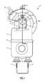
- FIG. 1illustrates a right side view of an example sensor transmitter receiver unit (“STR unit”).
- STR unitsensor transmitter receiver unit
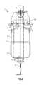
- FIG. 2illustrates a front view of the STR unit of FIG. 1 .
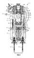
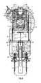
- FIG. 3illustrates a cross-sectional view taken along line A-A of FIG. 2 .
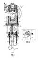
- FIG. 4illustrates a cross-sectional view taken along line A-A of FIG. 2 with an example hotstick.
- FIG. 5illustrates another cross-sectional view taken along line A-A of FIG. 2 with the example hotstick.
- FIG. 5 aillustrates an enlarged view of a keyhole slot.
- FIG. 6illustrates another cross-sectional view taken along line A-A of FIG. 2 engaging a conductor.
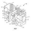
- FIG. 7illustrates an example upper magnetic core subassembly.
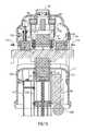
- FIG. 8illustrates an expanded view of an example upper magnetic core and an example lower magnetic core surrounding the conductor and an example power supply transformer.
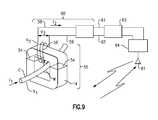
- FIG. 9illustrates a schematic view of the line mounted power supply, electronics and transmitter-receiver of the STR unit.
- FIG. 10illustrates an expanded view of the lower magnetic core, example lead screw assembly, and an example hotstick guide tube.
- FIG. 11illustrates the collapsed view of the lower magnetic core, the lead screw assembly, and the hotstick guide tube.
- FIG. 12illustrates a cross-sectional view taken along line B-B of FIG. 2 .
- FIG. 13illustrates a cross-sectional view taken along line C-C of FIG. 1 .
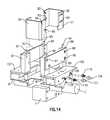
- FIG. 14illustrates an exploded view of example support blocks mounting the upper magnetic core subassembly and example upper and lower jaws.
- FIG. 15illustrates an exploded view of an upper magnetic core mount and the upper and lower jaws.
- FIG. 16illustrates a cross-sectional view taken along line N-N of FIG. 2 .
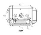
- FIG. 17illustrates a bottom cut away view of the STR unit showing an ambient temperature sensor.
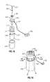
- FIG. 18illustrates an exploded view of the ambient temperature sensor of FIG. 16 .
- FIG. 19illustrates a collapsed view of the ambient temperature sensor of FIG. 18 .
- FIGS. 1 and 2illustrate an example sensor transmitter receiver unit (“STR unit”) 1 installed on a power line conductor C for measuring and monitoring various parameters of the power line conductor C and its environment.
- the STR unit 1is formed from a one piece upper housing 2 and a one piece lower housing 3 .
- the lower housing 3is accepted into a bead 4 formed on a distal end of the upper housing 2 .
- the bead 4which is an integral part of the upper housing 2 is formed by machining a portion of the upper housing 2 to form a groove on the inside of the bead 4 .
- the lower housing 3is secured to the bead 4 and the upper housing 2 by a collar 5 .
- the collar 5attaches to a hotstick guide tube 13 ( FIG. 3 ) that is secured to the upper housing 2 and extends through the lower housing 3 .
- the upper housing 2 and the lower housing 3are made of aluminum or other suitable electrically conductive material.
- the material chosenshould accommodate subassembly installation without the use of external surface fasteners which could generate corona discharges due to high voltage being applied to the upper housing 2 and the lower housing 3 .
- the upper housing 2has the advantage of reducing the number of mating surfaces and eliminating mismatches between multiple cast parts which can generate corona discharges and audible noise due to slightly offset sharp edges of the mating surfaces of the adjacent castings.
- a lower jaw 7is moved to its fully lowered position spaced from upper jaws 6 . This allows the conductor C to pass from position “A” of FIG. 3 through a throat T on the left side of the upper housing 2 and onto the upper jaws 6 in position “B” as shown in FIG. 5 .
- a specially designed hotstick 10is inserted into the bottom of the STR unit 1 and inside the hotstick guide tube 13 .
- the hotstick 10is made of an electrically insulated material such as fiberglass.
- the hotstick 10includes a hotstick driver assembly 9 ( FIG. 4 ) attached to the hotstick 10 with a pin 36 .
- the hotstick 10provides the required electrical insulation between the hands of the linemen and the energized conductor C.
- a flexible stirrup assembly 11( FIG. 4 ) contains a flexible braided conductor 12 which bends out of the way to allow the hotstick driver assembly 9 to enter a hole in the collar 5 .
- the collar 5secures the lower housing 3 to the bead 4 on the upper housing 2 .
- the collar 5is fastened to the hotstick guide tube 13 using the set screw 5 a which is screwed into the collar 5 and into a hole in the hotstick guide tube 13 .
- the STR unit 1can be lifted by the lineman with the hotstick 10 onto the conductor C while maintaining the STR unit 1 securely attached to the hotstick 10 .
- the upper housing 2includes two jaw inserts 8 , shown in FIGS. 5 and 14 , located adjacent the throat T and the upper jaws 6 .
- the two jaw inserts 8include inclined surfaces 8 a and the upper jaws 6 include inclined surfaces 6 a .
- the angle of incline of the inclined surfaces 8 amatches the angle of the incline of an inclined surface 2 a on the upper housing 2 .
- the angle of the inclined surfaces 6 ais steeper than the angle of the inclined surfaces 8 a and the inclined surface 2 a to aid in installing the STR Unit 1 on the conductor C.
- the STR unit 1will bounce slightly upward and land in a circular notch 6 b of the upper jaws 6 (See FIG. 4 ). This allows a conductor temperature sensor to be mounted vertically and in the middle inside the upper jaws 6 and initially extends slightly below the circular notch 6 b for the upper portion of the conductor C.
- the two different inclined surfaces 6 a and 8 a of the jaw inserts 8 and upper jaws 6prevent the conductor temperature sensor S, shown in FIGS. 3 and 4 , from becoming damaged since the conductor C firmly lands vertically in the circular notch 6 b of the upper jaws 6 and pushes the conductor temperature sensor S up to the inside surface of the circular notch 6 b.
- the lower jaw 7is located in a pocket P between two legs of a lower magnetic core 14 .
- the lower jaw 7is held in place with two spring pins 132 and 133 ( FIG. 15 ) located in the lower jaw 7 that snap into two holes 15 in a lower jaw holder 16 ( FIGS. 10 and 11 ) which is attached to a bottom block 19 using two screws 20 ( FIG. 3 ).
- the bottom block 19is located adjacent the base of the upper housing 2 .
- Two identical electrically conductive lower core covers 17partially surround the two legs of the lower magnetic core 14 .
- the lower core covers 17are attached to the bottom block 19 on each side of the lower jaw holder 16 using screws 18 of FIG. 3 on the front right side and one set of the screws 18 on the back left side (not shown).
- the front and back lower jaw holders 16are both held in place by the four screws 20 , two in the front and two in the back.
- the two legs of the lower magnetic core 14are totally encased by the two lower core covers 17 and the front and back lower jaw holders 16 . Therefore, the lower magnetic core 14 is not exposed to any moisture, such as from rain, snow, and ice that could enter through the throat T of the upper housing 2 ( FIG. 3 ).
- the bottom block 19contains a conical hole 21 in the center which provides a very low friction bearing surface for the semi-circular top of a lead screw 22 ( FIG. 3 ).
- the lead screw 22is held in the conical hole 21 with a retainer plate 23 which has a hole in the middle the size of the lead screw 22 diameter and is fastened to the bottom block 19 .
- the lead screw 22is threaded into the center of a threaded bushing 25 .
- the threaded bushing 25has a reduced diameter cylindrical lower portion which fits inside the hotstick guide tube 13 and a larger diameter cylindrical top portion of the threaded bushing 25 is supported on the upper end of the hotstick guide tube 13 .
- Both the threaded bushing 25 and the hotstick guide tube 13are attached to a hotstick guide support 26 using two large through bolts 27 and nuts which are placed through the holes in a bottom support 28 .
- the upper jaws 6include two spaced apart jaws and the lower jaw 7 includes a single jaw aligned between the two spaced apart upper jaws 6 .
- the conductor Cis bent slightly upward as the lower jaw 7 extends upward between the upper jaws 6 creating a bending moment in the conductor C.
- the bending moment in the conductor Cprevents the STR unit 1 from sliding down the conductor C, especially when the STR unit 1 is mounted at the point of attachment adjacent a utility pole or tower where the slope of the conductor C is at its maximum value. Preventing the upper jaws 6 and the lower jaw 7 from sliding down the conductor C at the point of attachment is necessary when the STR unit is being used to measure sag of the power line conductor.
- the bottom support 28includes an upside down “U” shaped cross member and is fastened at each end to the upper housing with two large threaded screws 29 on each side.
- the threaded bushing 25has two small vertical holes 25 a drilled through the threaded bushing 25 on each side of the threaded hole in the middle for the lead screw 22 .
- the vertical holes 25 aare countersunk on the top and provide drainage paths for fluid, such as rain water, that can accumulate underneath the bottom block 19 and on top of the bottom support 28 ( FIG. 5 a ). The water then drains through the two vertical holes 25 a in the threaded bushing 25 and drops on the inside of the hotstick guide tube 13 and out the bottom of the STR unit 1 . Therefore, water will not leak into the lower housing 3 .
- the lead screw 22has a small diameter hotstick guide 30 which is threaded on the inside and is screwed on the bottom of the lead screw 22 .
- a pin 31keeps the hotstick guide 30 from turning on the lead screw 22 .
- the hotstick guide 30prevents the inside of a hotstick lead screw driver 33 from coming into contact with the threads on the lead screw 22 and damaging the internal bore of the lead screw driver 33 . It also guides the lead screw driver 33 onto the lead screw 22 . When the pin 31 engages the lead screw driver 33 the STR unit 1 is ready for installation on the conductor C.
- the hotstick driver assembly 9includes the lead screw driver 33 , a hotstick driver coupling 32 , a rivet 34 , a hotstick sleeve 35 , the pin 36 , and the hotstick 10 .
- the hotstick 10 of FIG. 4rests on the rounded portion of the hotstick driver coupling 32 and the rounded inside bottom of the hotstick guide tube 13 . This prevents the lead screw driver 33 from applying pressure to the threaded bushing 25 upon installation of the STR unit 1 on the conductor C.
- the lead screw driver 33 and the hotstick driver coupling 32are each fastened to the hotstick sleeve 35 by the rivet 34 and the hotstick sleeve 35 is attached to the hotstick 10 with the pin 36 .
- a long narrow vertical slot in the lead screw driver 33allows the pin 31 of the lead screw 22 to be engaged with the lead screw driver 33 and is free to slide up or down in the vertical slot 37 as the lead screw is turned to tighten the lower jaw 7 on the conductor C or to loosen the lower jaw 7 from the conductor C to remove the STR unit 1 .
- the hotstick driver assembly 9When the hotstick driver assembly 9 is engaged with the lead screw 22 as shown in FIG. 4 , the STR unit 1 is raised to position “A” relative to the height of the conductor C. The STR unit 1 is then moved toward the conductor C so that the conductor C passes through the throat T of the upper housing 2 and into position “B” as shown in FIG. 5 . Once the STR unit 1 is fully supported by the conductor C in position “B”, the hotstick driver assembly 9 is turned clockwise by the installer with the hotstick 10 and allowed to drop down from its position in FIG. 4 to a lower position as in FIG. 5 . A horizontal keyhole slot 38 of the lead screw driver 33 is now engaged with the pin 31 of the lead screw 22 . With the pin 31 in the horizontal keyhole slot 38 , the hotstick driver assembly 9 and the hotstick 10 are secured to the STR unit 1 .
- an opening and closing mechanism 39 of FIG. 6extends the lower jaw 7 upward to secure the STR unit 1 on the conductor C. Additionally, the opening and closing mechanism 39 can also retract the lower jaw 7 to remove the STR unit 1 from the conductor C.
- the opening and closing mechanism 39includes the lower magnetic core 14 , the lower core covers 17 , the lower jaw holders 16 , the lower jaw 7 , spring pins 132 and 133 , the bottom block 19 , the retainer plate 23 , two fasteners 24 , the lead screw 22 , the hotstick guide 30 , and the pin 31 .
- FIG. 6illustrates the keyhole slot 38 on the lead screw driver 33 engaged with the pin 31 on the lead screw 22 .
- the opening and closing mechanism 39moves the lower magnetic core 14 toward an upper magnetic core 40 .
- the upper magnetic core 40has two large compression springs 41 to bias the upper magnetic core 40 downward.
- the compression springs 44provide pressure to hold both the upper magnetic core 40 and the lower magnetic core 14 together to reduce the magnetic reluctance caused by air gaps 54 ( FIG. 8 ) between the upper magnetic core 40 and the lower magnetic core 14 .
- the hotstick driver assembly 9can continue to be turned clockwise even after the lower magnetic core 14 begins to mate with the upper magnetic core 40 because the compression springs 41 compress at the top of the upper magnetic core 40 .
- the clockwise motion of the hotstick driver assembly 9can be achieved either manually or with a battery powered drill or another rotating device, until the lower jaw 7 is tightened onto the conductor C.
- the hotstick 10is turned slightly to the left, or counterclockwise, and the pin 31 will become disengaged from the horizontal portion of the keyhole slot 38 .
- the hotstick 10is then free to be removed when the pin 31 aligns with the vertical slot 37 .
- FIGS. 7 and 8illustrate the bottom of the compression springs 41 are held in alignment in two cylindrical pockets 42 of two identical horizontal upper core blocks 43 which are each used to clamp the upper magnetic core 40 to two identical magnetic horizontal lower core blocks 44 .
- the top of the compression springs 41are held in place with two projections 49 extending downward on the inside of the upper housing 2 .
- the compression springs 41are totally enclosed by the upper housing 2 and are protected from the adverse weather which can cause corrosion.
- the air gaps 54 between the upper and lower magnetic cores 40 and 14are totally enclosed by the upper housing 2 which prevents the air gaps 54 from becoming corroded due to moisture from the environment.
- the horizontal upper core blocks 43 and the horizontal lower core blocks 44are clamped around the upper magnetic core 40 on each side using two through bolts 45 and two nuts 46 in the front and two through bolts 45 and two nuts 46 located in the back of the upper horizontal core blocks 43 and horizontal lower core blocks 44 .
- the upper magnetic core 40is prevented from falling out of a left core shoe 50 and a right core shoe 51 , by a step 52 located at the bottom of the right core shoe 51 and a step 53 located at the bottom of the left core shoe 50 .
- the lead screw 22can be turned further clockwise to move the two upper core blocks 43 away from the steps 52 and 53 and further compress the compression springs 41 .
- the lead screw 22can continue to be turned clockwise and compress the compression springs 41 until the lower jaw 7 and the upper jaws 6 are tight on the conductor C.
- Electrical insulating spools 47are inserted over each of the through bolts 45 and electrical insulating washers 48 are inserted under the head of each through bolt 45 and under each nut 46 .
- the insulating spools 47 and the insulating washers 48 on each of the through bolts 45prevent shorted electrically conductive paths around the upper magnetic core 40 which is comprised of the four through bolts 45 , four nuts 46 , the two electrically conductive upper core blocks 43 and the two lower core blocks 44 .
- the compression springs 41are compressed to their maximum distance, and thus the maximum compressive force is also applied to the lower magnetic core 14 and the upper magnetic core 40 .
- varying amounts torquecan be applied to the hotstick driver assembly 9 to tighten the opening and closing mechanism 39 on the conductor C.
- the physical size and shape of the upper jaws 6 and the lower jaw 7are designed such that approximately the same compressive force is applied to the upper magnetic core 40 and the lower magnetic core 14 .
- the opening and closing mechanism 39allows the STR unit 1 to be installed on a wide range of conductor diameters without changing the upper jaws 6 and the lower jaws 7 while maintaining sufficient contact between the upper magnetic core 40 and the lower magnetic core 14 to complete the magnetic circuit of the power supply transformer 55 of the STR unit 1 which derives its power from the current flowing through the conductor C to power a power supply module 60 of FIG. 9 .
- the STR unit 1derives power from the conductor C, batteries or solar cells are not required to power the STR unit 1 .
- the STR unit 1is powered at all times when current is flowing in the conductor C, even at current levels as low as 6.8 amperes and still process data and transmit data at 1 watt power levels because of the low threshold of the power supply module 60 .
- the power supply transformer 55includes the upper magnetic core 40 , the lower magnetic core 14 , and a coil winding 56 .
- the upper magnetic core and the lower magnetic coreform a window W for accepting the conductor C.
- the number of secondary turns N 2 of wire on the coil winding 56are optimized to produce the required secondary voltage V 2 and secondary current I 2 with a minimum of current I 1 in the conductor C.
- the coil winding 56is held in place by two coil bobbins 57 which are supported laterally by the two upper core blocks 43 and the two lower core blocks 44 .
- Secondary leads 58 a and 59 a of coil windings 58 and 59are connected to the power supply module 60 which maintains the same level of secondary voltage across leads 61 and 62 for the sensor electronics module 63 and the transmitter/receiver 64 even though the primary current may range from 34 amperes up to 1000 amperes.
- the power supply module 60contains an energy storage device 256 ( FIG. 13 ) which can power the transmitter/receiver 64 when the conductor C current ceases to flow.
- a transmitting and receiving antenna 81 for the on-board transmitter/receiver 64is mounted on the upper housing 2 ( FIG. 12 ).
- Locating the coil winding 56 , 58 , and 59 on the upper magnetic core 40allows the heat from the coil winding 56 , 58 , and 59 to escape through a vent 65 ( FIG. 1 ) in the upper housing 2 .
- a vent 65FIG. 1
- the conductor sensor S located within the STR unit 1measures the temperature of the conductor C, it is important that the heat from the coil windings 56 , 58 , and 59 does not affect the temperature of the conductor C or the conductor temperature sensor S, which is in electrical communication with the sensor electronics module 63 . As shown in FIG.
- a thermally insulating barrier 66located below the coil windings 56 , 58 , and 59 , allows for a more accurate temperature reading of the conductor temperature by blocking heat from the coil windings 56 , 58 , and 59 .
- FIGS. 10-12 and 13illustrate the lower magnetic core 14 with the lower core covers 17 , the lead screw 22 , the hotstick guide tube 13 , and other related parts in both exploded and collapsed views.
- the hotstick guide tube 13is anchored at the top with the through bolts 27 that extend through the bottom support 28 and the hotstick guide support 26 .
- a round cylindrical milled slot 67is located along opposing sides of the top of the hotstick guide tube 13 to accept the through bolts 27 that support the hotstick guide tube 13 .
- a central hole 70extends through a base plate support 68 and a base plate 69 for accepting a bottom portion of the hotstick guide tube 13 .
- the base plate support 68 and the base plate 69are connected to each other with four identical threaded screws 71 .
- the hotstick guide tube 13is attached to the base plate support 68 and the base plate 69 with set screws 72 and 73 .
- Left and right side panels 76 of FIG. 12are attached to the base plate support 68 and the bottom support 28 for the lower core 14 with the use of two identical screws 74 extending through the bottom support 28 and the side panel 76 and at the bottom with two identical screws 75 extending through the side panel 76 and the base plate support 68 .
- the threaded bushing 25rests on top of the hotstick guide tube 13 and is prevented from turning relative to the hotstick guide tube 13 using a set screw 77 .
- the left and right side panels 76not only provide added strength, but also provide the physical space to mount the power supply module 60 , the transmitter/receiver 64 , the sensor electronics 63 , and support left and right lower core guides 78 and 79 .
- the left lower core guide 78 and a right lower core guide 79are “U” shaped and guide the opening and closing mechanism 39 such that the lower magnetic core 14 is aligned with the upper magnetic core 40 .
- Each of the left and right lower core guides 78 and 79are attached to the left and right side panels 76 with four threaded screws 80 .
- the lower housing 3is placed over the hotstick guide tube 13 at the bottom and fitted up to the base plate 69 and held in place with the collar 5 . This means that once the collar 5 is removed, the lower housing 3 can be removed thus allowing access to the power supply module 60 , sensor electronics module 63 , and the transmitter/receiver 64 of FIG. 9 mounted inside and on the left and right side panels 76 for easy maintenance and repair.
- FIGS. 7 and 12-15illustrate an upper magnetic core subassembly 40 a mounted to the upper housing 2 .
- the left and right core shoes 50 and 51support the upper magnetic core 40 such that the upper magnetic core 40 can move freely up and down inside the left and right shoes 50 and 51 .
- the left and right core shoes 50 and 51are attached to the upper housing 2 using four support blocks 86 and 87 of FIG. 14 , right and left upper core guides 90 and 93 , and four vertical through bolts 94 , 95 , 96 , and 97 .
- the upper magnetic core subassembly 40 acan be inserted through the throat T and fastened to the inside of the upper housing 2 .
- a top portion of the upper housing 2is “C” shaped which provides a surface on the inside for mounting a current sensing device 156 for measuring the power line frequency current (60 Hz or 50 Hz) and a loop coil 157 for measuring lightning stroke current ( FIGS. 13 and 16 ).
- the right core shoe 51has two identical threaded holes 82 and 83 on the front and back for a total of four
- left core shoe 50has two identical threaded holes 84 and 85 on the front and back for a total of four as shown in FIGS. 7 and 14 .
- two identical support blocks 86 on the right sideare placed on the front and back of the right core shoe 51 and two identical support blocks 87 are placed on the front and back of the left core shoe 50 .
- threaded screws 88 and 89are first inserted into the upper and lower holes in the right side upper core guide 90 and then through the two holes in the right support block 86 and screwed into the accommodating threaded holes 82 and 83 of the right core shoe 51 .
- the two left side support blocks 87are held in alignment with the left core shoe 50 by first inserting two threaded screws 91 and 92 through the other end of the right side upper core guide 90 and then through the holes in the left side support block 87 and screwed into the threaded holes 84 and 85 of the left core shoe 50 .
- the same processis repeated on the back side by connecting support blocks 86 and 87 to the left upper core guide 93 with the backside of the right core shoe 51 and the back side of the left core shoe 50 .
- the purpose of the upper core guides 90 and 93is to insure the two long vertical through bolts 94 and 95 placed through the vertical holes in the two right side support blocks 86 and two long vertical through bolts 96 and 97 placed through the vertical holes in the two left side support blocks 87 line up with the four threaded holes in four threaded inserts 98 , 99 , 100 , and 101 , which are embedded in the casting of the upper housing 2 .
- the two right side support blocks 86are prevented from falling down by inserting the back of a right side upper jaw holder 102 and the back of the left side upper jaw holder 103 over the vertical through bolts 94 and 95 and threading nuts 104 and 105 onto the two vertical through bolts 94 and 95 and tightening them down, respectively.
- the two left side support blocks 87are held in place by inserting the vertical through bolts 96 and 97 through the front hole in the right side upper jaw holder 102 and the front hole in the left side upper jaw holder 103 and threading two nuts 106 and 107 on the vertical through bolts 96 and 97 and tightening them down, respectively.
- FIGS. 2 and 15illustrate casting fillers 113 and 114 located on the back left and back right sides of the STR unit 1 and secured with round head screws 115 which are first inserted through holes in the casting fillers 113 and 114 and then through the two back holes on the right and left side of the thermal barrier 66 and into the standoffs 108 and 109 , respectively.
- the left and right lower core guides 78 and 79 including the opening and closing mechanism subassembly 39 and the left and right side panels 76are inserted through the bottom of the upper housing 2 (See FIG. 12 ).
- Four screws 29are inserted through the two holes on the left and the two holes on the right of the bottom support 28 and screwed into the threaded holes of the upper housing 2 .
- the right lower core guide 79shown in FIG. 12 , slides around the outside surface of the right core shoe 51 and underneath a tab 116 at the top as a weldment on the right upper side of the right core shoe 51 .
- the tab 116insures that the right lower core guide 79 fits precisely around the outside of the right core shoe 51 to provide a near perfect alignment of the lower magnetic core 14 with the upper magnetic core 40 .
- the precise alignment between the upper magnetic core 40 and the lower magnetic core 14reduces magnetic reluctance by decreasing the air gaps 54 . This results in a decrease in the threshold current for the operation of the power supply module 60 .
- the right side upper jaw holder 102 and the left side upper jaw holder 103support the two upper jaws 6 and the jaw inserts 8 .
- the long vertical through bolts 96 and 97which are screwed into the threaded inserts 100 and 101 at the top and on the inside of the upper housing 2 fit through top holes 117 and 118 on the back and front of the right side upper jaw holder 102 on the right side.
- flush mount screws 119 and 120are inserted on the back and through corresponding holes in the right side upper jaw holder 102 and are screwed into the upper housing.
- the flush mount screws 119 and 120are installed before the upper jaws 6 and inserts 8 are mounted to the right side upper jaw holder 102 .
- the same arrangement for mounting the left side upper jaw holder 103is followed using screws 121 and 122 .
- Right and left upper jaw keepers 123 and 124prevent the upper jaws 6 from dropping down on the inside, because spring pins 126 and 127 are located on the outside and when depressed snap into the holes 128 and 129 of the right side upper jaw holder 102 .
- the same procedureis followed with the left upper jaw keeper 124 .
- the jaw inserts 8 on the right and left sides of the STR unit 1 and in front of the upper jaws 6are held in place by inserting threaded bolts 130 and 131 into each insert 8 and through the right and left keepers 123 and 124 and screwing into the upper jaw holders 102 and 103 .
- the spring pins 132 and 133are included in the lower jaw 7 which when depressed snap into the two holes 15 in the lower jaw holder 16 .
- the transmitting and receiving antenna 81 for the on-board transmitter and receiver 64 shown in FIG. 9is mounted on the housing 2 .
- the antenna 81is displayed in FIGS. 1 and 2 and is installed on the top left side in FIG. 1 .
- the solar sensor assembly 134is located at the top of this housing and on its vertical centerline ( FIG. 13 ).
- the small hole 140 located directly to the right of the conductor 1allows access and adjustment of the electric power line sag sensor ( FIG. 1 ).
- An ambient temperature sensor assembly 307is mounted inside the STR unit 1 at the bottom right side and on a surface of a left side panel 308 as shown in FIG. 16 .
- the end view of the top of the left side panel 308is shown in FIG. 13 .
- the ambient temperature sensor assembly 307is mounted in the bottom of STR unit 1 to avoid direct sunlight from shining on the ambient temperature sensor assembly 307 and affecting an ambient temperature measurement. As shown in FIG. 16 , the bottom edge of the ambient temperature sensor assembly 307 is flush with the outside surface at the bottom of the housing 3 .
- FIG. 18illustrates an exploded view of the ambient temperature sensor assembly 307 .
- An ambient temperature sensing element 309includes leads 310 and 311 and has a measurement range of ⁇ 30° C. ( ⁇ 22° F.) to 60° C. (140° F.) and an absolute error of ⁇ 0.5 degrees Celsius.
- the output signalafter having been signal processed in the sensor electronics module 63 of FIGS. 9 and 13 , produces a maximum of 4.0 volts dc at 60° C. and 0 volts dc at ⁇ 30° C.
- the sensor electronics module 63is powered by the power supply electronics module 60 of FIG. 9 .
- the ambient temperature sensing element 309is inserted inside and at the bottom of an electrically conducting and electromagnetically shielding protection tube 312 .
- the protection tube 312shields the ambient temperature sensing element 309 from the high electromagnetic fields which result from the current flowing in the conductor C.
- the ambient temperature sensing element 309is mounted at the bottom and inside the protection tube 312 with a thermally conductive material such as epoxy or another suitable material.
- the leads 310 and 311are twisted (as shown in FIG. 18 ) and electrostatically shielded and are directly routed to the sensor electronics module 63 of FIGS. 16 and 17 .
- the protection tube 312 and ambient temperature sensing element 309 including the leads 310 and 311are pushed down through a hole 313 in a thermally insulating washer 314 .
- the thermally insulating washer 314has a reduced diameter at the bottom which fits inside and at the top of a tubular shaped chimney 315 .
- the tubular shaped chimney 315includes two slots 316 and 317 milled on each side and at the top which allows outside ambient air from the bottom of the STR unit 1 to flow upward and out of the slots 316 and 317 .
- the protection tube 312is in a direct path of the ambient air flow and is thermally insulated from the tubular shaped chimney 315 with the thermally insulating washer 314 .
- the tubular shaped chimney 315In order to thermally insulate the tubular shaped chimney 315 from the housing 3 , the tubular shaped chimney 315 is pushed down inside a thermally insulating sleeve 318 until the bottom of the slots 316 and 317 are flush with the top of the thermally insulating sleeve 318 . Because the housing 3 could be in direct sunlight, the housing 3 may be at a higher temperature than the outside ambient air or the housing 3 could be covered in ice and be at a lower temperature than the outside ambient air. Therefore, the thermally insulating sleeve 318 insulates the housing 3 from the tubular shaped chimney 315 and the washer 314 insulates the protection tube 312 from the tubular shaped chimney 315 .
- the protection tube 312extends downward near the bottom of the tubular shaped chimney 315 and the thermally insulating sleeve 318 of FIG. 16 and must be grounded to the same voltage as the conductor C. Therefore, a ring connector 319 is inserted over the protection tube 312 at the top and is bonded underneath a flare 320 at the top of the protection tube 312 .
- the ring connector 319is compressed onto a ground lead wire 321 and at the other end of the ground lead wire 321 another ring connector 322 is compressed.
- the ring connector 322is then connected to case ground 162 as shown in FIG. 16 .
- the STR unit 1determines a current carrying capacity of the conductor C by signal conditioning measured values of ambient temperature with the sensor electronics module 63 .
- the signal conditioned measured valuesare sent to a remote location with the transmitter-receiver unit 64 of FIG. 9 via the antenna 81 on a real time basis.
- the measured values of ambient temperatureare used to determine a current carrying capacity of the conductor C.
- An amount of current traveling through the conductor Cis determined to prevent ice from forming on the conductor C.
- the STR unit 1also forecasts an electric load on the conductor C of the electric power system based on the changes in ambient temperature.
Landscapes
- Physics & Mathematics (AREA)
- General Physics & Mathematics (AREA)
- Engineering & Computer Science (AREA)
- Power Engineering (AREA)
- Life Sciences & Earth Sciences (AREA)
- Signal Processing (AREA)
- Multimedia (AREA)
- Chemical & Material Sciences (AREA)
- Environmental & Geological Engineering (AREA)
- Geometry (AREA)
- General Health & Medical Sciences (AREA)
- Atmospheric Sciences (AREA)
- Immunology (AREA)
- Biochemistry (AREA)
- Analytical Chemistry (AREA)
- Health & Medical Sciences (AREA)
- Electrochemistry (AREA)
- Hydrology & Water Resources (AREA)
- Chemical Kinetics & Catalysis (AREA)
- Pathology (AREA)
- Biodiversity & Conservation Biology (AREA)
- Ecology (AREA)
- Environmental Sciences (AREA)
- Measuring Instrument Details And Bridges, And Automatic Balancing Devices (AREA)
- Measurement Of Current Or Voltage (AREA)
- Driving Mechanisms And Operating Circuits Of Arc-Extinguishing High-Tension Switches (AREA)
- Locating Faults (AREA)
- Cleaning In General (AREA)
- Transformers For Measuring Instruments (AREA)
- Measurement Of Length, Angles, Or The Like Using Electric Or Magnetic Means (AREA)
- Charge And Discharge Circuits For Batteries Or The Like (AREA)
- Electric Cable Installation (AREA)
- Resistance Heating (AREA)
- Rotary Switch, Piano Key Switch, And Lever Switch (AREA)
- Cable Transmission Systems, Equalization Of Radio And Reduction Of Echo (AREA)
- Tumbler Switches (AREA)
Abstract
Description
The application claims priority to U.S. Provisional Application No. 61/740,517 which was filed on Dec. 21, 2012.
The present disclosure relates to a multiple parameter sensor-transmitter/receiver unit which may be installed on or removed from an energized electric power line, such as an overhead power line. With the advent of Smart-Grid applications for electric power systems, there is an ever increasing need for a device that measures electric, mechanical, and environmental parameters of the power line.
In order to address the increasing need for monitoring power lines, devices have been developed that attach directly to the power line. These devices generally require a power source, such as batteries or solar panels. When utilizing batteries, regular maintenance must be performed to replace the batteries, which can become costly. When solar panels are used, the device may only be powered during sunny weather conditions and during daylight hours. Therefore, there is a need for a device which is low maintenance and can be constantly powered independent of weather conditions.
One example device for measuring environmental parameters is a land based weather station. One of the significant problems of land based weather stations, even if located in close proximity at the terminal ends of the electric power line, is the measured weather data at these two locations can never be representative of the differing weather conditions the line actually experiences throughout its entire length. This is especially true for long lines traversing over various types of terrain where the land based weather station may be shielded by trees and other natural obstacles such as hills and rocky formations. Additionally, the weather itself such as the amount of sunshine, fog, rain, snow and icing conditions the line is exposed to can dramatically vary from one point to another along these lines.
A device for attaching to an electric power line conductor includes an electrically conductive housing with an opening for accepting the power line conductor and configured to be grounded to the power line conductor. At least one magnetic core is configured to surround the power line conductor and power a power supply electronics module. An ambient temperature measuring assembly is mounted inside and near the bottom of the electrically conductive housing. The ambient temperature measuring assembly is thermally insulated from the housing for thermally separating the ambient temperature measuring assembly from the housing.
A method of determining a current carrying capacity of a power line conductor includes signal conditioning measured values of ambient temperature. The signal conditioned measured values are sent to a remote location with a transmitter-receiver unit located within a housing. A sensor electronics module and the transmitter-receiver unit are powered from current flowing in the power line conductor. The measured values processed to determine a current carrying capacity of the power line conductor.
These and other features of the disclosed examples can be understood from the following description and the accompanying drawings, which can be briefly described as follows.
In one example, theupper housing 2 and thelower housing 3 are made of aluminum or other suitable electrically conductive material. The material chosen should accommodate subassembly installation without the use of external surface fasteners which could generate corona discharges due to high voltage being applied to theupper housing 2 and thelower housing 3. Theupper housing 2 has the advantage of reducing the number of mating surfaces and eliminating mismatches between multiple cast parts which can generate corona discharges and audible noise due to slightly offset sharp edges of the mating surfaces of the adjacent castings.
Referring toFIGS. 3 and 4 , before theSTR unit 1 is clamped onto the conductor C, alower jaw 7 is moved to its fully lowered position spaced fromupper jaws 6. This allows the conductor C to pass from position “A” ofFIG. 3 through a throat T on the left side of theupper housing 2 and onto theupper jaws 6 in position “B” as shown inFIG. 5 .
With thelower jaw 7 of theSTR unit 1 in its fully lowered position, a specially designedhotstick 10 is inserted into the bottom of theSTR unit 1 and inside thehotstick guide tube 13. In this example, thehotstick 10 is made of an electrically insulated material such as fiberglass. Thehotstick 10 includes a hotstick driver assembly9 (FIG. 4 ) attached to thehotstick 10 with apin 36. Thehotstick 10 provides the required electrical insulation between the hands of the linemen and the energized conductor C. A flexible stirrup assembly11 (FIG. 4 ) contains a flexiblebraided conductor 12 which bends out of the way to allow thehotstick driver assembly 9 to enter a hole in thecollar 5. As mentioned earlier, thecollar 5 secures thelower housing 3 to thebead 4 on theupper housing 2. Thecollar 5 is fastened to thehotstick guide tube 13 using theset screw 5awhich is screwed into thecollar 5 and into a hole in thehotstick guide tube 13.
With thehotstick 10 and thehotstick driver assembly 9 fully engaged inside thehotstick guide tube 13, theSTR unit 1 can be lifted by the lineman with thehotstick 10 onto the conductor C while maintaining theSTR unit 1 securely attached to thehotstick 10.
Theupper housing 2 includes twojaw inserts 8, shown inFIGS. 5 and 14 , located adjacent the throat T and theupper jaws 6. The twojaw inserts 8 includeinclined surfaces 8aand theupper jaws 6 includeinclined surfaces 6a. The angle of incline of theinclined surfaces 8amatches the angle of the incline of aninclined surface 2aon theupper housing 2.
The angle of theinclined surfaces 6ais steeper than the angle of theinclined surfaces 8aand theinclined surface 2ato aid in installing theSTR Unit 1 on the conductor C. As the conductor C slides across theinclined surfaces inclined surface 6a, theSTR unit 1 will bounce slightly upward and land in acircular notch 6bof the upper jaws6 (SeeFIG. 4 ). This allows a conductor temperature sensor to be mounted vertically and in the middle inside theupper jaws 6 and initially extends slightly below thecircular notch 6bfor the upper portion of the conductor C. The two differentinclined surfaces upper jaws 6 prevent the conductor temperature sensor S, shown inFIGS. 3 and 4 , from becoming damaged since the conductor C firmly lands vertically in thecircular notch 6bof theupper jaws 6 and pushes the conductor temperature sensor S up to the inside surface of thecircular notch 6b.
InFIG. 3 , thelower jaw 7 is located in a pocket P between two legs of a lowermagnetic core 14. Thelower jaw 7 is held in place with twospring pins 132 and133 (FIG. 15 ) located in thelower jaw 7 that snap into twoholes 15 in a lower jaw holder16 (FIGS. 10 and 11 ) which is attached to abottom block 19 using two screws20 (FIG. 3 ). Thebottom block 19 is located adjacent the base of theupper housing 2.
Two identical electrically conductive lower core covers17 partially surround the two legs of the lowermagnetic core 14. The lower core covers17 are attached to thebottom block 19 on each side of thelower jaw holder 16 usingscrews 18 ofFIG. 3 on the front right side and one set of thescrews 18 on the back left side (not shown). The front and backlower jaw holders 16 are both held in place by the fourscrews 20, two in the front and two in the back. The two legs of the lowermagnetic core 14 are totally encased by the two lower core covers17 and the front and backlower jaw holders 16. Therefore, the lowermagnetic core 14 is not exposed to any moisture, such as from rain, snow, and ice that could enter through the throat T of the upper housing2 (FIG. 3 ).
Thebottom block 19 contains a conical hole21 in the center which provides a very low friction bearing surface for the semi-circular top of a lead screw22 (FIG. 3 ). Thelead screw 22 is held in the conical hole21 with aretainer plate 23 which has a hole in the middle the size of thelead screw 22 diameter and is fastened to thebottom block 19. Thelead screw 22 is threaded into the center of a threadedbushing 25. The threadedbushing 25 has a reduced diameter cylindrical lower portion which fits inside thehotstick guide tube 13 and a larger diameter cylindrical top portion of the threadedbushing 25 is supported on the upper end of thehotstick guide tube 13. Both the threadedbushing 25 and thehotstick guide tube 13 are attached to ahotstick guide support 26 using two large throughbolts 27 and nuts which are placed through the holes in abottom support 28.
Referring toFIG. 2 , theupper jaws 6 include two spaced apart jaws and thelower jaw 7 includes a single jaw aligned between the two spaced apartupper jaws 6. Whenlower jaw 7 is clamped onto the conductor C, the conductor C is bent slightly upward as thelower jaw 7 extends upward between theupper jaws 6 creating a bending moment in the conductor C. The bending moment in the conductor C prevents theSTR unit 1 from sliding down the conductor C, especially when theSTR unit 1 is mounted at the point of attachment adjacent a utility pole or tower where the slope of the conductor C is at its maximum value. Preventing theupper jaws 6 and thelower jaw 7 from sliding down the conductor C at the point of attachment is necessary when the STR unit is being used to measure sag of the power line conductor.
Referring toFIGS. 5 and 5 a, thebottom support 28 includes an upside down “U” shaped cross member and is fastened at each end to the upper housing with two large threadedscrews 29 on each side. The threadedbushing 25 has two smallvertical holes 25adrilled through the threadedbushing 25 on each side of the threaded hole in the middle for thelead screw 22. Thevertical holes 25aare countersunk on the top and provide drainage paths for fluid, such as rain water, that can accumulate underneath thebottom block 19 and on top of the bottom support28 (FIG. 5a ). The water then drains through the twovertical holes 25ain the threadedbushing 25 and drops on the inside of thehotstick guide tube 13 and out the bottom of theSTR unit 1. Therefore, water will not leak into thelower housing 3.
Referring toFIG. 6 , thelead screw 22 has a small diameter hotstick guide30 which is threaded on the inside and is screwed on the bottom of thelead screw 22. Apin 31 keeps thehotstick guide 30 from turning on thelead screw 22. Thehotstick guide 30 prevents the inside of a hotsticklead screw driver 33 from coming into contact with the threads on thelead screw 22 and damaging the internal bore of thelead screw driver 33. It also guides thelead screw driver 33 onto thelead screw 22. When thepin 31 engages thelead screw driver 33 theSTR unit 1 is ready for installation on the conductor C.
Thehotstick driver assembly 9 includes thelead screw driver 33, ahotstick driver coupling 32, arivet 34, ahotstick sleeve 35, thepin 36, and thehotstick 10. Thehotstick 10 ofFIG. 4 rests on the rounded portion of thehotstick driver coupling 32 and the rounded inside bottom of thehotstick guide tube 13. This prevents thelead screw driver 33 from applying pressure to the threadedbushing 25 upon installation of theSTR unit 1 on the conductor C. Thelead screw driver 33 and thehotstick driver coupling 32 are each fastened to thehotstick sleeve 35 by therivet 34 and thehotstick sleeve 35 is attached to thehotstick 10 with thepin 36. A long narrow vertical slot in thelead screw driver 33 allows thepin 31 of thelead screw 22 to be engaged with thelead screw driver 33 and is free to slide up or down in thevertical slot 37 as the lead screw is turned to tighten thelower jaw 7 on the conductor C or to loosen thelower jaw 7 from the conductor C to remove theSTR unit 1.
When thehotstick driver assembly 9 is engaged with thelead screw 22 as shown inFIG. 4 , theSTR unit 1 is raised to position “A” relative to the height of the conductor C. TheSTR unit 1 is then moved toward the conductor C so that the conductor C passes through the throat T of theupper housing 2 and into position “B” as shown inFIG. 5 . Once theSTR unit 1 is fully supported by the conductor C in position “B”, thehotstick driver assembly 9 is turned clockwise by the installer with thehotstick 10 and allowed to drop down from its position inFIG. 4 to a lower position as inFIG. 5 . Ahorizontal keyhole slot 38 of thelead screw driver 33 is now engaged with thepin 31 of thelead screw 22. With thepin 31 in thehorizontal keyhole slot 38, thehotstick driver assembly 9 and thehotstick 10 are secured to theSTR unit 1.
In this example, an opening andclosing mechanism 39 ofFIG. 6 extends thelower jaw 7 upward to secure theSTR unit 1 on the conductor C. Additionally, the opening andclosing mechanism 39 can also retract thelower jaw 7 to remove theSTR unit 1 from the conductor C. The opening andclosing mechanism 39 includes the lowermagnetic core 14, the lower core covers17, thelower jaw holders 16, thelower jaw 7, spring pins132 and133, thebottom block 19, theretainer plate 23, twofasteners 24, thelead screw 22, thehotstick guide 30, and thepin 31.
Thehotstick driver assembly 9 can continue to be turned clockwise even after the lowermagnetic core 14 begins to mate with the uppermagnetic core 40 because the compression springs41 compress at the top of the uppermagnetic core 40. The clockwise motion of thehotstick driver assembly 9 can be achieved either manually or with a battery powered drill or another rotating device, until thelower jaw 7 is tightened onto the conductor C. After theSTR unit 1 is mounted on the conductor C, thehotstick 10 is turned slightly to the left, or counterclockwise, and thepin 31 will become disengaged from the horizontal portion of thekeyhole slot 38. Thehotstick 10 is then free to be removed when thepin 31 aligns with thevertical slot 37.
When the two large compression springs41 push the upper core blocks43 down, the uppermagnetic core 40 is prevented from falling out of aleft core shoe 50 and aright core shoe 51, by astep 52 located at the bottom of theright core shoe 51 and astep 53 located at the bottom of theleft core shoe 50.
When the lowermagnetic core 14 mates with the uppermagnetic core 40, thelead screw 22 can be turned further clockwise to move the two upper core blocks43 away from thesteps lead screw 22 can continue to be turned clockwise and compress the compression springs41 until thelower jaw 7 and theupper jaws 6 are tight on the conductor C.
Electrical insulating spools47 are inserted over each of the throughbolts 45 and electrical insulatingwashers 48 are inserted under the head of each throughbolt 45 and under eachnut 46. The insulating spools47 and the insulatingwashers 48 on each of the throughbolts 45 prevent shorted electrically conductive paths around the uppermagnetic core 40 which is comprised of the four throughbolts 45, fournuts 46, the two electrically conductive upper core blocks43 and the two lower core blocks44.
When theupper jaws 6 and thelower jaw 7 are firmly tightened on the conductor C, the compression springs41 are compressed to their maximum distance, and thus the maximum compressive force is also applied to the lowermagnetic core 14 and the uppermagnetic core 40. This decreases the size of theair gaps 54 between the lowermagnetic core 14 and the uppermagnetic core 40 and the magnetic reluctance between the lowermagnetic core 14 and the uppermagnetic core 40. Depending on the size of the conductor C, varying amounts torque can be applied to thehotstick driver assembly 9 to tighten the opening andclosing mechanism 39 on the conductor C.
The physical size and shape of theupper jaws 6 and thelower jaw 7 are designed such that approximately the same compressive force is applied to the uppermagnetic core 40 and the lowermagnetic core 14. In one example, there are five different sets of upper andlower jaws closing mechanism 39 allows theSTR unit 1 to be installed on a wide range of conductor diameters without changing theupper jaws 6 and thelower jaws 7 while maintaining sufficient contact between the uppermagnetic core 40 and the lowermagnetic core 14 to complete the magnetic circuit of thepower supply transformer 55 of theSTR unit 1 which derives its power from the current flowing through the conductor C to power apower supply module 60 ofFIG. 9 . Because theSTR unit 1 derives power from the conductor C, batteries or solar cells are not required to power theSTR unit 1. TheSTR unit 1 is powered at all times when current is flowing in the conductor C, even at current levels as low as 6.8 amperes and still process data and transmit data at 1 watt power levels because of the low threshold of thepower supply module 60.
Maintaining a minimum magnetic reluctance insures that a power supply transformer55 (FIGS. 8 and 9 ) will provide the needed secondary voltage V2and secondary current I2to operate thepower supply transformer 55,sensor electronics module 63, and transmitter/receiver 64. Thepower supply transformer 55 includes the uppermagnetic core 40, the lowermagnetic core 14, and a coil winding56. The upper magnetic core and the lower magnetic core form a window W for accepting the conductor C.
The number of secondary turns N2of wire on the coil winding56 are optimized to produce the required secondary voltage V2and secondary current I2with a minimum of current I1in the conductor C. The coil winding56 is held in place by twocoil bobbins 57 which are supported laterally by the two upper core blocks43 and the two lower core blocks44. Secondary leads58aand59aofcoil windings power supply module 60 which maintains the same level of secondary voltage across leads61 and62 for thesensor electronics module 63 and the transmitter/receiver 64 even though the primary current may range from 34 amperes up to 1000 amperes. Lower primary currents of 6.8 amperes are achievable with the low threshold currentpower supply module 60. Thepower supply module 60 contains an energy storage device256 (FIG. 13 ) which can power the transmitter/receiver 64 when the conductor C current ceases to flow. A transmitting and receivingantenna 81 for the on-board transmitter/receiver 64 is mounted on the upper housing2 (FIG. 12 ).
Locating the coil winding56,58, and59 on the uppermagnetic core 40 allows the heat from the coil winding56,58, and59 to escape through a vent65 (FIG. 1 ) in theupper housing 2. When the conductor sensor S located within theSTR unit 1 measures the temperature of the conductor C, it is important that the heat from thecoil windings sensor electronics module 63. As shown inFIG. 6 , a thermally insulatingbarrier 66 located below thecoil windings coil windings
Acentral hole 70 extends through abase plate support 68 and abase plate 69 for accepting a bottom portion of thehotstick guide tube 13. Thebase plate support 68 and thebase plate 69 are connected to each other with four identical threaded screws71. Thehotstick guide tube 13 is attached to thebase plate support 68 and thebase plate 69 withset screws right side panels 76 ofFIG. 12 are attached to thebase plate support 68 and thebottom support 28 for thelower core 14 with the use of twoidentical screws 74 extending through thebottom support 28 and theside panel 76 and at the bottom with twoidentical screws 75 extending through theside panel 76 and thebase plate support 68.
The threadedbushing 25 rests on top of thehotstick guide tube 13 and is prevented from turning relative to thehotstick guide tube 13 using aset screw 77. The left andright side panels 76 not only provide added strength, but also provide the physical space to mount thepower supply module 60, the transmitter/receiver 64, thesensor electronics 63, and support left and right lower core guides78 and79.
The leftlower core guide 78 and a rightlower core guide 79 are “U” shaped and guide the opening andclosing mechanism 39 such that the lowermagnetic core 14 is aligned with the uppermagnetic core 40. Each of the left and right lower core guides78 and79 are attached to the left andright side panels 76 with four threadedscrews 80. Thelower housing 3 is placed over thehotstick guide tube 13 at the bottom and fitted up to thebase plate 69 and held in place with thecollar 5. This means that once thecollar 5 is removed, thelower housing 3 can be removed thus allowing access to thepower supply module 60,sensor electronics module 63, and the transmitter/receiver 64 ofFIG. 9 mounted inside and on the left andright side panels 76 for easy maintenance and repair.
The uppermagnetic core subassembly 40acan be inserted through the throat T and fastened to the inside of theupper housing 2. A top portion of theupper housing 2 is “C” shaped which provides a surface on the inside for mounting acurrent sensing device 156 for measuring the power line frequency current (60 Hz or 50 Hz) and aloop coil 157 for measuring lightning stroke current (FIGS. 13 and 16 ).
Theright core shoe 51 has two identical threadedholes core shoe 50 has two identical threadedholes FIGS. 7 and 14 . As shown inFIG. 14 , two identical support blocks86 on the right side are placed on the front and back of theright core shoe 51 and two identical support blocks87 are placed on the front and back of theleft core shoe 50.
To align the two right side support blocks86 with the two sets of threadedholes right core shoe 51, threaded screws88 and89 are first inserted into the upper and lower holes in the right sideupper core guide 90 and then through the two holes in theright support block 86 and screwed into the accommodating threadedholes right core shoe 51. The two left side support blocks87 are held in alignment with theleft core shoe 50 by first inserting two threadedscrews upper core guide 90 and then through the holes in the leftside support block 87 and screwed into the threadedholes left core shoe 50. The same process is repeated on the back side by connecting support blocks86 and87 to the left upper core guide93 with the backside of theright core shoe 51 and the back side of theleft core shoe 50.
The purpose of the upper core guides90 and93 is to insure the two long vertical throughbolts bolts inserts upper housing 2. The two right side support blocks86 are prevented from falling down by inserting the back of a right sideupper jaw holder 102 and the back of the left sideupper jaw holder 103 over the vertical throughbolts nuts bolts bolts upper jaw holder 102 and the front hole in the left sideupper jaw holder 103 and threading twonuts bolts
Four threaded throughstandoffs bolts thermal barrier 66 is placed over the four bottom holes of thestandoffs standoffs FIG. 15 .
After the uppermagnetic core subassembly 40ais mounted, the left and right lower core guides78 and79 including the opening andclosing mechanism subassembly 39 and the left andright side panels 76 are inserted through the bottom of the upper housing2 (SeeFIG. 12 ). Fourscrews 29 are inserted through the two holes on the left and the two holes on the right of thebottom support 28 and screwed into the threaded holes of theupper housing 2. It should be noted that during the insertion process, the rightlower core guide 79, shown inFIG. 12 , slides around the outside surface of theright core shoe 51 and underneath atab 116 at the top as a weldment on the right upper side of theright core shoe 51.
As shown inFIG. 12 , thetab 116 insures that the rightlower core guide 79 fits precisely around the outside of theright core shoe 51 to provide a near perfect alignment of the lowermagnetic core 14 with the uppermagnetic core 40. The precise alignment between the uppermagnetic core 40 and the lowermagnetic core 14 reduces magnetic reluctance by decreasing theair gaps 54. This results in a decrease in the threshold current for the operation of thepower supply module 60.
Referring toFIGS. 14 and 15 , the right sideupper jaw holder 102 and the left sideupper jaw holder 103 support the twoupper jaws 6 and the jaw inserts8. The long vertical throughbolts inserts upper housing 2 fit throughtop holes upper jaw holder 102 on the right side. Also, flush mount screws119 and120 are inserted on the back and through corresponding holes in the right sideupper jaw holder 102 and are screwed into the upper housing. The flush mount screws119 and120 are installed before theupper jaws 6 and inserts8 are mounted to the right sideupper jaw holder 102. The same arrangement for mounting the left sideupper jaw holder 103 is followed usingscrews
Right and leftupper jaw keepers upper jaws 6 from dropping down on the inside, because spring pins126 and127 are located on the outside and when depressed snap into theholes upper jaw holder 102. The same procedure is followed with the leftupper jaw keeper 124.
The jaw inserts8 on the right and left sides of theSTR unit 1 and in front of theupper jaws 6 are held in place by inserting threadedbolts insert 8 and through the right and leftkeepers upper jaw holders lower jaw 7 which when depressed snap into the twoholes 15 in thelower jaw holder 16.
The transmitting and receivingantenna 81 for the on-board transmitter andreceiver 64 shown inFIG. 9 is mounted on thehousing 2. Theantenna 81 is displayed inFIGS. 1 and 2 and is installed on the top left side inFIG. 1 . Thesolar sensor assembly 134 is located at the top of this housing and on its vertical centerline (FIG. 13 ). Thesmall hole 140 located directly to the right of theconductor 1 allows access and adjustment of the electric power line sag sensor (FIG. 1 ).
An ambienttemperature sensor assembly 307 is mounted inside theSTR unit 1 at the bottom right side and on a surface of aleft side panel 308 as shown inFIG. 16 . The end view of the top of theleft side panel 308 is shown inFIG. 13 .
The ambienttemperature sensor assembly 307 is mounted in the bottom ofSTR unit 1 to avoid direct sunlight from shining on the ambienttemperature sensor assembly 307 and affecting an ambient temperature measurement. As shown inFIG. 16 , the bottom edge of the ambienttemperature sensor assembly 307 is flush with the outside surface at the bottom of thehousing 3.
The ambienttemperature sensing element 309 is inserted inside and at the bottom of an electrically conducting and electromagnetically shieldingprotection tube 312. Theprotection tube 312 shields the ambienttemperature sensing element 309 from the high electromagnetic fields which result from the current flowing in the conductor C.
The ambienttemperature sensing element 309 is mounted at the bottom and inside theprotection tube 312 with a thermally conductive material such as epoxy or another suitable material. The leads310 and311 are twisted (as shown inFIG. 18 ) and electrostatically shielded and are directly routed to thesensor electronics module 63 ofFIGS. 16 and 17 . Theprotection tube 312 and ambienttemperature sensing element 309 including theleads hole 313 in a thermally insulatingwasher 314. The thermally insulatingwasher 314 has a reduced diameter at the bottom which fits inside and at the top of a tubular shapedchimney 315.
The tubular shapedchimney 315 includes twoslots STR unit 1 to flow upward and out of theslots protection tube 312 is in a direct path of the ambient air flow and is thermally insulated from the tubular shapedchimney 315 with the thermally insulatingwasher 314.
In order to thermally insulate the tubular shapedchimney 315 from thehousing 3, the tubular shapedchimney 315 is pushed down inside a thermally insulatingsleeve 318 until the bottom of theslots sleeve 318. Because thehousing 3 could be in direct sunlight, thehousing 3 may be at a higher temperature than the outside ambient air or thehousing 3 could be covered in ice and be at a lower temperature than the outside ambient air. Therefore, the thermally insulatingsleeve 318 insulates thehousing 3 from the tubular shapedchimney 315 and thewasher 314 insulates theprotection tube 312 from the tubular shapedchimney 315.
Theprotection tube 312 extends downward near the bottom of the tubular shapedchimney 315 and the thermally insulatingsleeve 318 ofFIG. 16 and must be grounded to the same voltage as the conductor C. Therefore, aring connector 319 is inserted over theprotection tube 312 at the top and is bonded underneath aflare 320 at the top of theprotection tube 312.
Thering connector 319 is compressed onto aground lead wire 321 and at the other end of theground lead wire 321 anotherring connector 322 is compressed. Thering connector 322 is then connected tocase ground 162 as shown inFIG. 16 .
TheSTR unit 1 determines a current carrying capacity of the conductor C by signal conditioning measured values of ambient temperature with thesensor electronics module 63. The signal conditioned measured values are sent to a remote location with the transmitter-receiver unit 64 ofFIG. 9 via theantenna 81 on a real time basis. The measured values of ambient temperature are used to determine a current carrying capacity of the conductor C. An amount of current traveling through the conductor C is determined to prevent ice from forming on the conductor C. TheSTR unit 1 also forecasts an electric load on the conductor C of the electric power system based on the changes in ambient temperature.
The preceding description is exemplary rather than limiting in nature. Variations and modifications to the disclosed examples may become apparent to those skilled in the art that do not necessarily depart from the essence of this disclosure. The scope of legal protection given to this disclosure can only be determined by studying the following claims.
Claims (18)
1. A device for attaching to an electric power line conductor comprising:
an electrically conductive housing including an opening for accepting the power line conductor and configured to be grounded to the power line conductor;
at least one magnetic core configured to surround the power line conductor and power a power supply electronics module; and
an ambient temperature measuring assembly mounted inside and near the bottom of the electrically conductive housing, the ambient temperature measuring assembly is thermally insulated from the housing for thermally separating the ambient temperature measuring assembly from the housing, wherein the ambient temperature measuring assembly includes a temperature sensing element located within and at the bottom of an electromagnetic shielding protection tube, the electromagnetic shielding protection tube is grounded to the housing.
2. The device ofclaim 1 wherein the temperature sensing element is attached to an internal bottom portion of the protection tube with a thermally conductive material.
3. The device ofclaim 2 , wherein the thermally conductive material is an epoxy.
4. The device ofclaim 1 wherein the protection tube and the temperature sensing element are surrounded by and thermally insulated from a vertical tubular chimney, the tubular chimney includes slots at the top for allowing outside ambient air to flow up and adjacent to the protection tube and out of the top of the tubular chimney.
5. The device ofclaim 4 wherein the tubular chimney is thermally insulated from the housing.
6. The device ofclaim 1 wherein the temperature sensing element is attached to an internal bottom portion of the protection tube and includes a pair of twisted lead wires extending from the sensing element through the protection tube.
7. The device ofclaim 6 wherein the protection tube extends through an opening in a thermally insulating washer such that the protection tube is suspended within a tubular chimney having at least one slot.
8. The device ofclaim 7 , comprising a thermally insulating sleeve including an opening in a first end aligned with an opening in the housing and the tubular chimney extending through an opening in a second end.
9. The device ofclaim 8 , wherein the at least one slot is spaced from the thermally insulating sleeve.
10. The device ofclaim 1 , wherein the housing includes a first housing portion and a second housing portion selectively attachable to the first housing portion, the opening for accepting the power line conductor is located in the first housing portion and the ambient temperature measuring assembly is attached to the second housing portion.
11. A method of determining a current carrying capacity of a power line conductor comprising:
measuring ambient temperature with an ambient temperature measuring assembly, the ambient temperature measuring assembly is thermally insulated from an electrically conductive housing for thermally separating the ambient temperature measuring assembly from the electrically conductive housing and the ambient temperature measuring assembly includes a temperature sensing element located within and at the bottom of an electromagnetic shielding protection tube, the electromagnetic shielding protection tube is grounded to the housing;
signal conditioning measured values of ambient temperature;
sending the signal conditioned measured values to a remote location with a transmitter-receiver unit located within a housing; and
powering a sensor electronics module and the transmitter-receiver unit from current flowing in the power line conductor; and
processing the measured values to determine a current carrying capacity of the power line conductor.
12. The method ofclaim 11 wherein the signal conditioned measured values are transmitted by the transmitter-receiver unit to a remote location receiver.
13. The method ofclaim 12 wherein the measured values are transmitted by the said transmitter-receiver unit to the remote location receiver on a real time basis.
14. The method ofclaim 12 including:
determining an amount of current traveling through the power line conductor needed to prevent ice from forming on the power line conductor.
15. The method ofclaim 11 wherein the ambient temperature measuring assembly is mounted inside and near the bottom of the electrically conductive housing.
16. The method ofclaim 15 wherein the temperature sensing element is attached to an internal bottom portion of the protection tube and includes a pair of twisted lead wires extending from the sensing element through the protection tube.
17. The method ofclaim 16 wherein the protection tube extends through an opening in a thermally insulating washer such that the protection tube is suspended within a tubular chimney having at least one slot.
18. The method ofclaim 17 , comprising a thermally insulating sleeve including an opening in a first end aligned with an opening in the housing and the tubular chimney extending through an opening in a second end and the at least one slot is spaced from the thermally insulating sleeve.
Priority Applications (1)
| Application Number | Priority Date | Filing Date | Title |
|---|---|---|---|
| US14/092,022US9380857B2 (en) | 2012-12-21 | 2013-11-27 | Portable self powered line mountable device for measuring and transmitting ambient temperature |
Applications Claiming Priority (2)
| Application Number | Priority Date | Filing Date | Title |
|---|---|---|---|
| US201261740517P | 2012-12-21 | 2012-12-21 | |
| US14/092,022US9380857B2 (en) | 2012-12-21 | 2013-11-27 | Portable self powered line mountable device for measuring and transmitting ambient temperature |
Publications (2)
| Publication Number | Publication Date |
|---|---|
| US20140176122A1 US20140176122A1 (en) | 2014-06-26 |
| US9380857B2true US9380857B2 (en) | 2016-07-05 |
Family
ID=50972903
Family Applications (18)
| Application Number | Title | Priority Date | Filing Date |
|---|---|---|---|
| US14/046,242ActiveUS9198500B2 (en) | 2012-12-21 | 2013-10-04 | Portable self powered line mountable electric power line and environment parameter monitoring transmitting and receiving system |
| US14/059,483ActiveUS8952679B2 (en) | 2012-12-21 | 2013-10-22 | Portable self powered line mountable electric power line current monitoring transmitting and receiving system |
| US14/084,978Active2034-04-01US9140764B2 (en) | 2012-12-21 | 2013-11-20 | Portable self powered line mounted device and method for measuring the voltage of electric power line conductors |
| US14/084,997AbandonedUS20140174171A1 (en) | 2012-12-21 | 2013-11-20 | Portable self powered line mountable device for measuring and transmitting rainfall measurements |
| US14/085,944ActiveUS8933687B2 (en) | 2012-12-21 | 2013-11-21 | Portable self powered line mountable device for measuring and transmitting solar radiation |
| US14/092,022Expired - Fee RelatedUS9380857B2 (en) | 2012-12-21 | 2013-11-27 | Portable self powered line mountable device for measuring and transmitting ambient temperature |
| US14/096,460ActiveUS9055808B2 (en) | 2012-12-21 | 2013-12-04 | Portable self powered line mountable device for measuring and transmitting the undisturbed conductor temperature of electric power line conductors |
| US14/096,471Expired - Fee RelatedUS9241559B2 (en) | 2012-12-21 | 2013-12-04 | Portable self powered line mountable device for measuring and transmitting relative humidity |
| US14/101,463ActiveUS8913126B2 (en) | 2012-12-21 | 2013-12-10 | Portable self powered line mounted high speed camera system for overhead electric power lines |
| US14/105,520ActiveUS8943926B2 (en) | 2012-12-21 | 2013-12-13 | Hotstick assembly for installing and removing devices from high voltage energized overhead power lines |
| US14/105,508ActiveUS8806694B2 (en) | 2012-12-21 | 2013-12-13 | Conductor cleaning brush assembly for overhead electric power lines |
| US14/108,613ActiveUS9078512B2 (en) | 2012-12-21 | 2013-12-17 | Portable self powered line mounted conductor ice thickness measuring system for overhead electric power lines |
| US14/108,625ActiveUS9066578B2 (en) | 2012-12-21 | 2013-12-17 | Fixed tap low threshold current power supply |
| US14/133,811Expired - Fee RelatedUS9060594B2 (en) | 2012-12-21 | 2013-12-19 | Automatic switchable low threshold current power supply |
| US14/133,819Expired - Fee RelatedUS8912920B2 (en) | 2012-12-21 | 2013-12-19 | Switchable low threshold current power supply |
| US14/479,410Expired - Fee RelatedUS9167885B2 (en) | 2012-12-21 | 2014-09-08 | Automatic switchable low threshold current power supply |
| US14/566,803Active2033-12-01US9271563B2 (en) | 2012-12-21 | 2014-12-11 | Portable self powered line mountable electric power line current monitoring transmitting and receiving system |
| US14/566,770ActiveUS9143745B2 (en) | 2012-12-21 | 2014-12-11 | Portable self powered line mounted high speed camera system for overhead electric power lines |
Family Applications Before (5)
| Application Number | Title | Priority Date | Filing Date |
|---|---|---|---|
| US14/046,242ActiveUS9198500B2 (en) | 2012-12-21 | 2013-10-04 | Portable self powered line mountable electric power line and environment parameter monitoring transmitting and receiving system |
| US14/059,483ActiveUS8952679B2 (en) | 2012-12-21 | 2013-10-22 | Portable self powered line mountable electric power line current monitoring transmitting and receiving system |
| US14/084,978Active2034-04-01US9140764B2 (en) | 2012-12-21 | 2013-11-20 | Portable self powered line mounted device and method for measuring the voltage of electric power line conductors |
| US14/084,997AbandonedUS20140174171A1 (en) | 2012-12-21 | 2013-11-20 | Portable self powered line mountable device for measuring and transmitting rainfall measurements |
| US14/085,944ActiveUS8933687B2 (en) | 2012-12-21 | 2013-11-21 | Portable self powered line mountable device for measuring and transmitting solar radiation |
Family Applications After (12)
| Application Number | Title | Priority Date | Filing Date |
|---|---|---|---|
| US14/096,460ActiveUS9055808B2 (en) | 2012-12-21 | 2013-12-04 | Portable self powered line mountable device for measuring and transmitting the undisturbed conductor temperature of electric power line conductors |
| US14/096,471Expired - Fee RelatedUS9241559B2 (en) | 2012-12-21 | 2013-12-04 | Portable self powered line mountable device for measuring and transmitting relative humidity |
| US14/101,463ActiveUS8913126B2 (en) | 2012-12-21 | 2013-12-10 | Portable self powered line mounted high speed camera system for overhead electric power lines |
| US14/105,520ActiveUS8943926B2 (en) | 2012-12-21 | 2013-12-13 | Hotstick assembly for installing and removing devices from high voltage energized overhead power lines |
| US14/105,508ActiveUS8806694B2 (en) | 2012-12-21 | 2013-12-13 | Conductor cleaning brush assembly for overhead electric power lines |
| US14/108,613ActiveUS9078512B2 (en) | 2012-12-21 | 2013-12-17 | Portable self powered line mounted conductor ice thickness measuring system for overhead electric power lines |
| US14/108,625ActiveUS9066578B2 (en) | 2012-12-21 | 2013-12-17 | Fixed tap low threshold current power supply |
| US14/133,811Expired - Fee RelatedUS9060594B2 (en) | 2012-12-21 | 2013-12-19 | Automatic switchable low threshold current power supply |
| US14/133,819Expired - Fee RelatedUS8912920B2 (en) | 2012-12-21 | 2013-12-19 | Switchable low threshold current power supply |
| US14/479,410Expired - Fee RelatedUS9167885B2 (en) | 2012-12-21 | 2014-09-08 | Automatic switchable low threshold current power supply |
| US14/566,803Active2033-12-01US9271563B2 (en) | 2012-12-21 | 2014-12-11 | Portable self powered line mountable electric power line current monitoring transmitting and receiving system |
| US14/566,770ActiveUS9143745B2 (en) | 2012-12-21 | 2014-12-11 | Portable self powered line mounted high speed camera system for overhead electric power lines |
Country Status (2)
| Country | Link |
|---|---|
| US (18) | US9198500B2 (en) |
| CA (13) | CA2834541A1 (en) |
Cited By (155)
| Publication number | Priority date | Publication date | Assignee | Title |
|---|---|---|---|---|
| US9544006B2 (en) | 2014-11-20 | 2017-01-10 | At&T Intellectual Property I, L.P. | Transmission device with mode division multiplexing and methods for use therewith |
| US9596001B2 (en) | 2014-10-21 | 2017-03-14 | At&T Intellectual Property I, L.P. | Apparatus for providing communication services and methods thereof |
| US9608740B2 (en) | 2015-07-15 | 2017-03-28 | At&T Intellectual Property I, L.P. | Method and apparatus for launching a wave mode that mitigates interference |
| US9608692B2 (en) | 2015-06-11 | 2017-03-28 | At&T Intellectual Property I, L.P. | Repeater and methods for use therewith |
| US9615269B2 (en) | 2014-10-02 | 2017-04-04 | At&T Intellectual Property I, L.P. | Method and apparatus that provides fault tolerance in a communication network |
| US9628116B2 (en) | 2015-07-14 | 2017-04-18 | At&T Intellectual Property I, L.P. | Apparatus and methods for transmitting wireless signals |
| US9627768B2 (en) | 2014-10-21 | 2017-04-18 | At&T Intellectual Property I, L.P. | Guided-wave transmission device with non-fundamental mode propagation and methods for use therewith |
| US9640850B2 (en) | 2015-06-25 | 2017-05-02 | At&T Intellectual Property I, L.P. | Methods and apparatus for inducing a non-fundamental wave mode on a transmission medium |
| US9653770B2 (en) | 2014-10-21 | 2017-05-16 | At&T Intellectual Property I, L.P. | Guided wave coupler, coupling module and methods for use therewith |
| US9654173B2 (en) | 2014-11-20 | 2017-05-16 | At&T Intellectual Property I, L.P. | Apparatus for powering a communication device and methods thereof |
| US9661505B2 (en) | 2013-11-06 | 2017-05-23 | At&T Intellectual Property I, L.P. | Surface-wave communications and methods thereof |
| US9667317B2 (en) | 2015-06-15 | 2017-05-30 | At&T Intellectual Property I, L.P. | Method and apparatus for providing security using network traffic adjustments |
| US9685992B2 (en) | 2014-10-03 | 2017-06-20 | At&T Intellectual Property I, L.P. | Circuit panel network and methods thereof |
| US9692101B2 (en) | 2014-08-26 | 2017-06-27 | At&T Intellectual Property I, L.P. | Guided wave couplers for coupling electromagnetic waves between a waveguide surface and a surface of a wire |
| US9699785B2 (en) | 2012-12-05 | 2017-07-04 | At&T Intellectual Property I, L.P. | Backhaul link for distributed antenna system |
| US9705610B2 (en) | 2014-10-21 | 2017-07-11 | At&T Intellectual Property I, L.P. | Transmission device with impairment compensation and methods for use therewith |
| US9705561B2 (en) | 2015-04-24 | 2017-07-11 | At&T Intellectual Property I, L.P. | Directional coupling device and methods for use therewith |
| US9712350B2 (en) | 2014-11-20 | 2017-07-18 | At&T Intellectual Property I, L.P. | Transmission device with channel equalization and control and methods for use therewith |
| US9722318B2 (en) | 2015-07-14 | 2017-08-01 | At&T Intellectual Property I, L.P. | Method and apparatus for coupling an antenna to a device |
| US9729197B2 (en) | 2015-10-01 | 2017-08-08 | At&T Intellectual Property I, L.P. | Method and apparatus for communicating network management traffic over a network |
| US9735833B2 (en) | 2015-07-31 | 2017-08-15 | At&T Intellectual Property I, L.P. | Method and apparatus for communications management in a neighborhood network |
| US9742462B2 (en) | 2014-12-04 | 2017-08-22 | At&T Intellectual Property I, L.P. | Transmission medium and communication interfaces and methods for use therewith |
| US9749013B2 (en) | 2015-03-17 | 2017-08-29 | At&T Intellectual Property I, L.P. | Method and apparatus for reducing attenuation of electromagnetic waves guided by a transmission medium |
| US9748626B2 (en) | 2015-05-14 | 2017-08-29 | At&T Intellectual Property I, L.P. | Plurality of cables having different cross-sectional shapes which are bundled together to form a transmission medium |
| US9749053B2 (en) | 2015-07-23 | 2017-08-29 | At&T Intellectual Property I, L.P. | Node device, repeater and methods for use therewith |
| US9762289B2 (en) | 2014-10-14 | 2017-09-12 | At&T Intellectual Property I, L.P. | Method and apparatus for transmitting or receiving signals in a transportation system |
| US9769020B2 (en) | 2014-10-21 | 2017-09-19 | At&T Intellectual Property I, L.P. | Method and apparatus for responding to events affecting communications in a communication network |
| US9769128B2 (en) | 2015-09-28 | 2017-09-19 | At&T Intellectual Property I, L.P. | Method and apparatus for encryption of communications over a network |
| US9768833B2 (en) | 2014-09-15 | 2017-09-19 | At&T Intellectual Property I, L.P. | Method and apparatus for sensing a condition in a transmission medium of electromagnetic waves |
| US9780834B2 (en) | 2014-10-21 | 2017-10-03 | At&T Intellectual Property I, L.P. | Method and apparatus for transmitting electromagnetic waves |
| US9787412B2 (en) | 2015-06-25 | 2017-10-10 | At&T Intellectual Property I, L.P. | Methods and apparatus for inducing a fundamental wave mode on a transmission medium |
| US9793955B2 (en) | 2015-04-24 | 2017-10-17 | At&T Intellectual Property I, Lp | Passive electrical coupling device and methods for use therewith |
| US9794003B2 (en) | 2013-12-10 | 2017-10-17 | At&T Intellectual Property I, L.P. | Quasi-optical coupler |
| US9793954B2 (en) | 2015-04-28 | 2017-10-17 | At&T Intellectual Property I, L.P. | Magnetic coupling device and methods for use therewith |
| US9793951B2 (en) | 2015-07-15 | 2017-10-17 | At&T Intellectual Property I, L.P. | Method and apparatus for launching a wave mode that mitigates interference |
| US9800327B2 (en) | 2014-11-20 | 2017-10-24 | At&T Intellectual Property I, L.P. | Apparatus for controlling operations of a communication device and methods thereof |
| US9820146B2 (en) | 2015-06-12 | 2017-11-14 | At&T Intellectual Property I, L.P. | Method and apparatus for authentication and identity management of communicating devices |
| US9836957B2 (en) | 2015-07-14 | 2017-12-05 | At&T Intellectual Property I, L.P. | Method and apparatus for communicating with premises equipment |
| US9838078B2 (en) | 2015-07-31 | 2017-12-05 | At&T Intellectual Property I, L.P. | Method and apparatus for exchanging communication signals |
| US9838896B1 (en) | 2016-12-09 | 2017-12-05 | At&T Intellectual Property I, L.P. | Method and apparatus for assessing network coverage |
| US9847850B2 (en) | 2014-10-14 | 2017-12-19 | At&T Intellectual Property I, L.P. | Method and apparatus for adjusting a mode of communication in a communication network |
| US9847566B2 (en) | 2015-07-14 | 2017-12-19 | At&T Intellectual Property I, L.P. | Method and apparatus for adjusting a field of a signal to mitigate interference |
| US9853342B2 (en) | 2015-07-14 | 2017-12-26 | At&T Intellectual Property I, L.P. | Dielectric transmission medium connector and methods for use therewith |
| US9860075B1 (en) | 2016-08-26 | 2018-01-02 | At&T Intellectual Property I, L.P. | Method and communication node for broadband distribution |
| US9866276B2 (en) | 2014-10-10 | 2018-01-09 | At&T Intellectual Property I, L.P. | Method and apparatus for arranging communication sessions in a communication system |
| US9865911B2 (en) | 2015-06-25 | 2018-01-09 | At&T Intellectual Property I, L.P. | Waveguide system for slot radiating first electromagnetic waves that are combined into a non-fundamental wave mode second electromagnetic wave on a transmission medium |
| US9866309B2 (en) | 2015-06-03 | 2018-01-09 | At&T Intellectual Property I, Lp | Host node device and methods for use therewith |
| US9871283B2 (en) | 2015-07-23 | 2018-01-16 | At&T Intellectual Property I, Lp | Transmission medium having a dielectric core comprised of plural members connected by a ball and socket configuration |
| US9871558B2 (en) | 2014-10-21 | 2018-01-16 | At&T Intellectual Property I, L.P. | Guided-wave transmission device and methods for use therewith |
| US9871282B2 (en) | 2015-05-14 | 2018-01-16 | At&T Intellectual Property I, L.P. | At least one transmission medium having a dielectric surface that is covered at least in part by a second dielectric |
| US9876571B2 (en) | 2015-02-20 | 2018-01-23 | At&T Intellectual Property I, Lp | Guided-wave transmission device with non-fundamental mode propagation and methods for use therewith |
| US9876264B2 (en) | 2015-10-02 | 2018-01-23 | At&T Intellectual Property I, Lp | Communication system, guided wave switch and methods for use therewith |
| US9876605B1 (en) | 2016-10-21 | 2018-01-23 | At&T Intellectual Property I, L.P. | Launcher and coupling system to support desired guided wave mode |
| US9882277B2 (en) | 2015-10-02 | 2018-01-30 | At&T Intellectual Property I, Lp | Communication device and antenna assembly with actuated gimbal mount |
| US9882257B2 (en) | 2015-07-14 | 2018-01-30 | At&T Intellectual Property I, L.P. | Method and apparatus for launching a wave mode that mitigates interference |
| US9887447B2 (en) | 2015-05-14 | 2018-02-06 | At&T Intellectual Property I, L.P. | Transmission medium having multiple cores and methods for use therewith |
| US9893795B1 (en) | 2016-12-07 | 2018-02-13 | At&T Intellectual Property I, Lp | Method and repeater for broadband distribution |
| US9904535B2 (en) | 2015-09-14 | 2018-02-27 | At&T Intellectual Property I, L.P. | Method and apparatus for distributing software |
| US9906269B2 (en) | 2014-09-17 | 2018-02-27 | At&T Intellectual Property I, L.P. | Monitoring and mitigating conditions in a communication network |
| US9913139B2 (en) | 2015-06-09 | 2018-03-06 | At&T Intellectual Property I, L.P. | Signal fingerprinting for authentication of communicating devices |
| US9912381B2 (en) | 2015-06-03 | 2018-03-06 | At&T Intellectual Property I, Lp | Network termination and methods for use therewith |
| US9911020B1 (en) | 2016-12-08 | 2018-03-06 | At&T Intellectual Property I, L.P. | Method and apparatus for tracking via a radio frequency identification device |
| US9912027B2 (en) | 2015-07-23 | 2018-03-06 | At&T Intellectual Property I, L.P. | Method and apparatus for exchanging communication signals |
| US9912419B1 (en) | 2016-08-24 | 2018-03-06 | At&T Intellectual Property I, L.P. | Method and apparatus for managing a fault in a distributed antenna system |
| US9917341B2 (en) | 2015-05-27 | 2018-03-13 | At&T Intellectual Property I, L.P. | Apparatus and method for launching electromagnetic waves and for modifying radial dimensions of the propagating electromagnetic waves |
| US9927517B1 (en) | 2016-12-06 | 2018-03-27 | At&T Intellectual Property I, L.P. | Apparatus and methods for sensing rainfall |
| US9930668B2 (en) | 2013-05-31 | 2018-03-27 | At&T Intellectual Property I, L.P. | Remote distributed antenna system |
| US9948333B2 (en) | 2015-07-23 | 2018-04-17 | At&T Intellectual Property I, L.P. | Method and apparatus for wireless communications to mitigate interference |
| US9948354B2 (en) | 2015-04-28 | 2018-04-17 | At&T Intellectual Property I, L.P. | Magnetic coupling device with reflective plate and methods for use therewith |
| US9954287B2 (en) | 2014-11-20 | 2018-04-24 | At&T Intellectual Property I, L.P. | Apparatus for converting wireless signals and electromagnetic waves and methods thereof |
| US9967173B2 (en) | 2015-07-31 | 2018-05-08 | At&T Intellectual Property I, L.P. | Method and apparatus for authentication and identity management of communicating devices |
| US9973940B1 (en) | 2017-02-27 | 2018-05-15 | At&T Intellectual Property I, L.P. | Apparatus and methods for dynamic impedance matching of a guided wave launcher |
| US9991580B2 (en) | 2016-10-21 | 2018-06-05 | At&T Intellectual Property I, L.P. | Launcher and coupling system for guided wave mode cancellation |
| US9997819B2 (en) | 2015-06-09 | 2018-06-12 | At&T Intellectual Property I, L.P. | Transmission medium and method for facilitating propagation of electromagnetic waves via a core |
| US9999038B2 (en) | 2013-05-31 | 2018-06-12 | At&T Intellectual Property I, L.P. | Remote distributed antenna system |
| US9998870B1 (en) | 2016-12-08 | 2018-06-12 | At&T Intellectual Property I, L.P. | Method and apparatus for proximity sensing |
| US10009063B2 (en) | 2015-09-16 | 2018-06-26 | At&T Intellectual Property I, L.P. | Method and apparatus for use with a radio distributed antenna system having an out-of-band reference signal |
| US10009067B2 (en) | 2014-12-04 | 2018-06-26 | At&T Intellectual Property I, L.P. | Method and apparatus for configuring a communication interface |
| US10009065B2 (en) | 2012-12-05 | 2018-06-26 | At&T Intellectual Property I, L.P. | Backhaul link for distributed antenna system |
| US10009901B2 (en) | 2015-09-16 | 2018-06-26 | At&T Intellectual Property I, L.P. | Method, apparatus, and computer-readable storage medium for managing utilization of wireless resources between base stations |
| US10020844B2 (en) | 2016-12-06 | 2018-07-10 | T&T Intellectual Property I, L.P. | Method and apparatus for broadcast communication via guided waves |
| US10020587B2 (en) | 2015-07-31 | 2018-07-10 | At&T Intellectual Property I, L.P. | Radial antenna and methods for use therewith |
| US10027397B2 (en) | 2016-12-07 | 2018-07-17 | At&T Intellectual Property I, L.P. | Distributed antenna system and methods for use therewith |
| US10033108B2 (en) | 2015-07-14 | 2018-07-24 | At&T Intellectual Property I, L.P. | Apparatus and methods for generating an electromagnetic wave having a wave mode that mitigates interference |
| US10033107B2 (en) | 2015-07-14 | 2018-07-24 | At&T Intellectual Property I, L.P. | Method and apparatus for coupling an antenna to a device |
| US10044409B2 (en) | 2015-07-14 | 2018-08-07 | At&T Intellectual Property I, L.P. | Transmission medium and methods for use therewith |
| US10069535B2 (en) | 2016-12-08 | 2018-09-04 | At&T Intellectual Property I, L.P. | Apparatus and methods for launching electromagnetic waves having a certain electric field structure |
| US10079661B2 (en) | 2015-09-16 | 2018-09-18 | At&T Intellectual Property I, L.P. | Method and apparatus for use with a radio distributed antenna system having a clock reference |
| US10090606B2 (en) | 2015-07-15 | 2018-10-02 | At&T Intellectual Property I, L.P. | Antenna system with dielectric array and methods for use therewith |
| US10090594B2 (en) | 2016-11-23 | 2018-10-02 | At&T Intellectual Property I, L.P. | Antenna system having structural configurations for assembly |
| US10103801B2 (en) | 2015-06-03 | 2018-10-16 | At&T Intellectual Property I, L.P. | Host node device and methods for use therewith |
| US10103422B2 (en) | 2016-12-08 | 2018-10-16 | At&T Intellectual Property I, L.P. | Method and apparatus for mounting network devices |
| US10135146B2 (en) | 2016-10-18 | 2018-11-20 | At&T Intellectual Property I, L.P. | Apparatus and methods for launching guided waves via circuits |
| US10136434B2 (en) | 2015-09-16 | 2018-11-20 | At&T Intellectual Property I, L.P. | Method and apparatus for use with a radio distributed antenna system having an ultra-wideband control channel |
| US10135147B2 (en) | 2016-10-18 | 2018-11-20 | At&T Intellectual Property I, L.P. | Apparatus and methods for launching guided waves via an antenna |
| US10135145B2 (en) | 2016-12-06 | 2018-11-20 | At&T Intellectual Property I, L.P. | Apparatus and methods for generating an electromagnetic wave along a transmission medium |
| US10139820B2 (en) | 2016-12-07 | 2018-11-27 | At&T Intellectual Property I, L.P. | Method and apparatus for deploying equipment of a communication system |
| US10142086B2 (en) | 2015-06-11 | 2018-11-27 | At&T Intellectual Property I, L.P. | Repeater and methods for use therewith |
| US10148016B2 (en) | 2015-07-14 | 2018-12-04 | At&T Intellectual Property I, L.P. | Apparatus and methods for communicating utilizing an antenna array |
| US10144036B2 (en) | 2015-01-30 | 2018-12-04 | At&T Intellectual Property I, L.P. | Method and apparatus for mitigating interference affecting a propagation of electromagnetic waves guided by a transmission medium |
| US10170840B2 (en) | 2015-07-14 | 2019-01-01 | At&T Intellectual Property I, L.P. | Apparatus and methods for sending or receiving electromagnetic signals |
| US10168695B2 (en) | 2016-12-07 | 2019-01-01 | At&T Intellectual Property I, L.P. | Method and apparatus for controlling an unmanned aircraft |
| US10178445B2 (en) | 2016-11-23 | 2019-01-08 | At&T Intellectual Property I, L.P. | Methods, devices, and systems for load balancing between a plurality of waveguides |
| US10205655B2 (en) | 2015-07-14 | 2019-02-12 | At&T Intellectual Property I, L.P. | Apparatus and methods for communicating utilizing an antenna array and multiple communication paths |
| US10224634B2 (en) | 2016-11-03 | 2019-03-05 | At&T Intellectual Property I, L.P. | Methods and apparatus for adjusting an operational characteristic of an antenna |
| US10225025B2 (en) | 2016-11-03 | 2019-03-05 | At&T Intellectual Property I, L.P. | Method and apparatus for detecting a fault in a communication system |
| US10243784B2 (en) | 2014-11-20 | 2019-03-26 | At&T Intellectual Property I, L.P. | System for generating topology information and methods thereof |
| US10243270B2 (en) | 2016-12-07 | 2019-03-26 | At&T Intellectual Property I, L.P. | Beam adaptive multi-feed dielectric antenna system and methods for use therewith |
| US10264586B2 (en) | 2016-12-09 | 2019-04-16 | At&T Mobility Ii Llc | Cloud-based packet controller and methods for use therewith |
| US10291311B2 (en) | 2016-09-09 | 2019-05-14 | At&T Intellectual Property I, L.P. | Method and apparatus for mitigating a fault in a distributed antenna system |
| US10291334B2 (en) | 2016-11-03 | 2019-05-14 | At&T Intellectual Property I, L.P. | System for detecting a fault in a communication system |
| US10298293B2 (en) | 2017-03-13 | 2019-05-21 | At&T Intellectual Property I, L.P. | Apparatus of communication utilizing wireless network devices |
| US10305190B2 (en) | 2016-12-01 | 2019-05-28 | At&T Intellectual Property I, L.P. | Reflecting dielectric antenna system and methods for use therewith |
| US10312567B2 (en) | 2016-10-26 | 2019-06-04 | At&T Intellectual Property I, L.P. | Launcher with planar strip antenna and methods for use therewith |
| US10320586B2 (en) | 2015-07-14 | 2019-06-11 | At&T Intellectual Property I, L.P. | Apparatus and methods for generating non-interfering electromagnetic waves on an insulated transmission medium |
| US10326689B2 (en) | 2016-12-08 | 2019-06-18 | At&T Intellectual Property I, L.P. | Method and system for providing alternative communication paths |
| US10326494B2 (en) | 2016-12-06 | 2019-06-18 | At&T Intellectual Property I, L.P. | Apparatus for measurement de-embedding and methods for use therewith |
| US10340983B2 (en) | 2016-12-09 | 2019-07-02 | At&T Intellectual Property I, L.P. | Method and apparatus for surveying remote sites via guided wave communications |
| US10340601B2 (en) | 2016-11-23 | 2019-07-02 | At&T Intellectual Property I, L.P. | Multi-antenna system and methods for use therewith |
| US10340573B2 (en) | 2016-10-26 | 2019-07-02 | At&T Intellectual Property I, L.P. | Launcher with cylindrical coupling device and methods for use therewith |
| US10340603B2 (en) | 2016-11-23 | 2019-07-02 | At&T Intellectual Property I, L.P. | Antenna system having shielded structural configurations for assembly |
| US10341142B2 (en) | 2015-07-14 | 2019-07-02 | At&T Intellectual Property I, L.P. | Apparatus and methods for generating non-interfering electromagnetic waves on an uninsulated conductor |
| US10340600B2 (en) | 2016-10-18 | 2019-07-02 | At&T Intellectual Property I, L.P. | Apparatus and methods for launching guided waves via plural waveguide systems |
| US10355367B2 (en) | 2015-10-16 | 2019-07-16 | At&T Intellectual Property I, L.P. | Antenna structure for exchanging wireless signals |
| US10359749B2 (en) | 2016-12-07 | 2019-07-23 | At&T Intellectual Property I, L.P. | Method and apparatus for utilities management via guided wave communication |
| US10361489B2 (en) | 2016-12-01 | 2019-07-23 | At&T Intellectual Property I, L.P. | Dielectric dish antenna system and methods for use therewith |
| US10374316B2 (en) | 2016-10-21 | 2019-08-06 | At&T Intellectual Property I, L.P. | System and dielectric antenna with non-uniform dielectric |
| US10382976B2 (en) | 2016-12-06 | 2019-08-13 | At&T Intellectual Property I, L.P. | Method and apparatus for managing wireless communications based on communication paths and network device positions |
| US10389037B2 (en) | 2016-12-08 | 2019-08-20 | At&T Intellectual Property I, L.P. | Apparatus and methods for selecting sections of an antenna array and use therewith |
| US10389029B2 (en) | 2016-12-07 | 2019-08-20 | At&T Intellectual Property I, L.P. | Multi-feed dielectric antenna system with core selection and methods for use therewith |
| US10411356B2 (en) | 2016-12-08 | 2019-09-10 | At&T Intellectual Property I, L.P. | Apparatus and methods for selectively targeting communication devices with an antenna array |
| US10439675B2 (en) | 2016-12-06 | 2019-10-08 | At&T Intellectual Property I, L.P. | Method and apparatus for repeating guided wave communication signals |
| USD862183S1 (en) | 2017-10-20 | 2019-10-08 | Otis Elevator Company | Reaching tool |
| US10446936B2 (en) | 2016-12-07 | 2019-10-15 | At&T Intellectual Property I, L.P. | Multi-feed dielectric antenna system and methods for use therewith |
| US10498044B2 (en) | 2016-11-03 | 2019-12-03 | At&T Intellectual Property I, L.P. | Apparatus for configuring a surface of an antenna |
| US10530505B2 (en) | 2016-12-08 | 2020-01-07 | At&T Intellectual Property I, L.P. | Apparatus and methods for launching electromagnetic waves along a transmission medium |
| US10535928B2 (en) | 2016-11-23 | 2020-01-14 | At&T Intellectual Property I, L.P. | Antenna system and methods for use therewith |
| US10547348B2 (en) | 2016-12-07 | 2020-01-28 | At&T Intellectual Property I, L.P. | Method and apparatus for switching transmission mediums in a communication system |
| US10601494B2 (en) | 2016-12-08 | 2020-03-24 | At&T Intellectual Property I, L.P. | Dual-band communication device and method for use therewith |
| US10637149B2 (en) | 2016-12-06 | 2020-04-28 | At&T Intellectual Property I, L.P. | Injection molded dielectric antenna and methods for use therewith |
| US10650940B2 (en) | 2015-05-15 | 2020-05-12 | At&T Intellectual Property I, L.P. | Transmission medium having a conductive material and methods for use therewith |
| US10665942B2 (en) | 2015-10-16 | 2020-05-26 | At&T Intellectual Property I, L.P. | Method and apparatus for adjusting wireless communications |
| US10694379B2 (en) | 2016-12-06 | 2020-06-23 | At&T Intellectual Property I, L.P. | Waveguide system with device-based authentication and methods for use therewith |
| US10727599B2 (en) | 2016-12-06 | 2020-07-28 | At&T Intellectual Property I, L.P. | Launcher with slot antenna and methods for use therewith |
| US10755542B2 (en) | 2016-12-06 | 2020-08-25 | At&T Intellectual Property I, L.P. | Method and apparatus for surveillance via guided wave communication |
| US10777873B2 (en) | 2016-12-08 | 2020-09-15 | At&T Intellectual Property I, L.P. | Method and apparatus for mounting network devices |
| US10784670B2 (en) | 2015-07-23 | 2020-09-22 | At&T Intellectual Property I, L.P. | Antenna support for aligning an antenna |
| US10797781B2 (en) | 2015-06-03 | 2020-10-06 | At&T Intellectual Property I, L.P. | Client node device and methods for use therewith |
| US10811767B2 (en) | 2016-10-21 | 2020-10-20 | At&T Intellectual Property I, L.P. | System and dielectric antenna with convex dielectric radome |
| US10819035B2 (en) | 2016-12-06 | 2020-10-27 | At&T Intellectual Property I, L.P. | Launcher with helical antenna and methods for use therewith |
| US10916969B2 (en) | 2016-12-08 | 2021-02-09 | At&T Intellectual Property I, L.P. | Method and apparatus for providing power using an inductive coupling |
| US10938108B2 (en) | 2016-12-08 | 2021-03-02 | At&T Intellectual Property I, L.P. | Frequency selective multi-feed dielectric antenna system and methods for use therewith |
| US10978262B2 (en) | 2017-10-20 | 2021-04-13 | Otis Elevator Company | Reach tool for use in low voltage applications |
| US11032819B2 (en) | 2016-09-15 | 2021-06-08 | At&T Intellectual Property I, L.P. | Method and apparatus for use with a radio distributed antenna system having a control channel reference signal |
| US20210231513A1 (en)* | 2018-03-28 | 2021-07-29 | Quanta Associates, L.P. | Method and apparatus for determining line sag in a conductor span |
Families Citing this family (105)
| Publication number | Priority date | Publication date | Assignee | Title |
|---|---|---|---|---|
| US9229036B2 (en) | 2012-01-03 | 2016-01-05 | Sentient Energy, Inc. | Energy harvest split core design elements for ease of installation, high performance, and long term reliability |
| US9182429B2 (en) | 2012-01-04 | 2015-11-10 | Sentient Energy, Inc. | Distribution line clamp force using DC bias on coil |
| DE102012004716B4 (en)* | 2012-03-07 | 2021-02-11 | Dehn Se + Co Kg | Circuit arrangement for status control and logging of surge protection devices or surge protection systems |
| US9620942B2 (en)* | 2012-10-05 | 2017-04-11 | Madi, Llc | Utility knife for cleaning a conductor |
| WO2014099876A1 (en)* | 2012-12-18 | 2014-06-26 | Smart Wire Grid, Inc. | Installation fixture for installing devices on power lines |
| EP2853904A1 (en)* | 2013-09-30 | 2015-04-01 | LEM Intellectual Property SA | Clip-on current transducer or current transformer |
| US20150212139A1 (en)* | 2014-01-24 | 2015-07-30 | GF Technologies, LLC | Sensitive and selective ground fault detection |
| US9217762B2 (en)* | 2014-02-07 | 2015-12-22 | Smart Wires Inc. | Detection of geomagnetically-induced currents with power line-mounted devices |
| USD724452S1 (en)* | 2014-04-28 | 2015-03-17 | Stephen Mate | Laser thickness gauge |
| US9541581B2 (en)* | 2014-10-27 | 2017-01-10 | Fluke Corporation | Flexible current sensor |
| WO2016112104A1 (en)* | 2015-01-06 | 2016-07-14 | Sentient Energy, Inc. | Methods and apparatus for mitigation of damage of power line assets from traveling electrical arcs |
| US9735588B2 (en) | 2015-01-13 | 2017-08-15 | Fluke Corporation | Power source system with multiple electrical outputs |
| US9698609B2 (en)* | 2015-01-13 | 2017-07-04 | Fluke Corporation | Testing device power induced by current transformer |
| US9915687B2 (en)* | 2015-03-27 | 2018-03-13 | Liebert Corporation | Real current meter |
| JP2018514787A (en)* | 2015-05-18 | 2018-06-07 | スリーエム イノベイティブ プロパティズ カンパニー | Voltage sensor |
| GB2539413B (en)* | 2015-06-15 | 2020-07-01 | Saunders Electronics Ltd | Apparatus for monitoring electrical current |
| WO2016207784A1 (en)* | 2015-06-23 | 2016-12-29 | Electrical Grid Monitoring Ltd. | A method and system for cleaning electric grid |
| CN105092928B (en)* | 2015-07-23 | 2018-04-20 | 深圳市华谊智测科技股份有限公司 | Digital split-core type meter and its method for automatic measurement |
| WO2017035312A1 (en)* | 2015-08-27 | 2017-03-02 | Delta T Corporation | Control with enhanced sensing capabilities and improved snap fit engagement |
| CN105300537B (en)* | 2015-11-18 | 2017-12-22 | 国网山东省电力公司莱芜供电公司 | Portable wire electrical equipment temperature measuring equipment |
| US9984818B2 (en) | 2015-12-04 | 2018-05-29 | Sentient Energy, Inc. | Current harvesting transformer with protection from high currents |
| US10903653B2 (en)* | 2015-12-08 | 2021-01-26 | Smart Wires Inc. | Voltage agnostic power reactor |
| WO2017127456A1 (en)* | 2016-01-18 | 2017-07-27 | Dci Marketing, Inc. Dba Dci - Artform | Sensors, devices, adapters and mating structures for merchandisers and related methods |
| CN105759182B (en)* | 2016-02-18 | 2018-08-28 | 河北工业大学 | Power transmission line insulation performance automatic detection device |
| CN105609299A (en)* | 2016-03-11 | 2016-05-25 | 吴世植 | Waterproof detachable current transformer |
| TWI612314B (en)* | 2016-03-29 | 2018-01-21 | 國立臺灣大學 | Sensor device and power transmission monitoring system with using thereof |
| US11101094B2 (en)* | 2016-04-08 | 2021-08-24 | Zenner-Networks Ltd. | Safety system |
| WO2017180668A1 (en)* | 2016-04-11 | 2017-10-19 | Lindsey Manufacturing Co. | Dropped conductor sensor |
| WO2017190065A1 (en)* | 2016-04-29 | 2017-11-02 | Win Sheng Cheng | Current sensor and battery current monitoring system |
| GB201608653D0 (en)* | 2016-05-17 | 2016-06-29 | Micromass Ltd | Ion mobility seperator |
| US11475385B2 (en)* | 2016-06-12 | 2022-10-18 | Green Grid, Inc. | Method and system for utility power line monitoring |
| JP2018004269A (en)* | 2016-06-27 | 2018-01-11 | アイシン精機株式会社 | Current sensor |
| CN105914656A (en)* | 2016-07-08 | 2016-08-31 | 安徽送变电工程公司 | Ground wire overhead vehicle special for large span |
| EP3485235B1 (en)* | 2016-07-15 | 2023-07-19 | South East Water Corporation | Systems and methods for sewer monitoring |
| CN106017271A (en)* | 2016-07-20 | 2016-10-12 | 国网浙江省电力公司绍兴供电公司 | Auxiliary scale for observing icing of power transmission line |
| CN106289001A (en)* | 2016-07-20 | 2017-01-04 | 国网浙江省电力公司绍兴供电公司 | A kind of aided ruler device for powerline ice-covering observation |
| KR101946972B1 (en)* | 2016-08-05 | 2019-02-12 | 주식회사 아모센스 | Core for current transformer |
| CN106569088A (en)* | 2016-09-13 | 2017-04-19 | 北京映翰通网络技术股份有限公司 | Power distribution network line fault indication and positioning device |
| CN106482849A (en)* | 2016-10-27 | 2017-03-08 | 北京许继电气有限公司 | A kind of method and system obtaining high pressure overhead power line temperature rise |
| US10634733B2 (en) | 2016-11-18 | 2020-04-28 | Sentient Energy, Inc. | Overhead power line sensor |
| CN106706968B (en)* | 2016-12-30 | 2023-11-03 | 上海海能先源科技有限公司 | Auxiliary installation equipment of transmission line fault detector |
| CN106643624A (en)* | 2017-01-10 | 2017-05-10 | 国网江苏省电力公司电力科学研究院 | Device and method of measuring minimum distance between lead and support during insulator wind deflection |
| US10424908B2 (en) | 2017-03-21 | 2019-09-24 | Texas Instruments Incorporated | Electronic fuse |
| US10514304B2 (en)* | 2017-03-23 | 2019-12-24 | Eaton Intelligent Power Limited | Temperature monitoring devices for electrical apparatus, switchgears with same and related methods |
| CN106707002B (en)* | 2017-04-01 | 2018-01-30 | 国网山东省电力公司高青县供电公司 | A kind of portable power detection device |
| JP1595290S (en)* | 2017-04-07 | 2021-01-18 | ||
| CN106972405B (en)* | 2017-04-14 | 2019-02-15 | 贵州电网有限责任公司 | Monofilament winder for repairing transmission line lead and use method thereof |
| CN107064746A (en)* | 2017-04-22 | 2017-08-18 | 徐勇 | A kind of three phase mains electric power monitoring method |
| US10923835B2 (en)* | 2017-06-22 | 2021-02-16 | One Energy Enterprises Llc | Grounding devices, systems, and associated kits and methods |
| KR102349318B1 (en)* | 2017-06-30 | 2022-01-11 | 한국전력공사 | Apparatus for detecting friction loss of line |
| US11031755B2 (en) | 2017-09-28 | 2021-06-08 | Honeywell International Inc. | Automated shotgun stick for clamping grounding devices on overhead lines |
| DE102018201488A1 (en)* | 2018-01-31 | 2019-08-01 | Siemens Aktiengesellschaft | Electrical device with pressing plates for clamping a magnetizable core |
| CN108169627B (en)* | 2018-02-09 | 2019-01-04 | 深圳市汉锐信息技术股份有限公司 | A kind of power network monitoring device |
| CN108414843B (en)* | 2018-03-08 | 2020-02-07 | 南方电网科学研究院有限责任公司 | Method for discriminating direct lightning strike from inductive lightning strike based on optical integrated electric field sensor |
| US11442083B2 (en)* | 2018-04-04 | 2022-09-13 | Schneider Electric USA, Inc. | Systems and methods for intelligent event waveform analysis |
| CN108663588B (en)* | 2018-04-10 | 2020-06-30 | 歌尔科技有限公司 | Electromagnetic test probe, electromagnetic test device and electromagnetic test method |
| CN108988265A (en)* | 2018-07-24 | 2018-12-11 | 安徽宏源线路器材有限公司 | A kind of power transmission tower aerial cable separated time adjusting fit structure device |
| CN108917807A (en)* | 2018-08-15 | 2018-11-30 | 苏州艾捷尔斯生物科技有限公司 | A kind of simple farmland monitoring device on the spot |
| CN108957576B (en)* | 2018-09-01 | 2024-06-21 | 云南沪滇应急装备制造有限公司 | Infrared sensor |
| US11476674B2 (en) | 2018-09-18 | 2022-10-18 | Sentient Technology Holdings, LLC | Systems and methods to maximize power from multiple power line energy harvesting devices |
| US11041915B2 (en) | 2018-09-18 | 2021-06-22 | Sentient Technology Holdings, LLC | Disturbance detecting current sensor |
| US10714239B2 (en)* | 2018-09-24 | 2020-07-14 | Ronald Murl Sundelin | Corrosion resistant fastener |
| CN109239438B (en)* | 2018-10-12 | 2023-09-12 | 四川大学 | Heating control detection equipment and detection control method for multi-strand insulating self-heating wire |
| US12050241B2 (en) | 2018-10-15 | 2024-07-30 | Sentient Technology Holdings, Llc. | Power line sensors with automatic phase identification |
| US10641820B1 (en)* | 2018-10-19 | 2020-05-05 | Teradyne, Inc. | Automated test equipment with relay hot-switch detection |
| US11125832B2 (en) | 2018-12-13 | 2021-09-21 | Sentient Technology Holdings, LLC | Multi-phase simulation environment |
| CN109586230B (en)* | 2018-12-18 | 2024-08-02 | 平高集团有限公司 | A split conductor support fixing hardware |
| CN109655642B (en)* | 2019-01-23 | 2023-12-01 | 柏宜照明(上海)股份有限公司 | Open type residual current transformer |
| WO2020163367A1 (en) | 2019-02-04 | 2020-08-13 | Sentient Energy, Inc. | Power supply for electric utility underground equipment |
| US20200256886A1 (en)* | 2019-02-11 | 2020-08-13 | Marmon Utility Llc | Powerline contact monitoring and alert system |
| CN110188914A (en)* | 2019-03-25 | 2019-08-30 | 华北电力大学 | An Intelligent Prediction Method for Icing Thickness of Transmission Lines in Power Grid |
| JP7519585B2 (en)* | 2019-04-24 | 2024-07-22 | パナソニックIpマネジメント株式会社 | Current Sensors |
| JP6987103B2 (en)* | 2019-09-27 | 2021-12-22 | 住友電装株式会社 | Clamps and wire harnesses |
| CN110854743B (en)* | 2019-12-11 | 2021-04-13 | 云南电网有限责任公司昆明供电局 | A windproof and anti-slip structure for a 500KV transmission line high-altitude patrol robot |
| EP4073741A4 (en)* | 2019-12-13 | 2023-11-29 | Lindsey Firesense, LLC | SYSTEM AND METHOD FOR DEBRIS DETECTION AND INTEGRITY VALIDATION FOR LAW-BASED INFRASTRUCTURE |
| CN110987055A (en)* | 2019-12-20 | 2020-04-10 | 盐城市方圆测绘有限公司 | On-spot survey and drawing system is used in engineering survey and drawing |
| EP3840135B1 (en)* | 2019-12-20 | 2023-09-13 | 3M Innovative Properties Company | Retrofittable voltage sensing device for power networks |
| CN111123410A (en)* | 2019-12-26 | 2020-05-08 | 国网北京市电力公司 | Precipitation monitoring system and method, storage medium and processor |
| CN111336887B (en)* | 2020-04-09 | 2021-06-08 | 中国人民解放军陆军军事交通学院汽车士官学校 | Automobile brake disc heat balance groove size measurement checking fixture and method |
| CN111490490A (en)* | 2020-04-17 | 2020-08-04 | 何珊 | Circuit icing detection device |
| CA3182290A1 (en) | 2020-05-04 | 2021-11-11 | Lindsey Manufacturing Co. | Methods and systems for predicting conductor health |
| CN111786468B (en)* | 2020-06-03 | 2022-04-01 | 山东信通电子股份有限公司 | Charging method and device for intelligent monitoring robot of power transmission line |
| CN111988503B (en)* | 2020-08-06 | 2021-11-23 | 杭州海康微影传感科技有限公司 | Deicing method and device applied to photoelectric turntable and electronic equipment |
| GB2598564B (en)* | 2020-08-28 | 2022-11-23 | Netico GmbH | Real time live line measurement of metrological properties of current transformers |
| CN112217136B (en)* | 2020-09-23 | 2022-05-24 | 国网山东省电力公司潍坊供电公司 | Disconnecting device for wire of distribution line and method of using the same |
| CN112202110B (en)* | 2020-09-29 | 2021-12-21 | 李德元 | Self-walking preformed armor rod winding device for electric power overhaul, installation equipment and operation method |
| CN112327011B (en)* | 2020-10-16 | 2023-01-31 | 贵州电网有限责任公司 | Insulator zero-value detection pole auxiliary stand |
| CN112273364B (en)* | 2020-10-20 | 2022-08-12 | 国网辽宁省电力有限公司朝阳供电公司 | A wind energy driven electric bird repelling device |
| CA3131764A1 (en)* | 2020-11-18 | 2022-05-18 | Green Grid Inc. | Method and system for utility infrastructure condition monitoring, detection and response |
| CN112467441B (en)* | 2020-11-20 | 2023-01-24 | 广东电网有限责任公司佛山供电局 | Electric power overhauls wiring equipment |
| CN112643700A (en)* | 2020-12-11 | 2021-04-13 | 贵州电网有限责任公司 | Pushing device for safety operating rod of electric shock prevention signboard and using method |
| CN112786303B (en)* | 2021-01-08 | 2022-07-08 | 台州百瑞电子科技有限公司 | Manufacturing and forming method of transformer iron core |
| US12374872B2 (en)* | 2021-01-27 | 2025-07-29 | Quanta Associates, L.P. | Electrically insulated boom mountable temporary conductor guard structure |
| CN113011015B (en)* | 2021-03-04 | 2022-07-22 | 国网浙江省电力有限公司嘉兴供电公司 | Safety control method for dynamic capacity increase of power transmission and transformation line |
| CN113030838B (en)* | 2021-03-25 | 2024-02-02 | 河南省计量科学研究院 | Electric energy meter calibrating device for on-line on-load calibration |
| CN113053646B (en)* | 2021-04-06 | 2025-08-15 | 江阴市星火电子科技有限公司 | Compact outdoor open-close type current transformer |
| CN113628843B (en)* | 2021-08-12 | 2023-04-14 | 德清盖格电子有限公司 | Precise current transformer |
| KR102673016B1 (en)* | 2022-04-20 | 2024-06-07 | 김민수 | Electric wire leakage current monitoring unit |
| CN114689005B (en)* | 2022-05-06 | 2022-10-04 | 中国南方电网有限责任公司超高压输电公司贵阳局 | Icing monitoring method under uneven icing working condition |
| US20240345137A1 (en)* | 2023-04-14 | 2024-10-17 | Fluke Corporation | Non-contact dc current measurement device with open loop degaussing |
| CN117081269A (en)* | 2023-07-18 | 2023-11-17 | 青岛鼎信通讯股份有限公司 | Modular fault indicator |
| CN117346715B (en)* | 2023-12-04 | 2024-03-08 | 成都深瑞同华科技有限公司 | Power distribution network overhead line sag determination method, system and storage medium |
| CN117990949B (en)* | 2024-04-07 | 2024-06-07 | 国网山东省电力公司青岛供电公司 | Abnormality monitoring device and method for high-voltage cable |
| CN118226182B (en)* | 2024-05-23 | 2024-07-19 | 深圳市迈杰罗遥控技术有限公司 | Fault matching detection device for power distribution network |
| CN119582075A (en)* | 2024-11-26 | 2025-03-07 | 广东电网有限责任公司 | Fixed components |
Citations (99)
| Publication number | Priority date | Publication date | Assignee | Title |
|---|---|---|---|---|
| US2303824A (en) | 1940-08-20 | 1942-12-01 | Ralph B Comins | Hose resizing tool |
| US2306117A (en) | 1941-04-24 | 1942-12-22 | Royal Electric Mfg Company | Electric switch |
| US3267507A (en) | 1962-03-30 | 1966-08-23 | Cox Paul Elbert | Conductor wire cleaning device |
| US3622867A (en) | 1970-04-16 | 1971-11-23 | Westinghouse Electric Corp | Load tap changer system including protective apparatus for monitoring the operation thereof |
| US3678372A (en) | 1970-04-07 | 1972-07-18 | Westinghouse Electric Corp | Portable circuit breaker tester for calibrating a circuit breaker over a wide range of current |
| US3820106A (en) | 1970-05-20 | 1974-06-25 | Mitsubishi Electric Corp | Signal transmission line for automatic gauge inspection system |
| US3861197A (en) | 1973-06-29 | 1975-01-21 | Technicon Instr | Method and apparatus for determining the viscosity of a liquid sample |
| US4032842A (en) | 1976-01-28 | 1977-06-28 | Champion Spark Plug Company | Spark plug tester ignition system |
| US4052000A (en) | 1976-04-19 | 1977-10-04 | Allen K. Cooper | Solar energy augmented water heating system |
| US4053830A (en) | 1976-11-10 | 1977-10-11 | Avtron Manufacturing, Inc. | Armature winding termination continuity tester and method |
| US4061963A (en) | 1976-04-27 | 1977-12-06 | Westinghouse Electric Corporation | Load tap changer system |
| US4234863A (en) | 1978-11-08 | 1980-11-18 | Dixson, Inc. | Inductive pickup clip |
| US4242930A (en) | 1979-04-27 | 1981-01-06 | A. B. Chance Company | Torque controlled clamp stick adapter |
| US4268818A (en) | 1978-03-20 | 1981-05-19 | Murray W. Davis | Real-time parameter sensor-transmitter |
| US4326316A (en) | 1980-10-06 | 1982-04-27 | Dolenti Alfred N | Hot stick rotary brush for cleaning aerial conductors |
| US4420752A (en) | 1978-03-20 | 1983-12-13 | Murray W. Davis | Real-time parameter sensor-transmitter |
| US4499417A (en) | 1981-10-27 | 1985-02-12 | General Electric Company P.L.C. | Determining location of faults in power transmission lines |
| US4546340A (en) | 1984-07-30 | 1985-10-08 | The Singer Company | Electrical coil assembly |
| US4728887A (en) | 1984-06-22 | 1988-03-01 | Davis Murray W | System for rating electric power transmission lines and equipment |
| US4746241A (en) | 1983-04-13 | 1988-05-24 | Niagara Mohawk Power Corporation | Hinge clamp for securing a sensor module on a power transmission line |
| US4801937A (en) | 1986-06-16 | 1989-01-31 | Fernandes Roosevelt A | Line mounted apparatus for remote measurement of power system or environmental parameters beyond line-of-site distanc |
| US4806855A (en) | 1984-06-22 | 1989-02-21 | Davis Murray W | System for rating electric power transmission lines and equipment |
| US4827272A (en) | 1984-06-04 | 1989-05-02 | Davis Murray W | Overhead power line clamp and antenna |
| US4855671A (en)* | 1983-04-13 | 1989-08-08 | Fernandes Roosevelt A | Electrical power line and substation monitoring apparatus |
| US4894785A (en) | 1987-09-18 | 1990-01-16 | Fernandes Roosevelt A | High voltage conductor mounted line powered monitoring system |
| US5006846A (en)* | 1987-11-12 | 1991-04-09 | Granville J Michael | Power transmission line monitoring system |
| US5029101A (en) | 1987-09-18 | 1991-07-02 | Fernandes Roosevelt A | High voltage conductor mounted line powered monitoring system |
| US5140257A (en) | 1984-06-22 | 1992-08-18 | Davis Murray W | System for rating electric power transmission lines and equipment |
| US5232518A (en) | 1990-11-30 | 1993-08-03 | United Solar Systems Corporation | Photovoltaic roof system |
| US5341088A (en)* | 1984-06-22 | 1994-08-23 | Davis Murray W | System for rating electric power transmission lines and equipment |
| US5351359A (en) | 1993-09-30 | 1994-10-04 | Golden Michael H | Anchor chain cleaning device |
| US5426360A (en) | 1994-02-17 | 1995-06-20 | Niagara Mohawk Power Corporation | Secondary electrical power line parameter monitoring apparatus and system |
| US5559430A (en)* | 1994-07-27 | 1996-09-24 | Seppa; Tapani O. | Net radiation sensor |
| US5703568A (en) | 1993-05-07 | 1997-12-30 | Hegyi; Dennis J. | Multi function light sensor for vehicle |
| US5796259A (en) | 1996-09-16 | 1998-08-18 | Abb Power T&D Company, Inc. | Methods and apparatus for detection of fault direction |
| US5883511A (en) | 1997-03-27 | 1999-03-16 | General Motors Corporation | Sensor wire lead strain relief |
| US6082894A (en) | 1996-08-30 | 2000-07-04 | Hubbell Incorporated | Temperature and passive infrared sensor module |
| US6144017A (en) | 1997-03-19 | 2000-11-07 | Libbey-Owens-Ford Co. | Condensation control system for heated insulating glass units |
| US6151065A (en) | 1995-06-20 | 2000-11-21 | Steed; Van P. | Concealed integrated vehicular camera safety system |
| US6157160A (en) | 1998-03-30 | 2000-12-05 | Aisin Seiki Kabushiki Kaisha | Energization control of a switched reluctance motor |
| US6299824B1 (en) | 1996-10-08 | 2001-10-09 | Mtu Motoren- Und Turbinen-Union Muenchen Gmbh | Process and arrangement for manufacturing brush-type seals |
| US6406180B1 (en)* | 1998-12-11 | 2002-06-18 | Bae Systems (Defence Systems) Limited | Ambient air temperature and/or humidity sensor |
| JP2003061752A (en) | 2001-08-23 | 2003-03-04 | Katsuhiko Yamagishi | Rotary brush for shower hose |
| US20030052687A1 (en) | 2001-07-31 | 2003-03-20 | Mcqueeney Kenneth A. | Coil on plug capacitive signal amplification and method of determining burn-time |
| US20040012678A1 (en) | 2002-07-16 | 2004-01-22 | Tung-Liang Li | Electric power line network video camera device for processing images and signals |
| US20040032320A1 (en)* | 2001-06-12 | 2004-02-19 | Main.Net Communications Ltd. | Information transmission over power lines |
| US6713670B2 (en) | 2001-08-17 | 2004-03-30 | Composite Optics, Incorporated | Electrostatically clean solar array |
| US6741069B1 (en) | 1999-11-03 | 2004-05-25 | Vestas Wind Systems A/S | Detector for high intensity electrical currents |
| US20050017751A1 (en)* | 2003-07-25 | 2005-01-27 | Gunn Colin N. | Body capacitance electric field powered device for high voltage lines |
| US6924732B2 (en) | 2002-09-25 | 2005-08-02 | Alps Electric Co., Ltd. | Camera for monitoring utilizing power line communication |
| US6983508B2 (en) | 2002-08-19 | 2006-01-10 | Saurer James M | Bolt cleaning system |
| US20060060007A1 (en)* | 2002-10-30 | 2006-03-23 | Mekhanoshin Boris I | Device for telemonitoring the state of aerial power lines(variants) |
| US7030593B2 (en) | 2002-08-30 | 2006-04-18 | Active Power, Inc. | Multiple path variable speed constant frequency device having automatic power path selection capability |
| US20060125469A1 (en) | 2002-10-07 | 2006-06-15 | Roger Hansen | Monitoring system and device for an electric power line network |
| US7127972B2 (en) | 2003-03-05 | 2006-10-31 | Klein David T | Method and apparatus for attaching a rod member to a remote surface |
| US7310109B2 (en) | 2000-04-07 | 2007-12-18 | Pilz Gmbh & Co. | Protective device for safeguarding a hazardous area and method of checking the functional reliability of such a device |
| US20080077336A1 (en) | 2006-09-25 | 2008-03-27 | Roosevelt Fernandes | Power line universal monitor |
| US20080136403A1 (en) | 2005-06-29 | 2008-06-12 | Abb Research Ltd | Apparatus for the detection of a current and method for operating such an apparatus |
| US7412338B2 (en) | 2004-03-18 | 2008-08-12 | Power Measurement Ltd. | Radio frequency device within an energy sensor system |
| US7432787B2 (en) | 2005-12-15 | 2008-10-07 | Cooper Technologies Company | Motorized loadbreak switch control system and method |
| US20080297162A1 (en) | 2004-11-01 | 2008-12-04 | Undergrounds Systems Inc. | Electrical Instrument Platform for Mounting on and Removal from an Energized High Voltage Power Conductor |
| US20090009180A1 (en) | 2007-07-03 | 2009-01-08 | Thomas & Betts International, Inc. | Directional fault current indicator |
| US7545140B2 (en) | 2006-09-01 | 2009-06-09 | Qinetiq Limited | Metal object detecting apparatus |
| US7557563B2 (en) | 2005-01-19 | 2009-07-07 | Power Measurement Ltd. | Current sensor assembly |
| US7570045B2 (en) | 2006-10-12 | 2009-08-04 | James G. Biddle Company | Attachment device and method for fastening electrical cable monitoring instruments to electrical cables |
| US20090207421A1 (en) | 2007-10-25 | 2009-08-20 | Alphonse Kelly | Laser 3-Point Distance and Angle Calculator |
| US7579824B2 (en) | 2006-09-29 | 2009-08-25 | Gm Global Technology Operations, Inc. | High-precision Rogowski current transformer |
| US20090212241A1 (en) | 2007-11-29 | 2009-08-27 | Plex Llc | Laser heated discharge plasma euv source |
| US20090243876A1 (en)* | 2005-09-16 | 2009-10-01 | Jean-Louis Lilien | Device, system and method for real-time monitoring of overhead power lines |
| US20090250449A1 (en)* | 2008-04-02 | 2009-10-08 | The Trustees Of Dartmouth College | System And Method For Deicing Of Power Line Cables |
| US20100039090A1 (en) | 2008-08-15 | 2010-02-18 | Technology Research Corporation | Voltage compensation circuit |
| US20100084920A1 (en) | 2007-11-02 | 2010-04-08 | Cooper Technologies Company | Power Line Energy Harvesting Power Supply |
| US20100085036A1 (en) | 2007-11-02 | 2010-04-08 | Cooper Technologies Company | Overhead Communicating Device |
| US7706596B2 (en) | 2004-06-18 | 2010-04-27 | Csi Technology, Inc. | Method and apparatus for automating an inspection procedure |
| US20100192975A1 (en) | 2004-07-14 | 2010-08-05 | Medical Components, Inc. | Scrubber for Medical Device Cleaner |
| US7902854B2 (en) | 2003-07-25 | 2011-03-08 | Power Measurement, Ltd. | Body capacitance electric field powered device for high voltage lines |
| US20110204879A1 (en) | 2008-11-18 | 2011-08-25 | Alberto Bauer | Construction system for an electrical current and/or voltage sensor |
| US8022291B2 (en) | 2008-10-15 | 2011-09-20 | Guardian Industries Corp. | Method of making front electrode of photovoltaic device having etched surface and corresponding photovoltaic device |
| US20110267673A1 (en) | 2008-01-31 | 2011-11-03 | Ajjer Llc | Sealants and conductive busbars for chromogenic devices |
| US20110308566A1 (en) | 2009-02-28 | 2011-12-22 | Alien Inspired Technologies Ait Sp. Z O. O. | Photovoltaic module and the way of connecting photovoltaic modules in a photovoltaic system |
| US8144445B2 (en) | 2007-06-12 | 2012-03-27 | General Electric Company | Micro-electromechanical system based switching |
| US20120086804A1 (en) | 2010-04-19 | 2012-04-12 | Sony Corporation | Imaging apparatus and method of controlling the same |
| US8170817B2 (en)* | 2006-05-18 | 2012-05-01 | Doble Lemke Gmbh | Method and device for determining the electrical loadability of overhead lines by means of temperature measurement |
| US8197130B2 (en) | 2008-07-08 | 2012-06-12 | Siemens Industry, Inc | Method to accurately read temperature for a room sensor apparatus |
| US8203328B2 (en) | 2009-03-12 | 2012-06-19 | Consolidated Edison Company Of New York, Inc. | Current measuring device |
| US20120152346A1 (en) | 2010-12-20 | 2012-06-21 | Qualcomm Mems Technologies, Inc. | Light absorption-enhancing substrate stacks |
| US8320146B2 (en) | 2007-05-08 | 2012-11-27 | American Power Conversion Corporation | Alternative-source energy management |
| US8322332B2 (en) | 2010-11-08 | 2012-12-04 | Rogers William E | Self-erecting gimbal mounted solar radiation collectors |
| US20130022078A1 (en) | 2011-07-21 | 2013-01-24 | Electric Power Research Institute, Inc. | Overhead Conductor Sensor |
| US8400504B2 (en) | 2010-04-05 | 2013-03-19 | King Fahd University Of Petroleum And Minerals | Contamination monitoring of high voltage insulators |
| US20130179079A1 (en) | 2008-11-06 | 2013-07-11 | Southwire Company | Real-Time Power Line Rating |
| US20130205900A1 (en) | 2012-02-14 | 2013-08-15 | Tollgrade Communications, Inc. | Power line management system |
| US20130221977A1 (en) | 2010-10-14 | 2013-08-29 | Abb Research Ltd | Fault direction parameter indicator device and related methods |
| US8536857B2 (en) | 2008-07-18 | 2013-09-17 | Tollgrade Communications, Inc. | Power line takeoff clamp assembly |
| US8628211B2 (en) | 2010-10-28 | 2014-01-14 | Jensen Group, LLC | Compact solar light assembly |
| US8686302B2 (en) | 2011-03-25 | 2014-04-01 | Abb Technology Ag | Selector switch assembly for load tap changer |
| US20140110376A1 (en) | 2011-03-22 | 2014-04-24 | Dehn + Söhne Gmbh + Co. Kg | Single- or multi-pole switching device, in particular for dc applications |
| US20140123750A1 (en) | 2011-06-10 | 2014-05-08 | State Grid Information & Telecommunication Branch | Method and system for monitoring power transmission line of power grid |
| US20140145858A1 (en) | 2010-09-22 | 2014-05-29 | Gary Miller | Transmission line measuring device and method for connectivity and monitoring |
Family Cites Families (26)
| Publication number | Priority date | Publication date | Assignee | Title |
|---|---|---|---|---|
| US2004998A (en) | 1933-11-29 | 1935-06-18 | Gen Electric | Transformer tap changing mechanisms |
| US3253215A (en)* | 1959-09-30 | 1966-05-24 | Automatic Switch Co | Overload current detecting device having laminated split core means coupled to a holding circuit with indicator |
| US3764891A (en)* | 1972-07-06 | 1973-10-09 | Westinghouse Electric Corp | Tap changing apparatus with prevention of floating tapped winding |
| US4384289A (en)* | 1981-01-23 | 1983-05-17 | General Electric Company | Transponder unit for measuring temperature and current on live transmission lines |
| JPH0727788Y2 (en)* | 1986-05-23 | 1995-06-21 | 住友電気工業株式会社 | Monitoring equipment for overhead power transmission and distribution equipment |
| US4904996A (en)* | 1988-01-19 | 1990-02-27 | Fernandes Roosevelt A | Line-mounted, movable, power line monitoring system |
| US5181026A (en)* | 1990-01-12 | 1993-01-19 | Granville Group, Inc., The | Power transmission line monitoring system |
| DE4011019C1 (en)* | 1990-04-05 | 1991-12-05 | Maschinenfabrik Reinhausen Gmbh, 8400 Regensburg, De | |
| JP3072880B2 (en)* | 1994-06-02 | 2000-08-07 | 株式会社アドバンテスト | Voltage generator for IC test |
| US5565783A (en)* | 1994-09-29 | 1996-10-15 | Pacific Gas And Electric Company | Fault sensor device with radio transceiver |
| DE19514342C1 (en)* | 1995-04-18 | 1996-02-22 | Siemens Ag | Radio-interrogated current transducer for HV or MV appts. |
| IES960198A2 (en)* | 1996-03-01 | 1996-10-16 | Suparules Ltd | Apparatus for measuring an A.C. current in a cable |
| JP3125916B2 (en)* | 1996-05-07 | 2001-01-22 | アンデン株式会社 | Load drive circuit with surge protection function |
| KR100605416B1 (en)* | 2000-09-06 | 2006-08-02 | 산요덴키가부시키가이샤 | Temperature recorder and temperature record management system of power transmission facility |
| NO313219B1 (en)* | 2000-12-07 | 2002-08-26 | Protura As | Apparatus and method for removing foreign matter such as ice / snow from an overhead line |
| US6611189B2 (en)* | 2001-05-22 | 2003-08-26 | Illinois Tool Works Inc. | Welding power supply transformer |
| US6498290B1 (en)* | 2001-05-29 | 2002-12-24 | The Sun Trust, L.L.C. | Conversion of solar energy |
| US7102478B2 (en)* | 2002-06-21 | 2006-09-05 | Current Technologies, Llc | Power line coupling device and method of using the same |
| US7046124B2 (en)* | 2003-01-21 | 2006-05-16 | Current Technologies, Llc | Power line coupling device and method of using the same |
| US7234669B2 (en)* | 2004-04-01 | 2007-06-26 | Senior Industries, Inc. | Clamp |
| JP2005304148A (en)* | 2004-04-09 | 2005-10-27 | Hitachi Industrial Equipment Systems Co Ltd | Insulation monitoring system |
| EP1952109A1 (en)* | 2005-11-25 | 2008-08-06 | Matsushita Electric Works, Ltd. | Infrared detection unit using a semiconductor optical lens |
| US7932480B2 (en)* | 2006-04-05 | 2011-04-26 | Mks Instruments, Inc. | Multiple heater control system with expandable modular functionality |
| US7884598B2 (en)* | 2007-08-30 | 2011-02-08 | Fluke Corporation | Clamp jaw assembly |
| CN202041573U (en)* | 2011-03-18 | 2011-11-16 | 武汉大学 | A pulse current sensor |
| JP2013061752A (en) | 2011-09-13 | 2013-04-04 | Fuji Xerox Co Ltd | Electronic conference system, server device, and program |
- 2013
- 2013-10-04USUS14/046,242patent/US9198500B2/enactiveActive
- 2013-10-22USUS14/059,483patent/US8952679B2/enactiveActive
- 2013-11-20USUS14/084,978patent/US9140764B2/enactiveActive
- 2013-11-20USUS14/084,997patent/US20140174171A1/ennot_activeAbandoned
- 2013-11-21USUS14/085,944patent/US8933687B2/enactiveActive
- 2013-11-27USUS14/092,022patent/US9380857B2/ennot_activeExpired - Fee Related
- 2013-11-28CACA2834541Apatent/CA2834541A1/ennot_activeAbandoned
- 2013-11-28CACA2834544Apatent/CA2834544C/enactiveActive
- 2013-11-28CACA2834611Apatent/CA2834611A1/ennot_activeAbandoned
- 2013-12-04USUS14/096,460patent/US9055808B2/enactiveActive
- 2013-12-04CACA2835724Apatent/CA2835724A1/ennot_activeAbandoned
- 2013-12-04USUS14/096,471patent/US9241559B2/ennot_activeExpired - Fee Related
- 2013-12-10USUS14/101,463patent/US8913126B2/enactiveActive
- 2013-12-11CACA2836209Apatent/CA2836209A1/ennot_activeAbandoned
- 2013-12-11CACA2836259Apatent/CA2836259C/enactiveActive
- 2013-12-11CACA2836224Apatent/CA2836224A1/ennot_activeAbandoned
- 2013-12-13USUS14/105,520patent/US8943926B2/enactiveActive
- 2013-12-13USUS14/105,508patent/US8806694B2/enactiveActive
- 2013-12-17CACA2836753Apatent/CA2836753A1/ennot_activeAbandoned
- 2013-12-17USUS14/108,613patent/US9078512B2/enactiveActive
- 2013-12-17CACA2836754Apatent/CA2836754A1/ennot_activeAbandoned
- 2013-12-17USUS14/108,625patent/US9066578B2/enactiveActive
- 2013-12-19USUS14/133,811patent/US9060594B2/ennot_activeExpired - Fee Related
- 2013-12-19USUS14/133,819patent/US8912920B2/ennot_activeExpired - Fee Related
- 2013-12-19CACA2836971Apatent/CA2836971A1/ennot_activeAbandoned
- 2013-12-19CACA2836970Apatent/CA2836970A1/ennot_activeAbandoned
- 2013-12-19CACA2836991Apatent/CA2836991A1/ennot_activeAbandoned
- 2013-12-19CACA2838093Apatent/CA2838093A1/ennot_activeAbandoned
- 2014
- 2014-09-08USUS14/479,410patent/US9167885B2/ennot_activeExpired - Fee Related
- 2014-12-11USUS14/566,803patent/US9271563B2/enactiveActive
- 2014-12-11USUS14/566,770patent/US9143745B2/enactiveActive
Patent Citations (102)
| Publication number | Priority date | Publication date | Assignee | Title |
|---|---|---|---|---|
| US2303824A (en) | 1940-08-20 | 1942-12-01 | Ralph B Comins | Hose resizing tool |
| US2306117A (en) | 1941-04-24 | 1942-12-22 | Royal Electric Mfg Company | Electric switch |
| US3267507A (en) | 1962-03-30 | 1966-08-23 | Cox Paul Elbert | Conductor wire cleaning device |
| US3678372A (en) | 1970-04-07 | 1972-07-18 | Westinghouse Electric Corp | Portable circuit breaker tester for calibrating a circuit breaker over a wide range of current |
| US3622867A (en) | 1970-04-16 | 1971-11-23 | Westinghouse Electric Corp | Load tap changer system including protective apparatus for monitoring the operation thereof |
| US3820106A (en) | 1970-05-20 | 1974-06-25 | Mitsubishi Electric Corp | Signal transmission line for automatic gauge inspection system |
| US3861197A (en) | 1973-06-29 | 1975-01-21 | Technicon Instr | Method and apparatus for determining the viscosity of a liquid sample |
| US4032842A (en) | 1976-01-28 | 1977-06-28 | Champion Spark Plug Company | Spark plug tester ignition system |
| US4052000A (en) | 1976-04-19 | 1977-10-04 | Allen K. Cooper | Solar energy augmented water heating system |
| US4061963A (en) | 1976-04-27 | 1977-12-06 | Westinghouse Electric Corporation | Load tap changer system |
| US4053830A (en) | 1976-11-10 | 1977-10-11 | Avtron Manufacturing, Inc. | Armature winding termination continuity tester and method |
| US4420752A (en) | 1978-03-20 | 1983-12-13 | Murray W. Davis | Real-time parameter sensor-transmitter |
| US4268818A (en) | 1978-03-20 | 1981-05-19 | Murray W. Davis | Real-time parameter sensor-transmitter |
| US4234863A (en) | 1978-11-08 | 1980-11-18 | Dixson, Inc. | Inductive pickup clip |
| US4242930A (en) | 1979-04-27 | 1981-01-06 | A. B. Chance Company | Torque controlled clamp stick adapter |
| US4326316A (en) | 1980-10-06 | 1982-04-27 | Dolenti Alfred N | Hot stick rotary brush for cleaning aerial conductors |
| US4499417A (en) | 1981-10-27 | 1985-02-12 | General Electric Company P.L.C. | Determining location of faults in power transmission lines |
| US4746241A (en) | 1983-04-13 | 1988-05-24 | Niagara Mohawk Power Corporation | Hinge clamp for securing a sensor module on a power transmission line |
| US4855671A (en)* | 1983-04-13 | 1989-08-08 | Fernandes Roosevelt A | Electrical power line and substation monitoring apparatus |
| US4827272A (en) | 1984-06-04 | 1989-05-02 | Davis Murray W | Overhead power line clamp and antenna |
| US4728887A (en) | 1984-06-22 | 1988-03-01 | Davis Murray W | System for rating electric power transmission lines and equipment |
| US4806855A (en) | 1984-06-22 | 1989-02-21 | Davis Murray W | System for rating electric power transmission lines and equipment |
| US5140257A (en) | 1984-06-22 | 1992-08-18 | Davis Murray W | System for rating electric power transmission lines and equipment |
| US5341088A (en)* | 1984-06-22 | 1994-08-23 | Davis Murray W | System for rating electric power transmission lines and equipment |
| US4546340A (en) | 1984-07-30 | 1985-10-08 | The Singer Company | Electrical coil assembly |
| US4801937A (en) | 1986-06-16 | 1989-01-31 | Fernandes Roosevelt A | Line mounted apparatus for remote measurement of power system or environmental parameters beyond line-of-site distanc |
| US4894785A (en) | 1987-09-18 | 1990-01-16 | Fernandes Roosevelt A | High voltage conductor mounted line powered monitoring system |
| US5029101A (en) | 1987-09-18 | 1991-07-02 | Fernandes Roosevelt A | High voltage conductor mounted line powered monitoring system |
| US5006846A (en)* | 1987-11-12 | 1991-04-09 | Granville J Michael | Power transmission line monitoring system |
| US5232518A (en) | 1990-11-30 | 1993-08-03 | United Solar Systems Corporation | Photovoltaic roof system |
| US5703568A (en) | 1993-05-07 | 1997-12-30 | Hegyi; Dennis J. | Multi function light sensor for vehicle |
| US5351359A (en) | 1993-09-30 | 1994-10-04 | Golden Michael H | Anchor chain cleaning device |
| US5426360A (en) | 1994-02-17 | 1995-06-20 | Niagara Mohawk Power Corporation | Secondary electrical power line parameter monitoring apparatus and system |
| US5559430A (en)* | 1994-07-27 | 1996-09-24 | Seppa; Tapani O. | Net radiation sensor |
| US6151065A (en) | 1995-06-20 | 2000-11-21 | Steed; Van P. | Concealed integrated vehicular camera safety system |
| US6082894A (en) | 1996-08-30 | 2000-07-04 | Hubbell Incorporated | Temperature and passive infrared sensor module |
| US5796259A (en) | 1996-09-16 | 1998-08-18 | Abb Power T&D Company, Inc. | Methods and apparatus for detection of fault direction |
| US6299824B1 (en) | 1996-10-08 | 2001-10-09 | Mtu Motoren- Und Turbinen-Union Muenchen Gmbh | Process and arrangement for manufacturing brush-type seals |
| US6144017A (en) | 1997-03-19 | 2000-11-07 | Libbey-Owens-Ford Co. | Condensation control system for heated insulating glass units |
| US5883511A (en) | 1997-03-27 | 1999-03-16 | General Motors Corporation | Sensor wire lead strain relief |
| US6157160A (en) | 1998-03-30 | 2000-12-05 | Aisin Seiki Kabushiki Kaisha | Energization control of a switched reluctance motor |
| US6406180B1 (en)* | 1998-12-11 | 2002-06-18 | Bae Systems (Defence Systems) Limited | Ambient air temperature and/or humidity sensor |
| US6741069B1 (en) | 1999-11-03 | 2004-05-25 | Vestas Wind Systems A/S | Detector for high intensity electrical currents |
| US7310109B2 (en) | 2000-04-07 | 2007-12-18 | Pilz Gmbh & Co. | Protective device for safeguarding a hazardous area and method of checking the functional reliability of such a device |
| US20040032320A1 (en)* | 2001-06-12 | 2004-02-19 | Main.Net Communications Ltd. | Information transmission over power lines |
| US20030052687A1 (en) | 2001-07-31 | 2003-03-20 | Mcqueeney Kenneth A. | Coil on plug capacitive signal amplification and method of determining burn-time |
| US6713670B2 (en) | 2001-08-17 | 2004-03-30 | Composite Optics, Incorporated | Electrostatically clean solar array |
| JP2003061752A (en) | 2001-08-23 | 2003-03-04 | Katsuhiko Yamagishi | Rotary brush for shower hose |
| US20040012678A1 (en) | 2002-07-16 | 2004-01-22 | Tung-Liang Li | Electric power line network video camera device for processing images and signals |
| US6983508B2 (en) | 2002-08-19 | 2006-01-10 | Saurer James M | Bolt cleaning system |
| US7030593B2 (en) | 2002-08-30 | 2006-04-18 | Active Power, Inc. | Multiple path variable speed constant frequency device having automatic power path selection capability |
| US6924732B2 (en) | 2002-09-25 | 2005-08-02 | Alps Electric Co., Ltd. | Camera for monitoring utilizing power line communication |
| US20060125469A1 (en) | 2002-10-07 | 2006-06-15 | Roger Hansen | Monitoring system and device for an electric power line network |
| US20060060007A1 (en)* | 2002-10-30 | 2006-03-23 | Mekhanoshin Boris I | Device for telemonitoring the state of aerial power lines(variants) |
| US7127972B2 (en) | 2003-03-05 | 2006-10-31 | Klein David T | Method and apparatus for attaching a rod member to a remote surface |
| US20050017751A1 (en)* | 2003-07-25 | 2005-01-27 | Gunn Colin N. | Body capacitance electric field powered device for high voltage lines |
| US7902854B2 (en) | 2003-07-25 | 2011-03-08 | Power Measurement, Ltd. | Body capacitance electric field powered device for high voltage lines |
| US7412338B2 (en) | 2004-03-18 | 2008-08-12 | Power Measurement Ltd. | Radio frequency device within an energy sensor system |
| US7706596B2 (en) | 2004-06-18 | 2010-04-27 | Csi Technology, Inc. | Method and apparatus for automating an inspection procedure |
| US8300922B1 (en) | 2004-06-18 | 2012-10-30 | Csi Technology, Inc. | Hand-held programmable inspection system with a display |
| US20100192975A1 (en) | 2004-07-14 | 2010-08-05 | Medical Components, Inc. | Scrubber for Medical Device Cleaner |
| US20080297162A1 (en) | 2004-11-01 | 2008-12-04 | Undergrounds Systems Inc. | Electrical Instrument Platform for Mounting on and Removal from an Energized High Voltage Power Conductor |
| USRE44256E1 (en) | 2004-11-01 | 2013-06-04 | Underground Systems, Inc. | Electrical instrument platform for mounting on and removal from an energized high voltage power conductor |
| US7557563B2 (en) | 2005-01-19 | 2009-07-07 | Power Measurement Ltd. | Current sensor assembly |
| US20080136403A1 (en) | 2005-06-29 | 2008-06-12 | Abb Research Ltd | Apparatus for the detection of a current and method for operating such an apparatus |
| US20090243876A1 (en)* | 2005-09-16 | 2009-10-01 | Jean-Louis Lilien | Device, system and method for real-time monitoring of overhead power lines |
| US8184015B2 (en)* | 2005-09-16 | 2012-05-22 | Université de Liège | Device, system and method for real-time monitoring of overhead power lines |
| US7432787B2 (en) | 2005-12-15 | 2008-10-07 | Cooper Technologies Company | Motorized loadbreak switch control system and method |
| US8170817B2 (en)* | 2006-05-18 | 2012-05-01 | Doble Lemke Gmbh | Method and device for determining the electrical loadability of overhead lines by means of temperature measurement |
| US7545140B2 (en) | 2006-09-01 | 2009-06-09 | Qinetiq Limited | Metal object detecting apparatus |
| US20080077336A1 (en) | 2006-09-25 | 2008-03-27 | Roosevelt Fernandes | Power line universal monitor |
| US7579824B2 (en) | 2006-09-29 | 2009-08-25 | Gm Global Technology Operations, Inc. | High-precision Rogowski current transformer |
| US7570045B2 (en) | 2006-10-12 | 2009-08-04 | James G. Biddle Company | Attachment device and method for fastening electrical cable monitoring instruments to electrical cables |
| US8320146B2 (en) | 2007-05-08 | 2012-11-27 | American Power Conversion Corporation | Alternative-source energy management |
| US8144445B2 (en) | 2007-06-12 | 2012-03-27 | General Electric Company | Micro-electromechanical system based switching |
| US20090009180A1 (en) | 2007-07-03 | 2009-01-08 | Thomas & Betts International, Inc. | Directional fault current indicator |
| US20090207421A1 (en) | 2007-10-25 | 2009-08-20 | Alphonse Kelly | Laser 3-Point Distance and Angle Calculator |
| US20100084920A1 (en) | 2007-11-02 | 2010-04-08 | Cooper Technologies Company | Power Line Energy Harvesting Power Supply |
| US20100085036A1 (en) | 2007-11-02 | 2010-04-08 | Cooper Technologies Company | Overhead Communicating Device |
| US20090212241A1 (en) | 2007-11-29 | 2009-08-27 | Plex Llc | Laser heated discharge plasma euv source |
| US20110267673A1 (en) | 2008-01-31 | 2011-11-03 | Ajjer Llc | Sealants and conductive busbars for chromogenic devices |
| US20090250449A1 (en)* | 2008-04-02 | 2009-10-08 | The Trustees Of Dartmouth College | System And Method For Deicing Of Power Line Cables |
| US8197130B2 (en) | 2008-07-08 | 2012-06-12 | Siemens Industry, Inc | Method to accurately read temperature for a room sensor apparatus |
| US8536857B2 (en) | 2008-07-18 | 2013-09-17 | Tollgrade Communications, Inc. | Power line takeoff clamp assembly |
| US20100039090A1 (en) | 2008-08-15 | 2010-02-18 | Technology Research Corporation | Voltage compensation circuit |
| US8022291B2 (en) | 2008-10-15 | 2011-09-20 | Guardian Industries Corp. | Method of making front electrode of photovoltaic device having etched surface and corresponding photovoltaic device |
| US20130179079A1 (en) | 2008-11-06 | 2013-07-11 | Southwire Company | Real-Time Power Line Rating |
| US20110204879A1 (en) | 2008-11-18 | 2011-08-25 | Alberto Bauer | Construction system for an electrical current and/or voltage sensor |
| US20110308566A1 (en) | 2009-02-28 | 2011-12-22 | Alien Inspired Technologies Ait Sp. Z O. O. | Photovoltaic module and the way of connecting photovoltaic modules in a photovoltaic system |
| US8203328B2 (en) | 2009-03-12 | 2012-06-19 | Consolidated Edison Company Of New York, Inc. | Current measuring device |
| US8400504B2 (en) | 2010-04-05 | 2013-03-19 | King Fahd University Of Petroleum And Minerals | Contamination monitoring of high voltage insulators |
| US20120086804A1 (en) | 2010-04-19 | 2012-04-12 | Sony Corporation | Imaging apparatus and method of controlling the same |
| US20140145858A1 (en) | 2010-09-22 | 2014-05-29 | Gary Miller | Transmission line measuring device and method for connectivity and monitoring |
| US20130221977A1 (en) | 2010-10-14 | 2013-08-29 | Abb Research Ltd | Fault direction parameter indicator device and related methods |
| US8628211B2 (en) | 2010-10-28 | 2014-01-14 | Jensen Group, LLC | Compact solar light assembly |
| US8322332B2 (en) | 2010-11-08 | 2012-12-04 | Rogers William E | Self-erecting gimbal mounted solar radiation collectors |
| US20120152346A1 (en) | 2010-12-20 | 2012-06-21 | Qualcomm Mems Technologies, Inc. | Light absorption-enhancing substrate stacks |
| US20140110376A1 (en) | 2011-03-22 | 2014-04-24 | Dehn + Söhne Gmbh + Co. Kg | Single- or multi-pole switching device, in particular for dc applications |
| US8686302B2 (en) | 2011-03-25 | 2014-04-01 | Abb Technology Ag | Selector switch assembly for load tap changer |
| US20140123750A1 (en) | 2011-06-10 | 2014-05-08 | State Grid Information & Telecommunication Branch | Method and system for monitoring power transmission line of power grid |
| US20130022078A1 (en) | 2011-07-21 | 2013-01-24 | Electric Power Research Institute, Inc. | Overhead Conductor Sensor |
| US20130205900A1 (en) | 2012-02-14 | 2013-08-15 | Tollgrade Communications, Inc. | Power line management system |
Non-Patent Citations (5)
| Title |
|---|
| Digital protective relay, available at http://en.wikipedia.org/wiki/Digital-protective-relay on Jun. 18, 2012. |
| Eissa, Evaluation of a New Current Directional Protection Technique Using Field Data, IEEE Transactions on Power Delivery, vol. 20, No. 2, pp. 566-572, Apr. 2005. |
| Pradhan, et al., Fault Direction Estimation in Radial Distribution System Using Phase Change in Sequence Current, IEEE Transactions on Power Delivery, vol. 22, No. 4, pp. 2065-2071, Oct. 2007. |
| Recloser, available at http://en.wikipedia.org/wiki/Recloser on Feb. 2, 2012. |
| Ukil, et al., Smart Distribution Protection Using Current-Only Directional Overcurrent Relay, Innovative Smart Grid Technologies Conference Europe, 2010 IEEE PES, pp. 1-7, 2010. |
Cited By (192)
| Publication number | Priority date | Publication date | Assignee | Title |
|---|---|---|---|---|
| US10194437B2 (en) | 2012-12-05 | 2019-01-29 | At&T Intellectual Property I, L.P. | Backhaul link for distributed antenna system |
| US9788326B2 (en) | 2012-12-05 | 2017-10-10 | At&T Intellectual Property I, L.P. | Backhaul link for distributed antenna system |
| US10009065B2 (en) | 2012-12-05 | 2018-06-26 | At&T Intellectual Property I, L.P. | Backhaul link for distributed antenna system |
| US9699785B2 (en) | 2012-12-05 | 2017-07-04 | At&T Intellectual Property I, L.P. | Backhaul link for distributed antenna system |
| US10051630B2 (en) | 2013-05-31 | 2018-08-14 | At&T Intellectual Property I, L.P. | Remote distributed antenna system |
| US10091787B2 (en) | 2013-05-31 | 2018-10-02 | At&T Intellectual Property I, L.P. | Remote distributed antenna system |
| US9999038B2 (en) | 2013-05-31 | 2018-06-12 | At&T Intellectual Property I, L.P. | Remote distributed antenna system |
| US9930668B2 (en) | 2013-05-31 | 2018-03-27 | At&T Intellectual Property I, L.P. | Remote distributed antenna system |
| US9661505B2 (en) | 2013-11-06 | 2017-05-23 | At&T Intellectual Property I, L.P. | Surface-wave communications and methods thereof |
| US9674711B2 (en) | 2013-11-06 | 2017-06-06 | At&T Intellectual Property I, L.P. | Surface-wave communications and methods thereof |
| US9876584B2 (en) | 2013-12-10 | 2018-01-23 | At&T Intellectual Property I, L.P. | Quasi-optical coupler |
| US9794003B2 (en) | 2013-12-10 | 2017-10-17 | At&T Intellectual Property I, L.P. | Quasi-optical coupler |
| US10096881B2 (en) | 2014-08-26 | 2018-10-09 | At&T Intellectual Property I, L.P. | Guided wave couplers for coupling electromagnetic waves to an outer surface of a transmission medium |
| US9692101B2 (en) | 2014-08-26 | 2017-06-27 | At&T Intellectual Property I, L.P. | Guided wave couplers for coupling electromagnetic waves between a waveguide surface and a surface of a wire |
| US9768833B2 (en) | 2014-09-15 | 2017-09-19 | At&T Intellectual Property I, L.P. | Method and apparatus for sensing a condition in a transmission medium of electromagnetic waves |
| US9906269B2 (en) | 2014-09-17 | 2018-02-27 | At&T Intellectual Property I, L.P. | Monitoring and mitigating conditions in a communication network |
| US10063280B2 (en) | 2014-09-17 | 2018-08-28 | At&T Intellectual Property I, L.P. | Monitoring and mitigating conditions in a communication network |
| US9615269B2 (en) | 2014-10-02 | 2017-04-04 | At&T Intellectual Property I, L.P. | Method and apparatus that provides fault tolerance in a communication network |
| US9973416B2 (en) | 2014-10-02 | 2018-05-15 | At&T Intellectual Property I, L.P. | Method and apparatus that provides fault tolerance in a communication network |
| US9998932B2 (en) | 2014-10-02 | 2018-06-12 | At&T Intellectual Property I, L.P. | Method and apparatus that provides fault tolerance in a communication network |
| US9685992B2 (en) | 2014-10-03 | 2017-06-20 | At&T Intellectual Property I, L.P. | Circuit panel network and methods thereof |
| US9866276B2 (en) | 2014-10-10 | 2018-01-09 | At&T Intellectual Property I, L.P. | Method and apparatus for arranging communication sessions in a communication system |
| US9762289B2 (en) | 2014-10-14 | 2017-09-12 | At&T Intellectual Property I, L.P. | Method and apparatus for transmitting or receiving signals in a transportation system |
| US9847850B2 (en) | 2014-10-14 | 2017-12-19 | At&T Intellectual Property I, L.P. | Method and apparatus for adjusting a mode of communication in a communication network |
| US9973299B2 (en) | 2014-10-14 | 2018-05-15 | At&T Intellectual Property I, L.P. | Method and apparatus for adjusting a mode of communication in a communication network |
| US9871558B2 (en) | 2014-10-21 | 2018-01-16 | At&T Intellectual Property I, L.P. | Guided-wave transmission device and methods for use therewith |
| US9705610B2 (en) | 2014-10-21 | 2017-07-11 | At&T Intellectual Property I, L.P. | Transmission device with impairment compensation and methods for use therewith |
| US9627768B2 (en) | 2014-10-21 | 2017-04-18 | At&T Intellectual Property I, L.P. | Guided-wave transmission device with non-fundamental mode propagation and methods for use therewith |
| US9653770B2 (en) | 2014-10-21 | 2017-05-16 | At&T Intellectual Property I, L.P. | Guided wave coupler, coupling module and methods for use therewith |
| US9769020B2 (en) | 2014-10-21 | 2017-09-19 | At&T Intellectual Property I, L.P. | Method and apparatus for responding to events affecting communications in a communication network |
| US9960808B2 (en) | 2014-10-21 | 2018-05-01 | At&T Intellectual Property I, L.P. | Guided-wave transmission device and methods for use therewith |
| US9912033B2 (en) | 2014-10-21 | 2018-03-06 | At&T Intellectual Property I, Lp | Guided wave coupler, coupling module and methods for use therewith |
| US9780834B2 (en) | 2014-10-21 | 2017-10-03 | At&T Intellectual Property I, L.P. | Method and apparatus for transmitting electromagnetic waves |
| US9876587B2 (en) | 2014-10-21 | 2018-01-23 | At&T Intellectual Property I, L.P. | Transmission device with impairment compensation and methods for use therewith |
| US9954286B2 (en) | 2014-10-21 | 2018-04-24 | At&T Intellectual Property I, L.P. | Guided-wave transmission device with non-fundamental mode propagation and methods for use therewith |
| US9948355B2 (en) | 2014-10-21 | 2018-04-17 | At&T Intellectual Property I, L.P. | Apparatus for providing communication services and methods thereof |
| US9596001B2 (en) | 2014-10-21 | 2017-03-14 | At&T Intellectual Property I, L.P. | Apparatus for providing communication services and methods thereof |
| US10243784B2 (en) | 2014-11-20 | 2019-03-26 | At&T Intellectual Property I, L.P. | System for generating topology information and methods thereof |
| US9544006B2 (en) | 2014-11-20 | 2017-01-10 | At&T Intellectual Property I, L.P. | Transmission device with mode division multiplexing and methods for use therewith |
| US9800327B2 (en) | 2014-11-20 | 2017-10-24 | At&T Intellectual Property I, L.P. | Apparatus for controlling operations of a communication device and methods thereof |
| US9954287B2 (en) | 2014-11-20 | 2018-04-24 | At&T Intellectual Property I, L.P. | Apparatus for converting wireless signals and electromagnetic waves and methods thereof |
| US9654173B2 (en) | 2014-11-20 | 2017-05-16 | At&T Intellectual Property I, L.P. | Apparatus for powering a communication device and methods thereof |
| US9712350B2 (en) | 2014-11-20 | 2017-07-18 | At&T Intellectual Property I, L.P. | Transmission device with channel equalization and control and methods for use therewith |
| US9742521B2 (en) | 2014-11-20 | 2017-08-22 | At&T Intellectual Property I, L.P. | Transmission device with mode division multiplexing and methods for use therewith |
| US9749083B2 (en) | 2014-11-20 | 2017-08-29 | At&T Intellectual Property I, L.P. | Transmission device with mode division multiplexing and methods for use therewith |
| US10009067B2 (en) | 2014-12-04 | 2018-06-26 | At&T Intellectual Property I, L.P. | Method and apparatus for configuring a communication interface |
| US9742462B2 (en) | 2014-12-04 | 2017-08-22 | At&T Intellectual Property I, L.P. | Transmission medium and communication interfaces and methods for use therewith |
| US10144036B2 (en) | 2015-01-30 | 2018-12-04 | At&T Intellectual Property I, L.P. | Method and apparatus for mitigating interference affecting a propagation of electromagnetic waves guided by a transmission medium |
| US9876571B2 (en) | 2015-02-20 | 2018-01-23 | At&T Intellectual Property I, Lp | Guided-wave transmission device with non-fundamental mode propagation and methods for use therewith |
| US9876570B2 (en) | 2015-02-20 | 2018-01-23 | At&T Intellectual Property I, Lp | Guided-wave transmission device with non-fundamental mode propagation and methods for use therewith |
| US9749013B2 (en) | 2015-03-17 | 2017-08-29 | At&T Intellectual Property I, L.P. | Method and apparatus for reducing attenuation of electromagnetic waves guided by a transmission medium |
| US9705561B2 (en) | 2015-04-24 | 2017-07-11 | At&T Intellectual Property I, L.P. | Directional coupling device and methods for use therewith |
| US9831912B2 (en) | 2015-04-24 | 2017-11-28 | At&T Intellectual Property I, Lp | Directional coupling device and methods for use therewith |
| US9793955B2 (en) | 2015-04-24 | 2017-10-17 | At&T Intellectual Property I, Lp | Passive electrical coupling device and methods for use therewith |
| US9948354B2 (en) | 2015-04-28 | 2018-04-17 | At&T Intellectual Property I, L.P. | Magnetic coupling device with reflective plate and methods for use therewith |
| US9793954B2 (en) | 2015-04-28 | 2017-10-17 | At&T Intellectual Property I, L.P. | Magnetic coupling device and methods for use therewith |
| US9748626B2 (en) | 2015-05-14 | 2017-08-29 | At&T Intellectual Property I, L.P. | Plurality of cables having different cross-sectional shapes which are bundled together to form a transmission medium |
| US9871282B2 (en) | 2015-05-14 | 2018-01-16 | At&T Intellectual Property I, L.P. | At least one transmission medium having a dielectric surface that is covered at least in part by a second dielectric |
| US9887447B2 (en) | 2015-05-14 | 2018-02-06 | At&T Intellectual Property I, L.P. | Transmission medium having multiple cores and methods for use therewith |
| US10650940B2 (en) | 2015-05-15 | 2020-05-12 | At&T Intellectual Property I, L.P. | Transmission medium having a conductive material and methods for use therewith |
| US9917341B2 (en) | 2015-05-27 | 2018-03-13 | At&T Intellectual Property I, L.P. | Apparatus and method for launching electromagnetic waves and for modifying radial dimensions of the propagating electromagnetic waves |
| US9912381B2 (en) | 2015-06-03 | 2018-03-06 | At&T Intellectual Property I, Lp | Network termination and methods for use therewith |
| US9935703B2 (en) | 2015-06-03 | 2018-04-03 | At&T Intellectual Property I, L.P. | Host node device and methods for use therewith |
| US10812174B2 (en) | 2015-06-03 | 2020-10-20 | At&T Intellectual Property I, L.P. | Client node device and methods for use therewith |
| US9912382B2 (en) | 2015-06-03 | 2018-03-06 | At&T Intellectual Property I, Lp | Network termination and methods for use therewith |
| US10103801B2 (en) | 2015-06-03 | 2018-10-16 | At&T Intellectual Property I, L.P. | Host node device and methods for use therewith |
| US10050697B2 (en) | 2015-06-03 | 2018-08-14 | At&T Intellectual Property I, L.P. | Host node device and methods for use therewith |
| US9967002B2 (en) | 2015-06-03 | 2018-05-08 | At&T Intellectual I, Lp | Network termination and methods for use therewith |
| US10797781B2 (en) | 2015-06-03 | 2020-10-06 | At&T Intellectual Property I, L.P. | Client node device and methods for use therewith |
| US9866309B2 (en) | 2015-06-03 | 2018-01-09 | At&T Intellectual Property I, Lp | Host node device and methods for use therewith |
| US9913139B2 (en) | 2015-06-09 | 2018-03-06 | At&T Intellectual Property I, L.P. | Signal fingerprinting for authentication of communicating devices |
| US9997819B2 (en) | 2015-06-09 | 2018-06-12 | At&T Intellectual Property I, L.P. | Transmission medium and method for facilitating propagation of electromagnetic waves via a core |
| US9608692B2 (en) | 2015-06-11 | 2017-03-28 | At&T Intellectual Property I, L.P. | Repeater and methods for use therewith |
| US10142010B2 (en) | 2015-06-11 | 2018-11-27 | At&T Intellectual Property I, L.P. | Repeater and methods for use therewith |
| US10142086B2 (en) | 2015-06-11 | 2018-11-27 | At&T Intellectual Property I, L.P. | Repeater and methods for use therewith |
| US10027398B2 (en) | 2015-06-11 | 2018-07-17 | At&T Intellectual Property I, Lp | Repeater and methods for use therewith |
| US9820146B2 (en) | 2015-06-12 | 2017-11-14 | At&T Intellectual Property I, L.P. | Method and apparatus for authentication and identity management of communicating devices |
| US9667317B2 (en) | 2015-06-15 | 2017-05-30 | At&T Intellectual Property I, L.P. | Method and apparatus for providing security using network traffic adjustments |
| US9640850B2 (en) | 2015-06-25 | 2017-05-02 | At&T Intellectual Property I, L.P. | Methods and apparatus for inducing a non-fundamental wave mode on a transmission medium |
| US9865911B2 (en) | 2015-06-25 | 2018-01-09 | At&T Intellectual Property I, L.P. | Waveguide system for slot radiating first electromagnetic waves that are combined into a non-fundamental wave mode second electromagnetic wave on a transmission medium |
| US9787412B2 (en) | 2015-06-25 | 2017-10-10 | At&T Intellectual Property I, L.P. | Methods and apparatus for inducing a fundamental wave mode on a transmission medium |
| US10069185B2 (en) | 2015-06-25 | 2018-09-04 | At&T Intellectual Property I, L.P. | Methods and apparatus for inducing a non-fundamental wave mode on a transmission medium |
| US9882657B2 (en) | 2015-06-25 | 2018-01-30 | At&T Intellectual Property I, L.P. | Methods and apparatus for inducing a fundamental wave mode on a transmission medium |
| US9853342B2 (en) | 2015-07-14 | 2017-12-26 | At&T Intellectual Property I, L.P. | Dielectric transmission medium connector and methods for use therewith |
| US10170840B2 (en) | 2015-07-14 | 2019-01-01 | At&T Intellectual Property I, L.P. | Apparatus and methods for sending or receiving electromagnetic signals |
| US9947982B2 (en) | 2015-07-14 | 2018-04-17 | At&T Intellectual Property I, Lp | Dielectric transmission medium connector and methods for use therewith |
| US9929755B2 (en) | 2015-07-14 | 2018-03-27 | At&T Intellectual Property I, L.P. | Method and apparatus for coupling an antenna to a device |
| US10205655B2 (en) | 2015-07-14 | 2019-02-12 | At&T Intellectual Property I, L.P. | Apparatus and methods for communicating utilizing an antenna array and multiple communication paths |
| US9836957B2 (en) | 2015-07-14 | 2017-12-05 | At&T Intellectual Property I, L.P. | Method and apparatus for communicating with premises equipment |
| US10148016B2 (en) | 2015-07-14 | 2018-12-04 | At&T Intellectual Property I, L.P. | Apparatus and methods for communicating utilizing an antenna array |
| US9628116B2 (en) | 2015-07-14 | 2017-04-18 | At&T Intellectual Property I, L.P. | Apparatus and methods for transmitting wireless signals |
| US9847566B2 (en) | 2015-07-14 | 2017-12-19 | At&T Intellectual Property I, L.P. | Method and apparatus for adjusting a field of a signal to mitigate interference |
| US10044409B2 (en) | 2015-07-14 | 2018-08-07 | At&T Intellectual Property I, L.P. | Transmission medium and methods for use therewith |
| US10033107B2 (en) | 2015-07-14 | 2018-07-24 | At&T Intellectual Property I, L.P. | Method and apparatus for coupling an antenna to a device |
| US10320586B2 (en) | 2015-07-14 | 2019-06-11 | At&T Intellectual Property I, L.P. | Apparatus and methods for generating non-interfering electromagnetic waves on an insulated transmission medium |
| US9722318B2 (en) | 2015-07-14 | 2017-08-01 | At&T Intellectual Property I, L.P. | Method and apparatus for coupling an antenna to a device |
| US10341142B2 (en) | 2015-07-14 | 2019-07-02 | At&T Intellectual Property I, L.P. | Apparatus and methods for generating non-interfering electromagnetic waves on an uninsulated conductor |
| US9882257B2 (en) | 2015-07-14 | 2018-01-30 | At&T Intellectual Property I, L.P. | Method and apparatus for launching a wave mode that mitigates interference |
| US10033108B2 (en) | 2015-07-14 | 2018-07-24 | At&T Intellectual Property I, L.P. | Apparatus and methods for generating an electromagnetic wave having a wave mode that mitigates interference |
| US9793951B2 (en) | 2015-07-15 | 2017-10-17 | At&T Intellectual Property I, L.P. | Method and apparatus for launching a wave mode that mitigates interference |
| US10090606B2 (en) | 2015-07-15 | 2018-10-02 | At&T Intellectual Property I, L.P. | Antenna system with dielectric array and methods for use therewith |
| US9608740B2 (en) | 2015-07-15 | 2017-03-28 | At&T Intellectual Property I, L.P. | Method and apparatus for launching a wave mode that mitigates interference |
| US9912027B2 (en) | 2015-07-23 | 2018-03-06 | At&T Intellectual Property I, L.P. | Method and apparatus for exchanging communication signals |
| US9806818B2 (en) | 2015-07-23 | 2017-10-31 | At&T Intellectual Property I, Lp | Node device, repeater and methods for use therewith |
| US9749053B2 (en) | 2015-07-23 | 2017-08-29 | At&T Intellectual Property I, L.P. | Node device, repeater and methods for use therewith |
| US10784670B2 (en) | 2015-07-23 | 2020-09-22 | At&T Intellectual Property I, L.P. | Antenna support for aligning an antenna |
| US9871283B2 (en) | 2015-07-23 | 2018-01-16 | At&T Intellectual Property I, Lp | Transmission medium having a dielectric core comprised of plural members connected by a ball and socket configuration |
| US9948333B2 (en) | 2015-07-23 | 2018-04-17 | At&T Intellectual Property I, L.P. | Method and apparatus for wireless communications to mitigate interference |
| US10074886B2 (en) | 2015-07-23 | 2018-09-11 | At&T Intellectual Property I, L.P. | Dielectric transmission medium comprising a plurality of rigid dielectric members coupled together in a ball and socket configuration |
| US10020587B2 (en) | 2015-07-31 | 2018-07-10 | At&T Intellectual Property I, L.P. | Radial antenna and methods for use therewith |
| US9838078B2 (en) | 2015-07-31 | 2017-12-05 | At&T Intellectual Property I, L.P. | Method and apparatus for exchanging communication signals |
| US9735833B2 (en) | 2015-07-31 | 2017-08-15 | At&T Intellectual Property I, L.P. | Method and apparatus for communications management in a neighborhood network |
| US9967173B2 (en) | 2015-07-31 | 2018-05-08 | At&T Intellectual Property I, L.P. | Method and apparatus for authentication and identity management of communicating devices |
| US9904535B2 (en) | 2015-09-14 | 2018-02-27 | At&T Intellectual Property I, L.P. | Method and apparatus for distributing software |
| US10136434B2 (en) | 2015-09-16 | 2018-11-20 | At&T Intellectual Property I, L.P. | Method and apparatus for use with a radio distributed antenna system having an ultra-wideband control channel |
| US10079661B2 (en) | 2015-09-16 | 2018-09-18 | At&T Intellectual Property I, L.P. | Method and apparatus for use with a radio distributed antenna system having a clock reference |
| US10225842B2 (en) | 2015-09-16 | 2019-03-05 | At&T Intellectual Property I, L.P. | Method, device and storage medium for communications using a modulated signal and a reference signal |
| US10009901B2 (en) | 2015-09-16 | 2018-06-26 | At&T Intellectual Property I, L.P. | Method, apparatus, and computer-readable storage medium for managing utilization of wireless resources between base stations |
| US10349418B2 (en) | 2015-09-16 | 2019-07-09 | At&T Intellectual Property I, L.P. | Method and apparatus for managing utilization of wireless resources via use of a reference signal to reduce distortion |
| US10009063B2 (en) | 2015-09-16 | 2018-06-26 | At&T Intellectual Property I, L.P. | Method and apparatus for use with a radio distributed antenna system having an out-of-band reference signal |
| US9769128B2 (en) | 2015-09-28 | 2017-09-19 | At&T Intellectual Property I, L.P. | Method and apparatus for encryption of communications over a network |
| US9729197B2 (en) | 2015-10-01 | 2017-08-08 | At&T Intellectual Property I, L.P. | Method and apparatus for communicating network management traffic over a network |
| US9876264B2 (en) | 2015-10-02 | 2018-01-23 | At&T Intellectual Property I, Lp | Communication system, guided wave switch and methods for use therewith |
| US9882277B2 (en) | 2015-10-02 | 2018-01-30 | At&T Intellectual Property I, Lp | Communication device and antenna assembly with actuated gimbal mount |
| US10355367B2 (en) | 2015-10-16 | 2019-07-16 | At&T Intellectual Property I, L.P. | Antenna structure for exchanging wireless signals |
| US10665942B2 (en) | 2015-10-16 | 2020-05-26 | At&T Intellectual Property I, L.P. | Method and apparatus for adjusting wireless communications |
| US9912419B1 (en) | 2016-08-24 | 2018-03-06 | At&T Intellectual Property I, L.P. | Method and apparatus for managing a fault in a distributed antenna system |
| US9860075B1 (en) | 2016-08-26 | 2018-01-02 | At&T Intellectual Property I, L.P. | Method and communication node for broadband distribution |
| US10291311B2 (en) | 2016-09-09 | 2019-05-14 | At&T Intellectual Property I, L.P. | Method and apparatus for mitigating a fault in a distributed antenna system |
| US11032819B2 (en) | 2016-09-15 | 2021-06-08 | At&T Intellectual Property I, L.P. | Method and apparatus for use with a radio distributed antenna system having a control channel reference signal |
| US10135147B2 (en) | 2016-10-18 | 2018-11-20 | At&T Intellectual Property I, L.P. | Apparatus and methods for launching guided waves via an antenna |
| US10135146B2 (en) | 2016-10-18 | 2018-11-20 | At&T Intellectual Property I, L.P. | Apparatus and methods for launching guided waves via circuits |
| US10340600B2 (en) | 2016-10-18 | 2019-07-02 | At&T Intellectual Property I, L.P. | Apparatus and methods for launching guided waves via plural waveguide systems |
| US10374316B2 (en) | 2016-10-21 | 2019-08-06 | At&T Intellectual Property I, L.P. | System and dielectric antenna with non-uniform dielectric |
| US10811767B2 (en) | 2016-10-21 | 2020-10-20 | At&T Intellectual Property I, L.P. | System and dielectric antenna with convex dielectric radome |
| US9991580B2 (en) | 2016-10-21 | 2018-06-05 | At&T Intellectual Property I, L.P. | Launcher and coupling system for guided wave mode cancellation |
| US9876605B1 (en) | 2016-10-21 | 2018-01-23 | At&T Intellectual Property I, L.P. | Launcher and coupling system to support desired guided wave mode |
| US10340573B2 (en) | 2016-10-26 | 2019-07-02 | At&T Intellectual Property I, L.P. | Launcher with cylindrical coupling device and methods for use therewith |
| US10312567B2 (en) | 2016-10-26 | 2019-06-04 | At&T Intellectual Property I, L.P. | Launcher with planar strip antenna and methods for use therewith |
| US10291334B2 (en) | 2016-11-03 | 2019-05-14 | At&T Intellectual Property I, L.P. | System for detecting a fault in a communication system |
| US10498044B2 (en) | 2016-11-03 | 2019-12-03 | At&T Intellectual Property I, L.P. | Apparatus for configuring a surface of an antenna |
| US10225025B2 (en) | 2016-11-03 | 2019-03-05 | At&T Intellectual Property I, L.P. | Method and apparatus for detecting a fault in a communication system |
| US10224634B2 (en) | 2016-11-03 | 2019-03-05 | At&T Intellectual Property I, L.P. | Methods and apparatus for adjusting an operational characteristic of an antenna |
| US10535928B2 (en) | 2016-11-23 | 2020-01-14 | At&T Intellectual Property I, L.P. | Antenna system and methods for use therewith |
| US10340601B2 (en) | 2016-11-23 | 2019-07-02 | At&T Intellectual Property I, L.P. | Multi-antenna system and methods for use therewith |
| US10340603B2 (en) | 2016-11-23 | 2019-07-02 | At&T Intellectual Property I, L.P. | Antenna system having shielded structural configurations for assembly |
| US10090594B2 (en) | 2016-11-23 | 2018-10-02 | At&T Intellectual Property I, L.P. | Antenna system having structural configurations for assembly |
| US10178445B2 (en) | 2016-11-23 | 2019-01-08 | At&T Intellectual Property I, L.P. | Methods, devices, and systems for load balancing between a plurality of waveguides |
| US10361489B2 (en) | 2016-12-01 | 2019-07-23 | At&T Intellectual Property I, L.P. | Dielectric dish antenna system and methods for use therewith |
| US10305190B2 (en) | 2016-12-01 | 2019-05-28 | At&T Intellectual Property I, L.P. | Reflecting dielectric antenna system and methods for use therewith |
| US10694379B2 (en) | 2016-12-06 | 2020-06-23 | At&T Intellectual Property I, L.P. | Waveguide system with device-based authentication and methods for use therewith |
| US10819035B2 (en) | 2016-12-06 | 2020-10-27 | At&T Intellectual Property I, L.P. | Launcher with helical antenna and methods for use therewith |
| US10326494B2 (en) | 2016-12-06 | 2019-06-18 | At&T Intellectual Property I, L.P. | Apparatus for measurement de-embedding and methods for use therewith |
| US10135145B2 (en) | 2016-12-06 | 2018-11-20 | At&T Intellectual Property I, L.P. | Apparatus and methods for generating an electromagnetic wave along a transmission medium |
| US10020844B2 (en) | 2016-12-06 | 2018-07-10 | T&T Intellectual Property I, L.P. | Method and apparatus for broadcast communication via guided waves |
| US9927517B1 (en) | 2016-12-06 | 2018-03-27 | At&T Intellectual Property I, L.P. | Apparatus and methods for sensing rainfall |
| US10637149B2 (en) | 2016-12-06 | 2020-04-28 | At&T Intellectual Property I, L.P. | Injection molded dielectric antenna and methods for use therewith |
| US10755542B2 (en) | 2016-12-06 | 2020-08-25 | At&T Intellectual Property I, L.P. | Method and apparatus for surveillance via guided wave communication |
| US10439675B2 (en) | 2016-12-06 | 2019-10-08 | At&T Intellectual Property I, L.P. | Method and apparatus for repeating guided wave communication signals |
| US10382976B2 (en) | 2016-12-06 | 2019-08-13 | At&T Intellectual Property I, L.P. | Method and apparatus for managing wireless communications based on communication paths and network device positions |
| US10727599B2 (en) | 2016-12-06 | 2020-07-28 | At&T Intellectual Property I, L.P. | Launcher with slot antenna and methods for use therewith |
| US10359749B2 (en) | 2016-12-07 | 2019-07-23 | At&T Intellectual Property I, L.P. | Method and apparatus for utilities management via guided wave communication |
| US10243270B2 (en) | 2016-12-07 | 2019-03-26 | At&T Intellectual Property I, L.P. | Beam adaptive multi-feed dielectric antenna system and methods for use therewith |
| US10389029B2 (en) | 2016-12-07 | 2019-08-20 | At&T Intellectual Property I, L.P. | Multi-feed dielectric antenna system with core selection and methods for use therewith |
| US10547348B2 (en) | 2016-12-07 | 2020-01-28 | At&T Intellectual Property I, L.P. | Method and apparatus for switching transmission mediums in a communication system |
| US10139820B2 (en) | 2016-12-07 | 2018-11-27 | At&T Intellectual Property I, L.P. | Method and apparatus for deploying equipment of a communication system |
| US9893795B1 (en) | 2016-12-07 | 2018-02-13 | At&T Intellectual Property I, Lp | Method and repeater for broadband distribution |
| US10446936B2 (en) | 2016-12-07 | 2019-10-15 | At&T Intellectual Property I, L.P. | Multi-feed dielectric antenna system and methods for use therewith |
| US10168695B2 (en) | 2016-12-07 | 2019-01-01 | At&T Intellectual Property I, L.P. | Method and apparatus for controlling an unmanned aircraft |
| US10027397B2 (en) | 2016-12-07 | 2018-07-17 | At&T Intellectual Property I, L.P. | Distributed antenna system and methods for use therewith |
| US10530505B2 (en) | 2016-12-08 | 2020-01-07 | At&T Intellectual Property I, L.P. | Apparatus and methods for launching electromagnetic waves along a transmission medium |
| US10916969B2 (en) | 2016-12-08 | 2021-02-09 | At&T Intellectual Property I, L.P. | Method and apparatus for providing power using an inductive coupling |
| US10601494B2 (en) | 2016-12-08 | 2020-03-24 | At&T Intellectual Property I, L.P. | Dual-band communication device and method for use therewith |
| US10938108B2 (en) | 2016-12-08 | 2021-03-02 | At&T Intellectual Property I, L.P. | Frequency selective multi-feed dielectric antenna system and methods for use therewith |
| US10069535B2 (en) | 2016-12-08 | 2018-09-04 | At&T Intellectual Property I, L.P. | Apparatus and methods for launching electromagnetic waves having a certain electric field structure |
| US10103422B2 (en) | 2016-12-08 | 2018-10-16 | At&T Intellectual Property I, L.P. | Method and apparatus for mounting network devices |
| US10411356B2 (en) | 2016-12-08 | 2019-09-10 | At&T Intellectual Property I, L.P. | Apparatus and methods for selectively targeting communication devices with an antenna array |
| US10389037B2 (en) | 2016-12-08 | 2019-08-20 | At&T Intellectual Property I, L.P. | Apparatus and methods for selecting sections of an antenna array and use therewith |
| US9998870B1 (en) | 2016-12-08 | 2018-06-12 | At&T Intellectual Property I, L.P. | Method and apparatus for proximity sensing |
| US10777873B2 (en) | 2016-12-08 | 2020-09-15 | At&T Intellectual Property I, L.P. | Method and apparatus for mounting network devices |
| US9911020B1 (en) | 2016-12-08 | 2018-03-06 | At&T Intellectual Property I, L.P. | Method and apparatus for tracking via a radio frequency identification device |
| US10326689B2 (en) | 2016-12-08 | 2019-06-18 | At&T Intellectual Property I, L.P. | Method and system for providing alternative communication paths |
| US10264586B2 (en) | 2016-12-09 | 2019-04-16 | At&T Mobility Ii Llc | Cloud-based packet controller and methods for use therewith |
| US9838896B1 (en) | 2016-12-09 | 2017-12-05 | At&T Intellectual Property I, L.P. | Method and apparatus for assessing network coverage |
| US10340983B2 (en) | 2016-12-09 | 2019-07-02 | At&T Intellectual Property I, L.P. | Method and apparatus for surveying remote sites via guided wave communications |
| US9973940B1 (en) | 2017-02-27 | 2018-05-15 | At&T Intellectual Property I, L.P. | Apparatus and methods for dynamic impedance matching of a guided wave launcher |
| US10298293B2 (en) | 2017-03-13 | 2019-05-21 | At&T Intellectual Property I, L.P. | Apparatus of communication utilizing wireless network devices |
| USD904839S1 (en) | 2017-10-20 | 2020-12-15 | Otis Elevator Company | Reaching tool |
| USD862183S1 (en) | 2017-10-20 | 2019-10-08 | Otis Elevator Company | Reaching tool |
| US10978262B2 (en) | 2017-10-20 | 2021-04-13 | Otis Elevator Company | Reach tool for use in low voltage applications |
| US20210231513A1 (en)* | 2018-03-28 | 2021-07-29 | Quanta Associates, L.P. | Method and apparatus for determining line sag in a conductor span |
| US11561143B2 (en)* | 2018-03-28 | 2023-01-24 | Quanta Associates, L.P. | Method and apparatus for determining line sag in a conductor span |
Also Published As
Similar Documents
| Publication | Publication Date | Title |
|---|---|---|
| US9380857B2 (en) | Portable self powered line mountable device for measuring and transmitting ambient temperature | |
| US4728887A (en) | System for rating electric power transmission lines and equipment | |
| BRPI0922403B1 (en) | apparatus and method of manufacturing an apparatus based on electrical component | |
| CN103250059A (en) | Apparatus for mounting an overhead monitoring device | |
| US8525512B2 (en) | Faraday optical current sensor arrangement | |
| CA2831225A1 (en) | Portable self powered line mountable electric power line and environment parameter monitoring transmitting and receiving system | |
| CA2834064C (en) | Portable self powered line mountable electric power line current monitoring transmitting and receiving system | |
| US10302679B2 (en) | Lightning measuring system for a wind turbine |
Legal Events
| Date | Code | Title | Description |
|---|---|---|---|
| ZAAA | Notice of allowance and fees due | Free format text:ORIGINAL CODE: NOA | |
| ZAAB | Notice of allowance mailed | Free format text:ORIGINAL CODE: MN/=. | |
| STCF | Information on status: patent grant | Free format text:PATENTED CASE | |
| MAFP | Maintenance fee payment | Free format text:PAYMENT OF MAINTENANCE FEE, 4TH YR, SMALL ENTITY (ORIGINAL EVENT CODE: M2551); ENTITY STATUS OF PATENT OWNER: SMALL ENTITY Year of fee payment:4 | |
| FEPP | Fee payment procedure | Free format text:MAINTENANCE FEE REMINDER MAILED (ORIGINAL EVENT CODE: REM.); ENTITY STATUS OF PATENT OWNER: SMALL ENTITY | |
| LAPS | Lapse for failure to pay maintenance fees | Free format text:PATENT EXPIRED FOR FAILURE TO PAY MAINTENANCE FEES (ORIGINAL EVENT CODE: EXP.); ENTITY STATUS OF PATENT OWNER: SMALL ENTITY | |
| STCH | Information on status: patent discontinuation | Free format text:PATENT EXPIRED DUE TO NONPAYMENT OF MAINTENANCE FEES UNDER 37 CFR 1.362 | |
| FP | Lapsed due to failure to pay maintenance fee | Effective date:20240705 |