US9379621B1 - Digital slope compensation for peak current controlled converters - Google Patents
Digital slope compensation for peak current controlled convertersDownload PDFInfo
- Publication number
- US9379621B1 US9379621B1US14/607,684US201514607684AUS9379621B1US 9379621 B1US9379621 B1US 9379621B1US 201514607684 AUS201514607684 AUS 201514607684AUS 9379621 B1US9379621 B1US 9379621B1
- Authority
- US
- United States
- Prior art keywords
- digital
- cmp
- peak current
- multiplying
- smps
- Prior art date
- Legal status (The legal status is an assumption and is not a legal conclusion. Google has not performed a legal analysis and makes no representation as to the accuracy of the status listed.)
- Active
Links
- 230000006870functionEffects0.000claimsabstractdescription24
- 238000000034methodMethods0.000claimsdescription48
- 238000005070samplingMethods0.000claimsdescription28
- 238000005259measurementMethods0.000claimsdescription9
- 238000010586diagramMethods0.000description16
- 230000014509gene expressionEffects0.000description8
- 230000001360synchronised effectEffects0.000description7
- 239000003990capacitorSubstances0.000description6
- 230000000295complement effectEffects0.000description6
- 230000004048modificationEffects0.000description3
- 238000012986modificationMethods0.000description3
- 238000012545processingMethods0.000description3
- 238000012546transferMethods0.000description3
- 230000010355oscillationEffects0.000description2
- 230000002093peripheral effectEffects0.000description2
- 230000000630rising effectEffects0.000description2
- 238000012360testing methodMethods0.000description2
- 230000009471actionEffects0.000description1
- 230000004075alterationEffects0.000description1
- 230000008901benefitEffects0.000description1
- 230000008859changeEffects0.000description1
- 238000013461designMethods0.000description1
- 230000004907fluxEffects0.000description1
- 230000004044responseEffects0.000description1
- 238000004804windingMethods0.000description1
Images


Classifications
- H—ELECTRICITY
- H02—GENERATION; CONVERSION OR DISTRIBUTION OF ELECTRIC POWER
- H02M—APPARATUS FOR CONVERSION BETWEEN AC AND AC, BETWEEN AC AND DC, OR BETWEEN DC AND DC, AND FOR USE WITH MAINS OR SIMILAR POWER SUPPLY SYSTEMS; CONVERSION OF DC OR AC INPUT POWER INTO SURGE OUTPUT POWER; CONTROL OR REGULATION THEREOF
- H02M1/00—Details of apparatus for conversion
- H—ELECTRICITY
- H02—GENERATION; CONVERSION OR DISTRIBUTION OF ELECTRIC POWER
- H02M—APPARATUS FOR CONVERSION BETWEEN AC AND AC, BETWEEN AC AND DC, OR BETWEEN DC AND DC, AND FOR USE WITH MAINS OR SIMILAR POWER SUPPLY SYSTEMS; CONVERSION OF DC OR AC INPUT POWER INTO SURGE OUTPUT POWER; CONTROL OR REGULATION THEREOF
- H02M3/00—Conversion of DC power input into DC power output
- H02M3/22—Conversion of DC power input into DC power output with intermediate conversion into AC
- H02M3/24—Conversion of DC power input into DC power output with intermediate conversion into AC by static converters
- H02M3/28—Conversion of DC power input into DC power output with intermediate conversion into AC by static converters using discharge tubes with control electrode or semiconductor devices with control electrode to produce the intermediate AC
- H02M3/325—Conversion of DC power input into DC power output with intermediate conversion into AC by static converters using discharge tubes with control electrode or semiconductor devices with control electrode to produce the intermediate AC using devices of a triode or a transistor type requiring continuous application of a control signal
- H02M3/335—Conversion of DC power input into DC power output with intermediate conversion into AC by static converters using discharge tubes with control electrode or semiconductor devices with control electrode to produce the intermediate AC using devices of a triode or a transistor type requiring continuous application of a control signal using semiconductor devices only
- H02M3/33507—Conversion of DC power input into DC power output with intermediate conversion into AC by static converters using discharge tubes with control electrode or semiconductor devices with control electrode to produce the intermediate AC using devices of a triode or a transistor type requiring continuous application of a control signal using semiconductor devices only with automatic control of the output voltage or current, e.g. flyback converters
- H—ELECTRICITY
- H02—GENERATION; CONVERSION OR DISTRIBUTION OF ELECTRIC POWER
- H02M—APPARATUS FOR CONVERSION BETWEEN AC AND AC, BETWEEN AC AND DC, OR BETWEEN DC AND DC, AND FOR USE WITH MAINS OR SIMILAR POWER SUPPLY SYSTEMS; CONVERSION OF DC OR AC INPUT POWER INTO SURGE OUTPUT POWER; CONTROL OR REGULATION THEREOF
- H02M1/00—Details of apparatus for conversion
- H02M1/0003—Details of control, feedback or regulation circuits
- H02M1/0012—Control circuits using digital or numerical techniques
- H—ELECTRICITY
- H02—GENERATION; CONVERSION OR DISTRIBUTION OF ELECTRIC POWER
- H02M—APPARATUS FOR CONVERSION BETWEEN AC AND AC, BETWEEN AC AND DC, OR BETWEEN DC AND DC, AND FOR USE WITH MAINS OR SIMILAR POWER SUPPLY SYSTEMS; CONVERSION OF DC OR AC INPUT POWER INTO SURGE OUTPUT POWER; CONTROL OR REGULATION THEREOF
- H02M3/00—Conversion of DC power input into DC power output
- H02M3/02—Conversion of DC power input into DC power output without intermediate conversion into AC
- H02M3/04—Conversion of DC power input into DC power output without intermediate conversion into AC by static converters
- H02M3/06—Conversion of DC power input into DC power output without intermediate conversion into AC by static converters using resistors or capacitors, e.g. potential divider
- H02M3/07—Conversion of DC power input into DC power output without intermediate conversion into AC by static converters using resistors or capacitors, e.g. potential divider using capacitors charged and discharged alternately by semiconductor devices with control electrode, e.g. charge pumps
- H—ELECTRICITY
- H02—GENERATION; CONVERSION OR DISTRIBUTION OF ELECTRIC POWER
- H02M—APPARATUS FOR CONVERSION BETWEEN AC AND AC, BETWEEN AC AND DC, OR BETWEEN DC AND DC, AND FOR USE WITH MAINS OR SIMILAR POWER SUPPLY SYSTEMS; CONVERSION OF DC OR AC INPUT POWER INTO SURGE OUTPUT POWER; CONTROL OR REGULATION THEREOF
- H02M3/00—Conversion of DC power input into DC power output
- H02M3/02—Conversion of DC power input into DC power output without intermediate conversion into AC
- H02M3/04—Conversion of DC power input into DC power output without intermediate conversion into AC by static converters
- H02M3/10—Conversion of DC power input into DC power output without intermediate conversion into AC by static converters using discharge tubes with control electrode or semiconductor devices with control electrode
- H02M3/145—Conversion of DC power input into DC power output without intermediate conversion into AC by static converters using discharge tubes with control electrode or semiconductor devices with control electrode using devices of a triode or transistor type requiring continuous application of a control signal
- H02M3/155—Conversion of DC power input into DC power output without intermediate conversion into AC by static converters using discharge tubes with control electrode or semiconductor devices with control electrode using devices of a triode or transistor type requiring continuous application of a control signal using semiconductor devices only
- H02M3/156—Conversion of DC power input into DC power output without intermediate conversion into AC by static converters using discharge tubes with control electrode or semiconductor devices with control electrode using devices of a triode or transistor type requiring continuous application of a control signal using semiconductor devices only with automatic control of output voltage or current, e.g. switching regulators
- H02M3/157—Conversion of DC power input into DC power output without intermediate conversion into AC by static converters using discharge tubes with control electrode or semiconductor devices with control electrode using devices of a triode or transistor type requiring continuous application of a control signal using semiconductor devices only with automatic control of output voltage or current, e.g. switching regulators with digital control
- H—ELECTRICITY
- H02—GENERATION; CONVERSION OR DISTRIBUTION OF ELECTRIC POWER
- H02M—APPARATUS FOR CONVERSION BETWEEN AC AND AC, BETWEEN AC AND DC, OR BETWEEN DC AND DC, AND FOR USE WITH MAINS OR SIMILAR POWER SUPPLY SYSTEMS; CONVERSION OF DC OR AC INPUT POWER INTO SURGE OUTPUT POWER; CONTROL OR REGULATION THEREOF
- H02M3/00—Conversion of DC power input into DC power output
- H02M3/22—Conversion of DC power input into DC power output with intermediate conversion into AC
- H02M3/24—Conversion of DC power input into DC power output with intermediate conversion into AC by static converters
- H02M3/28—Conversion of DC power input into DC power output with intermediate conversion into AC by static converters using discharge tubes with control electrode or semiconductor devices with control electrode to produce the intermediate AC
- H02M3/325—Conversion of DC power input into DC power output with intermediate conversion into AC by static converters using discharge tubes with control electrode or semiconductor devices with control electrode to produce the intermediate AC using devices of a triode or a transistor type requiring continuous application of a control signal
- H02M3/335—Conversion of DC power input into DC power output with intermediate conversion into AC by static converters using discharge tubes with control electrode or semiconductor devices with control electrode to produce the intermediate AC using devices of a triode or a transistor type requiring continuous application of a control signal using semiconductor devices only
- H02M3/33569—Conversion of DC power input into DC power output with intermediate conversion into AC by static converters using discharge tubes with control electrode or semiconductor devices with control electrode to produce the intermediate AC using devices of a triode or a transistor type requiring continuous application of a control signal using semiconductor devices only having several active switching elements
- H02M3/33576—Conversion of DC power input into DC power output with intermediate conversion into AC by static converters using discharge tubes with control electrode or semiconductor devices with control electrode to produce the intermediate AC using devices of a triode or a transistor type requiring continuous application of a control signal using semiconductor devices only having several active switching elements having at least one active switching element at the secondary side of an isolation transformer
- H02M3/33592—Conversion of DC power input into DC power output with intermediate conversion into AC by static converters using discharge tubes with control electrode or semiconductor devices with control electrode to produce the intermediate AC using devices of a triode or a transistor type requiring continuous application of a control signal using semiconductor devices only having several active switching elements having at least one active switching element at the secondary side of an isolation transformer having a synchronous rectifier circuit or a synchronous freewheeling circuit at the secondary side of an isolation transformer
- H—ELECTRICITY
- H02—GENERATION; CONVERSION OR DISTRIBUTION OF ELECTRIC POWER
- H02M—APPARATUS FOR CONVERSION BETWEEN AC AND AC, BETWEEN AC AND DC, OR BETWEEN DC AND DC, AND FOR USE WITH MAINS OR SIMILAR POWER SUPPLY SYSTEMS; CONVERSION OF DC OR AC INPUT POWER INTO SURGE OUTPUT POWER; CONTROL OR REGULATION THEREOF
- H02M1/00—Details of apparatus for conversion
- H02M1/0003—Details of control, feedback or regulation circuits
- H02M1/0029—Circuits or arrangements for limiting the slope of switching signals, e.g. slew rate
- H—ELECTRICITY
- H02—GENERATION; CONVERSION OR DISTRIBUTION OF ELECTRIC POWER
- H02M—APPARATUS FOR CONVERSION BETWEEN AC AND AC, BETWEEN AC AND DC, OR BETWEEN DC AND DC, AND FOR USE WITH MAINS OR SIMILAR POWER SUPPLY SYSTEMS; CONVERSION OF DC OR AC INPUT POWER INTO SURGE OUTPUT POWER; CONTROL OR REGULATION THEREOF
- H02M3/00—Conversion of DC power input into DC power output
- H02M3/22—Conversion of DC power input into DC power output with intermediate conversion into AC
- H02M3/24—Conversion of DC power input into DC power output with intermediate conversion into AC by static converters
- H02M3/28—Conversion of DC power input into DC power output with intermediate conversion into AC by static converters using discharge tubes with control electrode or semiconductor devices with control electrode to produce the intermediate AC
- H02M3/325—Conversion of DC power input into DC power output with intermediate conversion into AC by static converters using discharge tubes with control electrode or semiconductor devices with control electrode to produce the intermediate AC using devices of a triode or a transistor type requiring continuous application of a control signal
- H02M3/335—Conversion of DC power input into DC power output with intermediate conversion into AC by static converters using discharge tubes with control electrode or semiconductor devices with control electrode to produce the intermediate AC using devices of a triode or a transistor type requiring continuous application of a control signal using semiconductor devices only
- H02M3/33507—Conversion of DC power input into DC power output with intermediate conversion into AC by static converters using discharge tubes with control electrode or semiconductor devices with control electrode to produce the intermediate AC using devices of a triode or a transistor type requiring continuous application of a control signal using semiconductor devices only with automatic control of the output voltage or current, e.g. flyback converters
- H02M3/33515—Conversion of DC power input into DC power output with intermediate conversion into AC by static converters using discharge tubes with control electrode or semiconductor devices with control electrode to produce the intermediate AC using devices of a triode or a transistor type requiring continuous application of a control signal using semiconductor devices only with automatic control of the output voltage or current, e.g. flyback converters with digital control
Definitions
- the present disclosurerelates to peak current control for switched mode power supply (SMPS) applications, and in particular, to using digital slope compensation for the peak current control.
- SMPSswitched mode power supply
- Peak current controlis a popular control technique in switched mode power supply (SMPS) topologies such as buck, boost and buck-boost power converters and their derived topologies for improved dynamic response, greater noise rejection, flux balancing in magnetic components, cycle by cycle current limiting, and simplified load sharing between parallel connected SMPS equipment.
- SMPSswitched mode power supply
- a peak current controlled SMPS systemtypically has a compensator that generates a peak current reference signal. This signal is compared with a preprocessed inductor/switch current using a high speed analog comparator. The high speed analog comparator effectively controls a pulse width modulator (PWM) for the SMPS.
- PWMpulse width modulator
- the SMPS switch(es)When the preprocessed inductor/switch current exceeds the peak current reference signal (generated by the outer voltage compensator) the SMPS switch(es) is turned off. The SMPS power switch is turned on again after a programmed PWM switching period is completed, as a result of which a fixed frequency operation is achieved.
- the preprocessed inductor/switch currentis nothing but the sensed inductor/switch current modified by a “slope compensation” ramp signal that modulates a downward slope onto the current reference value to stabilize the power circuit.
- the slope compensation ramp signalis necessary to implement the peak current control technique in SMPS topologies, since it eliminates sub-harmonic oscillations when the SMPS is operated at a PWM duty cycle of greater than fifty percent.
- An alternative to the above methodcould be to continuously subtract a digital ramp signal from the digital peak current reference signal provided by the digital compensator. This would require very high speed interrupts to digital processor that may be several times the switching frequency of the converter. Such a requirement restricts the PWM switching frequency range and thus renders this method less feasible for commercial SMPS that typically run at high switching frequency, especially using low cost microcontrollers.
- Kscslope compensation factor
- a mathematical expressionwhich is a function of Ksc, measured inductor/switch current and the digital peak current reference are used in determining the digital slope compensated peak current reference.
- the digital slope compensated peak current referenceis loaded into a high speed DAC and the analog output thereof is applied to an input of a high speed analog comparator.
- a method for providing slope compensation in a switched-mode power supply (SMPS) controllermay comprise the steps of: turning on a PWM control signal at the beginning of a PWM cycle; sampling an input voltage (v in ) to a SMPS; converting the sampled input voltage (v in ) to a digital representation thereof (V IN _ D ); sampling an output voltage (v o ) from the SMPS; converting the sampled output voltage (v o ) to a digital representation thereof (V OUT _ D ); sampling an inductor current (I L ) of the SMPS when each pulse width modulation (PWM) signal turns on at a beginning of a PWM cycle, wherein the inductor current (I L ) may be at a minimum inductor current value (I V ); converting the sampled minimum inductor current (I V ) to a digital representation thereof (I V _ D ); determining a digital slope compensated peak current reference (I CMP _ D ) with a
- A⁇ ⁇ ⁇ V OUT_D ( V IN_D - V OUT_D + ⁇ ⁇ ⁇ V OUT_D ) ,
- A⁇ ⁇ ⁇ ( V OUT_D - V IN_D ) ( V IN_D + ⁇ ( ⁇ V OUT_D - V IN_D ) ) ,
- A⁇ ⁇ ⁇ V OUT_D ( V IN_D + ⁇ ⁇ ⁇ V OUT_D ) ,
- ⁇may be within a range of 0.5 ⁇ 1,
- Bmay be a function of the digital representations of the sampled output voltage (V OUT _ D ) and the sampled input voltage (V IN _ D ),
- V IN_DV IN_D + ⁇ ⁇ ⁇ ( V OUT_D - V IN_D ) )
- V IN_DV IN_D + ⁇ ⁇ ⁇ V OUT_D )
- ⁇may be within a range of 0.5 ⁇ 1,
- the step of determining the digital slope compensated peak current reference (I CMP _ D ) when ⁇ may be equal to 1may comprise the steps of: determining d, wherein
- the digital control reference current (I C _ D )may be determined by a digital compensator.
- the digital compensatormay be selected from the group consisting of a one pole one zero low pass filter, a two pole two zero low pass filter, a three pole three zero low pass filter, a digital proportional-integral-derivative (PID) controller, a digital proportional-integral (PI) controller, and a digital hardware compensator.
- a method for providing slope compensation in a buck converter topology switched-mode power supply (SMPS) controllermay comprise the steps of: turning on a PWM control signal at the beginning of a PWM cycle; sampling an input voltage (v in ) to a SMPS; converting the sampled input voltage (v in ) to a digital representation thereof (V IN _ D ); sampling an output voltage (v o ) from the SMPS; converting the sampled output voltage (v o ) to a digital representation thereof (V OUT _ D ); sampling an inductor current (I L ) of the SMPS when each pulse width modulation (PWM) signal turns on at a beginning of a PWM cycle, wherein the inductor current (I L ) may be at a minimum inductor current value (I V ); converting the sampled minimum inductor current (I V ) to a digital representation thereof (I V _ D ); determining a digital slope compensated peak current reference (I CMP _ D
- A⁇ ⁇ ⁇ V OUT ⁇ _ ⁇ D ( V IN ⁇ _ ⁇ D - V OUT ⁇ _ ⁇ D + ⁇ ⁇ ⁇ V OUT ⁇ _ ⁇ D ) and ⁇ may be within a range of 0.5 ⁇ 1, determining B, where B may be a function of the digital representations of the sampled output voltage (V OUT _ D ) and the sampled input voltage (V IN _ D ), wherein
- a method for providing slope compensation in a boost converter topology switched-mode power supply (SMPS) controllermay comprise the steps of: turning on a PWM control signal at the beginning of a PWM cycle; sampling an input voltage (v in ) to a SMPS; converting the sampled input voltage (v in ) to a digital representation thereof (V IN _ D ); sampling an output voltage (v o ) from the SMPS; converting the sampled output voltage (v o ) to a digital representation thereof (V OUT _ D ); sampling an inductor current (I L ) of the SMPS when each pulse width modulation (PWM) signal turns on at a beginning of a PWM cycle, wherein the inductor current (I L ) may be at a minimum inductor current value (I V ); converting the sampled minimum inductor current (I V ) to a digital representation thereof (I V _ D ); determining a digital slope compensated peak current reference (I CMP _ D
- A⁇ ⁇ ( V OUT ⁇ ⁇ _ ⁇ ⁇ D - V IN ⁇ ⁇ _ ⁇ ⁇ D ) ( V IN ⁇ ⁇ _ ⁇ ⁇ D + ⁇ ⁇ ( V OUT ⁇ ⁇ _ ⁇ ⁇ D - V IN ⁇ ⁇ _ ⁇ ⁇ D ) ) and ⁇ may be within a range of 0.5 ⁇ 1,
- Bmay be a function of the digital representations of the sampled output voltage (V OUT _ D ) and the sampled input voltage (V IN _ D ), wherein
- the digital control reference current (I C _ D )may be determined by a digital compensator.
- the digital compensatormay be selected from the group consisting of a one pole one zero low pass filter, a two pole two zero low pass filter, a three pole three zero low pass filter, a digital proportional-integral-derivative (PID) controller, a digital proportional-integral (PI) controller, and a digital hardware compensator.
- a method for providing slope compensation in a buck-boost converter topology switched-mode power supply (SMPS) controllermay comprise the steps of: turning on a PWM control signal at the beginning of a PWM cycle; sampling an input voltage (v in ) to a SMPS; converting the sampled input voltage (v in ) to a digital representation thereof (V IN _ D ); sampling an output voltage (v o ) from the SMPS; converting the sampled output voltage (v o ) to a digital representation thereof (V OUT _ D ); sampling an inductor current (I L ) of the SMPS when each pulse width modulation (PWM) signal turns on at a beginning of a PWM cycle, wherein the inductor current (I L ) may be at a minimum inductor current value (I V ); converting the sampled minimum inductor current (I V ) to a digital representation thereof (I V _ D ); determining a digital slope compensated peak current reference (I
- A⁇ ⁇ ⁇ V OUT ⁇ _ ⁇ D ( V IN ⁇ _ ⁇ D + ⁇ ⁇ ⁇ V OUT ⁇ _ ⁇ D ) and ⁇ may be within a range of 0.5 ⁇ 1, determining B, where B may be a function of the digital representations of the sampled output voltage (V OUT _ D ) and the sampled input voltage (V IN _ D ), wherein
- the digital control reference current (I C _ D )may be determined by a digital compensator.
- the digital compensatormay be selected from the group consisting of a one pole one zero low pass filter, a two pole two zero low pass filter, a three pole three zero low pass filter, a digital proportional-integral-derivative (PID) controller, a digital proportional-integral (PI) controller, and a digital hardware compensator.
- an apparatus using digital slope compensation for peak current control of a switched mode power supplymay comprise: a digital processor and memory; a fast first sample and hold circuit having an input coupled to an inductor current measurement circuit for sampling inductor current of the SMPS; an analog multiplexer having a first input coupled to an input voltage (V IN ) to the SMPS, a second input coupled to an output voltage (V OUT ) from the SMPS, and a third input coupled to an output of the fast sample and hold circuit; a second sample and hold circuit having an input coupled to an output of the analog multiplexer; an analog-to-digital converter (ADC) having an input coupled to an output of the second sample and hold circuit and a digital output coupled to the digital processor; a digital-to-analog converter (DAC) having a digital input coupled to the digital processor; a fast analog comparator having a first input coupled to the inductor current measurement circuit and a second input coupled to an output of the DAC; and a
- the SMPSmay comprise a buck converter topology.
- the SMPSmay comprise a converter boost topology.
- the SMPSmay comprise a buck-boost converter topology.
- the SMPSmay comprise a phase shifted full bridge converter topology.
- the apparatusmay comprise a microcontroller.
- the apparatusmay comprise a digital signal controller (DSC).
- DSCdigital signal controller
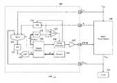
- FIG. 1illustrates a schematic block diagram of a mixed signal integrated circuit having fully digital peak current control with slope compensation for controlling a switched mode power supply (SMPS) module, according to a specific example embodiment of this disclosure;
- SMPSswitched mode power supply
- FIG. 2illustrates a schematic block diagram of the digital control system implementation inside the digital processor, according to the specific example embodiment shown in FIG. 1 ;
- FIG. 3illustrates a waveform of the inductor current for a single PWM cycle along with an uncompensated peak current reference and a slope compensation ramp waveform, according to the teachings of this disclosure
- FIG. 4illustrates a schematic diagram of a buck switched-mode converter module used in combination with the fully digital peak current controller having digital slope compensation, according to the specific example embodiment shown in FIG. 1 ;
- FIG. 5illustrates a schematic diagram of a boost switched-mode converter module used in combination with the fully digital peak current controller having digital slope compensation, according to the specific example embodiment shown in FIG. 1 ;
- FIG. 6illustrates a schematic diagram of a buck-boost switched-mode converter module used in combination with the fully digital peak current controller having digital slope compensation, according to the specific example embodiment shown in FIG. 1 ;
- FIG. 7illustrates a schematic block diagram of a phase-shifted full-bridge (PSFB) converter with a generic secondary rectifier block, running in complementary PWM mode and controlled by the fully digital peak current controller having digital slope compensation, according to the specific example embodiment shown in FIG. 1 ;
- PSFBphase-shifted full-bridge
- FIG. 8illustrates a schematic block diagram of a PSFB converter with a center tapped secondary full wave synchronous rectification scheme, running in complementary PWM mode and controlled by the fully digital peak current controller having digital slope compensation, according to the specific example embodiment shown in FIG. 1 ;
- FIG. 9illustrates a schematic timing diagram of the PWM switching waveforms for the PSFB converter shown in FIG. 8 along with the transformer current and voltage waveforms and the inductor current waveform, according to the teachings of this disclosure.
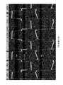
- FIG. 10illustrates oscilloscope waveforms captured from a PSFB test circuit as shown in FIG. 8 , implementing a fully digital peak current control having digital slope compensation as depicted in FIG. 1 , showing the transformer primary voltage and current waveforms indicative of stable converter operation, according to the teachings of this disclosure.
- a software program in combination with a digital processor in a mixed signal integrated circuitmay provide digital slope compensation for implementing peak current controlled SMPS systems, while having low latency and requiring minimal hardware and software resources.
- a microcontroller or digital signal controller (DSC) for providing digital slope compensation used with peak current control of a SMPS systemallows configurability, setting slope value by writing to a register(s) in the microcontroller or SDC memory map, allowing the power supply application to be dynamically adaptable or configurable on the fly.
- the entire slope compensation function and PWM controlmay be self-contained within the microcontroller or DSC and without the need of external components.
- This enhanced functionalitymay be applied to any microcontroller or DSC controlled SMPS for example, but is not limited to, buck, boost, buck-boost or derivatives thereof. References to input voltage “V IN ” or “v in ,” and output voltage “V OUT ” or “v o ” will be used interchangeable herein.
- FIG. 1depicted is a schematic block diagram of a mixed signal integrated circuit having fully digital peak current control with slope compensation for controlling a switched mode power supply (SMPS) module, according to a specific example embodiment of this disclosure.
- a mixed signal (analog and digital) microcontroller or digital signal controller (DSC) 102provides for a fully digital peak current control implementation of a switched mode power supply system, generally represented by the numeral 100 , without any external hardware required for the microcontroller or DSC 102 .
- the microcontroller or DSC 102may comprise a digital processor 104 , a memory 106 coupled to the digital processor 104 , a fast capture sample and hold circuit 116 , an analog voltage comparator 112 , PWM generator 108 , a power transistor driver 110 , a digital-to-analog converter (DAC) 118 , an analog multiplexer 124 a general sample and hold circuit 122 , and an analog-to-digital converter (ADC) 120 .
- the microcontroller/DSC 102may be coupled to and control a SMPS module 140 that supplies voltage and current (power) to a load 142 .
- the input voltage, V IN , and output voltage, V OUTmay be sampled through the multiplexer 124 and sample and hold circuit 122 , then converted to digital representations thereof by the ADC 120 . These input and output voltage digital representations may be coupled to the digital processor 104 for further processing.
- voltage sample timingis not critical as the input voltage, V IN , and output voltage, V OUT , do not change that quickly, e.g., much longer time than the PWM pulse period.
- the input voltagemay have to be sampled from the secondary side of the transformer (especially if the controller is placed in the secondary side). In such cases the input voltage sampling becomes timing critical and may also require fast capture sample and hold circuits.
- the fast capture sample and hold circuit 116may be used to capture valley currents, I V , each time the output of the PWM generator turns ON (goes to a logic high).
- the PWM generator outputturns ON at the start of a PWM cycle and at which time the inductor current, I L , is at a minimum current value, I V .
- the digital processor 104ultimately generates a digital slope compensated peak current reference, I CMP _ D .
- This digital slope compensated peak current reference, I CMP _ Dis passed through a DAC 118 to convert the digital slope compensated peak current reference, I CMP _ D , to an analog slope compensated peak current reference, I CMP , and then to an input of the comparator 112 .
- the comparator 112compares the analog slope compensated current reference, I CMP , to the PWM cycle inductor current, I L , and causes the PWM generator 108 to turn off a power switch in the SMPS power module 140 when the inductor current, I L , reaches substantially the same value as the analog slope compensated peak current reference, ICMP. This action prevents instability and sub-harmonic oscillations in the SMPS power module 140 when the PWM duty cycle is greater than 50 percent.
- FIG. 2depicted is a schematic block diagram of the digital control system implementation inside the digital processor, according to the specific example embodiment shown in FIG. 1 .
- the digitized sensed quantities V IN _ D , V OUT _ D , I V _ D along with the reference voltage V REF _ D (retrieved from the memory 106 in FIG. 1 )form the inputs to the digital processor 104 .
- a digital voltage errormay be computed using a subtraction block 210 . This error is fed to a digital voltage compensator 212 .
- the digital voltage compensator 212typically may comprise a difference equation implementation, e.g., one pole one zero, two pole two zero, three pole three zero, or a digital hardware based compensator.
- the coefficients of the difference equationsmay be determined by using digital control system design techniques in conjunction with the converter transfer functions.
- the converter transfer functionsare derived using small signal modeling or other techniques for individual converters.
- the digital voltage compensator 212may be designed to control the transfer function between the output voltage, V OUT , and a peak current reference, I C .
- a digital uncompensated peak current reference signal, I C _ Dmay be determined by the digital voltage compensator 212 .
- the PWM duty d and complementary PWM duty d′are calculated by a digital duty generator 216 that uses the digital input voltage V IN _ D and the digital output voltage V OUT _ D as its inputs.
- the output of the digital voltage compensator 212 (I C _ D ) and the outputs from the digital duty generator block 216 , (d and d′)are fed to a digital peak current control reference generator 214 which generates the digital slope compensated peak current reference, I CMP _ D .
- the digital voltage compensator 212may comprise for example, but is not limited to, a one pole one zero low pass filter, a two pole two zero low pass filter, a three pole three zero low pass filter, a digital proportional-integral-derivative (PID) controller, a digital proportional-integral (PI) controller, any other suitable digital compensator or a digital hardware based compensator.
- PIDdigital proportional-integral-derivative
- PIdigital proportional-integral controller
- FIG. 3depicted is a waveform of the inductor current for a single PWM cycle along with an uncompensated peak current reference and a slope compensation ramp waveform, according to the teachings of this disclosure.
- the compensation ramphas a slope of ⁇ m a .
- I Vis the inductor valley current which occurs at the start of every PWM cycle.
- I C(in analog form) is the uncompensated peak current reference from the voltage compensator and I CMP (i cmp ) is the slope compensated peak current reference. It can be seen that I CMP occurs at the meeting point of the rising inductor current, I L , and the compensation ramp subtracted from I C .
- the following instructionsmay be performed in the digital processor 104 : one division instruction, one MAC (multiply-accumulate operation) instruction and up to two addition instructions.
- the determination of the slope compensated peak current reference, I CMPis SMPS topology independent and does not require a specialized slope compensation module. Any standard microcontroller or DSC having analog inputs, an ADC, a DAC, and a comparator may be used to implement the teachings of this disclosure. Rapid sampling of only one input variable, inductor current, I L , in determining I V ; along with only one multiply and accumulate (MAC) instruction are required to calculate the slope compensated peak current reference, I CMP .
- the other variables: d and I REFare known from prior calculations based upon the measured input voltage, V IN , and output voltage, V OUT , that are much slower changing than are the PWM cycles.
- a buck convertergenerally represented by the numeral 140 a , can only produce lower average output voltage, V OUT , than the input voltage, V IN .
- a switch 456MOSFET
- the input voltage source, V INfeeds the output (load 142 in FIG. 1 ) through the switch 456 and a low-pass filter, implemented with an inductor 460 and a capacitor 462 .
- the switch 456is ON for a period of T ON
- the input voltage source, V INprovides energy to the output (load 142 ) as well as to the inductor (L).
- FIG. 5depicted is a schematic diagram of a boost switched-mode converter module used in combination with the fully digital peak current controller having digital slope compensation, according to the specific example embodiment shown in FIG. 1 .
- a boost convertergenerally represented by the numeral 140 b , can only produce a higher output average voltage, V OUT , than the input voltage source, V IN .
- an inductor 460is placed in series with the input voltage source, V IN .
- the input voltage source, V INfeeds the output through the inductor 460 , the diode 458 and capacitor 462 .
- FIG. 6depicted is a schematic diagram of a buck-boost switched-mode converter module used in combination with the fully digital peak current controller having digital slope compensation, according to the specific example embodiment shown in FIG. 1 .
- a buck-boost convertergenerally represented by the numeral 140 c , can produce a higher or lower output average voltage, V OUT , than the input voltage source, V IN .
- the rectifier module 622could be configured a number of different ways, for example but not limited to, a full wave diode, center tapped full wave diode, full wave synchronous, center tapped full wave synchronous, current doubler, etc.
- the teachings of this disclosurehave been successfully implemented in a PSFB converter with full wave center tapped synchronous rectification as shown in FIG. 8 more fully described hereinafter.
- FIG. 8depicted is a schematic block diagram of a PSFB converter with a center tapped secondary full wave synchronous rectification scheme, running in complementary PWM mode and controlled by the fully digital peak current controller having digital slope compensation, according to the specific example embodiment shown in FIG. 1
- the PSFB converteris controlled by a digital peak current controller having digital slope compensation, according to the specific example embodiment shown in FIG. 1 .
- a PSFB converter with center tapped full wave synchronous rectificationis generally represented by the numeral 640 a .
- the power switching transistors 670 , 672 , 674 and 676are connected in an “H-bridge” configuration, controlled by PWM generators 630 and 632 , and provide an alternating voltage to the primary of the transformer 682 .
- the power switching transistors 678 and 680are configured as a full-wave rectifier, controlled by PWM generator 634 , and provide low loss rectification of the alternating voltage from the transformer 682 secondary winding.
- the rectified voltageis passed through a low pass filter comprising an inductor 660 and a capacitor 662 before being fed to the load Ro 664 .
- the input voltage (V IN )may be sensed at the center-tap point on the secondary side of the transformer.
- the output voltage (V OUT )may be sensed directly at the output terminals.
- a reflection of the inductor currentis sensed using a current transformer 650 on the primary side of the transformer 682 and is available in the form of a DC voltage across the load resistor 654 from rectifier 652 .
- MOSFET 672At the end of t 7 , MOSFET 672 is turned OFF and after a dead time t 8 , MOSFET 670 turns ON restarting a new positive half power delivery cycle.
- MOSFET 680conducts during the positive half power delivery cycle from the start of the power delivery period up to end of the freewheeling period (t 1 to t 3 ), while MOSFET 678 conducts during the negative half power delivery cycle from the start of power delivery period up to end of freewheeling period (t 5 to t 7 ).
- FIG. 10depicted are oscilloscope waveforms captured from a PSFB test circuit as shown in FIG. 8 , implementing a fully digital peak current control having digital slope compensation as depicted in FIG. 1 , showing the transformer primary voltage and current waveforms indicative of stable converter operation, according to the teachings of this disclosure.
- a waveform of the primary current of transformer 682 in FIG. 8 , I PRI along with the primary voltage V PRIobtained from a real time PSFB converter hardware that is controlled by using the digital peak current control with digital slope compensation, according to the teachings of this disclosure.
- the digital controlhas been implemented using a Microchip dsPIC DSC. It can be seen from the figure that the converter has a stable operation with a duty cycle of around 80% (>50%) using digital peak current control with digital slope compensation based upon the teachings of this disclosure.
Landscapes
- Engineering & Computer Science (AREA)
- Power Engineering (AREA)
- Dc-Dc Converters (AREA)
Abstract
Description
and β may be within a range of 0.5<β≦1, determining B, where B may be a function of the digital representations of the sampled output voltage (VOUT_D) and the sampled input voltage (VIN_D), wherein
and β may be within a range of 0.5<β≦1, multiplying A with the digital minimum inductor current (IV_D), multiplying B with a digital control reference current (IC_D), and adding the results of the above two multiplication steps to determine the digital slope compensated peak current reference (ICMP_D=A*IV_D+B*IC_D); converting the digital slope compensated peak current reference (ICMP_D) to an analog slope compensated peak current reference (ICMP) with a digital-to-analog converter (DAC); comparing the analog slope compensated peak current reference (ICMP) to the inductor current (IL) with an analog comparator; turning off the PWM control signal with an output from the analog comparator when the inductor current (IL) may be substantially equal to the analog slope compensated peak current reference (ICMP); and returning to the step of turning on the PWM control signal at the beginning of a next PWM cycle.
and β may be within a range of 0.5<β≦1,
and β may be within a range of 0.5<β≦1, multiplying A with the digital minimum inductor current (IV_D); multiplying B with a digital control reference current (IC_D), and adding the results of the above two multiplication steps to determine the digital slope compensated peak current reference (ICMP_D=A*IV_D+B*IC_D); converting the digital slope compensated peak current reference (ICMP_D) to an analog slope compensated peak current reference (ICMP) with a digital-to-analog converter (DAC); comparing the analog slope compensated peak current reference (ICMP) to the inductor current (IL) with an analog comparator; turning off the PWM control signal with an output from the analog comparator when the inductor current (IL) may be substantially equal to the analog slope compensated peak current reference (ICMP); and returning to the step of turning on the PWM control signal at the beginning of a next PWM cycle.
and β may be within a range of 0.5<β≦1, determining B, where B may be a function of the digital representations of the sampled output voltage (VOUT_D) and the sampled input voltage (VIN_D), wherein
and β may be within a range of 0.5<β≦1, multiplying A with the digital minimum inductor current (IV_D); multiplying B with a digital control reference current (IC_D), and adding the results of the above two multiplication steps to determine the digital slope compensated peak current reference (ICMP_D=A*IV_D+B*IC_D); converting the digital slope compensated peak current reference (ICMP_D) to an analog slope compensated peak current reference (ICMP) with a digital-to-analog converter (DAC); comparing the analog slope compensated peak current reference (ICMP) to the inductor current (IL) with an analog comparator; turning off the PWM control signal with an output from the analog comparator when the inductor current (IL) may be substantially equal to the analog slope compensated peak current reference (ICMP); and returning to the step of turning on the PWM control signal at the beginning of a next PWM cycle.
iC−madTs=icmp (1)
iV+mONdTs=icmp (2)
From equation (1)
Substituting equation (3) into equation (2) and rearranging the terms would yield
From the above expressions for the A and B terms, it can be shown that
A+B=1 (5)
This implies that if we determine A, then B can be determined by using
B=1−A (6)
It is known that ma>½(mOFF) and the optimum value of ma=mOFF
Thus ma, preferably, would be within the range
½(mOFF)<ma≦mOFF (7)
Dividing equation (7) by mOFFyields
If mais varied as a proportion of mOFF, then
Substituting equation (9) in equation (8) yields
½<β≦1 (10)
From equation (10), β has the range (0.5,1]
Substituting equation (9) in the expression for A
Substituting expressions of mONand mOFFin equation (11) yields A and B=1−A as
For a boost converter,
Substituting expressions of mONand mOFFin equation (11) yields A and B=1−A as,
For a buck-boost converter,
Substituting expressions of mONand mOFFin equation (11) yields A and B=1−A as,
icmp=diC+d′iC (18)
Where the values of d for buck, boost and buck-boost SMPS topologies are,
Buck converter:
Boost converter:
Buck Boost converter:
For achieving optimal slope compensation, the following instructions may be performed in the digital processor104: one division instruction, one MAC (multiply-accumulate operation) instruction and up to two addition instructions.
Claims (23)
Priority Applications (6)
| Application Number | Priority Date | Filing Date | Title |
|---|---|---|---|
| US14/607,684US9379621B1 (en) | 2015-01-28 | 2015-01-28 | Digital slope compensation for peak current controlled converters |
| PCT/US2016/015119WO2016123214A1 (en) | 2015-01-28 | 2016-01-27 | Digital slope compensation for peak current controlled switch mode power converters |
| KR1020177015052AKR20170107961A (en) | 2015-01-28 | 2016-01-27 | Digital slope compensation for peak current controlled switch mode power converters |
| CN201680004596.XACN107112886B (en) | 2015-01-28 | 2016-01-27 | Method and apparatus for peak current control converter using digital slope compensation |
| EP16703036.0AEP3251204A1 (en) | 2015-01-28 | 2016-01-27 | Digital slope compensation for peak current controlled switch mode power converters |
| TW105102743ATW201640804A (en) | 2015-01-28 | 2016-01-28 | Digital slope compensation for peak current controlled converters |
Applications Claiming Priority (1)
| Application Number | Priority Date | Filing Date | Title |
|---|---|---|---|
| US14/607,684US9379621B1 (en) | 2015-01-28 | 2015-01-28 | Digital slope compensation for peak current controlled converters |
Publications (1)
| Publication Number | Publication Date |
|---|---|
| US9379621B1true US9379621B1 (en) | 2016-06-28 |
Family
ID=55300812
Family Applications (1)
| Application Number | Title | Priority Date | Filing Date |
|---|---|---|---|
| US14/607,684ActiveUS9379621B1 (en) | 2015-01-28 | 2015-01-28 | Digital slope compensation for peak current controlled converters |
Country Status (6)
| Country | Link |
|---|---|
| US (1) | US9379621B1 (en) |
| EP (1) | EP3251204A1 (en) |
| KR (1) | KR20170107961A (en) |
| CN (1) | CN107112886B (en) |
| TW (1) | TW201640804A (en) |
| WO (1) | WO2016123214A1 (en) |
Cited By (18)
| Publication number | Priority date | Publication date | Assignee | Title |
|---|---|---|---|---|
| US9762123B1 (en)* | 2016-08-29 | 2017-09-12 | Sea Sonic Electronics Co., Ltd. | Boost converter circuit able to sense current |
| US20180074100A1 (en)* | 2015-04-09 | 2018-03-15 | Weidmüller Interface GmbH & Co. KG | Electrical assembly and measurement circuit and method for monitoring a component thereof |
| US20180234007A1 (en)* | 2015-08-14 | 2018-08-16 | Southeast University | Control method for improving dynamic response of switch power |
| CN108736716A (en)* | 2018-06-22 | 2018-11-02 | 武汉理工大学 | A kind of digital imitative current controller and its control method of DC/DC converters |
| CN110308320A (en)* | 2018-03-20 | 2019-10-08 | 瑞萨电子美国有限公司 | The prediction samples for sharing ADC for the time in multi-phase PWM controller are lined up |
| US10476398B1 (en)* | 2018-05-01 | 2019-11-12 | Postech Academy-Industry Foundation | Power conversion circuit for photovoltaic power generation with high efficiency over wide input voltage range |
| WO2020050889A1 (en)* | 2018-09-07 | 2020-03-12 | Microchip Technology Incorporated | Adaptive slope compensation for current mode control |
| CN111162668A (en)* | 2020-03-06 | 2020-05-15 | 杰华特微电子(杭州)有限公司 | Control method and control circuit of switch circuit and switch circuit |
| US10771052B2 (en)* | 2016-10-07 | 2020-09-08 | Texas Instruments Incorporated | Gate driver with VGTH and VCESAT measurement capability for the state of health monitor |
| US10770969B2 (en) | 2016-09-28 | 2020-09-08 | B. G. Negev Technologies And Applications Ltd., At Ben-Gurion University | Digital average current-mode control voltage regulator and a method for tuning compensation coefficients thereof |
| CN111917304A (en)* | 2020-08-10 | 2020-11-10 | 北京新雷能科技股份有限公司 | Digital power supply |
| US10938309B1 (en) | 2019-10-18 | 2021-03-02 | Raytheon Company | Controlling operation of a voltage converter based on inductor current |
| US20210096585A1 (en)* | 2019-10-01 | 2021-04-01 | Allegro Microsystems, Llc | Converter digital control circuit with adaptive feedforward compensation |
| US10985664B1 (en) | 2019-10-18 | 2021-04-20 | Raytheon Company | Controlling operation of a voltage converter based on transistor drain voltages |
| US20220247313A1 (en)* | 2021-02-04 | 2022-08-04 | Analog Devices, Inc. | Peak current mode control for buck-boost regulators |
| US20220368226A1 (en)* | 2019-10-02 | 2022-11-17 | Raytheon Systems Limited | A peak current mode controller |
| US20230031756A1 (en)* | 2021-07-30 | 2023-02-02 | Nio Technology (Anhui) Co., Ltd | Control apparatus and method for electronic device, mobile equipment, and storage medium |
| EP4451533A1 (en)* | 2023-04-21 | 2024-10-23 | Qorvo US, Inc. | Dynamic current limits for direct current-to-direct current (dc-dc) converters |
Families Citing this family (10)
| Publication number | Priority date | Publication date | Assignee | Title |
|---|---|---|---|---|
| JP7054358B2 (en)* | 2018-03-30 | 2022-04-13 | 株式会社Soken | Power converter control device |
| US10175278B1 (en)* | 2018-04-23 | 2019-01-08 | Linear Technology Holding Llc | Detecting value of output capacitor in switching regulator |
| US10917003B2 (en)* | 2018-09-18 | 2021-02-09 | Astec International Limited | Control circuits with peak current limit protection for switched mode power supplies |
| FR3086470B1 (en)* | 2018-09-24 | 2021-04-09 | Renault Sas | CONTROL PROCEDURE FOR A BOOST TYPE CONVERTER WITH N SWITCHING CELLS. |
| US10425080B1 (en)* | 2018-11-06 | 2019-09-24 | Crane Electronics, Inc. | Magnetic peak current mode control for radiation tolerant active driven synchronous power converters |
| KR102807654B1 (en)* | 2018-11-28 | 2025-05-13 | 실라나 아시아 피티이 리미티드 | Digital compensation current sensing protection |
| TWI697185B (en) | 2019-02-25 | 2020-06-21 | 新唐科技股份有限公司 | Voltage converting apparatus |
| US10746118B1 (en)* | 2019-07-02 | 2020-08-18 | Delphi Technologies Ip Limited | Compensator circuitry and method for an oxygen sensor |
| IT202100007628A1 (en)* | 2021-03-29 | 2022-09-29 | St Microelectronics Srl | CONTROL CIRCUIT, CORRESPONDING ELECTRONIC CONVERTER DEVICE AND RELATED OPERATING METHOD |
| CN115276408B (en)* | 2022-06-27 | 2025-03-14 | 中国人民解放军海军工程大学 | Wide-input Buck-Boost chopper control circuit and control method |
Citations (5)
| Publication number | Priority date | Publication date | Assignee | Title |
|---|---|---|---|---|
| US20090039852A1 (en)* | 2007-08-06 | 2009-02-12 | Solaredge Technologies Ltd. | Digital average input current control in power converter |
| US20110115458A1 (en)* | 2009-09-18 | 2011-05-19 | Schafmeister Frank | Digital slope compensation for current mode control |
| US20120176824A1 (en) | 2011-01-06 | 2012-07-12 | Chris Michael Franklin | Methods and apparatus for digital peak current mode control for switch-mode power converters |
| US20140191743A1 (en)* | 2012-01-10 | 2014-07-10 | Texas Instruments Incorporated | Current mode control arrangement and method thereof |
| US20140239922A1 (en)* | 2013-02-23 | 2014-08-28 | Texas Instruments Incorporated | Apparatus and methods to control peak current mode controlled power converters using selective noise blanking |
Family Cites Families (4)
| Publication number | Priority date | Publication date | Assignee | Title |
|---|---|---|---|---|
| CN100397766C (en)* | 2004-12-01 | 2008-06-25 | 崇贸科技股份有限公司 | Switching type control device |
| JP6015370B2 (en)* | 2012-11-12 | 2016-10-26 | 株式会社デンソー | Switching power supply |
| CN103066823B (en)* | 2012-12-12 | 2015-07-08 | 矽力杰半导体技术(杭州)有限公司 | Controller and control method of switch power source |
| CN103916004B (en)* | 2014-04-22 | 2017-03-08 | 成都芯源系统有限公司 | Power factor correction circuit and control method thereof |
- 2015
- 2015-01-28USUS14/607,684patent/US9379621B1/enactiveActive
- 2016
- 2016-01-27KRKR1020177015052Apatent/KR20170107961A/ennot_activeWithdrawn
- 2016-01-27EPEP16703036.0Apatent/EP3251204A1/ennot_activeCeased
- 2016-01-27WOPCT/US2016/015119patent/WO2016123214A1/ennot_activeCeased
- 2016-01-27CNCN201680004596.XApatent/CN107112886B/enactiveActive
- 2016-01-28TWTW105102743Apatent/TW201640804A/enunknown
Patent Citations (7)
| Publication number | Priority date | Publication date | Assignee | Title |
|---|---|---|---|---|
| US20090039852A1 (en)* | 2007-08-06 | 2009-02-12 | Solaredge Technologies Ltd. | Digital average input current control in power converter |
| US20110115458A1 (en)* | 2009-09-18 | 2011-05-19 | Schafmeister Frank | Digital slope compensation for current mode control |
| US8278899B2 (en) | 2009-09-18 | 2012-10-02 | Det International Holding Limited | Digital slope compensation for current mode control |
| US20120176824A1 (en) | 2011-01-06 | 2012-07-12 | Chris Michael Franklin | Methods and apparatus for digital peak current mode control for switch-mode power converters |
| US8773097B2 (en)* | 2011-01-06 | 2014-07-08 | Texas Instruments Incorporated | Digital peak current mode control for switch-mode power converters |
| US20140191743A1 (en)* | 2012-01-10 | 2014-07-10 | Texas Instruments Incorporated | Current mode control arrangement and method thereof |
| US20140239922A1 (en)* | 2013-02-23 | 2014-08-28 | Texas Instruments Incorporated | Apparatus and methods to control peak current mode controlled power converters using selective noise blanking |
Non-Patent Citations (3)
| Title |
|---|
| Grote, T. et al., "Adaptive Digital Slope Compensation for Peak Current Mode Control," Energy Conversion Congress and Exposition, IEEE, pp. 3523-3529 (7 pages) Sep. 20, 2009. |
| Holme, P.R. et al., "Digital Control of High Frequency PWM Converters," Digital Controller Architecture, pp. 260-265 (6 pages) Jan. 1, 1993. |
| International Search Report and Written Opinion, Application No. PCT/US2016/015119, 16 pages Apr. 22, 2016. |
Cited By (30)
| Publication number | Priority date | Publication date | Assignee | Title |
|---|---|---|---|---|
| US10627434B2 (en)* | 2015-04-09 | 2020-04-21 | Weidmüller Interface GmbH & Co. KG | Electrical assembly and measurement circuit and method for monitoring a component thereof |
| US20180074100A1 (en)* | 2015-04-09 | 2018-03-15 | Weidmüller Interface GmbH & Co. KG | Electrical assembly and measurement circuit and method for monitoring a component thereof |
| US20180234007A1 (en)* | 2015-08-14 | 2018-08-16 | Southeast University | Control method for improving dynamic response of switch power |
| US10097077B2 (en)* | 2015-08-14 | 2018-10-09 | Southeast University | Control method for improving dynamic response of switch power |
| US9762123B1 (en)* | 2016-08-29 | 2017-09-12 | Sea Sonic Electronics Co., Ltd. | Boost converter circuit able to sense current |
| EP3520212A4 (en)* | 2016-09-28 | 2020-10-14 | B.G. Negev Technologies & Applications Ltd., at Ben-Gurion University | DIGITAL VOLTAGE REGULATOR FOR AVERAGE CURRENT CONTROL AND PROCESS FOR ADJUSTMENT OF COMPENSATION COEFFICIENTS |
| US10770969B2 (en) | 2016-09-28 | 2020-09-08 | B. G. Negev Technologies And Applications Ltd., At Ben-Gurion University | Digital average current-mode control voltage regulator and a method for tuning compensation coefficients thereof |
| US11239839B2 (en) | 2016-10-07 | 2022-02-01 | Texas Instruments Incorporated | Gate driver with VGTH and VCESAT measurement capability for the state of health monitor |
| US10771052B2 (en)* | 2016-10-07 | 2020-09-08 | Texas Instruments Incorporated | Gate driver with VGTH and VCESAT measurement capability for the state of health monitor |
| US11002771B2 (en)* | 2018-03-20 | 2021-05-11 | Renesas Electronics America Inc. | Predictive sample queueing for time-shared ADC in a multiphase PWM controller |
| CN110308320B (en)* | 2018-03-20 | 2023-10-24 | 瑞萨电子美国有限公司 | Predictive sample queuing for time-sharing ADC in multiphase PWM controllers |
| CN110308320A (en)* | 2018-03-20 | 2019-10-08 | 瑞萨电子美国有限公司 | The prediction samples for sharing ADC for the time in multi-phase PWM controller are lined up |
| US10476398B1 (en)* | 2018-05-01 | 2019-11-12 | Postech Academy-Industry Foundation | Power conversion circuit for photovoltaic power generation with high efficiency over wide input voltage range |
| CN108736716B (en)* | 2018-06-22 | 2023-11-28 | 武汉理工大学 | A digital imitation current controller for DC/DC converter and its control method |
| CN108736716A (en)* | 2018-06-22 | 2018-11-02 | 武汉理工大学 | A kind of digital imitative current controller and its control method of DC/DC converters |
| US10784766B2 (en)* | 2018-09-07 | 2020-09-22 | Microchip Technology Incorporated | Adaptive slope compensation for current mode control |
| WO2020050889A1 (en)* | 2018-09-07 | 2020-03-12 | Microchip Technology Incorporated | Adaptive slope compensation for current mode control |
| US20210096585A1 (en)* | 2019-10-01 | 2021-04-01 | Allegro Microsystems, Llc | Converter digital control circuit with adaptive feedforward compensation |
| US11469666B2 (en)* | 2019-10-01 | 2022-10-11 | Allegro Microsystems, Llc | Converter digital control circuit with adaptive feedforward compensation |
| US12015344B2 (en)* | 2019-10-02 | 2024-06-18 | Raytheon Systems Limited | Peak current mode controller |
| US20220368226A1 (en)* | 2019-10-02 | 2022-11-17 | Raytheon Systems Limited | A peak current mode controller |
| US10985664B1 (en) | 2019-10-18 | 2021-04-20 | Raytheon Company | Controlling operation of a voltage converter based on transistor drain voltages |
| WO2021076190A1 (en)* | 2019-10-18 | 2021-04-22 | Raytheon Company | Controlling operation of a voltage converter based on inductor current |
| US10938309B1 (en) | 2019-10-18 | 2021-03-02 | Raytheon Company | Controlling operation of a voltage converter based on inductor current |
| CN111162668A (en)* | 2020-03-06 | 2020-05-15 | 杰华特微电子(杭州)有限公司 | Control method and control circuit of switch circuit and switch circuit |
| CN111917304A (en)* | 2020-08-10 | 2020-11-10 | 北京新雷能科技股份有限公司 | Digital power supply |
| US11682972B2 (en)* | 2021-02-04 | 2023-06-20 | Analog Devices, Inc. | Peak current mode control for buck-boost regulators |
| US20220247313A1 (en)* | 2021-02-04 | 2022-08-04 | Analog Devices, Inc. | Peak current mode control for buck-boost regulators |
| US20230031756A1 (en)* | 2021-07-30 | 2023-02-02 | Nio Technology (Anhui) Co., Ltd | Control apparatus and method for electronic device, mobile equipment, and storage medium |
| EP4451533A1 (en)* | 2023-04-21 | 2024-10-23 | Qorvo US, Inc. | Dynamic current limits for direct current-to-direct current (dc-dc) converters |
Also Published As
| Publication number | Publication date |
|---|---|
| TW201640804A (en) | 2016-11-16 |
| EP3251204A1 (en) | 2017-12-06 |
| WO2016123214A1 (en) | 2016-08-04 |
| CN107112886A (en) | 2017-08-29 |
| CN107112886B (en) | 2019-12-31 |
| KR20170107961A (en) | 2017-09-26 |
Similar Documents
| Publication | Publication Date | Title |
|---|---|---|
| US9379621B1 (en) | Digital slope compensation for peak current controlled converters | |
| US10892686B2 (en) | Hysteretic control for transformer based power converters | |
| US8487600B2 (en) | Continuous-time digital controller for high-frequency DC-DC converters | |
| US9112417B2 (en) | Method and apparatus for providing power conversion using an interleaved flyback converter with automatic balancing | |
| CN103529269B (en) | Switching regulator Cycle by Cycle current estimation | |
| JP5402469B2 (en) | Power converter and control circuit | |
| US12068672B2 (en) | Control circuit for power converter apparatus provided with PFC circuit operating in current-critical mode | |
| US20180041119A1 (en) | Control circuit, control method and power converter thereof | |
| US11818815B2 (en) | Switching converter, control circuit and control method thereof | |
| US9998005B2 (en) | Single inductor dual output voltage converter and the method thereof | |
| CN110692187B (en) | Control method and control circuit of switching power supply device | |
| US20160147248A1 (en) | Reference signal generator and the method thereof | |
| JP2004364433A (en) | Dc voltage conversion circuit | |
| Choudhury et al. | A DSP based digitally controlled interleaved PFC converter | |
| US9742284B2 (en) | Multiphase power circuit | |
| US10638587B2 (en) | Device and method for processing an inductor current | |
| JP2002262565A (en) | Switching power supply | |
| Dashmiz et al. | Hardware efficient auto-tuned linear-gain based minimum deviation digital controller for indirect energy transfer converters | |
| JP7538737B2 (en) | Apparatus and method for controlling an electric circuit | |
| JP2008167578A (en) | Power supply unit | |
| TWI477050B (en) | Power converter and operating method thereof | |
| Leung | Optimizing system operation using a flexible digital PWM controller | |
| TW201929403A (en) | DC-DC converter circuit structure with current measuring circuit for estimating inductive current of DC-DC converter | |
| JP2006136076A (en) | AC-DC converter | |
| JP2002262564A (en) | Switching power supply |
Legal Events
| Date | Code | Title | Description |
|---|---|---|---|
| AS | Assignment | Owner name:MICROCHIP TECHNOLOGY INCORPORATED, ARIZONA Free format text:ASSIGNMENT OF ASSIGNORS INTEREST;ASSIGNORS:KALYANARMAN, SABARISH;KANKANALA, RAMESH;REEL/FRAME:034900/0025 Effective date:20141218 | |
| STCF | Information on status: patent grant | Free format text:PATENTED CASE | |
| AS | Assignment | Owner name:JPMORGAN CHASE BANK, N.A., AS ADMINISTRATIVE AGENT, ILLINOIS Free format text:SECURITY INTEREST;ASSIGNOR:MICROCHIP TECHNOLOGY INCORPORATED;REEL/FRAME:041675/0617 Effective date:20170208 Owner name:JPMORGAN CHASE BANK, N.A., AS ADMINISTRATIVE AGENT Free format text:SECURITY INTEREST;ASSIGNOR:MICROCHIP TECHNOLOGY INCORPORATED;REEL/FRAME:041675/0617 Effective date:20170208 | |
| AS | Assignment | Owner name:JPMORGAN CHASE BANK, N.A., AS ADMINISTRATIVE AGENT, ILLINOIS Free format text:SECURITY INTEREST;ASSIGNORS:MICROCHIP TECHNOLOGY INCORPORATED;SILICON STORAGE TECHNOLOGY, INC.;ATMEL CORPORATION;AND OTHERS;REEL/FRAME:046426/0001 Effective date:20180529 Owner name:JPMORGAN CHASE BANK, N.A., AS ADMINISTRATIVE AGENT Free format text:SECURITY INTEREST;ASSIGNORS:MICROCHIP TECHNOLOGY INCORPORATED;SILICON STORAGE TECHNOLOGY, INC.;ATMEL CORPORATION;AND OTHERS;REEL/FRAME:046426/0001 Effective date:20180529 | |
| AS | Assignment | Owner name:WELLS FARGO BANK, NATIONAL ASSOCIATION, AS NOTES COLLATERAL AGENT, CALIFORNIA Free format text:SECURITY INTEREST;ASSIGNORS:MICROCHIP TECHNOLOGY INCORPORATED;SILICON STORAGE TECHNOLOGY, INC.;ATMEL CORPORATION;AND OTHERS;REEL/FRAME:047103/0206 Effective date:20180914 Owner name:WELLS FARGO BANK, NATIONAL ASSOCIATION, AS NOTES C Free format text:SECURITY INTEREST;ASSIGNORS:MICROCHIP TECHNOLOGY INCORPORATED;SILICON STORAGE TECHNOLOGY, INC.;ATMEL CORPORATION;AND OTHERS;REEL/FRAME:047103/0206 Effective date:20180914 | |
| MAFP | Maintenance fee payment | Free format text:PAYMENT OF MAINTENANCE FEE, 4TH YEAR, LARGE ENTITY (ORIGINAL EVENT CODE: M1551); ENTITY STATUS OF PATENT OWNER: LARGE ENTITY Year of fee payment:4 | |
| AS | Assignment | Owner name:JPMORGAN CHASE BANK, N.A., AS ADMINISTRATIVE AGENT, DELAWARE Free format text:SECURITY INTEREST;ASSIGNORS:MICROCHIP TECHNOLOGY INC.;SILICON STORAGE TECHNOLOGY, INC.;ATMEL CORPORATION;AND OTHERS;REEL/FRAME:053311/0305 Effective date:20200327 | |
| AS | Assignment | Owner name:SILICON STORAGE TECHNOLOGY, INC., ARIZONA Free format text:RELEASE BY SECURED PARTY;ASSIGNOR:JPMORGAN CHASE BANK, N.A, AS ADMINISTRATIVE AGENT;REEL/FRAME:053466/0011 Effective date:20200529 Owner name:MICROSEMI STORAGE SOLUTIONS, INC., ARIZONA Free format text:RELEASE BY SECURED PARTY;ASSIGNOR:JPMORGAN CHASE BANK, N.A, AS ADMINISTRATIVE AGENT;REEL/FRAME:053466/0011 Effective date:20200529 Owner name:MICROCHIP TECHNOLOGY INC., ARIZONA Free format text:RELEASE BY SECURED PARTY;ASSIGNOR:JPMORGAN CHASE BANK, N.A, AS ADMINISTRATIVE AGENT;REEL/FRAME:053466/0011 Effective date:20200529 Owner name:ATMEL CORPORATION, ARIZONA Free format text:RELEASE BY SECURED PARTY;ASSIGNOR:JPMORGAN CHASE BANK, N.A, AS ADMINISTRATIVE AGENT;REEL/FRAME:053466/0011 Effective date:20200529 Owner name:MICROSEMI CORPORATION, CALIFORNIA Free format text:RELEASE BY SECURED PARTY;ASSIGNOR:JPMORGAN CHASE BANK, N.A, AS ADMINISTRATIVE AGENT;REEL/FRAME:053466/0011 Effective date:20200529 | |
| AS | Assignment | Owner name:WELLS FARGO BANK, NATIONAL ASSOCIATION, MINNESOTA Free format text:SECURITY INTEREST;ASSIGNORS:MICROCHIP TECHNOLOGY INC.;SILICON STORAGE TECHNOLOGY, INC.;ATMEL CORPORATION;AND OTHERS;REEL/FRAME:053468/0705 Effective date:20200529 | |
| AS | Assignment | Owner name:WELLS FARGO BANK, NATIONAL ASSOCIATION, AS COLLATERAL AGENT, MINNESOTA Free format text:SECURITY INTEREST;ASSIGNORS:MICROCHIP TECHNOLOGY INCORPORATED;SILICON STORAGE TECHNOLOGY, INC.;ATMEL CORPORATION;AND OTHERS;REEL/FRAME:055671/0612 Effective date:20201217 | |
| AS | Assignment | Owner name:WELLS FARGO BANK, NATIONAL ASSOCIATION, AS NOTES COLLATERAL AGENT, MINNESOTA Free format text:SECURITY INTEREST;ASSIGNORS:MICROCHIP TECHNOLOGY INCORPORATED;SILICON STORAGE TECHNOLOGY, INC.;ATMEL CORPORATION;AND OTHERS;REEL/FRAME:057935/0474 Effective date:20210528 | |
| AS | Assignment | Owner name:MICROSEMI STORAGE SOLUTIONS, INC., ARIZONA Free format text:RELEASE BY SECURED PARTY;ASSIGNOR:JPMORGAN CHASE BANK, N.A., AS ADMINISTRATIVE AGENT;REEL/FRAME:059333/0222 Effective date:20220218 Owner name:MICROSEMI CORPORATION, ARIZONA Free format text:RELEASE BY SECURED PARTY;ASSIGNOR:JPMORGAN CHASE BANK, N.A., AS ADMINISTRATIVE AGENT;REEL/FRAME:059333/0222 Effective date:20220218 Owner name:ATMEL CORPORATION, ARIZONA Free format text:RELEASE BY SECURED PARTY;ASSIGNOR:JPMORGAN CHASE BANK, N.A., AS ADMINISTRATIVE AGENT;REEL/FRAME:059333/0222 Effective date:20220218 Owner name:SILICON STORAGE TECHNOLOGY, INC., ARIZONA Free format text:RELEASE BY SECURED PARTY;ASSIGNOR:JPMORGAN CHASE BANK, N.A., AS ADMINISTRATIVE AGENT;REEL/FRAME:059333/0222 Effective date:20220218 Owner name:MICROCHIP TECHNOLOGY INCORPORATED, ARIZONA Free format text:RELEASE BY SECURED PARTY;ASSIGNOR:JPMORGAN CHASE BANK, N.A., AS ADMINISTRATIVE AGENT;REEL/FRAME:059333/0222 Effective date:20220218 | |
| AS | Assignment | Owner name:MICROCHIP TECHNOLOGY INCORPORATED, ARIZONA Free format text:RELEASE BY SECURED PARTY;ASSIGNOR:JPMORGAN CHASE BANK, N.A., AS ADMINISTRATIVE AGENT;REEL/FRAME:059666/0545 Effective date:20220218 | |
| AS | Assignment | Owner name:MICROSEMI STORAGE SOLUTIONS, INC., ARIZONA Free format text:RELEASE BY SECURED PARTY;ASSIGNOR:WELLS FARGO BANK, NATIONAL ASSOCIATION, AS NOTES COLLATERAL AGENT;REEL/FRAME:059358/0001 Effective date:20220228 Owner name:MICROSEMI CORPORATION, ARIZONA Free format text:RELEASE BY SECURED PARTY;ASSIGNOR:WELLS FARGO BANK, NATIONAL ASSOCIATION, AS NOTES COLLATERAL AGENT;REEL/FRAME:059358/0001 Effective date:20220228 Owner name:ATMEL CORPORATION, ARIZONA Free format text:RELEASE BY SECURED PARTY;ASSIGNOR:WELLS FARGO BANK, NATIONAL ASSOCIATION, AS NOTES COLLATERAL AGENT;REEL/FRAME:059358/0001 Effective date:20220228 Owner name:SILICON STORAGE TECHNOLOGY, INC., ARIZONA Free format text:RELEASE BY SECURED PARTY;ASSIGNOR:WELLS FARGO BANK, NATIONAL ASSOCIATION, AS NOTES COLLATERAL AGENT;REEL/FRAME:059358/0001 Effective date:20220228 Owner name:MICROCHIP TECHNOLOGY INCORPORATED, ARIZONA Free format text:RELEASE BY SECURED PARTY;ASSIGNOR:WELLS FARGO BANK, NATIONAL ASSOCIATION, AS NOTES COLLATERAL AGENT;REEL/FRAME:059358/0001 Effective date:20220228 | |
| AS | Assignment | Owner name:MICROSEMI STORAGE SOLUTIONS, INC., ARIZONA Free format text:RELEASE BY SECURED PARTY;ASSIGNOR:WELLS FARGO BANK, NATIONAL ASSOCIATION, AS NOTES COLLATERAL AGENT;REEL/FRAME:059863/0400 Effective date:20220228 Owner name:MICROSEMI CORPORATION, ARIZONA Free format text:RELEASE BY SECURED PARTY;ASSIGNOR:WELLS FARGO BANK, NATIONAL ASSOCIATION, AS NOTES COLLATERAL AGENT;REEL/FRAME:059863/0400 Effective date:20220228 Owner name:ATMEL CORPORATION, ARIZONA Free format text:RELEASE BY SECURED PARTY;ASSIGNOR:WELLS FARGO BANK, NATIONAL ASSOCIATION, AS NOTES COLLATERAL AGENT;REEL/FRAME:059863/0400 Effective date:20220228 Owner name:SILICON STORAGE TECHNOLOGY, INC., ARIZONA Free format text:RELEASE BY SECURED PARTY;ASSIGNOR:WELLS FARGO BANK, NATIONAL ASSOCIATION, AS NOTES COLLATERAL AGENT;REEL/FRAME:059863/0400 Effective date:20220228 Owner name:MICROCHIP TECHNOLOGY INCORPORATED, ARIZONA Free format text:RELEASE BY SECURED PARTY;ASSIGNOR:WELLS FARGO BANK, NATIONAL ASSOCIATION, AS NOTES COLLATERAL AGENT;REEL/FRAME:059863/0400 Effective date:20220228 | |
| AS | Assignment | Owner name:MICROSEMI STORAGE SOLUTIONS, INC., ARIZONA Free format text:RELEASE BY SECURED PARTY;ASSIGNOR:WELLS FARGO BANK, NATIONAL ASSOCIATION, AS NOTES COLLATERAL AGENT;REEL/FRAME:059363/0001 Effective date:20220228 Owner name:MICROSEMI CORPORATION, ARIZONA Free format text:RELEASE BY SECURED PARTY;ASSIGNOR:WELLS FARGO BANK, NATIONAL ASSOCIATION, AS NOTES COLLATERAL AGENT;REEL/FRAME:059363/0001 Effective date:20220228 Owner name:ATMEL CORPORATION, ARIZONA Free format text:RELEASE BY SECURED PARTY;ASSIGNOR:WELLS FARGO BANK, NATIONAL ASSOCIATION, AS NOTES COLLATERAL AGENT;REEL/FRAME:059363/0001 Effective date:20220228 Owner name:SILICON STORAGE TECHNOLOGY, INC., ARIZONA Free format text:RELEASE BY SECURED PARTY;ASSIGNOR:WELLS FARGO BANK, NATIONAL ASSOCIATION, AS NOTES COLLATERAL AGENT;REEL/FRAME:059363/0001 Effective date:20220228 Owner name:MICROCHIP TECHNOLOGY INCORPORATED, ARIZONA Free format text:RELEASE BY SECURED PARTY;ASSIGNOR:WELLS FARGO BANK, NATIONAL ASSOCIATION, AS NOTES COLLATERAL AGENT;REEL/FRAME:059363/0001 Effective date:20220228 | |
| AS | Assignment | Owner name:MICROSEMI STORAGE SOLUTIONS, INC., ARIZONA Free format text:RELEASE BY SECURED PARTY;ASSIGNOR:WELLS FARGO BANK, NATIONAL ASSOCIATION, AS NOTES COLLATERAL AGENT;REEL/FRAME:060894/0437 Effective date:20220228 Owner name:MICROSEMI CORPORATION, ARIZONA Free format text:RELEASE BY SECURED PARTY;ASSIGNOR:WELLS FARGO BANK, NATIONAL ASSOCIATION, AS NOTES COLLATERAL AGENT;REEL/FRAME:060894/0437 Effective date:20220228 Owner name:ATMEL CORPORATION, ARIZONA Free format text:RELEASE BY SECURED PARTY;ASSIGNOR:WELLS FARGO BANK, NATIONAL ASSOCIATION, AS NOTES COLLATERAL AGENT;REEL/FRAME:060894/0437 Effective date:20220228 Owner name:SILICON STORAGE TECHNOLOGY, INC., ARIZONA Free format text:RELEASE BY SECURED PARTY;ASSIGNOR:WELLS FARGO BANK, NATIONAL ASSOCIATION, AS NOTES COLLATERAL AGENT;REEL/FRAME:060894/0437 Effective date:20220228 Owner name:MICROCHIP TECHNOLOGY INCORPORATED, ARIZONA Free format text:RELEASE BY SECURED PARTY;ASSIGNOR:WELLS FARGO BANK, NATIONAL ASSOCIATION, AS NOTES COLLATERAL AGENT;REEL/FRAME:060894/0437 Effective date:20220228 | |
| MAFP | Maintenance fee payment | Free format text:PAYMENT OF MAINTENANCE FEE, 8TH YEAR, LARGE ENTITY (ORIGINAL EVENT CODE: M1552); ENTITY STATUS OF PATENT OWNER: LARGE ENTITY Year of fee payment:8 |