US9379556B2 - Systems and methods for energy harvesting and current and voltage measurements - Google Patents
Systems and methods for energy harvesting and current and voltage measurementsDownload PDFInfo
- Publication number
- US9379556B2 US9379556B2US13/828,878US201313828878AUS9379556B2US 9379556 B2US9379556 B2US 9379556B2US 201313828878 AUS201313828878 AUS 201313828878AUS 9379556 B2US9379556 B2US 9379556B2
- Authority
- US
- United States
- Prior art keywords
- measurement
- current
- circuit
- harvesting
- voltage
- Prior art date
- Legal status (The legal status is an assumption and is not a legal conclusion. Google has not performed a legal analysis and makes no representation as to the accuracy of the status listed.)
- Active, expires
Links
Images
Classifications
- H—ELECTRICITY
- H02—GENERATION; CONVERSION OR DISTRIBUTION OF ELECTRIC POWER
- H02J—CIRCUIT ARRANGEMENTS OR SYSTEMS FOR SUPPLYING OR DISTRIBUTING ELECTRIC POWER; SYSTEMS FOR STORING ELECTRIC ENERGY
- H02J50/00—Circuit arrangements or systems for wireless supply or distribution of electric power
- H02J50/001—Energy harvesting or scavenging
- H02J5/005—
- G—PHYSICS
- G01—MEASURING; TESTING
- G01R—MEASURING ELECTRIC VARIABLES; MEASURING MAGNETIC VARIABLES
- G01R15/00—Details of measuring arrangements of the types provided for in groups G01R17/00 - G01R29/00, G01R33/00 - G01R33/26 or G01R35/00
- G01R15/14—Adaptations providing voltage or current isolation, e.g. for high-voltage or high-current networks
- G01R15/142—Arrangements for simultaneous measurements of several parameters employing techniques covered by groups G01R15/14 - G01R15/26
Definitions
- the present disclosurerelates generally to harvesting energy as well as making current measurements with a device having a single current transformer and to systems, methods, and devices for improved energy harvesting, and making current and voltage measurements with the device.
- Typical current transformer devices for energy harvesting and current measurementsutilize one current transformer dedicated to energy harvesting and another current transformer for measuring current.
- Recent technologyhas provided current transformer devices that can use the same current transformer to both harvest energy from a conductor as well as to measure current on the conductor.
- Such current transformersinclude a harvesting circuit portion and a measurement circuit portion.
- the harvesting circuit portiongenerally includes non-linear elements. However, these non-linear elements can negatively affect the accuracy of the current measurements as shown in FIG. 3C . Additionally, such harvesting and measurement current transformer devices use the same iron or steel core current transformer for both energy harvesting and current measuring.
- a harvesting and measurement deviceincludes a current transformer and a device circuit coupled to the current transformer.
- the device circuitincludes an energy harvesting circuit having non-linear elements and a switching device coupled to the energy harvesting circuit capable of conductively coupling and decoupling the energy harvesting circuit from the device circuit.
- the device circuitalso includes a microcontroller coupled to the switching device, wherein the microcontroller controls the switching device to couple and decouple the energy harvesting circuit from the device circuit, and controls at least one Hall sensor coupled to the microcontroller.
- the device circuitis operable in at least a normal operation mode, a demand measurement mode, and a fault measurement mode. In the normal operation mode, the energy harvesting circuit is conductively coupled to the device circuit and the current transformer. In the demand measurement mode, the energy harvesting circuit is conductively decoupled from the device circuit, and the current transformer is configured to make accurate current readings. In the fault measurement mode, the Hall sensor is energized and configured to make current readings.
- a method of making a demand current measurementincludes bypassing one or more energy harvesting elements in a device circuit, taking a series of current measurement readings with a current transformer, wherein the current transformer is coupled to the device circuit, restoring the one or more energy harvesting elements in the device circuit, and calculating a current measurement from the series of current measurement readings.
- a method of making a fault measurementincludes the steps of: enabling at least one Hall sensor in a device circuit, making a first current measurement with the at least one Hall sensor, making a second current measurement with the current transformer, making a current direction measurement, determining if a number of AC cycles is completed, making another first current measurement, another second current measurement, and another current direction measurement if the number of AC cycles is not completed, and reporting a fault current measurement if the cycle is completed.
- FIG. 1illustrates a harvesting and measuring current transformer device in accordance with an example embodiment of the present disclosure
- FIG. 2illustrates another embodiment of a harvesting and measuring current transformer device in accordance with an example embodiment of the present disclosure
- FIG. 3Aillustrates a graph of voltage measurement relationship between conductors having different distances from ground, in accordance with an example embodiment of the present disclosure
- FIG. 3Billustrates a graph of a voltage calibration curve in accordance with an example embodiment of the present disclosure
- FIG. 3Cillustrates a graph of a current measurement relationship with energy harvesting enabled in accordance with an example embodiment of the present disclosure
- FIG. 3Dillustrates a graph of a current measurement relationship with energy harvesting disabled in accordance with an example embodiment of the present disclosure
- FIG. 4illustrates a process flowchart of a method of taking a current or voltage measurement under normal current conditions, in accordance with an example embodiment of the present disclosure
- FIG. 5illustrates a process flowchart of a method of taking a fault current measurement under high current conditions utilizing Hall effect sensors or lower current conditions with a current transformer, in accordance with an example embodiment of the present disclosure
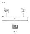
- FIG. 6illustrates a computing device for carrying out the harvesting, and current and voltage measuring functions of a current transformer device in accordance with an example embodiment of the present disclosures.
- some aspects of the present disclosureare implemented by a computer program executed by one or more processors, as described and illustrated.
- the present disclosuremay be implemented, at least in part, by computer-readable instructions in various forms, and the present disclosure is not intended to be limiting to a particular set or sequence of instructions executed by the processor.
- FIGS. 4 and 5it is noted that the present disclosure may be practiced using an alternative order of the steps illustrated in FIGS. 4 and 5 . That is, the process flows illustrated in FIGS. 4 and 5 are provided as examples only, and the present disclosure may be practiced using process flows that differ from those illustrated. Additionally, it is noted that not all steps are required in every embodiment. In other words, one or more of the steps may be omitted or replaced, without departing from the spirit and scope of the disclosure. In alternative embodiments, steps may be performed in different orders, in parallel with one another, or omitted entirely, and/or certain additional steps may be performed without departing from the scope and spirit of the disclosure.
- the present disclosureprovides a current transformer device capable of harvesting power from a conductor as well as making current measurements on the conductor and detecting high current fault events.
- the current transformer deviceis able to provide increased measurement accuracy by bypassing the non-linear elements of the energy harvesting function when making current measurements. Additionally, the current measurement function is further enhanced by the addition of two Hall effect sensors which are capable of measuring high fault currents and providing data associated with high current fault events.
- Certain embodiments of the current transformer devicealso provide voltage sensing means which allow the current transformer device to monitor for voltage conditions as well, such as sag and swell and other events. The means of detecting and measuring voltage also lends to determining load and fault current direction with the same current transformer and voltage plates.
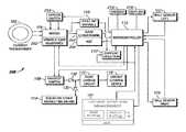
- FIG. 1illustrates a harvesting and measurement device 100 .
- the harvesting and measurement device 100includes a current transformer 102 and a circuit 104 coupled to and generally disposed with the current transformer 102 .
- the current transformer 102is disposed and enclosed around a conductor 126 to be monitored.
- the circuit 104further includes an energy harvesting bridge 106 , a switch 108 , one or more field effect transistors (FETs) or other types of analog switches 110 , a microcontroller 112 , a float charge circuit 116 , an energy storage device 119 , one or more alternate harvesting means 114 , a voltage measurement means 120 , a first Hall effect sensor 122 , and a second Hall effect sensor 124 .
- FETsfield effect transistors
- the first and second Hall sensors 122 , 124are used herein as examples of high current sensors. In certain other example embodiments, other types of high current sensors are used in addition to or in place of the Hall sensors 122 , 124 .
- Such high current sensorsinclude, but are not limited to, inductors, reed switches, and MEMS devices.
- the circuitis operable at least in a normal operation mode, a demand measurement mode, and a fault event measurement mode (also known as a high current measurement mode).
- the circuit 104is able to harvest energy from the conductor 126 via the energy harvesting bridge 106 and the current transformer 102 .
- the circuitis also continuously monitoring the current and/or the voltage in the conductor. The monitoring of the current and/or voltage is done through a low power monitoring circuit implemented within the circuit.
- the low power monitoring circuitcompares the current and/or voltage of the conductor to a preset current and/or voltage criteria, which represents an expected condition of the current and/or voltage in the conductor 126 for normal, stable operation.
- the low power monitoring circuitfurther includes a low power current monitoring circuit and a low power voltage monitoring circuit. Specific embodiments and implementations of current monitoring and voltage monitoring are described in further detail below along with example embodiments of the preset current and voltage criteria. Detecting a current and/or voltage which falls outside of the respective criteria may be an indication of a fault event in the conductor 126 . When it is detected that a fault event may have occurred according to the monitored current and/or voltage, the circuit 104 may be put into the fault event measurement mode.
- the energy harvesting bridge 106generally contains one or more non-linear elements, which may affect the accuracy of current measurements made on the current transformer 102 .
- the energy harvesting bridge 106In the normal operation mode, the energy harvesting bridge 106 remains conductively coupled to the circuit 104 because, in certain example embodiments, the low power monitoring circuit is configured to detect a relatively large shift or out of bound activity in the current and/or voltage signal rather than taking exact value measurements. Thus, high accuracy is not required.
- the energy harvesting bridge 106is bypassed from the circuit 104 because accurate current and/or voltage measurements are to be made in the demand measurement mode. In the demand measurement mode, the energy harvesting bridge 106 and its non-linear elements are bypassed or shorted out so as not to interfere with the accuracy of the current measurement.
- the energy harvesting bridge 106is shorted out or bypassed by the FETs or other types of analog switches 110 while in the demand measurement mode.
- the microcontroller 112controls the FET switches 110 to bypass the energy harvesting bridge 106 while using the current transformer 102 to take a series of current readings.
- the device 100is able to provide linear current readings from hundreds of milliamps to hundreds of amps.
- the FETs 110are controlled to restore the energy harvesting bridge 106 to its original state in the circuit 104 for optimal energy harvesting.
- the device 100is put into the demand measurement mode based on a command from an operator.
- the device 100is put into the measurement mode according to a predetermined and/or preprogrammed schedule or time interval. The process of making current measurements will be discussed in further detail below and with respect to the process flowchart of FIG. 3 .
- the current transformer 102saturates at high current level (i.e., saturation current), such as 1200 amps, and thus is not able to produce accurate current measurements when the current in the conductor 126 is greater than the saturation level.
- high current fault eventsmay not be properly measured by the current transformer 102 alone, in the present disclosure, when the device 100 detects that a potential fault condition has occurred, the device 100 goes into the fault event measurement mode. In the fault event measurement mode, the device 100 wakes up the Hall effect sensors 122 , 124 to take current readings on the conductor 126 as Hall effect sensors 122 , 124 are able to provide accurate readings at high currents.
- the current transformer 102is more accurate in measuring lower current levels than the Hall effect sensors 122 , 124 .
- both the current transformer 102 and the Hall effect sensors 122 , 124make current measurements.
- the microcontrollerdetermines whether the measured fault current is above or below the saturation current of the current transformer 102 . If the measured fault current is at or above the saturation current, then the current readings from the Hall effect sensors 122 , 124 are reported. If the measured fault current is below the saturation current, then the current reading from the current transformer 102 is reported. This is especially important when the device 100 is installed in delta systems in which fault currents are typically between 10 amps to 100 amps, and are thus more effectively measured with the current transformer 102 than then Hall effect sensors 122 , 124 .
- the devicemay go from the normal operation mode to the fault event measurement mode.
- the low power monitoring circuitdetects certain current/voltage activity, or a qualifying event, that may be indicative of a fault event
- the deviceis put into the fault event measurement mode.
- the current transformer 102detects a certain current spike, seen as a certain rise in current value with respect to time
- a qualifying current eventis said have occurred.
- the voltage sensing means 120detects a certain drop in voltage with respect to time, a qualifying voltage event is said to have occurred.
- the occurrence and/or detection of either a qualifying current event or a qualifying voltage eventtriggers the microcontroller 112 to put the device in the fault event measurement mode and wakes up high power portions of the circuit, such as the Hall effect sensors, portions of the voltage sensing circuit 120 , and certain amplification and conditioning circuit elements, to prepare to make accurate current and/or voltage measurements.
- the microcontroller 112must see both a qualifying current event and/or a qualifying voltage event to put the device into the fault event measurement mode. The process of making current measurements in response to a fault event will be discussed in further detail below and with respect to the process flowchart of FIG. 4 .
- the Hall effect sensors 122 , 124 and other high power components in the circuit 104typically use a relatively large amount of power, so such components remain unpowered during the normal operation mode when these components are not needed and only powered when accurate measurements are needed, such as in response to a detected fault event.
- the device 100is able to conserve power when possible and be energy efficient.
- the two Hall effect sensors 122 , 124are disposed on opposite sides of the device 100 at equal distances and on opposing sides of the conductor 126 when the device 100 is attached to the conductor 126 . Such a configuration aids in accommodating for possible alignment errors of the device 100 when attached to the conductor 126 .
- the Hall effect sensors 122 , 124do not necessarily have to be placed perfectly on either side of the conductor 126 , as having two Hall effect sensors 122 , 124 accommodates for alignment issues that may otherwise arise. Generally, if the sensor is perfectly placed or centered on the conductor 126 , the Hall effect sensors 122 , 124 produce equivalent amplitudes. However, if the device 100 is misaligned on the conductor 126 , but the device includes two Hall effect sensors 122 , 124 placed in the above configuration, the sum of the amplitudes from the two Hall effect sensors 122 , 124 is the same as that of the perfectly aligned condition. Thus, the device 100 can be effectively used anywhere with minimized decrease in accuracy.
- the Hall effect sensors 122 , 124are also able to detect current on adjacent conductors, which provides additional information at each location that can be used to determine system performance.
- the AC signals from the Hall effect sensors 122 , 124can also be used to compare and calibrate phase shift associated with the current transformer 102 .
- the voltage measurement circuit 120provides a means for voltage monitoring and measuring.
- the voltage measurement circuit 120includes a low power voltage monitoring circuit of the low power measurement circuit. For example, such portion of the voltage measurement circuit 120 continuously monitors voltage in the conductor 126 to detect for sag and swell in accordance with a configurable voltage window.
- the voltage windowdefines a voltage range in which the conductor is expected to stay within during normal stable operation.
- the device 100when installed on the conductor 126 , can self-detect the voltage on the conductor 126 and adjust the voltage window around the detected line voltage with a configuration tolerance range.
- the device 100alerts that there is an out of tolerance voltage event.
- the voltage windowalso allows for monitoring of voltage changes with respect to time that occur on the line in delta systems. For example, when a single phase fault occurs on one phase, the other phases see a high voltage change (i.e., spike) that can be used in conjunction with the measured current spike on the faulted phase to validate the fault event.
- the voltage measurement circuit 120includes one or more pairs of parallel plates which are tied to gain stages which then feed into the voltage window, providing a controlled and accurate means of detecting the line voltage.
- one of the platesi.e, the ground plate 193
- the circuit ground and the ground plateare brought to the conductor line potential.
- the electrical field strengthis substantially uniform between the conductor 126 and the neutral or system ground, and because the parallel plates are related to the thickness of a circuit board on which the circuit 104 is implemented, the electrical field strength across the board is substantially consistent and not influenced greatly by the distance between the conductor and ground.
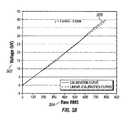
- FIG. 3Aillustrates a graph showing the effects of conductor 126 to ground distance on voltage measurements. As shown, the relationship 307 between the actual voltage 302 on the conductor 126 and the raw RMS value 304 , which is indicative of a measured voltage, is linear at all distances 306 and substantially similar, especially at larger distances from the conductor to ground.
- FIG. 3Billustrates a calibration curve 309 in accordance with an example embodiment of the present disclosure. As shown, because of the linearity of the data in FIG. 3A , the relationship between the line voltage 302 and the measured raw RMS 304 can be easily calibrated for the distance 306 between the line and ground.
- FIG. 3Aillustrates a graph showing the effects of conductor 126 to ground distance on voltage measurements. As shown, the relationship 307 between the actual voltage 302 on the conductor 126 and the raw RMS value 304 , which is indicative of a measured voltage, is linear at all distances 306 and substantially similar, especially at larger distances from the conductor to ground.
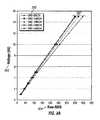
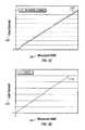
- 3Cillustrates a graph showing the relationship 310 between actual line current 308 and measured RMS 304 from the current transformer current readings when the energy harvesting bridge 106 is not bypassed. As shown, the relationship 310 is generally not linear, especially at lower line currents and thus provides less accurate current readings.
- FIG. 3Dillustrates a graph showing the relationship 312 between actual line current 308 and measured RMS 304 from the current transformer current readings when the energy harvesting bridge 106 is bypassed. As shown, the relationship 312 is linear and thus provides accurate current readings.
- a fault magnitude and directionmay be measured and analyzed by the Hall effect sensors 122 , 124 or directly from the current transformer 102 .
- the harvesting and measurement device 100allows for additional energy harvesting from alternative sources via the alternate harvesting means 114 .
- the harvesting and measurement device 100is able to obtain energy from solar, vibration, thermal, RF noise, wind, electrostatic field, and other energy sources in addition to energy harvested from the conductor 126 by the current transformer 102 .
- the alternate harvesting means 114includes a solar panel integrated into the device 100 , which allows the device 100 to harvest and store solar energy without affecting the current monitoring or measuring circuiting.
- the alternate harvesting means 114may continue to harvest while accurate current and/or voltage measurements are made.
- a rechargeable power sourcesuch as a battery or supercapacitor is charged by the alternate harvesting means 114 .
- a primary power sourcesuch as a battery is used in place of harvesting elements to serve the purpose of the alternate harvesting means 114 . Integrating such alternate harvesting means 114 and/or primary or rechargeable power sources into the device 100 aids in maintaining a completely pollable device on very low loaded lines or when the current transformer harvesting elements are being bypassed as discussed above.
- energy harvested from the current transformer 102 and the energy harvested from the alternate harvesting means 114is stored in the energy storage device 119 .
- the float charge circuit 116 and the diodes 130 which are coupled between the current transformer 102 and bridge 106 , and the alternate harvesting means 114help to prevent harvested and stored energy from feeding back into the respective harvesting and/or charging mechanisms.
- the switch 108provides a means of discontinuing harvesting from the current transformer 102 or during times when the device 100 is harvesting from the alternative harvesting means 114 or when there is an error in the float charge circuit 116 or energy storage device 119 .
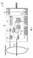
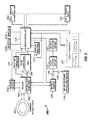
- FIG. 2illustrates another embodiment of a harvesting and measurement device 200 which includes a current transformer 102 .
- the harvesting and measurement device 200further includes an analog switch 210 which bypasses non-linear elements of the bridge 106 upon command from the microcontroller 112 .
- the analog switchmay be any type of switching device capable of coupling and decoupling the bridge 106 from the circuit 104 , such as a relay, switch, FET, and the like.
- the device 200further includes a gain/conditioning module 204 which conditions and/or amplifies the current measurement signal received from the current transformer 102 .
- the gain/conditioning module 204remains unpowered in the normal operation mode where accurate current measurements are not needed, and is only powered or used in the demand measurement mode and/or the fault event measurement mode.
- the bridge 106is coupled to a variable load resistance 202 which provides the added ability to vary the current transformer load sense resistance.
- the gain/conditioning moduleis coupled to an automatic gain control (AGC) 206 , which allows for improving the signal resolution based on a nominal value read by the device 200 . This allows for improved accuracy over a large range of line currents, such as from 200 milliamps to 600 amps.
- AGCautomatic gain control
- the devicefurther includes a current direction 212 detector which utilized data from the voltage measurements and the current measurements to determine the direction of the current and power factor, as discussed above.
- the device 200includes a radio 216 and an interface 218 .
- the radio 216may provide wireless communication means from the device 200 to an operator or other machine, and/or from the operator or other machine to the device 200 .
- the interface 218may include a display and/or input device which allows the device 200 to output information to be read by the operator and/or receive control commands from the operator. In certain example embodiments, the radio 216 and interface 218 remain unpowered during the normal operation mode.
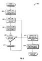
- FIG. 4illustrates a process flowchart of a method of taking a demand current or voltage measurement 400 in the demand measurement mode.
- the FETs 110 or switches 210are controlled by the microcontroller 112 to bypass or short out the energy harvesting bridge 106 (step 402 ).
- non-linear elementsare temporarily removed from the device circuit 104 such that accurate current measurements can be made.
- the device 100then takes the current measurements and takes N ADC readings over one AC cycle (Step 404 ).
- the device 100calculates a raw root mean square (RMS) value from the N ADC readings (Step 406 ). Then the device 100 determines whether or not the raw RMS value is optimal (Step 408 ), which indicates a strong robust signal.
- RMSroot mean square
- the device 100restores the energy harvesting bridge 106 (step 412 ).
- the device 100uses the measurements from the raw RMS to apply a slope and offset calibration (step 414 ) to obtain the current and voltage of the conductor 126 . The process is then complete.
- step 410the gain 204 is adjusted (step 410 ) to produce a more robust current signal, and the process goes to step 404 , where another set of N ADC readings are taken with the new gain.
- the processrepeats from step 404 to step 410 until it is determined at step 408 that the raw RMS value is optimal, at which point the process goes to steps 412 and 414 as discussed, and the process is completed.
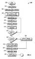
- FIG. 5illustrates a process flowchart of a method of measuring fault current 500 with the Hall effect sensors 122 , 124 as well as with the current transformer.
- the processgenerally begins when a qualifying current condition and/or a qualifying voltage condition is detected and an interrupt occurs (step 502 ).
- the microcontroller 112enables (i.e., powers up) the high powered analog components such as the conditioning components 204 , 206 (step 504 ) in preparation for making accurate current measurements.
- the microcontroller 112then enables the Hall effect sensors 122 , 124 (step 506 ).
- the sensors 122 , 124begins alternately taking measurements of the peak values from both sensors over N AC cycles (step 508 ). Specifically, in an example embodiments, the first (i.e., right) sensor takes a measurement (step 510 ), and then the second (i.e., left) sensor takes a measurement (step 512 ). In another example embodiment, the sensors may take measurements in a different order.
- the current transformer 102takes a current reading, referred to herein as I_Demand, for possible lower magnitude fault currents (step 514 ).
- the current directionis measured (step 516 ). In certain example embodiments, the current direction is measured by comparing the phase of the line voltage and the line current.
- the device 100determines if the N AC cycles are completed (step 518 ). If it is determined that the cycles are not completed, then the process returns to step 510 and the respective measurements are taken again in steps 510 , 512 , 514 , and 516 until the N AC cycles are complete.
- the device 100determines if I_Demand has reached the saturation current, which signifies a high current condition better measured by the Hall effect sensors 122 , 124 than by the current transformer 102 (step 520 ). If it is determined that the I_Demand has reached the saturation current, then the measured peak values of the first and second Hall sensors 122 , 124 are averaged (step 522 ) and reported as the fault current (step 524 ). If it is determined that the I_Demand is not saturated, then the I_Demand is reported as the fault current (step 530 ) and the fault current is reported (step 524 ). After the fault current is reported, the device 100 enters a fault timer (step 526 ) and then the Hall sensors 122 , 124 are disabled.
- FIG. 6illustrates one embodiment of a computing device 600 that can implement one or more of the various techniques described herein, and which may be representative, in whole or in part, of the elements described herein.
- Computing device 600is only one example of a computing device and is not intended to suggest any limitation as to scope of use or functionality of the computing device and/or its possible architectures. Neither should computing device 600 be interpreted as having any dependency or requirement relating to any one or combination of components illustrated in the example computing device 600 .
- Computing device 600includes one or more processors or processing units 602 , one or more memory/storage components 604 , one or more input/output (I/O) devices 606 , and a bus 608 that allows the various components and devices to communicate with one another.
- the microcontroller 112 shown in FIG. 1includes the computing device 600 .
- the microcontroller 112includes the one or more processors or processing units 602 and/or the memory/storage component 604 .
- Bus 608represents one or more of any of several types of bus structures, including a memory bus or memory controller, a peripheral bus, an accelerated graphics port, and a processor or local bus using any of a variety of bus architectures.
- Bus 608can include wired and/or wireless buses.
- Memory/storage component 604represents one or more computer storage media.
- Memory/storage component 604may include volatile media (such as random access memory (RAM)) and/or nonvolatile media (such as read only memory (ROM), flash memory, optical disks, magnetic disks, and so forth).
- RAMrandom access memory
- ROMread only memory
- Memory/storage component 604can include fixed media (e.g., RAM, ROM, a fixed hard drive, etc.) as well as removable media (e.g., a Flash memory drive, a removable hard drive, an optical disk, and so forth).
- One or more I/O devices 606allow a customer, utility, or other user to enter commands and information to computing device 600 or microcontroller 112 , and also allow information to be presented to the customer, utility, or other user and/or other components or devices.
- input devicesinclude, but are not limited to, a keyboard, a cursor control device (e.g., a mouse), a microphone, and a scanner.
- output devicesinclude, but are not limited to, a display device (e.g., a monitor or projector), speakers, a printer, and a network card.
- the I/O devices 606are physically attached to the computing device 600 .
- the I/O devices 606are electrically or communicatively coupled to the computing device 600 such that the I/O devices 606 can be located remotely or wirelessly from the computing device 600 .
- Computer readable mediamay be any available non-transitory medium or non-transitory media that can be accessed by a computing device.
- computer readable mediamay comprise “computer storage media”.
- Computer storage mediaand “computer readable medium” include volatile and non-volatile, removable and non-removable media implemented in any method or technology for storage of information such as computer readable instructions, data structures, program modules, or other data.
- Computer storage mediainclude, but are not limited to, computer recordable media such as RAM, ROM, EEPROM, flash memory or other memory technology, CD-ROM, digital versatile disks (DVD) or other optical storage, magnetic cassettes, magnetic tape, magnetic disk storage or other magnetic storage devices, or any other medium which can be used to store the desired information and which can be accessed by a computer.
- the computer device 600may be connected to a network (not shown) (e.g., a local area network (LAN), a wide area network (WAN) such as the Internet, or any other similar type of network) via a network interface connection (not shown).
- a networke.g., a local area network (LAN), a wide area network (WAN) such as the Internet, or any other similar type of network
- LANlocal area network
- WANwide area network
Landscapes
- Engineering & Computer Science (AREA)
- Power Engineering (AREA)
- Computer Networks & Wireless Communication (AREA)
- Measuring Instrument Details And Bridges, And Automatic Balancing Devices (AREA)
- Measurement Of Current Or Voltage (AREA)
- Physics & Mathematics (AREA)
- General Physics & Mathematics (AREA)
- General Engineering & Computer Science (AREA)
Abstract
Description
Claims (22)
Priority Applications (5)
| Application Number | Priority Date | Filing Date | Title |
|---|---|---|---|
| US13/828,878US9379556B2 (en) | 2013-03-14 | 2013-03-14 | Systems and methods for energy harvesting and current and voltage measurements |
| AU2014244259AAU2014244259B2 (en) | 2013-03-14 | 2014-03-13 | Systems and methods for energy harvesting and current and voltage measurements |
| BR112015022527-6ABR112015022527B1 (en) | 2013-03-14 | 2014-03-13 | HARVEST AND MEASUREMENT DEVICE, METHOD TO MAKE A CURRENT MEASUREMENT ON DEMAND, METHOD TO MAKE A HIGH CURRENT MEASUREMENT AND HARVEST AND MEASUREMENT DEVICE |
| NZ711164ANZ711164A (en) | 2013-03-14 | 2014-03-13 | Systems and methods for energy harvesting and current and voltage measurements |
| PCT/US2014/025589WO2014159995A1 (en) | 2013-03-14 | 2014-03-13 | Systems and methods for energy harvesting and current and voltage measurements |
Applications Claiming Priority (1)
| Application Number | Priority Date | Filing Date | Title |
|---|---|---|---|
| US13/828,878US9379556B2 (en) | 2013-03-14 | 2013-03-14 | Systems and methods for energy harvesting and current and voltage measurements |
Publications (2)
| Publication Number | Publication Date |
|---|---|
| US20140266240A1 US20140266240A1 (en) | 2014-09-18 |
| US9379556B2true US9379556B2 (en) | 2016-06-28 |
Family
ID=51524789
Family Applications (1)
| Application Number | Title | Priority Date | Filing Date |
|---|---|---|---|
| US13/828,878Active2034-02-27US9379556B2 (en) | 2013-03-14 | 2013-03-14 | Systems and methods for energy harvesting and current and voltage measurements |
Country Status (5)
| Country | Link |
|---|---|
| US (1) | US9379556B2 (en) |
| AU (1) | AU2014244259B2 (en) |
| BR (1) | BR112015022527B1 (en) |
| NZ (1) | NZ711164A (en) |
| WO (1) | WO2014159995A1 (en) |
Cited By (158)
| Publication number | Priority date | Publication date | Assignee | Title |
|---|---|---|---|---|
| US9544006B2 (en) | 2014-11-20 | 2017-01-10 | At&T Intellectual Property I, L.P. | Transmission device with mode division multiplexing and methods for use therewith |
| US9596001B2 (en) | 2014-10-21 | 2017-03-14 | At&T Intellectual Property I, L.P. | Apparatus for providing communication services and methods thereof |
| US9608692B2 (en) | 2015-06-11 | 2017-03-28 | At&T Intellectual Property I, L.P. | Repeater and methods for use therewith |
| US9608740B2 (en) | 2015-07-15 | 2017-03-28 | At&T Intellectual Property I, L.P. | Method and apparatus for launching a wave mode that mitigates interference |
| US9615269B2 (en) | 2014-10-02 | 2017-04-04 | At&T Intellectual Property I, L.P. | Method and apparatus that provides fault tolerance in a communication network |
| US9628116B2 (en) | 2015-07-14 | 2017-04-18 | At&T Intellectual Property I, L.P. | Apparatus and methods for transmitting wireless signals |
| US9627768B2 (en) | 2014-10-21 | 2017-04-18 | At&T Intellectual Property I, L.P. | Guided-wave transmission device with non-fundamental mode propagation and methods for use therewith |
| US9640850B2 (en) | 2015-06-25 | 2017-05-02 | At&T Intellectual Property I, L.P. | Methods and apparatus for inducing a non-fundamental wave mode on a transmission medium |
| US9653770B2 (en) | 2014-10-21 | 2017-05-16 | At&T Intellectual Property I, L.P. | Guided wave coupler, coupling module and methods for use therewith |
| US9654173B2 (en) | 2014-11-20 | 2017-05-16 | At&T Intellectual Property I, L.P. | Apparatus for powering a communication device and methods thereof |
| US9661505B2 (en) | 2013-11-06 | 2017-05-23 | At&T Intellectual Property I, L.P. | Surface-wave communications and methods thereof |
| US9667317B2 (en) | 2015-06-15 | 2017-05-30 | At&T Intellectual Property I, L.P. | Method and apparatus for providing security using network traffic adjustments |
| US9685992B2 (en) | 2014-10-03 | 2017-06-20 | At&T Intellectual Property I, L.P. | Circuit panel network and methods thereof |
| US9692101B2 (en) | 2014-08-26 | 2017-06-27 | At&T Intellectual Property I, L.P. | Guided wave couplers for coupling electromagnetic waves between a waveguide surface and a surface of a wire |
| US9699785B2 (en) | 2012-12-05 | 2017-07-04 | At&T Intellectual Property I, L.P. | Backhaul link for distributed antenna system |
| US9705610B2 (en) | 2014-10-21 | 2017-07-11 | At&T Intellectual Property I, L.P. | Transmission device with impairment compensation and methods for use therewith |
| US9705561B2 (en) | 2015-04-24 | 2017-07-11 | At&T Intellectual Property I, L.P. | Directional coupling device and methods for use therewith |
| US9712350B2 (en) | 2014-11-20 | 2017-07-18 | At&T Intellectual Property I, L.P. | Transmission device with channel equalization and control and methods for use therewith |
| US9722318B2 (en) | 2015-07-14 | 2017-08-01 | At&T Intellectual Property I, L.P. | Method and apparatus for coupling an antenna to a device |
| US9729197B2 (en) | 2015-10-01 | 2017-08-08 | At&T Intellectual Property I, L.P. | Method and apparatus for communicating network management traffic over a network |
| US9735833B2 (en) | 2015-07-31 | 2017-08-15 | At&T Intellectual Property I, L.P. | Method and apparatus for communications management in a neighborhood network |
| US9742462B2 (en) | 2014-12-04 | 2017-08-22 | At&T Intellectual Property I, L.P. | Transmission medium and communication interfaces and methods for use therewith |
| US9749053B2 (en) | 2015-07-23 | 2017-08-29 | At&T Intellectual Property I, L.P. | Node device, repeater and methods for use therewith |
| US9748626B2 (en) | 2015-05-14 | 2017-08-29 | At&T Intellectual Property I, L.P. | Plurality of cables having different cross-sectional shapes which are bundled together to form a transmission medium |
| US9749013B2 (en) | 2015-03-17 | 2017-08-29 | At&T Intellectual Property I, L.P. | Method and apparatus for reducing attenuation of electromagnetic waves guided by a transmission medium |
| US9762289B2 (en) | 2014-10-14 | 2017-09-12 | At&T Intellectual Property I, L.P. | Method and apparatus for transmitting or receiving signals in a transportation system |
| US9768833B2 (en) | 2014-09-15 | 2017-09-19 | At&T Intellectual Property I, L.P. | Method and apparatus for sensing a condition in a transmission medium of electromagnetic waves |
| US9769128B2 (en) | 2015-09-28 | 2017-09-19 | At&T Intellectual Property I, L.P. | Method and apparatus for encryption of communications over a network |
| US9769020B2 (en) | 2014-10-21 | 2017-09-19 | At&T Intellectual Property I, L.P. | Method and apparatus for responding to events affecting communications in a communication network |
| US9780834B2 (en) | 2014-10-21 | 2017-10-03 | At&T Intellectual Property I, L.P. | Method and apparatus for transmitting electromagnetic waves |
| US9787412B2 (en) | 2015-06-25 | 2017-10-10 | At&T Intellectual Property I, L.P. | Methods and apparatus for inducing a fundamental wave mode on a transmission medium |
| US9794003B2 (en) | 2013-12-10 | 2017-10-17 | At&T Intellectual Property I, L.P. | Quasi-optical coupler |
| US9793955B2 (en) | 2015-04-24 | 2017-10-17 | At&T Intellectual Property I, Lp | Passive electrical coupling device and methods for use therewith |
| US9793954B2 (en) | 2015-04-28 | 2017-10-17 | At&T Intellectual Property I, L.P. | Magnetic coupling device and methods for use therewith |
| US9793951B2 (en) | 2015-07-15 | 2017-10-17 | At&T Intellectual Property I, L.P. | Method and apparatus for launching a wave mode that mitigates interference |
| US9800327B2 (en) | 2014-11-20 | 2017-10-24 | At&T Intellectual Property I, L.P. | Apparatus for controlling operations of a communication device and methods thereof |
| US9820146B2 (en) | 2015-06-12 | 2017-11-14 | At&T Intellectual Property I, L.P. | Method and apparatus for authentication and identity management of communicating devices |
| US9836957B2 (en) | 2015-07-14 | 2017-12-05 | At&T Intellectual Property I, L.P. | Method and apparatus for communicating with premises equipment |
| US9838078B2 (en) | 2015-07-31 | 2017-12-05 | At&T Intellectual Property I, L.P. | Method and apparatus for exchanging communication signals |
| US9838896B1 (en) | 2016-12-09 | 2017-12-05 | At&T Intellectual Property I, L.P. | Method and apparatus for assessing network coverage |
| US9847850B2 (en) | 2014-10-14 | 2017-12-19 | At&T Intellectual Property I, L.P. | Method and apparatus for adjusting a mode of communication in a communication network |
| US9847566B2 (en) | 2015-07-14 | 2017-12-19 | At&T Intellectual Property I, L.P. | Method and apparatus for adjusting a field of a signal to mitigate interference |
| US9853342B2 (en) | 2015-07-14 | 2017-12-26 | At&T Intellectual Property I, L.P. | Dielectric transmission medium connector and methods for use therewith |
| US9860075B1 (en) | 2016-08-26 | 2018-01-02 | At&T Intellectual Property I, L.P. | Method and communication node for broadband distribution |
| US9866276B2 (en) | 2014-10-10 | 2018-01-09 | At&T Intellectual Property I, L.P. | Method and apparatus for arranging communication sessions in a communication system |
| US9865911B2 (en) | 2015-06-25 | 2018-01-09 | At&T Intellectual Property I, L.P. | Waveguide system for slot radiating first electromagnetic waves that are combined into a non-fundamental wave mode second electromagnetic wave on a transmission medium |
| US9866309B2 (en) | 2015-06-03 | 2018-01-09 | At&T Intellectual Property I, Lp | Host node device and methods for use therewith |
| US9871558B2 (en) | 2014-10-21 | 2018-01-16 | At&T Intellectual Property I, L.P. | Guided-wave transmission device and methods for use therewith |
| US9871283B2 (en) | 2015-07-23 | 2018-01-16 | At&T Intellectual Property I, Lp | Transmission medium having a dielectric core comprised of plural members connected by a ball and socket configuration |
| US9871282B2 (en) | 2015-05-14 | 2018-01-16 | At&T Intellectual Property I, L.P. | At least one transmission medium having a dielectric surface that is covered at least in part by a second dielectric |
| US9876264B2 (en) | 2015-10-02 | 2018-01-23 | At&T Intellectual Property I, Lp | Communication system, guided wave switch and methods for use therewith |
| US9876571B2 (en) | 2015-02-20 | 2018-01-23 | At&T Intellectual Property I, Lp | Guided-wave transmission device with non-fundamental mode propagation and methods for use therewith |
| US9876605B1 (en) | 2016-10-21 | 2018-01-23 | At&T Intellectual Property I, L.P. | Launcher and coupling system to support desired guided wave mode |
| US9882257B2 (en) | 2015-07-14 | 2018-01-30 | At&T Intellectual Property I, L.P. | Method and apparatus for launching a wave mode that mitigates interference |
| US9882277B2 (en) | 2015-10-02 | 2018-01-30 | At&T Intellectual Property I, Lp | Communication device and antenna assembly with actuated gimbal mount |
| US9887447B2 (en) | 2015-05-14 | 2018-02-06 | At&T Intellectual Property I, L.P. | Transmission medium having multiple cores and methods for use therewith |
| US9893795B1 (en) | 2016-12-07 | 2018-02-13 | At&T Intellectual Property I, Lp | Method and repeater for broadband distribution |
| US9904535B2 (en) | 2015-09-14 | 2018-02-27 | At&T Intellectual Property I, L.P. | Method and apparatus for distributing software |
| US9906269B2 (en) | 2014-09-17 | 2018-02-27 | At&T Intellectual Property I, L.P. | Monitoring and mitigating conditions in a communication network |
| US9912381B2 (en) | 2015-06-03 | 2018-03-06 | At&T Intellectual Property I, Lp | Network termination and methods for use therewith |
| US9913139B2 (en) | 2015-06-09 | 2018-03-06 | At&T Intellectual Property I, L.P. | Signal fingerprinting for authentication of communicating devices |
| US9911020B1 (en) | 2016-12-08 | 2018-03-06 | At&T Intellectual Property I, L.P. | Method and apparatus for tracking via a radio frequency identification device |
| US9912027B2 (en) | 2015-07-23 | 2018-03-06 | At&T Intellectual Property I, L.P. | Method and apparatus for exchanging communication signals |
| US9912419B1 (en) | 2016-08-24 | 2018-03-06 | At&T Intellectual Property I, L.P. | Method and apparatus for managing a fault in a distributed antenna system |
| US9917341B2 (en) | 2015-05-27 | 2018-03-13 | At&T Intellectual Property I, L.P. | Apparatus and method for launching electromagnetic waves and for modifying radial dimensions of the propagating electromagnetic waves |
| US9930668B2 (en) | 2013-05-31 | 2018-03-27 | At&T Intellectual Property I, L.P. | Remote distributed antenna system |
| US9927517B1 (en) | 2016-12-06 | 2018-03-27 | At&T Intellectual Property I, L.P. | Apparatus and methods for sensing rainfall |
| US9948354B2 (en) | 2015-04-28 | 2018-04-17 | At&T Intellectual Property I, L.P. | Magnetic coupling device with reflective plate and methods for use therewith |
| US9948333B2 (en) | 2015-07-23 | 2018-04-17 | At&T Intellectual Property I, L.P. | Method and apparatus for wireless communications to mitigate interference |
| US9954287B2 (en) | 2014-11-20 | 2018-04-24 | At&T Intellectual Property I, L.P. | Apparatus for converting wireless signals and electromagnetic waves and methods thereof |
| US9967173B2 (en) | 2015-07-31 | 2018-05-08 | At&T Intellectual Property I, L.P. | Method and apparatus for authentication and identity management of communicating devices |
| US9973940B1 (en) | 2017-02-27 | 2018-05-15 | At&T Intellectual Property I, L.P. | Apparatus and methods for dynamic impedance matching of a guided wave launcher |
| US9991580B2 (en) | 2016-10-21 | 2018-06-05 | At&T Intellectual Property I, L.P. | Launcher and coupling system for guided wave mode cancellation |
| US9998870B1 (en) | 2016-12-08 | 2018-06-12 | At&T Intellectual Property I, L.P. | Method and apparatus for proximity sensing |
| US9997819B2 (en) | 2015-06-09 | 2018-06-12 | At&T Intellectual Property I, L.P. | Transmission medium and method for facilitating propagation of electromagnetic waves via a core |
| US9999038B2 (en) | 2013-05-31 | 2018-06-12 | At&T Intellectual Property I, L.P. | Remote distributed antenna system |
| US10009901B2 (en) | 2015-09-16 | 2018-06-26 | At&T Intellectual Property I, L.P. | Method, apparatus, and computer-readable storage medium for managing utilization of wireless resources between base stations |
| US10009065B2 (en) | 2012-12-05 | 2018-06-26 | At&T Intellectual Property I, L.P. | Backhaul link for distributed antenna system |
| US10009067B2 (en) | 2014-12-04 | 2018-06-26 | At&T Intellectual Property I, L.P. | Method and apparatus for configuring a communication interface |
| US10009063B2 (en) | 2015-09-16 | 2018-06-26 | At&T Intellectual Property I, L.P. | Method and apparatus for use with a radio distributed antenna system having an out-of-band reference signal |
| US10020587B2 (en) | 2015-07-31 | 2018-07-10 | At&T Intellectual Property I, L.P. | Radial antenna and methods for use therewith |
| US10020844B2 (en) | 2016-12-06 | 2018-07-10 | T&T Intellectual Property I, L.P. | Method and apparatus for broadcast communication via guided waves |
| US10027397B2 (en) | 2016-12-07 | 2018-07-17 | At&T Intellectual Property I, L.P. | Distributed antenna system and methods for use therewith |
| US10033107B2 (en) | 2015-07-14 | 2018-07-24 | At&T Intellectual Property I, L.P. | Method and apparatus for coupling an antenna to a device |
| US10033108B2 (en) | 2015-07-14 | 2018-07-24 | At&T Intellectual Property I, L.P. | Apparatus and methods for generating an electromagnetic wave having a wave mode that mitigates interference |
| US10044409B2 (en) | 2015-07-14 | 2018-08-07 | At&T Intellectual Property I, L.P. | Transmission medium and methods for use therewith |
| US10069535B2 (en) | 2016-12-08 | 2018-09-04 | At&T Intellectual Property I, L.P. | Apparatus and methods for launching electromagnetic waves having a certain electric field structure |
| US10079661B2 (en) | 2015-09-16 | 2018-09-18 | At&T Intellectual Property I, L.P. | Method and apparatus for use with a radio distributed antenna system having a clock reference |
| US10090606B2 (en) | 2015-07-15 | 2018-10-02 | At&T Intellectual Property I, L.P. | Antenna system with dielectric array and methods for use therewith |
| US10090594B2 (en) | 2016-11-23 | 2018-10-02 | At&T Intellectual Property I, L.P. | Antenna system having structural configurations for assembly |
| US10103422B2 (en) | 2016-12-08 | 2018-10-16 | At&T Intellectual Property I, L.P. | Method and apparatus for mounting network devices |
| US10103801B2 (en) | 2015-06-03 | 2018-10-16 | At&T Intellectual Property I, L.P. | Host node device and methods for use therewith |
| US10135146B2 (en) | 2016-10-18 | 2018-11-20 | At&T Intellectual Property I, L.P. | Apparatus and methods for launching guided waves via circuits |
| US10136434B2 (en) | 2015-09-16 | 2018-11-20 | At&T Intellectual Property I, L.P. | Method and apparatus for use with a radio distributed antenna system having an ultra-wideband control channel |
| US10135147B2 (en) | 2016-10-18 | 2018-11-20 | At&T Intellectual Property I, L.P. | Apparatus and methods for launching guided waves via an antenna |
| US10135145B2 (en) | 2016-12-06 | 2018-11-20 | At&T Intellectual Property I, L.P. | Apparatus and methods for generating an electromagnetic wave along a transmission medium |
| US10142086B2 (en) | 2015-06-11 | 2018-11-27 | At&T Intellectual Property I, L.P. | Repeater and methods for use therewith |
| US10139820B2 (en) | 2016-12-07 | 2018-11-27 | At&T Intellectual Property I, L.P. | Method and apparatus for deploying equipment of a communication system |
| US10144036B2 (en) | 2015-01-30 | 2018-12-04 | At&T Intellectual Property I, L.P. | Method and apparatus for mitigating interference affecting a propagation of electromagnetic waves guided by a transmission medium |
| US10148016B2 (en) | 2015-07-14 | 2018-12-04 | At&T Intellectual Property I, L.P. | Apparatus and methods for communicating utilizing an antenna array |
| US10168695B2 (en) | 2016-12-07 | 2019-01-01 | At&T Intellectual Property I, L.P. | Method and apparatus for controlling an unmanned aircraft |
| US10170840B2 (en) | 2015-07-14 | 2019-01-01 | At&T Intellectual Property I, L.P. | Apparatus and methods for sending or receiving electromagnetic signals |
| US10178445B2 (en) | 2016-11-23 | 2019-01-08 | At&T Intellectual Property I, L.P. | Methods, devices, and systems for load balancing between a plurality of waveguides |
| US10205655B2 (en) | 2015-07-14 | 2019-02-12 | At&T Intellectual Property I, L.P. | Apparatus and methods for communicating utilizing an antenna array and multiple communication paths |
| US10225025B2 (en) | 2016-11-03 | 2019-03-05 | At&T Intellectual Property I, L.P. | Method and apparatus for detecting a fault in a communication system |
| US10224634B2 (en) | 2016-11-03 | 2019-03-05 | At&T Intellectual Property I, L.P. | Methods and apparatus for adjusting an operational characteristic of an antenna |
| US10243784B2 (en) | 2014-11-20 | 2019-03-26 | At&T Intellectual Property I, L.P. | System for generating topology information and methods thereof |
| US10243270B2 (en) | 2016-12-07 | 2019-03-26 | At&T Intellectual Property I, L.P. | Beam adaptive multi-feed dielectric antenna system and methods for use therewith |
| US10264586B2 (en) | 2016-12-09 | 2019-04-16 | At&T Mobility Ii Llc | Cloud-based packet controller and methods for use therewith |
| US10291311B2 (en) | 2016-09-09 | 2019-05-14 | At&T Intellectual Property I, L.P. | Method and apparatus for mitigating a fault in a distributed antenna system |
| US10291334B2 (en) | 2016-11-03 | 2019-05-14 | At&T Intellectual Property I, L.P. | System for detecting a fault in a communication system |
| US10298293B2 (en) | 2017-03-13 | 2019-05-21 | At&T Intellectual Property I, L.P. | Apparatus of communication utilizing wireless network devices |
| US10305190B2 (en) | 2016-12-01 | 2019-05-28 | At&T Intellectual Property I, L.P. | Reflecting dielectric antenna system and methods for use therewith |
| US10312567B2 (en) | 2016-10-26 | 2019-06-04 | At&T Intellectual Property I, L.P. | Launcher with planar strip antenna and methods for use therewith |
| US10320586B2 (en) | 2015-07-14 | 2019-06-11 | At&T Intellectual Property I, L.P. | Apparatus and methods for generating non-interfering electromagnetic waves on an insulated transmission medium |
| US10326494B2 (en) | 2016-12-06 | 2019-06-18 | At&T Intellectual Property I, L.P. | Apparatus for measurement de-embedding and methods for use therewith |
| US10326689B2 (en) | 2016-12-08 | 2019-06-18 | At&T Intellectual Property I, L.P. | Method and system for providing alternative communication paths |
| US10340603B2 (en) | 2016-11-23 | 2019-07-02 | At&T Intellectual Property I, L.P. | Antenna system having shielded structural configurations for assembly |
| US10340983B2 (en) | 2016-12-09 | 2019-07-02 | At&T Intellectual Property I, L.P. | Method and apparatus for surveying remote sites via guided wave communications |
| US10340601B2 (en) | 2016-11-23 | 2019-07-02 | At&T Intellectual Property I, L.P. | Multi-antenna system and methods for use therewith |
| US10340600B2 (en) | 2016-10-18 | 2019-07-02 | At&T Intellectual Property I, L.P. | Apparatus and methods for launching guided waves via plural waveguide systems |
| US10340573B2 (en) | 2016-10-26 | 2019-07-02 | At&T Intellectual Property I, L.P. | Launcher with cylindrical coupling device and methods for use therewith |
| US10341142B2 (en) | 2015-07-14 | 2019-07-02 | At&T Intellectual Property I, L.P. | Apparatus and methods for generating non-interfering electromagnetic waves on an uninsulated conductor |
| US10355367B2 (en) | 2015-10-16 | 2019-07-16 | At&T Intellectual Property I, L.P. | Antenna structure for exchanging wireless signals |
| US10361489B2 (en) | 2016-12-01 | 2019-07-23 | At&T Intellectual Property I, L.P. | Dielectric dish antenna system and methods for use therewith |
| US10359749B2 (en) | 2016-12-07 | 2019-07-23 | At&T Intellectual Property I, L.P. | Method and apparatus for utilities management via guided wave communication |
| US10374316B2 (en) | 2016-10-21 | 2019-08-06 | At&T Intellectual Property I, L.P. | System and dielectric antenna with non-uniform dielectric |
| US10382976B2 (en) | 2016-12-06 | 2019-08-13 | At&T Intellectual Property I, L.P. | Method and apparatus for managing wireless communications based on communication paths and network device positions |
| US10389037B2 (en) | 2016-12-08 | 2019-08-20 | At&T Intellectual Property I, L.P. | Apparatus and methods for selecting sections of an antenna array and use therewith |
| US10389029B2 (en) | 2016-12-07 | 2019-08-20 | At&T Intellectual Property I, L.P. | Multi-feed dielectric antenna system with core selection and methods for use therewith |
| US10411356B2 (en) | 2016-12-08 | 2019-09-10 | At&T Intellectual Property I, L.P. | Apparatus and methods for selectively targeting communication devices with an antenna array |
| US10439675B2 (en) | 2016-12-06 | 2019-10-08 | At&T Intellectual Property I, L.P. | Method and apparatus for repeating guided wave communication signals |
| US10446936B2 (en) | 2016-12-07 | 2019-10-15 | At&T Intellectual Property I, L.P. | Multi-feed dielectric antenna system and methods for use therewith |
| US10498044B2 (en) | 2016-11-03 | 2019-12-03 | At&T Intellectual Property I, L.P. | Apparatus for configuring a surface of an antenna |
| US10530505B2 (en) | 2016-12-08 | 2020-01-07 | At&T Intellectual Property I, L.P. | Apparatus and methods for launching electromagnetic waves along a transmission medium |
| US10535928B2 (en) | 2016-11-23 | 2020-01-14 | At&T Intellectual Property I, L.P. | Antenna system and methods for use therewith |
| US10547348B2 (en) | 2016-12-07 | 2020-01-28 | At&T Intellectual Property I, L.P. | Method and apparatus for switching transmission mediums in a communication system |
| US10601494B2 (en) | 2016-12-08 | 2020-03-24 | At&T Intellectual Property I, L.P. | Dual-band communication device and method for use therewith |
| US10637149B2 (en) | 2016-12-06 | 2020-04-28 | At&T Intellectual Property I, L.P. | Injection molded dielectric antenna and methods for use therewith |
| US10650940B2 (en) | 2015-05-15 | 2020-05-12 | At&T Intellectual Property I, L.P. | Transmission medium having a conductive material and methods for use therewith |
| US10665942B2 (en) | 2015-10-16 | 2020-05-26 | At&T Intellectual Property I, L.P. | Method and apparatus for adjusting wireless communications |
| US10694379B2 (en) | 2016-12-06 | 2020-06-23 | At&T Intellectual Property I, L.P. | Waveguide system with device-based authentication and methods for use therewith |
| US10727599B2 (en) | 2016-12-06 | 2020-07-28 | At&T Intellectual Property I, L.P. | Launcher with slot antenna and methods for use therewith |
| US10755542B2 (en) | 2016-12-06 | 2020-08-25 | At&T Intellectual Property I, L.P. | Method and apparatus for surveillance via guided wave communication |
| US10777873B2 (en) | 2016-12-08 | 2020-09-15 | At&T Intellectual Property I, L.P. | Method and apparatus for mounting network devices |
| US10784670B2 (en) | 2015-07-23 | 2020-09-22 | At&T Intellectual Property I, L.P. | Antenna support for aligning an antenna |
| US10797781B2 (en) | 2015-06-03 | 2020-10-06 | At&T Intellectual Property I, L.P. | Client node device and methods for use therewith |
| US10811767B2 (en) | 2016-10-21 | 2020-10-20 | At&T Intellectual Property I, L.P. | System and dielectric antenna with convex dielectric radome |
| US10819035B2 (en) | 2016-12-06 | 2020-10-27 | At&T Intellectual Property I, L.P. | Launcher with helical antenna and methods for use therewith |
| US10916969B2 (en) | 2016-12-08 | 2021-02-09 | At&T Intellectual Property I, L.P. | Method and apparatus for providing power using an inductive coupling |
| US10938108B2 (en) | 2016-12-08 | 2021-03-02 | At&T Intellectual Property I, L.P. | Frequency selective multi-feed dielectric antenna system and methods for use therewith |
| US11032819B2 (en) | 2016-09-15 | 2021-06-08 | At&T Intellectual Property I, L.P. | Method and apparatus for use with a radio distributed antenna system having a control channel reference signal |
| US11095110B1 (en) | 2018-06-28 | 2021-08-17 | Smart Wires Inc. | Energy harvesting from fault currents |
| WO2021226089A1 (en) | 2020-05-05 | 2021-11-11 | Novinium, Inc. | System for harvesting power from a current transformer |
| US11360121B2 (en) | 2017-10-12 | 2022-06-14 | Johnson Controls Tyco IP Holdings LLP | System and method for energy sensing and harvesting with fault detection |
| US20230117407A1 (en)* | 2021-10-19 | 2023-04-20 | Chargepoint, Inc. | Dynamic allocation of power modules for charging electric vehicles |
| US12002344B2 (en) | 2019-10-22 | 2024-06-04 | Ademco Inc. | Current sensing device |
| US20250035683A1 (en)* | 2023-07-28 | 2025-01-30 | Senva Inc. | Contactless Power Meter |
Families Citing this family (26)
| Publication number | Priority date | Publication date | Assignee | Title |
|---|---|---|---|---|
| US9678114B2 (en) | 2009-04-16 | 2017-06-13 | Panoramic Power Ltd. | Apparatus and methods thereof for error correction in split core current transformers |
| DE112010001638B4 (en) | 2009-04-16 | 2017-07-06 | Panoramic Power Ltd. | Apparatus and method for power consumption measurements at breaker points |
| US9134348B2 (en) | 2009-04-16 | 2015-09-15 | Panoramic Power Ltd. | Distributed electricity metering system |
| US9379556B2 (en)* | 2013-03-14 | 2016-06-28 | Cooper Technologies Company | Systems and methods for energy harvesting and current and voltage measurements |
| WO2014204649A1 (en)* | 2013-06-18 | 2014-12-24 | Rocketship, Inc. | Battery management system |
| US9958480B2 (en)* | 2015-02-10 | 2018-05-01 | Qualcomm Incorporated | Apparatus and method for a current sensor |
| US9543072B2 (en) | 2015-03-18 | 2017-01-10 | 3M Innovative Properties Company | Inductive power harvester with power limiting capability |
| US10142822B1 (en) | 2015-07-25 | 2018-11-27 | Gary M. Zalewski | Wireless coded communication (WCC) devices with power harvesting power sources triggered with incidental mechanical forces |
| US9911290B1 (en) | 2015-07-25 | 2018-03-06 | Gary M. Zalewski | Wireless coded communication (WCC) devices for tracking retail interactions with goods and association to user accounts |
| US9891252B2 (en) | 2015-07-28 | 2018-02-13 | Panoramic Power Ltd. | Thermal management of self-powered power sensors |
| US10024885B2 (en) | 2015-07-28 | 2018-07-17 | Panoramic Power Ltd. | Thermal management of self-powered power sensors |
| US10253956B2 (en) | 2015-08-26 | 2019-04-09 | Abl Ip Holding Llc | LED luminaire with mounting structure for LED circuit board |
| US20170059640A1 (en)* | 2015-08-31 | 2017-03-02 | Cooper Technologies Company | System for monitoring a fuse link, fuse tube assembly and fuse cutout including same |
| PL3414812T3 (en) | 2016-02-12 | 2021-12-27 | Laki Power EHF. | Apparatus, system and method for power extraction |
| CN107292005B (en)* | 2017-06-08 | 2021-02-05 | 株洲中车时代电气股份有限公司 | Track traffic converter vibration optimization method based on modal decoupling technology |
| DE102017129758B3 (en)* | 2017-12-13 | 2018-10-31 | SDA-engineering GmbH | Device for monitoring a current-carrying device |
| US10251279B1 (en) | 2018-01-04 | 2019-04-02 | Abl Ip Holding Llc | Printed circuit board mounting with tabs |
| RU2690860C1 (en)* | 2018-06-23 | 2019-06-06 | Дмитрий Валерьевич Хачатуров | High-voltage measuring device and method |
| US11656286B2 (en)* | 2018-08-06 | 2023-05-23 | Regal Beloit America, Inc. | Health monitor for an electric machine |
| CH716185A1 (en)* | 2019-01-28 | 2020-11-13 | Soraytec Scandinavia | Current and voltage measurement unit. |
| SE1951382A1 (en)* | 2019-12-03 | 2021-06-04 | Bombardier Transp Gmbh | Remote sensor arrangement |
| CN113640565B (en)* | 2021-07-26 | 2025-03-25 | 台达电子企业管理(上海)有限公司 | Current detection circuit, current detection method and converter |
| WO2024062401A1 (en) | 2022-09-21 | 2024-03-28 | Basis NZ Limited | Current detection device and related devices, systems and methods thereof |
| WO2024206392A1 (en)* | 2023-03-31 | 2024-10-03 | Schneider Electric USA, Inc. | Integrated current sensor and energy harvester based on microresonator energy transducer |
| GB2628666A (en)* | 2023-03-31 | 2024-10-02 | Etrel D O O | Power monitoring apparatus and system |
| CN119986104B (en)* | 2025-01-26 | 2025-09-05 | 北京国力电气科技有限公司 | Design method and system for fault current measurement CT integrating energy acquisition and measurement |
Citations (148)
| Publication number | Priority date | Publication date | Assignee | Title |
|---|---|---|---|---|
| US2273534A (en) | 1939-02-10 | 1942-02-17 | H D Electric Company | Split core transformer |
| US2953757A (en) | 1956-06-04 | 1960-09-20 | Ite Circuit Breaker Ltd | Molded epoxy current transformer |
| US3025512A (en) | 1959-07-01 | 1962-03-13 | Gen Railway Signal Co | Changeable indicators for display devices |
| US3253215A (en) | 1959-09-30 | 1966-05-24 | Automatic Switch Co | Overload current detecting device having laminated split core means coupled to a holding circuit with indicator |
| US3364481A (en) | 1965-06-04 | 1968-01-16 | Caterpillar Tractor Co | Magnetically controlled rotating ball indicating device |
| US3386032A (en) | 1966-04-28 | 1968-05-28 | Franklin Lewis B | Removable core structures for electrical devices |
| US3460038A (en) | 1965-12-17 | 1969-08-05 | Gen Motors Corp | Electric indicator utilizing a bidirectional and multiple unidirection coils to provide extended pointer movement in opposite directions |
| US3665243A (en) | 1969-02-27 | 1972-05-23 | New Nippon Electric Co | Discharge-lamp operating device using thyristor oscillating circuit |
| US3700967A (en) | 1972-01-10 | 1972-10-24 | Zinsco Electrical Products | Ground fault detector circuit |
| US3720872A (en) | 1970-09-04 | 1973-03-13 | Taft Electrosyst Inc | Power transmission fault indicator with automatic reset means |
| US3725846A (en) | 1970-10-30 | 1973-04-03 | Itt | Waterproof high voltage connection apparatus |
| US3735248A (en) | 1970-03-31 | 1973-05-22 | R Reese | Apparatus having automatic re-set means for detecting a fault current |
| US3816816A (en) | 1969-11-03 | 1974-06-11 | Schweitzer Mfg Co E | Indicating and automatically resettable system for detection of fault current flow in a conductor |
| US3995243A (en) | 1974-10-17 | 1976-11-30 | North American Philips Corporation | Fault detection indicator |
| US4000462A (en) | 1973-09-19 | 1976-12-28 | International Telephone And Telegraph Corporation | Fault indicator circuit |
| US4037155A (en) | 1974-04-15 | 1977-07-19 | Rca Corporation | Current-responsive threshold detection circuitry |
| US4045726A (en) | 1976-07-06 | 1977-08-30 | Schweitzer Edmund O Jun | Tool for manually tripping a fault indicator for high voltage electric power circuits and resetting same |
| US4157520A (en) | 1975-11-04 | 1979-06-05 | Westinghouse Electric Corp. | Magnetic flux shifting ground fault trip indicator |
| US4165528A (en) | 1976-07-26 | 1979-08-21 | Schweitzer Edmund O Jun | Fault indicator and means for resetting same |
| US4288743A (en) | 1978-10-10 | 1981-09-08 | Schweitzer Edmund O | Fault indicator operable from a remote excitation source through a uniformly distributed impedance cable |
| US4335437A (en) | 1980-04-15 | 1982-06-15 | Westinghouse Electric Corp. | Circuit interrupter with energy management functions |
| US4384289A (en) | 1981-01-23 | 1983-05-17 | General Electric Company | Transponder unit for measuring temperature and current on live transmission lines |
| US4456873A (en) | 1981-08-04 | 1984-06-26 | Schweitzer Edmund O Jun | Cable mounted magnetic core assembly |
| US4466042A (en) | 1983-05-09 | 1984-08-14 | Square D Company | Trip indicator assembly for electronic circuit breaker |
| US4495489A (en) | 1982-07-20 | 1985-01-22 | Schweitzer Edmund O Jun | Fault indicator with improved flag indicator assembly |
| US4510476A (en) | 1983-06-21 | 1985-04-09 | The United States Of America As Represented By The Administrator Of The National Aeronautics And Space Administration | High voltage isolation transformer |
| US4558310A (en) | 1982-09-29 | 1985-12-10 | Mcallise Raymond J | Current sensing device and monitor |
| US4593276A (en) | 1981-12-29 | 1986-06-03 | Takamatsu Electric Works, Ltd. | Overcurrent display device |
| US4630218A (en) | 1983-04-22 | 1986-12-16 | Cooper Industries, Inc. | Current measuring apparatus |
| US4661813A (en) | 1985-01-18 | 1987-04-28 | Minelco, Inc. | Magnetic latching and damping for electromagnetic indicators |
| US4686518A (en) | 1983-07-29 | 1987-08-11 | Schweitzer Edmund O Jun | Fault indicator having trip inhibit circuit |
| US4694599A (en) | 1985-11-27 | 1987-09-22 | Minelco, Inc. | Electromagnetic flip-type visual indicator |
| US4739149A (en) | 1986-10-03 | 1988-04-19 | Obara Corporation | Current sensor for welder conductor |
| US4746241A (en) | 1983-04-13 | 1988-05-24 | Niagara Mohawk Power Corporation | Hinge clamp for securing a sensor module on a power transmission line |
| US4758962A (en) | 1983-04-13 | 1988-07-19 | Fernandes Roosevelt A | Electrical power line and substation monitoring apparatus and systems |
| US4794328A (en) | 1983-04-13 | 1988-12-27 | Niagara Mohawk Power Corporation | Tool for mounting a sensor module on a live power transmission line |
| US4794332A (en) | 1986-03-28 | 1988-12-27 | Schweitzer Edmund O Jun | Fault indicator having improved trip inhibit circuit |
| US4794329A (en) | 1986-03-28 | 1988-12-27 | Schweitzer Edmund O Jun | Cable mounted capacitively-coupled circuit condition indicating device |
| US4795982A (en) | 1987-04-24 | 1989-01-03 | Schweitzer Edmund O Jun | Fault indicator having delayed trip circuit |
| US4799005A (en) | 1983-04-13 | 1989-01-17 | Fernandes Roosevelt A | Electrical power line parameter measurement apparatus and systems, including compact, line-mounted modules |
| US4801937A (en) | 1986-06-16 | 1989-01-31 | Fernandes Roosevelt A | Line mounted apparatus for remote measurement of power system or environmental parameters beyond line-of-site distanc |
| US4839600A (en) | 1986-01-10 | 1989-06-13 | Kuurstra John C | Ammeter for use with A.C. electric power lines |
| US4847780A (en)* | 1987-08-21 | 1989-07-11 | Tennessee Valley Public Power Association | Current measuring apparatus |
| US4881028A (en) | 1988-06-13 | 1989-11-14 | Bright James A | Fault detector |
| US4886980A (en) | 1985-11-05 | 1989-12-12 | Niagara Mohawk Power Corporation | Transmission line sensor apparatus operable with near zero current line conditions |
| US4984124A (en) | 1989-06-30 | 1991-01-08 | Sigma Instruments, Inc. | Faulted current indicator with inrush restraint |
| US5000462A (en) | 1990-01-31 | 1991-03-19 | Foster Wheeler Energy Corporation | Sealing assembly for a ball mill pulverizer |
| US5006846A (en) | 1987-11-12 | 1991-04-09 | Granville J Michael | Power transmission line monitoring system |
| US5029039A (en) | 1989-08-07 | 1991-07-02 | Sigma Instruments, Inc. | Current adaptive fault indicator |
| US5095274A (en) | 1989-09-22 | 1992-03-10 | Analog Devices, Inc. | Temperature-compensated apparatus for monitoring current having controlled sensitivity to supply voltage |
| US5155440A (en) | 1989-12-04 | 1992-10-13 | Huang George S K | Hand-held cable tester |
| US5159319A (en) | 1990-06-25 | 1992-10-27 | Cooper Industries, Inc. | Faulted circuit detector having an isolated indicator for an electrical transformer |
| US5220311A (en) | 1991-02-19 | 1993-06-15 | Schweitzer Edmund O Jun | Direction indicating fault indicators |
| US5241444A (en) | 1989-08-07 | 1993-08-31 | Pacific Scientific Company | Adaptive trip fault current indicator |
| US5258903A (en) | 1991-12-16 | 1993-11-02 | Thomson Consumer Electronics | Control circuit and power supply for televisions |
| EP0589729A2 (en) | 1992-09-25 | 1994-03-30 | Cooper Power Systems, Inc. | Releasable sensor for faulted circuit detector |
| US5341088A (en) | 1984-06-22 | 1994-08-23 | Davis Murray W | System for rating electric power transmission lines and equipment |
| US5426360A (en) | 1994-02-17 | 1995-06-20 | Niagara Mohawk Power Corporation | Secondary electrical power line parameter monitoring apparatus and system |
| US5440234A (en) | 1992-10-07 | 1995-08-08 | Nec Corporation | Fault detecting circuit incorporated in semiconductor sensor and effective against any fault having influence on output voltage of a circuit component of the sensor |
| FR2717582A1 (en) | 1994-03-21 | 1995-09-22 | Electricite De France | Voltage drop measurement on live electrical supply line |
| US5475371A (en) | 1990-06-25 | 1995-12-12 | Cooper Industries, Inc. | Faulted circuit detector having isolated indicator |
| US5485545A (en) | 1991-06-20 | 1996-01-16 | Mitsubishi Denki Kabushiki Kaisha | Control method using neural networks and a voltage/reactive-power controller for a power system using the control method |
| US5497096A (en) | 1993-07-02 | 1996-03-05 | Cooper Industries, Inc. | Faulted circuit indictor with three-dimensional display device |
| US5537327A (en) | 1993-10-22 | 1996-07-16 | New York State Electric & Gas Corporation | Method and apparatus for detecting high-impedance faults in electrical power systems |
| US5548279A (en) | 1994-07-22 | 1996-08-20 | Mcdonnell Douglas Corporation | Method and apparatus for detecting a power line |
| US5559500A (en) | 1994-03-11 | 1996-09-24 | Motorola, Inc. | Overcurrent sense circuit |
| US5574387A (en) | 1994-06-30 | 1996-11-12 | Siemens Corporate Research, Inc. | Radial basis function neural network autoassociator and method for induction motor monitoring |
| US5576632A (en) | 1994-06-30 | 1996-11-19 | Siemens Corporate Research, Inc. | Neural network auto-associator and method for induction motor monitoring |
| US5629870A (en) | 1994-05-31 | 1997-05-13 | Siemens Energy & Automation, Inc. | Method and apparatus for predicting electric induction machine failure during operation |
| US5630954A (en) | 1995-12-19 | 1997-05-20 | The Esab Group, Inc. | Digital meter for cutting or welding system and method of displaying digital data for same |
| US5650728A (en) | 1995-04-03 | 1997-07-22 | Hubbell Incorporated | Fault detection system including a capacitor for generating a pulse and a processor for determining admittance versus frequency of a reflected pulse |
| US5661626A (en) | 1994-09-22 | 1997-08-26 | Advantest Corporation | Excess current detection and control circuit for power source in semiconductor test system |
| US5714886A (en) | 1996-12-26 | 1998-02-03 | Square D Company | Method of calibrating the trip point of an overload relay |
| US5726847A (en) | 1993-09-27 | 1998-03-10 | Siemens Aktiengesellschaft | Method of generating a protection-triggering signal |
| US5754383A (en) | 1995-03-06 | 1998-05-19 | Dipl.-Ing H. Horstmann Gmbh | Faulted circuit indicatior with variable load levelling circuit |
| US5784233A (en) | 1994-01-06 | 1998-07-21 | Schneider Electric Sa | Differential protection device of a power transformer |
| US5796631A (en) | 1997-02-10 | 1998-08-18 | Tempo Instrument, Inc. | Method and apparatus for monitoring and characterizing power quality, faults and other phenomena in network power systems |
| US5805400A (en) | 1996-05-18 | 1998-09-08 | Korea Electric Power Corp. | Auto-reclosing dead time control apparatus and method thereof for transmission cable protection relay system |
| WO1999043010A2 (en) | 1998-02-19 | 1999-08-26 | Edel Thomas G | Self-powered current monitor |
| US5945820A (en) | 1997-02-06 | 1999-08-31 | The Board Of Trustees Of The Leland Stanford Junior University | DC-DC switching regulator with switching rate control |
| US5959537A (en) | 1998-07-09 | 1999-09-28 | Mcgraw-Edison Company | Variable trip fault indicator |
| US6344748B1 (en) | 2000-02-23 | 2002-02-05 | Lucent Technologies Inc. | Coaxial cable connector testing methods and apparatus |
| US6470283B1 (en)* | 1999-11-15 | 2002-10-22 | Thomas G. Edel | Non-contact self-powered electric power monitor |
| US6535797B1 (en) | 2000-02-01 | 2003-03-18 | Spectrum Engineering Corporation | Electrical distribution system and method of monitoring and/or controlling same |
| US6538797B1 (en) | 1999-02-01 | 2003-03-25 | Light & Sound Design, Ltd. | Pixel based gobo control format |
| US6587027B1 (en) | 2002-01-23 | 2003-07-01 | International Rectifier Corporation | Solid state fuse |
| US6677743B1 (en) | 1999-03-05 | 2004-01-13 | Foster-Miller, Inc. | High voltage powerline sensor with a plurality of voltage sensing devices |
| US6687574B2 (en) | 2001-11-01 | 2004-02-03 | Telcordia Technologies, Inc. | System and method for surveying utility outages |
| US6687575B2 (en) | 2000-04-19 | 2004-02-03 | Robert Bosch Gmbh | Device for classifying various driving manoeuveres |
| US20040037018A1 (en) | 2002-08-23 | 2004-02-26 | Byung-Kook Kim | Apparatus and method for determining mis-wiring in a ground fault circuit interrupter |
| US20040183522A1 (en) | 2003-03-19 | 2004-09-23 | Power Measurement Ltd. | Power line sensors and systems incorporating same |
| US6798211B1 (en) | 1997-10-30 | 2004-09-28 | Remote Monitoring Systems, Inc. | Power line fault detector and analyzer |
| US6815932B2 (en) | 2000-10-12 | 2004-11-09 | Capstone Turbine Corporation | Detection of islanded behavior and anti-islanding protection of a generator in grid-connected mode |
| US20050017751A1 (en) | 2003-07-25 | 2005-01-27 | Gunn Colin N. | Body capacitance electric field powered device for high voltage lines |
| US20050146220A1 (en) | 2002-03-07 | 2005-07-07 | Microstrain, Inc. | Energy harvesting for wireless sensor operation and data transmission |
| US20050151659A1 (en) | 2003-12-11 | 2005-07-14 | Donovan David L. | Transmission/distribution line fault indicator with remote polling and current sensing and reporting capability |
| US6963226B2 (en) | 2003-07-23 | 2005-11-08 | Realtek Semiconductor Corp. | Low-to-high level shifter |
| US7010437B2 (en) | 2003-11-03 | 2006-03-07 | Abb Research Ltd. | Electric utility storm outage management |
| US20060063522A1 (en) | 2004-09-21 | 2006-03-23 | Mcfarland Norman R | Self-powering automated building control components |
| US20060187074A1 (en) | 2003-01-31 | 2006-08-24 | Fmc Tech Limited | Monitoring device for a medium voltage overhead line |
| US20060279910A1 (en) | 2005-01-19 | 2006-12-14 | Gunn Colin N | Current sensor assembly |
| US20070059986A1 (en) | 2005-09-13 | 2007-03-15 | Daniel Rockwell | Monitoring electrical assets for fault and efficiency correction |
| US20070086135A1 (en) | 2005-10-18 | 2007-04-19 | Schweitzer Engineering Laboratories, Inc. | Method of detecting faults using graduated fault detection levels |
| US7256701B2 (en) | 2004-01-13 | 2007-08-14 | Fanuc Ltd | Motor driver |
| US7274186B2 (en) | 2004-01-16 | 2007-09-25 | Fieldmetrics, Inc | Temperature compensated and self-calibrated current sensor |
| US20070270114A1 (en) | 2006-05-19 | 2007-11-22 | Kesler James R | Apparatus and system for adjusting settings of a power system device using a magnetically coupled actuator |
| WO2007143378A2 (en) | 2006-05-19 | 2007-12-13 | Schweitzer Engineering Laboratories, Inc. | Faulted circuit indicator monitoring device with wireless memory monitor |
| US20070285201A1 (en) | 2006-04-13 | 2007-12-13 | Mitsubishi Electric Corporation | Induction coupling apparatus |
| US7312686B2 (en) | 2004-07-07 | 2007-12-25 | Veris Industries, Llc | Split core sensing transformer |
| US7312603B2 (en) | 2006-04-27 | 2007-12-25 | Fluke Corporation | Electrical measuring instrument having detachable current clamp |
| US20080001735A1 (en) | 2006-06-30 | 2008-01-03 | Bao Tran | Mesh network personal emergency response appliance |
| WO2008006521A1 (en)* | 2006-07-10 | 2008-01-17 | S.Thiim Aps | An ac current sensor for measuring electric ac current in a conductor and an indicator system comprising such a sensor |
| US20080012702A1 (en) | 2006-05-19 | 2008-01-17 | Laurence Virgil Feight | Magnetic probe apparatus and method for providing a wireless connection to a detection device |
| US20080077336A1 (en) | 2006-09-25 | 2008-03-27 | Roosevelt Fernandes | Power line universal monitor |
| US7382272B2 (en) | 2005-10-19 | 2008-06-03 | Schweitzer Engineering Laboratories, Inc. | System, a tool and method for communicating with a faulted circuit indicator using a remote display |
| US7398097B2 (en) | 2002-12-23 | 2008-07-08 | Scott Technologies, Inc. | Dual-mesh network and communication system for emergency services personnel |
| US7453267B2 (en) | 2005-01-14 | 2008-11-18 | Power Measurement Ltd. | Branch circuit monitor system |
| US20080284585A1 (en) | 2007-05-18 | 2008-11-20 | Schweitzer Iii Edmund O | System and method for communicating power system information through a radio frequency device |
| WO2008142431A1 (en)* | 2007-05-23 | 2008-11-27 | Onzo Limited | Energy meter with power source |
| US20090015239A1 (en) | 2007-03-01 | 2009-01-15 | Georgiou George E | Transmission Line Sensor |
| US7495574B2 (en) | 2004-09-03 | 2009-02-24 | Cooper Technologies Company | Electrical system controlling device with wireless communication link |
| US20090079417A1 (en)* | 2007-09-21 | 2009-03-26 | Mort Deborah K | Inductively powered power bus apparatus |
| US20090115426A1 (en)* | 2007-11-02 | 2009-05-07 | Cooper Technologies Company | Faulted circuit indicator apparatus with transmission line state display and method of use thereof |
| US20090119068A1 (en)* | 2007-11-02 | 2009-05-07 | Cooper Technologies Company | Communicating faulted circuit indicator apparatus and method of use thereof |
| US7576548B1 (en) | 2002-06-07 | 2009-08-18 | Marvell International Ltd. | Cable tester |
| US20090231764A1 (en) | 2008-03-14 | 2009-09-17 | Cooper Technologies Company | Capacitor Bank Monitor and Method of use Thereof |
| US7609158B2 (en) | 2006-10-26 | 2009-10-27 | Cooper Technologies Company | Electrical power system control communications network |
| US20100013457A1 (en) | 2008-07-18 | 2010-01-21 | Tollgrade Communications, Inc. | Power Line Takeoff Clamp Assembly |
| US7656763B1 (en) | 2007-06-04 | 2010-02-02 | Western Digital Technologies, Inc. | Calibrating a defect scan parameter for a disk drive |
| US7691538B2 (en) | 2007-03-28 | 2010-04-06 | Sanyo Electric Co., Ltd. | Nonaqueous electrolyte secondary battery |
| US20100085036A1 (en)* | 2007-11-02 | 2010-04-08 | Cooper Technologies Company | Overhead Communicating Device |
| US20100084920A1 (en)* | 2007-11-02 | 2010-04-08 | Cooper Technologies Company | Power Line Energy Harvesting Power Supply |
| US7733094B2 (en) | 2004-11-01 | 2010-06-08 | Underground Systems, Inc. | Electrical instrument platform for mounting on and removal from an energized high voltage power conductor |
| US20100264906A1 (en)* | 2009-04-16 | 2010-10-21 | Panoramic Power Ltd. | Apparatus and Methods Thereof for Power Consumption Measurement at Circuit Breaker Points |
| US20100280775A1 (en)* | 2009-04-29 | 2010-11-04 | Bradley John Schafer | High voltage power line communication system using an energy harvesting power supply |
| US7864012B2 (en) | 2005-05-20 | 2011-01-04 | Ambient Corporation | Inductive coupler for power line communications, having a member for maintaining an electrical connection |
| US8045309B2 (en)* | 2008-02-20 | 2011-10-25 | Merstech, Inc. | Magnetic energy recovery switch having protective circuit |
| US20110291488A1 (en)* | 2010-05-28 | 2011-12-01 | Namwook Paik | System for self-powered, wireless monitoring of electrical current, power and energy |
| US8342494B2 (en) | 2006-11-13 | 2013-01-01 | Schneider Electric USA, Inc. | Aligning structure for a power line and sensor |
| US8395372B2 (en) | 2009-10-28 | 2013-03-12 | Optisense Network, Llc | Method for measuring current in an electric power distribution system |
| US8441817B2 (en) | 2005-12-21 | 2013-05-14 | Abb Technology Ltd. | HVDC system including switching arrangements to switch current flow direction |
| US20140088776A1 (en)* | 2012-09-24 | 2014-03-27 | Cooper Technologies Company | Energy Harvesting Load Control Switch |
| US8686738B2 (en)* | 2006-07-24 | 2014-04-01 | Newire, Inc. | Electrical safety devices and systems for use with electrical wiring, and methods for using same |
| US20140145858A1 (en)* | 2010-09-22 | 2014-05-29 | Gary Miller | Transmission line measuring device and method for connectivity and monitoring |
| US20140200843A1 (en)* | 2009-04-16 | 2014-07-17 | Panoramic Power Ltd. | Apparatus and Methods Thereof for Error Correction in Split Core Current Transformers |
| US20140266240A1 (en)* | 2013-03-14 | 2014-09-18 | Cooper Technologies Company | Systems and Methods for Energy Harvesting and Current and Voltage Measurements |
| US20140268701A1 (en)* | 2013-03-15 | 2014-09-18 | Gregg James Haensgen | Systems, Methods, and Devices for Providing a Luminaire Inductively Coupled to a Power Transmission Line |
| US8843334B2 (en)* | 2008-07-17 | 2014-09-23 | Isis Innovation Limited | Utility metering |
Family Cites Families (1)
| Publication number | Priority date | Publication date | Assignee | Title |
|---|---|---|---|---|
| US9134348B2 (en)* | 2009-04-16 | 2015-09-15 | Panoramic Power Ltd. | Distributed electricity metering system |
- 2013
- 2013-03-14USUS13/828,878patent/US9379556B2/enactiveActive
- 2014
- 2014-03-13AUAU2014244259Apatent/AU2014244259B2/enactiveActive
- 2014-03-13BRBR112015022527-6Apatent/BR112015022527B1/enactiveIP Right Grant
- 2014-03-13WOPCT/US2014/025589patent/WO2014159995A1/enactiveApplication Filing
- 2014-03-13NZNZ711164Apatent/NZ711164A/enunknown
Patent Citations (163)
| Publication number | Priority date | Publication date | Assignee | Title |
|---|---|---|---|---|
| US2273534A (en) | 1939-02-10 | 1942-02-17 | H D Electric Company | Split core transformer |
| US2953757A (en) | 1956-06-04 | 1960-09-20 | Ite Circuit Breaker Ltd | Molded epoxy current transformer |
| US3025512A (en) | 1959-07-01 | 1962-03-13 | Gen Railway Signal Co | Changeable indicators for display devices |
| US3253215A (en) | 1959-09-30 | 1966-05-24 | Automatic Switch Co | Overload current detecting device having laminated split core means coupled to a holding circuit with indicator |
| US3364481A (en) | 1965-06-04 | 1968-01-16 | Caterpillar Tractor Co | Magnetically controlled rotating ball indicating device |
| US3460038A (en) | 1965-12-17 | 1969-08-05 | Gen Motors Corp | Electric indicator utilizing a bidirectional and multiple unidirection coils to provide extended pointer movement in opposite directions |
| US3386032A (en) | 1966-04-28 | 1968-05-28 | Franklin Lewis B | Removable core structures for electrical devices |
| US3665243A (en) | 1969-02-27 | 1972-05-23 | New Nippon Electric Co | Discharge-lamp operating device using thyristor oscillating circuit |
| US3816816A (en) | 1969-11-03 | 1974-06-11 | Schweitzer Mfg Co E | Indicating and automatically resettable system for detection of fault current flow in a conductor |
| US3735248A (en) | 1970-03-31 | 1973-05-22 | R Reese | Apparatus having automatic re-set means for detecting a fault current |
| US3720872A (en) | 1970-09-04 | 1973-03-13 | Taft Electrosyst Inc | Power transmission fault indicator with automatic reset means |
| US3725846A (en) | 1970-10-30 | 1973-04-03 | Itt | Waterproof high voltage connection apparatus |
| US3700967A (en) | 1972-01-10 | 1972-10-24 | Zinsco Electrical Products | Ground fault detector circuit |
| US4000462A (en) | 1973-09-19 | 1976-12-28 | International Telephone And Telegraph Corporation | Fault indicator circuit |
| US4037155A (en) | 1974-04-15 | 1977-07-19 | Rca Corporation | Current-responsive threshold detection circuitry |
| US3995243A (en) | 1974-10-17 | 1976-11-30 | North American Philips Corporation | Fault detection indicator |
| US4157520A (en) | 1975-11-04 | 1979-06-05 | Westinghouse Electric Corp. | Magnetic flux shifting ground fault trip indicator |
| US4045726A (en) | 1976-07-06 | 1977-08-30 | Schweitzer Edmund O Jun | Tool for manually tripping a fault indicator for high voltage electric power circuits and resetting same |
| US4165528A (en) | 1976-07-26 | 1979-08-21 | Schweitzer Edmund O Jun | Fault indicator and means for resetting same |
| US4288743A (en) | 1978-10-10 | 1981-09-08 | Schweitzer Edmund O | Fault indicator operable from a remote excitation source through a uniformly distributed impedance cable |
| US4335437A (en) | 1980-04-15 | 1982-06-15 | Westinghouse Electric Corp. | Circuit interrupter with energy management functions |
| US4384289A (en) | 1981-01-23 | 1983-05-17 | General Electric Company | Transponder unit for measuring temperature and current on live transmission lines |
| US4456873A (en) | 1981-08-04 | 1984-06-26 | Schweitzer Edmund O Jun | Cable mounted magnetic core assembly |
| US4593276A (en) | 1981-12-29 | 1986-06-03 | Takamatsu Electric Works, Ltd. | Overcurrent display device |
| US4495489A (en) | 1982-07-20 | 1985-01-22 | Schweitzer Edmund O Jun | Fault indicator with improved flag indicator assembly |
| US4558310A (en) | 1982-09-29 | 1985-12-10 | Mcallise Raymond J | Current sensing device and monitor |
| US4799005A (en) | 1983-04-13 | 1989-01-17 | Fernandes Roosevelt A | Electrical power line parameter measurement apparatus and systems, including compact, line-mounted modules |
| US4794328A (en) | 1983-04-13 | 1988-12-27 | Niagara Mohawk Power Corporation | Tool for mounting a sensor module on a live power transmission line |
| US4758962A (en) | 1983-04-13 | 1988-07-19 | Fernandes Roosevelt A | Electrical power line and substation monitoring apparatus and systems |
| US4746241A (en) | 1983-04-13 | 1988-05-24 | Niagara Mohawk Power Corporation | Hinge clamp for securing a sensor module on a power transmission line |
| US4630218A (en) | 1983-04-22 | 1986-12-16 | Cooper Industries, Inc. | Current measuring apparatus |
| US4466042A (en) | 1983-05-09 | 1984-08-14 | Square D Company | Trip indicator assembly for electronic circuit breaker |
| US4510476A (en) | 1983-06-21 | 1985-04-09 | The United States Of America As Represented By The Administrator Of The National Aeronautics And Space Administration | High voltage isolation transformer |
| US4686518A (en) | 1983-07-29 | 1987-08-11 | Schweitzer Edmund O Jun | Fault indicator having trip inhibit circuit |
| US5341088A (en) | 1984-06-22 | 1994-08-23 | Davis Murray W | System for rating electric power transmission lines and equipment |
| US4661813A (en) | 1985-01-18 | 1987-04-28 | Minelco, Inc. | Magnetic latching and damping for electromagnetic indicators |
| US4886980A (en) | 1985-11-05 | 1989-12-12 | Niagara Mohawk Power Corporation | Transmission line sensor apparatus operable with near zero current line conditions |
| US4694599A (en) | 1985-11-27 | 1987-09-22 | Minelco, Inc. | Electromagnetic flip-type visual indicator |
| US4839600A (en) | 1986-01-10 | 1989-06-13 | Kuurstra John C | Ammeter for use with A.C. electric power lines |
| US4794329A (en) | 1986-03-28 | 1988-12-27 | Schweitzer Edmund O Jun | Cable mounted capacitively-coupled circuit condition indicating device |
| US4794332A (en) | 1986-03-28 | 1988-12-27 | Schweitzer Edmund O Jun | Fault indicator having improved trip inhibit circuit |
| US4801937A (en) | 1986-06-16 | 1989-01-31 | Fernandes Roosevelt A | Line mounted apparatus for remote measurement of power system or environmental parameters beyond line-of-site distanc |
| US4739149A (en) | 1986-10-03 | 1988-04-19 | Obara Corporation | Current sensor for welder conductor |
| US4795982A (en) | 1987-04-24 | 1989-01-03 | Schweitzer Edmund O Jun | Fault indicator having delayed trip circuit |
| US4847780A (en)* | 1987-08-21 | 1989-07-11 | Tennessee Valley Public Power Association | Current measuring apparatus |
| US5006846A (en) | 1987-11-12 | 1991-04-09 | Granville J Michael | Power transmission line monitoring system |
| US4881028A (en) | 1988-06-13 | 1989-11-14 | Bright James A | Fault detector |
| US4984124A (en) | 1989-06-30 | 1991-01-08 | Sigma Instruments, Inc. | Faulted current indicator with inrush restraint |
| US5241444A (en) | 1989-08-07 | 1993-08-31 | Pacific Scientific Company | Adaptive trip fault current indicator |
| US5029039A (en) | 1989-08-07 | 1991-07-02 | Sigma Instruments, Inc. | Current adaptive fault indicator |
| US5095274A (en) | 1989-09-22 | 1992-03-10 | Analog Devices, Inc. | Temperature-compensated apparatus for monitoring current having controlled sensitivity to supply voltage |
| US5155440A (en) | 1989-12-04 | 1992-10-13 | Huang George S K | Hand-held cable tester |
| US5000462A (en) | 1990-01-31 | 1991-03-19 | Foster Wheeler Energy Corporation | Sealing assembly for a ball mill pulverizer |
| US5159319A (en) | 1990-06-25 | 1992-10-27 | Cooper Industries, Inc. | Faulted circuit detector having an isolated indicator for an electrical transformer |
| US5475371A (en) | 1990-06-25 | 1995-12-12 | Cooper Industries, Inc. | Faulted circuit detector having isolated indicator |
| US5220311A (en) | 1991-02-19 | 1993-06-15 | Schweitzer Edmund O Jun | Direction indicating fault indicators |
| US5485545A (en) | 1991-06-20 | 1996-01-16 | Mitsubishi Denki Kabushiki Kaisha | Control method using neural networks and a voltage/reactive-power controller for a power system using the control method |
| US5258903A (en) | 1991-12-16 | 1993-11-02 | Thomson Consumer Electronics | Control circuit and power supply for televisions |
| EP0589729A2 (en) | 1992-09-25 | 1994-03-30 | Cooper Power Systems, Inc. | Releasable sensor for faulted circuit detector |
| US5397982A (en) | 1992-09-25 | 1995-03-14 | Cooper Industries, Inc. | Releasable sensor for conductor fault detection including a rigid trigger arm |
| US5440234A (en) | 1992-10-07 | 1995-08-08 | Nec Corporation | Fault detecting circuit incorporated in semiconductor sensor and effective against any fault having influence on output voltage of a circuit component of the sensor |
| US5497096A (en) | 1993-07-02 | 1996-03-05 | Cooper Industries, Inc. | Faulted circuit indictor with three-dimensional display device |
| US5726847A (en) | 1993-09-27 | 1998-03-10 | Siemens Aktiengesellschaft | Method of generating a protection-triggering signal |
| US5537327A (en) | 1993-10-22 | 1996-07-16 | New York State Electric & Gas Corporation | Method and apparatus for detecting high-impedance faults in electrical power systems |
| US5734575A (en) | 1993-10-22 | 1998-03-31 | New York State Electric & Gas Corp. | Method and apparatus for detecting high-impedance faults in electrical power systems |
| US5784233A (en) | 1994-01-06 | 1998-07-21 | Schneider Electric Sa | Differential protection device of a power transformer |
| US5426360A (en) | 1994-02-17 | 1995-06-20 | Niagara Mohawk Power Corporation | Secondary electrical power line parameter monitoring apparatus and system |
| US5559500A (en) | 1994-03-11 | 1996-09-24 | Motorola, Inc. | Overcurrent sense circuit |
| FR2717582A1 (en) | 1994-03-21 | 1995-09-22 | Electricite De France | Voltage drop measurement on live electrical supply line |
| US5629870A (en) | 1994-05-31 | 1997-05-13 | Siemens Energy & Automation, Inc. | Method and apparatus for predicting electric induction machine failure during operation |
| US5576632A (en) | 1994-06-30 | 1996-11-19 | Siemens Corporate Research, Inc. | Neural network auto-associator and method for induction motor monitoring |
| US5675497A (en) | 1994-06-30 | 1997-10-07 | Siemens Corporate Research, Inc. | Method for monitoring an electric motor and detecting a departure from normal operation |
| US5574387A (en) | 1994-06-30 | 1996-11-12 | Siemens Corporate Research, Inc. | Radial basis function neural network autoassociator and method for induction motor monitoring |
| US5548279A (en) | 1994-07-22 | 1996-08-20 | Mcdonnell Douglas Corporation | Method and apparatus for detecting a power line |
| US5661626A (en) | 1994-09-22 | 1997-08-26 | Advantest Corporation | Excess current detection and control circuit for power source in semiconductor test system |
| US5754383A (en) | 1995-03-06 | 1998-05-19 | Dipl.-Ing H. Horstmann Gmbh | Faulted circuit indicatior with variable load levelling circuit |
| US5650728A (en) | 1995-04-03 | 1997-07-22 | Hubbell Incorporated | Fault detection system including a capacitor for generating a pulse and a processor for determining admittance versus frequency of a reflected pulse |
| US5630954A (en) | 1995-12-19 | 1997-05-20 | The Esab Group, Inc. | Digital meter for cutting or welding system and method of displaying digital data for same |
| US5805400A (en) | 1996-05-18 | 1998-09-08 | Korea Electric Power Corp. | Auto-reclosing dead time control apparatus and method thereof for transmission cable protection relay system |
| US5714886A (en) | 1996-12-26 | 1998-02-03 | Square D Company | Method of calibrating the trip point of an overload relay |
| US5945820A (en) | 1997-02-06 | 1999-08-31 | The Board Of Trustees Of The Leland Stanford Junior University | DC-DC switching regulator with switching rate control |
| US5796631A (en) | 1997-02-10 | 1998-08-18 | Tempo Instrument, Inc. | Method and apparatus for monitoring and characterizing power quality, faults and other phenomena in network power systems |
| US6798211B1 (en) | 1997-10-30 | 2004-09-28 | Remote Monitoring Systems, Inc. | Power line fault detector and analyzer |
| WO1999043010A2 (en) | 1998-02-19 | 1999-08-26 | Edel Thomas G | Self-powered current monitor |
| US5959537A (en) | 1998-07-09 | 1999-09-28 | Mcgraw-Edison Company | Variable trip fault indicator |
| US6538797B1 (en) | 1999-02-01 | 2003-03-25 | Light & Sound Design, Ltd. | Pixel based gobo control format |
| US6677743B1 (en) | 1999-03-05 | 2004-01-13 | Foster-Miller, Inc. | High voltage powerline sensor with a plurality of voltage sensing devices |
| US6470283B1 (en)* | 1999-11-15 | 2002-10-22 | Thomas G. Edel | Non-contact self-powered electric power monitor |
| US6535797B1 (en) | 2000-02-01 | 2003-03-18 | Spectrum Engineering Corporation | Electrical distribution system and method of monitoring and/or controlling same |
| US6344748B1 (en) | 2000-02-23 | 2002-02-05 | Lucent Technologies Inc. | Coaxial cable connector testing methods and apparatus |
| US6687575B2 (en) | 2000-04-19 | 2004-02-03 | Robert Bosch Gmbh | Device for classifying various driving manoeuveres |
| US6815932B2 (en) | 2000-10-12 | 2004-11-09 | Capstone Turbine Corporation | Detection of islanded behavior and anti-islanding protection of a generator in grid-connected mode |
| US6687574B2 (en) | 2001-11-01 | 2004-02-03 | Telcordia Technologies, Inc. | System and method for surveying utility outages |
| US6587027B1 (en) | 2002-01-23 | 2003-07-01 | International Rectifier Corporation | Solid state fuse |
| US20050146220A1 (en) | 2002-03-07 | 2005-07-07 | Microstrain, Inc. | Energy harvesting for wireless sensor operation and data transmission |
| US7576548B1 (en) | 2002-06-07 | 2009-08-18 | Marvell International Ltd. | Cable tester |
| US20040037018A1 (en) | 2002-08-23 | 2004-02-26 | Byung-Kook Kim | Apparatus and method for determining mis-wiring in a ground fault circuit interrupter |
| US7398097B2 (en) | 2002-12-23 | 2008-07-08 | Scott Technologies, Inc. | Dual-mesh network and communication system for emergency services personnel |
| US7518529B2 (en) | 2003-01-31 | 2009-04-14 | Fmc Tech Limited | Monitoring device for a medium voltage overhead line |
| US20060187074A1 (en) | 2003-01-31 | 2006-08-24 | Fmc Tech Limited | Monitoring device for a medium voltage overhead line |
| US20040183522A1 (en) | 2003-03-19 | 2004-09-23 | Power Measurement Ltd. | Power line sensors and systems incorporating same |
| US20070136010A1 (en) | 2003-03-19 | 2007-06-14 | Power Measurement Ltd. | Power line sensor |
| US6963226B2 (en) | 2003-07-23 | 2005-11-08 | Realtek Semiconductor Corp. | Low-to-high level shifter |
| US7282944B2 (en) | 2003-07-25 | 2007-10-16 | Power Measurement, Ltd. | Body capacitance electric field powered device for high voltage lines |
| US20050017751A1 (en) | 2003-07-25 | 2005-01-27 | Gunn Colin N. | Body capacitance electric field powered device for high voltage lines |
| US7010437B2 (en) | 2003-11-03 | 2006-03-07 | Abb Research Ltd. | Electric utility storm outage management |
| US20050151659A1 (en) | 2003-12-11 | 2005-07-14 | Donovan David L. | Transmission/distribution line fault indicator with remote polling and current sensing and reporting capability |
| US7256701B2 (en) | 2004-01-13 | 2007-08-14 | Fanuc Ltd | Motor driver |
| US7274186B2 (en) | 2004-01-16 | 2007-09-25 | Fieldmetrics, Inc | Temperature compensated and self-calibrated current sensor |
| US7312686B2 (en) | 2004-07-07 | 2007-12-25 | Veris Industries, Llc | Split core sensing transformer |
| US7495574B2 (en) | 2004-09-03 | 2009-02-24 | Cooper Technologies Company | Electrical system controlling device with wireless communication link |
| US20060063522A1 (en) | 2004-09-21 | 2006-03-23 | Mcfarland Norman R | Self-powering automated building control components |
| US7733094B2 (en) | 2004-11-01 | 2010-06-08 | Underground Systems, Inc. | Electrical instrument platform for mounting on and removal from an energized high voltage power conductor |
| US7453267B2 (en) | 2005-01-14 | 2008-11-18 | Power Measurement Ltd. | Branch circuit monitor system |
| US20060279910A1 (en) | 2005-01-19 | 2006-12-14 | Gunn Colin N | Current sensor assembly |
| US7557563B2 (en) | 2005-01-19 | 2009-07-07 | Power Measurement Ltd. | Current sensor assembly |
| US7864012B2 (en) | 2005-05-20 | 2011-01-04 | Ambient Corporation | Inductive coupler for power line communications, having a member for maintaining an electrical connection |
| US7714735B2 (en) | 2005-09-13 | 2010-05-11 | Daniel Rockwell | Monitoring electrical assets for fault and efficiency correction |
| US20070059986A1 (en) | 2005-09-13 | 2007-03-15 | Daniel Rockwell | Monitoring electrical assets for fault and efficiency correction |
| US20070086135A1 (en) | 2005-10-18 | 2007-04-19 | Schweitzer Engineering Laboratories, Inc. | Method of detecting faults using graduated fault detection levels |
| US7382272B2 (en) | 2005-10-19 | 2008-06-03 | Schweitzer Engineering Laboratories, Inc. | System, a tool and method for communicating with a faulted circuit indicator using a remote display |
| US8441817B2 (en) | 2005-12-21 | 2013-05-14 | Abb Technology Ltd. | HVDC system including switching arrangements to switch current flow direction |
| US7777605B2 (en) | 2006-04-13 | 2010-08-17 | Mitsubishi Electric Corporation | Induction coupling apparatus |
| US20070285201A1 (en) | 2006-04-13 | 2007-12-13 | Mitsubishi Electric Corporation | Induction coupling apparatus |
| US7312603B2 (en) | 2006-04-27 | 2007-12-25 | Fluke Corporation | Electrical measuring instrument having detachable current clamp |
| US20070270114A1 (en) | 2006-05-19 | 2007-11-22 | Kesler James R | Apparatus and system for adjusting settings of a power system device using a magnetically coupled actuator |
| US7868776B2 (en) | 2006-05-19 | 2011-01-11 | Schweitzer Engineering Laboratories, Inc. | Apparatus and system for adjusting settings of a power system device using a magnetically coupled actuator |
| WO2007143378A2 (en) | 2006-05-19 | 2007-12-13 | Schweitzer Engineering Laboratories, Inc. | Faulted circuit indicator monitoring device with wireless memory monitor |
| US20080012702A1 (en) | 2006-05-19 | 2008-01-17 | Laurence Virgil Feight | Magnetic probe apparatus and method for providing a wireless connection to a detection device |
| US7746241B2 (en) | 2006-05-19 | 2010-06-29 | Schweitzer Engineering Laboratories, Inc. | Magnetic probe apparatus and method for providing a wireless connection to a detection device |
| US20080001735A1 (en) | 2006-06-30 | 2008-01-03 | Bao Tran | Mesh network personal emergency response appliance |
| US7733224B2 (en) | 2006-06-30 | 2010-06-08 | Bao Tran | Mesh network personal emergency response appliance |
| WO2008006521A1 (en)* | 2006-07-10 | 2008-01-17 | S.Thiim Aps | An ac current sensor for measuring electric ac current in a conductor and an indicator system comprising such a sensor |
| US8686738B2 (en)* | 2006-07-24 | 2014-04-01 | Newire, Inc. | Electrical safety devices and systems for use with electrical wiring, and methods for using same |
| US20080077336A1 (en) | 2006-09-25 | 2008-03-27 | Roosevelt Fernandes | Power line universal monitor |
| US7609158B2 (en) | 2006-10-26 | 2009-10-27 | Cooper Technologies Company | Electrical power system control communications network |
| US8342494B2 (en) | 2006-11-13 | 2013-01-01 | Schneider Electric USA, Inc. | Aligning structure for a power line and sensor |
| US20090015239A1 (en) | 2007-03-01 | 2009-01-15 | Georgiou George E | Transmission Line Sensor |
| US7691538B2 (en) | 2007-03-28 | 2010-04-06 | Sanyo Electric Co., Ltd. | Nonaqueous electrolyte secondary battery |
| US20080284585A1 (en) | 2007-05-18 | 2008-11-20 | Schweitzer Iii Edmund O | System and method for communicating power system information through a radio frequency device |
| US20100318306A1 (en)* | 2007-05-23 | 2010-12-16 | Onzo Limited | Capacitive voltage sensor |
| WO2008142431A1 (en)* | 2007-05-23 | 2008-11-27 | Onzo Limited | Energy meter with power source |
| US7656763B1 (en) | 2007-06-04 | 2010-02-02 | Western Digital Technologies, Inc. | Calibrating a defect scan parameter for a disk drive |
| US20090079417A1 (en)* | 2007-09-21 | 2009-03-26 | Mort Deborah K | Inductively powered power bus apparatus |
| US20100084920A1 (en)* | 2007-11-02 | 2010-04-08 | Cooper Technologies Company | Power Line Energy Harvesting Power Supply |
| US20090119068A1 (en)* | 2007-11-02 | 2009-05-07 | Cooper Technologies Company | Communicating faulted circuit indicator apparatus and method of use thereof |
| US20090115426A1 (en)* | 2007-11-02 | 2009-05-07 | Cooper Technologies Company | Faulted circuit indicator apparatus with transmission line state display and method of use thereof |
| US7930141B2 (en) | 2007-11-02 | 2011-04-19 | Cooper Technologies Company | Communicating faulted circuit indicator apparatus and method of use thereof |
| US20100085036A1 (en)* | 2007-11-02 | 2010-04-08 | Cooper Technologies Company | Overhead Communicating Device |
| US8045309B2 (en)* | 2008-02-20 | 2011-10-25 | Merstech, Inc. | Magnetic energy recovery switch having protective circuit |
| US20090231764A1 (en) | 2008-03-14 | 2009-09-17 | Cooper Technologies Company | Capacitor Bank Monitor and Method of use Thereof |
| US8843334B2 (en)* | 2008-07-17 | 2014-09-23 | Isis Innovation Limited | Utility metering |
| US20100013457A1 (en) | 2008-07-18 | 2010-01-21 | Tollgrade Communications, Inc. | Power Line Takeoff Clamp Assembly |
| US8536857B2 (en) | 2008-07-18 | 2013-09-17 | Tollgrade Communications, Inc. | Power line takeoff clamp assembly |
| US20100264906A1 (en)* | 2009-04-16 | 2010-10-21 | Panoramic Power Ltd. | Apparatus and Methods Thereof for Power Consumption Measurement at Circuit Breaker Points |
| US20140200843A1 (en)* | 2009-04-16 | 2014-07-17 | Panoramic Power Ltd. | Apparatus and Methods Thereof for Error Correction in Split Core Current Transformers |
| US20100280775A1 (en)* | 2009-04-29 | 2010-11-04 | Bradley John Schafer | High voltage power line communication system using an energy harvesting power supply |
| US8395372B2 (en) | 2009-10-28 | 2013-03-12 | Optisense Network, Llc | Method for measuring current in an electric power distribution system |
| US20110291488A1 (en)* | 2010-05-28 | 2011-12-01 | Namwook Paik | System for self-powered, wireless monitoring of electrical current, power and energy |
| US20140145858A1 (en)* | 2010-09-22 | 2014-05-29 | Gary Miller | Transmission line measuring device and method for connectivity and monitoring |
| US20140088776A1 (en)* | 2012-09-24 | 2014-03-27 | Cooper Technologies Company | Energy Harvesting Load Control Switch |
| US20140266240A1 (en)* | 2013-03-14 | 2014-09-18 | Cooper Technologies Company | Systems and Methods for Energy Harvesting and Current and Voltage Measurements |
| US20140268701A1 (en)* | 2013-03-15 | 2014-09-18 | Gregg James Haensgen | Systems, Methods, and Devices for Providing a Luminaire Inductively Coupled to a Power Transmission Line |
Non-Patent Citations (20)
| Title |
|---|
| "Examination Report from the Intellectual Property Office" dated Jan. 2, 2012, including Search Report, for related Taiwanese patent appication No. 09614009 (5 pages). |
| "Research for Structure of Wireless Sensor Networks based on power transmission hallway", Peng Zheng et al., Engineering Journal of Wuhan University, vol. 39, No. 3, Jun. 30, 2006, pp. 12-16, cited in office action dated Nov. 9, 2011 for related Chinese patent application No. 200780048163.5 (6 pages). |
| Cooper Power Systems; Fault Indicators, S.T.A.R.(TM) Faulted Circuit Indicators Electrostatic Reset Type, Electrical Apparatus 320-60, May 1997, 4 pages. |
| Cooper Power Systems; Fault Indicators, S.T.A.R.(TM) Faulted Circuit Indicators Low Voltage Reset Type, Electrical Apparatus 320-50, May 1997, 4 pages. |
| Cooper Power Systems; Fault Indicators, S.T.A.R.(TM) Faulted Circuit Indicators Test Point Reset Type, Electrical Apparatus 320-40, May 1997, 4 pages. |
| Cooper Power Systems; Fault Indicators, S.T.A.R.(TM) Type ER Faulted Circuit Indicator Installation Instructions, Service Information S320-60-1, Dec. 1997, 2 pages. |
| Cooper Power Systems; Fault Indicators, S.T.A.R.(TM) Type LV Faulted Circuit Indicator Installation Instructions, Service Information S320-50-1, May 1997, 4 pages. |
| Cooper Power Systems; Fault Indicators, S.T.A.R.(TM) Type TPR Faulted Circuit Indicator Installation Instrutions, Service Information S320-40-1, Dec. 1997, 3 pages. |
| Cooper Power Systems; Fault Indicators, S.T.A.R.™ Faulted Circuit Indicators Electrostatic Reset Type, Electrical Apparatus 320-60, May 1997, 4 pages. |
| Cooper Power Systems; Fault Indicators, S.T.A.R.™ Faulted Circuit Indicators Low Voltage Reset Type, Electrical Apparatus 320-50, May 1997, 4 pages. |
| Cooper Power Systems; Fault Indicators, S.T.A.R.™ Faulted Circuit Indicators Test Point Reset Type, Electrical Apparatus 320-40, May 1997, 4 pages. |
| Cooper Power Systems; Fault Indicators, S.T.A.R.™ Type ER Faulted Circuit Indicator Installation Instructions, Service Information S320-60-1, Dec. 1997, 2 pages. |
| Cooper Power Systems; Fault Indicators, S.T.A.R.™ Type LV Faulted Circuit Indicator Installation Instructions, Service Information S320-50-1, May 1997, 4 pages. |
| Cooper Power Systems; Fault Indicators, S.T.A.R.™ Type TPR Faulted Circuit Indicator Installation Instrutions, Service Information S320-40-1, Dec. 1997, 3 pages. |
| Cooper Power Systems; S.T.A.R.(TM) Faulted Circuit Indicators, Low Voltage Reset Type, Bulletin No. 97035, Jan. 1998, 2 pages. |
| Cooper Power Systems; S.T.A.R.(TM) Faulted Circuit Indicators, Test Point Reset Type, Bulletin No. 97034, Jan. 1998, 2 pages. |
| Cooper Power Systems; S.T.A.R.™ Faulted Circuit Indicators, Low Voltage Reset Type, Bulletin No. 97035, Jan. 1998, 2 pages. |
| Cooper Power Systems; S.T.A.R.™ Faulted Circuit Indicators, Test Point Reset Type, Bulletin No. 97034, Jan. 1998, 2 pages. |
| International Search Report and Written Opinion From Corresponding PCT Application No. PCT/US2014/025589, Mailed Sep. 4, 2014, 7 Pages. |
| The institute of Electrical and Electronics Engineers, Inc., IEEE Spectrum, New Ways to Play, Electronic Music Interfaces, Dec. 1997, 3 pages. |
Cited By (195)
| Publication number | Priority date | Publication date | Assignee | Title |
|---|---|---|---|---|
| US10194437B2 (en) | 2012-12-05 | 2019-01-29 | At&T Intellectual Property I, L.P. | Backhaul link for distributed antenna system |
| US10009065B2 (en) | 2012-12-05 | 2018-06-26 | At&T Intellectual Property I, L.P. | Backhaul link for distributed antenna system |
| US9788326B2 (en) | 2012-12-05 | 2017-10-10 | At&T Intellectual Property I, L.P. | Backhaul link for distributed antenna system |
| US9699785B2 (en) | 2012-12-05 | 2017-07-04 | At&T Intellectual Property I, L.P. | Backhaul link for distributed antenna system |
| US10091787B2 (en) | 2013-05-31 | 2018-10-02 | At&T Intellectual Property I, L.P. | Remote distributed antenna system |
| US9999038B2 (en) | 2013-05-31 | 2018-06-12 | At&T Intellectual Property I, L.P. | Remote distributed antenna system |
| US10051630B2 (en) | 2013-05-31 | 2018-08-14 | At&T Intellectual Property I, L.P. | Remote distributed antenna system |
| US9930668B2 (en) | 2013-05-31 | 2018-03-27 | At&T Intellectual Property I, L.P. | Remote distributed antenna system |
| US9674711B2 (en) | 2013-11-06 | 2017-06-06 | At&T Intellectual Property I, L.P. | Surface-wave communications and methods thereof |
| US9661505B2 (en) | 2013-11-06 | 2017-05-23 | At&T Intellectual Property I, L.P. | Surface-wave communications and methods thereof |
| US9876584B2 (en) | 2013-12-10 | 2018-01-23 | At&T Intellectual Property I, L.P. | Quasi-optical coupler |
| US9794003B2 (en) | 2013-12-10 | 2017-10-17 | At&T Intellectual Property I, L.P. | Quasi-optical coupler |
| US10096881B2 (en) | 2014-08-26 | 2018-10-09 | At&T Intellectual Property I, L.P. | Guided wave couplers for coupling electromagnetic waves to an outer surface of a transmission medium |
| US9692101B2 (en) | 2014-08-26 | 2017-06-27 | At&T Intellectual Property I, L.P. | Guided wave couplers for coupling electromagnetic waves between a waveguide surface and a surface of a wire |
| US9768833B2 (en) | 2014-09-15 | 2017-09-19 | At&T Intellectual Property I, L.P. | Method and apparatus for sensing a condition in a transmission medium of electromagnetic waves |
| US9906269B2 (en) | 2014-09-17 | 2018-02-27 | At&T Intellectual Property I, L.P. | Monitoring and mitigating conditions in a communication network |
| US10063280B2 (en) | 2014-09-17 | 2018-08-28 | At&T Intellectual Property I, L.P. | Monitoring and mitigating conditions in a communication network |
| US9998932B2 (en) | 2014-10-02 | 2018-06-12 | At&T Intellectual Property I, L.P. | Method and apparatus that provides fault tolerance in a communication network |
| US9973416B2 (en) | 2014-10-02 | 2018-05-15 | At&T Intellectual Property I, L.P. | Method and apparatus that provides fault tolerance in a communication network |
| US9615269B2 (en) | 2014-10-02 | 2017-04-04 | At&T Intellectual Property I, L.P. | Method and apparatus that provides fault tolerance in a communication network |
| US9685992B2 (en) | 2014-10-03 | 2017-06-20 | At&T Intellectual Property I, L.P. | Circuit panel network and methods thereof |
| US9866276B2 (en) | 2014-10-10 | 2018-01-09 | At&T Intellectual Property I, L.P. | Method and apparatus for arranging communication sessions in a communication system |
| US9973299B2 (en) | 2014-10-14 | 2018-05-15 | At&T Intellectual Property I, L.P. | Method and apparatus for adjusting a mode of communication in a communication network |
| US9762289B2 (en) | 2014-10-14 | 2017-09-12 | At&T Intellectual Property I, L.P. | Method and apparatus for transmitting or receiving signals in a transportation system |
| US9847850B2 (en) | 2014-10-14 | 2017-12-19 | At&T Intellectual Property I, L.P. | Method and apparatus for adjusting a mode of communication in a communication network |
| US9912033B2 (en) | 2014-10-21 | 2018-03-06 | At&T Intellectual Property I, Lp | Guided wave coupler, coupling module and methods for use therewith |
| US9876587B2 (en) | 2014-10-21 | 2018-01-23 | At&T Intellectual Property I, L.P. | Transmission device with impairment compensation and methods for use therewith |
| US9596001B2 (en) | 2014-10-21 | 2017-03-14 | At&T Intellectual Property I, L.P. | Apparatus for providing communication services and methods thereof |
| US9948355B2 (en) | 2014-10-21 | 2018-04-17 | At&T Intellectual Property I, L.P. | Apparatus for providing communication services and methods thereof |
| US9960808B2 (en) | 2014-10-21 | 2018-05-01 | At&T Intellectual Property I, L.P. | Guided-wave transmission device and methods for use therewith |
| US9954286B2 (en) | 2014-10-21 | 2018-04-24 | At&T Intellectual Property I, L.P. | Guided-wave transmission device with non-fundamental mode propagation and methods for use therewith |
| US9769020B2 (en) | 2014-10-21 | 2017-09-19 | At&T Intellectual Property I, L.P. | Method and apparatus for responding to events affecting communications in a communication network |
| US9780834B2 (en) | 2014-10-21 | 2017-10-03 | At&T Intellectual Property I, L.P. | Method and apparatus for transmitting electromagnetic waves |
| US9705610B2 (en) | 2014-10-21 | 2017-07-11 | At&T Intellectual Property I, L.P. | Transmission device with impairment compensation and methods for use therewith |
| US9871558B2 (en) | 2014-10-21 | 2018-01-16 | At&T Intellectual Property I, L.P. | Guided-wave transmission device and methods for use therewith |
| US9627768B2 (en) | 2014-10-21 | 2017-04-18 | At&T Intellectual Property I, L.P. | Guided-wave transmission device with non-fundamental mode propagation and methods for use therewith |
| US9653770B2 (en) | 2014-10-21 | 2017-05-16 | At&T Intellectual Property I, L.P. | Guided wave coupler, coupling module and methods for use therewith |
| US9654173B2 (en) | 2014-11-20 | 2017-05-16 | At&T Intellectual Property I, L.P. | Apparatus for powering a communication device and methods thereof |
| US9749083B2 (en) | 2014-11-20 | 2017-08-29 | At&T Intellectual Property I, L.P. | Transmission device with mode division multiplexing and methods for use therewith |
| US9800327B2 (en) | 2014-11-20 | 2017-10-24 | At&T Intellectual Property I, L.P. | Apparatus for controlling operations of a communication device and methods thereof |
| US9712350B2 (en) | 2014-11-20 | 2017-07-18 | At&T Intellectual Property I, L.P. | Transmission device with channel equalization and control and methods for use therewith |
| US10243784B2 (en) | 2014-11-20 | 2019-03-26 | At&T Intellectual Property I, L.P. | System for generating topology information and methods thereof |
| US9544006B2 (en) | 2014-11-20 | 2017-01-10 | At&T Intellectual Property I, L.P. | Transmission device with mode division multiplexing and methods for use therewith |
| US9954287B2 (en) | 2014-11-20 | 2018-04-24 | At&T Intellectual Property I, L.P. | Apparatus for converting wireless signals and electromagnetic waves and methods thereof |
| US9742521B2 (en) | 2014-11-20 | 2017-08-22 | At&T Intellectual Property I, L.P. | Transmission device with mode division multiplexing and methods for use therewith |
| US10009067B2 (en) | 2014-12-04 | 2018-06-26 | At&T Intellectual Property I, L.P. | Method and apparatus for configuring a communication interface |
| US9742462B2 (en) | 2014-12-04 | 2017-08-22 | At&T Intellectual Property I, L.P. | Transmission medium and communication interfaces and methods for use therewith |
| US10144036B2 (en) | 2015-01-30 | 2018-12-04 | At&T Intellectual Property I, L.P. | Method and apparatus for mitigating interference affecting a propagation of electromagnetic waves guided by a transmission medium |
| US9876570B2 (en) | 2015-02-20 | 2018-01-23 | At&T Intellectual Property I, Lp | Guided-wave transmission device with non-fundamental mode propagation and methods for use therewith |
| US9876571B2 (en) | 2015-02-20 | 2018-01-23 | At&T Intellectual Property I, Lp | Guided-wave transmission device with non-fundamental mode propagation and methods for use therewith |
| US9749013B2 (en) | 2015-03-17 | 2017-08-29 | At&T Intellectual Property I, L.P. | Method and apparatus for reducing attenuation of electromagnetic waves guided by a transmission medium |
| US9793955B2 (en) | 2015-04-24 | 2017-10-17 | At&T Intellectual Property I, Lp | Passive electrical coupling device and methods for use therewith |
| US9831912B2 (en) | 2015-04-24 | 2017-11-28 | At&T Intellectual Property I, Lp | Directional coupling device and methods for use therewith |
| US9705561B2 (en) | 2015-04-24 | 2017-07-11 | At&T Intellectual Property I, L.P. | Directional coupling device and methods for use therewith |
| US10224981B2 (en) | 2015-04-24 | 2019-03-05 | At&T Intellectual Property I, Lp | Passive electrical coupling device and methods for use therewith |
| US9948354B2 (en) | 2015-04-28 | 2018-04-17 | At&T Intellectual Property I, L.P. | Magnetic coupling device with reflective plate and methods for use therewith |
| US9793954B2 (en) | 2015-04-28 | 2017-10-17 | At&T Intellectual Property I, L.P. | Magnetic coupling device and methods for use therewith |
| US9748626B2 (en) | 2015-05-14 | 2017-08-29 | At&T Intellectual Property I, L.P. | Plurality of cables having different cross-sectional shapes which are bundled together to form a transmission medium |
| US9871282B2 (en) | 2015-05-14 | 2018-01-16 | At&T Intellectual Property I, L.P. | At least one transmission medium having a dielectric surface that is covered at least in part by a second dielectric |
| US9887447B2 (en) | 2015-05-14 | 2018-02-06 | At&T Intellectual Property I, L.P. | Transmission medium having multiple cores and methods for use therewith |
| US10650940B2 (en) | 2015-05-15 | 2020-05-12 | At&T Intellectual Property I, L.P. | Transmission medium having a conductive material and methods for use therewith |
| US9917341B2 (en) | 2015-05-27 | 2018-03-13 | At&T Intellectual Property I, L.P. | Apparatus and method for launching electromagnetic waves and for modifying radial dimensions of the propagating electromagnetic waves |
| US9866309B2 (en) | 2015-06-03 | 2018-01-09 | At&T Intellectual Property I, Lp | Host node device and methods for use therewith |
| US9967002B2 (en) | 2015-06-03 | 2018-05-08 | At&T Intellectual I, Lp | Network termination and methods for use therewith |
| US10812174B2 (en) | 2015-06-03 | 2020-10-20 | At&T Intellectual Property I, L.P. | Client node device and methods for use therewith |
| US9935703B2 (en) | 2015-06-03 | 2018-04-03 | At&T Intellectual Property I, L.P. | Host node device and methods for use therewith |
| US10797781B2 (en) | 2015-06-03 | 2020-10-06 | At&T Intellectual Property I, L.P. | Client node device and methods for use therewith |
| US10103801B2 (en) | 2015-06-03 | 2018-10-16 | At&T Intellectual Property I, L.P. | Host node device and methods for use therewith |
| US10050697B2 (en) | 2015-06-03 | 2018-08-14 | At&T Intellectual Property I, L.P. | Host node device and methods for use therewith |
| US9912381B2 (en) | 2015-06-03 | 2018-03-06 | At&T Intellectual Property I, Lp | Network termination and methods for use therewith |
| US9912382B2 (en) | 2015-06-03 | 2018-03-06 | At&T Intellectual Property I, Lp | Network termination and methods for use therewith |
| US9997819B2 (en) | 2015-06-09 | 2018-06-12 | At&T Intellectual Property I, L.P. | Transmission medium and method for facilitating propagation of electromagnetic waves via a core |
| US9913139B2 (en) | 2015-06-09 | 2018-03-06 | At&T Intellectual Property I, L.P. | Signal fingerprinting for authentication of communicating devices |
| US9608692B2 (en) | 2015-06-11 | 2017-03-28 | At&T Intellectual Property I, L.P. | Repeater and methods for use therewith |
| US10142086B2 (en) | 2015-06-11 | 2018-11-27 | At&T Intellectual Property I, L.P. | Repeater and methods for use therewith |
| US10027398B2 (en) | 2015-06-11 | 2018-07-17 | At&T Intellectual Property I, Lp | Repeater and methods for use therewith |
| US10142010B2 (en) | 2015-06-11 | 2018-11-27 | At&T Intellectual Property I, L.P. | Repeater and methods for use therewith |
| US9820146B2 (en) | 2015-06-12 | 2017-11-14 | At&T Intellectual Property I, L.P. | Method and apparatus for authentication and identity management of communicating devices |
| US9667317B2 (en) | 2015-06-15 | 2017-05-30 | At&T Intellectual Property I, L.P. | Method and apparatus for providing security using network traffic adjustments |
| US9865911B2 (en) | 2015-06-25 | 2018-01-09 | At&T Intellectual Property I, L.P. | Waveguide system for slot radiating first electromagnetic waves that are combined into a non-fundamental wave mode second electromagnetic wave on a transmission medium |
| US9787412B2 (en) | 2015-06-25 | 2017-10-10 | At&T Intellectual Property I, L.P. | Methods and apparatus for inducing a fundamental wave mode on a transmission medium |
| US9882657B2 (en) | 2015-06-25 | 2018-01-30 | At&T Intellectual Property I, L.P. | Methods and apparatus for inducing a fundamental wave mode on a transmission medium |
| US9640850B2 (en) | 2015-06-25 | 2017-05-02 | At&T Intellectual Property I, L.P. | Methods and apparatus for inducing a non-fundamental wave mode on a transmission medium |
| US10069185B2 (en) | 2015-06-25 | 2018-09-04 | At&T Intellectual Property I, L.P. | Methods and apparatus for inducing a non-fundamental wave mode on a transmission medium |
| US9853342B2 (en) | 2015-07-14 | 2017-12-26 | At&T Intellectual Property I, L.P. | Dielectric transmission medium connector and methods for use therewith |
| US10320586B2 (en) | 2015-07-14 | 2019-06-11 | At&T Intellectual Property I, L.P. | Apparatus and methods for generating non-interfering electromagnetic waves on an insulated transmission medium |
| US9947982B2 (en) | 2015-07-14 | 2018-04-17 | At&T Intellectual Property I, Lp | Dielectric transmission medium connector and methods for use therewith |
| US10148016B2 (en) | 2015-07-14 | 2018-12-04 | At&T Intellectual Property I, L.P. | Apparatus and methods for communicating utilizing an antenna array |
| US10170840B2 (en) | 2015-07-14 | 2019-01-01 | At&T Intellectual Property I, L.P. | Apparatus and methods for sending or receiving electromagnetic signals |
| US9929755B2 (en) | 2015-07-14 | 2018-03-27 | At&T Intellectual Property I, L.P. | Method and apparatus for coupling an antenna to a device |
| US9836957B2 (en) | 2015-07-14 | 2017-12-05 | At&T Intellectual Property I, L.P. | Method and apparatus for communicating with premises equipment |
| US10205655B2 (en) | 2015-07-14 | 2019-02-12 | At&T Intellectual Property I, L.P. | Apparatus and methods for communicating utilizing an antenna array and multiple communication paths |
| US9628116B2 (en) | 2015-07-14 | 2017-04-18 | At&T Intellectual Property I, L.P. | Apparatus and methods for transmitting wireless signals |
| US9847566B2 (en) | 2015-07-14 | 2017-12-19 | At&T Intellectual Property I, L.P. | Method and apparatus for adjusting a field of a signal to mitigate interference |
| US10044409B2 (en) | 2015-07-14 | 2018-08-07 | At&T Intellectual Property I, L.P. | Transmission medium and methods for use therewith |
| US9722318B2 (en) | 2015-07-14 | 2017-08-01 | At&T Intellectual Property I, L.P. | Method and apparatus for coupling an antenna to a device |
| US10033108B2 (en) | 2015-07-14 | 2018-07-24 | At&T Intellectual Property I, L.P. | Apparatus and methods for generating an electromagnetic wave having a wave mode that mitigates interference |
| US10033107B2 (en) | 2015-07-14 | 2018-07-24 | At&T Intellectual Property I, L.P. | Method and apparatus for coupling an antenna to a device |
| US10341142B2 (en) | 2015-07-14 | 2019-07-02 | At&T Intellectual Property I, L.P. | Apparatus and methods for generating non-interfering electromagnetic waves on an uninsulated conductor |
| US9882257B2 (en) | 2015-07-14 | 2018-01-30 | At&T Intellectual Property I, L.P. | Method and apparatus for launching a wave mode that mitigates interference |
| US9608740B2 (en) | 2015-07-15 | 2017-03-28 | At&T Intellectual Property I, L.P. | Method and apparatus for launching a wave mode that mitigates interference |
| US10090606B2 (en) | 2015-07-15 | 2018-10-02 | At&T Intellectual Property I, L.P. | Antenna system with dielectric array and methods for use therewith |
| US9793951B2 (en) | 2015-07-15 | 2017-10-17 | At&T Intellectual Property I, L.P. | Method and apparatus for launching a wave mode that mitigates interference |
| US9749053B2 (en) | 2015-07-23 | 2017-08-29 | At&T Intellectual Property I, L.P. | Node device, repeater and methods for use therewith |
| US10074886B2 (en) | 2015-07-23 | 2018-09-11 | At&T Intellectual Property I, L.P. | Dielectric transmission medium comprising a plurality of rigid dielectric members coupled together in a ball and socket configuration |
| US9912027B2 (en) | 2015-07-23 | 2018-03-06 | At&T Intellectual Property I, L.P. | Method and apparatus for exchanging communication signals |
| US9871283B2 (en) | 2015-07-23 | 2018-01-16 | At&T Intellectual Property I, Lp | Transmission medium having a dielectric core comprised of plural members connected by a ball and socket configuration |
| US9948333B2 (en) | 2015-07-23 | 2018-04-17 | At&T Intellectual Property I, L.P. | Method and apparatus for wireless communications to mitigate interference |
| US9806818B2 (en) | 2015-07-23 | 2017-10-31 | At&T Intellectual Property I, Lp | Node device, repeater and methods for use therewith |
| US10784670B2 (en) | 2015-07-23 | 2020-09-22 | At&T Intellectual Property I, L.P. | Antenna support for aligning an antenna |
| US9967173B2 (en) | 2015-07-31 | 2018-05-08 | At&T Intellectual Property I, L.P. | Method and apparatus for authentication and identity management of communicating devices |
| US10020587B2 (en) | 2015-07-31 | 2018-07-10 | At&T Intellectual Property I, L.P. | Radial antenna and methods for use therewith |
| US9838078B2 (en) | 2015-07-31 | 2017-12-05 | At&T Intellectual Property I, L.P. | Method and apparatus for exchanging communication signals |
| US9735833B2 (en) | 2015-07-31 | 2017-08-15 | At&T Intellectual Property I, L.P. | Method and apparatus for communications management in a neighborhood network |
| US9904535B2 (en) | 2015-09-14 | 2018-02-27 | At&T Intellectual Property I, L.P. | Method and apparatus for distributing software |
| US10136434B2 (en) | 2015-09-16 | 2018-11-20 | At&T Intellectual Property I, L.P. | Method and apparatus for use with a radio distributed antenna system having an ultra-wideband control channel |
| US10225842B2 (en) | 2015-09-16 | 2019-03-05 | At&T Intellectual Property I, L.P. | Method, device and storage medium for communications using a modulated signal and a reference signal |
| US10079661B2 (en) | 2015-09-16 | 2018-09-18 | At&T Intellectual Property I, L.P. | Method and apparatus for use with a radio distributed antenna system having a clock reference |
| US10009063B2 (en) | 2015-09-16 | 2018-06-26 | At&T Intellectual Property I, L.P. | Method and apparatus for use with a radio distributed antenna system having an out-of-band reference signal |
| US10349418B2 (en) | 2015-09-16 | 2019-07-09 | At&T Intellectual Property I, L.P. | Method and apparatus for managing utilization of wireless resources via use of a reference signal to reduce distortion |
| US10009901B2 (en) | 2015-09-16 | 2018-06-26 | At&T Intellectual Property I, L.P. | Method, apparatus, and computer-readable storage medium for managing utilization of wireless resources between base stations |
| US9769128B2 (en) | 2015-09-28 | 2017-09-19 | At&T Intellectual Property I, L.P. | Method and apparatus for encryption of communications over a network |
| US9729197B2 (en) | 2015-10-01 | 2017-08-08 | At&T Intellectual Property I, L.P. | Method and apparatus for communicating network management traffic over a network |
| US9876264B2 (en) | 2015-10-02 | 2018-01-23 | At&T Intellectual Property I, Lp | Communication system, guided wave switch and methods for use therewith |
| US9882277B2 (en) | 2015-10-02 | 2018-01-30 | At&T Intellectual Property I, Lp | Communication device and antenna assembly with actuated gimbal mount |
| US10355367B2 (en) | 2015-10-16 | 2019-07-16 | At&T Intellectual Property I, L.P. | Antenna structure for exchanging wireless signals |
| US10665942B2 (en) | 2015-10-16 | 2020-05-26 | At&T Intellectual Property I, L.P. | Method and apparatus for adjusting wireless communications |
| US9912419B1 (en) | 2016-08-24 | 2018-03-06 | At&T Intellectual Property I, L.P. | Method and apparatus for managing a fault in a distributed antenna system |
| US9860075B1 (en) | 2016-08-26 | 2018-01-02 | At&T Intellectual Property I, L.P. | Method and communication node for broadband distribution |
| US10291311B2 (en) | 2016-09-09 | 2019-05-14 | At&T Intellectual Property I, L.P. | Method and apparatus for mitigating a fault in a distributed antenna system |
| US11032819B2 (en) | 2016-09-15 | 2021-06-08 | At&T Intellectual Property I, L.P. | Method and apparatus for use with a radio distributed antenna system having a control channel reference signal |
| US10135147B2 (en) | 2016-10-18 | 2018-11-20 | At&T Intellectual Property I, L.P. | Apparatus and methods for launching guided waves via an antenna |
| US10340600B2 (en) | 2016-10-18 | 2019-07-02 | At&T Intellectual Property I, L.P. | Apparatus and methods for launching guided waves via plural waveguide systems |
| US10135146B2 (en) | 2016-10-18 | 2018-11-20 | At&T Intellectual Property I, L.P. | Apparatus and methods for launching guided waves via circuits |
| US10374316B2 (en) | 2016-10-21 | 2019-08-06 | At&T Intellectual Property I, L.P. | System and dielectric antenna with non-uniform dielectric |
| US10811767B2 (en) | 2016-10-21 | 2020-10-20 | At&T Intellectual Property I, L.P. | System and dielectric antenna with convex dielectric radome |
| US9991580B2 (en) | 2016-10-21 | 2018-06-05 | At&T Intellectual Property I, L.P. | Launcher and coupling system for guided wave mode cancellation |
| US9876605B1 (en) | 2016-10-21 | 2018-01-23 | At&T Intellectual Property I, L.P. | Launcher and coupling system to support desired guided wave mode |
| US10340573B2 (en) | 2016-10-26 | 2019-07-02 | At&T Intellectual Property I, L.P. | Launcher with cylindrical coupling device and methods for use therewith |
| US10312567B2 (en) | 2016-10-26 | 2019-06-04 | At&T Intellectual Property I, L.P. | Launcher with planar strip antenna and methods for use therewith |
| US10224634B2 (en) | 2016-11-03 | 2019-03-05 | At&T Intellectual Property I, L.P. | Methods and apparatus for adjusting an operational characteristic of an antenna |
| US10498044B2 (en) | 2016-11-03 | 2019-12-03 | At&T Intellectual Property I, L.P. | Apparatus for configuring a surface of an antenna |
| US10291334B2 (en) | 2016-11-03 | 2019-05-14 | At&T Intellectual Property I, L.P. | System for detecting a fault in a communication system |
| US10225025B2 (en) | 2016-11-03 | 2019-03-05 | At&T Intellectual Property I, L.P. | Method and apparatus for detecting a fault in a communication system |
| US10340603B2 (en) | 2016-11-23 | 2019-07-02 | At&T Intellectual Property I, L.P. | Antenna system having shielded structural configurations for assembly |
| US10535928B2 (en) | 2016-11-23 | 2020-01-14 | At&T Intellectual Property I, L.P. | Antenna system and methods for use therewith |
| US10090594B2 (en) | 2016-11-23 | 2018-10-02 | At&T Intellectual Property I, L.P. | Antenna system having structural configurations for assembly |
| US10178445B2 (en) | 2016-11-23 | 2019-01-08 | At&T Intellectual Property I, L.P. | Methods, devices, and systems for load balancing between a plurality of waveguides |
| US10340601B2 (en) | 2016-11-23 | 2019-07-02 | At&T Intellectual Property I, L.P. | Multi-antenna system and methods for use therewith |
| US10361489B2 (en) | 2016-12-01 | 2019-07-23 | At&T Intellectual Property I, L.P. | Dielectric dish antenna system and methods for use therewith |
| US10305190B2 (en) | 2016-12-01 | 2019-05-28 | At&T Intellectual Property I, L.P. | Reflecting dielectric antenna system and methods for use therewith |
| US10382976B2 (en) | 2016-12-06 | 2019-08-13 | At&T Intellectual Property I, L.P. | Method and apparatus for managing wireless communications based on communication paths and network device positions |
| US10439675B2 (en) | 2016-12-06 | 2019-10-08 | At&T Intellectual Property I, L.P. | Method and apparatus for repeating guided wave communication signals |
| US10135145B2 (en) | 2016-12-06 | 2018-11-20 | At&T Intellectual Property I, L.P. | Apparatus and methods for generating an electromagnetic wave along a transmission medium |
| US10326494B2 (en) | 2016-12-06 | 2019-06-18 | At&T Intellectual Property I, L.P. | Apparatus for measurement de-embedding and methods for use therewith |
| US10819035B2 (en) | 2016-12-06 | 2020-10-27 | At&T Intellectual Property I, L.P. | Launcher with helical antenna and methods for use therewith |
| US9927517B1 (en) | 2016-12-06 | 2018-03-27 | At&T Intellectual Property I, L.P. | Apparatus and methods for sensing rainfall |
| US10020844B2 (en) | 2016-12-06 | 2018-07-10 | T&T Intellectual Property I, L.P. | Method and apparatus for broadcast communication via guided waves |
| US10755542B2 (en) | 2016-12-06 | 2020-08-25 | At&T Intellectual Property I, L.P. | Method and apparatus for surveillance via guided wave communication |
| US10727599B2 (en) | 2016-12-06 | 2020-07-28 | At&T Intellectual Property I, L.P. | Launcher with slot antenna and methods for use therewith |
| US10694379B2 (en) | 2016-12-06 | 2020-06-23 | At&T Intellectual Property I, L.P. | Waveguide system with device-based authentication and methods for use therewith |
| US10637149B2 (en) | 2016-12-06 | 2020-04-28 | At&T Intellectual Property I, L.P. | Injection molded dielectric antenna and methods for use therewith |
| US10139820B2 (en) | 2016-12-07 | 2018-11-27 | At&T Intellectual Property I, L.P. | Method and apparatus for deploying equipment of a communication system |
| US10547348B2 (en) | 2016-12-07 | 2020-01-28 | At&T Intellectual Property I, L.P. | Method and apparatus for switching transmission mediums in a communication system |
| US10389029B2 (en) | 2016-12-07 | 2019-08-20 | At&T Intellectual Property I, L.P. | Multi-feed dielectric antenna system with core selection and methods for use therewith |
| US10027397B2 (en) | 2016-12-07 | 2018-07-17 | At&T Intellectual Property I, L.P. | Distributed antenna system and methods for use therewith |
| US10168695B2 (en) | 2016-12-07 | 2019-01-01 | At&T Intellectual Property I, L.P. | Method and apparatus for controlling an unmanned aircraft |
| US10446936B2 (en) | 2016-12-07 | 2019-10-15 | At&T Intellectual Property I, L.P. | Multi-feed dielectric antenna system and methods for use therewith |
| US9893795B1 (en) | 2016-12-07 | 2018-02-13 | At&T Intellectual Property I, Lp | Method and repeater for broadband distribution |
| US10359749B2 (en) | 2016-12-07 | 2019-07-23 | At&T Intellectual Property I, L.P. | Method and apparatus for utilities management via guided wave communication |
| US10243270B2 (en) | 2016-12-07 | 2019-03-26 | At&T Intellectual Property I, L.P. | Beam adaptive multi-feed dielectric antenna system and methods for use therewith |
| US10777873B2 (en) | 2016-12-08 | 2020-09-15 | At&T Intellectual Property I, L.P. | Method and apparatus for mounting network devices |
| US10411356B2 (en) | 2016-12-08 | 2019-09-10 | At&T Intellectual Property I, L.P. | Apparatus and methods for selectively targeting communication devices with an antenna array |
| US10326689B2 (en) | 2016-12-08 | 2019-06-18 | At&T Intellectual Property I, L.P. | Method and system for providing alternative communication paths |
| US9998870B1 (en) | 2016-12-08 | 2018-06-12 | At&T Intellectual Property I, L.P. | Method and apparatus for proximity sensing |
| US9911020B1 (en) | 2016-12-08 | 2018-03-06 | At&T Intellectual Property I, L.P. | Method and apparatus for tracking via a radio frequency identification device |
| US10530505B2 (en) | 2016-12-08 | 2020-01-07 | At&T Intellectual Property I, L.P. | Apparatus and methods for launching electromagnetic waves along a transmission medium |
| US10601494B2 (en) | 2016-12-08 | 2020-03-24 | At&T Intellectual Property I, L.P. | Dual-band communication device and method for use therewith |
| US10069535B2 (en) | 2016-12-08 | 2018-09-04 | At&T Intellectual Property I, L.P. | Apparatus and methods for launching electromagnetic waves having a certain electric field structure |
| US10389037B2 (en) | 2016-12-08 | 2019-08-20 | At&T Intellectual Property I, L.P. | Apparatus and methods for selecting sections of an antenna array and use therewith |
| US10103422B2 (en) | 2016-12-08 | 2018-10-16 | At&T Intellectual Property I, L.P. | Method and apparatus for mounting network devices |
| US10938108B2 (en) | 2016-12-08 | 2021-03-02 | At&T Intellectual Property I, L.P. | Frequency selective multi-feed dielectric antenna system and methods for use therewith |
| US10916969B2 (en) | 2016-12-08 | 2021-02-09 | At&T Intellectual Property I, L.P. | Method and apparatus for providing power using an inductive coupling |
| US10264586B2 (en) | 2016-12-09 | 2019-04-16 | At&T Mobility Ii Llc | Cloud-based packet controller and methods for use therewith |
| US10340983B2 (en) | 2016-12-09 | 2019-07-02 | At&T Intellectual Property I, L.P. | Method and apparatus for surveying remote sites via guided wave communications |
| US9838896B1 (en) | 2016-12-09 | 2017-12-05 | At&T Intellectual Property I, L.P. | Method and apparatus for assessing network coverage |
| US9973940B1 (en) | 2017-02-27 | 2018-05-15 | At&T Intellectual Property I, L.P. | Apparatus and methods for dynamic impedance matching of a guided wave launcher |
| US10298293B2 (en) | 2017-03-13 | 2019-05-21 | At&T Intellectual Property I, L.P. | Apparatus of communication utilizing wireless network devices |
| US11360121B2 (en) | 2017-10-12 | 2022-06-14 | Johnson Controls Tyco IP Holdings LLP | System and method for energy sensing and harvesting with fault detection |
| US11095110B1 (en) | 2018-06-28 | 2021-08-17 | Smart Wires Inc. | Energy harvesting from fault currents |
| US12002344B2 (en) | 2019-10-22 | 2024-06-04 | Ademco Inc. | Current sensing device |
| WO2021226089A1 (en) | 2020-05-05 | 2021-11-11 | Novinium, Inc. | System for harvesting power from a current transformer |
| EP4147326A4 (en)* | 2020-05-05 | 2024-07-10 | Novinium LLC | SYSTEM FOR ENERGY GENERATION FROM A CURRENT CONVERTER |
| US20230117407A1 (en)* | 2021-10-19 | 2023-04-20 | Chargepoint, Inc. | Dynamic allocation of power modules for charging electric vehicles |
| US20250035683A1 (en)* | 2023-07-28 | 2025-01-30 | Senva Inc. | Contactless Power Meter |
Also Published As
| Publication number | Publication date |
|---|---|
| NZ711164A (en) | 2018-05-25 |
| AU2014244259B2 (en) | 2017-08-24 |
| BR112015022527B1 (en) | 2021-11-23 |
| BR112015022527A2 (en) | 2017-07-18 |
| AU2014244259A1 (en) | 2015-09-10 |
| WO2014159995A1 (en) | 2014-10-02 |
| US20140266240A1 (en) | 2014-09-18 |
Similar Documents
| Publication | Publication Date | Title |
|---|---|---|
| US9379556B2 (en) | Systems and methods for energy harvesting and current and voltage measurements | |
| US8465859B2 (en) | Current sensor | |
| KR101364194B1 (en) | Current sensor with a self-test function | |
| US20130285670A1 (en) | Ground fault detection device, ground fault detection method, solar energy generator system, and ground fault detection program | |
| US8593133B2 (en) | Current measuring systems and methods of assembling the same | |
| US20130033260A1 (en) | Current sensor | |
| US9354257B2 (en) | Systems and methods for use in measuring current through a conductor | |
| CN101363895B (en) | Method and system for detecting DC loop fault | |
| KR102109414B1 (en) | Switchgear capable of detecting current transformer faults by variation in secondary current | |
| CN108966670B (en) | Electric meter and current acquisition calibration circuit and calibration method thereof | |
| GB2547732A (en) | Current sensor for a switch gear protection relay | |
| US20170219653A1 (en) | Detecting method and apparatus for abnormal electrical connection in main circuit of switchgear | |
| KR101715742B1 (en) | Voltage detection apparatus, battery and voltage detection method | |
| JP2013068452A (en) | Current sensor failure diagnosis equipment | |
| CN107843799A (en) | A kind of low pressure residue leakage current measurement instrument and its method of work | |
| KR101972304B1 (en) | Power distribution system | |
| CN106468736B (en) | Method for determining dielectric conductance rate | |
| JP2014078938A (en) | Speaker system and measurement method for the same | |
| JP2012093343A (en) | Failure detection device and failure detection method | |
| JP3691364B2 (en) | Current detection device and battery device including current detection device | |
| CN201335870Y (en) | DC circuit fault detection system | |
| JP2002162423A (en) | Device for current detection of power transmission/ distribution line and for analysis of electrical conditions thereof | |
| JP6809189B2 (en) | Insulation resistance measurement method for DC power supply circuit | |
| KR20210051887A (en) | Apparatus and method for detecting secondary failure of MOF | |
| CN106353643B (en) | Resistance ratio electric cable failure detector |
Legal Events
| Date | Code | Title | Description |
|---|---|---|---|
| AS | Assignment | Owner name:COOPER TECHNOLOGIES COMPANY, TEXAS Free format text:ASSIGNMENT OF ASSIGNORS INTEREST;ASSIGNORS:HAENSGEN, GREGG JAMES;BANTING, JOHN FREDRICK;HOEPPNER, BRUCE;AND OTHERS;REEL/FRAME:030771/0791 Effective date:20130314 | |
| FEPP | Fee payment procedure | Free format text:PAYOR NUMBER ASSIGNED (ORIGINAL EVENT CODE: ASPN); ENTITY STATUS OF PATENT OWNER: LARGE ENTITY | |
| STCF | Information on status: patent grant | Free format text:PATENTED CASE | |
| AS | Assignment | Owner name:EATON INTELLIGENT POWER LIMITED, IRELAND Free format text:ASSIGNMENT OF ASSIGNORS INTEREST;ASSIGNOR:COOPER TECHNOLOGIES COMPANY;REEL/FRAME:048207/0819 Effective date:20171231 | |
| AS | Assignment | Owner name:EATON INTELLIGENT POWER LIMITED, IRELAND Free format text:CORRECTIVE ASSIGNMENT TO CORRECT THE COVER SHEET TO REMOVE APPLICATION NO. 15567271 PREVIOUSLY RECORDED ON REEL 048207 FRAME 0819. ASSIGNOR(S) HEREBY CONFIRMS THE ASSIGNMENT;ASSIGNOR:COOPER TECHNOLOGIES COMPANY;REEL/FRAME:048655/0114 Effective date:20171231 | |
| MAFP | Maintenance fee payment | Free format text:PAYMENT OF MAINTENANCE FEE, 4TH YEAR, LARGE ENTITY (ORIGINAL EVENT CODE: M1551); ENTITY STATUS OF PATENT OWNER: LARGE ENTITY Year of fee payment:4 | |
| MAFP | Maintenance fee payment | Free format text:PAYMENT OF MAINTENANCE FEE, 8TH YEAR, LARGE ENTITY (ORIGINAL EVENT CODE: M1552); ENTITY STATUS OF PATENT OWNER: LARGE ENTITY Year of fee payment:8 |