US9379437B1 - Continuous horn circular array antenna system - Google Patents
Continuous horn circular array antenna systemDownload PDFInfo
- Publication number
- US9379437B1 US9379437B1US13/018,145US201113018145AUS9379437B1US 9379437 B1US9379437 B1US 9379437B1US 201113018145 AUS201113018145 AUS 201113018145AUS 9379437 B1US9379437 B1US 9379437B1
- Authority
- US
- United States
- Prior art keywords
- probe feeds
- probe
- feeds
- antenna system
- switch
- Prior art date
- Legal status (The legal status is an assumption and is not a legal conclusion. Google has not performed a legal analysis and makes no representation as to the accuracy of the status listed.)
- Active, expires
Links
- 239000000523sampleSubstances0.000claimsabstractdescription135
- 230000000153supplemental effectEffects0.000claimsdescription17
- 239000000758substrateSubstances0.000claims10
- 230000005540biological transmissionEffects0.000abstractdescription3
- 238000000034methodMethods0.000description9
- 238000003491arrayMethods0.000description4
- 238000004891communicationMethods0.000description4
- 238000010586diagramMethods0.000description4
- 230000010287polarizationEffects0.000description3
- 230000008569processEffects0.000description3
- 230000004913activationEffects0.000description2
- 238000012986modificationMethods0.000description2
- 230000004048modificationEffects0.000description2
- 230000005855radiationEffects0.000description2
- 238000007493shaping processMethods0.000description2
- 230000003068static effectEffects0.000description2
- 230000003213activating effectEffects0.000description1
- 230000004075alterationEffects0.000description1
- 229910052782aluminiumInorganic materials0.000description1
- XAGFODPZIPBFFR-UHFFFAOYSA-NaluminiumChemical compound[Al]XAGFODPZIPBFFR-UHFFFAOYSA-N0.000description1
- 238000010276constructionMethods0.000description1
- 230000007613environmental effectEffects0.000description1
- 229910052751metalInorganic materials0.000description1
- 239000002184metalSubstances0.000description1
- 230000000116mitigating effectEffects0.000description1
- 239000002991molded plasticSubstances0.000description1
- 238000007747platingMethods0.000description1
- 230000011218segmentationEffects0.000description1
- 125000006850spacer groupChemical group0.000description1
- 239000003351stiffenerSubstances0.000description1
- 230000007704transitionEffects0.000description1
Images


Classifications
- H—ELECTRICITY
- H01—ELECTRIC ELEMENTS
- H01Q—ANTENNAS, i.e. RADIO AERIALS
- H01Q3/00—Arrangements for changing or varying the orientation or the shape of the directional pattern of the waves radiated from an antenna or antenna system
- H01Q3/24—Arrangements for changing or varying the orientation or the shape of the directional pattern of the waves radiated from an antenna or antenna system varying the orientation by switching energy from one active radiating element to another, e.g. for beam switching
- H01Q3/242—Circumferential scanning
- H—ELECTRICITY
- H01—ELECTRIC ELEMENTS
- H01Q—ANTENNAS, i.e. RADIO AERIALS
- H01Q1/00—Details of, or arrangements associated with, antennas
- H01Q1/27—Adaptation for use in or on movable bodies
- H01Q1/28—Adaptation for use in or on aircraft, missiles, satellites, or balloons
- H—ELECTRICITY
- H01—ELECTRIC ELEMENTS
- H01Q—ANTENNAS, i.e. RADIO AERIALS
- H01Q13/00—Waveguide horns or mouths; Slot antennas; Leaky-waveguide antennas; Equivalent structures causing radiation along the transmission path of a guided wave
- H01Q13/02—Waveguide horns
- H—ELECTRICITY
- H01—ELECTRIC ELEMENTS
- H01Q—ANTENNAS, i.e. RADIO AERIALS
- H01Q21/00—Antenna arrays or systems
- H01Q21/0006—Particular feeding systems
- H—ELECTRICITY
- H01—ELECTRIC ELEMENTS
- H01Q—ANTENNAS, i.e. RADIO AERIALS
- H01Q21/00—Antenna arrays or systems
- H01Q21/06—Arrays of individually energised antenna units similarly polarised and spaced apart
- H01Q21/061—Two dimensional planar arrays
- H01Q21/065—Patch antenna array
- H—ELECTRICITY
- H01—ELECTRIC ELEMENTS
- H01Q—ANTENNAS, i.e. RADIO AERIALS
- H01Q21/00—Antenna arrays or systems
- H01Q21/06—Arrays of individually energised antenna units similarly polarised and spaced apart
- H01Q21/20—Arrays of individually energised antenna units similarly polarised and spaced apart the units being spaced along or adjacent to a curvilinear path
- H01Q21/205—Arrays of individually energised antenna units similarly polarised and spaced apart the units being spaced along or adjacent to a curvilinear path providing an omnidirectional coverage
- H—ELECTRICITY
- H01—ELECTRIC ELEMENTS
- H01Q—ANTENNAS, i.e. RADIO AERIALS
- H01Q21/00—Antenna arrays or systems
- H01Q21/24—Combinations of antenna units polarised in different directions for transmitting or receiving circularly and elliptically polarised waves or waves linearly polarised in any direction
- H01Q21/245—Combinations of antenna units polarised in different directions for transmitting or receiving circularly and elliptically polarised waves or waves linearly polarised in any direction provided with means for varying the polarisation
- H—ELECTRICITY
- H01—ELECTRIC ELEMENTS
- H01Q—ANTENNAS, i.e. RADIO AERIALS
- H01Q21/00—Antenna arrays or systems
- H01Q21/28—Combinations of substantially independent non-interacting antenna units or systems
- H—ELECTRICITY
- H01—ELECTRIC ELEMENTS
- H01Q—ANTENNAS, i.e. RADIO AERIALS
- H01Q21/00—Antenna arrays or systems
- H01Q21/29—Combinations of different interacting antenna units for giving a desired directional characteristic
- H—ELECTRICITY
- H01—ELECTRIC ELEMENTS
- H01Q—ANTENNAS, i.e. RADIO AERIALS
- H01Q23/00—Antennas with active circuits or circuit elements integrated within them or attached to them
- H—ELECTRICITY
- H01—ELECTRIC ELEMENTS
- H01Q—ANTENNAS, i.e. RADIO AERIALS
- H01Q3/00—Arrangements for changing or varying the orientation or the shape of the directional pattern of the waves radiated from an antenna or antenna system
- H01Q3/26—Arrangements for changing or varying the orientation or the shape of the directional pattern of the waves radiated from an antenna or antenna system varying the relative phase or relative amplitude of energisation between two or more active radiating elements; varying the distribution of energy across a radiating aperture
- H01Q3/30—Arrangements for changing or varying the orientation or the shape of the directional pattern of the waves radiated from an antenna or antenna system varying the relative phase or relative amplitude of energisation between two or more active radiating elements; varying the distribution of energy across a radiating aperture varying the relative phase between the radiating elements of an array
- H01Q3/34—Arrangements for changing or varying the orientation or the shape of the directional pattern of the waves radiated from an antenna or antenna system varying the relative phase or relative amplitude of energisation between two or more active radiating elements; varying the distribution of energy across a radiating aperture varying the relative phase between the radiating elements of an array by electrical means
- H01Q3/36—Arrangements for changing or varying the orientation or the shape of the directional pattern of the waves radiated from an antenna or antenna system varying the relative phase or relative amplitude of energisation between two or more active radiating elements; varying the distribution of energy across a radiating aperture varying the relative phase between the radiating elements of an array by electrical means with variable phase-shifters
Definitions
- a continuous horn circular array antenna systemthat is electronically steerable 360° in a first plane is provided.
- phased arraycan be easily conformed to an existing structure, such as the skin of an aircraft, or concealed beneath a surface, that can be used on a moving vehicle, and that can provide a steered beam.
- monolithic microwave integrated circuit (MMIC) or other electronically scanned or steered planar phased arrayshave been used for such applications because they provide a low profile aperture.
- MMICmonolithic microwave integrated circuit
- the usual reasons why an electronic phased array may be selected for a particular applicationinclude the phased array's ability to provide high speed beam scanning and meet multi-beam/multi-function requirements.
- Mechanically steered antennasinclude directional antennas, such as dishes, that are mechanically moved so that they point towards the endpoint that they are exchanging communications with.
- Other examples of mechanically steered antennasinclude antennas with beams that can be steered by rotating one or more lenses that intersect the antenna's beam.
- directional antennas that are mechanically steeredoften have a relatively high profile, and are therefore unsuitable for applications requiring a low-profile antenna.
- An antenna with a mechanically steered lens assemblycan suffer from increased losses due to the inclusion of the lens elements and, like other systems that include mechanically steered components, can be prone to mechanical failure.
- Still another alternativeis to substitute an antenna with an omni-directional beam pattern for an antenna with a beam that can be steered.
- many antenna designs that produce a suitable omni-directional beam patternhave a relatively high profile.
- the gain of such systems for a particular antenna size or configurationcan be inadequate for certain applications.
- an antenna system featuring a continuous horn or flared radiatoris provided. More particularly, an antenna system with an aperture comprising a circular flared radiator aperture that is continuous about a circumference of the flared radiator is provided. Accordingly, the radiator provided by embodiments of the present invention comprises a flared radiator that has been revolved around a center axis.
- the antenna systemadditionally includes a circular array that includes probe feeds arranged around a circle that coincides with a parallel plate waveguide portion of the flared radiator aperture. Probe feeds within selected segments or areas of the circle can be operated selectively, to provide steering of the beam in a plane parallel to the plane or base plate of the antenna.
- a beam produced by probe feeds within selected segmentscan be electronically steered, to provide fine pointing of the beam.
- the antenna systemprovides a narrow beam in the plane parallel to the base plate of the antenna and a broad fan-beam perpendicular to the base plate of the antenna.
- the continuous horn or flared radiator of the antenna systemincludes a wave guide portion and a flared radiator portion.
- the wave guide portionmay comprise a parallel plate wave guide.
- a plurality of probe feedsare disposed within the wave guide portion.
- the plurality of probe feedsmay be arranged about a circle that is concentric with the continuous flared radiator.
- each probe feed in the plurality of probe feedsmay be interconnected to a feed network.
- a “feed network”can refer to a receive only system, a transmit only system, a half duplex system, or a full duplex system. The feed network is operated to selectively activate a subset of the probe feeds at a time.
- steering of the beam associated with the continuous horn antennacan be controlled.
- the beamcan be steered in a plane that is parallel to the plane of the base plate and/or the parallel plate waveguide portion of the antenna system.
- segments that encompass probe feeds along some number of degrees of arc of the continuous flared radiatorcan be operated at any one point in time, allowing the beam to be steered in like increments.
- segments or sectors of any sizecan be used, example segment sizes include 45°, 30° or 15°.
- Switches included in the feed networkcan be operated to select any two adjacent segments for operation at a point in time.
- phase shiftersare provided such that a beam of the antenna system can be electronically steered within at least some portion of the active or adjacent segments. For example, where two adjacent 45° sectors are active simultaneously to produce a 45° coverage area, phase shifters can be provided to steer the beam within a range of ⁇ 22.5°. Accordingly, a hybrid switched/electronically steered antenna system is provided.
- an antenna system featuring multiple continuous horn radiator structures or elementscan be stacked about a common axis.
- the different continuous flared radiator structuresprovide different patterns in elevation
- steering of a beam of the antenna system in a plane perpendicular to a base plate of the antenna systemcan be accomplished by appropriate selection of the active continuous flared radiator structure.
- Embodiments with multiple continuous flared radiator structurescan also facilitate support for simultaneous transmit and receive operations, and/or support for multiple frequency ranges.
- supplemental antenna elementscan be provided such that a fuller coverage pattern is achieved.
- one or more supplemental antenna elementscan be disposed within a circumference defined by the continuous horn radiator, to provide coverage along or more nearly along the axis of the continuous horn radiator.
- Such one or more supplemental antenna elementscan comprise one or more patch elements.
- phase shiftersmay be used to provide a steerable beam with these supplemental antenna elements.
- a feed network in accordance with embodiments of the present inventioncan include switches for selectively operating probe feeds. More particularly, the feed network can comprise a plurality of four-way switches. Moreover, each of the four-way switches can be formed using a set of three transmit/receive switches. Additional components that can be provided as part of a feed network include low noise amplifiers, power amplifiers, phase shifters, and limiters. In addition, the feed network can be configured to provide splitters/combiners.
- Methods in accordance with embodiments of the present inventioninclude disposing a plurality of feed probes within a waveguide region of a flared radiator, and selectively operating a subset of the plurality of feed probes to control the steering of an antenna beam.
- the methodmay include operating feed probes over some number of degrees of arc at any one point of time through the selective operation of switches.
- the beamcan additionally be steered using phase shifters.
- the methodmay include operating probe feeds over a 90° arc which can be centered in 45° increments at any one point in time through the selected operation of switches.
- the resulting beamcan be pointed within a selected 45° arc by ⁇ 22.5° electronically.
- Methods in accordance with embodiments of the present inventioncan also include providing and selectively operating a plurality of concentric continuous flared radiator structures as described herein to provide support for multiple frequency bands and/or steering of the beam in elevation.
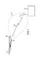
- FIG. 1depicts an antenna system in accordance with embodiments of the present invention in an exemplary operating environment
- FIG. 2is a plan view of an antenna system in accordance with embodiments of the present invention.
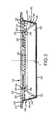
- FIG. 3is a cross-section in elevation of an antenna system in accordance with embodiments of the present invention.
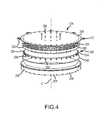
- FIG. 4is an exploded perspective view of components of an antenna system in accordance with embodiments of the present invention.
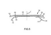
- FIG. 5is a cross-section in elevation of components of an antenna system in accordance with other embodiments of the present invention.
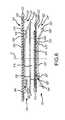
- FIG. 6is a cross-section in elevation of components of an antenna system in accordance with other embodiments of the present invention.
- FIG. 7is a cross-section in elevation of components of an antenna system in accordance with other embodiments of the present invention.
- FIG. 8depicts aspects of a feed network in accordance with embodiments of the present invention.
- FIG. 9depicts other aspects of a feed network in accordance with embodiments of the present invention.
- FIG. 10is a block diagram of portions of a receive only feed network in accordance with embodiments of the present invention.
- FIG. 11is a block diagram of portions of a half duplex feed network system in accordance with embodiments of the present invention.
- FIG. 12depicts elevation patterns for beams steered in azimuth
- FIG. 13depicts azimuth patterns for a beam steered in azimuth
- FIG. 14depicts aspects of a method in accordance with embodiments of the present invention.
- FIG. 1illustrates an antenna system 104 in accordance with embodiments of the present invention, in an exemplary operating environment.
- the antenna system 104is shown mounted to a platform 108 .
- the platform 108comprises an airplane.
- an antenna system 104 in accordance with embodiments of the present inventioncan be associated with any type of platform 108 , whether that platform 108 comprises a vehicle, stationary structure, or other platform.
- the antenna system 104operates to transmit and/or receive information relative to an endpoint 112 .
- the endpoint 112can itself include or be associated with an endpoint antenna 116 .
- Endpoint 112can be a stationary structure or a mobile platform. Accordingly, data can be exchanged between the antenna system 104 and the endpoint antenna 116 .
- the example environment illustrated in FIG. 1depicts communications between two cooperating endpoints, embodiments of the present invention can also be used in other scenarios.
- an antenna system 104can be used as a sensor or beacon.
- the antenna system 104is used to receive control information from a ground station or endpoint 112 related to the operation of an associated platform 108 .
- the antenna system 104can be used to transmit telemetry information, environmental information, or information gathered from sensors mounted to the platform 108 to the endpoint 112 .
- the ability of the antenna system 104 in accordance with embodiments of the present invention to steer an associated beam 120is desirable.
- the beam 120 of the antenna system 104which can, for example, support wireless transmission line 124 , can be steered in at least one plane, to maximize or increase the gain of the antenna system 104 relative to the endpoint antenna 116 .
- the antenna system 104can be mounted such that the beam 120 produced by the antenna system 104 can be steered in azimuth.
- the antenna 116 associated with the endpoint 112can comprise an antenna system 104 in accordance with embodiments of the present invention, a phased array antenna system, a mechanically steered antenna system, or other antenna system.
- FIG. 2depicts an antenna system 104 in accordance with an exemplary embodiment of the present invention in plan view.
- the antenna system 104may have a circular configuration, according to which at least some of the components of the antenna system 104 are disposed symmetrically about a center point C, defining a central axis.
- Visible in the figureis radome 204 , and a portion of a base plate 208 .
- the base plate 208can include mounting members 212 , to facilitate mounting the antenna system 104 to a platform 108 .
- the radome 204can be interconnected to the base plate 208 by a plurality of fasteners 216 .
- FIG. 3is a cross-section in elevation of an antenna system 104 in accordance with an exemplary embodiment of the present invention.
- the radome 204cooperates with the base plate 208 to define an enclosed volume 304 .
- a radome 204is not required as part of the antenna system 104 .
- a radome 204can be desirable, for example where the antenna system 104 is mounted to the exterior of a platform 108 .
- a horn structure or flared radiator 308is interconnected to the base plate 208 .
- the horn structure 308includes a flared radiator portion 312 , a wave guide portion 316 , and a central or mounting portion 320 .
- the flared radiator 312 , wave guide 316 , and mounting 320 portions of the horn structure 308 shown in cross-section in FIG. 3are continuous such that they form a generally circular structure centered about the central axis C′ of the antenna system 104 . Moreover, the horn structure 308 is generally symmetric about the central axis C′.
- a plurality of probe feeds 324are disposed adjacent to or within the wave guide portion 316 of the horn structure 308 to form a circular array 326 .
- the probe feeds 324are mechanically and electrically interconnected to a printed circuit board (PCB) 328 .
- the printed circuit board 328is generally parallel to the base plate 208 , and may be interconnected to the base plate 208 directly, or through and intermediate component or components, such as a stiffener or spacer 336 .
- the PCB 328may comprise some or all of a ground plane 332 .
- the base plate 208may comprise some or all of a ground plane 332 .
- the horn structure 308in combination with the ground plane 332 , forms an aperture comprising a continuous horn or flared radiator structure 334 that extends 360° about the central axis C′ of the antenna system 104 .
- the horn structure 308 and the ground plane 332define an aperture volume 344 .
- This aperture volume 344includes a parallel plate waveguide portion 348 that is generally between the waveguide portion 316 of the horn structure 308 and the ground plane 332 , and a flared radiator portion 352 that is generally between the waveguide 316 of the horn structure 308 and the ground plane 332 .
- An antenna system 104 in accordance with embodiments of the present inventioncan also include a feed network that is at least partially incorporated into and/or associated with the PCB 328 .
- the feed networkgenerally functions to operate a selected subset or subsets of the plurality of probe feeds 324 disposed along a segment or arc of the circular array 326 at different points in time.
- the feed networkcan also include phase shifters, to allow for steering of the beam produced by the selected probe feeds 324 within a selected segment.
- a horn type antennawill radiate a linearly polarized wave.
- a polarizer 340can be mounted about the perimeter of the circular aperture adjacent the flared radiator portion 352 of the aperture volume 344 , to transition between a linearly polarized wave and a circularly polarized wave.
- polarizer 340can be mounted to radome 204 and spaced away from the flared radiator portion 352 .
- Fasteners 356can be used to interconnect the various components of the antenna system 104 to one another.
- FIG. 4is an exploded perspective view of components of an antenna system 104 in accordance with embodiments of the present invention.
- the aperture or continuous flared radiator structure 334is essentially formed from two components, the base plate 208 (or alternatively the PCB 328 ), which defines a ground plane 332 , and the horn structure 308 .
- this simple constructionnonetheless provides coverage in any direction with respect to the plane of the base plate 208 .
- the beam 120can be steered in any direction in azimuth.
- FIG. 5is a cross-section in elevation of components of an antenna system 104 in accordance with other embodiments of the present invention.
- the base plate 208comprises a ground plane 332 that includes an angled outer portion 504 adjacent the flared radiator portion 312 of the horn structure 308 . More particularly, the angled outer portion 504 is angled towards the horn structure 308 .
- the inclusion of an angled outer portion 504 of the ground plane 332can alter the pointing and/or shaping of the beam produced by the antenna system 104 .
- the beam or beams formed by the antenna system 104can be steered in azimuth.
- the beam or beams produced by the antenna system 104are pointed away from the plane of the base plate 208 . Accordingly, in this example, the beam is pointed at a different angle in elevation as compared to the beam of the embodiment illustrated in FIG. 3 .
- FIG. 6is a cross-section in elevation of components of an antenna system 104 in accordance with other embodiments of the present invention.
- the antenna system 104includes two concentric continuous flared radiator structures 334 .
- the first continuous flared radiator structure 334 ′includes a first ground plane 332 ′ and a first horn structure 308 ′.
- the first continuous flared radiator structure 334 ′features a first waveguide portion 348 ′ and a first flared radiator portion 352 ′, and extends 360° about the central axis C′ of the antenna system 104 .
- a first plurality of probe feeds 324 ′comprising a first circular array 326 ′ are interconnected to the first PCB 328 ′.
- a portion of each probe feed included in the first plurality of probe feeds 324 ′is disposed within the parallel plate waveguide portion 348 ′ of the first continuous flared radiator structure 334 ′.
- the second continuous flared radiator structure 334 ′′generally includes a second ground plane 332 ′′ and a second horn structure 308 ′′.
- the second continuous flared radiator structure 334 ′′includes a second waveguide portion 348 ′′ and a second flared radiator portion 352 ′′ and extends 360° about the central axis C′ of the antenna system 104 .
- a second plurality of probe feeds 324 ′′ comprising a second circular array 326 ′′are interconnected to the second PCB 328 ′′. At least a portion of the probe feeds included in the second plurality of probe feeds 324 ′′ extend into the second parallel plate waveguide portion 348 ′′ of the second continuous flared radiator 334 ′′.
- a bracket structure 604may be provided to interconnect the first continuous flared radiator structure 334 ′ and the second continuous radiator structure 334 ′′.
- the bracket structure 604 in the exemplary embodiment shown in FIG. 6includes a top plate 608 that is interconnected to the first horn structure 308 ′.
- the top plate 608is interconnected to a bottom plate 612 by a connecting structure 616 .
- the bottom plate 612is interconnected to the base plate 208 ′′ of the second continuous flared radiator structure 334 ′′.
- first horn structure 308 ′ and second base plate 208 ′′may be directly fastened together or fabricated as a single component to eliminate the need for connecting parts.
- the first continuous flared radiator structure 334 ′has a larger diameter than the second continuous flared radiator structure 334 ′′.
- the gain of the first continuous flared radiator structure 334 ′will generally be greater than the gain of the second continuous flared radiator structure 334 ′′.
- providing multiple continuous flared radiator structures 334can facilitate the provision of an antenna system 104 having expanded functionality.
- the first continuous flared radiator structure 334 ′can be configured to perform a receive function
- the second continuous flared radiator structure 334 ′′can be configured to perform a transmit function.
- the first continuous flared radiator structure 334 ′can function over a wavelength range that is different than the second continuous flared radiator structure 334 ′′.
- the multiple continuous flared radiator structure 334 antenna system 104 depicted in FIG. 6includes two continuous flared radiator structures 334 ′ and 334 ′′, a multiple continuous flared radiator 334 antenna system 104 can include more than two continuous flared radiator structures 334 .
- Embodiments of the present invention having multiple continuous flared radiator structures 334can also feature steering of the beam 120 in elevation, by providing continuous flared radiator structures 334 having different beam profiles in elevation.
- a beam produced by the antenna system 104 having a desired angle or coverage area in a plane perpendicular to a base plate 208 of the antenna system 104can be produced by appropriately selecting the continuous flared radiator structure 334 used to produce the beam.
- a single radome 204can be used to enclose the aperture volumes 344 ′ and 344 ′′.
- each of the multiple continuous flared radiator structure 334can optionally include a polarizer 340 (see FIG. 3 ).
- Each flared radiator structure 334may have an associated polarizer 340 to provide the same polarization or different polarizations.
- a single polarizer 340can be fabricated to cover more than one flared radiator.
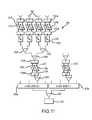
- FIG. 7is a cross-section in elevation of components of an antenna system 104 in accordance with other embodiments of the present invention.
- a supplemental antenna element 704is provided, in addition to the flared continuous radiator structure 334 .
- the provision of a supplemental antenna element 704can assist in providing an antenna beam that covers areas not covered by a beam or beams formed by the continuous flared radiator structure 334 .
- a supplemental antenna element 704can provide coverage within areas along or near the central axis C′ of the antenna system 104 .
- a supplemental antenna element 704can comprise a plurality of radiating elements 708 .
- the supplemental antenna element 704can comprise a phased array antenna. Moreover, the radiating element or elements 708 can be interconnected to a supplemental antenna element PCB 712 that is in turn interconnected to a mounting plate 716 .
- the mounting plate 716can function to interconnect the supplemental antenna system 704 to the horn structure 308 of the flared radiator structure 334 .
- the PCB 712 and/or the mounting plate 716can function as a ground plane.
- FIG. 8depicts aspects of a feed network in accordance with embodiments of the present invention. More particularly, FIG. 8 illustrates an exemplary arrangement according to which the plurality of probe feeds 324 of a circular array 326 are divided into sectors 804 .
- the probe feeds 324are divided into eight groups or sectors 804 that each span 45° of the 360° flared radiator 334 .
- a beam produced by the antenna system 104can be steered or pointed in increments of 45°, by operating the feed network probe feeds 324 such that probe feeds 324 within two adjacent sectors 804 are operative at any one point in time.
- the resulting beamcan be electronically steered within a coverage area 808 centered in the 90° section.
- the beamcan be electronically steered within a 45° coverage area 808 by operating phase shifters. Accordingly, where the beam can be steered electronically by ⁇ 22.5°, the beam can be pointed in any direction around the flared radiator structure 334 .
- This exemplary configurationprovides a worst case scan angle of 67.5° for elements at the edge of the selected 90° section.
- coverage areas 808that extend over areas of different angular extents can be selected by selectively switching segments of probe feeds that extend over sectors or areas of different sizes. Therefore, as further examples, and without limitation, a feed network that allows sectors that span 30° or 15° to be selected can be provided.
- FIG. 9depicts features of a feed network 904 in accordance with embodiments of the present invention.
- the feed network 904includes a plurality of four-way switches 908 .
- the four-way switches 908allow the feed network 904 to address different subsets or sectors 804 of the probe feeds 324 to select the active coverage area 808 of the beam of the antenna system 104 so that the beam can then be electronically steered in a desired direction.
- the four-way switches 908 that the sectors 804 of probe feeds 324 are connected toare alternated. For example, with reference again to FIG.
- the probe feeds 324 in the odd numbered sectors 804can be interconnected to the first four-way switch 908 a
- the probe feeds 324 in the even numbered sectors 804can be interconnected to the second four-way switch 908 b
- the four-way switch 908 aoperates to interconnect a selected segment from a set of odd number sectors 804 of probe feeds 324 to transceiver electronics 912
- the second four-way switch 908 boperates to interconnect a selected segment from a set of even number sectors 804 to be the transceiver electronics 912
- a combiner/splitter 916can be included to pass signals between the four-way switches 908 and the transceiver electronics 912 .
- transceiver electronics 912can include a transceiver, transmitter, receiver, or the like.
- FIG. 10is a block diagram of a receive only feed network 904 in accordance with exemplary embodiments of the present invention.
- one odd numbered segment 804 of probe feeds 324 and one even numbered segment 804 of probe feeds 324are shown, interconnected to a selected output of a first four-way switch 908 a and a selected output of a second four-way switch 908 b respectively.
- a distribution network 1004that includes a plurality of splitters 1008 and amplifiers 1012 .
- the amplifiers 1012can include low noise amplifiers 1016 , located proximate to the individual probe feeds 324 , and buffer amplifiers 1020 , that receive signals from a plurality of low noise amplifiers 1016 .
- the distribution network 1004can additionally include a plurality of phase shifters 1024 , to support electronic steering of the beam within a selected coverage area 808 .
- a transmit only feed network 904can be provided by reversing the operative direction of the included amplifiers 1012 , and operating the combiners 916 and 1008 as splitters.
- one or more of the amplifiers 1012can comprise power amplifiers.
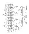
- FIG. 11is a block diagram of a half duplex feed network system 904 in accordance with embodiments of the present invention.
- switches 1104are incorporated into the feed network 904 , to selectively provide signals to amplifiers 1012 . More particularly, in a receive mode, switches 1104 a proximate to the probe feeds 324 provide received signals to low noise amplifiers 1016 . Also in the receive mode of operation, a second set of switches 1104 b pass signals from the low noise amplifiers 1016 to other components of the feed network 904 . For example, the receive signals can be provided to phase shifters 1024 .
- the phase shifters 1024can be operated to steer the receive beam of the antenna system 104 .
- the receive signalsare then passed through splitters/combiners 1008 .
- the combined signalcan be provided to a third switch 1104 c , that passes the combined signal to a buffer amplifier 1020 , and from there to other components of the feed network 904 through a fourth switch 1104 d.
- the transceiver 912provides signals for transmission by the probe feeds 324 to the feed network 904 .
- the signal provided by the transceiver 912can be split in a splitter/combiner 916 , and provided to four-way switches 908 .
- Each four-way switch 908provides the signal to a distribution network associated with the selected sector of probe feeds 324 .
- the fourth switch 1104 dcan receive a signal from a connected four-way switch 908 , and provide that signal to a driver amplifier 1108 .
- the driver amplifier 1108provides the now amplified signal to the third switch 1104 c , which receives the amplified signal, passes it through a series of splitters 1008 to a plurality of second switches 1104 b .
- the amplified and divided signalscan be passed through phase shifters 1024 .
- the phase shifters 1024can be operated to steer the transit beam of the antenna system 104 .
- the third switches 1104 bare operated to provide signals to second power amplifiers 1108 b , proximate to the probe feeds 324 .
- the first switches 1104 aare set to receive signals from associated second power amplifiers 1108 b , and to provide the amplified signal to the probe feeds 324 .
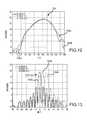
- FIG. 12depicts elevation patterns 1204 for beams produced by an antenna system 104 that are electronically steered within a coverage area 808 in accordance with embodiments of the present invention.
- the elevation pattern associated with a first beam 1204 a steered at 0°, a second beam 1204 b steered at 10°, and a third beam 1204 c steered at 22.5°are illustrated.
- the beam pattern in elevation 1204remains relatively constant, regardless of the angle in azimuth at which the beam produced by the antenna system 104 is steered.
- FIG. 13depicts azimuth patterns 1304 for a beam that is electronically steered in azimuth within a selected coverage area 808 in accordance with embodiments of the present invention.
- a first beam 1304 a steered at 0°, a second beam 1304 b steered at 10°, and a third beam 1304 c steered at 22.5°are shown.
- an antenna system 104 in accordance with embodiments of the present inventioncan produce beams that exhibit a relatively consistent pattern regardless of the direction in azimuth at which the beams are steered.
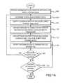
- FIG. 14is a flow chart depicting aspects of the operation of an antenna system 104 in accordance with embodiments of the present invention.
- a continuous flared radiator 334 with an associated circular array 326 of probe feeds 324is provided.
- the desired beam 120 steering angleis determined (step 1408 ). From the desired beam steering angle, the coverage area 808 that includes the desired beam 120 steering angle can be identified (step 1412 ). Having identified the coverage area 808 corresponding to the desired beam steering angle, switches 908 within the feed network 904 can be operated to interconnect the probe feeds 324 within sectors 804 corresponding to the beam coverage area 808 that includes the desired steering angle to the transceiver electronics 912 (step 1116 ).
- phase shifters 1024can be operated (step 1420 ).
- phase shifters 1024 associated with individual probe feeds 324can be operated to taper the phase of the signal received by or transmitted by or from the probe feeds 324 , to steer the resulting beam 120 within the operative coverage area 808 .
- the antenna system 104can then be operated to transmit and/or receive information (step 1124 ).
- an antenna system 104 in accordance with embodiments of the present inventioncan provide a beam 120 that is steered within a plane perpendicular to the central axis C′ of the antenna system 104 .
- an antenna system 104 in accordance with embodiments of the present inventionprovides steering using a combination of a switching network to select the particular sector or sectors within which the beam 120 can be steered, and the selective alteration of the phase of signals passed through operative probe feeds 324 .
- steering of a beam in a plane perpendicular to the base plate 208 of the antenna system 104can be achieved by providing multiple concentric continuous horn or flared radiator structures 334 having different profiles, and operating the probe feeds 324 and supporting feed network 904 components associated with a selected continuous flared radiator structure 334 included in the multiple continuous flared radiator structures.
- an antenna system 104can be deployed in connection with an unmanned aerial vehicle 108 , and can operate to track a stationary or mobile endpoint antenna 116 that provides control information to such a vehicle 108 , and that receives information from such a vehicle 108 .
- the continuous flared radiator 344is operated in connection with a circular array 326 of probe feeds 324 that can be selectively operated according to the grouping or sector 804 that corresponds to a desired steering angle of the beam 120 .
- two four-way switches 904can be provided to selectively activate adjacent 45° sectors of the circular array 326 , such that a 90° sector of probe feeds 326 is operative at any particular point in time.
- the selected 90° sector of probe feeds 326can effectively provide a beam 120 that is steered within a 45° coverage area 808 that is centered within the 90° active sector.
- This configurationallows the coverage area 808 to be moved in 45° steps around the circumference of the antenna system 104 . Moreover, this configuration provides a 67.5° worst case scan angle 810 for elements at the edge of an active quadrant.
- different segmentation of the circular array 326can be used for different applications and/or coverage area 808 extents.
- steering within a selected coverage area 808can be performed electronically through the selective activation of phase shifters. Accordingly, fine pointing or steering of a relatively narrow beam in azimuth can be achieved.
- a continuous flared radiator structure 334 as described hereincan provide a beam that is relatively narrow in azimuth, and relatively broad in elevation.
- supplemental antenna elements 704can be provided.
- the probe feeds 324 placed around the circular array 326have a spacing of ⁇ HI /2 where ⁇ m is the wavelength at the highest frequency of operation. This spacing allows grating-lobe free operation at all steering angles. Although up to half of the array 326 may be illuminated at one time, such a configuration requires that the probe feeds 324 near the edge of the operative segment have an effective steering angle of 90° from their respective boresight direction. This can result in significant impedance mismatch of the probe feeds and increased side lobe levels away from the desired direction of radiation. Accordingly, smaller active segments, for example 90° segments of the circular array, can be used to provide improved impedance matching and reduced side-lobe levels.
- the azimuth beam width of an antenna system 104 in accordance with embodiments of the present inventionis determined by the diameter of the continuous flared radiator 334 aperture and how much of the array 326 is illuminated.
- the elevation beam width and angle of maximum gainare controlled by the features of the flared radiator portion 352 .
- flare heightscan extend from 0.4 to 0.8 inches, with a continuous flared radiator 334 diameter of ten inches. Increasing flare height increases aperture size, resulting in higher gain and a narrower beam width.
- the angle of the flarecan be used to alter the angle of the maximum gain. With a fixed height, increasing the flare angle moves the direction of maximum gain further below the horizon.
- the pattern shapecan be altered by changing the top surface of the radiator, for example by providing an angled outer portion 504 of the ground plane 332 . By varying the overall diameter and flare characteristics, the radiation pattern can be optimized for a given platform 108 and link.
- Exemplary aperture diametersare ten, fourteen, and eighteen inches.
- Exemplary numbers of probe feeds 324are 64, 96, and 128, which corresponds to 16, 24, or 32 active elements 324 at any one point in time.
- the active aperture width for the three sizesis 7.1 inches, 9.9 inches, and 12.7 inches.
- the antenna system 104can be fabricated in a simple, cost effective manner.
- the horn structure 308 and base plate 208can be machined aluminum or other metal or can be a molded plastic part with suitable electrically conductive plating.
- a single printed circuit board 328can contain the probe feeds 324 , the transmit and receive electronics 912 , combining feed networks 1 , 004 , switches 908 , and power/control electronics.
- the continuous flared radiator structure 334 and printed circuit board 328can be attached to the base plate 208 with relief for the traces and components.
- the printed circuit board 328can define the upper portion of the continuous flared radiator structure 334 .
- the base plate 208can serve as the upper portion of the radiator structure 334 , which allows shaping of the element to control pattern characteristics such as beam width and peak gain angle.
- a supplemental antenna 704can comprise a separate component, or can be integrated into the printed circuit board 328 .
- An assembled antenna system 104 in accordance with embodiments of the present invention with a ten inch diameter radiator structure 334 and a 0.8 inch flare heightcan comprise a base plate diameter of 10.75 inches and an overall antenna system 104 thickness or height of 1.225 inches.
- Exemplary frequency ranges supported by the antenna system 104are from twelve to twenty gigahertz, with a gain of 20 dB at 15 GHz.
Landscapes
- Physics & Mathematics (AREA)
- Engineering & Computer Science (AREA)
- Astronomy & Astrophysics (AREA)
- Aviation & Aerospace Engineering (AREA)
- General Physics & Mathematics (AREA)
- Remote Sensing (AREA)
- Variable-Direction Aerials And Aerial Arrays (AREA)
Abstract
Description
Claims (17)
Priority Applications (2)
| Application Number | Priority Date | Filing Date | Title |
|---|---|---|---|
| US13/018,145US9379437B1 (en) | 2011-01-31 | 2011-01-31 | Continuous horn circular array antenna system |
| PCT/US2011/060564WO2012106021A1 (en) | 2011-01-31 | 2011-11-14 | Continuous horn circular array antenna system |
Applications Claiming Priority (1)
| Application Number | Priority Date | Filing Date | Title |
|---|---|---|---|
| US13/018,145US9379437B1 (en) | 2011-01-31 | 2011-01-31 | Continuous horn circular array antenna system |
Publications (1)
| Publication Number | Publication Date |
|---|---|
| US9379437B1true US9379437B1 (en) | 2016-06-28 |
Family
ID=45003095
Family Applications (1)
| Application Number | Title | Priority Date | Filing Date |
|---|---|---|---|
| US13/018,145Active2034-08-28US9379437B1 (en) | 2011-01-31 | 2011-01-31 | Continuous horn circular array antenna system |
Country Status (2)
| Country | Link |
|---|---|
| US (1) | US9379437B1 (en) |
| WO (1) | WO2012106021A1 (en) |
Cited By (14)
| Publication number | Priority date | Publication date | Assignee | Title |
|---|---|---|---|---|
| US20150357709A1 (en)* | 2014-06-09 | 2015-12-10 | Electronics And Telecommunications Research Institute | Circular array antenna |
| US20170117628A1 (en)* | 2015-10-27 | 2017-04-27 | Ford Global Technologies, Llc | Vehicle phased array antenna pattern generation |
| WO2019161096A1 (en)* | 2018-02-15 | 2019-08-22 | Space Exploration Technologies Corp. | Phased array antenna systems |
| WO2019161106A1 (en)* | 2018-02-15 | 2019-08-22 | Space Exploration Technologies Corp. | Antenna-to-beamformer assignment and mapping in phased array antenna systems |
| US10998606B2 (en) | 2018-02-15 | 2021-05-04 | Space Exploration Technologies Corp. | Hierarchical network signal routing apparatus and method |
| US11018436B2 (en) | 2018-02-15 | 2021-05-25 | Space Exploration Technologies Corp. | Antenna modules for phased array antennas |
| US11056801B2 (en) | 2018-02-15 | 2021-07-06 | Space Exploration Technologies Corp. | Antenna aperture in phased array antenna systems |
| US11146323B2 (en) | 2018-02-15 | 2021-10-12 | Space Exploration Technologies Corp. | Beamformer lattice for phased array antennas |
| US11309638B1 (en) | 2019-05-09 | 2022-04-19 | Space Exploration Technolgies Corp. | Antenna modules in phased array antennas |
| US20220321151A1 (en)* | 2021-03-30 | 2022-10-06 | Skyworks Solutions, Inc. | Reprogrammable array of selectable antenna elements for frequency adjustment |
| US11476563B2 (en)* | 2018-06-29 | 2022-10-18 | Advanced Automotive Antennas, S.L.U. | Under-roof antenna modules for vehicle |
| US12334640B1 (en)* | 2022-05-05 | 2025-06-17 | Lockheed Martin Corporation | Waveguide antenna structures with concurrent transmit and receive |
| US12355158B1 (en) | 2021-07-08 | 2025-07-08 | Lockheed Martin Corporation | Vivaldi antenna structures with concurrent transmit and receive |
| WO2025188760A1 (en)* | 2024-03-06 | 2025-09-12 | Air Wireless, Inc. | Triple horn antenna system and method for use thereof |
Families Citing this family (5)
| Publication number | Priority date | Publication date | Assignee | Title |
|---|---|---|---|---|
| US10305176B2 (en) | 2014-05-20 | 2019-05-28 | University Of North Dakota | Conformal antennas for unmanned and piloted vehicles and method of antenna operation |
| CN105390824B (en)* | 2015-12-14 | 2018-06-19 | 华为技术有限公司 | Cleave the feeding network of antenna and splitting antenna |
| KR102599996B1 (en)* | 2016-11-11 | 2023-11-09 | 삼성전자 주식회사 | Beamforming antenna assembly including metal structure |
| WO2018088745A1 (en) | 2016-11-11 | 2018-05-17 | Samsung Electronics Co., Ltd. | Beamforming antenna assembly including metal structure |
| CN115566386B (en)* | 2022-08-31 | 2025-04-11 | 电子科技大学 | A broadband four-way dual circularly polarized power divider for waveguide array antenna |
Citations (59)
| Publication number | Priority date | Publication date | Assignee | Title |
|---|---|---|---|---|
| US3090956A (en) | 1960-12-23 | 1963-05-21 | Rca Corp | Steerable antenna |
| US3116485A (en) | 1960-06-27 | 1963-12-31 | Ite Circuit Breaker Ltd | Omnidirectional horn radiator for beacon antenna |
| GB1011303A (en) | 1961-11-23 | 1965-11-24 | Siemens Ag | Improvements in or relating to antenna arrays |
| US3569976A (en) | 1968-08-29 | 1971-03-09 | William Korvin | Antenna array at focal plane of reflector with coupling network for beam switching |
| US3775773A (en) | 1972-07-17 | 1973-11-27 | Itt | Technique for generating planar beams from a linear doppler line source employing a circular parallel-plate waveguide |
| US3887926A (en) | 1973-11-14 | 1975-06-03 | Singer Co | Phased array scanning antenna |
| DE2714643A1 (en) | 1976-04-01 | 1978-02-16 | Raytheon Co | HIGH FREQUENCY ANTENNA WITH A MULTIPLE DIRECTIONAL BEAM |
| GB1505375A (en) | 1974-05-07 | 1978-03-30 | Int Standard Electric Corp | Antenna for producing a rotating cardioid pattern |
| US4127857A (en) | 1977-05-31 | 1978-11-28 | Raytheon Company | Radio frequency antenna with combined lens and polarizer |
| US4359738A (en) | 1974-11-25 | 1982-11-16 | The United States Of America As Represented By The Secretary Of The Navy | Clutter and multipath suppressing sidelobe canceller antenna system |
| US4423422A (en) | 1981-08-10 | 1983-12-27 | Andrew Corporation | Diagonal-conical horn-reflector antenna |
| US4630062A (en) | 1981-09-07 | 1986-12-16 | U.S. Philips Corporation | Horn antenna with wide flare angle |
| US4673943A (en) | 1984-09-25 | 1987-06-16 | The United States Of America As Represented By The Secretary Of The Air Force | Integrated defense communications system antijamming antenna system |
| US4825222A (en) | 1986-01-30 | 1989-04-25 | British Telecommunications Plc | Omnidirectional antenna with hollow point source feed |
| US4890117A (en) | 1987-01-20 | 1989-12-26 | National Research Development Corporation | Antenna and waveguide mode converter |
| US5023594A (en) | 1990-03-01 | 1991-06-11 | C & K Systems, Inc. | Ceiling mount microwave transceiver with 360 degree radiation pattern |
| EP0456034A2 (en) | 1990-05-07 | 1991-11-13 | Hughes Aircraft Company | Bicone antenna with hemispherical beam |
| GB2258345A (en) | 1991-07-29 | 1993-02-03 | Marconi Gec Ltd | Microwave antenna. |
| US5202697A (en) | 1991-01-18 | 1993-04-13 | Cubic Defense Systems, Inc. | Low-profile steerable cardioid antenna |
| US5506592A (en) | 1992-05-29 | 1996-04-09 | Texas Instruments Incorporated | Multi-octave, low profile, full instantaneous azimuthal field of view direction finding antenna |
| US5714964A (en)* | 1995-11-07 | 1998-02-03 | Condor Systems, Inc. | Horned interferometer antenna apparatus |
| US5742257A (en) | 1996-08-13 | 1998-04-21 | Raytheon Company | Offset flared radiator and probe |
| WO2000001031A1 (en) | 1998-06-29 | 2000-01-06 | Ems Technologies, Inc. | Antenna exhibiting azimuth and elevation beam shaping characteristics |
| US6023246A (en) | 1997-04-09 | 2000-02-08 | Nec Corporation | Lens antenna with tapered horn and dielectric lens in horn aperture |
| JP2000138521A (en) | 1998-10-30 | 2000-05-16 | Ntt Mobil Communication Network Inc | Antenna device |
| US6104346A (en) | 1998-11-06 | 2000-08-15 | Ail Systems Inc. | Antenna and method for two-dimensional angle-of-arrival determination |
| WO2000076028A1 (en) | 1999-06-07 | 2000-12-14 | Spike Broadband Techologies, Inc. | Hemispheroidally shaped lens and antenna system employing same |
| WO2001028162A1 (en) | 1999-10-13 | 2001-04-19 | Caly Corporation | Spatially switched router for wireless data packets |
| GB2355855A (en) | 1999-10-29 | 2001-05-02 | Univ Sheffield | Steerable-beam multiple-feed dielectric resonator antenna |
| WO2001069720A1 (en) | 2000-03-14 | 2001-09-20 | Technische Universität Dresden | Device for transmitting and receiving electromagnetic waves in a route-selective manner |
| US6317096B1 (en) | 1998-07-31 | 2001-11-13 | Fuba Automotive Gmbh | Antenna system |
| US6353418B1 (en) | 1999-08-10 | 2002-03-05 | Endress + Hauser Gmbh + Co. | Horn antenna having a dielectric insert with a wide-based cone section |
| US6384795B1 (en) | 2000-09-21 | 2002-05-07 | Hughes Electronics Corp. | Multi-step circular horn system |
| US20020167449A1 (en) | 2000-10-20 | 2002-11-14 | Richard Frazita | Low profile phased array antenna |
| US20030052831A1 (en) | 2001-09-20 | 2003-03-20 | Andrew Corporation | Dual-polarized shaped-reflector antenna |
| WO2003098740A1 (en) | 1999-08-17 | 2003-11-27 | Ems Technologies, Inc. | Scanning directional antenna with lens and reflector assembly |
| US20040085249A1 (en) | 2002-11-01 | 2004-05-06 | Nobumasa Kitamori | Sector antenna apparatus and vehicle-mounted transmission and reception apparatus |
| US6816118B2 (en) | 2000-03-11 | 2004-11-09 | Antenova Limited | Multi-segmented dielectric resonator antenna |
| US20050200531A1 (en) | 2004-02-11 | 2005-09-15 | Kao-Cheng Huang | Circular polarised array antenna |
| US20050219126A1 (en) | 2004-03-26 | 2005-10-06 | Automotive Systems Laboratory, Inc. | Multi-beam antenna |
| US6987489B2 (en) | 2003-04-15 | 2006-01-17 | Tecom Industries, Inc. | Electronically scanning direction finding antenna system |
| US7012572B1 (en) | 2004-07-16 | 2006-03-14 | Hrl Laboratories, Llc | Integrated ultra wideband element card for array antennas |
| US20060071876A1 (en) | 2002-08-20 | 2006-04-06 | Aerosat Corporation | Communication system with broadband antenna |
| US7081858B2 (en)* | 2004-05-24 | 2006-07-25 | Science Applications International Corporation | Radial constrained lens |
| US20070252768A1 (en) | 2005-05-31 | 2007-11-01 | Farrokh Mohamadi | Integrated circuit beamforming horn array |
| US7307596B1 (en) | 2004-07-15 | 2007-12-11 | Rockwell Collins, Inc. | Low-cost one-dimensional electromagnetic band gap waveguide phase shifter based ESA horn antenna |
| US20080055175A1 (en) | 1999-11-18 | 2008-03-06 | Gabriel Rebeiz | Multi-beam antenna |
| US20080100523A1 (en) | 2005-12-19 | 2008-05-01 | The Boeing Company | Flap antenna and communications system |
| US20080117113A1 (en) | 2006-05-24 | 2008-05-22 | Haziza Dedi David | Integrated waveguide cavity antenna and reflector rf feed |
| US20090237318A1 (en) | 2008-03-19 | 2009-09-24 | Astron Wireless Technologies, Inc. | Direction finding antenna |
| US20090267852A1 (en) | 2008-04-29 | 2009-10-29 | Tahmisian Jr Theodore N | Small Aperture Interrogator Antenna System Employing Sum Difference Azimuth Discrimination Techniques |
| US20090309801A1 (en) | 2008-06-11 | 2009-12-17 | Lockheed Martin Corporation | Antenna systems for multiple frequency bands |
| US20100013726A1 (en) | 2006-05-11 | 2010-01-21 | James Christopher Gordon Matthews | Antenna |
| US20100052987A1 (en) | 2008-09-03 | 2010-03-04 | Lockheed Martin Corporation | Electronically steered, dual-polarized, dual-plane, monopulse antenna feed |
| US20100066590A1 (en) | 2008-07-28 | 2010-03-18 | Physical Domains, LLC | Omnidirectional Retrodirective Antennas |
| US7728772B2 (en) | 2006-06-09 | 2010-06-01 | The Regents Of The University Of Michigan | Phased array systems and phased array front-end devices |
| US20100164784A1 (en) | 2006-01-17 | 2010-07-01 | Filtronic Pty Ltd. | Surveillance Apparatus and Method |
| US20100207819A1 (en) | 2008-11-25 | 2010-08-19 | Uhl Brecken H | System and method for electronically steering an antenna |
| US8581794B1 (en)* | 2010-03-04 | 2013-11-12 | Qualcomm Incorporated | Circular antenna array systems |
- 2011
- 2011-01-31USUS13/018,145patent/US9379437B1/enactiveActive
- 2011-11-14WOPCT/US2011/060564patent/WO2012106021A1/enactiveApplication Filing
Patent Citations (61)
| Publication number | Priority date | Publication date | Assignee | Title |
|---|---|---|---|---|
| US3116485A (en) | 1960-06-27 | 1963-12-31 | Ite Circuit Breaker Ltd | Omnidirectional horn radiator for beacon antenna |
| US3090956A (en) | 1960-12-23 | 1963-05-21 | Rca Corp | Steerable antenna |
| GB1011303A (en) | 1961-11-23 | 1965-11-24 | Siemens Ag | Improvements in or relating to antenna arrays |
| US3569976A (en) | 1968-08-29 | 1971-03-09 | William Korvin | Antenna array at focal plane of reflector with coupling network for beam switching |
| US3775773A (en) | 1972-07-17 | 1973-11-27 | Itt | Technique for generating planar beams from a linear doppler line source employing a circular parallel-plate waveguide |
| US3887926A (en) | 1973-11-14 | 1975-06-03 | Singer Co | Phased array scanning antenna |
| GB1505375A (en) | 1974-05-07 | 1978-03-30 | Int Standard Electric Corp | Antenna for producing a rotating cardioid pattern |
| US4359738A (en) | 1974-11-25 | 1982-11-16 | The United States Of America As Represented By The Secretary Of The Navy | Clutter and multipath suppressing sidelobe canceller antenna system |
| DE2714643A1 (en) | 1976-04-01 | 1978-02-16 | Raytheon Co | HIGH FREQUENCY ANTENNA WITH A MULTIPLE DIRECTIONAL BEAM |
| US4127857A (en) | 1977-05-31 | 1978-11-28 | Raytheon Company | Radio frequency antenna with combined lens and polarizer |
| US4423422A (en) | 1981-08-10 | 1983-12-27 | Andrew Corporation | Diagonal-conical horn-reflector antenna |
| US4630062A (en) | 1981-09-07 | 1986-12-16 | U.S. Philips Corporation | Horn antenna with wide flare angle |
| US4673943A (en) | 1984-09-25 | 1987-06-16 | The United States Of America As Represented By The Secretary Of The Air Force | Integrated defense communications system antijamming antenna system |
| US4825222A (en) | 1986-01-30 | 1989-04-25 | British Telecommunications Plc | Omnidirectional antenna with hollow point source feed |
| US4890117A (en) | 1987-01-20 | 1989-12-26 | National Research Development Corporation | Antenna and waveguide mode converter |
| US5023594A (en) | 1990-03-01 | 1991-06-11 | C & K Systems, Inc. | Ceiling mount microwave transceiver with 360 degree radiation pattern |
| EP0456034A2 (en) | 1990-05-07 | 1991-11-13 | Hughes Aircraft Company | Bicone antenna with hemispherical beam |
| US5202697A (en) | 1991-01-18 | 1993-04-13 | Cubic Defense Systems, Inc. | Low-profile steerable cardioid antenna |
| GB2258345A (en) | 1991-07-29 | 1993-02-03 | Marconi Gec Ltd | Microwave antenna. |
| US5506592A (en) | 1992-05-29 | 1996-04-09 | Texas Instruments Incorporated | Multi-octave, low profile, full instantaneous azimuthal field of view direction finding antenna |
| US5714964A (en)* | 1995-11-07 | 1998-02-03 | Condor Systems, Inc. | Horned interferometer antenna apparatus |
| US5742257A (en) | 1996-08-13 | 1998-04-21 | Raytheon Company | Offset flared radiator and probe |
| US6023246A (en) | 1997-04-09 | 2000-02-08 | Nec Corporation | Lens antenna with tapered horn and dielectric lens in horn aperture |
| WO2000001031A1 (en) | 1998-06-29 | 2000-01-06 | Ems Technologies, Inc. | Antenna exhibiting azimuth and elevation beam shaping characteristics |
| US6317096B1 (en) | 1998-07-31 | 2001-11-13 | Fuba Automotive Gmbh | Antenna system |
| JP2000138521A (en) | 1998-10-30 | 2000-05-16 | Ntt Mobil Communication Network Inc | Antenna device |
| US6104346A (en) | 1998-11-06 | 2000-08-15 | Ail Systems Inc. | Antenna and method for two-dimensional angle-of-arrival determination |
| WO2000076028A1 (en) | 1999-06-07 | 2000-12-14 | Spike Broadband Techologies, Inc. | Hemispheroidally shaped lens and antenna system employing same |
| US6353418B1 (en) | 1999-08-10 | 2002-03-05 | Endress + Hauser Gmbh + Co. | Horn antenna having a dielectric insert with a wide-based cone section |
| WO2003098740A1 (en) | 1999-08-17 | 2003-11-27 | Ems Technologies, Inc. | Scanning directional antenna with lens and reflector assembly |
| WO2001028162A1 (en) | 1999-10-13 | 2001-04-19 | Caly Corporation | Spatially switched router for wireless data packets |
| GB2355855A (en) | 1999-10-29 | 2001-05-02 | Univ Sheffield | Steerable-beam multiple-feed dielectric resonator antenna |
| US6452565B1 (en) | 1999-10-29 | 2002-09-17 | Antenova Limited | Steerable-beam multiple-feed dielectric resonator antenna |
| US6900764B2 (en) | 1999-10-29 | 2005-05-31 | Antenova Limited | Steerable-beam multiple-feed dielectric resonator antenna |
| US20080055175A1 (en) | 1999-11-18 | 2008-03-06 | Gabriel Rebeiz | Multi-beam antenna |
| US6816118B2 (en) | 2000-03-11 | 2004-11-09 | Antenova Limited | Multi-segmented dielectric resonator antenna |
| WO2001069720A1 (en) | 2000-03-14 | 2001-09-20 | Technische Universität Dresden | Device for transmitting and receiving electromagnetic waves in a route-selective manner |
| US6384795B1 (en) | 2000-09-21 | 2002-05-07 | Hughes Electronics Corp. | Multi-step circular horn system |
| US20020167449A1 (en) | 2000-10-20 | 2002-11-14 | Richard Frazita | Low profile phased array antenna |
| US20030052831A1 (en) | 2001-09-20 | 2003-03-20 | Andrew Corporation | Dual-polarized shaped-reflector antenna |
| US20060071876A1 (en) | 2002-08-20 | 2006-04-06 | Aerosat Corporation | Communication system with broadband antenna |
| US20040085249A1 (en) | 2002-11-01 | 2004-05-06 | Nobumasa Kitamori | Sector antenna apparatus and vehicle-mounted transmission and reception apparatus |
| US6987489B2 (en) | 2003-04-15 | 2006-01-17 | Tecom Industries, Inc. | Electronically scanning direction finding antenna system |
| US20050200531A1 (en) | 2004-02-11 | 2005-09-15 | Kao-Cheng Huang | Circular polarised array antenna |
| US20050219126A1 (en) | 2004-03-26 | 2005-10-06 | Automotive Systems Laboratory, Inc. | Multi-beam antenna |
| US7081858B2 (en)* | 2004-05-24 | 2006-07-25 | Science Applications International Corporation | Radial constrained lens |
| US7307596B1 (en) | 2004-07-15 | 2007-12-11 | Rockwell Collins, Inc. | Low-cost one-dimensional electromagnetic band gap waveguide phase shifter based ESA horn antenna |
| US7012572B1 (en) | 2004-07-16 | 2006-03-14 | Hrl Laboratories, Llc | Integrated ultra wideband element card for array antennas |
| US20070252768A1 (en) | 2005-05-31 | 2007-11-01 | Farrokh Mohamadi | Integrated circuit beamforming horn array |
| US20080100523A1 (en) | 2005-12-19 | 2008-05-01 | The Boeing Company | Flap antenna and communications system |
| US20100164784A1 (en) | 2006-01-17 | 2010-07-01 | Filtronic Pty Ltd. | Surveillance Apparatus and Method |
| US20100013726A1 (en) | 2006-05-11 | 2010-01-21 | James Christopher Gordon Matthews | Antenna |
| US20080117113A1 (en) | 2006-05-24 | 2008-05-22 | Haziza Dedi David | Integrated waveguide cavity antenna and reflector rf feed |
| US7728772B2 (en) | 2006-06-09 | 2010-06-01 | The Regents Of The University Of Michigan | Phased array systems and phased array front-end devices |
| US20090237318A1 (en) | 2008-03-19 | 2009-09-24 | Astron Wireless Technologies, Inc. | Direction finding antenna |
| US20090267852A1 (en) | 2008-04-29 | 2009-10-29 | Tahmisian Jr Theodore N | Small Aperture Interrogator Antenna System Employing Sum Difference Azimuth Discrimination Techniques |
| US20090309801A1 (en) | 2008-06-11 | 2009-12-17 | Lockheed Martin Corporation | Antenna systems for multiple frequency bands |
| US20100066590A1 (en) | 2008-07-28 | 2010-03-18 | Physical Domains, LLC | Omnidirectional Retrodirective Antennas |
| US20100052987A1 (en) | 2008-09-03 | 2010-03-04 | Lockheed Martin Corporation | Electronically steered, dual-polarized, dual-plane, monopulse antenna feed |
| US20100207819A1 (en) | 2008-11-25 | 2010-08-19 | Uhl Brecken H | System and method for electronically steering an antenna |
| US8581794B1 (en)* | 2010-03-04 | 2013-11-12 | Qualcomm Incorporated | Circular antenna array systems |
Non-Patent Citations (9)
| Title |
|---|
| Inoue et al., "Horn-Array Type Electrically Despun Antenna for the 11-GHz Band", Electronics and Communications in Japan, vol. 53-B, No. 7, 1970, 8 pages. |
| International Preliminary Report on Patentability for International Application No. PCT/US2011/060564, mailed Aug. 6, 2013, 10 pages. |
| International Preliminary Report on Patentability for International Application No. PCT/US2011/060571, mailed Aug. 6, 2013, 7 pages. |
| International Search Report and Written Opinion for International Application No. PCT/US2011/060564, mailed Mar. 6, 2012, 16 pages. |
| International Search Report and Written Opinion for International Application No. PCT/US2011/060571, mailed Feb. 29, 2012, 12 pages. |
| Mussler, Michael. E., U.S. Appl. No. 13/018,146, Entitled "Conical Switched Beam Antenna Method and Apparatus", filed Jan. 31, 2011, 30 pages. |
| Notice of Allowance for U.S. Appl. No. 13/018,146, mailed Sep. 27, 2013, 9 pages. |
| Official Action for U.S. Appl. No. 13/018,146, mailed Apr. 17, 2013, 6 pages (Restriction Requirement). |
| Official Action for U.S. Appl. No. 13/018,146, mailed Jun. 14, 2013, 8 pages. |
Cited By (25)
| Publication number | Priority date | Publication date | Assignee | Title |
|---|---|---|---|---|
| US20150357709A1 (en)* | 2014-06-09 | 2015-12-10 | Electronics And Telecommunications Research Institute | Circular array antenna |
| US10056700B2 (en)* | 2014-06-09 | 2018-08-21 | Electronics And Telecommunications Research Institute | Circular array antenna |
| US20170117628A1 (en)* | 2015-10-27 | 2017-04-27 | Ford Global Technologies, Llc | Vehicle phased array antenna pattern generation |
| US11469517B2 (en) | 2018-02-15 | 2022-10-11 | Space Exploration Technologies Corp. | Antenna modules for phased array antennas |
| US11606134B2 (en) | 2018-02-15 | 2023-03-14 | Space Exploration Technologies Corp. | Beamformer lattice for phased array antennas |
| US10971817B2 (en) | 2018-02-15 | 2021-04-06 | Space Exploration Technologies Corp. | Antenna-to-beamformer assignment and mapping in phased array antenna systems |
| US10998606B2 (en) | 2018-02-15 | 2021-05-04 | Space Exploration Technologies Corp. | Hierarchical network signal routing apparatus and method |
| US11018436B2 (en) | 2018-02-15 | 2021-05-25 | Space Exploration Technologies Corp. | Antenna modules for phased array antennas |
| US11056801B2 (en) | 2018-02-15 | 2021-07-06 | Space Exploration Technologies Corp. | Antenna aperture in phased array antenna systems |
| US11146323B2 (en) | 2018-02-15 | 2021-10-12 | Space Exploration Technologies Corp. | Beamformer lattice for phased array antennas |
| US12322865B2 (en) | 2018-02-15 | 2025-06-03 | Space Exploration Technologies Corp. | Antenna modules for phased array antennas |
| US11862837B2 (en) | 2018-02-15 | 2024-01-02 | Space Exploration Technologies Corp. | Hierarchical network signal routing apparatus and method |
| WO2019161096A1 (en)* | 2018-02-15 | 2019-08-22 | Space Exploration Technologies Corp. | Phased array antenna systems |
| US11799210B2 (en) | 2018-02-15 | 2023-10-24 | Space Exploration Technologies Corp. | Antenna modules for phased array antennas |
| WO2019161106A1 (en)* | 2018-02-15 | 2019-08-22 | Space Exploration Technologies Corp. | Antenna-to-beamformer assignment and mapping in phased array antenna systems |
| US11695222B2 (en) | 2018-02-15 | 2023-07-04 | Space Exploration Technologies Corp. | Antenna aperture in phased array antenna systems |
| US11699852B2 (en) | 2018-02-15 | 2023-07-11 | Space Exploration Technologies Corp. | Phased array antenna systems |
| US11476563B2 (en)* | 2018-06-29 | 2022-10-18 | Advanced Automotive Antennas, S.L.U. | Under-roof antenna modules for vehicle |
| US11705640B2 (en) | 2019-05-09 | 2023-07-18 | Space Exploration Technologies Corp. | Antenna modules in phased array antennas |
| US12166282B2 (en) | 2019-05-09 | 2024-12-10 | Space Exploration Technologies Corp. | Antenna modules in phased array antennas |
| US11309638B1 (en) | 2019-05-09 | 2022-04-19 | Space Exploration Technolgies Corp. | Antenna modules in phased array antennas |
| US20220321151A1 (en)* | 2021-03-30 | 2022-10-06 | Skyworks Solutions, Inc. | Reprogrammable array of selectable antenna elements for frequency adjustment |
| US12355158B1 (en) | 2021-07-08 | 2025-07-08 | Lockheed Martin Corporation | Vivaldi antenna structures with concurrent transmit and receive |
| US12334640B1 (en)* | 2022-05-05 | 2025-06-17 | Lockheed Martin Corporation | Waveguide antenna structures with concurrent transmit and receive |
| WO2025188760A1 (en)* | 2024-03-06 | 2025-09-12 | Air Wireless, Inc. | Triple horn antenna system and method for use thereof |
Also Published As
| Publication number | Publication date |
|---|---|
| WO2012106021A1 (en) | 2012-08-09 |
Similar Documents
| Publication | Publication Date | Title |
|---|---|---|
| US9379437B1 (en) | Continuous horn circular array antenna system | |
| US10950939B2 (en) | Systems and methods for ultra-ultra-wide band AESA | |
| US6999044B2 (en) | Reflector antenna system including a phased array antenna operable in multiple modes and related methods | |
| US6965355B1 (en) | Reflector antenna system including a phased array antenna operable in multiple modes and related methods | |
| US10910700B2 (en) | Omnidirectional antenna for mobile communication service | |
| JP6497447B2 (en) | Luneberg lens antenna device | |
| US5874915A (en) | Wideband cylindrical UHF array | |
| US7212163B2 (en) | Circular polarized array antenna | |
| US9397740B2 (en) | Modular antenna array with RF and baseband beamforming | |
| US6864852B2 (en) | High gain antenna for wireless applications | |
| EP2016643B1 (en) | Stacked multiband antenna | |
| US8184056B1 (en) | Radial constrained lens | |
| US20090015498A1 (en) | Dual staggered vertically polarized variable azimuth beamwidth antenna for wireless network | |
| US20120268324A1 (en) | Dual beam sector antenna array with low loss beam forming network | |
| US10879978B2 (en) | Differential phase shifter for hybrid beamforming | |
| US10749258B1 (en) | Antenna system and method for a digitally beam formed intersecting fan beam | |
| EP3231037B1 (en) | High coverage antenna array and method using grating lobe layers | |
| US7907098B1 (en) | Log periodic antenna | |
| US20120194386A1 (en) | Conical switched beam antenna method and apparatus | |
| US6958738B1 (en) | Reflector antenna system including a phased array antenna having a feed-through zone and related methods | |
| US20230231299A1 (en) | Base station antennas having staggered linear arrays with improved phase center alignment between adjacent arrays | |
| US20190131705A1 (en) | User insensitive phased antenna array devices, systems, and methods | |
| US8514142B1 (en) | Reconfigurable surface reflector antenna | |
| US12113294B2 (en) | Reconfigurable antenna | |
| US12206173B1 (en) | Dual mode omni / directional sectored array |
Legal Events
| Date | Code | Title | Description |
|---|---|---|---|
| AS | Assignment | Owner name:BALL AEROSPACE & TECHNOLOGIES CORP., COLORADO Free format text:ASSIGNMENT OF ASSIGNORS INTEREST;ASSIGNOR:STUTZKE, NATHAN A.;REEL/FRAME:025991/0844 Effective date:20110131 | |
| STCF | Information on status: patent grant | Free format text:PATENTED CASE | |
| MAFP | Maintenance fee payment | Free format text:PAYMENT OF MAINTENANCE FEE, 4TH YEAR, LARGE ENTITY (ORIGINAL EVENT CODE: M1551); ENTITY STATUS OF PATENT OWNER: LARGE ENTITY Year of fee payment:4 | |
| AS | Assignment | Owner name:BALL AEROSPACE & TECHNOLOGIES CORP., COLORADO Free format text:ASSIGNMENT OF ASSIGNORS INTEREST;ASSIGNORS:STUTZKE, NATHAN A.;MOOSBRUGGER, PETER J.;REEL/FRAME:064182/0064 Effective date:20110131 | |
| MAFP | Maintenance fee payment | Free format text:PAYMENT OF MAINTENANCE FEE, 8TH YEAR, LARGE ENTITY (ORIGINAL EVENT CODE: M1552); ENTITY STATUS OF PATENT OWNER: LARGE ENTITY Year of fee payment:8 | |
| AS | Assignment | Owner name:BAE SYSTEMS SPACE & MISSION SYSTEMS INC., COLORADO Free format text:CHANGE OF NAME;ASSIGNOR:BALL AEROSPACE & TECHNOLOGIES CORP.;REEL/FRAME:067134/0901 Effective date:20240223 |